Zhejiang Flashforge 3D Technology INVENTOR Inventor User Manual
Zhejiang Flashforge 3D Technology CO., Ltd. Inventor Users Manual
UserManual.wiki
>
Zhejiang Flashforge 3D Technology
>
INVENTOR User Manual
User Manual
Navigation menu
Upload a User Manual
Namespaces
Wiki Guide
HTML
PDF
Info
Views
User Manual
Discussion / Help
Navigation


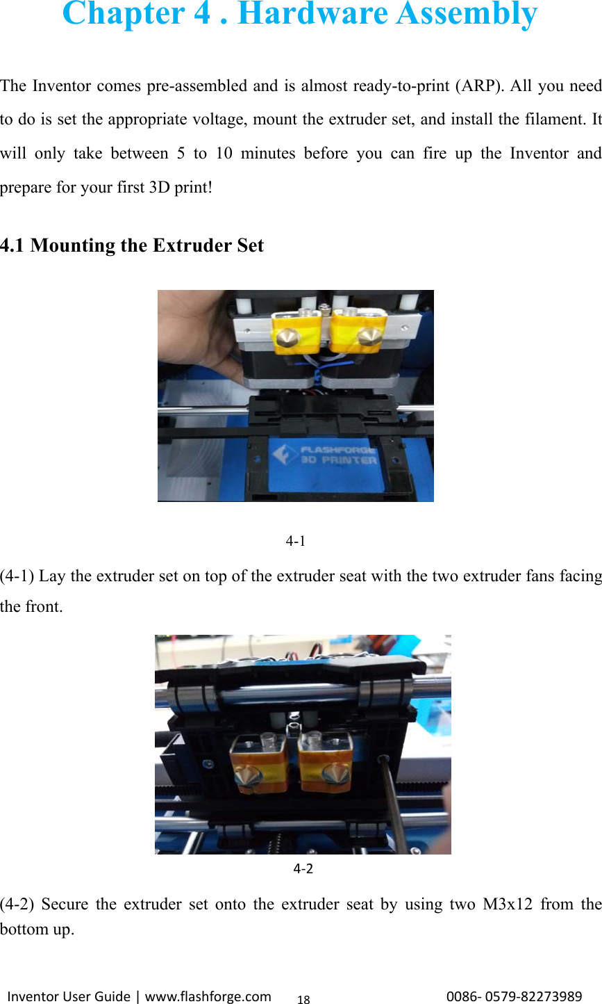
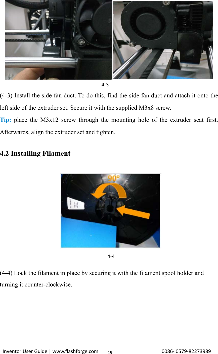
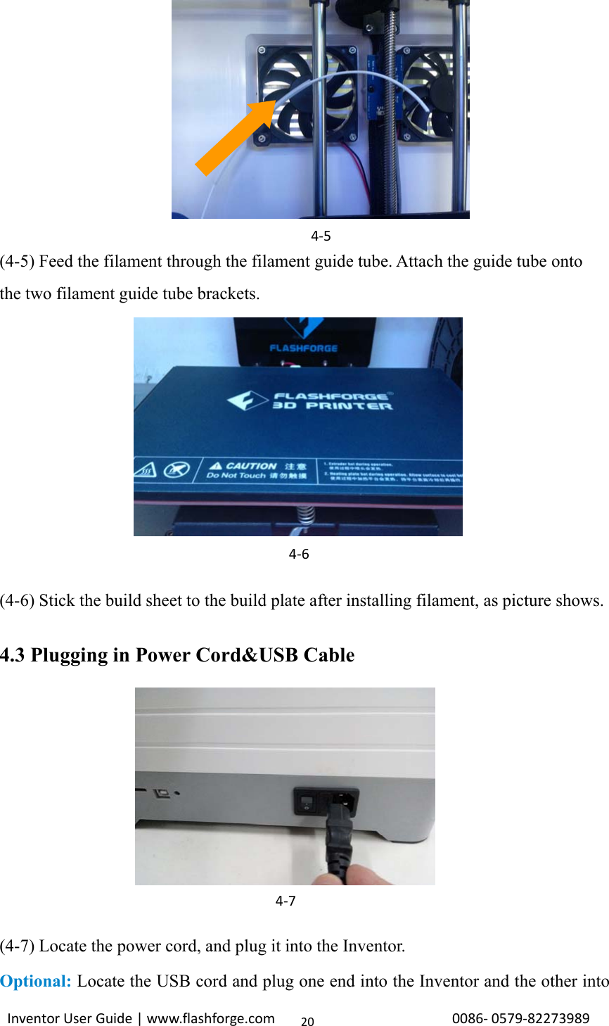
![Inventor User Guide | www.flashforge.com 0086‐0579‐8227398921your computer. The Inventor supports USB .4.4 Loading and Unloading FilamentFilament must pass through the extruder and into the heating block in order to bemelted. In this user guide, we will demonstrate loading and unloading filament usingthe left side extruder.Loading filament:(4-8) Remove the lid of the Inventor4-9(4-9) From the main menu, press the right icon labeled [Tools ].4‐8](https://usermanual.wiki/Zhejiang-Flashforge-3D-Technology/INVENTOR/User-Guide-3241556-Page-21.png)
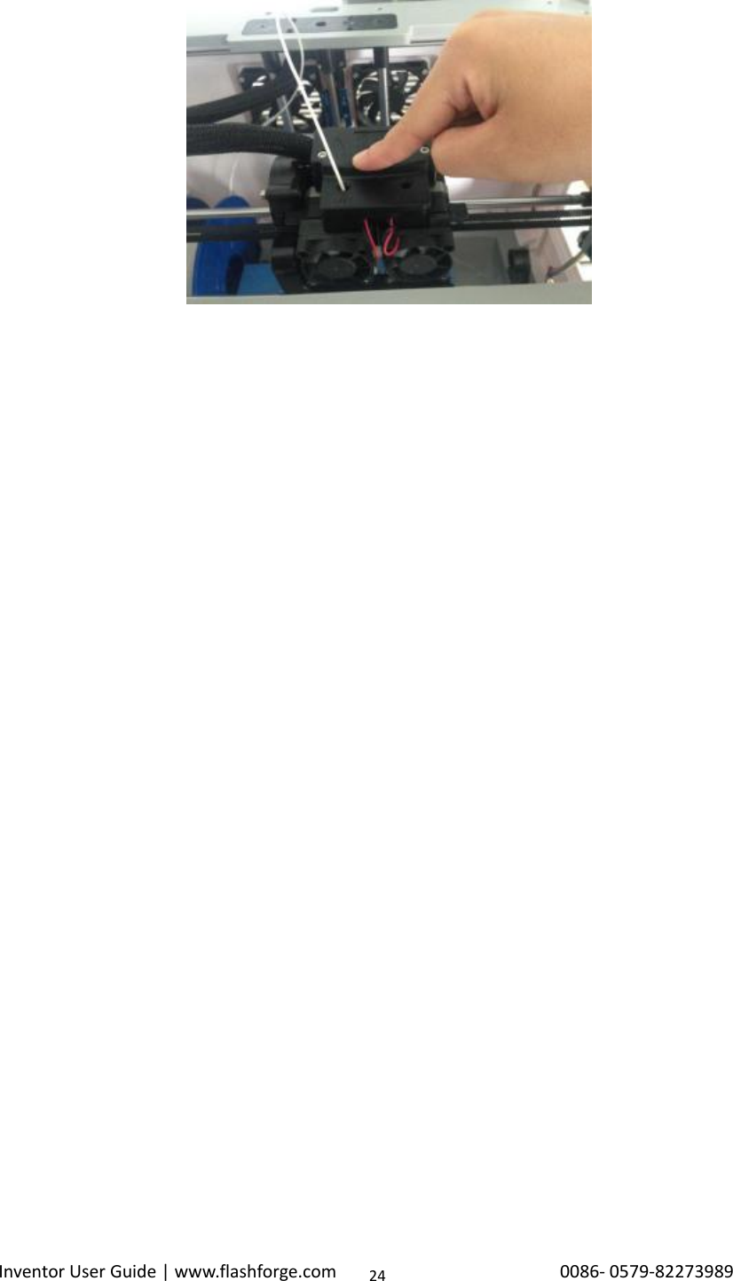
![Inventor User Guide | www.flashforge.com 0086‐0579‐8227398922(4-10)Select [ Filament ] and [ Load Left ].4-11(4-11)Wait for the extruder to heat up to the operating temperature. The extruder willalert you once it is at the operating temperature. Load the filament by inserting it intothe extruder at an upright angle.(4-12) Filament will start to extrude out of the nozzle. Continue loading to ensure thatthe filament is extruding in a straight line. Refer to the troubleshooting section if thefilament is extruding at an angle.4‐104‐12](https://usermanual.wiki/Zhejiang-Flashforge-3D-Technology/INVENTOR/User-Guide-3241556-Page-22.png)
![Inventor User Guide | www.flashforge.com 0086‐0579‐8227398923Unloading filament:4-13(4-13) Remove the lid of the Inventor4-14(4-14) From the main menu, press the right icon labeled [Tools].(4-15) Select [ Filament ] and [Unload Left ].4-16](https://usermanual.wiki/Zhejiang-Flashforge-3D-Technology/INVENTOR/User-Guide-3241556-Page-23.png)

![Inventor User Guide | www.flashforge.com 0086‐0579‐8227398926Chapter 5: Build Plate LevelingA correctly leveled build plate will almost always guarantee a quality 3D object.When printed objects have issues, the first step to diagnose is to check anddouble-check to make sure the build plate is leveled. A general rule of thumb is toleave a gap that is the thickness of a piece of paper. However, for printing finerobjects (150 micron and lower), please use a feeler gauge to level the build plate as itrequires a lesser gap between the nozzle and the build plate.The Inventor utilizes a three-point leveling system for its build plate. At the bottom ofthe build plate, there is one spring-loaded knob in the front and two in the back.Tightening the screw will create a bigger gap between the build plate and the nozzlewhile loosening it will create lesser gap.5-11. (5-1)From the main menu, select [Tools] and [Level]. The extruder and the buildplate will begin to move to the starting position.5-2](https://usermanual.wiki/Zhejiang-Flashforge-3D-Technology/INVENTOR/User-Guide-3241556-Page-26.png)
![Inventor User Guide | www.flashforge.com 0086‐0579‐82273989272. (5-2)Take out the leveling card (QR-Code for leveling video can be scanned)5-33. (5-3)Once the extruder and build plate stops moving, slide the piece of papercontinuously back and forth between the nozzle and the build plate. Andsimultaneously adjust the knob just enough so that the paper causes a slight friction.5-44. (5-4)Press [NEXT]and wait for the extruder to move to the second position.Slide the paper back and forth again, and adjust the screw to create the same amountof friction as the previous step.5-5](https://usermanual.wiki/Zhejiang-Flashforge-3D-Technology/INVENTOR/User-Guide-3241556-Page-27.png)
![Inventor User Guide | www.flashforge.com 0086‐0579‐82273989285. (5-5)Press [NEXT]again and repeat the same leveling technique.5-66. (5-6)Press [NEXT]. The nozzle will move to the center of the build plate. Slidethe paper through to make sure there is a slight friction. Slowly adjust all the screwsby the same amount if there is no friction or too much friction.5-77. (5-7)Press [FINISH]once you have finished this.25](https://usermanual.wiki/Zhejiang-Flashforge-3D-Technology/INVENTOR/User-Guide-3241556-Page-28.png)
![Inventor User Guide | www.flashforge.com 0086‐0579‐8227398930When you start FlashPrint, a dialog box will pop up. Just need to select FlashforgeInventor in the machine type list and click [OK]. You can also change the machinetype via clicking [Print]--[Machine type]. Please see graphic 6-2:6-26.2.2 Flashprint MenusLoad one or multiple files.Enter the support edit modeView FlashPrint home screen from one of six viewing angles.Move model around on xy-plane; shift+click to move along z axisTurn and rotate your modelScale the size of your object6‐3](https://usermanual.wiki/Zhejiang-Flashforge-3D-Technology/INVENTOR/User-Guide-3241556-Page-30.png)
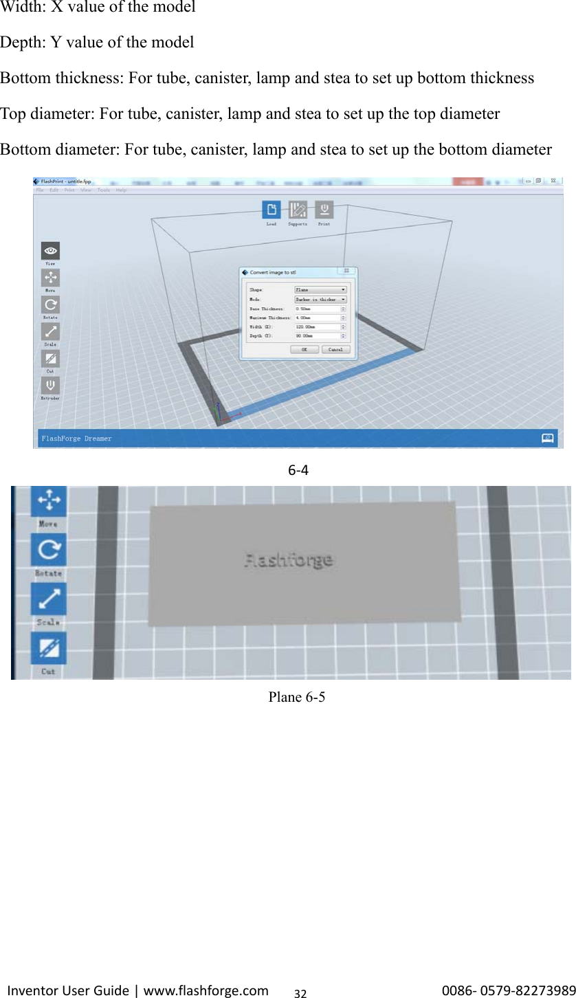
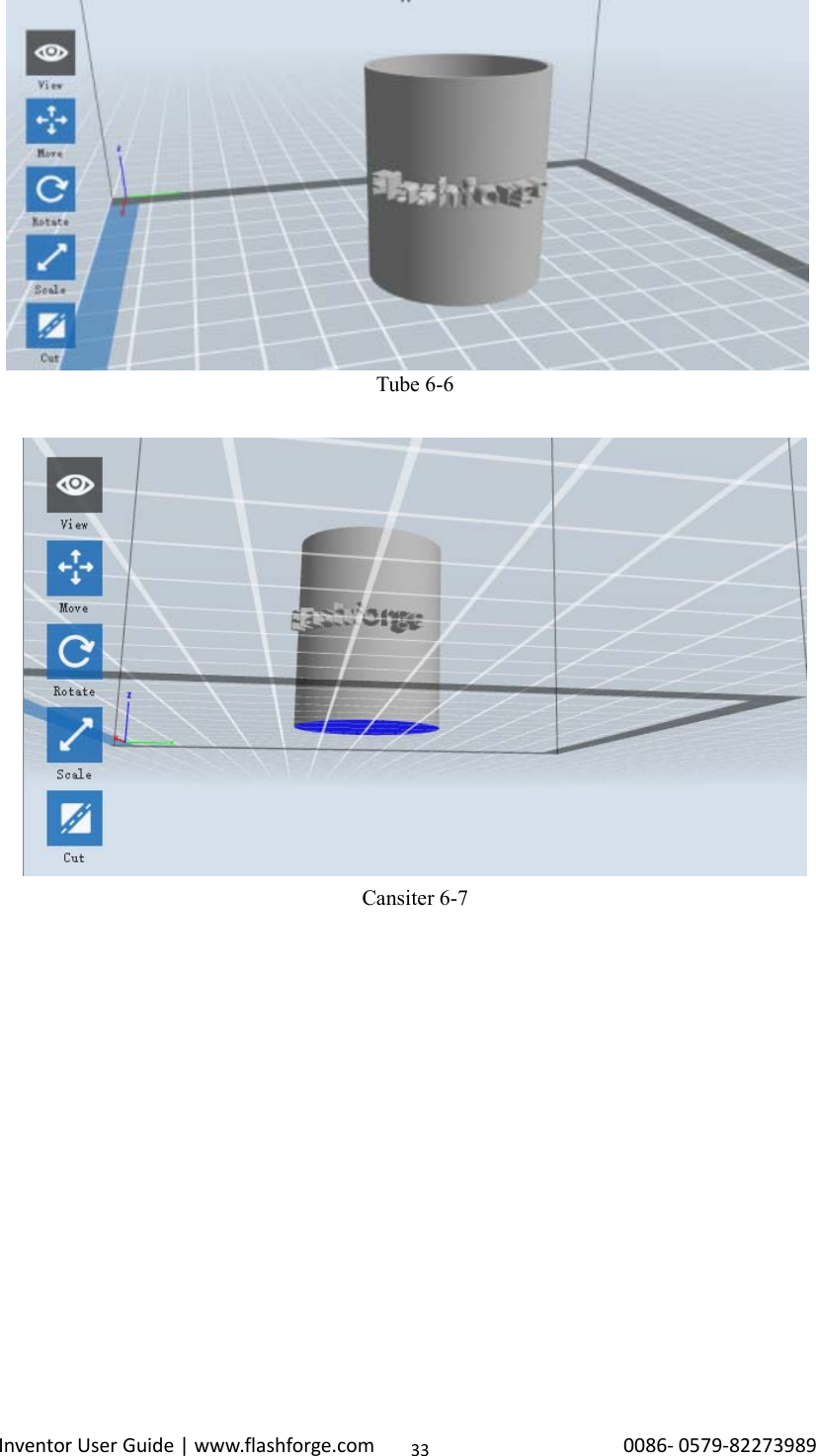
![Inventor User Guide | www.flashforge.com 0086‐0579‐82273989316.2.3 LoadingYou can load a model file or Gcode file into your Flashprint by the following sixmethods:Method 1: Click the Load icon on the main interface. Then select theobject file.Method 2: Select the file for loading and drag the file to the main interface of thesoftware.Method 3: Click [File]--[Load File]. Then select the object file for loading.Method 4: Click [File]--[Examples]to load the example filesMethod 5: Click [File]--[Recent Files]to load the files opened recently.Method 6: Select and drag the target file to the icon of Flashprint.Note: .STL, .OBJ, .3MF and .FPP,ways to store 3D models, are supported byFlashprint for editing.Generating RilievoLoading a png, jpg, jpeg, bmp picture file into the FlashPrint. And the followingdialogue box(6-4) will pop up. The setting box includes settings for shape, mode,maximum thickness, base thickness, bottom thickness,width, height, top diameter andbottom diameter.Shape: including plane, tube, canister and lamp.Mode: including “darker is higher”and “lighter is higher”.Maximum thickness: Z value of the modelBase thickness: The minimum raft thickness and the default value is 0.5mmCut the model into several partsPrint it directly with your Inventor or export to your USB stick.](https://usermanual.wiki/Zhejiang-Flashforge-3D-Technology/INVENTOR/User-Guide-3241556-Page-31.png)
![Inventor User Guide | www.flashforge.com 0086‐0579‐8227398934Lamp 6-8Seal 6-96.2.4 Views①Changing viewsChange model views by moving, rotating, scaling.●DragClick the [View] icon and then you can move the object by the followingthree methods:](https://usermanual.wiki/Zhejiang-Flashforge-3D-Technology/INVENTOR/User-Guide-3241556-Page-34.png)
![Inventor User Guide | www.flashforge.com 0086‐0579‐8227398935Method 1: Hold down the left mouse button and drag.Method 2: Hold down the middle mouse button and drag.Method 3: Hold down the Shift key, hold down the right mouse button and drag.●RotateClick the [View] icon and then you can rotate the object by the followingtwo methods:Method 1. Hold down the right mouse button and drag.Method 2. Hold down the Shift key, hold down the left mouse button and drag.●ScaleRotate the mouse wheel to enlarge or shrink the build plate.②Set ViewAllows users to view the object on the build plate. Six views are under the view menu,that is, home view, bottom view, top view, front view, back view, left view and rightview.Method 1: Click the the [View] button, there are six views in the drop- down listMethod 2: Click the the [Look] icon on the left, click it again and asubmenu will appear with six views for selecting.③Reset ViewAllow users to reset views by the following two methods:Method 1: Click the [View] menu and select [Home View]Method 2: Click the [View]button on the left, click it again and you will see theviewing options, you can click [Reset].④Show Model OutlineClick [View]--[Show Model Outline], it will highlight the yellow border of theobject](https://usermanual.wiki/Zhejiang-Flashforge-3D-Technology/INVENTOR/User-Guide-3241556-Page-35.png)
![Inventor User Guide | www.flashforge.com 0086‐0579‐8227398936⑤Show Steep OverhangClick [View]--[Show Steep Overhang]. When the intersection angle between themodel surface and horizontal line is within the overhang threshold value, the surfacehas steep overhang and it becomes red in the software. Overhang threshold valuecould be set as needed. The default value is 45 degree.6.2.5 MoveSelect the object and move the object by the following two methods:Method 1: Click the [Move] icon on the left, hold down the left mousebutton and drag to adjust the location of the model in XY direction. Hold down theShift key, hold down the left mouse button and drag to adjust the location of themodel in Z direction. The distance and the direction of the movement shall bedisplayed.Method 2: Click the [Move]button on the left and then enter the distance value.Click [Reset]to reset distance values.Note: Users shall click [Center] and [On Platform] after the location adjustment toensure the model(s) be within the build area and on the build platform. If a specifiedposition is needed, only to click [On Platform].6.2.6 RotateSelect the target object and rotate the object by the following two methods:Method 1: Click the [Rotate] icon on the left and three mutuallyperpendicular rings appear around the object Click one ring and rotate on the presentaxis, you will see the rotation angle and direction in the center of circle. In this way,you could make the model rotate on X/Y/Z axis.](https://usermanual.wiki/Zhejiang-Flashforge-3D-Technology/INVENTOR/User-Guide-3241556-Page-36.png)
![Inventor User Guide | www.flashforge.com 0086‐0579‐8227398937Method 2: Click the [Rotate] icon on the left, and then enter into rotatingangel values in X/Y/Z axes positioning. Click [Reset] to reset rotating angel values.6.2.7 ScaleSelect the target object and scale the object by the following two methods:Method 1: Click the [Scale] icon on the left, hold down the left mouse buttonand scale the model. The corresponding values will display near the object..Method 2: Click the [Scale] icon on the left and then enter into scale valuesin X/Y/Z axes positioning. Click the [Maximum] button to get largest size possiblefor building. Click [Reset] to reset the size of model.Note: If the [Uniform Scaling] radio button is clicked, it will scale the model in equalproportion when changing value in any positioning of the model. Otherwise it willonly change the value of the corresponding positioning.6.2.8 CutLeft-click on the model to select it and double-click on the Cut icon to set the cutplane. The direction and position are available for setting.①Draw with Mouse](https://usermanual.wiki/Zhejiang-Flashforge-3D-Technology/INVENTOR/User-Guide-3241556-Page-37.png)
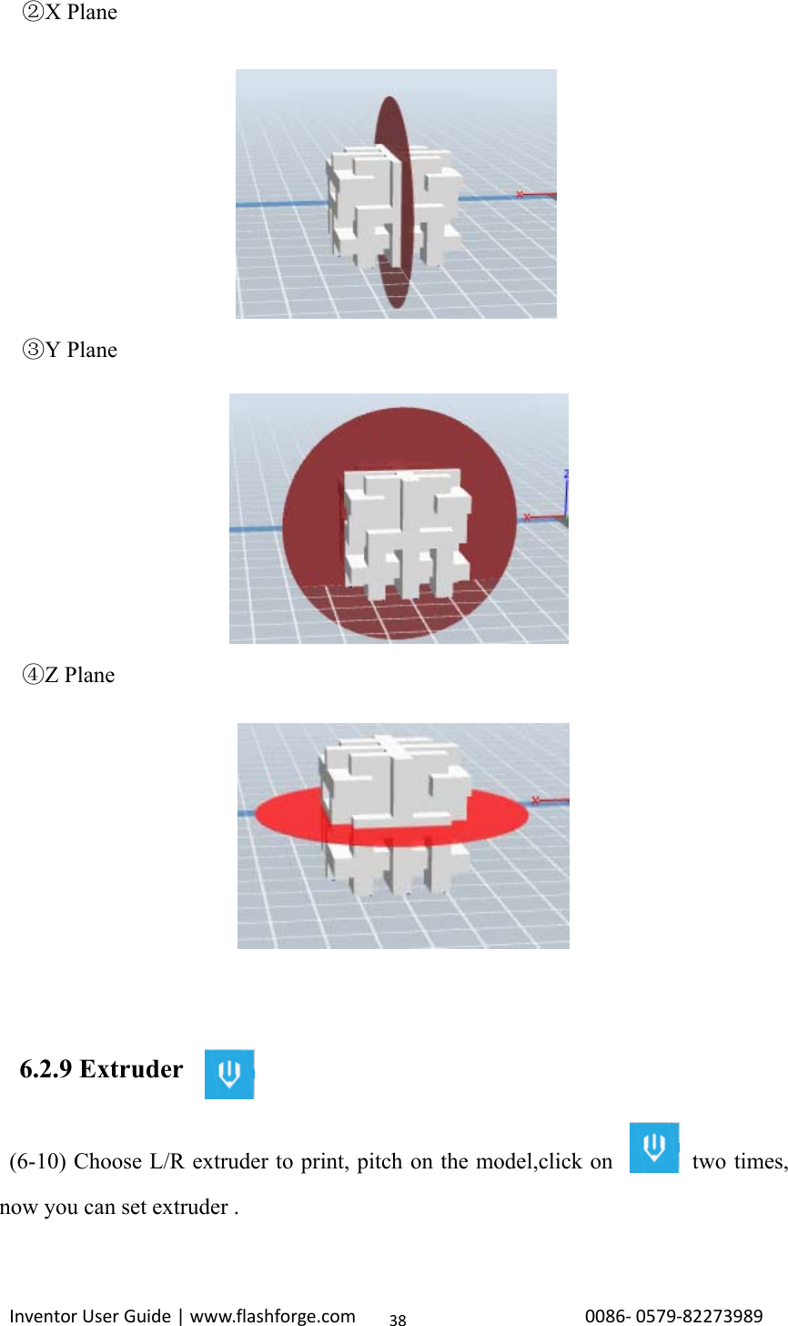
![Inventor User Guide | www.flashforge.com 0086‐0579‐82273989396-106.2.10 SupportsAfter loading the model, click [Edit]--[Supports]or click the Supports icondirectly, then you will enter the support edit mode(6-11). Click [Back]to exit whenyou finish editing.6-11①Support OptionsClick the Support Options, an option box will appear, supports options include“treelike”and “linear”, when choose “treelike”, click [OK], then the support generatedwill be treelike structure; when choose “linear”, click [OK], then the supportgenerated will be linear structure; if the model already had support, when you choose](https://usermanual.wiki/Zhejiang-Flashforge-3D-Technology/INVENTOR/User-Guide-3241556-Page-39.png)
![Inventor User Guide | www.flashforge.com 0086‐0579‐8227398940one of the supports options,software will judge whether existing supports need to bedeleted or not depend on the type of existing support, and will pop up thecorresponding prompt to let you make the choice.6-12②Auto SupportsClick the [Auto Supports] button, the software will judge the position where supportsare needed and generate corresponding treelike or linear supports. If the modelalready had support, the existing supports will be deleted and new supports will begenerated.③Add SupportsSupports will be added once clicking the [Add]button. Move the cursor to theposition where needs supports, left-click to choose the starting point of supports, holddown the left mouse button and drag the mouse the supports preview will show up(ifsupport surface doesn’t need support or the support column angle is too large, willhighlight the support review ).Loosen the left mouse button, if support column doesn’tmeet with model, then support will be generated on origin and terminal point(thehighlighted preview support won’t generate support structure )](https://usermanual.wiki/Zhejiang-Flashforge-3D-Technology/INVENTOR/User-Guide-3241556-Page-40.png)
![Inventor User Guide | www.flashforge.com 0086‐0579‐8227398941④Clear SupportsClick [Clear Supports], all supports will be deleted. The operation can be repealedvia clicking [Undo] or pressing the shortcut key Ctrl+Z.⑤Delete SupportsSupports will be deleted once clicking the [Delete]button. Move the cursor to thesupports needed deleting, current supports and its child node support will behighlighted, click the left mouse button to delete these highlighted support.6.2.11 Print①Preview: Choose to enter preview interface or not②Print when slice done: Print or not when slice done6‐13](https://usermanual.wiki/Zhejiang-Flashforge-3D-Technology/INVENTOR/User-Guide-3241556-Page-41.png)
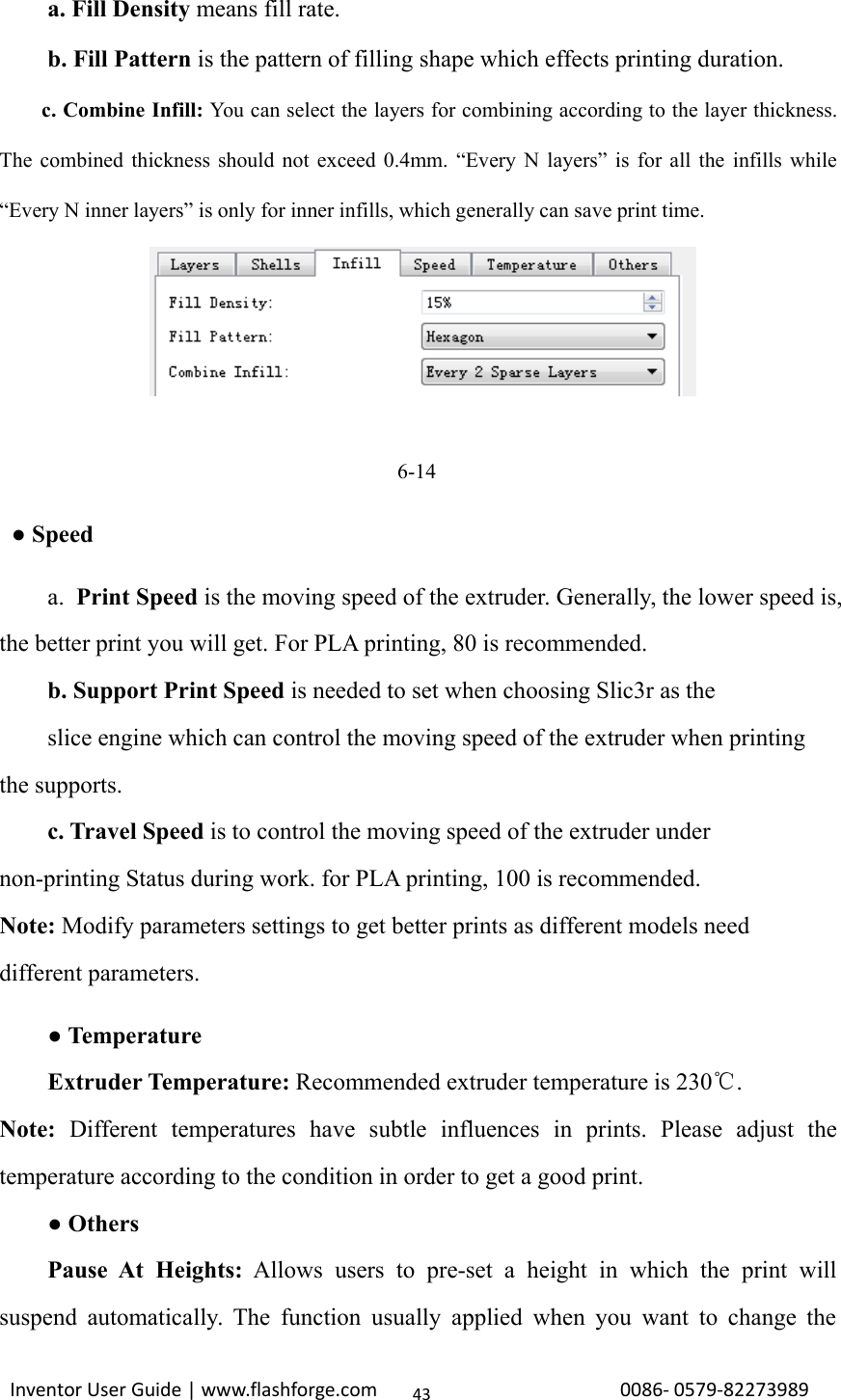
![Inventor User Guide | www.flashforge.com 0086‐0579‐8227398942③Material type: Choose according to the type of model④Supports: When print with model contains part hanging in the air or top-heavy,support is necessary. Click [supports] to create support part for the printing.⑤Raft: This function will help the model to stick well on the platform.⑥Wall: During dual color printing, this function will help to clear the leakingfilament of another extruder.⑦Vase Mode: No capping for the model⑧Resolution:You have three resolution solution(with default setting)to choose from,high resolution is corresponding with slow printing speed, opposite for the lowresolution.For PLA printing, an extra solution “Hyper” is available.⑨More options: Click [More options] to set for layer, shell, infill, speed andtemperature. Different resolution solution is corresponding to different defaults, click[Restore Defaults] to back to default setting.●Layera. Layer: Layer thickness of the printing model. With a small number, thesurface of the model will be more smooth.b. First Layer Height: This is the first layer of the model, which will affect thesticking performance between the model and platform. Maximize is 0.4mm, usuallythe default is ok.c. Shell: Contains of the outside shell number, capping layer number (under vasepattern, top solid layer setting is invalid.)●Primeter Shells: Maximize is 10a. Top Solid Layer: Maximize is 10, minimum is 1.b. Bottom Solid Layer: Maximize is 10, minimum is 1.●Infill](https://usermanual.wiki/Zhejiang-Flashforge-3D-Technology/INVENTOR/User-Guide-3241556-Page-42.png)
![Inventor User Guide | www.flashforge.com 0086‐0579‐8227398944filament at a certain point.(5-7) Click[Edit], then you can add or remove a height.6.2.12 File Menus①New ProjectClick [File]--[New Project]can build a blank project. If there is an unsavedmodification on previous project, then will inform you whether the modificationneeds to be saved or not. Click [Yes]will save the modification , click [No]willabandon it. If click [Cancel]or close tool tip, then will cancel the new project.6-16②SavingAfter finishing the model edit and adjustment, there are two ways below to save allmodels in the scene.Method 1:Click [File]--[Save Project] in the menu bar, can save the file as a project file whichsuffix is ”.fpp” in this type of file,all models in the scene (include support) areindependent .after reloading the files, extruder configuration information and modelposition will be as same as the configuration during saving.Method 2:6‐15](https://usermanual.wiki/Zhejiang-Flashforge-3D-Technology/INVENTOR/User-Guide-3241556-Page-44.png)
![Inventor User Guide | www.flashforge.com 0086‐0579‐8227398945Click on [File]--[Save as...] to save the model as project file .fpp or .stl and .obj.For .stl and .boj, models are integrated as one(include support part). If load it again,only the position of the model was saved, not included the printing parameters.③PreferencesClick [File]--[Preferences], you can choose language and if needs detecting updatewhen start6-17●Language: The software supports six languages, that is Chinese(simplified Chineseand traditional Chinese), English, French, Korean, Japanese and Russian.●Printing Window Type: Including Base Mode and Expert Mode●Check for Update after start up: It is used to set if needs to activate the onlineautomatic update function, if choose yes, every time when you open software, it canonline detect if there is new version software, once new version found, it will remindsuses to download and install new version firmware.6.2.13 Edit Menus①UndoAllows users to undo the recent edits by the following two methods:Method 1: Click [Edit]--[Undo].Method 2: Press the shortcut Ctrl+Z.②Redo](https://usermanual.wiki/Zhejiang-Flashforge-3D-Technology/INVENTOR/User-Guide-3241556-Page-45.png)
![Inventor User Guide | www.flashforge.com 0086‐0579‐8227398946Allows users to redo the most recent edit you have undone to your model file by thefollowing two methodsMethod 1: Click [Edit]--[Redo]Method 2: Press the shortcut Ctrl+Y.③Empty Undo-stackTo clean up the recorded operating steps so as to release the memory.④Select AllBy the following two methods, you could select all models in the scene.(Whenmodelsare too small to be seen or out of viewing scope, please click [Center] and [Scale]buttons to adjust the model.)Method 1: Click [Edit]--[Select All].Method 2: Press the shortcut Ctrl+A.⑤DuplicateSelect the object and duplicate the object through the following two methods:Method 1: Click [Edit]--[Duplicate]Method 2: Press the shortcut Ctrl+D⑥DeleteSelect the object and delete the object through the following two methods:Method 1: Click [Edit]--[Delete]Method 2: Press the shortcut Delete⑦Surface to PlatformAfter selecting the model, you can make the model surface to platform via the followingoperation.Click [Edit]--[Surface to Platform]into surface to platform mode(6-18)](https://usermanual.wiki/Zhejiang-Flashforge-3D-Technology/INVENTOR/User-Guide-3241556-Page-46.png)
![Inventor User Guide | www.flashforge.com 0086‐0579‐8227398947(Surface to Platform 6-18)⑧Auto Layout AllClick [Edit]--[Auto Layout All]after loading one or more than one models, allmodels will be placed automatically as automatic placement rule.6.2.14 Print Menus①Connect MachineYou can connect the Inventor with your PC via a USB cable or WIFI.Note: The machine icon on the bottom right displays the connection status:ConnectedDisconnectedMethod 1:Connect Via USB Cablea. Connect your Inventor with your PC via an USB cable.b. Turn on your Inventor and start Flashprint.c.Click [Print]--[Connect Machine],then select USB in the [Connection Mode]option and select machine you want to connect in [Select Machine] option. If you can](https://usermanual.wiki/Zhejiang-Flashforge-3D-Technology/INVENTOR/User-Guide-3241556-Page-47.png)
![Inventor User Guide | www.flashforge.com 0086‐0579‐8227398948not find your machine, click the [Rescan] button to scan your machine and select it.Finally click [Connect] button to connect to the printer. If you still can not find yourmachine after rescan, which means you haven’t installed the driver in the software.6-19Method 2:Connect Via WIFI1. Turn on Inventor. Make sure the build plate is leveled and filament is loaded on theleft extruder.2.Turn on Wi-Fi on the Inventor. To do this, press [Tools],[ Setting ],[WIFI],and[WIFION].3.Aconnection called“HF-LPB” canbe foundon the list of available networks.Connect to this network.4. Open your Internet browser. Type in “10.10.100.254” and hit [ Enter ] on yourkeyboard. Enter the username and password to login. The default username andpassword are both “admin.” The control panel will appear after a successful login.6‐20](https://usermanual.wiki/Zhejiang-Flashforge-3D-Technology/INVENTOR/User-Guide-3241556-Page-48.png)
![Inventor User Guide | www.flashforge.com 0086‐0579‐82273989496-215. Click on [WorkMode]and choose“AP+STA mode” and save it.6. Click on [STASetting], select a working network, enter the correspondingpassword and save.6-227. Restart the interface, close the page, turn off the Inventor, disconnect from thenetwork, and wait for 10 seconds.8. Turn the Inventor back on and connect to the Inventor network. In FlashPrint,choose [Print]from menu and select [ Connect ].9. Under “Connection Mode”, selectWi-Fi, and enter the “IP Address, Port” as shown on printer LCD screen. Then, click](https://usermanual.wiki/Zhejiang-Flashforge-3D-Technology/INVENTOR/User-Guide-3241556-Page-49.png)
![Inventor User Guide | www.flashforge.com 0086‐0579‐8227398950[ Connect ].10. If successfully connected, you will see the following red mark.①Connect Inventor with your PC under STA modea. Turn on the WIFI of Inventor and connect your PC with Inventor via the WIFI.②Disconnect InventorClick [Print]--[Disconnect] to disconnect your PC and Inventor.6.2.14 Tool Menus①Control PanelAfter connecting PC with Inventor, click [Tools]--[Control Panel] to open the controlpanel.●Jog Controlsa. Jog Mode:Select the distance that extruder/build plate move a single time (that is,the distance extruder/build plate move upon your single click).b. Six blue arrow direction button: Control the move along X/Y/Z axis. X/Y axis123456](https://usermanual.wiki/Zhejiang-Flashforge-3D-Technology/INVENTOR/User-Guide-3241556-Page-50.png)
![Inventor User Guide | www.flashforge.com 0086‐0579‐8227398951button control extruder move, Z axis button control build plate move. Click X-,extruder will move leftward a specified distance; Click X+, extruder will move aspecified distance rightward. Click Y-, extruder will move forward a specifieddistance; Click Y-, extruder will move backward a specified distance. Click Z-, buildplate will move upward a specified distance; Click Z-, build plate will movedownward a specified distance. (Specified distance refers to the move distance you setin Jog Mode.c. Stop: Click the [stop] button to abort the current movement.d. XYZ coordinateframe on the right side: Show the current position of extruder/build plate.e. Make Current Position Zero button: Set the current position of theextruder/build plate as (0, 0, 0). (NOTE: X, Y, and Z boxes are for display purposes.Changing the value in the boxes will not affect anything.f. Center X/Y/Z button: Extruder and build platform will back to the zero (0, 0, 0)you set last time.g. X/Y Speed and Z Speed: Set the move speed of extruder/ build platform.●Limit Switch: In order to protect your Inventor, three limit switches are equippedto control the maximum position, and the three limit switches corresponding to X/Y/Zaxis limit switch. It has two status:a. Not Triggered: If the extruder/build plate don’t move to its maximum, X/Y/Z axislimit switch is not triggered, and shows “Not Triggered”.b. Triggered: If the extruder/build plate moves to its maximum, X/Y/Z axis limitswitch is triggered, and shows “Triggered”.●Stepper Motor Controls: Allows users to control to stepper motor. Click [Enable],and lock the motor so it does not allow any movement; click [Disable], and unlockthe motor to be controlled manually.●LED Color: Allows users to change the LED color of Inventor.](https://usermanual.wiki/Zhejiang-Flashforge-3D-Technology/INVENTOR/User-Guide-3241556-Page-51.png)
![Inventor User Guide | www.flashforge.com 0086‐0579‐8227398952●Extruder Controls: You can set the value of “Motor Speed(RPM)”, which cancontrol the rotation speed of filament feeding wheel. The motor rotation time can becontrolled via setting the value of “Extruder Duration”.Generally we suggest theusers choose option of continuous time 60 seconds. The filament must loaded in theextruder before motor starts. Therefore, do not start rotation operation until theextruder temperature reach the printing temperature of filament. For PLAfilament, the extruder temperature should reach 220℃, after reaching the extrudertemperature, click the [Forward]/[Reverse] rotation button to control filament loadand filament unload. Furthermore, if you want to stop filament load and unload, youcan click [Stop].●Temperature Control: Input the temperature you want to get in the left frame,click [Apply], the printer will automatically heat the corresponding part, the right sideshows the current actual temperature of corresponding part. After start heating, thebelow curve of temperature form will start to change, different color corresponddifferent parts’ temperatures②Update FirmwareEvery time when you start Flashprint, it will automatically detect and download theup-to-date firmware. If any update is available, a dialog box will pop up for remindingthe users to update.Step 1: Click [Tools]--[Update firmware]. It needs to cut off connection beforeupdating firmware. If software and printer are already in connection, it reminds youcutting off the connection, choose [Yes] and go on to the next step.Step 2: Choose corresponding printer type and firmware version and click [OK] inthe firmware updating box. After confirming the printer is in free state, the softwarewill automatically update the firmware.](https://usermanual.wiki/Zhejiang-Flashforge-3D-Technology/INVENTOR/User-Guide-3241556-Page-52.png)
![Inventor User Guide | www.flashforge.com 0086‐0579‐82273989536-23Step 3:Reboot you Inventor and wait for 4-5 seconds, then you can see the updateprocess bar. When the update finishes, it will go back to the main interface.Step 4:Tap[Tools]--[About] to check] to check whether the updated version is right.③On Board PreferencesWhen the computer and printer are in connection, click [Tools]--[On BoardPreferences], you can check the printer name.④Machine informationWhen the computer and printer are in connection state, click [Tools]--[Machineinformation], you can check the machine type, machine name and firmware etc.6.2.15 Help Menus①Help Contents:Click [Help]--[Help Contents], you can read the help contents.②Check for Updates :Click [Help]--[Check for Update] to detect the availableupdates online.③About FlashPrint:Click [Help]--[About Flashprint], the software informationbox will pop up. The contents include the current software version and copyrightinformation.](https://usermanual.wiki/Zhejiang-Flashforge-3D-Technology/INVENTOR/User-Guide-3241556-Page-53.png)
![Inventor User Guide | www.flashforge.com 0086‐0579‐8227398954Chapter 7: PrintingThis chapter will provide a step-by-step guide on turning a 3D model into a physicalreality. Before proceeding, it is recommended that you go over prior chapters onloading/unloading filament, leveling the build plate, and the functions and capabilitiesof FlashPrint.There are two modes of printing: single-extrusion and dual-extrusion. With singleextrusion, you can choose the print head to use for making the print. Dual extrusion isuseful if you want to print dual colors or complex models that require supportingmaterial.There are three connection methods in order to print using the Inventor. All methods,which include USB, SD card, and Wi-Fi are covered in thischapter.7.1 Single-Extrusion and Dual-Extrusion Print7.1.1 Single-Extrusion Print1. Open FlashPrint by double-clicking on the icon.2. Click on [ Load ] and choose an .stl file from hard drive.3. The object will then be shown on the screen.4. Click on the object and then click on [ Extruder ],select[ Use left extruder ].*Left extruder will be used for illustration purposes.5. Now the 3D model is ready to be created.](https://usermanual.wiki/Zhejiang-Flashforge-3D-Technology/INVENTOR/User-Guide-3241556-Page-54.png)
![Inventor User Guide | www.flashforge.com 0086‐0579‐82273989557.1.2 Dual-Extrusion Print1. Open FlashPrint by double-clicking on the icon.2. Press [ Load ] and choose an .stl file from hard drive.3. The object will then be shown on the screen.4. Press [ Load ] and choose another (or the same) file from hard drive.5. Click on the object and then click on [Extruder], select [ Use left extruder ].NOTE: one object is turned to green, that indicates it will be print wit the leftextruder.6. Now the 3D model is ready tobe created.Before introducing the connection methods, let me give you a brief introduction ofInventor’s interfaces.PrintRead the print file fromThe local memory cardThe SD cardReturn arrow](https://usermanual.wiki/Zhejiang-Flashforge-3D-Technology/INVENTOR/User-Guide-3241556-Page-55.png)
![Inventor User Guide | www.flashforge.com 0086‐0579‐8227398956Select the target print file among the listPrint: To begin printingCopy: To copy the files to the localmemory card from the SD card.(Noavailable [Copy] button for printingfrom local memory card )Delete: To delete the print filePrint interfaceAbort: To abort the print job.Pause/Resume: To suspend or resumethe print job.Tools: To change filament and set upauto shutdown during printing.Tools in print interfaceFilament: To change filament duringprinting.(Note: You need to suspend theoperation first)Wifi: To turn on the WifiCancel: To end the tool orders andreturn to the print interface.](https://usermanual.wiki/Zhejiang-Flashforge-3D-Technology/INVENTOR/User-Guide-3241556-Page-56.png)
![Inventor User Guide | www.flashforge.com 0086‐0579‐8227398957PreheatTap the [Preheat] button to enter thepreheat interface. Tap the [Start] buttonto heat up to the setting temperature.The default temperature is 230℃.Tap the temperature display bar to setthe temperature.To set the preheat temperature.Tap [Yes] to save the setting while tap[No] to cancel the setting.The picture displays the preheatinterface. It shows the actualtemperature and the target temperature.Tap the [Stop] button to abort thepreheat job.](https://usermanual.wiki/Zhejiang-Flashforge-3D-Technology/INVENTOR/User-Guide-3241556-Page-57.png)
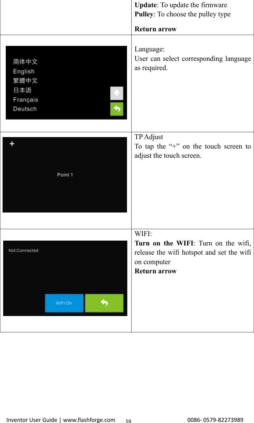
![Inventor User Guide | www.flashforge.com 0086‐0579‐8227398958ToolTap [Tools] to enter tool options.Filament: To load/unload the filament.Level: To adjust the build plate.Home: To make the X, Y and Z axesback to the zero point.Manual: To manually adjust thepositions of X, Y and Z axes.Setting:To implement relevant functionsetups.Status: The check the real-time statusof the printer.About: Information about the printer.Return arrowManual adjustmentY+: The extruder moves to the zeropoint, that is, the back of the machineY-: The extruder moves to the directionopposite to the Y+.X+: The extruder moves to the zeropoints, that is, to the right directionX-: The extruder moves to the directionopposite to the X+.Z+: The build plate elevates.Z-: The build plate descends.Return arrowTap [Setting] to enter the settinginterfaceLanguage: To set the display languageTP Adjust: Adjust the touch screenFactory Reset: Restore factory defaultsFan on: To turn on/off the fanWIFI: To turn on/off the Wifi](https://usermanual.wiki/Zhejiang-Flashforge-3D-Technology/INVENTOR/User-Guide-3241556-Page-58.png)
![Inventor User Guide | www.flashforge.com 0086‐0579‐8227398960Pulley:To select the equipped pulley type.Status:It displays the real-time status of theextruder temperature, the platformtemperature and the internaltemperature.About:It displays the basic information aboutthe device.7.2 Methods of printingPrinting from USB1. Connect Inventor to the computer using the included USB 2.0 cable.2. Turn on the Inventor. Make sure the build plate is leveled and filament is loaded tothe left extruder.3. Select [Print]from menu bar, then select [ Connect ].4. Click on [ Rescan ], then [ Connect ].](https://usermanual.wiki/Zhejiang-Flashforge-3D-Technology/INVENTOR/User-Guide-3241556-Page-60.png)
![Inventor User Guide | www.flashforge.com 0086‐0579‐82273989615. Now the printer is connected with FlashPrint. A status box at the lower right cornerwill show the temperature of both extruders and the platform.6. Press [Print]icon, and a printing options screen will appear. Make sure that “ABS”is selected under Material Left. Advanced settings can be set under [ More Options ]icon. Check the box “Print When Slice Done” and click [OK].7. Save the file at any location, and the object will start slicing8. After the object is done slicing, it will automatically upload the gcode to theInventor.9. After the gcode is done uploading, the printer will go into a preheat phase . TheInventor will begin printing once it has finished preheating.Printing from SD Card1. Press [Print], and a printing options screen will show up.2. Make sure that the “Material Left”isselectedas“ABS.” Advanced settings can beset under [ More Options ] icon.3. Click [OK], and save the gcode file in the SD card.4. FlashPrint will begin slicing the 3D model.5.After the object is done slicing, take the SD card from the computer. Insert it intothe SD card slot on the Inventor.6. Turn on the Inventor. Make sure the build plate is leveled and filament is loaded onthe left extruder.7. Press [Print]and then press the middle SD Card icon.8. A list of file(s) will show up, press the file that you would like to print, then press[Yes].9. The printer will now enter preheating phase and will start printing once it finishespreheatingPrinting via Wi-Fi1. Turn on Inventor. Make sure the build plate is leveled and filament is loaded on the](https://usermanual.wiki/Zhejiang-Flashforge-3D-Technology/INVENTOR/User-Guide-3241556-Page-61.png)
![Inventor User Guide | www.flashforge.com 0086‐0579‐8227398962left extruder2. Turn on Wi-Fi on the Inventor. To do this, press [Tools],[Setting],[WIFI],and [WIFION].3.A connection called“HF-LPB” can be found on the list of available networks.Connect to this network.7-14. Open your Internet browser. Type in “10.10.100.254” and hit [Enter]on yourkeyboard. Enter the username and password to login. The default username andpassword are both “admin.” The control panel will appear after a successful login.7-2](https://usermanual.wiki/Zhejiang-Flashforge-3D-Technology/INVENTOR/User-Guide-3241556-Page-62.png)
![Inventor User Guide | www.flashforge.com 0086‐0579‐82273989635. Click on [WorkMode]and choose “AP+STA mode” and save it.6. Click on [STASetting], select a working network, enter the correspondingpassword and save.7-37. Under “Connection Mode”, select Wi-Fi, and enter the “IP Address, Port”asshown on printer LCD screen. Then, click [ Connect ].8. Now the Inventor is connected with FlashPrint. A status box at the lower rightcorner will show the temperature of both extruders and the Platform.9. In FlashPrint, click [Print]. A printing options screen will appear Make sure that“ABS” is selected under “Material Left.” Advanced settings can be set by clicking on[ More Options ].Check the box of “Print When Slice Done,” and hit [OK].10. Save the file at any location, and the object will start slicing.After the object isdone slicing, it will automatically upload the gcode to the Inventor. After the gcode isdone uploading, the printer will go into a preheat phase. The Inventor will startprinting once preheating is finished.NOTE: Printing from SD card is unavailable when WIFI is ON.Printing with SupportIf the 3D model has excessive over-hang, then support will be needed. In the Slice](https://usermanual.wiki/Zhejiang-Flashforge-3D-Technology/INVENTOR/User-Guide-3241556-Page-63.png)
![Inventor User Guide | www.flashforge.com 0086‐0579‐8227398964options screen, select from “Supports” the left or right extruder.Click [OK]to beginslicing.](https://usermanual.wiki/Zhejiang-Flashforge-3D-Technology/INVENTOR/User-Guide-3241556-Page-64.png)
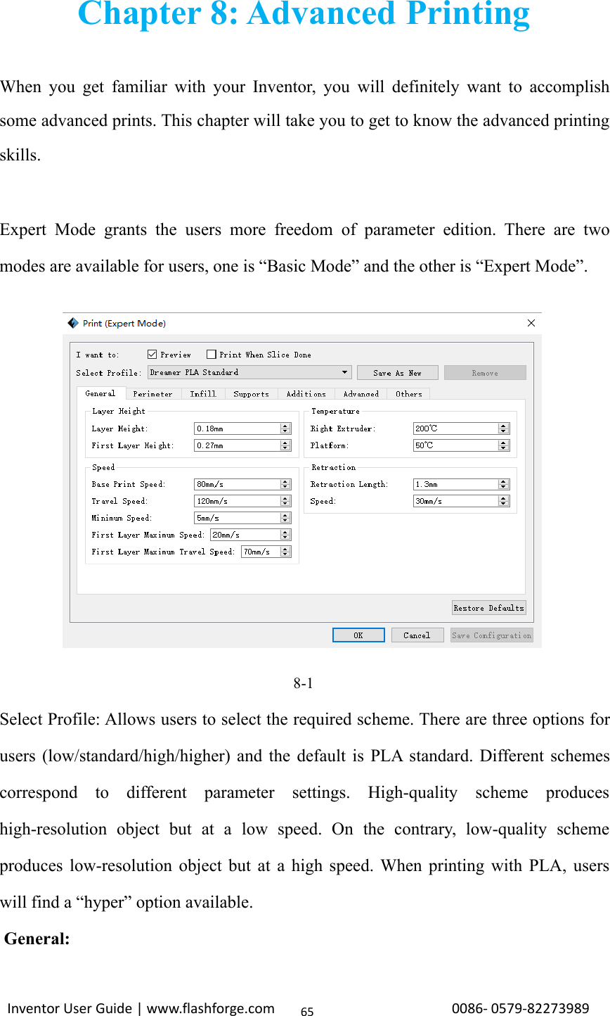
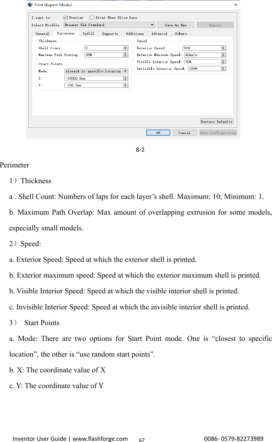
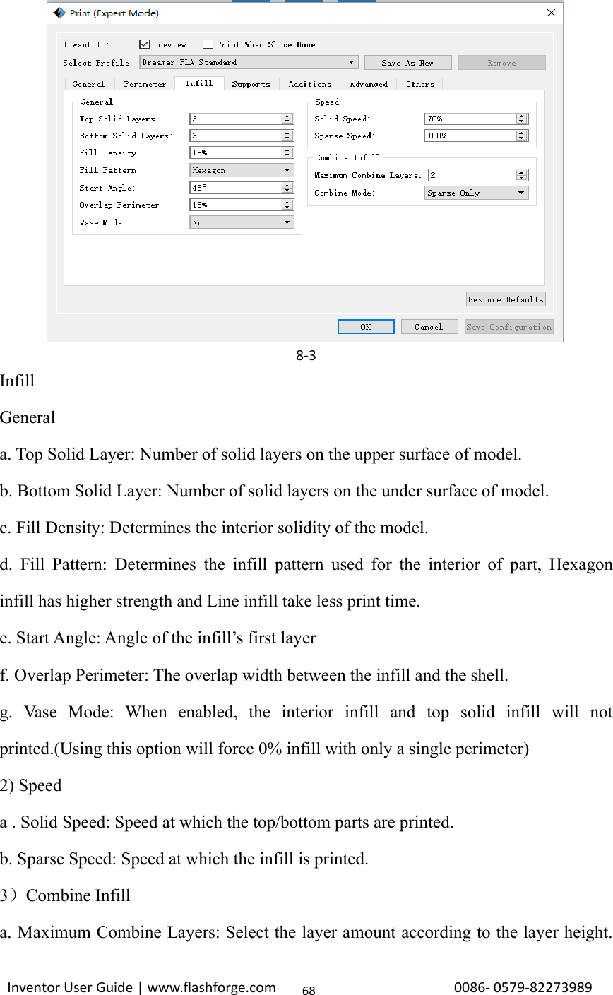
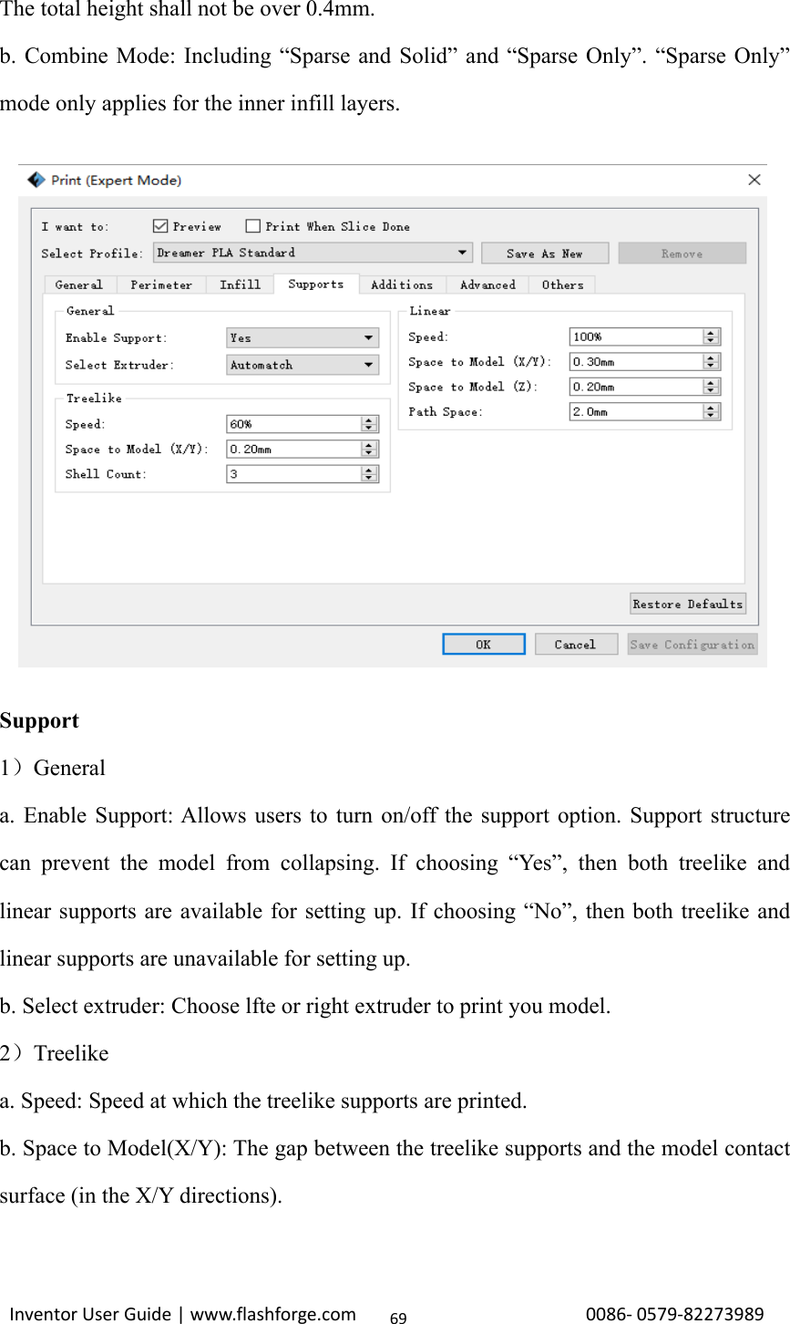
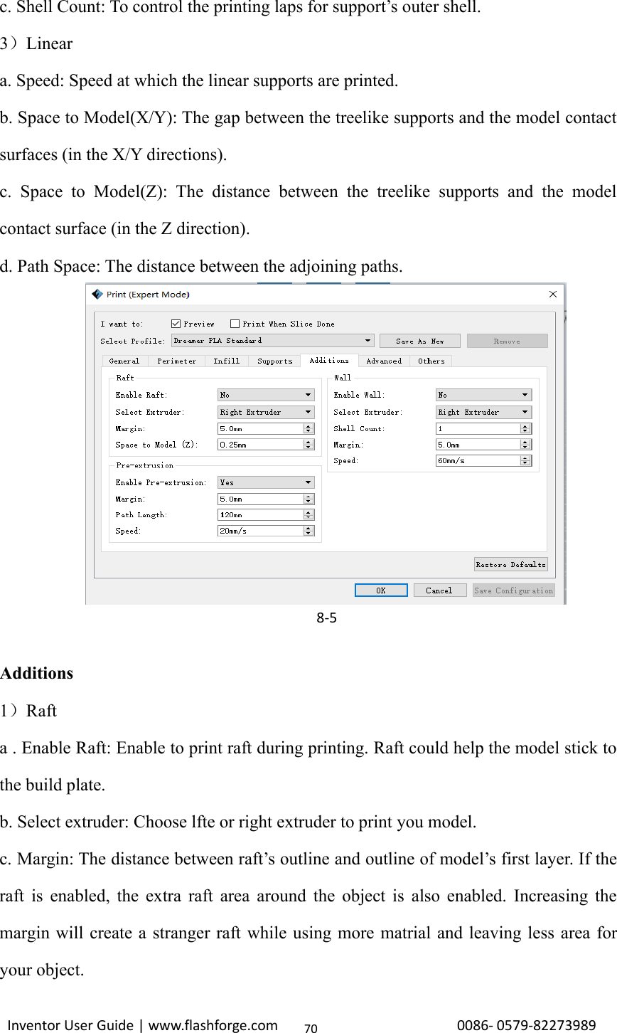
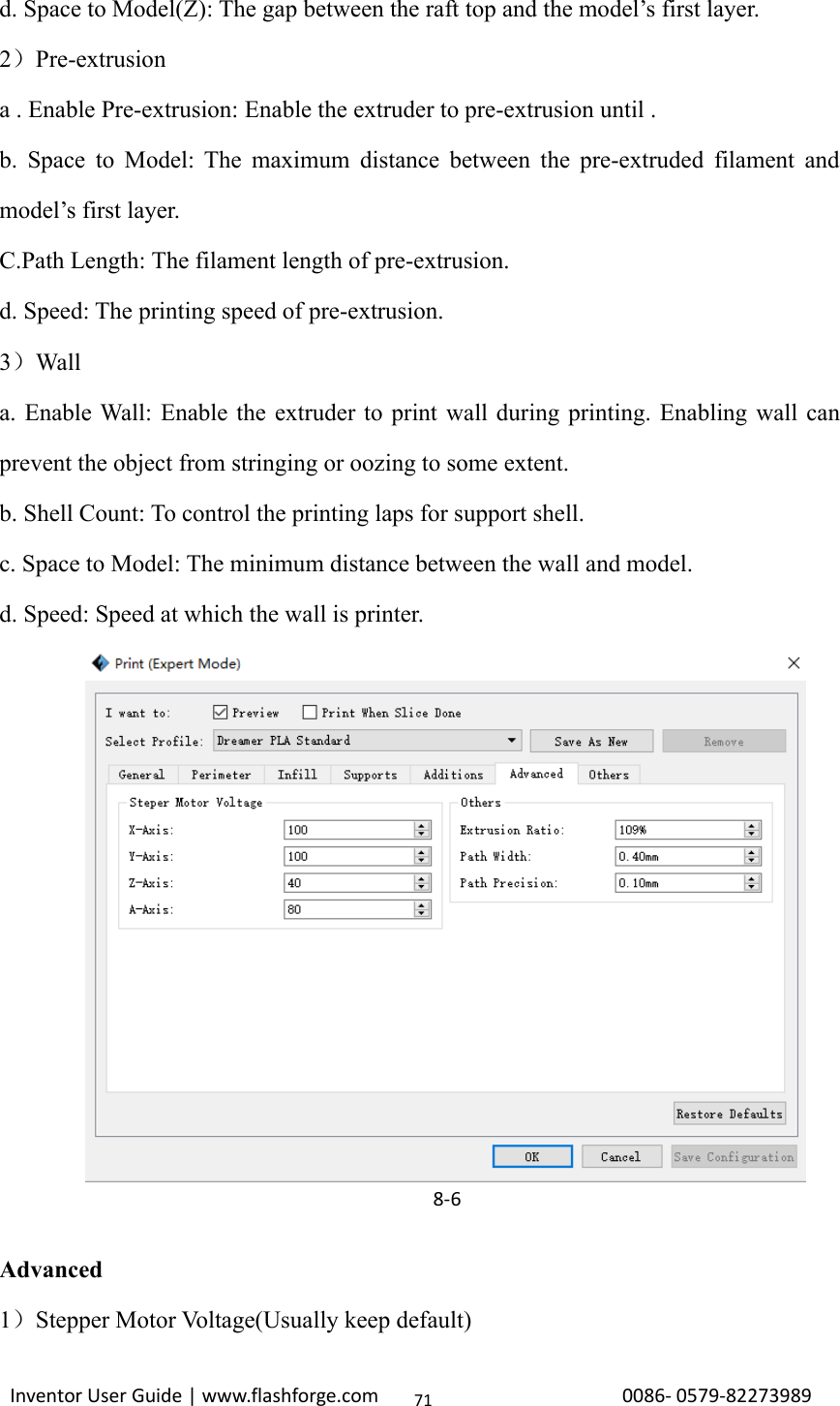
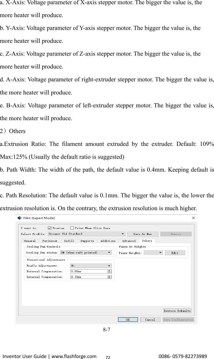
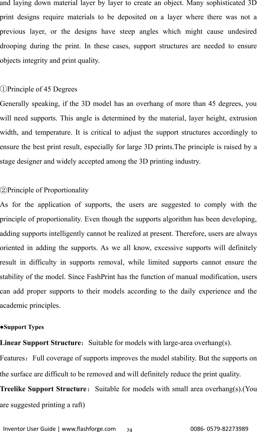
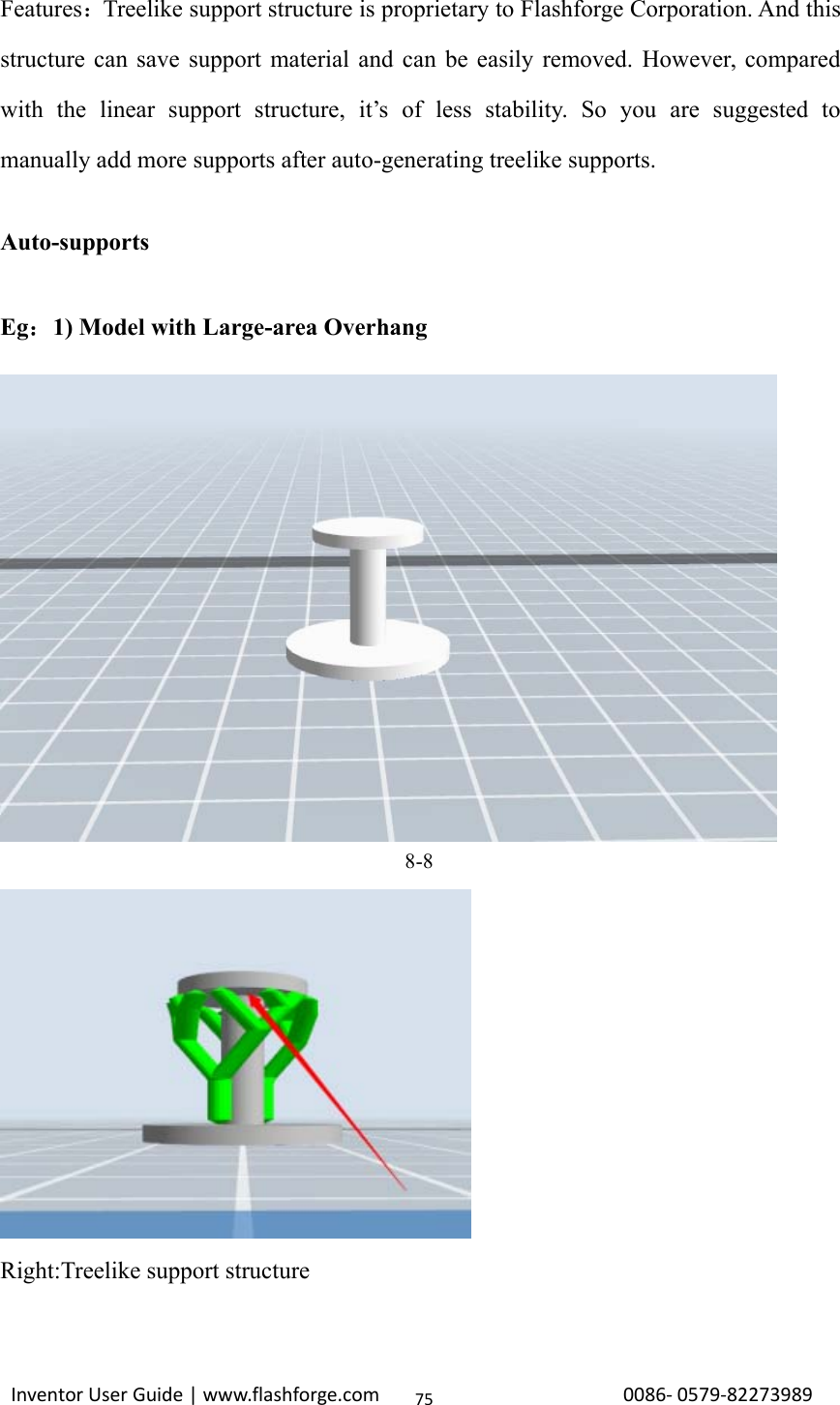
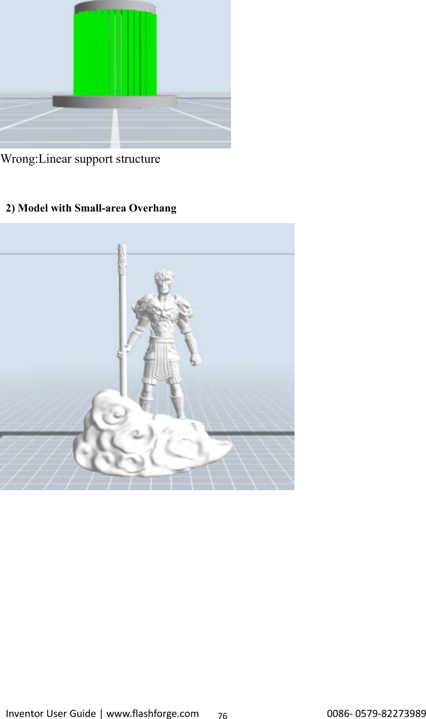
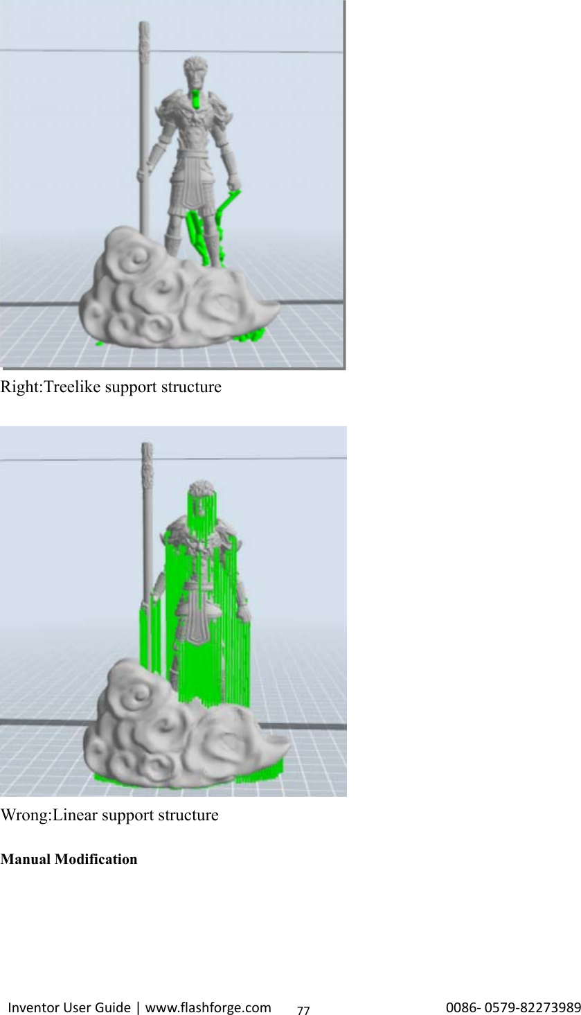
![Inventor User Guide | www.flashforge.com 0086‐0579‐8227398973OthersDimensional Adjustmenta. Enable Adjustments: Enable software to make compensation for errors.b. External Compensation: Enable software to make compensation for the outerdiameter error.c. Internal Compensation: Enable software to make compensation for the innerdiameter error.Save as newAllows users to save the model as a new file after parameter modification.How to do?After getting all the required parameters modified, click [Save as new], then adialogue box will pop up. Users need to enter the file name into the box, then click[OK]. Click the drop-down menu of [Select Profile], the new added scheme can befound in the list.RemoveAllows the users to delete the added scheme(s). Select one of the added schemes,click [Remove] and a dialogue box will pop up for confirmation. Click [Yes] toremove it or click [No] to cancel the current operation.Restore Default: Allows users to restore to the default settings.Save Configuration: Allows users to save the present configuration.8.1 Skills on Supports(Reference Video:Skills on Supports)Support structures enable the printing of models with steep overhangs andcantilevered sections. The Inventor 3D printer utilizes Fused Filament Fabrication(FFF) technology, which works on the additive manufacturing principle of heating](https://usermanual.wiki/Zhejiang-Flashforge-3D-Technology/INVENTOR/User-Guide-3241556-Page-73.png)
![Inventor User Guide | www.flashforge.com 0086‐0579‐82273989788-9For the experienced 3D printer users, the [Add] and [Delete] buttons are suggestedusing for manually adding or deleting supports.1)Manual Add8-10You can add the support structure manually to according to the actual shape of themodel.](https://usermanual.wiki/Zhejiang-Flashforge-3D-Technology/INVENTOR/User-Guide-3241556-Page-78.png)
![Inventor User Guide | www.flashforge.com 0086‐0579‐8227398979Left click [Add] on the left, and then click on the position when support structure isneeded. Press down the left mouse button and drag to generate the support.2)Manual Delete8-11Like the picture above, a hole inside the model doesn’t need any supports.](https://usermanual.wiki/Zhejiang-Flashforge-3D-Technology/INVENTOR/User-Guide-3241556-Page-79.png)
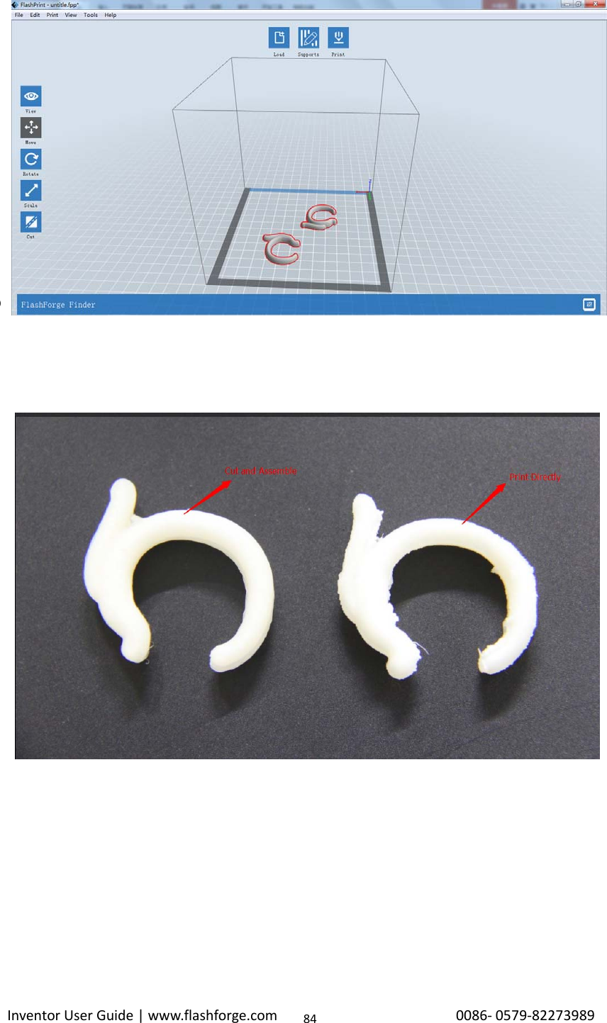
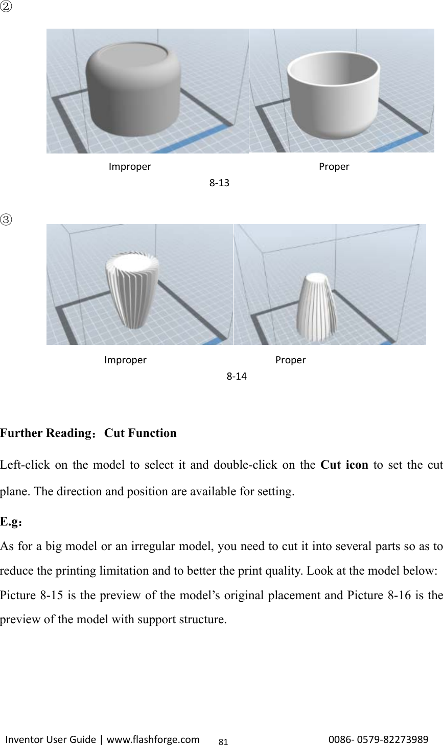
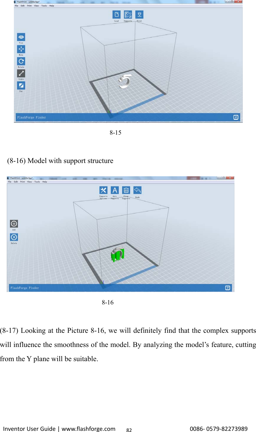
![Inventor User Guide | www.flashforge.com 0086‐0579‐8227398980Left click the [Delete] button and then left click the supports needed deleting. And thesupport will be deleted.8.2 Control over Printing Quality①Enhance the build plate adhesiveness●Leveling the build plate●Keeping the build plate smooth and tidy●Using the build tape or glue②Adjusting the printing speed●Low (Fast) (Print Speed 80mm/s Travel Speed 100mm/s)●Standard (Print Speed 60mm/s Travel Speed 80mm/s)●High (Slow) (Print Speed 50mm/s Travel Speed 70mm/s)●Hyper (Print Speed 50mm/s Travel Speed 70mm/s)8.3 Skills of Model PlacementNot all the models are in the right positions after being loaded. Therefore, you need toplace it in an appropriate position for better print quality. Such as the models below,you need to put one of the surfaces onto the platform.(Please refer to 5.1.12-⑦Surfaceto Platform)①Improper Proper8‐12](https://usermanual.wiki/Zhejiang-Flashforge-3D-Technology/INVENTOR/User-Guide-3241556-Page-80.png)
![Inventor User Guide | www.flashforge.com 0086‐0579‐82273989838-17(8-18) The model preview after cutting.8-18(8-19) Click [Edit]--[Surface to Platform] to put the flat surfaces onto the platform.](https://usermanual.wiki/Zhejiang-Flashforge-3D-Technology/INVENTOR/User-Guide-3241556-Page-83.png)