Zhuhai Tianqin IT TYPE-C GPS/BD GPS TRACKER User Manual
Zhuhai Tianqin IT Co.,Ltd. GPS/BD GPS TRACKER Users Manual
User Manual
TY-C car machine user manual
TY-C is based on the mobile Internet of things hardware platform MT32A, and the
software development system MproIDK to develop and produce, it is a new type positioning
products. Prominent feature is small volume, low power consumption, strong function and low
cost,Communication protocol are fully compatible with our company other series products And
support records 64 - byte format communication protocol.
Can bear 150V high pressure for a long time ,monitor function specially optimized, high
sensitivity clear voice, standard analog input is used for oil measurement ,Add two road pulse
counting input used for traffic ,Mileage statistics .Analog and pulse input doing high level input
at the same time, Use for the engine、ACC、positive and negative detection ,etc. This machine
can be external hands-free speaker .
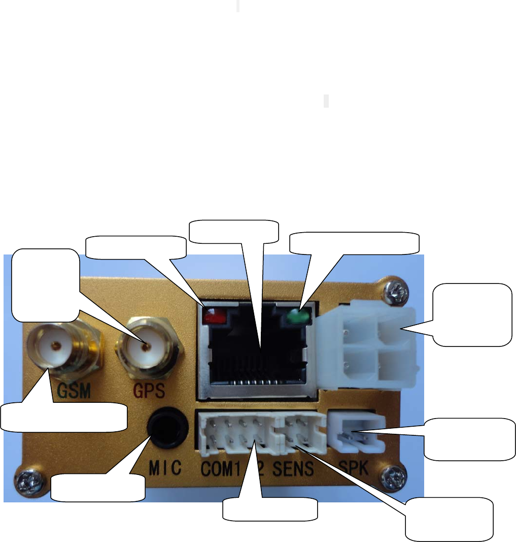
1, Host panel
External GSM antenna socket
External GPS
antenna
socket
GPS status indicator
Handle socket
GSM status indicator light
Power, control,
emergency alarm
socket
Analog/ Sensing
wire socket
External hands-free
speaker socket
COM1/2 socket
Monitor MIC SOCKET
2,Power cord J501(Low configuration)
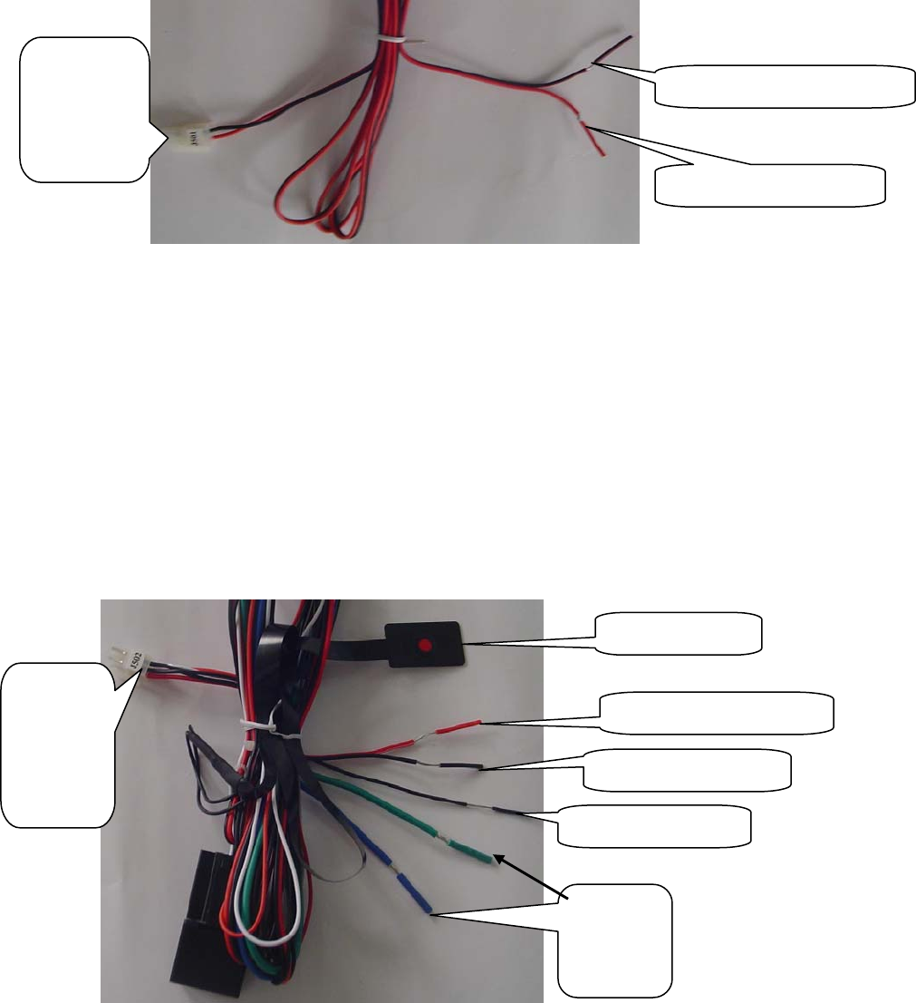
3, Power supply + Cut off oil and electricity +Emergency alarm wire J502 (high
configuration)
Black:connect ground
Power, control,
emergency
alarm socket
Red:Power supply
Power,
control,
emergency
alarm socket
Power supply ground wire
Alarm button ground wire
Red:Power supply
Emergency button
Green、Blue:
Power
outages wire
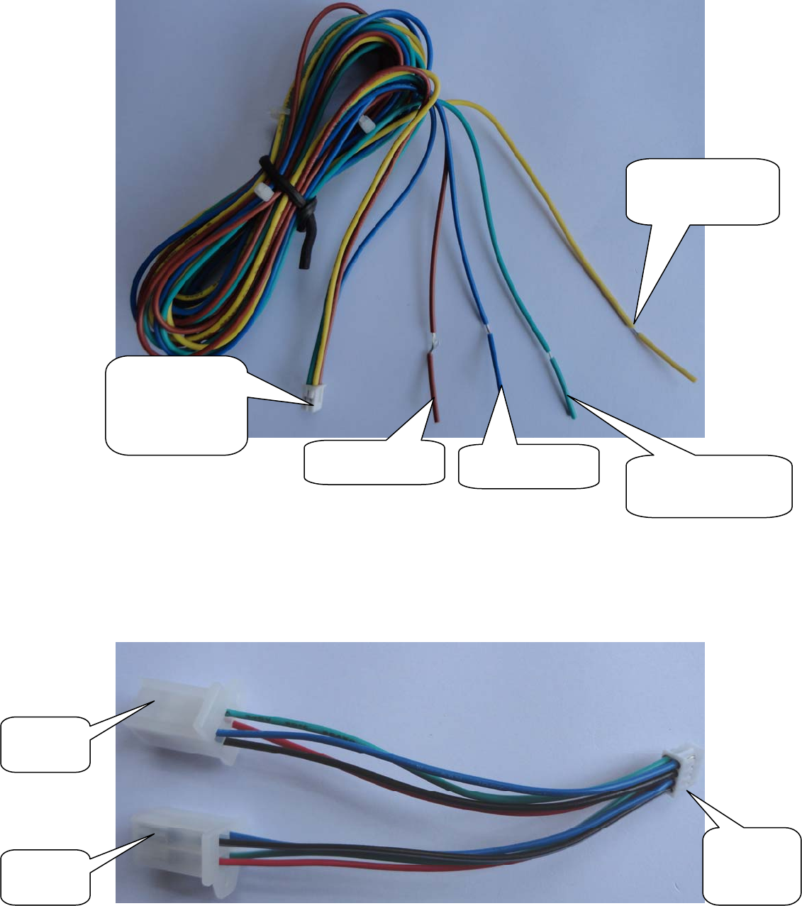
4, Analog input 、H11/H22 sensing wire、ACC/ Engine sensing wire J504
5, Serial port wire(COM1/2)J506
Connect:
Analog/sensing wire
socket
Blue:ACC / pulse 0
Yellow: High level sensor
1(1 H11 / analog 0)
Connect :
COM1/2
socket
COM1 outlet
COM2 outlet
Brown: Engine / pulse
1
Green: High level sensor
2 (H22 / analog 1)
Serial port wire color instruction :COM1 Black color negative 、COM1 Red color positive 5V、
Blue color COM1-RX、green color COM1-TX;COM2 black white color negative 、COM2 Red white
color positive 5V、Blue white color COM2-RX、green white colorCOM2-TX。
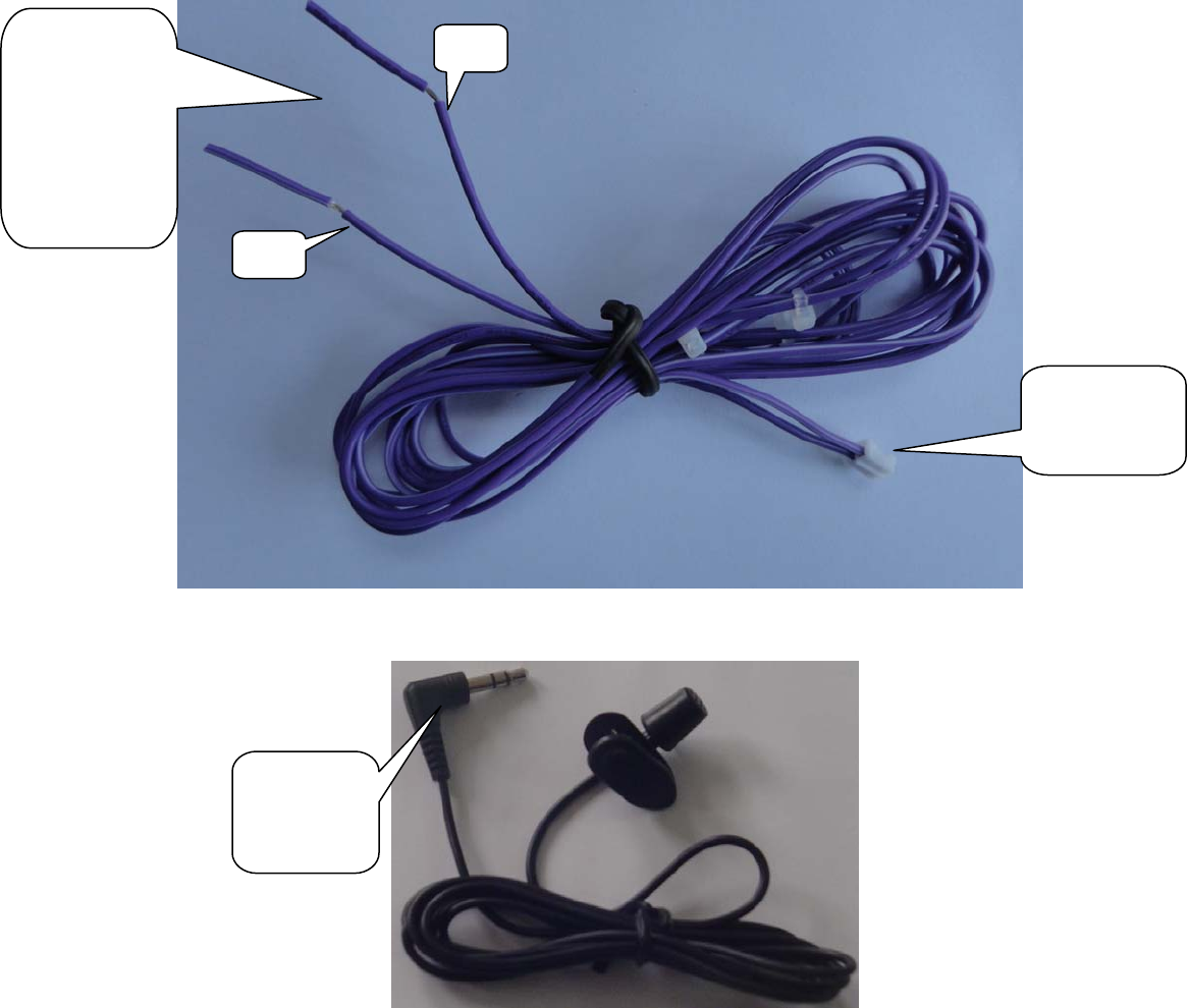
6, Hand-free speaker wire J505
7,Monitor MIC
Connect:External
speaker socket
Connect an external
speaker (0.5 -3 w /
4 - 8 Ω) can be not
distinguish positive
and negative
V+
V-
Connect: the
host monitor
socket
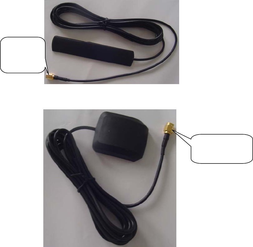
8,GSM Antenna
9,GPS Antenna
10, Wiring self-inspection
1、 Plug in the maintenance hand shank.
2、 Hold down the "self-check" button,Until the "X" symbol to appear on the screen,The
following process can be regardless of the sequence,Can be combined at random
3、 Press the "1" key,Cut off oil and circuit (engine doesn't work),Press "1" again to
restore oil and circuit.
4、 Press the "6" key,display:A serial port 1 test:,Short circuit COM1 blue wire and green
wire,display:A serial port 1 test:OK Please disconnect the short circuit loop.
5、 Press“7”key,display:A serial 2 test:,Short circuit COM2blue white wire and green
white wire,display:A serial 2 test:OK Please disconnect the short circuit loop.
Connect: GSM
antenna socket
Connect:GPS antenna
socket
6、 Press "8"key, hands-free speaker play music;press "8"key again ,music off
7、 Press the "emergency button",display:Button is open;Loosen the "emergency
button",display:button off
8、 High level sensor 1 (Input DC 0V-15V),Press the handle "0" key ,display:analog
input ,The upper screen XXXX numerical change according to the supply voltage (The
numerical is 16 hexadecimal characters)
9、 High level sensor 2 (Input DC 0V-15V),Press the handle“0”key,display:analog
input ,The lower screen XXXX numerical change according to the supply voltage (The numerical
is 16 hexadecimal characters)
10、 Open “ACC”,display:ACC Already open;Shut down “ACC”,display:ACC shut
down。
11、 Open the "engine",display:engine already open;shut down“engine”,display:
engine shut down
12、 Plug in "GPS antenna",Display: antenna shut;Unplug the GPS antenna,display:
antenna open
13、 Short circuit "GPS antenna",display:Antenna short circuit is open;Do not short
circuit the "GPS antenna",display:Antenna short circuit. shut down
14、 Disconnect the "power",Display: battery removal has been opened(This feature
need backup battery has been charged can be test);Turn on the "power",display:battery
removal off
15、 Supply voltage from normal to low ,under 10V or over 34V,display:backup battery
open;Supply voltage from low or overpressure to normal,display:backup battery off
16、 After the above test,Press the "hang up" to exit the self-check state,the host power
automatic restart
11, System setting and verify
1、 Plug in the maintenance hand shank.
2、 Press "set" button,Until the display screen reminder: Please enter the mobile message
center number.
3、 Input the short message service center number,If not correct press "CLR" key to clear,
Long press "CLR" key to clear all Numbers,for example:8613800755500,after click "OK" to
confirm.
4、 Input service center massage number,for example:075588888888,If not correct , can
press CLR button to clear and then enter again,Long press "CLR" key to clear all Numbers,
In front of the number can’t be add 86,after click "OK" to confirm.
5、 Input the hotline number,for example:075588888888,If not correct, can press CLR
button to clear and then enter again,Long press "CLR" key to clear all Numbers,In front of the
number can’t be add 86,after click "OK" to confirm.
6、 Display screen shows the serial number of the host and the software version number,
Press "OK" button, appear "set success!" ,Says it has complete set.
FCC Statement
This equipment has been tested and found to comply with the limits for a Class
B digital device, pursuant to part 15 of the FCC rules. These limits are
designed to provide reasonable protection against harmful interference in a
residential installation. This equipment generates, uses and can radiate radio
frequency energy and, if not installed and used in accordance with the
instructions, may cause harmful interference to radio communications.
However, there is no guarantee that interference will not occur in a particular
installation. If this equipment does cause harmful interference to radio or
television reception, which can be determined by turning the equipment off and
on, the user is encouraged to try to correct the interference by one or more of
the following measures:
-Reorient or relocate the receiving antenna.
-Increase the separation between the equipment and receiver.
-Connect the equipment into an outlet on a circuit different from that to which
the receiver is connected.
-Consult the dealer or an experienced radio/TV technician for help.
To assure continued compliance, any changes or modifications not expressly
approved by the party.
Responsible for compliance could void the user’s authority to operate this
equipment. (Example- use only shielded interface cables when connecting to
computer or peripheral devices).
This device complies with part 15 of the FCC Rules. Operation is subject to the
condition that this device does not cause harmful interference.
FCC Radiation Exposure Statement:
The equipment complies with FCC Radiation exposure limits set forth for
uncontrolled enviroment. This equipment should be installed and operated with
minimum distance 20cm between the radiator and your body.