Zilink Electrical Appliance DHXXH IP Camera User Manual
Shenzhen Zilink Electrical Appliance Co., Ltd. IP Camera Users Manual
UserManual.wiki
>
Zilink Electrical Appliance
>
DHXXH User Manual
Users Manual
Navigation menu
Upload a User Manual
Namespaces
Wiki Guide
HTML
PDF
Info
Views
User Manual
Discussion / Help
Navigation

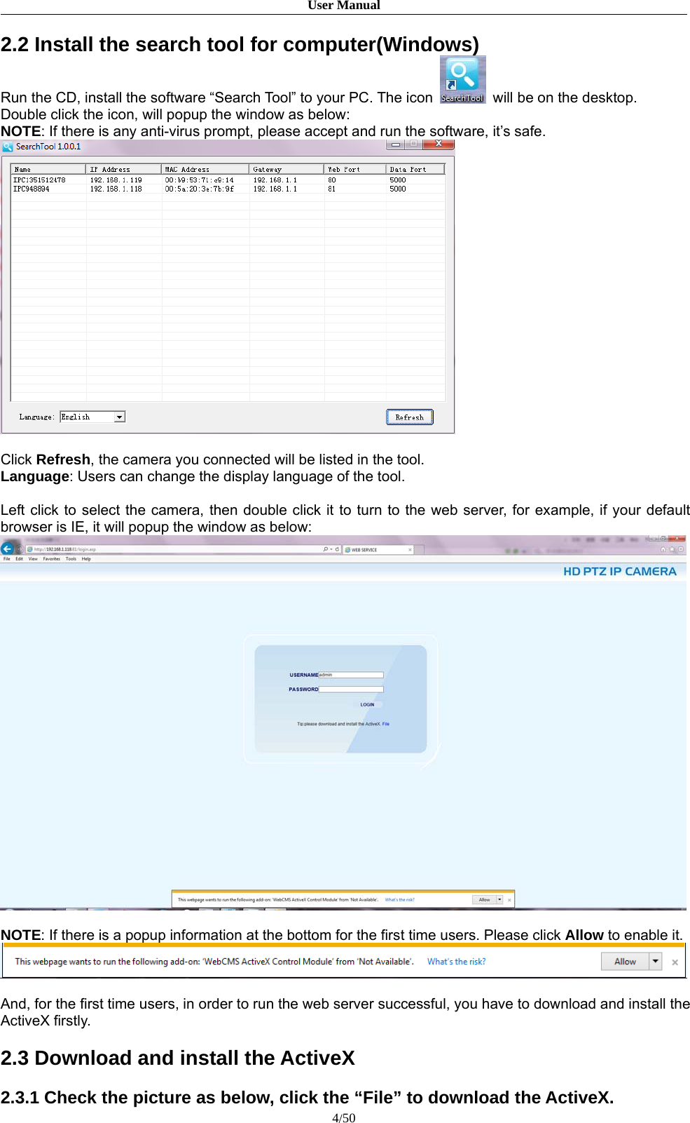
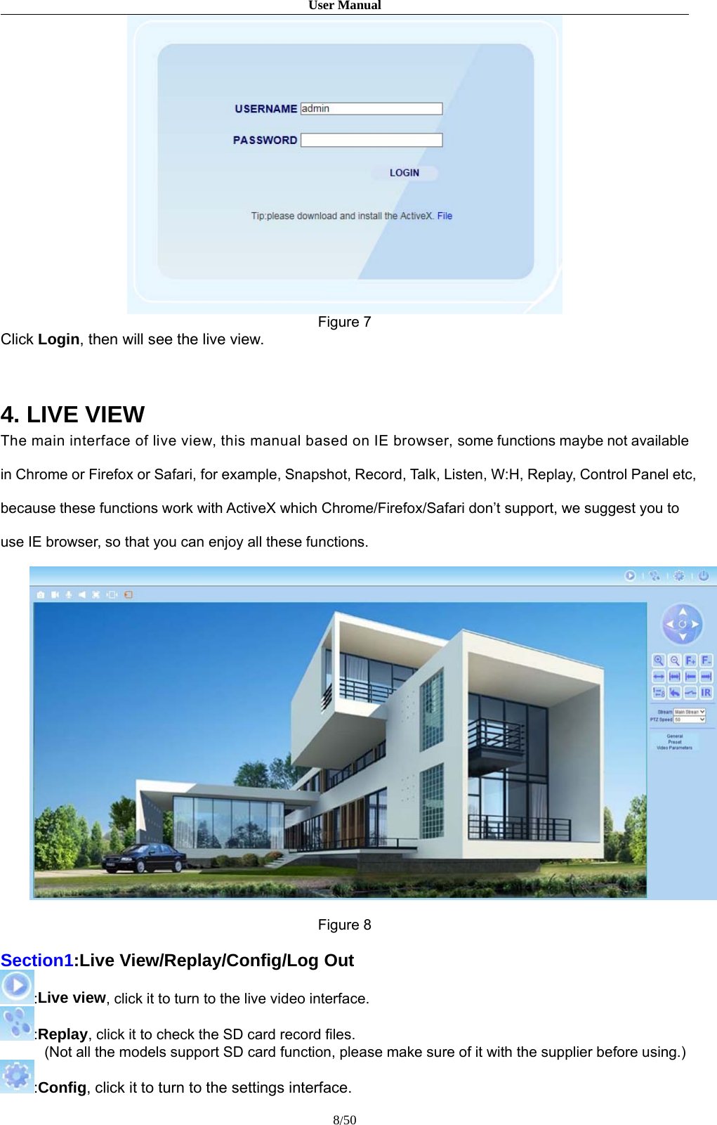
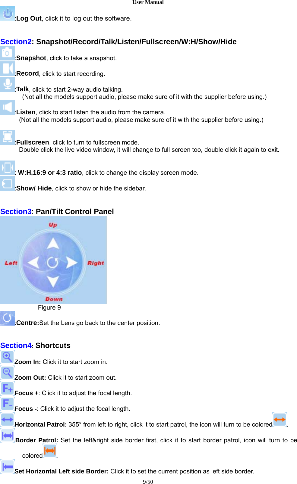
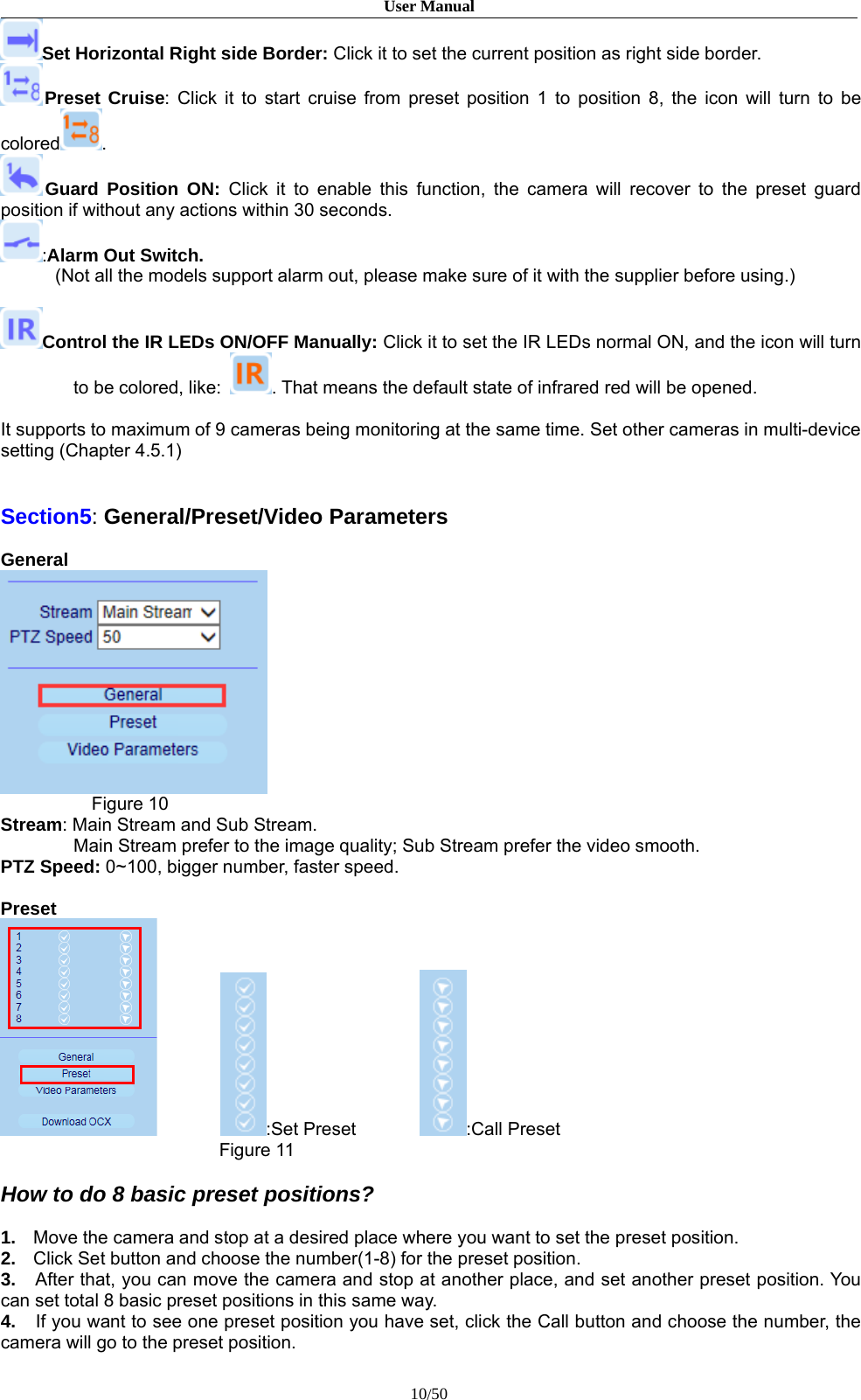
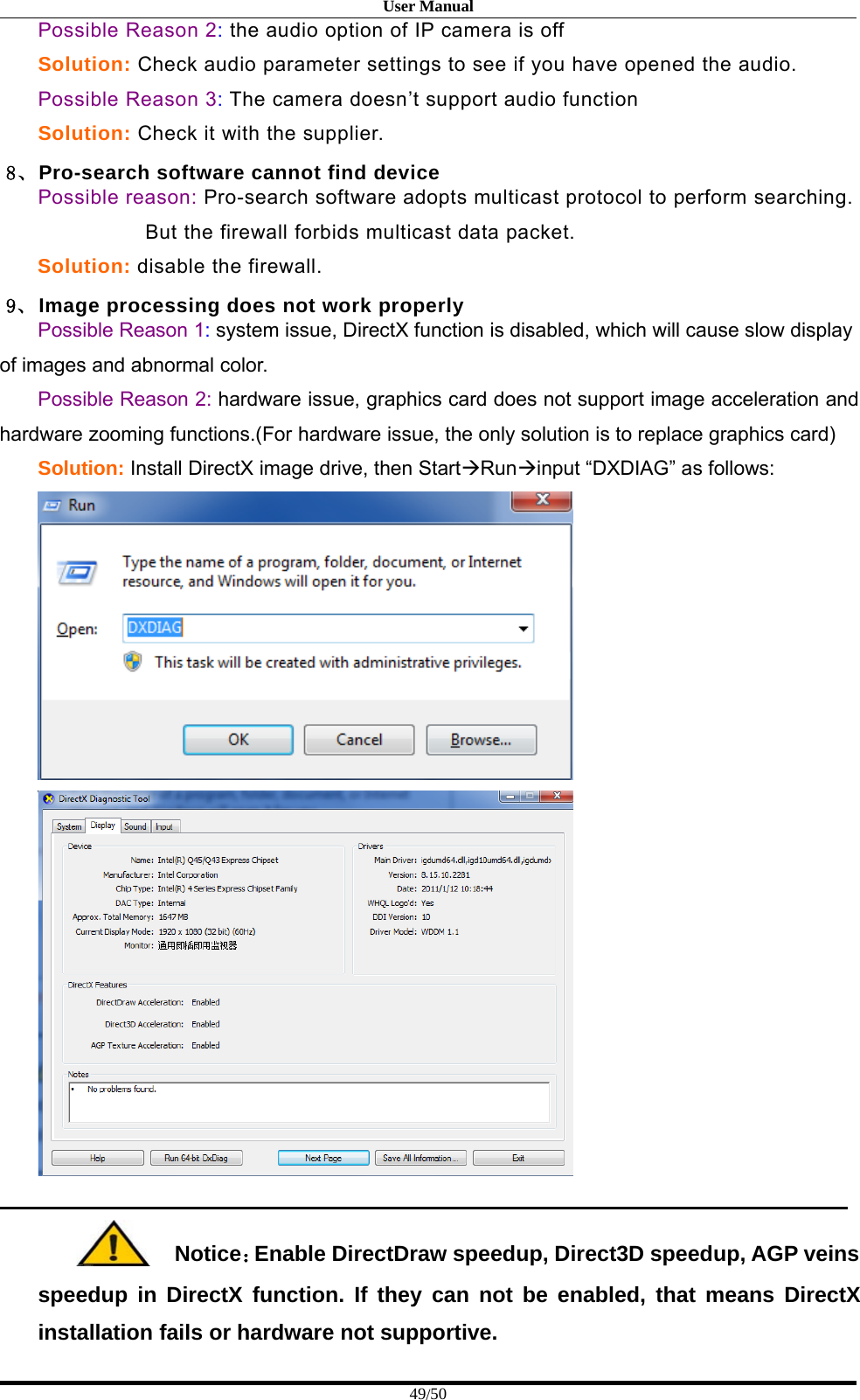
![User Manual11/50Video ParametersFigure 12Brightness: Adjust the brightness parameter from 0 to 255, default is 128.Contrast: Adjust the contrast parameter from 0 to 255, default is 128.Hue: Adjust the chroma parameter from 0 to 255, default is 100.Saturation: Adjust the saturation parameter from 0 to 255, default is 142.Default: Click the default, which means all the video parameters like Brightness, Contrast, Saturation,Chroma will be presented the default values.5 SET SYSTEM PARAMETERS5.1 Local ConfigClick to login the system configuration,Figure 13[Preview Mode]: Users can choose Real time priority or Fluency priority mode according to the needs.[Reset Mosaic]: Select this option to make image quality better, but CPU usage rate will be higher atthe same time.[Record file packing time]: Set packing time of record files for local PC when it is recording.[Record file path]: Set the storage directory for local records and snapped files.After setting these parameters, please click to make them valid.](https://usermanual.wiki/Zilink-Electrical-Appliance/DHXXH/User-Guide-2871206-Page-11.png)
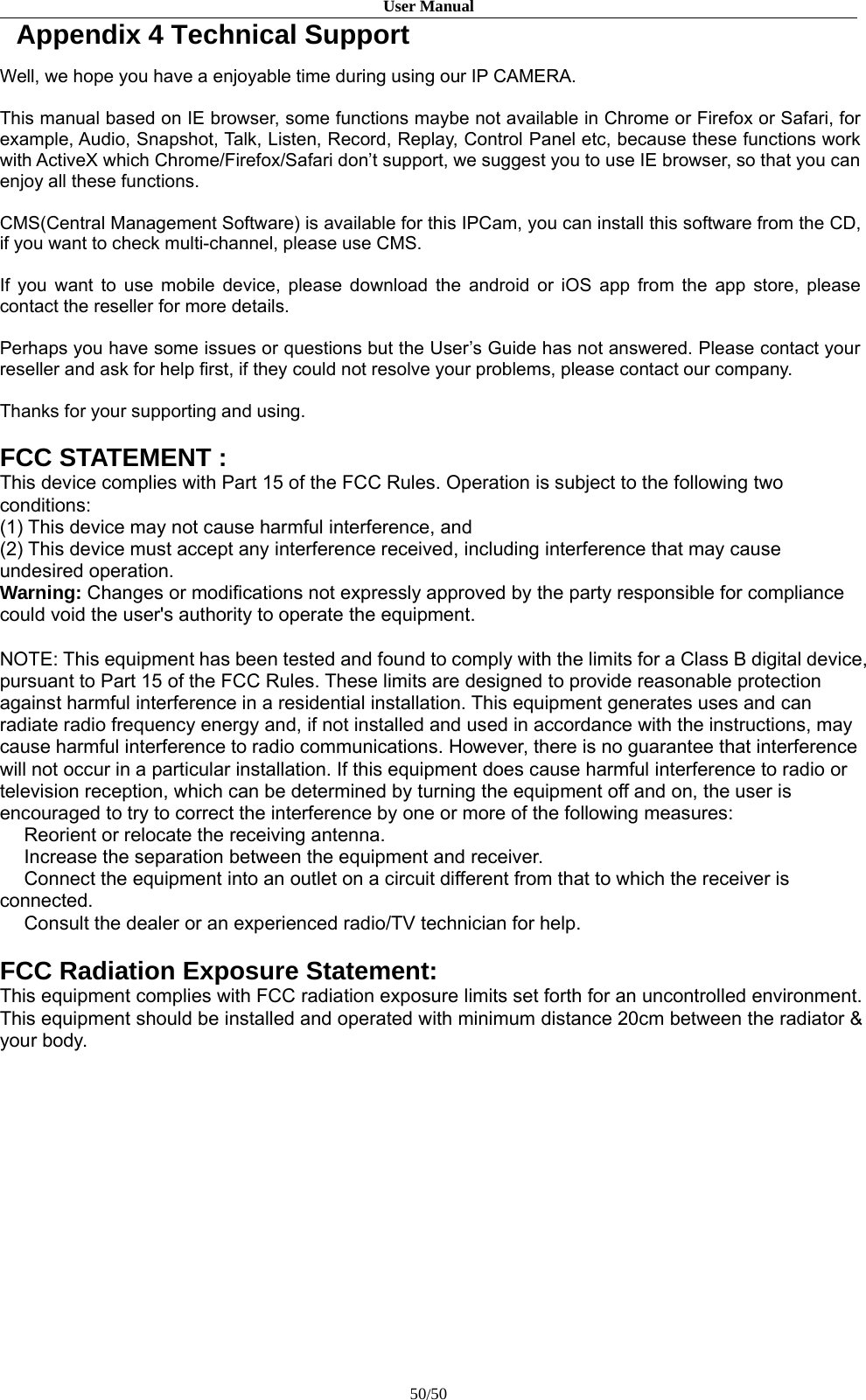
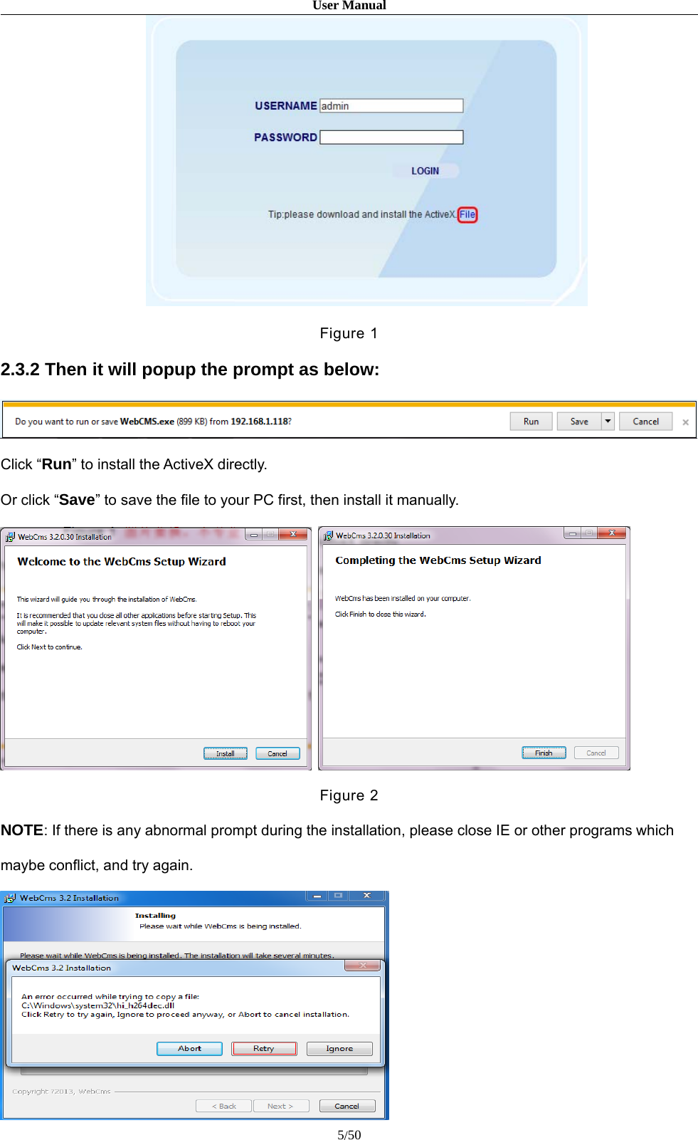
![User Manual12/505.2 Audio SettingNOTE: Not all the models support audio function, please make sure of it with the supplier before using.Figure 14[Enable]: Turn on or turn off the audio of IP camera, if there is no need for audio, close audio input tosave DSP resource and network resource. Audio is disabled by default.[Audio Input]: Choose MIC or Line In input mode.[Compression Type]: Supports three types of audio compressed format:G.726,G.711A,G.711U.[Sampling Rate]: Supports audio sample rates of 8k.[Input Volume]: Adjust the device’s input volume.[Output Volume]: Adjust the device’s output volume.After setting these parameters, please click to make them valid.](https://usermanual.wiki/Zilink-Electrical-Appliance/DHXXH/User-Guide-2871206-Page-12.png)
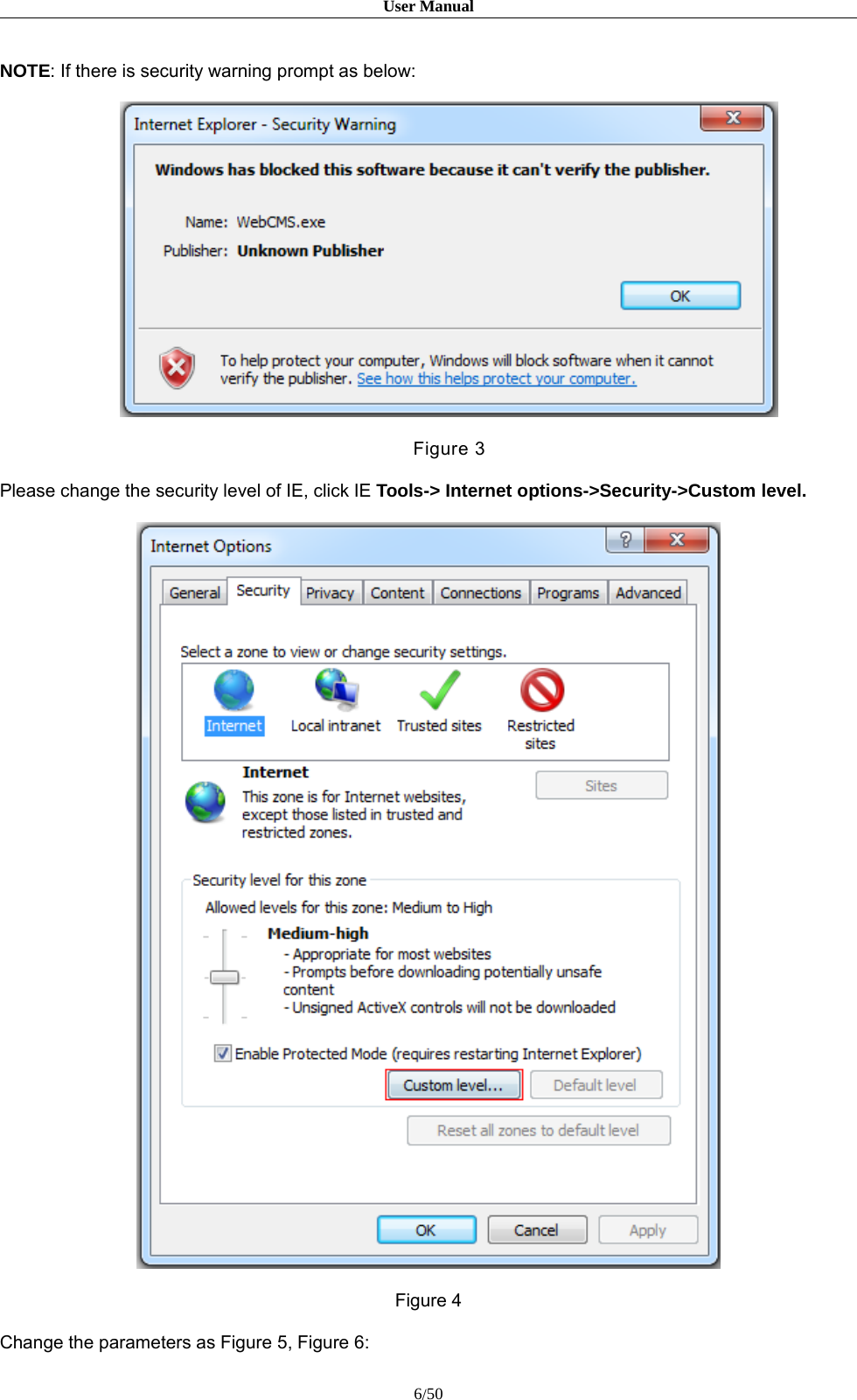
![User Manual13/505.3 Video Settings5.3.1 OSD SettingsFigure 15[Title]: Set the name of video channel, displayed at the bottom left of image(movable),Maximum 32 characters allowed.[Color]: Set the color for the text.[OSD]: Display or not to display Title, Date, Time, Week and Frame/Bitrate of channels.[Arrows]: Can adjust the text display position of Title, Date, Time and Week etc.After setting these parameters, please click to make them valid.5.3.2 Video Coding](https://usermanual.wiki/Zilink-Electrical-Appliance/DHXXH/User-Guide-2871206-Page-13.png)
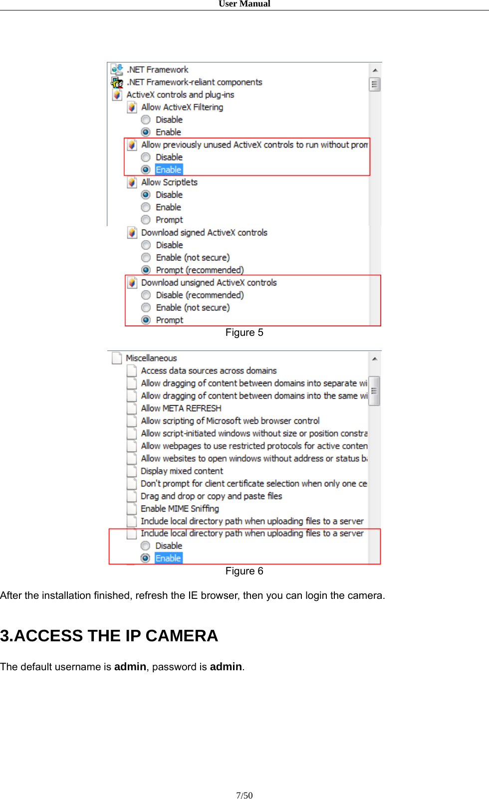
![User Manual14/50Figure 16[Coding Level]: Baseline and Main profile available, it’s only for H.264 compression format.Baseline is suit for low delay, and the situation have requirement on real time.Main profile is suit for better image quality.[Coding]: Supports H.264 or MJPEG.[Resolution]: Set the resolution of images.720P supports:Main Stream:1280*720;Sub Stream:704*576/320*240;960P Supports:Main Stream:1280*1024/1280*960/1280*720;Sub Stream:704*576/640*480/640*352/320*240;1080P supports:Main Stream:1920*1080/1280*960/1280*720;Sub Stream: 720*576/640*480/640*352/320*240;[Quality]: Choose the right quality according to the requirement: Fine, Normal, Basic.The parameters can also be user-defined by choosing [Advanced].[Rate control]: CBR and VBR are optional.CBR adopts constant encoding bitrate, VBR adopts variable encoding bitrate.[Quality]: CBR setting: set the bitrate range via “Image Quality”, can choose self-adaption,it means the bitrate controlled by the software, and also can choose ±10%~±50%,±10% means the bitrate range from -10% to +10% of the value of bitrate.VBR setting: set image quality via “Image Quality”, 6 levels available, from best to worst.[Bitrate]:The range of preferred and alternate stream is 30~16384Kbps.Higher bitrate setting can generate better image quality, but it occupies more bandwidth,please adjust the setting according to your actual bandwidth.Under CBR setting, [Bitrate] is the constant bitrate of encoding.Under VBR setting, [Bitrate] is the variable bitrate of encoding.[Frame rate]: Set encoding frame rate per second. Under poor network condition, frame rate canbe reduced to control encoding bitrate to make motion images flow more smoothly.[GOP]: Adjustable between 1~200(Main Stream), 1~200(Sub Stream).Smaller I frame intervalmeans higher bitrate and better image quality. It is recommended to set the I frame interval](https://usermanual.wiki/Zilink-Electrical-Appliance/DHXXH/User-Guide-2871206-Page-14.png)
![User Manual15/50as above 25.[LAN Default]: Click to restore the default value settings.[WAN Default]: Click to restore the default value settings.After setting these parameters, please click to make them valid.(After change the coding lever, resolution and coding, device will restart.)Note: Non-professional users please use “Advanced Settings” with caution.5.3.3 Video MaskFigure 17[Enable Mask]: Enable or disable video mask.[Set Mask Area]: Click and move cursor to set the image mask area, an image can be entirelyor partially masked, maximum 4 mask areas supported.[All]: Mask the whole image.[Clear]: Clear masked areas.After setting these parameters, please click to make them valid.](https://usermanual.wiki/Zilink-Electrical-Appliance/DHXXH/User-Guide-2871206-Page-15.png)
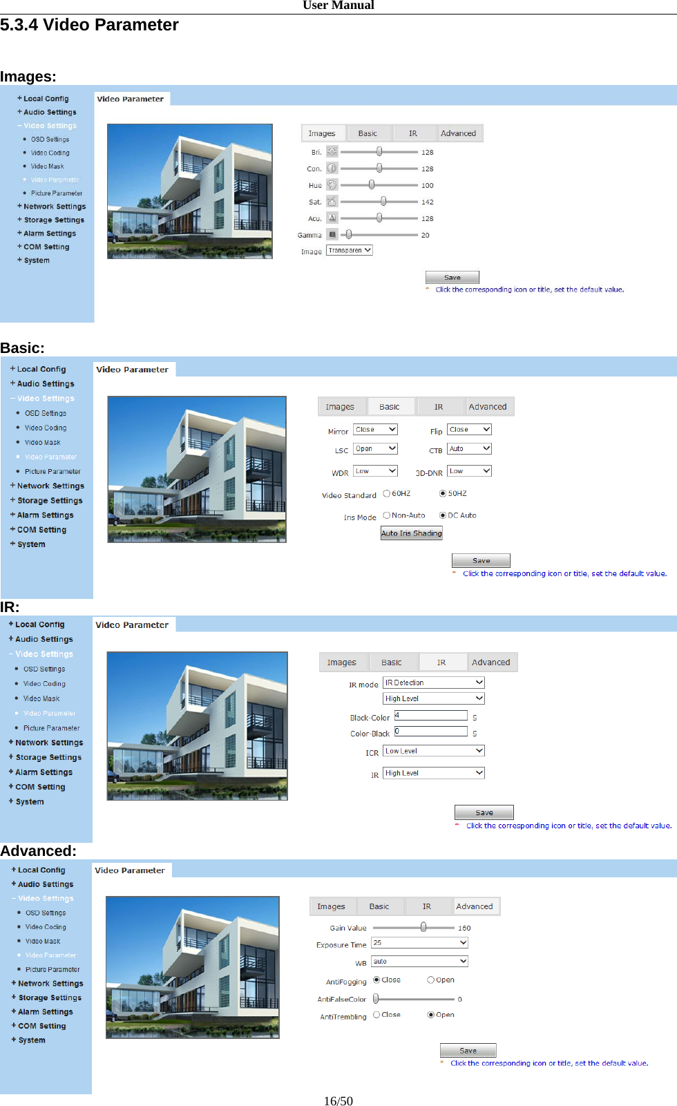
![User Manual17/50Figure 18[Images]: Adjust the Brightness, Contrast, Hue, Saturation, Acutance, Gamma of video.Image Mode: Transparent or True Color.[Basic]Mirror: Set mirror, horizontally rotate the video;Flip: Set flip, vertically rotate the video;LSC: Open or close the Auto IRIS rectifyCTB: Set CTB ,IPC will automatically turns on D/N function according to the image’ssituation.WDR: Set WDR,Enhance the image quality in such area: strong light source (sunlight,lamps or reflectors, etc.) , shadow of high-brightness, backlight3D-DNR: Set 3D NR to get a clearer picture in low light environment, effectivelyeliminate video noise and color noise In low light conditions.Video Standard: In indoor environment, if the flashing of lamps results in the flickeringof images, please choose 50HZ or 60HZ according to the power frequency. 50HZ suitfor PAL system, 60HZ suit for NTSC system;Iris Mode: Set Non-Auto Iris, Can be used with non-auto iris lens.Set DC Auto Iris, Adjust the control level of auto-iris to control the luminous flux.Auto Iris Shading: for the first time using auto iris, please redress the iris in the lightbox.[IR]IR Mode: This function only for the camera has infrared function, support 3 kinds ofdetection mode, suit for different infrared light board and situation.Time Detection: for this mode, set the time to turn day mode and B/W mode, this modewith first priority.Video Detection: for this mode, the sensor will detect the value of LUX, and decideturn to B/W mode or not. The lager the value is, more sensitive about turn to B/Wmode.IR Detection: for this mode, the photo-resistor will detect the value of LUX, to suitdifferent infrared Light board, we support 3 kinds of wording mode:1, low level mode, when the device get low level voltage from Infrared light board,the device will turn to B/W mode;](https://usermanual.wiki/Zilink-Electrical-Appliance/DHXXH/User-Guide-2871206-Page-17.png)
![User Manual18/502, high level mode, when the device get high level voltage from infrared light board,the device will turn to B/W mode;3, auto detection mode, when the device power on, it will take sample of light, thenjust it is day mode or B/W mode, and it also get the value of voltage from infraredlight board, combination the two value and take them as the condition to turn to daymode or B/W Mode.Black-color: The Video from Black-White to color when the detection becomeseffective.Color-black: The video from color to Black-White when the detection becomeseffective.The two time control only in the IR Detection mode.ICR:Setting the control level of the IR-CUT according to the IR-CUT control level.IR:This function suit for the camera with IRCUT and infrared light board. Eg.: for ICR,when set low level, it means when the device send a low level voltage to IRCUTmodule, the IRCUT will turn to B/W mode.[Advanced]Gain Value: change the value of AGC can adjust the effect of image in low lighe-level.Exposure Time: Set the value of Shutter to control exposure timeWB: You can choose Manual WB or AWB mode to adjust white balance,AWB isdefault open.AntiFogging: Set anti fogging function, when the density of fog up to a high value, theISP will change the brightness and contrast to improve the quality of image.AntiFalseColor: Set anti false color function, can cancel the Moore profile effect inhigh frequency part.After setting these parameters, please click to make them valid.](https://usermanual.wiki/Zilink-Electrical-Appliance/DHXXH/User-Guide-2871206-Page-18.png)
![User Manual19/505.3.5 Picture ParameterFigure 19[Picture Format]: Only supports JPG format currently,[Resolution]: It is the same as set in [Video Coding].After setting these parameters, please click to make them valid.5.4 Network Settings5.4.1 Basic SettingFigure 20[Data Port]: Default value is 5000 (users are recommended not to change it).[Web Port]: Default value is 80.[ONVIF Port]: Default value is 2000 (users are recommended not to change it).After setting these parameters, please click and the device will reboot to make theparameters valid.](https://usermanual.wiki/Zilink-Electrical-Appliance/DHXXH/User-Guide-2871206-Page-19.png)
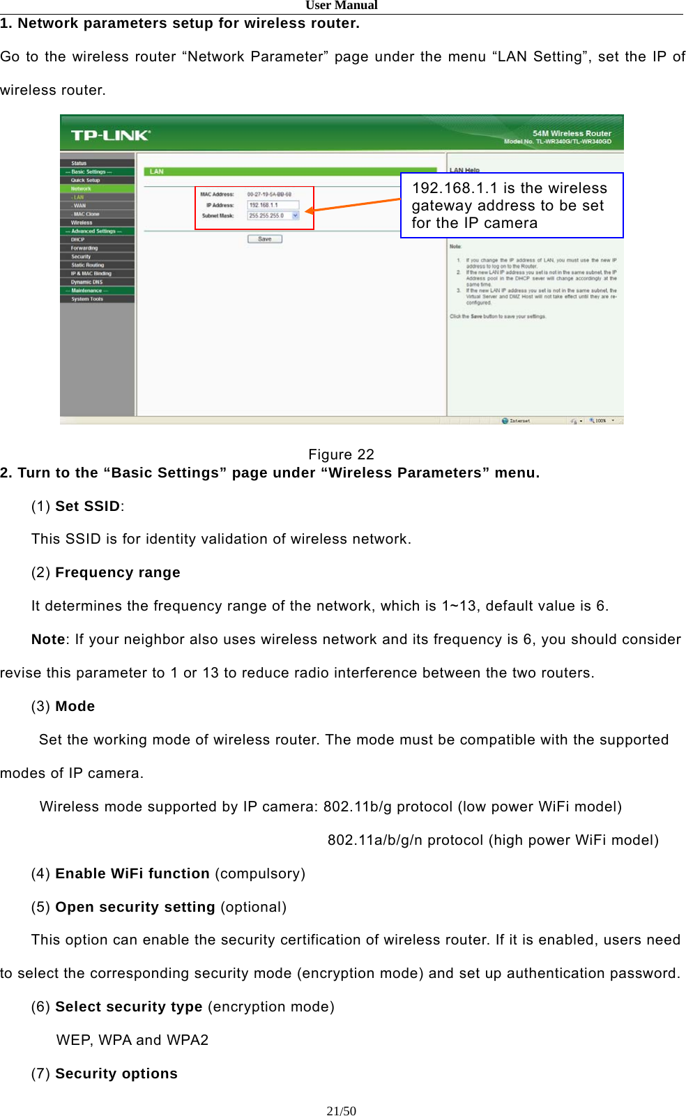
![User Manual20/505.4.2 LAN SettingFigure 21[DHCP Enable]: If DHCP function of the router is enabled, IP camera will automatically fetch IPaddress from the router.[IP]: Set the camera’s IP address.[Subnet Mask]: Default value is 255.255.255.0 (users are recommended not to change it).[Gateway]: Set the gateway IP of IP camera, for example when the device is connected to publicnetwork via a router, the gateway IP is the router IP.[DNS]: The DNS should be same with the DNS inside the router.[MAC]: The Physical address of IP camera (users are recommended not to change it).Note: After revise and save parameters, the device will restart. If itis applied in LAN, please pay attention to avoid IP collision5.4.3 Wireless SettingCheck the wireless settings of router before setting the IP Camera.For example, TP-Link WR340G 54M wireless router, check settings as follows:](https://usermanual.wiki/Zilink-Electrical-Appliance/DHXXH/User-Guide-2871206-Page-20.png)
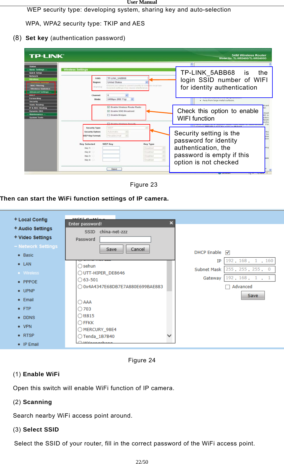
![User Manual23/50(4) IP addressSet the wireless IP address of IP camera manually, e.g. 192.168.1.122.Or you can select the DHCP, get the IP from the router automatically.(5) GatewaySet the IP address of current wireless gateway, the same as the router, e.g. 192.168.1.1.(6) AdvancedSelect to enable dvanced settings, like Encryption type, Auxiliary Encryption type and KeyFormat, if connected the WiFi successful, it will get the parameters automatically.After setting completes, save all parameters. Then disconnect the network cable, IP cameracan be visited via wireless IP, such as 192.168.1.122.Note: Applies to models with WiFi function only.Notice: The LAN IP addr. and wireless IP addr. should be different.5.4.4 PPPOE SettingFigure 25[Enable]:Enable or disable PPPOE dial-up function.[IP]: After successful setting of device dial-up, it will display the public IP Address.[User Name]: ADSL dial-up account, obtain from the IP service provider.[Password]: ADSL dial-up password, obtain from the IP service provider.[Online Time]: Start timing after dial-up to see the online duration after successful dial-up.](https://usermanual.wiki/Zilink-Electrical-Appliance/DHXXH/User-Guide-2871206-Page-23.png)
![User Manual24/50After setting these parameters, please click to make them valid.5.4.5 UPNP SettingFigure 26Auto-mapping of port, when IP camera is connected to a router with UPNP function enabled, therouter will automatically map the port in UPNP settings to public network, manual port mappingby users is not necessary.[Network Card]: Select the type of NIC connecting UPNP router. For WIFI models, when IPcamera is connected to router via WIFI network, select “wireless” mode.[Mode]: Designate mode or Auto mode.Designate mode means to specify data mapping port and web mapping port to router.Auto mode means data mapping port and web mapping port are set up by router.[Server URL]: IP address of the router with UPNP function.[Data Port Map No.]: Data mapping port of user-specified device on the router(works only underspecified mode).[Web Port Map No.]: Web mapping port of user-specified device on the router(works only underspecified mode).[Data Mapping Status]: When UPNP function runs successfully, the status bar will echo the dataport mapped to the router by the device.[Web Mapping Status]: When UPNP function runs successfully, the status bar will echo the webport mapped to the router by the device.After setting these parameters, please click to make them valid.](https://usermanual.wiki/Zilink-Electrical-Appliance/DHXXH/User-Guide-2871206-Page-24.png)
![User Manual25/505.4.6 Email SettingFigure 27To set the mailbox addresses and parameters of alarm mails and public network IP mails.[To]: Mailbox that receives mails.[From]:Mailbox that sends mails.[Password]:The login password of the mailbox that sends mails.[SMTP Server]: The address of servers that send the mails, the address format of mail serversvaries from provider to provider, e.g. the SMTP server of 163 mailbox is smtp.163.com.[MAIL Title]: Title of mails.[SMTP Port]: Port of SMTP port, different mail server has different port. For example, the serverport of Gmail is 465.Commonly used mail server configuration:1. Gmail mail server:SMTP server: smtp.gmail.com SMTP user name: username@gmail.comSMTP port: 465 SSL: enabled2. Yahoo mail server:SMTP server: smtp.mail.yahoo.com SMTP user name: username@yahoo.comSMTP port: 465 SSL: enabled3. 163 mail server:SMTP server: smtp.163.com SMTP user name:usernameSMTP port:25 SSL: disabledAfter setting these parameters, please click to make them valid.](https://usermanual.wiki/Zilink-Electrical-Appliance/DHXXH/User-Guide-2871206-Page-25.png)
![User Manual26/505.4.7 FTP SettingFigure 28FTP server sends the record files and snapped images generated after alarm is triggered in FTPmode to specified FTP server, it supports 2 FTP servers, when the preferred one goes wrong,system will switch to the alternate one.[Server URL]: The IP address or HTTP address of FTP server.[Server Port]: Port of FTP server, the default port is 21.[FTP Catalog]:Path on remote FTP server, if the path does not exist or has not been filled in, thedevice will create a file folder under the root directory of FTP server.[User Name] and [Password]: User name and password of FTP server.Notice:If you want to upload the record files and snappedimages,you must have the authority to write on the FTP server.](https://usermanual.wiki/Zilink-Electrical-Appliance/DHXXH/User-Guide-2871206-Page-26.png)
![User Manual27/505.4.8 DDNS SettingFigure 29Bind the device with a fixed domain name by DNNS setting so that visiting to the device can berealized no matter how the public IP changes.(Refer to Appendix 3 for detailed steps).If your camera supports P2P function, normally no need to set the DDNS function.[Enable]: Enable or disable DDNS function.[Service Provider]: Supports 3322.org and dyndns.org.[User Name]: User name registered in DDNS server.[Password]: User password registered in DDNS server.[Domain]: The domain name set up by users, e.g.: test1.3322.net.[Server URL]: DDNS server address. When DDNS address is the domain name, please set theDNS address in [Basic Parameters] correctly.[Server port]: Default value is 30000,this is the DDNS server’s port. (users are recommended notto change it).[Data Port Map No.]:Fill in the external data port mapped by the IP camera on the router that isconnected to public website.[Web Port Map No.]:Fill in the external web port mapped by the IP camera on the router that isconnected to public website.[Update Interval]:Choose the upgrade interval time, eg:30 minutes, so the IP camera will](https://usermanual.wiki/Zilink-Electrical-Appliance/DHXXH/User-Guide-2871206-Page-27.png)
![User Manual28/50upgrade the WAN IP to the DDNS every 30 minutesAfter setting these parameters, please click to make them valid.5.4.9 VPN SettingFigure 30[Enable]: Enable or disable VPN function.[Server URL]: IP address or domain of VPN server.[User Name]: User registered in VPN server.[Password]: User password registered in VPN server.[IP]: Display IP after VPN dial-up success.[Status]: Display the status of dial-up.After setting these parameters, please click to make them valid.](https://usermanual.wiki/Zilink-Electrical-Appliance/DHXXH/User-Guide-2871206-Page-28.png)
![User Manual29/505.4.10 RTSP SettingFigure 31[Enable]: Check RTSP switch to enable RTSP function, RTSP function enabled as default.[Enable Authentication]: Check encryption switch,disabled as default, when enableencryption,you need the password when using VLC player connect camera.Open: rtsp://ip/av0_0&user=admin&password=admin;Close: rtsp://ip/av0_0[&user=admin&password=admin],” [ ]” Optional content;“av0_0 ”, frist“0” shows channel:0,1,2,3, represent the channel :1,2,3,4; IP camera has only onechannel, fill in“0”;The second “0” shows main / sub stream,0:main stream,1:sub stream;If the authentication mode is changed, the camera reboot.[Packet Size]: Set the packet size.[Port]: Default port is 554.With RTSP function enabled, users can review the audio and video streams in real time via playersthat supports standard RTSP protocol[Communicate]: Multicast function is enabled as default.[Multicast Server Address]: when camera supports multicast, camera will be the multicastserver,and have the multicast address, 239.0.0.0 as default address.[Multicast Port], video of main stream and sub stream using port 5010 and 5020, audio of main](https://usermanual.wiki/Zilink-Electrical-Appliance/DHXXH/User-Guide-2871206-Page-29.png)
![User Manual30/50stream and sub stream using port 5012 and 5022.[Onvif Password Enable]: Enable or disable Onvif password.After setting these parameters, please click to make them valid.5.4.11 Public IP Noticed by EmailFigure 32[Enable]:Check this switch to enable public IP mail notification function.[Update Interval]: Select the interval of public IP mail notifications.After enable this function, when the device detects public IP changed, it will send notification mailto the mail address setted in [Mail Setting].After setting these parameters, please click to make them valid.](https://usermanual.wiki/Zilink-Electrical-Appliance/DHXXH/User-Guide-2871206-Page-30.png)
![User Manual31/505.4.12 Connecting SettingFigure 33[Enable]: Enable or disable active connection of the device to surveillance center.[Server URL]:The address of surveillance center (e.g. 192.168.55.99).[Server Port]: The port of surveillance center (e.g. 6000).After setting all the network parameters, click to make the parameters valid.](https://usermanual.wiki/Zilink-Electrical-Appliance/DHXXH/User-Guide-2871206-Page-31.png)
![User Manual32/505.4.13 MobileFigure 34[UDID]: The P2P ID to visit the camera remotely[Port Server]:Port for mobile monitor5.5 Storage Settings5.5.1 Device Setting](https://usermanual.wiki/Zilink-Electrical-Appliance/DHXXH/User-Guide-2871206-Page-32.png)
![User Manual33/50Figure 35[Storage Device]: View information of SD card here, including No.,Total Size,Free Size and Status.Users can also click [Format] button to format SD card, during the formatting process, pleaseclick [Refresh] button to the display formatting completion percentage.[Code Stream]:Set record stream for SD card, Main stream and Sub stream are selectable.[Record File Packing Time]:Set packing time for record file .10M means recording files will bepacked every 10 minute.Note:Hot-plugging is not recommended for SD card, compulsory hot-pluggingmay damage the SD card, causing data loss or abnormal operation.Do not cut off the power of the device during formatting process.Ext2 file is used to format system by default.IP Camera does not support the storage that formatted into severalpartitions, so if you want to format it on PC before using it, pleaseformat it into one partition.After setting all the parameters, click to make the parameters valid.](https://usermanual.wiki/Zilink-Electrical-Appliance/DHXXH/User-Guide-2871206-Page-33.png)
![User Manual34/505.5.2 Record SettingFigure 36[Schedule Record]:Set the period of scheduled recording, two periods allowed.[File Storage Mode]:Set the save scheduled recorded files to FTP server via FTP uploading, FTPserver can be set up in [FTP Settings].After setting all the parameters, click to make them valid.Notice:Record files are saved in FTP server. SD card is needed forcache memory support, otherwise record files will be overwritten by new files dueto insufficient cache memory space.](https://usermanual.wiki/Zilink-Electrical-Appliance/DHXXH/User-Guide-2871206-Page-34.png)
![User Manual35/505.5.3 Snap SettingFigure 37[Snapshot Interval]: Set the interval of IP camera picture snapping, minimum interval is 1 second.[Schedule Snap]: Set the period of scheduled snapping, two periods allowed.[File Storage Mode]: The snapped pictures can be saved via E-mail sending or FTP uploading.E-Mail server can be set up in [Mail Setting], FTP server can be set up in [FTP Setting].Notice:When upload picture via E-mail, we recommend interval time up30 seconds, if snapshots so frequency, SMTP server will block the email.After setting all the parameters, click to make the parameters valid.](https://usermanual.wiki/Zilink-Electrical-Appliance/DHXXH/User-Guide-2871206-Page-35.png)
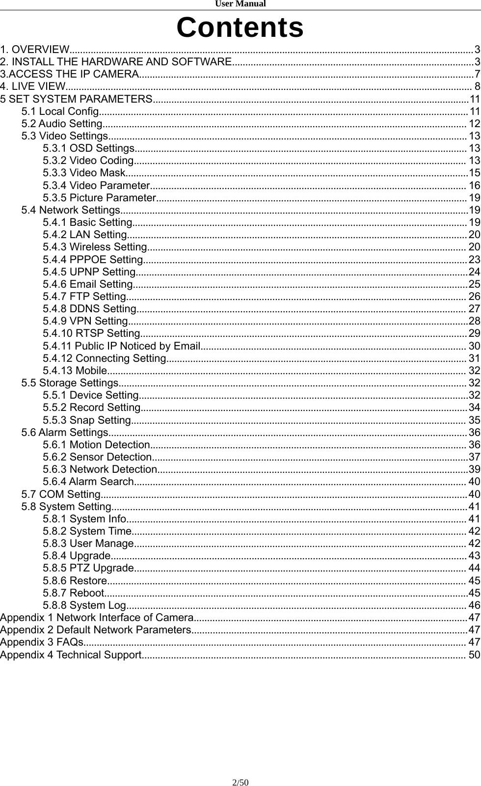
![User Manual36/505.6 Alarm Settings5.6.1 Motion DetectionFigure 38In this page, users can set features like motion detection on/off, sensitivity, detection time, linkagealarm output, alarm output duration, E-mail sending when alarm been triggered, linkagesnapping/recording, etc.NOTE:The Linkage alarm output only be available on the model that supports this function.[Motion Area Set]: Left click and drive the mouse to set the surveillance areas (4 areas at most).[All]: Set the whole video as motion detection area.[Clear]: Clear all motion detection areas.[Sensitivity]:Sensitivity range is 1~5, greater value means higher sensitivity.[Enable]:Enable or disable motion detection.[Time]:Set the period of time for motion detection, two periods allowed.[Linkage Alarm Output]: Support Email, IO output, snapshot and record.[E-mail]: Send motion detection alarm messages to users via E-mail, details about E-mail settingplease refer to [Network Settings].[IO Output]: Enable or disable alarm output.( Only available when the model support this function)[Type]: The type is NO or NC, normal open or normal close. (Only available when the modelsupport this function)](https://usermanual.wiki/Zilink-Electrical-Appliance/DHXXH/User-Guide-2871206-Page-36.png)
![User Manual37/50[Alarm Output duration]: Set the duration after being triggered (in seconds), the range of theduration is 0~86400s.0 means that there is no limit for alarm output.[Snapshot]: When alarm is triggered, the device SD card will be driven to snap pictures. Thepictures can be sent via or FTP . For snapping parameters, if the number of pictures snapped atone time is set as 10, and the snapping interval is 1 second, that means when there is an alarm,10 pictures will be snapped and the interval between each picture is 1 second.[Record]: When alarm is triggered, the device SD card will be driven to record files. The recordfiles can be saved to FTP server.[Audio Out]: (Only available when the model support this function)After setting all the parameters, click to make the parameters valid.Notice:Record file packet time equals duration of alarm add the recordtime setted in [Linkage recording].5.6.2 Sensor DetectionFigure 39NOTE: The Linkage Alarm Output only be available when the model supports this functionSet sensor alarm parameters here: Enable detect,sensor type, detect time, linkage alarm output,linkage output duration, e-mail sending when alarm has been triggered, linkagesnapping/recording etc.](https://usermanual.wiki/Zilink-Electrical-Appliance/DHXXH/User-Guide-2871206-Page-37.png)
![User Manual38/50[Enable]:Enable or disable sensor alarm detection.[Type]: NO and NC mode.[Time]: Set the period of time for sensor alarm detection, two periods allowed.[Linkage Alarm Output]: Support Email, FTP, IO output, Snapshot and Record.[E-mail]: Send sensor alarm message to users via E-mail, details about E-mail setting please referto [Network Settings].[IO Output]: Enable or disable linkage alarm output[Type]: The type is NO or NC, normal open or normal close. Only available when the modelsupports this function.[Alarm Output Duration]: Set the duration after being triggered (in seconds), the range of theduration is 0~86400s.0 means that there is no limit for alarm output.[Snapshot]: When alarm is triggered, the device SD card will be driven to snap pictures. Thepictures can be saved via E-mail sending or FTP uploading. For snapping parameters, if thenumber of pictures snapped at one time is set as 10, and the snapping interval is 1 second, thatmeans when there is an alarm, 10 pictures will be snapped and the interval between each pictureis 1 second.[Record]: When alarm is triggered, the device SD card will be driven to record files. The recordfiles can be saved to FTP server.[Audio Out]: Only available when the model support this function.After setting all the parameters, click to make the parameters valid.Notice:Record file packet time equals duration of alarm add the recordtime setted in [Linkage recording].](https://usermanual.wiki/Zilink-Electrical-Appliance/DHXXH/User-Guide-2871206-Page-38.png)
![User Manual39/505.6.3 Network DetectionFigure 40Set network failure alarm parameters here: detection on/off, linkage alarm, alarm output duration,E-mail sending when alarm has been triggered, linkage snapping/recording, etc.[Enable]: Enable or disable network failure alarm detection.[Linkage Alarm output]: Support IO output, snapshot and record.[IO Output]: Enable or disable linkage alarm output[Type]: The type is NO or NC, normal open or normal close. (Only available when the modelsupport this function)[Alarm Output Duration]: Set the duration of the linkage alarm output after being triggered (inseconds), the range of the duration is 0~86400s.0 means that there is no limit for alarm output.[Snapshot]: When alarm is triggered, the device SD card will be driven to snap pictures. Thepictures can be saved via E-mail sending or FTP uploading. For snapping parameters, if thenumber of pictures snapped at one time is set as 10, and the snapping interval is 1 second, thatmeans when there is an alarm, 10 pictures will be snapped and the interval between each pictureis 1 second.[Record]: When alarm is triggered, the device SD card will be driven to record files. The recordfiles can be saved to FTP .After setting all the parameters, click to make the parameters valid.[Audio Out]: Only available when the model support this function.Notice:](https://usermanual.wiki/Zilink-Electrical-Appliance/DHXXH/User-Guide-2871206-Page-39.png)
![User Manual40/50Record file packet time equals duration of alarm add the record time settedin [Linkage recording].When network failure occurs, E-mail sending and FTP uploading cannot beperformed, the pictures and recorded files will be stored in SD card. E-mailsending and FTP uploading will resume after network is recovered.5.6.4 Alarm SearchFigure 41Users can search the alarm information here.5.7 COM SettingFigure 42[COM Setting]: When IP camera is connected to RS485 (or RS232) communication or controldevice (e.g. PTZ decoder, dome camera), the parameters of RS485 (or RS232) need to be set](https://usermanual.wiki/Zilink-Electrical-Appliance/DHXXH/User-Guide-2871206-Page-40.png)
![User Manual41/50according to the settings of the communication control device (address, protocol, baud rate), andthe corresponding protocol need to be downloaded.Notice:Only when the parameters and protocol are correctly setthat the control of add-on communication control device can beimplemented.5.8 System Setting5.8.1 System InfoFigure 43[System]:Display device name,VO standard, Language, Device ID,version etc.[Device Name]: Users can define the device name.[VO Standard]: PAL or NTSC mode.[Language]: Users can change the device language here, once changed the device language,click save and refresh the browser to login again.[Device ID]: The ID of the device.[Version]: Firmware version.[WEB Version]: WEB UI version.After setting all the parameters, click to make the parameters valid.](https://usermanual.wiki/Zilink-Electrical-Appliance/DHXXH/User-Guide-2871206-Page-41.png)
![User Manual42/505.8.2 System TimeFigure 44[System Time]: Supports three method to upgrade the device’s time[NTP Server] : After starting the function, switch on NTP switch and select time zone, click save,the camera will send the query to NTP server, after get the message from NTP server, camera willupgrade the system time, and it will be displayed in the live view.[Synchronize with Local Computer] : After starting the function, the date and time of camera willbe synchronized with the local PC.[Set the Time Manually]:If you select this option,you can modify the time manually.After setting all the parameters, click to make the parameters valid.5.8.3 User ManageFigure 45Can set three users for every camera, one is Administrator, the others are general users.Administrator authority: can operate and set all functions and parameters of the camera.](https://usermanual.wiki/Zilink-Electrical-Appliance/DHXXH/User-Guide-2871206-Page-42.png)
![User Manual43/50General user authority:(1) can perform operations like snapping, recording, playback, talkback, monitoring, alarm clearing,log searching, zooming and full-screen reviewing;(2) Can perform operations like visit setting, image lightness and color adjustment, PTZ and lenscontrol, etc.Notice:User name and password must be 1-16-character-stringsconsisted by letters, numbers, underlines or dots. The characters are casesensitive.5.8.4 UpgradeFigure 46Click “Browse…” button, select correct file of upgrade (kernel file, suffix.uot), then click [Upgrade],the completion rate will be displayed during this process. After upgrade completes, camera willrestart automatically. Please login again to check whether the kernel edition is the upgradededition.Notice:Don’t cut off the power and internet connection while upgrading.Default user name of administrator: admin Password: adminDefault user name of general user: user 1 \user 2 Password: user 1 \user 2Note: user name and password are case sensitive](https://usermanual.wiki/Zilink-Electrical-Appliance/DHXXH/User-Guide-2871206-Page-43.png)
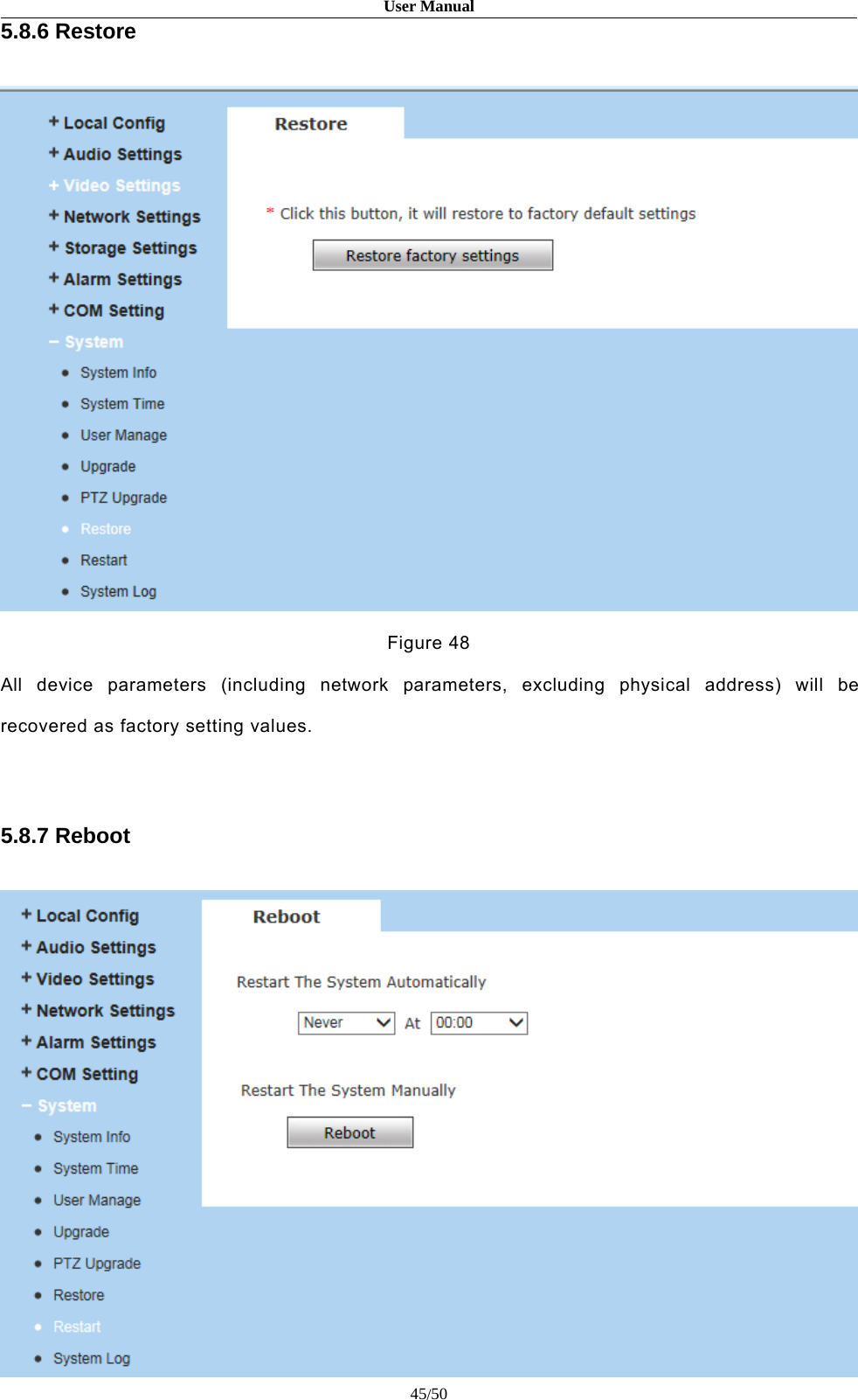
![User Manual44/505.8.5 PTZ UpgradeFigure 47[PTZ Address]: 1~255.[Protocol File]: Echo the built-in protocol name of current IP camera,PELCO-D(STD-Speed).COD as default.[Choose Upgrade File]:You can upload the decoder/dome camera communication protocolselected by yourself. The system supports hundreds of decoder/dome camera communicationprotocols, it can also be defined by yourself according to the standard format of protocols.](https://usermanual.wiki/Zilink-Electrical-Appliance/DHXXH/User-Guide-2871206-Page-44.png)
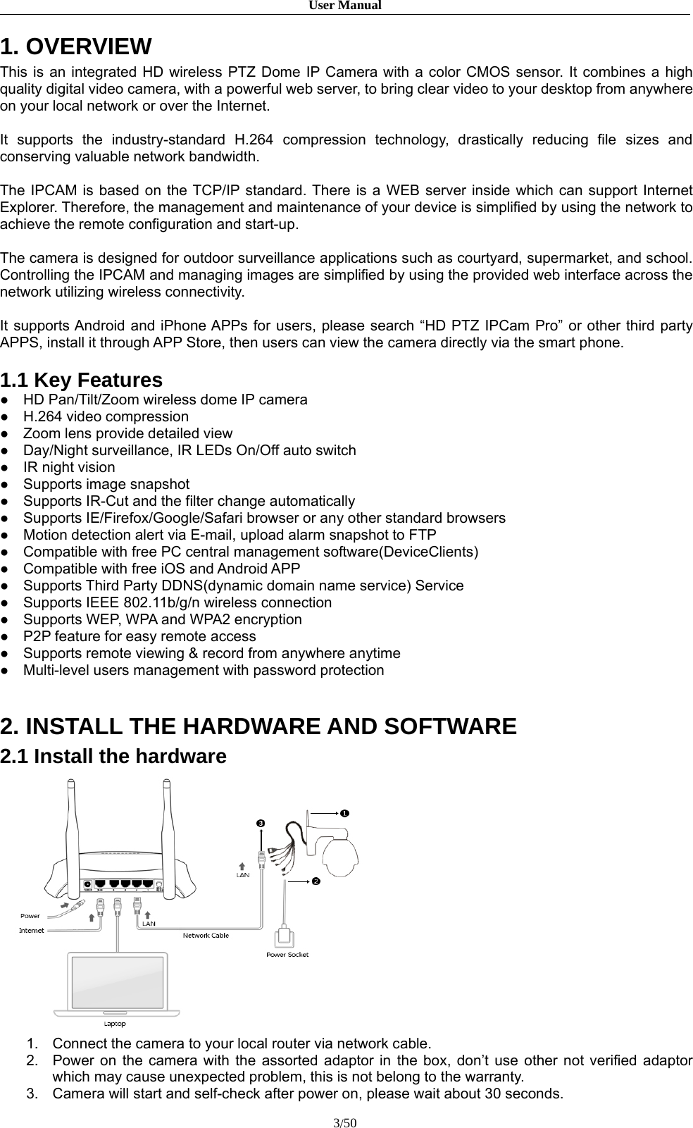
![User Manual46/50Figure 49Users can set the reboot automatically here.Click [Reboot], it will pop up a box, enter the password,the IP camera will restart.5.8.8 System LogFigure 50[Log Search]: Supports operation log and alarm log searching, the maximum capacity is 512entries of message, when the number of entries exceeds 512, system will delete records of theearliest date automatically.](https://usermanual.wiki/Zilink-Electrical-Appliance/DHXXH/User-Guide-2871206-Page-46.png)
![User Manual47/50Appendix 1 Network Interface of CameraThe default network ports:TCP80 Web port5000 Communication port, audio/video data transmission port,talkback data transmission portUDP 5000 Audio/video data transmission portMulti-cast port Multicast original port + channel numberONVIF 2000Appendix 2 Default Network ParametersDefault network parameters:Cabled Network:IP Address: 192.168.1.88 Data Port: 5000Subnet mask: 255.255.255.0 Web Port: 80Gateway: 192.168.1.1 DHCP: OffWireless Network:IP Address: 192.168.1.160 Frequency: AutoGateway: 192.168.1.1 Mode: AutoSubnet mask: 255.255.255.0Appendix 3 FAQs1、Forget PasswordSolution: There is a [RESET] button on the back panel (cable) of the IP camera, pressit 1-2 seconds, then loosen it 1-2 seconds, and try 3 times . Camera willrestore all default parameters (Factory Settings), user name and passwordare both “admin”.Notice:Please don’t press RESET if you are not a professionaloperator. After reset, all parameters will restore factory settings (except forthe physical network address).2、IP camera audio/video function fails after abnormalities or abnormal power cutoccur during upgrade, core edition is V4.0.0.0 (Backup file)Solution: Connect the power cord and network cable of IP camera, press and hold theRESET button and release it after 10 seconds, system will run the back-upprogramme automatically. After enter into the back-up programme, upgradesystem. After upgrade completes, the IP camera will work normally. Theback-up programme offers only upgrade and parameter setup functions,](https://usermanual.wiki/Zilink-Electrical-Appliance/DHXXH/User-Guide-2871206-Page-47.png)
![User Manual48/50audio and video functions are not available.3、 NovideoimagedisplayedinIEbrowserPossible reason: ActiveX not installedSolution: ActiveX must be installed when visiting IP camera for the first time viaInternet Explore.How to install: Visit IP camera, click [File], file download dialog will pop up, select [Run]or [Save] to download. Please reference the ActiveX install part to installthe ActiveX.4、 Fail to visit IP camera via IE after upgradeSolution: Delete the caching of Browser.Steps: Open IE—click “Tools”—select “Internet Options”—click “delete files” button in“Internet temporary files”, select “delete all offline contents”, then click “OK”and re-log in IP camera.5、 TheimagesdonotsmoothlyPossible reason 1: The frame rate of IP camera is too low.Solution: Increase the video frame ratePossible reason 2: Too many users are viewing the images.Solution: Block some clients or reduce the video frame rate.Possible reason 3: The bandwidth is low.Solution: Reduce video frame rate or video compression bitrate.6、 Fail to visit IP camera via IE browserPossible Reason 1: Network is disconnected.Solution: Connect your PC to network, checking whether it works properly or not.Check whether there is cable failure or network failure caused by PC virus,until PC can be connected with the command of Ping.Possible reason 2: IP Address has been occupied by other devicesSolution: Stop the connection between IP camera and Network, hook up IP camera toPC separately, reset IP address according to the proper operationsrecommended.Possible reason 3: IP addresses are in different subnets.Solution: Check IP address, subnet masking of router and the settings of Gateway.Possible reason 4: Physical address of network conflict with IP cameraSolution: modify the physical address of IP camera.Possible Reason 5: Web port has been modifiedSolution: Contact Network Administrator to obtain related information.Possible Reason 6: UnknownSolution: Press RESET to restore default settings then connect it again, the default IPaddress is 192.168.1.88, subnet mask is 255.255.255.07、 There is no sound while monitoringPossible Reason: No audio input connectionSolution: Check the audio connection.](https://usermanual.wiki/Zilink-Electrical-Appliance/DHXXH/User-Guide-2871206-Page-48.png)