Zinwave 2765 Zinwave 2765 Distributed Antenna System User Manual
Zinwave Ltd Zinwave 2765 Distributed Antenna System Users Manual
Zinwave >
Users Manual

Zinwave 2700 DAS – User Manual
Issue 1.2
April 2007
© Zinwave Ltd. 2007
Zinwave 2700
Distributed Antenna System
User Manual

Zinwave 2700 DAS – User Manual
Issue 1.2
April 2007
© Zinwave Ltd. 2007
Document History
Issue Date Changes to previous issue
1.2 03.04.2007 • Added information regarding RF exposure
1.1 27.03.2007 • Editorial changes
• Changed default IP, added description of DHCP
1.0 05.03.2007 • Initial release

Zinwave 2700 DAS – User Manual
Issue 1.2
April 2007
© Zinwave Ltd. 2007
NOTICES
© Zinwave Ltd. 2007
No part of this manual may be reproduced in any form or by any means (including
electronic storage and retrieval or translation into a foreign language) without prior
agreement and written consent from Zinwave Ltd. as governed by United Kingdom
and international copyright laws.
Edition
Issue 1.2, April 2007
Warranty
The material contained in this document is provided “as is,” and is subject to being
changed, without notice, in future editions. Further, to the maximum extent permitted
by applicable law, Zinwave disclaims all warranties, either express or implied, with
regard to this manual and any information contained herein, including but not limited to
the implied warranties of merchantability and fitness for a particular purpose. Zinwave
shall not be liable for errors or for incidental or consequential damages in connection
with the furnishing, use, or performance of this document or of any information
contained herein. Should Zinwave and the user have a separate written agreement
with warranty terms covering the material in this document that conflict with these
terms, the warranty terms in the separate agreement shall control.
Technology Licenses
The hardware and/or software described in this document are furnished under a
license and may be used or copied only in accordance with the terms of such license.
Safety Notices
CAUTION A CAUTION notice denotes a hazard. It calls attention to an operating procedure,
practice, or the like that, if not correctly performed or adhered to, could result in
damage to the product or loss of important data. Do not proceed beyond a CAUTION
notice until the indicated conditions are fully understood and met.
WARNING A WARNING notice denotes a hazard. It calls attention to an operating procedure,
practice, or the like that, if not correctly performed or adhered to, could result in
personal injury or death. Do not proceed beyond a WARNING notice until the
indicated conditions are fully understood and met.

Zinwave 2700 DAS – User Manual
Issue 1.2
April 2007
© Zinwave Ltd. 2007
Trademark Acknowledgements
Cisco ® and Aironet ® are registered trademarks of Cisco Corporation. Pentium ® is a
registered trademark of Intel Corporation. Adobe ® is a trademark of Adobe Systems
Incorporated. Windows XP, Windows 2000, and Windows 98 are U.S. registered
trademarks of Microsoft Corporation. All other trademarks are the property of their
respective holders.
About this guide
This guide contains installation and operating instructions for the Zinwave 2700
Distributed Antenna System (DAS). The basic 2700 DAS consists of one Hub Unit
(HU) and up to 8 Antenna Units (AU).
This guide is one member of a comprehensive documentation set for the Zinwave
DAS. It is designed to provide you with a smooth, successful installation and set-up. In
addition to this guide, the documentation set includes:
o Installation Guide
o System Design and Configuration (To be added later)
o Software Manual

Zinwave 2700 DAS – User Manual
Issue 1.2
April 2007
© Zinwave Ltd. 2007
TABLE OF CONTENTS
Document History 2
Edition 3
Warranty 3
Technology Licenses 3
Safety Notices 3
Trademark Acknowledgements 4
About this guide 4
Chapter 1 System Description 8
1.1
Overview 8
1.2
Key features 8
1.3
Architecture 9
1.4
System Components 11
1.5
Configuration and Control 12
Chapter 2 Quick Start 13
2.1
Overview 13
2.2
Setting up the Hub Unit 13
2.3
Setting up the Antenna Units 14
2.4
Configuring the system 15
Chapter 3 Equipment Description 17
3.1
2700 Hub Unit 17
3.2
2780/2781 SFP module 24
3.3
2760 + 2765 Antenna Unit – Wideband 27
3.4
277X Antenna Unit – Band specific 36
Chapter 4 Configuration and Control 42
4.1
Overview 42
4.2
Control via ZinConfig 42
4.3
Control via Command Line Interface (CLI) 46
Chapter 5 Get Assistance, if You Need It 54
5.1
Troubleshooting the 2700 DAS 54
5.2
Device communication problems 55
5.3
Returning the System for Service 55
5.4
Warranty repair 55
5.5
Preparing the system for shipping 55
Appendix A Safety and Regulatory Information 56
A.1
Warning and caution notices 56
A.2
General safety considerations 58
A.3
Optical Safety Precautions 58
A.4
Installation, Use and Storage 58
A.5
Signal and input power 59
Appendix B System Information 60

Zinwave 2700 DAS – User Manual
Issue 1.2
April 2007
© Zinwave Ltd. 2007
B.1
Overview 60
B.2
ZinConfig/CLI Hardware and Software Requirements 60
B.3
System specification 61
Appendix C Glossary of terms 67
C.1
Abbreviations 67

Zinwave 2700 DAS – User Manual
Issue 1.2
April 2007
© Zinwave Ltd. 2007
TABLE OF FIGURES
Figure 1-1:
Extended MMF bandwidth using the Zinwave patented technology.....8
Figure 1-2:
Schematic of a basic 8-port 2700 system. ............................................9
Figure 1-3:
Five different possibilities to distribute the input signals. ....................10
Figure 3-1:
Block diagram of the 2700 HU. ...........................................................17
Figure 3-2:
Front View of the 2700 Hub Unit.........................................................18
Figure 3-3:
Rear View of the 2700 Hub Unit. ........................................................18
Figure 3-4:
Hub Unit mounted into a 19” equipment rack. ....................................20
Figure 3-5:
Connection of the mains cable............................................................21
Figure 3-6:
Connection of the RS232 null modem and the RJ45 Ethernet cable. 22
Figure 3-7:
Connecting a pair of jumper leads from a RF transceiver. .................22
Figure 3-8:
Block diagram of the 2780/2781 SFP module. ...................................24
Figure 3-9:
Picture of fully latched SFP module. ...................................................25
Figure 3-10:
To remove the SFP pull at the de-latch bail........................................25
Figure 3-11:
Block diagram of the 2760 AU. ...........................................................27
Figure 3-12:
Block diagram of the 2765 AU. ...........................................................27
Figure 3-13:
Front view of the 2760 AU...................................................................28
Figure 3-14:
Rear view of the 2760 AU. ..................................................................29
Figure 3-15:
Front view of the 2765 AU...................................................................29
Figure 3-16:
Rear view of 2765 AU. ........................................................................30
Figure 3-17:
Mounting instructions for the 2760 AU................................................32
Figure 3-18:
Mounting instructions for the 2765 AU................................................33
Figure 3-19:
Connecting antenna cables to the 2760 AU. ......................................33
Figure 3-20:
Connecting the DC supply unit or the PoE mains adaptor. ................34
Figure 3-21:
Block diagram of the 277X AU. ...........................................................36
Figure 3-22:
Front view of the 277X AU. .................................................................37
Figure 3-23:
Connecting the RF jumper leads on the 277X AU. .............................38
Figure 3-24:
Connecting the antenna cable to the 277X AU...................................39
Figure 3-25:
Connecting the fiber-optic cable to the 277X AU. ...............................40
Figure 3-26:
Connecting the power supply cable to the 277X AU. .........................41
Figure 4-1:
Select the IP range and the access community..................................43
Figure 4-2:
Selecting the HU. ................................................................................43
Figure 4-3:
Buttons for discovering AUs and updating values. .............................43
Figure 4-4:
Schematic of the HU distribution and attenuation circuit ....................44
Figure 4-5:
Enabling the optical ports....................................................................45
Figure 4-6:
Changing the AU attenuators..............................................................45
Figure 4-7:
Reading out alarms on the optical link. ...............................................46
Figure 4-8:
Alarm description. ...............................................................................46
Figure 4-9:
Required connections for local and remote control of the 2700 DAS. 47
Figure 4-10
Open a new HyperTerminal session...................................................47
Figure 4-11:
Identify the serial port on your computer.............................................48
Figure 4-12:
Adjust the serial port settings. .............................................................48
Figure 4-13:
Serial connection via Telnet. ...............................................................49
Zinwave 2700 DAS – User Manual
Issue 1.2
April 2007
© Zinwave Ltd. 2007
Chapter 1
System Description
1.1 Overview
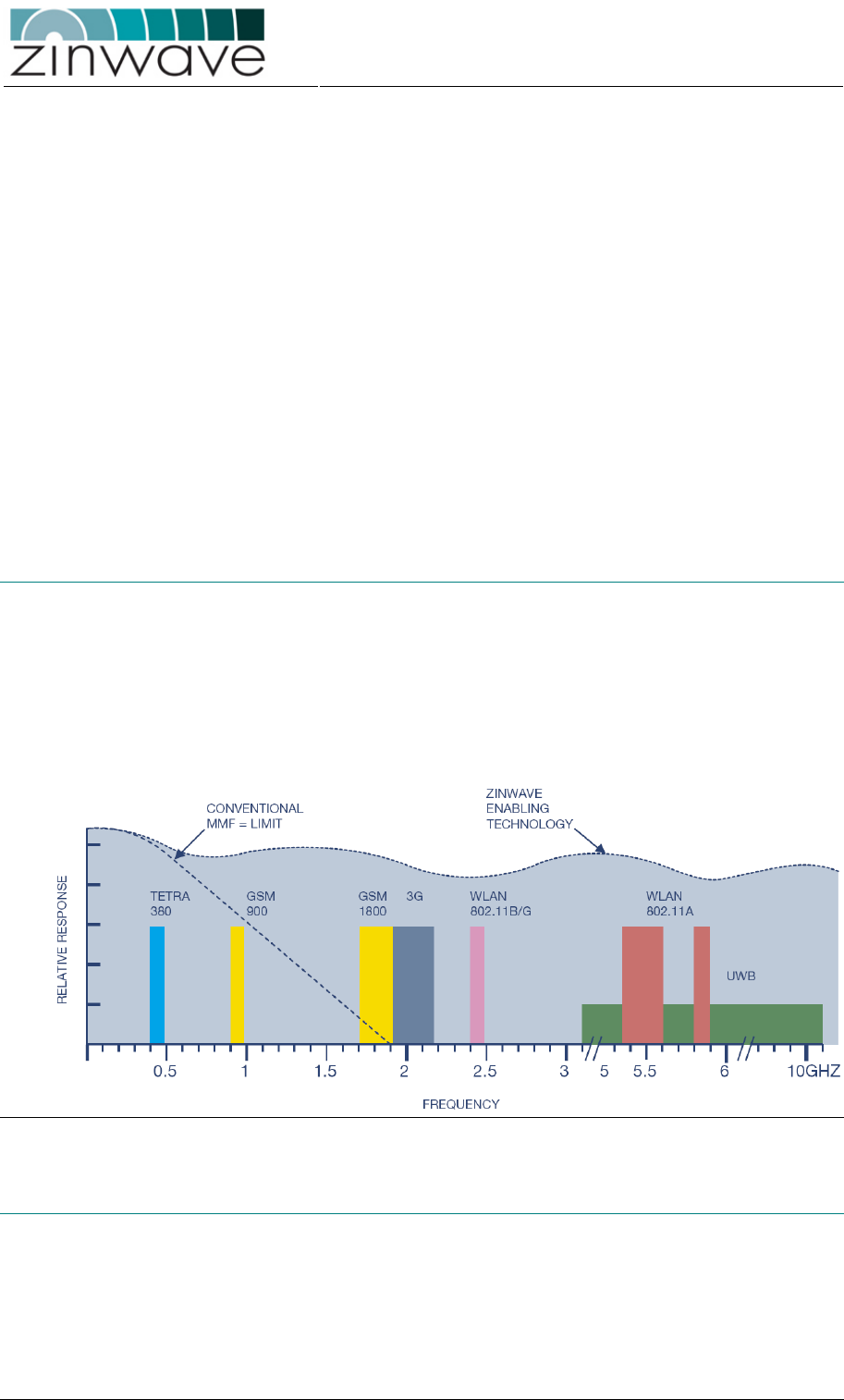
The Zinwave 2700 Distributed Antenna System (DAS) is a simple two-stage fiber-optic
solution comprising a centrally located Hub Unit (HU) and distributed Antenna Units
(AU). The Zinwave 2700 DAS is at present the only available system which provides a
truly wideband solution utilizing multimode fiber (MMF). Zinwave’s technology
approach allows the bandwidth of in situ MMF optic cables to be extended sufficiently
to conduct multiple radio frequency signals, at original carrier frequency, over long
distances.
Figure 1-1: Extended MMF bandwidth using the Zinwave patented technology.
1.2 Key features
o Simple two-stage fiber-optic DAS: one Hub Unit (HU) distributes to eight
Antenna Units (AU)
o Wide frequency range: 370 – 2500 MHz
o Only system to deliver truly broadband solution over multimode fiber (MMF)
o Minimum supported distance of 550 m over OM1, OM2 and OM3 type MMF, in
excess of building wiring standard
Zinwave 2700 DAS – User Manual
Issue 1.2
April 2007
© Zinwave Ltd. 2007
o Minimum supported distance of 2000 m over standard SMF
o Dynamically configurable RF signal distribution
o Electronically adjustable signal levels without the need of manual handling
o Hot-pluggable optical transceivers used in HU
o SNMP and CLI based network management
1.3 Architecture
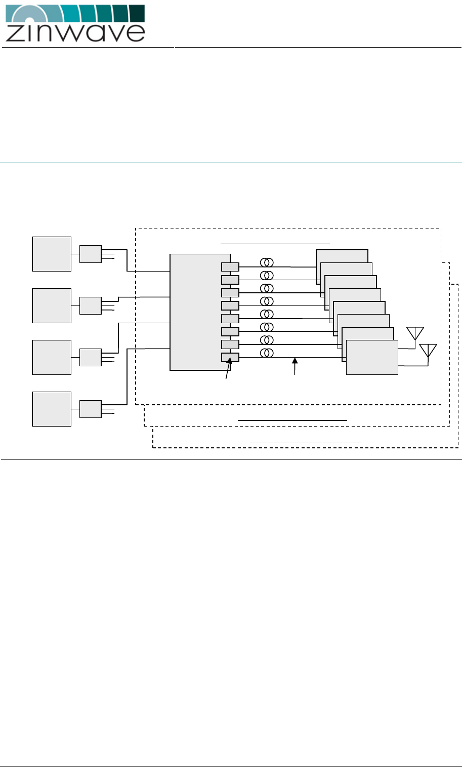
The 2700 DAS system is built from several basic 8-port systems. Each basic 8-port
system comprises one 2700 HU and up to eight AU. The AU can be wideband (276X
series), band-selective (277X series) or a combination of the two.
Figure 1-2: Schematic of a basic 8-port 2700 system.
Each basic 8-port system can be connected to four radio transceivers (e.g. BTS, BDA,
WLAN access point). The connections are made via simplex connectors. Duplex
connections can be realized through the use of external duplexers. The I/O ports are
wideband and accept signals operating in the range 370 – 2500 MHz.
The HU is equipped with eight ports which accept analogue optical transceivers in the
small form pluggable (SFP) form factor. While following the industry standard, these
analogue SFP transceivers are proprietary to Zinwave. Ports which are not connected
to an AU do not have to be equipped with an SFP module.
The SFP modules are connected to the AU via the optical fiber plant. The maximum
optical link length for MMF is at least 550 m, provided that a special Zinwave patch-
cord is used to connect SFP and AU to the fiber plant.
In the AU the signals in both the uplink and the downlink are amplified, however
without applying any complex signal processing. In the downlink direction the
amplification is required to compensate for the electrical-to-optical (E/O) and optical-
to-electrical (O/E) conversion losses as well as fiber attenuation. In the uplink direction
the amplification is used to optimize the dynamic range of the system. The wideband
AUs (276X series) are equipped with two simplex antenna connectors while the band-
selective AUs (277X series) are equipped with a single duplex antenna connector.
HU
AU
SFP
MMF
(50µm or 62.µm)
I/O 1
I/O 2
I/O 3
I/O 4
Basic 8-port System (1)
Radio
TRX
Radio
TRX
Radio
TRX
Radio
TRX
1:n
1:n
1:n
1:n
Basic 8-port System (2)
Basic 8-port System (n)
Zinwave 2700 DAS – User Manual
Issue 1.2
April 2007
© Zinwave Ltd. 2007
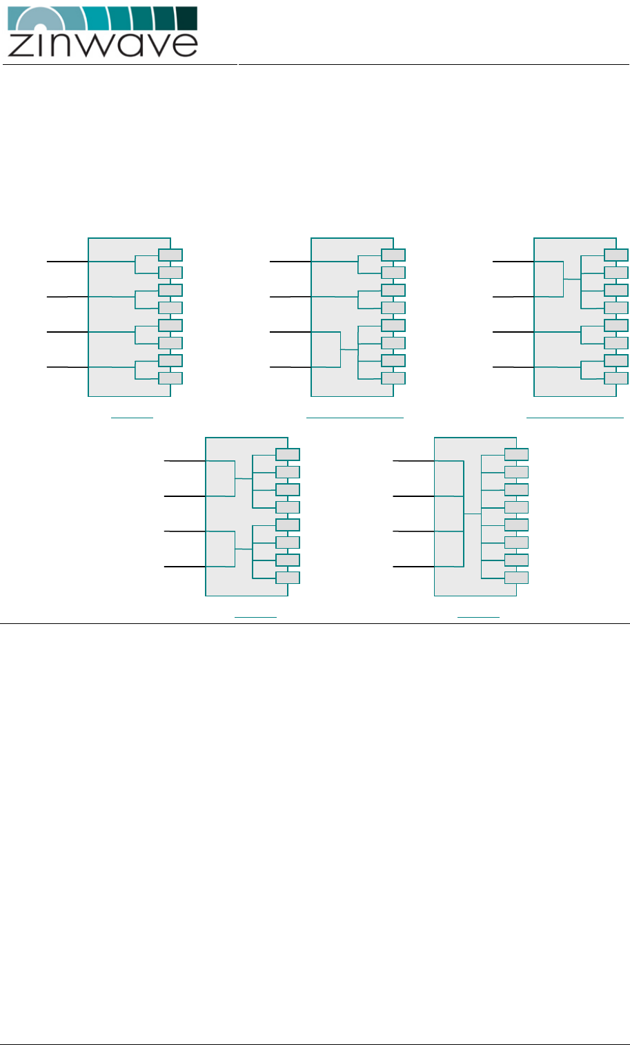
1.3.1 RF Signal Distribution
In the HU a RF signal distribution circuitry is implemented which gives the flexibility to
dynamically adjust the routing of radio transceivers to AU. In its default configuration
the HU routes each electrical I/O port to two adjacent optical ports. By enabling a set
of switches in the circuitry this distribution can be changed to simultaneously route two
electrical I/O ports to four optical ports or to route all four electrical I/O ports to all eight
optical ports.
Figure 1-3: Five different possibilities to distribute the input signals.
1.3.2 Signal Level Control
The Zinwave 2700 DAS implements a two-stage attenuator based approach to signal
level control. All attenuators are electronically switched and do not require manual
handling.
A first set of attenuators is situated in the HU right at the electrical I/O ports. These
attenuators are intended to balance signal power of different services such that each
service covers the same area. A high frequency signal, such as UMTS or WLAN for
example, requires more RF power than a PMR or GSM900 signal for the same
coverage area. In addition these attenuators allow the HU to be connected to a range
of radio transceivers with different output power values. A similar attenuator is
provided in the uplink path which can be adjusted to establish link balance between
the uplink and the downlink of the DAS.
A second set of attenuators is situated in the AU. These attenuators are intended to
adjust the cell size of the specific AU and to compensate for different optical loss
values. In the uplink direction the attenuator is used to trade-off cell size and minimum
coupling loss (MCL).
HU
I/O 1
I/O 2
I/O 3
I/O 4
HU
I/O 1
I/O 2
I/O 3
I/O 4
HU
I/O 1
I/O 2
I/O 3
I/O 4
HU
I/O 1
I/O 2
I/O 3
I/O 4
HU
I/O 1
I/O 2
I/O 3
I/O 4
4 × 1:2 2 × 1:2 / 1 × 2:4
1 × 2:4 / 2 × 1:2
2 × 2:4 1 × 4:8

Zinwave 2700 DAS – User Manual
Issue 1.2
April 2007
© Zinwave Ltd. 2007
1.3.3 AU Remote Setup
To simplify installation and maintenance and to enhance security, all AU are controlled
remotely via the HU. This includes setting attenuator values, enabling or disabling
overload protection and reading status and alarm information. Each AU can be
addressed individually. The required routing information for this is obtained by
following the setup-procedure after all units are connected.
1.4 System Components
The Zinwave 2700 DAS consists of HU, SFP modules and wideband or band-selective
AU. Apart from the band-selective AU all components cover the frequency range
370 – 2500 MHz.
1.4.1 Hub Unit (2700)
The Zinwave 2700 HU is a 1U high 19” rack mountable device which distributes four
electrical ports to eight SFP ports. The connection to each of the four possible radio
transceivers is via two simplex RF connectors (female SMA type) located at the back
of the unit. The eight optical ports can be equipped with the Zinwave 2780 SFP optical
transceivers. These transceivers are hot-pluggable.
The HU features a series of LED indicators on the front of the unit, indicating the
status of each optical link and of the whole system. Control and network management
is performed via an SNMP based GUI or via a Command Line Interface (CLI) through
a direct serial (RS232) connection. The HU also acts as a master device when
remotely configuring the attached AU.
1.4.2 SFP optical transceiver (278X)
The Zinwave 278X SFP optical transceiver comprises a directly modulated DFB laser
diode operating at a wavelength of 1.3 µm and a PIN photodiode which is capable of
detecting light at this wavelength. In addition a control circuitry is implemented which
is used for bias control, temperature compensation and status and alarm reporting.
The SFP module can be used to connect to both single mode fiber (SMF) and
multimode fiber (MMF).
The SFP module is designed to the mechanical dimensions specified in the SFP-MSA.
An electronic circuitry ensures that no damage occurs when mistakenly plugging a
digital SFP transceiver into one of the Zinwave SFP ports and vice versa. The SFP is
equipped with an LC duplex connector which requires only half the foot-print of the
traditionally used SC connector.
1.4.3 Wideband Antenna Units (276X series)
The Zinwave 276X series of wideband AU amplify the received optical (downlink) and
wireless (uplink) signals and perform the electrical-optical conversion. The units are
designed to operate in the frequency range 370 – 2500 MHz.
The 2760 AU is equipped with a SFP port which is populated with a 2781 SFP
module.
The 2765 AU has integrated optics connected to a SC duplex connector on the front
panel. Because of the very wide bandwidth of the unit, the AU features two simplex
electrical antenna connectors (female SMA type), one for uplink and one for downlink.
It is recommended that patch antennas are used with this class of AU. These units are
not intended to be connected to omni-directional antennas as they do not provide
sufficient transmit-receive isolation.
The wideband AU are powered via PoE (power over Ethernet) according to the IEEE
802.3af standard. Configuration of the AU is remotely via a 2700 HU. The 276X series
AU are intended for mounting to a wall or a ceiling.

Zinwave 2700 DAS – User Manual
Issue 1.2
April 2007
© Zinwave Ltd. 2007
Table 1-1: 276X wideband Antenna Units.
PN Product description Max. Output power (composite)
2760 Wideband (370 – 2500 MHz) + 6 dBm
2765 Wideband (370 – 2500 MHz) + 12 dBm
1.4.4 Band-selective Antenna Units (277X series)
The Zinwave 277X series of band-selective AU are designed to operate at certain
combinations of frequency bands only. The 277X AU comprise a 276X wideband AU
together with a single-, dual- or tri-band duplexer. The optical interface is identical to
that of the 276X series AU. However, the 277X AU features only one duplex electrical
antenna connector (female N-type).
Because of the filtering performed in the duplexer, the 277X series AU can be
operated at higher composite powers than the 276X series AU and they also support
installations with omni-directional antennas.
The band-selective AUs are powered via PoE (power over Ethernet) according to the
IEEE 802.3af standard. Configuration of the AU is remotely via a 2700 HU. The 277X
series AUs are intended for mounting to a wall, a ceiling or into a 19” rack.
Table 1-2: 277X band selective Antenna Units.
PN Product description Max Output power (composite)
2776 GSM850 & PCS 1900 (US) + 18 dBm GSM / + 15 dBm WCDMA & CDMA
2777 GSM900 & UMTS (Europe) + 18 dBm GSM / + 15 dBm WCDMA & CDMA
2778 DCS1800 & UMTS (Europe) + 18 dBm GSM / + 15 dBm WCDMA & CDMA
1.5 Configuration and Control
The 2700DAS can be remotely controlled via an Ethernet interface or locally via a
serial RS232 connection on the Hub Unit. The Ethernet interface supports DHCP. The
AUs are controlled through the HU interface. All settings on the system area
configured through one of these interfaces, there are no manual controls on the 2700
DAS. In addition alarm and status information on a range of system parameters can
be obtained and monitored.
The remote control supports SNMP V2.0. The application ZinConfig provides a
graphical user interface (GUI) for the control via the Ethernet Interface.
The local command line interface (CLI) can be accessed using a terminal application
such as HyperTerminal on a MS Windows based computer. Connection is via a 9 pin
null- modem.

Zinwave 2700 DAS – User Manual
Issue 1.2
April 2007
© Zinwave Ltd. 2007
Chapter 2
Quick Start
2.1 Overview
This chapter provides a brief overview over the steps required to setup a Zinwave
2700 DAS. For a more detailed description of each step please refer to the relevant
section of this user guide.
2.2 Setting up the Hub Unit
2.2.1 Mount the Hub
o Mount the HU in a 19” equipment rack using the provided
rack-mounting brackets and screws. Alternatively the HU
can be shelf-mounted using the provided rubber feet.
section 3.1.4.1
2.2.2 Connect the Hub
2.2.2.1 RF
o Connect up to four RF signal sources (BTS, BDA,
repeater, or WLAN access point) to the RF ports located
on the back of the HU. Each RF port has two simplex
SMA-female connectors, one for downlink and one for
uplink. When connecting an RF signal source equipped
with a duplex connector, a diplexer or circulator is required
to separate uplink and downlink signals. When setting up a
larger system consisting of several basic 2700 DAS, a
splitter is required to feed the RF signals into each HU.
section 3.1.4.4
2.2.2.2 Power and Control
o Make sure that the ON/OFF switch is in the OFF (O)
position. Connect the AC power cord to the HU. Plug the
AC power cord into an outlet providing AC power (110-230
V, 50-60 Hz).
section 3.1.4.2
o For local control connect an RS232 null-modem from a
computer running a RS232 terminal (e.g. Microsoft
section 3.1.4.3

Zinwave 2700 DAS – User Manual
Issue 1.2
April 2007
© Zinwave Ltd. 2007
HyperTerminal) to the serial port (9-pin dub-D) of the HU.
If no RS232 terminal is available a local connection can be
established by directly connecting an Ethernet Cross-Over
cable from a laptop/computer to the Ethernet port of the
HU.
o For remote control connect an RJ45 patch-lead from a
spare outlet of your LAN to the Ethernet port of the HU.
Section 3.1.4.3
2.2.2.3 Optical Fiber
Section 3.2.4
o Insert the required number of SFP modules into the SFP
ports on the HU. Push the module firmly into the SFP port
to ensure that it is fully latched.
o Connect the Zinwave fiber-optic patch-lead from the patch-
panel of your fiber distribution to the SFP, making sure that
both sides of the duplex connector are fully latched. The
connector labeled “Equipment” connects to the HU, the
connector labeled “Infrastructure” connects to the fiber
distribution.
o When using MMF, ensure that the patch-leads are of the
same MMF type (i.e. OM1, OM2 or OM3) as your fiber
infrastructure
2.3 Setting up the Antenna Units
2.3.1 Mount the Antennas
o Mount the antennas according to your system design plan
following the manufacturer guidelines
section 3.3.4.1
section 3.4.4.1
2.3.2 Mount the Antenna Unit
o Mount the 276X wideband AU to the ceiling or the wall in
the locations identified in your system design plan using
the provided brackets and screws.
section 3.3.4.2
section 3.3.4.3
o Mount the 277X band-selective AUs either to a ceiling/wall
or in a 19” equipment rack using the optionally available
rack-mounting set.
section 3.4.4.2
o Make sure to allow enough clearance for the minimum
bend radius of the coaxial and fiber cables.
2.3.3 Connect the Antenna Unit
2.3.3.1 RF
o Connect the antennas (for the 276X AU) / antenna (for the
277X AU) to the AU using the shortest possible length of
coaxial cable. Excessive cable lengths will affect the
system performance.
section 3.3.4.4
section 3.4.4.3
2.3.3.2 Power
section 3.3.4.5
section 3.4.4.5
o Connect the mains cable of the Power-over-Ethernet PoE
adaptor into an outlet providing AC power (110-230 V, 50-

Zinwave 2700 DAS – User Manual
Issue 1.2
April 2007
© Zinwave Ltd. 2007
60 Hz). A green LED on the PoE adaptor will illuminate.
o Connect the PoE adaptor (the port labeled “To
Equipment”) to the RJ45 connector on the AU using a
Cat5 Ethernet cable no longer than 100m. On powering up
the green LED indicators on the RJ45 connector will
illuminate.
o 2760 only: Alternatively the AU can be powered using the
optional 48V mains adaptor. Do not connect both types of
power adaptors to the AU at the same time as this may
cause permanent damage to the unit.
2.3.3.3 Optical Fiber
section 3.4.4.4
o 2760 AU only: Insert the SFP module into the SFP port on
the AU. Push the module firmly into the SFP port to ensure
that it is fully latched.
o Connect the Zinwave fiber-optic patch-lead from the patch-
panel of your fiber distribution to the SFP, making sure that
both sides of the duplex connector are fully latched. The
connector labeled “Equipment” connects to the HU, the
connector labeled “Infrastructure” connects to the fiber
distribution.
o When using MMF, ensure that the patch-leads are of the
same MMF type (i.e. OM1, OM2 or OM3) as your fiber
infrastructure
2.4 Configuring the system
2.4.1 Configure the network interface of the HU
o Connect to the HU through the RS232 interface using the
following settings for the serial port:
→ 19200 Baud, 8 Data Bits, 1 Stop Bit, No Parity and no
flow control.
section 4.3.1
o If the default network interface settings do not match your
network configuration, change the IP address, the subnet
mask and the gateway address of the network port using
the following command line interface (CLI) commands.
Each command is terminated by a carriage return.
→ config ip <xxx.xxx.xxx.xxx>
→ config netmask <xxx.xxx.xxx.xxx>
→ config gateway <xxx.xxx.xxx.xxx>
section 4.3.3.2
section 4.3.4.1
o Reboot the HU using the following CLI command:
→ reboot
2.4.2 Install the ZinConfig utility tool
o Place the installation CD in your CD drive. If the installer
does not start automatically, open a Windows File Explorer
window, and double-click on readme.htm
section 4.2.1

Zinwave 2700 DAS – User Manual
Issue 1.2
April 2007
© Zinwave Ltd. 2007
2.4.3 Use the ZinConfig utility tool
o To launch ZinConfig double click on the desk top icon or
click Start >Programs >Zinwave->ZinConfig
section 4.2.2
o The default community for read/write access is “private”,
for read-only access is “public”. These are configured
through the CLI.
section 4.3.4.2
o Specify the IP address range (Start IP address / End IP
address) of your attached Hub Units and press “Find
Hubs” to load them into ZinConfig.
section 4.2.3
o Select the HU which you wish to configure (and the AUs
attached to it).
o Press “Discover AUs” to associate the connected AUs to
the HU
section 4.2.4
o Adjust the HU signal distribution, the HU gain settings and
the AU gain settings according to you r system design.
section 4.2.6
section 4.2.7
Zinwave 2700 DAS – User Manual
Issue 1.2
April 2007
© Zinwave Ltd. 2007
Chapter 3
Equipment Description
3.1 2700 Hub Unit
3.1.1 Overview
The HU is a 1U high rack or shelf mountable device with four RF input ports (each port
has two simplex connectors, 1 for downlink and 1 for uplink). The signals are routed
from the RF I/O ports to 8 SFP ports through a dynamically configurable distribution
circuit. In addition the signal amplitudes can be adjusted using 8 controllable
attenuators (4 in the downlink and 4 in the uplink direction). A block diagram of the HU
is shown in Figure 3-1.
Figure 3-1: Block diagram of the 2700 HU.
3.1.2 Dimensions and Weight
Dimensions and weight of the HU are listed in Table 3-1. These are for a HU not
populated with SFP modules and without the rack mounting brackets attached.
SFP Ports Attenuators Distribution
RF port 1
RF port 2
RF port 3
RF port 4
SFP port 1
SFP port 2
SFP port 3
SFP port 4
SFP port 5
SFP port 6
SFP port 7
SFP port 8
Zinwave 2700 DAS – User Manual
Issue 1.2
April 2007
© Zinwave Ltd. 2007
Table 3-1: Dimensions and weight of the 2700 HU.
Parameter Value Unit
Height 4.4 (1.8) cm (inch)
Width 44.5 (17.8) cm (inch)
Depth 27.0 (10.6) cm (inch)
Weight 3.5 kg
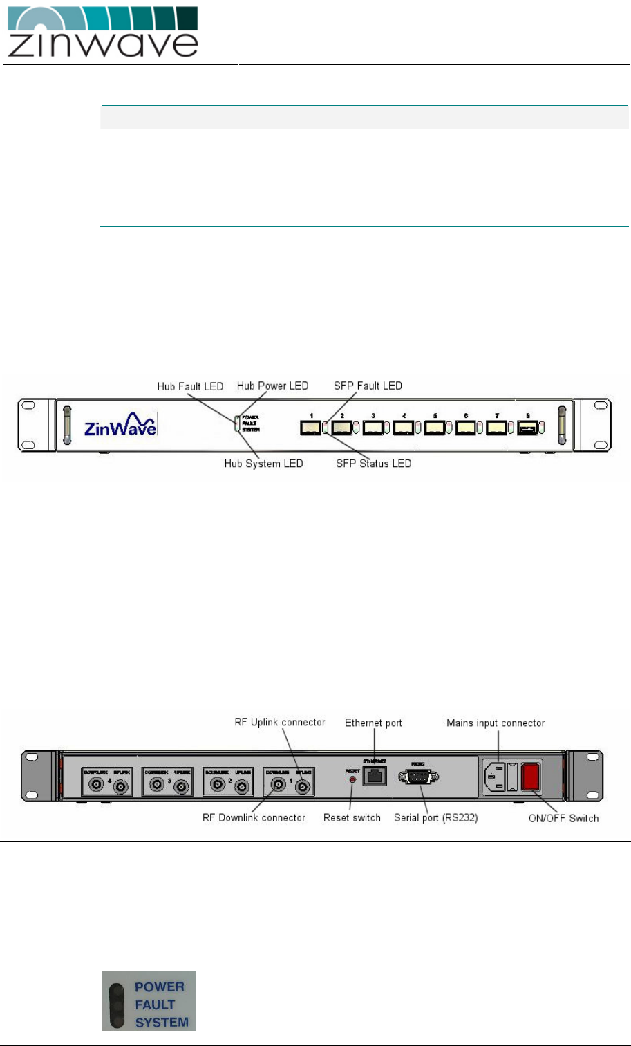
3.1.3 Connection panels and LED indicators
A drawing of the front view is shown in Figure 3-2. The front panel of the HU contains
o 8 SFP ports for the 2780 SFP modules
o Hub + System LED indicators for status information and alarms.
o SFP port LED indicators
Figure 3-2: Front View of the 2700 Hub Unit.
A drawing of the rear view is shown in Figure 3-3. The back panel of the HU contains
o 8 SMA-female RF connectors (4 × downlink / 4 × uplink)
o RJ45 Ethernet port
o RS232 Serial port (9 pin sub-D)
o Mains input connector
o Fuse drawer
o ON/OFF switch
o Reset switch
Figure 3-3: Rear View of the 2700 Hub Unit.
Following is a description of all interfaces and LED indicators of the 2700 HU.
Hub + System LED indicators
Hub Power LED indicates the power status of the HU
(see
Table 3-2)
Hub Fault LED indicates a fault in the HU (see Table 3-2)
Zinwave 2700 DAS – User Manual
Issue 1.2
April 2007
© Zinwave Ltd. 2007
System Status LED Indicates the status of the 2700 DAS
(see
Table 3-2)
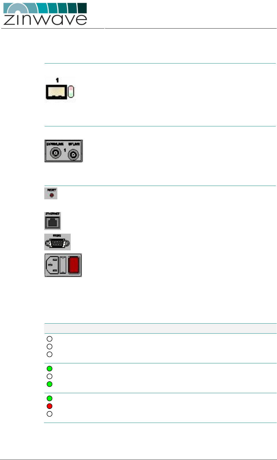
SFP ports and LED indicators
SFP port
8 SFP ports which can be individually
populated with the Zinwave 2780 SFP module.
SFP Fault LED indicates a fault in the fiber-
optic link or a fault
in the attached AU (see Table 3-3)
SFP Status LED Indicates the status of the SFP port (see
Table
3-3)
RF ports
RF Uplink 4 simplex SMA-female connectors (
labeled 1 to
4) located at the rear of the HU to connect to
the RX port of a radio TXR.
RF Downlink 4 simplex SMA-female connectors (
labeled 1 to
4) located at the rear of the HU to connect to
the TX port of a radio TRX.
Control and Power
Reset switch
Can be used to reset the HU to the factory
default state (refer to Table 4-4
for a list of all
default settings)
RJ45 Ethernet port Connects t
o a local area network (LAN) for
remote control and management of the system
9-pin sub-D
connector
For local control of the system
via a RS232
null-modem cable.
Mains input
connector
IEC connector to mains (110-240V, 50-
60)
including fuse tray for 2 × 2A fuses
ON/OFF switch (O) indicates OFF state, (I) indicates ON state
Table 3-2 lists the possible indications of the Hub and system LEDs. A description of
the SFP port indicators on is provided in Table 3-3.
Table 3-2: Description of Hub + System LED indicators.
LED indicators Description
No power to unit
Unit operational
Fault (see section 5.1.1)
Power
Fault
System
Power
Fault
System
Power
Fault
System
Zinwave 2700 DAS – User Manual
Issue 1.2
April 2007
© Zinwave Ltd. 2007
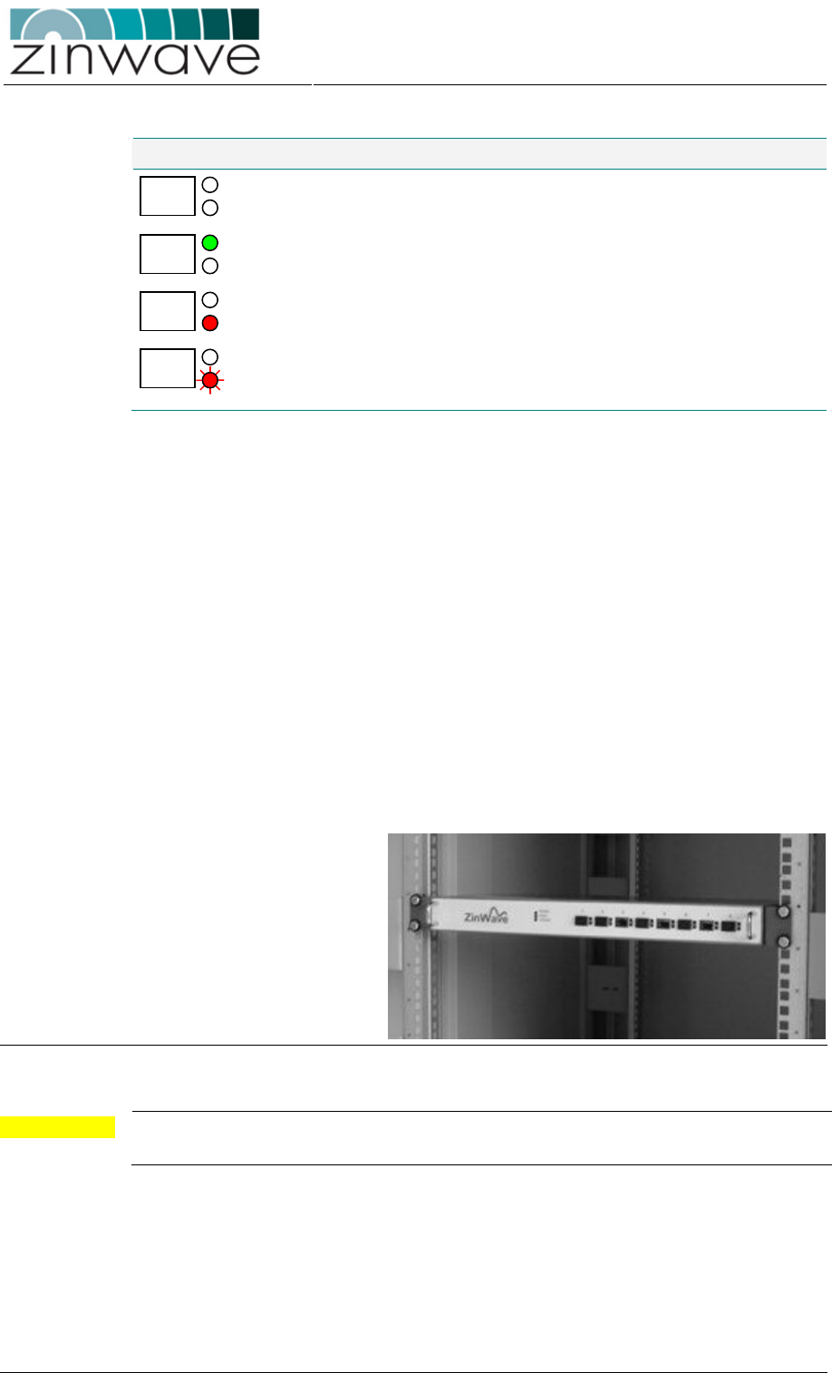
Table 3-3: Description of SFP port LED indicators.
LED indicators Description
No SFP in port or
SFP disabled
Port operational
A fault has occurred on the optical link or the attached AU
(see
section 5.1.2)
blinking
Communication to AU is active
3.1.4 Installation
3.1.4.1 Mounting the Unit
The HU package should contain the following items:
o 1 × Hub Unit
o 2 × 19” rack mounting brackets (including screws)
o 4 × M6 screws for rack-mounting
o 4 × Rubber feet for shelf mount
o 1 × IEC mains cable
The HU can be mounted into a standard 19” equipment rack using the supplied rack
mounting brackets. Mount the Hub onto the rack in the assigned equipment cabinet
using the four screws supplied (Figure 3-4). If the Hub is shelf mounted ensure that
the rubber feet supplied are in place to prevent blocking the ventilation holes on the
underside.
Figure 3-4: Hub Unit mounted into a 19” equipment rack.
CAUTION For sufficient air circulation, ensure a top and bottom clearance of 25 mm (1 “) to any
other equipment.
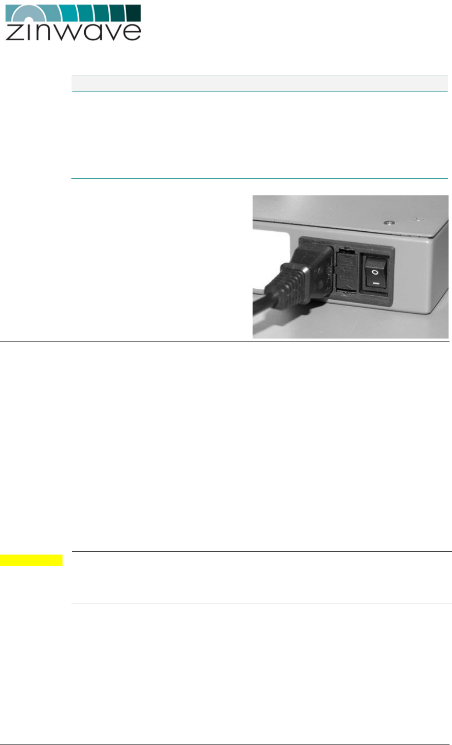
3.1.4.2 Connecting the mains cable
The specifications of the power supply unit (PSU) of the HU are listed in Table 3-4.
Ensure that the ON/OFF switch is in the OFF (O) position before connecting the IEC
mains cable to the Hub (Figure 3-5). Plug the mains cable into an outlet providing AC
power with a voltage of 100 – 240 VAC and a frequency of 47 – 63 Hz.
Zinwave 2700 DAS – User Manual
Issue 1.2
April 2007
© Zinwave Ltd. 2007
Table 3-4: Power supply unit (PSU) parameters.
Parameter Min Typical Max Unit Comment
Input voltage 100 240 VAC
Input Frequency 47 63 Hz
Fuse 2 A Anti-surge
Current consumption
220 mA
Power consumption 15 W
Figure 3-5: Connection of the mains cable.
3.1.4.3 Connecting the control cables
The 2700 DAS can be controlled locally via the serial port or remotely via the network
interface (Figure 3-6). For details on controlling the 2700 DAS refer Chapter 4 of this
guide. To attach the required cables to the Hub Unit follow these steps:
o Serial Port: The serial interface connector is a 9 pin sub-D male connector. To
connect the HU directly to a computer, use a RS 232 null modem. Connect the
RS232 cable to the serial connector, hand tightening the screws to prevent the
connector from loosening.
o Ethernet Port: Connect the Ethernet port of the HU to your network using a
RJ45 category 5e patch cable. For further details on how to configure the
network interface refer to section 4.3.4.1 of this guide.
CAUTION Before connecting the Ethernet port of the hub unit make sure that the network
parameters (IP address, subnet mask, and gateway) on the HU are properly set.
Failure to do so may affect the performance of the network. Contact your network
administrator if necessary, for valid parameters.
Zinwave 2700 DAS – User Manual
Issue 1.2
April 2007
© Zinwave Ltd. 2007
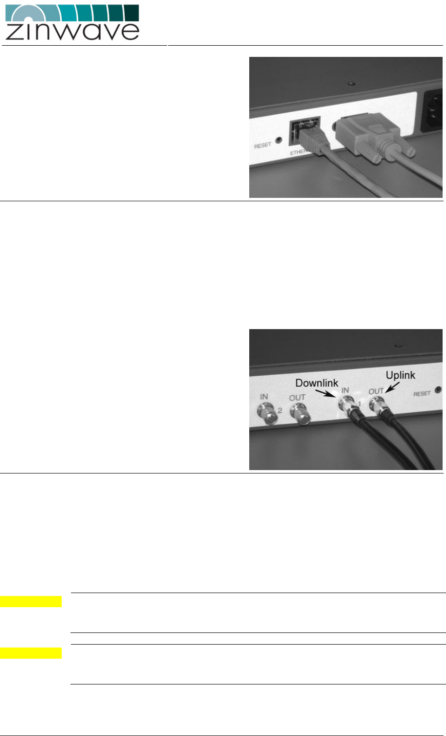
Figure 3-6: Connection of the RS232 null modem and the RJ45 Ethernet cable.
3.1.4.4 Connecting the RF transceiver
Connection of the RF signal sources (e.g. BDA, BTS, WLAN access point) is via a pair
of simplex SMF-female connectors per RF port. The ports are labeled 1 to 4 for
connecting up to four RF transceivers. Connect the ports labeled “IN” to the transmit
port of the RF transceiver (= downlink). Connect the ports labeled “OUT” to the
receive ports of the RF transceivers (= uplink).
Figure 3-7: Connecting a pair of jumper leads from a RF transceiver.
As the 2700 DAS is a broadband system, the connections to the RF transceivers are
via simplex connectors. In cases where the RF transceiver has a common duplex
connector for uplink and downlink the signals traveling in opposite direction need to be
separated. This is done with an external duplexer or circulator.
For a larger system with more than eight AU, the RF signals have to be routed to
several hubs. This is achieved by inserting a passive splitting/combining circuitry.
CAUTION When connecting to the SMA connector on the Hub, DO NOT over tighten the
connector. Use a dedicated torque wrench pre-set to 0.8 to 1.1 Nm. If a torque wrench
is not available, firmly hand-tightening the connector is adequate.
CAUTION In the US and Canada, only the use of the Cisco® Aironet ®1200 WLAN access point
(Model AIR-AP1231-A-K9) is approved for connection to the 2700 Hub Unit for
providing WLAN services.

Zinwave 2700 DAS – User Manual
Issue 1.2
April 2007
© Zinwave Ltd. 2007
NOTE Termination of the unused RF ports with a 50Ω load is not necessary. It is however
recommended to set all gain control settings of the unused ports to maximum
attenuation (refer to section 4.2.6.1 of this guide for directions on how to do this).
3.1.5 Environmental
The environmental specifications of the HU for operation and storage are listed in
Table 3-5.
Table 3-5: Environmental specifications of 2700 HU.
Parameter Min Typical Max Unit
Temperature - Operating 0 +55 °C
Temperature - Storage -25 +55 °C
Relative Humidity (non-condensing) 10 95 %
Zinwave 2700 DAS – User Manual
Issue 1.2
April 2007
© Zinwave Ltd. 2007
3.2 2780/2781 SFP module
3.2.1 Overview
The 2780/2781 small form-factor pluggable (SFP) modules are broadband
components (350-2700MHz) converting electrical to optical signals (Transmit) and
optical to electrical signals (Receive). A block diagram of the SFP module is shown in
Figure 3-8.
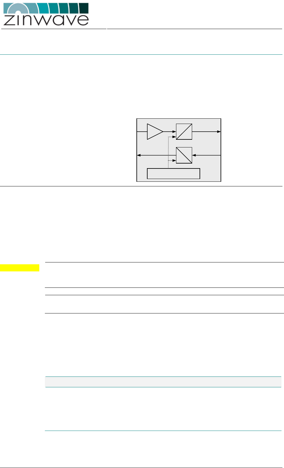
Figure 3-8: Block diagram of the 2780/2781 SFP module.
The electrical input signal is amplified before it is modulated onto the optical carrier
wave. The optical input signal is directly routed to the electrical connector. A micro
controller is included for control and monitoring purpose.
The 2780 SFP is designed to be used in the 2700 Hub Unit. The 2781 SFP is
designed to be used in the 2760 Antenna Unit. While the modules are identical in their
design they differ in the rated operating temperature range.
CAUTION Electrostatic discharge (ESD) preventative measures (i.e. wrist straps, use of ESD
protective bags) should be taken when storing, transporting and handling SFPs as
voltages in excess of 50V can cause damage to the device.
NOTE The 2780 and 2781 SFP have an identical form factor. Make sure to insert the 2780
only in the 2700 HU and the 2781 only in the 2760 AU.
3.2.2 Dimensions and Weight
The physical design of the 2780/2781 SFP module follows the design of standard
digital SFP transceivers as outlined in the SFP Multi-Source Agreement (MSA).
Table 3-6:.Physical parameter of the 2780/2781 SFP modules.
Parameter Value Unit
Height 0.85 (0.33) cm (inch)
Width 1.37 (0.54) cm (inch)
Length 5.65 (2.22) cm (inch)
Weight 40 g
Optical Signal OUT
E
O
RF Signal IN
E
O
RF Signal OUT
Optical Signal IN
Control + Monitor
Zinwave 2700 DAS – User Manual
Issue 1.2
April 2007
© Zinwave Ltd. 2007
3.2.3 Ports
3.2.3.1 Electrical port
The electrical connection of the SFP is via a push-fit 20-pin connector located at the
rear of the module.
3.2.3.2 Optical port
The optical port on the SFP module is LC duplex (according to IEC 61754-20).
Looking from the front, the optical transmit port is on the left hand side and the optical
receive port is on the right hand side.
WARNING Optical emission can damage your eye-sight. DO NOT look directly into the transmit
port of an active SFP module.
3.2.4 Installation
The SFP is a hot pluggable module. To install the SFP in the HU or the AU, the unit
does NOT need to be powered down. The remaining system remains completely
operational and unaffected by plugging or un-plugging a module into an SFP port.
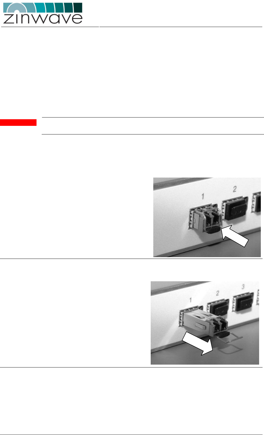
To insert the SFP, hold the
module by the metal body and
slide it into the designated HU/AU
port. An audible click can be
heard when the SFP is fully
latched. Ensure that the de-latch
bail is in the upright position (this
prevents accidental unlatching of
the module).
Figure 3-9: Picture of fully latched SFP module.
Removal of the SFP is achieved
by extending the de-latch bail and
pulling it away from the unit.
Figure 3-10: To remove the SFP pull at the de-latch bail.

Zinwave 2700 DAS – User Manual
Issue 1.2
April 2007
© Zinwave Ltd. 2007
3.2.5 Environmental
Table 3-7: Environmental specifications of 2780 SFP module (designed for the 2700
Hub Unit).
Parameter Min Typical Max Unit
Temperature - Operating 0 +85 °C
Temperature - Storage -25 +55 °C
Relative Humidity (non-condensing) 10 95 %
Table 3-8: Environmental specifications of 2781 SFP module (designed for the 2760
Antenna Unit).
Parameter Min Typical Max Unit
Temperature - Operating 0 +55 °C
Temperature - Storage -25 +55 °C
Relative Humidity (non-condensing) 10 95 %
Zinwave 2700 DAS – User Manual
Issue 1.2
April 2007
© Zinwave Ltd. 2007
3.3 2760 + 2765 Antenna Unit – Wideband
3.3.1 Overview
o The 2760/2765 AUs are small wall- or ceiling mountable units which amplify the
received optical signals for transmission over a wireless link (in the case of the
downlink signals) and amplify the received wireless signals for transmission
over the optical link (in the case of the uplink signals).
o The 2760 AU utilizes the 2781 SFP optical transceiver for the electrical-optical
signal conversion. The 2765 AU utilizes an integrated optical transceiver which
is not pluggable.
o Because of the wide bandwidth of the units (370 – 2500 MHz) separate
wideband antennas are required for Transmit and Receive.
o Adjustable gain settings allow you to define the coverage area of each AU
individually. Control of the AU is remotely via the HU. These are controlled
remotely via the Hub Unit.
o The 2760 AU can be powered via a 48 V DC supply or Power-over-Ethernet
(PoE). The 2765 is powered only via PoE.
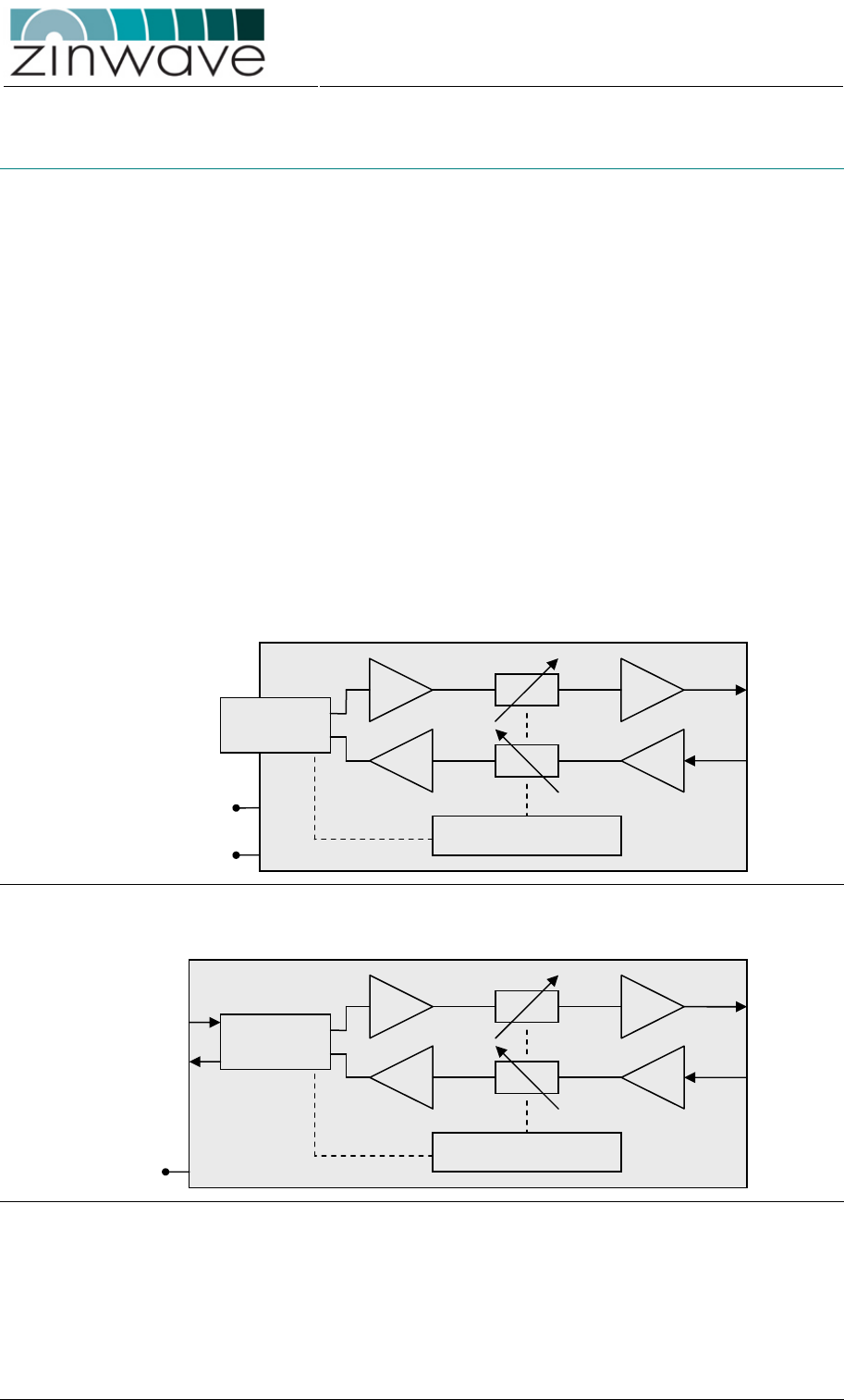
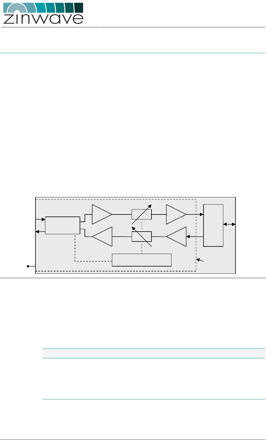
Figure 3-11 and Figure 3-12 show a block diagram of the 2760 and 2765 AU,
respectively.
Figure 3-11: Block diagram of the 2760 AU.
Figure 3-12: Block diagram of the 2765 AU.
Control + Monitoring
To TX
antenna
From RX
antenna
Optical
Transceiv
er
PoE
From Hub
To Hub
Control + Monitoring
To TX
antenna
From RX
antenna
SFP Port
(2781)
48VDC
or
PoE
Zinwave 2700 DAS – User Manual
Issue 1.2
April 2007
© Zinwave Ltd. 2007
3.3.2 Dimensions and Weight
Dimensions and weight listed in Table 3-9 are for an AU without the optional cover.
Table 3-9: Dimensions and weight of the 2760 + 2765 AU.
Parameter 2760 2765 Unit
Height 21.5 (8.5) 20.0 (8.0) cm (inch)
Width 13.0 (5.125) 12.0 (4.75) cm (inch)
Depth 4.5 (1.8) 6.0 (2.4) cm (inch)
Weight 0.75 0.75 kg
3.3.3 Connection panels and LED indicators
3.3.3.1 2760 AU
A drawing of the front view is shown in
Figure 3-13. The front panel of the AU contains:
o SFP port for the 2781 SFP module
o RJ45 connector for powering via Power-over-Ethernet (PoE, IEEE 802.3af)
o 2-pin 48VDC input for powering via AC/DC
o Status LED, incorporated in the RJ45 connector
o Power LED, incorporated in the RJ45 connector
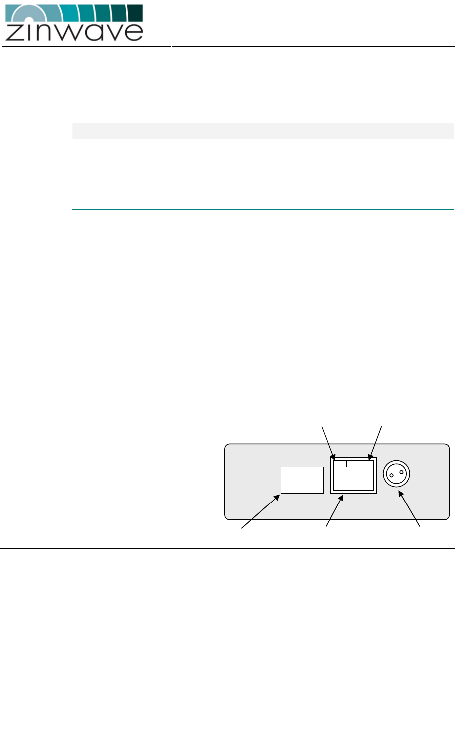
Figure 3-13: Front view of the 2760 AU.
A drawing of the rear view is shown in Figure 3-14. The rear panel of the AU contains
o 2 SMA-female RF connectors, one for TX and one for RX
SFP Port RJ45 PoE Connector 48V DC Input
Status LED
Power LED
Zinwave 2700 DAS – User Manual
Issue 1.2
April 2007
© Zinwave Ltd. 2007
Figure 3-14: Rear view of the 2760 AU.
Following is a description of all interfaces and LED indicators of the 2760 AU.
Optical and Electrical I/O ports
SFP port SFP port
which can be populated with the
Zinwave 2781 SFP module.
RF ports Two simplex wideband (370 –
2500 MHz)
SMA-female connectors
, one for TX (downlink)
and one for RX (uplink)
Powering and LED indicators
48 VDC Input 2-pin latching connector (
LEMO,
EGG.00.302.CLL) for powering via the DC
mains adapter
PoE Connector RJ45 connector for powering via PoE
Status LED Indicates the status of the AU (see Table 3-10)
Power LED Indicates the power state of the AU (see
Table
3-10)
3.3.3.2 2765 AU
A drawing of the front view is shown in
Figure 3-13. The front panel of the AU contains
o RJ45 connector for powering via Power-over-Ethernet (PoE, IEEE 802.3af)
o Status LED, incorporated in the RJ45 connector
o Power LED, incorporated in the RJ45 connector
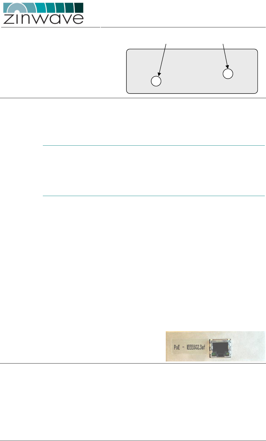
Figure 3-15: Front view of the 2765 AU.
A drawing of the rear view is shown in Figure 3-14. The rear panel of the AU contains
o 2 SMA-female RF connectors, one for TX and one for RX
o Optical Duplex SC connector
TX port RX port
Zinwave 2700 DAS – User Manual
Issue 1.2
April 2007
© Zinwave Ltd. 2007
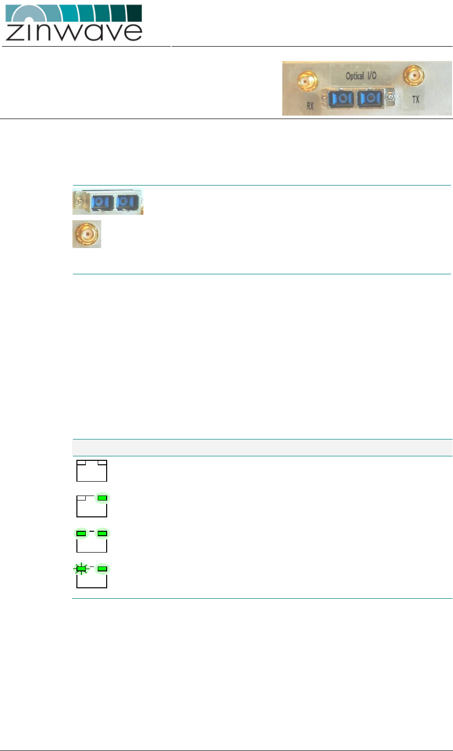
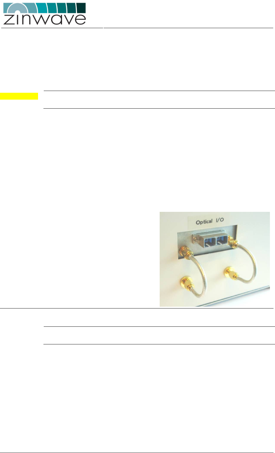
Figure 3-16: Rear view of 2765 AU.
Following is a description of all interfaces and LED indicators of the 2765 AU.
Optical and Electrical I/O ports
Duplex SC
connector
Optical port which connects to the fiber-
infrastructure.
RF ports Two simplex wideband (370 –
2500 MHz)
SMA-
female connectors, one for TX (downlink)
and one for RX (uplink)
Powering and LED indicators
PoE Connector RJ45 connector for powering via PoE
Status LED Indicates the status of the AU (see Table 3-10)
Power LED Indicates the power state of the AU (see
Table
3-10)
3.3.3.3 LED indications
Table 3-10 lists the possible indications of the Antenna Unit LEDs.
Table 3-10: Description of Antenna Unit LED indicators.
LED indicators Description
No power to unit
Unit powered but optical connection not active
Unit operational and optical connection active
Status LED
blinking
Communication to Hub Unit is active
3.3.4 Installation
3.3.4.1 Mounting the Antennas
Prior to mounting the Antenna Unit, mount the Transmit and Receive antennas
following your system installation plan in the assigned locations. Follow the antenna
manufacturer guidelines to do so.

Zinwave 2700 DAS – User Manual
Issue 1.2
April 2007
© Zinwave Ltd. 2007
Transmit and receive antennas need to be separated to improve the required antenna
isolation of 35dB. Lower antenna isolation leads to increased blocking and uplink
noise figure. The use of directional antennas is recommended to improve this antenna
isolation.
CAUTION The antenna must be installed / positioned at a distance of greater than 20 cm away
from the proximity of operators and intended operators.
3.3.4.2 Mounting the 2760 Antenna Unit
The 2760 AU package should contain the following items:
o 1 × 2760 AU
o 1 × Mounting bracket
o 1 × 2781 SFP module
o 1 × PoE converter (incl. mains cable and 1m Cat5 Ethernet cable) (optional)
o 1 × 48V PSU (incl. mains cable) (optional)
The Antenna Unit can be mounted to a ceiling or a wall or any horizontal or vertical flat
surface using the provided mounting bracket.
Chose the Antenna Unit position following these guidelines:
o Mount the Antenna Unit as close as possible to the relevant Transmit and
Receive antenna such that the minimum length of coaxial cable is required to
connect the AU to the antennas. Excessive coaxial cable lengths will reduce the
available signal power and increase the uplink noise figure.
o Allow space above and below the unit for adequate ventilation and to
accommodate the minimum bend radius for the coaxial and fiber cables
according to Figure 3-17
o The position of the Antenna Unit should provide sufficient air circulation
Prepare the Antenna Unit for mounting following these steps:
o Push the SFP module firmly into the SFP port, ensuring that it is fully latched.
Do not remove the dust-cover at this stage.
o Attach the Antenna Unit cover (optional) to the Antenna Unit using the four
provided M4 screws.
Mount the Antenna Unit to the identified location following these steps:
o To attach the mounting bracket, drill four holes into the wall, using the
dimensions shown in Figure 3-17.
o Secure the mounting bracket using 4 countersunk M3 screws (not provided)
o For vertical mounting: Slide the Antenna Unit onto the mounting bracket with the
RF ports pointing downwards
o For horizontal mounting: Slide the Antenna Unit onto the mounting bracket with
either the RF ports or the SFP port pointing forward. Ensure that the Antenna
Unit latches on the mounting bracket.
Zinwave 2700 DAS – User Manual
Issue 1.2
April 2007
© Zinwave Ltd. 2007
Figure 3-17: Mounting instructions for the 2760 AU.
3.3.4.3 Mounting the 2765 Antenna Unit
The 2765 AU package should contain the following items:
o 1 × 2765 AU
o 1 × PoE converter (incl. mains cable and 1m Cat5 Ethernet cable) (optional)
The Antenna Unit can be mounted to a ceiling or a wall or any horizontal or vertical flat
surface.
Chose the Antenna Unit position following these guidelines:
o Mount the Antenna Unit as close as possible to the relevant Transmit and
Receive antenna such that the minimum length of coaxial cable is required to
connect the AU to the antennas. Excessive coaxial cable lengths will reduce the
available signal power and increase the uplink noise figure.
Zinwave 2700 DAS – User Manual
Issue 1.2
April 2007
© Zinwave Ltd. 2007
o Allow space above and below the unit for adequate ventilation and to
accommodate the minimum bend radius for the coaxial and fiber cables
o The position of the Antenna Unit should provide sufficient air circulation
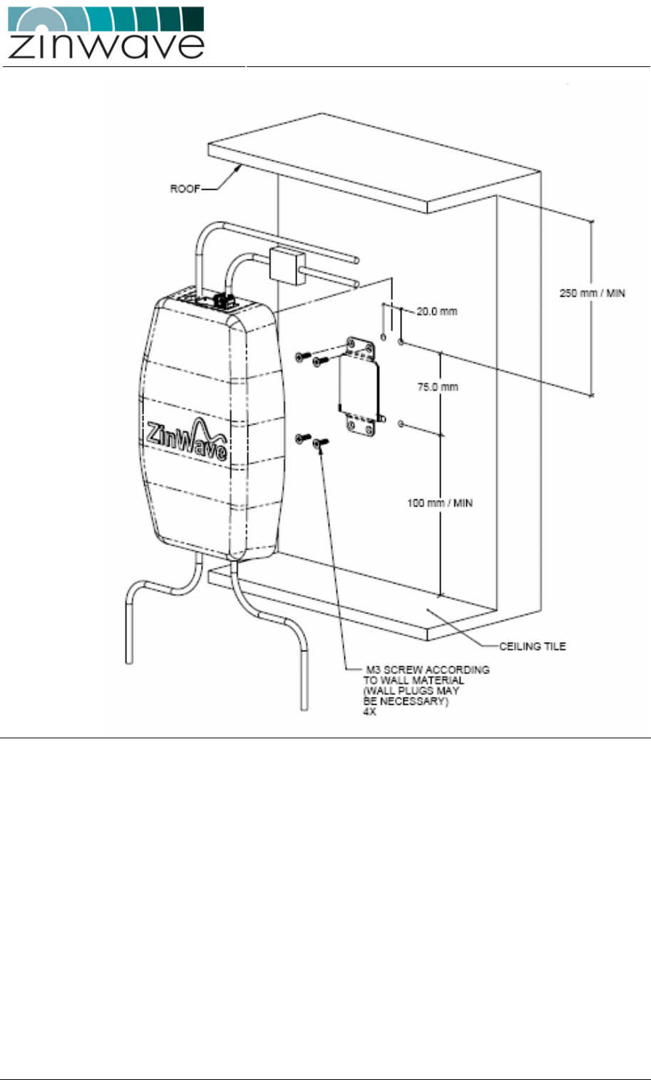
Mount the Antenna Unit to the identified location following these steps:
o To attach the AU, drill four holes into the wall, using the dimensions shown in
Figure 3-18.
o Secure the AU using 4 countersunk M4 screws (not provided)
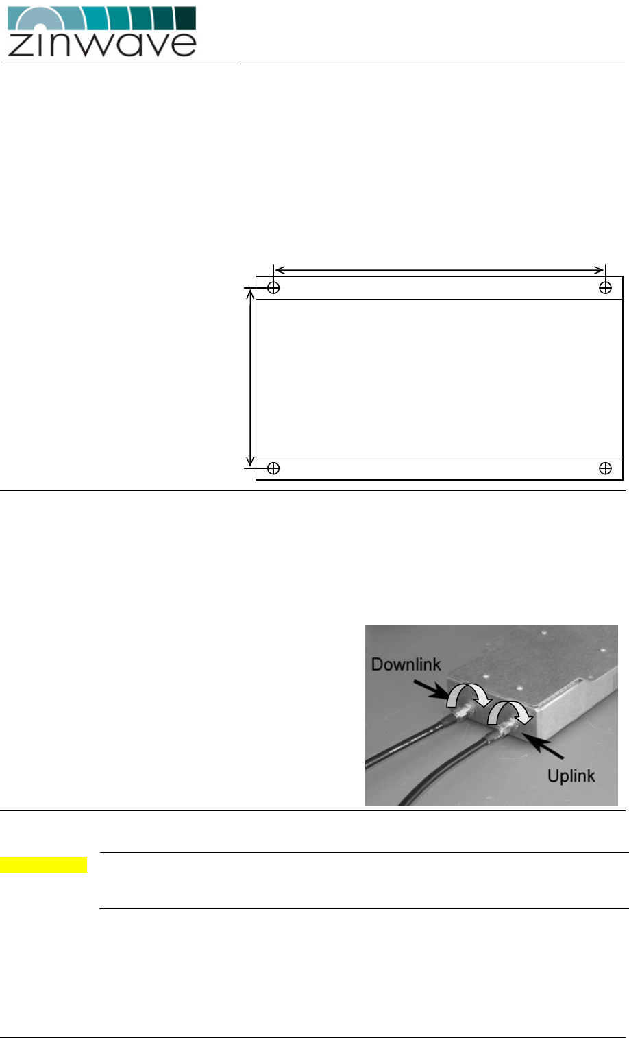
Figure 3-18: Mounting instructions for the 2765 AU.
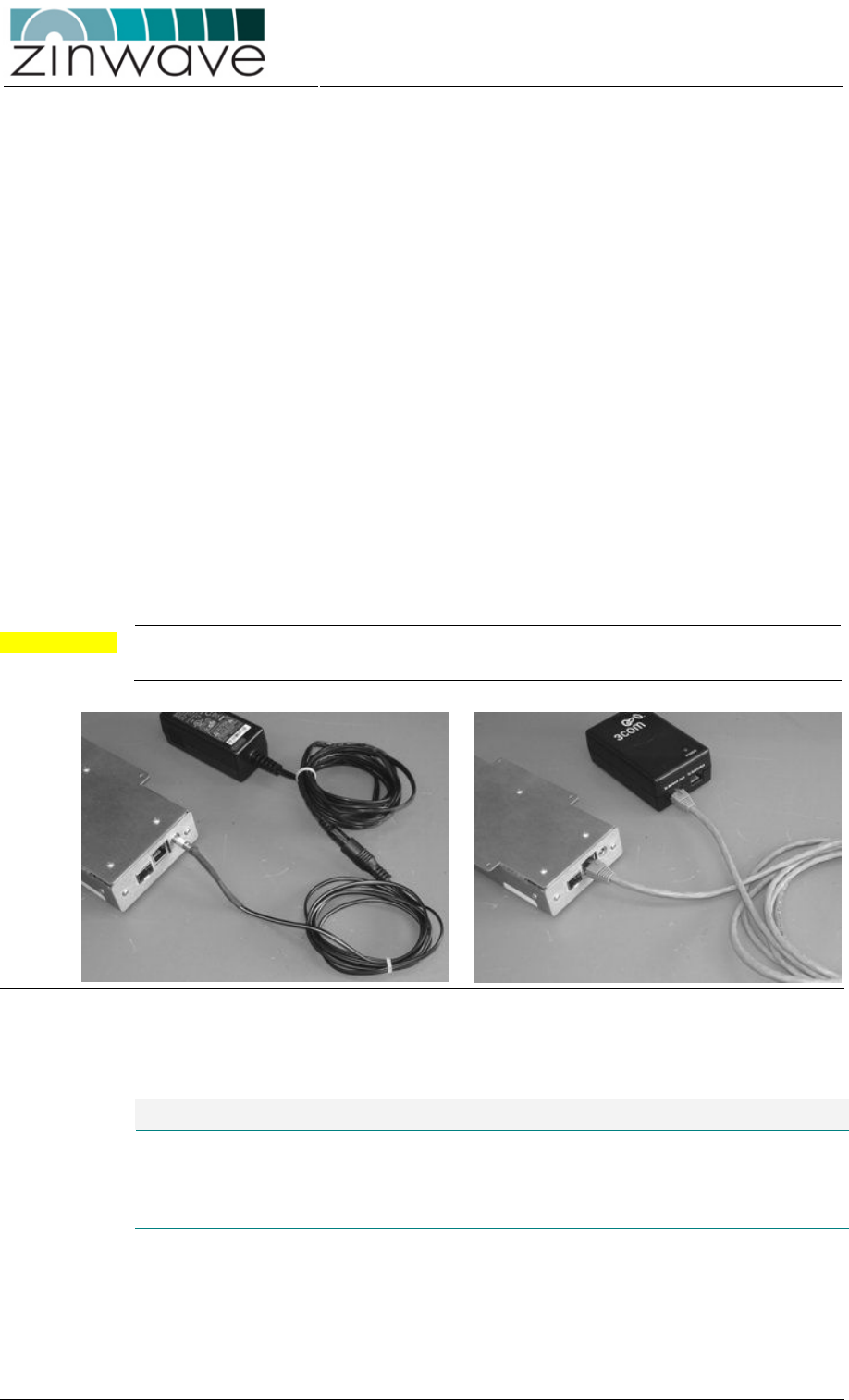
3.3.4.4 Connecting the antennas to the AU
Connect the antennas to the AU, using low loss coaxial cables. The downlink port (TX)
of the AU connects to the TX antenna and the uplink port (RX) of the AU connects to
the RX antenna.
Figure 3-19: Connecting antenna cables to the 2760 AU.
CAUTION When connecting to the SMA connectors on the Antenna Unit, DO NOT over-tighten
the connectors. Use a dedicated torque wrench pre-set to 0.8 to 1.1 Nm. If a torque
wrench is not available, firmly hand-tightening the connector is adequate.
3.3.4.5 Connecting the Power Supply Unit
The 2760 AU can be powered by and external 48V DC power supply or by Power over
Ethernet (PoE) (Figure 3-20). The 2765 AU can be powered only by PoE. To connect
the power supply to the AU, follow these steps:
192.5 mm
96 mm
Zinwave 2700 DAS – User Manual
Issue 1.2
April 2007
© Zinwave Ltd. 2007
o Using an external 48VDC power supply unit (optional).
→ Mount the PSU next to the Antenna Unit using the provided brackets with
the IEC mains connector facing downwards
→ Connect the mains cable from the PSU to an outlet providing 110 – 250 V,
50 – 60 Hz AC power.
→ Connect the DC cable of the PSU to the 2-pin latching input of the Antenna
Unit
o By Power over Ethernet. (PoE) using an IEEE802.3af compliant PoE injector.
→ Using the IEEE 802.3af PoE protocol the PoE injector can be connected to
the Antenna Unit with a Cat5 Ethernet cable of up to 100 m length. This can
be beneficial in situations where it is difficult to provide AC power near the
Antenna Unit location
→ Install the PSU in a suited location, making sure that adequate air circulation
is provided.
→ Connect the Cat5 Ethernet cable to the connector labeled “To Network Jack”
on the PoE injector.
→ Connect the other end of the Ethernet cable to the RJ45 connector on the
Antenna Unit.
CAUTION Connecting more than one source of power at a time to any single 2760 AU can
cause permanent damage to the unit.
Figure 3-20: Connecting the DC supply unit or the PoE mains adaptor.
Table 3-11: DC Power Supply Unit (PSU) characteristics.
Parameter Min Typical Max Unit Comment
Power supply voltage 40 48 V
Power supply frequency DC -
Power consumption 3 W
3.3.5 Environmental
Table 3-12: Environmental specifications of 2760 + 2765 Antenna Unit.

Zinwave 2700 DAS – User Manual
Issue 1.2
April 2007
© Zinwave Ltd. 2007
Parameter Min Typical Max Unit
Temperature - Operating 0 +45 °C
Temperature - Storage -25 +55 °C
Relative Humidity (non-condensing) 10 95 %
Zinwave 2700 DAS – User Manual
Issue 1.2
April 2007
© Zinwave Ltd. 2007
3.4 277X Antenna Unit – Band specific
3.4.1 Overview
o The 277X AUs are 3U high wall, ceiling or rack mountable units which amplify
the received optical signals for transmission over a wireless link (in the case of
the downlink signals) and amplify the received wireless signals for transmission
over the optical link (in the case of the uplink signals).
o The 277X AUs utilize the 2765 wideband AU in its core together with a band-
specific duplexer to suppress undesired frequency bands.
o Because of the integrated duplexer, a single antenna is required for both
transmit and receive.
o Adjustable gain settings allow you to define the coverage area of each AU
individually. Control of the AU is remotely via the HU. These are controlled
remotely via the Hub Unit.
o The 277X AUs are powered via IEEE 802.3af compliant Power over Ethernet
(PoE).
Figure 3-21 show a block diagram of the 277X AU.
Figure 3-21: Block diagram of the 277X AU.
3.4.2 Dimensions and Weight
Dimensions and weight listed in Table 3-13 are for an AU without the optional 19” rack
mounting kit.
Table 3-13: Dimensions and weight of the 277X AU.
Parameter 277X Unit
Height 12.0 (4.75) cm (inch)
Width 37.0 (14.5) cm (inch)
Depth 26.0 (10.25) cm (inch)
Weight 5.3 kg
Control + Monitoring
To/From
antenna
Optical
Transceiver
PoE
From Hub
To Hub
Duplexer
2765 AU
Zinwave 2700 DAS – User Manual
Issue 1.2
April 2007
© Zinwave Ltd. 2007
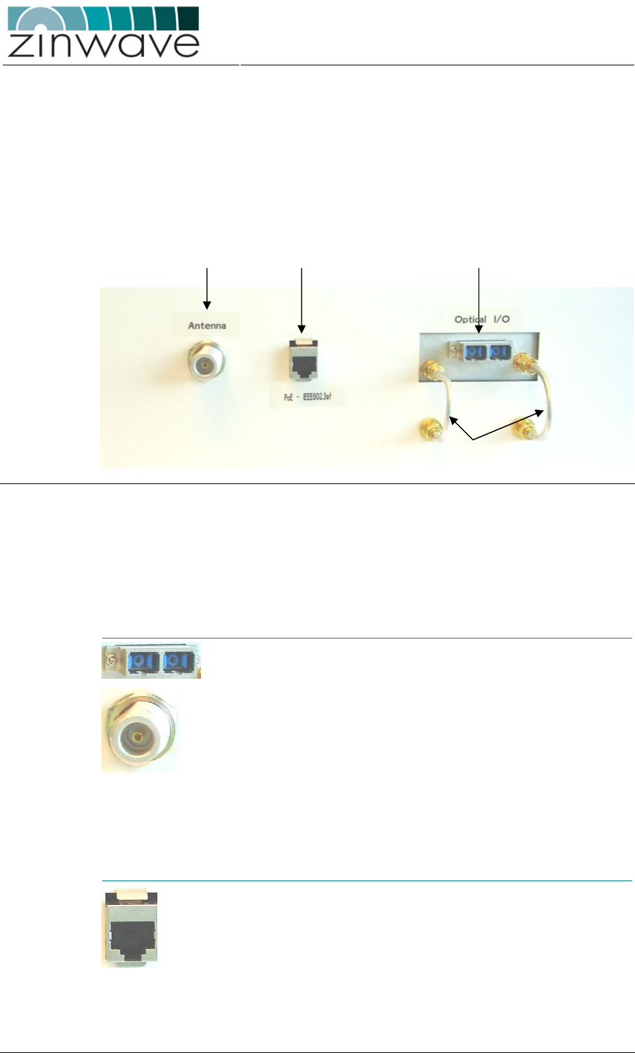
3.4.3 Connection panels and LED indicators
A drawing of the front view of the 277X AU is shown Figure 3-22. The front panel of
the AU contains
o Optical I/O
o RJ45 connector for powering via Power-over-Ethernet (PoE, IEEE 802.3af)
o N-type (female) antenna connector
o 4 SMA (female) connectors for semi-rigid jumper cables
Figure 3-22: Front view of the 277X AU.
The 277X AU rear panel does not contain any interfaces
The 277X AU does not contain any LED indicators.
Following is a description of all interfaces of the 277X AU.
Optical and Electrical I/O ports
Duplex SC
connector
Optical port which connects to the fiber-
infrastructure.
RF port Duplex N-type (female ) connector
DL Jumpers
Connects the DL output of the integrated 2765
AU to the duplexer
UL Jumpers Connects the UL input of the integrated 2
765
AU to the duplexer
Powering
PoE Connector RJ45 connector for powering via PoE
Antenna Connector PoE Connector
Optical Connector
Jumper cables
Zinwave 2700 DAS – User Manual
Issue 1.2
April 2007
© Zinwave Ltd. 2007
3.4.4 Installation
3.4.4.1 Mounting the Antenna
Prior to mounting the Antenna Unit, mount the antenna following your system
installation plan in the assigned locations. Follow the antenna manufacturer guidelines
to do so.
CAUTION The antenna must be installed / positioned at a distance of greater than 20 cm away
from the proximity of operators and intended operators.
3.4.4.2 Mounting the 277X Antenna Unit
The 277X AU package should contain the following items:
o 1 × 277X AU
o 2 × SMA (male) – SMA (male) jumper cables
o 1 × PoE converter (incl. mains cable and 1m Cat5 Ethernet cable) – optional
o 1 × 19” equipment rack mounting kit (shelf and screws) – optional
Connect the SMA (male) – SMA (male) jumper cables to the provided SMA (female)
ports on the 277X (Figure 3-23).
Figure 3-23: Connecting the RF jumper leads on the 277X AU.
NOTE Once connected, do not remove the jumper leads as they are required for the
functioning of the 277X Antenna Unit.
The Antenna Unit can be mounted to a ceiling or a wall or any horizontal or vertical flat
surface. Alternatively the AU can be installed in a 19” equipment rack using the
optional mounting kit.
For ceiling or wall mounting, chose the Antenna Unit position following these
guidelines:
o Mount the Antenna Unit as close as possible to the relevant antenna such that
the minimum length of coaxial cable is required to connect the AU to the
antenna. Excessive coaxial cable lengths will reduce the available signal power
and increase the uplink noise figure.
o Allow space above and below the unit for adequate ventilation and to
accommodate the minimum bend radius for the coaxial and fiber cables
Zinwave 2700 DAS – User Manual
Issue 1.2
April 2007
© Zinwave Ltd. 2007
o The position of the Antenna Unit should provide sufficient air circulation
For mounting in a 19” equipment rack, chose the Antenna Unit position following these
guidelines:
o Locate free space in the rack of 3U height
o Use a location which allows for minimum coaxial cable length to connect the
antenna
Follow the following steps to mount the AU in a 19” equipment rack using the rack
mounting kit (optional)
o Attach the 277X AU to the shelf using the 4 provided screws.
o Place the shelf into the rack and secure with the 4 provided screws
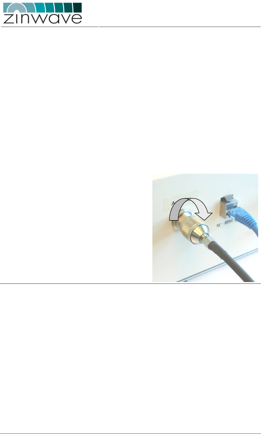
3.4.4.3 Connecting the Antenna to the AU
Connect the antenna to the AU, using low loss coaxial cables. If the antenna cable is
terminated with a connector other than N-type (male) on the AU end, use an
appropriate connector adaptor.
When connecting an N-type connector, firmly hand-tightening is adequate.
Figure 3-24: Connecting the antenna cable to the 277X AU.
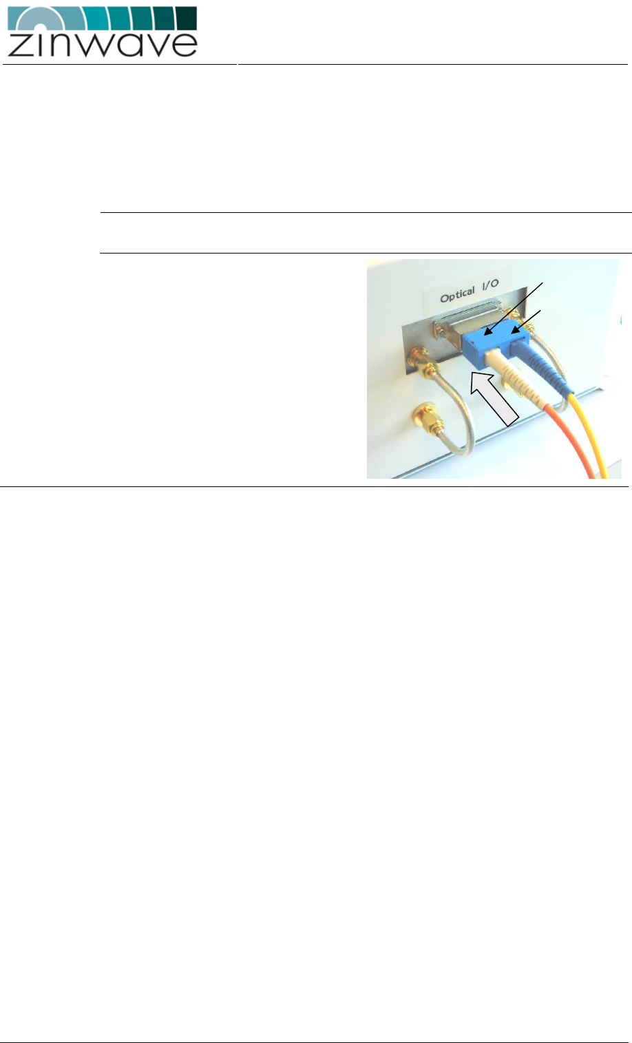
3.4.4.4 Connecting the Optical Fiber
o When using MMF, connect the 277X AU to the fiber-infrastructure using the
special Zinwave patch-cord. Connecting to the fiber-infrastructure without the
special patch-cord will lead to a poor quality optical link and reduced maximum
transmission distance.
o Connect the patch-cord end with the SMF (yellow) and MMF (orange or grey)
cords to the AU. Connect the patch-cord end with the two MMF (both cables
either orange or grey) cords to the fiber infrastructure.
o The SC connectors are keyed with a slot and will thus only fit in one (i.e. the
correct) direction.
o Insert the SC duplex connector into the optical I/O port on the AU and press it
firmly into place, making sure that both sides of the connector are securely
latched (indicated by a “clicking” sound)
Zinwave 2700 DAS – User Manual
Issue 1.2
April 2007
© Zinwave Ltd. 2007
Follow these guidelines when using fiber-optic cabling:
o Do not remove the dust-caps on both the equipment and the optical fiber until
required – they’re there for a reason
o Before connecting, clean the facet of the connectors with a lint-free tissue
o Always make sure that all optical connectors are securely latched
o Do not bend the optical fiber below a radius of 3 cm
NOTE Failure do follow these guidelines may result in a poor quality optical link or in a
complete link failure
Figure 3-25: Connecting the fiber-optic cable to the 277X AU.
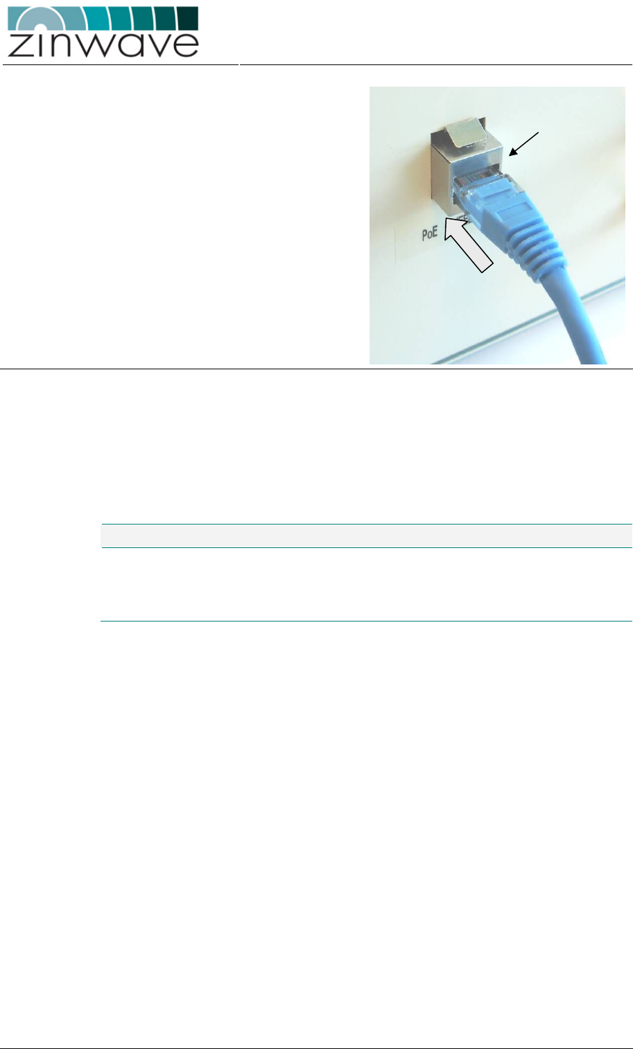
3.4.4.5 Connecting the Power Supply Unit
o Using the IEEE 802.3af PoE protocol the PoE injector can be connected to the
Antenna Unit with a Cat5 Ethernet cable of up to 100 m length. This can be
beneficial in situations where it is difficult to provide AC power near the Antenna
Unit location
o Install the PSU in a suited location, making sure that adequate air circulation is
provided.
o Connect the Cat5 Ethernet cable to the connector labeled “To Network Jack” on
the PoE injector.
o Connect the other end of the Ethernet cable to the RJ45 connector on the
Antenna Unit.
“Click”
“Click”
Zinwave 2700 DAS – User Manual
Issue 1.2
April 2007
© Zinwave Ltd. 2007
Figure 3-26: Connecting the power supply cable to the 277X AU.
3.4.5 Environmental
Table 3-14: Environmental specifications of the 277X Antenna Unit.
Parameter Min Typical Max Unit
Temperature - Operating 0 +45 °C
Temperature - Storage -25 +55 °C
Relative Humidity (non-condensing) 10 95 %
“Click”

Zinwave 2700 DAS – User Manual
Issue 1.2
April 2007
© Zinwave Ltd. 2007
Chapter 4
Configuration and
Control
4.1 Overview
The 2700 DAS can be configured and controlled either via a command line interface
(CLI) or using SNMP (Simple Network Management Protocol). Control of the system
with the CLI gives the same functionality as with the SNMP. Please refer to the
Zinwave 2700 DAS – Software Manual for a detailed description of all the commands
available through the CLI.
4.2 Control via ZinConfig
ZinConfig is an application based on the SNMP. It has a graphical user interface (GUI)
and can be used to control the most important aspects of the 2700 DAS.
4.2.1 Installing the Software
Place the installation CD in your CD drive. If the installer does not start automatically,
open a Windows File Explorer window, and double-click on readme.htm.
4.2.2 Starting the software
To launch ZinConfig double click on the desk top icon or click
Start->Programs->Zinwave->ZinConfig.
Zinwave 2700 DAS – User Manual
Issue 1.2
April 2007
© Zinwave Ltd. 2007
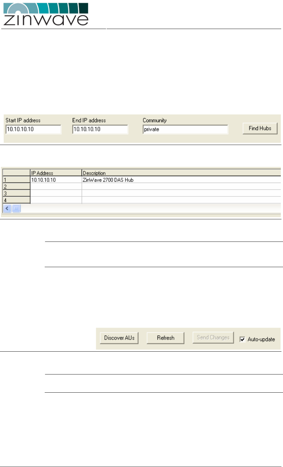
4.2.3 Identifying Hubs
Enter the start and end IP address range of the attached Hubs and click on the “Find
Hubs” button (Figure 4-1). All detected Hubs will be displayed showing their IP
address and description (Figure 4-2). Selecting a Hub from the list will reveal its
settings.
Use the “Community” field as defined in section 4.3.4.2 if you wish read-only or read-
write access. This field is required for communication with the HU.
Refer to section 4.3.3.2 for a list of all default settings of the HU.
Figure 4-1: Select the IP range and the access community.
Figure 4-2: Selecting the HU.
NOTE The attached Hubs need to be on the same IP subnet in order to be detected by
ZinConfig. If this is not the case refer to section 4.3.4.1 of this guide for changing the
network settings on the HU.
4.2.4 Enabling control of the attached AUs
If the attached AUs are not displayed, use the “Discover AUs” button to detect all
attached AUs (Figure 4-3). This process can take up to 1 minute. During the execution
of this command do not connect/disconnect any of the optical cables.
Figure 4-3: Buttons for discovering AUs and updating values.
NOTE Control of the attached AUs is not possible without first running the “Discover AUs”
command.
4.2.5 Updating values
o Values are changed by selecting the new value from the drop-down list or by
checking/unchecking the check-boxes.
o When “Auto-update” is enabled, the values are updated immediately. In this
case the “Send Changes” button is disabled.
Zinwave 2700 DAS – User Manual
Issue 1.2
April 2007
© Zinwave Ltd. 2007
o When “Auto-update” is disabled, the values are only updated after pressing
“Send changes” (Figure 4-3).
o “Refresh” reads the current configuration from the 2700 system (Figure 4-3).
Changes in the GUI that haven’t been updated will be lost.
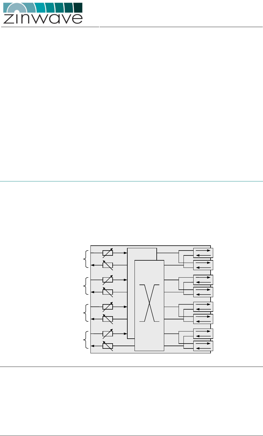
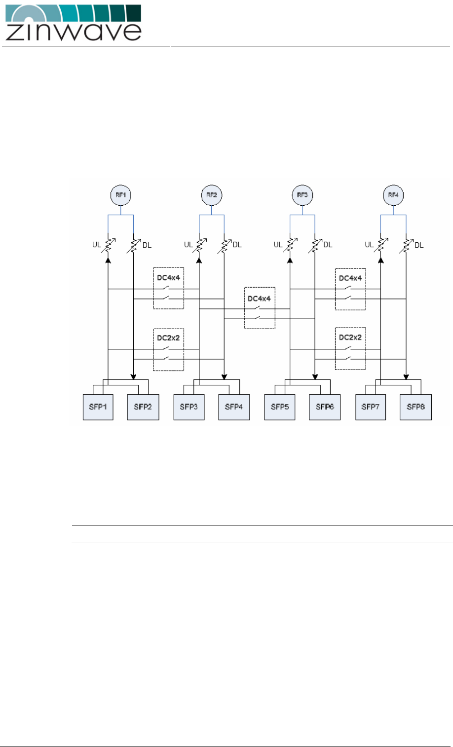
4.2.6 Controlling the Hub Unit
Figure 4-4 shows a schematic of the 2700 HU with the downlink input attenuators (DL)
and uplink output attenuators (UL). Also shown is the distribution circuitry.
Figure 4-4: Schematic of the HU distribution and attenuation circuit
4.2.6.1 Setting the attenuation values
The values which can be selected on the GUI represent attenuation values by which
the gain of the HU can be reduced.
NOTE The attenuation setting on the HU does not correspond with the actual gain of the unit.
The downlink (DL) and uplink (UL) attenuators for the HU can be selected using the
drop down lists. The range of permitted values is 5 – 31 dB for all attenuators in steps
of 1 dB.
4.2.6.2 Setting the RF signal distribution
o Without any of the distribution switches enabled, RF1 port is connected to SFP
ports 1 & 2, RF2 to SFP ports 3 & 4, RF3 to SFP ports 5 & 6 and RF4 to SFP
ports 7 & 8, as shown in Figure 4-4
o RF ports 1 and 2 can be cross-connected simultaneously to SFP ports 1 – 4 by
ticking the DC2x2 box. RF 3 and 4 can be cross-connected in the same manner
to SFP ports 5 – 8.
o Ticking the DC4x4 box will cross-connect all four RF ports to all eight SFP/AU
ports.
Zinwave 2700 DAS – User Manual
Issue 1.2
April 2007
© Zinwave Ltd. 2007
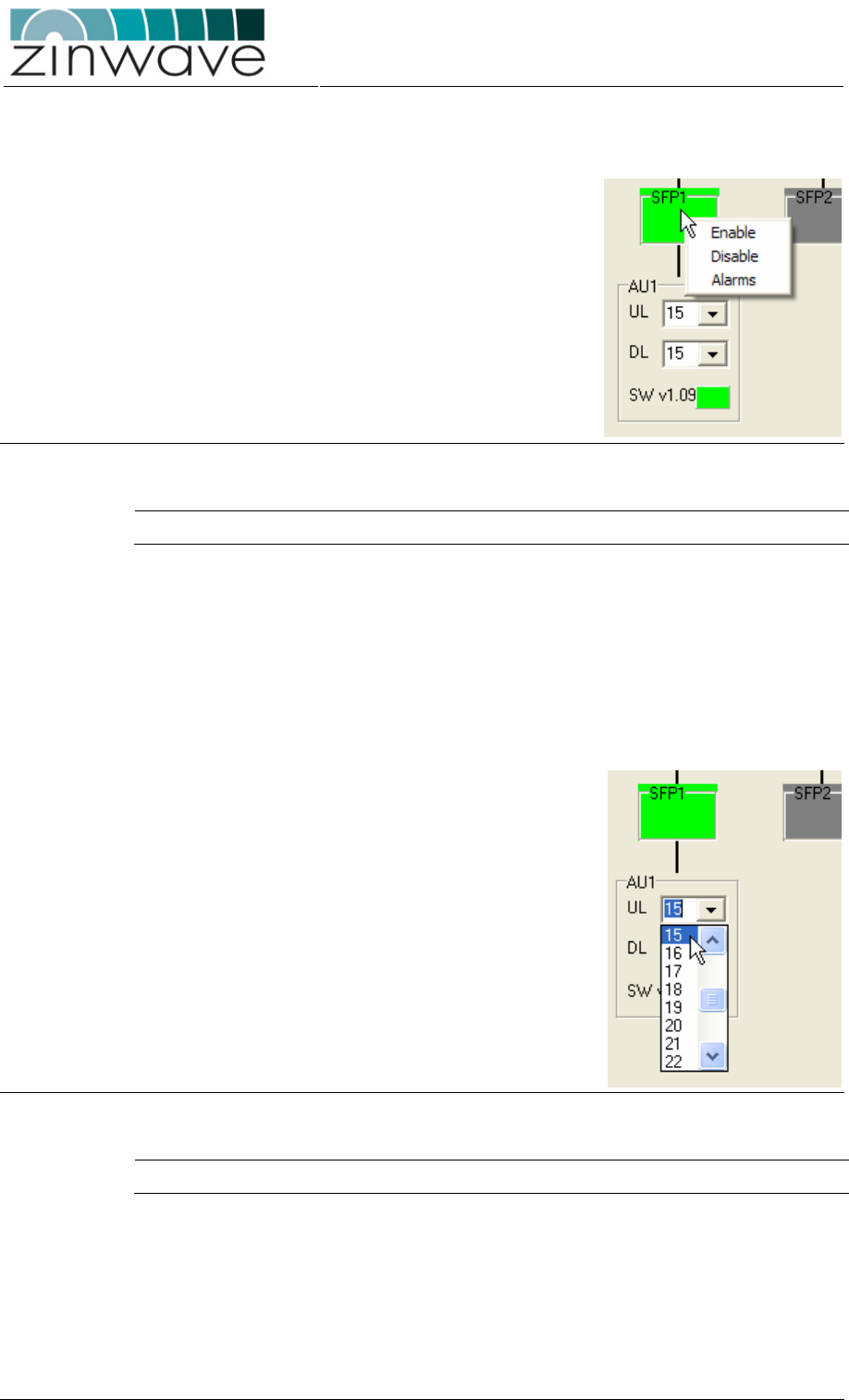
4.2.6.3 Enabling/Disabling the optical ports
Active SFP ports are shown
green, inactive ports are grayed
out and red indicates an alarm
condition. SFP ports can be
enabled/disabled by right
clicking on the SFP port and
selecting the required option
from the pop-up menu (Figure
4-5).
Figure 4-5: Enabling the optical ports.
NOTE Disabling a port will result in the attached AU not transmitting or receiving any signal.
4.2.7 Controlling the Antenna Unit
The changeable parameters in the AU are the downlink and uplink attenuators and
downlink and uplink gain controls.
4.2.7.1 Setting the attenuation values
The values which can be
selected on the GUI represent
attenuation values by which the
gain of the AU can be reduced.
The downlink (DL) and uplink
(UL) attenuators for the AU can
be selected using the drop
down lists. The range of
permitted values is 5 – 31 dB for
all attenuators in steps of 1 dB
(Figure 4-6).
Figure 4-6: Changing the AU attenuators.
NOTE The attenuation setting on the AU does not correspond to the actual gain of the unit.
Zinwave 2700 DAS – User Manual
Issue 1.2
April 2007
© Zinwave Ltd. 2007
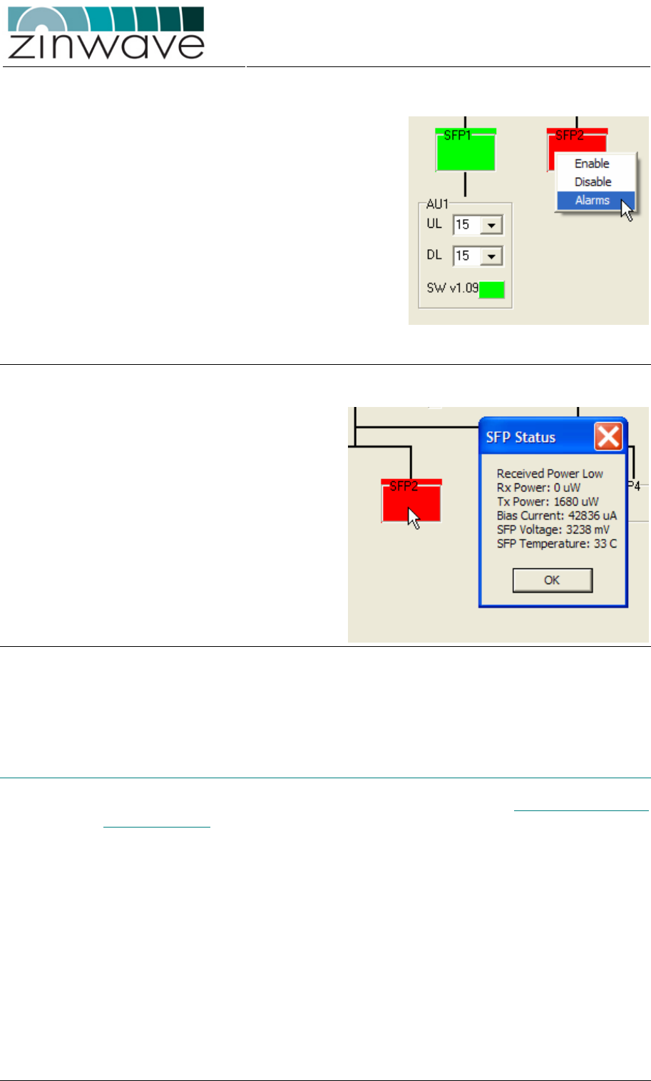
4.2.8 Status and Alarms
When an alarm is present, the SFP port
or the status box in the AU frame is
colored red. Status and alarm
information is displayed by left-clicking
on one of the colored boxes.
Alternatively status information on the
SFP ports can be displayed by right-
clicking on the SFP port and selecting
“Alarms” from the pop-up menu (Figure
4-7).
Clicking on one of the SFP ports displays
information on the HU SFP. Clicking on
the colored box in the AU frame displays
information on the AU optical transceiver
Figure 4-7: Reading out alarms on the optical link.
A box will appear describing the
alarm if present together with a
range of status information
(Figure 4-8). The displayed
parameters are:
o RX optical power
o TX optical power
o Laser bias current
o SFP supply voltage
o SFP temperature
Figure 4-8: Alarm description.
4.3 Control via Command Line Interface (CLI)
A detailed description of the full CLI functionality can be found in Zinwave 2700 DAS –
Software Manual.
The CLI can be accessed directly with an RS-232 serial connection, or remotely
through a network using the Telnet protocol.
Zinwave 2700 DAS – User Manual
Issue 1.2
April 2007
© Zinwave Ltd. 2007
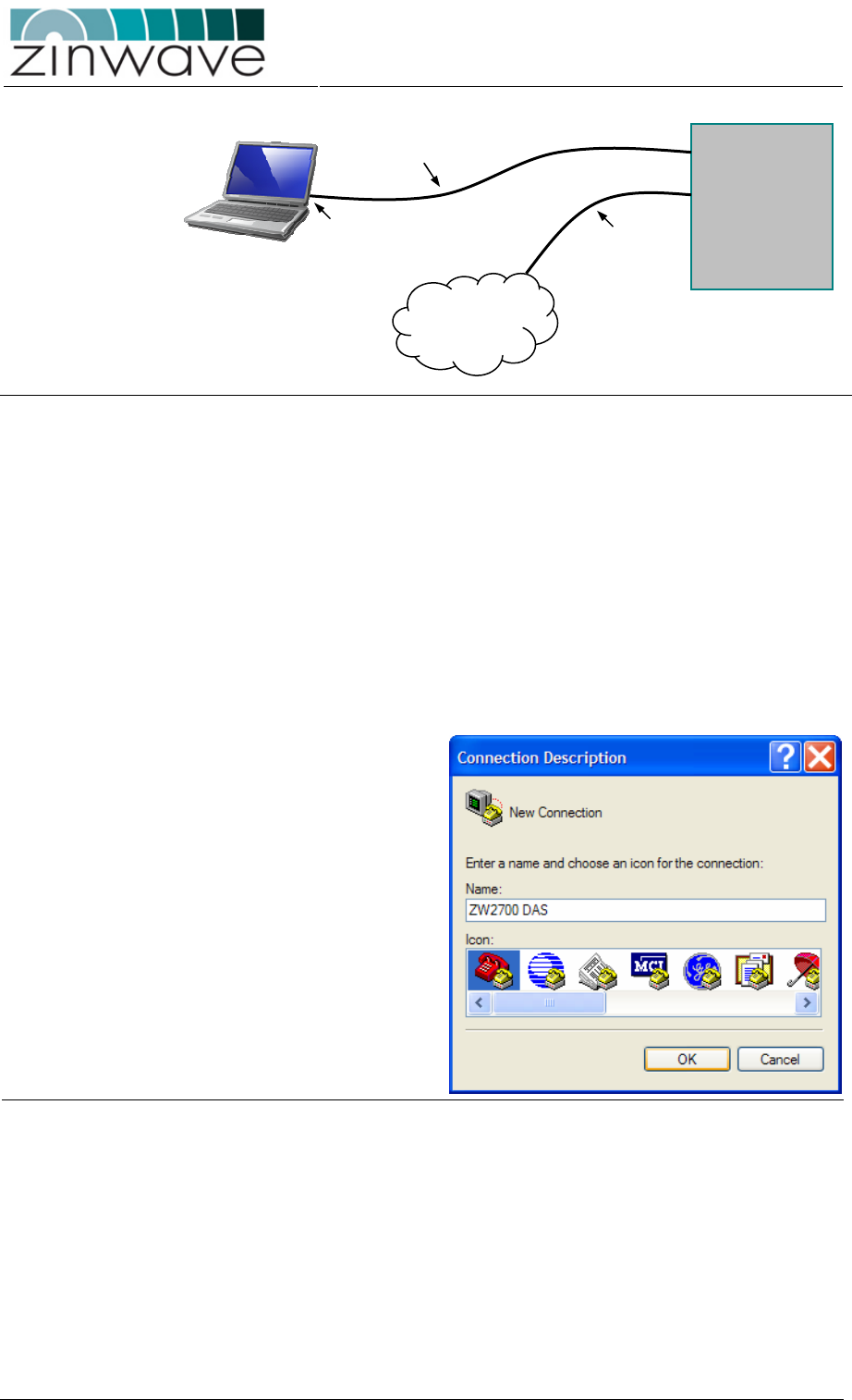
Figure 4-9: Required connections for local and remote control of the 2700 DAS.
4.3.1 Connecting to the CLI via RS232
This section describes how to access the CLI via the RS232 protocol using the
Microsoft Windows based HyperTerminal application. The setup using a different
terminal emulation application is likely to be very similar.
The serial port on the HU is configured as DTE (Data Terminal Equipment). When the
HU is directly connected to the serial port of a computer (which is another DTE), a null
modem has to be used. Follow these steps to establish a RS232 connection:
o Connect your laptop/PC via the null modem cable to the hub unit.
o Run HyperTerminal. This
application can be found
under Start
All Programs
Accessories
Communications
HyperTerminal. After
entering a descriptive name
for the connection click OK
to proceed.
Figure 4-10 Open a new HyperTerminal session.
Serial
Ethernet
HU
COM port
9-pin sub-D
null-modem cable
Ethernet
Cable
Ethernet
Zinwave 2700 DAS – User Manual
Issue 1.2
April 2007
© Zinwave Ltd. 2007
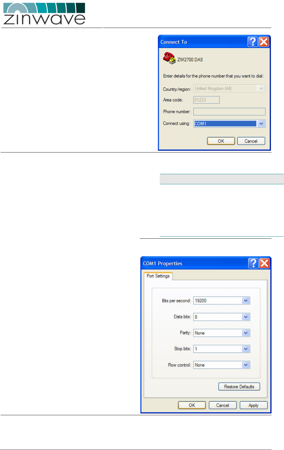
o Select the serial port of
your laptop or PC. Typically
this is the COM1 port.
Press OK to continue.
Figure 4-11: Identify the serial port on your computer.
o Adjust the parameters of
the serial connection
according to the values
listed in table 3-1. Clicking
OK stores these settings
under the name defined in
step 1 and a connection to
the Hub Unit is established.
Parameter Value
Baud rate 19200
Data bits 8
Parity None
Stop bits 1
Flow control None
Table 4-1: Serial port settings.
Figure 4-12: Adjust the serial port settings.
Zinwave 2700 DAS – User Manual
Issue 1.2
April 2007
© Zinwave Ltd. 2007
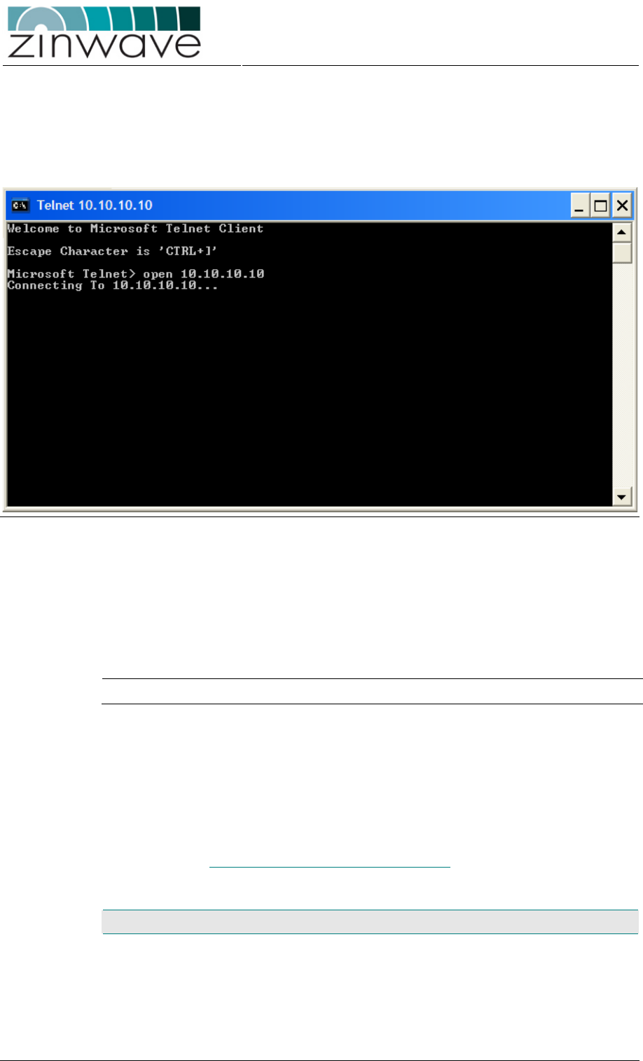
4.3.2 Connecting to the CLI via Telnet
When a network connection to the HU is available, the CLI can be accessed via the
Telnet protocol. On a Windows based laptop/PC Telnet can be started via Start
Run… telnet).
Figure 4-13: Serial connection via Telnet.
To open a connection to the hub unit type “open <ip address>” where
<ip address> should be replaced by the IP address of the HU.
A password is required to access the CLI using Telnet. If this is not known or if the HU
cannot be accessed, use the local RS232 interface to change the password or to
adjust the network settings.
NOTE The factory set password of the hub unit is “password”.
4.3.3 CLI Commands
4.3.3.1 Overview
Table 3-2 shows a list of all available CLI commands. This list can be generated by
typing the command “?” in the CLI. This chapter briefly introduces those commands
most important to set up the 2700 DAS. A more detailed description of all commands
can be found the Zinwave 2770 DAS – Software Manual.
Table 4-2: Overview of CLI commands for control of the HU.
Hub Commands Description Type
dlia <1-4> <0-31> Downlink Input Attenuation R/W
uloa <1-4> <0-
31>
Uplink Output Attenuation R/W
dc22 <1-2> <1/0> Distribution Circuits(2x2) R/W
dc44 <1/0>
Distribution Circuit (4x4) R/W

Zinwave 2700 DAS – User Manual
Issue 1.2
April 2007
© Zinwave Ltd. 2007
Hub Commands Description Type
default Set default values and reboot W
discover Discover AUs W
sfpdis <1-
8> <1/0>
SFP Enable/Disable R/W
reID <au1-au8>
Set the active remote AU R/W
config <IP/GATEWAY/NETMASK/
USR/PSWD(Telnet)/
TRAPIP/TRAPPORT/
R_COMMUNITY/
RW_COMMUNITY>
Misc. configuration R/W
alarm <1-
8>
SFP Alarm Status R
version Software / Hardware / SFP Version R
help Display help information R
reboot Reboot the system W
Table 4-3: Overview of CLI commands for control of the AU
Antenna Unit Command Description Type
++dla <0-31> Downlink Attenuation R/W
++ula <0-31>
Uplink Attenuation R/W
++dle <1/0> Enable/disable downlink gain control R/W
++ule <1/0>
Enable/disable uplink gain control R/W
++dflt Set default values W
++alarm AU alarm status R
++version Software Version R
Commands are executed on typing a carriage return. Settings can be queried by
replacing the last value with a “>” sign. The CLI is case in-sensitive.
EXAMPLE The command “sfpdis 5 1” disables the SFP module plugged into SFP port #5.
This setting can be queried using the command “sfpdis 5 >”. The command
“sfpdis >” returns the settings for all eight SFP ports #1 – #8.
The values of all settings in the factory default state and after execution of the
“default” command are listed in Table 4-4.
4.3.3.2 Default settings
The default settings are loaded when installing a new HU or AU. The unit can be reset
to this factory default state using the “default” command (for the Hub Unit) or the
“++dflt” command (for the Antenna Unit).
Table 4-4: Factory default state of the HU
Hub Parameter Description Default value
dlia <1-4> Downlink Input Attenuation 31

Zinwave 2700 DAS – User Manual
Issue 1.2
April 2007
© Zinwave Ltd. 2007
Hub Parameter Description Default value
uloa <1-4> Uplink Output Attenuation 31
dc22 <1-2> Distribution Circuits(2x2) Disabled
dc44 <1/0>
Distribution Circuit (4x4) Disabled
sfpdis <1-8> SFP Enable/Disable Disabled
ReID <au1-
au8>
Set the active remote AU AU1
config IP IP address of the HU 10.10.10.10
config GATEWAY IP address of the gateway 10.10.10.1
config NETMASK Subnet mask 255.255.255.0
config USR Administrator username ‘admin’
config PSWD(Telnet) Administrator password ‘password’
config TRAPIP
IP address to which SNMP traps are
sent
0.0.0.0
config TRAPPORT
Port number to which SNMP traps
are sent
162
config R_COMMUNITY Read-only community string ‘public’
config RW_COMMUNITY>
Read-write community string ‘private’
Table 4-5: Factory default state of the AU
Hub Parameter Description Default value
dla Downlink Attenuation 15
ula Uplink Attenuation 15
dle Downlink Gain Control Disabled
ule
Uplink Gain Control Disabled
4.3.4 Controlling the HU (2700)
Commands to control the HU are typed directly into the HyperTerminal application
window as listed in Table 4-2.
4.3.4.1 Configuring the network interface manually
Setup the network interface of the HU using the “config” command. Make sure that
the subnet mask matches that of your network and that the IP address is not already
assigned to another device.
EXAMPLE To configure the network interface with an IP address of 10.10.10.2, a subnet-mask of
255.255.255.0 and a gateway address of 10.10.10.1 use the following commands:
“config ip 10.10.10.2”
“config netmask 255.255.255.0”
“config gateway 10.10.10.1”.

Zinwave 2700 DAS – User Manual
Issue 1.2
April 2007
© Zinwave Ltd. 2007
4.3.4.2 Configuring the network interface via DHCP
The network interface can be configured to obtain the relevant parameters via DHCP
(Dynamic Host Configuration Protocol). DHCP is enabled by setting the IP address of
the HU to 0.0.0.0. This will cause the HU to request IP address, subnet mask and
gateway address from a DHCP server.
4.3.4.3 Configuring Communities
Communities define the user groups for SNMP with read-only access to the system or
with read-write access. Define these communities using the “config” command.
EXAMPLE To designate the read-only community “readonly” and the read-write community
“readwrite” use the following commands:
“CONFIG R_COMMUNITY readonly”
“config RW_COMMUNITY readwrite”.
4.3.4.4 Setting the Signal Distribution
The routing of the RF signals in the HU is controlled via the commands “dc22” and
“dc44”. As described in section 4.2.6, five different routing combinations are possible.
The command “dc22 1” addresses the switch combining RF ports 1 & 2 onto the SFP
ports 1 – 4. The command “dc22 2” addresses the switch combining RF ports 2 & 3
onto the SFP ports 5 – 8.The command “dc44” addresses the switch coupling the two
other switches in order to combine all four RF ports onto all eight SFP ports. The
commands required to set all viable distributions are listed in Table 4-6.
Table 4-6: Setting the RF distribution.
Distribution Command 1 Command 2 Command 3
1x2 / 1x2 / 1x2 / 1x2 dc22 1 0 dc22 2 0 dc44 0
2x4 / 1x2 / 1x2 dc22 1 1 dc22 2 0 dc44 0
1x2 / 1x2 / 2x4 dc22 1 0 dc22 2 1 dc44 0
2x4 / 2x4 dc22 1 1 dc22 2 1 dc44 0
4x8 dc22 1 1 dc22 2 1 dc44 1
EXAMPLE The three commands “dc22 1 1”, “dc22 2 1” and “dc44 1” entered sequentially
set the HU to full distribution where all input RF signals are present at all eight SFP
ports.
4.3.4.5 Setting the Attenuator Values in the Hub Unit
The attenuators in the HU are controlled using the “DLIA” (DownLink Input Attenuator)
and the “ULOA” (UpLink Output Attenuator) commands for the downlink and the uplink,
respectively. The first parameter selects the RF I/O while the second parameter
specifies the required attenuation value.
EXAMPLE The commands “uloa 2 15” sets the uplink output attenuator of RF I/O # 2 to 15dB.

Zinwave 2700 DAS – User Manual
Issue 1.2
April 2007
© Zinwave Ltd. 2007
4.3.5 Enabling Communication to Antenna Units
4.3.5.1 Auto configuration
In order to be able to communicate with the attached AUs, the HU requires information
on their unique identifiers (MID-numbers). This information is collected via the
command “discover”.
NOTE Control of the attached AUs is not possible without first running the discover
command.
4.3.5.2 Manually adding AUs
If for some reason the “discover” command is not executed successfully the AUs
can be manually added to the system configuration. For this you need the unique
identifier of the AU, the MID number. This is an 8-digit hexadecimal (0-9, A-F) number
and can be found on the AU label. The AU is added using the “+addau” command.
EXAMPLE The command “+addau 1 10F54D9A” adds the AU with the MID 10F54D9A to the
SFP port 1.
Adding the same AU to another SFP port deletes the old entry. Multiple entries of the
same MID are not possible.
4.3.6 Controlling the AU (276X and 277X)
Commands proceeded by ++ are Antenna Unit commands and routed to the currently
active AU. AUs are activated using the REID command. On activating a new AU its
current settings are displayed.
EXAMPLE The command “reid au3” activates the AU connected to the SFP port # 3. All
commands proceeded by “++” are now directed to this AU.
4.3.6.1 Setting the Attenuator Values in the Antenna Unit
The attenuators in the AU are controlled using the “++dla” (DownLink Attenuator) and
the “++ula” (UpLink Attenuator) commands for the downlink and the uplink,
respectively. Before using this command, make sure that the correct AU is active.
EXAMPLE To set the attenuation of the AU which is connected to SFP port # 7 to 3 dB, the AU
has to be activated using the command “reid au7”. Then the attenuation setting can
be changed using the command “++dla 3”.

Zinwave 2700 DAS – User Manual
Issue 1.2
April 2007
© Zinwave Ltd. 2007
Chapter 5
Get Assistance, if You
Need It
5.1 Troubleshooting the 2700 DAS
5.1.1 Hub Unit (HU) main LED Indicators
Condition Green Power LED Red Fault LED Green System LED
No power to unit Off Off Off
Unit operational On Off On
Fault On On Off
The red fault LED indicates the occurrence of a fault condition in the system. Use the
ZinConfig tool (see section 4.2) to determine the source of the fault.
5.1.2 Hub Unit SFP port indicators
Condition Green Status LED Red Fault LED
No SFP in port Off Off
Port disabled Off Off
Port operational On Off
Data activity / communicating Flashing Off
Fault in Fiber or AU Off On
The red fault LED indicates the occurrence of a fault condition in the optical link or one
of the attached AUs. Use the ZinConfig tool (see section 4.2) to determine the source
of the fault.

Zinwave 2700 DAS – User Manual
Issue 1.2
April 2007
© Zinwave Ltd. 2007
5.1.3 2760 + 2765 Wideband Antenna Unit
Condition Green Status LED Green Power LED
No power to unit Off Off
Unit operational On On
Data activity / communicating Flashing On
Fault in Fiber or Hub Off On
5.1.4 277X Antenna Unit
There are no LED indicators located on the front or rear panel of the 277X AU.
5.2 Device communication problems
5.2.1 Network Connection
o The IP address on the Hub is incorrectly configured
o The computer used for control & monitoring and the Hub Unit are not on the
same subnet.
o Your firewall may block the SNMP traffic
5.2.2 Serial Connection
o The Hub or a device connected to a serial port is not powered on.
o The Hub has a defective interface cable.
o The serial port has no device connected to it.
o The Hub is communicating at the wrong baud rate.
o The Hub itself is defective.
5.3 Returning the System for Service
Contact equipment vendor.
5.4 Warranty repair
Contact equipment vendor.
5.5 Preparing the system for shipping
Use suitable packaging to same standard as original packaging. Include Returns
Material Authorization (RMA).

Zinwave 2700 DAS – User Manual
Issue 1.2
April 2007
© Zinwave Ltd. 2007
Appendix A
Safety and Regulatory
Information
This appendix contains important warnings and cautions for hardware products that
comprise the 2700 DAS system.
A.1 Warning and caution notices
WARNING If this product is not used as specified, the protection provided by the equipment
could be impaired. This product must be used in a normal condition (in which all
means for protection is intact) only. No operator serviceable parts are inside this
system. Refer servicing to an authorized Zinwave Ltd service center. To prevent
electrical shock, do not remove the covers.
NOTE 2700 Hub unit. This device complies with Part 15 of the FCC rules for provision of
WLAN services when connected to a Cisco® Aironet® 1200 WLAN access point
(model AIR AP1231G-A-K9). Operation is subject to the following conditions:
• This device may not cause harmful interference, and
• The device must accept any interference received, including interference that may
cause undesired operation.
Changes or modifications not expressly approved by Zinwave Ltd could void the
user’s authority to operate the equipment.
NOTE 2760 Antenna Unit. This device complies with Part 15, Part 22, Part 24 and Part 90
of the FCC rules. Changes or modifications not expressly approved by Zinwave Ltd
could void the user’s authority to operate the equipment.
NOTE 2765 Antenna Unit. This device complies with Part 15, Part 22, Part 24 and Part 90
of the FCC rules. Changes or modifications not expressly approved by Zinwave Ltd
could void the user’s authority to operate the equipment.

Zinwave 2700 DAS – User Manual
Issue 1.2
April 2007
© Zinwave Ltd. 2007
NOTE 2776 Antenna Unit. This device complies with Part 22 and Part 24 of the FCC rules.
Changes or modifications not expressly approved by Zinwave Ltd could void the
user’s authority to operate the equipment.
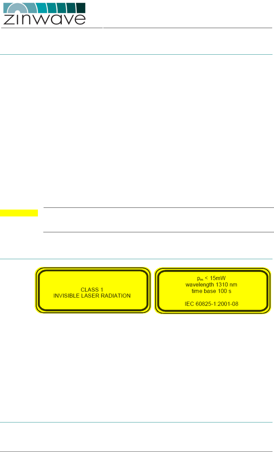
Zinwave 2700 DAS – User Manual
Issue 1.2
April 2007
© Zinwave Ltd. 2007
A.2 General safety considerations
The installation of electrical supplies in support of Zinwave 2700 DAS products shall
be in accordance with national and local regulations.
Other aspects of the installation of Zinwave 2700 DAS products and interconnecting
cabling shall be in accordance with the following standards:
A.2.1 Cabling installation
o EN 50174 series: Information technology – Cabling installation
A.2.2 Optical safety
o IEC 60825-2: Safety of laser products - Part 2: Safety of optical fiber
communication systems (OFCS).
A.2.3 RF exposure
CAUTION This equipment complies with FCC radiation exposure limits set forth for an
occupational/ controlled environment. This equipment should be operated with a
minimum distance of 20cm between radiator and your body.
A.3 Optical Safety Precautions
o Do not stare with unprotected eyes at the connector ends of the fiber or the
ports of the SFP. Do not remove the Fiber Port dust covers unless the port is in
use. Do not stare directly into a Fiber Port.
o Cover any unconnected fiber ends with an approved cap.
o Do not stare with unprotected eyes at any broken ends of the fiber.
o Use only approved methods for cleaning optical fiber connectors.
o Do not make any unauthorized modifications to this fiber optical system.
o No warning signs are required as it is a Class 1 hazard.
o Use Class 1 test equipment.
A.4 Installation, Use and Storage
The Zinwave 2700 DAS is designed to operate in conditions conformant with Pollution
Degree 2 as defined in IEC 60950 (the normal environmental class for offices).

Zinwave 2700 DAS – User Manual
Issue 1.2
April 2007
© Zinwave Ltd. 2007
The installation of sub-assemblies into the main units of the Zinwave 2700 DAS shall
only be undertaken if precautions required by IEC/TS 61340-5-1 have been taken.
This covers:
o the installation of Zinwave 2780 SFP optical fiber transceiver modules into the
Zinwave 2700 Hub Unit,
o the replacement of the Zinwave 2781 SFP optical fiber transceiver modules in
the Zinwave 2760 Antenna Unit.
WARNING CLASS I PLUGGABLE EQUIPMENT TYPE A as defined in IEC 60950. This
equipment is intended for connection to other equipment or a network, relies on
connection to protective earth and must be connected to an earthed mains socket-
outlet.
Country specific warnings:
Finland "Laite on liitettävä suojamaadoituskoskettimilla varustettuun pistorasiaan "
Norway “Apparatet må tilkoples jordet stikkontakt”
Sweden "Apparaten skall anslutas till jordat uttag"
A.5 Signal and input power
CAUTION The input power to the 2700 Hub Unit should not exceed +10 dBm. Power levels
greater than +20 dBm will damage the unit
CAUTION The input power to the Zinwave Antenna Unit Hub (2760 / 2765 / 277X) should not
exceed -15 dBm. Power levels greater than 0 dBm will damage the unit
CAUTION The total broadband composite output power is limited to +6dBm (2760) / + 12dBm
(2765) / +18dBm (277X).

Zinwave 2700 DAS – User Manual
Issue 1.2
April 2007
© Zinwave Ltd. 2007
Appendix B
System Information
B.1 Overview
This appendix provides you with hardware specifications, options, and part numbers
for the following.
o 2700 Hub Unit
o 2760 wideband AU
o 2765 wideband AU
o 2776 band-specific AU (GSM850 / PCS1900)
o 2777 band-specific AU (GSM900 / UMTS)
o 2778 band-specific AU (DCS1800 / UMTS)
B.2 ZinConfig/CLI Hardware and Software Requirements
The following are the recommended minimum computer requirements
o Windows 2000 or XP operating system
o 1 RS-232 DB9 serial port or external serial adaptor
o 10BASE-T Ethernet port or faster
o 10 megabytes free hard disk space
o 800 x 600 display resolution
o CD-ROM drive (for software installation)

Zinwave 2700 DAS – User Manual
Issue 1.2
April 2007
© Zinwave Ltd. 2007 Page 61
B.3 System specification
B.3.1 Channel transmission performance
Parameter Value Unit Comments
Min. Nom. Max.
Input impedance 50 Ohms At HU service & AU uplink inputs
Output impedance 50 Ohms At HU service & AU downlink outputs
Operating Temperature Range 0 +55 °C Ambient, non-condensing
Channel length - MMF 1 550 m OM1 (62.5/125 µm
1
), OM2, OM3 (both 50/125 µm)
Channel insertion loss - MMF 0 4 dB @ 1300 nm, includes fiber attenuation and connector losses
Channel length - SMF 1 2000 m
Channel insertion loss - SMF 0 4 dB @ 1310 nm, includes fiber attenuation and connector losses
TX-RX Isolation
2
30 dB HU service input to service output (same service)
TX-RX Isolation
2
70 dB HU service input to any other service output
TX-TX Isolation
2
70 dB HU service input to any other service input
Antenna Isolation 35 dB AU antenna output to AU antenna input
NOTE 1: Minimum modal bandwidth @ 1300 nm = 500 MHz·km. Reduced channel lengths/insertion loss values may be supportable for lower modal
bandwidth options following detailed analysis by Zinwave.
NOTE 2: At max HU RF input power, max AU RF output power, maximum uplink noise figure and for any RF combiner distribution
B.3.2 System Downlink RF parameters
Parameter Value Unit Comments
Min. Nom. Max.
System Bandwidth
2760/2765 AU
2776 AU
370
869-894
2500
1930-1990
MHz
MHz
Wideband Unit
Dual band GSM850 / PCS1900

Zinwave 2700 DAS – User Manual
Issue 1.2
April 2007
© Zinwave Ltd. 2007 Page 62
Parameter Value Unit Comments
Min. Nom. Max.
2777 AU
2778 AU
925-960
1805-1880
2110-2170
2110-2170
MHz
MHz
Dual band GSM900 / UMTS
Dual band DCS1800 / UMTS
RF input power -5 0 +10 dBm At HU service input with 14dB peak-average-ratio
RF output power
2760 AU
2765 AU
2776 AU
2777 AU
2778 AU
+ 6
+12
+18
+18
+18
dBm
dBm
dBm
dBm
dBm
Broadband RMS composite power at AU antenna output
Broadband RMS composite power at AU antenna output
CW power (+15 dBm composite for W-CDMA & CDMA)
CW power (+15 dBm composite for W-CDMA & CDMA)
CW power (+15 dBm composite for W-CDMA & CDMA)
VSWR 1.5:1
Return loss 14 dB
Response variation -5 +5 dB Full bandwidth
Response variation -1 +1 dB Any 5 MHz band
Response variation -2 +2 dB Any 100 MHz band
B.3.3 System Uplink RF parameters
Parameter Value Unit Comments
Min. Nom. Max.
System Bandwidth
2760/2765 AU
2776 AU
2777 AU
2778 AU
370
824-849
880-915
1710-1785
2500
1850-1919
1920-1980
1920-1980
MHz
MHz
MHz
MHz
Wideband Unit
Dual band GSM850 / PCS1900
Dual band GSM900 / UMTS
Dual band DCS1800 / UMTS
RF input power – operation -15 dBm Input gain adjustment for minimum coupling loss
RF input power – absolute max 0 dBm Exceeding this value can result in permanent damage to the unit.

Zinwave 2700 DAS – User Manual
Issue 1.2
April 2007
© Zinwave Ltd. 2007 Page 63
Parameter Value Unit Comments
Min. Nom. Max.
Max RF output power -20 -10 dBm At HU service output for 1dB compression with maximum AU input
power
Response variation -5 +5 dB Full bandwidth
Response variation -1 +1 dB Any 5 MHz band
Response variation -2 +2 dB Any 100 MHz band
B.3.4 Zinwave 2700 Hub Unit physical parameters
Parameter Value Unit Comments
Min. Nom. Max.
Height 44 (1.8) mm (in)
Width 445 (17.5) mm (in)
Depth 270 (10.6) mm (in)
Weight 3.5 kg
Mains power voltage 100 250 VAC
Mains power frequency 50 60 Hz
Mains power consumption 15 W
Mains power interface 1 - IEC Socket
RF interfaces 8 - SMA female (separate TX and RX providing 4 RF I/O pairs)
Optical interfaces - - 8 - Using Zinwave 2780 SFP modules
Control interfaces 1 - IEC 60603-7 (RJ-45) 10BASE-T
Control interfaces 1 - 9-pin D connector (RS232 - CLI)
Temperature - operating 0 +55
o
C
Temperature - storage -25 +55
o
C

Zinwave 2700 DAS – User Manual
Issue 1.2
April 2007
© Zinwave Ltd. 2007 Page 64
B.3.5 Zinwave 2780 + 2781 SFP module physical parameters
Parameter Value Unit Comments
Min. Nom. Max.
Weight 0.04 kg
Optical interfaces - - 1 - IEC 61754-20 (LC-Duplex)
Temperature – operating 0
0
+85
+55
o
C
o
C
2780 SFP
2781 SFP
Temperature - storage -25 +55
o
C
B.3.6 Zinwave 2760 Antenna Unit physical parameters
Parameter Value Unit Comments
Min. Nom. Max.
Height 215 (8.5) mm (in)
Width 130 (5.1) mm (in)
Depth 45 (1.8) mm (in)
Weight 0.75 kg
Power supply voltage 40 48 V
Power supply frequency DC -
Power consumption 3 W
Power supply interface – AC/DC 1 - LEMO
Power supply interface – PoE 1 - IEC 60603-7 (RJ-45)
RF interfaces 2 - SMA female
Optical interfaces 1 - IEC 61754-20 (LC-Duplex)
Temperature - operating 0 +45
o
C
Temperature - storage -25 +55
o
C

Zinwave 2700 DAS – User Manual
Issue 1.2
April 2007
© Zinwave Ltd. 2007 Page 65
B.3.7 Zinwave 2765 Antenna Unit physical parameters
Parameter Value Unit Comments
Min. Nom. Max.
Height 200 (8.0) mm (in)
Width 120 (4.75) mm (in)
Depth 60 (2.4) mm (in)
Weight 0.75 kg
Power supply voltage 40 48 V
Power supply frequency DC -
Power consumption 15 W
Power supply interface – PoE 1 - IEC 60603-7 (RJ-45)
RF interfaces 2 - SMA female
Optical interfaces 1 - SC-Duplex
Temperature - operating 0 +45
o
C
Temperature - storage -25 +55
o
C
B.3.8 Zinwave 277X Antenna Unit physical parameters
Parameter Value Unit Comments
Min. Nom. Max.
Height 120 (4.75) mm (in)
Width 370 (14.5) mm (in)
Depth 260 (10.25) mm (in)
Weight 5.3 kg
Power supply voltage 40 48 V

Zinwave 2700 DAS – User Manual
Issue 1.2
April 2007
© Zinwave Ltd. 2007 Page 66
Parameter Value Unit Comments
Min. Nom. Max.
Power supply frequency DC -
Power consumption 15 W
Power supply interface – PoE 1 - IEC 60603-7 (RJ-45)
RF interfaces 1 - N-type female
Optical interfaces 1 - SC-Duplex
Temperature - operating 0 +45
o
C
Temperature - storage -25 +55
o
C

Zinwave 2700 DAS – User Manual
Issue 1.2
April 2007
© Zinwave Ltd. 2007 Page 67
Appendix C
Glossary of terms
C.1 Abbreviations
2G 2
nd
Generation
3G 3
rd
Generation
AGC Automatic Gain Control
AP Access Point
AU Antenna Unit
CDMA Code Division Multiple Access
CEN European Committee for Standardization
CENELEC European Committee for Electrotechnical Standardization
CISPR Comité International Spécial des Perturbations Radioélectriques
CLI Command Line Interface
DAS Distributed Antenna System
dB Decibels
dBm Decibels referenced to one milliwatt
DCS Digital Cellular System
EDGE Enhanced Data rates for GSM Evolution
EMC Electromagnetic Compatibility
EN Euronorm (European Standard)
ESD Electro Static Discharge
ETSI European Telecommunications Standards Institute
EVDO Evolution-Data Optimized
FCC Federal Communications Commission
GSM Global System for Mobile Communications
HU Hub Unit
Hi-conn High concentricity
iDEN integrated Dispatched Enhanced Network
IEC International Electrotechnical Commission
LMR Land Mobile Radio (US Department of Defense)
MMF Multimode optical fiber

Zinwave 2700 DAS – User Manual
Issue 1.2
April 2007
© Zinwave Ltd. 2007 Page 68
R&TTE Radio and Telecommunication Terminal Equipment
RF Radio frequency
RMA Returns Material Authorization
Rx (RX) Receiver
SFP Small Form Pluggable
SMF Singlemode optical fiber
SNMP Simple Network Management Protocol
TDMA Time division multiple access
TETRA Terrestrial Trunked Radio
Tx (TX) Transmitter
UMTS Universal Mobile Telecommunications System
VSWR Voltage Standing Wave Ratio
W-CDMA Wideband - Code division multiple access
WLAN Wireless Local Area Network