Zinwave 302-0006 Zinwave DAS3000 Booster User Manual 3000 DAS UG
Zinwave Ltd Zinwave DAS3000 Booster 3000 DAS UG
Zinwave >
Contents
- 1. User manual
- 2. User Manual
User manual

Zinwave 3000
Distributed Antenna System
User Guide
3000_DAS_UG_v1.11

2 Zinwave 3000 DAS User Guide
© Zinwave Ltd. 2008
No part of this manual may be reproduced in any form or by any means (including electronic
storage and retrieval or translation into a foreign language) without prior agreement and
written consent from Zinwave Ltd. as governed by United Kingdom and international
copyright laws.
Edition
Issue 3000_DAS_UG_v1.11, October 2008
Warranty
The material contained in this document is provided “as is,” and is subject to being changed,
without notice, in future editions. Further, to the maximum extent permitted by applicable
law, Zinwave disclaims all warranties, either express or implied, with regard to this manual
and any information contained herein, including but not limited to the implied warranties of
merchantability and fitness for a particular purpose. Zinwave shall not be liable for errors or
for incidental or consequential damages in connection with the furnishing, use, or
performance of this document or of any information contained herein. Should Zinwave and
the user have a separate written agreement with warranty terms covering the material in
this document that conflict with these terms, the warranty terms in the separate agreement
shall control.
Technology licenses
The hardware and/or software described in this document are furnished under a license and
may be used or copied only in accordance with the terms of such license.
Trademark acknowledgements
Pentium ® is a registered trademark of Intel Corporation. Adobe ® is a trademark of Adobe
Systems Incorporated. Windows XP, Windows 2000, and Windows 98 are U.S. registered
trademarks of Microsoft Corporation. Macintosh is a trademark of Apple Computer. Linux is
a trademark of Linus Torvalds. All other trademarks are the property of their respective
holders.
About this guide
This guide contains hardware installation and software configuration & operating instructions
for the Zinwave 3000 Distributed Antenna System (DAS).
Warning: A WARNING notice denotes a hazard. It calls attention to an operating
procedure, practice, or the like that, if not correctly performed or adhered to, could result
in personal injury or death. Do not proceed beyond a WARNING notice until the indicated
conditions are fully understood and met.
Caution: A CAUTION notice denotes a hazard. It calls attention to an operating
procedure, practice, or the like that, if not correctly performed or adhered to, could result
in damage to the product or loss of important data. Do not proceed beyond a CAUTION
notice until the indicated conditions are fully understood and met.

3
Safety notices
Cautions and warnings
Caution: This unit is fitted with a 5A 20x5mm anti-surge ceramic fuse (RC). For continued
protection against risk of fire, replace only with same type and rating of fuse. Keep all
product information for future reference.
Warning: High voltages exist inside the product; Do not remove the lid or base: No user
serviceable parts inside.
Warning: If this product is not used as specified, the protection provided by the equipment
could be impaired. This product must be used in a normal condition (in which all means for
protection is intact) only. No operator serviceable parts are inside this system. Refer
servicing to an authorized Zinwave Ltd service centre. To prevent electrical shock, do not
remove the covers.
Notes
•Read this User Manual and follow all operating and safety instructions.
•Position the power cord to avoid possible damage; do not overload wall outlets.
•Do not place this product on or near a direct heat source, and avoid placing objects on
the terminal.
•Do not operate this device near water or in a wet location.
•Use only a damp cloth for cleaning. Do not use liquid or aerosol cleaners. Disconnect
the power before cleaning.
•Installation of the 3000 DAS system must be contracted to a suitably trained and
competent professional installer.
Declaration of Conformity
•Hereby, Zinwave Ltd, declares that this Distributed Antenna System is in compliance
with the essential requirements and other relevant provisions of Directive 1999/5/EC.
•Zinwave Ltd, vakuuttaa täten että Distributed Antenna System tyyppinen laite on
direktiivin 1999/5/EY oleellisten vaatimusten ja sitä koskevien direktiivin muiden ehtojen
mukainen.
•Hierbij verklaart Zinwave Ltd, dat het toestel Distributed Antenna System in
overeenstemming is met de essentiële eisen en de andere relevante bepalingen van
richtlijn 1999/5/EG
•Bij deze verklaart Zinwave Ltd, dat deze Distributed Antenna System voldoet aan de
essentiële eisen en aan de overige relevante bepalingen van Richtlijn 1999/5/EC.
•Par la présente, Zinwave Ltd, déclare que ce Distributed Antenna System est conforme
aux exigences essentielles et aux autres dispositions de la directive 1999/5/CE qui lui
sont applicables
•Härmed intygar Zinwave Ltd, att denna Distributed Antenna System står I
överensstämmelse med de väsentliga egenskapskrav och övriga relevanta bestämmelser
som framgår av direktiv 1999/5/EG.
•Undertegnede Zinwave Ltd, erklærer herved, at følgende udstyr Distributed Antenna
System overholder de væsentlige krav og øvrige relevante krav i direktiv 1999/5/EF
4 Zinwave 3000 DAS User Guide
•Hiermit erklärt Zinwave Ltd., dass sich dieser Distributed Antenna System in
Übereinstimmung mit den grundlegenden Anforderungen und den anderen relevanten
Vorschriften der Richtlinie 1999/5/EG befindet
•ΜΕ ΤΗΝ ΠΑΡΟΥΣΑ Zinwave Ltd, ΔΗΛΩΝΕΙ ΟΤΙ Distributed Antenna System
ΣΥΜΜΟΡΦΩΝΕΤΑΙ ΠΡΟΣ ΤΙΣ ΟΥΣΙΩΔΕΙΣ ΑΠΑΙΤΗΣΕΙΣ ΚΑΙ ΤΙΣ ΛΟΙΠΕΣ
ΣΧΕΤΙΚΕΣ ΔΙΑΤΑΞΕΙΣ ΤΗΣ ΟΔΗΓΙΑΣ 1999/5/ΕΚ
•Con la presente Zinwave Ltd, dichiara che questo Distributed Antenna System è
conforme ai requisiti essenziali ed alle altre disposizioni pertinenti stabilite dalla direttiva
1999/5/CE.
•Por medio de la presente Zinwave Ltd, declara que el Distributed Antenna System
cumple con los requisitos esenciales y cualesquiera otras disposiciones aplicables o
exigibles de la Directiva 1999/5/CE
•Zinwave Ltd, declara que este Distributed Antenna System está conforme com os
requisitos essenciais e outras disposições da Directiva 1999/5/CE.
Optical Remote Unit interference
Warning: This is a class A product (as defined in EN 55022). In a domestic environment
this product may cause radio interference, in which case the user may be required to take
adequate measures.
FCC compliance and interference statements
Hub. This device complies with Part 15 of the FCC rules. Operation is subject to the
following two conditions:
1) This device must accept any interference and
2) This device must accept any interference received including interference that may cause
undesired operation
Changes or modifications not expressly approved by Zinwave Ltd. could void the user’s
authority to operate the equipment.
Remote Unit. This device complies with Part 22, Part 24, Part 27 and Part 90 of the FCC
rules. Changes or modifications not expressly approved by Zinwave Ltd. could void the user’s
authority to operate the equipment. For a list of services, please contact Zinwave.
Remote Units with FCC ID:UPO302-0006 and FCC ID:UPO302-0007 only support services
in the following bands of operation:
•406.1 – 454.0 MHz
•456.0 – 512.0 MHz
•698.0 – 824.0 MHz
•851.0 – 869.0 MHz
•869.0 – 894.0 MHz
•928.0 – 929.0 MHz
•931.0 – 935.0 MHz
•935.0 – 940.0 MHz
•1930.0 – 1990.0 MHz
•2110.0 – 2155.0 MHz

5
Rack mount instructions
Caution: Double Pole/Neutral Fusing.
•Elevated Operating Ambient – If installed in a closed or multi-unit rack assembly, the
operating ambient temperature of the rack environment may be greater than room
ambient. Therefore, consideration should be given to installing the equipment in an
environment compatible with the maximum ambient temperature (Tma) specified by the
manufacturers. 3000 DAS Primary and Secondary Hubs have a Tma of 45°C.
•Reduced Air Flow – Installation of the equipment in a rack should be such that the
amount of air flow required for safe operation of the equipment is not compromised.
•Mechanical Loading – Mounting of the equipment in the rack should be such that a
hazardous condition is not achieved due to uneven mechanical loading.
•Circuit Overloading – Consideration should be given to the connection of the equipment
to the supply circuit and the effect that overloading of the circuits might have on
overcurrent protection and supply wiring. Appropriate consideration of equipment
nameplate ratings should be used when addressing this concern.
•Reliable Earthing – Reliable earthing of rack-mounted equipment should be maintained.
Particular attention should be given to supply connections other than direct connections
to the branch circuit (e.g. use of power strips).
•Disconnect Device – The socket outlet shall be installed near the equipment, be easily
accessible and will act as the disconnect for the Hub.
•Keep these Instructions in a safe place.
6 Zinwave 3000 DAS User Guide
General safety considerations
The installation of electrical supplies in support of Zinwave 3000 DAS products shall be in
accordance with national and local regulations.
Other aspects of the installation of Zinwave 3000 DAS products and interconnecting cabling
shall be in accordance with the following standards:
•EN 50174 series: Information technology – Cabling installation
•IEC 60825-2: Safety of laser products – Part 2: Safety of optical fibre communication
systems (OFCS)
•This equipment complies with 21CFR1040 - Performance Standards For Light-Emitting
Products (FDA).
RF exposure
Warning: This equipment complies with FCC radiation exposure limits set forth for an
occupational/ controlled environment. This equipment should be operated with a minimum
distance of 20cm between radiator and your body.
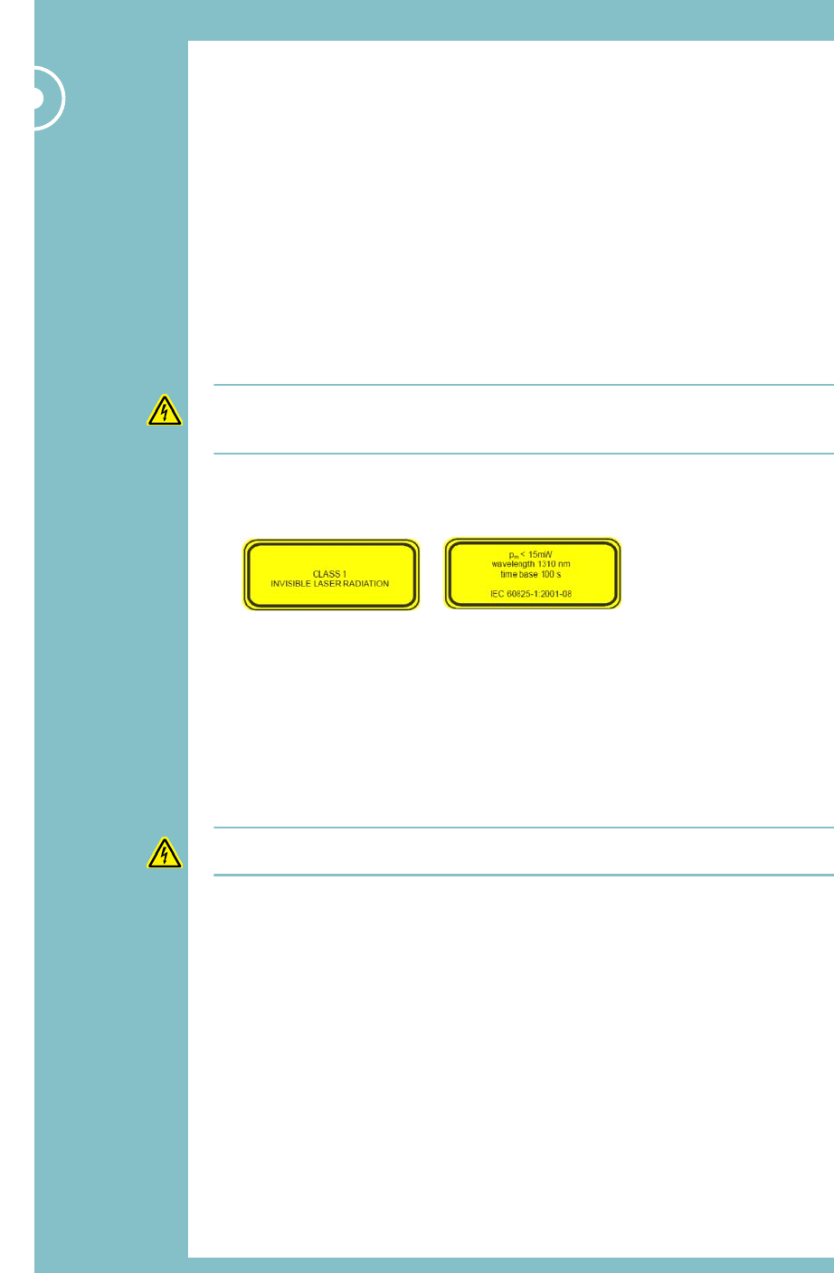
Optical Safety Precautions
•Do not remove the Fibre Port dust covers unless the port is in use. Do not stare
directly into a Fibre Port.
•Cover any unconnected fibre ends with an approved cap.
•Do not stare with unprotected eyes at any broken ends of the fibre.
•Use only approved methods for cleaning optical fibre connectors.
•Do not make any unauthorized modifications to this fibre optical system.
•No warning signs are required as it is a Class 1 hazard.
•Use Class 1 test equipment.
Warning: Use of controls or adjustments or performance of procedures other than those
specified herein may result in hazardous radiation exposure.
7
Installation, use and storage
The Zinwave 3000 DAS is designed to operate in conditions conformant with Pollution
Degree 2 as defined in IEC 60950 (the normal environmental class for offices).
The installation of sub-assemblies into the main units of the Zinwave 3000 DAS shall only be
undertaken if precautions required by IEC/TS 61340-5-1 have been taken.
This covers the installation of Zinwave Optical Link modules into the Zinwave 3000 DAS
Hub Unit.
Warning: CLASS I PLUGGABLE EQUIPMENT TYPE A as defined in IEC 60950. This
equipment is intended for connection to other equipment or a network, relies on
connection to protective earth and must be connected to an earthed mains socket-outlet.
Country specific warnings:
Finland "Laite on liitettävä suojamaadoituskoskettimilla varustettuun pistorasiaan"
Norway “Apparatet må tilkoples jordet stikkontakt”
Sweden "Apparaten skall anslutas till jordat uttag"
Caution: Unit operating voltage is factory set at either 120V or 230V and cannot be
changed by an operator. Check which variant is supplied and only operate at the rated
voltage.
Signal and input power
Caution: The input power to the 3000 DAS Hub Unit should not exceed +10dBm. Power
levels greater than +25dBm will damage the unit
Caution: The input power to the Zinwave Remote Unit should not exceed -10dBm. Power
levels greater than 0dBm will damage the unit
Caution: The total broadband composite output power is limited to +18dBm in Europe
and +20dBm in the USA and Canada. The maximum allowed EIRP in the USA & Canada is
+28dBm which corresponds to an antenna gain of 8dBi. Contact Zinwave for the maximum
output power in other regions.
Caution: The maximum allowed antenna gain when operating in Europe in the 2.4GHz ISM
band shall be +2dBi. Contact Zinwave for further information regarding use of the ISM band
in other regions.

8 Zinwave 3000 DAS User Guide

Zinwave 3000 DAS User Guide 9
Table of Contents
Safety notices 3
General safety considerations 6
Optical Safety Precautions 6
Installation, use and storage 7
Signal and input power 7
1 System Description . . . . . . . . . . . . . . . . . . . . . . . 11
1.1 Key features 12
1.2 Multimode fibre technology 12
1.3 System architecture 12
2 Hardware Installation . . . . . . . . . . . . . . . . . . . . . 13
2.1 Overview 14
2.2 Installing the Primary Hub 16
2.3 Installing the Secondary Hub 18
2.4 Installing Remote Units and Antennas 19
2.5 Making the signal connections 21
2.6 Connecting service inputs 22
3 Configuration and Control . . . . . . . . . . . . . . . . . 23
3.1 Overview 24
3.2 Before you start 24
3.3 Initial Hub configuration 25
3.4 Detailed Hub configuration 28

10 Zinwave 3000 DAS User Guide

Zinwave 3000 DAS User Guide 11
Chapter 1
SYSTEM DESCRIPTION
The Zinwave 3000 Distributed Antenna System is a
wideband in-building system that provides excellent RF
coverage for a multitude of wireless services, irrespective
of carrier frequency or signal protocol.
•Different services are carried without multiple infrastructure overlays, or specific band
units. New services can be easily integrated without adding more components to the
infrastructure.
•The 3000 DAS double-star architecture (Primary Hub Unit, Secondary Hub Unit and
Remote Units) provides enhanced scalability; a single-star configuration supports small
site solutions.
•Modular system design means the same equipment can be used for a wide variety of
applications.

12 Zinwave 3000 DAS User Guide
System Description
1.1 Key features
•Simple 3-stage fibre-optic DAS: one Primary Hub Unit (PH) distributes to eight
Secondary Hub Units (SH), each of which distributes to eight Remote Units (RUs). This
gives a maximum of 64 RUs fed by one PH (when more RUs are required, more than
one PH can be used)
•The same components support a 2-stage, single star configuration: one Primary Hub Unit
(PH) distributing to eight RUs
•Wide frequency range: 136 - 2700 MHz, with both FDD and TDD systems supported
•Each Hub has four inputs. All four are used as service inputs in the Primary Hub; In the
Secondary Hub, one input is used for optical connection to the Primary Hub (with a
second for service distribution flexibility or redundancy if required) and the remainder
can be used for local service signal injection (such as WiFi)
•Only system to deliver truly broadband solution over multimode fibre (MMF), but can
also be used over singlemode fibre (SMF)
•Optional Coax or Fibre link connection to the RUs
•Remote Units are remotely powered from the hub
•Maximum total supported cable distances: 100m (Coax LMR400), 550m (MMF), 2000m
(SMF)
•Self calibrating system, gain levels adjusted automatically to accommodate different cable
lengths
•Hot-pluggable Optical & Coaxial transceiver modules used in PH and SH
•Web-based and SNMP network management, plus local command interface
•Unique service distribution matrix on the hubs.
1.2 Multimode fibre technology
The 3000 DAS is the only system that provides a truly wideband solution based on
multimode fibre (MMF). Zinwave's technology extends the bandwidth of in-situ MMF optic
cables to conduct multiple radio frequency signals, at original carrier frequency, over long
distances.
1.3 System architecture
The 3000 DAS system is built from Hub Units and Remote Units (RU). Smaller systems
comprise a single Hub and up to 8 RUs. Larger systems comprise one or two Primary Hubs,
each of which can serve up to eight Secondary Hubs (and hence up to sixty-four RUs).
The RUs can be:
•wideband coaxial or fibre fed
•band-specific coaxial or fibre fed.

Zinwave 3000 DAS User Guide 13
Chapter 2
HARDWARE INSTALLATION
This chapter explains how to install Primary and Secondary
Hubs, Remote Units and Antennas.
14 Zinwave 3000 DAS User Guide
Hardware Installation
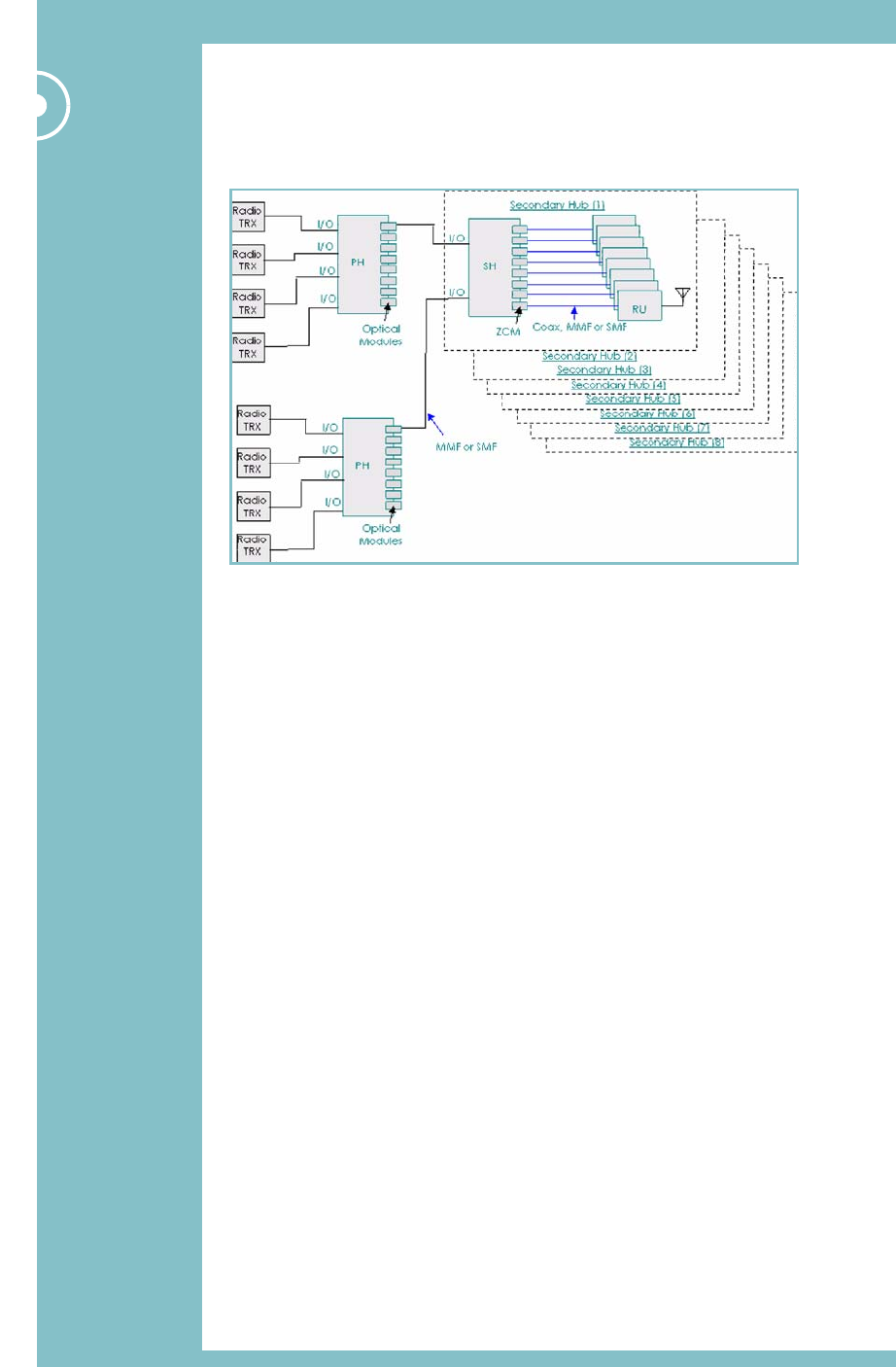
2.1 Overview
Rather than trying to cover every possible network topology in this guide, we’ll explain how
to install each type of unit in a simple dual-star configuration.
Fig. 2-1 Simple dual-star configuration to illustrate installation procedures
Generally, you should install Zinwave 3000 DAS hardware in the following order:
•Install the Primary Hub:
–Install into a 19" rack.
–Provide mains power to Primary Hub and switch on.
–Populate the Primary Hub with Service, Drive and Link Modules.
•Install the Secondary Hub into a 19" rack, provide power and populate with Modules.
•Install Remote Units (RU) and Antennas
•Make optical and RF connections:
–Connect Primary and Secondary Hubs via fibre infrastructure.
–Connect Remote Units (RU) to Hubs.
–Connect Antennas to Remote Units (RU)
That’s the main part of the hardware installation process. Once complete, later chapters
explain how to:
•Configure and test the network before you connect your services.
•Connect service inputs to Hubs.
Once you’ve got this far, you’re ready to configure your system using the pre-installed
software, via a web browser. This is explained in Configuration and Control on page 23.
Hardware Installation 15
Hardware Installation
2.1.1 Module types
Before installing modules, it may help to understand what each module does, and where it
can be installed (i.e. front or rear panel of a Hub):
Table 2-1 Zinwave 3000 DAS Module types
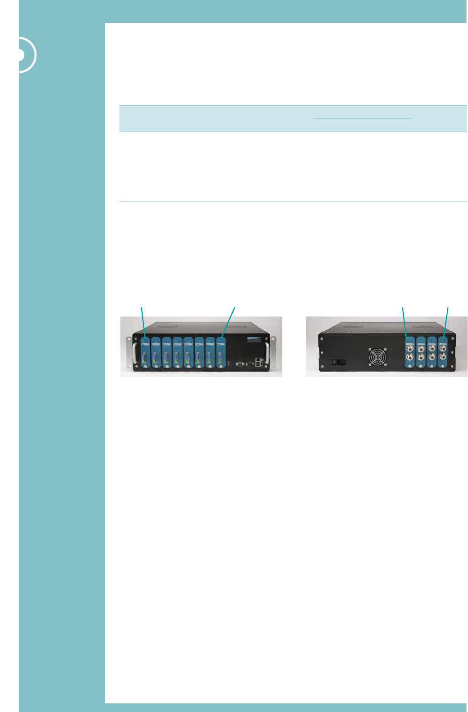
2.1.2 Slot numbering
The slots on the front and rear panels adhere to a numbering system that is reflected in the
web-based configuration application:
•Front (from left to right, looking from the front of the unit) slots 1 to 8
•Rear (from right to left, looking from the rear of the unit) slots A to D
Module Description
Installed in?
ConnectorsPrimary Secondary
Service Input of RF signal sources (e.g. BDA, BTS,
WLAN access point)
Rear slots Rear slots N-type female
Optical Link Fibre (SM-MM) link between Primary and
Secondary Hubs
Front slots Rear Slots Zinwave SC
RU Drive Currently, coaxial link from Hub to RU.
Power and signal to RU are provided over
the coaxial link.
Front slots Front slots N-type female
18 DA
16 Zinwave 3000 DAS User Guide
Hardware Installation
2.2 Installing the Primary Hub
Caution: Installation of the equipment in a rack should be such that the amount of air flow
required for safe operation of the equipment is not compromised. Leave sufficient space
around ventilation holes in the top and bottom of the Hub casing.
2.2.1 Install the Hub into a rack
Caution: 3000 DAS Hubs are heavy 3U units (18kg) which must be supported front and
rear when installed into a 19" rack.
There are many 19" rack systems on the market of various depths. It is essential that the
weight of the hub is supported front and rear. If it is not possible to use both sets of
brackets, alternative supports mechanisms must be used such as front-to-rear chassis
runners or fully supported shelves. Once installed, the unit should be fixed into the rack
using the supplied rack-mount brackets.
It is beyond the scope of this manual to cover all rack depths and mounting systems. Here
we give an example installation using the supplied rack-mounting brackets.
2.2.1.1 Installing using the supplied rack-mount brackets
You’ll need the following tools and equipment before you start:
•4 x rack-mount brackets
•8 x (screws to fix brackets to Hub)
•8 x M6 cage nuts
•8 x M6 nylon cup washer
•8 x M6 x 16 pozi pan head screw
•M6 pozi-driv screwdriver
•Flat-bladed screwdriver
•Cage nut insertion/extraction tool
To install the Primary Hub:
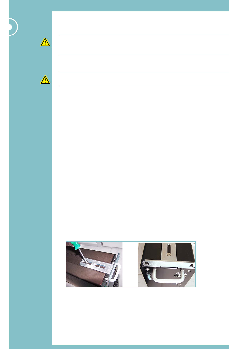
1Fix the four rack-mount brackets to the Primary Hub.
2Adjust the position of the brackets to suit the depth of the 19" rack being used. If using
a 455mm (18inch) rack depth when complete, the brackets should be flush with the
front and rear of the Hub.
Hardware Installation 17
Hardware Installation
3Install the eight cage nuts into the rack using a cage nut
insertion/extraction tool.
You’ll need to take the rack-mount bracket size and Hub
size into account when fitting the cage nuts (you need
clearance above and below the brackets, as shown).
4Fit the Hub into the rack using the pan head screws and
nylon washers.
2.2.2 Provide mains power to Primary Hub
Caution: Unit operating voltage is factory set at either 120V or 230V and cannot be
changed by an operator. Check which variant is supplied and only operate at the rated
voltage.
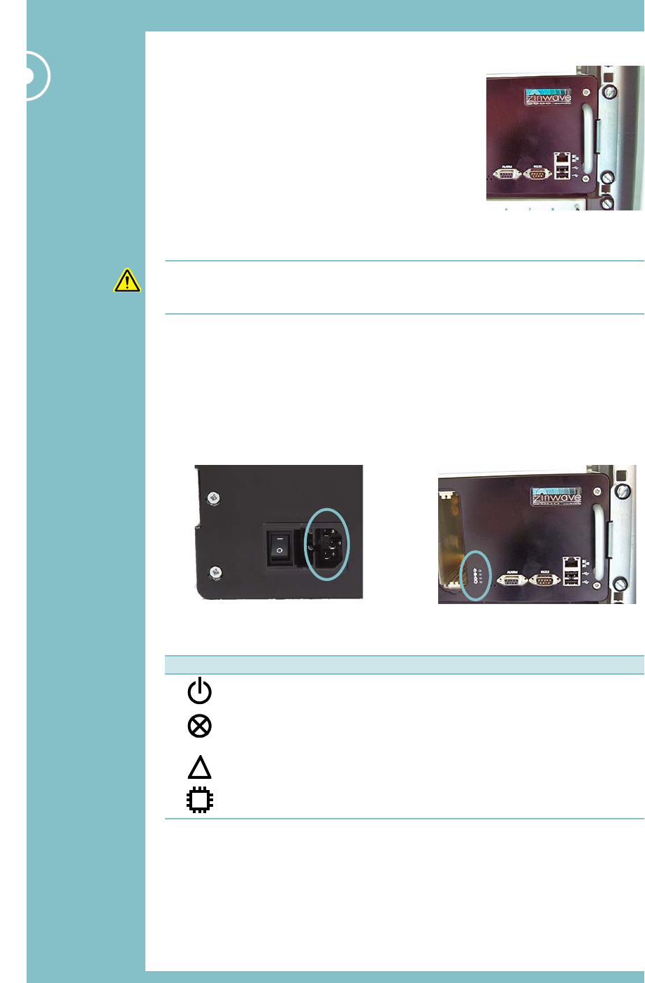
1Make sure that the ON/OFF switch is in the OFF (O) position.
2Connect the AC power cord to the Hub.
3Plug the AC power cord into an outlet providing AC power (either 110V or 230V,
50-60Hz).
4Switch on the Primary Hub.
5Check the LED status indicators show correct operation.
Table 2-2 HUB front panel LED status
Rear left of Hub Front right of Hub
Status LEDsmains power input
LED Status Description
Green
Off
Power connected to CPU board
No power connected
Green
Red
Red/Green Flashing
No error
Error relay activated
Firmware programming in progress
Green
Red
No warning
Warning relay activated
Green
Red
CPU running
CPU restarting
!
18 Zinwave 3000 DAS User Guide
Hardware Installation
2.2.3 Populate the Primary Hub
1Follow the instructions below to install any Service modules into the rear of the Primary
Hub.
2Follow the instructions below to install any RU Drive and Optical Link modules into the
front of the Primary Hub.
Caution: Optical Link Modules must be installed on the front panel in a Primary Hub, or
the unit will not function as expected.
2.2.3.1 Installing a Module (general instructions)
In order to make a good signal connection, all modules are a very snug fit when you install
them into a hub.
1If necessary, remove any blanking panels from slots that you want to populate. To do
this, remove the retaining screw using a flat-bladed screwdriver.
2Carefully align and slide the module into the hub.
3Once the module is in place, press it home firmly with your thumbs at the top and
bottom to ensure the internal contacts mate correctly.
4Replace the retaining screw and tighten using a flat-bladed screwdriver.
5It’s good practice to fit blanking plates (supplied) to any unused slots in the hub.
When you install a module into a slot, the three LEDs on the front of the module will
indicate operational status:
Table 2-3 Module LED status
2.3 Installing the Secondary Hub
Essentially, this is very similar to installing the Primary Hub, described in Section 2.2. The only
differences are in the modules you install:
1Install the Secondary Hub into the 19" rack.
2Provide mains power to the Secondary Hub and switch on.
Caution: Unit operating voltage is factory set at either 120V or 230V and cannot be
changed by an operator. Check which variant is supplied and only operate at the rated
voltage.
3Ethernet connection to Secondary Hub (optional).
4Rear panel: Install Optical Link Modules and any Service Modules (optional).
Caution: The Optical Link module must be installed on the rear panel in a Secondary Hub,
or the unit will not function as expected.
5Front panel: Install any RU Drive Modules.
LED Status Description
Lefthand LED Green
Red
Ready for use
Condition when first plugged in
Middle LED Green
Red
Off
Comms link running
No comms with unit
Disabled
Righthand LED Green
Red
Off
Unit normal
Fault
Disabled
Hardware Installation 19
Hardware Installation
2.4 Installing Remote Units and Antennas
You should mount the RUs and Antennas in the locations assigned in your system installation
plan. Antennas are supplied with 1m N-type (female) tails. For most installations, you will
need to supply longer coaxial cables to extend the distance between an RU and Antenna.
You’ll need the following tools and equipment before you start:
•Any extra coaxial extension cables (N-type male to N-type female).
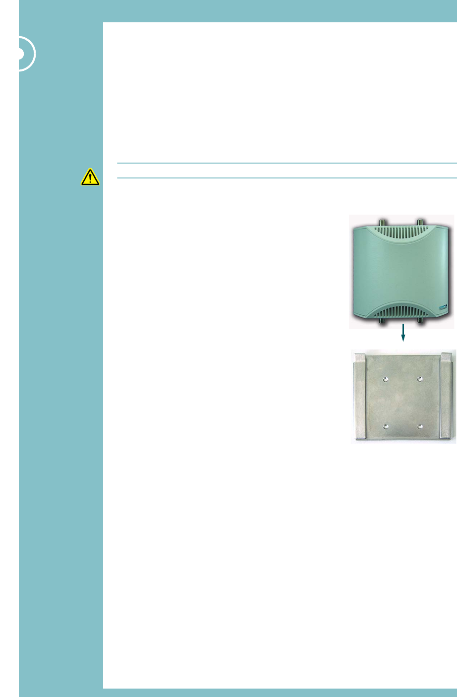
2.4.1 Mounting an RU
Caution: RUs must be vertically-mounted to ensure optimum cooling effect.
Often, RUs are sited in equipment rooms, out of sight. This also allows for easier cable
routing to the Antenna (which must exit from a hole in the ceiling).
1Note which way up the bracket goes.
2Offer the RU mounting bracket up to the wall.
3Mark the four holes using a pencil.
4Drill four M3 holes.
5Fix the bracket to the wall using four M3 screws and
appropriate fixings such as rawl plugs (not supplied).
6Position the RU above the bracket, then slide it down
onto the bracket.
Top of bracket
20 Zinwave 3000 DAS User Guide
Hardware Installation
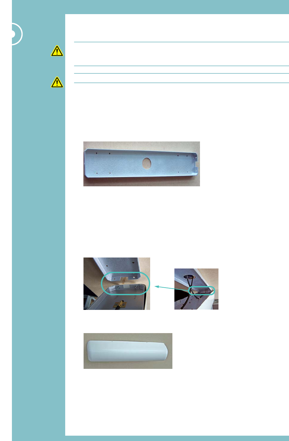
2.4.2 Mounting an Antenna
Caution: This section relates to Zinwave antenna units, which are dual-port (Tx/Rx)
devices. If you are using a third-party antenna unit, you must ensure there is adequate
isolation between Tx and Rx.
Caution: Antennas must be ceiling-mounted, horizontally, for correct operation.
An Antenna is supplied with 1m coaxial tails. You need to make a suitable hole in the ceiling
and feed the coaxial tails up into the space above, so that they are out of sight. Ensure that
any coaxial extension cables can reach from the RU to the Antenna.
1Separate the Antenna casing from the mounting bracket.
2Offer the Antenna mounting bracket up to the ceiling.
3Mark the eight screw holes and the large cable entry hole using a pencil.
4Drill eight M4 holes.
5Cut out the cable entry hole.
6Fix the bracket to the wall using eight M4 screws and appropriate fixings such as rawl
plugs (not supplied).
7Feed the 1m Antenna coaxial tails through the cable entry hole.
8Offer the Antenna up to the bracket. The Antenna will only fit one way round on the
bracket: Ensure the two locating screws in the Antenna mounting fit into the two holes
at one end of the mounting bracket.
9Lower the other end of the Antenna onto the mounting bracket and fix in place with the
screw (supplied).
Hardware Installation 21
Hardware Installation
2.5 Making the signal connections
Caution: Observe safety precautions when working with fibre cables and devices (see
Optical Safety Precautions on page 6).
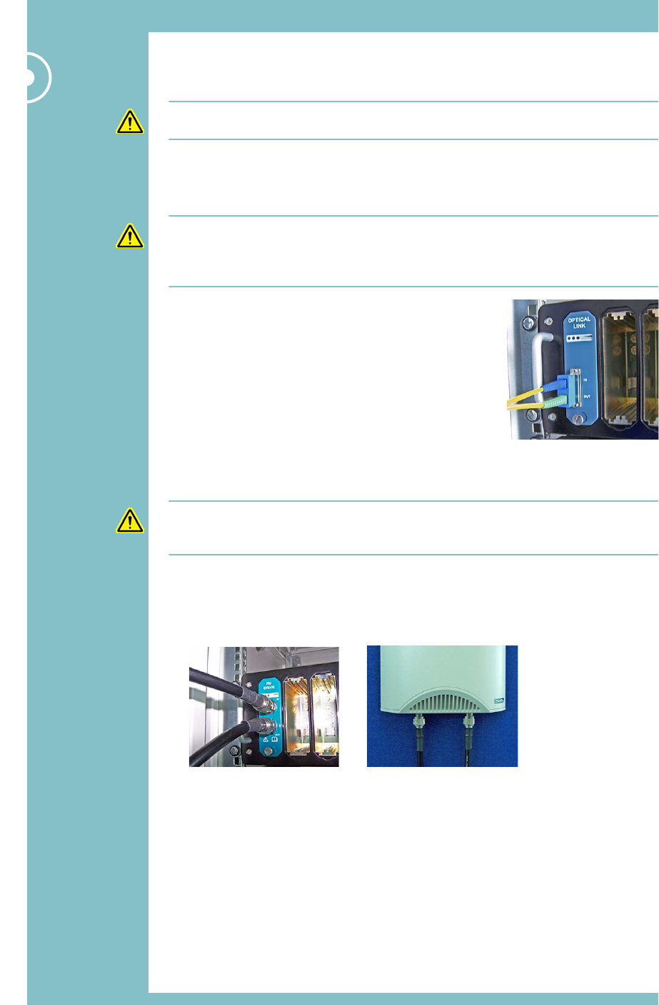
2.5.1 Connect Primary and Secondary Hubs to the fibre infrastructure
Follow these instructions for each Optical Link Module in the Primary and Secondary Hubs.
Caution: Zinwave Optical Link Modules use Single Mode on Transmit (APC) and Multimode
on the receive direction (PC). Both transmit and receive are SC Connectors.
All optical devices require a Zinwave patch cord irrespective of the existing or installed fibre
and connector type.
1Remove the protectors from the SC connectors on the
Optical Link Module and the Zinwave patch cord.
2Plug the green/blue end of the Zinwave SC optical patch
cable into the Optical Link Module. It is vital that you fit
this connector the right way up (blue tag at the top, as
shown). Incorrect installation will damage the ends of the
fibre.
3Connect the other end of the patch cable to your fibre
infrastructure (this will usually be via a fibre patch panel).
2.5.2 Connect Hubs to Remote Units (RUs)
Caution: Power and data is carried over the co-axial cable between the RU Drive Module
and the RU. The power carried is 16VDC, so you must not connect other equipment (e.g. a
spectrum analyzer) directly into the output of an RU Drive Module.
1Connect two coaxial cables (N-type male connectors) to the female connectors on the
RU Drive Module.
2Connect the other ends of the coaxial cables to the N-type female connectors on the
underside of the RU.

22 Zinwave 3000 DAS User Guide
Hardware Installation
2.5.3 Connect RUs to Antennas
If you’re not using extension RF cables:
1Connect the 1m coaxial tails of the Antenna to the top of
the RU.
If you are using extension RF cables (N-type male to N-type
female):
1Connect the two N-type male connectors to the top of
the RU.
2If you haven’t already done so, feed the RF extension cables through from the RU to the
Antenna.
3Connect the two N-type female connectors to the Antenna RF tails.
2.6 Connecting service inputs
You can connect Service inputs (e.g. BDA, BTS, WLAN access
point) to Primary and Secondary Hubs:
1Make N-type male connections to the N-type female
connectors on the Service Modules (on the rear of the
Hub).

Zinwave 3000 DAS User Guide 23
Chapter 3
CONFIGURATION AND CONTROL
This chapter explains how to use a web browser to
configure and control your Zinwave 3000 Distributed
Antenna System.

24 Zinwave 3000 DAS User Guide
Configuration and Control
3.1 Overview
The Zinwave 3000 DAS provides a built-in Element Management System (EMS), for
centralised monitoring, and configuration. With a user friendly web interface, the
management features can be accessed using a standard internet browser, and standard alarms
management tools – no proprietary equipment or software is required. An SNMP interface
supports integration with higher order NMS applications. Security features such as separate
user classes and secure communications via SSH & SSL are provided, along with support for
secure SNMP v3. Local diagnostics are also available via LEDs indicating equipment status on
the hubs for rapid fault isolation.
In brief, the steps you need to follow are:
•Make some initial configuration changes via a direct Ethernet connection to a standalone
PC:
–Configure a standalone PC so it can communicate directly (over Ethernet) with
factory-default Hubs
–Make an Ethernet connection to each Hub in turn from the standalone PC and set up
IP addressing (DHCP or fixed IP address) and Hub status (Primary or Secondary)
–Make final Ethernet connections as necessary to each Hub
•Configure each Hub via a web interface to the Primary Hub.
3.2 Before you start
Before you start to configure your Zinwave 3000 Distributed Antenna System, you should
have a firm idea of your final system architecture and any operational parameters (for
example, you may have used Zinwave’s Design Guide documentation, and planned your RF
strategy using Zinwave’s Link Budget spreadsheet.
You will need to have the following information to hand:
•Input power from each Service
•Composite power settings
•Results of any coverage calculations for each RU.
You’ll enter this information as part of the system configuration process described in this
chapter.

Configuration and Control 25
Configuration and Control
3.3 Initial Hub configuration
You need to set up a standalone PC so that it can communicate over Ethernet with your
Primary Hub in its factory default state, to make some initial configuration changes. After
this, you will be able to make any other configuration changes via a local network connection
to the Primary Hub.
•Every Primary Hub is supplied from the factory with exactly the same IP address
(192.168.0.2). You need to change this so that it will operate on your enterprise network
(using static IP addressing or DHCP as appropriate).
•Secondary Hubs do not normally need an Ethernet connection to the local network; all
communications are via the fibre-optic link to the Primary Hub.
Since 3000 DAS configuration is web-based, you can use any type of PC (e.g. Macintosh,
Windows, Linux) to make these changes.
3.3.1 Change the standalone PC’s IP address
1On the standalone PC, change the IP address so that it is on the same subnet as a
factory default Primary Hub. For example, set the standalone PC’s IP address to
192.168.0.1 (the default Hub IP address is 192.168.0.2).
3.3.2 Connect the standalone PC
Make an Ethernet connection from the standalone PC to the Primary Hub (you can use a
crossover or straight-through Ethernet cable):
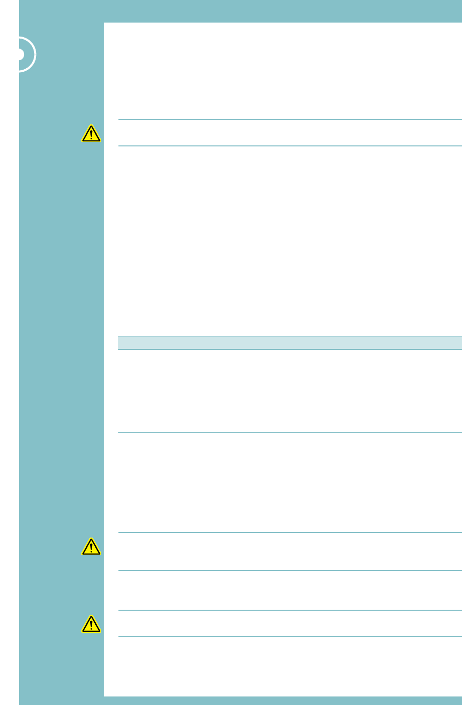
1:Connect one end of a CAT-5 Ethernet cable to
the network (RJ45) port on the front of the
Primary Hub.
2Connect the other end of the Ethernet cable to
the standalone PC.
RJ45 port
26 Zinwave 3000 DAS User Guide
Configuration and Control
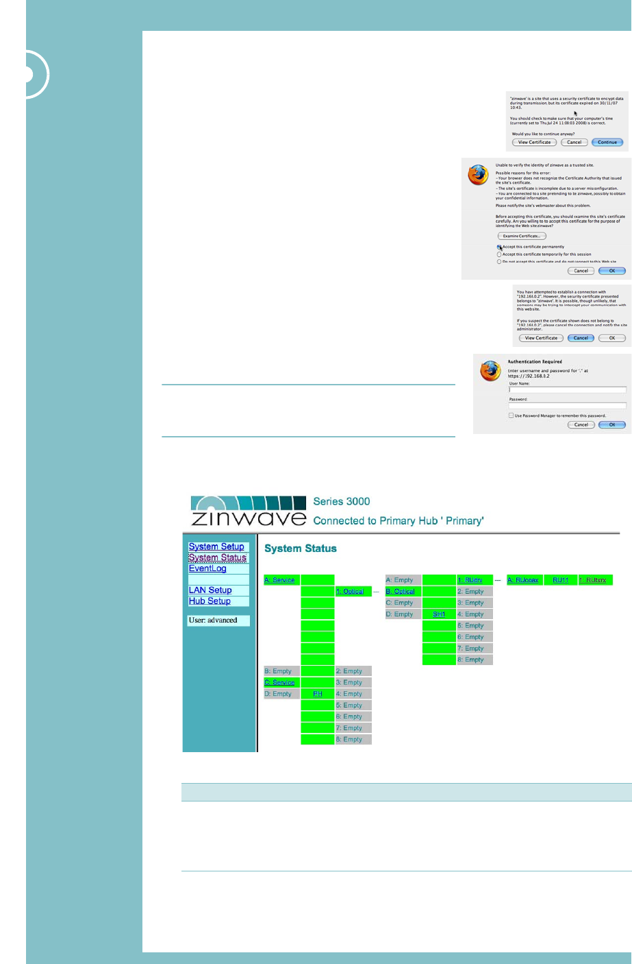
3.3.3 Start the web configuration GUI
1On the standalone PC, start a web browser and
enter the following URL:
https://192.168.0.2
Note the ‘s’ in https, as this is a secure page.
2Since this is the first time you’ve connected to a
Hub, you’ll need to step through three screens to
accept a security certificate (you’ll need to do this
every time you connect a different computer for the
first time):
–Click Continue.
–Click the first radio button to Accept this certificate
permanently and click OK.
–Click OK to establish the connection.
3At the Login screen, enter the username and
password for the level of access you need (see
Tab le -3 -1 ; for this session you need to be an
Advanced user) then click OK.
Note: Once logged in, you can only change user login
type by closing the browser window and logging in
again.
4You’ll see the default web configuration GUI screen
(the System Status page):
Table 3-1 User login types
User type Description Default password
Viewer Can view system status but not make any configuration changes (none)
Basic can view system status and make changes to a subset of
configuration options
installer
Advanced can view all status settings and make changes to all configuration
options
supervisor
Configuration and Control 27
Configuration and Control
3.3.4 Note the MAC address of the Primary Hub
You only need to follow the steps in this section if you want your Primary Hub to be
allocated its IP address by a DHCP server. In the next section, we’ll be setting up IP
addressing, and once you change the IP address of the Primary Hub you will lose contact
with it from the standalone PC. You will need to know its new IP address so that you can
continue the initial configuration from the standalone PC, and so that subsequently you’ll be
able to configure and monitor the Hub from any network-attached PC on your LAN.
•If you’re going to allocate the Primary Hub a static IP address, there’s no need to
discover its MAC address (although it won’t hurt to note it down anyway)
•If you’re going to be using DHCP, knowing the Hub’s MAC address will allow you to
interrogate the DHCP server and discover which IP address it has allocated to the Hub.
Proceed as follows:
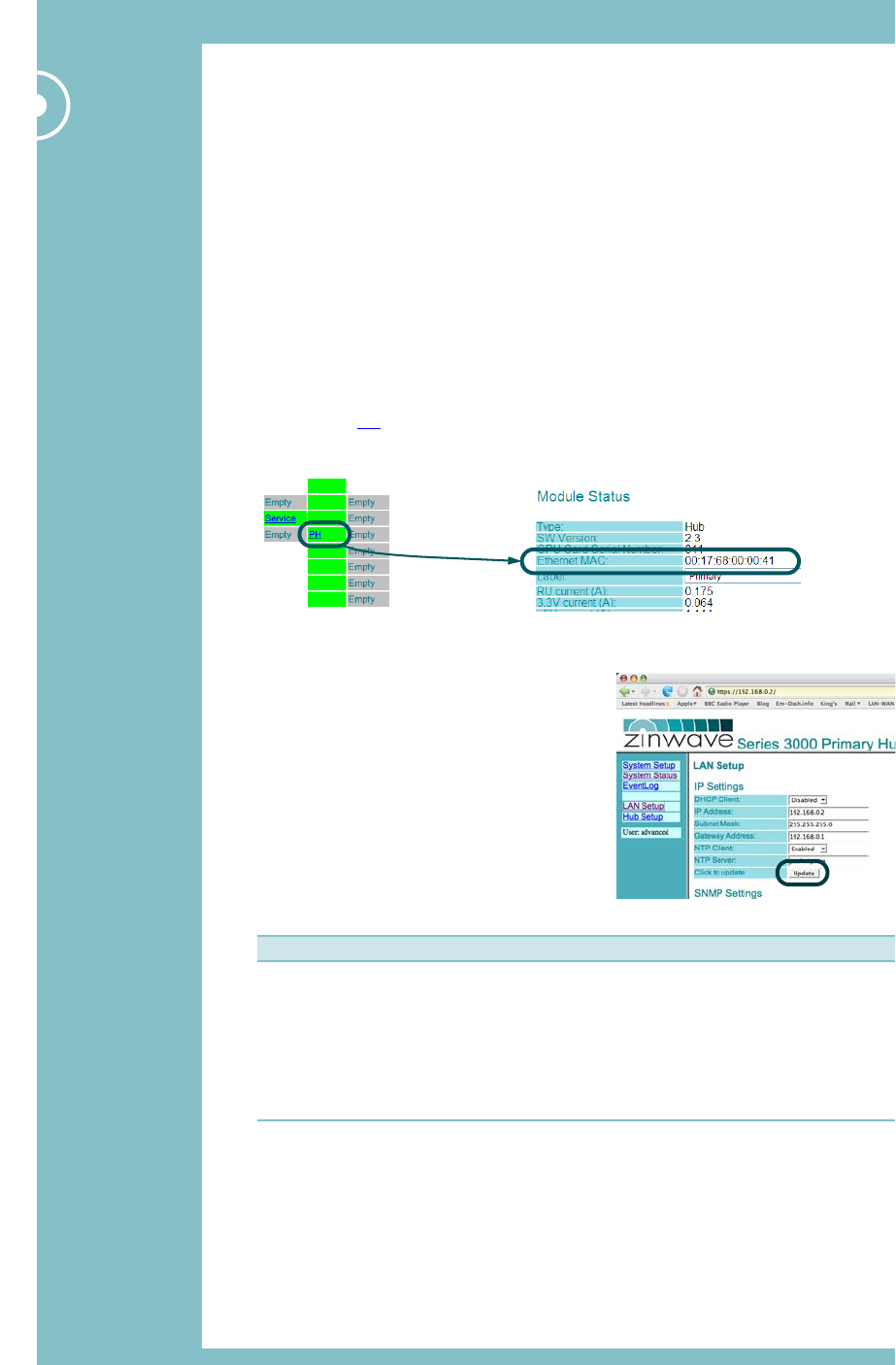
1On the System Status page in the web configuration GUI, click the link for the Primary
Hub (labelled PH) to display its module status page.
2Make a note of the Hub’s Ethernet MAC address.
3.3.5 Set up Primary Hub IP addressing
1Display the LAN Setup screen.
–If your enterprise network uses DHCP, select
Enabled in the DHCP Client drop-down
menu.
–If you are using static IP addresses, select
Static and enter the static IP settings needed
for correct operation on your network:
2Click Update at the bottom of the IP Settings
table in the web configuration GUI.
Table 3-2 Static IP addressing parameters
At this point you will lose connection with the Primary Hub, as you’ve changed its IP
address. We’ll reconnect in the next section.
Field Description
IP Address The IP address of the Hub on your enterprise network. Make sure it is unique.
Subnet Mask Defines how IP addresses are partitioned on your network. Usually
255.255.255.0
Gateway Address IP address of a computer on your network that provides access to other
networks or the Internet.
NTP Client When enabled, the Hub will fetch the correct time from the specified server (on
your network, or the Internet).
NTP Server A list of time servers used by this Hub to set the correct time.
28 Zinwave 3000 DAS User Guide
Configuration and Control
3.4 Detailed Hub configuration
Your Primary Hub should now be using its new IP address. From this point on, you can
•Continue to configure the Hub from the standalone PC (don’t forget to change the
standalone PC’s IP address to be on the new subnet)
•Connect the Hub to your LAN and access the web configuration GUI from any network-
attached PC.
3.4.1 Log back in to the web configuration GUI
1Knowing the Hub’s new IP address, log back into the web configuration GUI.
2For example:
–If you gave the Primary Hub the static IP address 10.10.10.5, you log in from the URL
https://10.10.10.5
–If you changed the Hub to be a DHCP client, you need to discover its IP address from
the lookup table on your DHCP server (you’ll need to know the Hub’s MAC address;
see page 27). DHCP server instructions are beyond the scope of this manual.
3For now, log in as the advanced user with the default password (supervisor).
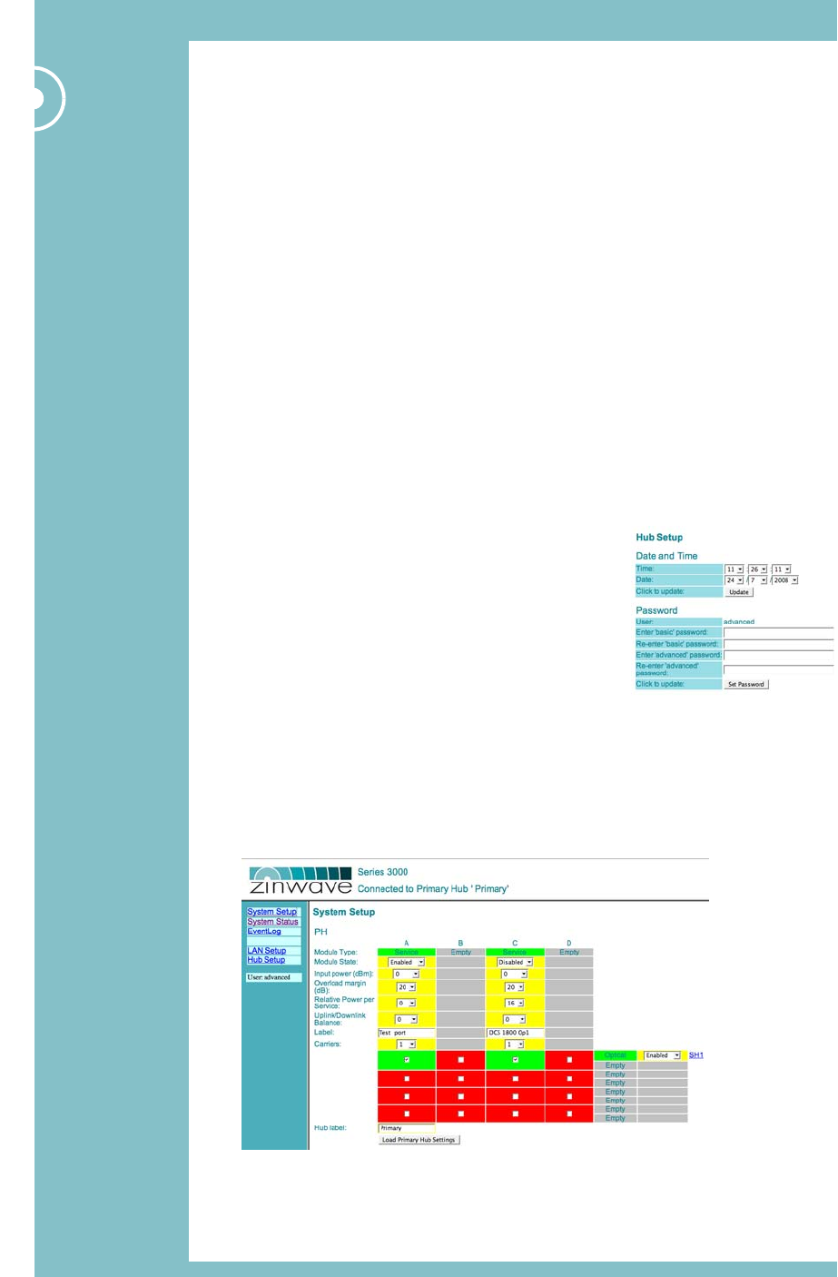
3.4.2 Set the date, time and passwords
1In the web configuration GUI, display the Hub Setup
page.
2Set the date and time and click Update.
3Change the default passwords for basic and advanced
users and click Set Password.
3.4.3 Set up the operating parameters and switching matrix
1Display the System Setup page.
This shows the switching matrix for your system (which Service inputs are connected to
which outputs on the Primary Hub. Lower down the page there are configuration
options for the Secondary Hub and any RUs. Initially, all settings are defaults.

Configuration and Control 29
Configuration and Control
2Tell the system which of the available Service inputs you want it to use by setting them
to Enabled.
3For each Service, select the Input power in dBm. This is the value that you know you
should be getting from the donor Service. We assume 0dB, but change this if necessary.
Caution: The Input power must not exceed the safe operating limit of +25dBm.
4Set the Overload margin.
This is in effect an alarm threshold for input power. If, for example, you had your system
all set up then added another Service, your input power might rise by 3dB. You might set
the Overload margin to 3dB to flag this. Alternatively, you might want to know whenever
the input power level changed, for any reason, in which case you’d set the Overload
margin to a very low threshold.
5Set the Relative Power per Service.
Here you are setting the relative power level for each Service, based on values you
should have calculated as part of your system design. This should take into account all
Service inputs that contribute to the composite power level.
The maximum that all Services can add up to is 18dBm in Europe and 20dBm in the USA
& Canada (the maximum power that an RU can handle). The maximum EIRP is 20dBm
for WLAN in Europe and 28dBm for all approved services in USA & Canada. This
corresponds to antenna gains of 2dBi for WLAN in Europe and 8dBi for USA & Canada.
6Set the Uplink/Downlink balance.
Set the relative gain according to your system design parameters.
7Enter a label (name) for each Service (e.g. Tetra, or DCS 1800).
8Set the number of carriers for each Service.
9Enable or disable the links to the Secondary Hub as appropriate.
10 Click to tick (enable) boxes in the switching matrix. This is where you tell the system
which Services are output on which link.
11 Enter a label (name) for the Primary Hub.
12 Click Load Primary Hub Settings below the Primary Hub table to make your settings
take effect.
30 Zinwave 3000 DAS User Guide
Configuration and Control
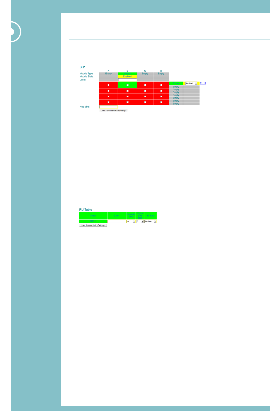
3.4.4 Set up the Secondary Hubs
Note: You’ll need to follow the steps in this section for each Secondary Hub in turn.
1On the System Setup page, scroll to the Secondary Hub table.
2Enter a label (name) for the Secondary Hub.
3Set up your switching matrix (which Optical Link Modules are connected to which RU
Drive Module).
4Enter a label (name) for the Secondary Hub.
5Click Load Secondary Hub Settings below the Secondary Hub table to make your
settings take effect.
6Repeat steps 1 through 5 for other Secondary Hubs (each will have their own table).
3.4.5 Set up the RUs
1On the System Setup page, scroll to the RU table.
There is one row per RU in this table. Set up all the RUs before loading the settings.
2Enter a label (name) for the RU.
3Set the Downlink power.
4Set the upper limit for the Uplink power.
This value should come from your system design. It limits the power back from the RU,
and is also an alarm threshold.
5Set the RU Tx state (Enabled or Disabled).
6If necessary, repeat steps 2 through 5 for other RUs in the table.
7Click Load Remote Unit Settings below the RU table to make your settings take
effect.
Configuration and Control 31
Configuration and Control
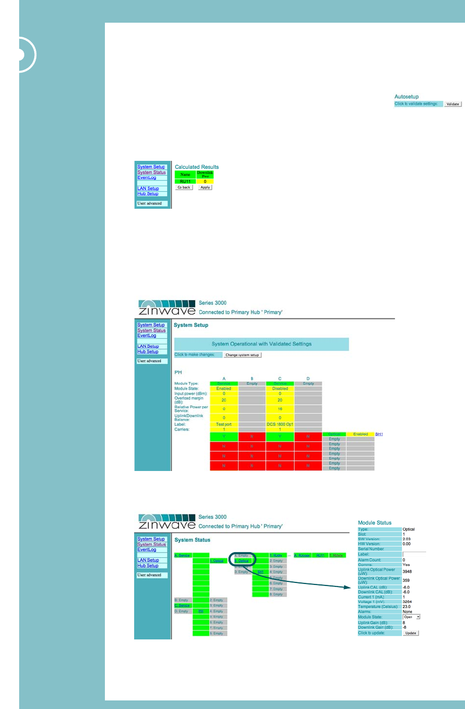
3.4.6 Run Autosetup
So far, we have applied configuration changes to the Hubs, but the system has not made any
automatic gain calculations or ‘switched on’ the RF.
1At the bottom of the System Setup page, click Validate.
The system will automatically make gain calculations, based on the
values you’ve supplied. It will take into account any path losses due
to cable lengths.
2When you calculations are complete, you’ll see the downlink power available to each RU.
3If there are no errors, click Apply.
If there are errors, click Go Back to return to the System Setup page and check the
settings. Click Validate again once you’re sure they’re OK.
Once the settings have been applied and there are no errors, the System Setup page will
redisplay. Note that, now the settings are correct, you can’t edit them (as the system is
operational, with those values in operation):
4Once you’ve finished, take a look at the System Status page. Click on the links to see
detailed status information for a particular unit.

32 Zinwave 3000 DAS User Guide
Configuration and Control
3.4.7 Changing the System Setup
Once you’ve clicked Validate and made your settings active, they are not immediately
editable in the System Setup page. If you want to make more changes, you can do so by
clicking the Change System Setup button at the top of the System Setup page.