Zinwave 302-1107 Distributed Antenna System Remote Unit User Manual Job Description
Zinwave Ltd Distributed Antenna System Remote Unit Job Description
Zinwave >
Contents
- 1. Users manual 1
- 2. Users manual 2
- 3. User manual 1
- 4. User manual 2
- 5. Users manual
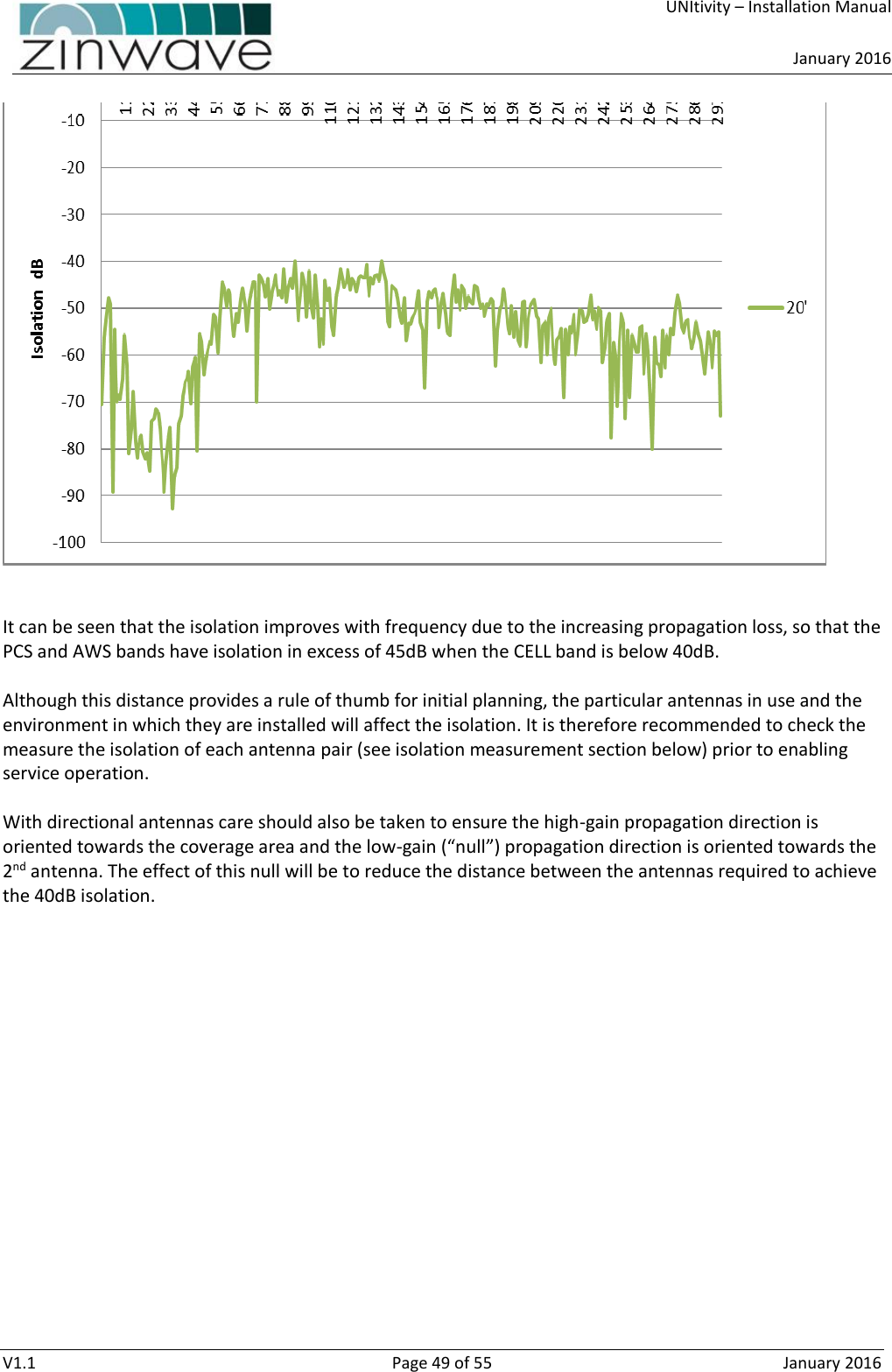
Users manual 1