Zinwell PWQ51N00 Powerline Wireless N User Manual
Zinwell Corporation Powerline Wireless N
Zinwell >
User manual

802.11n+HomePlugAV
Embeddedantenna
LowPowerConsumption
PowerlineWirelessNExtender
PWQ‐5101
UserManual
2
Preface
This product is a wireless AP device with PowerLine Communication (PLC) capability. With
its newest 500Mbps PLC technologies (Homeplug AV), crossing-floor communication in a
concrete building, which has been a big problem of wireless networking, become very
reliable. Its cutting edge 802.11n wireless technology provides the highest wireless
throughput for devices in the same floors. Its embedded 1T1R MIMO antenna makes it the
easiest for wall installations.
This product is suitable for general users to install in their home/houses, while advanced
configuration through web-browser described in later chapters is suitable for the
experienced users who installs and manages the Powerline Wireless N Extender products
(hereafter referred to as the “device”). To use these chapters, you should have experience
working with the TCP/IP configuration and be familiar with the concepts and terminology of
wireless local area networks.
3
Important Safety Notes
This product is intended for connection to the AC power line. For installation instructions,
refer to the Installation section. The following precautions should be taken when using this
product.
Please read all instructions before installing and operating this product.
Please keep all instructions for later reference.
Please follow all warnings and instructions marked on the product.
For safety reason, when device is being powered on, this product should NOT be
installed in any electric socket which makes the surface with venting holes on
the product to face downward (facing the floor).
Unplug the Powerline device from the wall outlet before cleaning. Use a dry cloth
for cleaning. DO NOT use liquid cleaners or aerosol cleaners.
DO NOT operates this product near water.
This product should never be placed near or over a radiator, or heat register.
This product relies on the building’s electrical installation for short-circuit (over current)
protection.
DO NOT allow anything to rest on the product interconnect plug. DO NOT locates this
product where people may walk on the cords.
Because this product sends data over the power line, it is recommended that you plug
directly into a power outlet. Do not plug the device into a UPS or power strip with surge
protection. The product has its own power filter for protection against surges.
Only a qualified technician should service this product. Opening or removing covers
may result in exposure to dangerous voltage points or other risks.
Unplug the product from the wall outlet and refer the product to qualified service
personnel for the following conditions:
When the interconnect cords are damaged or frayed.
If liquid has been spilled into the product.
If the product has been exposed to rain or water.
If the product does not operate normally when the operating instructions are
followed.
If the product exhibits a distinct change in performance.
4
TABLET of CONTENT
CH 1. PRODUCT OVERVIEW..............................................................................................6
Packing List....................................................................................................................................................... 6
Buttons and LEDs............................................................................................................................................. 6
CH 2. HARDWARE INSTALLATION ...................................................................................9
Application 1 – Link to remote DSL via Powerline ........................................................................................ 9
Application 2 – wireless AP + Ethernet switch ............................................................................................ 10
Application 3– multiple floor home networking........................................................................................... 10
Application 4– Powerline Ethernet switch ................................................................................................... 12
Application 5 – AP client adapter .................................................................................................................. 12
Fast Encryption by Buttons........................................................................................................................... 13
CH 3. ADVANCED SETTING – VIA WEB BROWSER......................................................16
Before Starting Configure.............................................................................................................................. 16
Operation Mode............................................................................................................................................... 16
Setup Wizard ................................................................................................................................................... 17
Internet Settings.............................................................................................................................................. 18
LAN Settings -------------------------------------------------------------------------------------------------------------------- 18
DHCP Clients-------------------------------------------------------------------------------------------------------------------- 20
Wireless Settings............................................................................................................................................ 20
Basic ------------------------------------------------------------------------------------------------------------------------------- 20
Advanced------------------------------------------------------------------------------------------------------------------------- 22
Security --------------------------------------------------------------------------------------------------------------------------- 23
WPS --------------------------------------------------------------------------------------------------------------------------------25
Station list------------------------------------------------------------------------------------------------------------------------ 26
Site Survey----------------------------------------------------------------------------------------------------------------------- 26
MAC Filter ------------------------------------------------------------------------------------------------------------------------ 27
5
Administration................................................................................................................................................. 27
Management--------------------------------------------------------------------------------------------------------------------- 27
Upgrade firmware-------------------------------------------------------------------------------------------------------------- 28
Settings management -------------------------------------------------------------------------------------------------------- 29
Status ------------------------------------------------------------------------------------------------------------------------------ 29
Statistics-------------------------------------------------------------------------------------------------------------------------- 30
System log ----------------------------------------------------------------------------------------------------------------------- 30
FEDERAL COMMUNICATIONS COMMISSION INTERFERENCE STATEMENT------------------------------ 31
CH 4 ENHANCE PLC PERFORMANCE DURING INSTALLATION ..................................33
AC outlets connection.................................................................................................................................... 33
Connection via power strip............................................................................................................................ 35
Electrical interference .................................................................................................................................... 35
Electrical wiring............................................................................................................................................... 35
CH 5 SPECIFICATION .......................................................................................................36
6
Ch 1. Product Overview
Packing List
Before starting the installation of the device, please make sure the package contains the following
items:
Single package Combo package
Device
Accessories RJ-45 Cable x 1 RJ-45 Cable x2
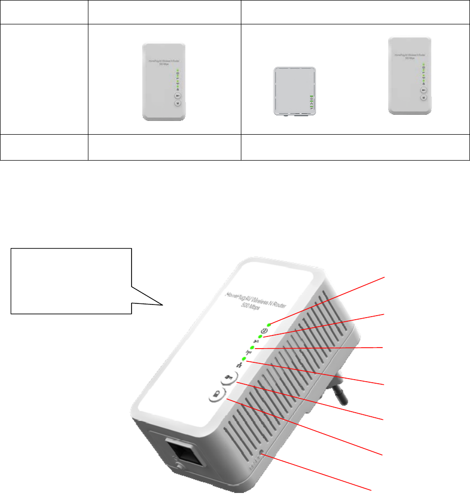
Buttons and LEDs
Front View
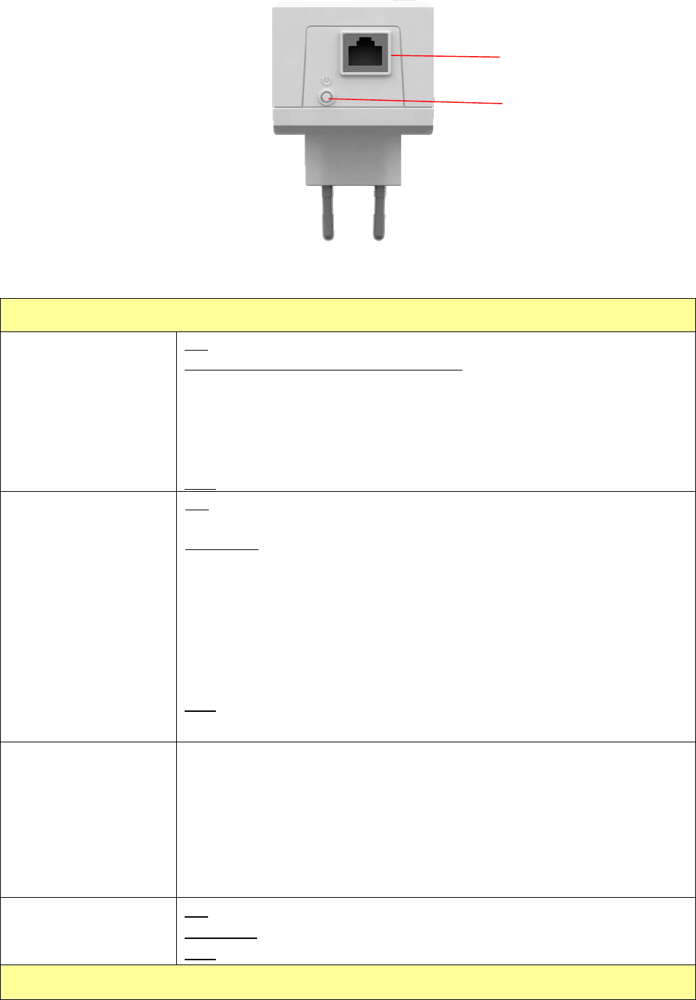
Bottom View
Powerline
EthernetBridge
PowerlineWireless
NExtender
PowerlineWireless
NExtender
PowerLED
PLCLED
WLANLINK/ACTLED
EthernetLNK/ACTLED
WPS
GROUP
1T1Rantennasare
embeddedintothe
device
RESET
button
7
LED
Power LED
Green
ON: Power on and ready.
BLINKING: ( 0.5 sec ON / 0.5 sec OFF )
1. During Group pairing procedure. In this procedure, the device
joining or being joined into same logical network will continue 2
minutes’ blinking, until the procedure succeeds or is canceled). To
enter or cancel Group pairing procedure, just press the GROUP
button 2~3 sec.
OFF: Power off.
PLC LED
Green
ON: Powerline Link detected but no powerline traffic.
BLINKING:
1. Fast blinking (0.06 s ON/ 0.06 s OFF): Powerline data rate higher
than 80Mbps.
2. Normal blinking (0.2 s ON/ 0.2 s OFF) Powerline data rate between
40Mbps to 80Mbps.
3. Slow blinking (1 s ON/ 1 s OFF): Powerline data rate slower than
40Mbps.
OFF: Powerline Link not detected (either other devices in same network
is too far to communicate or it is alone in its logical network).
WLAN LED
Green + Red
Steady Green: Wi-Fi active under security protection
Flash Green: Wi-Fi transmits packets under security protection,
Steady Red: Wi-Fi active under NO security protection,
Flash Red: Wi-Fi transmits packets under NO security protection,
BLINKING Green (0.5 sec ON / 0.5 sec OFF): WPS negotiation
OFF:Wi-Fi off
Ethernet LNK/ACT
LED
ON: Ethernet Link Detected.
BLINKING: Ethernet traffic detected.
OFF: No Ethernet Link detected.
Buttons
LANport
PowerOn/Off

8
WPS Press it to enable PBC (Press Button Configuration) for WPS authentication.
GROUP Press 1 to 3 seconds ( until the Power LED blinking ) and release button: this
will enter Group pairing procedure. In this procedure, the device starts
joining into a logical network of other device or announcing its network group
name for other devices to join. This maximum two-minute procedure
automatically ends when it succeeds or is manually stopped. Press this
button 2 to 3 seconds will manually stop the procedure.
Press 10 seconds (until Power LED blink once and PLC LED off): clear the
current and randomly generate a new network group name.
Power On/Off Push to turn on and off the power of PWQ-5101
RESET button
(inside the needle
pin hole)
Press the button when the device is powered on (not standby) to complete
following functions:
Pushing 1 second and release : will make both PLC and Wi-Fi FW settings
back to factory default.
NOTE: Every new PLC devices’ factory default PLC network group name is
HomePlugAV. During trouble shooting the powerline network group
assignment, doing this to every PLC devices will make each device return to
default network group, thus ensure their mutual communicability.
9
Ch 2. Hardware Installation
Once you check everything from the package, you can start to install the device. All wireless devices
which want to connect this AP wirelessly need to search and connect the SSID of this device:
PWQ-5101 (factory default is no wireless security setting)
Please see the following application diagrams for different application connections of this device.
Application 1 – Link to remote DSL via Powerline
Via Powerline technology, the Powerline Wireless N Extender can access DSL modem at other
floors for internet accesses. Note that this needs another Powerline to Ethernet Bridge device at
other floor, so that connection between Powerline to Ethernet Bridge and Powerline to Ethernet
Bridge can be done through the embedded PLC technology.
10
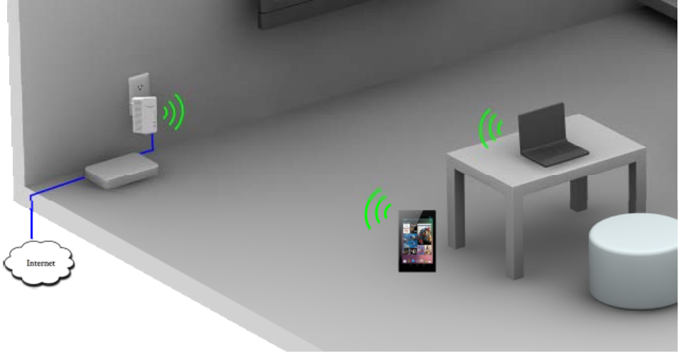
Application 2 – wireless AP + Ethernet switch
The Powerline Wireless N Extender can be a central 802.11n Access point and Ethernet switch
hub to link all WLAN devices and Ethernet devices.
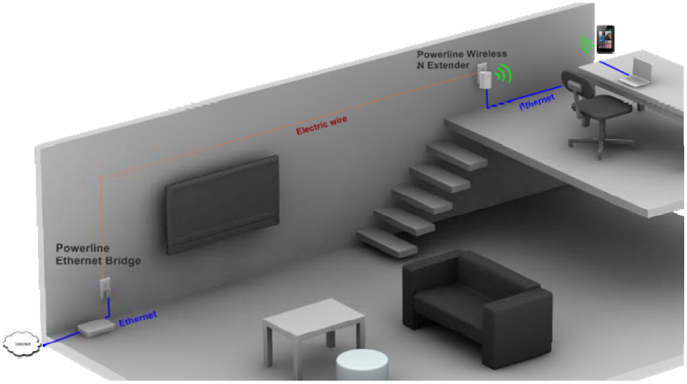
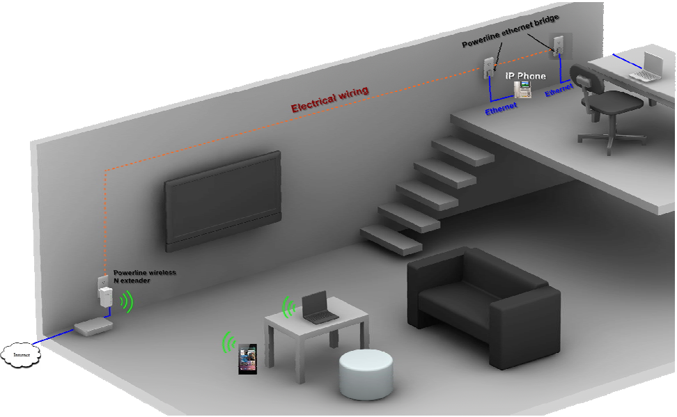
Application 3– multiple floor home networking
When WLAN signal is not good to penetrate concrete floors, use Powerline technology afforded by
the Powerline Wireless N Extender to extend home networking range to upper (other) floors. While
on the same floor, the WLAN function can be used for IP devices or PC/NB to access internet.
Please see the diagram below and please note that this needs Powerline to Ethernet Bridge
devices for users at the other floor to access network resources via the Powerline communication.
11
12
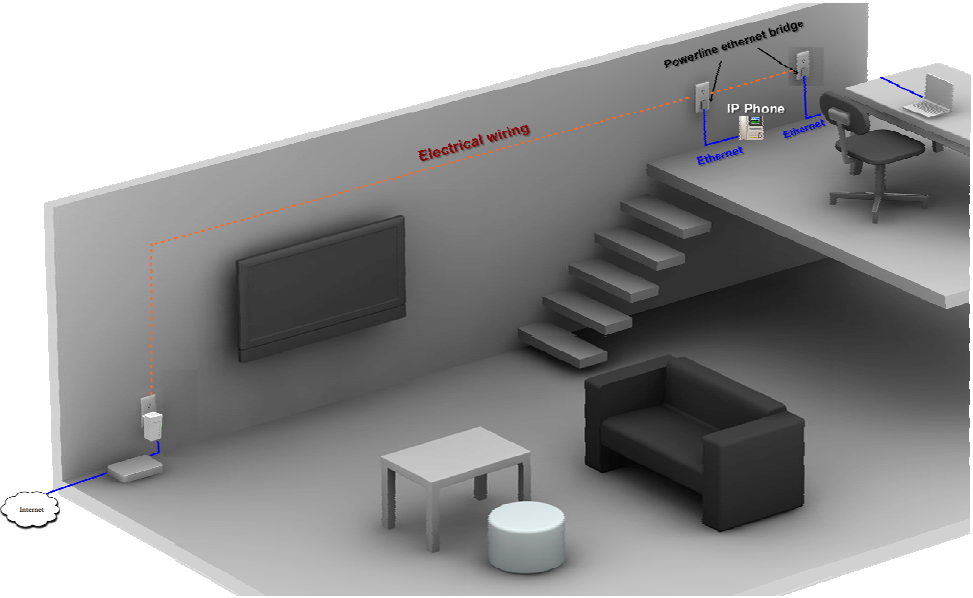
Application 4– Powerline Ethernet switch
By pushing the WLAN ON/OFF button, the wireless function of this device can be turned
ON or OFF. In this case, HomePlug AV Wireless N Extender acts as Powerline to
Ethernet switch, which, when used together with a remote Powerline Ethernet Bridge,
enables two remote Ethernet devices (ex. PC, Notebook, or VIOP) on different floors or
locations at home to communicate via the embedded Powerline technology.
Application 5 – AP client adapter
This device can act as wireless client adapter for a PC host (see application diagram below).
To activate this function, visit the operation mode web page of the device and enable this
mode through a web browser on your PC. Please see later chapters for detail description of
this procedure.
13
Fast Encryption by Buttons
The factory default wireless setting of this machine is no encryption and default powerline
communication encryption is public encryption, HomePlugAV. Using the buttons on the
machine, this section describes quick wireless encryption set up using WPS button and
quick encryption set up in a PLC network group using Group button.
Setting Wireless encryption by WPS button
This button can be pressed for WPS PBC authentication. First, login the web configuration
to setup the wireless encryption to be WPA-PSK or WPA2-PSK, and then enable the WPS
Config as well. Now press the WPS button on this device and then press WPS button on the
WLAN station/client card to start WPS process. It is also working if pressing WPS button on
the WLAN station card first and then this device. The WPS process will be started and
connected after a few seconds.
For those WLAN station card without physical WPS button, the software WPS button should
be found in its utility software for this function.
Create Private encrypted PLC network group
This product is a HomePlug AV powerline device. Each powerline device has predefined
attributes of Powerline network name. Multiple Powerline devices with same network
names can communicate to one another, thus belonging to a same PLC network group.
Devices with different network name won’t communicate. Max number of devices in a PLC
network group is defined in the SPECIFICATIONS section of this manual.
Any Homeplug-AV compliant PLC device newly from factories, including this device, has its
default network name of HomePlugAV, and can communicate with other brands of new
Homeplug-AV compliant devices, thus belongs to the public network. Pushing the GROUP
button of the device will change its network name. This way, users can create one or
multiple private PLC network groups with the button, without complicated setup software
involved, thus protect their data been transmitted over the powerline. Pressing the RESET
button of a power-active powerline device will reset the network name back to its factory
default.
By pushing GROUP button for more than 10 seconds, a random network name (different
from HomePlugAV) for the device will be generated. This device can then ask other devices
14
to join its PLC network to form private network group. Any other devices, device B, which
want to join this device’s (device A) PLC network group need to follow steps below: (NOTE:
it is more convenient to bring devices, which are to be configured into same logical network
group, side by side during this procedure. After network group is set, the devices can be
deployed anywhere at home)
Step 1. (Clear group attribute) Firstly clear the original network group of device B by
pressing its GROUP button more than 10 seconds until all LED lights
simultaneously turns off and on once. At this moment, its network group name
has been changed to a random name and ready to be assigned another
network name. At this moment, this device also can be used as a seed device
so other PLC devices can join it to form a private network group.
Step 2. (Join) Press GROUP Button of device A and device B for 2 to 3 sec (make sure
POWER LED starts blinking). The device (device B) which has cleared its
group attribute will join to the device (device A) which hasn’t. It doesn’t matter
which device’s button is pushed earlier than the other, but please push the
second device’s Group button within two minutes after pushing first device’s
Group button.
This way, Powerline device B joins same encrypted network as device A. Users can join
device C to device A’s logical network with same procedure, thus make device A, B, and C
all in the same encrypted network group.
Remove a device from a network Group
For example, device A and device B are in the same logical network group, if uses want to
remove device A from this logical network group, just follow the procedure in Step 1 by
pressing GROUP button of device A for 10 seconds. This makes device A not able to
communicate with device B.
Make two public network devices private
If users want to make two new public devices (network name HomePlugAV) become
private, please carry out Step 1 on both devices, then do step 2 on these two devices.
Finally, a private random network name is generated for these two devices.
Partition four devices into two network Groups
15
For example, A, B, C, and D four devices, originally are in same network group. Please carry
out step 1 on device A and B, to remove them from this network group. Then carry out step
2 on A and B to form a new network group.

16
Ch 3. Advanced Setting – via Web
Browser
Before Starting Configure
The configuration of this device is through web-browser on a PC. The default IP address
of the device is 192.168.2.253, and the subnet-mask is 255.255.255.0. The DHCP server
inside the device is default to “Off” (Disable).
1. Power on PWQ-5101.
2. Set your IP to 192.168.2. X manually (Control panel > Network connections > double
click “Local area connection” > Properties > select “Internet Protocol TCP/IP” and
click Properties > select "Use the following IP address” )
3. Turn on a browser and type 192.168.2.253 on the place you enter URL address, then
you may link to PWQ-5101 for further settings.
4. For the first time configuration, please login with username: root and password: root.
5. At first login, please select the language you want to use. (English, Traditional
Chinese, Simple Chinese)
Please ensure there is not multiple DHCP servers in your network environment, otherwise
it will cause abnormal situation.
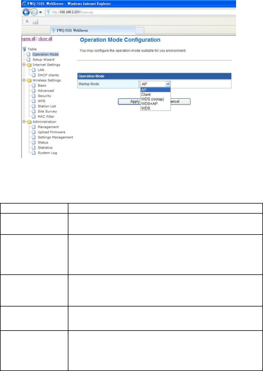
Operation Mode
17
This device supports 5 operation modes for the IP network. Click to select one between the
following wireless operation modes, then press Apply button.
Item Description
AP The wireless radio of device serves as communications “hub”
for wireless clients and provides a connection to a wired LAN
Client This mode enables the establishment of connection with the
other AP using infrastructure /Ad-hoc networking types. With
bridge operation mode, you can directly connect one of the
wired Ethernet port to your PC and the device becomes a
wireless adapter
WDS (rootap) The wireless radio of device serves as communications “hub”
for wireless clients and provides a connection to a wired LAN
(the other AP must use the same chipset with this device)
WDS+AP This mode combines WDS plus AP modes, and it not only
allows WDS connections but also the wireless clients can
survey and associate to the device
WDS
(Wireless
Distribution System)
This mode combines up to 8 AP to a single wireless network;
the device forwards the packets to another AP with WDS
function. When this mode is selected, all the wireless clients
can’t survey and connect to the device. The device only allows
the WDS connection
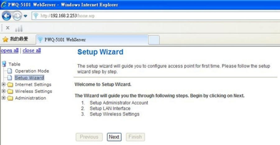
Setup Wizard
18
The setup Wizard can help you to setup the device with minimum setting. Open the
page from the left panel and click “Next” button in the welcome page.
1. In the first page, enter the new account name and password for login this web page
configuration in the future.
2. In the second page, you may choose to enable/disable networking functions and
configure their parameters as you wish
3. The third page is for basic wireless setting, to set network mode and SSID…etc
4. The last page is about setting the wireless security and encryption to prevent from
unauthorized access and monitoring.
5. Click “Finish” button and the device will reboot to apply the settings.
Internet Settings
LAN Settings
19
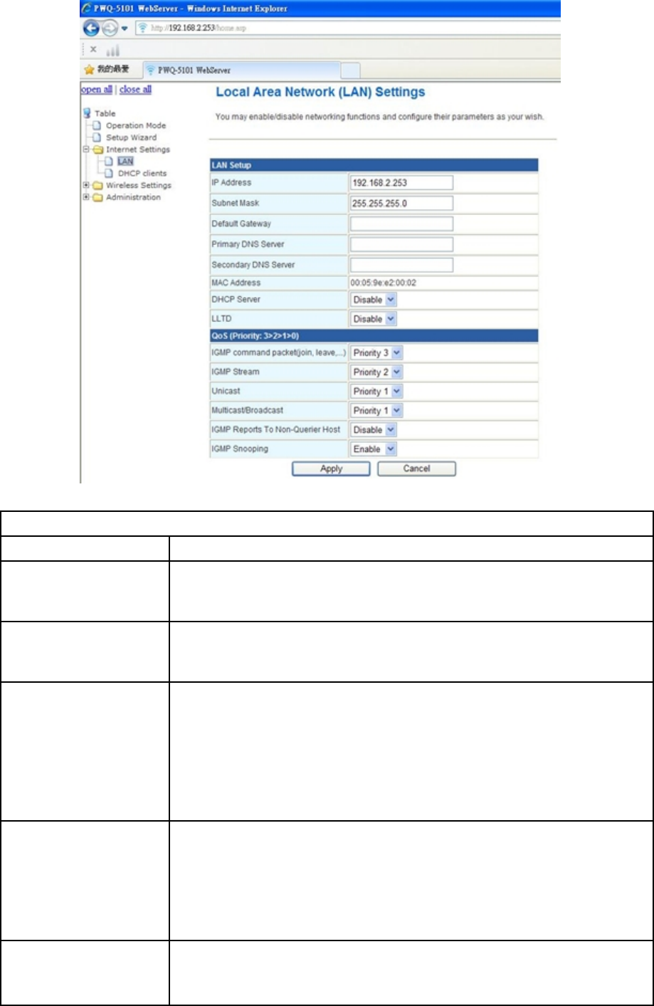
LAN setup
Item Description
IP Address The Internet Protocol (IP) address of WAN interface provided
by your ISP or MIS. The address will be your network identifier
besides your local network.
Subnet mask The number used to identify the IP subnet network, indicating
whether the IP address can be recognized on the LAN or if it
must be reached through a gateway.
Default gateway The IP address of Default Gateway provided by your ISP or
MIS.
Default Gateway is the intermediate network device that has
knowledge of the network IDs of the other networks in the
Wide Area Network, so it can forward the packets to other
gateways until they are delivered to the one connected to the
specified destination.
Primary &
Secondary DNS The IP addresses of DNS provided by your ISP.
DNS (Domain Name Server) is used to map domain names to
IP addresses. DNS maintain central lists of domain name/IP
addresses and map the domain names in your Internet
requests to other servers on the Internet until the specified
web site is found.
LLTD Enable this function to support LLTD (Link Layer Topology
Discovery) for Windows Vista. It shows the status of
connection in the Windows Vista.
20
QoS
Item Description
IGMP command
packet (join, leave..) recommend to set the highest priority (3) to keep it work
smoothly
IGMP Stream recommend to set the higher priority (2) to make sure the
good streaming video and audio quality
Unicast recommend to set priority 1
Multicast/Broadcast recommend to set priority 1
IGMP Reports To
Non-Querier Host default disable but recommend to turn on this function while
using PWQ-5101 in China
IGMP Snooping default and also recommend to enable IGMP snooping
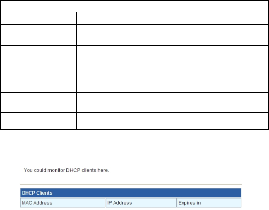
DHCP Clients
Wireless Settings
Basic
21
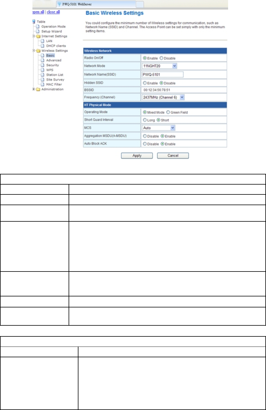
Wireless Network
Item Description
Radio On/Off Click to enable/disable the radio.
Network Mode The available options are 11B, 11G, 11NGHT20,
11NGHT40PUS (default), 11NGHT40MINUS
Network Name
(SSID) The SSID, which is also called ESSID is a unique identifier
that wireless networking devices use in order to establish and
maintain wireless connectivity. Multiple access point/bridges
on a network or sub-network can use the same SSID. SSIDs
are case sensitive and can contain up to 32 alphanumeric
characters.
Hidden SSID Click to enable/disable, With hidden SSID, the AP can’t be
scanned and the wireless client must input SSID manually to
associate this AP.
BSSID The BSSID is displayed in this field.
Frequency
(Channel) Click the drop down box to select the radio channel. Select the
unused channel to prevent the radio overlapping.
HT Physical Mode
Item Description
Operating Mode Default: Mixed (Mixed, Green Field).
Mixed mode: In this mode the device transmits the
packets with preamble compatible legacy (802.11g), so
they can be decoded by legacy devices. The device
receives and decodes both Mixed Mode packets and
22
legacy packets.
Green Field mode: the device transmits HT packets
without legacy compatible part. But the device receives and
decodes both Green Field and legacy packets.
Short Guard Interval The 11n device inserts the Guard Interval into the signal.
You can choose the interval between “Long” and “Short”.
This option affects the Phy data rate of radio. Please refer
to the table below.
MCS It is Modulation Coding Scheme. The available options are
“Auto, 0, 1-7”. It changes the modulation of this device and
effect the maximum Phy data rate. We recommend “Auto”
setting. For the details, please refer to the table below.
Aggregation MSDU
(A-MSDU) The multiple HT packets can be transmitted with single
ACK reply packet. Enable it to apply this function and
reduce the network congestion.
Auto Block ACK It is another aggregation technique which prevents sending
ACK in the communication to increase the throughput. If
this option is enabled, the device will activate this function
when transmitting massive data.
Advanced
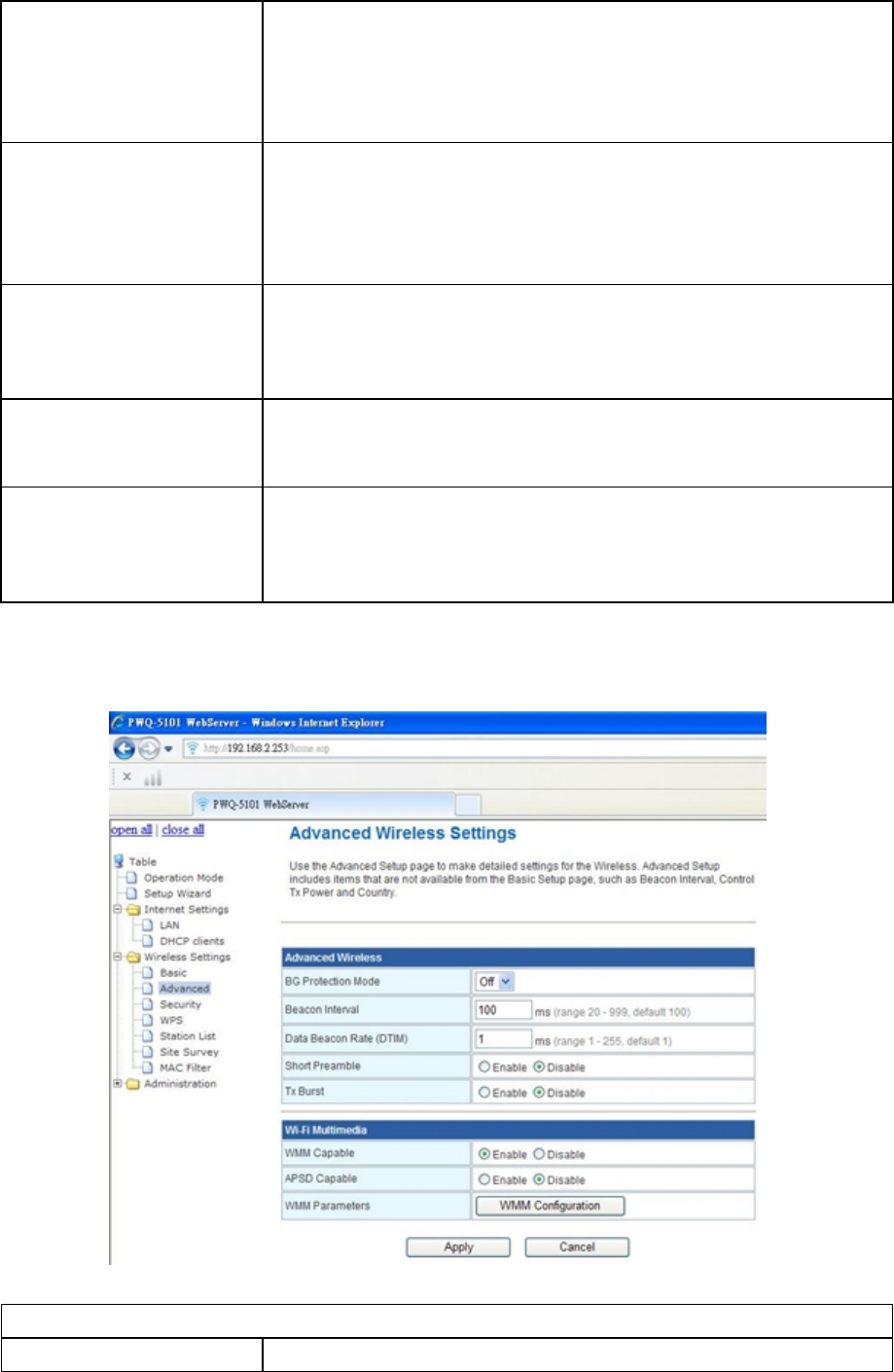
Advanced Wireless
Item Description

23
BG Protection Mode Default: Auto. You can select the other options including On
and Off. The B/G protection technology is CTS-To-Self. It
will try to reserve the throughput for 11g clients from 11b
clients connecting to the device as AP mode.
Beacon Interval Beacons are the packets sending by Access point to
synchronize the wireless network. The beacon interval is
the time interval between beacons sending by this unit in
AP or AP+WDS mode. The default and recommended
beacon interval is 100 milliseconds.
Data Beacon Rate
(DTIM) This is the Delivery Traffic Indication Map. It is used to alert
the clients that multicast and broadcast packets buffered at
the AP will be transmitted immediately after the
transmission of this beacon frame. You can change the
value from 1 to 255. The AP will check the buffered data
according to this value. For example, selecting “1” means
to check the buffered data at every beacon.
Short Preamble Default: Disable. It is a performance parameter for 802.11
b/g mode and not supported by some of very early stage of
802.11b station cards. If there is no such kind of stations
associated to this AP, you can enable this function.
Tx Burst The device will try to send a serial of packages with single
ACK reply from the clients. Enable this function to apply it.
Wi-Fi Multimedia
Item Description
WMM Capable Choose “Enable” to enable WMM function.
APSD Capable Turn on this feature so this device can detect whether the
connecting wireless client device has turned on power
saving feature. If yes, this device will send packets with
power saving tag accordingly.
WMM Parameter Click the button to edit the WMM parameter.
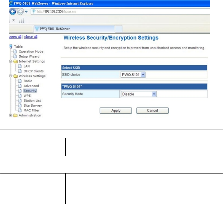
Security
24
Select SSID
Item Description
SSID choice Choose the ESSID to configure the security setting.
Wireless Security/Encryption Settings
Item Description
Security Mode Disable, OPEN, SHARED, WEPAUTO, WPA, WPA-PSK,
WPA2, WPA2-PSK, WPA/WPA2 PSK, WPA/WPA2,
802.1X.
WPA Authentication Mode
This device supports six WPA modes including WPA-PSK (Pre-Shared Key), WPA,
WPA2-PSK, WPA2 and additional WPA/WPA2 PSK and WPA/WPA2 mixed mode. For
individual and residential user, it is recommended to select WPA-PSK or WPA2-PSK to
encrypt the link without additional RADIUS server. This mode requires only an access point
and client station that supports WPA-PSK. For WPA/WPA2, authentication is achieved via
WPA RADIUS Server. You need a RADIUS or other authentication server on the network.
WPA/WPA2-PSK:
Pass Phrase:
Option: Pass Phrase (8-32bytes). This mode requires only an access point and
client station that supports WPA-PSK. The WPA-PSK settings include Key Format,
Length and Value. They must be as same as each wireless client in your wireless
network. When Key format is Passphrase, the key value should have 8-63 ACSII
chars.
25
Key Renewal Interval:
The WPA Algorithm will regroup the key for a period. The default value is 3600
seconds and you can adjust the time interval.
WPA/WPA2:
When selecting WPA/WPA2, you have to add user accounts and the target device to the
RADIUS Server. In the device, you need to specify the Server Network, Server address,
Server Port and Server Key of the target RADIUS server.
WPA Algorithms: TKIP, AES, TKIP/AES. Select the encryption type. When selecting
TKIP/AES, the client can use whether TKIP or AES for the authentication.
Pre-Authentication Support option: This option only appears when selecting WPA2
or WPA/WPA2 as the authentication mode. Enable it to use this function.
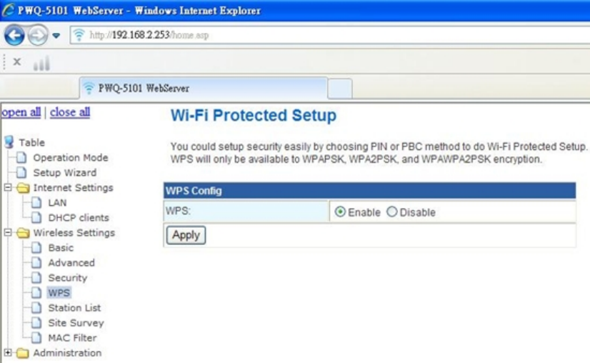
WPS
This function helps to establish the Wi-Fi security. For AP mode, it can be setup one WPS
method including PIN (Personal Identification Number) and PBC (Push Button Certification).
To begin the WPS progress, the WLAN security must be setup first. Please setup one
among WPAPSK, WPA2PSK, WPA/WPA2PSK and then apply WPS setting. WPS will only
be available in these encryption types.
PIN: query the PIN code in the utility of the WLAN client connecting to this AP, and then
enter it in the PIN field. The Wi-Fi link between the WLAN client and the device should be
encrypted.
26
PBC: Select PBC, and then you can begin the PBC process. Press the PBC button in the
front panel can also trigger this process. Press or click the PBC button on the WLAN client
to finish the communication. You can press the PBC button on the WLAN client first and
then click the PBC button on this device to establish the encryption.
The options and the information fields are showed below.
WPS Config
Item Description
WPS Capable Select enable then press Apply button to start this
function.
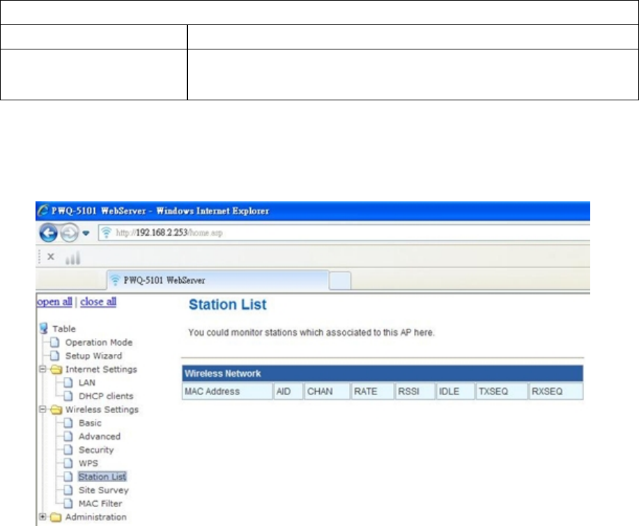
Station list
In the Station list, the information of associated clients is displayed.
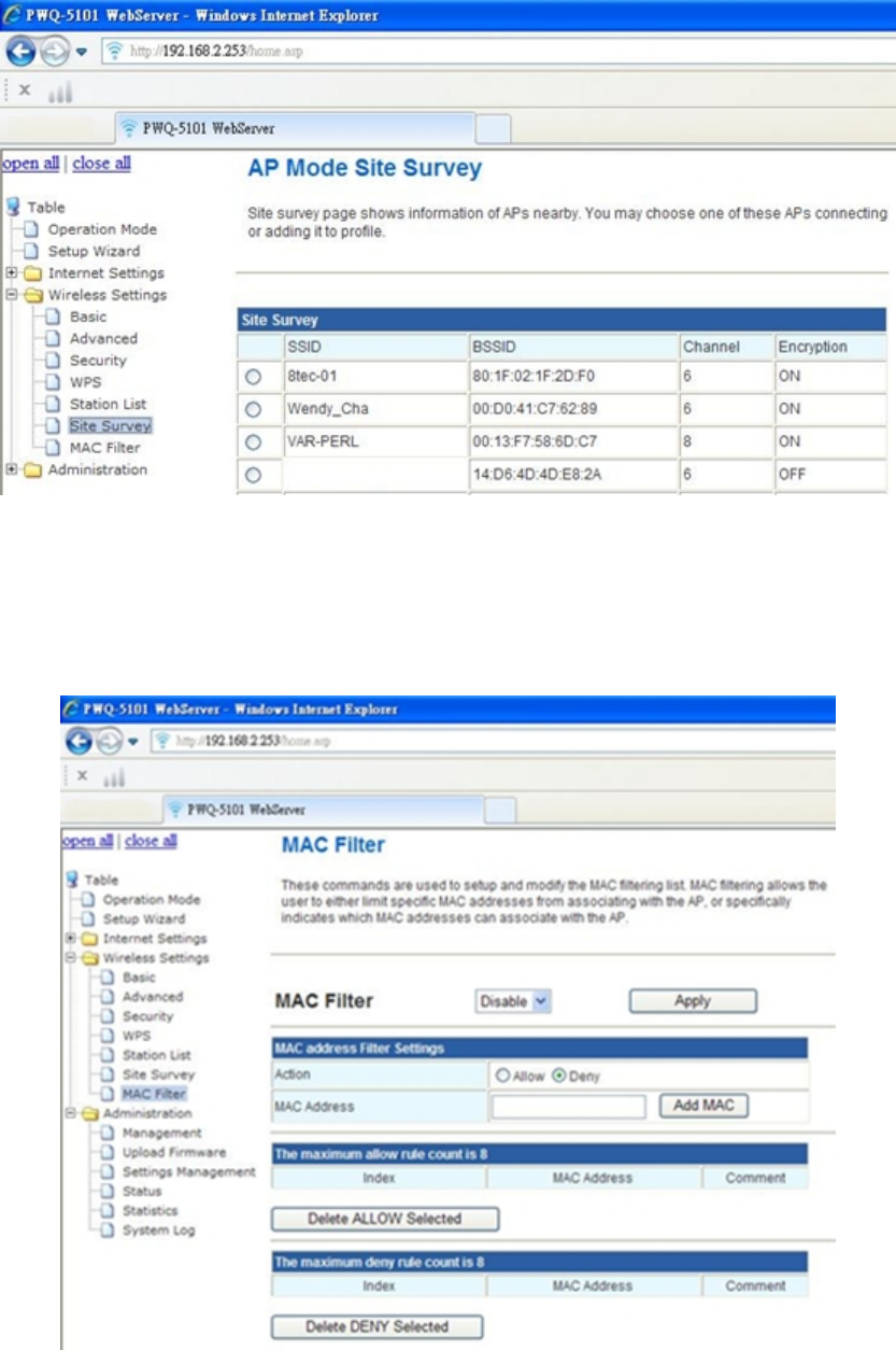
Site Survey
Site survey page shows information of APs nearby;
You may choose one of these APs connecting or adding it to profile.
27
MAC Filter
MAC filtering allows the user to either limit specific MAC addresses from associating with
the AP, or specifically indicates which MAC addresses can associate with the AP
Administration
Management
28
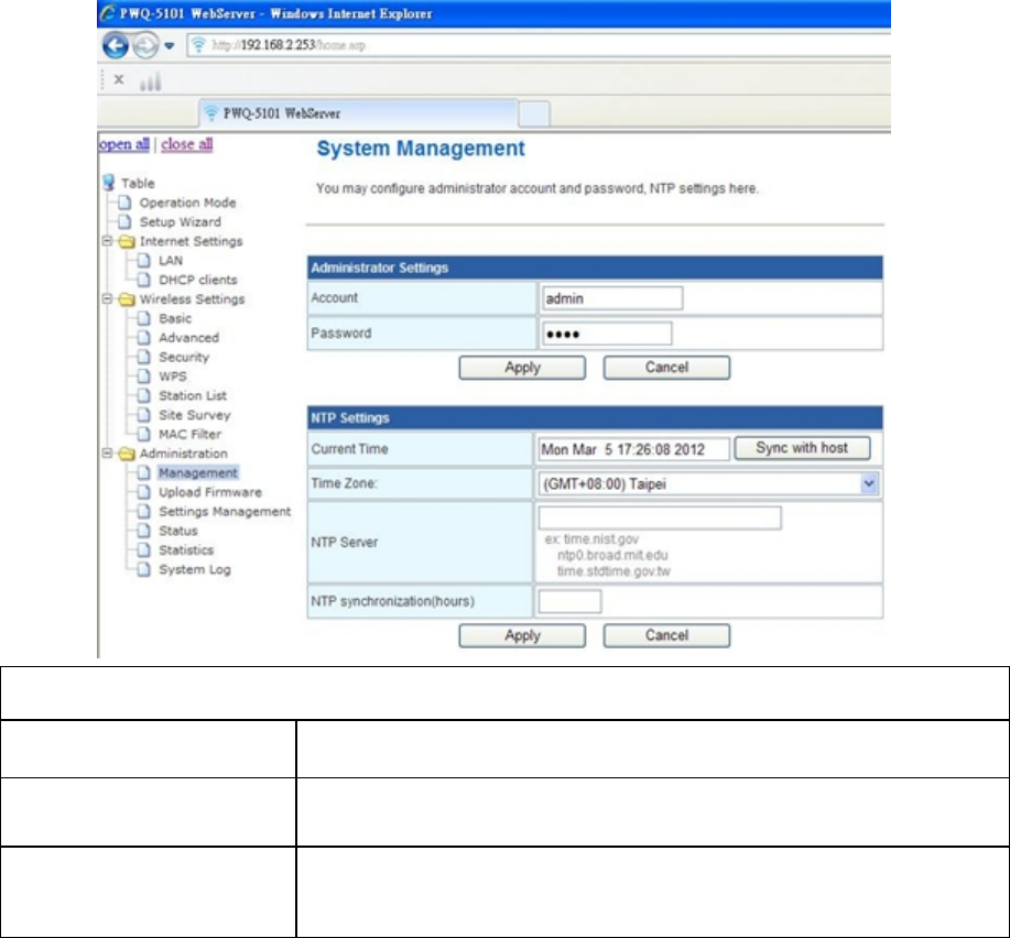
Management
Item Description
NTP server set the NTP (network time protocol) server address
NTP Synchronization set a duration of checking time with the server (ex. 48
hours)
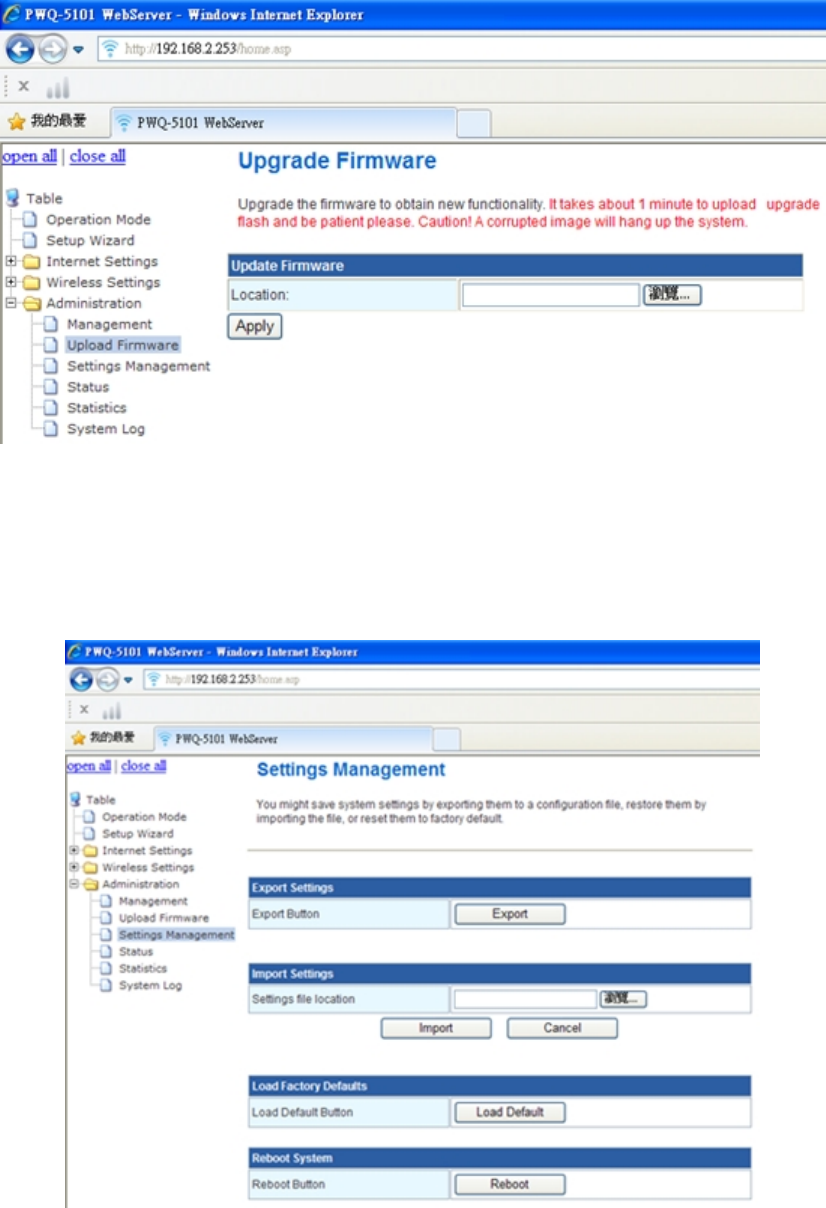
Upgrade firmware
Click “ Brows “ to upload file to upgrade PWQ-5101’s firmware
29
Settings management
You might save system settings by exporting them to a configuration file, restore them by
importing the file, or reset them to factory default
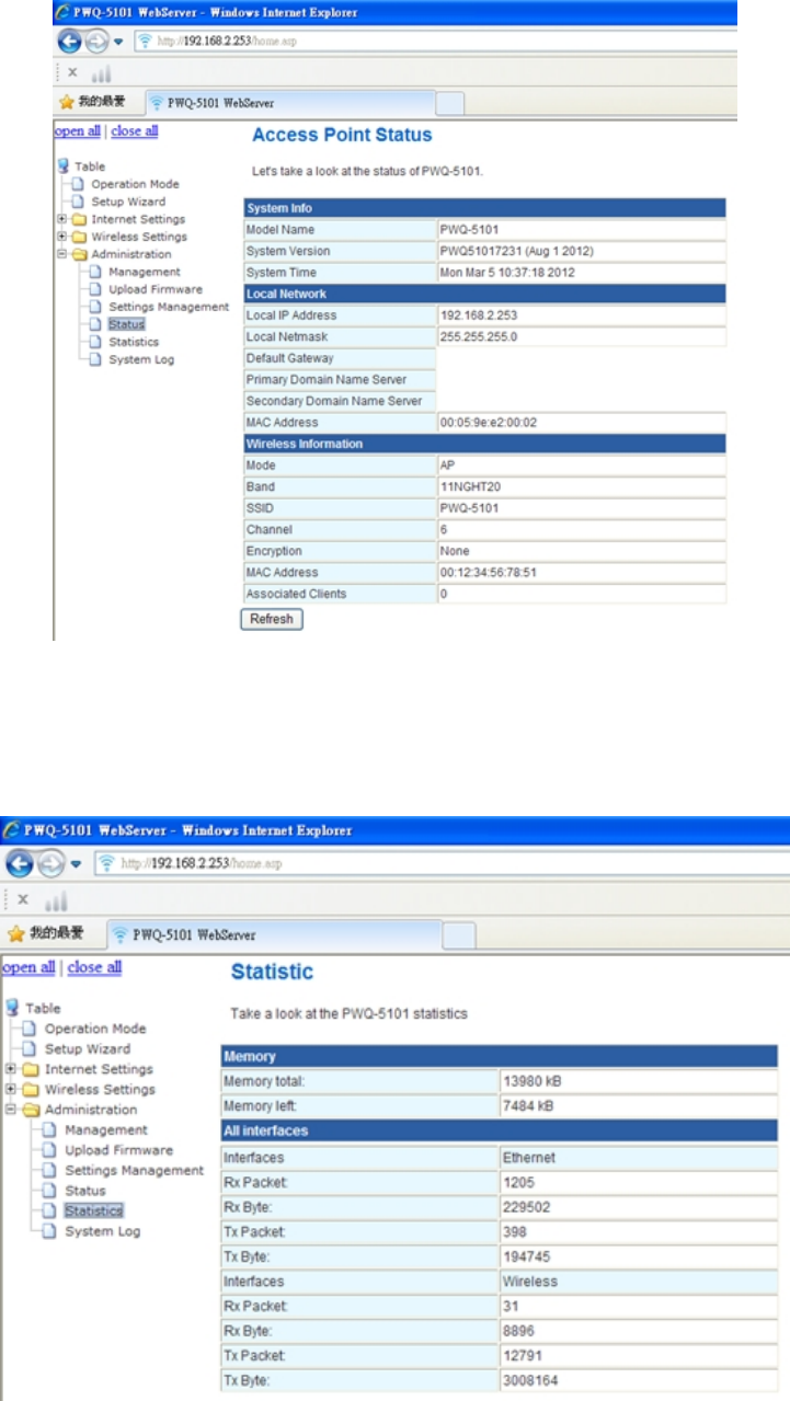
Status
The system info, network and wireless status of PWQ-5101
30
Statistics
Memory and interface
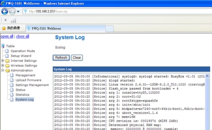
System log
Show the log of PWQ-5101
31
FEDERAL COMMUNICATIONS COMMISSION INTERFERENCE STATEMENT
This equipment has been tested and found to comply with the limits for a Class B digital device,
pursuant to part 15 of the FCC Rules. These limits are designed to provide reasonable protection
against harmful interference in a residential installation. This equipment generates, uses and can
radiate radio frequency energy and, if not installed and used in accordance with the instructions,
may cause harmful interference to radio communications. However, there is no guarantee that
interference will not occur in a particular installation. If this equipment does cause harmful
interference to radio or television reception, which can be determined by turning the equipment off
and on, the user is encouraged to try to correct the interference by one or more of the following
measures:
-Reorient or relocate the receiving antenna.
-Increase the separation between the equipment and receiver.
-Connect the equipment into an outlet on a circuit different from that to which the receiver is
connected.
-Consult the dealer or an experienced radio/ TV technician for help.
CAUTION:
Any changes or modifications not expressly approved by the grantee of this device could void the
user's authority to operate the equipment.
Labeling requirements
This device complies with Part 15 of the FCC Rules. Operation is subject to the following two
conditions: (1) this device may not cause harmful interference, and (2) this device must accept any
interference received, including interference that may cause undesired operation.
RF exposure warning
32
This equipment must be installed and operated in accordance with provided instructions and the
antenna(s) used for this transmitter must be installed to provide a separation distance of at least 20
cm from all persons and must not be co-located or operating in conjunction with any other antenna
or transmitter. End-users and installers must be provide with antenna installation instructions and
transmitter operating conditions for satisfying RF exposure compliance.
Canada, Industry Canada (IC) Notices
This Class B digital apparatus complies with Canadian ICES-003 and RSS-210.
Operation is subject to the following two conditions: (1) this device may not cause interference, and
(2) this device must accept any interference, including interference that may cause undesired
operation of the device.
Radio Frequency (RF) Exposure Information
The radiated output power of the Wireless Device is below the Industry Canada (IC) radio frequency
exposure limits. The Wireless Device should be used in such a manner such that the potential for
human contact during normal operation is minimized.
This device has also been evaluated and shown compliant with the IC RF Exposure limits under
mobile exposure conditions. (antennas are greater than 20cm from a person's body).
Canada, avis d'Industry Canada (IC)
Cet appareil numérique de classe B est conforme aux normes canadiennes ICES-003 et RSS-210.
Son fonctionnement est soumis aux deux conditions suivantes : (1) cet appareil ne doit pas causer
d'interférence et (2) cet appareil doit accepter toute interférence, notamment les interférences qui
peuvent affecter son fonctionnement.
Informations concernant l'exposition aux fréquences radio (RF)
La puissance de sortie émise par l’appareil de sans fil est inférieure à la limite d'exposition aux
fréquences radio d'Industry Canada (IC). Utilisez l’appareil de sans fil de façon à minimiser les
contacts humains lors du fonctionnement normal.
Ce périphérique a également été évalué et démontré conforme aux limites d'exposition aux RF d'IC
dans des conditions d'exposition à des appareils mobiles (les antennes se situent à moins de 20 cm
du corps d'une personne).
33
Ch 4 Enhance PLC performance during
installation
This Powerline device sends data to remote device using WLAN or PLC technology. When it
sends data to another remote Powerline device over the existing electrical wiring in your
home, it may be affected by noises on the electric wire or the length of the wiring between
transmitting and receiving devices. Keep the following in mind when placing this Powerline
device at home.
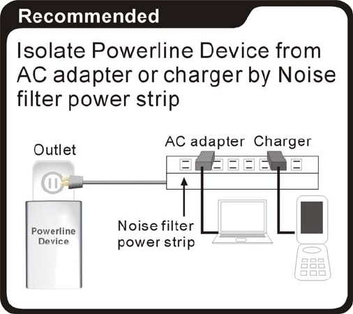
AC outlets connection
Avoid connecting this device to an uninterruptible power supply (UPS) or backup power
supply device. For best results, we recommend connecting the adaptors directly to a wall
outlet. Avoid connecting high power-consumption appliances to the same wall outlet. Plug
these power consuming devices onto a noise filtering power strip to prevent these device
interfere with this Powerline device. See the following illustration figure:
For better performance, the following connection is recommended, although not isolate with
Noise filter power strip will still work OK.
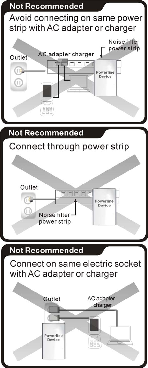
34
The following connections are NOT recommended, although current PLC technology will
overcome most noise interference from electronic devices’ AC adapters or chargers.
35
Connection via power strip
If you must connect this device to a power strip, please keep the following recommendation
in mind:
• Make sure the power strip does not have a noise filter or a surge protector, as these
features may impair communication signaling of the Powerline device sent over the
electric wiring, and its throughput or distance will be degraded.
• Use a power strip with an AC cord that is as short as possible.
• Do not connect the adaptor to a power strip that receives power from another power
strip.
Electrical interference
Certain electrical devices emit electrical noise. If this noise is spread over to the electrical
wiring in your home, it may interfere with the performance, speed, and reliability of this
device. For best results, we recommend connecting an electrical noise filter to noise
emitting appliances.
The following appliances are more likely to produce noise:
Battery chargers (including cell phone chargers)
Hair dryers
Power drills
Halogen light
vacuum cleaner
Additionally, this product may interfere with the following appliance:
Lights or lamps which have a touch-sensitive on/off feature
Electrical wiring
This device sends data to and from each other over the existing electrical wiring of your
house. If two wall outlets are separated by a great distance of electrical wiring, these
devices may not communicate well with each other. For more information, refer to the
troubleshooting section.

36
Ch 5 Specification
Powerline Wireless N Extender
WLAN: IEEE 802.11 b/g, IEEE 802.11n
LAN: IEEE 802.3, IEEE 802.3u
Standards
Powerline: HomePlug AV 1.0
WLAN to Ethernet: up to 93 Mbps (Under 802.11n 40MHz)
Maximum Throughput
Powerline to Ethernet: TCP: 92 Mbps
WLAN: 2.4~2.4835GHz
Frequency band
PLC: 2~ 68MHz
RF Power:
802.11b TX: 16 dBm +/- 1.5dB (typ.)@1Mbps
802.11g TX : 16 dBm +/- 1.5dB (typ.)@6Mbps
802.11n TX : 14 dBm +/- 1.5dB (typ.)@6.5Mbps
802.11n TX : 13 dBm +/- 1.5dB (typ.)@13.5Mbps
Sensitivity:
802.11b RX: 82 dBm(typ.)@11Mbps
802.11g RX: 70 dBm(typ.)@54Mbps
802.11n RX(20MHz): 67dBm(typ.)@ 72.2Mbps
802.11n RX(40MHz): 64dBm(typ.)@ 150Mbps
Physical Data Rate:
802.11b: 1,2, 5.5, 11Mbps
802.11g: 6, 9, 12, 18, 24, 36, 48, 54Mbps
802.11n (20MHz): MCS0~7, Up to 72.2Mbps
WLAN transceiver spec
802.11n (40MHz): MCS0~7, Up to 150Mbps
Wi-Fi mode Wireless AP+ Bridge mode (Default)
WLAN
WPS PBC / PIN code, WPA‐PSK, and WPA2‐PSK
Security mode
PLC
128‐bit AES
Antenna type 1T1R
LAN port 1 port
AC input 100 - 240 V
50‐60Hz

37
Power consumption (Note: Ethernet and Wi‐Fi is connected and running)
POWER LED (Green);
PLC Link/Activity LED (Green);
Wireless & Security LED (dual color);
LEDs
Ethernet (Green)
WPS
GROUP/Pairing
Power on/off
Buttons
RESET
PLC PHY Rate 500 Mbps
PLC Modulation OFDM (QAM 8/16/64/256/1024/4096, BPSK, QPSK, ROBO)
PLC Distance AC Wire : up to 300 meters
Max. dev in a PLC
network Group 8/16 (Active/Total)
Temperature Operating: 0~40 ℃; Storage: ‐20~60 ℃
Relative Humidity Operating: 10~85% Non‐Condensing ,
Storage: 5~90% Non‐Condensing
Dimension 56 x 105 x 48(H) mm
Certification FCC, CE, CE‐LVD, RoHS, WEEE