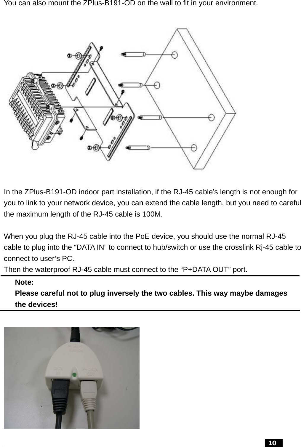
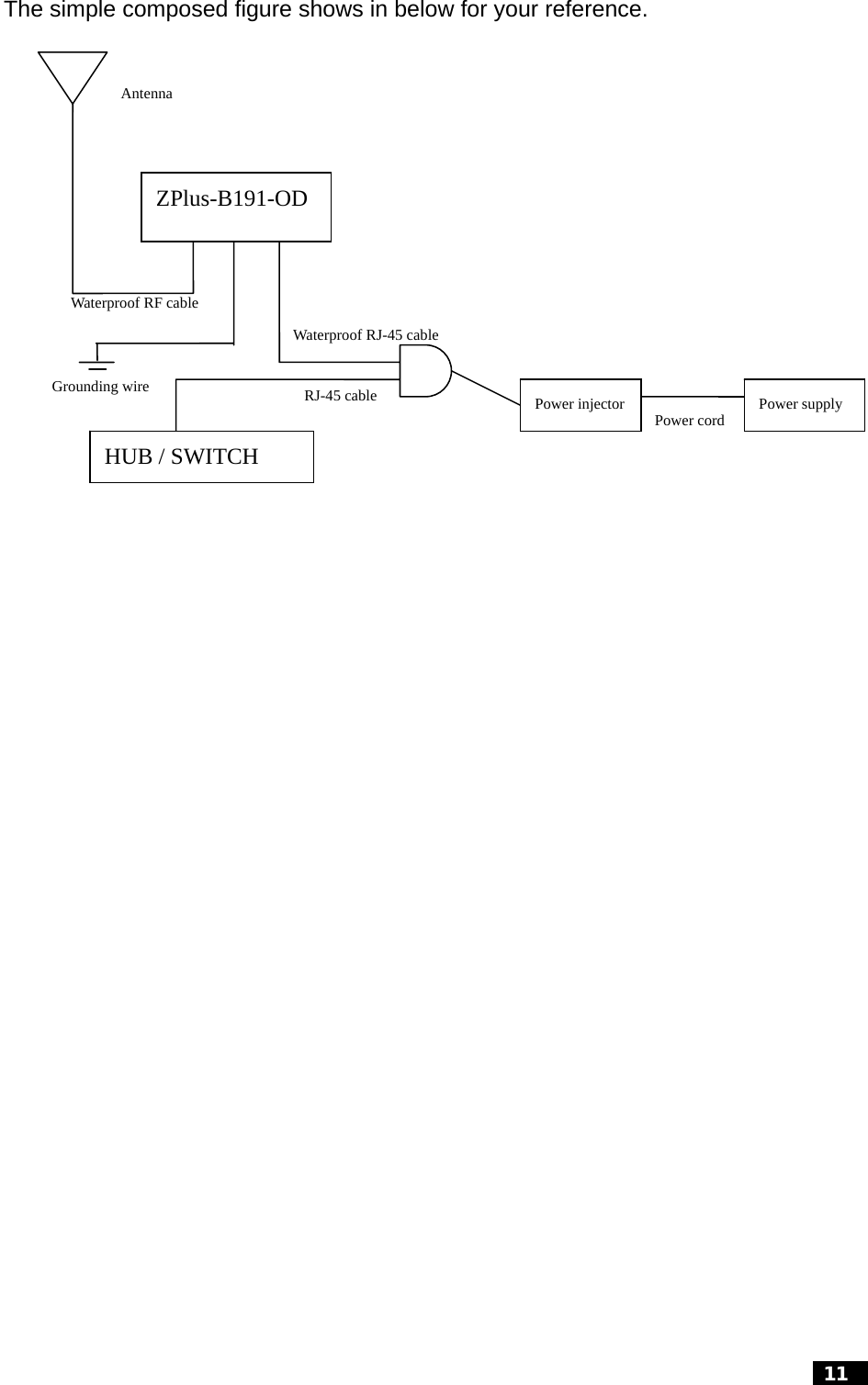
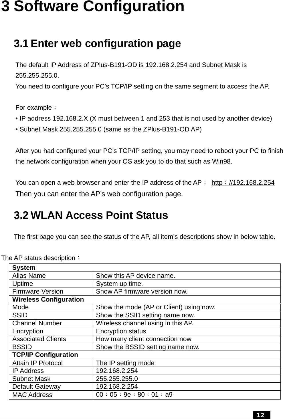
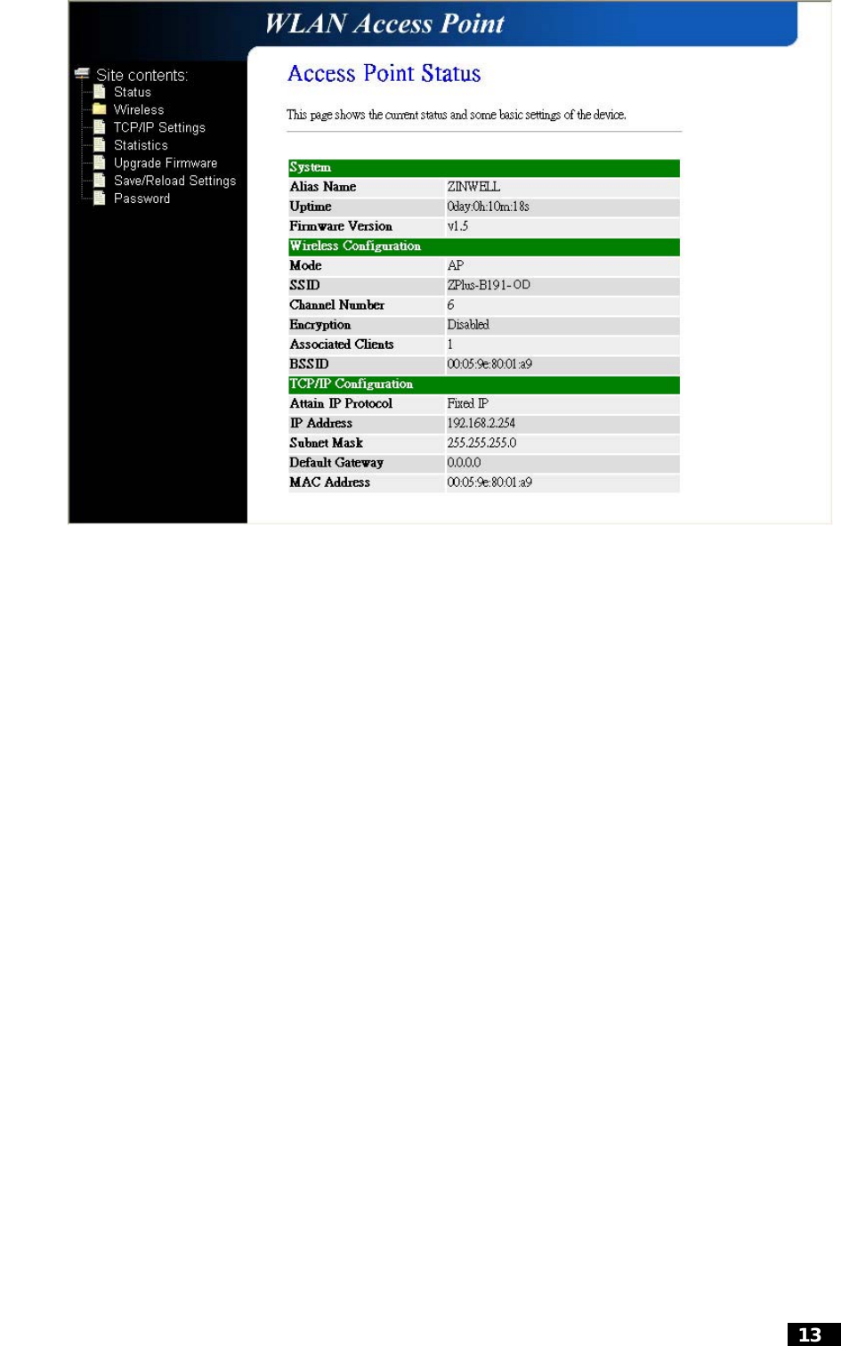
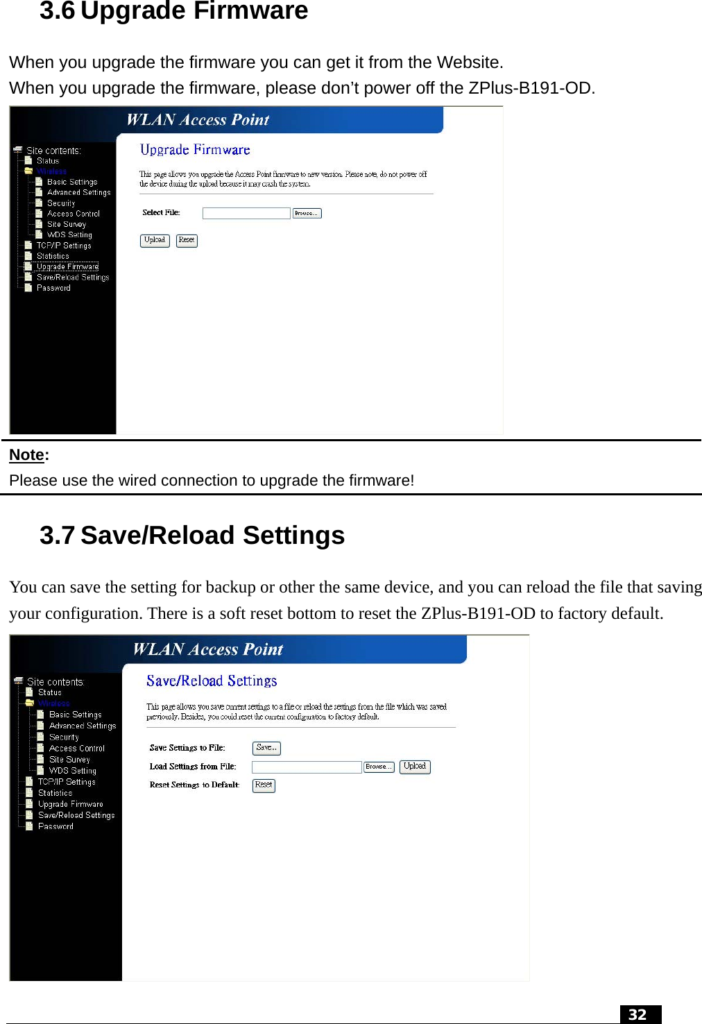
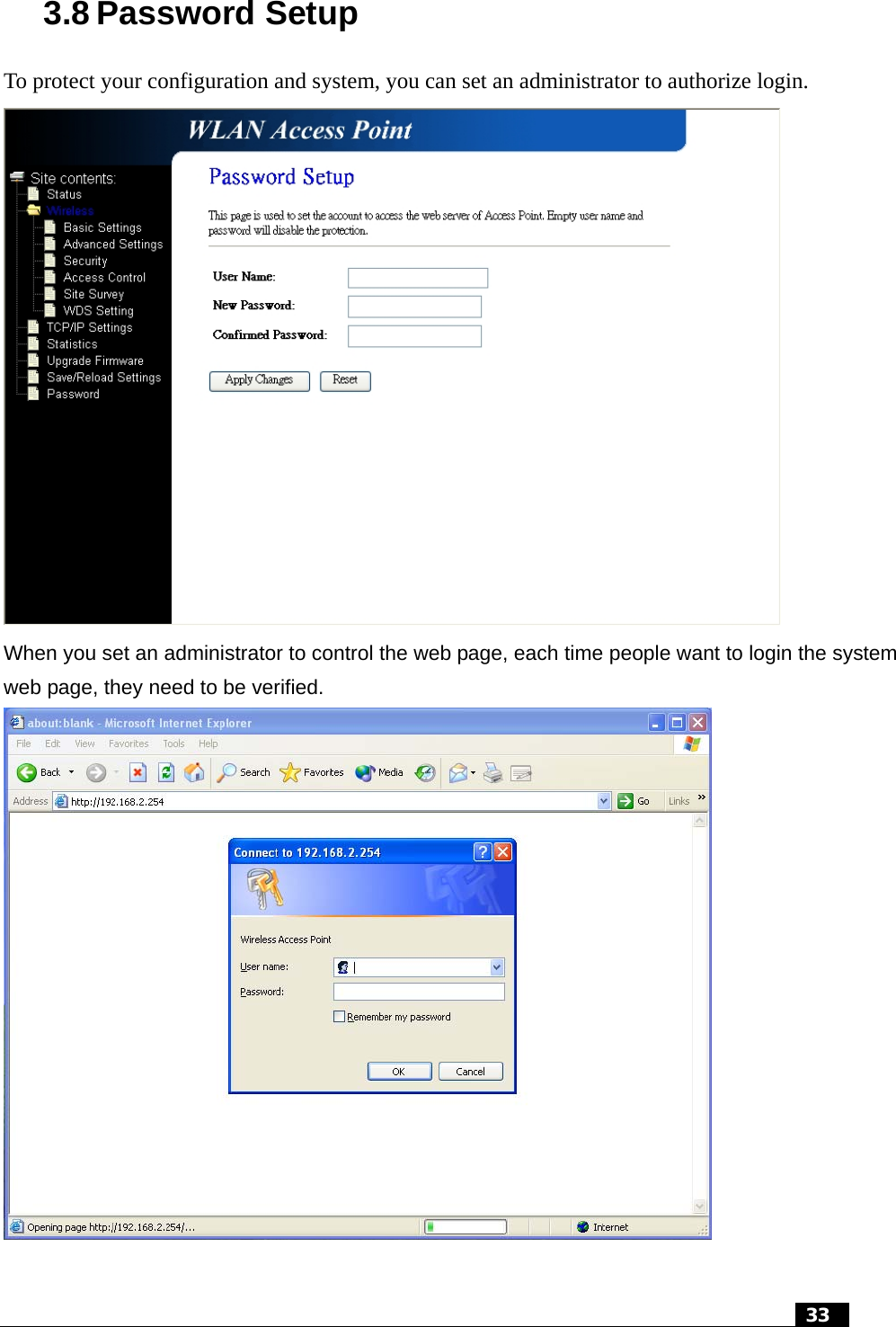
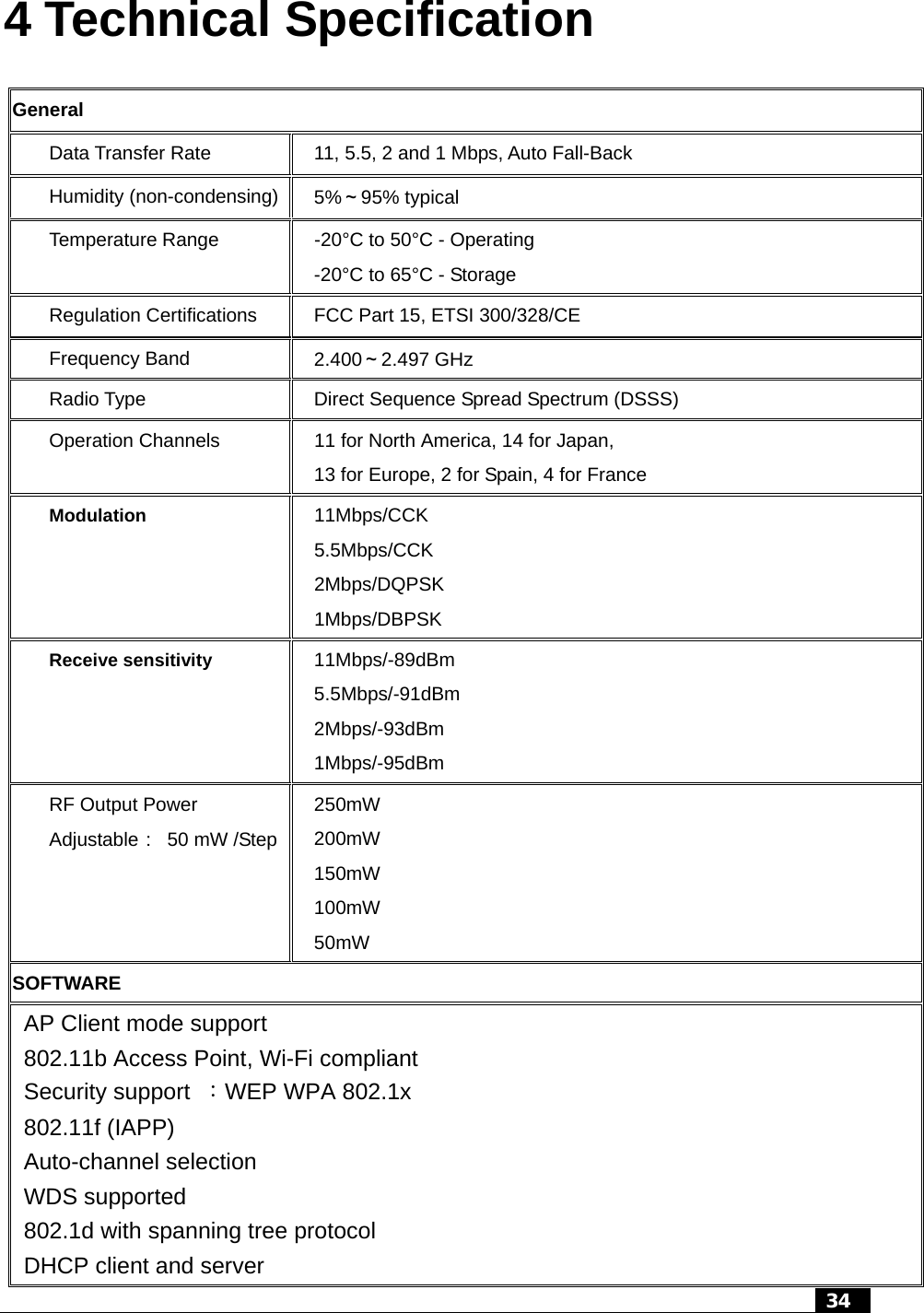
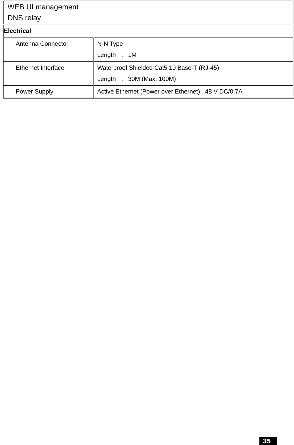
Zinwell ZWA-B191-OD WLAN Outdoor Bridge User Manual revised manual

Zinwell Corporation WLAN Outdoor Bridge revised manual

revised manual

   Wireless LAN Device Series  WLAN Outdoor Bridge  ZPlus-B191-OD User’s Manual          Version. 1.02 (06.01.2004)
  2   Notice    “This device complies with Part 15 of the FCC Rules.   Operation is subject to the following two conditions:    (1) This device may not cause harmful interference, and (2) this device must accept any interference received, including interference that may cause undesired operation.  Warning:  Changes or modifications to this unit not expressly approved by the party responsible for compliance could void the user authority to operate the equipment. This device complies with Part 15 of the FCC Rules. Operation is subject to the following two conditions:    (1) This device may not cause harmful interference, and (2) this device must accept any interference received, including interference that may cause undesired operation. The user’s manual or instruction manual for an intentional or unintentional radiator shall caution the user that changes or modifications not expressly approved by the party responsible for compliance could void the user’s authority to operate the equipment.  NOTE:  This equipment has been tested and found to comply with the limits for a Class B digital device, pursuant to Part 15 of the FCC Rules.  These limits are designed to provide reasonable protection against harmful interference in a residential installation.  This equipment generates uses and can radiate radio frequency energy and, if not installed and used in accordance with the instructions, may cause harmful interference to radio communications. However, there is no guarantee that interference will not occur in a particular installation.  If this equipment does cause harmful interference to radio or television reception, which can be determined by turning the equipment off and on, the user is encouraged to try to correct the interference by one or more of the following measures:  Reorient or relocate the receiving antenna.  Increase the separation between the equipment and receiver.  Connect the equipment into an outlet on a circuit different from that to    which the receiver is needed.  Consult the dealer or an experienced radio/TV technician for help.  Changes or modifications not expressly approved by the party responsible for compliance could void the user‘s authority to operate the equipment.  The antenna(s) used for this transmitter must not be co-located or operating in conjunction with any other antenna or transmitter  Shielded interface cables must be used in order to comply with emission limits.
 This EUT is incompliance with SAR for general population /uncontrolled exposure limits in ANSI/IEEE C95.1-1999 and had been tested in accordance with the measurement methods and procedures specified in OET Bulletin 65 Supplement C  This device and its antenna(s) must not be co-located or operating in conjunction with any other antenna or transmitter   CAUTION: 1. The antenna(s) used for this transmitter must be fixed-mounted on outdoor permanent structures with a separation distance of at least 2 meters from all persons    and must not be co-located or operating in conjunction with any other antenna or transmitter.  Users and installers must be provided with antenna installation instructions and transmitter operating conditions for satisfying RF exposure compliance.   2. This Transmitter must not be co-located or operating in conjunction with any other antenna or transmitter.   3. This equipment is only allowed to be professionally installed.   3
  4   Contents   1 INTRODUCTION...................................................................................................................................................6 2 HARDWARE INSTALLATION............................................................................................................................7 2.1 PACKING LIST...................................................................................................................................................7 2.2 HARDWARE INSTALLATION............................................................................................................................... 8 3 SOFTWARE CONFIGURATION.......................................................................................................................12 3.1 ENTER WEB CONFIGURATION PAGE .................................................................................................................12 3.2 WLAN ACCESS POINT STATUS .......................................................................................................................12 3.3 WIRELESS LAN SETTING ...............................................................................................................................14 3.3.1 Basic settings ............................................................................................................................................14 3.3.2 Wireless Advanced Settings.......................................................................................................................17 3.3.3 Wireless Security setup..............................................................................................................................19 3.3.3.1 WEP Encryption Setting.......................................................................................................................19 3.3.3.2 WEP Encryption with 802.1x Setting ...................................................................................................22 3.3.3.3 WPA Encryption Setting .......................................................................................................................23 3.3.4 Wireless Access Control............................................................................................................................ 24 3.3.5 Wireless Site Survey ..................................................................................................................................26 3.3.6 WDS Settings ............................................................................................................................................27 3.4 LAN INTERFACE SETUP.................................................................................................................................. 28 3.4.1 Using the Fixed IP....................................................................................................................................28 3.4.2 Using DHCP Client ..................................................................................................................................29 3.4.3 Enable DHCP Server................................................................................................................................30 3.5 WLAN AP STATISTICS ...................................................................................................................................31 3.6 UPGRADE FIRMWARE .....................................................................................................................................32 3.7 SAVE /RELOAD SETTINGS ................................................................................................................................32 3.8 PASSWORD SETUP...........................................................................................................................................33 4 TECHNICAL SPECIFICATION ........................................................................................................................34 5 WIRELESS CONNECTION ARCHITECTURE ..............................................................................................36 5.1 Infrastructure mode ..................................................................................................................................36 5.2 Ad-Hoc mode ............................................................................................................................................ 36 5.3 WIRELESS AP FUNCTIONS ..............................................................................................................................37 5.3.1 Access Point Mode....................................................................................................................................37 5.3.2 Access Point Client Mode (ad-Hoc)..........................................................................................................38 5.3.3 Access Point Client Mode (Infrastructure) ...............................................................................................38 5.3.4 Wireless Repeater......................................................................................................................................39
  5  5.3.5 WDS (Wireless Distribution System).........................................................................................................39 5.3.6 Wireless Bridge.........................................................................................................................................40 5.4 SELECTING AN APPROPRIATE SITE................................................................................................................... 41 5.5 POWER OVER ETHERNET ................................................................................................................................41
  6  1 Introduction ZINWELL ZPlus-B191-OD Wireless Outdoor Bridge is fully complying with 802.11b standard, featuring with easy-to-install, and easy-to-manage, building-to-building and building to multibuildings connection. Our Outdoor Bridge is a flexible and cost-effective product which allows you to connect LANs located in far distant buildings with data rate up to 11Mbps, ZPlus-B191-OD is an idea device to replace the expensive lease lines, such as T1 line or fiber optics.  With Power over Ethernet function, ZPlus-B191-OD reduces installation expenses and increases location options by using a single Ethernet cable to supply both data and power to our Wireless Outdoor Bridge.   Applications z  Point-to-Point / Point-to-Multipoint Architecture z Indoor/Outdoor Architecture z Easy Installation   Features z  Complied With IEEE 802.11b 2.4GHz Standard z  Excellent Range with Power Build-in Amplifier z  Maximum Sensitivity of 89dBm at 11Mbps z  Data Security with 64/128- Bit WEP Encryption
 2 Hardware Installation This Chapter helps you to quickly and easily install the hardware. 2.1 Packing List Before you start install the Wireless Outdoor Bridge, you should check the following packages you must have:  z  Wireless Outdoor Bridge * 1 z  Mounting Kits * 1 z  Waterproof RJ-45 Cable (30M) * 1 z  Waterproof RF Cable (1M) * 1 z  Power Over Ethernet Kits * 1 z  Grounding Wired * 1 z  2.5” /4” U bolts * 2 and Anchor * 4 z  6 / 9 dBi omni directional antenna * 1  Package Picture  Package Name Package Picture  Package Name Wireless Outdoor Bridge  Mounting Kits  Waterproof RJ-45 Cable  Waterproof RF Cable   7
 Power Over Ethernet Kits Grounding Wire  2.5” /4” U bolts and Anchor  6 / 9 dBi omni directional antenna   2.2 Hardware Installation After you check all of your packages are ready, you can start installing your wireless outdoor bridge. You can mount to a pipe or a side of a building. The steps showed in following:  1.  You must mount the ZPlus-B191-OD into the bracket first.  Note:    ALL the 4 screws had been tightly onto the Wireless Outdoor Bridge and bracket  2.  You can use the 2” inch or 4” inch U bolts to mount on the pipe. The two U bolts must tightly mount and take care not to over-tighten  3.  After check the ZPlus-B191-OD is mount well, you can connect two cables, Waterproof   RJ-45 network cable and RF cable, and the grounding wire. The waterproof RF cable must tightly onto the Wireless Outdoor Bridge and another side that link to the Antenna better to have the lightening protector  4.  The waterproof RJ-45 cable also had been tightly onto the Wireless Outdoor Bridge and another side that be plugged into PoE device.    8
  ZPlus-B191-OD Cable connection  ZPlus-B191-OD grounding wire connection  Note:  DON’T plug the power cord into PoE device to power on the system before you finish install the antenna and grounding wire to ensure the safety.   You can follow the figure to mount the ZPlus-B191-OD quickly.    9
You can also mount the ZPlus-B191-OD on the wall to fit in your environment.   In the ZPlus-B191-OD indoor part installation, if the RJ-45 cable’s length is not enough for you to link to your network device, you can extend the cable length, but you need to careful the maximum length of the RJ-45 cable is 100M.  When you plug the RJ-45 cable into the PoE device, you should use the normal RJ-45 cable to plug into the “DATA IN” to connect to hub/switch or use the crosslink Rj-45 cable to connect to user’s PC. Then the waterproof RJ-45 cable must connect to the “P+DATA OUT” port. Note: Please careful not to plug inversely the two cables. This way maybe damages the devices!     10
The simple composed figure shows in below for your reference.   11   Power injectorZPlus-B191-OD Antenna Waterproof RF cable Waterproof RJ-45 cable Grounding wire  RJ-45 cable  Power supplyPower cord HUB / SWITCH
  12  3 Software Configuration 3.1 Enter web configuration page The default IP Address of ZPlus-B191-OD is 192.168.2.254 and Subnet Mask is 255.255.255.0. You need to configure your PC’s TCP/IP setting on the same segment to access the AP.  For example: • IP address 192.168.2.X (X must between 1 and 253 that is not used by another device) • Subnet Mask 255.255.255.0 (same as the ZPlus-B191-OD AP)  After you had configured your PC’s TCP/IP setting, you may need to reboot your PC to finish the network configuration when your OS ask you to do that such as Win98.  You can open a web browser and enter the IP address of the AP: http://192.168.2.254   Then you can enter the AP’s web configuration page. 3.2 WLAN Access Point Status The first page you can see the status of the AP, all item’s descriptions show in below table.  The AP status description: System Alias Name  Show this AP device name. Uptime  System up time. Firmware Version  Show AP firmware version now. Wireless Configuration Mode  Show the mode (AP or Client) using now. SSID  Show the SSID setting name now. Channel Number  Wireless channel using in this AP. Encryption Encryption status Associated Clients  How many client connection now BSSID  Show the BSSID setting name now. TCP/IP Configuration Attain IP Protocol  The IP setting mode   IP Address  192.168.2.254 Subnet Mask  255.255.255.0 Default Gateway  192.168.2.254 MAC Address  00:05:9e:80:01:a9
   13
 3.3 Wireless LAN Setting 3.3.1 Basic settings  1.  The “Alias name” let you can set this AP’s name, to distinguish each AP.  2.  You can disable the wireless LAN interface by choosing this function.  3.  ZPlus-B191-OD can support AP and Client modes; you can use the “AP” mode for normal function and “Client” mode to connect to another AP, like a standard wireless client.  Note :    When you choice the client mode, you need connect by wired RJ-45 cable.  4.  When you choice the “Client” mode you still can have two types to connect the WLAN, one is infrastructure mode and another is ad-hoc mode. (You can see more detail steps in Site Survey chapter.)  5.  You can set the SSID name to let the wireless device to discover this AP.  6.  The channel range is from 1 to 14 and auto function, you can manually choice the channel to fit your WLAN environment, or you can just choice the auto function to detect the best channel that every time the AP power on for your WLAN environment.   14
 7.  In the “Associated Client”, you also can click the “Show Active Client” to see which client had connected to this AP.  When you using the Client mode of the AP, you must connect by wired RJ-45 cable and can’t use the AP mode’s functions.    This table shows the status of all clients that connected to this AP.    15
 Each time you change the default setting successful, the page will show the successful message.       16
3.3.2 Wireless Advanced Settings In this wireless advanced settings page, you must configure it very carefully, because the default setting is almost optimized for the entire wireless LAN environment.  Note : Any unreasonable value change will reduce the throughput of the AP.   1. Authentication Type:  you can choice the Open system or Shared Key or Auto, the default setting is “Auto”.  2. Fragment Threshold:  When you always transmit the large files, you can use this function to improve the network performance. The default setting is disable (set the value to the maximum)   17
  18   3. RTS Threshold:  This function is to prevent the low throughput from the hidden node of WLAN device. The default setting is disable(set the value to the maximum)  4. Beacon Interval:  The interval time to send the beacon. The default value is 100ms.  5. Broadcast SSID:  Broadcasting the SSID can let your client auto find this AP, if you disable the function, you must connect by manually write down the AP’s SSID in your client setting.  6. Int. Roaming:  This function let user can roam between the APs, user can have more wireless working range. You should meet the following requirement to roam between the wireless coverage areas. z  All the access points must be on the same subnet network and the SSID must be the same. z  If you using the 802.1x authentication, you need have the user profile in these AP for the roaming station.  Tx Power:  The output power you can adjust to follow different country regulations.   Output Power  Antenna gain FCC Certification  200mW (default )  6 dBi    or    9 dBi CE  Certification  100mW (after Antenna) 6 dBi  or  9 dBi
3.3.3  Wireless Security setup The default security setting is disable the encryption function, you can choice which the security you want.    3.3.3.1 WEP Encryption Setting When you use the WEP encryption, you can choice just set the WEP key or use the 802.1x Authentication.   19
  When you decide to use the WEP encryption to secure your WLAN, the following explain the setting of the WEP encryption:  1.  64-bit WEP Encryption:  64-bit WEP key are the same with the encryption method of 40-bit WEP, you can input 10 hexadecimal digits {0~9},{a~f},{A~F}  2.  128-bit WEP Encryption:  128-bit WEP key are the same with the encryption method of 104-bit WEP, you can input 26 hexadecimal digits {0~9},{a~f},{A~F}  3.  The Default Tx Key field let you specify which of four keys you want to use in your WLAN environment.    20
   21
3.3.3.2  WEP Encryption with 802.1x Setting When you use the WEP encryption, you can also use the RADIUS server to check the admission of the users.  Then you can choice WEP 64 or 128 bit encryption to fit in with your network environment, the default Port is 1812, and in IP address field you need to specify the RADIUS server’s IP and the Password’s length is depend on your choice of WEP key’s bits.      22
3.3.3.3 WPA Encryption Setting When you choice the WPA encryption, you can use the WPA-RADIUS or Pre-shared Key to enhance your security setting. You also can enable or disable the TKIP. And the Pre-shared Key format has two choices, one is passphrase and other is Hex (64 characters).   When you choice the WPA encryption, you can use the WPA-RADIUS or Pre-shared Key to enhance your security setting. You also can enable or disable the TKIP. The default Port for RADIUS Server is 1812, and in IP address field for you to specify the RADIUS server’s IP   23
 3.3.4 Wireless Access Control In this page you can have a simple firewall to prevent the unauthenticated customer to connect to our AP.  1.  If you add the filtering MAC address to allow the connection, you must carefully do with the “Wireless Access Control”, when you enable the access control, you need to add the MAC address that be allowed to connect to the AP.  2.  When you type in the MAC address, you can just key in the MAC address number.  3.  The Current Access Control List shows the clients that connect to the AP. If you want to clean the control list, please carefully using it. When you delete all in the control list, then your wireless access control function still enable and you will not connect to the AP again by using wireless port again.    24
    25
3.3.5 Wireless Site Survey When you enable the Client mode, you can use this page to discover the AP and connect to it by this function.    26
3.3.6 WDS Settings When you set up the WDS system, you should consider follow things: 1.  ALL your ZPlus-B191-ODs must have the same channel.  2.  ALL The ZPlus-B191-ODs and Clients device must at the same subnet network.  3.  WDS system support both WDS device and client connection, if you want to let only the WDS devices to connect, you can enable the “Access control” function and don’t add any MAC address to the list. Then the system will automatic only allow the WDS device to connect.  4.  The following figure is the example for your reference. IP:192.168.2.2 Mask:255.255.25.0IP:192.168.2.3 Mask:255.255.25.0ZPlus-B191-OD:   ZPlus-B191-OD:  : 6 4  5.0 SSID: C1  SSID: C2 : 6 3  5.0 CHANNEL CHANNELIP:192.168.2.25 IP:192.168.2.25MASK:255.255.25 MASK:255.255.25    27
3.4 LAN Interface Setup This configuration is mainly for setting the ZPlus-B191-OD’s IP mode (Fix and DHCP) and DHCP Server setting.   You can set the ZPlus-B190-OD’s IP by using the fixed IP or DHCP client.    ZPlus-B191-OD also can support the DHCP Server for your network environment.   ZPlus-B191-OD also supports the 802.1d spanning tree function.   And you also can do the Clone MAC address to simulate other network device’s MAC address.  3.4.1 Using the Fixed IP When you use the fixed IP for ZPlus-B191-OD, you must fill up the IP address and Subnet Mask and Default Gateway (if you need to have.)     28
3.4.2 Using DHCP Client You also can use the DHCP client mode to get the IP and other setting, but you must carefully to use this function.    You need to know what IP that ZPlus-B191-OD will get or you can’t connect to the ZPlus-B191-OD’s web page.     29
3.4.3 Enable DHCP Server If you don’t have another DHCP server in your network, you can enable this function to support your network to make the network setting easier.  You must setup follow setting: 1.  DHCP Client range: 192.168.2.X (X:1~253) 2.  DNS Server: to identify what DNS is usefully to you.   When you finish the default setting, if you change the ZPlus-B191-OD’s IP, you have to re-connect the Web Server with the new address.    30
When you enable the DHCP server, you can see which client had been assigned the IP address.   3.5 WLAN AP Statistics This page shows the wireless statistics, the packet counters for transmission and reception regarding to wireless and Ethernet networks.     31
3.6 Upgrade Firmware When you upgrade the firmware you can get it from the Website. When you upgrade the firmware, please don’t power off the ZPlus-B191-OD.  Note: Please use the wired connection to upgrade the firmware! 3.7 Save/Reload Settings You can save the setting for backup or other the same device, and you can reload the file that saving your configuration. There is a soft reset bottom to reset the ZPlus-B191-OD to factory default.    32
3.8 Password Setup To protect your configuration and system, you can set an administrator to authorize login.  When you set an administrator to control the web page, each time people want to login the system web page, they need to be verified.    33
  34    4 Technical Specification General  Data Transfer Rate    11, 5.5, 2 and 1 Mbps, Auto Fall-Back Humidity (non-condensing)    5%~95% typical Temperature Range    -20°C to 50°C - Operating -20°C to 65°C - Storage Regulation Certifications    FCC Part 15, ETSI 300/328/CE Frequency Band    2.400~2.497 GHz Radio Type    Direct Sequence Spread Spectrum (DSSS) Operation Channels    11 for North America, 14 for Japan, 13 for Europe, 2 for Spain, 4 for France Modulation 11Mbps/CCK 5.5Mbps/CCK 2Mbps/DQPSK 1Mbps/DBPSK Receive sensitivity 11Mbps/-89dBm 5.5Mbps/-91dBm 2Mbps/-93dBm 1Mbps/-95dBm RF Output Power Adjustable:  50 mW /Step  250mW 200mW 150mW 100mW 50mW SOFTWARE  AP Client mode support   802.11b Access Point, Wi-Fi compliant  Security support :WEP WPA 802.1x  802.11f (IAPP)  Auto-channel selection  WDS supported   802.1d with spanning tree protocol   DHCP client and server
  35    WEB UI management  DNS relay Electrical  Antenna Connector   N-N Type  Length  : 1M Ethernet Interface    Waterproof Shielded Cat5 10 Base-T (RJ-45) Length  :  30M (Max. 100M) Power Supply    Active Ethernet (Power over Ethernet) –48 V DC/0.7A
5  Wireless Connection Architecture IEEE 802.11 defines two types of network service:  Infrastructure and ad-Hoc mode. You can select either one to fit your network environment.    5.1 Infrastructure mode ALL PCs, with wireless LAN card, connect to the AP that has been linking to the LAN and all the resource can be integrated or shared.  This is the traditional mode of the AP, you can put your AP in a center position of your office or other better position to have good RF cover range, and your entire wireless device, such as Laptop or PC, can connect and be controlled by this AP.    The entire PC can share the resource and have internet service through the wireless AP.  5.2 Ad-Hoc mode In this mode, client can have an independent wireless group in a meeting or small office.  You can setup a SSID in a mobile device or a PC, and then other device can connect to this SSID to join the small network to share the resource.   36
 5.3 Wireless AP Functions Access Point can have different functions to make your network more effectively.   5.3.1  Access Point Mode In the Access Point function, you can connect the AP to the LAN with RJ-45 cable and PC can use the wireless LAN adapter to connect to this AP to share the resource and join to the network environment. In this function, you can use it indoor for normal using in wireless networking. And you also can use it outdoor for Hot Spot, people can use wireless in square or courtyard outside the house.      37
5.3.2  Access Point Client Mode (ad-Hoc) Using the Access Point Client function, you can have both the AP function and Client function. You can use the wire line connect to the LAN and use the wireless client “ad-Hoc” function to join to each other.  5.3.3  Access Point Client Mode (Infrastructure) Using the Access Point Client function in Infrastructure mode, you can connect to the LAN with wire line and can setup a Basic service set to let other client including the PC client and AP Client.   38
5.3.4 Wireless Repeater Wireless Repeater can extend the range of the wireless radio, and you can add the long range of the wireless group.   5.3.5  WDS (Wireless Distribution System) You can use the WDS function to connect to both of the AP and wireless LAN client.      39
5.3.6 Wireless Bridge You can use this function to connect two or more location (Point-to-Point, Point to multi-Point).     40
  41  5.4 Selecting an appropriate site 1  Selecting an appropriate site for your Wireless Outdoor Bridge will ensure the best performance.  2  Avoid locating the Wireless Outdoor Bridge near metal objects such as appliances like refrigerators, ovens, and washer/dryers. Keep in mind that your appliances may be on the other side of the wall in the area that you may be considering to locate the Wireless Outdoor Bridge.  3  For best performance, locate the Wireless Outdoor Bridge as close to the center of the area that you will be covering. Keep in mind that radio waves radiate outward from the Wireless Outdoor Bridge in a circular pattern.    4  Normally, the higher that you locate the Wireless Outdoor Bridge, the better the performance and range will be.  5  Remember that many things can cause a degrade of the radio signal such as brick walls, metal-reinforced concrete, the metal housing of appliances, or even wiring in the walls.   5.5 Power over Ethernet Power over Ethernet is a new industrial standard for product that difficult to have the power supply, only one RJ-45 cable can transmit both data and power.  Using the PoE system can let you system more easy to install and less cable lines. Plugging with the PoE device, you can have low cost, easy maintenance, convenience, high reliability, high stability and high security.

Navigation menu