Zinwell ZWA-G120 Wireless b/g AP User Manual G120X
Zinwell Corporation Wireless b/g AP G120X
Zinwell >
Contents
- 1. Users Manual 1
- 2. Users Manual 2
Users Manual 1

Wireless LAN Device Series
Multi-Mode AP
ZWA-G120 User Manual
Version. 1.0.0 (13.05.2005)
i
TABLE OF CONTENTS
PREFACE ...............................................................................................................................................1
CH 1. ZWA-G120 INSTALLATION.....................................................................................................2
PACKING LIST.......................................................................................................................................2
HARDWARE INSTALLATION...................................................................................................................2
CH 2. FIRST TIME CONFIGURATION ............................................................................................3
BEFORE START TO CONFIGURE .............................................................................................................3
KNOWING THE NETWORK APPLICATION ...............................................................................................3
ADVANCED SETTINGS.........................................................................................................................28
CONFIGURING WIRELESS SECURITY...................................................................................................31
CONFIGURING AS WLAN CLIENT ADAPTER.......................................................................................34
QUICK START TO CONFIGURE ..............................................................................................................34
CH 3. CONFIGURING WDS..............................................................................................................37
WDS NETWORK TOPOLOGY................................................................................................................37
WDS APPLICATION.............................................................................................................................39
CH 4. ADVANCED CONFIGURATIONS .........................................................................................41
CONFIGURING LAN TO WAN FIREWALL ............................................................................................41
PORT FILTERING .................................................................................................................................41
IP FILTERING ......................................................................................................................................41
MAC FILTERING.................................................................................................................................42
CONFIGURING PORT FORWARDING (VIRTUAL SERVER).......................................................................42
MULTIPLE SERVERS BEHIND NAT EXAMPLE: .....................................................................................43
CONFIGURING DMZ...........................................................................................................................43
CONFIGURING WAN INTERFACE.........................................................................................................44
STATIC IP............................................................................................................................................45
DHCP CLIENT (DYNAMIC IP).............................................................................................................46
PPPOE................................................................................................................................................46
PPTP..................................................................................................................................................47
CONFIGURING CLONE MAC ADDRESS ...............................................................................................48
CONFIGURING DHCP SERVER ............................................................................................................50
USING CLI MENU...............................................................................................................................51
THE SYSTEM MANAGEMENT ..............................................................................................................51
ABOUT SNMP AGENT ........................................................................................................................52
FIRMWARE UPGRADE .........................................................................................................................52
CONFIGURATION DATA BACKUP & RESTORE ......................................................................................53
1
Preface
This guide is for the networking professional who installs and manages the Ziwell
ZWA-G120 Multi-Mode AP, hereafter referred to as the “device”. To use this guide,
you should have experience working with the TCP/IP configuration and be familiar
with the concepts and terminology of wireless local area networks.
2
Ch 1. ZWA-G120 Installation
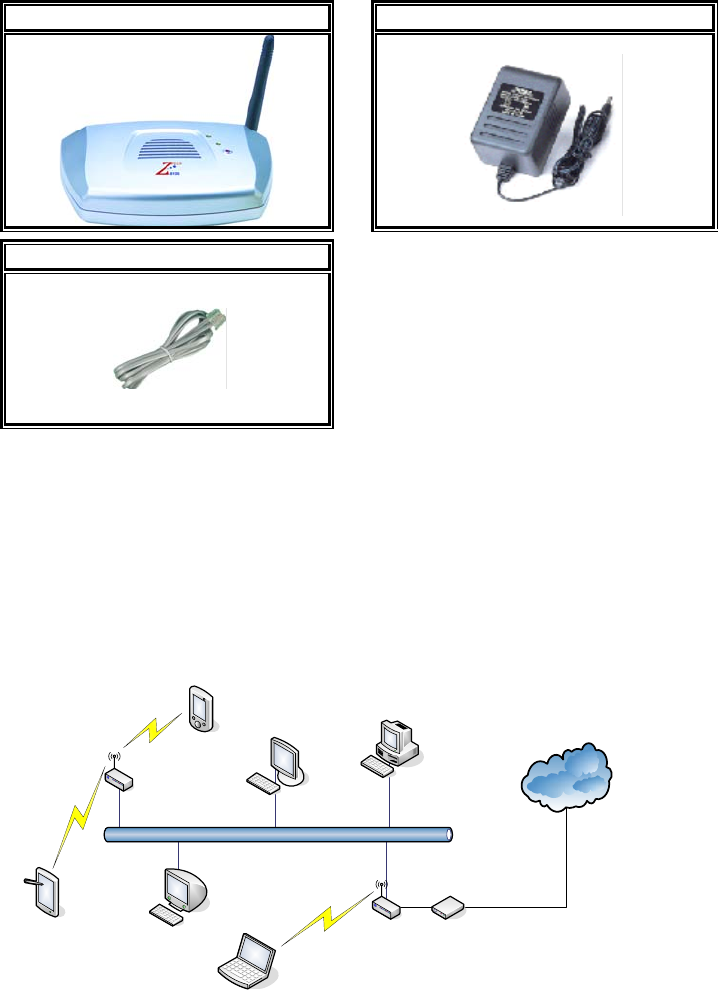
Packing List
Before you start to install the device, make sure the package contains the
following items:
z ZWA-G120 Multi-Mode AP * 1
z Power Adapter * 1
z RJ-45 Cable * 1
Multi-Mode AP Power Adapter
RJ-45 Cable
Hardware Installation
Once you check off everything from the package, you can start to install the
device. You can use the wall mount hole on the bottom of the device to
mount the device on the wall, or just put the device on the desktop. The
administrator can refer to the figure below while constructing your WLAN
environment.
Internet
Ethernet
ZWA-G120
(As AP)
Tablet PC
NB
PDA
ZWA-G120
(As Router) Broadband
Modem
3
Ch 2. First Time Configuration
Before Start to Configure
There are two ways to configure the device, one is through web-browser,
and the other is through Secure Shell CLI interface. To access the
configuration interfaces, make sure you are using a computer connected to
the same network as the device. The default IP address of the device is
192.168.2.254, and the subnet-mask is 255.255.255.0.
The device has three operation modes (Router/Bridge/WISP). In bridge
mode, also known as AP Client, you can access the device by both WLAN
(Wireless Local Area Network) and wired LAN. And in router/WISP modes,
the device can be accessed by both WLAN and WAN. The default IP
addresses for the device are 192.168.2.254(for LAN), 172.1.1.1(for WAN),
so you need to make sure the IP address of your PC is in the same subnet
as the device, such as 192.168.2.X (for LAN), 172.1.1.X (for WAN).
Please note that the DHCP server inside the device is default to up and
running. Do not have multiple DHCP servers in your network environment,
otherwise it will cause abnormal situation.
We also provide an auto-discovery tool which is for finding out the IP of the
device. In case, you’ve forgot the IP of the device or the IP of the device has
been changed, you can use the tool to find out the IP of the device even your
PC is not in the same subnet as the device is.
Knowing the Network Application
ZWA-G120 can act as the following roles, and it supports WDS (Wireless
Distribution System) function.
z Access Point
z WDS (Wireless Repeater)
z Bridge/Router
z WISP
z AP Client
The device provides 3 different operation modes and the wireless radio of device
can act as AP/Client/WDS. The operation mode is about the communication
mechanism between the wired Ethernet NIC and wireless NIC, the following is the
4
types of operation mode.
Router
The wired Ethernet (WAN) port is used to connect with ADSL/Cable modem and
the wireless NIC is used for your private WLAN. The NAT is existed between the 2
NIC and all the wireless clients share the same public IP address through the WAN
port to ISP. The default IP configuration for WAN port is static IP. You can access
the web server of device through the default WAN IP address 172.1.1.1 and modify
the setting base on your ISP requirement.
Bridge
The wired Ethernet and wireless NIC are bridged together. Once the mode is
selected, all the WAN related functions will be disabled.
WISP (Wireless ISP)
This mode can let you access the AP of your wireless ISP and share the same public
IP address form your ISP to the PCs connecting with the wired Ethernet port of the
device. To use this mode, first you must set the wireless radio to be client mode and
connect to the AP of your ISP then you can configure the WAN IP configuration to
meet your ISP requirement.
The wireless radio of the device acts as the following roles.
AP (Access Point)
The wireless radio of device serves as communications “hub” for wireless clients
and provides a connection to a wired LAN.
AP Client
This mode provides the capability to connect with the other AP using
infrastructure/Ad-hoc networking types. With bridge operation mode, you can
directly connect the wired Ethernet port to your PC and the device becomes a
wireless adapter. And with WISP operation mode, you can connect the wired
Ethernet port to a hub/switch and all the PCs connecting with hub/switch can share
the same public IP address from your ISP.
WDS (Wireless Distribution System)
This mode serves as a wireless repeater; the device forwards the packets to another
AP with WDS function. When this mode is selected, all the wireless clients can’t
survey and connect to the device. The device only allows the WDS connection.
WDS+AP
This mode combines WDS plus AP modes, it not only allows WDS connections but
5
also the wireless clients can survey and connect to the device.
The following table shows the supporting combination of operation and wireless
radio modes.
Bridge Router WISP
AP V V X
WDS V V X
Client V X V
AP+WDS V V V
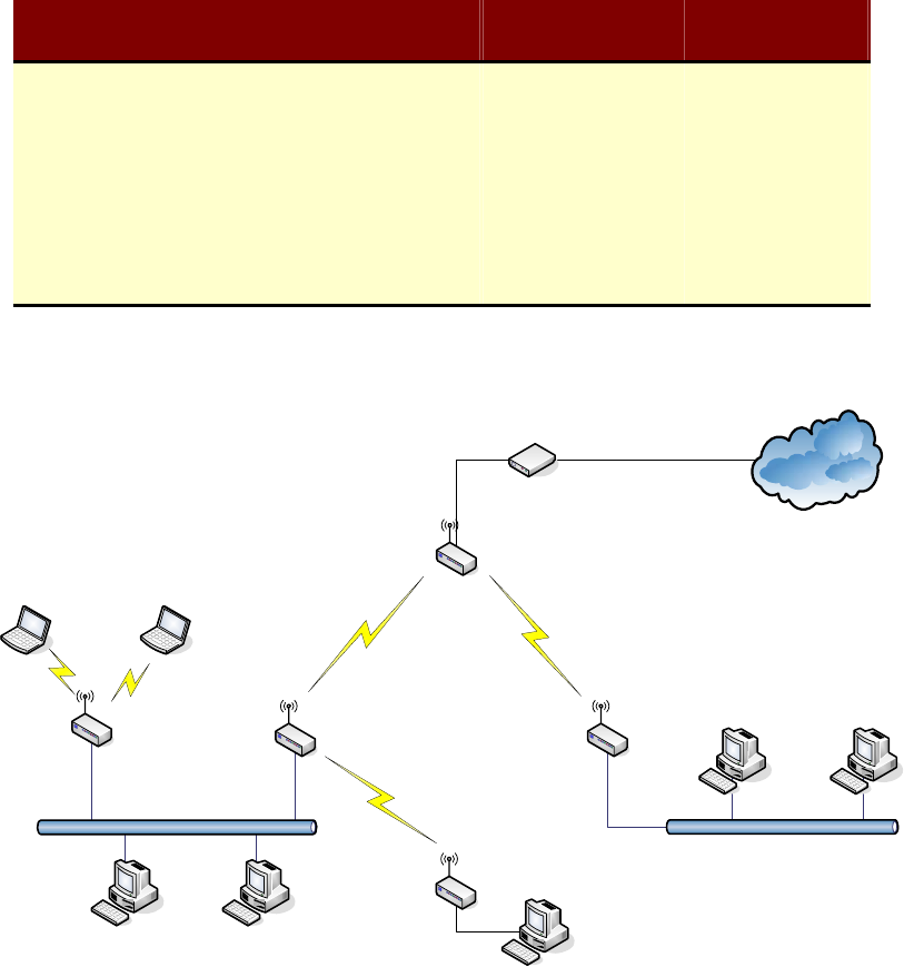
Hereafter are some topologies of network application for your reference.
Bridge Mode
With
AP
Bridge Mode
With
WDS + AP
Bridge Mode
Router Mode
With
WDS + AP
WISP Mode
Internet
Broadband
Modem
6
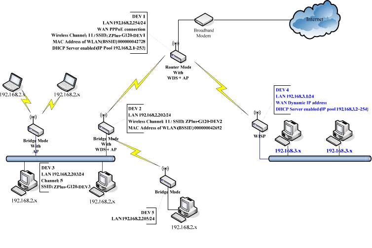
Examples of Configuration
This example demonstrates how to set up a network with different device
configurations. There are 2 DHCP servers (DEV1/DEV4) in the network to control
the IP configuration of 2 domains (192.168.2.x/192.168.3.x). Once the setting is
done, all the PCs can visit Internet through DEV1.
We assume all the devices keep the factory default setting. To make sure that user
can continuing press the rest button for more than 5 seconds to restore the factory
default setting.
The following descriptions show the steps to configure DEV1 to DEV5.
7
Configure DEV1:
1. Connect the ADSL modem to Ethernet port of device using Ethernet cable.
2. Access the web server (http://192.168.2.254) of device from the wireless
station.
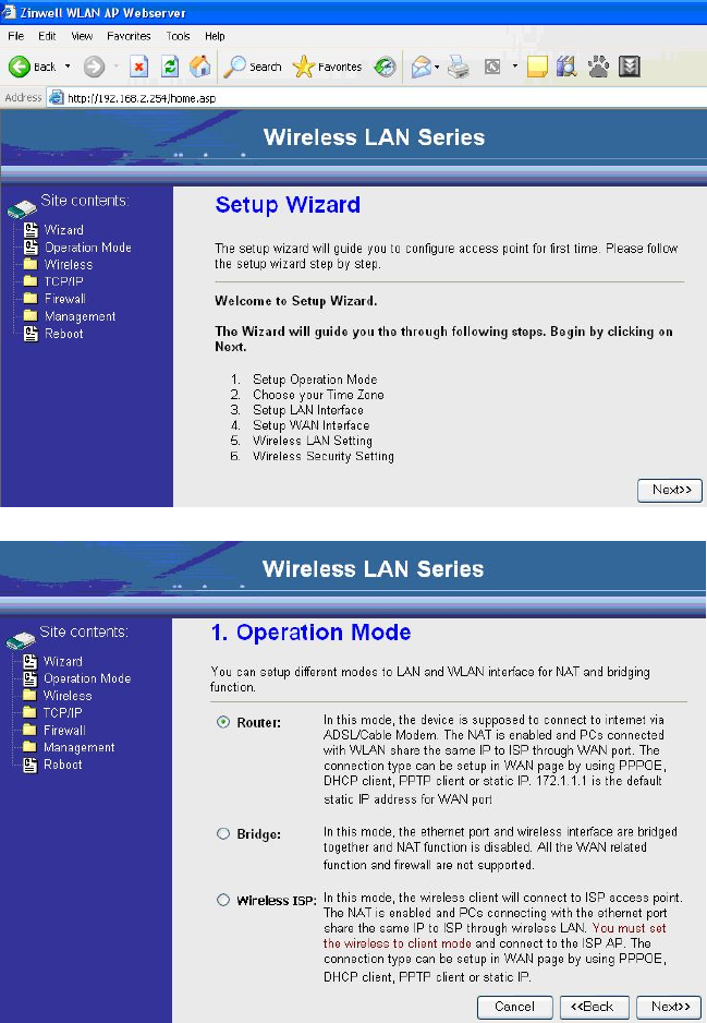
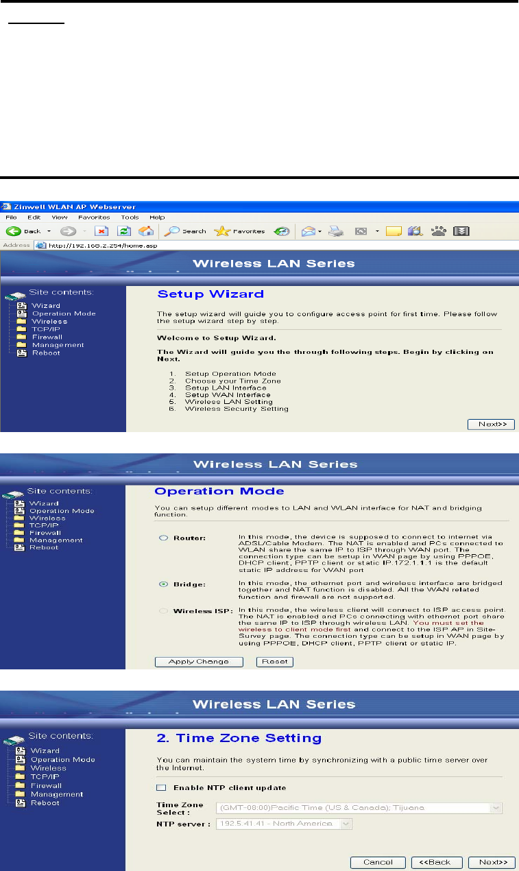
3. Use Wizard page to setup device.
4. Press “Next>>” button then set the “Operation Mode” to “Router” mode.
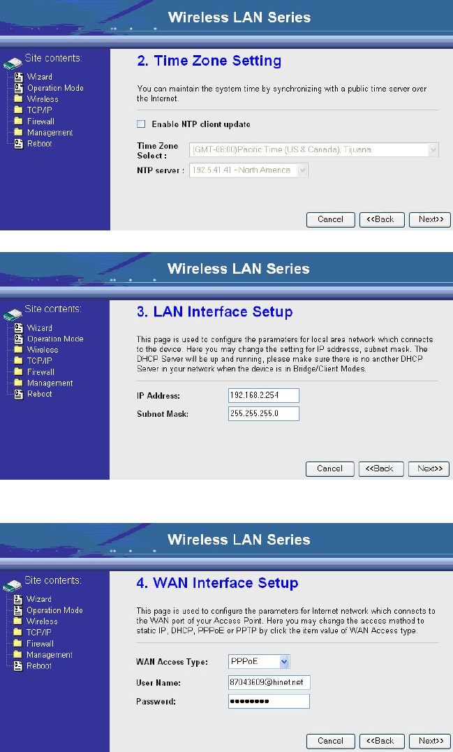
5. Press “Next>>” button then disable “Time Zone” function.
8
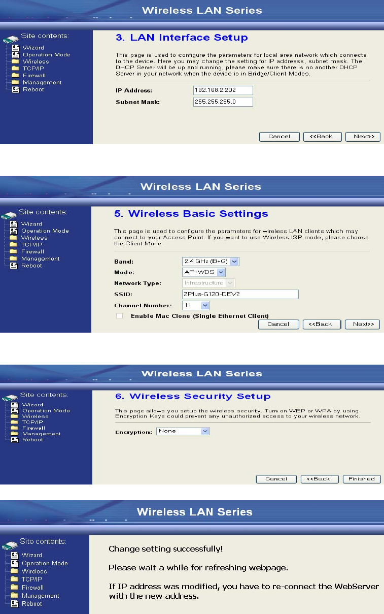
6. Press “Next>>” button then set the IP address of LAN interface.
7. Press “Next>>” button then select the “PPPoE” for “WAN Access Type” and
fill in the “User Name” and “Password” fields.
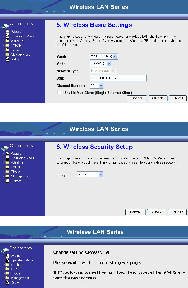
8. Press “Next>>” button then select the “AP+WDS” for “mode” and change the
SSID to “ZPlus-G120-DEV1”.
9
9. Press “Next>>” button then select “None” for “Encryption” then press
“Finished” button.
10. Wait for refreshing web page.
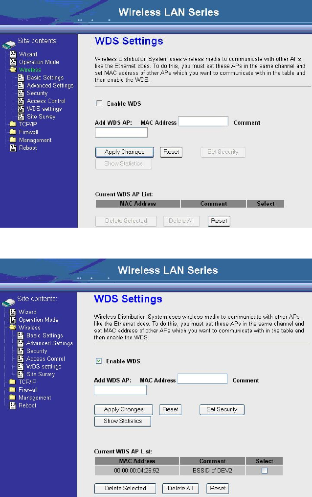
11. Use “WDS Settings” page to configure WDS.
10
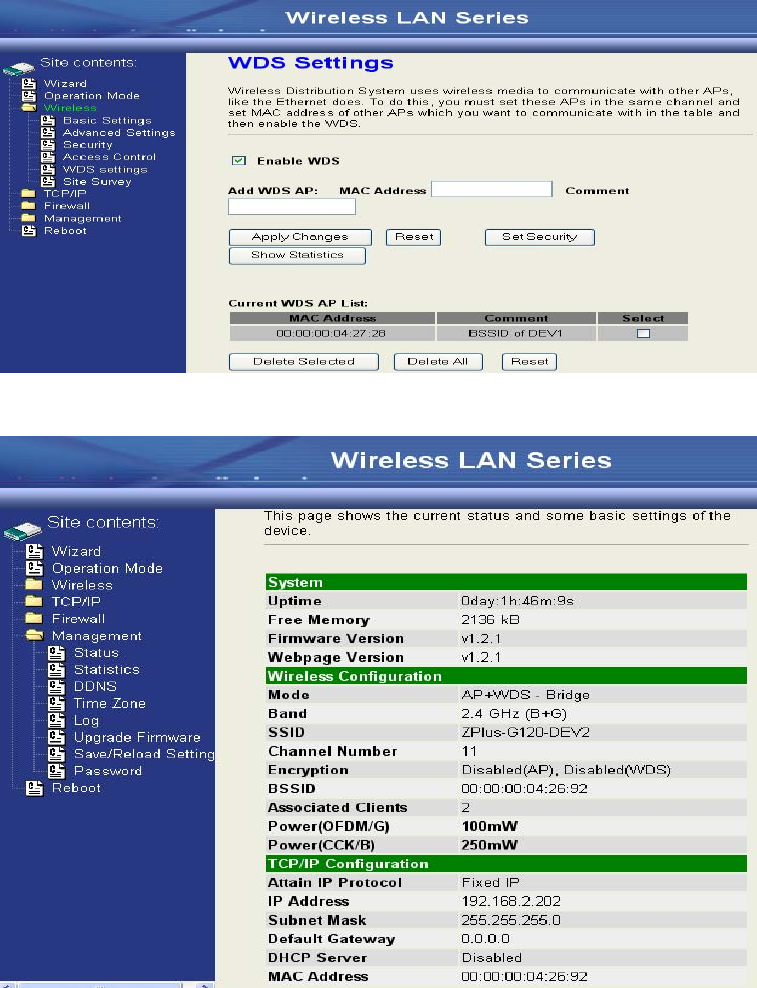
12. Enable WDS function and add the BSSID of DEV2 to “Current WDS AP
List”.
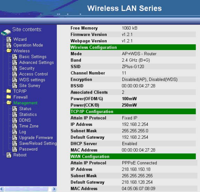
13. Since we access the device by wireless connection, it may temporarily
disconnect when applying the WDS setting. After re-connecting to the device,
use the “Status” page to check the settings.
11
12
Configure DEV2:
1. Access the web server (http://192.168.2.254) of device from the Ethernet port.
Caution
If you configure multiple devices in the same PC, since the devices
have the same default IP address but different MAC addresses, it may
cause you not able to access the web server of device. If the situation
happens, please try to clean the ARP table of your PC by DOS
command “arp –d” then you can access the web server of device
using the default IP address.
2. Use Wizard page to setup device.
3. Press “Next>>” button then set the “Operation Mode” to “Bridge” mode.
4. Press “Next>>” button then disable “Time Zone” function.
13
5. Press “Next>>” button then set the IP address of LAN interface.
6. Press “Next>>” button then select the “AP+WDS” for “mode” and change the
SSID to “ZPlus-G120-DEV2”.
7. Press “Next>>” button then select “None” for “Encryption” then press
“Finished” button.
8. Wait for refreshing web page.
14
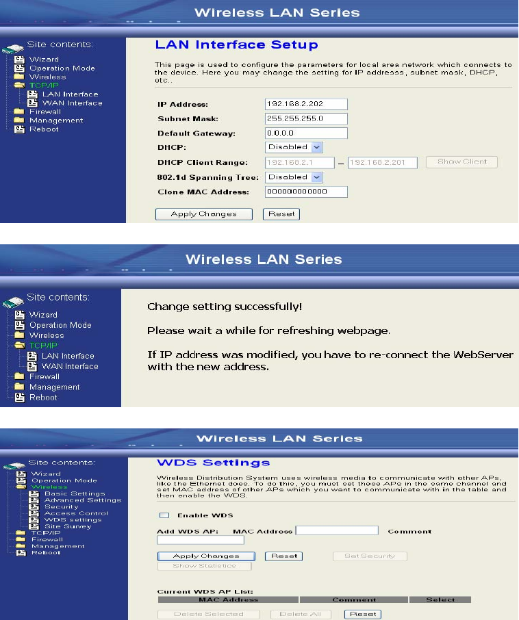
9. Access the web server by new IP address “192.168.2.202” then use “LAN
Interface” page to disable DHCP Server.
10. Wait for refreshing web page.
11. Use “WDS Settings” page to configure WDS.
15
12. Enable WDS function and add the BSSID of DEV1 to “Current WDS AP
List”.
13. Use the “Status” page to check the settings.
16
Configure DEV3:
1. Access the web server (http://192.168.2.254) of device from the Ethernet port.
Caution
If you configure multiple devices in the same PC, since the devices have the
same default IP address but different MAC addresses, it may cause you not
able to access the web server of device. If the situation happens, please try
to clean the ARP table of your PC by DOS command “arp –d” then you can
access the web server of device using the default IP address.
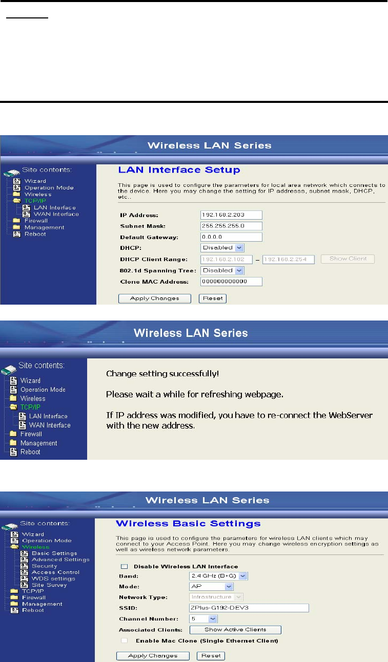
2. Use “LAN Interface” page to set the IP address of LAN interface and disable
DHCP server.
3. Wait for refreshing web page.
4. Access the web server by new IP address “192.168.2.203” then use “Basic
Settings” page to change SSID and CHANNEL.
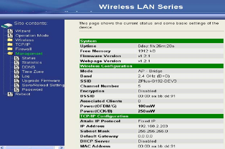
17
5. Use the “Status” page to check the settings.
18
Configure DEV4:
1. Access the web server (http://192.168.2.254) of device from the Ethernet port.
Caution
If you configure multiple devices in the same PC, since the devices have the
same default IP address but different MAC addresses, it may cause you
unable to access the web server of device. If the situation happens, please
try to clean the ARP table of your PC by DOS command “arp –d” then you
can access the web server of device using the default IP address.
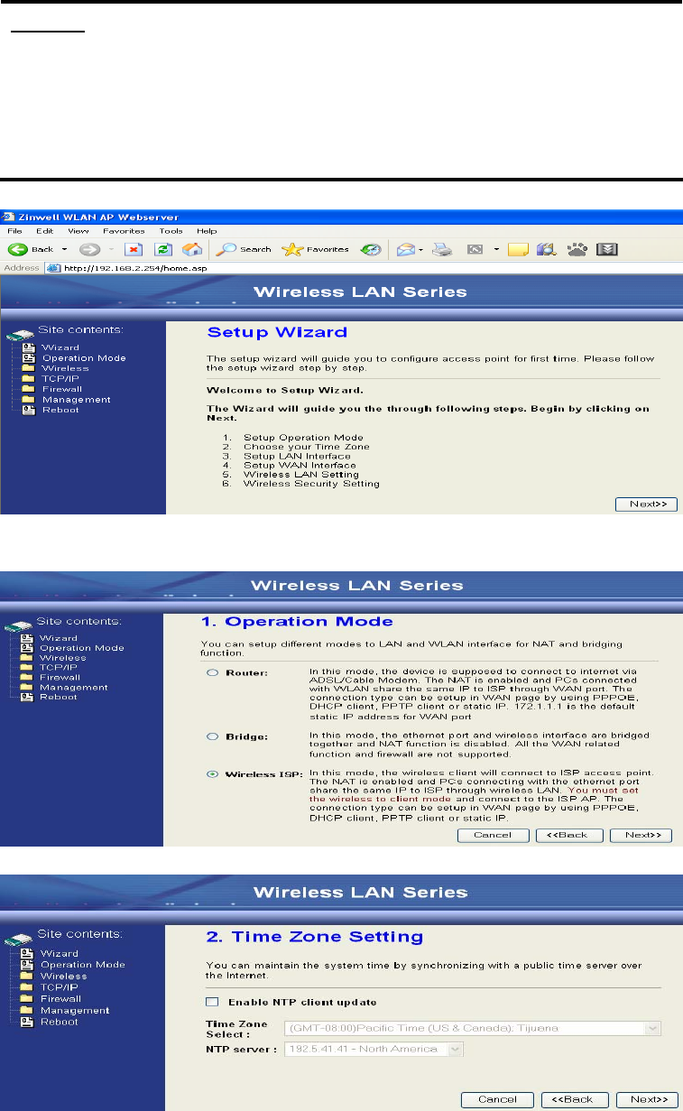
2. Use Wizard page to setup device.
3. Press “Next>>” button then set the “Operation Mode” to “Wireless ISP”
mode.
4. Press “Next>>” button then disable “Time Zone” function.
19
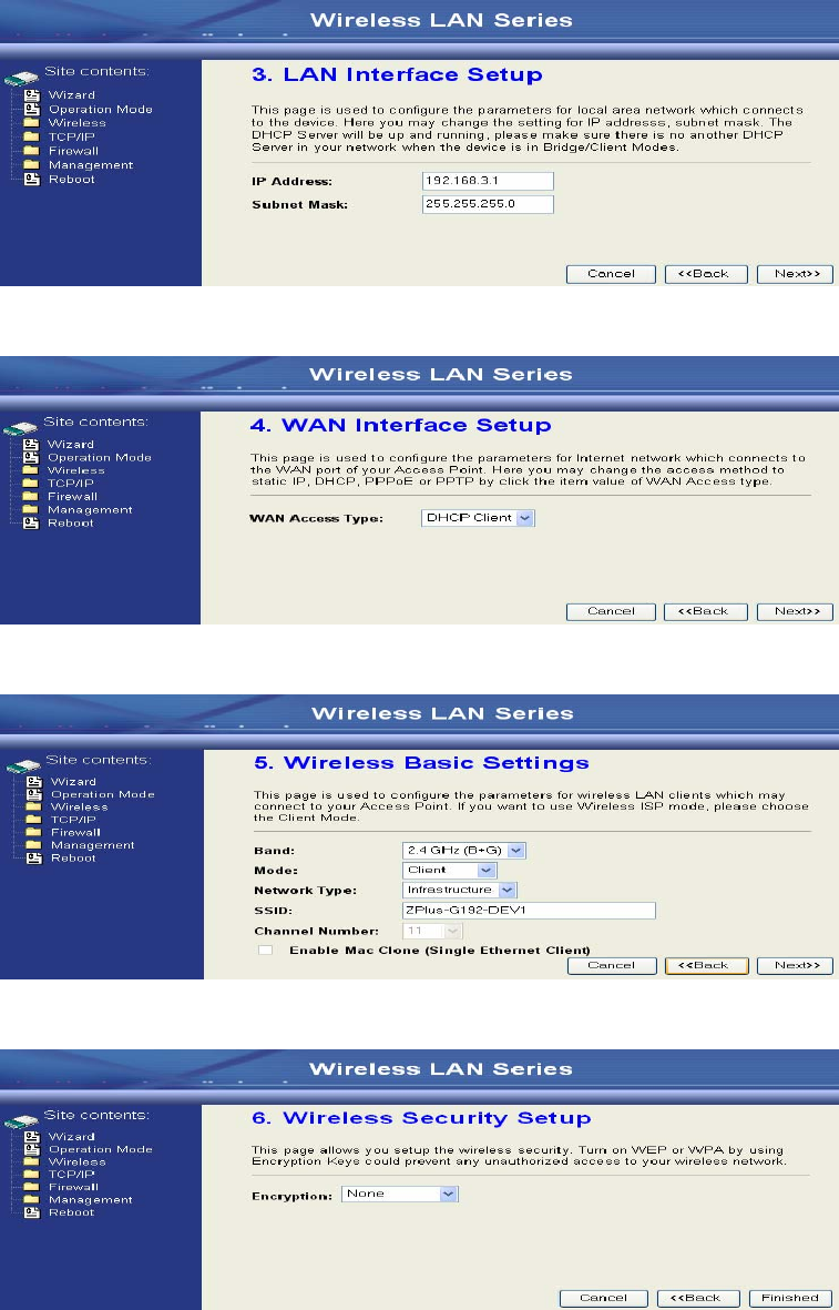
5. Press “Next>>” button then set the IP address of LAN interface.
6. Press “Next>>” button then select the “DHCP Client” for “WAN Access
Type”.
7. Press “Next>>” button then select the “Client” for “mode” and change the
SSID to “ZPlus-G120-DEV4”.
8. Press “Next>>” button then select “None” for “Encryption” then press
“Finished” button.
20
9. Wait for refreshing web page.
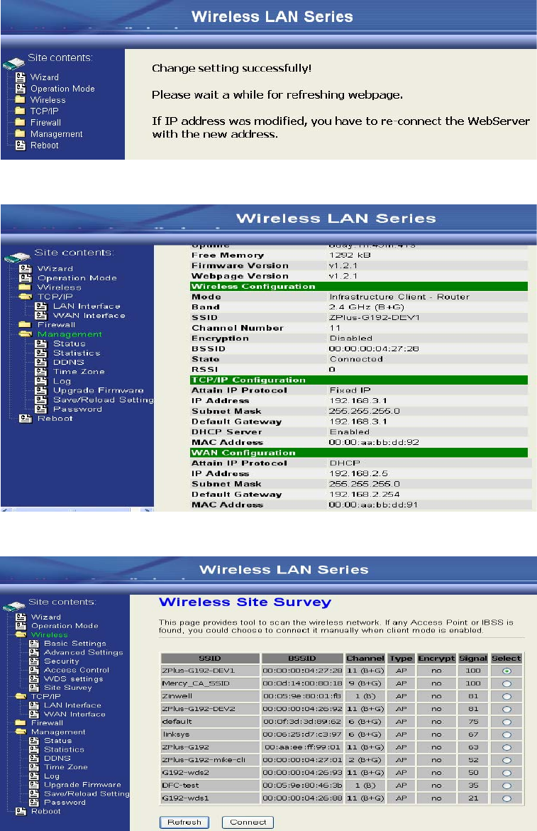
10. Change the IP address of your PC to 192.168.3.x then access the web server
by the new IP address “192.168.3.1” and use “Status” page check the setting.
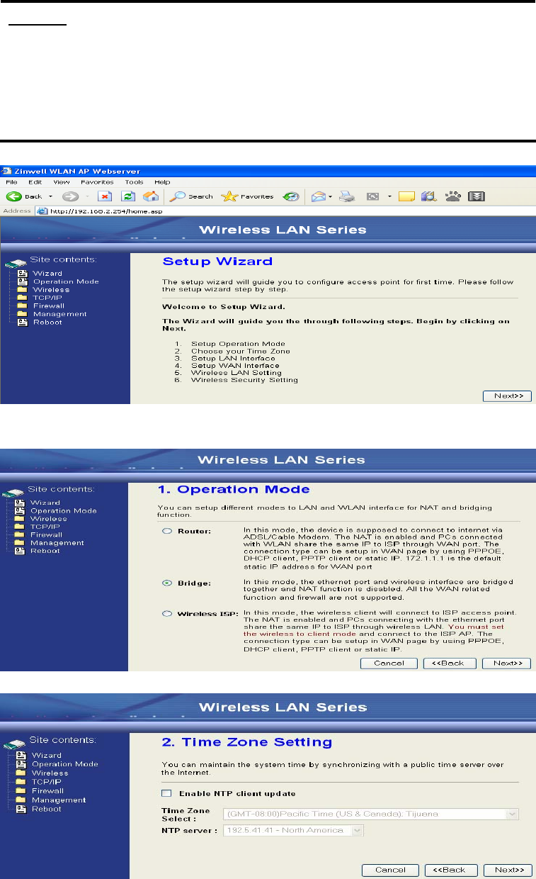
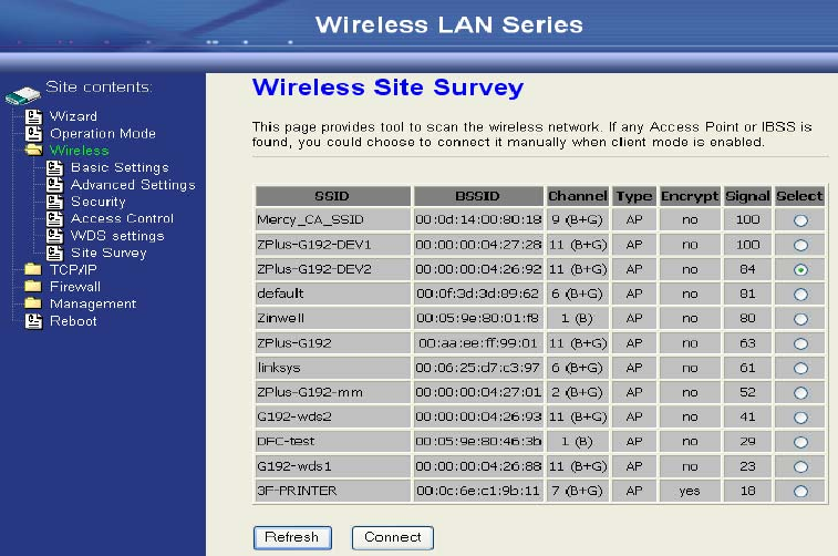
11. If the “State” of “Wireless Configuration” is not “Connected” or you want to
refresh the “RSSI “, please use “Site Survey” page to re-connect a AP.
21
Configure DEV5:
1. Access the web server (http://192.168.2.254) of device from the Ethernet port.
Caution
If you configure multiple devices in the same PC, since the devices have the
same default IP address but different MAC addresses, it may cause you
unable to access the web server of device. If the situation happens, please
try to clean the ARP table of your PC by DOS command “arp –d” then you
can access the web server of device using the default IP address.
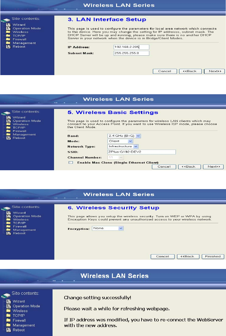
2. Use Wizard page to setup device.
3. Press “Next>>” button then set the “Operation Mode” to “Wireless ISP”
mode.
4. Press “Next>>” button then disable “Time Zone” function.
22
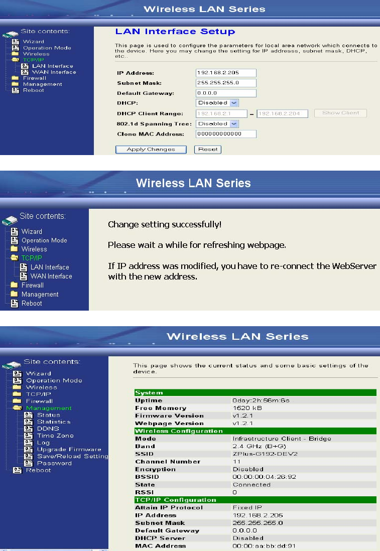
5. Press “Next>>” button then set the IP address of LAN interface.
6. Press “Next>>” button then select the “Client” for “mode” and change the
SSID to “ZPlus-G120-DEV5”.
7. Press “Next>>” button then select “None” for “Encryption” then press
“Finished” button.
8. Wait for refreshing web page.
23
9. Access the web server by the new IP address “192.168.2.205” and use “LAN
Interface” page to disable DHCP Server.
10. Wait for refreshing webpage.
11. Use “State” page to check setting.
24
12. If the “State” of “Wireless Configuration” is not “Connected” or you want to
refresh the “RSSI “, please use “Site Survey” page to re-connect a AP.
25
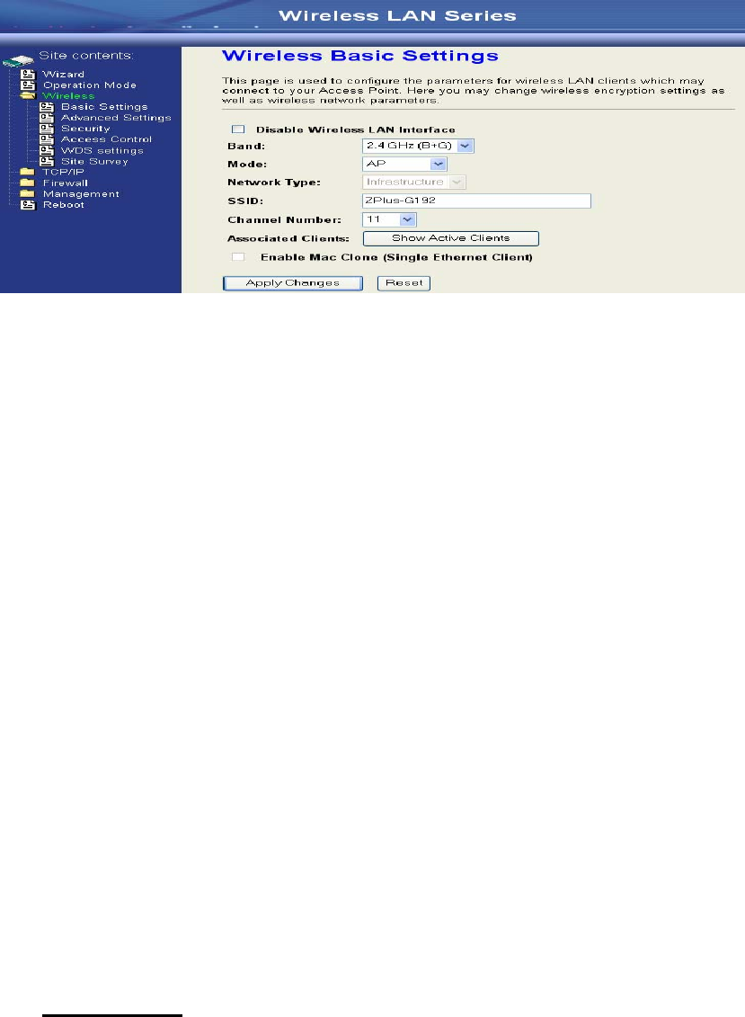
Basic Settings
Disable Wireless LAN Interface
Disable the wireless interface of device
Band:
The device supports 2.4GHz(B), 2.4GHz(G) and 2.4GHz(B+G) mixed modes.
Mode:
The radio of device supports different modes as following:
1. AP
The radio of device acts as an Access Point to serves all wireless clients
to join a wireless local network.
2. Client
Support Infrastructure and Ad-hoc network types to act as a wireless
adapter.
3. WDS
Wireless Distribution System, this mode serves as a wireless repeater,
only devices with WDS function supported can connect to it, all the
wireless clients can’t survey and connect the device when the mode is
selected.
4. AP+WDS
Support both AP and WDS functions, the wireless clients and devices
with WDS function supported can survey and connect to it.
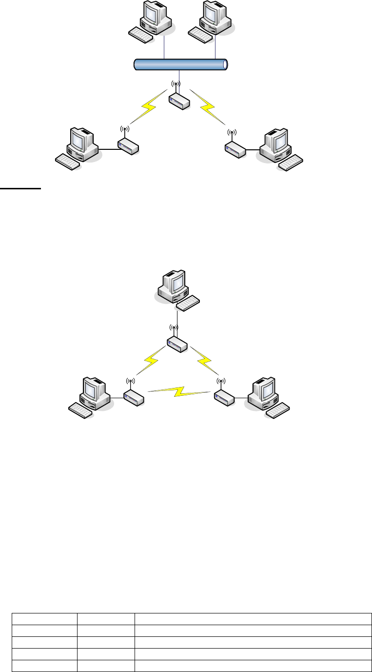
z Infrastructure:
This type requires the presence of 802.11b/g Access Point. All
communication is done via the Access Point.
26
Ethernet
AP
AP Client #2
AP Client #1
z Ad Hoc:
This type provides a peer-to-peer communication between wireless
stations. All the communication is done from Client to Client without any
Access Point involved. Ad Hoc networking must use the same SSID and
channel for establishing the wireless connection.
PC #3 PC #2
AP Client #1
AP Client #2AP Client #3
PC #1
In client mode, the device can’t support the Router mode function
including Firewall and WAN settings.
SSID:
The SSID is a unique identifier that wireless networking devices use to
establish and maintain wireless connectivity. Multiple access point/bridges on
a network or sub-network can use the same SSID. SSIDs are case sensitive
and can contain up to 32 alphanumeric characters. Do not include spaces in
your SSID.
Channel Number
The following table is the available frequencies (in MHz) for the 2.4-GHz radio:
Channel No. Frequency Country Domain
1 2412 Americas, EMEA, Japan, and China
2 2417 Americas, EMEA, Japan, and China
3 2422 Americas, EMEA, Japan, Israel, and China
4 2427 Americas, EMEA, Japan, Israel, and China

27
5 2432 Americas, EMEA, Japan, Israel, and China
6 2437 Americas, EMEA, Japan, Israel, and China
7 2442 Americas, EMEA, Japan, Israel, and China
8 2447 Americas, EMEA, Japan, Israel, and China
9 2452 Americas, EMEA, Japan, Israel, and China
10 2457 Americas, EMEA, Japan, and China
11 2462 Americas, EMEA, Japan, and China
12 2467 EMEA and Japan only
13 2472 EMEA and Japan only
14 2484 Japan only
When set to “Auto”, the device will find the least-congested channel for use.
Associated Client
Show the information of active wireless client stations that connected to the
device.
REMARK: Channels are used (CH1~CH11) by firmware controlled in U.S.A..