Zinwell ZWA-G192-OD 802.11g Hi-Power Outdoor AP User Manual ZWA G192 OD v121
Zinwell Corporation 802.11g Hi-Power Outdoor AP ZWA G192 OD v121
UserManual.wiki
>
Zinwell
>
ZWA G192 OD User Manual
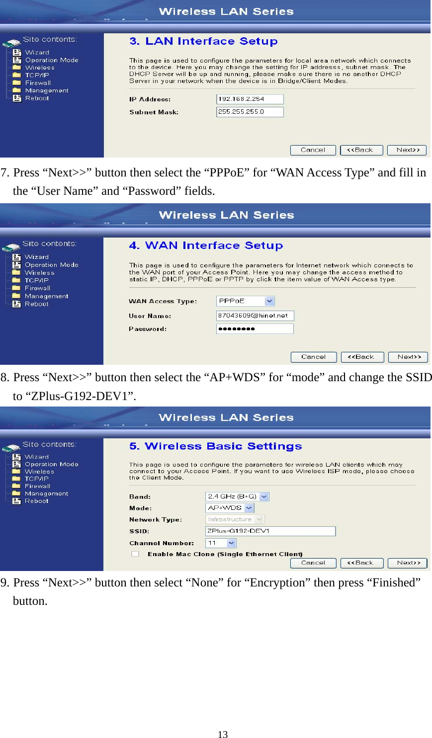
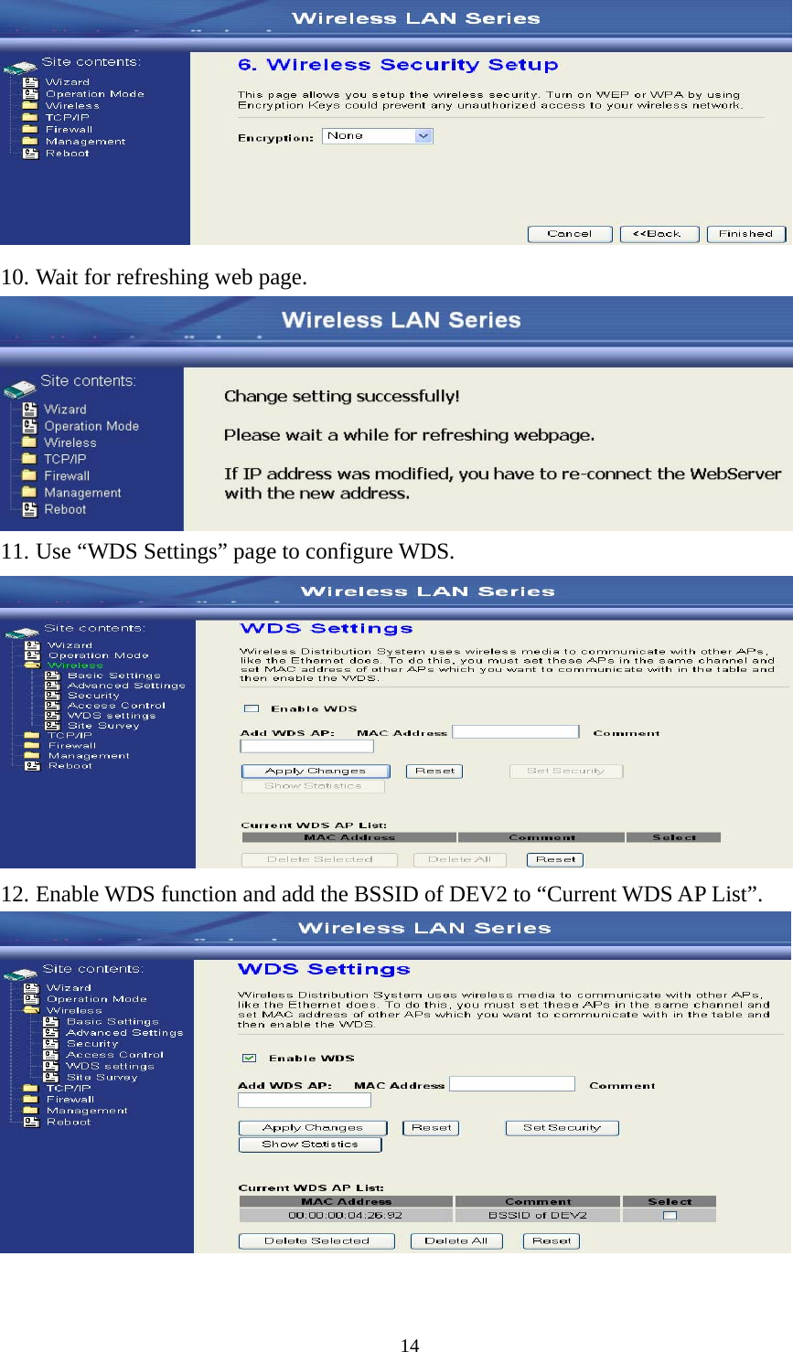
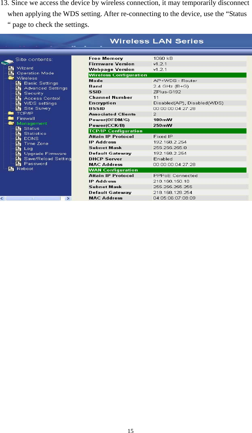
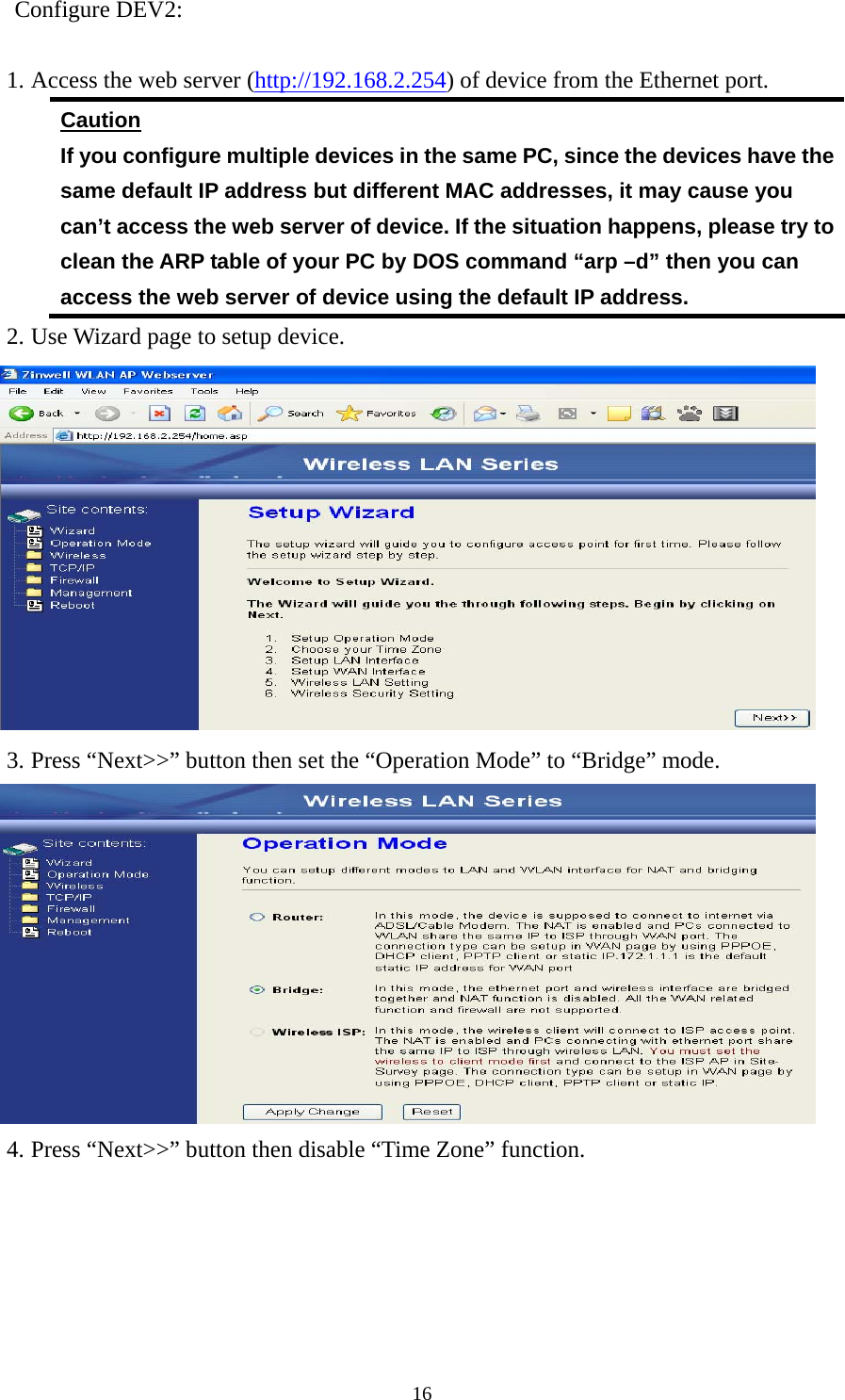
Users manual
Navigation menu
Upload a User Manual
Namespaces
Wiki Guide
HTML
PDF
Info
Views
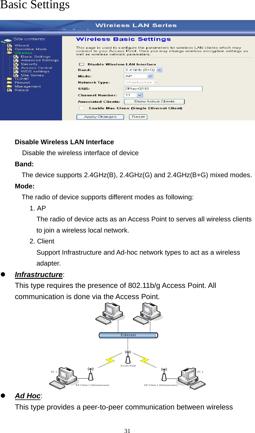
User Manual
Discussion / Help
Navigation