Zinwell ZWA-G220 ZINWELL 802.11b/g Wireless AP User Manual G220 Manual 143b 0731
Zinwell Corporation ZINWELL 802.11b/g Wireless AP G220 Manual 143b 0731
UserManual.wiki
>
Zinwell
>
ZWA-G220 User Manual
>
User Manual1
Contents
1.
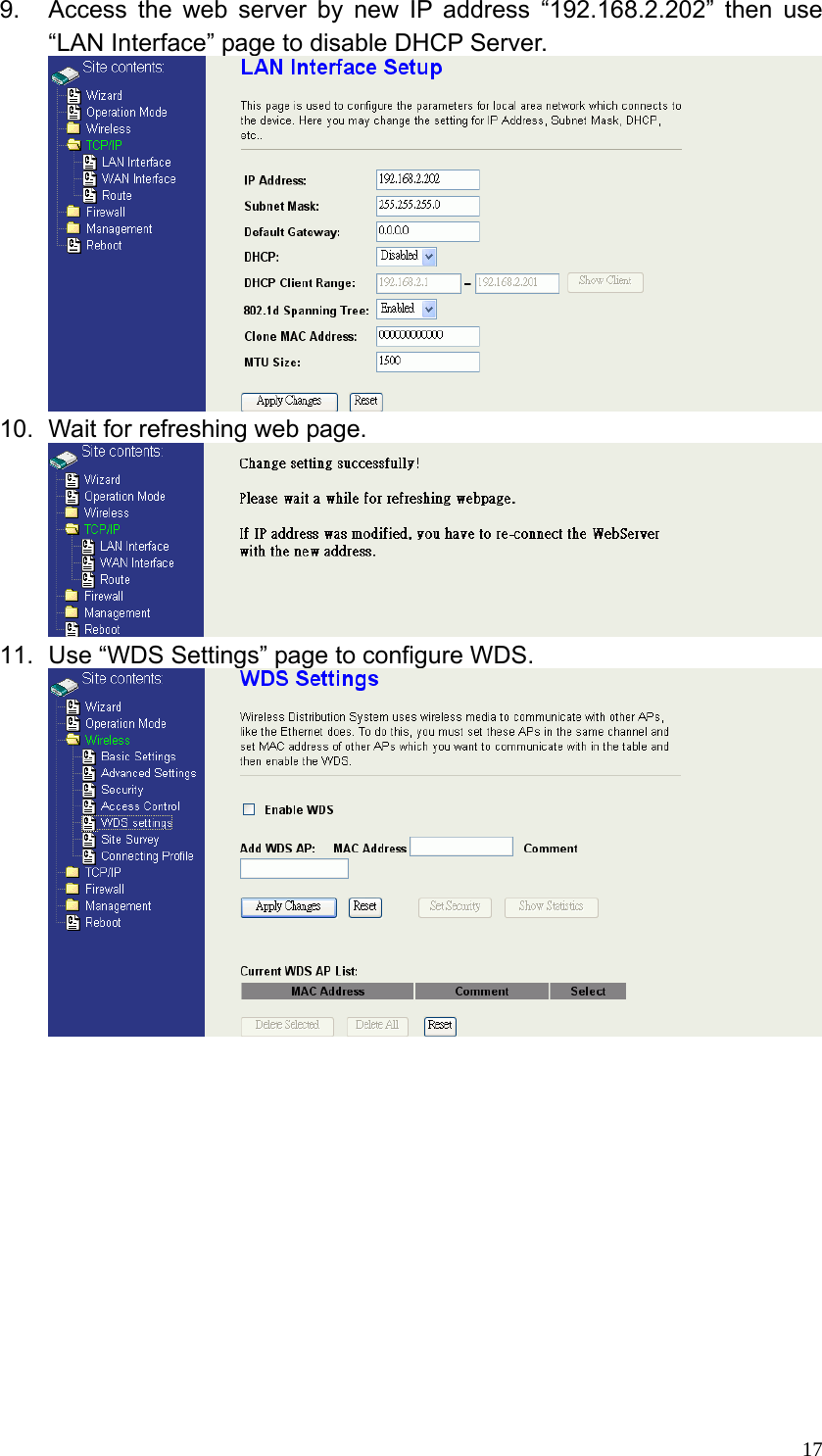
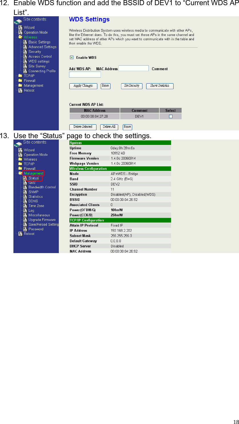
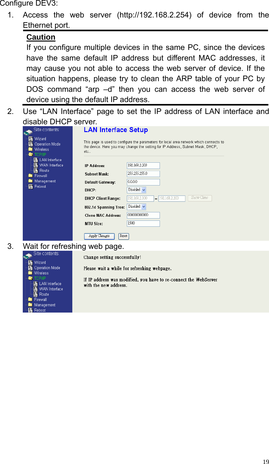
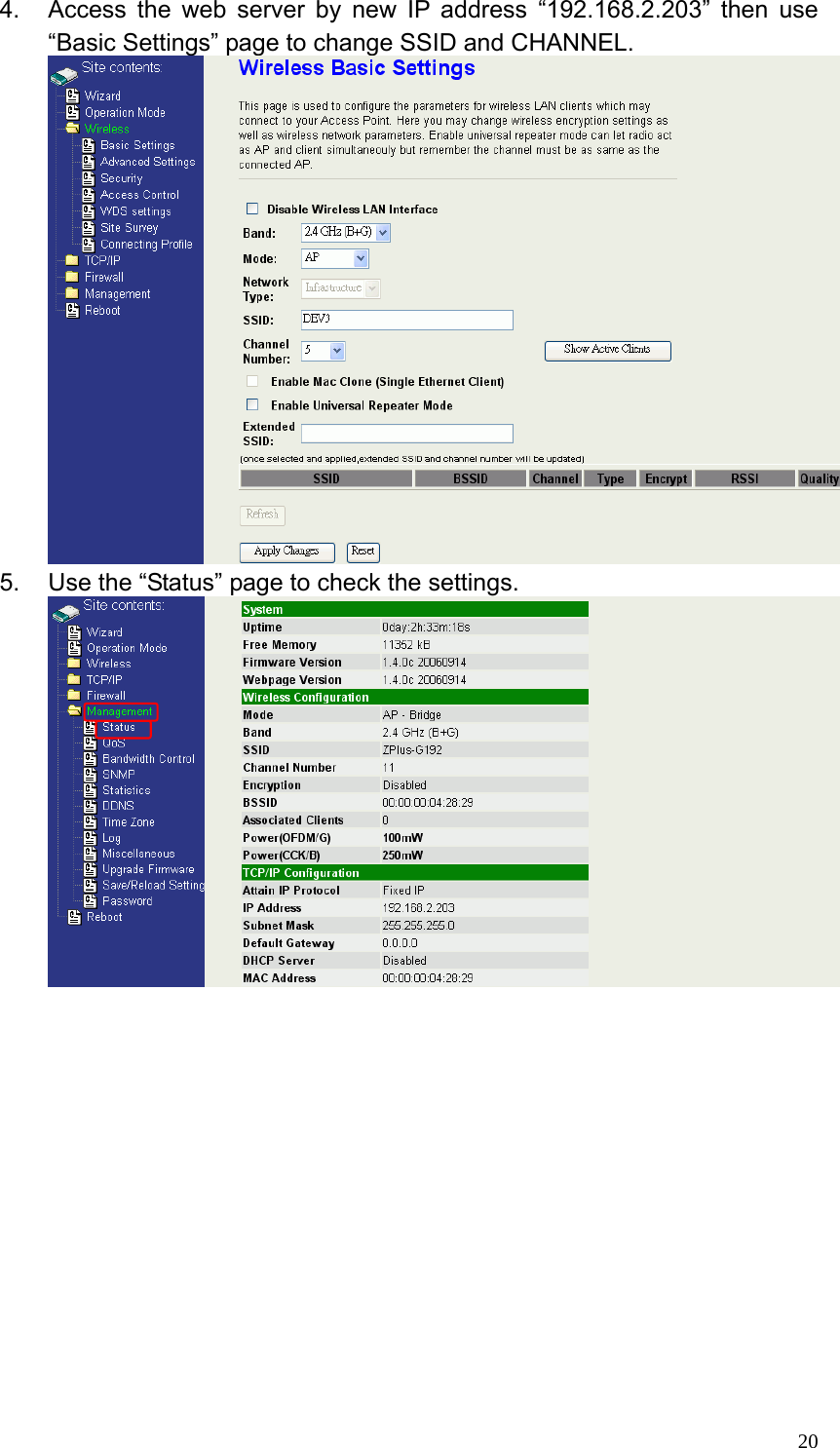
User Manual1
2.
User Manual2
User Manual1
Navigation menu
Upload a User Manual
Namespaces
Wiki Guide
HTML
PDF
Info
Views
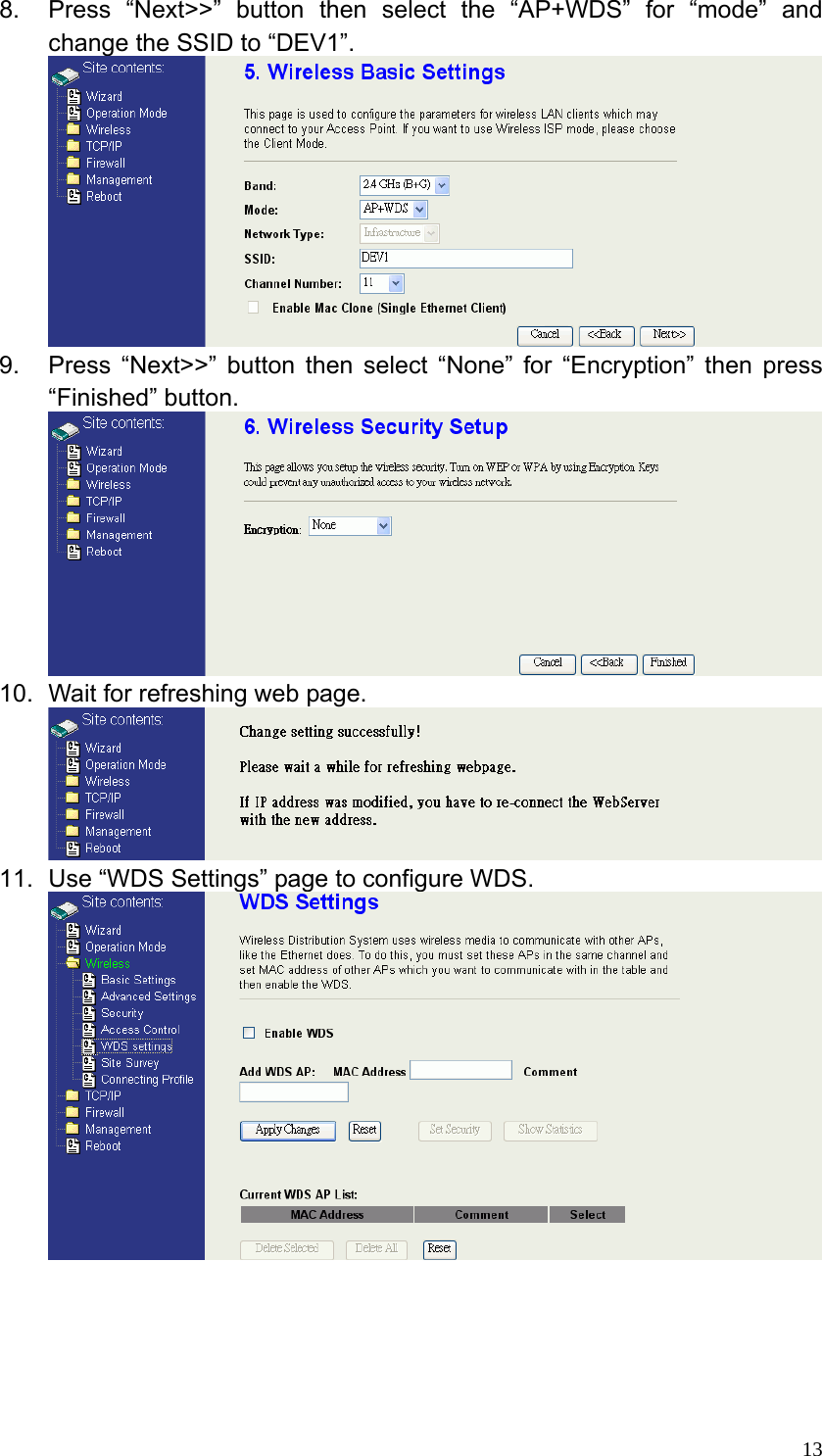
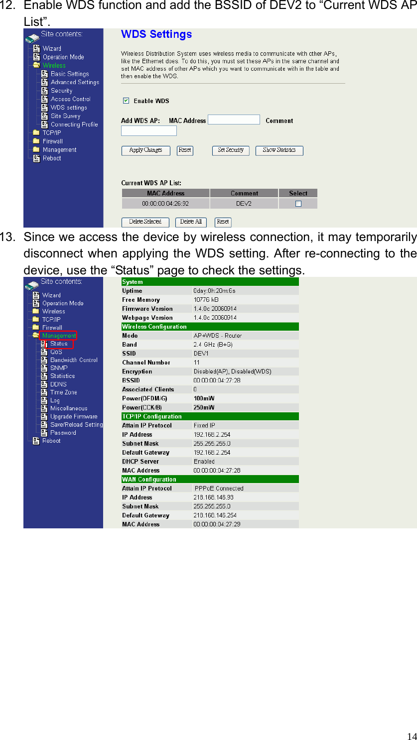
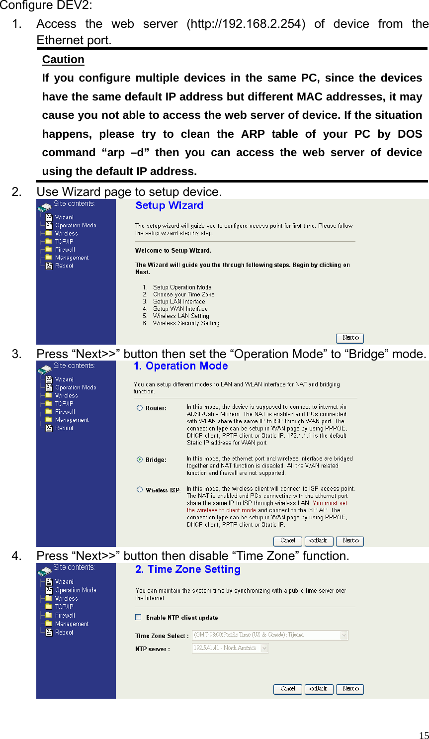
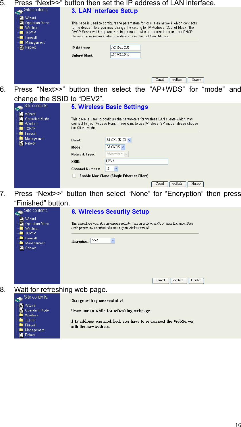
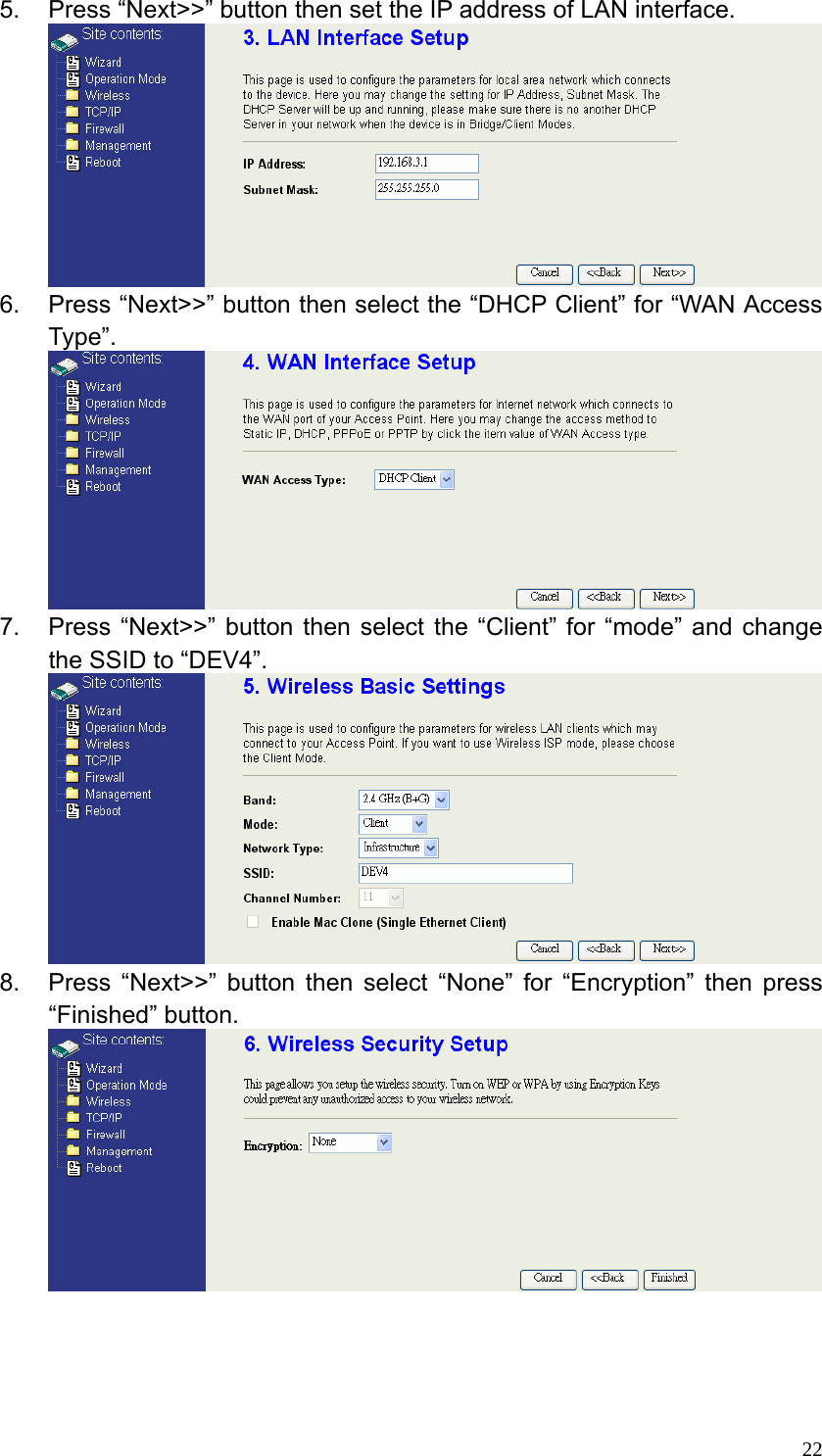
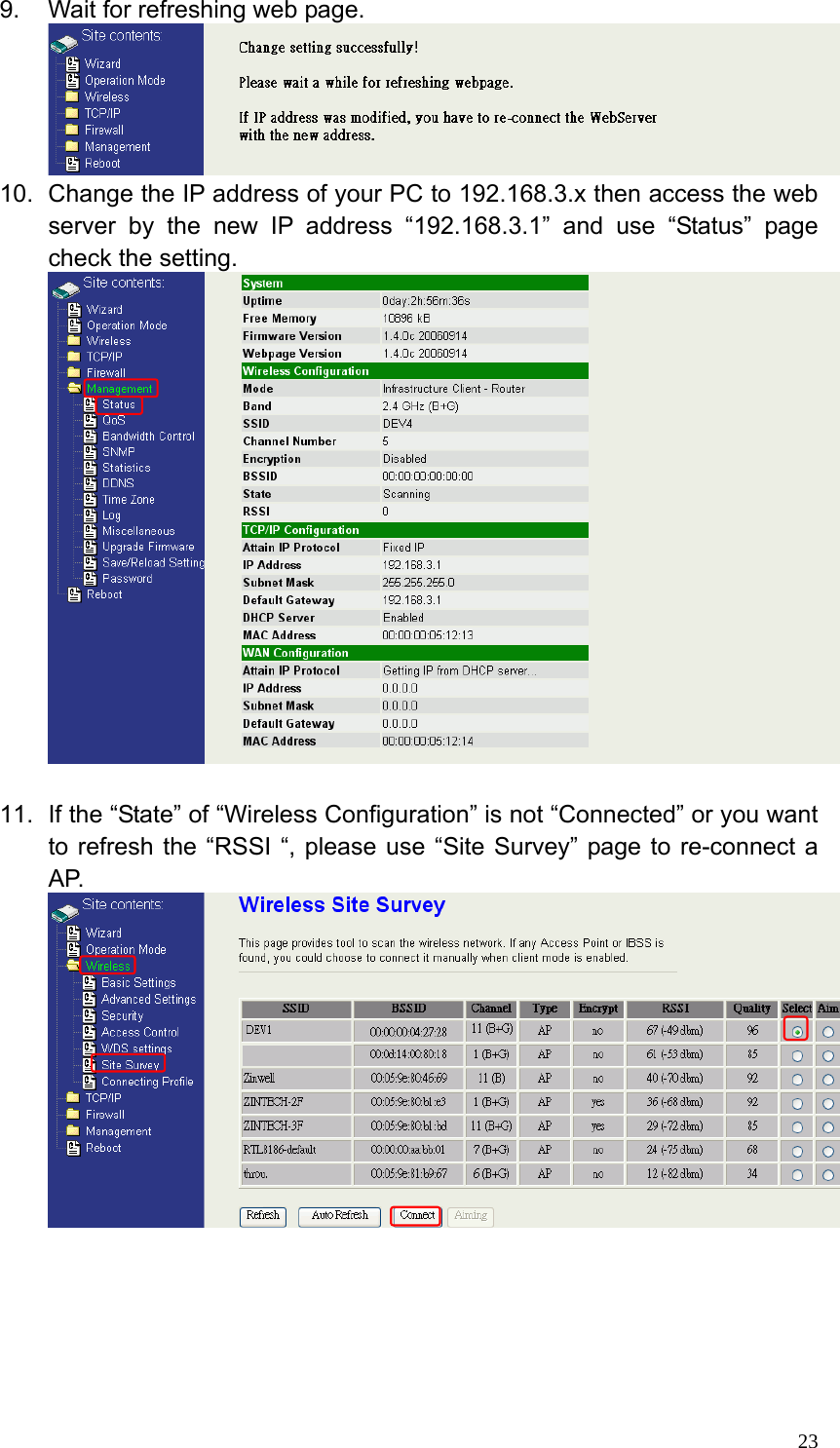
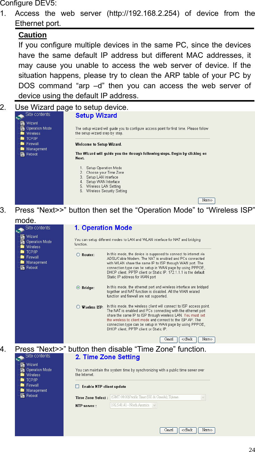
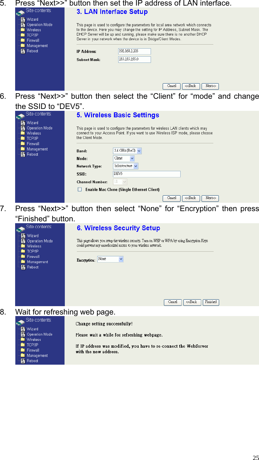
User Manual
Discussion / Help
Navigation