801314NZ HEAT_BC_instructions 8 15 V2.01 HT G4 BC Instructions
2016-12-15
: Zip Water 801314Nz - Ht G4 Bc Instructions 801314NZ - HT G4_BC_Instructions zenithwater. manuals zenithwater. hydrotaps zenithwater.products zenithwater.nz
Open the PDF directly: View PDF ![]() .
.
Page Count: 40
801314NZ - HydroTap BC, BCHA, AIO, Installation Instructions - August 2015 - V2.01 Page 1 of 40
Zenith HydroTap G4
Installation Instructions
Affix Model Number Label
Here
801314NZ
Filtered boiling and chilled drinking water for commercial kitchens and tea rooms.
®
BC Commercial
Page 2 of 40 801314NZ - HydroTap BC, BCHA, AIO, Installation Instructions - August 2015 - V2.01
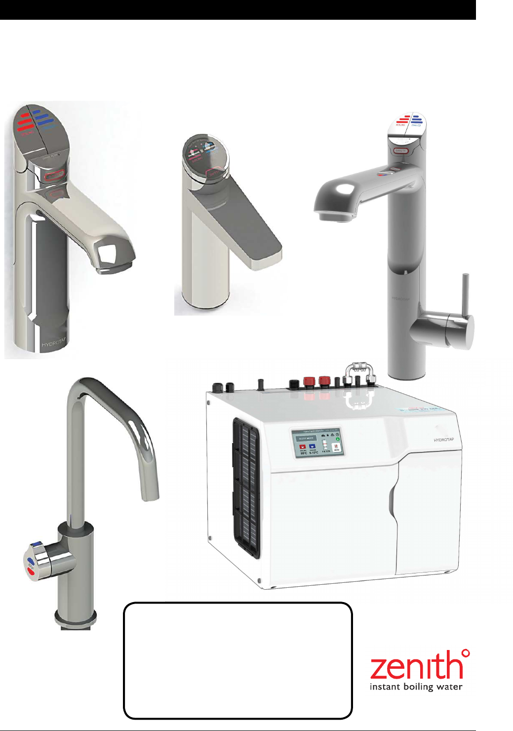
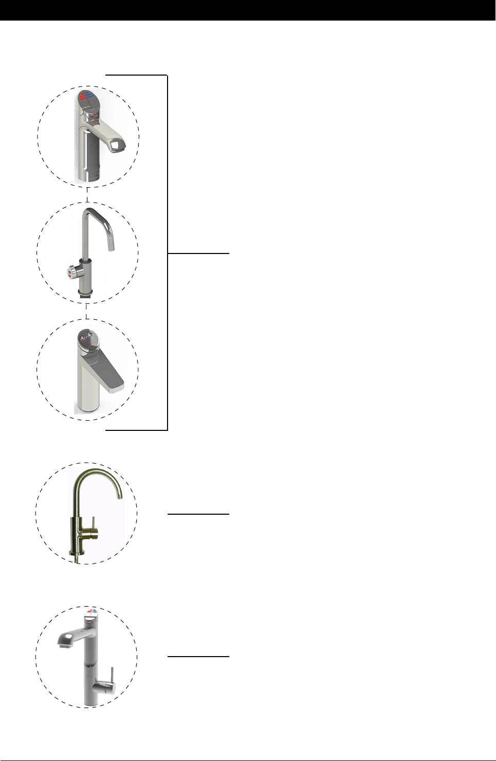
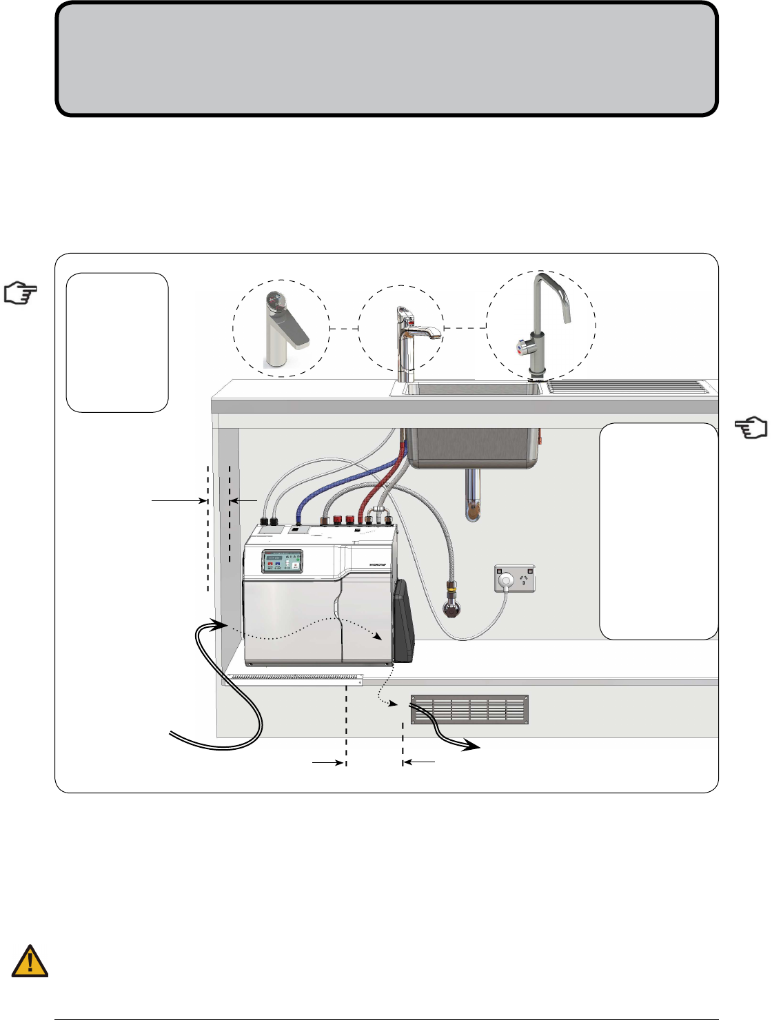
Tap options
The G4 appliance series offers a range of interchangeable taps to suit the customer’s needs
These three taps are directly compatible with the G4
under bench unit.
The All-In-One Tap is a stand alone tap that may be used
as an alternative to any of the above combinations. The
A-I-O is compatible with the G4 underbench unit.
The Mixer tap range is an additional series of taps that
may be used in conjunction with any one of the three taps
shown above, to create 4-IN-1 models

801314NZ - HydroTap BC, BCHA, AIO, Installation Instructions - August 2015 - V2.01 Page 3 of 40
Index
HydroTap Specifications
Installation check list .................................................................................................................... 4
General Product Features ............................................................................................................ 5
Important Safety Instructions ....................................................................................................... 6
Warnings and Regulatory Information .......................................................................................... 7
Major components and Accessories ............................................................................................ 8
Technical Specification ................................................................................................................ 9
Before Installation, site requirements and special tools required ................................................. 10
Installation Instructions
STEP 1 -
Measure and cut all the tap holes before fitting the taps
Section 1 - Tap Installation instructions
1.1 - HydroTap Classic and Elite Tap Installation ............................................................. 11-13
1.6 - HydroTap Arc/Cube Installation ................................................................................ 14-15
1.10 - Mixer Tap Installation .............................................................................................. 16-18
1.14 - All-In-One Tap with MAINS Installation ................................................................... 19-22
STEP 2
- Check for adequate ventilation
Section 2- Ventilation
2.1- Vent cut out details.....................................................................................................23-24
STEP 3
- Install the Booster Heater (if required)
Section 3 - Booster heater Installation
3.1- Booster Heater specifications and Installation ........................................................... 25-27
STEP 4
- Mount the external filter / softener (if required)
Section 4- Filter / Softener installation
4.1- Mounting the filter head & cartridge Installation ......................................................... 28
STEP 5
- Install the undersink unit
Section 5 - Undersink unit installation
5.1- Check the external bypass valve setting ................................................................... 29
5.2- Fit the mains water supply hose ................................................................................ 29
5.3- Model BC 160/125 and BC 160/175 .......................................................................... 30
5.4- Model BC 240/175 ..................................................................................................... 31
5.5- Model AIO Mains ....................................................................................................... 32
5.6- Model AIO Vented ...................................................................................................... 33
5.7- Model 4-In-1 Vented .................................................................................................. 34
STEP 6
- Commission the HydroTap
Section 6 - Commissioning
6.1- Select the Language .................................................................................................. 35
6.2- Filter Flush ............................................................................................................... 35
6.3- Flow Calibration ......................................................................................................... 36
6.4- Boiling Calibration ...................................................................................................... 36
6.5- Booster activation ...................................................................................................... 36
6.6- Safety Sensor Calibration .......................................................................................... 37
Trouble Shooting
End of life disposal ....................................................................................................................... 37
Trouble Shooting Table ................................................................................................................ 38
Contact details ............................................................................................................................. 40

Page 4 of 40 801314NZ - HydroTap BC, BCHA, AIO, Installation Instructions - August 2015 - V2.01
Installation checklist
Before Installation:
A. Read the instructions and check if there is adequate space to mount all of the components.
B. Note: Not all fittings are supplied with the appliance kit. Isolation valves are not supplied.
C. Check the mains water pressure is between 172 - 700kPa and 200 - 700kPa when a booster
and /or filter softener is fitted
D. Check the water quality to determine if extra filtration will be required.
NOTE: This product must be fitted to a potable water supply
E. Check the appliance rating plate and ensure correct power is available for the appliance.
F. Check the under counter cupboard supporting the appliance is adequate for
the total weight of the appliance, when full of water.
Before Commissioning:
1. Check the unit has been installed correctly.
2. Check all plumbing fittings have been tightened.
3. Ensure the outlet and vent pipes are positioned to drain correctly.
4. Ensure there is adequate ventilation.
5. Check all tubes from the undersink unit to the tap, have a constant rise and there are no
sags or kinks in the hoses.
6. Check all electrical connections are correct and there are no loose wires.
Commission: (See section 6)
7. Flush the supply line before connecting.
8. Turn on the water and check for leaks.
9. Flush the filter(s).
10. Where applicable, programme the unit to suit the customer’s requirements.
801314NZ - HydroTap BC, BCHA, AIO, Installation Instructions - August 2015 - V2.01 Page 5 of 40
Thank you for purchasing a Zenith HydroTap. Please read and follow these instructions carefully to ensure
safe and trouble free service. If service is required, please call 0800 558055
What is the Zenith HydroTap ?
The Zenith HydroTaps are electronically controlled, filtered, Boiling water and Chilled water drinking systems
for kitchens and tea rooms. The HydroTap units are under bench drinking water appliances with a dispensing
tap mounted on a sink or bench, which may be used for residential or commercial applications. These units
utilise a conventional refrigerant compressor to chill the water and an immersion heating element to boil the
water. These units dispense boiling water (factory set to 98°C) and chilled water (factory set to 5-10°C).
These units are NOT designed to be used for sanitary fixtures.
The Boiling water units are fitted with a tap mounted, safety lock. In addition, there are various energy saving
options accessible via the main menu. Each unit is equipped with a self-calibrating program which caters
for altitude adjustment. The water filter is a disposable item which will require periodic replacement and is
covered by a limited OEM warranty.
It is important that the Installation be done safely, correctly and completely, in order to utilise all the benefits
the HydroTap can provide. The Classic and All-In-One taps may be ordered with the Tap Head Assembly for
Disabled use. The disabled levers are supplied with Braille caps for the visually impaired.
General Product Features
HydroTap Classic
BC160/125

Page 6 of 40 801314NZ - HydroTap BC, BCHA, AIO, Installation Instructions - August 2015 - V2.01
Important Safety Instructions
This manual contains important safety, Installation instructions for the Zenith HydroTap G4.
Safety
This appliance is not intended for use by persons (including children) with reduced physical,
sensory or mental capabilities, or lack of experience and knowledge, unless they have been
given supervision or instruction concerning use of the appliance by a person responsible for their safety.
Children should be supervised to ensure that they do not play with the appliance.
For products sold in Europe, this appliance can be used by children aged from 8 years and above and
persons with reduced physical, sensory or mental capabilities or lack of experience and knowledge if they
have been given supervision or instruction concerning use of the appliance in a safe way and understand
the hazards involved. Children shall not play with the appliance. Cleaning and user maintenance shall not be
made by children without supervision.
Refrigerant
The Zenith HydroTap unit contains R134A refrigerant under pressure. Maintenance of the refrigeration unit
must be carried out by an accredited service provider or qualified refrigeration technician.
Qualifications
If the power cable is damaged it must be repaired only by a qualified technician. To avoid hazards, all
Installation procedures must be carried out by a suitably qualified tradesperson. The power cable and power
outlet must be in a safe visible position for connection.
Venting
Sometimes steam and / or condensed droplets may discharge through a vent outlet at the tap. If the tap is not
installed using the Font pedestal, ensure the tap body is located so the tap outlet safely dispenses into the
sink bowl area.
Lifting
Take care when lifting the Zenith HydroTap unit. Some units may exceed safe lifting limits. If you feel this is
beyond your personal capabilities, please seek assistance with the lift. The weights of the units are marked
on the packaging. Do not lift the unit by the front cover or any connections at the top rear of the unit. Refer to
section 1.2 technical specification for the weight of your product.
Airflow
The ambient operating temperatures, when installed in a cupboard, must be between 5ºC - 35ºC. Proper air
circulation must be provided. The system will operate satisfactorily only if the recommended air gaps of 50mm
on each side are provided. If a vent kit is supplied it must be fitted. See technical specifications for correct
Installation to prevent overheating.
Altitude
Water boils at varying temperatures at different altitudes. Your HydroTap adjusts for this during startup
calibration and will recalibrate itself on a regular basis.
Frost Protection
If this appliance is located where the ambient air temperature could fall below 5ºC when the heater is not
in use, do not turn off the appliance electrically. This safeguard does not offer the same protection to the
connecting pipework and fittings.

801314NZ - HydroTap BC, BCHA, AIO, Installation Instructions - August 2015 - V2.01 Page 7 of 40
Important Safety Instructions
WARNINGS
1.
The Zenith HydroTap unit must be earthed. The resistance of the earth
connection from each exposed metal part must be less than 1 ohm.
2.
All Installation and service work must be completed by trained and
suitably qualified Tradespeople. Faulty operation due to unqualified
persons working on this product, or any other Zenith product may void
warranty coverage.
3.
All Plumbing must comply with AS/NZS3500.
4.
All Electrical must comply with AS/NZS3000
5.
All Plumbing and Electrical connections must be made in accordance with
local regulations.
6.
This HydroTap product is rated for 230V 50Hz AC operation.
7.
Undersink units must never be located near, or cleaned with water jets.
8.
Zenith HydroTaps are not to be exposed to the elements of nature
9.
Due to the process of continuous improvement, Zenith Heaters reserves
the right to change details mentioned in this manual, without notice.
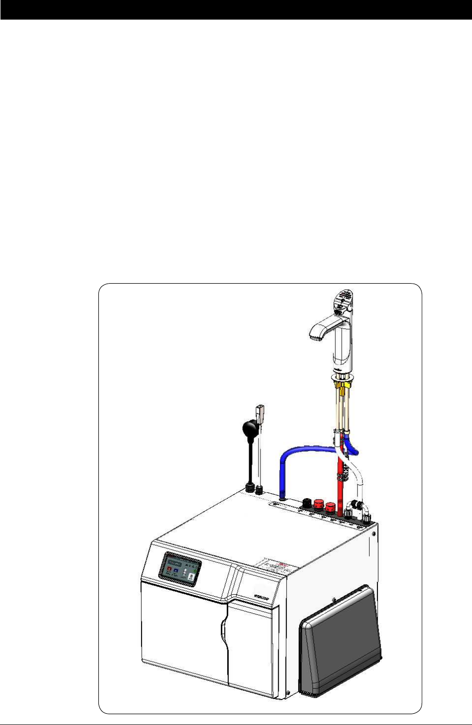
Positioning
It is important to ensure the undersink unit is positioned in an accessible area close to the floor level. The unit
must have it’s base mounted in a horizontal position with all inlets and outlets facing up. The Tap must be
located above the undersink unit and positioned so that it dispenses into the sink bowl with ample clearance
for a cup or tea pot. See section 1 for details.
Page 8 of 40 801314NZ - HydroTap BC, BCHA, AIO, Installation Instructions - August 2015 - V2.01
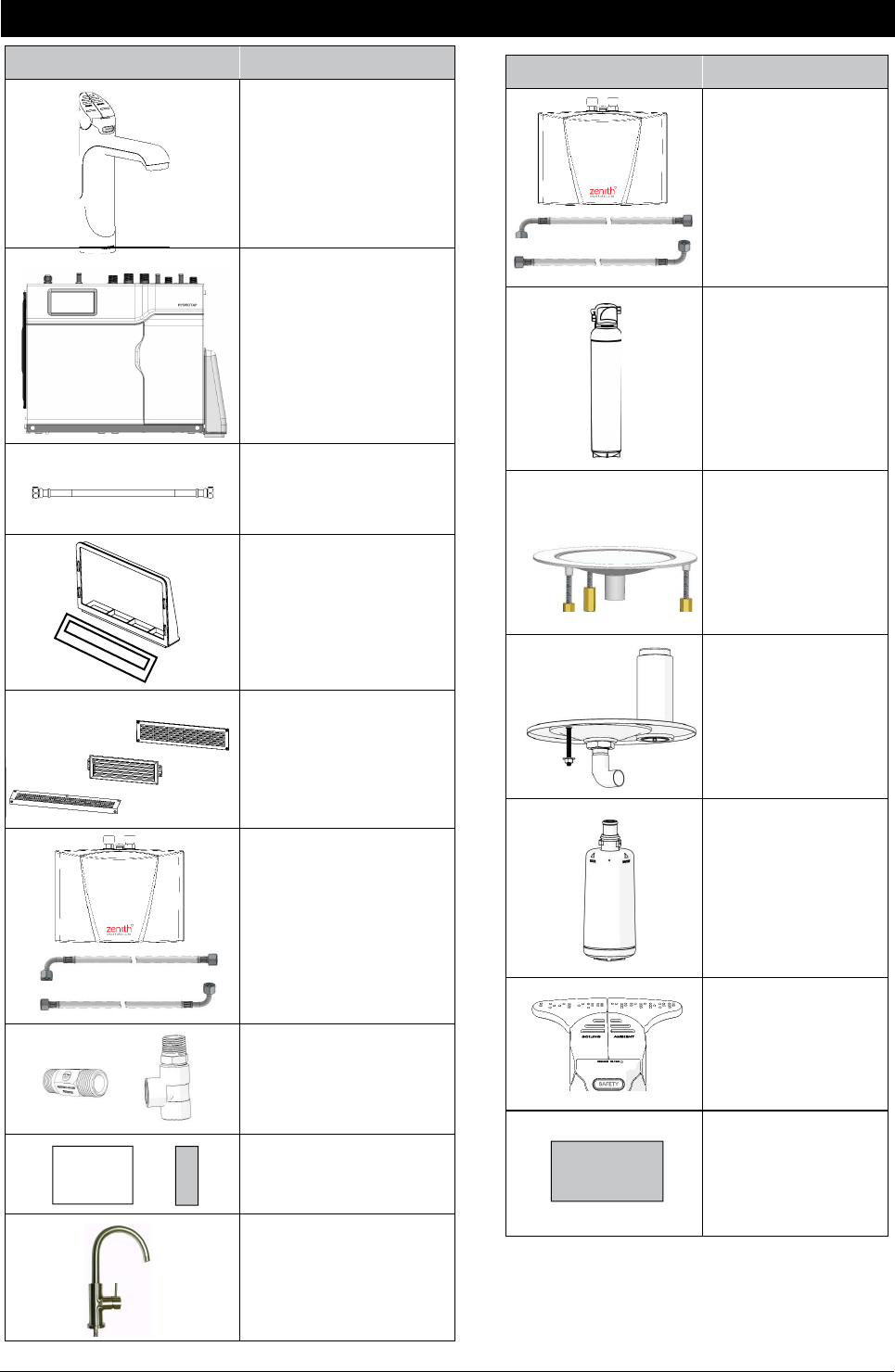
Major components and accessories
Parts supplied Description
1 off 4
Tap options with hoses
(Classic tap shown)
1 off
HydroTap
Undersink Unit with air
and water filters
1 off
Mains water
connection hose
Duct kit
1 x Air Duct
1 x Mounting plate
Vent Kit
1 x Kickboard louvre
1 x Door vent louvre
1 x Front vent grill
1 off
HydroTap Booster
Heater & hoses.
(Supplied with
240 /175 models)
1 x Restrictaflow valve
and Tee piece for Mixer
taps
1 x User guide and
1 x Quick start guide
1 x Mixer Tap
for 4-In-1 and select
models (with hoses)
(Arc tap shown)
Guide
Accessories Description
HydroTap Booster
Water System with
connection hoses
Softener
and head assembly
Font Kit for
Arc & Cube Models
Font Kit for Classic &
Elite Models
Replacement Filter
Disabled lever Kit
BC - 4-in-1 upgrade
Kit
KIT
801314NZ - HydroTap BC, BCHA, AIO, Installation Instructions - August 2015 - V2.01 Page 9 of 40
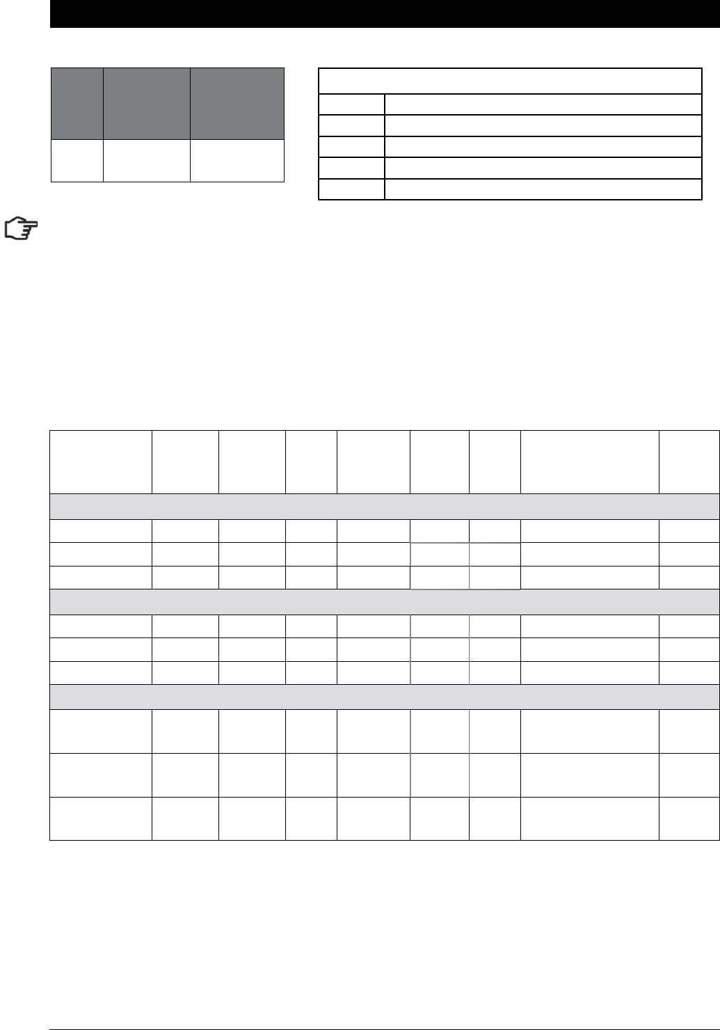
Technical Specifications
Model
Cups of
Boiling
Water per
Hour
Glasses
of Chilled
Water per
Hour
BC 160 125
Note
:
1. The Cup measurement =167ml and the Glass measurement = 200ml
2. Chilled water will continue to be dispensed after the rated capacity has been used, although this may be at
slightly higher temperature.
Product covered by these instructions:
** Add an extra 5 kg when full of water
Capacity
Boiling
(cups)
Capacity
Chilled
(glasses)
Boost
(10A)
GPO's
Required
Power
Rating
(kW)
Boost
Rating
(kW)
Unit Dimensions
W x D x H (mm)
with air duct
**Dry
Weight
(KG)
Boiling Chilled
BC160/125 160 125 no 1x10A 2.1 450 x 470 x 335 23
BC160/175 160 175 no 1x10A 2.2 450 x 470 x 335 23
BC240/175 240 175 yes 2x10A 2.2 2.2 450 x 470 x 335 23
4 in 1
BCHA160/125 160 125 no 1x10A 2.1 450 x 470 x 335 23
BCHA160/175 160 175 no 1x10A 2.2 450 x 470 x 335 23
BCHA240/175 240 175 yes 2x10A 2.2 2.2 450 x 470 x 335 23
All in One
AV160/125
A 160 /125
160 125 no 1x10A 2.1 450 x 470 x 335 23
AV160/175
A 160 /175
160 175 no 1x10A 2.2 450 x 470 x 335 23
AV240/175
A 240 /175
240 175 yes 2x10A 2.2 2.2 450 x 470 x 335 23
Commercial Models
BC Boiling and Chilled
BCHA 4 in 1
A All in One - Mains
AV All in One - Vented
D Disabled lever controls (optional accessory)

Page 10 of 40 801314NZ - HydroTap BC, BCHA, AIO, Installation Instructions - August 2015 - V2.01
Before Installation
Before installing ensure that the following have been provided at the
Installation site:
•
Review all the technical specifications.
•
Ensure the underbench can support the product weight when full of water,
(allow an extra 5kg when full. )
•
Sufficient space in the cupboard to install all of the undersink units in accordance with these
Installation Instructions. Refer to technical specification for dimensions. Make allowance for a booster
heater and / or water softener if required. Refer to section 3 & 4, for Installation instructions.
•
For Zenith HydroTap 160/125 &160/175 models, a 220-240Vac, 10A GPO will be required. For Zenith
HydroTap 240/175 models, two 220-240Vac, 10A GPOs will be required. (One GPO is for the Zenith
HydroTap and the other for the Booster heater).
Note: Check all cable and hose lengths against inlet /outlet positions before pro-
ceeding (See section 5 for general layout).
•
A potable water supply connection with isolating valve inside the cupboard within reach of the braided
hoses and positioned so that the connection point and the stop cock will not be obstructed when the
undersink units are installed.
•
For the mains pressure All-IN-ONE, an external hot and cold water supply will be required.
•
If an external filtration or water softening device is required, then it is important to allow extra space
for these items.
•
A cold water supply with a minimum working pressure of 172kPa (200kPa when a booster and /or
filter softener is fitted) and a maximum working pressure of 700kPa connected via an isolation valve.
•
The fitting of an air flow duct, attached to the right hand side of the unit, requires a rectangular cut
size of 284mm x 45mm, to provide adequate warm air displacement. See section 2.
•
The appliance must be placed with it’s base in a horizontal position.
IMPORTANT!
Do not proceed with the Installation if these requirements are not met.
Special Tools Required:
In addition to normal tools, the following will be required:
For the standard and Mixer taps:
•
35mm diameter sheet metal hole punch for sink tops. (Not supplied)
•
35mm diameter hole saw for timber bench tops. (Not supplied)
•
Nut runner tube spanner (supplied) for fixing tap assembly.
For the All-In-One tap:
•
50mm diameter sheet metal hole punch for sink tops. (Not supplied)
•
50mm diameter hole saw for timber bench tops. (Not supplied)
•
Nut runner tube spanner (supplied) for fixing tap assembly.
801314NZ - HydroTap BC, BCHA, AIO, Installation Instructions - August 2015 - V2.01 Page 11 of 40
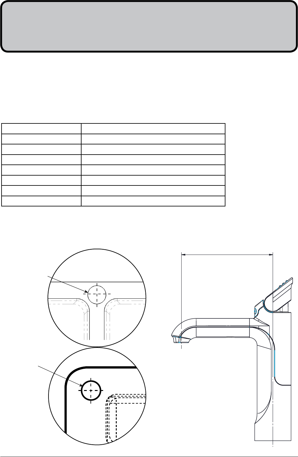
Hole positioning:
Position the tap such that it dispenses into the sink bowl with ample clearance for a cup or tea pot. Alternative-
ly, the tap could be mounted away from the sink using a Zenith Font, available as an accessory.
Section 1
Tap Installation
116
BC HydroTap
** Check bowl depth and adjust accordingly
TAP Recommended dispensing distance **
Elite 116 mm
HydroTap Classic 116 mm
HydroTap Arc/Cube 171 - 174 mm (Extended)
All-In-One 211 mm
Mixer - Arc neck 231 mm
Mixer - Classic 270 mm
Mixer - Cube neck 310 mm
Single
Bowl
For
Elite,Classic
and Arc/Cube
35mm hole
For
A-I-O 50mm and
Mixer taps 35mm
hole
Double Bowl
Page 12 of 40 801314NZ - HydroTap BC, BCHA, AIO, Installation Instructions - August 2015 - V2.01
Apply a light smearing of silicon sealant on the
underside of the spacer to ensure a watertight fit.
1.2
Cut a 35mm hole in the bench / sink top.
BENCH TOP
1.1
Ø35mm
ALL THREAD
ROD
STAINLESS
STEEL
SPACER
SPIDER
CLAMP
NUT
BLACK PLASTIC
SPACER
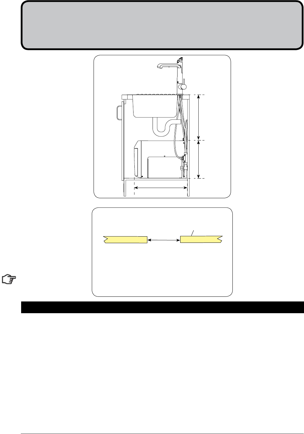
Tap assembly exploded view and kitchen layout side view.
470mm
335mm
HydroTap Classic & Elite
Min 300mm
HydroTap
Classic
EliteTap
801314NZ - HydroTap BC, BCHA, AIO, Installation Instructions - August 2015 - V2.01 Page 13 of 40
BLACK
PLASTIC
SPACER
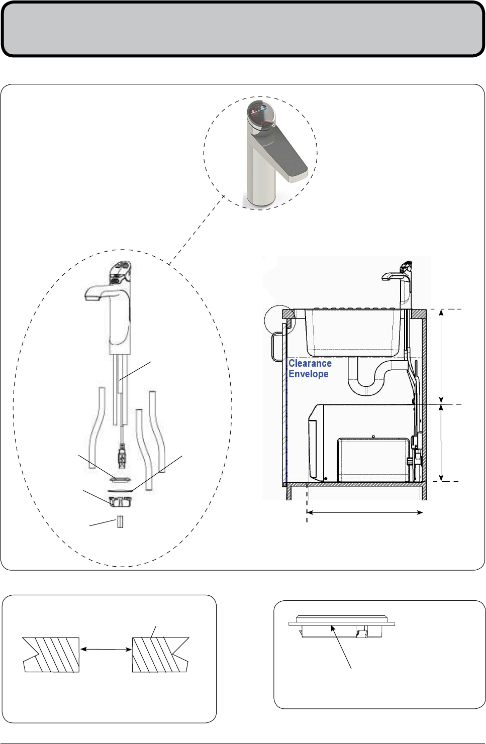
1.3
Installation Instructions
Pass all the hoses, tubes and USB lead
through the 35mm hole.
1.4
35mm hole
Note: feed each of the three tubes and
electrical cable evenly in between the legs of
the SPIDER CLAMP when installing.
Fit the
STAINLESS STEEL
WASHER,
SPIDER CLAMP,
AND 6mm NUT. 6mm NUT
SPIDER CLAMP
STAINLESS
STEEL WASHER
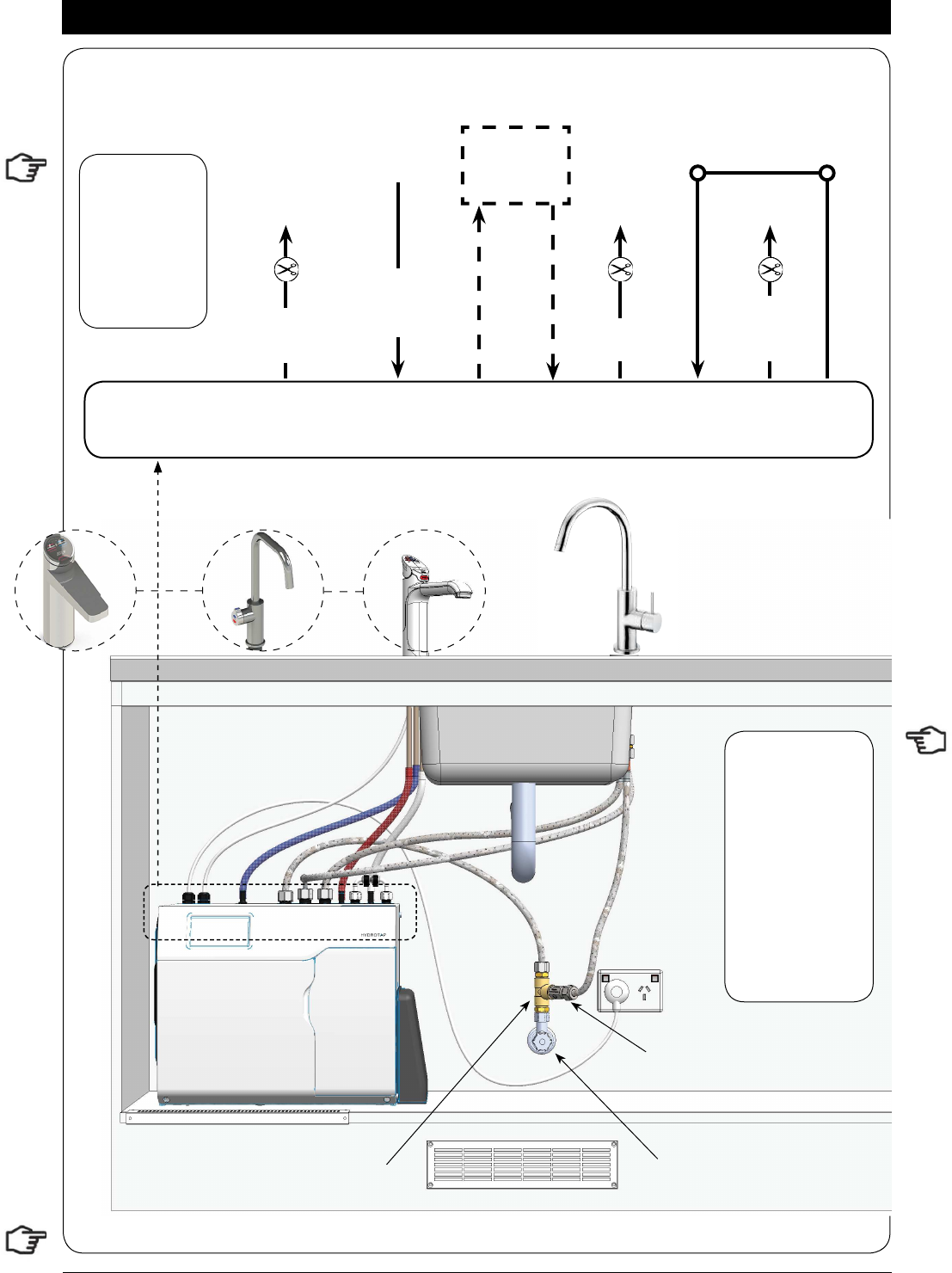
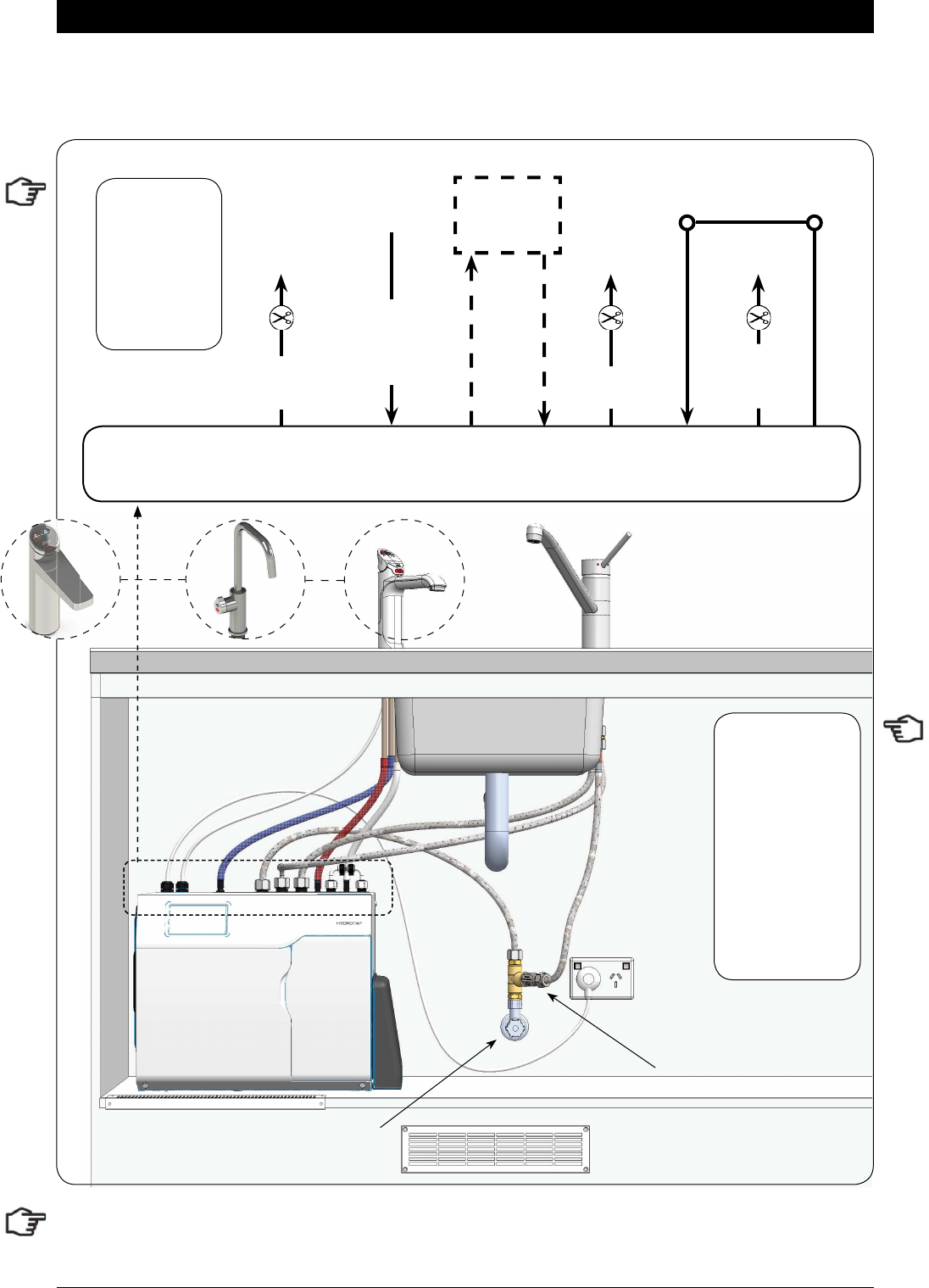
Incoming water
Blue hose
to chilled
water outlet
Red hose to boiling
water outlet
Clear hose to
Vent
Typical HydroTap Installa-
tion (see section 5)
1.5
Note: All
silicon tubes
must be cut to
size. They must
have a constant
fall back to the
unit.
Note:
- Mains hose
length is 750mm
- Plug and Cord
length is 1800mm
Position the under
sink unit close
to the outlet tap,
within reach of
the hose and cord
lengths supplied
Page 14 of 40 801314NZ - HydroTap BC, BCHA, AIO, Installation Instructions - August 2015 - V2.01
HydroTap Arc/Cube
The HydroTap Arc/Cube has a spout that may be fixed in one of 6 angular positions (depending on the
position of the rotary control) and fixed in one of two height positions. The spout is fixed and does not swivel.
NOTE: The tube kit must be fitted after the HydroTap has been mounted on the benchtop or sink.
Refer to the tube kit assembly instructions, supplied with the tap kit.
To reduce the risk of scalding, Position A should not
be selected with any of the Boiling water units. (See fig. 1.8)
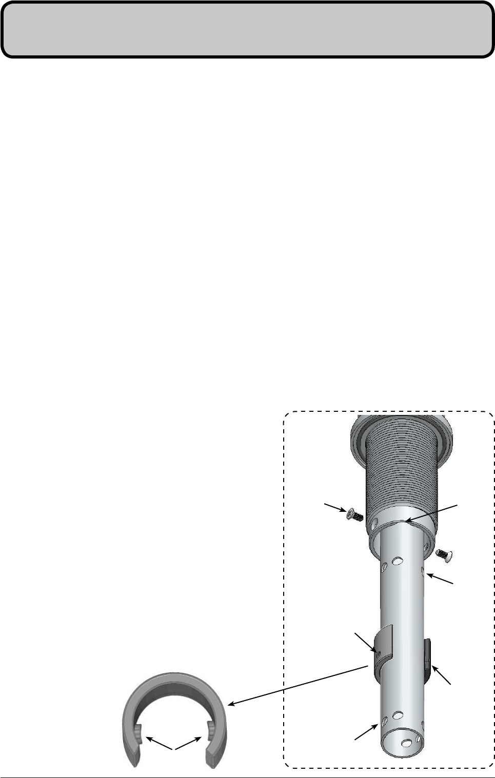
1.6
1.
Remove the 2 x spout locating screws and lower the spout to expose the plastic spring clip
NOTE: The plastic spring clip has two internal dimples that may be positioned in the 6 upper or 6 lower,
pre drilled holes in the spout (see diags. below & Figs. 1.7 & 1.8)
2.
To reposition the spout, gently spread the plastic spring clip to release the dimples from the spout
holes. When released, slide the clip on the spout so that it ends up between the two rows of holes.
3.
Rotate the plastic clip on the spout to orient the dimples, so they are in line with the newly selected
holes.
NOTE: When determining which of the 6 holes are required for the new spout height and orientation,
check the new plastic clip position will clear the undercut and that the wiring loom will not be pinched,
when assembled.
4.
Slide the plastic clip up/down to engage with the selected holes, making sure the two dimples engage
simultaneously with the two selected holes.
NOTE: The clip will not fit correctly if one dimple engages before the other. Both dimples must engage at
the same time.
5.
With the clip fitted to the newly selected holes,
carefully raise the spout (ensure the wiring loom is
a neat fit in the undercut and is located between the
open ends of the clip) until the clip locating holes are
in line with the spout locating screws.
6.
Replace the 2 x locating screws.
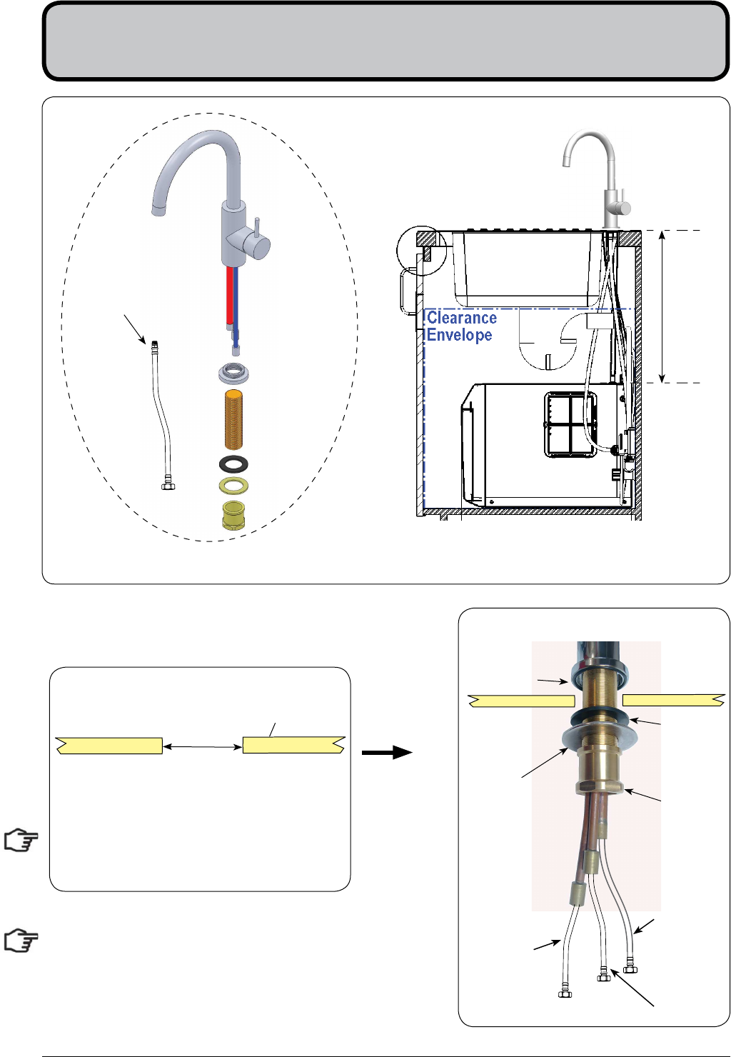
7.
If mounting on an uneven surface, apply a light
smearing of silicon sealant on the O ring to ensure a
watertight fit. (See fig. 1.9)
8.
Pass the assembly through the 35mm hole and
position the tap so it discharges into the sink.
9.
Fit the lower rubber seal to the threaded extension.
10.
Secure the tap in position with the metal washer and
nut.
11.
Fit the tube kit, as supplied.
To change the spout position
Spout locating
screws (2)
Plastic spring
clip
Upper locating
positions
Lower locating
positions
Clip locating
holes (2)
Undercut
for loom
Plastic spring clip
Dimples
801314NZ - HydroTap BC, BCHA, AIO, Installation Instructions - August 2015 - V2.01 Page 15 of 40
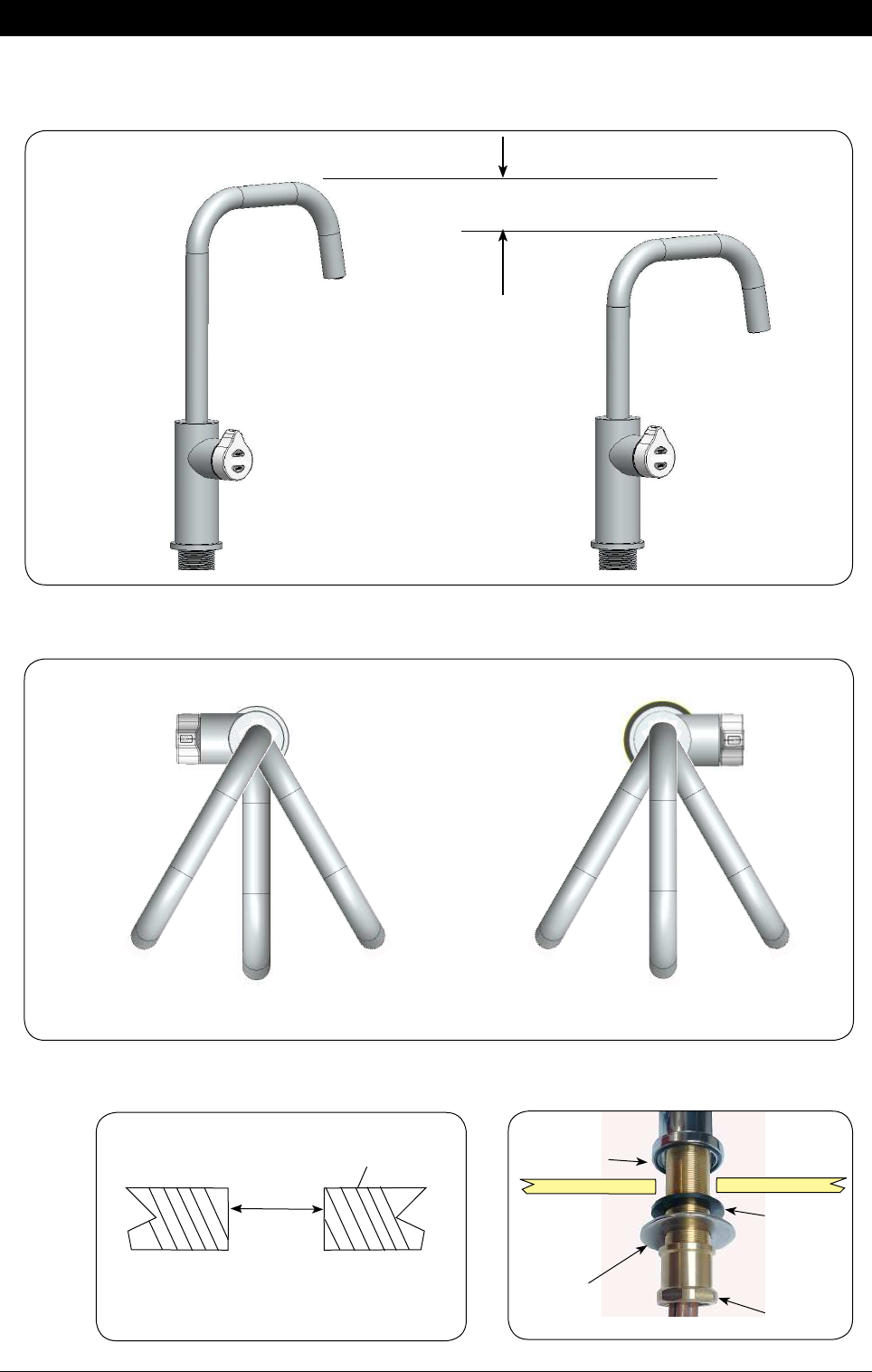
Installation Instructions
A A
Left Hand Control Right Hand Control
BCCB
50mm
Height adjustment (Fixed position options)
Angular adjustment (Fixed position options)
1.7
O-RING
LOWER
RUBBER
WASHER
WASHER
NUT
1.8
1.9 Mounting (See table on Page 11 )
Cut a 35mm hole in the bench / sink top.
BENCH TOP
Ø35mm
NOTE: Position A is
not recommended with
Boiling water units
Page 16 of 40 801314NZ - HydroTap BC, BCHA, AIO, Installation Instructions - August 2015 - V2.01
Cut a 35mm hole in the bench / sink top.
SINK TOP
1.10
35mm
Note: make sure the tap location will allow
the nozzle to drain into the sink.
Tap assembly exploded view and kitchen layout side view.
BRAIDED
HOSE x 3
Mixer Tap Installation
1.11
O-RING
LOWER
RUBBER
WASHER
WASHER
NUT
Blue band
Mixer IN
Red band
Mixer Out
Note
:
The mixer tap requires a Zenith Restricta! ow
valve, as supplied, to be " tted in the cold
water supply line, from the isolation valve tee
piece, to the mixer tap. (See Fig. 1.13)
Min 300mm
External Mains
801314NZ - HydroTap BC, BCHA, AIO, Installation Instructions - August 2015 - V2.01 Page 17 of 40
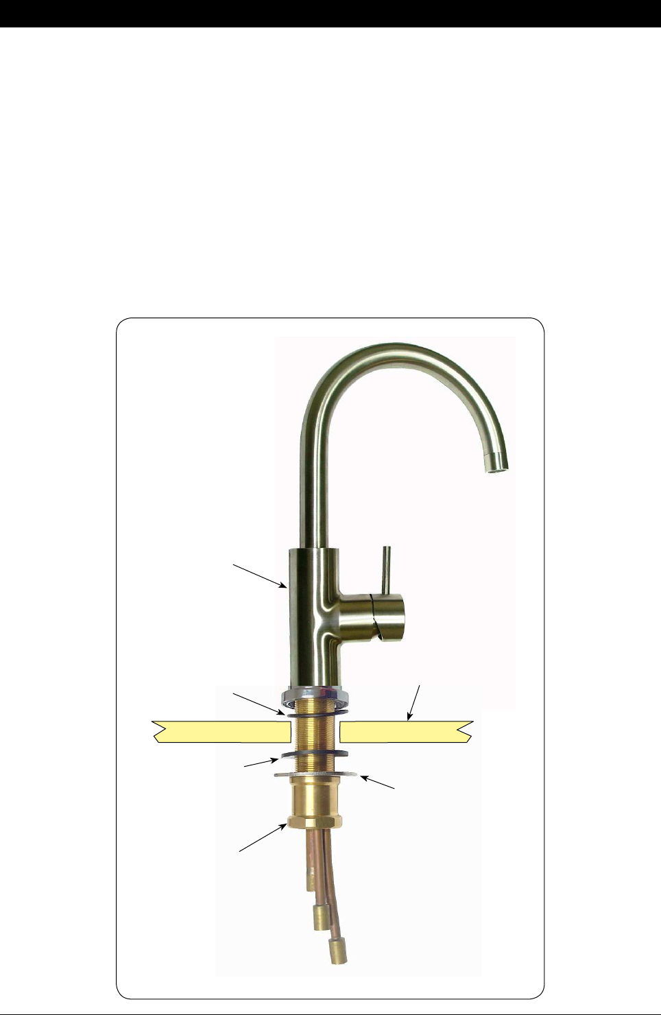
1.12
Installing the Mixer Tap
(Classic, Arc and Cube)
Installation Instructions
Sink top
O-ring
Lower seal
Washer
Securing nut
Mixer tap
Arc Mixer Tap
•
Fit the O-ring into the recess on the underside of the Mixer tap. (Note: If mounting on an uneven
surface, a light smear of silicone on the O-ring will ensure a water tight seal)
•
Pass the tap tubes and threaded extension through the 35mm hole and position the tap so that it
discharges into the sink.
•
Fit the lower rubber seal to the threaded extension.
•
Secure the tap in position with the metal washer and Nut.
•
Affix the three hoses to the tap. Match the hose colours to the coloured bands on the copper extension
tubes. (See diag. 1.11)
Page 18 of 40 801314NZ - HydroTap BC, BCHA, AIO, Installation Instructions - August 2015 - V2.01
Installation Instructions
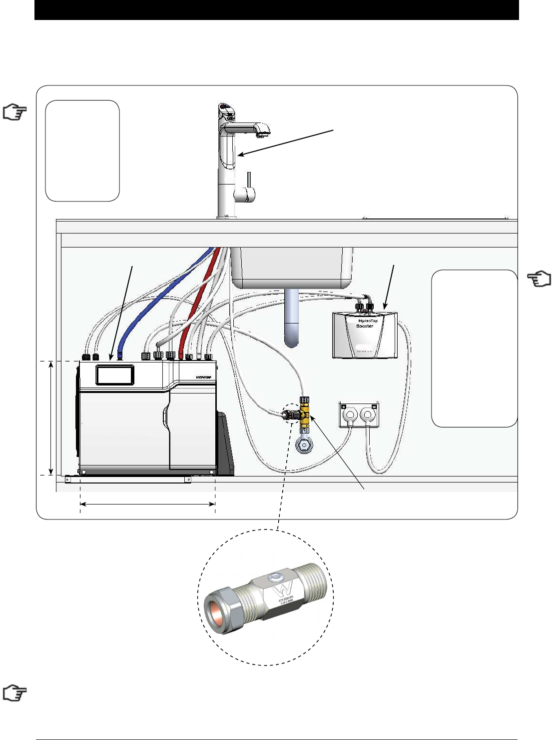
1.13
COLD isolation valve
(Not supplied)
HydroTap
Mixer
Connections
RED
CLEAR
BLUE
WHITE
Restricta! ow valve
(Supplied)
Typical HydroTap 4-in-1 Installation (see section 5)
Tee piece
(Supplied)
POWER
CORD
USB CHILLED
OUTLET
MAINS
IN
MIXER
OUT
MIXER
IN
BOILING
OUT
BYPASS
IN
VENT BYPASS
OUT
Note:
- Mains hose
length is 750mm
- Plug and Cord
length is 1800mm
Position the under
sink unit close
to the outlet tap,
within reach of
the hose and cord
lengths supplied
Note: All
silicon tubes
must be cut to
size. They must
have a constant
fall back to the
unit.
Note:
The tube lengths are matched to the pumps performance and therefore CANNOT be lengthened
801314NZ - HydroTap BC, BCHA, AIO, Installation Instructions - August 2015 - V2.01 Page 19 of 40
Cut a 50mm hole in the bench / sink top.
SINK TOP
1.14
50mm
Note: make sure the tap location will allow the
nozzle to drain into the sink. (See Page 11)
All-In-One Tap
Installation
Min 300mm335mm
470mm
1.15
• Fit the seal ring to the base
of the tap and If mounting on an uneven surface, apply
a light smear of silicone
sealant to ensure a watertight seal
• Mount the tap on top of the cut out hole after passing the usb cable and tubes through the 50mm hole
• Thread the cable and silicon tubes through the circular clamp block (Check the tube colour alignment with the
coloured dots on the clamp block). (See fig 1.16)
• Clamp the assembly in position using the threaded nut and clamp block
• Working from inside the cupboard, attach the braided hoses to the tube extensions (ensure the seals on the end of
the hoses are lubricated). Check the correct position for Hot and Cold connections by matching the colours on the
braided hoses with the coloured markings on the copper extension tubes. (See fig. 1.18)
• Test for leaks after all the connections have been secured.
Installation Procedure
Page 20 of 40 801314NZ - HydroTap BC, BCHA, AIO, Installation Instructions - August 2015 - V2.01
FIXING NUT
1.16
Installation Instructions
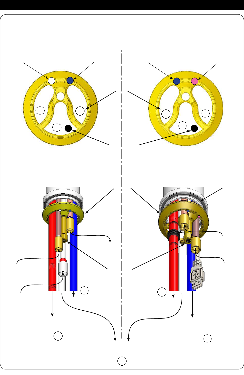
1.17 CLAMP BLOCK O-RING
AIO Vented assy
BLUE to Chiller
connection
CLEAR
to vent
RED to Boiling
connection
From Mixer
OUT
AIO Mains assy
BLUE mark
WHITE mark BLUE mark RED mark
Clamp Block markings and silicon tube positions,
viewed from underneath
RED to Boiling
connection
BLUE to Chiller
connection
Mains IN From HWS
connection
Mains IN
To Mixer
IN
R
SILICON TUBES
USB CABLE
R
C
B
C
B
R
R
C
B
B
801314NZ - HydroTap BC, BCHA, AIO, Installation Instructions - August 2015 - V2.01 Page 21 of 40
1.18
Installation Instructions
External HOT & COLD
isolation valves
(Not supplied)
Tee piece
(Supplied)
Typical All-in-1 Mains Installation (see section 5)
CLAMP
BLOCK
•
Screw the braided hoses
into the extension tubes.
Ensure the o-rings
are lubricated prior to
assembly and that the
braided hoses, with
coloured markings,
are correctly matched
with the colours on the
extension tubes and
on the clamp block (as
indicated).
•
Make sure all tubes and
hoses are firmly secured.
1.19 Note: All silicon tubes must
be cut to size. They must have a
constant fall back to the unit.
Braided
hoses
Vented braided hose positions
Mains braided hose positions
BLUE to
Mixer IN
HOT IN
from HWS
WHITE
Mains IN
RED from
Mixer OUT
Underside view
BLUE
Mains IN
RED
Extension
tubes
Typical Vented assembly
RED Hot
BLUE Chilled Note:
- Mains hose
length is 750mm
- Plug and Cord
length is 1800mm
Position the under
sink unit close
to the outlet tap,
within reach of
the hose and cord
lengths supplied
Page 22 of 40 801314NZ - HydroTap BC, BCHA, AIO, Installation Instructions - August 2015 - V2.01
Installation Instructions
1.20 Typical All-In-One Vented assembly with Booster heater (See section 5)
Booster
BC Unit
A-I-O Tap
400mm
335mm
Restrictaflow valve & Tee piece
(Supplied)
Note:
The All-In-One vented taps require a Zenith Restrictafl ow valve and Tee piece, as supplied, to be fi tted
in the cold water supply line, from the isolation valve (Not supplied), to the mixer tap. (See diagrams)
Restrictaflow valve
Note:
- Mains hose
length is 750mm
- Plug and Cord
length is 1800mm
Position the under
sink unit close
to the outlet tap,
within reach of
the hose and cord
lengths supplied
Note: All
silicon tubes
must be cut to
size. They must
have a constant
fall back to the
unit.
801314NZ - HydroTap BC, BCHA, AIO, Installation Instructions - August 2015 - V2.01 Page 23 of 40
2.1 All Models
Proper air circulation must be provided for all Boiling and Chilled models. The system will operate correctly
only if the recommended air gaps are achieved during Installation. The vent duct and louvre panels must be
installed for all under floor and /or door vent systems, as instructed.
**Note: Inlet and outlet vents should be separated by a Min 100mm, to avoid hot air recirculation.
IMPORTANT:
See section 5.3 for clearances.
When installing air flow ducts, the following tools will be required:
•
Jigsaw and 12mm Drill
•
Keyhole or Wall Board saw.
Section 2
Ventilation
Cool Air IN
via cabinet
floor, front
vent grille Warm Air OUT via kickboard louvre
Recommended Installation showing the correct air flow
MIN.
50mm
Air Gap
**MIN.
100mm
Note:
- Mains hose
length is 750mm
- Plug and Cord
length is 1800mm
Position the under
sink unit close
to the outlet tap,
within reach of
the hose and cord
lengths supplied
Note: All
silicon tubes
must be cut to
size. They must
have a constant
fall back to the
unit.
Page 24 of 40 801314NZ - HydroTap BC, BCHA, AIO, Installation Instructions - August 2015 - V2.01
Ventilation
= =
max 43
314.00
12.00
12.00
285.00
12.00
5
326.00
CUT OUT DETAILS
A
A - KICKBOARD CUT-OUT
1.Drill 4 pilot holes Ø12 in corners
2.Finish cut-out using Jigsaw
and Keyhole or Wall Board saw
B - CABINET FLOOR
CUT-OUT
1.Drill two pilot holes Ø12
2.Finish cut-out using Jigsaw
C - CABINET FLOOR
CUT-OUT
1.Drill 4 pilot holes
Ø12 in corners
2.Finish cut-out using Jigsaw
and Keyhole or Wall Board saw
ATTENTION:
Insure that: Cut outs 'A' and 'B' are on opposite side of cabinet.
Cut out 'C' is straight behind'A'
60.00
BC
12.00
45.00
284
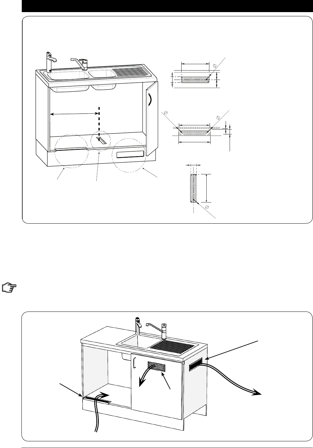
The following instructions are critical if the vent kit, as supplied, is not fitted:
If the kick board vent kit cannot be used then it is important to fit a standard HydroTap vent kit, which ensures
heat dissipation through natural convection via installed vents. For normal applications, where the cupboard
space temperature is near 35°C, or higher, an auxiliary ventilation kit must be fitted. (Contact your local
service centre for availability).
Note: The vent kit has to be installed in a way that allows air to be drawn in from the bottom of the cupboard
and expelled through the top of the cupboard. Therefore placement of the outlet vent should be towards the
top of the door (Option 1) or on the upper side of the cupboard (Option 2).
Min 450mm
For positioning of cutout C
use the template marked on the cardboard carton
Side outlet vent (Option 2)
Door outlet
louvre
(Option 1)
Front inlet vent
Cool Air IN
Warm Air OUT
801314NZ - HydroTap BC, BCHA, AIO, Installation Instructions - August 2015 - V2.01 Page 25 of 40
Booster Specifications:
Rating Unit
Nominal Power Rating 2.2 kW
Nominal Current 10 A
Electric Supply 50Hz AC 230 V
Elect • ex and plug (black) - 1 meter length (with 90º Aus-
tralian plug)
10 A
Fixed Flow Rate 1.2 L/min
Minimum water pressure 200 kPa
Section 3
Booster Heater
Mount base
Horizontally
3.1 Product Description
The boost unit is a compact electronically
controlled auxiliary water heater. It is intended to
provide pre heating of water before it enters the
Zenith HydroTap G4 boiling tank. The Booster is
supplied as standard equipment with all 240 cup
models. However, it may be later installed, as an
accessory for the 160 cup models, to increase
their delivery to 240 cups.
400mm
Note 1: water connection
:Blue marking - water in
:Red marking - water out.
The braided hoses cannot be
lengthened.
Note 2: The electrical cable
length is 1.0 metre.
Note 3: Position the Booster
within reach of the fixed hose
lengths, keeping the Booster
as close as possible to the
undersink unit inlet/ outlet
fittings.
Note 4: Ensure the Booster
heater is mounted in an
upright position (as shown)
with a horizontal base
Page 26 of 40 801314NZ - HydroTap BC, BCHA, AIO, Installation Instructions - August 2015 - V2.01
Booster Installation
3.2 Installation Procedure
Site requirements
•
Appliance must only be installed in a frost-free area. Never expose appliance to frost.
•
The Appliance is designed for wall mounted Installation and must to be installed with water connectors
facing upwards.
•
The appliance complies with protection class IP 25.
•
The 400mm braided hoses supplied with the unit cannot be lengthened.
•
The 90° elbow hose ends, should be fitted to the inlet and outlet connections on top of the Booster.
•
The hot water outlet hose must be thermally insulated with the insulation provided.
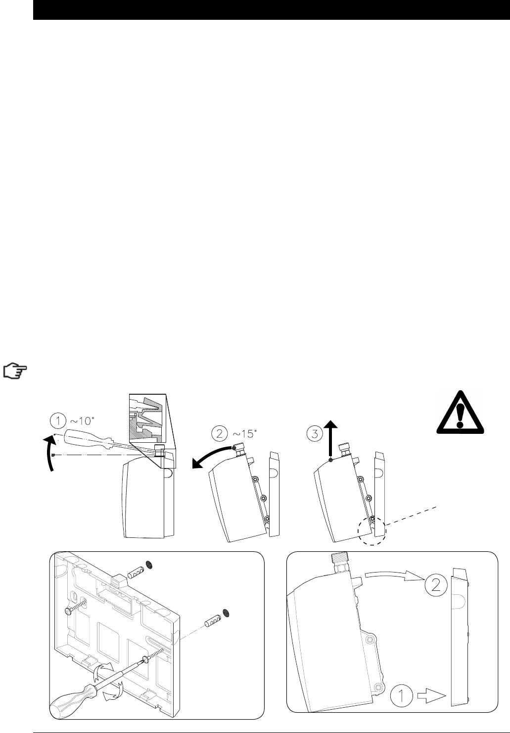
Tilt Forward Lift UP
Release
Note: Remove the backing plate for wall mounting
3.3 To Remove / Install the appliance
1.
Insert a flat head screwdriver all the way into the lock.
2.
Gently angle the screwdriver upwards by approximately 10° as shown in the image below.
3.
Pull the appliance forwards by approximately 15° as shown.
4.
Carefully pull the appliance upwards to complete the removal process. Taking care not to break the
lower clips
5.
To install; Place the appliance on the wall bracket and snap into position (See installation below).
Take care
not to break
the lower
clips when
removing or
installing the
Booster
Installation
801314NZ - HydroTap BC, BCHA, AIO, Installation Instructions - August 2015 - V2.01 Page 27 of 40
Note 1: This appliance is intended for use with the Zenith HydroTap under sink
unit.
Note 2: Water connections must be pointing vertically upwards.
Note 3: The booster unit should be installed as close as possible to the Zenith
HydroTap Unit as the 400mm connection hoses cannot be lengthened.
Booster System
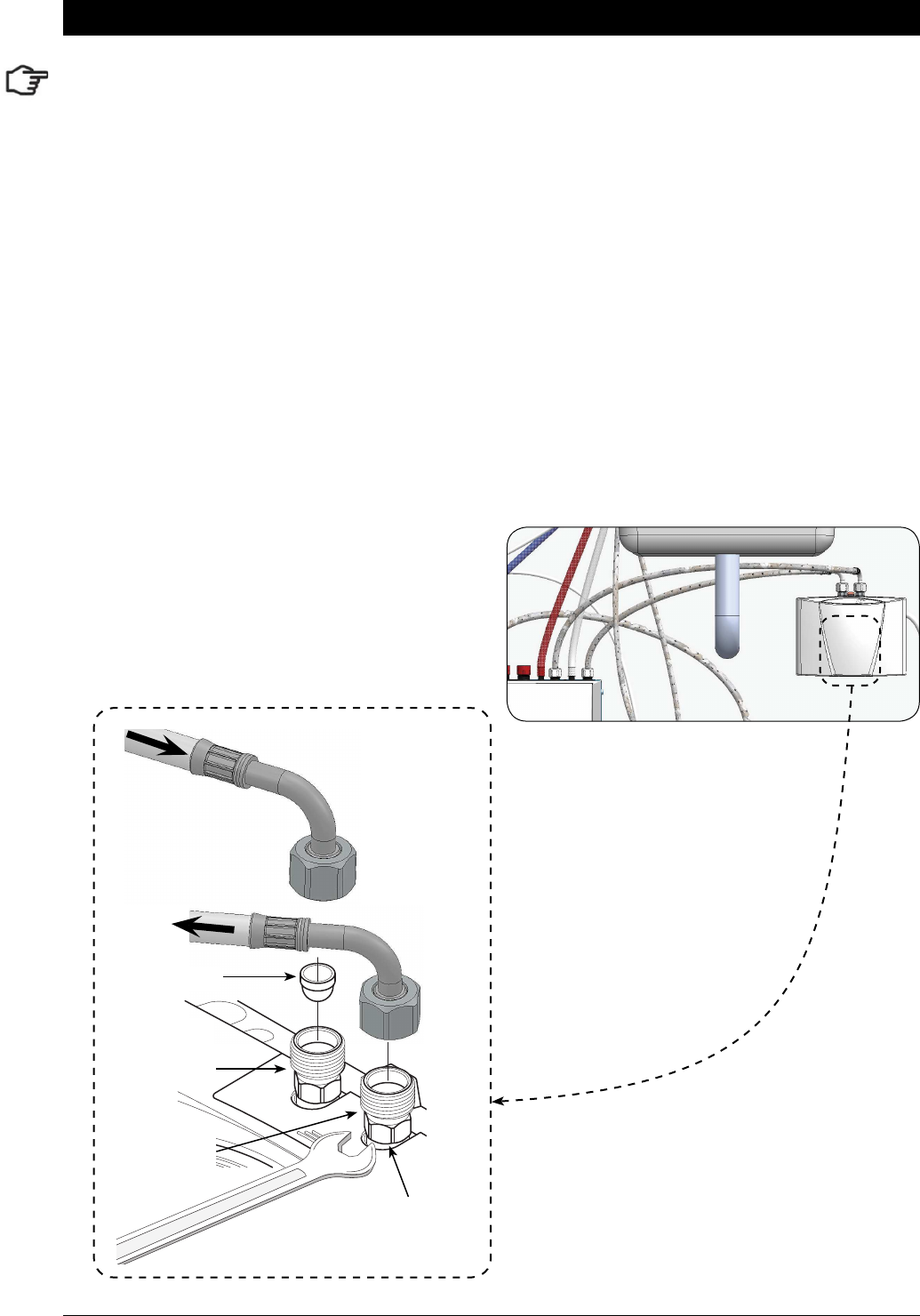
3.4 Braided hose connection
s
1.
The cold water inlet (blue) and hot water outlet (red) are marked on the rating plate. Connect the
braided hoses from the ‘Bypass Out’ fitting on the Zenith HydroTap, to the water inlet of the booster
unit (Marked Blue) and from the outlet of the booster unit (Marked Red) to the ‘Bypass IN’ fitting on the
Zenith HydroTap unit. Avoid exerting any mechanical pressure on the appliance. This can be achieved
by applying a spanner on the flats of the inlet and outlet connections when tightening the braided hose
connectors. Do not overtighten ! Tighten the braided hoses by hand, then turn an additional 90° - 180°
with a spanner
2.
Once the water connections have been made, check for any leaks and rectify as necessary.
Hot Water
Connection
(outlet, G1/2”)
Strainer
Cold Water
Connection
(inlet, G1/2”)
Hold the hexagon while
tightening the braided
hose fittings
Braided Hoses
Typical Installation
Page 28 of 40 801314NZ - HydroTap BC, BCHA, AIO, Installation Instructions - August 2015 - V2.01
Section 4
Filter / Softener Installation
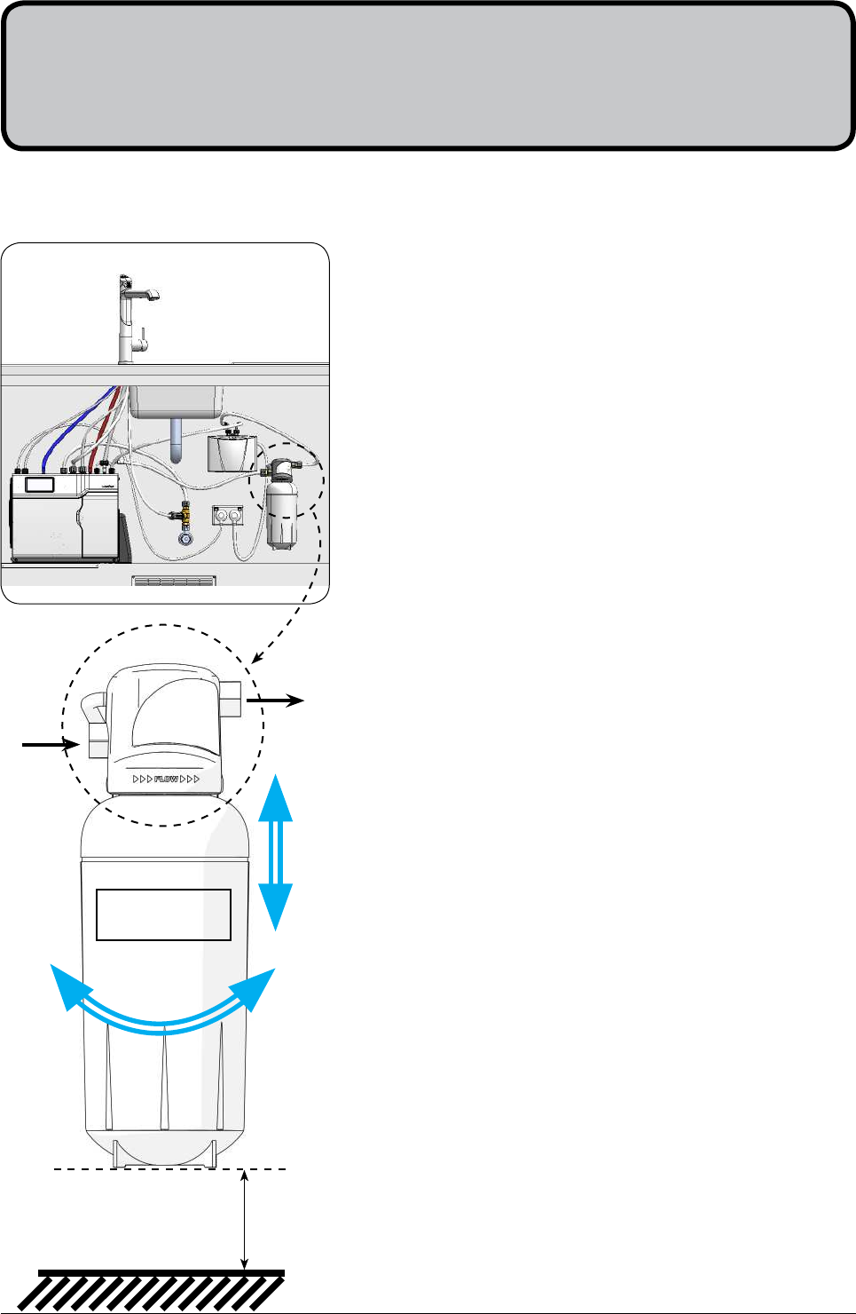
An external filter / Softener may be fitted to reduce the incidence of scale build up in the hot tank or may be
at the customer’s request.
•
Choose a suitable location, (cupboard back or side wall)
within the reach of the braided hoses.
•
Mount the filter head bracket in an upright position, using the
screws supplied in the kit
•
Ensure there is enough headroom for the filter cartridge to be
easily fitted and removed. *Allow a Min 80mm base clearance
•
Attach the hoses as shown in section 5.5 - 5.7. Noting the flow
directions as marked on the filter head.
4.1 Mounting the filter head
*Min. 80mm
Clearance
4.2 Cartridge Installation
1.
Unpack replacement cartridge, write today’s date where
shown on the label and remove the sanitary cap.
2.
Avoid touching the filter O-rings and filter opening as this may
cause bacterial contamination of the cartridge.
3.
Moisten the O-rings with water, align the front cartridge label
to the left and push the new cartridge into the filter head.
4.
Turn the cartridge a quarter turn to the right until the cartridge
comes to a complete stop, with the front label facing forward.
5.
Disconnect the filter outlet hose from the undersink unit and
direct the hose end into a container ready for flushing.
6.
Turn the power and water ON and depress the tap’s Boiling
lever and allow water to run for 30 seconds to flush the tank.
7.
Allow at least 10L to flow through the filter to ensure all
carbon particles have been flushed.
8.
Turn the power and water off (after flushing 10L).
9.
Reconnect the filter outlet hose to the undersink unit.
10.
Turn the water supply back on and check for leaks.
11.
Set the appropriate selection on the Internal Filter Bypass
valve located at the rear of the unit in accordance with
Sections 5.1 and 5.2.
Filter Label
Inlet
Outlet
801314NZ - HydroTap BC, BCHA, AIO, Installation Instructions - August 2015 - V2.01 Page 29 of 40
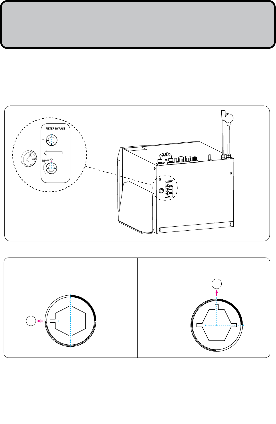
If an external filter is installed, select position B
B
Rotate 90°
only
1
2
3
4
Check the table below to determine which filter bypass position you need for your product.
Before you install an undersink unit, determine whether a water softener or an external filter is required.
5.1 External Bypass Valve
The diverter bypass valve allows the user to choose to have the boiling water filtered either by the internal or
by an optional external filter. This diverter valve is located at the rear panel of the Zenith HydroTap undersink
unit on the filter door side, see the image below.
5.2 Hose and tube fitting. (Do not overtighten)
•
Remove all caps from the top of the undersink unit
•
Install the mains water braided hoses to the undersink unit before locating the unit in place.
Section 5
Undersink Unit Installation
If no external fi lter is installed, select position A
A
Rotate 90°
only
1
2
3
4
NO EXTERNAL
FILTER INSTALLED
SELECT POSITION A
EXTERNAL
FILTER INSTALLED
SELECT POSITION B
B
1
2
3
4
A
1
2
3
4
PN: 801231
Page 30 of 40 801314NZ - HydroTap BC, BCHA, AIO, Installation Instructions - August 2015 - V2.01
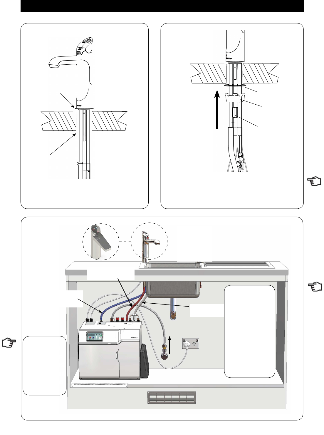
Installation Instructions
: Not required for standard BC HydroTap models.
Min.
50mm
Clearance
400mm
RED
CLEAR
BLUE
BRAIDED
Max.
1000mm
Max.
500mm
POWER
CORD
USB CHILLED
OUTLET
MAINS
IN
MIXER
OUT
MIXER
IN
BOILING
OUT
BYPASS
IN
VENT BYPASS
OUT
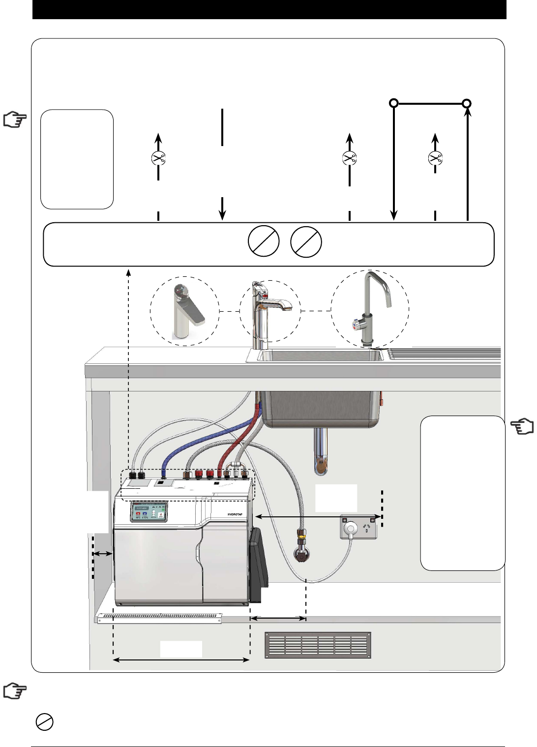
5.3 Models BC 160/125 and BC 160/175
Note:
- Mains hose
length is 750mm
- Plug and Cord
length is 1800mm
Position the under
sink unit close
to the outlet tap,
within reach of
the hose and cord
lengths supplied
Note: All
silicon tubes
must be cut to
size. They must
have a constant
fall back to the
unit.
Note:
The tube lengths are matched to the pumps performance and therefore CANNOT be lengthened
801314NZ - HydroTap BC, BCHA, AIO, Installation Instructions - August 2015 - V2.01 Page 31 of 40
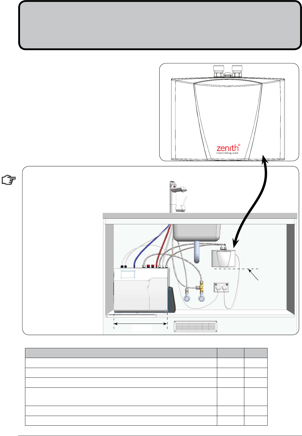
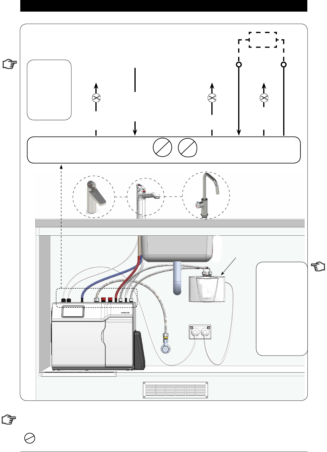
Installation Instructions
: Not required for standard BC HydroTap models
Booster
RED
CLEAR
BLUE
BRAIDED
5.4 Model BC 240/175
Booster
option
POWER
CORD
USB CHILLED
OUTLET
MAINS
IN
MIXER
OUT
MIXER
IN
BOILING
OUT
BYPASS
IN
VENT BYPASS
OUT
Note:
- Mains hose
length is 750mm
- Plug and Cord
length is 1800mm
Position the under
sink unit close
to the outlet tap,
within reach of
the hose and cord
lengths supplied
Note: All
silicon tubes
must be cut to
size. They must
have a constant
fall back to the
unit.
Note:
The tube lengths are matched to the pumps performance and therefore CANNOT be lengthened
Page 32 of 40 801314NZ - HydroTap BC, BCHA, AIO, Installation Instructions - August 2015 - V2.01
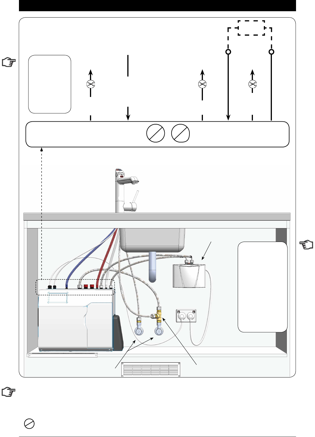
Installation Instructions
Note: to activate the filter, flush at least 10L of water through the filter before connecting to a softener or to a
Booster heater.
: Not required for AIO mains pressure HydroTap.
External HOT and COLD
isolation valves (Not Supplied)
Tee piece
(Supplied)
Booster
RED
CLEAR
BLUE
BRAIDED
5.5 Model All-In-One Mains Pressure
Booster option
POWER
CORD
USB CHILLED
OUTLET
MAINS
IN
MIXER
OUT
MIXER
IN
BOILING
OUT
BYPASS
IN
VENT BYPASS
OUT
Note:
- Mains hose
length is 750mm
- Plug and Cord
length is 1800mm
Position the under
sink unit close
to the outlet tap,
within reach of
the hose and cord
lengths supplied
Note: All
silicon tubes
must be cut to
size. They must
have a constant
fall back to the
unit.
Note:
The tube lengths are matched to the pumps performance and therefore CANNOT be lengthened
801314NZ - HydroTap BC, BCHA, AIO, Installation Instructions - August 2015 - V2.01 Page 33 of 40
Installation Instructions
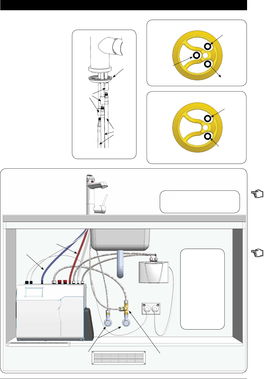
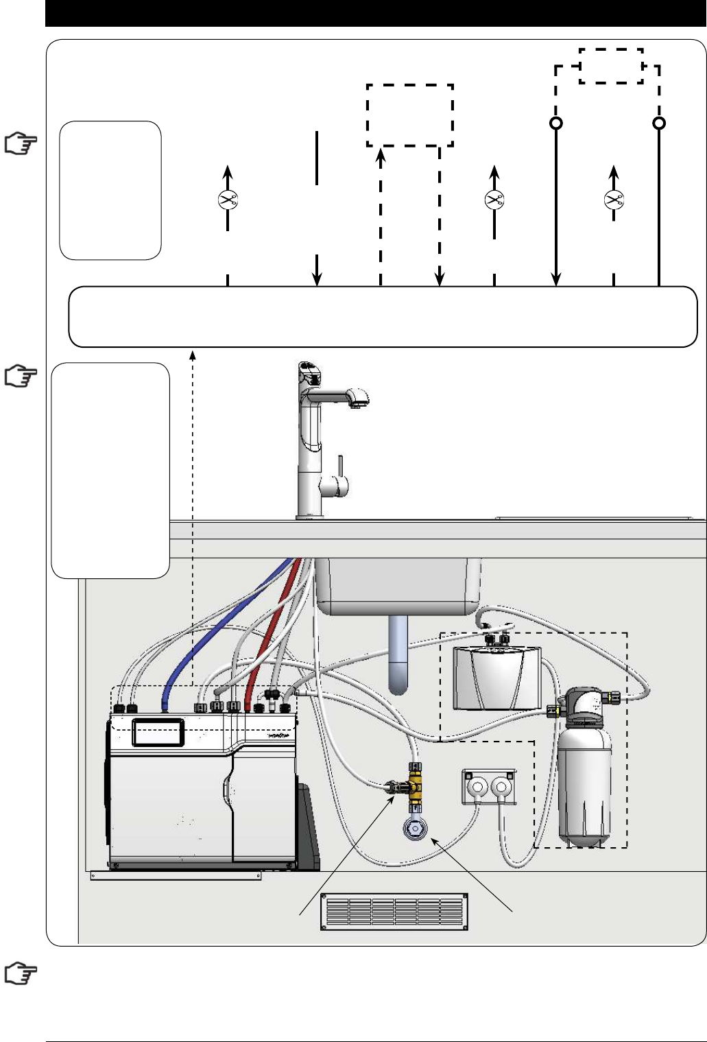
5.6 Model All-In-One Vented
HydroTap
AIO Mixer
Connections
Note: Take time to consider hose lengths when determining the mounting positions for the options
Options
RED
CLEAR
BLUE
BRAIDED
Tee piece and
Restricta! ow
valve
External COLD
isolation valve
(Not Supplied)
Options
POWER
CORD
USB CHILLED
OUTLET
MAINS
IN
MIXER
OUT
MIXER
IN
BOILING
OUT
BYPASS
IN
VENT BYPASS
OUT
Note:
- Mains hose
length is 750mm
- Plug and Cord
length is 1800mm
Position the under
sink unit close
to the outlet tap,
within reach of
the hose and cord
lengths supplied
Note: All
silicon tubes
must be cut to
size. They must
have a constant
fall back to the
unit.
Note:
The tube lengths are matched to the pumps performance and therefore CANNOT be lengthened
Page 34 of 40 801314NZ - HydroTap BC, BCHA, AIO, Installation Instructions - August 2015 - V2.01
Installation Instructions
5.7 Model HydroTap 4-In-1 Vented
HydroTap
Mixer
Connections
RED
CLEAR
BLUE
BRAIDED
Note: All
silicon tubes
must be cut to
size. They must
have a constant
fall back to the
unit.
Tee piece and
Restricta! ow
valve (supplied)
External COLD
isolation valve
(Not Supplied)
POWER
CORD
USB CHILLED
OUTLET
MAINS
IN
MIXER
OUT
MIXER
IN
BOILING
OUT
BYPASS
IN
VENT BYPASS
OUT
Note:
- Mains hose
length is 750mm
- Plug and Cord
length is 1800mm
Position the under
sink unit close
to the outlet tap,
within reach of
the hose and cord
lengths supplied
Note:
The tube lengths are matched to the pumps performance and therefore CANNOT be lengthened
801314NZ - HydroTap BC, BCHA, AIO, Installation Instructions - August 2015 - V2.01 Page 35 of 40
•
Turn ON the water and check for any leaks.
•
Turn the power ON at the GPO.
•
If fitted, ensure the Booster is turned OFF. (The Booster is commissioned, later, at section 5.4)
•
Familiarise yourself with the operation of the Tap, in preparation for use (See User Guide)
•
Follow the Installation instructions below (and review Section C of the User Guide).
•
After commissioning, the system may be customised by selecting further options in Section G -
Settings, within the User Guide.
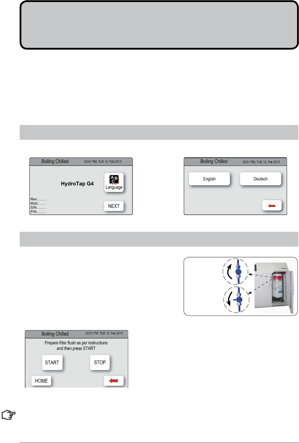
1.
Turn the stop cock ON
2.
Press [Start] [Stop] buttons to start and stop the filter flush.
3.
Allow at least 10 litres of water to flush through the filter.
4.
Once the filter flush is finished, Turn the stop cock OFF
then press [Stop] to end filter flush mode.
5.
Press [Next] and the View screen will show the Flow
calibration mode.
Have a 10L bucket or similar container (not supplied) at the
ready to hold a quantity of water that will be ejected while the
Filter Flush Mode is in operation. Open the filter access door
on the front of the HydroTap and the filter cartridge will be
exposed. Located to the rear RHS of the cartridge is a flush
line, approx 600mm long and the flush line stop cock. Place
the valve end of the flush line into the 10L bucket or container.
6.2 - Filter Flush
Section 6
Commissioning
NOTE: For any subsequent fi lter changes or any operational procedures, please refer to the HydroTap user
guide, located inside the fi lter housing access door.
6.1 - Select the Language
Initial Commissioning screen Language selection screen
OPEN
CLOSED
Stop cock
operation
Page 36 of 40 801314NZ - HydroTap BC, BCHA, AIO, Installation Instructions - August 2015 - V2.01
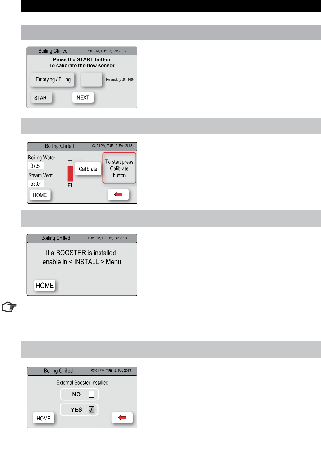
1. Press the [MENU] button for main menu.
2. Press the [Install] button.
3. Press the [Booster] button.
4. In the next screen, press YES to enable the Booster.
5. Turn the Booster ON
6. Water must be run through the Booster for a min of 30
seconds, before the heater will activate.
7. Dispense boiling water for 30secs and check the
Booster outlet hose is warm when the boiling water
tank is replenishing.
HydroTap Booster Screen
6.4 - Boiling Calibration
Commissioning
6.5 - Booster
•
Press the calibration button and the system will
commence the Boiling calibration procedure. This
will take aprox 5-6 minutes.
•
Upon completion, a Booster reminder screen will
appear and allow you to return home by pressing
the [Home] button.
•
Check the Date and Time settings (See Note
below)
To enabled when a Booster unit is installed.
Note: failing to make the correct selection for the “Booster”, will affect product performance.
Note: Depending on your location you may need to re-set the internal clock. See section G of the user guide
to check and if necessary, reset the Date and Time for your time zone.
6.3 - Flow Calibration
1.
Press the [Start] button and the tank will first
empty then fill. This will take aprox 5 minutes.
2.
Upon completion the actual pulse will be
displayed.
3.
Press [Next] for the Boiling Calibration screen.

801314NZ - HydroTap BC, BCHA, AIO, Installation Instructions - August 2015 - V2.01 Page 37 of 40
1.
With the unit in Normal operating mode and with the safety enabled
2.
Turn the power OFF
3.
Pull both tap levers to the forward position
4.
Turn ON the power
5.
The unit will calibrate the safety switch
6.
Return the levers to the neutral position.
7.
To check the calibration, dispense Boiling water, in normal light
conditions with the safety enabled.
Light intensity varies from site to site, therefore it is recommended that a re-calibration be performed at the
time of the installation. All direct natural sun light must be shaded from the HydroTap, during the calibration.
This can be achieved by closing any nearby curtains, blinds, or by shielding the HydroTap with a dark cloth.
Safety
sensor
Pull both levers forward
Safety Sensor Calibration
End of Life Disposal
In order to help preserve our environment we ask that you dispose of this product correctly. Please contact
your local city council for collection centre details.
6.6 - Sensor

Page 38 of 40 801314NZ - HydroTap BC, BCHA, AIO, Installation Instructions - August 2015 - V2.01
Trouble Shooting
System Fault
Message Possible Cause Solutions
Power board fault Electrical disruption Check power supply and all fuses
Interface fault Internal fault Call Zenith Service
Level board fault Internal fault Call Zenith Service
Condenser screen blocked Blocked Air filter Remove blockage / Clean filter / check user guide
Water leak, Isolate mains Water leak Turn off mains water supply / Call for service
Compressor over-run Compressor too Hot Check ventilation
Water supply failed No water Check water supply is turned ON
Hot sensor Open Internal fault Call Zenith Service
Hot sensor Closed Internal fault Call Zenith Service
Cold sensor Open Internal fault Call Zenith Service
Cold sensor Closed Internal fault Call Zenith Service
Flood sensor Open Internal fault Call Zenith Service
Condenser sensor Closed Internal fault Check Ventilation / Call Zenith Service
Condenser sensor Open Internal fault Check ventilation / Call Zenith service
Heater fuse / driver fault Internal fault Call Zenith Service
Heater driver fault No hot water Call Zenith Service
Compressor driver fault No chilled water Call Zenith Service
Hot sensor degraded Internal fault Call Zenith Service
Condenser over temp. Blocked air filter Remove blockage / Clean filter / check user guide
Cold overload Internal fault Call Zenith Service
Steam is too cool Internal fault Call Zenith Service
Steam sensor Open Internal fault Call Zenith Service
Steam sensor Closed Internal fault Call Zenith Service
Hot overload Internal fault Turn OFF to reset / Call Zenith Service
Hot tank overfilled Internal fault Call Zenith Service
Outputs fuse fault Internal fault Call Zenith Service
Safety lock ON Safety button active See User guide Section - G (Safety mode)
Safety lock OFF Safety button Inactive See User guide Section - G
Hot Isolation ON Safety button active See User guide Section - G
Hot Isolation OFF Safety button Inactive See User guide Section - G
Hot Isolation Enabled Safety button active See User guide Section - G
Hot Isolation Disabled Safety button Inactive See User guide Section - G
Sleep mode Enabled Auto sleep mode active See User guide Section - G (Energy Mode)
Sleep mode Disabled Auto sleep mode inactive See User guide Section - G (Energy Mode)
Calibration Auto calibration reset Normal operation, once per month
Overload Reset Internal fault Call Zenith Service
Call an electrician, a plumber, or Zenith on 0800 558055 for assistance, service, spare parts or enquiries.

801314NZ - HydroTap BC, BCHA, AIO, Installation Instructions - August 2015 - V2.01 Page 39 of 40
Notes

Page 40 of 40 801314NZ - HydroTap BC, BCHA, AIO, Installation Instructions - August 2015 - V2.01
Contact Details
WMKA00099
AS 3498
Head Office
Zenith Heaters Limited,
IRD No. 95 640 729
Unit 2/15 Moselle Avenue,
Henderson.
Auckland. 0610
New Zealand.
Website: www.zenithheaters.co.nz
Int. Phone: +(64 9) 838 8612
Telephone: 0800 558055
Facsimile: 0800 559055
As Zenith policy is one of continuous product improvement, changes to
specifications may be made without prior notice. Images in this booklet have been
modified and may not be true representations of the finished Goods.
The standard cup referred to in this publication is 167 ml (6 fl oz).
The standard glass is 200 ml (7 fl oz).
The terms “Zenith” and “HydroTap” are registered trade marks of Zip Heaters
(Aust) Pty Ltd.
Zenith products described in this publication are manufactured under one or
more of the following patents: AU675601, AU637412, AU635979, GB0422305,
GB2065848, US4354049, US5103859, US5099825 and SA2006/08043. Other
patents are in force and patent applications are pending.
