Zoll Medical RDC002 Z-RS-DC002 User Manual 9650 0912 06 SF G
Zoll Medical Corp Z-RS-DC002 9650 0912 06 SF G
Contents
- 1. User Manual
- 2. user manual
user manual
R Series® ALS Operator’s Guide
PPI
CPR
9650-0912-06 Rev. G

The issue date for the R Series Operator’s Guide ALS (REF 9650-0912-06 Rev. G) is May, 2016.
Copyright © 2016 ZOLL Medical Corporation. All rights reserved.
R Series, M Series, pedi-padz, pro-padz, stat-padz, CodeNet, Real CPR Help, RescueNet, See-Thru CPR,
Code-Ready, SurePower, OneStep, Smart Alarms, CPR Index, Defib Mentor, Rectilinear Biphasic, and ZOLL
are trademarks or registered trademarks of ZOLL Medical Corporation in the United States and/or other
countries.
Masimo is a registered trademark of Masimo Corporation in the United States and/or other countries.
All other trademarks are property of their respective owners.
0123
ZOLL Medical Corporation
269 Mill Road
Chelmsford, MA USA
01824-4105
ZOLL International Holding B.V.
Newtonweg 18
6662 PV ELST
The Netherlands

9650-0912-06 Rev. G ZOLL R Series Operator’s Guide i
Table of Contents
Chapter 1 General Information
Product Description ............................................................................................................ 1-1
How to Use This Manual..................................................................................................... 1-2
Operator’s Guide Updates..................................................................................................1-3
Unpacking........................................................................................................................... 1-3
Symbols Used on the Equipment ....................................................................................... 1-3
Conventions........................................................................................................................ 1-6
Defibrillator Function........................................................................................................... 1-6
Intended Use — Manual Operation ............................................................................ 1-6
Intended Use — ECG Monitoring ...............................................................................1-7
Intended Use — Real CPR Help ................................................................................ 1-7
Defibrillator Complications ..........................................................................................1-7
Defibrillator Output Energy ......................................................................................... 1-7
External Pacemaker (Optional)...........................................................................................1-8
Intended Use — Pacemaker ....................................................................................... 1-8
Pacemaker Complications .......................................................................................... 1-9
Pediatric Pacing ........................................................................................................ 1-10
Intended Use — SpO2 Monitoring .................................................................................... 1-10
Intended Use — EtCO2 Monitoring................................................................................... 1-10
Intended Use — NIBP....................................................................................................... 1-11
ECG Monitoring ................................................................................................................ 1-11
Recorder Function ............................................................................................................ 1-11
Paddles and Electrodes.................................................................................................... 1-12
Batteries............................................................................................................................ 1-12
Code-Ready System.........................................................................................................1-13
Safety Considerations.......................................................................................................1-13
Warnings........................................................................................................................... 1-14
Operator Safety ........................................................................................................1-15
Patient Safety ........................................................................................................... 1-16
Cautions............................................................................................................................ 1-18
Restarting the Defibrillator ................................................................................................ 1-18
FDA Tracking Requirements............................................................................................. 1-19
Notification of Adverse Events .................................................................................. 1-19
Software License .............................................................................................................. 1-20
Service.............................................................................................................................. 1-20
The ZOLL Serial Number.................................................................................................. 1-21

TABLE OF CONTENTS
ii www.zoll.com 9650-0912-06 Rev. G
Chapter 2 Product Overview
Defibrillator Controls and Indicators.................................................................................... 2-1
The Front Panel ..........................................................................................................2-3
Display Screen ............................................................................................................ 2-5
Patient Cables and Connectors .................................................................................. 2-7
External Paddles ......................................................................................................... 2-9
Working with Menus.......................................................................................................... 2-11
Defib Mentor Mode (Optional) .................................................................................. 2-12
Common Tasks ................................................................................................................. 2-13
Replacing a Battery Pack ......................................................................................... 2-13
Adjusting Display Brightness .................................................................................... 2-13
Using Code Markers ................................................................................................. 2-14
Chapter 3 Manual Defibrillation
Emergency Defibrillation Procedure with Paddles.............................................................. 3-1
Determine the Patient’s Condition Following Local Medical Protocols ....................... 3-1
Begin CPR Following Local Medical Protocols. ..........................................................3-2
1 Select DEFIB ........................................................................................................... 3-2
2 Charge Defibrillator .................................................................................................. 3-4
3 Deliver Shock ...........................................................................................................3-5
Autoclavable External Paddles........................................................................................... 3-5
Emergency Defibrillation Procedure with Hands-Free Therapy Electrodes........................ 3-6
Determine the Patient’s Condition Following Local Medical Protocols ....................... 3-6
Begin CPR Following Medical Protocols .................................................................... 3-6
Prepare Patient ........................................................................................................... 3-6
1 Select DEFIB ........................................................................................................... 3-7
2 Charge Defibrillator .................................................................................................. 3-9
3 Deliver Shock ...........................................................................................................3-9
Autoclavable Electrodes ................................................................................................... 3-10
Chapter 4 Advisory Defibrillation
Advisory Defibrillation Procedure........................................................................................ 4-2
Determine the Patient’s Condition Following Local Medical Protocols ....................... 4-2
Begin CPR Following Local Medical Protocols ...........................................................4-2
Prepare Patient ........................................................................................................... 4-2
1 Select DEFIB ........................................................................................................... 4-2
2 Press ANALYZE Button ........................................................................................... 4-3
3 Press SHOCK .......................................................................................................... 4-5
Advisory Function Messages.............................................................................................. 4-7
Warning Messages ............................................................................................................. 4-7

9650-0912-06 Rev. G ZOLL R Series Operator’s Guide iii
Chapter 5 Synchronized Cardioversion
Synchronized Cardioversion Procedure .............................................................................5-2
Determine the Patient’s Condition and Provide Care Following Local Medical
Protocols ..................................................................................................................5-2
Prepare Patient ........................................................................................................... 5-2
1 Select DEFIB ........................................................................................................... 5-3
2 Charge Defibrillator .................................................................................................. 5-4
3 Deliver SHOCK ........................................................................................................ 5-5
Remote Synchronized Cardioversion Procedure................................................................ 5-5
Determine the Patient’s Condition and Provide Care Following Local Medical
Protocols ..................................................................................................................5-6
Prepare Patient ........................................................................................................... 5-6
1 Select DEFIB ........................................................................................................... 5-6
2 Charge Defibrillator .................................................................................................. 5-7
3 Deliver SHOCK ........................................................................................................ 5-7
Chapter 6 Real CPR Help
Real CPR Help Field........................................................................................................... 6-2
CPR Index (Optional) .................................................................................................. 6-2
CPR Idle Time Display ................................................................................................ 6-2
CPR Rate and Depth Display ..................................................................................... 6-2
Compression Release Bar (Adult only) ....................................................................... 6-2
CPR Metronome ......................................................................................................... 6-3
Fully Release prompt .................................................................................................. 6-3
CPR Voice Prompts ............................................................................................................ 6-3
Chest Compressions Waveform ......................................................................................... 6-3
Displaying the CPR Waveform ........................................................................................... 6-4
Chapter 7 See-Thru CPR (Optional)
Using See-Thru CPR .......................................................................................................... 7-2
Examples .................................................................................................................... 7-2
Chapter 8 Noninvasive Temporary Pacing (Optional)
Noninvasive Temporary Pacing .......................................................................................... 8-2
Determine Patient Condition and Provide Care Following Local Medical Protocols. .. 8-2
Prepare the Patient ..................................................................................................... 8-2
1 Apply ECG Electrodes/Hands-Free Therapy Electrodes ......................................... 8-2
2 Turn Selector Switch to PACER .............................................................................. 8-3
3 Set Pacer Rate ........................................................................................................ 8-3
4 Set Pacer Output ..................................................................................................... 8-4
5 Determine Capture .................................................................................................. 8-5
6 Determine Optimum Threshold ................................................................................ 8-6

TABLE OF CONTENTS
iv www.zoll.com 9650-0912-06 Rev. G
Special Pacing Applications................................................................................................ 8-7
Standby Pacing ........................................................................................................... 8-7
Asynchronous Pacing ................................................................................................. 8-7
Pediatric Pacing .......................................................................................................... 8-8
Chapter 9 ECG Monitoring
Preparations ....................................................................................................................... 9-2
Electrode Placement...........................................................................................................9-2
Monitoring Electrodes Attachment ...................................................................................... 9-3
Monitoring the Patient’s ECG.............................................................................................. 9-5
Set the Controls ..........................................................................................................9-5
Implanted Pacemakers....................................................................................................... 9-5
5-Lead Monitoring...............................................................................................................9-6
Simultaneous 3-Lead Printing ..................................................................................... 9-7
See-Thru CPR Filter (Optional) .................................................................................. 9-7
Adding Traces to Be Displayed ..................................................................................9-7
Printing the ECG on a Stripchart ........................................................................................ 9-8
Diagnostic Bandwidth ................................................................................................. 9-8
Alarms................................................................................................................................. 9-8
Setting Alarm Limits .................................................................................................... 9-8
Heart Rate Alarm Limits .............................................................................................. 9-9
Vital Sign Alarms ...................................................................................................... 9-10
Suspending and Silencing Alarms ............................................................................ 9-10
Smart Alarms ............................................................................................................ 9-11
Chapter 10 Event Records and Reports
Summary Report............................................................................................................... 10-1
Summary Report Formats ........................................................................................10-2
Printing the Entire Summary Report ......................................................................... 10-7
Printing a Partial Summary Report ........................................................................... 10-8
Full Disclosure Recording................................................................................................. 10-8
Incident Logs .................................................................................................................... 10-8
Printing an Incident Log ............................................................................................10-8
Erasing Summary Report and Full Disclosure.................................................................. 10-9
Manual Erasure ........................................................................................................ 10-9
Automatic Erasure .................................................................................................... 10-9
Formatting the Disk ................................................................................................... 10-9
Related Messages ............................................................................................................ 10-9
Chapter 11 File Transfer
Transferring Files to an External Device........................................................................... 11-1
Wi-Fi (Optional)................................................................................................................. 11-2
Installing or Removing a Compact Flash Card ................................................................. 11-2

9650-0912-06 Rev. G ZOLL R Series Operator’s Guide v
Transferring a Full Disclosure File to a Compact Flash Card ........................................... 11-3
Transferring Device Check and Activity Log Files to a Compact Flash Card.................... 11-3
Transferring Files Through the USB Port (Optional)......................................................... 11-4
Transferring Full Disclosure Files Through Wi-Fi (Optional)............................................. 11-5
Transferring Device Check and Activity Log Files Through Wi-Fi (Optional) .................... 11-6
Related Wi-Fi Messages ........................................................................................... 11-7
Chapter 12 Maintenance
Routine Procedures .......................................................................................................... 12-2
Daily Visual Inspection ..............................................................................................12-2
Code Readiness Test ............................................................................................... 12-3
Manual Defibrillator Testing............................................................................................... 12-3
Defibrillator Testing with Paddles ............................................................................. 12-4
Defibrillator Testing with Hands-Free Therapy Electrodes ....................................... 12-5
Pacer Testing ............................................................................................................ 12-5
Recorder Check ........................................................................................................ 12-6
Code Readiness Log ................................................................................................ 12-6
Setting Time and Date .............................................................................................. 12-8
Cleaning the R Series Unit .......................................................................................12-8
Loading Stripchart Paper .......................................................................................... 12-9
Cleaning the Print Head .......................................................................................... 12-10
Operator’s Checklist for R Series Product ............................................................. 12-11
Chapter 13 Troubleshooting
Code-Ready .............................................................................................................. 13-1
Monitor ...................................................................................................................... 13-2
Recorder ...................................................................................................................13-3
Pacer ........................................................................................................................13-4
Defibrillator ................................................................................................................ 13-5
AC Charger ............................................................................................................... 13-7
Appendix A Specifications
Defibrillator Specifications ..................................................................................................A-2
Battery Pack Specifications ........................................................................................A-6
IEC 60601-1-2 Specifications .............................................................................................A-7
Electromagnetic Emissions Declaration .....................................................................A-7
Electromagnetic Immunity Declaration (EID) ..............................................................A-8
EID for Life-Support Functions ...................................................................................A-9
Recommended Separation Distances from RF Equipment for the R Series
Life-Support Functions ...........................................................................................A-10
EID for Non–Life-Support Functions .........................................................................A-11
Recommended Separation Distances from RF Equipment for the R Series
Non–Life-Support Functions ...................................................................................A-12
R Series Rectilinear Biphasic Waveform Characteristics .................................................A-13

TABLE OF CONTENTS
vi www.zoll.com 9650-0912-06 Rev. G
Clinical Trial Results for the Biphasic Waveform ..............................................................A-25
Randomized Multicenter Clinical Trial for Defibrillation of Ventricular Fibrillation
(VF) and Ventricular Tachycardia (VT) ...................................................................A-25
Randomized Multi-Center Clinical trial for Cardioversion of Atrial Fibrillation (AF) ...A-26
Synchronized Cardioversion of Atrial Fibrillation ......................................................A-27
ECG Rhythm Analysis Algorithm Accuracy.......................................................................A-29
Appendix B R Series Accessories
Appendix C Wi-Fi Radio Module Information

9650-0912-06 Rev. G ZOLL R Series Operator’s Guide 1–1
Chapter 1
General Information
Product Description
The ZOLL® RSeries
® products combine a defibrillator, ECG display, advanced monitoring
capabilities, and Noninvasive Transcutaneous Pacing (NTP) with communication, data printing
and recording capabilities in a single lightweight portable instrument. The unit has been
designed for all resuscitation situations and its small, compact, lightweight design makes it
ideal for accompanying patients during transport. The product is powered by AC mains and an
easily replaced battery pack that is quickly recharged in the device when it is connected to AC
mains. In addition, the unit’s battery may be recharged and tested using a ZOLL SurePower™
Battery Charger.
The product is designed for use in the hospital. All of its ruggedized features add to its
durability in hospital applications.
The R Series is a versatile manual/advisory external defibrillator. When operating in the
manual configuration, the device operates as a conventional defibrillator where the device’s
charging and discharging are fully controlled by the operator. In advisory mode, some of the
features of the device are automated and a sophisticated algorithm is used to identify shockable
ECG rhythms (VF and wide complex VT >150 bpm) that should be treated by defibrillator
shock delivery. Depending on local protocols, the unit may be configured to automatically
analyze the ECG, charge the defibrillator (if appropriate), and prompt the operator to PRESS
SHOCK between periods of CPR.
The R Series unit assists caregivers during cardiopulmonary resuscitation (CPR) by evaluating
the rate and depth of chest compressions and providing feedback to the rescuer.
There are multiple models of the R Series defibrillator that can contain a variety of
functions. Your model may not contain all of the functions that are documented in this
manual. Those features that are not contained in all models are specified as optional.

CHAPTER 1GENERAL INFORMATION
1–2 www.zoll.com 9650-0912-06 Rev. G
Real CPR Help® requires the use of OneStep™ CPR electrodes or OneStep Complete
electrodes. When using these pads, the displayed ECG waveforms can be adaptively filtered,
using the See-Thru CPR® feature, to reduce the artifact caused by chest compressions.
The R Series is a Code-Ready® defibrillator. It extends testing beyond shock delivery and
checks more than 40 measures of readiness, including the presence of the correct cables and
electrodes, the type of electrode, and other important electronic functions. The R Series also
verifies the condition and expiration date of OneStep electrodes. This code readiness testing
can occur automatically, without disconnecting electrodes or paddles, or requiring additional
equipment to test shock delivery. The system also provides a printed, or electronic log to alert
hospital personnel of any defibrillator functions or accessories that are compromised in
advance of a code.
Some R Series models include an optional transcutaneous pacemaker consisting of a pulse
generator and ECG sensing circuitry. The pacing option supports both demand and
asynchronous noninvasive pacing for adult, pediatric, or neonatal patients. OneStep Pacing
electrodes and OneStep Complete electrodes allow demand pacing and ECG monitoring
without separate ECG electrodes when the R Series is used with the OneStep Pacing cable.
Information regarding the unit’s operation, ECG, and other physiological waveforms are
displayed on a large 6.5 inch (16.5 cm) diagonal display which provides high contrast and
visibility under virtually all lighting conditions. Operating and warning messages are displayed
on the monitor, and the unit can also be configured with voice prompts to alert the user to unit
status. The R Series performs code readiness testing when the unit is OFF but connected to
AC power, when the defibrillator is initially turned on, and periodically during operation.
An annotating strip chart recorder is included to provide immediate documentation as well as
summary report functions about patient care and treatment.
A sophisticated data collection system, including summary report, printer, and multiple
communication ports is available for this unit. The stored data can be reviewed and archived on
a properly equipped personal computer using ZOLL CodeNet® Central software or ZOLL
RescueNet® Code Review software. R Series data files may be transferred to a PC using USB
or Compact Flash cards or Wi-Fi.
R Series products are intended for use in Manual mode by personnel certified by appropriate
federal, state, or local government authority to provide advanced life support care.
How to Use This Manual
The R Series Operator’s Guide provides information operators need for the safe and effective
use and care of the R Series products. It is important that all persons using this device read and
understand all the information contained within.
Please read thoroughly the safety considerations and warnings section.
Procedures for daily checkout and unit care are located in “Maintenance” on page 12-1.
This manual is supplemented by manual inserts for options available on the R Series. These
inserts contain additional warnings, precautions, and safety-related information.
Operator’s Guide Updates
9650-0912-06 Rev. G ZOLL R Series Operator’s Guide 1–3
Operator’s Guide Updates
An issue or revision date for this manual is shown on the front cover. If more than three years
have elapsed since this date, contact ZOLL Medical Corporation to determine if additional
product information updates are available.
All users should carefully review each manual update to understand its significance and then
file it in its appropriate section within this manual for subsequent reference.
Product documentation is available through the ZOLL website at www.zoll.com. From the
Products menu, choose Product Manuals.
Unpacking
Carefully inspect each container for damage. If the shipping container or cushion material is
damaged, keep it until the contents have been checked for completeness and the instrument has
been checked for mechanical and electrical integrity. If the contents are incomplete, if there is
mechanical damage, or if the defibrillator does not pass its electrical self-test, U.S.A. customers
should call ZOLL Medical Corporation (1-800-348-9011). Customers outside of the U.S.A.
should contact the nearest ZOLL authorized representative. If the shipping container is
damaged, also notify the carrier.
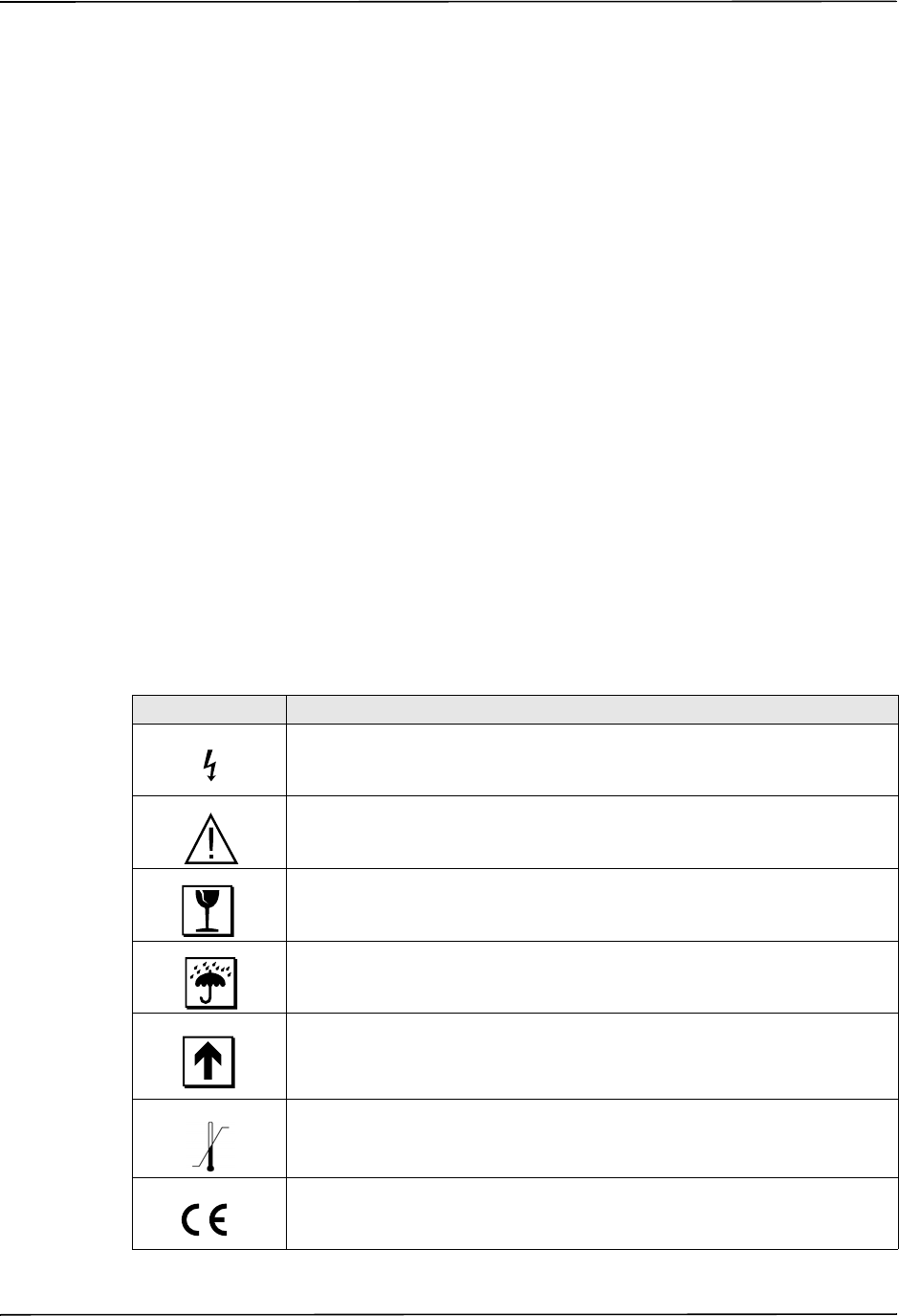
Symbols Used on the Equipment
Any or all of the following symbols may be used in this manual or on this equipment:
Symbol Description
Dangerous voltage.
Attention, consult accompanying documents.
Fragile, handle with care.
Keep dry.
This end up.
Temperature limitation.
Conformité Européenne Complies with medical device directive 93/42/EEC.
CHAPTER 1GENERAL INFORMATION
1–4 www.zoll.com 9650-0912-06 Rev. G
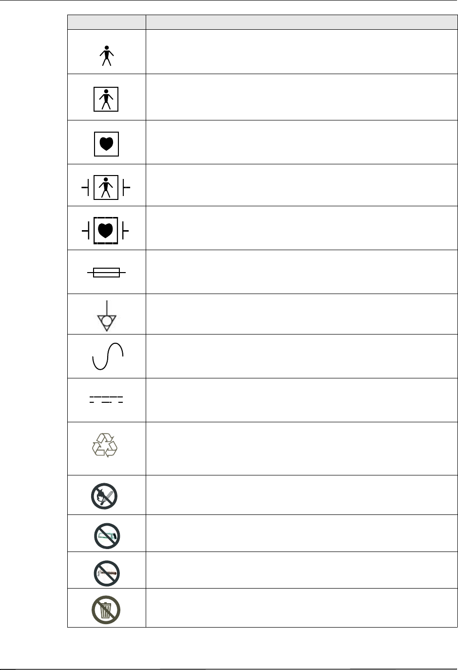
Type B patient connection.
Type BF patient connection.
Type CF patient connection.
Defibrillator-proof type BF patient connection.
Defibrillator-proof type CF patient connection.
Fusible link.
Equipotentiality.
Alternating current (AC).
Direct current (DC).
Contains lithium. Recycle or dispose of properly.
Keep away from open flame and high heat.
Do not open, disassemble, or intentionally damage.
Do not crush.
Do not discard in trash. Recycle or dispose of properly.
Symbol Description
2%452.
,I)/.
RECYCLE
,I)/.
Symbols Used on the Equipment
9650-0912-06 Rev. G ZOLL R Series Operator’s Guide 1–5
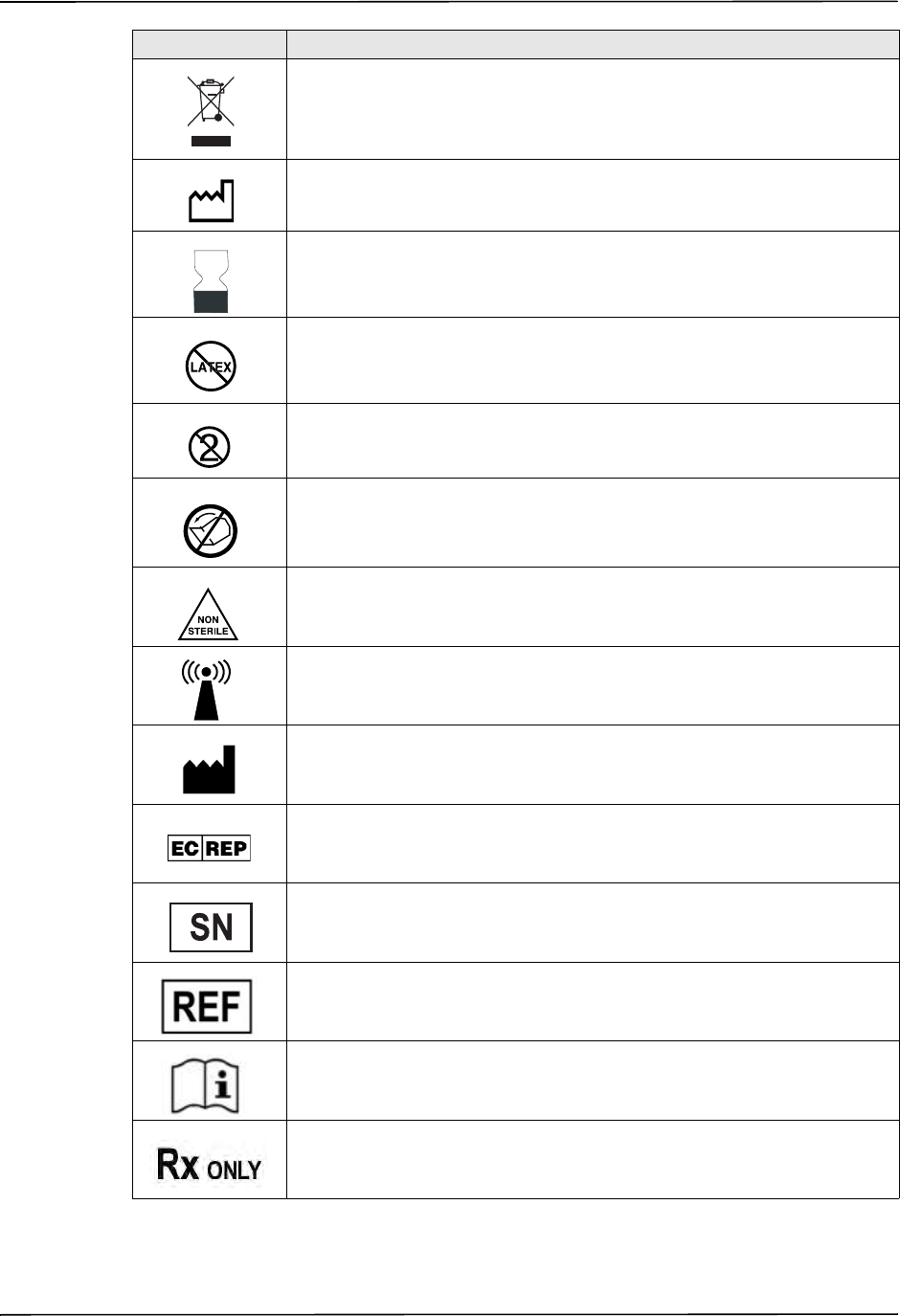
Return to a collection site intended for waste electrical and electronic
equipment (WEEE). Do not dispose of in unsorted trash.
Date of manufacture.
Use by.
Latex-free.
Do not reuse.
Do not fold.
Not sterile.
Nonionizing electromagnetic radiation from Wi-Fi during data transfer.
Manufacturer.
Authorized representative in the European Community.
Serial Number.
Catalogue number.
Consult instructions for use.
Prescription only.
Symbol Description
CHAPTER 1GENERAL INFORMATION
1–6 www.zoll.com 9650-0912-06 Rev. G
Conventions
This guide uses the following conventions:
Within text, the names and labels for physical buttons and softkeys appear in boldface type (for
example, “Press the SHOCK button or the Code Marker softkey”).
This guide uses uppercase italics for audible prompts and for text messages displayed on the
screen (for example, CHECK PATIENT).
WARNING! Warning statements alert you to conditions or actions that can result in personal injury
or death.
Caution Caution statements alert you to conditions or actions that can result in damage to the unit.
Defibrillator Function
The R Series product contains a direct current (DC) defibrillator capable of delivering up to 200
joules. It may be used in synchronized mode to perform synchronized cardioversion using the
patient’s R-wave as a timing reference. The unit uses paddles or disposable, pregelled
electrodes for defibrillation.
Intended Use — Manual Operation
Use of the R Series products in the manual mode for defibrillation is indicated on victims of
cardiac arrest where there is apparent lack of circulation as indicated by:
•Unconsciousness.
•Absence of breathing.
•Absence of pulse.
This product should be used only by qualified medical personnel for converting ventricular
fibrillation and rapid ventricular tachycardia to sinus rhythm or other cardiac rhythms capable
of producing hemodynamically significant heart beats.
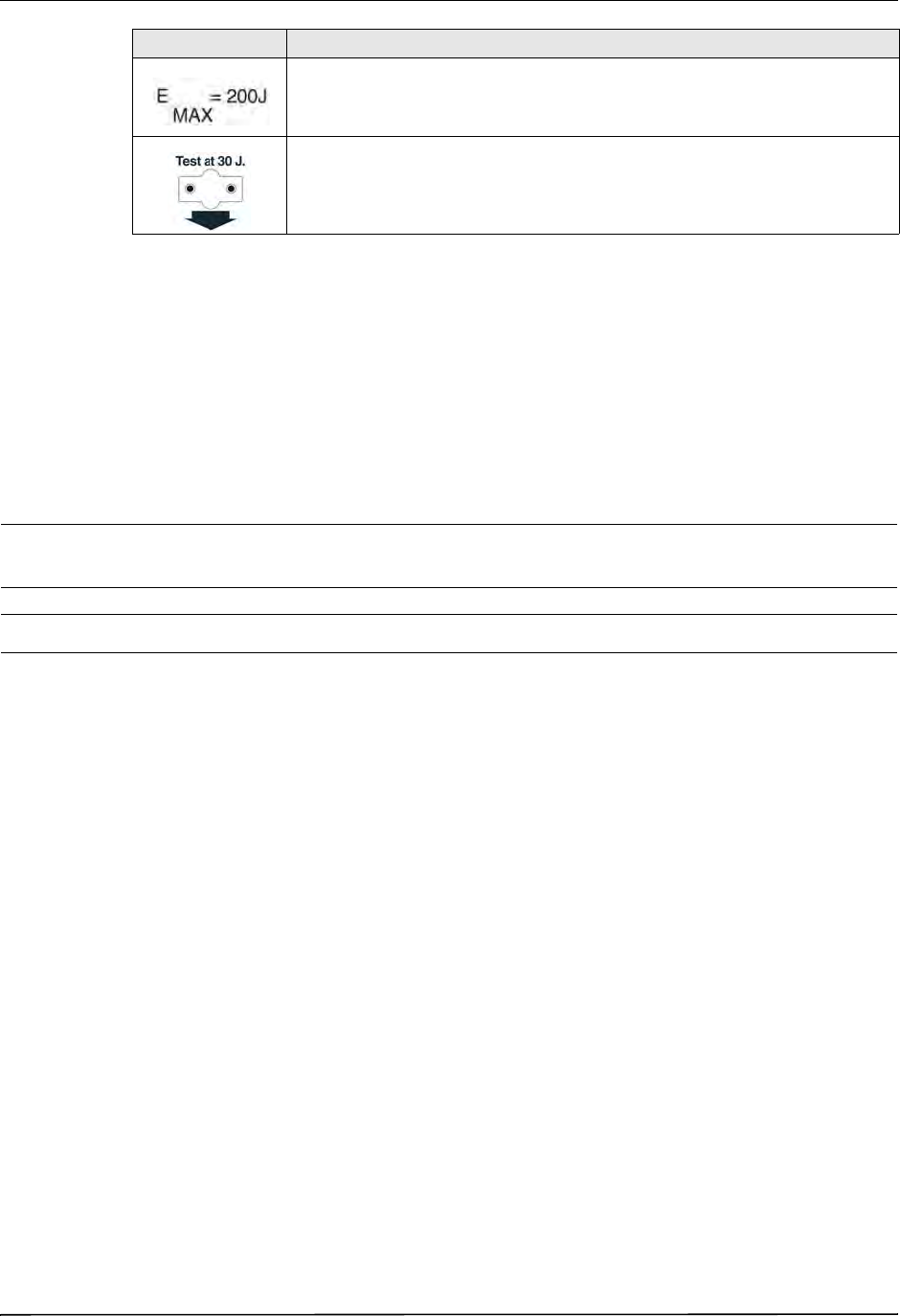
Maximum energy.
Test port.
Symbol Description

Defibrillator Function
9650-0912-06 Rev. G ZOLL R Series Operator’s Guide 1–7
In manual mode, the unit can also be used for synchronized cardioversion of certain atrial or
ventricular arrhythmias. A qualified physician must decide when synchronized cardioversion is
appropriate.
The advisory function should be used to confirm ventricular fibrillation or wide complex
ventricular tachycardia (greater than 150 beats per minute) in patients meeting the three
conditions indicating lack of circulation (listed above).
Intended Use — ECG Monitoring
The unit is intended for use when ECG monitoring is indicated to evaluate the patient’s heart
rate or ECG morphology. In ECG monitoring mode, the unit is intended to be used by
personnel who are qualified by training in the use of the R Series defibrillator, basic life and/or
advanced life support, or other physician-authorized emergency medical training.
Intended Use — Real CPR Help
The Real CPR Help function provides visual and audio feedback designed to encourage
rescuers to perform chest compressions at the AHA/ERC recommended rate of 100
compressions per minute. Voice and visual prompts encourage a compression depth in
accordance with AHA and/or ERC recommendations of 2 inches (5 cm) minimum for adult
patients.
Defibrillator Complications
Inappropriate defibrillation or cardioversion of a patient (for example, with no malignant
arrhythmia) may precipitate ventricular fibrillation, asystole, or other dangerous arrhythmias.
Defibrillation without proper application of electrodes or paddle electrolyte gel might be
ineffective and cause burns, particularly when repeated shocks are necessary. Erythema or
hyperemia of the skin under the paddles, or electrodes often occurs; this effect is usually
enhanced along the perimeter of the paddles or electrodes. This reddening should diminish
substantially within 72 hours.
Defibrillator Output Energy
R Series defibrillators can deliver as much as 200 joules into a 50 ohm impedance. The energy
delivered through the chest wall, however, is determined by the patient’s transthoracic
impedance. An adequate amount of electrolyte gel must be applied to the paddles and a force of
10 to 12 kilograms (22 to 26.4 pounds) must be applied to each paddle in order to minimize this
impedance. If hands-free therapy electrodes are used, make sure that they are properly applied.
(Refer to the instructions on the electrode package).

CHAPTER 1GENERAL INFORMATION
1–8 www.zoll.com 9650-0912-06 Rev. G
External Pacemaker (Optional)
Some R Series products include an optional transcutaneous pacemaker consisting of a pulse
generator and ECG-sensing circuitry. Noninvasive transcutaneous pacing (NTP) is an
established and proven technique. This therapy is easily and rapidly applied in both emergency
and nonemergency situations when temporary cardiac stimulation is indicated.
The output current of the pacemaker is continuously variable from 0 to 140 mA. The rate is
continuously variable from 30 to 180 pulses per minute (ppm), by increments of 2.
The pacing output pulse is delivered to the heart via ZOLL hands-free defibrillation/pacing
electrodes placed on the patient’s back and the precordium.
The characteristics of the output pulse, together with the design and placement of the
electrodes, minimize cutaneous nerve stimulation, cardiac stimulation threshold currents, and
reduce discomfort due to skeletal muscle contraction.
The unique design of the R Series products allow clear viewing and interpretation of the
electrocardiogram on the display without offset or distortion during external pacing.
Proper operation of the device, together with correct electrode placement, is critical to
obtaining optimal results. Every operator must be thoroughly familiar with these operating
instructions.
Intended Use — Pacemaker
This product can be used for temporary external cardiac pacing in conscious or unconscious
patients as an alternative to endocardial stimulation.
The purposes of pacing include:
•Resuscitation from standstill or bradycardia of any etiology.
Noninvasive pacing has been used for resuscitation from cardiac standstill, reflex vagal
standstill, drug-induced standstill (due to procainamide, quinidine, digitalis, b-blockers,
verapamil, etc.) and unexpected circulatory arrest (due to anesthesia, surgery, angiography,
and other therapeutic or diagnostic procedures). It has also been used for temporary
acceleration of bradycardia in Stokes-Adams disease and sick-sinus syndrome. It is safer,
more reliable, and more rapidly applied in an emergency than endocardial or other
temporary electrodes.
•As a standby when standstill or bradycardia might be expected.
Noninvasive pacing can be useful as a standby when cardiac arrest or symptomatic
bradycardia might be expected due to acute myocardial infarction, drug toxicity, anesthesia,
or surgery. It is also useful as a temporary treatment in patients awaiting pacemaker implants
or the introduction of transvenous therapy. In standby pacing applications, noninvasive
pacing might provide an alternative to transvenous therapy that avoids the risks of
displacement, infection, hemorrhage, embolization, perforation, phlebitis, and mechanical
or electrical stimulation of ventricular tachycardia or fibrillation associated with endocardial
pacing.

External Pacemaker (Optional)
9650-0912-06 Rev. G ZOLL R Series Operator’s Guide 1–9
•Suppression of tachycardia.
Increased heart rates in response to external pacing often suppress ventricular ectopic
activity and might prevent tachycardia.
WARNING! This device must not be connected to internal pacemaker electrodes.
Pacemaker Complications
Ventricular fibrillation does not respond to pacing and requires immediate defibrillation.
Therefore, the patient’s dysrhythmia must be determined immediately, so that you can employ
appropriate therapy. If the patient is in ventricular fibrillation and defibrillation is successful but
cardiac standstill (asystole) ensues, you should use the pacemaker.
Ventricular or supraventricular tachycardias can be interrupted with pacing, but in an
emergency or during circulatory collapse, synchronized cardioversion is faster and more
certain.
Pulseless electrical activity (PEA) can occur following prolonged cardiac arrest or in other
disease states with myocardial depression. Pacing might then produce ECG responses without
effective mechanical contractions, making other effective treatment necessary.
Pacing can evoke undesirable repetitive responses, tachycardia, or fibrillation in the presence of
generalized hypoxia, myocardial ischemia, cardiac drug toxicity, electrolyte imbalance, or
other cardiac diseases.
Pacing by any method tends to inhibit intrinsic rhythmicity. Abrupt cessation of pacing,
particularly at rapid rates, can cause ventricular standstill and should be avoided.
Noninvasive temporary pacing can cause discomfort of varying intensity, which occasionally
can be severe and preclude its continued use in conscious patients.
Similarly, unavoidable skeletal muscle contraction might be troublesome in very sick patients
and might limit continuous use to a few hours. Erythema or hyperemia of the skin under the
hands-free therapy electrodes often occurs; this effect is usually enhanced along the perimeter
of the electrode. This reddening should lessen substantially within 72 hours.
There have been reports of burns under the anterior electrode when pacing adult patients with
severely restricted blood flow to the skin. Prolonged pacing should be avoided in these cases
and periodic inspection of the underlying skin is advised.
There are reports of transient inhibition of spontaneous respiration in unconscious patients with
previously available units when the anterior electrode was placed too low on the abdomen.
WARNING! This device must not be connected to internal pacemaker electrodes.

CHAPTER 1GENERAL INFORMATION
1–10 www.zoll.com 9650-0912-06 Rev. G
Pediatric Pacing
Pacing can be performed on pediatric patients weighing 33 lb. (15 kg) or less using ZOLL
pediatric hands-free therapy electrodes. Prolonged pacing (in excess of 30 minutes),
particularly in neonates, can cause burns. Periodic inspection of the underlying skin is
recommended.
Intended Use — SpO2 Monitoring
The R Series pulse oximeter, with the Masimo® SET® technology and the LNCS® series of
oximeter sensors, is indicated for the continuous, noninvasive monitoring of arterial oxygen
saturation (SpO2) and pulse rate during both no motion and patient motion conditions for adult
patients, and no motion conditions for pediatric and neonatal patients in a hospital or
prehospital environment.
Intended Use — EtCO2 Monitoring
The ZOLL R Series EtCO2 option with Respironics Novametrix technology is indicated for the
continuous noninvasive monitoring of end tidal carbon dioxide (EtCO2) and respiration rate in
patients requiring ventilator support, in-hospital transport, or anesthesia.
This option uses the CAPNOSTAT 5 Mainstream CO2 sensor attached to an airway adapter that
connects to an endotracheal tube, mask or disposable mouthpiece.
The R Series EtCO2 option is designed to monitor adult, pediatric, and neonatal patients.
The following substances can influence CO2 measurements made with the CAPNOSTAT 5 CO2
sensor:
• elevated oxygen levels
• nitrous oxide
• halogenated agents
The R Series EtCO2 option provides settings for high oxygen and/or nitrous oxide
compensation. Halogenated anesthetic agents alter CO2 readings, but the R Series unit will
monitor CO2 within specifications when these agents are present at normal clinical levels. The
presence of Desflurane in the exhaled breath beyond normal values (5%) may positively bias
measured carbon dioxide values by up to an additional 3 mmHg.
The R Series EtCO2 option is intended for use only with the ZOLL/Respironics Novametrix
CAPNOSTAT 5 Mainstream CO2 Sensor and mainstream airway adapters.
The R Series EtCO2 option can be used on adult patients (21 years of age and older) and on
pediatric patients, as described in the following table:
Pediatric Subpopulation Approximate Age Range
Newborn (neonate) Birth to 1 month of age
Infant 1 month to 2 years of age
Child 2 to 12 years of age
Adolescent 12-21 years of age

Intended Use — NIBP
9650-0912-06 Rev. G ZOLL R Series Operator’s Guide 1–11
Intended Use — NIBP
The ZOLL R Series NIBP option is indicated for the non-invasive measurement of arterial
blood pressure for resting patients in critical care and in-hospital transport.
The R Series NIBP option is designed to measure blood pressure for adult patients (21 years of
age and older) and for pediatric patients, as described in the following table:
ECG Monitoring
The patient’s ECG is monitored by connecting the patient to the unit via a 3- or 5-lead patient
cable, hands-free therapy electrodes, or through paddles. Five seconds of ECG is presented on
the display along with the following information:
•averaged heart rate, derived by measuring R to R intervals
•lead selection - I, II, III, aVR, aVL, aVF, V (with ECG cable), PADDLES or PADS, P1, P2,
P3 (when using OneStep Pacing cable with OneStep Complete electrodes).
P1, P2, and P3 are non-standard ECG leads derived from electrodes within particular
OneStep electrodes. While ECG signals acquired from these leads are appropriate for
rhythm assessment and determining electrical capture during pacing, they should not be
used for ECG morphological evaluation. Attach conventional ECG electrodes for diagnostic
purposes.
•ECG size - 0.5, 1, 1.5, 2, 3 cm/mV
•other operational prompts, messages, and diagnostic codes
Monitoring or diagnostic ECG bandwidth is selectable.
Recorder Function
The strip recorder is provided to document events. The strip recorder normally operates in the
delay mode (6 seconds) to ensure the capture of ECG information immediately preceding
critical events. The recorder may be activated manually by pressing the RECORDER button.
It is activated automatically whenever a defibrillation SHOCK is delivered, a heart rate alarm
occurs, or the rhythm analysis function is activated. The strip recorder may also be configured
not to print during these events.
Pediatric Subpopulation Approximate Age Range
Newborn (neonate) Birth to 1 month of age
Infant 1 month to 2 years of age
Child 2 to 12 years of age
Adolescent 12-21 years of age

CHAPTER 1GENERAL INFORMATION
1–12 www.zoll.com 9650-0912-06 Rev. G
Paddles and Electrodes
The R Series will defibrillate, cardiovert, and monitor ECG using either defibrillation paddles
or hands-free therapy electrodes.
The pacer version of the R Series will pace using ZOLL hands-free therapy electrodes.
ENERGY SELECT, CHARGE and SHOCK controls are located on the paddles and front
panel. When using hands-free therapy electrodes, you must use the controls on the front panel
of the unit. To switch between paddles and hands-free therapy electrodes, remove the OneStep
cable from the apex paddle and connect the hands-free therapy electrodes to the cable.
The Advisory function cannot be activated unless hands-free therapy electrodes are attached to
the OneStep cable and used as the ECG monitoring lead.
The R Series can monitor the patient’s ECG while pacing without the need for a separate ECG
cable and ECG electrodes. This also allows demand pacing when separate ECG electrodes are
either not connected, or unavailable. OneStep pacing capability requires the OneStep Pacing
cable along with OneStep Pacing electrodes, or OneStep Complete electrodes.
Note: The ZOLL OneStep Pacing electrodes, or OneStep Complete electrodes, MFE Pads,
Pediatric MFE Pads, stat-padz®, and ECG electrodes are disposable, single-use items.
You should always check the expiration date on the electrode packaging. Do not use expired
electrodes, which might result in false patient impedance readings and affect the level of
delivered energy, or cause burns.
The R Series defibrillator reads and reports the expiration date for OneStep Pacing electrodes,
OneStep CPR electrodes, and OneStep Complete electrodes. When these electrodes exceed
their expiration date, the Code Readiness indicator will change to a red “X.”
Note: ZOLL electrodes contain no hazardous materials and may be disposed of in general
trash unless contaminated with pathogens. Use appropriate precautions when
disposing of contaminated electrodes.
When the patient is less than 8 years old or weighs less than 55 lb. (25 kg), use ZOLL
pedi-padz® II pediatric defibrillation electrodes. Do not delay therapy to determine the
patient’s exact age or weight.
Batteries
R Series products use an easily replaced rechargeable lithium-ion battery pack (the ZOLL
SurePower battery pack). A new, fully charged battery pack typically delivers more than 5
hours of ECG monitoring. Use of other functions (such as the defibrillator, printer, or
pacemaker) reduces this time.
When a LOW BATTERY message appears on the display and the unit emits two beeps in
conjunction with the displayed message, the battery must be replaced and recharged.
This symbol on the electrode package is accompanied by the expiration date.
For stat-padz II, this symbol does not appear; the expiration date appears on the lower
right corner of the label, below the lot number.

Code-Ready System
9650-0912-06 Rev. G ZOLL R Series Operator’s Guide 1–13
You can charge the battery by either of the following methods:
•Internal charging — plug the R Series into an AC power supply to automatically begin
charging the installed battery pack. The front panel battery indicator operates as follows:
Note: Upon power up, it takes approximately 45 seconds for the LEDs on the battery to
accurately display run time.
•External charging — use the ZOLL SurePower Battery Charger to charge the battery pack
and test the battery’s capacity. For details, refer to the ZOLL SurePower defibrillator battery
Operator’s Manual.
Code-Ready System
The R Series defibrillator’s Code-Ready system tests the defibrillator whenever the unit is
turned on, periodically during operation, whenever manual testing is initiated by the operator,
and automatically, at pre-configured intervals.
The code readiness indicator on the front panel shows the result of the most recent readiness
check. Also, OneStep Pacing, CPR or Complete electrodes provide an interface that
communicates the electrode’s expiration date and condition to the defibrillator.
The Defib Test Log stores the results for as many as 1000 defibrillator tests in internal memory.
Each log entry shows the time and date of the defibrillator test. The Defib Test Log can be
printed on the stripchart or transferred to a personal computer for printing and archiving.
Safety Considerations
All operators should review these safety considerations before using the R Series.
R Series products are high-energy defibrillators capable of delivering 200 joules. To completely
deactivate the unit, turn the Mode Selector to OFF.
To manually disarm a charged (or charging) defibrillator, do one of the following:
•Turn the Mode Selector to OFF, MONITOR, or PACER.
•Change the selected defibrillator energy.
For safety, the R Series unit automatically disarms if left charged for more than either 60 or 120
seconds (user configurable) if the SHOCK button is not pressed.
When the indicator is: It means:
Steady yellow Battery is charging
Steady green Battery is charged
Alternating yellow and
green No battery is installed or a battery
charging fault has been detected.
Not lit The defibrillator is not connected to
AC mains.

CHAPTER 1GENERAL INFORMATION
1–14 www.zoll.com 9650-0912-06 Rev. G
Warnings
General
Federal (U.S.A.) law restricts this defibrillator to use by or on the order of a physician.
Only appropriately trained, skilled personnel who are familiar with equipment operation should
perform emergency defibrillation. The prescribing physician should determine what training,
such as Advanced Cardiac Life Support (ACLS) or Basic Life Support (BLS) certification, is
appropriate.
Only skilled personnel trained in Advanced Cardiac Life Support (ACLS) and who are familiar
with equipment operation should perform synchronized cardioversion. The precise cardiac
arrhythmia must be determined before attempting defibrillation.
These operating instructions describe the functions and proper operation of the R Series
products. They are not a substitute for a formal patient care training course. Operators should
obtain formal training from an appropriate authority before using this defibrillator for patient
care.
Proper operation of the unit and correct electrode placement is critical to obtaining optimal
results. Operators must be thoroughly familiar with proper device operation.
The use of external pacing/defibrillation electrodes or adapter devices from sources other than
ZOLL is not recommended. ZOLL makes no representations or warranties regarding the
performance or effectiveness of its products when used with pacing/defibrillation electrodes or
adapter devices from other sources. Defibrillator failures attributable to the use of pacing/
defibrillation electrodes or adapters not manufactured by ZOLL might void ZOLL’s warranty.
Do not disassemble the unit. A shock hazard exists. Refer all problems to authorized service
personnel.
Follow all recommended maintenance instructions. If a problem occurs, obtain service
immediately. Do not use the defibrillator until it has been inspected by appropriate personnel.
The R Series unit might not perform to specifications when stored at the upper or lower
extreme limits of storage temperature and then immediately put into use.
Avoid using the R Series adjacent to, or stacked on, other equipment. If unavoidable, verify that
the R Series operates normally in this configuration before clinical use.
The R Series should be installed and put into service according to the EMC information in
Appendix A of this manual.
Assess the Wi-Fi performance for the possibility of RFI in your environment of use.
If multiple devices are transmitting simultaneously to the same access point, Wi-Fi data transfer
will be slowed down. If the access point is too overloaded, data transmission failures can occur.
The use of accessories, transducers, and cables other than those specified in this manual and
related R Series option manual inserts may result in increased emissions or decreased immunity
of the R Series.
Do not use or place the unit in service if the Code Readiness indicator (at the upper right of the
front panel) displays a red “X”.
Carefully route patient cables to avoid tripping over them, or inadvertently pulling the unit onto
the patient.
Always inspect the unit for damage if it has been dropped.

Warnings
9650-0912-06 Rev. G ZOLL R Series Operator’s Guide 1–15
ECG Analysis, Defibrillating, Pacing and CPR
Prior to attempting synchronized cardioversion, ensure the ECG signal quality is good and that
sync markers are displayed above each QRS complex.
Do not use the unit in advisory mode during patient movement. A patient must be motionless
during ECG rhythm analysis. Do not touch the patient during analysis. If transporting the
patient, cease all movement before beginning ECG analysis.
ECG rhythm analysis does not warn of patient asystole, which is not a shockable rhythm.
The ECG rhythm analysis function might not reliably identify ventricular fibrillation in the
presence of an implanted pacemaker. Inspection of the electrocardiogram and clinical evidence
of cardiopulmonary arrest should be the basis for any treatment of patients with an implanted
pacemaker.
Implanted pacemakers might cause the heart rate meter to count the pacemaker rate during
incidents of cardiac arrest or other arrhythmias. Dedicated pacemaker detection circuitry may
not detect all implanted pacemaker spikes. Check the patient's pulse; do not rely solely on heart
rate meters. Patient history and physical examination are important factors in determining the
presence of an implanted pacemaker. Pacemaker patients should be carefully observed.
Do not place electrodes directly over an implanted pacemaker.
The R Series unit detects ECG electrical signals only. It does not detect a pulse (effective
circulatory perfusion). Always verify pulse and heart rate by physical assessment of the patient.
Never assume that the display of a nonzero heart rate means that the patient has a pulse.
To avoid possible damage to the R Series unit, turn off pacing before defibrillating the patient
with a second defibrillator.
Do not use the unit’s ECG-out signal as a synchronization pulse for another defibrillator or
cardioverter.
Place the patient on a firm surface before performing CPR.
Battery
Do not operate the unit without a battery. Keep a fully charged spare battery pack with the
defibrillator at all times.
Test battery packs regularly. A battery that does not pass the ZOLL charger’s capacity test
might cause the R Series unit to shut down unexpectedly.
When the warning LOW BATTERY appears, plug the R Series unit into a power source or install
a fully charged battery pack. When the warning REPLACE BATTERY appears, immediately
replace the battery pack with a fully charged pack or plug the R Series unit into a power source,
as unit shut down due to a low battery condition is imminent.
If mistreated, a battery pack might explode. Do not disassemble a battery pack or dispose of it
in fire.
Operator Safety
Do not use R series products in the presence of oxygen-rich atmospheres, flammable
anesthetics, or other flammable agents (such as gasoline). Using the unit in such environments
might cause an explosion.

CHAPTER 1GENERAL INFORMATION
1–16 www.zoll.com 9650-0912-06 Rev. G
Do not use the unit near or within standing water. Electrical safety might be compromised when
the defibrillator is wet.
Never discharge the unit with the defibrillation electrodes or paddles shorted together or in
open air.
Do not discharge the defibrillator except as indicated in the instructions. Discharge the
defibrillator only when defibrillation electrodes or paddles are properly applied to the patient.
To avoid risk of electrical shock, do not touch the gelled area of the hands-free therapy
electrodes during pacing or defibrillation.
To avoid risk of electrical shock, do not allow electrolyte gel to accumulate on hands or paddle
handles.
To avoid risk of electrical shock, do not allow patient connectors to contact other conductive
parts, including earth.
For defibrillation using paddles, use only high-conductivity electrolyte gel specified for such
use by the manufacturer.
When using paddles for defibrillation, use your thumbs to operate the SHOCK buttons. Doing
so avoids inadvertent shock to the operator and unintentional depression of an ENERGY
SELECT button, which causes the defibrillator to disarm. Keep your hands and fingers away
from the paddle plates.
The use of accessory equipment that does not comply with the equivalent safety requirements
of the R Series defibrillator could reduce the level of safety of the combined system. When
choosing accessory equipment, consider the following:
•Use of the accessory in the patient vicinity.
•Evidence that the safety certification of the accessory has been performed in accordance
with the appropriate IEC (EN) 60601-1 and/or IEC (EN) 60601-1-1 harmonized national
standards.
Always check that the equipment functions properly and is in proper condition before use.
Disconnect all electro-medical equipment that is not defibrillation-protected from the patient
prior to defibrillation.
Before discharging the defibrillator, warn everyone to STAND CLEAR of the patient.
Do not touch the bed, patient, or any equipment connected to the patient during defibrillation.
A severe shock can result. To avoid hazardous pathways for the defibrillation current, do not
allow exposed portions of the patient's body to touch any metal objects, such as a bed frame.
When the R Series is performing a Code Readiness test, as indicated on the display, do not
touch the connected paddles, electrodes, or OneStep cable connector.
Patient Safety
This equipment should be connected to only one patient at a time.
Use only OneStep Pediatric electrodes to defibrillate patients under 8 years of age in Advisory
modes. Use of adult electrodes, or pediatric electrodes other than OneStep Pediatric electrodes,
can result in the delivery of excessive energy doses.
Neonatal and pediatric defibrillation energy level settings should be based on site-specific
clinical protocols.

Warnings
9650-0912-06 Rev. G ZOLL R Series Operator’s Guide 1–17
To ensure patient safety, connect the R Series only to equipment with galvanically isolated
circuits.
Use only high-quality ECG electrodes. ECG electrodes are for rhythm acquisition only; you
cannot use ECG electrodes for defibrillation or pacing.
Do not use therapy or ECG electrodes if the gel is dried, separated, torn or split from the foil;
patient burns may result from using such electrodes. Poor adherence and/or air pockets under
therapy electrodes can cause arcing and skin burns.
Check the expiration date on the electrode packaging. Do not use electrodes after their
expiration date.
Excessive body hair or wet, diaphoretic skin can inhibit electrode coupling to the skin. Clip
excess hair and dry any moisture from the area where an electrode is to be attached.
Therapy electrodes should be replaced periodically during continuous pacing. Consult
electrode directions for proper replacement instructions.
Prolonged pacing (more than 30 minutes), particularly in neonates or adults with severely
restricted blood flow, may cause burns. Periodically inspect the skin under the electrodes.
Carefully route the patient cables to reduce the possibility of patient entanglement or
strangulation.
To avoid electrosurgery burns at monitoring sites, ensure proper connection of the
electrosurgery return circuit so that a return path cannot be made through monitoring electrodes
or probes.
During electrosurgery, observe the following guidelines to minimize electrosurgery unit (ESU)
interference and provide maximum operator and patient safety:
•Keep all patient monitoring cables away from earth ground, ESU knives, and ESU
return wires.
•Use electrosurgical grounding pads with the largest practical contact area.
Always ensure proper application of the electrosurgical return electrode to the patient.
Check electrical leakage levels before use. Leakage current may be excessive if more than one
monitor or other piece of equipment is connected to the patient.
Do not use the ZOLL OneStep Pacing cable (REF 1009-0913-02) or the ZOLL Multi-Function
Cable (REF 1009-0913-03) in a 220/240 VAC 60Hz power environment. Patient leakage
current may be excessive.

CHAPTER 1GENERAL INFORMATION
1–18 www.zoll.com 9650-0912-06 Rev. G
Cautions
If the unit is to be stored longer than 90 days, remove the battery pack.
Do not sterilize the defibrillator, or its accessories unless the accessories are labelled as
sterilizable.
Do not immerse any part of the defibrillator in water.
Do not use ketones (such as acetone or MEK) on the defibrillator.
Avoid using abrasives (including paper towels) on the display window.
Grounding reliability can be achieved only when the equipment is connected to a receptacle
marked “HOSPITAL ONLY,” “HOSPITAL GRADE,” or equivalent. If the grounding integrity
of the line cord or AC receptacle is questionable, operate the defibrillator using battery power
only.
To protect the unit from damage during defibrillation, for accurate ECG information, and to
protect against noise and other interference, use only internal current-limiting ECG cables
specified or supplied by ZOLL.
For continued safety and EMI performance, use only the line cord supplied by ZOLL.
Dispose of battery packs in accordance with national, regional and local regulations. Battery
packs should be shipped to a reclamation facility for recovery of metal and plastic compounds
as the proper method of waste management.
Restarting the Defibrillator
Certain events require the R Series products to be restarted after they shut off or become
inoperative (for example, when the battery runs down and the unit shuts off).
In such a case, always try to restore defibrillator operation as follows:
1. Turn the Mode Selector to OFF.
2. If necessary, replace a depleted battery with a fully charged pack, or connect the defibrillator
to AC mains.
3. Turn the Mode Selector to the desired operating mode to restart the unit.
This sequence is necessary to restart the defibrillator and can also be used to clear some fault
messages when immediate use of the defibrillator is required.
If restarted after a shutdown period of 10 seconds or more, the unit restores all settings (such as
ECG lead, ECG size, and alarm state and limits) to their power-up default values. After
restoring device operation, you might need to reinstate previously selected, non-default
settings.

FDA Tracking Requirements
9650-0912-06 Rev. G ZOLL R Series Operator’s Guide 1–19
FDA Tracking Requirements
U.S. Federal Law (21 CFR 821) requires the tracking of defibrillators. Under this law, owners
of this defibrillator must notify ZOLL Medical Corporation if this product is
•received
•lost, stolen, or destroyed
•donated, resold, or otherwise distributed to a different organization
If any such event occurs, contact ZOLL Medical Corporation in writing with the following
information:
1. Originator's organization – Company name, address, contact name, and contact phone
number
2. Model number, and serial number of the defibrillator
3. Disposition of the defibrillator (for example, received, lost, stolen, destroyed, distributed to
another organization), new location and/or organization (if known and different from
originator’s organization) – company name, address, contact name, and contact phone
number
4. Date when the change took effect
Please address the information to:
ZOLL Medical Corporation
Attn: Tracking Coordinator
269 Mill Road
Chelmsford, MA 01824-4105
Fax: (978) 421-0025
Telephone: (978) 421-9655
Notification of Adverse Events
As a health care provider, you may have responsibilities under the Safe Medical Devices Act
(SMDA), for reporting to ZOLL Medical Corporation, and possibly to the FDA, the occurrence
of certain events.
These events, described in 21 CFR Part 803, include device-related death and serious injury or
illness. In addition, as part of our Quality Assurance Program, ZOLL Medical Corporation
requests to be notified of device failures or malfunctions. This information is required to ensure
that ZOLL Medical Corporation provides only the highest quality products.

CHAPTER 1GENERAL INFORMATION
1–20 www.zoll.com 9650-0912-06 Rev. G
Software License
Note: Read this Operator’s Guide and License agreement carefully before operating any of
the R Series products.
Software incorporated into the system is protected by copyright laws and international
copyright treaties as well as other intellectual property laws and treaties. This software is
licensed, not sold. By taking delivery of and using this system, the Purchaser signifies
agreement to and acceptance of the following terms and conditions:
1. Grant of License: In consideration of payment of the software license fee which is part of
the price paid for this product ZOLL Medical Corporation grants the Purchaser a
non-exclusive license, without right to sublicense, to use the system software in object-code
form only.
2. Ownership of Software/Firmware: Title to, ownership of and all rights and interests in the
system software and all copies thereof remain at all times vested in the manufacturer, and
Licensors to ZOLL Medical Corporation and they do not pass to purchaser.
3. Assignment: Purchaser agrees not to assign, sublicense or otherwise transfer or share its
rights under the license without the express written permission of ZOLL Medical
Corporation.
4. Use Restrictions: As the Purchaser, you may physically transfer the products from one
location to another provided that the software/firmware is not copied. You may not disclose,
publish, translate, release or distribute copies of the software/firmware to others. You may
not modify, adapt, translate, reverse engineer, decompile, crosscompile, disassemble or
create derivative works based on the software/firmware.
NO IMPLIED LICENSE
Possession or purchase of this device does not convey any express or implied license to use the
device with replacement parts which would, alone, or in combination with this device, fall
within the scope of one or more of the patents relating to this device.
Service
The R Series does not require periodic recalibration or adjustment. Appropriately trained and
qualified personnel should, however, perform periodic tests of the defibrillator to verify proper
operation.
If a unit requires service, contact the ZOLL Technical Service Department.
For customers In the U.S.A. For customers outside the U.S.A.
Telephone:
Fax:
1- 80 0-3 48 -9 011
1-978-421-9655
1-978-421-0010
Call the nearest authorized ZOLL Medical Corporation
representative.
To locate an authorized service center, contact the
International Sales Department at
ZOLL Medical Corporation
269 Mill Road
Chelmsford, MA 01824-4105
Telephone: 1-978-421-9655

The ZOLL Serial Number
9650-0912-06 Rev. G ZOLL R Series Operator’s Guide 1–21
When requesting service, please provide the following information to the service
representative:
•Unit serial number
•Description of the problem
•Department using the equipment and name of the person to contact
•Purchase order to allow tracking of loan equipment
•Purchase order for a unit with an expired warranty
•Sample ECG or other stripcharts demonstrating the problem (if available and applicable),
less any confidential patient information.
Returning a unit for service
Before sending a unit to the ZOLL Technical Service Department for repair, obtain a service
request (SR) number from the service representative.
Remove the battery pack from the unit. Pack the unit with its cables and battery in the original
containers (if available) or equivalent packaging. Be sure the assigned service request number
appears on each package.
The ZOLL Serial Number
Each ZOLL product displays a serial number that contains information about that product.
From left to right, ZOLL serial numbers are structured as follows:
•A two-character product code
•A three-character date-of-manufacture code
•A product serial number of six or more alphanumeric characters
The product code for the R Series defibrillator is AF.
For customers Return the unit to
In the U.S.A. ZOLL Medical Corporation
269 Mill Road
Chelmsford, MA 01824-4105
Attention: Technical Service Department (SR number)
Telephone: 1-800-348-9011
In Canada ZOLL Medical Canada Inc.
1750 Sismet Road, Unit #1
Mississauga, ON L4W 1R6
Attention: Technical Service Department (SR number)
Telephone: 1-866-442-1011
In other locations The nearest authorized ZOLL Medical Corporation representative.
To locate an authorized service center, contact the International Sales
Department at
ZOLL Medical Corporation
269 Mill Road
Chelmsford, MA 01824-4105
Telephone: 1-978-421-9655

The first two characters of the date-of-manufacture code give the last two digits of the year (for
example, “06” appears for products manufactured in 2006). The last character of the
date-of-manufacture code gives the month in which the product was manufactured. The month
appears in the form of a single alphanumeric character: “A” for January, “B” for February, “C”
for March, and so on through “L” for December.
The product serial number is a unique set of alphanumeric characters that ZOLL assigns to each
individual unit.
9650-0912-06 Rev. G ZOLL R Series Operator’s Guide 2–1
Chapter 2
Product Overview
Defibrillator Controls and Indicators
LEAD
SIZE
ANALYZE CHARGE
SHOCK
ENERGY
SELECT
RECORDER
ALARM
SUSPEND
OUTPUT
mA
RATE
ppm
4:1
PACER
OFF
MONITOR DEFIB
?
SpO2
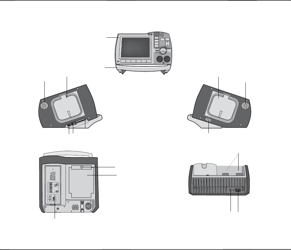
Front
Left Right
4
5678
9
33
12
10
11
Rear
13 14
15
Top
1
2

CHAPTER 2PRODUCT OVERVIEW
2–2 www.zoll.com 9650-0912-06 Rev. G
Table 2-1. R Series Unit Features
Item Description
1 Front panel Includes the display screen and primary controls.
2 Handle Integrated carrying handle.
3 External paddle well Holds paddles when not in use. Allows defib self-test when
paddles are stowed in their respective wells.
4 Beeper Emits R-wave detection beeps, defib charge Ready tones, and
alarm tones.
5 USB host connector
(Optional) (Reserved for future use — do not connect to any equipment.)
6 USB device connector For connecting the R Series defibrillator to a USB device. For
details, refer to “Event Records and Reports” on page 10-1.
7 Data card slot Holds a compact flash card for copying data stored in the
device’s internal memory. Accepts a CF memory card or a
WiFi card.
8 Defibrillator test port When not using OneStep electrodes or paddles, connect the
patient end of a OneStep cable to this port to allow device
checks.
9 Speaker Issues voice prompts.
10 Paper Compartment Holds the paper for the stripchart printer.
11 RELEASE button Allows access to the paper compartment.
12 Battery compartment Holds a rechargeable lithium ion battery pack.
13 Grounding post Electrical ground for biomedical test equipment.
14 AC mains connector For connecting the device to an AC power source.
15 Patient connectors For details, refer to “Patient Cables and Connectors” on
page 2-7.
Defibrillator Controls and Indicators
9650-0912-06 Rev. G ZOLL R Series Operator’s Guide 2–3
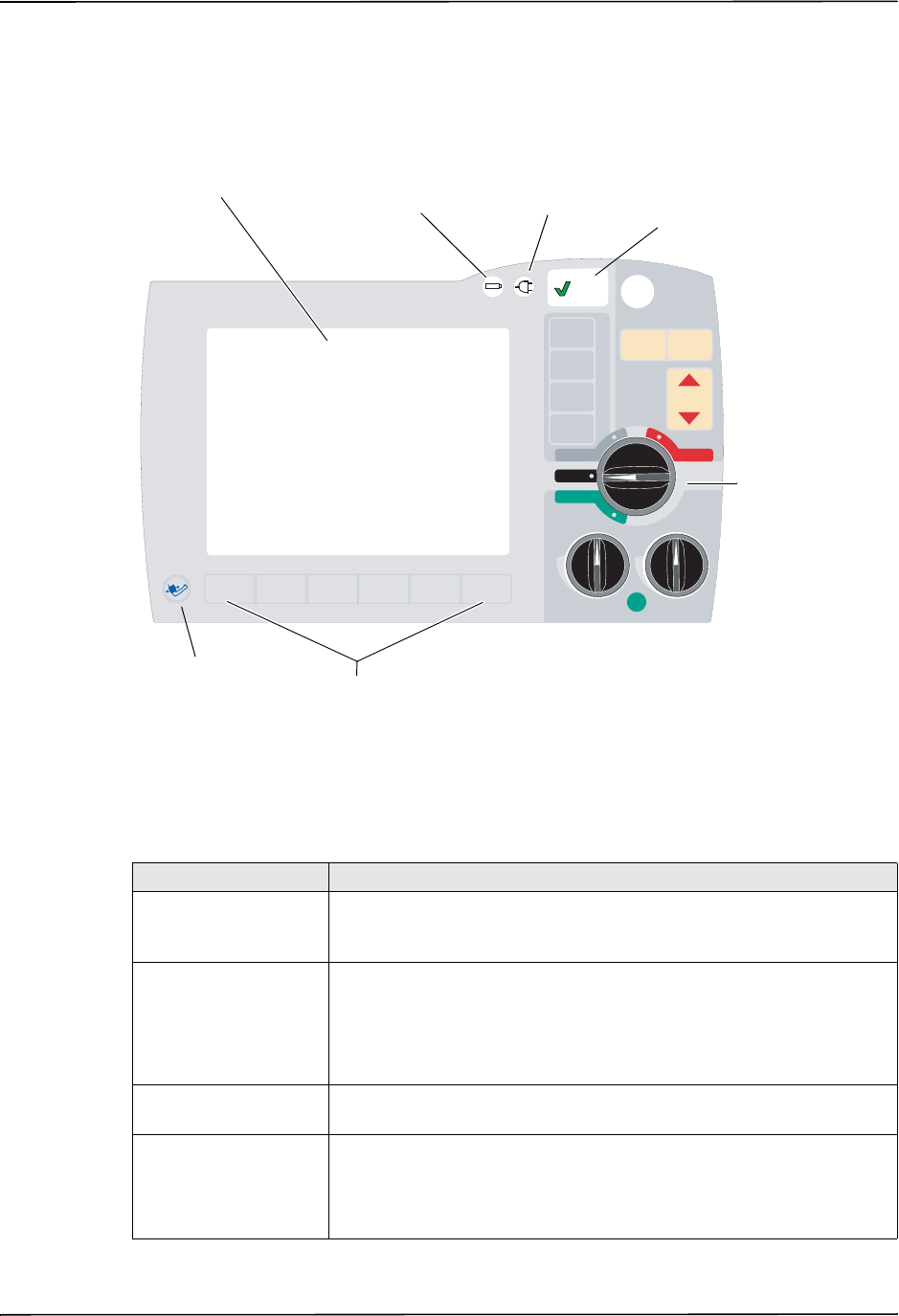
The Front Panel
The front panel of the R Series device includes the display screen, softkeys, battery indicator,
AC power indicator, Code Readiness indicator, SHOCK button, and control panel. The control
panel configuration varies slightly depending on the model. See Figure 2-1.
Figure 2-1. R Series Front Panel
Table 2-2 describes the controls and indicators that appear on the front panel.
Table 2-2. R Series Controls and Indicators
Control or Indicator Description
Display screen Shows therapeutic settings, physiological waveforms, and other
information for each monitored parameter, messages, time, and softkey
labels.
Battery indicator Indicates battery status:
Steady yellow: Battery is charging.
Steady green: Battery is charged.
Alternating yellow and green: No battery is installed, or there is a
battery charging fault.
Indicator for AC power Illuminated when the unit is plugged into an alternating current (AC)
power source.
Code Readiness
indicator Shows the status of the unit, based on its most recent Readiness check:
•A green ““ indicates the unit is ready for therapeutic use.
•A red “X” indicates the unit’s Readiness is compromised an that it
may not be ready for therapeutic use.
3
1
SHOCKSHOCK
2
ENERGY
SELECT
ENERGY
SELECT
ANALYZEANALYZE CHARGECHARGE
OUTPUT
mA
OUTPUT
mA
RATE
ppm
RATE
ppm
4:1
LEAD
SIZE
ALARM
SUSPEND
RECORDER
DEFIB
OFF
MONITOR
PACER
Display screen
Six softkeys
Mode Selector
AC power
indicator
Battery
indicator
Code
Readiness
indicator
NIBP Button
(optional)

CHAPTER 2PRODUCT OVERVIEW
2–4 www.zoll.com 9650-0912-06 Rev. G
Mode Selector Selects the mode of operation (available options depend on model):
•OFF — Unit is powered off.
•MONITOR — Physiological monitoring (ECG and other options)
•DEFIB — Manual or advisory defibrillation
•PACER — Noninvasive external pacing
ENERGY SELECT
Buttons Two sets of up-down arrow buttons control the selection of defibrillator
energy, one set located on the front panel and the other located on the
sternum paddle.
CHARGE Button Charges the defibrillator to the selected energy. In addition to the
CHARGE button on the front panel, there is one located on the apex
paddle handle.
SHOCK Button The front panel SHOCK button is only active when using OneStep
electrodes, hands-free therapy electrodes (see “R Series Accessories”
on page B-1 for a list), external autoclavable paddles, or internal
defibrillation paddles without a discharge button. The SHOCK button
illuminates when the device is charged and ready.
To discharge the defibrillator when using paddles (internal or external)
with discharge buttons, press and hold the SHOCK buttons on the
paddles.
ANALYZE Button Initiates ECG analysis to determine whether or not a shockable rhythm
is present.
LEAD Button Selects the ECG source for display and printing. Pressing this button
sequentially selects ECG signals derived from each of the following lead
configurations: I, II, III, aVR, aVL, aVF, PADDLES, or PADS, P1, P2, and
P3 (when using OneStep Pacing electrodes, or OneStep Complete
electrodes with OneStep Pacing cable) for display. The PADS or
PADDLES lead setting is automatically selected when the defibrillator
powers up in DEFIB or MONITOR mode with either hands-free therapy
electrodes or paddles attached to the OneStep cable. Lead II or P3
(OneStep Pacing) is automatically selected when the R Series is
powered up in PACER mode. Pads or Paddles monitoring is not
available in PACER mode.
SIZE Button Selects the amplitude scale for the displayed ECG waveform. Available
sizes are 0.5, 1, 1.5, 2, and 3 centimeters per millivolt (cm/mV).
ALARM SUSPEND
Button Activates, deactivates or audibly suspends all alarm functions. A bell
symbol () appears on the display when alarms are enabled. When
alarms are either audibly or permanently disabled, an “X” appears
across the bell ( ) symbol.
RECORDER Button Starts or stops the stripchart recorder. You can switch the unit to
diagnostic ECG bandwidth (0.05 - 150Hz) by pressing and holding the
RECORDER button. Diagnostic bandwidth is maintained as long as the
RECORDER button is held down. When the RECORDER button is
released, the unit reverts to standard monitoring bandwidth.
PACER OUTPUT mA
(optional) When pacing is selected, this control sets the amount of current
delivered. The selected current setting is indicated on the display.
PACER RATE ppm
(optional) When pacing is selected, this control sets the rate (pulses per minute) at
which the pacemaker will operate. The selected pace rate setting is
indicated on the display.
Table 2-2. R Series Controls and Indicators (continued)
Control or Indicator Description

Defibrillator Controls and Indicators
9650-0912-06 Rev. G ZOLL R Series Operator’s Guide 2–5
Display Screen
The front panel includes a color display which shows:
•The elapsed time (since the unit was turned on).
•The ECG trace, selected lead, size, heartbeat indicator, and alarm status.
•The selected energy, charging status, and delivered energy for defibrillation and
synchronized cardioversion.
•The output current and stimulus rate for pacing.
•The measured SpO2 percent saturation, signal strength, plethsymographic trace (if
applicable), and alarm status indicators for optional SpO2 monitoring.
•Non-invasive blood pressure (NIBP) readings: diastolic, systolic, and mean, plus alarm
status indicators (optional; refer to the insert Non-Invasive Blood Pressure (NIBP), part
number 9650-0914-01).
•The patient’s carbon dioxide level, respiration rate and capnogram (if applicable), and alarm
status indicators for CO2 monitoring (optional; refer to the insert End Tidal Carbon Dioxide
(EtCO2), part number 9650-0915-01).
•Messages and prompts.
•Labels above the softkeys (appropriate to the context).
•CPR Index™ and Release Bar.
•CPR Rate and Depth.
Figure 2-2 shows the layout of parameter values, waveforms, system data, and softkey labels.
4:1 Button
(optional) This button is used to determine a patient’s underlying ECG rhythm.
While depressed, this button causes pacing stimuli to be delivered at ¼
of the indicated ppm setting. When the button is released, normal
pacing resumes.
NIBP Button
(optional) Allows you to start single, auto, or STAT non-invasive blood pressure
measurements as described in the option insert Non-Invasive Blood
Pressure (part number 9650-0914-01). Your unit has this button only if
you ordered this configuration.
Softkeys Six unlabeled buttons located directly below the display control different
functions depending on the operating mode of the unit.
Labels for the softkeys appear at the bottom of the display directly
above each softkey to indicate its function.
Charge Indicator Light
(not shown) Located on the apex paddle, this light turns on when the defibrillator is
charged and ready.
Table 2-2. R Series Controls and Indicators (continued)
Control or Indicator Description
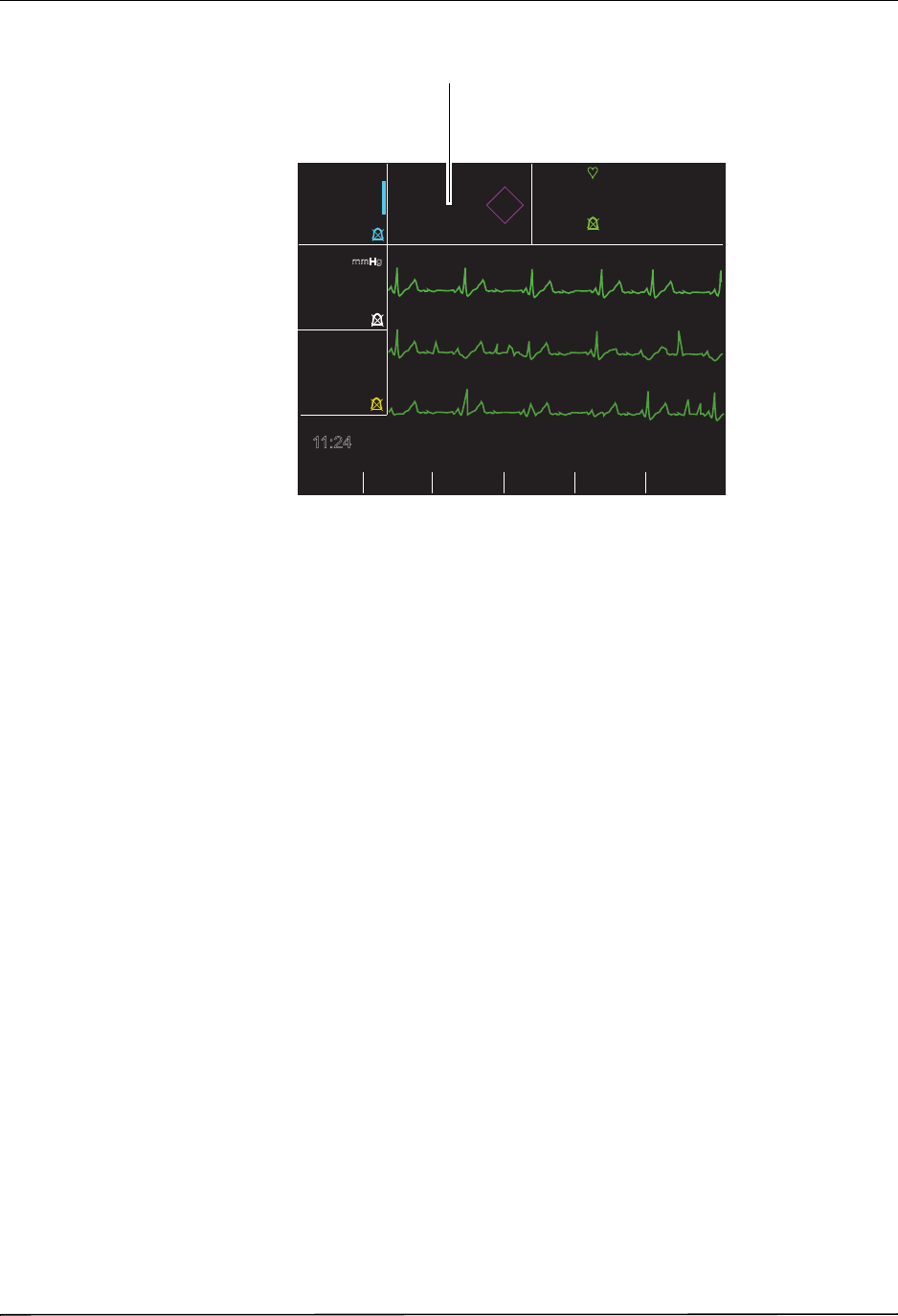
CHAPTER 2PRODUCT OVERVIEW
2–6 www.zoll.com 9650-0912-06 Rev. G
Figure 2-2. R Series Display Screen (shown with optional SpO2, NIBP and CO2
monitoring)
Color coding
To differentiate information for various parameters, the unit displays each type of information
in a specific user-configurable color.
Messages
During operation, a fault or error message is displayed when a fault is detected. If this occurs,
turn the unit off and then on and recheck operation. If the fault persists, contact your authorized
ZOLL agent as described on page 1-21.
Options Param
Code
Marker
Report
Data Alarms
11:24
72
ECG
I
x1
SpO2%
0:00
IDLE
Depth
Rate
99
NIBP
mmHg
CO2
mmHg
35
13
RR
Ɔ
Sync
On/Off
II
III
I
120
80
100
CPR 1:51
CPR
PPI
Heart rate
(beats per
Softkey labels
ECG
• size
• selected lead
• alarm indicator
Elapsed time Mode/Messages
Trace 1
Trace 2
Trace 3
SpO2 values and
alarm indicator
(optional)
CPR
Index
Messages
CPR
Idle
Time
Rate and Depth Indicators
• heartbeat indicator
(optional)
NIBP values and
alarm indicator
(optional)
CO2 values and
alarm indicator
(optional)
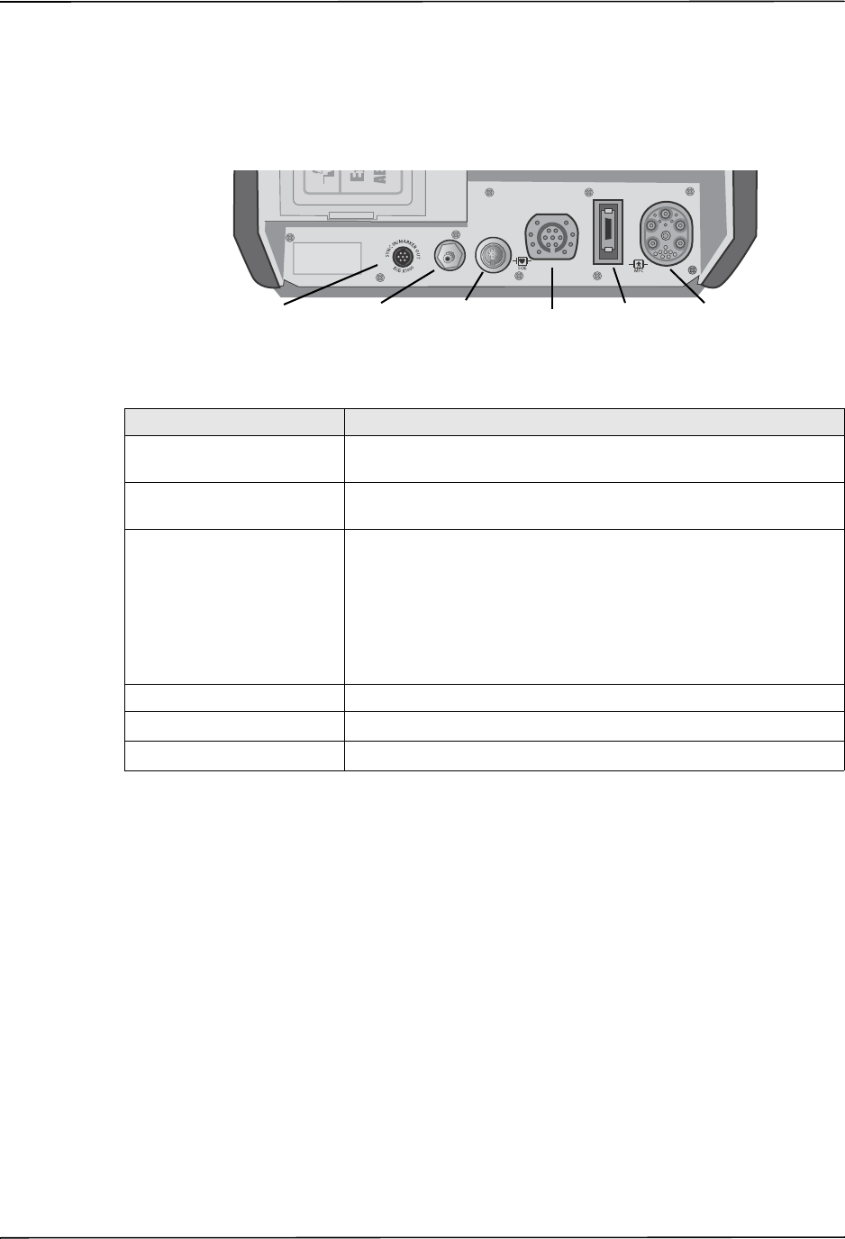
Defibrillator Controls and Indicators
9650-0912-06 Rev. G ZOLL R Series Operator’s Guide 2–7
Patient Cables and Connectors
The back of the unit includes a set of connectors for patient cables.
Figure 2-3. Patient Cable Connectors
OneStep Cables
The R Series ships with either a OneStep, or OneStep Pacing cable.
The OneStep Pacing cable has an additional connector that plugs into the rear panel ECG
connector. This cable is used with OneStep Pacing electrodes or OneStep Complete electrodes
for external pacing and ECG monitoring. Alternatively, you can disconnect the OneStep Pacing
cable from the ECG connector and use a 3- or 5-lead ECG cable.
Connector Description
OneStep Cable For connecting paddles or ZOLL hands-free therapy and pacing
electrodes using either OneStep or OneStep Pacing cables.
ECG For connecting 3- or 5-lead ECG cable or OneStep Pacing cable’s
ECG cable.
Sync In / Marker Out / ECG
x1000 Connector for
•An incoming defibrillator synchronization signal from an
external patient monitor.
•Output of R wave marker to an external patient monitor.
•ECG signal output for use with other equipment such as patient
monitors and radio telemetry equipment (1 V/cm of displayed
ECG signal).
NIBP (Optional) For connecting blood pressure cuff cable.
EtCO2(Optional) For connecting CO2 monitor cable.
SpO2(Optional) For connecting pulse oximeter cable.
OneStep
SpO2
(optional) Cable
Sync In/
Marker Out/
ECG Out
ECG
NIBP
(optional)
EtCO2
(optional)
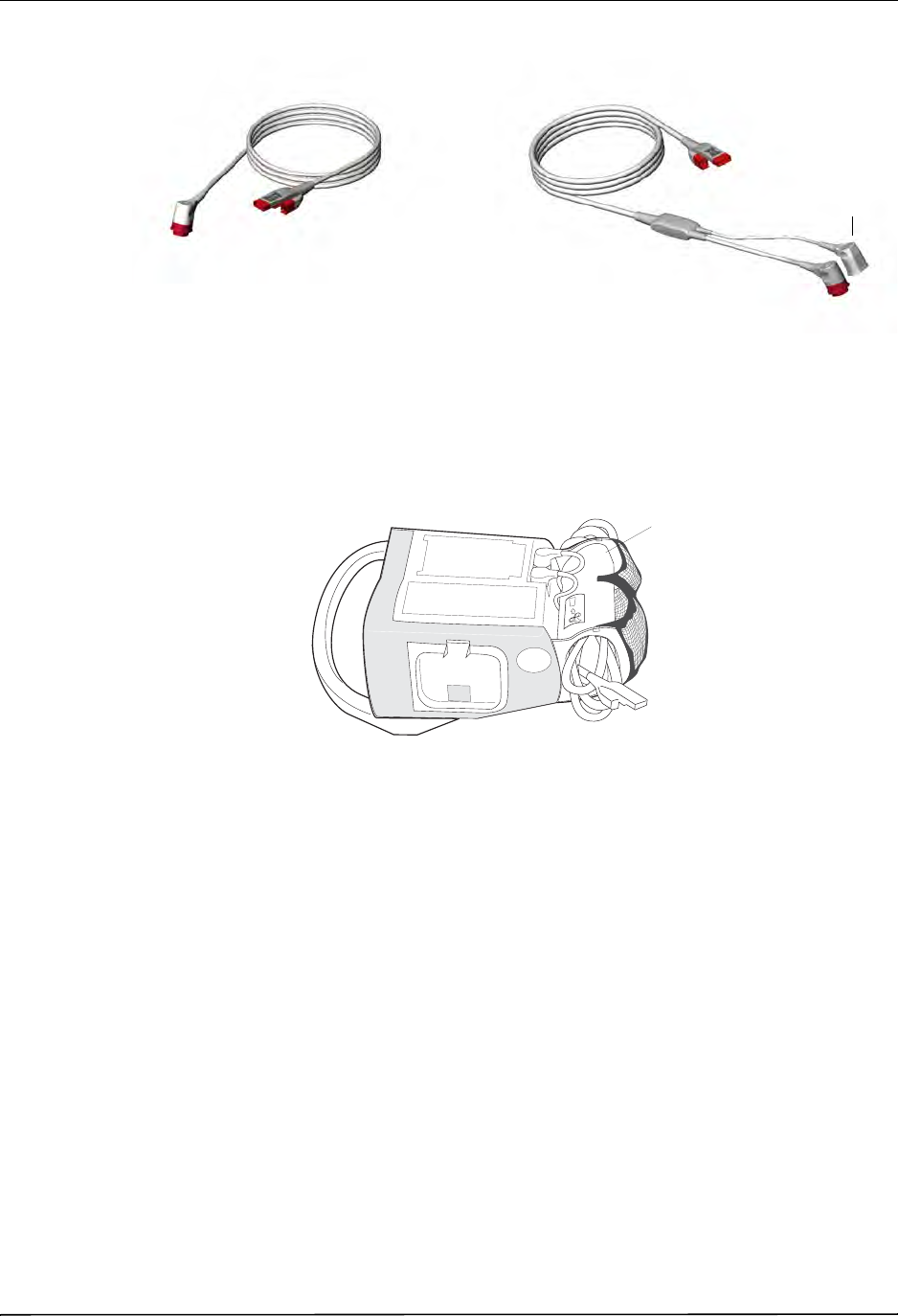
CHAPTER 2PRODUCT OVERVIEW
2–8 www.zoll.com 9650-0912-06 Rev. G
Figure 2-4. OneStep Cables
OneStep Cable Manager (Optional)
As an option, the OneStep Cable Manager is available to store and organize cables.
Figure 2-5. The R Series with the Optional OneStep Cable Manager (Side View)
OneStep Pacing Cable
OneStep Cable
ECG Connector
Cable Caddy
OneStep Cable
Manager
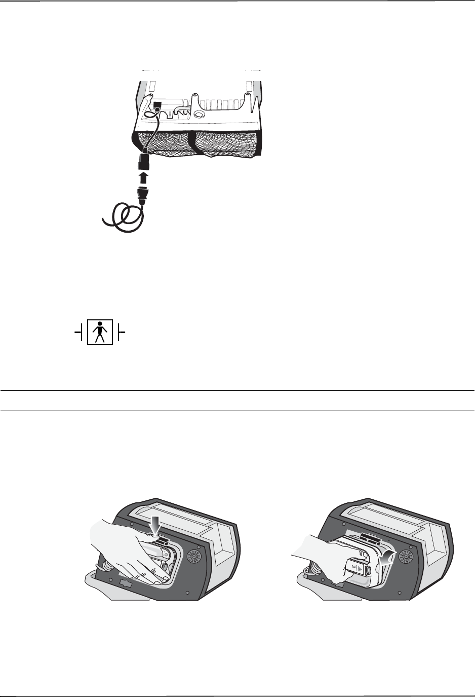
Defibrillator Controls and Indicators
9650-0912-06 Rev. G ZOLL R Series Operator’s Guide 2–9
Power Cord
The AC power cord is used to operate the R Series unit when battery power is not being used.
An additional extension cord is available for use when the cable organizer accessory is attached
to the unit. The extension cord plugs into the main AC power cord as shown below.
External Paddles
The external paddles on the R Series device are used for defibrillation and synchronized
cardioversion.
Caution You cannot use paddles for ECG analysis or pacing.
Defibrillation paddles can be used for ECG monitoring when it is not practical to apply ECG
electrodes. Press the LEAD button to select PADDLES as the ECG source.
The paddles are stowed in wells on either side of the unit. To release the paddles, grasp the
handles and then press down on the latch button above each paddle.
Figure 2-6. Releasing the Paddles
Paddles are defibrillation-proof Type BF equipment.
RELEASE
RELEASE
RELEASE
RELEASE
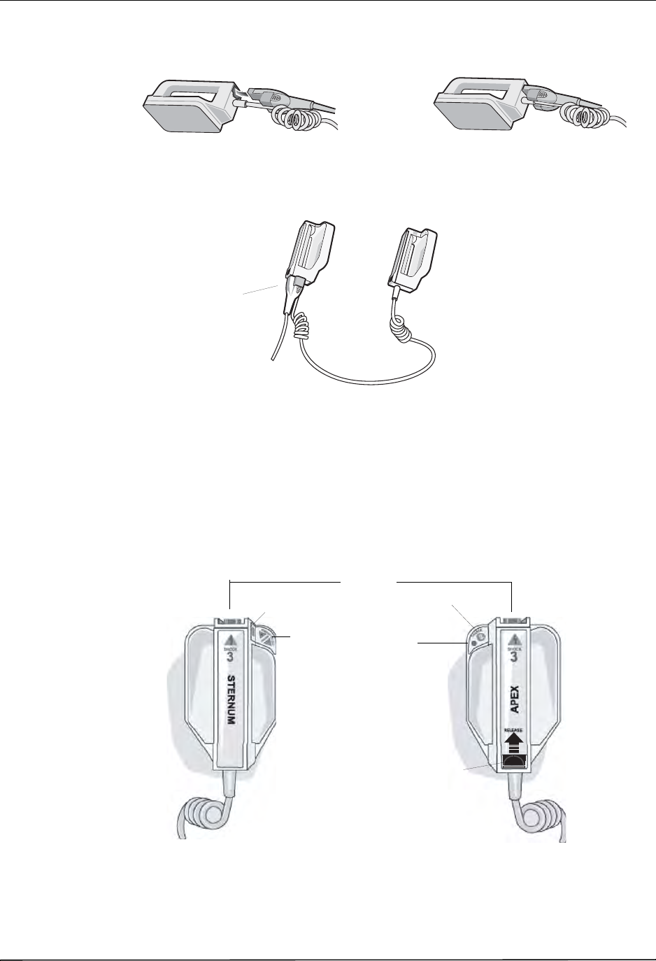
CHAPTER 2PRODUCT OVERVIEW
2–10 www.zoll.com 9650-0912-06 Rev. G
Attach the OneStep cable from the R Series unit to the connector at the base of the apex paddle.
Figure 2-7. Attaching the OneStep Cable to the APEX Paddle
Figure 2-8. OneStep Cable Connected to APEX Paddle
If you need to detach the OneStep cable from the APEX paddles, push the RELEASE button
(see Figure 2-9) in the direction of the arrow and unplug the OneStep cable.
Refer to Chapter 3, "Manual Defibrillation" before using paddles for defibrillation. The paddles
include controls for selecting defibrillation energy, charging, delivering a shock, and turning
the stripchart recorder on and off.
Figure 2-9. External Paddles
1. Align OneStep cable as shown. 2. Insert OneStep cable into APEX paddle.
OneStep cable connected
to APEX paddle
SHOCK
Buttons
RECORDER
Button
ENERGY
SELECT
Buttons
CHARGE
Button
Charge Ready
Indicator
Sternum Paddle Apex Paddle
Connector
and RELEASE
button for
OneStep cable
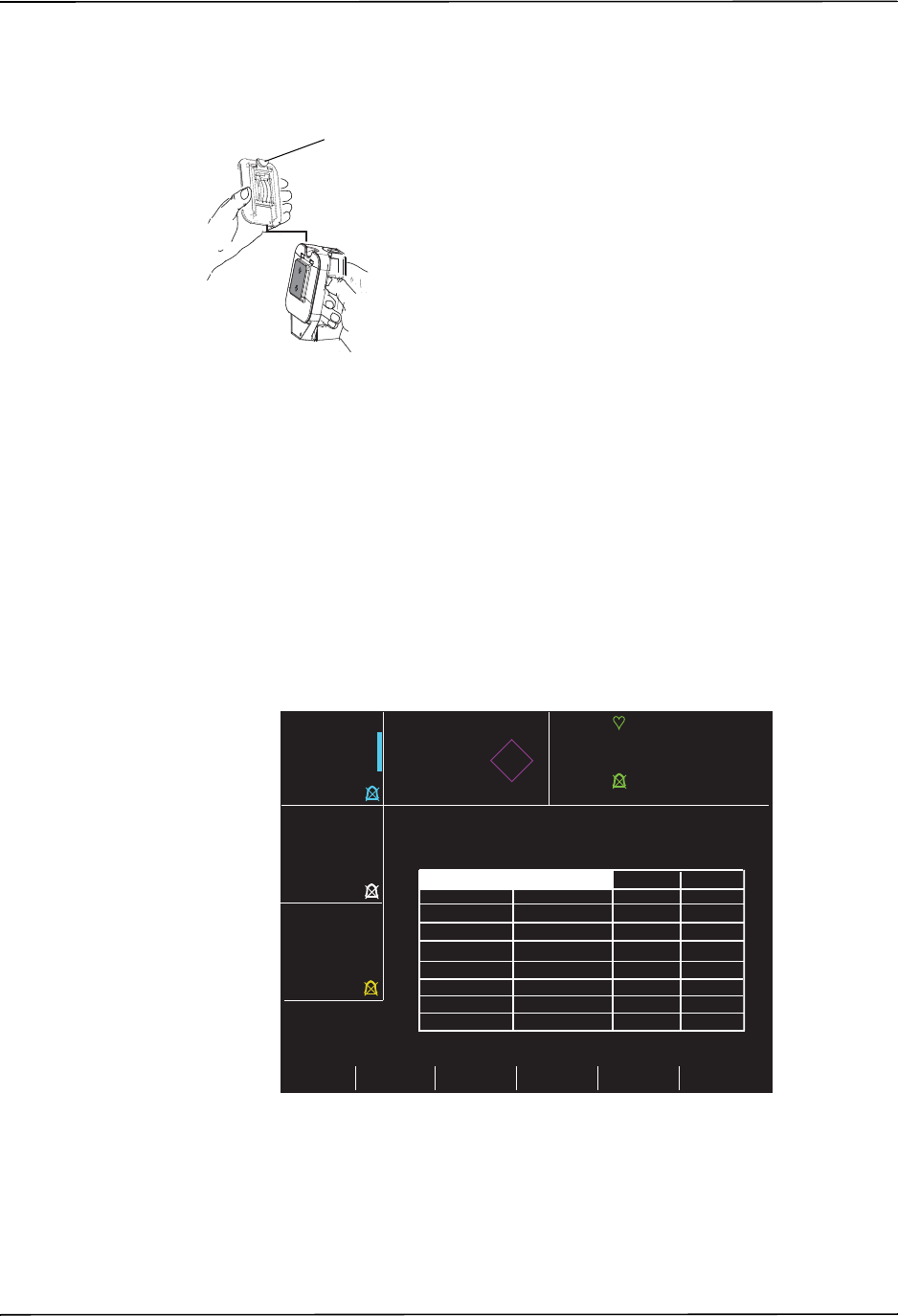
Working with Menus
9650-0912-06 Rev. G ZOLL R Series Operator’s Guide 2–11
Pediatric-size electrodes are built into the paddle assembly beneath the standard electrode
plates. The user must manually adjust energy settings to pediatric levels consistent with their
institution’s protocols.
Figure 2-10. Pediatric Plate
Note: The R Series defibrillator also supports ZOLL autoclavable internal handles for use
during open chest defibrillation procedures.
Working with Menus
For some functions, the screen shows a menu of options with related softkeys for navigating
through the menus and making selections and entries.
Figure 2-11. Example Display Screen
On the display, highlighting indicates the currently selected item, that is, the item or value you
are working with.
To expose the pediatric
plate, press the PEDI
button at the top of the
paddle, then slide the
Adult plate upward.
Before replacing the
Adult plate, be sure to
clean the pediatric plate
and surrounding area
PEDI button
Prev
Param
Next
Field Return
72
ECG
PADS x1
SpO2% 0:00
IDLE
Depth
Rate
99
NIBP
mmHg
---
---
---
CO2
mmHg
---
---
RR
Ɔ
Parameter State Low High
SpO2 ENABLE
DISABLE
30
85
150
100
ECG HR
ALARM SET
Next
Param
Change
Value
EtCO2
RESP RATE
NIBP SYS
NIBP DIA
NIBP MEAN
ENABLE
ENABLE
ENABLE
ENABLE
ENABLE
25 55
5120
90 160
50 110
60 130
CPR
PPI

CHAPTER 2PRODUCT OVERVIEW
2–12 www.zoll.com 9650-0912-06 Rev. G
The following table summarizes some of the more common softkeys.
Defib Mentor Mode (Optional)
Defib Mentor™ mode is a nonclinical tutorial mode available when the Mode Selector is
turned to MONITOR. When in this mode, the device displays a brief description of each front
panel control’s function when that control is activated.
Note: Do not run the Defib Mentor mode with a patient connected to the R Series unit.
To access Defib Mentor mode:
1. Turn the Mode Selector to MONITOR.
2. Press the Options softkey.
3. Press MORE.
Additional options appear.
4. Press Mentor.
5. Press Confirm Mentor Mode.
The unit is now in Defib Mentor Mode, a non-clinical operating mode.
6. Activate a front panel control (except the Mode Selector or the Exit Mentor softkey).
A brief description of that control’s function appears on the screen.
To exit Mentor mode, press the Exit Mentor softkey or turn the Mode Selector to OFF,
DEFIB, or PACER.
Note: After 60 seconds of non use in the Mentor mode, the R Series returns to MONITOR
mode.
Softkey Action
Next Item
Next Field Moves the highlighting down to the next item in a vertical list.
Prev Item Moves the highlighting up to the previous item in a vertical list.
Next Digit Moves the highlighting to the right in a series of letters or digits.
Prev Digit Moves the highlighting to the left in a series of letters or digits.
Inc
Inc Digit Increases the highlighted value or digit.
(For example, changes 2 to 3 or B to C).
Dec
Dec Digit Decreases the highlighted value or digit.
(For example, changes 2 to 1 or B to A).
Newer Moves the highlighting to the adjacent item with the more recent date or time.
Older Moves the highlighting to the adjacent item with the older date or time.
Enter Accepts the settings with the values currently shown.
Return Displays the previous menu.
Next Param Moves the highlighting to the next parameter.
Prev Param Moves the highlighting to the previous parameter.
Change Value Changes the value of the selected parameter.
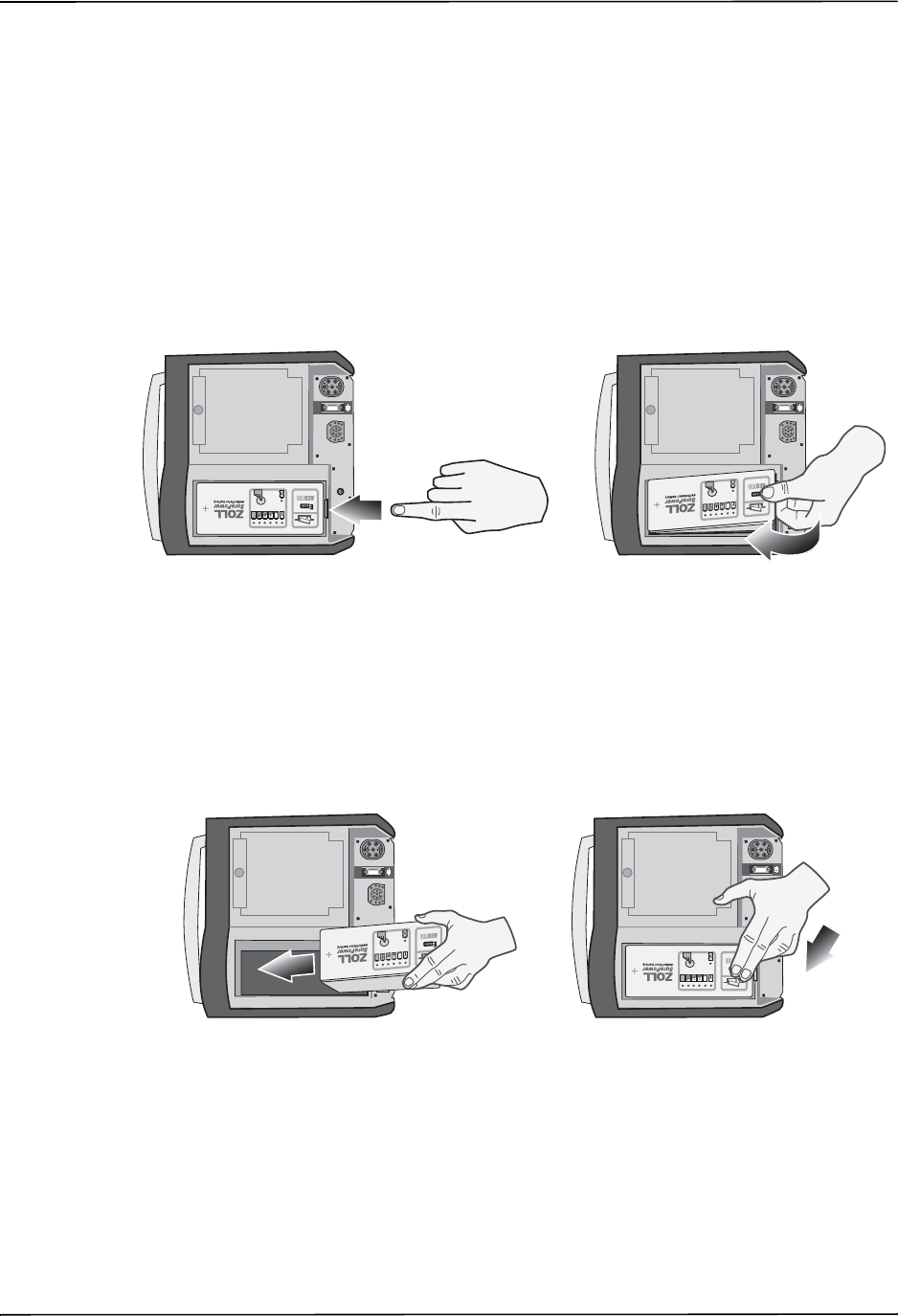
Common Tasks
9650-0912-06 Rev. G ZOLL R Series Operator’s Guide 2–13
Common Tasks
Follow the instructions in the subsequent sections for:
•“Replacing a Battery Pack” on page 2-13.
•“Adjusting Display Brightness” on page 2-13.
•“Using Code Markers” on page 2-14.
Replacing a Battery Pack
To remove a battery pack, press the tab on the end of the battery pack inward, and lift the
battery pack out of the compartment.
Figure 2-12. Removing a Battery Pack
To install a battery pack:
1. Place the end of the battery pack opposite the tab into the end of the compartment closest to
the front of the unit.
2. Lower the tabbed end of the battery pack into the compartment and press down on the tabbed
end until it locks into place.
Figure 2-13. Installing a Battery Pack
Adjusting Display Brightness
To adjust brightness:
1. Press the Options softkey.
?
?
3P/3P/
3P/3P/
?
?
3P/3P/
3P/3P/

CHAPTER 2PRODUCT OVERVIEW
2–14 www.zoll.com 9650-0912-06 Rev. G
2. Press the High Bright or Low Bright softkey to select high and low brightness.
Note: Brightness level affects battery run time. Selecting high bright will cause the battery
charge to be depleted at a faster rate than when selecting low bright.
Using Code Markers
Pressing the CODE MARKER softkey causes the unit to display a preconfigured list of
clinical actions. Pressing the softkey associated with a particular action causes that action, and
6 seconds of ECG, to be recorded along with a date and time stamp in the Summary Report
memory. You can supplement an event summary by manually adding code markers which
itemize drugs or treatments administered to the patient.
Up to six Code Markers can be displayed on the screen at one time.
Figure 2-14. Code Markers
The right-most softkey is labeled MORE when there are more than six items on the code
marker list. Press the MORE softkey to see the next set of Code Markers displayed above the
softkeys.
Separate code marker lists are maintained for DEFIB, MONITOR, and PACER modes, thereby
enabling the display of appropriate code markers for each particular protocol. (For information
on configuring these code marker lists, refer to the R Series Configuration Guide.)
The code markers are removed from the display after 10 seconds. If no Code Marker softkey
has been pressed during that time, a “default” event mark is stored in Summary Report
memory.
CPR Intubate EPI LIDO Narcan MORE
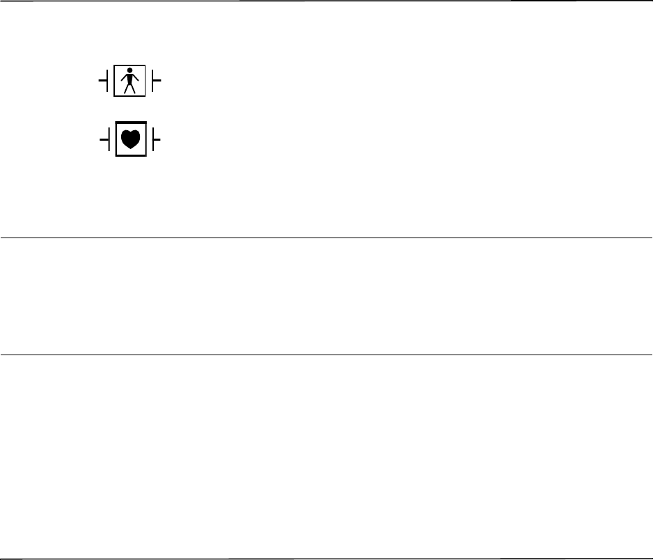
9650-0912-06 Rev. G ZOLL R Series Operator’s Guide 3–1
Chapter 3
Manual Defibrillation
Emergency Defibrillation Procedure with Paddles
WARNING! To avoid risk of electrical shock, do not allow electrolyte gel to accumulate on hands or
paddle handles.
When defibrillating with paddles, use your thumbs to operate the SHOCK buttons in
order to avoid inadvertent operator shock. No portion of the hands should be near the
paddle plates.
Determine the Patient’s Condition Following Local Medical Protocols
Verify:
•Unconsciousness.
•Absence of breathing.
•Absence of pulse.
Paddles are a defibrillation-protected Type BF patient connection.
ECG leads are a defibrillation-protected Type CF patient connection.
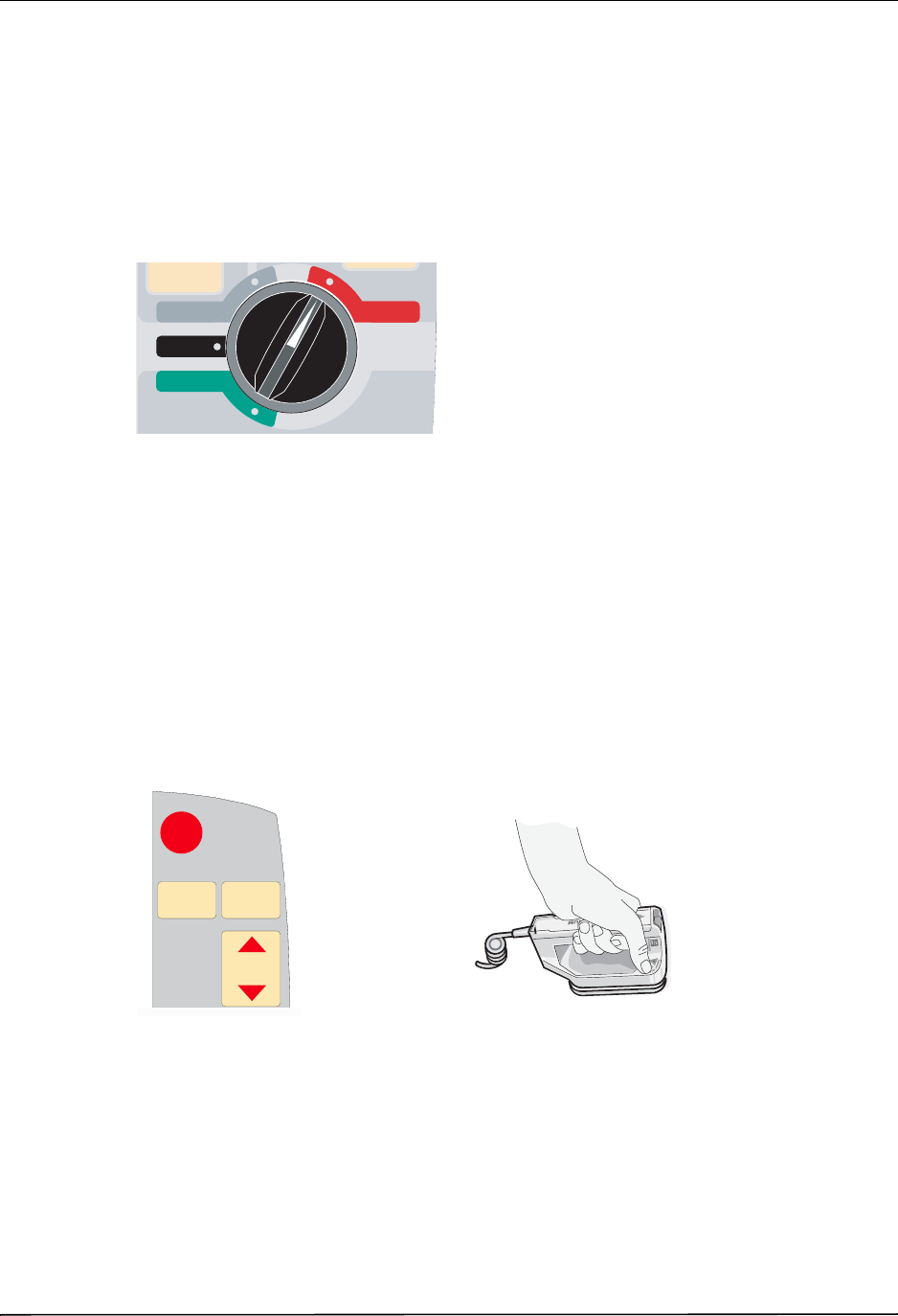
CHAPTER 3MANUAL DEFIBRILLATION
3–2 www.zoll.com 9650-0912-06 Rev. G
Begin CPR Following Local Medical Protocols.
Request additional assistance.
1 Select DEFIB
Turn the Mode Selector to DEFIB. The unit automatically defaults to 120 joules or the
preconfigured first shock energy selection.
Note: Defibrillator PADDLES are selected as the ECG source when the instrument is turned
to MONITOR or DEFIB with paddles connected to the OneStep cable.
Energy Select
Look at the Display and verify the energy is appropriate. Unless internal handles are connected
to the OneStep cable, the default energy selections for adult patients are:
•Shock 1 - 120 joules
•Shock 2 - 150 joules
•Shock 3 - 200 joules
If medical protocol allows, you may select a different energy level using the up and down arrow
buttons. One pair is located on the front panel of the unit; the other pair is located on the
sternum paddle.
Note: Neonatal and pediatric defibrillator energy levels should be selected based on site-
specific protocols.
1
RECORDER
DEFIB
OFF
MONITOR
PACER
3
SHOCKSHOCK
ENERGY
SELECT
ENERGY
SELECT
ANALYZEANALYZE CHARGECHARGE
2
1
or
or
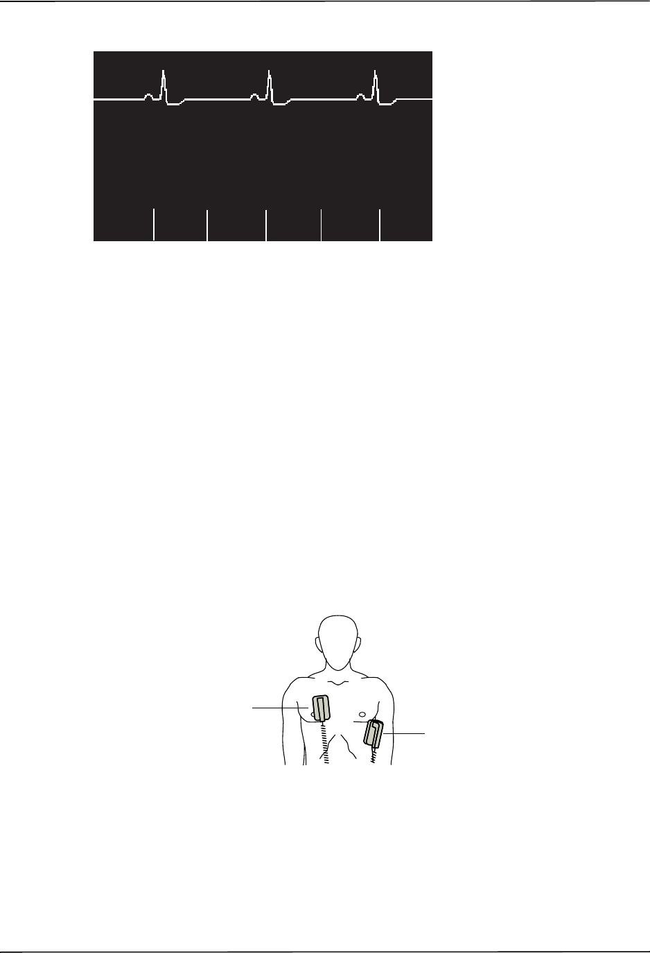
Emergency Defibrillation Procedure with Paddles
9650-0912-06 Rev. G ZOLL R Series Operator’s Guide 3–3
The selected energy level is shown as DEFIB XXXJ SEL. on the display.
If you have configured Shocks 1, 2, and 3 to escalating energy levels (see the R Series
Configuration Guide for instructions), the R Series automatically sets the energy to the
preconfigured Energy Level: Shock 1, 2, 3 setting at power-up and after each of the first two
shocks. The ENERGY INCREMENTED message will be displayed after Shocks 1 and 2 are
delivered. Manually changing the energy level outside the preprogrammed sequence and
delivering a shock disables the automatic escalation function.
Prepare Paddles
Release the paddles, apply a liberal amount of electrolyte gel to the electrode surface of each
paddle, and rub the electrode surfaces together to evenly distribute the applied gel. (You can
substitute electrode gel patches for the gel.)
Apply Paddles to Chest
Apply the paddles firmly to the anterior wall of the chest. Place the sternum paddle to the right
of the patient’s sternum (patient’s right), just below the clavicle.
Place the apex paddle on the chest wall, just below and to the left of the patient’s left nipple,
along the anterior-axillary line.
Rub the paddles against the skin to maximize the paddle-to-patient contact.
DEFIB 120J SEL.
Code
MarkerOptions
00:01
ECG
Param
Report
Data
Sync
On/Off
Alarms
Sternum
Apex
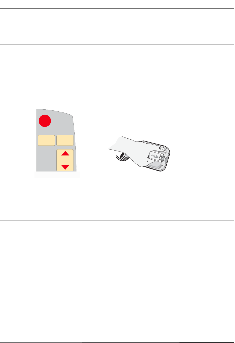
CHAPTER 3MANUAL DEFIBRILLATION
3–4 www.zoll.com 9650-0912-06 Rev. G
WARNING! Do not permit gel to accumulate between the paddle electrodes on the chest wall (gel
bridge). This could cause burns and reduce the amount of energy delivered to the heart.
If using defibrillator gel pads, make sure that the size of the pad is large enough to cover
the entire paddle electrode area.
The paddles may be used for ECG monitoring in emergency situations when time does not
allow connection of standard ECG monitoring electrodes.
If an ECG cable and ECG electrodes are in use, press the LEAD button to select the desired
ECG lead.
2 Charge Defibrillator
Press the CHARGE button on the apex handle or on the front panel.
If both SHOCK buttons on the paddles are depressed when the CHARGE button is activated,
the unit does not charge and a RELEASE SHOCK BUTTON message appears on the display.
To increase or decrease the selected energy after you have pressed the CHARGE button, use
the defibrillator ENERGY SELECT buttons on either the sternum paddle or the defibrillator
front panel.
Caution Changing the selected energy while the unit is charging or charged causes the defibrillator to
disarm itself. Press the CHARGE button again to charge the unit to the newly selected energy
level.
After charging to the selected energy, the charge indicator on the apex paddle lights. A
distinctive charge ready tone sounds, and the message DEFIB XXXJ READY is displayed. The
defibrillator is now ready to discharge.
3
SHOCKSHOCK
ENERGY
SELECT
ENERGY
SELECT
ANALYZEANALYZE CHARGECHARGE
2
1
RELEASE
RELEASE
or
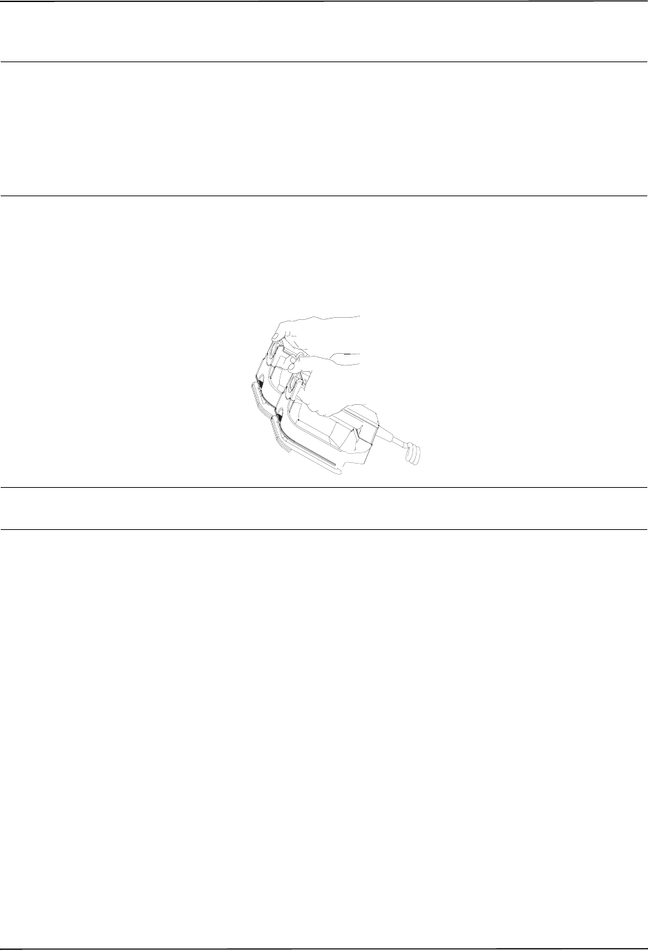
Autoclavable External Paddles
9650-0912-06 Rev. G ZOLL R Series Operator’s Guide 3–5
3 Deliver Shock
WARNING! Warn all persons in attendance of the patient to STAND CLEAR prior to defibrillator
discharge.
Do not touch the bed, patient, or any equipment connected to the patient during
defibrillation. A severe shock can result. Do not allow exposed portions of the patient’s
body to come into contact with metal objects, such as a bed frame, as unwanted
pathways for defibrillation current may result.
Apply a force of 10 - 12 kilograms (22 - 26.4 pounds) to each paddle in order to minimize
patient impedance and achieve optimal results.
Using your thumbs, simultaneously press and hold both SHOCK buttons (one on each paddle)
until energy is delivered to the patient.
Caution Use only thumbs to depress the SHOCK buttons. Failure to do so could result in the inadvertent
depression of the ENERGY SELECT buttons, causing the defibrillator to disarm itself.
Once the energy is delivered, the display simultaneously shows XXXJ DELIVERED and DEFIB
XXXJ SEL. After approximately 5 seconds, the XXXJ DELIVERED message disappears, and
the DEFIB XXXJ SEL. message remains to indicate the selected energy level.
Note: If the defibrillator is not discharged within 60 seconds after reaching the selected
energy level, the unit automatically disarms itself.
During the 10 seconds prior to disarming, the charge ready tone beeps intermittently. The
charge ready tone then stops, the charge indicator light goes off, and the monitor message
changes to DEFIB XXXJ SEL. Press the CHARGE button to recharge the unit.
Autoclavable External Paddles
ZOLL Autoclavable External Paddles are available for use with manually operated ZOLL
defibrillators when sterile conditions must be maintained during defibrillation.

CHAPTER 3MANUAL DEFIBRILLATION
3–6 www.zoll.com 9650-0912-06 Rev. G
Emergency Defibrillation Procedure with Hands-Free
Therapy Electrodes
Determine the Patient’s Condition Following Local Medical Protocols
Verify:
•Unconsciousness.
•Absence of breathing.
•Absence of pulse.
Begin CPR Following Medical Protocols
Request additional assistance.
Prepare Patient
Remove all clothing covering the patient’s chest. Dry chest if necessary. If the patient has
excessive chest hair, clip or shave it to ensure proper adhesion of the electrodes.
Attach hands-free therapy electrodes according to instructions on the electrode packaging.
Ensure that the therapy electrodes are making good contact with the patient’s skin and are not
covering any part of the ECG electrodes.
Connect the hands-free therapy electrodes to the OneStep cable if not preconnected.
If defibrillation electrodes are not making good contact with the patient’s skin, the unit issues
the messages CHECK PADS and POOR PAD CONTACT and does not allow delivery of energy.
If a short circuit exists between the electrodes, the unit issues the message DEFIB PAD SHORT.
Therapy Electrode Application
WARNING! Poor adherence and/or air under the therapy electrodes can lead to the possibility of
arcing and skin burns.
1. Apply one edge of the pad securely to the patient.
2. Roll the pad smoothly from the applied edge to the other, being careful not to trap any air
pockets between the gel and skin.
ZOLL hands-free therapy electrodes are a defibrillation-protected Type BF patient
connection.
ECG leads are a defibrillation-protected Type CF patient connection.
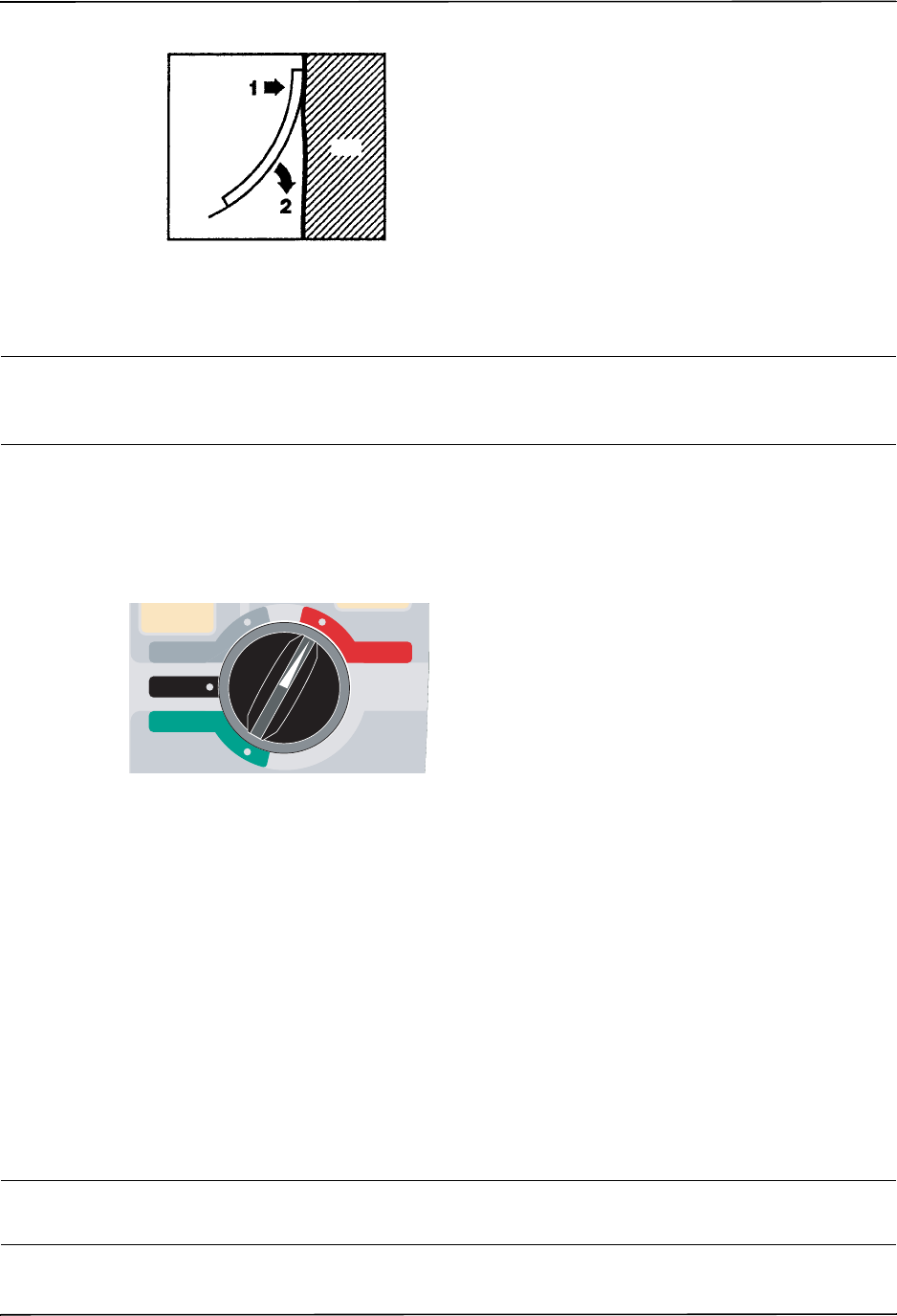
Emergency Defibrillation Procedure with Hands-Free Therapy Electrodes
9650-0912-06 Rev. G ZOLL R Series Operator’s Guide 3–7
Note: If it is not possible to place the “BACK” electrode on the patient’s back, place the
electrodes in the standard apex-sternum positions. Effective defibrillation results, but
pacing will usually be less effective.
WARNING! Application of adult electrodes to a pediatric patient will result in the automatic
selection of adult energy levels. If needed, manually adjust the energy settings based on
site-specific protocols.
1 Select DEFIB
Turn the Mode Selector to DEFIB. The unit automatically defaults to 120 joules or the
preconfigured first shock energy selection.
PADS are selected as the ECG source when the instrument is turned to MONITOR or DEFIB
and paddles are not connected to the OneStep cable. You may select any of the other ECG leads
by pressing the front panel LEAD button.
Energy Select
Look at the display, and verify the selected energy is appropriate. The default energy selections
for adult patients are:
•Shock 1 - 120 joules
•Shock 2 - 150 joules
•Shock 3 - 200 joules
When used with OneStep Pediatric electrodes, the default energy selections are:
•Shock 1 - 50 joules
•Shock 2 - 70 joules
•Shock 3 - 85 joules
WARNING! When used with pedi-padz, defibrillator energies must be set manually based on site-
specific institutional protocols for pediatric defibrillation.
Pad
Skin
1
RECORDER
DEFIB
OFF
MONITOR
PACER
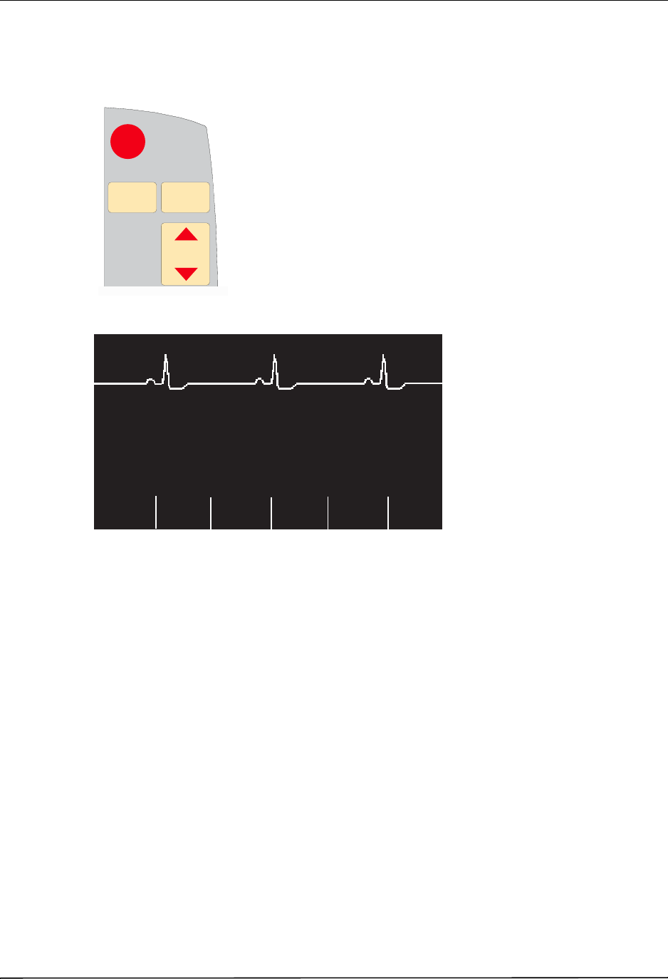
CHAPTER 3MANUAL DEFIBRILLATION
3–8 www.zoll.com 9650-0912-06 Rev. G
After the third shock, all subsequent shocks are delivered at the same energy as the third shock
in both Adult and Pediatric modes.
If medical protocol allows, you may select a different energy level using the ENERGY
SELECT buttons on the front panel.
The selected energy level is shown as DEFIB XXXJ SEL. on the display.
If you have configured Shocks 1, 2, and 3 to escalating energy levels (see the R Series
Configuration Guide for instructions), the R Series automatically sets the energy to the
preconfigured Energy Level: Shock 1, 2, 3 setting at power-up and after each of the first two
shocks. The ENERGY INCREMENTED message will be displayed after Shocks 1 and 2 are
delivered. Manually changing the energy level outside the preprogrammed sequence and
delivering a shock disables this function.
3
SHOCKSHOCK
ENERGY
SELECT
ENERGY
SELECT
ANALYZEANALYZE CHARGECHARGE
2
1
DEFIB 120J SEL.
Code
MarkerOptions
00:01
ECG
Param
Report
Data
Sync
On/Off
Alarms
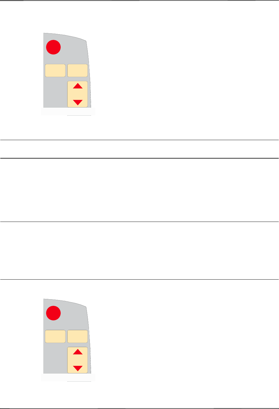
Emergency Defibrillation Procedure with Hands-Free Therapy Electrodes
9650-0912-06 Rev. G ZOLL R Series Operator’s Guide 3–9
2 Charge Defibrillator
Press the CHARGE button on the front panel.
To increase or decrease the selected energy after you have pressed the CHARGE button, use
the defibrillator ENERGY SELECT buttons.
Caution Changing the selected energy while the unit is charging or charged causes the defibrillator to
disarm itself. Press the CHARGE button again to charge the unit.
After charging to the selected energy, the SHOCK button on the front panel lights. A
distinctive charge ready tone sounds and the DEFIB XXXJ READY is displayed. The
defibrillator is now ready to discharge.
3 Deliver Shock
WARNING! Warn all persons in attendance of the patient to STAND CLEAR prior to defibrillator
discharge.
Do not touch the bed, patient, or any equipment connected to the patient during
defibrillation. A severe shock can result. Do not allow exposed portions of the patient’s
body to come into contact with metal objects, such as a bed frame, as unwanted
pathways for defibrillation current may result.
Press and hold the SHOCK button until energy is delivered to the patient.
3
SHOCKSHOCK
ENERGY
SELECT
ENERGY
SELECT
ANALYZEANALYZE CHARGECHARGE
2
1
3
SHOCKSHOCK
ENERGY
SELECT
ENERGY
SELECT
ANALYZEANALYZE CHARGECHARGE
2
1

CHAPTER 3MANUAL DEFIBRILLATION
3–10 www.zoll.com 9650-0912-06 Rev. G
Note: If the defibrillator is not discharged within 60 seconds after reaching the selected
energy level, the unit automatically disarms itself.
During the 10 seconds prior to disarming, the charge ready tone beeps intermittently. The
charge ready tone then stops, the SHOCK button light goes off, and the monitor message
changes to DEFIB XXXJ SEL. Press the CHARGE button to recharge the unit.
Once the energy is delivered, the display simultaneously shows XXXJ DELIVERED and DEFIB
XXXJ SEL. After approximately 5 seconds, the XXXJ DELIVERED message disappears and the
DEFIB XXXJ SEL. message remains to indicate the selected energy level.
Autoclavable Electrodes
ZOLL Autoclavable Internal Handles are designed for use with a manually operated ZOLL
defibrillator to defibrillate the heart during open chest procedures. Two types of Autoclavable
Internal Handles are available:
•Molded Autoclavable Internal handles with integrated electrode spoons
•Autoclavable Internal Handles with removable internal defibrillation electrodes
When these internal handles are used, the R Series defibrillator can operate only in Manual
mode even if the unit supports Advisory mode. When an internal handle set is connected to the
R Series, it automatically limits energy output to a maximum of 50 joules.
For step-by-step procedures for open chest defibrillation as well as important cleaning and
sterilization information, refer to the Autoclavable Internal Handle and Electrode Operator’s
Guide.
9650-0912-06 Rev. G ZOLL R Series Operator’s Guide 4–1
Chapter 4
Advisory Defibrillation
When the Mode Selector is turned to DEFIB and hands-free therapy electrodes are used, the
R Series can identify shockable rhythms using its built in ECG analysis capability. You must
read the advisory messages, charge the defibrillator to the preconfigured or user-selected
energy level (if automatic charge is disabled), and deliver treatment to the patient when
required by protocol and patient condition.
The advisory function can be activated only when:
•Hands-free therapy electrodes are connected and selected as the ECG source.
•Hands-free therapy electrodes are properly connected to the patient.
•The Mode Selector is turned to DEFIB.
WARNING! Use only pediatric electrodes to defibrillate patients under 8 years of age in Advisory
mode. Use of adult electrodes with pediatric patients can result in the delivery of
excessive energy doses.
ZOLL hands-free therapy electrodes are a defibrillation-protected Type BF patient
connection.

CHAPTER 4ADVISORY DEFIBRILLATION
4–2 www.zoll.com 9650-0912-06 Rev. G
Advisory Defibrillation Procedure
Determine the Patient’s Condition Following Local Medical Protocols
Verify:
•Unconsciousness.
•Absence of breathing.
•Absence of pulse.
Begin CPR Following Local Medical Protocols
Request additional assistance.
Prepare Patient
Remove all clothing covering the patient’s chest. Dry chest if necessary. If the patient has
excessive chest hair, clip or shave it to ensure proper adhesion of the electrodes.
Attach hands-free therapy electrodes according to instructions on the electrode packaging and
as described in “Therapy Electrode Application” on page 3-6.
Ensure that the electrodes are making good contact with the patient’s skin and are not covering
any part of the ECG electrodes.
If therapy electrodes are not making good contact with the patient’s skin, the unit issues the
messages CHECK PADS and POOR PAD CONTACT and does not allow delivery of energy. If a
short circuit exists between the electrodes, the unit issues the message DEFIB PAD SHORT.
1 Select DEFIB
Turn the Mode Selector to DEFIB. The unit displays DEFIB 120J SEL on the monitor.
Energy Select
The default energy selections for adult patients are:
•Shock 1 - 120 joules
•Shock 2 - 150 joules
•Shock 3 - 200 joules
1
RECORDER
DEFIB
OFF
MONITOR
PACER
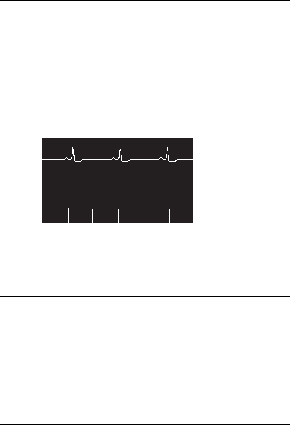
Advisory Defibrillation Procedure
9650-0912-06 Rev. G ZOLL R Series Operator’s Guide 4–3
When used with OneStep Pediatric electrodes, the default energy selections for pediatric
patients are:
•Shock 1 - 50 joules
•Shock 2 - 70 joules
•Shock 3 - 85 joules
WARNING! Use only OneStep Pediatric electrodes to defibrillate patients under 8 years of age in
Advisory mode. Use of adult electrodes, or pediatric electrodes other than OneStep
Pediatric electrodes, can result in the delivery of excessive energy doses.
After the third shock, all subsequent shocks are delivered at the same energy as the third shock
in both Adult and Pediatric modes.
If medical protocols allow, you may select a different energy level using the energy select up
and down arrow buttons on the front panel. The new energy setting displays on the monitor.
If you have configured SHOCK 1, 2, and 3 to escalating energy levels, and then you manually
change the energy level outside preconfigured SHOCK 1, 2, 3 sequence and deliver a shock, it
disables the automatic energy escalation. See the Energy Level: Shock 1, 2, 3 section of the
R Series Configuration Guide for more details.
2 Press ANALYZE Button
WARNING! Keep patient motionless during ECG analysis. Do not touch the patient during analysis.
Cease all movement via stretcher or vehicle before analyzing the ECG.
DEFIB 120J SEL.
Code
MarkerOptions
00:01
ECG
Param
Report
Data
Sync
On/Off
Alarms
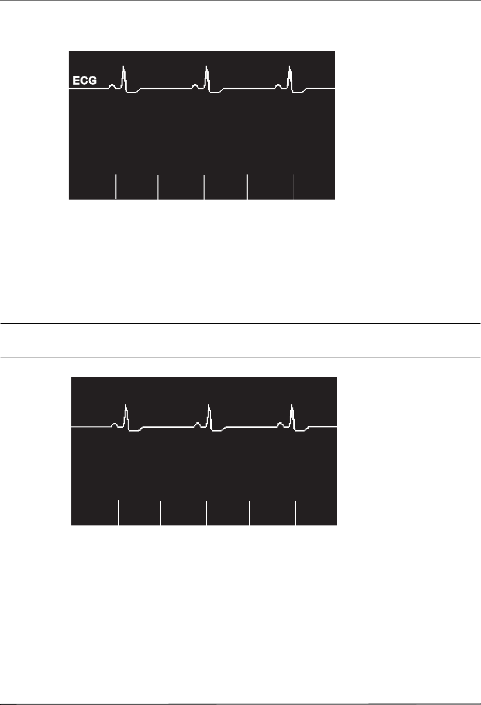
CHAPTER 4ADVISORY DEFIBRILLATION
4–4 www.zoll.com 9650-0912-06 Rev. G
Press the ANALYZE button to begin the analysis of the patient’s ECG rhythm and to determine
if a shockable rhythm is present.
An ANALYZING ECG message is displayed for 6 to 12 seconds while the patient’s ECG is
analyzed. Once the analysis is completed, the unit indicates whether or not a shock is advised.
The analysis normally consists of three consecutive 3-second ECG rhythm analyses. If at least
two of the three analyses determine that the patient has a shockable rhythm, the unit
automatically charges to the preconfigured energy level and prompts the operator to shock the
patient. If two or more of the three 3-second ECG analyses do not detect a shockable rhythm,
the unit alerts the operator that no shock is advised.
WARNING! ECG rhythm analysis does not warn of patient asystole, which is not a shockable
rhythm.
When a nonshockable rhythm is detected, the unit displays a NO SHOCK ADV. message.
Follow the local protocols to continue CPR or other life support, and re-analyze the ECG at
appropriate intervals.
Note: When a nonshockable rhythm is detected, the R Series does not prevent the user from
manually defibrillating the patient.
When a shockable rhythm is detected (ventricular fibrillation or wide-complex tachycardia
with heart rate > 150), one of the following occur:
•Units with the automatic charge option enabled automatically charge to the preconfigured or
user selected energy setting.
ANALYZING ECG
Code
Marker
00:01
ECG
Param
Sync
On/Off
Alarms
Options
Report
Data
DEFIB 120J SEL.
Sync
On/Off
00:01
ECG
NO SHOCK ADV.
Alarms
Param
Options
Code
Marker
Report
Data
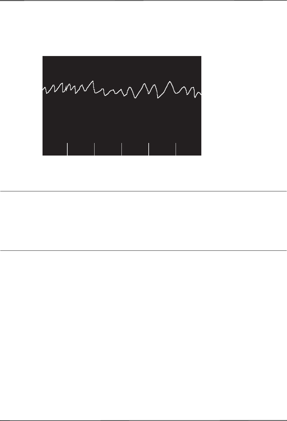
Advisory Defibrillation Procedure
9650-0912-06 Rev. G ZOLL R Series Operator’s Guide 4–5
•Units with the automatic charge option disabled will alternately display the messages
SHOCK ADVISED and PRESS CHARGE. Press the CHARGE button.
Regardless of the analysis result, the user can control the defibrillator manually. For example,
the user can defibrillate the patient even if the advisory function issues a NO SHOCK ADV.
message.
3 Press SHOCK
WARNING! Warn all persons in attendance of the patient to STAND CLEAR prior to defibrillator
discharge.
Do not touch the bed, patient, or any equipment connected to the patient during
defibrillation. A severe shock can result. Do not allow exposed portions of the patient’s
body to come in contact with metal objects, such as a bed frame, as unwanted pathways
for defibrillation current may result.
DEFIB 120J SEL.
Code
MarkerParam
Sync
On/Off
00:01
SHOCK ADVISED
ECG
Options Alarms
Report
Data

CHAPTER 4ADVISORY DEFIBRILLATION
4–6 www.zoll.com 9650-0912-06 Rev. G
Once the unit is charged to the selected energy, the SHOCK button illuminates and the PRESS
SHOCK message is displayed. Simultaneously, the monitor displays the energy level to which
the defibrillator is charged, DEFIB XXXJ READY.
Note: Rhythm analysis does not continue after the defibrillator is charged and ready once a
decision to shock has been made. The R Series unit will not automatically disarm the
defibrillator if the patient’s rhythm reverts to a non-shockable rhythm before the shock
has been delivered.
A continuous tone sounds for 50 seconds, followed by an intermittent beeping for 10
seconds.You must deliver the shock within this 60 second interval, or the defibrillator will
disarm itself.
Press and hold the illuminated SHOCK button on the front panel until energy is delivered to
the patient. An XXXJ DELIVERED message appears on the display for approximately 5
seconds.
Watch the patient or ECG response to verify that the shock has been delivered.
After the energy has been delivered to the patient, the display returns to DEFIB XXX J SEL.
Perform CPR
Begin chest compressions and rescue breathing per local protocol.
Repeat Analysis
Press the ANALYZE button to restart an ECG analysis and determine if additional shocks are
required.
Note: Reanalysis of the ECG rhythm is inhibited for 3 seconds after each shock.
Continue Patient Care
Continue patient care according to medical protocols.
DEFIB 120J READY
Code
MarkerParam
Sync
On/Off
00:01
PRESS SHOCK
ECG
Options Alarms
Report
Data

Advisory Function Messages
9650-0912-06 Rev. G ZOLL R Series Operator’s Guide 4–7
Advisory Function Messages
SELECT DEFIB MODE
Displayed if the ANALYZE button is pressed, but the unit is not in the DEFIB mode. Turn the
Mode Selector to DEFIB to enable the defibrillator and advisory capability.
SELECT PADS
Displayed if the ANALYZE button is pressed while the device is operating in any ECG lead
other than “PADS.” Press the LEAD button until “PADS” is selected.
REMOVE SYNC
Displayed if the ANALYZE button is pressed while the device is in Sync mode. Turn off Sync
mode by pressing the Sync On/Off softkey. Press the ANALYZE button again to initiate ECG
rhythm analysis.
Warning Messages
Warning messages prompt the operator to check the patient, the unit, the electrodes and/or
connections.
NOISY ECG / RETRY ANALYSIS
A NOISY ECG message alternating with a RETRY ANALYSIS message is displayed for 5
seconds when the unit detects a noisy ECG signal during ECG analysis. Check and adjust
electrode placement and cable connections to help eliminate the noise source. Keep patient
motionless during ECG analysis. Press the ANALYZE button again to begin ECG analysis.
CHECK PATIENT
The unit has detected a shockable rhythm during continuous background ECG analysis
(i.e., Smart Alarms™). The prompt is given only when the heart rate alarms are enabled and the
unit detects a shockable rhythm. The screen message persists as long as a shockable rhythm is
being detected. Press the ANALYZE button to begin ECG analysis.
Note: This CHECK PATIENT analysis function operates continuously when heart rate
alarms are enabled and does not require pressing the ANALYZE button for operation.
CHECK PADS / POOR PAD CONTACT
The therapy electrodes are not properly attached to the patient, or the cable connections have
become loose.
Check that the therapy electrodes are making good contact with the patient’s skin and that all
cables are securely connected. This voice prompt will not sound if the therapy electrodes were
not previously connected to the patient.

CHAPTER 4ADVISORY DEFIBRILLATION
4–8 www.zoll.com 9650-0912-06 Rev. G
(This page intentionally left blank.)
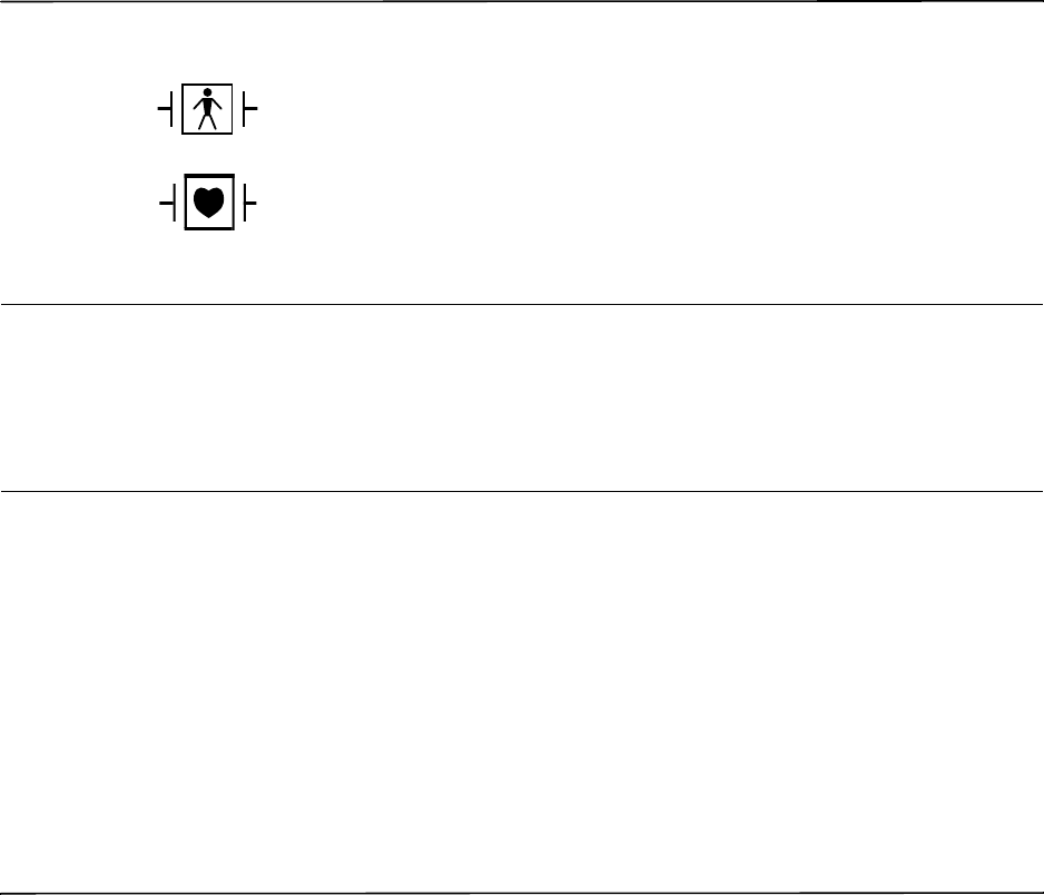
9650-0912-06 Rev. G ZOLL R Series Operator’s Guide 5–1
Chapter 5
Synchronized Cardioversion
WARNING! Only skilled personnel trained in Advanced Cardiac Life Support and familiar with
equipment operation should perform synchronized cardioversion. The precise cardiac
arrhythmia must be determined before attempting defibrillation or cardioversion.
Before attempting synchronized cardioversion, ensure that ECG signal quality is
sufficient to minimize the risk of synchronizing on artifact.
Certain arrhythmias, such as ventricular tachycardia, atrial fibrillation, and atrial flutter,
require synchronizing the defibrillator discharge with the ECG R-wave to avoid the induction
of ventricular fibrillation. In this case, a synchronizing (Sync) circuit within the defibrillator
detects the patient’s R-waves. When the SHOCK button (or buttons, if using paddles) is
pressed and held, the unit discharges with the next detected R-wave, thus avoiding the
vulnerable T-wave segment of the cardiac cycle.
When in the Sync mode, the unit displays markers () above the ECG trace to indicate the
points in the cardiac cycle (R waves) where discharge can occur.
Paddles are a defibrillation-protected Type BF patient connection.
ECG leads are a defibrillation-protected Type CF patient connection.

CHAPTER 5SYNCHRONIZED CARDIOVERSION
5–2 www.zoll.com 9650-0912-06 Rev. G
Verify that markers are clearly visible on the monitor and their location is appropriate and
consistent from beat to beat. If necessary, use the LEAD and SIZE buttons to establish settings
that yield the most consistent Sync marker pattern.
The synchronized cardioversion procedure for ZOLL hands-free therapy electrodes is identical
to that for paddles with the exception of the SHOCK button location.
The R Series defibrillator supports two types of synchronized cardioversion:
•Synchronized Cardioversion — The R Series monitors the patient’s ECG and
synchronizes shock delivery with this ECG source. For instructions, refer to “Synchronized
Cardioversion Procedure” below.
•Remote Synchronized Cardioversion — An external device (such as a patient monitor)
monitors the patient’s ECG and provides a synchronization pulse to the R Series’ Sync
In/Marker Out connector. The R Series synchronizes shock delivery with these external
pulses.
Note: When using the Remote Sync function, the procedure and displayed information are
different. Make sure to follow the instructions for Remote Synchronized Cardioversion
on page 5-5.
Synchronized Cardioversion Procedure
Determine the Patient’s Condition and Provide Care Following Local
Medical Protocols
Prepare Patient
Remove all clothing covering the patient’s chest. Dry chest if necessary. If the patient has
excessive chest hair, clip or shave it to ensure proper adhesion of the electrodes.
Attach ECG electrodes as described in“Monitoring Electrodes Attachment” on page 9-3.
A standard ECG cable and ECG electrodes are recommended for use during cardioversion.
Hands-free therapy electrodes may be used as an ECG source. Signal quality will be equal to
that of standard leads except immediately following a discharge when there may be more noise
due to muscle tremors, especially if an electrode is not in complete contact with the skin.
Attach hands-free therapy electrodes according to instructions on the electrode packaging and
as described in “Therapy Electrode Application” on page 3-6.
Ensure that the therapy electrodes are making good contact with the patient’s skin and are not
covering any part of any other electrodes.
Connect the hands-free therapy electrodes to the OneStep cable if not preconnected.
Marker indicates each detected
R wave during synchronization
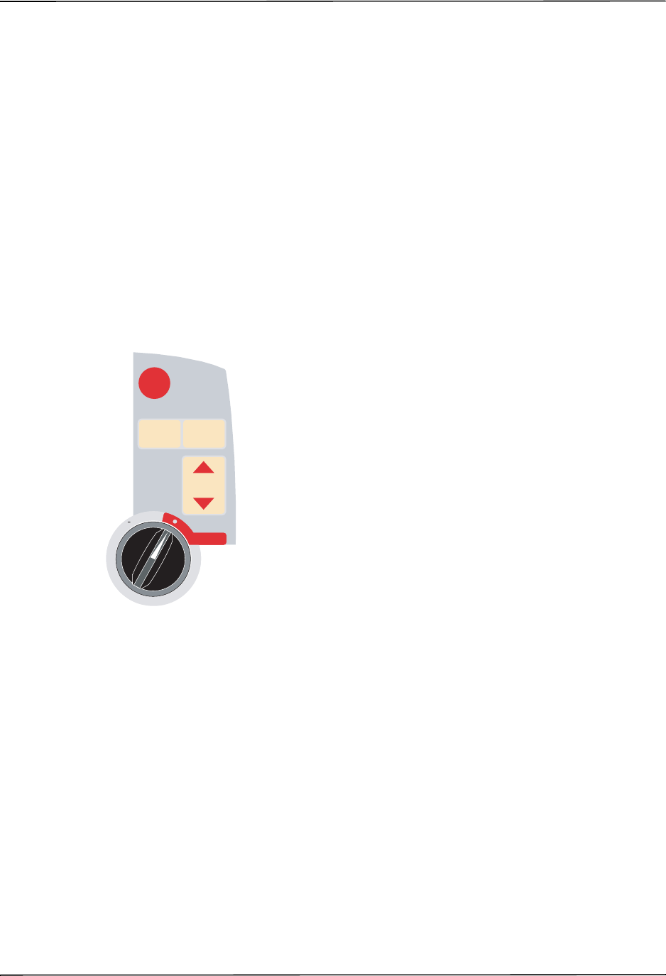
Synchronized Cardioversion Procedure
9650-0912-06 Rev. G ZOLL R Series Operator’s Guide 5–3
If therapy electrodes are not making good contact with the patient’s skin, the unit issues the
messages CHECK PADS and POOR PAD CONTACT and does not allow delivery of energy. If a
short circuit exists between the electrodes, the unit issues the message DEFIB PAD SHORT.
An ECG LEAD OFF condition prevents synchronized discharge if leads are selected as the
ECG source. This condition does not prevent the use of the defibrillator; it simply prevents use
in a synchronized manner.
If paddles are being used for synchronized cardioversion, refer to “Emergency Defibrillation
Procedure with Paddles” on page 3-1 for preparing paddles, applying paddles, charging the
defibrillator, and delivering a shock. Note, however, that synchronized discharge with paddles
as an ECG source is discouraged since the artifact induced by moving the paddles may
resemble an R-wave and trigger defibrillator discharge at the wrong time.
1 Select DEFIB
Turn the Mode Selector to DEFIB. Select the desired energy using the up and down arrow keys
on the front panel (or sternum paddle if using paddles).
Press the Sync On/Off softkey
Your system will be in Sync mode once you press the Sync On/Off softkey if your R Series is
not configured to support Remote Sync. However, if your R Series is configured to support
Remote Sync, pressing the Sync On/Off softkey will cause two other softkeys to be displayed:
Remote Sync and Sync. Press the Sync softkey to enter Sync mode.
The selected energy level is displayed on the monitor.
A Sync marker () appears on the monitor above each detected R-wave to indicate where
discharge will occur.
Verify that the markers are clearly visible on the monitor and their location is appropriate and
consistent from beat to beat. If necessary, use the LEAD and SIZE buttons to establish settings
that yield the best display.
3
1
SHOCKSHOCK
2
ENERGY
SELECT
ENERGY
SELECT
ANALYZEANALYZE CHARGECHARGE
DEFIB
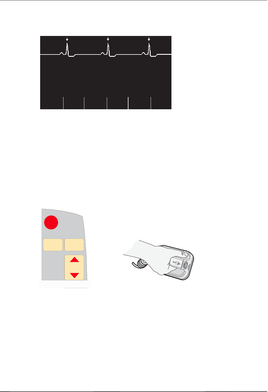
CHAPTER 5SYNCHRONIZED CARDIOVERSION
5–4 www.zoll.com 9650-0912-06 Rev. G
A SYNC XXXJ SEL. message appears on the display. If DEFIB XXXJ SEL. appears, press the
Sync On/Off softkey. (If your unit supports Remote Sync, you must also press the Sync
softkey.) Two quick beeps sound.
Unless otherwise configured, the unit automatically exits Sync mode after each shock and when
the Mode Selector is moved to MONITOR, PACER or OFF.
To reactivate Sync mode, press the Sync On/Off softkey again. (If your unit supports Remote
Sync, press the Sync softkey again.) Changing the selected energy levels does not cause the
unit to leave Sync mode.
Note that the unit can be configured to stay in Sync mode after defibrillation, if desired. Refer
to the R Series Configuration Guide for instructions.
2 Charge Defibrillator
Press the CHARGE button on the front panel or on the apex paddle handle.
To abort charging and increase or decrease the selected energy after the CHARGE button has
been pressed, use the ENERGY SELECT buttons on either the defibrillator front panel or the
sternum paddle. Press the CHARGE button again to charge the unit to the newly selected
energy level.
After charging the unit to the selected energy, either the front panel SHOCK button or the
APEX paddle charge indicator illuminates. A distinctive audible tone sounds and the SYNC
XXXJ READY message is displayed.
The defibrillator is now ready to deliver therapy.
SYNC 120J SEL.
Code
MarkerOptions
00:01
ECG
Param
Report
Data
Sync
On/Off
Alarms
3
SHOCKSHOCK
ENERGY
SELECT
ENERGY
SELECT
ANALYZEANALYZE CHARGECHARGE
2
1
RELEASE
RELEASE
or

Remote Synchronized Cardioversion Procedure
9650-0912-06 Rev. G ZOLL R Series Operator’s Guide 5–5
3 Deliver SHOCK
WARNING! Warn all persons in attendance of the patient to STAND CLEAR prior to defibrillator
discharge.
Verify that no one is in contact with the patient, monitoring cable or leads, bed rails, or
any other potential current pathways.
Verify that the ECG waveform is stable and that Sync markers appear over each R-wave.
Press and hold the illuminated SHOCK button on the front panel, (or simultaneously press and
hold both paddle SHOCK buttons) until energy is delivered to the patient. The defibrillator will
discharge with the next detected R wave.
Note: If the defibrillator is not discharged within 60 seconds after reaching the selected
energy level, the unit automatically disarms itself. During the ten seconds prior to this
internal disarm, the charge ready tone beeps intermittently. The charge ready tone then
stops, and the defibrillator remains in Sync mode.
Once the energy is delivered, the display simultaneously shows XXXJ DELIVERED and DEFIB
XXXJ SEL. After approximately 5 seconds, the XXXJ DELIVERED message disappears and the
DEFIB XXXJ SEL. message remains to indicate the selected energy level.
If additional countershocks are necessary, readjust the energy level as necessary, press the
Sync On/Off softkey, followed by the Sync softkey (if your unit supports Remote Sync), and
repeat. Note that SYNC XXXJ SEL must be displayed prior to pressing the CHARGE button.
If the ANALYZE button is pressed while the unit is in Sync mode, the unit displays the
REMOVE SYNC message and does not allow ECG rhythm analysis until the unit is taken out of
Sync mode.
Remote Synchronized Cardioversion Procedure
The R Series may be configured to receive defibrillation synchronization pulses from a remote
ECG monitoring device. See the R Series Configuration Manual. Be sure that the remote
device is connected to the Sync In/Marker Out connector on the R Series unit. The remote
device must have a Sync out connector and a cable must be provided to connect the two
devices. Ensure the remote device conforms with the Sync In/Marker Out specifications
(described in Appendix A, “Defibrillator Specifications”).
WARNING! A lethal arrhythmia may be induced through improper synchronization. Qualified
personnel within the hospital should verify synchronization delay for the entire remote
monitor and defibrillator system prior to clinical use. Synchronization delay for the
system as a whole must not exceed 60 msec.
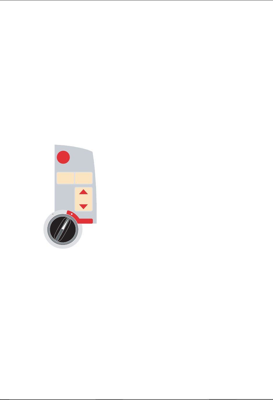
CHAPTER 5SYNCHRONIZED CARDIOVERSION
5–6 www.zoll.com 9650-0912-06 Rev. G
Determine the Patient’s Condition and Provide Care Following Local
Medical Protocols
Prepare Patient
Prepare the patient as described in “Prepare Patient” on page 5-2.
Follow the instructions provided with the external monitoring device to prepare the patient for
ECG monitoring and synchronization with a separate defibrillator.
1 Select DEFIB
Turn the Mode Selector to DEFIB.
Select the desired energy using the up and down arrow keys on the front panel (or sternum
paddle if using paddles).
Press Sync On/Off softkey, then press the Remote Sync Softkey
The selected energy level is displayed on the monitor.
The words “REMOTE SYNC” are displayed in place of the ECG trace, and a REMOTE SYNC
XXXJ SEL. message appears on the display.
The ECG heartbeat indicator will flash with each synchronization pulse received from the
remote monitoring device.
Unless otherwise configured, the unit automatically exits Sync mode after each shock, and if
the Mode Selector is moved to MONITOR, PACER or OFF.
Press the Sync On/Off, Remote Sync softkey sequence again to reactivate Remote Sync mode.
Changing the selected energy levels does not cause the unit to leave Remote Sync mode.
View the ECG trace on the remote device’s display. Verify that Sync markers appear with each
R-wave. The Sync markers will appear as described in the remote device’s user manual.
3
1
SHOCKSHOCK
2
ENERGY
SELECT
ENERGY
SELECT
ANALYZEANALYZE CHARGECHARGE
DEFIB
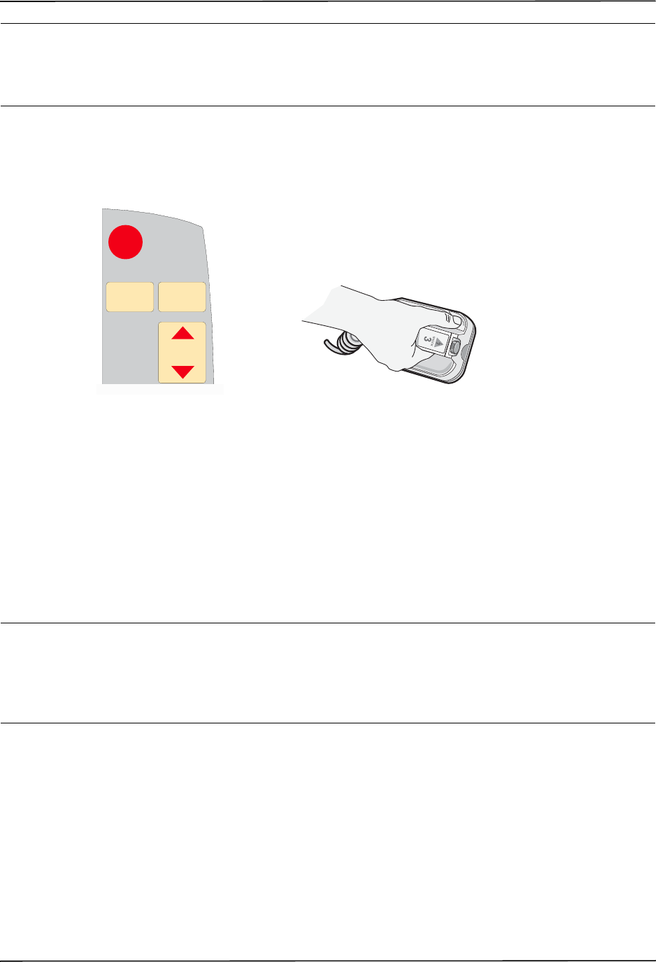
Remote Synchronized Cardioversion Procedure
9650-0912-06 Rev. G ZOLL R Series Operator’s Guide 5–7
WARNING! Verify the ECG waveform is stable and that a Sync marker appears only with R-waves.
If Sync markers are not present on the remote device display, or do not appear to be
nearly simultaneous with each R-wave, do not proceed with synchronized
cardioversion.
2 Charge Defibrillator
Press the CHARGE button on the front panel or, if using paddles, on the apex paddle handle.
To abort charging and increase or decrease the selected energy after the CHARGE button has
been pressed, use the ENERGY SELECT buttons on either the defibrillator front panel or the
sternum paddle. Press the CHARGE button again to charge the unit.
After charging the unit to the selected energy, either the front panel SHOCK button or, the apex
paddle charge indicator illuminates. A distinctive audible tone sounds and the energy ready
REMOTE SYNC XXXJ READY message is displayed.
The defibrillator is now ready to deliver therapy.
3 Deliver SHOCK
WARNING! Warn all persons in attendance of the patient to STAND CLEAR prior to defibrillator
discharge.
Verify that no one is in contact with the patient, monitoring cable or leads, bed rails, or
any other potential current pathways.
Press and hold the illuminated SHOCK button on the front panel, or simultaneously press and
hold both paddle SHOCK buttons until energy is delivered. The defibrillator will discharge
with the next remote synchronization pulse.
Note: If the defibrillator is not discharged within 60 seconds after reaching the selected
energy level, the unit automatically disarms itself. During the ten seconds prior to this
internal disarm, the charge ready tone beeps intermittently. The charge ready tone then
stops and the defibrillator remains in Remote Sync mode.
3
SHOCKSHOCK
ENERGY
SELECT
ENERGY
SELECT
ANALYZEANALYZE CHARGECHARGE
2
1
RELEASE
RELEASE
or

CHAPTER 5SYNCHRONIZED CARDIOVERSION
5–8 www.zoll.com 9650-0912-06 Rev. G
Once the energy is delivered, the display simultaneously shows XXXJ DELIVERED and DEFIB
XXXJ SEL. After approximately 5 seconds, the XXXJ DELIVERED message disappears and the
DEFIB XXXJ SEL. message remains to indicate the selected energy level.
If additional countershocks are necessary, readjust the energy level as necessary, press the
Sync On/Off, and then the Remote Sync softkeys and repeat. Note that REMOTE SYNC XXXJ
SEL must be displayed prior to pressing the CHARGE button.
If the ANALYZE button is pressed while the unit is in Remote Sync mode, the unit displays the
REMOVE SYNC message and disallows ECG rhythm analysis until the unit is taken out of Sync
mode.
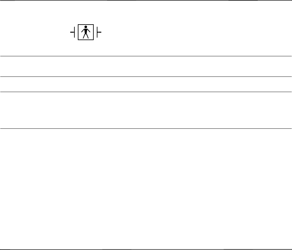
9650-0912-06 Rev. G ZOLL R Series Operator’s Guide 6–1
Chapter 6
Real CPR Help
WARNING! The Real CPR Help function is fully functional only when using adult CPR electrodes.
Do not use Adult CPR electrodes with patients under 8 years of age.
WAR NIN G! U se only Pediatric CPR electrodes with patients under 8 years of age. The use of
Pediatric CPR electrodes enables the R Series unit to display Idle Time and
Compression Rate and Depth measurements. Pediatric CPR electrodes do not enable
Real CPR voice prompts or any visual indication of ineffective CPR.
When used with OneStep CPR electrodes or OneStep Complete electrodes, the R Series unit
can provide rescuers with feedback about the quality of CPR they are delivering to their
patients. The way in which feedback is provided varies with respect to the operational mode
and user configuration, but is derived from compression rate and depth measurements.
When applied according to package instructions, ZOLL OneStep CPR and OneStep Complete
electrodes provide a chest compression sensor that is located between the rescuer’s hands and
the patient’s lower sternum. This sensor monitors the rate and depth of chest compressions and
sends this information to the R Series unit for processing and display.
The R Series defibrillator uses this information to provide feedback to the rescuer in one or
more of the following forms:
•CPR Index
Real CPR Help is defibrillation-proof Type BF equipment.

CHAPTER 6REAL CPR HELP
6–2 www.zoll.com 9650-0912-06 Rev. G
•CPR Idle Time Display
•CPR Rate Metronome
•Voice prompts
•Chest Compressions Waveform display
•FULLY RELEASE display prompt (if configured)
Real CPR Help Field
Whenever OneStep CPR, or OneStep Complete electrodes are connected to the R Series
defibrillator, the unit illuminates the Real CPR Help field in the upper center portion of the
display. This field includes the indicators described in the next sections.
CPR Index (Optional/Adult Only)
This diamond-shaped figure provides a quick, overall indicator of how well the rescuer's
combined rate and depth of chest compressions match the AHA/ERC recommendations for
adult CPR.
Before chest compressions begin (and after each shock), the CPR Index is displayed as a
hollow outline. This index starts to fill from the center out as compressions begin, and becomes
fully filled when consistent chest compression depth exceeding 1.5 or 2 inches, depending on
the configuration, and rate exceeding 90 compressions per minute (cpm) are simultaneously
achieved. Should the chest compression rate or depth begin to fall below the AHA/ERC
recommended levels, the Index will only partially fill to indicate the need for more vigorous
efforts. Following the cessation of compressions, the Index’s fill level gradually decreases until
a hollow outline is displayed after a short period of time.
When complete filling of the CPR Index has not been achieved due to diminished compression
rate or depth, and the CPR Dashboard is configured Off, the R Series will display the words
RATE and/or DEPTH to assist the rescuer in determining whether chest compression rate or
depth should be increased. When an appropriate rate or depth has been achieved, 80 cpm and
1.5 or 2 inches, respectively, one or both of these words will disappear from the display.
This feature is unavailable while using Pediatric CPR electrodes.
CPR Idle Time Display
This display indicates the elapsed time in minutes and seconds since the last detected chest
compression. When compressions are being delivered, this time display will be blanked. Three
seconds following the cessation of compressions, the display will illuminate and show the
elapsed time since the last detected compression. If no compressions have been delivered for
more than 20 minutes, dashes (---) will be displayed in this time field.
CPR Rate and Depth Display
If the CPR Dashboard is configured On and the CPR Idle Time is not displayed, the Rate and
Depth values will be displayed in the Real CPR Help field. The values will be highlighted and
displayed in red if they are below the appropriate values (adult CPR electrodes only).

Real CPR Help Field
9650-0912-06 Rev. G ZOLL R Series Operator’s Guide 6–3
Compression Release Bar (Adult only)
If the CPR Dashboard is configured On, the Compression Release Bar shows the release of the
chest compression by the rescuer. When the release of the chest is properly administered (fully
released), the bar will fill all the way to the top.
This feature is unavailable while using Pediatric CPR electrodes.
CPR Metronome
The R Series unit includes a CPR metronome feature that can be used to encourage rescuers to
perform chest compressions at the AHA/ERC recommended rate of 100 compressions per
minute. This feature can be configured.
When activated, the metronome beeps at the AHA/ERC recommended rate to provide a
compression rhythm for rescuers to follow. The metronome is silent when no chest
compressions are being detected by CPR-equipped hands-free therapy electrodes.
When Manual and Advisory modes are configured to “Yes,” the metronome only beeps when
chest compressions are detected and their rate falls below the AHA/ERC recommended levels.
When compressions are being performed at 80 compressions per minute or higher, the
metronome is silent. Should the detected compression rate fall below this level, the metronome
will begin beeping until recommended compression rates are consistently achieved over several
compression cycles. The metronome stops beeping approximately 2 seconds after the last chest
compression is detected.
When Manual and Advisory modes are configured to “Continuous,” the metronome beeps as
long as compressions are detected, even when they are being performed at 80 compressions per
minute or higher. The metronome stops beeping approximately 2 seconds after the last chest
compression is detected.
Fully Release prompt
The R Series unit can be configured to display the text prompt, FULLY RELEASE, which
reminds rescuers to lift (fully release) their hands from the patient’s chest during compressions
to allow full recoil.
By default, the FULLY RELEASE text prompt is not enabled.
CPR
PPI
Release
Depth Rate
1.8 170
(in) (cpm)
CPR Index
CPR Dashboard
Compression Release Bar
Depth and Rate Indicators

CHAPTER 6REAL CPR HELP
6–4 www.zoll.com 9650-0912-06 Rev. G
This feature is unavailable while using Pediatric CPR electrodes.
CPR Voice Prompts (Adult only)
The R Series unit can be configured to issue voice prompts related to the depth of chest
compressions as feedback to rescuers performing CPR. Two voice prompts are available for
this purpose:
•Push Harder
•Good Compressions
When chest compressions are detected but their depth is consistently less than 1.5 or 2 inches
(3.8 or 5 cm), depending on the configuration, the defibrillator will issue the prompt “Push
Harder” every 15 seconds. If the rescuer responds by increasing compression depth to more
than 1.5 or 2 inches (3.8 or 5 cm), depending on the configuration, on a consistent basis, the
unit will issue a “Good Compressions” prompt.
See the R Series Configuration Guide for information on enabling/disabling CPR voice
prompts.
CPR Voice prompts are unavailable while using Pediatric CPR electrodes.
Chest Compressions Bar Graph
The R Series unit can display a CPR compression bar graph computed from the CPR sensor
signals. This bar graph, representing depth of compression, is presented on a displacement scale
with a reference marker at 1.5 or 2.0 inches, depending on the configuration. When the full
width of the trace is visible, the unit displays a minimum of 12 seconds of compression data.
Displaying the CPR Bar Graph
To display the CPR displacement bar graph in the Trace 2 or 3 position:
1. Press the Options softkey, then press Traces.
2. Press either the Trace 2 or Trace 3 softkey.
3. Press CPR.
Note: Note: The CPR softkey appears only when OneStep CPR or OneStep Complete
electrodes are in use.

9650-0912-06 Rev. G ZOLL R Series Operator’s Guide 7–1
Chapter 7
See-Thru CPR (Optional)
WARNING! The See-Thru CPR filter works only when the R Series defibrillator is monitoring CPR.
The See-Thru CPR filter stops if:
— The unit is in pace mode.
— Patient impedance is invalid.
— OneStep CPR electrodes or OneStep Complete electrodes are no longer detected.
The See-Thru CPR filter will not remove all CPR artifact. Always stop CPR to verify
the patient’s ECG rhythm before making treatment decisions.
The See-Thru CPR filter does not operate during ECG rhythm analysis. Always stop
chest compressions during ECG rhythm analysis to avoid incorrect results caused by
the presence of CPR artifact.
Diagnostic bandwidth is never applied to the See-Thru CPR waveform.
See-Thru CPR enables the rescuer to see a close approximation of the patient’s underlying ECG
rhythm while performing CPR. See-Thru CPR is available if the R Series is monitoring CPR.
Chest compressions introduce CPR artifact into the ECG signal. See-Thru CPR uses a filter
that relies on the correlation between CPR compressions, as detected by the ZOLL Onestep
CPR or OneStep Complete electrodes, and the CPR artifact to remove much, but not all, of the
artifact from the ECG signal. Under some conditions, residual noise after filtering can obscure
the ECG rhythm, requiring the rescuer to stop CPR to assess the ECG. For example, in the case
of asystole or low amplitude PEA, the residual artifact seen after filtering may look like fine
ventricular fibrillation.

CHAPTER 7SEE-THRU CPR (OPTIONAL)
7–2 www.zoll.com 9650-0912-06 Rev. G
Because the filtered ECG signal may contain residual chest compression and/or filtering
artifacts, a rescuer should always follow the standard procedure of stopping CPR to assess the
patient’s ECG rhythm before determining treatment.
Using See-Thru CPR
To use See-Thru CPR
•The R Series unit must be monitoring CPR.
•OneStep CPR or OneStep Complete electrodes must be attached to the unit.
When chest compressions begin, the R Series unit automatically starts filtering the CPR artifact
after detecting the first 3 to 6 compressions.
The filtered ECG, with the label “FIL,” may be displayed on the second or third trace (by
selecting FILT ECG in the Trace2 or Trace3 menu). See-Thru CPR filtering continues as long
as the OneStep CPR or OneStep Complete electrodes detect compressions and patient
impedance is valid. When no compressions are detected or one of the conditions noted above
occurs, See-Thru CPR filtering stops, and unfiltered ECG signals are displayed. When
compressions resume, filtering automatically restarts after 3 to 6 chest compressions.
Note: There is a delay of approximately 1/16 second between the See-Thru CPR waveform
and the Trace 1 ECG waveform.
If configured to display the CPR Dashboard, the R Series unit can also be configured to display
the filtered ECG in Trace1. When the unit is configured to display the filtered ECG in Trace1,
the softkey Disable Filt ECG appears, which you can press to disable display of the filtered
ECG in Trace1 and replace it with the unfiltered ECG. When the unit displays the unfiltered
ECG in Trace1, the softkey Enable Filt ECG appears, which can redisplay the filtered ECG in
Trace1.
Examples
The following examples show the effects of See-Thru CPR filtering on ECG signals
contaminated with CPR artifacts.
Each example includes:
•ECG signal with CPR artifact.
•ECG signal after the See-Thru CPR filter has removed CPR artifact.
•Indication of the period during which See-Thru CPR is active.
•CPR signal to show when CPR activity occurred.
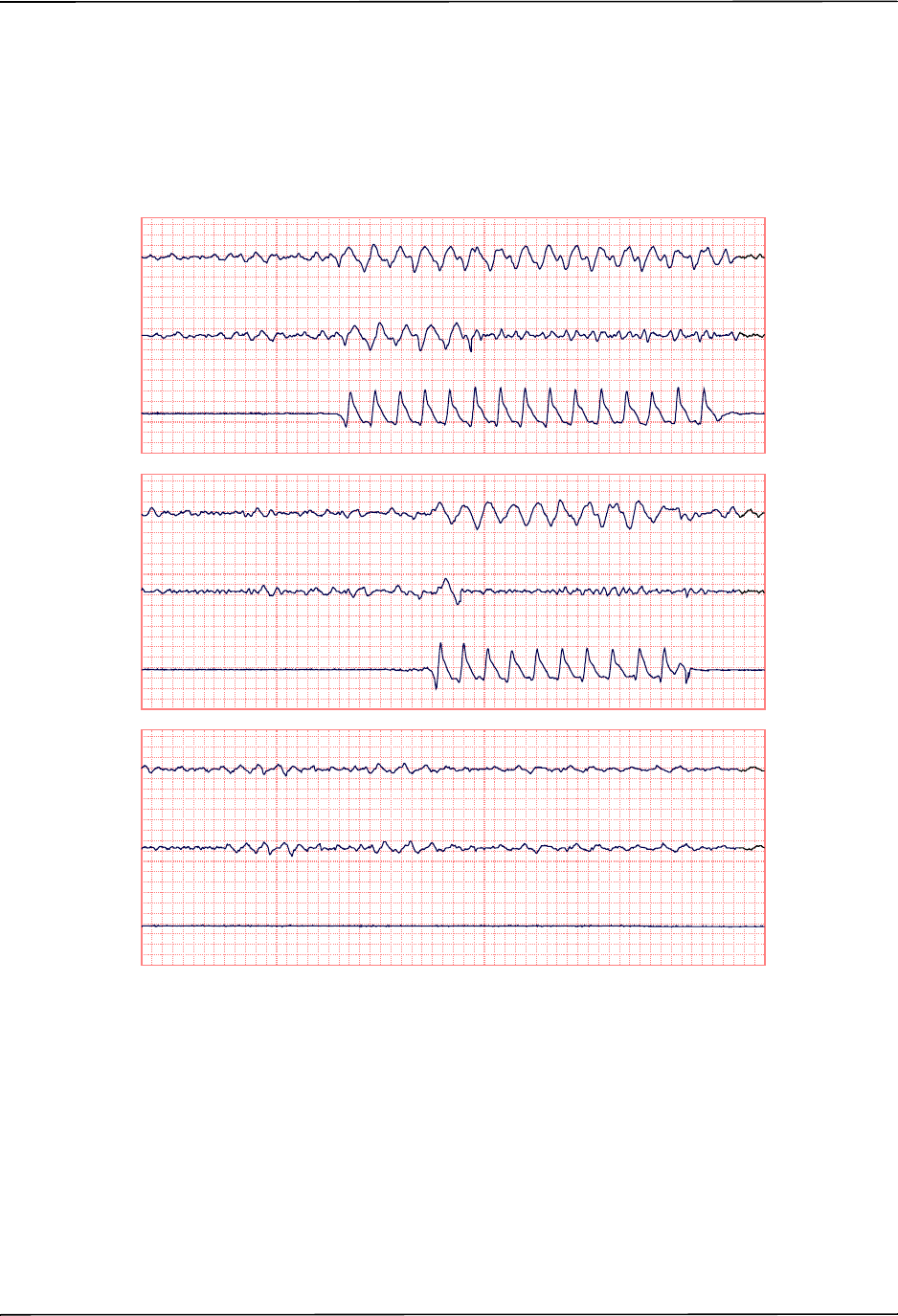
Using See-Thru CPR
9650-0912-06 Rev. G ZOLL R Series Operator’s Guide 7–3
The following figure shows a patient in Fine VF. It is difficult for a rescuer to discern this
rhythm during CPR compressions. When the CPR filter turns on, the Fine VF rhythm becomes
more obvious.
FineVF
0:00 0:12
Raw ECG Raw ECG
Filtered ECG Filtered ECG
CPR CPR
| Filter ON
•
FineVF
0:12 0:24
Raw ECG Raw ECG
Filtered ECG Filtered ECG
CPR CPR
| Filter OFF
•| Filter ON
•
FineVF
0:24 0:36
Raw ECG Raw ECG
Filtered ECG Filtered ECG
CPR CPR
| Filter OFF
•
12.5 mm/sec, 5 mm/mV
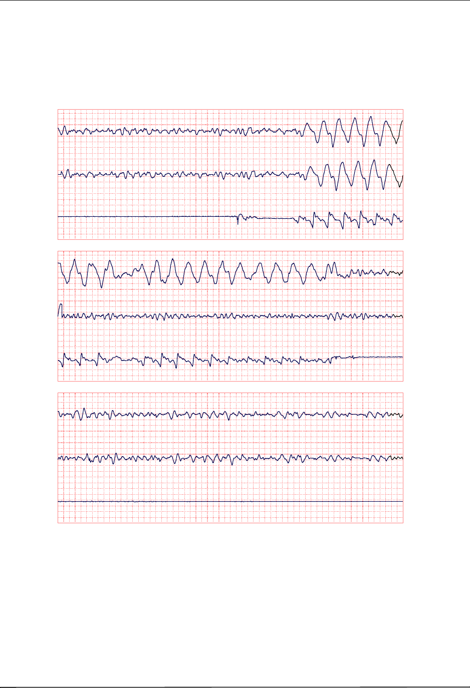
CHAPTER 7SEE-THRU CPR (OPTIONAL)
7–4 www.zoll.com 9650-0912-06 Rev. G
The following figure shows a patient in VF, which, during compressions, is slightly more
difficult to discern. When viewing this ECG, it is possible to view the underlying rhythm as the
filter is able to reject all of the CPR artifact.
CoarseVF
0:00 0:12
Raw ECG Raw ECG
Filtered ECG Filtered ECG
CPR CPR
CoarseVF
0:12 0:24
Raw ECG Raw ECG
Filtered ECG Filtered ECG
CPR CPR
| Filter ON
•
CoarseVF
0:24 0:36
Raw ECG Raw ECG
Filtered ECG Filtered ECG
CPR CPR
| Filter OFF
•
12.5 mm/sec, 5 mm/mV
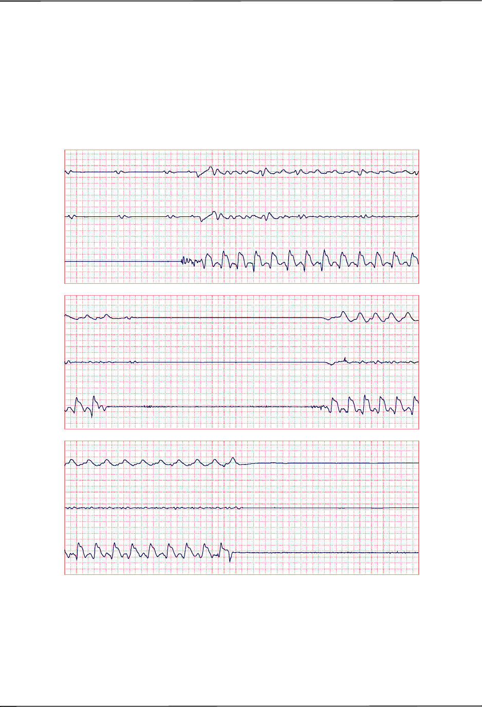
Using See-Thru CPR
9650-0912-06 Rev. G ZOLL R Series Operator’s Guide 7–5
The following figure shows a patient in PEA, which could easily be mistaken for Fine VF
because enough of the compression artifact leaks through to distort this signal. When the CPR
filter turns on, the PEA is still not obvious because of the left over ripples from the CPR signal.
About 14 seconds into this chart, the rhythm changes to asystole, which could easily be
mistaken for coarse VF. When the CPR filter turns on, the CPR compression ripples are still
obvious, making the rhythm look like Fine VF.
Asystole
0:00 0:12
Raw ECG Raw ECG
Filtered ECG Filtered ECG
CPR CPR
| Filter ON
•
Asystole
0:12 0:24
Raw ECG Raw ECG
Filtered ECG Filtered ECG
CPR CPR
| Filter OFF
•| Filter ON
•
Asystole
0:24 0:36
Raw ECG Raw ECG
Filtered ECG Filtered ECG
CPR CPR
| Filter OFF
•
12.5 mm/sec, 5 mm/mV
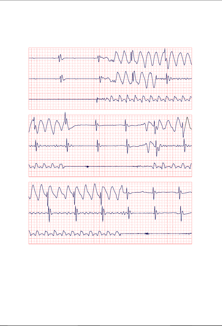
CHAPTER 7SEE-THRU CPR (OPTIONAL)
7–6 www.zoll.com 9650-0912-06 Rev. G
The following figure shows a patient with an organized rhythm where See-Thru CPR
effectively filters out artifact created by CPR.
SinusRhythm
0:00 0:12
Raw ECG Raw ECG
Filtered ECG Filtered ECG
CPR CPR
| Filter ON
•
SinusRhythm
0:12 0:24
Raw ECG Raw ECG
Filtered ECG Filtered ECG
CPR CPR
| Filter OFF
•| Filter ON
•
SinusRhythm
0:24 0:36
Raw ECG Raw ECG
Filtered ECG Filtered ECG
CPR CPR
| Filter OFF
•
12.5 mm/sec, 5 mm/mV
9650-0912-06 Rev. G ZOLL R Series Operator’s Guide 8–1
Chapter 8
Noninvasive Temporary Pacing
(Optional)
WARNING! To avoid risk of electrical shock, do not touch the gelled area of the hands-free therapy
electrodes while pacing.
Therapy electrodes should be replaced periodically. Consult electrode directions for
specific recommendations.
Prolonged pacing (in excess of 30 minutes), particularly in neonates or adults with
severely restricted blood flow, may cause burns. Periodic inspection of the underlying
skin is recommended.
If the unit was NOT turned off and less than 10 minutes have elapsed since the pacing
mode was last used, reactivating the pacer mode causes pacing to resume immediately
at the previously selected mA and ppm settings.
When ZOLL hands-free therapy electrodes are used, the patient connection is
considered to be defibrillation-protected Type BF.
ECG leads are a defibrillation-protected Type CF patient connection.

CHAPTER 8NONINVASIVE TEMPORARY PACING (OPTIONAL)
8–2 www.zoll.com 9650-0912-06 Rev. G
Noninvasive Temporary Pacing
R Series defibrillators with the pacer option contain a VVI demand pacemaker – a safe and
effective design for Noninvasive Temporary Pacemakers.
Proper demand pacing requires a reliable, high quality surface ECG signal. For best results:
•Apply both standard ECG monitoring electrodes and hands-free pacing therapy electrodes
(such as, OneStep electrodes or stat-padz) to the patient,
or
•Use OneStep Pacing electrodes, or OneStep Complete electrodes. These hands-free therapy
pads include both ECG monitoring and pacing/defibrillation electrodes in a single pad
assembly. They provide reliable ECG monitoring without the need to use separate ECG
leads. With these electrodes you must also use the OneStep Pacing cable.
Determine Patient Condition and Provide Care Following Local
Medical Protocols.
Prepare the Patient
Remove all clothing covering the patient’s chest. Dry chest if necessary. If the patient has
excessive chest hair, clip it to ensure proper adhesion of the electrodes.
1 Apply ECG Electrodes/Hands-Free Therapy Electrodes
The R Series supports two electrode configurations for pacing:
•OneStep Pacing Configuration
Simultaneous ECG monitoring and pacing can be performed with a single set of therapy
electrodes when using OneStep Pacing electrodes or OneStep Complete electrodes along
with a OneStep Pacing cable. The OneStep Pacing cable must be connected to both the MFC
and ECG connectors of the R Series unit. Attach OneStep electrodes according to
instructions on the electrode packaging. Then connect the electrodes to the OneStep Pacing
cable.
•Separate ECG Electrodes and Hands-free Therapy Electrodes Configuration
Apply ECG electrodes, attach lead wires, and connect the ECG cable to the R Series rear
panel (see page 9-3 for instructions on attaching ECG electrodes to the patient). Attach
hands-free therapy electrodes according to instructions on the electrode packaging. Connect
these therapy electrodes to the OneStep cable.
Therapy Electrode Application
WARNING! Poor adherence and/or air under the therapy electrodes can lead to the possibility of
arcing and skin burns.
1. Apply one edge of the pad securely to the patient.
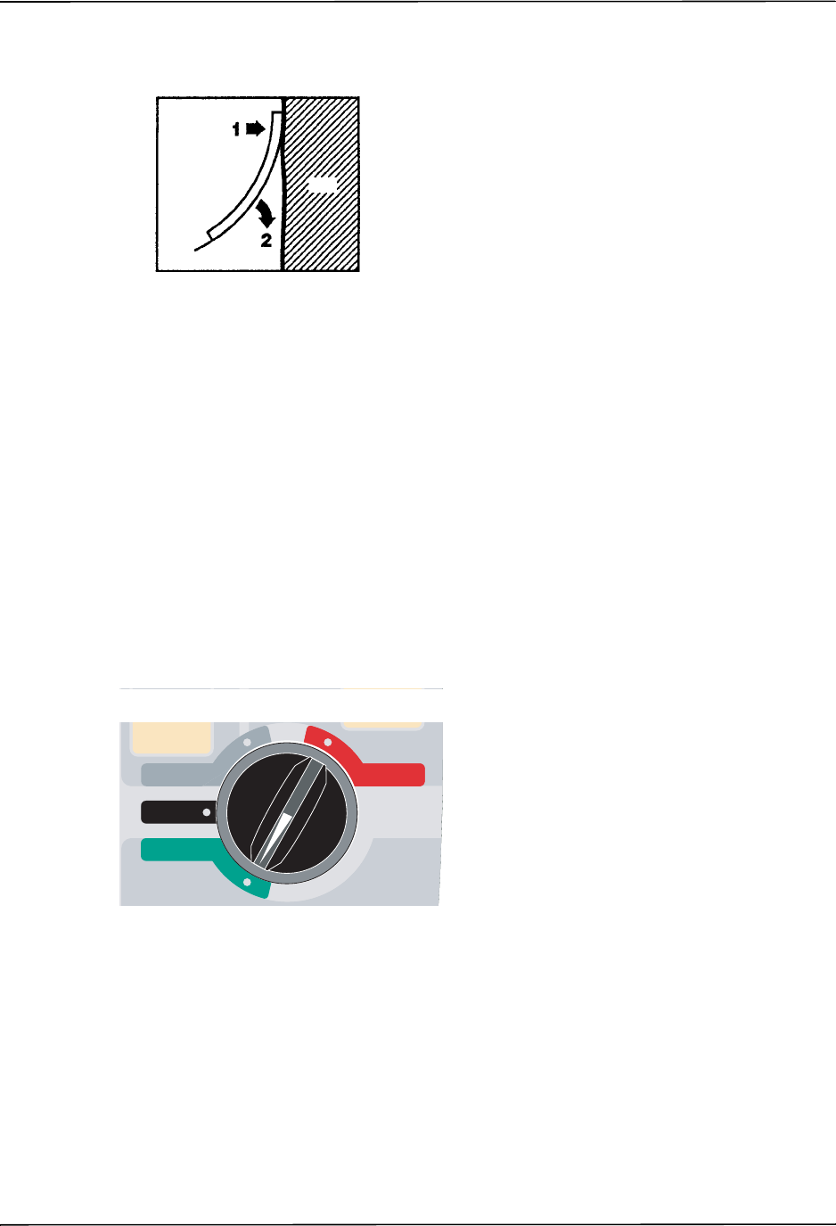
Noninvasive Temporary Pacing
9650-0912-06 Rev. G ZOLL R Series Operator’s Guide 8–3
2. Roll the pad smoothly from the applied edge to the other, being careful not to trap any air
pockets between the gel and skin.
3. Ensure that hands-free therapy electrodes are making good contact with the patient’s skin and
are not covering any part of any other ECG electrodes.
4. If using OneStep Pacing electrodes or OneStep Complete electrodes, select ECG lead P1, P2,
or P3; otherwise, select an appropriate ECG lead. Adjust ECG size for a clean, well-defined
ECG signal.
5. Verify proper R-wave detection. The heart-shaped symbol flashes with each R-wave when
proper detection is taking place. Adjust ECG size for a clean, well-defined ECG signal.
Note: When the OneStep Pacing electrode configuration is used and the unit is switched to
PACER mode, P3 is automatically selected as the ECG source. When separate ECG
electrodes and hands-free therapy electrodes are used, Lead II is automatically selected
as the ECG source.
While ECG signals acquired from P1, P2 or P3 are appropriate for ECG rhythm assessment and
determining electrical capture during pacing, they should not be used for diagnostic purposes.
Conventional ECG electrodes and cable should be used for this purpose.
2 Turn Selector Switch to PACER
Set the Pacer Output to 0 mA
If the unit has just been turned on, the PACER OUTPUT is automatically set to 0 mA.
3 Set Pacer Rate
Set the PACER RATE to a value 10-20 ppm higher than the patient’s intrinsic heart rate. If no
intrinsic rate exists, use 100 ppm.
Pad
Skin
1
RECORDER
DEFIB
OFF
MONITOR
PACER
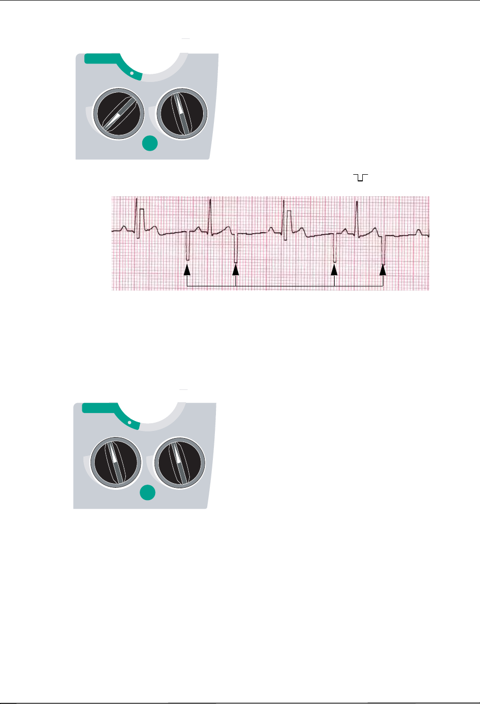
CHAPTER 8NONINVASIVE TEMPORARY PACING (OPTIONAL)
8–4 www.zoll.com 9650-0912-06 Rev. G
The pacer rate increments or decrements by a value of 2 ppm on the display when the knob is
turned.
Observe the pacing stimulus marker on the display or stripchart ( ) and verify that it is
well-positioned in diastole.
4 Set Pacer Output
Increase PACER OUTOUT until stimulation is effective (capture); the output mA value is
displayed. The pacer output increments and decrements by a value of 2 mA on the display
when the knob is turned.
Note: When the unit is switched out of PACER mode into DEFIB or MONITOR mode and
then switched back to PACER mode, within 10 minutes the pacer settings remain
unchanged.
If the unit is turned off for more than 10 seconds, the pacer’s power up default settings are
restored.
OUTPUT
mA
OUTPUT
mA
RATE
ppm
RATE
ppm
4:1
OFF
PACER
Pacing Stimuli
OUTPUT
mA
OUTPUT
mA
RATE
ppm
RATE
ppm
4:1
OFF
PACER
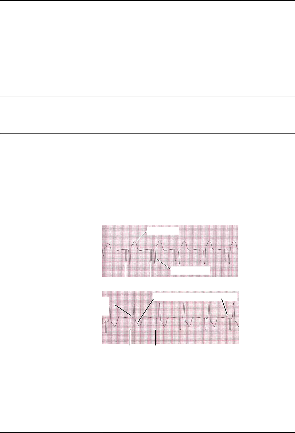
Noninvasive Temporary Pacing
9650-0912-06 Rev. G ZOLL R Series Operator’s Guide 8–5
5 Determine Capture
It is important to recognize when pacing stimulation has produced a ventricular response
(capture). Determination of capture must be assessed both electrically and mechanically in
order to ensure appropriate circulatory support of the patient.
Electrical capture is determined by the presence of a widened QRS complex, the loss of any
underlying intrinsic rhythm, and the appearance of an extended, and sometimes enlarged,
T-wave.
Ventricular response is normally characterized by suppression of the intrinsic QRS complex.
WARNING! Determination of electrical capture should only be performed by viewing the ECG trace
on the R Series display with its ECG connection directly attached to the patient. Use of
other ECG monitoring devices might provide misleading information due to the
presence of pacer artifacts.
Mechanical capture is assessed by palpation of the peripheral pulse.
To avoid mistaking muscular response to pacing stimuli for arterial pulsations, use ONLY the
following locations for palpating pulse during pacing:
•femoral artery
•right brachial or radial artery
Effective pacing
The following ECG traces illustrate typical examples of effective pacing.
Changing ECG leads and size can sometimes be helpful in determining capture.
Note: The shape and size of the paced ECG waveforms can vary depending on the ECG lead
configuration chosen; variation from patient to patient can be expected.
Large T wave
Negative R wave
Inverted T wave/ absence of P waves
Pacer Markers
Pacer Markers
Widened, positive QRS
(which looks like an
ectopic beat).
,
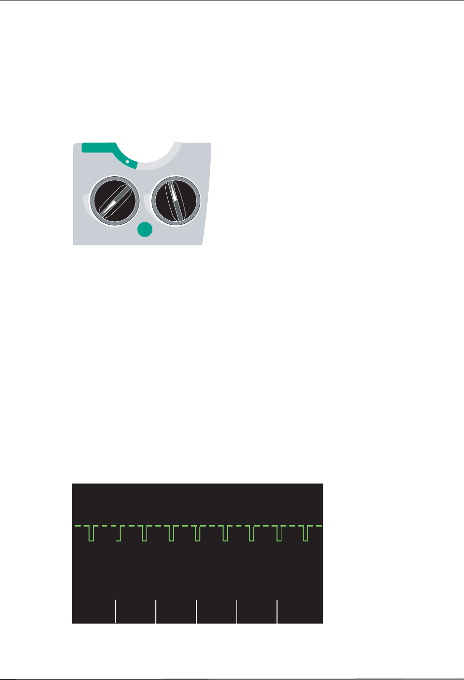
CHAPTER 8NONINVASIVE TEMPORARY PACING (OPTIONAL)
8–6 www.zoll.com 9650-0912-06 Rev. G
6 Determine Optimum Threshold
The ideal pacer current is the lowest value that maintains capture — usually about 10% above
threshold. Typical threshold currents range from 40 to 80 mA. Location of the hands-free
therapy or OneStep therapy electrodes affects the current required to obtain ventricular capture.
Typically the lowest threshold is obtained when the position of the electrodes provides the most
direct current pathway through the heart while avoiding large chest muscles. Lower stimulation
currents produce less skeletal muscle contraction and are better tolerated.
4:1 Mode
Pressing and holding the 4:1 button temporarily withholds pacing stimuli, thereby allowing you
to observe the patient’s underlying ECG rhythm and morphology.
When depressed, this button causes pacing stimuli to be delivered at ¼ of the indicated ppm
setting.
Pace Fault
If the unit is attempting to deliver pacing therapy and one of the following conditions occur, the
messages CHECK PADS and POOR PAD CONTACT are alternately displayed on the screen
and an audible alarm sounds:
•The OneStep cable is not connected to the device.
•The cable is defective.
•Therapy pads are not connected to the OneStep cable.
•The therapy pads are not making good skin contact.
The alarm will continue to sound until proper connections between the patient and pacer are
achieved and the leftmost softkey (Clear Pace Alarm) is pressed.
OUTPUT
mA
OUTPUT
mA
RATE
ppm
RATE
ppm
4:1
OFF
PACER
PACE
Clear
Pace
Alarm
00:01
Async
Pacing
On/Off
50 mA 70 PPM
_ _ _ _ _ _ _ _ _ _ _ _ _ _ _ _ _ _ _ _ _ _ _ _ _ _ _ _
ECG
CHECK PADS

Special Pacing Applications
9650-0912-06 Rev. G ZOLL R Series Operator’s Guide 8–7
Special Pacing Applications
Noninvasive Temporary Pacing can be performed in the Cardiac Catheterization Lab either for
emergency pacing or standby pacing. For pacing in X-ray and fluoroscopic applications, ZOLL
pro-padz® radiolucent hands-free therapy electrodes may be used.
Noninvasive Temporary Pacing can be performed in the Operating Room using ZOLL
pro-padz sterile hands-free therapy electrodes.
Caution Under certain conditions, it might not be possible to properly monitor or pace while
electrosurgical apparatus is operating. Observe the device carefully for evidence of proper
operation.
Standby Pacing
For certain patients at risk of developing symptomatic bradycardia, it may be advisable to use
the unit in standby mode. When used in standby mode, the unit automatically provides pacing
stimuli whenever the patient’s heart rate drops below the pacer rate setting. Patient’s ECG must
be monitored using one of the two electrode configurations described on page 8-2. To use the
device in standby mode:
1. Establish effective pacing (see instructions on previous pages). Note the mA output at
capture and run an ECG stripchart to document ECG morphology during capture.
2. Set the mA output 10% higher than the minimum mA output necessary to effect consistent
ventricular capture.
3. Turn the pacing rate (ppm) below the patient’s heart rate. This suppresses pacing unless the
patient’s own rate drops below the pacer rate setting. The pacing rate should be set at a level
sufficient to ensure adequate cardiac output.
4. Check the threshold periodically.
Asynchronous Pacing
If ECG electrodes are not available or there is some circumstance that prevents or interferes
with the surface ECG, the R Series delivers pacemaker pulses asynchronously.
Asynchronous pacing should be performed only in an emergency when no alternative is
available. To pace asynchronously:
Turn the Mode Selector to PACER.
Press the Async Pacing On/Off softkey.
Note: If the pacer output is set to 8 mA or higher, pacing stimuli begin immediately at the set
rate.
The display shows “ASYNC PACE” to indicate that asynchronous pacing has been activated.
The annotation “ASYNC PACE” is also printed on the stripchart when activated by the

CHAPTER 8NONINVASIVE TEMPORARY PACING (OPTIONAL)
8–8 www.zoll.com 9650-0912-06 Rev. G
RECORDER button, and printed on the corresponding summary report. To return to demand
pacing, press the Async Pacing On/Off softkey again. The display returns to “PACE.”
Pace stimuli are also delivered asynchronously whenever there is an ECG LEAD OFF
condition. Due to the lead off condition, no ECG waveforms will be displayed when pacing by
this method. Use other means to determine capture such as checking the patient’s pulse.
When asynchronously pacing with an ECG LEAD OFF condition, the rate and mA should be
set at the known capture level or high enough (100mA) to presume capture.
Pediatric Pacing
Noninvasive pacing of pediatric patients is performed in an identical manner to adult pacing.
Smaller size pediatric therapy electrodes (OneStep pediatric electrodes) are available for
patients weighing less than 33 lbs/15 kg. Continuous pacing of neonates can cause skin burns.
If it is necessary to pace for more than 30 minutes, periodic inspection of the underlying skin is
strongly advised. Carefully follow all instructions on electrode packaging.
ASYNC PACE
Param
00:01
Alarms
Async
Pacing
On/Off
50 mA 70 PPM
Options
Report
Data
Code
Marker