Zoll Medical XSCP0001 X Series User Manual 9650 1355 01 SF 1
Zoll Medical Corp X Series 9650 1355 01 SF 1
User Manual
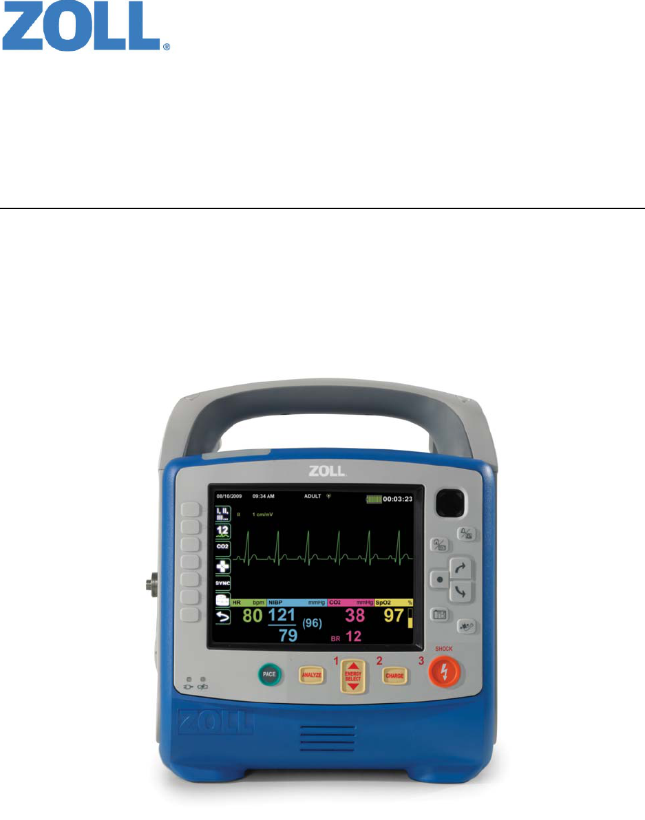
X Series™ Operator’s Guide
9650-1355-01 Rev. 1
DRAFT

The issue date for the X Series Operator's Guide (REF 9650-1355-01 Rev. 1) is November, 2011.
If more than 3 years have elapsed since the issue date, contact ZOLL Medical Corporation to determine if
additional product information updates are available.
Copyright © 2011 ZOLL Medical Corporation. All rights reserved. CPR-D-padz, pedi-padz, OneStep, Real
CPR Help, Rectilinear Biphasic, RescueNet, See-Thru CPR, stat-padz, SurePower, X Series, and ZOLL are
trademarks or registered trademarks of ZOLL Medical Corporation in the United States and/or other countries.
Masimo Rainbow and Masimo SET are trademarks or registered trademarks of Masimo Corporation in the
United States and/or other countries.
Propaq, Smartcuf and SureBP are trademarks or registered trademarks of Welch Allyn or its subsidiaries in the
United States and other countries.
All other trademarks are the property of their respective owners.
IC Model: XSCP-1
ZOLL International Holding B.V.
Newtonweg 18
6662 PV ELST
The Netherlands
Tel.: +31 (0) 481 366410
Fax: +31 (0) 481 366411
DRAFT COPY

9650-1355-01 Rev. 1 X Series Operator’s Guide i
Table of Contents
Chapter 1 General Information
Product Description ............................................................................................................ 1-1
X Series Optional Features ......................................................................................... 1-2
How to Use This Manual..................................................................................................... 1-3
Operator’s Guide Updates .................................................................................................. 1-3
Unpacking........................................................................................................................... 1-3
Symbols Used on the Equipment ....................................................................................... 1-4
Conventions........................................................................................................................ 1-7
X Series Indications for Use ............................................................................................... 1-7
Manual Defibrillation ................................................................................................... 1-8
Semiautomatic Operation (AED) ................................................................................ 1-8
ECG Monitoring .......................................................................................................... 1-9
CPR Monitoring .......................................................................................................... 1-9
External Transcutaneous Pacing ................................................................................ 1-9
Non-Invasive Blood Pressure Monitoring ................................................................. 1-10
Temperature Monitoring ........................................................................................... 1-10
SpO2 Monitoring ....................................................................................................... 1-10
Respiration Monitoring .............................................................................................. 1-10
CO2 Monitoring ......................................................................................................... 1-10
Invasive Pressure Monitoring ................................................................................... 1-10
12-Lead Analysis ...................................................................................................... 1-11
X Series Product Functions .............................................................................................. 1-11
Defibrillator Function ................................................................................................. 1-11
Defibrillator Output Energy ....................................................................................... 1-11
External Pacemaker ................................................................................................. 1-11
ECG Monitoring ........................................................................................................ 1-12
Electrodes ................................................................................................................. 1-12
Batteries .................................................................................................................... 1-12
Ready For Use (RFU) Indicator ................................................................................ 1-14
Safety Considerations....................................................................................................... 1-15
DRAFT COPY

TABLE OF CONTENTS
ii www.zoll.com 9650-1355-01 Rev. 1
Warnings........................................................................................................................... 1-15
General .... ................................................................................................................. 1-15
ECG Monitoring ........................................................................................................ 1-16
Defibrillation ........ ...................................................................................................... 1-17
Pacing ....................................................................................................................... 1-18
CPR ......... ................................................................................................................. 1-19
Pulse Oximeter ......................................................................................................... 1-19
Noninvasive Blood Pressure ..................................................................................... 1-20
IBP ........... .................................................................................................................1-20
CO2 ......... ................................................................................................................. 1-21
Respiration ................................................................................................................ 1-21
Ferromagnetic Equipment ........................................................................................ 1-21
Battery ..... ................................................................................................................. 1-21
Operator Safety ........................................................................................................ 1-22
Patient Safety ........................................................................................................... 1-23
Cautions............................................................................................................................ 1-24
Restarting the Defibrillator ................................................................................................ 1-25
FDA Tracking Requirements............................................................................................. 1-25
Notification of Adverse Events .................................................................................. 1-26
Software License .............................................................................................................. 1-26
Service.............................................................................................................................. 1-27
The ZOLL Serial Number.................................................................................................. 1-28
Chapter 2 Product Overview
Defibrillator Controls and Indicators.................................................................................... 2-1
The Front Panel .......................................................................................................... 2-2
Display Screen ............................................................................................................ 2-4
Battery Status and Auxiliary Power Indicators ............................................................ 2-6
Patient Cables and Connectors .................................................................................. 2-7
External Paddles ......................................................................................................... 2-9
Auxiliary Power Adapter ........................................................................................... 2-11
Navigating the Display Screen.......................................................................................... 2-12
Quick Access Keys ................................................................................................... 2-12
Navigation Keys ....................................................................................................... 2-15
Display Brightness .................................................................................................... 2-15
Common Tasks ................................................................................................................. 2-15
Changing the Display Brightness .............................................................................. 2-16
Replacing a Battery Pack on the X Series ................................................................ 2-16
Using Treatment Buttons .......................................................................................... 2-17
DRAFT COPY

9650-1355-01 Rev. 1 X Series Operator’s Guide ix
Chapter 19 Real CPR Help
CPR Dashboard................................................................................................................ 19-2
Rate and Depth Measurements ................................................................................ 19-2
CPR Release Indicator ............................................................................................. 19-2
Chest Compression Indicator ................................................................................... 19-2
CPR Metronome ............................................................................................................... 19-3
FULLY RELEASE Prompt................................................................................................. 19-3
CPR Voice Prompts (Optional) ......................................................................................... 19-3
CPR Idle Time Display...................................................................................................... 19-4
CPR Countdown Timer ..................................................................................................... 19-4
CPR Compression Bar Graph .......................................................................................... 19-4
Chapter 20 See-Thru CPR (Optional)
Using See-Thru CPR ........................................................................................................ 20-2
Examples . ................................................................................................................. 20-2
Chapter 21 Patient Data
Storing Data ...................................................................................................................... 21-1
Capturing a Data Snapshot............................................................................................... 21-2
Reviewing and printing snapshots ............................................................................ 21-2
Treatment Summary Report ............................................................................................. 21-2
Printing Treatment Summary Report ........................................................................ 21-3
Transferring Data to a USB Device................................................................................... 21-3
Clearing the Log ....................................................................................................... 21-4
Chapter 22 Wireless Communications
Wireless Icon .................................................................................................................... 22-2
Selecting and Creating a Temporary Access Point Profile ....................................... 22-3
Setting up Communications in the Supervisor Menu........................................................ 22-6
WiFi Access Point Profiles ........................................................................................ 22-8
Configuring Report Transmissions Via a Cellular Phone ........................................ 22-11
Configure RN12Lead Server .................................................................................. 22-13
View Distribution List .............................................................................................. 22-13
Sending a 12-lead report ................................................................................................ 22-13
Communications System Messages............................................................................... 22-15
DRAFT COPY

TABLE OF CONTENTS
x www.zoll.com 9650-1355-01 Rev. 1
Chapter 23 Printing
Printing Patient Data ......................................................................................................... 23-1
Printer Setup ............................................................................................................. 23-2
Automatic Prints ........................................................................................................ 23-2
Printing Waveforms .................................................................................................. 23-2
Printing Reports ........................................................................................................ 23-3
Printing Trends ......................................................................................................... 23-4
Chapter 24 Maintenance
Daily/Shift Check Procedure ............................................................................................. 24-2
Inspection ........... ...................................................................................................... 24-2
Defibrillator/Pacing Test with Hands-Free Therapy Electrodes......................................... 24-3
Defibrillator Testing with External Paddles........................................................................ 24-5
Recommended Minimum Preventive Maintenance Schedule .......................................... 24-7
Annually ... ................................................................................................................. 24-7
Guidelines for Maintaining Peak Battery Performance ..................................................... 24-7
Cleaning instructions ........................................................................................................ 24-8
Cleaning the X Series unit ........................................................................................ 24-8
Cleaning the NIBP Blood Pressure Cuff ................................................................... 24-8
Cleaning SpO2 Sensors ........................................................................................... 24-9
Cleaning Cables and Accessories ............................................................................ 24-9
Loading Recorder Paper ........................................................................................... 24-9
Cleaning the Print Head .......................................................................................... 24-10
Appendix A Specifications
Defibrillator..........................................................................................................................A-2
Monitor/Display .................................................................................................................A-14
Impedance Pneumography...............................................................................................A-15
Alarms...............................................................................................................................A-15
Recorder ...........................................................................................................................A-16
Battery . ............................................................................................................................A-17
General .............................................................................................................................A-17
Pacer ................................................................................................................................A-18
CO2 ..................................................................................................................................A-18
Pulse Oximeter .................................................................................................................A-19
Non-Invasive Blood Pressure ...........................................................................................A-21
Invasive Pressures ...........................................................................................................A-22
Temperature......................................................................................................................A-23
DRAFT COPY

9650-1355-01 Rev. 1 X Series Operator’s Guide xi
Clinical Trial Results for the Biphasic Waveform ..............................................................A-24
Randomized Multicenter Clinical Trial for Defibrillation of Ventricular Fibrillation
(VF) and Ventricular Tachycardia (VT) ...................................................................A-24
Randomized Multi-Center Clinical trial for Cardioversion of
Atrial Fibrillation (AF) ..............................................................................................A-25
Synchronized Cardioversion of Atrial Fibrillation ......................................................A-27
Electromagnetic Compatibility Guidance and Manufacturer’s Declaration .......................A-28
ECG Analysis Algorithm Accuracy....................................................................................A-32
Clinical Performance Results ....................................................................................A-32
Wireless Output Guidance and Manufacturer’s Declaration.............................................A-33
RF Transmission Emitted (IEC 60601-1-2) ...............................................................A-33
FCC Notice ...............................................................................................................A-33
Canada, Industry Canada (IC) Notices .....................................................................A-33
Appendix B Accessories
DRAFT COPY

9650-1355-01 Rev. 1 X Series Operator’s Guide 1-1
Chapter 1
General Information
Product Description
The ZOLL® X Series™ unit is an easy-to-use portable defibrillator that combines defibrillation
and external pacing with the following monitoring capabilities: ECG, CO-Oximeter, Non-
invasive Blood Pressure, IBP, CO2, Temperature, and Respiration. It has been designed for all
resuscitation situations and its rugged, compact, lightweight design makes it ideal for transport
situations. It is powered by auxiliary power and an easily replaced battery pack that is quickly
recharged in the device when it is connected to auxiliary power. In addition, the unit’s battery
may be recharged and tested using a ZOLL SurePower™ Battery Charger Station.
Note: The X Series has defibrillation and pacing functionality, but some of the monitoring
functions are optional features. See the complete list of options in Fig. 1-1. Optional
features are specified as “optional” within this guide.
The product is designed for use in both the hospital and the rugged EMS environment. The
device is a versatile automated external defibrillator with manual capabilities and may be
configured to operate in Manual, Advisory or Semiautomatic modes. It can be configured to
start up in Semiautomatic (AED) mode or manual mode.
When operating in manual configuration, the device operates as a conventional defibrillator
where the device’s charging and discharging is fully controlled by the operator. In Advisory and
AED modes, some features of the device are automated and a sophisticated detection algorithm
is used to identify ventricular fibrillation and determine the appropriateness of defibrillator
shock delivery. Units may be configured to automatically charge, analyze, recharge, and
prompt the operator to “PRESS SHOCK”, depending on local protocols. The unit is switched
from AED mode to Manual mode for ACLS use by pressing the appropriate key on the front
panel.
DRAFT COPY

CHAPTER 1GENERAL INFORMATION
1-2 www.zoll.com 9650-1355-01 Rev. 1
The X Series unit assists caregivers during cardiopulmonary resuscitation (CPR) by evaluating
the rate and depth of chest compressions and providing feedback to the rescuer.
Real CPR Help® requires the use of ZOLL OneStep™ CPR electrodes, OneStep™ Complete
electrodes, or CPR-D-padz®. When using these pads, the displayed ECG waveforms can be
adaptively filtered, using the See-Thru CPR® feature, to reduce the artifact caused by chest
compressions.
The unit has a large colorful LCD display of numerics and waveform data that provides easy
visibility from across the room and at any angle. ECG, plethysmograph, and respiration
waveform traces can be displayed simultaneously, giving easy access to all patient monitoring
data at once. The display screen is configurable, so you can choose the best visual layout to fit
your monitoring needs. The X Series includes a transcutaneous pacemaker consisting of a pulse
generator and ECG sensing circuitry. Pacing supports both demand and fixed noninvasive
pacing for adult patients and adolescent, child, and infant pediatric patients.
The X Series has a patient data review and collection system that allows you to view, store, and
transfer patient data. The X Series unit contains a printer and USB port, which you can use to
print the data and transfer it to a PC.
The X Series unit can send data through a wireless connection to remote locations. The
X Series unit can send 12-lead report snapshots (including trend data) to a recipient via a ZOLL
server. Full disclosure cases, which also contain trend data, can be automatically retrieved from
the X Series unit using ZOLL RescueNet or ePCR software.
X Series Optional Features
The following features are optional in the X Series unit.
Figure 1-1 X Series Optional Features
Optional Feature
12-Lead ECG with Interpretation
SpO2 (Masimo) with SpCO and SpMet
NIBP (with Smartcuf® and SureBPTM)
EtCO2 (Oridion® Microstream®)
Temperature
Invasive Pressures (3 Channels)
Advanced CPR Help
Pacing
DRAFT COPY

How to Use This Manual
9650-1355-01 Rev. 1 X Series Operator’s Guide 1-3
How to Use This Manual
The X Series Operator's Guide provides information operators need for the safe and effective
use and care of the X Series product. It is important that all persons using this device read and
understand all the information contained within.
Please thoroughly read the safety considerations and warnings section.
Procedures for daily checkout and unit care are located in the Chapter 24, "Maintenance".
Operator’s Guide Updates
An issue or revision date for this manual is shown on the front cover. If more than three years
have elapsed since this date, contact ZOLL Medical Corporation to determine if additional
product information updates are available.
All users should carefully review each manual update to understand its significance and then
file it in its appropriate section within this manual for subsequent reference.
Product documentation is available through the ZOLL website at www.zoll.com. From the
Products menu, choose Product Manuals.
Unpacking
Carefully inspect each container for damage. If the shipping container or cushion material is
damaged, keep it until the contents have been checked for completeness and the instrument has
been checked for mechanical and electrical integrity. If the contents are incomplete, if there is
mechanical damage, or if the defibrillator does not pass its electrical self-test, U.S.A. customers
should call ZOLL Medical Corporation (1-800-348-9011). Customers outside of the U.S.A.
should contact the nearest ZOLL authorized representative. If the shipping container is
damaged, also notify the carrier.
DRAFT COPY
CHAPTER 1GENERAL INFORMATION
1-4 www.zoll.com 9650-1355-01 Rev. 1
Symbols Used on the Equipment
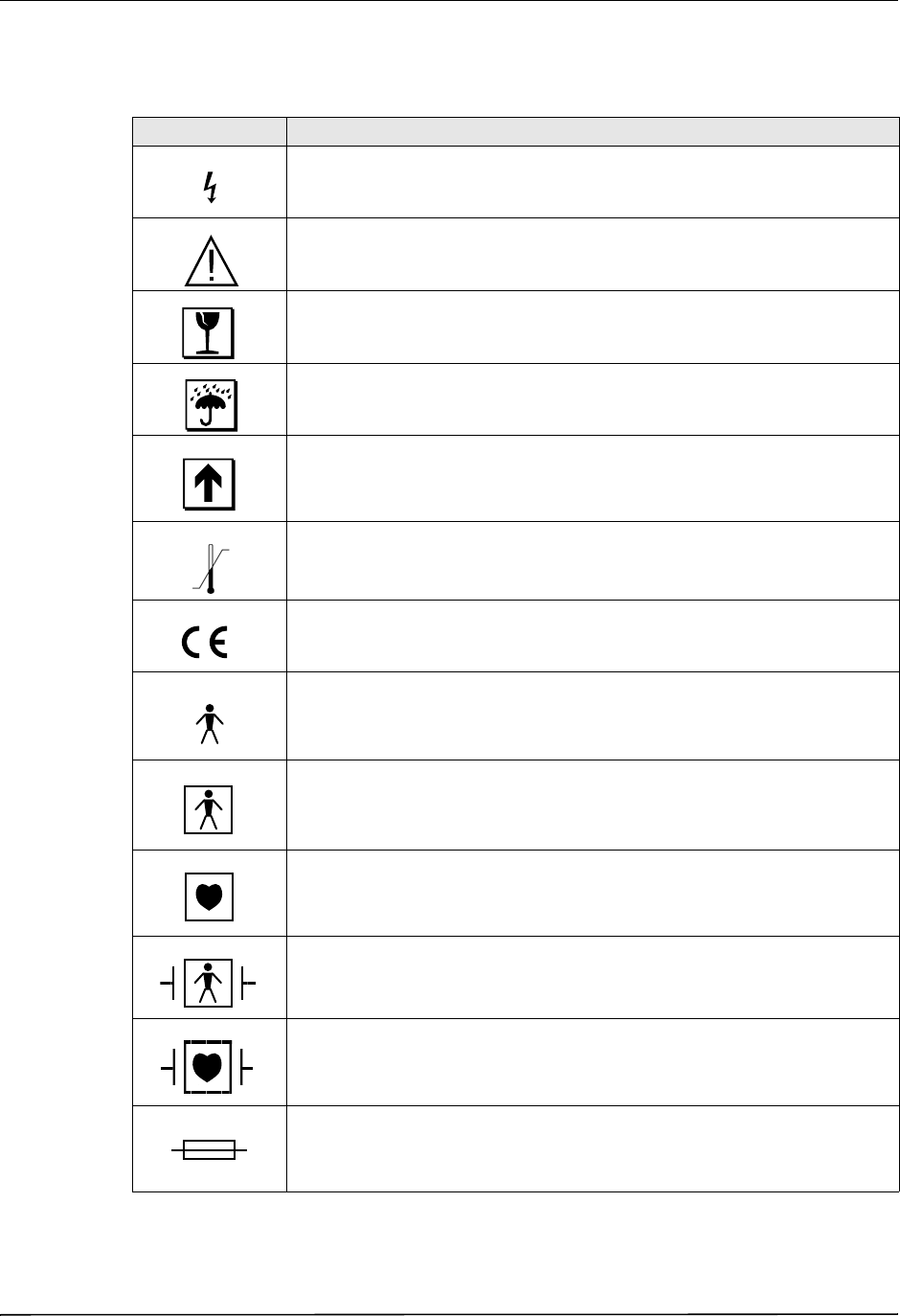
Any or all of the following symbols may be used in this manual or on this equipment:
Symbol Description
Dangerous voltage.
Attention, consult accompanying documents.
Fragile, handle with care.
Keep dry.
This end up.
Temperature limitation.
Conformité Européenne Complies with medical device directive 93/42/EEC.
Type B patient connection.
Type BF patient connection.
Type CF patient connection.
Defibrillator-proof type BF patient connection.
Defibrillator-proof type CF patient connection.
Fusible link.
DRAFT COPY
Symbols Used on the Equipment
9650-1355-01 Rev. 1 X Series Operator’s Guide 1-5
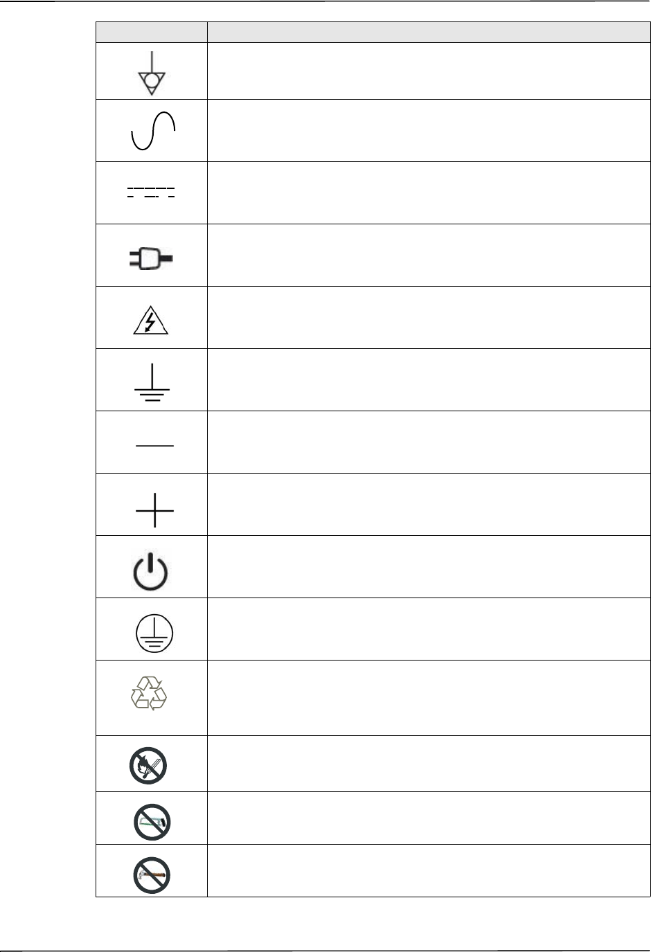
Equipotentiality.
Alternating current (ac).
Direct current (dc).
Auxiliary power adapter operation.
Caution, high voltage.
Earth (ground).
Negative input terminal.
Positive input terminal.
Power On/Off
Protective earth (ground).
Contains lithium. Recycle or dispose of properly.
Keep away from open flame and high heat.
Do not open, disassemble, or intentionally damage.
Do not crush.
Symbol Description
2%452.
,I)/.
RECYCLE
,I)/.
DRAFT COPY
CHAPTER 1GENERAL INFORMATION
1-6 www.zoll.com 9650-1355-01 Rev. 1
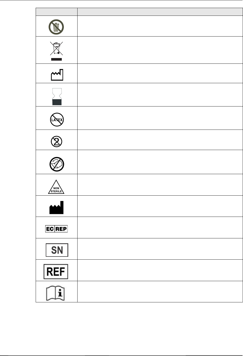
Do not discard in trash. Recycle or dispose of properly.
Return to a collection site intended for waste electrical and electronic
equipment (WEEE). Do not dispose of in unsorted trash.
Date of manufacture.
Use by.
Latex-free.
Do not reuse.
Do not fold.
Not sterile.
Manufacturer.
Authorized representative in the European Community.
Serial Number.
Catalogue number.
Consult instructions for use.
Symbol Description
DRAFT COPY
Conventions
9650-1355-01 Rev. 1 X Series Operator’s Guide 1-7
Conventions
This guide uses the following conventions:
Within text, the names and labels for physical buttons and softkeys appear in boldface type (for
example, “Press the Charge button or press the Pacer button”).
This guide uses uppercase italics for audible prompts and for text messages displayed on the
screen (for example, LEAD FAULT).
Warning! Warning statements alert you to conditions or actions that can result in personal injury
or death.
Caution Caution statements alert you to conditions or actions that can result in damage to the unit.
X Series Indications for Use
The X Series is intended for use by trained medical personnel who are familiar with basic
monitoring, vital sign assessment, emergency cardiac care, and the use of the X Series.
The X Series is also intended for use by (or on the order of) physicians at the scene of an
emergency or in a hospital emergency room, intensive care unit, cardiac care unit, or other
similar areas of a hospital. The usage may be in an ambulance or at the scene of an emergency.
It is also intended to be used during the transport of patients. The X Series will be used
primarily on patients experiencing symptoms of cardiac arrest or in post trauma situation. It
may also be used whenever it is required to monitor any of those functions that are included (as
options) in the device. The X Series unit can be used on pediatric patients (as described in the
following table) and on adult patients (21 years of age or older) with and without heart
dysfunction.
Prescription only.
Battery charging status.
Symbol Description
Pediatric Patient Subpopulation Approximate Age Range
Newborn (neonate) Birth to 1 month of age.
Infant 1 month to 2 years of age.
Child 2 to 12 years of age.
Adolescent 12 to 21 years of age.
DRAFT COPY

CHAPTER 1GENERAL INFORMATION
1-8 www.zoll.com 9650-1355-01 Rev. 1
When the pediatric patient is less than 8 years of age or weighs less than 55 lbs. (25 kg.), use
ZOLL pedi-padz® pediatric defibrillation electrodes. Do not delay therapy to determine the
patient’s exact age or weight.
Manual Defibrillation
Use of the X Series in the manual mode for external and internal defibrillation is indicated on
victims of cardiac arrest where there is apparent lack of circulation as indicated by:
•Unconsciousness.
•Absence of breathing.
•Absence of pulse.
This product should be used only by qualified medical personnel for converting ventricular
fibrillation and rapid ventricular tachycardia to sinus rhythm or other cardiac rhythms capable
of producing hemodynamically significant heart beats.
The unit can also be used for synchronized cardioversion of certain atrial or ventricular
arrhythmias. Qualified medical personnel must decide when synchronized cardioversion is
appropriate.
The patient population will range from newborn (neonate) to adult.
Semiautomatic Operation (AED)
X Series products are designed for use by emergency care personnel who have completed
training and certification requirements applicable to the use of a defibrillator where the device
operator controls delivery of shocks to the patient.
They are specifically designed for use in early defibrillation programs where the delivery of a
defibrillator shock during resuscitation involving CPR, transportation, and definitive care are
incorporated into a medically-approved patient care protocol.
Use of the X Series in the Semiautomatic mode for defibrillation is indicated on victims of
cardiac arrest where there is apparent lack of circulation as indicated by:
• Unconsciousness.
• Absence of breathing.
• Absence of pulse.
Specifications for the ECG rhythm analysis function are provided in the section “ECG Analysis
Algorithm Accuracy” on page A-32.
When the patient is less than 8 years of age or weighs less that 55 lbs. (25 Kg), you must use
ZOLL pediatric defibrillation electrodes. Do not delay therapy to determine patient’s exact age
or weight.
DRAFT COPY

Safety Considerations
9650-1355-01 Rev. 1 X Series Operator’s Guide 1-15
Safety Considerations
All operators should review these safety considerations before using the X Series unit.
X Series units are high-energy defibrillators capable of delivering 200 joules. To completely
deactivate the unit, press the power switch to turn the unit off.
To manually disarm a charged (or charging) defibrillator, do one of the following:
•Press the Disarm quick access key.
•Change the selected energy.
•Press the power switch to turn the unit off.
For safety, the X Series automatically disarms if left charged for more than 60 seconds if the
shock button ( ) is not pressed.
Warnings
General
Federal (U.S.A.) law restricts this defibrillator to sale by or on the order of a physician.
Only appropriately trained, skilled personnel who are familiar with equipment operation should
perform emergency defibrillation. The prescribing physician should determine what training,
such as Advanced Cardiac Life Support (ACLS) or Basic Life Support (BLS) certification, is
appropriate.
Only skilled personnel trained in Advanced Cardiac Life Support (ACLS) and who are familiar
with equipment operation should perform synchronized cardioversion. The precise cardiac
arrhythmia must be determined before attempting defibrillation.
These operating instructions describe the functions and proper operation of the X Series
products. They are not a substitute for a formal patient care training course. Operators should
obtain formal training from an appropriate authority before using this defibrillator for patient
care.
Proper operation of the unit and correct electrode placement is critical to obtaining optimal
results. Operators must be thoroughly familiar with proper device operation.
The use of external pacing/defibrillation electrodes, accessories, or adapter devices from
sources other than ZOLL is not recommended. ZOLL makes no representations or warranties
regarding the performance or effectiveness of its products when used with pacing/defibrillation
electrodes or adapter devices from other sources. Defibrillator failures attributable to the use of
pacing/defibrillation electrodes or adapters not manufactured by ZOLL might void ZOLL’s
warranty.
At receipt of shipment, check pacing/defibrillation electrodes to ensure compatibility.
Allow ample slack in cables to make sure that cables do not tug at electrodes.
Do not disassemble the unit. A shock hazard exists. Refer all problems to authorized service
personnel.
Follow all recommended maintenance instructions. If a problem occurs, obtain service
immediately. Do not use the defibrillator until it has been inspected by appropriate personnel.
DRAFT COPY

CHAPTER 1GENERAL INFORMATION
1-16 www.zoll.com 9650-1355-01 Rev. 1
The X Series unit might not perform to specifications when stored at the upper or lower
extreme limits of storage temperature and then immediately put into use. The X Series unit
should not be stored or used outside of the environmental limits provided in Appendix A of this
manual.
Avoid using the X Series adjacent to, or stacked on, other equipment. If unavoidable, verify that
the unit operates normally in this configuration before clinical use.
The X Series unit should be installed and put into service according to the EMC information in
Appendix A of this manual.
Do not use internal paddles while the X Series unit’s auxiliary power source is connected to an
aircraft AC power operating at a frequency of 400 Hz.
The use of accessories, transducers, and cables other than those specified in this manual and
related X Series option manual inserts may result in increased emissions or decreased immunity
of the X Series.
Perform functional test of internal paddles prior to use.
Do not use or place the unit in service if the Ready For Use indicator (at the upper right of the
front panel) displays a red circle with a line through it.
Carefully route patient cables to avoid tripping over them, or inadvertently pulling the unit onto
the patient.
Always inspect the unit for damage if it has been dropped.
Only authorized personnel should use the Supervisor menus.
If uncertain about the accuracy of any measurement, first check the patient’s vital signs by
alternate means, and then make sure the monitor is functioning correctly.
ECG Monitoring
Implanted pacemakers might cause the heart rate meter to count the pacemaker rate during
incidents of cardiac arrest or other arrhythmias. Dedicated pacemaker detection circuitry may
not detect all implanted pacemaker spikes. Check the patient's pulse; do not rely solely on heart
rate meters. Patient history and physical examination are important factors in determining the
presence of an implanted pacemaker. Pacemaker patients should be carefully observed. See
“Pacemaker Pulse Rejection:” on page A-15 of this manual for disclosure of the pacemaker
pulse rejection capability of this instrument.
Use only ECG electrodes that meet the AAMI standard for electrode performance
(AAMI EC-12). Use of electrodes not meeting this AAMI standard could cause the ECG trace
recovery after defibrillation to be significantly delayed.
Prior to attempting synchronized cardioversion, ensure the ECG signal quality is good and that
sync markers are displayed above each QRS complex.
Do not place electrodes directly over an implanted pacemaker.
The X Series unit detects ECG electrical signals only. It does not detect a pulse (effective
circulatory perfusion). Always verify pulse and heart rate by physical assessment of the patient.
Never assume that the display of a nonzero heart rate means that the patient has a pulse.
Excessive artifact can result due to improper skin preparation of the electrode sites. Follow skin
preparation instructions in Chapter 6: “Monitoring ECG.”
DRAFT COPY

Warnings
9650-1355-01 Rev. 1 X Series Operator’s Guide 1-21
CO2
During MRI scanning, the monitor must be placed outside the MRI suite. When the monitor is
used outside the MRI suite, EtCO2 monitoring can be implemented using a long FilterLine®
which permits placement of the monitor outside the MRI suite.
When using the monitor with anesthetics, nitrous oxide or high concentrations of oxygen,
connect the gas outlet to a scavenger system.
Use only Oridion Microstream CO2 sampling lines.
Microstream CO2 sampling lines are labeled for single patient use only. Do not reuse sampling
lines.
If using the CO2 Monitor for extended critical care, replace the airway adapter every 24 hours
or when it becomes occluded.
CO2 readings and respiratory rate can be affected by sensor application errors, certain ambient
environmental conditions, and certain patient conditions.
Respiration
Do not operate the X Series with any other monitor with respiration measurements on the same
patient. The two devices could affect the respiration accuracy.
The device should not be used as an apnea monitor.
Ferromagnetic Equipment
Biomedical equipment and accessories, such as ECG electrodes, cables, and oximeter probes
contain ferromagnetic materials. Ferromagnetic equipment must not be used in the presence of
high magnetic fields created by magnetic resonance imaging (MRI) equipment.
The large magnetic fields generated by an MRI device can attract ferromagnetic equipment
with an extremely violent force, which could cause serious personal injury or death to persons
between the equipment and the MRI device.
Battery
Although the device can operate with auxiliary power alone, ZOLL strongly recommends that
you operate the unit with a battery installed at all times. Operating the unit with a battery
provides a backup in case of ac power shortage, and results in faster charge time. The battery
can be automatically recharged while it is installed in the unit. Keep a fully charged spare
battery pack with the defibrillator at all times.
Test battery packs regularly. A battery that does not pass the ZOLL charger’s capacity test
might cause the X Series unit to shut down unexpectedly.
If the Low Battery indication occurs at any time during operation, immediately replace the
battery pack.
DRAFT COPY

CHAPTER 1GENERAL INFORMATION
1-22 www.zoll.com 9650-1355-01 Rev. 1
If the LOW BATTERY icon appears, plug the X Series unit into a power source or install a fully
charged battery pack. When the warning low battery shutdown prompt appears, immediately
replace the battery pack with a fully charged pack or plug the X Series unit into a power source,
as unit shut down due to a low battery condition is imminent.
If mistreated, a battery pack might explode. Do not disassemble a battery pack or dispose of it
in fire.
Operator Safety
The X Series can deliver 200 joules of electrical energy. If this electrical energy is not
discharged properly, as described in this manual, the electrical energy could cause personal
injury or death to the operator or bystanders.
Do not use the X Series in the presence of oxygen-rich atmospheres, flammable anesthetics, or
other flammable agents (such as gasoline). Using the unit in such environments might cause an
explosion.
Do not use the unit near or within standing water. Electrical safety might be compromised when
the defibrillator is wet.
Never discharge the unit with the defibrillation electrodes or paddles shorted together or in
open air.
Do not discharge the defibrillator except as indicated in the instructions. Discharge the
defibrillator only when defibrillation electrodes or paddles are properly applied to the patient.
To avoid risk of electrical shock, do not touch the gelled area of the hands-free therapy
electrodes during pacing or defibrillation.
To avoid risk of electrical shock, do not allow electrolyte gel to accumulate on hands or paddle
handles.
To avoid risk of electrical shock, do not allow patient connectors to contact other conductive
parts, including earth.
For defibrillation using paddles, use only high-conductivity electrolyte gel specified for such
use by the manufacturer.
When using paddles for defibrillation, use your thumbs to operate the SHOCK buttons. Doing
so avoids inadvertent shock to the operator.
The use of accessory equipment that does not comply with the equivalent safety requirements
of the X Series defibrillator could reduce the level of safety of the combined system. When
choosing accessory equipment, consider the following:
•Use of the accessory in the patient vicinity.
•Evidence that the safety certification of the accessory has been performed in accordance
with the appropriate IEC (EN) 60601-1 and/or IEC (EN) 60601-1-1 harmonized national
standards.
Always check that the equipment functions properly and is in proper condition before use.
Disconnect all electro-medical equipment that is not defibrillation-protected from the patient
prior to defibrillation.
Before discharging the defibrillator, warn everyone to STAND CLEAR of the patient.
DRAFT COPY

Warnings
9650-1355-01 Rev. 1 X Series Operator’s Guide 1-23
Do not touch the bed, patient, or any equipment connected to the patient during defibrillation.
A severe shock can result. To avoid hazardous pathways for the defibrillation current, do not
allow exposed portions of the patient's body to touch any metal objects, such as a bed frame.
To avoid risk of electrical shock, do not allow printer to come into contact with other conducive
parts, such as equipment connected to the USB port.
Patient Safety
Inappropriate defibrillation or cardioversion of a patient (for example, with no malignant
arrhythmia) may precipitate ventricular fibrillation, asystole, or other dangerous arrhythmias.
Defibrillation without proper application of electrodes or paddle electrolyte gel might be
ineffective and cause burns, particularly when repeated shocks are necessary. Erythema or
hyperemia of the skin under the paddles, or electrodes often occurs; this effect is usually
enhanced along the perimeter of the paddles or electrodes. This reddening should diminish
substantially within 72 hours.
This equipment should be connected to only one patient at a time.
Neonatal and pediatric defibrillation energy level settings should be based on site-specific
clinical protocols.
To ensure patient safety, do not place the monitor in any position that might cause it to fall on
the patient.
To ensure patient safety, connect the X Series only to equipment with circuits that are
electrically isolated.
Use only high-quality ECG electrodes. ECG electrodes are for rhythm acquisition only; you
cannot use ECG electrodes for defibrillation or pacing.
Do not use therapy or ECG electrodes if the gel is dried, separated, torn or split from the foil;
patient burns may result from using such electrodes. Poor adherence and/or air pockets under
therapy electrodes can cause arcing and skin burns.
Check the expiration date on the electrode packaging. Do not use electrodes after their
expiration date.
Excessive body hair or wet, diaphoretic skin can inhibit electrode coupling to the skin. Clip
excess hair and dry any moisture from the area where an electrode is to be attached.
Therapy electrodes should be replaced periodically during continuous pacing. Consult
electrode directions for proper replacement instructions.
Prolonged pacing (more than 30 minutes), particularly in neonates or adults with severely
restricted blood flow, may cause burns. Periodically inspect the skin under the electrodes.
Carefully route the patient cables away from the patient’s neck to reduce the possibility of
patient entanglement or strangulation.
To avoid electrosurgery burns at monitoring sites, ensure proper connection of the
electrosurgery return circuit so that a return path cannot be made through monitoring electrodes
or probes.
DRAFT COPY

CHAPTER 1GENERAL INFORMATION
1-24 www.zoll.com 9650-1355-01 Rev. 1
During electrosurgery, observe the following guidelines to minimize electrosurgery unit (ESU)
interference and provide maximum operator and patient safety:
•Keep all patient monitoring cables away from earth ground, ESU knives, and ESU return
wires.
•Use electrosurgical grounding pads with the largest practical contact area.
Always ensure proper application of the electrosurgical return electrode to the patient.
Check electrical leakage levels before use. Leakage current might be excessive if more than one
monitor or other piece of equipment is connected to the patient.
Cautions
If the unit is to be stored longer than 90 days, remove the battery pack.
Do not sterilize the defibrillator, or its accessories unless the accessories are labelled as
sterilizable.
Do not immerse any part of the defibrillator in water.
Do not use the defibrillator if excessive condensation is visible on the device. Wipe only the
outside with a damp cloth.
Do not use ketones (such as acetone or MEK) on the defibrillator.
Avoid using abrasives (including paper towels) on the display window.
To achieve the specified level of protection against spilled or splashed liquids, thoroughly dry
all exposed surfaces of this device prior to operation or connections to auxiliary power.
If liquids enter the device connectors, remove all liquid from the connectors and allow the
device to dry thoroughly prior to use.
Grounding reliability can be achieved only when the equipment is connected to a receptacle
marked “HOSPITAL ONLY,” “HOSPITAL GRADE,” or equivalent. If the grounding integrity
of the line cord or ac receptacle is questionable, operate the defibrillator using battery power
only.
Do not connect to an electrical outlet controlled by a wall switch or dimmer.
To protect the unit from damage during defibrillation, for accurate ECG information, and to
protect against noise and other interference, use only internal current-limiting ECG cables
specified or supplied by ZOLL.
For continued safety and EMI performance, use only the line cord supplied by ZOLL.
Electrical installation of the room or the building in which the monitor is to be used must
comply with regulations specified by the country in which the equipment is to be used.
Dispose of battery packs in accordance with national, regional and local regulations. Battery
packs should be shipped to a reclamation facility for recovery of metal and plastic compounds
as the proper method of waste management.
Do not place the device where the controls can be changed by the patient.
DRAFT COPY

Restarting the Defibrillator
9650-1355-01 Rev. 1 X Series Operator’s Guide 1-25
Restarting the Defibrillator
Certain events require the X Series products to be restarted after they shut off or become
inoperative (for example, when the battery runs down and the unit shuts off).
In such a case, always try to restore defibrillator operation as follows:
1. Press the power switch on the top of the unit to turn it off.
2. If necessary, replace a depleted battery with a fully charged pack, or connect the defibrillator
to auxiliary power.
3. Press the power switch on the top of the unit to turn it back on.
This sequence is necessary to restart the defibrillator and can also be used to clear some fault
messages when immediate use of the defibrillator is required.
If the X Series unit is powered off for less than 2 minutes, all patient monitoring parameter
settings will be retained. If the unit has been powered off for at least two minutes, it will be
considered a New Patient and all of the patient-specific parameters (alarm limits, defibrillator
energy, etc.) will be reset to their default values.
FDA Tracking Requirements
U.S. Federal Law (21 CFR 821) requires the tracking of defibrillators. Under this law, owners
of this defibrillator must notify ZOLL Medical Corporation if this product is
•received
•lost, stolen, or destroyed
•donated, resold, or otherwise distributed to a different organization
If any such event occurs, contact ZOLL Medical Corporation in writing with the following
information:
1. Originator's organization – Company name, address, contact name, and contact phone
number
2. Model number, and serial number of the defibrillator
3. Disposition of the defibrillator (for example, received, lost, stolen, destroyed, distributed to
another organization), new location and/or organization (if known and different from
originator’s organization) – company name, address, contact name, and contact phone
number
4. Date when the change took effect
Please address the information to:
ZOLL Medical Corporation
Attn: Tracking Coordinator
269 Mill Road
Chelmsford, MA 01824-4105
Fax: (978) 421-0025
Telephone: (978) 421-9655
DRAFT COPY

CHAPTER 1GENERAL INFORMATION
1-26 www.zoll.com 9650-1355-01 Rev. 1
Notification of Adverse Events
As a health care provider, you may have responsibilities under the Safe Medical Devices Act
(SMDA), for reporting to ZOLL Medical Corporation, and possibly to the FDA, the occurrence
of certain events.
These events, described in 21 CFR Part 803, include device-related death and serious injury or
illness. In addition, as part of our Quality Assurance Program, ZOLL Medical Corporation
requests to be notified of device failures or malfunctions. This information is required to ensure
that ZOLL Medical Corporation provides only the highest quality products.
Software License
Note: Read this Operator’s Guide and License agreement carefully before operating any of
the X Series products.
Software incorporated into the system is protected by copyright laws and international
copyright treaties as well as other intellectual property laws and treaties. This software is
licensed, not sold. By taking delivery of and using this system, the Purchaser signifies
agreement to and acceptance of the following terms and conditions:
1. Grant of License: In consideration of payment of the software license fee which is part of
the price paid for this product ZOLL Medical Corporation grants the Purchaser a non-
exclusive license, without right to sublicense, to use the system software in object-code
form only.
2. Ownership of Software/Firmware: Title to, ownership of and all rights and interests in the
system software and all copies thereof remain at all times vested in the manufacturer, and
Licensors to ZOLL Medical Corporation and they do not pass to purchaser.
3. Assignment: Purchaser agrees not to assign, sublicense or otherwise transfer or share its
rights under the license without the express written permission of ZOLL Medical
Corporation.
4. Use Restrictions: As the Purchaser, you may physically transfer the products from one
location to another provided that the software/firmware is not copied. You may not disclose,
publish, translate, release or distribute copies of the software/firmware to others. You may
not modify, adapt, translate, reverse engineer, decompile, crosscompile, disassemble or
create derivative works based on the software/firmware.
NO IMPLIED LICENSE
Possession or purchase of this device does not convey any express or implied license to use the
device with replacement parts which would, alone, or in combination with this device, fall
within the scope of one or more of the patents relating to this device.
DRAFT COPY

Service
9650-1355-01 Rev. 1 X Series Operator’s Guide 1-27
Service
The X Series only requires recalibration of the CO2 module. Service is required after 20,000
hours of use of the CO2 module. Appropriately trained and qualified personnel should,
however, perform periodic tests of the defibrillator functionality to verify proper operation.
If a unit requires service, contact the ZOLL Technical Service Department.
When requesting service, please provide the following information to the service
representative:
•Unit serial number
•Description of the problem
•Department using the equipment and name of the person to contact
•Purchase order to allow tracking of loan equipment
•Purchase order for a unit with an expired warranty
•Sample ECG or other stripcharts demonstrating the problem (if available and applicable),
less any confidential patient information.
Returning a unit for service
Before sending a unit to the ZOLL Technical Service Department for repair, obtain a service
request (SR) number from the service representative.
Remove the battery pack from the unit. Pack the unit with its cables and battery in the original
containers (if available) or equivalent packaging. Be sure the assigned service request number
appears on each package.
For customers In the U.S.A. For customers outside the U.S.A.
Telephone:
Fax:
1-800-348-9011
1-978-421-9655
1-978-421-0010
Call the nearest authorized ZOLL Medical Corporation
representative.
To locate an authorized service center, contact the
International Sales Department at
ZOLL Medical Corporation
269 Mill Road
Chelmsford, MA 01824-4105
Telephone: 1-978-421-9655
For customers Return the unit to
In the U.S.A. ZOLL Medical Corporation
269 Mill Road
Chelmsford, MA 01824-4105
Attention: Technical Service Department (SR number)
Telephone: 1-800-348-9011
DRAFT COPY

CHAPTER 1GENERAL INFORMATION
1-28 www.zoll.com 9650-1355-01 Rev. 1
The ZOLL Serial Number
Each ZOLL product displays a serial number that contains information about that product.
From left to right, ZOLL serial numbers are structured as follows:
•A two-character product code
•A three-character date-of-manufacture code
•A product serial number of six or more alphanumeric characters
The first two characters of the date-of-manufacture code give the last two digits of the year (for
example, “06” appears for products manufactured in 2006). The last character of the date-of-
manufacture code gives the month in which the product was manufactured. The month appears
in the form of a single alphanumeric character: “A” for January, “B” for February, “C” for
March, and so on through “L” for December.
The product serial number is a unique set of alphanumeric characters that ZOLL assigns to each
individual unit.
In Canada ZOLL Medical Canada Inc.
1750 Sismet Road, Unit #1
Mississauga, ON L4W 1R6
Attention: Technical Service Department (SR number)
Telephone: 1-866-442-1011
In other locations The nearest authorized ZOLL Medical Corporation representative.
To locate an authorized service center, contact the International Sales
Department at
ZOLL Medical Corporation
269 Mill Road
Chelmsford, MA 01824-4105
Telephone: 1-978-421-9655
For customers Return the unit to
DRAFT COPY

9650-1355-01 Rev. 1 X Series Operator’s Guide 22–1
Chapter 22
Wireless Communications
The X Series unit can send data through a wireless connection to remote locations. The
X Series unit can send 12-lead report snapshots (including trend data) to a recipient via a ZOLL
server. Full disclosure cases, which also contain trend data, can be automatically retrieved from
the X Series unit using ZOLL RescueNet or ePCR software.
You can set up a temporary wireless access point on the X Series unit by selecting the wireless
icon on the display screen. Supervisors can set up permanent WiFi profiles (up to 255) in the
Setup/Communications menu, which requires a password.
Once you have set up a wireless access point, you can send 12-lead reports to an email or fax
recipient. Data can also be retrieved automatically using ZOLL RescueNet or ePCR software.
This chapter describes how to select different recipients and how to set up wireless
communications in the X Series unit for different types of recipients.
Note: Test all wireless connections after initial setup and prior to use.
DRAFT COPY
CHAPTER 22 WIRELESS COMMUNICATIONS
22–2 www.zoll.com 9650-1355-01 Rev. 1
Wireless Icon
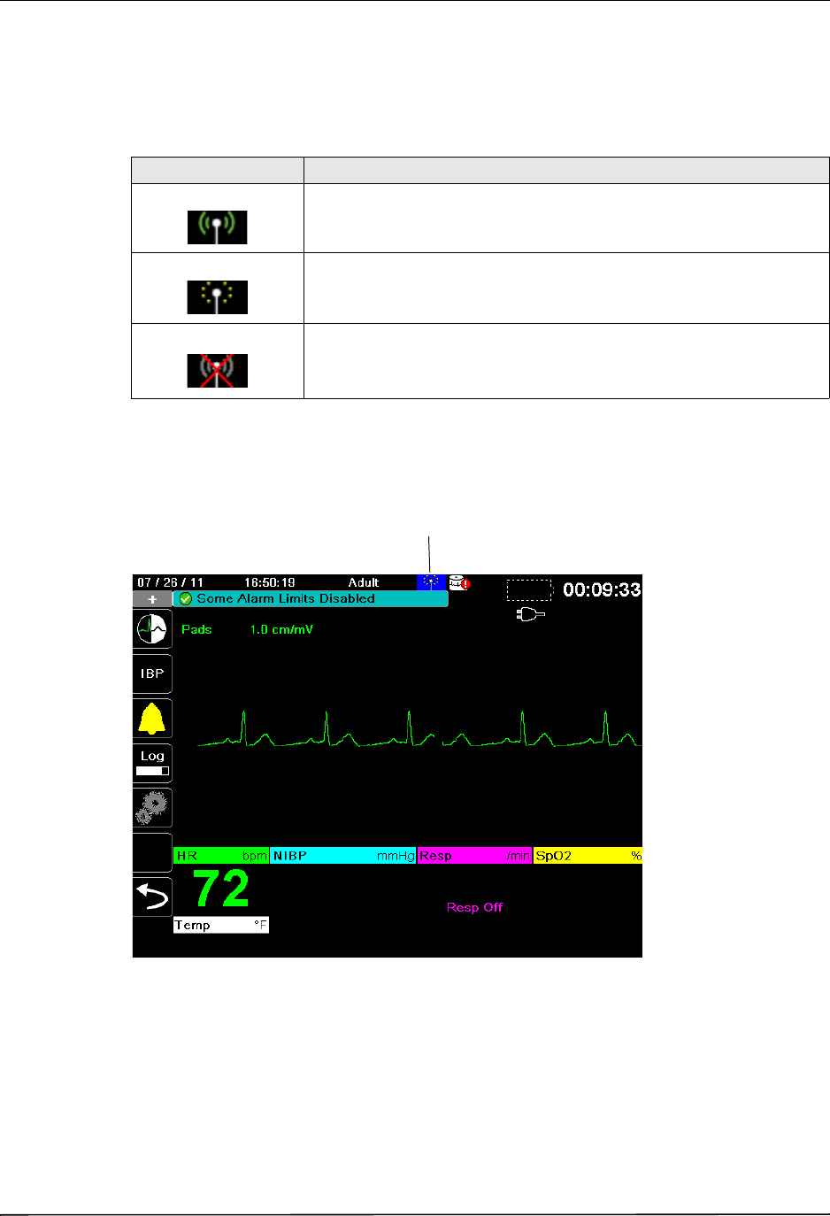
The wireless icon is located to the right of the patient mode in the display screen. It has three
possible states shown the table below.
Note: If wireless connectivity is disabled, no icon is displayed.
You can select this icon to access the Wireless menu and view preconfigured WiFi access
points or distribution lists, or to set up a temporary WiFi access point. Use the navigation keys
to select the wireless icon.
State Description
Connected Wireless connectivity is available.
Not connected Wireless connectivity is not available due to incorrect configuration or
weak/no signal strength.
Failed Wireless communication hardware has failed.
Wireless icon
DRAFT COPY
Wireless Icon
9650-1355-01 Rev. 1 X Series Operator’s Guide 22–3
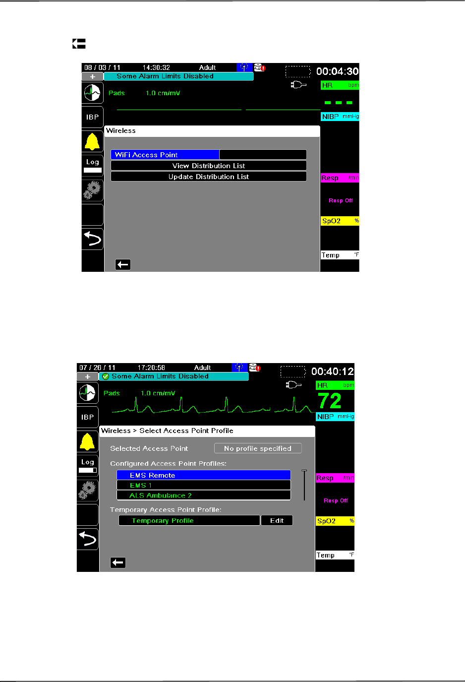
The Wireless menu has three options: WiFi Access Point, View Distribution List, and Update
Distribution List. Use the navigation keys to navigate the menu items; press the back arrow
( ) to exit the wireless menu.
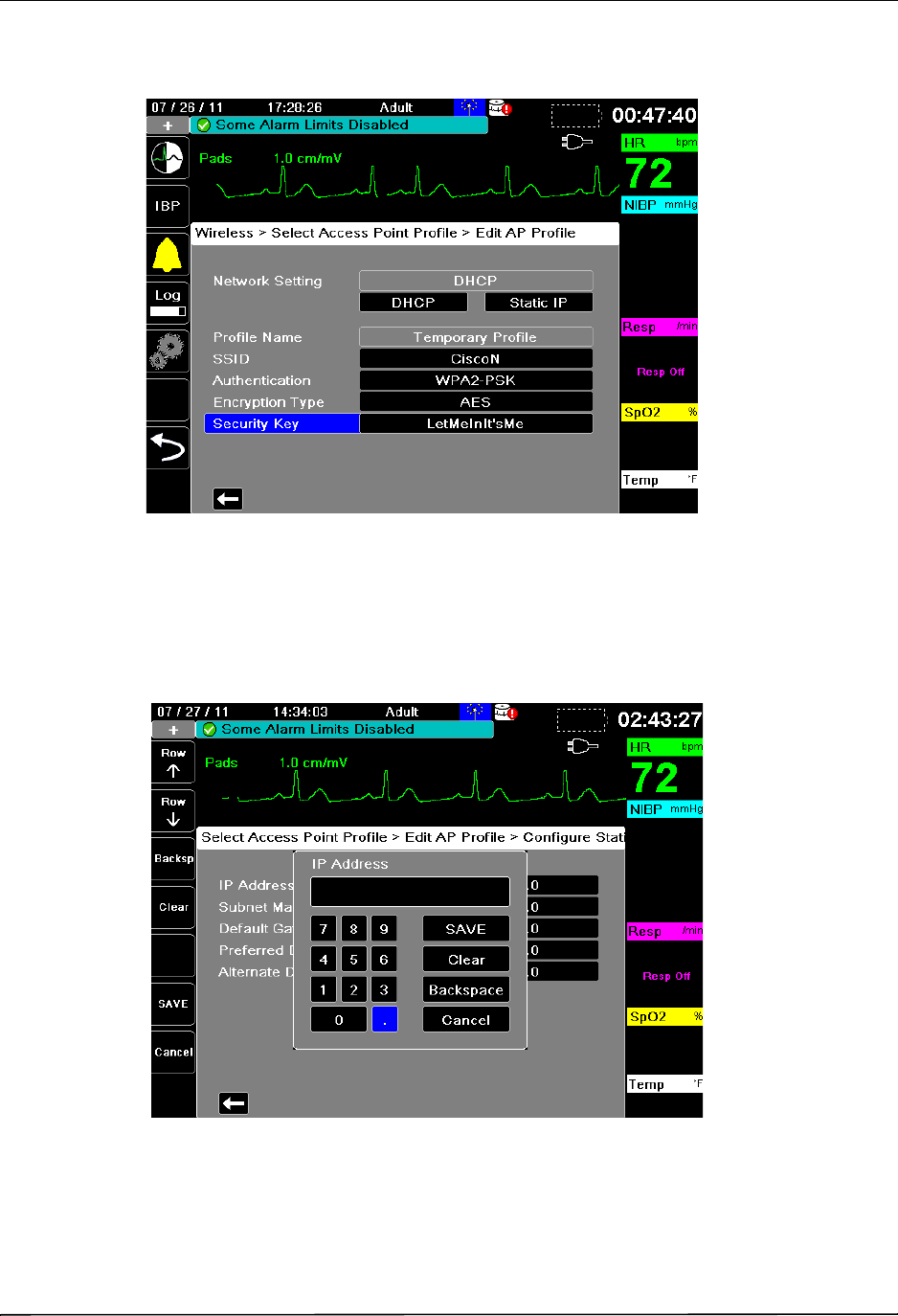
Selecting and Creating a Temporary Access Point Profile
In the wireless menu, use the navigation keys to highlight and select WiFi Access Point. You
can now view preconfigured Access Point Profiles.
Use the navigation keys to highlight and select Temporary Profile. A green check mark
appears to show that the profile has been selected.
DRAFT COPY
CHAPTER 22 WIRELESS COMMUNICATIONS
22–4 www.zoll.com 9650-1355-01 Rev. 1
To edit the profile, use the navigation keys to highlight and select Edit. The unit displays the
Edit AP Profile menu.
Network Setting
Use the navigation keys to select either DHCP or Static IP. If you select Static IP, use the
numeric keypad to enter values for the IP Address, Subnet Mask, Default Gateway, Preferred
SDNS Server, and Alternate DNS Server.
Profile Name
The profile name is “Temporary Profile” and cannot be changed.
DRAFT COPY
Wireless Icon
9650-1355-01 Rev. 1 X Series Operator’s Guide 22–5
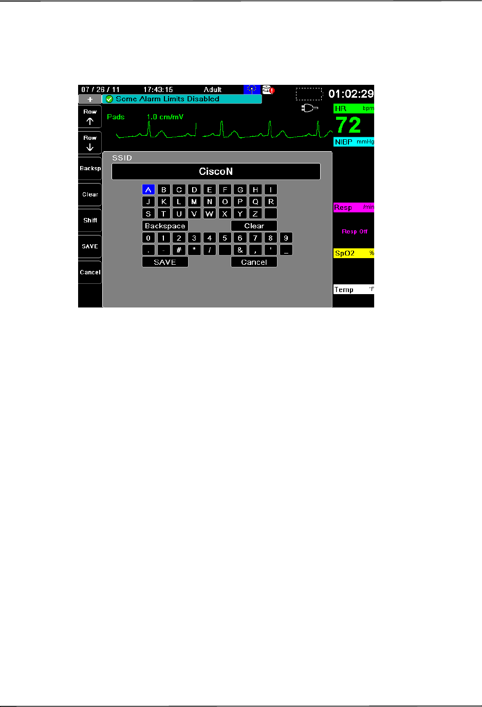
SSID
Use the alphabetical keypad to enter the SSID name. Press SAVE to save changes and return to
the Temporary Profile menu; press Cancel to return to the Temporary Profile menu without
saving changes.
Authenication
Use the navigation keys to select the authentication type.
Encryption Type
Use the navigation keys to select the encryption type.
DRAFT COPY
CHAPTER 22 WIRELESS COMMUNICATIONS
22–6 www.zoll.com 9650-1355-01 Rev. 1
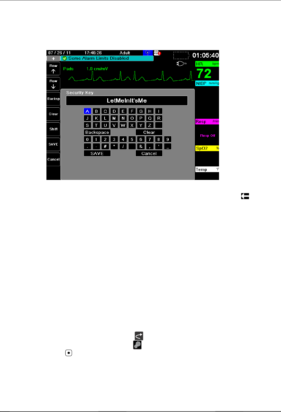
Security Key
Use the alphabetical keypad to enter the security key. Press SAVE to save changes and return to
the Temporary Profile menu; press Cancel to return to the Temporary Profile menu without
saving changes.
When you are done editing the Temporary Profile menu, press the back arrow ( ) to exit the
wireless menu.
Note: The selected Temporary Profile remains as the default profile until configured
otherwise.
Setting up Communications in the Supervisor Menu
You can set up wireless access profiles in the Communications setup menu. This is located in
the Supervisor Setup menu, which requires a password. In this menu, you can set up the
following:
•WiFi access points
•Bluetooth connections using a cellular device
•USB cell modems
Note: Communications setup is not available in AED mode.
To access the Communications menu:
1. Press the More quick access key ( ).
2. Press the Setup quick access key ( ). Use the navigation keys to scroll down to Supervisor.
Press .
3. Enter the password. The Supervisor menu appears.
DRAFT COPY
Setting up Communications in the Supervisor Menu
9650-1355-01 Rev. 1 X Series Operator’s Guide 22–7
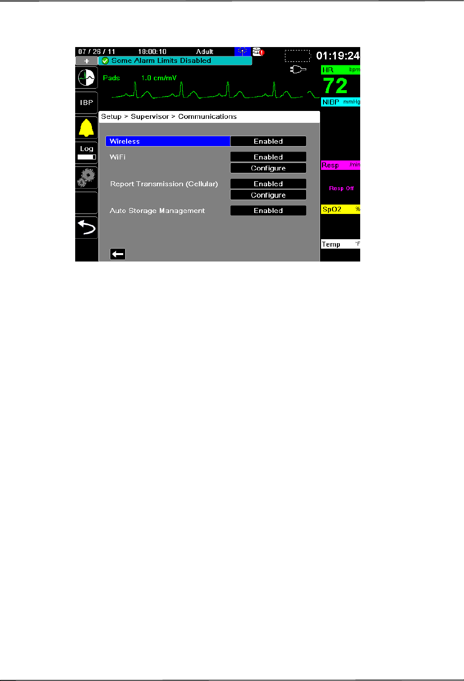
4. Use the navigation keys to highlight and select Communications. The options for
Communications are displayed.
Wireless
Use the navigation keys to enable or disable this function.When disabled, all wireless
capabilities are disabled in the X Series unit.
WiFi
Use the navigation keys to enable or disable this function, and to configure access point profiles
(see “WiFi Access Point Profiles” on page 22-8). When disabled, all WiFi access points are
disabled in the X Series unit.
Report Transmission (Cellular)
Use the navigation keys to enable or disable this function, and to configure access point profiles
(“WiFi Access Point Profiles” on page 22-8). When disabled, all cellular transmission
functions (Bluetooth or USB cell modem) are disabled.
Auto Storage Management
Storage and management of 12-lead reports and full disclosure case files on the X Series unit
can be managed from third-party software such as ZOLL RescueNet. When disabled, you
cannot access reports that are stored on the unit from outside software.
DRAFT COPY
CHAPTER 22 WIRELESS COMMUNICATIONS
22–8 www.zoll.com 9650-1355-01 Rev. 1
WiFi Access Point Profiles
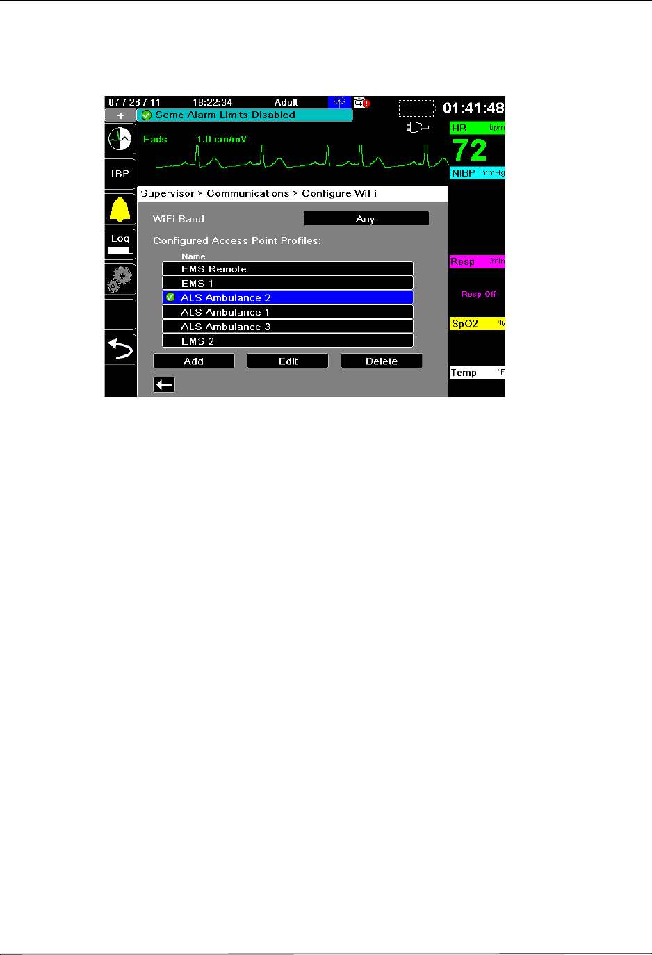
To select and modify WiFi Access Point Profiles, use the navigation keys to highlight and
select Configure WiFi.
A green check mark indicates the active access point. Use the navigation keys to select a
different profile, or to add, edit or delete other profiles.
Use the navigation keys to select the correct WiFi Band. The options are Any, 5.0 GHz (A/N),
or 2.4 GHz (B/G/N).
DRAFT COPY
Setting up Communications in the Supervisor Menu
9650-1355-01 Rev. 1 X Series Operator’s Guide 22–9
To add a new Access Point Profile:
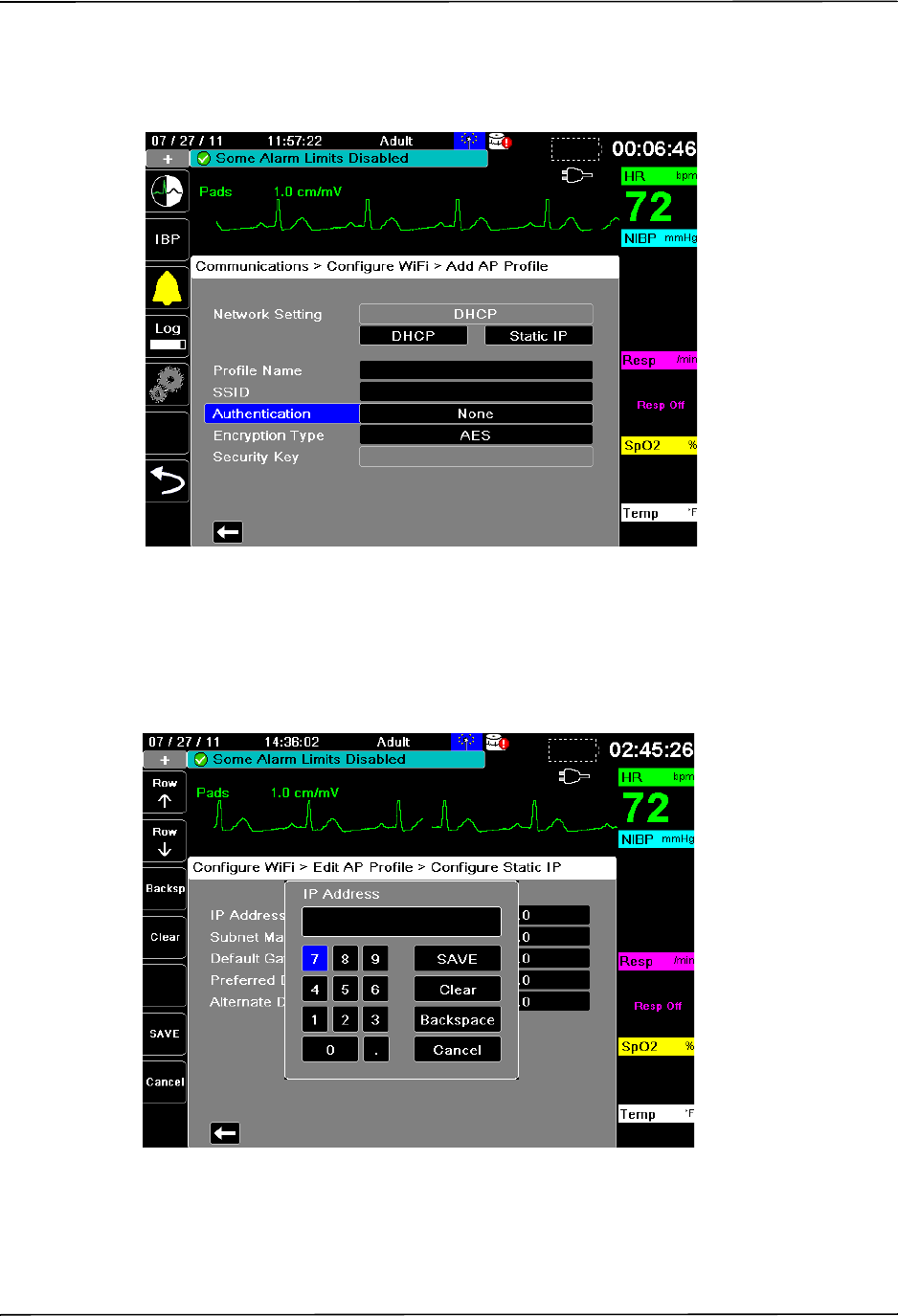
Use the navigation keys to highlight and select Add. You can enter the type of network setting,
profile name, SSID, authentication, encryption type, and security key.
Network Setting
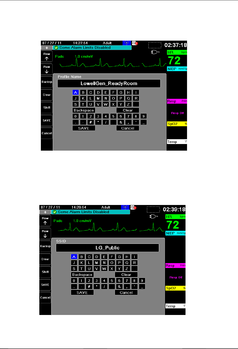
Use the navigation keys to select either DHCP or Static IP. If you select Static IP, use the
numeric keypad to enter values for the IP Address, Subnet Mask, Default Gateway, Preferred
SDNS Server, and Alternate DNS Server.
DRAFT COPY
CHAPTER 22 WIRELESS COMMUNICATIONS
22–10 www.zoll.com 9650-1355-01 Rev. 1
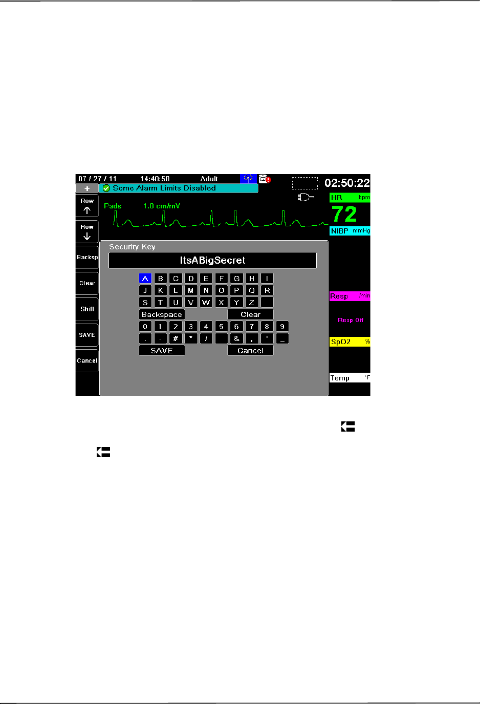
Profile Name
Use the alphabetical keypad to enter the profile name. Press SAVE to save changes and return
to the WiFi configuration menu; press Cancel to return to the WiFi configuration menu without
saving changes.
SSID
Use the alphabetical keypad to enter the SSID name. Press SAVE to save changes and return to
the WiFi configuration menu; press Cancel to return to the WiFi configuration menu without
saving changes.
DRAFT COPY
Setting up Communications in the Supervisor Menu
9650-1355-01 Rev. 1 X Series Operator’s Guide 22–11
Authenication
Use the navigation keys to select the authentication type.
Encryption Type
Use the navigation keys to select the encryption type.
Security Key
Use the alphabetical keypad to enter the security key. Press SAVE to save changes and return to
the WiFi configuration menu; press Cancel to return to the WiFi configuration menu without
saving changes.
When finished editing your WiFi profile, press the back arrow ( ) to return to return to the list
of configured access point profiles. From this menu you can also edit or delete existing profiles.
Press to return to the Communications menu.
Configuring Report Transmissions Via a Cellular Phone
You can send12-lead reports to an email or fax machine using a bluetooth-equipped cellular
device or a USB cell modem. You can configure the X Series unit to select a particular device.
DRAFT COPY
CHAPTER 22 WIRELESS COMMUNICATIONS
22–12 www.zoll.com 9650-1355-01 Rev. 1
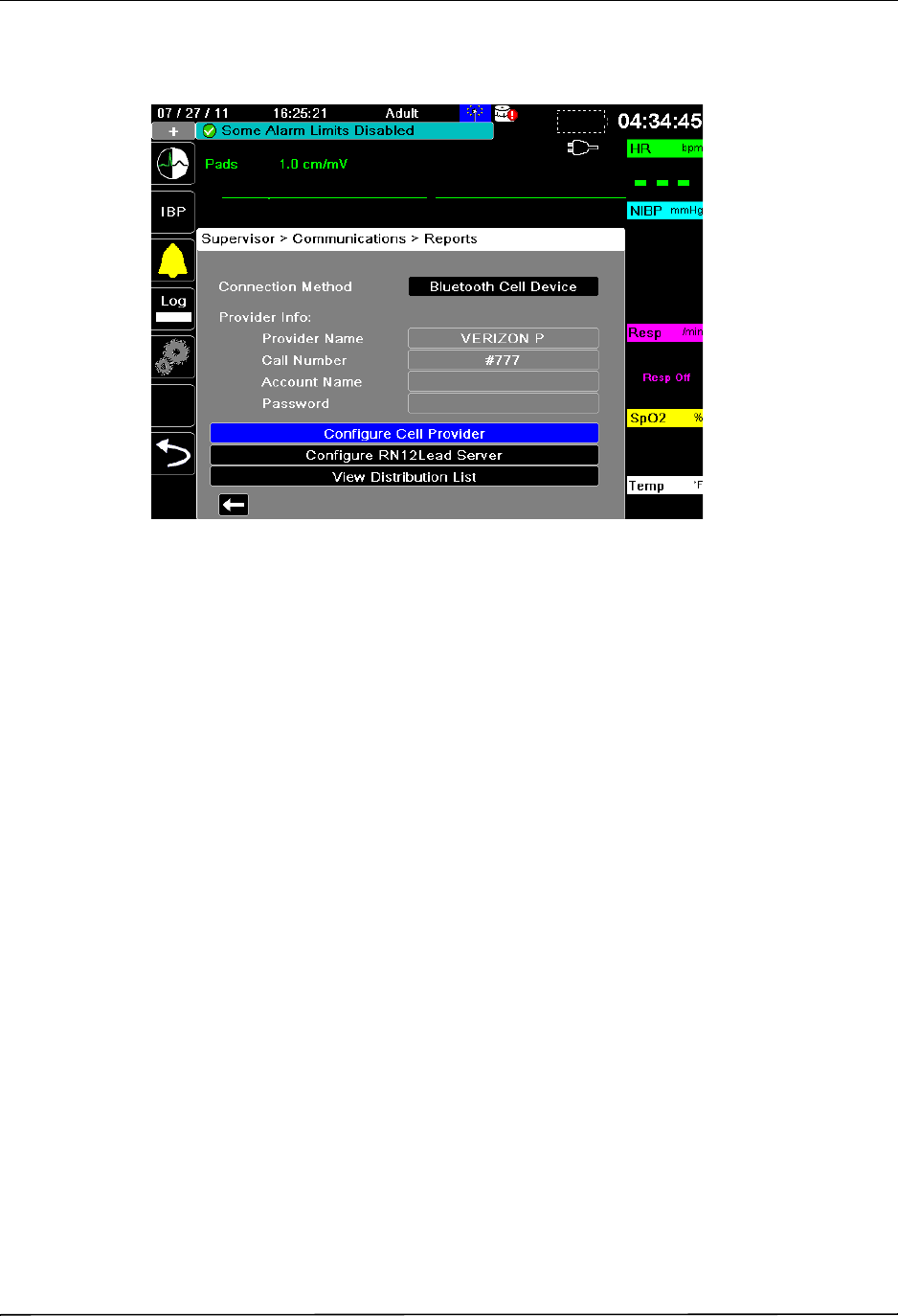
To set up your cellular device: In the Communications menu, select Configure Report
Transmission (Cellular). The Reports menu displays.
Communication Method
Select either Bluetooth Cell Device or USB Cell Modem.
Provider Info
Your current cellular provider information is listed.
Configure Cell Provider
Use this option to configure your cellular device. Use the alphanumeric keypads to enter the
Provider Name, Call Number, Account Name (optional) or Password (optional). Refer to your
cellular provider’s documentation for details.
DRAFT COPY
Sending a 12-lead report
9650-1355-01 Rev. 1 X Series Operator’s Guide 22–13
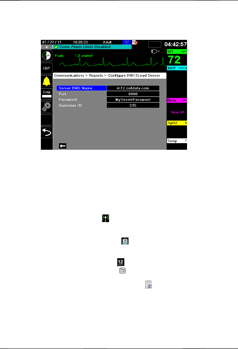
Configure RN12Lead Server
12-lead reports are sent to recipients via a ZOLL server. Use the alphanumeric keypads to enter
the correct server information.
View Distribution List
Use this option to view preconfigured distribution lists.
Sending a 12-lead report
The (connected) wireless icon ( ) at the top of the screen indicates that wireless connectivity
is available.
Once a 12-lead report has been acquired (or a previously acquired 12-lead has been selected for
review), The Transmit quick access key( ) displays.
To send a 12-lead report to a preconfigured distribution list:
1. Press the 12-lead quick access key( ).
2. If desired, press the snapshot button( ) to take a 12-lead snapshot (see Chapter 14: 12-Lead
ECG Interpretive Analysis for more information about acquiring 12-lead data).
3. Press the 12-lead review next quick access key ( ). A list of snapshots appears; select the
desired snapshot.
DRAFT COPY
CHAPTER 22 WIRELESS COMMUNICATIONS
22–14 www.zoll.com 9650-1355-01 Rev. 1
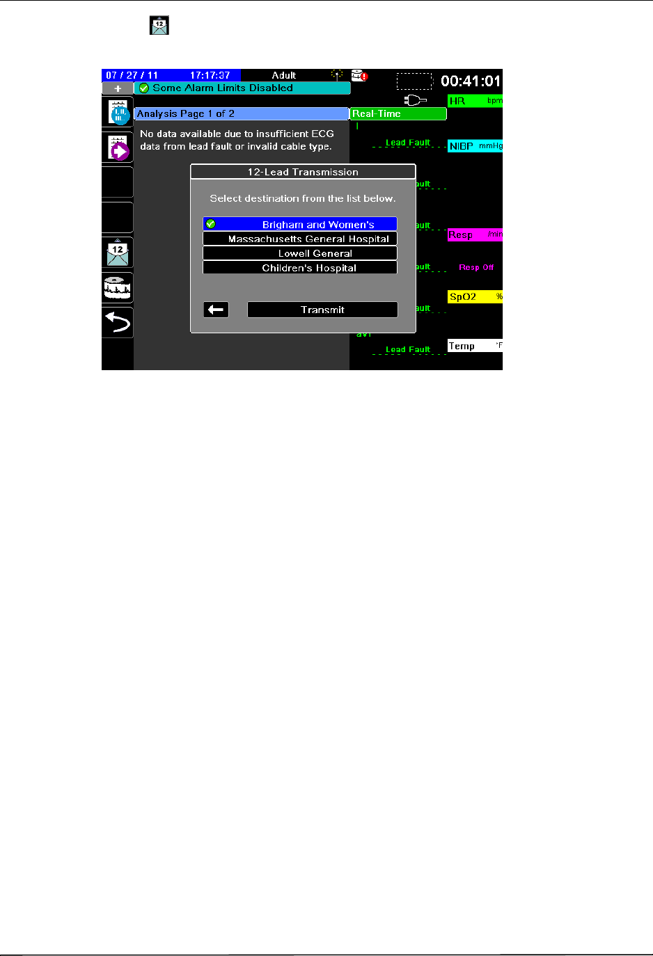
4. Press . A list of preconfigured distribution lists appears.
Use the navigation keys to highlight and select the desired distribution list. A green check
box indicates the selected list.When a destination has been selected, the Transmit button is
enabled.
5. Press Transmit to initiate the 12-lead transmission
While the transmission is in process, the green LED on top of the unit is illuminated.
DRAFT COPY

Communications System Messages
9650-1355-01 Rev. 1 X Series Operator’s Guide 22–15
Communications System Messages
The X Series unit may display one of the following status messages during the transmission:
System Message Cause
TRYING TO CONNECT TO
NETWORK
The unit is connecting to the network.
TRYING TO CONNECT TO
SERVER
The unit is connecting to the ZOLL server.
TRANSMITTING The data transfer is in progress
TRANSMISSION COMPLETE The data transfer is complete.
TRANSMISSION FAILED The data transfer has failed.
To correct the problem, check the following:
•Verify that wireless communications is enabled
on your X Series unit.
•Verify that the WiFi settings are correct in the
Communications setup menu.
•Verify that the ZOLL server is configured
correctly.
•Verify that your cellular device is configured
correctly.
•Make sure that the X Series unit is within range of
the wireless server.
DRAFT COPY

9650-1355-01 Rev. 1 X Series Operator’s Guide A-1
Appendix A
Specifications
This chapter provides specification information for the X Series Monitor/Defibrillator.
•“Defibrillator” on page A-2.
•“Monitor/Display” on page A-14
•“Impedance Pneumography” on page A-15
•“Alarms” on page A-15
•“Recorder” on page A-16
•“Battery ” on page A-17
•“General” on page A-17
•“Pacer” on page A-18
•“CO2” on page A-18
•“Pulse Oximeter” on page A-19
•“Non-Invasive Blood Pressure” on page A-21
•“Invasive Pressures” on page A-22
•“Temperature” on page A-23
•“Electromagnetic Compatibility Guidance and Manufacturer’s Declaration” on page A-28
DRAFT COPY

Specifications
A-2 www.zoll.com 9650-1355-01 Rev. 1
Defibrillator
Charge Time:
•Less than 7 seconds with a new, fully charged battery (first 15 charges to 200 joules).
•For the sixteenth discharge at maximum energy, the charge time is less than 10 seconds.
Depleted batteries result in a longer defibrillator charge time.
•Less than 15 seconds when operating without a battery, using AC power alone at 90% of the
rated mains voltage.
•Less than 25 seconds from the initial power on, with a new, fully charged battery pack
(depleted by up to fifteen 200 joule discharges) or when operating without a battery, using
AC power alone at 90% of the rated mains voltage.
Rhythm Analysis and Charge Time in AED Mode
•Less than 30 seconds with a new, fully charged battery (first 15 charges to 200 joules).
•For the sixteenth discharge at maximum energy, the analysis and charge time is less than 30
seconds. Depleted batteries result in a longer defibrillator charge time.
•Less than 30 seconds when operating without a battery, using AC power alone at 90% of the
rated mains voltage.
•Less than 40 seconds from the initial power on, with a new, fully charged battery pack
(depleted by up to fifteen 200 joule discharges) or when operating without a battery, using
AC power alone at 90% of the rated mains voltage.
Patient Impedance Range: 10- 300 ohms
Synchronized Mode: Synchronizes defibrillator discharge to the patient’s R wave. SYNC is
indicated on the display with R wave markers above the ECG waveform on the screen and
stripchart. When ECG is monitored by the device, meets the DF-80:2003 requirement of 60ms
maximum time delay between the peak of the R wave and the delivery of energy.
Table A-1 shows the characteristics of the X Series Rectilinear Biphasic™ waveform when
discharged into 25 ohm, 50 ohm, 100 ohm, 125 ohm, 150 ohm and 175 ohm loads at the
maximum energy setting of 200 joules.
Table A-1. X Series Rectilinear Biphasic Waveform Characteristics
200 J discharged into
2550100125150175
First phase
Maximum initial current 31.4 A 30.4 A 19.7 A 19.4 A 16.7 A 15.6 A
Average current 27.1 A 24.9 A 17.5 A 16.2 A 14.4 A 13.2 A
Duration 6 ms 6 ms 6 ms 6 ms 6 ms 6 ms
Interphase duration
(between first and
second phases)
200 s 200 s 200 s 200 s 200 s200 s
Second phase
Initial current 29.2 A 18.8 A 15.1 A 13.2 A 12.1 A 11 A
Average current 14.7 A 13 A 12.5 A 11.3 A 10.7 A 9.9 A
Duration 4 ms 4 ms 4 ms 4 ms 4 ms 4 ms
DRAFT COPY

Electromagnetic Compatibility Guidance and Manufacturer’s Declaration
9650-1355-01 Rev. 1 X Series Operator’s Guide A-29
Guidance and Manufacturer’s Declaration – Electromagnetic
(IEC 60601-1-2 Table 202)
The X Series unit is intended for use in the electromagnetic environment specified below. The
customer or the user of the X Series should assure that it is used in such an environment.
Immunity Test IEC 60601 Test Level Compliance Level Electromagnetic Environment
– Guidance
Electrostatic
Discharge (ESD)
IEC 61000-4-2
± 6 kV contact
± 8 kV air
± 6 kV contact
± 8 kV air
Floors should be wood, concrete
or ceramic tile. If floors are
covered with synthetic material,
the relative humidity should be at
least 30%.
Electrical Fast
Transient / Burst
IEC 61000-4-4
± 2 kV for power
supply lines
± 1 kV for input/
output lines
± 2 kV for power
supply lines
± 1 kV for input/
output lines
Mains power quality should be
that of a typical commercial or
hospital environment.
Surge IEC 61000-4-
5
± 1 kV differential
mode
± 2 kV common mode
± 1 kV differential
mode
± 2 kV common mode
Mains power quality should be
that of a typical commercial or
hospital environment.
Voltage Dips, Short
Interruptions and
Voltage Variations on
Power Supply Input
Lines IEC 61000-4-
11
<5% UT
(>95% dip in UT) for
0.5 cycle
40% UT
(60% dip in UT) for
5 cycles
70% UT
(30% dip in UT) for
25 cycles
<5% UT
(>95% dip in UT) for
5sec
<5% UT
(>95% dip in UT) for
0.5 cycle
40% UT
(60% dip in UT) for
5 cycles
70% UT
(30% dip in UT) for
25 cycles
<5% UT
(>95% dip in UT) for
5sec
Mains power quality should be
that of a typical commercial or
hospital environment. If the user
of the X Series unit requires
continued operation during
power mains interruptions, it is
recommended that the X Series
unit be powered from an
uninterruptible power supply or a
battery.
Power Frequency
(50/60 Hz) Magnetic
Field IEC 61000-4-8
3 A/m 3 A/m Power frequency magnetic fields
should be at levels characteristic
of a typical location in a typical
commercial or hospital
environment.
Note: UT is the AC mains voltage prior to application of the test level.
DRAFT COPY
Specifications
A-30 www.zoll.com 9650-1355-01 Rev. 1
Guidance and Manufacturer’s Declaration – Electromagnetic Immunity
(IEC 60601-1-2 Table 203)
The X Series unit is intended for use in the electromagnetic environment specified below. The
customer or the user of the X Series should assure that it is used in such an environment.
Immunity Test IEC 60601 Test Level Compliance
Level Electromagnetic Environment – Guidance
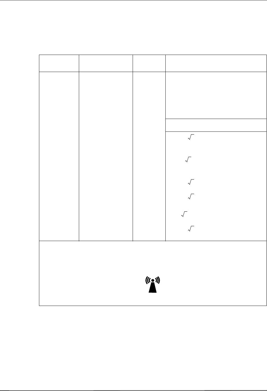
IEC 60601-1-2
Portable and mobile RF communications
equipment should be used no closer to any
part of the X Series unit, including cables,
than the recommended separation distance
calculated from the equation applicable to the
frequency of the transmitter.
Recommended Separation Distance
Conducted RF
IEC 61000-4-6
3Vrms
150 kHz to 80 MHz
outside ISM bandsa
3 Vrms d = 1.17
10 Vrms
150 kHz to 80 MHz in
ISM bandsa
10Vrms d = 1.2
Radiated RF
IEC 61000-4-3
10 V/m
80 MHz to 2.5 GHz
10 V/m d = 1.20
80 MHz to 800 MHz
d = 2.30
800 MHz to 2.5 GHz
3V/m
80 MHz to 2.5 CHz
(IEC 60601-2-34)
3V/m
(IBP only)
d = 4
80 MHz to 800 MHz
d = 7.67
800 MHz to 2.5 GHz
Where P is the maximum output power rating of the transmitter in watts (W) according to the transmitter
manufacturer and d is the recommended separation distance in meters (m).b
Field strengths from fixed RF transmitters, as determined by an electromagnetic site surveyc, should be
less than the compliance level in each frequency ranged.
Interference may occur in the vicinity of equipment marked with the following symbol:
P
P
P
P
P
P
DRAFT COPY

Electromagnetic Compatibility Guidance and Manufacturer’s Declaration
9650-1355-01 Rev. 1 X Series Operator’s Guide A-31
Recommended Separation Distances Between Portable and Mobile RF
Communications Equipment and the X Series (IEC 60601-1-2 Table 205)
The X Series unit is intended for use in an environment in which radiated RF disturbances are
controlled. The customer or the user of the X Series unit can help prevent electromagnetic
interference by maintaining a minimum distance between portable and mobile RF
communications equipment (transmitters) and the X Series unit as recommended below,
according to the maximum output power of the communications equipment.
Note 1: At 80 MHz and 800 MHz, the higher frequency range applies.
Note 2: These guidelines may not apply in all situations. Electromagnetic propagation is affected by
absorption and reflection from structures, objects, and people.
a. The ISM (industrial, scientific, and medical) bands between 150 KHz and 80 MHz are 6.765 MHz to
6.795 MHz; 13.553 MHz to 13.567 MHz; 26.957 MHz to 27.283 MHz; and 40.66 MHz to 40.70 MHz.
b. The compliance levels in the ISM frequency bands between 150 kHz and 80 MHz and in the
frequency range 80 MHz to 2.5 GHz are intended to decrease the likelihood that mobile/portable
communications equipment could cause interference if it is inadvertently brought into patient areas. For
this reason, an additional factor of 10/3 is used in calculating the recommended separation distance for
transmitters in these frequency ranges.
c. Field strengths from fixed transmitters, such as base stations for radio (cellular / cordless) telephones
and land mobile radios, amateur radio, AM and FM radio broadcast, and TV broadcast cannot be
predicted theoretically with accuracy. To assess the electromagnetic environment due to fixed RF
transmitters, an electromagnetic site survey should be considered. If the measured field strength in the
location in which the ZOLL X Series unit is used exceeds the applicable RF compliance level above, the
X Series unit should be observed to verify normal operation. If abnormal performance is observed,
additional measures may be necessary, such as reorienting or relocating the X Series unit.
d. Over the frequency range 150 kHz to 80 MHz, field strengths should be less than [V 1] V/m.
Separation Distance According to Frequency of Transmitter (meters)
Rated
maximum
output
power of
transmitter
150 kHz to
80 MHz
outside ISM
bands
150 kHz to
80 MHz in
ISM bands
80 MHz to
800 MHz
800 MHz to
2.5 GHz
W d = [3.5/3]P d = [12/3]P d = [12/10]P d = [23/10]P
0.01 0.12 0.40 0.12 0.23
0.1 0.37 1.26 0.38 0.73
1 1.17 4.00 1.20 2.3
10 3.69 12.65 3.79 7.27
100 11.70 40.00 12.00 23.00
For transmitters rated at a maximum output power not listed above, the recommended separation distance d in
meters (m) can be determined using the equation applicable to the frequency of the transmitter, where P is the
maximum output power rating of the transmitter in watts (W) according to the transmitter manufacturer.
Note 1: At 80 Hz and 800 MHz, the separation distance for the higher frequency range applies.
Note 2: The ISM (industrial, scientific and medical) bands between 150 kHz and 80 MHz are 6.765 MHz to
6.795 MHz; 13.553 MHz to 13.567 MHz; 26.957 MHz to 27.283 MHz; and 40.66 MHz to 40.70 MHz.
Note 3: An additional factor of 10/3 is used in calculating the recommended separation distance for transmitters
in the ISM frequency bands between 150 kHz and 80 MHz and in the frequency range 80 MHz to 2.5 GHz to
decrease the likelihood that mobile/portable communications equipment could cause interference if it is
inadvertently brought into patient areas.
Note 4: These guidelines may not apply in all situations. Electromagnetic propagation is affected by absorption
and reflection from structures, objects, and people.
DRAFT COPY

Specifications
A-32 www.zoll.com 9650-1355-01 Rev. 1
ECG Analysis Algorithm Accuracy
Sensitivity and specificity are expressions of ECG analysis algorithm performance when compared to
ECG interpretation by a clinician or expert. Sensitivity refers to the algorithm’s ability to correctly
identify shockable rhythms (as a percentage of the total number of shockable rhythms). Specificity
refers to the algorithm’s ability to correctly identify non-shockable rhythms (as a percentage of the
total number of non-shockable rhythms). The data in the following table summarizes the accuracy of
the ECG analysis algorithm as tested against ZOLL’s ECG Rhythm Database.
The algorithm sequence takes approximately 9 seconds and proceeds as follows:
•Divides the ECG rhythm into three-second segments.
•Filters and measures noise, artifact, and baseline wander.
•Measures baseline content (‘waviness’ at the correct frequencies — frequency domain analysis)
of signal.
•Measures QRS rate, width, and variability.
•Measures amplitude and temporal regularity (‘auto-correlation’) of peaks and troughs.
•Determines if multiple 3 second segments are shockable then displays SHOCK ADVISED
message.
Clinical Performance Results
The performance of the incorporated analysis algorithm in a single analysis sequence satisfies the
applicable requirements specified in ANSI/AAMI DF80 (section 6.8.3) and the recommendations by
Kerber et al. (Circulation. 1997;95(6):1677).
Table A-4. Clinical Performance Results
References:
Young KD, Lewis RJ: “What is confidence? Part 2: Detailed definition and determination of
confidence intervals”. Annals of Emergency Medicine, September 1997; 30; 311-218
William H. Beyer, Ph.D.: “CRC Standard Mathematical Tables 28th Edition,” CRC Press, Inc, Boca
Raton, FL., 1981, Percentage Points, F-Distribution Table, pg 573.
Rhythms Sample
Size Performance Goals Observed
Performance 90% One-sided
Lower Confidence
Limit
Shockable Sensitivity
Coarse VF
Rapid VT
536
80
>90%
>75%
>99%
>99%
>99%
>96%
Non-shockable Specificity
NSR
AF, SB, SVT, Heart block,
idioventricular, PVCs
Asystole
2210
819
115
>99%
>95%
>95%
>99%
>99%
>99%
>99%
>99%
>97%
Intermediate
Fine VF
Other VT
69
28
Report only
Report only
Sensitivity
>89%
>96%
>81%
>84%
DRAFT COPY

Specifications
A-34 www.zoll.com 9650-001355-01 Rev. B
Wireless Output Guidance and Manufacturer’s Declaration
RF Transmission Emitted (IEC 60601-1-2)
The X Series unit complies with IEC 60601-1-2 for medical electrical equipment and medical
electrical systems that include RF transmitters as specified below.
FCC Notice
ZOLL Medical Corporation has not approved any changes or modifications to this device by
the user. Any changes or modifications could void the user’s authority to operate the
equipment. See 47 CFR Section 15.21.
This device complies with part 15 of the FCC Rules. Operation is subject to the following two
conditions: (1) This device may not cause harmful interference, and (2) this device must accept
any interference received, including interference that may cause undesired operation. See 47
CFR Section 15.19(a)(3).
The user is cautioned to maintain 20cm (8 inches) of space from the product to ensure
compliance with FCC requirements.
This device is limited to indoor use in the 5150MHz to 5250MHz band.
Canada, Industry Canada (IC) Notices
This device complies with Industry Canada license-exempt RSS standard(s). Operation is
subject to the following two conditions: (1) this device may not cause interference, and (2) this
device must accept any interference, including interference that may cause undesired operation
of the device.
Standard Frequency
Range Effective Radiated
Power Modulation Type Data Rates
802.11b 2412-2472 MHz 100 mW DSSS 1, 2, 5.5, 11 Mbps
802.11g 2412-2472 MHz 32 mW OFDM 6, 9, 12, 24, 36, 48, 54 Mbps
802.11n 2412-2472 MHz 32 mW OFDM 6.5, 13, 19.5, 26, 39, 52,
58.5, 65 Mbps
Bluetooth 2400-2483.5 MHz 10 mW FHSS; GFSK/
DQPSK/8DPSK
1, 3 Mbps
802.11a 5180-5320 MHz
5500-5700 MHz
5745-5825 MHz
32 mW OFDM 6, 9, 12, 24, 36, 48, 54 Mbps
802.11n 5180-5320 MHz
5500-5700 MHz
5745-5825 MHz
32 mW OFDM 6.5, 13, 19.5, 26, 39, 52,
58.5, 65 Mbps
DRAFT