Zonar Systems 80446 80446 User Manual
Zonar Systems Inc 80446
User Manual
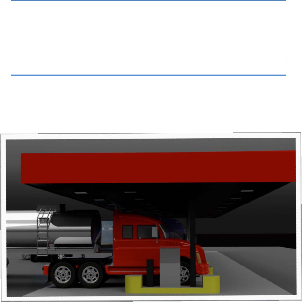
Rev:4/15/2011
Z-Con Station
Installation Guide
Rev: 04/15/2011
1 Rev:4/15/2011
Table of Contents
Z-CON Fueling Station Installation Process .................................................................................2
Pre-Installation Template for Email...............................................................................................4
Z-Con Canopy Kit Installation Guide.............................................................................................5
Required Parts..............................................................................................................................7
Required Tools & Consumables ...................................................................................................7
J-Box Installation...........................................................................................................................9
Z-Con Ultrasonic Sensor Assembly............................................................................................10
Z-Con Antenna & IR Receiver ....................................................................................................15
Z-Con Pump Board Installation Guide ........................................................................................20
Z-Con Pump Provisioning Application Guide..............................................................................24
Z-Con Validation Tool…………………………………………………………………………………..29
Hardware Troubleshooting Guide...............................................................................................32
Post Installation Template for Email Response to Zonar............................................................33
Appendix
Z-CON Fueling Station Installation Process…………………………………………………………InstallationProcess
Pre-Installation Template for Email…………………………………………………………………….Pre‐InstallationEmail
Z-Con Canopy Kit Installation Guide………………………………………………………………..CanopyKitInstallation
Z-Con Pump Provisioning Application Guide………………………………………………..ProvisioningApplication
Z-Con Pump Validation User Tool Guide…………………………………………………………………….ValidationTool
Hardware Troubleshooting Guide………………………………………………………………HardwareTroubleshooting
Post Installation Template for Email Response to Zonar………………………………..PostInstallationEmail
2 Rev:4/15/2011
Z-CON Fueling Station Installation Process
Pre-Installation
Phase 1:
1. Take a total of four photos capturing the following:
a. Photo of entire landscape of fueling area (File Name: Store#-City-State-Direct)
b. Photo of landscape from a side view (File Name: Store#-City-State-Side)
c. Photo of support beam where pump board enclosure will be installed
(File Name: Store#-City-State-Enclosure)
d. Picture of canopy installation location (File Name: Store#-City-State-Canopy)
2. Obtain measurements of the canopy height and distance between IR Antenna and
Ultrasonic sensor installation points.
a. Record measurement
b. Reference table below
Height of Canopy (measured from
the underside of the canopy to the
ground)
Minimum distance between IR
Antenna and Ultrasonic sensor
16’ 8’
17’ 9’
18’ 9’ 6”
19’ 10’
20’ 10’ 6”
c. If mounting the ultrasonic sensor perpendicular to the master fuel pump does not
meet the distance specified in the table above, then the ultrasonic sensor will
need to be moved backwards until it meets the minimum distance.
3. If moving ultrasonic sensor to meet the specification above results in the sensor being
mounted behind the back edge of the fuel pump, note this in the Pre‐InstallationEmail
Phase 2:
1. Verify that the on hand quantity at the store matches the quantity on the packing slip and
is adequate for station install.
a. Refer to packing slip provided with shipment and verify all components have
been received in the appropriate quantities.
i. Z-Con Pump Board Assembly (Dual and Single)
ii. Canopy Kit
1. Ultrasonic Assembly
3 Rev:4/15/2011
2. IR Antenna
2. Email zcon-installation@zonarsystems.com the signed packing slip
Installation:
1. Install hardware per the Z‐ConCanopyKit&Z‐ConPumpBoardInstallationGuide
2. Provision pump per the Z‐ConPumpProvisioningApplicationGuide
3. Validate pump per the Z‐ConPumpValidationUserToolGuide
4. Place call to the Pilot Network Team at 865-474-2837; inform the representative Z-Con is
currently being installed at the station
a. Supply the Pilot representative with the following:
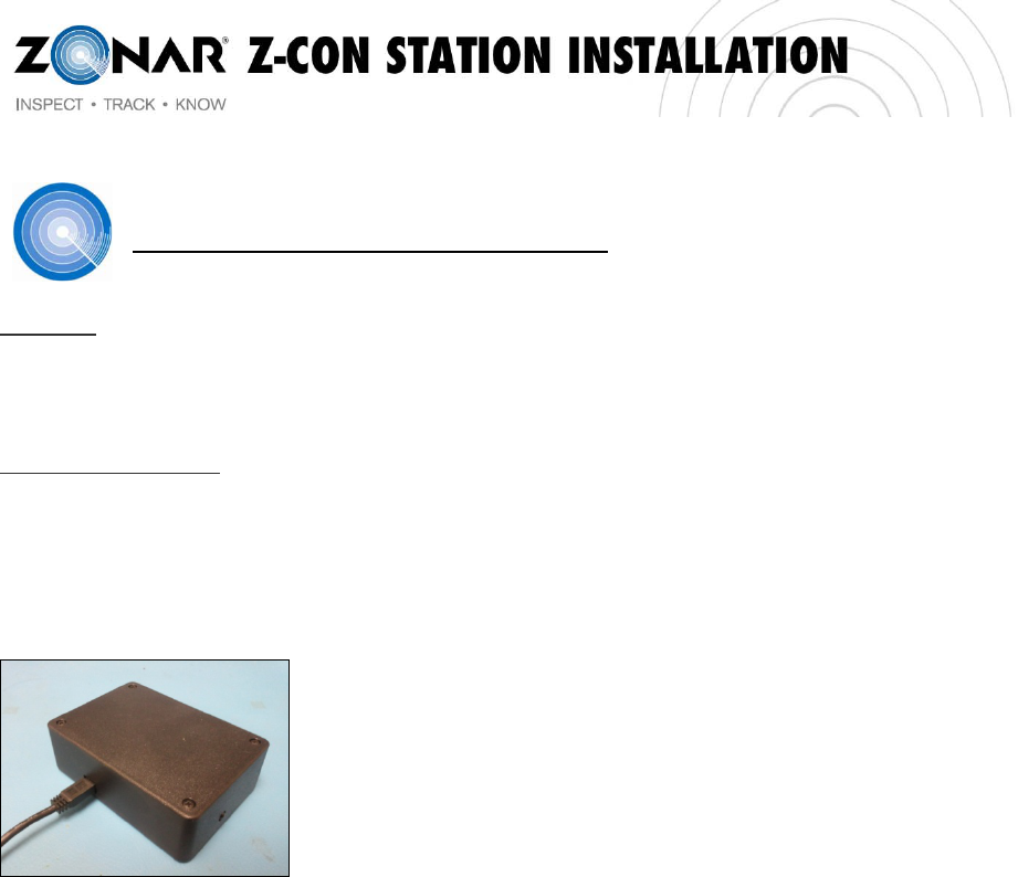
*Store number
*IP Address of installed pump board
b. Ask the representative to verify the pump is on the network
c. Ask the representative to verify the data is being sent to “64.14.140.29”
5. Troubleshoot hardware as needed per the HardwareTroubleshootingGuide
Post Installation/ Checkout:
1. Place call to Tyler Ferdun or Jacob Thomas at 877-843-3847
a. Supply the following:
*Store Number
*Pump IDs
*ZID of Test Board
b. Verify all lanes were installed properly with Zonar
2. Handling Remaining Equipment
a. Box all equipment up securely
b. Apply Zonar supplied ship labels to all boxes
c. Ensure equipment ships out
3. Supply PostInstallationEmailto the following:
zcon-installation@zonarsystems.com
4 Rev:4/15/2011
Pre-Installation Template for Email
Date of Installation:
Store Number and Location:
Number of Lanes Being Installed:
Pump/Lane numbers:
Installer Name and Phone Number:
1. Attach Photos to email (please see attached file for reference photos) :
a. Photo of entire landscape of fueling area (File Name: Store#-City-State-Head on)
b. Photo of landscape from a side view (File Name: Store#-City-State-Side View)
c. Photo of support beam where pump boards will be installed
(File Name: Store#-City-State-Pump Board)
d. Picture of canopy installation location (File Name: Store#-City-State-Canopy)
2.
3. Unique situations that have been prindentified during the pre-installation process.
Height of Canopy (measured from the
underside of the canopy to the ground) Distance between Antenna and Ultrasonic
sensor installation points
5 Rev:4/15/2011
Z-Con Canopy Kit Installation Guide

6 Rev:4/15/2011
Contents
Required Parts..............................................................................................................................7
Required Tools & Consumables ...................................................................................................7
Nomenclature................................................................................................................................8
J-Box Installation...........................................................................................................................9
Z-Con Ultrasonic Sensor Assembly............................................................................................10
Z-Con Antenna & IR Receiver ....................................................................................................15

7 Rev:4/15/2011
Required Parts
1. Canopy Kit (includes the following)
a. Z-Con Ultrasonic Sensor Assembly – p/n 80586
b. Z- Con Antenna & IR Receiver Assembly – p/n 80585
c. L-Com 2.4GHz HG2412P Antenna
2. Z-Con Pump Panel Board Assembly – p/n 80476 (Dual) or 80521 (Single)
Required Tools & Consumables
Tools
1. #2 Phillips Screwdriver
2. 1” NPT Jam Nut tightening tool
3. Calibrated torque wrench
4. Wire cutters
5. Channel locks
Consumables
1. Loctite 425
2. IDC Connectors
8 Rev:4/15/2011
Nomenclature
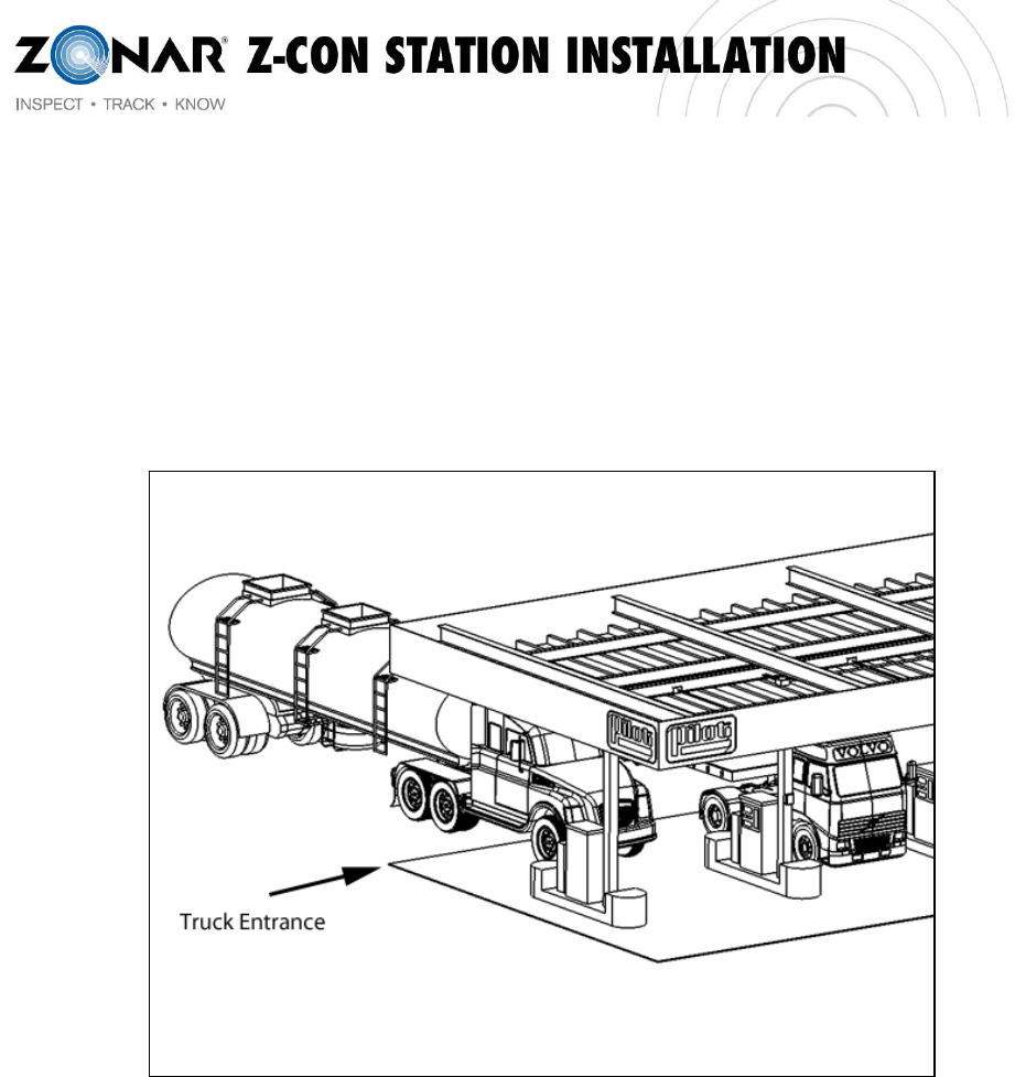
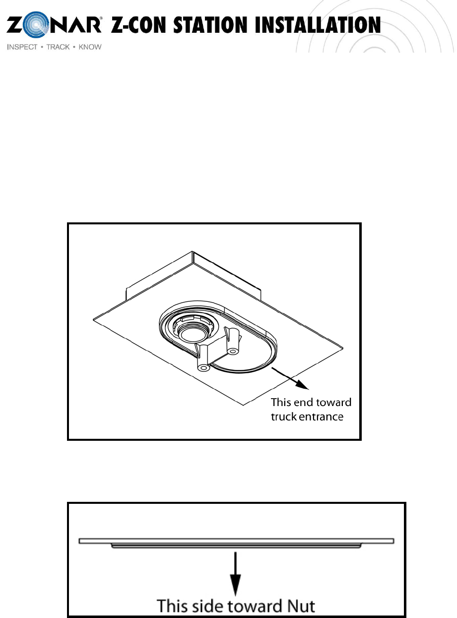
Some items are installed with specific orientations. The Truck Entrance will be the reference
point.
The Truck Entrance is defined as the side of the station that trucks enter from. See Figure 1.
Figure 1 - Truck Entrance
9 Rev:4/15/2011
J-Box Installation
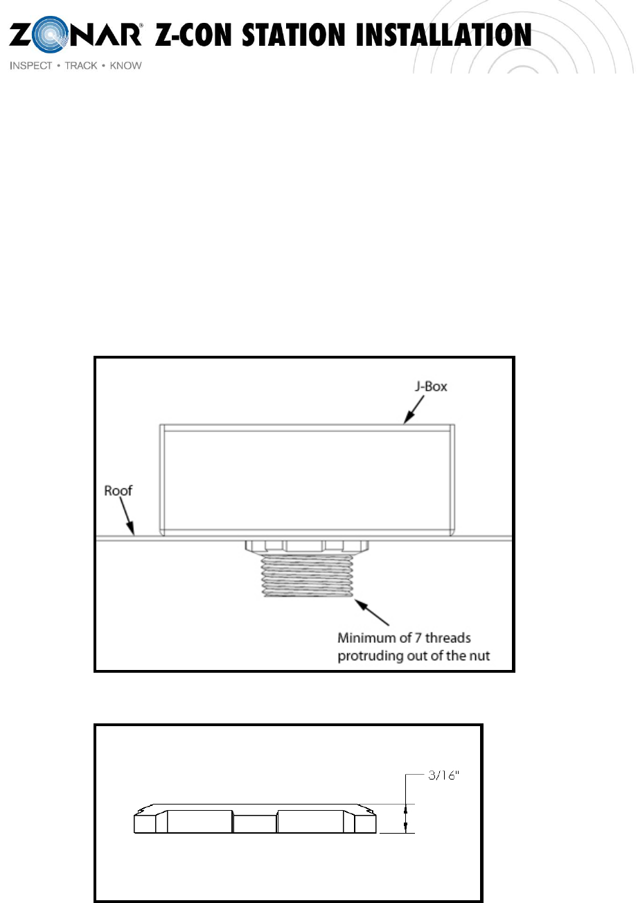
1. Install the J-Box with a minimum of 7 threads protruding out from the Jam Nut. See
Figure 2. The nuts must be standard size 1” NPT (~3/16” tall). See Figure 3.
WARNING: Using nuts that are taller than 3/16” may damage the plastic housings.
NOTE: A seal must be installed between the J-Box and the roof and between the J-Box
Cover and the J-Box.
Figure 2 - J-Box Installation
Figure 3 - Nut Height
10 Rev:4/15/2011
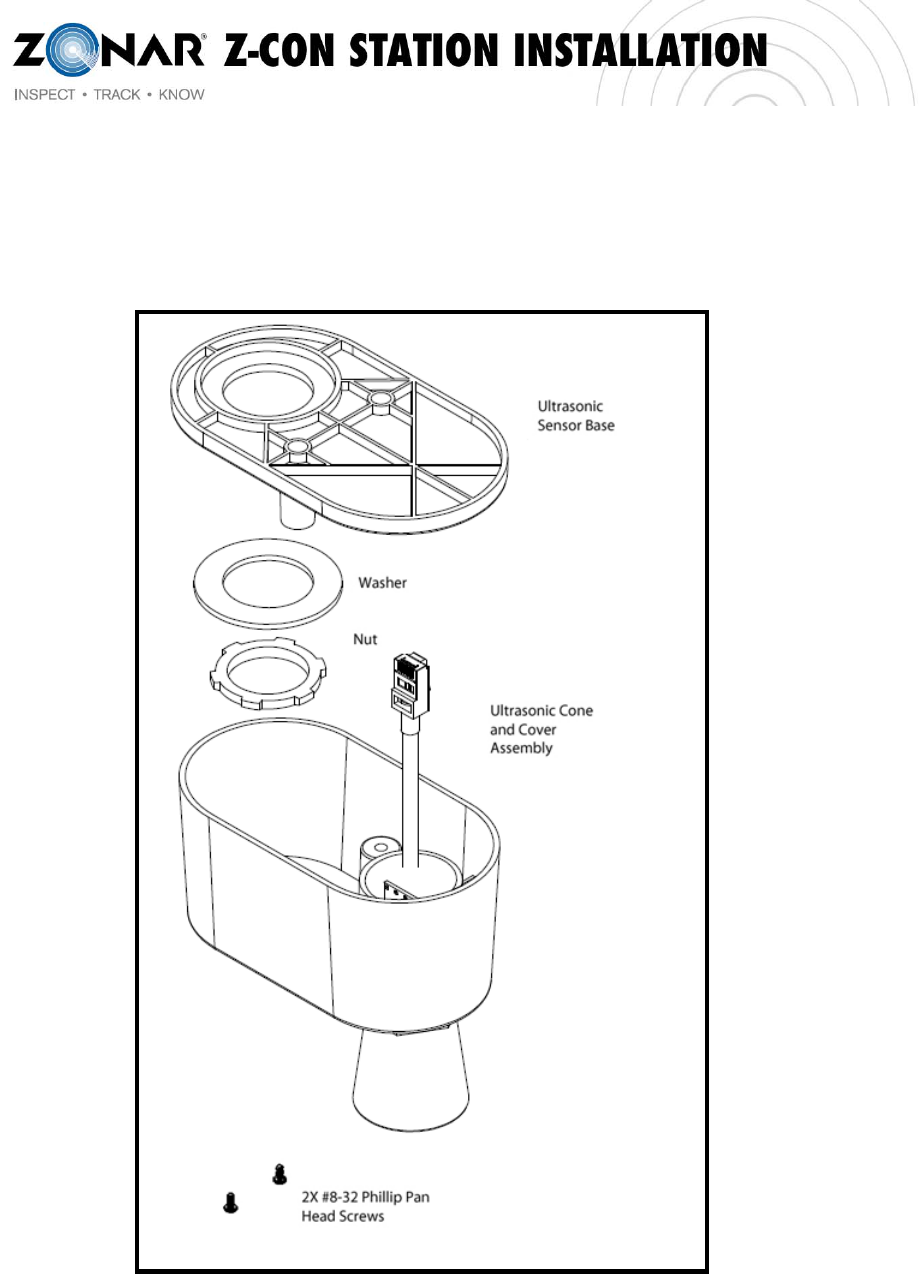
Z-Con Ultrasonic Sensor Assembly
Figure 4 - Ultrasonic Sensor Assembly Components
11 Rev:4/15/2011
1. Install the Ultrasonic Sensor Base to the underside of the canopy where the conduit has
been run for that lane and device. See Figure 5. Add washer and nut. Torque the nut to
approximately 10 in-lbs.
NOTE: See Figure 6 for washer orientation.
NOTE: Ensure that the washer is centered on the pipe.
Figure 5 - Ultrasonic Sensor Base Installation
Figure 6 - Washer Orientation
12 Rev:4/15/2011
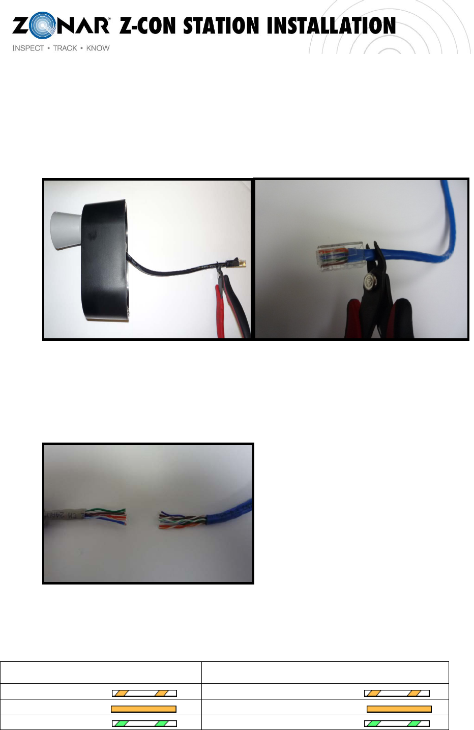
2. Using wire cutters, cut off the Male RJ45 connector from the CAT5 cable attached to the
Ultrasonic Sensor (Image A). Also, cut off the Male RJ45 connector from the end of the
CAT5 cable that is used to connect to the Ultrasonic Sensor (Image B).
(A) (B)
3. Strip back 1”-1.5” of the CAT5 insulation ONLY on both cables. Do NOT strip individual
colored wires within CAT5 cables.
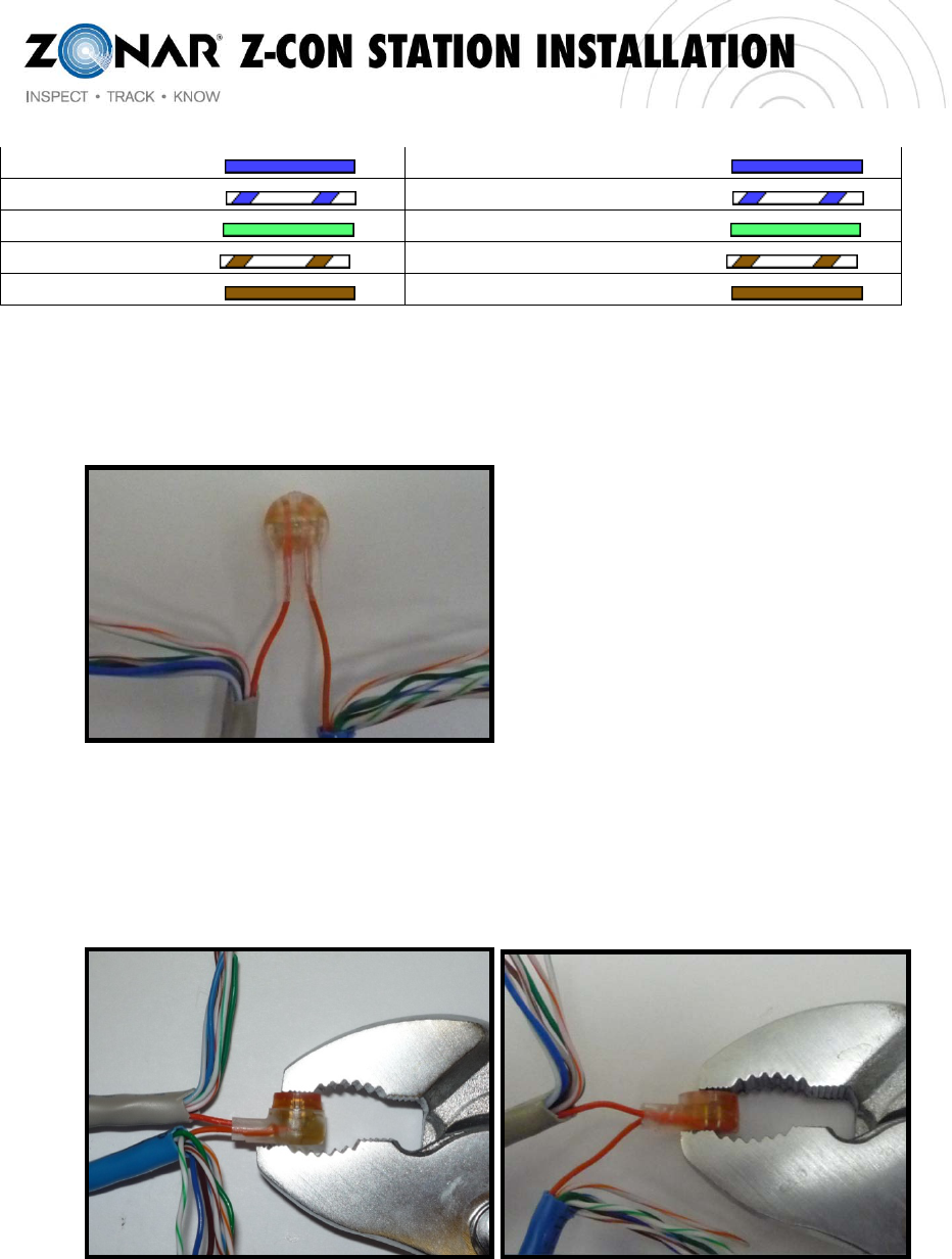
4. Use the IDC connectors to splice the CAT5 cable from the Ultrasonic Sensor to the
CAT5 cable from the pump board. Match each wire with corresponding colors as follows:
CAT5 (From Ultrasonic Sensor) To: CAT5 (From Pump Board)
Orange/White Orange/White
Orange Orange
Green/White Green/White
13 Rev:4/15/2011
Blue Blue
Blue/White Blue/White
Green Green
Brown/White Brown/White
Brown Brown
5. Hold the IDC connector with button side down. Insert same colored wires (see above
chart) all the way into the IDC connector ports until they reach the top of the IDC
connector (Again, Do Not Strip Insulation on Individual Wires).
6. Using channel locks or other tool, crimp button down so that it sits flush in the base of
the IDC connector.
7. When finished with all wires, tuck exposed IDC connectors into the base of the
Ultrasonic Sensor and finish securing installation.
14 Rev:4/15/2011
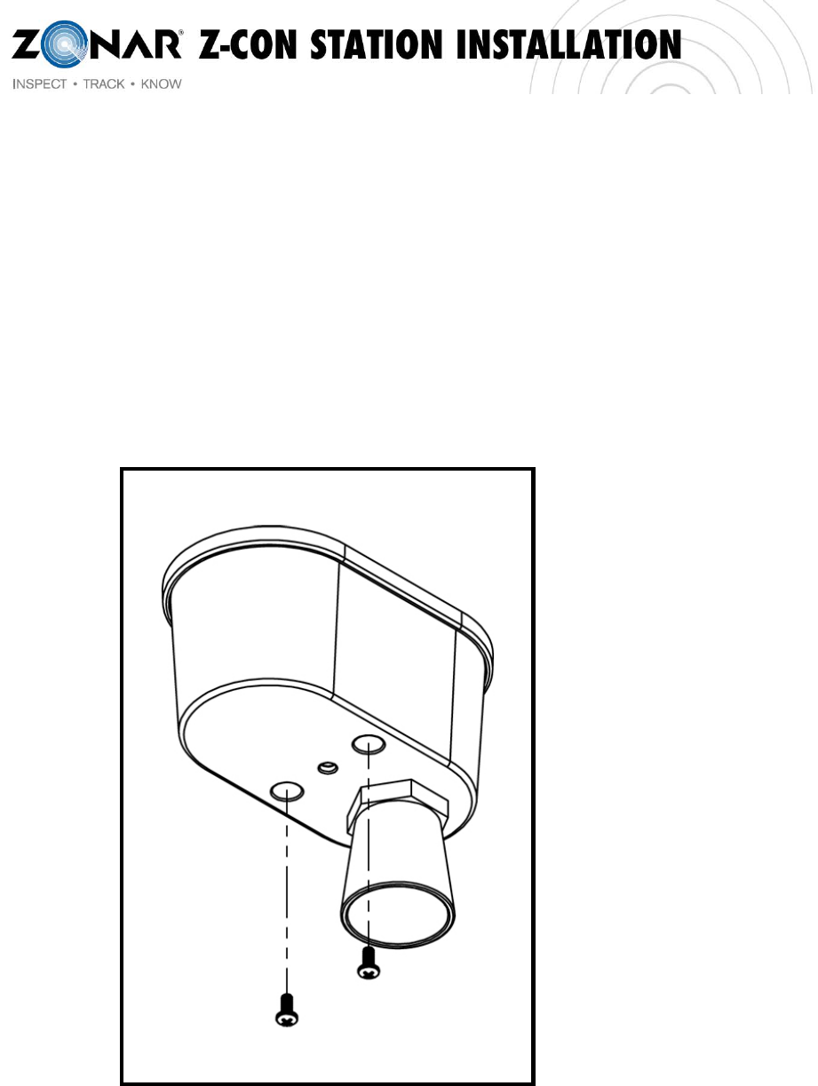
8. Install the Ultrasonic Sensor Cover with the cone on the opposite side of the Nut &
Washer. See Figure 4 for orientation.
NOTE: Ensure that the Receptacle does not get pinched between the rib between the
two mount posts in the base and the cover.
9. Apply Loctite 425 to the 2, #8-32 X 3/8 Phillip Pan Head Screws and install as shown in
Figure 7. Torque to 4 in-lbs.
Figure 7 – Ultrasonic Sensor Cover and Fasteners
15 Rev:4/15/2011
Z-Con Antenna & IR Receiver
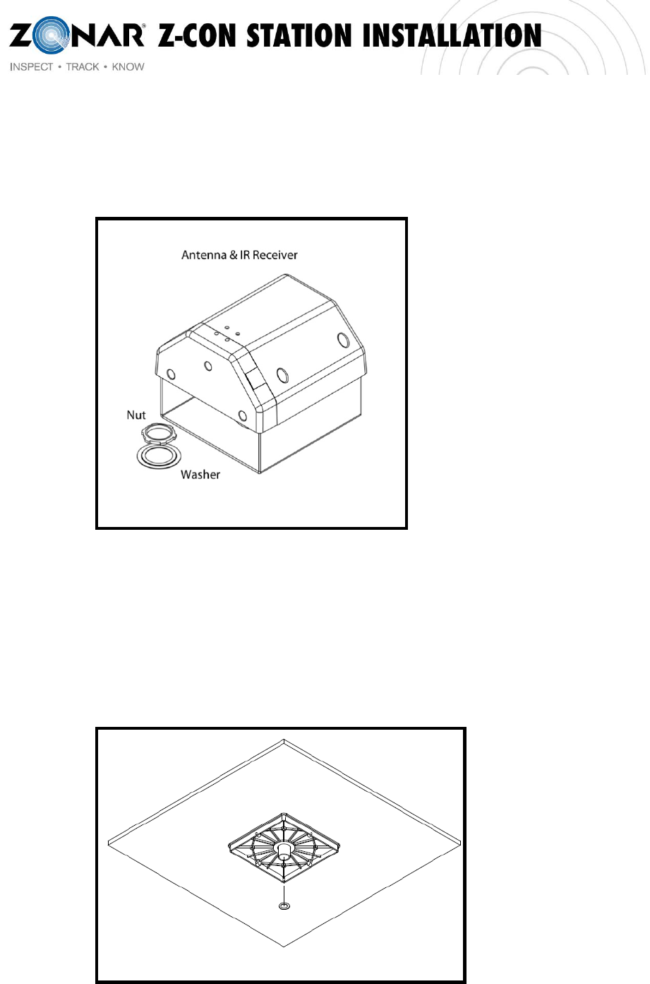
Figure 8 - Antenna & IR Receiver Assembly
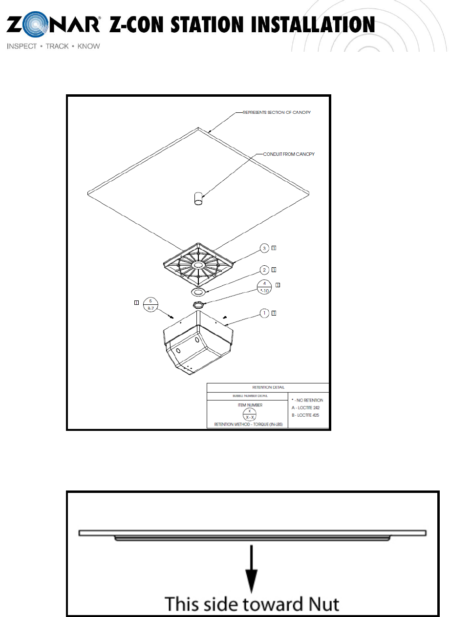
1. Install mount plate to the underside of the canopy where the conduit has been run for
that specific lane and device. See Figure 9 & 10. Add washer and nut. See Figure 11
for washer orientation.
16 Rev:4/15/2011
Figure 9 – Mount Plate
Figure 10 – Antenna & IR Receiver Assembly Components
Figure 11 - Washer Orientation
2. Install the N-Type Connector from the LMR-200 coax cable on to the HG2412P Antenna
and tighten to torque spec of 7 inch/oz.
17 Rev:4/15/2011
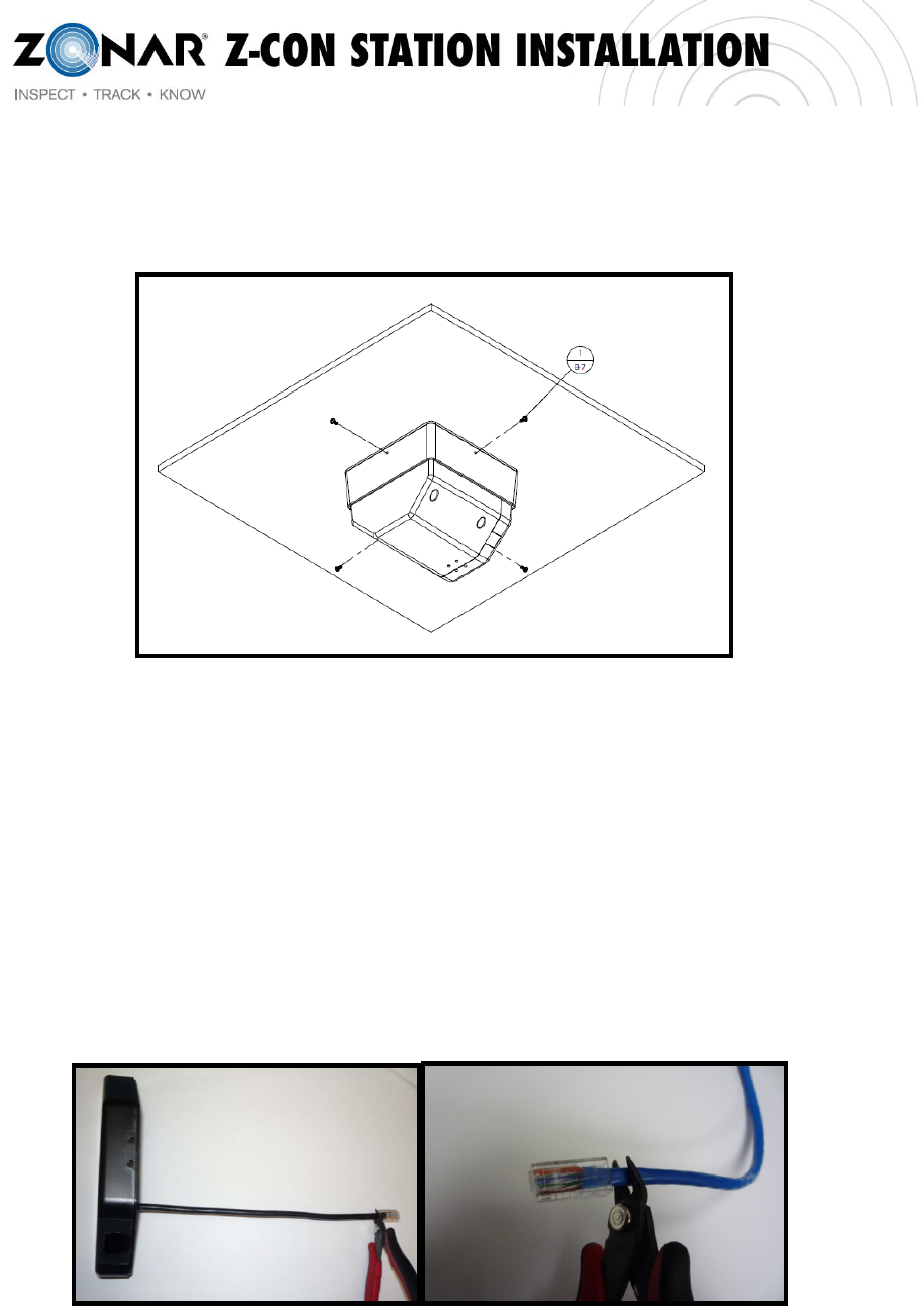
3. Attach the Antenna & IR Receiver Base (with cover) to the mount plate using four
screws as shown below. See Figure 12.
Figure 12 – Antenna & IR Receiver Base Screw Locations
4. Remove the Antenna & IR Receiver Cover from the Base by removing four top screws
and pulling down on the cover.
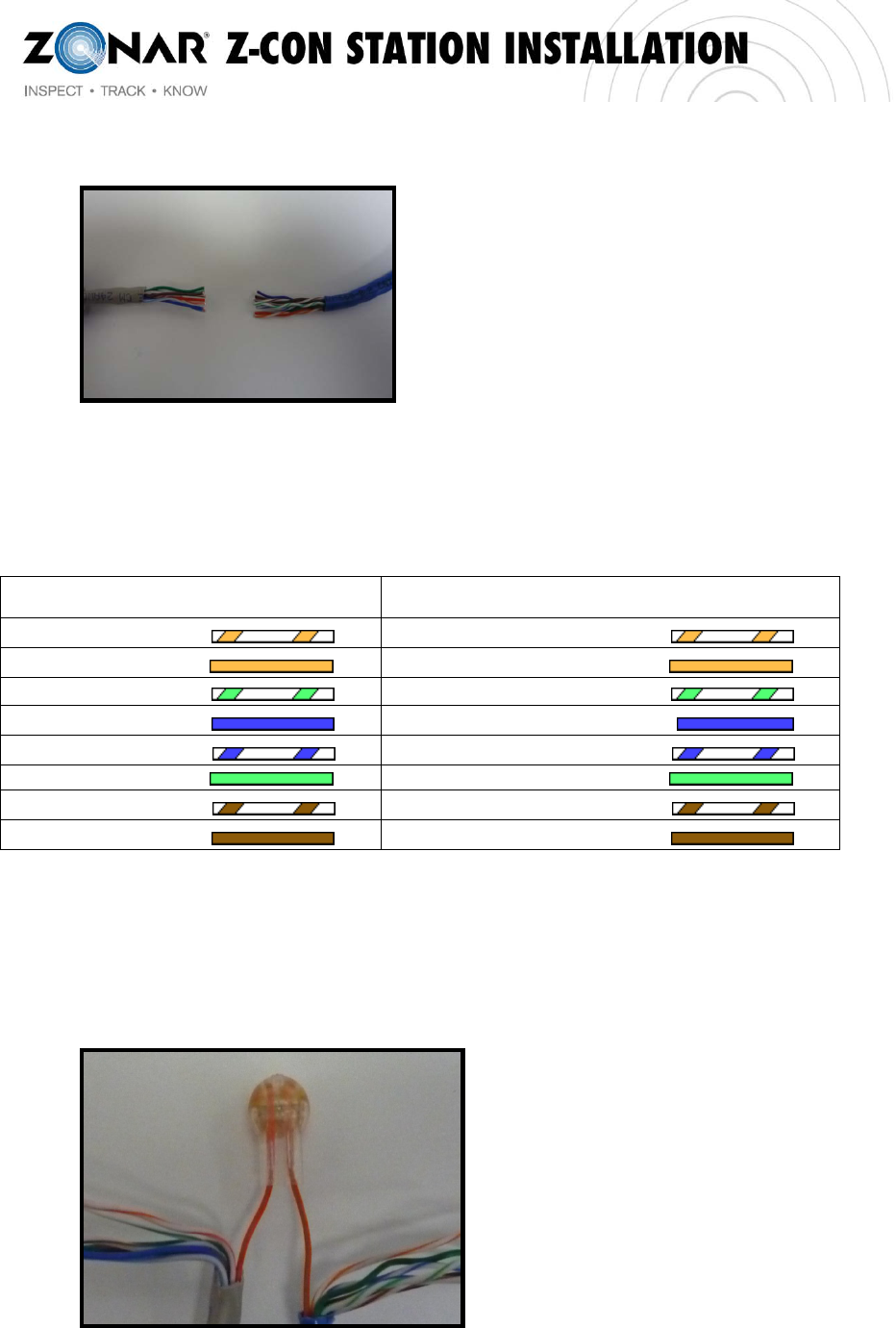
5. Using wire cutters, cut off the Male RJ45 connector from the CAT5 cable attached to the
IR Receiver (Image A). Also, cut off the Male RJ45 connector from the end of the CAT5
cable that is used to connect to the IR Receiver (Image B).
(A) (B)
6. Strip back 1”-1.5” of the CAT5 insulation ONLY on both cables. Do NOT strip individual
colored wires within CAT5 cables.
18 Rev:4/15/2011
7. Use the IDC connectors to splice the CAT5 cable coming from the IR Receiver to the
CAT5 cable ran from the pump board location. Match each wire with corresponding
colors as follows:
CAT5 (From Ultrasonic Sensor) To: CAT5 (From Pump Board)
Orange/White Orange/White
Orange Orange
Green/White Green/White
Blue Blue
Blue/White Blue/White
Green Green
Brown/White Brown/White
Brown Brown
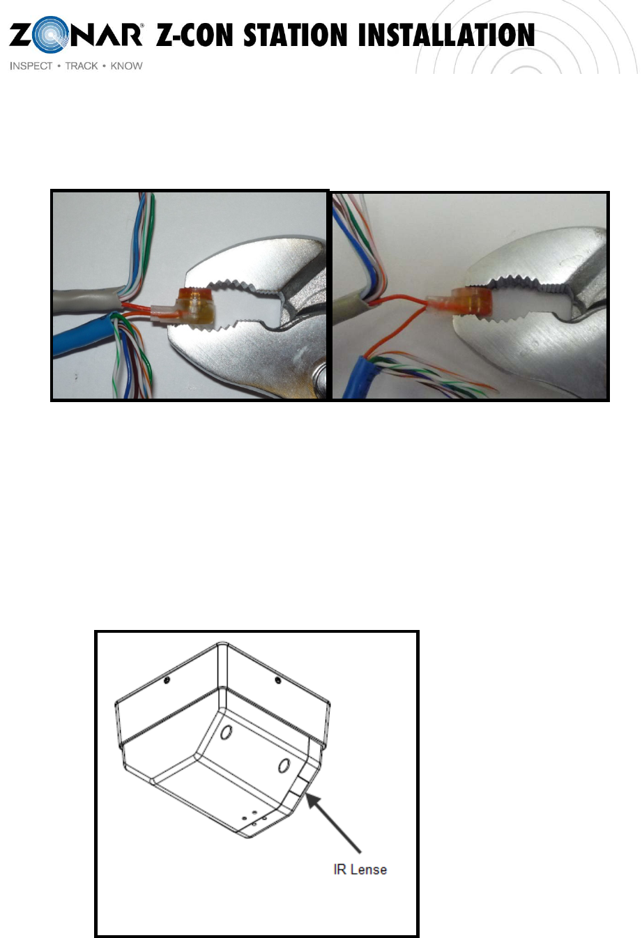
8. Hold the IDC connector with button side down. Insert same colored wires (see above
chart) all the way into the IDC connector ports until they reach the top of the IDC
connector (Again, Do Not Strip Insulation on Individual Wires).
19 Rev:4/15/2011
9. Using channel locks or other tool, crimp button down so that it sits flush in the base of
the IDC connector.
10. When finished with all wires, tuck exposed IDC connectors into the base of the IR
Receiver and secure the Antenna & IR Receiver Cover to the Base using the four top
screws.
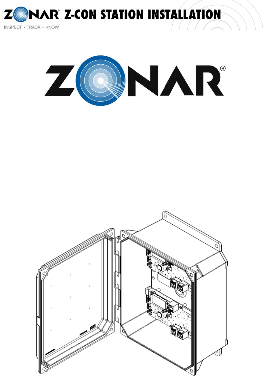
11. Remove the tape covering the IR Lens. See Figure 13.
Figure 13 – IR Lens Location

20 Rev:4/15/2011
21 Rev:4/15/2011
Z-Con Pump Board Installation Guide
22 Rev:4/15/2011
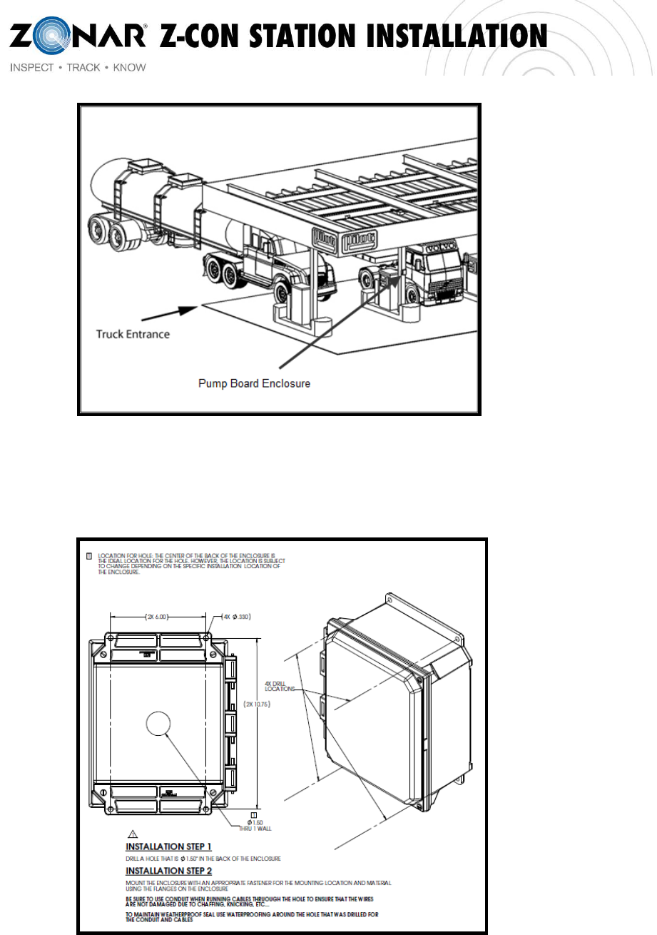
1. Install Pump Board enclosure to face out bound to traffic
a. Enclosure is not be installed towards a lane
b. This limits possible customer interaction with hardware
23 Rev:4/15/2011
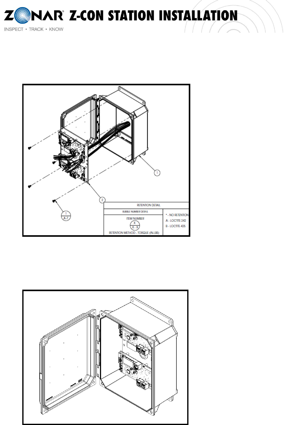
2. See enclosure installation reference below
24 Rev:4/15/2011
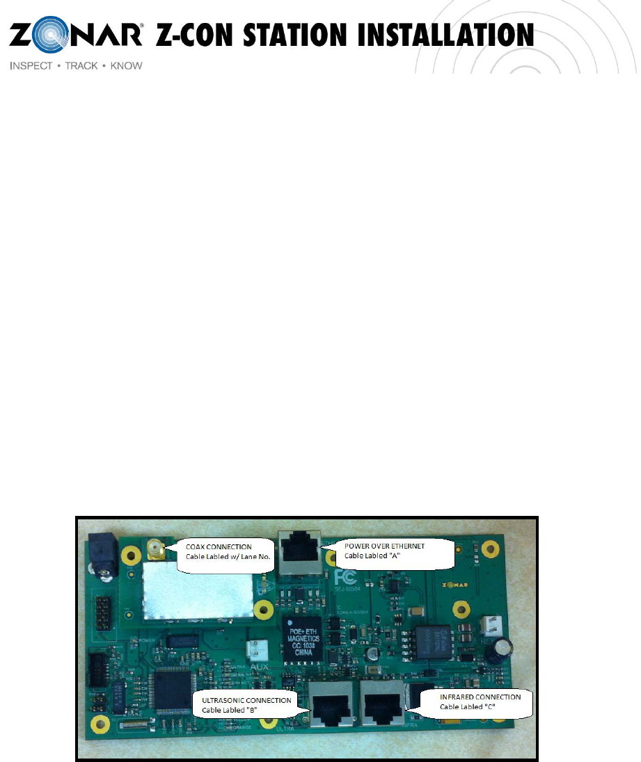
3. Prior to mounting the Pump Panel Board, route each lane’s cables through their
respective grommet holes
4. Secure Pump Panel Board to the mounting posts within the enclosure
25 Rev:4/15/2011
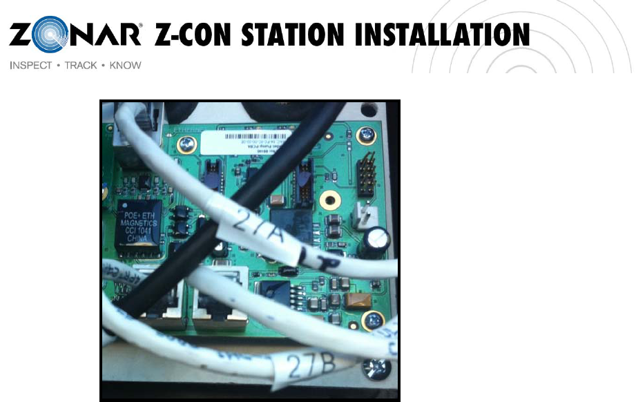
5. Once the Pump Panel Board is mounted, connect the appropriate cables to the
appropriate connectors (see reference below)
a. Power over Ethernet (Top of Board Labeled “A”)
b. Ultrasonic Sensor (Bottom Left Labeled “B”)
c. Infrared Receiver Interface (Bottom Right Labeled “C”)
d. 2.4 GHz RF Coax Connection (Top Left on the Radio Board) – tighten connection
to torque spec of 7 inch/oz
6. Verify that all cables have been labeled appropriately (A,B,C)
a. Label all cables with printed (not hand written) identifiers
26 Rev:4/15/2011
7. Once hardware has been installed, provision each lane per the Zcon Pump
Provisioning Application Guide
27 Rev:4/15/2011
Z-Con Pump Provisioning Application Guide
Function:
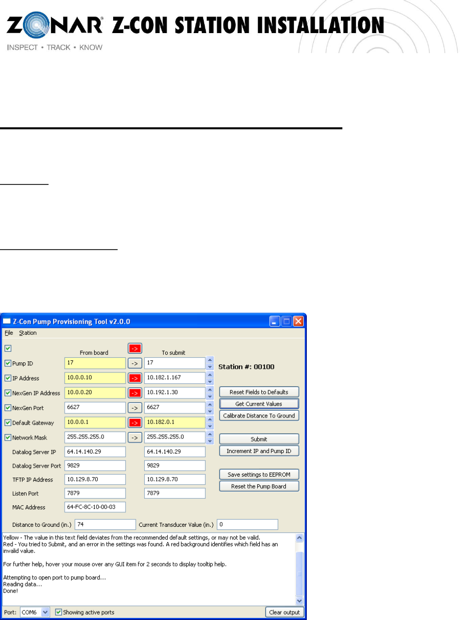
This application is required to apply network settings to the pump board and to calibrate the distance to
ground for each lane. It provides a quick and easy way to view and edit the settings of a pump board.
Necessary Equipment:
1. Laptop equipped with Z-Con Pump Provisioning Tool
2. Provisioning Cable #80582 RJ45 to Serial RS-422 (Provided)
3. Internet Connection (on older installations)
*Default settings for the pump board are in the left column and the default store settings are in the right, in this example, store
00100.
28 Rev:4/15/2011
Provisioning Tool Steps:
1.Start at lowest numbered lane
2.Launch the Provisioning Application (from Start Menu or Desktop Icon).
3.Once started, the application attempts to connect to the update server and download a new flatfile.
This flatfile will contain the information for every station supported by Z-Con. You will need an internet
connection.
o The application is installed with the most recent flatfile already provided, so the above step is
only necessary on older installations.
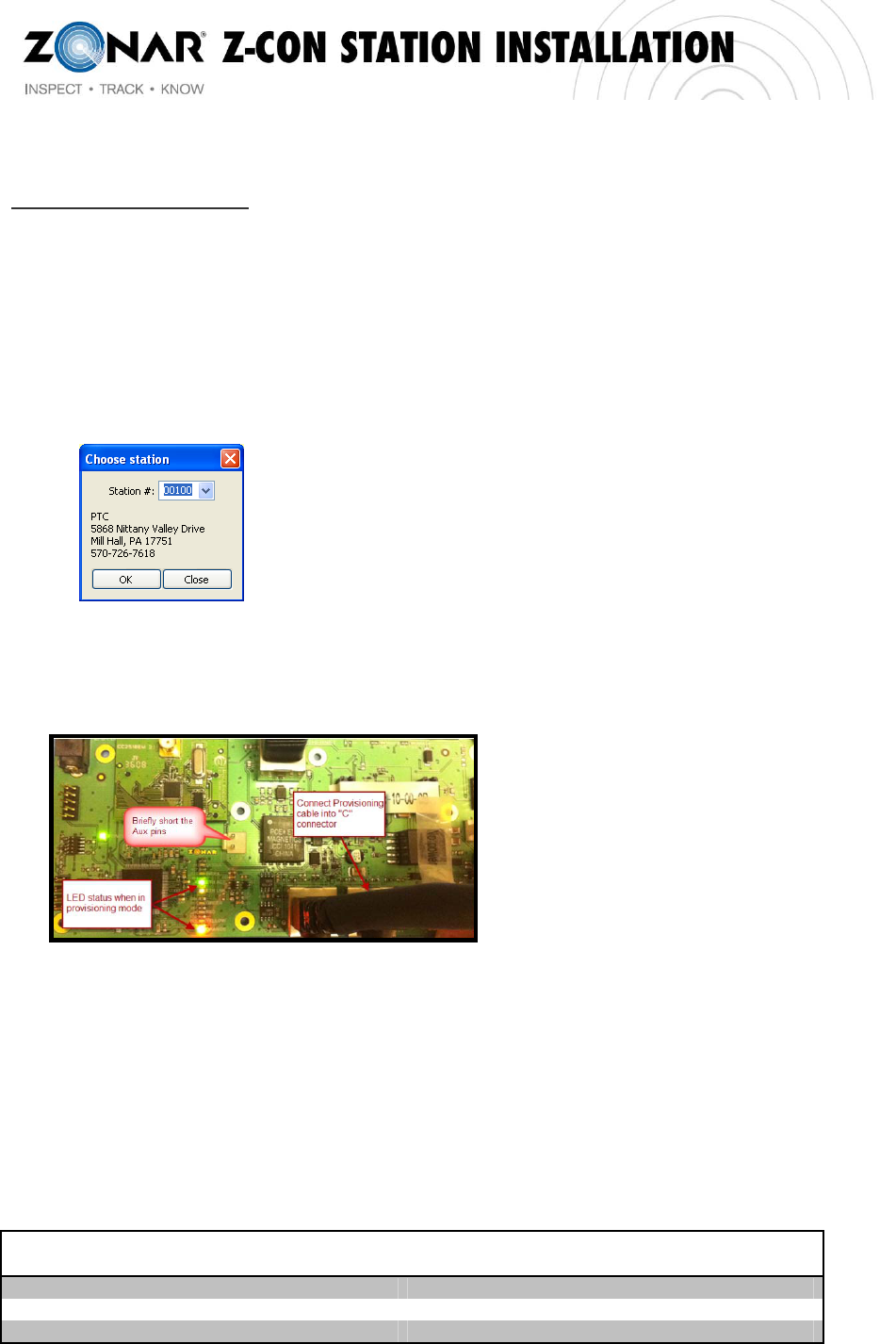
4.Go to ‘Station Choose from station list’. Enter the store number or select from the drop down, once
selected or entered click OK.
5.Connect serial end of the provisioning cable to your computer and the other to the bottom right RJ45
port on the pump board (pictured below).
6.Choose the proper COM port that corresponds to the proper serial port.
7.On the pump board, briefly short the AUX pins by tapping lightly with a screwdriver to enter the board
into Provisioning Mode. To verify provisioning mode look for bottom LED to be flashing
8.Adjust the values in the right hand column (see picture on page 1 for reference) to fit the individual
pump
9.Click ‘Write Settings to Board’. Once the output text box says ‘Done!’, provisioning is finished.
10.Next, verify an ultrasonic transducer is connected to the pump board, click ‘Calibrate Distance to
Ground’. Make sure that there is NOT a vehicle in the lane when calibrating the distance to ground
11.Click ‘Get Current Values’ to verify correct values have been set. The values will appear in the left
column.
o If the values you submitted differ at all from the ones that are returned, the button in between
the fields will turn red. Repeat steps 7 and 8 until the values are accurate.
12. Check that the value for distance to ground is similar to the chart below, distance is displayed in
inches. Please note that this may take several attempts to attain an accurate reading.
DISTANCE FROM SENSOR TO GROUND
(FT.) DISTANCE FROM SENSOR TO GROUND
(IN.)
16’ 192”
17’ 204”
18’ 216”
29 Rev:4/15/2011
19’ 228”
20’ 240”
13.Reset the board by either tapping the AUX pins on the pump board, or clicking the 'Reset the
Pump Board' button in the application.
Application Functions:
Menu Items Options Description
Save Saves the current, enabled values to a .prov file
for later use or sharing between laptops.
File
Load Loads a saved .prov file, overwriting any text fields
with the values that were saved.
Chose from
Station List Displays a dialog box with a dropdown of all store
numbers and addresses of the currently selected
store. Click ‘OK’ to load the selected store’s
default network settings to the main app. Click
‘Cancel’ to return without making any changes.
Update
Stations File
Station
Attempts to connect to the server and download a
new flatfile with information for every station
supported by Z-Con. (Internet connection is
required).
Errors Description
Please Set a Valid Com Port Number Reselect a port from the COM Port dropdown
Failed to Retrieve Settings Commonly triggered when the provisioning cable is not
connected to the pump board or the pump board is not in
‘provisioning mode’. If the problem persists, the pump
board is either not receiving the request for its settings, or
the computer is not receiving the pump board’s response.
The provisioning cable or the pump board may be faulty,
test a known functioning pump board to determine which
is malfunctioning.
Board Not Provisioned. Found Some
Fields With Invalid Values If you see this error, one or more of the fields will be
colored red. These fields have invalid values in them and
need to be changed before you can Submit. See the
output text box for more information.
X Value Couldn’t Be Retrieved:
Invalid Data Stored Values in the EEPROM are either invalid or there
was an error when retrieving the values from the board.
Try ‘Get Current Values’ again, submit a new value to the
board and try to ‘Get Current Values’ again. If the
30 Rev:4/15/2011
problem persists, the ARM or the EEPROM may be faulty.
‘X’ Could Not Be Opened. Please
Double-Check That You’ve Chosen
the Right COM Port
Occurs when the serial port connection is not made
properly. Most common causes are either choosing a
serial port from the dropdown currently inactive or
choosing a serial port that is currently claimed by another
program or device. Check your connections and Device
Manager, and shut down any other telnet/terminal
programs that may be open on your laptop.
GUI Objects Function
Checkboxes Used to enable or disable specific text fields. When ‘submit’ is clicked, only the
enabled fields will be programmed onto the pump board. When saving a .prov
file, only the enabled fields will be saved. The very top checkbox can be used
to enable or disable all fields with a single click.
Arrow Buttons These buttons turn red if the text in the field to their immediate left does not
match the one to their immediate right. Click the button to copy the text from
the left to the right. The very top button functions the same as if all the arrow
buttons below were pressed.
COM Port Selector Select the COM port that the provisioning cable is connected to. If ‘Auto-
Detect Ports’ is checked, the program will scan for available ports each time
the dropdown is selected. This may cause a slight delay in response.
Unchecking that box will list all COM ports from 1 to 128.
Reset All Values Resets all the text fields back to some null value. It does not automatically
reset the provisions on the pump board.
Get Current Values Resets the current provisions from the pump board, displaying them in the
text fields.
Recall Last
Submitted Values Displays the values that were last submitted to a pump board. This is useful for
comparing the values you attempted to store in a pump board with the actual
values retrieved with ‘Get Current Values’.
Calibrate Distance to
Ground Sets the pump board to read the current value of the distance from the
ultrasonic sensor in the canopy to the ground. During ‘Default Mode’, if the
current transducer value is significantly below the saved Distance to Ground
Value, the pump board registers that a truck has arrived and attempts to
connect to the truck via radio. Otherwise, it assumes that that the ‘truck’ as left
and shuts off any radio connections.
Submit Checks all of the current settings in the text fields, returning with errors if any
are not valid. If there are no errors, it attempts to set any checked text fields
onto the board and save those values to local memory. These values can be
recalled with ‘Recall Last Submitted Values’.
Save Saves the current, enabled values to a .prov file for later use or to share
between PCs.
Load Loads a saved .prov file, overwriting any text fields with the values that were
last saved.
Save Settings to
EEPROM Saves the settings to the EEPROM, allowing them to be saved without having
to tap the AUX pins.
Reset the Pump
Board Resets the board. This is the equivalent to tapping the AUX pins.
Output Text Box Most extra output goes into this text box, including details about the
performance of the application as well as any errors that may come up.
31 Rev:4/15/2011
TROUBLESHOOTING
RECEIVED ECHO
REQUEST LIGHT – solid red COM port is inactive. Verify that the tool is
properly plugged into your computer and
you’ve chosen the correct COM port in the
Pump Validation App. Try toggling the “show
active ports” checkbox to refresh the ports
drop down box
– does not light up The tool did not receive a radio echo request from
the pump board. Check the RAD1-A and RAD1-B
LEDs on the pump board. RAD1-A should be solid.
RAD1-B should flash every few seconds. If RAD1-
a and RAD1-B are:
Both solid, the radio board may not
have firmware installed. See pump
installation instructions for help
Both off, radio board is likely missing
power, verify that the pump board is
powering up and the radio board is
properly seated in its slot.
Behaving normally, there is likely a
faulty antenna connection. Verify that
the COAX is connected properly to the
radio board and the radio antenna is
installed correctly
SENDING ZID LIGHT &
BACKGROUND OF ZID
INPUT BOX
– solid red & solid
yellow The ZID value in the text input box is invalid.
Adjust the ZID to a valid one* and try again.
*(note a valid ZID consists of 17 alphanumeric
characters)
RADIO CONNECTION
MADE LIGHT – does not
illuminate The tool is not making a radio connection with the
pump board. Check the INFRA LED on the front of
the pump board. If the LED is:
Not flashing green every few seconds
then the pump is not receiving the ZID
over IR from the tool. Verify that the IR
LED is pointed directly at the canopy,
free of any obstructions.
Flashing green every few seconds, then
there is likely a faulty antenna
connection. Verify that the coax is
connected properly to the radio board
and the radio antenna is properly
installed. Also, try moving closer to the
antenna, if possible.
32 Rev:4/15/2011
PumpValidationToolUserGuide
FUNCTION:
ThePumpValidationToolensuresthatthepumpsidehardwarehasbeenproperlyinstalledandprovisionedby
testingtheconnectivityineachlane.
NECESSARYEQUIPMENT:
1. LaptopequippedwiththeZ‐ConPumpValidationApplication(suppliedonCD)
2. USBcable(provided)
3. ValidationTool(provided)
STANDARDUSE(FollowingInstallationofthePumpBoard)
1. ConnectthePumpValidationTooltoyourlaptopviatheUSBcable
2. LaunchthePumpValidationApplicationonyourlaptopfromthestartmenuordesktopicon
3. ClickonthePumpValidationtabinthePumpValidationApplication
4. SettheactiveCOMport(todetermineportclick‐StartMenu‐ControlPanel‐HardwareandSound‐Device
Manager‐Ports)thetoolwilldisplayaCOMportnexttoit
5. Pullvehicle(orman‐lift)intofuelinglaneasifattemptingtopurchasediesel
6. PointtheIRtransmitter(PumpValidationLabel)attheIRReceiver/radioantennaenclosureinstalledin
thecanopy
7. Clickthe'Start'button
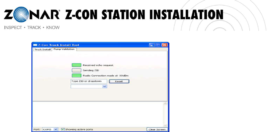
8. ObservethePumpValidationApplication.Thepumpwillattempttomakeaconnectionwiththetool.
FIRST,the"ReceivedEchoRequest"indicatorwilllightupgreen(seebelow)
NEXTthe"SendingZID”willflashyellow
Finally,onceaconnectionhasbeenmade,the"RadioConnectionmade"indicatorwillturnsolid
greenorflashred.Ifflashingred,investigatewaystoimprovesignalstrength(see
Troubleshootingsectiononthenextpage).
33 Rev:4/15/2011
9. Driveontothenextlane.
10. Resettheapplicationbyclicking'Stop'then'Start'again.
34 Rev:4/15/2011
TROUBLESHOOTING
RECEIVEDECHOREQUEST
LIGHT
–solidredCOMportisinactive.Verifythatthetoolisproperly
pluggedintoyourcomputerandyou’vechosenthe
correctCOMportinthePumpValidationApp.Try
togglingthe“showactiveports”checkboxtorefresh
theportsdropdownbox
–doesnotlightupThetooldidnotreceivearadioechorequestfromthe
pumpboard.ChecktheRAD1‐AandRAD1‐BLEDson
thepumpboard.RAD1‐Ashouldbesolid.RAD1‐B
shouldflasheveryfewseconds.IfRAD1‐aandRAD1‐B
are:
Bothsolid,theradioboardmaynothave
firmwareinstalled.Seepumpinstallation
instructionsforhelp
Bothoff,radioboardislikelymissing
power,verifythatthepumpboardis
poweringupandtheradioboardis
properlyseatedinitsslot.
Behavingnormally,thereislikelyafaulty
antennaconnection.VerifythattheCOAX
isconnectedproperlytotheradioboard
andtheradioantennaisinstalledcorrectly
SENDINGZIDLIGHT&
BACKGROUNDOFZID
INPUTBOX
–solidred&solid
yellow
TheZIDvalueinthetextinputboxisinvalid.Adjustthe
ZIDtoavalidone*andtryagain.
*(noteavalidZIDconsistsof17alphanumeric
characters)
RADIOCONNECTION
MADELIGHT
–doesnot
illuminate
Thetoolisnotmakingaradioconnectionwiththe
pumpboard.ChecktheINFRALEDonthefrontofthe
pumpboard.IftheLEDis:
Notflashinggreeneveryfewsecondsthen
thepumpisnotreceivingtheZIDoverIR
fromthetool.VerifythattheIRLEDis
pointeddirectlyatthecanopy,freeofany
obstructions.
Flashinggreeneveryfewseconds,then
thereislikelyafaultyantennaconnection.
Verifythatthecoaxisconnectedproperly
totheradioboardandtheradioantennais
properlyinstalled.Also,trymovingcloser
totheantenna,ifpossible.

35 Rev:4/15/2011
Hardware Troubleshooting Guide
The Z-Con Canopy Kit is composed of two devices: an ultrasonic sensor and the Antenna & IR Receiver.
These devices are installed on the underside of the canopy in each fuel lane.
If validation of the pump hardware is not successful, please refer to the troubleshooting sections below for
each device.
Ultrasonic Sensor
The ultrasonic sensor receives power from the pump board over the CAT5 cable which is also
used to transmit data from the ultrasonic sensor to the pump board.
To verify the ultrasonic sensor is working, verify the pump board is powered up
(Illuminated LEDs indicate the board is receiving power). Attach the ultrasonic sensor to
the CAT5 cable in the canopy and listen for a faint "ticking" noise. If you hear a “ticking”
noise the sensor is receiving power and should be working.
If you do not hear a ticking noise use a short CAT5 patch cable to attach an ultrasonic
sensor to the pump board. If you hear ticking, the cabling between the pump board and
canopy is faulty.
If you do not hear ticking then either the pump board or sensor is bad. Use a known
good sensor to verify the problem is with the pump board or the sensor.
If the sensor is "clicking" when installed then you should see "valid" data on the Z-Con
Pump Provisioning Tool. Valid Data would be around 200" depending on the height of
the canopy.
If the data in the Z-Con Pump Provisioning Tool does not look reasonable try swapping
the ultrasonic sensor with a known good sensor.
Infrared Receiver (IR Receiver)
The IR receiver receives power from the pump board over the CAT5 cable which is also used to
transmit data from the IR receiver to the pump board.
To verify the cabling to the IR receiver is working, you can use an ultrasonic sensor to
verify power is getting to the IR receiver. Attach an ultrasonic sensor to the IR receiver
cable, make sure the other end is attached to the IR receiver port on the pump board
and listen for "ticking". This will verify that power is getting to the IR receiver.
If there is no ticking then use a short CAT5 patch cable to attach an ultrasonic sensor to
the IR receiver port on the pump board. You should hear ticking, if not, the pump board
is bad.
If there is ticking then you can attach the IR receiver to the pump board using the short
CAT5 patch cable and point the Pump Validation Tool directly at the IR receiver.
36 Rev:4/15/2011
Post Installation Template for Email Response to Zonar
Prior to finalizing a sites installation the follow steps must be taken:
1. Date and time call was placed to Zonar Systems Customer Care to verify station
2. Name of representatives from Zonar Systems that verified installation
3. Outstanding issues on site (IE: enclosure issues, power issues etc.)
a. Detail outstanding issue and resolution
4. Extra material on site if applicable
a. Provide Zonar with the following information
Component Qty Location/Store #
Mac Address (if Pump
board)
Ultrasonic Sensor Assembly
Pump Board Enclosure
Pump Board Assembly Single Mac address here
Pump Board Assembly Dual Mac address here
Antenna & IR Receiver
Assembly
5. Provide pictures of unique situation work around

37 Rev:4/15/2011