Zonar Systems ZPASSV2 ZpassV2 User Manual
Zonar Systems Inc ZpassV2
User Manual
REV: 02/28/11

INTRODUCTION
2
Zonar Systems Hardware Installation Tips For Professional Installers
Zonar equipment will provide years of reliable service if properly installed and maintained. Zonar
equipment is typically installed in heavy vehicle applications and is often subject to extreme
temperatures, dust, dirt, vibration, and shock. Proper installation is the critical first step to equipment
longevity and optimal performance.
This guide is meant to be a general guideline for the professional installer and technician. While
we attempt to point out the most common installation questions and issues; common sense,
good housekeeping procedures, attention to detail, safety adherence, and technical competence
of the professional installer is critical for a successful installation.
Please refer to your specific vehicle manufacturer guidelines for the installation of electrical
components and wiring.
A professional team of Zonar support technicians and engineers are available to answer your
installation questions. Contact Zonar at 1-877-843-3847 or by email at
customercare@zonarsystems.com.
Thank you,
Jeff Wells, Field Service Manager - Zonar Systems
As Zonar Systems is continuously improving the Product, Zonar may make changes to the Product at any time which may not be reflected in this document.
TABLE OF CONTENTS
3
ZPass™
Introduction .....................................................................................2
Warranty & Notices..........................................................................4
General Guidelines ..........................................................................5
Schematic .......................................................................................6
ZPass Mounting ..............................................................................7
Operation and Troubleshooting .............................................8-10
www.zonarsystems.com
CONTACT US TODAY • CALL TOLL-FREE: 877 843 3847
EMAIL: customercare@zonarsystems.com
©2011 Zonar Systems. All rights reserved. Products and services protected by one or more patents.
REV: 02/28/11
WARRANTY & NOTICES
4
Limited Warranty
LIMITED WARRANTY: Zonar® warrants that the Hardware
provided under Zonar’s Subscription Agreement is free from
material defects in workmanship for a period of one year for
hardware purchased by customer. THIS LIMITED
WARRANTY IS MADE TO CUSTOMER ONLY AND IS IN
LIEU OF ALL OTHER WARRANTIES, EXPRESS OR IMPLIED.
Zonar EXPRESSLY DISCLAIMS ANY IMPLIED WARRANTY
OF MERCHANTABILITY AND FITNESS FOR A PARTICULAR
PURPOSE, AND ANY WHICH MAY ARISE FROM COURSE
OF PERFORMANCE, COURSE OF DEALING OR USAGE
OF TRADE
CUSTOMER’S SOLE AND EXCLUSIVE REMEDY AND
ZONAR’S ENTIRE OBLIGATION UNDER THESE LIMITED
WARRANTIES for defective equipment is the repair and
replacement of the equipment free of charge by Zonar.
Zonar shall not be liable to Customer or any third party for
any general, special, punitive, incidental, indirect or
consequential damages, or any lost profits or business,
arising out of Zonar’s Subscription Agreement.
FCC Compliance Statement (Part 15.19)
This device complies with Part 15 of the FCC Rules. Operation
is subject to the following two conditions:
1. This device may not cause harmful interference, and
2. This device must accept any interference received,
including interference that may cause undesired operation.
Warning: (Part 15.21)
Changes or modifications not expressly approved by Zonar
Systems could void the user's authority to operate the
equipment.
GENERAL GUIDLINES
5
Layout
1) Mount all equipment in the interior of the vehicle. GPS
antenna and RFID tags are the only Zonar components
that may be exposed to the outdoor elements.
2) Do not install Zonar equipment below windows and
doors which open to the vehicles exterior to prevent
water damage.
3) Lay all components out prior to installation to check for
proper cable length and interference issues.
4) Avoid mounting equipment in difficult to access areas.
5) Avoid mounting equipment in dirty, dusty, or damp
areas. (e.g. near floors and entrance ways)
Electrical
1) Consult the vehicles manufacturer for specific
installation guidelines. (Highly recommended
for Multiplex electrical systems)
2) All power leads (Red and White leads, GPS- Power
Cable) must be connected to the vehicles protected
circuitry (e.g. fuse panel, circuit breaker panel, protected
circuits). Never electrically connect Zonar equipment to
unprotected circuits. (e.g. directly to battery)
3) It is also required that all power leads (Red and White
leads, GPS-Power Cable) be protected with a 3 to 5
amp fuse and inline fuse holder (included) for optimal
system protection.
4) Electrical fuses should be installed as close to the source
of power as possible.
Drill Holes
1) Capture all drill chips during drilling operations. Do not
allow chips to fall onto equipment, furnishings, etc.
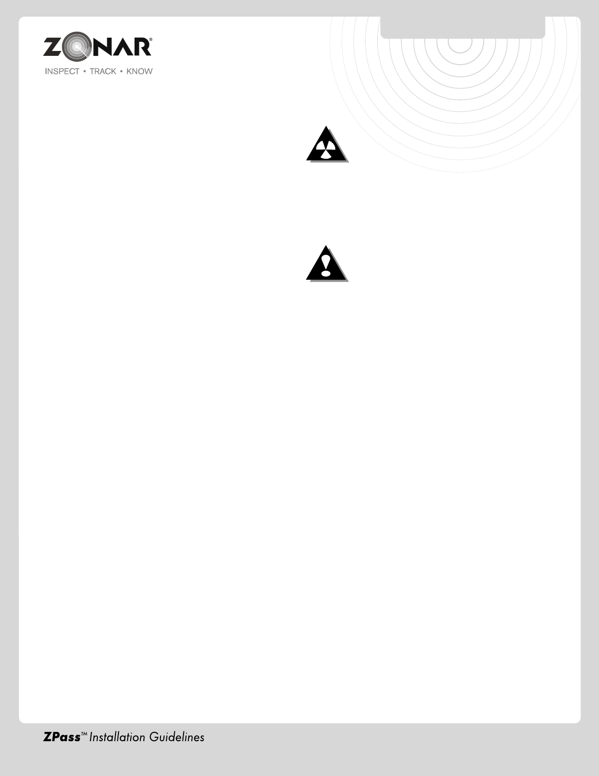
2) Deburr all drill holes on both sides of drilled surface.
Example deburr tool: See Fig. 5-1 or visit
http://www.grainger.com/Grainger/items/3VB51
3) All drill holes must have a rubber grommet or similar
anti-chaffing system installed to protect cable assemblies.
(e.g. plastic conduit)
4) Seal all penetration drill holes which may pass rain water.
Cable Management
1) Strain relieve and support all cable installations.
2) Avoid sharp bends and tight radius installations of
cables.
3) Avoid moving components. (e.g. doors, steering, shafts,
handles, fans, etc.)
4) Provide an adequate "Service Loops" i.e “cable slack”
to allow for servicing of equipment.
5) Avoid routing cables thru doors, windows, and other
pinch points.
6) Avoid routing cables in high personnel traffic areas.
7) Avoid routing antenna cables near radio and PA
equipment.
General Housekeeping
1) Capture all drill chips during drilling operations. Do not
allow drill chips to fall onto electrical equipment,
furnishings, heating ducts, etc. Magnets, sticky tape,
vacuums, physical barrier, etc. may all be used to
accomplish this task.
2) Remove excess sealant. Sealant should be
debris/contaminant free (e.g. drill chips), consistent,
and uniform in appearance. Clip excess wire tie
protrusions.
Fig. 5-1 Typical Deburr Tool
Zonar V2J™
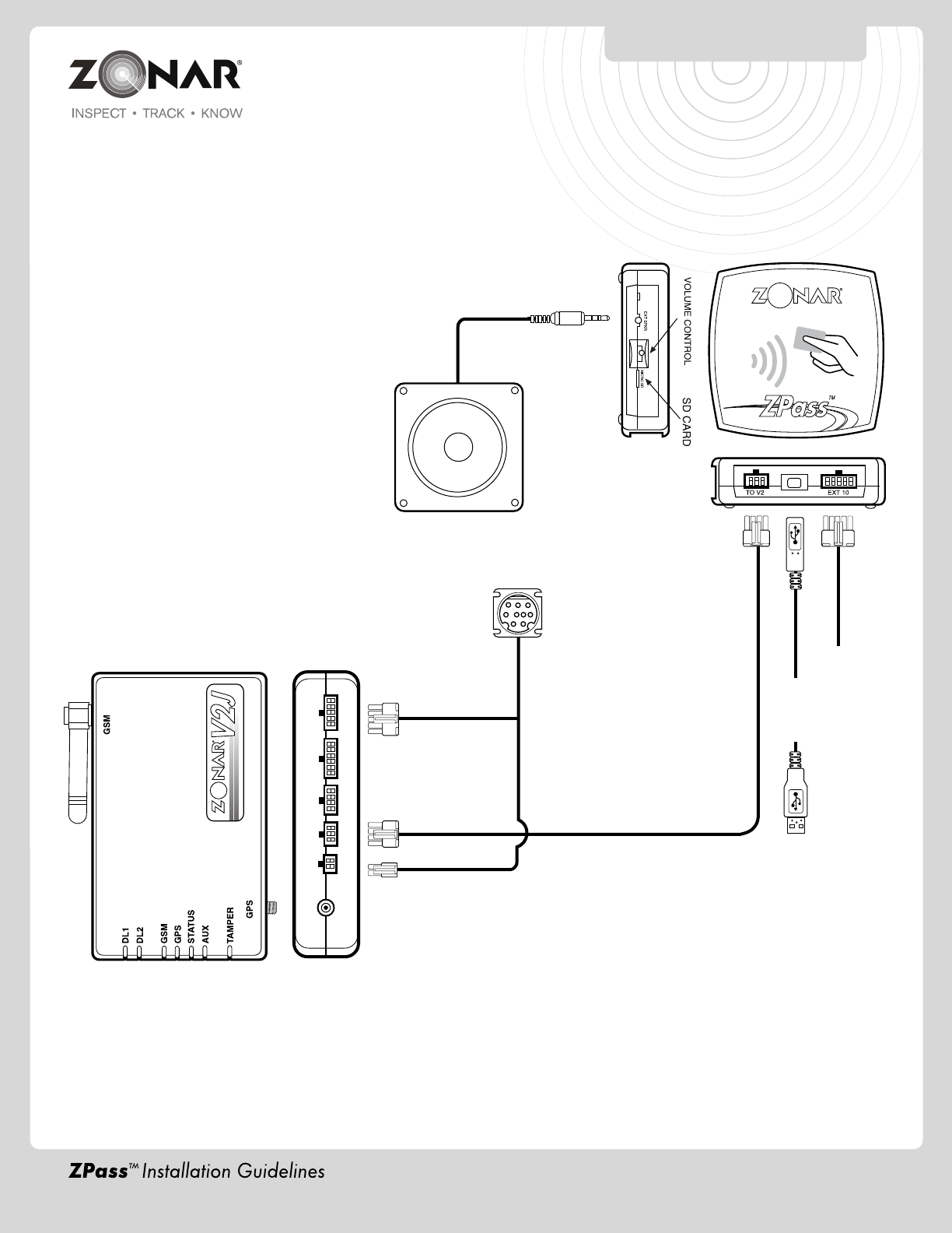
SCHEMATIC
6
Zonar ZPass™
Note: Speaker (optional) -
External power is not required.
Zonar recommends
Radio Shack Model# 21-131
or equivalent
Speaker
3.5 mm
Audio Input Jack
ZPass Interface Cable
Part# 80438
15’
Optional-
Used for
Computer
Interface
*Future
Use
9 Pin JBus Cable
Vehicles
Diagnostics
Optional
Backing
Plate
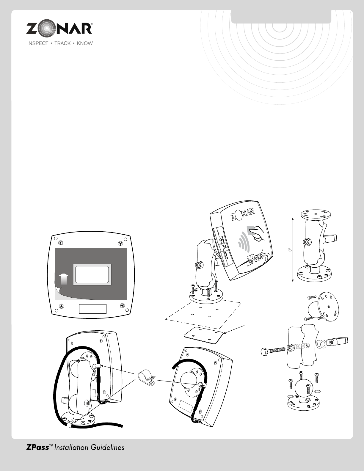
ZPass™ MOUNTING SYSTEM
7
Peel and Stick Adhesive Strip Method:
1) Select a flat surface, large enough to accommodate
the reader.
2) Clean and dry the surface before placing the mounting
plate. To obtain optimum adhesion, the surface must
be clean and dry. The best surface cleaning solvent is
an isopropyl alcohol/water mixture (rubbing alcohol).
3) Remove the backing from the peel and stick. Press and
hold mounting position for 10 seconds to assure good
adhesion. See Fig.7-1
Ram Mount:
All hardware included.
Optional backing plate (see Fig 7-2) - Used to provide
additional structural support when needed (e.g. Mounting
Ram Mount to Vinyl or thin sheet metal dashboard)
Mounting Options:
1) Peel and stick. See Fig 7-1
2) Ram mount. See Fig 7-2
3) User supplied options (e.g. Velcro®)
Suggested Mounting Areas:
1) Follow all general guidelines on page 5.
2) Typically mounted at passenger entrance/exit points at
a convenient height and angle for passengers boarding
and exiting the vehicle.
3) Ensure location of installed ZPass does not block driver
view, interfere with vehicle operation and loading/unloading
of passengers (e.g. snags coats, clothes, book bags,
etc).
4) To prevent degrading read range and accuracy, keep
reader away from metal structures and electrical sources
of interference (e.g. radios, wiring, switches and relays)
as much as possible.
Note: Verify placement acceptability with state DOT/Law
Enforcement prior to installation.
Fig. 7-1
Fig. 7-2
Fig. 7-3
INFORMATION
LABEL
Cable
Support
Clamps
OPERATION &
TROUBLESHOOTING
8
Post Install Checkout:
1) Start vehicle for one minute to establish GPS and Cellular connections
2) Reader LED should now be a steady blue to indicate the reader is ready to accept card scans
3 Scan card - Reader will 1X blink green and beep once to acknowledge a successful card scan
4) Reader LED will return to a solid blue state to indicate it is ready for additional scans
5) Verify successful card scan in Zonar's web based "ZPass" program. Customercode.zonarsystems.net/zpass or
customercode.zonarsystems.net and go to the home tab the go to ZPass.
Volume Control Button:
1) Only works with external speaker. It does not change the volume level of the internal speaker.
2) Pushing the volume control button cycles through 4 available volume levels.
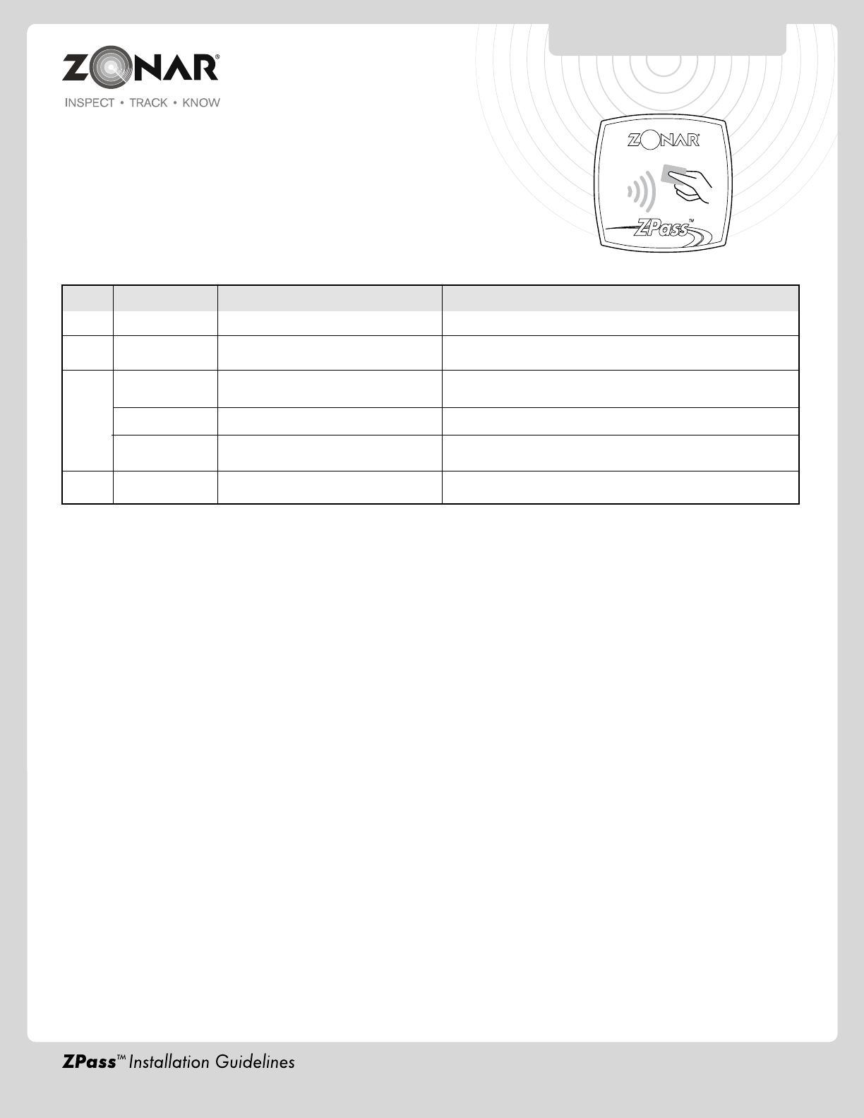
Color State Description Notes
Blue Solid Ready to scan cards
Green 1X Blink & Successful card scan Rescan of the same card requires 15 seconds
Audible Beep between consecutive scans
Red 2X Red SD memory card missing or error Reinsert or reseat SD card
blinking LED
Red 1X blink Synchronizing time If continuous, see Troubleshooting Section (page 9)
Solid Card reader disabled - occurs when
vehicle speed is greater than 25 mph
Orange Solid Receiving Firmware update This takes approximately 3 minutes
Operation
OPERATION &
TROUBLESHOOTING
9
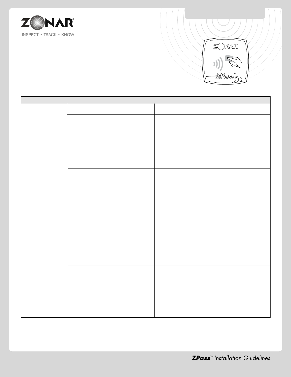
Troubleshooting
Issue Possible Cause Remedy
No LED lights Non-issue - Unit may be in lower power mode Swipe ZPass card, if unit 1 X blinks green and beeps the ZPass
unit is working properly
ZPass unit sleeping. ZPass unit goes to low Start engine, run for at least one minute
power / sleep mode 60 minutes after to reestablish GPS connection
engine shutdown
Improper GPS Firmware Ensure GPS Firmware (GTC, Assets, GPS units) is 97 or above
ZPass interface cable issue (e.g. Visually inspect ZPass interface cable
disconnected, severed, damaged, etc) Part # 80438 for proper connection and replace if necessary
GPS unit has no power (e.g. blown fuse, Reestablish power to GPS unit
disconnected power cable, etc)
Unit continuously GPS does not have correct Firmware Requires GPS Firmware 97 or greater
1X blinks Red GPS does not have correct time Verify vehicle / Cellular connection / Zonar equipment is
functioning properly by observing the GPS light states (3 solid
Green LED (GSM, GPS, Status) with ignition on. If this is not
the case it will be necessary to troubleshoot the vehicle,
cellular connection, and/or Zonar equipment.
GPS device port speed incorrect You must contact Zonar to have the port speed set correctly.
They will need to send two special parameters to the unit
(8065/0 and 8091/1). After Zonar schedules these parameters,
power cycle the GPS units (or wait 4 hours)
2X Red Blinking LED SD memory card issue Check to ensure SD card is present and properly
seated. Reformat or replace if the SD memory
card is present and properly seated
Red Solid LED The Red LED will be solid when the vehicle Do not scan cards when vehicle
is in motion (greater than 25 MPH). The speed exceeds 25 MPH
reader will not scan cards in this condition
Scans are not showing Card number is not entered in the ZPass Enter via CSV or manually enter all card numbers
up in the web based web based system
ZPass program. Ground Traffic Control™ user permission not Grant ZPass user “Show events” permission
properly set
Scanning a card before it is eligible for rescan Card requires 15 seconds between rescans
Vehicle or environmental issue (e.g. Vehicle
Verify vehicle / Cellular connection / Zonar equipment is
has no power, in a no cellular zone, blocked
functioning properly by observing the GPS light states (3 solid
GPS signal, etc.)
Green LED (GSM, GPS, Status) with ignition on. If this is not
the case it will be necessary to troubleshoot the vehicle,
cellular connection, and/or Zonar equipment

Operational Notes:
1) SD card must be inserted and fully seated for the unit to operate. 2X Red blinking LED indicates an issue with the SD card.
2) Sleep Modes:
A) Upon turning the vehicle engine off the ZPass unit LED will remain blue (Ready to scan cards) for approximate 10 minutes.
B) After 10 minutes the reader will go into a low power savings mode (Blue LED will not be illuminated). The ZPass will still
scan cards in this mode (The unit will 1X blink green and beep to indicate a successful scan).
C) 1 hour after the Blue LED extinguishes the unit will go into a deep sleep mode - Blue LED will not be illuminated and the
reader will not scan cards (No Green 1X blink and beep). The vehicle engine must be restarted and ran for 1 minute to
re-enable card scanning.
3) Once a card is scanned, it cannot be rescanned for another 15 seconds.
4) Requires GPS Firmware 97 or greater.
5) Scan distance = 0-3"
OPERATION &
TROUBLESHOOTING
10