Zoom Telephonics 0381WL Sensor User Manual Manual for Multisensor M
Zoom Telephonics Inc Sensor Manual for Multisensor M
Contents
- 1. Manual - 8105
- 2. Manual - 8106
Manual - 8105
ZoomGuard
tm
Starter Package Documentation
Chapter 1. Overview
ZoomGuard lets you protect, monitor, and control a home, office, or other site.
This package includes:
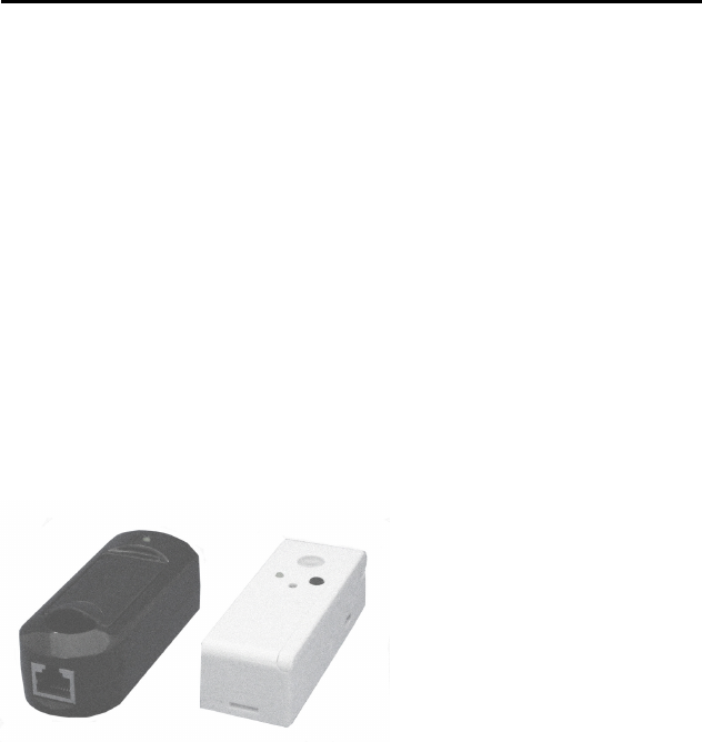
* Internet Link Model XX and its power cube and Ethernet cable.
* Wireless Multi-sensor M Model XX and its optional mounting bracket
* 1,000 mAH battery for Multi-Sensor M
* Magnet for Multi-Sensor M that’s used to monitor a door, window, or drawer opening
and/or closing
* Tape for optional use in mounting
A ZoomGuard system always includes the following:
1) At least one ZoomGuard Internet Link. A
ZoomGuard Internet Link communicates
wirelessly with up to 12 nearby ZoomGuard sensor
and/or controls, linking those sensor/controls
through the Internet and a Zoom Internet-
connected Server to smartphones, computers,
phones and other devices you choose. The
ZoomGuard Internet Link Model 8005 connects to
a router that’s linked to the Internet, so you need a router or modem/router. The Multi-
sensor M Model 8105 in this Starter Package is one of the 12 sensor/controls that can
connect to the Internet Link. You can add additional multi-sensors and other ZoomGuard
sensor/controls to your system now or in the future.
2) One or more Sensors and Controls. The Zoom Multi-sensor M can sense water
leaks, temperature, light, motion, door/window/drawer openings and closings, or a button
push. The Zoom Multi-sensor H is similar, but replaces the motion sensor with a
humidity sensor. The Zoom Power Sensor/Control can monitor power usage at an outlet
and also temperature and light; and can allow you to power on or off a connected heater,
air conditioner, light, or other device locally or from a distance over the Internet. Zoom
has a long list of planned wireless sensors and controls, including a Smoke Detector
Companion, Indoor/Outdoor Alarm, Thermostat, and Lightswitch. ZoomGuard Monitors
and Controls always connect wirelessly to a ZoomGuard Internet Link, with typically up
to 12 Monitors and Controls connected to one Internet Link. More than one Internet Link
can be used in an installation with more than 12 Monitors and Controls or one that spans
a greater distance than one ZoomGuard Internet Link can reach. ZoomGuard software
allows you to setup and control as many Internet Links and sensor/controls as you like,
even ones spread all over your city or country!
3) The Internet. This transmits Sensor information from a ZoomGuard Internet Link
through a Zoom Server to Remote ZoomGuard Devices, and also transmits Control
information from ZoomGuard Sensors and Remote ZoomGuard Devices through a Zoom
Server to a ZoomGuard Internet Link and connected ZoomGuard Controls.
4) Remote ZoomGuard Devices can be a mix of any of the following:
- Computers, tablets, phones, and other devices that have an Internet Web browser
- Smartphones running ZoomGuard smartphone software
- Any phone that can receive text messages
- Any phone that can receive a phone call, typically for a voice alert like “ZoomGuard
Alert: Flooding Detected.”
- Any device that can access Twitter or Facebook.
Please note that Remote ZoomGuard Devices can be almost anywhere, far from the
ZoomGuard Internet Link or right next to it.
5) ZoomGuard Alerts and Commands. Alerts typically flow from a ZoomGuard
Monitor through an Internet Link to a Remote ZoomGuard Device. Commands
typically flow from a Remote ZoomGuard Device through an Internet Link to a
ZoomGuard Control. Commands can also come from a local device such as a button built
into a ZoomGuard Monitor/Control.
When you set up a ZoomGuard system, you typically do the following in this order:
1) Connect the Internet Link.
2) Connect the wireless Monitors and Controls for the Internet Link.
3) Run ZoomGuard Setup software to specify what you want the ZoomGuard system to
do. For instance, what do you want to monitor? When an alert occurs, where do you
want it sent?
4) If you’d like, set up another Internet Link and its associated monitors and controls.
You might do this if you have multiple homes, for instance, or if you are a building
manager. If you do set up a second Internet Link, you can use the same software to
control all your Internet Links if you like.
5) Use the system, paying attention to alerts and issuing commands when you like.
If you’re ready to start setting up a system, please go to one of the following as
appropriate:
Chapter 2: Connecting ZoomGuard Internet Link Model 8005 To A Router
Chapter 3: Connecting and using a Multi-sensor M Model 8105
Chapter 4: Using ZoomGuard Web Software
Chapter 5: Using the ZoomGuard iPhone Ap
Chapter 6: Using the ZoomGuard Android Ap
Chapter 2. Connecting ZoomGuard Internet Link Model 8005 To A
Router
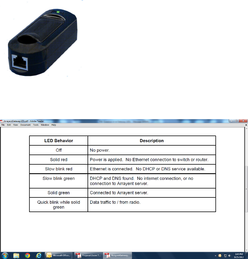
ZoomGuard Internet Link Model 8005 connects to the
Ethernet port of almost any router or broadband
modem/router. Just do the following:
1) Connect the Internet Link’s Power Cube between a
power outlet and the power jack of the Internet Link.
2) Flip up the antenna on the top of the Internet Link,
since that antenna position normally gives you better
wireless connection to ZoomGuard sensor/controls.
3) Connect the supplied Ethernet cord between the
Internet Link’s Etherrnet jack and an Ethernet LAN (not
WAN) jack of a router or modem/router.
The table below summarizes the LED behavior of the Internet Link.
Chapter 3: Connecting and using a Multi-sensor M Model 8105
First you need to decide where to put the multi-sensor. This depends on what you want
to do with it. Please keep in mind that you can use anywhere from one to all of the multi-
sensor’s sensors if you’d like. The only sensors that have a noticeable effect on battery
life are the motion sensor, the open/close detector, and the flood sensors; and ZoomGuard
setup software lets you turn each of these on or off.
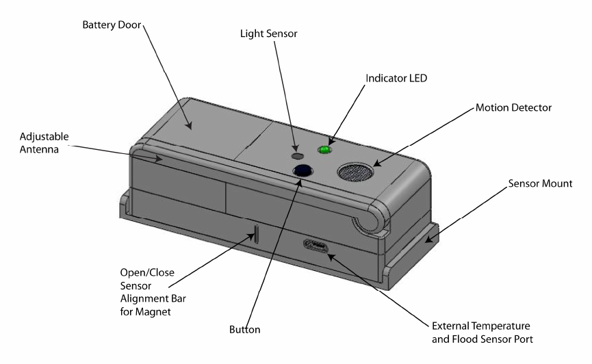
Please note the location of various sensors on the multi-sensor. Not shown are 2 screws
for sensing water on the bottom of the unit, a temperature sensor just inside the top cover
of the multi-sensor, and a power jack for use with an optional power cube instead of the
included battery. The mounting bracket option is shown, and you can also use the
included mounting tape if you prefer.
Please note the following:
1) The adjustable antenna can be positioned for best radio performance. Sometimes
you can just leave it as shown in the picture above. Normally it’s best to have the
antenna pointing up, especially if it’s on a metal table or other metal object.
2) The light sensor measures light that falls on it.
3) The temperature sensor measures temperature at the multi-sensor.
4) The motion detector detects motion within an elliptical cone coming straight out
from the front of the multi-sensor. When the multi-sensor is oriented vertically
(for instance, with the motion detector toward the top), it sees motion best within
an angle of about 15 degrees on left or right of the line coming straight out of the
sensor. (Discuss this further and show a drawing. Ideally we’d determine an
angle up and down for the cone.) The angle of view is much smaller vertically, to
allow you to place the multi-sensor high enough that it doesn’t detect pets.
ZoomGuard software has a Calibration function that blinks a light on the Multi-
sensor so you can see when it detects motion. Normally the motion detector
should be at a spot that best surveys a room, positioned higher or lower depending
on whether or not you want it to see pets.
5) The open/close sensor is a Hall effect magnetic sensor that works with the
included magnet. For best results, position the magnet as close as practical to the
multi-sensor and no more than ¾ inches away. Ideally the middle of the magnet
should line up with the alignment bar, and the magnet’s broad face should point at
the multi-sensor as shown below.
6) The flood sensor looks for the presence of water between the 2 screws on the
bottom of the multi-sensor.
7) The button can be used to activate and deactivate sensors, or it can be used instead
as a panic button. This is controlled by the ZoomGuard setup software.
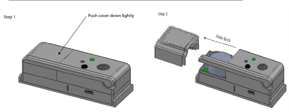
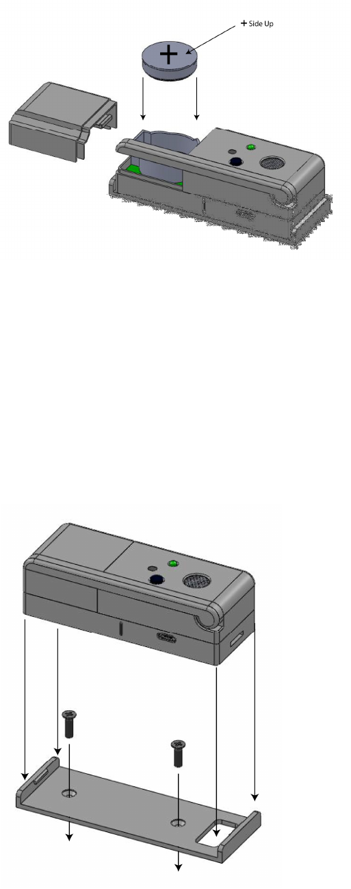
Installing the included 3V 1000 mAH battery, part number CR2477 or equivalent.
To open the battery door, press the cover down lightly and push it away from the button
and light as shown. Then install the battery with the Plus side up.
Once the battery is installed, it helps to bring the multi-sensor within 30 feet or so of its
Internet Link. This helps the multi-sensor and Internet Link to establish a wireless
connection, which you can tell by seeing a rapidly blinking green light when the
connection is first established. Then you can bring the multi-sensor much farther away,
sometimes over 100 feet, and it will continue to work. The actual distance depends on a
number of factors including the layout of your building and the number of other wireless
devices in the area. If the multi-sensor loses its connection, you’ll see a rapidly blinking
red light when that occurs.
If you decide to use the mounting bracket, screw it into place and then snap the multi-
sensor into the bracket. If you prefer, you can mount the multi-sensor using the supplied
tape. For sensing water leaks, you may want to just put the multi-sensor on the floor.

Chapter 4: Using ZoomGuard Web Software
ZoomGuard Web software is easy and self-documented. We recommend doing setup
using a computer or tablet, since they have a larger screen than a phone. However, you
can use a phone if you like as long as it has a Web browser.
To use ZoomGuard Web software, go to www.XXX and follow the easy instructions.
Appendix A: Compliance Information
FCC Statement: This equipment has been tested and fount to comply with the limits for
a Class B Digital Device, pursuant to Part 15 of the FCC Rules. These limits are
designed to provide reasonable Protection against harmful interference in a residential
installation. This equipment generates, uses and can radiate radio frequency energy and,
if not installed and used in accordance with the instructions, may cause harmful
interference to radio communications. However, there is no guarantee that interference
will not occur in a particular installation. If this equipment does cause harmful
interference to radio of television reception, which can be determined by turning the
equipment off and on, the user is encouraged to try and correct the interference by one of
the following measures:
-Reorient or relocate the receiving antenna.
-Increase the separation between the equipment and the receiver.
-Connect the equipment into an outet on a circuit different from that to which the
receiver is connected.
- Consult the dealer or an experience radio/TV technician for help.
Changes or modifications not expressly approved by Zoom Telephonics, Inc could void
the user’s authority to operate the equipment.
Industry Canada Statement: Operation is subject to the following two conditions: (1)
this device may not cause harmful interference, and (2) this device must accept any
interference received, including interference that may cause undesired operation.