Zoom Telephonics WL1046 ADSL WIRELESS X6 ROUTER/MODEM User Manual
Zoom Telephonics Inc ADSL WIRELESS X6 ROUTER/MODEM
UserManual.wiki
>
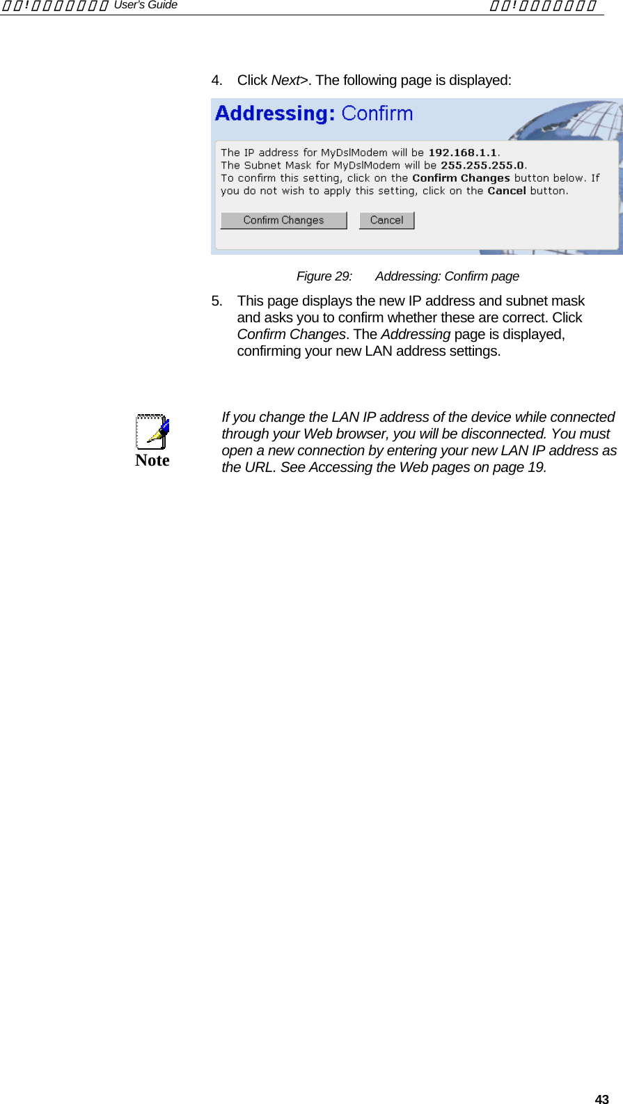
Zoom Telephonics
>
WL1046 User Manual
USERS MANUAL
Navigation menu
Upload a User Manual
Namespaces
Wiki Guide
HTML
PDF
Info
Views
User Manual
Discussion / Help
Navigation
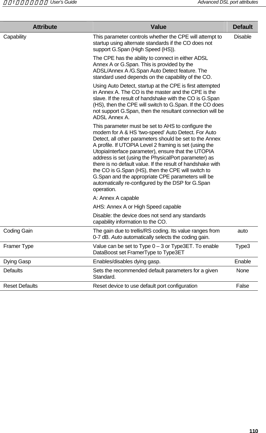
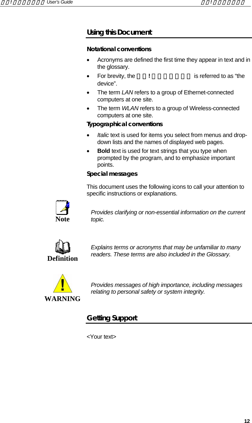
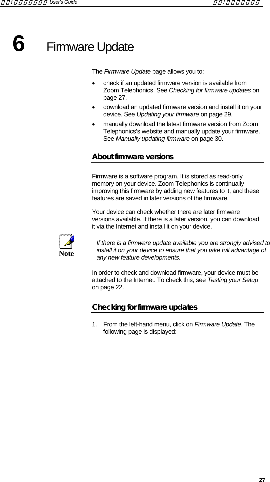
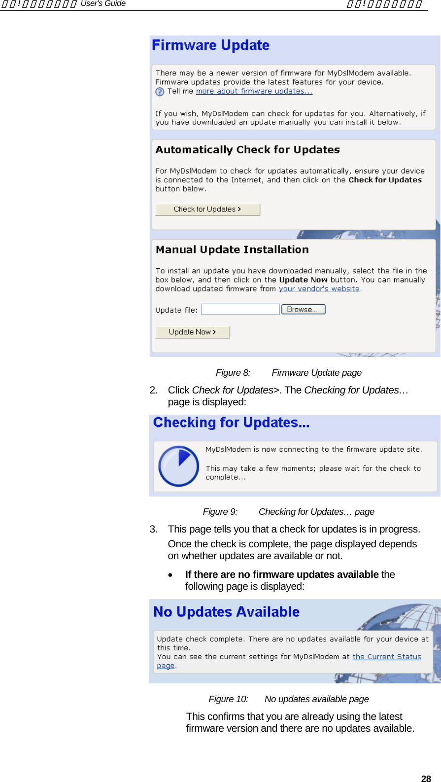
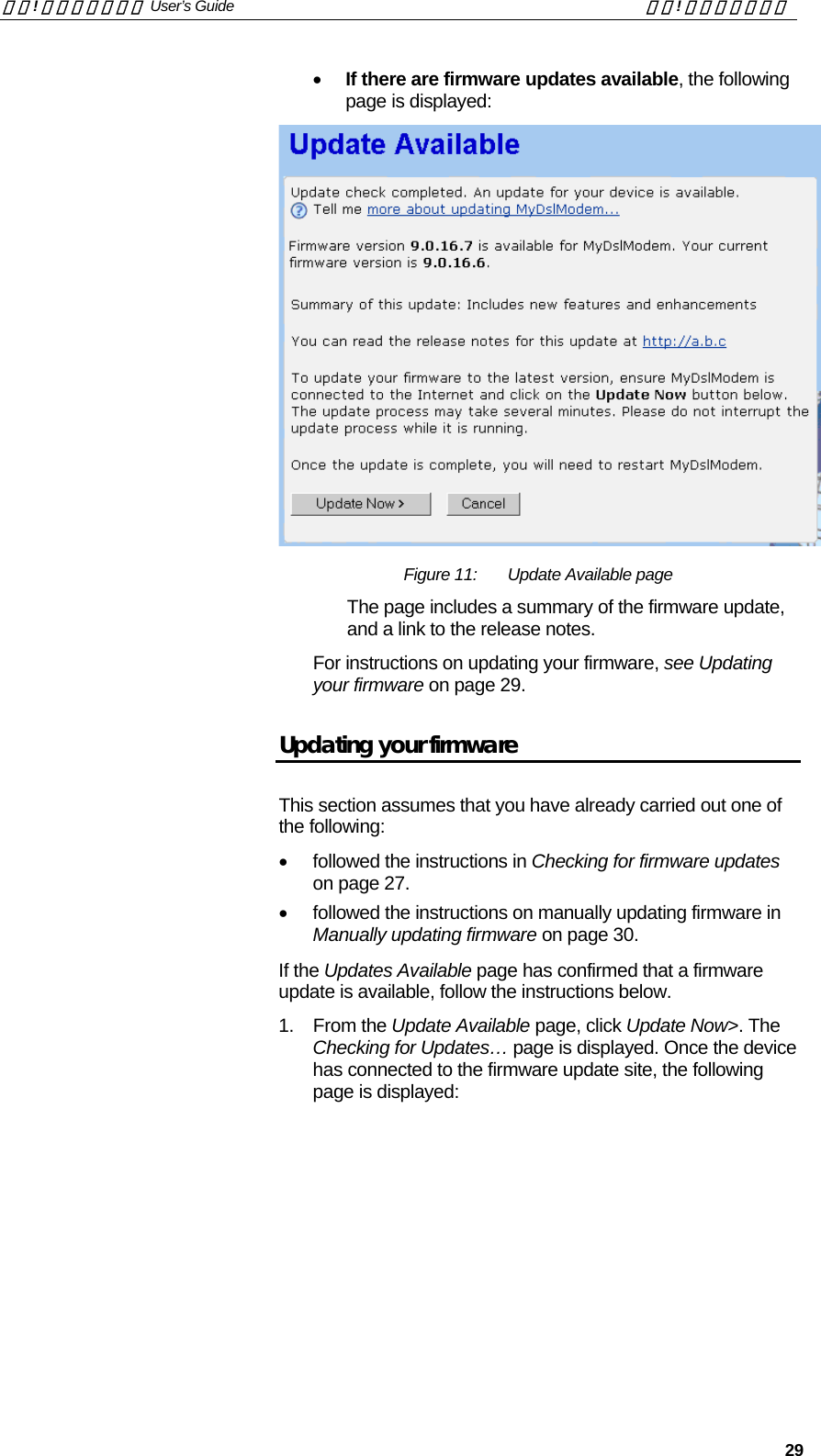
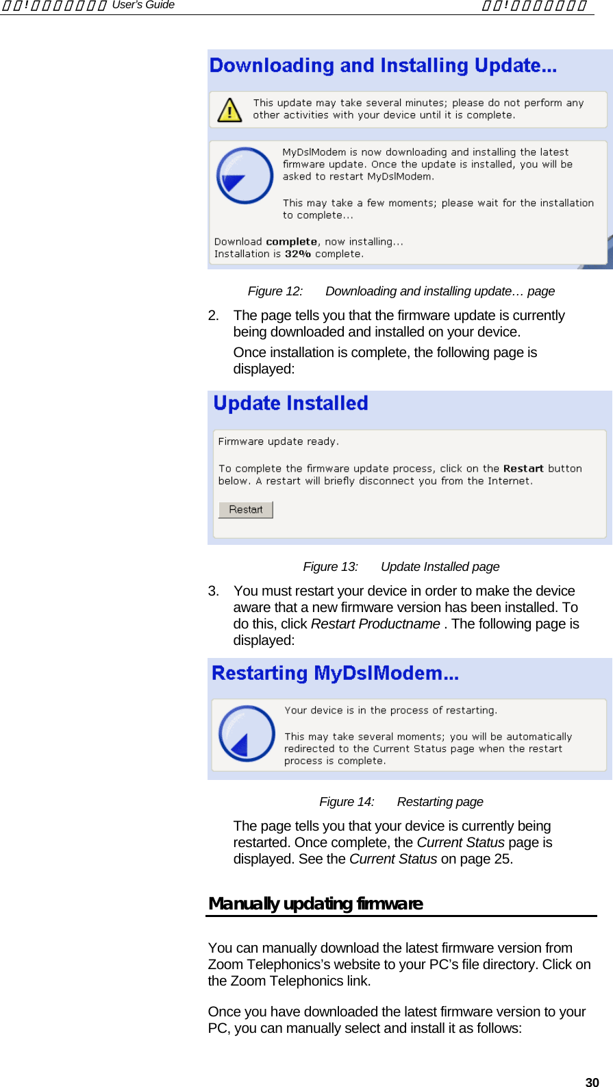
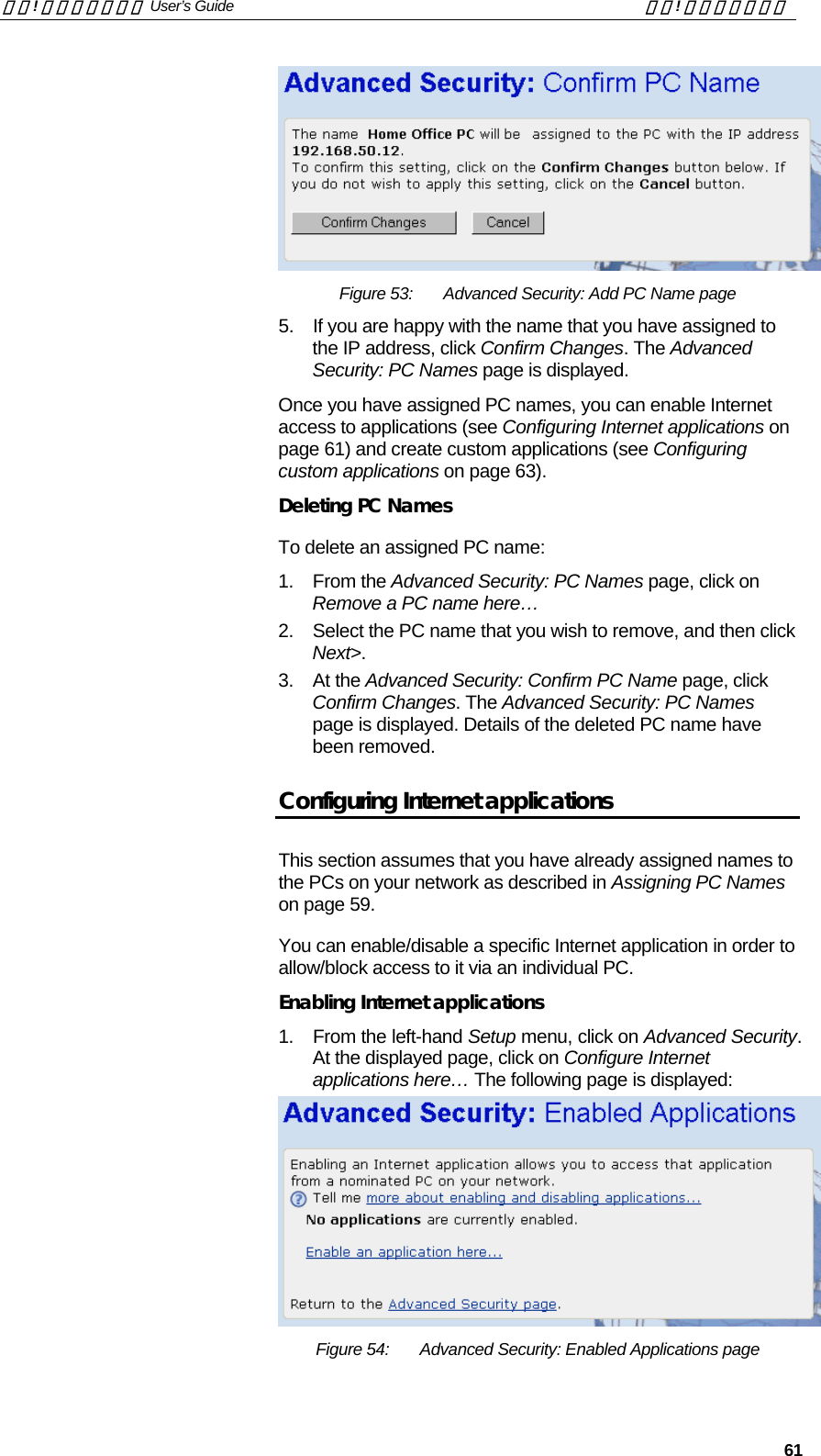
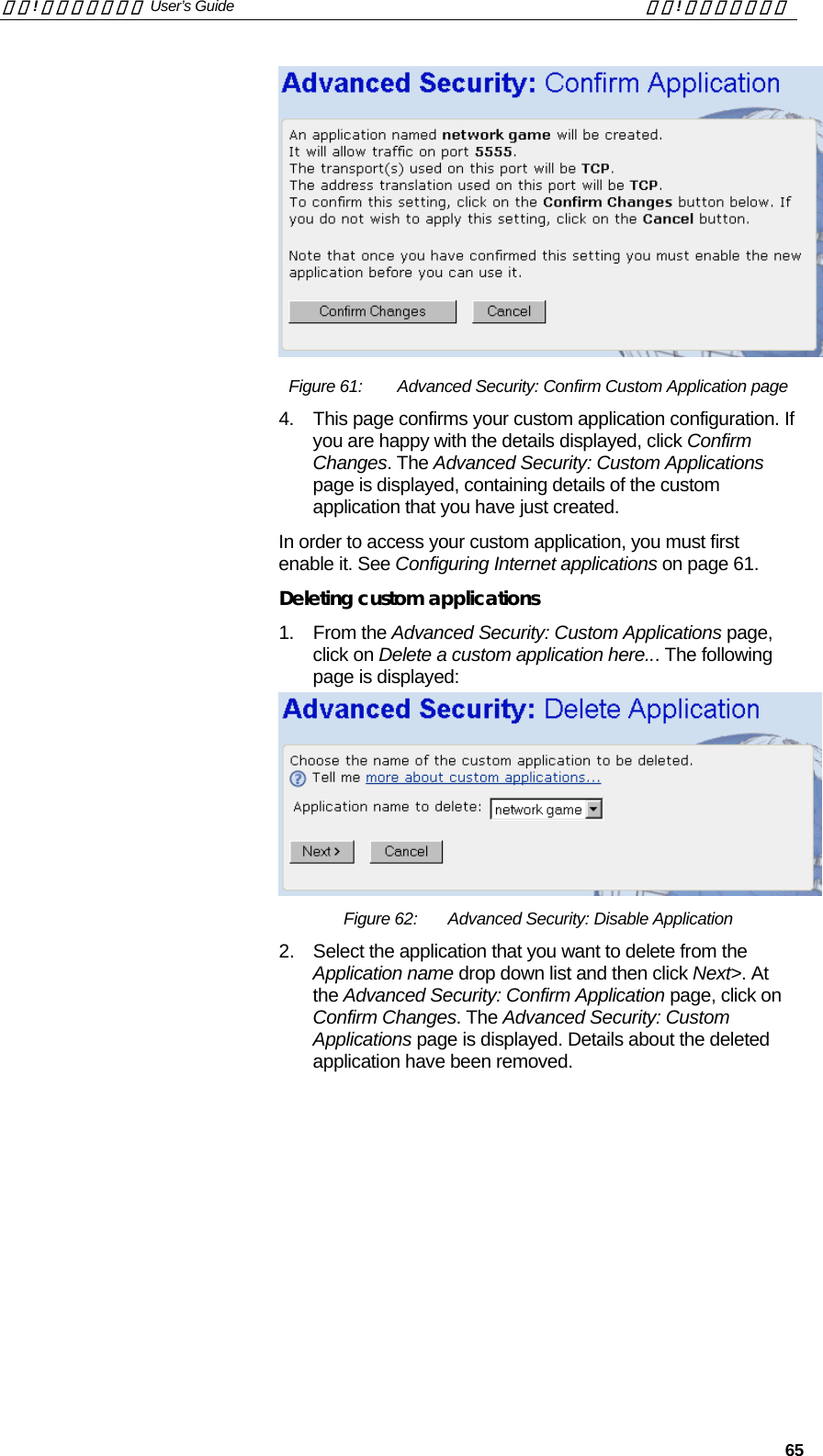
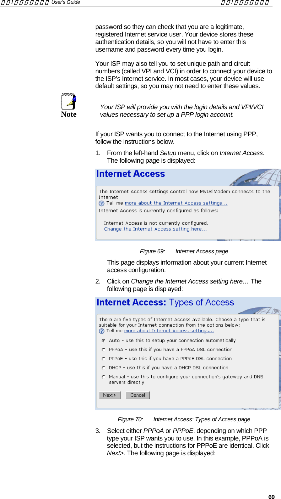
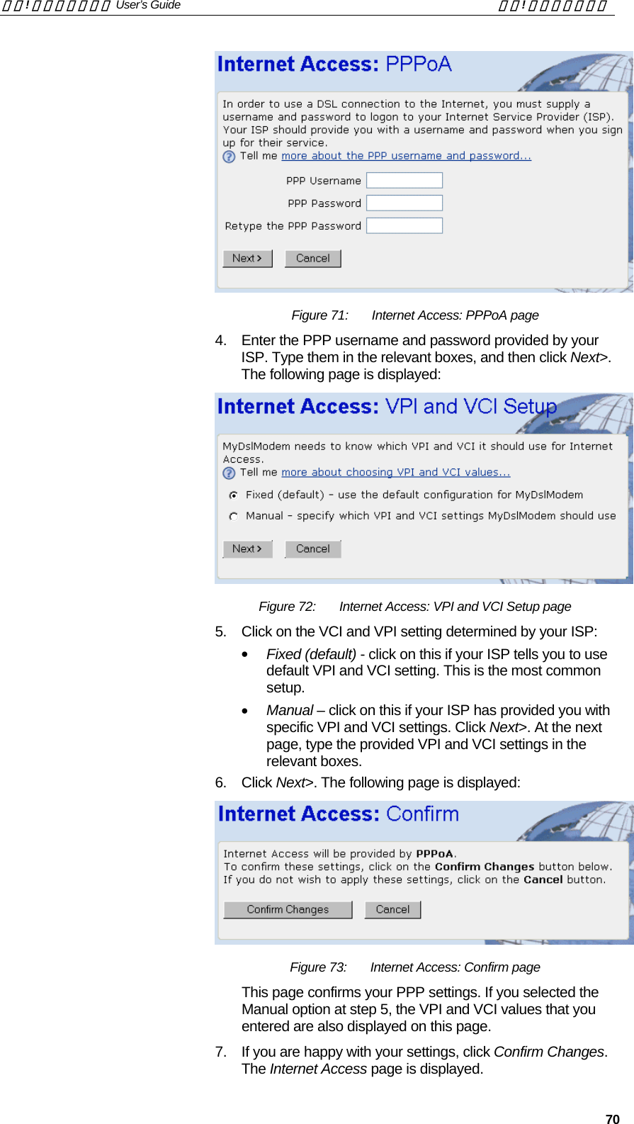
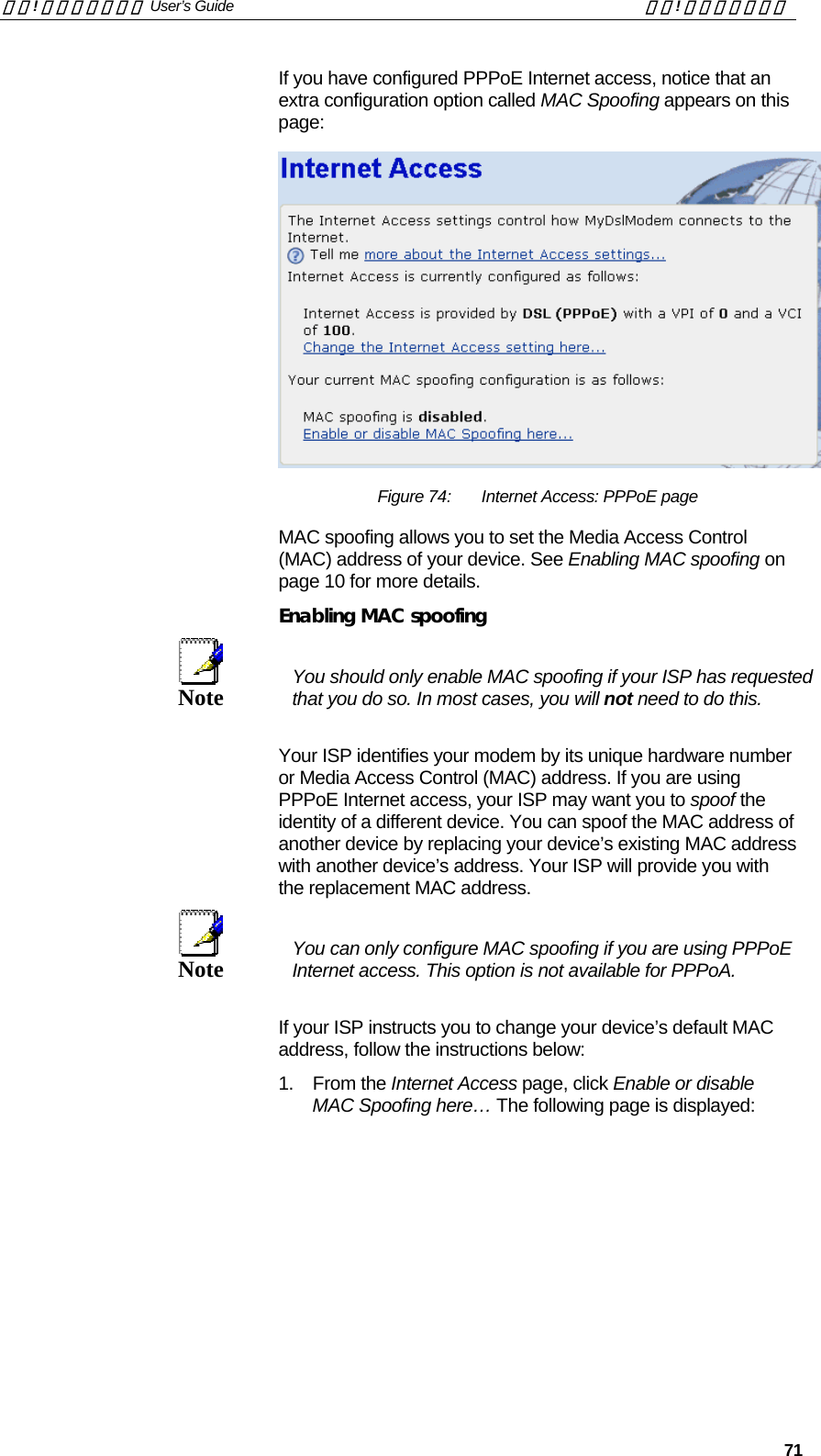
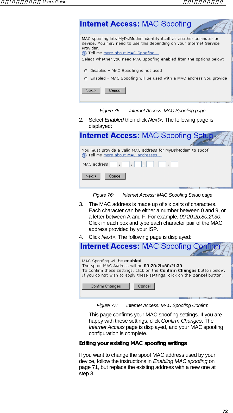
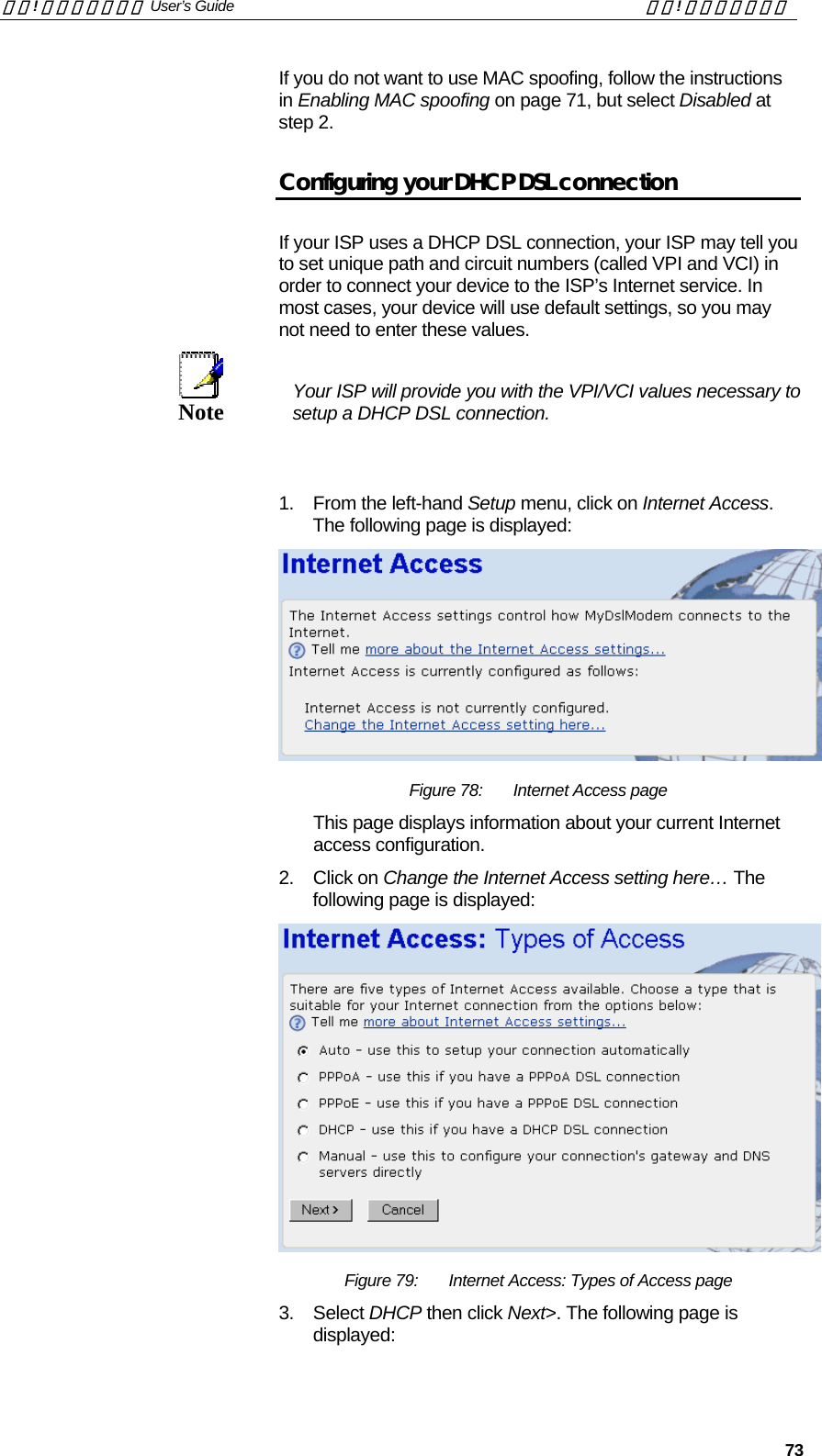
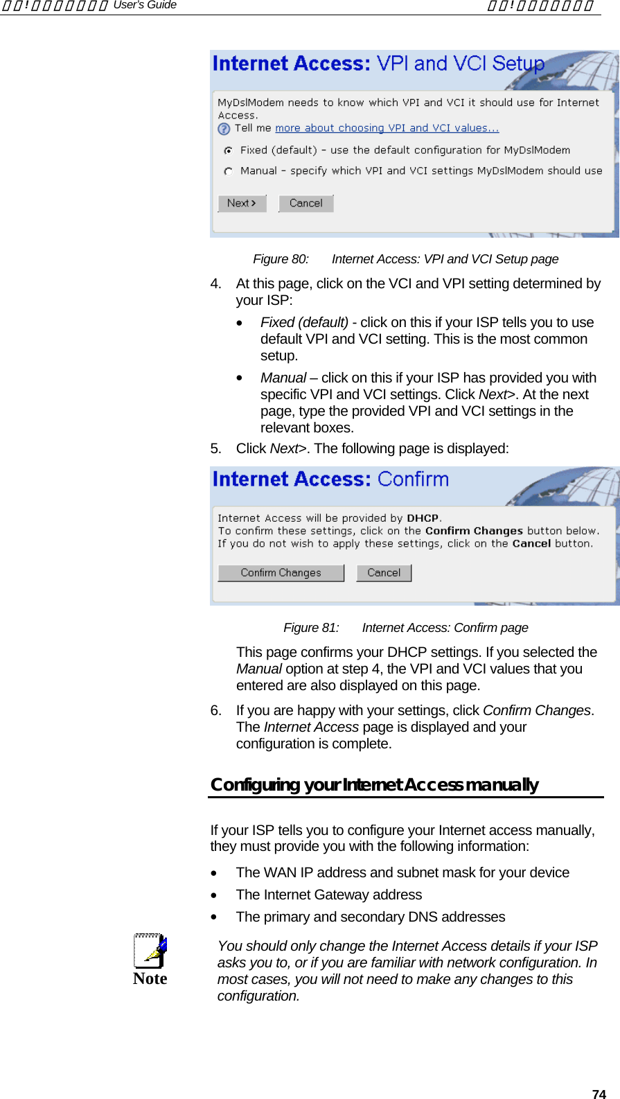
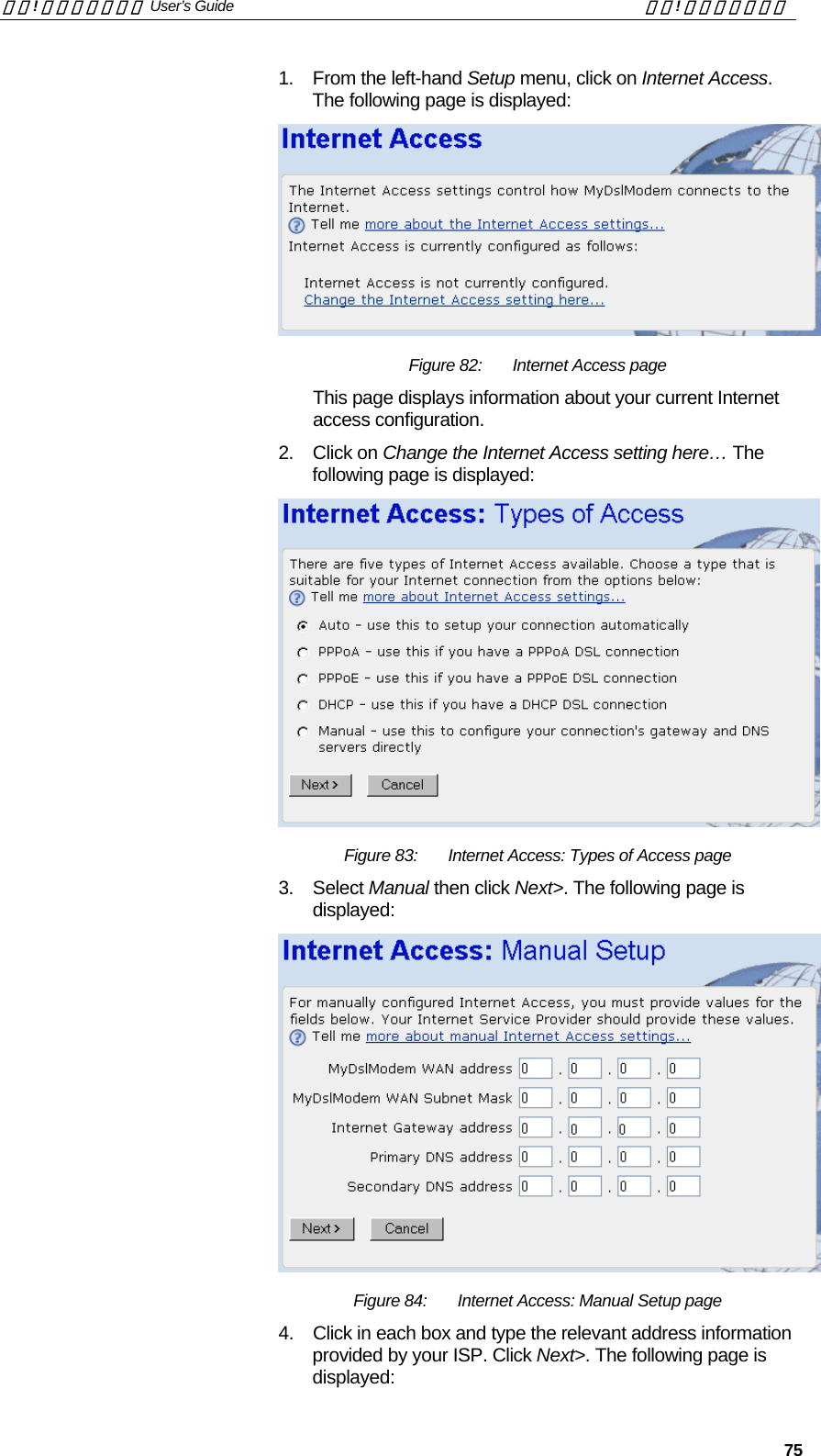
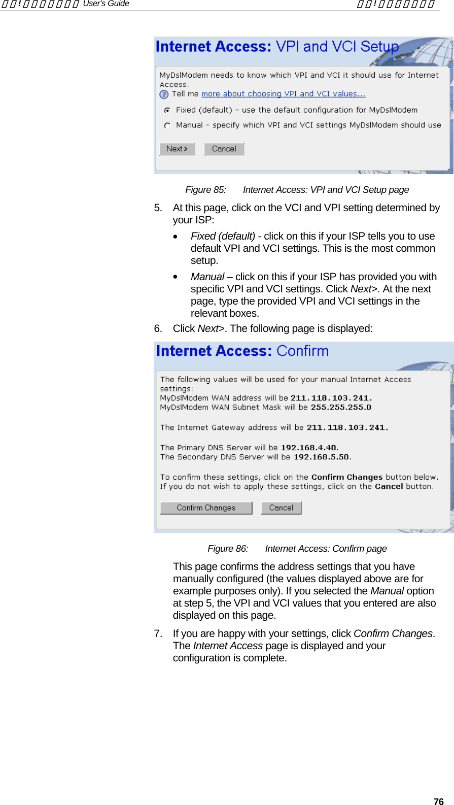
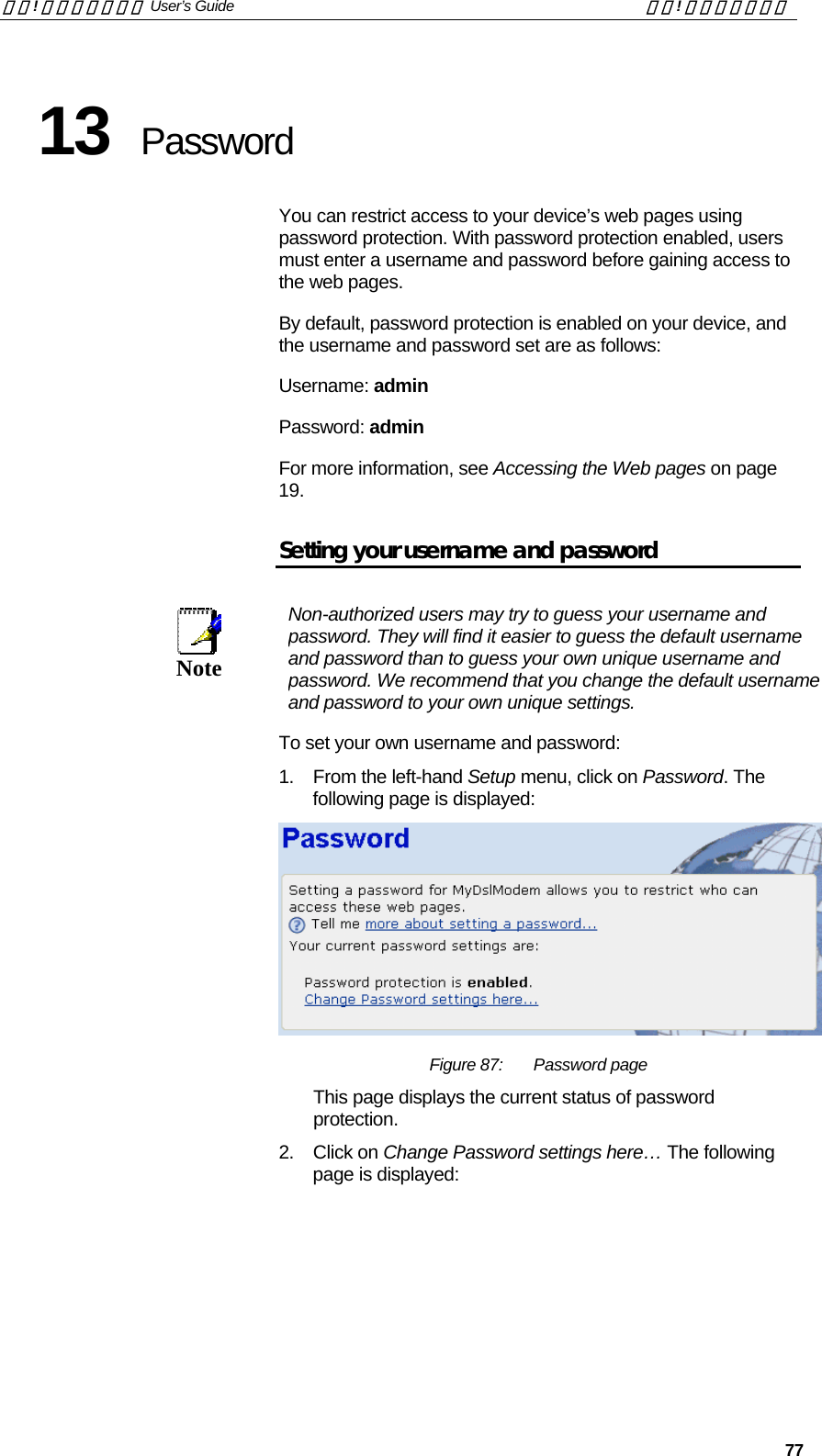
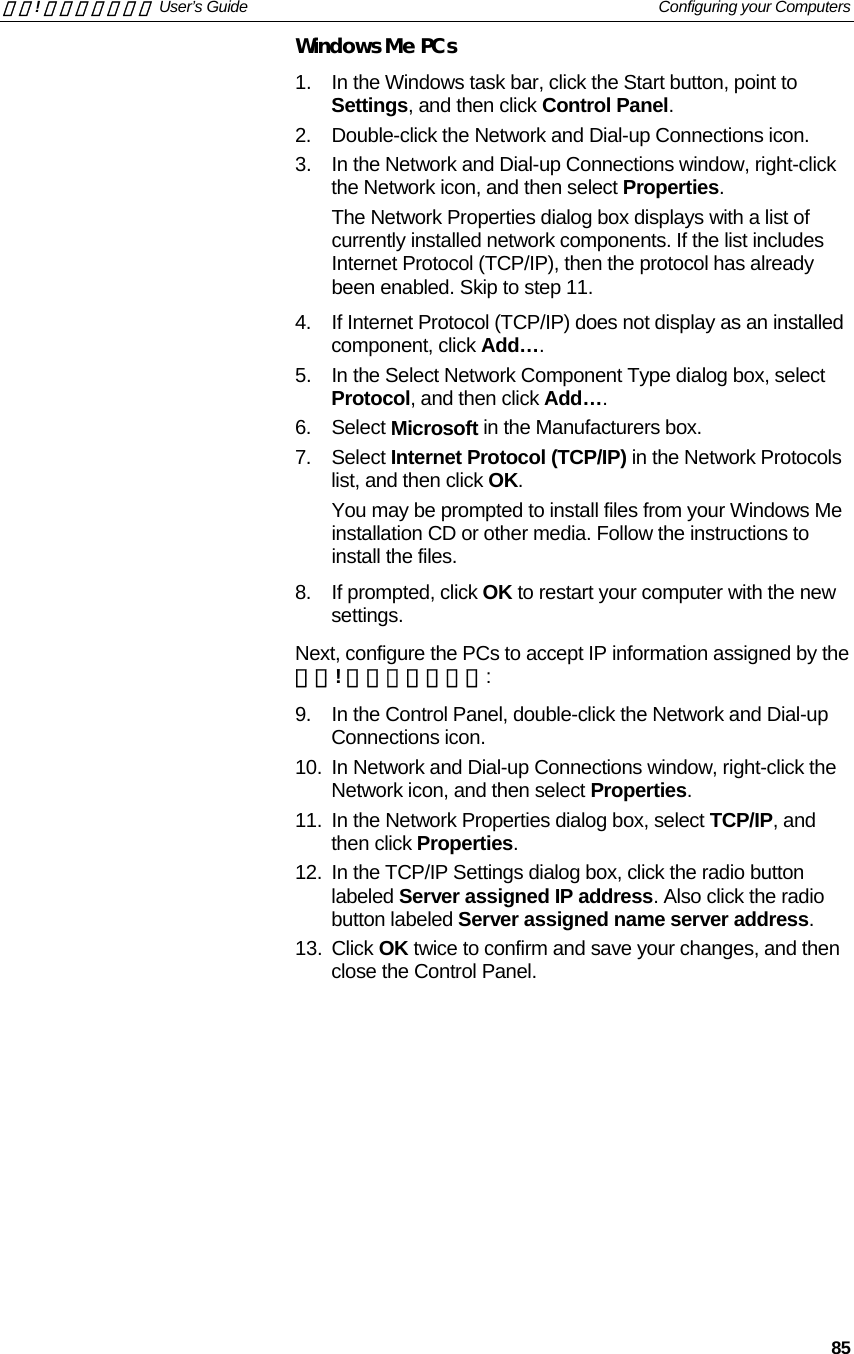
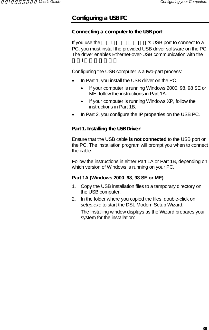
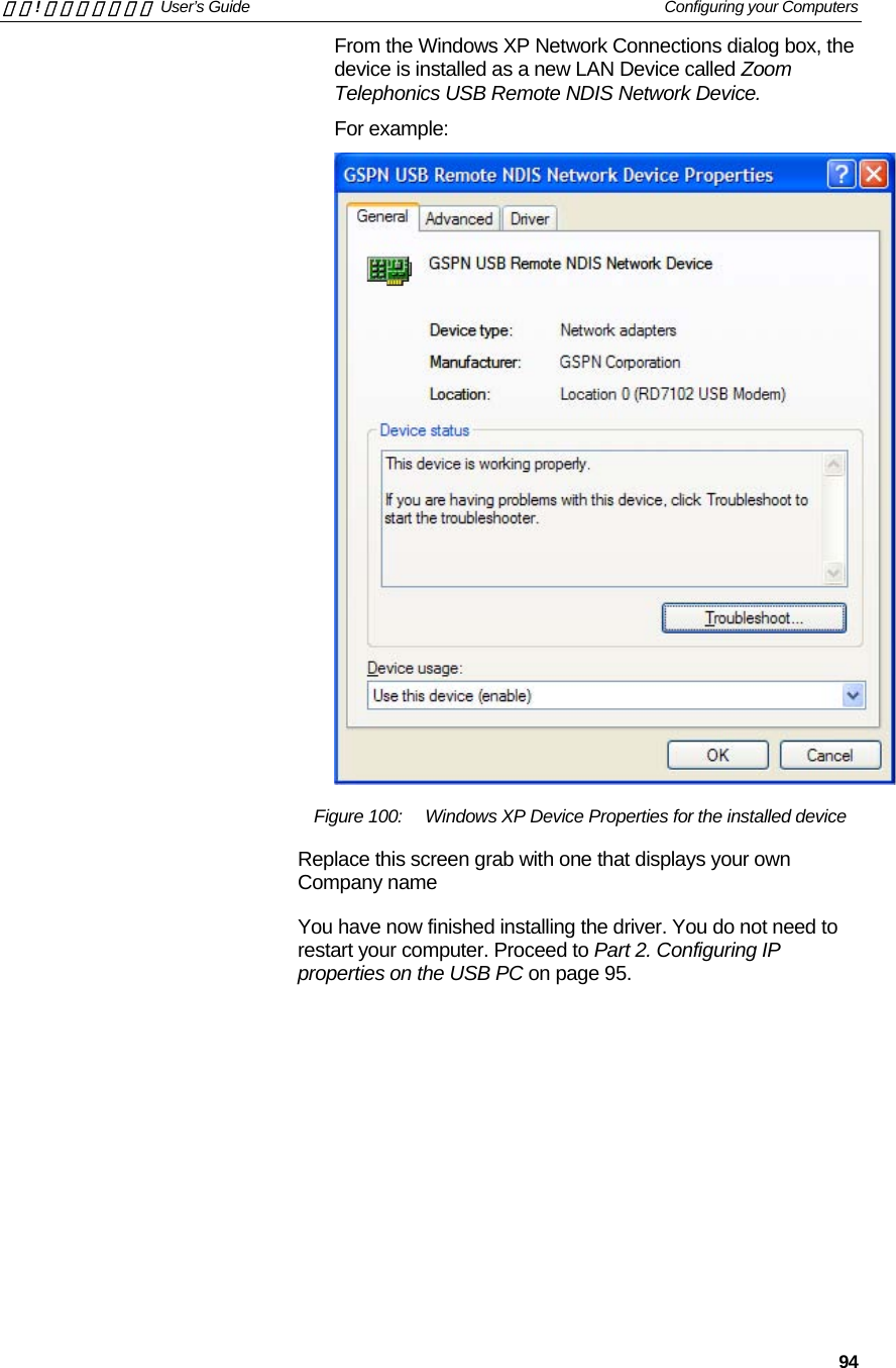
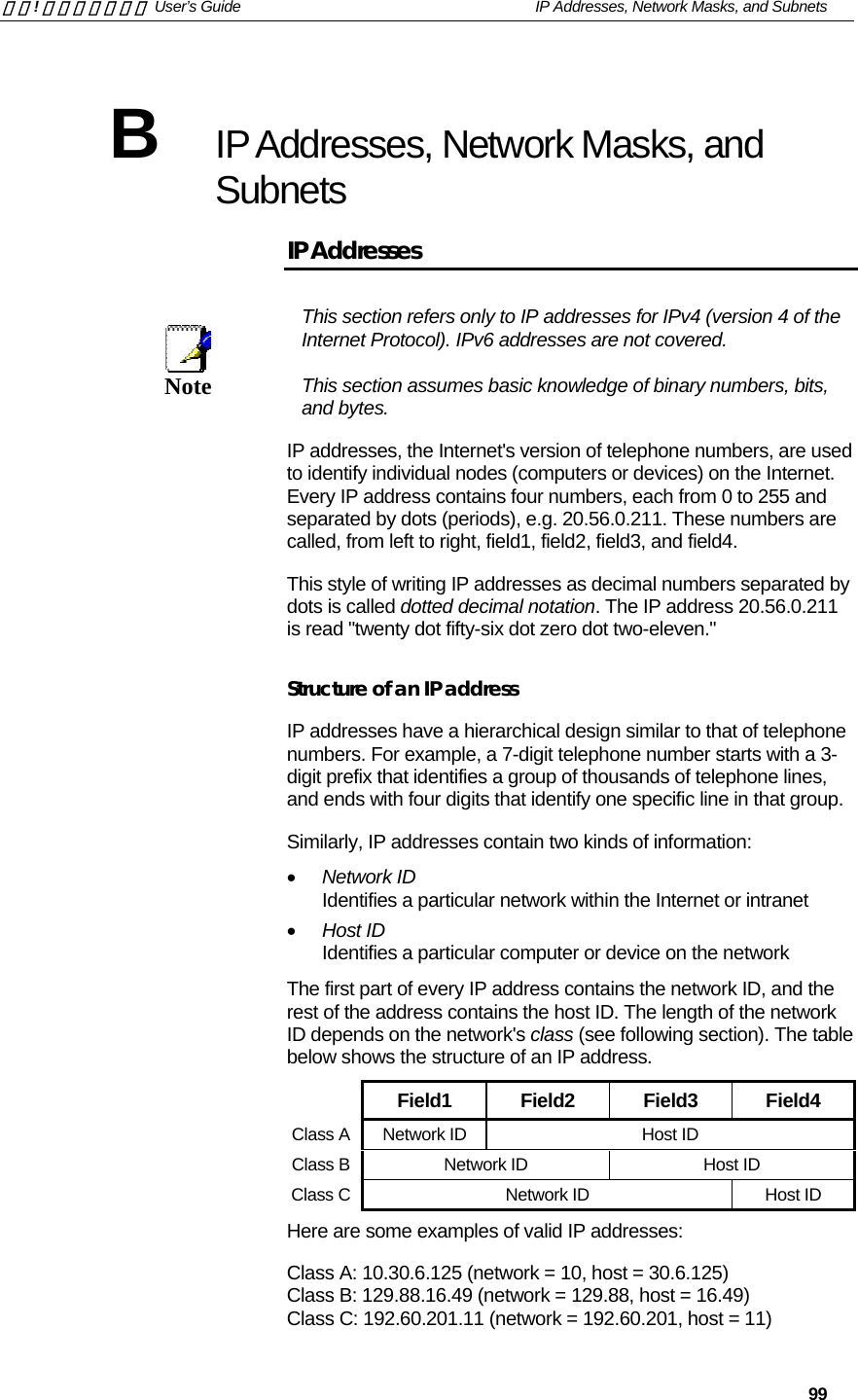
![錯誤! 尚未定義樣式。 User’s Guide 錯誤! 尚未定義樣式。 10 1 Introduction Congratulations on becoming the owner of the Zoom Telephonics 錯誤! 尚未定義樣式。. You will now be able to access the Internet using your high-speed DSL connection. This User Guide will show you how to connect your 錯誤! 尚未定義樣式。 DSL Modem, and how to customize its configuration to get the most out of your new product. Features The list below contains the main features of the device and may be useful to users with knowledge of networking protocols. If you are not an experienced user, the chapters throughout this guide will provide you with enough information to get the most out of your device. Features include:[CT3] • Internal DSL modem for high-speed Internet access • 10/100Base-T Ethernet router to provide Internet connectivity to all computers on your LAN • USB port for connecting a USB-enabled PC • Wireless access via a wireless network card and wireless security features • Network address translation (NAT) functions to provide security for your LAN • Network configuration through DHCP Server and DHCP Client • Services including IP route and DNS configuration, RIP, and IP and DSL performance monitoring • Configuration program you access via a web browser Device Requirements In order to use the 錯誤! 尚未定義樣式。, you must have the following: • DSL service up and running on your telephone line • Instructions from your ISP on what type of Internet access you will be using, and the addresses needed to set up access • One or more computers each containing an Ethernet card (10Base-T/100Base-T network interface card (NIC)) and/or a single computer with a USB port](https://usermanual.wiki/Zoom-Telephonics/WL1046/User-Guide-521686-Page-10.png)
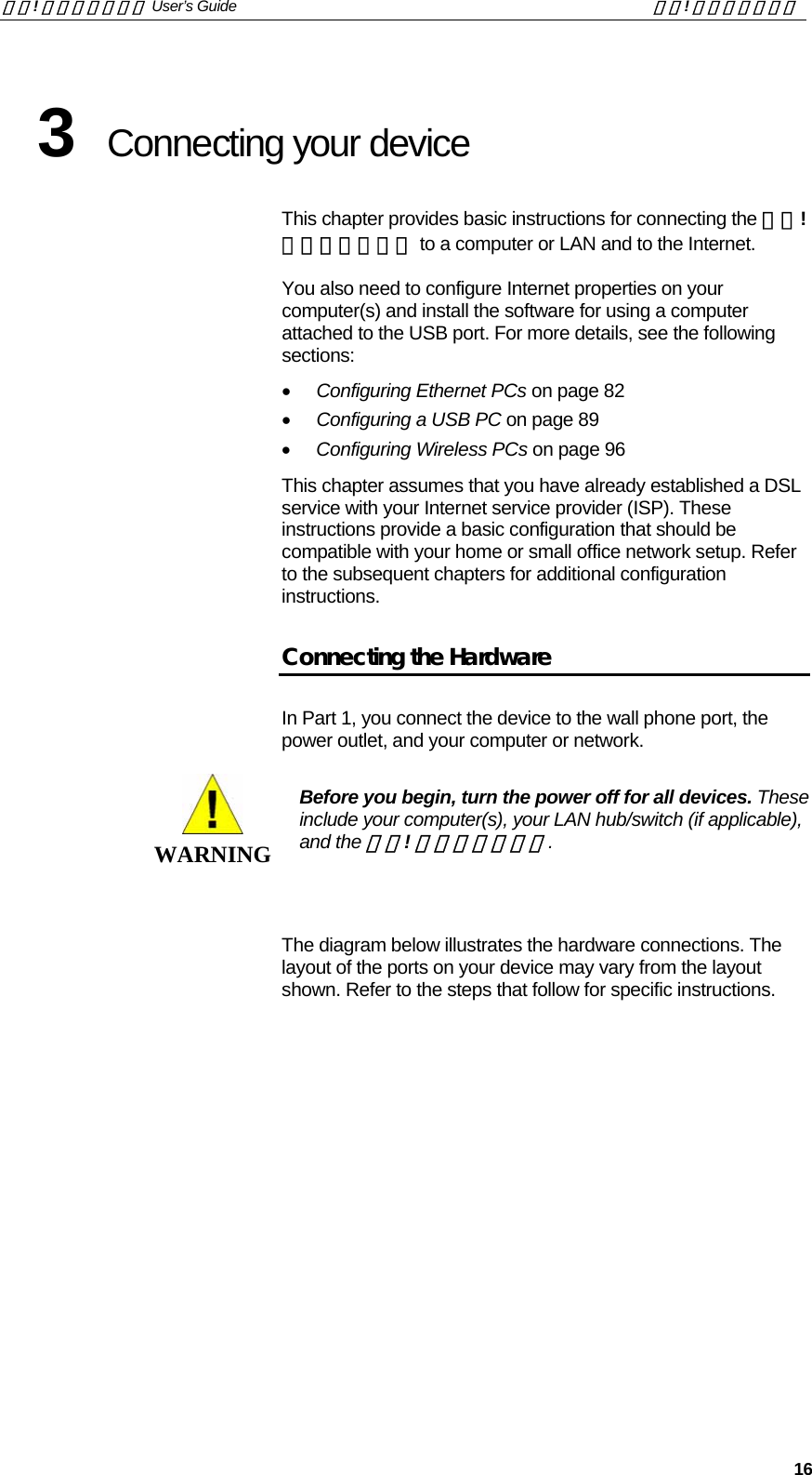
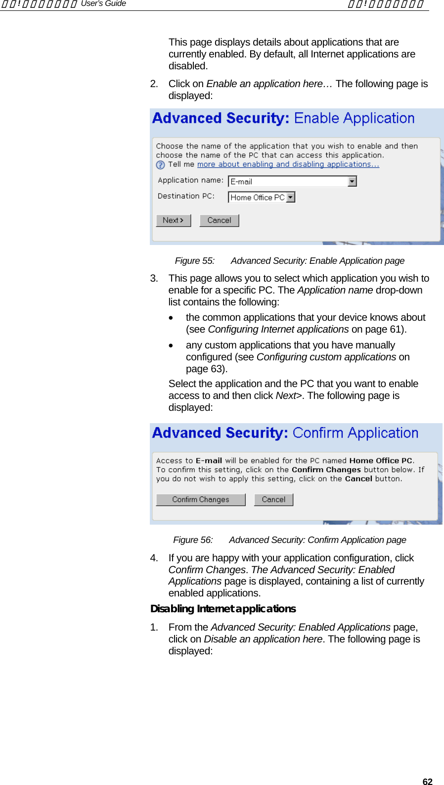
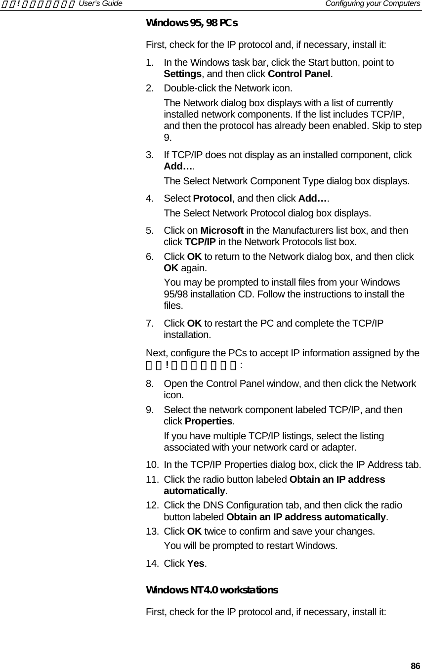
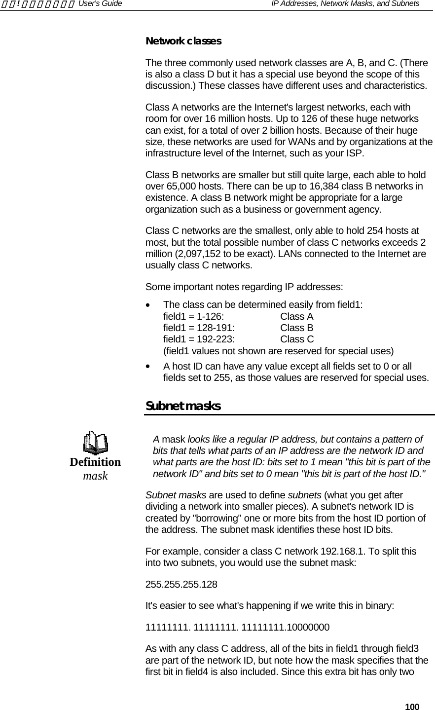
![錯誤! 尚未定義樣式。 User’s Guide 錯誤! 尚未定義樣式。 13 2 Getting to know the device Parts Check In addition to this document, your package should arrive containing the following: • 錯誤! 尚未定義樣式。 DSL Modem • Power adapter and power cord • USB cable • Ethernet cable • Standard phone/DSL line cable [Insert a photograph of the contents of your product kit.] Figure 1: DSL Modem Package Contents](https://usermanual.wiki/Zoom-Telephonics/WL1046/User-Guide-521686-Page-13.png)
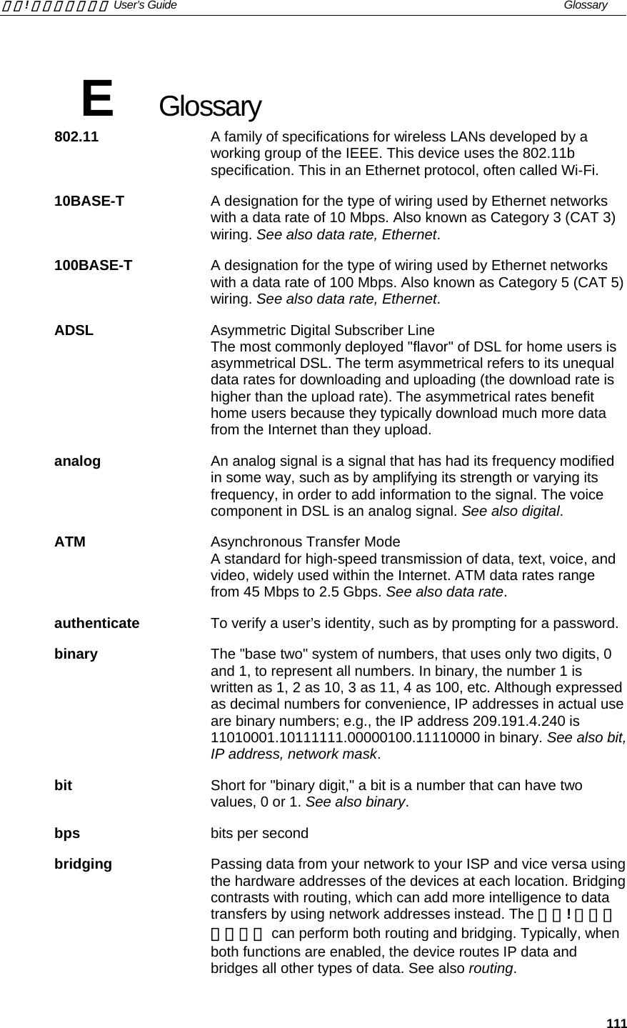
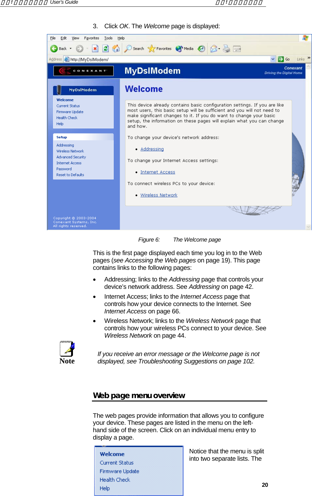
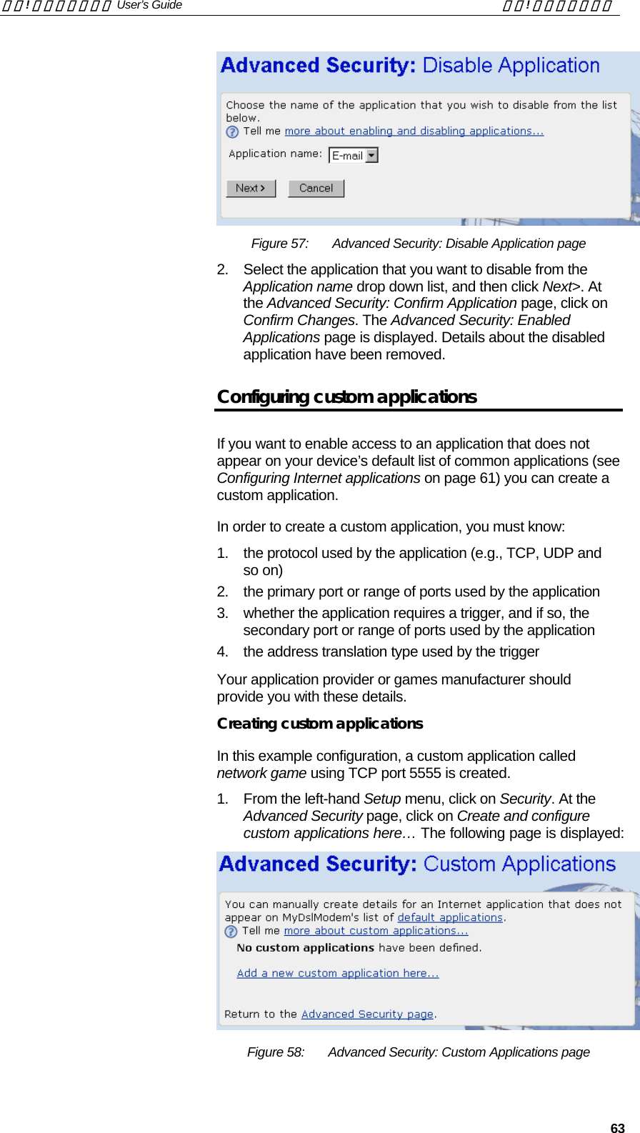
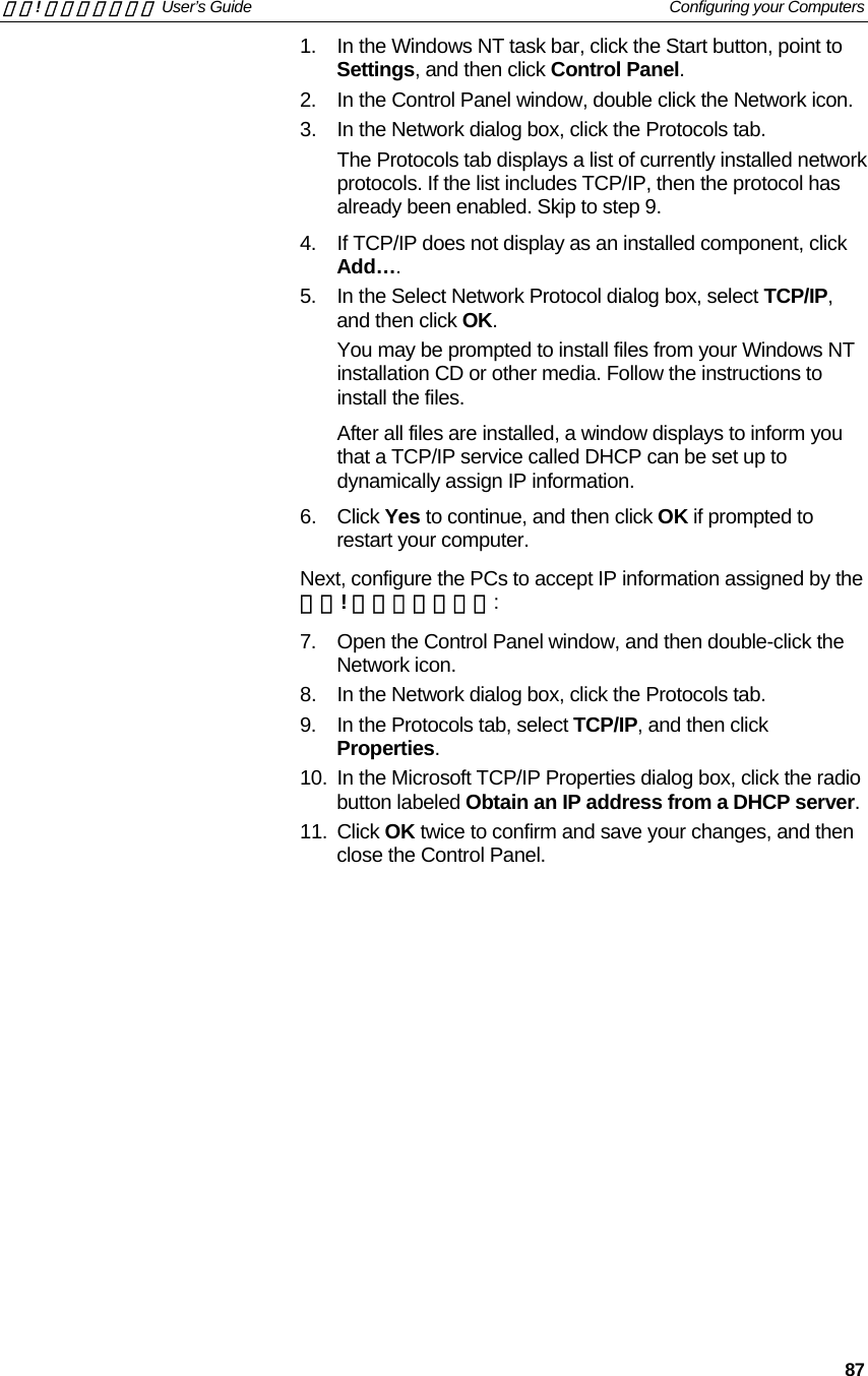
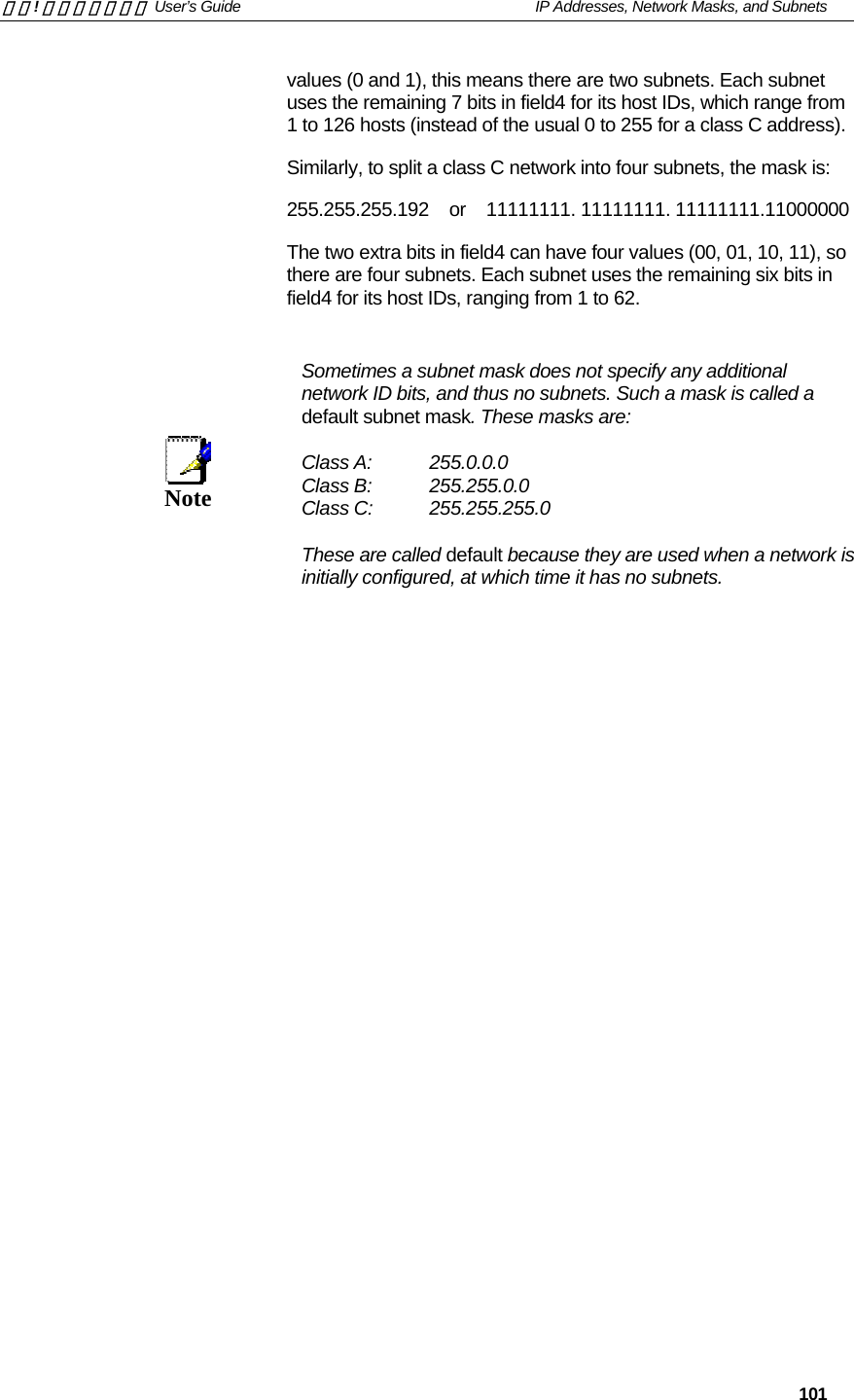
![錯誤! 尚未定義樣式。 User’s Guide 錯誤! 尚未定義樣式。 14 Front Panel The front panel contains a Restore Defaults button, a wireless network card slot and lights called LEDs that indicate the status of the unit. [Insert photo of your own front-panel with LEDs] Figure 2: Front Panel and LEDs Label Color Function Restore Defaults N/A Pressing this button restores the factory default configuration on your device PCMCIA 802.11b N/A Allows you to insert a Wireless network card that enables a Wireless LAN to attach to your device Power green On: device is powered on Off: device is powered off USB Link/Act green On: USB link is established Off: No USB link Blink: Data being transmitted W-LAN Link/Act green On: Wireless LAN link established Off: No Wireless LAN link Blink: Data being transmitted Internet orange On: Valid IP address obtained Off: No IP address obtained Blink: Valid IP packet being transferred DSL HS green On: High Speed (16 Mbit) rate established Off: 8 Mbit rate established DSL Link/Act green On: DSL link reaches showtime, which means that your device has successfully connected to your ISP’s DSL network. Off: DSL link not in showtime, your device has not successfully connected to your ISP’s DSL network. Blink: Data being transmitted LAN 10/100 green On: Fast (100BaseT) Ethernet link established and active Off: 10BaseT Ethernet link established and active LAN Link/Act green On: LAN link established and active Off: No LAN link The initial Argon 4x1 Customer Evaluation Board only supports the green Power LED (D1705 – TOP). This table is provided as an example of the status LEDs that you may wish to create. You must edit this table and the table in Testing your Setup on page 22 to reflect your own LED configuration.[CT9]](https://usermanual.wiki/Zoom-Telephonics/WL1046/User-Guide-521686-Page-14.png)
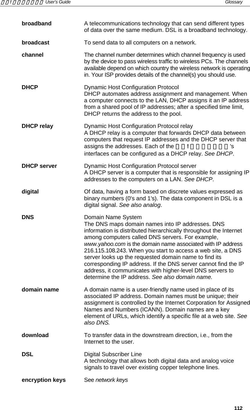
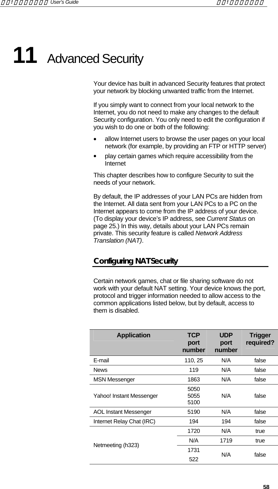
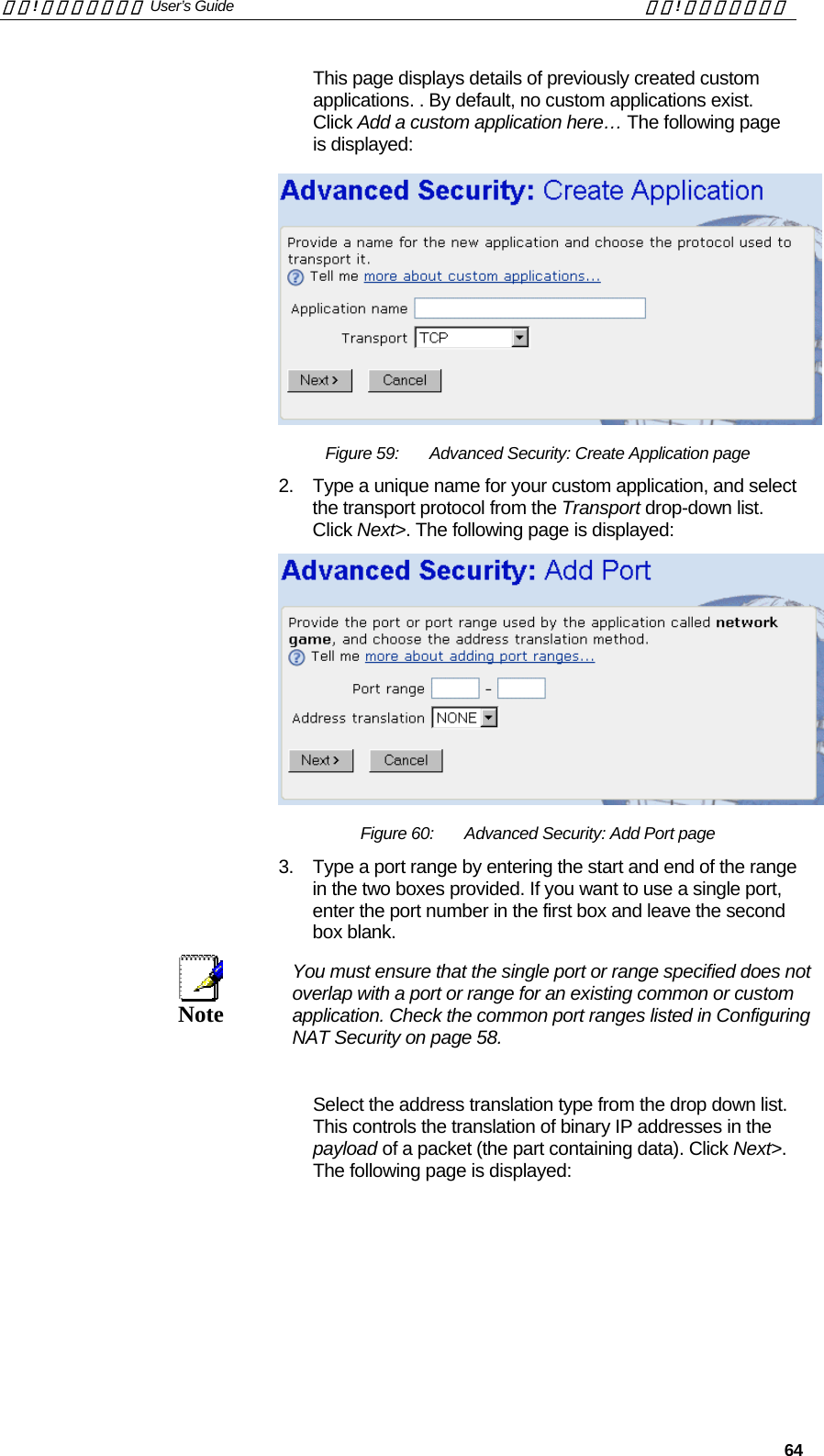
![錯誤! 尚未定義樣式。 User’s Guide 錯誤! 尚未定義樣式。 15 Rear Panel The rear panel contains the ports for the unit's data and power connections. [Insert photo of your own rear-panel with connectors] Figure 3: Rear Panel Connections Label Function Power Connects to the supplied power cable USB Connects to the USB port on your PC Ethernet 1 Connects the device via Ethernet to your LAN’s hub or switch (disabled) Ethernet 2 Connects the device via Ethernet to up to four PCs on your LAN (default) DSL Connects the device to a telephone port in the wall of your home/office for DSL communication V.9x Provides an optional connection to your telephone](https://usermanual.wiki/Zoom-Telephonics/WL1046/User-Guide-521686-Page-15.png)
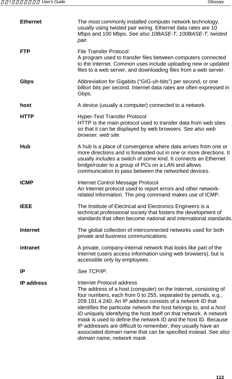
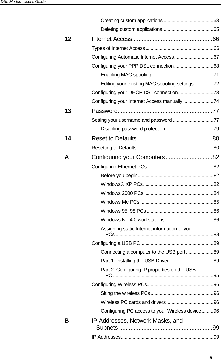
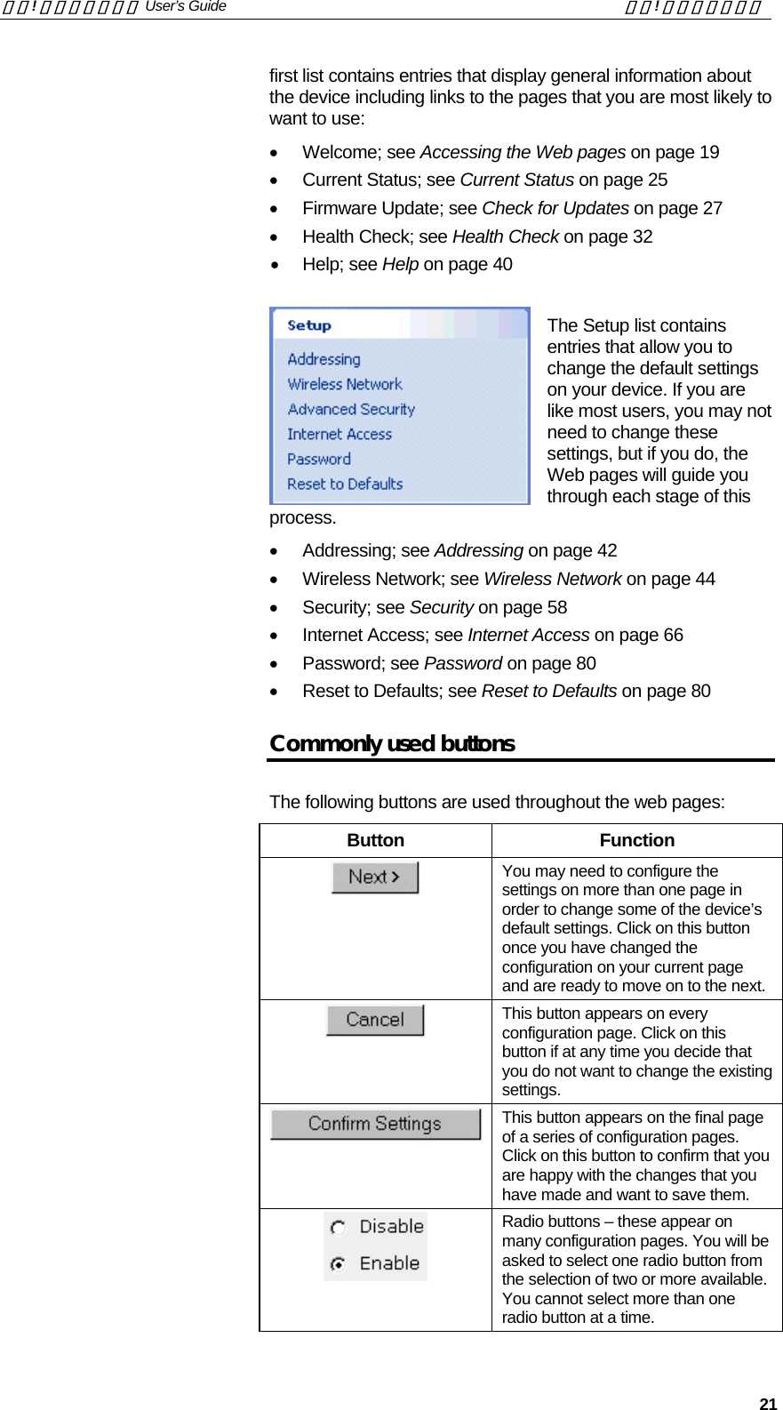
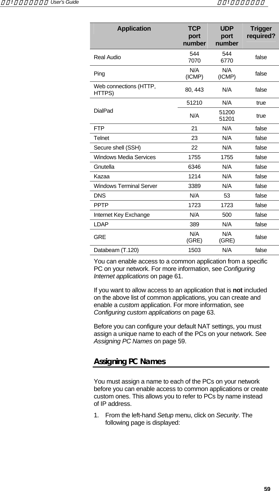
![錯誤! 尚未定義樣式。 User’s Guide 錯誤! 尚未定義樣式。 17 ADSL/Ethernet Bridge/RouterPower Ethernet 1 DSLUSB V.9x(optional)123TelephoneWall phoneport Stand-alone PCAC adapterEthernet 2 To up to 4 stand-alone PCsHub/switch(for local areanetwork)To a hubNetworked ComputersOR4Wireless PCs 5 Figure 4: Overview of Hardware Connections Step 1. Connect the DSL cable and optional telephone Connect one end of the provided phone cable to the port labeled DSL on the rear panel of the device. Connect the other end to your wall phone port. You can attach a telephone line to the device. This is helpful when the DSL line uses the only convenient wall phone port. If desired, connect the telephone cable to the port labeled V.9x[CT15]. WARNING Although you use the same type of cable, The DSL and V.9x ports are not interchangeable. Do not route the DSL connection through the V.9x port.](https://usermanual.wiki/Zoom-Telephonics/WL1046/User-Guide-521686-Page-17.png)
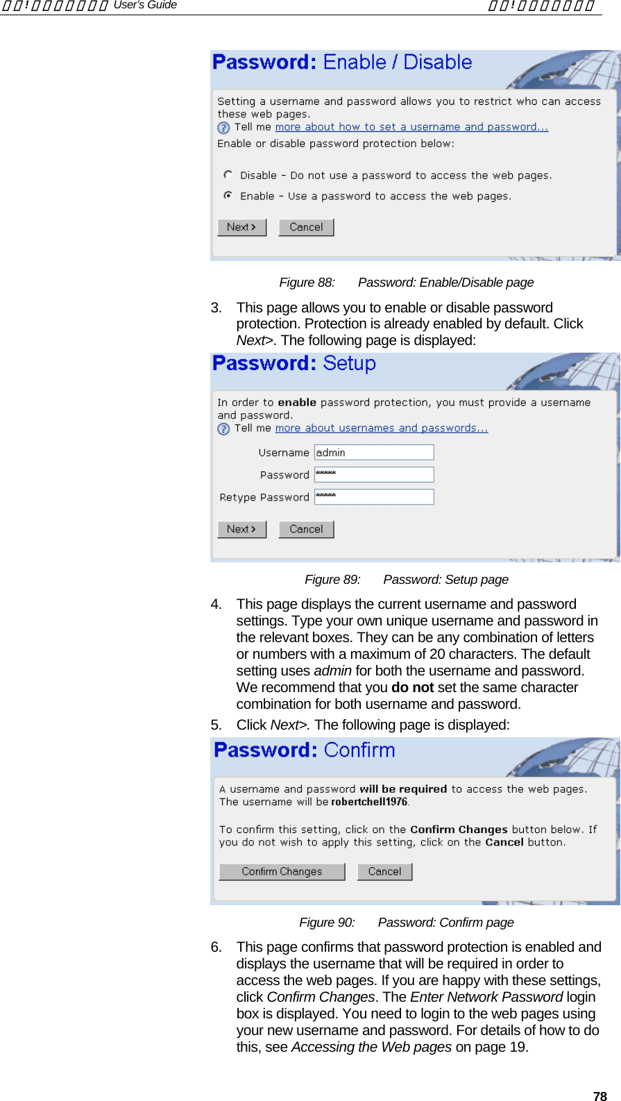
![錯誤! 尚未定義樣式。 User’s Guide 錯誤! 尚未定義樣式。 18 Step 2. Connect the Ethernet cable You must delete one of the following Ethernet connection options:[CT17] Connect either a LAN hub or a single Ethernet computer directly to the device via Ethernet cable. Connect either a LAN hub or up to four single Ethernet computers directly to the device via Ethernet cable. Note that the cables do not need to be crossover cables. Step 3. Attach the power connector Connect the AC power adapter to the Power connector on the back of the device and plug in the adapter to a wall outlet or power strip. Turn on and boot up your computer(s) and any LAN devices such as hubs or switches. Step 4. Configure your Ethernet PCs You must also configure the Internet properties on your Ethernet PCs. See Configuring Ethernet PCs on page 82. Step 5. Install USB software and connect the USB cable Only include this step if your product supports the USB port.[CT20] You can attach a single computer to the device using a USB cable. The USB port is useful if you have an USB-enabled PC that does not have a network interface card for attaching to your Ethernet network. Before attaching the USB cable, you must install a USB driver on your PC and configure the computer. For complete instructions, see Configuring a USB PC on page 89. Step 6. Install Wireless card and connect Wireless PCs Only include this step if your product supports the use of wireless[CT21] You can attach a Wireless LAN that enables Wireless PCs to access the Internet via your device. Install a compatible Wireless card such as the Conexant PRISM3 wireless network card in the PCMCIA slot on the front of the device (see Front Panel and LEDs). You must configure your Wireless computer(s) in order to access your device. For complete instructions, see Configuring Wireless PCs on page 96. Next step After setting up and configuring the device and PCs, you can log on to the device by following the instructions in Getting Started with the Web pages on page 19. The chapter includes a section called Testing your Setup on page 22, which enables you to verify that the device is working properly.](https://usermanual.wiki/Zoom-Telephonics/WL1046/User-Guide-521686-Page-18.png)
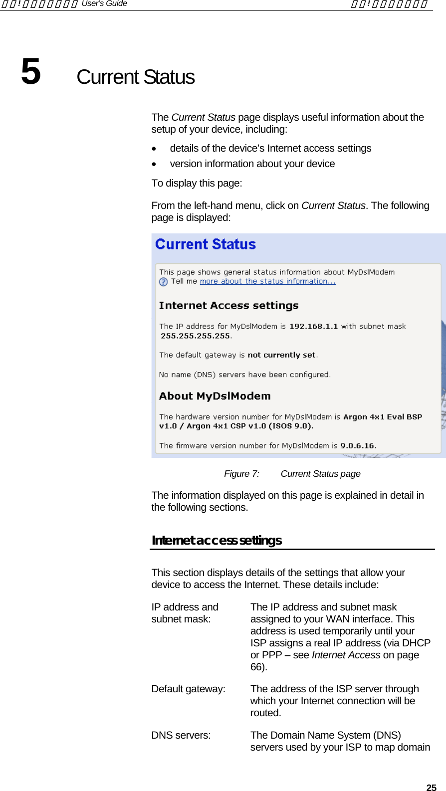
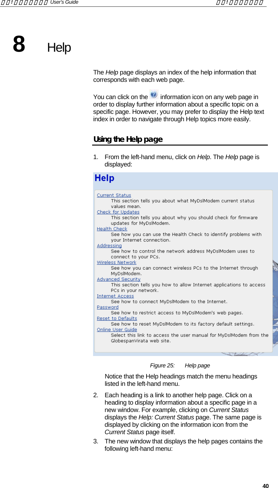
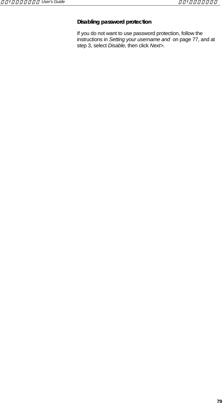
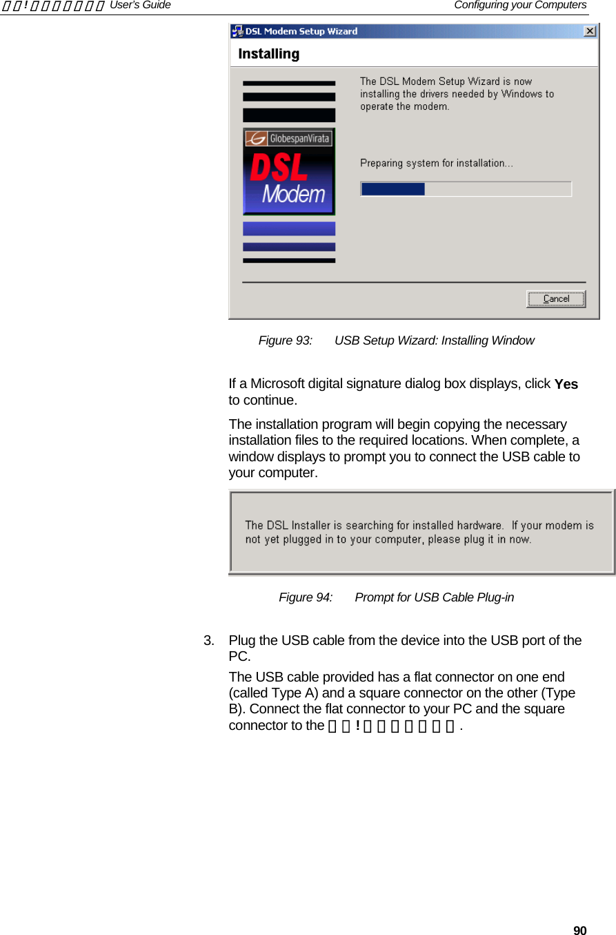
![錯誤! 尚未定義樣式。 User’s Guide 錯誤! 尚未定義樣式。 19 4 Getting Started with the Web pages The DSL Modem includes a series of Web pages that provide an interface to the software installed on the device. It enables you to configure the device settings to meet the needs of your network. You can access it through your web browser from any PC connected to the device via the LAN, WLAN or USB ports. Accessing the Web pages To access the Web pages, you need the following: • A PC or laptop connected to the LAN, WLAN or USB port on the device. • A web browser installed on the PC. The minimum browser version requirement is Internet Explorer v4 or Netscape v4. For the best display quality, use Internet Explorer v5, or Netscape v6.1. 1. From any of the LAN computers, open your web browser, type the following URL in the web address (or location) box, and press [Enter] on your keyboard: http://MyDslModem A login screen is displayed: Figure 5: Login screen 2. Enter your user name and password. The first time you log into the program, use these defaults: User Name: admin Password: admin Note You can change the password at any time or you can configure your device so that you do not need to enter a password. See Password on page 77.](https://usermanual.wiki/Zoom-Telephonics/WL1046/User-Guide-521686-Page-19.png)
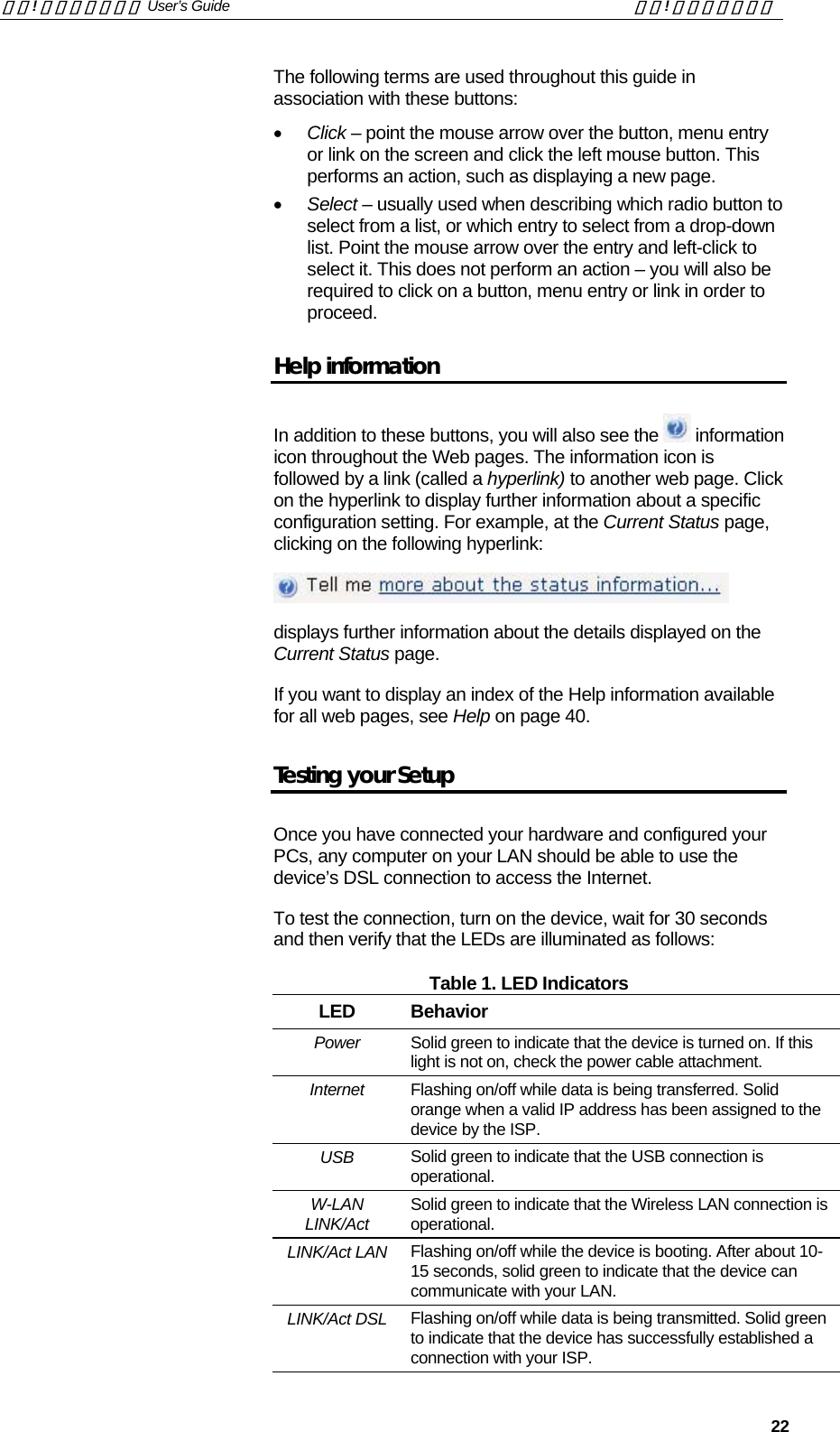
![錯誤! 尚未定義樣式。 User’s Guide 錯誤! 尚未定義樣式。 23 LINK/Act DSL Flashing when the device is sending or receiving data from the Internet. It may be unlit, flashing, or appear solid depending on the current activity. The initial Argon 4x1 Customer Evaluation Board only supports the green Power LED (D1705 – TOP). This table is provided as an example of the LEDs that your product may support. You must edit this table to reflect your own LED configuration. [CT25] If the LEDs illuminate as expected, test your Internet connection from a LAN computer (and from the USB computer, if applicable). To do this, open your web browser, and type the URL of any external website (such as http://www.yahoo.com). The LED labeled LINK/Act DSL should be blinking rapidly and may appear solid as the device connects to the site. If the LEDs do not illuminate as expected, you may need to configure your Internet access settings using the information provided by your ISP. For details, see Internet Access on page 66. If the LEDs still do not illuminate as expected, or the web page is not displayed, see Troubleshooting Suggestions on page 102, or contact your ISP for assistance. Default device settings In addition to handling the DSL connection to your ISP, the DSL Modem can provide a variety of services to your network. The device is preconfigured with default settings for use with a typical home or small office network. The table below lists some of the most important default settings; these and other features are described fully in the subsequent chapters. If you are familiar with network configuration, review these settings to verify that they meet the needs of your network. Follow the instructions to change them if necessary. If you are unfamiliar with these settings, try using the device without modification, or contact your ISP for assistance. Before you modify any settings, we strongly recommend that you contact your ISP prior to changing the default configuration. Option Default Setting Explanation/Instructions DSL Port IP Address Unnumbered interface: 192.168.1.1 Subnet mask: 255.255.255.255 This is the temporary public IP address of the WAN port on the device. It is an unnumbered interface that is replaced as soon as your ISP assigns a ‘real’ IP address. See Internet Access on page 66. LAN Port IP Address Assigned static IP address: 192.168.1.1 Subnet mask: 255.255.255.0 This is the IP address of the LAN port on the device. The LAN port connects the device to your Ethernet network. Typically, you will not need to change this address. See Addressing on page 42. DHCP (Dynamic Host Configuration Protocol) DHCP server enabled with the following pool of addresses: 192.168.1.2 through 192.168.1.20 The 錯誤! 尚未定義樣式。 maintains a pool of private IP addresses for dynamic assignment to your LAN computers. To use this service, you must have set up your computers to accept IP information dynamically, as described in Configuring Ethernet PCs on page 82.](https://usermanual.wiki/Zoom-Telephonics/WL1046/User-Guide-521686-Page-23.png)
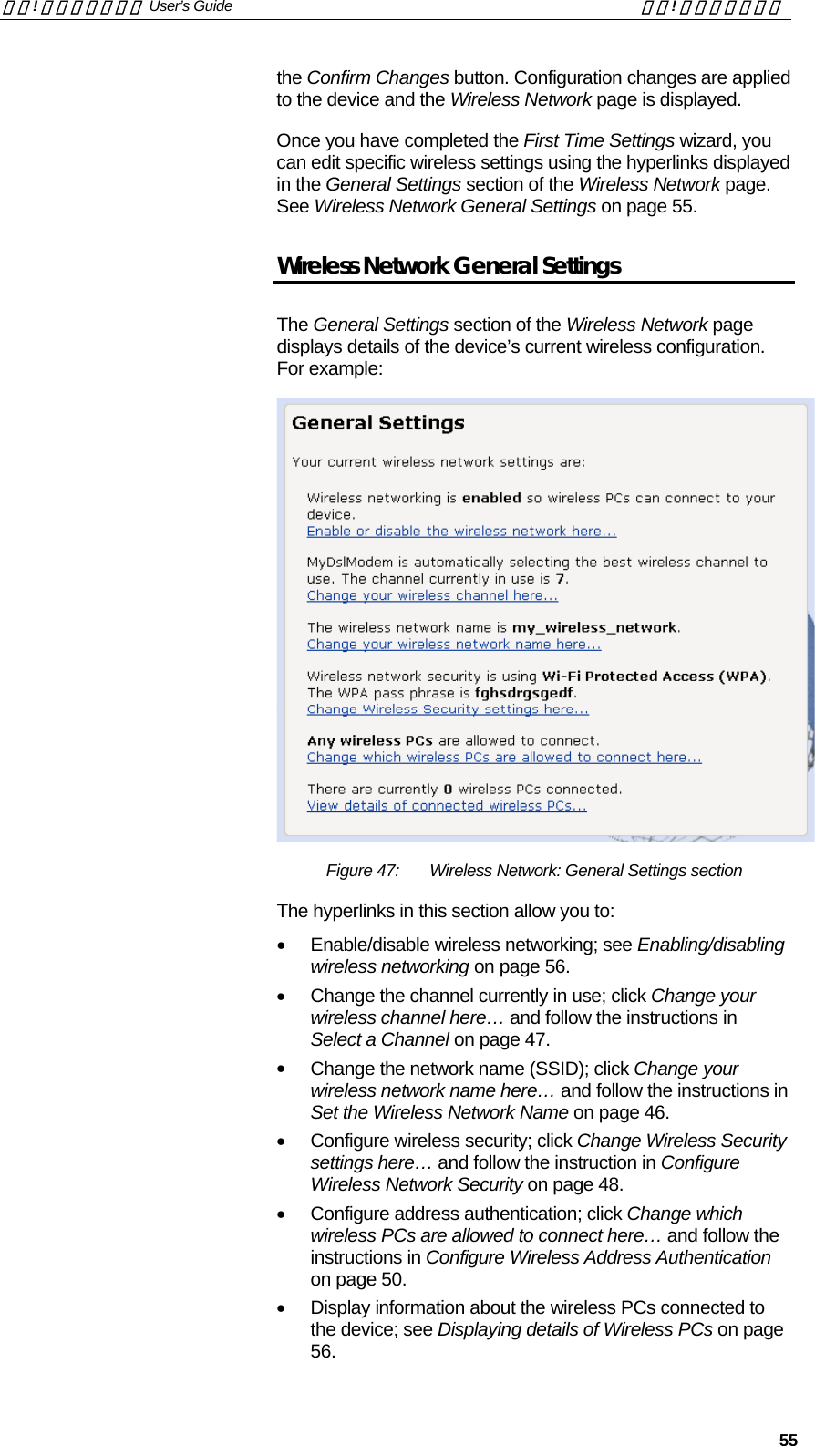
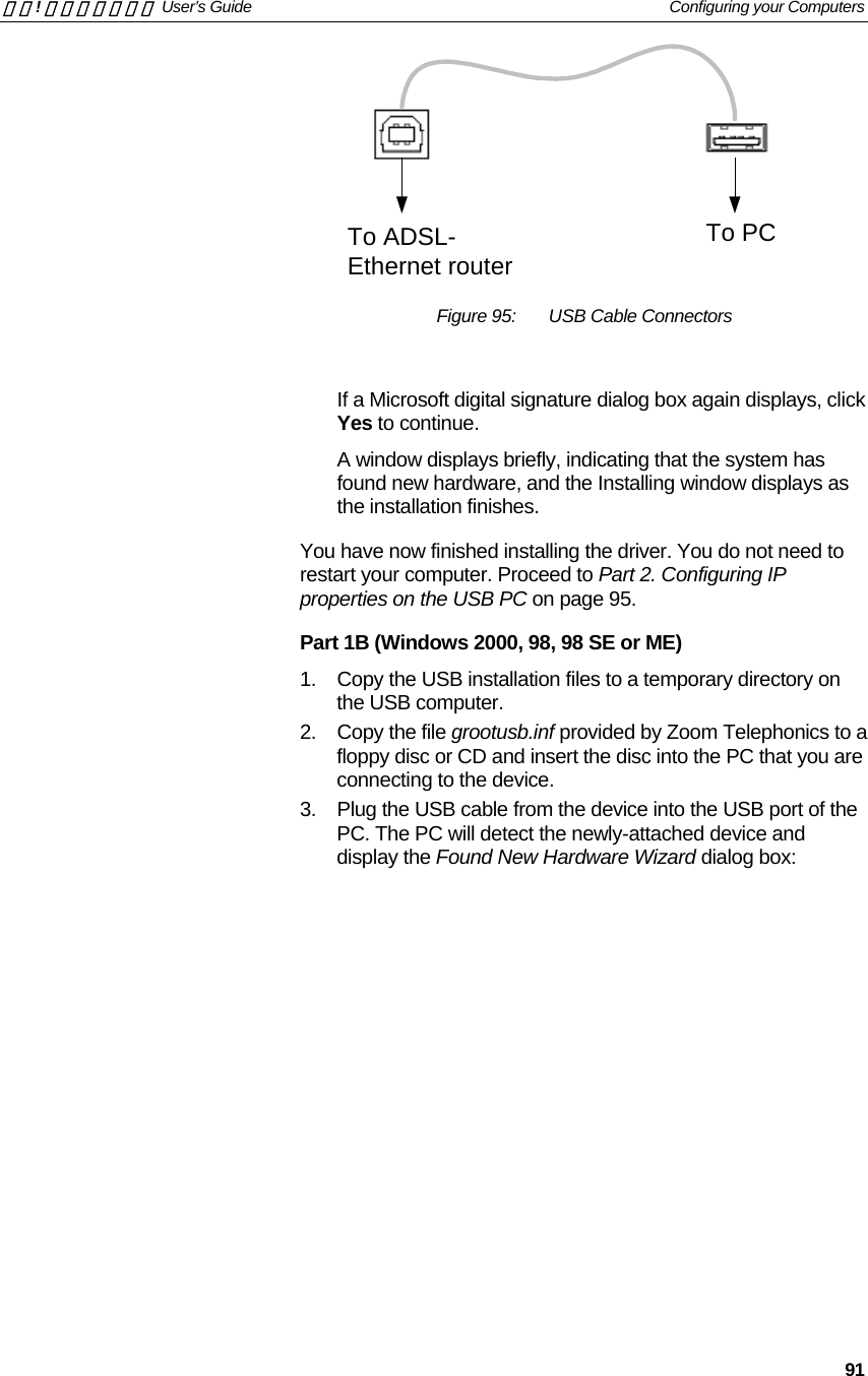
![錯誤! 尚未定義樣式。 User’s Guide 錯誤! 尚未定義樣式。 44 10 Wireless Network This chapter assumes that you have already set up your Wireless PCs and installed a compatible Wireless card on your device. See Configuring Wireless PCs on page 96. The Wireless Network page allows you to configure the Wireless features of your device. To access the Wireless Network page: From the left-hand Setup menu, click on Wireless Network. The following page is displayed: Figure 30: Wireless Network page The settings on this page are split into two sections: • First Time Settings[CT33]; contains a hyperlink wizard that takes you through a sequence of pages, with each page corresponding to a specific wireless network setting. You should only need to change all of these settings once; i.e., when you initially setup your wireless network. See the Wireless Network First Time Settings Wizard on page 45. This section also displays the country that the wireless network is set to operate in and the type of wireless network used. • General Settings; contains details of the current wireless configuration and hyperlinks relating to individual wireless network settings previously configured by completing the First Time Settings wizard. This allows you to make](https://usermanual.wiki/Zoom-Telephonics/WL1046/User-Guide-521686-Page-44.png)
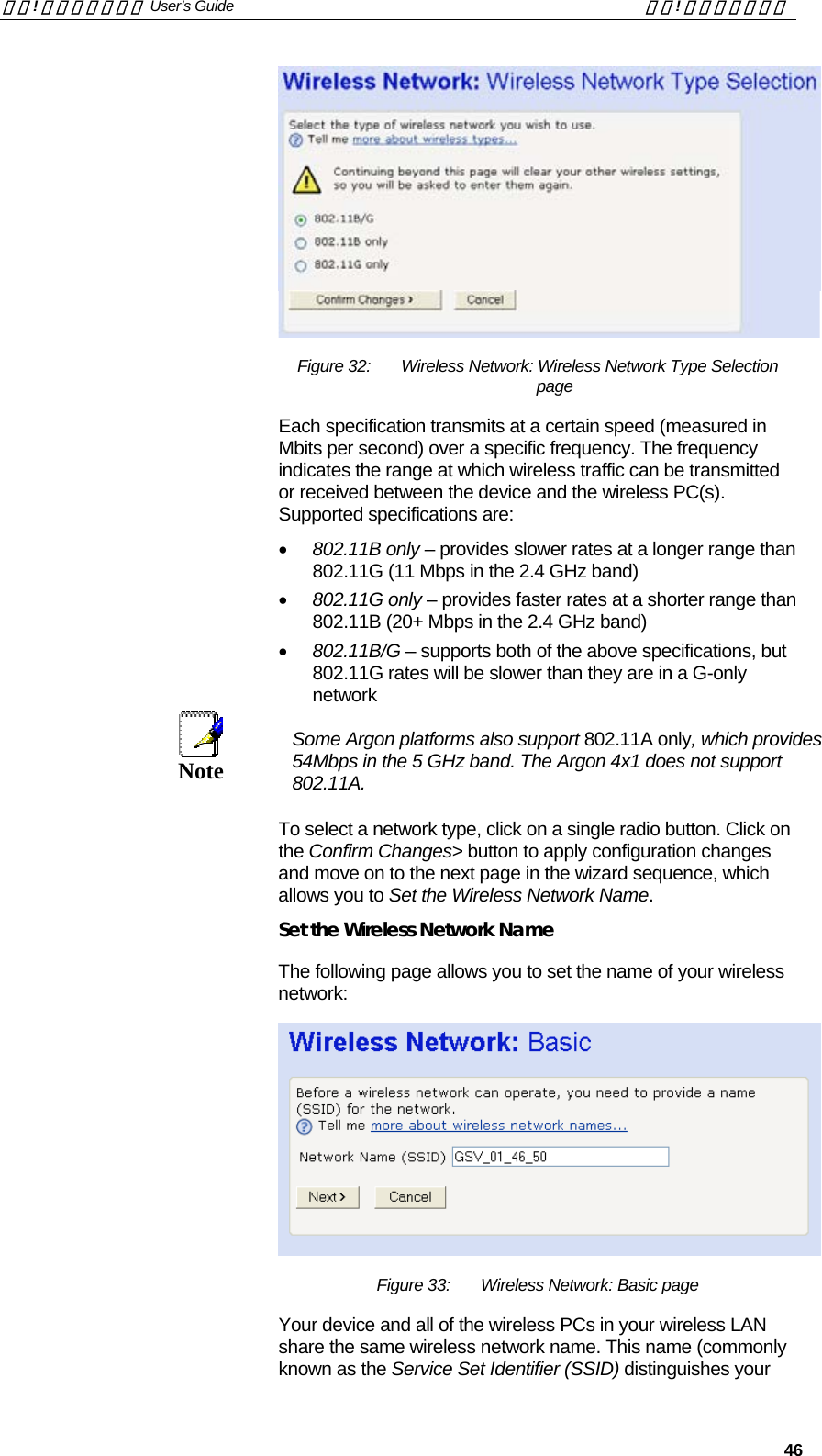
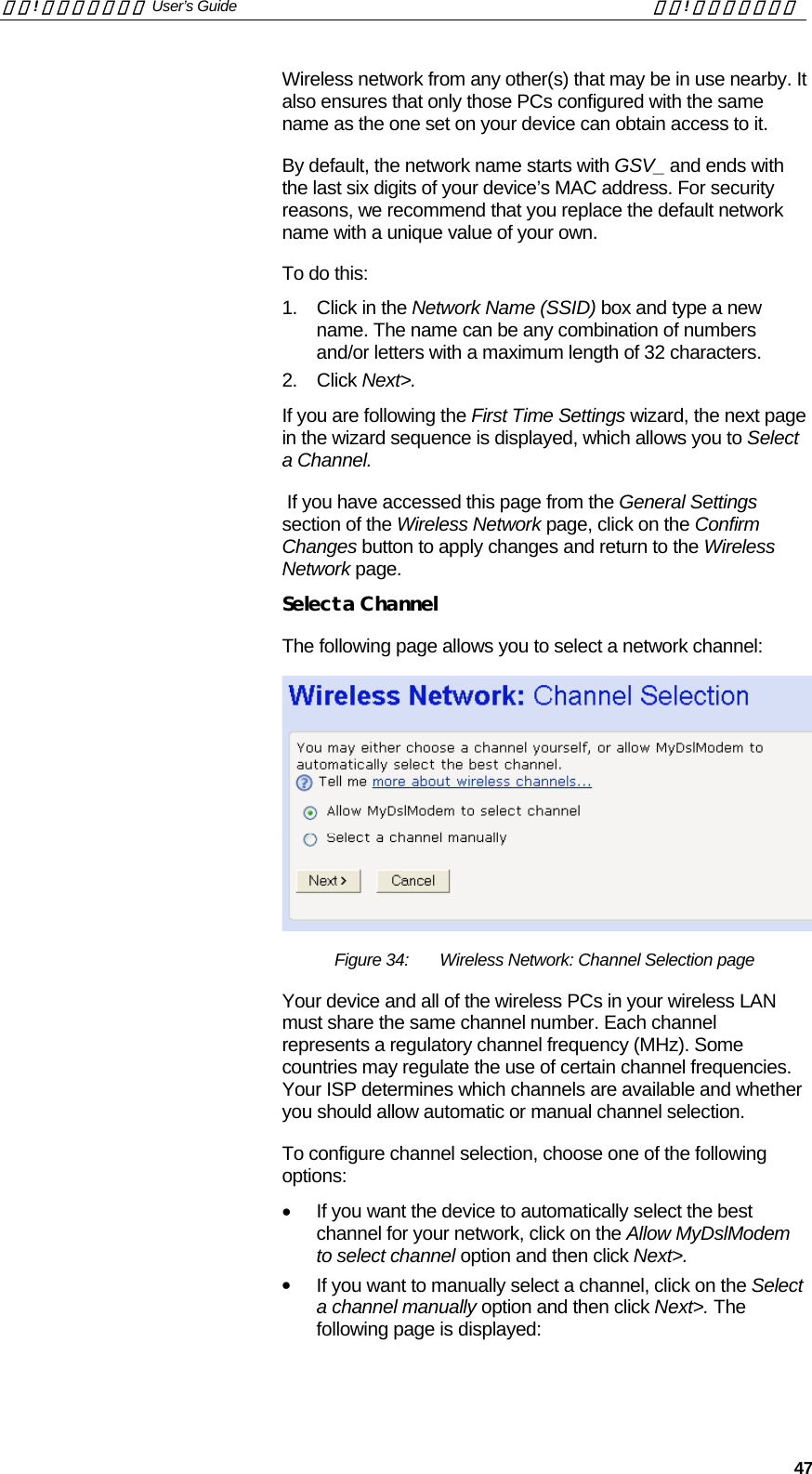
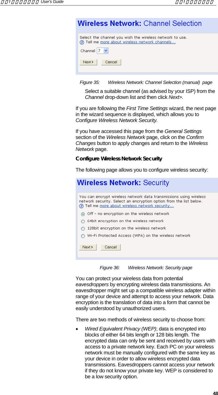
![錯誤! 尚未定義樣式。 User’s Guide 錯誤! 尚未定義樣式。 45 changes to specific wireless settings without going through the entire wizard. See Wireless Network General Settings on page 55. Wireless Network First Time Settings Wizard This section describes how to follow the wireless network wizard in order to configure your wireless network settings for the first time. The wizard sequence allows you to configure each of the following Wireless settings in order: • The country that your network is operating in • The specification standard used by the wireless network • The wireless network name • The wireless network channel • Wireless network security • Wireless network address authentication Note Each page of the wizard contains a Cancel button. Click on this if you want to exit the wizard at any time. Setting the Country[CT34] 1. From the First Time Settings section of the Wireless Network page, click Change your wireless first time settings here… The first page of the wizard is displayed: Figure 31: Wireless Network: Set Country page The number of valid wireless network frequencies varies from country to country and you need to identify which country you are operating the device in to ensure that your network will transmit on the correct frequency. 2. From the Country drop-down list, select the appropriate country. Click on the Confirm Changes> button to apply configuration changes and move on to the next page in the wizard sequence, which allows you to Select your Wireless Network Type. Select your Wireless Network Type[CT35] The following page allows you to select the IEEE specification supported by your network:](https://usermanual.wiki/Zoom-Telephonics/WL1046/User-Guide-521686-Page-45.png)
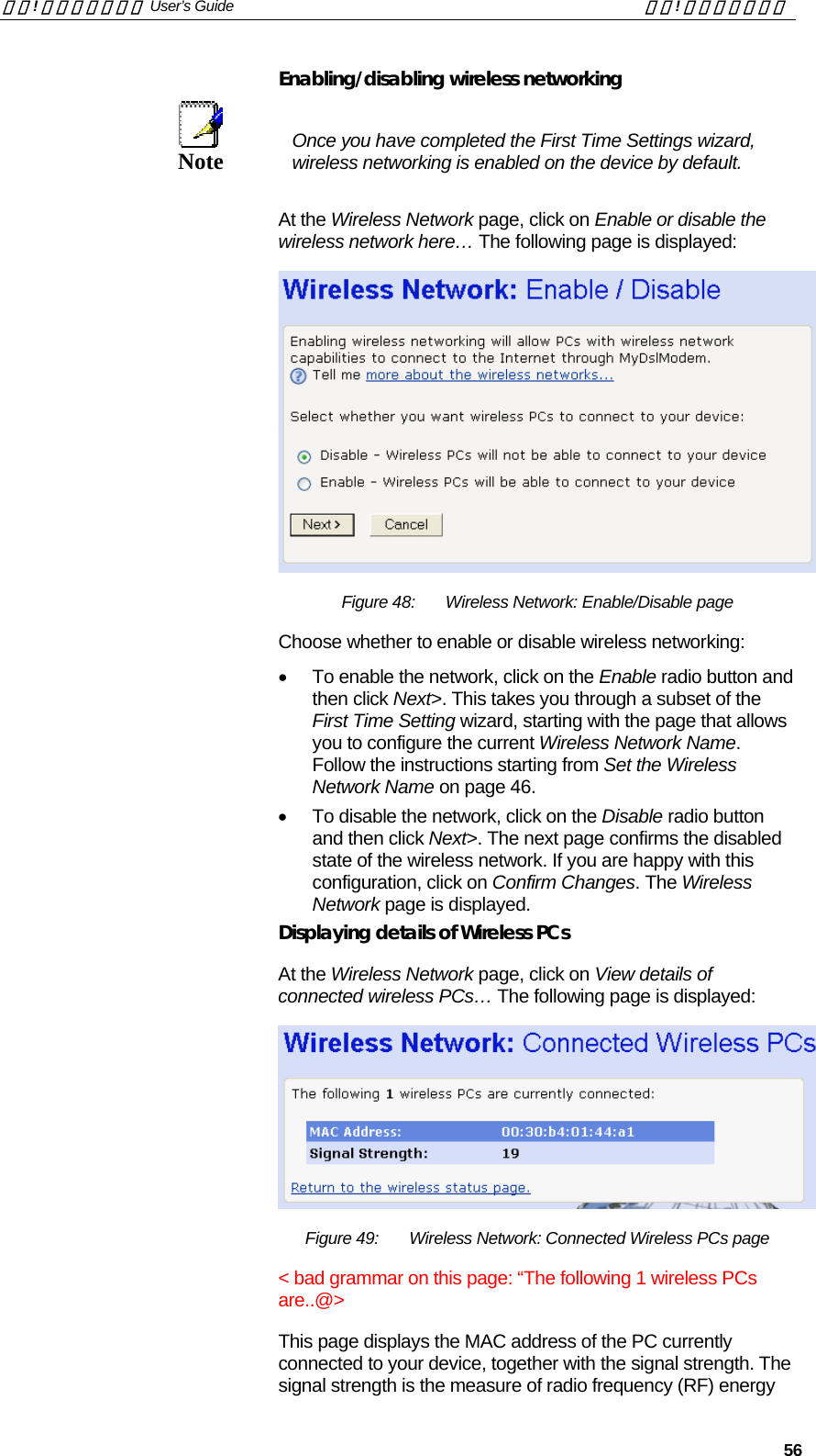
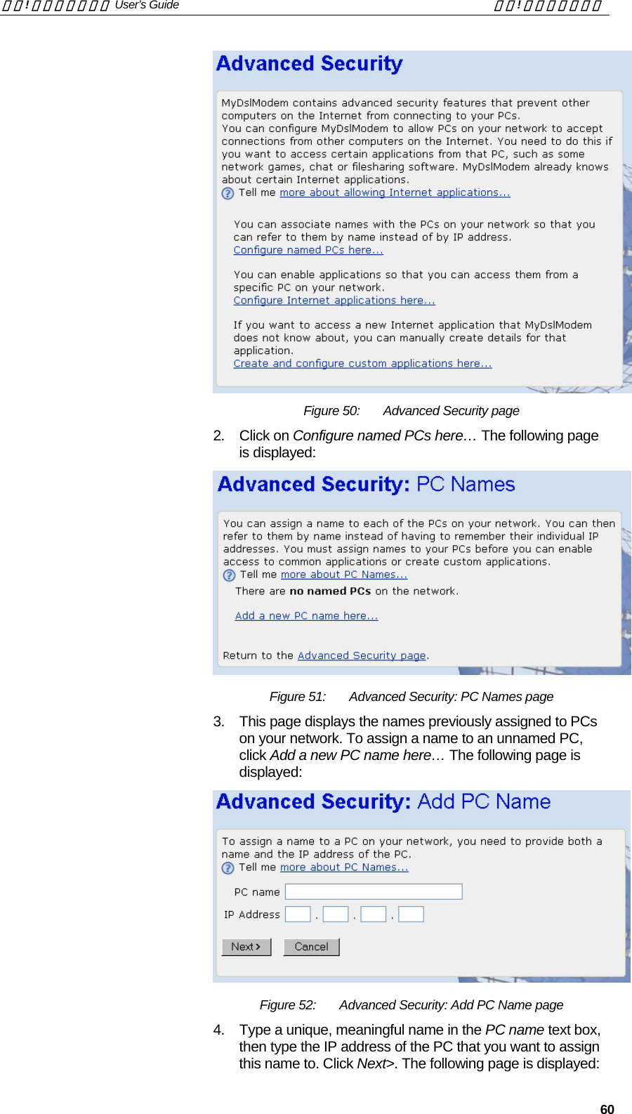
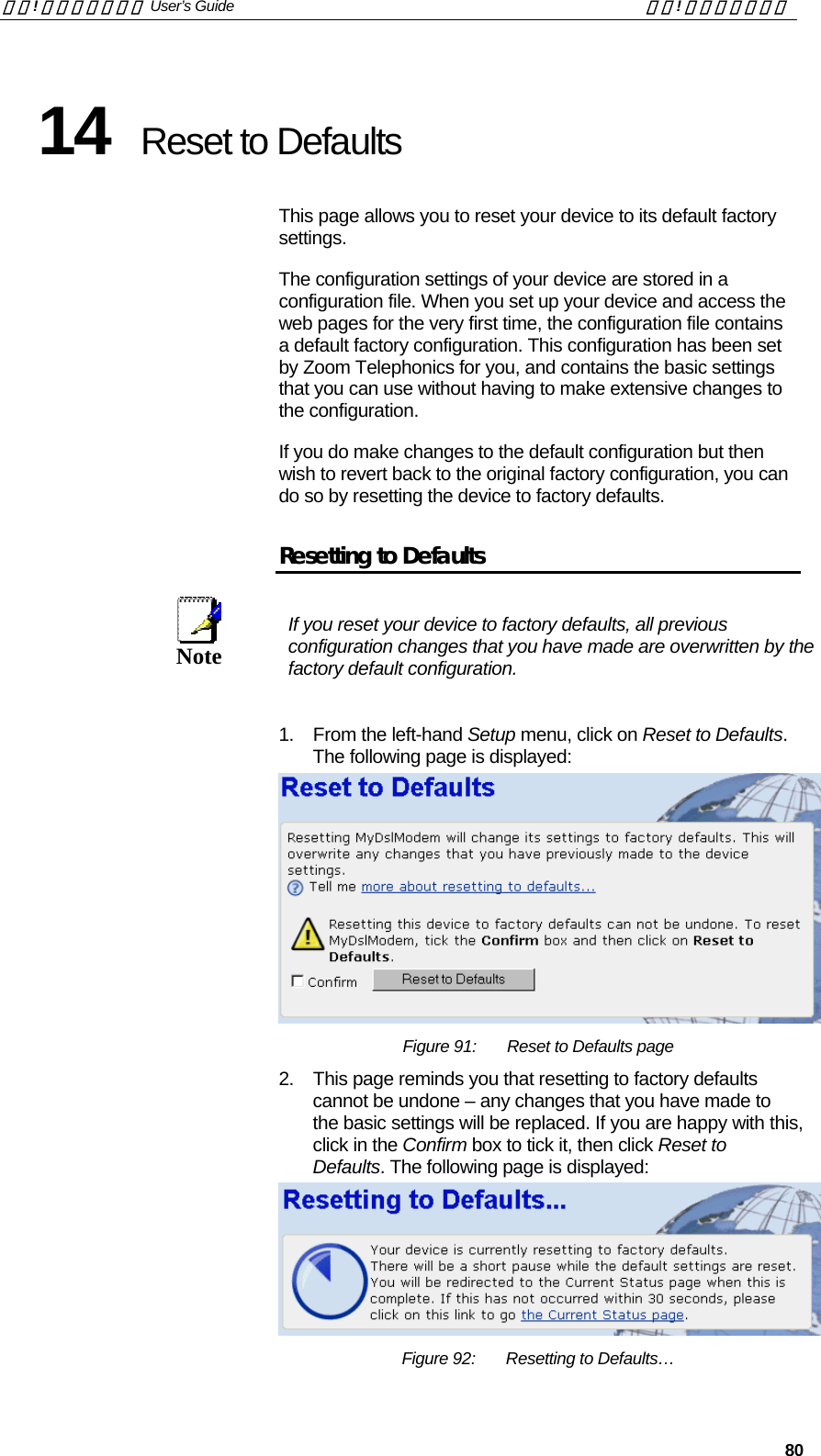
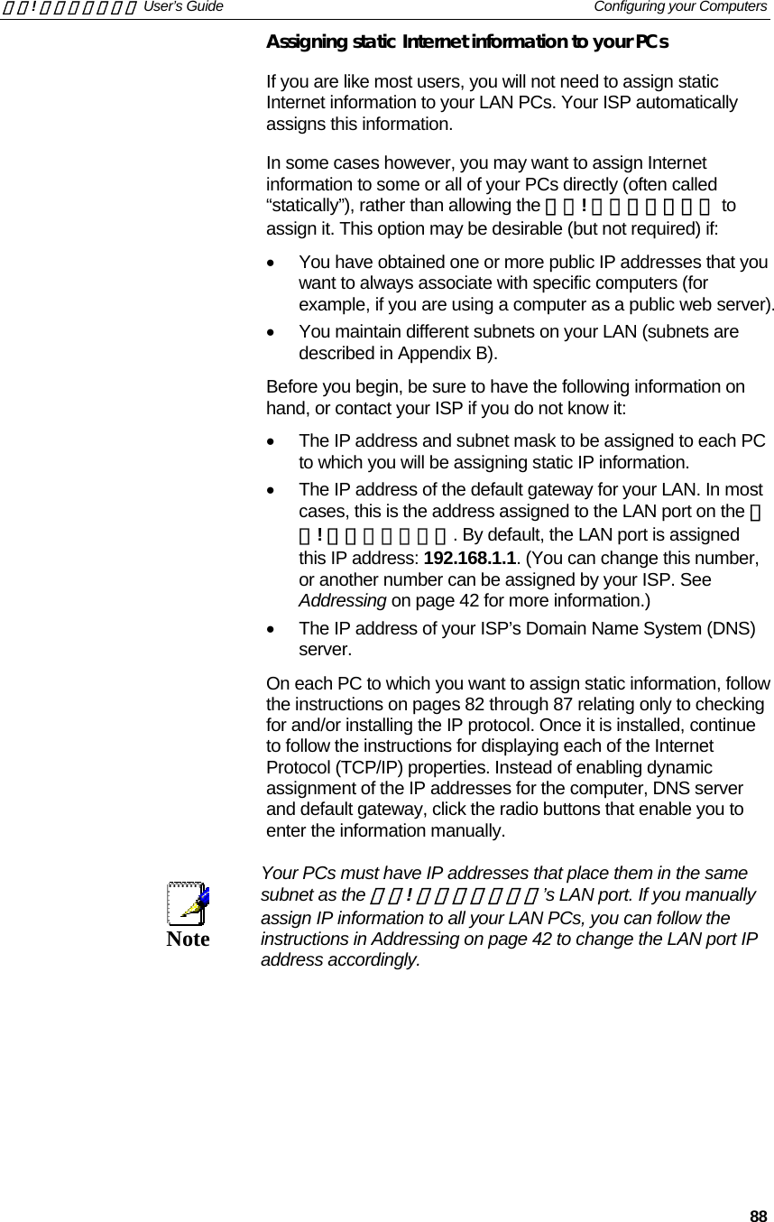
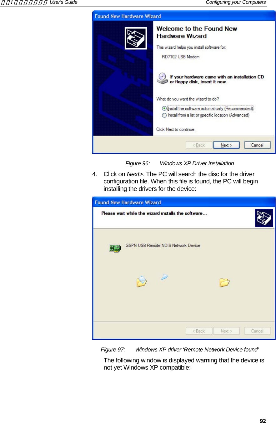

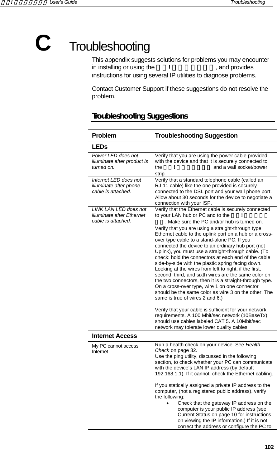
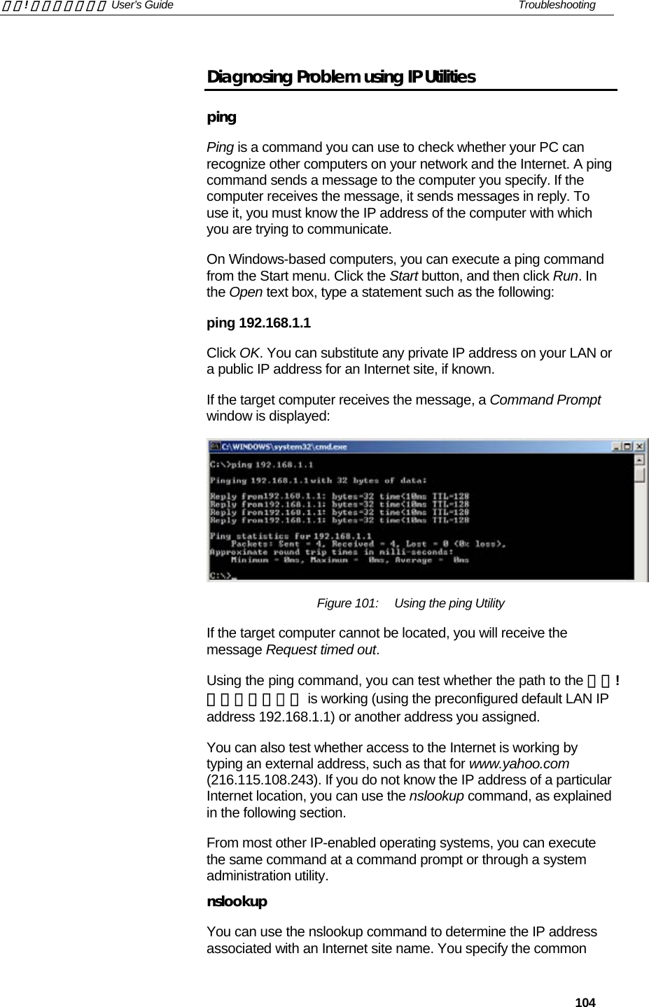
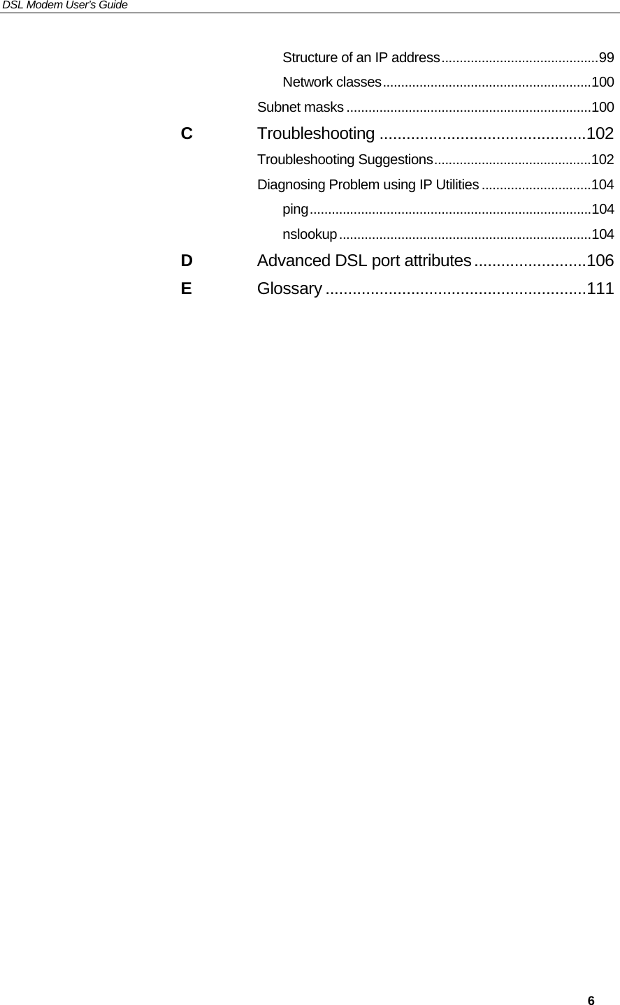
![錯誤! 尚未定義樣式。 User’s Guide Troubleshooting 105 name, and the nslookup command looks up the name in on your DNS server (usually located with your ISP). If that name is not an entry in your ISP’s DNS table, the request is then referred to another higher-level server, and so on, until the entry is found. The server then returns the associated IP address. On Windows-based computers, you can execute the nslookup command from the Start menu. Click the Start button, and then click Run. In the Open text box, type the following: Nslookup Click OK. A Command Prompt window displays with a bracket prompt (>). At the prompt, type the name of the Internet address that you are interested in, such as www.microsoft.com. The window will display the associate IP address, if known, as shown below: Figure 102: Using the nslookup Utility There may be several addresses associated with an Internet name. This is common for web sites that receive heavy traffic; they use multiple, redundant servers to carry the same information. To exit from the nslookup utility, type exit and press [Enter] at the command prompt.](https://usermanual.wiki/Zoom-Telephonics/WL1046/User-Guide-521686-Page-105.png)