Zoom Telephonics WLANPCCRD11 Wireless LAN PCMCIA Card User Manual DIPOLE ANTENNA
Zoom Telephonics Inc Wireless LAN PCMCIA Card DIPOLE ANTENNA
INSTALLATION GUIDE

ANTENNA OPTIONS and
INSTALLATION INSTRUCTIONS
ZoomAir Wireless Network Interface Cards are available with either an integrated antenna or an
external antenna. The 11Mbps ZoomAir, supporting both PCMCIA and PCI formats, and shipping
with the ZoomAir Hardware Access Point, comes with an external dipole antenna, providing more
uniform coverage and up to 30% greater range in specific settings. Additional antenna models are
available to meet specific wireless networking installation needs.
MAXIMIZING RANGE
The built-in patch antenna on the PCMCIA and PCI Models has a horizontal pattern shaped like a cone. When
using two ZoomAir cards with the integrated patch antenna in an office environment where set-up is less than
10 ft. apart, you can minimize packet errors by placing the units on different planes. Once the units are further
than 10 ft. apart, the antenna signals will reflect off walls, tables, and people, thus changing signal
polarization. Outdoor polarization has an even greater effect. If there are not any objects in the path of the two
radio cards, the two cards should be on different planes to achieve the best range and to minimize packet
errors.
The external dipole antenna model has an omni pattern. It transmits and receives signals equally in all
directions. When using ZoomAir cards with external dipole antennas, it’s best to have them all oriented in the
same direction. If you have one card with a dipole antenna and another with an integrated antenna, we
recommend that the dipole be at 90° to the integrated patch.
With all cards, placement is very important. If one computer is under a desk, loss will occur. Glass and metal
will also cause degradation (e.g., inside a car). Weather conditions such as snow and rain water increase
signal attenuation. Essentially, different materials affect the propagation of radio waves: Some cause more
attenuation than others. See below for some common examples:
• Wood Floors Low
• Plaster Walls Low
• Glass Windows Low
• Water Damp Wood; Aquariums Medium
• Bricks Inner and Outer Walls Medium
• Marble Inner Walls Medium
• Paper Paper Rolls High
• Concrete Floors and Outer Walls High
• Metal Desks; Partitions Very High
Materials Examples Attenuation
W I R E L E S S N E T W O R K I N G
ANTENNAS
■ DIPOLE ANTENNA
The ZoomAir 2.2 dBi Dipole Antenna Model #98110-02 is
supplied as standard equipment with the 11Mbps ZoomAir Wireless
Network Interface Card and the ZoomAir Hardware Access Point. It
attaches directly to each device's built-in antenna jack. The
ZoomAir Dipole Antenna's radiation pattern is omni-directional: It
transmits and receives signals equally well in all directions. When
compared with the 11 Mbps ZoomAir Model with the NIC's
integrated antenna, the ZoomAir Dipole typically provides more
uniform coverage and up to 30% greater range.
Model 98110-02 Specifications
Frequency range 2.4-2.483 GHz
Gain1 2.2 dBi
Polarization2Linear
Nominal impedance 50 ohms
Connector Reverse polarity
SMA male (plug)
Dimensions 3.25”(82mm) length; 9/32”(7mm) diameter
Weight < 0.5 oz (<14gm)
Omni-directional to 300 ft. (90m) in a typical partitioned office or 1,000 ft. (300m) with an unobstructed line of sight
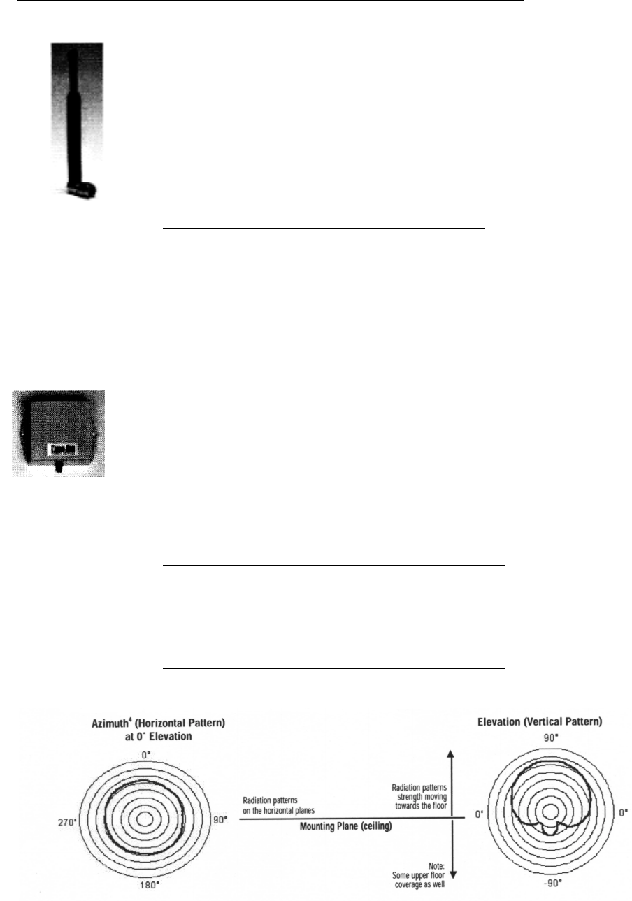
■ OMNI-DIRECTIONAL ANTENNA
ZoomAir 4.0 dBi Omni-Directional Antenna Model #98110-04 can
be mounted on a ceiling for use as an omni-directional antenna, or
mounted on a wall to provide increased range in a single direction.
The antenna attaches to the 11 Mbps ZoomAir Wireless Network
Interface Card or a ZoomAir Hardware Access Point through a 1-
meter or 3-meter low-loss coaxial cable (sold separately). Cable
length can be extended to a maximum recommended 6 meters by
attaching additional cable segments using a supplied adapter. The
ZoomAir Omni-Directional Antenna package includes mounting
hardware.
Model 98110-04 Specifications
Frequency range 2.4-2.484 GHz
Gain14.0 dBic (circular)
3 dB beamwidth (elevation) 220° (typical)
Polarization3Right-hand circular
Nominal impedance 50 ohms
Connector Reverse polarity
SMA female (jack)
Dimensions 3”W (7.6cm) x 3”H (7.6cm) x 1.5” (3.8cm)
Weight 3.0 oz (85 gr)
Ceiling mounted for a radius coverage of 380ft.(115m) in a typical partitioned office or 1,500ft.(455m) in an unobstructed
environment. Directional range to 450ft. (115m) in a partitioned office or 1275ft.(390m) in an unobstructed environment.
Omni-directional to 300 ft.(90m) in a typical partitioned office or 1,000 ft.(300m) with an unobstructed line of sight
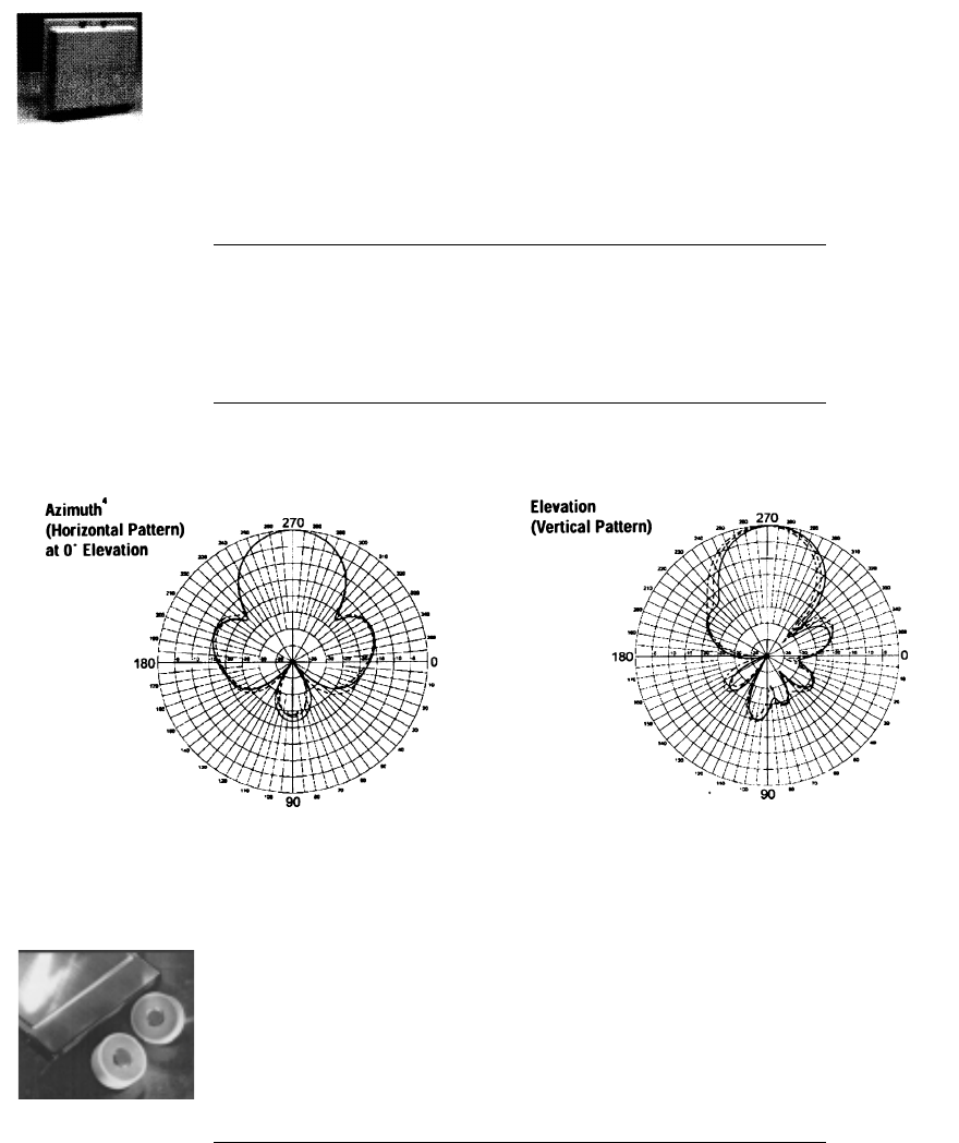
■ DIRECTIONAL ANTENNA
A range of one mile can be achieved if a line-of-sight position is
established using two ZoomAir 13.0 dBi Directional Antennas
Model #98110-13. The unit is designed for both indoor and outdoor
use. Connection is made through a 1-meter or 3-meter low-loss
coaxial cable (sold separately). Cable length may be extended to a
maximum recommended 6 meters by attaching additional cable
segments using a supplied adapter. Mounting/positioning hardware
is included.
Model 98110-13 Specifications
Frequency range 2.3-2.500 GHz
Gain113.0 dBi
Polarization2Linear
Azimuth and elevation beamwidth 35’
Nominal impedance 50 ohms
Lightning protection DC grounded
Connector Reverse polarity SMA female (jack)
Dimensions 8.7”W(22.1cm) x 7.9”H(20.1cm) x 1.4”D(3.6cm)
Weight 0.77 lb (0.35 kg)
Up to1 mile(1.6km) point-to-point unobstructed line of sight
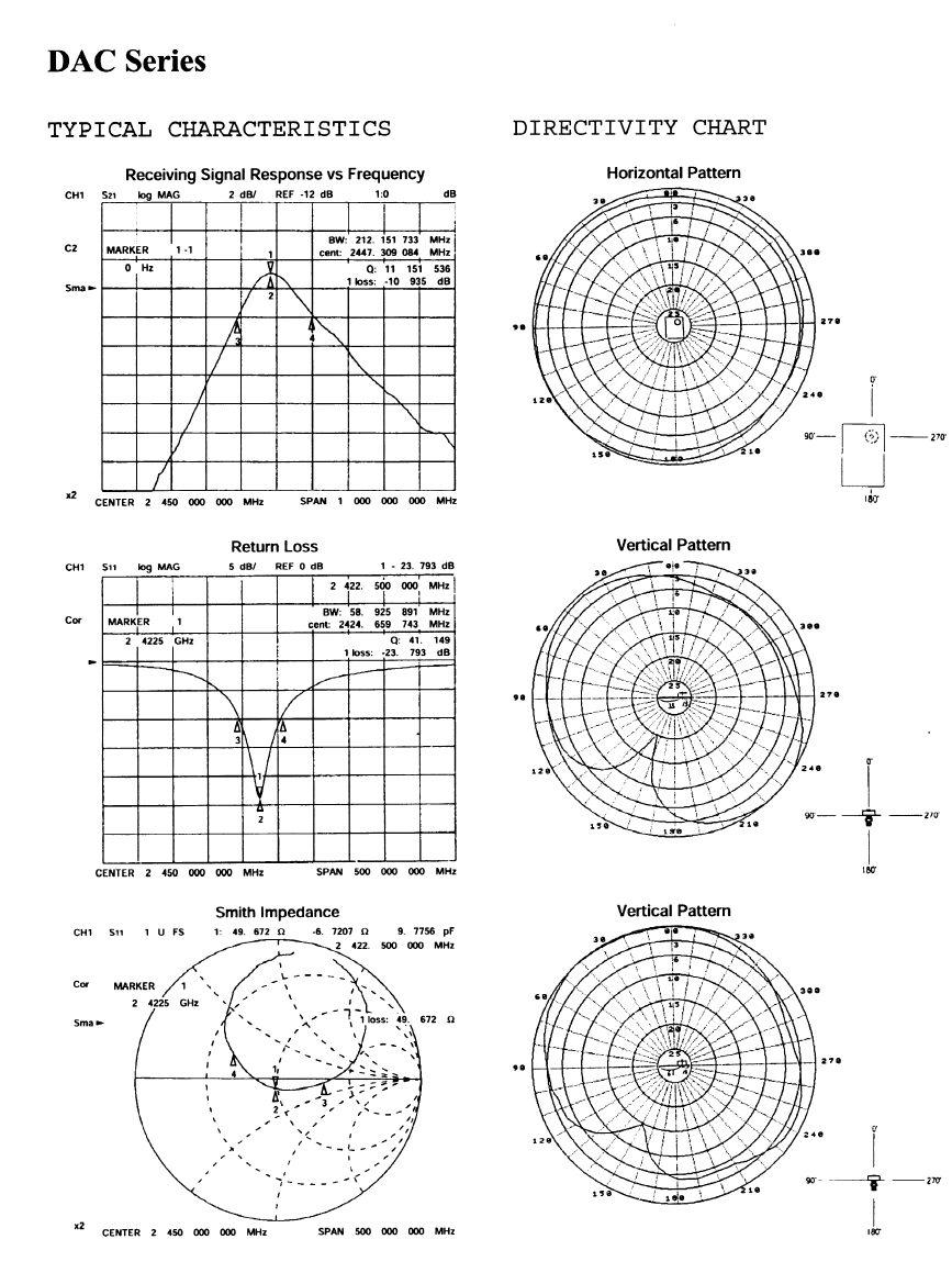
■ MINIATURE DIELECTRIC ANTENNA
The ZoomAir 2.15 dBi Miniature Dielectric Antenna Model #98110-21 is
supplied to OEM’s for installation within their equipment. The antenna
attaches to the ZoomAir 11Mbps Wireless Network Interface Card with
a 6 inch supplied cable.
Model 98110-21 Specifications
Frequency range 2.4-2.5 GHz
Gain 2.15 dBi
Polarization2Vertical
Nominal impedance 50 ohms
Connector Reverse polarity SMA male (plug)
Dimensions 3”W(76mm) 2”H(50mm) wide .382”D (9.7mm)
Weight .14 oz (4g)

98110-02
98110-04
2.2 dBI dipole onmi-directional antenna with an
SMA male (plug) connector – rated at 300 ft. (90m)
coverage in a typical indoor office and over 1,000
ft. (300m) space in an open environment. Provided
as standard equipment with the 11 Mbps ZoomAir
with an external attenna Wireless Network
Interface Card and ZoomAir Hardware Access
Points.
4.0 dBic (circular) omni-directional antenna with an
SMA female(jack) bulk-head connector for
improved indoor coverage or point-to-point
application use. Typical range: 450 ft.(135m) in an
office environment and 1500 ft.(450m)
unobstructed point-to-point application use.
Mounting hardware included.
98110-13
98112-3
98112-1
98110-21
13 dBi directional patch antenna with SMA female/jack
connector (for indoor or outdoor use) provides up to 1
mile point-to-point range. Includes fully adjustable
mounting bracket.
3-meter low-loss cable with SMA male(plug) connectors
(total loss of ~1.0 dB); includes an extension adapter
(~0.2 dB loss).
1-meter low-loss cable with SMA male(plug) connectors
(total loss of ~0.5 dB); includes an extension adapter
(~0.2 dB loss).
2.15 dBi Miniature Dielectric Antenna with cable is
provided to OEMs for their installation within their
equipment.
Contact Your ZoomAir Dealer or Visit www.zoom.com
Footnotes:
1 Gain: Decibel (dBi or dBic for circular) expression for the ratio of the
radiation intensity in a given direction relative to a theo-retical isotropic
(omni-directional) radiator.
2 Polarization (Linear): A pattern requiring antennas to be placed in the same
orientation with close attention to polarization alignment angle (alignment
should be within ±5° for optimum performance).
3 Polarization (Right-hand circular): A pattern that reduces the effects of
reflections in a typical indoor environment (best suited as an access point).
4 Azimuth: The radiation intensity pattern located in the horizontal plane.
5 Installation must comply with FCC RF exposure requirements.
Important Installation Note:
ZoomAir and its resellers or distributors are not liable for
injury, damage, or violation of government regulations, or state
and local codes, associated with the installation and use of
ZoomAir antenna products. Professional antenna installers are
recommended if there are any questions, concerns, unknowns,
or liability risk with the handling of these products.
Antenna Products and Application Summary

ANTENNA
INSTALLATION INSTRUCTIONS
Caution: For the purpose of satisfying FCC RF exposure compliance requirements, antennas
should be positioned in such a way that a separation distance of at least 20cm is maintained
between the transmitter’s radiating structures and the body of the user or nearby persons.
■ DIPOLE ANTENNA
Remove the antenna from the box. You’ll notice that the antenna is L-shaped and the
short part of the L has a built-in connector with a silver hexagonal collar. The ZoomAir
Card’s mating connector has a knurled brass collar.
To maintain consistent antenna orientation, hold the antenna vertically and gently tighten
the hexagonal collar on the antenna body until the antenna stays in place. Do not attempt
to turn the knurled brass collar on the PC Card. It is glued in place.
■ OMNI-DIRECTIONAL ANTENNA
1. Carefully remove the existing dipole antenna: Gently unscrew the hexagonal collar on
the antenna body. Do not attempt to turn the knurled brass collar on the PC
Card. It is glued in place.
2. Attach one end of the cable* to the omni-directional antenna and the other to the
ZoomAir PC Card. Again, be careful of the collar glued in place.
3. 3A. If you are using a ZoomAir Hardware Access Point, mount the antenna in a
central location as an “umbrella” to provide optimal coverage.
3B. If you are using ZoomAir in a point-to-point application, mount both antennas so
that they are facing each other in a line of sight orientation.
■ DIRECTIONAL ANTENNA
1. Carefully remove the existing dipole antenna: Gently unscrew the hexagonal collar on
the antenna body. Do not attempt to turn the knurled brass collar on the PC
Card. It is glued in place.
2. Attach one end of the cable* to the directional antenna and the other to the ZoomAir
PC Card. Again, be careful of the collar glued in place.
3. Using the supplied universal mounting and positioning hardware, position the antenna
in a vertical orientation so that the receiving antenna is in the line of sight.
■ MINIATURE DIELECTRIC ANTENNA
1. Mount the antenna as per OEM requirement
2. Attach one end of the cable* to the ZoomAir PCMCIA Card. Again, be careful of the
collar glued in place.
3. Attach the other end of the cable* to the antenna.
* Sold separately See Antenna Options for Selection Information.
Zoom is a registered trademark. ZoomAir is a trademarks of Zoom Telephonics, Inc.
All other registered trademarks and trademarks used herein are the property of their respective holders.
©2000 Zoom Telephonics, Inc. 25657-C
Note: If you later want to reposition the antenna due to orientation changes, you must first
loosen the antenna’s hexa
g
onal nut
,
re
p
osition the antenna
,
and then reti
g
hten the nut.
Note: With the omni-directional and directional antennas, you can couple cables to achieve a
recommended maximum len
g
th of 6 meters before ex
p
eriencin
g
an unacce
p
table si
g
nal dB loss.
ZOOM World Headquarters
Zoom Telephonics, Inc., 207 South Street, Boston, MA 02111 USA
Tel: 617-423-1072 Fax: 617-423-3923
www.zoom.com