Zoom R24 Users Manual
R24 to the manual 86d9579d-d9dd-46f8-a24e-95513bc01dd2
2014-12-13
: Zoom Zoom-R24-Users-Manual-134754 zoom-r24-users-manual-134754 zoom pdf
Open the PDF directly: View PDF ![]() .
.
Page Count: 36
© ZOOM Corporation
Reproduction of this manual, in whole or in part, by any means, is prohibited.
AUDIO INTERFACE MANUAL

1
Audio interface manual
Contents
Contents . . . . . . . . . . . . . . . . . . . . . . . . . . . . . . . . . . . 1
Audio interface and control surface . . . . . . . . . . . . . . . . . . . . . 3
Cubase LE 5 Installation overview . . . . . . . . . . . . . . . . . . . . . . 5
Audio interface . . . . . . . . . . . . . . . . . . . . . . . . . . . . . . . . . . . . . . . 5
Control surface . . . . . . . . . . . . . . . . . . . . . . . . . . . . . . . . . . . . . . . 5
R24 Audio Interface system requirements . . . . . . . . . . . . . . . . . . 6
Cubase LE 5 Startup Guide . . . . . . . . . . . . . . . . . . . . . . . . . . . . . . . . . 6
Connecting and disconnecting in audio interface mode. . . . . . . . . . . . 7
Connecting the R24 to a computer for the first time . . . . . . . . . . . . . . . . . . . . . 7
R24 setup and connection . . . . . . . . . . . . . . . . . . . . . . . . . . . . . . . . . . 7
Disconnecting . . . . . . . . . . . . . . . . . . . . . . . . . . . . . . . . . . . . . . . . 8
Using control surface functions . . . . . . . . . . . . . . . . . . . . . . . 9
About the control surface . . . . . . . . . . . . . . . . . . . . . . . . . . . . . . . . . . 9
Control surface setup . . . . . . . . . . . . . . . . . . . . . . . . . . . . . . . . . . . . 9
Transport section . . . . . . . . . . . . . . . . . . . . . . . . . . . . . . . . . . . . . .10
Fader section operation . . . . . . . . . . . . . . . . . . . . . . . . . . 11
About banks . . . . . . . . . . . . . . . . . . . . . . . . . . . . . . . . . . . . . . . . .11
Operating the fader section . . . . . . . . . . . . . . . . . . . . . . . . . . . . . . . . .11
R24 level meters (Audio interface use). . . . . . . . . . . . . . . . . . . . . . . . . . . .12
Setting the function keys . . . . . . . . . . . . . . . . . . . . . . . . . . 13
Function key setup . . . . . . . . . . . . . . . . . . . . . . . . . . . . . . . . . . . . . .13
Control surface functions quick reference guide . . . . . . . . . . . . . . 14
Recording with Cubase LE 5 . . . . . . . . . . . . . . . . . . . . . . . . 15
Create a new project . . . . . . . . . . . . . . . . . . . . . . . . . . . . . . . . . . . . .15
Create a new audio track . . . . . . . . . . . . . . . . . . . . . . . . . . . . . . . . . .16
Connect an instrument . . . . . . . . . . . . . . . . . . . . . . . . . . . . . . . . . . . .17
Adjust the recording level . . . . . . . . . . . . . . . . . . . . . . . . . . . . . . . . . .18
Recording . . . . . . . . . . . . . . . . . . . . . . . . . . . . . . . . . . . . . . . . . .19
Check the recording (playback) . . . . . . . . . . . . . . . . . . . . . . . . . . . . . . .19
Importing audio data into Cubase LE 5 . . . . . . . . . . . . . . . . . . . 21
Importing by drag & drop . . . . . . . . . . . . . . . . . . . . . . . . . . . . . . . . . .21
Using the “Import” command . . . . . . . . . . . . . . . . . . . . . . . . . . . . . . . .23

2
Audio interface manual
The mixer in audio interface mode . . . . . . . . . . . . . . . . . . . . . 25
Volume, reverb send, pan . . . . . . . . . . . . . . . . . . . . . . . . . . . . . . . . . .25
Stereo link . . . . . . . . . . . . . . . . . . . . . . . . . . . . . . . . . . . . . . . . . .25
Balance . . . . . . . . . . . . . . . . . . . . . . . . . . . . . . . . . . . . . . . . . . .25
Tuner . . . . . . . . . . . . . . . . . . . . . . . . . . . . . . . . . . . 26
Chromatic tuner . . . . . . . . . . . . . . . . . . . . . . . . . . . . . . . . . . . . . . .26
Effects in audio interface mode . . . . . . . . . . . . . . . . . . . . . . . 27
INSERT effect . . . . . . . . . . . . . . . . . . . . . . . . . . . . . . . . . . . . . . . .27
SEND return effect . . . . . . . . . . . . . . . . . . . . . . . . . . . . . . . . . . . . . .27
Working with patches . . . . . . . . . . . . . . . . . . . . . . . . . . . . 28
Patch operations . . . . . . . . . . . . . . . . . . . . . . . . . . . . . . . . . . . . . . .28
Patch initialization (factory reset) . . . . . . . . . . . . . . . . . . . . . . . . . . . . . . .28
Control surface setup for other DAWs . . . . . . . . . . . . . . . . . . . 29
Logic . . . . . . . . . . . . . . . . . . . . . . . . . . . . . . . . . . . . . . . . . . . . .29
SONAR . . . . . . . . . . . . . . . . . . . . . . . . . . . . . . . . . . . . . . . . . . . .30
Live. . . . . . . . . . . . . . . . . . . . . . . . . . . . . . . . . . . . . . . . . . . . . .31
Digital Performer . . . . . . . . . . . . . . . . . . . . . . . . . . . . . . . . . . . . . . .32
3
Audio interface manual
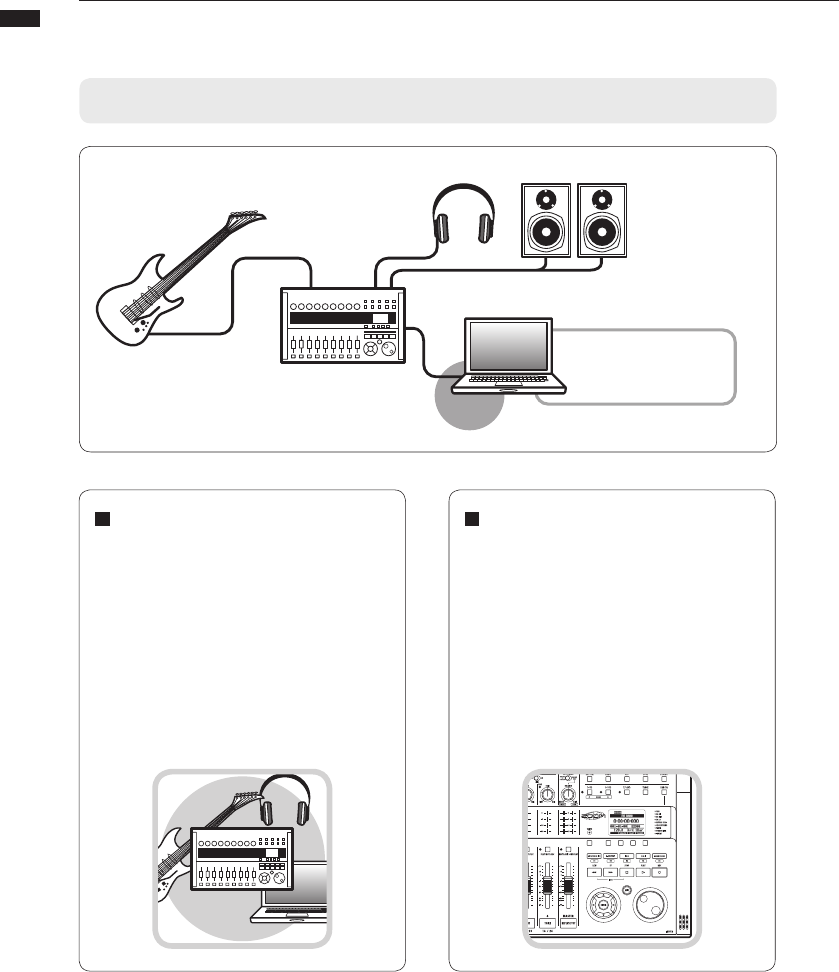
Audio interface and control surface
Functions of the audio interface and control surface
This section explains how to connect the unit with a computer and how to set up and
use the audio interface and control surface functions of the R24 with a DAW and other
software.
Control surface functions
On-board control surface functions can be
used to control DAW software on a com-
puter via USB. Transport operations, in-
cluding playback, recording and stopping,
and physical control of the DAW faders
are possible. Furthermore, various other
DAW software functions can be mapped
to the F1~F5 keys (assignable functions
depend on the DAW used).
DAW software
Cubase LE 5, etc.
Windows/Mac
USB Cable
R24
[PHONES] jack
Playback device like
headphones or an
audio system
[OUTPUT] jacks
Stereo system,
speakers with built-in
amplifiers, etc.
[INPUT 1-8] jacks
Guitars and other
musical instruments,
built-in stereo mic
Audio driver
Audio interface
The R24 has numerous inputs and outputs
and it can be used as a Hi-Speed USB
(USB 2.0) audio interface with 8 inputs
and 2 outputs at quality up to 24-bit/96
kHz. Effects can be used when the sam-
pling rate is 44.1 kHz, and the unit can be
powered by a computer’s USB bus.
4
Audio interface manual
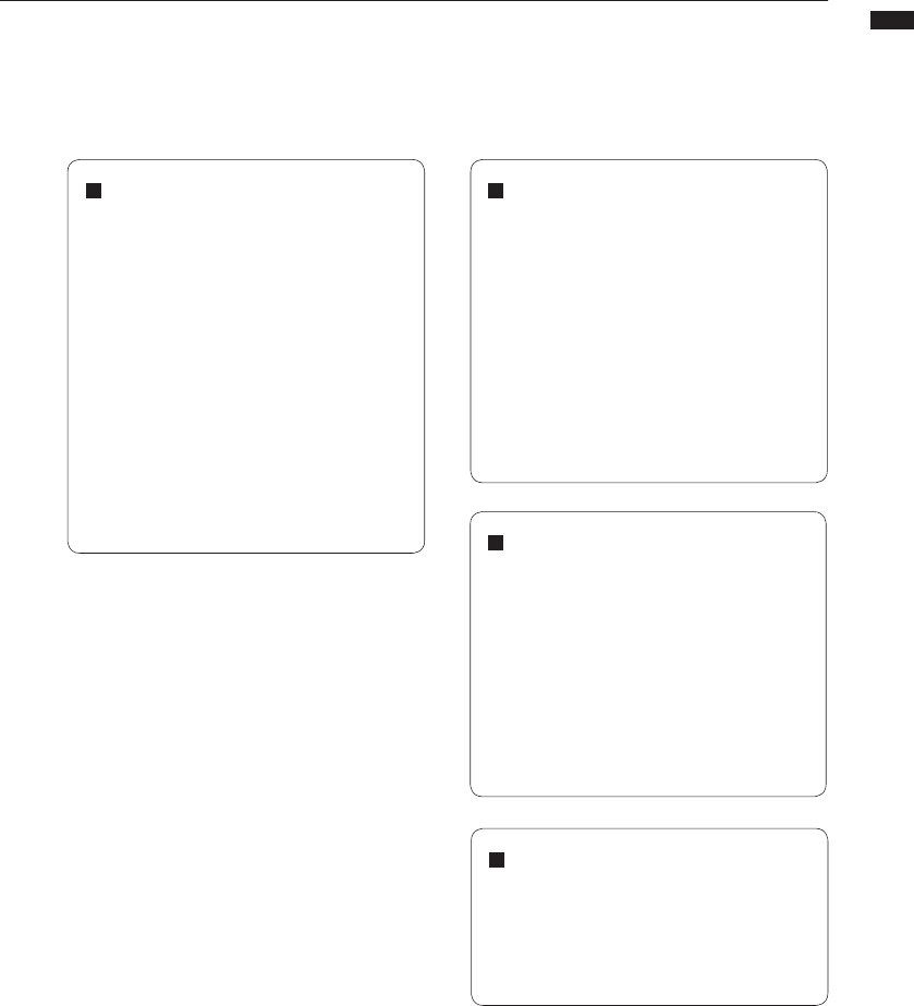
Multifunction tuner
In addition to standard chromatic tuning,
the on-board multifunction tuner also sup-
ports 7-string guitar, 5-string bass and
various drop tunings.
Comprehensive built-in mixer
Using the R24’s mixer, you can make a
mix for monitoring. When simultaneously
recording guitar and vocals, for example,
you can adjust volume balance, panning
and reverb levels.
Moreover, you can also adjust the balance
between the built-in mixer and the sound
sent from a computer.
Versatile effect functions
Built-in insert effects can be applied to
specific channel paths, and two-types
of send/return effects work via the mixer
send/return. These effects can be applied
when recording, of course, but they can
also be applied to only the monitor output.
For example, when recording vocals, you
can apply reverb only to the monitor sig-
nal to make singing easier.
Supports input from a variety of
sources, including guitars, mics and
line level instruments
The 8 onboard jacks accept XLR and
standard phone plugs and include one
high-impedance input and two inputs with
phantom power (24V or 48V).
Many sources are supported from high-
impedance guitars and basses to dynamic
and condenser microphones and line-
level devices like synthesizers. In addition,
built-in high- performance condenser
microphones are convenient for recording
acoustic guitars and vocals.
5
Audio interface manual
❶ ❷
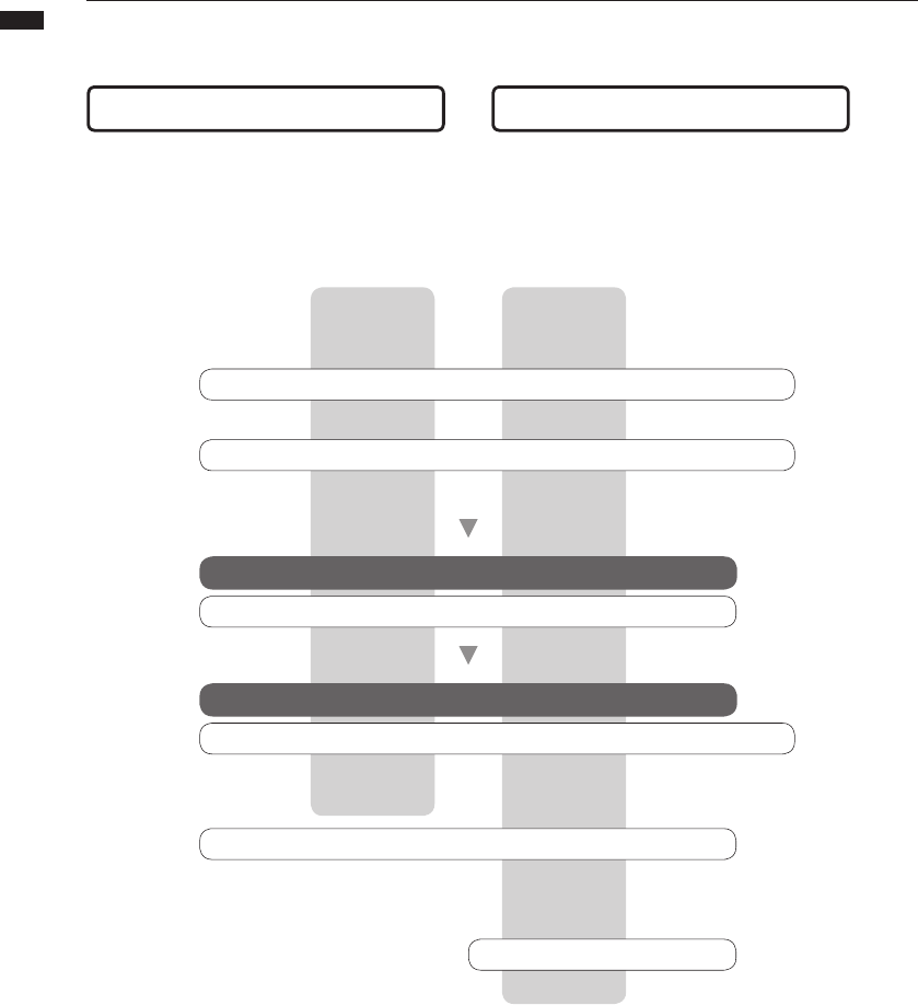
Cubase LE 5 installation overview
By using the R24 between a computer and
external audio devices and instruments, their
signals can be recorded using a DAW or other
software. Instruments and mics that require
Hi-Z or phantom power can also be connected.
Using the faders and keys on the R24, you can
control transport operation and mixing in digi-
tal audio workstation (DAW) software on your
computer.
To use the R24 with DAW software, after installing that software, a driver must be
installed and set to recognize it. We explain how to do this with Cubase LE 5.
Install DAW software
Install driver
ZOOM R16/R24 audio driver
Audio interface setup
Connect R24 to computer P.7
Device setup
Control surface setup P.9, 29~
ZOOM R16/R24 audio driver
Mackie Control
DAW software setup
Cubase LE 5
❶ Audio interface ❷ Control surface
Recording P.15
Reference: "Cubase LE 5 Startup Guide"
Reference: "Cubase LE 5 Startup Guide"
Reference: "Cubase LE 5 Startup Guide"
6
Audio interface manual
R24 Audio Interface system requirements
Please refer to the Cubase LE 5 Startup Guide
for detailed instructions for installing the R16/
R24 audio driver and Cubase LE 5.
R24 Audio Interface system
requirements
Cubase LE 5 installation guide
Windows
Windows® XP SP2 or later (32-bit)
Windows® Vista SP1 or later (32-bit, 64-bit)
Windows® 7 (32-bit, 64-bit)
32-bit: Intel® Pentium® 4 1.8 GHz or faster
64-bit: Intel® Pentium® Dual Core 2.7 GHz or faster
32-bit: RAM 1 GB or faster
64-bit: RAM 2 GB or faster
Intel Mac
OS X 10.4.11 or later/10.5 or later/10.6
Intel® Core Duo 1.83 GHz or faster
RAM 1 GB or faster
Both
USB 2.0 compatible port
• USBhubsarenotsupported.
• Intel® chipsets recommended.
Note about descriptions and images
This manual was prepared based on use with Win-
dows systems. Special functions related to Mac OS
X are indicated separately.
The screen images are of the Windows version.
About trademarks
• The SD symbol and SDHC symbol are trademarks.
• Windows®, Windows® XP, Windows Vista® and Windows 7® are registered trademarks of Microsoft®
in the USA.
• Macintosh® and Mac OS® are trademarks of Apple Inc.
• Steinberg and Cubase are registered trademarks of Steinberg Media Technologies GmbH Inc.
• Intel® and Pentium® are trademarks of Intel Corporation.
• MACKIE Control is a registered trademark of LOUD Technologies.
• Logic is a trademark of Apple Inc.
• SONAR is a trademark of Cakewalk, Inc.
• Ableton Live is a trademark of Ableton AG.
• Digital Performer is a registered trademark of Mark of the Unicorn.
• All other product names, registered trademarks, and company names mentioned in this documentation
are the property of their respective owners.
In order to improve the product, specifications might be changed without advance notice.
7
Audio interface manual
Connecting and disconnecting in audio interface mode
This is an overview of connecting and disconnecting the R24 to a computer with a USB
cable. For details, see the included Cubase LE 5 Startup Guide guide.
Connecting the R24 to a computer
for the first time
Install the Cubase LE 5 DAW
software on the computer.
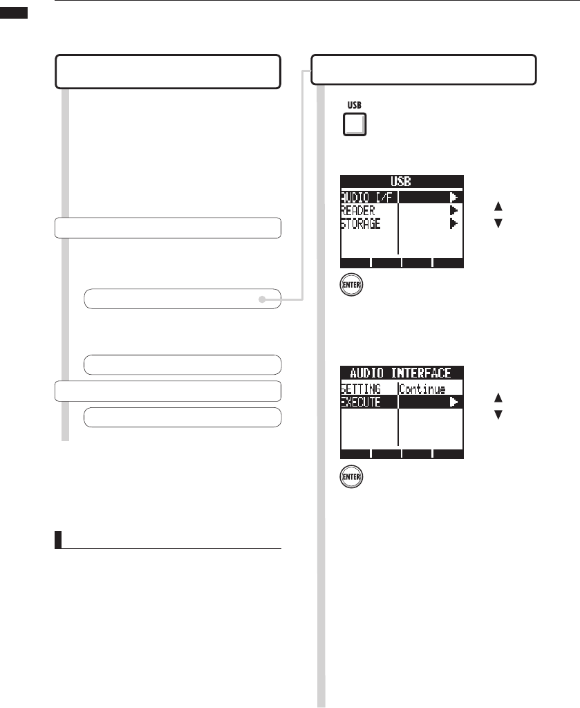
1 1 Press USB.
Install the audio driver on the
computer from the included
CD-ROM.
2
Press ENTER.
Select AUDIO I/F.
2
Press ENTER.
Select EXECUTE.
3
☞Reference: "Cubase LE 5 Startup Guide"
Installation and setup details
R24 setup and connection
Connect the R24 to a computer.
4
R24 setup and connection
Follow these procedures when connecting again.
NOTE
• The ZOOM R16/R24 audio driver is essential for
using the R24 as an audio interface with DAW
software such as Cubase LE 5.
When downloading it, follow the included instal-
lation guide to install it correctly.
• Download the latest R24 audio driver from the
Zoom Corporation website.
http://www.zoom.co.jp/
Device setup
Control surface setup P.9
Setup the DAW software.
5
☞Reference: "Cubase LE 5 Startup Guide"
Change
menu
Change
menu
Mackie Control
8
Audio interface manual
1
• The audio interface and control surface func-
tions of the R24 can be used by drawing power
through a USB cable from the USB bus.
• We recommend always using the latest R24
system software.
• When using phantom power, we recommend
using batteries or an AC adapter even when the
unit is used as an audio interface.
Press the below
Press ENTER.
Select YES.
2
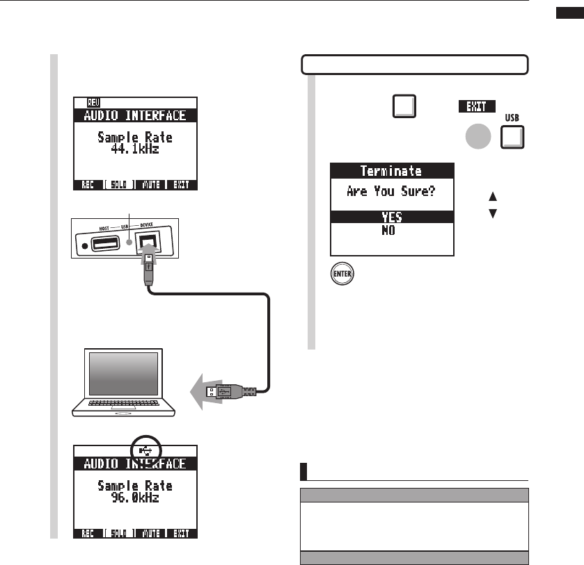
Disconnect the USB cable
3
USB DEVICE indicator lights
Connect the USB cable to the R24.
4
Connect the USB cable to the
computer.
5
USB icon appears when connection completes.
NOTE
Disconnecting
Select CONTINUE to use the same settings as last time.
•INSERTEFFECTsettings
•SENDRETURNEFFECTsettings
•Mixersettings
•TUNERsettings
Select RESET to restore default settings for each item.
Change
menu
or
.
9
Audio interface manual
Using control surface functions
When using the R24 connected by USB as an audio interface, the R24 keys and faders
can be used to control Cubase LE 5’s transport and mixer.
HINT
Assigning keys
For a listoffunctions that canbe assignedtothe
knobsandkeysofthe R24,aswellasother trans-
port/functionkeysthat are supportedbyCubase
LE5,pleaseconsultthe“Controlsurfacefunctions
quickreferenceguide”inthismanual.
About the control surface Control surface setup
In control surface mode the keys and knobs on
the R24 can be assigned to particular Cubase
LE 5 functions.
6Then, launch Cubase LE 5.
Transport section P.10
About banks P.11
Fader section P.11
☞Reference: Control surface functions quick
reference guide P.14
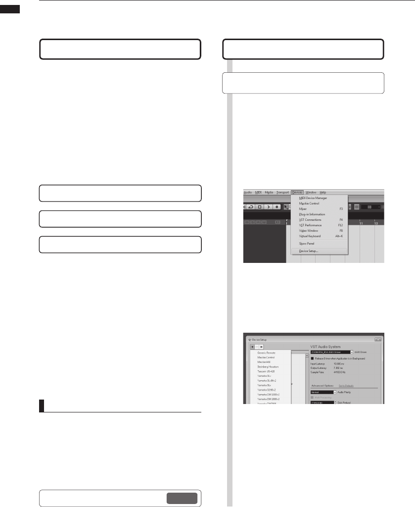
7From the Cubase LE 5 “Devices”
menu, select “Device setup…”
Open the “Device Setup…” window.
8At the top left of the Device setup
window [+], [−] and [|<] buttons
appear. Click the [+] and select
“Mackie Control”
9Set the MIDI input and output
MIDI input: ZOOM R16_R24
MIDI output: ZOOM R16_R24
See R24 setup and connection steps 1–5 on P7~8
10
Audio interface manual
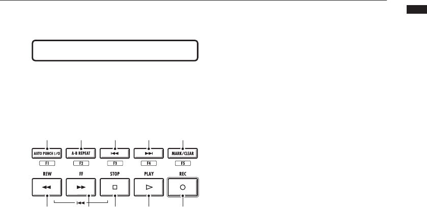
Transport section
By setting up the control surface, the R24’s
transport section keys can be assigned to indi-
vidual functions in Cubase LE 5.
[REW]
key
[FF]
key [STOP]
key [PLAY]
key [REC]
key
[F1]
key [F5]
key
[F2]
key [F3]
key [F4]
key
11
Audio interface manual
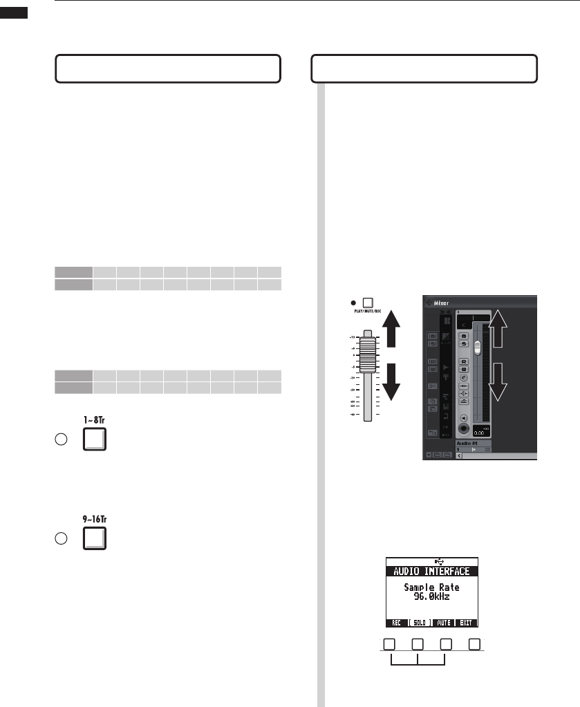
Fader section operation
Using the faders and status keys of the fader section, you can adjust the volume of
corresponding Cubase LE 5 tracks, mute and solo them, and arm them for recording.
Operating the fader section
1Assign the Cubase LE 5 tracks
(channels) that you want to control
to the fader section.
About banks
After setting up control surface operation, the
main parameters of Cubase LE 5 can be oper-
ated using the R24’s fader and status keys.
A group of tracks operated by the faders and
status keys is called a “bank.” With the R24,
one bank of 8 adjacent tracks can be con-
trolled.
For example, if fader 1 is assigned to Cubase
LE 5 track 1, tracks 1-8 can be controlled as
shown in the following diagram.
Control 1 2 3 4 5 6 7 8
Track Tr.1 Tr.2 Tr.3 Tr.4 Tr.5 Tr.6 Tr.7 Tr.8
As the diagram shows, when tracks 1~8 are
selected, pressing the [9~16tr (Bank>)] key
once switches the assignments as shown be-
low.
Control 1 2 3 4 5 6 7 8
Track Tr.9 Tr.1 0 Tr.11 Tr. 12 Tr.1 3 Tr.14 Tr. 15 Tr.1 6
1~8Tr (< BANK) key
Tracks(channels)assignedtothefadersectionare
movedbackwardbyeighttracks.
9~16Tr (BANK >) key
Tracks(channels)assignedtothefadersectionare
movedforwardbyeighttracks.
2Use the faders to control the
volumes of the corresponding
tracks.
The faders control the volumes of their re-
spective tracks. Change the master volume
by moving the [Master] Fader.
3To change the function of the
status keys for all the tracks,
press the soft key for the desired
function.
12
Audio interface manual
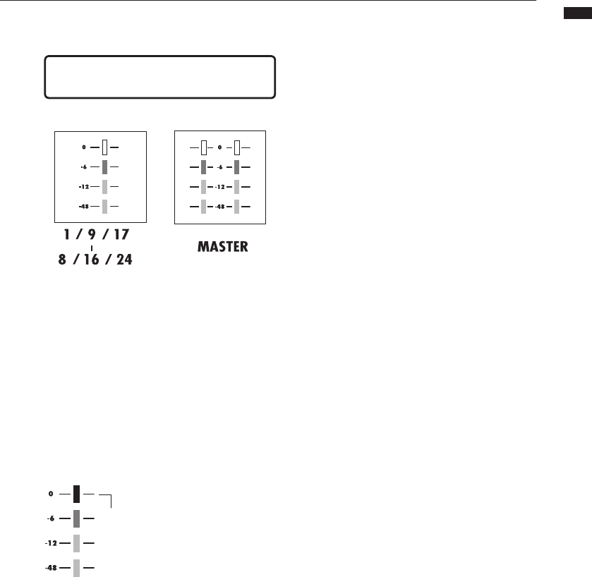
R24 level meters
(Audio interface use)
Each level meter other
than the MASTER displays
the signal immediately
before sending it to the
computer.
Themasterlevel
meterdisplaysthe
returningsignalfrom
the computer.
Checking DAW recording levels
Set “REC SIGNAL” (in the INSERT
EFFECT menu) to “WET” (signal with
effect) or “DRY” (no effect) to send
signals to the computer with or without
being processed by the insert effects.
The recording levels of the sent signals are dis-
played on the level meters. The signal shown
on the master level meter differs from that
shown on each level meter.
Adjustthelevelsso thatthe
red(0dB)clippingindicators
onthemetersdonotlight.
Red light
(clipping)
13
Audio interface manual
Setting the function keys
The ve keys above the transport keys can be used as function keys (F1~F5) and
assigned as desired.
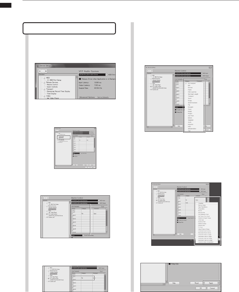
Function key setup
5
1Open the “Device setup…” dialog
in Cubase LE 5.
7Press the “Apply” button.
Choose the type of Cubase LE 5
function from the Category pop-up
menu.
2
Commands can be assigned using the three
columns displayed on the right side of the window.
Select “Mackie Control”.
3From the “Button” column choose
the function key (F1~F5) to be
assigned a Cubase LE 5 function.
6Click on the “Command” column
and select the desired Cubase LE
5 function from the pop-up menu.
The items in this pop-up menu will differ depending
on the category chosen.
4Click on the “Category” column for
that control.
14
Audio interface manual
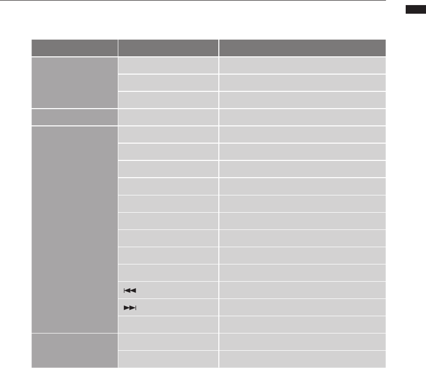
Control surface functions quick reference guide
These functions work with Cubase LE 5, Cubase 5, Logic Pro, SONAR, Ableton Live
and Digital Performer.
Control Explanation
Fadersection
Statuskeys Turnsmute,soloorrecordarmingon/offforthetrack
Faders Controlsthevolumeofthecorrespondingtracks
MASTERFader Mastervolumeoperation
Displaysection Soft keys Changefunctionsofstatuskeys/Endconnection(EXIT)
Transportsection
Cursorkeys Performsthesamefunctionsasthecomputerarrowkeys1
DIAL Movestheprojectcursorposition2
REWkey Rewind
FFkey Fastforward
STOPkey Stop
PLAYkey Play
RECkey Record
AUTO PUNCH I/Okey Dependsonthe[F1]keysetting
A-B REPEATkey Dependsonthe[F2]keysetting
(marker)key Dependsonthe[F3]keysetting
(marker)key Dependsonthe[F4]keysetting
MARK/CLEARkey Dependsonthe[F5]keysetting
Controlsection
1-8Trkey Movesonebankforward
9-16Trkey Movesonebankbackward
1Scrolls window in Digital Performer
2No function in Digital Performer
15
Audio interface manual
Recording with Cubase LE 5
In this chapter, we explain how to record into Cubase LE 5 using the R24.
Create a new project
Copy the ZOOM R24 project templates
to the computer.
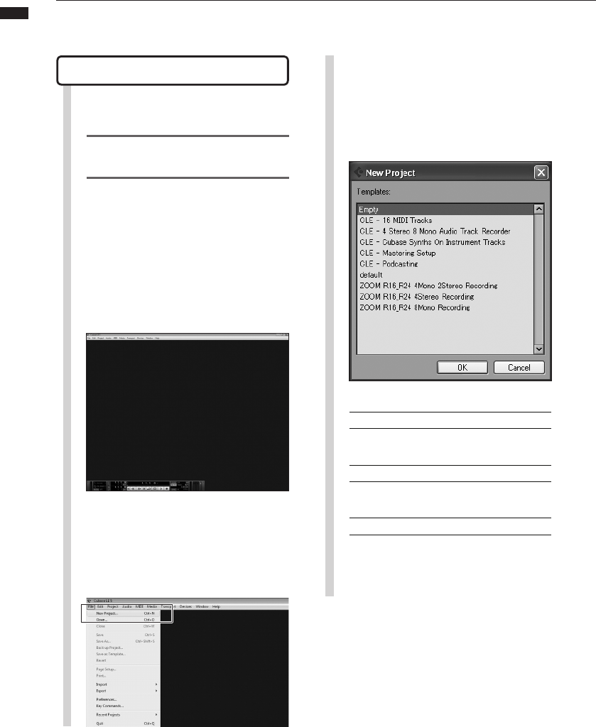
Launch Cubase LE 5.
1
2Choose “New Project” from the File
menu.
Choose a new project template from the New
Project Window.
Windows
C:\Program Files\Steinberg\Cubase LE 5\tem-
plates
Macintosh
/Applications/CubaseLE5.app/Contents/tem-
plates/
From the CubaseLE5_template folder on the
CD included with R24, copy the templates to the
location where Cubase LE 5 is installed.
3Create a new project
After copying the R24 project templates to
the designated folder, the R24 project tem-
plates will be displayed when creating a new
project. By choosing these templates you will
be able to easily create projects with audio
track input and output settings already ar-
ranged for the R24.
Template names and details
ZOOM R16_R24 8Mono Recording
Project with Cubase LE 5 mono tracks 1~8
assigned to R24 INPUTS 1~8
ZOOM R16_R24 4Stereo Recording
Project with Cubase LE 5 stereo tracks 1~4
assigned to R24 INPUTS 1/2 ~ 7/8
ZOOM R16_R24 4Mono 2Stereo Recording
Project with Cubase LE 5 mono tracks 1~4
assigned to R24 INPUTS 1~4 and Cubase LE 5
stereo tracks 5~6 assigned to R24 INPUTS 5/6 and
INPUTS 7/8
16
Audio interface manual
NOTE
Theinspectordisplaysinformationaboutthetrack
currently selected.If itdoesnotdisplay anything
clickonatracktoseethattrack’sstatus.
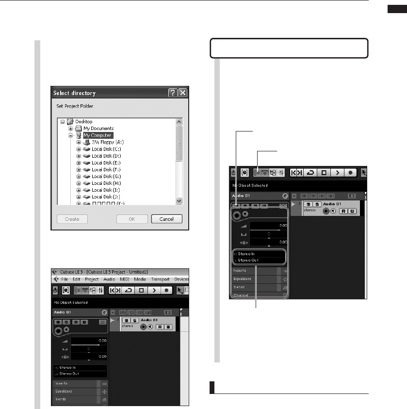
Create a new audio track
5Set-up the audio tracks that were
made as follows.
The project file save location window is displayed.
4Set the save location and click the
“OK” button (“Choose” button on
Mac OS X).
This will create a new project and the project
window where most Cubase LE 5 operations are
conducted will open.
Inspector area allows setting of detailed track
information
If the inspector is not shown, click
here to show/hide the inspector
Select the track input/output bus.
The names of the R24 busses assigned in
the VST Connections (Devices menu) will be
displayed.
Click here to choose a different bus from the
menu.
To add a new audio track, select “Add Track” from
the “Project” menu and then choose “Audio” from
the sub-menu that appears.
17
Audio interface manual
Recording With Cubase LE 5
HINT
WhentheMonitorbuttonislit,theaudiotrackinput
levelwillbedisplayedinthelevelmeternexttothe
fader.When the light isoff,theaudiotrack output
levelwillbedisplayed.
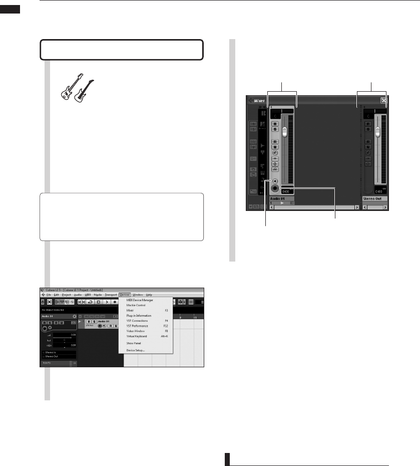
Connect an instrument
6
Connect an instrument such as a
guitar to an R24 INPUT jack and
choose an effect patch.
The chosen effect patch will be applied to the signal
and recorded on the computer via the USB port.
7Select “Mixer” from the Cubase LE
5 “Devices” menu.
The mixer window opens, showing the channels
corresponding to the created tracks and the
master channel.
☞Reference:R24OperationManual
Selectinganinputsignal
Selectinganeffectpatch
See the following for information about how to
choose the R24 input signal.
8Enable the track for recording.
Master Channel
Click the Monitor
button until it lights
orange.
Click the record enable
button. It will light red
and recording will be
enabled.
Channel corresponding
to an audio track
18
Audio interface manual
NOTE
• If the Monitor button is on, the R24 input signal
and the signal returning to the R24 via the
computer will both be output from the R24 at
the same time. This can create a flanger-like
sound. To monitor accurately while adjusting the
recording level, turn the BALANCE knob toward
DIRECT.
• The meter above shows the signal level after it
has been processed internally by Cubase LE 5.
For this reason, a slight delay might occur from
the time a string is plucked until the level meter
moves; this is not a defect.
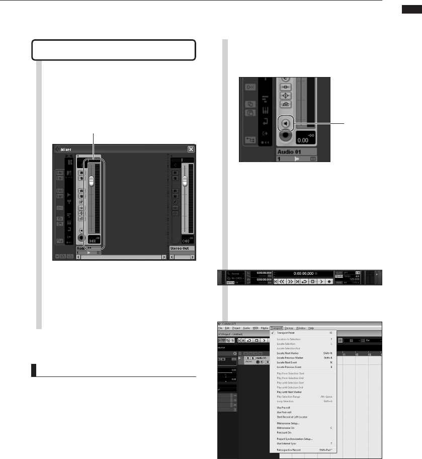
Adjust the recording level
9While playing the instrument,
adjust the R24 input level and set
the Cubase LE 5 recording level.
The recording level for Cubase LE 5 can be
checked by viewing the level meter of the
corresponding channel of the recording-enabled
track. Please set it as high as possible without
making the meter peak.
When adjusting the level, do not move the Cubase
LE 5 fader, but instead use the fader and adjust
the gain on the R16.
Level Meter
10
11
After adjusting the recording level,
click the Monitor button to turn off
the light.
Monitor
button
This turns off display of the input level, and mutes
the signal from the computer to the R24.
When the Monitor button is off, the signal just
before it is sent to the computer can be monitored
from the R24 PHONES and OUTPUT jacks.
Conrm that the Transport Panel is
displayed
If the Transport Panel is not displayed, select
“Transport Panel” from the “Transport” menu.
19
Audio interface manual
Recording with Cubase LE 5
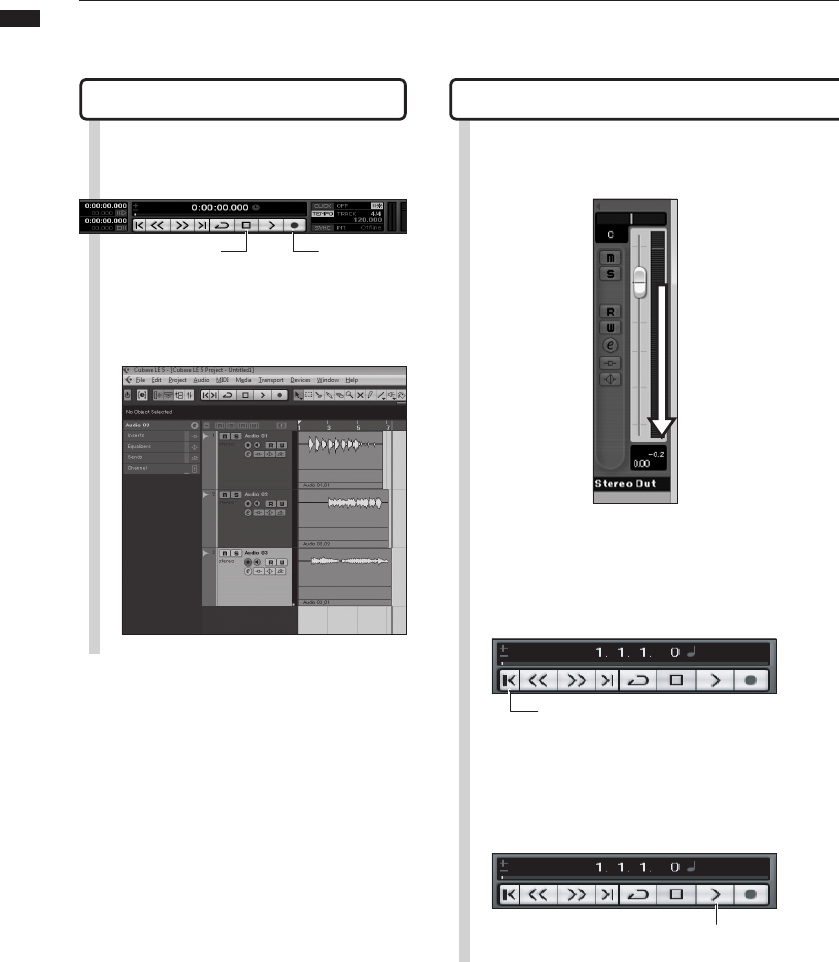
Check the recording (playback)Recording
12 1
Click the Record button on the
Transport Panel to start recording.
Stop button
As you play the instrument, a recorded waveform
is drawn in real time in the project window.
To stop recording, click the Stop button in the
transport panel.
Lower the master channel fader.
2Click the |< button in the Transport
Panel to return to the beginning of
the project.
Return to the beginning of the project
3Click the Play button in the
Transport Panel to begin playback.
Play button
Record button
20
Audio interface manual
Tips to improve performance
When using Cubase LE 5, application perfor-
mance could become extremely delayed or
error messages such as “cannot synchronize
with USB audio interface” might be dis-
played. Should such occurrences become
frequent, the following measures might im-
prove the situation.
➊ Terminate programs other than
Cubase LE 5 that are running.
In particular, confirm that many background
applications are not running.
➋ Reduce the use of plug-ins
(effects, virtual instruments)
If a large number of plug-ins are running, the
computer processing capacity might not be
able to keep up. In addition, reducing the
number of simultaneous playback tracks
might be effective.
➌ Use the R24 AC adapter
When devices draw power from the USB
bus, on rare occasions computer perfor-
mance can suffer. Try using the AC adapter.
If the sound breaks up, please increase the
Audio Buffer Size in the Device Setup…
menu > VST Audio System window.
For details, see Step 5 of the Cubase LE 5
Startup Guide.
Moreover, if the application performance is
extremely slow and regular computer op-
eration is affected, we recommend quitting
Cubase LE 5 and disconnecting the R24
USB port from the computer once, and then
reconnecting the USB port and relaunching
Cubase LE 5.
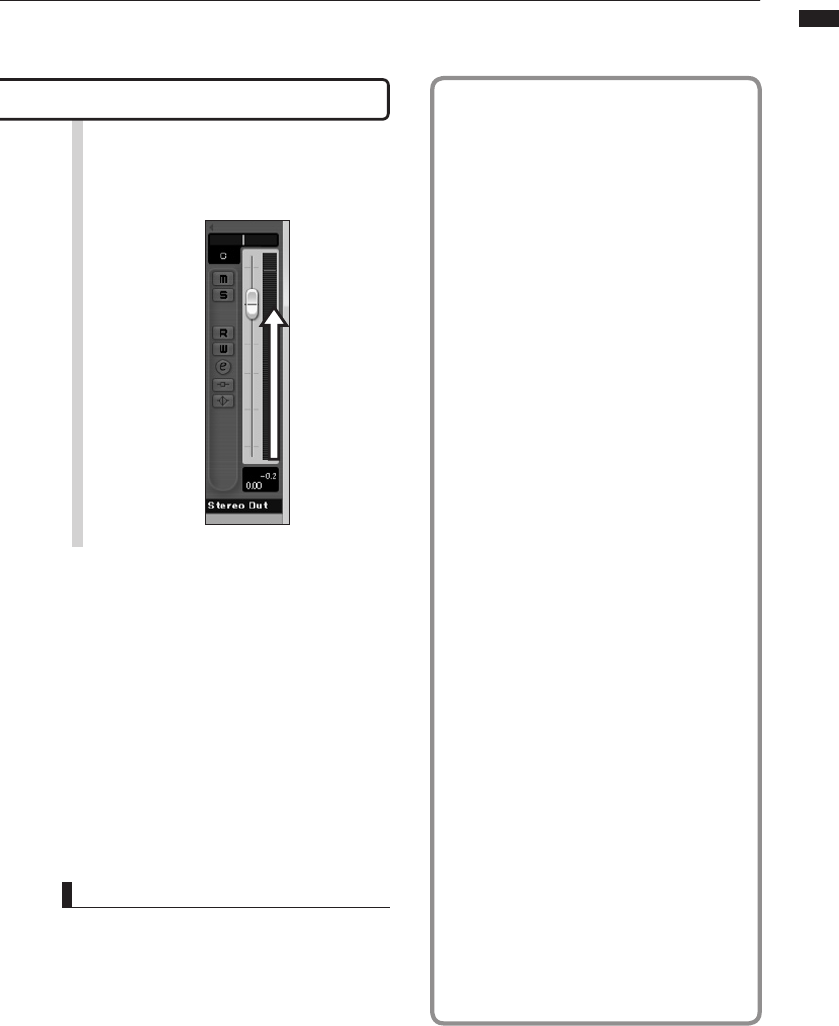
Check the recording (playback)
HINT
If no sound comes out after clicking the Play button
following recording, recheck the VST Connections
(step 6 in the Cubase LE 5 Startup Guide).
In addition, conrm that the BALANCE control is at
the center.
4Raise the master channel fader to a
suitable playback level.
21
Audio interface manual
Importing audio data into Cubase LE 5
By connecting a computer and the R24 with a USB cable and setting the R24 to
function as a card reader, you can import audio data as WAV les into Cubase LE 5
audio tracks.
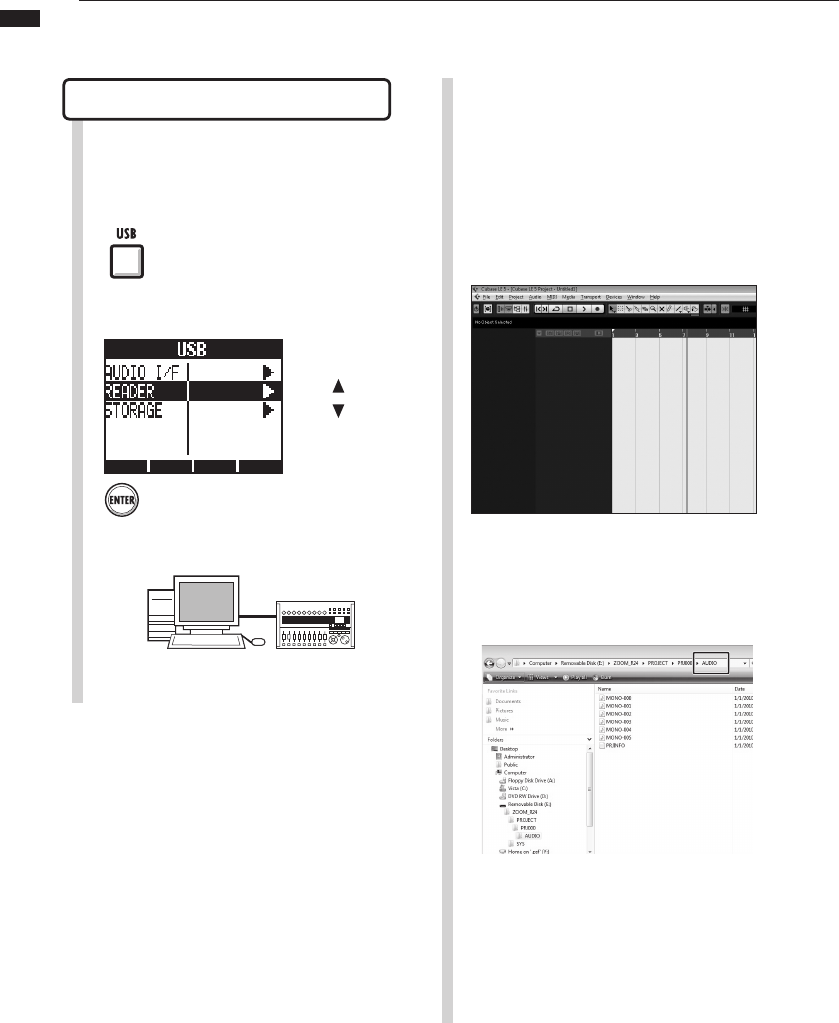
Importing by drag & drop
4Launch Cubase LE 5.
6Open the R24 SD card from the
computer and open the “AUDIO”
folder of the project from which you
want to import audio data.
5Open the Cubase LE 5 project into
which you want to import audio
data.
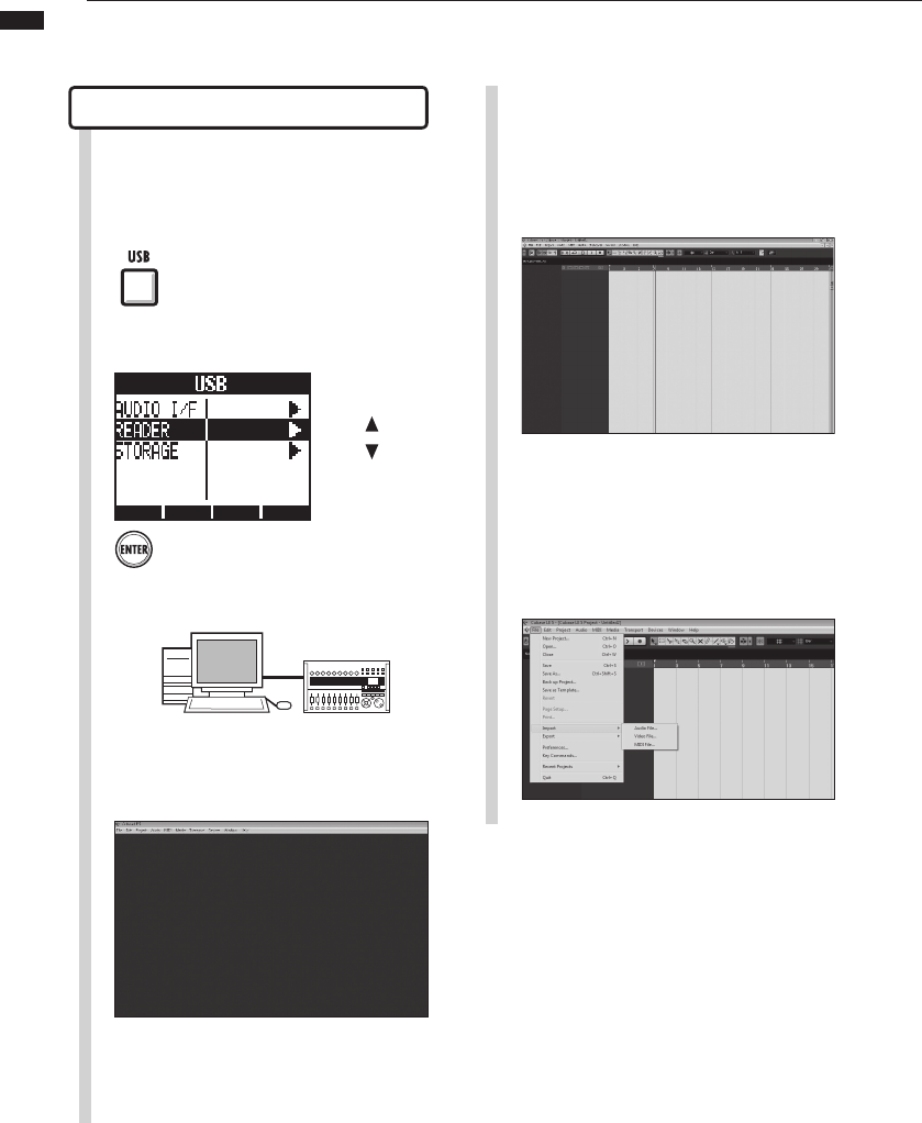
1Connect the computer and the R24
DEVICE port with a USB cable.
2Press USB.
Press Enter.
3Select READER.
コンピューターからR24を操作
Change
menu
Access the R24 from the computer.
22
Audio interface manual
HINT
• The USB cable can be connected even when the
computer or the R24 is on.
• If the R24 is connected when off, it can be run on
USB bus power.
• Project data is stored in folders for each project
in the PROJECT folder in the ZOOM_R24 folder.
Audio recordings are stored as WAV files in
the “AUDIO” subfolders of each project folder.
Each AUDIO folder also contains a file called
“PRJINFO.TXT” that lists the names of files
assigned to tracks.
• Master tracks and stereo tracks are stereo
WAV les.
• To copy a WAV le from a computer, copy it to
the AUDIO subfolder of the desired project folder
Use the R24 to assign the les to tracks.
In the “Import Options” window
click the “Copy Files to Working
Directory” check box, and click the
OK button.
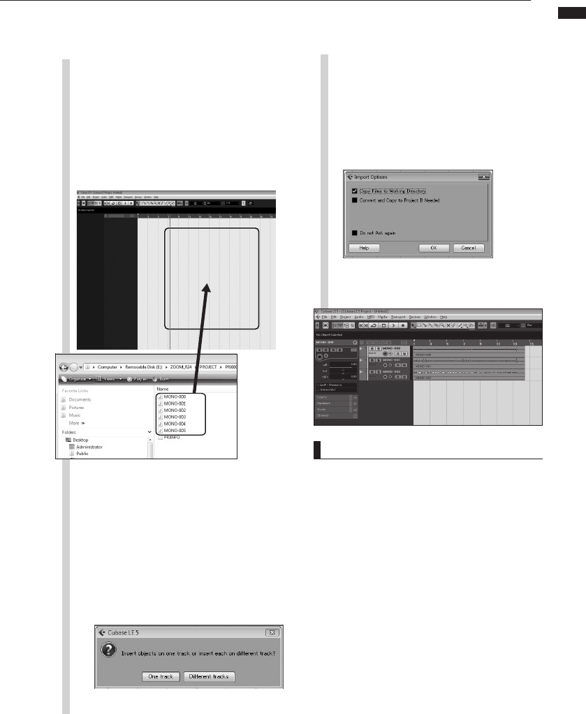
7 9
Select the le (or les) that you
wish to import from the “AUDIO”
folder and drag and drop them into
the Cubase LE 5 project window.
When a file is dragged and dropped, a
window will open asking how Cubase
LE 5 should place the file.
When dragging multiple les at one
time, select either “Different Tracks” or
“One Track” as the import method.
8
Generally, select “Different Tracks” to automati-
cally create one track for each file. The files will
be arranged vertically in the project window.
Select “One track” to create one track with the
audio files arranged horizontally.
This window where you can select the import
method appears.
The audio les are loaded into
Cubase LE 5 tracks.
23
Audio interface manual
Importing audio data into Cubase LE 5
From the Cubase LE 5 “File” menu
select “Import” and “Audio File…”
The “Import Audio” window opens.
6
1Connect the computer and the R24
DEVICE port with a USB cable.
2Press USB.
3Select READER.
Using the “Import” command
5Open the Cubase LE 5 project into
which you want to import audio
data.
Press ENTER.
コンピューターからR24を操作
Change
menu
Access the R24 from the computer.
4Launch Cubase LE 5.
24
Audio interface manual
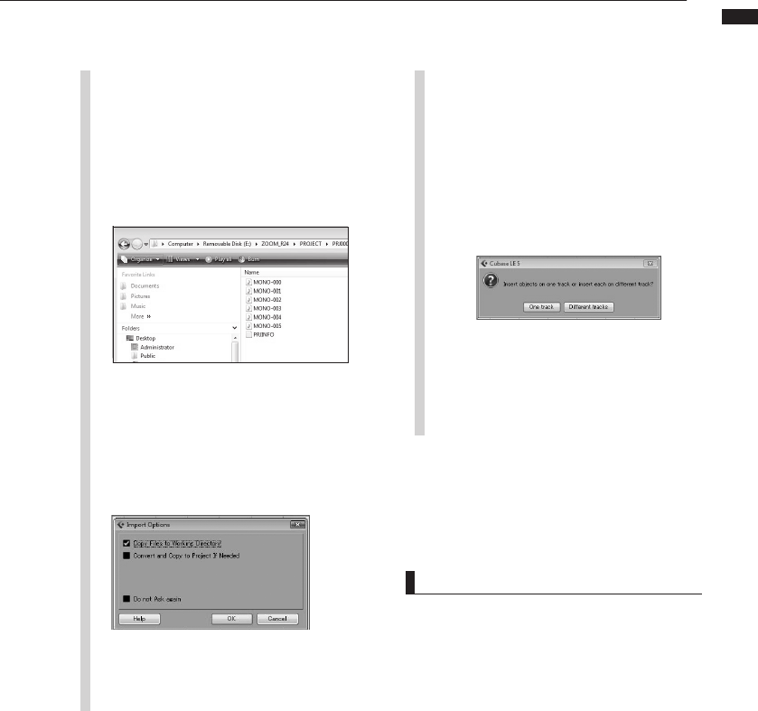
7Select the desired audio le (or
les) from the “AUDIO” folder of
the project from which you wish to
import. Click “Open.”
Importing files will cause the “Import Options”
window to appear.
8In the “Import Options” window
click the “Copy File to Working
Directory” check box, and click the
OK button.
When a le is imported, a window
will open asking how Cubase LE 5
should place the le.
When importing multiple les at
one time, select either “Different
Tracks” or “One Track” as the
import method.
9
The audio data is assigned to one or more Cubase
LE 5 tracks.
Generally, select “Different Tracks” to
automatically create one track for each
file. The files will be arranged vertically in
the project window.
Select “One track” to create one track
with the audio files arranged horizontally.
HINT
• The USB cable can be connected even when the
computer or the R24 is on.
• If the R24 is connected when off, it can be run on
USB bus power.
• Project data is stored in folders for each project
in the PROJECT folder in the ZOOM_R24 folder.
Audio recordings are stored as WAV files in
the “AUDIO” subfolders of each project folder.
Each AUDIO folder also contains a file called
“PRJINFO.TXT” that lists the names of files
assigned to tracks.
• Master tracks and stereo tracks are stereo
WAV les.
• To copy a WAV le from a computer, copy it to
the AUDIO subfolder of the desired project folder
Use the R24 to assign the les to tracks.
25
Audio interface manual
The mixer in audio interface mode
In audio interface mode you can make a mix for monitoring using the R24’s internal
mixer. In addition, you can adjust the balance of the internal mixer and the sound from
the computer.
NOTE
Thereverbsend, pan,volumeandstereolink
settingsareallsaved whenyouterminate(EXIT)
audiointerfacemode andcanbe usedagainthe
nexttime.
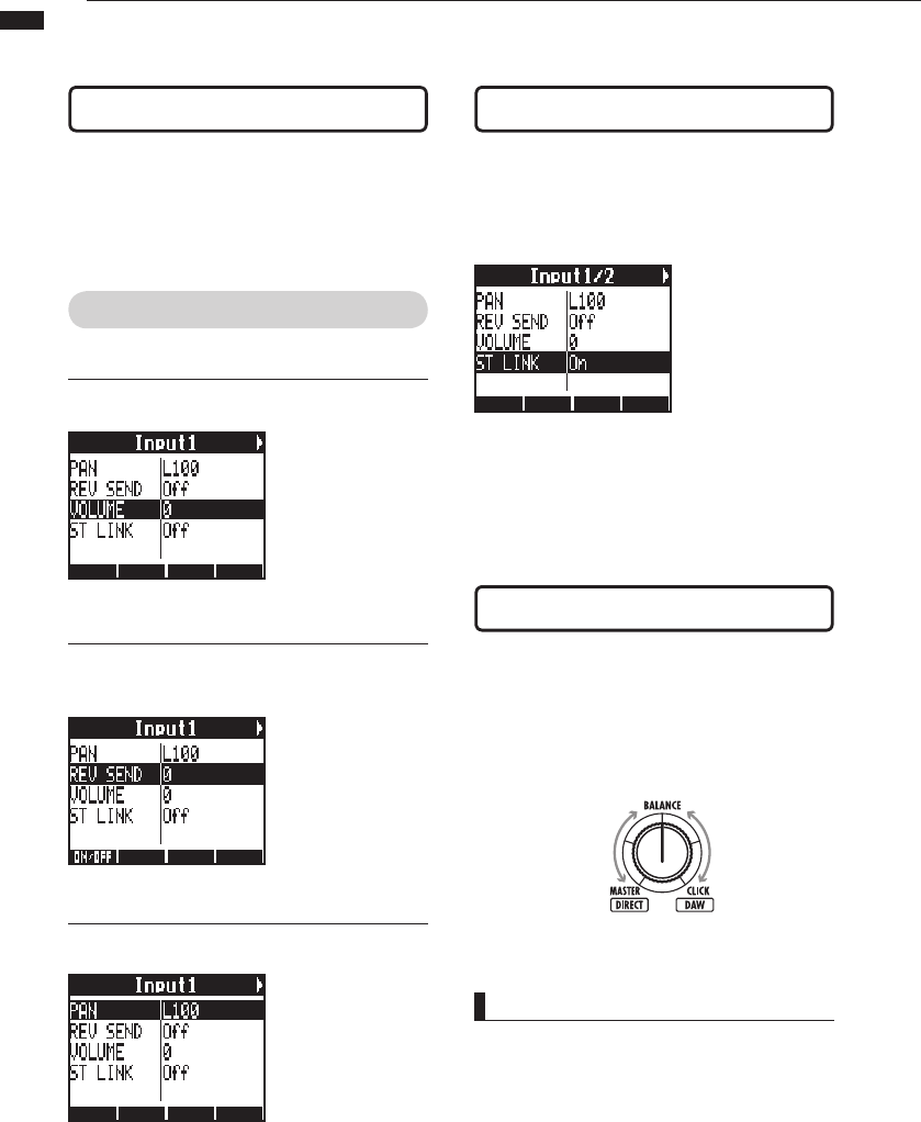
You can be adjust the reverb send, pan, vol-
ume and stereo link settings as in recorder
mode.
Operation is the same as in recorder mode.
(Reference: OPERATION MANUAL)
PAN/EQ menu
VOLUME
Adjust the volumes of INPUTS 1~8.
0~127 (increments of 1)
Default value: 100
REV SEND
Adjust the reverb send levels of INPUTS 1~8.
0~100 (increments of 1)
Default value: 0
Reverb only affects the
monitored signal (as in
recording mode).
PAN (BALANCE)
Adjust the pan for INPUTS 1~8.
L100~R100
(increments of 2)
Default value: Center
(as in recording mode)
Link even and odd numbered INPUTS to handle
them as stereo pairs.
On/Off
Default setting: Off
By setting up a stereo link, volume, reverb send and pan
track parameters can be shared by pairs of even and odd
inputs simultaneously (as in recording mode).
(Reference: Operation Manual)
Volume, reverb send, pan
Balance knob
In audio interface mode, the balance of the in-
put monitoring signal and the signal from DAW
software (the computer) can be adjusted with
the BALANCE knob.
Stereo link
Left
Only the INPUT
1~8 signals
Right
Only the DAW
stereo signal
26
Audio interface manual
Tuner
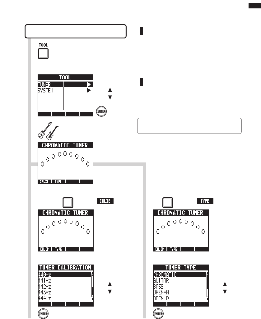
The R24 tuner can be used as when recording. For details, see the Operation Manual.
1Press TOOL.
Select TUNER.
2
Press
ENTER.
Press ENTER.
Chromatic tuner
TOOL > TUNER
4To change the standard pitch,
press the beneath .
5Select the standard pitch.
NOTE
Tunersettingsaresavedwhenyouterminate(EXIT)
audiointerfacemode andcanbe usedagainthe
nexttime.
HINT
• The default value of the standard pitch is 440 Hz.
• Tuners other than the chromatic tuner can also
be used.
Re
ference: Operation Manual
)
☞Reference: Operation Manual
Tuner
Change
menu
Change the
standard pitch
Press ENTER.
4To change the tuner type, press
the beneath .
5Change the tuner type.
Change the
tuner type
3Tune the instrument.
27
Audio interface manual
Effects in audio interface mode
The R24’s insert and send-return effects can both be used when the sampling
frequency is set to 44.1 kHz. Basic operation is the same but there are a few
differences in the menus.
NOTE
• Effects can only be used when the sampling rate
is 44.1 kHz. At all other times it is turned OFF.
• Insert and send return effect settings are saved
when you terminate (EXIT) audio interface mode
and can be used again the next time.
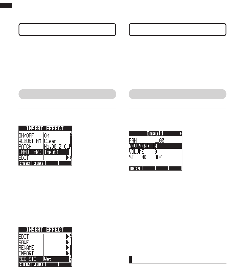
Insert effect Send return effect
As in recording mode, you can select the insert
location and the insert effect algorithm, as well
as the effect patches to be applied to the sig-
nal being recorded.
INSERT EFFECT menu
Select the insert location
Insert on any INPUT 1~8.
(Reference: Operation Manual )
Apply the effect only to monitoring
The effect can be set to only be applied to the monitoring
signal and to not affect signals recorded in DAW software.
(Reference: Operation Manual )
As in recorder mode, use the SEND REVERB
menu to change the patch and use the PAN/EQ
menu to set the REV SEND level that adjusts the
reverb depth.
Setting the reverb send level
REVERB SEND
Adjust the amount of reverb using the REV
SEND level of the PAN/EQ menu.
(Reference: Operation Manual )
(Reference:
Audio interface manual – Mixer
)
28
Audio interface manual
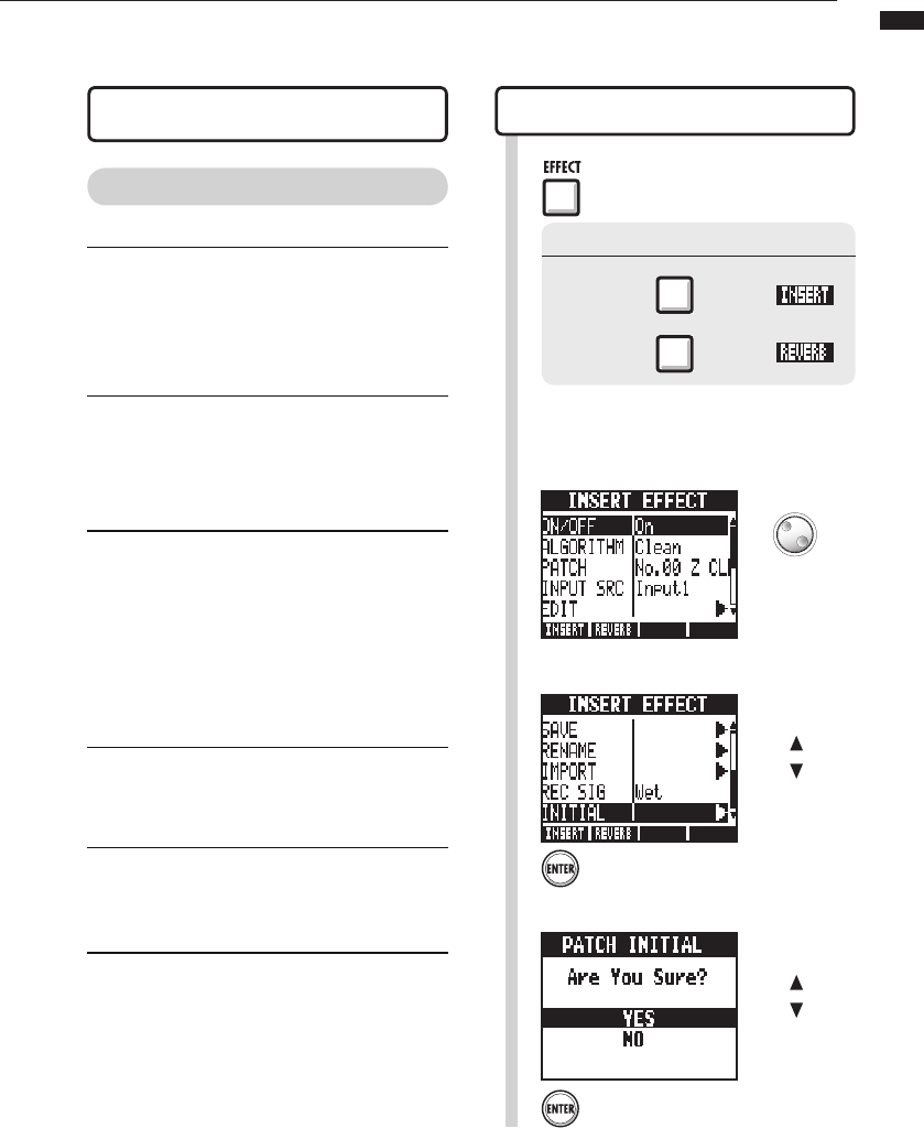
Working with patches
After making many changes, you can restore a patch to its pre-edited settings by
initializing it. This will return it to its factory preset condition.
1Press EFFECT.
Turning effects on/off
Insert effect
Send return effect
Patch initialization (factory reset)
EFFECT > INITIAL
Selecting insert effect/reverb patches
To use an insert effect, select an algorithm and
a patch.
To use a send reverb effect, select a patch.
(Reference:
Operation Manual
)
Editing patches (EDIT)
By adjusting effect module parameters and
levels, you can create the desired result. (Refer-
ence:
Operation Manual
)
Importing patches (IMPORT)
All effect algorithms (and reverb patches) or
a single one can be imported from a selected
project on the R24.
(Reference: Operation Manual )
In audio interface mode, one complete set of effect
data is saved for the mode. There are no project
based settings.
Saving patches (SAVE)
Edited patches can be saved.
(Reference: Operation Manual )
Initializing patches (INITIAL)
Restores patches to their original factory set-
tings (only available in audio interface mode).
Changing patch names (RENAME)
The name of the currently selected patch can
be changed.
Patch operation menu
Patch operations
For both insert and send return effects
The following example is of an insert
effect.
Press the beneath .
Press the beneath .
Turn the effect On.
2
Select INITIAL.
3
Press ENTER.
Change
menu
4Select YES.
Press ENTER.
Change
menu
Change
29
Audio interface manual
Control surface setup for other DAWs
You can set up the R24 as a controller for use with a variety of DAW software besides
Cubase LE 5. Please refer to the manual for the software that you are using.
Logic
Control surface setup Function key setup
Select “Preferences” >
“Control surfaces” > “Setup…”
from the “Logic Pro” menu.
This opens the “Setup” window.
Click on the top left “New” and
select “Install” from the pull-down
menu.
Select “Mackie Designs/Mackie
Control/Logic Control” from the list
in the “Install” window and click
the “Add” button.
“Mackie Control” will be added to
the setup window.
Click the “Mackie Control” icon.
Then, from the top of the list at the
left set “Out Port” and “Input” to
“ZOOM R16_R24” using their pull-
down menus.
Select “Preferences” >
“Control surface” > “Controller
Assignments…” from the “Logic
Pro” menu.
This opens the “Controller
Assignments” window.
From the “Zone” column select
“Control Surface: Mackie Control.”
Change the functions as you like.
Controls F1~F5 correspond to the
F1~F5 keys on the R24.
The above procedures are for Logic
Pro 9.
The names of the menus, for
example, might be different in a
different version of Logic.
Please refer to the manual for the
version of Logic that you are using
for details.
1 1
33
4
22
30
Audio interface manual
SONAR
Control surface setup Function key setup
Select “Controller/Surface” from
the “Options” menu to open the
“Controller/Surface” dialog.
If a controller/surface has already
been selected, click on the “Delete”
button to delete it.
Click the “Add” button and open
the “Controller/Surface Setup”
dialog.
Choose “ZOOM R16_R24” from the
drop-down menu of the “Controller/
surface” column.
Select “ZOOM R16_R24” in the
input/output port column.
For Cakewalk SONAR, installation
of a control surface plug-in is
necessary. Please install it when
installing the driver.
Choose “Option key bind” to open
the “Key bind” dialog.
Press “Search for the key” in
“Setup”.
Press the F1-F5 key that you
want to setup to see the currently
assigned function. Change that
function as necessary.
The above procedures are for
Sonar 7.
The names of the menus, for
example, might be different in a
different version of Sonar.
Please refer to the manual for the
version of Sonar that you are using
for details.
1 1
3
3
2
2
HINT
The F1~F5 keys on the R24 are labeled as follows.
F1:AUTO PUNCH I/O key
F2:A-B REPEAT key
F3: (marker)key
F4: (marker)key
F5:MARK/CLEAR key
31
Audio interface manual
Control surface setup for other DAWs
Live
Control surface setup Function key setup
Select “Preferences” from the
“Option” (Windows) or “Live” (Mac)
menu.
The Preferences window will open.
Click the “MIDI” setting tab on the
left side of Preferences window to
select it.
The setup window related to MIDI
will open.
Select “Mackie Control” in the pull-
down menu of the Control Surface
column.
Select “ZOOM R16_R24” from the
pull-down menus of the Input and
Output columns.
In the MIDI Ports section below,
turn “On” the Remote column
button for the “Input: Mackie
Control Input (Zoom R16_R24)”
item.
Press the MIDI button at the top
right of the main LIVE window to
open MIDI map mode.
Interface elements that can be
assigned will be highlighted in blue.
Click on a parameter that you want
to control.
Press the F1~F5 key of the R24
that you want to use to control the
selected parameter in Live.
The above procedures are for
Ableton Live 8.
The names of the menus, for
example, might be different in a
different version of Live.
Please refer to the manual for the
version of Live that you are using for
details.
1 1
3
3
4
5
22
HINT
The F1~F5 keys on the R24 are labeled as follows.
F1:AUTO PUNCH I/O key
F2:A-B REPEAT key
F3: (marker)key
F4: (marker)key
F5:MARK/CLEAR key
32
Audio interface manual
Digital Performer
Control surface setup
Function key setup
Launch the Audio MIDI Setup
application (/Applications/Utilities).
Open the MIDI Studio window
(Window > Show MIDI Window)
and conrm that “ZOOM R24” is
displayed.
Click “Add Device.”
A “new external device” will be
added.
Click the “new external device” to
select it, and then click the “Show
Info” button.
Enter the name “R24” in the “Device
Name” eld.
Click and drag the downward arrow
of the original “ZOOM R24” icon
and connect it to the downward
arrow of the “R24” icon that you
added.
Use same method to connect the
upward arrows.
Launch Digital Performer
Select “Control Surface Setup”
from the “Setup” menu to open the
Control Surface window.
1
9
10
11
12
3
4
5
6
7
8
2
Click the “+” icon in the Control
Surface window and select “Mackie
Control” from the “Driver” pull-
down menu.
Select “Mackie Control” from the
“Unit” pull-down menu that will be
displayed at bottom.
Select “R24” from the “MIDI” pull-
down menu of the Control Surface
window and select “R24-1” from
the menu list.
Click the “OK” button.
The above procedures are for Mac
OS X 10.6 and Digital Performer 5.
The names of the menus, for
example, might be different in a
different version of Digital Performer.
Please refer to the manual for the
version of Digital Performer that you
are using for details.
The functions are already assigned in Digital Performer
and cannot be changed.
AUTO PUNCH I/Okey: SelectsYESindialogboxes
A-B REPEATkey: SelectsNOindialogboxes
(marker)key: Createsgroups/trackgroups
(marker)key: Noassignment
MARK/CLEARkey: Noassignment
Refer to sections about Mackie Control dialog boxes
and track groups in the manual for the version of Digital
Performer that you are using.

4-4-3 Kandasurugadai, Chiyoda-ku, Tokyo 101-0062 Japan
Web Site: http://www.zoom.co.jp
R24-Audio Interface Manual-E-1
NOTE
To use Cubase LE 5 continuously, it is necessary to have the User
Registration and the Software License Authentication. The Registration and
Authentication are available to be processed when Cubase LE 5 is
activated on a computer connected to the internet. Click “Register now”
which is shown when activating, enter all the items. If it is not recognized as
Registration, Cubase LE 5 can only be used for a limited period after
installation.
“PDF Manuals and Drivers” CD-ROM supplied with R24
Drivers>Windows>32bit or >64bit “Setup.exe”
or
Download the latest “ZOOM R16/R24 Audio Driver”
from ZOOM homepage (http://zoom.co.jp)
and install it on a computer.
ZOOM R16/R24 Audio Driver software is required to enable use of
Cubase LE 5 for audio input and output with a computer. Refer to
the "R16_R24 ASIO Driver Installation Guide_Windows.pdf"
included in the download package for instructions on how to install
the driver correctly.
32bit folder:Windows® XP SP2 later(32bit) / Windows® Vista SP1
later(32bit) /Windows® 7 later(32bit)
64bit folder:Windows® Vista SP1 later(64bit) /Windows® 7 later
(64bit)
[How to install the driver]
Double-click Setup.exe file to activate the installer.
Continued overleaf
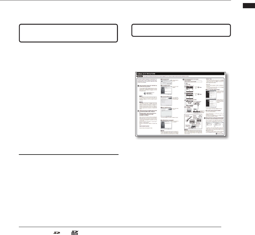
Cubase LE5 Starting Manual R24-E-1
Cubase LE 5
Startup Guide
This Cubase LE 5 Startup Guide explains how to install Cubase LE 5 on a computer, make connections and other settings for the R24.
Windows
To connect the R24 to a computer running Windows 7 (or
Windows Vista, XP) and to enable audio input/output,
proceed as follows. The installation description uses
Windows 7 as an example.
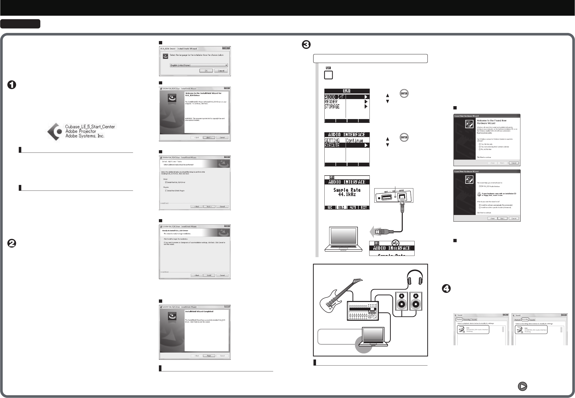
Insert the supplied “Cubase LE 5” DVD-ROM into
the DVD drive of the computer.
When you insert the DVD-ROM, a screen asking what you want to
do appears. Select "Cubase_LE_5_Start_Center.exe". A language
selection screen will appear. Select your language, and then follow
the on-screen prompts.
Start to “Found New Hardware Wizard”
•Windows 7 / Vista
When you connect the R24 to the computer, the message
"Installing device driver software" appears. When the software
installation is completed, the message "The device driver
software installed correctly" appears.
•Windows XP
When the connection is operated on the R24, it is recognized by
the computer.
If this is the first time to connect the R24, wait until the message
“Your devices are ready to use” appears.
“Found New Hardware Wizard completed”
Click [Finish] to complete installation.
When connected operation on the R24 side is finished, it is
recognized by the computer.
Connects the first time,Please wait until the message of "The
device was able to be prepared" is displayed.
Click [Next] to start
installation.
If you use SONER,
select Installation Plug
In for Control Surface.
Click [Install] to start
installation.
Click [Complete] to
finish installation.
Choose [No, not this
time]of Windows Update
and click[Next].
Choose [Install the
software automatically]
and click [Next]to start
installation.
If nothing happens when you insert the DVD-ROM, open the Start menu
and select “Computer” (“My Computer” in Windows XP). Then
double-click the “Cubase LE 5” DVD-ROM icon to display the contents of
the DVD-ROM.
NOTE
We recommend you upgrade the system software to the latest version on
the R24. An R24 operated on an old system may not be recognized
correctly. The latest version can also be downloaded from our homepage.
NOTE
Use a high-quality USB cable and keep the connection as short as
possible. If USB bus power is supplied to the R24 via a USB cable
which is more than 3 meters in length, the low voltage warning
indication may appear.
Choose language and
click [OK].
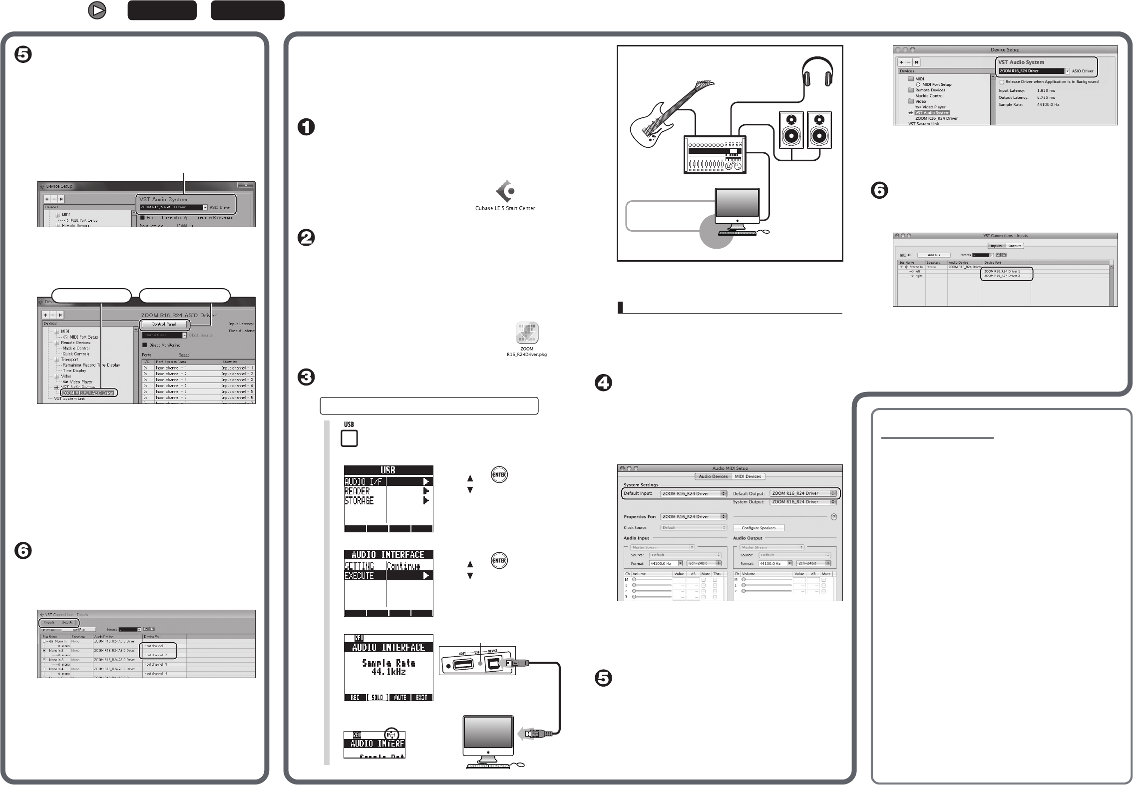
Set and connect the R24 to the computer
using a USB cable.
Connect USB cable to the R24
Menu moves
Select >AUDIO I/F
Press.
1
2
4
Connect USB cable
to computer
5
Press.
USB indicator [DEVICE] flashes
How to set and connect the R24
Set language selection
Start InstallShield Wizard
Driver-Plug In selection screen
Ready to install the program
When a warning message “Windows security” appears, click [Install].
InstallShield Wizard was completed
DAW software
Cubase LE 5 etc
Windows PC
USB cable
[PHONES]Jack
Audio system,
headphones or other
playback equipment
[OUTPUT]Jack
Audio components,
amp built-in
speakers etc
[INPUT 1-8]Jack
Guitar, other instrument or
built-in stereo mic
R24
ZOOM R16/R24 Audio Driver
If a warning dialogue “Install hardware” appears, click [Continue].
Bring up the “Sound” window from the Control Panel
and make the input device setting for the computer.
To bring up the “Sound” window, select “Control Panel” from the
Start menu and click “Hardware and Sound”, then click “Sound”.
In the “Sound” window, verify that “ZOOM R16_R24 Audio
Interface” is listed under the Play and Record devices and that the
device is checked. (To switch between Play and Record, click the
tabs at the top of the window.)
If the device is not checked, right-click on the icon for the device
and click “Set as Default Device” so that a check mark appears.
HINT
Menu moves
Select >EXECUTE
Press.
3
Icon flashes when the
connection is
complete Connection
setting completed
When the connection is operated on the R24, it is recognized by
the computer.
Open the “Applications” folder and then the
“Utilities” folder, and double-click “Audio MIDI
Setup”.
The Audio MIDI Setup screen appears. Click “Audio Devices” and
check that “ZOOM R16_R24 Driver” is selected as default
input/default output.
If another device is selected, use the pull-down menu to change
the selection to “ZOOM R16_R24 Driver”.
When the setting is done, close Audio MIDI Setup.
Start Cubase LE 5. Then access the “Devices”
menu, select “Device Setup...” and click “VST
Audio System”.
To start Cubase LE 5, double-click the Cubase LE 5 icon in the
“Applications” folder.
After startup, be sure to verify that “ZOOM R16_R24 Driver” is
selected in the right section of the Device Setup window.
Start Cubase LE 5. Then access the “Devices”
menu, select “Device Setup...” and click “VST
Audio System”
To start Cubase LE 5, double-click the Cubase LE 5 shortcut
icon which was created on the desktop.
After startup, select “ZOOM R16_R24 ASIO Driver” as the ASIO
driver in the right section of the Device Setup window. When you
change the ASIO driver selection, a confirmation message
appears. Click the “Switch” button.
The device indication in the left section of the window now shows
“ZOOM R16_R24 ASIO Driver” as the ASIO driver.
Click on this indication to select it, and then click the “Control
Panel” button in the right section of the Device Setup window.
The window which appears lets you set the buffer size for the
ASIO driver. The buffer size should be set to a value which is as
low as possible without causing sound dropouts during
recording and playback.
The sampling frequency can be changed in Cubase LE 5 in
Project Settings.
When the setting is complete, click the OK buttons in the
respective windows to return to the startup condition of Cubase
LE 5.
From the “Devices” menu of Cubase LE 5, select
“VST Connections” and set INPUT(Input channel
1 - Input channel 8) as the input port to be used
and Output channel 1, Output channel 2 as
Output port on the displayed window.
Use the tabs at top left to switch between input and output, and verify
that “Input channel 1 - Input channel 8 / Output channel 1, Output
channel 2” are selected as device ports.
If another device is selected, click the device port field and change the
selection.
Insert the supplied “Cubase LE 5” DVD-ROM into
the DVD drive of Macintosh. And start installation.
The contents of the DVD-ROM will be shown automatically. If
they are not shown automatically, double-click “Cubase LE 5”
icon displayed on the desktop.
When the content is displayed, use
"Cubase LE 5 Start Center" to perform the
installation.
Continued from front
Windows This Cubase LE 5 Startup Guide explains how to install Cubase LE 5 on a computer, make connections and other settings for the R24.
Mac OS X
NOTE
Use a high-quality USB cable and keep the connection as short as
possible. If USB bus power is supplied to the R24 via a USB cable
which is more than 3 meters in length, the low voltage warning
indication may appear.
To connect the R24 to a computer running Mac OS X and to
enable audio input/output or control R24 as control surface
for Cubase LE 5, proceed as follows.
The installation description uses Mac OS X v10.5 as an
example.
Set and connect the R24 to Macintosh
using a USB cable.
Menu moves
Menu moves
Select >AUDIO I/F
Press.
Press.
1
2
Select >EXECUTE
3
Connect USB cable to the R24
4
Press.
How to set and connect the R24
5Connect USB cable
to computer
USB indicator [DEVICE] flashes
For optimum enjoyment
While using Cubase LE 5, other applications may slow down drastically
or a message such as “Cannot synchronize with USB audio interface”
may appear. If this happens frequently, consider taking the following
steps to optimize the operation conditions for Cubase LE 5.
1) Shut down other applications besides Cubase LE 5.
In particular, check for resident software and other utilities.
2) Reduce plug-ins (effects, instruments) used
by Cubase LE 5.
When there is a high number of plug-ins, the computer's processing
power may not be able to keep up. Reducing the number of tracks for
simultaneous playback can also be helpful.
3) Power the R24 from an AC adapter.
When a device designed to use USB power is powered via the USB
port, the current supply may sometimes fluctuate, leading to problems.
See if using an AC adapter improves operation.
Please set latency from the device menu when the sound
cutting occurs. Refer: Install Guide-step5 about details.
If applications still run very slowly or the computer itself does
not function properly, disconnect the R24 from the computer
and shut down Cubase LE 5. Then reconnect the USB cable
and start Cubase LE 5 again.
DAW software
Cubase LE 5 etc USB cable
R24
[PHONES]Jack
Audio system,
headphones or other
playback equipment
[OUTPUT]Jack
Audio components,
amp built-in
speakers etc
[INPUT 1-8]Jack
Guitar, other instrument
or built-in stereo mic
ZOOM R16/R24 Driver
Macintosh
If another device is selected, use the pull-down menu to change
the selection to “ZOOM R16_R24 Driver”.
When the setting is done, click OK button and close the window.
From the “Devices” menu of Cubase LE 5, select
“VST Connections” and select the device containing
the string “ZOOM R16_R24 Driver 1 ~ 8” as input
port and output port.
Use the tabs at top center to switch between input and output, and
verify that “ZOOM R16_R24 Driver 1 ~ 8” is selected as device
port.
If another device is selected, click the device port field and change
the selection.
“PDF Manuals and Drivers” CD-ROM supplied with R24
Drivers/Mac “ZOOM R16/R24 Driver”
or
Download the latest “ZOOM R16/R24 Driver” from
ZOOM homepage (http://zoom.co.jp)
and install it on a computer.
ZOOM R16/R24 Driver software is required to enable use of
Cubase LE 5 for audio input and output with a computer.
Double-click installer (ZOOM R16_R24 Driver.pkg)
icon. Start install it according to the instruction.
Connection setting completed
Icon flashes when
the connection is
complete
ASIO Driver
This button is clicked.
Clicking here …
