Zowee Technology WL150GC 54Mbps Wireless PCI LAN Adapter User Manual WL 150G 1
Shenzhen Zowee Technology Co., Ltd. 54Mbps Wireless PCI LAN Adapter WL 150G 1
User Manual
WL-150G
User Manual
Version 1.0
PCI Adapter
1. Installation instruction ...........................................................2
1.1 System nfiguration............................................................2
1.2 Package contents.............................................................2
2. Installation guide....................................................................2
2.1 Hardware Installation .......................................................2
2.2 Install the driver and utility................................................3
2.3 Ensure the system was installed TCP/IP..........................4
3. The use of application ...........................................................5
3.1 Launch the utility .............................................................5
3.2 WLAN network.................................................................5
3.3 Connect status.................................................................6
3.4 Statistics...........................................................................7
3.5 Advanced configuration....................................................9
3.6 Configuration....................................................................9
4. Zero configuration................................................................14
5. SOFT AP...............................................................................17
5.1 Choose SOFT AP mode.................................................17
5.2 Configuration Page.........................................................18
5.3 Access Control...............................................................18
5.4 MAC list .........................................................................19
5.5 Switch to working station mode......................................20
6.Product Specifications...........................................................21
Table of Contents

1. Installation Instruction
1.1 System requirement
Before installation, please be sure that your computer meets the
followings:
With the CPU above 300MHz;
With the memory at least 32MB;
With OS Windows XP/2000/ME/98SE;
With CD-ROM(To install the CD driver).
1.2 Package contents
The following contents should be found in your box,
PCI adapter 1 PCS
Antenna 1 PCS
CD driver 1 PCS
Quick installation guide 1 PCS
If there is any damage or missing, please kindly contact your retailer.
2. Installation Guide
This chapter will guide you how to install the Wireless PCI adapter,
including hardware and software installation. This Wireless PCI adapter
supports Windows 98/Me/2000/XP,the installation here is for Windows
XP, similarly same as for other Operation System。
2.1 Hardware Installation
To install the adapter, follow these steps listed below:
1. Turn off your desktop PC and disconnect the power.
2. Open your PC case and locate an available PCI slot on the mother
board. Remove the metal slot cover on the back of the PC. Check
with your computer manufacturer for instructions if needed.
3. Slide the PCI Adapter into the PCI slot. Make sure that all of its pins
are touching the slot's contacts. Once the adapter is firmly in place,
secure its fastening tab to your PC’s chassis with a mounting screw.
Then, close your PC case.
4. Reconnect your PC’s power and turn on your desktop PC.
2
2.2 Software Installation
2.2.1 Overview
The Adapter’s Setup Wizard will guide you through the Installation
procedure.
Note: When you install the hardware before installing the software, the
system will prompt
“Found New Hardware Wizard”, click Cancel, and run the Setup Wizard
program on the
CD-ROM.
2.2.2 Software installation in Windows XP
1.Insert the Resource CD into your CD-ROM drive, open the CD driver
and choose the setup program, execute it. Figure 2-1 should then
appear.
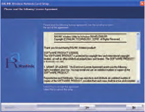
2.You can click No to end the installation on the Preparing Setup
screen, figure 2-1. Click Yes to continue the installation process, next
installation screen will appear as Figure 2-2.
Figure 2-1 Ralink Wireless Card Setup Wizard
3
4
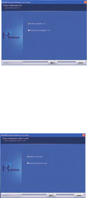
Figure 2-2 Ralink wireless Network Card Setup (Choose Configuration tool)
3.You can choose Ralink Configuration Tool or Microsoft Zero Configuration Tool
to install in the screen as Figure 2-2. The default selection is Ralink Configura
tion Tool. If you click Next, the next screen will appear as Figure 2-3.
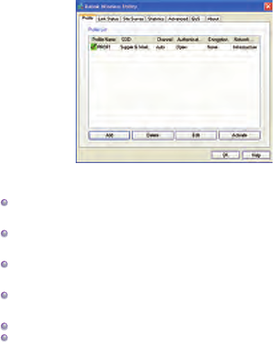
4.As the screen of Figure 2-3, you can choose you device’s work mode, it can be
configured as TxBurst or WiFi mode, select one of them and click Next to
proceed the installation. After a few minutes, the finish windows will appear as
Figure 2-4. Click Finish to complete the setup.
Figure 2-3 Ralink wireless Network Card Setup (Choose TxBurst or WiFi mode)

5
Figure 2-4 Setup Finish
3. The use of utility
This chapter describes how to configure your Wireless Adapter for
wireless connectivity on your Wireless Local Area Network (WLAN) and
use the data security encryption features.
After Installing the Adapter, the Adapter’s tray icon will appear in your
system tray at the bottom of the screen.
3.1 Launch the utility
Double-click the icon and the Ralink Wireless Utility will run. You
can also run the utility by clicking the Start>Program>Ralink Wireless
Utility. The utility provides a complete and easy to use set of tools to:
Manage profiles
Display link status
Execute site survey and connect the site
Display current transmit and receiver statistics
Configure advanced option
Configure linkage QoS
Manage Profiles
The Profile tab display general profile information, it contains Profile
Name, SSID, Channel, Authentication, Encryption, Network type. You
can change the Profile by add, delete, edit and active. See Figure 3-1.
6
Figure 3-1 Profile Management Tab
Profile Name - The name of configuration profile. Use the Edit
function to change the Profile name.
SSID - The IEEE 802.11 wireless network name. It is been config
ured in the AP.
Channel - Shows the channel of respective wireless network be
used.
Authentication – Shows the mode the wireless adapter uses to
authenticate to an access point
Encryption - Displays the encryption type the driver is using.
Network Type - The type of network of the station currently
connected. The options
include:
• Infrastructure (access point)
• Ad Hoc
Configure the network type use the Edit function.
3.2 Link Status
The information on this tab can not be changed, it shows the current
link information, includes Network name, channel, link speed, transmit
and receive rate, link quality, signal strength, and noise level. See
Figure 3-2.

7
Figure 3-2 Link status
3.3 Site survey
Site Survey tab shows that the connection status of the adapter. (If
connected). See figure 3-3.
SSID – Means the adapter is connected or will be connected, the right
figure shows that the adapter is connected, SSID is the default network.
BSSID – Means the MAC address of connected AP or the basic service
device of AD Hoc AP.
Channel – Means the adapter current signal channel, the figure is
variational because the signal could search the available channel and
variate the channel.
Encryption – Means wireless network encryption information. All the
devices in the network have to use the same encryption to ensure the
communication.
Two network modes:
Infrastructure (access point) - means to get connection by AP, once
connected, AP will permit you visit wireless network or LAN network. If
the connection is infrastructure, the Channel will display Auto.
AD Hoc – means to get connection not by AP, AD Hoc can be setup
conveniently without plan in advance. For example, all the persons in
the meeting could share the meeting record in the meeting room.
8
Figure 3-3 Site Survey tab
Rescan – make the adapter rescan the available device. If the link is
not good or the signal is weak, the rescan will make the adapter link to
a better device which will take several seconds.
Connect – choose Network and click it to link from Network list.
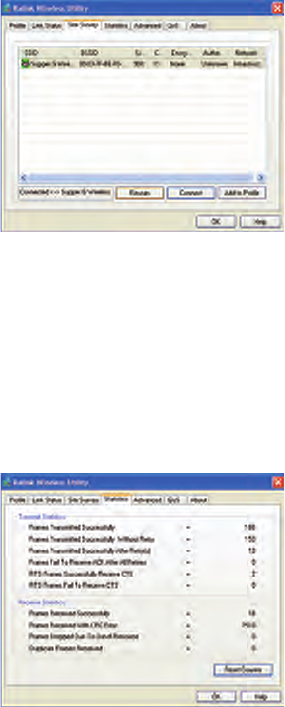
3.4 Statistics
Click “Statistics” and the figure 3-4 will appears which displays
Transmit and Receive statistics. Click “Reconfigure Counter” could
reconfigure the statistics to zero.
Figure 3-4 Statistics information
9
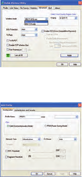
3.5 Advanced
Click “Advanced” and the figure 3-5 will appear, we suggest not modify
any item but keep the default configurations.
Figure 3-5 Advanced Configuration tab
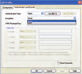
3.6 Configuration
“Configuration” saves the configurations to each wireless network or the
different configurations to one network. See figure 3-6.
Figure 3-6 Profile Configuration
10
【General Configuration】
RTS --RTS/CTS (Request to Send/Clear to Send) is used to lower the
base stations conflict to the minimum. When RTC/CTS is opened, the
router will resend the data frames until another RTC/CTS finishes the
handshake. You could start the RTS/CTS by configureting the packet
minimum and maximum value, we suggest to use the default (2347).
Frame value – frame value is used to share 802.11 frame to the smaller
segments and transmit them to the target independently. You could
specify the packet minimum and maximum value to start the segmenta-
tion. If there are many conflicts in the wireless network, you could make
tests by configureting different maximum value to strengthen the frame
transmission reliability. For the general use, we suggest to use the
default (2346)
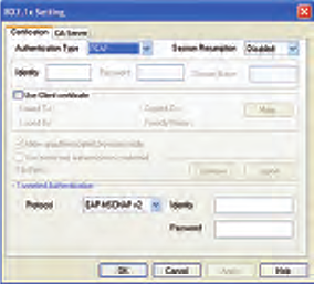
Authentication and Security
“Authentication and Security” is to make the encryption and authentica-
tion of the adapter. IEEE 802.11 stipulates WEP(be equivalent to Wired
encryption) to ensure the transmission security. WEP uses the
encryption key to encrypt or decrypt the packet. The encryption
confuses the frame order to avoid any leak to others. WPA/WPA2 is the
improved security system of
802.11 and overcomes the shortage of WEP. See Figure 3-7.
Figure 3-7 Authentication and Security
11
Authentication
As there is no accurate limit of wireless network, the wireless network
users need complement the specific configuration for security. The
authentication in this tab provides the different protection levels, such as
open, shared encryption key, LEAP, WPA, WPA, WPA-PSK,WPA2,
WPA2-PSK.
Open – this option makes the network run in the open system mode w/o
any authentication. Open base station and AP could authenticate each
other even there is WEP encryption key.
Shared encryption key- this option makes the network run in shared
encryption key. In shared encryption key authentication system modem,
it need four-step frame switch ensure if the base station uses the same
WEP encryption key as the AP.
LEAP: LEAP (Light Extensible Authentication Protocol) is an edition of
EAP(Extensible Authentication Protocol),EAP ensures the mutual
authentication between the wireless network users and the server in the
networking operation centre.
WPA-PSK/ WPA2-PSK – this option permits the use of WPA Pre-
Shared encryption key in infrastructure mode and permit you use the
WPA-PSK/WPA2-PSK encryption between users and AP.
WPA/ WPA2 – the network uses the authentication IEEE 802.1x.which
can adapt to RADIUS(Remote Access Dial-in User Service,Telnet)
.RADIUS supports multi EPA including PEAP,TLS/Smart Card, TTLS
and LEAP.
Data encryption
In the modes of open authentication and shared key authentication, the
options of encryption are FORBID and WEP, in the modes of WPA,
WPA-PSK, WPA2 and WPA2-PSK,it supports TemporalKey Integrity
12
Protocol (TKIP) and Advanced Encryption Standard (AES)
FORBID – forbid the encryption function.
WEP -- the shared key performs the encryption before data wireless
transportation, you could communicate with the wireless devices which
use the same shared key.
TKIP --TKIP uses the stricter encryption rules than the WEP, and also
use the existing WLAN arithmetic to realize the encryption. TKIP will
verify the security configuretings after shared key encrption is ensured.
AES --AES is a 128 bits symmetrical encryption technology, could work
in the multi-layer at same time.
WPA shared-key.
This option could be started until you choose WPA-PSK or WPA2-PSK.
Choose “TIKP” or “AES” in the area of “Data encryption” to start the
encryption process. Notice: 8-64 characters are needed.
Key configuration
This option could be configure until you choose WEP in the area of
Data encryption. WEP is 64/128 bits data, used encrypt and decrypt
data packet.
Display key
After choose this option, your configuration key will be displayed.
【802.1x configuration】
When choose “WPA” or “WPA2” during authentication, you could
configure this option. If choose “Open” and “Shared-key”, you could
also click “802.11 x authentication” to configure 802.11x.
See Figure 3-8.
13
Figure 3-8 802.1X configuration
The authentication including,
PEAP --PEAP (Protected Extensible Authentication Protocol) is an
edition of EAP ( Extensible Authentication Protocol。EAP assures the
mutual authentication of wireless users and server in the networking
operation center.
TLS/Smart Card -- TLS (Transport Layer Security),is used to configure
up an encryption channel and obtain the authentication of server, similar
to the webpage server authentication by SSL(Secure Sockets Layer).
This way uses data certificate to check the identity of users and server.
TTLS --TTLS uses certificate to validate the server identity and keep the
similar security properties of TLS at same time. Such as, to mutually
authenticate and dialog the shared secret of WEP key.
Md5 challenge --Md5-challenge is a single arithmetic using user name
and password, it doesn’t support key management, but need a
pre-configure key.
14
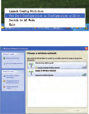
4. Zero Configuration
Right click the tray utility, and choose “Use Zero Configuration as
configuration Utility”,and then Windows wireless network configuration
could be used. See Figure 4-1. The windows wireless Network
connection will prompt, choose the wireless network and click connect
to setup the association. See Figure 4-2.
Figure 4-1 Switch to Windows configuration utility
Figure 4-2 Windows XP wireless Network Connection utility
1. Double click the wireless network icon in the taskbar to check the
wireless network, choose the network and click “Connect”.
See Figure 4-2.
2. If your wireless router has been encrypted, there will be a window
appeared to prompt you to input the key. Please input the key and click
“Connect”, then the connect finishes.
15
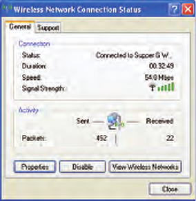
3.To configure the wireless connect properties, please right click the
wireless icon in the tray and choose “Status”, open the page “wireless
network link status”, see figure 4-3.
Figure 4-3 Wireless Network Connection Status
The page of“General” in Figure 4-3 displays link time, speed and signal
strength which is shown in green line, 5 lines means good, 1 line means
worse.
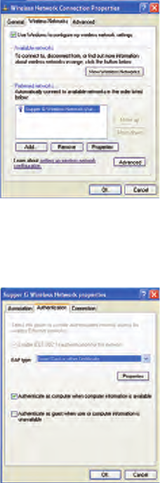
Click the button “Properties” in Figure 4-3 and choose the tab “wireless
network’’ configuration in Figure 4-4 to show firstly chosen network. Use
the button “Add” to add the “SSID” of available network, if there are
several available networks, link priority could be configured by the
button “up” and “down”. The icon like a transmitter tower shows the
current linked AP. Click “Properties” to configure authentication of
wireless connection.
16
Figure 4-4 Windows wireless properties
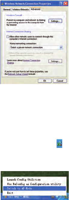
2.The page of “Authentication” in figure 5-5 permits you add security
configuration. You could refer to Windows Help to get more informa-
tion.
Figure 5-5 Wireless Authentication configuration
17
3.The page of “Advanced” in figure 5-6 permits you configure firewall
and share. You could refer to Windows Help to get more information.
Figure 5-6 Wireless Network properties Advanced Configuration
5. Soft AP
The adapter has two modes: working station and Soft AP. After start
Soft AP, the adapter will be an AP to accept any wireless device access.
Notice: the soft AP is available only in Windows XP.
5.1 Start Soft AP
After start adapter driver, you could see figure in the tray of operation
system.
Right click the icon and appear the menu as figure 5-1. Click “Switch to
AP Mode” menu,The soft Ap configuration Utility window will appear,
see figure 5-2.
Figure 5-1 Switch to AP Mode
18
Figure 5-2 Soft AP Configuration window
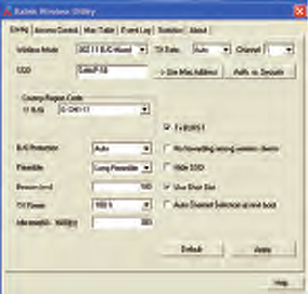
5.2 Configuration Page
As the figure 5-2, you could make some basic configuration, such as
wireless network name, mode, channel and authentication.
Click the button “Auth. Vs. Security” to make different security configu-
rations of wireless communication, and you could choose the authenti-
cation type and encryption type.
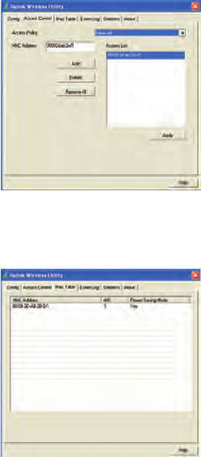
5.3 Access Control
See figure 5-3, you could choose this page to start MAC control 。
MAC control includes “Permit all” and “Refuse all”. After edit the MAC
address access list, only the MAC in the list “Permit all” could access
the Soft AP.
19
Figure 5-3 Access control configuration
5.4 MAC
This page shows the information of the wireless devices accessed to
this AP. See figure 5-4.
Figure 5-4 Soft AP Accessed MAC table

20
5.5 Switch to Working Station mode
As the figure 5-5, in the Soft AP mode, right click the tray icon and
appear a menu, please choose “Switch to Station Mode”, then the
adapter is switched to working station mode together with an interface
of working station.
Figure 5-5

21
5.Product Specifications
General Features
Standards IEEE 802.11g; IEEE 802.11b
Interface 32-bit PCI
OS Windows 98/SE/ME,Windows 2000/XP, Windows, CE, Linux, MAX
OSX
User interface Easy to use user configuration software
Transmit distance indoor up to 100 meters and outdoor up to 300 meters (standard
transmit distance is limited to the environments)
roaming Support multipoint auto roaming and configuration; Support wireless
network environments auto detect.
LED Link/Active status indicator
Antenna type Omni-directional exterior Antenna (removable)
RF and baseband Technical Features
Frequency range 2.412-2.462GHz
Radio data rate 11g:54/48/36/24/18/12/9/6M(auto adaptive);
11b:11/5.5/2/1M(auto adaptive)
Modulation BPSK, QPSK, CCK and OFDM (BPSK/QPSK/16-QAM/ 64-QAM)
Spectrum Spread
Technology DSSS
Transmit power 14.39dBm(11g),
17.17d Bm(11b)
Receive sensitivity
54M :-72dBm@10%PER ;11M :-88dBm@8% PER ;6M :
-89dBm@10% PER;1M:-90dBm@8% PER;256K:-105dBm@8%
PER(typical)
Antenna Gain 2dBi
Channel 11
Media Access
Protocol CSMA/CA with ACK
Data security WPA/WPA2; 64/128/152-bit WEP; TKIP/AES
Environmental
Operation Temp. 0℃ - 45℃
Storage Temp. -20℃ - 70℃
Operation Humidity 10% - 95% RH, Non-condensing
Federal Communication Commission Interference
Statement
This equipment has been tested and found to comply with the limits for a Class B digital
device, pursuant to Part 15 of the FCC Rules. These limits are designed to provide
reasonable protection against harmful interference in a residential installation. This
equipment generates, uses and can radiate radio frequency energy and, if not installed
and used in accordance with the instructions, may cause harmful interference to radio
communications. However, there is no guarantee that interference will not occur in a
particular installation. If this equipment does cause harmful interference to radio or
television reception, which can be determined by turning the equipment off and on, the
user is encouraged to try to correct the interference by one of the following measures:
Reorient or relocate the receiving antenna.
Increase the separation between the equipment and receiver.
Connect the equipment into an outlet on a circuit different from that to which the
receiver is connected.
Consult the dealer or an experienced radio/TV technician for help.
FCC Caution: Any changes or modifications not expressly approved by the party
responsible for compliance could void the user's authority to operate this equipment.
This device complies with Part 15 of the FCC Rules. Operation is subject to the following
two conditions: (1) This device may not cause harmful interference, and (2) this device
must accept any interference received, including interference that may cause undesired
operation.
This device and its antenna(s) must not be co-located or operating in conjunction with any
other antenna or transmitter.
Country Code selection feature to be disabled for products marketed to the US/CANADA
IMPORTANT NOTE:
FCC Radiation Exposure Statement:
This equipment complies with FCC radiation exposure limits set forth for an uncontrolled
environment. This equipment should be installed and operated with minimum distance
20cm between the radiator & your body.