Zultys Technologies WIP2 WI-FI IP PHONE User Manual ZIP 4x4 User s Manual 1 0 2 20 April 2003
Zultys Technologies WI-FI IP PHONE ZIP 4x4 User s Manual 1 0 2 20 April 2003
UserManual.wiki
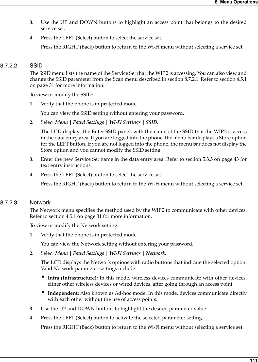
>
Zultys Technologies
>
WIP2 User Manual
MANUAL
Navigation menu
Upload a User Manual
Namespaces
Wiki Guide
HTML
PDF
Info
Views
User Manual
Discussion / Help
Navigation

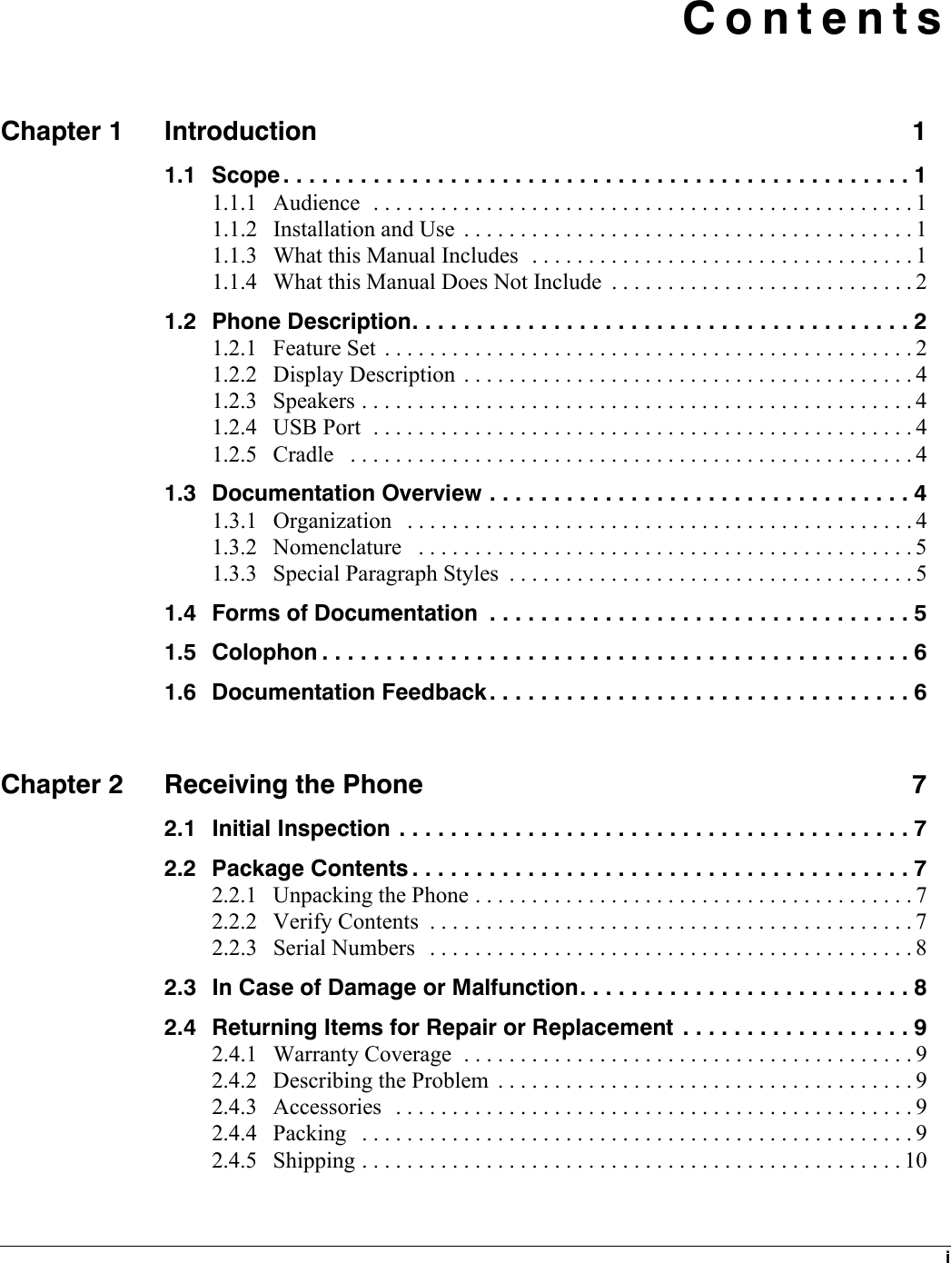

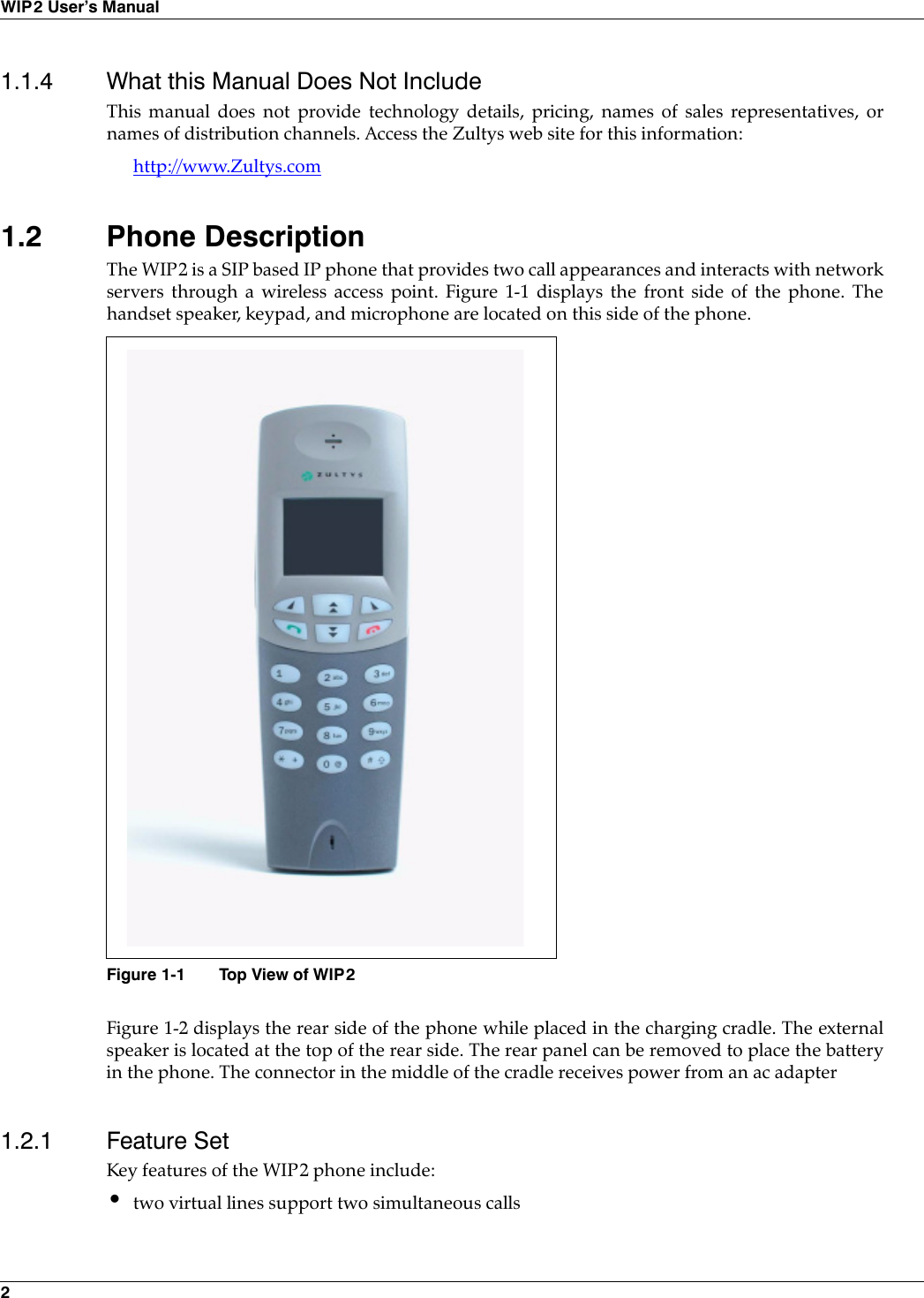
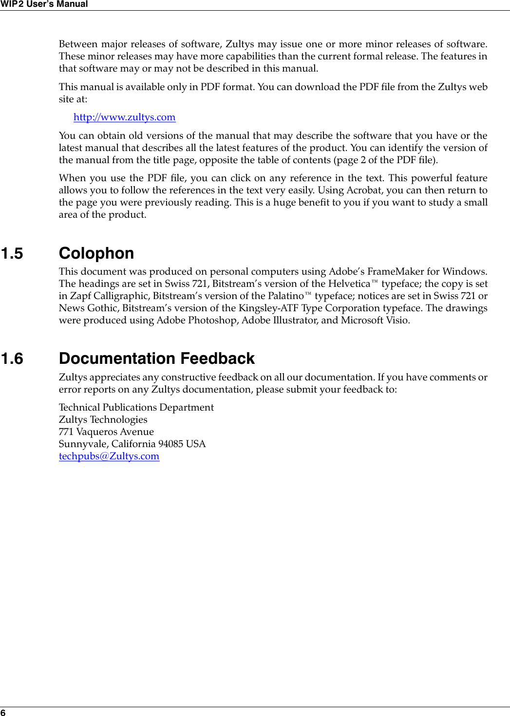

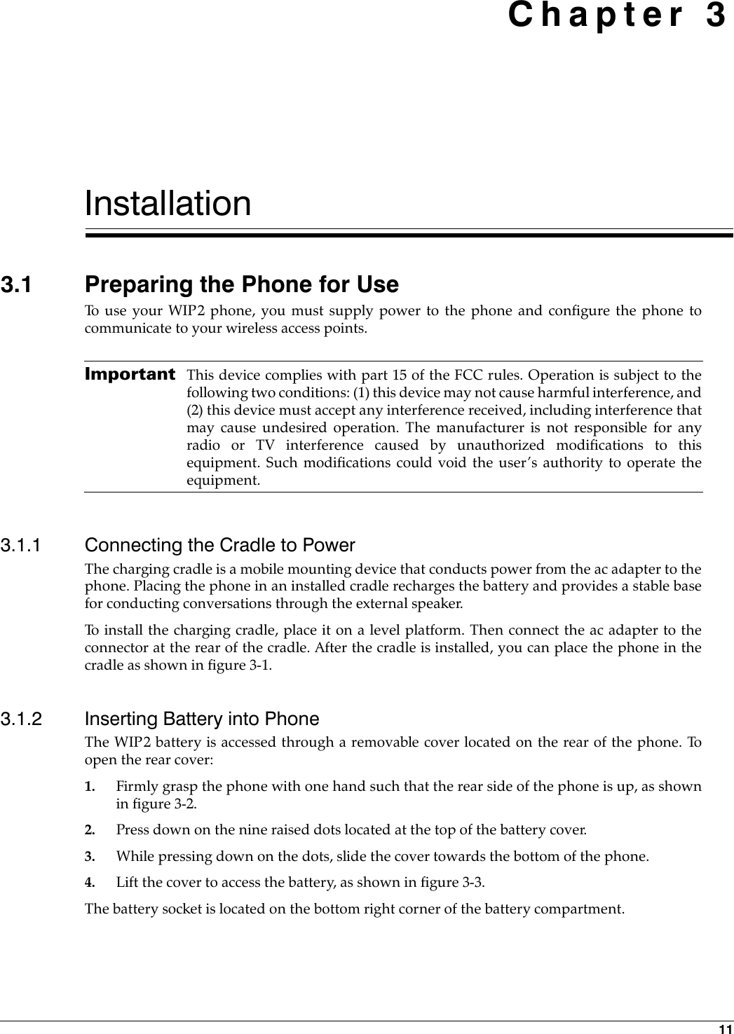
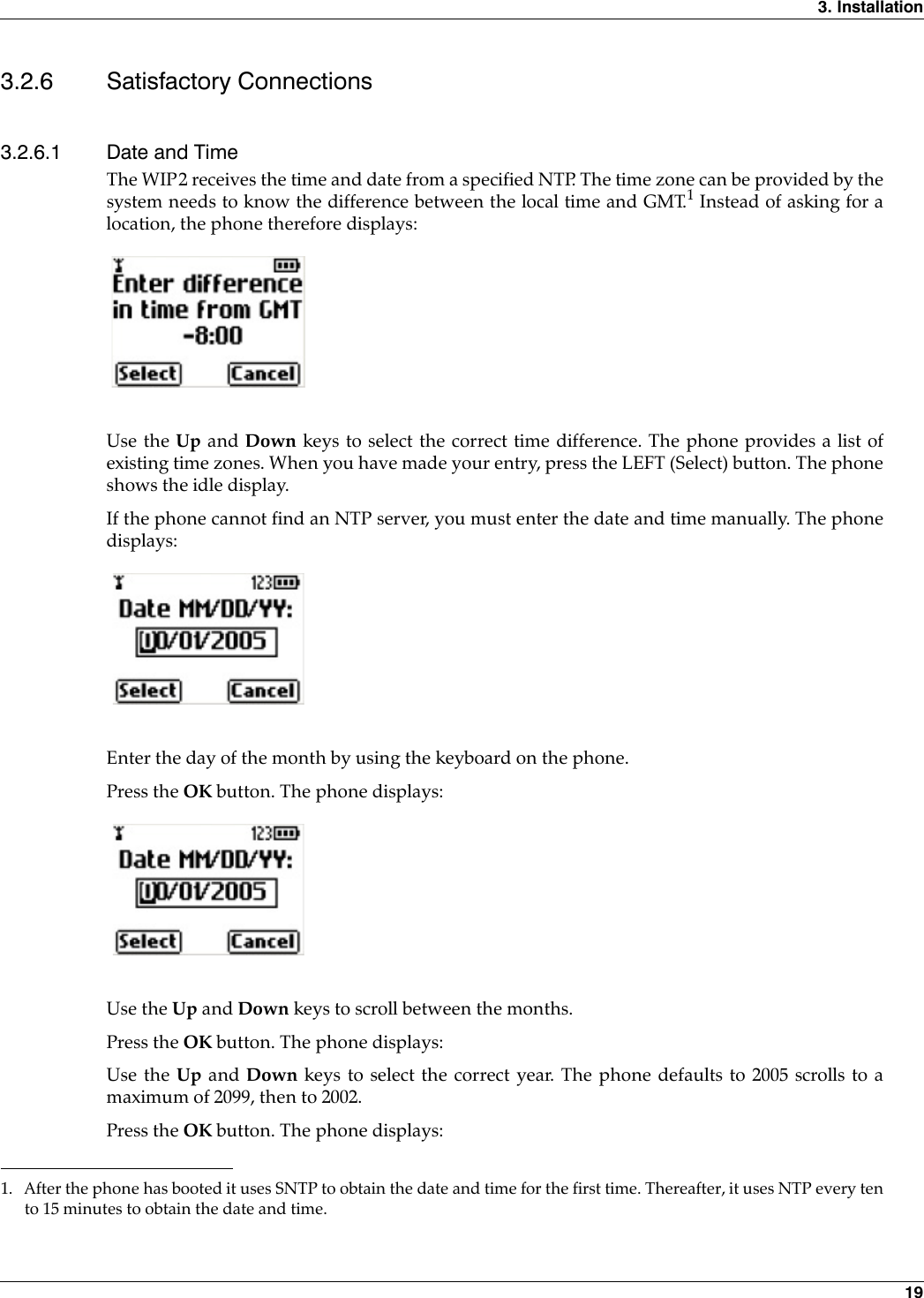
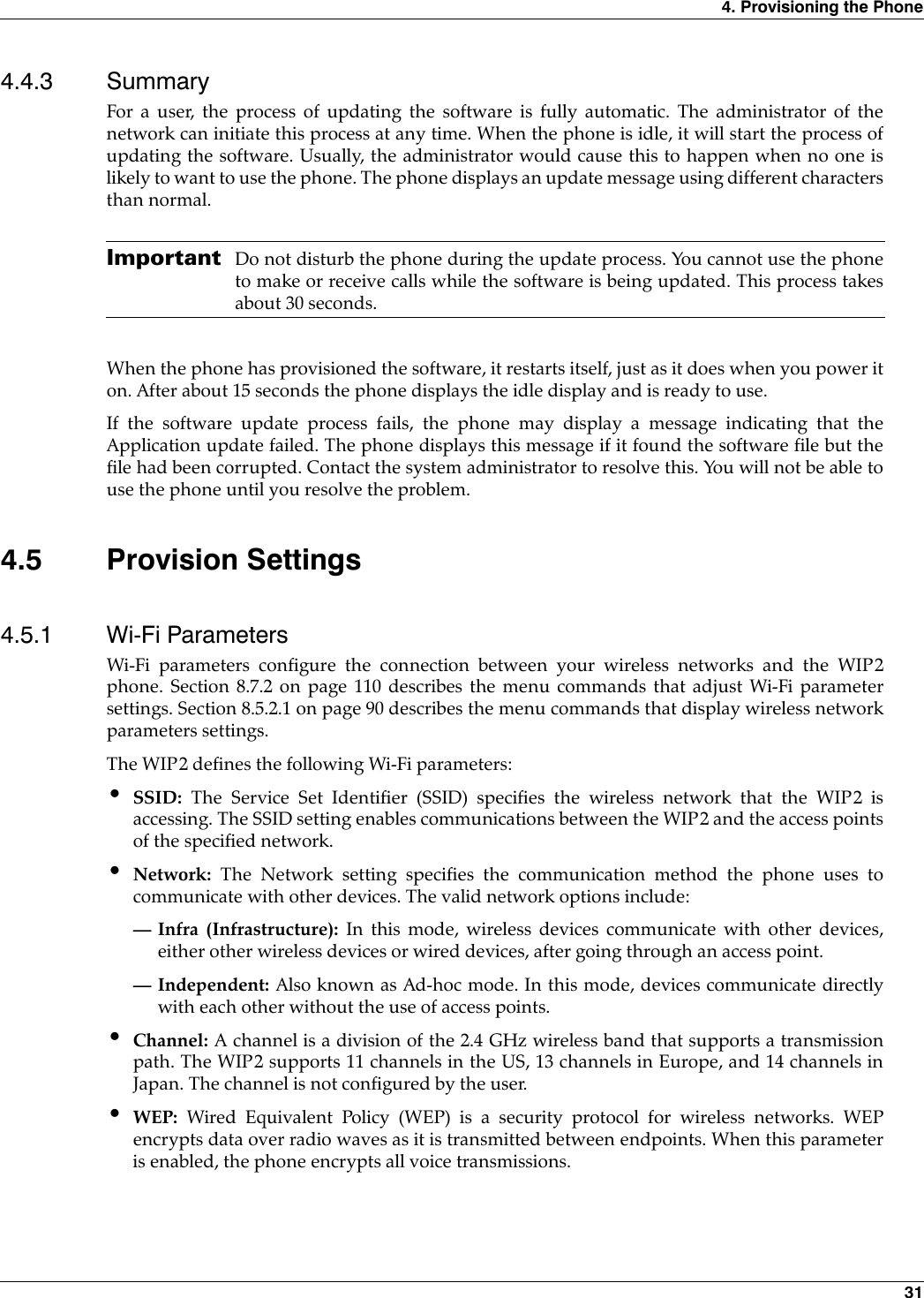
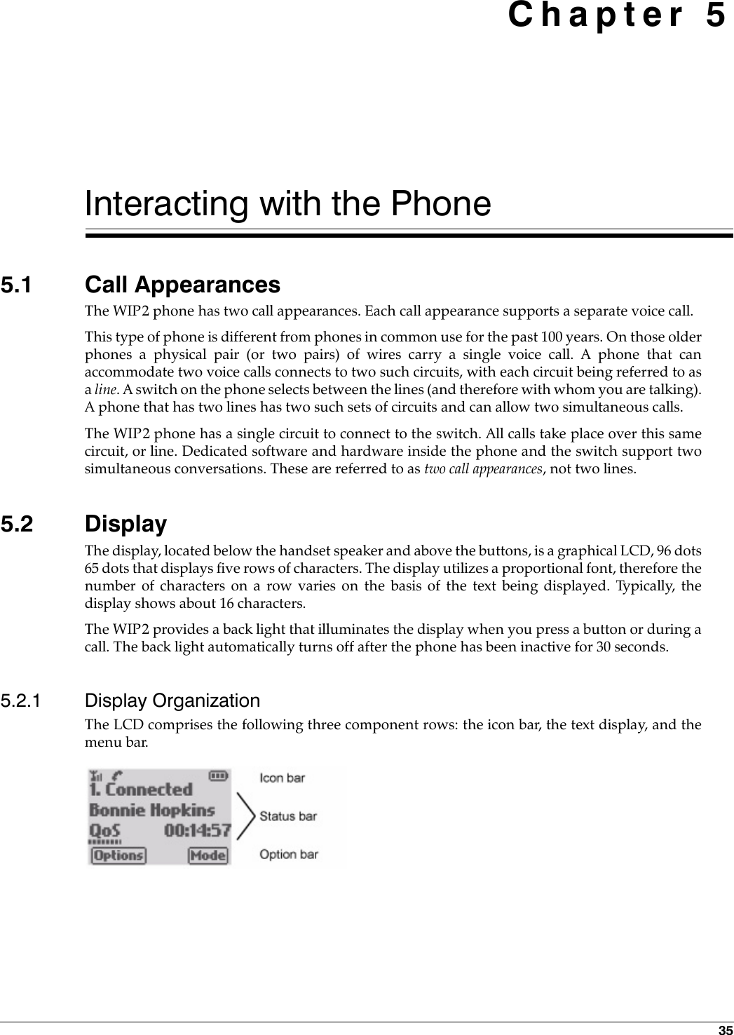
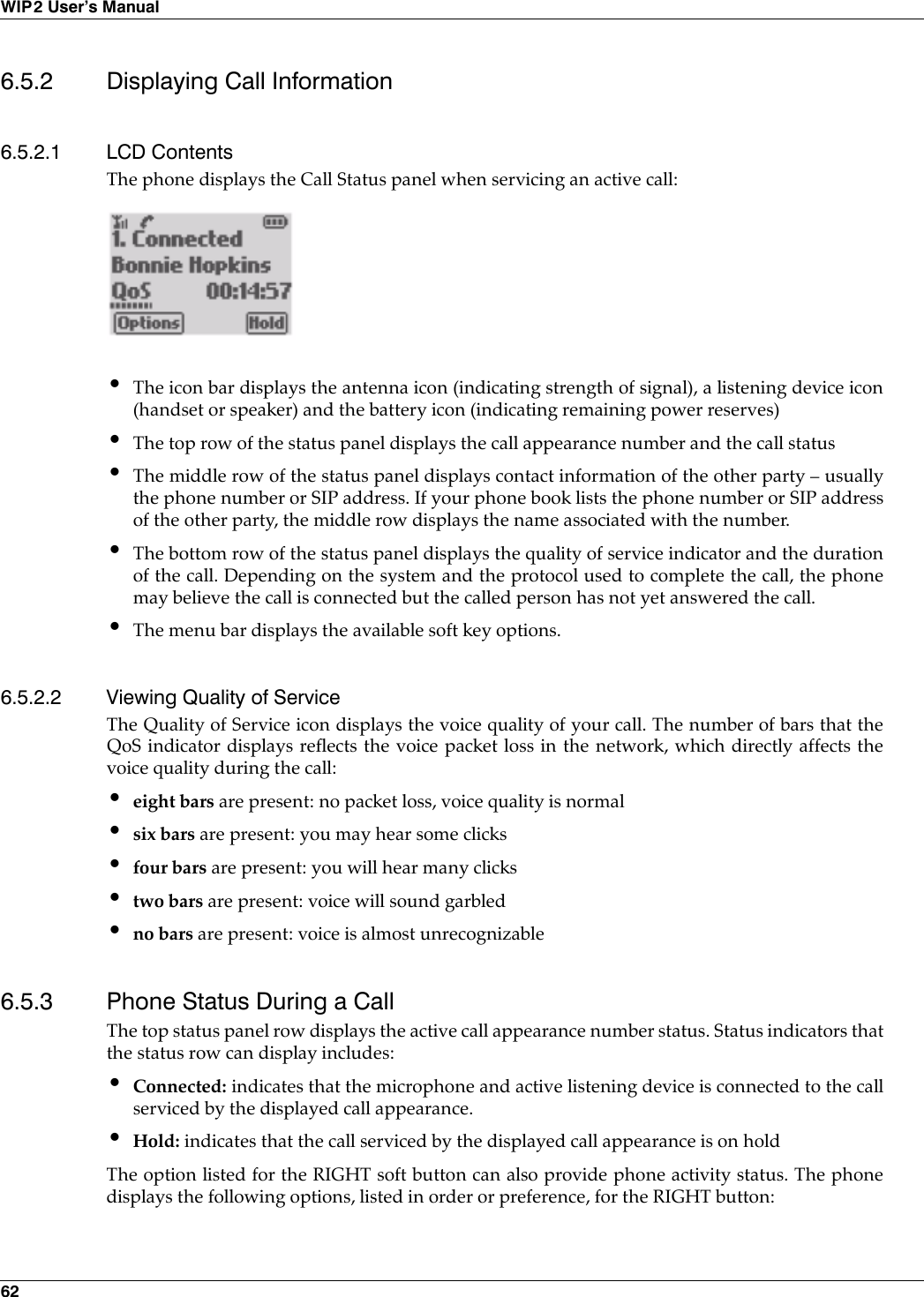
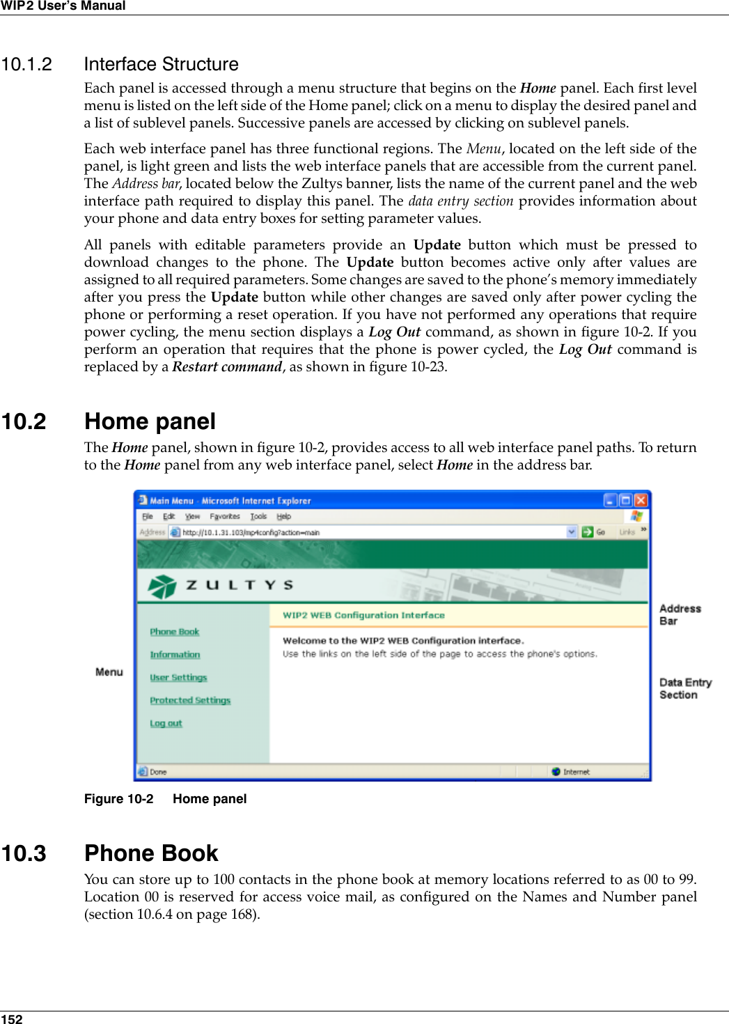
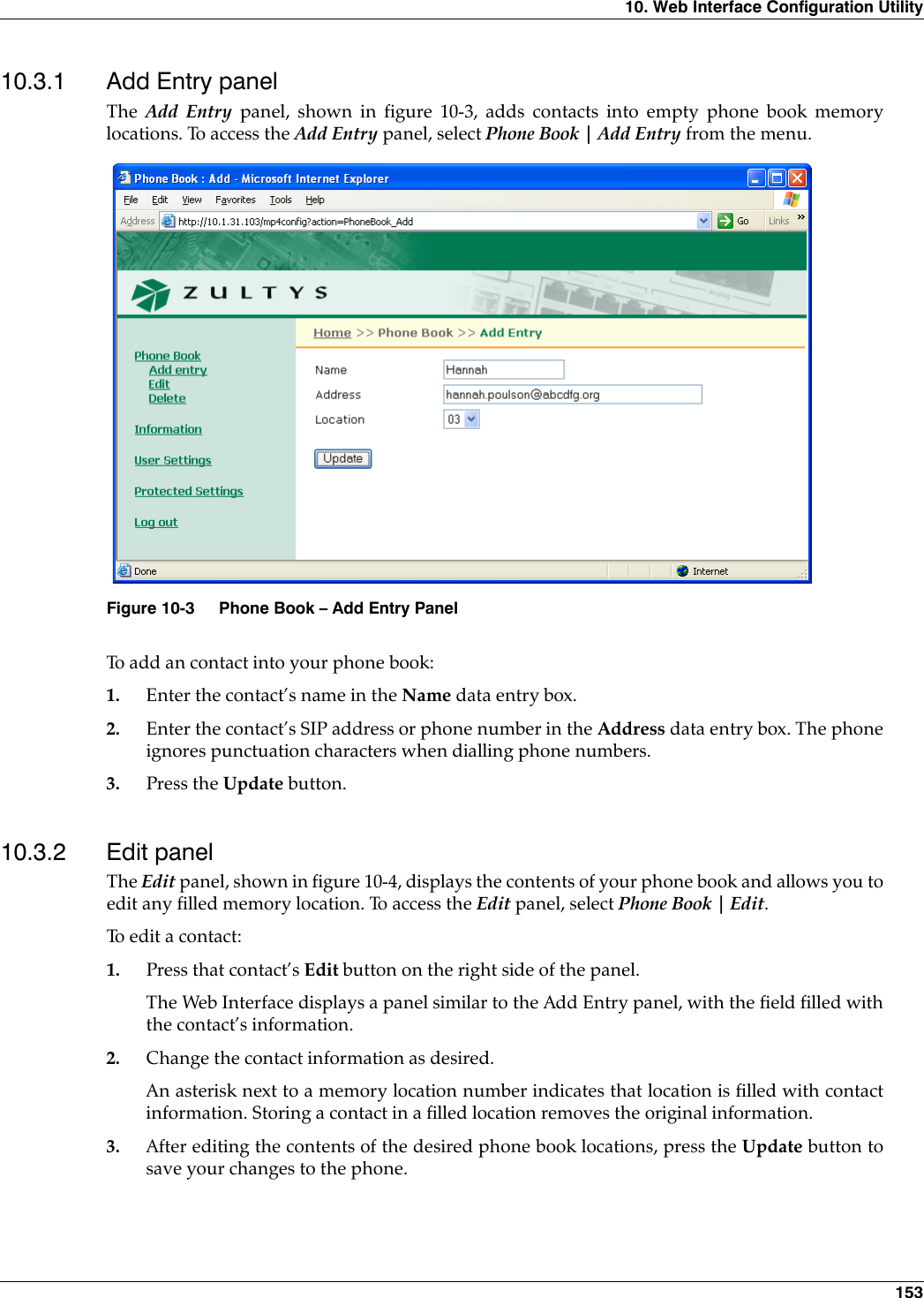
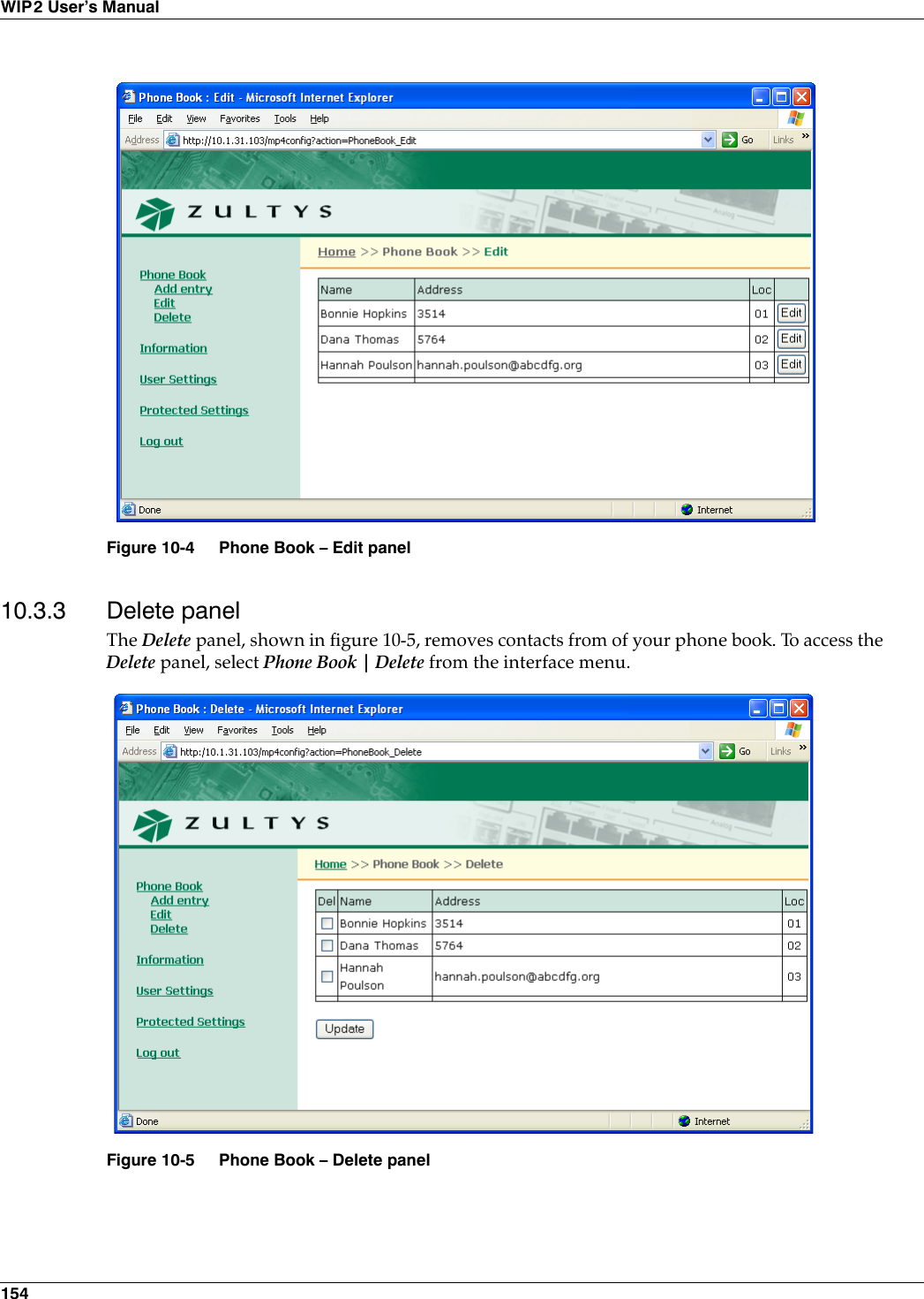
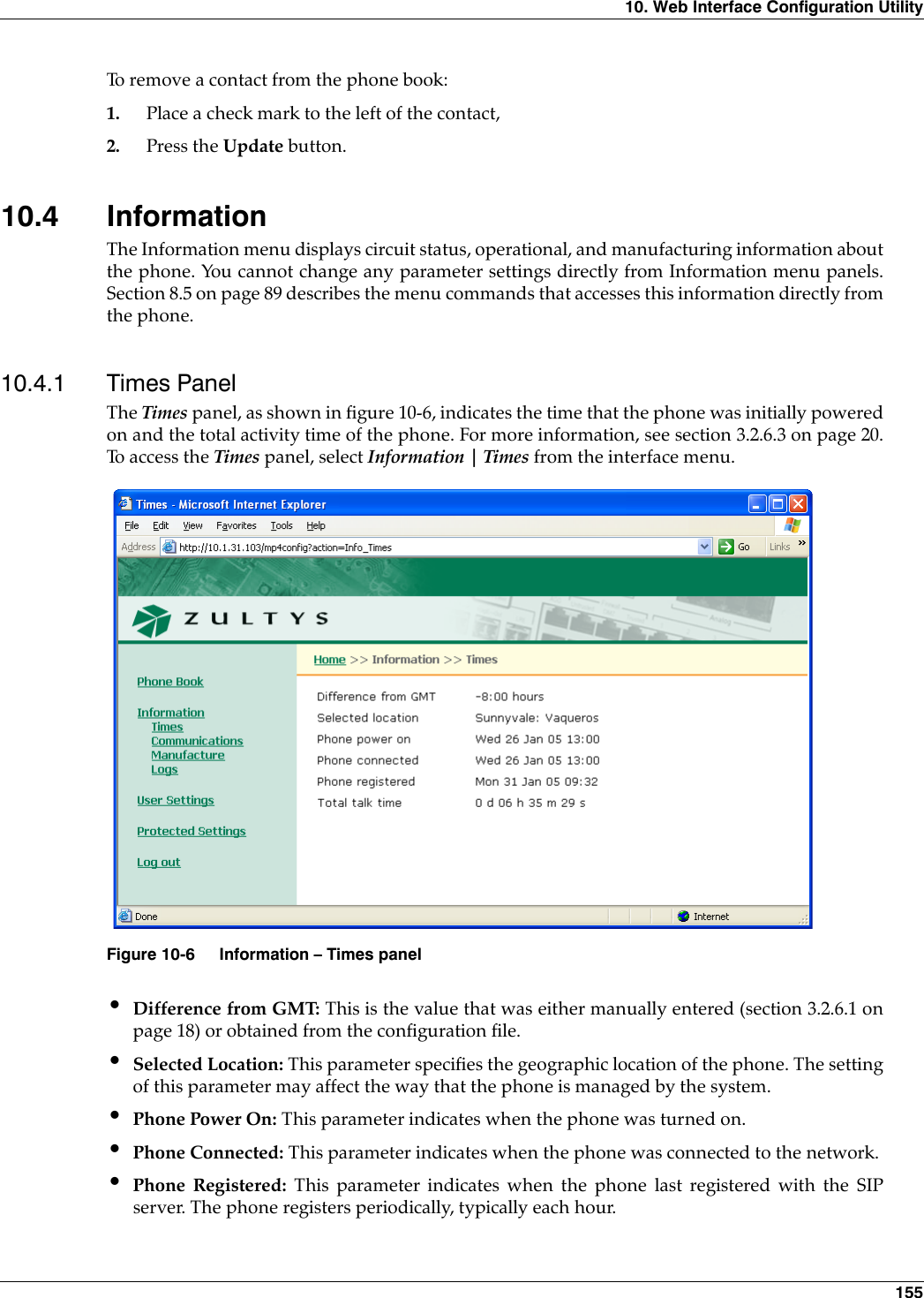
![22WIP2 User’s ManualWIP2_common.cfgThe common configuration file specifies parameter settings that are common for all phones thataccess the TFTP server, such as server addresses, registration periods, and service phonenumbers. The common configuration file is stored in the root directory of the TFTP server.4.2.1.2 Specific Configuration FileThe specific configuration file defines parameter settings that are unique to an individual phoneor a set of phones. The specific configuration file is stored in the TFTP directory designated by thecommon configuration file.If a parameter is defined in the common file and the specific file, the specific file setting takesprecedence. The file name of a specific configuration file is constructed by using the MAC ID forthe individual device:<MAC address>.cfgFor example,0050C2180FD8.cfgEach phone, knowing its own MAC address, locates the file that has been uniquely created for itand obtains configuration data that is unique for the phone.4.2.1.3 Configuration File FormatThe format for common and specific configuration files is identical; an example of a configurationfile is shown in figure 4-1. This is an ASCII text file, with the name of the parameter and the valueof the parameter listed on the same line. Each parameter must be within the section (denoted bysquare brackets “[ ]”). The contents of the file are not case sensitive; you can enter parameternames in upper or lower case. Comment lines are denoted with a leading semi-colon (;) and haveno effect on the operation of the phone.[HW_CONFIG]lcd_contrast=8ring_volume=5speaker_volume=5handset_volume=5[NET_CONFIG]use_dhcp=yesip_addr=subnet_mask=default_gateway=primary_dns=secondary_dns=;host_name is DNS lookup for this phonehost_name=domain=zultys.comntp_server_addr=tftp_server_addr=tftp_cfg_dir=./WIP2Figure 4-1 Format for Configuration File](https://usermanual.wiki/Zultys-Technologies/WIP2/User-Guide-630473-Page-32.png)
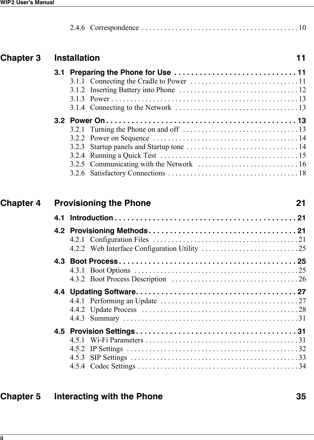
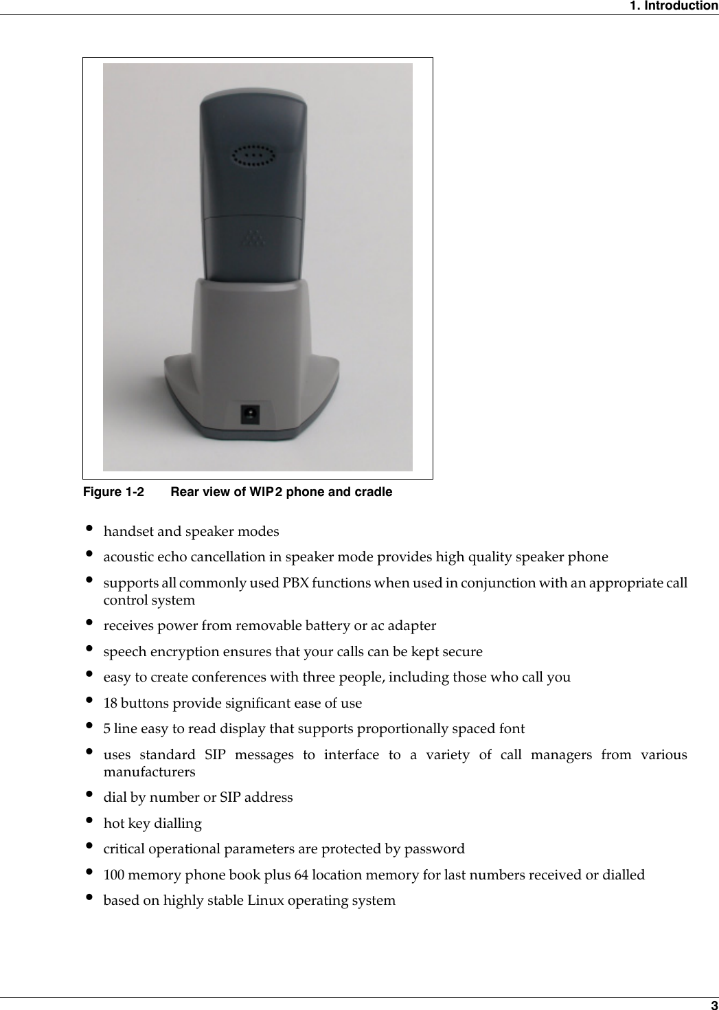
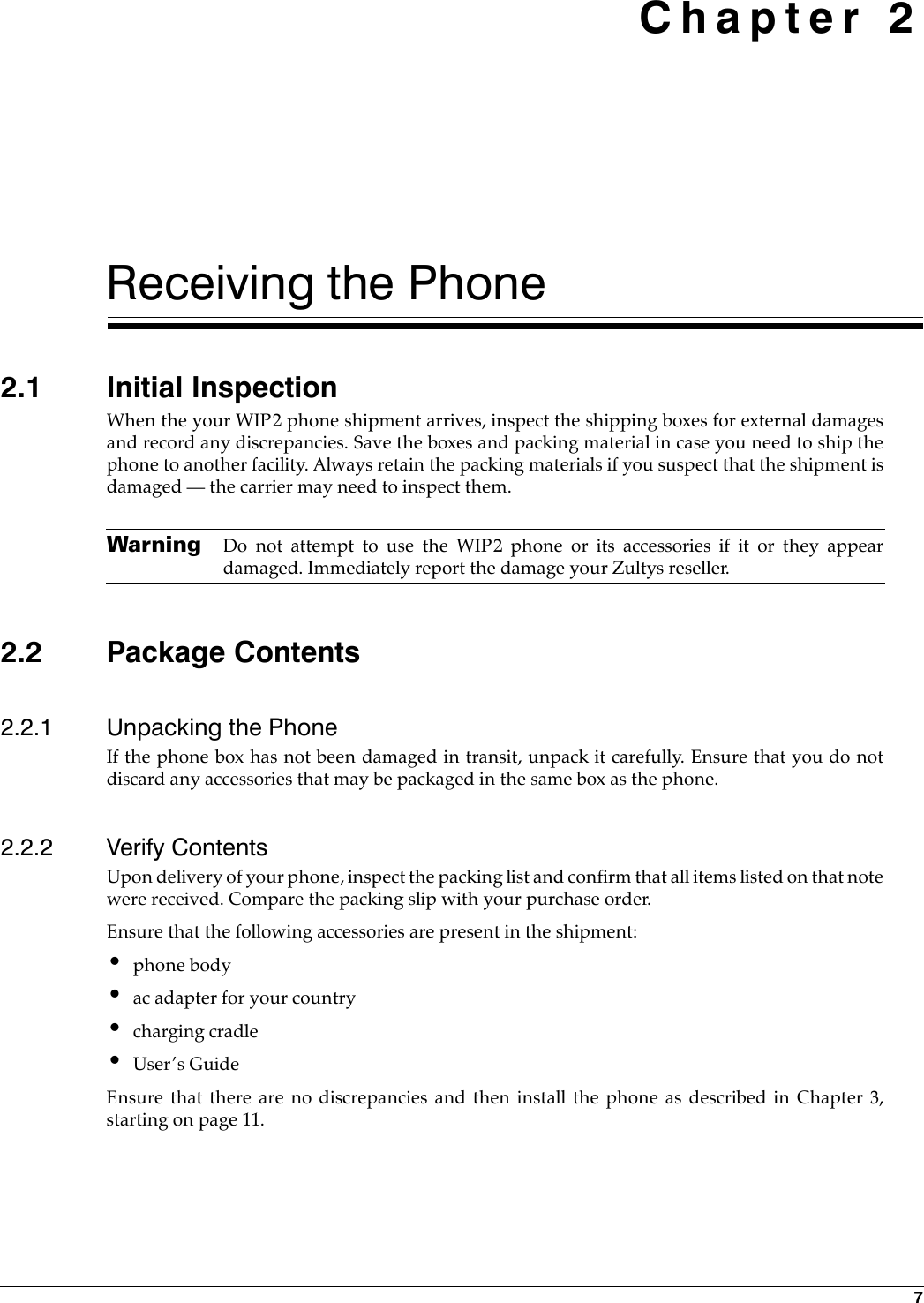
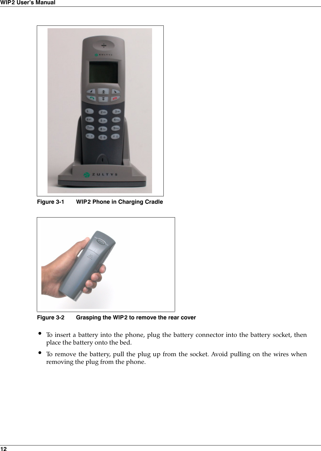
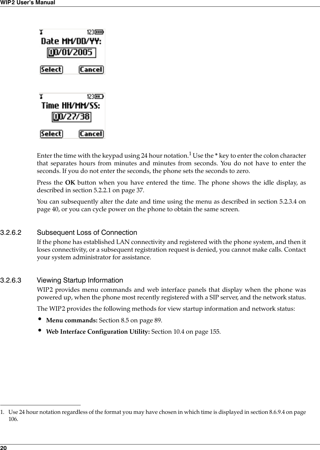
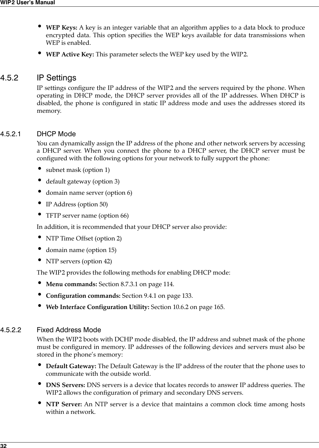
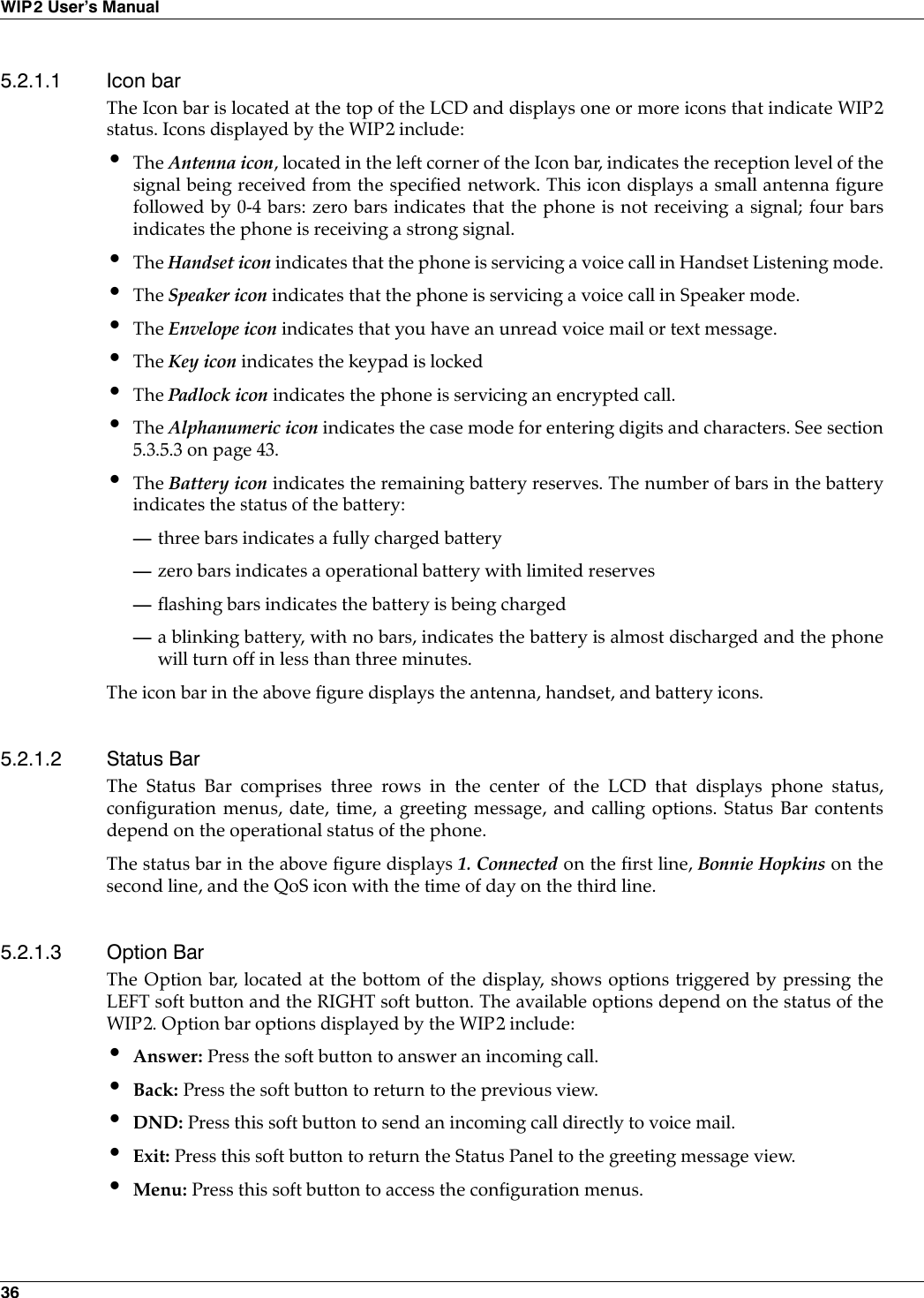
![4. Provisioning the Phone 234.2.1.4 Accessing the Configuration FilesEvery time the phone restarts (either by command or by power on), the phone may read theconfiguration files. The phone extracts the data in the files and saves it to memory. Thisoverwrites all parameters that are saved in memory except for user settings that are notconfigured to be cleared; these settings are retained in the phone.For example, suppose the common configuration specifies the greeting message as:WIP2 SIP Phoneand the specific configuration specifies the greeting message as:[SIP_CONFIG]phone_sip_port=5060rtp_start_port=33000;The Device ID is the user portion of the SIP URIdevice_id=West;The Display Name is sent in SIP messagesdisplay_name=Zultys WIP2register_w_proxy=yesproxy_addr=10.1.32.224proxy_port=5060voice_mail_uri=258registration_expires=3600session_expires=3600[AUDIO_INFO]ext_ring_tone=0ext_cust_ring=int_ring_tone=0int_cust_ring=ring_tone2=0cust_ring2=key_click=0codec=0distinctive_ring=yessound_url=[GENERAL_INFO]software_version=1.0.0;The message displayed on the LCD in idle modegreeting_message=WIP2 SIP Phonepassword=985897time_fmt=%H:%Mdate_fmt=%m/%-d/%Ydate_time_order=0;This is the offset from GMT, in minutestimezone=-480country=USAlanguage=ENGLISHclear_settings=2Figure 4-1 Format for Configuration File (Continued)](https://usermanual.wiki/Zultys-Technologies/WIP2/User-Guide-630473-Page-33.png)
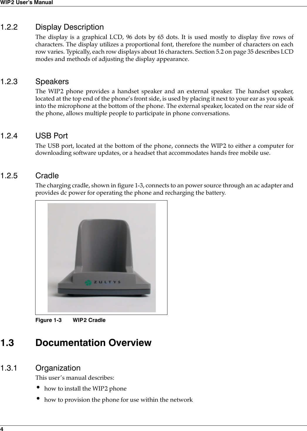
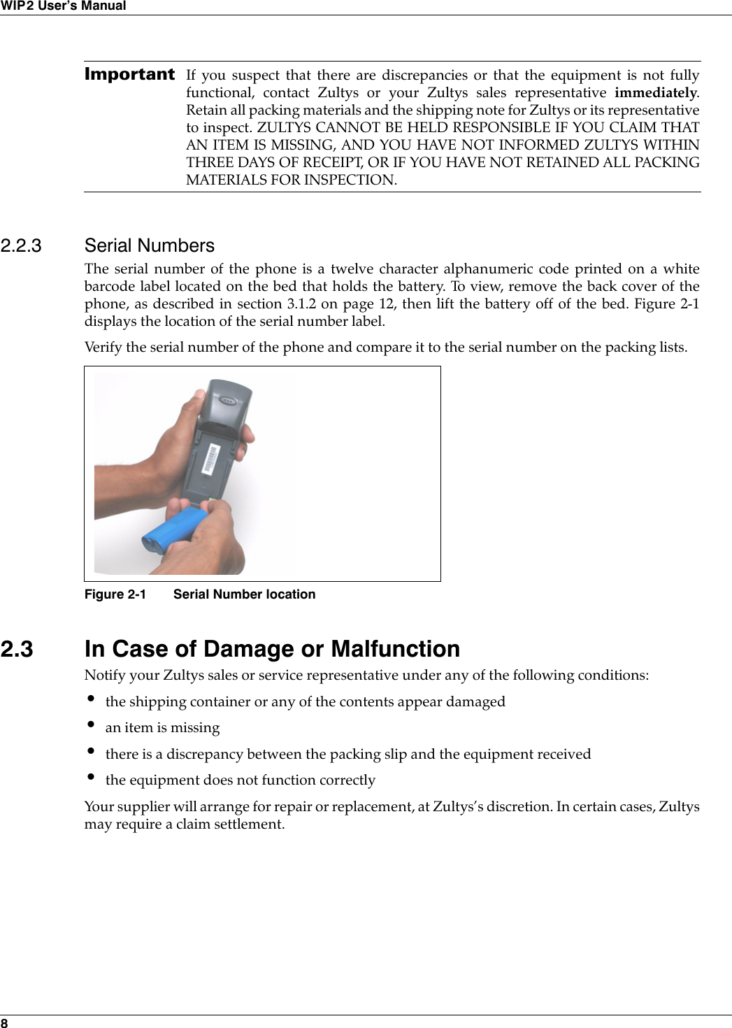
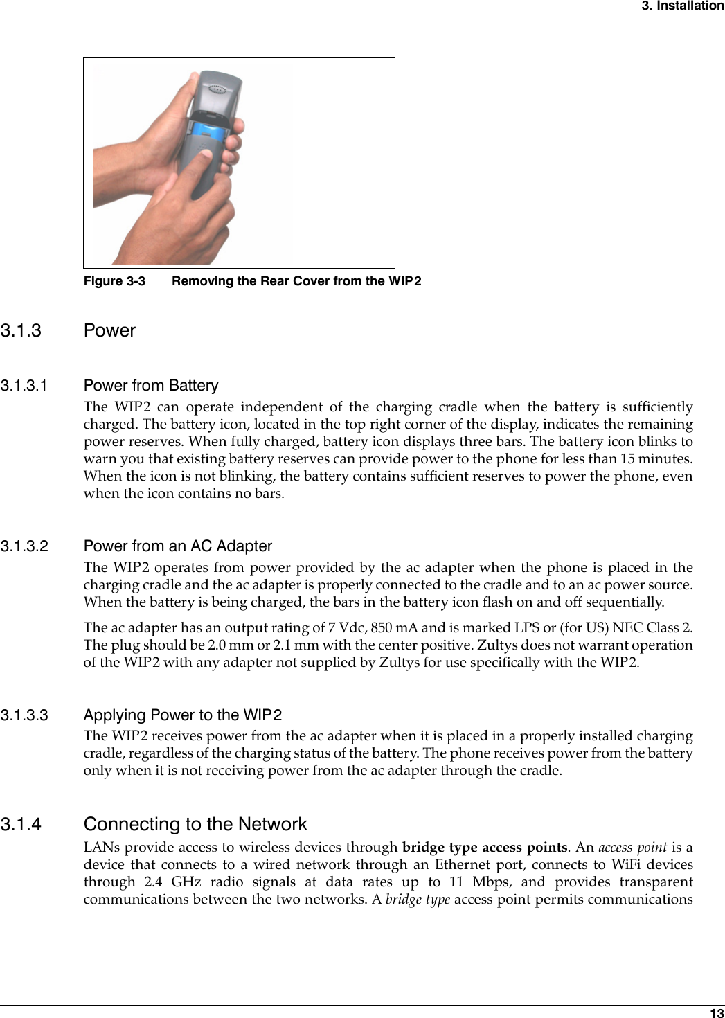
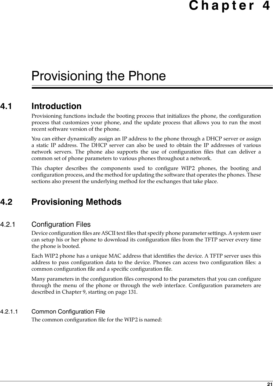
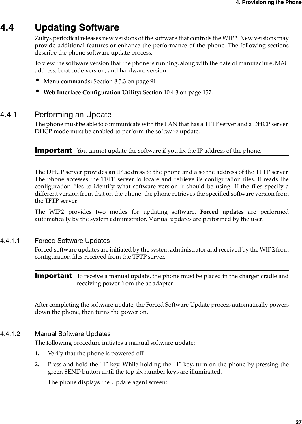
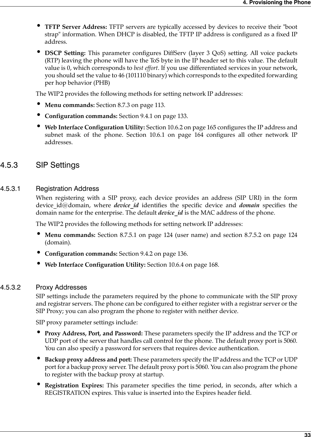
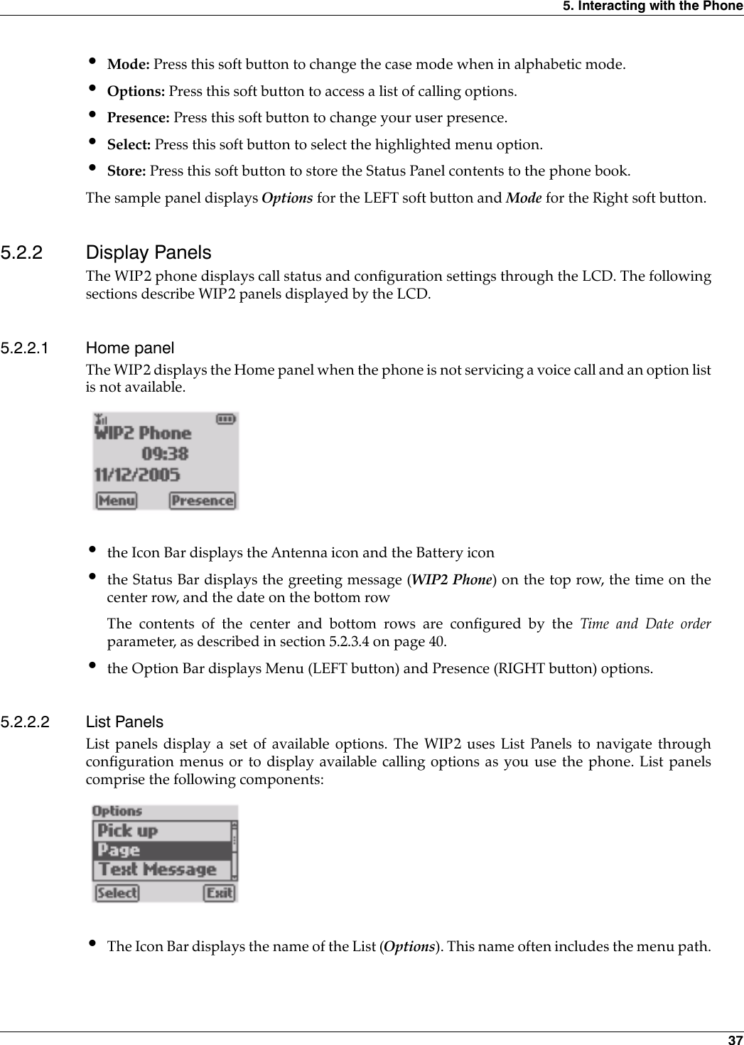
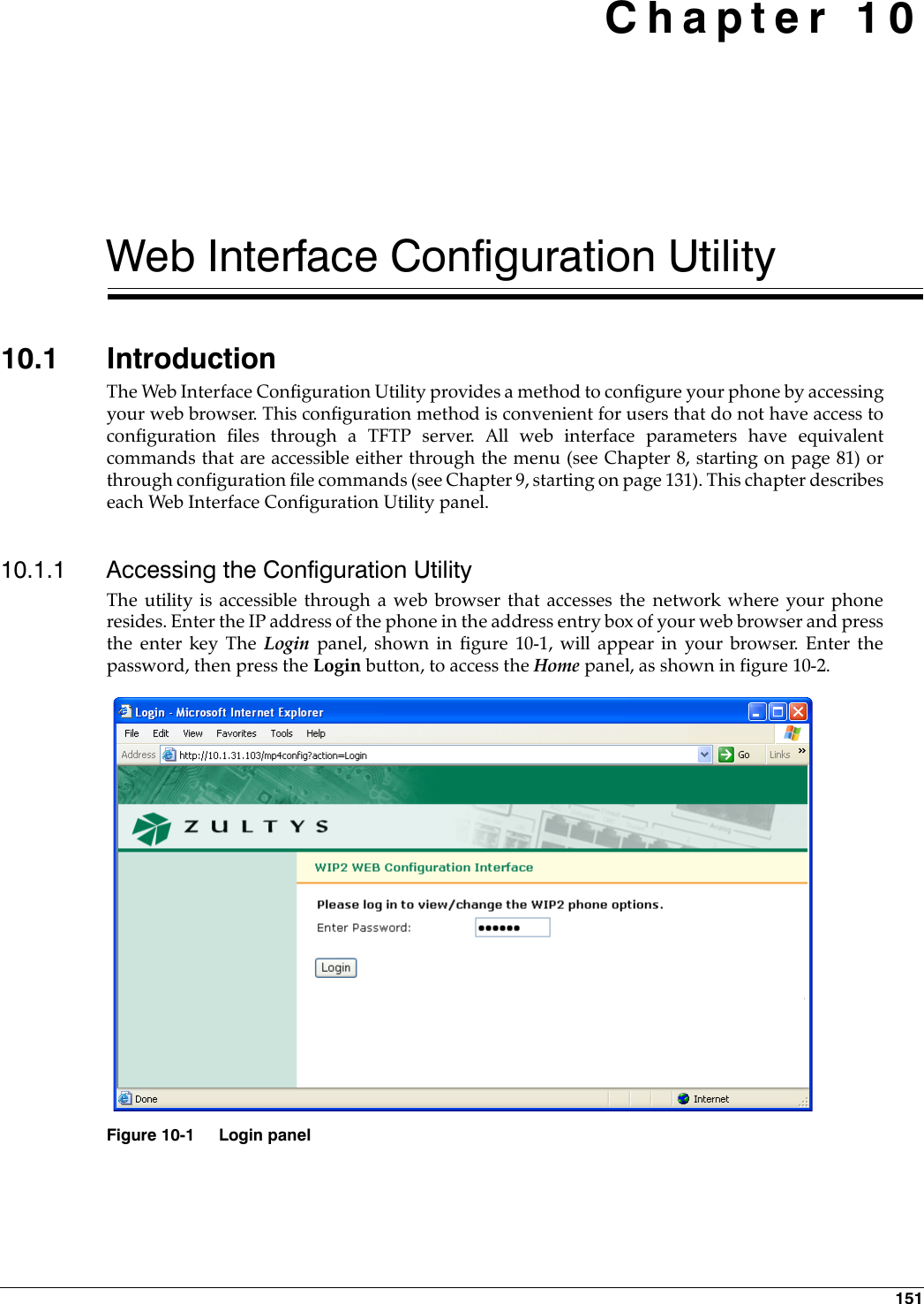
![4. Provisioning the Phone 254.2.2 Web Interface Configuration UtilityThe phone provides a web interface configuration utility, offering an alternative method ofstoring information to your phone. Through this utility, you can modify all operating parametersthat are available through configuration files. To access the web interface, enter the IP address of your phone in the address entry box of yourweb browser and press the key button. The login panel will appear in your browser. Section8.7.3.2 on page 114 provides the menu command that displays your phone’s IP address.Web Interface panels provide an update button to download changes to your phone. Manychanges take effect when you download them to the phone. Some changes require that youreboot the phone to become enabled. When you have made at least one change that requires aphone reboot, a Restart Phone option appears in the menu on the left side of the panel.If you have specified a TFTP server, restarting the phone reloads the configuration files to thephone which files may write over the changes specified by the web interface; see section 4.3.1.2for details on booting the phone without reloading the configuration files.Chapter 10, starting on page 151, describes each panel of the web interface configuration utility.4.3 Boot Process4.3.1 Boot OptionsThe phone provides several boot process options, allowing you to customize the phone to yournetwork configuration. This section describes the process options, then lists the steps that theboot up process requires.4.3.1.1 IP Address Assignment OptionsDynamic IP and TFTP Address Assignment. This option uses DHCP to specify the IP address andsubnet mask of the phone, the IP address of the default gateway, and the IP address of the variousnetwork servers that the phone will access. Figure 4-2 displays the configuration commands thatspecify this option.Dynamic IP Address and Fixed TFTP Address Assignments. This option uses DHCP to specify theIP address and subnet mask of the phone, the IP address of the default gateway, and the IPaddress of the various network servers that the phone will access except for the TFTP server. TheIP address of the TFTP server is either provided by the configuration file or retained from theprevious setting in the phone’s internal memory. Figure 4-3 displays the configuration commandsthat specify this option.Fixed IP Address Assignment. This option fixes the phone’s IP address and subnet mask and theIP address of the default gateway and all of the various network servers that the phone willaccess. Figure 4-4 displays the configuration commands that specify this option.[NET_CONFIG]use_dhcp=yestftp_addr_fixed=noFigure 4-2 Configuration File Instructions: Dynamic IP and TFTP Assignment](https://usermanual.wiki/Zultys-Technologies/WIP2/User-Guide-630473-Page-35.png)
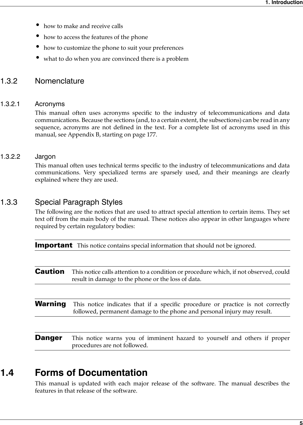
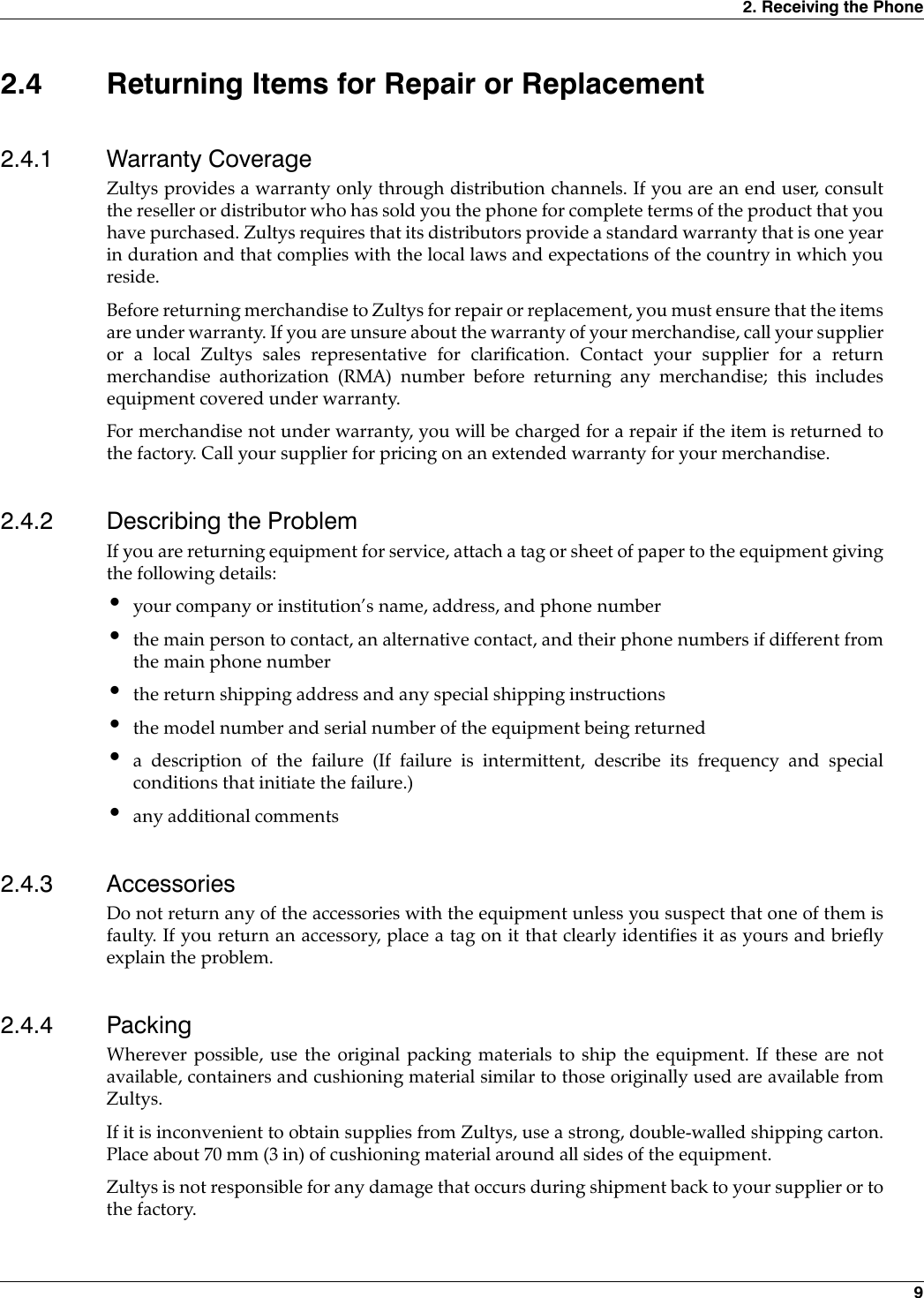
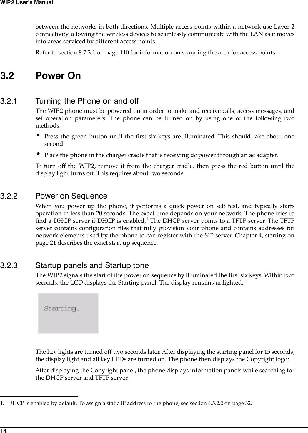
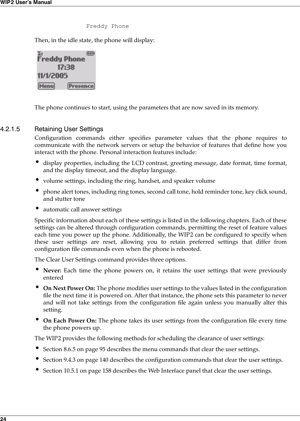
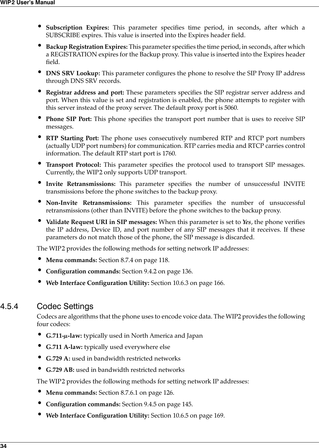
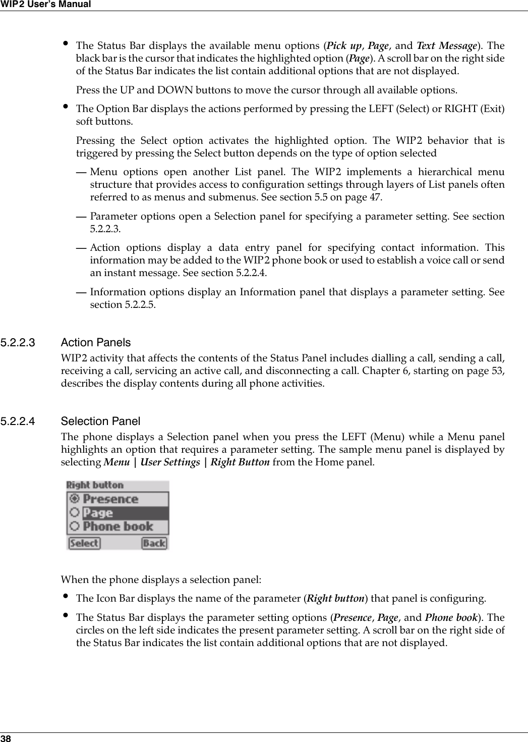
![26WIP2 User’s Manual4.3.1.2 Configuration File Usage OptionsDownload Configuration Files. This option downloads the common and specific configurationfiles from the TFTP server and stores the values specified by the commands in the files into thememory of the phone. To download configuration files, you must either enable DHCP mode andspecify dynamic TFTP address assignment, or specify fixed TFTP assignment and assign a validIP address to the TFTP address parameter.Do Not Access Configuration Files. This option does not download any configuration files fromthe TFTP. The phone uses its memory contents to configure itself upon startup. To perform thisoption, specify fixed TFTP assignment (see section 8.7.3.8 on page 117) and assign an empty valueto the TFTP address parameter (see section 8.7.3.9 on page 117).4.3.2 Boot Process DescriptionThe following steps provision the WIP2 phone:1. The phone obtains its IP address and the address of the TFTP server. These addresses areobtained in one of the following ways:•dynamic assignment by accessing the DHCP server•static assignment from the configuration file•maintains address assignment as configured in the phone’s internal memory2. The phone accesses the TFTP server to locate the common configuration file. If the TFTPaddress parameter does not specify an address to the TFTP server, the phone does not accessthe common configuration file.3. If the phone downloaded the common configuration file, it reads the file and accesses thespecific configuration file from the directory pointed at by the common configuration file.4. The phone reads its specific configuration file.5. The phone stores the data retrieved from the configuration files in its internal memory.6. The phone uses the parameter settings in its internal memory to configure itself to operateproperly in the network.[NET_CONFIG]use_dhcp=yestftp_addr_fixed=yestftp_server_addr=10.1.32.224Figure 4-3 Configuration File Instructions: Dynamic IP, Static TFTP Assignment[NET_CONFIG]use_dhcp=notftp_addr_fixed=yestftp_server_addr=10.1.32.224Figure 4-4 Configuration File Instructions: Static IP and TFTP Assignment](https://usermanual.wiki/Zultys-Technologies/WIP2/User-Guide-630473-Page-36.png)
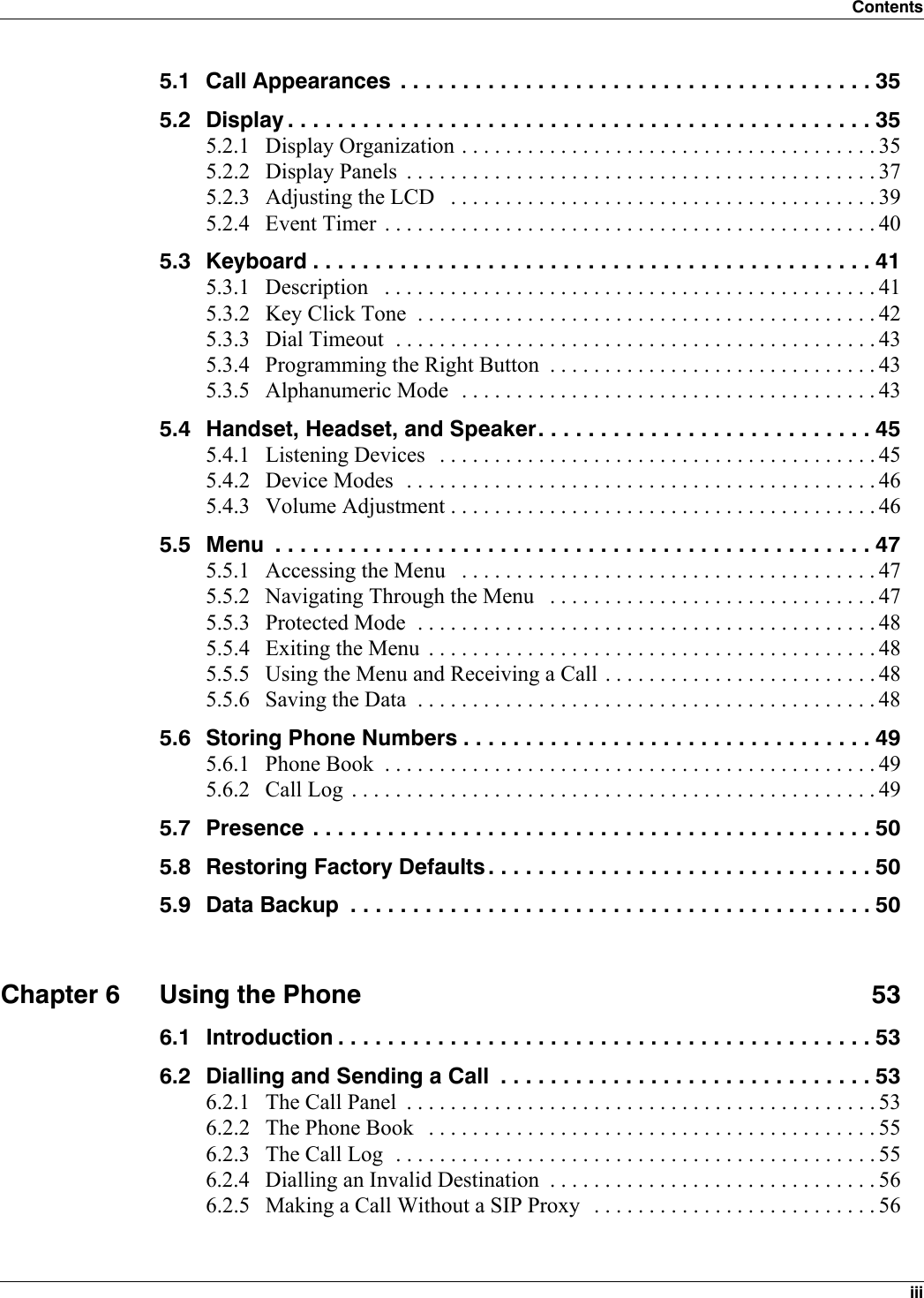
![44WIP2 User’s ManualTo change the character mode, press the RIGHT Soft Button (Mode) when available or the #button when Mode is not available.5.3.5.4 Entering Alphanumeric CharactersThe digit keys 2 to 9 enter letters of the alphabet that are displayed on those keys. When you pressa key, it selects the first character. If you quickly press the key again, it selects the second letter andso on. When you repeatedly press the key, the phone selects the next character in sequence, thenthe number of the key, then it scrolls back to the first letter.To scroll through the list of characters, press the key within 800 ms of the last press. If you takelonger than this, the cursor position moves to the right and when you next press the key you willselect the first letter in the list. If you want to select a character from the same key to be the nextcharacter you enter, you can wait or you can press the UP key.5.3.5.5 Character Mapping on Numeric KeysThe characters mapped to the numeric keys depends on the language parameter selected (seesection 5.2.3.3 on page 40). This is a list of the English characters selected by repeatedly pressingthe specified keys:•1: ~, -, _, !, 1•2: a, b, c, 2; or A, B, C, 2•3: d, e, f, 3; or D, E, F, 3•4: g, h, i, 4; or G, H, I, 4•5: j, k, l, 5; or J, K, L, 5•6: m, n, o, 6; or M, N, O, 6•7: p, q, r, s, 7; or P, Q, R, S, 7•8: t, u, v, 8; or T, U, V, 8•9: w, x, y, z, 9; or W, X, Y, Z, 9•0: @, space, 0•*: * . , : ; - _ ( ) ’ ” @ & % / \ < > ~ + = ? ! $ { } [ ] | You can enter a dot (period or full stop) quickly by pressing the * key two twice.•#: Pressing the # button can either change the alphanumeric mode (section 5.3.5.6) or executea call (section 6.2.1.3 on page 54). To enter the # character into the data entry area, press andhold the # key.5.3.5.6 Exiting Alphanumeric ModeTo exit alphanumeric mode, terminate the function that you are performing. When entering a SIPaddress, you terminate the function by either calling the address (pressing the SEND or # button)or discontinuing the call (press the END button). When entering a phone book address, press theLEFT (Store) button to add the address to memory or press the RIGHT (Back) button to discardthe field contents.](https://usermanual.wiki/Zultys-Technologies/WIP2/User-Guide-630473-Page-54.png)


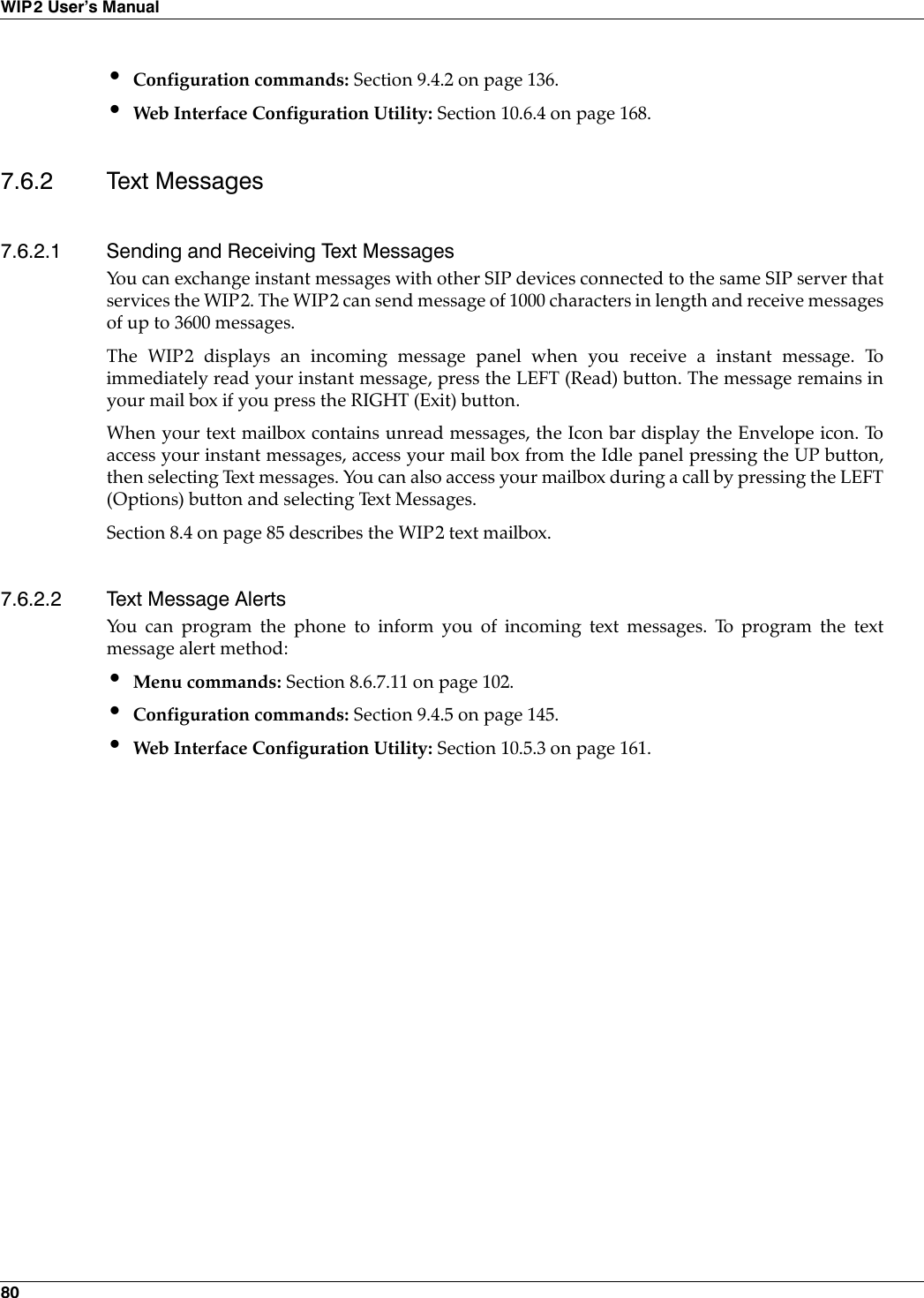
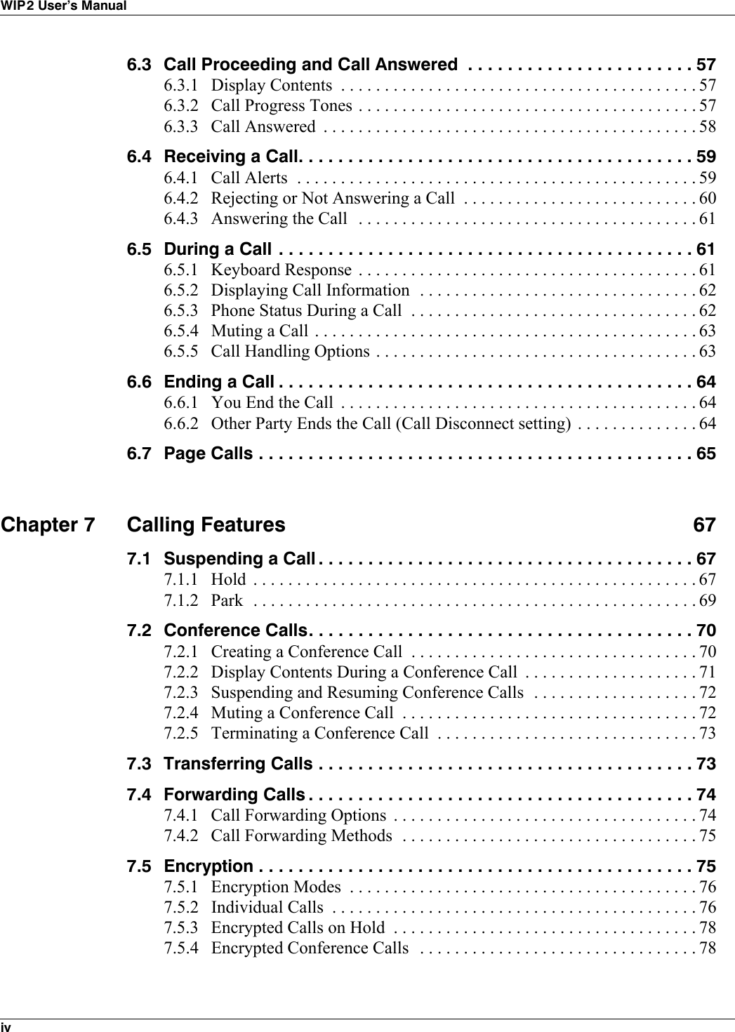
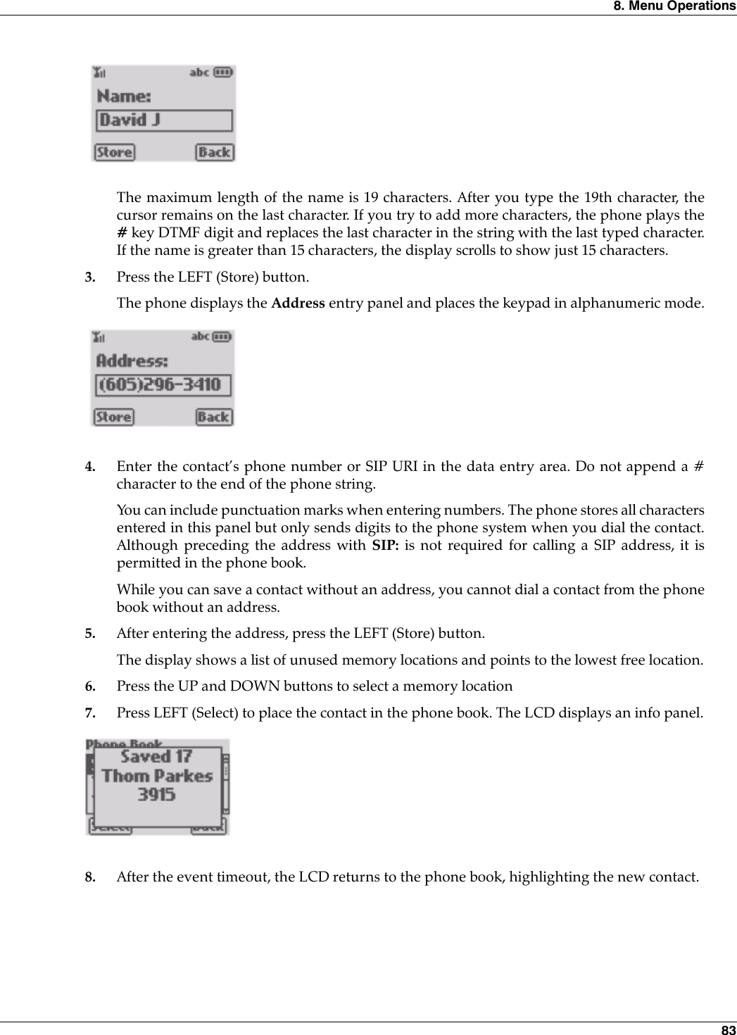
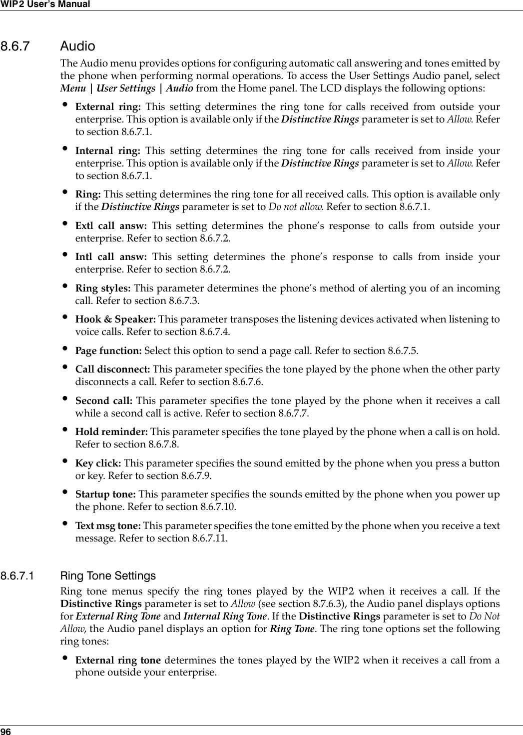
![82WIP2 User’s Manual8.2 PresencePresence is a service available on the MX250, MX30, and many other systems that uses anddistributes the availability status of each system user. Presence information allows you to verifythe availability of system users before attempting to contact them. Refer to section 5.7 on page 50for more information.To modify your presence state:1. Select Menu | Presence.The Presence list comprises the following presence states: Available, Not Available, Busy, AtLunch, In a Meeting, Be Right Back, and Appear offline.2. Use the UP and DOWN buttons to scroll through the Presence list. Select the desired stateand press the LEFT (Select) button.Press the RIGHT (Back) button to exit the Presence list without changing the presence state.8.3 Phone BookMenu commands add, edit, and remove contacts from your WIP2 phone book. You can alsosearch for a specific contact or execute a voice call to a contact from phone book menu. Section 5.6on page 49 describes the WIP2 phone book. The following section describes procedures foradding, editing, and deleting contacts and for searching the phone book for specific contacts.When you select Menu | Phone Book, the first row is a New Entry option, followed by the nameof the first contact in the phone book. The phone book lists your contacts in alphabetic order.8.3.1 Add New ContactTo add a new contact to the phone book:1. Select Menu | Phone Book | [New entry]The phone displays the Name entry panel and places the keypad in alphanumeric mode:2. Type the name of the contact using alphabetic mode, as described in section 5.3.5 on page 43.](https://usermanual.wiki/Zultys-Technologies/WIP2/User-Guide-630473-Page-92.png)
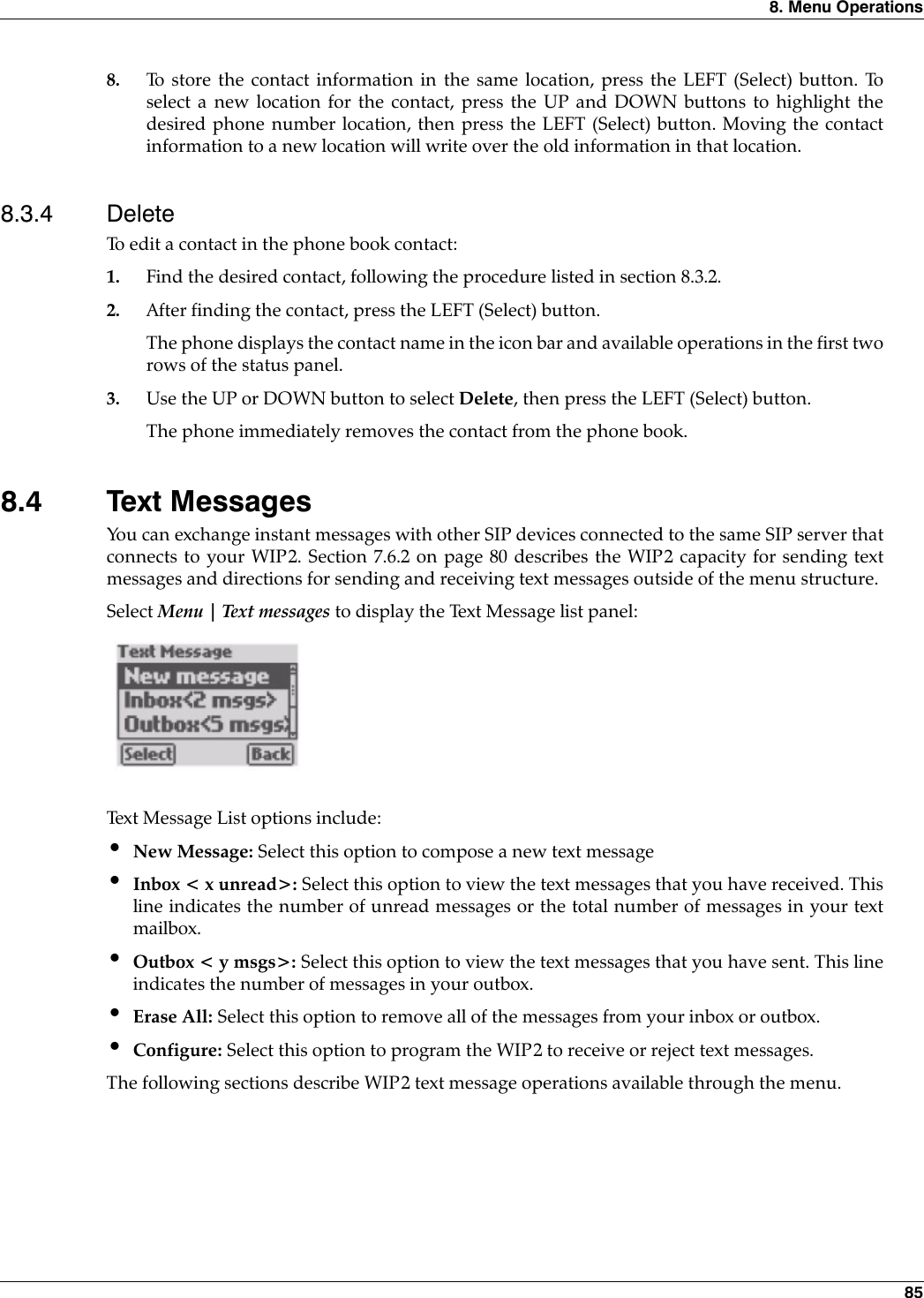
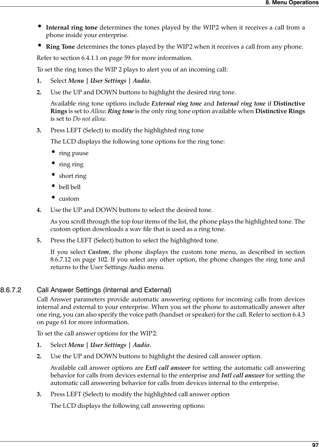
![86WIP2 User’s Manual8.4.1 Composing and Sending a New Text MessageTo create and send a new text message: 1. Select Menu | Text Message | New message from the Home panel.The phone displays the Text message data entry panel and places the keypad in characterentry mode:2. Enter the message in the data entry area using the character mode described in section 5.3.5on page 43.3. Press LEFT (Options) after entering your message.4. Select Send and press the LEFT (Select) button to specify the recipient to your message. Thephone displays the phone book contacts, which you can use to select the message recipient.To delete the message and return to the date entry area, select Erase all text before pressingLEFT (Select).5. Specify the recipient of your message from the phone book.If the phone book contains the contact to receive the message, highlight the contact name bysearching the phone book (section 8.3.2) or by using the UP and DOWN buttons.If the phone book does not contain the contact, select [New Entry] from the Send Message topanel, then enter the phone number or address of the recipient (see step 4 in section 8.3.1).If the phone book is empty, the WIP2 displays a Phone Number data entry panel. Enter thephone number of the recipient, then press LEFT (Select).6. Press the LEFT (Select) button to send the message to the highlighted contact.The phone displays a Message sent panel, then returns to the Text messages panel.8.4.2 View Inbox ContentsText messages received by the WIP2 are placed in the inbox. The icon bar displays the Envelopeicon when the inbox contains unopened instant messages. If you have unread messages, theInbox line displays number of unread messages in the Inbox; otherwise, this line displays thenumber of messages the Inbox contains.From the Inbox, you can view the contents of the Inbox and access each text message in the box.You can also reply to your text messages or remove messages from the Inbox.To access the instant message inbox:1. Select Menu | Text Message | Inbox from the Home panel. The LCD displays the list of instant messages in your inbox, as shown below. If the Inboxcontains more than three messages, the Inbox displays contents bar on the right side of thepanel. This bar indicates the cursor position relative to the contents of the entire Inbox.](https://usermanual.wiki/Zultys-Technologies/WIP2/User-Guide-630473-Page-96.png)
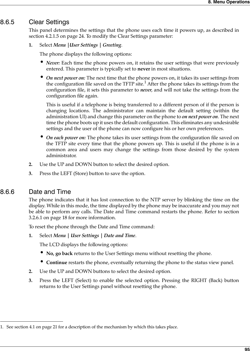
![8. Menu Operations 933. Press the LEFT (Store) to enable the new contrast setting and return to the User Settingspanel. Press the RIGHT (Back) button to return to the User Settings panel without changingthe Contrast setting.8.6.2 Call ForwardingThis panel programs the phone to forward incoming calls. Section 7.4 on page 74 describes theWIP2 call forwarding function.To configure the phone to forward calls:1. Select Menu | User Settings | Contrast.The phone displays the following options:•off: select this option to turn off call forwarding•all calls: select this option to forward all incoming calls•on no answer: select this option to forward calls that you do not answer•when busy: select this option to forward calls when you are 2. Press the UP and DOWN buttons to highlight the desired forwarding option.3. Press the LEFT (Select) button to select the highlighted optionIf you select Off, the menu returns to the User Settings menuIf you select any other option, the phone displays the Forward to menu that lists your phonebook contacts.4. To select a contact, press the UP and DOWN buttons to highlight the contact.To specify a phone number or address instead of a phone book contact, highlight [SpecifyNumber], press LEFT (Select), then enter the number or address of the phone that willreceive your calls5. Press the LEFT (Select) button to activate call forwarding.The Home panel displays a forwarding icon on the icon bar when call forwarding is active:8.6.3 Right ButtonThis panel determines the function that the phone performs when you press the RIGHT softbutton from the Home panel. Section 5.3.4 on page 43 provides more information about RIGHTsoft button options.To program the Right Button:1. Select Menu | User Settings | Right Button.](https://usermanual.wiki/Zultys-Technologies/WIP2/User-Guide-630473-Page-103.png)

![132WIP2 User’s ManualThe common configuration file identifies the location of the specific configuration files. A phoneextracts configuration information from the common file first, then from its specific configurationfile. Parameter settings in the specific file take precedence over settings of the same parameters inthe common file. The name of the specific configuration file is:<MAC address>.cfgFor example,000BEA801ADC.cfgis the specific configuration file for a phone that has the MAC address 00:0B:EA:80:1A:DC.9.3 Configuration File FormatCommon and specific configuration files are similar in format and composition. Mostconfiguration parameters can be set in either file. Configuration files are stored in ASCII format. 9.3.1 File SectionsEach file is separated into sections, with each section containing settings for a functionalparameter group. The order of the functional sections within each configuration file has no affectupon the configuration of the phone. The first line in each section contains the name of thefunctional group, denoted by square brackets. Figure 9-1 displays the name of each functionheading and the proper format of the headings.9.3.2 Parameter EntriesAll available parameter settings are classified by function, as described in section 9.4. Eachparameter within a configuration file must be contained within its defined functional section. Theorder of parameters within each function section does not effect the configuration of the phone.If a parameter is defined in the common file and the specific file, the specific file setting takesprecedence. Figure 9-2 displays an example of parameter settings in a configuration file.[NET_CONFIG][SIP_CONFIG][GENERAL_INFO][HW_CONFIG][AUDIO_INFO][LOCATIONS]Figure 9-1 Configuration File Section Headings](https://usermanual.wiki/Zultys-Technologies/WIP2/User-Guide-630473-Page-142.png)
![9. Configuration Files 133The name of the parameter and the parameter value must be on the same line. The name of theparameter is not case sensitive; it can be entered in either upper or lower case. However,parameter values are case sensitive. Refer to the parameter tables in section 9.4 for more details.Comment lines are denoted with a leading semi-colon (;) and have no effect on the configurationof the phone.9.4 Configuration ParametersThis section provides tables that list all of the configuration parameters in each functional group.Parameters in each table are listed in alphabetic order. Many parameters correspond to anequivalent menu command; the tables refer to the section describing the menu command for eachof these parameters.9.4.1 Network ConfigurationNetwork configuration parameters define settings required by the phone to communicate withthe network. Figure 9-3 lists the network configuration parameters.[HW_CONFIG]lcd_contrast=8ring_volume=5speaker_volume=5[NET_CONFIG]use_dhcp=yestftp_cfg_dir=./WIP2Figure 9-2 Configuration File ExampleParameter Description Referencedefault_gateway Parameter is IP address of default gateway that is used for manual configuration when use_dhcp is set to ‘no’ or DHCP does not provide the default gateway (DHCP option 3). Valid setting is 32 bit IP address in dotted decimal notation.Default value is NULL string.section 4.5.2.2 on page 32domain Parameter is name of the domain in which the phone resides; used for manual configuration when use_dhcp is set to ‘no’ or DHCP does not return the domain (DHCP option 15). Valid settings include FQDN or IP address in dotted decimal notation.No default value.section 4.5.3.1 on page 33dscp_setting Configures DiffServ (layer 3 QoS) setting. All voice packets (RTP) leaving the phone will have the ToS byte in the IP header set to this value. Valid settings range from 0 to 63.Default value is 0.section 4.5.2.2 on page 32ip_addr Parameter is static address assigned to the phone. Used for manual configuration when use_dhcp is set to ‘no’ or DHCP does not return an address (DHCP option 50). Valid setting is 32 bit IP address in dotted decimal notation.Default value is NULL string.section 4.5.2 on page 32Figure 9-3 Network Configuration Parameters](https://usermanual.wiki/Zultys-Technologies/WIP2/User-Guide-630473-Page-143.png)
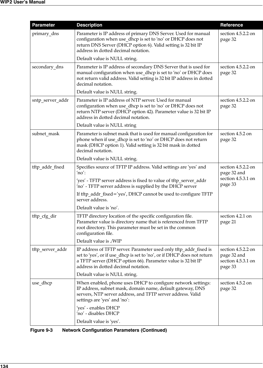
![9. Configuration Files 1359.4.1.1 Server Parameter SettingsAlthough the default values for the following parameters may be set properly for your networkconfiguration, it is highly recommended that the configuration files explicitly define the settingsfor these variables.use_dhcp: This command specifies the use of DHCP to configure the phones network settings.When DHCP is enabled, the DHCP server should dynamically provide an IP address and subnetmask for the phone, along with IP addresses for the DNS servers, default gateway, NTP server,and TFTP server. If dhcp is not enabled, or if the DHCP is unable to return addresses for any of these servers, youmust specify valid IP addresses for each server or the phone will not properly configure onstartup.tftp_cfg_dir: This parameter points to the TFTP server directory that stores the specificconfiguration file for your phone. This parameter must be set in the common configuration file inorder for the phone to read and process its specific configuration file. The default value of ./WIP2is valid only if your TFTP server contains a directory by that name and if the specific configurationfile resides in that directory.9.4.1.2 Sample Configuration FileFigure 9-4 displays the network settings section from a sample configuration file.[NET_CONFIG]use_dhcp=yesip_addr=subnet_mask=default_gateway=primary_dns=secondary_dns=domain=zultys.comsntp_server_addr=tftp_server_addr=tftp_cfg_dir=./WIP2dscp_setting=0Figure 9-4 Sample Configuration File – Network Settings](https://usermanual.wiki/Zultys-Technologies/WIP2/User-Guide-630473-Page-145.png)
![9. Configuration Files 139[SIP_CONFIG]phone_sip_port=5060rtp_start_port=33000;The Device ID is the user portion of the SIP URIdevice_id=West;The Display Name is sent in SIP messagesdisplay_name=Zultys WIP2;This must always be set to “yes”register_w_proxy=yesproxy_addr=10.1.32.224proxy_port=5060voice_mail_uri=258registration_expires=3600Figure 9-6 Sample Configuration File – SIP Settings](https://usermanual.wiki/Zultys-Technologies/WIP2/User-Guide-630473-Page-149.png)
![9. Configuration Files 1439.4.3.3 Sample Configuration File Figure 9-10 displays the General Information settings section from a sample configuration file.[GENERAL_INFO]software_version=1.0.0;The message displayed on the LCD in idle modegreeting_message=WIP2 Phonepassword=985897time_fmt=%H:%Mdate_fmt=%m-%-d-%Ydate_time_order=0;This is the offset from GMT, in minutestimezone=-480country=USAlanguage=en_US.iso88591clear_settings=2Figure 9-10 Sample Configuration File – General Information Settings](https://usermanual.wiki/Zultys-Technologies/WIP2/User-Guide-630473-Page-153.png)
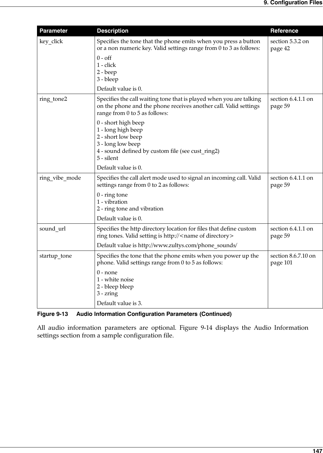
![144WIP2 User’s Manual9.4.4 Hardware ConfigurationHardware configuration parameters adjust LCD and volume characteristics. Figure 9-11 lists thehardware configuration parameters.All hardware configuration parameters are optional. Figure 9-12 displays the Hardware settingssection from a sample configuration file.Parameter Description Referencehandset_volume Adjusts the handset volume. Values range from 0 (silent) to 20 (loud).Default value is 10.section 5.4.3 on page 46lcd_contrast Adjusts the LCD contrast. Values range from 1 (light) to 20 (dark).Default value is 7.section 5.2.3.1 on page 39ring_volume Adjusts the ringer volume. Values range from 0 (silent) to 20 (loud).Default value is 10.section 5.4.3 on page 46speaker_volume Adjusts the speaker volume. Values range from 0 (silent) to 20 (loud).Default value is 10.section 5.4.3 on page 46Figure 9-11 Hardware Configuration Parameters[HW_CONFIG]lcd_contrast=8ring_volume=5speaker_volume=5handset_volume=5Figure 9-12 Sample Configuration File – Hardware Configuration Settings](https://usermanual.wiki/Zultys-Technologies/WIP2/User-Guide-630473-Page-154.png)
![148WIP2 User’s Manual[AUDIO_INFO]ext_ring_tone=0ext_cust_ring=int_ring_tone=0int_cust_ring=ring_tone2=0cust_ring2=key_click=0codec=0distinctive_ring=yessound_url=Figure 9-14 Sample Configuration File – Audio Information Settings](https://usermanual.wiki/Zultys-Technologies/WIP2/User-Guide-630473-Page-158.png)
![150WIP2 User’s Manual[LOCATIONS]L1=Sunnyvale:VaquerosT1=PST+8:00L2=MoscowT2=MST-3:00L3=ChicagoT3=PST+8:00def_location=Sunnyvale:VaquerosFigure 9-15 Sample Configuration File – Locations Settings](https://usermanual.wiki/Zultys-Technologies/WIP2/User-Guide-630473-Page-160.png)
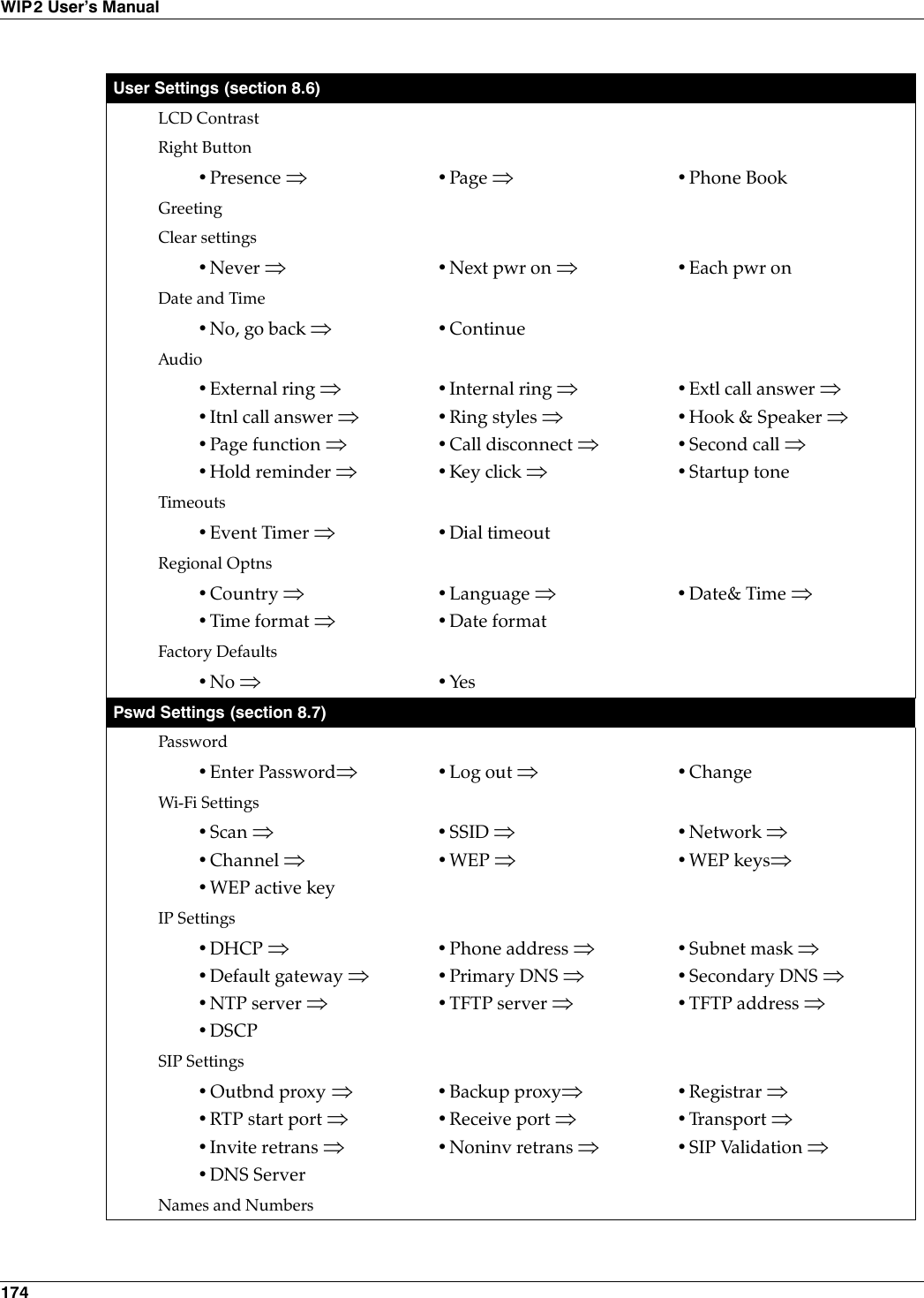
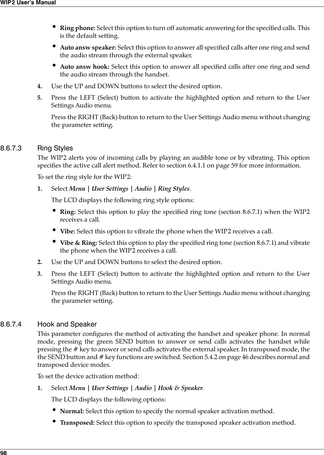
![173 Appendix AMenu StructurePresence (section 8.2)•Available ⇒•At lunch ⇒•Appear offline•Not available⇒•In a meeting ⇒•Busy ⇒•Be right back ⇒Phone Book (section 8.3)[New Entry]Contact Name•Edit ⇒•Delete ⇒Text Messages (section 8.4)New Messages•Send ⇒•Erase all textInbox•Reply ⇒•DeleteOutbox•Resend ⇒•DeleteErase All•Inbox ⇒•Outbox ⇒•BothConfigure•Receive & Show ⇒•RejectInformation (section 8.5)Times•Offset from GMT ⇒•Registered ⇒•Powered on ⇒•Total talk time•Connected ⇒Communications•Wireless ⇒ •TFTP address ⇒•Config fileManufacture•MAC address ⇒•H/W version ⇒•S/W version ⇒•Date•Boot code ⇒](https://usermanual.wiki/Zultys-Technologies/WIP2/User-Guide-630473-Page-183.png)