ZyXEL Communications 5VZ-A2011 Wireless router with VDSL2/ADSL broadband access User Manual ZyBook2
ZyXEL Communications Corporation Wireless router with VDSL2/ADSL broadband access ZyBook2
UserManual.wiki
>
ZyXEL Communications
>
5VZ A2011 User Manual
user manual
Navigation menu
Upload a User Manual
Namespaces
Wiki Guide
HTML
PDF
Info
Views
User Manual
Discussion / Help
Navigation
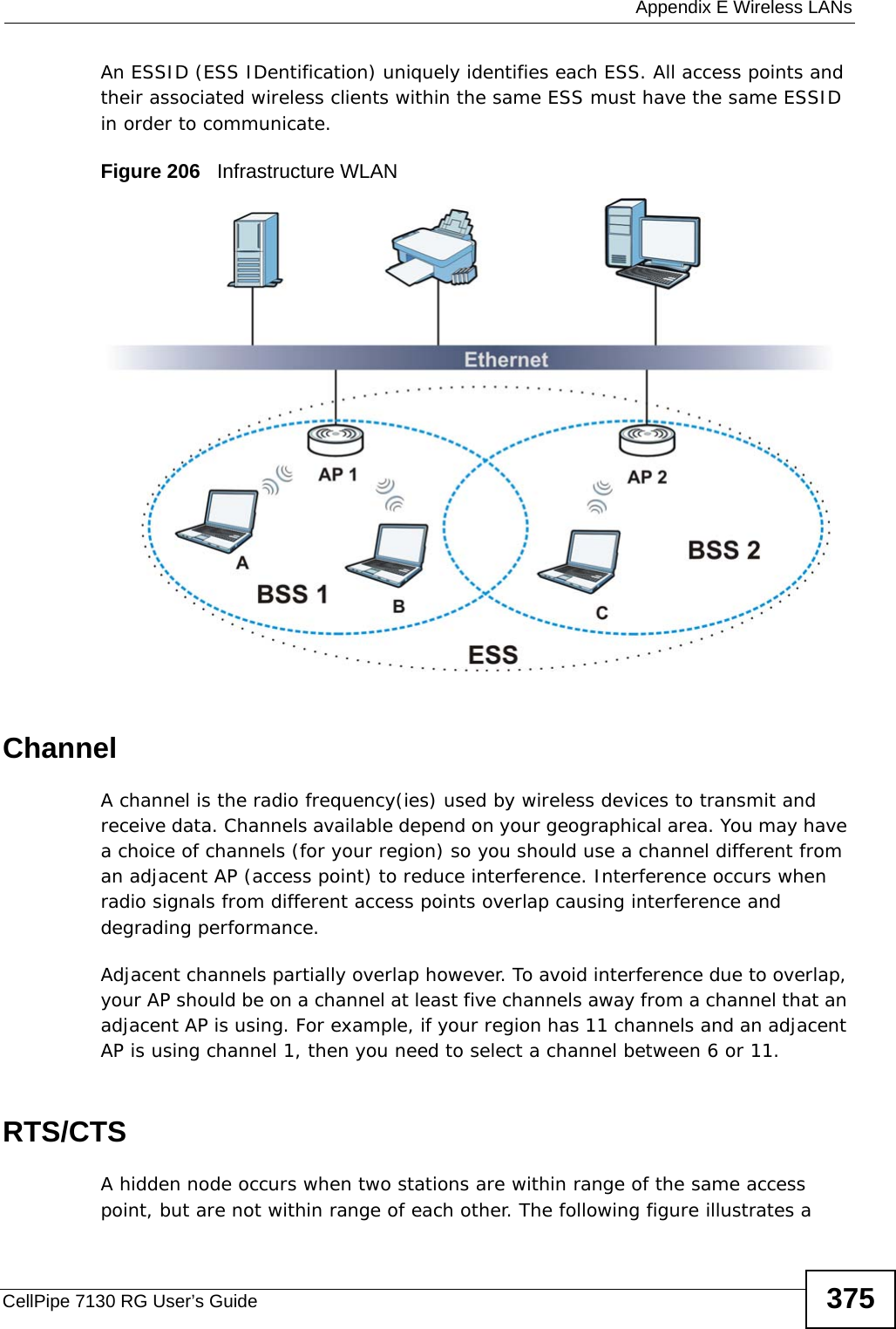
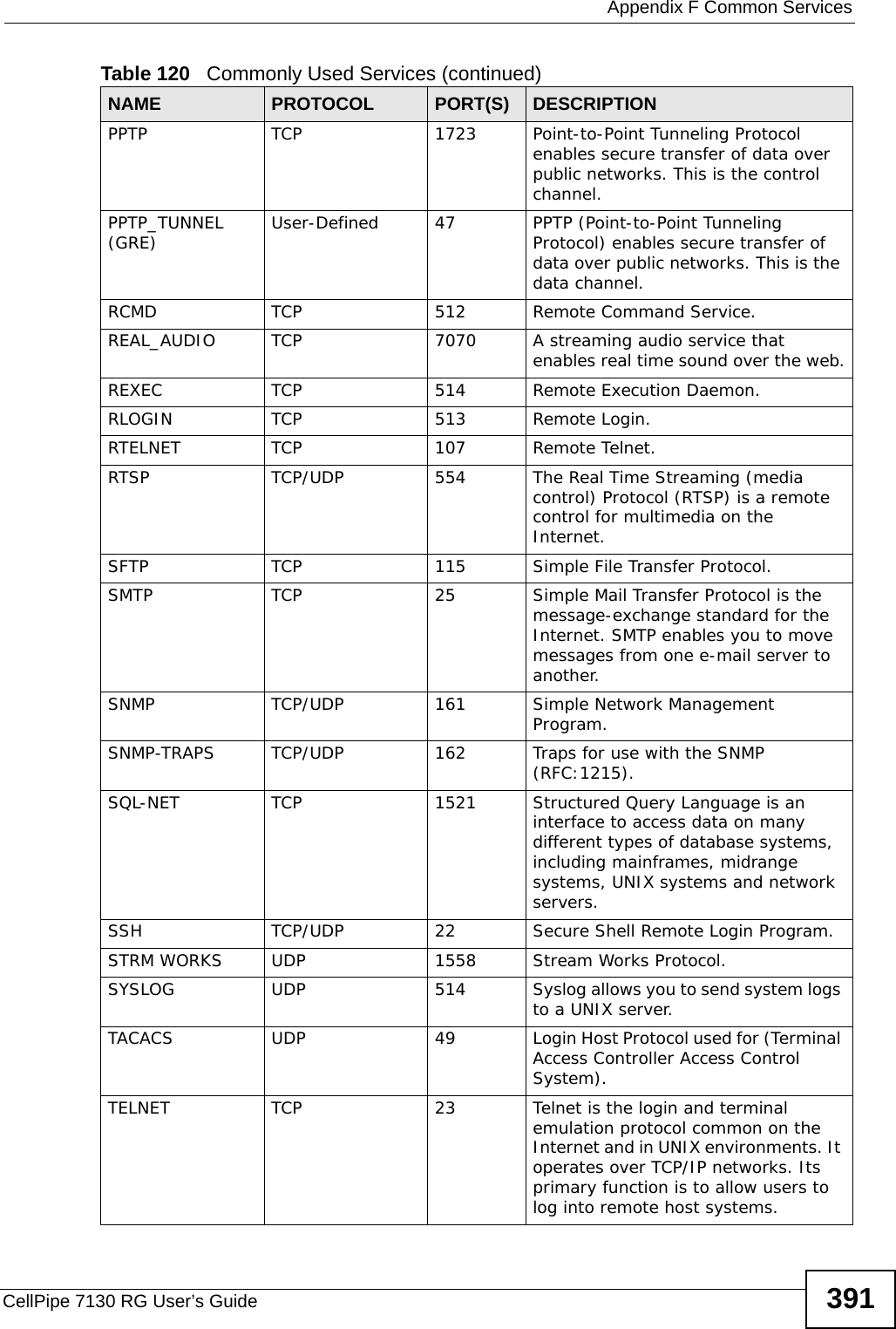
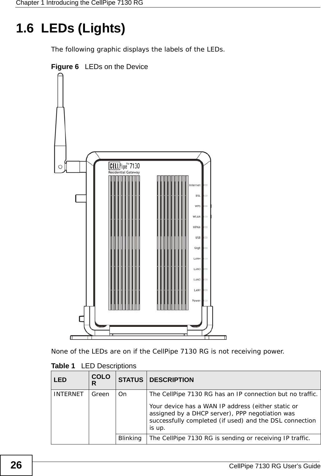
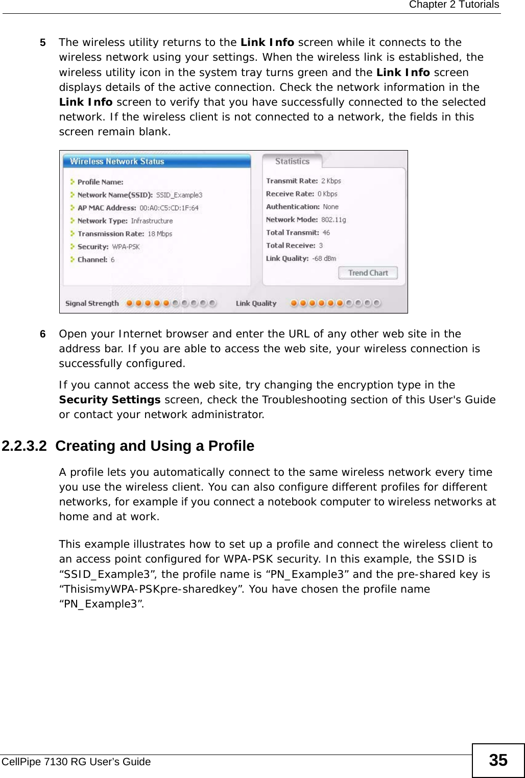
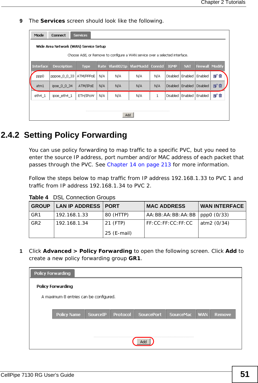
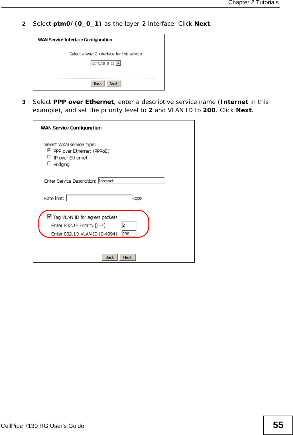
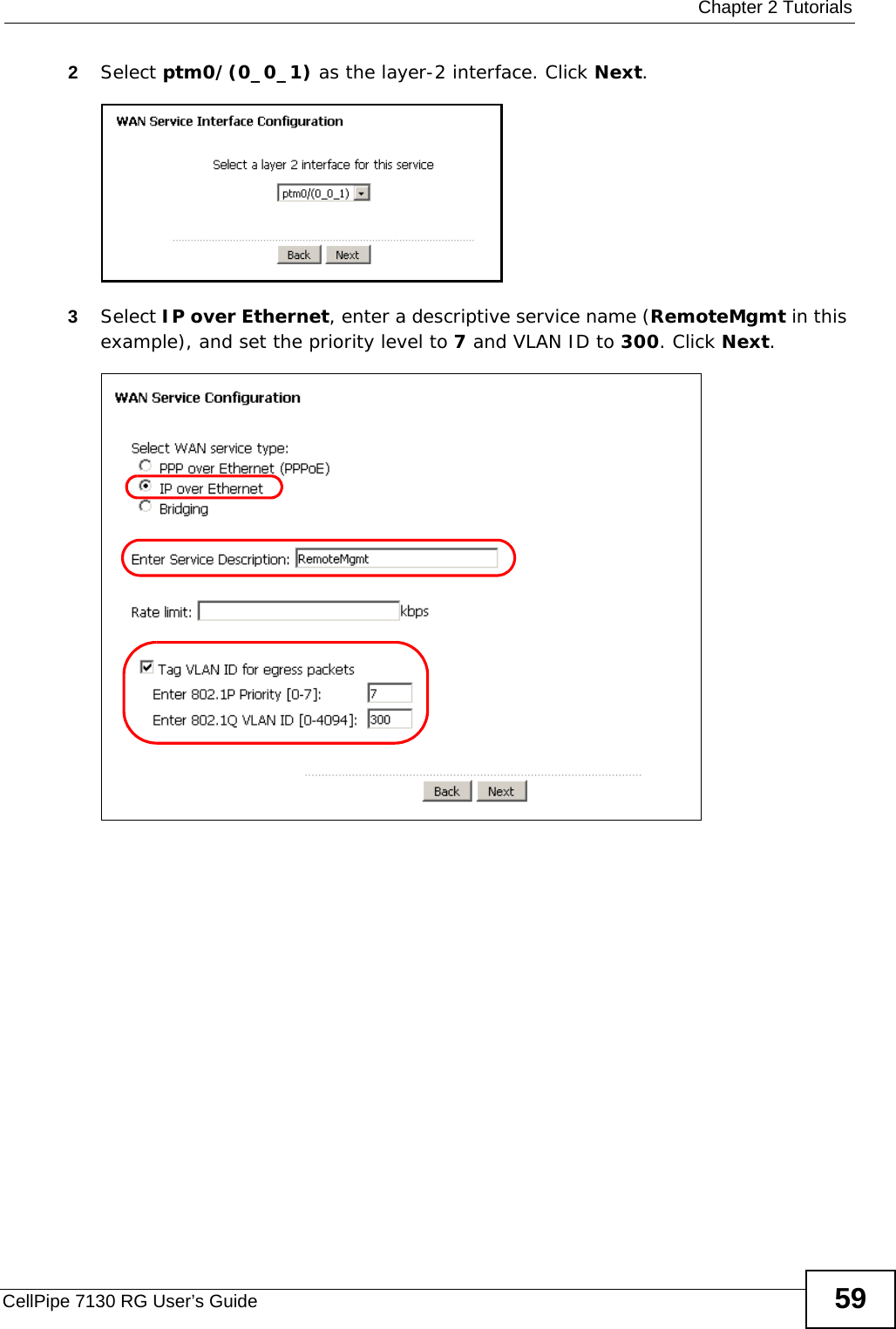
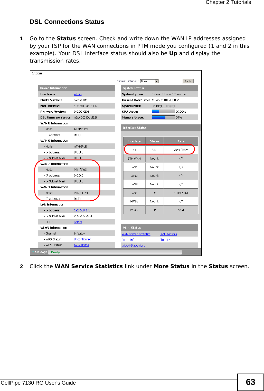
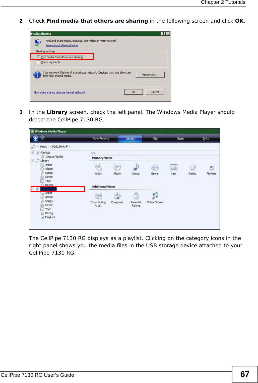
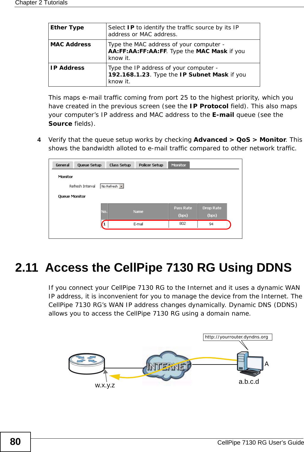
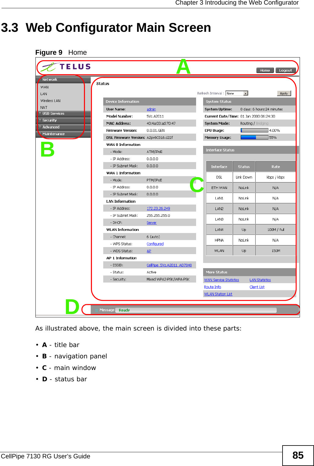
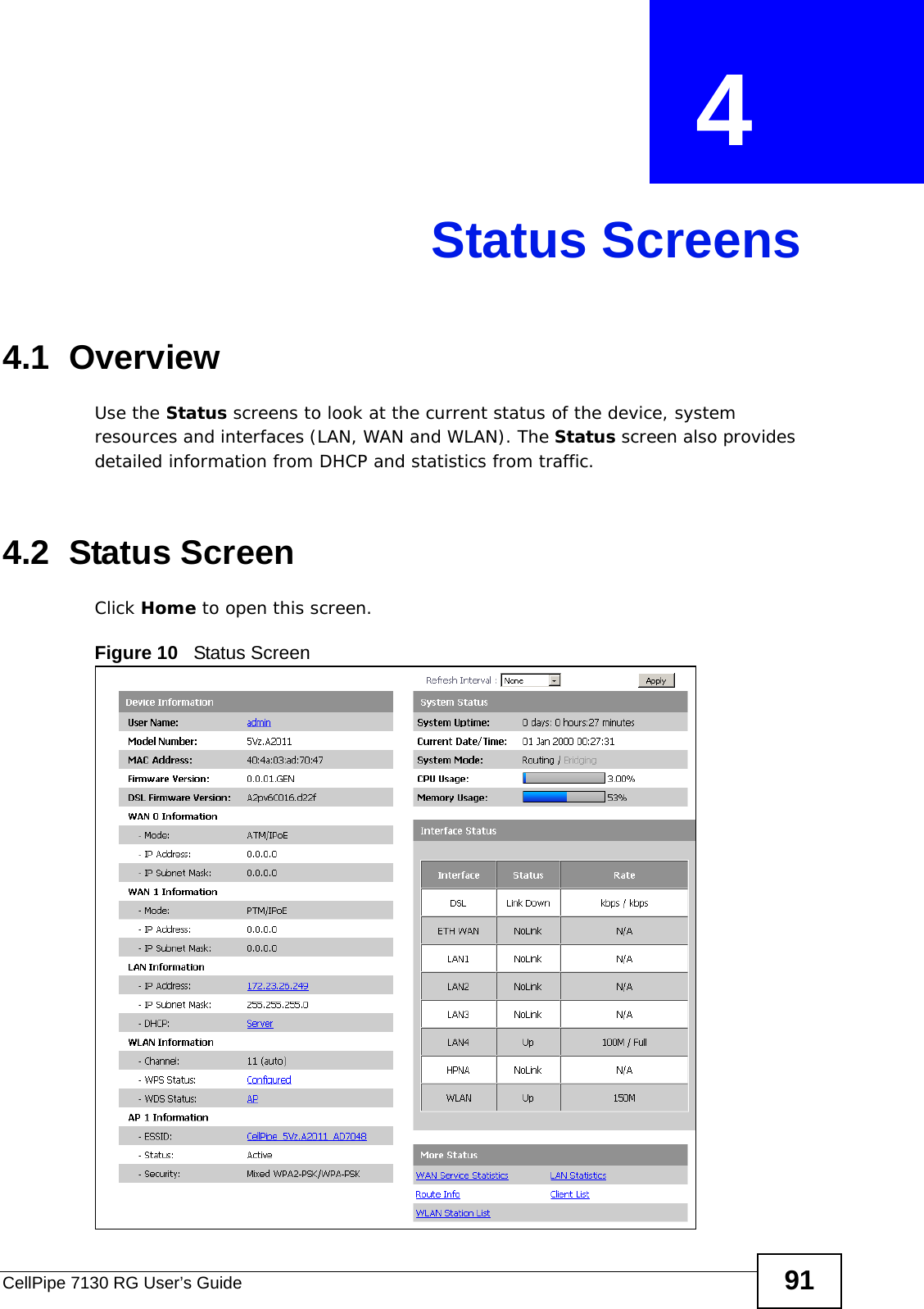
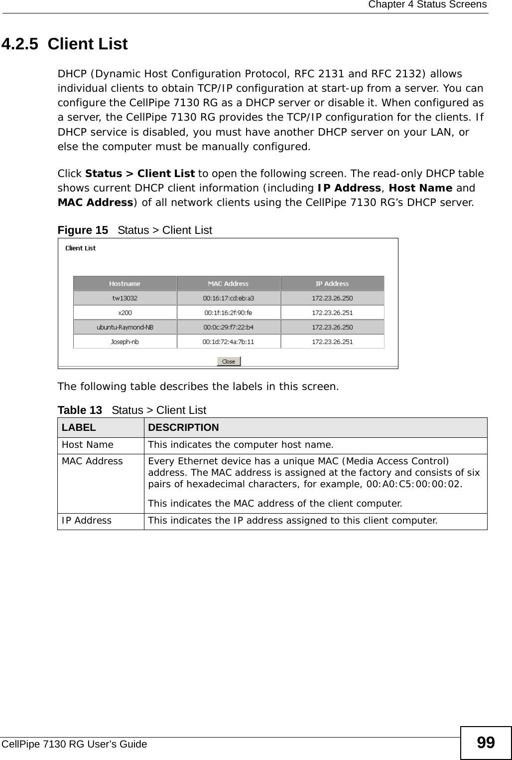
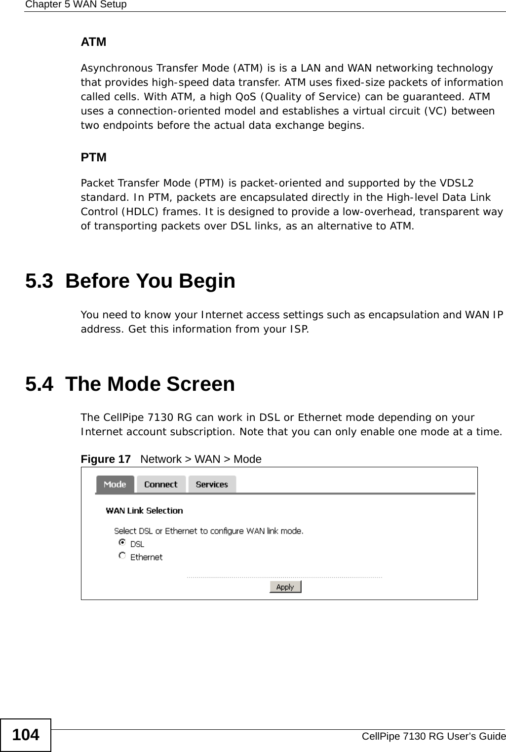
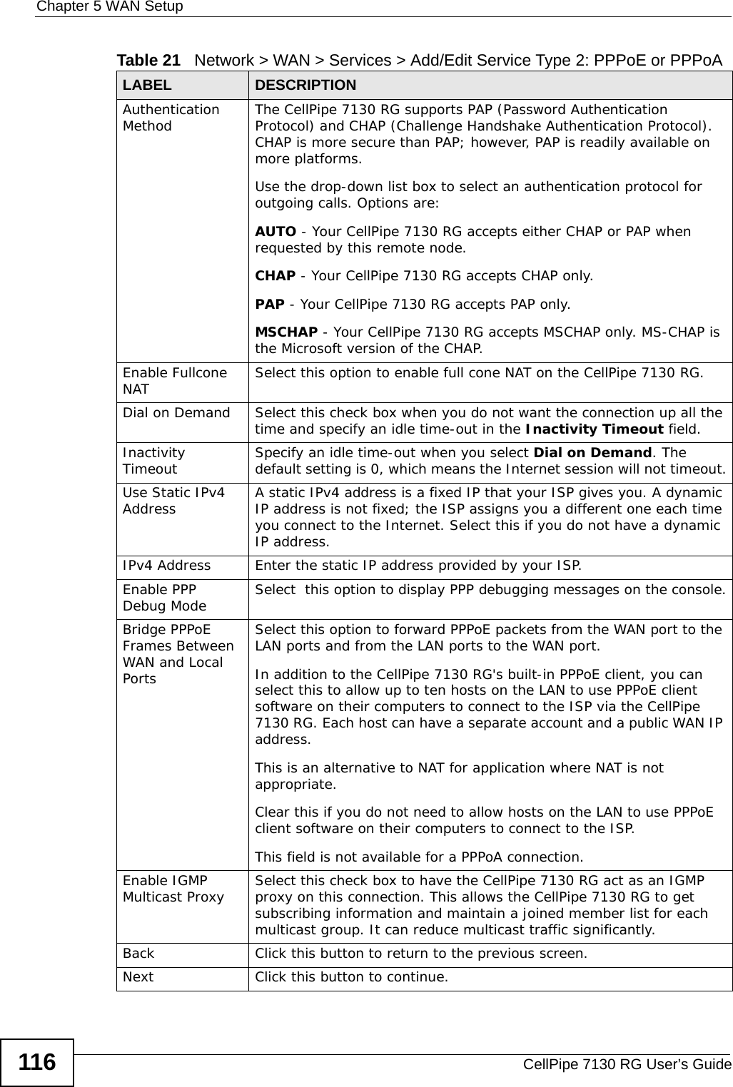
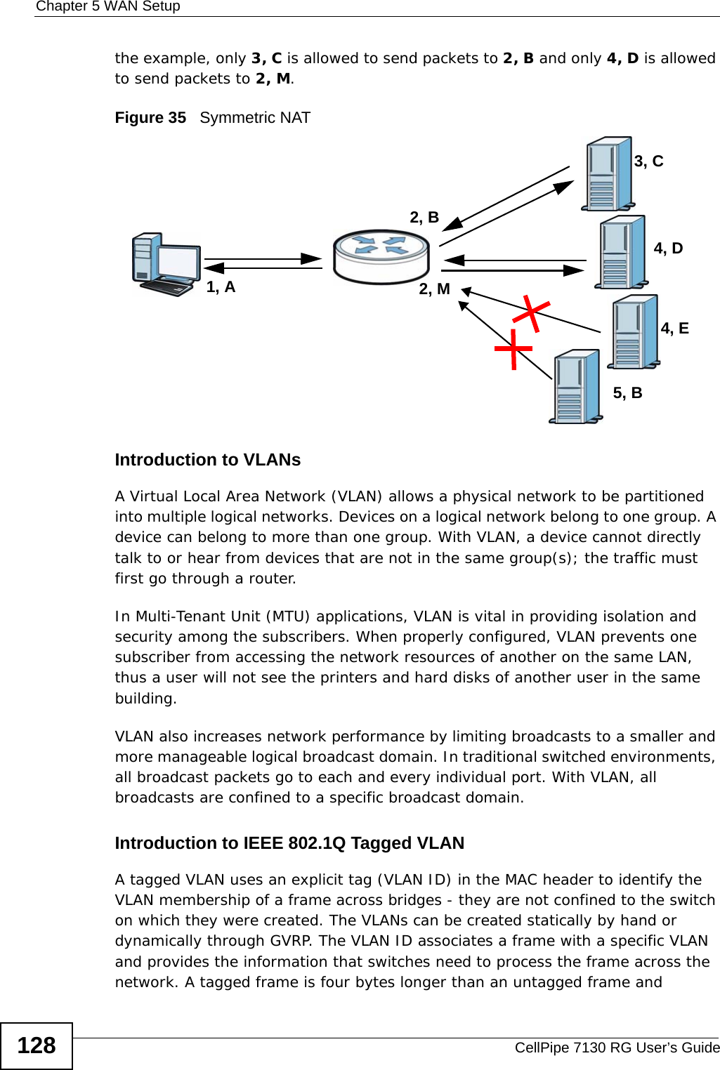
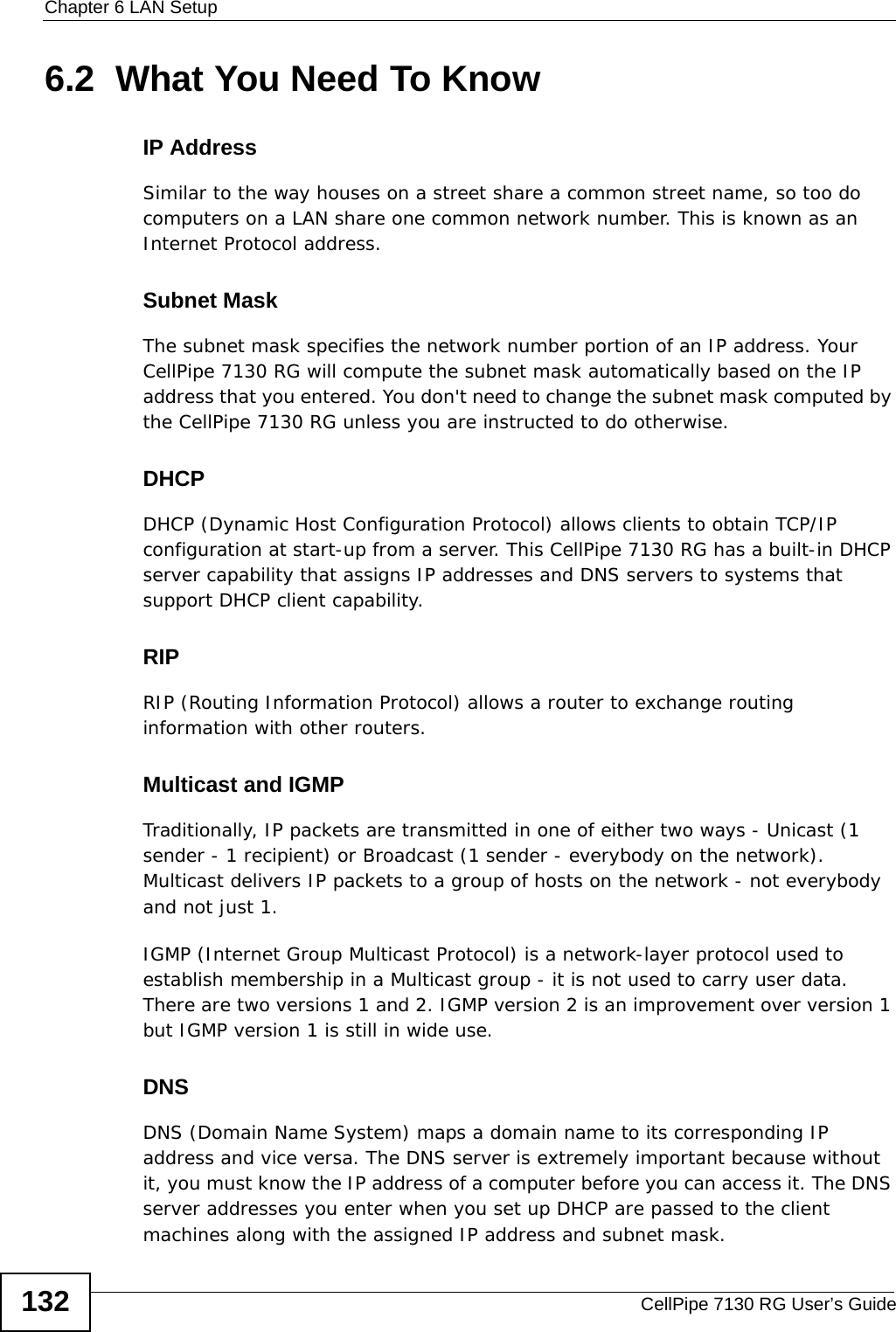
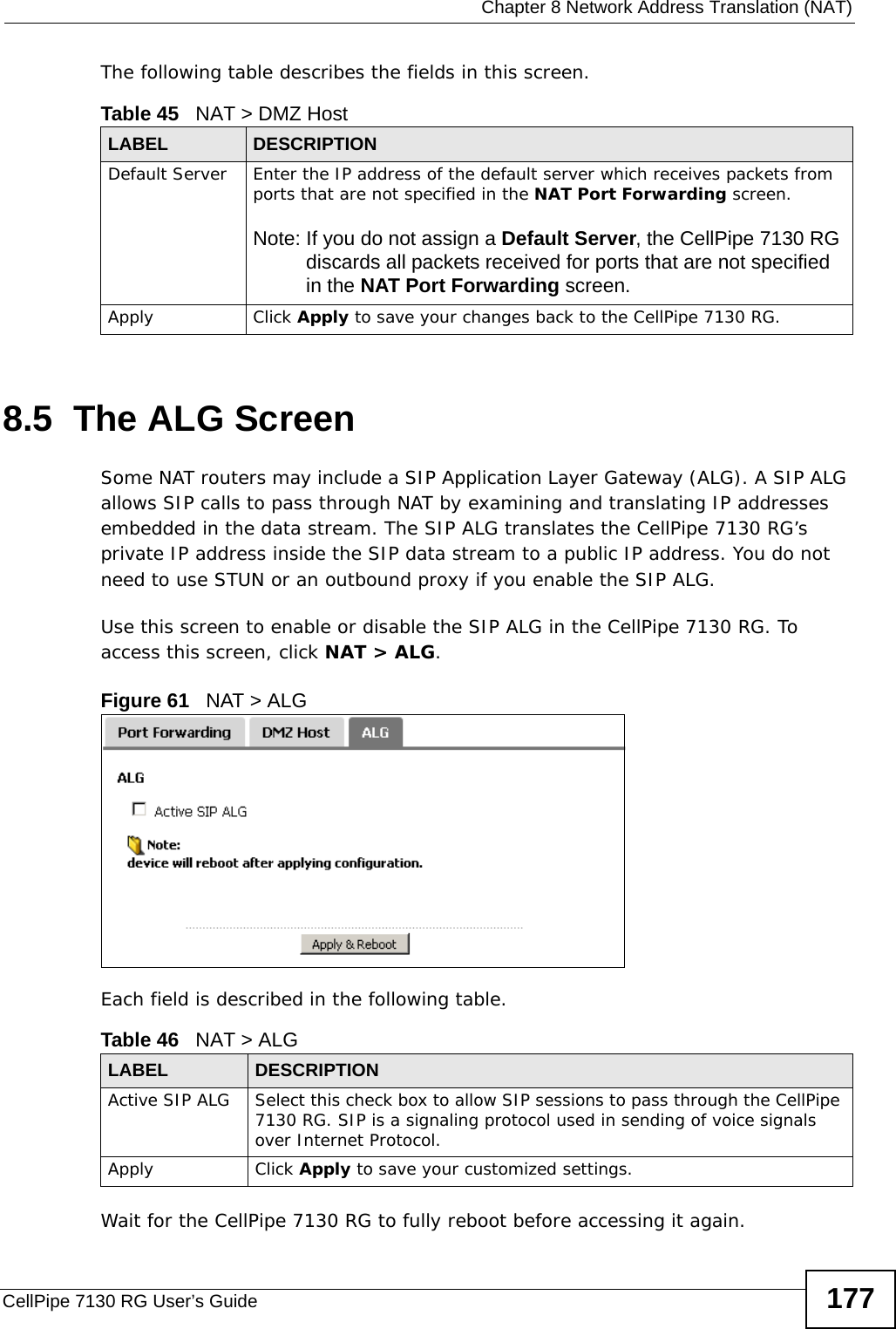
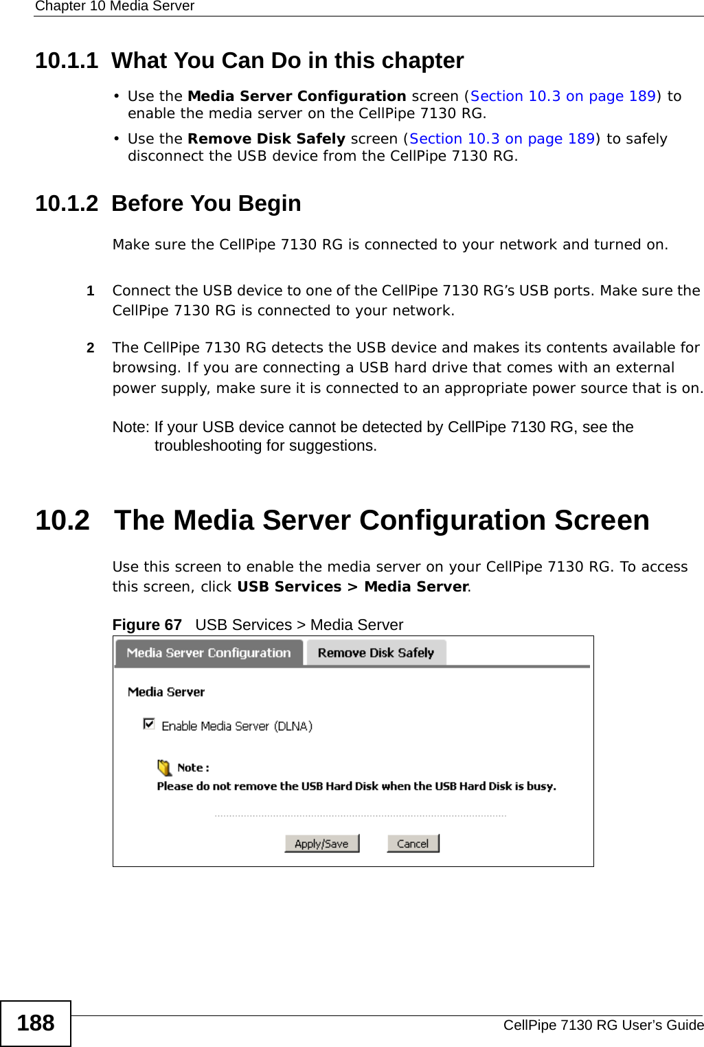
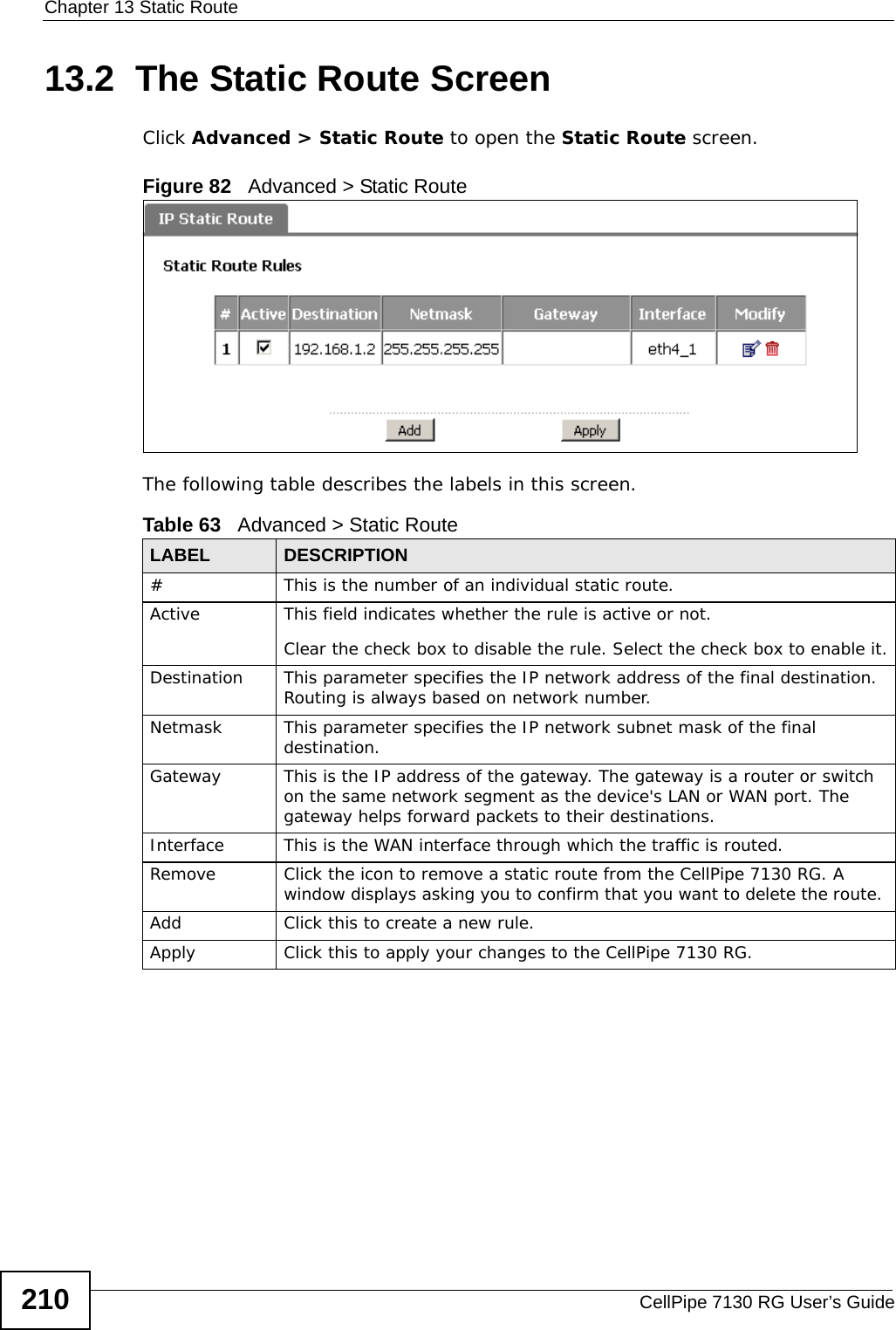
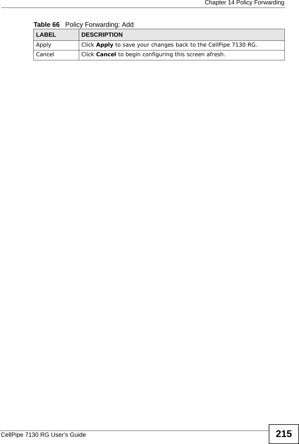
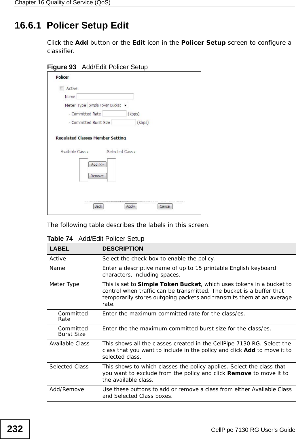
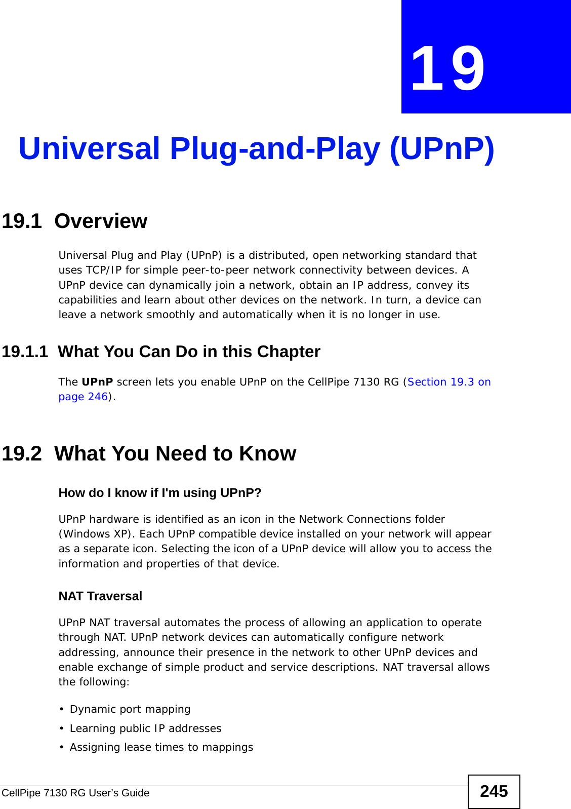
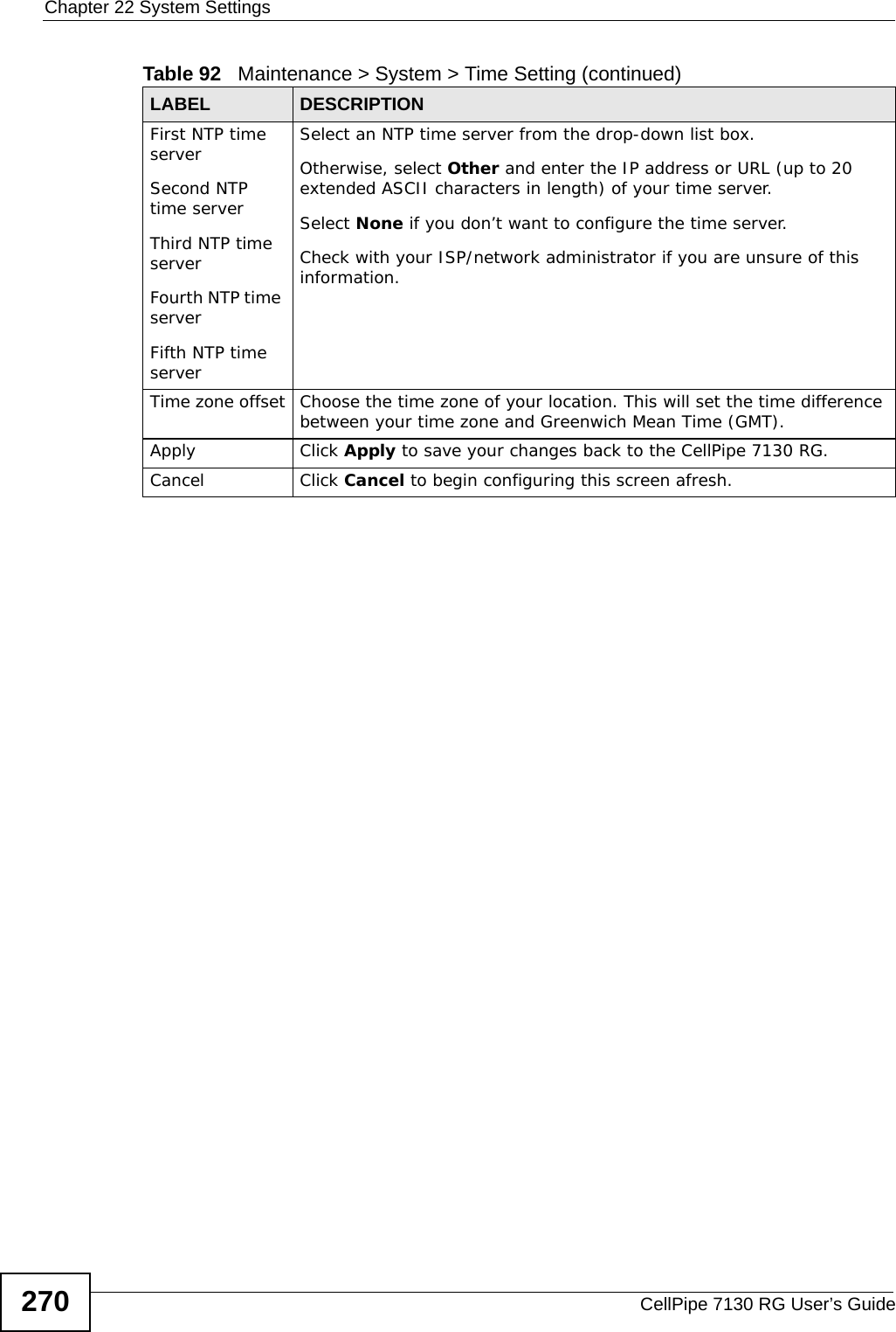
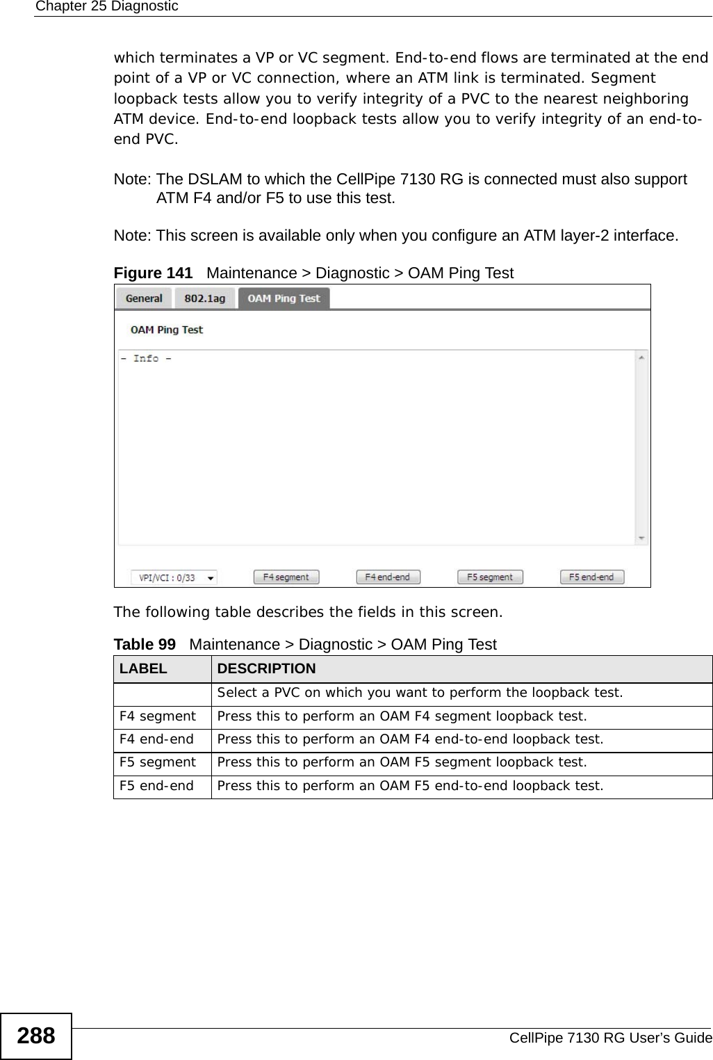
![Document ConventionsCellPipe 7130 RG User’s Guide4Document ConventionsWarnings and NotesThese are how warnings and notes are shown in this User’s Guide. Warnings tell you about things that could harm you or your device.Note: Notes tell you other important information (for example, other things you may need to configure or helpful tips) or recommendations.Syntax Conventions• The CellPipe 7130 RG may be referred to as the “CellPipe 7130 RG”, the “device”, the “system” or the “product” in this User’s Guide.• Product labels, screen names, field labels and field choices are all in bold font.• A key stroke is denoted by square brackets and uppercase text, for example, [ENTER] means the “enter” or “return” key on your keyboard.• “Enter” means for you to type one or more characters and then press the [ENTER] key. “Select” or “choose” means for you to use one of the predefined choices.• A right angle bracket ( > ) within a screen name denotes a mouse click. For example, Maintenance > Log > Log Setting means you first click Maintenance in the navigation panel, then the Log sub menu and finally the Log Setting tab to get to that screen.• Units of measurement may denote the “metric” value or the “scientific” value. For example, “k” for kilo may denote “1000” or “1024”, “M” for mega may denote “1000000” or “1048576” and so on.• “e.g.,” is a shorthand for “for instance”, and “i.e.,” means “that is” or “in other words”.](https://usermanual.wiki/ZyXEL-Communications/5VZ-A2011/User-Guide-1284006-Page-4.png)

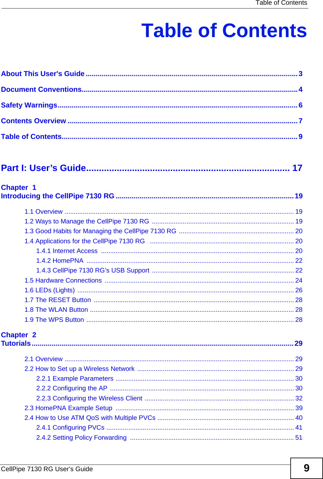
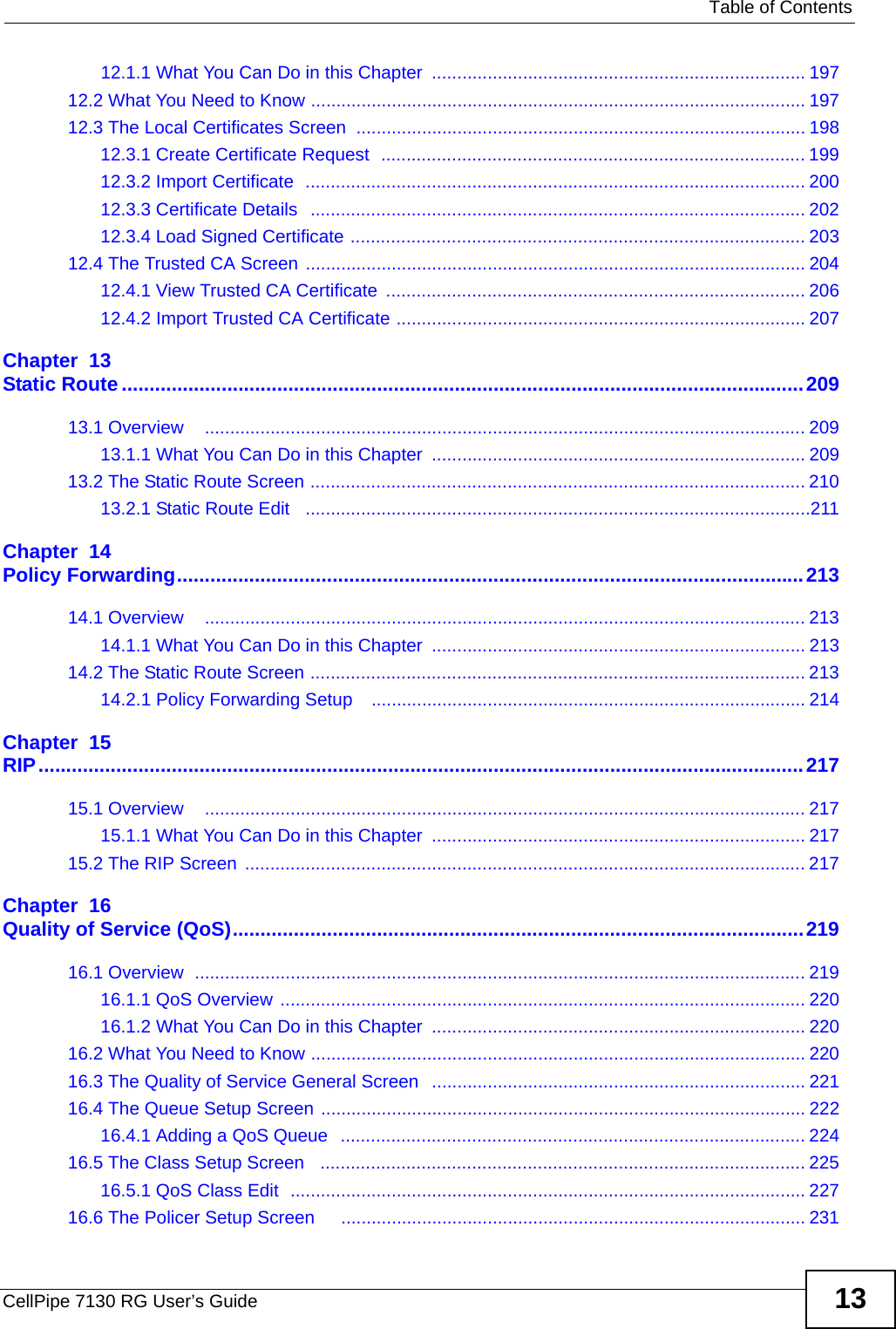


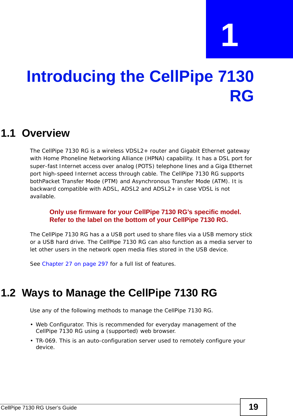
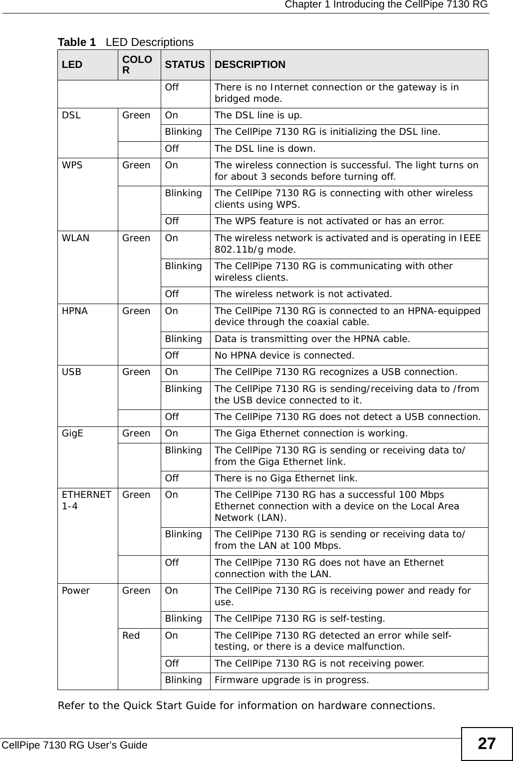

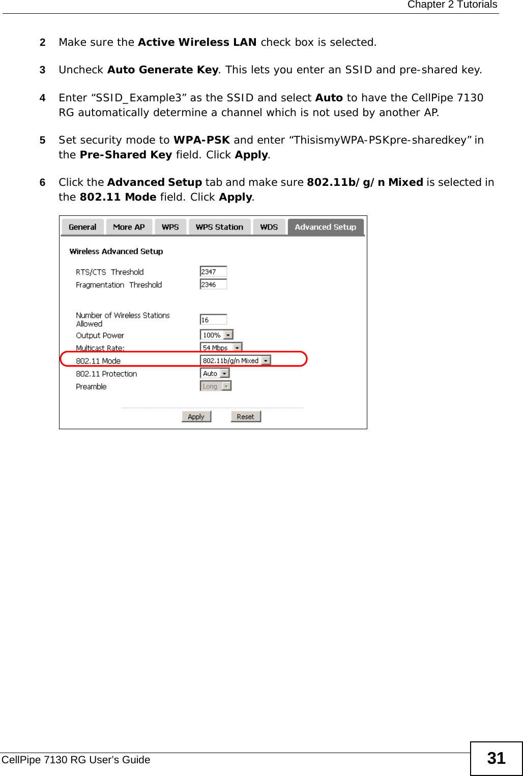
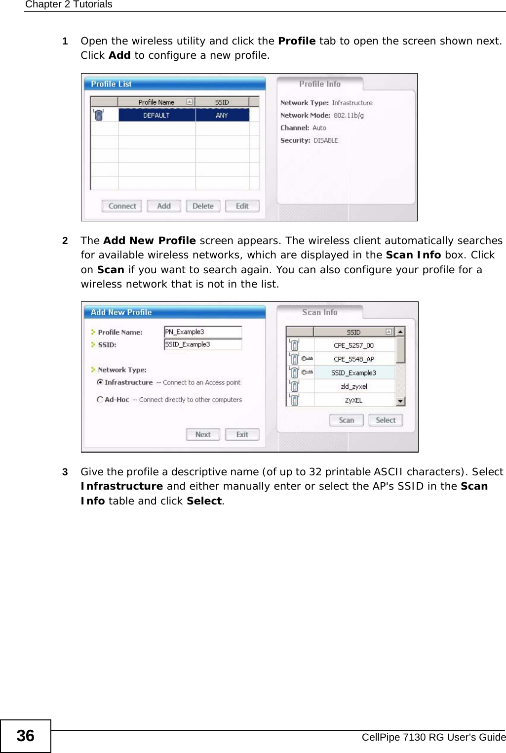
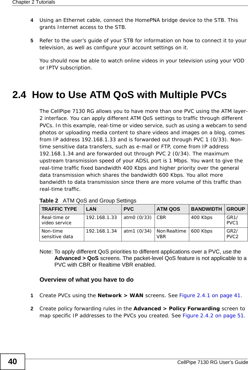
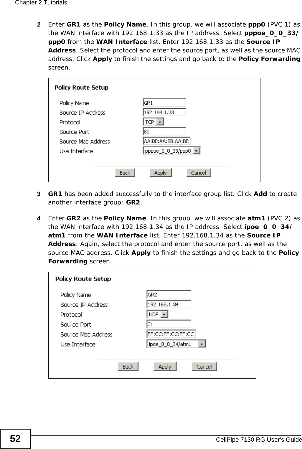
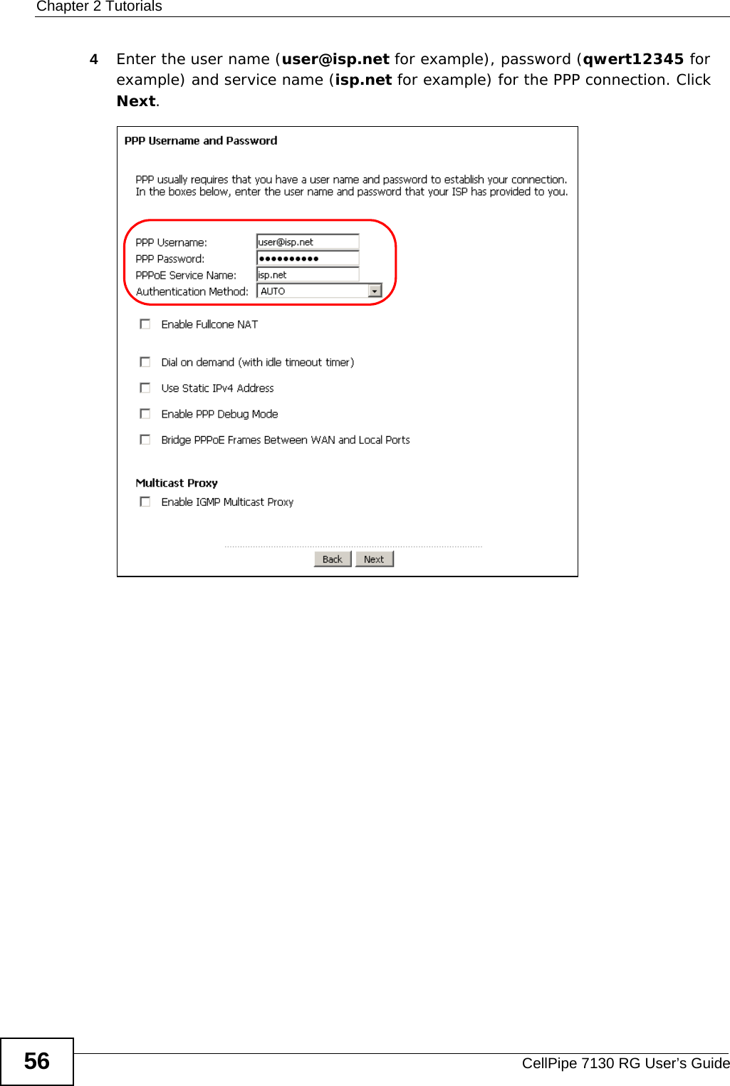
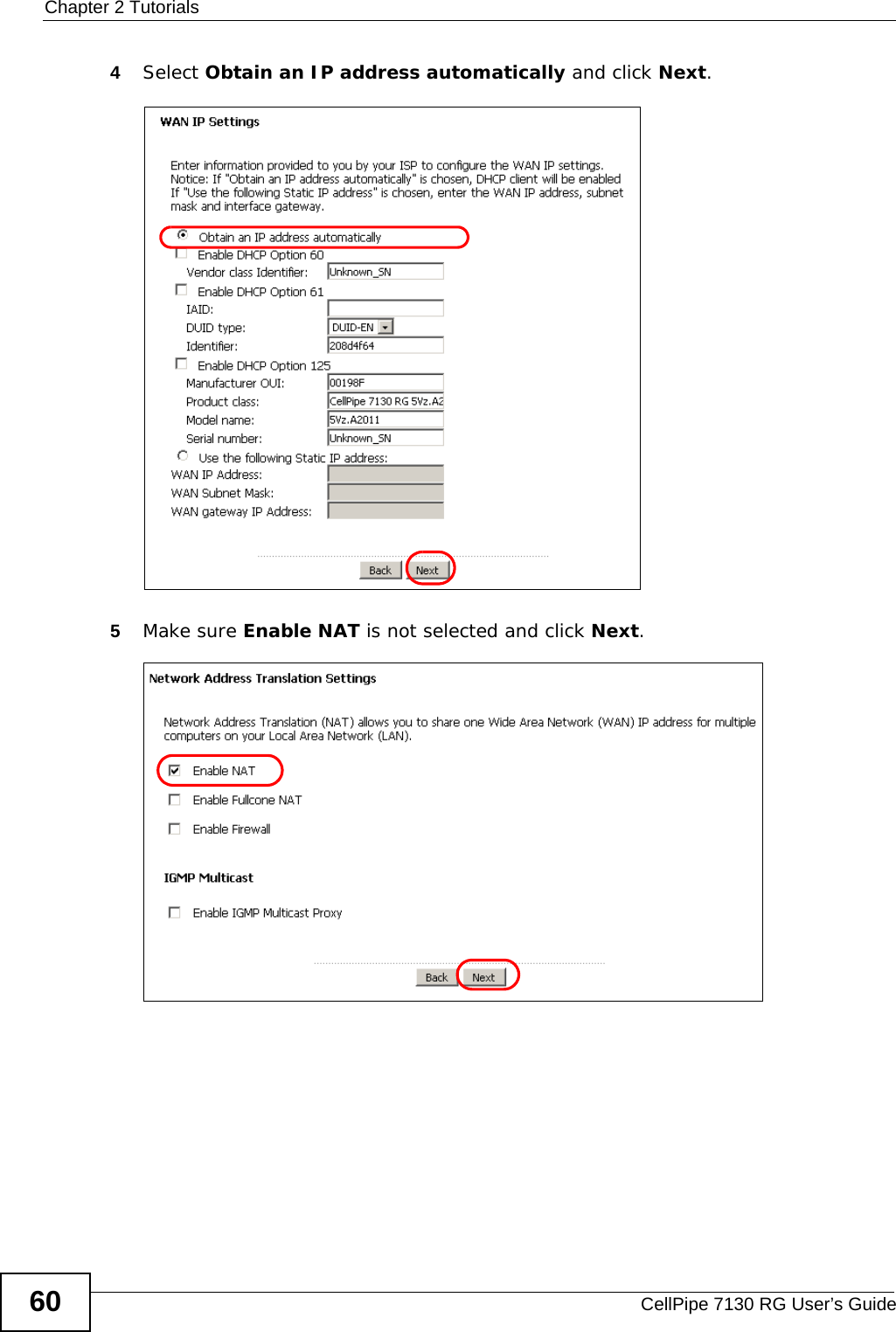
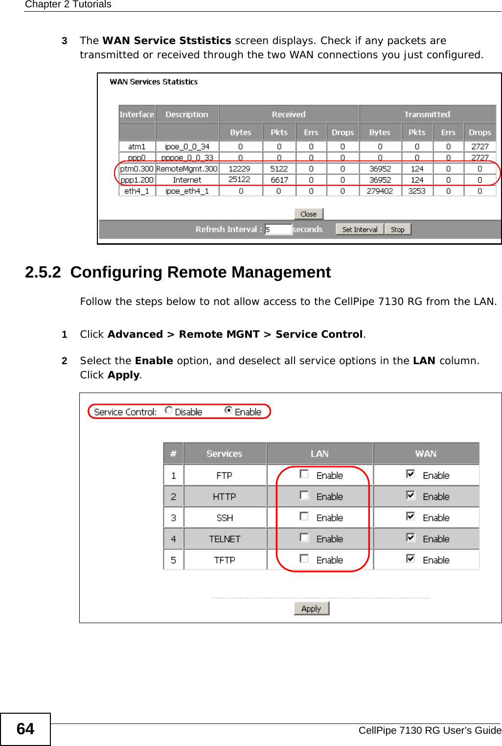
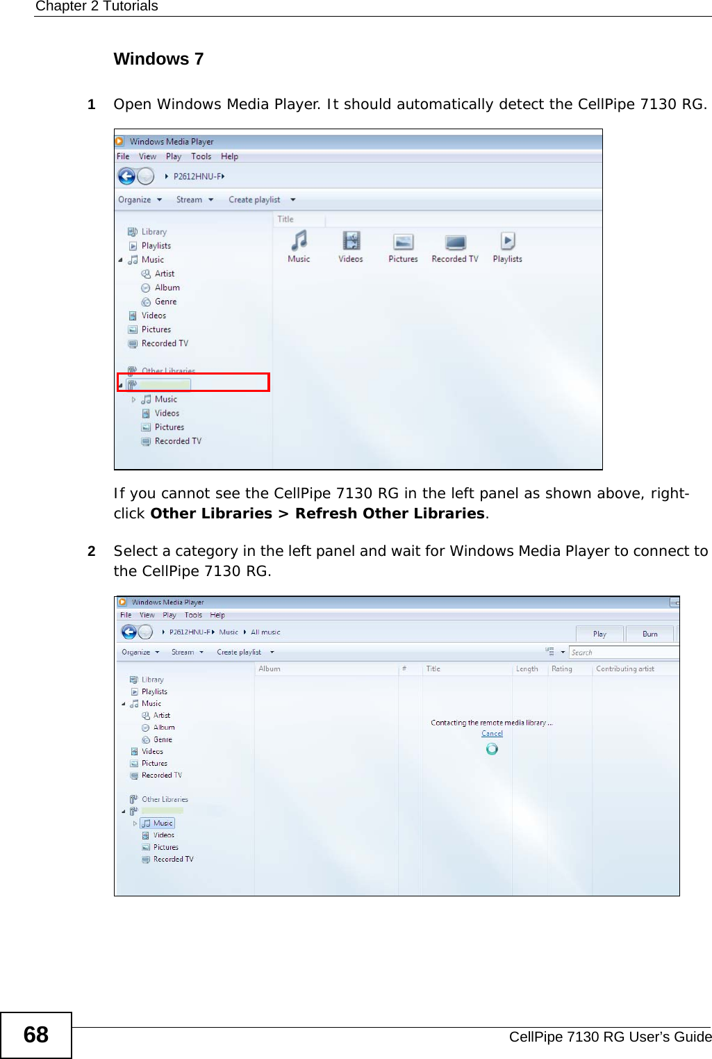
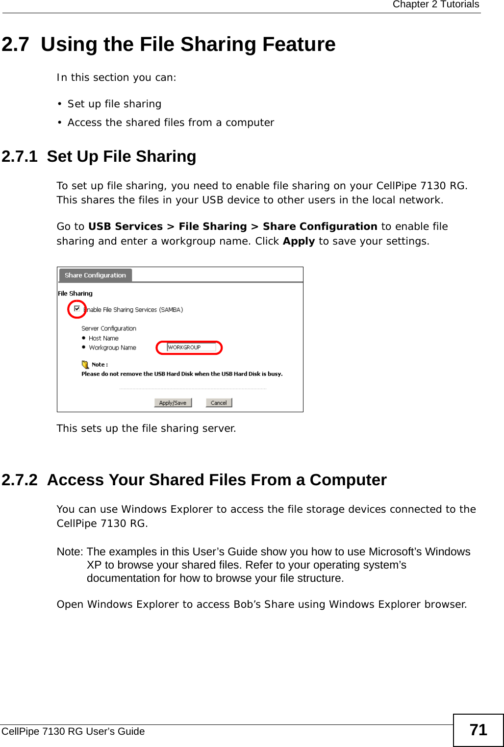
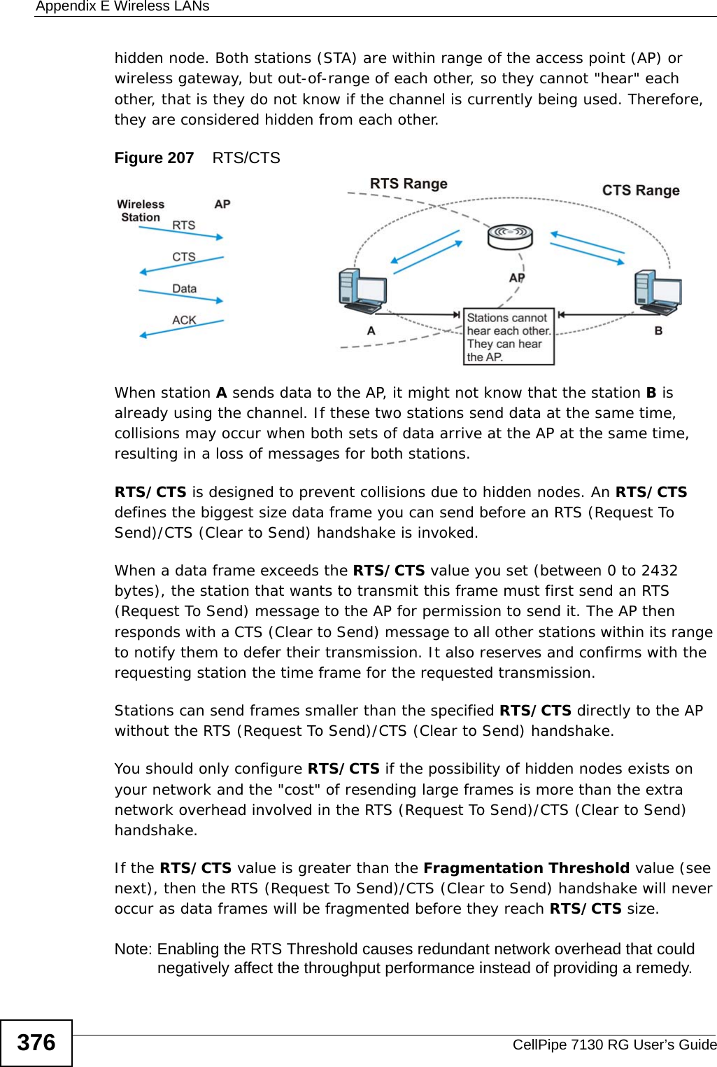
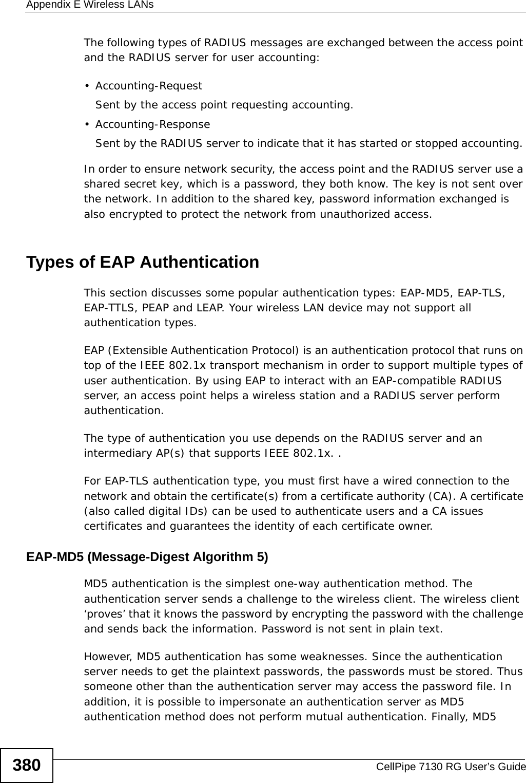
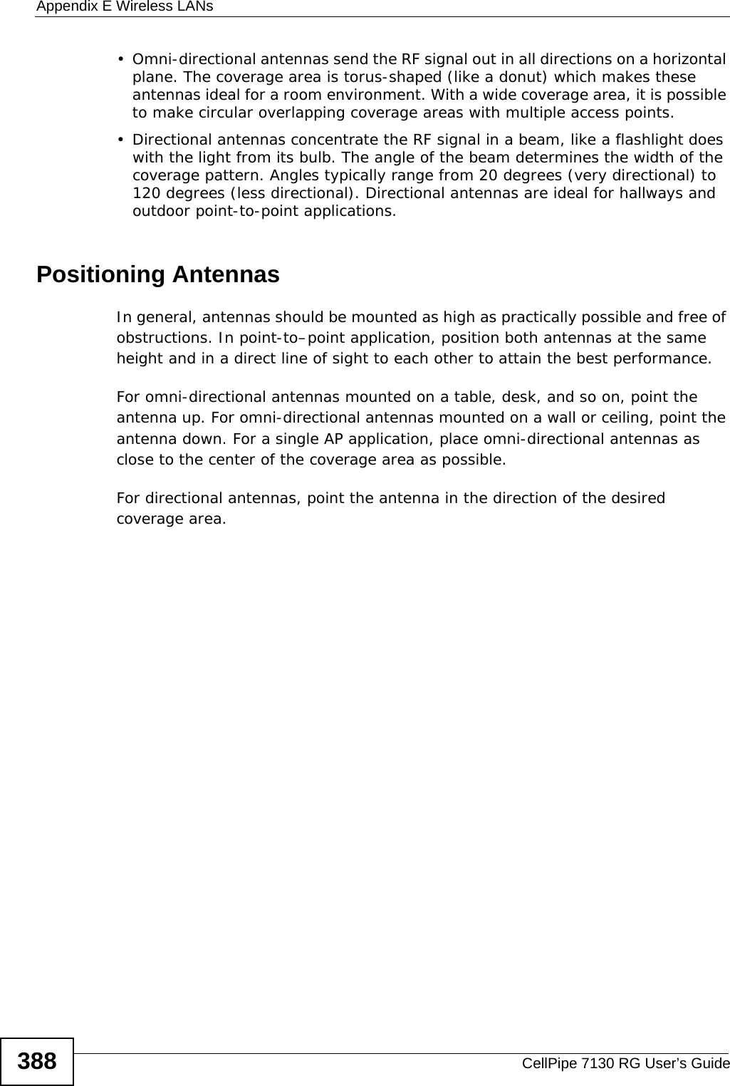
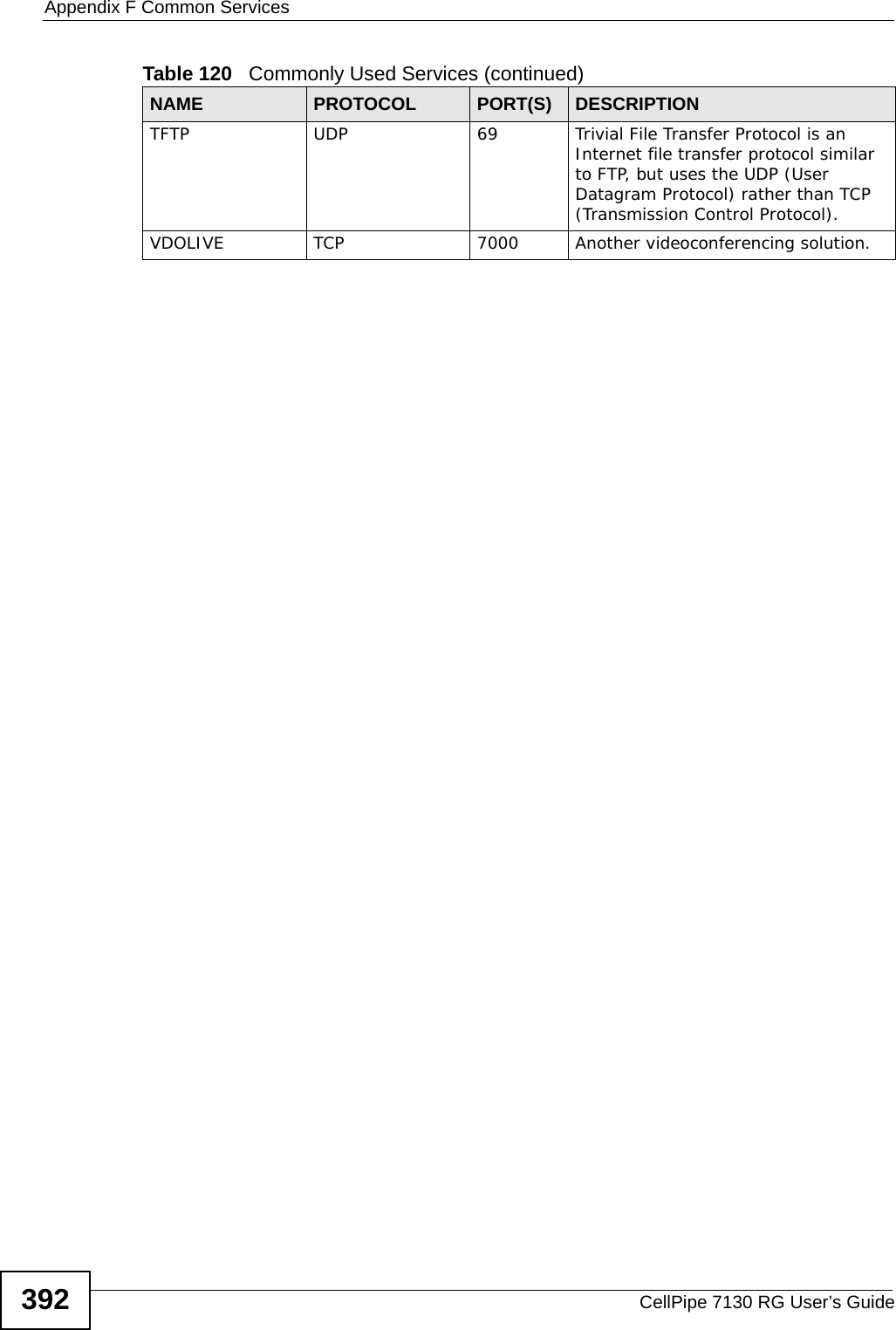
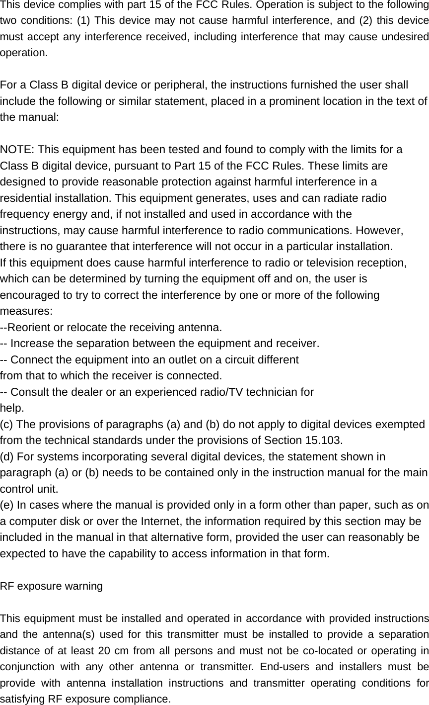
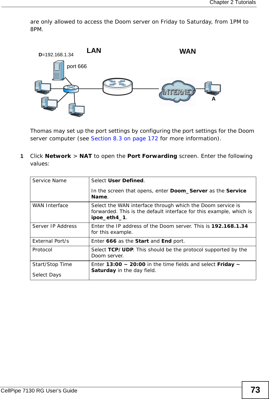
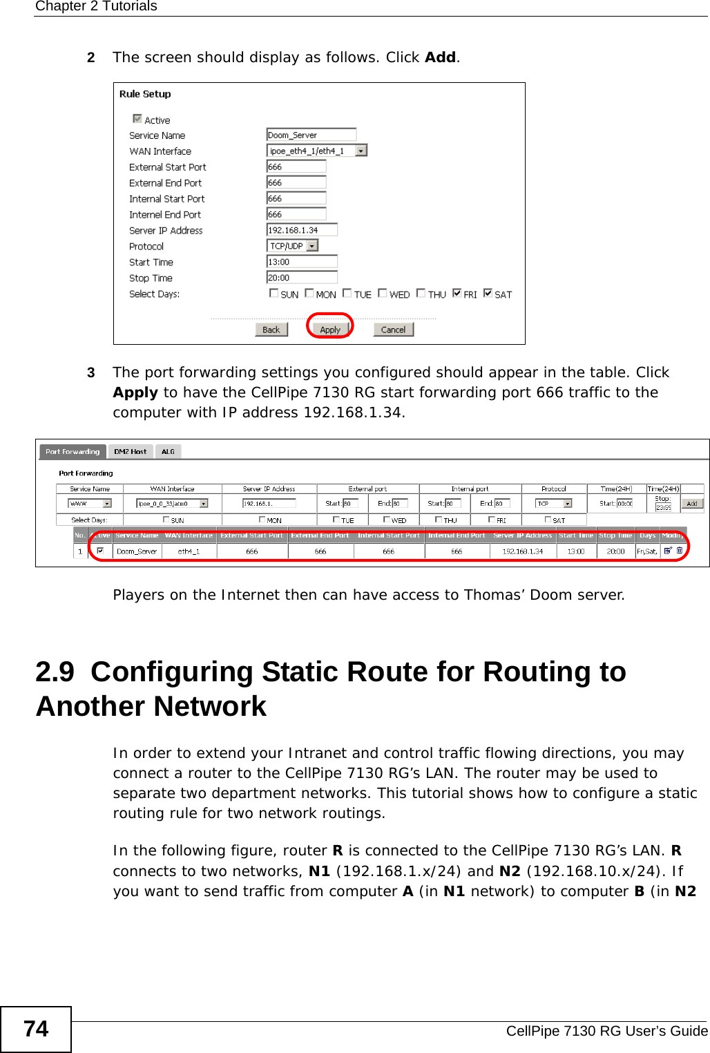
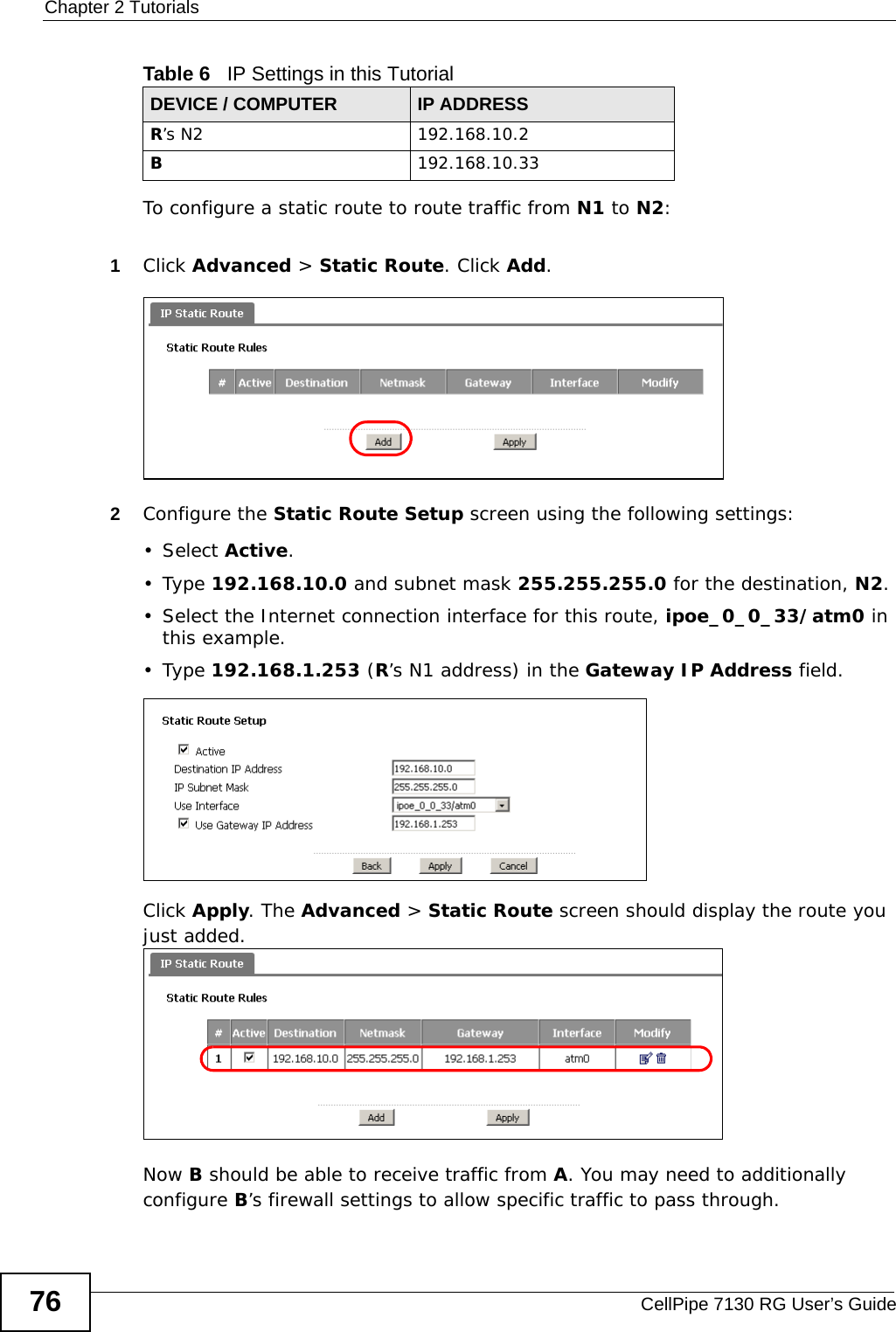
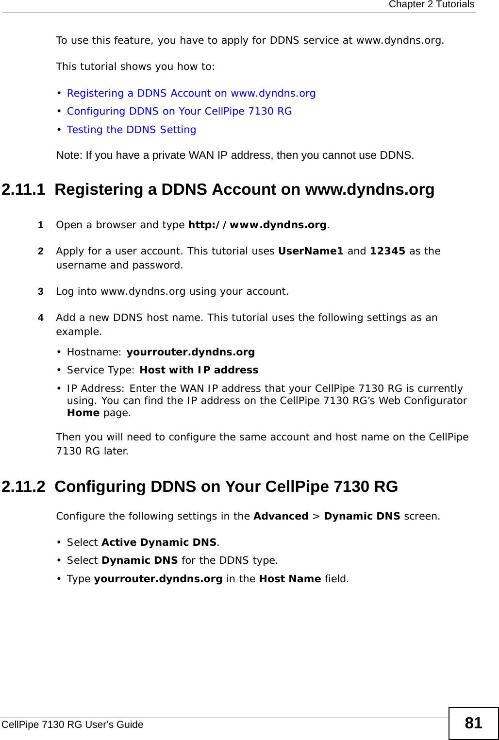
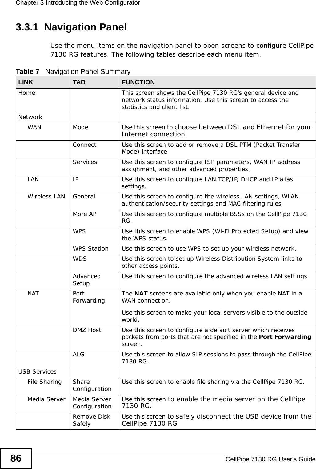
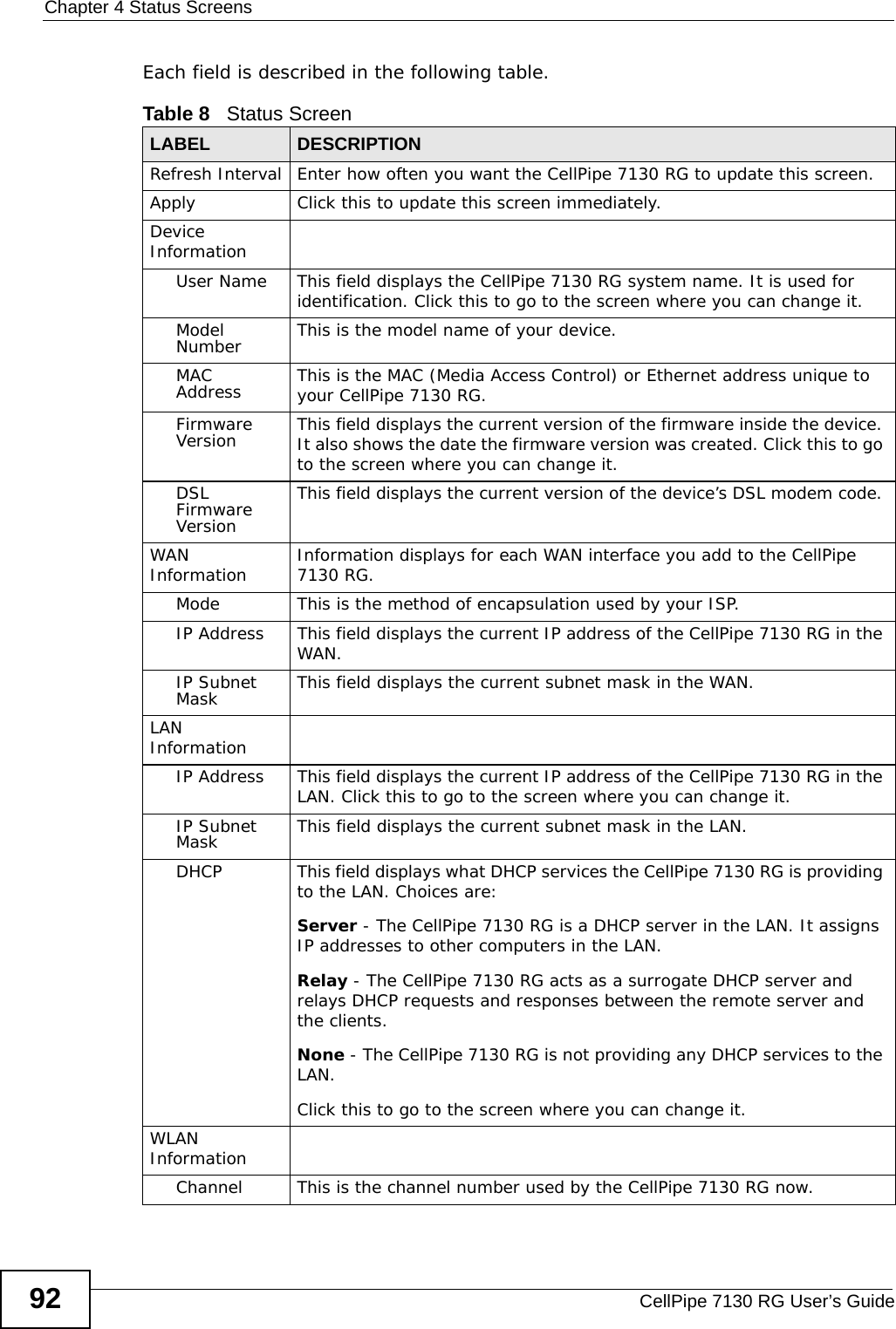
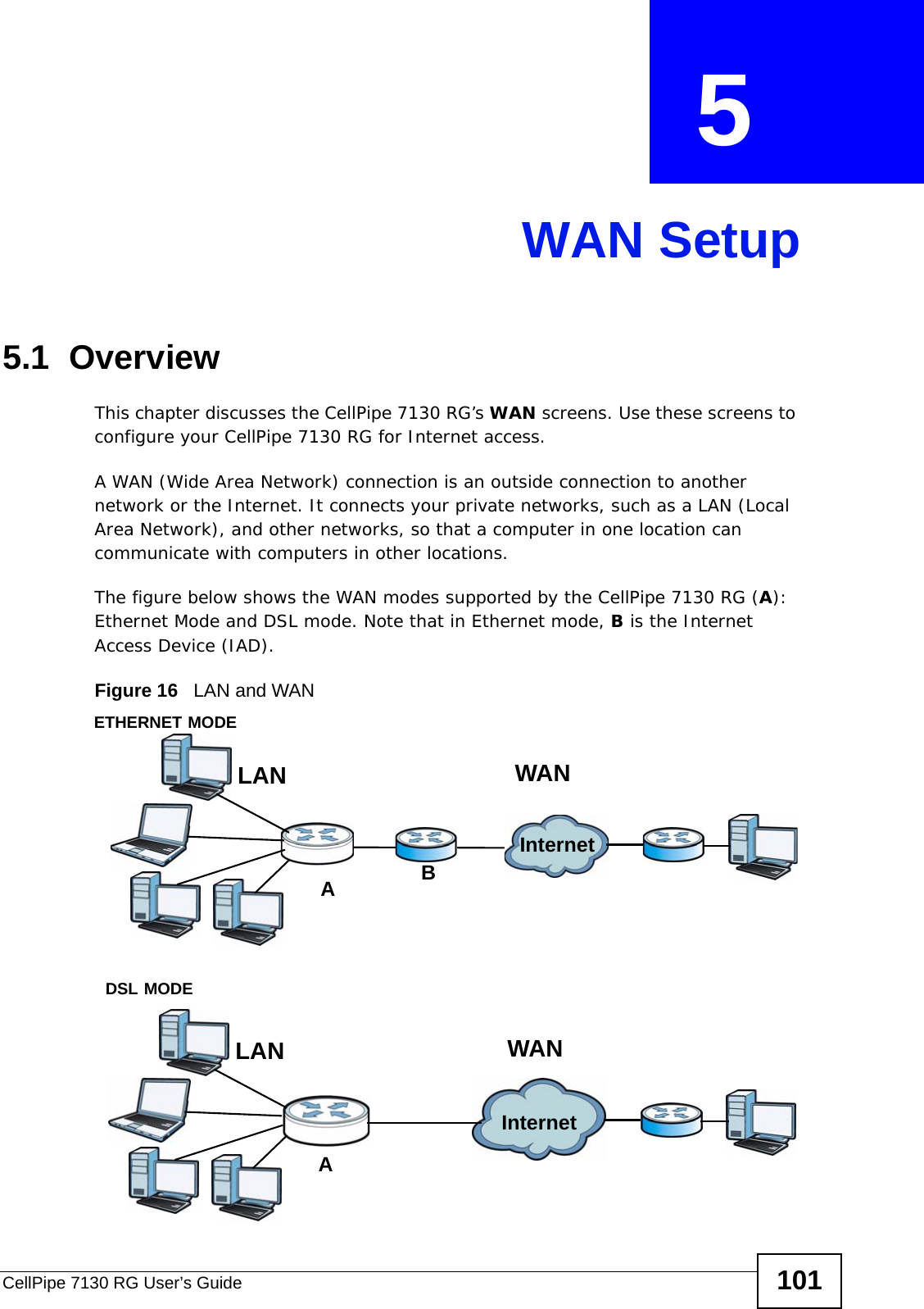
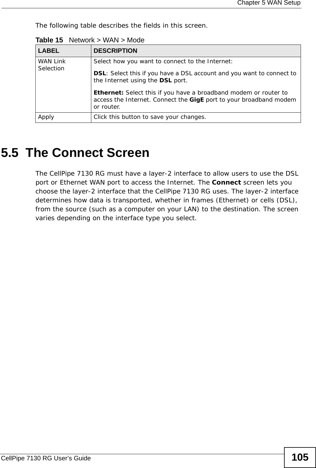
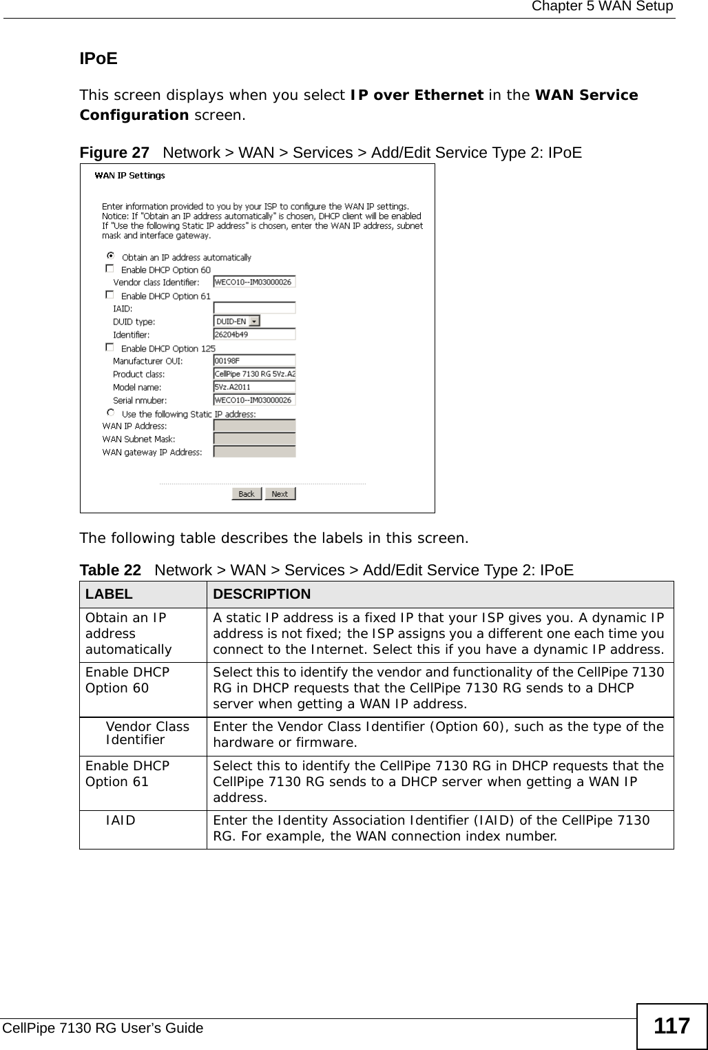
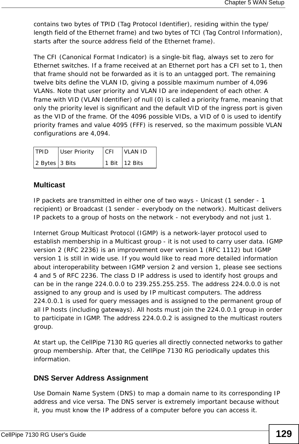
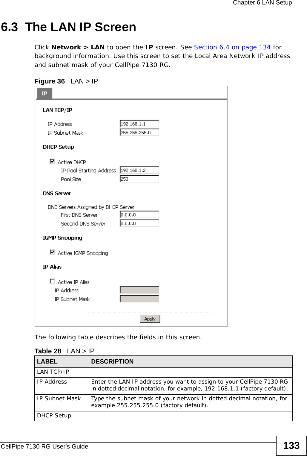
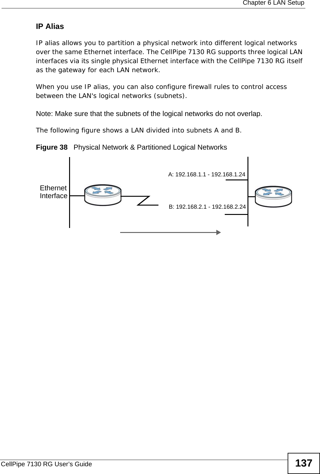
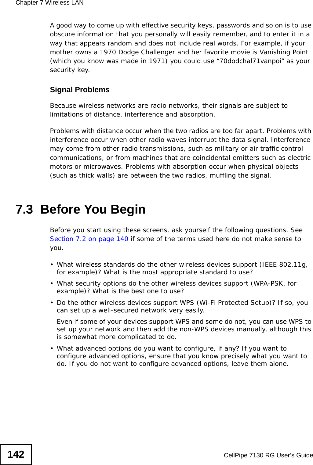
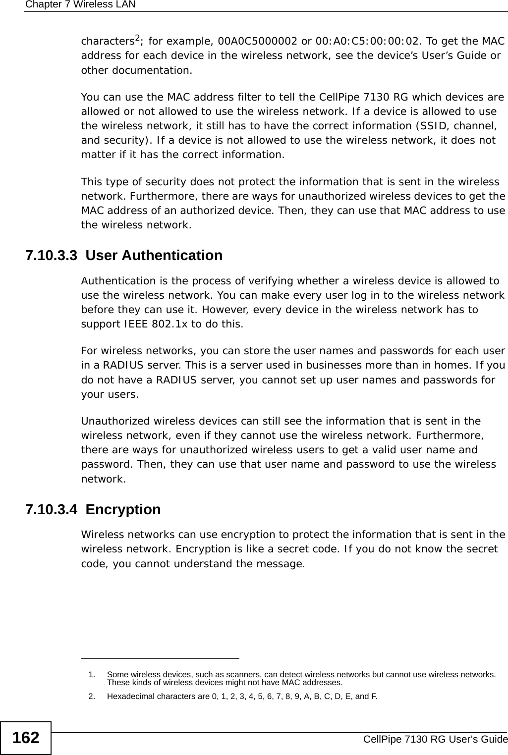
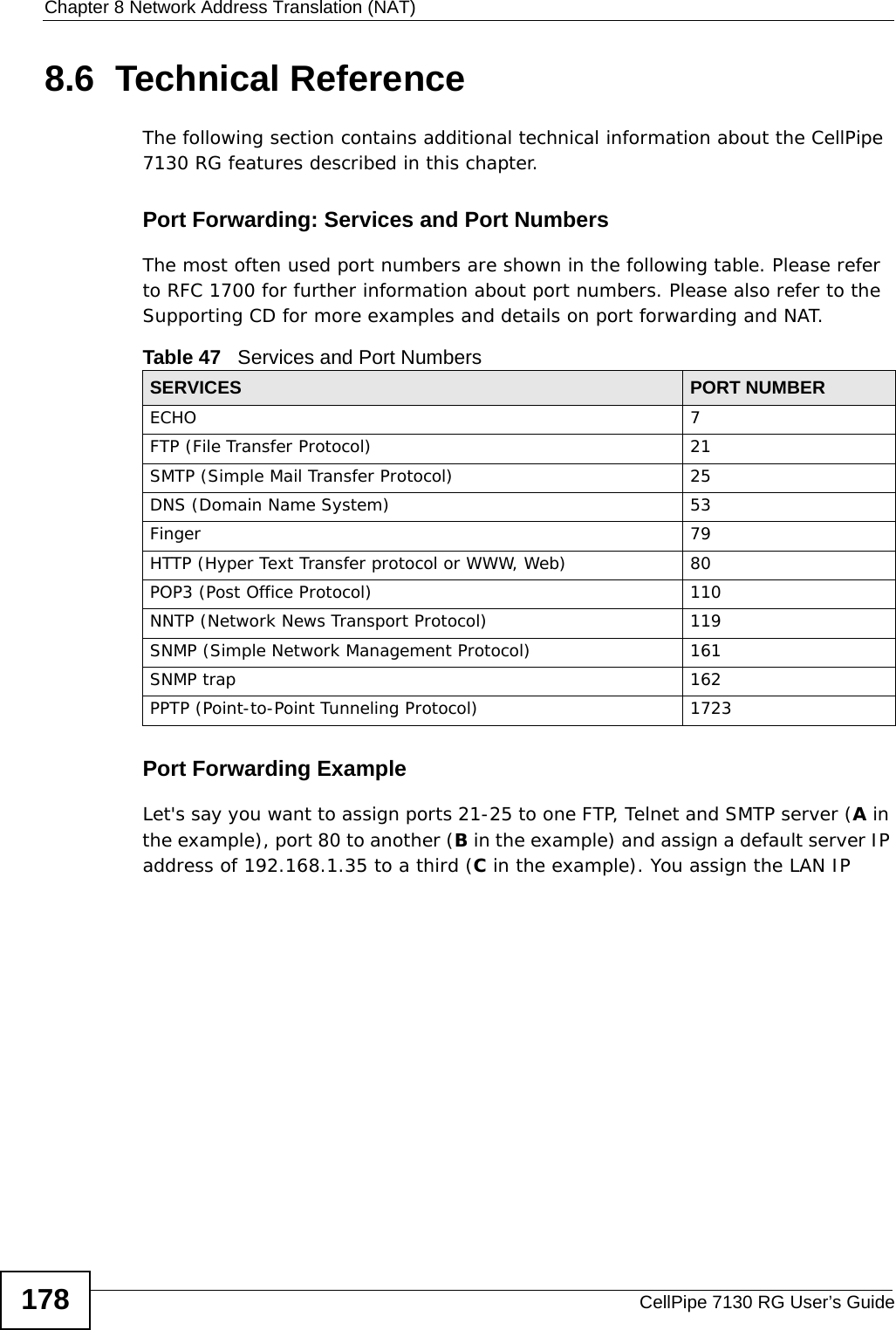
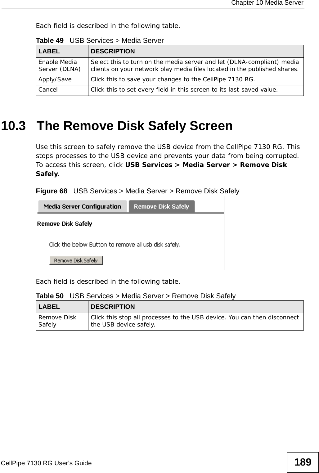
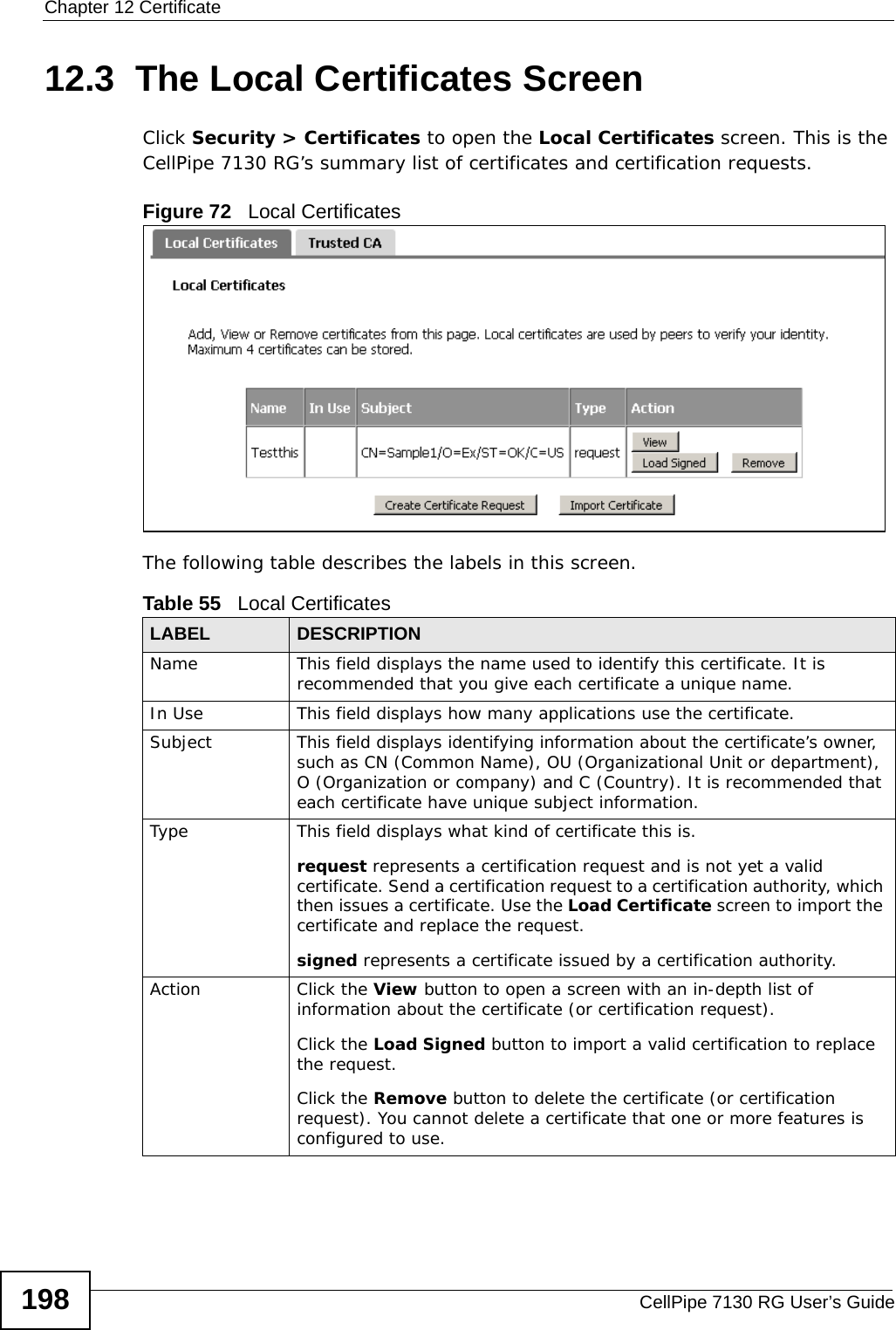
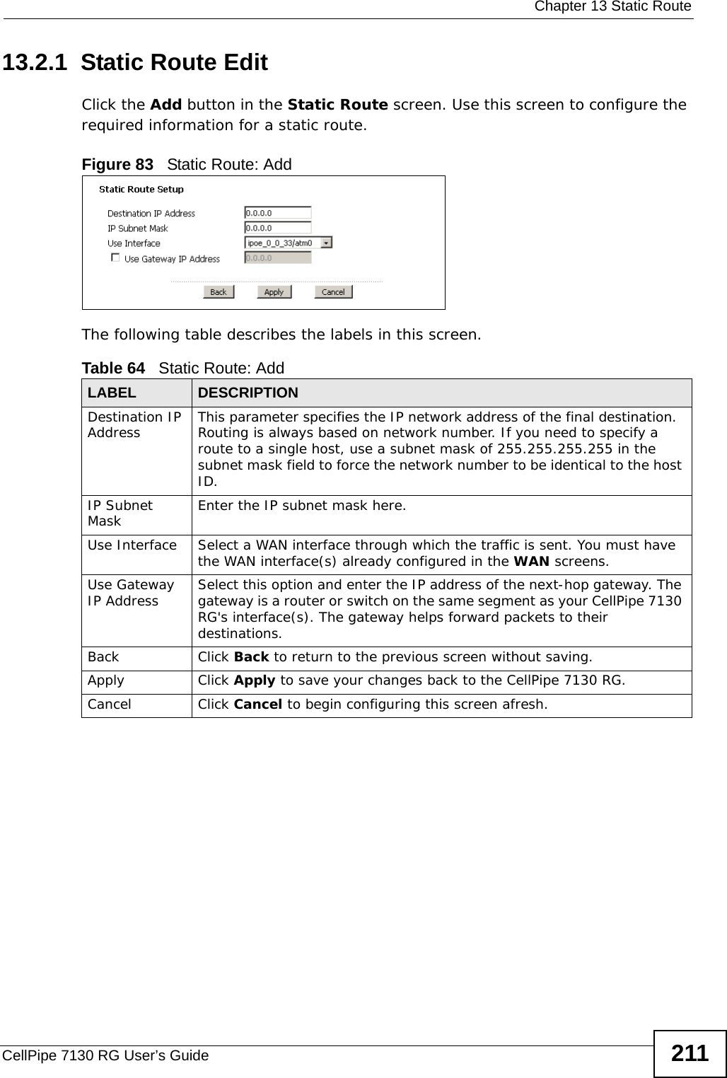
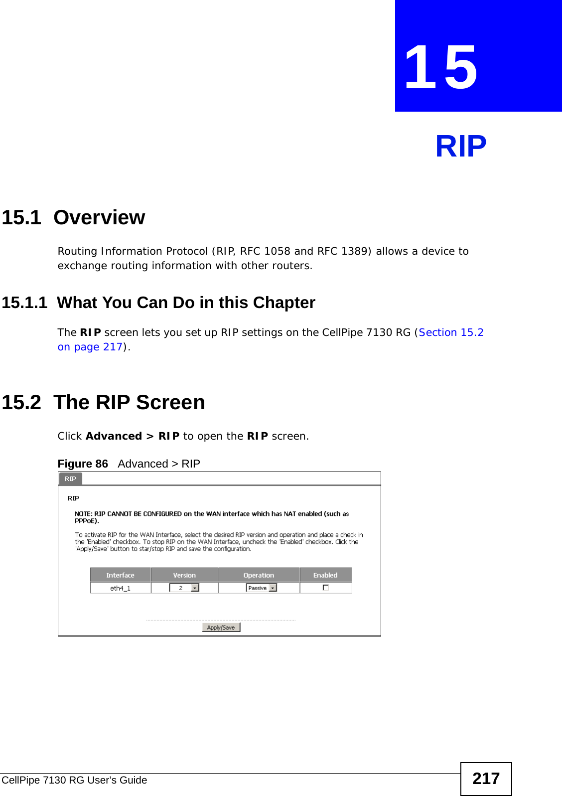
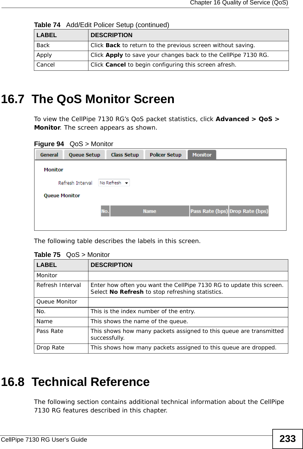
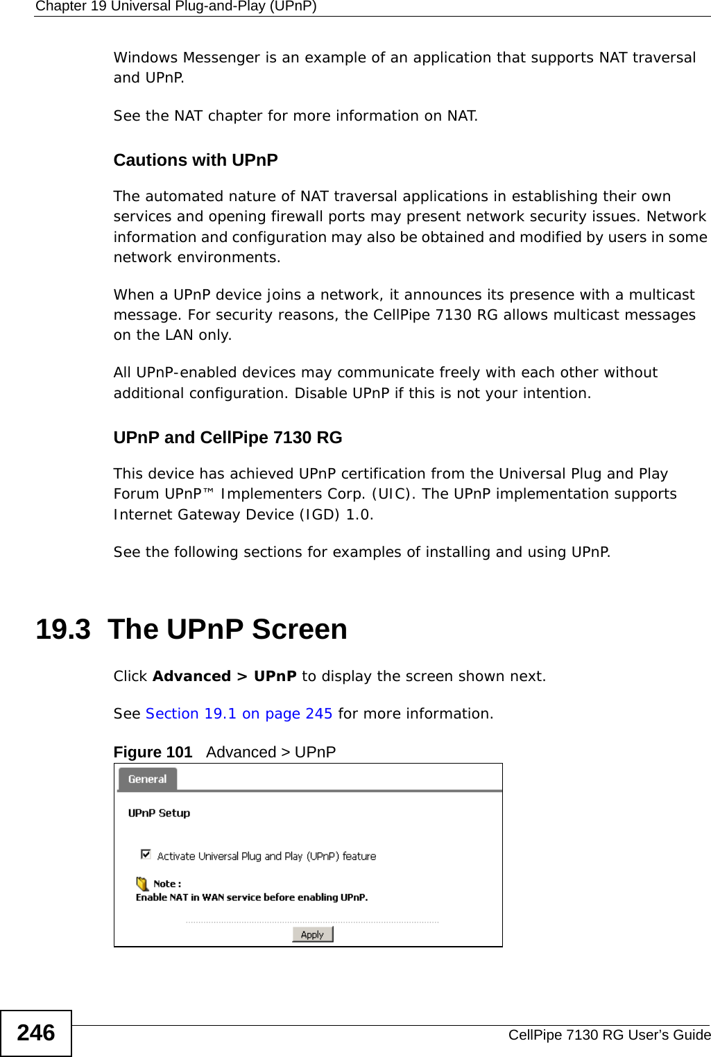
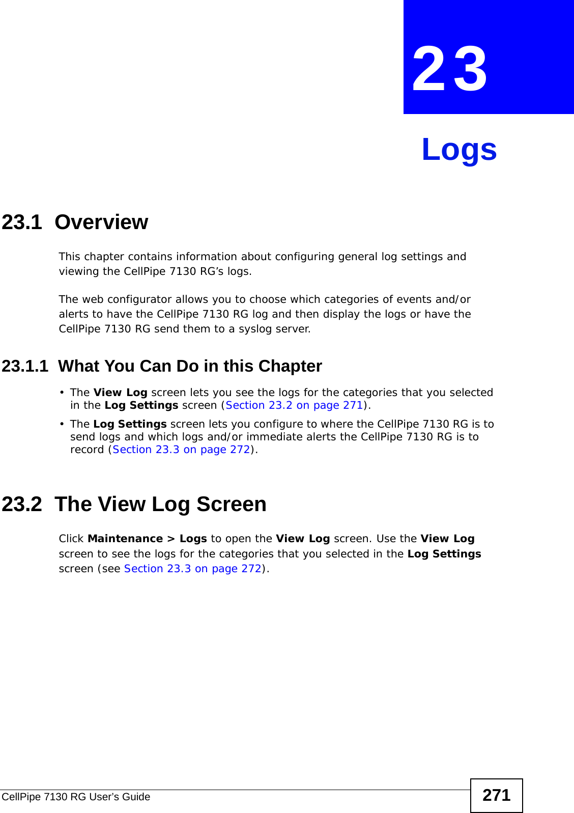
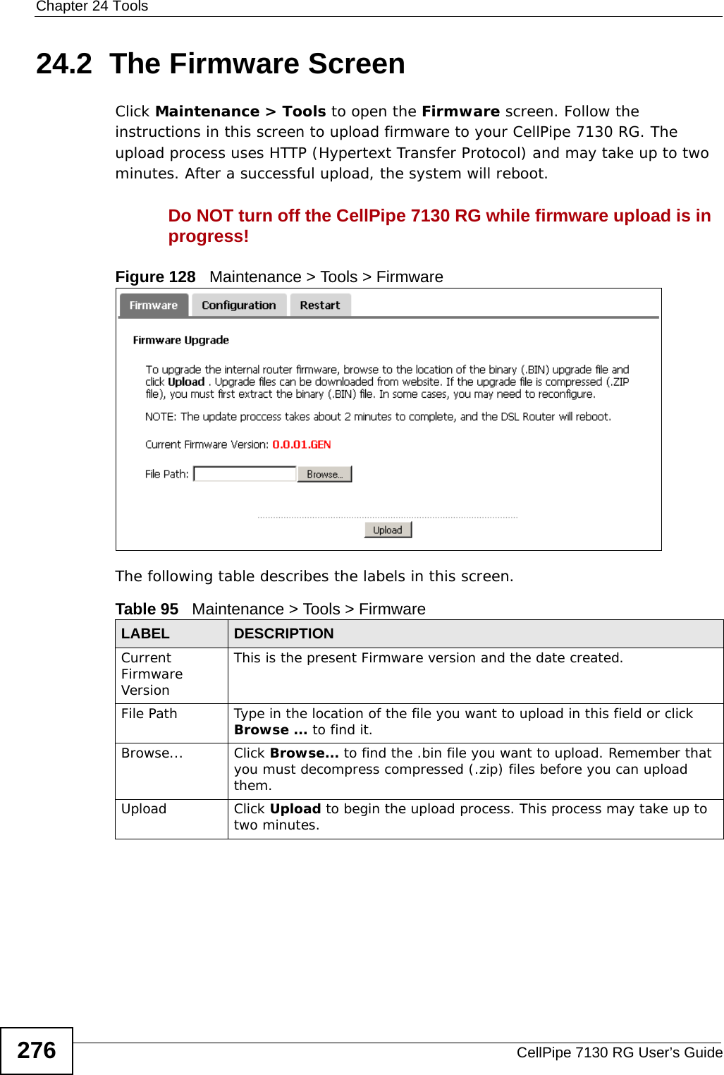
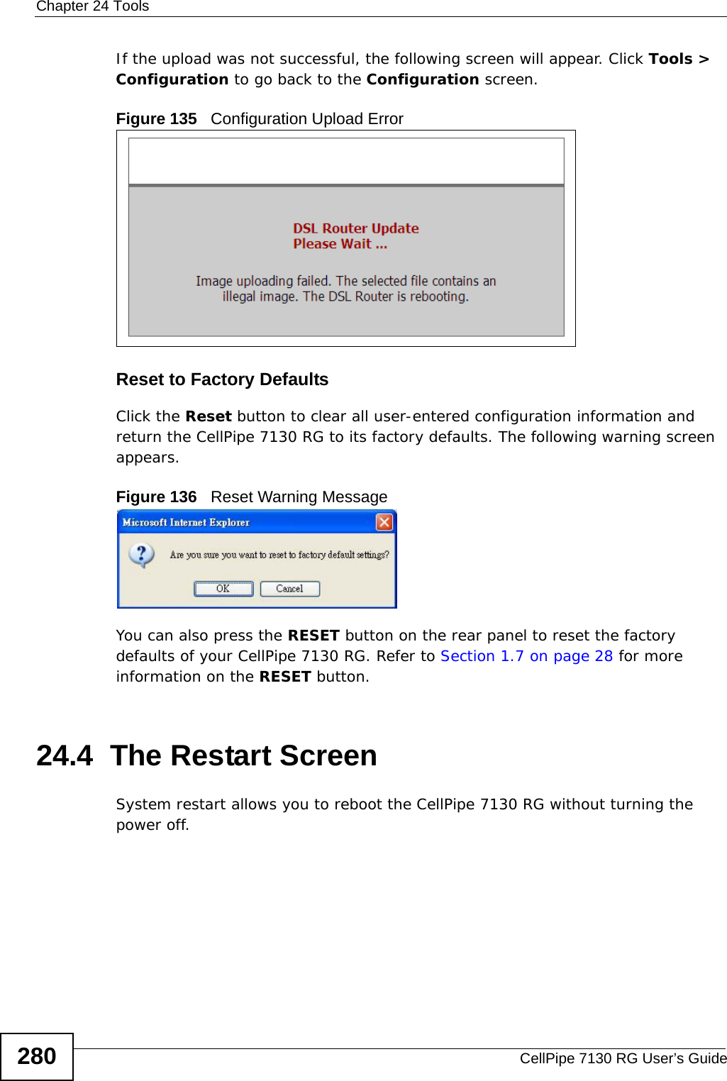
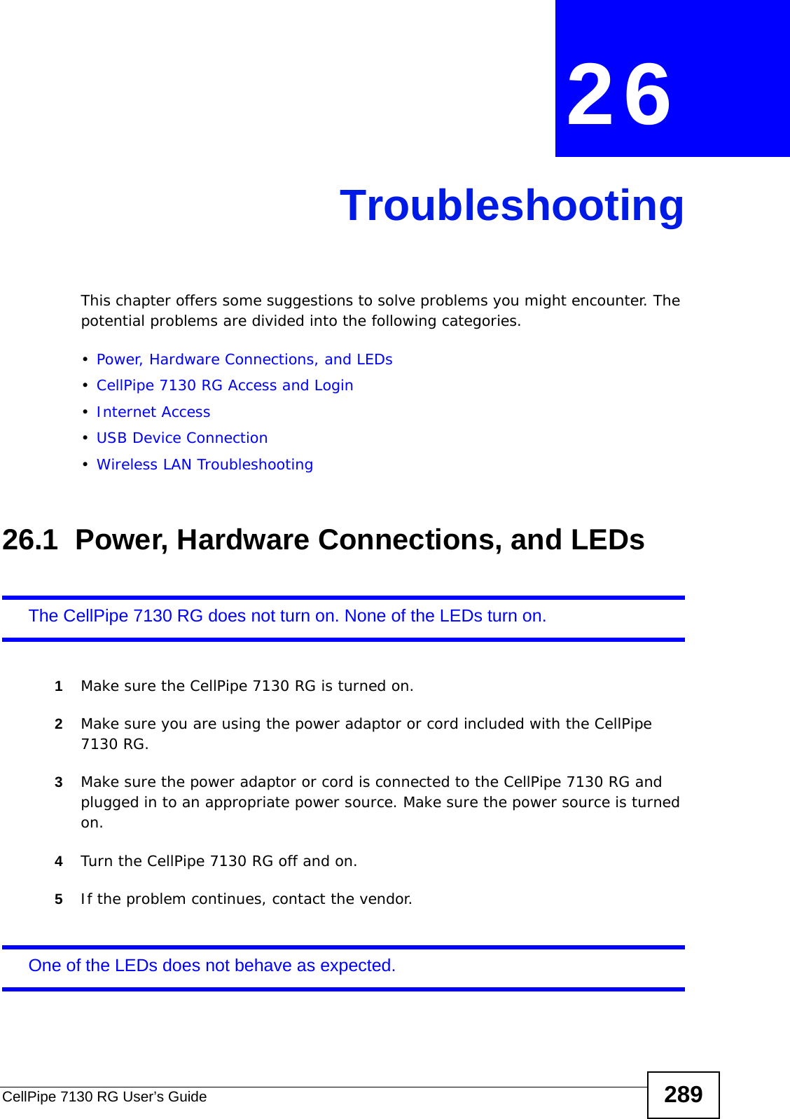
![Chapter 2 TutorialsCellPipe 7130 RG User’s Guide721In Windows Explorer’s Address bar type a double backslash “\\” followed by the IP address of the CellPipe 7130 RG (the default IP address of the CellPipe 7130 RG is 192.168.1.1) and press [ENTER]. A screen asking for password authentication appears. Type the user name and password and click OK. File Shari ng via Windows Expl orerOnce you log in to the shared folder via your CellPipe 7130 RG, you do not have to re-log in unless you restart your computer. 2.8 Setting Up NAT Port ForwardingThomas manages the Doom server on a computer behind the CellPipe 7130 RG. In order for players on the Internet (like A in the figure below) to communicate with the Doom server, Thomas needs to configure the port settings and IP address on the CellPipe 7130 RG. Traffic should be forwarded to the port 666 of the Doom server computer which has an IP address of 192.168.1.34. Additionally, players](https://usermanual.wiki/ZyXEL-Communications/5VZ-A2011/User-Guide-1284006-Page-72.png)
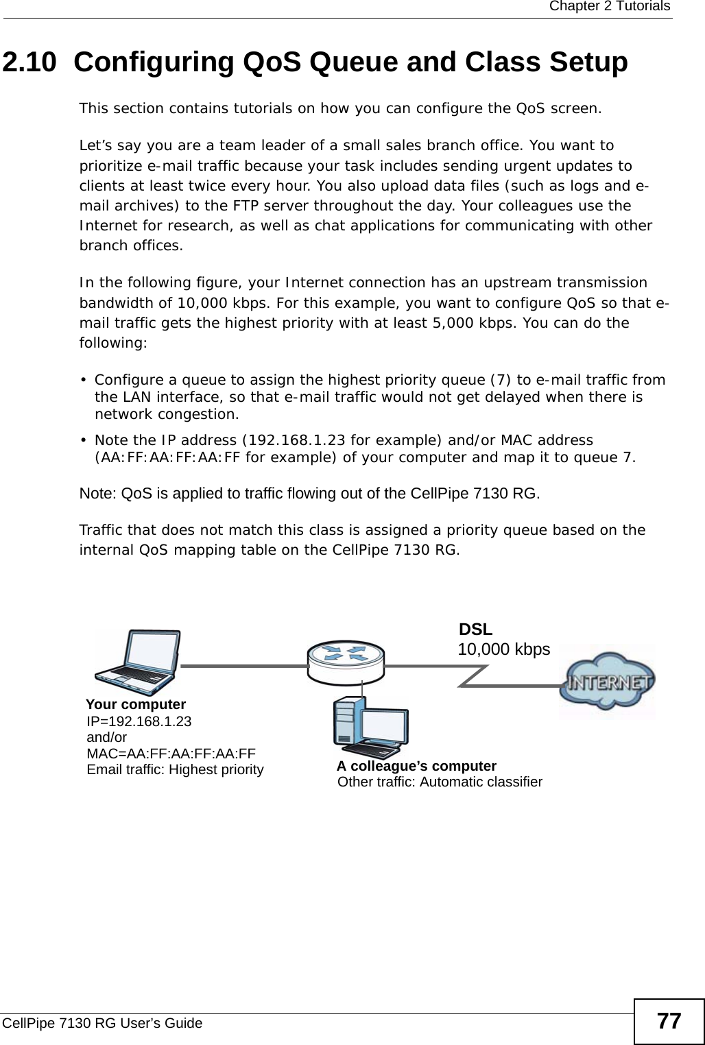
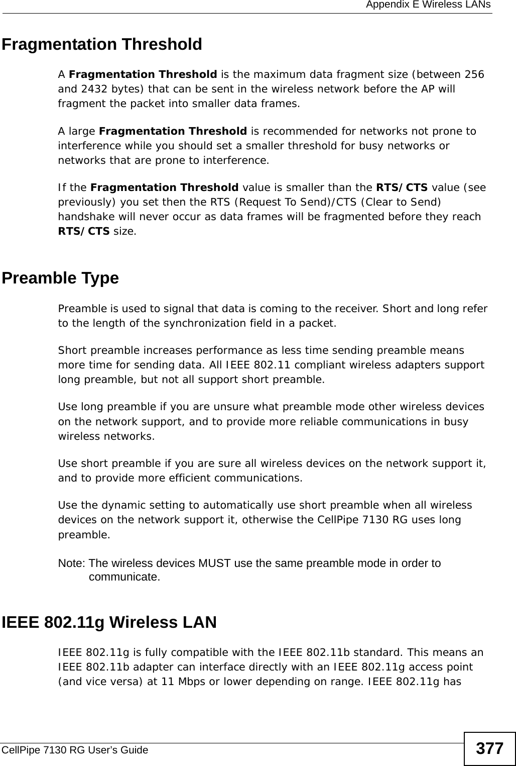
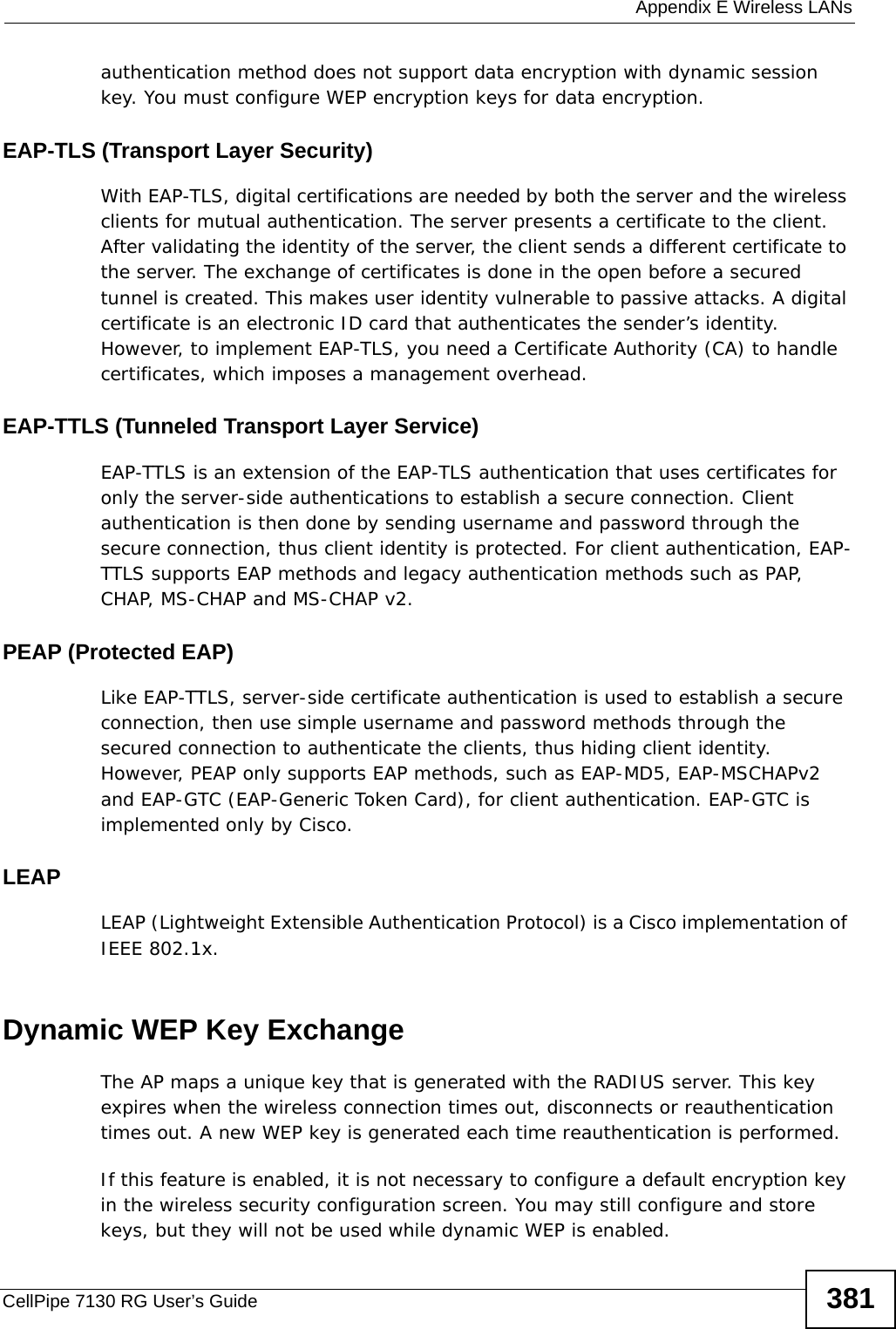
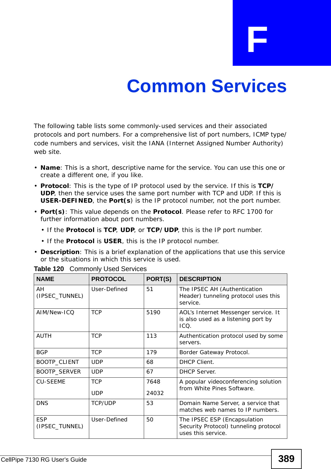
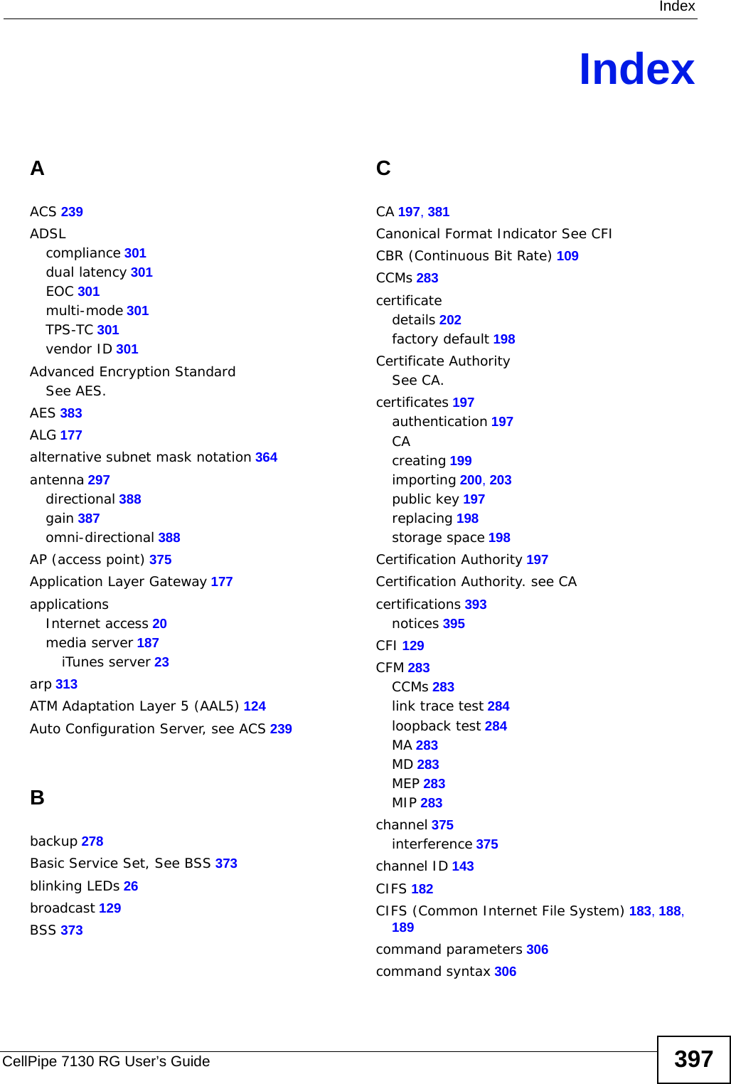
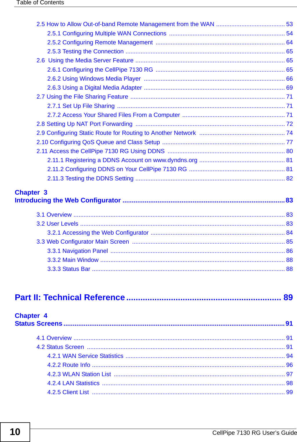
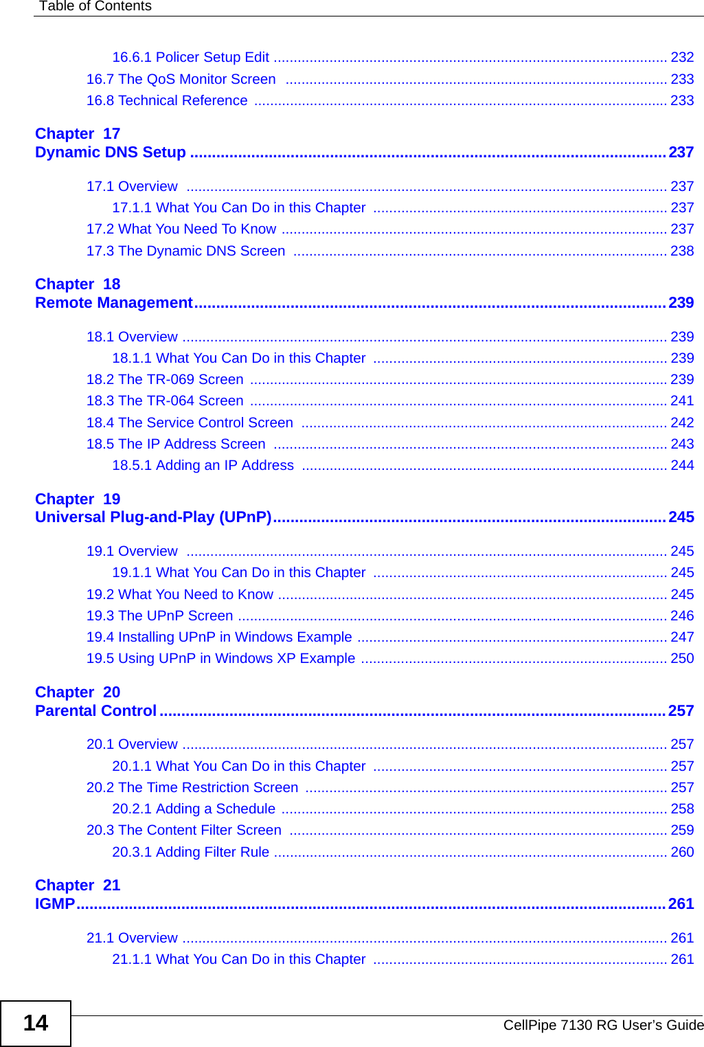
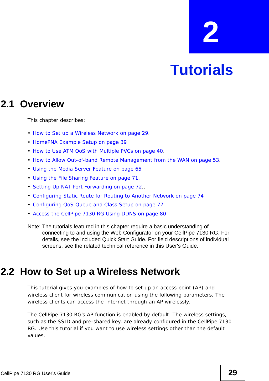
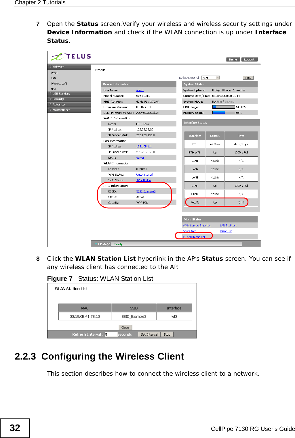
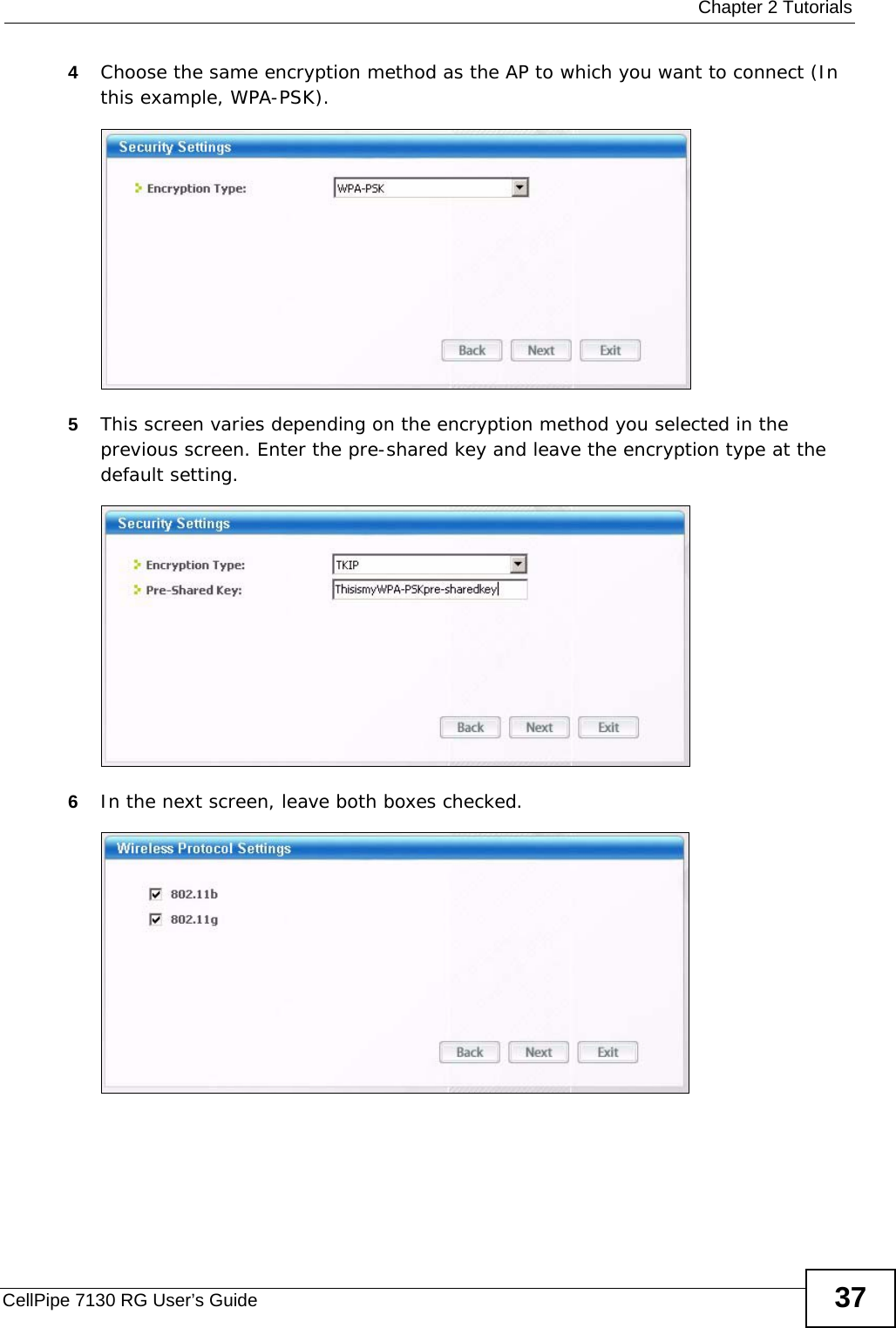
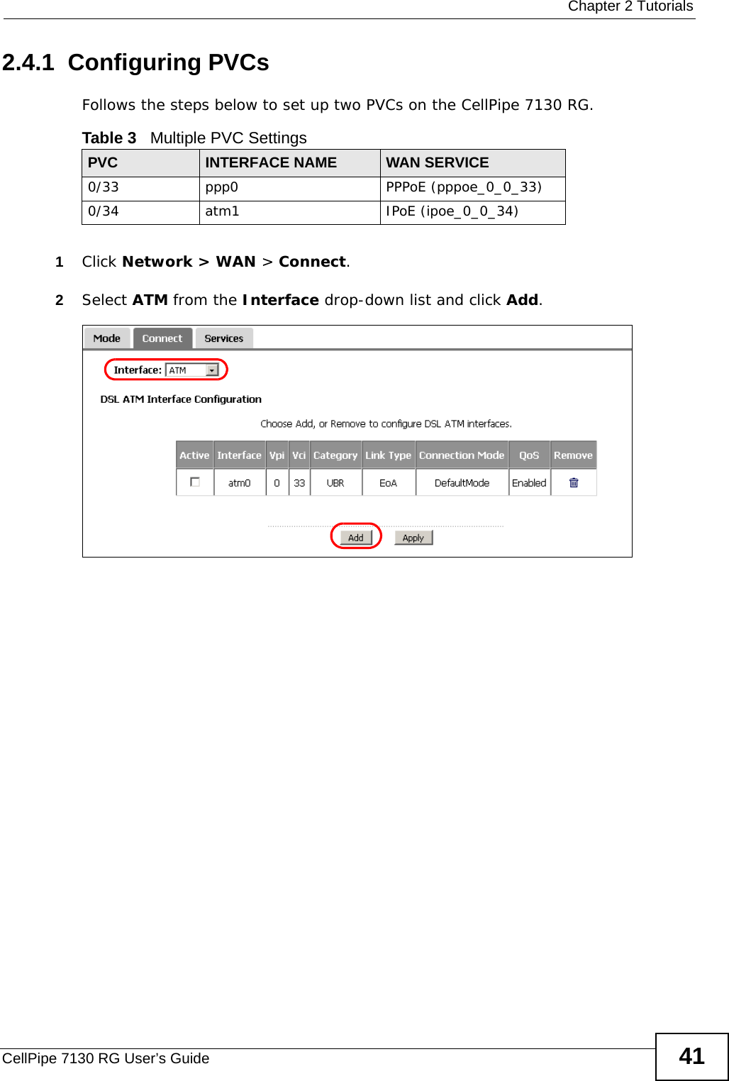
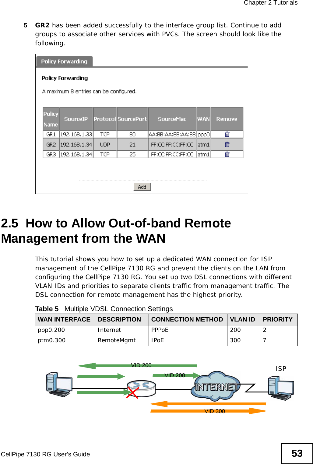
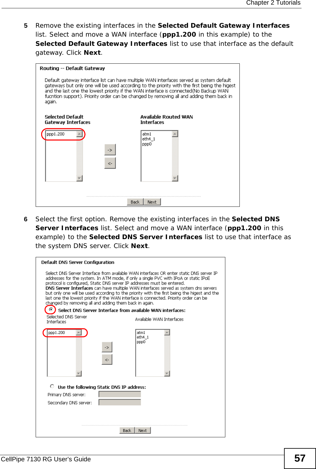
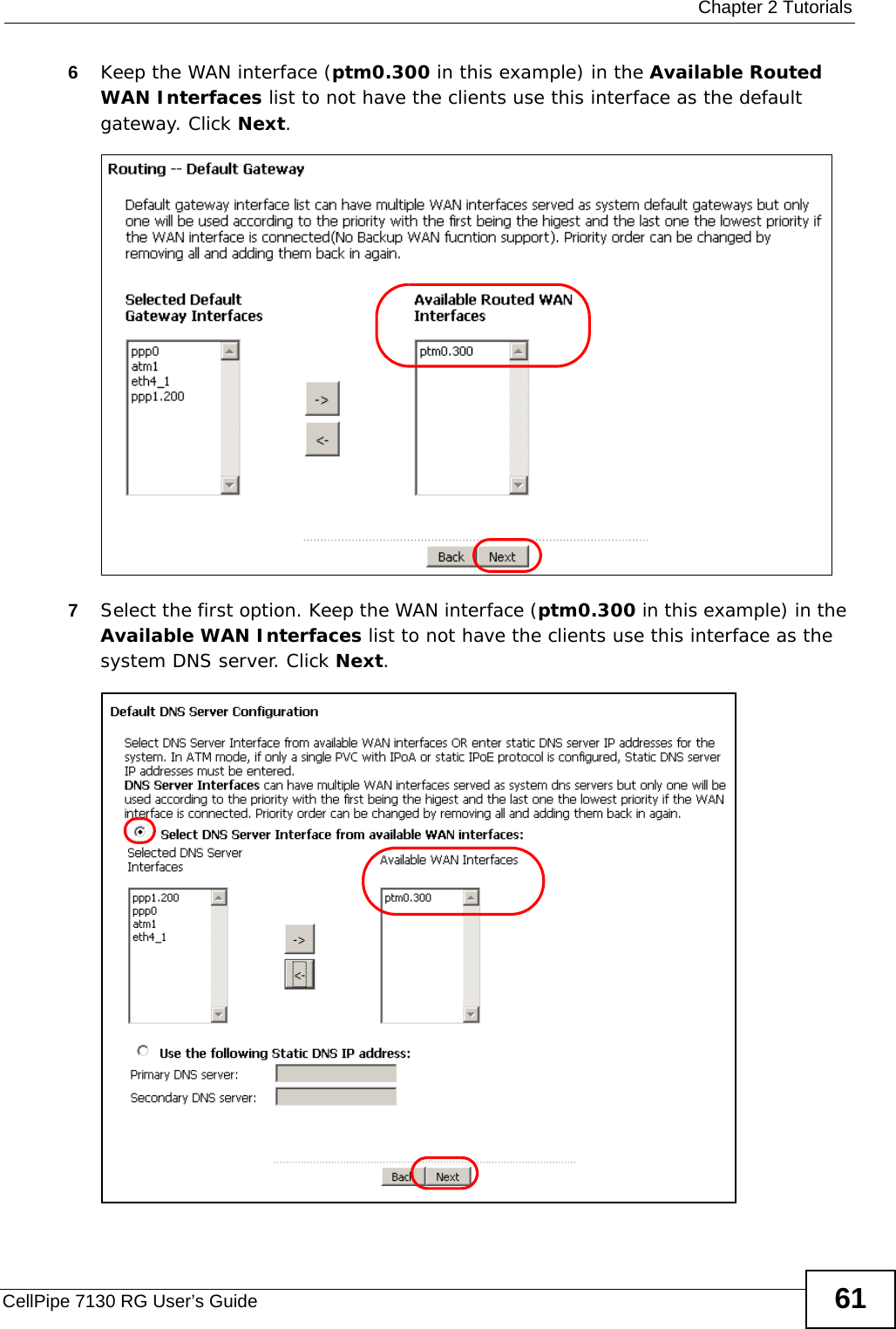
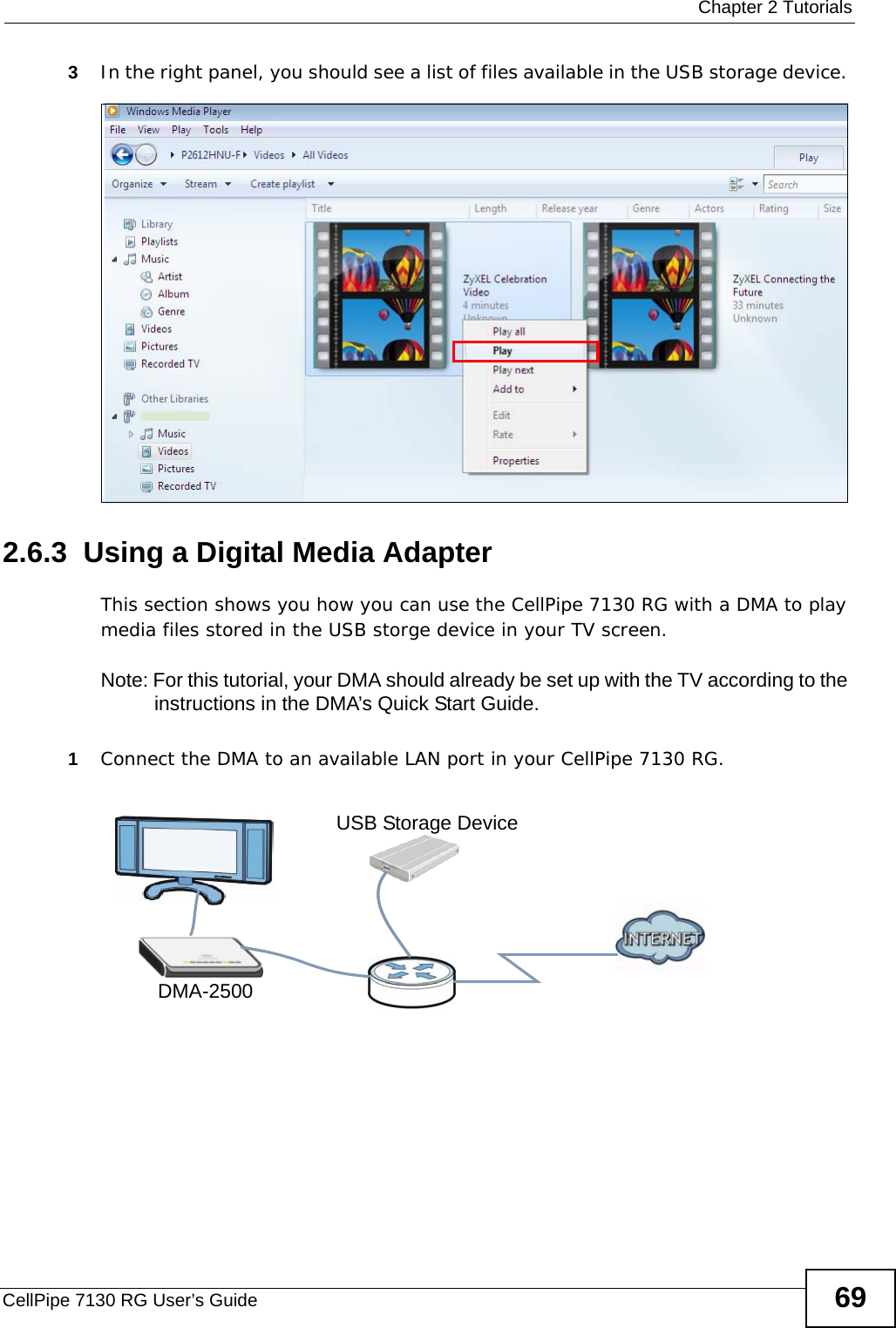
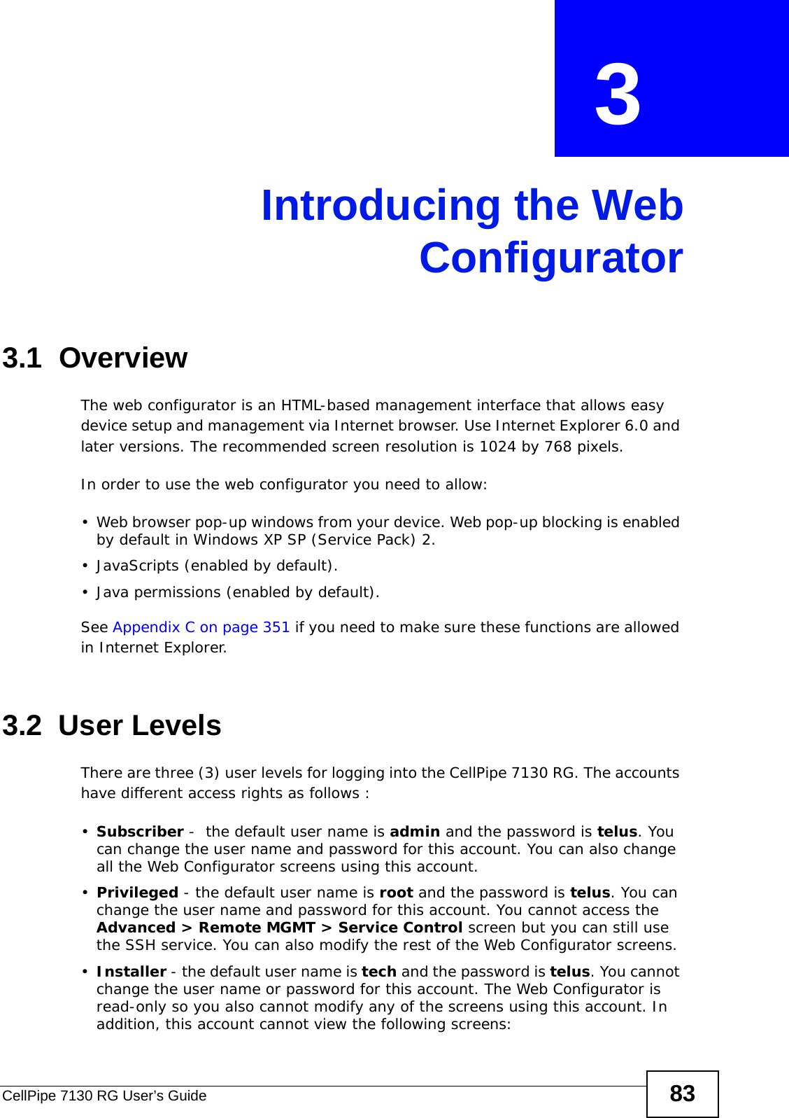
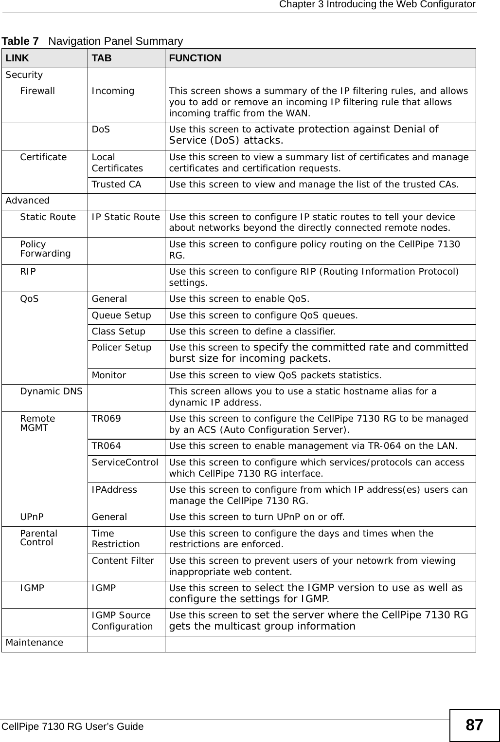
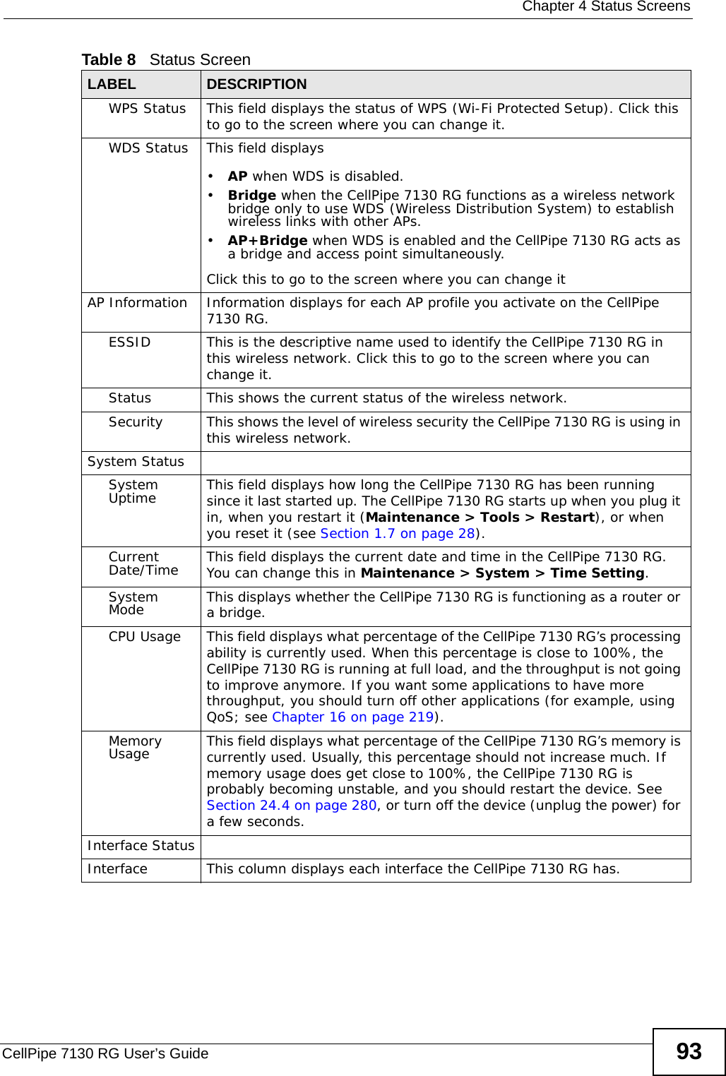
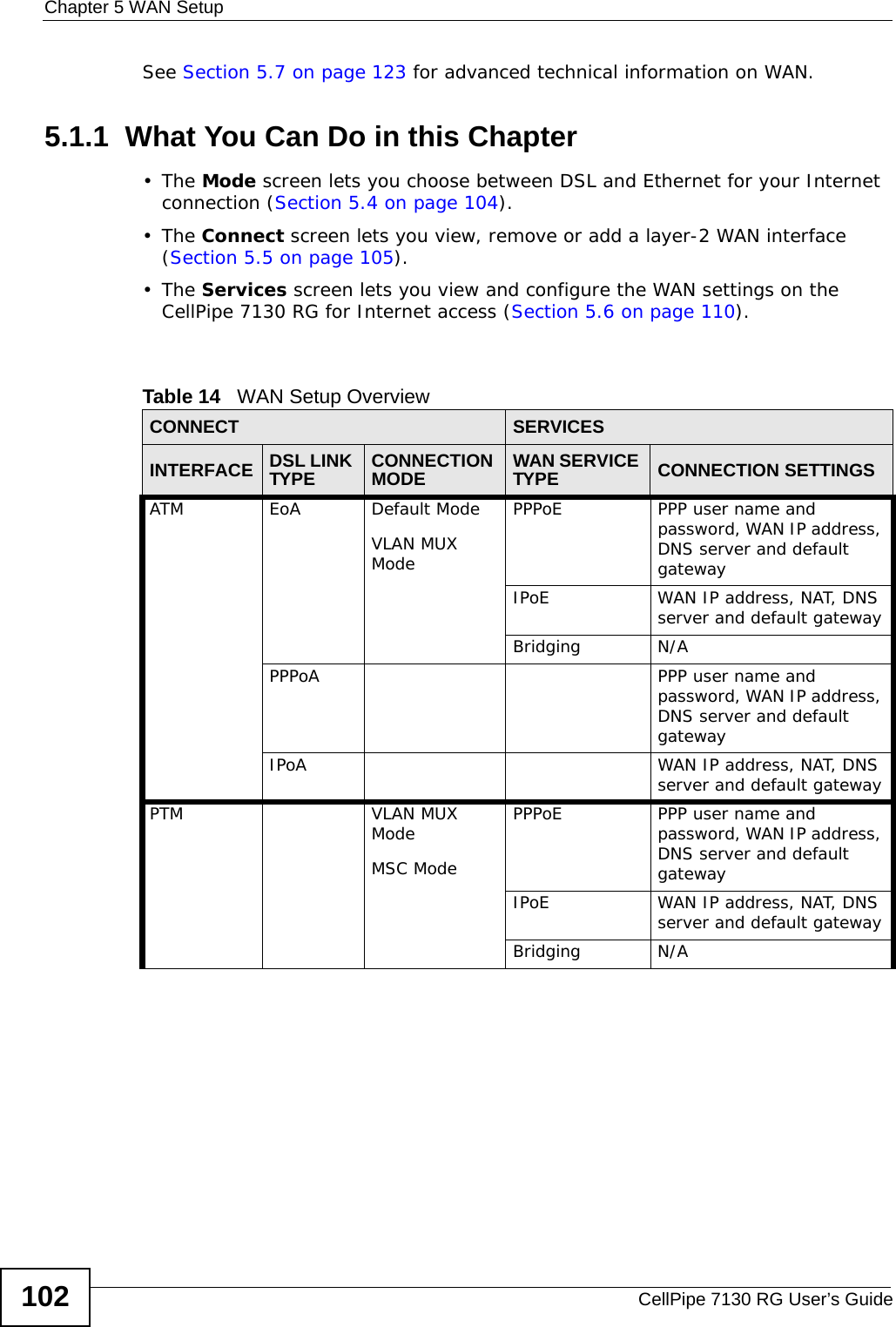
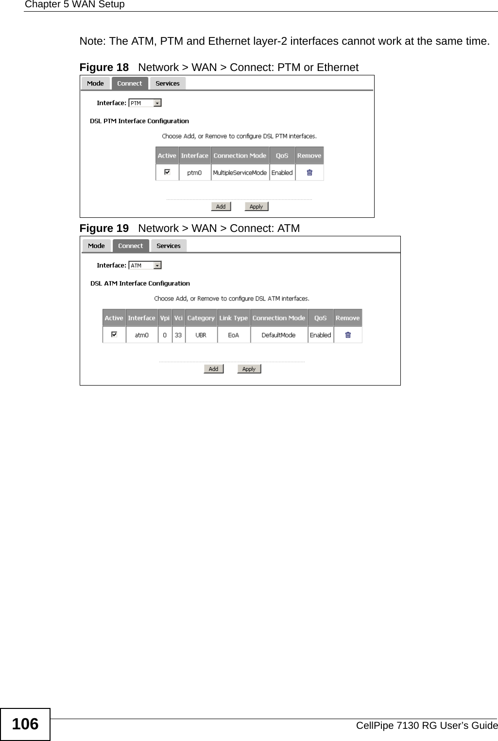
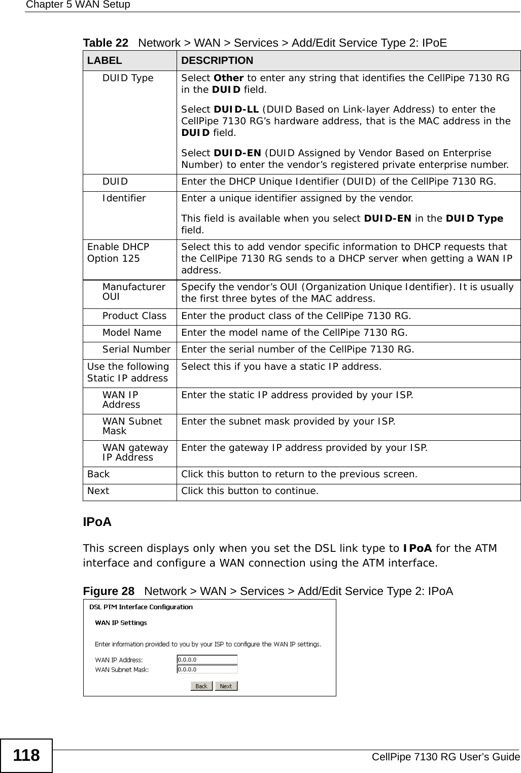
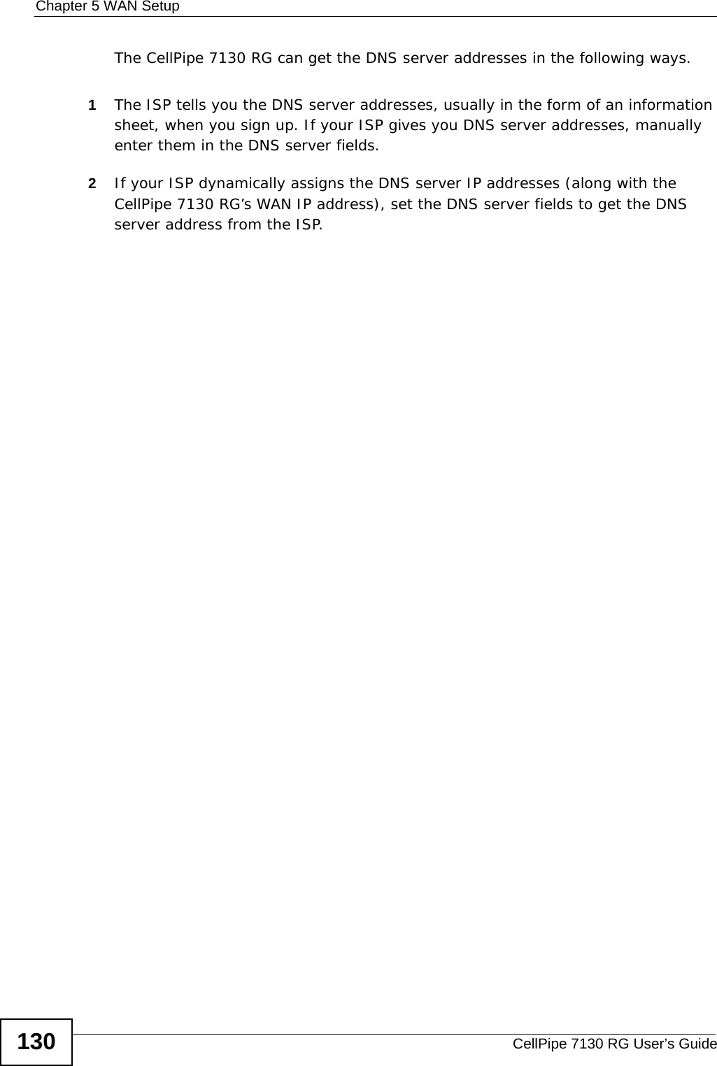
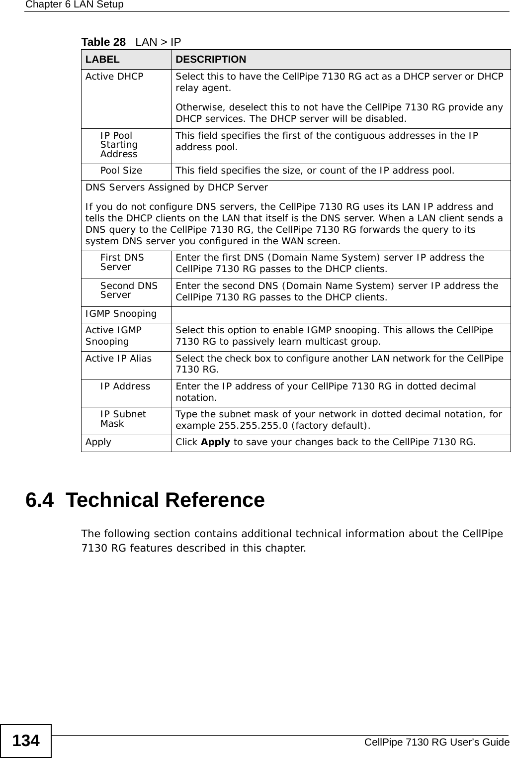
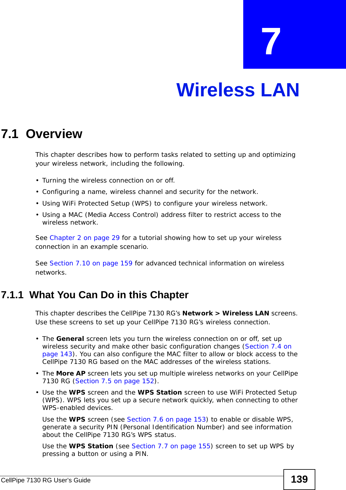
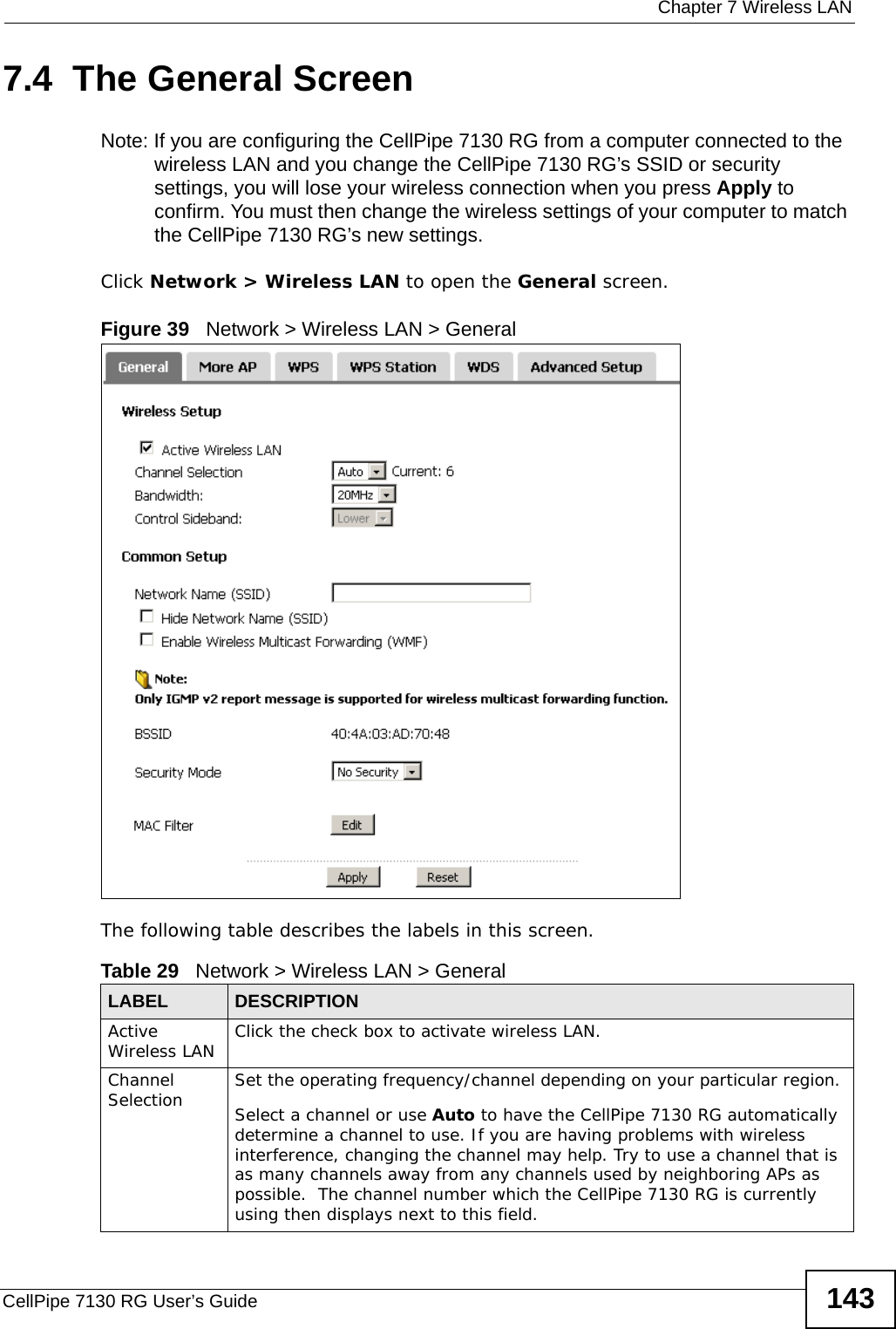
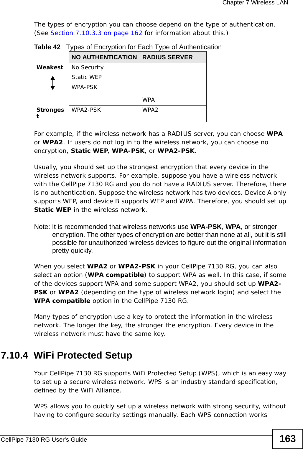
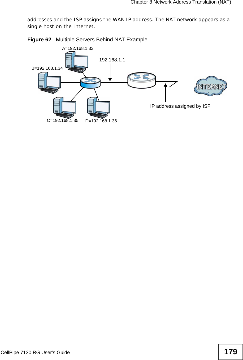
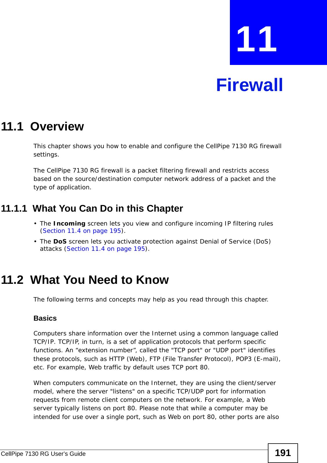
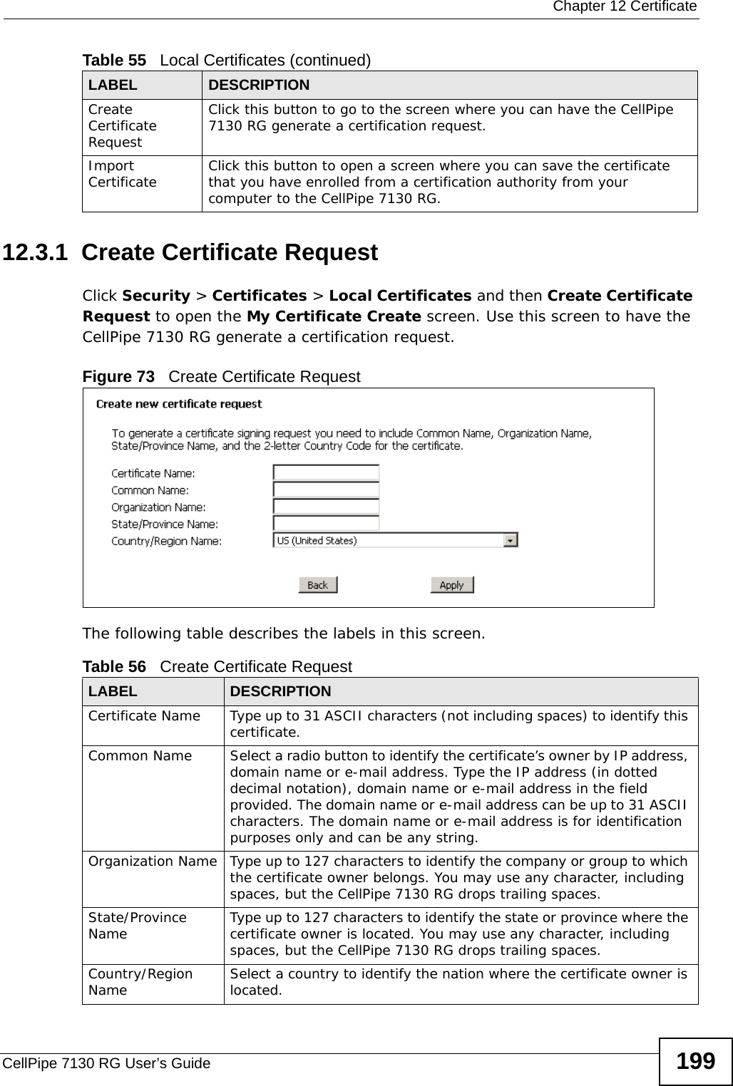
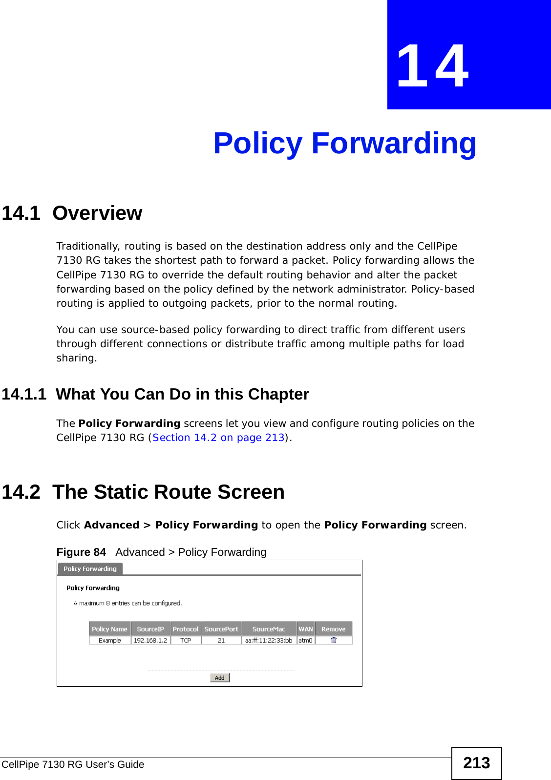
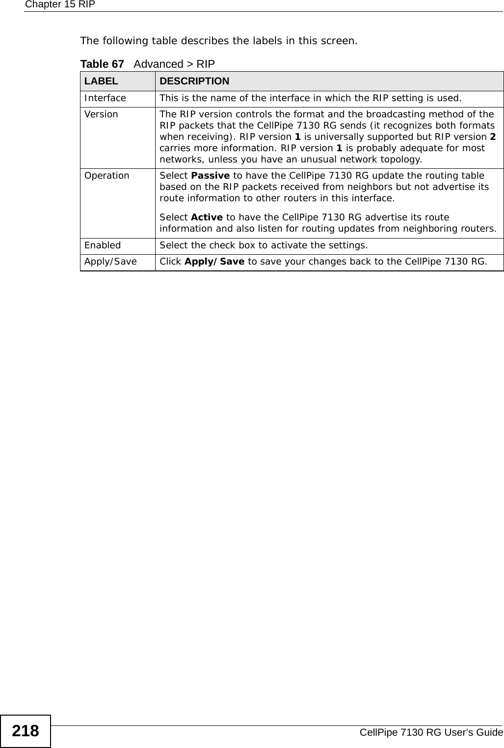
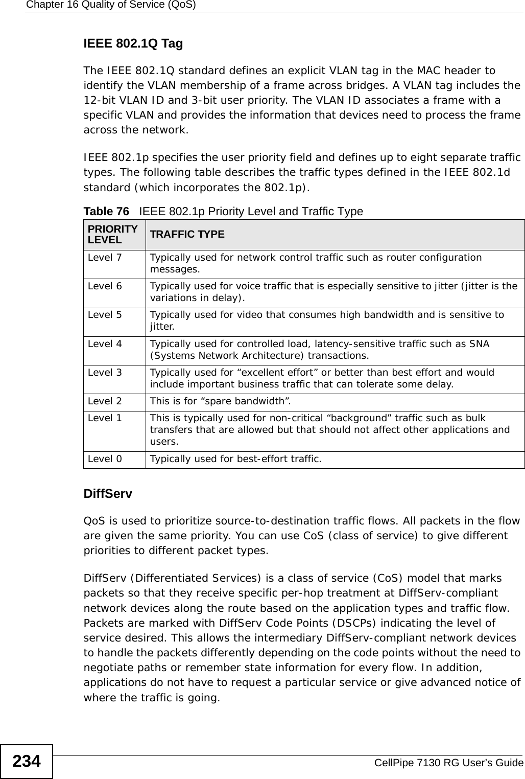
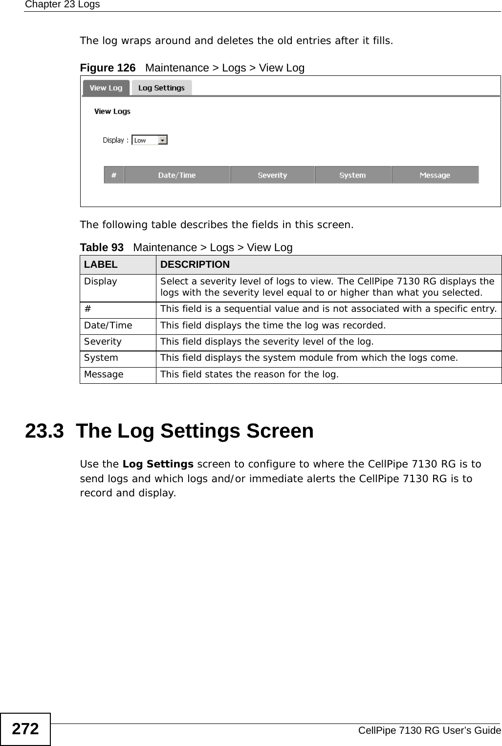
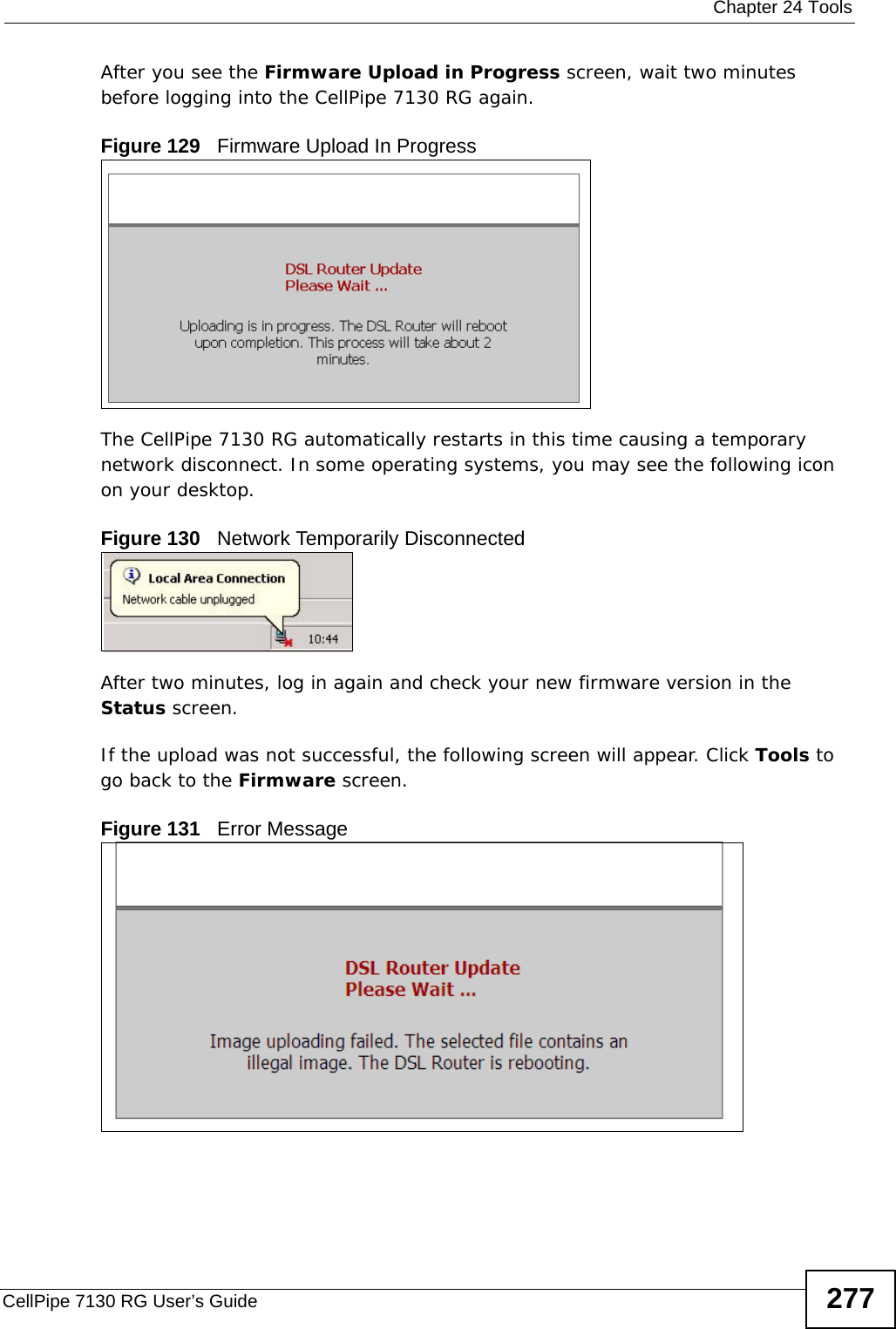
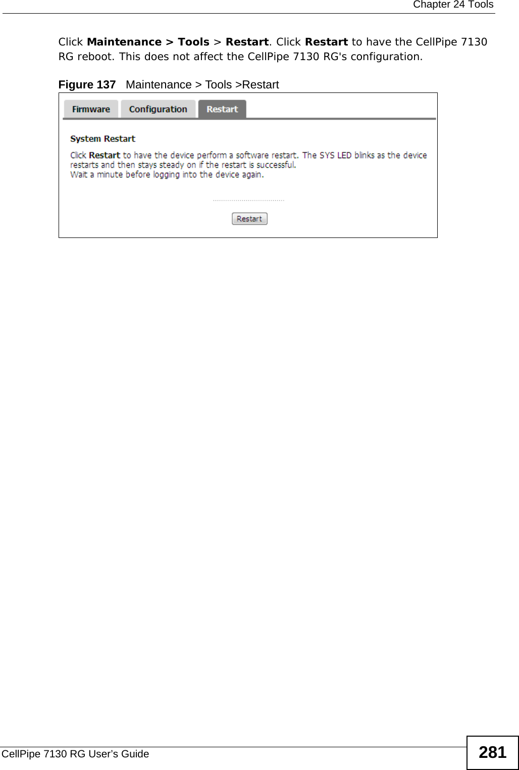
![Chapter 2 TutorialsCellPipe 7130 RG User’s Guide82• Enter the user name (UserName1) and password (12345).Click Apply.2.11.3 Testing the DDNS SettingNow you should be able to access the CellPipe 7130 RG from the Internet. To test this:1Open a web browser on the computer (using the IP address a.b.c.d) that is connected to the Internet.2Type http://yourrouter.dyndns.org and press [Enter].3The CellPipe 7130 RG’s login page should appear. You can then log into the CellPipe 7130 RG and manage it.](https://usermanual.wiki/ZyXEL-Communications/5VZ-A2011/User-Guide-1284006-Page-82.png)
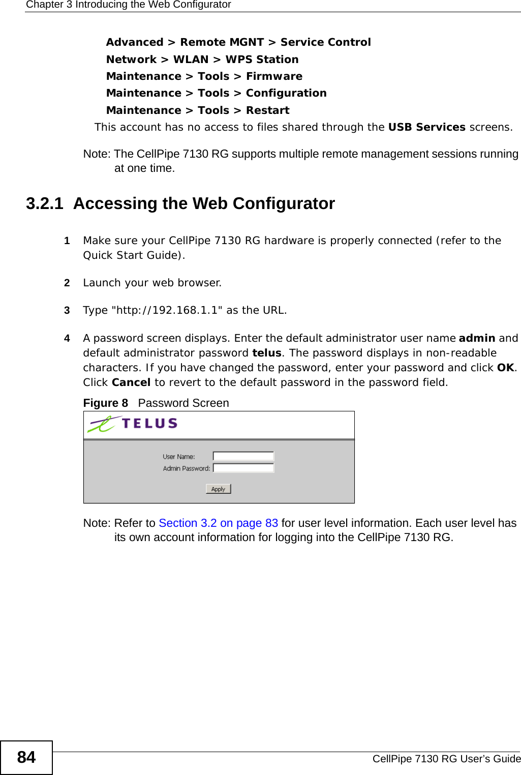
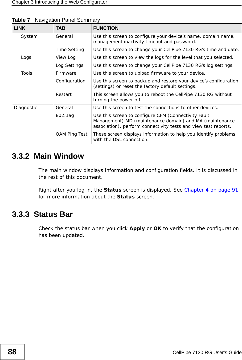


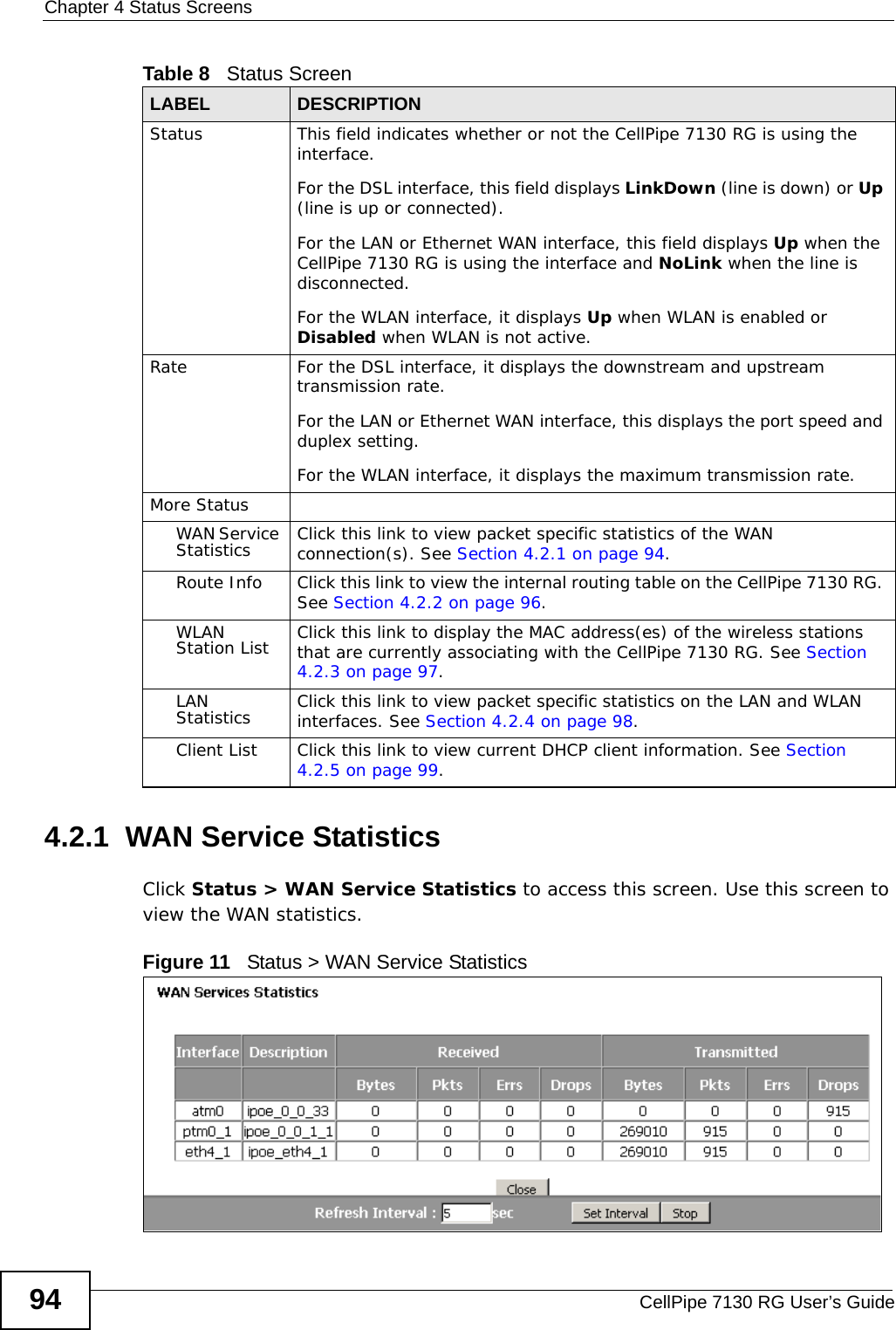

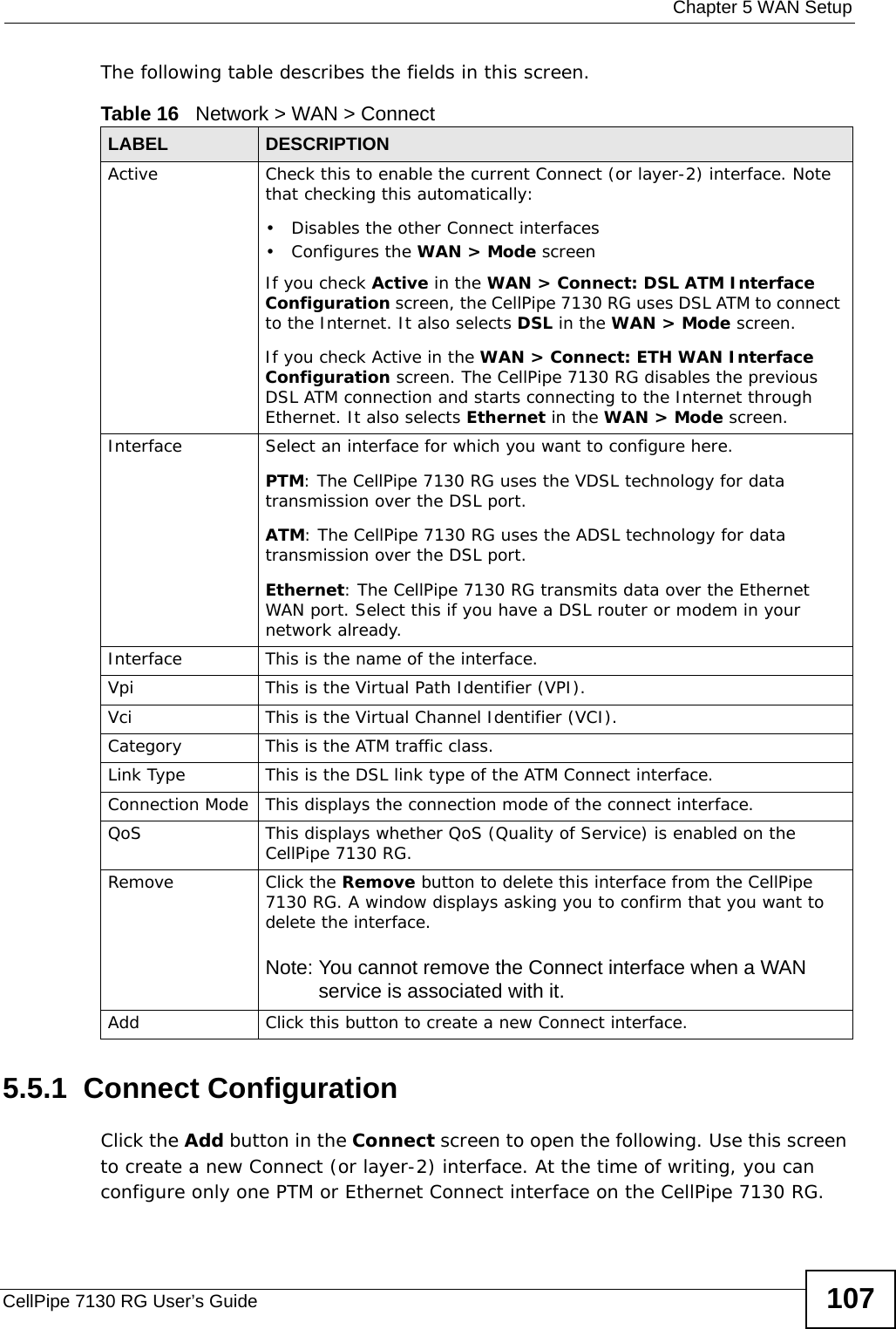
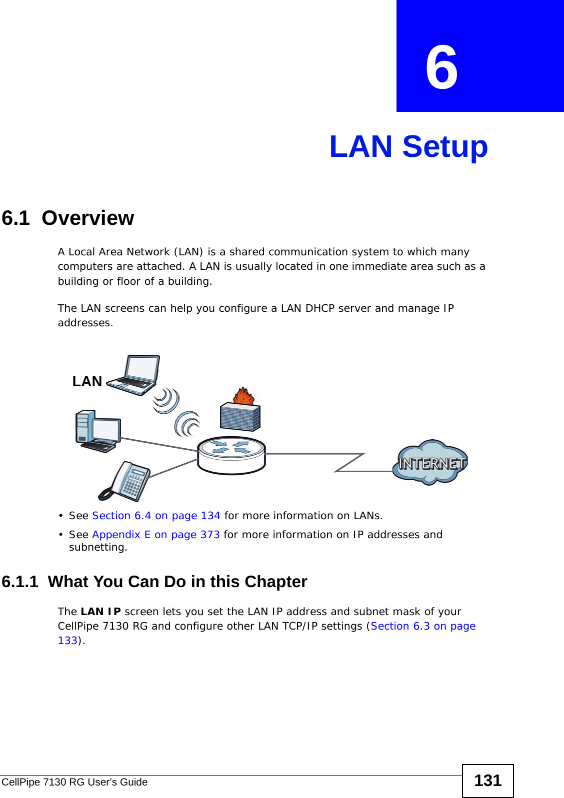
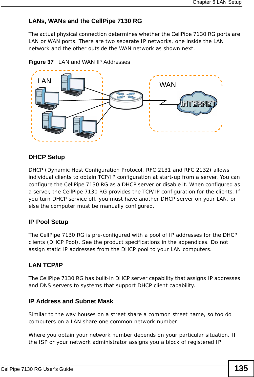

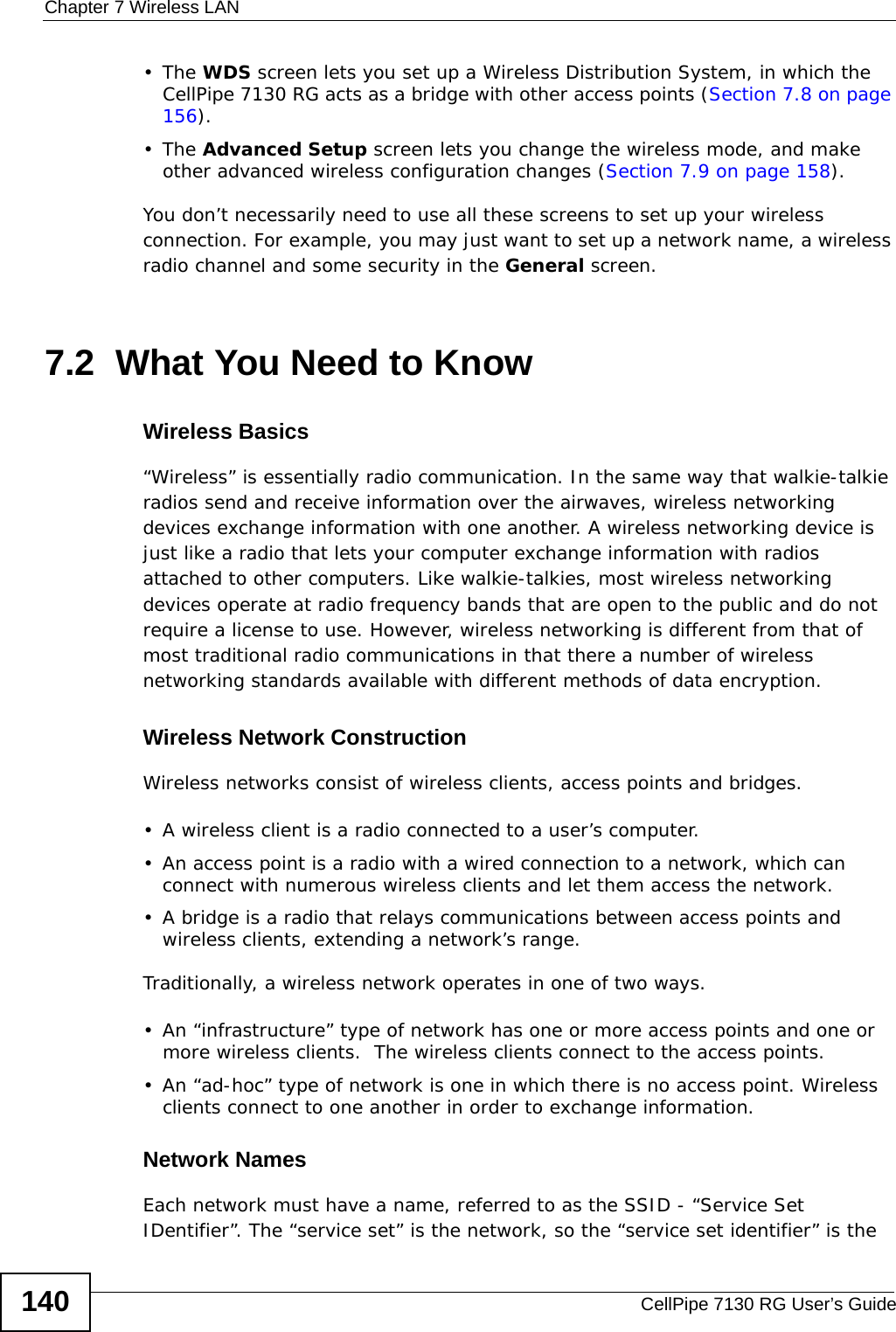
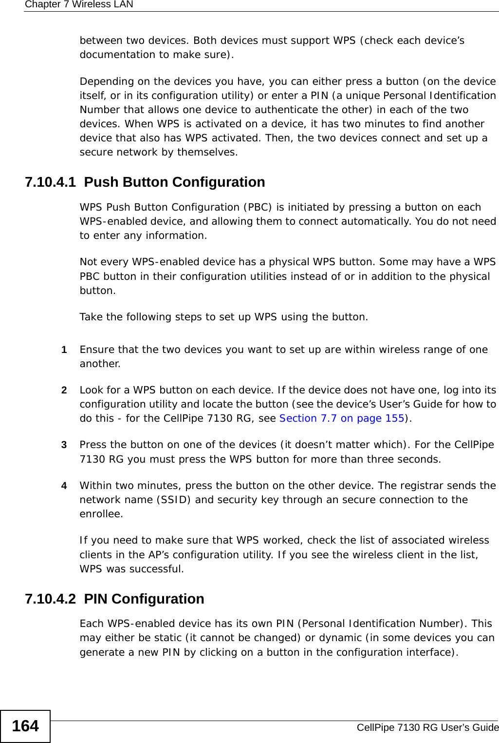

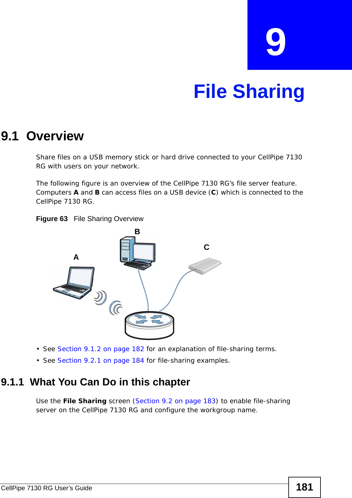
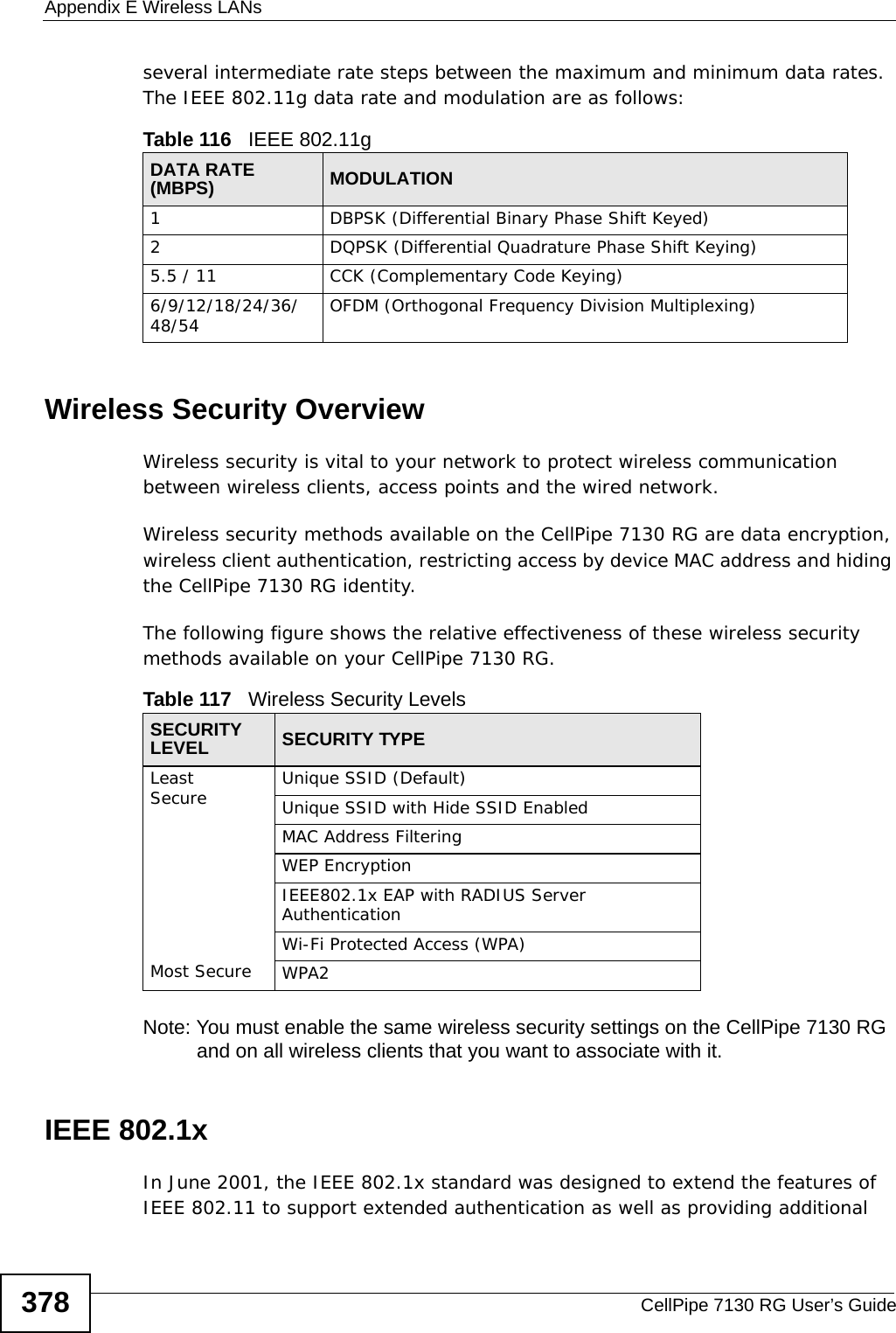
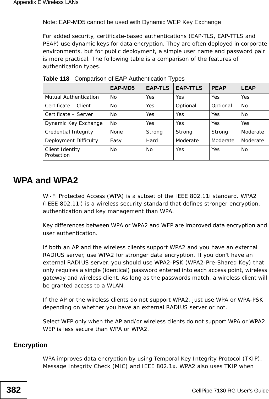
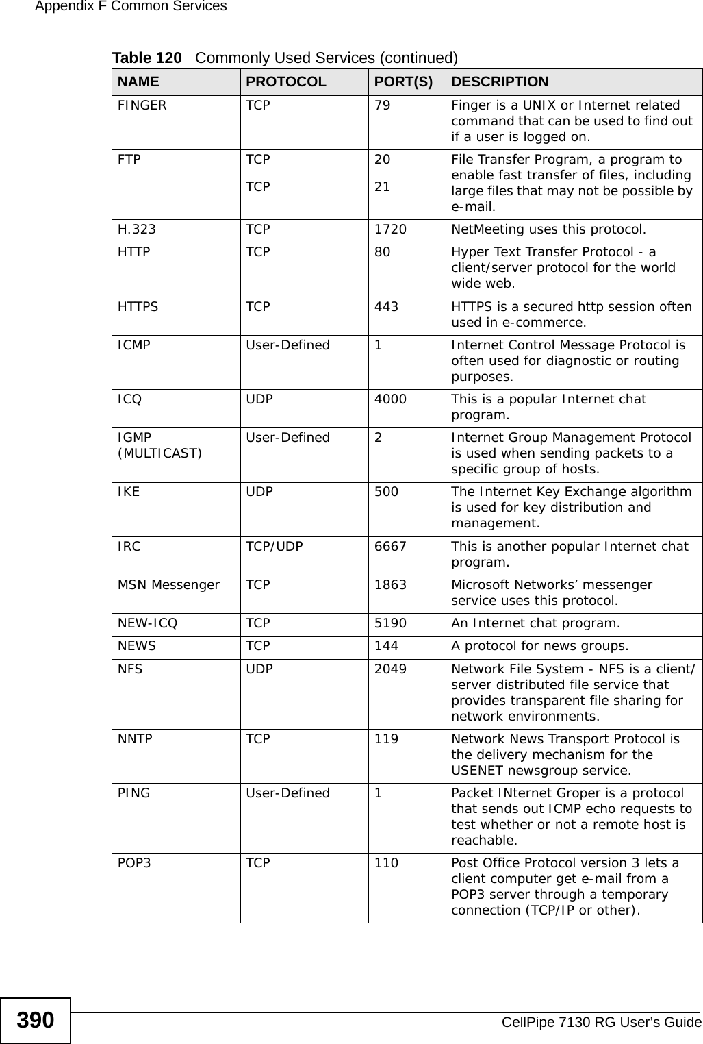
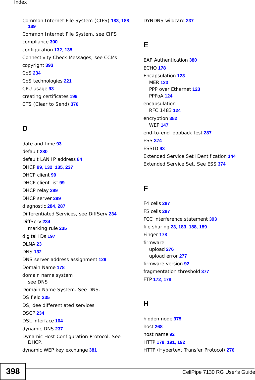
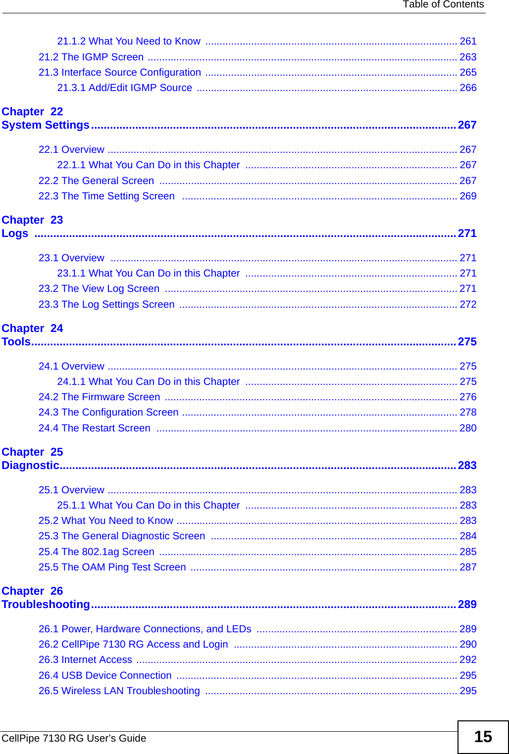
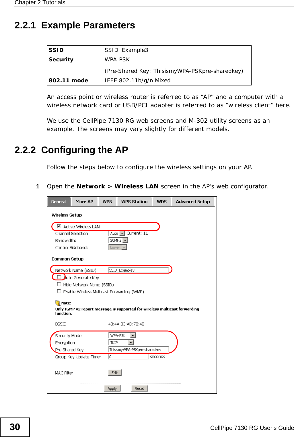
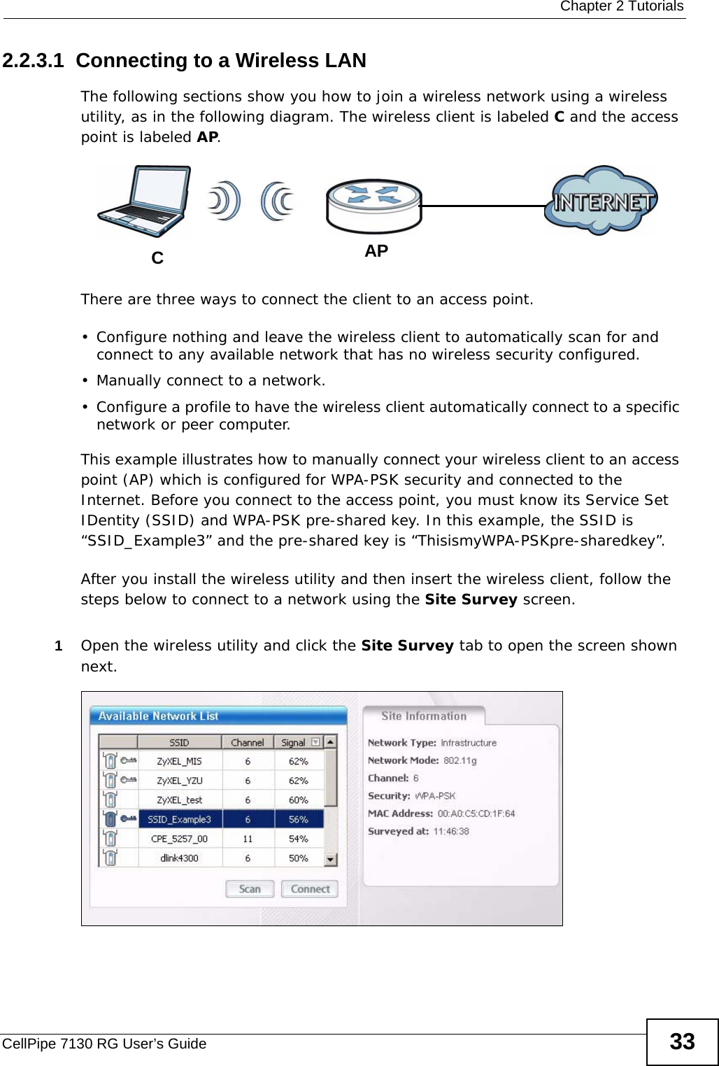
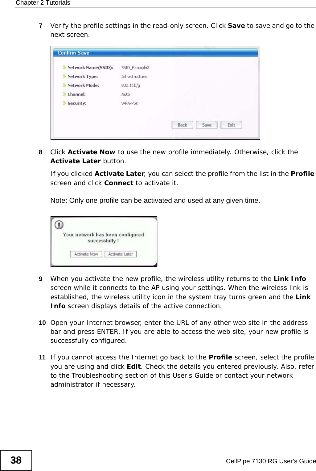
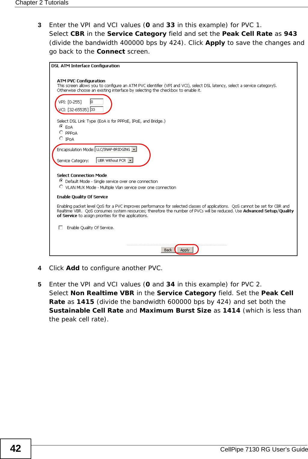
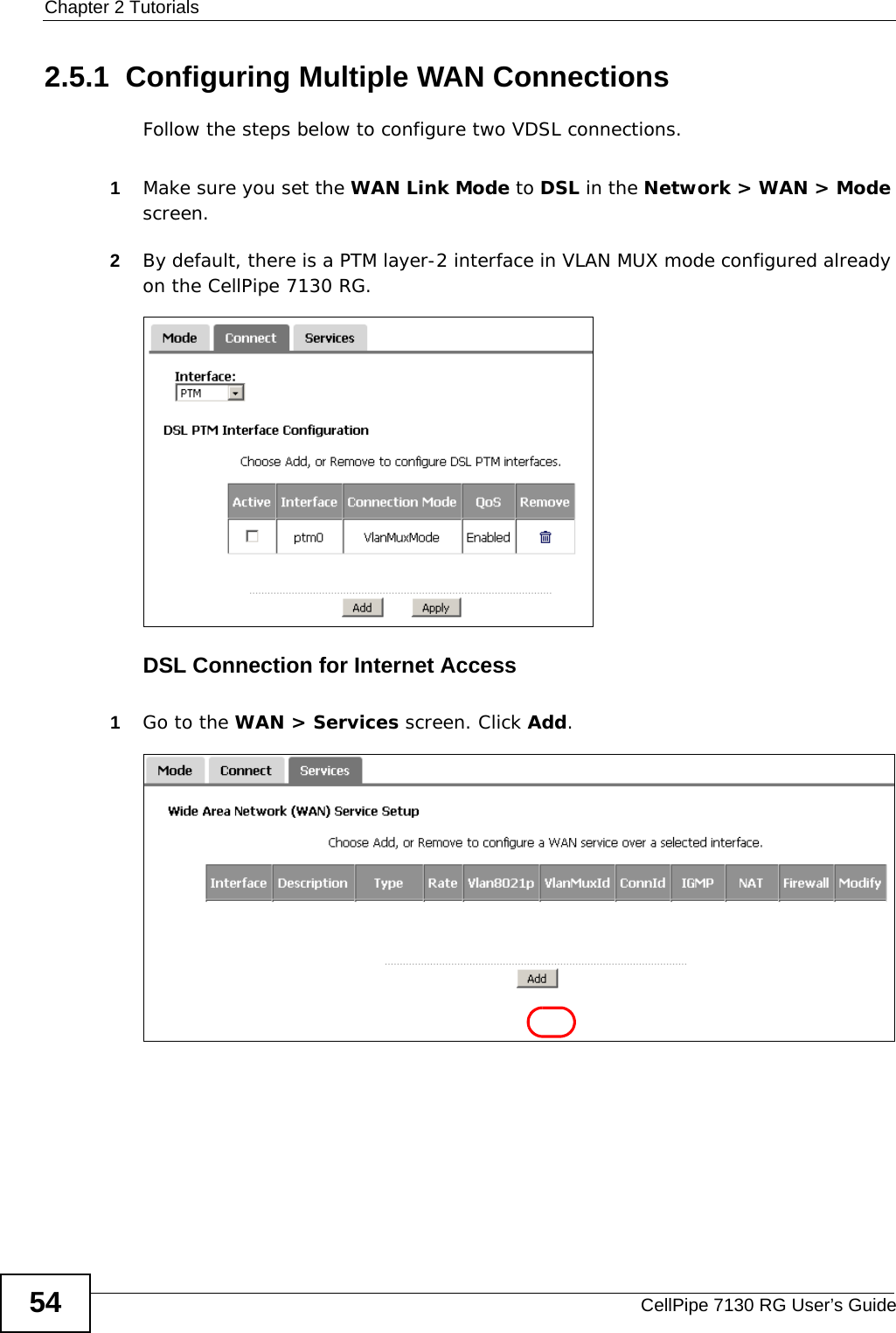
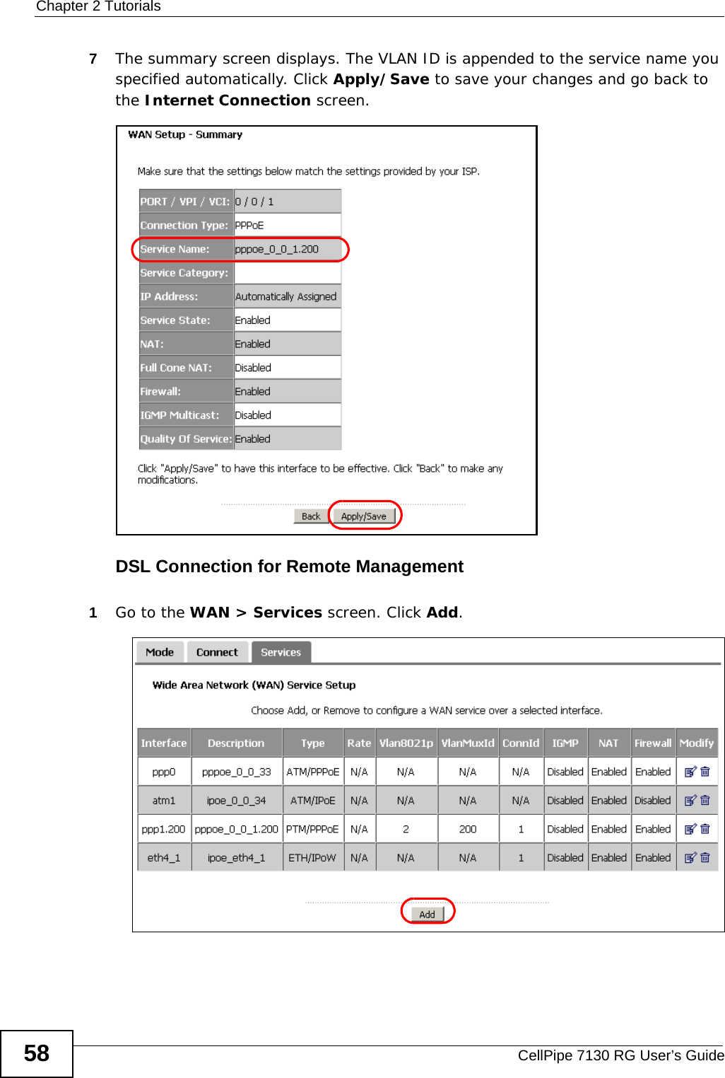
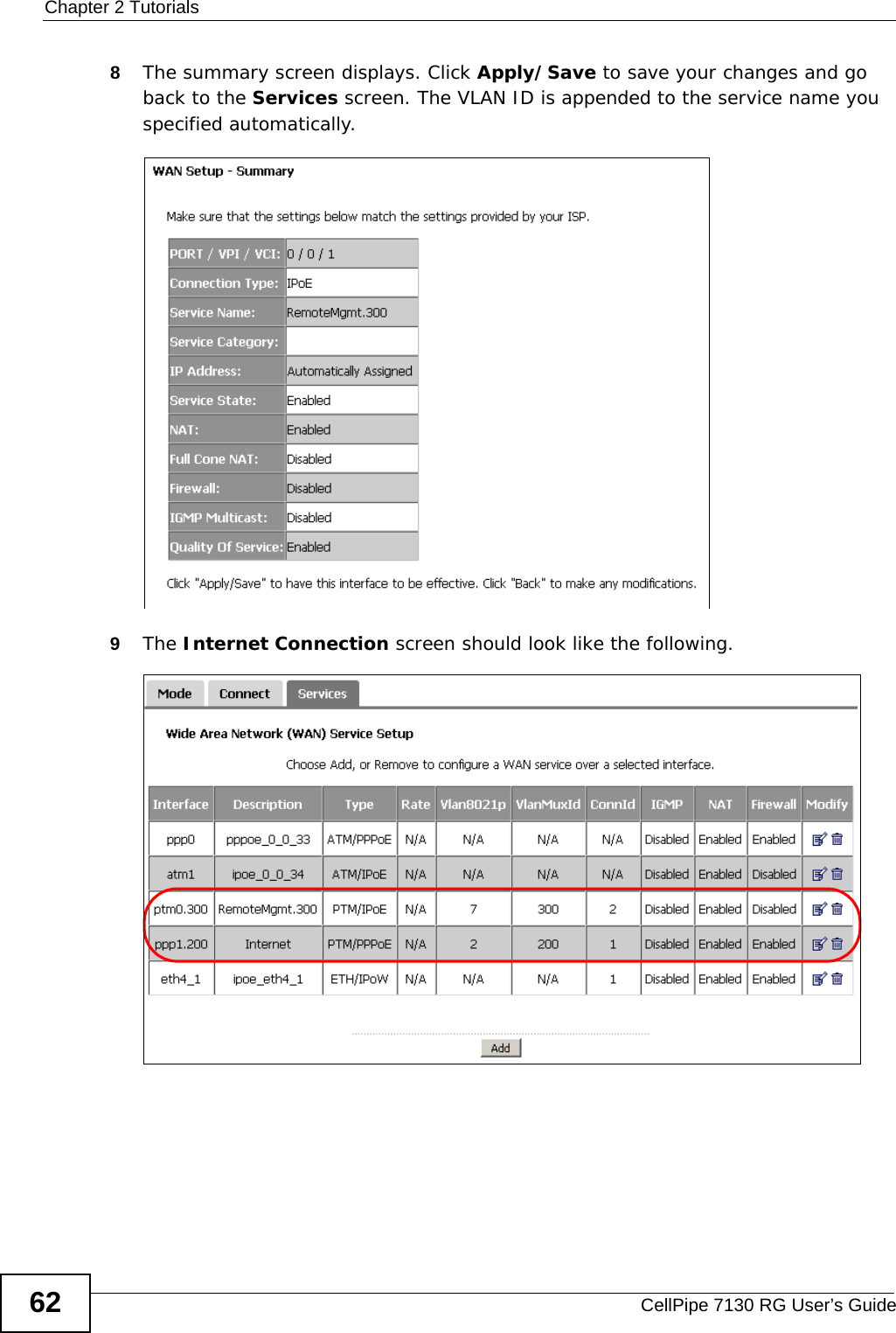
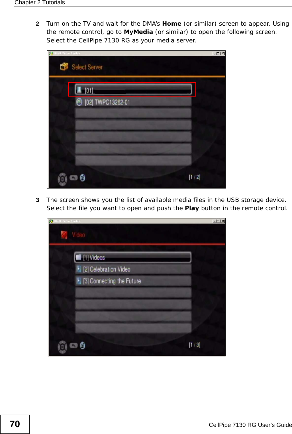
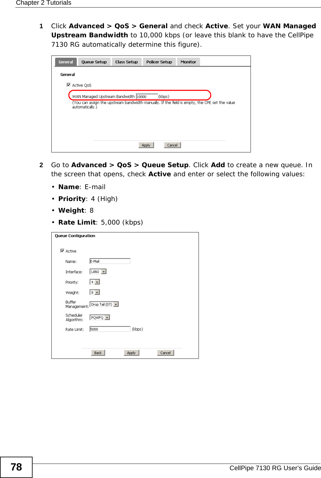
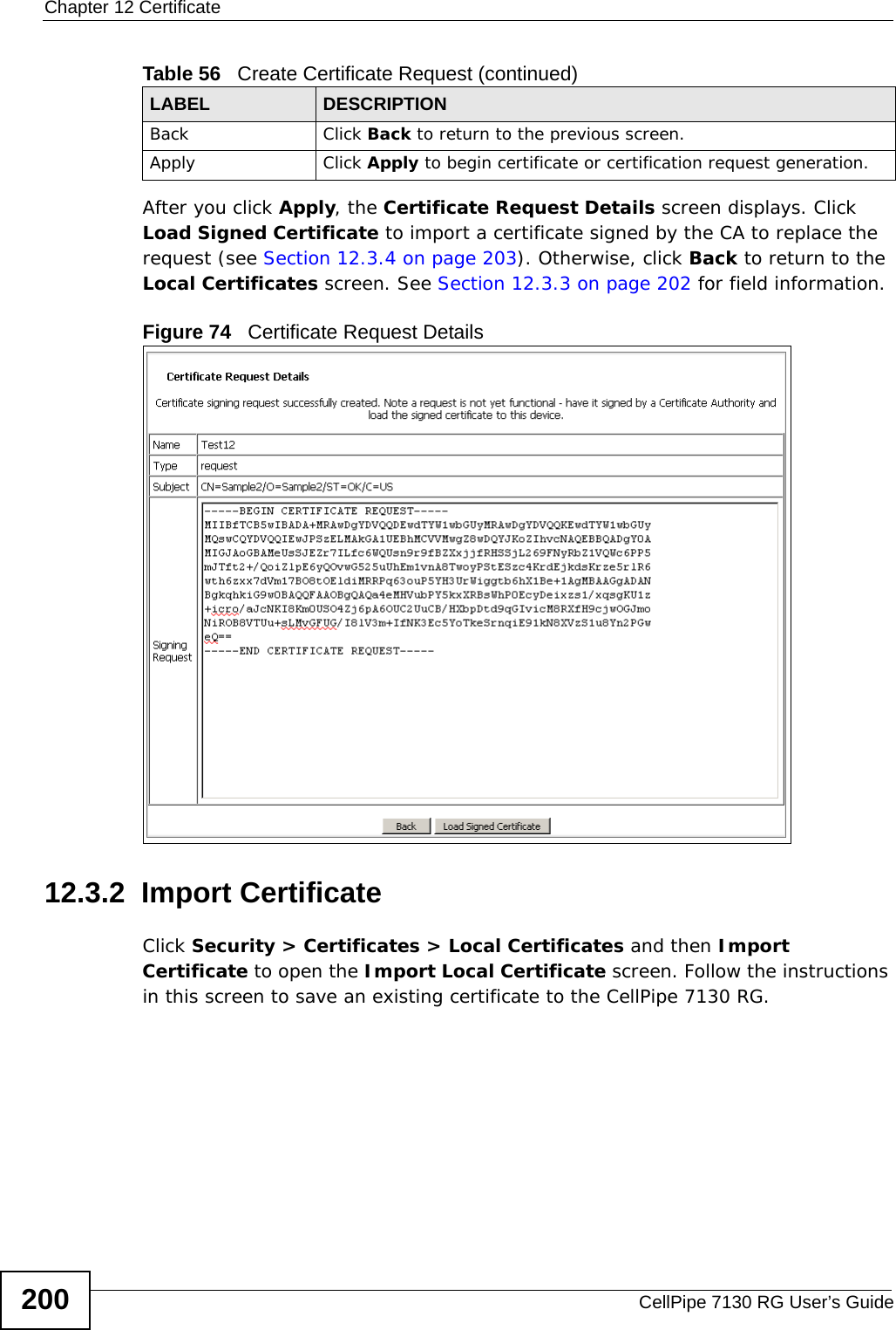
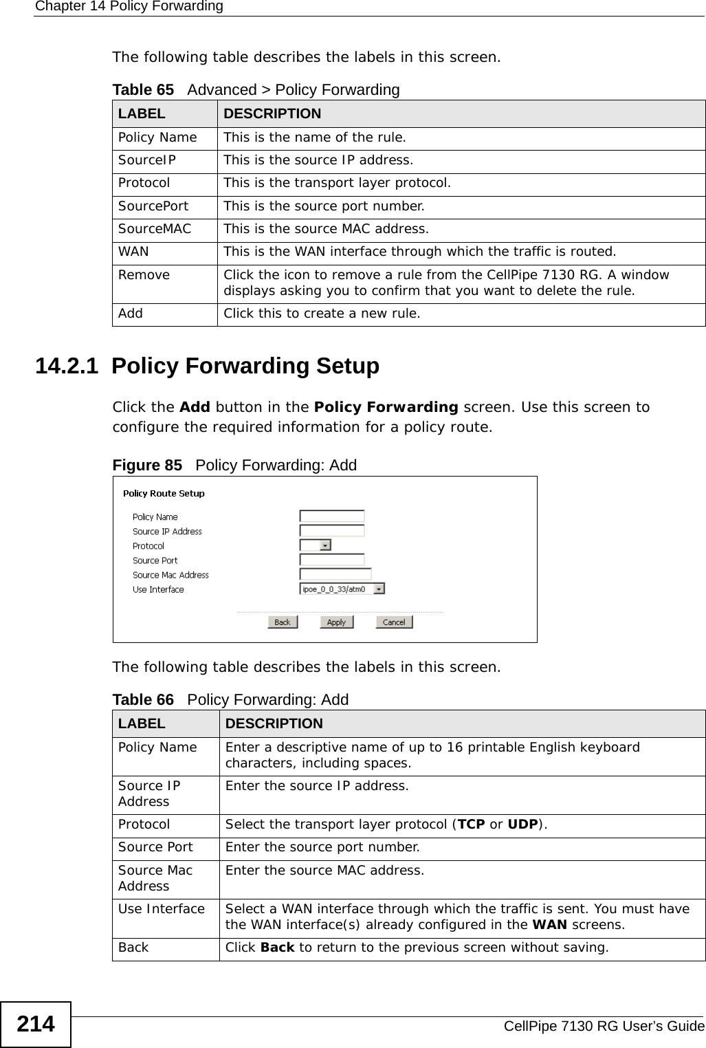
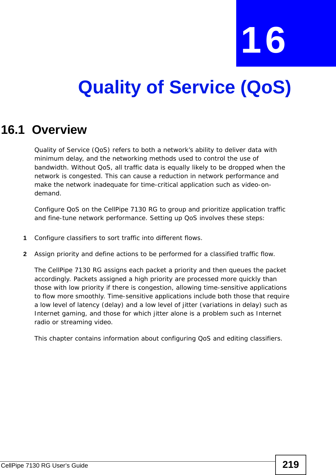
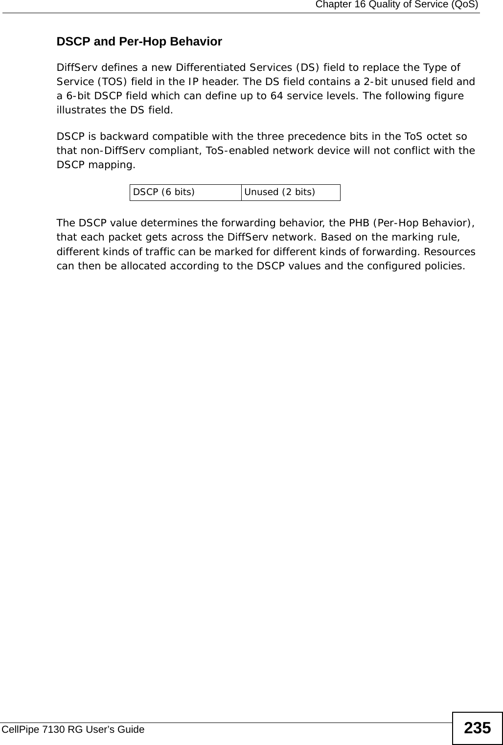
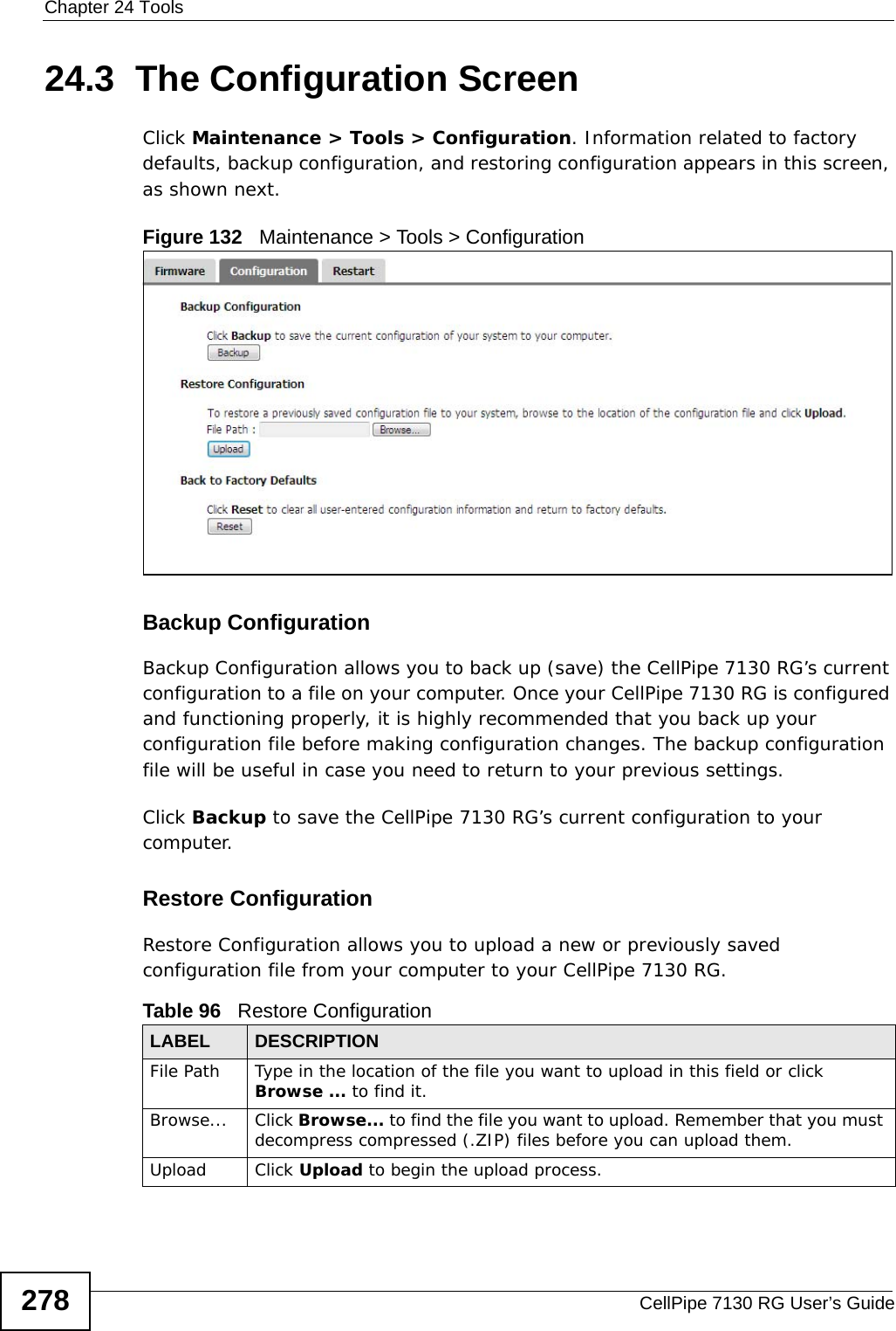
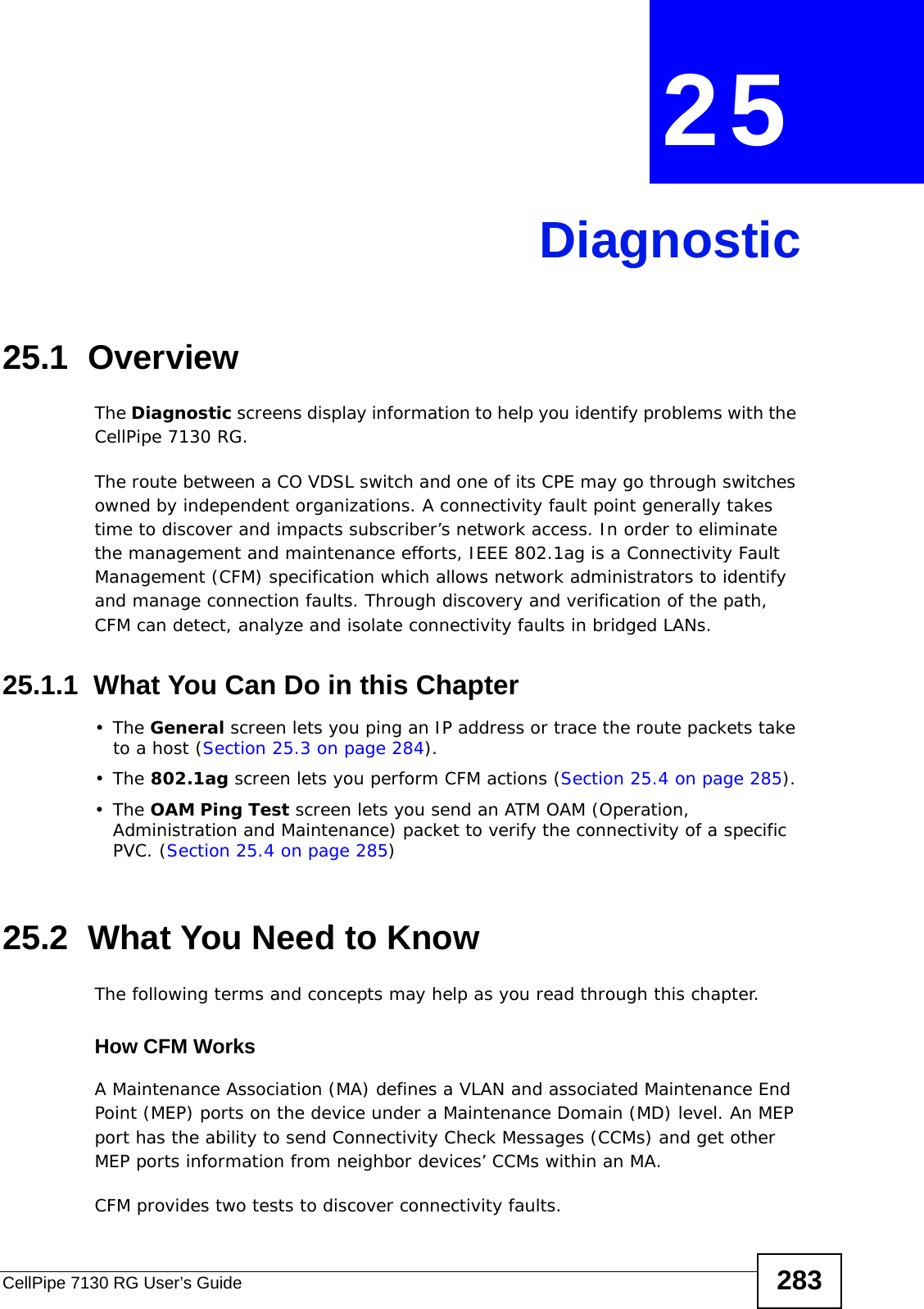
![Chapter 9 File SharingCellPipe 7130 RG User’s Guide 1852In Windows Explorer’s Address bar type a double backslash “\\” followed by the IP address of the CellPipe 7130 RG (the default IP address of the CellPipe 7130 RG is 192.168.1.1) and press [ENTER]. A screen asking for password authentication appears. Type the user name and password you use to access the system and click OK. (The default system user name is admin and the default system password is telus.)Figure 65 File Sharing via Windows ExplorerNote: Once you log in to the file share via your CellPipe 7130 RG, you do not have to log in again unless you restart your computer. Note: Refer to Section 3.2 on page 83 for user level information. Each user level has its own account information for logging into the CellPipe 7130 RG.](https://usermanual.wiki/ZyXEL-Communications/5VZ-A2011/User-Guide-1284006-Page-185.png)


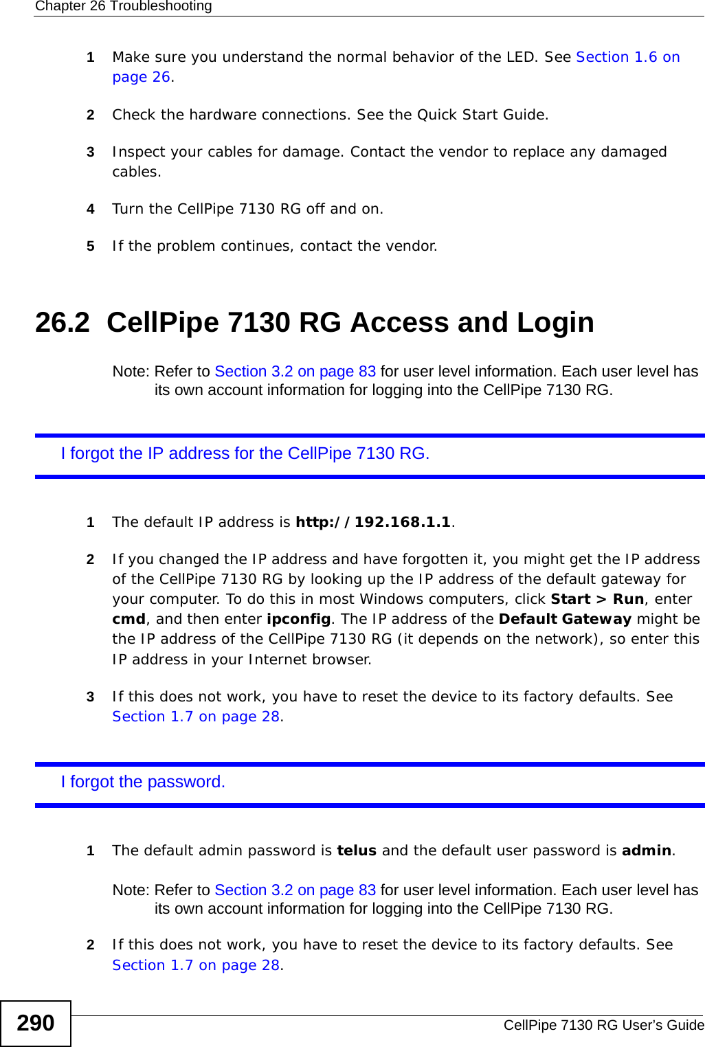
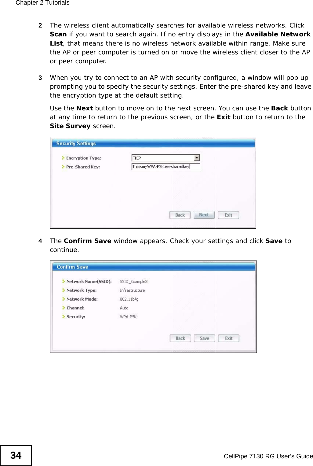
![Chapter 26 TroubleshootingCellPipe 7130 RG User’s Guide 291I cannot see or access the Login screen (or other screens) in the web configurator.1Make sure you are using the correct IP address.• The default IP address is http://192.168.1.1.• If you changed the IP address (Section on page 135), use the new IP address.• If you changed the IP address and have forgotten it, see the troubleshooting suggestions for I forgot the IP address for the CellPipe 7130 RG.2Check the hardware connections, and make sure the LEDs are behaving as expected. See the Quick Start Guide.3Make sure your Internet browser does not block pop-up windows and has JavaScripts and Java enabled. See Appendix C on page 351.4Reset the device to its factory defaults, and try to access the CellPipe 7130 RG with the default IP address. See Section 1.7 on page 28. 5If the problem continues, contact the network administrator or vendor, or try one of the advanced suggestions.Advanced Suggestions• If your computer is connected to the WAN port or is connected wirelessly, use a computer that is connected to an ETHERNET port.• Try to access the CellPipe 7130 RG using another service, such as Telnet. If you can access the CellPipe 7130 RG, check the remote management settings and firewall rules to find out why the CellPipe 7130 RG does not respond to HTTPS. I can see the Login screen, but I cannot log in to the CellPipe 7130 RG.1Make sure you have entered the user name and password correctly. The default admin user name is admin and default admin password is telus. These fields are case-sensitive, so make sure [Caps Lock] is not on. Note: Refer to Section 3.2 on page 83 for user level information. Each user level has its own account information for logging into the CellPipe 7130 RG.2Turn the CellPipe 7130 RG off and on.](https://usermanual.wiki/ZyXEL-Communications/5VZ-A2011/User-Guide-1284006-Page-291.png)
![Chapter 26 TroubleshootingCellPipe 7130 RG User’s Guide2923If this does not work, you have to reset the device to its factory defaults. See Section 26.1 on page 289.I cannot Telnet to the CellPipe 7130 RG. See the troubleshooting suggestions for I cannot see or access the Login screen (or other screens) in the web configurator. Ignore the suggestions about your browser.I cannot use FTP to upload / download the configuration file. / I cannot use FTP to upload new firmware.See the troubleshooting suggestions for I cannot see or access the Login screen (or other screens) in the web configurator. Ignore the suggestions about your browser.I cannot access the CellPipe 7130 RG again after configuring a new interface group.Make sure your computer is connected to a LAN port in the default group. Otherwise, you need to use the CellPipe 7130 RG’s LAN IP address for the new group to access the CellPipe 7130 RG again.26.3 Internet AccessI cannot access the Internet.1Check the hardware connections, and make sure the LEDs are behaving as expected. See the Quick Start Guide and Section 1.6 on page 26. 2Make sure you entered your ISP account information correctly in the WAN screens. These fields are case-sensitive, so make sure [Caps Lock] is not on.](https://usermanual.wiki/ZyXEL-Communications/5VZ-A2011/User-Guide-1284006-Page-292.png)


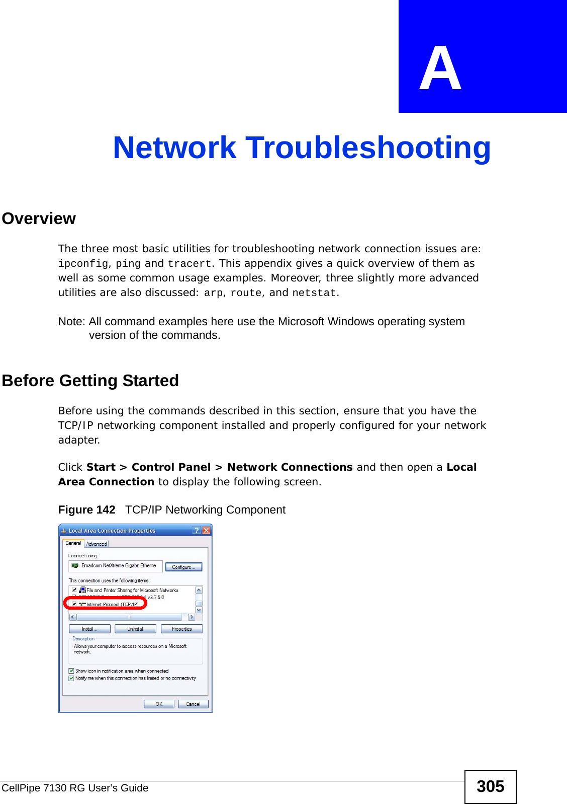
![Appendix A Network TroubleshootingCellPipe 7130 RG User’s Guide306Note: Most operating systems ship with TCP/IP already installed and enabled. See your Windows documentation for details on installing or configuring TCP/IP.The Command Line InterfaceTo open the Windows command line interface:1Click Start > Run.2In the Run dialog box, enter cmd then click OK.3The Command Prompt window opens.Command Syntax and ParametersCommand descriptions always indicate the default syntax you must use when entering them on the command line. Some commands require additional parameters in order to execute properly. Some may have optional parameters.Parameters are displayed as follows: command [parameter]](https://usermanual.wiki/ZyXEL-Communications/5VZ-A2011/User-Guide-1284006-Page-306.png)
![Appendix A Network TroubleshootingCellPipe 7130 RG User’s Guide 307For example, the date command has the optional /t and date parameters. If you do not use either of them and enter just date by itself, then the system shows you the date it is currently using and then prompts you to change it. However, if you use the /t parameter it just displays the date and nothing more. To view the parameters for any given command, enter help [command].ipconfigThe ipconfig command line utility allows you to display current network (TCP/IP) configuration settings and, in some cases, adjust them. When you have network connectivity problems, the first thing you should do is run this command to ensure that your device or computer does in fact have an IP address as well as display the source of that IP address (such as a default gateway).Syntax: ipconfigParameters: ipconfig [/release] [/renew]There are other parameters, but these are the only ones you need to use for now.The following examples show the typical output of this command: C:\>dateThe current date is: 2009/10/21Enter the new date: (mm-dd-yy)C:\>date /t2009/10/21C:\>C:\>ipconfigWindows IP ConfigurationEthernet adapter Local Area Connection: Connection-specific DNS Suffix . : example.com IP Address. . . . . . . . . . . . : 192.168.1.1 Subnet Mask . . . . . . . . . . . : 255.255.255.0 Default Gateway . . . . . . . . . : 1.1.1.4C:\>](https://usermanual.wiki/ZyXEL-Communications/5VZ-A2011/User-Guide-1284006-Page-307.png)
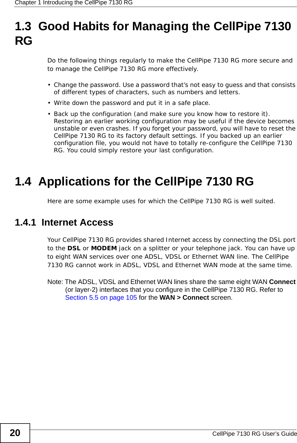
![Appendix A Network TroubleshootingCellPipe 7130 RG User’s Guide 309pingThe ping command line utility allows you to verify the connection and latency between your computer and either the CellPipe 7130 RG or other devices on the network. If you cannot reach a target using this command, then it may indicate possible network trouble.Syntax: ping targetThe target can be an IP address or a host name.Parameters: ping [-w timeout] targetThe timeout parameter allows you to input the number of seconds (in milliseconds) that your computer waits for a reply.The following examples show the typical output of this command: The number of bytes here indicates packet size. As most data is broken up into smaller packets, this makes the ping test fairly representative of a typical network connection. The default packet size on Windows is 32 bytes.Time is the number of milliseconds the data requires to make the roundtrip journey from your computer to the destination host and back again. The lower the number, the faster the connection between the two points.Note: Some hosts are deliberately configured to not respond to ping requests. As such, we suggest pinging two or three hosts when performing your ping test.C:\>ping www.example.comPinging a1524.g.akamai.net [203.69.113.18] with 32 bytes of data:Reply from 203.69.113.18: bytes=32 time=6ms TTL=56Reply from 203.69.113.18: bytes=32 time=6ms TTL=56Reply from 203.69.113.18: bytes=32 time=6ms TTL=56Reply from 203.69.113.18: bytes=32 time=7ms TTL=48Ping statistics for 203.69.113.18: Packets: Sent = 4, Received = 4, Lost = 0 (0% loss),Approximate round trip times in milli-seconds: Minimum = 6ms, Maximum = 7ms, Average = 6ms>](https://usermanual.wiki/ZyXEL-Communications/5VZ-A2011/User-Guide-1284006-Page-309.png)
![Appendix A Network TroubleshootingCellPipe 7130 RG User’s Guide310If your ping test fails to get a response, then you may see a message like this: When a request times out it may mean: • your computer is not connected to the network• your Internet access device is not connected to the network• or the device which you are pinging is not connected to the networkIf you think the destination is active but responding slowly, you can try increasing the ping timeout value from its default of 4 seconds (4000 milliseconds) to something like 8 seconds (or 8000 milliseconds). A long ping response could indicate network problems:• on your side of the connection• between the start and end points of the connection• on the receiving endTo determine where the slowdown is, you may need to use traceroute.C:\>ping www.example.comPinging www.example.com [192.0.32.10] with 32 bytes of data:Request timed out.Request timed out.Request timed out.Request timed out.Ping statistics for 192.0.32.10: Packets: Sent = 4, Received = 0, Lost = 4 (100% loss),C:\>C:\>ping -w 8000 www.example.comPinging www.example.com [192.0.32.10] with 32 bytes of data:Reply from 192.0.32.10: bytes=32 time=157ms TTL=238Reply from 192.0.32.10: bytes=32 time=154ms TTL=238Reply from 192.0.32.10: bytes=32 time=152ms TTL=236Reply from 192.0.32.10: bytes=32 time=162ms TTL=236Ping statistics for 192.0.32.10: Packets: Sent = 4, Received = 4, Lost = 0 (0% loss),Approximate round trip times in milli-seconds: Minimum = 152ms, Maximum = 162ms, Average = 156msC:\>](https://usermanual.wiki/ZyXEL-Communications/5VZ-A2011/User-Guide-1284006-Page-310.png)
![Appendix A Network TroubleshootingCellPipe 7130 RG User’s Guide 311tracertThe tracert command line utility allows you to determine the network path between your computer and a host you specify. When you communicate with other devices on a network, the data is not often sent directly from point A to point B; rather, it moves through a series of intermediate servers, passed along until eventually the server closest to point B hands it off directly. This command can be useful for helping determine whether your connection issues are happening locally, somewhere in transit, or at the destination end.• Each step in the chain of connections is called a ‘hop’. • The time it takes for a server at any given hop to pass the data packet is called ‘latency’ and is measured in milliseconds. When a tracert command is run, it sends out a burst of three data packets per hop. The results table, therefore, always displays three values for latency in addition to the IP address and domain name (where available) of the server on that leg of the journey.Syntax: tracert targetThe target can be an IP address or a host name.Parameters: tracert [-d] [-h maximumhops ] target There are other parameters but these are the only ones you need to use for now.](https://usermanual.wiki/ZyXEL-Communications/5VZ-A2011/User-Guide-1284006-Page-311.png)
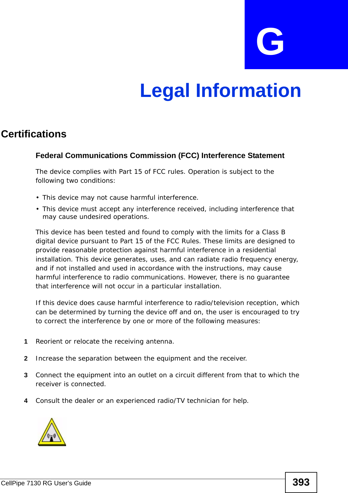
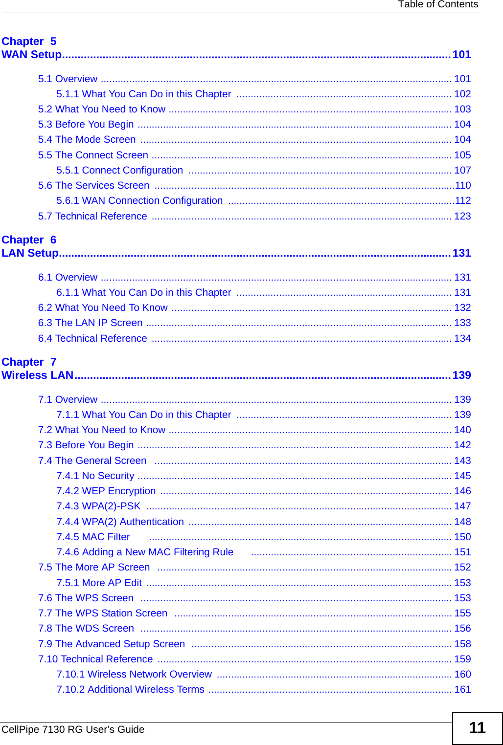
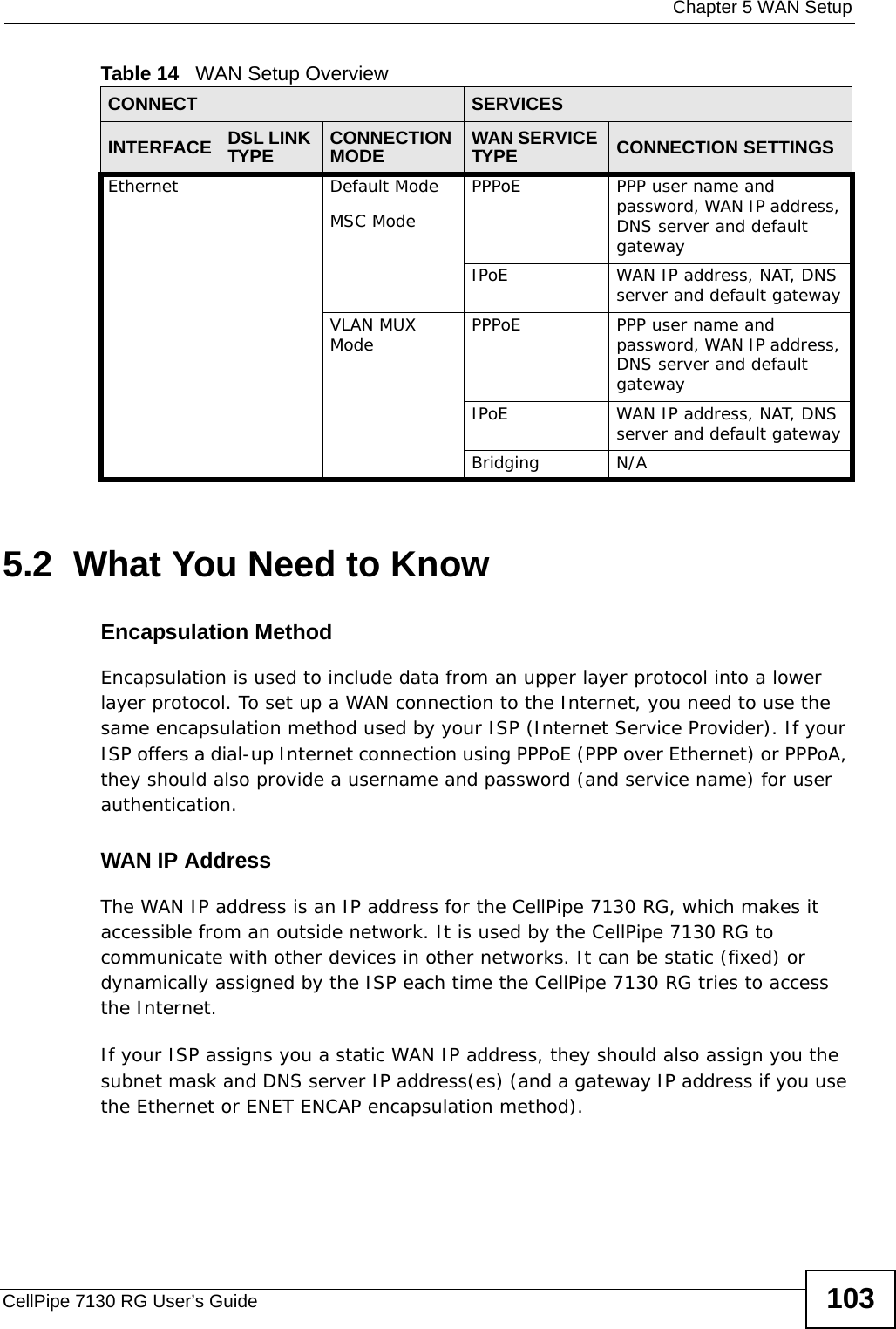
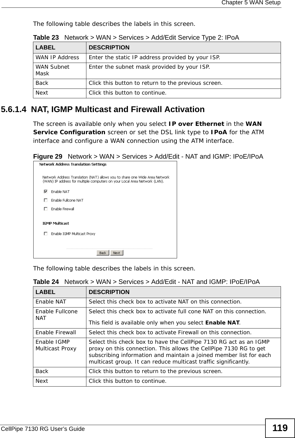
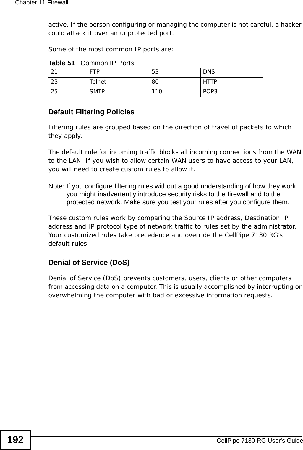
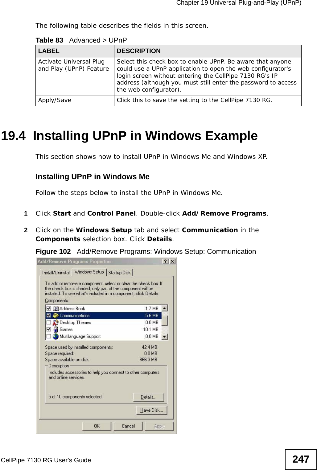
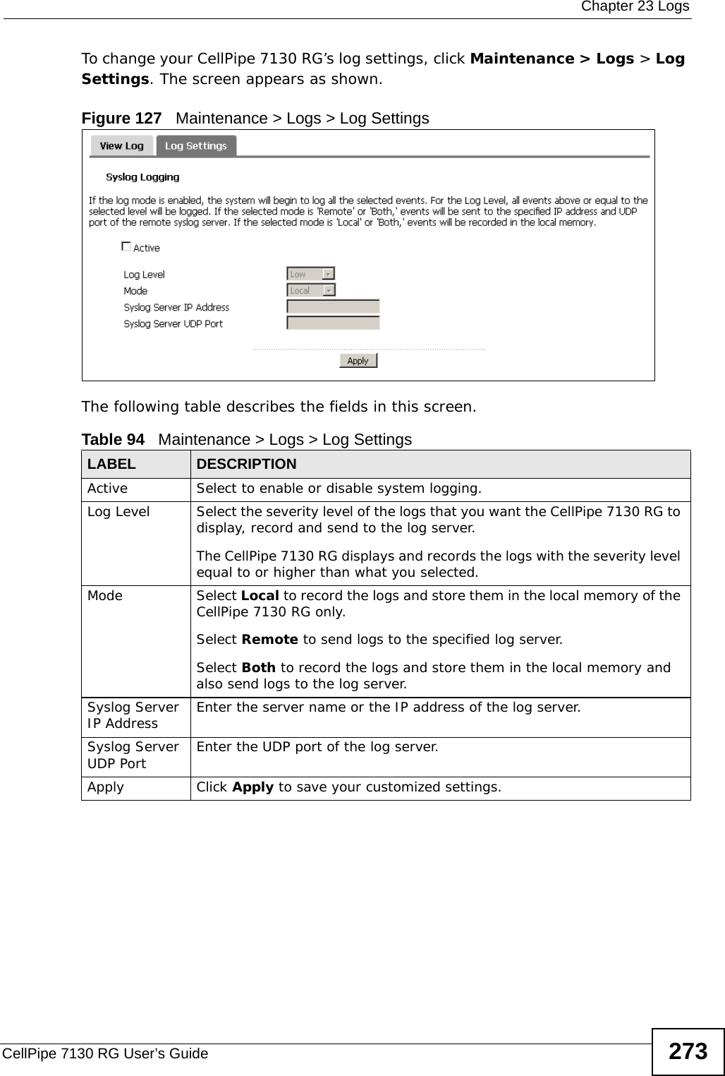
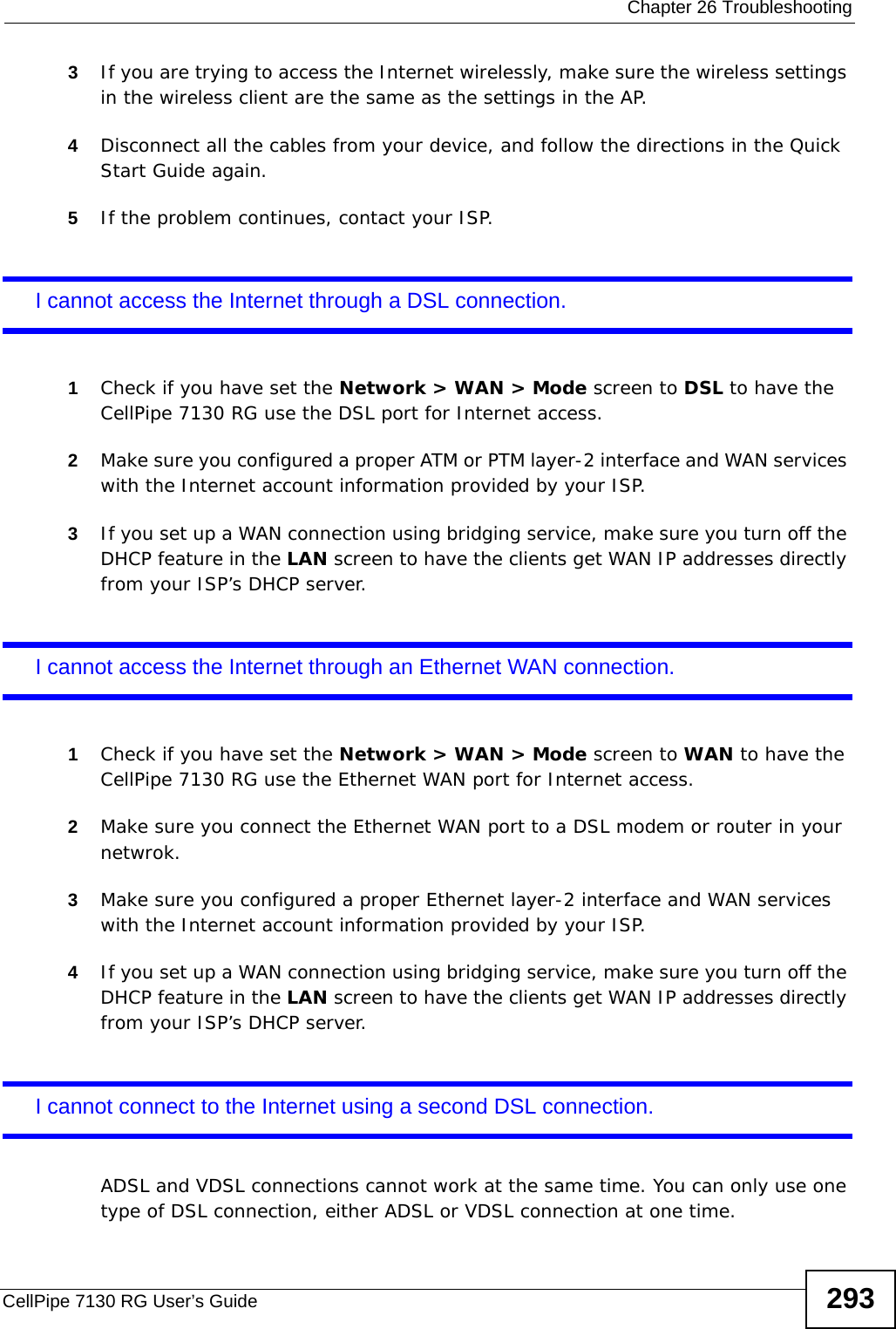
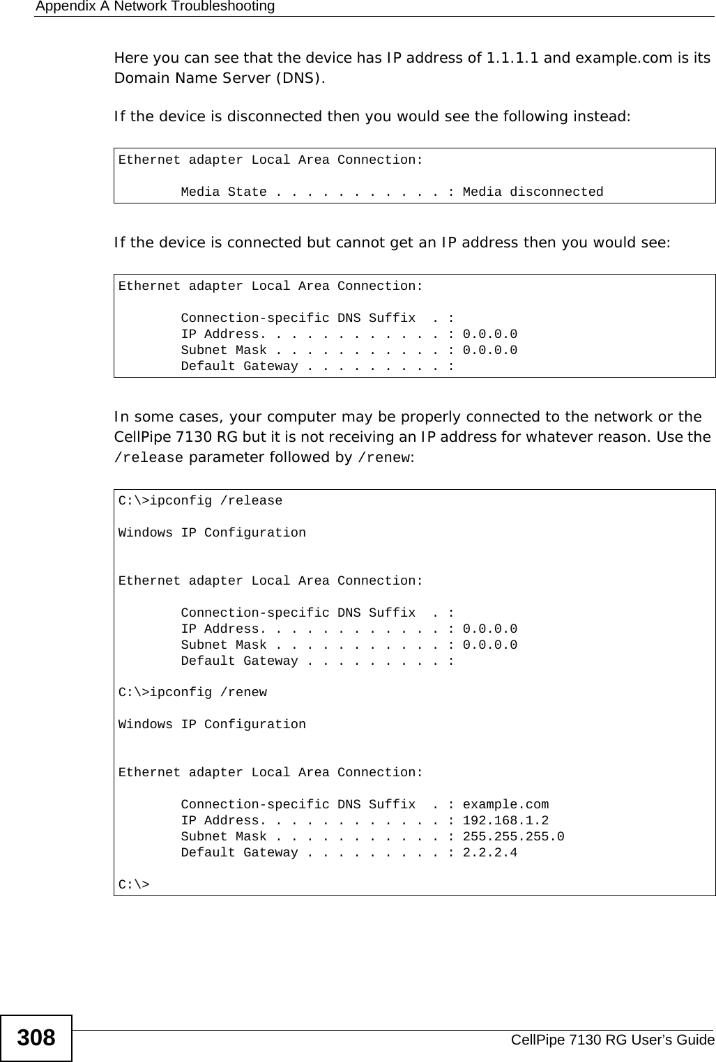
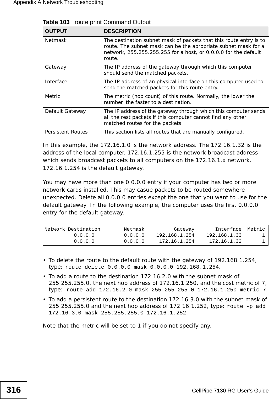
![Appendix A Network TroubleshootingCellPipe 7130 RG User’s Guide312The following examples show the typical output of this command: Here, the tracert to www.example.com took 18 hops to reach its destination. Looking at the latency data, you’ll see the first slow down happens at hop 10. The extremely low latency on the first few hops indicates a network local to the computer where the tracert command originated, such as a home or office LAN. The packets then move onto the local WAN (such as your Internet Service Provider’s network). Because of the close proximity of those servers to your computer, the latency remains low.Once the data packets move out of the regional network to the first international server (at hop 10 in this example), the latency increases. This is because of the distance between the regional and international servers - it physically takes longer for the response to get back to your computer.Finally, on transition hop 15 from the server in Japan to the server in California, another latency spike occurs. If you were having connection problems, this would most likely be the source of it. For whatever reason, the server in Japan has a less than optimal connection with its counterpart in the United States.C:\>tracert www.example.comTracing route to www.example.com [192.0.32.10]over a maximum of 30 hops: 1 <1 ms <1 ms <1 ms 172.23.x.x 2 5 ms 4 ms 5 ms 172.23.x.x 3 4 ms 4 ms 4 ms 172.23.x.x 4 5 ms 4 ms 6 ms 219-87-158-97.static.tfn.tw [219.87.158.97] 5 6 ms 5 ms 4 ms 10.42.232.150 6 5 ms 4 ms 4 ms hc-c12r2.router.tw [220.128.7.86] 7 10 ms 7 ms 10 ms tp-s2-c12r12.router.tw [220.128.2.90] 8 9 ms 7 ms 8 ms pr03-s2.tp.tw [220.128.4.181] 9 6 ms 6 ms 9 ms 220-128-3-249.NET-IP.tw [220.128.3.249] 10 138 ms 137 ms 138 ms r11-pa.NET-IP.net [211.72.108.129] 11 138 ms 138 ms 138 ms po4-0.core01.sjc04.atlas.com [154.54.11.129] 12 128 ms 139 ms 140 ms te9-2.mpd01.sjc04.atlas.com [154.54.0.173] 13 140 ms 139 ms 136 ms 61.58.33.173 14 154 ms 153 ms 137 ms xe-0-0-0.r20.gin.ntt.net [129.250.16.161] 15 154 ms 154 ms 137 ms as-2.r21.tokyjp01.jp.ntt.net [129.250.4.81] 16 562 ms 553 ms 553 ms 38.106.6.34 17 554 ms 554 ms 553 ms po-2.r00.lsanca19.us.ntt.net [129.250.6.42] 18 254 ms 254 ms 248 ms 204.1.254.150 19 154 ms 253 ms 154 ms 192.0.32.10Trace complete.C:\>](https://usermanual.wiki/ZyXEL-Communications/5VZ-A2011/User-Guide-1284006-Page-312.png)
![Appendix A Network TroubleshootingCellPipe 7130 RG User’s Guide 313In this example, we abridge the tracert results table to show only server IP addresses and not domain names by using the -d parameter. We also use the -h parameter to limit the number of hops to 5 to test local connections only. arpLocal network transmission is based on MAC addresses. Data transmission between two networks is based on IP addresses.Address Resolution Protocol (ARP) is a protocol that converts IP addresses into MAC addresses. Before a computer transmits data to an IP address on the same network, it will check whether the IP address exists in its ARP table. If it does, the computer then sends the data directly to the mapped MAC address. If it does not, the computer broadcasts an ARP request to the network. The host whose MAC address maps to the IP address responds.When you use ping to check the connection to a computer, no response does not mean the computer is not alive on the network. The destination computer may be configured not to respond to any ping requests. However, you can use the arp -a command line utility to check the IP addresses and MAC addresses of your neighboring computers or devices. Syntax: arp -aParameters: arp [-d inet_addr] [-s inet_addr eth_addr]The -d parameter can be use alone to remove all entries from an arp table or in conjunction with an IP address to remove just that IP address (inet_addr). The -s parameter allows you to add entries based on IP address (inet_addr) and/or MAC address (eth_addr).There are other parameters but these are the only ones you need to use for now.C:\>tracert -d -h 5 www.example.comTracing route to a1524.g.akamai.net [203.69.113.16]over a maximum of 5 hops: 1 <1 ms <1 ms <1 ms 172.23.31.254 2 5 ms 4 ms 4 ms 172.23.6.113 3 5 ms 5 ms 6 ms 172.23.6.253 4 17 ms 16 ms 14 ms 218.160.188.254 5 24 ms 25 ms 24 ms 10.42.232.150Trace complete.C:\>](https://usermanual.wiki/ZyXEL-Communications/5VZ-A2011/User-Guide-1284006-Page-313.png)
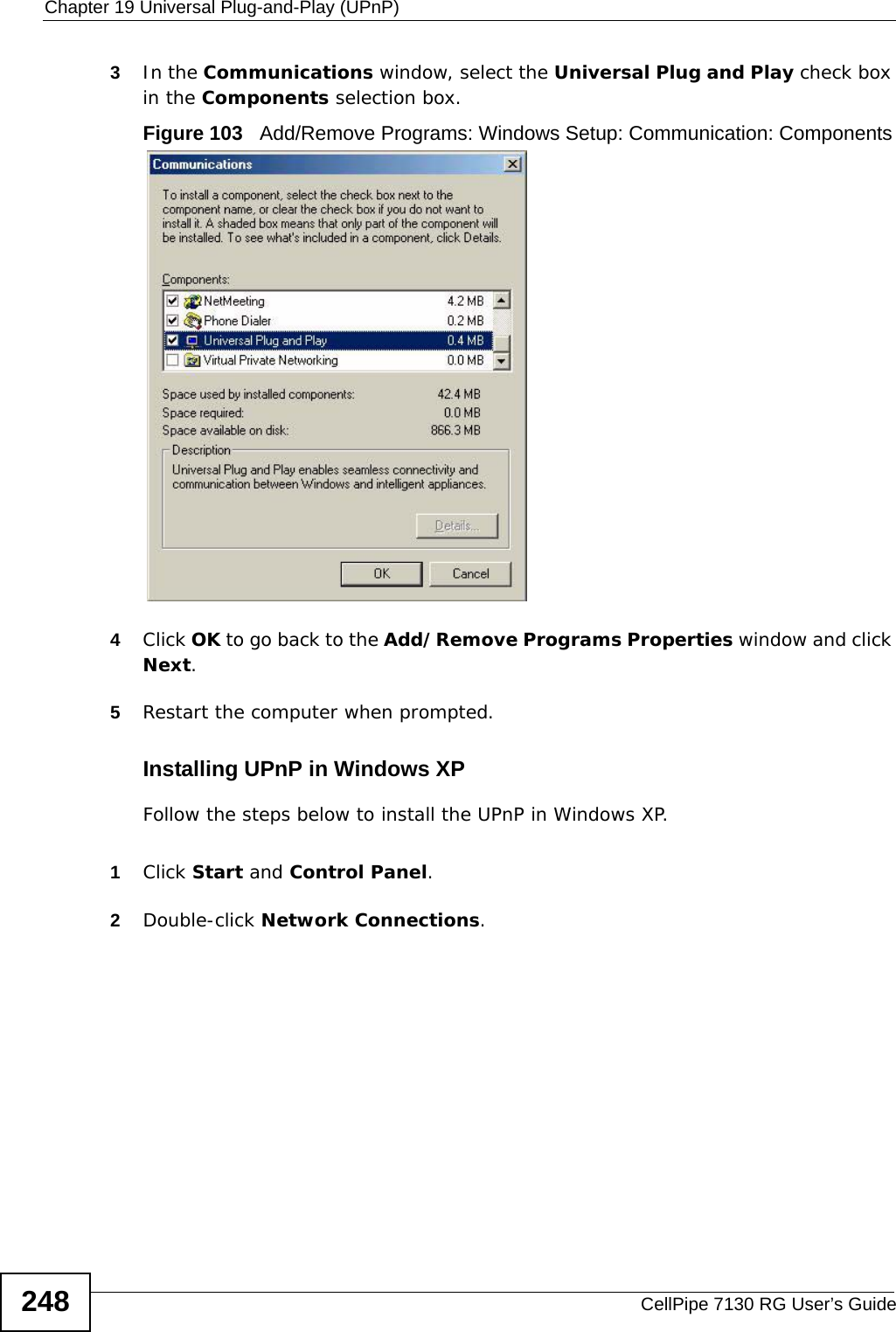
![Appendix A Network TroubleshootingCellPipe 7130 RG User’s Guide314To check the ARP table on a Windows XP computer:1Click Start > Programs > Accessories > Command Prompt. The Command Prompt screen appears.2Type arp -a and press [Enter].The following examples show the typical output of this command: In this example, the Physical Address indicates the associated MAC address. A Type entry with dynamic means it was dynamically learned through an ARP response. Use the arp -s [inet_addr eth_addr] to manually add an ARP entry if you want your computer to connect to the host with the specified MAC address when you access the specified IP address.You can additionally check whether the MAC address associated with the IP address that you are looking for is correct. In some circumstances, your ARP table may keep a wrong MAC address until the entry expires. You can then manually update the ARP table. To update the ARP table:1Type arp -d [inet_addr] or just use arp -d to remove all entries in the ARP table. For example, type arp -d 172.16.1.5.2Type ping 172.16.1.5 and press [Enter].3Next, use the arp -a command again to check whether the MAC address matches what you expected. If it does not, another computer may be using a duplicate IP address on the network. Change the IP address on either computer to an unused one to fix this problem.routeThe route command line utility allows you to display or adjust your computer’s network table. The routing table on your computer contains the default gateway C:\>arp -aInterface: 172.16.1.28 on Interface 0x1000003 Internet Address Physical Address Type 172.16.1.5 00-00-aa-19-07-38 dynamic 172.16.1.25 00-18-f3-f0-aa-34 dynamic 172.16.1.44 00-0e-a6-2c-60-10 dynamic 172.16.1.210 00-19-cb-e9-66-33 dynamic 172.16.1.254 00-04-80-4c-a8-05 dynamic](https://usermanual.wiki/ZyXEL-Communications/5VZ-A2011/User-Guide-1284006-Page-314.png)
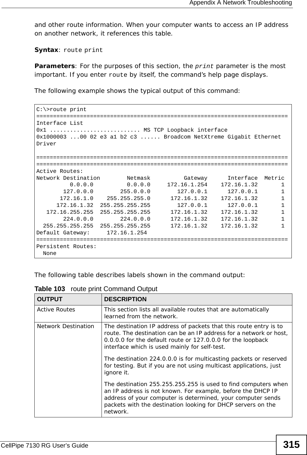
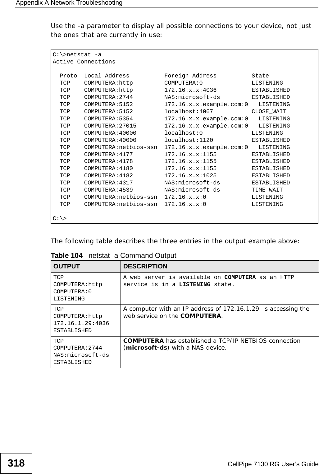
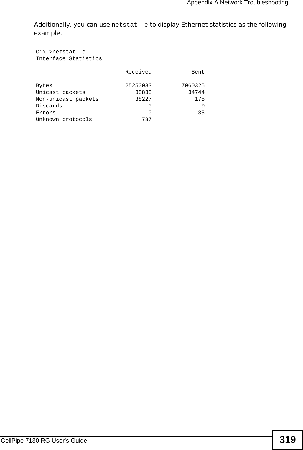
![Appendix A Network TroubleshootingCellPipe 7130 RG User’s Guide 317netstatThe netstat command line utility is used to show Ethernet statistics and current TCP/IP network connections.Syntax: netstatWith no parameters, this command simply displays only active statistics for ports that are currently in use by one process or another.Parameter: netstat [-a] [-e]The -a parameter displays all available listening ports and connections whether they are active or not, while the -e parameter displays Ethernet statistics.There are other parameters but these are the only ones you need to use for now.The following examples show the typical output of this command: C:\>netstatActive Connections Proto Local Address Foreign Address State TCP COMPUTERA:1056 localhost:5091 ESTABLISHED TCP COMPUTERA:1091 localhost:27015 ESTABLISHED TCP COMPUTERA:1120 localhost:40000 ESTABLISHED TCP COMPUTERA:3243 localhost:3244 ESTABLISHED TCP COMPUTERA:3244 localhost:3243 ESTABLISHED TCP COMPUTERA:3246 localhost:3247 ESTABLISHED TCP COMPUTERA:3247 localhost:3246 ESTABLISHED TCP COMPUTERA:5091 localhost:1056 ESTABLISHED TCP COMPUTERA:5152 localhost:3245 CLOSE_WAIT TCP COMPUTERA:27015 localhost:1091 ESTABLISHED TCP COMPUTERA:40000 localhost:1120 ESTABLISHED TCP COMPUTERA:3229 172.20.0.201:http CLOSE_WAIT TCP COMPUTERA:3234 172.16.1.29:1155 ESTABLISHED TCP COMPUTERA:3237 172.16.1.29:1155 ESTABLISHED TCP COMPUTERA:3240 172.16.1.29:1155 ESTABLISHEDC:\>](https://usermanual.wiki/ZyXEL-Communications/5VZ-A2011/User-Guide-1284006-Page-317.png)

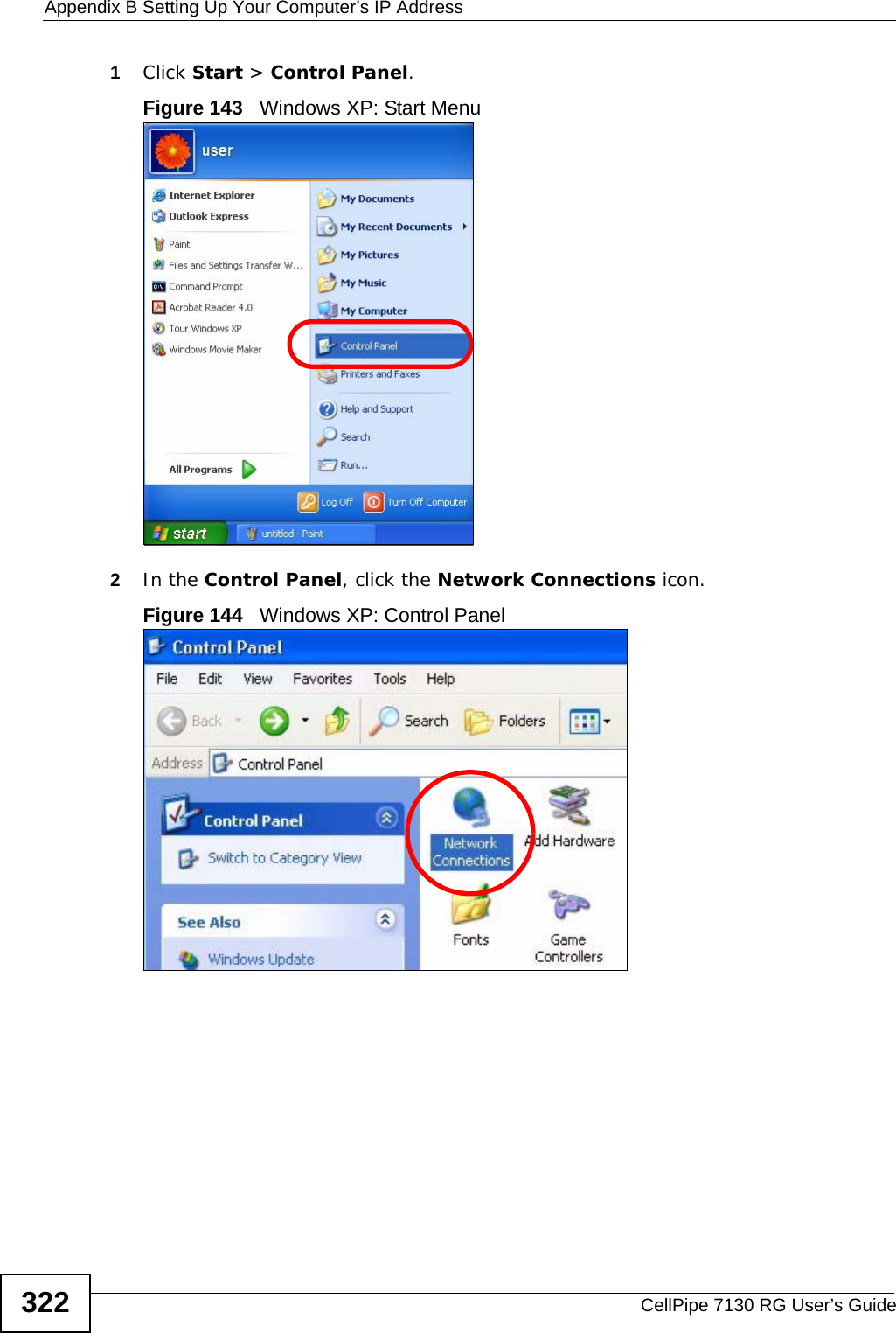
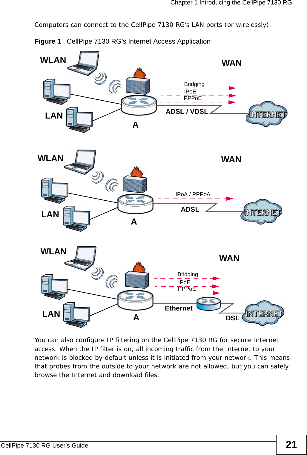
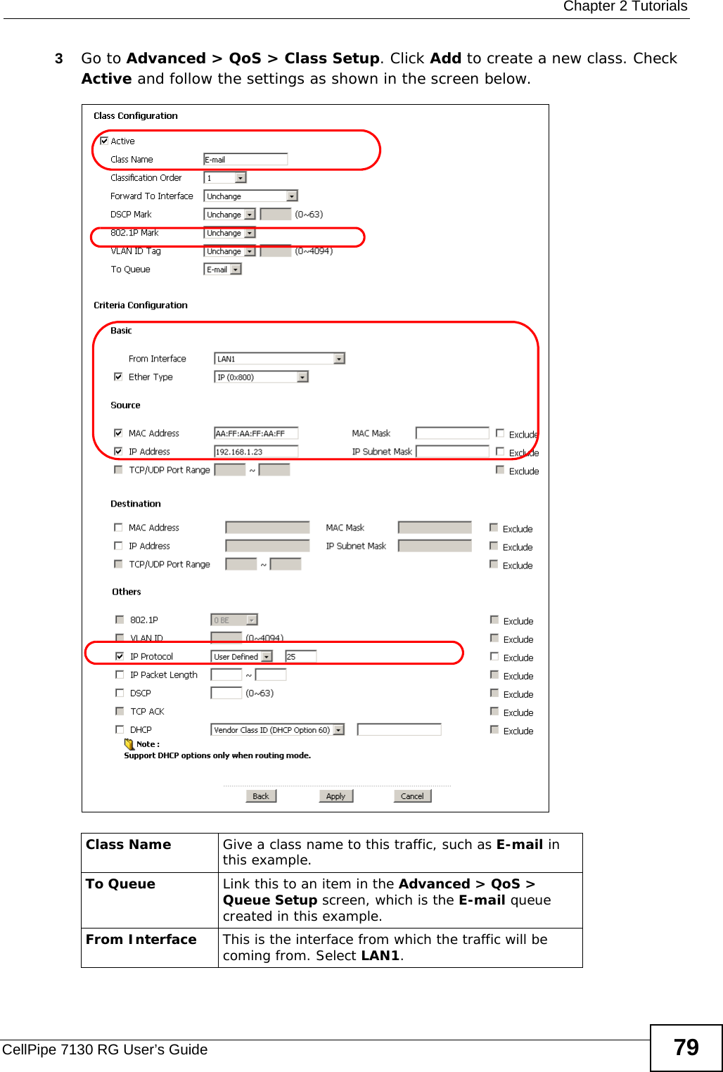
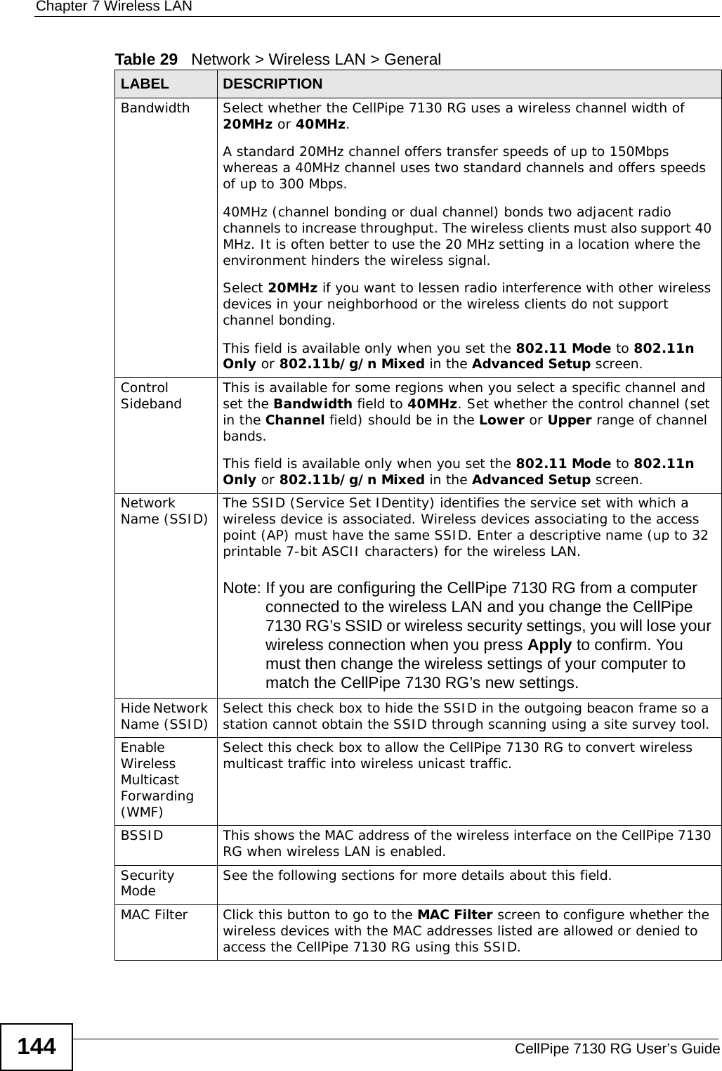
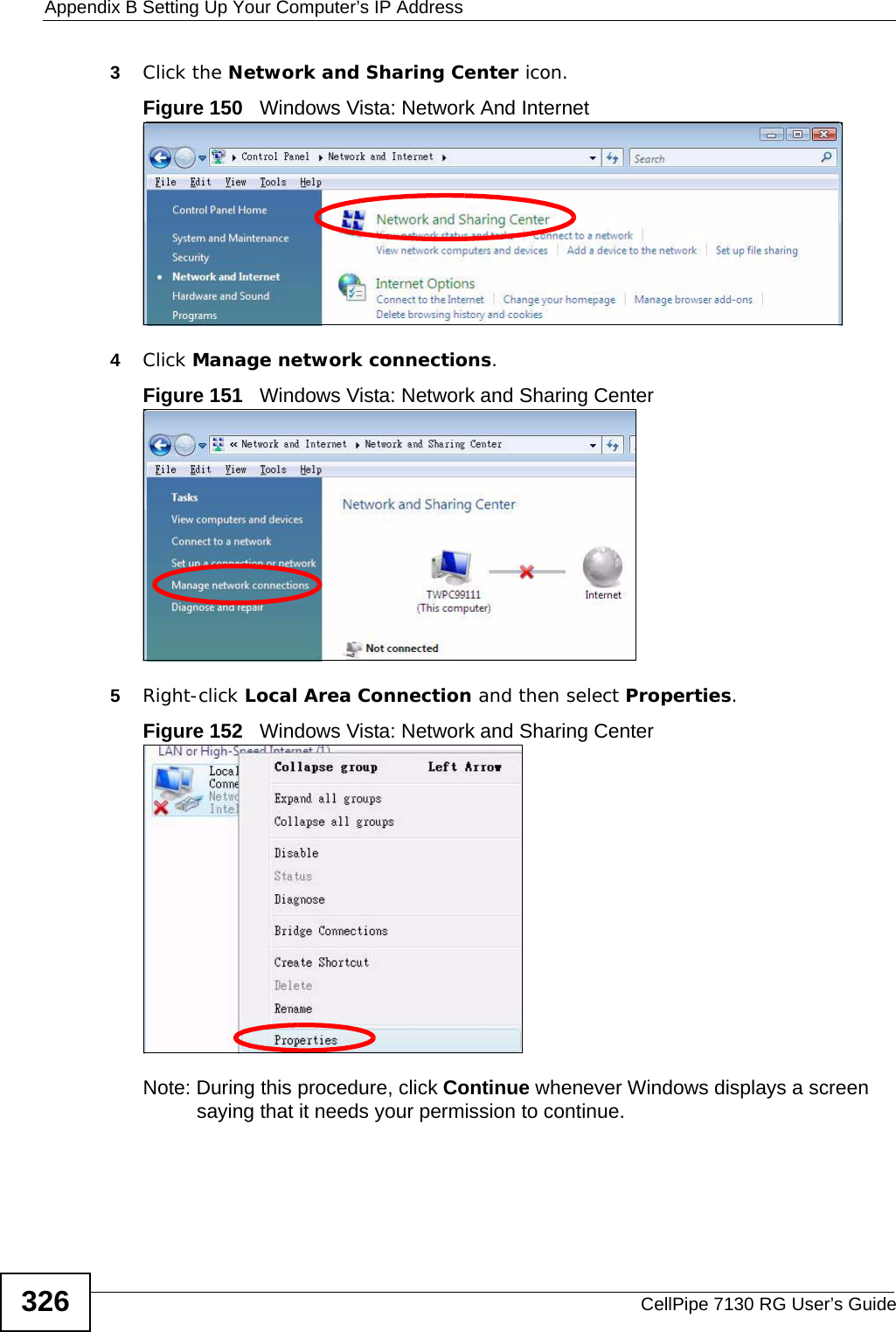
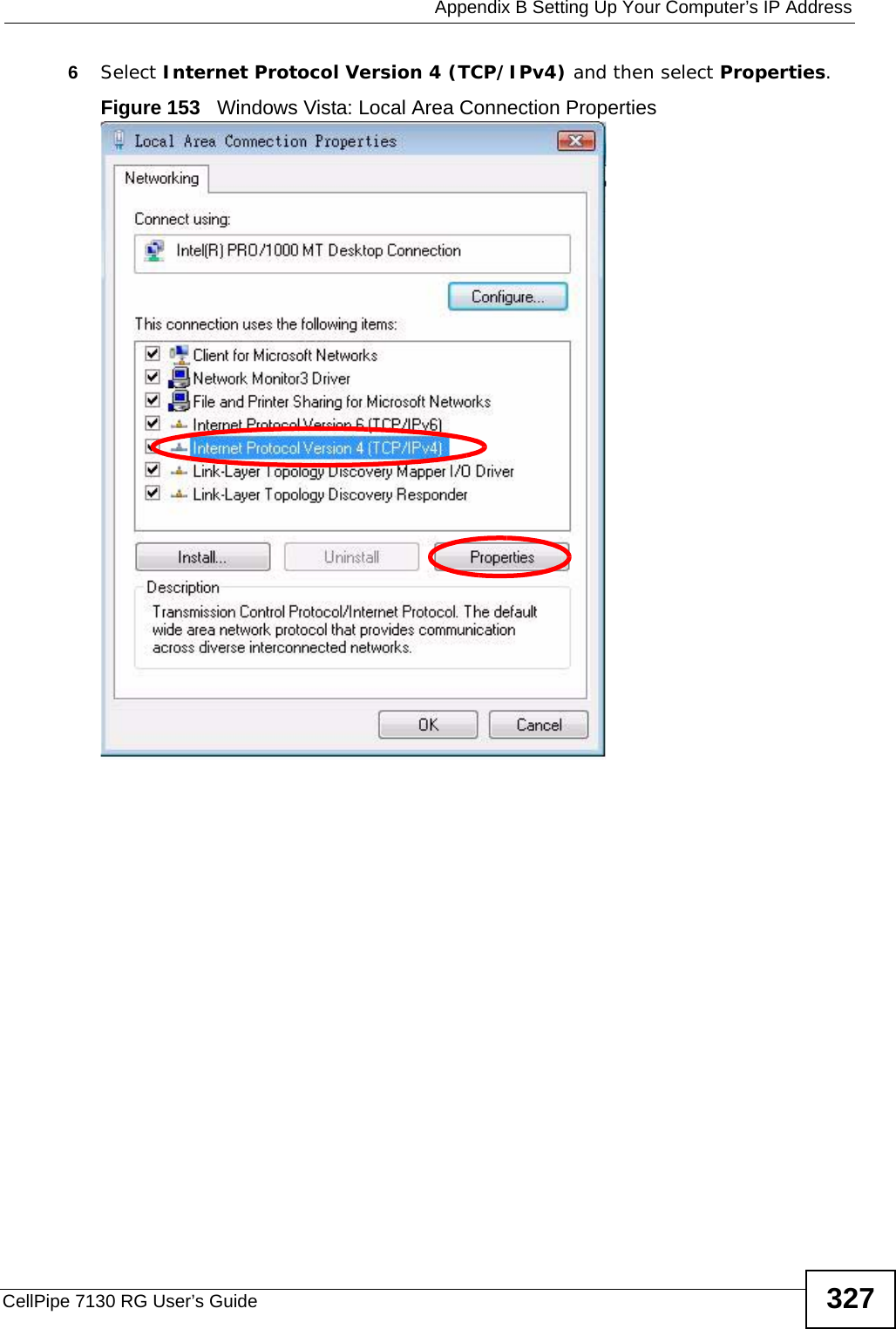
![Appendix B Setting Up Your Computer’s IP AddressCellPipe 7130 RG User’s Guide 3252In the Command Prompt window, type "ipconfig" and then press [ENTER]. You can also go to Start > Control Panel > Network Connections, right-click a network connection, click Status and then click the Support tab to view your IP address and connection information.Windows VistaThis section shows screens from Windows Vista Professional.1Click Start > Control Panel.Figure 148 Windows Vista: Start Menu2In the Control Panel, click the Network and Internet icon.Figure 149 Windows Vista: Control Panel](https://usermanual.wiki/ZyXEL-Communications/5VZ-A2011/User-Guide-1284006-Page-325.png)
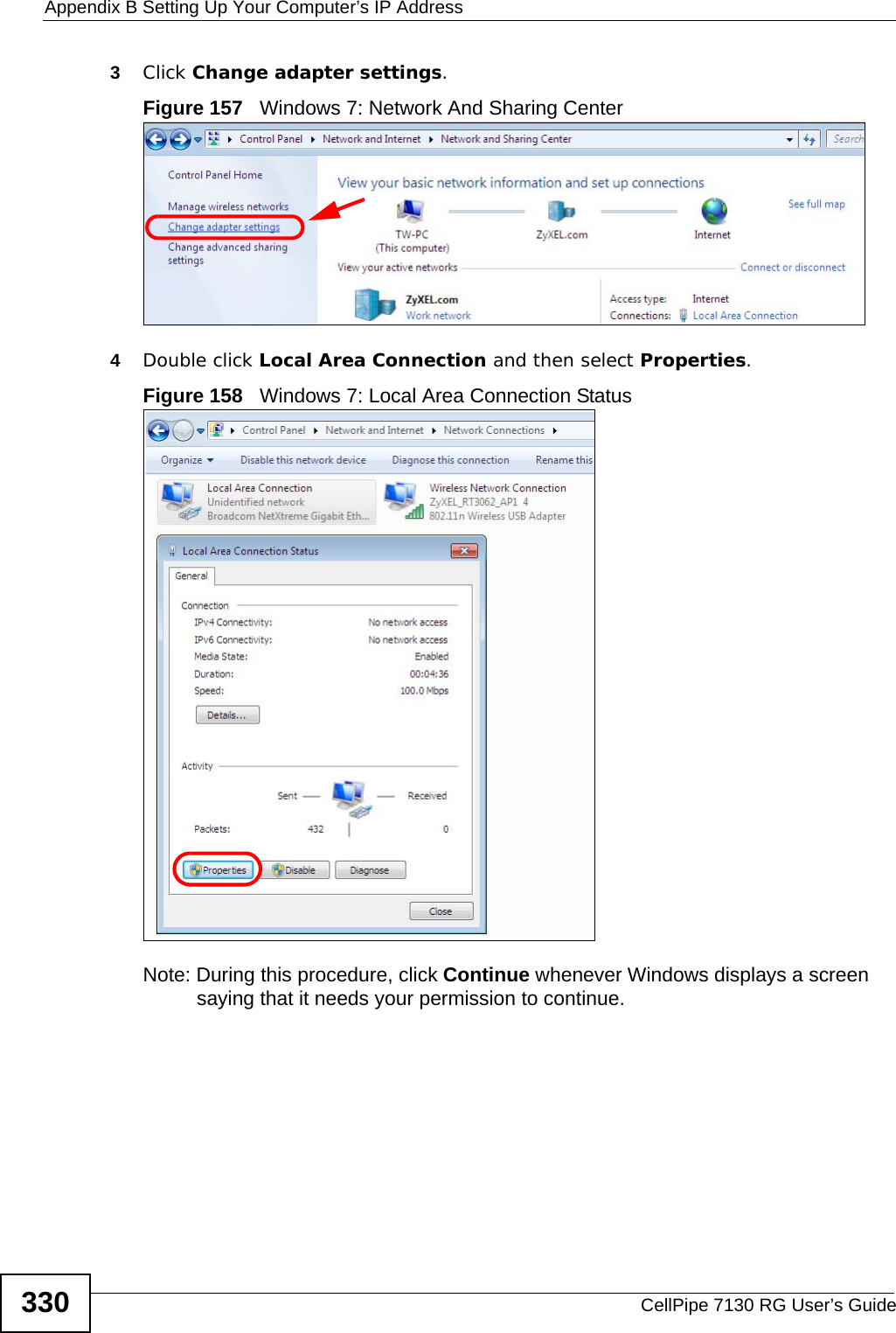
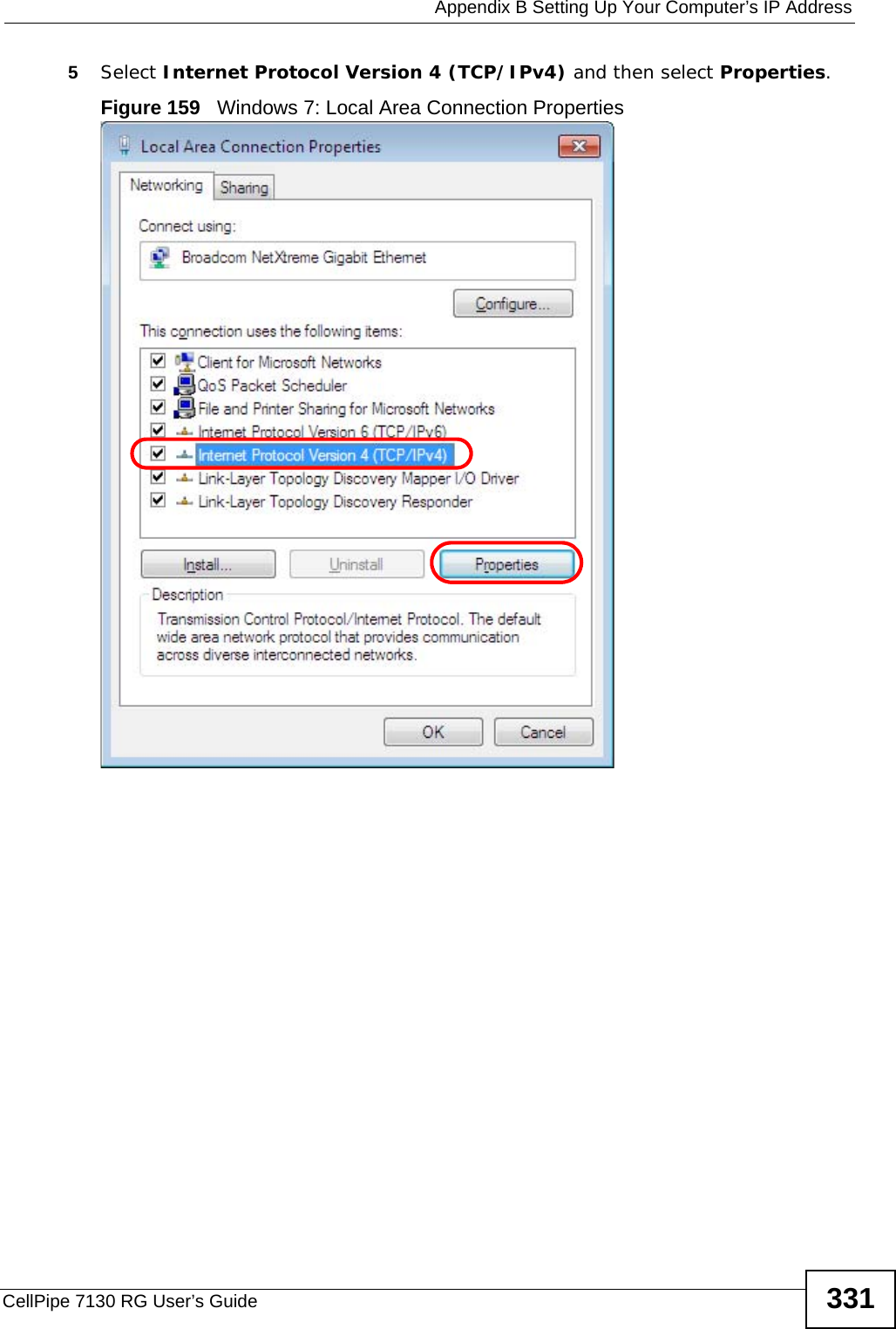
![Appendix B Setting Up Your Computer’s IP AddressCellPipe 7130 RG User’s Guide 3292In the Command Prompt window, type "ipconfig" and then press [ENTER]. You can also go to Start > Control Panel > Network Connections, right-click a network connection, click Status and then click the Support tab to view your IP address and connection information.Windows 7This section shows screens from Windows 7 Enterprise.1Click Start > Control Panel.Figure 155 Windows 7: Start Menu2In the Control Panel, click View network status and tasks under the Network and Internet category.Figure 156 Windows 7: Control Panel](https://usermanual.wiki/ZyXEL-Communications/5VZ-A2011/User-Guide-1284006-Page-329.png)
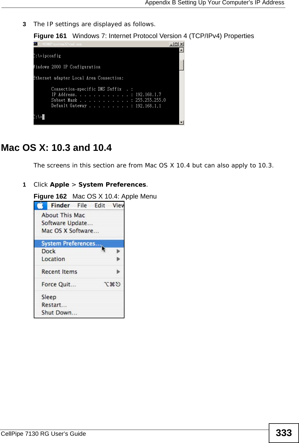
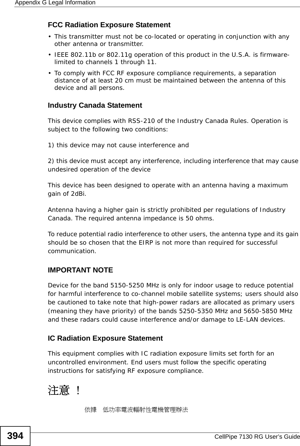
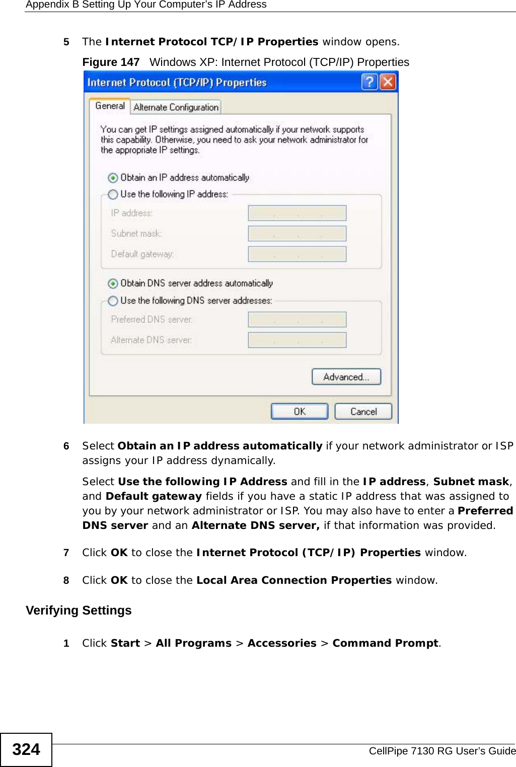
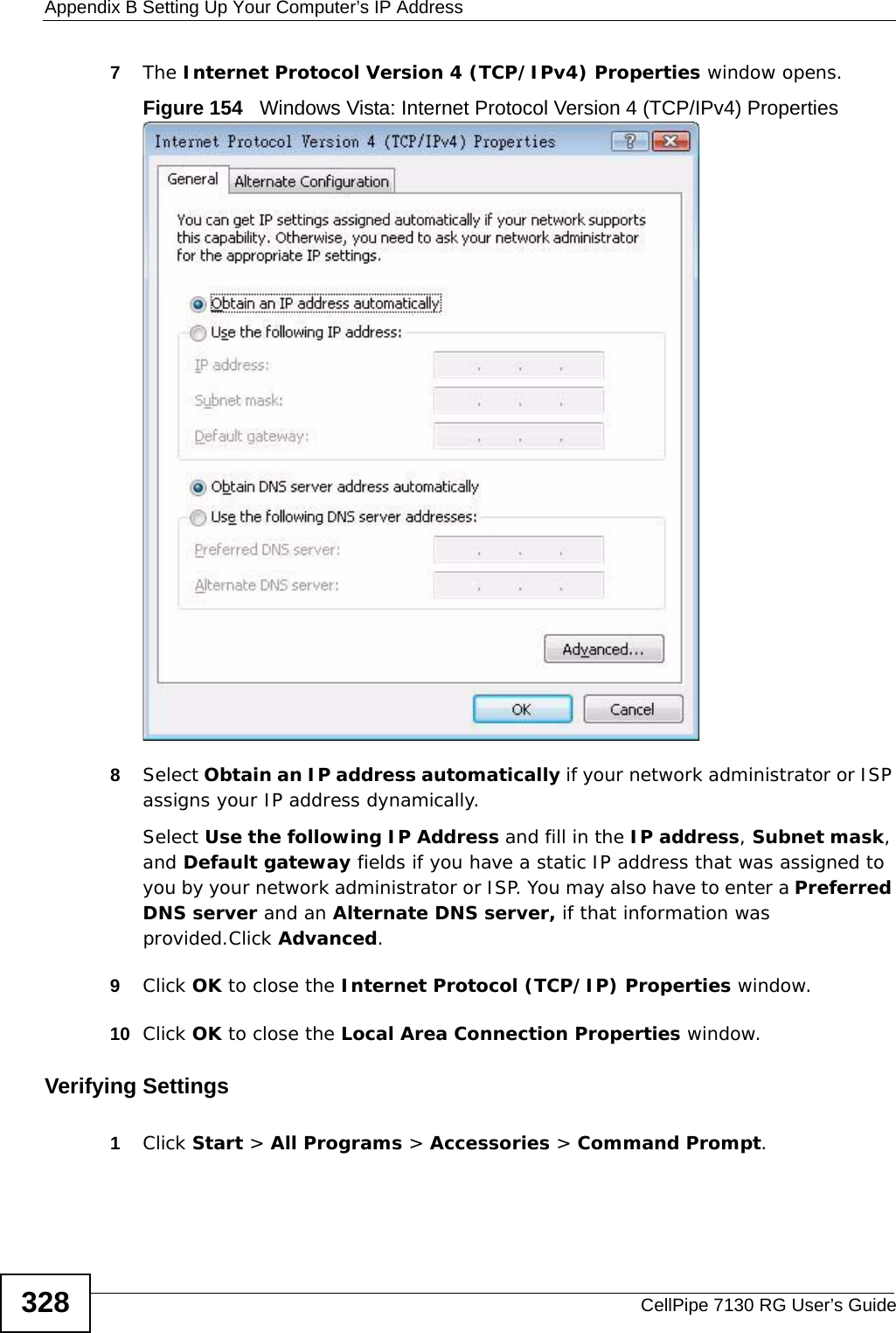
![Appendix B Setting Up Your Computer’s IP AddressCellPipe 7130 RG User’s Guide3326The Internet Protocol Version 4 (TCP/IPv4) Properties window opens.Figure 160 Windows 7: Internet Protocol Version 4 (TCP/IPv4) Properties7Select Obtain an IP address automatically if your network administrator or ISP assigns your IP address dynamically.Select Use the following IP Address and fill in the IP address, Subnet mask, and Default gateway fields if you have a static IP address that was assigned to you by your network administrator or ISP. You may also have to enter a Preferred DNS server and an Alternate DNS server, if that information was provided. Click Advanced if you want to configure advanced settings for IP, DNS and WINS. 8Click OK to close the Internet Protocol (TCP/IP) Properties window.9Click OK to close the Local Area Connection Properties window.Verifying Settings1Click Start > All Programs > Accessories > Command Prompt.2In the Command Prompt window, type "ipconfig" and then press [ENTER].](https://usermanual.wiki/ZyXEL-Communications/5VZ-A2011/User-Guide-1284006-Page-332.png)