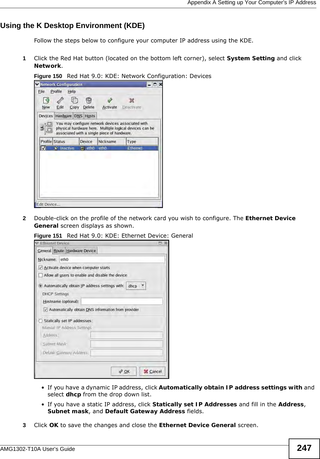
ZyXEL Communications AMG1302 Wireless N ADSL2+ 4-port Gateway User Manual AMG1302 T10A UG rev1
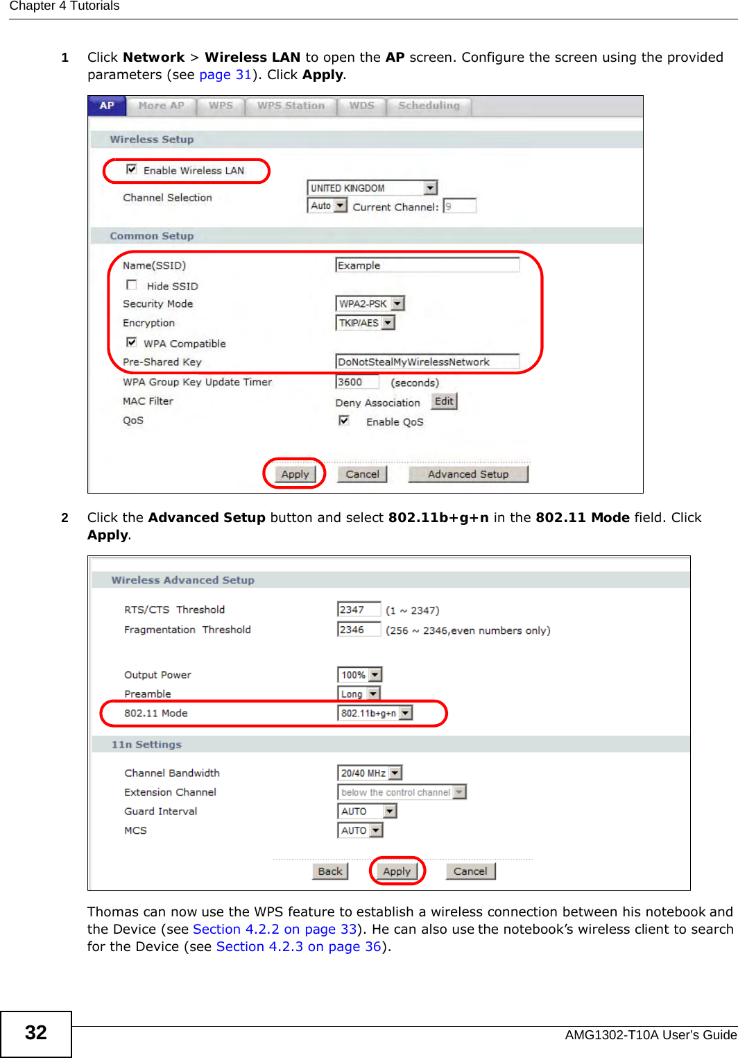
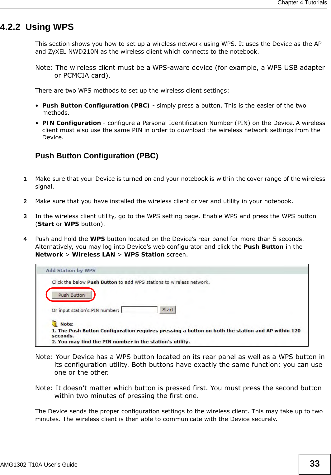
ZyXEL Communications Corporation Wireless N ADSL2+ 4-port Gateway AMG1302 T10A UG rev1
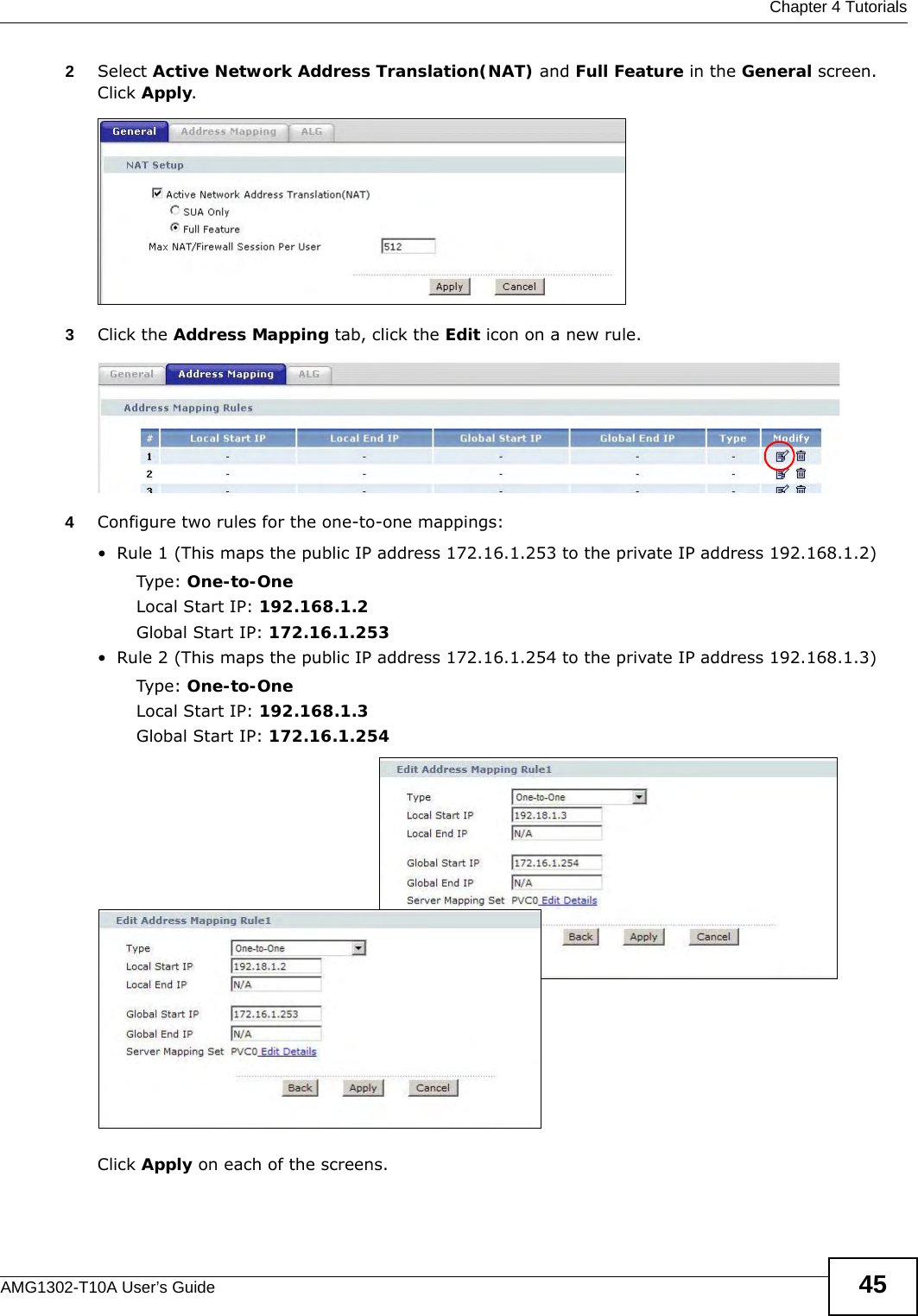
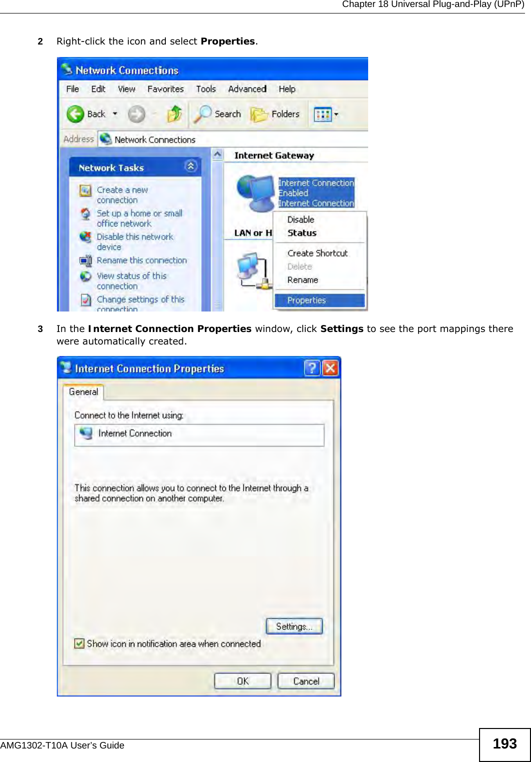
UserManual.wiki
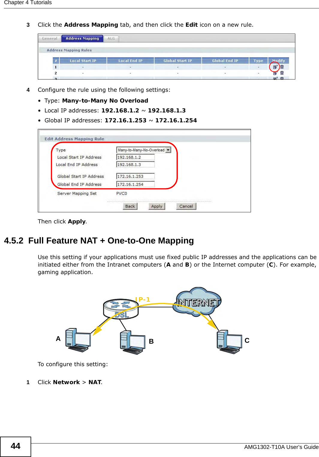
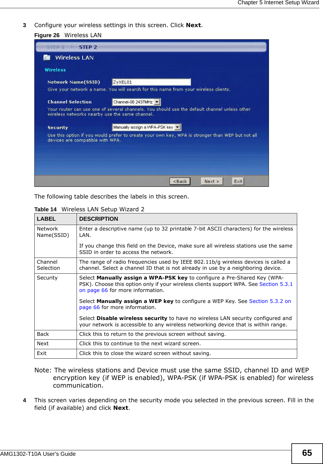
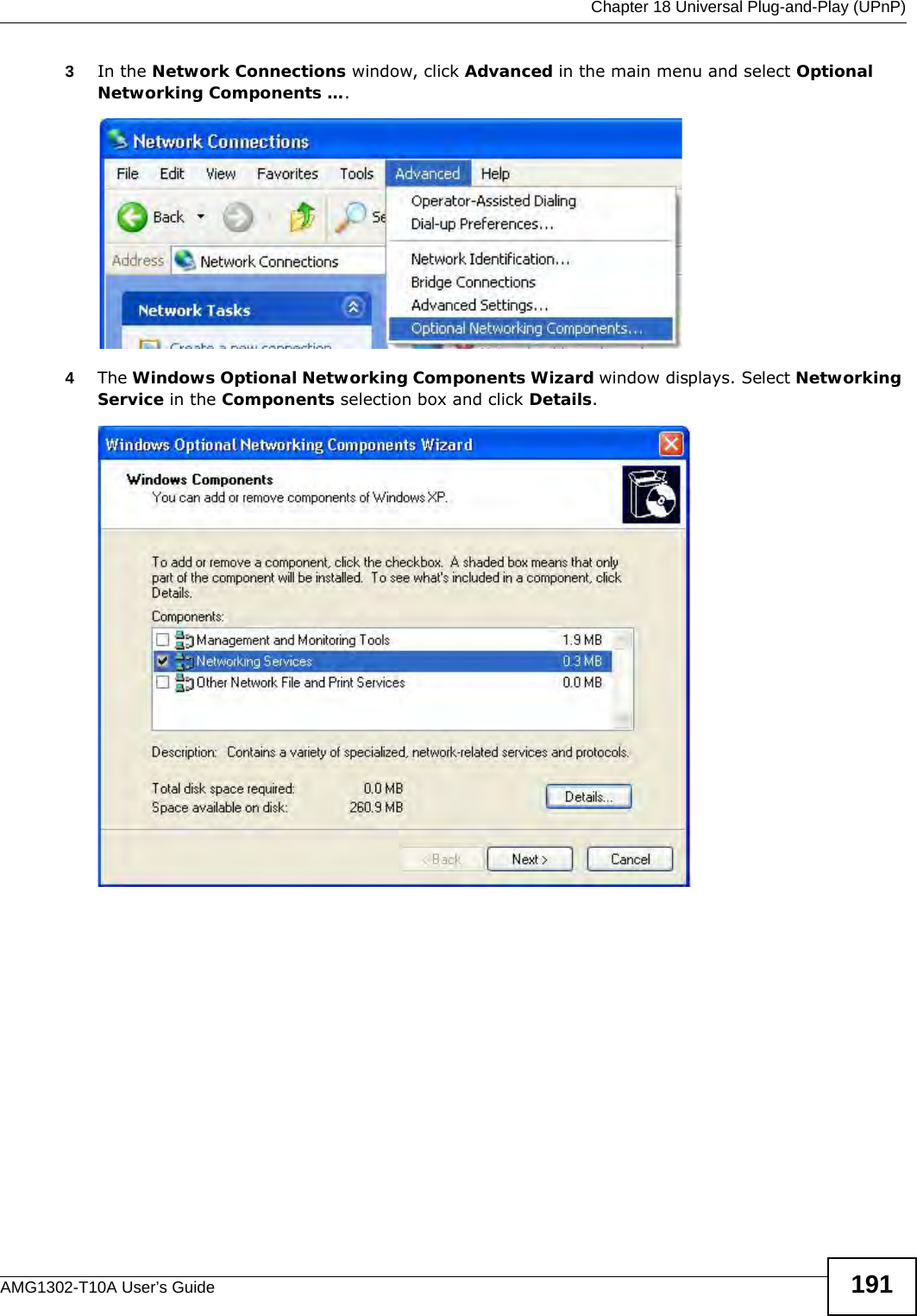
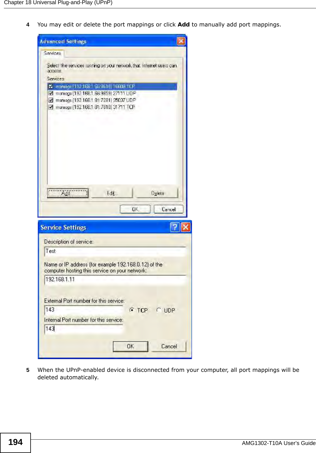
>
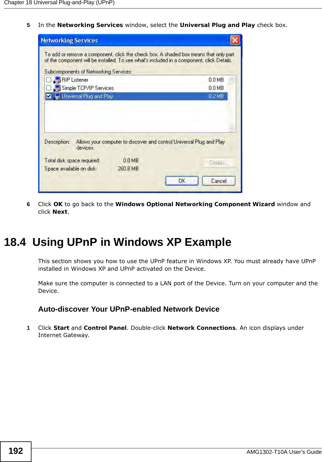
ZyXEL Communications
>
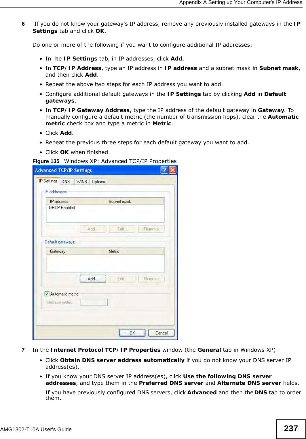
AMG1302 User Manual
AMG1302-T10A_UG_rev1
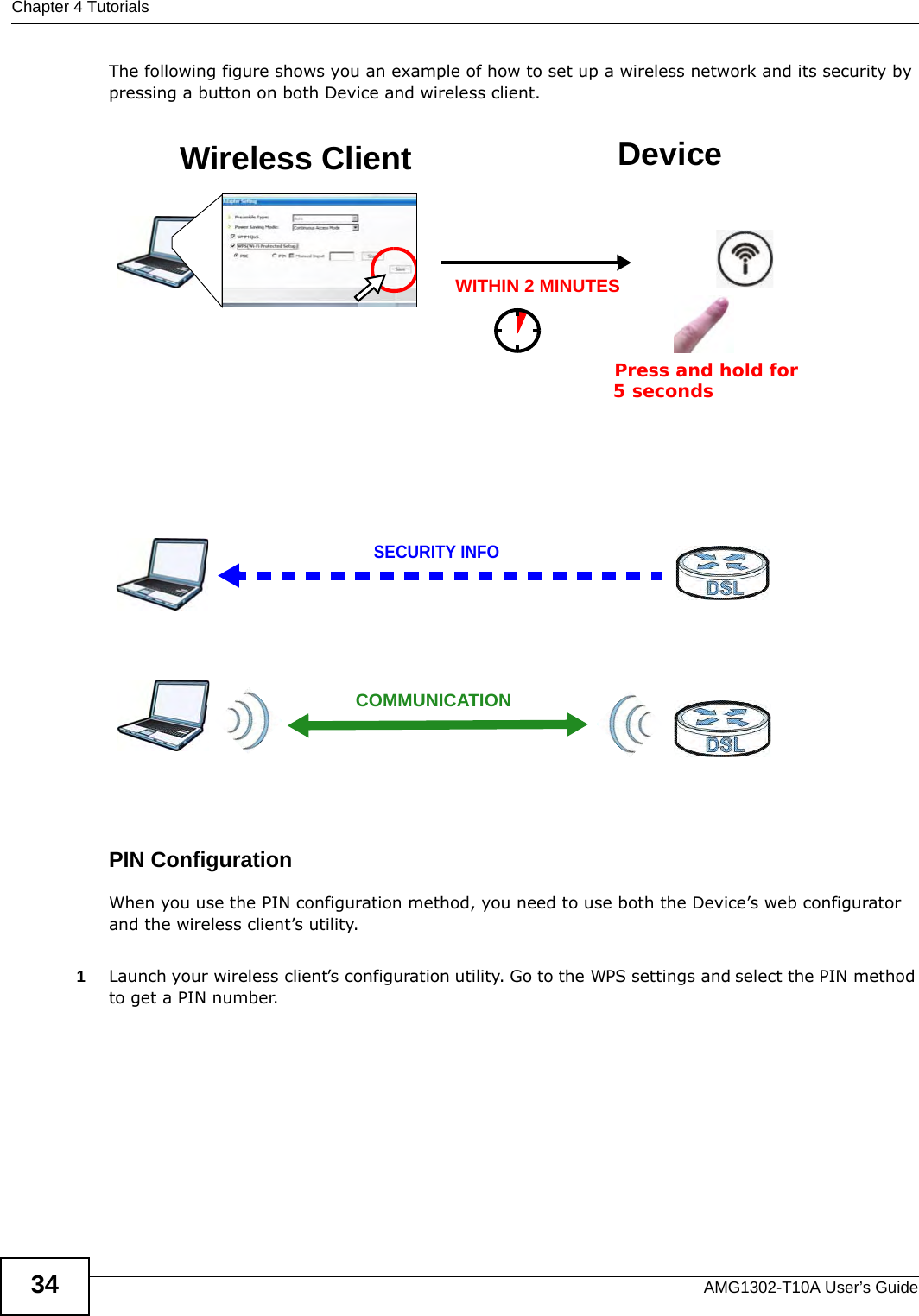
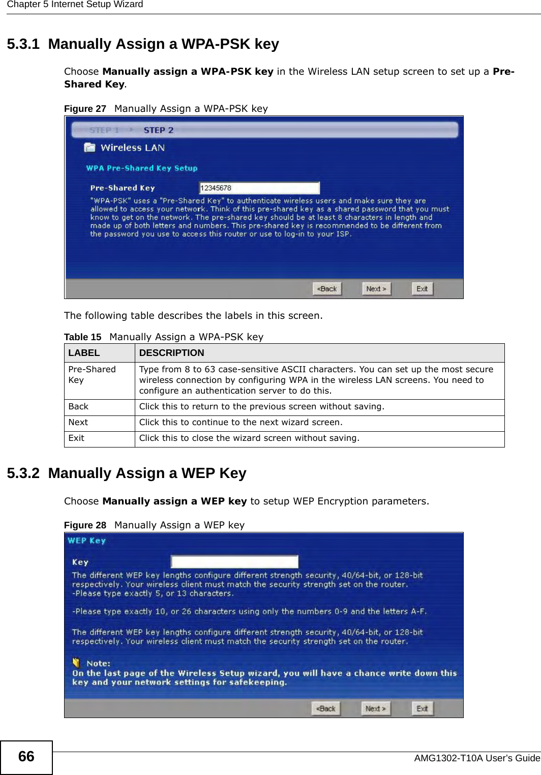
Navigation menu
Upload a User Manual
Namespaces
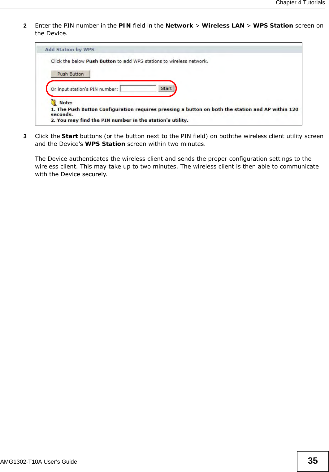
Wiki Guide
HTML
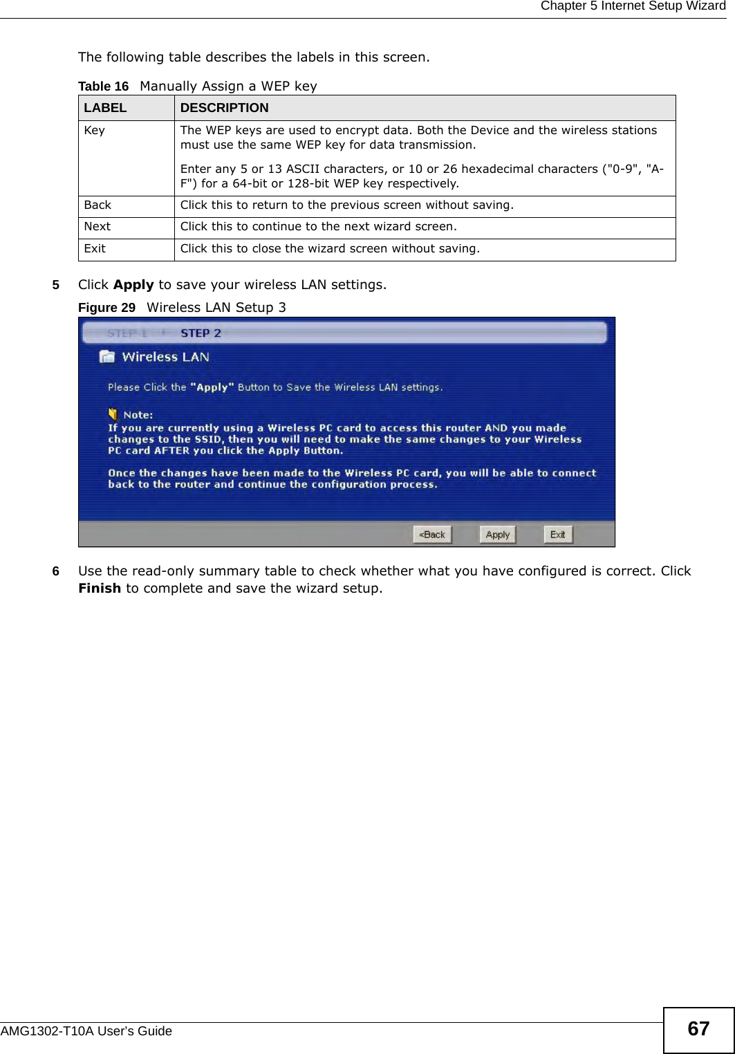
PDF
Info
Views
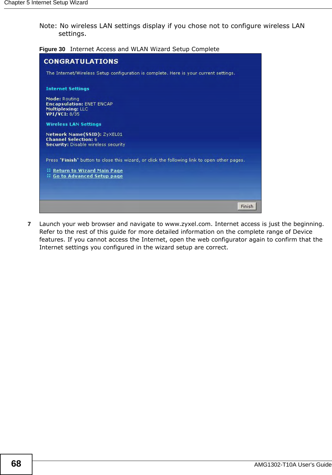
User Manual
Discussion / Help
Navigation


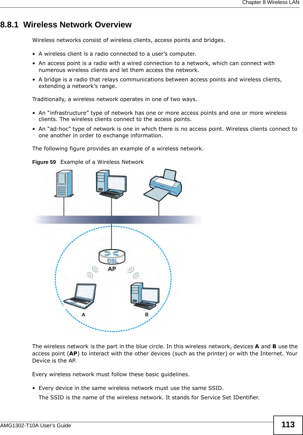

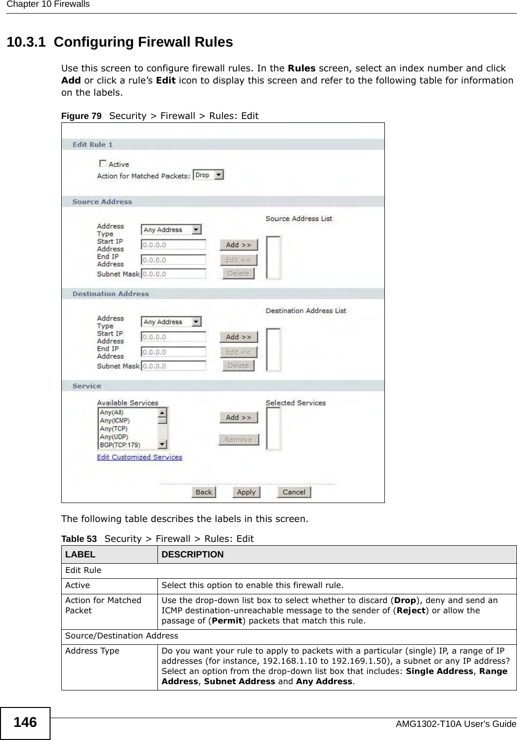

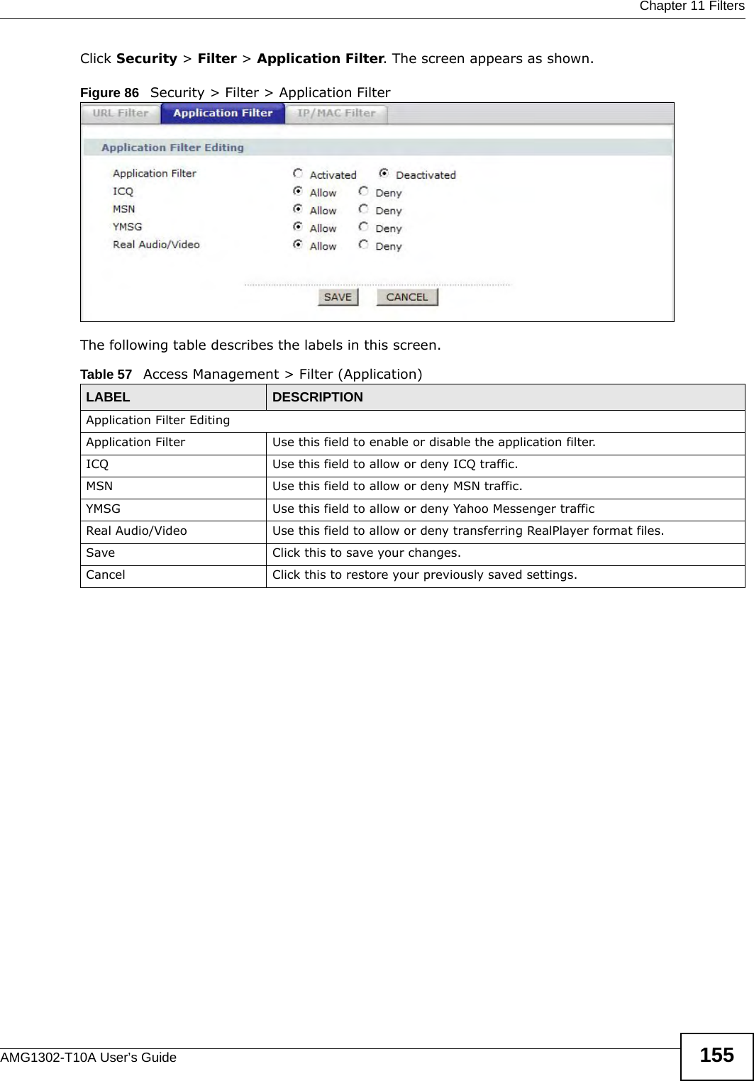


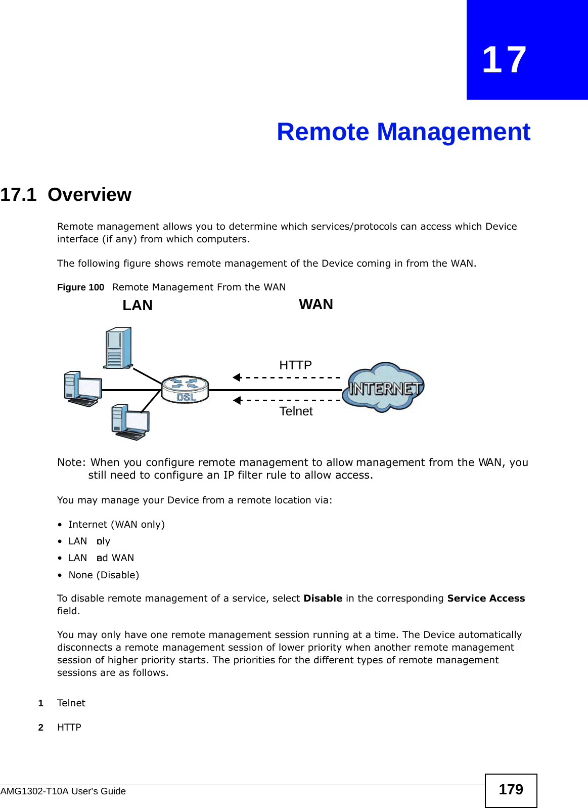

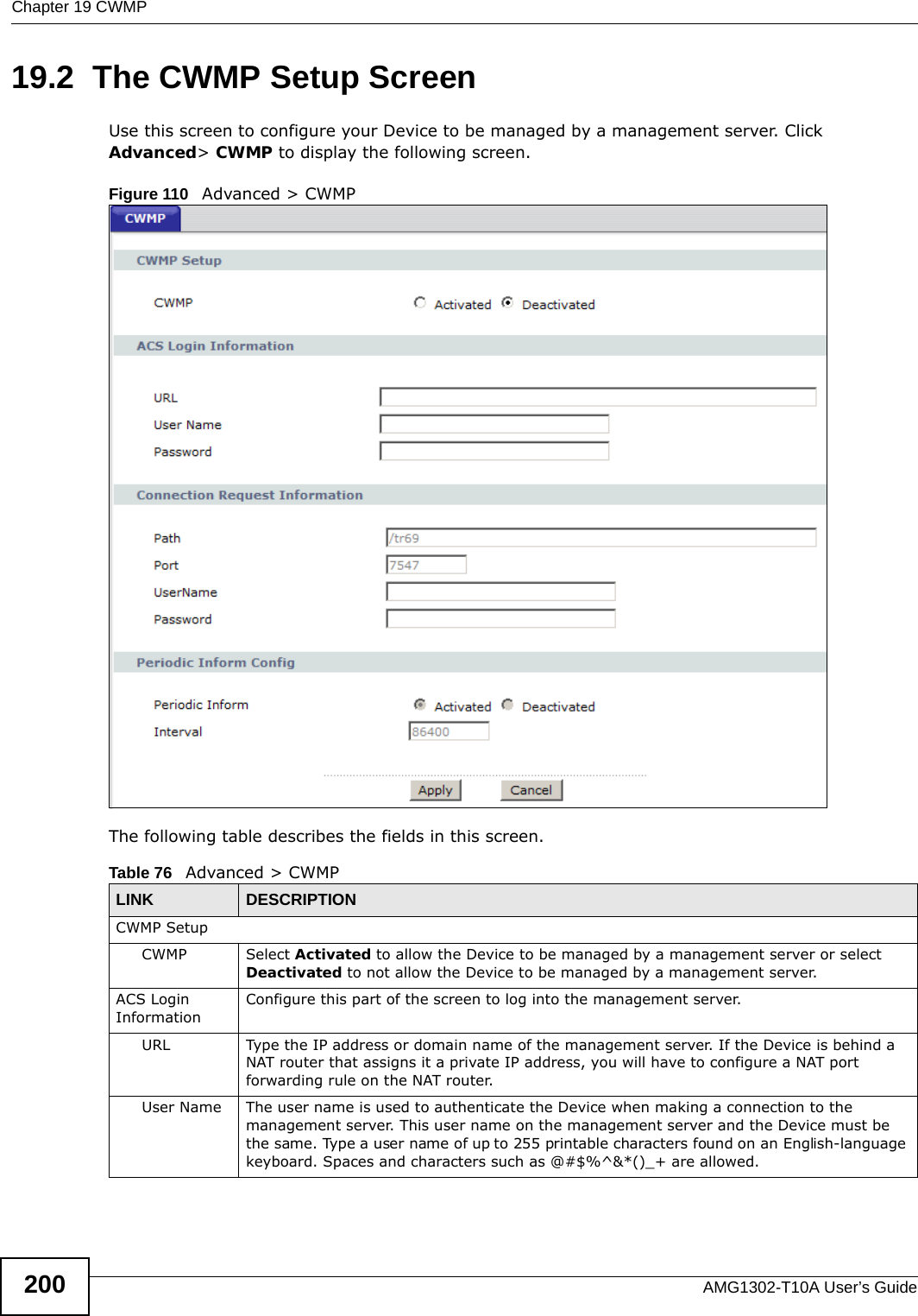

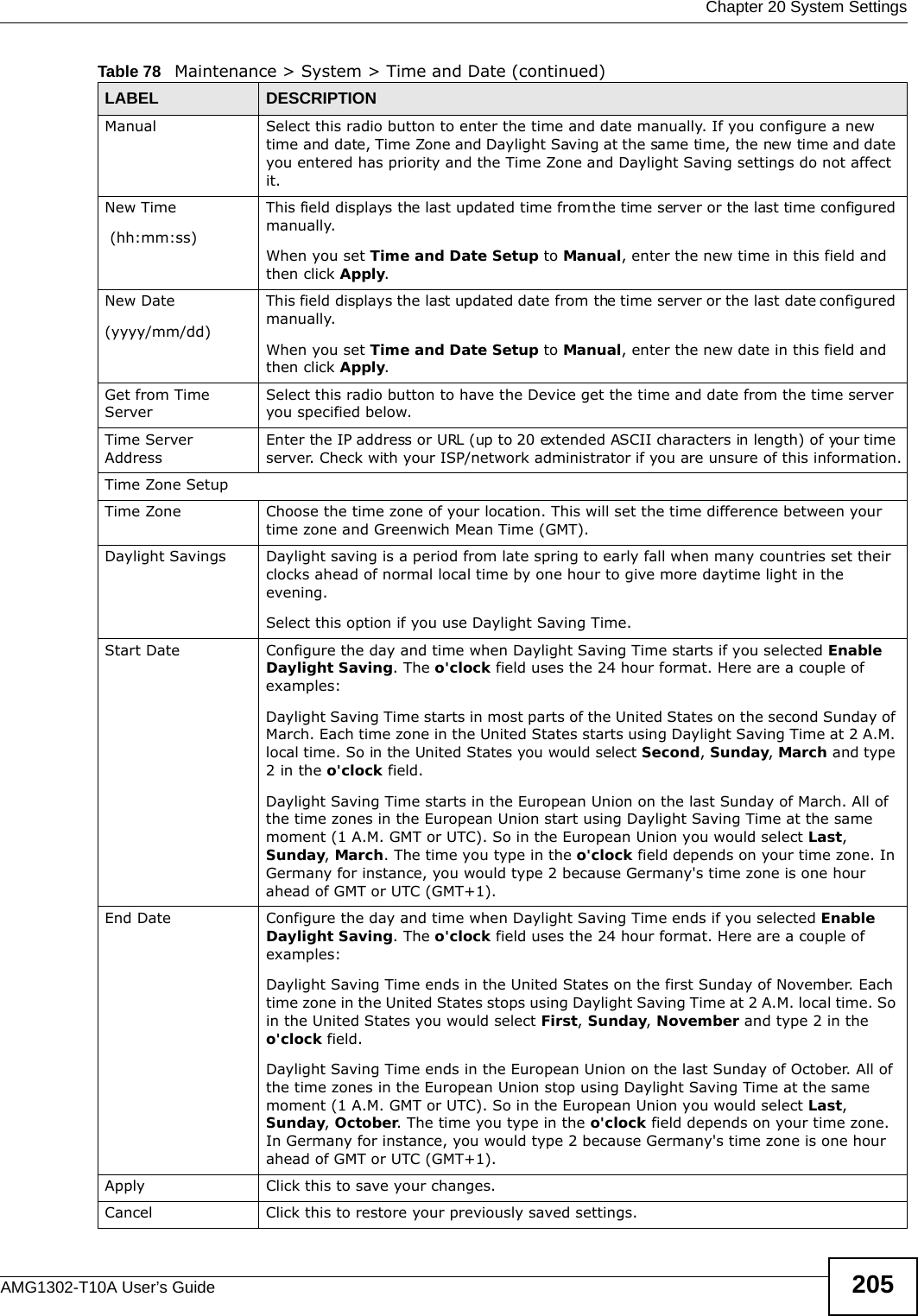

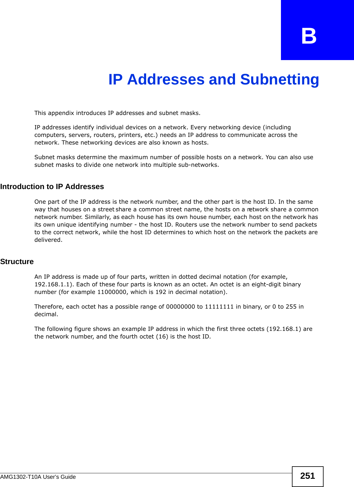
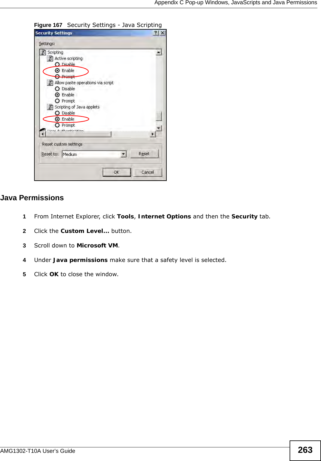
![Chapter 21 LogsAMG1302-T10A User’s Guide210 Table 81 System Error LogsLOG MESSAGE DESCRIPTION%s exceeds the max. number of session per host!This attempt to create a NAT session exceeds the maximum number of NAT session table entries allowed to be created per host.setNetBIOSFilter: calloc errorThe router failed to allocate memory for the NetBIOS filter settings.readNetBIOSFilter: calloc errorThe router failed to allocate memory for the NetBIOS filter settings.WAN connection is down. A WAN connection is down. You can access the network through this interface.Table 82 Access Control LogsLOG MESSAGE DESCRIPTIONFirewall default policy: [ TCP | UDP | IGMP | ESP | GRE | OSPF ] <Packet Direction>Attempted TCP/UDP/IGMP/ESP/GRE/OSPF access matched the default policy and was blocked or forwarded according to the default policy’s setting.Firewall rule [] match:[ TCP | UDP | IGMP | ESP | GRE | OSPF ] <Packet Direction>, <rule:%d>Attempted TCP/UDP/IGMP/ESP/GRE/OSPF access matched (or did not match) a configured firewall rule (deed by its number) and was blocked or forwarded according to the rule. Triangle route packet forwarded: [ TCP | UDP | IGMP | ESP | GRE | OSPF ]The firewall allowed a triangle route session to pass through.Packet without a NAT table entry blocked: [ TCP | UDP | IGMP | ESP | GRE | OSPF ]The router blocked a packet that didn't have a corresponding NAT table entry.Router sent blocked web site message: TCPThe router sent a message to notify a user that the router blocked access to a web site that the user requested.Table 83 TCP Reset LogsLOG MESSAGE DESCRIPTIONUnder SYN flood attack, sent TCP RSTThe router sent a TCP reset packet when a host was under a SYN flood attack (the TCP incomplete count is per destination host.) Exceed TCP MAX incomplete, sent TCP RSTThe router sent a TCP reset packet when the number of TCP incomplete connections exceeded the user configured threshold. (the TCP incomplete count is per destination host.) e: Refer to TCP Maximum Incomplete in the Firewall Attack Alerts screen. Peer TCP state out of order, sent TCP RSTThe router sent a TCP reset packet when a TCP connection state was out of order.e: The firewall refers to RFC793 Figure 6 to check the TCP state.Firewall session time out, sent TCP RSTThe router sent a TCP reset packet when a dynamic firewall session timed out.Default timeout values:ICMP idle timeout (s): 60UDP idle timeout (s): 60TCP connection (three way handshaking) timeout (s): 30TCP FIN-wait timeout (s): 60TCP idle (established) timeout (s): 3600](https://usermanual.wiki/ZyXEL-Communications/AMG1302/User-Guide-1700682-Page-210.png)
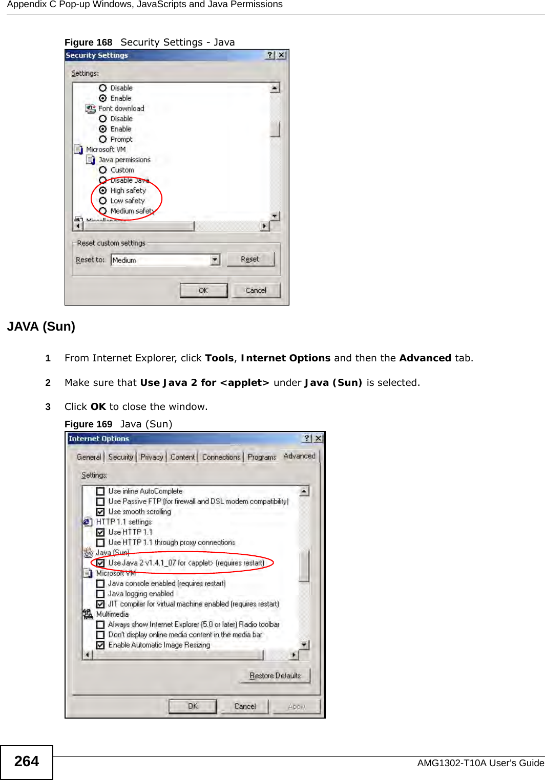
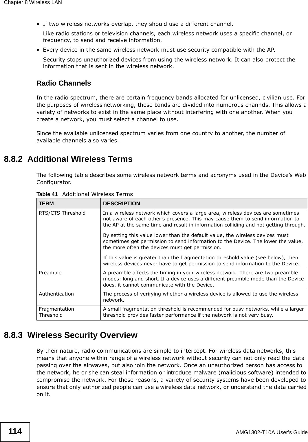
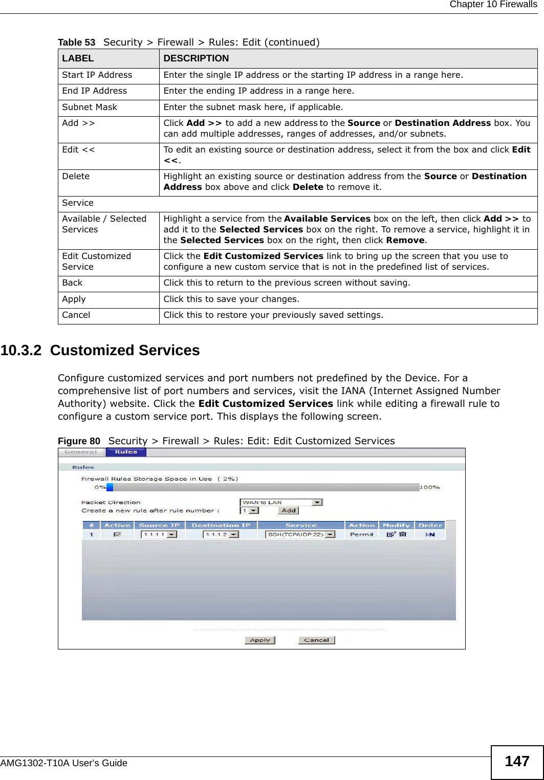
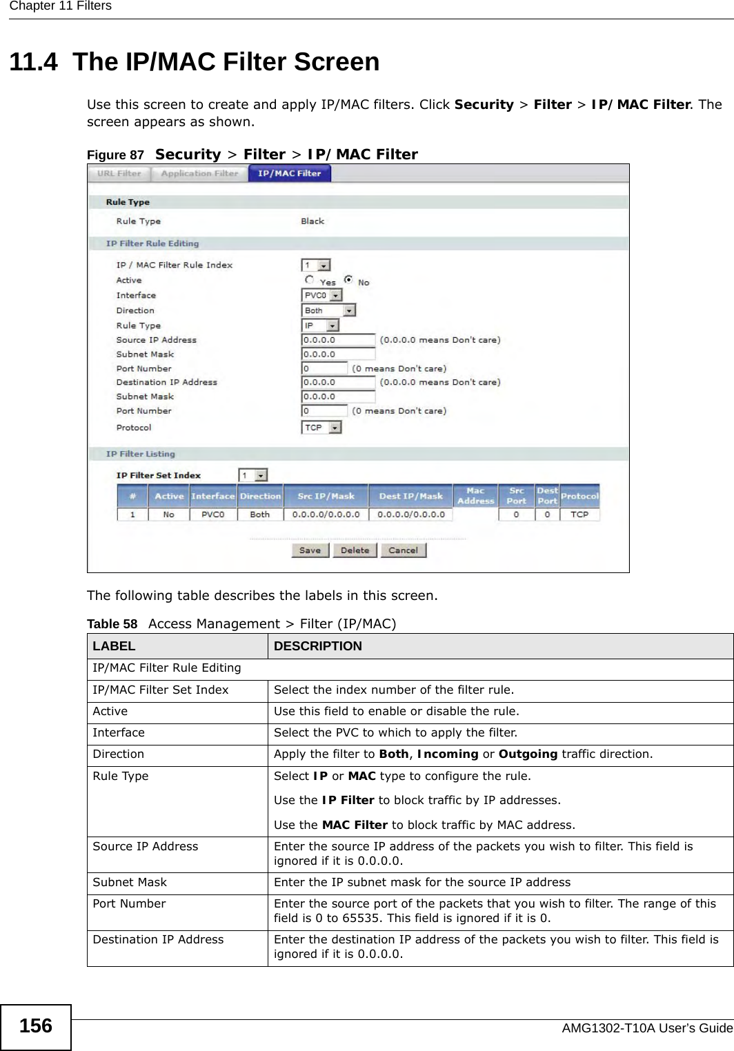
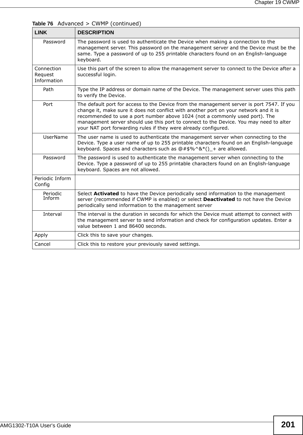
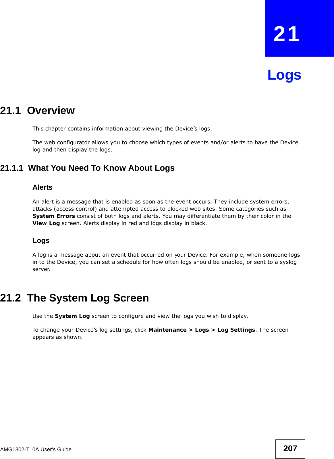
![Chapter 21 LogsAMG1302-T10A User’s Guide 211 For type and code details, see Table 93 on page 214. Exceed MAX incomplete, sent TCP RSTThe router sent a TCP reset packet when the number of incomplete connections (TCP and UDP) exceeded the user-configured threshold. (Incomplete count is for all TCP and UDP connections through the firewall.)e: When the number of incomplete connections (TCP + UDP) > “Maximum Incomplete High”, the router sends TCP RST packets for TCP connections and destroys TOS (firewall dynamic sessions) until incomplete connections < “Maximum Incomplete Low”.Access block, sent TCP RST The router sends a TCP RST packet and generates this log if you turn on the firewall TCP reset mechanism (via CI command: "sys firewall tcprst").Table 84 Packet Filter LogsLOG MESSAGE DESCRIPTION[ TCP | UDP | ICMP | IGMP | Generic ] packet filter matched (set: %d, rule: %d)Attempted access matched a configured filter rule (deed by its set and rule number) and was blocked or forwarded according to the rule.Table 85 ICMP LogsLOG MESSAGE DESCRIPTIONFirewall default policy: ICMP <Packet Direction>, <type:%d>, <code:%d>ICMP access matched the default policy and was blocked or forwarded according to the user's setting.Firewall rule [] match: ICMP <Packet Direction>, <rule:%d>, <type:%d>, <code:%d>ICMP access matched (or didn’t match) a firewall rule (deed by its number) and was blocked or forwarded according to the rule. Triangle route packet forwarded: ICMPThe firewall allowed a triangle route session to pass through.Packet without a NAT table entry blocked: ICMPThe router blocked a packet that didn’t have a corresponding NAT table entry.Unsupported/out-of-order ICMP: ICMPThe firewall does not support this kind of ICMP packets or the ICMP packets are out of order.Router reply ICMP packet: ICMP The router sent an ICMP reply packet to the sender.Table 86 CDR LogsLOG MESSAGE DESCRIPTIONboard %d line %d channel %d, call %d, %s C01 Outgoing Call dev=%x ch=%x %sThe router received the setup requirements for a call. “call” is the reference (count) number of the call. “dev” is the device type (3 is for dial-up, 6 is for PPPoE, 10 is for PPTP) "channel" or “ch” is the call channel ID. For example,"board 0 line 0 channel 0, call 3, C01 Outgoing Call dev=6 ch=0 "Means the router has dialed to the PPPoE server 3 times.Table 83 TCP Reset Logs (continued)LOG MESSAGE DESCRIPTION](https://usermanual.wiki/ZyXEL-Communications/AMG1302/User-Guide-1700682-Page-211.png)
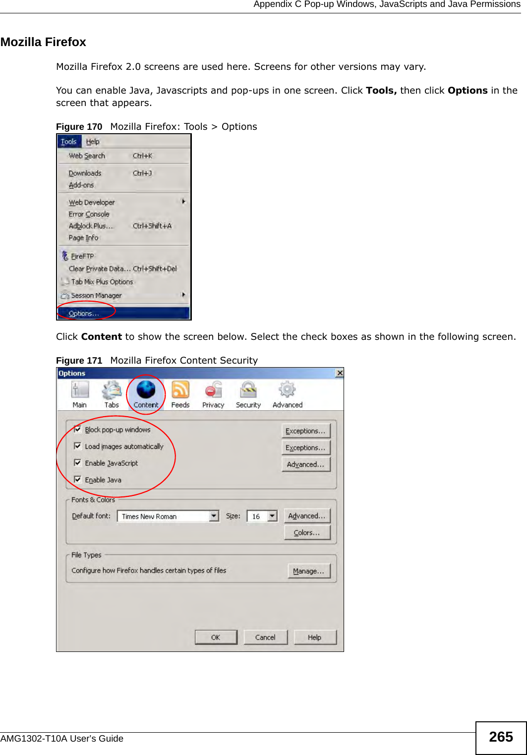
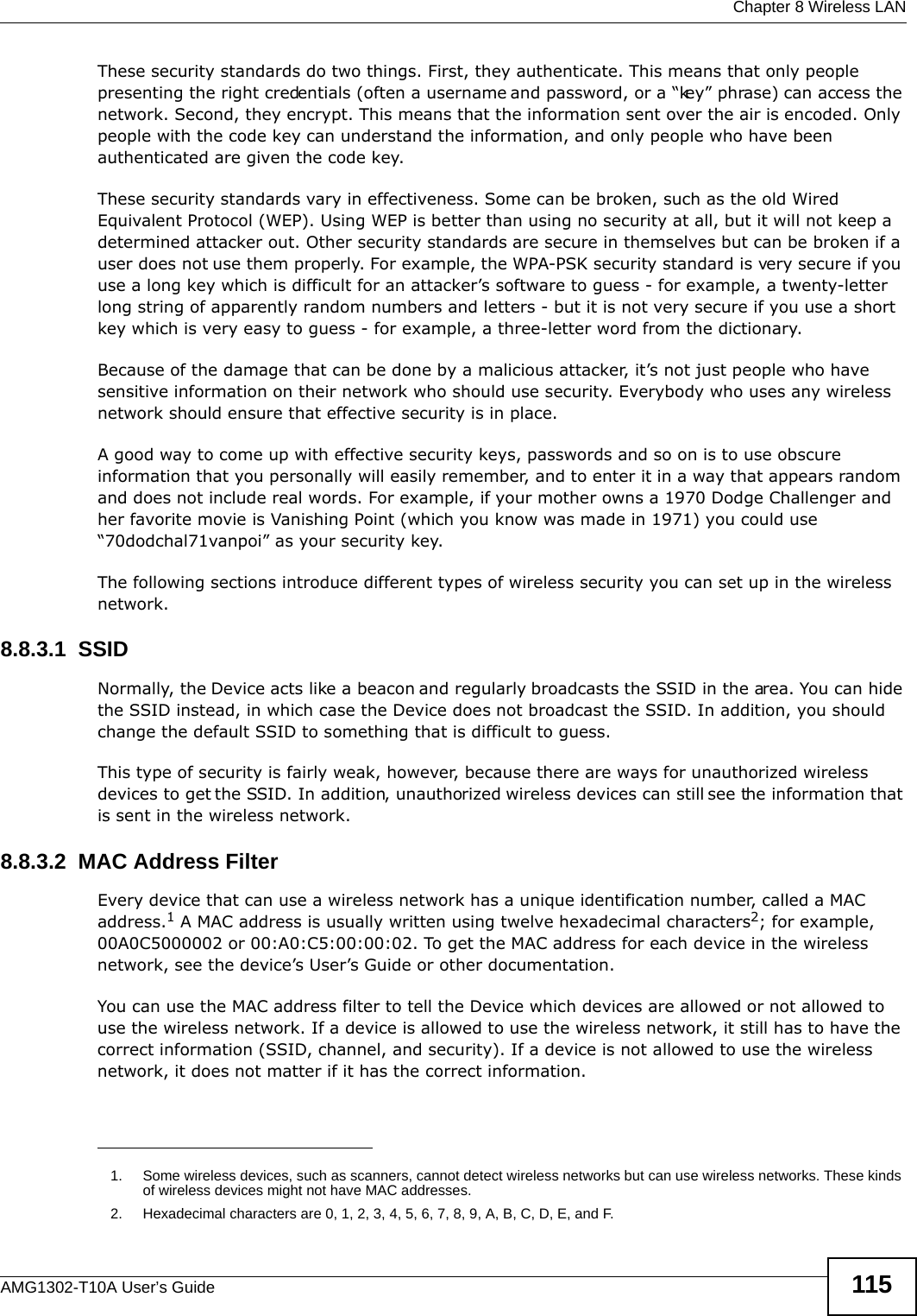
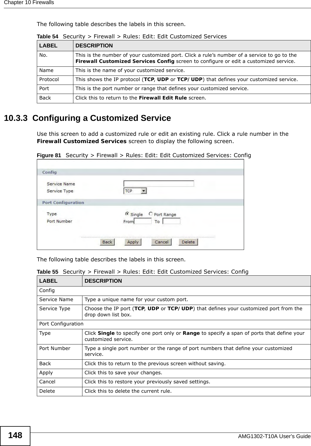
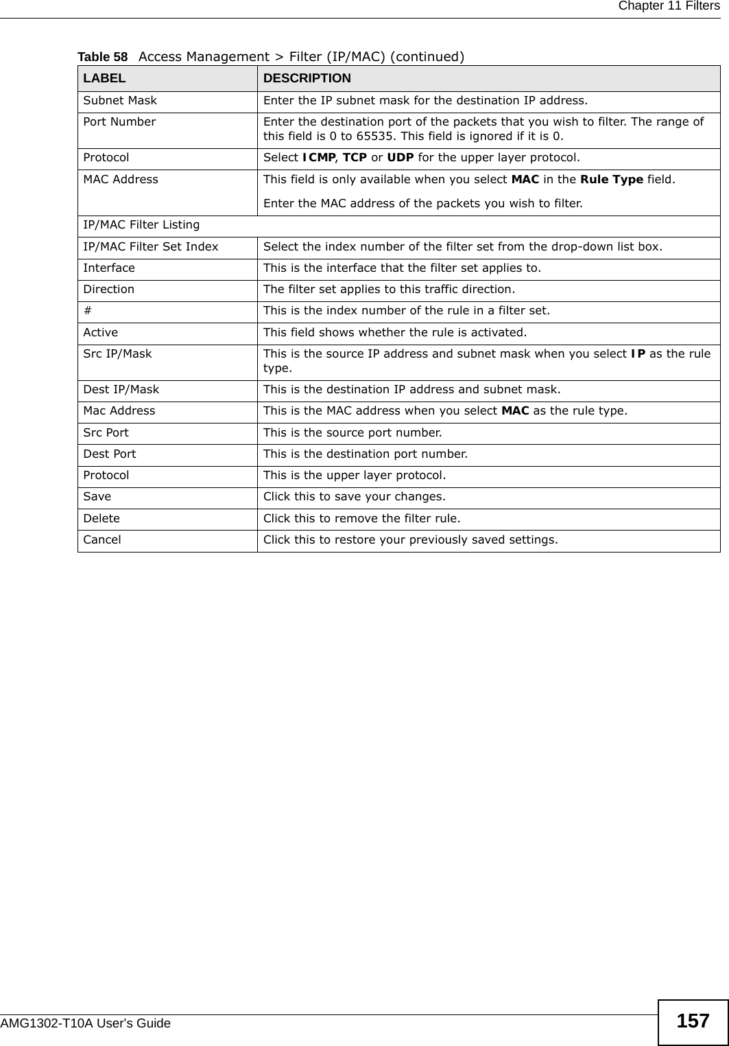
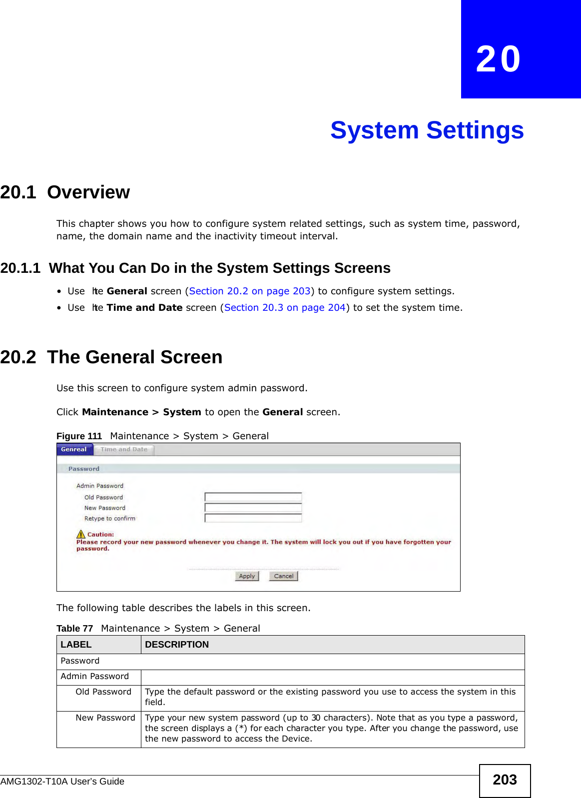
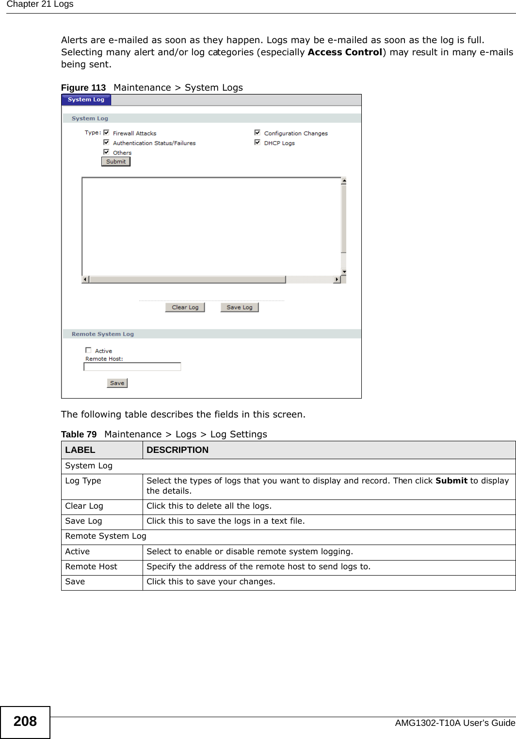
![Chapter 21 LogsAMG1302-T10A User’s Guide212 For type and code details, see Table 93 on page 214.board %d line %d channel %d, call %d, %s C02 OutCall Connected %d %sThe PPPoE, PPTP or dial-up call is connected.board %d line %d channel %d, call %d, %s C02 Call TerminatedThe PPPoE, PPTP or dial-up call was disconnected.Table 87 PPP LogsLOG MESSAGE DESCRIPTIONppp:LCP Starting The PPP connection’s Link Control Protocol stage has started.ppp:LCP Opening The PPP connection’s Link Control Protocol stage is opening.ppp:CHAP Opening The PPP connection’s Challenge Handshake Authentication Protocol stage is opening.ppp:IPCP Starting The PPP connection’s Internet Protocol Control Protocol stage is starting.ppp:IPCP Opening The PPP connection’s Internet Protocol Control Protocol stage is opening.ppp:LCP Closing The PPP connection’s Link Control Protocol stage is closing.ppp:IPCP Closing The PPP connection’s Internet Protocol Control Protocol stage is closing.Table 88 UPnP LogsLOG MESSAGE DESCRIPTIONUPnP pass through Firewall UPnP packets can pass through the firewall.Table 89 Content Filtering LogsLOG MESSAGE DESCRIPTION%s: block keyword The content of a requested web page matched a user defined keyword.%s The system forwarded web content.Table 90 Attack LogsLOG MESSAGE DESCRIPTIONattack [ TCP | UDP | IGMP | ESP | GRE | OSPF ]The firewall detected a TCP/UDP/IGMP/ESP/GRE/OSPF attack.attack ICMP (type:%d, code:%d)The firewall detected an ICMP attack.land [ TCP | UDP | IGMP | ESP | GRE | OSPF ]The firewall detected a TCP/UDP/IGMP/ESP/GRE/OSPF land attack.land ICMP (type:%d, code:%d)The firewall detected an ICMP land attack.ip spoofing - WAN [ TCP | UDP | IGMP | ESP | GRE | OSPF ]The firewall detected an IP spoofing attack on the WAN port.Table 86 CDR Logs (continued)LOG MESSAGE DESCRIPTION](https://usermanual.wiki/ZyXEL-Communications/AMG1302/User-Guide-1700682-Page-212.png)
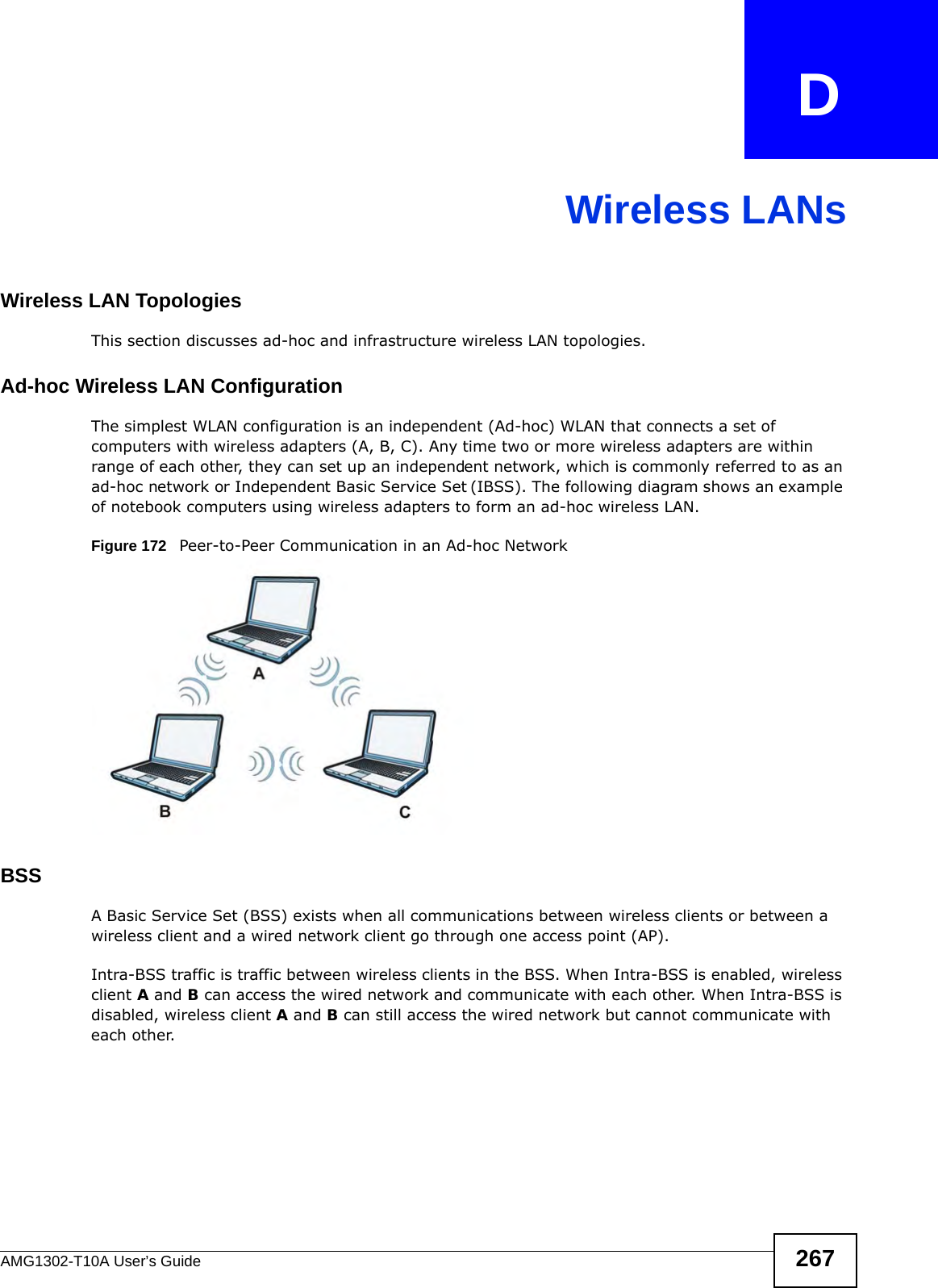
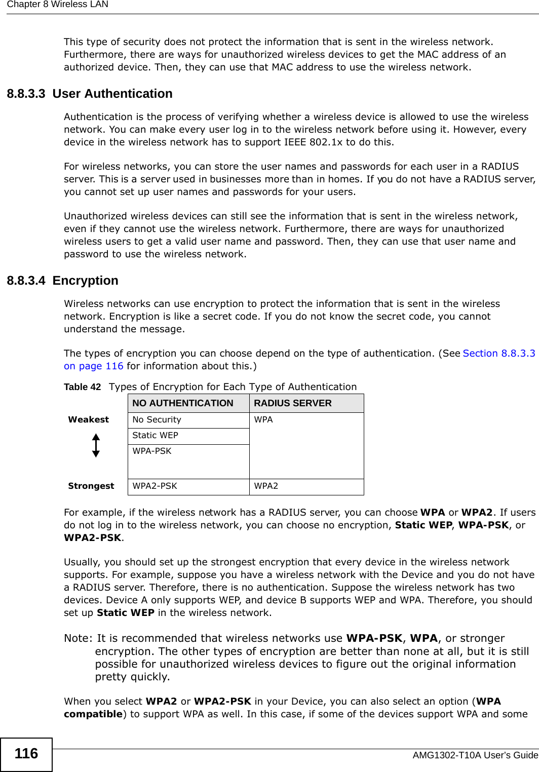
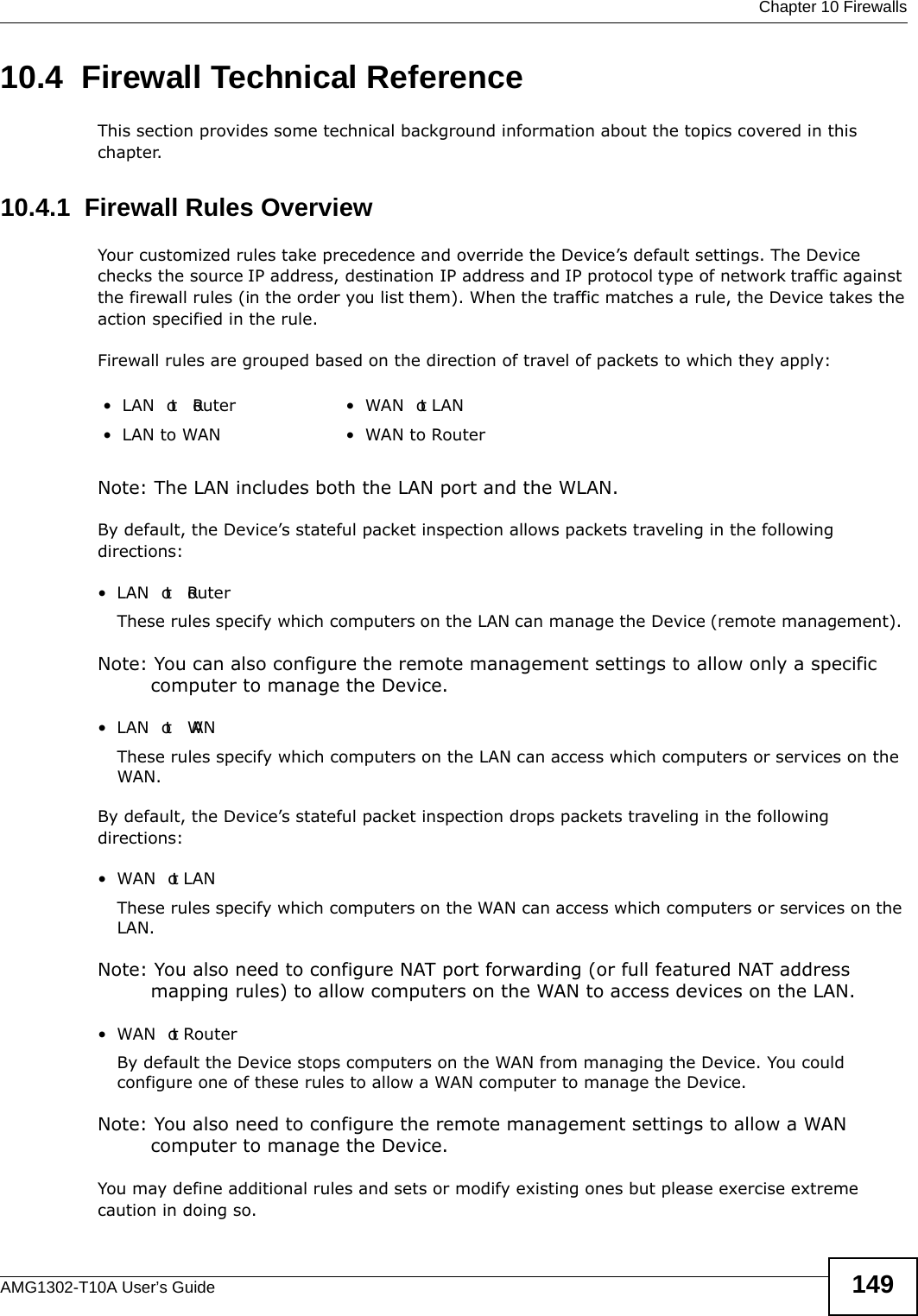
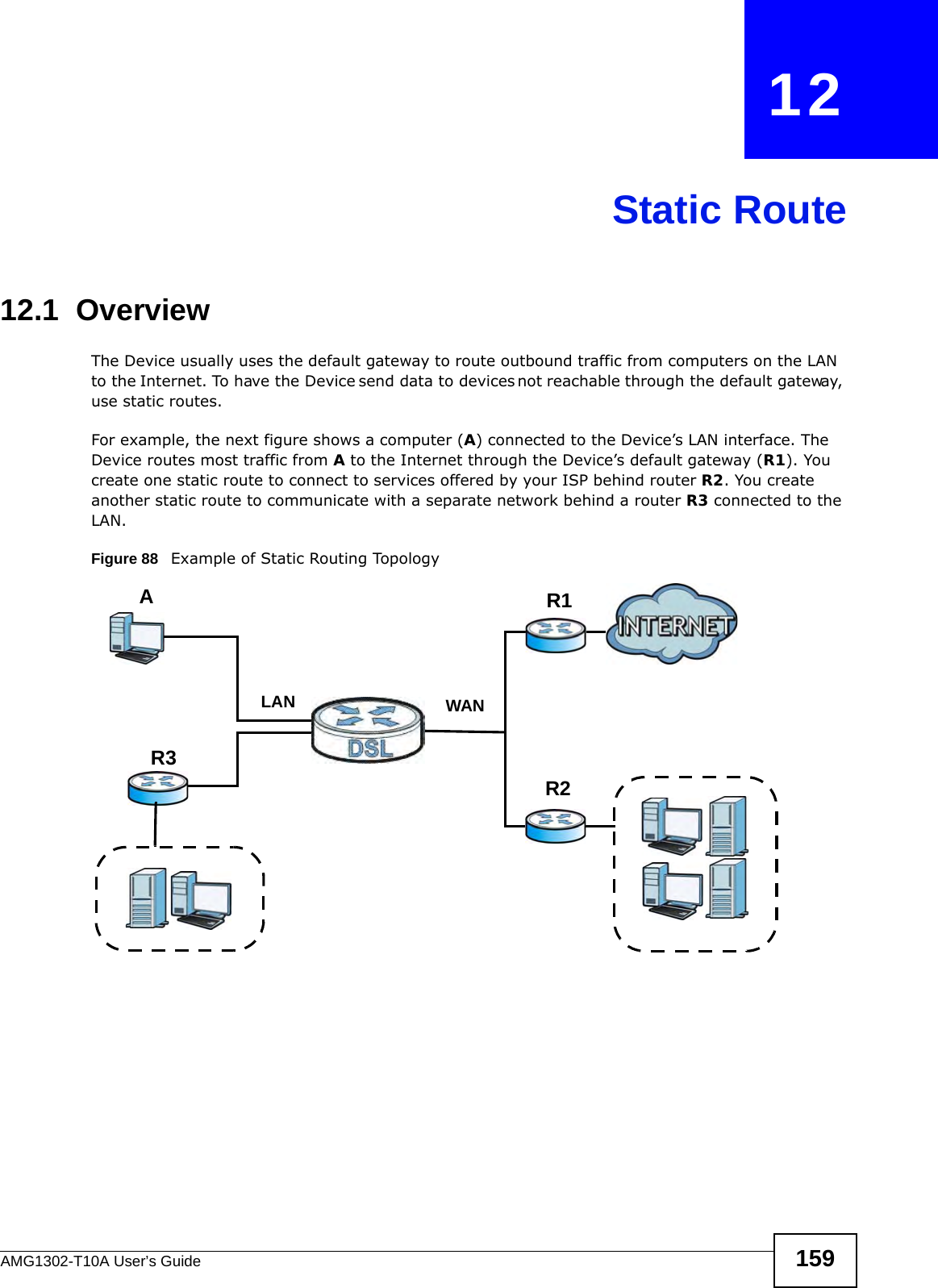
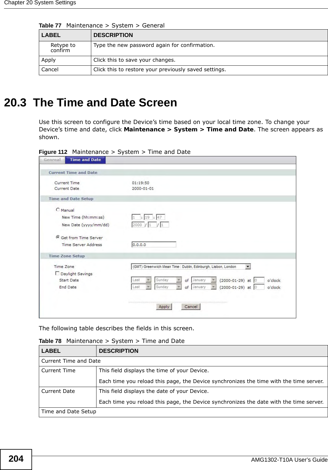
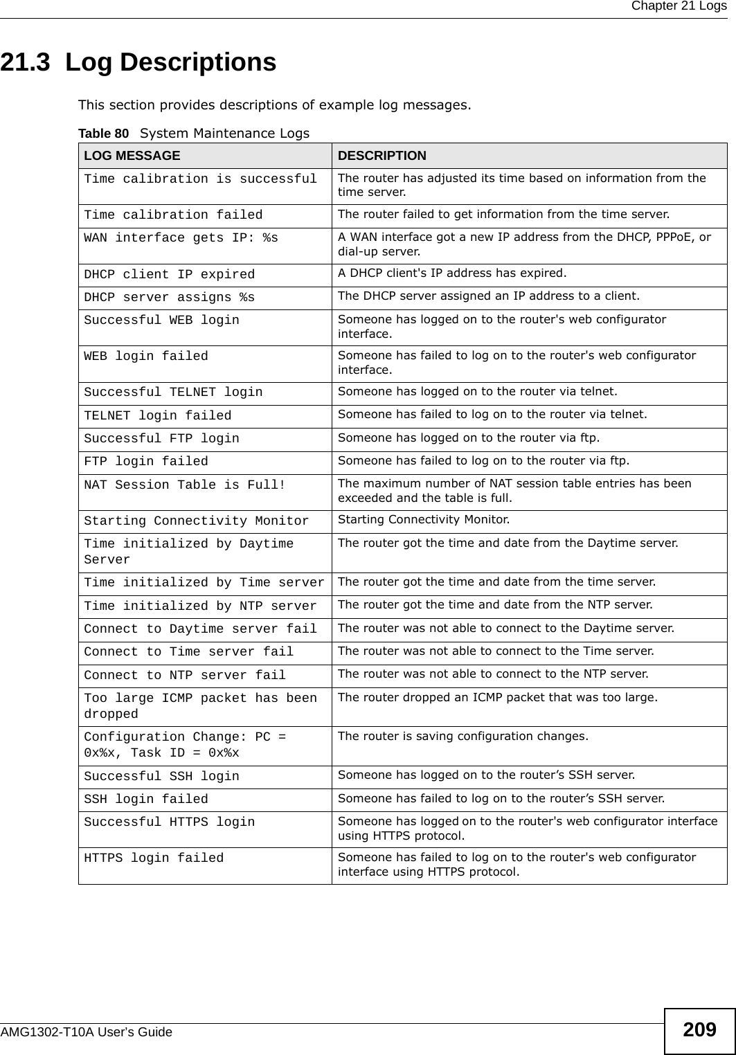
![Chapter 21 LogsAMG1302-T10A User’s Guide 213 ip spoofing - WAN ICMP (type:%d, code:%d)The firewall detected an ICMP IP spoofing attack on the WAN port. icmp echo : ICMP (type:%d, code:%d)The firewall detected an ICMP echo attack. syn flood TCP The firewall detected a TCP syn flood attack.ports scan TCP The firewall detected a TCP port scan attack.teardrop TCP The firewall detected a TCP teardrop attack.teardrop UDP The firewall detected an UDP teardrop attack.teardrop ICMP (type:%d, code:%d)The firewall detected an ICMP teardrop attack. illegal command TCP The firewall detected a TCP illegal command attack.NetBIOS TCP The firewall detected a TCP NetBIOS attack.ip spoofing - no routing entry [ TCP | UDP | IGMP | ESP | GRE | OSPF ]The firewall classified a packet with no source routing entry as an IP spoofing attack.ip spoofing - no routing entry ICMP (type:%d, code:%d)The firewall classified an ICMP packet with no source routing entry as an IP spoofing attack.vulnerability ICMP (type:%d, code:%d)The firewall detected an ICMP vulnerability attack.traceroute ICMP (type:%d, code:%d)The firewall detected an ICMP traceroute attack. Table 91 802.1X LogsLOG MESSAGE DESCRIPTIONRADIUS accepts user. A user was authenticated by the RADIUS Server.RADIUS rejects user. Pls check RADIUS Server.A user was not authenticated by the RADIUS Server. Please check the RADIUS Server.User logout because of session timeout expired.The router logged out a user whose session expired.User logout because of user deassociation.The router logged out a user who ended the session.User logout because of no authentication response from user.The router logged out a user from which there was no authentication response.User logout because of idle timeout expired.The router logged out a user whose idle timeout period expired.User logout because of user request.A user logged out.No response from RADIUS. Pls check RADIUS Server.There is no response message from the RADIUS server, please check the RADIUS server.Use RADIUS to authenticate user. The RADIUS server is operating as the authentication server.No Server to authenticate user. There is no authentication server to authenticate a user.Table 90 Attack Logs (continued)LOG MESSAGE DESCRIPTION](https://usermanual.wiki/ZyXEL-Communications/AMG1302/User-Guide-1700682-Page-213.png)


![Chapter 24 TroubleshootingAMG1302-T10A User’s Guide 229• Try to access the Device using another service, such as Telnet. If you can access the Device, check the remote management settings and firewall rules to find out why the Device does not respond to HTTP. • If your computer is connected to the WAN port or is connected wirelessly, use a computer that is connected to a ETHERNET port.I can see the Login screen, but I cannot log in to the Device.1Make sure you have entered the password correctly. The default admin password is 1234. The field is case-sensitive, so make sure [Caps Lock] is not on. 2You cannot log in to the web configurator while someone is using Telnet to access the Device. Log out of the Device in the other session, or ask the person who is logged in to log out. 3Turn the Device off and on. 4If this does not work, you have to reset the device to its factory defaults. See Section 24.1 on page 227.I cannot Telnet to the Device.See the troubleshooting suggestions for I cannot see or access the Login screen in the web configurator. Ignore the suggestions about your browser.I cannot use FTP to upload / download the configuration file. / I cannot use FTP to upload new firmware.See the troubleshooting suggestions for I cannot see or access the Login screen in the web configurator. Ignore the suggestions about your browser.24.3 Internet AccessI cannot access the Internet.1Check the hardware connections, and make sure the LEDs are behaving as expected. See the Quick Start Guide and Section 1.6 on page 18.2Make sure you entered your ISP account information correctly in the wizard. These fields are case-sensitive, so make sure [Caps Lock] is not on.](https://usermanual.wiki/ZyXEL-Communications/AMG1302/User-Guide-1700682-Page-229.png)
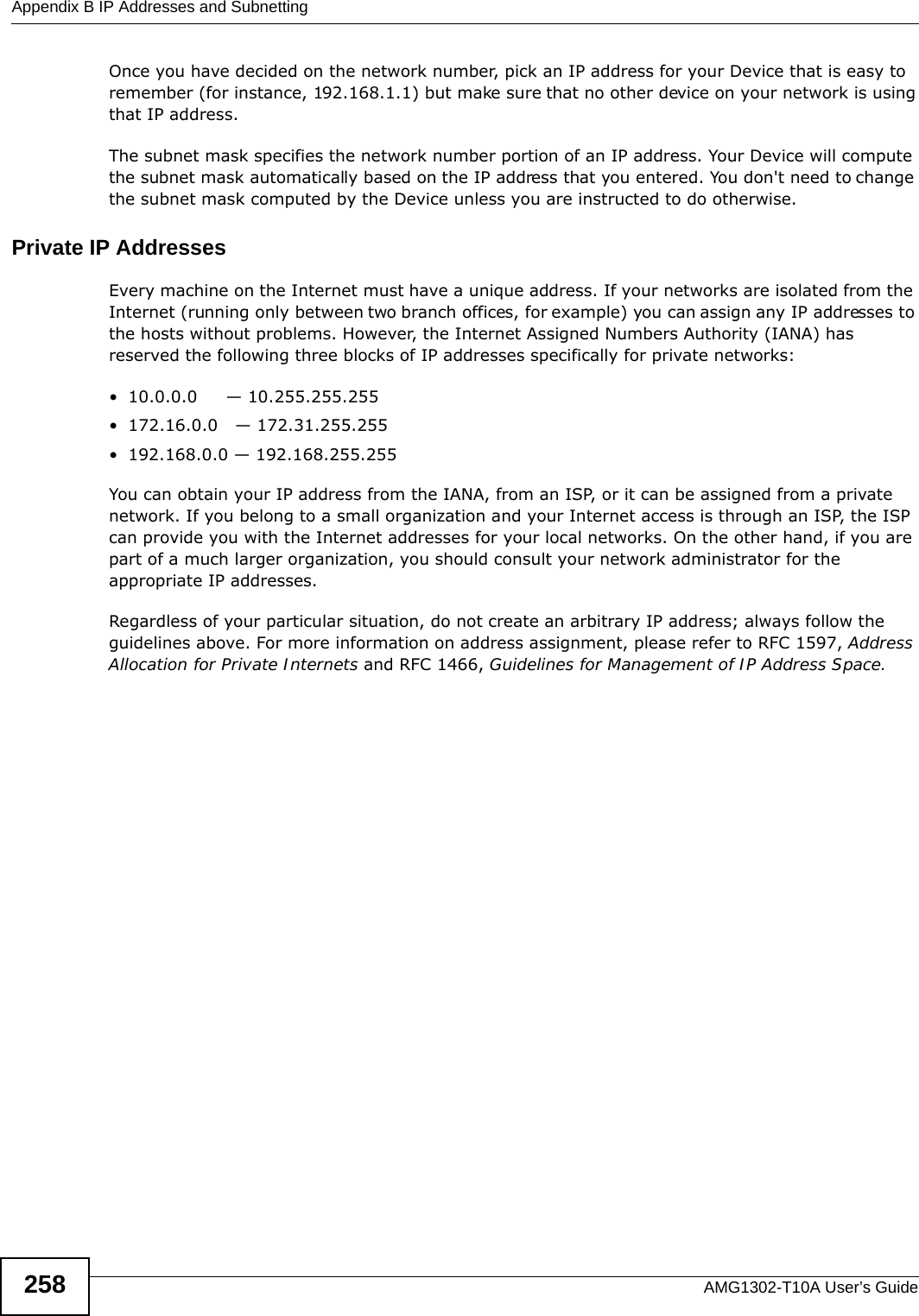
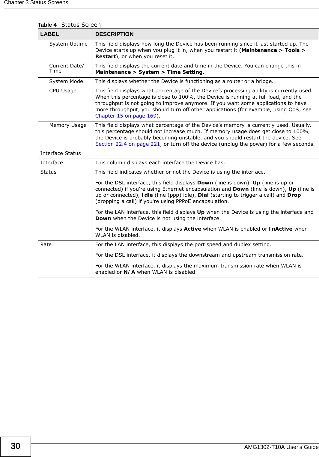
![Appendix A Setting up Your Computer’s IP AddressAMG1302-T10A User’s Guide238Figure 136 Windows XP: Internet Protocol (TCP/IP) Properties8Click OK to close the Internet Protocol (TCP/IP) Properties window.9Click Close (OK in Windows 2000/NT) to close the Local Area Connection Properties window.10 Close the Network Connections window (Network and Dial-up Connections in Windows 2000/NT).11 Turn on your Device and restart your computer (if prompted).Verifying Settings1Click Start, All Programs, Accessories and then Command Prompt.2In the Command Prompt window, type "ipconfig" and then press [ENTER]. You can also open Network Connections, right-click a network connection, click Status and then click the Support tab.Windows VistaThis section shows screens from Windows Vista Enterprise Version 6.0.1Click the Start icon, Control Panel.](https://usermanual.wiki/ZyXEL-Communications/AMG1302/User-Guide-1700682-Page-238.png)
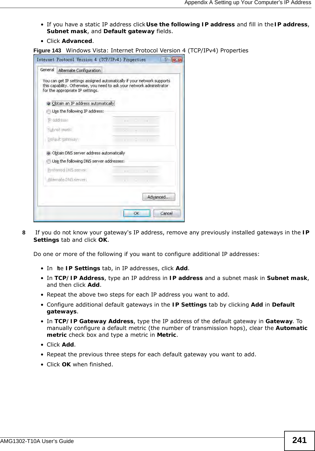
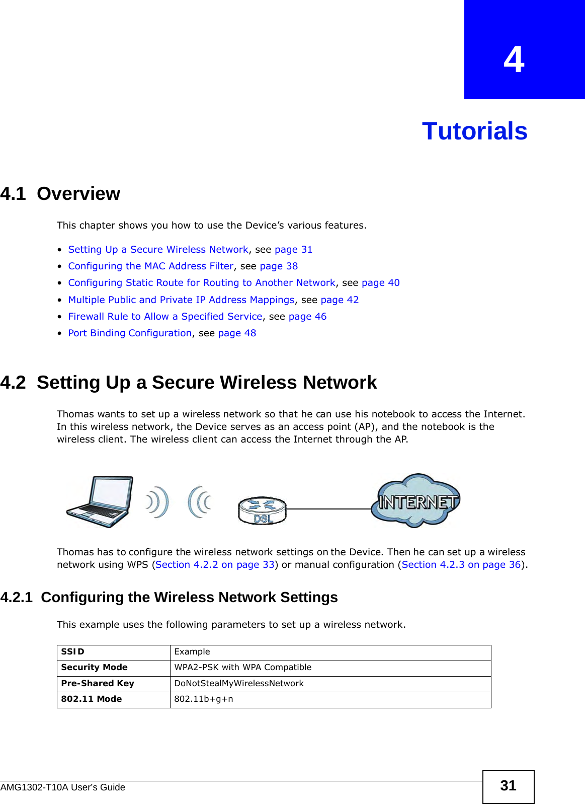
![Appendix A Setting up Your Computer’s IP AddressAMG1302-T10A User’s Guide 243Figure 145 Windows Vista: Internet Protocol Version 4 (TCP/IPv4) Properties10 Click OK to close the Internet Protocol Version 4 (TCP/IPv4) Properties window.11 Click Close to close the Local Area Connection Properties window.12 Close the Network Connections window.13 Turn on your Device and restart your computer (if prompted).Verifying Settings1Click Start, All Programs, Accessories and then Command Prompt.2In the Command Prompt window, type "ipconfig" and then press [ENTER]. You can also open Network Connections, right-click a network connection, click Status and then click the Support tab.Macintosh OS 8/9 1Click the Apple menu, Control Panel and double-click TCP/IP to open the TCP/IP Control Panel.](https://usermanual.wiki/ZyXEL-Communications/AMG1302/User-Guide-1700682-Page-243.png)
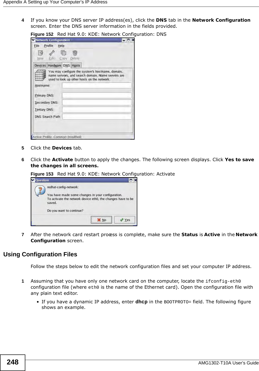
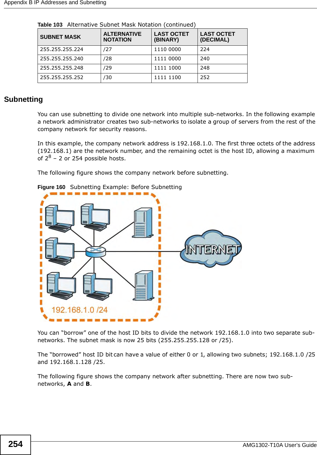
![Appendix A Setting up Your Computer’s IP AddressAMG1302-T10A User’s Guide 249Figure 154 Red Hat 9.0: Dynamic IP Address Setting in ifconfig-eth0 • If you have a static IP address, enter static in the BOOTPROTO= field. Type IPADDR= followed by the IP address (in dotted decimal notation) and type NETMASK= followed by the subnet mask. The following example shows an example where the static IP address is 192.168.1.10 and the subnet mask is 255.255.255.0. Figure 155 Red Hat 9.0: Static IP Address Setting in ifconfig-eth0 2If you know your DNS server IP address(es), enter the DNS server information in the resolv.conf file in the /etc directory. The following figure shows an example where two DNS server IP addresses are specified.Figure 156 Red Hat 9.0: DNS Settings in resolv.conf 3After you edit and save the configuration files, you must restart the network card. Enter ./network restart in the /etc/rc.d/init.d directory. The following figure shows an example.Figure 157 Red Hat 9.0: Restart Ethernet Card Verifying SettingsEnter ifconfig in a terminal screen to check your TCP/IP properties. DEVICE=eth0ONBOOT=yesBOOTPROTO=dhcpUSERCTL=noPEERDNS=yesTYPE=EthernetDEVICE=eth0ONBOOT=yesBOOTPROTO=staticIPADDR=192.168.1.10NETMASK=255.255.255.0USERCTL=noPEERDNS=yesTYPE=Ethernetnameserver 172.23.5.1nameserver 172.23.5.2[root@localhost init.d]# network restartShutting down interface eth0: [OK]Shutting down loopback interface: [OK]Setting network parameters: [OK]Bringing up loopback interface: [OK]Bringing up interface eth0: [OK]](https://usermanual.wiki/ZyXEL-Communications/AMG1302/User-Guide-1700682-Page-249.png)
![Appendix A Setting up Your Computer’s IP AddressAMG1302-T10A User’s Guide250Figure 158 Red Hat 9.0: Checking TCP/IP Properties [root@localhost]# ifconfig eth0 Link encap:Ethernet HWaddr 00:50:BA:72:5B:44 inet addr:172.23.19.129 Bcast:172.23.19.255 Mask:255.255.255.0 UP BROADCAST RUNNING MULTICAST MTU:1500 Metric:1 RX packets:717 errors:0 dropped:0 overruns:0 frame:0 TX packets:13 errors:0 dropped:0 overruns:0 carrier:0 collisions:0 txqueuelen:100 RX bytes:730412 (713.2 Kb) TX bytes:1570 (1.5 Kb) Interrupt:10 Base address:0x1000 [root@localhost]#](https://usermanual.wiki/ZyXEL-Communications/AMG1302/User-Guide-1700682-Page-250.png)