ZyXEL Communications CAM1215 HD Cube IP Camera User Manual
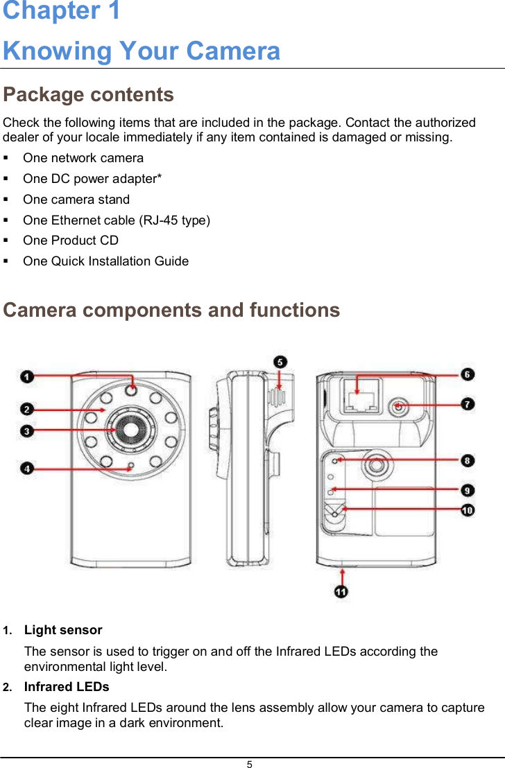
ZyXEL Communications Corporation HD Cube IP Camera
UserManual.wiki
>
ZyXEL Communications
>
CAM1215 User Manual
>
User manual
Contents
1.
User manual
2.
User Manual
User manual
Navigation menu
Upload a User Manual
Namespaces
Wiki Guide
HTML
PDF
Info
Views
User Manual
Discussion / Help
Navigation
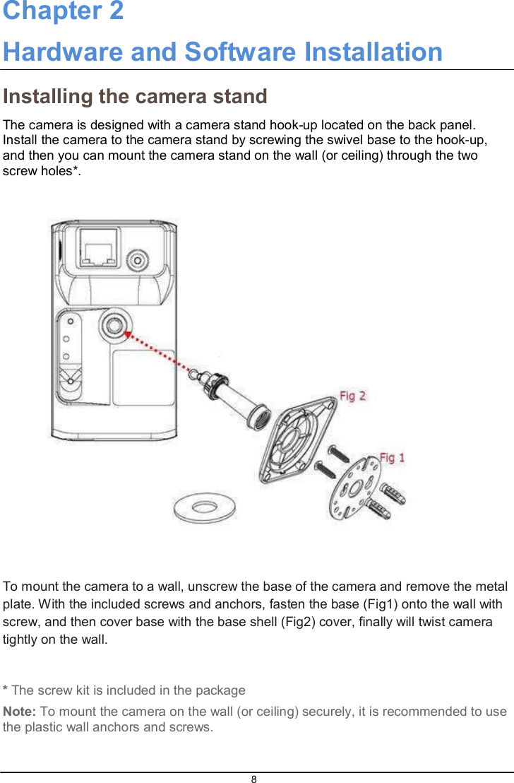
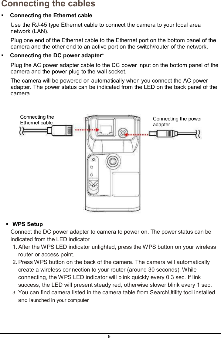
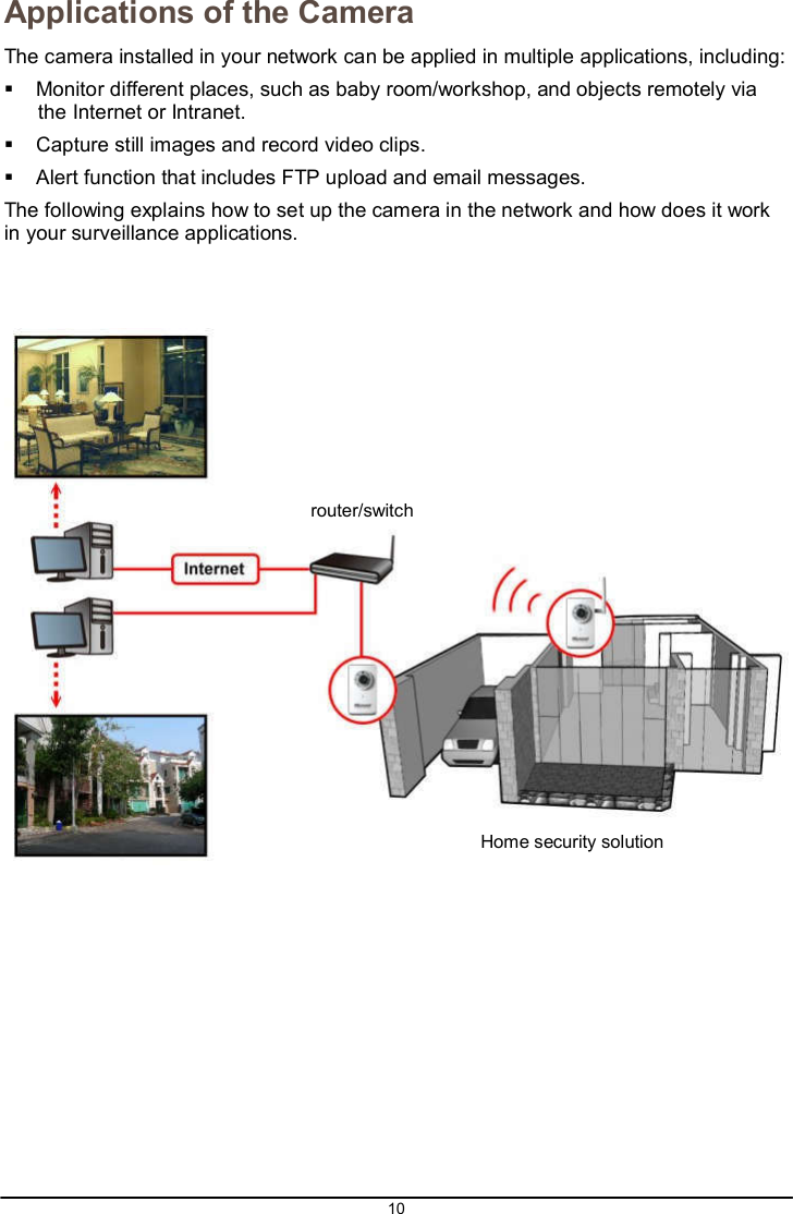
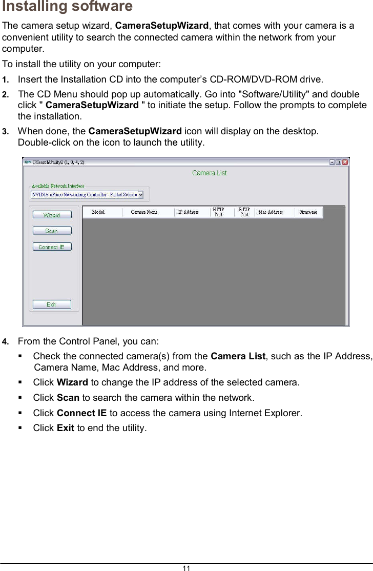
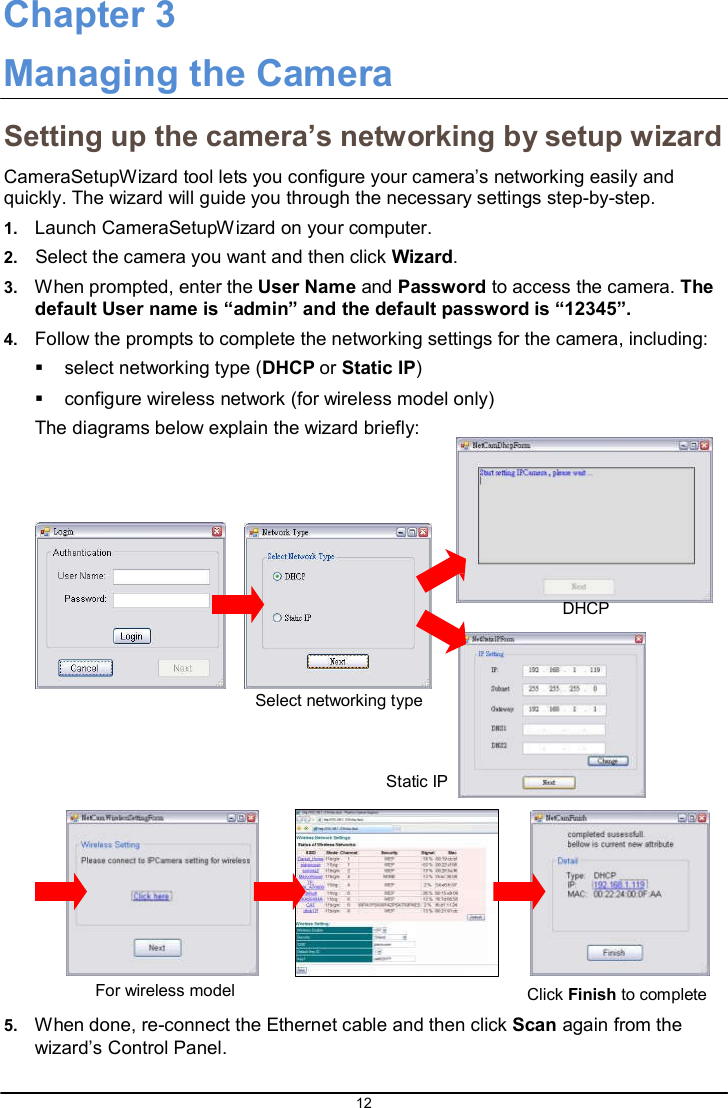
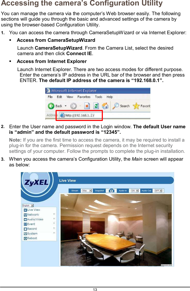
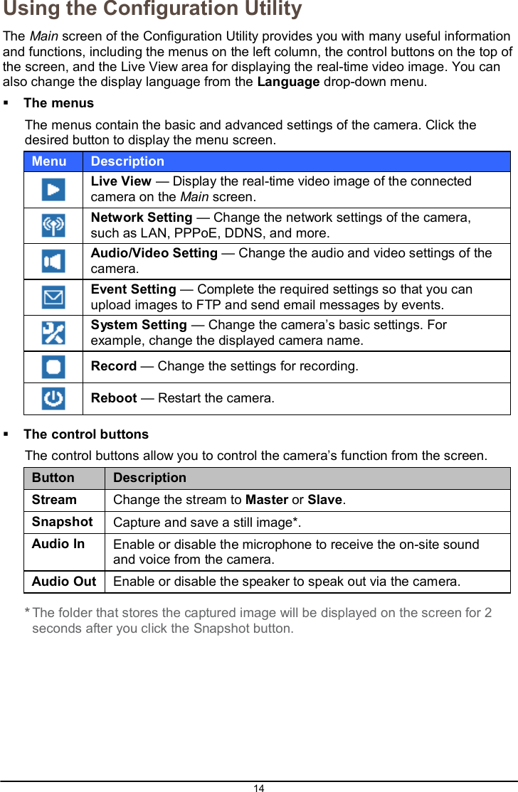
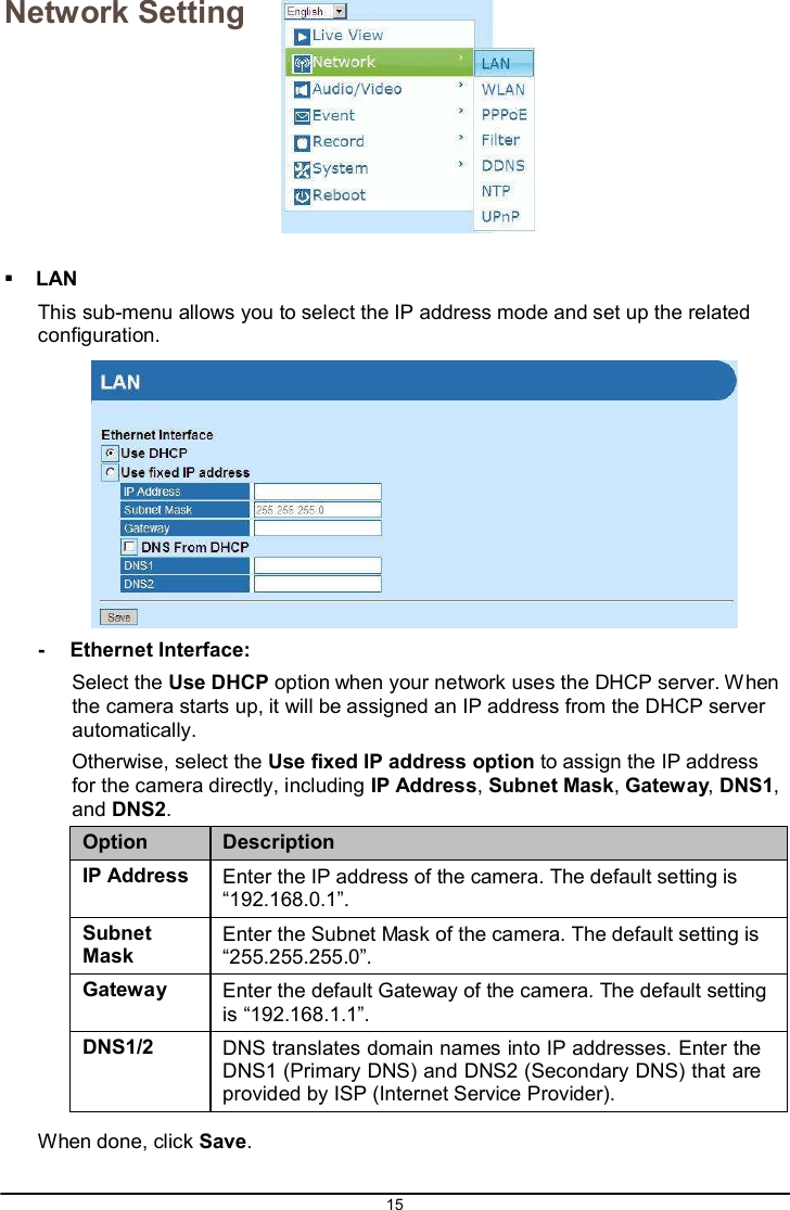
![34 Dimension (mm) 100(L) x 56 (W) x 40 (D) Weight 80.0 g Emission CE, FCC Configuring the IP Address of the computer The camera’s default IP address is “192.168.1.2”. If you cannot access the camera by entering the default IP address froom the browser, check the settings of your computer. When you connect the camera to your computer directly to configure the camera, you have to set the computer’s IP address to be in the same segment as the camera’s to communicate. 1. On your computer, click Start Control Panel to open the Control Panel window. 2. Double-click Network Connection to open the Network Connection window. 3. Right-click Local Area Connection and then click Properties from the shortcut menu. 4. When the Local Area Connection Properties window appears, select the General tab. 5. Select Internet Protocol [TCP/IP] and then click Properties to bring up the Internet Protocol [TCP/IP] Properties window. 6. To configure a fixed IP address that is within the segment of the camera, select the Use the following IP address option. Then, enter an IP address into the empty field. The suggested IP address is “192.168.0.X” (X is 2~254), and the suggested Subnet mask is “255.255.255.0”. 7. When done, click OK.](https://usermanual.wiki/ZyXEL-Communications/CAM1215.User-manual/User-Guide-3005132-Page-34.png)