ZyXEL Communications FR1000Z Wireless N FTTH Router User Manual MQSG A5 EN v2 00
ZyXEL Communications Corporation Wireless N FTTH Router MQSG A5 EN v2 00
manual
3
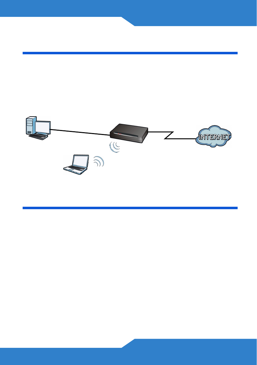
Introduction
FR1000Z is a router that provides high-speed Internet access, a built-in
switch, a firewall and high-speed wireless networking capability. It allows
you to enjoy high-bandwidth applications, such as video streaming, on-
line gaming and peer-to-peer (P2P). You can also set up a secure
wireless network connection using the WPS button.
Before You Begin
Make sure you have the following things before you set up your
FR1000Z.
• Internet access - account information provided by your ISP, such as
user name, password, and so on.
• Internet Explorer 6.0, Firefox 3.6, Safari: 4.0.5, Opera: 10.51 or
Chrome 4.1.249.1064 as well as later versions of all these
browsers, with JavaScript enabled.
4
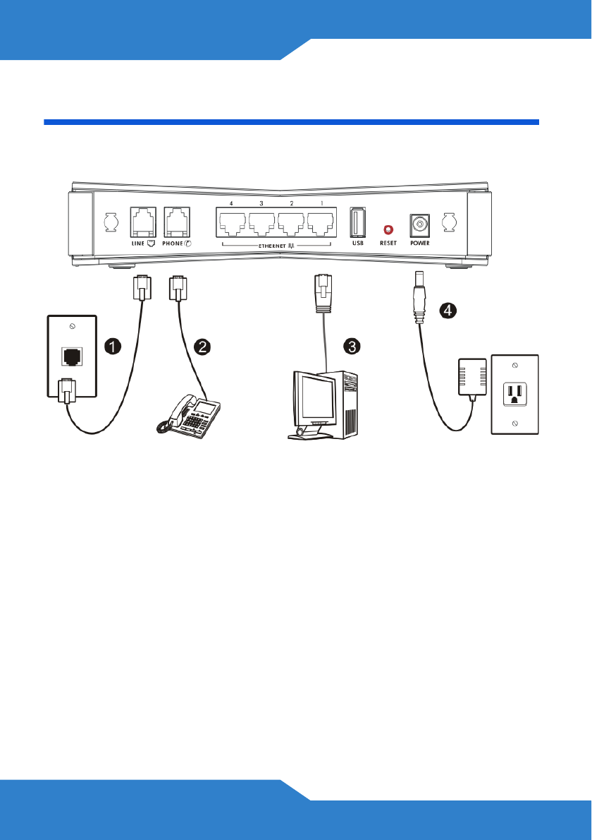
Hardware Connections
This section shows you how to set up your FR1000Z.
1. WAN: Use an Ethernet cable to connect this port to an Ethernet jack
with Internet access.
2. ETHERNET: Use an Ethernet cable to connect a computer to this port
for initial configuration and/or Internet access.
3. Use the power adaptor provided with your FR1000Z to connect an
appropriate power source to this socket.
As of writing, the USB port is reserved for future use.
5
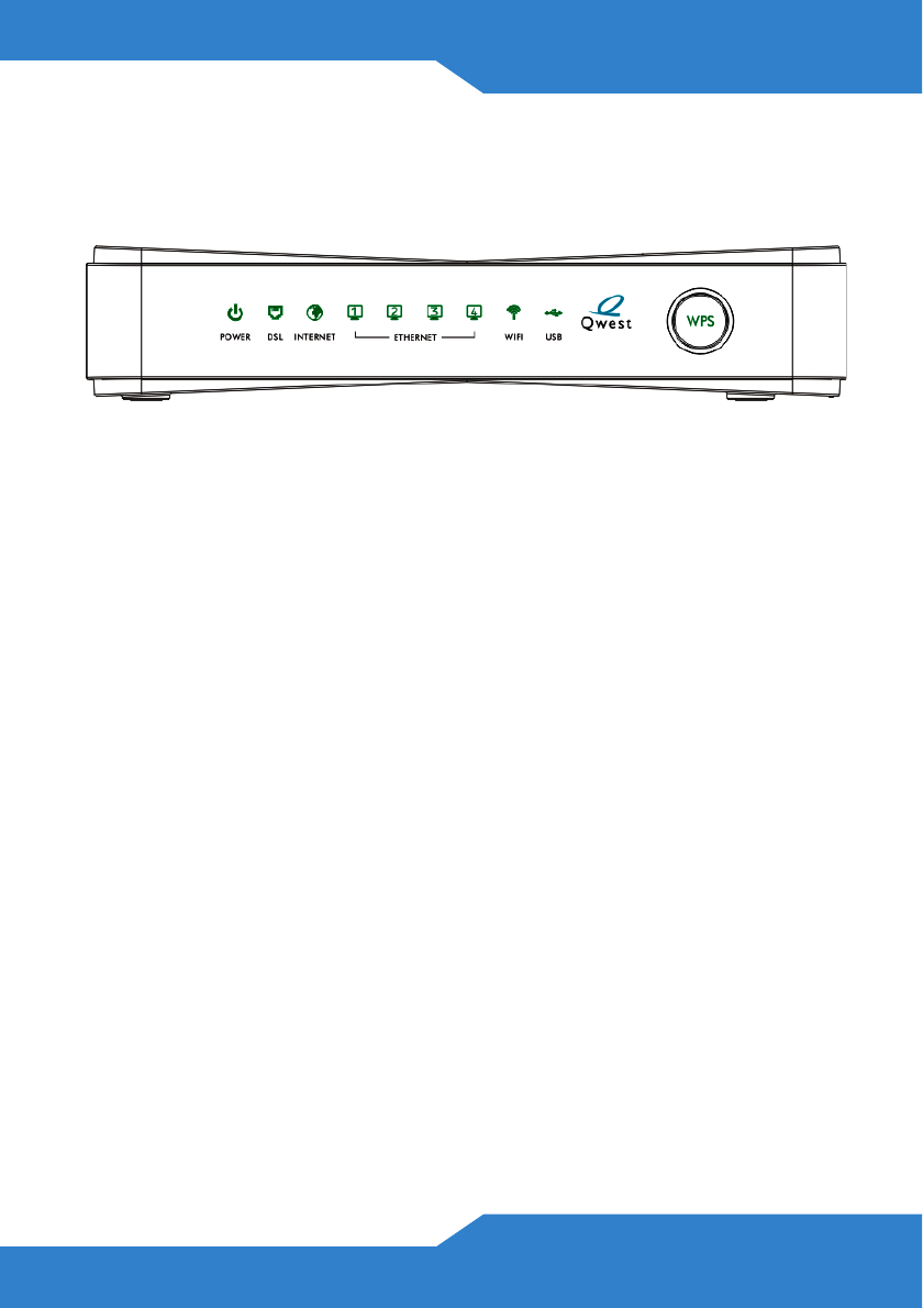
Checking the LEDs (Lights)
Look at the LEDs (lights) on the top panel of the FR1000Z.
• The POWER light blinks during start-up and is green once the
FR1000Z is ready.
• The WAN light is green if the Internet connection exists and blinks
when transmitting data.
• The INTERNET light is green when Internet access is available.
• The ETHERNET light turns on if the ETHERNET port is properly
connected. The light blinks when the FR1000Z is sending or
receiving data through the ETHERNET port.
• The WIFI light turns on when the wireless network is enabled.
If none of the LEDs (lights) are on, check your connections.
Make sure that you have the power adaptor connected to the
FR1000Z and plugged in to an appropriate power source.
Make sure the power source is turned on. Turn the FR1000Z
off, wait for a few seconds and turn it back on. If the LEDs
are still off, contact your local vendor.
As of writing, the USB LED is reserved for future use.
6
Testing Internet Connection
After you have connected the hardware and turned on the FR1000Z,
open a web browser on your computer and go to any web site (for
example, www.zyxel.com) to test your Internet connection.
If you are prompted for a user name and password, enter the account
information as given by your Internet service provider (ISP).
If the INTERNET light is off but the WAN light is on, go to the Initial
Configuration section to configure your Internet access settings.
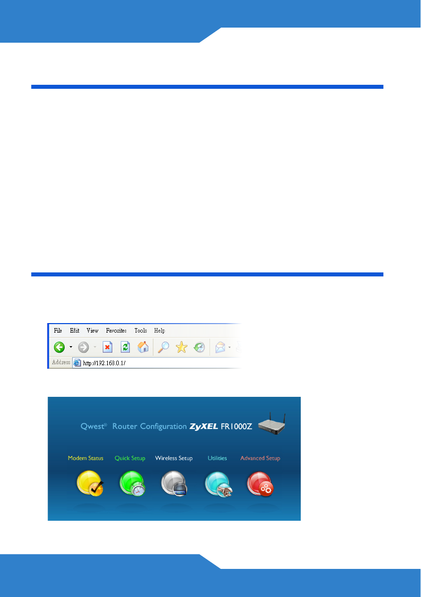
Initial Configuration
1. Open your browser and enter http://192.168.0.1 (the FR1000Z's
default IP address) as the address.
2. The main screen displays.
7
If the main screen does not display, make sure your
computer is set to get an IP address automatically from a
DHCP server.
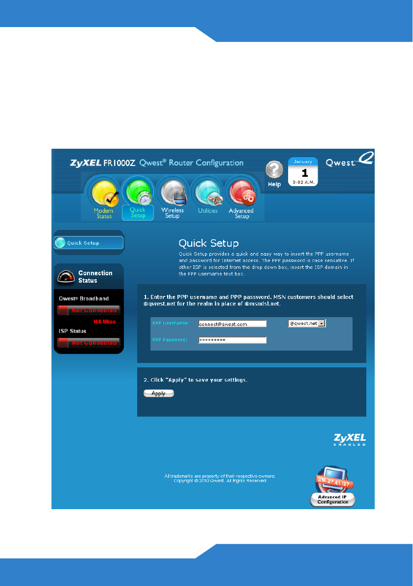
Click Quick Setup from the main screen. Follow the instructions in
the screen and enter the Internet access information exactly as given
to you by your ISP and click Apply.
8
3. If your ISP didn’t provide you a username and password, click the
Advanced IP Configuration button. Configure your FR1000Z for
Internet access according to instructions provided by your ISP. Make
sure you enter the correct information.
When your Internet connection is set up correctly, the WAN and
INTERNET lights should be green.
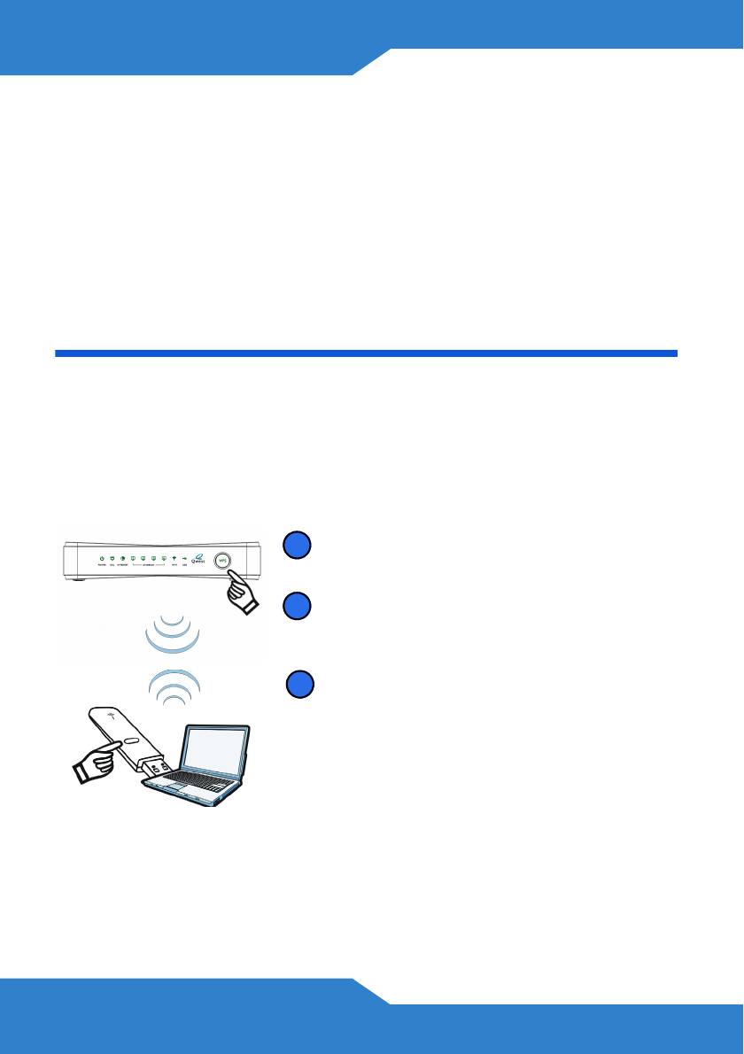
Set Up a WPS Connection
Press the WPS button on the FR1000Z’s front panel for more than 5
seconds to turn the WPS function on.
Follow these steps to add a WPS-enabled device to the wireless network
using the WPS button.
Place the devices you want to connect
near one another.
Press the WPS button on the FR1000Z.
The WPS light blinks.
Press the WPS button on a compatible
device within 2 minutes of pressing the
button on the FR1000Z.
The WPS light on the FR1000Z shines
steadily when connected.
1
2
3
9
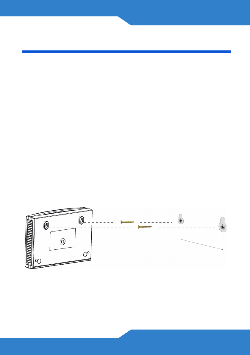
Wall-mounting
Take the following steps to hang your FR1000Z on a wall.
1. Select a position free of obstructions on a sturdy wall.
2. Drill two holes for the screws, exactly 110 mm apart.
3. Be careful to avoid damaging pipes or cables located inside the wall
when drilling holes for the screws.
4. Do not insert the screws all the way into the wall. Leave a small gap of
about 0.5 cm between the heads of the screws and the wall.
5. Make sure the screws are snugly fastened to the wall. They need to
hold the weight of the FR1000Z with the connection cables.
6. Align the holes on the back of the FR1000Z with the screws on the
wall. Hang the FR1000Z on the screws.

10
Customer Information Statement
The information informing the user of his and the telephone company's
rights and obligations is outlined on the following pages. This information
will be included in the final version of the manual.
1. This equipment complies with Part 68 of the FCC rules and the
requirements adopted by the ACTA. On bottom of this equipment is
a label that contains, among other information, a product identifier of
QWEST FR1000Z. If requested, this number must be provided to the
telephone company.
2. If this equipment DL causes harm to the telephone network, the
telephone company will notify you in advance that temporary
discontinuance of service may be required. But if advance notice isn’t
practical, the telephone company will notify the customer as soon as
possible. Also you will be advised of your right to file a complaint with
the FCC if you believe it is necessary.
3. The telephone company may make changes in its facilities,
equipment, operations or procedures that could affect the operation
of the equipment. If this happens, the telephone company will provide
advance notice in order for you to make necessary modification to
maintain uninterrupted service.
4. If you experience trouble with this equipment, you disconnect it from
the network until the problem has been corrected or until you are sure
that the equipment is not malfunctioning.
5. Please follow instructions for repairing if any (e.g. battery replacement
section); otherwise do not alternate or repair any parts of device
except specified.

11
6. Connection to party line service is subject to state tariffs. Contact the
state public utility commission, public service commission or
corporation commission for information.
7. If the telephone company requests information on what equipment is
connected to their lines, inform them of:
a. The ringer equivalence number 02
b. The USOC jack required RJ14
c. The FCC Registration Number US: 1RODL02BQ1000Z
Item (a) and (c) are indicated on the label. The ringer equivalence
number (REN) is used to determine how many devices can be
connected to your telephone line. In most areas, the sum of the
RENs of all devices on any one line should not exceed five (5.0). If
too many devices are attached, they may not ring properly.
8. If your home has specially wired alarm equipment connected to the
telephone line, ensure the installation of this equipment does not
disable alarm equipment; consult your telephone company or a
qualified installer.
Service Requirements
In the event of equipment malfunction, all repairs should be performed
by our Company or an authorized agent. It is the responsibility of users
requiring service to report the need for service to our Company or to one
of our authorized agents.

12
Service can be facilitated through our office at:
ZyXEL Communications Corporation
6, Innovation Rd II, Science-Based Industrial Park, Hsin-Chu, Taiwan,
R.O.C.
+886- 3-578-3942
This device complies with part 15 of the FCC Rules. Operation is subject
to the following two conditions: (1) This device may not cause harmful
interference, and (2) this device must accept any interference received,
including interference that may cause undesired operation.
For a Class B digital device or peripheral, the instructions furnished the
user shall include the following or similar statement, placed in a
prominent location in the text of the manual:
NOTE: This equipment has been tested and found to comply with the
limits for a Class B digital device, pursuant to Part 15 of the FCC Rules.
These limits are designed to provide reasonable protection against
harmful interference in a residential installation. This equipment
generates, uses and can radiate radio frequency energy and, if not
installed and used in accordance with the instructions, may cause
harmful interference to radio communications. However, there is no
guarantee that interference will not occur in a particular installation.
If this equipment does cause harmful interference to radio or television
reception, which can be determined by turning the equipment off and on,
the user is encouraged to try to correct the interference by one or more
of the following measures:
• Reorient or relocate the receiving antenna.
• Increase the separation between the equipment and receiver.

13
• Connect the equipment into an outlet on a circuit different from that
to which the receiver is connected.
• Consult the dealer or an experienced radio/TV technician for help.
RF exposure warning
This equipment must be installed and operated in accordance with
provided instructions and the antenna(s) used for this transmitter must
be installed to provide a separation distance of at least 20 cm from all
persons and must not be co-located or operating in conjunction with any
other antenna or transmitter. End-users and installers must be provide
with antenna installation instructions and transmitter operating conditions
for satisfying RF exposure compliance.