ZyXEL Communications G570S Access Point User Manual Part 1
ZyXEL Communications Corporation Access Point Part 1
Contents
- 1. Part 1
- 2. Part 2
Part 1

ZyXEL G-570S
802.11g Wireless Access Point
User’s Guide
Version 1.00
11/2005

ZyXEL G-570S User’s Guide
2Copyright
Copyright
Copyright © 2005 by ZyXEL Communications Corporation.
The contents of this publication may not be reproduced in any part or as a whole, transcribed,
stored in a retrieval system, translated into any language, or transmitted in any form or by any
means, electronic, mechanical, magnetic, optical, chemical, photocopying, manual, or
otherwise, without the prior written permission of ZyXEL Communications Corporation.
Published by ZyXEL Communications Corporation. All rights reserved.
Disclaimer
ZyXEL does not assume any liability arising out of the application or use of any products, or
software described herein. Neither does it convey any license under its patent rights nor the
patent rights of others. ZyXEL further reserves the right to make changes in any products
described herein without notice. This publication is subject to change without notice.
Trademarks
ZyNOS (ZyXEL Network Operating System) is a registered trademark of ZyXEL
Communications, Inc. Other trademarks mentioned in this publication are used for
identification purposes only and may be properties of their respective owners.

ZyXEL G-570S User’s Guide
Interference Statements and Certifications 3
Interference Statements and
Certifications
Federal Communications Commission (FCC) Interference Statement
This device complies with Part 15 of FCC rules. Operation is subject to the following two
conditions:
• This device may not cause harmful interference.
• This device must accept any interference received, including interference that may cause
undesired operations.
This equipment has been tested and found to comply with the limits for a Class B digital
device pursuant to Part 15 of the FCC Rules. These limits are designed to provide reasonable
protection against harmful interference in a commercial environment. This equipment
generates, uses, and can radiate radio frequency energy, and if not installed and used in
accordance with the instructions, may cause harmful interference to radio communications.
If this equipment does cause harmful interference to radio/television reception, which can be
determined by turning the equipment off and on, the user is encouraged to try to correct the
interference by one or more of the following measures:
• Reorient or relocate the receiving antenna.
• Increase the separation between the equipment and the receiver.
• Connect the equipment into an outlet on a circuit different from that to which the receiver
is connected.
• Consult the dealer or an experienced radio/TV technician for help.
Caution
1To comply with FCC RF exposure compliance requirements, a separation distance of at
least 20 cm must be maintained between the antenna of this device and all persons.
2This transmitter must not be co-located or operating in conjunction with any other
antenna or transmitter.
Notice 1
Changes or modifications not expressly approved by the party responsible for compliance
could void the user's authority to operate the equipment.
This product has been designed for the WLAN 2.4 GHz network throughout the EC region and
Switzerland, with restrictions in France.
This Class B digital apparatus complies with Canadian ICES-003.

ZyXEL G-570S User’s Guide
4 Interference Statements and Certifications
Cet appareil numérique de la classe B est conforme à la norme NMB-003 du Canada.
Certifications
1Go to www.zyxel.com.
2Select your product from the drop-down list box on the ZyXEL home page to go to that
product's page.
3Select the certification you wish to view from this page.

ZyXEL G-570S User’s Guide
Safety Warnings 5
Safety Warnings
For your safety, be sure to read and follow all warning notices and instructions.
• Do NOT open the device or unit. Opening or removing covers can expose you to
dangerous high voltage points or other risks. ONLY qualified service personnel can
service the device. Please contact your vendor for further information.
• Connect the power cord to the right supply voltage (110V AC in North America or 230V
AC in Europe).
• Place connecting cables carefully so that no one will step on them or stumble over them.
Do NOT allow anything to rest on the power cord and do NOT locate the product where
anyone can walk on the power cord.
• If you wall mount your device, make sure that no electrical, gas or water pipes will be
damaged.
• Do NOT install nor use your device during a thunderstorm. There may be a remote risk of
electric shock from lightning.
• Do NOT expose your device to dampness, dust or corrosive liquids.
• Do NOT use this product near water, for example, in a wet basement or near a swimming
pool.
• Make sure to connect the cables to the correct ports.
• Do NOT obstruct the device ventilation slots, as insufficient airflow may harm your
device.
• Do NOT store things on the device.
• Connect ONLY suitable accessories to the device.

ZyXEL G-570S User’s Guide
6ZyXEL Limited Warranty
ZyXEL Limited Warranty
ZyXEL warrants to the original end user (purchaser) that this product is free from any defects
in materials or workmanship for a period of up to two years from the date of purchase. During
the warranty period, and upon proof of purchase, should the product have indications of failure
due to faulty workmanship and/or materials, ZyXEL will, at its discretion, repair or replace the
defective products or components without charge for either parts or labor, and to whatever
extent it shall deem necessary to restore the product or components to proper operating
condition. Any replacement will consist of a new or re-manufactured functionally equivalent
product of equal value, and will be solely at the discretion of ZyXEL. This warranty shall not
apply if the product is modified, misused, tampered with, damaged by an act of God, or
subjected to abnormal working conditions.
Note
Repair or replacement, as provided under this warranty, is the exclusive remedy of the
purchaser. This warranty is in lieu of all other warranties, express or implied, including any
implied warranty of merchantability or fitness for a particular use or purpose. ZyXEL shall in
no event be held liable for indirect or consequential damages of any kind of character to the
purchaser.
To obtain the services of this warranty, contact ZyXEL's Service Center for your Return
Material Authorization number (RMA). Products must be returned Postage Prepaid. It is
recommended that the unit be insured when shipped. Any returned products without proof of
purchase or those with an out-dated warranty will be repaired or replaced (at the discretion of
ZyXEL) and the customer will be billed for parts and labor. All repaired or replaced products
will be shipped by ZyXEL to the corresponding return address, Postage Paid. This warranty
gives you specific legal rights, and you may also have other rights that vary from country to
country.

ZyXEL G-570S User’s Guide
Customer Support 7
Customer Support
Please have the following information ready when you contact customer support.
• Product model and serial number.
• Warranty Information.
• Date that you received your device.
• Brief description of the problem and the steps you took to solve it.
METHOD
LOCATION
SUPPORT E-MAIL TELEPHONEAWEB SITE REGULAR MAIL
SALES E-MAIL FAX FTP SITE
CORPORATE
HEADQUARTERS
(WORLDWIDE)
support@zyxel.com.tw +886-3-578-3942 www.zyxel.com
www.europe.zyxel.com
ZyXEL Communications Corp.
6 Innovation Road II
Science Park
Hsinchu 300
Taiwan
sales@zyxel.com.tw +886-3-578-2439 ftp.zyxel.com
ftp.europe.zyxel.com
CZECH REPUBLIC
info@cz.zyxel.com +420-241-091-350 www.zyxel.cz ZyXEL Communications
Czech s.r.o.
Modranská 621
143 01 Praha 4 - Modrany
Ceská Republika
info@cz.zyxel.com +420-241-091-359
DENMARK
support@zyxel.dk +45-39-55-07-00 www.zyxel.dk ZyXEL Communications A/S
Columbusvej
2860 Soeborg
Denmark
sales@zyxel.dk +45-39-55-07-07
FINLAND
support@zyxel.fi +358-9-4780-8411 www.zyxel.fi ZyXEL Communications Oy
Malminkaari 10
00700 Helsinki
Finland
sales@zyxel.fi +358-9-4780 8448
FRANCE
info@zyxel.fr +33-4-72-52-97-97 www.zyxel.fr ZyXEL France
1 rue des Vergers
Bat. 1 / C
69760 Limonest
France
+33-4-72-52-19-20
GERMANY
support@zyxel.de +49-2405-6909-0 www.zyxel.de ZyXEL Deutschland GmbH.
Adenauerstr. 20/A2 D-52146
Wuerselen
Germany
sales@zyxel.de +49-2405-6909-99
HUNGARY
support@zyxel.hu +36-1-3361649 www.zyxel.hu ZyXEL Hungary
48, Zoldlomb Str.
H-1025, Budapest
Hungary
info@zyxel.hu +36-1-3259100
KAZAKHSTAN
http://zyxel.kz/support +7-3272-590-698 www.zyxel.kz ZyXEL Kazakhstan
43, Dostyk ave.,Office 414
Dostyk Business Centre
050010, Almaty
Republic of Kazakhstan
sales@zyxel.kz +7-3272-590-689
NORTH AMERICA
support@zyxel.com 1-800-255-4101
+1-714-632-0882
www.us.zyxel.com ZyXEL Communications Inc.
1130 N. Miller St.
Anaheim
CA 92806-2001
U.S.A.
sales@zyxel.com +1-714-632-0858 ftp.us.zyxel.com
NORWAY
support@zyxel.no +47-22-80-61-80 www.zyxel.no ZyXEL Communications A/S
Nils Hansens vei 13
0667 Oslo
Norway
sales@zyxel.no +47-22-80-61-81

ZyXEL G-570S User’s Guide
8Customer Support
POLAND
info@pl.zyxel.com +48-22-5286603 www.pl.zyxel.com ZyXEL Communications
ul.Emilli Plater 53
00-113 Warszawa
Poland
+48-22-5206701
RUSSIA
http://zyxel.ru/support +7-095-542-89-29 www.zyxel.ru ZyXEL Russia
Ostrovityanova 37a Str.
Moscow, 117279
Russia
sales@zyxel.ru +7-095-542-89-25
SPAIN
support@zyxel.es +34-902-195-420 www.zyxel.es ZyXEL Communications
Alejandro Villegas 33
1º, 28043 Madrid
Spain
sales@zyxel.es +34-913-005-345
SWEDEN support@zyxel.se +46-31-744-7700 www.zyxel.se ZyXEL Communications A/S
Sjöporten 4, 41764 Göteborg
Sweden
sales@zyxel.se +46-31-744-7701
UKRAINE
support@ua.zyxel.com +380-44-247-69-78 www.ua.zyxel.com ZyXEL Ukraine
13, Pimonenko Str.
Kiev, 04050
Ukraine
sales@ua.zyxel.com +380-44-494-49-32
UNITED KINGDOM
support@zyxel.co.uk +44-1344 303044
08707 555779 (UK only)
www.zyxel.co.uk ZyXEL Communications UK
Ltd.,11 The Courtyard,
Eastern Road, Bracknell,
Berkshire, RG12 2XB,
United Kingdom (UK)
sales@zyxel.co.uk +44-1344 303034 ftp.zyxel.co.uk
a. “+” is the (prefix) number you enter to make an international telephone call.
METHOD
LOCATION
SUPPORT E-MAIL TELEPHONEAWEB SITE REGULAR MAIL
SALES E-MAIL FAX FTP SITE

ZyXEL G-570S User’s Guide
Table of Contents 9
Table of Contents
Copyright .................................................................................................................. 2
Interference Statements and Certifications ........................................................... 3
Safety Warnings .......................................................................................................5
ZyXEL Limited Warranty.......................................................................................... 6
Customer Support.................................................................................................... 7
Table of Contents ..................................................................................................... 9
List of Figures ........................................................................................................ 13
List of Tables .......................................................................................................... 17
Preface .................................................................................................................... 19
Chapter 1
Getting to Know Your G-570S ............................................................................... 21
1.1 Introducing the G-570S Wireless Access Point .................................................21
1.2 G-570S Features ................................................................................................21
1.3 Applications for the G-570S ...............................................................................24
1.3.1 Access Point for Internet Access ..............................................................24
1.3.2 Corporate Network Access Application ....................................................24
1.3.3 Wireless Client Application .......................................................................25
1.3.4 Bridge / Repeater ......................................................................................26
1.3.5 Access Point and Repeater ......................................................................27
1.4 The LED Display ................................................................................................27
Chapter 2
Management Computer Setup ..............................................................................29
2.1 Introduction ........................................................................................................29
2.2 Wired Connection ...............................................................................................29
2.2.1 Setting Up Your Computer's IP Address ...................................................29
2.2.1.1 Windows 2000/NT/XP .....................................................................30
2.3 Wireless Connection ..........................................................................................32
2.4 Restarting the G-570S .......................................................................................33
2.5 Resetting the G-570S .........................................................................................33
2.5.1 Methods of Restoring Factory-Defaults ....................................................33

ZyXEL G-570S User’s Guide
10 Table of Contents
Chapter 3
Introducing the Web Configurator........................................................................ 35
3.1 Web Configurator Overview ...............................................................................35
3.2 Accessing the G-570S Web Configurator ..........................................................35
3.3 Configuring the G-570S Using the Wizard .........................................................37
3.3.3.1 Disable ............................................................................................39
3.3.3.2 WEP ................................................................................................40
3.3.3.3 WPA(2)-PSK ....................................................................................41
3.4 Navigating the Advanced Screens .....................................................................43
3.4.1 Navigation Panel .......................................................................................44
Chapter 4
Status Screens ....................................................................................................... 47
Chapter 5
System Screen ....................................................................................................... 53
5.1 TCP/IP Parameters ............................................................................................53
5.1.1 IP Address Assignment ............................................................................53
5.1.2 IP Address and Subnet Mask ...................................................................53
Chapter 6
Wireless Screens ................................................................................................... 57
6.1 Wireless LAN Overview .....................................................................................57
6.1.1 IBSS ..........................................................................................................57
6.1.2 BSS ...........................................................................................................57
6.1.3 ESS ...........................................................................................................58
6.2 Wireless LAN Basics ..........................................................................................59
6.2.1 Channel ....................................................................................................59
6.2.2 SSID .........................................................................................................59
6.2.3 RTS/CTS .................................................................................................60
6.2.4 Fragmentation Threshold ..........................................................................61
6.3 Configuring Wireless ..........................................................................................61
6.4 Wireless Security Overview ...............................................................................73
6.4.1 Encryption .................................................................................................74
6.4.2 Authentication ...........................................................................................74
6.4.3 Restricted Access .....................................................................................74
6.4.4 Hide G-570S Identity ................................................................................75
6.5 WEP Overview ...................................................................................................75
6.5.1 Data Encryption .......................................................................................75
6.5.2 Authentication ...........................................................................................75
6.6 802.1x Overview ................................................................................................76
6.7 Introduction to RADIUS ......................................................................................76
6.7.1 Types of RADIUS Messages ....................................................................76

ZyXEL G-570S User’s Guide
Table of Contents 11
6.8 EAP Authentication Overview ............................................................................77
6.9 Dynamic WEP Key Exchange ............................................................................78
6.10 Introduction to WPA and WPA2 ........................................................................78
6.10.1 Encryption ..............................................................................................79
6.10.2 User Authentication ...............................................................................79
6.11 WPA(2)-PSK Application Example ...................................................................79
6.12 WPA(2) with RADIUS Application Example .....................................................80
6.13 Security Parameters Summary ........................................................................81
6.14 Wireless Client WPA Supplicants .....................................................................81
6.15 Configuring Wireless Security ..........................................................................81
6.17.1 Enabling OTIST ......................................................................................89
6.17.1.1 AP .................................................................................................89
6.17.1.2 Wireless Client ..............................................................................90
6.17.2 Starting OTIST ........................................................................................91
6.17.3 Notes on OTIST ......................................................................................92
Chapter 7
Management Screens ............................................................................................ 95
7.1 Maintenance Overview .......................................................................................95
7.4.1 Backup Configuration ...............................................................................98
7.4.2 Restore Configuration ...............................................................................98
7.4.3 Back to Factory Defaults ...........................................................................99
Chapter 8
Troubleshooting................................................................................................... 103
8.1 Problems Starting Up the G-570S ....................................................................103
8.2 Problems with the Password ............................................................................103
8.3 Problems with the WLAN Interface ..................................................................104
8.4 Problems with the Ethernet Interface ...............................................................104
8.4.1 Pop-up Windows, JavaScripts and Java Permissions ............................105
8.4.1.1 Internet Explorer Pop-up Blockers ................................................105
8.4.1.2 JavaScripts ....................................................................................108
8.4.1.3 Java Permissions ..........................................................................110
8.5 Testing the Connection to the G-570S .............................................................112
Appendix A
Product Specifications ........................................................................................ 115
Appendix B
Setting up Your Computer’s IP Address............................................................ 121
Appendix C
Wireless LANs...................................................................................................... 137
Appendix D

ZyXEL G-570S User’s Guide
12 Table of Contents
IP Subnetting........................................................................................................ 151
Index...................................................................................................................... 159

ZyXEL G-570S User’s Guide
List of Figures 13
List of Figures
Figure 1 WDS Functionality Example ................................................................................. 22
Figure 2 Internet Access Application ................................................................................... 24
Figure 3 Corporate Network Application ............................................................................. 25
Figure 4 Wireless Client Application .................................................................................. 25
Figure 5 Bridge Application ................................................................................................. 26
Figure 6 Bridge Repeater Application ................................................................................. 26
Figure 7 AP+Repeater Application ...................................................................................... 27
Figure 8 Front Panel ...........................................................................................................27
Figure 9 Wired Connection ................................................................................................. 29
Figure 10 Control Panel ...................................................................................................... 30
Figure 11 Network Connection ............................................................................................ 30
Figure 12 Local Area Connection Properties ...................................................................... 31
Figure 13 Internet Protocol Properties ............................................................................... 31
Figure 14 Advanced TCP/IP Settings ................................................................................. 32
Figure 15 Wireless Connection ........................................................................................... 32
Figure 16 Web Configurator Address .................................................................................. 36
Figure 17 Login Screen ....................................................................................................... 36
Figure 18 Language Screen ................................................................................................ 36
Figure 19 Select Wizard or Advanced Setup Screen .......................................................... 37
Figure 20 Wizard: Basic Settings ........................................................................................ 38
Figure 21 Wizard: Wireless Settings ................................................................................... 39
Figure 22 Setup Wizard 3: Disable ..................................................................................... 40
Figure 23 Wizard 3: WEP .................................................................................................... 41
Figure 24 Wizard 3: WPA(2)-PSK ....................................................................................... 42
Figure 25 Wizard: Confirm Your Settings ............................................................................ 43
Figure 26 Status Screen ...................................................................................................... 44
Figure 27 Status .................................................................................................................. 47
Figure 28 Status: View Statistics ......................................................................................... 49
Figure 29 Status: View Association List .............................................................................. 50
Figure 30 Status: View Association List: Wireless Client Mode .......................................... 50
Figure 31 System Settings .................................................................................................. 54
Figure 32 IBSS (Ad-hoc) Wireless LAN .............................................................................. 57
Figure 33 Basic Service set ................................................................................................ 58
Figure 34 Extended Service Set ......................................................................................... 59
Figure 35 RTS/CTS ............................................................................................................. 60
Figure 36 Wireless Settings: Access Point ......................................................................... 62
Figure 37 Wireless Settings: Wireless Client ...................................................................... 64
Figure 38 Bridging Example ................................................................................................ 66

ZyXEL G-570S User’s Guide
14 List of Figures
Figure 39 Bridge Loop: Two Bridges Connected to Hub ..................................................... 67
Figure 40 Bridge Loop: Bridge Connected to Wired LAN ................................................... 67
Figure 41 Wireless Settings: Bridge .................................................................................... 68
Figure 42 Wireless Settings: AP+Repeater ........................................................................ 71
Figure 43 WEP Authentication Steps .................................................................................. 75
Figure 44 EAP Authentication ............................................................................................. 78
Figure 45 WPA(2)-PSK Authentication ............................................................................... 80
Figure 46 WPA with RADIUS Application Example ............................................................ 80
Figure 47 Wireless Security: Disable .................................................................................. 82
Figure 48 Wireless Security: WEP ...................................................................................... 83
Figure 49 Wireless Security: WPA(2)-PSK ......................................................................... 84
Figure 50 Wireless Security: WPA(2) .................................................................................. 85
Figure 51 Wireless Security: 802.1x ................................................................................... 86
Figure 52 MAC Filter ...........................................................................................................88
Figure 53 OTIST ................................................................................................................. 90
Figure 54 Example Wireless Client OTIST Screen ............................................................. 91
Figure 55 Security Key ........................................................................................................ 91
Figure 56 OTIST in Progress (AP) ...................................................................................... 92
Figure 57 OTIST in Progress (Client) .................................................................................. 92
Figure 58 No AP with OTIST Found ................................................................................... 92
Figure 59 Start OTIST? ....................................................................................................... 93
Figure 60 Management: Password ..................................................................................... 95
Figure 61 Management: Logs ............................................................................................. 96
Figure 62 Management: Configuration File ......................................................................... 97
Figure 63 Configuration Upload Successful ........................................................................ 98
Figure 64 Network Temporarily Disconnected .................................................................... 99
Figure 65 Configuration Upload Error ................................................................................. 99
Figure 66 Reset Warning Message ..................................................................................... 99
Figure 67 Management: F/W Upload .................................................................................. 100
Figure 68 Firmware Upgrading Screen ............................................................................... 100
Figure 69 Network Temporarily Disconnected .................................................................... 101
Figure 70 Firmware Upload Error ........................................................................................ 101
Figure 71 Pop-up Blocker ................................................................................................... 106
Figure 72 Internet Options .................................................................................................. 106
Figure 73 Internet Options .................................................................................................. 107
Figure 74 Pop-up Blocker Settings ..................................................................................... 108
Figure 75 Internet Options .................................................................................................. 109
Figure 76 Security Settings - Java Scripting ....................................................................... 110
Figure 77 Security Settings - Java ...................................................................................... 111
Figure 78 Java (Sun) ...........................................................................................................112
Figure 79 Pinging the G-650 ............................................................................................... 112
Figure 80 WIndows 95/98/Me: Network: Configuration ....................................................... 122
Figure 81 Windows 95/98/Me: TCP/IP Properties: IP Address ........................................... 123

ZyXEL G-570S User’s Guide
List of Figures 15
Figure 82 Windows 95/98/Me: TCP/IP Properties: DNS Configuration .............................. 124
Figure 83 Windows XP: Start Menu .................................................................................... 125
Figure 84 Windows XP: Control Panel ................................................................................ 125
Figure 85 Windows XP: Control Panel: Network Connections: Properties ......................... 126
Figure 86 Windows XP: Local Area Connection Properties ................................................ 126
Figure 87 Windows XP: Internet Protocol (TCP/IP) Properties ........................................... 127
Figure 88 Windows XP: Advanced TCP/IP Properties ........................................................ 128
Figure 89 Windows XP: Internet Protocol (TCP/IP) Properties ........................................... 129
Figure 90 Macintosh OS 8/9: Apple Menu .......................................................................... 130
Figure 91 Macintosh OS 8/9: TCP/IP .................................................................................. 130
Figure 92 Macintosh OS X: Apple Menu ............................................................................. 131
Figure 93 Macintosh OS X: Network ................................................................................... 132
Figure 94 Red Hat 9.0: KDE: Network Configuration: Devices .......................................... 133
Figure 95 Red Hat 9.0: KDE: Ethernet Device: General ................................................... 133
Figure 96 Red Hat 9.0: KDE: Network Configuration: DNS ............................................... 134
Figure 97 Red Hat 9.0: KDE: Network Configuration: Activate ......................................... 134
Figure 98 Red Hat 9.0: Dynamic IP Address Setting in ifconfig-eth0 ................................ 135
Figure 99 Red Hat 9.0: Static IP Address Setting in ifconfig-eth0 .................................... 135
Figure 100 Red Hat 9.0: DNS Settings in resolv.conf ...................................................... 135
Figure 101 Red Hat 9.0: Restart Ethernet Card ................................................................ 136
Figure 102 Red Hat 9.0: Checking TCP/IP Properties ...................................................... 136
Figure 103 Peer-to-Peer Communication in an Ad-hoc Network ........................................ 137
Figure 104 Basic Service Set .............................................................................................. 138
Figure 105 Infrastructure WLAN ......................................................................................... 139
Figure 106 RTS/CTS ........................................................................................................... 140
Figure 107 EAP Authentication ........................................................................................... 143
Figure 108 WEP Authentication Steps ................................................................................ 145
Figure 109 Roaming Example ............................................................................................. 148

ZyXEL G-570S User’s Guide
16 List of Figures

ZyXEL G-570S User’s Guide
List of Tables 17
List of Tables
Table 1 Front Panel LED Description ................................................................................. 27
Table 2 Factory Defaults .................................................................................................... 33
Table 3 Global Icon Key ..................................................................................................... 44
Table 4 Screens Summary ................................................................................................. 45
Table 5 Status ..................................................................................................................... 47
Table 6 Status: View Statistics ............................................................................................ 49
Table 7 Status: View Association List ................................................................................. 50
Table 8 Status: View Association List: Wireless Client Mode ............................................. 51
Table 9 Private IP Address Ranges ................................................................................... 53
Table 10 System Settings ................................................................................................... 54
Table 11 Wireless Settings: Access Point .......................................................................... 62
Table 12 Wireless Settings: Wireless Client ....................................................................... 65
Table 13 Wireless Settings: Bridge .................................................................................... 69
Table 14 Wireless Settings: AP + Repeater ....................................................................... 72
Table 15 Wireless Security Levels ..................................................................................... 74
Table 16 Wireless Security Relational Matrix ..................................................................... 81
Table 17 Wireless Security: Disable ................................................................................... 82
Table 18 Wireless Security: WEP ....................................................................................... 83
Table 19 Wireless Security: WPA-PSK .............................................................................. 84
Table 20 Wireless Security: WPA(2) .................................................................................. 85
Table 21 Wireless Security: 802.1x .................................................................................... 87
Table 22 MAC Filter ............................................................................................................ 89
Table 23 OTIST .................................................................................................................. 90
Table 24 Management: Password ...................................................................................... 95
Table 25 Management: Logs .............................................................................................. 96
Table 26 Management: Configuration File: Restore Configuration .................................... 98
Table 27 Management: F/W Upload ................................................................................... 100
Table 28 Troubleshooting the Start-Up of Your G-570S ..................................................... 103
Table 29 Troubleshooting the Password ............................................................................ 103
Table 30 Troubleshooting the WLAN Interface ................................................................... 104
Table 31 Troubleshooting the Ethernet Interface ............................................................... 104
Table 32 Device Specifications ........................................................................................... 115
Table 33 Feature Specifications ......................................................................................... 115
Table 34 Wireless RF Specifications .................................................................................. 116
Table 35 Approvals ............................................................................................................. 117
Table 36 Power Adaptor Specifications .............................................................................. 118
Table 37 IEEE 802.11g ....................................................................................................... 141
Table 38 Comparison of EAP Authentication Types ........................................................... 146

ZyXEL G-570S User’s Guide
18 List of Tables
Table 39 Classes of IP Addresses ..................................................................................... 151
Table 40 Allowed IP Address Range By Class ................................................................... 152
Table 41 “Natural” Masks .................................................................................................. 152
Table 42 Alternative Subnet Mask Notation ....................................................................... 153
Table 43 Two Subnets Example ......................................................................................... 153
Table 44 Subnet 1 .............................................................................................................. 154
Table 45 Subnet 2 .............................................................................................................. 154
Table 46 Subnet 1 .............................................................................................................. 155
Table 47 Subnet 2 .............................................................................................................. 155
Table 48 Subnet 3 .............................................................................................................. 155
Table 49 Subnet 4 .............................................................................................................. 156
Table 50 Eight Subnets ...................................................................................................... 156
Table 51 Class C Subnet Planning ..................................................................................... 156
Table 52 Class B Subnet Planning ..................................................................................... 157

ZyXEL G-570S User’s Guide
Preface 19
Preface
Congratulations on your purchase from the ZyXEL G-570S 802.11g Wireless Access Point.
Note: Register your product online to receive e-mail notices of firmware upgrades and
information at www.zyxel.com for global products, or at www.us.zyxel.com for
North American products.
An access point (AP) acts as a bridge between the wireless and wired networks, extending
your existing wired network without any additional wiring.
This User's Guide is designed to guide you through the configuration of your ZyXEL G-570S
using the web configurator.
Related Documentation
• Supporting Disk
Refer to the included CD for support documents.
• Quick Start Guide
The Quick Start Guide is designed to help you get up and running right away. It contains
hardware connection and installation information.
• ZyXEL Glossary and Web Site
Please refer to www.zyxel.com for an online glossary of networking terms and additional
support documentation.
User Guide Feedback
Help us help you. E-mail all User Guide-related comments, questions or suggestions for
improvement to techwriters@zyxel.com.tw or send regular mail to The Technical Writing
Team, ZyXEL Communications Corp., 6 Innovation Road II, Science-Based Industrial Park,
Hsinchu, 300, Taiwan. Thank you.
Syntax Conventions
• “Enter” means for you to type one or more characters. “Select” or “Choose” means for
you to use one predefined choices.
• Mouse action sequences are denoted using a right arrow bracket key ( > ). For example,
“In Windows, click Start > Settings > Control Panel” means first click the Start button,
then point your mouse pointer to Settings and then click Control Panel.
• “e.g.,” is a shorthand for “for instance”, and “i.e.,” means “that is” or “in other words”.
• The ZyXEL G-570S 802.11g Wireless Access Point may be referred to simply as the G-
570S in the User's Guide.
ZyXEL G-570S User’s Guide
20 Preface
Graphics Icons Key
G-570S Computer Notebook computer
Server Modem Wireless Signal
Telephone Switch Router

ZyXEL G-570S User’s Guide
Chapter 1 Getting to Know Your G-570S 21
CHAPTER 1
Getting to Know Your G-570S
This chapter introduces the main features and applications of the G-570S.
1.1 Introducing the G-570S Wireless Access Point
The ZyXEL G-570S is a 4-in-1 Access Point with Super G and Turbo G wireless technology.
Access Point (AP), repeater, bridge and wireless client functions allow you to use the G-570S
in various network deployments. Super G and Turbo G technology boost the wireless data
throughput.
The G-570S Access Point (AP) allows wireless stations to communicate and/or access a wired
network. It can work as a bridge and repeater to extend your wireless network. You can also
use it as a wireless client to access a wired network through another AP. The G-570S uses
IEEE 802.1x, WEP data encryption, WPA (Wi-Fi Protected Access), WPA2 and MAC address
filtering to give mobile users highly secured wireless connectivity. Both IEEE 802.11b and
IEEE 802.11g compliant wireless devices can associate with the G-570S.
In addition to being highly flexible, the G-570S is easy to install and configure.
1.2 G-570S Features
The following sections describe the features of the G-570S.
Bridge/Repeater
The G-570S can act as a bridge, establishing wireless links with other APs or as a repeater,
establishing wireless links to APs.
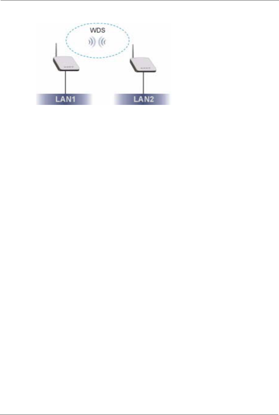
WDS Functionality
A Distribution System (DS) is a wired connection between two or more APs, while a Wireless
Distribution System (WDS) is a wireless connection. Your G-570S supports WDS connections
to other G-570S APs.1 This provides a cost-effective solution for wireless network expansion.
1. The G-570S only supports WDS connections to G-570S APs, not other devices.
ZyXEL G-570S User’s Guide
22 Chapter 1 Getting to Know Your G-570S
Figure 1 WDS Functionality Example
OTIST (One-Touch Intelligent Security Technology)
OTIST allows your G-570S to assign its SSID and security settings (WEP or WPA-PSK) to
the ZyXEL wireless adapters that support OTIST and are within transmission range. The
ZyXEL wireless adapters must also have OTIST enabled.
10/100M Auto-negotiating Ethernet/Fast Ethernet Interface
This auto-negotiating feature allows the G-570S to detect the speed of incoming transmissions
and adjust appropriately without manual intervention. It allows data transfer of either 10 Mbps
or 100 Mbps in either half-duplex or full-duplex mode depending on your Ethernet network.
10/100M Auto-crossover Ethernet/Fast Ethernet Interface
The LAN interface automatically adjusts to either a crossover or straight-through Ethernet
cable.
Reset Button
The G-570S reset button is built into the rear panel. Use this button to restart the device or
restore the factory default password.
802.11g Wireless LAN Standard
The ZyXEL wireless products containing the letter "G" in the model name, such as G-570S
and G-162, comply with the IEEE 802.11g wireless standard.
IEEE 802.11g is fully compatible with the IEEE 802.11b standard. This means an IEEE
802.11b radio card can interface directly with an IEEE 802.11g access point (and vice versa) at
11 Mbps or lower depending on range.
Wi-Fi Protected Access
Wi-Fi Protected Access (WPA) is a subset of the IEEE 802.11i standard. Key differences
between WPA and WEP are user authentication and improved data encryption.

ZyXEL G-570S User’s Guide
Chapter 1 Getting to Know Your G-570S 23
WPA2
WPA 2 (IEEE 802.11i) is a wireless security standard that defines stronger encryption,
authentication and key management than WPA.
SSL Passthrough
The G-570S allows SSL connections to go through the G-570S. SSL (Secure Sockets Layer)
uses a public key to encrypt data that's transmitted over an SSL connection. Both Netscape
Navigator and Internet Explorer support SSL, and many Web sites use the protocol to obtain
confidential user information, such as credit card numbers. By convention, URLs that require
an SSL connection start with "https" instead of "http".
Wireless LAN MAC Address Filtering
Your G-570S checks the MAC address of the wireless station against a list of allowed or
denied MAC addresses.
WEP Encryption
WEP (Wired Equivalent Privacy) encrypts data frames before transmitting over the wireless
network to help keep network communications private.
IEEE 802.1x Network Security
The G-570S supports the IEEE 802.1x standard to enhance user authentication. Use the built-
in user profile database to authenticate up to 32 users using MD5 encryption. Use an EAP-
compatible RADIUS (RFC2138, 2139 - Remote Authentication Dial In User Service) server
to authenticate a limitless number of users using EAP (Extensible Authentication Protocol).
EAP is an authentication protocol that supports multiple types of authentication.
Full Network Management
The embedded web configurator is an all-platform web-based utility that allows you to easily
access the G-570S's management settings.
Logging and Tracing
Built-in message logging and packet tracing.
Wireless Association List
With the wireless association list, you can see the list of the wireless stations that are currently
using the G-570S to access your wired network. When the G-570S is in client mode, the
wireless association list displays a list of wireless devices and networks in the area.
ZyXEL G-570S User’s Guide
24 Chapter 1 Getting to Know Your G-570S
Output Power Management
Output Power Management is the ability to set the level of output power.
There may be interference or difficulty with channel assignment when there is a high density
of APs within a coverage area. In this case you can lower the output power of each access
point, thus enabling you to place access points closer together.
Limit the Number of Client Connections
You may set a maximum number of wireless stations that may connect to the G-570S. This
may be necessary if for example, there is interference or difficulty with channel assignment
due to a high density of APs within a coverage area.
1.3 Applications for the G-570S
Here are some application examples of how you can use your G-570S.
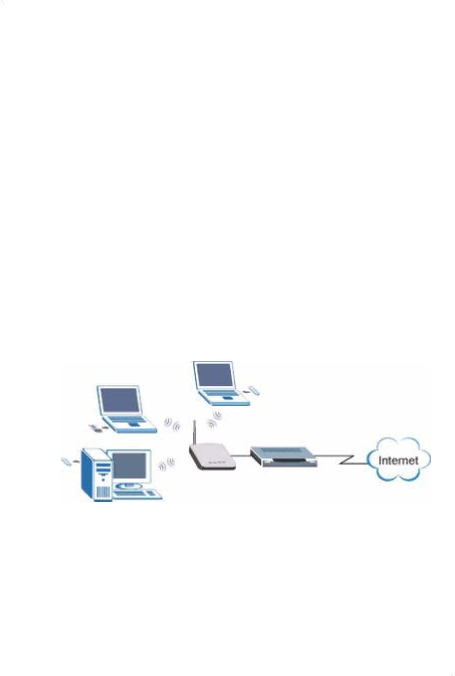
1.3.1 Access Point for Internet Access
The G-570S is an ideal access solution for wireless Internet connection. A typical Internet
access application for your G-570S is shown as follows.
Figure 2 Internet Access Application
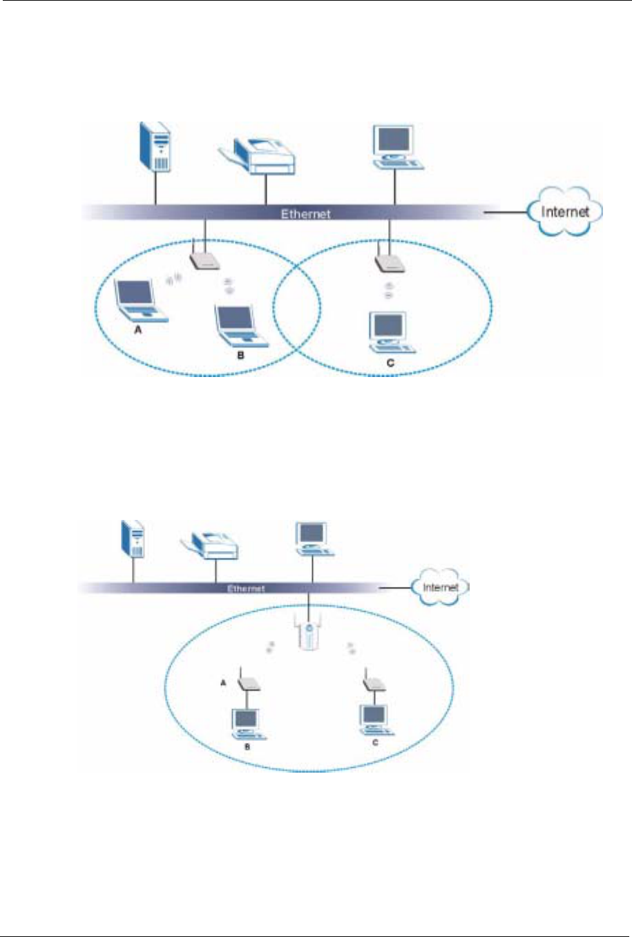
1.3.2 Corporate Network Access Application
In situations where users need to access corporate network resources and the Internet, the G-
570S is an ideal solution for wireless stations to connect to the corporate network without
expensive network cabling. Stations A, B and C can access the wired network through the G-
570Ss.
ZyXEL G-570S User’s Guide
Chapter 1 Getting to Know Your G-570S 25
The following figure depicts a typical application of the G-570S in an enterprise environment.
The three computers with wireless adapters are allowed to access the network resource
through the G-570S after account validation by the network authentication server.
Figure 3 Corporate Network Application
1.3.3 Wireless Client Application
The G-570S can function as a wireless client to connect to a network via an Access Point (AP).
The AP provides access to the wired network and the Internet.
Figure 4 Wireless Client Application
ZyXEL G-570S User’s Guide
26 Chapter 1 Getting to Know Your G-570S
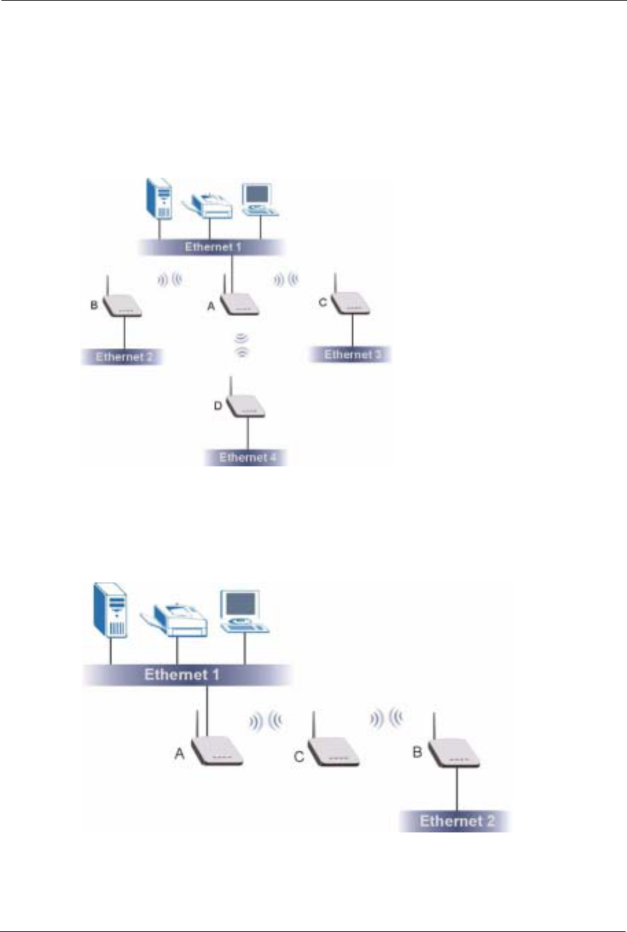
1.3.4 Bridge / Repeater
The G-570S can act as a wireless network bridge and establish wireless links with other APs.
The G-570Ss in the following example are using bridge mode with a star configuration. A, B,
C and D are connected to independent wired networks and have bridge connections at the
same time (B, C and D can communicate with A).
Figure 5 Bridge Application
A G-570S in bridge mode without an Ethernet connection can function as a repeater. It
transmits traffic from one AP to another AP without using a wired connection. C in the
following graphic repeats wireless traffic between A and B.
Figure 6 Bridge Repeater Application
ZyXEL G-570S User’s Guide
Chapter 1 Getting to Know Your G-570S 27
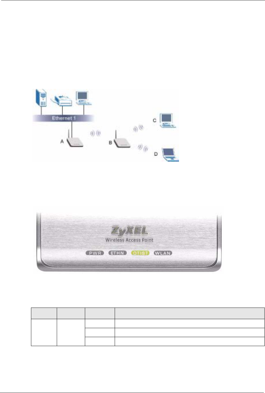
1.3.5 Access Point and Repeater
Set the G-570S to AP+Repeater mode to have it simultaneously provide access for wireless
clients and use the repeater function. This allows you to extend the coverage of your wireless
network without installing Ethernet cable to connect the G-570S. In the following figure, B is
in AP+Repeater mode. B functions as an AP for wireless clients C and D. B also repeats
traffic between the wireless clients and AP A which is connected to the wired network. You
could also set AP A to AP+Repeater mode so that wireless clients could connect to A as well.
Figure 7 AP+Repeater Application
1.4 The LED Display
Figure 8 Front Panel
The following table describes the LEDs on the G-570S.
Table 1 Front Panel LED Description
LED COLOR STATUS DESCRIPTION
PWR Green Blinking The G-570S is not ready or rebooting.
On The G-570S has a successful reboot and is receiving power.
Off The G-570S is not receiving power.

ZyXEL G-570S User’s Guide
28 Chapter 1 Getting to Know Your G-570S
ETHN Green Blinking The G-570S is sending/receiving data.
On The G-570S has a successful 10Mbps Ethernet connection.
Amber Blinking The G-570S is sending/receiving data.
On The G-570S has a successful 100Mbps Ethernet connection.
Off The G-570S does not have an Ethernet connection.
OTIST Green Blinking The OTIST automatic wireless configuration is in progress.
On The OTIST feature is activated on the G-570S.
Off The OTIST feature is not activated or activated but the wireless
settings have been changed.
WLAN Green Blinking The G-570S is sending or receiving data through the wireless
LAN.
On The G-570S is ready, but is not sending/receiving data.
Table 1 Front Panel LED Description
LED COLOR STATUS DESCRIPTION

ZyXEL G-570S User’s Guide
Chapter 2 Management Computer Setup 29
CHAPTER 2
Management Computer Setup
This chapter describes how to prepare your computer to access the G-570S web configurator.
2.1 Introduction
You can connect a computer to the G-570S for management purposes either using an Ethernet
connection (recommended for a first time management session) or wirelessly.
2.2 Wired Connection
You must prepare your computer/computer network to connect to the G-570S if you are using
a wired connection. Your computer's IP address and subnet mask must be on the same subnet
as the G-570S. This can be done by setting up your computer's IP address.
The following figure shows you an example of accessing your G-570S via a wired connection
with an Ethernet cable.
Figure 9 Wired Connection
2.2.1 Setting Up Your Computer's IP Address
Note: Skip this section if your computer's IP address is already between 192.168.1.3
and 192.168.1.254 with subnet mask 255.255.255.0.
Your computer must have a network card and TCP/IP installed. TCP/IP should already be
installed on computers using Windows NT/2000/XP, Macintosh OS 7 and later operating
systems. Refer to the appendix about setting up your computer's IP address for other operating
systems.
192.168.1.3
Default IP Address:
192.168.1.2
ZyXEL G-570S User’s Guide
30 Chapter 2 Management Computer Setup
2.2.1.1 Windows 2000/NT/XP
The following example figures use the default Windows XP GUI theme.
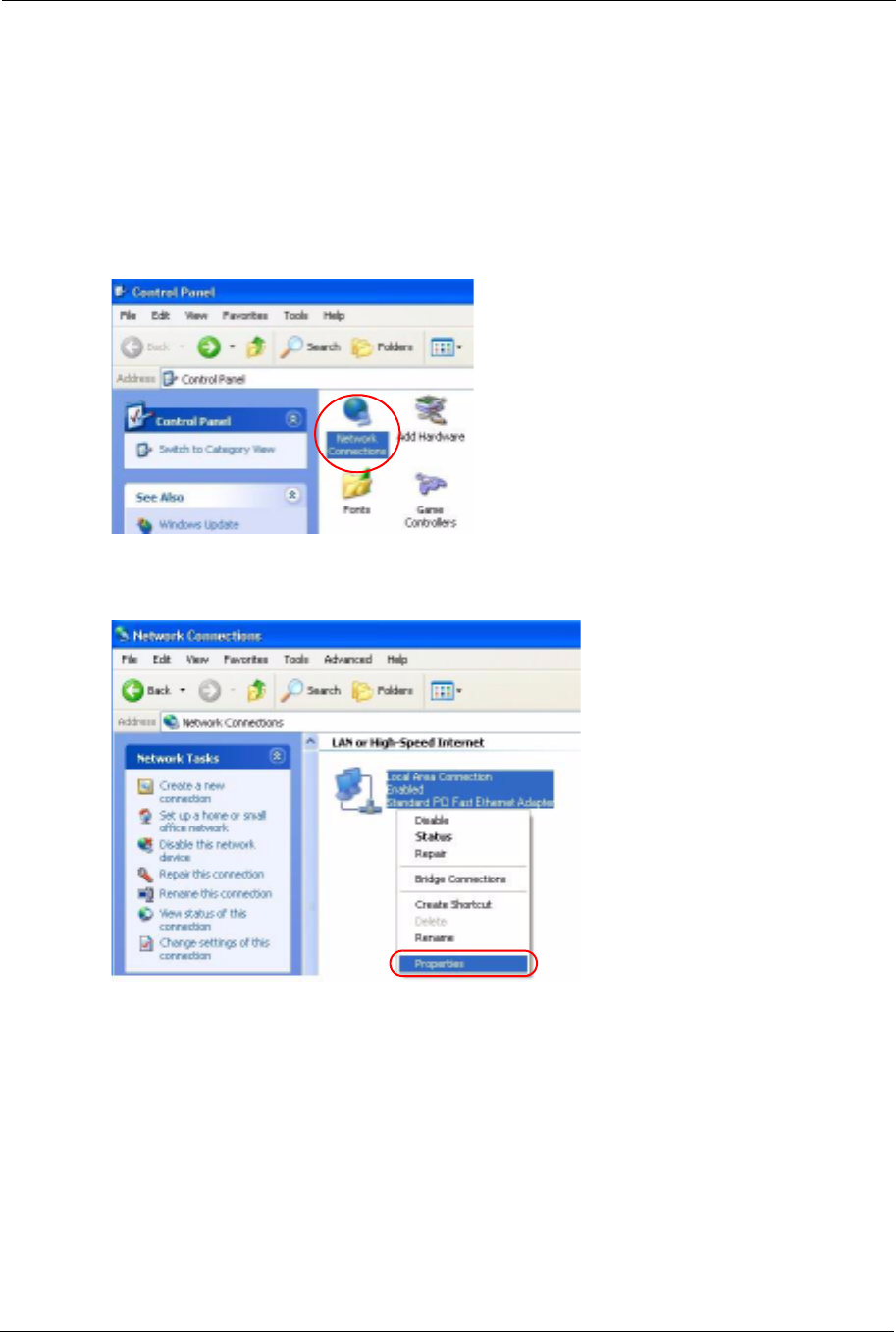
1Click start (Start in Windows 2000/NT) > Settings > Control Panel.
2In the Control Panel, double-click Network Connections (Network and Dial-up
Connections in Windows 2000/NT).
Figure 10 Control Panel
3Right-click Local Area Connection and then Properties.
Figure 11 Network Connection
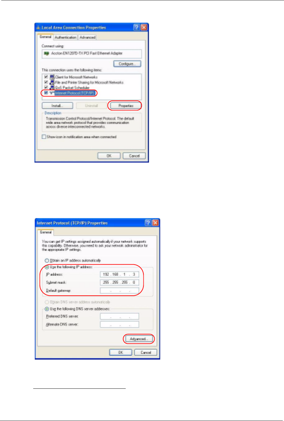
4Select Internet Protocol (TCP/IP) and then click Properties.
ZyXEL G-570S User’s Guide
Chapter 2 Management Computer Setup 31
Figure 12 Local Area Connection Properties
5Select Use the following IP Address and fill in an IP address (between 192.168.1.3 and
192.168.1.254).
• Type 255.255.255.0 as the Subnet mask.
• Click Advanced1.
Figure 13 Internet Protocol Properties
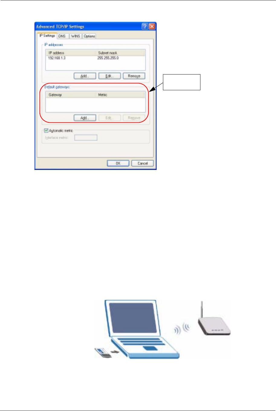
6Remove any previously installed gateways in the IP Settings tab and click OK to go back
to the Internet Protocol TCP/IP Properties screen.
1. See the appendices for information on configuring DNS server addresses.
ZyXEL G-570S User’s Guide
32 Chapter 2 Management Computer Setup
Figure 14 Advanced TCP/IP Settings
7Click OK to close the Internet Protocol (TCP/IP) Properties window.
8Click Close (OK in Windows 2000/NT) to close the Local Area Connection Properties
window.
9Close the Network Connections window (Network and Dial-up Connections in
Windows 2000/NT).
2.3 Wireless Connection
Ensure that the wireless stations have a compatible wireless card/adapter with the same
wireless settings as the G-570S. The following figure shows how you can access your G-570S
wirelessly.
Figure 15 Wireless Connection
No gateways
configured.
SSID: ZyXEL G-
570S
Channel: 6

ZyXEL G-570S User’s Guide
Chapter 2 Management Computer Setup 33
Note: The wireless stations and G-570S must use the same SSID, channel and
wireless security settings for wireless communication.
If you do not enable any wireless security on your G-570S, your network traffic
is visible to any wireless networking device that is within range.
2.4 Restarting the G-570S
Press and immediately release the RESET button to restart the G-570S.
Note: Holding the RESET button in for five seconds or longer resets the device to the
factory-default settings.
2.5 Resetting the G-570S
If you forget the G-570S's IP address or your password, to access the G-570S, you will need to
reload the factory-default using the RESET button. Resetting the G-570S replaces the current
configuration file with the factory-default configuration file. This means that you will lose all
configurations that you had previously. The following parameters will be reset to the default
values.
2.5.1 Methods of Restoring Factory-Defaults
You can erase the current configuration and restore factory defaults in two ways:
1Use the RESET button on the G-570S to upload the default configuration file (hold this
button in for at least five seconds).
2Use the web configurator to restore defaults. Click SYSTEM > Management >
Configuration File. From here you can restore the G-570S to factory defaults.
Table 2 Factory Defaults
PARAMETER DEFAULT VALUE
IP Address 192.168.1.2
Password 1234
Wireless Security Disabled
SSID ZyXEL G-570S

ZyXEL G-570S User’s Guide
34 Chapter 2 Management Computer Setup

ZyXEL G-570S User’s Guide
Chapter 3 Introducing the Web Configurator 35
CHAPTER 3
Introducing the Web
Configurator
This chapter describes how to configure the G-570S using the Wizard.
3.1 Web Configurator Overview
The web configurator is an HTML-based management interface that allows easy G-570S setup
and management via Internet browser. Use Internet Explorer 6.0 and later or Netscape
Navigator 7.0 and later versions. The recommended screen resolution is 1024 by 768 pixels.
In order to use the web configurator you need to allow:
• Web browser pop-up windows from your device. Web pop-up blocking is enabled by
default in Windows XP SP (Service Pack) 2.
• JavaScripts (enabled by default).
• Java permissions (enabled by default).
See the Troubleshooting chapter if you want to make sure these functions are allowed in
Internet Explorer or Netscape Navigator.
3.2 Accessing the G-570S Web Configurator
Follow the steps below to access the web configurator, select a language, change your login
password and choose a configuration method from the status screen.
1Make sure your G-570S hardware is properly connected (refer to the Quick Start Guide).
2Prepare your computer/computer network to connect to the G-570S (refer to Section 2.2.1
on page 29 for instructions on how to do this).
3Launch your web browser.
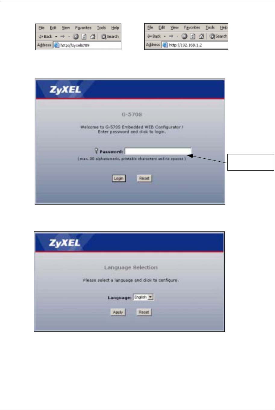
4Type the device name of your G-570S as the URL. ZyXELXXXX is the default where
“XXXX” is the last four digits of the MAC address. The MAC address is on the bottom
of the device). You could also use the IP address of the G-570S (192.168.1.2 is the
default). Press Enter.
ZyXEL G-570S User’s Guide
36 Chapter 3 Introducing the Web Configurator
Figure 16 Web Configurator Address
5Type "1234" (default) as the password and click Login.
Figure 17 Login Screen
6Select your language and click Apply.
Figure 18 Language Screen
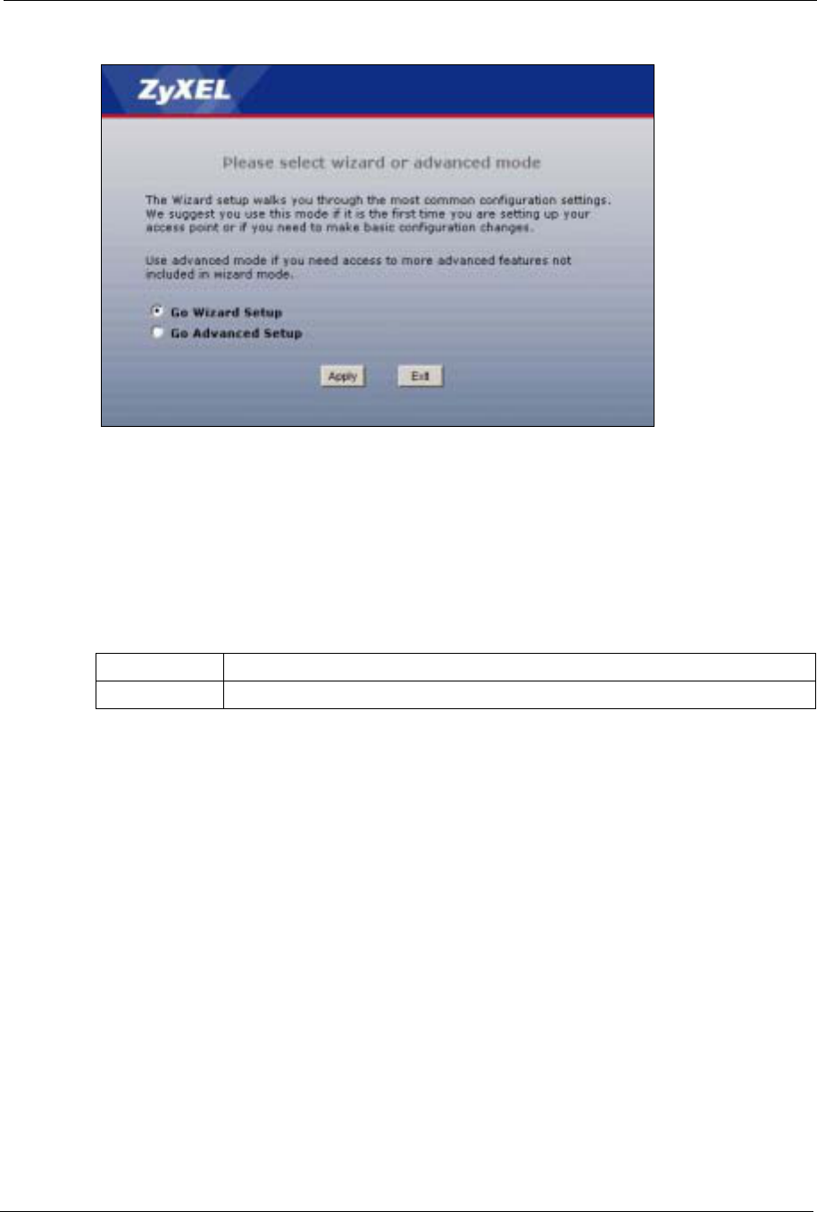
7The following screen displays. Select Go Wizard Setup and click Apply to use the
wizard setup screens for initial configuration (see Section 3.3 on page 37). Select Go
Advanced Setup and click Apply to go directly to the advanced screens (see Section 3.4
on page 43).
or
Default password
is 1234.
ZyXEL G-570S User’s Guide
Chapter 3 Introducing the Web Configurator 37
Figure 19 Select Wizard or Advanced Setup Screen
3.3 Configuring the G-570S Using the Wizard
The wizard consists of a series of screens to help you configure your G-570S for wireless
stations to access your wired LAN.
Use the following buttons to navigate the Wizard:
No configuration changes will be saved to the G-570S until you click Finish.
3.3.1 Wizard: Basic Settings
Click SETUP WIZARD to display the first wizard screen shown next. Refer to the System
Screens chapter for more background information.
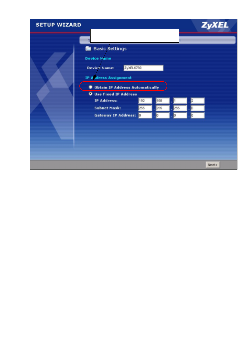
1Enter a descriptive name to identify the device in the Ethernet network.
2Select Obtain IP Address Automatically if you want to put the device behind a router
that assigns an IP address. If you select this by mistake, use the RESET button to restore
the factory default IP address.
3Select Use fixed IP Address to give the device a static IP address. The IP address you
configure here is used for management of the device (accessing the web configurator).
4Enter a Subnet Mask appropriate to your network and the Gateway IP Address of the
neighboring device, if you know it. If you do not, leave the Gateway IP Address field as
0.0.0.0.
Back Click Back to return to the previous screen.
Next Click Next to continue to the next screen.
ZyXEL G-570S User’s Guide
38 Chapter 3 Introducing the Web Configurator
Figure 20 Wizard: Basic Settings
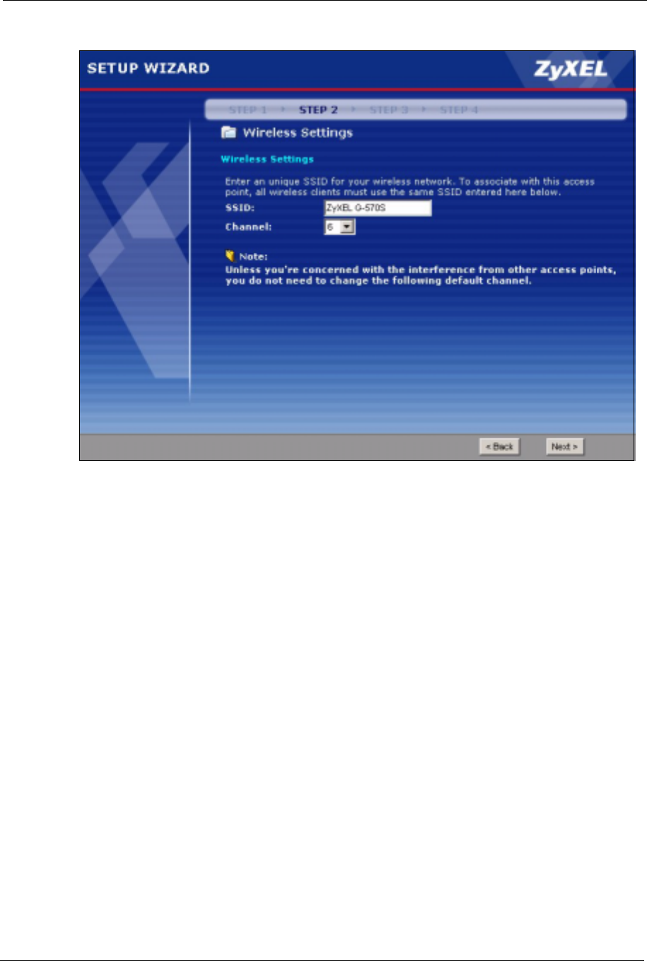
3.3.2 Wizard: Wireless Settings
Use this wizard screen to set up the wireless LAN. See the chapter on the wireless screens for
background information.
1The SSID is a unique name to identify the device in a wireless network. Enter up to 32
printable characters. Spaces are allowed. If you change this field on the device, make sure
all wireless stations use the same SSID in order to access the network.
2A wireless device uses a channel to communicate in a wireless network. Select a channel
that is not already in use by a neighboring wireless device.
Note: The wireless stations and this device must use the same SSID, channel and
wireless security settings for wireless communication.
Do not select this unless you have a router
that can assign the G-570S an IP address.
ZyXEL G-570S User’s Guide
Chapter 3 Introducing the Web Configurator 39
Figure 21 Wizard: Wireless Settings
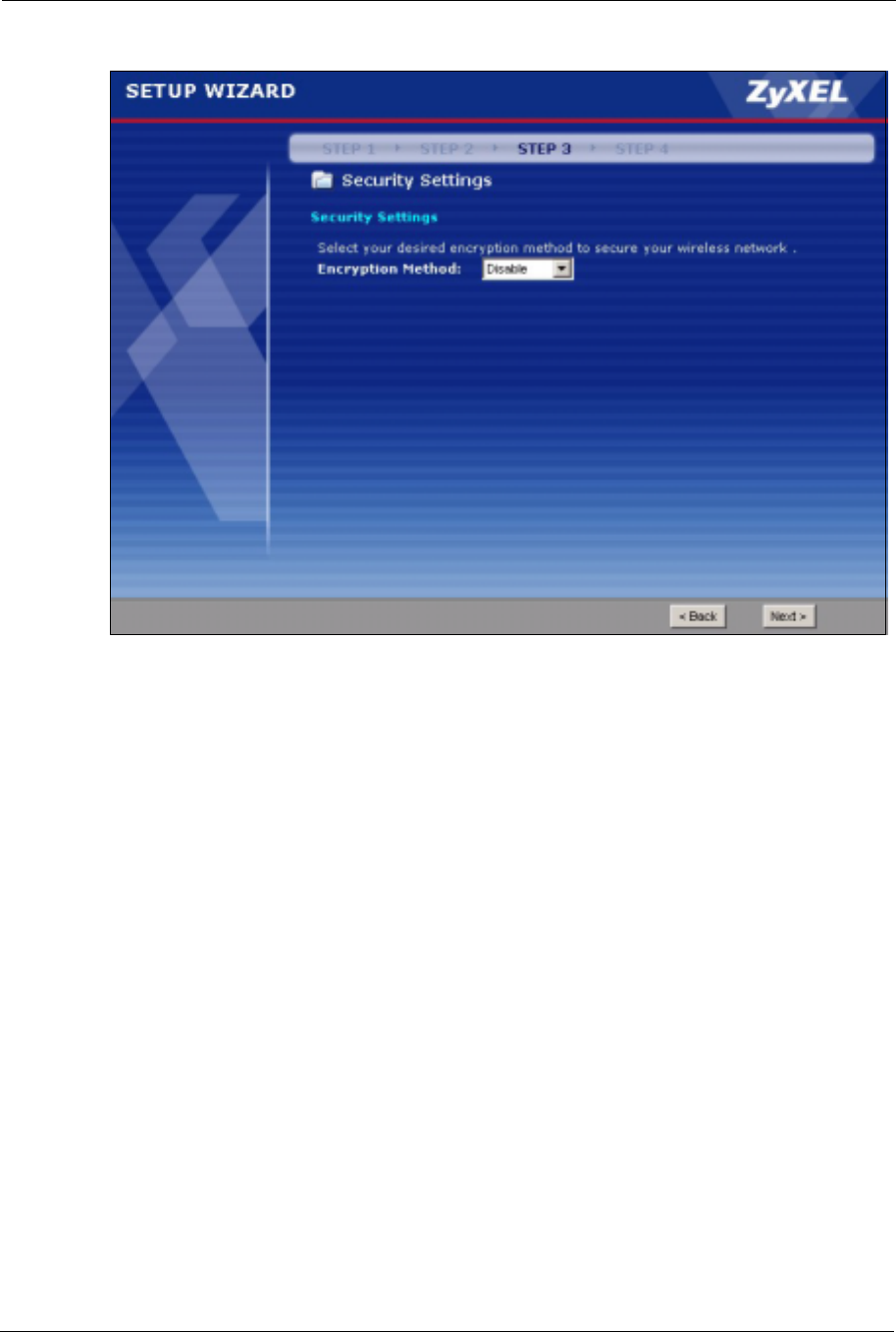
3.3.3 Wizard: Security Settings
Use this screen to configure security for your wireless LAN. The screen varies depending on
what you select in the Encryption Method field. Select Disable to have no wireless security
configured, select WEP, or select WPA-PSK if your wireless clients support WPA-PSK.
Select WPA2-PSK if your wireless clients support WPA2-PSK Go to SETTINGS >
WIRELESS > Security if you want WPA2, WPA or 802.1x. See Chapter 6 on page 57 for
background information.
3.3.3.1 Disable
Select Disable to have no wireless LAN security configured. If you do not enable any
wireless security on your device, your network is accessible to any wireless networking device
that is within range.
Note: With no wireless security a neighbor can access and see traffic in your network.
ZyXEL G-570S User’s Guide
40 Chapter 3 Introducing the Web Configurator
Figure 22 Setup Wizard 3: Disable
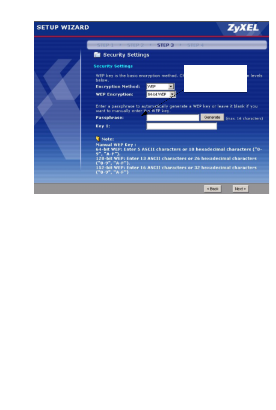
3.3.3.2 WEP
1WEP (Wired Equivalent Privacy) encrypts data frames before transmitting over the
wireless network. Select 64-bit,128-bit or 152-bit from the WEP Encryption drop-
down list box and then follow the on-screen instructions to set up the WEP keys.
2Choose an encryption level from the drop-down list. The higher the WEP encryption, the
higher the security but the slower the throughput.
3You can generate or manually enter a WEP key.
• If you selected 64-bit or 128-bit WEP, you can enter a Passphrase (up to 32 printable
characters) and click Generate. The device automatically generates WEP keys. One key
displays in the Key 1 field. Go to SETTINGS > WIRELESS > Security if you want to
see the other WEP keys.
or
• Enter a manual key in the Key 1 field.
ZyXEL G-570S User’s Guide
Chapter 3 Introducing the Web Configurator 41
Figure 23 Wizard 3: WEP
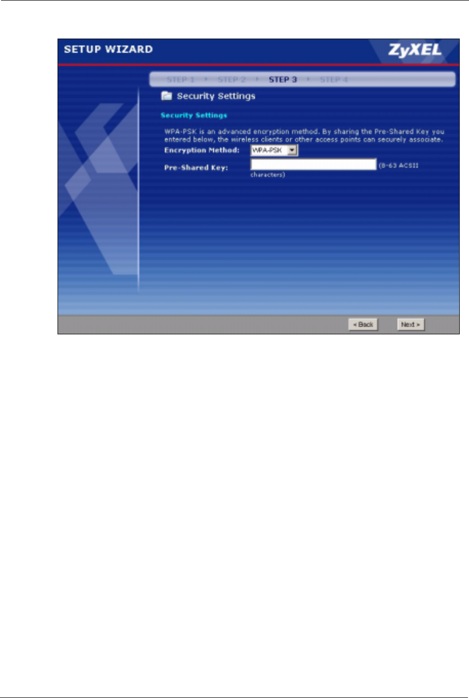
3.3.3.3 WPA(2)-PSK
Only select WPA-PSK or WPA2-PSK if your wireless clients support it.
Type a pre-shared key from 8 to 63 ASCII characters (including spaces and symbols). This
field is case-sensitive.
Use Passphrase to
automatically generate
keys or manually enter
a key in the Key 1 field.
ZyXEL G-570S User’s Guide
42 Chapter 3 Introducing the Web Configurator
Figure 24 Wizard 3: WPA(2)-PSK
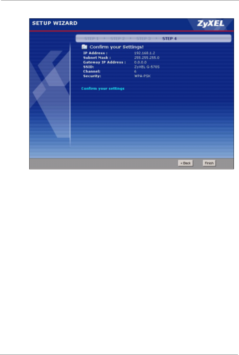
3.3.4 Wizard: Confirm Your Settings
This read-only screen shows the status of the current settings. Use the summary table to check
whether what you have configured is correct. Click Finish to complete the wizard
configuration and save your settings.
ZyXEL G-570S User’s Guide
Chapter 3 Introducing the Web Configurator 43
Figure 25 Wizard: Confirm Your Settings
For more detailed background information, see the rest of this User's Guide.
3.4 Navigating the Advanced Screens
The STATUS screen is the first advanced screen that displays. This section explains how to
navigate the advanced configuration screens. See the chapter on the Status screen for details
about the individual screen.
ZyXEL G-570S User’s Guide
44 Chapter 3 Introducing the Web Configurator
Figure 26 Status Screen
The following table describes the global web configurator icons (in the upper left corner of
most screens).
3.4.1 Navigation Panel
After you enter the password, use the links on the navigation panel to go to the various
advanced screens.
Table 3 Global Icon Key
ICON DESCRIPTION
Click the Wizard icon to open the setup wizard.
Click the About icon to view copyright information.
Click the Logout icon at any time to exit the web configurator.
Make sure you save any changes before you log out.

ZyXEL G-570S User’s Guide
Chapter 3 Introducing the Web Configurator 45
The following table describes the sub-menus.
Note: See the rest of this User's Guide for configuration details and background
information on all G-570S features using the web configurator.
Table 4 Screens Summary
LINK TAB FUNCTION
Status This screen shows the Prestige’s general device, system and interface
status information. Use this screen to access the wizard, and summary
statistics tables.
System Use this screen to configure the device name and IP address assignment
settings.
Wireless Wireless Settings Use this screen to configure wireless LAN.
Security Use this screen to configure wireless LAN security settings.
MAC Filter Use the MAC filter screen to configure the Prestige to block access to
devices or block the devices from accessing the Prestige.
OTIST This screen allows you to assign wireless clients the Prestige’s wireless
security settings.
Management
Password Use this screen to configure the administrator password.
Logs Use this screen to view logs and alert messages.
Configuration Use this screen to backup and restore the configuration or reset the factory
defaults to your Prestige.
F/W Upload Use this screen to upload firmware to your Prestige.

ZyXEL G-570S User’s Guide
46 Chapter 3 Introducing the Web Configurator
ZyXEL G-570S User’s Guide
Chapter 4 Status Screens 47
CHAPTER 4
Status Screens
This chapter describes the Status screens.
4.1 System Status
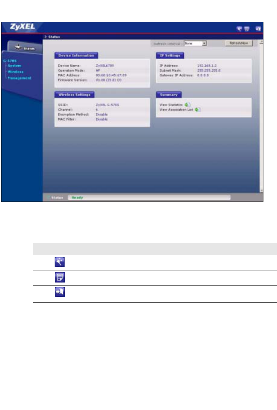
Click Status to open the following screen. The Status screen display a snapshot of your
device’s settings. You can also view network statistics and a list of wireless stations currently
associated with your device. Note that these labels are READ-ONLY and are meant to be used
for diagnostic purposes.
Figure 27 Status
The following table describes the labels in this screen.
Table 5 Status
LABEL DESCRIPTION
Refresh Interval Use the drop-down list box to select how often you want the device to renew the
information on this screen.
Refresh Now Click this button to have the device renew the information on this screen.
Device Information
Device Name This is the same as the device name you entered in the first wizard screen if you
entered one there. It is for identification purposes.
Operation Mode This field shows whether the device is functioning as an access point, a wireless
client, a bridge or an access point and repeater.

ZyXEL G-570S User’s Guide
48 Chapter 4 Status Screens
4.1.1 Statistics
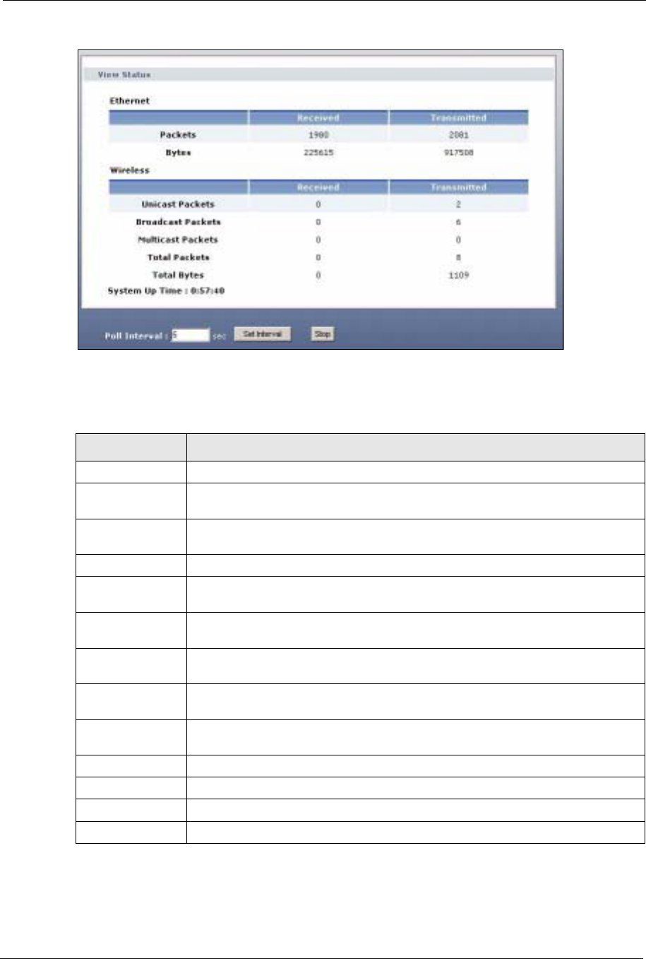
Click View Statistics in the STATUS screen. This screen displays read-only information
including port status and packet specific statistics. Also provided are "system up time" and
"poll interval(s)". The Poll Interval(s) field is configurable.
MAC Address This field displays the MAC address of the device.
The MAC (Media Access Control) or Ethernet address on a LAN (Local Area
Network) is unique to your computer. A network interface card such as an Ethernet
adapter has a hardwired address that is assigned at the factory. This address
follows an industry standard that ensures no other adapter has a similar address.
Firmware Version This is the firmware version and the date the firmware was created.
IP Settings
IP Address This is the Ethernet port IP address.
Subnet Mask This is the Ethernet port subnet mask.
Gateway IP
Address This is the IP address of a gateway. Leave this field as 0.0.0.0 if you do not know it.
Wireless Settings
SSID This is the descriptive name used to identify the device in a wireless network.
Channel This field displays the radio channel the device is currently using.
Encryption Method This field shows whether data encryption is activated (WEP,WPA-PSK,WPA,
WPA2-PSK,WPA2 or 802.1X) or inactive (Disable).
MAC Filter This field shows whether MAC filter is enabled or not. With MAC filtering, you can
allow or deny access to the device based on the MAC addresses of the wireless
stations.
View Statistics Click View Statistics to see performance statistics such as number of packets
sent and number of packets received.
View Association
List Click View Association List to show the wireless stations that are currently
associated to the device.
Table 5 Status
LABEL DESCRIPTION
ZyXEL G-570S User’s Guide
Chapter 4 Status Screens 49
Figure 28 Status: View Statistics
The following table describes the labels in this screen.
Table 6 Status: View Statistics
LABEL DESCRIPTION
Ethernet
Packets This row displays the numbers of packets received and transmitted by the Ethernet
port.
Bytes This row displays the numbers of bytes received and transmitted by the Ethernet
port.
Wireless
Unicast
Packets This row displays the numbers of unicast packets received and transmitted by the
wireless adapter.
Broadcast
Packets This row displays the numbers of broadcast packets received and transmitted by
the wireless adapter.
Multicast
Packets This row displays the numbers of multicast packets received and transmitted by the
wireless adapter.
Total Packets This row displays the numbers of all types of packets received and transmitted by
the wireless adapter.
Total Bytes This row displays the numbers of bytes received and transmitted by the wireless
adapter.
System Up Time This is the total time the device has been on.
Poll Interval(s) Enter the time interval for refreshing statistics.
Set Interval Click this button to apply the new poll interval you entered above.
Stop Click this button to stop refreshing statistics.
ZyXEL G-570S User’s Guide
50 Chapter 4 Status Screens
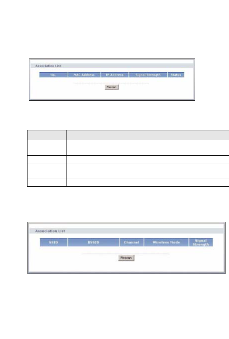
4.1.2 Association List
Click STATUS and then the View Association List button to display the Association List
screen. When the device is not in wireless client mode, this screen displays which wireless
stations are currently associated to the device in the Association List screen.
Figure 29 Status: View Association List
The following table describes the labels in this screen.
When the device is in client mode, this screen displays a list of wireless devices and networks
in the area.
Figure 30 Status: View Association List: Wireless Client Mode
Table 7 Status: View Association List
LABEL DESCRIPTION
No. This is the index number of an associated wireless station.
MAC Address This field displays the MAC address of an associated wireless station.
IP Address This field displays the IP address of an associated wireless station.
Signal Strength This field displays the signal strength of each associated wireless station.
Status This field displays Associated for associated wireless stations.
Rescan Click Rescan to check for associated wireless stations.

ZyXEL G-570S User’s Guide
Chapter 4 Status Screens 51
The following table describes the labels in this screen.
Table 8 Status: View Association List: Wireless Client Mode
LABEL DESCRIPTION
SSID This field displays the SSID (Service Set IDentifier) of each wireless device that the
device detected.
BSSID This field displays the BSSID (Basic Service Set IDentifier) of each wireless
network that the device detected.
Channel This field displays the channel number used by each wireless device.
Wireless Mode This field shows whether the network is using IEEE 802.11b or IEEE 802.11g.
Signal Strength This field displays the signal strength of each wireless device that the device
detected.
Rescan Click Rescan to check for associated wireless stations.

ZyXEL G-570S User’s Guide
52 Chapter 4 Status Screens

ZyXEL G-570S User’s Guide
Chapter 5 System Screen 53
CHAPTER 5
System Screen
This chapter provides information on the System screen.
5.1 TCP/IP Parameters
5.1.1 IP Address Assignment
Every computer on the Internet must have a unique IP address. If your networks are isolated
from the Internet, for instance, only between your two branch offices, you can assign any IP
addresses to the hosts without problems. However, the Internet Assigned Numbers Authority
(IANA) has reserved the following three blocks of IP addresses specifically for private
networks.
You can obtain your IP address from the IANA, from an ISP or have it assigned by a private
network. If you belong to a small organization and your Internet access is through an ISP, the
ISP can provide you with the Internet addresses for your local networks. On the other hand, if
you are part of a much larger organization, you should consult your network administrator for
the appropriate IP addresses.
Note: Regardless of your particular situation, do not create an arbitrary IP address;
always follow the guidelines above. For more information on address
assignment, please refer to RFC 1597, Address Allocation for Private Internets
and RFC 1466, Guidelines for Management of IP Address Space.
5.1.2 IP Address and Subnet Mask
Similar to the way houses on a street share a common street name, so too do computers on a
LAN share one common network number.
Where you obtain your network number depends on your particular situation. If the ISP or
your network administrator assigns you a block of registered IP addresses, follow their
instructions in selecting the IP addresses and the subnet mask.
Table 9 Private IP Address Ranges
10.0.0.0 - 10.255.255.255
172.16.0.0 - 172.31.255.255
192.168.0.0 - 192.168.255.255
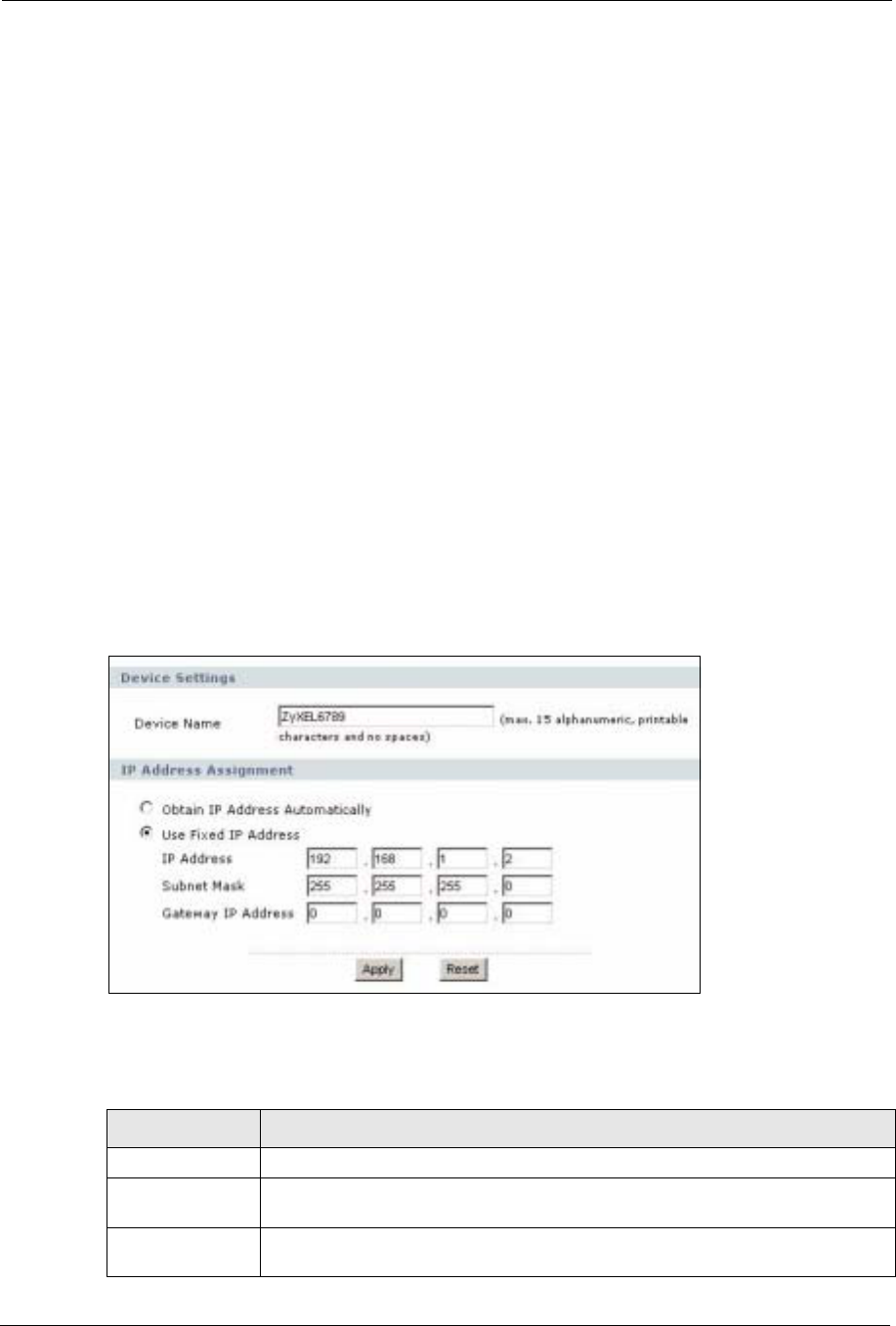
ZyXEL G-570S User’s Guide
54 Chapter 5 System Screen
If the ISP did not explicitly give you an IP network number, then most likely you have a single
user account and the ISP will assign you a dynamic IP address when the connection is
established. The Internet Assigned Number Authority (IANA) reserved this block of addresses
specifically for private use; please do not use any other number unless you are told otherwise.
Let's say you select 192.168.1.0 as the network number; which covers 254 individual
addresses, from 192.168.1.1 to 192.168.1.254 (zero and 255 are reserved). In other words, the
first three numbers specify the network number while the last number identifies an individual
computer on that network.
Once you have decided on the network number, pick an IP address that is easy to remember,
for instance, 192.168.1.2, for your device, but make sure that no other device on your network
is using that IP address.
The subnet mask specifies the network number portion of an IP address. Your device will
compute the subnet mask automatically based on the IP address that you entered. You don't
need to change the subnet mask computed by the device unless you are instructed to do
otherwise.
5.2 System Settings
Click SETTINGS > SYSTEM to open the System Settings screen.
Figure 31 System Settings
The following table describes the labels in this screen.
Table 10 System Settings
LABEL DESCRIPTION
Device Name This name can be up to 30 printable characters long. Spaces are allowed.
IP Address
Assignment
Obtain IP Address
Automatically Select this option to have your device use a dynamically assigned IP address from
a router each time.

ZyXEL G-570S User’s Guide
Chapter 5 System Screen 55
Use fixed IP
address Select this option to have your device use a static IP address. When you select this
option, fill in the fields below.
IP Address Enter the IP address of your device in dotted decimal notation.
Subnet Mask Enter the subnet mask.
Gateway IP
Address Type the IP address of the gateway. The gateway is a router or switch on the same
network segment as the device. The gateway helps forward packets to their
destinations. Leave this field as 0.0.0.0 if you do not know it.
Apply Click Apply to save your changes back to the device.
Reset Click Reset to reload the previous configuration for this screen.
Table 10 System Settings
LABEL DESCRIPTION

ZyXEL G-570S User’s Guide
56 Chapter 5 System Screen
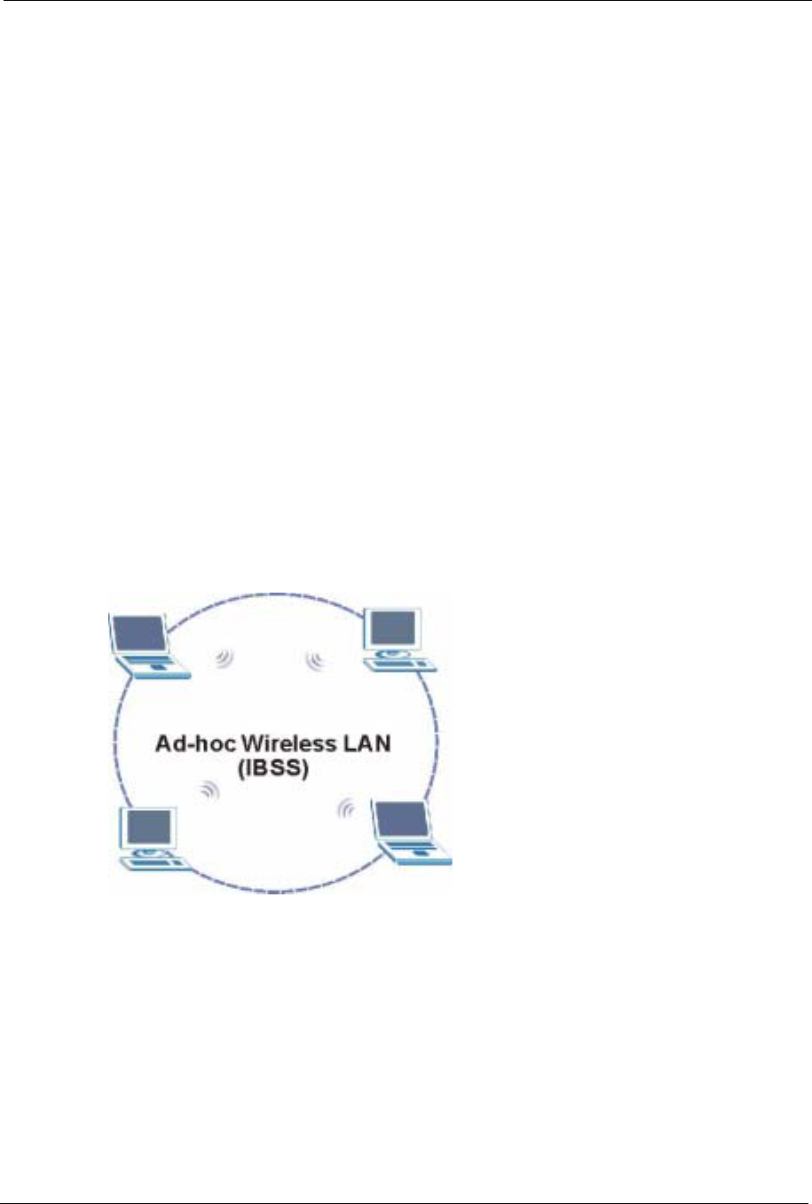
ZyXEL G-570S User’s Guide
Chapter 6 Wireless Screens 57
CHAPTER 6
Wireless Screens
This chapter discusses how to configure wireless settings and wireless security on your G-
570S.
6.1 Wireless LAN Overview
This section introduces the wireless LAN (WLAN) and some basic scenarios.
6.1.1 IBSS
An Independent Basic Service Set (IBSS), also called an Ad-hoc network, is the simplest
WLAN configuration. An IBSS is defined as two or more computers with wireless adapters
within range of each other that from an independent (wireless) network without the need of an
access point (AP).
Figure 32 IBSS (Ad-hoc) Wireless LAN
6.1.2 BSS
A Basic Service Set (BSS) exists when all communications between wireless stations or
between a wireless station and a wired network client go through one access point (AP).
Intra-BSS traffic is traffic between wireless stations in the BSS. When Intra-BSS is enabled,
wireless station A and B can access the wired network and communicate with each other.
When Intra-BSS is disabled, wireless station A and B can still access the wired network but
cannot communicate with each other.
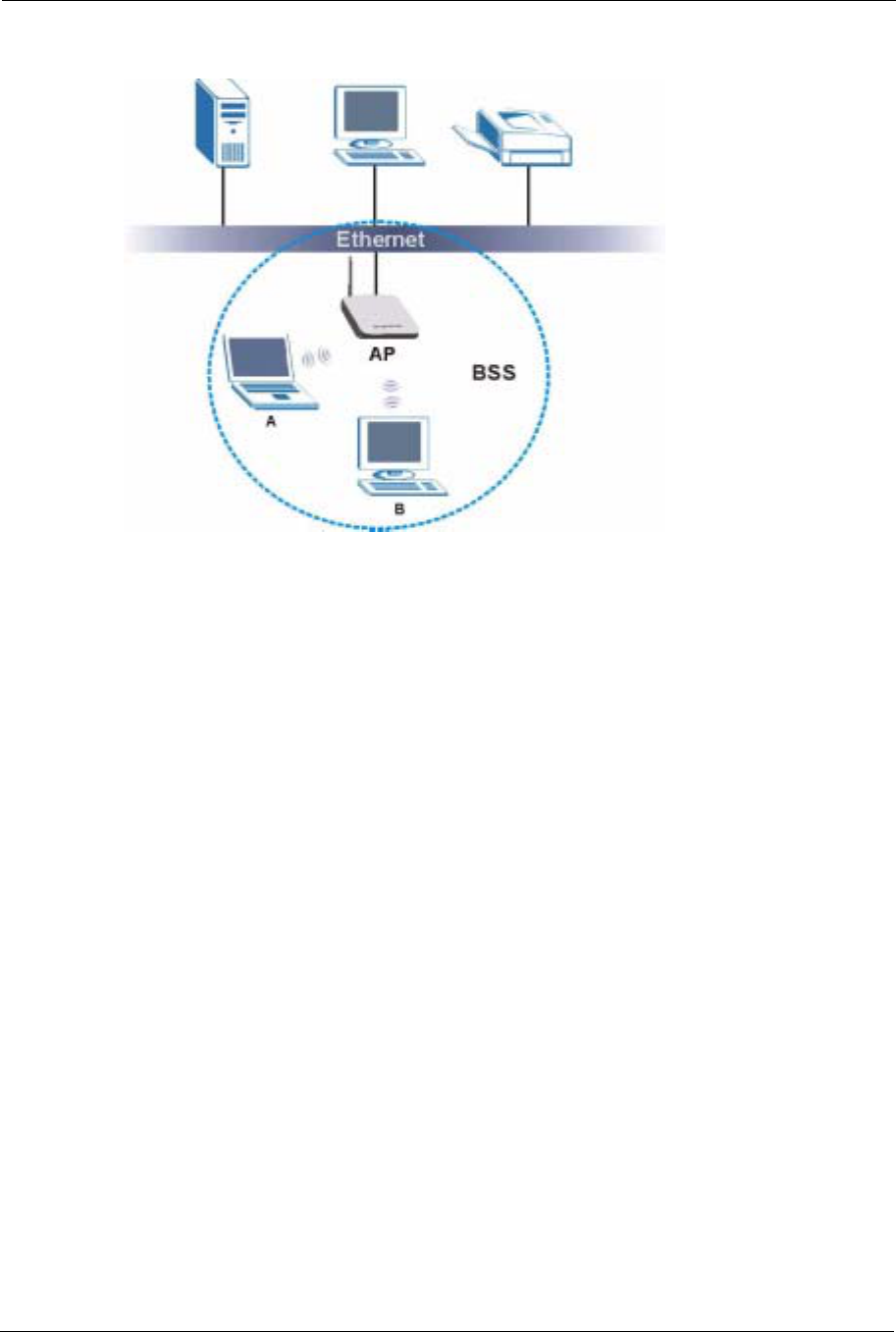
ZyXEL G-570S User’s Guide
58 Chapter 6 Wireless Screens
Figure 33 Basic Service set
6.1.3 ESS
An Extended Service Set (ESS) consists of a series of overlapping BSSs, each containing an
access point, with each access point connected together by a wired network. This wired
connection between APs is called a Distribution System (DS). An ESSID (ESS IDentification)
uniquely identifies each ESS. All access points and their associated wireless stations within
the same ESS must have the same ESSID in order to communicate.
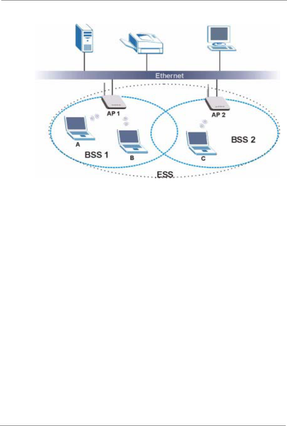
ZyXEL G-570S User’s Guide
Chapter 6 Wireless Screens 59
Figure 34 Extended Service Set
6.2 Wireless LAN Basics
This section describes the wireless LAN network terms.
6.2.1 Channel
A channel is the radio frequency(ies) used by IEEE 802.11b wireless devices. Channels
available depend on your geographical area. You may have a choice of channels (for your
region) so you should use a different channel than an adjacent AP (access point) to reduce
interference. Interference occurs when radio signals from different access points overlap
causing interference and degrading performance.
Adjacent channels partially overlap however. To avoid interference due to overlap, your AP
should be on a channel at least five channels away from a channel that an adjacent AP is using.
For example, if your region has 11 channels and an adjacent AP is using channel 1, then you
need to select a channel between 6 or 11.
6.2.2 SSID
The SSID (Service Set Identity) is a unique name shared among all wireless devices in a
wireless network. Wireless devices must have the same SSID to communicate with each other.
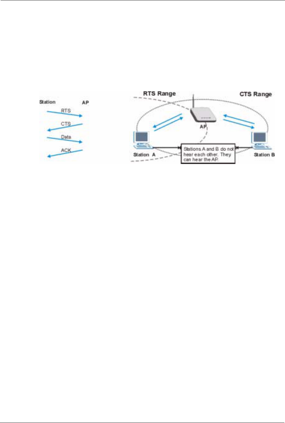
ZyXEL G-570S User’s Guide
60 Chapter 6 Wireless Screens
6.2.3 RTS/CTS
A hidden node occurs when two stations are within range of the same access point, but are not
within range of each other. The following figure illustrates a hidden node. Both stations (STA)
are within range of the access point (AP) or wireless gateway, but out-of-range of each other,
so they cannot “hear” each other, that is they do not know if the channel is currently being
used. Therefore, they are considered hidden from each other.
Figure 35 RTS/CTS
When station A sends data to the G-570S, it might not know that the station B is already using
the channel. If these two stations send data at the same time, collisions may occur when both
sets of data arrive at the AP at the same time, resulting in a loss of messages for both stations.
RTS/CTS is designed to prevent collisions due to hidden nodes. An RTS/CTS defines the
biggest size data frame you can send before an RTS (Request To Send)/CTS (Clear to Send)
handshake is invoked.
When a data frame exceeds the RTS/CTS value you set (between 0 to 2432 bytes), the station
that wants to transmit this frame must first send an RTS (Request To Send) message to the AP
for permission to send it. The AP then responds with a CTS (Clear to Send) message to all
other stations within its range to notify them to defer their transmission. It also reserves and
confirms with the requesting station the time frame for the requested transmission.
Stations can send frames smaller than the specified RTS/CTS directly to the AP without the
RTS (Request To Send)/CTS (Clear to Send) handshake.
You should only configure RTS/CTS if the possibility of hidden nodes exists on your network
and the “cost” of resending large frames is more than the extra network overhead involved in
the RTS (Request To Send)/CTS (Clear to Send) handshake.
If the RTS/CTS value is greater than the Fragmentation Threshold value (see next), then the
RTS (Request To Send)/CTS (Clear to Send) handshake will never occur as data frames will
be fragmented before they reach RTS/CTS size.
Note: Enabling the RTS Threshold causes redundant network overhead that could
negatively affect the throughput performance instead of providing a remedy.

ZyXEL G-570S User’s Guide
Chapter 6 Wireless Screens 61
6.2.4 Fragmentation Threshold
AFragmentation Threshold is the maximum data fragment size (between 256 and 2432
bytes) that can be sent in the wireless network before the G-570S will fragment the packet into
smaller data frames.
A large Fragmentation Threshold is recommended for networks not prone to interference
while you should set a smaller threshold for busy networks or networks that are prone to
interference.
If the Fragmentation Threshold value is smaller than the RTS/CTS value (see previously)
you set then the RTS (Request To Send)/CTS (Clear to Send) handshake will never occur as
data frames will be fragmented before they reach RTS/CTS size.
6.3 Configuring Wireless
Click SETTINGS > WIRELESS to display the Wireless Settings screen.The screen varies
depending upon the operation mode you select.
6.3.1 Access Point Mode
Select Access Point in the Operation Mode field to display the screen as shown next. This
mode has the device act as an access point (AP) through which wireless stations can
communicate and/or access a wired network.
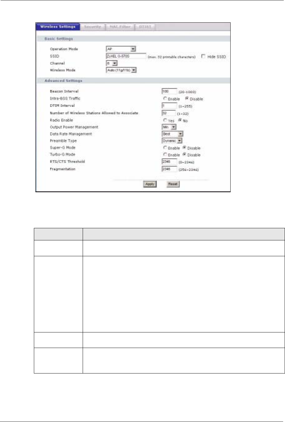
ZyXEL G-570S User’s Guide
62 Chapter 6 Wireless Screens
Figure 36 Wireless Settings: Access Point
The following table describes the labels in this screen.
Table 11 Wireless Settings: Access Point
LABEL DESCRIPTION
Operation Mode Select the operating mode from the drop-down list. The options are Access Point,
Wireless Client,Bridge and AP+Repeater.
SSID Wireless stations associating to the access point (AP) must have the same SSID.
Enter a descriptive name (up to 32 printable characters) for the wireless LAN.
Spaces are allowed.
Note: If you are configuring the device from a computer connected
to the wireless LAN and you change the device's SSID,
channel or security settings, you will lose your wireless
connection when you press Apply to confirm. You must then
change the wireless settings of your computer to match the
device's new settings.
Hide SSID Select this check box to hide the SSID in the outgoing beacon frame so a station
cannot obtain the SSID through scanning using a site survey tool.
Channel Set the operating frequency/channel depending on your particular region.
Select a channel from the drop-down list box.
Refer to the chapter on wizard setup for more information about channels.

ZyXEL G-570S User’s Guide
Chapter 6 Wireless Screens 63
Wireless Mode Select 802.11b only to allow only IEEE 802.11b compliant WLAN devices to
associate with the device.
Select 802.11g only to allow only IEEE 802.11g compliant WLAN devices to
associate with the device.
Select Auto (11g/11b) to allow either IEEE 802.11b or IEEE 802.11g compliant
WLAN devices to associate with the device. The transmission rate of your device
might be reduced.
Advanced Settings
Beacon Interval Set the number of milliseconds that should pass between the sending out of
beacons.
Intra-BSS Traffic Intra-BSS traffic is traffic between wireless stations in the same BSS.
Enable Intra-BSS traffic to allow wireless stations connected to the device to
communicate with each other.
Disable Intra-BSS traffic to only allow wireless stations to communicate with the
wired network, not with each other.
DTIM Interval Set the interval for wireless clients in sleep mode to wake up and check for
multicast or broadcast traffic.
The AP includes a Delivery Traffic Indication Message (DTIM) in the beacon to
notify wireless clients in sleep mode that there is a multicast or broadcast packet
awaiting delivery. The interval is a multiple of the beacon interval. For example, if
the beacon interval is 100 milliseconds and the DTIM interval is 2, the AP includes
a DTIM with every second beacon (or every 200 milliseconds).
Number of
Wireless Stations
Allowed to
Associate:
Use this field to set a maximum number of wireless stations that may connect to
the device.
Enter the number (from 1 to 32) of wireless stations allowed.
Radio Enable Turn on the wireless adapter to allow wireless communications between the device
and other IEEE 802.11b and IEEE 802.11g compliant wireless devices. Turn off
the wireless adapter to stop wireless communications between the device and
other IEEE 802.11b and IEEE 802.11g compliant wireless devices.
Output Power
Management Set the output power of the device in this field. If there is a high density of APs
within an area, decrease the output power of the device to reduce interference with
other APs.
The options are Full,50%,25%,12% and Min.
Data Rate
Management Use this field to select a maximum data rate for the wireless connection(s). Please
note that this is a total rate to be shared by all of the device’s wireless connections.
Preamble Type Preamble is used to signal that data is coming to the receiver.
Short preamble increases performance as less time sending preamble means
more time for sending data. All IEEE 802.11b compliant wireless adapters support
long preamble, but not all support short preamble.
Select Long preamble if you are unsure what preamble mode the wireless
adapters support, and to provide more reliable communications in busy wireless
networks.
Select Short preamble if you are sure the wireless adapters support it, and to
provide more efficient communications.
Select Auto to have the device automatically use short preamble when all wireless
clients support it, otherwise the device uses long preamble.
Note: The device and the wireless stations MUST use the same
preamble mode in order to communicate.
Table 11 Wireless Settings: Access Point (continued)
LABEL DESCRIPTION
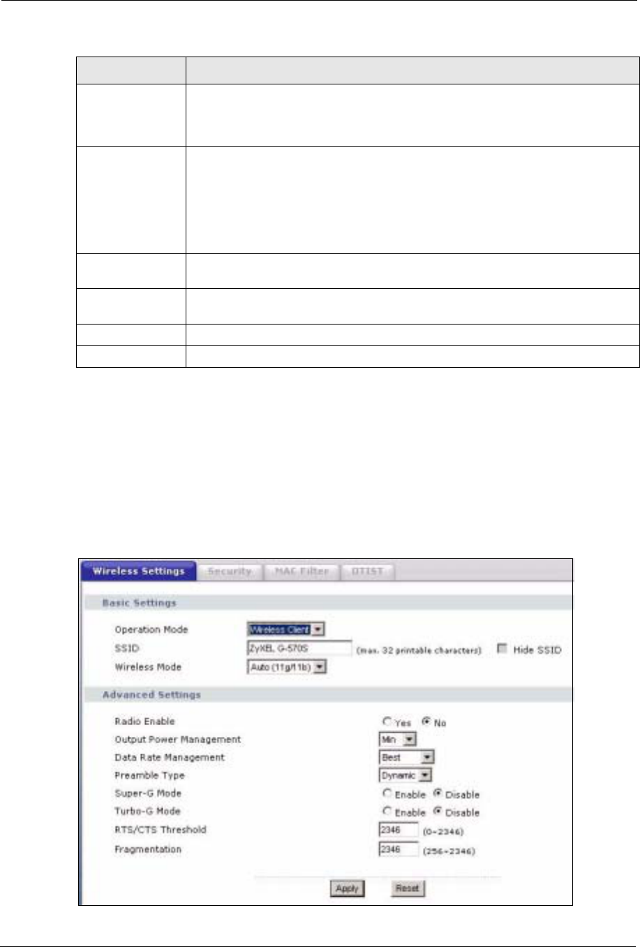
ZyXEL G-570S User’s Guide
64 Chapter 6 Wireless Screens
6.3.2 Wireless Client Mode
Select Wireless Client in the Operation Mode field to display the screen as shown next. This
mode has the device act as wireless client to connect to a wireless network.
Note: WPA, WPA2 and IEEE 802.1x wireless security are not available when you use
Wireless Client, Bridge or AP+Repeater mode.
Figure 37 Wireless Settings: Wireless Client
Super-G Mode Super-G mode provides higher speed transmissions than regular IEEE 802.11g.
The other device must also support super-G mode in order for the device to use it
for the wireless connection. This is available when you select a Wireless Mode
that includes IEEE 802.11g.
Turbo-G Mode Turbo-G mode provides higher speed transmissions than regular IEEE 802.11g or
super-G mode. The other device must also support turbo-G mode in order for the
device to use it for the wireless connection. This is available when you select a
Wireless Mode that includes IEEE 802.11g.
Turbo-G uses two channels bonded together in order to achieve its higher
transmission rates. This may cause interference with other APs in the area. The
Channel field is automatically fixed at 6 when you use turbo-G mode.
RTS/CTS
Threshold Enter a value between 0 and 2432. The default is 2432.
Fragmentation Enter a value between 256 and 2432. The default is 2432. It is the maximum data
fragment size that can be sent.
Apply Click Apply to save your changes back to the device.
Reset Click Reset to begin configuring this screen afresh.
Table 11 Wireless Settings: Access Point (continued)
LABEL DESCRIPTION

ZyXEL G-570S User’s Guide
Chapter 6 Wireless Screens 65
The following table describes the labels in this screen.
Table 12 Wireless Settings: Wireless Client
LABEL DESCRIPTION
Operation Mode Select the operating mode from the drop-down list. The options are Access Point,
Wireless Client,Bridge and AP+Repeater.
SSID Wireless stations associating to the access point (AP) must have the same SSID.
Enter a descriptive name (up to 32 printable characters) for the wireless LAN.
Spaces are allowed.
Note: If you are configuring the device from a computer connected
to the wireless LAN and you change the device's SSID,
channel or security settings, you will lose your wireless
connection when you click Apply to save your settings. You
must then change the wireless settings of your computer to
match the device's new settings.
Wireless Mode Select 802.11b only to allow only IEEE 802.11b compliant WLAN devices to
associate with the device.
Select 802.11g only to allow only IEEE 802.11g compliant WLAN devices to
associate with the device.
Select Auto (11g/11b) to allow either IEEE 802.11b or IEEE 802.11g compliant
WLAN devices to associate with the device. The transmission rate of your device
might be reduced.
Advanced Settings
Radio Enable Turn on the wireless adapter to allow wireless communications between the device
and other IEEE 802.11b and IEEE 802.11g compliant wireless devices. Turn off
the wireless adapter to stop wireless communications between the device and
other IEEE 802.11b and IEEE 802.11g compliant wireless devices.
Output Power
Management Set the output power of the device in this field. If there is a high density of APs
within an area, decrease the output power of the device to reduce interference with
other APs.
The options are Full,50%,25%,12% and Min.
Data Rate
Management Use this field to select a maximum data rate for the wireless connection(s). Please
note that this is a total rate to be shared by all of the device’s wireless connections.
Preamble Type Preamble is used to signal that data is coming to the receiver.
Short preamble increases performance as less time sending preamble means
more time for sending data. All IEEE 802.11b compliant wireless adapters support
long preamble, but not all support short preamble.
Select Long preamble if you are unsure what preamble mode the wireless
adapters support, and to provide more reliable communications in busy wireless
networks.
Select Short preamble if you are sure the wireless adapters support it, and to
provide more efficient communications.
Select Auto to have the device automatically use short preamble when all wireless
clients support it, otherwise the device uses long preamble.
Note: The device and the wireless stations MUST use the same
preamble mode in order to communicate.
Super-G Mode Super-G mode provides higher speed transmissions than regular IEEE 802.11g.
The other device must also support super-G mode in order for the device to use it
for the wireless connection. This is available when you select a Wireless Mode
that includes IEEE 802.11g.
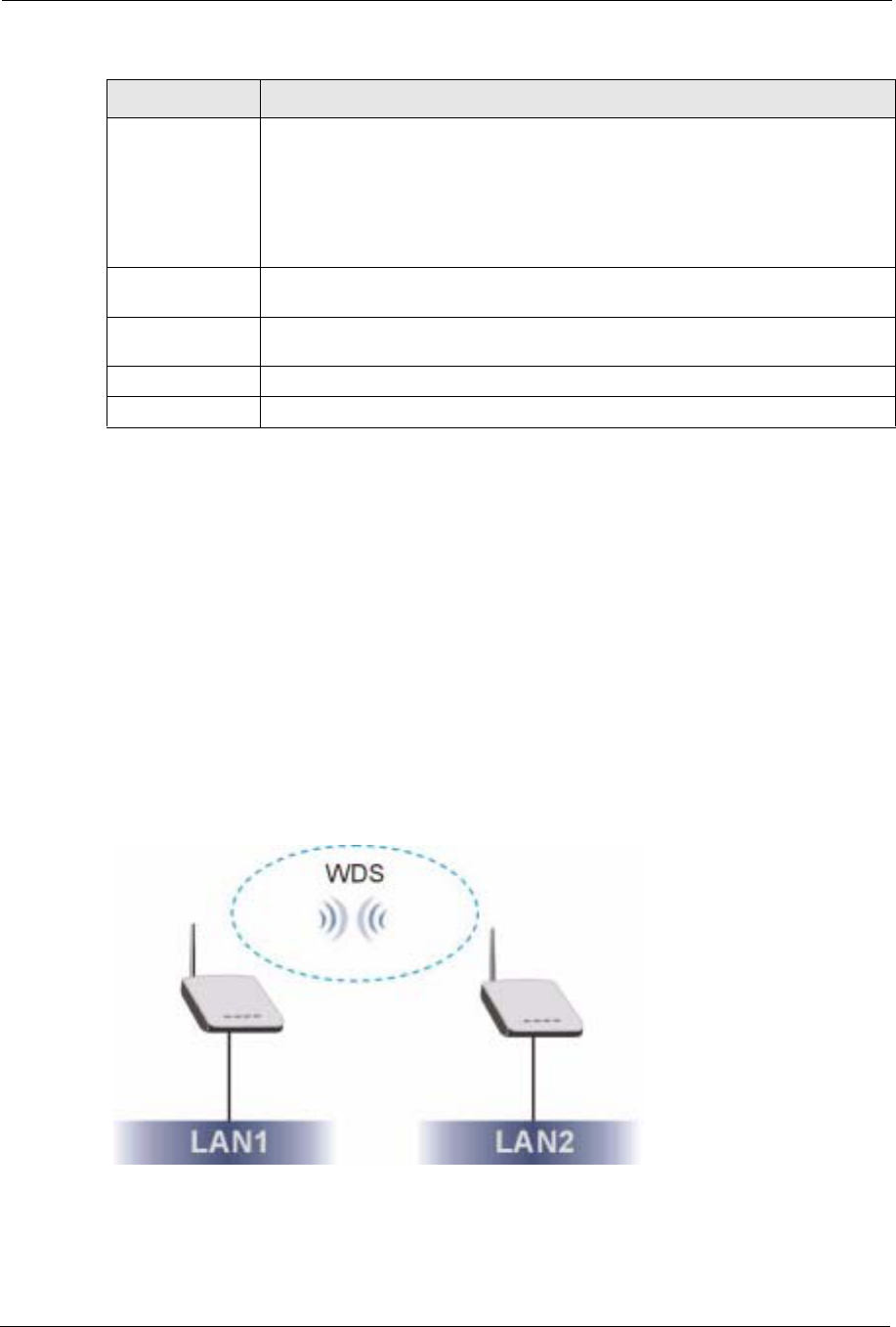
ZyXEL G-570S User’s Guide
66 Chapter 6 Wireless Screens
6.3.3 Bridge Mode
The device can act as a wireless network bridge and establish wireless links with other APs.
You need to know the MAC address of the peer device, which also must be in bridge mode.
When two devices connect in Bridge mode, they form a WDS (Wireless Distribution System)
allowing the computers in one LAN to connect to the computers in another LAN. See the
following example.
Note: WPA, WPA2 and IEEE 802.1x wireless security are not available when you use
Wireless Client, Bridge or AP+Repeater mode.
You can only use WEP keys to encrypt traffic between APs.
Figure 38 Bridging Example
Turbo-G Mode Turbo-G mode provides higher speed transmissions than regular IEEE 802.11g or
super-G mode. The other device must also support turbo-G mode in order for the
device to use it for the wireless connection. This is available when you select a
Wireless Mode that includes IEEE 802.11g.
Turbo-G uses two channels bonded together in order to achieve its higher
transmission rates. This may cause interference with other APs in the area. The
Channel field is automatically fixed at 6 when you use turbo-G mode.
RTS/CTS
Threshold Enter a value between 0 and 2432. The default is 2432.
Fragmentation Enter a value between 256 and 2432. The default is 2432. It is the maximum data
fragment size that can be sent.
Apply Click Apply to save your changes back to the device.
Reset Click Reset to begin configuring this screen afresh.
Table 12 Wireless Settings: Wireless Client (continued)
LABEL DESCRIPTION
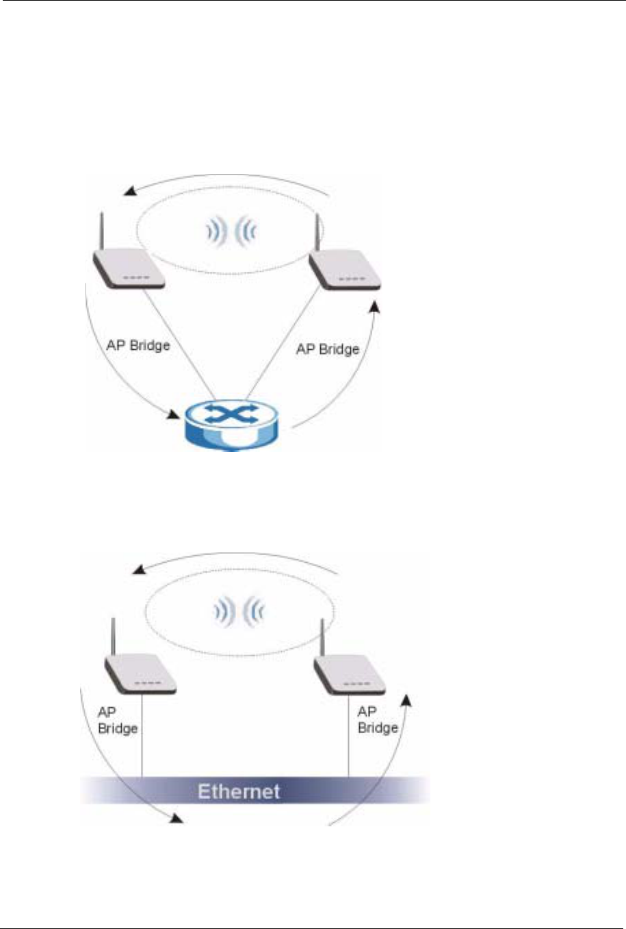
ZyXEL G-570S User’s Guide
Chapter 6 Wireless Screens 67
Be careful to avoid bridge loops when you enable bridging in the G-570S. Bridge loops cause
broadcast traffic to circle the network endlessly, resulting in possible throughput degradation
and disruption of communications. The following examples show two network topologies that
can lead to this problem:
If two or more G-570Ss (in bridge mode) are connected to the same hub as shown next.
Figure 39 Bridge Loop: Two Bridges Connected to Hub
If your G-570S (in bridge mode) is connected to a wired LAN while communicating with
another wireless bridge that is also connected to the same wired LAN as shown next.
Figure 40 Bridge Loop: Bridge Connected to Wired LAN
To prevent bridge loops, ensure that your G-570S is not set to bridge mode while connected to
both wired and wireless segments of the same LAN.
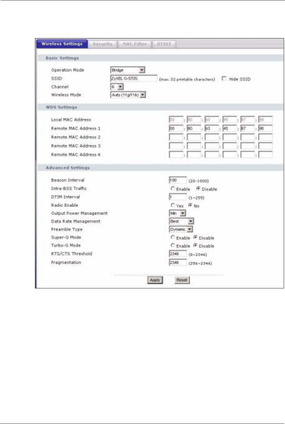
ZyXEL G-570S User’s Guide
68 Chapter 6 Wireless Screens
Select Bridge as the Operation Mode to have the device act as a wireless bridge only.
Figure 41 Wireless Settings: Bridge
The following table describes the labels in this screen.

ZyXEL G-570S User’s Guide
Chapter 6 Wireless Screens 69
Table 13 Wireless Settings: Bridge
LABEL DESCRIPTION
Operation Mode Select the operating mode from the drop-down list. The options are Access Point,
Wireless Client,Bridge and AP+Repeater.
Note: If you are configuring the device from a computer connected
to the wireless LAN and you change the device to use bridge
mode, you will lose your wireless connection when you click
Apply to save your settings. You must then connect to the
device through the wired network.
SSID The device does not use the SSID with bridge mode. You do not need to configure
it.
Hide SSID The device does not use the SSID with bridge mode. You do not need to configure
this field.
Channel Set the operating frequency/channel depending on your particular region.
Select a channel from the drop-down list box.
Refer to the chapter on wizard setup for more information about channels.
Wireless Mode Select 802.11b only to allow only IEEE 802.11b compliant WLAN devices to
associate with the device.
Select 802.11g only to allow only IEEE 802.11g compliant WLAN devices to
associate with the device.
Select Auto (11g/11b) to allow either IEEE 802.11b or IEEE 802.11g compliant
WLAN devices to associate with the device. The transmission rate of your device
might be reduced.
Local MAC
Address This is the MAC address of the device.
Remote MAC
Address 1~4 Type the MAC address of the peer device in a valid MAC address format, that is,
six hexadecimal character pairs, for example, 12:34:56:78:9a:bc.
Advanced Settings
Beacon Interval Set the number of milliseconds that should pass between the sending out of
beacons.
Intra-BSS Traffic Intra-BSS traffic is traffic between wireless stations in the same BSS.
Enable Intra-BSS traffic to allow wireless stations connected to the device to
communicate with each other.
Disable Intra-BSS traffic to only allow wireless stations to communicate with the
wired network, not with each other.
DTIM Interval Set the interval for wireless clients in sleep mode to wake up and check for
multicast or broadcast traffic.
The AP includes a Delivery Traffic Indication Message (DTIM) in the beacon to
notify wireless clients in sleep mode that there is a multicast or broadcast packet
awaiting delivery. The interval is a multiple of the beacon interval. For example, if
the beacon interval is 100 milliseconds and the DTIM interval is 2, the AP includes
a DTIM with every second beacon (or every 200 milliseconds).
Radio Enable Turn on the wireless adapter to allow wireless communications between the device
and other IEEE 802.11b and IEEE 802.11g compliant wireless devices. Turn off
the wireless adapter to stop wireless communications between the device and
other IEEE 802.11b and IEEE 802.11g compliant wireless devices.

ZyXEL G-570S User’s Guide
70 Chapter 6 Wireless Screens
6.3.4 AP+Repeater Mode
Select AP+Repeater as the Operation Mode to have the device act as an access point and a
wireless bridge.
Output Power
Management Set the output power of the device in this field. If there is a high density of APs
within an area, decrease the output power of the device to reduce interference with
other APs.
The options are Full,50%,25%,12% and Min.
Data Rate
Management Use this field to select a maximum data rate for the wireless connection(s). Please
note that this is a total rate to be shared by all of the device’s wireless connections.
Preamble Type Preamble is used to signal that data is coming to the receiver.
Short preamble increases performance as less time sending preamble means
more time for sending data. All IEEE 802.11b compliant wireless adapters support
long preamble, but not all support short preamble.
Select Long preamble if you are unsure what preamble mode the wireless
adapters support, and to provide more reliable communications in busy wireless
networks.
Select Short preamble if you are sure the wireless adapters support it, and to
provide more efficient communications.
Select Auto to have the device automatically use short preamble when all wireless
clients support it, otherwise the device uses long preamble.
Note: The device and the wireless stations MUST use the same
preamble mode in order to communicate.
Super-G Mode Super-G mode provides higher speed transmissions than regular IEEE 802.11g.
The other device must also support super-G mode in order for the device to use it
for the wireless connection. This is available when you select a Wireless Mode
that includes IEEE 802.11g.
Turbo-G Mode Turbo-G mode provides higher speed transmissions than regular IEEE 802.11g or
super-G mode. The other device must also support turbo-G mode in order to use it
for the wireless connection. This is available when you select a Wireless Mode
that includes IEEE 802.11g.
Turbo-G uses two channels bonded together in order to achieve its higher
transmission rates. This may cause interference with other APs in the area. The
Channel field is automatically fixed at 6 when you use turbo-G mode.
RTS/CTS
Threshold Enter a value between 0 and 2432. The default is 2432.
Fragmentation Enter a value between 256 and 2432. The default is 2432. It is the maximum data
fragment size that can be sent.
Apply Click Apply to save your changes back to the device.
Reset Click Reset to begin configuring this screen afresh.
Table 13 Wireless Settings: Bridge (continued)
LABEL DESCRIPTION
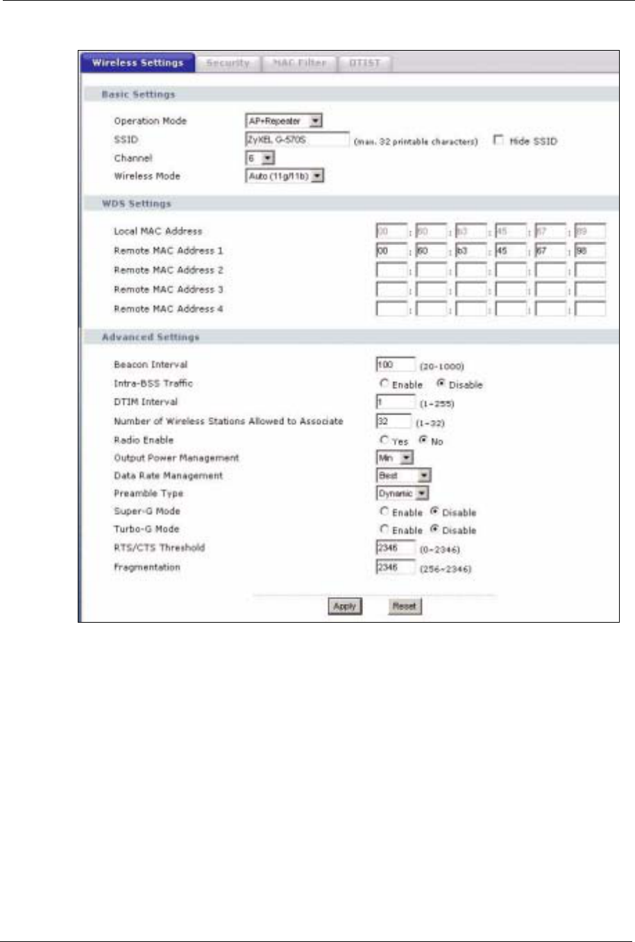
ZyXEL G-570S User’s Guide
Chapter 6 Wireless Screens 71
Figure 42 Wireless Settings: AP+Repeater

ZyXEL G-570S User’s Guide
72 Chapter 6 Wireless Screens
The following table describes the labels in this screen.
Table 14 Wireless Settings: AP + Repeater
LABEL DESCRIPTION
Operation Mode Select the operating mode from the drop-down list. The options are Access Point,
Wireless Client,Bridge and AP+Repeater.
SSID Wireless stations associating to the access point (AP) must have the same SSID.
Enter a descriptive name (up to 32 printable characters) for the wireless LAN.
Spaces are allowed.
Note: If you are configuring the device from a computer connected
to the wireless LAN and you change the device's SSID,
channel or security settings, you will lose your wireless
connection when you click Apply to save your settings. You
must then change the wireless settings of your computer to
match the device's new settings.
Hide SSID Select this check box to hide the SSID in the outgoing beacon frame so a station
cannot obtain the SSID through scanning using a site survey tool.
Channel Set the operating frequency/channel depending on your particular region.
Select a channel from the drop-down list box.
Refer to the chapter on wizard setup for more information about channels.
Wireless Mode Select 802.11b only to allow only IEEE 802.11b compliant WLAN devices to
associate with the device.
Select 802.11g only to allow only IEEE 802.11g compliant WLAN devices to
associate with the device.
Select Auto (11g/11b) to allow either IEEE 802.11b or IEEE 802.11g compliant
WLAN devices to associate with the device. The transmission rate of your device
might be reduced.
Local MAC
Address This is the MAC address of the device.
Remote MAC
Address 1~4 Type the MAC address of the peer device in a valid MAC address format, that is,
six hexadecimal character pairs, for example, 12:34:56:78:9a:bc.
Advanced Settings
Beacon Interval Set the number of milliseconds that should pass between the sending out of
beacons.
Intra-BSS Traffic Intra-BSS traffic is traffic between wireless stations in the same BSS.
Enable Intra-BSS traffic to allow wireless stations connected to the device to
communicate with each other.
Disable Intra-BSS traffic to only allow wireless stations to communicate with the
wired network, not with each other.
DTIM Interval Set the interval for wireless clients in sleep mode to wake up and check for
multicast or broadcast traffic.
The AP includes a Delivery Traffic Indication Message (DTIM) in the beacon to
notify wireless clients in sleep mode that there is a multicast or broadcast packet
awaiting delivery. The interval is a multiple of the beacon interval. For example, if
the beacon interval is 100 milliseconds and the DTIM interval is 2, the AP includes
a DTIM with every second beacon (or every 200 milliseconds).
Radio Enable Turn on the wireless adapter to allow wireless communications between the device
and other IEEE 802.11b and IEEE 802.11g compliant wireless devices. Turn off
the wireless adapter to stop wireless communications between the device and
other IEEE 802.11b and IEEE 802.11g compliant wireless devices.

ZyXEL G-570S User’s Guide
Chapter 6 Wireless Screens 73
6.4 Wireless Security Overview
Wireless security is vital to your network to protect wireless communication between wireless
stations, access points and the wired network.
Output Power
Management Set the output power of the device in this field. If there is a high density of APs
within an area, decrease the device’s output power to reduce interference with
other APs.
The options are Full,50%,25%,12% and Min.
Data Rate
Management Use this field to select a maximum data rate for the wireless connection(s). Please
note that this is a total rate to be shared by all of the device’s wireless connections.
Preamble Type Preamble is used to signal that data is coming to the receiver.
Short preamble increases performance as less time sending preamble means
more time for sending data. All IEEE 802.11b compliant wireless adapters support
long preamble, but not all support short preamble.
Select Long preamble if you are unsure what preamble mode the wireless
adapters support, and to provide more reliable communications in busy wireless
networks.
Select Short preamble if you are sure the wireless adapters support it, and to
provide more efficient communications.
Select Auto to have the device automatically use short preamble when all wireless
clients support it, otherwise the device uses long preamble.
Note: The device and the wireless stations MUST use the same
preamble mode in order to communicate.
Super-G Mode Super-G mode provides higher speed transmissions than regular IEEE 802.11g.
The other device must also support super-G mode in order to use it for the wireless
connection. This is available when you select a Wireless Mode that includes IEEE
802.11g.
Turbo-G Mode Turbo-G mode provides higher speed transmissions than regular IEEE 802.11g or
super-G mode. The other device must also support turbo-G mode in order to use it
for the wireless connection. This is available when you select a Wireless Mode
that includes IEEE 802.11g.
Turbo-G uses two channels bonded together in order to achieve its higher
transmission rates. This may cause interference with other APs in the area. The
Channel field is automatically fixed at 6 when you use turbo-G mode.
RTS/CTS
Threshold Enter a value between 0 and 2432. The default is 2432.
Fragmentation Enter a value between 256 and 2432. The default is 2432. It is the maximum data
fragment size that can be sent.
Apply Click Apply to save your changes back to the device.
Reset Click Reset to begin configuring this screen afresh.
Table 14 Wireless Settings: AP + Repeater (continued)
LABEL DESCRIPTION

ZyXEL G-570S User’s Guide
74 Chapter 6 Wireless Screens
The figure below shows the possible wireless security levels on your G-570S. EAP
(Extensible Authentication Protocol) is used for authentication and utilizes dynamic WEP key
exchange. It requires interaction with a RADIUS (Remote Authentication Dial-In User
Service) server either on the WAN or your LAN to provide authentication service for wireless
stations.
If you do not enable any wireless security on your G-570S, your network is accessible to any
wireless networking device that is within range.
6.4.1 Encryption
• Use WPA(2) security if you have WP(2)A-aware wireless clients and a RADIUS server.
WPA(2) has user authentication and improved data encryption over WEP.
• Use WPA(2)-PSK if you have WPA(2)-aware wireless clients but no RADIUS server.
• If you don’t have WPA(2)-aware wireless clients, then use WEP key encrypting. A
higher bit key offers better security at a throughput trade-off. You can use the passphrase
feature to automatically generate WEP keys or manually enter WEP keys.
6.4.2 Authentication
Use a RADIUS server with WPA or IEEE 802.1x key management protocol.
See the appendix for information on protocols used when a client authenticates with a
RADIUS server via the G-570S.
6.4.3 Restricted Access
The MAC Filter screen allows you to configure the AP to give exclusive access to devices
(Allow Association) or exclude them from accessing the AP (Deny Association).
Table 15 Wireless Security Levels
SECURITY LEVEL SECURITY TYPE
L e a s t S e c u r e
Most Secure
Unique SSID (Default)
Unique SSID with Hide SSID Enabled
MAC Address Filtering
WEP Encryption
IEEE802.1x EAP with RADIUS Server Authentication
Wi-Fi Protected Access (WPA)
WPA2
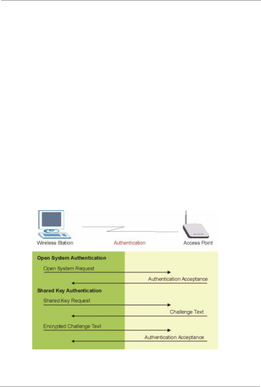
ZyXEL G-570S User’s Guide
Chapter 6 Wireless Screens 75
6.4.4 Hide G-570S Identity
If you hide the ESSID, then the G-570S cannot be seen when a wireless client scans for local
APs. The trade-off for the extra security of “hiding” the G-570S may be inconvenience for
some valid WLAN clients.
6.5 WEP Overview
WEP (Wired Equivalent Privacy) as specified in the IEEE 802.11 standard provides methods
for both data encryption and wireless station authentication.
6.5.1 Data Encryption
WEP provides a mechanism for encrypting data using encryption keys. Both the AP and the
wireless stations must use the same WEP key to encrypt and decrypt data. Your G-570S
allows you to configure up to four 64-bit, 128-bit or 152-bit WEP keys, but only one key can
be enabled at any one time.
6.5.2 Authentication
Three different methods can be used to authenticate wireless stations to the network: Open
System,Shared and Auto. The following figure illustrates the steps involved.
Figure 43 WEP Authentication Steps

ZyXEL G-570S User’s Guide
76 Chapter 6 Wireless Screens
Open system authentication involves an unencrypted two-message procedure. A wireless
station sends an open system authentication request to the AP, which will then automatically
accept and connect the wireless station to the network. In effect, open system is not
authentication at all as any station can gain access to the network.
Shared key authentication involves a four-message procedure. A wireless station sends a
shared key authentication request to the AP, which will then reply with a challenge text
message. The wireless station must then use the AP’s default WEP key to encrypt the
challenge text and return it to the AP, which attempts to decrypt the message using the AP’s
default WEP key. If the decrypted message matches the challenge text, the wireless station is
authenticated.
When your G-570S's authentication method is set to open system, it will only accept open
system authentication requests. The same is true for shared key authentication. However,
when it is set to auto authentication, the G-570S will accept either type of authentication
request and the G-570S will fall back to use open authentication if the shared key does not
match.
6.6 802.1x Overview
The IEEE 802.1x standard outlines enhanced security methods for both the authentication of
wireless stations and encryption key management. Authentication can be done using the local
user database internal to the G-570S (authenticate up to 32 users) or an external RADIUS
server for an unlimited number of users.
6.7 Introduction to RADIUS
RADIUS is based on a client-sever model that supports authentication and accounting, where
access point is the client and the server is the RADIUS server. The RADIUS server handles
the following tasks among others:
• Authentication
Determines the identity of the users.
• Accounting
Keeps track of the client’s network activity.
RADIUS user is a simple package exchange in which your G-570S acts as a message relay
between the wireless station and the network RADIUS server.
6.7.1 Types of RADIUS Messages
The following types of RADIUS messages are exchanged between the access point and the
RADIUS server for user authentication:

ZyXEL G-570S User’s Guide
Chapter 6 Wireless Screens 77
• Access-Request
Sent by an access point, requesting authentication.
• Access-Reject
Sent by a RADIUS server rejecting access.
• Access-Accept
Sent by a RADIUS server allowing access.
• Access-Challenge
Sent by a RADIUS server requesting more information in order to allow access. The
access point sends a proper response from the user and then sends another Access-
Request message.
The following types of RADIUS messages are exchanged between the access point and the
RADIUS server for user accounting:
• Accounting-Request
Sent by the access point requesting accounting.
• Accounting-Response
Sent by the RADIUS server to indicate that it has started or stopped accounting.
In order to ensure network security, the access point and the RADIUS server use a shared
secret key, which is a password, they both know. The key is not sent over the network. In
addition to the shared key, password information exchanged is also encrypted to protect the
wired network from unauthorized access.
6.8 EAP Authentication Overview
EAP (Extensible Authentication Protocol) is an authentication protocol that runs on top of the
IEEE802.1x transport mechanism in order to support multiple types of user authentication. By
using EAP to interact with an EAP-compatible RADIUS server, the access point helps a
wireless station and a RADIUS server perform authentication.
The type of authentication you use depends on the RADIUS server or the AP. The G-570S
supports EAP-TLS, EAP-TTLS, EAP-MD5 and PEAP with RADIUS. Refer to the appendix
about the types of EAP authentication for descriptions on the common types.
Your G-570S supports EAP-MD5 (Message-Digest Algorithm 5) and PEAP (Protected EAP)
with the built-in RADIUS server.
The following figure shows an overview of authentication when you specify a RADIUS server
on your access point.

ZyXEL G-570S User’s Guide
78 Chapter 6 Wireless Screens
Figure 44 EAP Authentication
The details below provide a general description of how IEEE 802.1x EAP authentication
works. For an example list of EAP-MD5 authentication steps, see the IEEE 802.1x appendix.
1The wireless station sends a “start” message to the G-570S.
2The G-570S sends a “request identity” message to the wireless station for identity
information.
3The wireless station replies with identity information, including user name and password.
4The RADIUS server checks the user information against its user profile database and
determines whether or not to authenticate the wireless station.
6.9 Dynamic WEP Key Exchange
The AP maps a unique key that is generated with the RADIUS server. This key expires when
the wireless connection times out, disconnects or reauthentication times out. A new WEP key
is generated each time reauthentication is performed.
If this feature is enabled, it is not necessary to configure a default WEP encryption key in the
Wireless screen. You may still configure and store keys here, but they will not be used while
Dynamic WEP is enabled.
To use Dynamic WEP, enable and configure the RADIUS server and enable Dynamic WEP
Key Exchange in the WIRELESS Security 802.1x screen. Ensure that the wireless station’s
EAP type is configured to one of the following:
•EAP-TLS
•EAP-TTLS
•PEAP
Note: EAP-MD5 cannot be used with Dynamic WEP Key Exchange.
6.10 Introduction to WPA and WPA2
Wi-Fi Protected Access (WPA) is a subset of the IEEE 802.11i standard. WPA2 (IEEE
802.11i) is a wireless security standard that defines stronger encryption, authentication and
key management than WPA.

ZyXEL G-570S User’s Guide
Chapter 6 Wireless Screens 79
Key differences between WPA(2) and WEP are improved data encryption and user
authentication.
If both an AP and the wireless clients support WPA2 and you have an external RADIUS
server, use WPA2 for stronger data encryption. If you don't have an external RADIUS server,
you should use WPA2-PSK (WPA2-Pre-Shared Key) that only requires a single (identical)
password entered into each access point, wireless gateway and wireless client. As long as the
passwords match, a wireless client will be granted access to a WLAN.
If the AP or the wireless clients do not support WPA2, just use WPA or WPA-PSK depending
on whether you have an external RADIUS server or not.
Select WEP only when the AP and/or wireless clients do not support WPA or WPA2. WEP is
less secure than WPA or WPA2.
6.10.1 Encryption
Both WPA and WPA2 improve data encryption by using Temporal Key Integrity Protocol
(TKIP), Message Integrity Check (MIC) and IEEE 802.1x. In addition to TKIP, WPA2 also
uses Advanced Encryption Standard (AES) in the Counter mode with Cipher block chaining
Message authentication code Protocol (CCMP) to offer stronger encryption.
The encryption mechanisms used for WPA(2) and WPA(2)-PSK are the same. The only
difference between the two is that WPA-PSK uses a simple common password, instead of
user-specific credentials. The common-password approach makes WPA(2)-PSK susceptible to
brute-force password-guessing attacks but it’s still an improvement over WEP as it employs
an easier-to-use, consistent, single, alphanumeric password.
6.10.2 User Authentication
WPA or WPA2 applies IEEE 802.1x and Extensible Authentication Protocol (EAP) to
authenticate wireless clients using an external RADIUS database.
6.11 WPA(2)-PSK Application Example
A WPA(2)-PSK application looks as follows.
1First enter identical passwords into the AP and all wireless clients. The Pre-Shared Key
(PSK) must consist of between 8 and 63 ASCII characters (including spaces and
symbols).
2The AP checks each client’s password and (only) allows it to join the network if it
matches its password.
3The AP derives and distributes keys to the wireless clients.
4The AP and wireless clients use the TKIP or AES encryption process to encrypt data
exchanged between them.
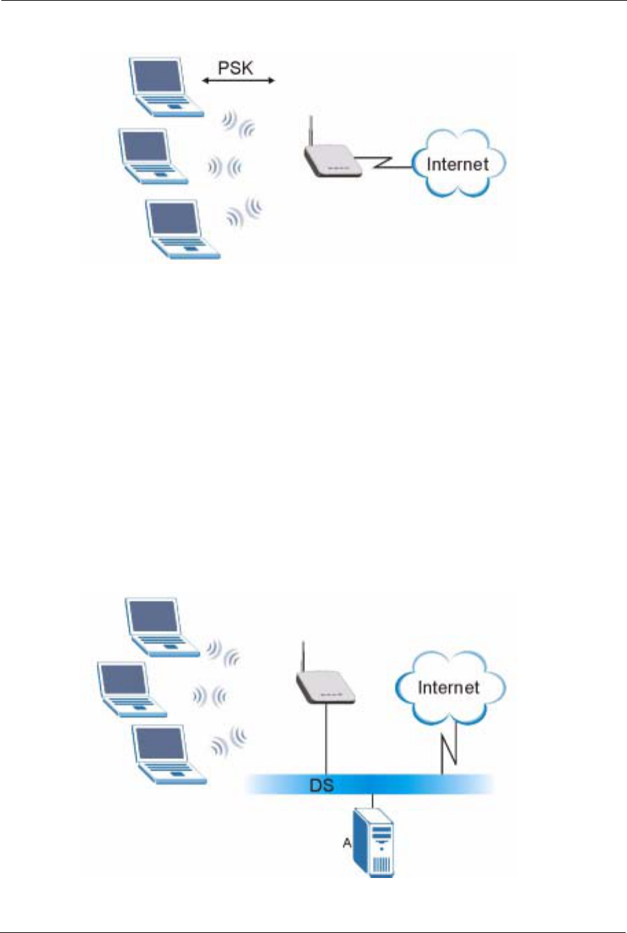
ZyXEL G-570S User’s Guide
80 Chapter 6 Wireless Screens
Figure 45 WPA(2)-PSK Authentication
6.12 WPA(2) with RADIUS Application Example
You need the IP address of the RADIUS server, its port number (default is 1812), and the
RADIUS shared secret. A WPA(2) application example with an external RADIUS server
looks as follows. “A” is the RADIUS server. “DS” is the distribution system.
1The AP passes the wireless client’s authentication request to the RADIUS server.
2The RADIUS server then checks the user's identification against its database and grants
or denies network access accordingly.
3The RADIUS server distributes a Pairwise Master Key (PMK) key to the AP that then
sets up a key hierarchy and management system, using the pair-wise key to dynamically
generate unique data encryption keys to encrypt every data packet that is wirelessly
communicated between the AP and the wireless clients.
Figure 46 WPA with RADIUS Application Example