ZyXEL Communications IX253P WiMAX MIMO 2.5GHz Indoor Simple CPE User Manual User s manual
ZyXEL Communications Corporation WiMAX MIMO 2.5GHz Indoor Simple CPE User s manual
UserManual.wiki
>
ZyXEL Communications
>
IX253P User Manual
User Manual
Navigation menu
Upload a User Manual
Namespaces
Wiki Guide
HTML
PDF
Info
Views
User Manual
Discussion / Help
Navigation
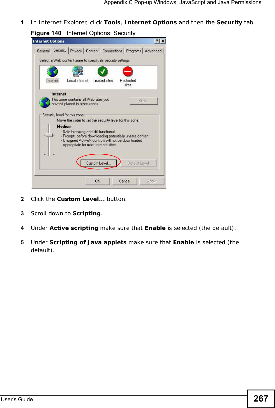
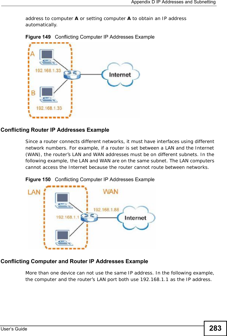
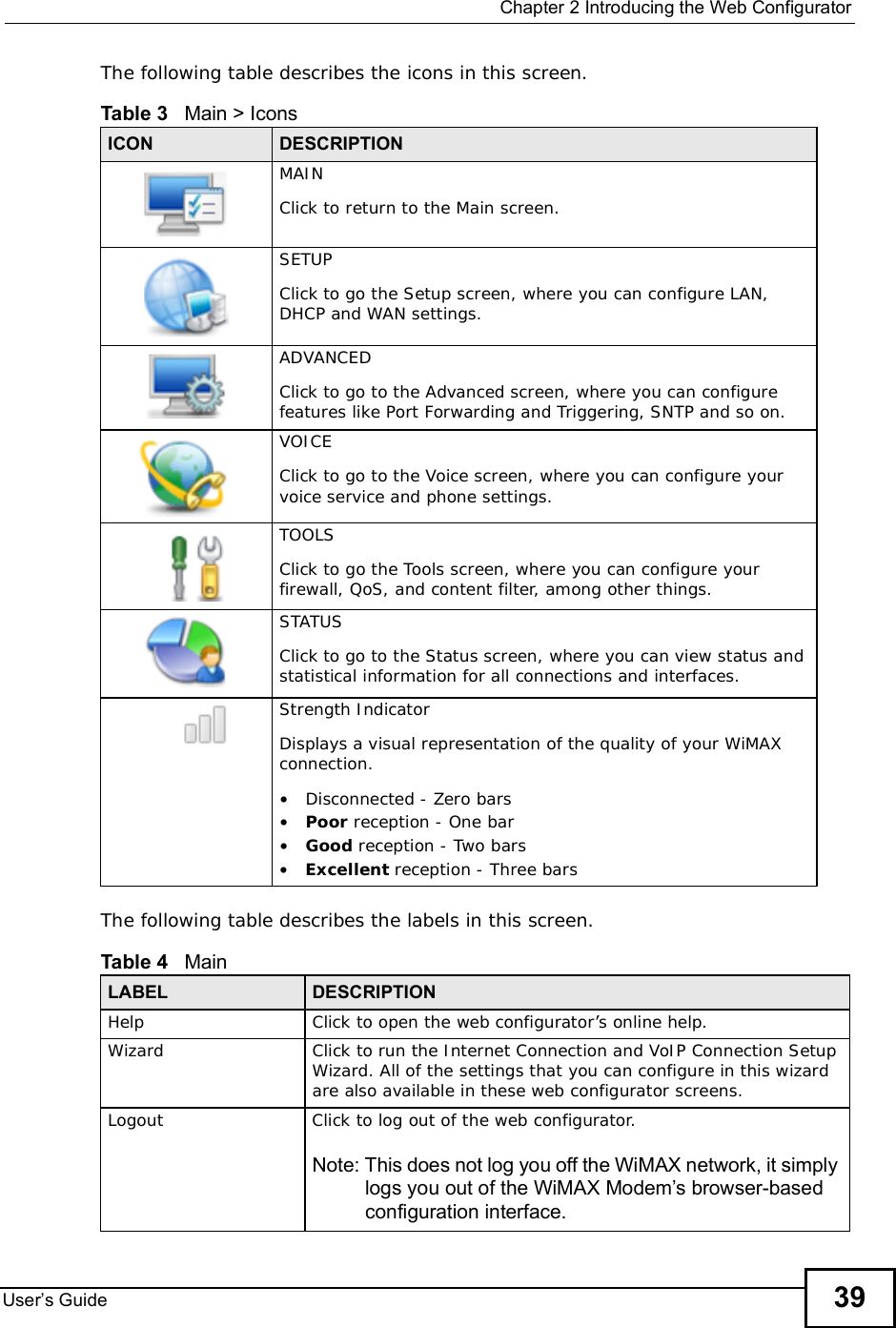
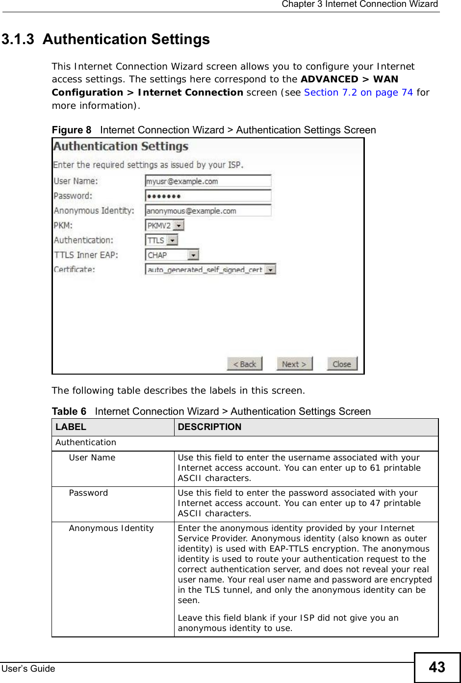
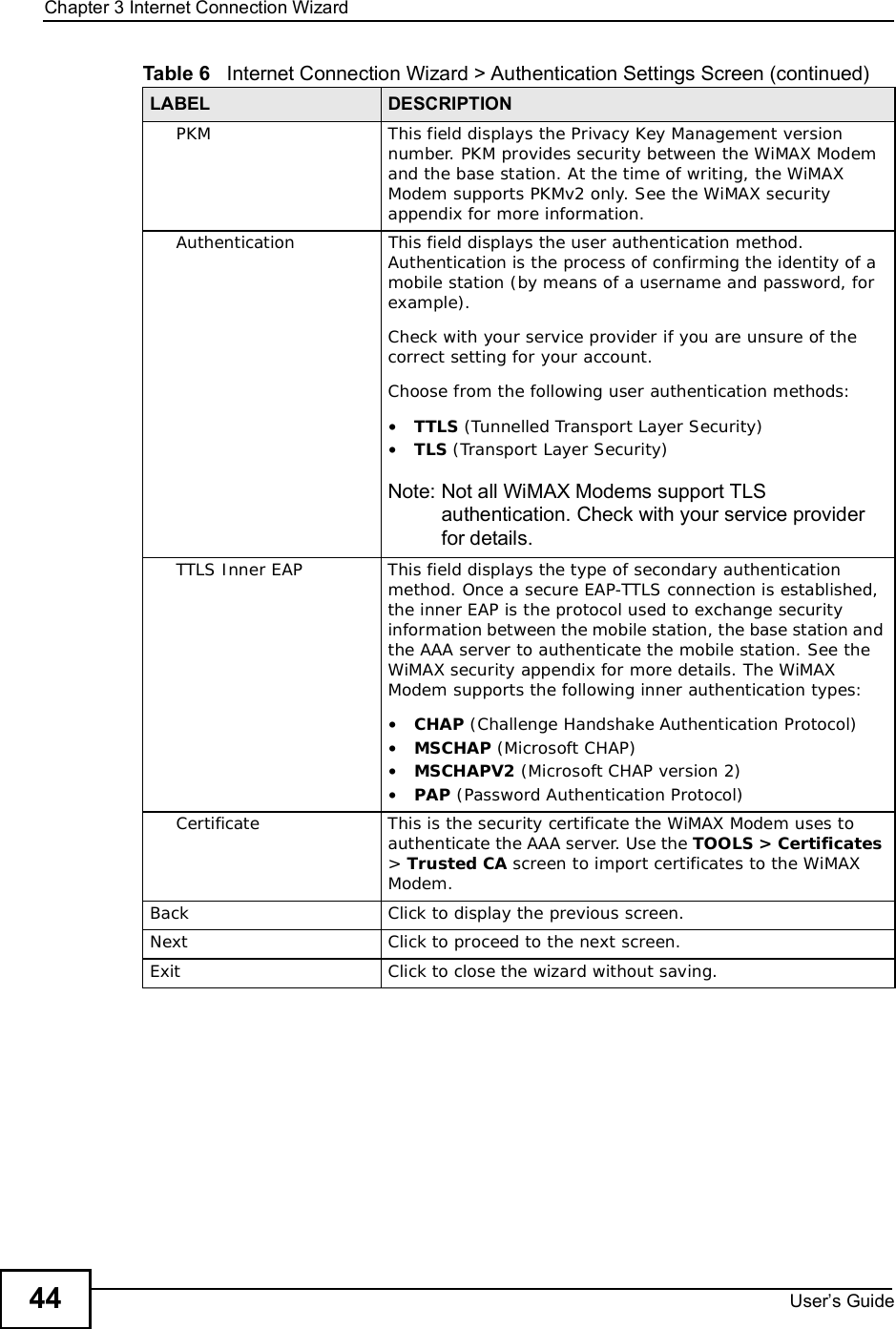
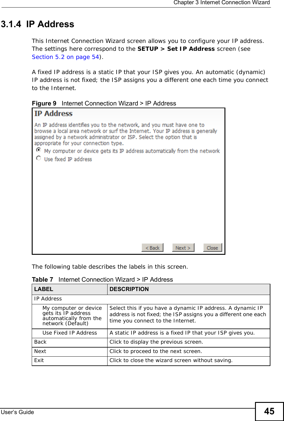
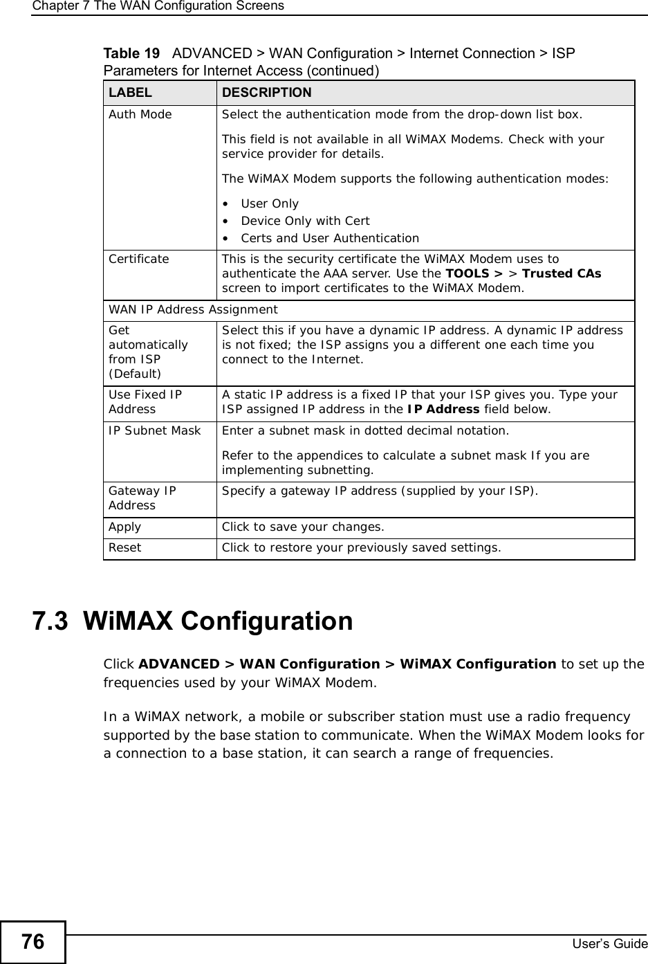
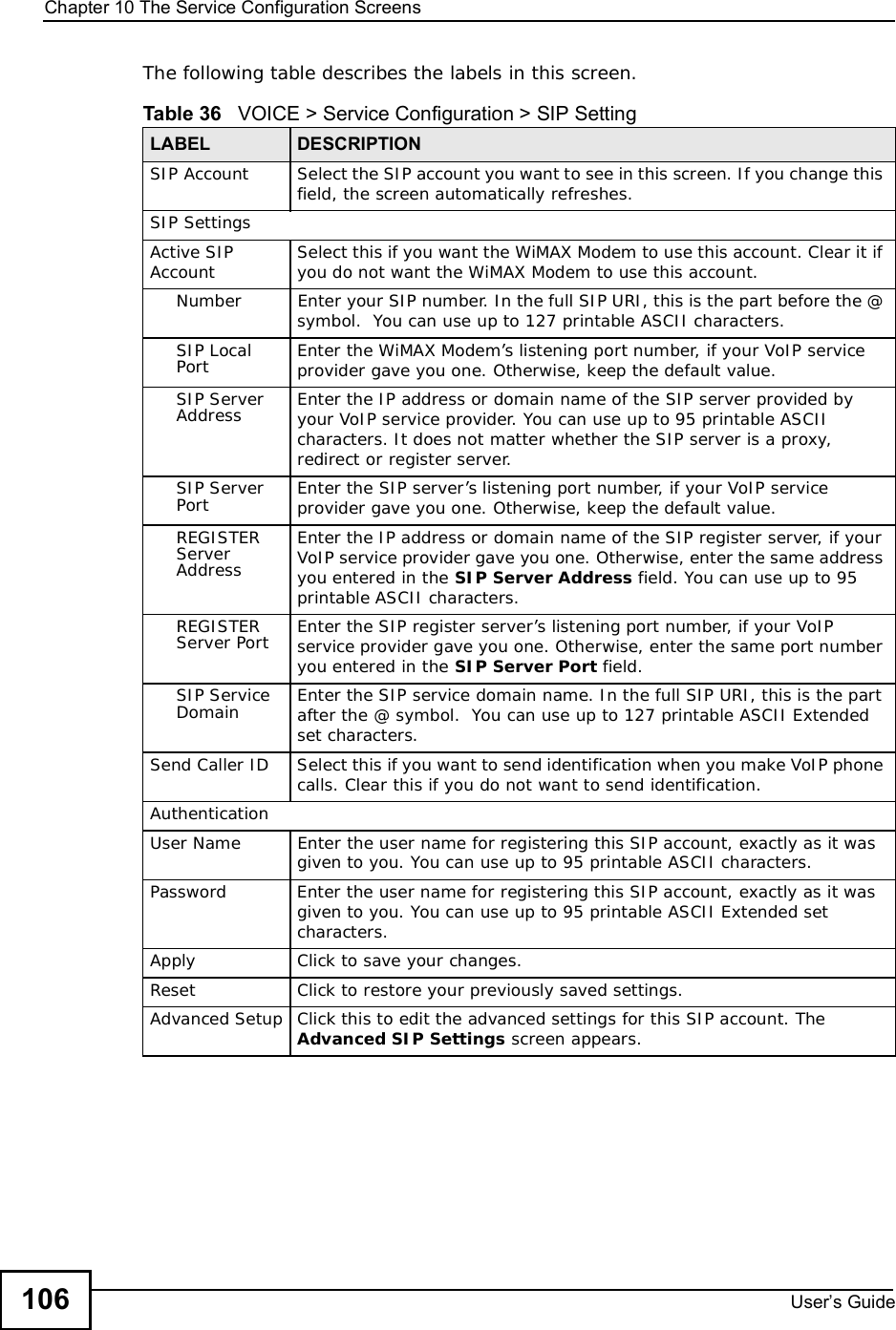
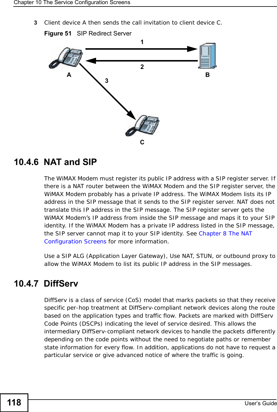
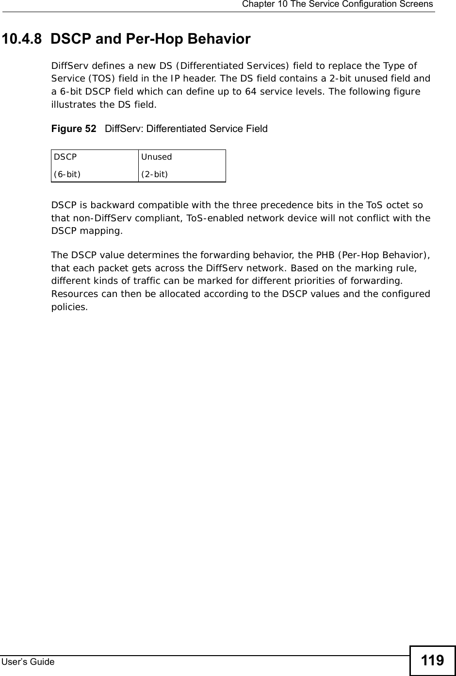
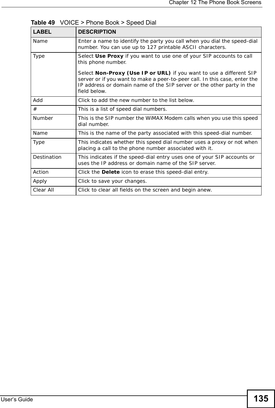
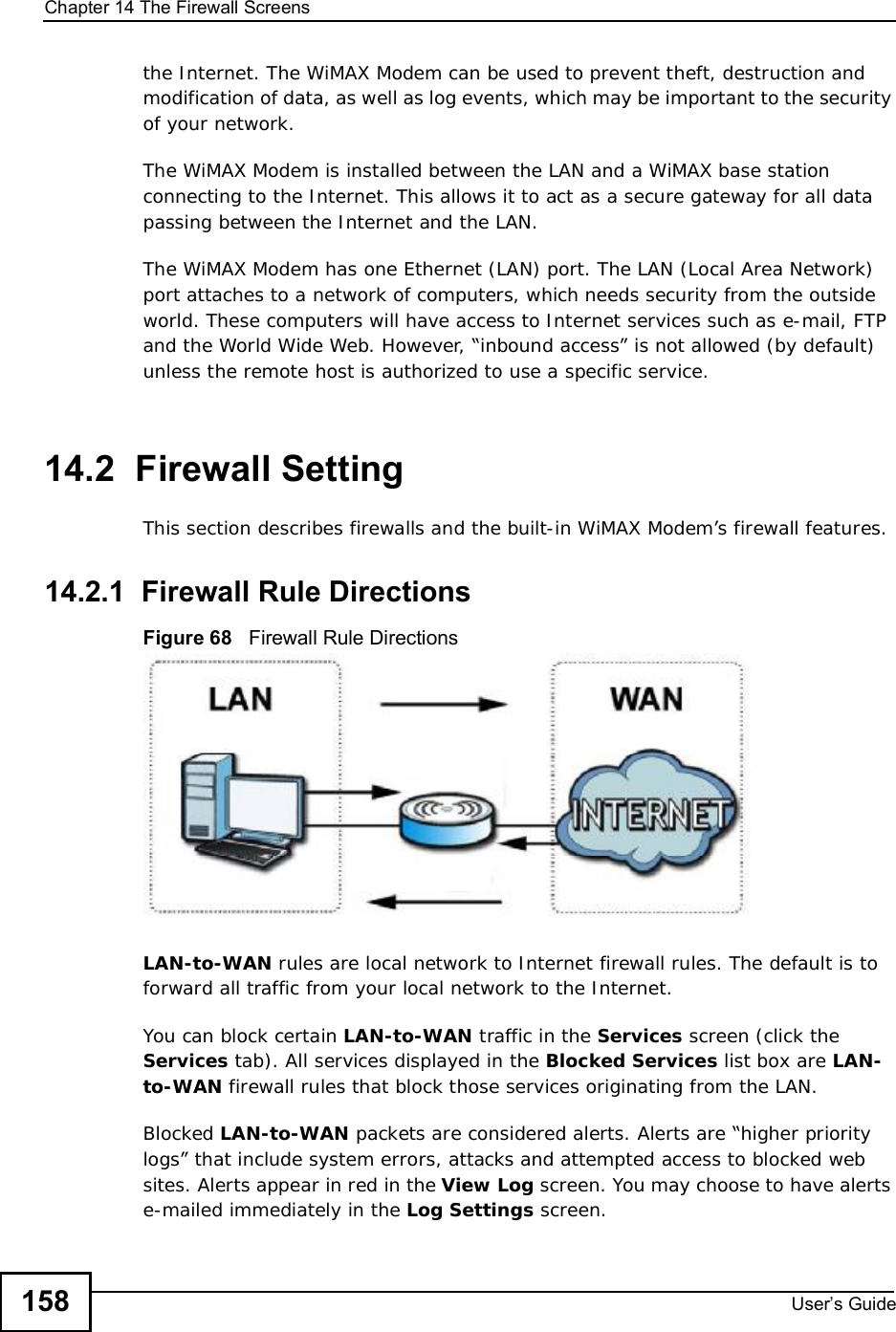
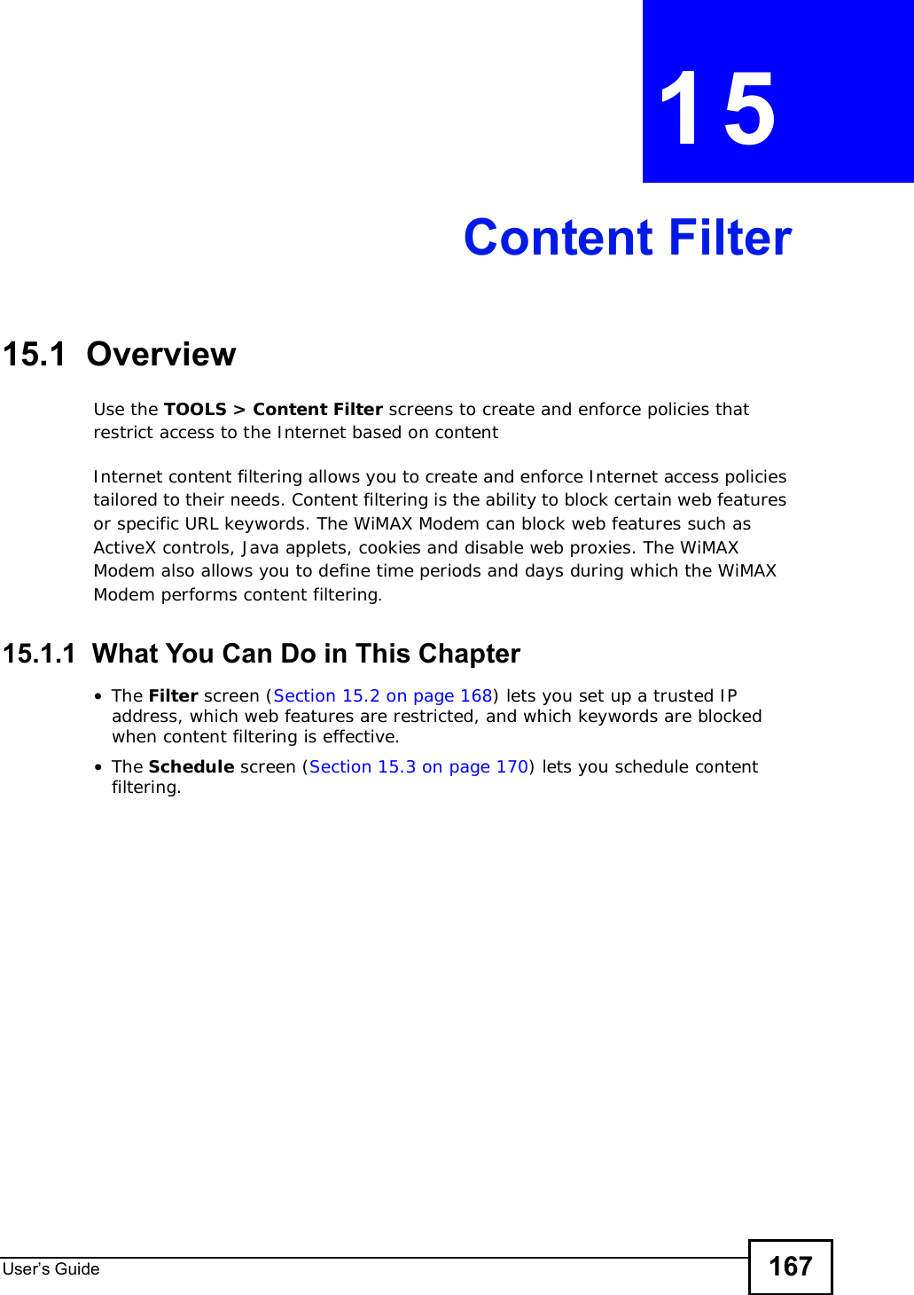
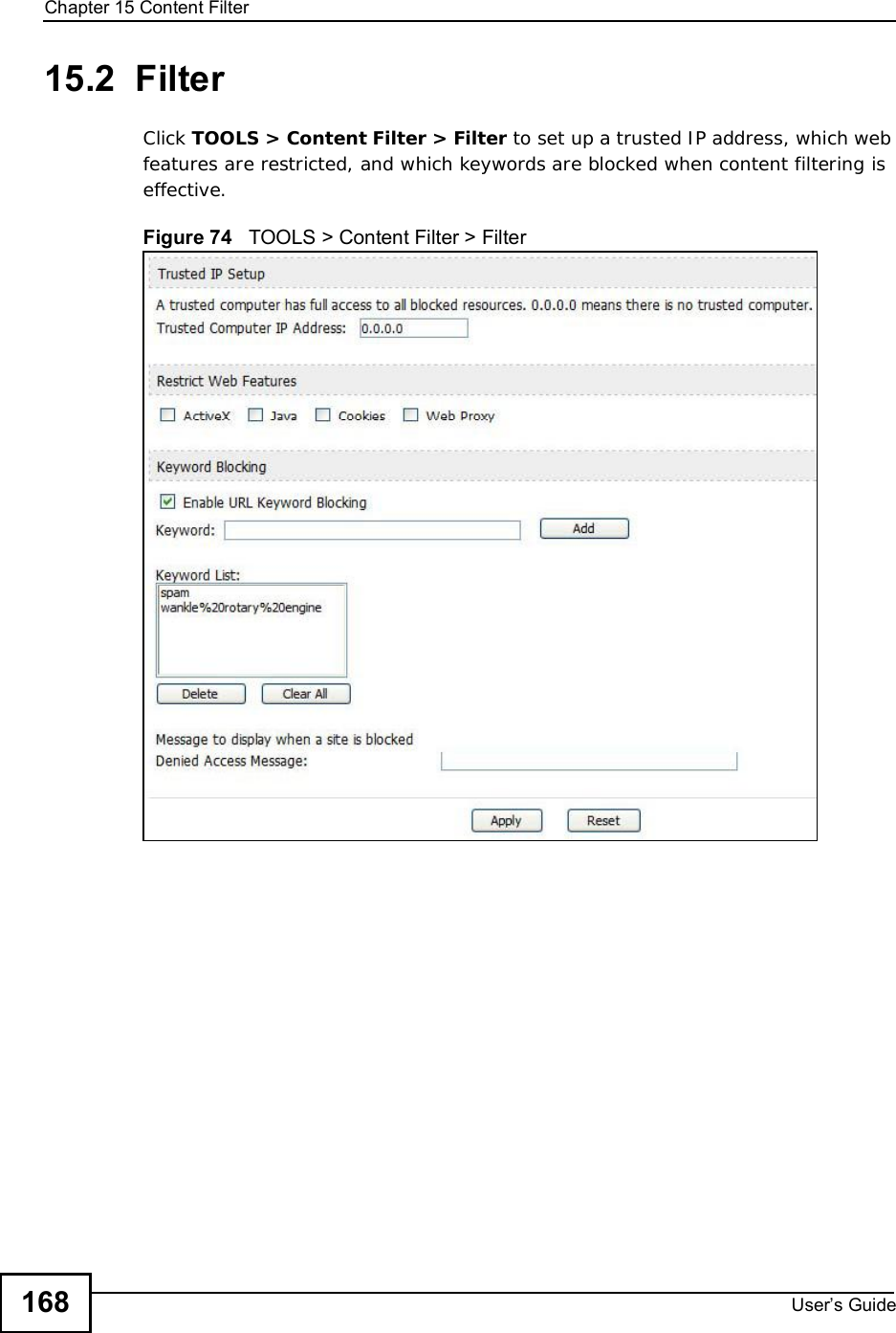
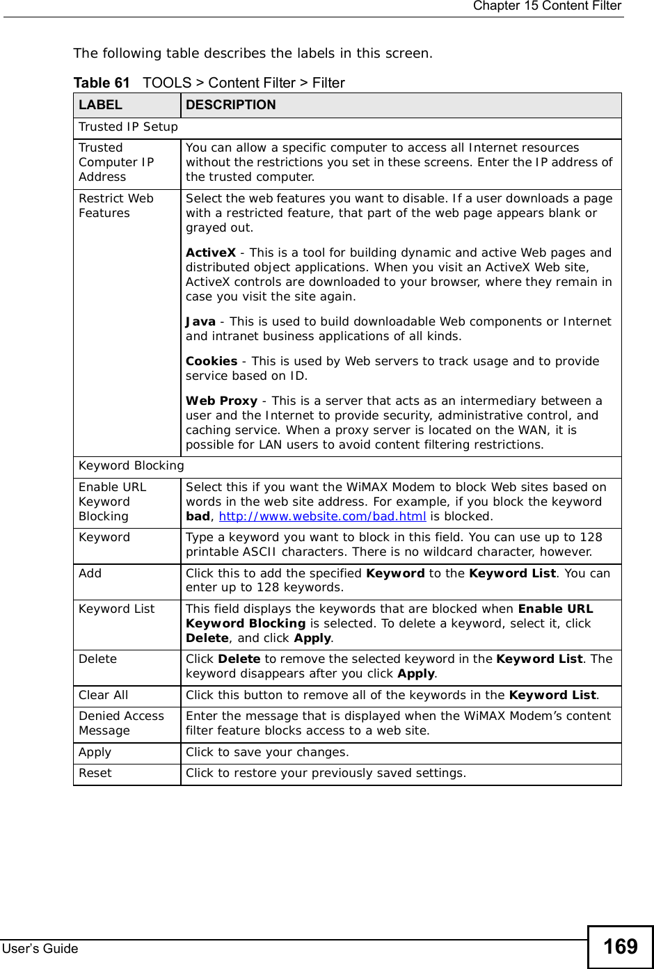
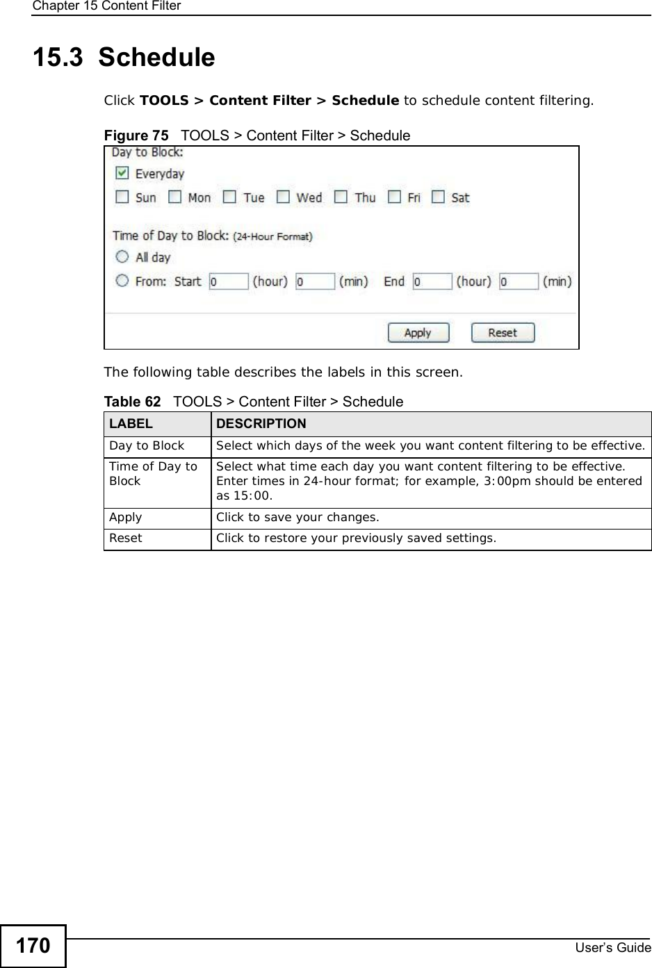
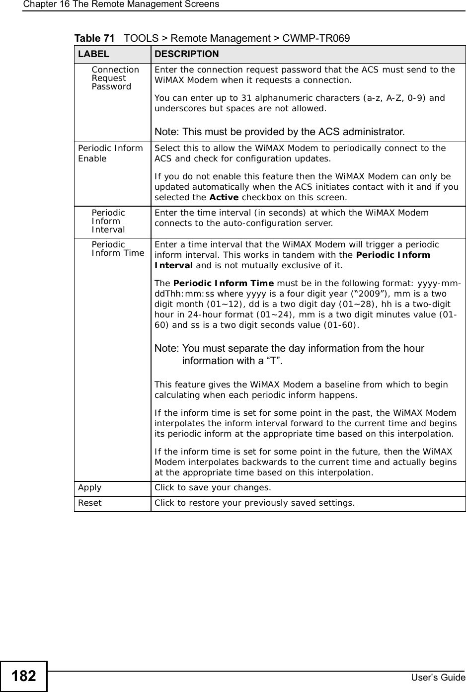
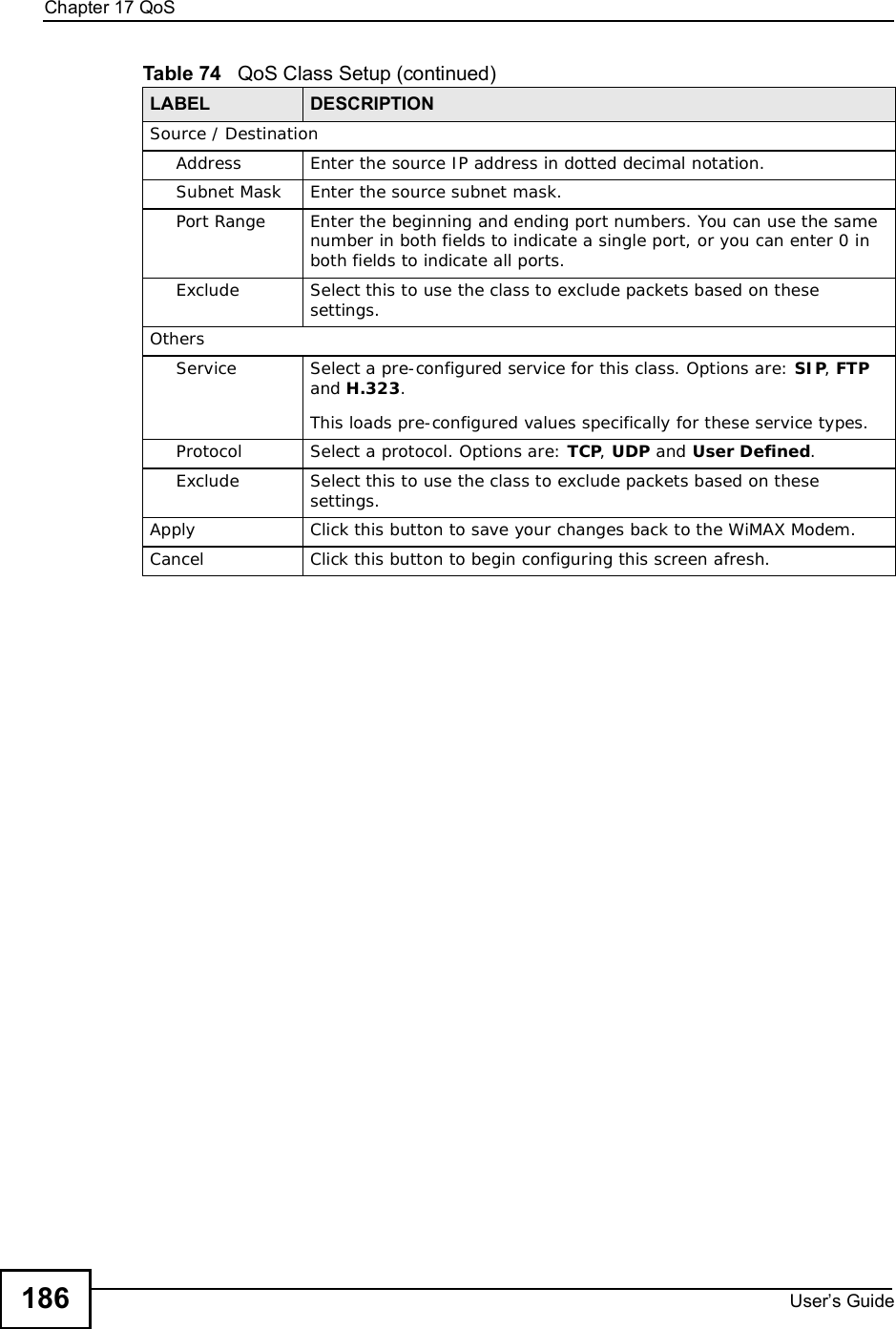
![Document ConventionsUser s Guide4Document ConventionsWarnings and NotesThese are how warnings and notes are shown in this User’s Guide. Warnings tell you about things that could harm you or your WiMAX Modem.Note: Notes tell you other important information (for example, other things you may need to configure or helpful tips) or recommendations.Syntax Conventions•The product(s) described in this book may be referred to as the “WiMAX Modem”, the “device”, the “system” or the “product” in this User’s Guide.•Product labels, screen names, field labels and field choices are all in bold font.•A key stroke is denoted by square brackets and uppercase text, for example, [ENTER] means the “enter” or “return” key on your keyboard.•“Enter” means for you to type one or more characters and then press the [ENTER] key. “Select” or “choose” means for you to use one of the predefined choices.•A right angle bracket ( > ) within a screen name denotes a mouse click. For example, TOOLS > Logs > Log Settings means you first click Tools in the navigation panel, then the Logs sub menu and finally the Log Settings tab to get to that screen.•Units of measurement may denote the “metric” value or the “scientific” value. For example, “k” for kilo may denote “1000” or “1024”, “M” for mega may denote “1000000” or “1048576” and so on.•“e.g.,” is a shorthand for “for instance”, and “i.e.,” means “that is” or “in other words”.DisclaimerGraphics in this book may differ slightly from the product due to differences in operating systems, operating system versions, or if you installed updated firmware/software for your device. Every effort has been made to ensure that the information in this manual is accurate.](https://usermanual.wiki/ZyXEL-Communications/IX253P/User-Guide-1403071-Page-3.png)

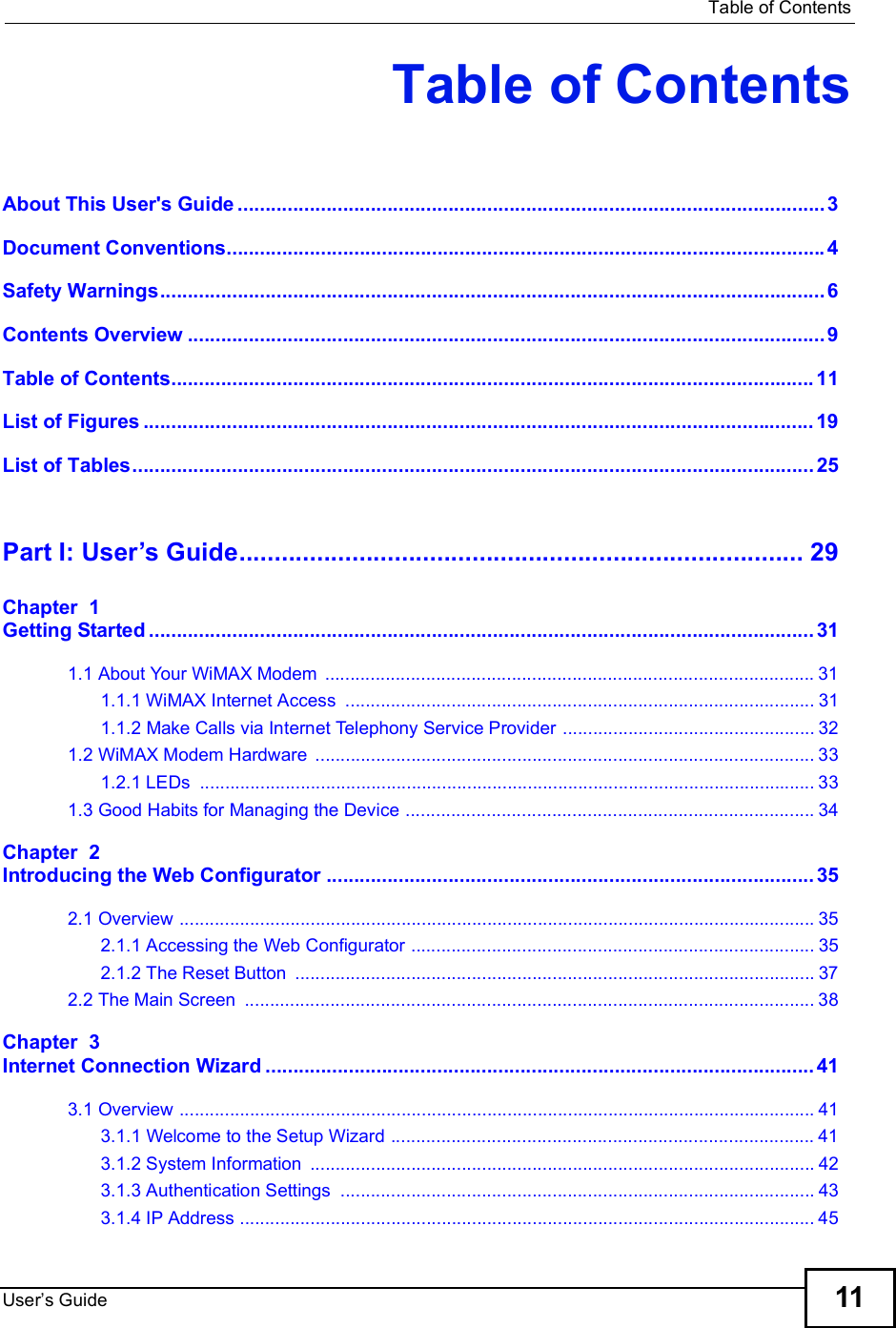
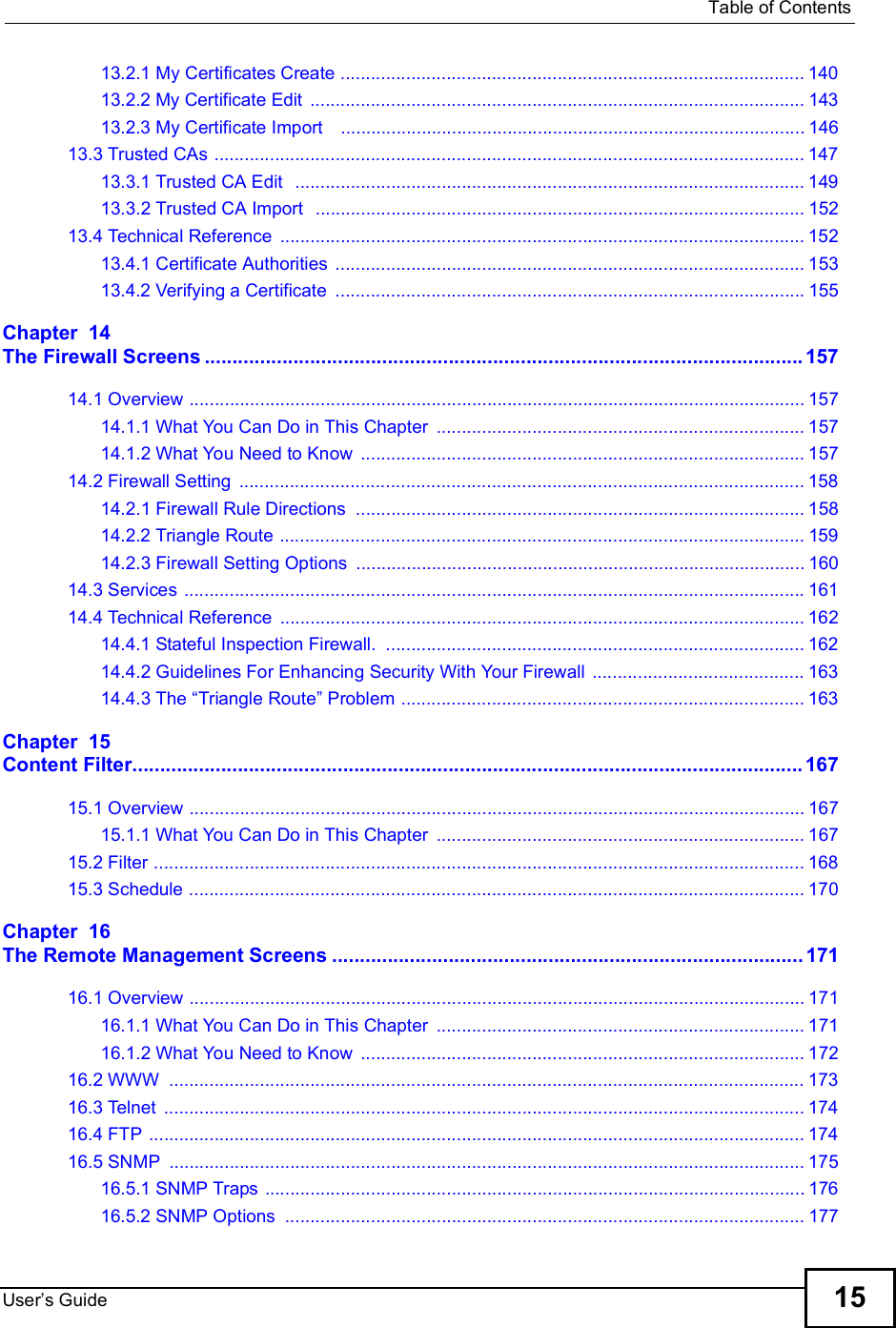
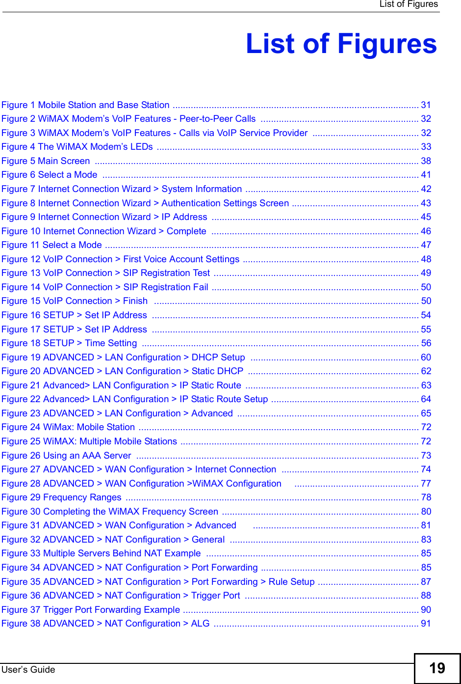

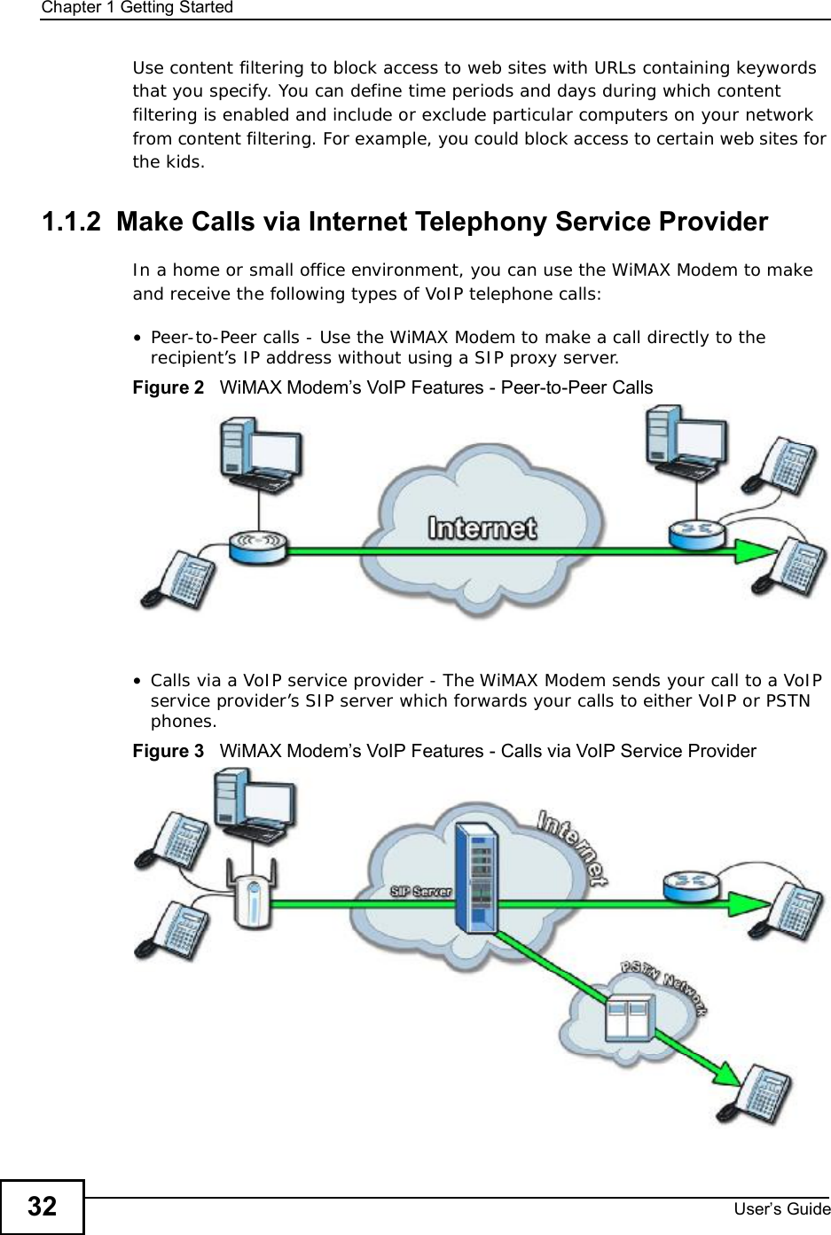
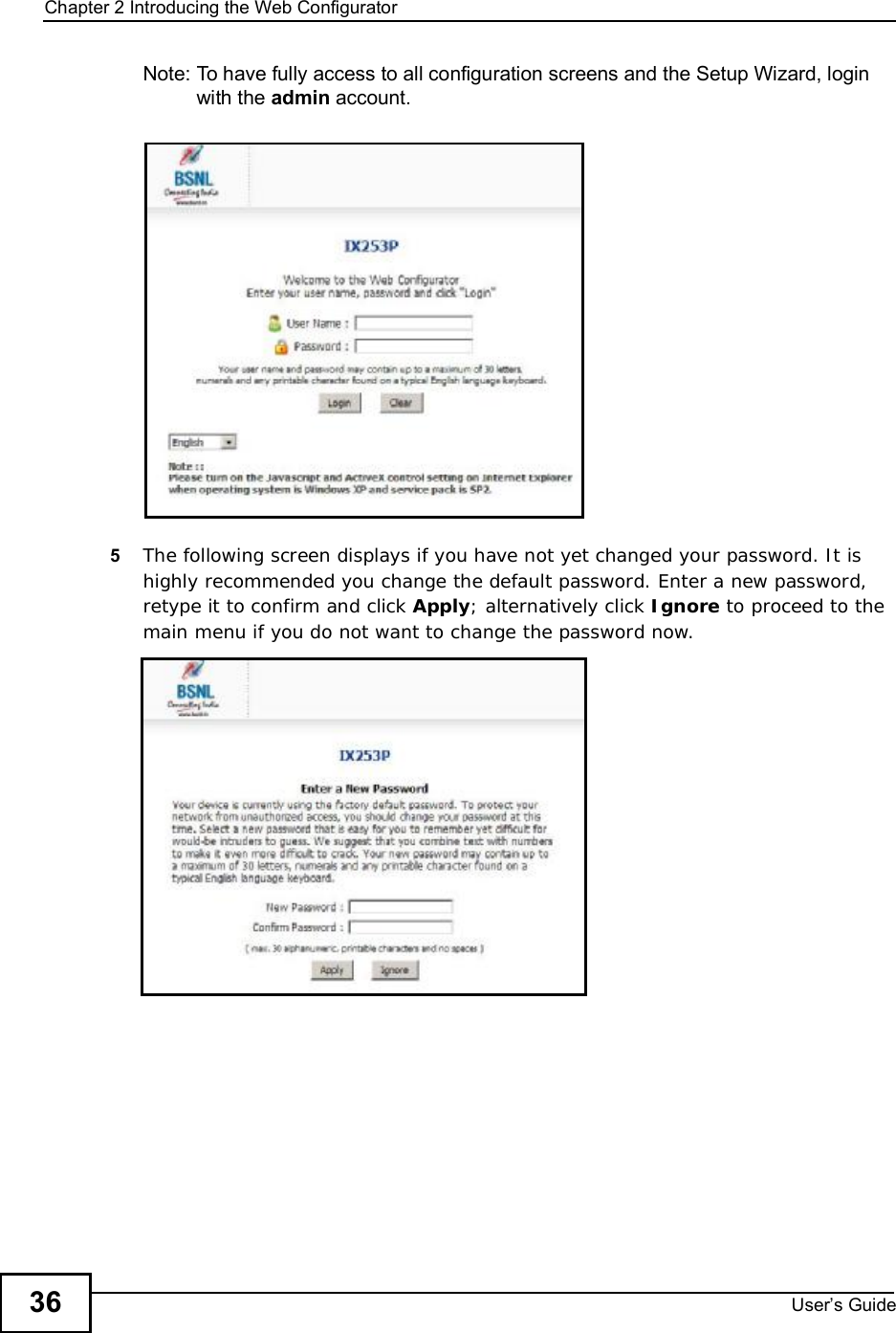
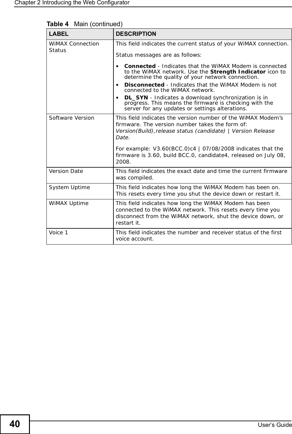

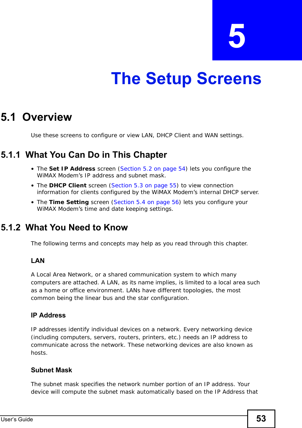
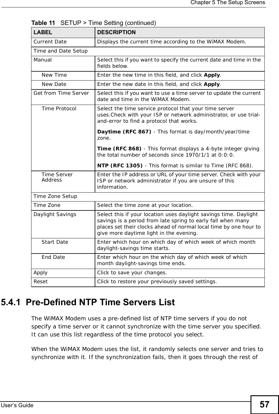
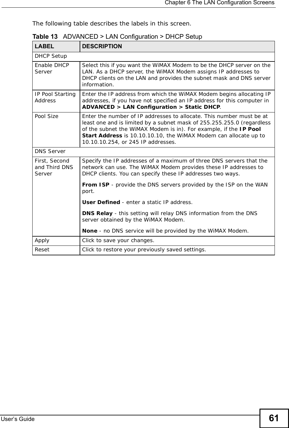
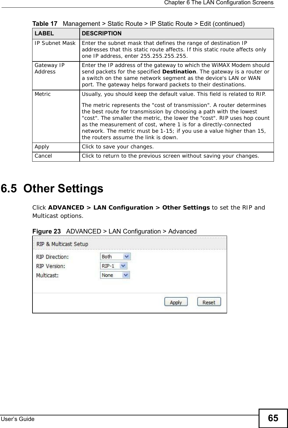
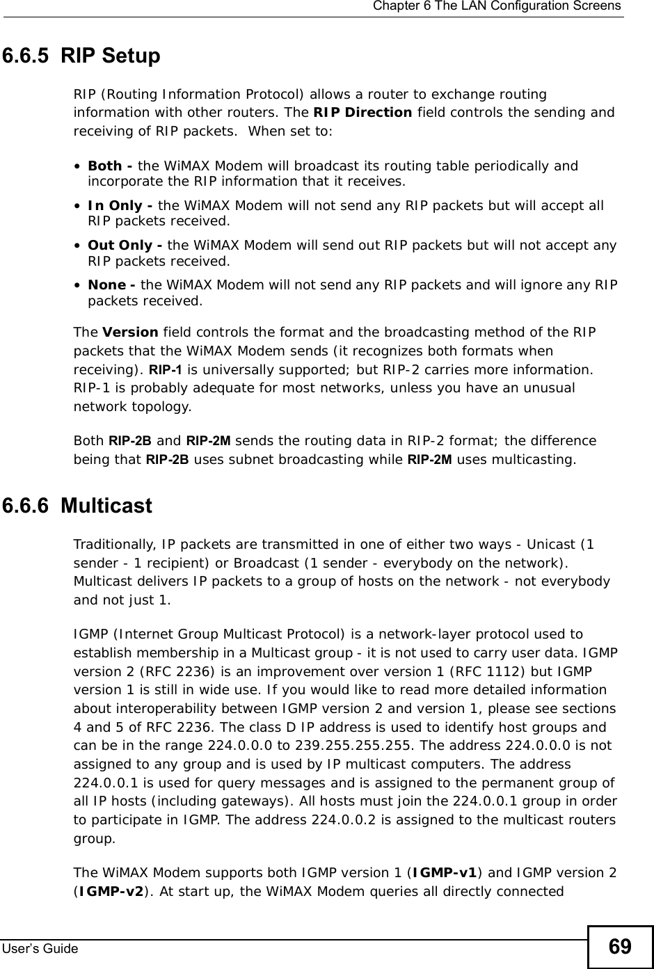
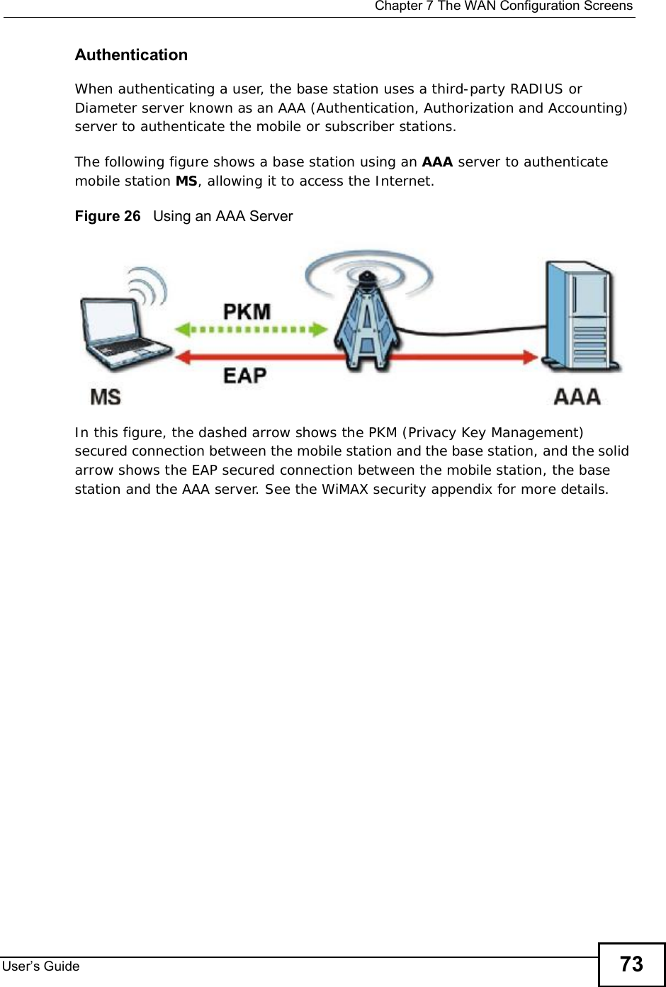
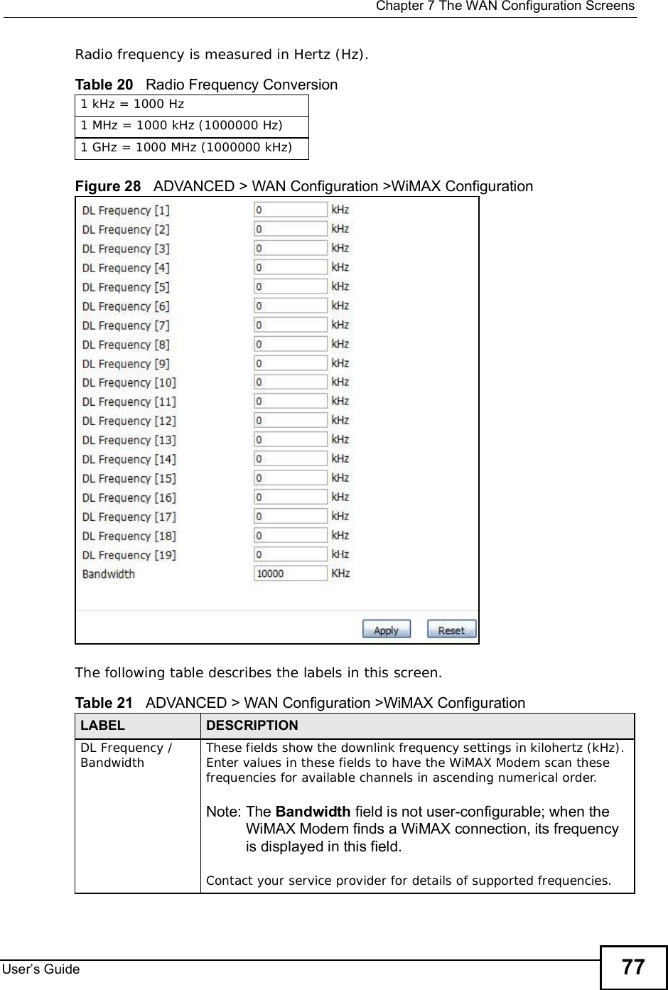
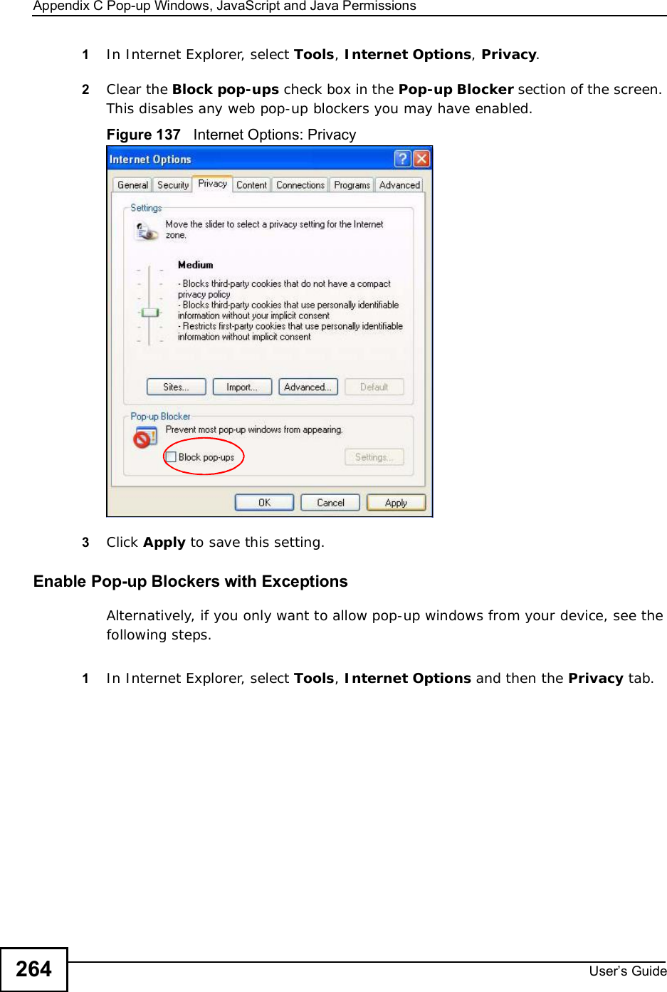
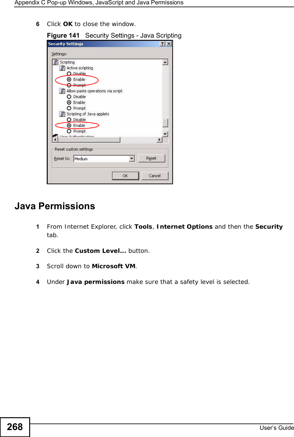
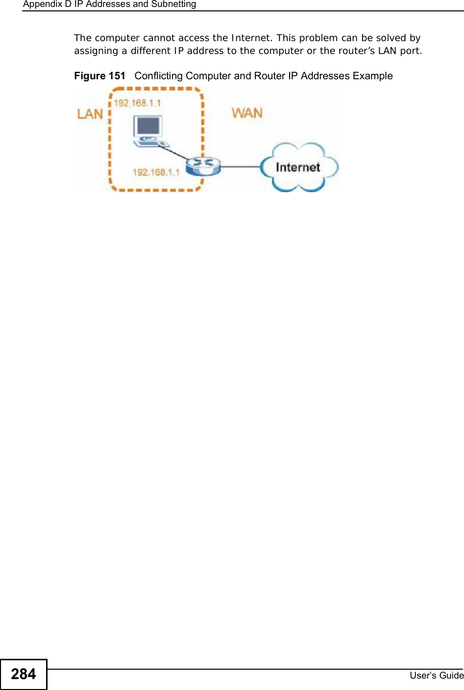
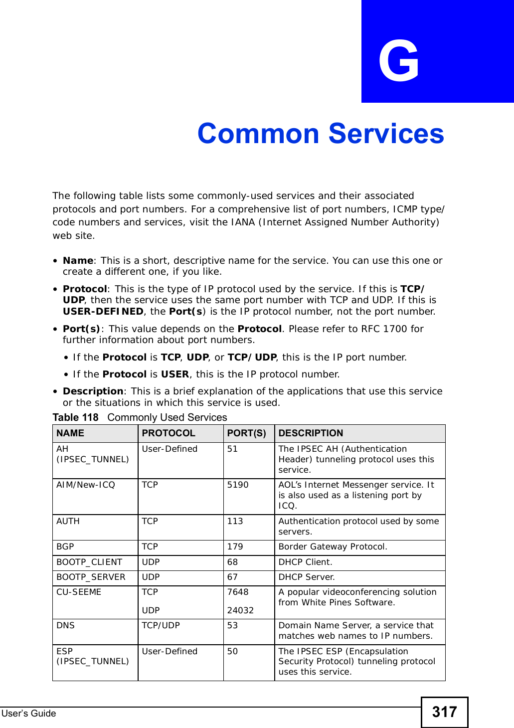
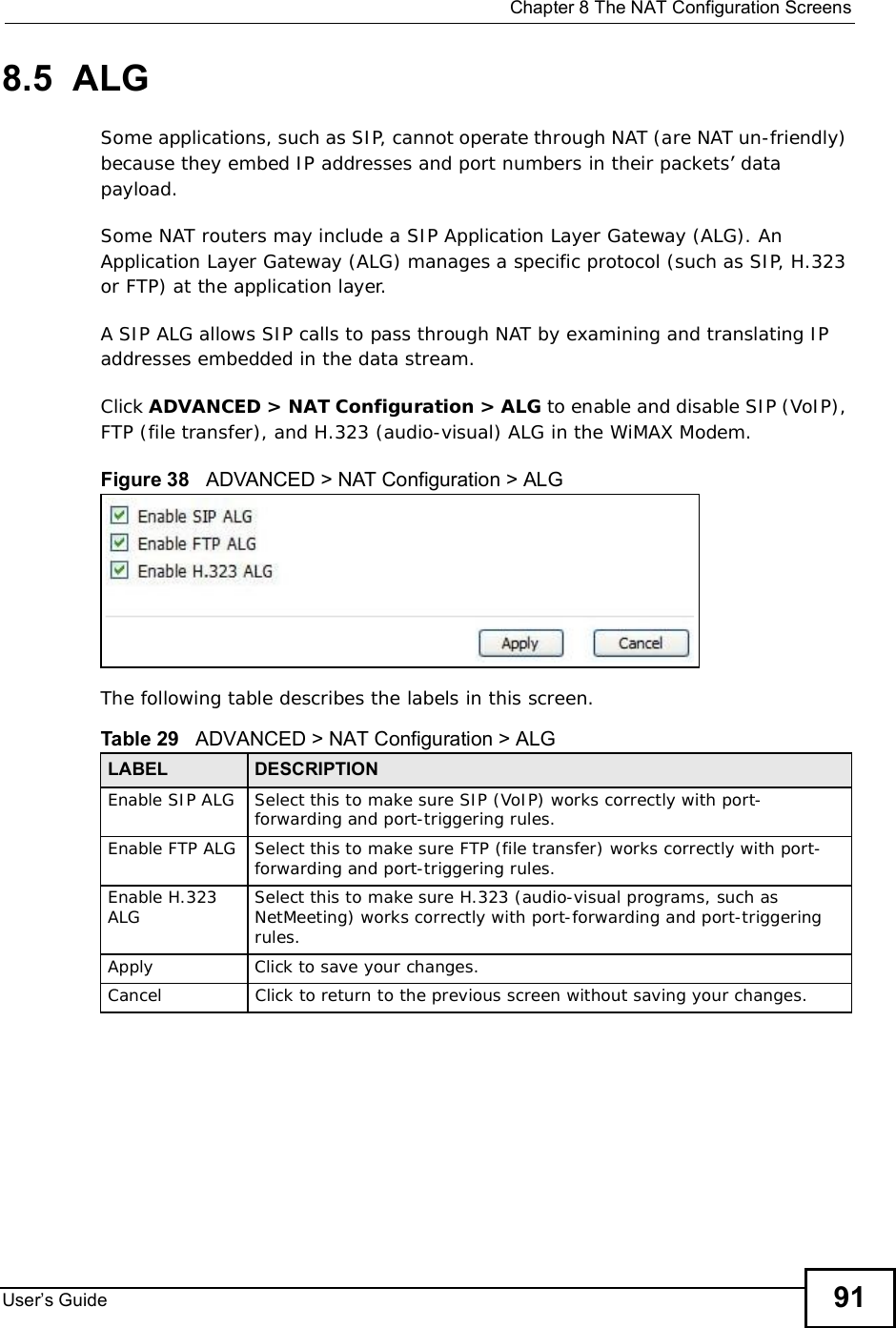
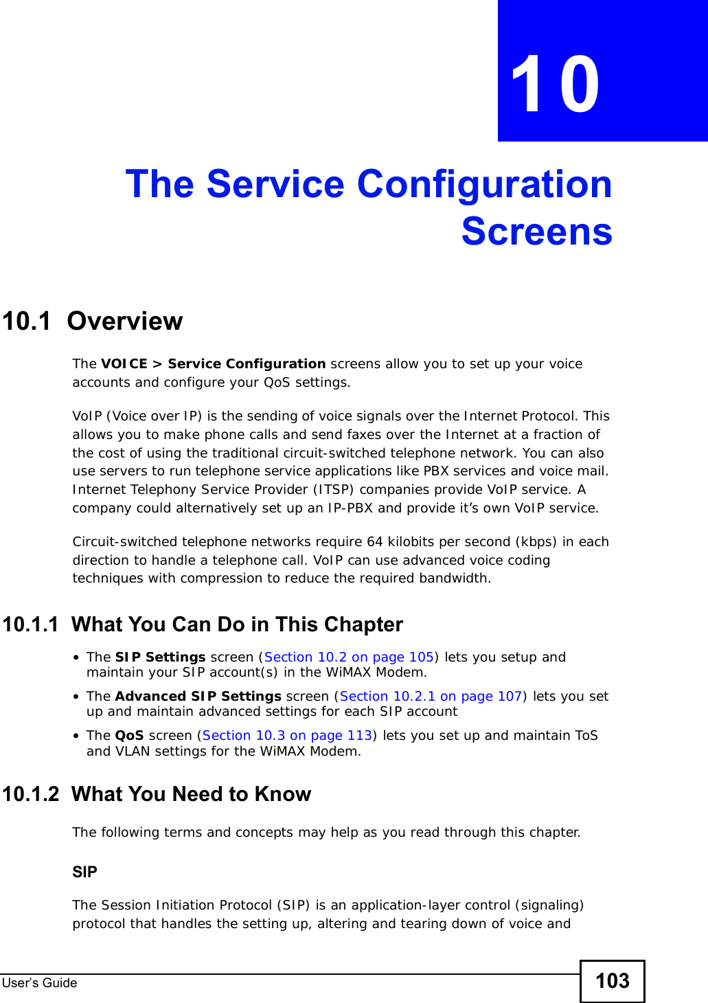
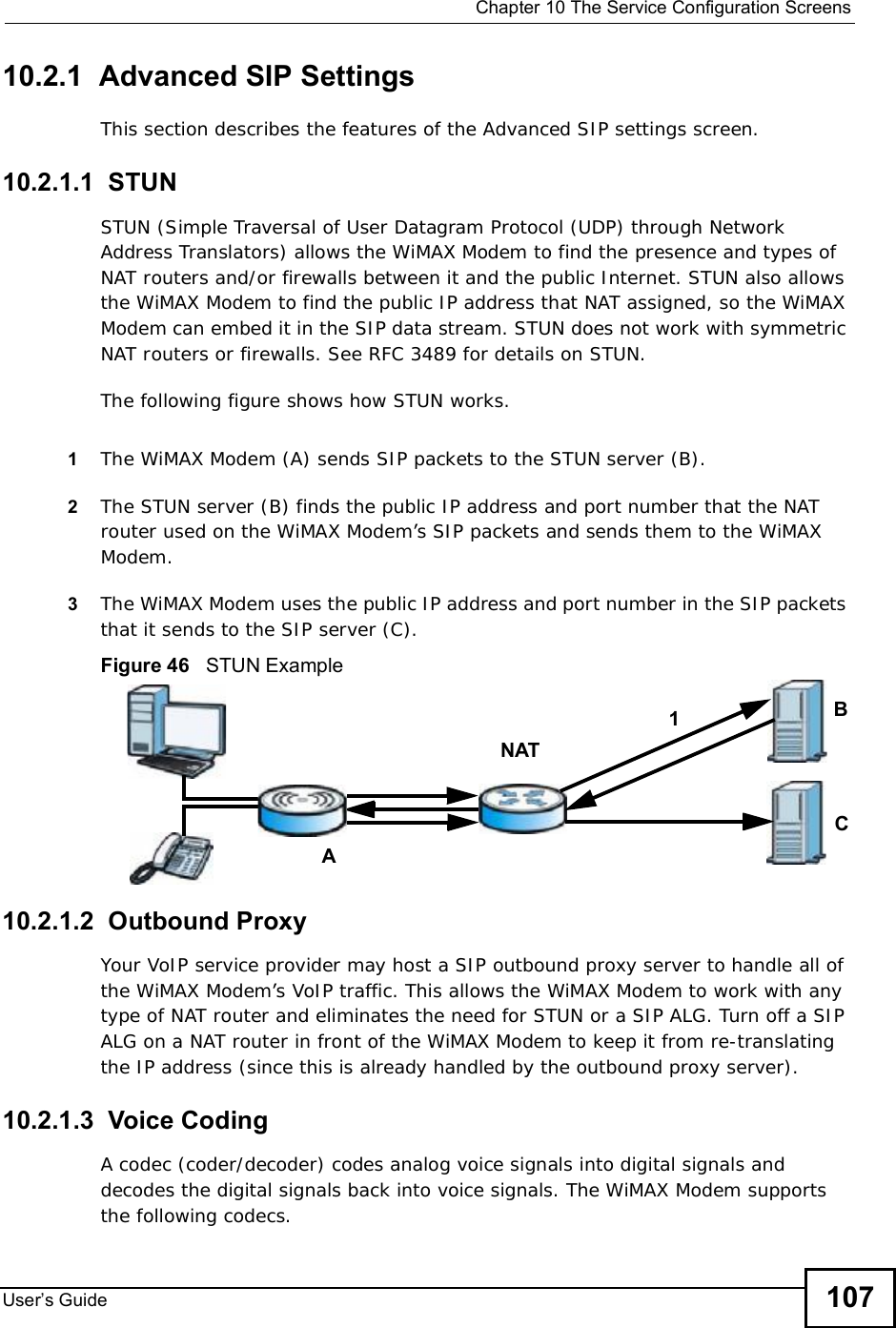
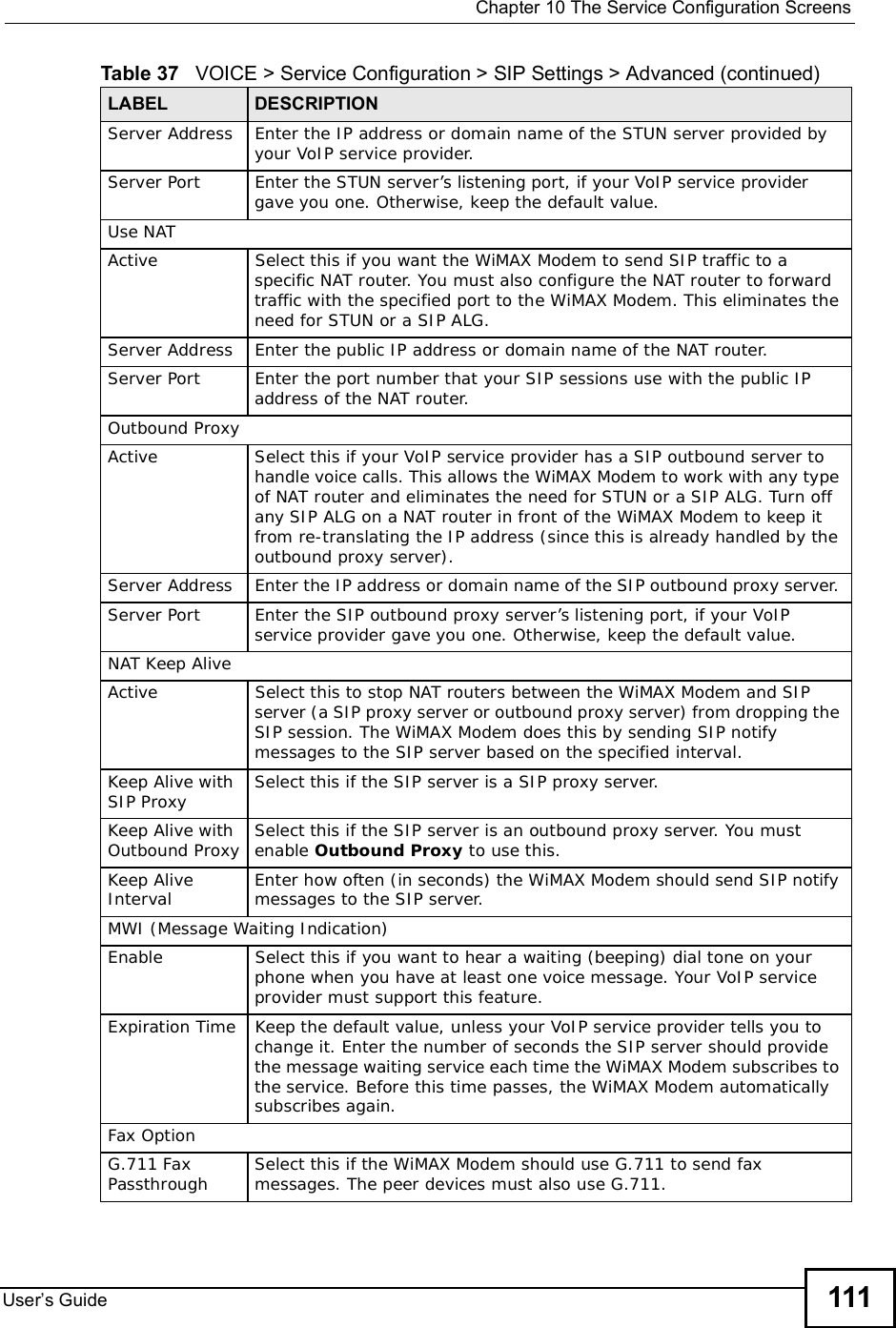
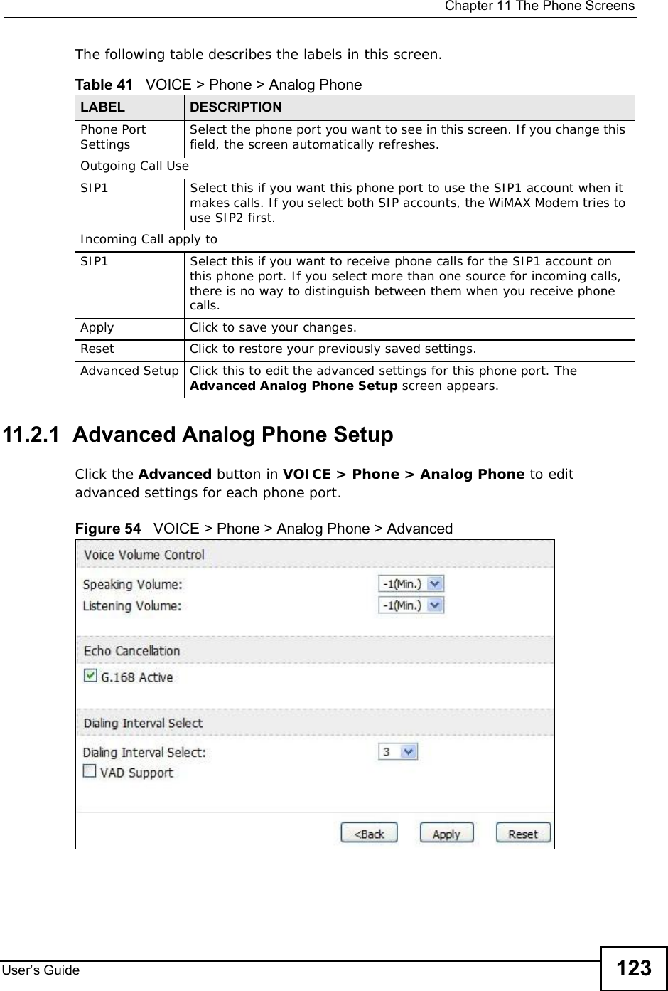
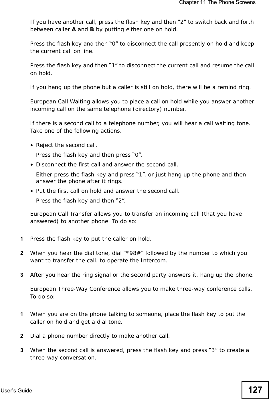
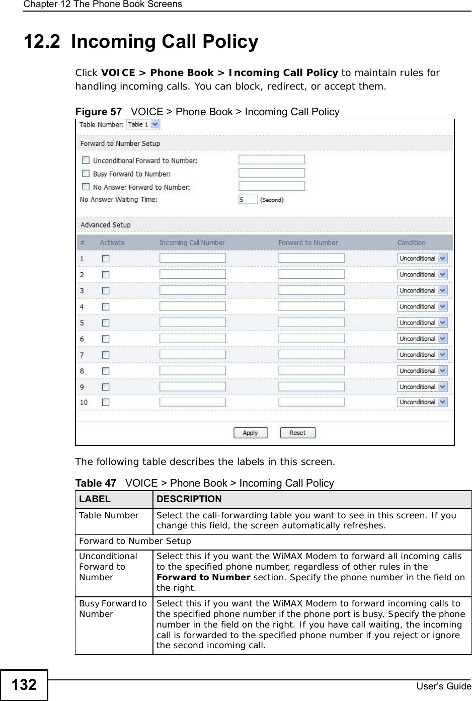
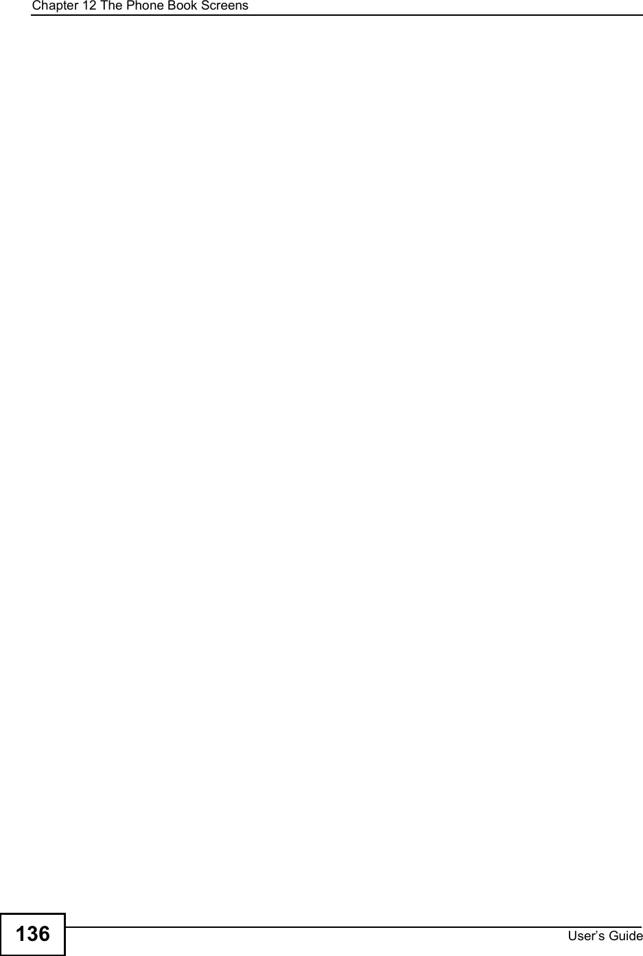
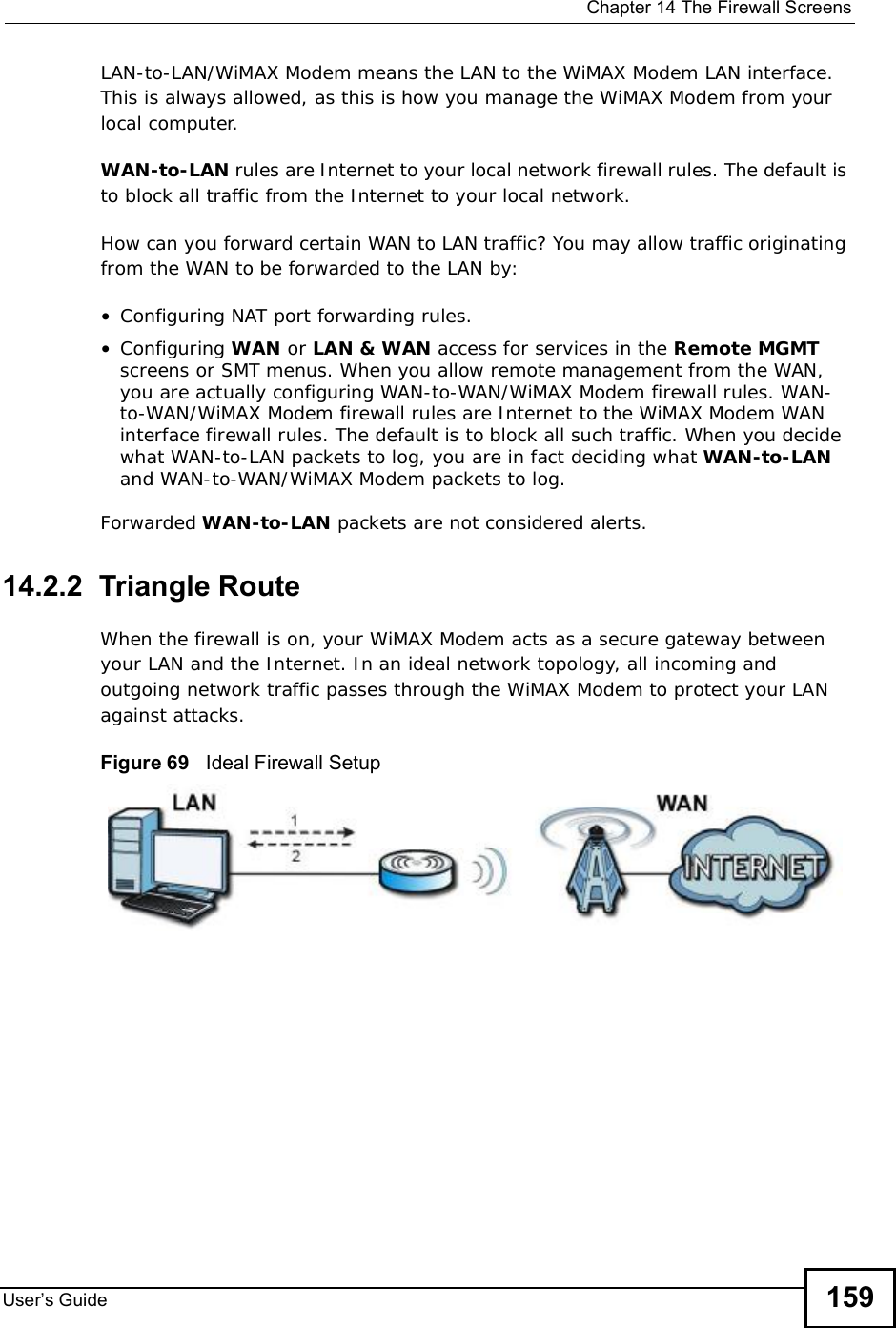
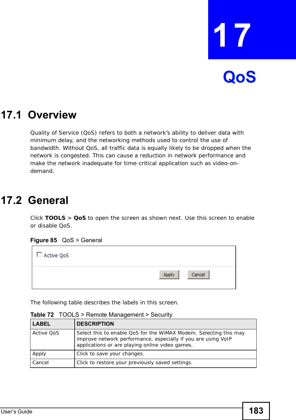
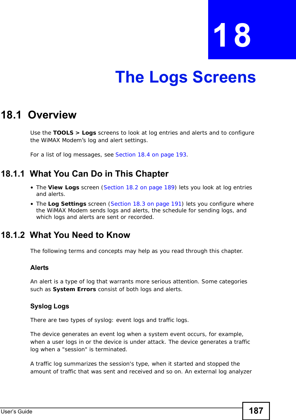
![Chapter 7The WAN Configuration ScreensUser s Guide 797.3.2 Configuring Frequency SettingsYou need to set the WiMAX Modem to scan one or more specific radio frequencies to find an available connection to a WiMAX base station. Use the WiMAX Frequency screen to define the radio frequencies to be searched for available wireless connections. See Section 7.3.3 on page 79 for an example of using the WiMAX Frequency screen.Note: It may take several minutes for the WiMAX Modem to find a connection.•The WiMAX Modem searches the DL Frequency settings in ascending numerical order, from [1] to [9].Note: The Bandwidth field is not user-configurable; when the WiMAX Modem finds a WiMAX connection, its frequency is displayed in this field.•If you enter a 0 in a DL Frequency field, the WiMAX Modem immediately moves on to the next DL Frequency field.•When the WiMAX Modem connects to a base station, the values in this screen are automatically set to the base station’s frequency. The next time the WiMAX Modem searches for a connection, it searches only this frequency. If you want the WiMAX Modem to search other frequencies, enter them in the DLFrequency fields.The following table describes some examples of DL Frequency settings.7.3.3 Using the WiMAX Frequency ScreenIn this example, your Internet service provider has given you a list of supported frequencies: 2.51, 2.525, 2.6, and 2.625. Table 22 DL Frequency Example SettingsEXAMPLE 1 EXAMPLE 2DL Frequency [1] 25000002500000DL Frequency [2] 25500002550000DL Frequency [3] 02600000DL Frequency [4] 00DL Frequency [5] 00The WiMAX Modem searches at 2500000 kHz, and then searches at 2550000 kHz if it has not found a connection.The WiMAX Modemsearches at 2500000 kHz and then at 2550000 kHz if it has not found an available connection. If it still does not find an available connection, it searches at 2600000 kHz.](https://usermanual.wiki/ZyXEL-Communications/IX253P/User-Guide-1403071-Page-78.png)
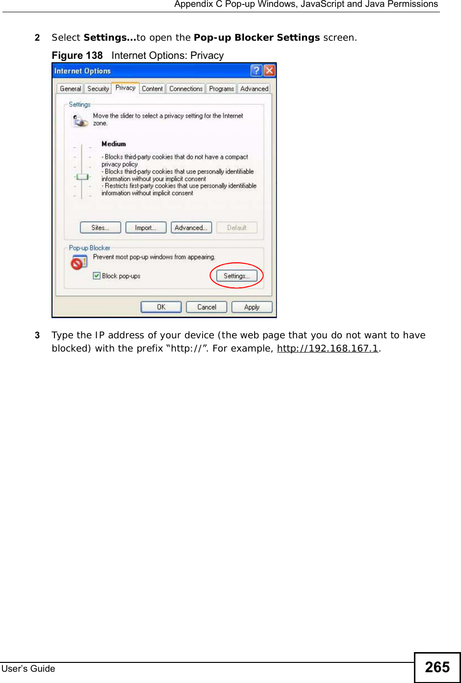
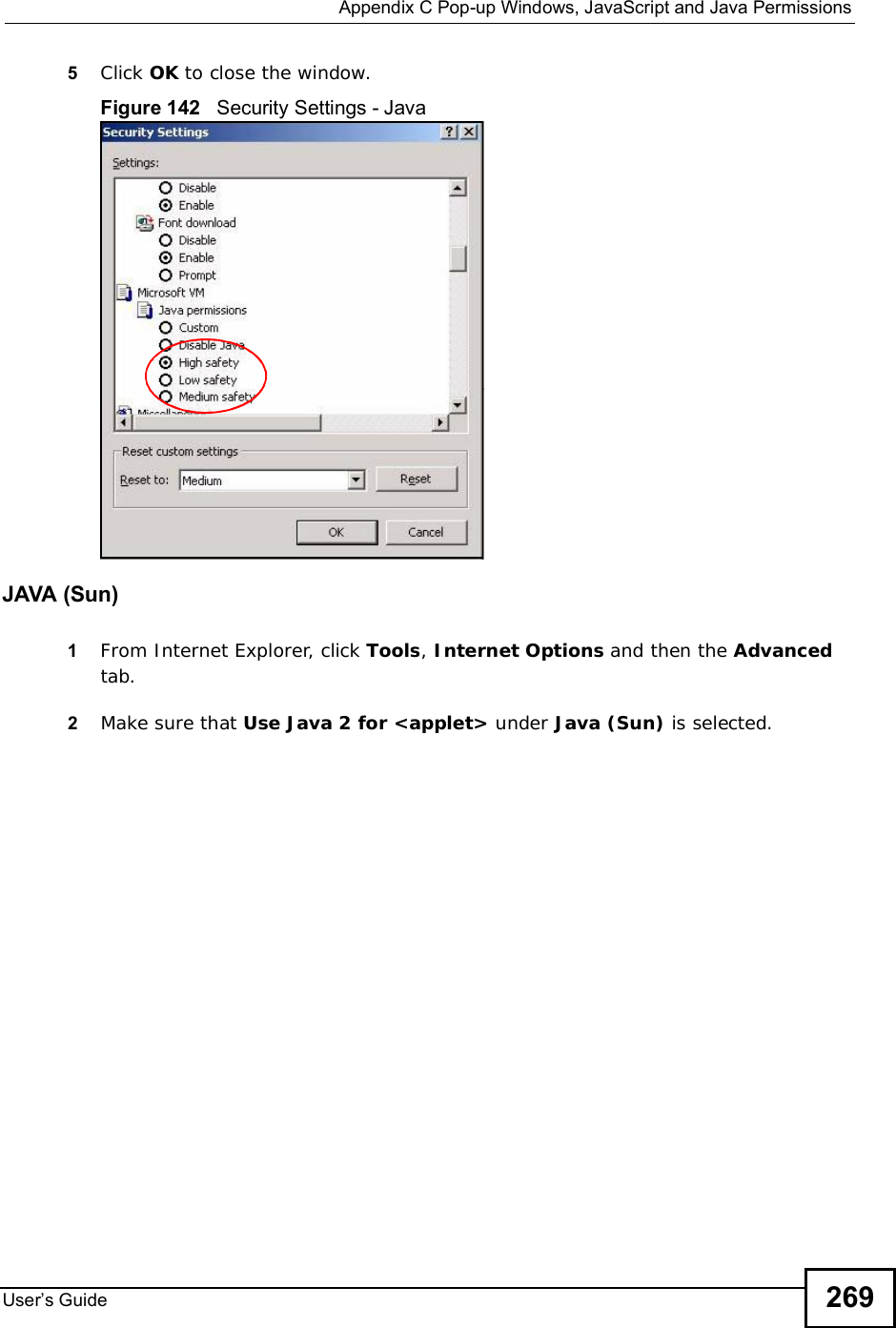
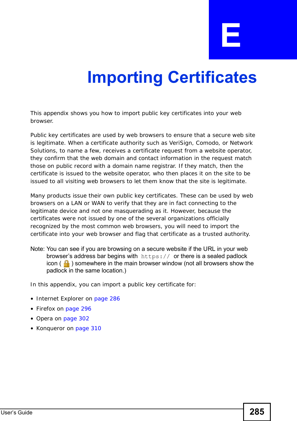
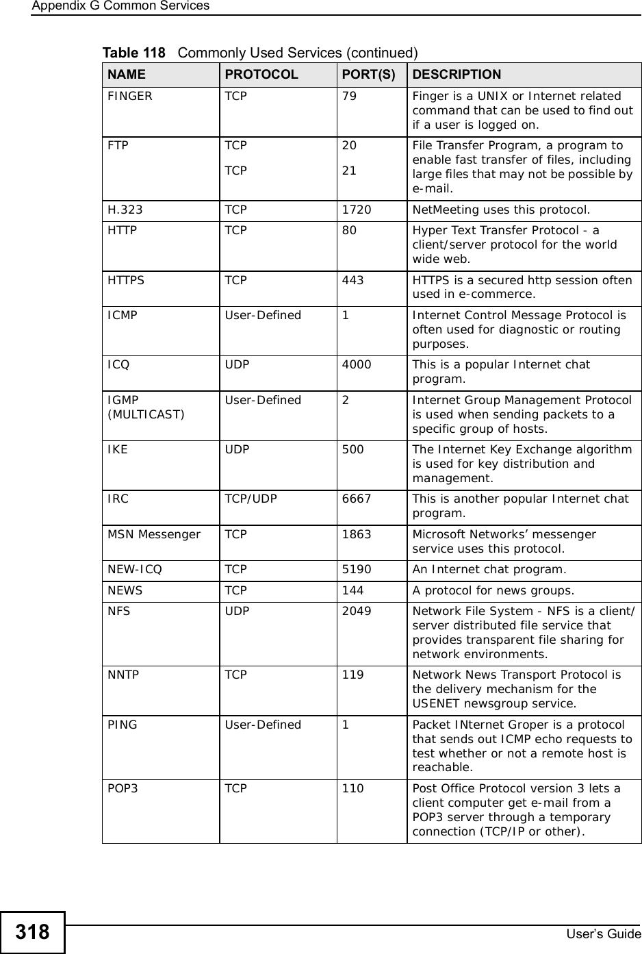
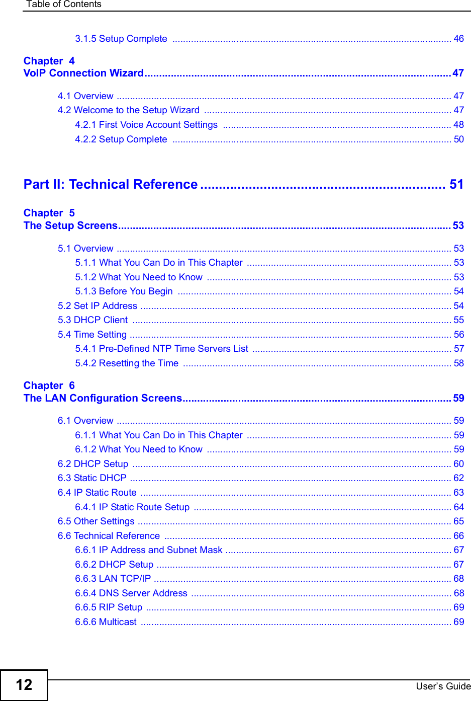
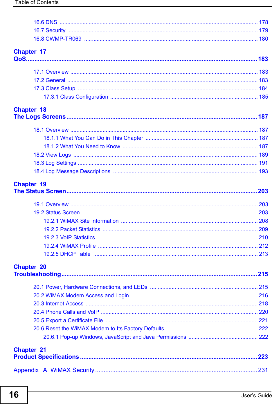
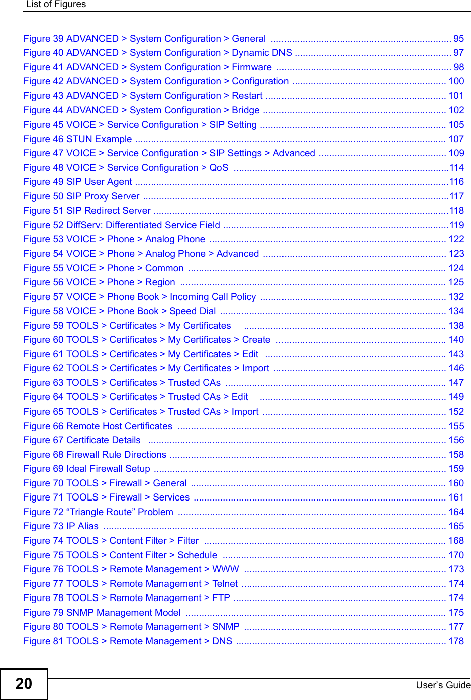
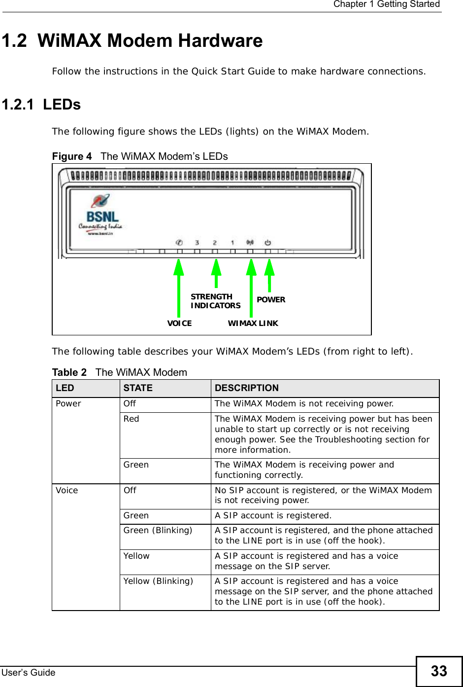
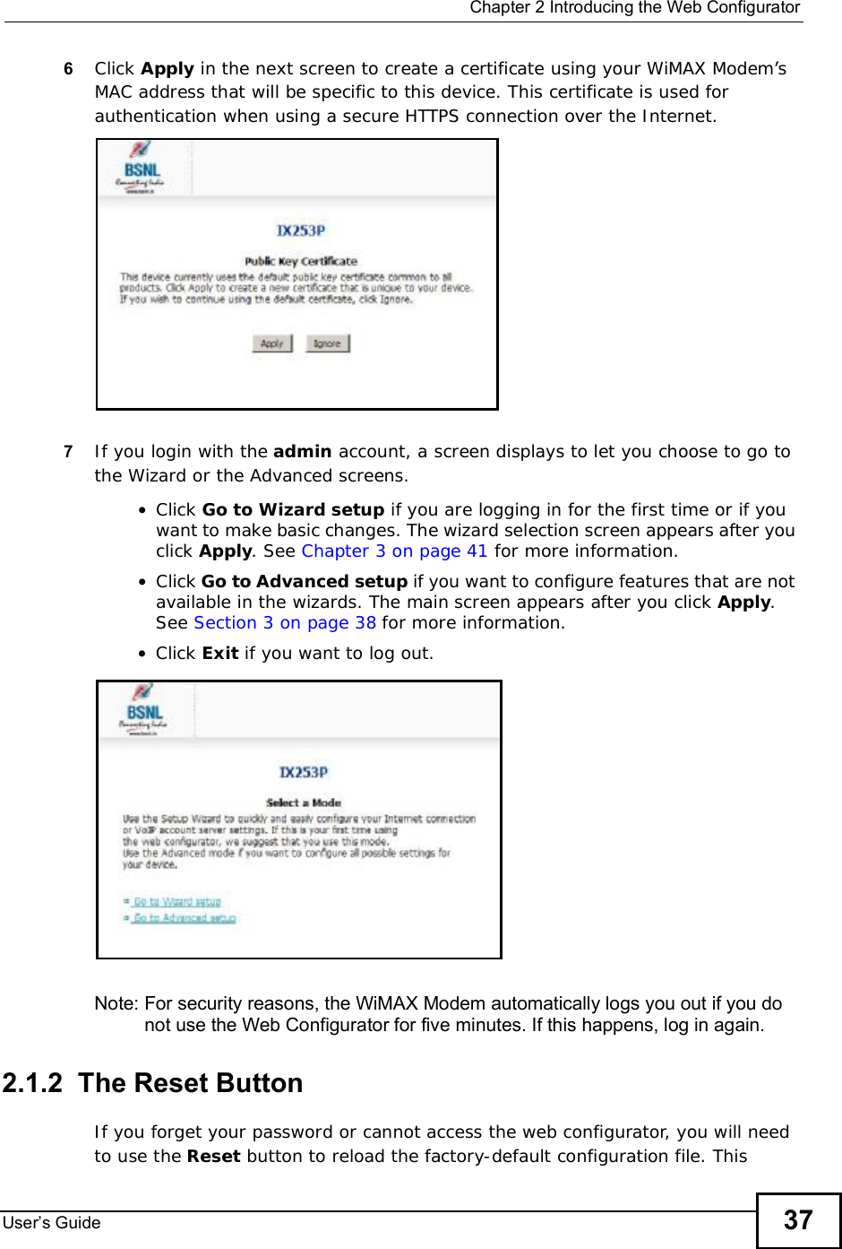
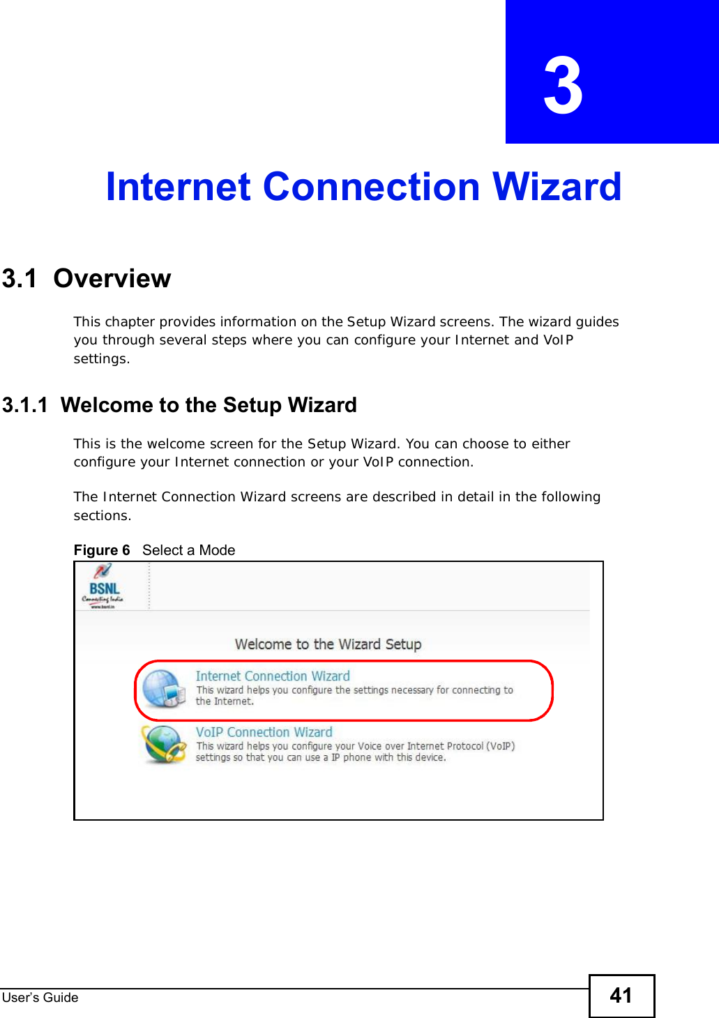
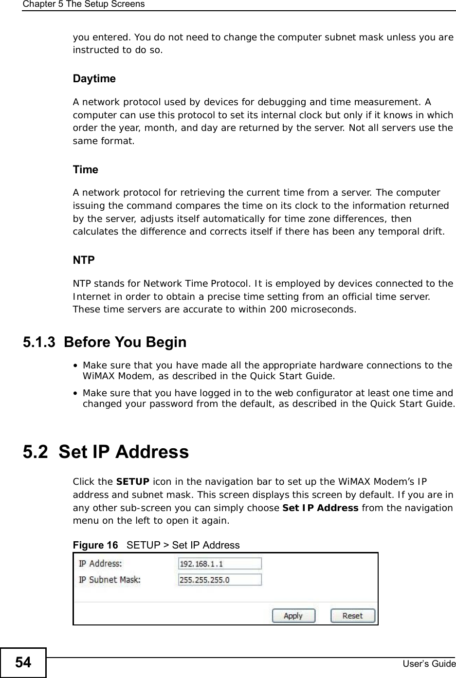
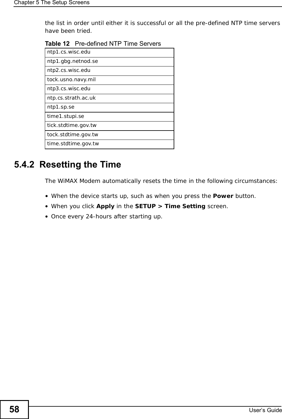
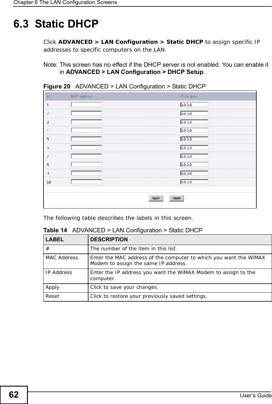
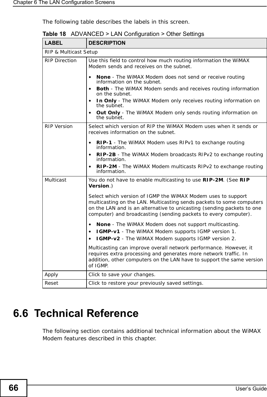
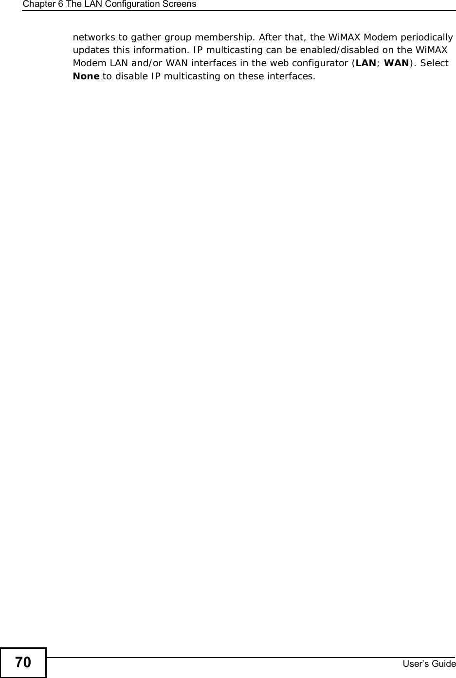
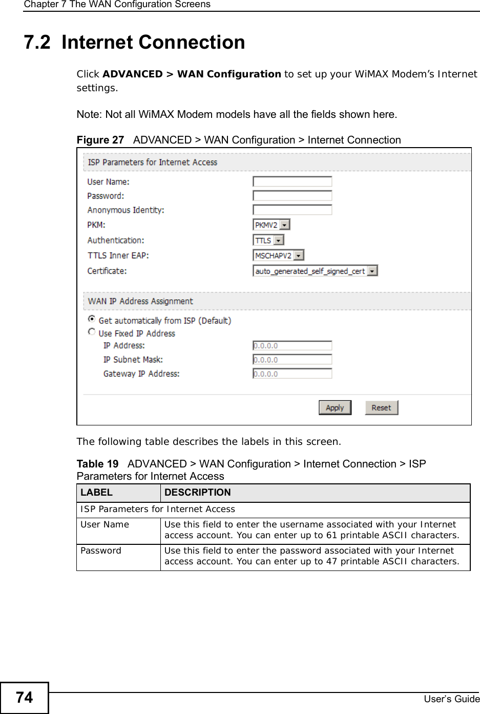
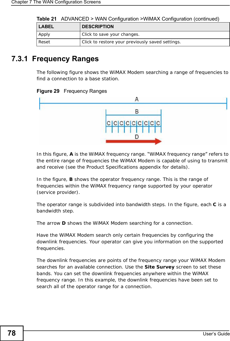
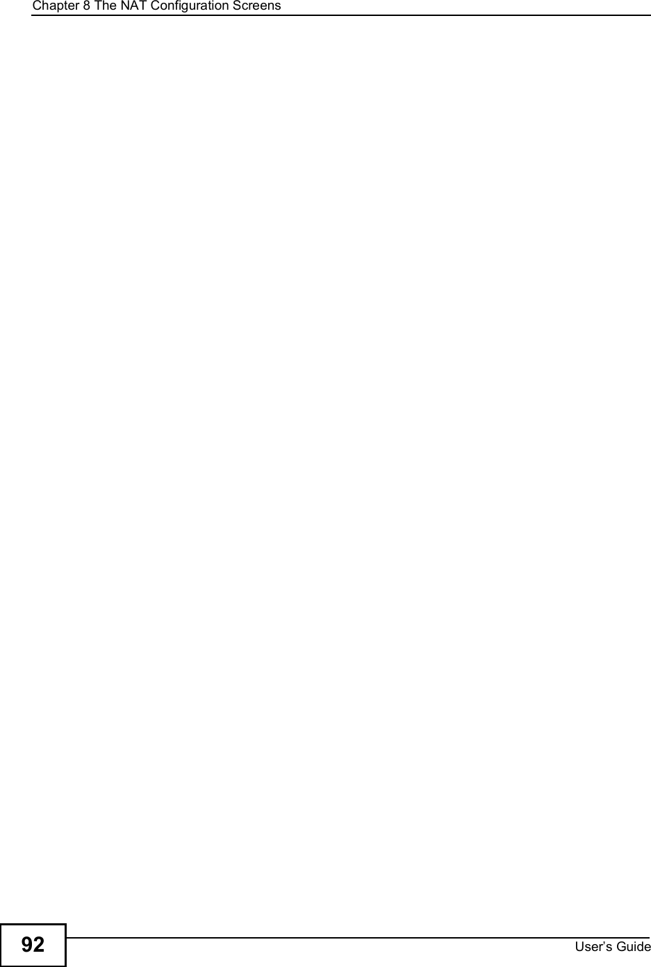
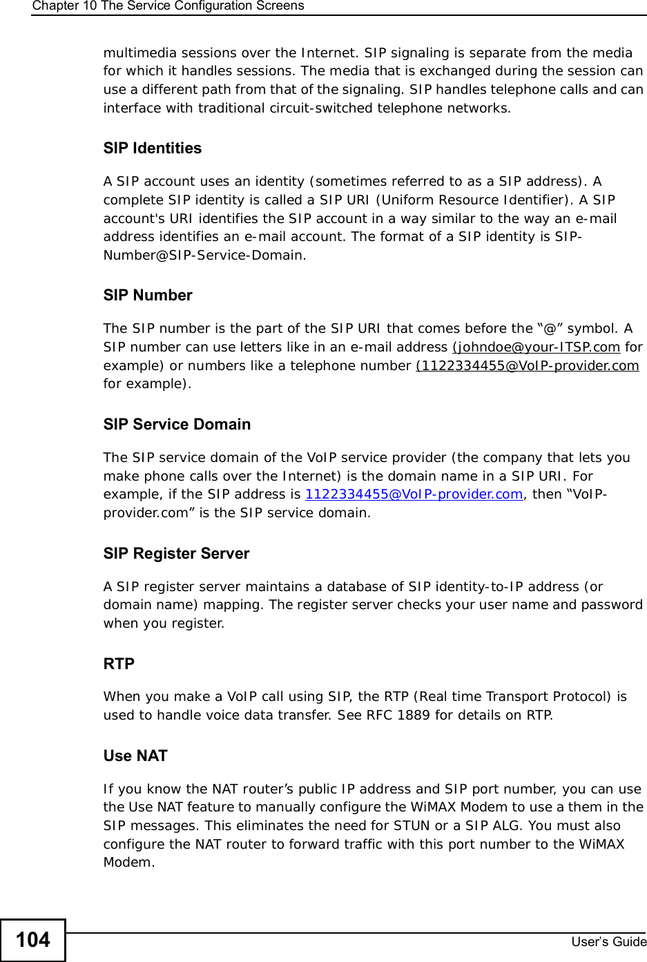
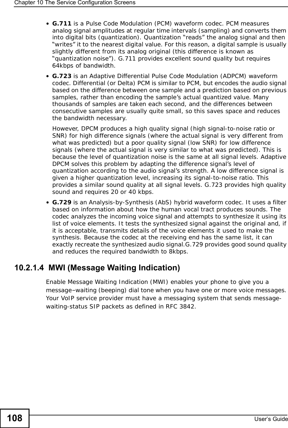
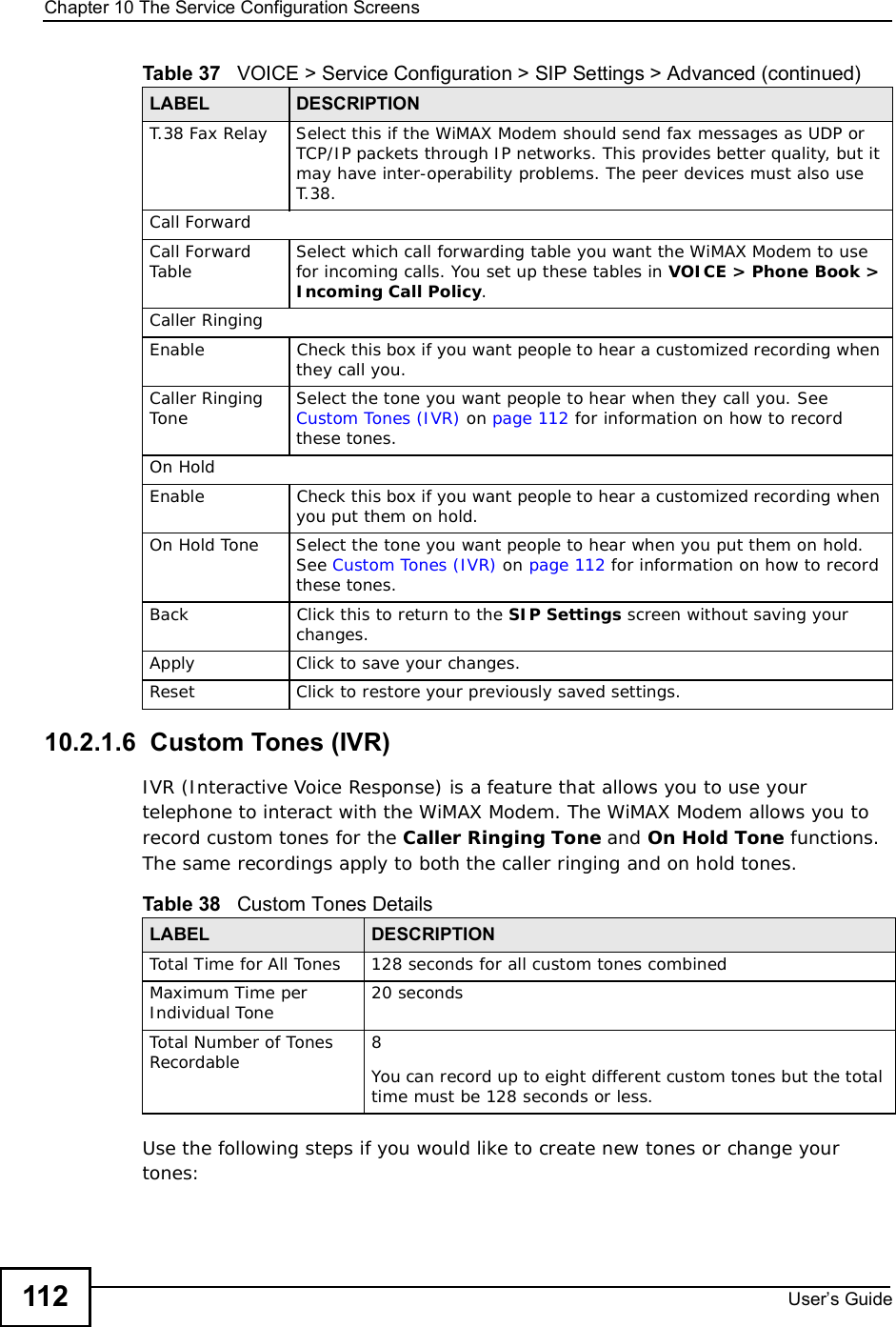
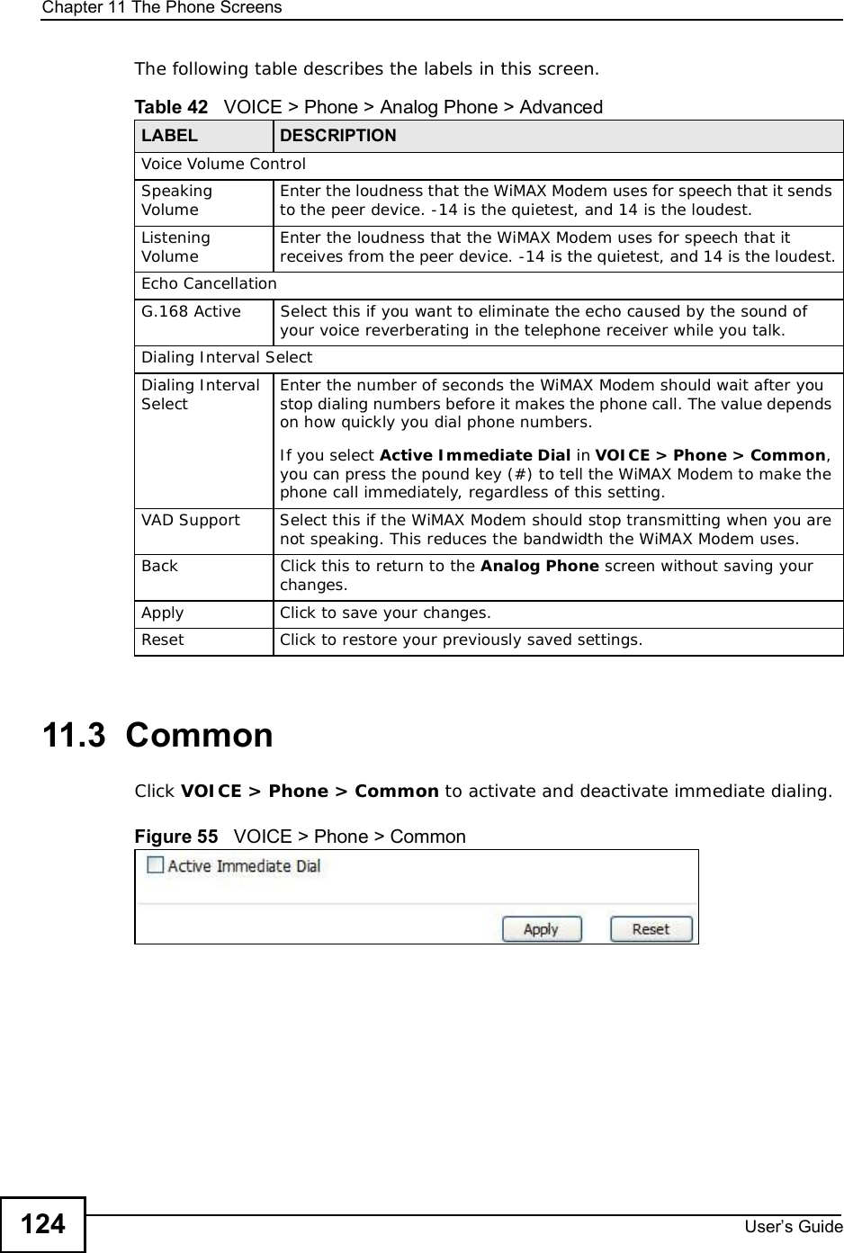
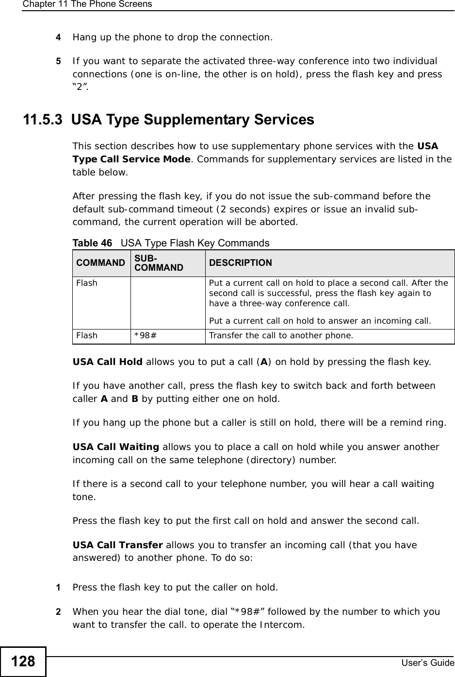
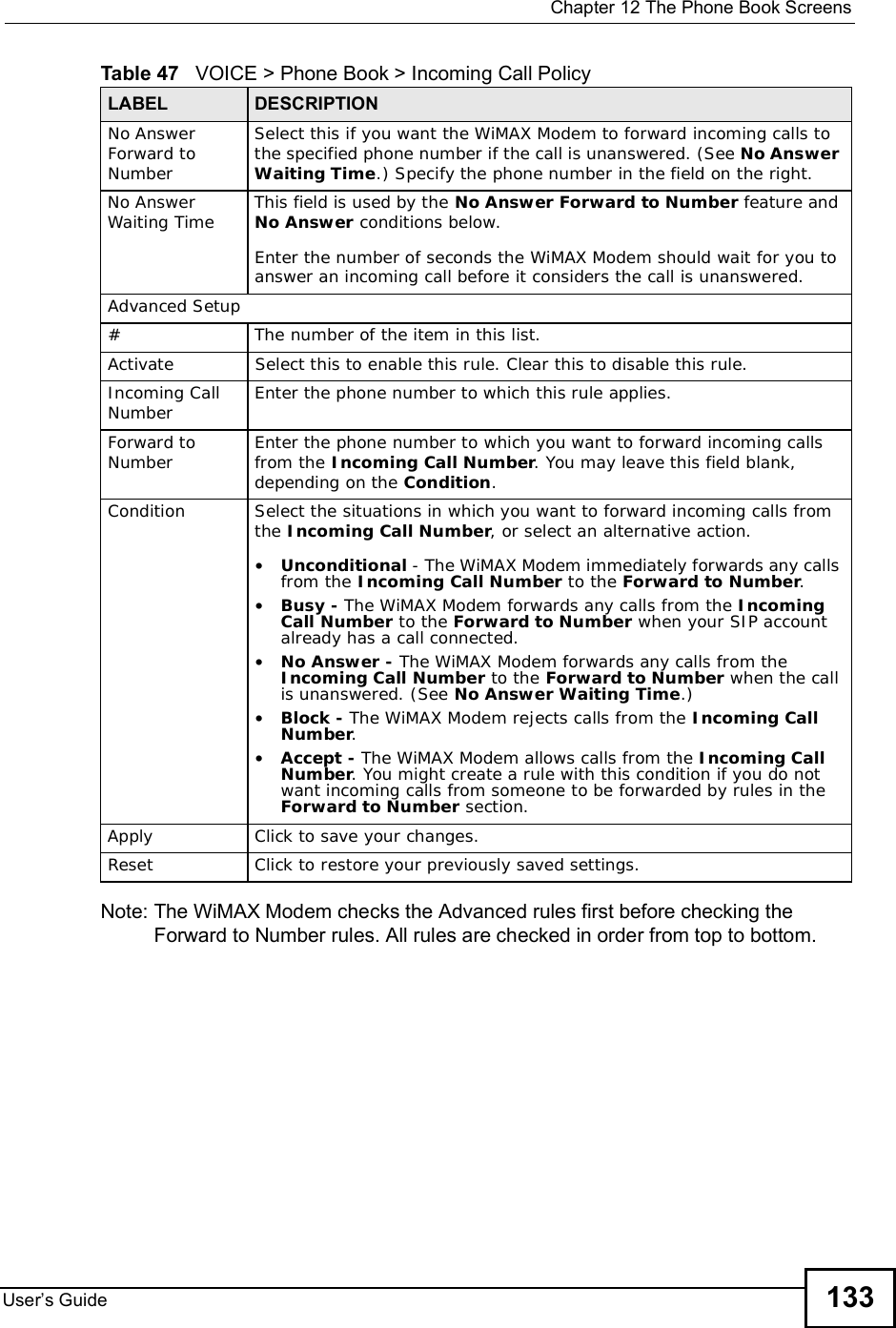
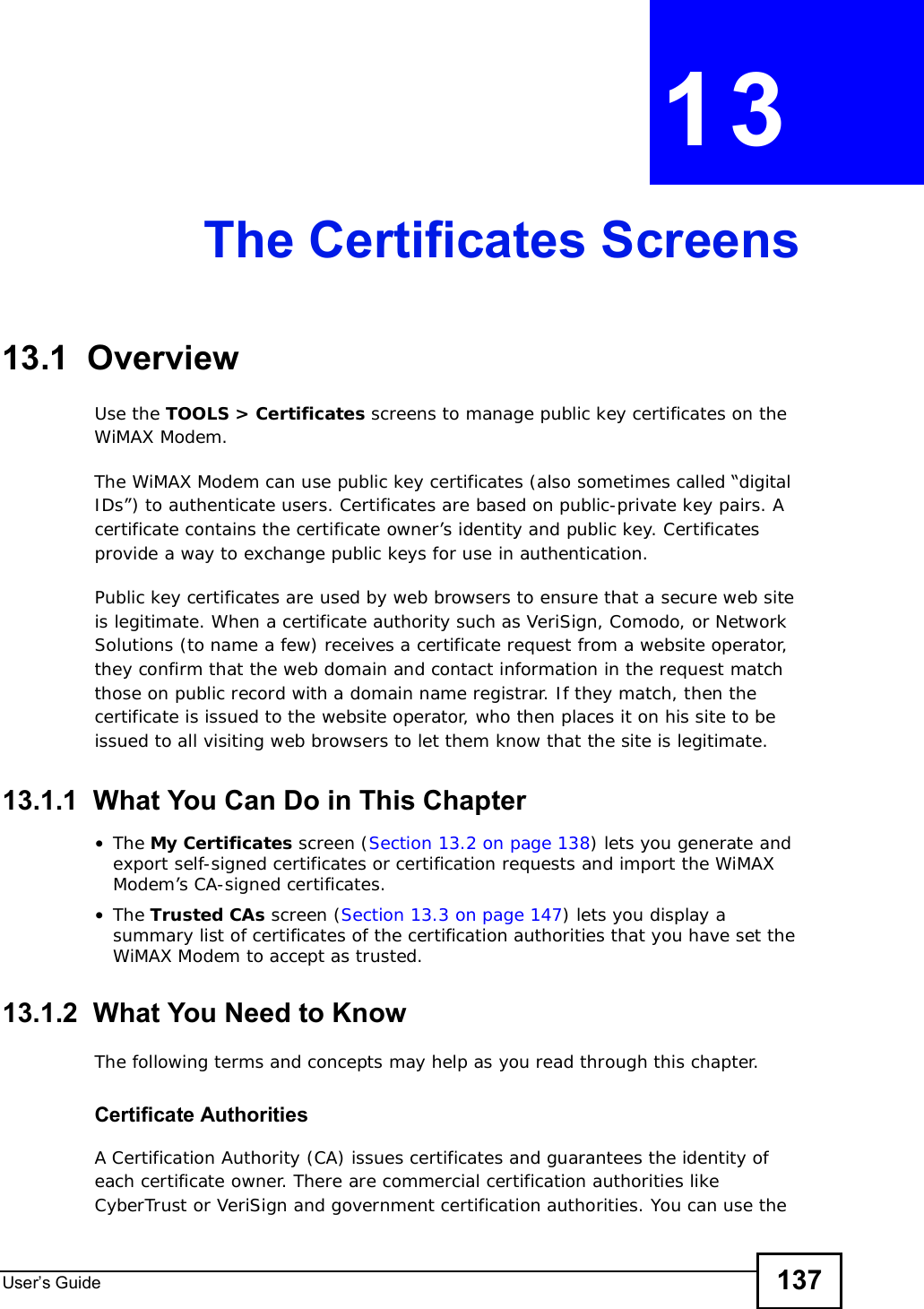
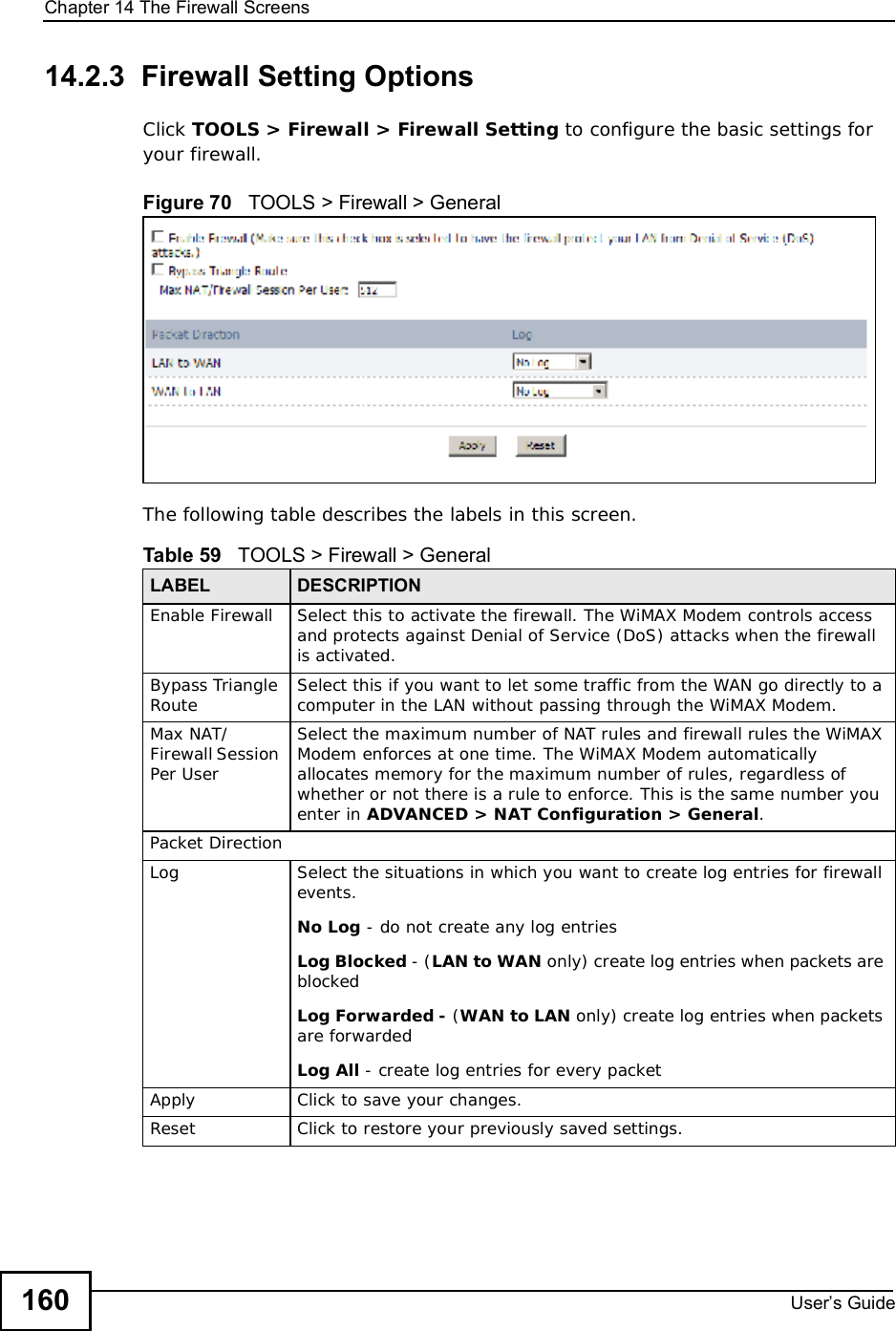
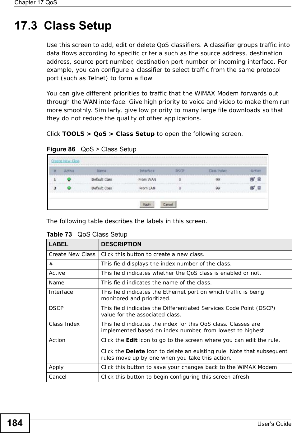
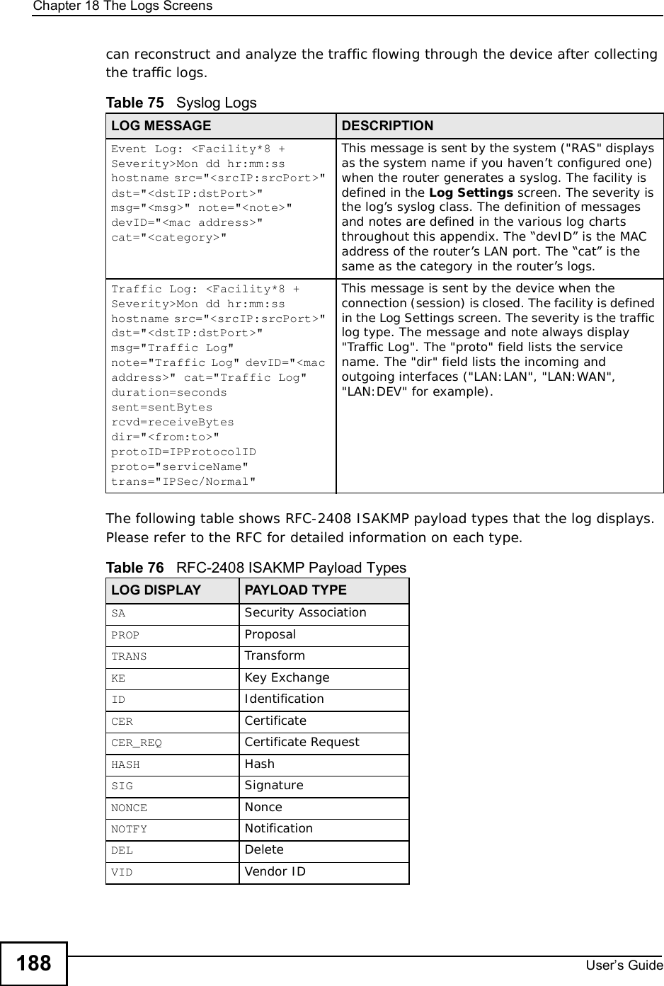
![Chapter 7The WAN Configuration ScreensUser s Guide801In the DL Frequency [1] field, enter 2510000 (2510000 kilohertz (kHz) is equal to 2.51 gigahertz).2In the DL Frequency [2] field, enter 2525000.3In the DL Frequency [3] field, enter 2600000.4In the DL Frequency [4] field, enter 2625000.Leave the rest of the DL Frequency fields at zero. The screen appears as follows.Figure 30 Completing the WiMAX Frequency Screen5Click Apply. The WiMAX Modem stores your settings. When the WiMAX Modem searches for available frequencies, it scans all frequencies from DL Frequency [1] to DL Frequency [4]. When it finds an available connection, the fields in this screen will be automatically set to use that frequency.](https://usermanual.wiki/ZyXEL-Communications/IX253P/User-Guide-1403071-Page-79.png)
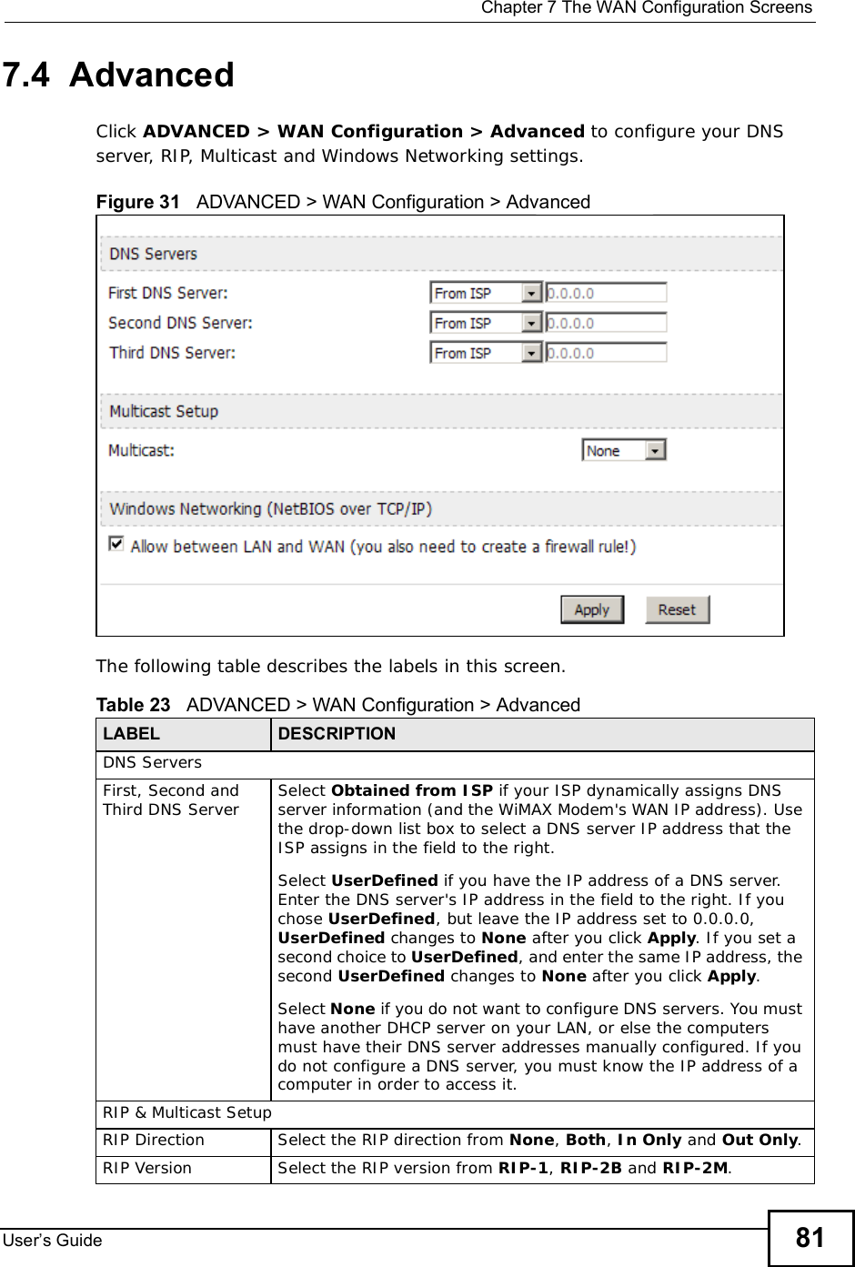
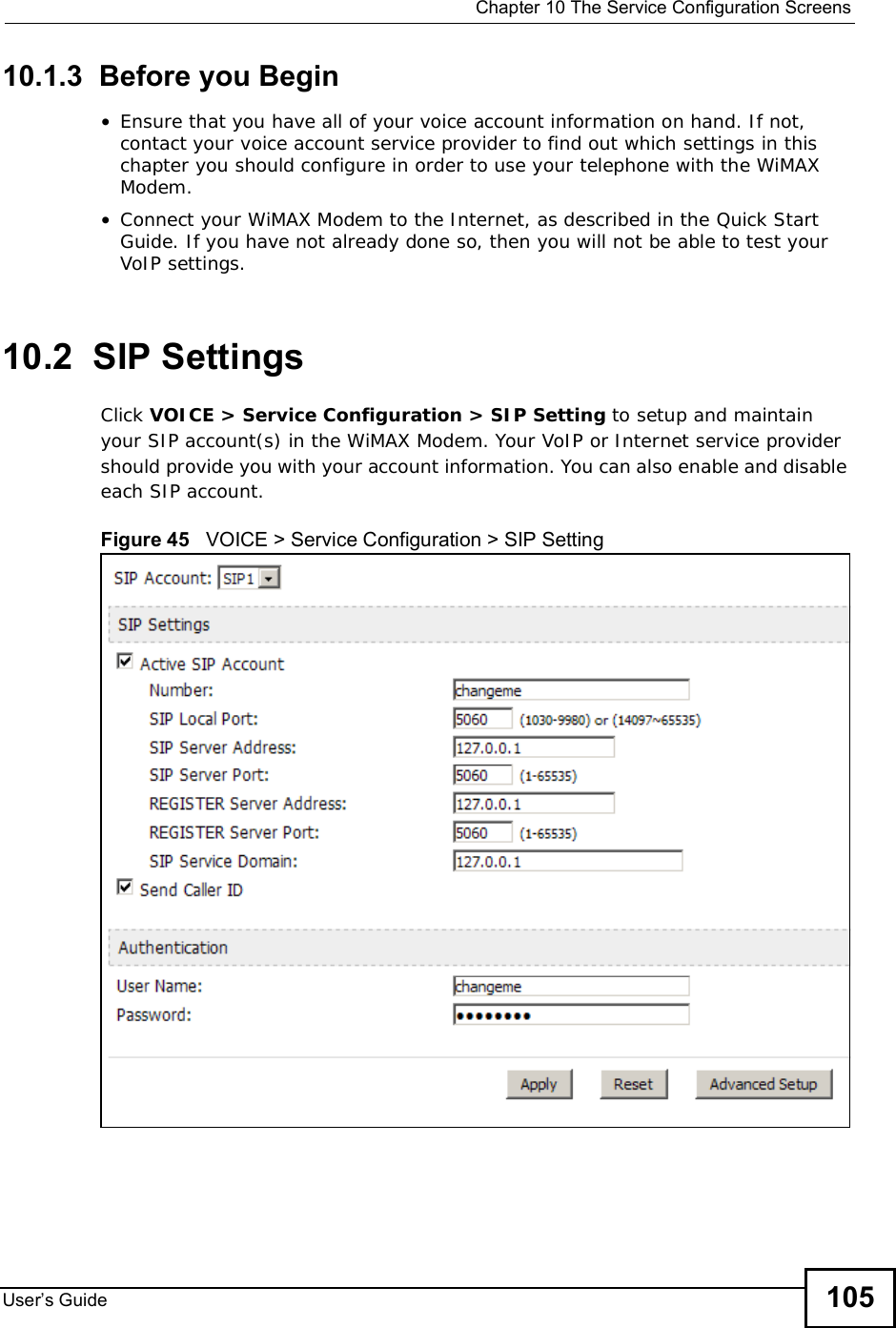
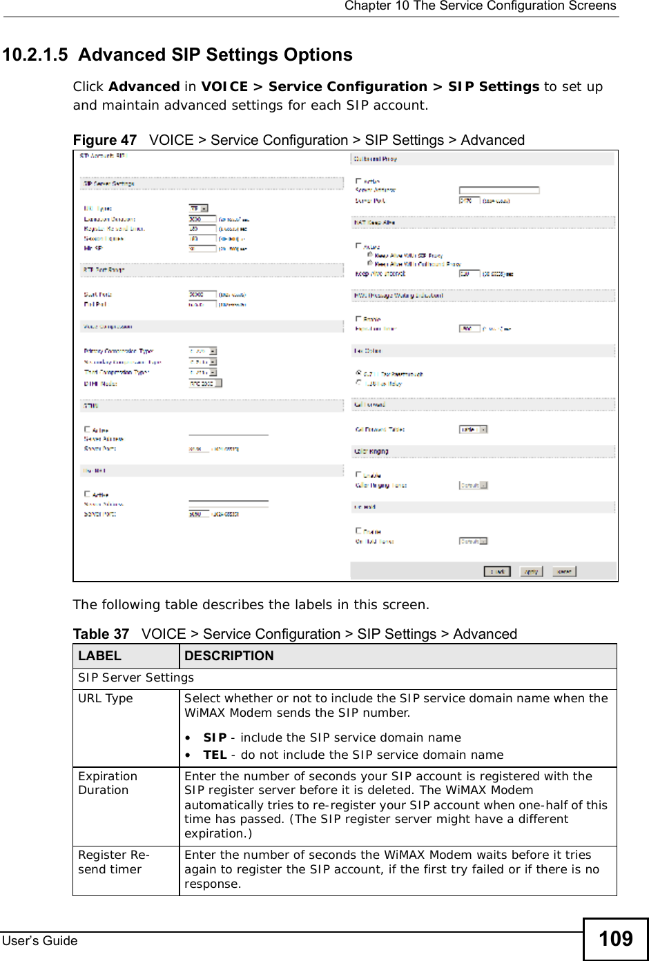
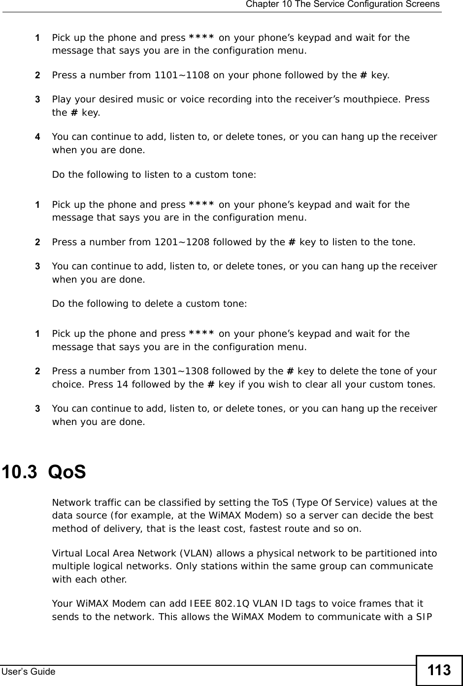
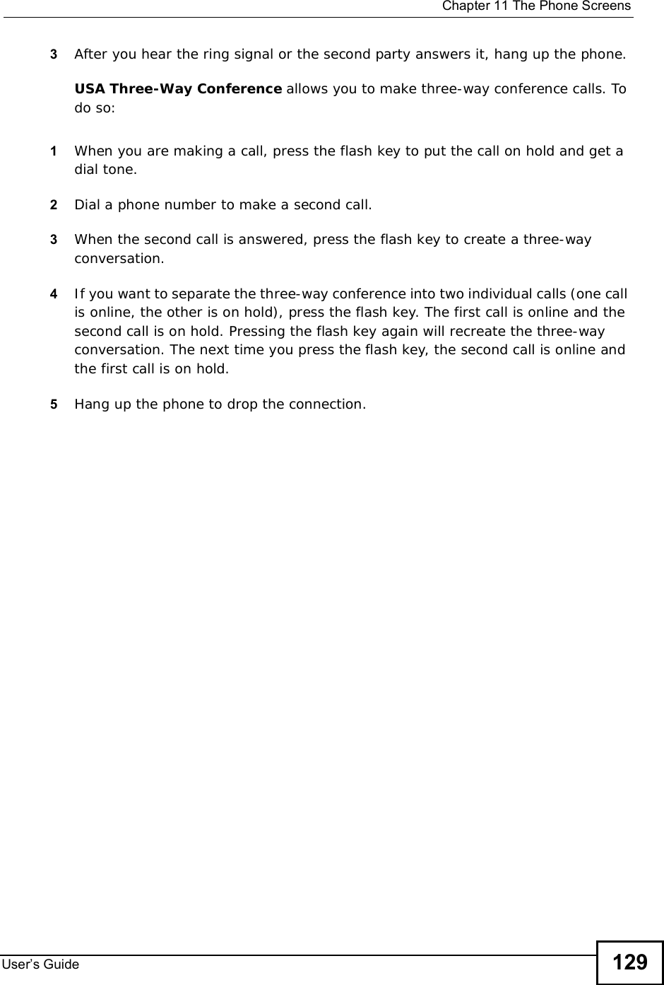

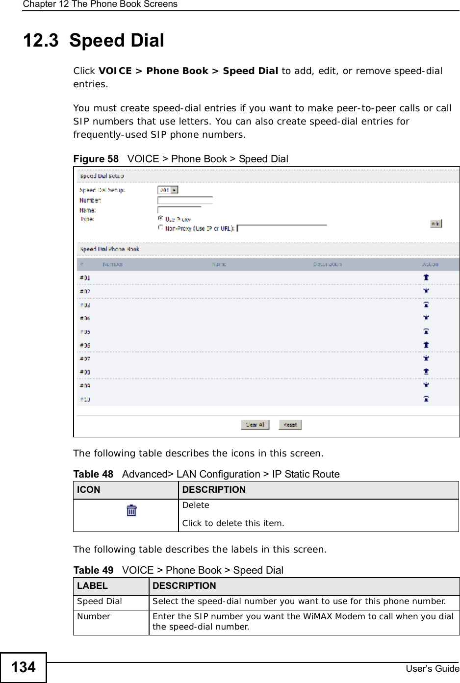
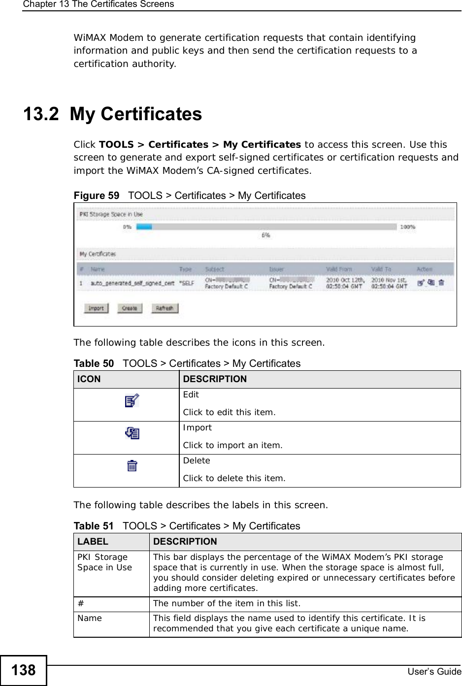
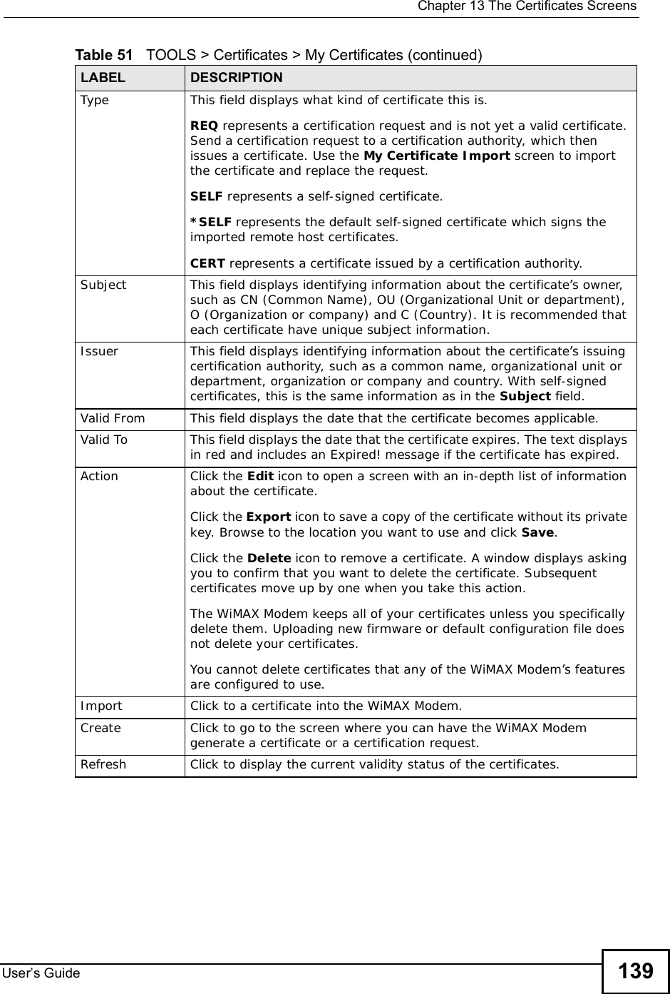
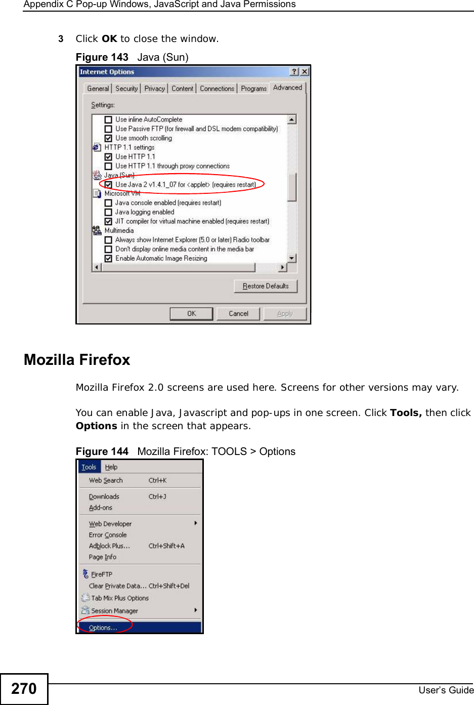
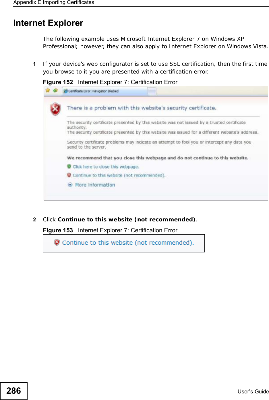
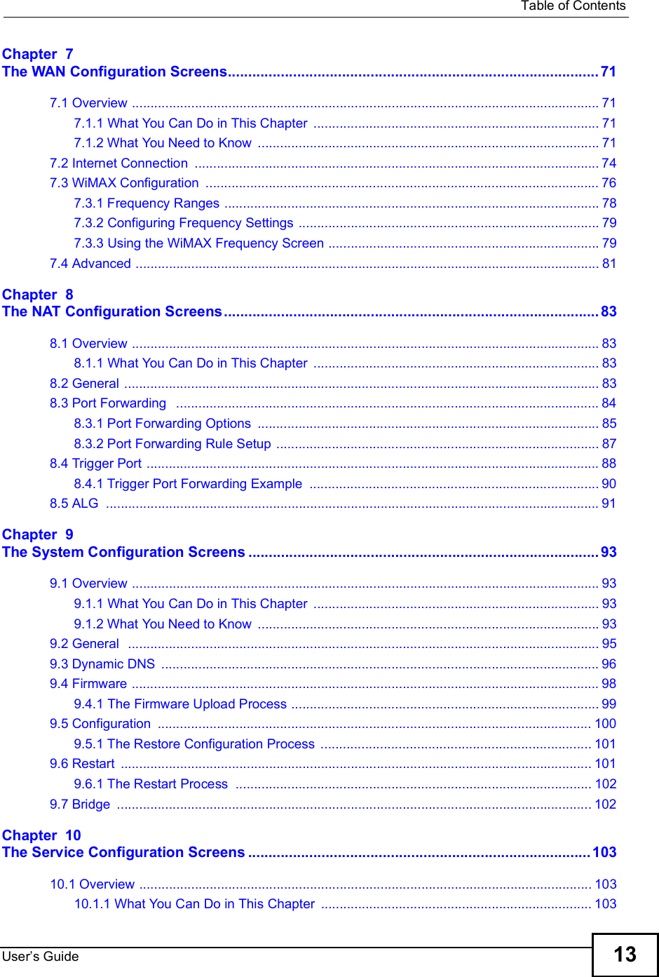
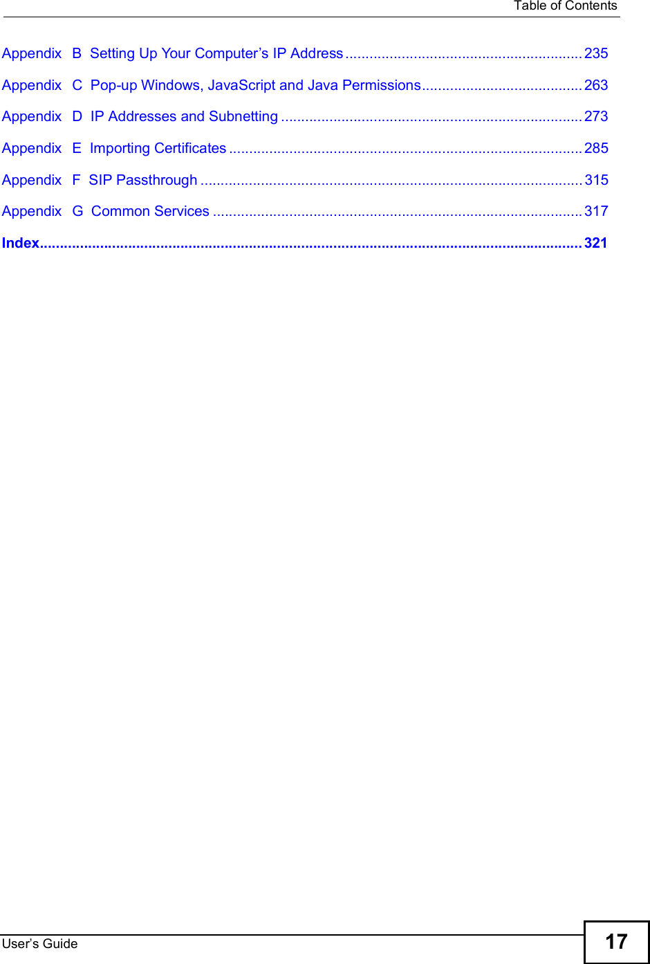
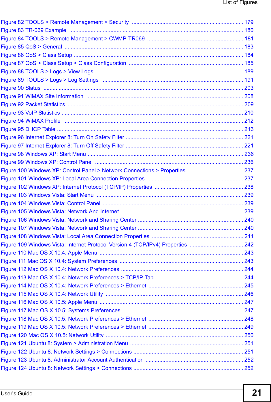
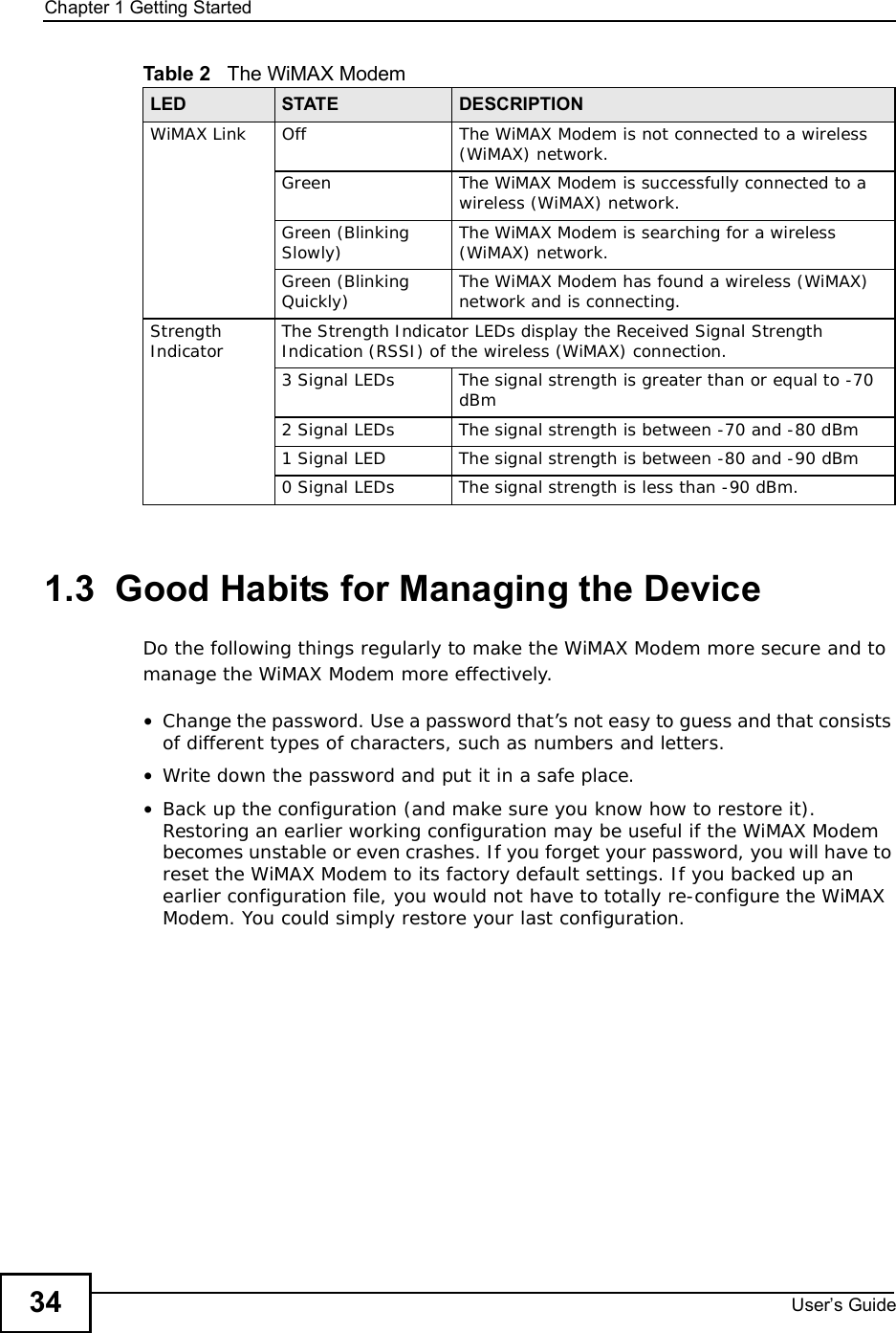
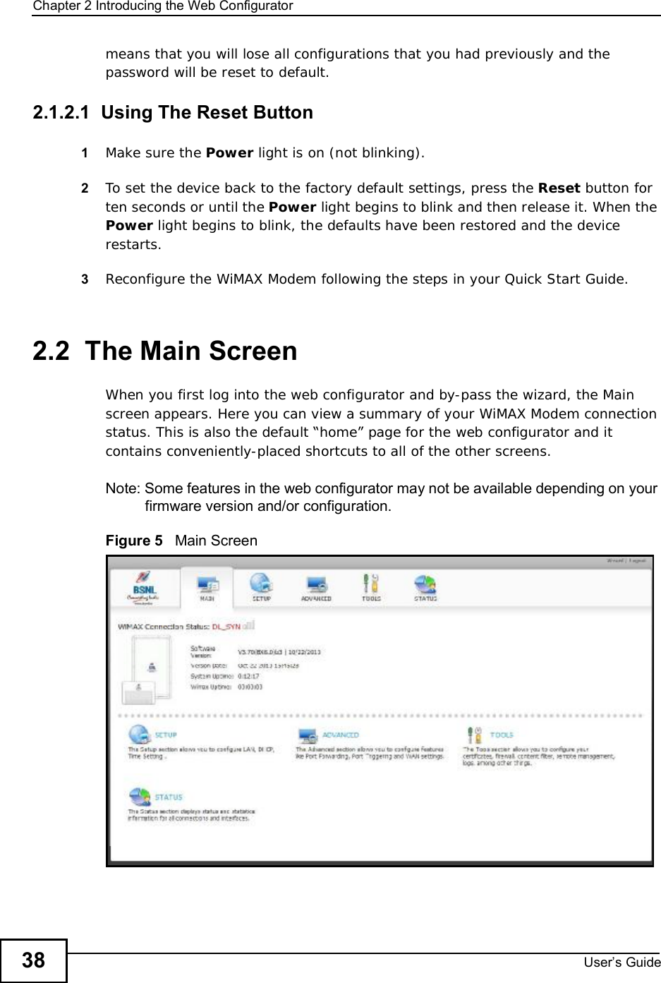
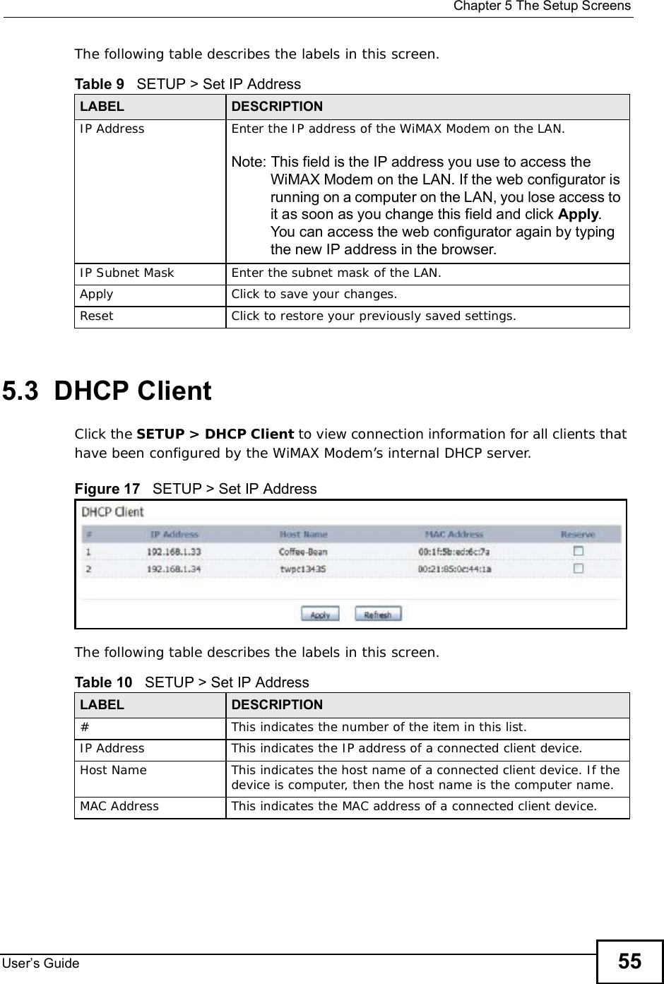
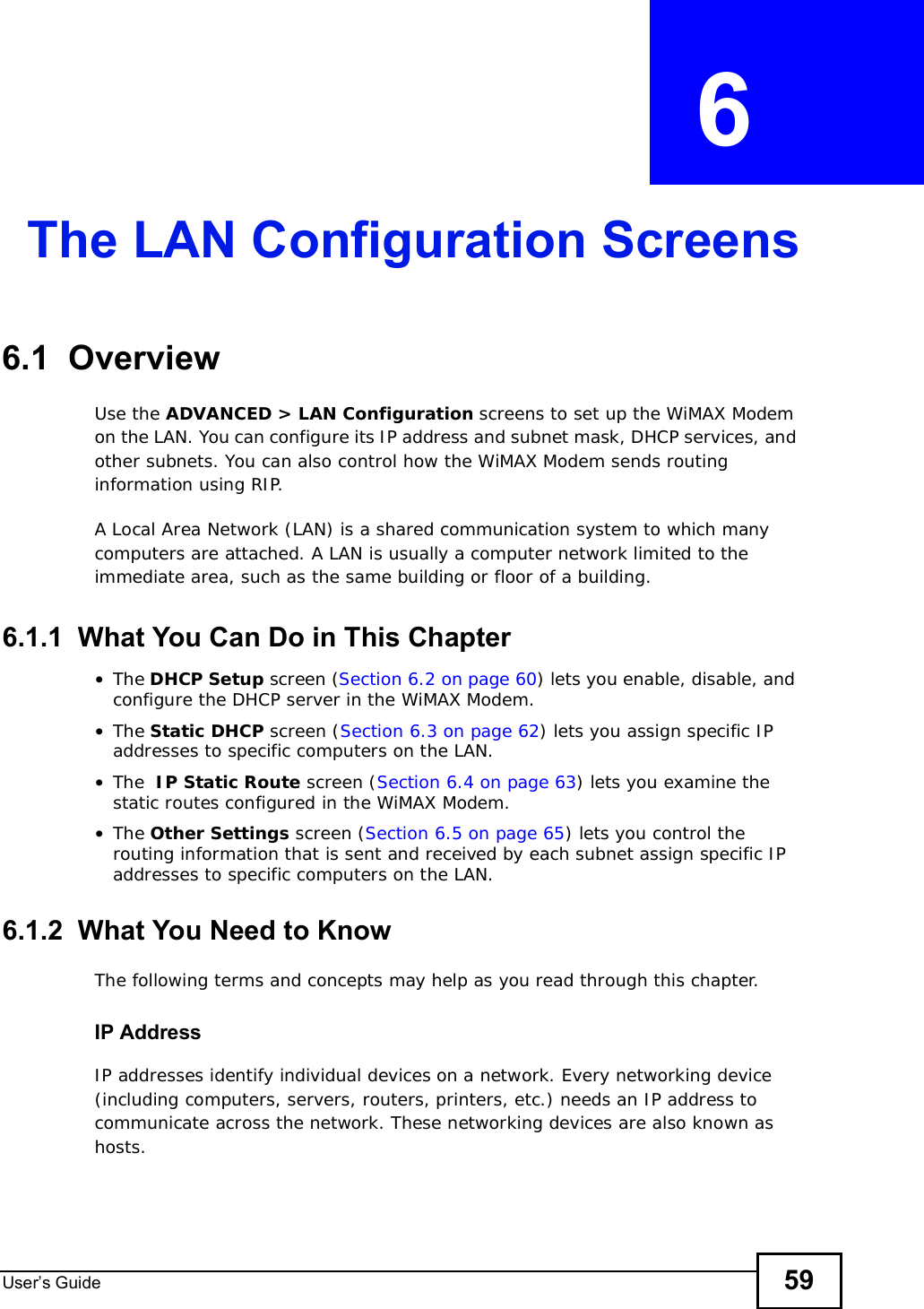
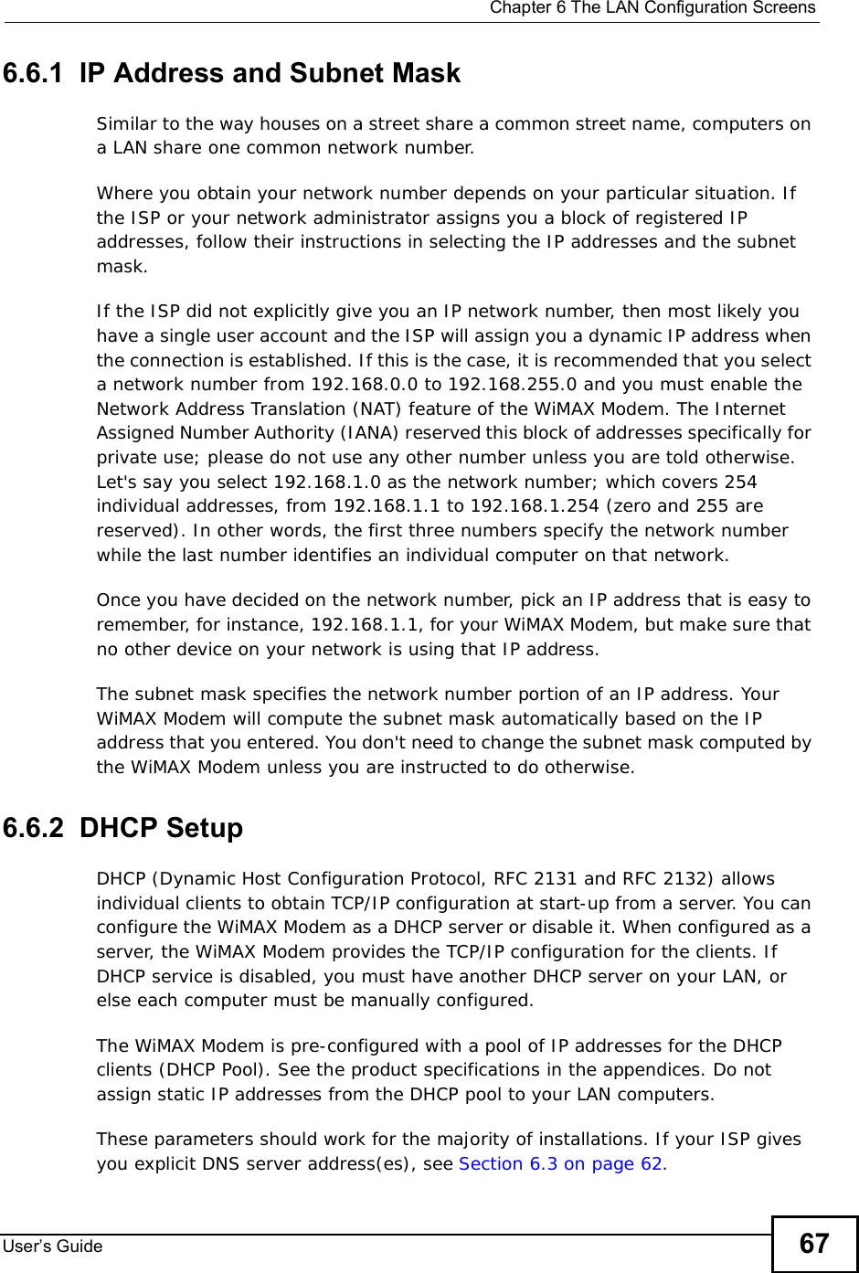
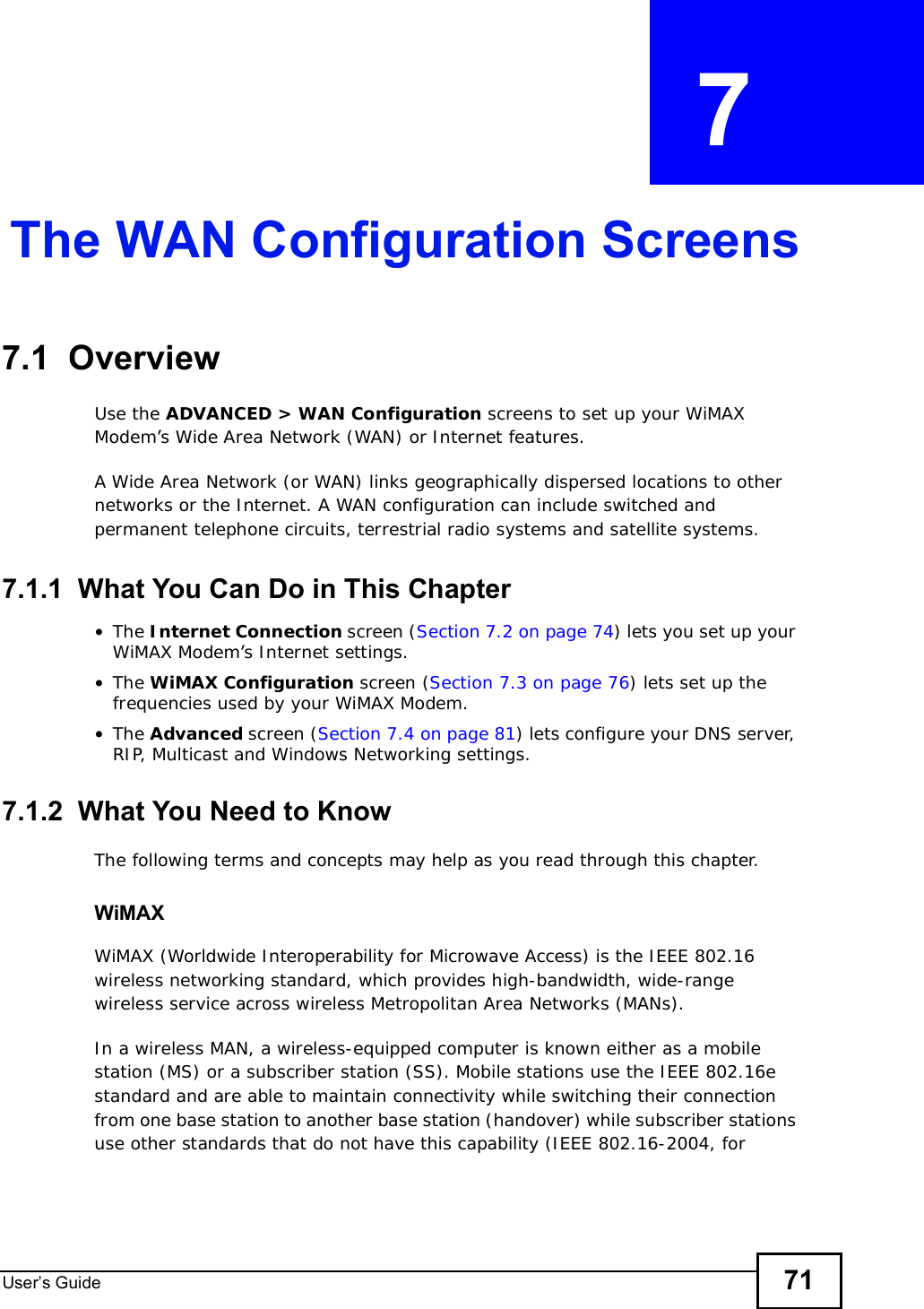
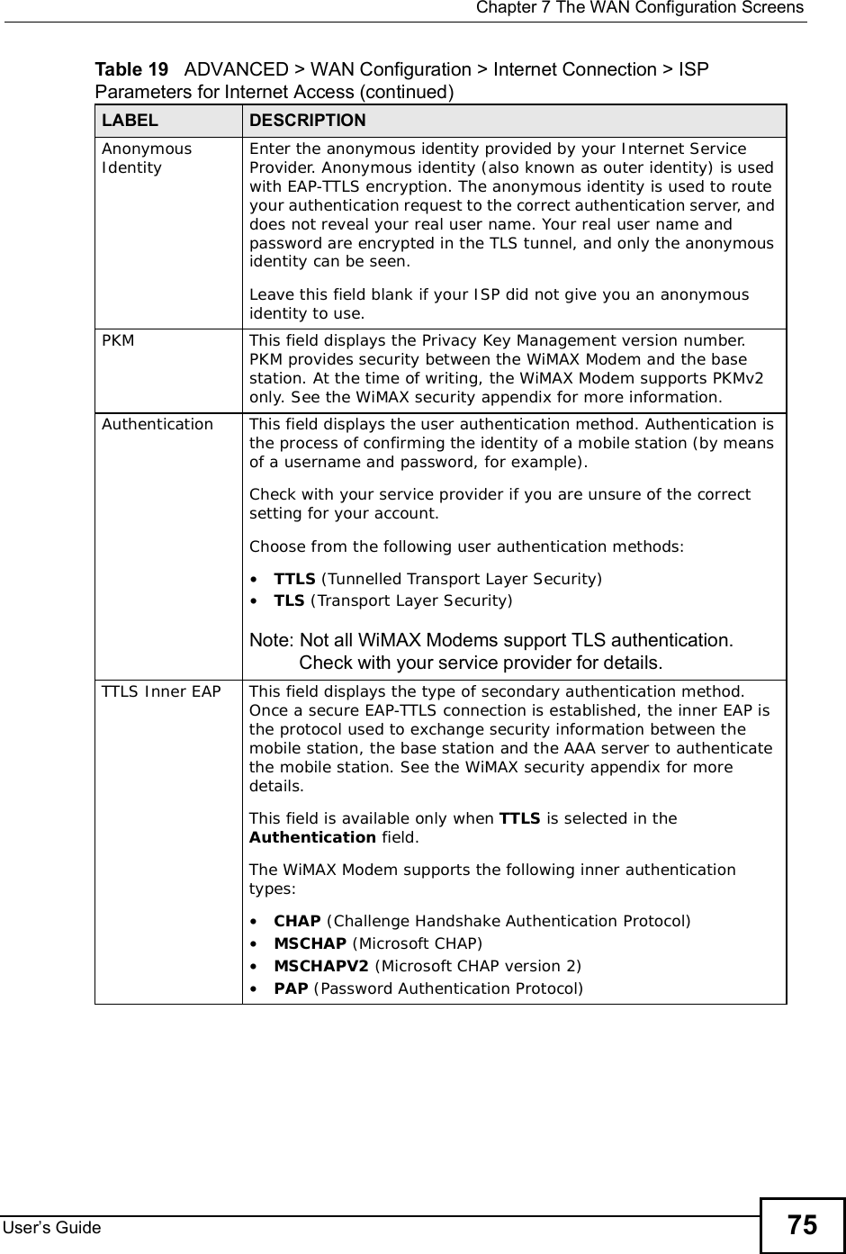
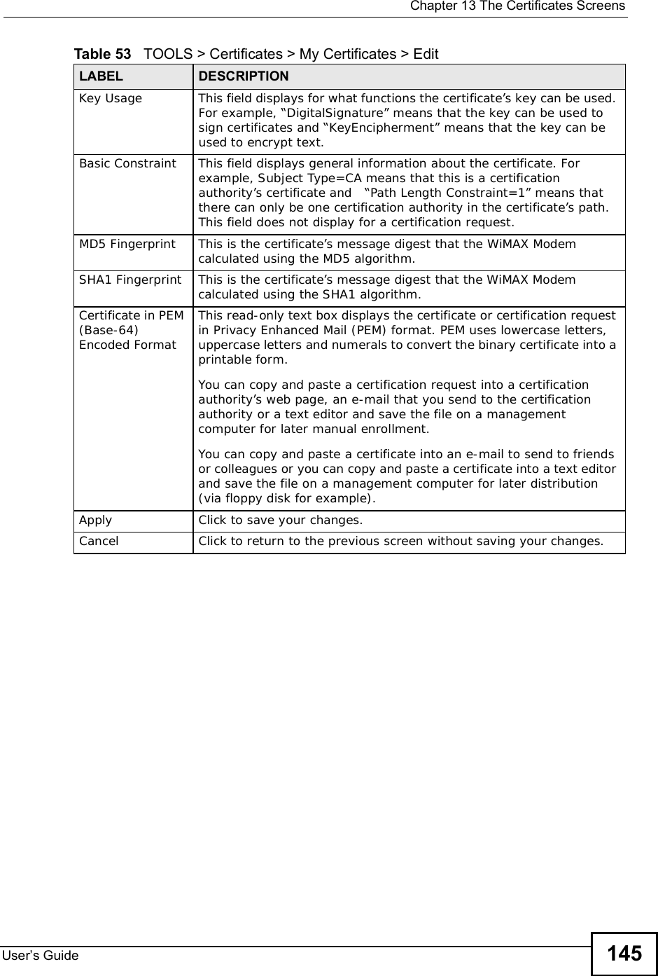
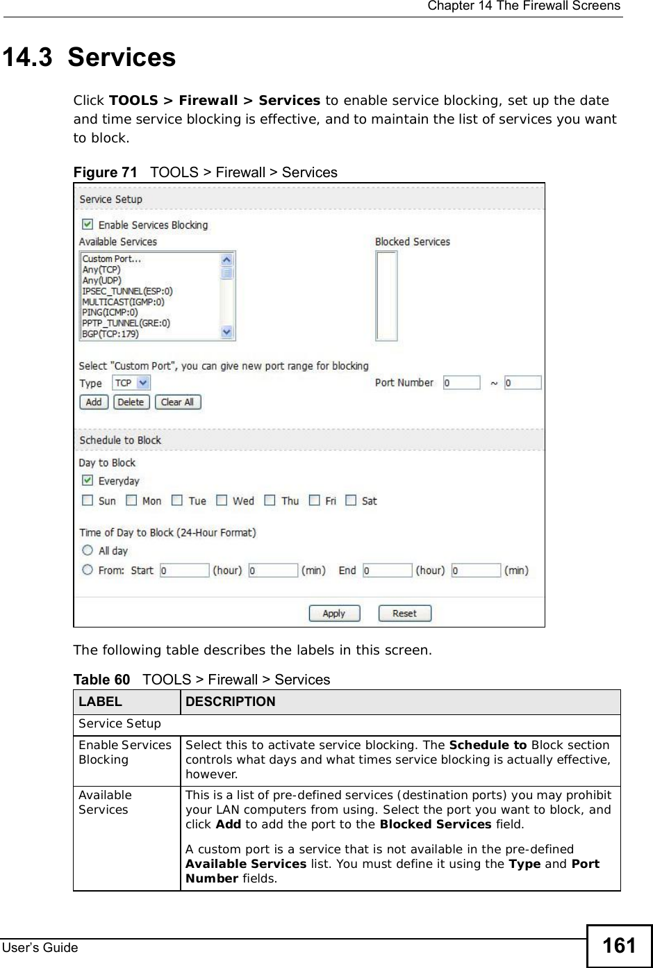
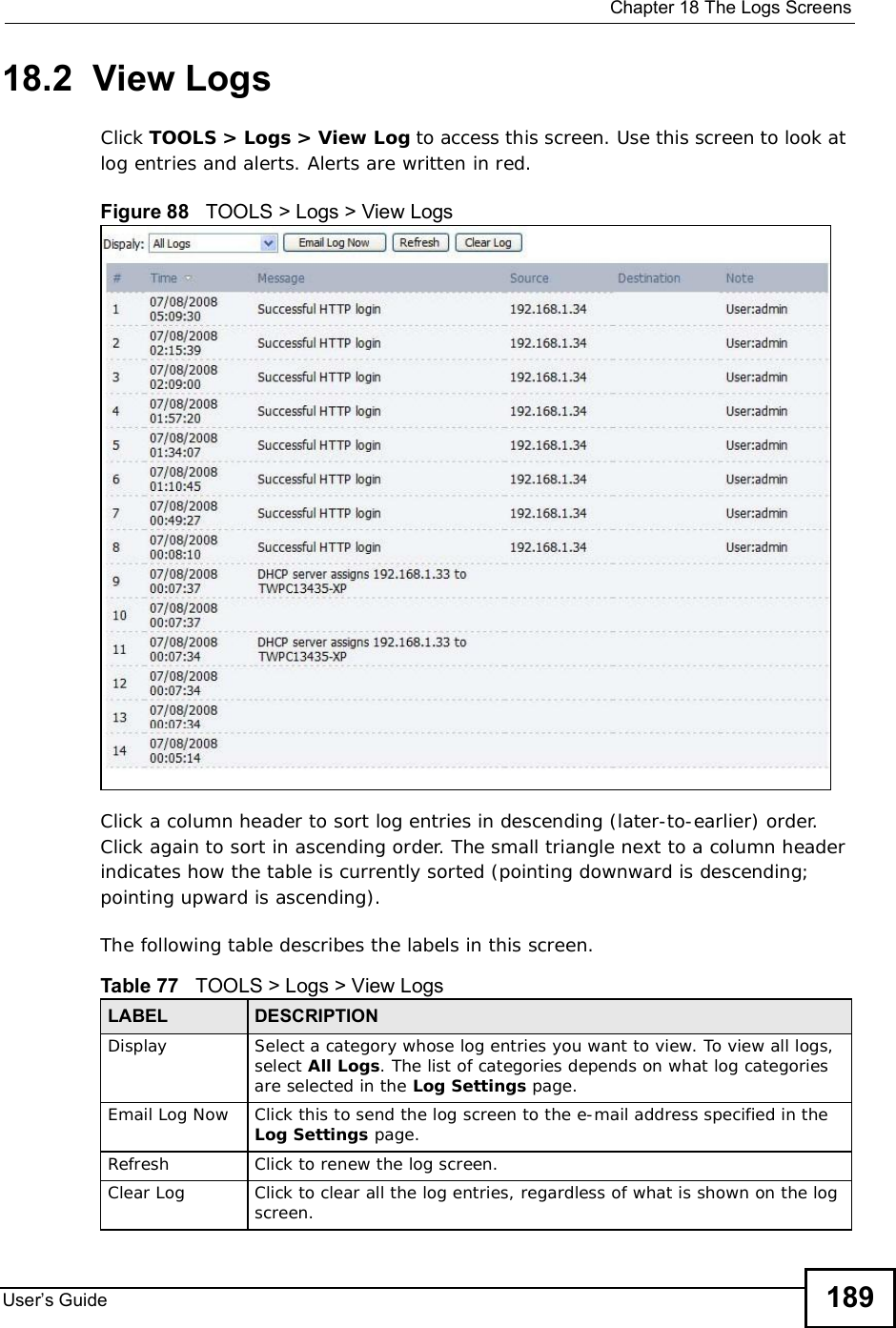
![Chapter 13The Certificates ScreensUser s Guide14013.2.1 My Certificates Create Click TOOLS > Certificates > My Certificates and then the Create icon to open the My Certificates Create screen. Use this screen to have the WiMAX Modem create a self-signed certificate, enroll a certificate with a certification authority or generate a certification request.Figure 60 TOOLS > Certificates > My Certificates > CreateThe following table describes the labels in this screen. Table 52 TOOLS > Certificates > My Certificates > CreateLABEL DESCRIPTIONCertificate NameType a name to identify this certificate. You can use up to 31 alphanumeric and ;‘~!@#$%^&()_+[]{}’,.=- characters.Subject Information Use these fields to record information that identifies the owner of the certificate. You do not have to fill in every field, although the Common Name is mandatory. The certification authority may add fields (such as a serial number) to the subject information when it issues a certificate. It is recommended that each certificate have unique subject information.](https://usermanual.wiki/ZyXEL-Communications/IX253P/User-Guide-1403071-Page-139.png)
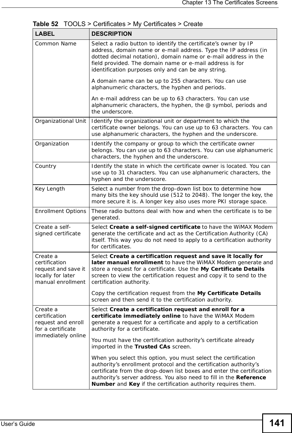
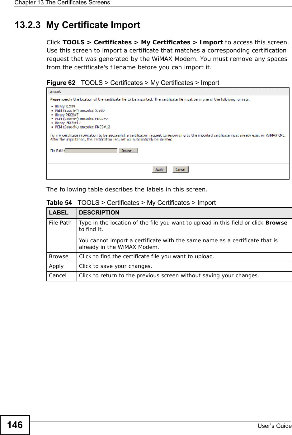
![Chapter 13The Certificates ScreensUser s Guide 14313.2.2 My Certificate EditClick TOOLS > Certificates > My Certificates then the Edit icon to access this screen. Use this screento view in-depth certificate information and change the certificate’s name. Figure 61 TOOLS > Certificates > My Certificates > Edit The following table describes the labels in this screen. Table 53 TOOLS > Certificates > My Certificates > EditLABEL DESCRIPTIONNameThis field displays the identifying name of this certificate. You can use up to 31 alphanumeric and ;‘~!@#$%^&()_+[]{}’,.=- characters.PropertySelect Default self-signed certificate which signs the imported remote host certificates to use this certificate to sign the remote host certificates you upload in the TOOLS > Certificates >TrustedCAs screen.](https://usermanual.wiki/ZyXEL-Communications/IX253P/User-Guide-1403071-Page-142.png)
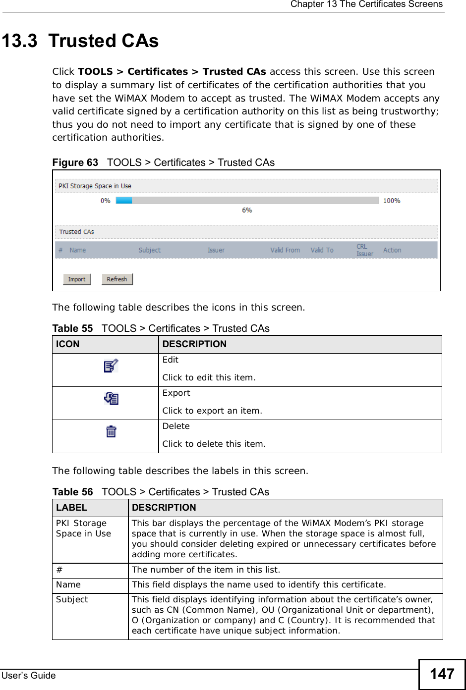
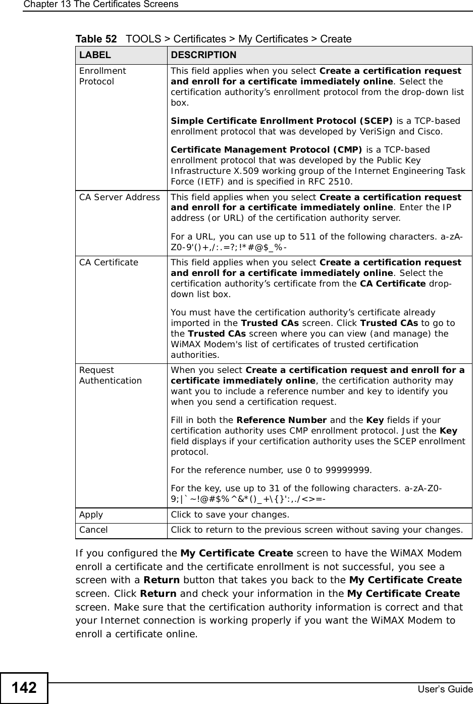
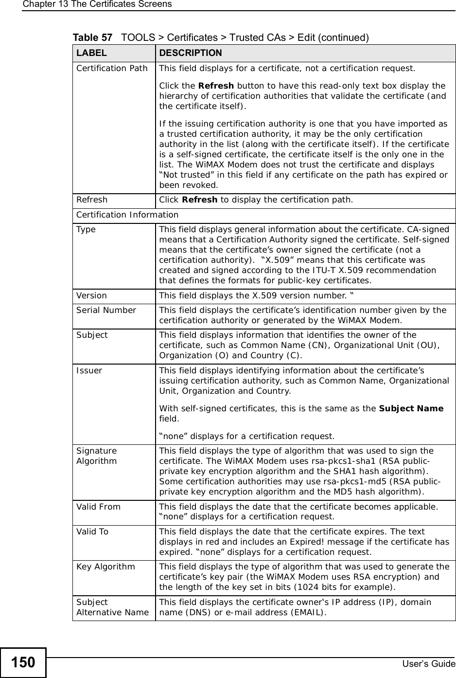
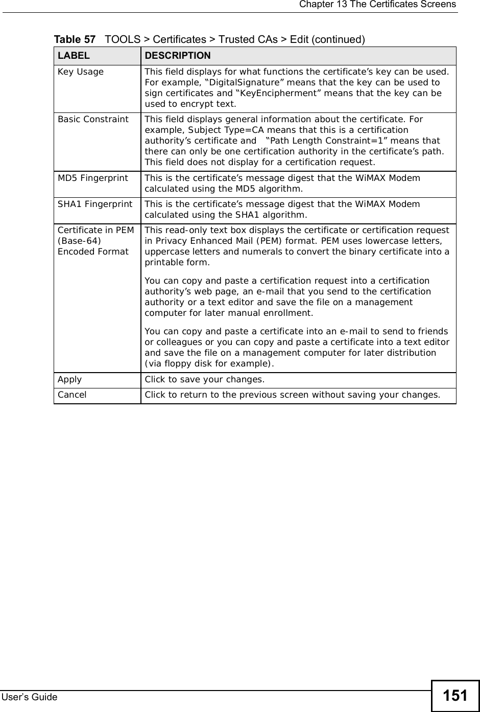
![Chapter 13The Certificates ScreensUser s Guide 14913.3.1 Trusted CA Edit Click TOOLS > Certificates >Trusted CAs and then click the Edit icon to open the Trusted CAs screen. Use this screen to view in-depth certificate information and change the certificate’s name.Figure 64 TOOLS > Certificates > Trusted CAs > Edit The following table describes the labels in this screen. Table 57 TOOLS > Certificates > Trusted CAs > EditLABEL DESCRIPTIONNameThis field displays the identifying name of this certificate. You can use up to 31 alphanumeric and ;‘~!@#$%^&()_+[]{}’,.=- characters.PropertySelect Default self-signed certificate which signs the imported remote host certificates to use this certificate to sign the remote host certificates you upload in the TOOLS > Certificates >TrustedCAs screen.](https://usermanual.wiki/ZyXEL-Communications/IX253P/User-Guide-1403071-Page-148.png)
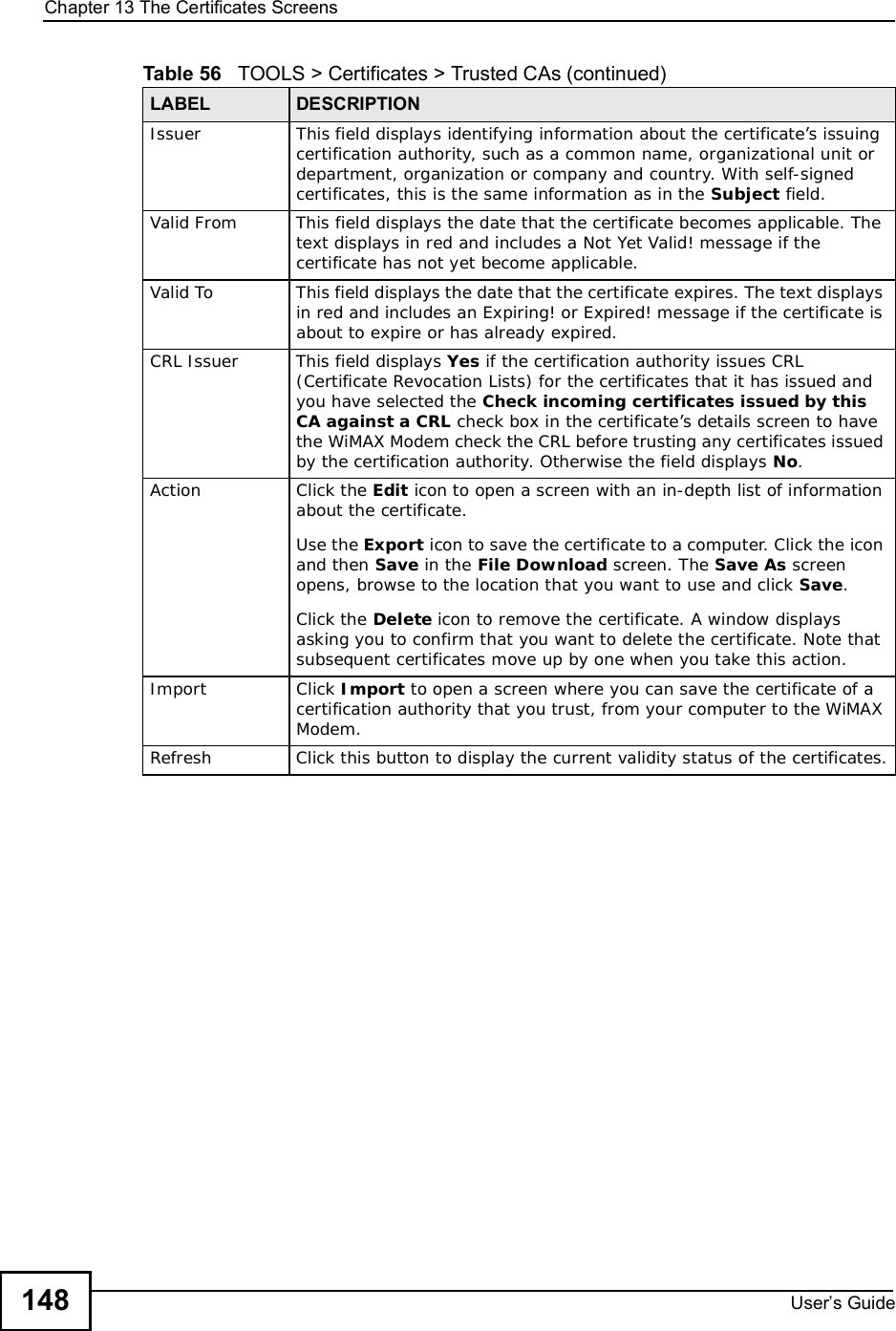
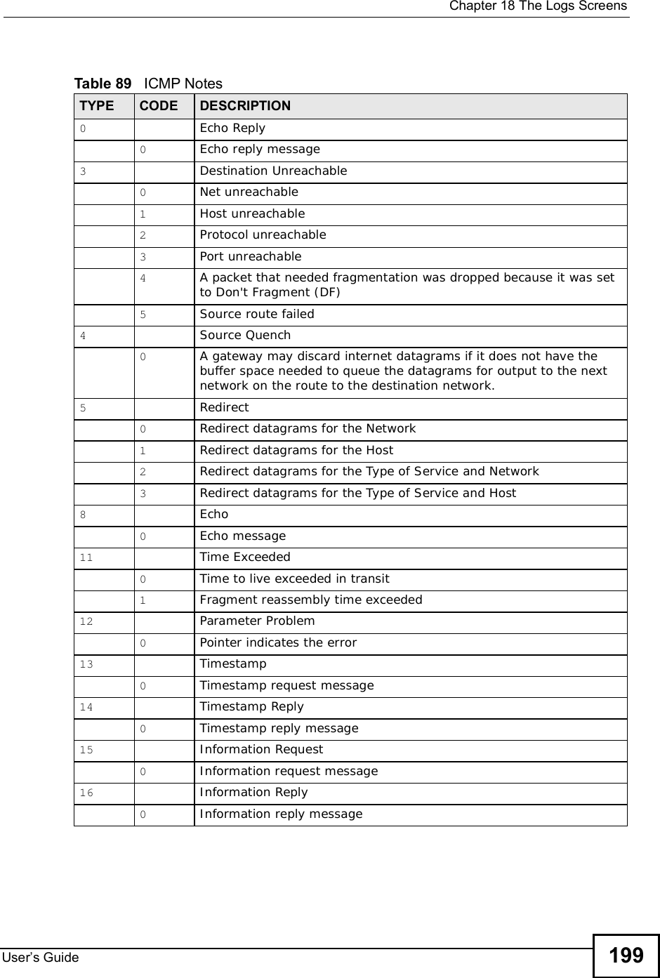
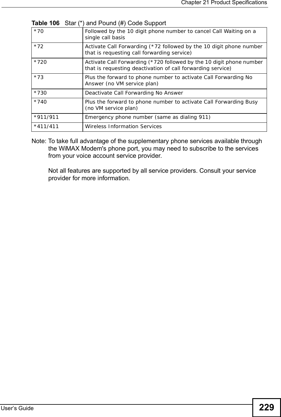
![Chapter 18The Logs ScreensUser s Guide194Time initialized by Time server The device got the time and date from the time server.Time initialized by NTP server The device got the time and date from the NTP server.Connect to Daytime server fail The device was not able to connect to the Daytime server.Connect to Time server fail The device was not able to connect to the Time server.Connect to NTP server fail The device was not able to connect to the NTP server.Too large ICMP packet has been dropped The device dropped an ICMP packet that was too large.Configuration Change: PC = 0x%x, Task ID = 0x%x The device is saving configuration changes.Table 81 Access Control LogsLOG MESSAGE DESCRIPTIONFirewall default policy: [ TCP | UDP | IGMP | ESP | GRE | OSPF ] <Packet Direction>Attempted TCP/UDP/IGMP/ESP/GRE/OSPF access matched the default policy and was blocked or forwarded according to the default policy’s setting.Firewall rule [NOT] match:[ TCP | UDP | IGMP | ESP | GRE | OSPF ] <Packet Direction>, <rule:%d>Attempted TCP/UDP/IGMP/ESP/GRE/OSPF access matched (or did not match) a configured firewall rule (denoted by its number) and was blocked or forwarded according to the rule. Triangle route packet forwarded: [ TCP | UDP | IGMP | ESP | GRE | OSPF ]The firewall allowed a triangle route session to pass through.Packet without a NAT table entry blocked: [ TCP | UDP | IGMP | ESP | GRE | OSPF ]The router blocked a packet that didn't have a corresponding NAT table entry.Router sent blocked web site message: TCP The router sent a message to notify a user that the router blocked access to a web site that the user requested.Exceed maximum sessions per host (%d). The device blocked a session because the host's connections exceeded the maximum sessions per host.Firewall allowed a packet that matched a NAT session: [ TCP | UDP ]A packet from the WAN (TCP or UDP) matched a cone NAT session and the device forwarded it to the LAN.Table 80 System Maintenance Logs (continued)LOG MESSAGE DESCRIPTION](https://usermanual.wiki/ZyXEL-Communications/IX253P/User-Guide-1403071-Page-193.png)
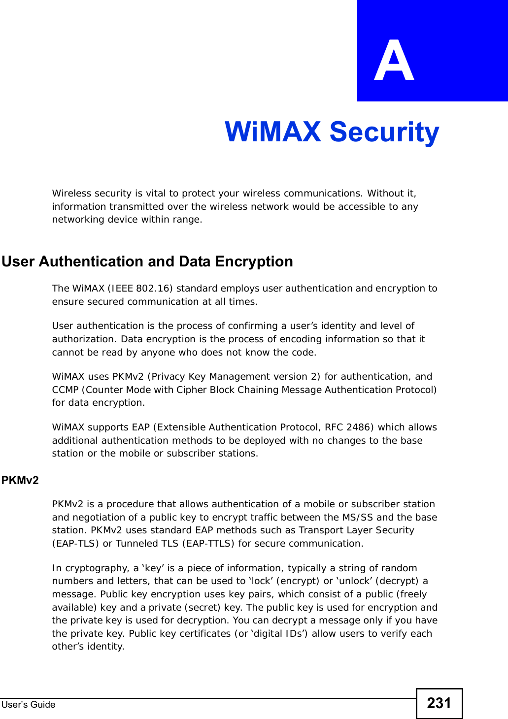
![Chapter 18The Logs ScreensUser s Guide 195Table 82 TCP Reset LogsLOG MESSAGE DESCRIPTIONUnder SYN flood attack, sent TCP RST The router sent a TCP reset packet when a host was under a SYN flood attack (the TCP incomplete count is per destination host.) Exceed TCP MAX incomplete, sent TCP RST The router sent a TCP reset packet when the number of TCP incomplete connections exceeded the user configured threshold. (the TCP incomplete count is per destination host.) Peer TCP state out of order, sent TCP RST The router sent a TCP reset packet when a TCP connection state was out of order.Note: The firewall refers to RFC793 Figure 6 to check the TCP state.Firewall session time out, sent TCP RST The router sent a TCP reset packet when a dynamic firewall session timed out.The default timeout values are as follows:ICMP idle timeout: 3 minutesUDP idle timeout: 3 minutesTCP connection (three way handshaking) timeout: 270 secondsTCP FIN-wait timeout: 2 MSL (Maximum Segment Lifetime set in the TCP header).TCP idle (established) timeout (s): 150 minutesTCP reset timeout: 10 secondsExceed MAX incomplete, sent TCP RST The router sent a TCP reset packet when the number of incomplete connections (TCP and UDP) exceeded the user-configured threshold. (Incomplete count is for all TCP and UDP connections through the firewall.)Note: When the number of incomplete connections (TCP + UDP) > “Maximum Incomplete High”, the router sends TCP RST packets for TCP connections and destroys TOS (firewall dynamic sessions) until incomplete connections < “Maximum Incomplete Low”.Access block, sent TCP RST The router sends a TCP RST packet and generates this log if you turn on the firewall TCP reset mechanism (via CI command: sys firewall tcprst).Table 83 Packet Filter LogsLOG MESSAGE DESCRIPTION[ TCP | UDP | ICMP | IGMP | Generic ] packet filter matched (set: %d, rule: %d)Attempted access matched a configured filter rule (denoted by its set and rule number) and was blocked or forwarded according to the rule.](https://usermanual.wiki/ZyXEL-Communications/IX253P/User-Guide-1403071-Page-194.png)
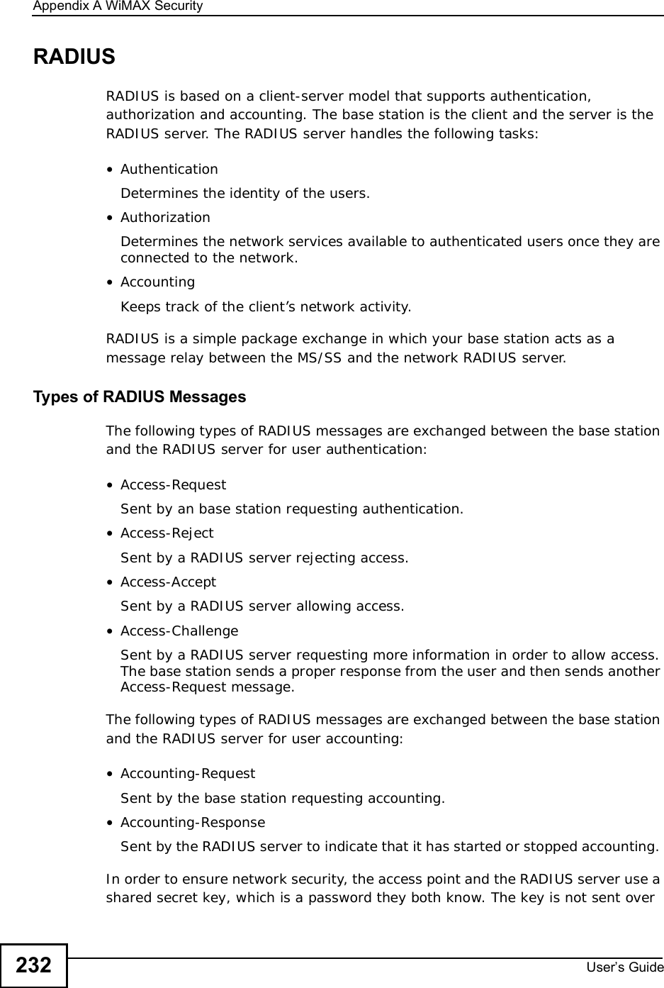
![Chapter 18The Logs ScreensUser s Guide196For type and code details, see Table 89 on page 199.Table 84 ICMP LogsLOG MESSAGE DESCRIPTIONFirewall default policy: ICMP <Packet Direction>, <type:%d>, <code:%d>ICMP access matched the default policy and was blocked or forwarded according to the user's setting.Firewall rule [NOT] match: ICMP <Packet Direction>, <rule:%d>, <type:%d>, <code:%d>ICMP access matched (or didn’t match) a firewall rule (denoted by its number) and was blocked or forwarded according to the rule. Triangle route packet forwarded: ICMP The firewall allowed a triangle route session to pass through.Packet without a NAT table entry blocked: ICMP The router blocked a packet that didn’t have a corresponding NAT table entry.Unsupported/out-of-order ICMP: ICMP The firewall does not support this kind of ICMP packets or the ICMP packets are out of order.Router reply ICMP packet: ICMP The router sent an ICMP reply packet to the sender.Table 85 PPP LogsLOG MESSAGE DESCRIPTIONppp:LCP Starting The PPP connection’s Link Control Protocol stage has started.ppp:LCP Opening The PPP connection’s Link Control Protocol stage is opening.ppp:CHAP Opening The PPP connection’s Challenge Handshake Authentication Protocol stage is opening.ppp:IPCP Starting The PPP connection’s Internet Protocol Control Protocol stage is starting.ppp:IPCP Opening The PPP connection’s Internet Protocol Control Protocol stage is opening.ppp:LCP Closing The PPP connection’s Link Control Protocol stage is closing.ppp:IPCP Closing The PPP connection’s Internet Protocol Control Protocol stage is closing.Table 86 Content Filtering LogsLOG MESSAGE DESCRIPTION%s: Keyword blocking The content of a requested web page matched a user defined keyword.%s: Not in trusted web list The web site is not in a trusted domain, and the router blocks all traffic except trusted domain sites.%s: Forbidden Web site The web site is in the forbidden web site list.%s: Contains ActiveX The web site contains ActiveX.%s: Contains Java applet The web site contains a Java applet.](https://usermanual.wiki/ZyXEL-Communications/IX253P/User-Guide-1403071-Page-195.png)
![Chapter 18The Logs ScreensUser s Guide 197For type and code details, see Table 89 on page 199.%s: Contains cookie The web site contains a cookie.%s: Proxy mode detected The router detected proxy mode in the packet.%s: Trusted Web site The web site is in a trusted domain.%s When the content filter is not on according to the time schedule:Waiting content filter server timeoutThe external content filtering server did not respond within the timeout period.DNS resolving failed The WiMAX Modem cannot get the IP address of the external content filtering via DNS query.Creating socket failed The WiMAX Modem cannot issue a query because TCP/UDP socket creation failed, port:port number.Connecting to content filter server failThe connection to the external content filtering server failed.License key is invalid The external content filtering license key is invalid.Table 87 Attack LogsLOG MESSAGE DESCRIPTIONattack [ TCP | UDP | IGMP | ESP | GRE | OSPF ]The firewall detected a TCP/UDP/IGMP/ESP/GRE/OSPF attack.attack ICMP (type:%d, code:%d) The firewall detected an ICMP attack. land [ TCP | UDP | IGMP | ESP | GRE | OSPF ] The firewall detected a TCP/UDP/IGMP/ESP/GRE/OSPF land attack.land ICMP (type:%d, code:%d) The firewall detected an ICMP land attack. ip spoofing - WAN [ TCP | UDP | IGMP | ESP | GRE | OSPF ]The firewall detected an IP spoofing attack on the WAN port.ip spoofing - WAN ICMP (type:%d, code:%d) The firewall detected an ICMP IP spoofing attack on the WAN port. icmp echo : ICMP (type:%d, code:%d) The firewall detected an ICMP echo attack. syn flood TCP The firewall detected a TCP syn flood attack.ports scan TCP The firewall detected a TCP port scan attack.teardrop TCP The firewall detected a TCP teardrop attack.teardrop UDP The firewall detected an UDP teardrop attack.teardrop ICMP (type:%d, code:%d) The firewall detected an ICMP teardrop attack. illegal command TCP The firewall detected a TCP illegal command attack.Table 86 Content Filtering Logs (continued)LOG MESSAGE DESCRIPTION](https://usermanual.wiki/ZyXEL-Communications/IX253P/User-Guide-1403071-Page-196.png)
![Chapter 18The Logs ScreensUser s Guide198NetBIOS TCP The firewall detected a TCP NetBIOS attack.ip spoofing - no routing entry [ TCP | UDP | IGMP | ESP | GRE | OSPF ]The firewall classified a packet with no source routing entry as an IP spoofing attack.ip spoofing - no routing entry ICMP (type:%d, code:%d)The firewall classified an ICMP packet with no source routing entry as an IP spoofing attack.vulnerability ICMP (type:%d, code:%d) The firewall detected an ICMP vulnerability attack. traceroute ICMP (type:%d, code:%d) The firewall detected an ICMP traceroute attack. ports scan UDP The firewall detected a UDP port scan attack.Firewall sent TCP packet in response to DoS attack TCPThe firewall sent TCP packet in response to a DoS attackICMP Source Quench ICMP The firewall detected an ICMP Source Quench attack.ICMP Time Exceed ICMP The firewall detected an ICMP Time Exceed attack.ICMP Destination Unreachable ICMP The firewall detected an ICMP Destination Unreachable attack.ping of death. ICMP The firewall detected an ICMP ping of death attack.smurf ICMP The firewall detected an ICMP smurf attack.Table 88 Remote Management LogsLOG MESSAGE DESCRIPTIONRemote Management: FTP denied Attempted use of FTP service was blocked according to remote management settings.Remote Management: TELNET denied Attempted use of TELNET service was blocked according to remote management settings.Remote Management: WWW denied Attempted use of WWW service was blocked according to remote management settings.Remote Management: HTTPS denied Attempted use of HTTPS service was blocked according to remote management settings.Remote Management: SSH denied Attempted use of SSH service was blocked according to remote management settings.Remote Management: ICMP Ping response denied Attempted use of ICMP service was blocked according to remote management settings.Remote Management: DNS denied Attempted use of DNS service was blocked according to remote management settings.Table 87 Attack Logs (continued)LOG MESSAGE DESCRIPTION](https://usermanual.wiki/ZyXEL-Communications/IX253P/User-Guide-1403071-Page-197.png)
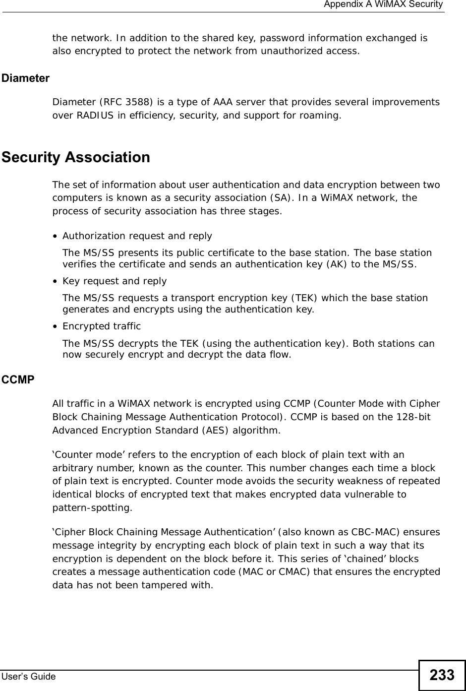
![Chapter 18The Logs ScreensUser s Guide200Table 90 SIP LogsLOG MESSAGE DESCRIPTIONSIP Registration Success by SIP:SIP Phone Number The listed SIP account was successfully registered with a SIP register server.SIP Registration Fail by SIP:SIP Phone Number An attempt to register the listed SIP account with a SIP register server was not successful.SIP UnRegistration Success by SIP:SIP Phone NumberThe listed SIP account’s registration was deleted from the SIP register server.SIP UnRegistration Fail by SIP:SIP Phone Number An attempt to delete the listed SIP account’s registration from the SIP register server failed.Table 91 RTP LogsLOG MESSAGE DESCRIPTIONError, RTP init fail The initialization of an RTP session failed.Error, Call fail: RTP connect fail A VoIP phone call failed because the RTP session could not be established.Error, RTP connection cannot close The termination of an RTP session failed.Table 92 FSM Logs: Caller SideLOG MESSAGE DESCRIPTIONVoIP Call Start Ph[Phone Port Number] <- Outgoing Call NumberSomeone used a phone connected to the listed phone port to initiate a VoIP call to the listed destination.VoIP Call Established Ph[Phone Port] -> Outgoing Call NumberSomeone used a phone connected to the listed phone port to make a VoIP call to the listed destination.VoIP Call End Phone[Phone Port] A VoIP phone call made from a phone connected to the listed phone port has terminated.Table 93 FSM Logs: Callee SideLOG MESSAGE DESCRIPTIONVoIP Call Start from SIP[SIP Port Number] A VoIP phone call came to the WiMAX Modem from the listed SIP number.](https://usermanual.wiki/ZyXEL-Communications/IX253P/User-Guide-1403071-Page-199.png)
![Chapter 18The Logs ScreensUser s Guide 201VoIP Call Established Ph[Phone Port] <- Outgoing Call NumberA VoIP phone call was set up from the listed SIP number to the WiMAX Modem.VoIP Call End Phone[Phone Port] A VoIP phone call that came into the WiMAX Modem has terminated.Table 94 Lifeline LogsLOG MESSAGE DESCRIPTIONPSTN Call Start A PSTN call has been initiated.PSTN Call End A PSTN call has terminated.PSTN Call Established A PSTN call has been set up.Table 93 FSM Logs: Callee Side (continued)LOG MESSAGE DESCRIPTION](https://usermanual.wiki/ZyXEL-Communications/IX253P/User-Guide-1403071-Page-200.png)

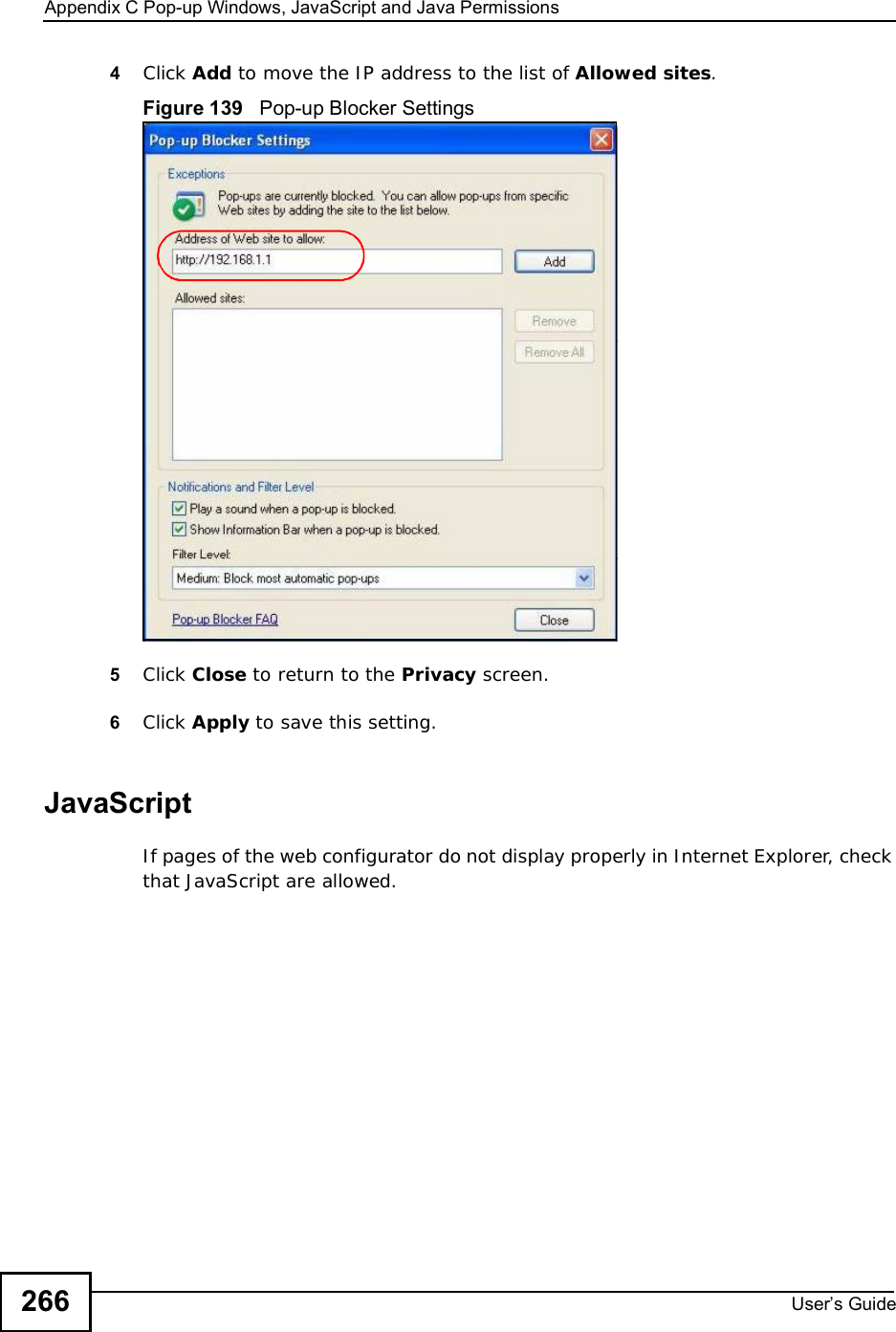
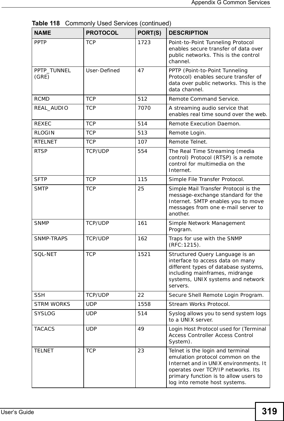
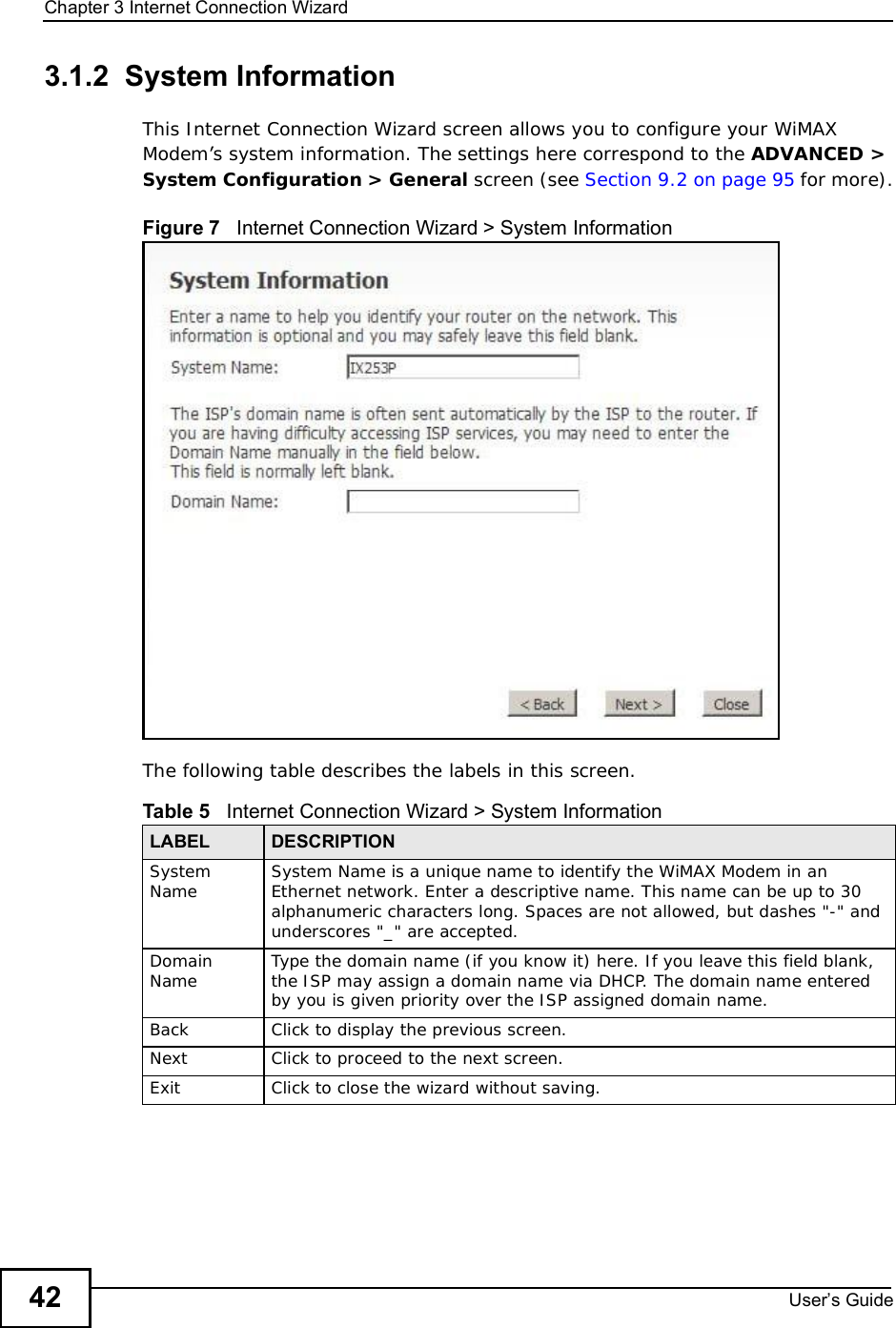
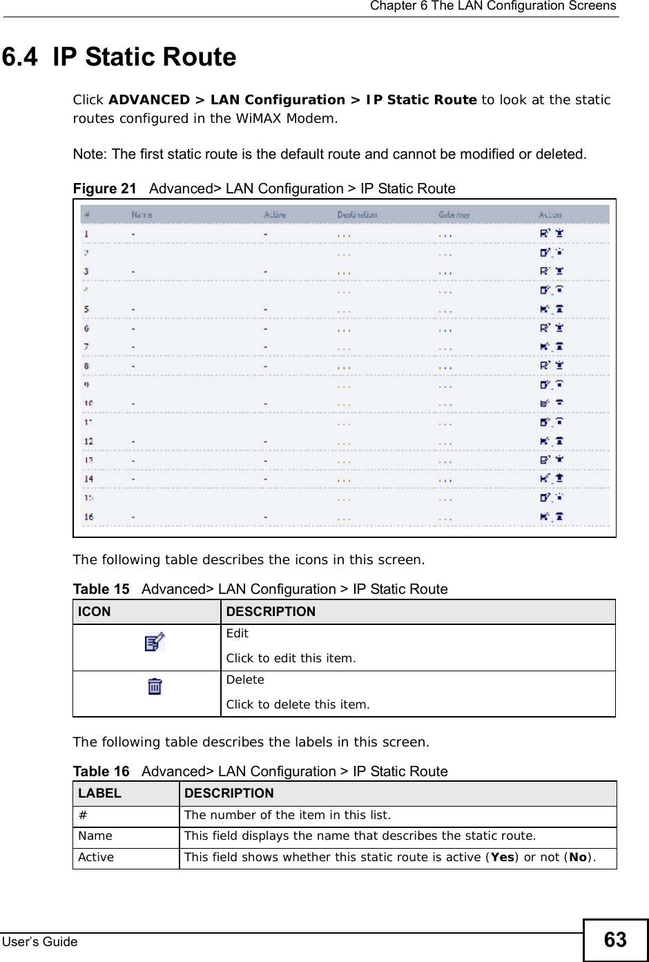
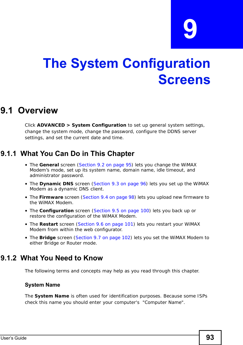
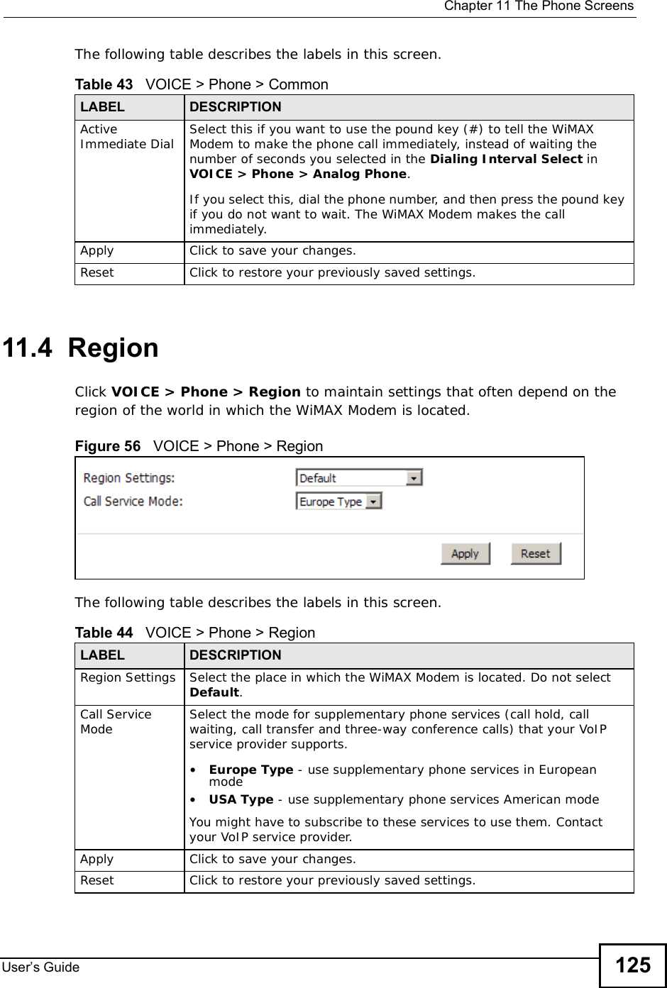
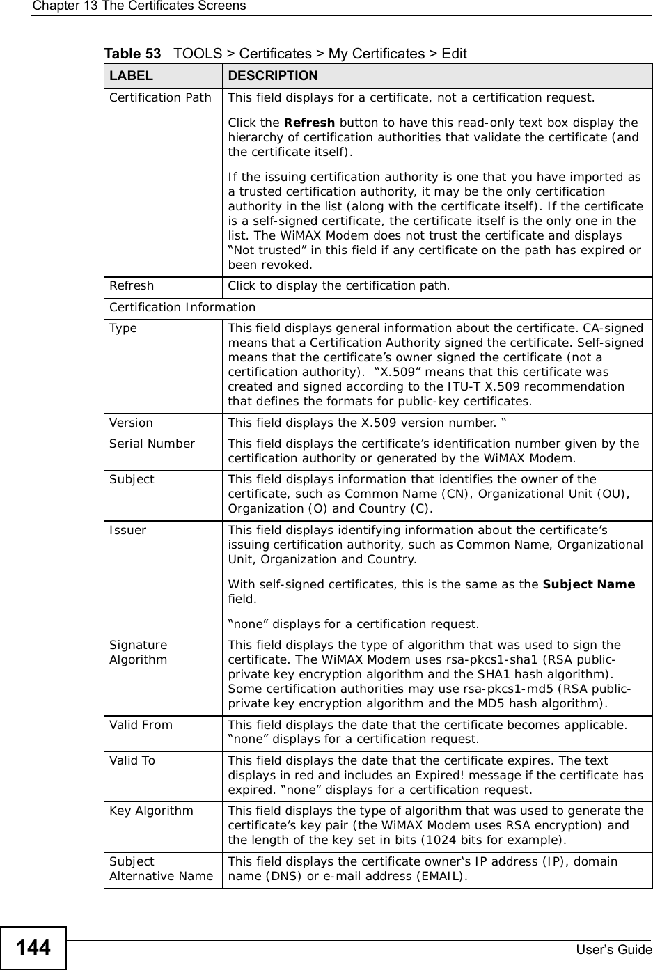
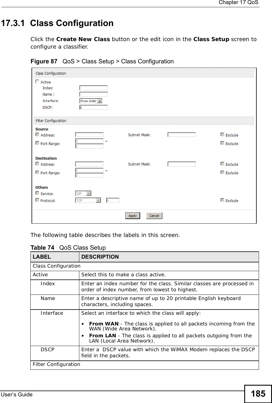
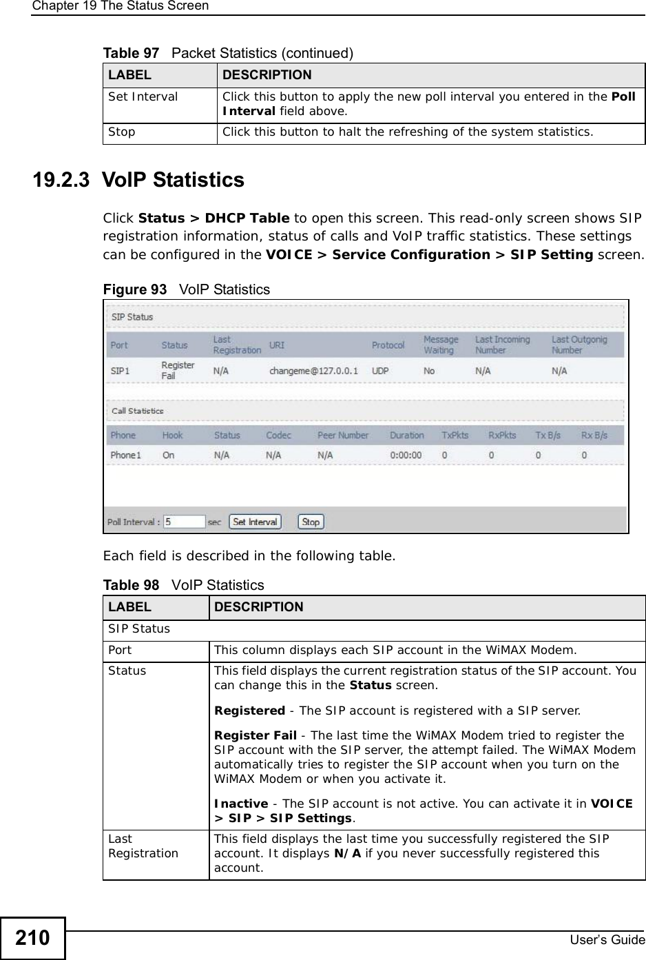
![Chapter 19The Status ScreenUser s Guide20819.2.1 WiMAX Site InformationClick Status > WiMAX Site Information to open this screen. This read-only screen shows WiMAX frequency information for the WiMAX Modem. These settings can be configured in the ADVANCED > WAN Configuration > WiMAX Configuration screen.Figure 91 WiMAX Site Information The following table describes the labels in this screen. Table 96 WiMAX Site InformationLABEL DESCRIPTIONDL Frequency[1] ~ [18]These fields show the downlink frequency settings in kilohertz (kHz). These settings determine how the WiMAX Modem searches for an available wireless connection.](https://usermanual.wiki/ZyXEL-Communications/IX253P/User-Guide-1403071-Page-207.png)
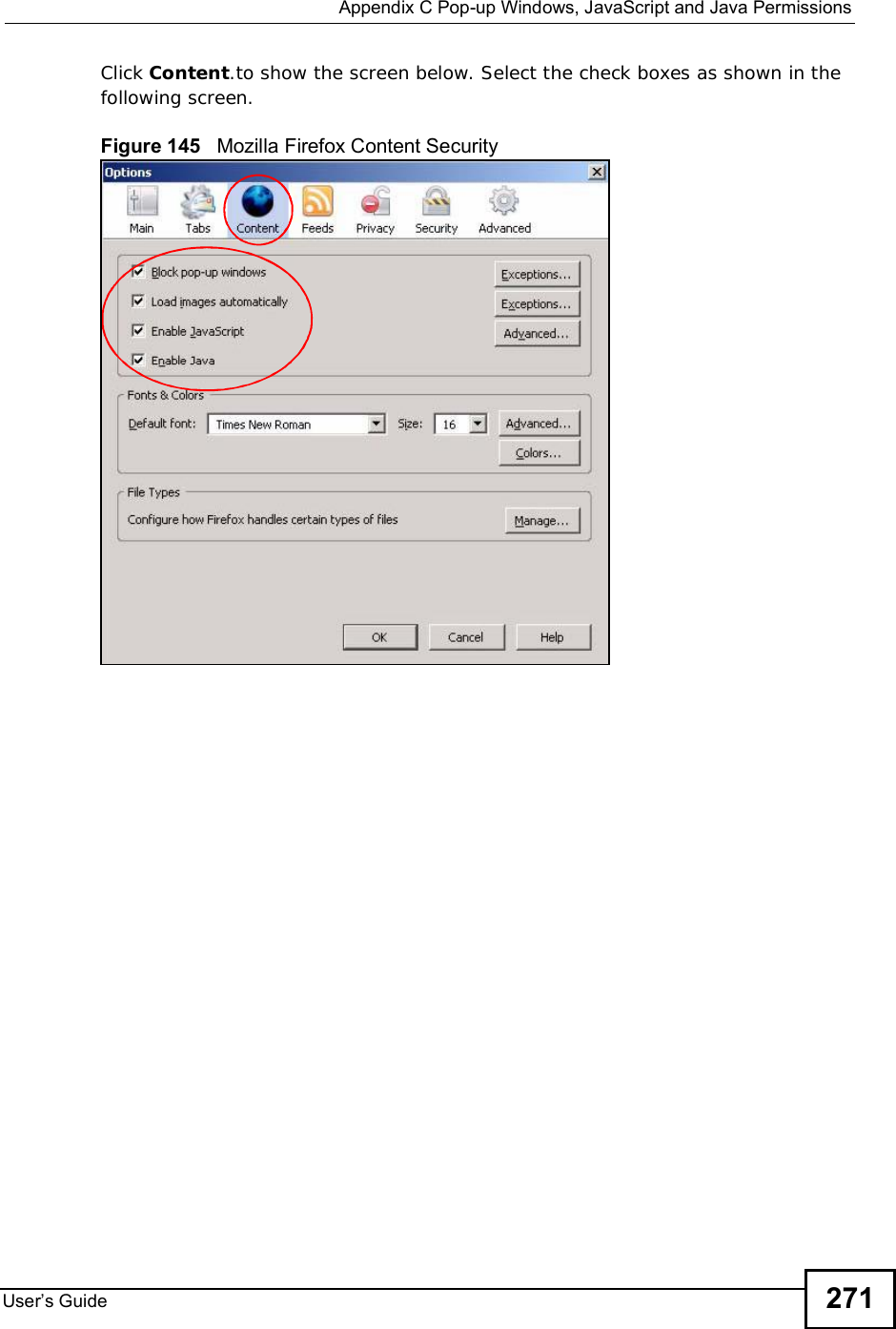
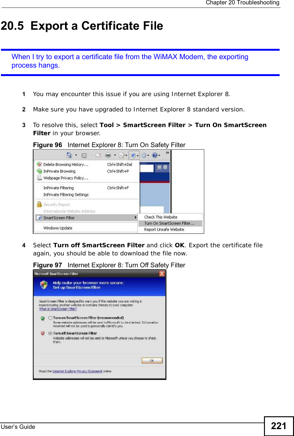
![Chapter 20TroubleshootingUser s Guide 2171Make sure you are using the correct IP address.•Refer to the UG cover for the default IP address.•If you changed the IP address (Section 5.2 on page 54), use the new IP address.•If you changed the IP address and have forgotten it, see the troubleshooting suggestions for I forgot the IP address for the WiMAX Modem.2Check the hardware connections, and make sure the LEDs are behaving as expected. See the Quick Start Guide and Section 1.2.1 on page 33.3Make sure your Internet browser does not block pop-up windows and has JavaScript and Java enabled. See Appendix C on page 263.4If there is a DHCP server on your network, make sure your computer is using a dynamic IP address. Your WiMAX Modem is a DHCP server by default.If there is no DHCP server on your network, make sure your computer’s IP address is in the same subnet as the WiMAX Modem. See Appendix D on page 273.5Reset the WiMAX Modem to its factory defaults, and try to access the WiMAX Modem with the default IP address. See Section 9.6 on page 101.6If the problem continues, contact the network administrator or vendor, or try one of the advanced suggestions.Advanced Suggestions•Try to access the WiMAX Modem using another service, such as Telnet. If you can access the WiMAX Modem, check the remote management settings and firewall rules to find out why the WiMAX Modem does not respond to HTTP.•If your computer is connected wirelessly, use a computer that is connected to a LAN/ETHERNET port.I can see the Login screen, but I cannot log in to the WiMAX Modem.1Refer to the UG cover for the default name and password for user and adminaccount. The fields are case-sensitive, so make sure [Caps Lock] is not on.2You cannot log in to the web configurator while someone is using Telnet to access the WiMAX Modem. Log out of the WiMAX Modem in the other session, or ask the person who is logged in to log out.3Disconnect and re-connect the power adapter or cord to the WiMAX Modem.](https://usermanual.wiki/ZyXEL-Communications/IX253P/User-Guide-1403071-Page-216.png)
![Chapter 20TroubleshootingUser s Guide2184If this does not work, you have to reset the WiMAX Modem to its factory defaults. See Section 9.5 on page 100.I cannot telnet to the WiMAX Modem.See the troubleshooting suggestions for I cannot see or access the Login screen in the web configurator. Ignore the suggestions about your browser.20.3 Internet AccessI cannot access the Internet.1Check the hardware connections, and make sure the LEDs are behaving as expected. See the Quick Start Guide and Section 1.2.1 on page 33.2Make sure you entered your ISP account information correctly in the wizard. These fields are case-sensitive, so make sure [Caps Lock] is not on.3Check your security settings. In the web configurator, go to the Status screen. Click the WiMAX Profile link in the Summary box and make sure that you are using the correct security settings for your Internet account.4Check your WiMAX settings. The WiMAX Modem may have been set to search the wrong frequencies for a wireless connection. In the web configurator, go to the Status screen. Click the WiMAX Site Information link in the Summary box and ensure that the values are correct. If the values are incorrect, enter the correct frequency settings in the ADVANCED > WAN Configuration > WiMAX Configuration screen. If you are unsure of the correct values, contact your service provider.5If you are trying to access the Internet wirelessly, make sure the wireless settings in the wireless client are the same as the settings in the AP.6Disconnect all the cables from your WiMAX Modem, and follow the directions in the Quick Start Guide again.7If the problem continues, contact your ISP.](https://usermanual.wiki/ZyXEL-Communications/IX253P/User-Guide-1403071-Page-217.png)

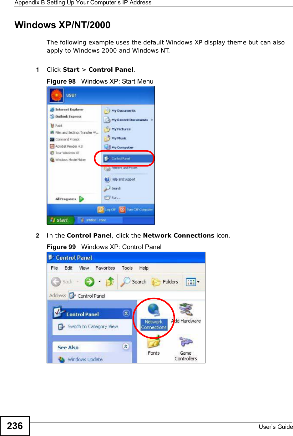
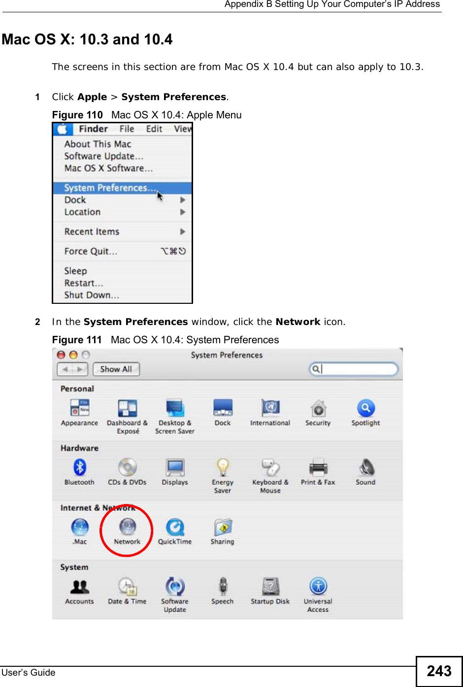
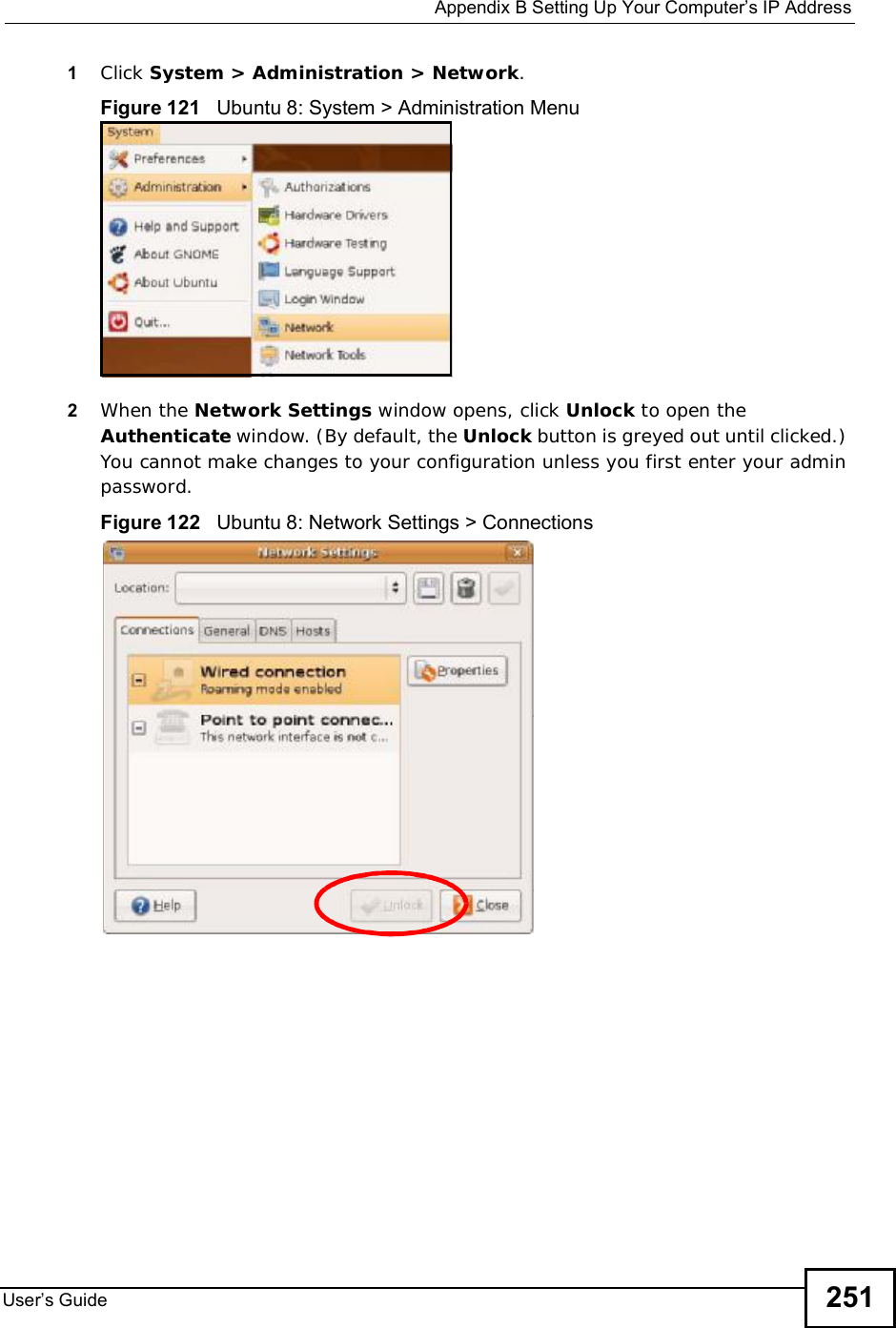
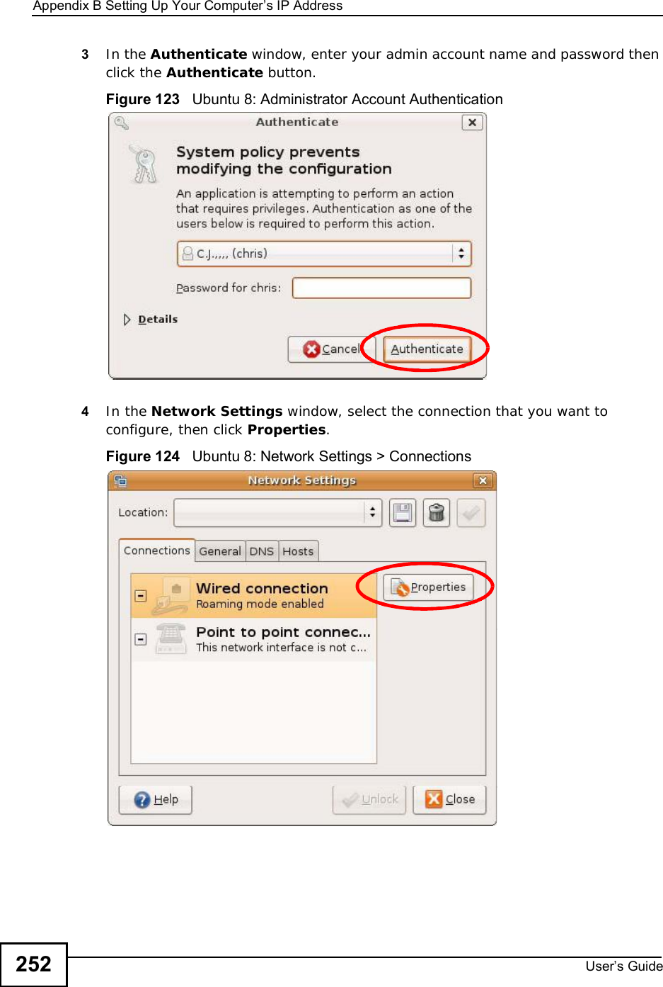
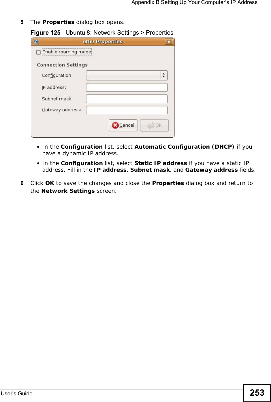
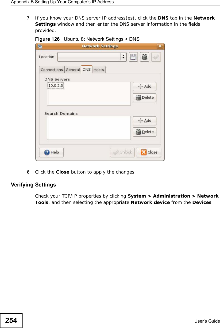
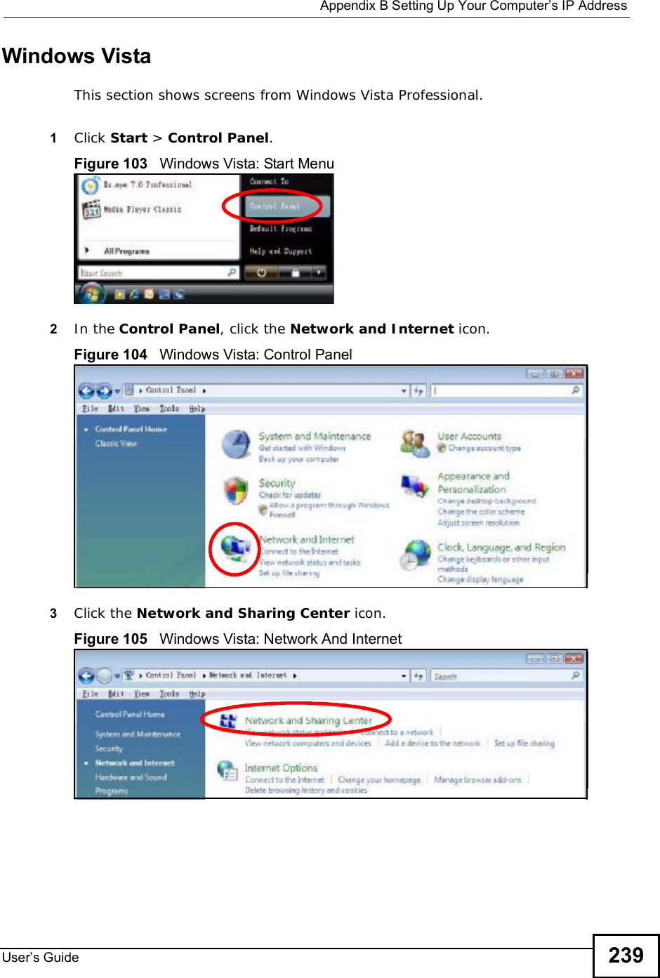
![Appendix BSetting Up Your Computer s IP AddressUser s Guide2385The Internet Protocol TCP/IP Properties window opens.Figure 102 Windows XP: Internet Protocol (TCP/IP) Properties6Select Obtain an IP address automatically if your network administrator or ISP assigns your IP address dynamically.Select Use the following IP Address and fill in the IP address,Subnet mask,and Default gateway fields if you have a static IP address that was assigned to you by your network administrator or ISP. You may also have to enter a Preferred DNS server and an AlternateDNS server, if that information was provided.7Click OK to close the Internet Protocol (TCP/IP) Properties window.Click OK to close the Local Area Connection Properties window.Verifying Settings1Click Start > All Programs > Accessories > Command Prompt.2In the Command Prompt window, type "ipconfig" and then press [ENTER]. You can also go to Start > Control Panel > Network Connections, right-click a network connection, click Status and then click the Support tab to view your IP address and connection information.](https://usermanual.wiki/ZyXEL-Communications/IX253P/User-Guide-1403071-Page-237.png)
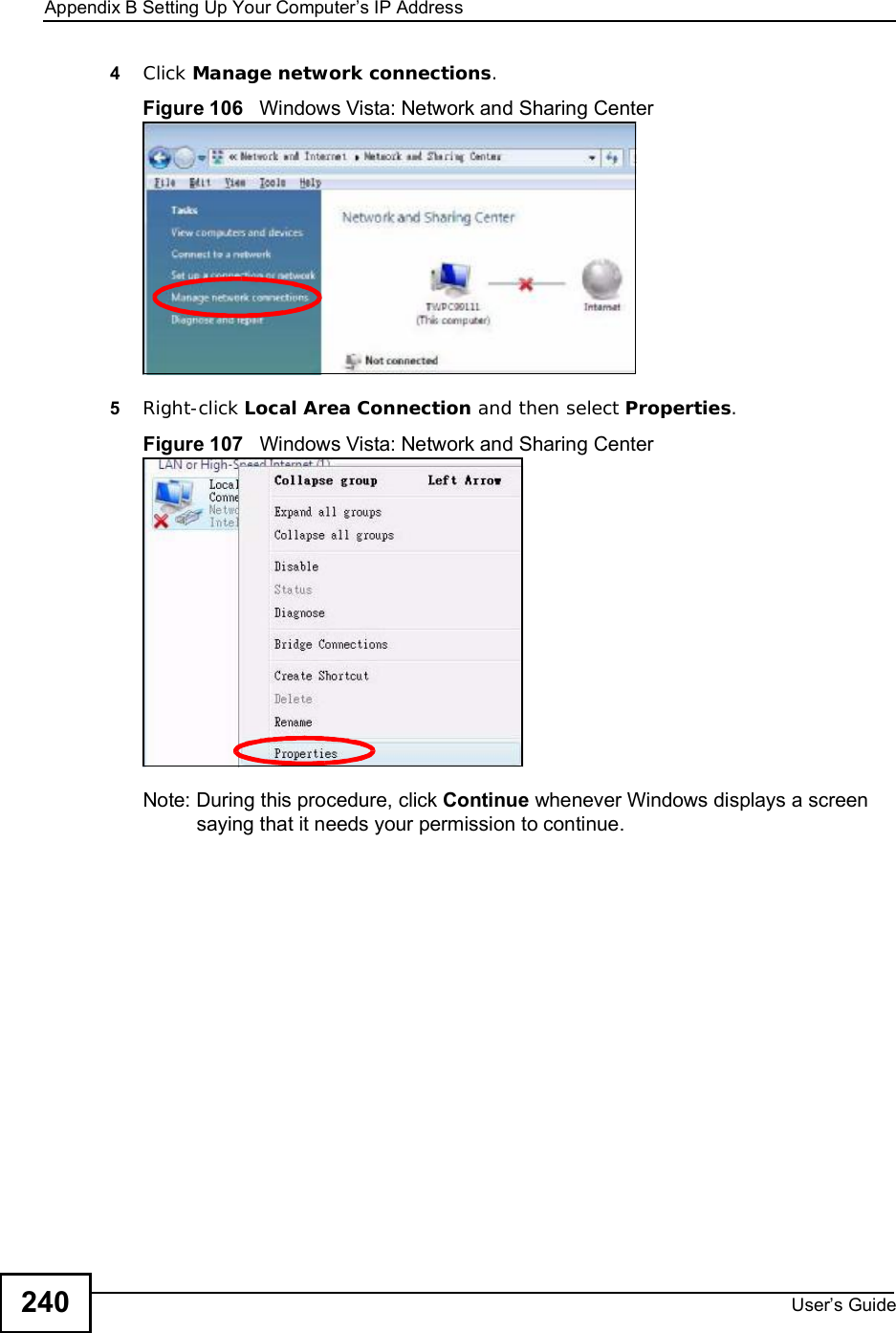
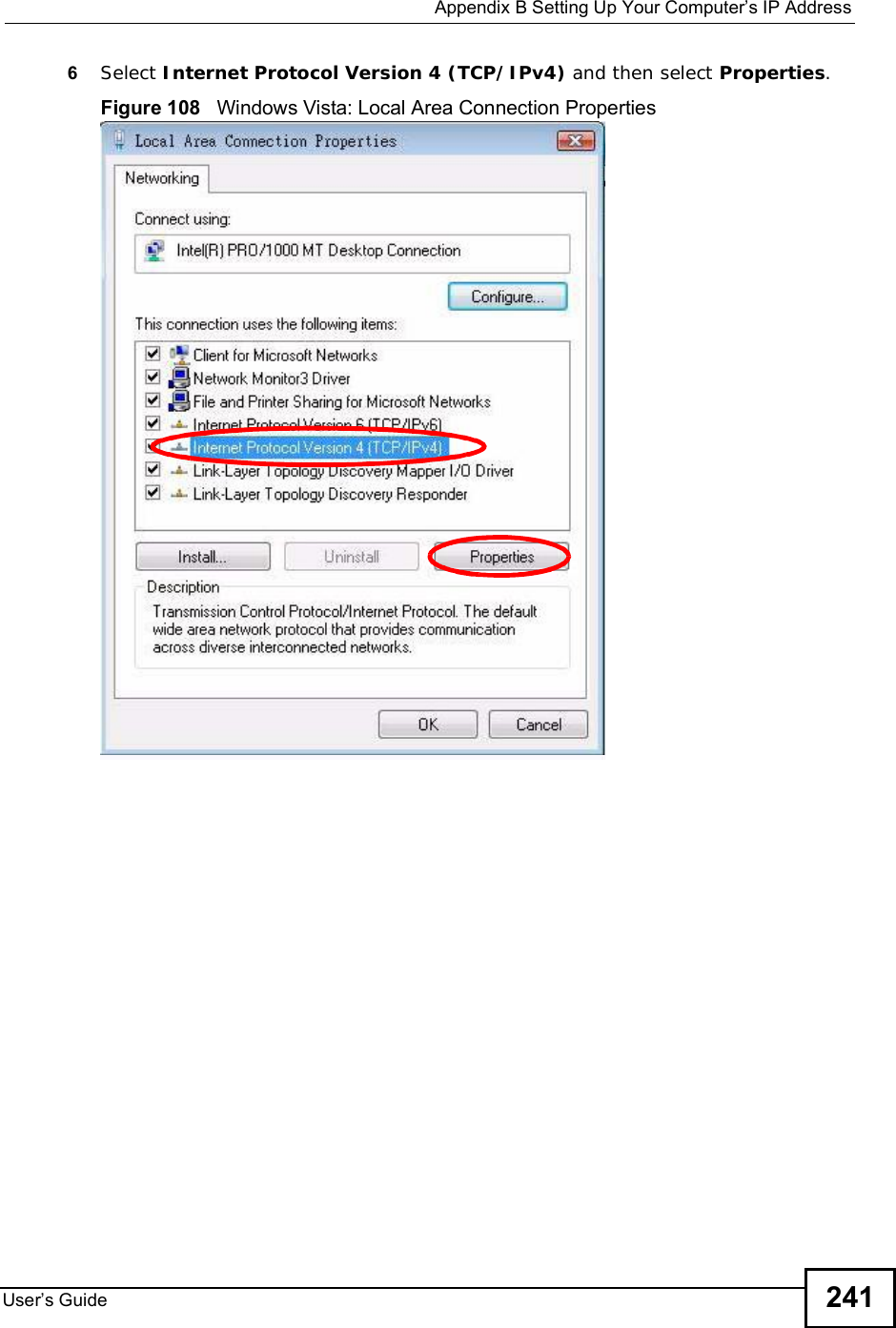
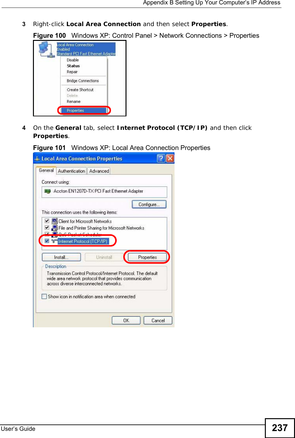
![Appendix BSetting Up Your Computer s IP AddressUser s Guide2427The Internet Protocol Version 4 (TCP/IPv4) Properties window opens.Figure 109 Windows Vista: Internet Protocol Version 4 (TCP/IPv4) Properties8Select Obtain an IP address automatically if your network administrator or ISP assigns your IP address dynamically.Select Use the following IP Address and fill in the IP address,Subnet mask,and Default gateway fields if you have a static IP address that was assigned to you by your network administrator or ISP. You may also have to enter a Preferred DNS server and an AlternateDNS server, if that information was provided.Click Advanced.9Click OK to close the Internet Protocol (TCP/IP) Properties window.Click OK to close the Local Area Connection Properties window.Verifying Settings1Click Start > All Programs > Accessories > Command Prompt.2In the Command Prompt window, type "ipconfig" and then press [ENTER]. You can also go to Start > Control Panel > Network Connections, right-click a network connection, click Status and then click the Support tab to view your IP address and connection information.](https://usermanual.wiki/ZyXEL-Communications/IX253P/User-Guide-1403071-Page-241.png)