ZyXEL Communications IX280P WiMAX MIMO 2.5GHz Indoor Simple CPE User Manual ZyBook2
ZyXEL Communications Corporation WiMAX MIMO 2.5GHz Indoor Simple CPE ZyBook2
UserManual.wiki
>
ZyXEL Communications
>
IX280P User Manual
>
UserMan-1_I88IX280P
Contents
1.
UserMan-2_I88IX280P
2.
UserMan-1_I88IX280P
UserMan-1_I88IX280P
Navigation menu
Upload a User Manual
Namespaces
Wiki Guide
HTML
PDF
Info
Views
User Manual
Discussion / Help
Navigation
![Document ConventionsMAX-207HW2R User’s Guide 5Document ConventionsWarnings and NotesThese are how warnings and notes are shown in this User’s Guide. Warnings tell you about things that could harm you or your MAX-207HW2R.Note: Notes tell you other important information (for example, other things you may need to configure or helpful tips) or recommendations.Syntax Conventions• The MAX-207HW2R may be referred to as the “MAX-207HW2R”, the “device”, the “system” or the “product” in this User’s Guide.• Product labels, screen names, field labels and field choices are all in bold font.• A key stroke is denoted by square brackets and uppercase text, for example, [ENTER] means the “enter” or “return” key on your keyboard.• “Enter” means for you to type one or more characters and then press the [ENTER] key. “Select” or “choose” means for you to use one of the predefined choices.• A right angle bracket ( > ) within a screen name denotes a mouse click. For example, TOOLS > Logs > Log Settings means you first click Tools in the navigation panel, then the Logs sub menu and finally the Log Settings tab to get to that screen.• Units of measurement may denote the “metric” value or the “scientific” value. For example, “k” for kilo may denote “1000” or “1024”, “M” for mega may denote “1000000” or “1048576” and so on.• “e.g.,” is a shorthand for “for instance”, and “i.e.,” means “that is” or “in other words”.](https://usermanual.wiki/ZyXEL-Communications/IX280P.UserMan-1-I88IX280P/User-Guide-1290917-Page-5.png)


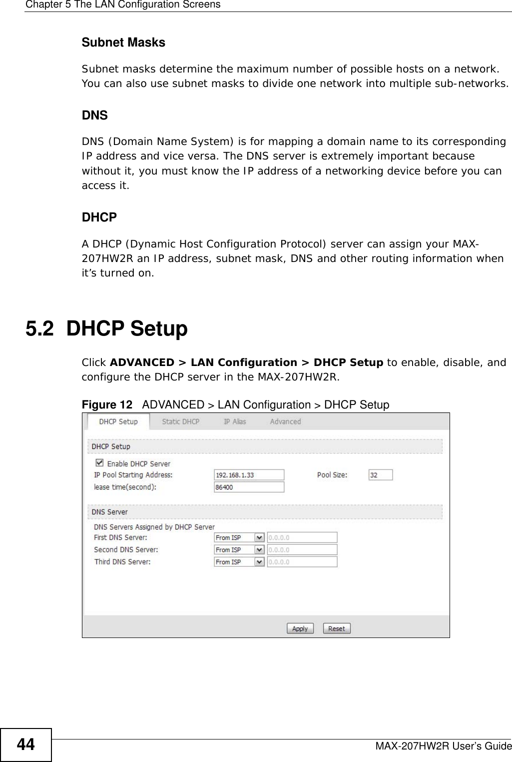
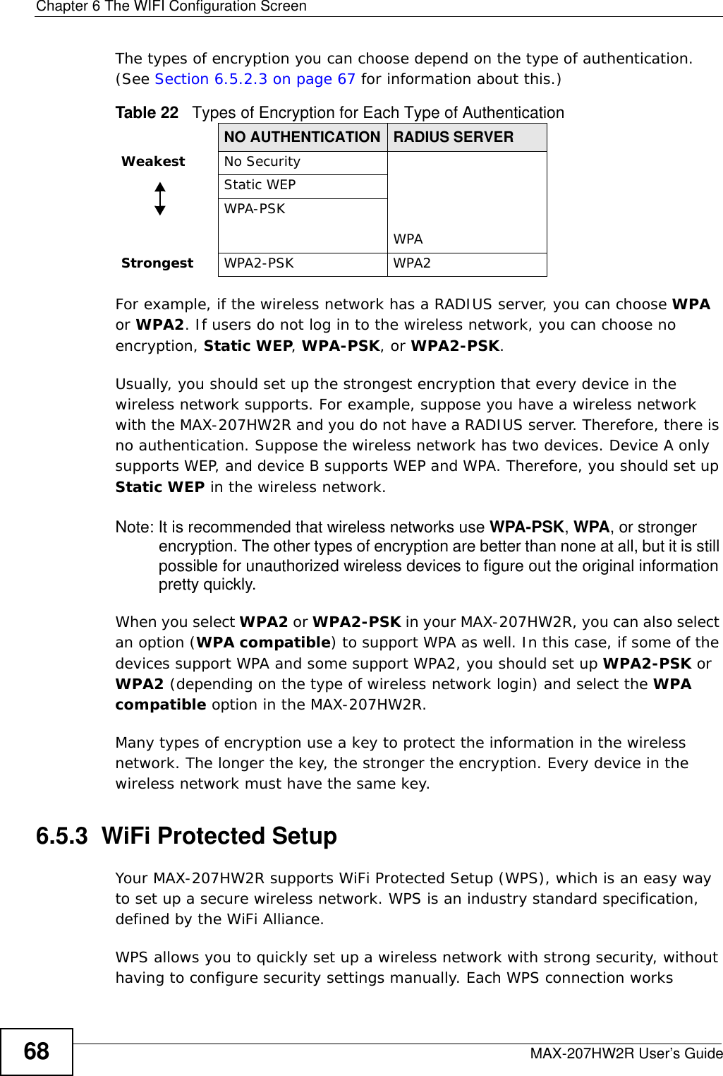
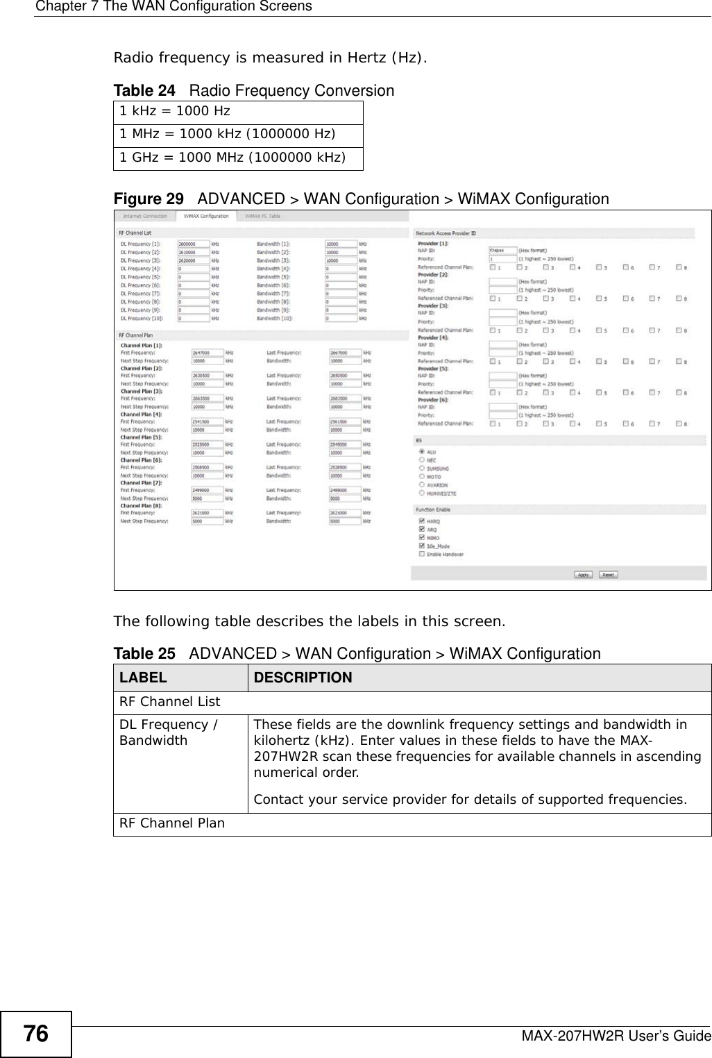
![Chapter 7 The WAN Configuration ScreensMAX-207HW2R User’s Guide 79• The MAX-207HW2R searches the DL Frequency settings in ascending numerical order, from [1] to [10].• If you enter a 0 in a DL Frequency field, the MAX-207HW2R immediately moves on to the next DL Frequency field.• When the MAX-207HW2R connects to a base station, the values in this screen are automatically set to the base station’s frequency. The next time the MAX-207HW2R searches for a connection, it searches only this frequency. If you want the MAX-207HW2R to search other frequencies, enter them in the DL Frequency fields.The following table describes some examples of DL Frequency settings.Table 26 DL Frequency Example SettingsEXAMPLE 1 EXAMPLE 2DL Frequency [1]: 2500000 2500000DL Frequency [2]: 2550000 2550000DL Frequency [3]: 0 2600000DL Frequency [4]: 00The MAX-207HW2R searches at 2500000 kHz, and then searches at 2550000 kHz if it has not found a connection.The MAX-207HW2R searches at 2500000 kHz and then at 2550000 kHz if it has not found an available connection. If it still does not find an available connection, it searches at 2600000 kHz.](https://usermanual.wiki/ZyXEL-Communications/IX280P.UserMan-1-I88IX280P/User-Guide-1290917-Page-79.png)