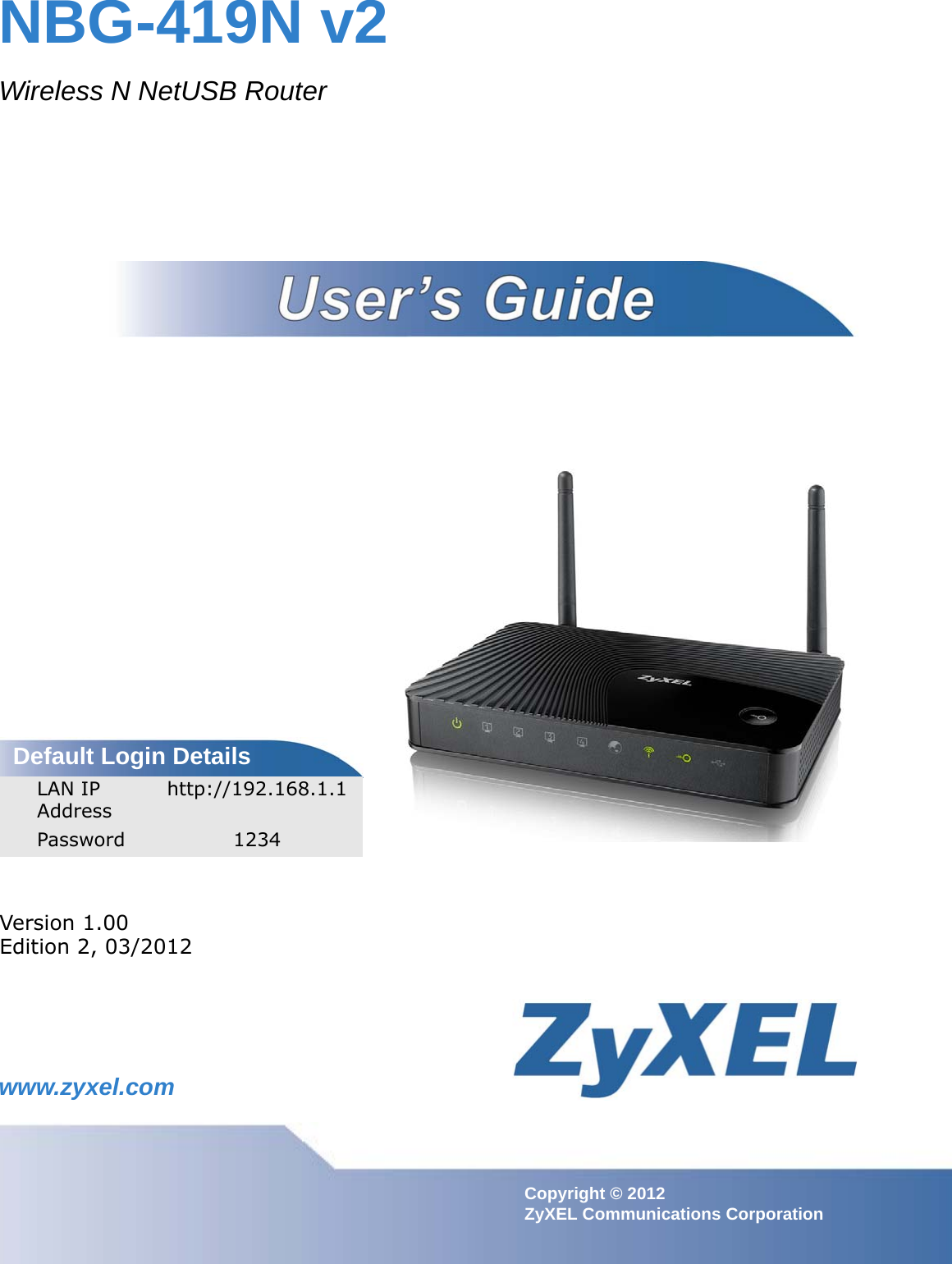
ZyXEL Communications NBG-419NV2 Wireless N NetUSB Router User Manual Book
ZyXEL Communications Corporation Wireless N NetUSB Router Book
UserManual.wiki
>
ZyXEL Communications
>
NBG-419NV2 User Manual
>
Users Manual-1
Contents
1.
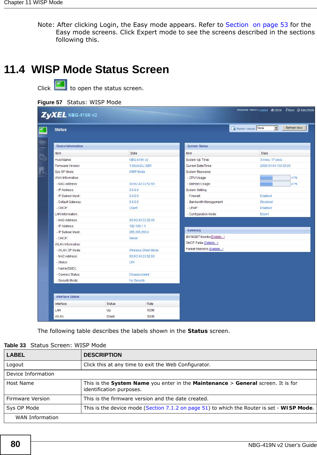
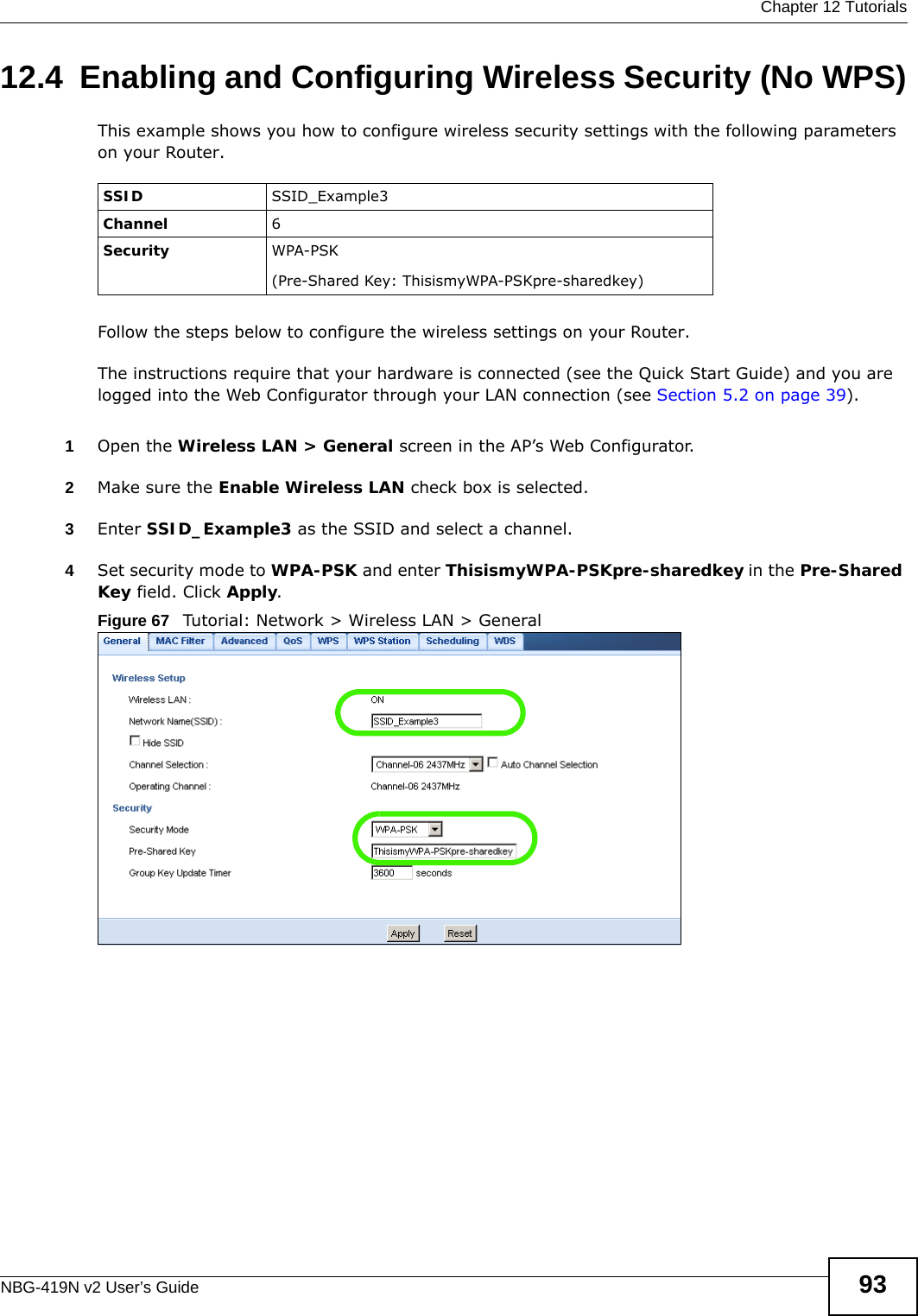
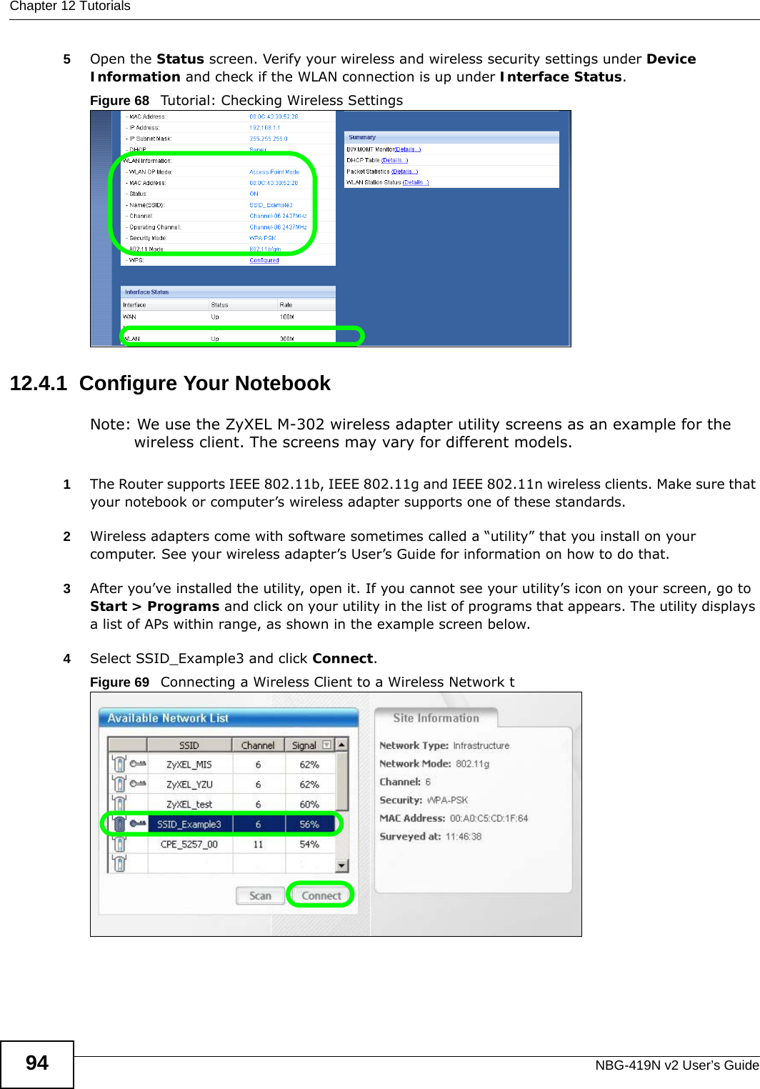
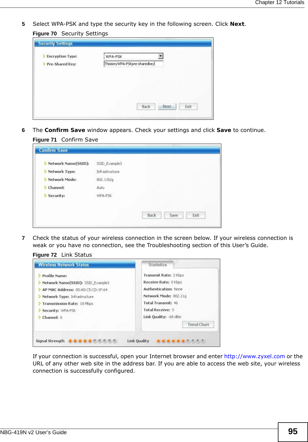
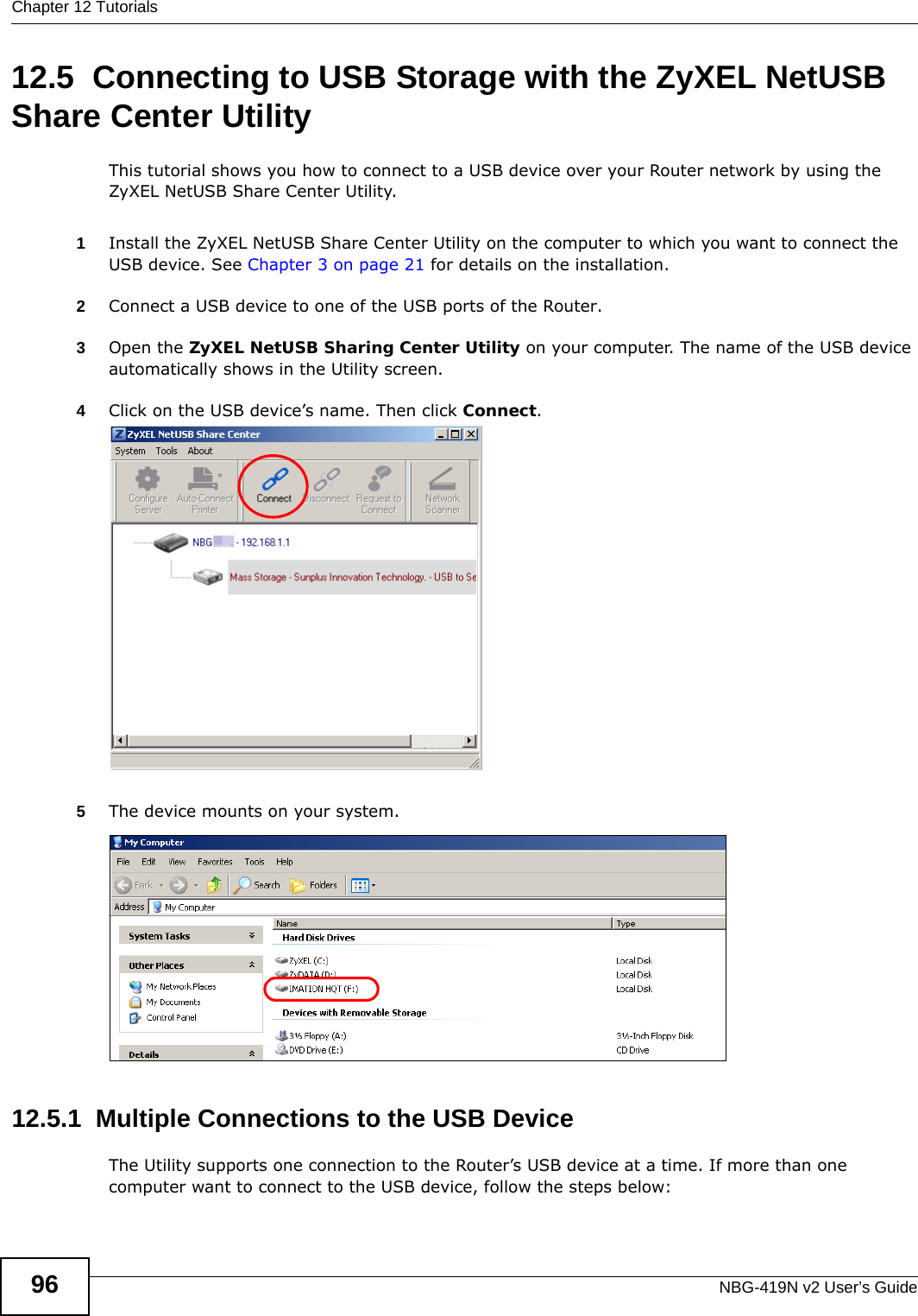
Users Manual-1
2.
Users Manual-2
Users Manual-1
Navigation menu
Upload a User Manual
Namespaces
Wiki Guide
HTML
PDF
Info
Views
User Manual
Discussion / Help
Navigation