ZyXEL Communications NBG4604 Wireless N Gigabit Managed Router User Manual User s manual
ZyXEL Communications Corporation Wireless N Gigabit Managed Router User s manual
Contents
- 1. Manual Part 1
- 2. Manual Part 2
Manual Part 1
Company Confidential

About This User's Guide
NBG4604 User’s Guide 3
About This User's Guide
Intended Audience
This manual is intended for people who want to configure the NBG4604 using the
Web Configurator. You should have at least a basic knowledge of TCP/IP
networking concepts and topology.
Tips for Reading User’s Guides On-Screen
When reading a ZyXEL User’s Guide On-Screen, keep the following in mind:
•If you don’t already have the latest version of Adobe Reader, you can download
it from http://www.adobe.com.
•Use the PDF’s bookmarks to quickly navigate to the areas that interest you.
Adobe Reader’s bookmarks pane opens by default in all ZyXEL User’s Guide
PDFs.
•If you know the page number or know vaguely which page-range you want to
view, you can enter a number in the toolbar in Reader, then press [ENTER] to
jump directly to that page.
•Type [CTRL]+[F] to open the Adobe Reader search utility and enter a word or
phrase. This can help you quickly pinpoint the information you require. You can
also enter text directly into the toolbar in Reader.
•To quickly move around within a page, press the [SPACE] bar. This turns your
cursor into a “hand” with which you can grab the page and move it around freely
on your screen.
•Embedded hyperlinks are actually cross-references to related text. Click them to
jump to the corresponding section of the User’s Guide PDF.
Related Documentation
•Quick Start Guide
The Quick Start Guide is designed to help you get your NBG4604 up and running
right away. It contains information on setting up your network and configuring
for Internet access.
•Supporting Disc
The embedded Web Help contains descriptions of individual screens and
supplementary information.
•Support Disc
Refer to the included CD for support documents.
Company Confidential
About This User's Guide
NBG4604 User’s Guide
4
Documentation Feedback
Send your comments, questions or suggestions to: techwriters@zyxel.com.tw
Thank you!
The Technical Writing Team, ZyXEL Communications Corp.,
6 Innovation Road II, Science-Based Industrial Park, Hsinchu, 30099, Taiwan.
Need More Help?
More help is available at www.zyxel.com.
•Download Library
Search for the latest product updates and documentation from this link. Read
the Tech Doc Overview to find out how to efficiently use the User Guide, Quick
Start Guide and Command Line Interface Reference Guide in order to better
understand how to use your product.
•Knowledge Base
If you have a specific question about your product, the answer may be here.
This is a collection of answers to previously asked questions about ZyXEL
products.
•Forum
This contains discussions on ZyXEL products. Learn from others who use ZyXEL
products and share your experiences as well.
Company Confidential

About This User's Guide
NBG4604 User’s Guide 5
Customer Support
Should problems arise that cannot be solved by the methods listed above, you
should contact your vendor. If you cannot contact your vendor, then contact a
ZyXEL office for the region in which you bought the device.
See http://www.zyxel.com/web/contact_us.php for contact information. Please
have the following information ready when you contact an office.
•Product model and serial number.
•Warranty Information.
•Date that you received your device.
Company Confidential

Document Conventions
NBG4604 User’s Guide
6
Document Conventions
Warnings and Notes
These are how warnings and notes are shown in this User’s Guide.
Warnings tell you about things that could harm you or your device.
Note: Notes tell you other important information (for example, other things you may
need to configure or helpful tips) or recommendations.
Syntax Conventions
•The NBG4604 may be referred to as the “NBG4604”, the “device”, the “product”
or the “system” in this User’s Guide.
•Product labels, screen names, field labels and field choices are all in bold font.
•A key stroke is denoted by square brackets and uppercase text, for example,
[ENTER] means the “enter” or “return” key on your keyboard.
•“Enter” means for you to type one or more characters and then press the
[ENTER] key. “Select” or “choose” means for you to use one of the predefined
choices.
•A right angle bracket ( > ) within a screen name denotes a mouse click. For
example, Maintenance > Log > Log Setting means you first click
Maintenance in the navigation panel, then the Log sub menu and finally the
Log Setting tab to get to that screen.
•Units of measurement may denote the “metric” value or the “scientific” value.
For example, “k” for kilo may denote “1000” or “1024”, “M” for mega may
denote “1000000” or “1048576” and so on.
•“e.g.,” is a shorthand for “for instance”, and “i.e.,” means “that is” or “in other
words”.
Company Confidential
Document Conventions
NBG4604 User’s Guide 7
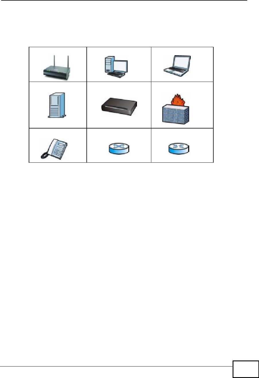
Icons Used in Figures
Figures in this User’s Guide may use the following generic icons. The NBG4604
icon is not an exact representation of your device.
NBG4604 Computer Notebook computer
Server Modem Firewall
Telephone Switch Router
Company Confidential

Safety Warnings
NBG4604 User’s Guide
8
Safety Warnings
•Do NOT use this product near water, for example, in a wet basement or near a swimming
pool.
•Do NOT expose your device to dampness, dust or corrosive liquids.
•Do NOT store things on the device.
•Do NOT install, use, or service this device during a thunderstorm. There is a remote risk
of electric shock from lightning.
•Connect ONLY suitable accessories to the device.
•Do NOT open the device or unit. Opening or removing covers can expose you to
dangerous high voltage points or other risks. ONLY qualified service personnel should
service or disassemble this device. Please contact your vendor for further information.
•Make sure to connect the cables to the correct ports.
•Place connecting cables carefully so that no one will step on them or stumble over them.
•Always disconnect all cables from this device before servicing or disassembling.
•Use ONLY an appropriate power adaptor or cord for your device.
•Connect the power adaptor or cord to the right supply voltage (for example, 110V AC in
North America or 230V AC in Europe).
•Do NOT allow anything to rest on the power adaptor or cord and do NOT place the
product where anyone can walk on the power adaptor or cord.
•Do NOT use the device if the power adaptor or cord is damaged as it might cause
electrocution.
•If the power adaptor or cord is damaged, remove it from the power outlet.
•Do NOT attempt to repair the power adaptor or cord. Contact your local vendor to order a
new one.
•Do not use the device outside, and make sure all the connections are indoors. There is a
remote risk of electric shock from lightning.
•Do NOT obstruct the device ventilation slots, as insufficient airflow may harm your
device.
•Antenna Warning! This device meets ETSI and FCC certification requirements when using
the included antenna(s). Only use the included antenna(s).
•If you wall mount your device, make sure that no electrical lines, gas or water pipes will
be damaged.
Your product is marked with this symbol, which is known as the WEEE mark. WEEE
stands for Waste Electronics and Electrical Equipment. It means that used electrical
and electronic products should not be mixed with general waste. Used electrical and
electronic equipment should be treated separately.
Company Confidential

Contents Overview
NBG4604 User’s Guide 9
Contents Overview
User’s Guide ...........................................................................................................................19
Introduction ................................................................................................................................21
The WPS Button ........................................................................................................................25
The Web Configurator ...............................................................................................................27
Connection Wizard ....................................................................................................................39
AP Mode ....................................................................................................................................55
Tutorials .....................................................................................................................................63
Technical Reference ..............................................................................................................75
Wireless LAN .............................................................................................................................77
WAN ........................................................................................................................................101
LAN ...........................................................................................................................................113
DHCP Server ............................................................................................................................117
Network Address Translation (NAT) ........................................................................................123
Dynamic DNS ..........................................................................................................................131
Firewall ....................................................................................................................................135
Content Filtering ......................................................................................................................139
Static Route .............................................................................................................................143
Bandwidth Management ..........................................................................................................147
Remote Management ..............................................................................................................155
Universal Plug-and-Play (UPnP) .............................................................................................159
SNMP ......................................................................................................................................167
ACS .........................................................................................................................................171
System .....................................................................................................................................177
Logs .........................................................................................................................................183
Tools ........................................................................................................................................187
Sys OP Mode ..........................................................................................................................193
Language .................................................................................................................................197
Troubleshooting .......................................................................................................................199
Product Specifications .............................................................................................................207
Company Confidential

Contents Overview
NBG4604 User’s Guide
10
Company Confidential

Table of Contents
NBG4604 User’s Guide 11
Table of Contents
About This User's Guide..........................................................................................................3
Document Conventions............................................................................................................6
Safety Warnings........................................................................................................................8
Contents Overview...................................................................................................................9
Table of Contents....................................................................................................................11
Part I: User’s Guide................................................................................19
Chapter 1
Introduction.............................................................................................................................21
1.1 Overview ..............................................................................................................................21
1.2 Applications .........................................................................................................................21
1.3 Ways to Manage the NBG4604 ...........................................................................................22
1.4 Good Habits for Managing the NBG4604 ............................................................................22
1.5 LEDs ....................................................................................................................................22
Chapter 2
The WPS Button......................................................................................................................25
2.1 Overview ..............................................................................................................................25
Chapter 3
The Web Configurator............................................................................................................27
3.1 Overview ..............................................................................................................................27
3.2 Accessing the Web Configurator .........................................................................................27
3.3 Resetting the NBG4604 .......................................................................................................29
3.3.1 Procedure to Use the Reset Button ...........................................................................29
3.4 Navigating the Web Configurator ......................................................................................29
3.5 Status Screen (Router Mode) ..............................................................................................30
3.5.1 Navigation Panel ........................................................................................................32
3.5.2 Summary: DHCP Table ...........................................................................................34
3.5.3 Summary: Packet Statistics .....................................................................................35
3.5.4 Summary: WLAN Station Status ............................................................................36
Chapter 4
Connection Wizard.................................................................................................................39
Company Confidential

Table of Contents
NBG4604 User’s Guide
12
4.1 Wizard Setup .......................................................................................................................39
4.2 Connection Wizard: STEP 1: System Information ...............................................................40
4.2.1 System Name .............................................................................................................40
4.2.2 Domain Name ............................................................................................................41
4.3 Connection Wizard: STEP 2: Wireless LAN ........................................................................42
4.3.1 Extend (WPA-PSK or WPA2-PSK) Security ...............................................................44
4.4 Connection Wizard: STEP 3: Internet Configuration ...........................................................44
4.4.1 Ethernet Connection ..................................................................................................45
4.4.2 PPPoE Connection ....................................................................................................46
4.4.3 PPTP Connection .......................................................................................................47
4.4.4 Your IP Address .........................................................................................................48
4.4.5 WAN IP Address Assignment .....................................................................................49
4.4.6 IP Address and Subnet Mask .....................................................................................49
4.4.7 DNS Server Address Assignment ..............................................................................50
4.4.8 WAN IP and DNS Server Address Assignment .........................................................51
4.4.9 WAN MAC Address ....................................................................................................52
4.5 Connection Wizard Complete ..............................................................................................53
Chapter 5
AP Mode...................................................................................................................................55
5.1 Overview ..............................................................................................................................55
5.2 Setting your NBG4604 to AP Mode .....................................................................................55
5.3 Status Screen (AP Mode) ....................................................................................................56
5.3.1 Navigation Panel ........................................................................................................58
5.4 Configuring Your Settings ....................................................................................................60
5.4.1 LAN Settings ..............................................................................................................60
5.4.2 WLAN and Maintenance Settings ..............................................................................60
5.5 Logging in to the Web Configurator in AP Mode .................................................................61
Chapter 6
Tutorials...................................................................................................................................63
6.1 Overview ..............................................................................................................................63
6.2 How to Connect to the Internet from an AP .........................................................................63
6.2.1 Configure Wireless Security Using WPS on both your NBG4604 and Wireless Client 63
6.2.2 Enable and Configure Wireless Security without WPS on your NBG4604 ................67
6.3 Bandwidth Management for your Network ...........................................................................70
6.3.1 Configuring Bandwidth Management by Application ..................................................70
6.3.2 Configuring Bandwidth Management by Custom Application ....................................71
6.3.3 Configuring Bandwidth Allocation by IP or IP Range .................................................72
Part II: Technical Reference..................................................................75
Company Confidential

Table of Contents
NBG4604 User’s Guide 13
Chapter 7
Wireless LAN...........................................................................................................................77
7.1 Overview ..............................................................................................................................77
7.2 What You Can Do ................................................................................................................78
7.3 What You Should Know .......................................................................................................78
7.3.1 Wireless Security Overview .......................................................................................78
7.4 General Wireless LAN Screen ............................................................................................81
7.4.1 No Security .................................................................................................................83
7.4.2 WEP Encryption .........................................................................................................84
7.4.3 WPA-PSK/WPA2-PSK ................................................................................................86
7.5 MAC Filter ............................................................................................................................87
7.6 Wireless LAN Advanced Screen .........................................................................................89
7.7 Quality of Service (QoS) Screen .........................................................................................90
7.7.1 Application Priority Configuration ...............................................................................92
7.8 WPS Screen ........................................................................................................................93
7.9 WPS Station Screen ............................................................................................................94
7.10 Scheduling Screen ............................................................................................................95
7.11 WDS Screen ......................................................................................................................96
7.11.1 Security Mode: Static WEP ......................................................................................98
7.11.2 Security Mode: WPA-PSK/WPA2-PSK .....................................................................99
Chapter 8
WAN........................................................................................................................................101
8.1 Overview ............................................................................................................................101
8.2 What You Can Do ..............................................................................................................101
8.3 What You Need To Know ...................................................................................................102
8.3.1 Configuring Your Internet Connection ......................................................................102
8.3.2 Multicast ...................................................................................................................103
8.3.3 NetBIOS over TCP/IP ..............................................................................................104
8.3.4 Auto-Bridge ..............................................................................................................104
8.4 Internet Connection ...........................................................................................................105
8.4.1 Ethernet Encapsulation ............................................................................................105
8.4.2 PPPoE Encapsulation ..............................................................................................106
8.4.3 PPTP Encapsulation ................................................................................................108
8.5 Advanced WAN Screen ......................................................................................................111
Chapter 9
LAN.........................................................................................................................................113
9.1 Overview .............................................................................................................................113
9.2 What You Can Do ...............................................................................................................113
9.3 What You Need To Know ....................................................................................................114
9.3.1 IP Pool Setup ............................................................................................................114
9.3.2 LAN TCP/IP ...............................................................................................................114
Company Confidential

Table of Contents
NBG4604 User’s Guide
14
9.4 LAN IP Screen ....................................................................................................................115
Chapter 10
DHCP Server..........................................................................................................................117
10.1 Overview ...........................................................................................................................117
10.2 What You Can Do .............................................................................................................117
10.3 What You Need To Know ..................................................................................................117
10.4 General Screen ................................................................................................................118
10.5 Advanced Screen ..........................................................................................................118
10.6 Client List Screen ............................................................................................................120
Chapter 11
Network Address Translation (NAT)....................................................................................123
11.1 Overview .......................................................................................................................123
11.2 What You Can Do ............................................................................................................124
11.3 General NAT Screen ........................................................................................................124
11.4 NAT Application Screen .................................................................................................125
11.5 NAT Advanced Screen .....................................................................................................128
11.5.1 Trigger Port Forwarding Example ...........................................................................129
11.5.2 Two Points To Remember About Trigger Ports ......................................................130
Chapter 12
Dynamic DNS........................................................................................................................131
12.1 Overview .........................................................................................................................131
12.2 What You Can Do ............................................................................................................131
12.3 What You Need To Know .................................................................................................131
12.3.1 DynDNS Wildcard ..................................................................................................131
12.4 Dynamic DNS Screen ....................................................................................................132
Chapter 13
Firewall...................................................................................................................................135
13.1 Overview ........................................................................................................................135
13.2 What You Can Do ............................................................................................................136
13.3 What You Need To Know .................................................................................................136
13.3.1 About the NBG4604 Firewall ..................................................................................136
13.4 General Firewall Screen ...............................................................................................137
13.5 Services Screen ...........................................................................................................137
Chapter 14
Content Filtering...................................................................................................................139
14.1 Overview ..........................................................................................................................139
14.2 What You Can Do ............................................................................................................139
14.3 What You Need To Know .................................................................................................139
Company Confidential

Table of Contents
NBG4604 User’s Guide 15
14.3.1 Content Filtering Profiles ........................................................................................139
14.4 Filter Screen ....................................................................................................................140
14.5 Technical Reference ........................................................................................................141
14.5.1 Customizing Keyword Blocking URL Checking ......................................................141
Chapter 15
Static Route...........................................................................................................................143
15.1 Overview ..........................................................................................................................143
15.2 What You Can Do ............................................................................................................143
15.3 IP Static Route Screen ....................................................................................................144
15.3.1 Static Route Setup Screen ...................................................................................145
Chapter 16
Bandwidth Management.......................................................................................................147
16.1 Overview .........................................................................................................................147
16.2 What You Can Do ............................................................................................................147
16.3 What You Need To Know .................................................................................................148
16.4 General Configuration ...................................................................................................148
16.5 Advanced Configuration .................................................................................................149
16.5.1 Priority Levels .........................................................................................................152
16.5.2 User Defined Service Rule Configuration ...........................................................152
16.5.3 Predefined Bandwidth Management Services .......................................................153
16.5.4 Services and Port Numbers ...................................................................................154
Chapter 17
Remote Management............................................................................................................155
17.1 Overview ..........................................................................................................................155
17.2 What You Can Do ............................................................................................................155
17.3 What You Need To Know .................................................................................................155
17.3.1 Remote Management Limitations ..........................................................................156
17.3.2 Remote Management and NAT ..............................................................................156
17.3.3 System Timeout ....................................................................................................156
17.4 WWW Screen ...............................................................................................................157
Chapter 18
Universal Plug-and-Play (UPnP)..........................................................................................159
18.1 Overview .........................................................................................................................159
18.2 What You Can Do ............................................................................................................159
18.3 What You Need to Know ..................................................................................................159
18.4 UPnP Screen ...................................................................................................................160
18.5 Technical Reference ........................................................................................................161
18.5.1 Using UPnP in Windows XP Example ...................................................................161
18.5.2 Web Configurator Easy Access .............................................................................164
Company Confidential

Table of Contents
NBG4604 User’s Guide
16
Chapter 19
SNMP......................................................................................................................................167
19.1 Overview ..........................................................................................................................167
19.2 What You Need to Know ..................................................................................................167
19.3 SNMP Screen ..................................................................................................................168
Chapter 20
ACS........................................................................................................................................171
20.1 Overview ..........................................................................................................................171
20.2 What You Can Do in this Chapter ....................................................................................171
20.3 What You Need to Know ..................................................................................................171
20.4 General Screen ...............................................................................................................172
20.4.1 STUN .....................................................................................................................172
20.5 Certificate Screen ............................................................................................................175
20.6 Technical Reference ........................................................................................................176
Chapter 21
System...................................................................................................................................177
21.1 Overview ..........................................................................................................................177
21.2 What You Can Do ............................................................................................................177
21.3 System General Screen .................................................................................................177
21.4 Time Setting Screen ........................................................................................................179
Chapter 22
Logs.......................................................................................................................................183
22.1 Overview ..........................................................................................................................183
22.2 What You Can Do ............................................................................................................183
22.3 What You Need to Know ..................................................................................................183
22.4 View Log Screen ..............................................................................................................184
22.5 Log Settings Screen ........................................................................................................185
Chapter 23
Tools.......................................................................................................................................187
23.1 Overview ..........................................................................................................................187
23.2 What You Can Do ............................................................................................................187
23.3 Firmware Upload Screen .................................................................................................187
23.4 Configuration Screen .......................................................................................................190
23.4.1 Backup Configuration .............................................................................................190
23.4.2 Restore Configuration ............................................................................................191
23.4.3 Back to Factory Defaults ........................................................................................192
23.5 Restart Screen .................................................................................................................192
Company Confidential

Table of Contents
NBG4604 User’s Guide 17
Chapter 24
Sys OP Mode.........................................................................................................................193
24.1 Overview ..........................................................................................................................193
24.2 What You Can Do ............................................................................................................193
24.3 What You Need to Know ..................................................................................................193
24.4 General Screen ...............................................................................................................194
Chapter 25
Language...............................................................................................................................197
25.1 Language Screen ............................................................................................................197
Chapter 26
Troubleshooting....................................................................................................................199
26.1 Power, Hardware Connections, and LEDs ......................................................................199
26.2 NBG4604 Access and Login ...........................................................................................200
26.3 Internet Access ................................................................................................................202
26.4 Resetting the NBG4604 to Its Factory Defaults ...............................................................203
26.5 Wireless Router/AP Troubleshooting ...............................................................................204
Chapter 27
Product Specifications.........................................................................................................207
27.1 Wall-mounting Instructions ..............................................................................................209
Appendix A IP Addresses and Subnetting...........................................................................211
Appendix B Pop-up Windows, JavaScript and Java Permissions........................................221
Appendix C Setting up Your Computer’s IP Address...........................................................229
27.1.1 Verifying Settings ...................................................................................................246
Appendix D Wireless LANs..................................................................................................247
27.1.2 WPA(2)-PSK Application Example .........................................................................257
27.1.3 WPA(2) with RADIUS Application Example ...........................................................257
Appendix E Services............................................................................................................259
Appendix F ..........................................................................................................................263
Appendix F Open Software Announcements.......................................................................263
Appendix G Legal Information..............................................................................................281
Index.......................................................................................................................................289
Company Confidential

Table of Contents
NBG4604 User’s Guide
18
Company Confidential

19
PART I
User’s Guide
Introduction (21)
The WPS Button (25)
The Web Configurator (27)
Connection Wizard (39)
AP Mode (55)
Tutorials (63)
Company Confidential

20
Company Confidential
NBG4604 User’s Guide 21
CHAPTER 1
Introduction
1.1 Overview
This chapter introduces the main features and applications of the NBG4604.
The NBG4604 extends the range of your existing wired network without additional
wiring, providing easy network access to mobile users. You can set up a wireless
network with other IEEE 802.11b/g/n compatible devices.
A range of services such as a firewall and content filtering are also available for
secure Internet computing.
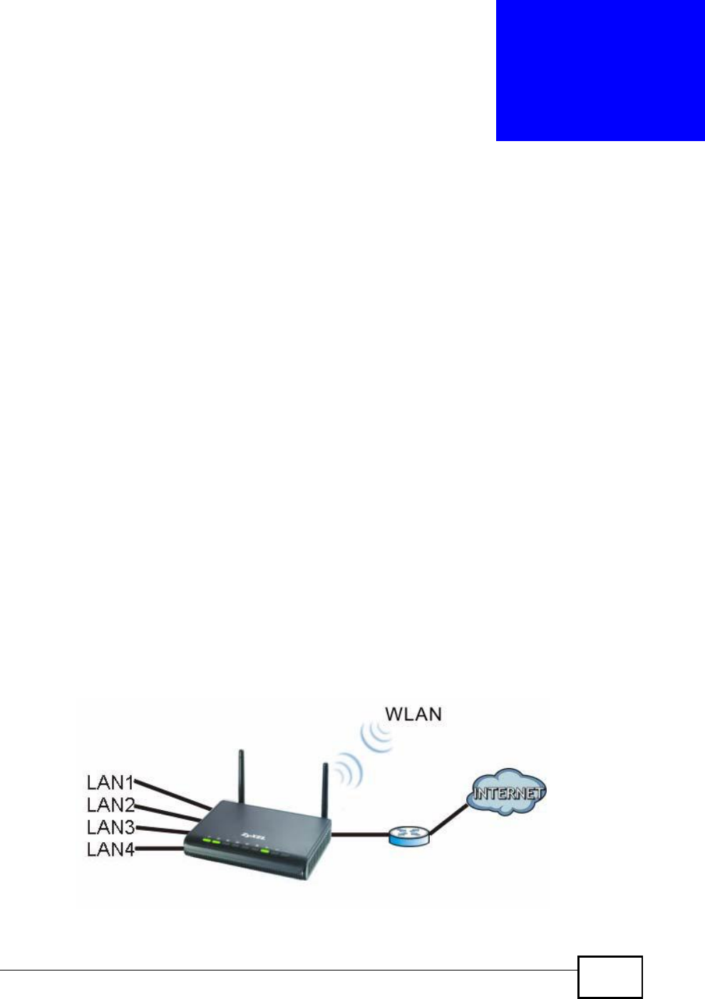
1.2 Applications
Your can create the following networks using the NBG4604:
•Wired. You can connect network devices via the Ethernet ports of the NBG4604
so that they can communicate with each other and access the Internet.
•Wireless. Wireless clients can connect to the NBG4604 to access network
resources.
•WAN. Connect to a broadband modem/router for Internet access.
Figure 1 NBG4604 Network
Company Confidential
Chapter 1Introduction
NBG4604 User’s Guide
22
1.3 Ways to Manage the NBG4604
Use any of the following methods to manage the NBG4604.
•WPS (Wi-Fi Protected Setup). You can use the WPS button or the WPS section of
the Web Configurator to set up a wireless network with your ZyXEL Device.
•Web Configurator. This is recommended for everyday management of the
NBG4604 using a (supported) web browser.
1.4 Good Habits for Managing the NBG4604
Do the following things regularly to make the NBG4604 more secure and to
manage the NBG4604 more effectively.
•Change the password. Use a password that’s not easy to guess and that consists
of different types of characters, such as numbers and letters.
•Write down the password and put it in a safe place.
•Back up the configuration (and make sure you know how to restore it).
Restoring an earlier working configuration may be useful if the device becomes
unstable or even crashes. If you forget your password, you will have to reset the
NBG4604 to its factory default settings. If you backed up an earlier
configuration file, you would not have to totally re-configure the NBG4604. You
could simply restore your last configuration.
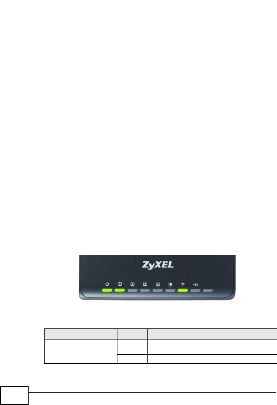
1.5 LEDs
Figure 2 Front Panel
The following table describes the LEDs and the WPS button.
Table 1 Front Panel LEDs and WPS Button
LED COLOR STATUS DESCRIPTION
POWERGreenOnThe NBG4604 is receiving power and functioning
properly.
OffThe NBG4604 is not receiving power.
Company Confidential

Chapter 1Introduction
NBG4604 User’s Guide 23
WLANGreenOnThe NBG4604 is ready, but is not sending/
receiving data through the wireless LAN.
BlinkingThe NBG4604 is sending/receiving data through
the wireless LAN.
The NBG4604 is negotiating a WPS connection
with a wireless client.
OffThe wireless LAN is not ready or has failed.
WPSGreenOnThe NBG4604 is ready, but is not sending/
receiving data through the WPS connection.
BlinkingThe NBG4604 is sending/receiving data through
the WPS connection.
OffThe WPS connection is not ready or has failed.
WANGreenOnThe NBG4604 has a successful 10/100/1000 MB
WAN connection.
BlinkingThe NBG4604 is sending/receiving data through
the WAN.
OffThe WAN connection is not ready, or has failed.
LAN 1-4GreenOnThe NBG4604 has a successful 10/100/1000 MB
Ethernet connection.
BlinkingThe NBG4604 is sending/receiving data through
the LAN.
OffThe LAN is not connected.
WPS ButtonPress this button for 1 second to set up a wireless connection via WiFi
Protected Setup with another WPS-enabled client. You must press the
WPS button on the client side within 120 seconds for a successful
connection.
Table 1 Front Panel LEDs and WPS Button
LED COLOR STATUS DESCRIPTION
Company Confidential

Chapter 1Introduction
NBG4604 User’s Guide
24
Company Confidential

NBG4604 User’s Guide 25
CHAPTER 2
The WPS Button
2.1 Overview
Your NBG4604 supports WiFi Protected Setup (WPS), which is an easy way to set
up a secure wireless network. WPS is an industry standard specification, defined
by the WiFi Alliance.
WPS allows you to quickly set up a wireless network with strong security, without
having to configure security settings manually. Each WPS connection works
between two devices. Both devices must support WPS (check each device’s
documentation to make sure).
Depending on the devices you have, you can either press a button (on the device
itself, or in its configuration utility) or enter a PIN (a unique Personal Identification
Number that allows one device to authenticate the other) in each of the two
devices. When WPS is activated on a device, it has two minutes to find another
device that also has WPS activated. Then, the two devices connect and set up a
secure network by themselves.
For more information on using WPS, see Section 6.2.1 on page 63.
Company Confidential

Chapter 2The WPS Button
NBG4604 User’s Guide
26
Company Confidential

NBG4604 User’s Guide 27
CHAPTER 3
The Web Configurator
3.1 Overview
This chapter describes how to access the NBG4604 Web Configurator and provides
an overview of its screens.
The Web Configurator is an HTML-based management interface that allows easy
setup and management of the NBG4604 via Internet browser. Use Internet
Explorer 7.0 and later or Firefox 1.5 and later. The recommended screen
resolution is 1024 by 768 pixels.
In order to use the Web Configurator you need to allow:
•Web browser pop-up windows from your device. Web pop-up blocking is enabled
by default in Windows XP SP (Service Pack) 2.
•JavaScript (enabled by default).
•Java permissions (enabled by default).
Refer to the Troubleshooting chapter to see how to make sure these functions are
allowed in Internet Explorer.
3.2 Accessing the Web Configurator
1Make sure your NBG4604 hardware is properly connected and prepare your
computer or computer network to connect to the NBG4604 (refer to the Quick
Start Guide).
2Launch your web browser.
3Type "http://192.168.1.1" as the website address. Your computer must be in the
same subnet in order to access this website address.
Company Confidential
Chapter 3The Web Configurator
NBG4604 User’s Guide
28
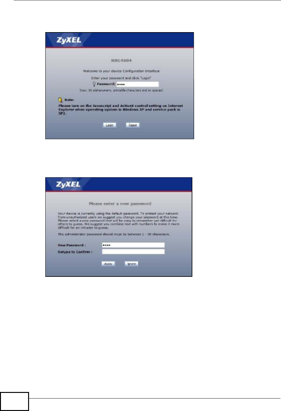
4Type "1234" (default) as the password and click Login. In some versions, the
default password appears automatically - if this is the case, click Login.
5You should see a screen asking you to change your password (highly
recommended) as shown next. Type a new password (and retype it to confirm)
and click Apply or click Ignore.
Note: The management session automatically times out when the time period set in
the Administrator Inactivity Timer field expires (default five minutes). Simply
log back into the NBG4604 if this happens.
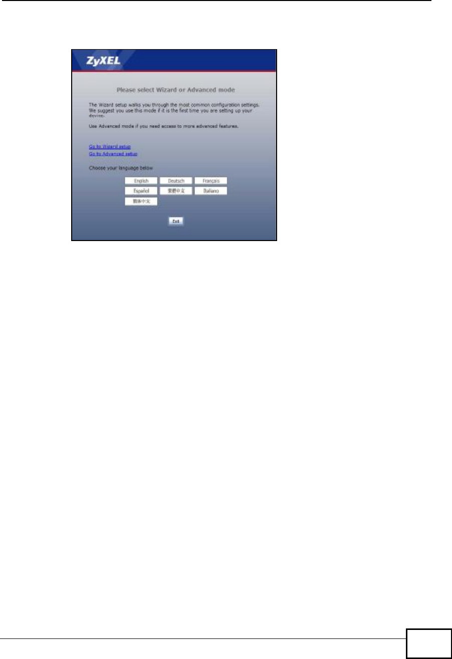
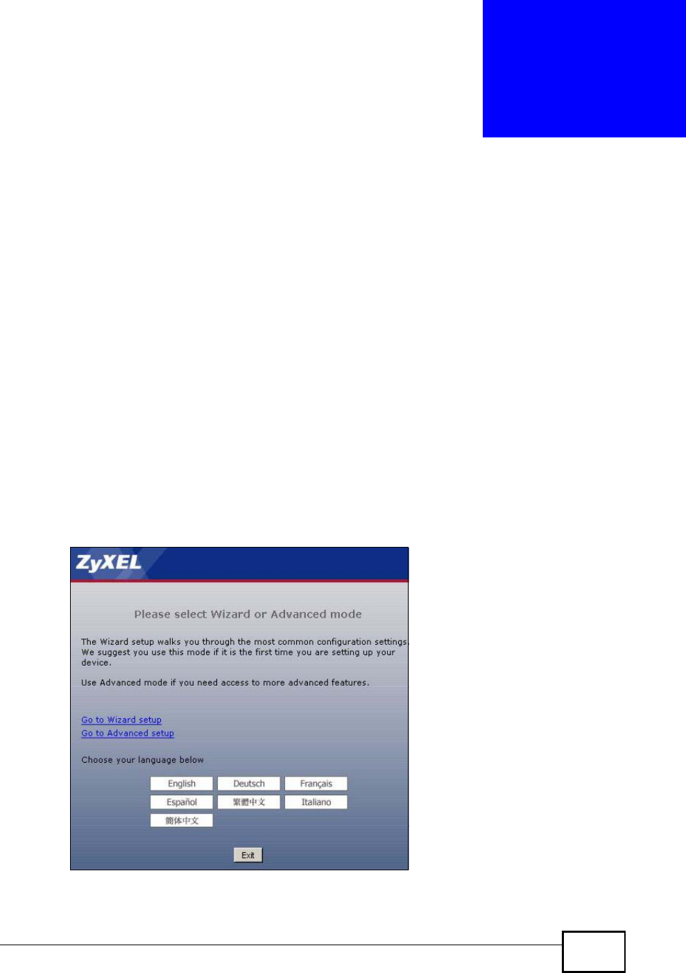
6Select the setup mode you want to use.
•Click Go to Wizard Setup to use the Configuration Wizard for basic Internet
and Wireless setup.
•Click Go to Advanced Setup to view and configure all the NBG4604’s
settings.
Company Confidential
Chapter 3The Web Configurator
NBG4604 User’s Guide 29
•Select a language to go to the basic Web Configurator in that language. To
change to the advanced configurator see Chapter 25 on page 197.
3.3 Resetting the NBG4604
If you forget your password or IP address, or you cannot access the Web
Configurator, you will need to use the RESET button at the back of the NBG4604
to reload the factory-default configuration file. This means that you will lose all
configurations that you had previously saved, the password will be reset to “1234”
and the IP address will be reset to “192.168.1.1”.
3.3.1 Procedure to Use the Reset Button
1Make sure the power LED is on.
2Press the RESET button for longer than 1 second to restart/reboot the NBG4604.
3Press the RESET button for longer than five seconds to set the NBG4604 back to
its factory-default configurations.
3.4 Navigating the Web Configurator
The following summarizes how to navigate the Web Configurator from the Status
screen in Router Mode and AP Mode.
Company Confidential
Chapter 3The Web Configurator
NBG4604 User’s Guide
30
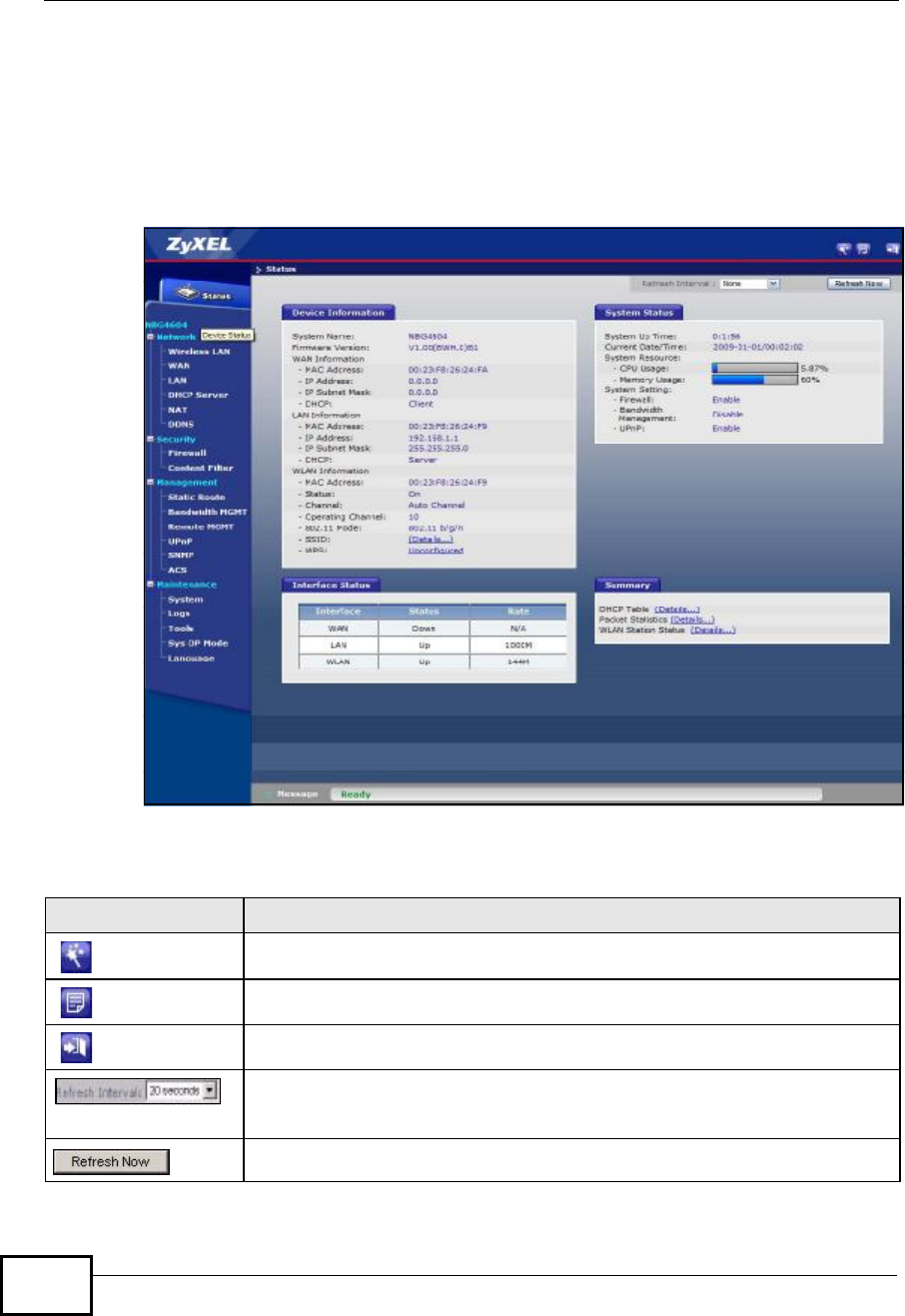
3.5 Status Screen (Router Mode)
Click on Status. The screen below shows the status screen in Router Mode.
(For information on the status screen in AP Mode see Chapter 5 on page 56.)
Figure 3 Status Screen (Router Mode)
The following table describes the icons shown in the Status screen.
Table 2 Status Screen Icon Key
ICON DESCRIPTION
Click this icon to open the setup wizard.
Click this icon to view copyright and a link for related product information.
Click this icon at any time to exit the Web Configurator.
Select a number of seconds or None from the drop-down list box to refresh
all screen statistics automatically at the end of every time interval or to not
refresh the screen statistics.
Click this button to refresh the status screen statistics.
Company Confidential

Chapter 3The Web Configurator
NBG4604 User’s Guide 31
The following table describes the labels shown in the Status screen.
Table 3 Web Configurator Status Screen (Router Mode)
LABEL DESCRIPTION
Device Information
System NameThis is the System Name you enter in the Maintenance > System >
General screen. It is for identification purposes.
Firmware VersionThis is the firmware version and the date created.
WAN Information
- MAC AddressThis shows the WAN Ethernet adapter MAC Address of your device.
- IP AddressThis shows the WAN port’s IP address.
- IP Subnet MaskThis shows the WAN port’s subnet mask.
- DHCPThis shows the WAN port’s DHCP role - Client or None.
LAN Information
- MAC AddressThis shows the LAN Ethernet adapter MAC Address of your device.
- IP AddressThis shows the LAN port’s IP address.
- IP Subnet MaskThis shows the LAN port’s subnet mask.
- DHCPThis shows the LAN port’s DHCP role - Server or None.
WLAN Information
- MAC AddressThis shows the wireless adapter MAC Address of your device.
- StatusThis shows the current status of the Wireless LAN - On or Off.
- ChannelThis shows the channel number which you select manually.
- Operating ChannelThis shows the channel number which the NBG4604 is currently using
over the wireless LAN.
- 802.11 ModeThis shows the wireless standard.
- SSIDThis shows a descriptive name used to identify the NBG4604 in the
wireless LAN.
- WPSThis displays Configured when the WPS has been set up.
This displays Unconfigured if the WPS has not been set up.
Click the status to display Network > Wireless LAN > WPS screen.
System Status
System Up TimeThis is the total time the NBG4604 has been on.
Current Date/TimeThis field displays your NBG4604’s present date and time.
System Resource
- CPU UsageThis displays what percentage of the NBG4604’s processing ability is
currently used. When this percentage is close to 100%, the NBG4604 is
running at full load, and the throughput is not going to improve anymore.
If you want some applications to have more throughput, you should turn
off other applications.
- Memory UsageThis shows what percentage of the heap memory the NBG4604 is using.
System Setting
- FirewallThis shows whether the firewall is active or not.
Company Confidential

Chapter 3The Web Configurator
NBG4604 User’s Guide
32
3.5.1 Navigation Panel
Use the sub-menus on the navigation panel to configure NBG4604 features.
The following table describes the sub-menus.
- Bandwidth
Management This shows whether bandwidth management is active or not.
- UPnPThis shows whether UPnP is active or not.
Interface Status
InterfaceThis displays the NBG4604 port types. The port types are: WAN,LAN and
WLAN.
StatusFor the LAN and WAN ports, this field displays Down (line is down) or Up
(line is up or connected).
For the WLAN, it displays Up when the WLAN is enabled or Down when
the WLAN is disabled.
RateFor the LAN ports, this displays the port speed and duplex setting or N/A
when the line is disconnected.
For the WLAN, it displays the maximum transmission rate when the WLAN
is enabled and N/A when the WLAN is disabled.
Summary
DHCP TableUse this screen to view current DHCP client information.
Packet StatisticsUse this screen to view port status and packet specific statistics.
WLAN Station StatusUse this screen to view the wireless stations that are currently associated
to the NBG4604.
Table 3 Web Configurator Status Screen (Router Mode) (continued)
LABEL DESCRIPTION
Table 4 Screens Summary
LINK TAB FUNCTION
Status This screen shows the NBG4604’s general device, system
and interface status information. Use this screen to
access the wizard, and summary statistics tables.
Network
Company Confidential

Chapter 3The Web Configurator
NBG4604 User’s Guide 33
Wireless
LAN General Use this screen to configure wireless LAN.
MAC Filter Use the MAC filter screen to configure the NBG4604 to
block access to devices or block the devices from
accessing the NBG4604.
Advanced This screen allows you to configure advanced wireless
settings.
QoS Use this screen to configure Wi-Fi Multimedia Quality of
Service (WMM QoS). WMM QoS allows you to prioritize
wireless traffic according to the delivery requirements of
individual services.
WPS Use this screen to configure WPS.
WPS Station Use this screen to add a wireless station using WPS.
Scheduling Use this screen to schedule the times the Wireless LAN is
enabled.
WDS Use this screen to set up Wireless Distribution System
(WDS) on your NBG4604.
WAN Internet
Connection This screen allows you to configure ISP parameters, WAN
IP address assignment, DNS servers and the WAN MAC
address.
Advanced Use this screen to configure other advanced properties.
LAN IP Use this screen to configure LAN IP address and subnet
mask.
DHCP
Server General Use this screen to enable the NBG4604’s DHCP server.
Advanced Use this screen to assign IP addresses to specific
individual computers based on their MAC addresses and
to have DNS servers assigned by the DHCP server.
Client List Use this screen to view current DHCP client information
and to always assign an IP address to a MAC address
(and host name).
NAT General Use this screen to enable NAT.
Application Use this screen to configureservers behind the
NBG4604.
Advanced Use this screen to change your NBG4604’s port triggering
settings.
DDNS General Use this screen to set up dynamic DNS.
Security
Firewall General Use this screen to activate/deactivate the firewall.
Services This screen shows a summary of the firewall rules, and
allows you to edit/add a firewall rule.
Content
Filter Filter Use this screen to block certain web features and sites
containing certain keywords in the URL.
Management
Static
Route IP Static
Route Use this screen to configure IP static routes.
Table 4 Screens Summary
LINK TAB FUNCTION
Company Confidential

Chapter 3The Web Configurator
NBG4604 User’s Guide
34
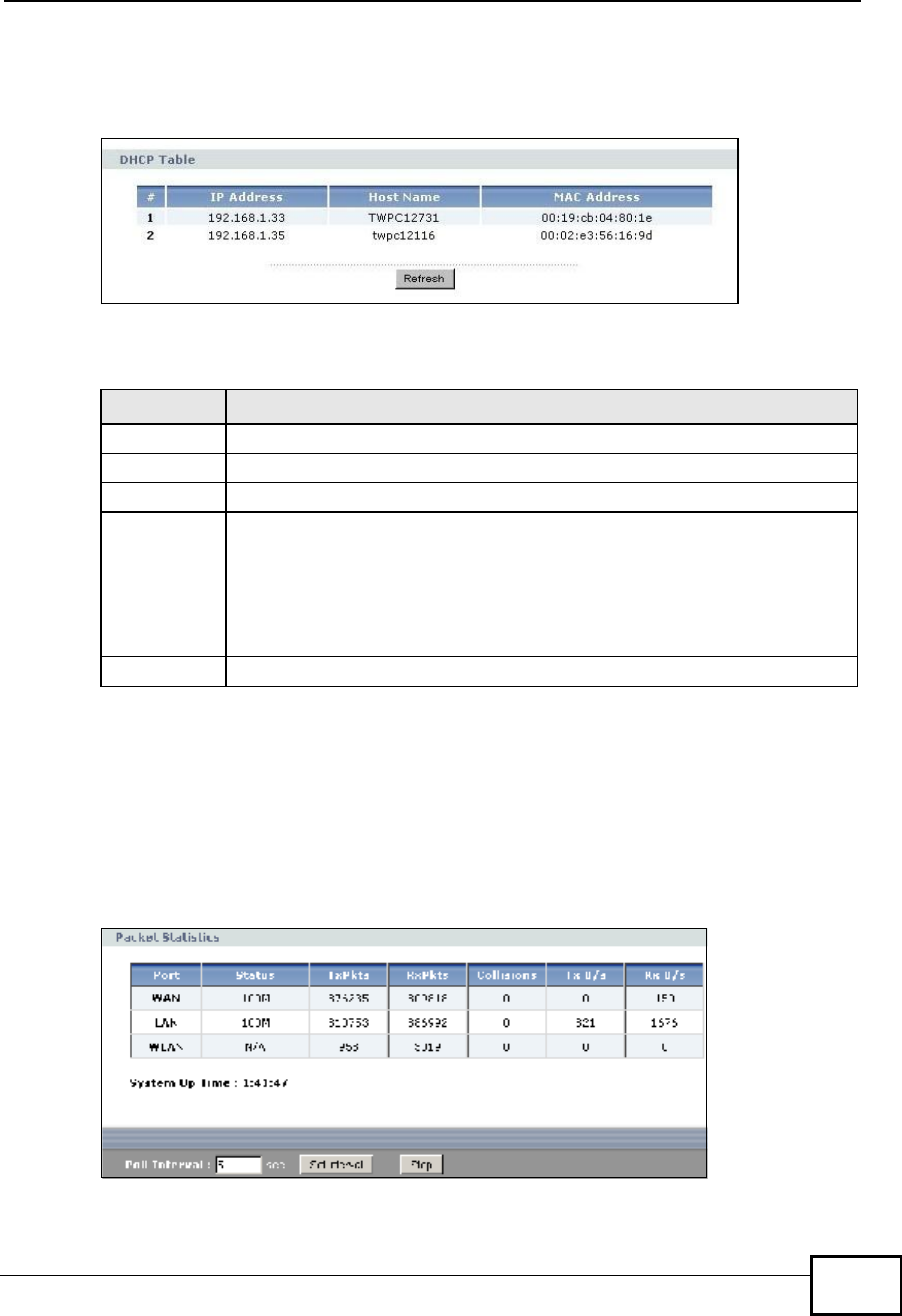
3.5.2 Summary: DHCP Table
DHCP (Dynamic Host Configuration Protocol, RFC 2131 and RFC 2132) allows
individual clients to obtain TCP/IP configuration at start-up from a server. You can
configure the NBG4604’s LAN as a DHCP server or disable it. When configured as a
server, the NBG4604 provides the TCP/IP configuration for the clients. If DHCP
service is disabled, you must have another DHCP server on that network, or else
the computer must be manually configured.
Click the DHCP Table (Details...) hyperlink in the Status screen. Read-only
information here relates to your DHCP status. The DHCP table shows current
Bandwidth
MGMT General Use this screen to configure a bandwidth management
service type.
Advanced Use this screen to configure bandwidth management for
specific types of applications.
Remote
MGMT WWW Use this screen to configure through which interface(s)
and from which IP address(es) users can use HTTP to
manage the NBG4604.
UPnP General Use this screen to enable UPnP on the NBG4604.
SNMP General Use this screen to configure SNMP.
ACS General Use this screen configure ACS.
Certificate Use this screen to upload security certificates to the
device.
Maintenance
System General Use this screen to view and change administrative
settings such as system and domain names, password
and inactivity timer.
Time Setting Use this screen to change your NBG4604’s time and
date.
Logs View Log Use this screen to view the logs for the categories that
you selected.
Log Settings Use this screen to activate syslog logging as well as the
syslog server IP address.
Tools Firmware Use this screen to upload firmware to your NBG4604.
Configuration Use this screen to backup and restore the configuration
or reset the factory defaults to your NBG4604.
Restart This screen allows you to reboot the NBG4604 without
turning the power off.
Sys OP
Mode General This screen allows you to select whether your device acts
as a Router or a Access Point.
Language This screen allows you to select the language you prefer.
Table 4 Screens Summary
LINK TAB FUNCTION
Company Confidential
Chapter 3The Web Configurator
NBG4604 User’s Guide 35
DHCP client information (including IP Address,HostName and MAC Address)
of all network clients using the NBG4604’s DHCP server.
Figure 4 Summary: DHCP Table
The following table describes the labels in this screen.
3.5.3 Summary: Packet Statistics
Click the Packet Statistics (Details...) hyperlink in the Status screen. Read-
only information here includes port status, packet specific statistics and the
"system up time". The Poll Interval(s) field is configurable and is used for
refreshing the screen.
Figure 5 Summary: Packet Statistics
Table 5 Summary: DHCP Table
LABEL DESCRIPTION
# This is the index number of the host computer.
IP AddressThis field displays the IP address relative to the # field listed above.
Host Name This field displays the computer host name.
MAC AddressThis field shows the MAC address of the computer with the name in the
Host Name field.
Every Ethernet device has a unique MAC (Media Access Control) address
which uniquely identifies a device. The MAC address is assigned at the
factory and consists of six pairs of hexadecimal characters, for example,
00:A0:C5:00:00:02.
RefreshClick Refresh to renew the screen.
Company Confidential
Chapter 3The Web Configurator
NBG4604 User’s Guide
36
The following table describes the labels in this screen.
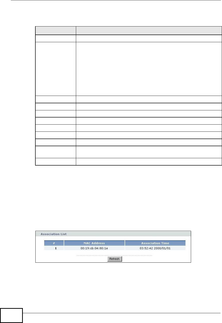
3.5.4 Summary: WLAN Station Status
Click the WLAN Station Status (Details...) hyperlink in the Status screen. View
the wireless stations that are currently associated to the NBG4604 in the
Association List. Association means that a wireless client (for example, your
network or computer with a wireless network card) has connected successfully to
the AP (or wireless router) using the same SSID, channel and security settings.
Figure 6 Summary: Wireless Association List
Table 6 Summary: Packet Statistics
LABEL DESCRIPTION
Port This is the NBG4604’s port type.
Status For the LAN ports, this displays the port speed and duplex setting or
Down when the line is disconnected.
For the WAN port, it displays the port speed and duplex setting if
you’re using Ethernet encapsulation and Idle (line (ppp) idle), Dial
(starting to trigger a call) and Drop (dropping a call) if you're using
PPPoE or PPTP encapsulation. This field displays Down when the line
is disconnected.
For the WLAN, it displays the maximum transmission rate when the
WLAN is enabled and Down when the WLAN is disabled.
TxPkts This is the number of transmitted packets on this port.
RxPkts This is the number of received packets on this port.
Collisions This is the number of collisions on this port.
Tx B/s This displays the transmission speed in bytes per second on this port.
Rx B/s This displays the reception speed in bytes per second on this port.
System Up Time This is the total time the NBG4604 has been on.
Poll Interval(s) Enter the time interval for refreshing statistics in this field.
Set Interval Click this button to apply the new poll interval you entered in the Poll
Interval(s) field.
Stop Click Stop to stop refreshing statistics.
Company Confidential

Chapter 3The Web Configurator
NBG4604 User’s Guide 37
The following table describes the labels in this screen.
Table 7 Summary: Wireless Association List
LABEL DESCRIPTION
#This is the index number of an associated wireless station.
MAC Address This field displays the MAC address of an associated wireless station.
Association Time This field displays the time a wireless station first associated with the
NBG4604’s WLAN network.
Refresh Click Refresh to reload the list.
Company Confidential

Chapter 3The Web Configurator
NBG4604 User’s Guide
38
Company Confidential
NBG4604 User’s Guide 39
CHAPTER 4
Connection Wizard
4.1 Wizard Setup
This chapter provides information on the wizard setup screens in the Web
Configurator.
The Web Configurator’s wizard setup helps you configure your device to access the
Internet. Refer to your ISP (Internet Service Provider) checklist in the Quick Start
Guide to know what to enter in each field. Leave a field blank if you don’t have
that information.
1After you access the NBG4604 Web Configurator, click the Go to Wizard setup
hyperlink.
You can click Go to Advanced setup hyperlink to skip this wizard setup and
configure basic or advanced features accordingly.
Figure 7 Select Wizard or Advanced Mode
Company Confidential
Chapter 4Connection Wizard
NBG4604 User’s Guide
40
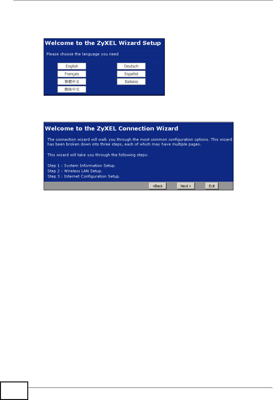
2Choose a language by clicking on the language’s button. The screen will update.
Click the Next button to proceed to the next screen.
Figure 8 Select a Language
3Read the on-screen information and click Next.
Figure 9 Welcome to the Connection Wizard
4.2 Connection Wizard: STEP 1: System
Information
System Information contains administrative and system-related information.
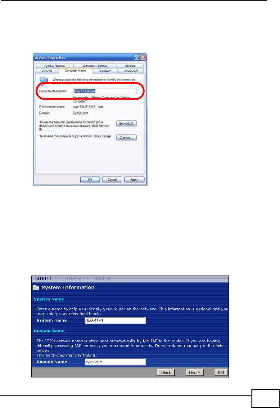
4.2.1 System Name
System Name is for identification purposes. However, because some ISPs check
this name you should enter your computer's "Computer Name".
Company Confidential
Chapter 4Connection Wizard
NBG4604 User’s Guide 41
To view (or set) your computer name in Windows, right click over My Computer
on your desktop, then select Properties. When the System Properties window
opens, select the Computer Name tab.
Figure 10 Computer Name
4.2.2 Domain Name
The Domain Name entry is what is propagated to the DHCP clients on the LAN. If
you leave this blank, the domain name obtained by DHCP from the ISP is used.
While you must enter the host name (System Name) on each individual computer,
the domain name can be assigned from the NBG4604 via DHCP.
Click Next to configure the NBG4604 for Internet access.
Figure 11 Wizard Step 1: System Information
Company Confidential
Chapter 4Connection Wizard
NBG4604 User’s Guide
42
The following table describes the labels in this screen.
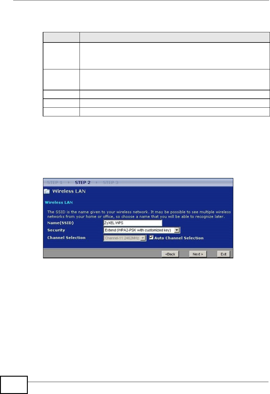
4.3 Connection Wizard: STEP 2: Wireless LAN
Set up your wireless LAN using the following screen.
Figure 12 Wizard Step 2: Wireless LAN
Table 8 Wizard Step 1: System Information
LABEL DESCRIPTION
System
Name System Name is a unique name to identify the NBG4604 in an Ethernet
network. Enter a descriptive name. This name can be up to 30
alphanumeric characters long. Spaces are not allowed, but dashes "-" and
underscores "_" are accepted.
Domain
Name Type the domain name (if you know it) here. If you leave this field blank,
the ISP may assign a domain name via DHCP. The domain name entered
by you is given priority over the ISP assigned domain name.
Back Click Back to display the previous screen.
Next Click Next to proceed to the next screen.
Exit Click Exit to close the wizard screen without saving.
Company Confidential

Chapter 4Connection Wizard
NBG4604 User’s Guide 43
The following table describes the labels in this screen.
Note: The wireless stations and NBG4604 must use the same SSID, channel ID,
WPA-PSK (if WPA-PSK is enabled) or WPA2-PSK (if WPA2-PSK is enabled) for
wireless communication.
Table 9 Wizard Step 2: Wireless LAN
LABEL DESCRIPTION
Name
(SSID) Enter a descriptive name (up to 32 printable 7-bit ASCII characters) for the
wireless LAN.
If you change this field on the NBG4604, make sure all wireless stations
use the same SSID in order to access the network.
Security Select a Security level from the drop-down list box.
Choose Auto (WPA2-PSK) to have the NBG4604 generate a pre-shared
key automatically. After you click Next a screen pops up displaying the
generated pre-shared key. Write down the key for use later when
connecting other wireless devices to your network. Click OK to continue.
Choose None to have no wireless LAN security configured. If you do not
enable any wireless security on your NBG4604, your network is accessible
to any wireless networking device that is within range. If you choose this
option, skip directly to Section 4.4 on page 44.
Choose Extend (WPA-PSK or WPA2-PSK) security to configure a Pre-
Shared Key. Choose this option only if your wireless clients support WPA-
PSK or WPA2-PSK respectively. If you choose this option, skip directly to
Section 4.3.1 on page 44.
Channel
Selection The range of radio frequencies used by IEEE 802.11b/g/n wireless devices
is called a channel. The device will automatically select the channel with
the least interference.
Back Click Back to display the previous screen.
Next Click Next to proceed to the next screen.
Exit Click Exit to close the wizard screen without saving.
Company Confidential
Chapter 4Connection Wizard
NBG4604 User’s Guide
44
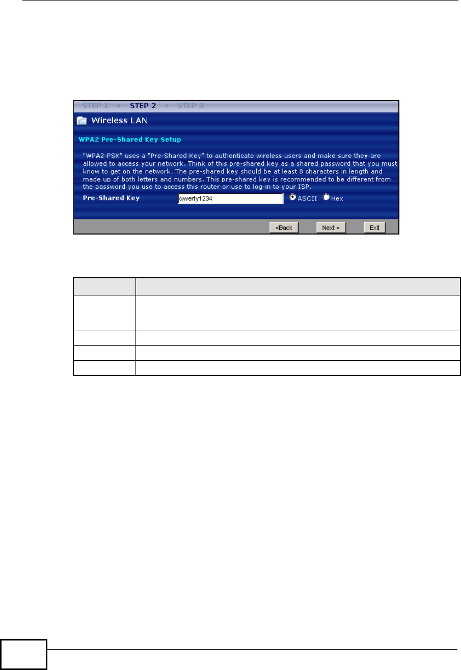
4.3.1 Extend (WPA-PSK or WPA2-PSK) Security
Choose Extend (WPA-PSK) or Extend (WPA2-PSK) security in the Wireless
LAN setup screen to set up a Pre-Shared Key.
Figure 13 Wizard Step 2: Extend (WPA-PSK or WPA2-PSK) Security
The following table describes the labels in this screen.
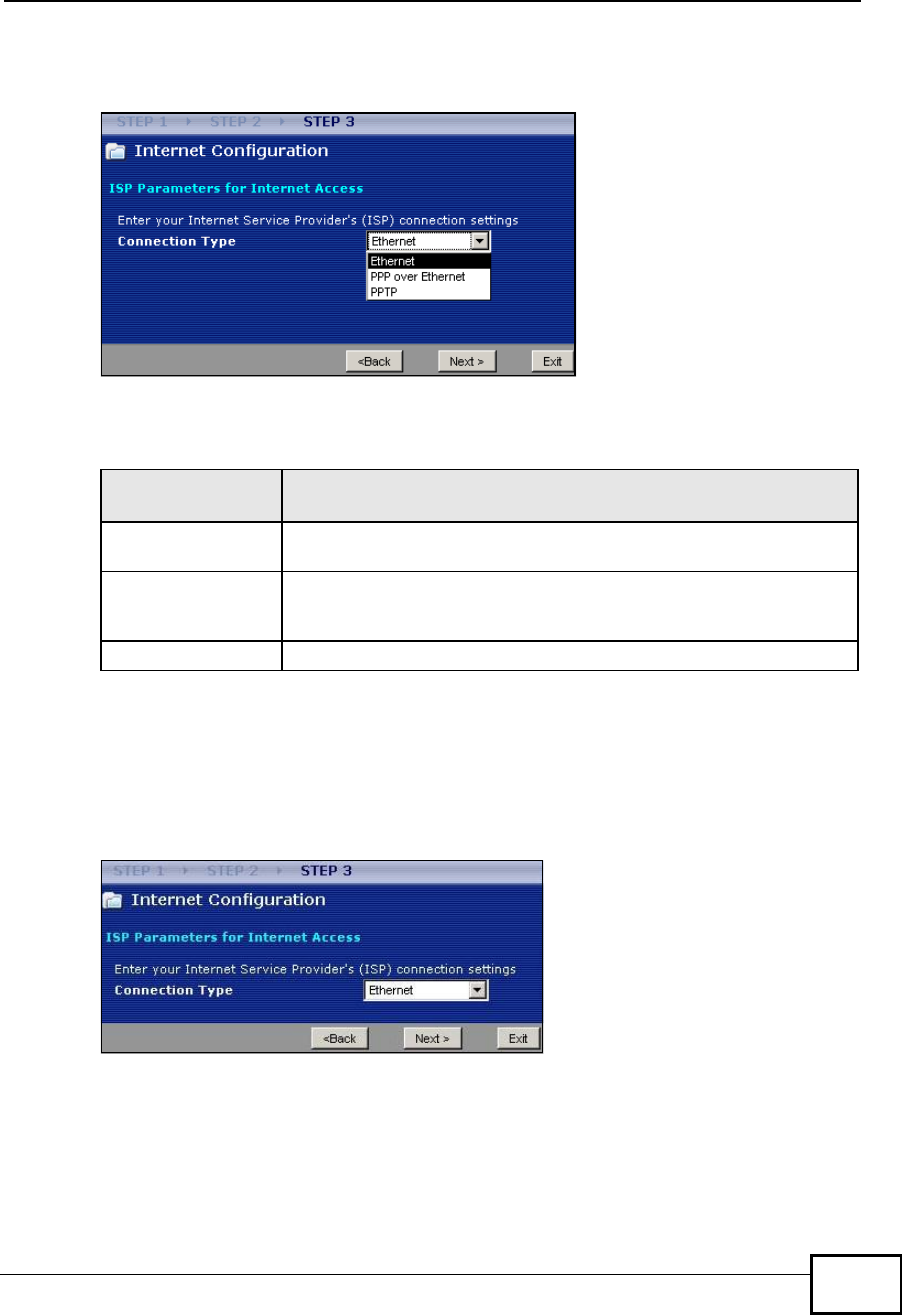
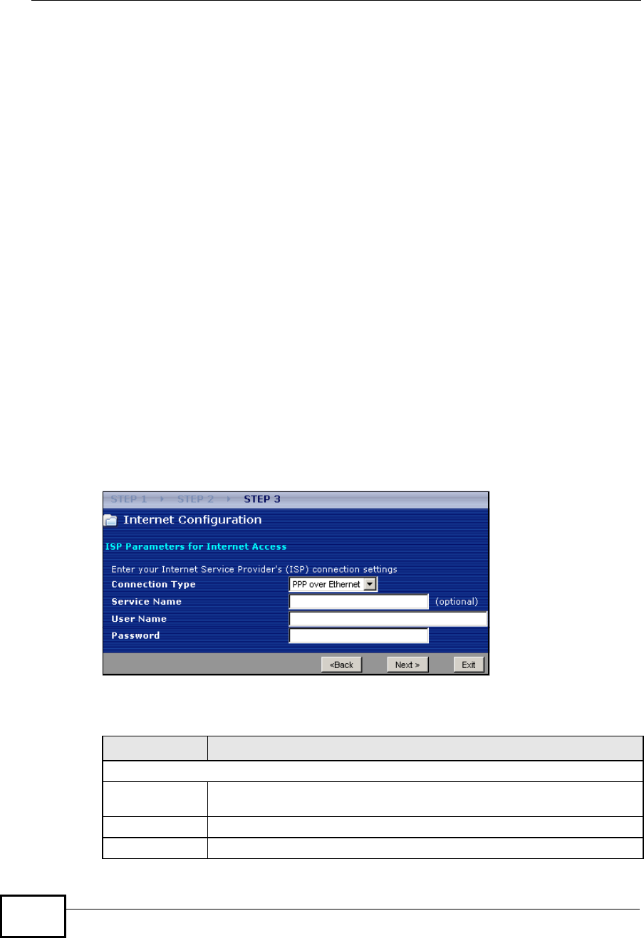
4.4 Connection Wizard: STEP 3: Internet
Configuration
The NBG4604 offers three Internet connection types. They are Ethernet,PPP
over Ethernet or PPTP. The wizard attempts to detect which WAN connection
type you are using. If the wizard does not detect a connection type, you must
select one from the drop-down list box. Check with your ISP to make sure you use
the correct type.
Table 10 Wizard Step 2: Extend (WPA-PSK or WPA2-PSK) Security
LABEL DESCRIPTION
Pre-Shared
Key Type from 8 to 63 case-sensitive ASCII or 64 HEX characters. You can set
up the most secure wireless connection by configuring WPA in the wireless
LAN screens. You need to configure an authentication server to do this.
Back Click Back to display the previous screen.
Next Click Next to proceed to the next screen.
Exit Click Exit to close the wizard screen without saving.
Company Confidential
Chapter 4Connection Wizard
NBG4604 User’s Guide 45
This wizard screen varies according to the connection type that you select.
Figure 14 Wizard Step 3: ISP Parameters.
The following table describes the labels in this screen,
4.4.1 Ethernet Connection
Choose Ethernet when the WAN port is used as a regular Ethernet. Continue to
Section 4.4.4 on page 48.
Figure 15 Wizard Step 3: Ethernet Connection
Table 11 Wizard Step 3: ISP Parameters
CONNECTION
TYPE DESCRIPTION
EthernetSelect the Ethernet option when the WAN port is used as a regular
Ethernet.
PPPoE Select the PPP over Ethernet option for a dial-up connection. If
your ISP gave you an IP address and/or subnet mask, then select
PPTP.
PPTPSelect the PPTP option for a dial-up connection.
Company Confidential
Chapter 4Connection Wizard
NBG4604 User’s Guide
46
4.4.2 PPPoE Connection
Point-to-Point Protocol over Ethernet (PPPoE) functions as a dial-up connection.
PPPoE is an IETF (Internet Engineering Task Force) standard specifying how a host
personal computer interacts with a broadband modem (for example DSL, cable,
wireless, etc.) to achieve access to high-speed data networks.
For the service provider, PPPoE offers an access and authentication method that
works with existing access control systems (for instance, RADIUS).
One of the benefits of PPPoE is the ability to let end users access one of multiple
network services, a function known as dynamic service selection. This enables the
service provider to easily create and offer new IP services for specific users.
Operationally, PPPoE saves significant effort for both the subscriber and the ISP/
carrier, as it requires no specific configuration of the broadband modem at the
subscriber’s site.
By implementing PPPoE directly on the NBG4604 (rather than individual
computers), the computers on the LAN do not need PPPoE software installed,
since the NBG4604 does that part of the task. Furthermore, with NAT, all of the
LAN's computers will have Internet access.
Refer to the appendix for more information on PPPoE.
Figure 16 Wizard Step 3: PPPoE Connection
The following table describes the labels in this screen.
Table 12 Wizard Step 3: PPPoE Connection
LABEL DESCRIPTION
ISP Parameter for Internet Access
Connection
Type Select the PPP over Ethernet option for a dial-up connection.
Service Name Type the name of your service provider.
User Name Type the user name given to you by your ISP.
Company Confidential
Chapter 4Connection Wizard
NBG4604 User’s Guide 47
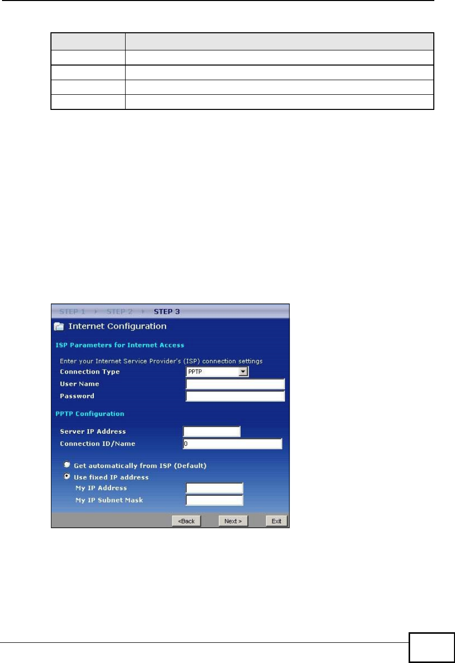
4.4.3 PPTP Connection
Point-to-Point Tunneling Protocol (PPTP) is a network protocol that enables
transfers of data from a remote client to a private server, creating a Virtual Private
Network (VPN) using TCP/IP-based networks.
PPTP supports on-demand, multi-protocol, and virtual private networking over
public networks, such as the Internet.
Refer to the appendix for more information on PPTP.
Note: The NBG4604 supports one PPTP server connection at any given time.
Figure 17 Wizard Step 3: PPTP Connection
Password Type the password associated with the user name above.
Back Click Back to return to the previous screen.
Next Click Next to continue.
Exit Click Exit to close the wizard screen without saving.
Table 12 Wizard Step 3: PPPoE Connection
LABEL DESCRIPTION
Company Confidential
Chapter 4Connection Wizard
NBG4604 User’s Guide
48
The following table describes the fields in this screen
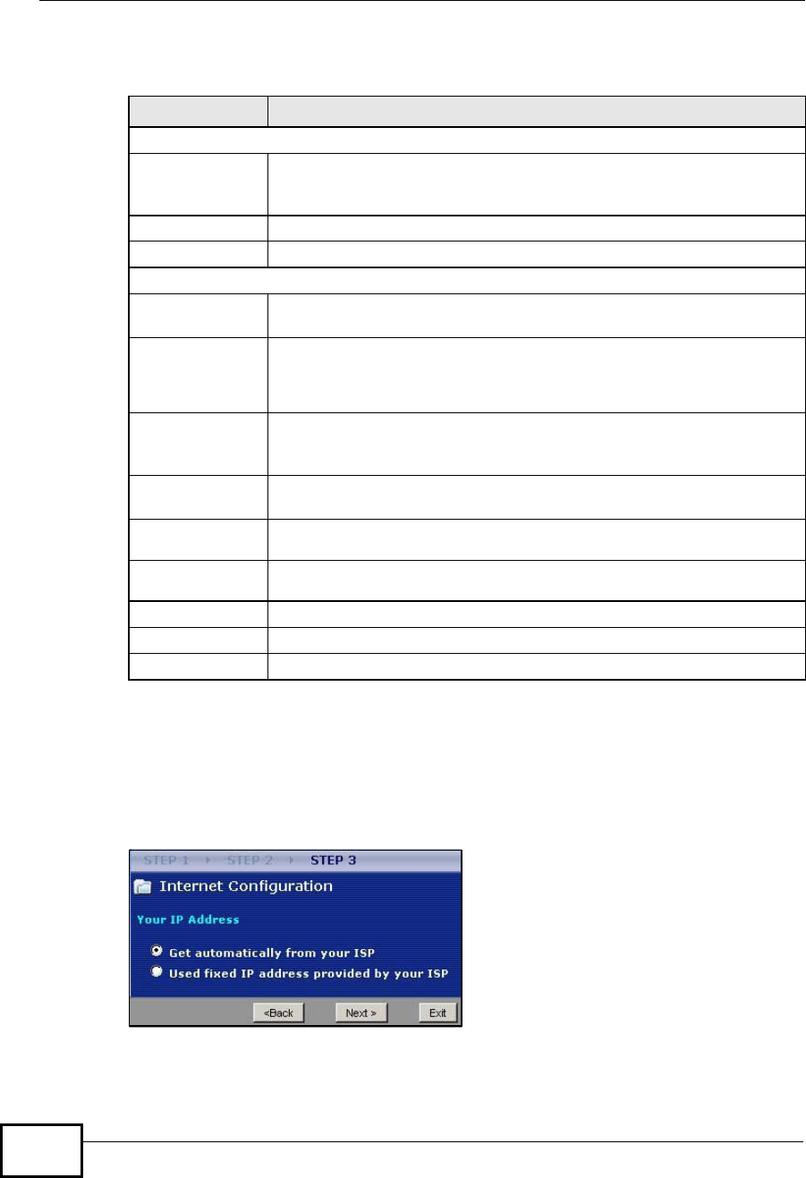
4.4.4 Your IP Address
The following wizard screen allows you to assign a fixed IP address or give the
NBG4604 an automatically assigned IP address depending on your ISP.
Figure 18 Wizard Step 3: Your IP Address
Table 13 Wizard Step 3: PPTP Connection
LABEL DESCRIPTION
ISP Parameters for Internet Access
Connection TypeSelect PPTP from the drop-down list box. To configure a PPTP client,
you must configure the User Name and Password fields for a PPP
connection and the PPTP parameters for a PPTP connection.
User Name Type the user name given to you by your ISP.
Password Type the password associated with the User Name above.
PPTP Configuration
Server IP
Address Type the IP address of the PPTP server.
Connection ID/
Name Enter the connection ID or connection name in this field. It must follow
the "c:id" and "n:name" format. For example, C:12 or N:My ISP.
This field is optional and depends on the requirements of your ISP.
Get
automatically
from ISP
Select this radio button if your ISP did not assign you a fixed IP
address.
Use fixed IP
address Select this radio button, provided by your ISP to give the NBG4604 a
fixed, unique IP address.
My IP
Address Type the (static) IP address assigned to you by your ISP.
My IP Subnet
Mask Type the subnet mask assigned to you by your ISP (if given).
Back Click Back to return to the previous screen.
Next Click Next to continue.
Exit Click Exit to close the wizard screen without saving.
Company Confidential

Chapter 4Connection Wizard
NBG4604 User’s Guide 49
The following table describes the labels in this screen
4.4.5 WAN IP Address Assignment
Every computer on the Internet must have a unique IP address. If your networks
are isolated from the Internet, for instance, only between your two branch offices,
you can assign any IP addresses to the hosts without problems. However, the
Internet Assigned Numbers Authority (IANA) has reserved the following three
blocks of IP addresses specifically for private networks.
You can obtain your IP address from the IANA, from an ISP or have it assigned by
a private network. If you belong to a small organization and your Internet access
is through an ISP, the ISP can provide you with the Internet addresses for your
local networks. On the other hand, if you are part of a much larger organization,
you should consult your network administrator for the appropriate IP addresses.
Note: Regardless of your particular situation, do not create an arbitrary IP address;
always follow the guidelines above. For more information on address
assignment, please refer to RFC 1597, Address Allocation for Private Internets
and RFC 1466, Guidelines for Management of IP Address Space.
4.4.6 IP Address and Subnet Mask
Similar to the way houses on a street share a common street name, so too do
computers on a LAN share one common network number.
Where you obtain your network number depends on your particular situation. If
the ISP or your network administrator assigns you a block of registered IP
Table 14 Wizard Step 3: Your IP Address
LABEL DESCRIPTION
Get automatically from
your ISP Select this option If your ISP did not assign you a fixed IP
address. This is the default selection. If you choose this option,
skip directly to Section 4.4.9 on page 52.
Use fixed IP address
provided by your ISP Select this option if you were given IP address and/or DNS server
settings by the ISP. The fixed IP address should be in the same
subnet as your broadband modem or router.
Back Click Back to return to the previous screen.
Next Click Next to continue.
Exit Click Exit to close the wizard screen without saving.
Table 15 Private IP Address Ranges
10.0.0.0 - 10.255.255.255
172.16.0.0 - 172.31.255.255
192.168.0.0 - 192.168.255.255
Company Confidential

Chapter 4Connection Wizard
NBG4604 User’s Guide
50
addresses, follow their instructions in selecting the IP addresses and the subnet
mask.
If the ISP did not explicitly give you an IP network number, then most likely you
have a single user account and the ISP will assign you a dynamic IP address when
the connection is established. The Internet Assigned Number Authority (IANA)
reserved this block of addresses specifically for private use; please do not use any
other number unless you are told otherwise. Let's say you select 192.168.1.0 as
the network number; which covers 254 individual addresses, from 192.168.1.1 to
192.168.1.254 (zero and 255 are reserved). In other words, the first three
numbers specify the network number while the last number identifies an individual
computer on that network.
Once you have decided on the network number, pick an IP address that is easy to
remember, for instance, 192.168.1.1, for your NBG4604, but make sure that no
other device on your network is using that IP address.
The subnet mask specifies the network number portion of an IP address. Your
NBG4604 will compute the subnet mask automatically based on the IP address
that you entered. You don't need to change the subnet mask computed by the
NBG4604 unless you are instructed to do otherwise.
4.4.7 DNS Server Address Assignment
Use DNS (Domain Name System) to map a domain name to its corresponding IP
address and vice versa, for instance, the IP address of www.zyxel.com is
204.217.0.2. The DNS server is extremely important because without it, you must
know the IP address of a computer before you can access it.
The NBG4604 can get the DNS server addresses in the following ways.
1The ISP tells you the DNS server addresses, usually in the form of an information
sheet, when you sign up. If your ISP gives you DNS server addresses, enter them
in the DNS Server fields in the Wizard and/or WAN> Internet Connection
screen.
2If the ISP did not give you DNS server information, leave the DNS Server fields
set to 0.0.0.0 in the Wizard screen and/or set to From ISP in the WAN>
Internet Connection screen for the ISP to dynamically assign the DNS server IP
addresses.
Company Confidential
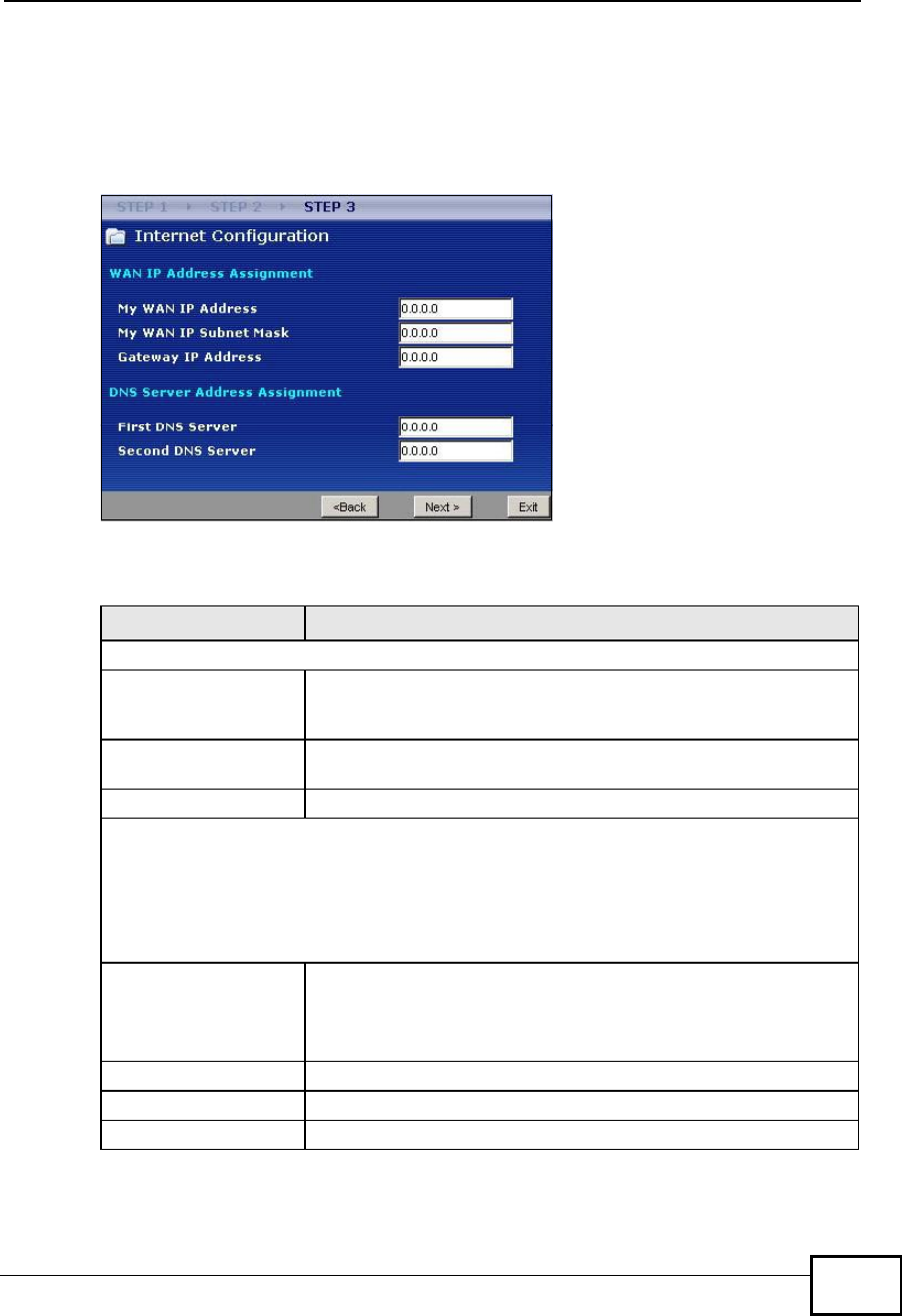
Chapter 4Connection Wizard
NBG4604 User’s Guide 51
4.4.8 WAN IP and DNS Server Address Assignment
The following wizard screen allows you to assign a fixed WAN IP address and DNS
server addresses.
Figure 19 Wizard Step 3: WAN IP and DNS Server Addresses
The following table describes the labels in this screen
Table 16 Wizard Step 3: WAN IP and DNS Server Addresses
LABEL DESCRIPTION
WAN IP Address Assignment
My WAN IP AddressEnter your WAN IP address in this field. The WAN IP address
should be in the same subnet as your DSL/Cable modem or
router.
My WAN IP Subnet
Mask Enter the IP subnet mask in this field.
Gateway IP Address Enter the gateway IP address in this field.
System DNS Server Address Assignment (if applicable)
DNS (Domain Name System) is for mapping a domain name to its corresponding IP
address and vice versa. The DNS server is extremely important because without it, you
must know the IP address of a computer before you can access it. The NBG4604 uses a
system DNS server (in the order you specify here) to resolve domain names for DDNS and
the time server.
First DNS Server
Second DNS Server
Enter the DNS server's IP address in the fields provided.
If you do not configure a system DNS server, you must use IP
addresses when configuring DDNS and the time server.
Back Click Back to return to the previous screen.
Next Click Next to continue.
Exit Click Exit to close the wizard screen without saving.
Company Confidential
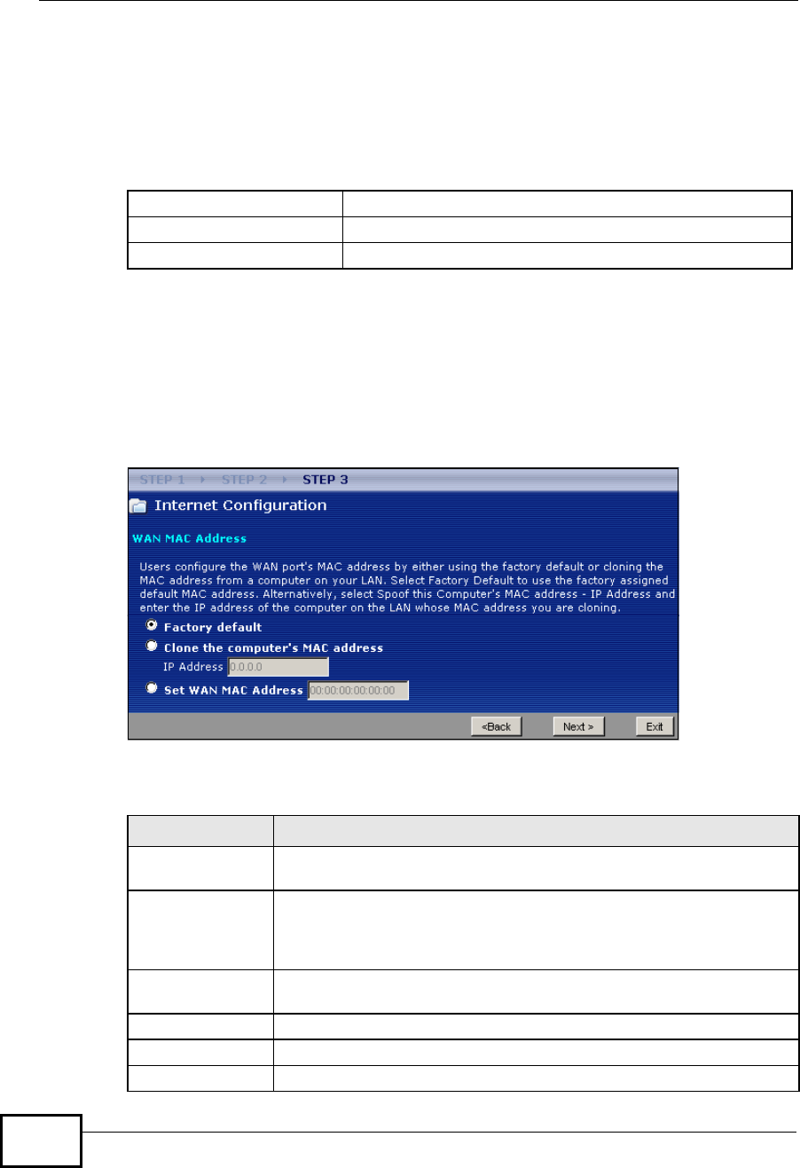
Chapter 4Connection Wizard
NBG4604 User’s Guide
52
4.4.9 WAN MAC Address
Every Ethernet device has a unique MAC (Media Access Control) address. The MAC
address is assigned at the factory and consists of six pairs of hexadecimal
characters, for example, 00:A0:C5:00:00:02.
This screen allows users to configure the WAN port's MAC address by either using
the NBG4604’s MAC address, copying the MAC address from a computer on your
LAN or manually entering a MAC address. Once it is successfully configured, the
address will be copied to configuration file. It is advisable to clone the MAC
address from a computer on your LAN even if your ISP does not presently require
MAC address authentication.
Figure 20 Wizard Step 3: WAN MAC Address
The following table describes the fields in this screen.
Table 17 Example of Network Properties for LAN Servers with Fixed IP Addresses
Choose an IP address 192.168.1.2-192.168.1.32; 192.168.1.65-192.168.1.254.
Subnet mask 255.255.255.0
Gateway (or default route) 192.168.1.1(NBG4604 LAN IP)
Table 18 Wizard Step 3: WAN MAC Address
LABEL DESCRIPTION
Factory DefaultSelect Factory Default to use the factory assigned default MAC
address.
Clone the
computer’s MAC
address
Select this option and enter the IP address of the computer on the
LAN whose MAC you are cloning. It is advisable to clone the MAC
address from a computer on your LAN even if your ISP does not
presently require MAC address authentication.
Set WAN MAC
Address Select this option and enter the MAC address you want to use.
Back Click Back to return to the previous screen.
Next Click Next to continue.
Exit Click Exit to close the wizard screen without saving.
Company Confidential
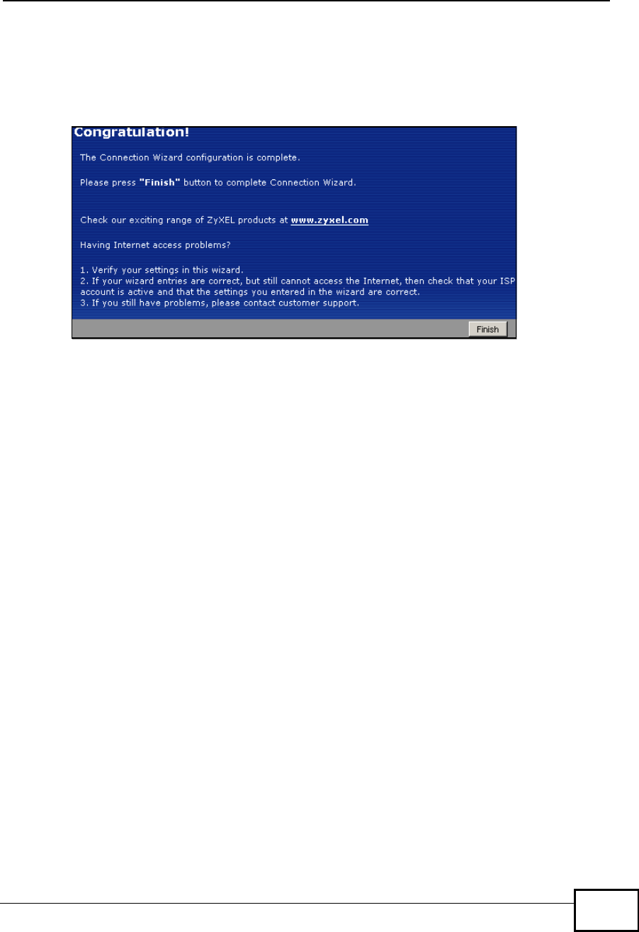
Chapter 4Connection Wizard
NBG4604 User’s Guide 53
4.5 Connection Wizard Complete
Click Finish to complete the wizard setup.
Figure 21 Connection Wizard Complete
Well done! You have successfully set up your NBG4604 to operate on your network
and access the Internet.
Company Confidential

Chapter 4Connection Wizard
NBG4604 User’s Guide
54
Company Confidential
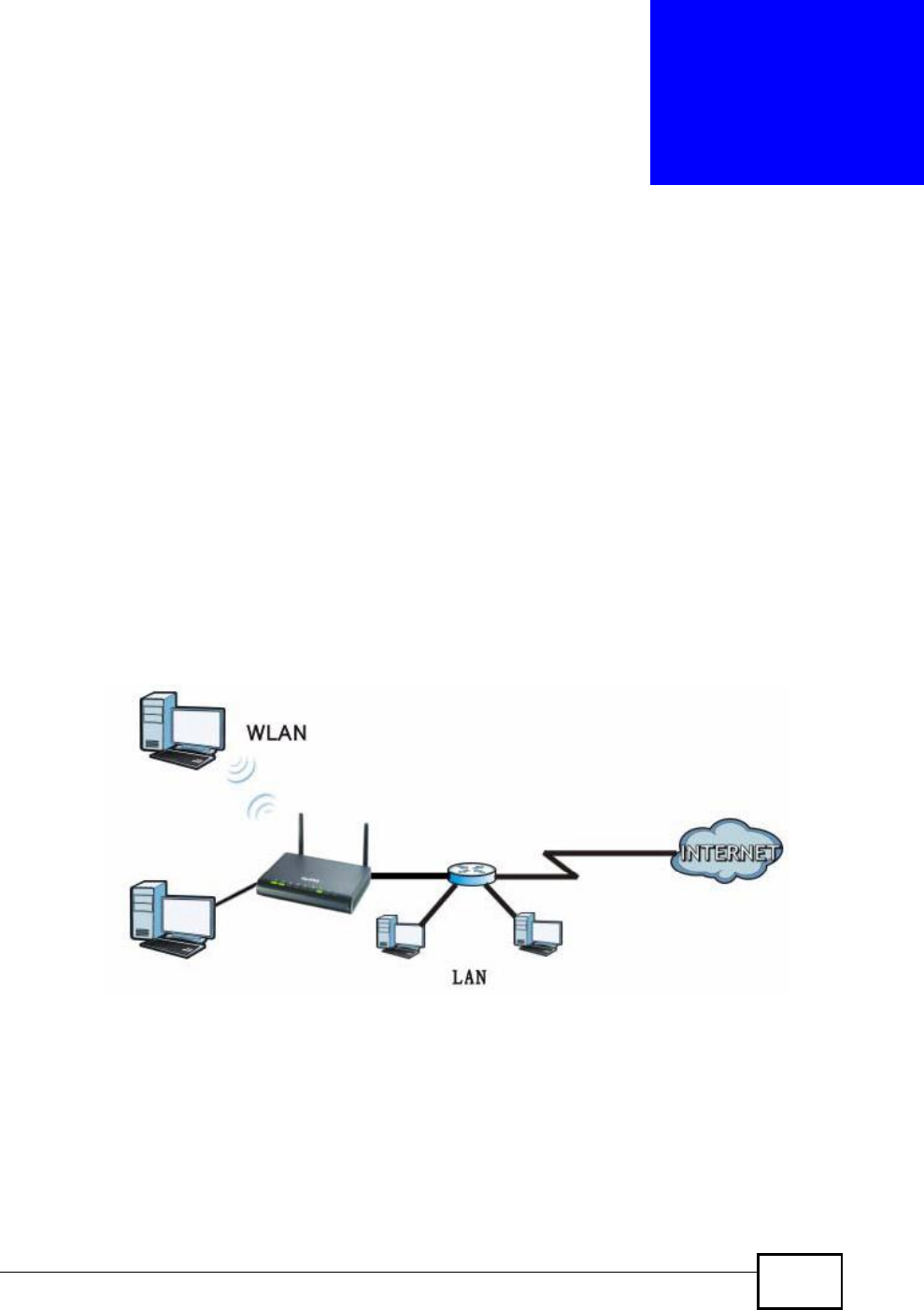
NBG4604 User’s Guide 55
CHAPTER 5
AP Mode
5.1 Overview
This chapter discusses how to configure settings while your NBG4604 is set to AP
Mode. Many screens that are available in Router Mode are not available in AP
Mode.
Note: See Chapter 6 on page 63 for an example of setting up a wireless network in
AP mode.
Use your NBG4604 as an AP if you already have a router or gateway on your
network. In this mode your device bridges a wired network (LAN) and wireless
LAN (WLAN) in the same subnet. See the figure below for an example.
Figure 22 Wireless Internet Access in AP Mode
5.2 Setting your NBG4604 to AP Mode
1Log into the Web Configurator if you haven’t already. See the Quick start Guide for
instructions on how to do this.
Company Confidential
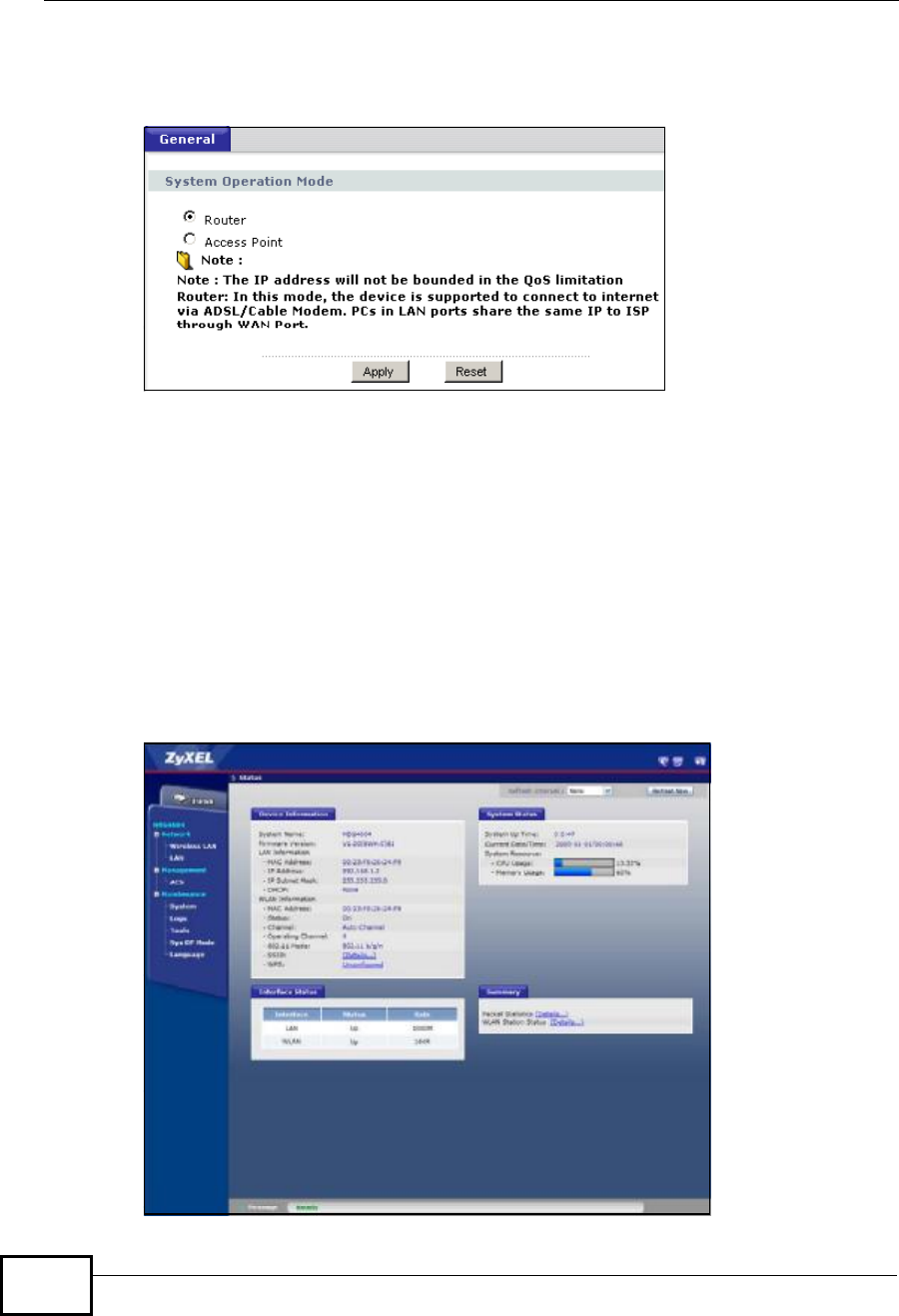
Chapter 5AP Mode
NBG4604 User’s Guide
56
2To set your NBG4604 to AP Mode, go to Maintenance > Sys OP Mode >
General and select Access Point.
Figure 23 Maintenance > Sys OP Mode > General
3A pop-up appears providing information on this mode. Click OK in the pop-up
message window. (See Section 24.4 on page 194 for more information on the
pop-up.) Click Apply. Your NBG4604 is now in AP Mode.
Note: You have to log in to the Web Configurator again when you change modes.
5.3 Status Screen (AP Mode)
Click on Status. The screen below shows the status screen in AP Mode.
Figure 24 Status Screen (AP Mode)
Company Confidential

Chapter 5AP Mode
NBG4604 User’s Guide 57
The following table describes the labels shown in the Status screen.
Table 19 Status Screen (AP Mode)
LABEL DESCRIPTION
Device Information
System NameThis is the System Name you enter in the Maintenance > System >
General screen. It is for identification purposes.
Firmware VersionThis is the firmware version and the date created.
LAN Information
- MAC AddressThis shows the LAN Ethernet adapter MAC Address of your device.
- IP AddressThis shows the LAN port’s IP address.
- IP Subnet MaskThis shows the LAN port’s subnet mask.
- DHCPThis shows the LAN port’s DHCP role - Client.
WLAN Information
- MAC AddressThis shows the wireless adapter MAC Address of your device.
- StatusThis shows the current status of the Wireless LAN - On or Off.
- ChannelThis shows the channel number which you select manually.
- Operating ChannelThis shows the channel number which the NBG4604 is currently using
over the wireless LAN.
- 802.11 ModeThis shows the IEEE 802.11 standard that the NBG4604 supports.
Wireless clients must support the same standard in order to be able to
connect to the NBG4604
- SSIDThis shows a descriptive name used to identify the NBG4604 in the
wireless LAN.
- WPSThis shows the WPS (WiFi Protected Setup) Status. Click the status to
display Network > Wireless LAN > WPS screen.
System Status
System Up TimeThis is the total time the NBG4604 has been on.
Current Date/TimeThis field displays your NBG4604’s present date and time.
System Resource
- CPU UsageThis displays what percentage of the NBG4604’s processing ability is
currently used. When this percentage is close to 100%, the NBG4604 is
running at full load, and the throughput is not going to improve anymore.
If you want some applications to have more throughput, you should turn
off other applications.
- Memory UsageThis shows what percentage of the heap memory the NBG4604 is using.
Interface Status
InterfaceThis displays the NBG4604 port types. The port types are: LAN and
WLAN.
StatusFor the LAN port, this field displays Down (line is down) or Up (line is up
or connected).
For the WLAN, it displays Up when the WLAN is enabled or Down when
the WLAN is disabled.
Company Confidential
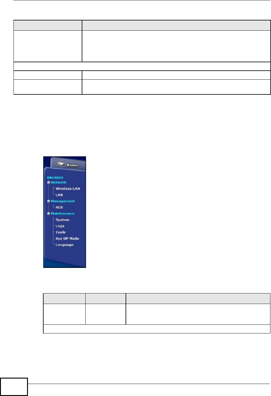
Chapter 5AP Mode
NBG4604 User’s Guide
58
5.3.1 Navigation Panel
Use the menu in the navigation panel to configure NBG4604 features in AP Mode.
The following screen and table show the features you can configure in AP Mode.
Figure 25 Menu: AP Mode
The following table describes the sub-menus.
RateFor the LAN ports, this displays the port speed and duplex setting or N/A
when the line is disconnected.
For the WLAN, it displays the maximum transmission rate when the WLAN
is enabled and N/A when the WLAN is disabled.
Summary
Packet StatisticsUse this screen to view port status and packet specific statistics.
WLAN Station StatusUse this screen to view the wireless stations that are currently associated
to the NBG4604.
Table 19 Status Screen (AP Mode) (continued)
LABEL DESCRIPTION
Table 20 Menu: AP Mode
LINK TAB FUNCTION
Status This screen shows the NBG4604’s general device,
system and interface status information. Use this screen
to access the wizard, and summary statistics tables.
Network
Company Confidential

Chapter 5AP Mode
NBG4604 User’s Guide 59
Wireless
LAN General Use this screen to configure wireless LAN.
MAC Filter Use the MAC filter screen to configure the NBG4604 to
block access to devices or block the devices from
accessing the NBG4604.
Advanced This screen allows you to configure advanced wireless
settings.
QoS Use this screen to configure Wi-Fi Multimedia Quality of
Service (WMM QoS). WMM QoS allows you to prioritize
wireless traffic according to the delivery requirements of
individual services.
WPS Use this screen to configure WPS.
WPS Station Use this screen to add a wireless station using WPS.
Scheduling Use this screen to schedule the times the Wireless LAN
is enabled.
WDS Use this screen to set up Wireless Distribution System
(WDS) on your NBG4604.
LAN IP Use this screen to configure LAN IP address and subnet
mask or to get the LAN IP address from a DHCP server.
Management
ACS General Use this screen configure ACS.
Certificate Use this screen to upload security certificates to the
device.
Maintenance
System General Use this screen to view and change administrative
settings such as system and domain names, password
and inactivity timer.
Time Setting Use this screen to change your NBG4604’s time and
date.
Logs View Log Use this screen to view the logs for the categories that
you selected.
Log Settings Use this screen to activate syslog logging as well as the
syslog server IP address.
Tools Firmware Use this screen to upload firmware to your NBG4604.
Configuration Use this screen to backup and restore the configuration
or reset the factory defaults to your NBG4604.
Restart This screen allows you to reboot the NBG4604 without
turning the power off.
Sys OP
Mode General This screen allows you to select whether your device
acts as a Router or a Access Point.
Language This screen allows you to select the language you prefer.
Table 20 Menu: AP Mode
LINK TAB FUNCTION
Company Confidential
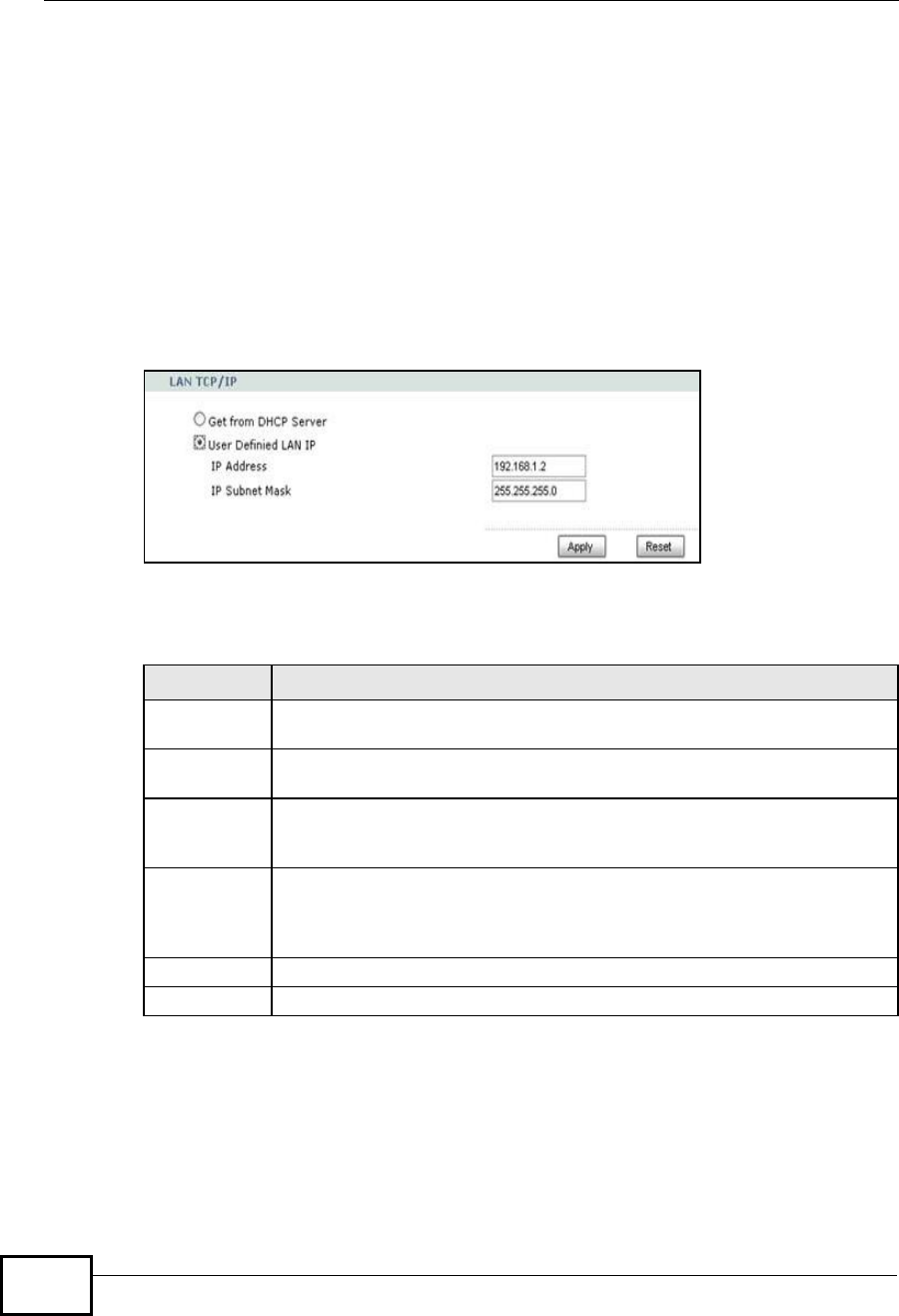
Chapter 5AP Mode
NBG4604 User’s Guide
60
5.4 Configuring Your Settings
Use this section to configure your NBG4604 settings while in AP Mode.
5.4.1 LAN Settings
Click Network > LAN to see the screen below.
Note: If you change the IP address of the NBG4604 in the screen below, you will need
to log into the NBG4604 again using the new IP address.
Figure 26 Network > LAN > IP
The table below describes the labels in the screen.
Table 21 Network > LAN > IP
5.4.2 WLAN and Maintenance Settings
The configuration of wireless and maintenance settings in AP Mode is the same as
for Router Mode.
•See Chapter 5 on page 69 for information on the configuring your wireless
network.
LABEL DESCRIPTION
Get from
DHCP Server Select this to let the DHCP server in the gateway assign the NBG4604 IP
address.
User Defined
LAN IP Select this to give the NBG4604 a static IP address.
IP Address Type the IP address in dotted decimal notatiion. The default setting is
192.168.1.2. If you change the IP address you will have to log in again
with the new IP address.
IP Subnet
Mask The subnet mask specifies the network number portion of an IP address.
Your NBG4604 will automatically calculate the subnet mask based on the
IP address that you assign. Unless you are implementing subnetting, use
the subnet mask computed by the NBG4604.
Apply Click Apply to save your changes to the NBG4604.
Reset Click Reset to reload the previous configuration for this screen.
Company Confidential

Chapter 5AP Mode
NBG4604 User’s Guide 61
•See Maintenance and Troubleshooting (169) for information on configuring your
maintenance settings.
5.5 Logging in to the Web Configurator in AP
Mode
1Connect your computer to the LAN port of the NBG4604.
2The default IP address of the NBG4604 is “192.168.1.2”. In this case, your
computer must have an IP address in the range between “192.168.1.3” and
“192.168.1.254”.
3Click Start > Run on your computer in Windows.
4Type “cmd” in the dialog box.
5Type “ipconfig” to show your computer’s IP address. If your computer’s IP address
is not in the correct range then see Appendix C on page 229 for information on
changing your computer’s IP address.
6After you’ve set your computer’s IP address, open a web browser such as Internet
Explorer and type “192.168.1.2” as the web address in your web browser.
See Chapter 6 on page 63 for a tutorial on setting up a network with an AP.
Company Confidential

Chapter 5AP Mode
NBG4604 User’s Guide
62
Company Confidential
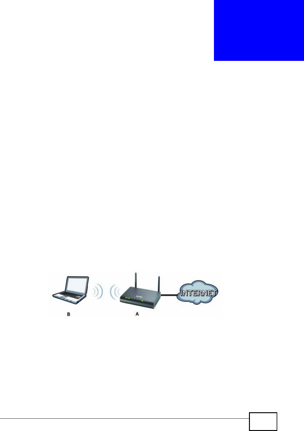
NBG4604 User’s Guide 63
CHAPTER 6
Tutorials
6.1 Overview
This chapter provides tutorials for your NBG4604 as follows:
•How to Connect to the Internet from an AP
•Configure Wireless Security Using WPS on both your NBG4604 and Wireless
Client
•Enable and Configure Wireless Security without WPS on your NBG4604
•Bandwidth Management for your Network
6.2 How to Connect to the Internet from an AP
This section gives you an example of how to set up an access point (AP) and
wireless client (a notebook, B in this example) for wireless communication. B can
access the Internet through the AP wirelessly.
Figure 27 Wireless AP Connection to the Internet
6.2.1 Configure Wireless Security Using WPS on both your
NBG4604 and Wireless Client
This section gives you an example of how to set up wireless network using WPS.
This example uses the NBG4604 as the AP and NWD210N as the wireless client
which connects to a notebook.
Note: The wireless client must be a WPS-aware device (for example, a WPS USB
adapter or PCI card).
Company Confidential

Chapter 6Tutorials
NBG4604 User’s Guide
64
There are two WPS methods for creating a secure connection. This tutorial shows
you how to do both.
•Push Button Configuration (PBC) - create a secure wireless network simply
by pressing a button. See Section 6.2.1.1 on page 64.This is the easier method.
•PIN Configuration - create a secure wireless network simply by entering a
wireless client's PIN (Personal Identification Number) in the NBG4604’s
interface. See Section 6.2.1.2 on page 65. This is the more secure method,
since one device can authenticate the other.
6.2.1.1 Push Button Configuration (PBC)
1Make sure that your NBG4604 is turned on and that it is within range of your
computer.
2Make sure that you have installed the wireless client (this example uses the
NWD210N) driver and utility in your notebook.
3In the wireless client utility, find the WPS settings. Enable WPS and press the WPS
button (Start or WPS button)
4Log into NBG4604’s Web Configurator and press the Push Button button in the
Network > Wireless Client >WPS Station screen.
Note: Your NBG4604 has a WPS button located on its panel, as well as a WPS button
in its configuration utility. Both buttons have exactly the same function; you can
use one or the other.
Note: It doesn’t matter which button is pressed first. You must press the second
button within two minutes of pressing the first one.
The NBG4604 sends the proper configuration settings to the wireless client. This
may take up to two minutes. Then the wireless client is able to communicate with
the NBG4604 securely.
Company Confidential
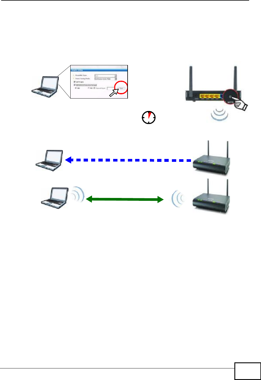
Chapter 6Tutorials
NBG4604 User’s Guide 65
The following figure shows you an example to set up wireless network and security
by pressing a button on both NBG4604 and wireless client (the NWD210N in this
example).
Figure 28 Example WPS Process: PBC Method
6.2.1.2 PIN Configuration
When you use the PIN configuration method, you need to use both NBG4604’s
configuration interface and the client’s utilities.
1Launch your wireless client’s configuration utility. Go to the WPS settings and
select the PIN method to get a PIN number.
2Enter the PIN number to the PIN field in the Network > Wireless LAN >WPS
Station screen on the NBG4604.
3Click the Start buttons (or button next to the PIN field) on both the wireless client
utility screen and the NBG4604’s WPS Station screen within two minutes.
The NBG4604 authenticates the wireless client and sends the proper configuration
settings to the wireless client. This may take up to two minutes. Then the wireless
client is able to communicate with the NBG4604 securely.
Wireless Client NBG4604
SECURITY INFO
COMMUNICATION
WITHIN 2 MINUTES
Company Confidential
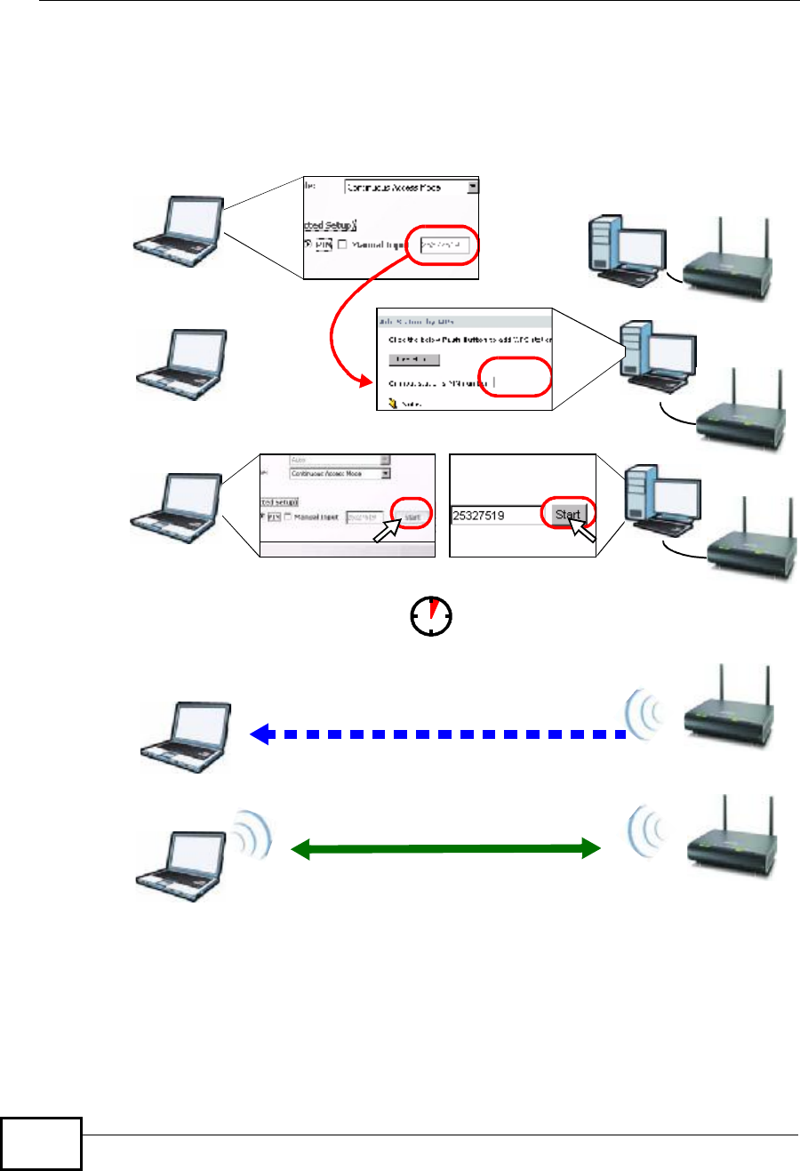
Chapter 6Tutorials
NBG4604 User’s Guide
66
The following figure shows you the example to set up wireless network and
security on NBG4604 and wireless client (ex. NWD210N in this example) by using
PIN method.
Figure 29 Example WPS Process: PIN Method
Authentication by PIN
SECURITY INFO
WITHIN 2 MINUTES
Wireless Client NBG4604
COMMUNICATION
Company Confidential
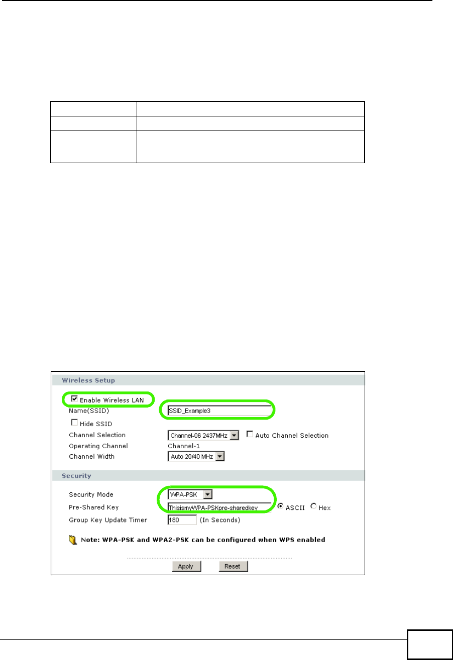
Chapter 6Tutorials
NBG4604 User’s Guide 67
6.2.2 Enable and Configure Wireless Security without WPS
on your NBG4604
This example shows you how to configure wireless security settings with the
following parameters on your NBG4604.
Follow the steps below to configure the wireless settings on your NBG4604.
The instructions require that your hardware is connected (see the Quick Start
Guide) and you are logged into the Web Configurator through your LAN connection
(see Section 3.2 on page 27).
1Open the Wireless LAN > General screen in the NBG4604’s Web Configurator.
2Make sure the Enable Wireless LAN check box is selected.
3Enter SSID_Example3 as the SSID and select a channel.
4Set security mode to WPA-PSK and enter ThisismyWPA-PSKpre-sharedkey in
the Pre-Shared Key field. Click Apply.
Figure 30 Tutorial: Network > Wireless LAN > General
SSID SSID_Example3
Channel 6
Security WPA-PSK
(Pre-Shared Key: ThisismyWPA-PSKpre-sharedkey)
Company Confidential
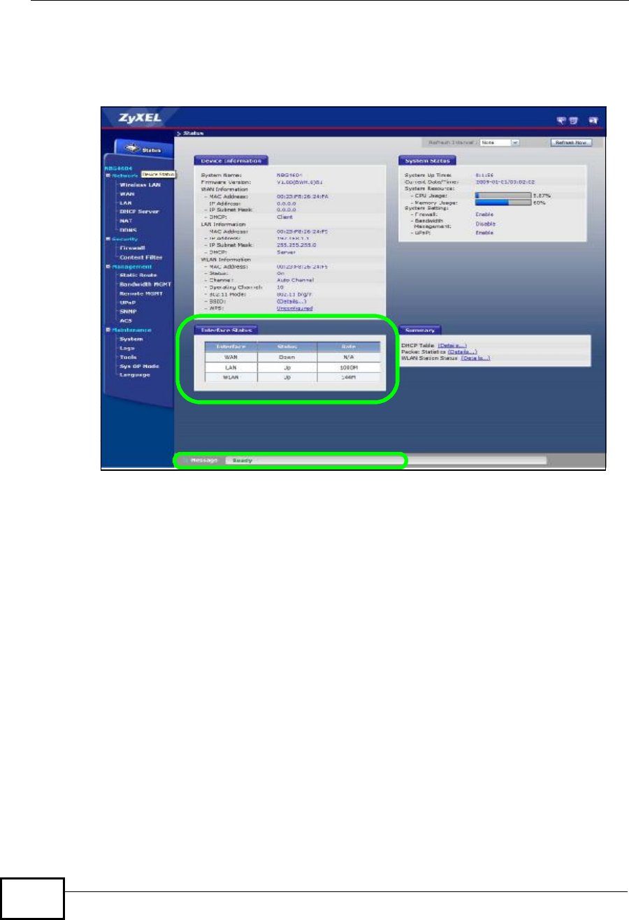
Chapter 6Tutorials
NBG4604 User’s Guide
68
5Open the Status screen. Verify your wireless and wireless security settings under
Device Information and check if the WLAN connection is up under Interface
Status.
Figure 31 Tutorial: Status Screen
6.2.2.1 Configure Your Notebook
Note: We use the ZyXEL M-302 wireless adapter utility screens as an example for the
wireless client. The screens may vary for different models.
1The NBG4604 supports IEEE 802.11b, IEEE 802.11g and IEEE 802.11n wireless
clients. Make sure that your notebook or computer’s wireless adapter supports
one of these standards.
2Wireless adapters come with software sometimes called a “utility” that you install
on your computer. See your wireless adapter’s User’s Guide for information on
how to do that.
3After you’ve installed the utility, open it. If you cannot see your utility’s icon on
your screen, go to Start > Programs and click on your utility in the list of
programs that appears. The utility displays a list of APs within range, as shown in
the example screen below.
Company Confidential
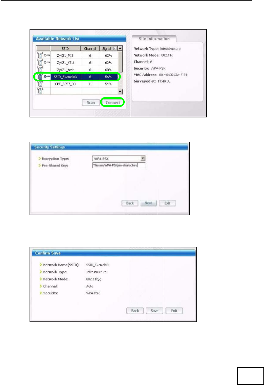
Chapter 6Tutorials
NBG4604 User’s Guide 69
4Select SSID_Example3 and click Connect.
Figure 32 Connecting a Wireless Client to a Wireless Network t
5Select WPA-PSK and type the security key in the following screen. Click Next.
Figure 33 Security Settings
6The Confirm Save window appears. Check your settings and click Save to
continue.
Figure 34 Confirm Save
Company Confidential
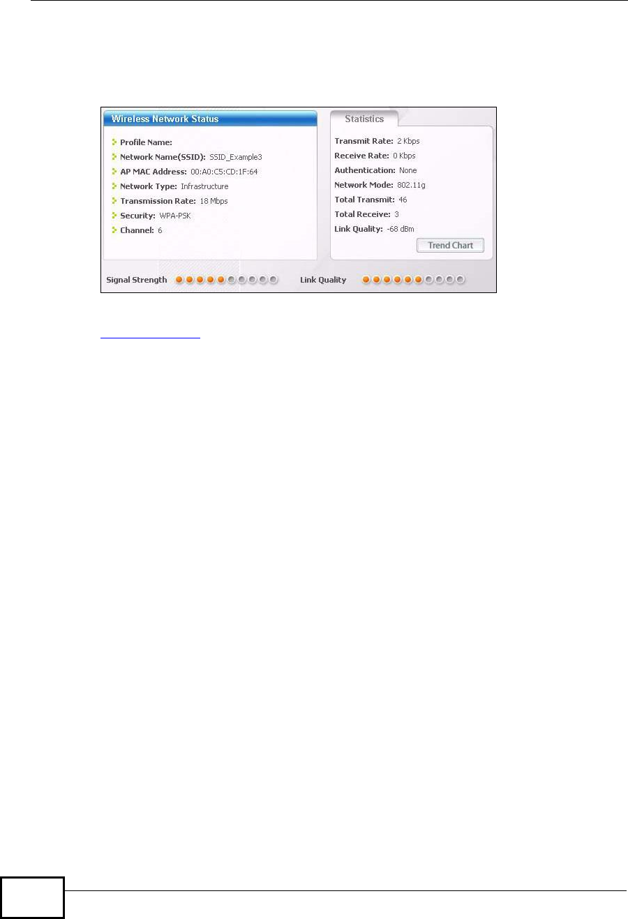
Chapter 6Tutorials
NBG4604 User’s Guide
70
7Check the status of your wireless connection in the screen below. If your wireless
connection is weak or you have no connection, see the Troubleshooting section of
this User’s Guide.
Figure 35 Link Status
If your connection is successful, open your Internet browser and enter http://
www.zyxel.com or the URL of any other web site in the address bar. If you are able
to access the web site, your wireless connection is successfully configured.
6.3 Bandwidth Management for your Network
This section shows you how to configure the bandwidth management feature on
the NBG4604 to limit the bandwidth for specific kinds of outgoing traffic. ZyXEL's
bandwidth management feature allows you to specify bandwidth management
rules based on an application or subnet.
Use the Management > Bandwidth MGMT > Advanced screen to configure
bandwidth management for your network.
6.3.1 Configuring Bandwidth Management by Application
For this example, your company’s customer support department wants to
prioritize VoIP, e-mail and MSN Messenger services.
In the Priority Queue table, VoIP and e-mail services are already pre-defined.
However, you still need to add MSN Messenger in the list (refer to Section 6.3.2 on
page 71).
Company Confidential
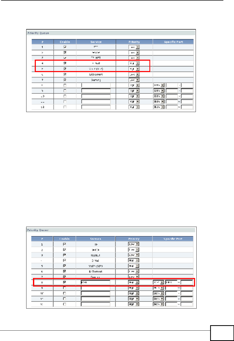
Chapter 6Tutorials
NBG4604 User’s Guide 71
In the following screen, you set the priorities for VoIP and e-mail.
Figure 36 Tutorial: Priority Queue
Click Enable for the VoIP (SIP) service and set priority to High. Do the same for
E-mail. For the rest of the applications, click Enable if you need these services
and set the priority to Low.
Note: You can also leave the Enable field blank for the rest of the applications. In
doing so, the NBG4604 does not apply bandwidth management to these
services.
6.3.2 Configuring Bandwidth Management by Custom
Application
Aside from the VOIP and e-mail services, you need to set the priority for MSN
Messenger. To do this, add the service in the Priority Queue table of the
Management > Bandwidth MGMT > Advanced screen.
Figure 37 Tutorial: Adding MSN Messenger to Priority Queue
Company Confidential

Chapter 6Tutorials
NBG4604 User’s Guide
72
To add the MSN Messenger service in the Priority Queue:
1Click Enable in one of the fields for additional services.
2Add MSN as the service name.
3Set the priority for this to High.
4For the port, choose TCP from the drop-down menu and enter 1863 in the
Specific Port field.
Your priority table should now have the VoIP,E-mail and MSN Messenger
services priorities set to High.
6.3.3 Configuring Bandwidth Allocation by IP or IP Range
For this example, your company’s 20th anniversary is coming up. You want to use
the multimedia room’s Internet connection to upload some videos to the website.
You also use this room for video conferences, radio broadcasts, live video
streaming, and so on throughout the day. While these media-heavy activities are
going on, you still want to keep uploading the videos in the background. As such,
you want to dedicate the minimum amount of bandwidth for this traffic.
You know the following:
•Multimedia room’s LAN IP range: 192.168.1.1 to 192.168.1.34
•IP Address of the computer uploading through FTP: 192.168.1.34
•Services you want to configure:
Click the Edit icon in Management > Bandwidth MGMT > Advanced to open
the following screen.
Figure 38 Tutorial: Bandwidth Allocation Example
REAL AUDIO TCP 7070
RTSPTCP or UDP 554
VDO LIVETCP 7000
FTPTCP 20 ~ 21
Company Confidential
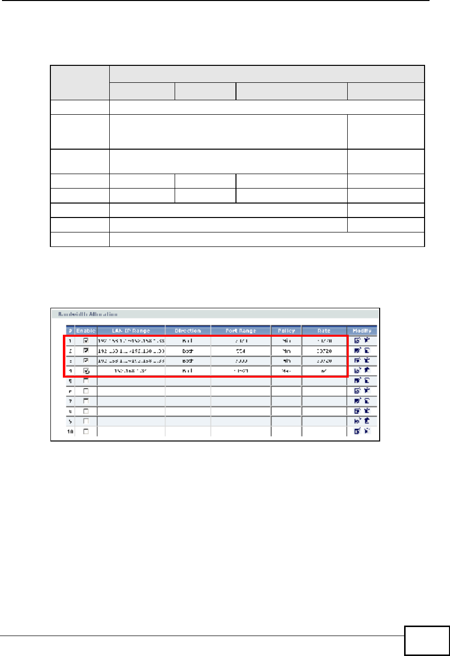
Chapter 6Tutorials
NBG4604 User’s Guide 73
Enter the following values for each service you want to add. For this tutorial, you
need to add each of the following service (see table below) and click Apply.
After adding these services, go to Management > Bandwidth MGMT >
Advanced and check if you have the correct values.
Figure 39 Tutorial: Bandwidth Allocation Example
Note: The Policy column displays either Max (maximum) or Min (minimum). This is
directly directed to the value in the Rate column. For example, you selected
Min and entered 30M as the rate for the VoIP service. The NBG4604 allocates
at least 30 megabytes for the VoIP service.
Refer to Appedix F on page 259 for a list of common services that you can add in
the Bandwidth Mgnt screen.
Table 22 Services and Values
FIELDS SERVICES
REAL AUDIO RTSP VDO LIVE FTP
ActiveCheck this to turn on this bandwidth management rule.
DirectionSelect Both applies bandwidth management to traffic
that the NBG4604 forwards to both the LAN and the
WAN.
Select To WAN
LAN IP
Range Enter 192.168.1.1 ~ 192.168.1.33.Enter
192.168.1.34
Protocol TCPTCP or UDPTCP TCP
Port Range 7070554700020 ~ 21
Policy MinMax
RateSelect 30M as the minimum bandwidth allowed. Select 64K
ApplyClick this to add the rule to the Bandwidth Allocation table.
Company Confidential

Chapter 6Tutorials
NBG4604 User’s Guide
74
Company Confidential

75
PART II
Technical Reference
Wireless LAN (77)
WAN (101)
LAN (113)
DHCP Server (117)
Network Address Translation (NAT) (123)
Dynamic DNS (131)
Company Confidential

76
Company Confidential
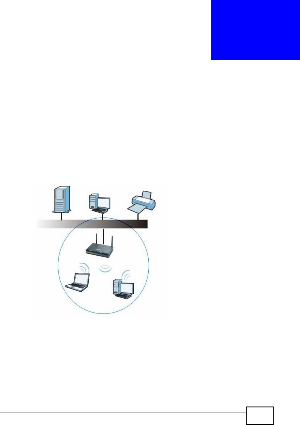
NBG4604 User’s Guide 77
CHAPTER 7
Wireless LAN
7.1 Overview
This chapter discusses how to configure the wireless network settings in your
NBG4604. See the appendices for more detailed information about wireless
networks.
The following figure provides an example of a wireless network.
Figure 40 Example of a Wireless Network
The wireless network is the part in the blue circle. In this wireless network,
devices A and B are called wireless clients. The wireless clients use the access
point (AP) to interact with other devices (such as the printer) or with the Internet.
Your NBG4604 is the AP.
Company Confidential

Chapter 7Wireless LAN
NBG4604 User’s Guide
78
7.2 What You Can Do
•Use the General screen (Section 7.4 on page 81) to enable the Wireless LAN,
enter the SSID and select the wireless security mode.
•Use the MAC Filter screen (Section 7.5 on page 87) to allow or deny wireless
stations based on their MAC addresses from connecting to the NBG4604.
•Use the Advanced screen (Section 7.6 on page 89) to allow intra-BSS
networking and set the RTS/CTS Threshold.
•Use the QoS screen (Section 7.7 on page 90) to ensure Quality of Service (QoS)
in your wireless network.
•Use the WPS screen (Section 7.8 on page 93) to quickly set up a wireless
network with strong security, without having to configure security settings
manually.
•Use the WPS Station screen (Section 7.9 on page 94) to add a wireless station
using WPS.
•Use the Scheduling screen (Section 7.10 on page 95) to set the times your
wireless LAN is turned on and off.
•Use the WDS screen (Section 7.11 on page 96) to set the operating mode of
your NBG4604 to AP + Bridge or Bridge Only and establish wireless links with
other APs.
7.3 What You Should Know
Every wireless network must follow these basic guidelines.
•Every wireless client in the same wireless network must use the same SSID.
The SSID is the name of the wireless network. It stands for Service Set IDentity.
•If two wireless networks overlap, they should use different channels.
Like radio stations or television channels, each wireless network uses a specific
channel, or frequency, to send and receive information.
•Every wireless client in the same wireless network must use security compatible
with the AP.
Security stops unauthorized devices from using the wireless network. It can also
protect the information that is sent in the wireless network.
7.3.1 Wireless Security Overview
The following sections introduce different types of wireless security you can set up
in the wireless network.
Company Confidential

Chapter 7Wireless LAN
NBG4604 User’s Guide 79
7.3.1.1 SSID
Normally, the AP acts like a beacon and regularly broadcasts the SSID in the area.
You can hide the SSID instead, in which case the AP does not broadcast the SSID.
In addition, you should change the default SSID to something that is difficult to
guess.
This type of security is fairly weak, however, because there are ways for
unauthorized devices to get the SSID. In addition, unauthorized devices can still
see the information that is sent in the wireless network.
7.3.1.2 MAC Address Filter
Every wireless client has a unique identification number, called a MAC address.1 A
MAC address is usually written using twelve hexadecimal characters2; for
example, 00A0C5000002 or 00:A0:C5:00:00:02. To get the MAC address for each
wireless client, see the appropriate User’s Guide or other documentation.
You can use the MAC address filter to tell the AP which wireless clients are allowed
or not allowed to use the wireless network. If a wireless client is allowed to use the
wireless network, it still has to have the correct settings (SSID, channel, and
security). If a wireless client is not allowed to use the wireless network, it does not
matter if it has the correct settings.
This type of security does not protect the information that is sent in the wireless
network. Furthermore, there are ways for unauthorized devices to get the MAC
address of an authorized wireless client. Then, they can use that MAC address to
use the wireless network.
7.3.1.3 User Authentication
You can make every user log in to the wireless network before they can use it.
This is called user authentication. However, every wireless client in the wireless
network has to support IEEE 802.1x to do this.
For wireless networks, there are two typical places to store the user names and
passwords for each user.
•In the AP: this feature is called a local user database or a local database.
•In a RADIUS server: this is a server used in businesses more than in homes.
If your AP does not provide a local user database and if you do not have a RADIUS
server, you cannot set up user names and passwords for your users.
1.Some wireless devices, such as scanners, can detect wireless networks but cannot use wireless networks.
These kinds of wireless devices might not have MAC addresses.
2.Hexadecimal characters are 0, 1, 2, 3, 4, 5, 6, 7, 8, 9, A, B, C, D, E, and F.
Company Confidential

Chapter 7Wireless LAN
NBG4604 User’s Guide
80
Unauthorized devices can still see the information that is sent in the wireless
network, even if they cannot use the wireless network. Furthermore, there are
ways for unauthorized wireless users to get a valid user name and password.
Then, they can use that user name and password to use the wireless network.
Local user databases also have an additional limitation that is explained in the
next section.
7.3.1.4 Encryption
Wireless networks can use encryption to protect the information that is sent in the
wireless network. Encryption is like a secret code. If you do not know the secret
code, you cannot understand the message.
The types of encryption you can choose depend on the type of user
authentication. (See Section 7.3.1.3 on page 79 for information about this.)
For example if the wireless network has a RADIUS server, you can choose WPA or
WPA2. If users do not log in to the wireless network, you can choose no
encryption, Static WEP,WPA-PSK, or WPA2-PSK.
Usually, you should set up the strongest encryption that every wireless client in
the wireless network supports. For example, suppose the AP does not have a local
user database, and you do not have a RADIUS server. Therefore, there is no user
authentication. Suppose the wireless network has two wireless clients. Device A
only supports WEP, and device B supports WEP and WPA. Therefore, you should
set up Static WEP in the wireless network.
Note: It is recommended that wireless networks use WPA-PSK, WPA, or stronger
encryption. IEEE 802.1x and WEP encryption are better than none at all, but it
is still possible for unauthorized devices to figure out the original information
pretty quickly.
Note: It is not possible to use WPA-PSK, WPA or stronger encryption with a local user
database. In this case, it is better to set up stronger encryption with no
authentication than to set up weaker encryption with the local user database.
When you select WPA2 or WPA2-PSK in your NBG4604, you can also select an
option (WPA Compatible) to support WPA as well. In this case, if some wireless
clients support WPA and some support WPA2, you should set up WPA2-PSK or
Table 23 Types of Encryption for Each Type of Authentication
NO AUTHENTICATION RADIUS SERVER
Weakest No SecurityWPA
Static WEP
WPA-PSK
Strongest WPA2-PSKWPA2
Company Confidential
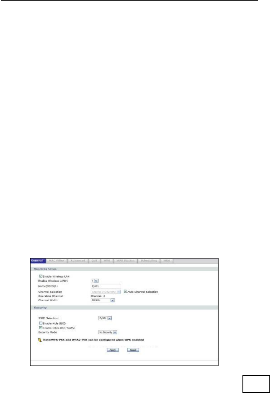
Chapter 7Wireless LAN
NBG4604 User’s Guide 81
WPA2 (depending on the type of wireless network login) and select the WPA
Compatible option in the NBG4604.
Many types of encryption use a key to protect the information in the wireless
network. The longer the key, the stronger the encryption. Every wireless client in
the wireless network must have the same key.
7.3.1.5 WPS
WiFi Protected Setup (WPS) is an industry standard specification, defined by the
WiFi Alliance. WPS allows you to quickly set up a wireless network with strong
security, without having to configure security settings manually. Depending on the
devices in your network, you can either press a button (on the device itself, or in
its configuration utility) or enter a PIN (Personal Identification Number) in the
devices. Then, they connect and set up a secure network by themselves. See how
to set up a secure wireless network using WPS in the Section 6.2.1 on page 63.
7.4 General Wireless LAN Screen
Use this screen to enable the Wireless LAN, enter the SSID and select the wireless
security mode.
Note: If you are configuring the NBG4604 from a computer connected to the wireless
LAN and you change the NBG4604’s SSID, channel or security settings, you
will lose your wireless connection when you press Apply to confirm. You must
then change the wireless settings of your computer to match the NBG4604’s
new settings.
Click Network > Wireless LAN to open the General screen.
Figure 41 Network > Wireless LAN > General
Company Confidential

Chapter 7Wireless LAN
NBG4604 User’s Guide
82
The following table describes the general wireless LAN labels in this screen.
Table 24 Network > Wireless LAN > General
LABEL DESCRIPTION
Enable
Wireless LAN Click the check box to activate wireless LAN.
Enable
Wireless LAN
#1
Set the number of wireless LANs to enable on this device, up to a
maximum of 4.
Name(SSID) (Service Set IDentity) The SSID identifies the Service Set with which a
wireless station is associated. Wireless stations associating to the access
point (AP) must have the same SSID. Enter a descriptive name (up to 32
printable 7-bit ASCII characters) for the wireless LAN.
There is one Name(SSID) field for each wireless LAN enabled on this
device.
Channel
Selection Set the operating frequency/channel depending on your particular region.
Select a channel from the drop-down list box. The options vary depending
on the frequency band and the country you are in.
Refer to the Connection Wizard chapter for more information on channels.
This option is only available if Auto Channel Selection is disabled.
Auto Channel
Selection Select this check box for the NBG4604 to automatically choose the
channel with the least interference. Deselect this check box if you wish to
manually select the channel using the Channel Section field.
Operating
Channel This displays the channel the NBG4604 is currently using.
Channel
Width Select whether the NBG4604 uses a wireless channel width of 20 or 40
MHz. A standard 20 MHz channel offers transfer speeds of up to 150Mbps
whereas a 40MHz channel uses two standard channels and offers speeds
of up to 300 Mbps. Because not all devices support 40 MHz channels,
select Auto 20/40MHz to allow the NBG4604 to adjust the channel
bandwidth automatically.
SSID
Selection Select a wireless LAN for which to configure security settings.
The security settings only apply to the selected wireless LAN.
Enable Hide
SSID Select this check box to hide the SSID in the outgoing beacon frame so a
station cannot obtain the SSID through scanning using a site survey tool.
Enable Intra-
BSS Traffic A Basic Service Set (BSS) exists when all communications between
wireless clients or between a wireless client and a wired network client go
through one access point (AP).
Intra-BSS traffic is traffic between wireless clients in the BSS. When Intra-
BSS is enabled, wireless client A and B can access the wired network and
communicate with each other. When Intra-BSS is disabled, wireless client
A and B can still access the wired network but cannot communicate with
each other.
Company Confidential
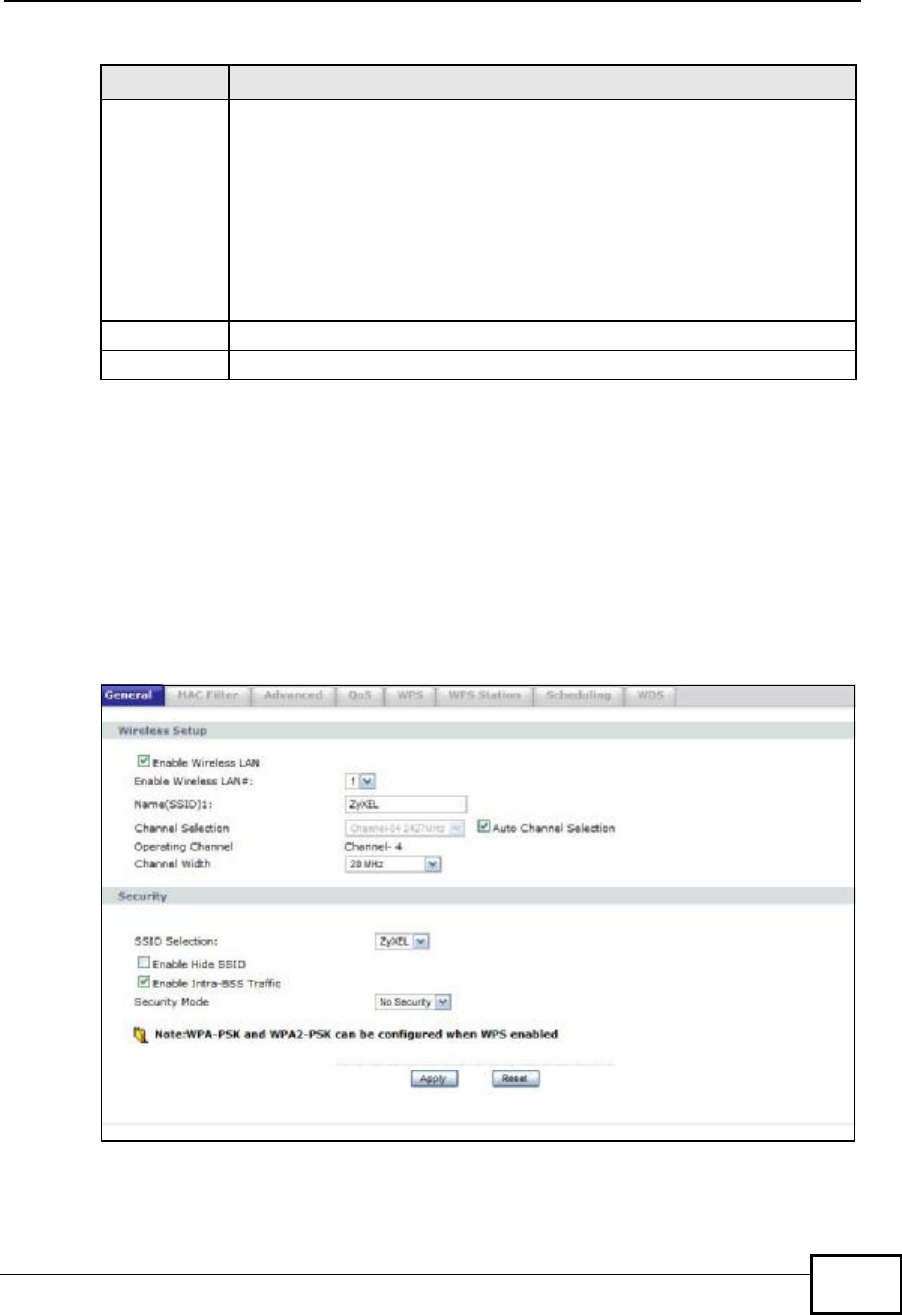
Chapter 7Wireless LAN
NBG4604 User’s Guide 83
See the rest of this chapter for information on the other labels in this screen.
7.4.1 No Security
Select No Security to allow wireless stations to communicate with the access
points without any data encryption.
Note: If you do not enable any wireless security on your NBG4604, your network is
accessible to any wireless networking device that is within range.
Figure 42 Network > Wireless LAN > General: No Security
Security
Mode Select No Security,Static WEP,WPA-PSK, or WPA2-PSK to add
security on this wireless network. The wireless clients which want to
associate to this network must have same wireless security settings as
this device. After you select to use a security, additional options appears
in this screen. See 7.4.2 and 7.4.3 sections. Or you can select No
Security to allow any client to associate this network without
authentication.
Note: If you enable the WPS function, only No Security,WPA-PSK
and WPA2-PSK are available in this field.
Apply Click Apply to save your changes back to the NBG4604.
Reset Click Reset to reload the previous configuration for this screen.
Table 24 Network > Wireless LAN > General
LABEL DESCRIPTION
Company Confidential

Chapter 7Wireless LAN
NBG4604 User’s Guide
84
The following table describes the labels in this screen.
7.4.2 WEP Encryption
WEP encryption scrambles the data transmitted between the wireless stations and
the access points to keep network communications private. It encrypts unicast
and multicast communications in a network. Both the wireless stations and the
access points must use the same WEP key.
Your NBG4604 allows you to configure up to four 64-bit or 128-bit WEP keys but
only one key can be enabled at any one time.
Table 25 Network > Wireless LAN > General: No Security
LABEL DESCRIPTION
Security
Mode Choose No Security from the drop-down list box.
Apply Click Apply to save your changes back to the NBG4604.
Reset Click Reset to reload the previous configuration for this screen.
Company Confidential
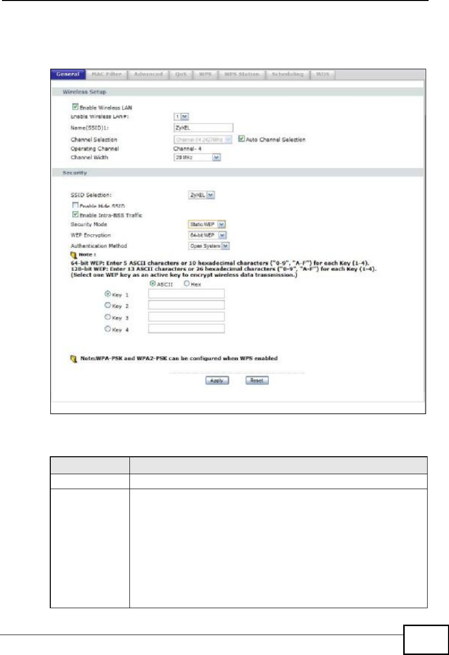
Chapter 7Wireless LAN
NBG4604 User’s Guide 85
In order to configure and enable WEP encryption; click Network > Wireless LAN
to display the General screen. Select Static WEP from the Security Mode list.
Figure 43 Network > Wireless LAN > General: Static WEP
The following table describes the wireless LAN security labels in this screen.
Table 26 Network > Wireless LAN > General: Static WEP
LABEL DESCRIPTION
WEP Encryption Select 64-bit WEP or 128-bit WEP to enable data encryption.
Authentication
Method This field is activated when you select 64-bit WEP or 128-bit WEP in
the WEP Encryption field.
Select Auto, Open System or Shared Key from the drop-down list
box.
This field specifies whether the wireless clients have to provide the
WEP key to login to the wireless client. Keep this setting at Auto or
Open System unless you want to force a key verification before
communication between the wireless client and the ZyXEL Device
occurs. Select Shared Key to force the clients to provide the WEP key
prior to communication.
Company Confidential
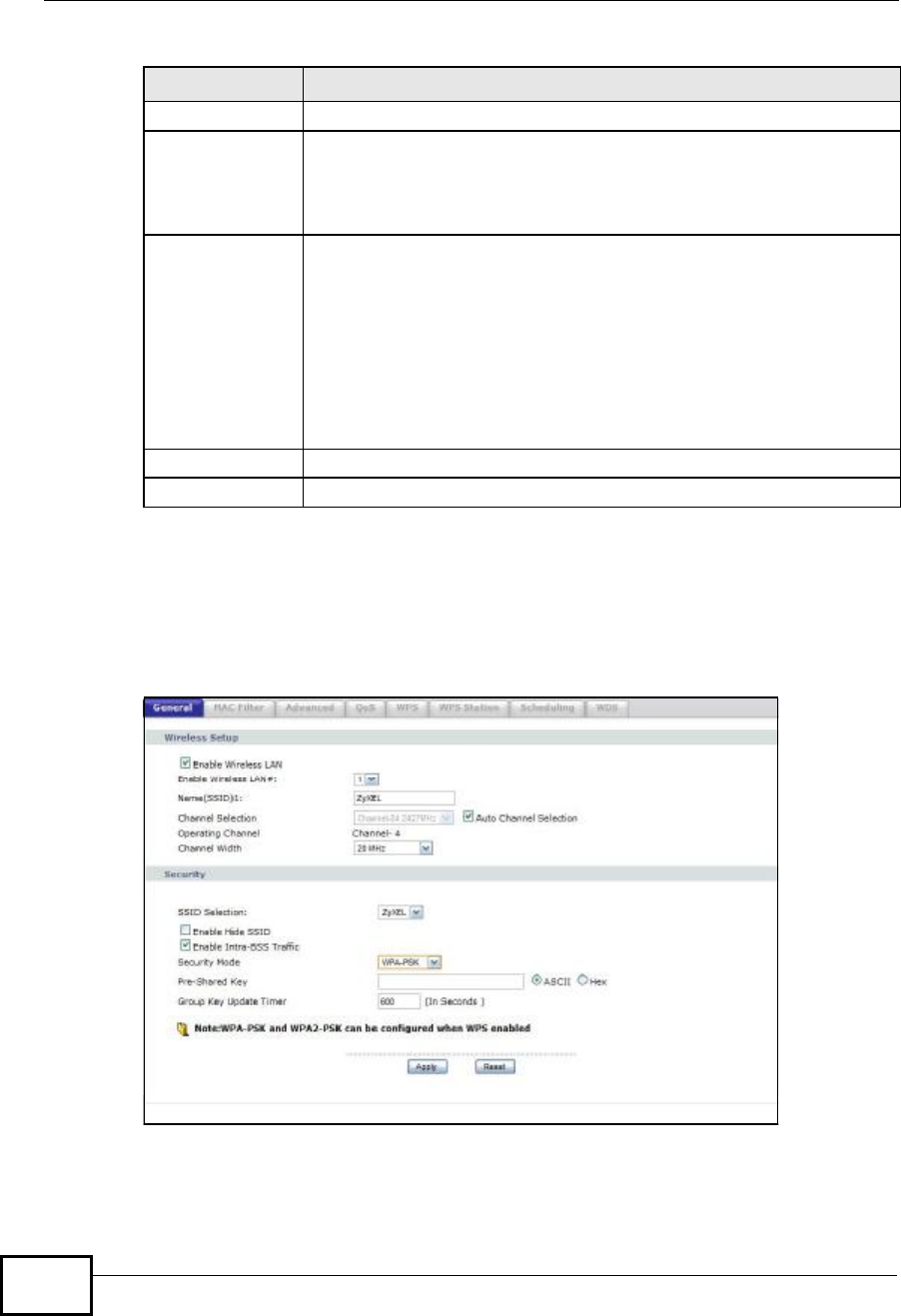
Chapter 7Wireless LAN
NBG4604 User’s Guide
86
7.4.3 WPA-PSK/WPA2-PSK
Click Network > Wireless LAN to display the General screen. Select WPA-PSK
or WPA2-PSK from the Security Mode list.
Figure 44 Network > Wireless LAN > General: WPA-PSK/WPA2-PSK
ASCII Select this option in order to enter ASCII characters as WEP key.
Hex Select this option in order to enter hexadecimal characters as a WEP
key.
The preceding "0x", that identifies a hexadecimal key, is entered
automatically.
Key 1 to Key 4 The WEP keys are used to encrypt data. Both the NBG4604 and the
wireless stations must use the same WEP key for data transmission.
If you chose 64-bit WEP, then enter any 5 ASCII characters or 10
hexadecimal characters ("0-9", "A-F").
If you chose 128-bit WEP, then enter 13 ASCII characters or 26
hexadecimal characters ("0-9", "A-F").
You must configure at least one key, only one key can be activated at
any one time. The default key is key 1.
Apply Click Apply to save your changes back to the NBG4604.
Reset Click Reset to reload the previous configuration for this screen.
Table 26 Network > Wireless LAN > General: Static WEP
LABEL DESCRIPTION
Company Confidential

Chapter 7Wireless LAN
NBG4604 User’s Guide 87
The following table describes the labels in this screen.
7.5 MAC Filter
The MAC filter screen allows you to configure the NBG4604 to give exclusive
access to up to 16 devices (Allow) or exclude up to 16 devices from accessing the
NBG4604 (Deny). Every Ethernet device has a unique MAC (Media Access Control)
address. The MAC address is assigned at the factory and consists of six pairs of
hexadecimal characters, for example, 00:A0:C5:00:00:02. You need to know the
MAC address of the devices to configure this screen.
Table 27 Network > Wireless LAN > General: WPA-PSK/WPA2-PSK
LABEL DESCRIPTION
WPA
Compatible This check box is available only when you select WPA2-PSK in the
Security Mode field.
Select the check box to have both WPA2 and WPA wireless clients be
able to communicate with the NBG4604 even when the NBG4604 is
using WPA2-PSK.
Pre-Shared Key WPA-PSK/WPA2-PSK uses a simple common password for
authentication.
Type a pre-shared key from 8 to 63 case-sensitive ASCII characters
(including spaces and symbols).
Type a pre-shared key less than 64 case-sensitive HEX characters ("0-
9", "A-F").
Group Key
Update Timer The Group Key Update Timer is the rate at which the AP (if using
WPA-PSK/WPA2-PSK key management) or RADIUSserver (if using
WPA/WPA2 key management) sends a new group key out to all
clients. The re-keying process is the WPA/WPA2 equivalent of
automatically changing the WEP key for an AP and all stations in a
WLAN on a periodic basis. Setting of the Group Key Update Timer is
also supported in WPA-PSK/WPA2-PSK mode. The default is 600
seconds (10 minutes).
Apply Click Apply to save your changes back to the NBG4604.
Reset Click Reset to reload the previous configuration for this screen.
Company Confidential
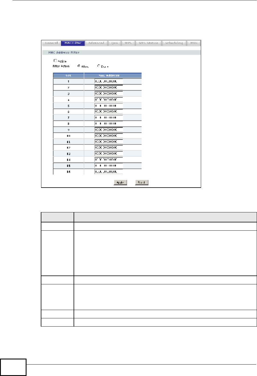
Chapter 7Wireless LAN
NBG4604 User’s Guide
88
To change your NBG4604’s MAC filter settings, click Network > Wireless LAN >
MAC Filter. The screen appears as shown.
Figure 45 Network > Wireless LAN > MAC Filter
The following table describes the labels in this menu.
Table 28 Network > Wireless LAN > MAC Filter
LABEL DESCRIPTION
Active Select Yes from the drop down list box to enable MAC address filtering.
Filter Action Define the filter action for the list of MAC addresses in the MAC Address
table.
Select Deny to block access to the NBG4604, MAC addresses not listed will
be allowed to access the NBG4604
Select Allow to permit access to the NBG4604, MAC addresses not listed
will be denied access to the NBG4604.
Set This is the index number of the MAC address.
MAC
Address Enter the MAC addresses of the wireless station that are allowed or denied
access to the NBG4604 in these address fields. Enter the MAC addresses in
a valid MAC address format, that is, six hexadecimal character pairs, for
example, 12:34:56:78:9a:bc.
Apply Click Apply to save your changes back to the NBG4604.
Reset Click Reset to reload the previous configuration for this screen.
Company Confidential
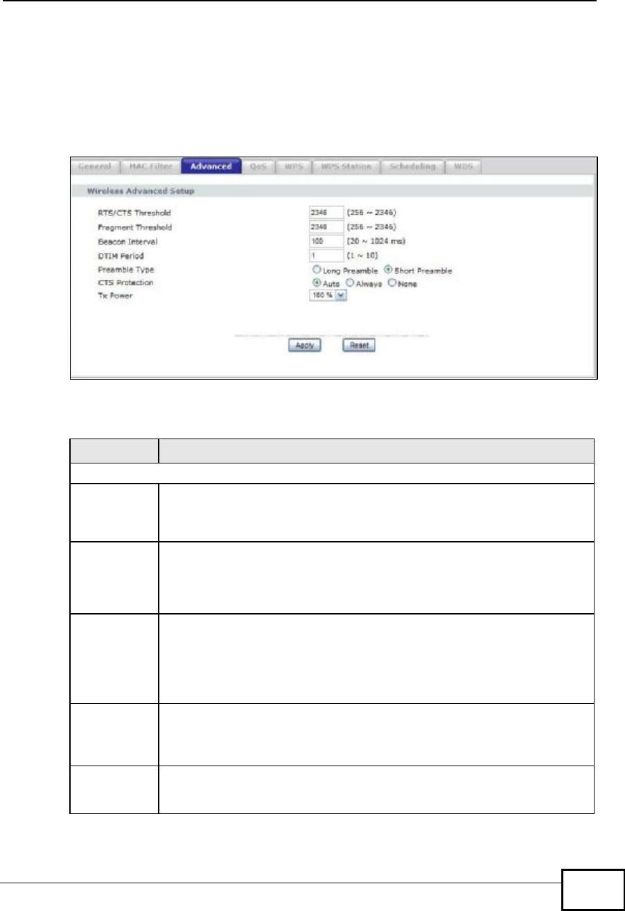
Chapter 7Wireless LAN
NBG4604 User’s Guide 89
7.6 Wireless LAN Advanced Screen
Use this screen to allow intra-BSS networking and set the RTS/CTS Threshold.
Click Network > Wireless LAN > Advanced. The screen appears as shown.
Figure 46 Network > Wireless LAN > Advanced
The following table describes the labels in this screen.
Table 29 Network > Wireless LAN > Advanced
LABEL DESCRIPTION
Wireless Advanced Setup
RTS/CTS
Threshold Data with its frame size larger than this value will perform the RTS
(Request To Send)/CTS (Clear To Send) handshake.
Enter a value between 0 and 2432.
Fragmentatio
n Threshold The threshold (number of bytes) for the fragmentation boundary for
directed messages. It is the maximum data fragment size that can be
sent. Enter an even number between 256 and 2346.
This field is not available when Super Mode is selected.
Beacon
Interval When a wirelessly networked device sends a beacon, it includes with it a
beacon interval. This specifies the time period before the device sends the
beacon again. The interval tells receiving devices on the network how long
they can wait in low-power mode before waking up to handle the beacon.
This value can be set from 20ms to 1000ms. A high value helps save
current consumption of the access point.
DTIM Delivery Traffic Indication Message (DTIM) is the time period after which
broadcast and multicast packets are transmitted to mobile clients in the
Active Power Management mode. A high DTIM value can cause clients to
lose connectivity with the network. This value can be set from 1 to 100.
PreambleA preamble affects the timing in your wireless network. There are two
preamble modes: long and short.If a device uses a different preamble
mode than the NBG4604 does, it cannot communicate with the NBG4604.
Company Confidential
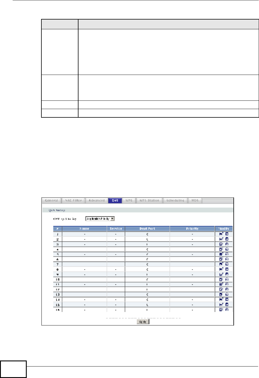
Chapter 7Wireless LAN
NBG4604 User’s Guide
90
7.7 Quality of Service (QoS) Screen
The QoS screen allows you to automatically give a service (such as e-mail, VoIP or
FTP) a priority level.
Click Network > Wireless LAN > QoS. The following screen appears.
Figure 47 Network > Wireless LAN > QoS
CTS
Protection When set to None, the NBG4604 protects wireless communication against
interference.
When set to Always, the NBG4604 improves performance within mixed
wireless modes.
Select Auto to let the NBG4604 determine whether to turn this feature on
or off in the current environment.
Tx PowerThis field controls the transmission power of the NBG4604. When using
the NBG4604 with a notebook computer, select a lower transmission
power level when you are close to the AP in order to conserve battery
power.
Apply Click Apply to save your changes back to the NBG4604.
Reset Click Reset to reload the previous configuration for this screen.
Table 29 Network > Wireless LAN > Advanced
LABEL DESCRIPTION
Company Confidential

Chapter 7Wireless LAN
NBG4604 User’s Guide 91
The following table describes the labels in this screen.
Table 30 Network > Wireless LAN > QoS
LABEL DESCRIPTION
WMM QoS PolicySelect Default to have the NBG4604 automatically give a service a
priority level according to the ToS value in the IP header of packets
it sends. WMM QoS (Wifi MultiMedia Quality of Service) gives high
priority to voice and video, which makes them run more smoothly.
Select Application Priority from the drop-down list box to display
a table of application names, services, ports and priorities to which
you want to apply WMM QoS.
The table appears only if you select Application Priority in WMM
QoS Policy.
#This is the number of an individual application entry.
NameThis field displays a description given to an application entry.
ServiceThis field displays either FTP,WWW,E-mail or a User Defined
service to which you want to apply WMM QoS.
Dest PortThis field displays the destination port number to which the
application sends traffic.
PriorityThis field displays the priority of the application.
Highest - Typically used for voice or video that should be high-
quality.
High - Typically used for voice or video that can be medium-quality.
Mid - Typically used for applications that do not fit into another
priority. For example, Internet surfing.
Low - Typically used for non-critical “background” applications,
such as large file transfers and print jobs that should not affect
other applications.
Modify Click the Edit icon to open the Application Priority
Configuration screen. Modify an existing application entry or
create a application entry in the Application Priority
Configuration screen.
Click the Remove icon to delete an application entry.
Apply Click Apply to save your changes to the NBG4604.
Company Confidential
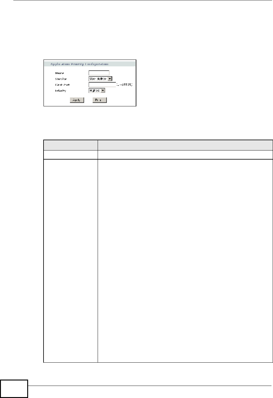
Chapter 7Wireless LAN
NBG4604 User’s Guide
92
7.7.1 Application Priority Configuration
Use this screen to edit a WMM QoS application entry. Click the edit icon under
Modify. The following screen displays.
Figure 48 Network > Wireless LAN > QoS: Application Priority Configuration
See Appendix E on page 259 for a list of commonly-used services and destination
ports. The following table describes the fields in this screen.
Table 31 Network > Wireless LAN > QoS: Application Priority Configuration
LABEL DESCRIPTION
NameType a description of the application priority.
ServiceThe following is a description of the applications you can prioritize
with WMM QoS. Select a service from the drop-down list box.
•E-Mail
Electronic mail consists of messages sent through a computer
network to specific groups or individuals. Here are some default
ports for e-mail:
POP3 - port 110
IMAP - port 143
SMTP - port 25
HTTP - port 80
•FTP
File Transfer Protocol enables fast transfer of files, including large
files that it may not be possible to send via e-mail. FTP uses port
number 21.
•WWW
The World Wide Web is an Internet system to distribute graphical,
hyper-linked information, based on Hyper Text Transfer Protocol
(HTTP) - a client/server protocol for the World Wide Web. The Web is
not synonymous with the Internet; rather, it is just one service on
the Internet. Other services on the Internet include Internet Relay
Chat and Newsgroups. The Web is accessed through use of a
browser.
•User-Defined
User-defined services are user specific services configured using
known ports and applications.
Company Confidential
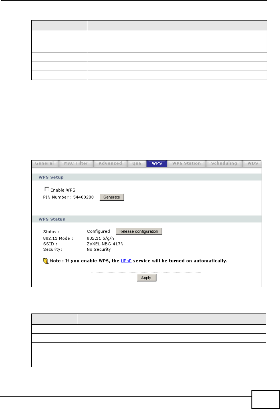
Chapter 7Wireless LAN
NBG4604 User’s Guide 93
7.8 WPS Screen
Use this screen to enable/disable WPS, view or generate a new PIN number and
check current WPS status. To open this screen, click Network >Wireless LAN >
WPS tab.
Figure 49 Network > Wireless LAN > WPS
The following table describes the labels in this screen.
Dest PortThis displays the port the selected service uses. Type a port number
in the field provided if you want to use a different port to the default
port.
PrioritySelect a priority from the drop-down list box.
Apply Click Apply to save your changes back to the NBG4604.
Cancel Click Cancel to return to the previous screen.
Table 31 Network > Wireless LAN > QoS: Application Priority Configuration
LABEL DESCRIPTION
Table 32 Network > Wireless LAN > WPS
LABEL DESCRIPTION
WPS Setup
Enable WPS Select this to enable the WPS feature.
PIN Number This displays a PIN number last time system generated. Click Generate
to generate a new PIN number.
WPS Status
Company Confidential
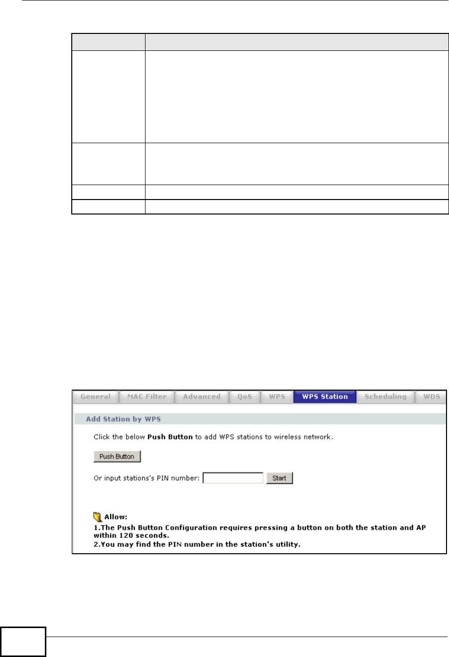
Chapter 7Wireless LAN
NBG4604 User’s Guide
94
7.9 WPS Station Screen
Use this screen when you want to add a wireless station using WPS. To open this
screen, click Network > Wireless LAN > WPS Station tab.
Note: Note: After you click Push Button on this screen, you have to press a similar
button in the wireless station utility within 2 minutes. To add the second wireless
station, you have to press these buttons on both device and the wireless station
again after the first 2 minutes.
Figure 50 Network > Wireless LAN > WPS Station
Status This displays Configured when the NBG4604 has connected to a
wireless network using WPS or when Enable WPS is selected and
wireless or wireless security settings have been changed. The current
wireless and wireless security settings also appear in the screen.
This displays Unconfigured if WPS is disabled and there are no
wireless or wireless security changes on the NBG4604 or you click
Release_Configuration to remove the configured wireless and
wireless security settings.
Release
Configuration This button is only available when the WPS status displays Configured.
Click this button to remove all configured wireless and wireless security
settings for WPS connections on the NBG4604.
Apply Click Apply to save your changes back to the NBG4604.
Refresh Click Refresh to get this screen information afresh.
Table 32 Network > Wireless LAN > WPS
LABEL DESCRIPTION
Company Confidential
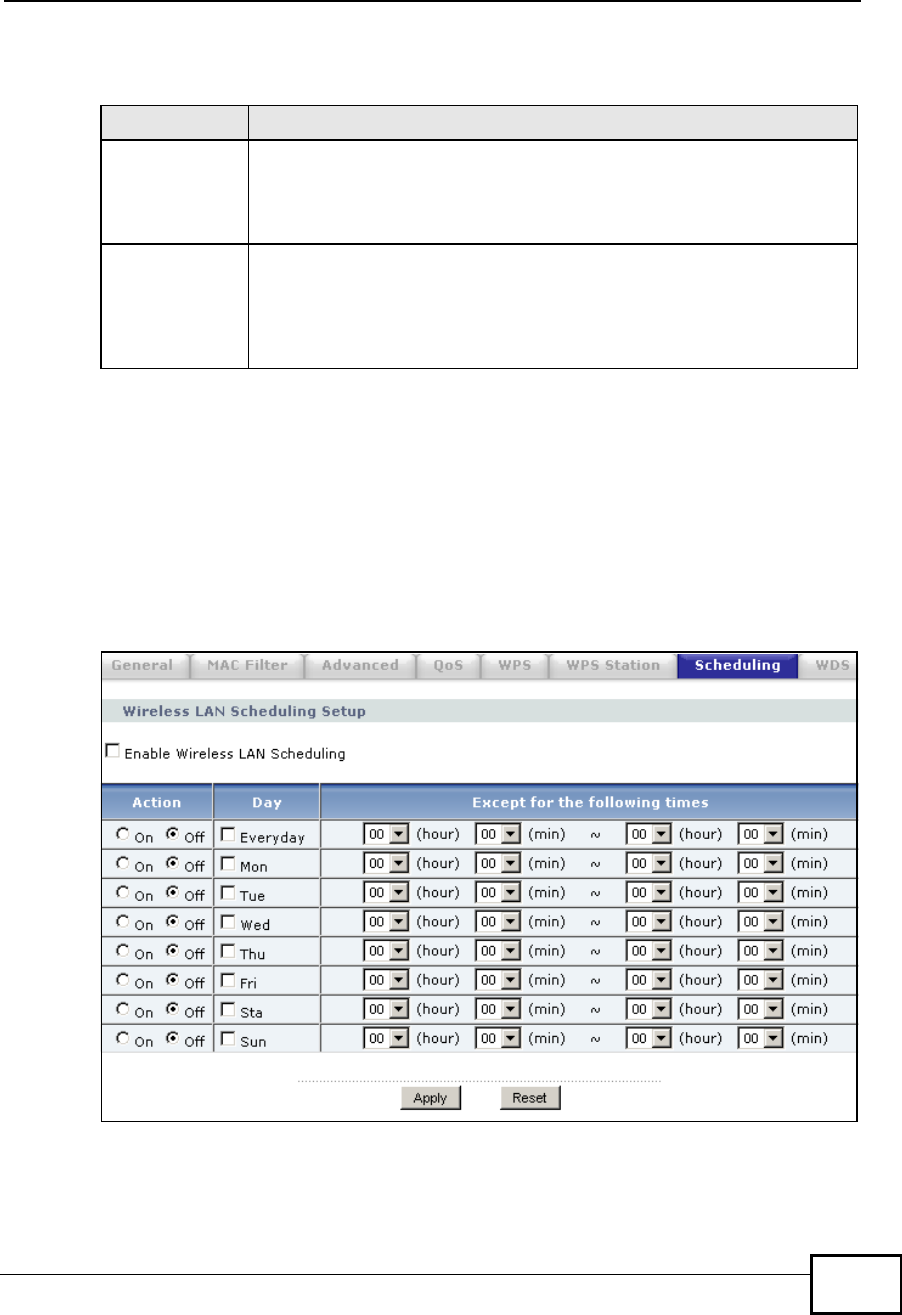
Chapter 7Wireless LAN
NBG4604 User’s Guide 95
The following table describes the labels in this screen.
7.10 Scheduling Screen
Use this screen to set the times your wireless LAN is turned on and off. Wireless
LAN scheduling is disabled by default. The wireless LAN can be scheduled to turn
on or off on certain days and at certain times. To open this screen, click Network
>Wireless LAN > Scheduling tab.
Figure 51 Network > Wireless LAN > Scheduling
Table 33 Network > Wireless LAN > WPS Station
LABEL DESCRIPTION
Push Button Use this button when you use the PBC (Push Button Configuration)
method to configure wireless stations’s wireless settings.
Click this to start WPS-aware wireless station scanning and the wireless
security information synchronization.
Or input
station’s PIN
number
Use this button when you use the PIN Configuration method to
configure wireless station’s wireless settings.
Type the same PIN number generated in the wireless station’s utility.
Then click Start to associate to each other and perform the wireless
security information synchronization.
Company Confidential

Chapter 7Wireless LAN
NBG4604 User’s Guide
96
The following table describes the labels in this screen.
7.11 WDS Screen
A Wireless Distribution System is a wireless connection between two or more APs.
Use this screen to set the operating mode of your NBG4604 to AP + Bridge or
Bridge Only and establish wireless links with other APs. You need to know the
MAC address of the peer device, which also must be in bridge mode.
Note: You must enable the same wireless security settings on the NBG4604 and on
all wireless clients that you want to associate with it.
Table 34 Network > Wireless LAN > Scheduling
LABEL DESCRIPTION
Enable Wireless
LAN Scheduling Select this to enable Wireless LAN scheduling.
Action Select On or Off to specify whether the Wireless LAN is turned on or off.
This field works in conjunction with the Day and Except for the
following times fields.
Day Select Everyday or the specific days to turn the Wireless LAN on or off.
If you select Everyday you can not select any specific days. This field
works in conjunction with the Except for the following times field.
Except for the
following times
(24-Hour
Format)
Select a begin time using the first set of hour and minute (min) drop
down boxes and select an end time using the second set of hour and
minute (min) drop down boxes. If you have chosen On earlierfor the
WLAN Status the Wireless LAN will turn off between the two times you
enter in these fields. If you have chosen Off earlierfor the WLAN Status
the Wireless LAN will turn on between the two times you enter in these
fields.
Note: Entering the same begin time and end time will mean the
whole day.
Apply Click Apply to save your changes back to the NBG4604.
Reset Click Reset to reload the previous configuration for this screen.
Company Confidential
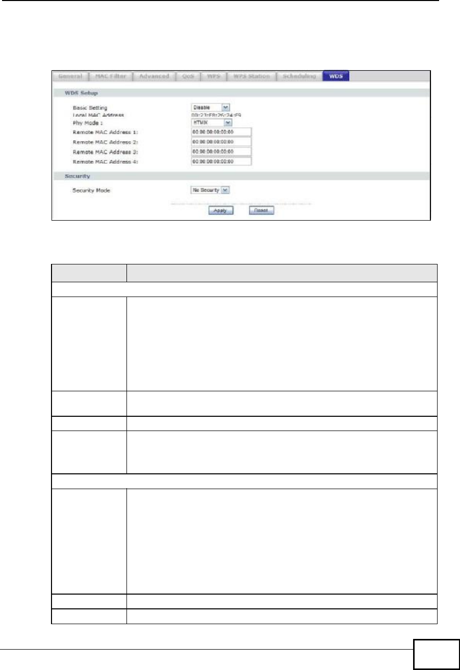
Chapter 7Wireless LAN
NBG4604 User’s Guide 97
Click Network > Wireless LAN > WDS tab. The following screen opens with the
Basic Setting set to Disabled, and Security Mode set to No Security.
Figure 52 Network > Wireless LAN > WDS
The following table describes the labels in this screen.
Table 35 Network > Wireless LAN > WDS
LABEL DESCRIPTION
WDS Setup
Basic Settings Select the operating mode for your NBG4604.
•AP + Bridge - The NBG4604 functions as a bridge and access point
simultaneously.
•Bridge - The NBG4604 acts as a wireless network bridge and
establishes wireless links with other APs. You need to know the MAC
address of the peer device, which also must be in bridge mode. The
NBG4604 can establish up to five wireless links with other APs.
Select Disable if you do not want to use this feature.
Local MAC
Address This is the MAC address of your NBG4604.
Phy Mode Select a WDS physical layer transceiver mode.
Remote MAC
Address This is the MAC address of the peer device that your NBG4604 wants to
make a bridge connection with.
You can connect to up to 4 peer devices.
Security
Security Mode Note: WDS security is independent of the security settings
between the NBG4604 and any wireless clients.
The WDS is set to No Security by default.
•Refer to Section 7.11.1 on page 98 to view the screen for Static
WEP security.
•Refer to Section 7.11.2 on page 99 to view the screen for WPA2-
PSK security.
Apply Click Apply to save your changes to NBG4604.
Refresh Click Refresh to reload the previous configuration for this screen.
Company Confidential
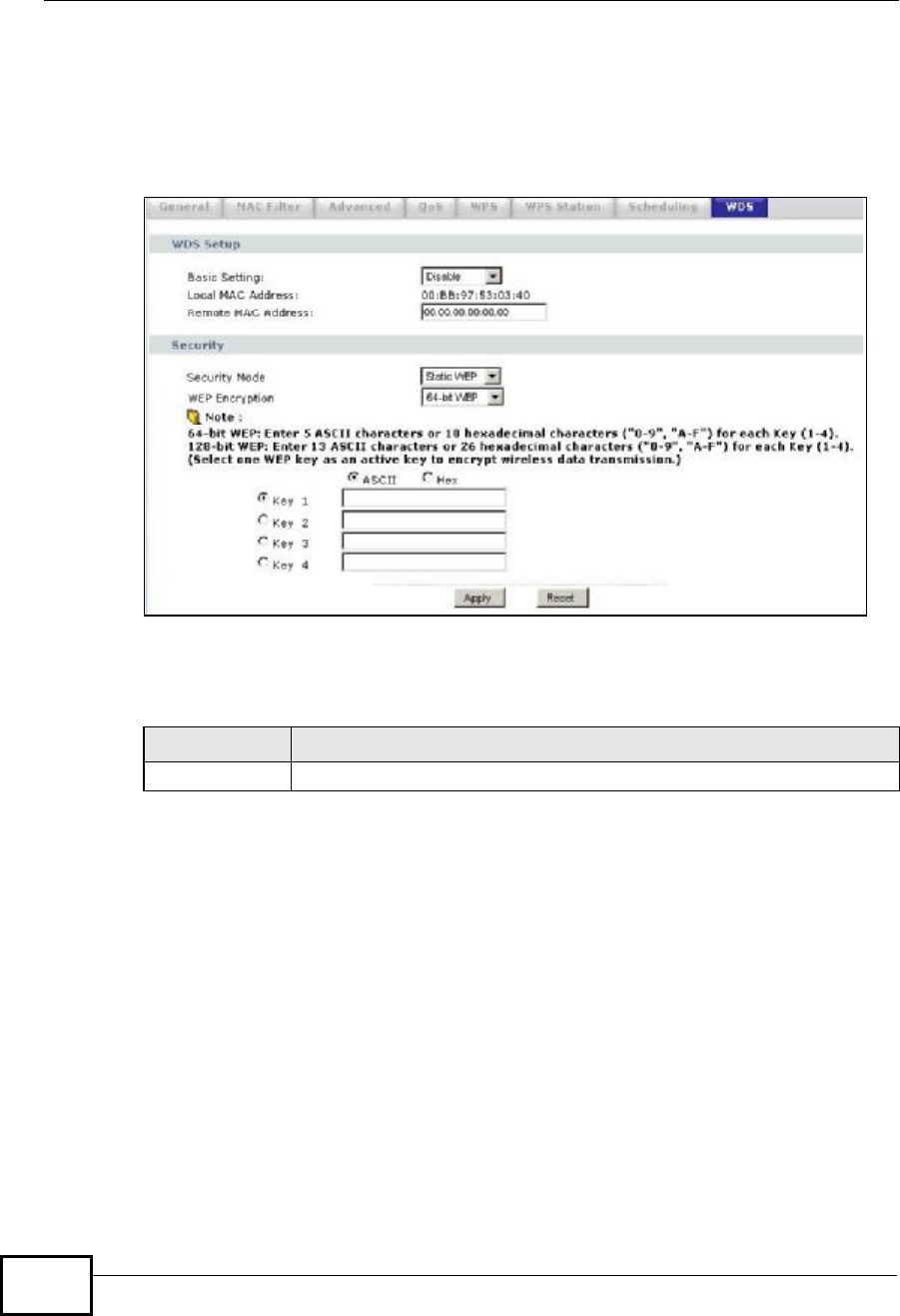
Chapter 7Wireless LAN
NBG4604 User’s Guide
98
7.11.1 Security Mode: Static WEP
Use this screen to configure the Static WEP security for your NBG4604 when it is
in AP + Bridge or Bridge Only mode.
Figure 53 Network > Wireless LAN > WDS (Static WEP)
The following table describes the labels in this screen. Refer to Table 35 on page
97 for descriptions of other fields in this screen.
Table 36 Network > Wireless LAN > WDS (Static WEP)
LABEL DESCRIPTION
WEP Encryption Select 64-bit WEP or 128-bit WEP to enable data encryption.
Company Confidential

Chapter 7Wireless LAN
NBG4604 User’s Guide 99
7.11.2 Security Mode: WPA-PSK/WPA2-PSK
Use this screen to configure the WPA-PSK or WPA2-PSK security for your
NBG4604 when it is in AP + Bridge or Bridge Only mode.
Figure 54 Network > Wireless LAN > WDS (WPA-PSK/WPA2-PSK)
Authentication
Method There are two types of WEP authentication namely, Open System and
Shared Key.
Open system is implemented for ease-of-use and when security is not
an issue. The wireless station and the AP or peer computer do not share
a secret key. Thus the wireless stations can associate with any AP or
peer computer and listen to any transmitted data that is not encrypted.
Shared key mode involves a shared secret key to authenticate the
wireless station to the AP or peer computer. This requires you to enable
the wireless LAN security and use same settings on both the wireless
station and the AP or peer computer.
•Select Shared Key to have the NBG4604 authenticate only those
wireless clients that use Shared Key mode and have the correct WEP
key.
•Select Auto to have the NBG4604 allow association with wireless
clients that use Open System mode. Data transfer is encrypted as
long as the wireless client has the correct WEP key for encryption.
The NBG4604 authenticates wireless clients using Shared Key mode
that have the correct WEP key.
ASCII/HEX
Keys 1 to 4t
The WEP keys are used to encrypt data. Both the NBG4604 and the
wireless stations must use the same WEP key for data transmission.
If you chose 64-bit WEP, then enter any 5 ASCII characters or 10
hexadecimal characters ("0-9", "A-F").
If you chose 128-bit WEP, then enter 13 ASCII characters or 26
hexadecimal characters ("0-9", "A-F").
You must configure all four keys, but only one key can be activated at
any one time. The default key is key 1.
Table 36 Network > Wireless LAN > WDS (Static WEP)
LABEL DESCRIPTION
Company Confidential

Chapter 7Wireless LAN
NBG4604 User’s Guide
100
The following table describes the labels in this screen. Refer to Table 35 on page
97 for descriptions of other fields in this screen.
Table 37 Network > Wireless LAN > WDS (WPA-PSK/WPA2-PSK)
LABEL DESCRIPTION
Pre-Shared Key Type a pre-shared key from 8 to 63 case-sensitive ASCII characters
(including spaces and symbols).
Company Confidential
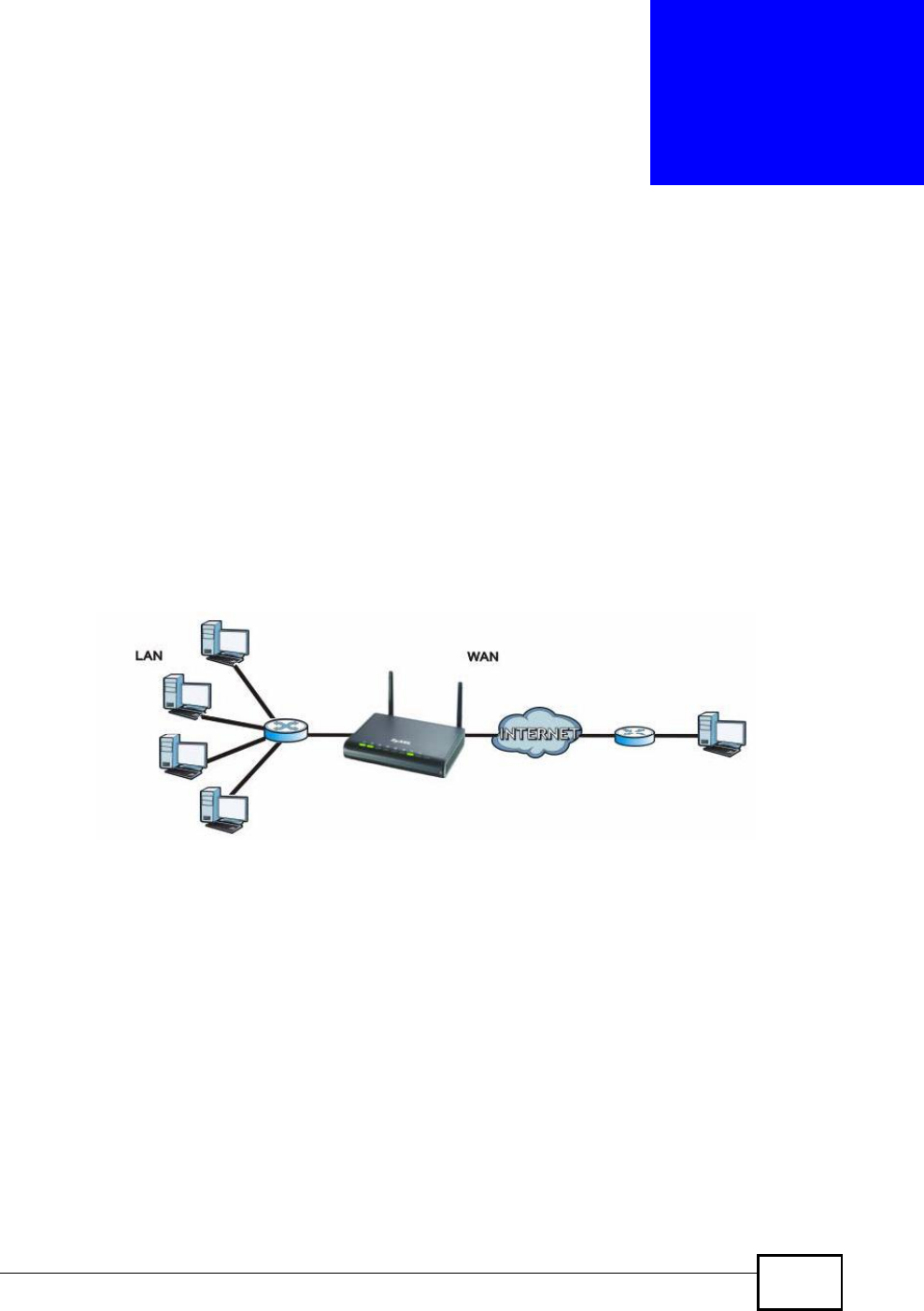
NBG4604 User’s Guide 101
CHAPTER 8
WAN
8.1 Overview
This chapter discusses the NBG4604’s WAN screens. Use these screens to
configure your NBG4604 for Internet access.
A WAN (Wide Area Network) connection is an outside connection to another
network or the Internet. It connects your private networks (such as a LAN (Local
Area Network) and other networks, so that a computer in one location can
communicate with computers in other locations.
Figure 55 LAN and WAN
See the chapter about the connection wizard for more information on the fields in
the WAN screens.
8.2 What You Can Do
•Use the Internet Connection screen (Section 8.4 on page 105) to enter your
ISP information and set how the computer acquires its IP, DNS and WAN MAC
addresses.
•Use the Advanced screen (Section 8.5 on page 111) to enable multicasting,
configure Windows networking and bridge.
Company Confidential

Chapter 8WAN
NBG4604 User’s Guide
102
8.3 What You Need To Know
The information in this section can help you configure the screens for your WAN
connection, as well as enable/disable some advanced features of your NBG4604.
8.3.1 Configuring Your Internet Connection
Encapsulation Method
Encapsulation is used to include data from an upper layer protocol into a lower
layer protocol. To set up a WAN connection to the Internet, you need to use the
same encapsulation method used by your ISP (Internet Service Provider). If your
ISP offers a dial-up Internet connection using PPPoE (PPP over Ethernet) or PPTP
(Point-to-Point Tunneling Protocol), they should also provide a username and
password (and service name) for user authentication.
WAN IP Address
The WAN IP address is an IP address for the NBG4604, which makes it accessible
from an outside network. It is used by the NBG4604 to communicate with other
devices in other networks. It can be static (fixed) or dynamically assigned by the
ISP each time the NBG4604 tries to access the Internet.
If your ISP assigns you a static WAN IP address, they should also assign you the
subnet mask and DNS server IP address(es) (and a gateway IP address if you use
the Ethernet or ENET ENCAP encapsulation method).
DNS Server Address Assignment
Use Domain Name System (DNS) to map a domain name to its corresponding IP
address and vice versa, for instance, the IP address of www.zyxel.com is
204.217.0.2. The DNS server is extremely important because without it, you must
know the IP address of a computer before you can access it.
The NBG4604 can get the DNS server addresses in the following ways.
1The ISP tells you the DNS server addresses, usually in the form of an information
sheet, when you sign up. If your ISP gives you DNS server addresses, manually
enter them in the DNS server fields.
2If your ISP dynamically assigns the DNS server IP addresses (along with the
NBG4604’s WAN IP address), set the DNS server fields to get the DNS server
address from the ISP.
Company Confidential
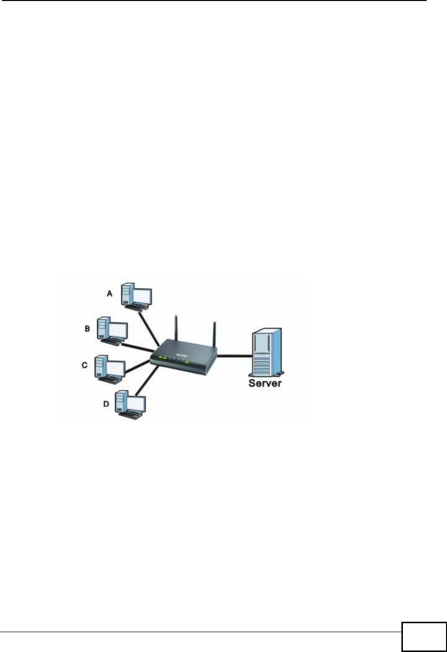
Chapter 8WAN
NBG4604 User’s Guide 103
WAN MAC Address
The MAC address screen allows users to configure the WAN port's MAC address by
either using the factory default or cloning the MAC address from a computer on
your LAN. Choose Factory Default to select the factory assigned default MAC
Address.
Otherwise,click Clone the computer's MAC address - IP Address and enter
the IP address of the computer on the LAN whose MAC you are cloning. Once it is
successfully configured, the address will be copied to configuration file. It is
recommended that you clone the MAC address prior to hooking up the WAN Port.
8.3.2 Multicast
Traditionally, IP packets are transmitted in one of either two ways - Unicast (1
sender - 1 recipient) or Broadcast (1 sender - everybody on the network).
Multicast delivers IP packets to a group of hosts on the network - not everybody
and not just 1.
Figure 56 Multicast Example
In the multicast example above, systems A and D comprise one multicast group.
In multicasting, the server only needs to send one data stream and this is
delivered to systems A and D.
IGMP (Internet Group Multicast Protocol) is a network-layer protocol used to
establish membership in a multicast group - it is not used to carry user data. The
NBG4604 supports both IGMP version 1 (IGMP-v1) and IGMP version 2 (IGMP-
v2).
At start up, the NBG4604 queries all directly connected networks to gather group
membership. After that, the NBG4604 periodically updates this information. IP
multicasting can be enabled/disabled on the NBG4604 LAN and/or WAN interfaces
in the Web Configurator (LAN; WAN). Select None to disable IP multicasting on
these interfaces.
Company Confidential
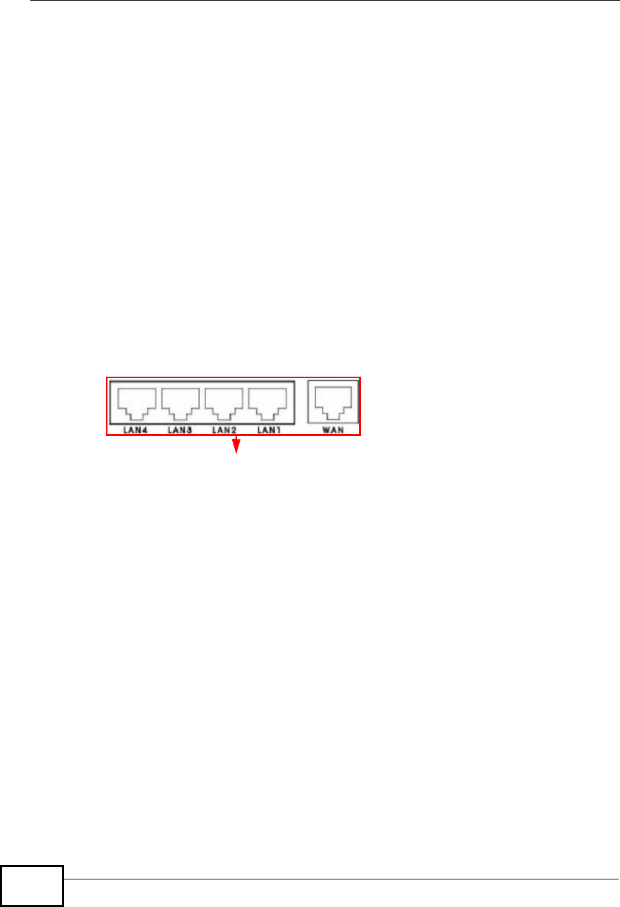
Chapter 8WAN
NBG4604 User’s Guide
104
8.3.3 NetBIOS over TCP/IP
NetBIOS (Network Basic Input/Output System) are TCP or UDP broadcast packets
that enable a computer to connect to and communicate with a LAN. For some dial-
up services such as PPPoE or PPTP, NetBIOS packets cause unwanted calls.
However it may sometimes be necessary to allow NetBIOS packets to pass
through to the WAN in order to find a computer on the WAN.
8.3.4 Auto-Bridge
In the rear panel of your NBG4604, you can see four LAN ports (1 to 4) and one
WAN port. The WAN port is for your Internet access connection, and the LAN ports
are for your network devices. The WAN port has a different IP address from the
LAN ports.
When you enable auto-bridging in your NBG4604, all five ports (4 LAN ports and
the WAN port) share the same IP address as shown in the figure below.
Figure 57 Autobridging Example
This might happen if you put the NBG4604 behind a NAT router that assigns it this
IP address. When the NBG4604 is in auto-bridge mode, the NBG4604 acts as an
AP and all the interfaces (LAN, WAN and WLAN) are bridged. In this mode, your
NAT, DHCP server and firewall on the NBG4604 are not available. You do not have
to reconfigure them if you return to router mode.
Auto-bridging only works under the following conditions:
•The WAN IP must be 192.168.x.y (where x and y must be from zero to nine). If
the LAN IP address and the WAN IP address are in the same subnet but x or y
is greater than nine, the device operates in router mode (with firewall
available).
•The device must be in Router Mode (see Chapter 24 on page 193 for more
information) for auto-bridging to become active.
IP Address: 192.168.1.20
Company Confidential
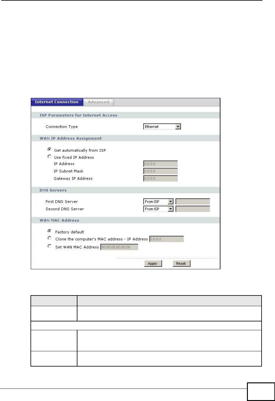
Chapter 8WAN
NBG4604 User’s Guide 105
8.4 Internet Connection
Use this screen to change your NBG4604’s Internet access settings. Click
Network > WAN. The screen differs according to the encapsulation you choose.
8.4.1 Ethernet Encapsulation
This screen displays when you select Ethernet encapsulation.
Figure 58 Network > WAN > Internet Connection: Ethernet Encapsulation
The following table describes the labels in this screen.
Table 38 Network > WAN > Internet Connection: Ethernet Encapsulation
LABEL DESCRIPTION
Connection Type You must choose the Ethernet option when the WAN port is used as a
regular Ethernet.
WAN IP Address Assignment
Get
automatically
from ISP
Select this option If your ISP did not assign you a fixed IP address. This
is the default selection.
Use Fixed IP
Address Select this option If the ISP assigned a fixed IP address.
Company Confidential

Chapter 8WAN
NBG4604 User’s Guide
106
8.4.2 PPPoE Encapsulation
The NBG4604 supports PPPoE (Point-to-Point Protocol over Ethernet). PPPoE is an
IETF standard (RFC 2516) specifying how a personal computer (PC) interacts with
a broadband modem (DSL, cable, wireless, etc.) connection. The PPP over
Ethernet option is for a dial-up connection using PPPoE.
For the service provider, PPPoE offers an access and authentication method that
works with existing access control systems (for example Radius).
IP Address Enter your WAN IP address in this field if you selected Use Fixed IP
Address.
IP Subnet
Mask Enter the IP Subnet Mask in this field.
Gateway IP
Address Enter a Gateway IP Address (if your ISP gave you one) in this field.
DNS Servers
First DNS Server
Second DNS
Server
Select From ISP if your ISP dynamically assigns DNS server
information (and the NBG4604's WAN IP address). The field to the right
displays the (read-only) DNS server IP address that the ISP assigns.
Select User-Defined if you have the IP address of a DNS server. Enter
the DNS server's IP address in the field to the right. If you chose User-
Defined, but leave the IP address set to 0.0.0.0, User-Defined
changes to None after you click Apply. If you set a second choice to
User-Defined, and enter the same IP address, the second User-
Defined changes to None after you click Apply.
Select None if you do not want to configure DNS servers. If you do not
configure a DNS server, you must know the IP address of a computer in
order to access it.
WAN MAC
Address The MAC address section allows users to configure the WAN port's MAC
address by either using the NBG4604’s MAC address, copying the MAC
address from a computer on your LAN or manually entering a MAC
address.
Factory default Select Factory default to use the factory assigned default MAC
Address.
Clone the
computer’s MAC
address - IP
Address
Select Clone the computer's MAC address - IP Address and enter
the IP address of the computer on the LAN whose MAC you are cloning.
Once it is successfully configured, the address will be copied to the rom
file. It will not change unless you change the setting or upload a
different ROM file.
Set WAN MAC
Address Select this option and enter the MAC address you want to use.
Apply Click Apply to save your changes back to the NBG4604.
Reset Click Reset to begin configuring this screen afresh.
Table 38 Network > WAN > Internet Connection: Ethernet Encapsulation
LABEL DESCRIPTION
Company Confidential
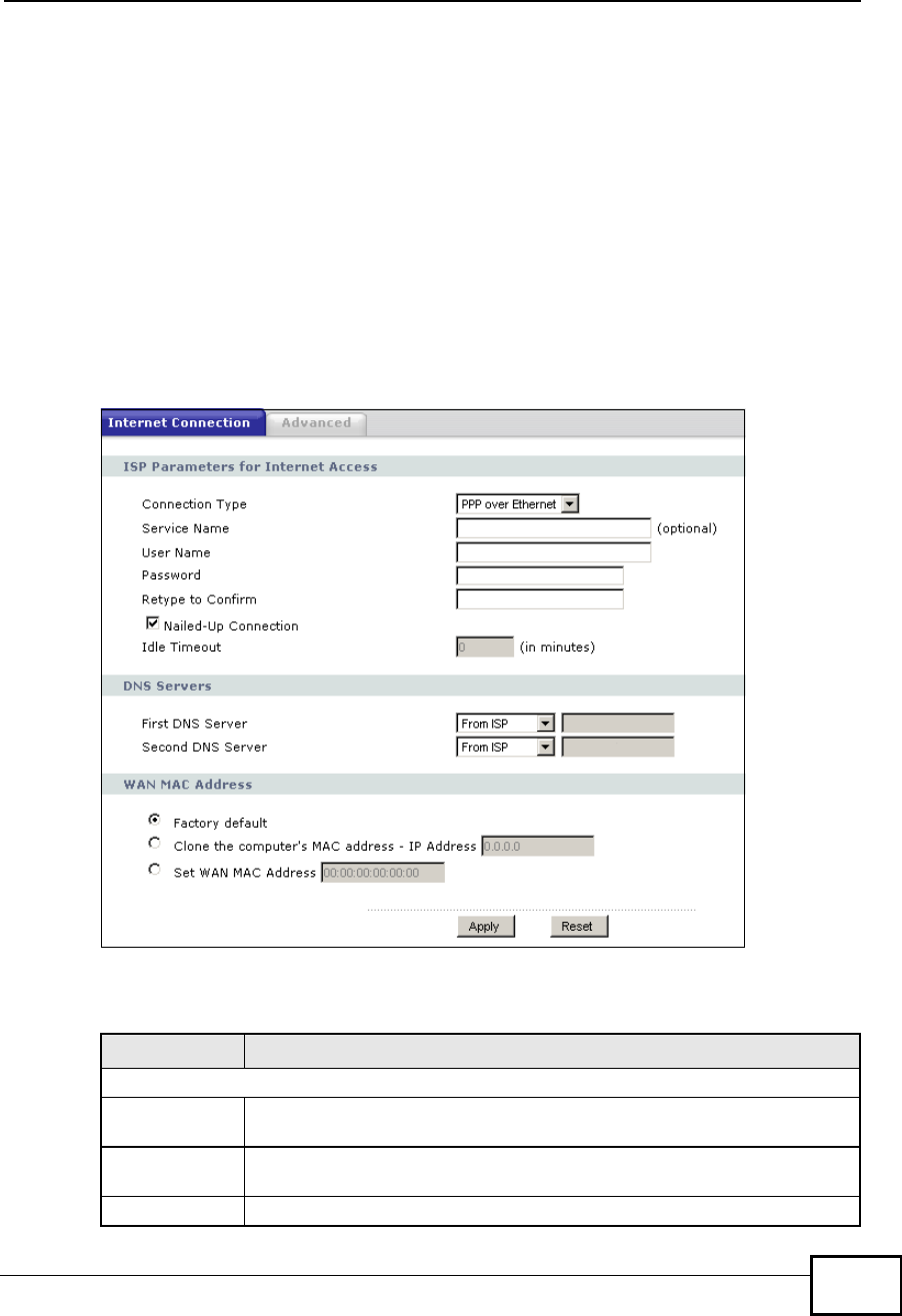
Chapter 8WAN
NBG4604 User’s Guide 107
One of the benefits of PPPoE is the ability to let you access one of multiple network
services, a function known as dynamic service selection. This enables the service
provider to easily create and offer new IP services for individuals.
Operationally, PPPoE saves significant effort for both you and the ISP or carrier, as
it requires no specific configuration of the broadband modem at the customer site.
By implementing PPPoE directly on the NBG4604 (rather than individual
computers), the computers on the LAN do not need PPPoE software installed,
since the NBG4604 does that part of the task. Furthermore, with NAT, all of the
LANs’ computers will have access.
This screen displays when you select PPPoE encapsulation.
Figure 59 Network > WAN > Internet Connection: PPPoE Encapsulation
The following table describes the labels in this screen.
Table 39 Network > WAN > Internet Connection: PPPoE Encapsulation
LABEL DESCRIPTION
ISP Parameters for Internet Access
Connection
Type Select PPP over Ethernet if you connect to your Internet via dial-up.
Service Name Type the PPPoE service name provided to you. PPPoE uses a service
name to identify and reach the PPPoE server.
User Name Type the user name given to you by your ISP.
Company Confidential

Chapter 8WAN
NBG4604 User’s Guide
108
8.4.3 PPTP Encapsulation
Point-to-Point Tunneling Protocol (PPTP) is a network protocol that enables secure
transfer of data from a remote client to a private server, creating a Virtual Private
Network (VPN) using TCP/IP-based networks.
PPTP supports on-demand, multi-protocol and virtual private networking over
public networks, such as the Internet.
Password Type the password associated with the user name above.
Retype to
Confirm Type your password again to make sure that you have entered is
correctly.
Nailed-Up
Connection Select Nailed-Up Connection if you do not want the connection to time
out.
Idle Timeout This value specifies the time in minutes that elapses before the router
automatically disconnects from the PPPoE server.
DNS Servers
First DNS
Server
Second DNS
Server
Select From ISP if your ISP dynamically assigns DNS server information
(and the NBG4604's WAN IP address). The field to the right displays the
(read-only) DNS server IP address that the ISP assigns.
Select User-Defined if you have the IP address of a DNS server. Enter
the DNS server's IP address in the field to the right. If you chose User-
Defined, but leave the IP address set to 0.0.0.0, User-Defined
changes to None after you click Apply. If you set a second choice to
User-Defined, and enter the same IP address, the second User-
Defined changes to None after you click Apply.
Select None if you do not want to configure DNS servers. If you do not
configure a DNS server, you must know the IP address of a computer in
order to access it.
WAN MAC
Address The MAC address section allows users to configure the WAN port's MAC
address by using the NBG4604’s MAC address, copying the MAC address
from a computer on your LAN or manually entering a MAC address.
Factory default Select Factory default to use the factory assigned default MAC
Address.
Clone the
computer’s
MAC address -
IP Address
Select Clone the computer's MAC address - IP Address and enter
the IP address of the computer on the LAN whose MAC you are cloning.
Once it is successfully configured, the address will be copied to the rom
file. It will not change unless you change the setting or upload a
different ROM file.
Set WAN MAC
Address Select this option and enter the MAC address you want to use.
Apply Click Apply to save your changes back to the NBG4604.
Reset Click Reset to begin configuring this screen afresh.
Table 39 Network > WAN > Internet Connection: PPPoE Encapsulation
LABEL DESCRIPTION
Company Confidential
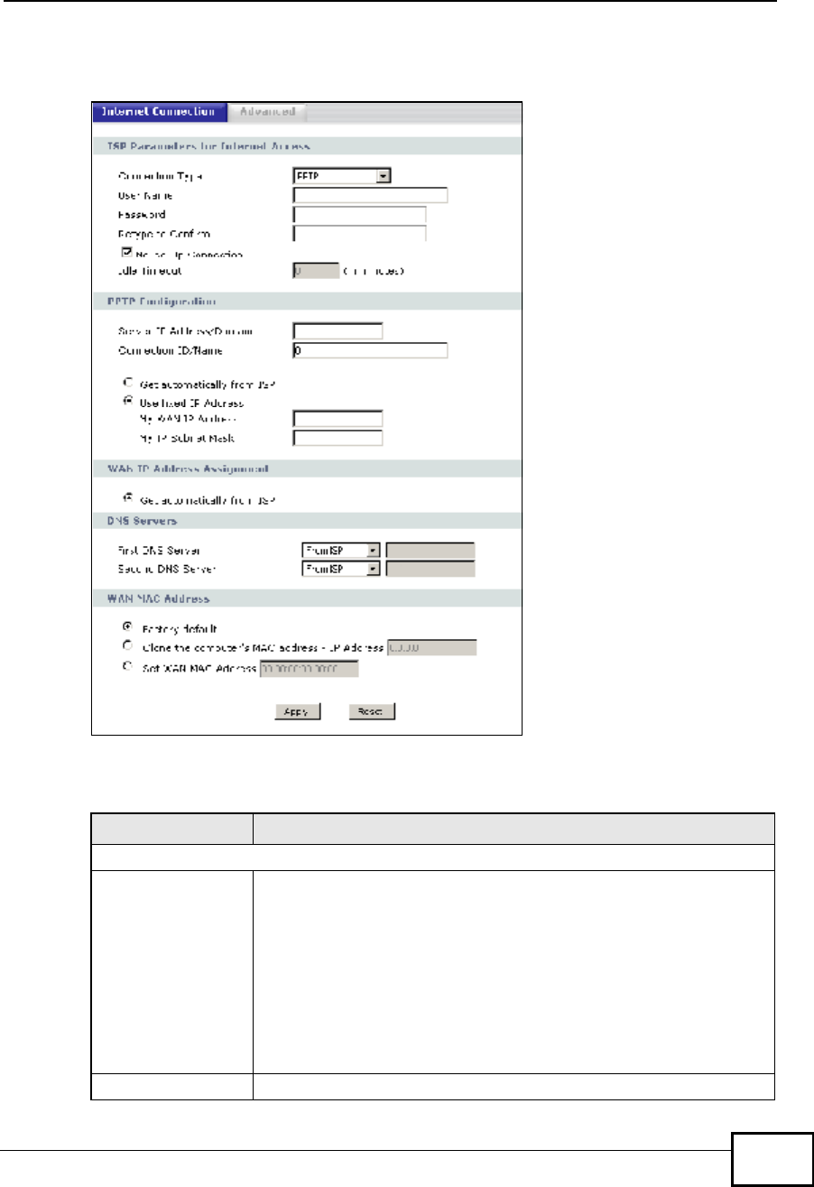
Chapter 8WAN
NBG4604 User’s Guide 109
This screen displays when you select PPTP encapsulation.
Figure 60 Network > WAN > Internet Connection: PPTP Encapsulation
The following table describes the labels in this screen.
Table 40 Network > WAN > Internet Connection: PPTP Encapsulation
LABEL DESCRIPTION
ISP Parameters for Internet Access
Connection Type Point-to-Point Tunneling Protocol (PPTP) is a network protocol that
enables secure transfer of data from a remote client to a private
server, creating a Virtual Private Network (VPN) using TCP/IP-based
networks. PPTP supports on-demand, multi-protocol, and virtual
private networking over public networks, such as the Internet. The
NBG4604 supports only one PPTP server connection at any given
time.
To configure a PPTP client, you must configure the User Name and
Password fields for a PPP connection and the PPTP parameters for
a PPTP connection.
User Name Type the user name given to you by your ISP.
Company Confidential

Chapter 8WAN
NBG4604 User’s Guide
110
Password Type the password associated with the User Name above.
Retype to Confirm Type your password again to make sure that you have entered is
correctly.
Nailed-up
Connection Select Nailed-Up Connection if you do not want the connection to
time out.
Idle Timeout This value specifies the time in minutes that elapses before the
NBG4604 automatically disconnects from the PPTP server.
PPTP Configuration
Server IP Address/
Domain Type the IP address of the PPTP server.
Connection ID/
Name Type your identification name for the PPTP server.
Get automatically
from ISP Select this option If your ISP did not assign you a fixed IP address.
This is the default selection.
Use Fixed IP
Address Select this option If the ISP assigned a fixed IP address.
My WAN IP
Address Enter your WAN IP address in this field if you selected Use Fixed IP
Address.
My IP Subnet
Mask Your NBG4604 will automatically calculate the subnet mask based
on the IP address that you assign. Unless you are implementing
subnetting, use the subnet mask computed by the NBG4604.
WAN IP Address Assignment
Get automatically
from ISP Select this to get your WAN IP address from your ISP.
DNS Servers
First DNS Server
Second DNS Server
Select From ISP if your ISP dynamically assigns DNS server
information (and the NBG4604's WAN IP address). The field to the
right displays the (read-only) DNS server IP address that the ISP
assigns.
Select User-Defined if you have the IP address of a DNS server.
Enter the DNS server's IP address in the field to the right. If you
chose User-Defined, but leave the IP address set to 0.0.0.0, User-
Defined changes to None after you click Apply. If you set a second
choice to User-Defined, and enter the same IP address, the
second User-Defined changes to None after you click Apply.
Select None if you do not want to configure DNS servers. If you do
not configure a DNS server, you must know the IP address of a
computer in order to access it.
WAN MAC Address The MAC address section allows users to configure the WAN port's
MAC address by either using the NBG4604’s MAC address, copying
the MAC address from a computer on your LAN or manually entering
a MAC address.
Factory default Select Factory default to use the factory assigned default MAC
Address.
Table 40 Network > WAN > Internet Connection: PPTP Encapsulation
LABEL DESCRIPTION
Company Confidential
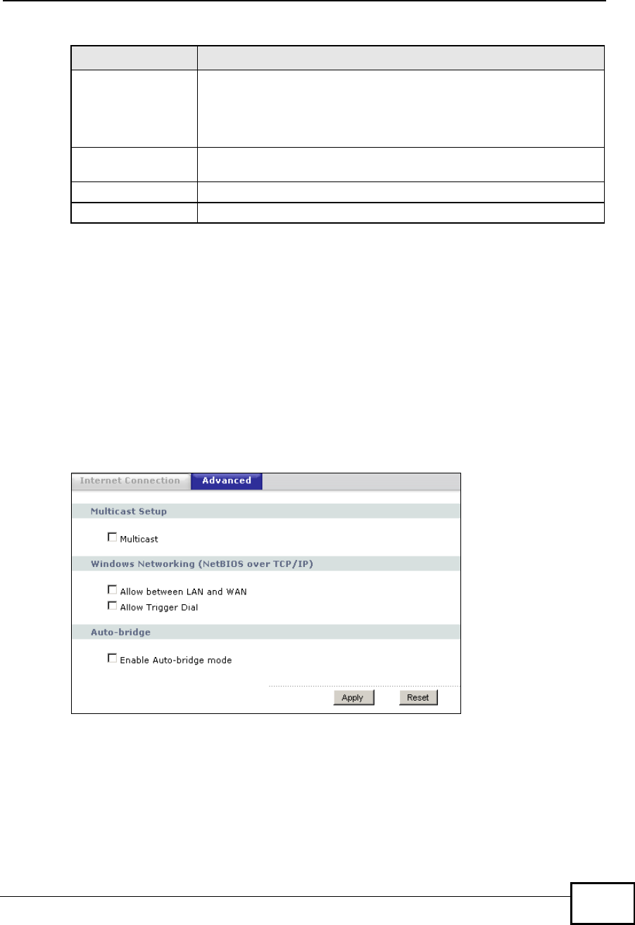
Chapter 8WAN
NBG4604 User’s Guide 111
8.5 Advanced WAN Screen
Use this screen to enable Multicast, allow Windows Networking and enable
Auto-bridge.
Note: The three categories shown in this screen are independent of each other.
To change your NBG4604’s advanced WAN settings, click Network > WAN >
Advanced. The screen appears as shown.
Figure 61 Network > WAN > Advanced
Clone the
computer’s MAC
address - IP
Address
Select Clone the computer's MAC address - IP Address and
enter the IP address of the computer on the LAN whose MAC you
are cloning. Once it is successfully configured, the address will be
copied to the rom file. It will not change unless you change the
setting or upload a different ROM file.
Set WAN MAC
Address Select this option and enter the MAC address you want to use.
Apply Click Apply to save your changes back to the NBG4604.
Reset Click Reset to begin configuring this screen afresh.
Table 40 Network > WAN > Internet Connection: PPTP Encapsulation
LABEL DESCRIPTION
Company Confidential

Chapter 8WAN
NBG4604 User’s Guide
112
The following table describes the labels in this screen.
Table 41 Network > WAN > Advanced
LABEL DESCRIPTION
Multicast Setup
Multicast Check this to enable multicasting. This applies to traffic routed from
the WAN to the LAN.
Leaving this blank may cause incoming traffic to be dropped or sent
to all connected network devices.
Windows Networking (NetBIOS over TCP/IP)
Allow between LAN
and WAN Select this check box to forward NetBIOS packets from the LAN to
the WAN and from the WAN to the LAN. If your firewall is enabled
with the default policy set to block WAN to LAN traffic, you also
need to enable the default WAN to LAN firewall rule that forwards
NetBIOS traffic.
Clear this check box to block all NetBIOS packets going from the
LAN to the WAN and from the WAN to the LAN.
Allow Trigger Dial Select this option to allow NetBIOS packets to initiate calls.
Auto-bridge
Enable Auto-bridge
mode Select this option to have the NBG4604 switch to bridge mode
automatically when the NBG4604 gets a WAN IP address in the
range of 192.168.x.y (where x and y are from zero to nine) no
matter what the LAN IP address is.
ApplyClick Apply to save your changes back to the NBG4604.
Reset Click Reset to begin configuring this screen afresh.
Company Confidential
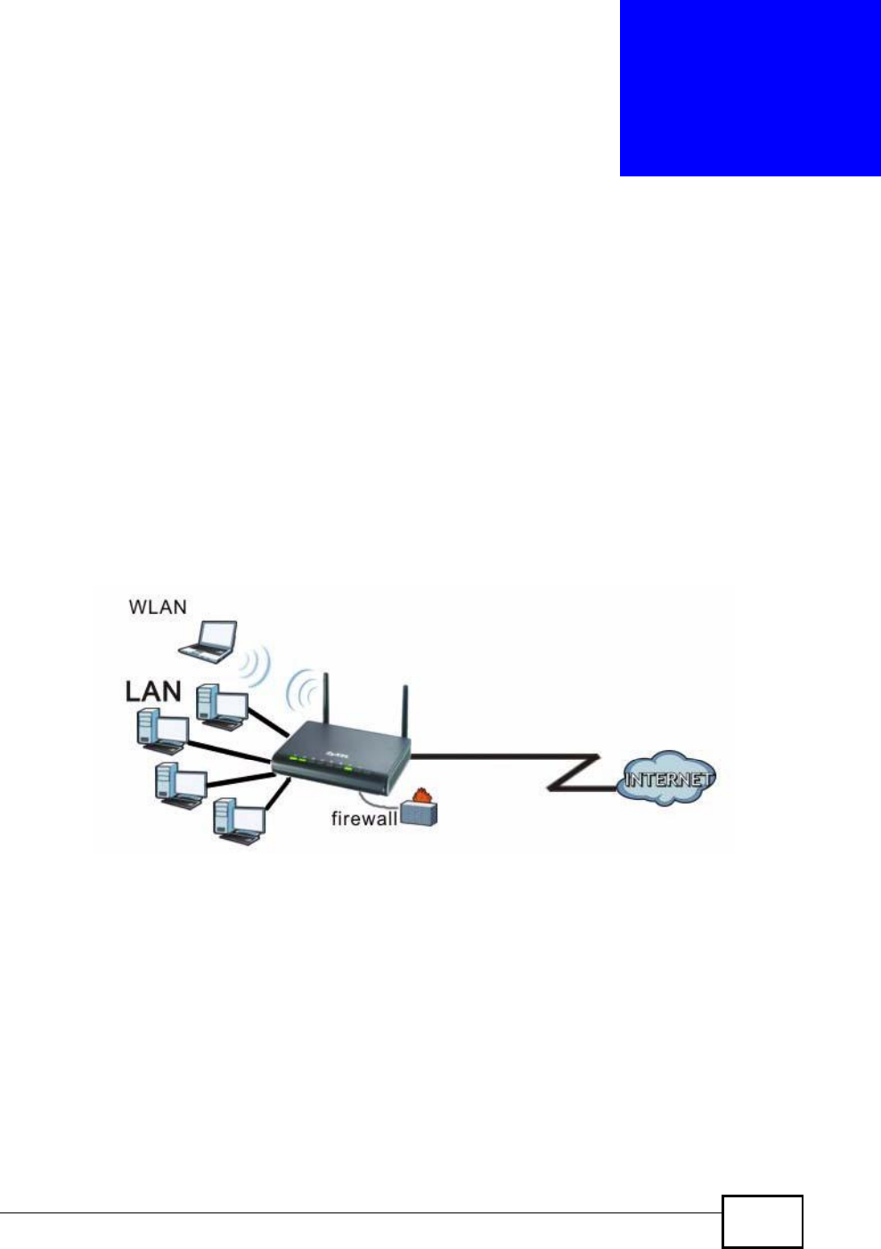
NBG4604 User’s Guide 113
CHAPTER 9
LAN
9.1 Overview
This chapter describes how to configure LAN settings.
A Local Area Network (LAN) is a shared communication system to which many
computers are attached. A LAN is a computer network limited to the immediate
area, usually the same building or floor of a building. The LAN screens can help
you configure a LAN DHCP server, manage IP addresses, and partition your
physical network into logical networks.
Figure 62 LAN Setup
The LAN screens can help you configure a LAN DHCP server and manage IP
addresses.
9.2 What You Can Do
Use the IP screen (Section 9.4 on page 115) to change your basic LAN settings.
Company Confidential
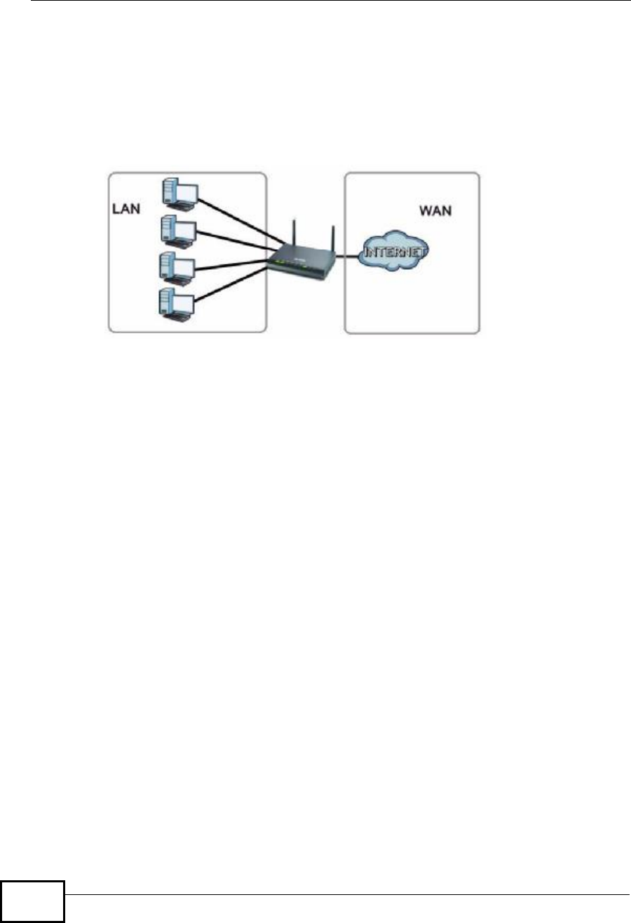
Chapter 9LAN
NBG4604 User’s Guide
114
9.3 What You Need To Know
The actual physical connection determines whether the NBG4604 ports are LAN or
WAN ports. There are two separate IP networks, one inside the LAN network and
the other outside the WAN network as shown next.
Figure 63 LAN and WAN IP Addresses
The LAN parameters of the NBG4604 are preset in the factory with the following
values:
•IP address of 192.168.1.1 with subnet mask of 255.255.255.0 (24 bits)
•DHCP server enabled with 32 client IP addresses starting from 192.168.1.33.
These parameters should work for the majority of installations. If your ISP gives
you explicit DNS server address(es), read the embedded Web Configurator help
regarding what fields need to be configured.
9.3.1 IP Pool Setup
The NBG4604 is pre-configured with a pool of 32 IP addresses starting from
192.168.1.33 to 192.168.1.64. This configuration leaves 31 IP addresses
(excluding the NBG4604 itself) in the lower range (192.168.1.2 to 192.168.1.32)
for other server computers, for instance, servers for mail, FTP, TFTP, web, etc.,
that you may have.
Refer to Section 4.4.6 on page 49 for information on IP Address and Subnet Mask.
9.3.2 LAN TCP/IP
The NBG4604 has built-in DHCP server capability that assigns IP addresses and
DNS servers to systems that support DHCP client capability.
Refer to the Section 4.4.7 on page 50 section for information on System DNS
Servers.
Company Confidential
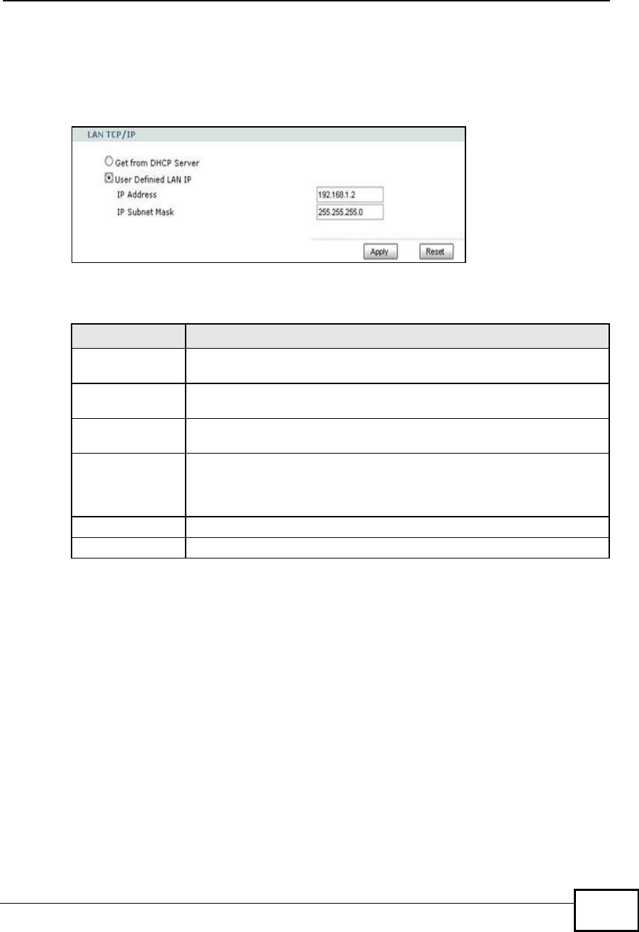
Chapter 9LAN
NBG4604 User’s Guide 115
9.4 LAN IP Screen
Use this screen to change your basic LAN settings. Click Network > LAN.
Figure 64 Network > LAN > IP
The following table describes the labels in this screen.
Table 42 Network > LAN > IP
LABEL DESCRIPTION
Get from DHCP
Server Select this to have your NBG4604 receive its IP address automatically
from a DHCP server.
User Defined LAN
IP Select this to manually enter the IP address and Subnet Mask as they
were provided to you by your network administrator.
IP Address Type the IP address of your NBG4604 in dotted decimal notation
192.168.1.1 (factory default).
IP Subnet
Mask The subnet mask specifies the network number portion of an IP
address. Your NBG4604 will automatically calculate the subnet mask
based on the IP address that you assign. Unless you are implementing
subnetting, use the subnet mask computed by the NBG4604.
Apply Click Apply to save your changes back to the NBG4604.
Reset Click Reset to begin configuring this screen afresh.
Company Confidential

Chapter 9LAN
NBG4604 User’s Guide
116
Company Confidential

NBG4604 User’s Guide 117
CHAPTER 10
DHCP Server
10.1 Overview
DHCP (Dynamic Host Configuration Protocol, RFC 2131 and RFC 2132) allows
individual clients to obtain TCP/IP configuration at start-up from a server. You can
configure the NBG4604’s LAN as a DHCP server or disable it. When configured as a
server, the NBG4604 provides the TCP/IP configuration for the clients. If DHCP
service is disabled, you must have another DHCP server on your LAN, or else the
computer must be manually configured.
10.2 What You Can Do
•Use the General screen (Section 10.4 on page 118) to enable the DHCP server.
•Use the Advanced screen (Section 10.5 on page 118) to assign IP addresses on
the LAN to specific individual computers based on their MAC Addresses.
•Use the Client List screen (Section 10.6 on page 120) to view the current DHCP
client information.
10.3 What You Need To Know
Every Ethernet device has a unique MAC (Media Access Control) address. The MAC
address is assigned at the factory and consists of six pairs of hexadecimal
characters, for example, 00:A0:C5:00:00:02. Find out the MAC addresses of your
network devices if you intend to add them to the DHCP Client List screen.
Refer to Section 4.4.6 on page 49 for information on IP Address and Subnet Mask.
Refer to the Section 4.4.7 on page 50 section for information on System DNS
Servers.
Company Confidential
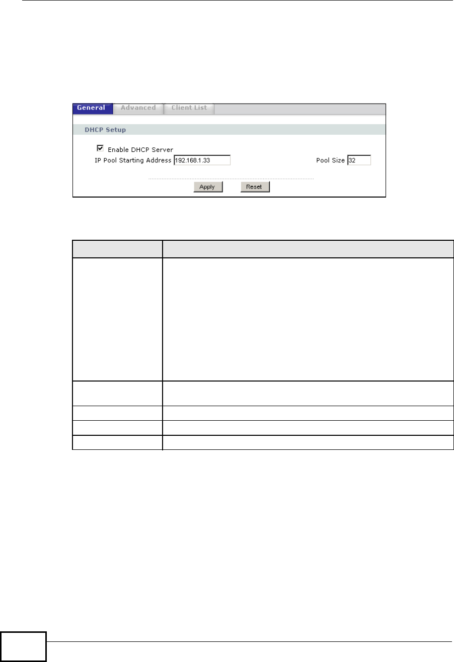
Chapter 10DHCP Server
NBG4604 User’s Guide
118
10.4 General Screen
Use this screen to enable the DHCP server. Click Network > DHCP Server.The
following screen displays.
Figure 65 Network > DHCP Server > General
The following table describes the labels in this screen.
10.5 Advanced Screen
This screen allows you to assign IP addresses on the LAN to specific individual
computers based on their MAC addresses. You can also use this screen to
configure the DNS server information that the NBG4604 sends to the DHCP
clients.
Table 43 Network > DHCP Server > General
LABEL DESCRIPTION
Enable DHCP
Server Enable or Disable DHCP for LAN.
DHCP (Dynamic Host Configuration Protocol, RFC 2131 and RFC
2132) allows individual clients (computers) to obtain TCP/IP
configuration at startup from a server. Leave the Enable DHCP
Server check box selected unless your ISP instructs you to do
otherwise. Clear it to disable the NBG4604 acting as a DHCP server.
When configured as a server, the NBG4604 provides TCP/IP
configuration for the clients. If not, DHCP service is disabled and
you must have another DHCP server on your LAN, or else the
computers must be manually configured. When set as a server, fill in
the following four fields.
IP Pool Starting
Address This field specifies the first of the contiguous addresses in the IP
address pool for LAN.
Pool Size This field specifies the size, or count of the IP address pool for LAN.
Apply Click Apply to save your changes back to the NBG4604.
Reset Click Reset to begin configuring this screen afresh.
Company Confidential
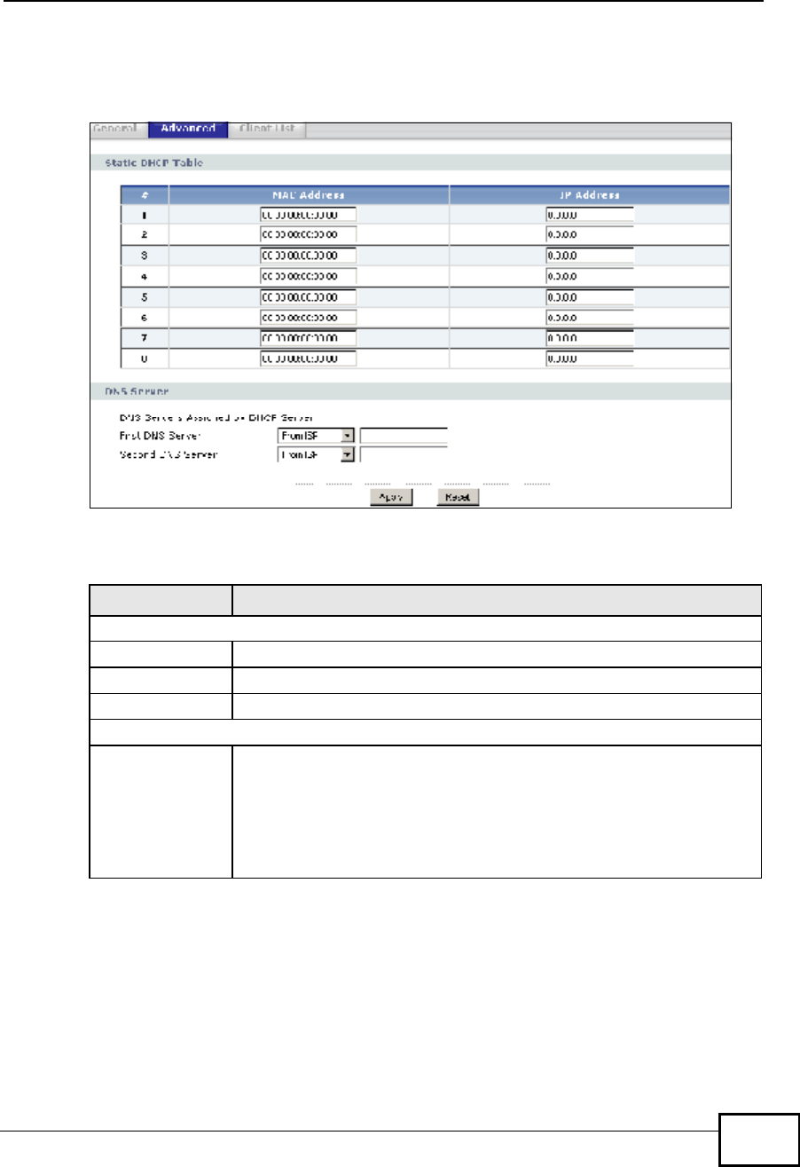
Chapter 10DHCP Server
NBG4604 User’s Guide 119
To change your NBG4604’s static DHCP settings, click Network > DHCP Server
>Advanced. The following screen displays.
Figure 66 Network > DHCP Server > Advanced
The following table describes the labels in this screen.
Table 44 Network > DHCP Server > Advanced
LABEL DESCRIPTION
Static DHCP Table
#This is the index number of the static IP table entry (row).
MAC Address Type the MAC address (with colons) of a computer on your LAN.
IP Address Type the LAN IP address of a computer on your LAN.
DNS Server
DNS Servers
Assigned by
DHCP Server
The NBG4604 passes a DNS (Domain Name System) server IP
address (in the order you specify here) to the DHCP clients. The
NBG4604 only passes this information to the LAN DHCP clients when
you select the Enable DHCP Server check box. When you clear the
Enable DHCP Server check box, DHCP service is disabled and you
must have another DHCP sever on your LAN, or else the computers
must have their DNS server addresses manually configured.
Company Confidential

Chapter 10DHCP Server
NBG4604 User’s Guide
120
10.6 Client List Screen
The DHCP table shows current DHCP client information (including IP Address,
HostName and MAC Address) of network clients using the NBG4604’s DHCP
servers.
Configure this screen to always assign an IP address to a MAC address (and host
name). Click Network > DHCP Server > Client List.
Note: You can also view a read-only client list by clicking the DHCP Table (Details...)
hyperlink in the Status screen.
First DNS Server
Second DNS
Server
Select From ISP if your ISP dynamically assigns DNS server
information (and the NBG4604's WAN IP address). The field to the
right displays the (read-only) DNS server IP address that the ISP
assigns.
Select User-Defined if you have the IP address of a DNS server.
Enter the DNS server's IP address in the field to the right. If you chose
User-Defined, but leave the IP address set to 0.0.0.0, User-Defined
changes to None after you click Apply. If you set a second choice to
User-Defined, and enter the same IP address, the second User-
Defined changes to None after you click Apply.
Select DNS Relay to have the NBG4604 act as a DNS proxy. The
NBG4604's LAN IP address displays in the field to the right (read-
only). The NBG4604 tells the DHCP clients on the LAN that the
NBG4604 itself is the DNS server. When a computer on the LAN sends
a DNS query to the NBG4604, the NBG4604 forwards the query to the
NBG4604's system DNS server (configured in the WAN > Internet
Connection screen) and relays the response back to the computer.
You can only select DNS Relay for one of the three servers; if you
select DNS Relay for a second or third DNS server, that choice
changes to None after you click Apply.
Select None if you do not want to configure DNS servers. If you do
not configure a DNS server, you must know the IP address of a
computer in order to access it.
Apply Click Apply to save your changes back to the NBG4604.
Reset Click Reset to begin configuring this screen afresh.
Table 44 Network > DHCP Server > Advanced
LABEL DESCRIPTION
Company Confidential
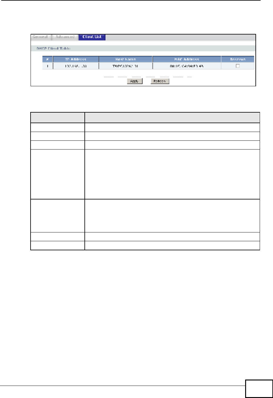
Chapter 10DHCP Server
NBG4604 User’s Guide 121
The following screen displays.
Figure 67 Network > DHCP Server > Client List
The following table describes the labels in this screen.
Table 45 Network > DHCP Server > Client List
LABEL DESCRIPTION
# This is the index number of the host computer.
IP AddressThis field displays the IP address relative to the # field listed above.
Host Name This field displays the computer host name.
MAC AddressThe MAC (Media Access Control) or Ethernet address on a LAN
(Local Area Network) is unique to your computer (six pairs of
hexadecimal notation).
A network interface card such as an Ethernet adapter has a
hardwired address that is assigned at the factory. This address
follows an industry standard that ensures no other adapter has a
similar address.
ReserveSelect this check box in the DHCP Setup section to have the
NBG4604 always assign the IP address(es) to the MAC address(es)
(and host name(s)). After you click Apply, the MAC address and IP
address also display in the Advanced screen (where you can edit
them).
ApplyClick Apply to save your settings.
RefreshClick Refresh to reload the DHCP table.
Company Confidential

Chapter 10DHCP Server
NBG4604 User’s Guide
122
Company Confidential
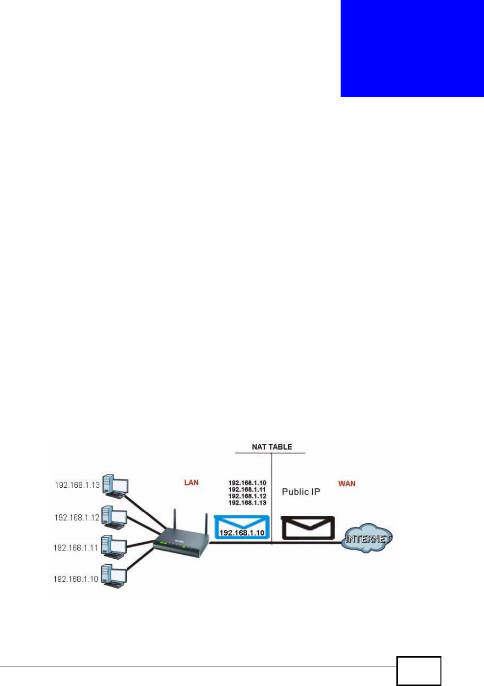
NBG4604 User’s Guide 123
CHAPTER 11
Network Address Translation
(NAT)
11.1 Overview
This chapter discusses how to configure NAT on the NBG4604.
NAT (Network Address Translation - NAT, RFC 1631) is the translation of the IP
address of a host in a packet. For example, the source address of an outgoing
packet, used within one network is changed to a different IP address known within
another network.
Each packet has two addresses – a source address and a destination address. For
outgoing packets, NAT maps private (local) IP addresses to globally unique ones
required for communication with hosts on other networks. It replaces the original
IP source address in each packet and then forwards it to the Internet. The
NBG4604 keeps track of the original addresses and port numbers so incoming
reply packets can have their original values restored. The following figure
illustrates this.
Figure 68 NAT Example
For more information on IP address translation, refer to RFC 1631,The IP Network
Address Translator (NAT).
Company Confidential
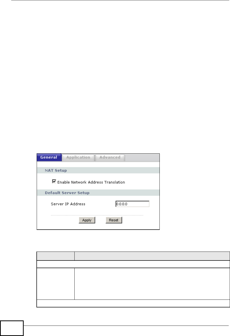
Chapter 11Network Address Translation (NAT)
NBG4604 User’s Guide
124
Note: You must create a firewall rule in addition to setting up NAT, to allow traffic from
the WAN to be forwarded through the NBG4604.
11.2 What You Can Do
•Use the General screen (Section 11.3 on page 124) to enable NAT and set a
default server.
•Use the Application screen (Section 11.4 on page 125) to change your
NBG4604’s port forwarding settings.
•Use the Advanced screen (Section 11.5 on page 128) to change your
NBG4604’s trigger port settings.
11.3 General NAT Screen
Use this screen to enable NAT and set a default server. Click Network > NAT to
open the General screen.
Figure 69 Network > NAT > General
The following table describes the labels in this screen.
Table 46 Network > NAT > General
LABEL DESCRIPTION
NAT Setup
Enable Network
Address
Translation
Network Address Translation (NAT) allows the translation of an Internet
protocol address used within one network (for example a private IP
address used in a local network) to a different IP address known within
another network (for example a public IP address used on the Internet).
Select the check box to enable NAT.
Default Server Setup
Company Confidential

Chapter 11Network Address Translation (NAT)
NBG4604 User’s Guide 125
11.4 NAT Application Screen
Use the Application screen to forward incoming service requests to the server(s)
on your local network. You may enter a single port number or a range of port
numbers to be forwarded, and the local IP address of the desired server. The port
number identifies a service; for example, web service is on port 80 and FTP on
port 21. In some cases, such as for unknown services or where one server can
support more than one service (for example both FTP and web service), it might
be better to specify a range of port numbers.
In addition to the servers for specified services, NAT supports a default server. A
service request that does not have a server explicitly designated for it is forwarded
to the default server. If the default is not defined, the service request is simply
discarded.
Note: Many residential broadband ISP accounts do not allow you to run any server
processes (such as a Web or FTP server) from your location. Your ISP may
periodically check for servers and may suspend your account if it discovers any
active services at your location. If you are unsure, refer to your ISP.
Port forwarding allows you to define the local servers to which the incoming
services will be forwarded. To change your NBG4604’s port forwarding settings,
click Network > NAT > Application. The screen appears as shown.
Note: If you do not assign a Default ServerIP address in the NAT >General screen,
the NBG4604 discards all packets received for ports that are not specified in
this screen or remote management.
Server IP
Address In addition to the servers for specified services, NAT supports a default
server. A default server receives packets from ports that are not
specified in the Application screen.
If you do not assign a DefaultServerIP address, the NBG4604
discards all packets received for ports that are not specified in the
Application screen or remote management.
Apply Click Apply to save your changes back to the NBG4604.
Reset Click Reset to begin configuring this screen afresh.
Table 46 Network > NAT > General
LABEL DESCRIPTION
Company Confidential
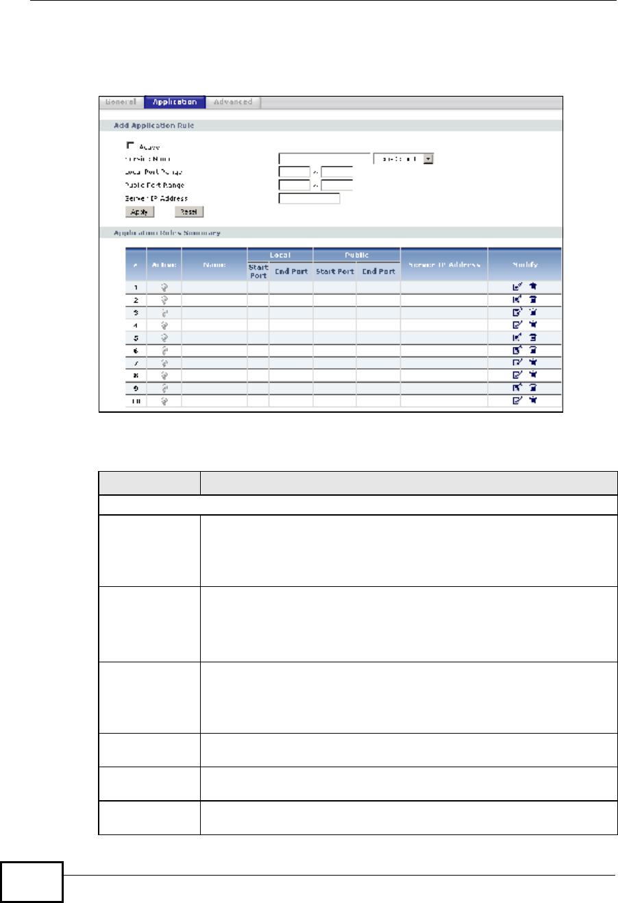
Chapter 11Network Address Translation (NAT)
NBG4604 User’s Guide
126
Refer to Appendix E on page 259 for port numbers commonly used for particular
services.
Figure 70 Network > NAT > Application
The following table describes the labels in this screen.
Table 47 Network > NAT > Application
LABEL DESCRIPTION
Add Application Rule
Active Select the check box to enable this rule and the requested service can
be forwarded to the host with a specified internal IP address.
Clear the checkbox to disallow forwarding of these ports to an inside
server without having to delete the entry.
Service Name Type a name (of up to 31 printable characters) to identify this rule in
the first field next to Service Name. Otherwise, select a predefined
service in the second field next to Service Name. The predefined
service name and port number(s) will display in the Service Name and
Port fields.
Local Port
Range
Public Port
Range
Enter the port number ranges to be forwarded.
Server IP
Address Type the inside IP address of the server that receives packets from the
port(s) specified in the Port field.
Apply Click Apply to save your changes to the Application Rules Summary
table.
Reset Click Reset to not save and return your new changes in the Service
Name and Port fields to the previous one.
Company Confidential

Chapter 11Network Address Translation (NAT)
NBG4604 User’s Guide 127
Application Rules Summary
#This is the number of an individual port forwarding server entry.
Active This icon is turned on when the rule is enabled.
Name This field displays a name to identify this rule.
Local Start/End
Port
Public Start/End
Port
This field displays the port number(s).
Server IP
Address This field displays the inside IP address of the server.
Modify Click the Edit icon to display and modify an existing rule setting in the
fields under Add Application Rule.
Click the Remove icon to delete a rule.
Table 47 Network > NAT > Application (continued)
LABEL DESCRIPTION
Company Confidential
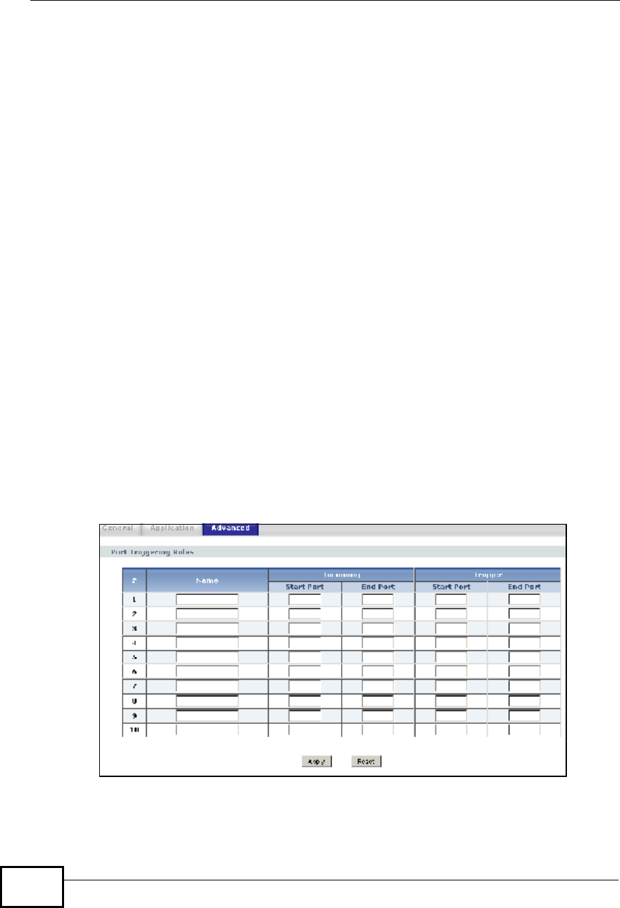
Chapter 11Network Address Translation (NAT)
NBG4604 User’s Guide
128
11.5 NAT Advanced Screen
Some services use a dedicated range of ports on the client side and a dedicated
range of ports on the server side. With regular port forwarding you set a
forwarding port in NAT to forward a service (coming in from the server on the
WAN) to the IP address of a computer on the client side (LAN). The problem is
that port forwarding only forwards a service to a single LAN IP address. In order to
use the same service on a different LAN computer, you have to manually replace
the LAN computer's IP address in the forwarding port with another LAN
computer's IP address.
Trigger port forwarding solves this problem by allowing computers on the LAN to
dynamically take turns using the service. The NBG4604 records the IP address of
a LAN computer that sends traffic to the WAN to request a service with a specific
port number and protocol (a "trigger" port). When the NBG4604's WAN port
receives a response with a specific port number and protocol ("incoming" port),
the NBG4604 forwards the traffic to the LAN IP address of the computer that sent
the request. After that computer’s connection for that service closes, another
computer on the LAN can use the service in the same manner. This way you do not
need to configure a new IP address each time you want a different LAN computer
to use the application.
To change your NBG4604’s trigger port settings, click Network > NAT >
Advanced. The screen appears as shown.
Note: Only one LAN computer can use a trigger port (range) at a time.
Figure 71 Network > NAT > Advanced
Company Confidential
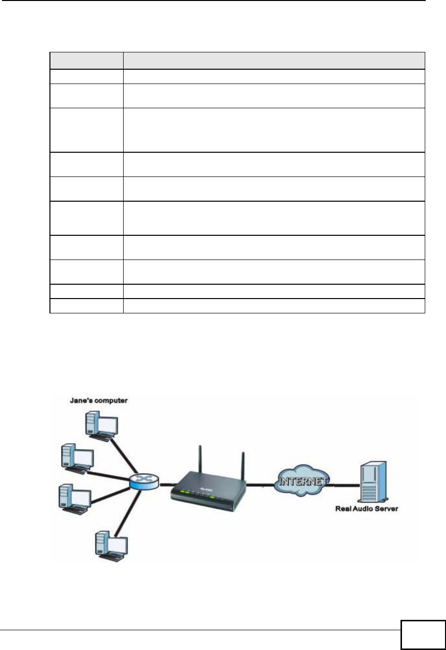
Chapter 11Network Address Translation (NAT)
NBG4604 User’s Guide 129
The following table describes the labels in this screen.
11.5.1 Trigger Port Forwarding Example
The following is an example of trigger port forwarding.
Figure 72 Trigger Port Forwarding Process: Example
1Jane requests a file from the Real Audio server (port 7070).
Table 48 Network > NAT > Advanced
LABEL DESCRIPTION
#This is the rule index number (read-only).
Name Type a unique name (up to 15 characters) for identification purposes. All
characters are permitted - including spaces.
Incoming Incoming is a port (or a range of ports) that a server on the WAN uses
when it sends out a particular service. The NBG4604 forwards the traffic
with this port (or range of ports) to the client computer on the LAN that
requested the service.
Start Port Type a port number or the starting port number in a range of port
numbers.
End Port Type a port number or the ending port number in a range of port
numbers.
Trigger The trigger port is a port (or a range of ports) that causes (or triggers)
the NBG4604 to record the IP address of the LAN computer that sent
the traffic to a server on the WAN.
Start Port Type a port number or the starting port number in a range of port
numbers.
End Port Type a port number or the ending port number in a range of port
numbers.
Apply Click Apply to save your changes back to the NBG4604.
Reset Click Reset to begin configuring this screen afresh.
Company Confidential

Chapter 11Network Address Translation (NAT)
NBG4604 User’s Guide
130
2Port 7070 is a “trigger” port and causes the NBG4604 to record Jane’s computer IP
address. The NBG4604 associates Jane's computer IP address with the "incoming"
port range of 6970-7170.
3The Real Audio server responds using a port number ranging between 6970-7170.
4The NBG4604 forwards the traffic to Jane’s computer IP address.
5Only Jane can connect to the Real Audio server until the connection is closed or
times out. The NBG4604 times out in three minutes with UDP (User Datagram
Protocol), or two hours with TCP/IP (Transfer Control Protocol/Internet Protocol).
11.5.2 Two Points To Remember About Trigger Ports
1Trigger events only happen on data that is going coming from inside the NBG4604
and going to the outside.
2If an application needs a continuous data stream, that port (range) will be tied up
so that another computer on the LAN can’t trigger it.
Company Confidential

NBG4604 User’s Guide 131
CHAPTER 12
Dynamic DNS
12.1 Overview
Dynamic DNS (DDNS) services let you use a domain name with a dynamic IP
address.
12.2 What You Can Do
Use the Dynamic DNS screen (Section 12.4 on page 132) to enable DDNS and
configure the DDNS settings on the NBG4604.
12.3 What You Need To Know
Dynamic DNS allows you to update your current dynamic IP address with one or
many dynamic DNS services so that anyone can contact you (in NetMeeting, CU-
SeeMe, etc.). You can also access your FTP server or Web site on your own
computer using a domain name (for instance myhost.dhs.org, where myhost is a
name of your choice) that will never change instead of using an IP address that
changes each time you reconnect. Your friends or relatives will always be able to
call you even if they don't know your IP address.
12.3.1 DynDNS Wildcard
Enabling the wildcard feature for your host causes *.yourhost.dyndns.org to be
aliased to the same IP address as yourhost.dyndns.org. This feature is useful if
you want to be able to use, for example, www.yourhost.dyndns.org and still reach
your hostname.
Note: If you have a private WAN IP address, then you cannot use Dynamic DNS. You
must have a public WAN IP address.
Company Confidential
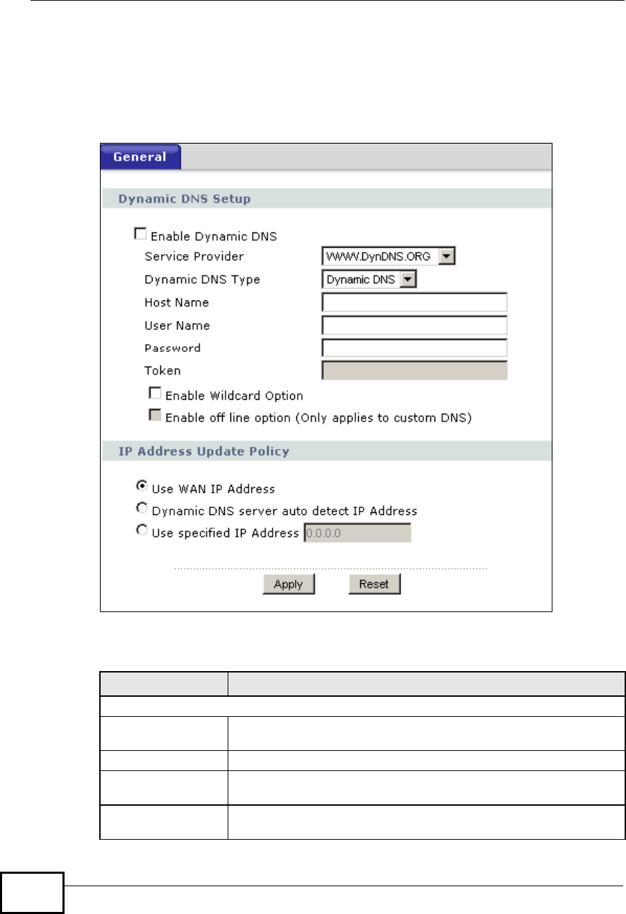
Chapter 12Dynamic DNS
NBG4604 User’s Guide
132
12.4 Dynamic DNS Screen
To change your NBG4604’s DDNS, click Network > DDNS. The screen appears as
shown.
Figure 73 Network > Dynamic DNS
The following table describes the labels in this screen.
Table 49 Network > Dynamic DNS
LABEL DESCRIPTION
Dynamic DNS Setup
Enable Dynamic
DNS Select this check box to use dynamic DNS.
Service Provider Select the name of your Dynamic DNS service provider.
Dynamic DNS Type Select the type of service that you are registered for from your
Dynamic DNS service provider.
Host Name Enter a host names in the field provided. You can specify up to two
host names in the field separated by a comma (",").
Company Confidential

Chapter 12Dynamic DNS
NBG4604 User’s Guide 133
User Name Enter your user name.
Password Enter the password assigned to you.
Token Enter your client authorization key provided by the server to
update DynDNS records.
This field is configurable only when you select
WWW.REGFISH.COM in the Service Provider field.
Enable Wildcard
Option Select the check box to enable DynDNS Wildcard.
Enable off line
option This option is available when CustomDNS is selected in the DDNS
Type field. Check with your Dynamic DNS service provider to have
traffic redirected to a URL (that you can specify) while you are off
line.
IP Address Update Policy:
Use WAN IP Address Select this option to update the IP address of the host name(s) to
the WAN IP address.
Dynamic DNS
server auto detect
IP Address
Select this option to update the IP address of the host name(s)
automatically by the DDNS server. It is recommended that you
select this option.
Use specified IP
Address Type the IP address of the host name(s). Use this if you have a
static IP address.
Apply Click Apply to save your changes back to the NBG4604.
Reset Click Reset to begin configuring this screen afresh.
Table 49 Network > Dynamic DNS
LABEL DESCRIPTION
Company Confidential

Chapter 12Dynamic DNS
NBG4604 User’s Guide
134
Company Confidential
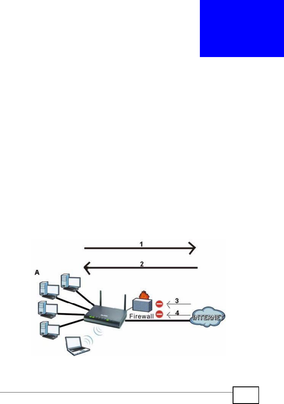
NBG4604 User’s Guide 135
CHAPTER 13
Firewall
13.1 Overview
Use these screens to enable and configure the firewall that protects your NBG4604
and your LAN from unwanted or malicious traffic.
Enable the firewall to protect your LAN computers from attacks by hackers on the
Internet and control access between the LAN and WAN. By default the firewall:
•allows traffic that originates from your LAN computers to go to all of the
networks.
•blocks traffic that originates on the other networks from going to the LAN.
The following figure illustrates the default firewall action. User A can initiate an IM
(Instant Messaging) session from the LAN to the WAN (1). Return traffic for this
session is also allowed (2). However other traffic initiated from the WAN is blocked
(3 and 4).
Figure 74 Default Firewall Action
Company Confidential

Chapter 13Firewall
NBG4604 User’s Guide
136
13.2 What You Can Do
•Use the General screen(Section 13.4 on page 137) to enable or disable the
NBG4604’s firewall.
•Use the Services screen (Section 13.5 on page 137) screen enable service
blocking, enter/delete/modify the services you want to block and the date/time
you want to block them.
13.3 What You Need To Know
The NBG4604’s firewall feature physically separates the LAN and the WAN and
acts as a secure gateway for all data passing between the networks.
13.3.1 About the NBG4604 Firewall
The NBG4604 firewall is a stateful inspection firewall and is designed to protect
against Denial of Service attacks when activated (clickthe General tab under
Firewall and then click the EnableFirewall check box). The NBG4604's purpose
is to allow a private Local Area Network (LAN) to be securely connected to the
Internet. The NBG4604 can be used to prevent theft, destruction and modification
of data, as well as log events, which may be important to the security of your
network.
The NBG4604 is installed between the LAN and a broadband modem connecting to
the Internet. This allows it to act as a secure gateway for all data passing between
the Internet and the LAN.
The NBG4604 has one Ethernet WAN port and four Ethernet LAN ports, which are
used to physically separate the network into two areas.The WAN (Wide Area
Network) port attaches to the broadband (cable or DSL) modem to the Internet.
The LAN (Local Area Network) port attaches to a network of computers, which
needs security from the outside world. These computers will have access to
Internet services such as e-mail, FTP and the World Wide Web. However, "inbound
access" is not allowed (by default) unless the remote host is authorized to use a
specific service.
Company Confidential
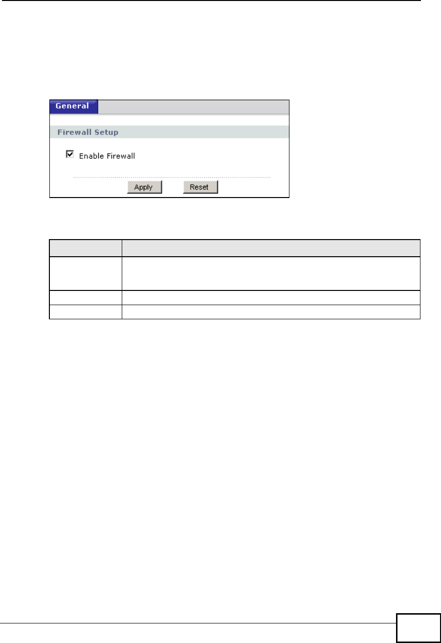
Chapter 13Firewall
NBG4604 User’s Guide 137
13.4 General Firewall Screen
Use this screen to enable or disable the NBG4604’s firewall, and set up firewall
logs. Click Security > Firewall to open the General screen.
Figure 75 Security > Firewall > General
The following table describes the labels in this screen.
13.5 Services Screen
If an outside user attempts to probe an unsupported port on your NBG4604, an
ICMP response packet is automatically returned. This allows the outside user to
know the NBG4604 exists. Use this screen to prevent the ICMP response packet
from being sent. This keeps outsiders from discovering your NBG4604 when
unsupported ports are probed.
You can also use this screen to enable service blocking, enter/delete/modify the
services you want to block and the date/time you want to block them.
Table 50 Security > Firewall > General
LABEL DESCRIPTION
Enable FirewallSelect this check box to activate the firewall. The NBG4604 performs
access control and protects against Denial of Service (DoS) attacks
when the firewall is activated.
Apply Click Apply to save the settings.
Reset Click Reset to start configuring this screen again.
Company Confidential
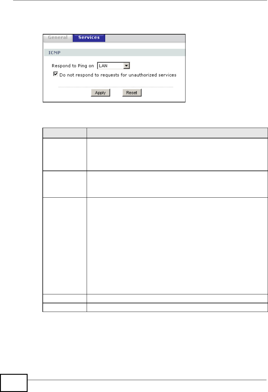
Chapter 13Firewall
NBG4604 User’s Guide
138
Click Security > Firewall > Services. The screen appears as shown next.
Figure 76 Security > Firewall > Services
The following table describes the labels in this screen.
Table 51 Security > Firewall > Services
LABEL DESCRIPTION
ICMP Internet Control Message Protocol is a message control and error-
reporting protocol between a host server and a gateway to the Internet.
ICMP uses Internet Protocol (IP) datagrams, but the messages are
processed by the TCP/IP software and directly apparent to the
application user.
Respond to Ping
on The NBG4604 will not respond to any incoming Ping requests when
Disable is selected. Select LAN to reply to incoming LAN Ping requests.
Select WAN to reply to incoming WAN Ping requests. Otherwise select
LAN & WAN to reply to all incoming LAN and WAN Ping requests.
Do not respond
to requests for
unauthorized
services
Select this option to prevent hackers from finding the NBG4604 by
probing for unused ports. If you select this option, the NBG4604 will not
respond to port request(s) for unused ports, thus leaving the unused
ports and the NBG4604 unseen. By default this option is not selected
and the NBG4604 will reply with an ICMP Port Unreachable packet for a
port probe on its unused UDP ports, and a TCP Reset packet for a port
probe on its unused TCP ports.
Note that the probing packets must first traverse the NBG4604's firewall
mechanism before reaching this anti-probing mechanism. Therefore if
the firewall mechanism blocks a probing packet, the NBG4604 reacts
based on the firewall policy, which by default, is to send a TCP reset
packet for a blocked TCP packet. You can use the command "sys firewall
tcprst rst [on|off]" to change this policy. When the firewall mechanism
blocks a UDP packet, it drops the packet without sending a response
packet.
Apply Click Apply to save the settings.
Reset Click Reset to start configuring this screen again.
Company Confidential

NBG4604 User’s Guide 139
CHAPTER 14
Content Filtering
14.1 Overview
This chapter provides a brief overview of content filtering using the embedded
web GUI.
Internet content filtering allows you to create and enforce Internet access policies
tailored to your needs. Content filtering is the ability to block certain web features
or specific URL keywords.
14.2 What You Can Do
Use the Filter (Section 14.4 on page 140) screen to restrict web features, add
keywords for blocking and designate a trusted computer.
14.3 What You Need To Know
Content filtering allows you to block certain web features, such as cookies, and/or
block access to specific web sites. For example, you can configure one policy that
blocks John Doe’s access to arts and entertainment web pages.
14.3.1 Content Filtering Profiles
A content filtering profile conveniently stores your custom settings for the
following features.
Restrict Web Features
The NBG4604 can disable web proxies and block web features such as ActiveX
controls, Java applets and cookies.
Company Confidential
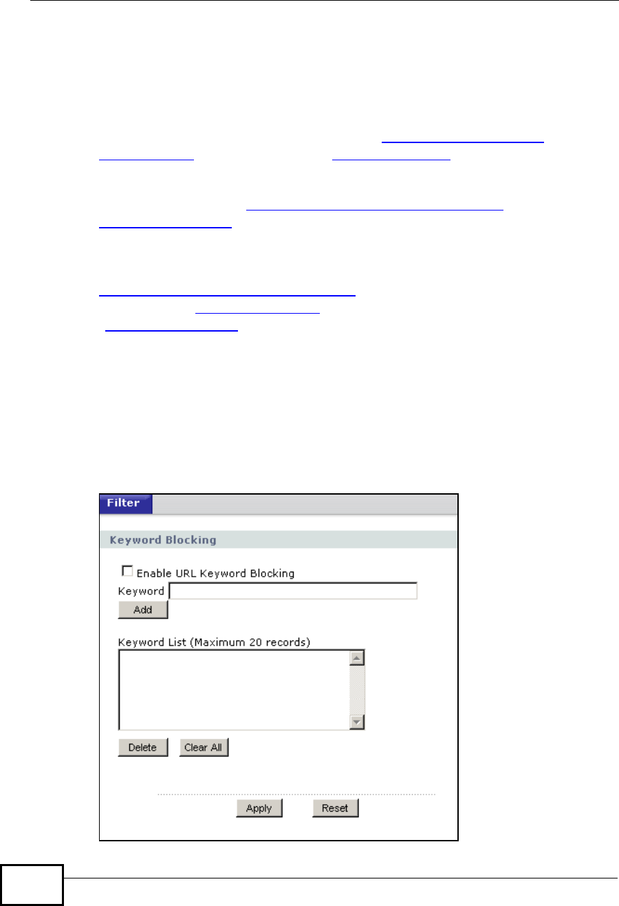
Chapter 14Content Filtering
NBG4604 User’s Guide
140
Keyword Blocking URL Checking
The NBG4604 checks the URL’s domain name (or IP address) and file path
separately when performing keyword blocking.
The URL’s domain name or IP address is the characters that come before the first
slash in the URL. For example, with the URL www.zyxel.com.tw/news/
pressroom.php, the domain name is www.zyxel.com.tw.
The file path is the characters that come after the first slash in the URL. For
example, with the URL www.zyxel.com.tw/news/pressroom.php, the file path is
news/pressroom.php.
Since the NBG4604 checks the URL’s domain name (or IP address) and file path
separately, it will not find items that go across the two. For example, with the URL
www.zyxel.com.tw/news/pressroom.php, the NBG4604 would find “tw” in the
domain name (www.zyxel.com.tw). It would also find “news” in the file path
(news/pressroom.php) but it would not find “tw/news”.
14.4 Filter Screen
Use this screen to restrict web features, add keywords for blocking and designate
a trusted computer. Click Security > Content Filter to open the Filter screen.
Figure 77 Security > Content Filter > Filter
Company Confidential

Chapter 14Content Filtering
NBG4604 User’s Guide 141
The following table describes the labels in this screen.
14.5 Technical Reference
The following section contains additional technical information about the NBG4604
features described in this chapter.
14.5.1 Customizing Keyword Blocking URL Checking
You can use commands to set how much of a website’s URL the content filter is to
check for keyword blocking. See the appendices for information on how to access
and use the command interpreter.
Domain Name or IP Address URL Checking
By default, the NBG4604 checks the URL’s domain name or IP address when
performing keyword blocking.
This means that the NBG4604 checks the characters that come before the first
slash in the URL.
Table 52 Security > Content Filter > Filter
LABEL DESCRIPTION
Enable URL
Keyword
Blocking
The NBG4604 can block Web sites with URLs that contain certain
keywords in the domain name or IP address. For example, if the
keyword "bad" was enabled, all sites containing this keyword in the
domain name or IP address will be blocked, e.g., URL http://
www.website.com/bad.html would be blocked. Select this check box to
enable this feature.
Keyword Type a keyword in this field. You may use any character (up to 64
characters). Wildcards are not allowed. You can also enter a numerical
IP address.
Keyword List This list displays the keywords already added.
Add Click Add after you have typed a keyword.
Repeat this procedure to add other keywords. Up to 64 keywords are
allowed.
When you try to access a web page containing a keyword, you will get
a message telling you that the content filter is blocking this request.
Delete Highlight a keyword in the lower box and click Delete to remove it.
The keyword disappears from the text box after you click Apply.
Clear All Click this button to remove all of the listed keywords.
Apply Click Apply to save your changes.
Reset Click Reset to begin configuring this screen afresh
Company Confidential

Chapter 14Content Filtering
NBG4604 User’s Guide
142
For example, with the URL www.zyxel.com.tw/news/pressroom.php, content
filtering only searches for keywords within www.zyxel.com.tw.
Full Path URL Checking
Full path URL checking has the NBG4604 check the characters that come before
the last slash in the URL.
For example, with the URL www.zyxel.com.tw/news/pressroom.php, full path URL
checking searches for keywords within www.zyxel.com.tw/news/.
Use the ip urlfilter customize actionFlags 6 [disable | enable]
command to extend (or not extend) the keyword blocking search to include the
URL's full path.
File Name URL Checking
Filename URL checking has the NBG4604 check all of the characters in the URL.
For example, filename URL checking searches for keywords within the URL
www.zyxel.com.tw/news/pressroom.php.
Use the ip urlfilter customize actionFlags 8 [disable | enable]
command to extend (or not extend) the keyword blocking search to include the
URL's complete filename.
Company Confidential
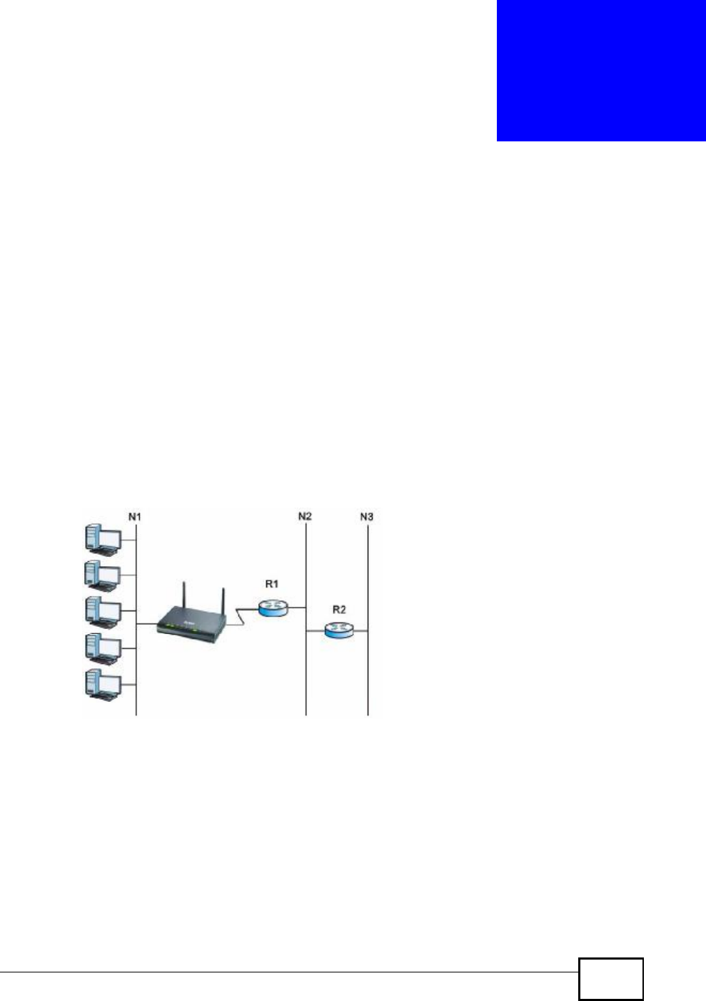
NBG4604 User’s Guide 143
CHAPTER 15
Static Route
15.1 Overview
This chapter shows you how to configure static routes for your NBG4604.
Each remote node specifies only the network to which the gateway is directly
connected, and the NBG4604 has no knowledge of the networks beyond. For
instance, the NBG4604 knows about network N2 in the following figure through
remote node Router 1. However, the NBG4604 is unable to route a packet to
network N3 because it doesn't know that there is a route through the same
remote node Router 1 (via gateway Router 2). The static routes are for you to tell
the NBG4604 about the networks beyond the remote nodes.
Figure 78 Example of Static Routing Topology
15.2 What You Can Do
•Use the IP Static Route screen (Section 15.3 on page 144) to view existing
static route rules.
•Use the Static Route Setup screen (Section 15.3.1 on page 145) to add or edit
a static route rule.
Company Confidential
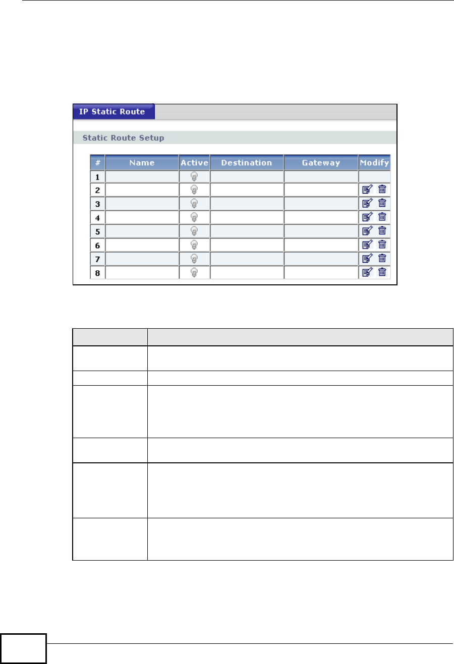
Chapter 15Static Route
NBG4604 User’s Guide
144
15.3 IP Static Route Screen
Use this screen to view existing static route rules. Click Management > Static
Route to open the IP Static Route screen. The following screen displays.
Figure 79 Management > Static Route > IP Static Route
The following table describes the labels in this screen.
Table 53 Management > Static Route > IP Static Route
LABEL DESCRIPTION
#This is the index number of an individual static route. The first entry is
for the default route and not editable.
Name This is the name that describes or identifies this route.
Active This icon is turned on when this static route is active.
Click the Edit icon under Modify and select the Active checkbox in the
Static Route Setup screen to enable the static route. Clear the
checkbox to disable this static route without having to delete the entry.
Destination This parameter specifies the IP network address of the final destination.
Routing is always based on network number.
Gateway This is the IP address of the gateway. The gateway is an immediate
neighbor of your NBG4604 that will forward the packet to the
destination. On the LAN, the gateway must be a router on the same
segment as your NBG4604; over the WAN, the gateway must be the IP
address of one of the remote nodes.
Modify Click the Edit icon to open the static route setup screen. Modify a static
route or create a new static route in the Static Route Setup screen.
Click the Remove icon to delete a static route.
Company Confidential
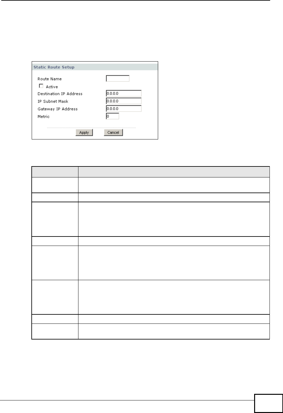
Chapter 15Static Route
NBG4604 User’s Guide 145
15.3.1 Static Route Setup Screen
To edit a static route, click the edit icon under Modify. The following screen
displays. Fill in the required information for each static route.
Figure 80 Management > Static Route > IP Static Route: Static Route Setup
The following table describes the labels in this screen.
Table 54 Management > Static Route > IP Static Route: Static Route Setup
LABEL DESCRIPTION
Route Name Enter the name of the IP static route. Leave this field blank to delete
this static route.
Active This field allows you to activate/deactivate this static route.
Destination IP
Address This parameter specifies the IP network address of the final destination.
Routing is always based on network number. If you need to specify a
route to a single host, use a subnet mask of 255.255.255.255 in the
subnet mask field to force the network number to be identical to the
host ID.
IP Subnet Mask Enter the IP subnet mask here.
Gateway IP
Address Enter the IP address of the gateway. The gateway is an immediate
neighbor of your NBG4604 that will forward the packet to the
destination. On the LAN, the gateway must be a router on the same
segment as your NBG4604; over the WAN, the gateway must be the IP
address of one of the Remote Nodes.
Metric Metric represents the “cost” of transmission for routing purposes. IP
routing uses hop count as the measurement of cost, with a minimum of
1 for directly connected networks. Enter a number that approximates
the cost for this link. The number need not be precise, but it must be
between 1 and 15. In practice, 2 or 3 is usually a good number.
Apply Click Apply to save your changes back to the NBG4604.
Cancel Click Cancel to return to the previous screen and not save your
changes.
Company Confidential

Chapter 15Static Route
NBG4604 User’s Guide
146
Company Confidential
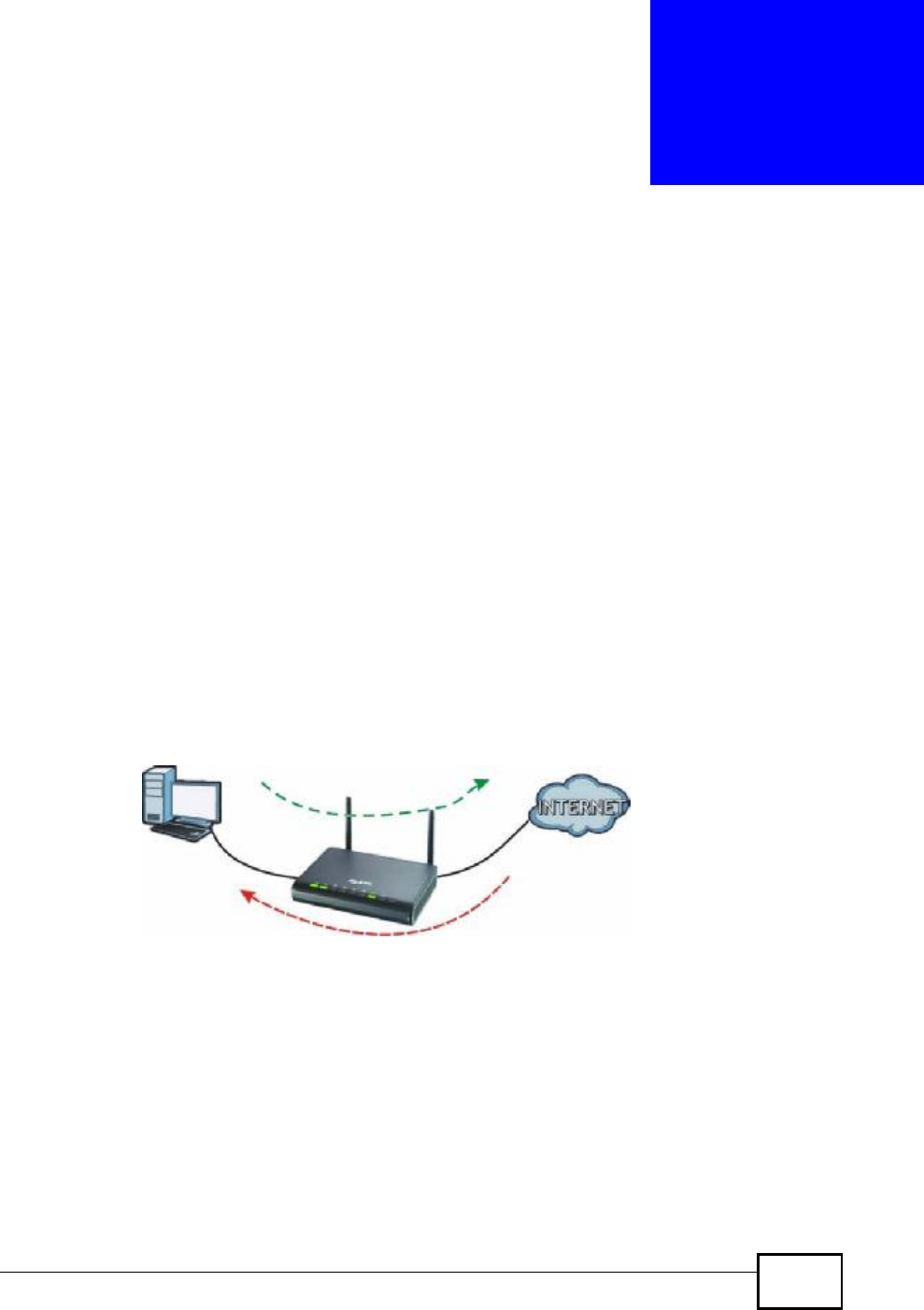
NBG4604 User’s Guide 147
CHAPTER 16
Bandwidth Management
16.1 Overview
This chapter contains information about configuring bandwidth management and
editing rules.
ZyXEL’s Bandwidth Management allows you to specify bandwidth management
rules based on an application.
In the figure below, uplink traffic goes from the LAN device (A) to the WAN device
(B). Bandwidth management is applied before sending the packets out to the
WAN. Downlink traffic comes back from the WAN device (B) to the LAN device
(A). Bandwidth management is applied before sending the traffic out to LAN.
Figure 81 Bandwidth Management
You can allocate specific amounts of bandwidth capacity (bandwidth budgets) to
individual applications (like VoIP, Web, FTP, and E-mail for example).
16.2 What You Can Do
•Use the General screen (Section 16.4 on page 148) to enable bandwidth
management and assign uplink/downlink limits.
•Use the Advanced screen (Section 16.5 on page 149) to configure bandwidth
management rules for the pre-defined services and applications.
AB
-> VOIP
-> FTP
-> HTTP
-> Chat, Email
Company Confidential