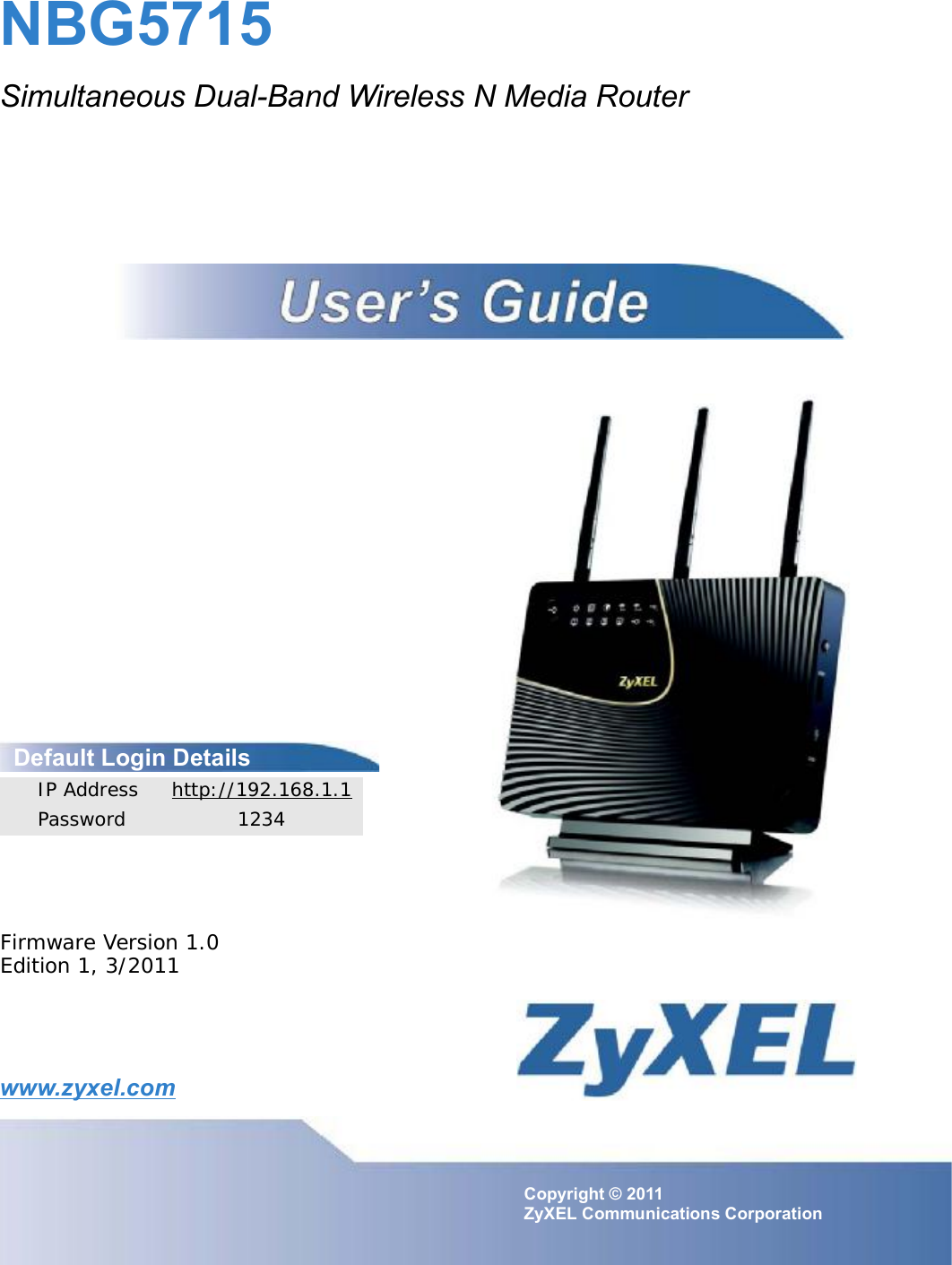
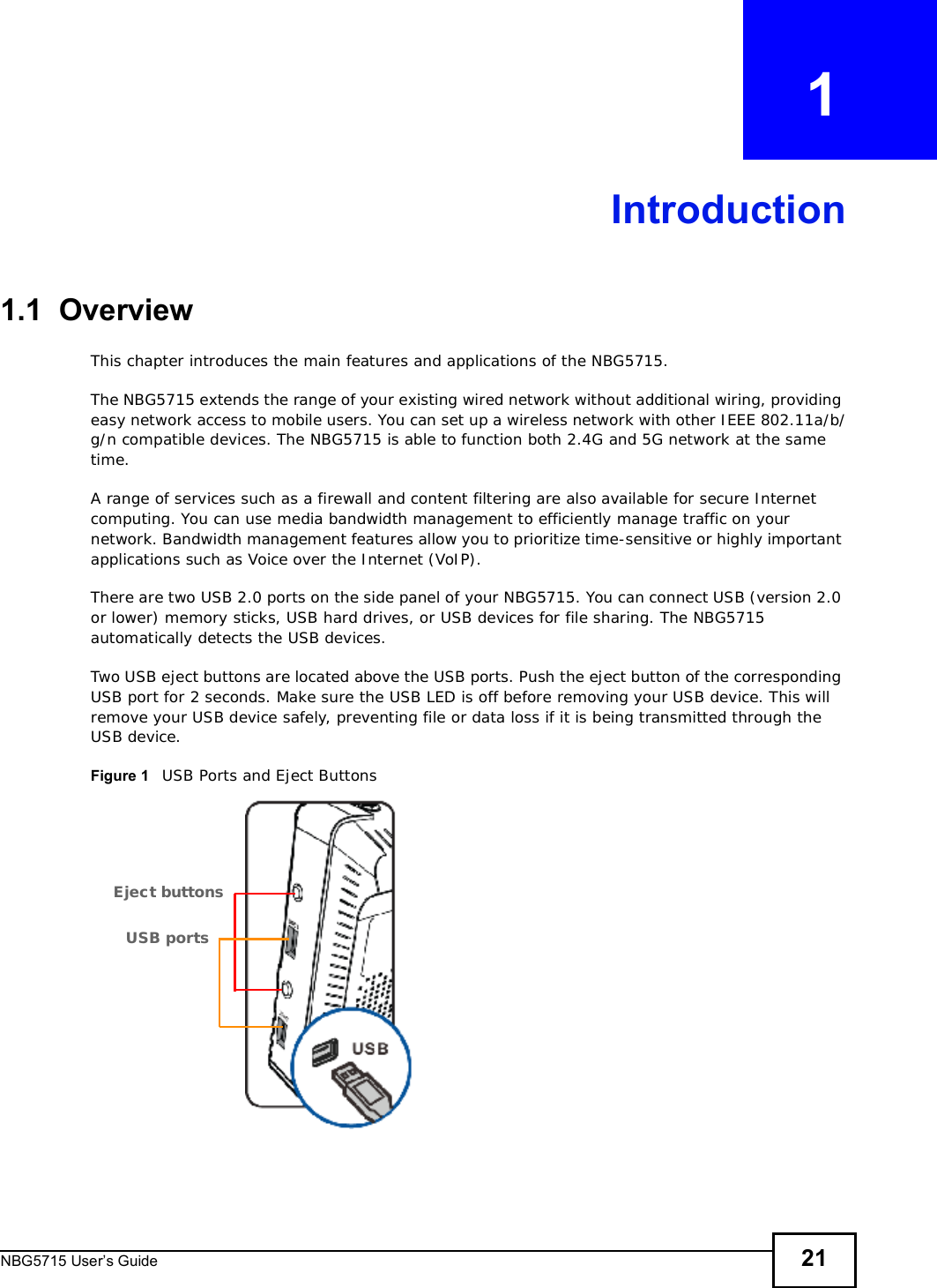
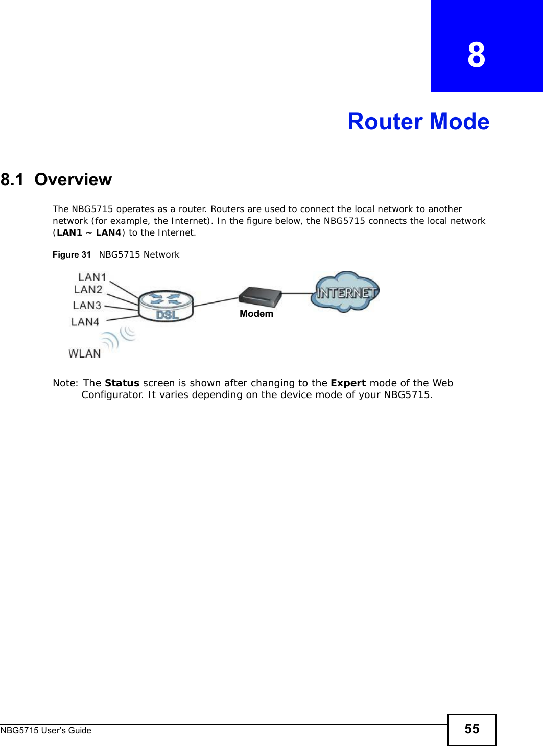
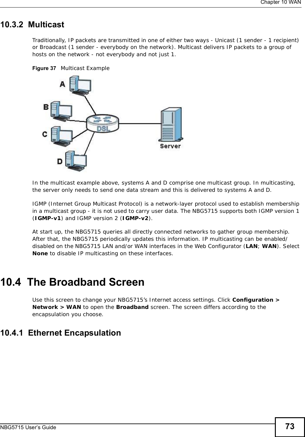
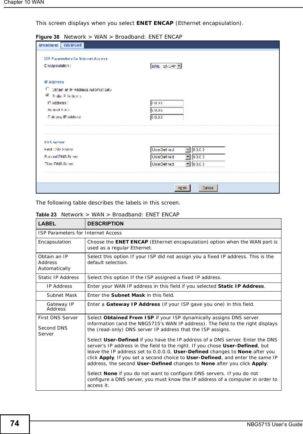
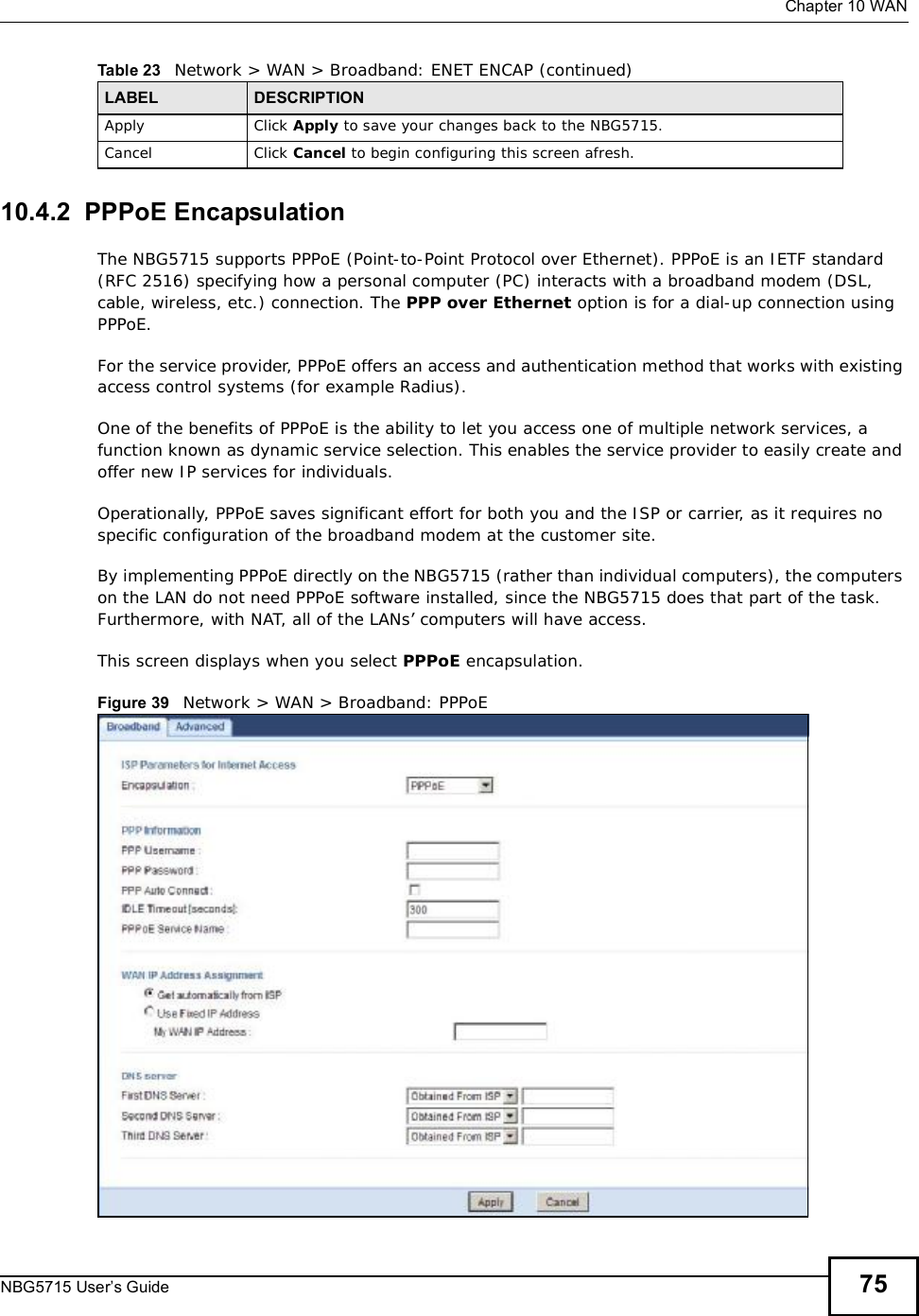
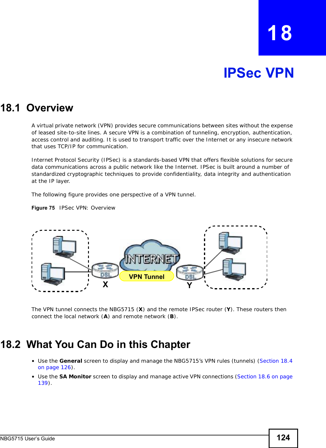
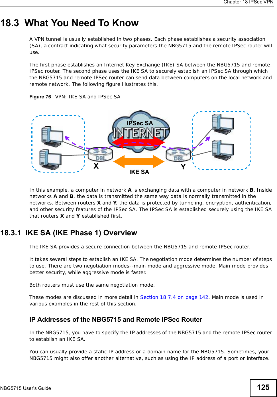
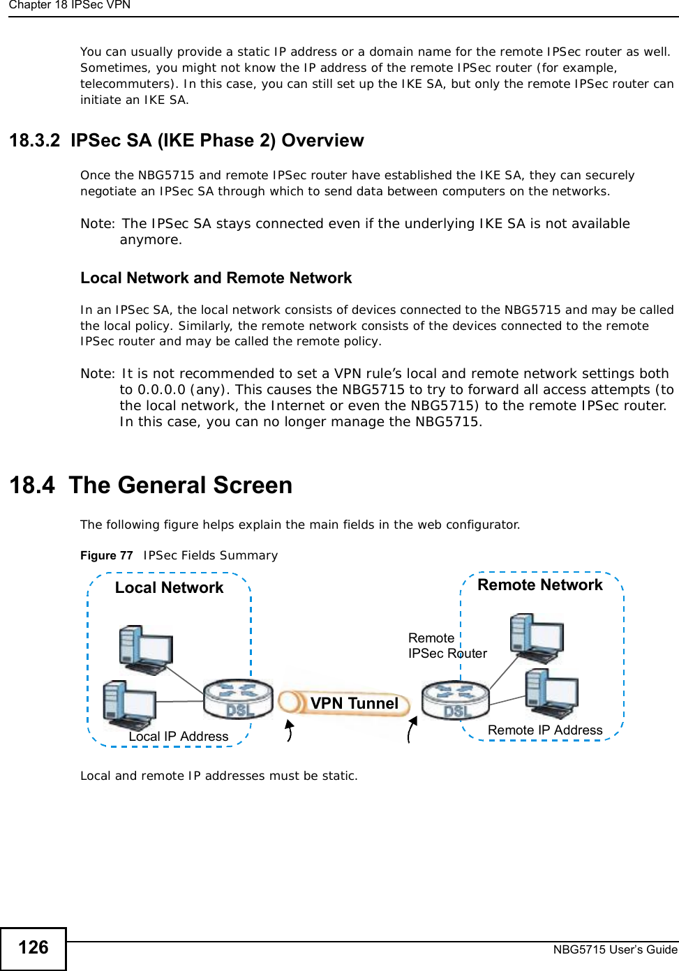
ZyXEL Communications NBG5715 Simultaneous Dual-Band Wireless N Media Router User Manual NBG5715 UG v1 00 ed1 2011 04 01
ZyXEL Communications Corporation Simultaneous Dual-Band Wireless N Media Router NBG5715 UG v1 00 ed1 2011 04 01
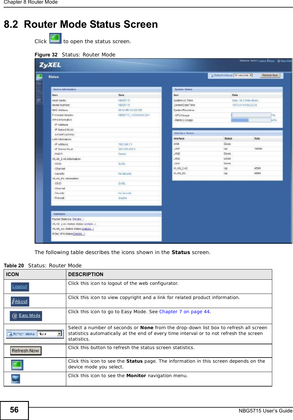
UserMan_I88NBG5715
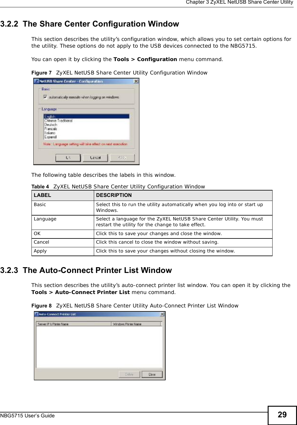
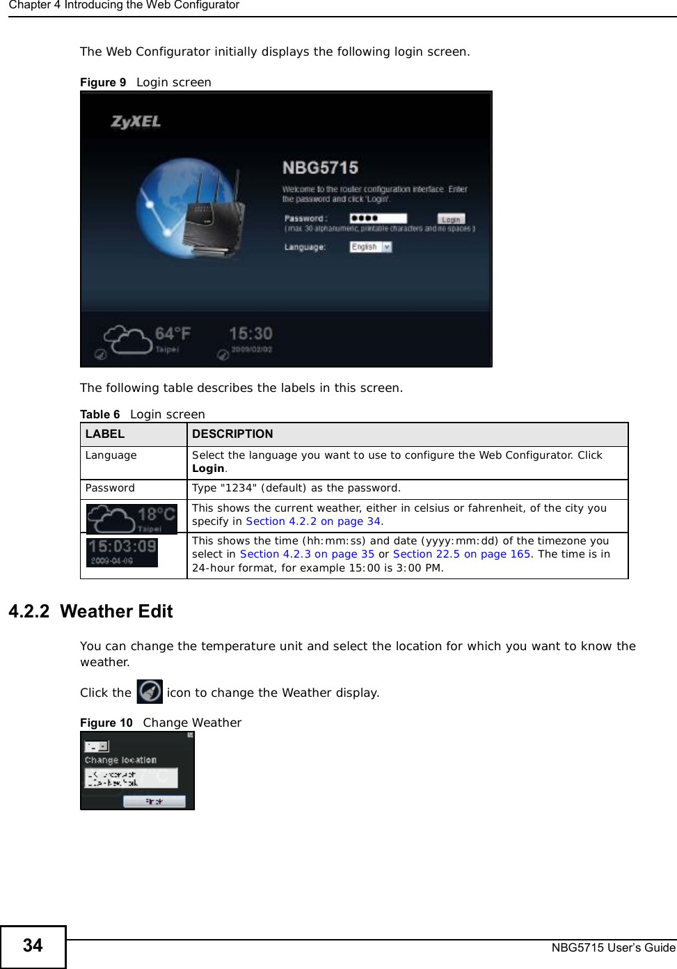
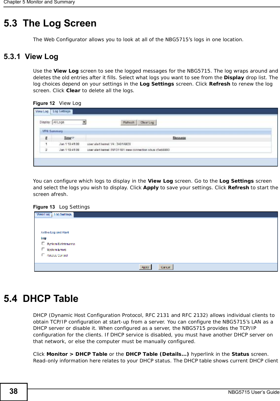
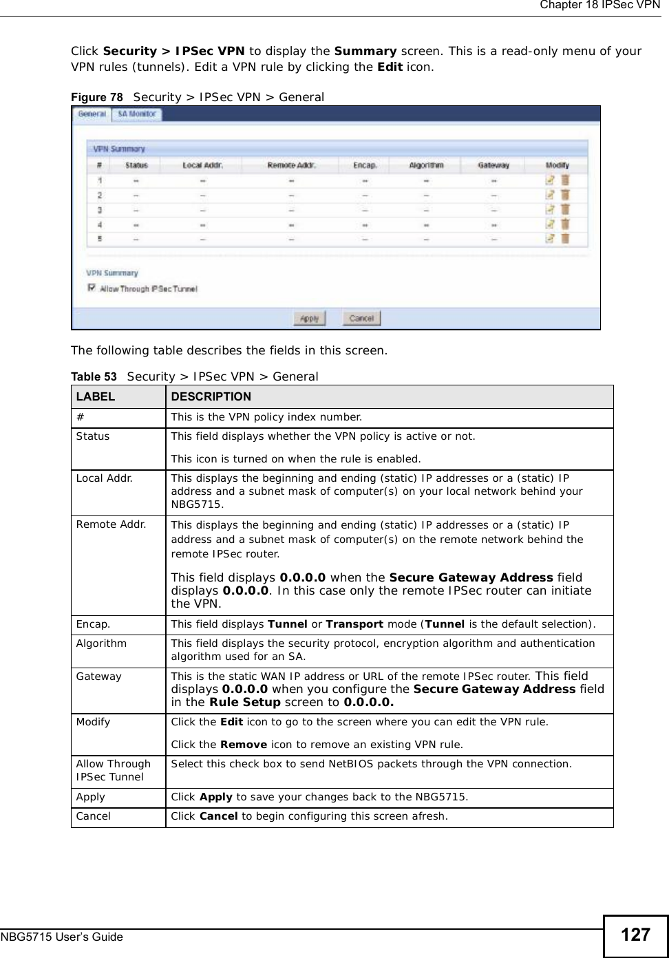
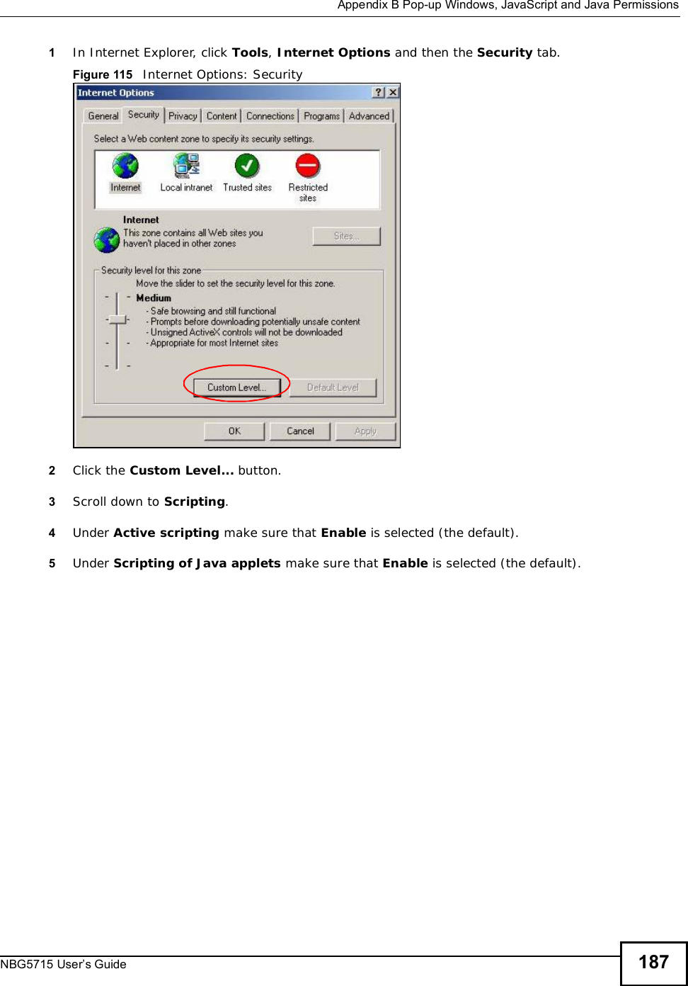
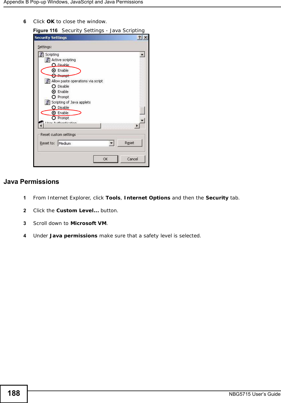
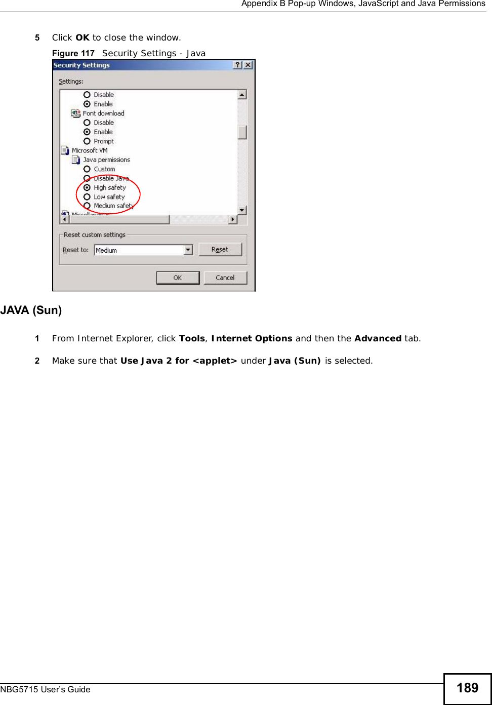
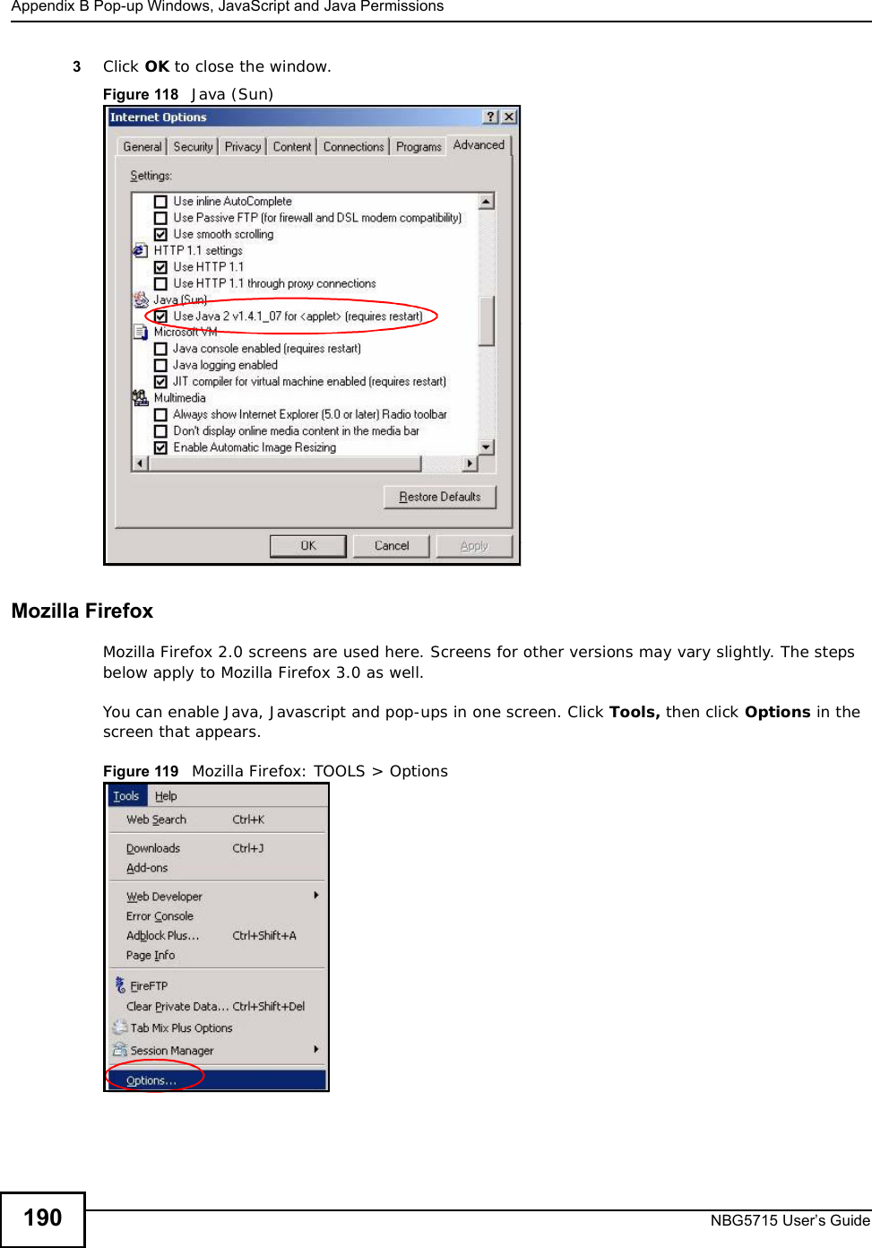
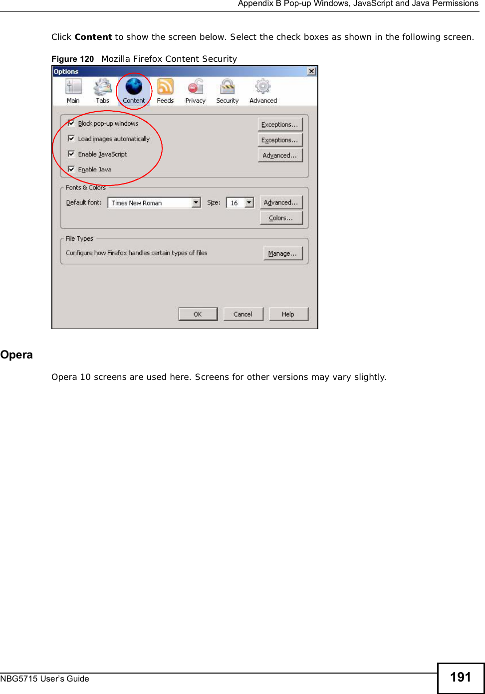
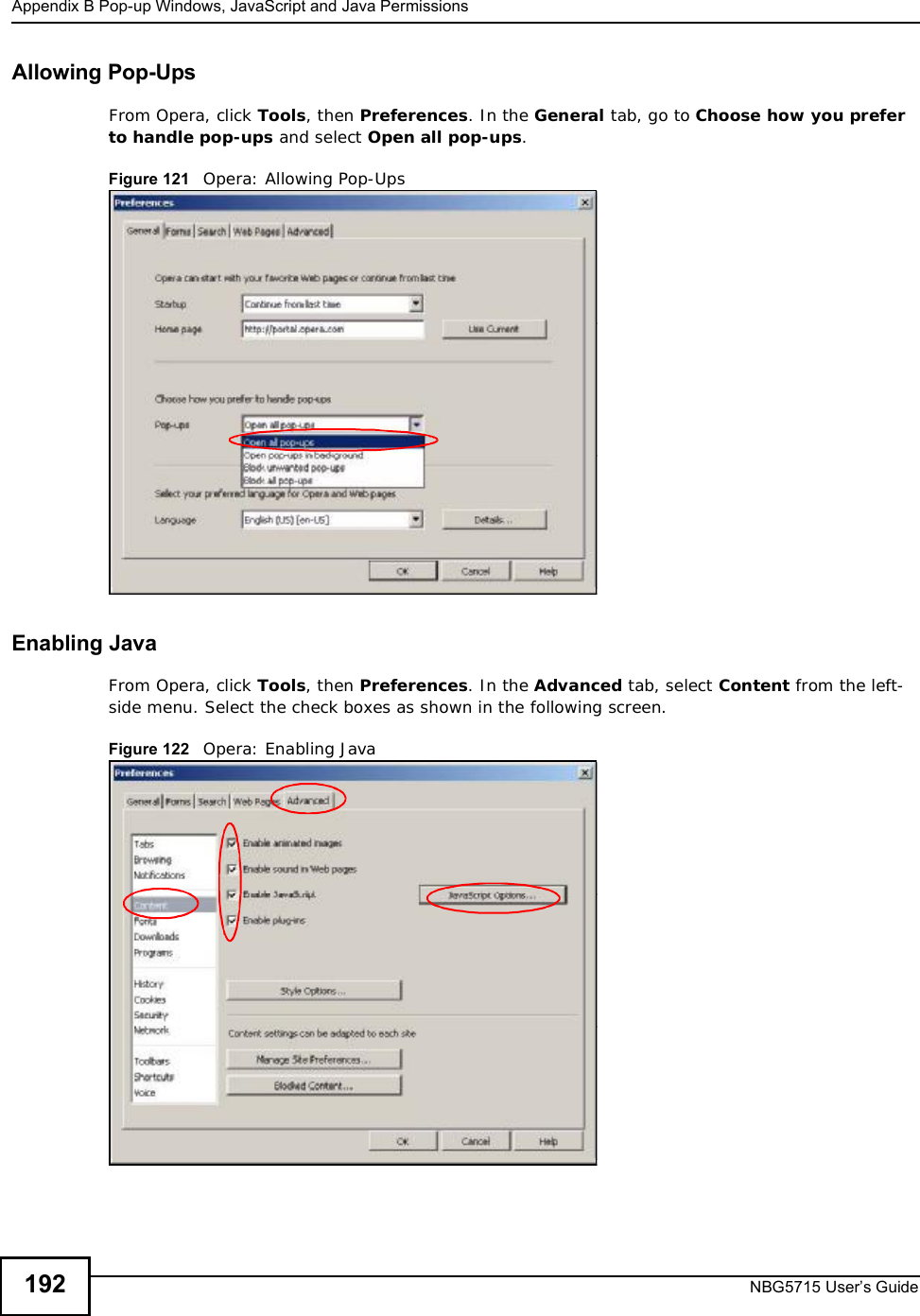
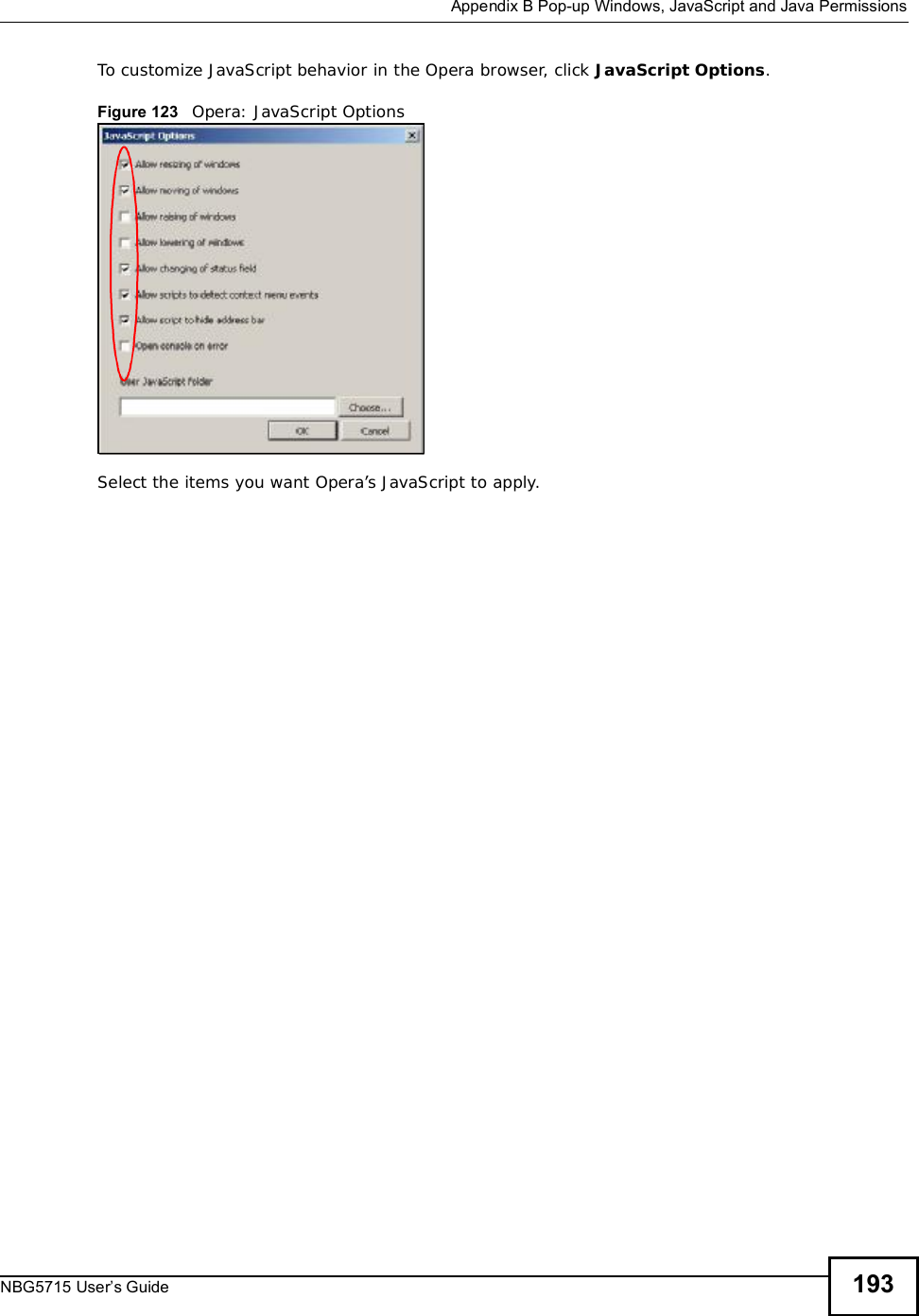
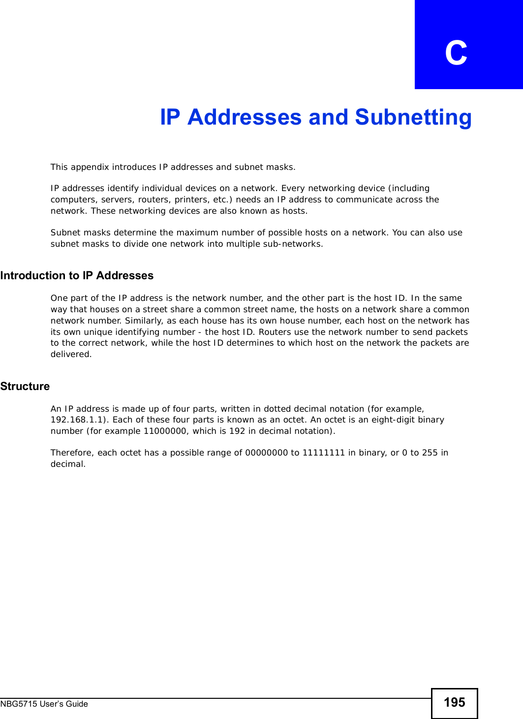
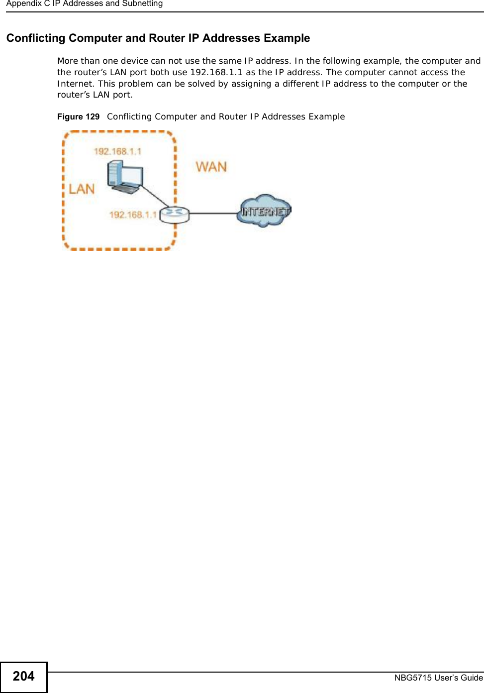
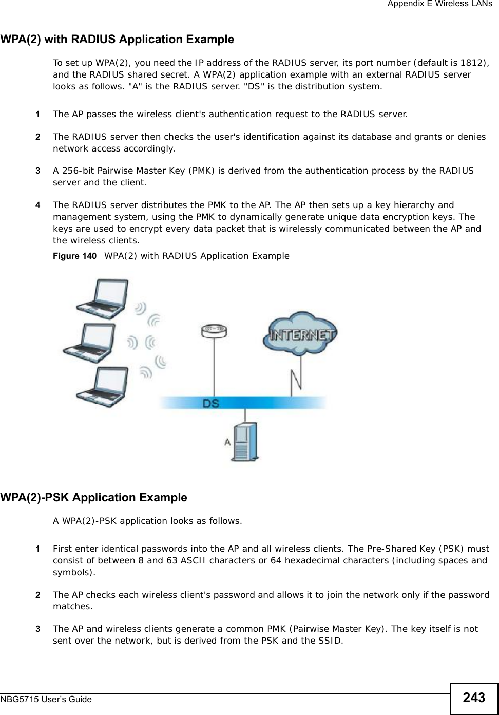
![About This User's GuideNBG5715 User’s Guide 3About This User's GuideIntended AudienceThis manual is intended for people who want to configure the NBG5715 using the Web Configurator. You should have at least a basic knowledge of TCP/IP networking concepts and topology.Tips for Reading User’s Guides On-ScreenWhen reading a ZyXEL User’s Guide On-Screen, keep the following in mind:•If you don’t already have the latest version of Adobe Reader, you can download it from http://www.adobe.com.•Use the PDF’s bookmarks to quickly navigate to the areas that interest you. Adobe Reader’s bookmarks pane opens by default in all ZyXEL User’s Guide PDFs.•If you know the page number or know vaguely which page-range you want to view, you can enter a number in the toolbar in Reader, then press [ENTER] to jump directly to that page.•Type [CTRL]+[F] to open the Adobe Reader search utility and enter a word or phrase. This can help you quickly pinpoint the information you require. You can also enter text directly into the toolbar in Reader.•To quickly move around within a page, press the [SPACE] bar. This turns your cursor into a “hand” with which you can grab the page and move it around freely on your screen.•Embedded hyperlinks are actually cross-references to related text. Click them to jump to the corresponding section of the User’s Guide PDF.Related Documentation•Quick Start Guide The Quick Start Guide is designed to help you get your NBG5715 up and running right away. It contains information on setting up your network and configuring for Internet access.•Support DiscRefer to the included CD for support documents.Documentation FeedbackSend your comments, questions or suggestions to: techwriters@zyxel.com.twThank you!The Technical Writing Team, ZyXEL Communications Corp.,6 Innovation Road II, Science-Based Industrial Park, Hsinchu, 30099, Taiwan.](https://usermanual.wiki/ZyXEL-Communications/NBG5715/User-Guide-1542926-Page-2.png)
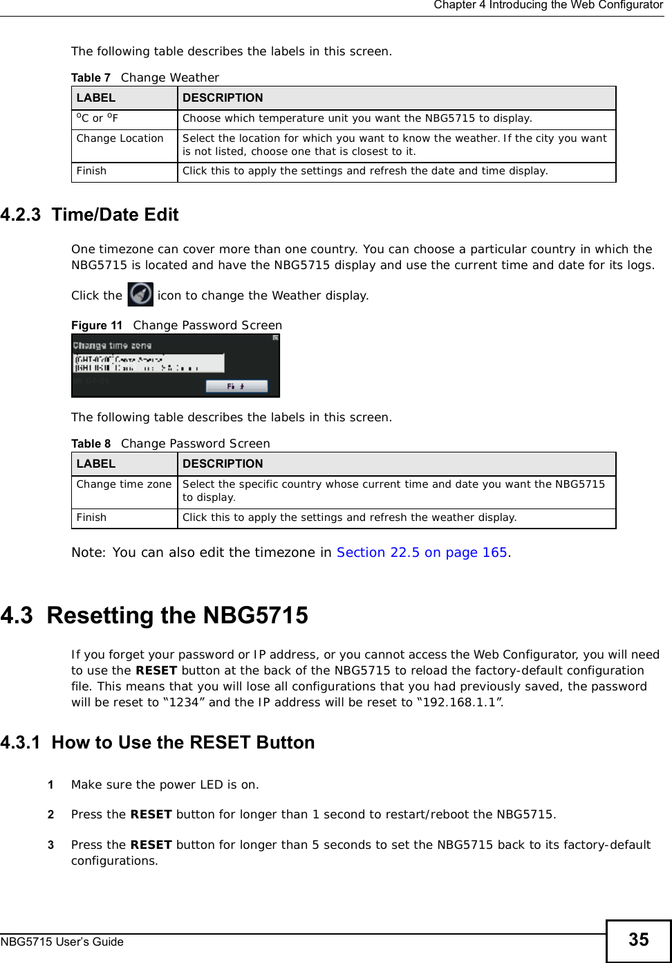
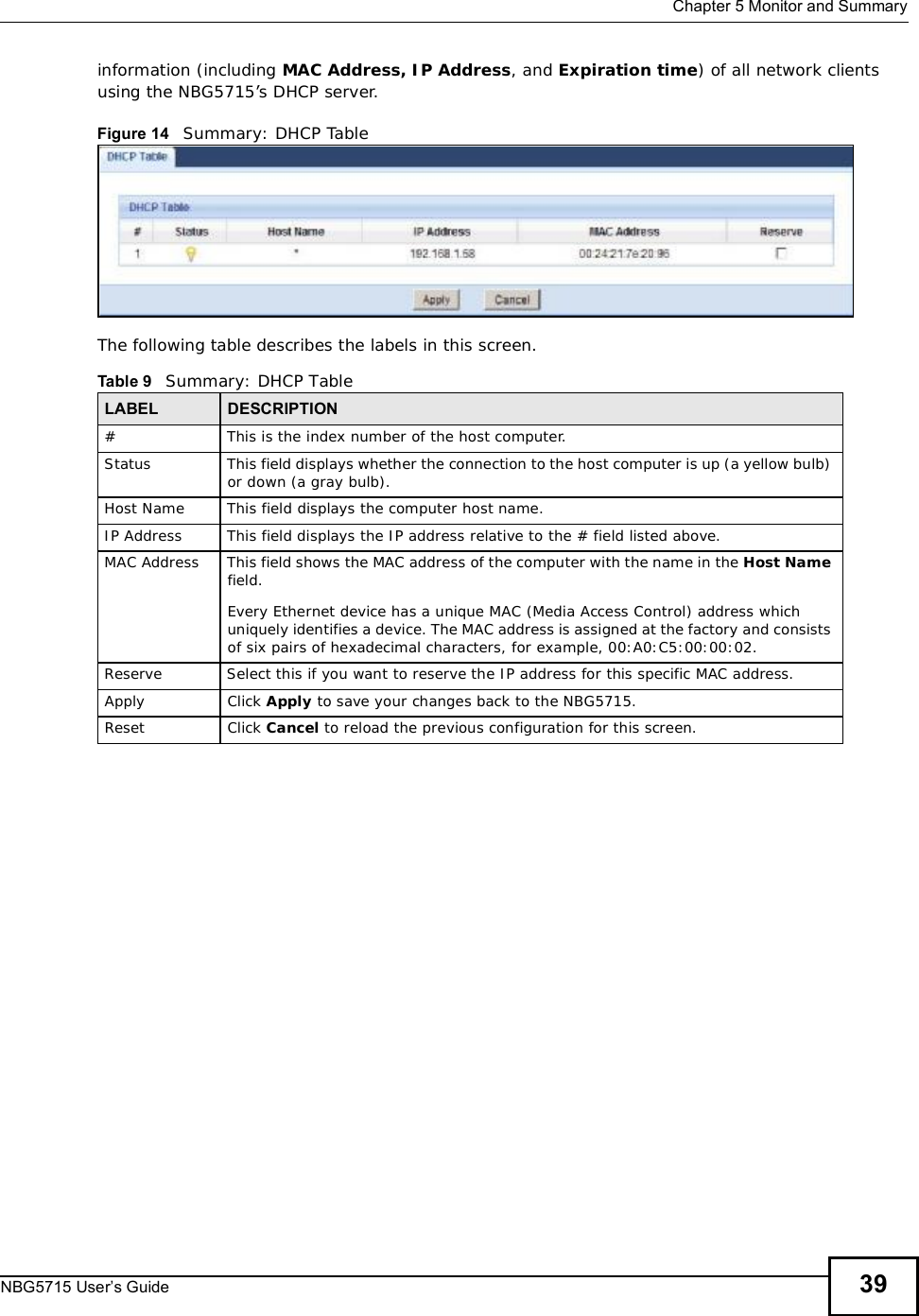
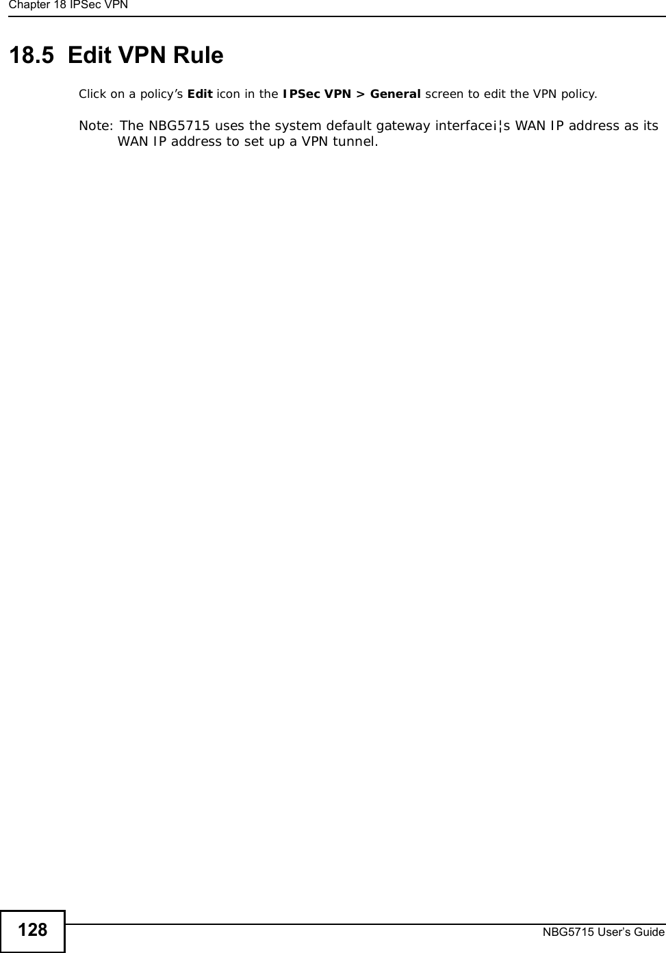
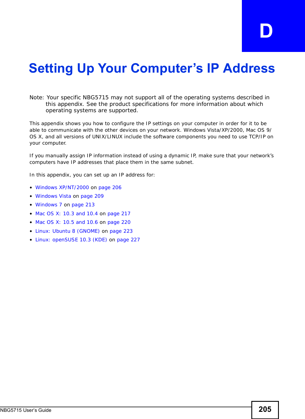
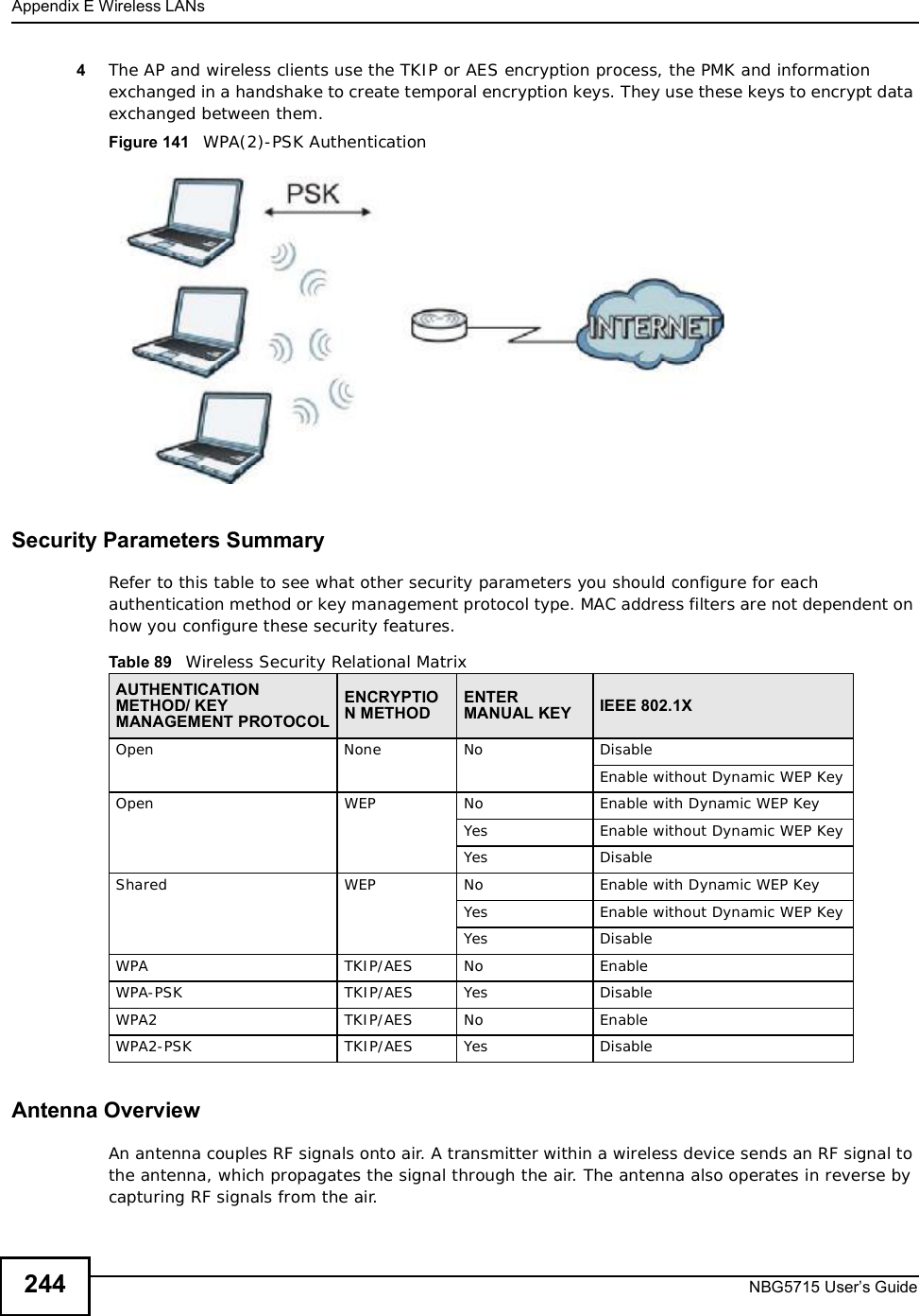
![Document ConventionsNBG5715 User’s Guide 5Document ConventionsWarnings and NotesThese are how warnings and notes are shown in this User’s Guide. Warnings tell you about things that could harm you or your device.Note: Notes tell you other important information (for example, other things you may need to configure or helpful tips) or recommendations.Syntax Conventions•The NBG5715 may be referred to as the “NBG5715”, the “device”, the “product” or the “system” in this User’s Guide.•Product labels, screen names, field labels and field choices are all in bold font.•A key stroke is denoted by square brackets and uppercase text, for example, [ENTER] means the “enter” or “return” key on your keyboard.•“Enter” means for you to type one or more characters and then press the [ENTER] key. “Select” or “choose” means for you to use one of the predefined choices.•A right angle bracket ( > ) within a screen name denotes a mouse click. For example, Maintenance > Log > Log Setting means you first click Maintenance in the navigation panel, then the Log sub menu and finally the Log Setting tab to get to that screen.•Units of measurement may denote the “metric” value or the “scientific” value. For example, “k” for kilo may denote “1000” or “1024”, “M” for mega may denote “1000000” or “1048576” and so on.•“e.g.,” is a shorthand for “for instance”, and “i.e.,” means “that is” or “in other words”.](https://usermanual.wiki/ZyXEL-Communications/NBG5715/User-Guide-1542926-Page-4.png)


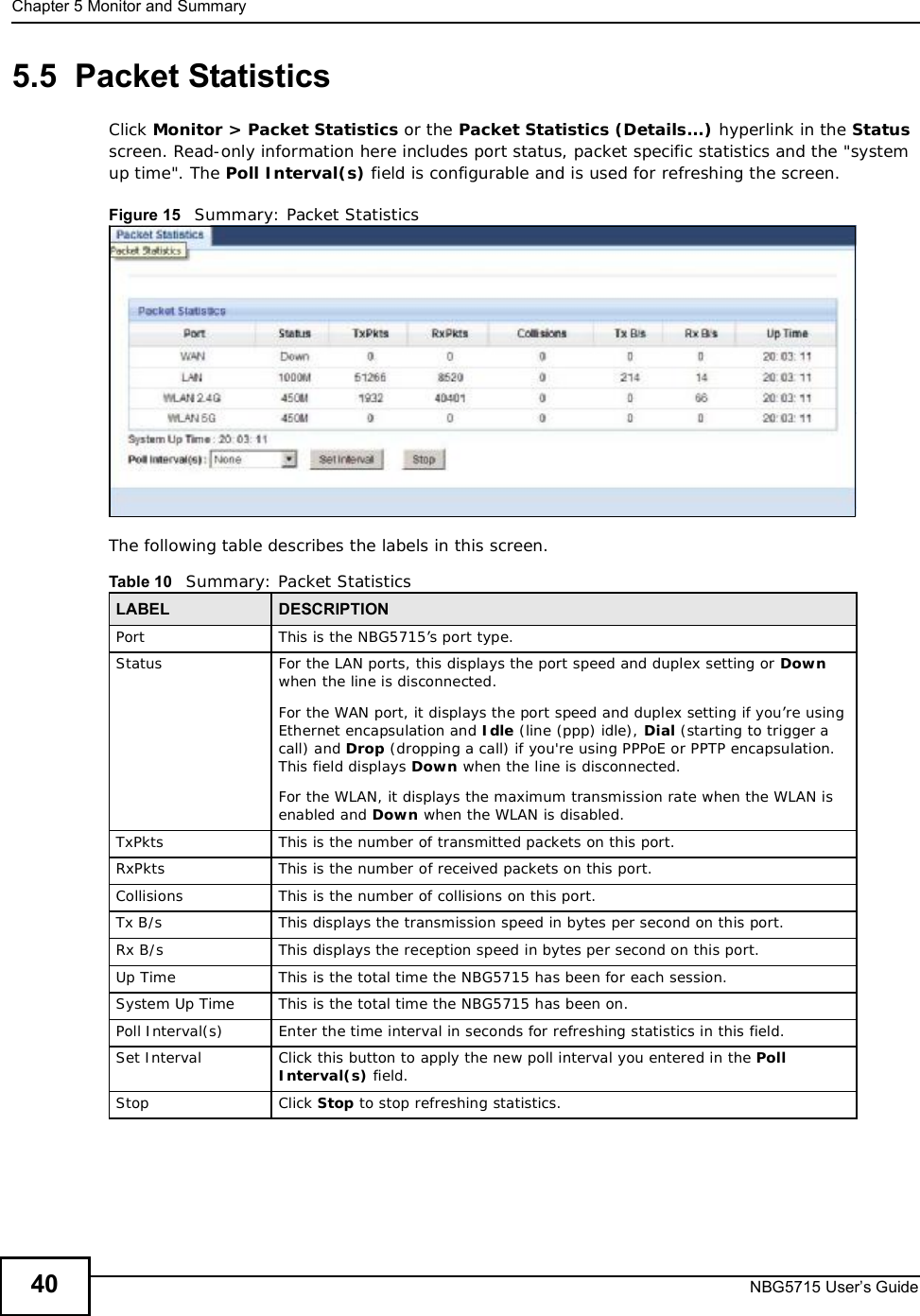
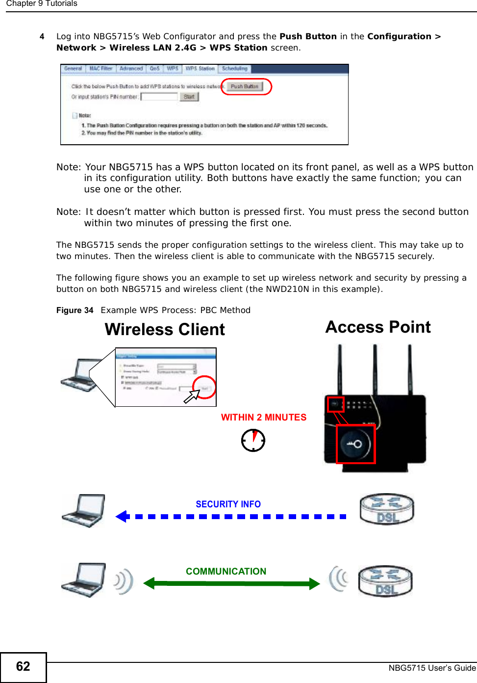
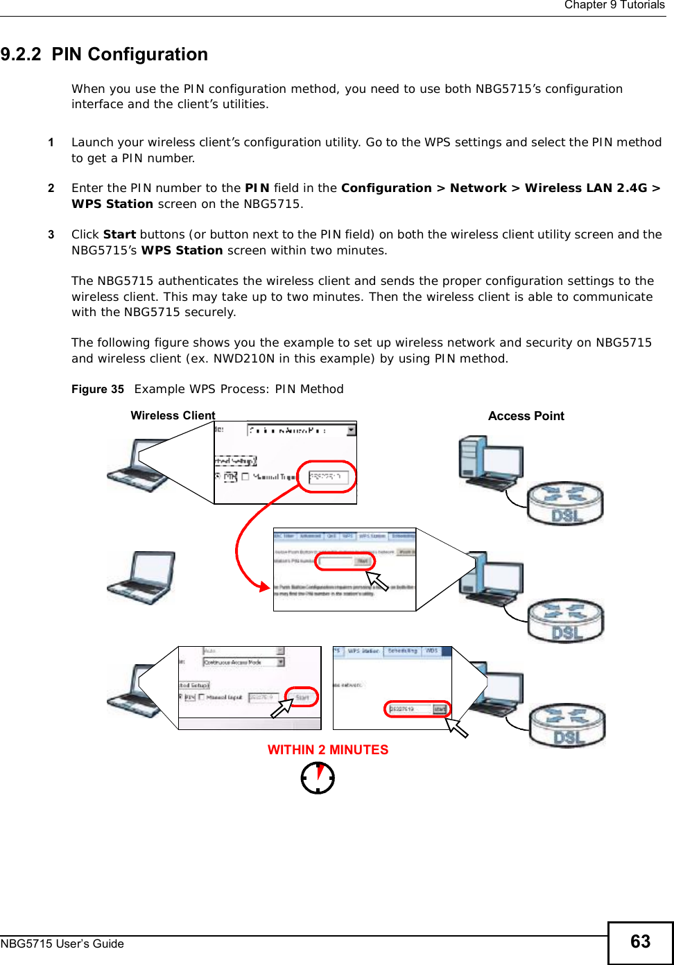
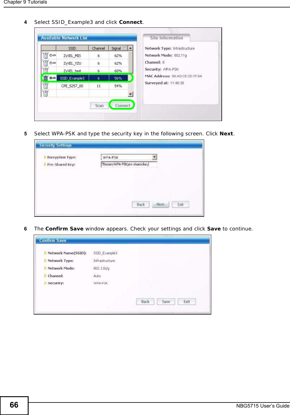
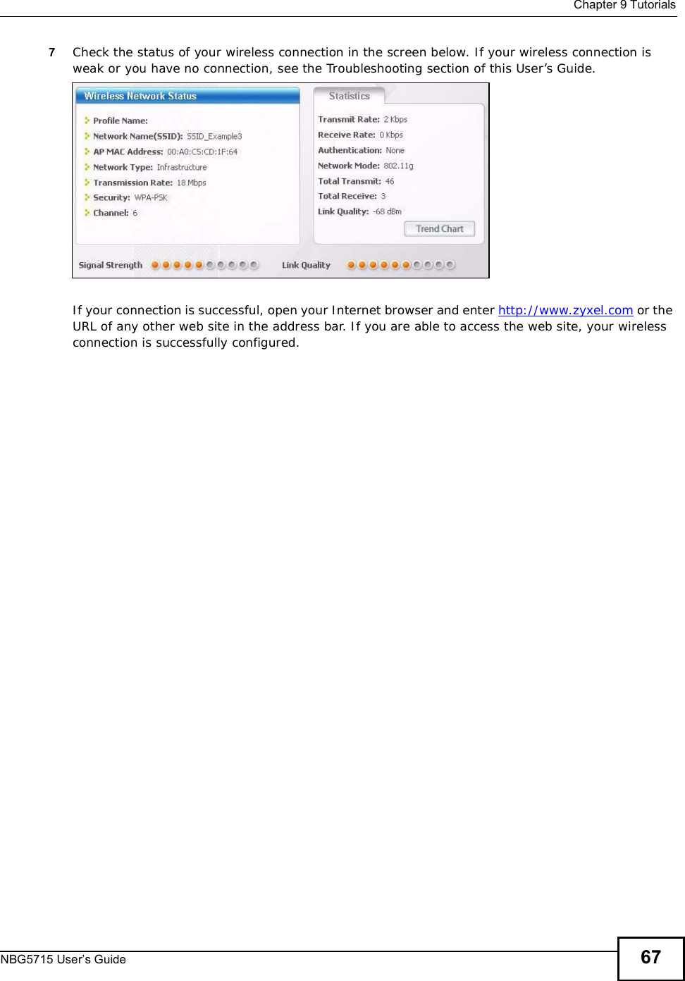


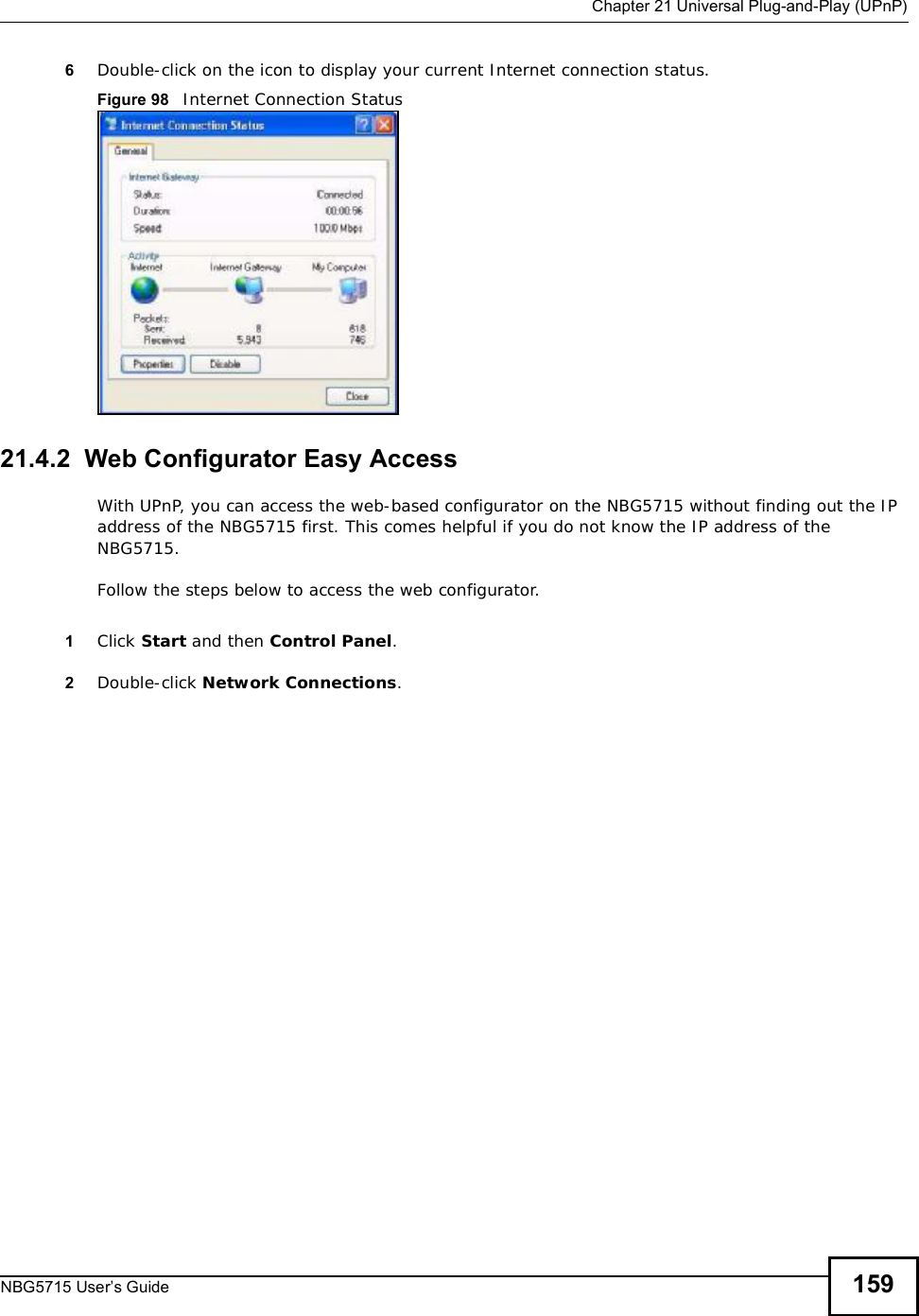

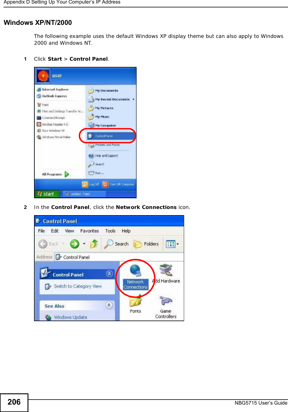
![Chapter 23TroubleshootingNBG5715 User’s Guide 1731Make sure you are using the correct IP address.•The default IP address is 192.168.1.1.•If you changed the IP address (Section 12.4 on page 97), use the new IP address.•If you changed the IP address and have forgotten it, see the troubleshooting suggestions for Idon’t know the IP address of my NBG5715.2Check the hardware connections, and make sure the LEDs are behaving as expected. See the Quick Start Guide. 3Make sure your Internet browser does not block pop-up windows and has JavaScript and Java enabled. See Appendix B on page 183.4Make sure your computer is in the same subnet as the NBG5715. (If you know that there are routers between your computer and the NBG5715, skip this step.)•If there is a DHCP server on your network, make sure your computer is using a dynamic IP address. See Section 13.2 on page 99.•If there is no DHCP server on your network, make sure your computer’s IP address is in the same subnet as the NBG5715. See Appendix C on page 196.5Reset the device to its factory defaults, and try to access the NBG5715 with the default IP address. See Chapter 22 on page 167.6If the problem continues, contact the network administrator or vendor, or try one of the advanced suggestions.Advanced Suggestions•Try to access the NBG5715 using another service, such as Telnet. If you can access the NBG5715, check the remote management settings and firewall rules to find out why the NBG5715 does not respond to HTTP.•If your computer is connected to the WAN port or is connected wirelessly, use a computer that is connected to a LAN/ETHERNET port.I can see the Login screen, but I cannot log in to the NBG5715.1Make sure you have entered the password correctly. The default password is 1234. This field is case-sensitive, so make sure [Caps Lock] is not on. 2You cannot log in to the Web Configurator while someone is using Telnet to access the NBG5715. Log out of the NBG5715 in the other session, or ask the person who is logged in to log out. 3This can happen when you fail to log out properly from your last session. Try logging in again after 5 minutes.4Disconnect and re-connect the power adaptor or cord to the NBG5715. 5If this does not work, you have to reset the device to its factory defaults. See Section 23.5 on page 175.](https://usermanual.wiki/ZyXEL-Communications/NBG5715/User-Guide-1542926-Page-172.png)
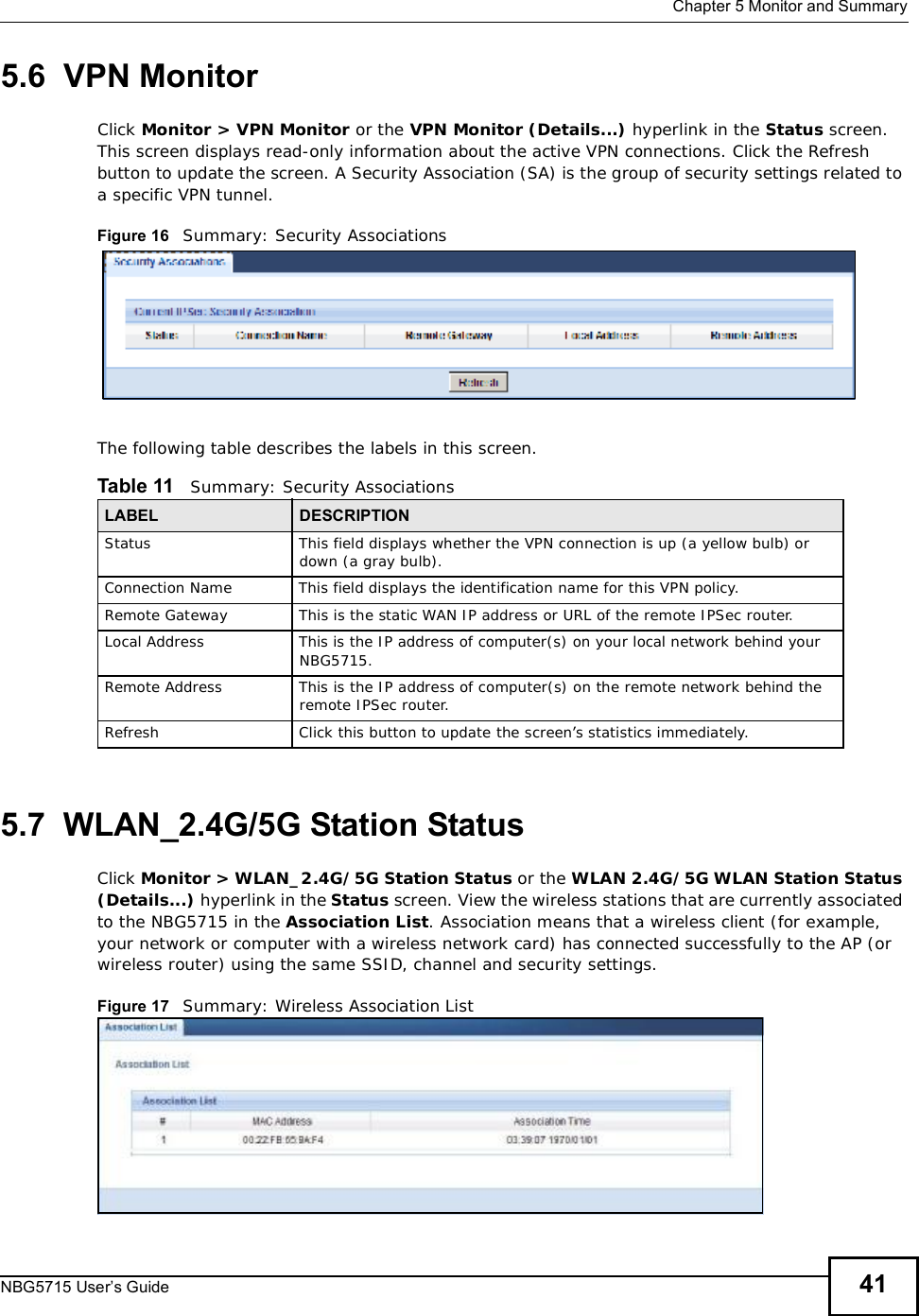
![Chapter 23TroubleshootingNBG5715 User’s Guide17423.4 Internet AccessI cannot access the Internet.1Check the hardware connections, and make sure the LEDs are behaving as expected. See the Quick Start Guide.2Make sure you entered your ISP account information correctly in the wizard. These fields are case-sensitive, so make sure [Caps Lock] is not on.3If you are trying to access the Internet wirelessly, make sure the wireless settings in the wireless client are the same as the settings in the AP.4Disconnect all the cables from your device, and follow the directions in the Quick Start Guide again. 5If the problem continues, contact your ISP.I cannot access the Internet anymore. I had access to the Internet (with the NBG5715), but my Internet connection is not available anymore.1Check the hardware connections, and make sure the LEDs are behaving as expected. See the Quick Start Guide and Section 1.5 on page 23.2Reboot the NBG5715.3If the problem continues, contact your ISP. The Internet connection is slow or intermittent.1There might be a lot of traffic on the network. Look at the LEDs, and check Section 1.5 on page 23.If the NBG5715 is sending or receiving a lot of information, try closing some programs that use the Internet, especially peer-to-peer applications.2Check the signal strength. If the signal strength is low, try moving the NBG5715 closer to the AP if possible, and look around to see if there are any devices that might be interfering with the wireless network (for example, microwaves, other wireless networks, and so on).3Reboot the NBG5715.4If the problem continues, contact the network administrator or vendor, or try one of the advanced suggestions.Advanced Suggestion](https://usermanual.wiki/ZyXEL-Communications/NBG5715/User-Guide-1542926-Page-173.png)


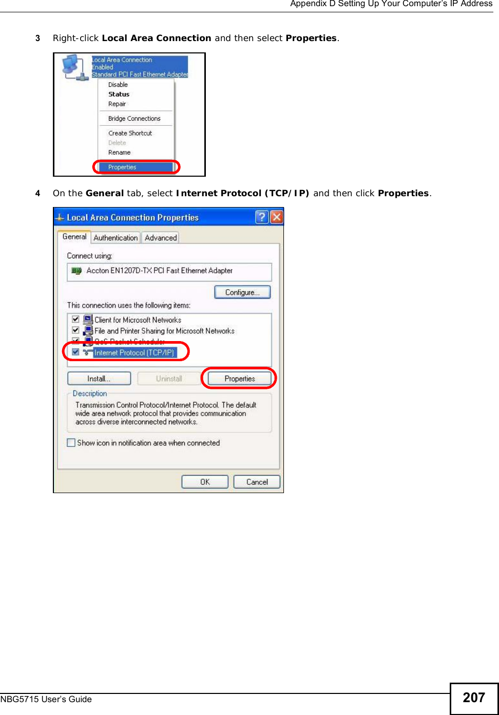
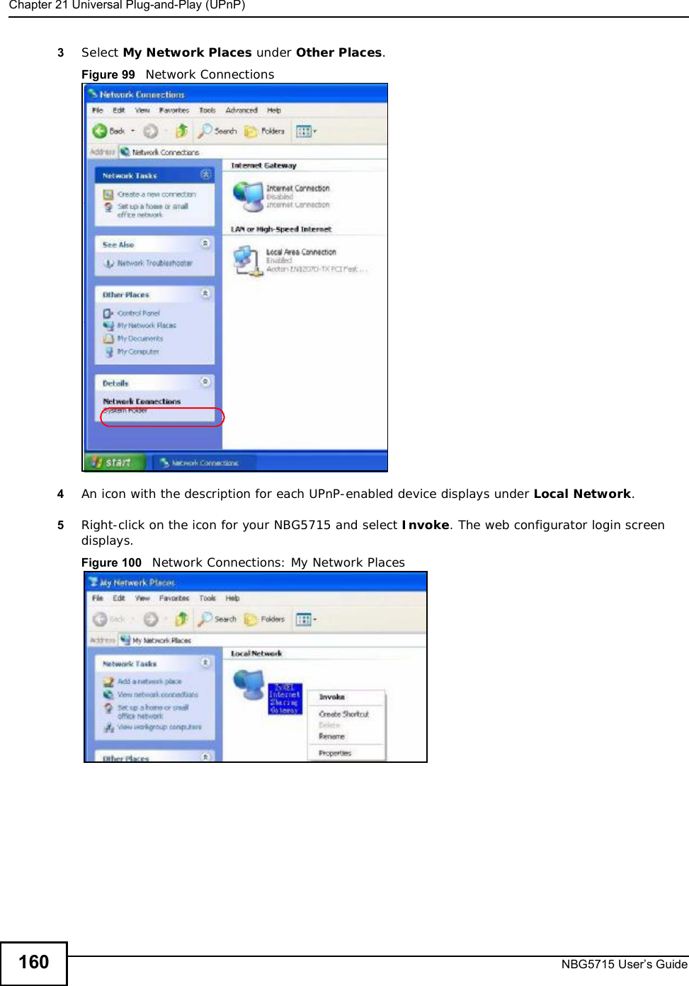
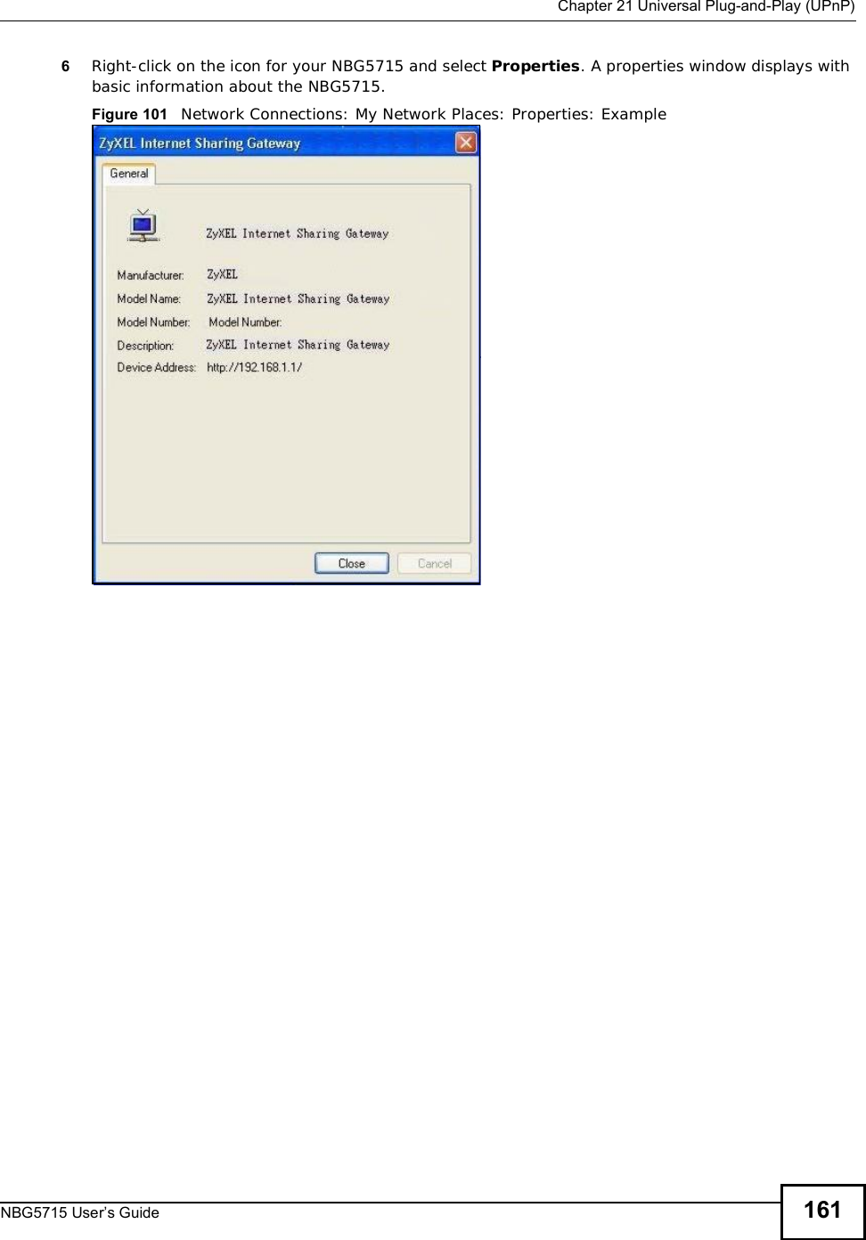
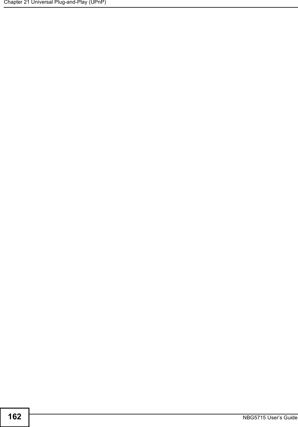
![Appendix DSetting Up Your Computer’s IP AddressNBG5715 User’s Guide2085The Internet Protocol TCP/IP Properties window opens.6Select Obtain an IP address automatically if your network administrator or ISP assigns your IP address dynamically.Select Use the following IP Address and fill in the IP address,Subnet mask, and Default gateway fields if you have a static IP address that was assigned to you by your network administrator or ISP. You may also have to enter a Preferred DNS server and an AlternateDNSserver, if that information was provided.7Click OK to close the Internet Protocol (TCP/IP) Properties window.8Click OK to close the Local Area Connection Properties window.Verifying Settings1Click Start > All Programs > Accessories > Command Prompt.2In the Command Prompt window, type "ipconfig" and then press [ENTER]. You can also go to Start > Control Panel > Network Connections, right-click a network connection, click Status and then click the Support tab to view your IP address and connection information.](https://usermanual.wiki/ZyXEL-Communications/NBG5715/User-Guide-1542926-Page-207.png)
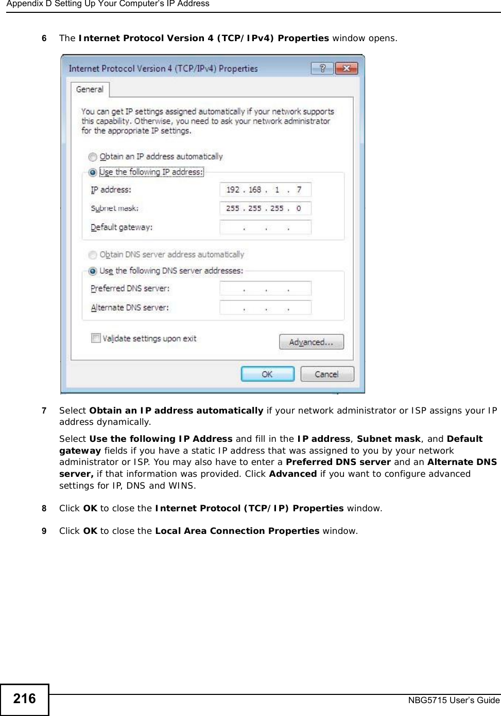
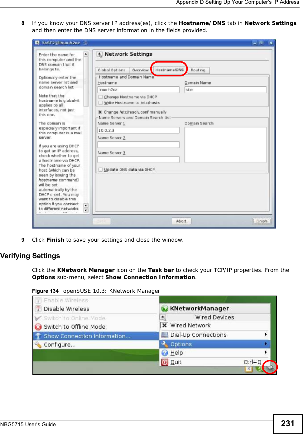
![Appendix DSetting Up Your Computer’s IP AddressNBG5715 User’s Guide2127The Internet Protocol Version 4 (TCP/IPv4) Properties window opens.8Select Obtain an IP address automatically if your network administrator or ISP assigns your IP address dynamically.Select Use the following IP Address and fill in the IP address,Subnet mask, and Default gateway fields if you have a static IP address that was assigned to you by your network administrator or ISP. You may also have to enter a Preferred DNS server and an AlternateDNSserver, if that information was provided.Click Advanced.9Click OK to close the Internet Protocol (TCP/IP) Properties window.10 Click OK to close the Local Area Connection Properties window.Verifying Settings1Click Start > All Programs > Accessories > Command Prompt.2In the Command Prompt window, type "ipconfig" and then press [ENTER]. You can also go to Start > Control Panel > Network Connections, right-click a network connection, click Status and then click the Support tab to view your IP address and connection information.](https://usermanual.wiki/ZyXEL-Communications/NBG5715/User-Guide-1542926-Page-211.png)
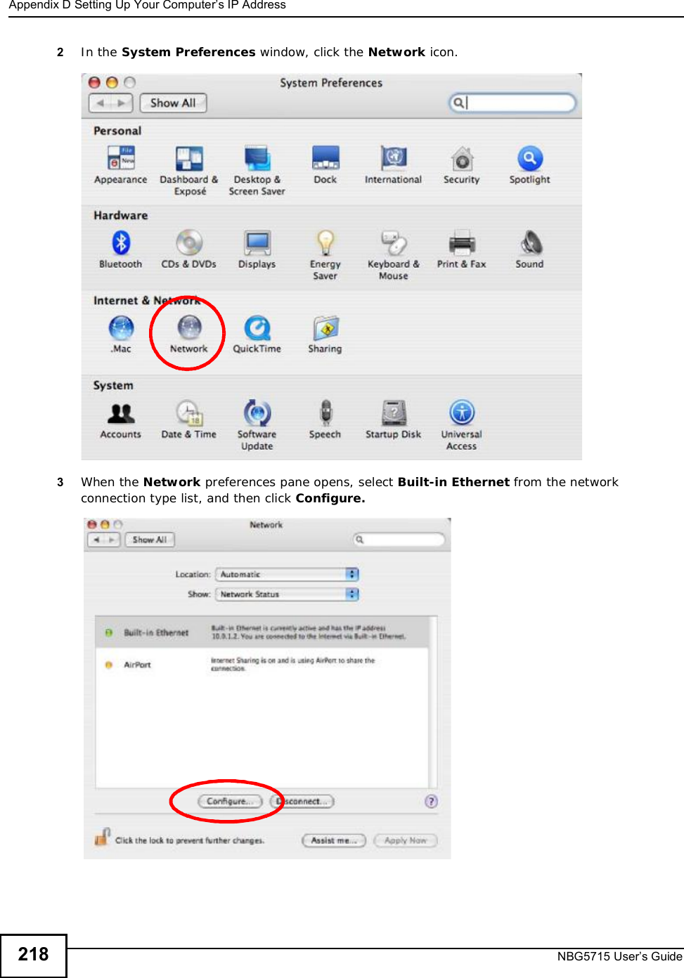
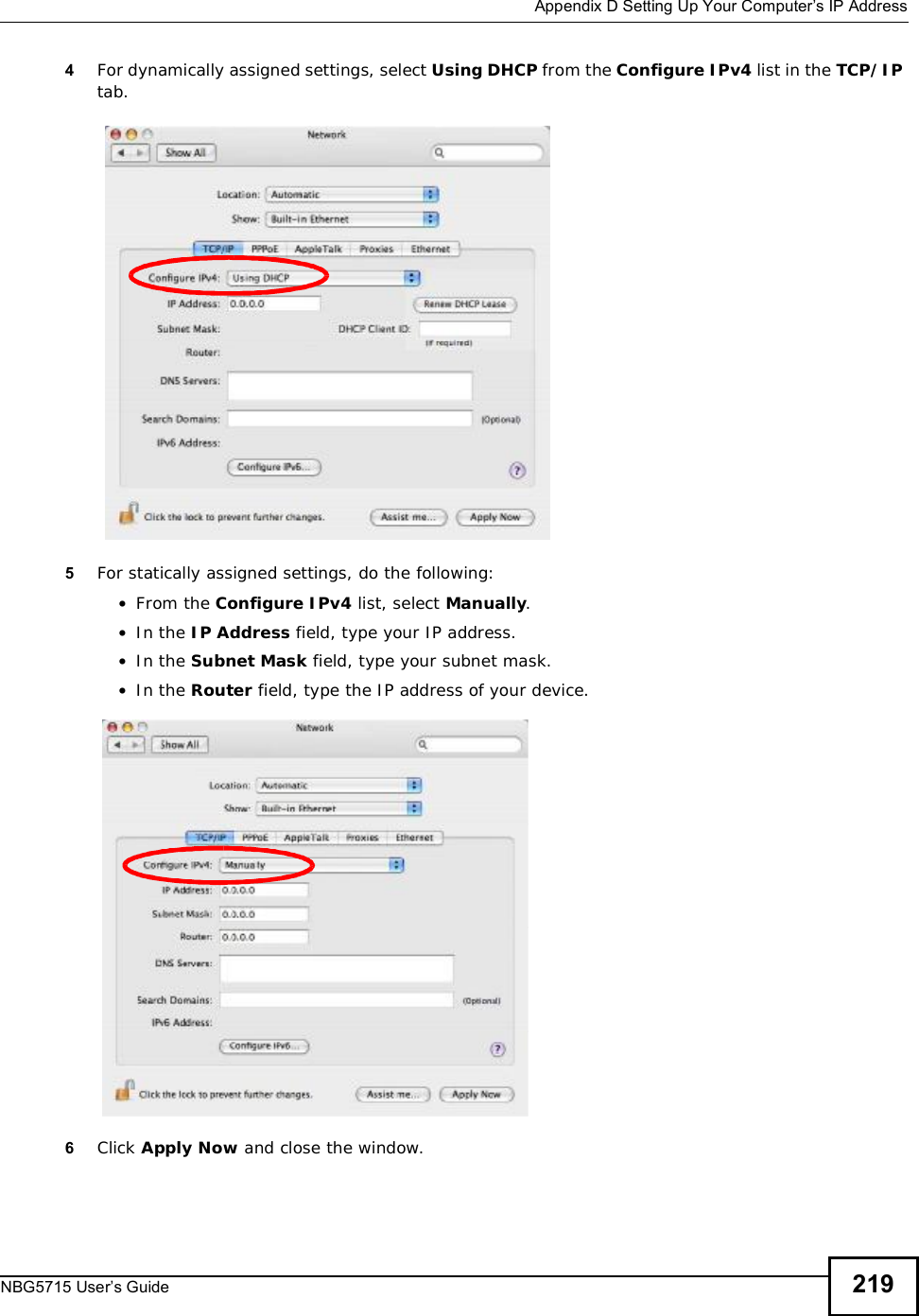
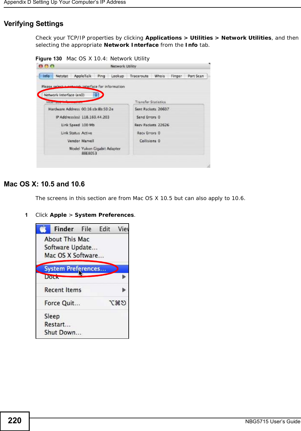
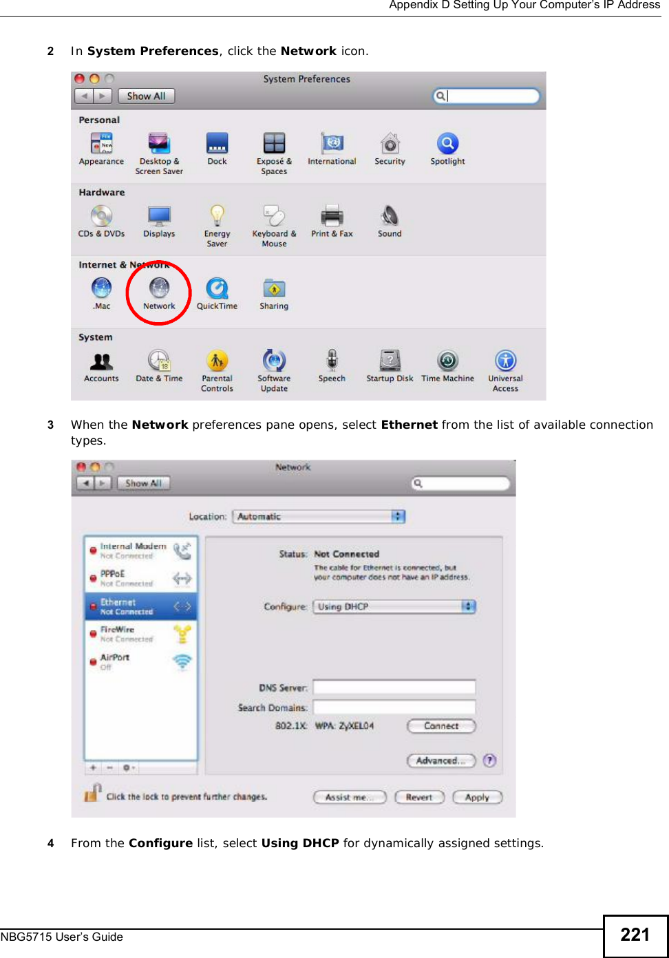
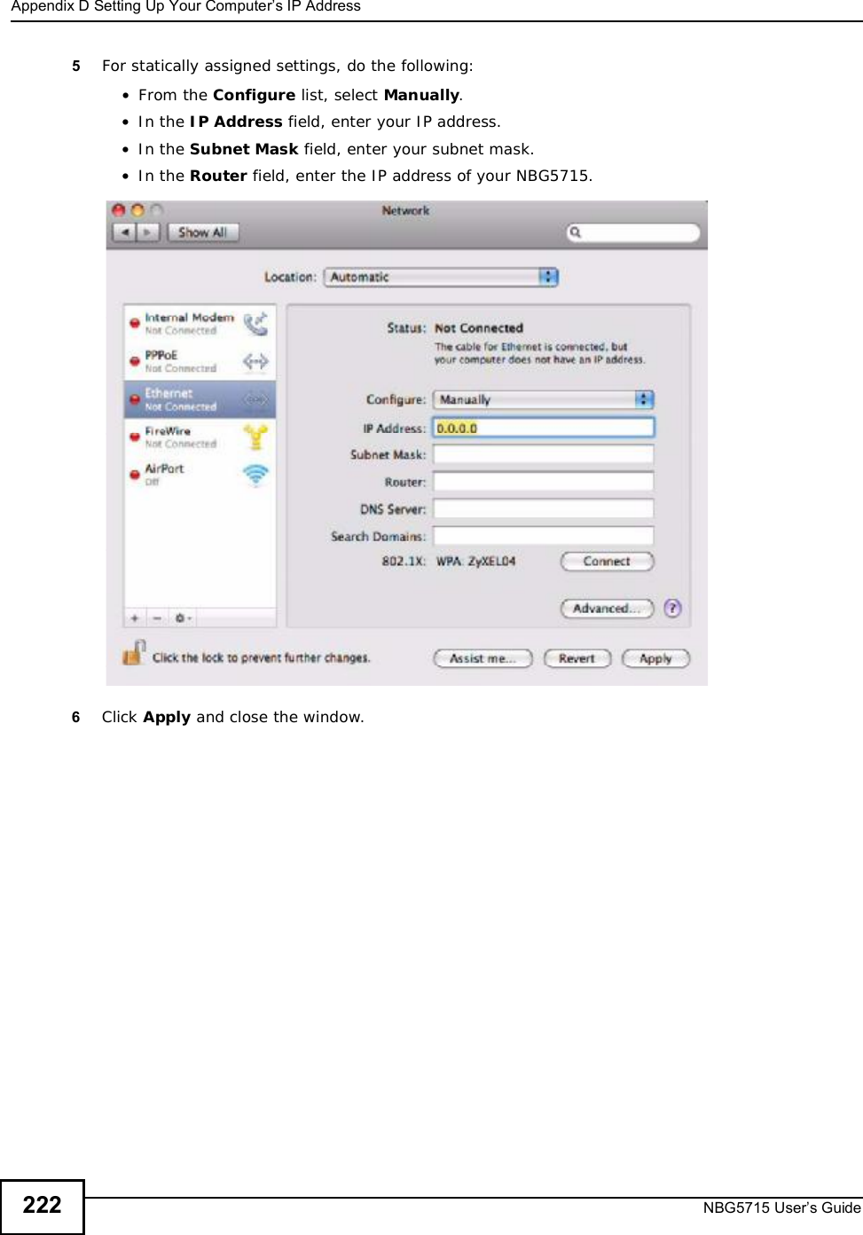
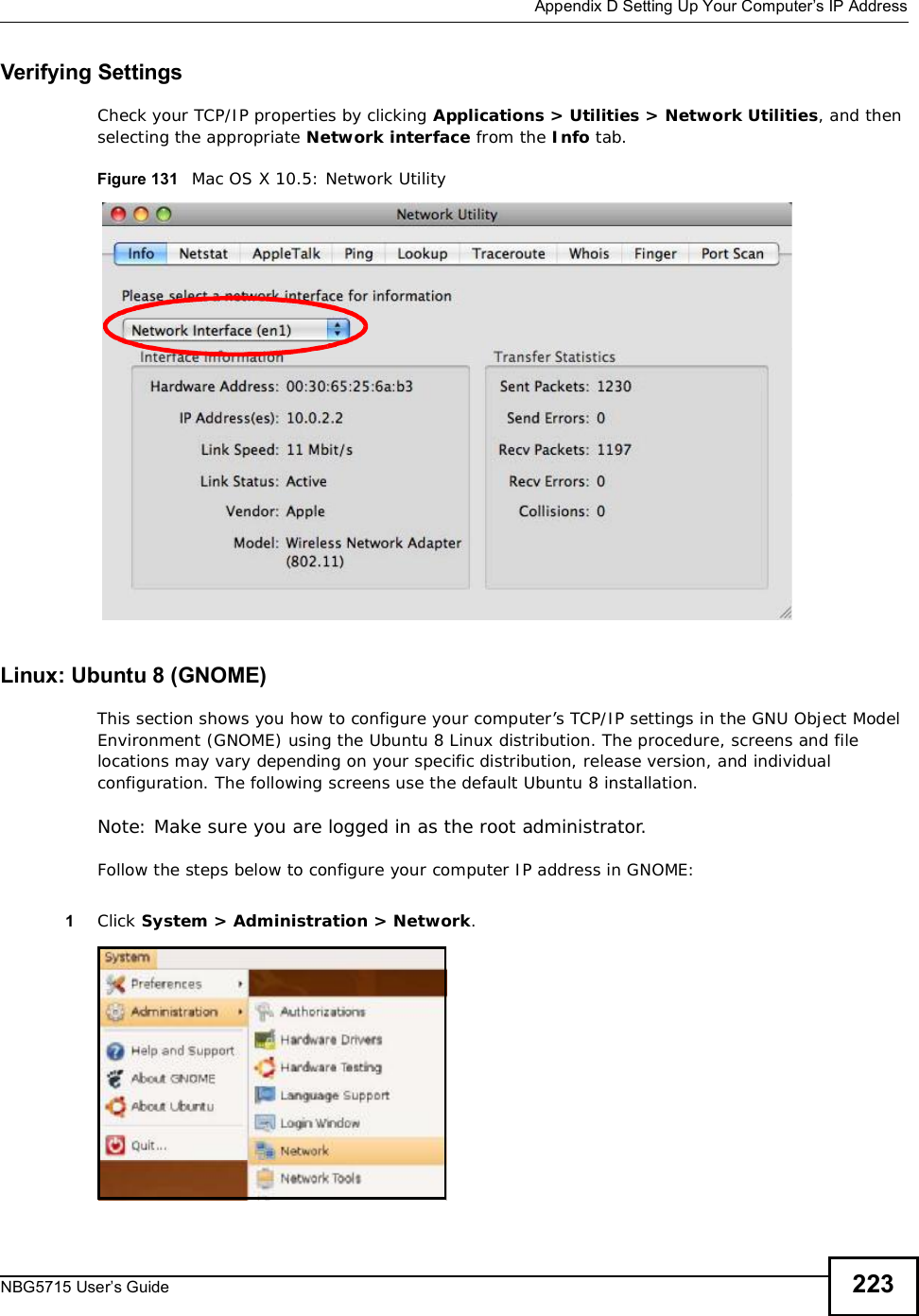
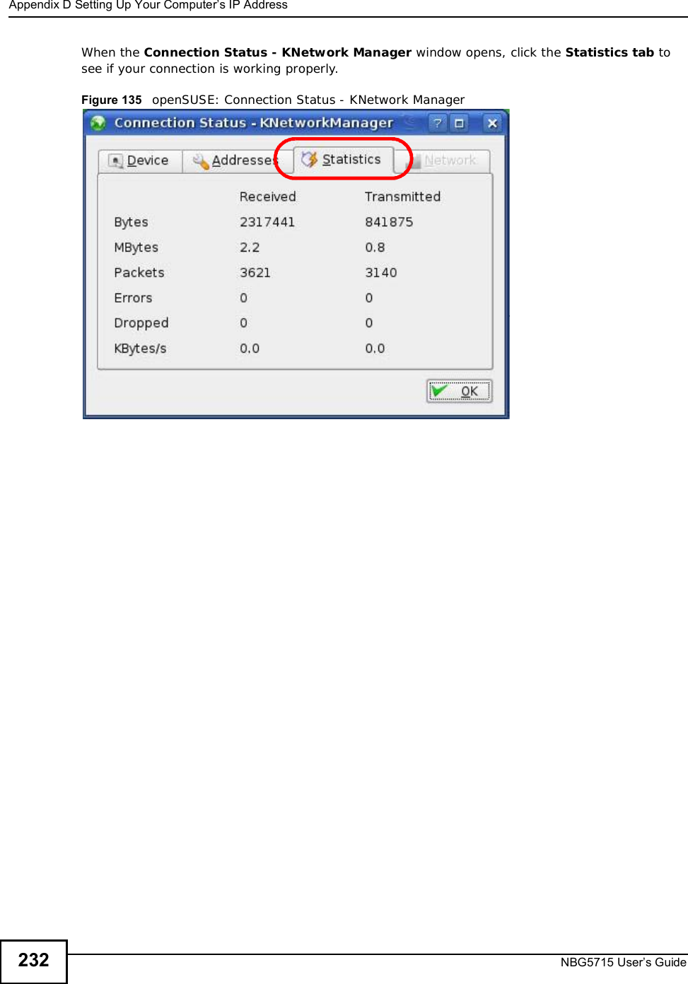
![Appendix DSetting Up Your Computer’s IP AddressNBG5715 User’s Guide 217Verifying Settings1Click Start > All Programs > Accessories > Command Prompt.2In the Command Prompt window, type "ipconfig" and then press [ENTER]. 3The IP settings are displayed as follows.Mac OS X: 10.3 and 10.4The screens in this section are from Mac OS X 10.4 but can also apply to 10.3.1Click Apple > System Preferences.](https://usermanual.wiki/ZyXEL-Communications/NBG5715/User-Guide-1542926-Page-216.png)

![Appendix GOpen Software AnnouncementsNBG5715 User’s Guide 259The above copyright notice and this permission notice shall be included in all copies or substantial portions of the Software.THE SOFTWARE IS PROVIDED "AS IS", WITHOUT WARRANTY OF ANY KIND, EXPRESS ORIMPLIED, INCLUDING BUT NOT LIMITED TO THE WARRANTIES OF MERCHANTABILITY, FITNESS FOR A PARTICULAR PURPOSE AND NONINFRINGEMENT. IN NO EVENT SHALL THEAUTHORS OR COPYRIGHT HOLDERS BE LIABLE FOR ANY CLAIM, DAMAGES OR OTHERLIABILITY, WHETHER IN AN ACTION OF CONTRACT, TORT OR OTHERWISE, ARISING FROM,OUT OF OR IN CONNECTION WITH THE SOFTWARE OR THE USE OR OTHER DEALINGS INTHE SOFTWARE.This Product includes isakmpd, miniupnpd, ipsec-tools, Ppp, and libpcap, under the license by BSDBSDCopyright (c) [dates as appropriate to package] The Regents of the University of California. All rights reserved. Redistribution and use in source and binary forms, with or without modification, are permitted provided that the following conditions are met:Redistributions of source code must retain the above copyright notice, this list of conditions and the following disclaimer.Redistributions in binary form must reproduce the above copyright notice, this list of conditions and the following disclaimer in the documentation and/or other materials provided with the distribution.Neither the name of the University nor of the Laboratory may be used to endorse or promote products derived from this software without specific prior written permission. THIS SOFTWARE IS PROVIDED BY THE REGENTS AND CONTRIBUTORS ``AS IS'' AND ANY EXPRESS OR IMPLIED WARRANTIES, INCLUDING, BUT NOT LIMITED TO, THE IMPLIED WARRANTIES OF MERCHANTABILITY AND FITNESS FOR A PARTICULAR PURPOSE ARE DISCLAIMED. IN NO EVENT SHALL THE REGENTS OR CONTRIBUTORS BE LIABLE FOR ANY DIRECT, INDIRECT, INCIDENTAL, SPECIAL, EXEMPLARY, OR CONSEQUENTIAL DAMAGES (INCLUDING, BUT NOT LIMITED TO, PROCUREMENT OF SUBSTITUTE GOODS OR SERVICES; LOSS OF USE, DATA, OR PROFITS; OR BUSINESS INTERRUPTION) HOWEVER CAUSED AND ON ANY THEORY OF LIABILITY, WHETHER IN CONTRACT, STRICT LIABILITY, OR TORT (INCLUDING NEGLIGENCE OR OTHERWISE) ARISING IN ANY WAY OUT OF THE USE OF THIS SOFTWARE, EVEN IF ADVISED OF THE POSSIBILITY OF SUCH DAMAGE. This Product includes luci, and uhttpd under the license by Apache software](https://usermanual.wiki/ZyXEL-Communications/NBG5715/User-Guide-1542926-Page-258.png)
![Appendix GOpen Software AnnouncementsNBG5715 User’s Guide266 License. However, in accepting such obligations, You may act only on Your own behalf and on Your sole responsibility, not on behalf of any other Contributor, and only if You agree to indemnify, defend, and hold each Contributor harmless for any liability incurred by, or claims asserted against, such Contributor by reason of your accepting any such warranty or additional liability. END OF TERMS AND CONDITIONS APPENDIX: How to apply the Apache License to your work. To apply the Apache License to your work, attach the following boilerplate notice, with the fields enclosed by brackets "[]" replaced with your own identifying information. (Don't include the brackets!) The text should be enclosed in the appropriate comment syntax for the file format. We also recommend that a file or class name and description of purpose be included on the same "printed page" as the copyright notice for easier identification within third-party archives. Copyright [yyyy] [name of copyright owner] Licensed under the Apache License, Version 2.0 (the "License"); you may not use this file except in compliance with the License. You may obtain a copy of the License at http://www.apache.org/licenses/LICENSE-2.0](https://usermanual.wiki/ZyXEL-Communications/NBG5715/User-Guide-1542926-Page-265.png)