ZyXEL Communications NBG6604 AC1200 Dual-Band Wireless Router User Manual
ZyXEL Communications Corporation AC1200 Dual-Band Wireless Router
UserManual.wiki
>
ZyXEL Communications
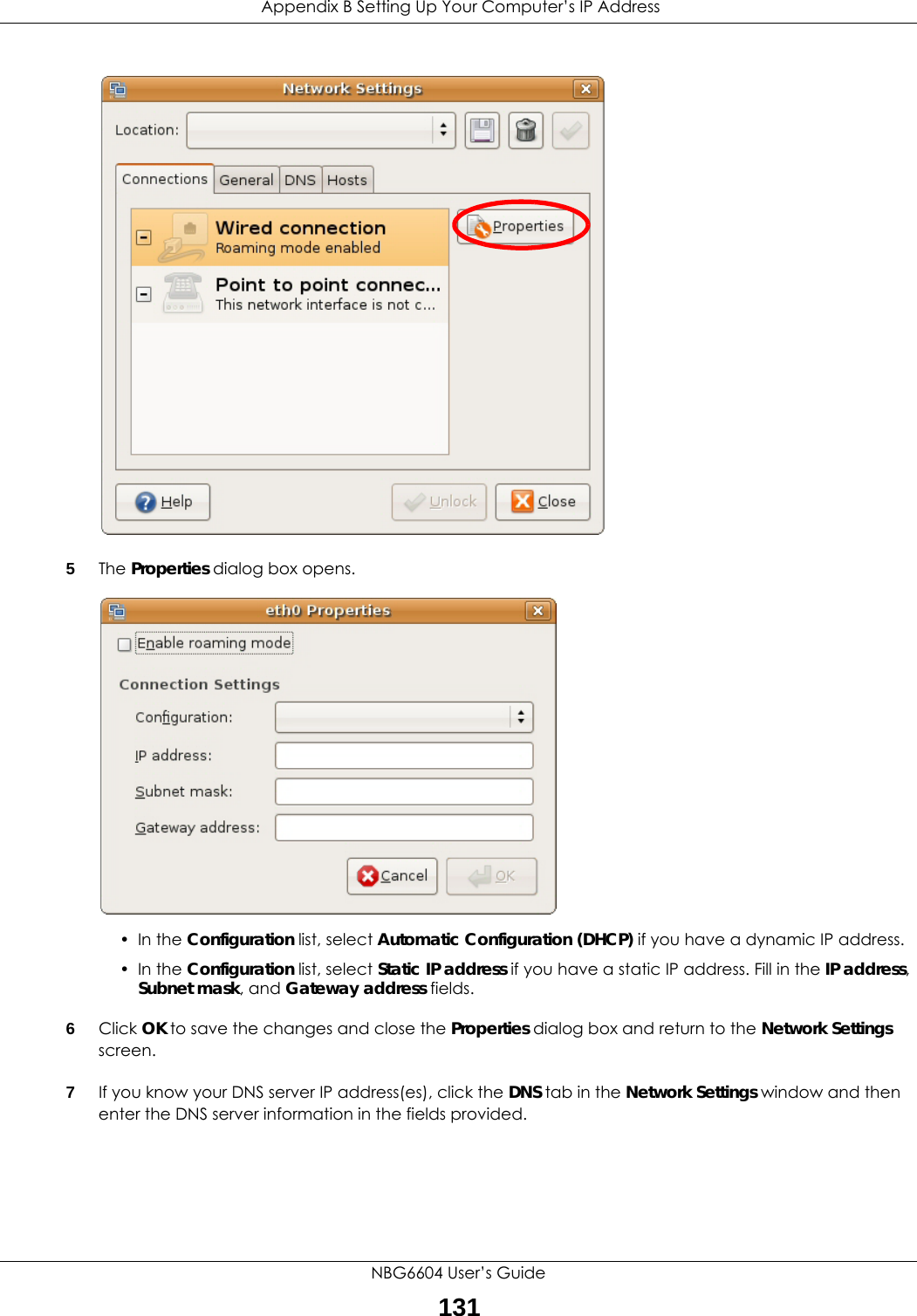
>
NBG6604 User Manual
User Manual
Navigation menu
Upload a User Manual
Namespaces
Wiki Guide
HTML
PDF
Info
Views
User Manual
Discussion / Help
Navigation
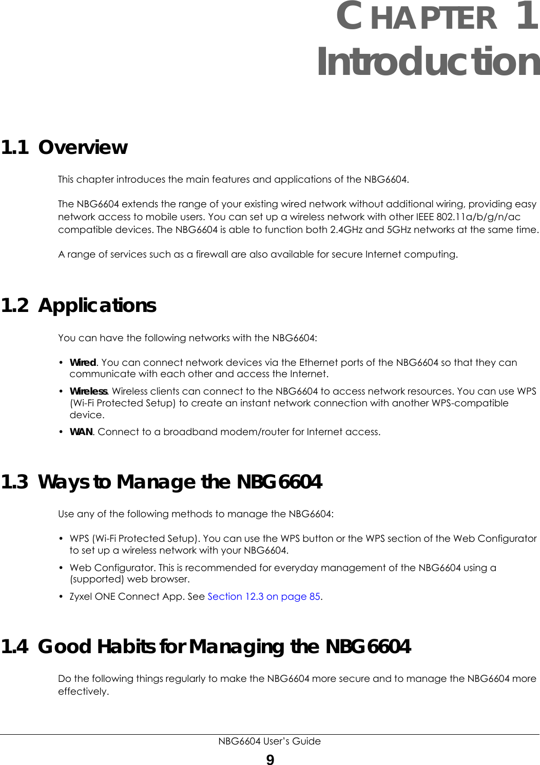
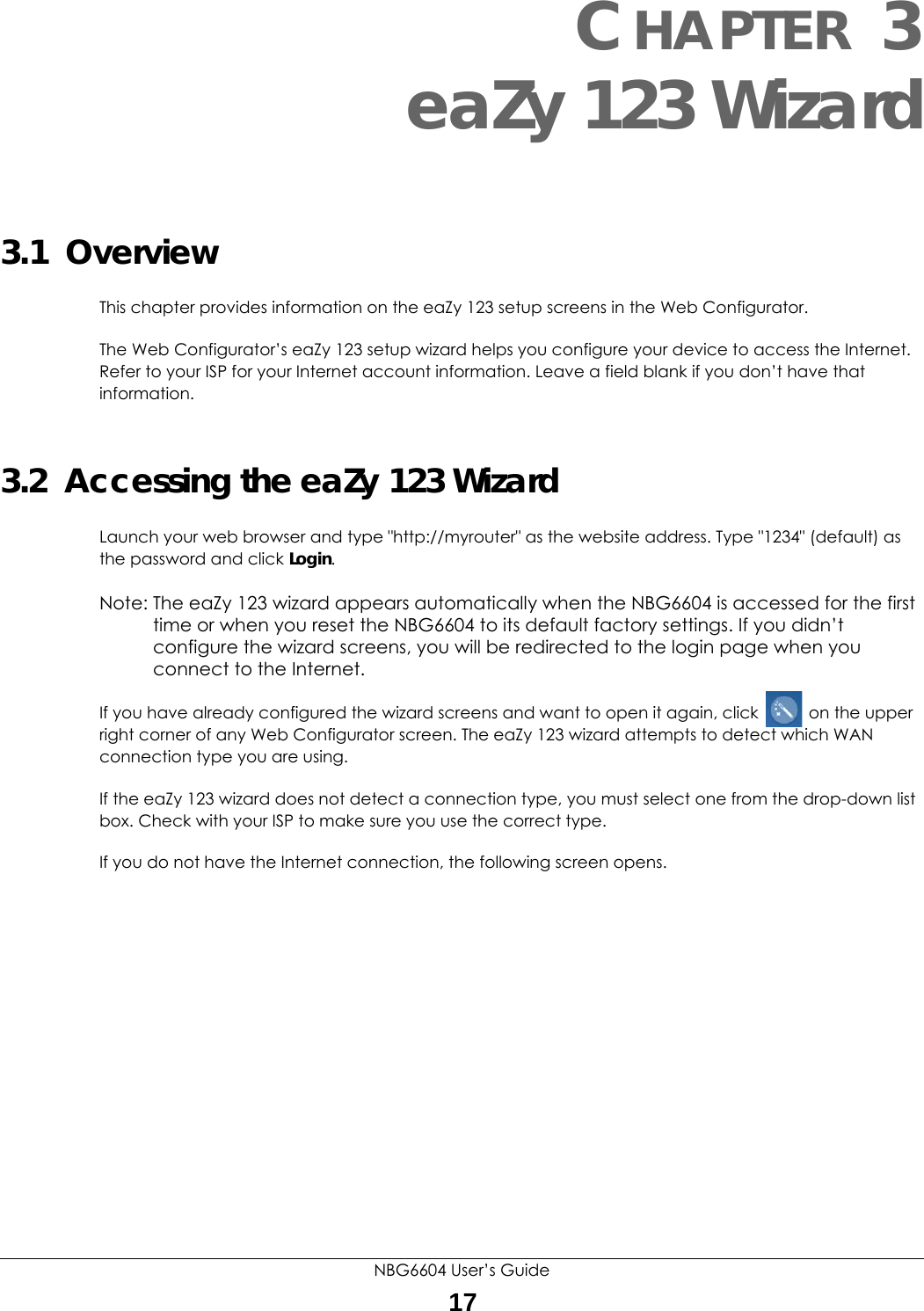
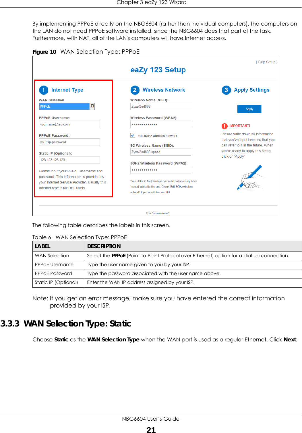
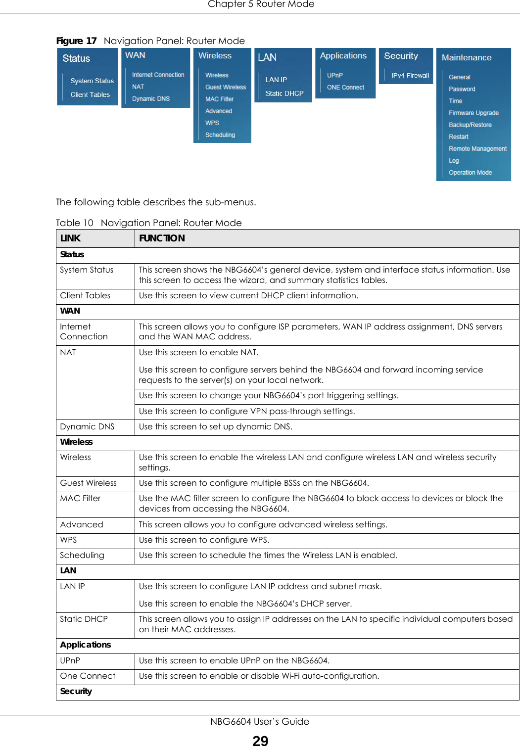
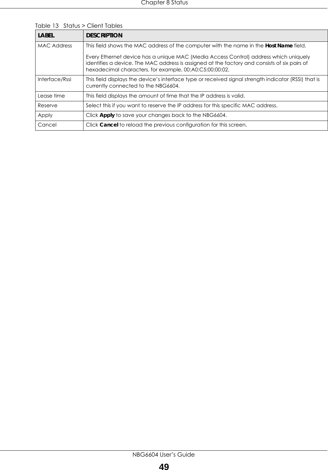
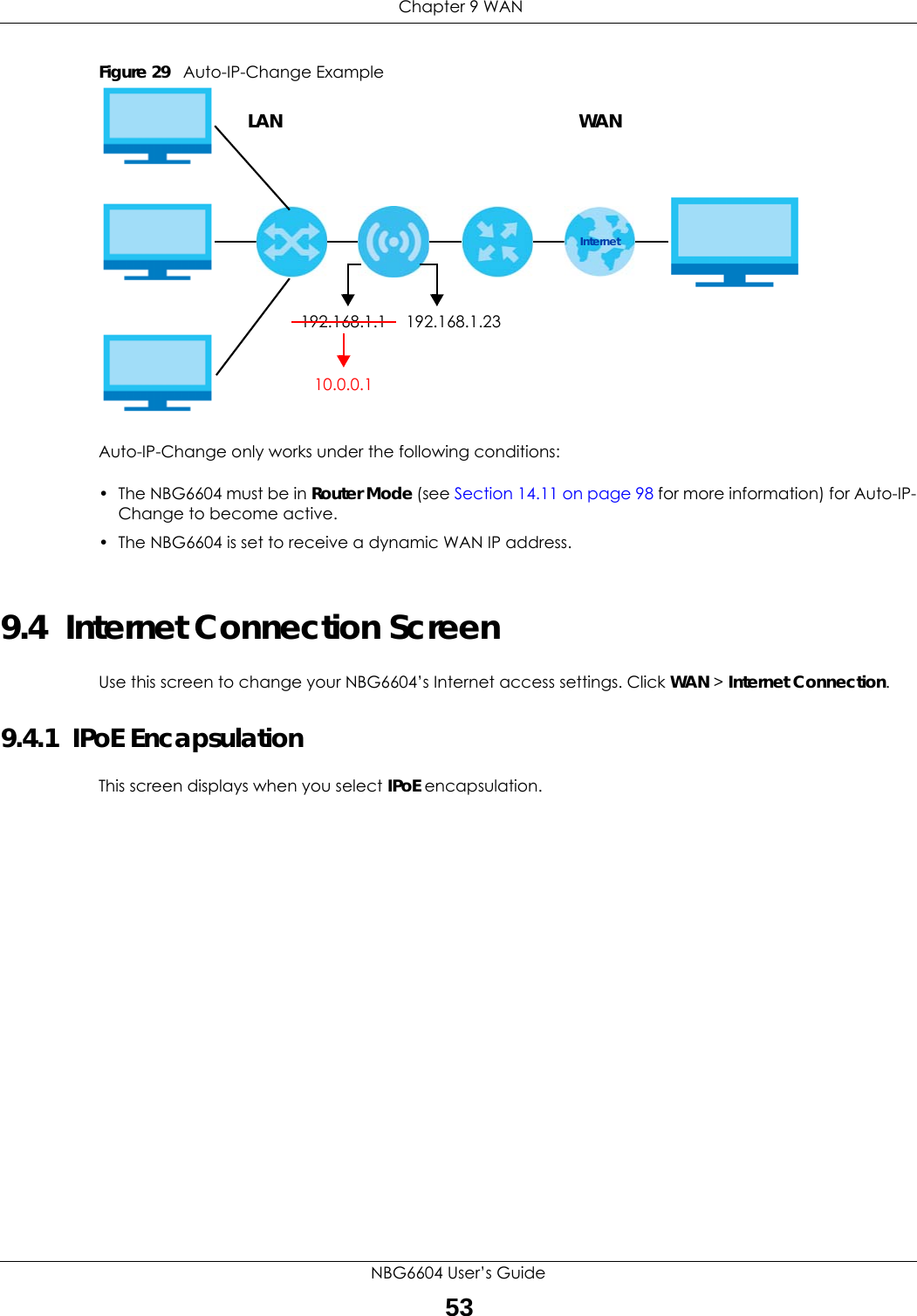
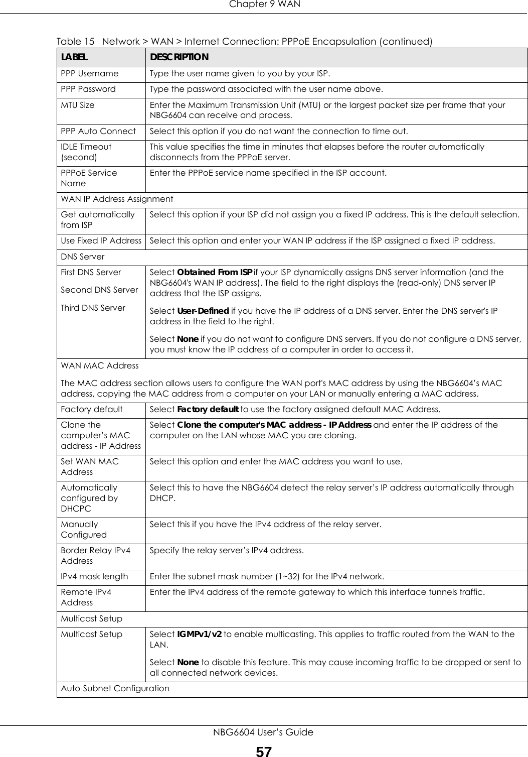

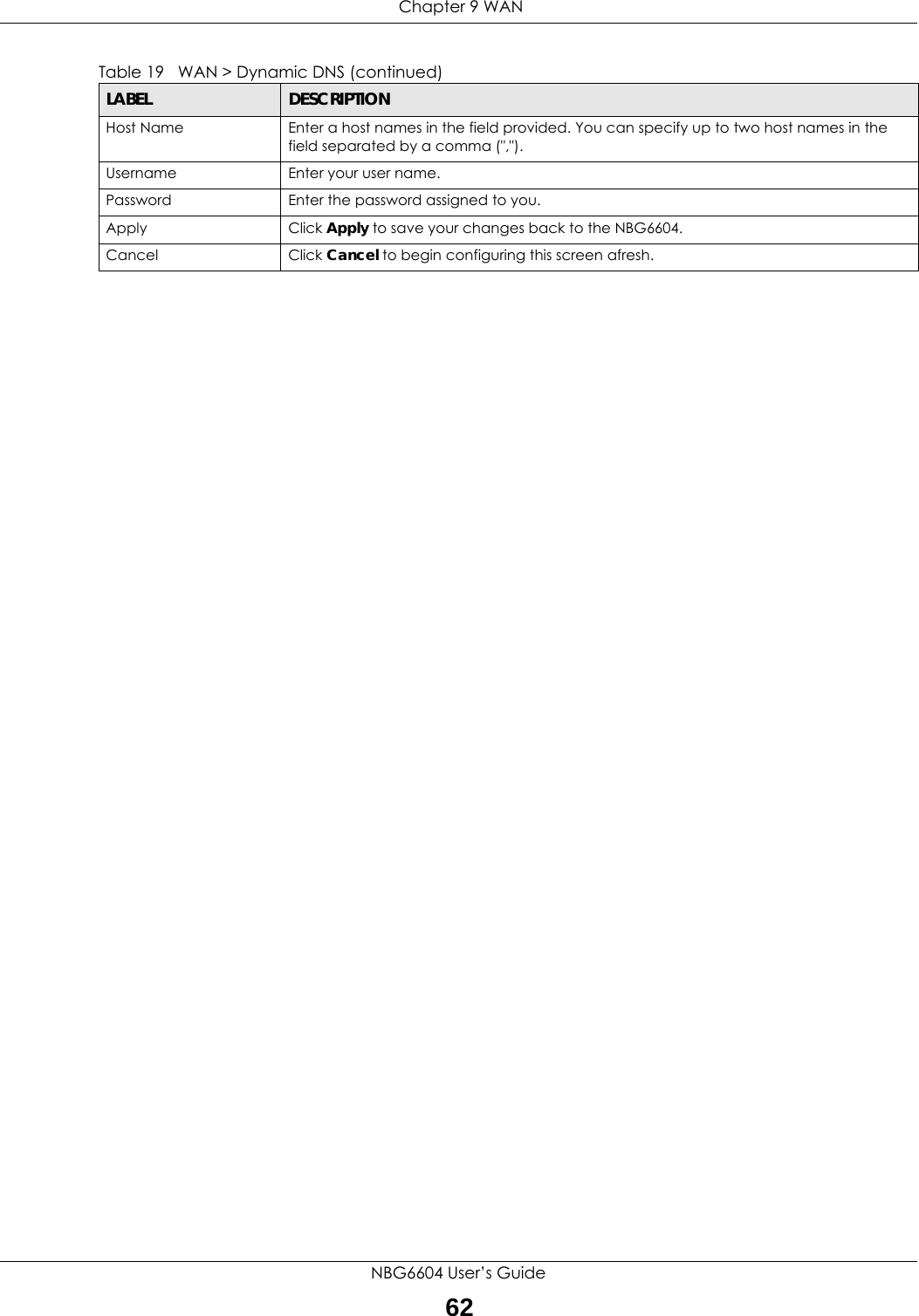
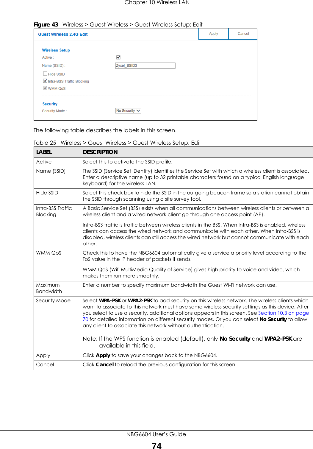
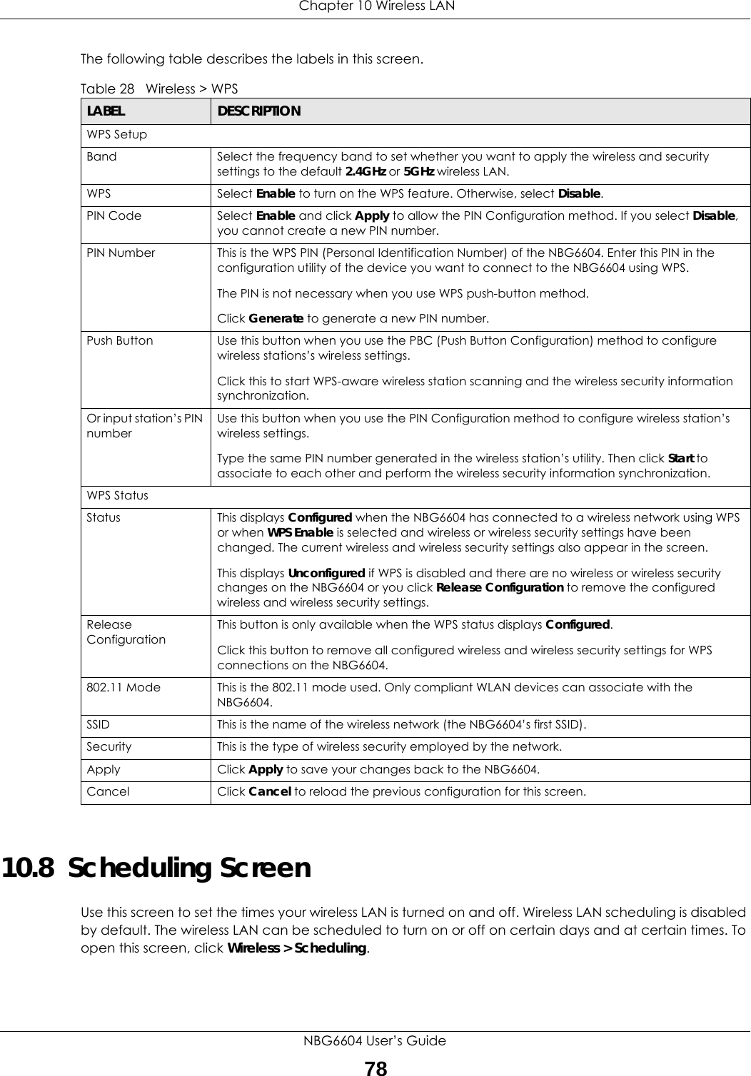
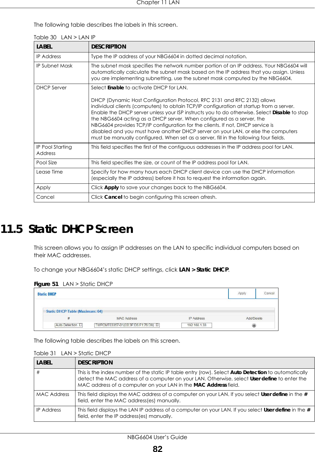
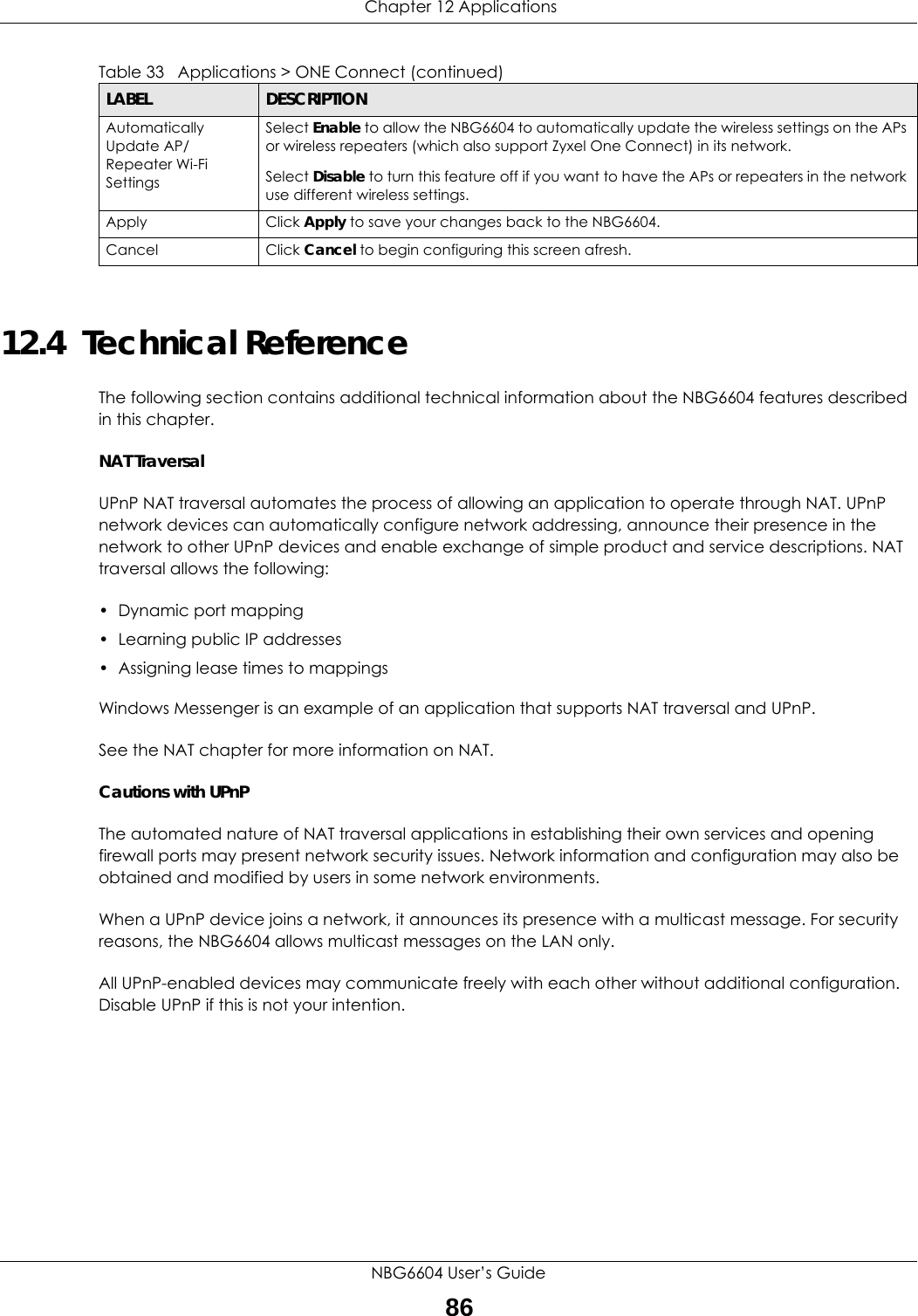
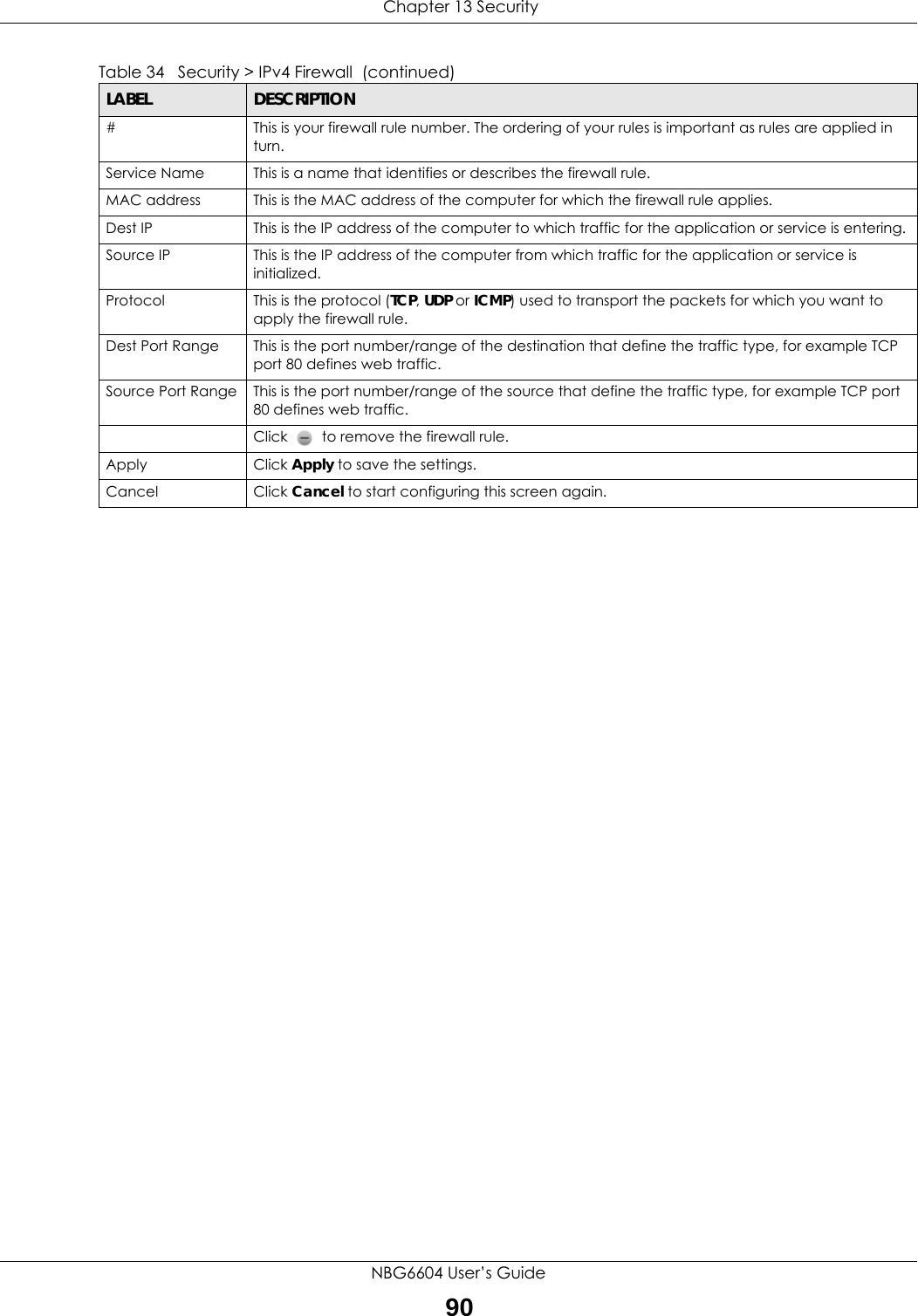
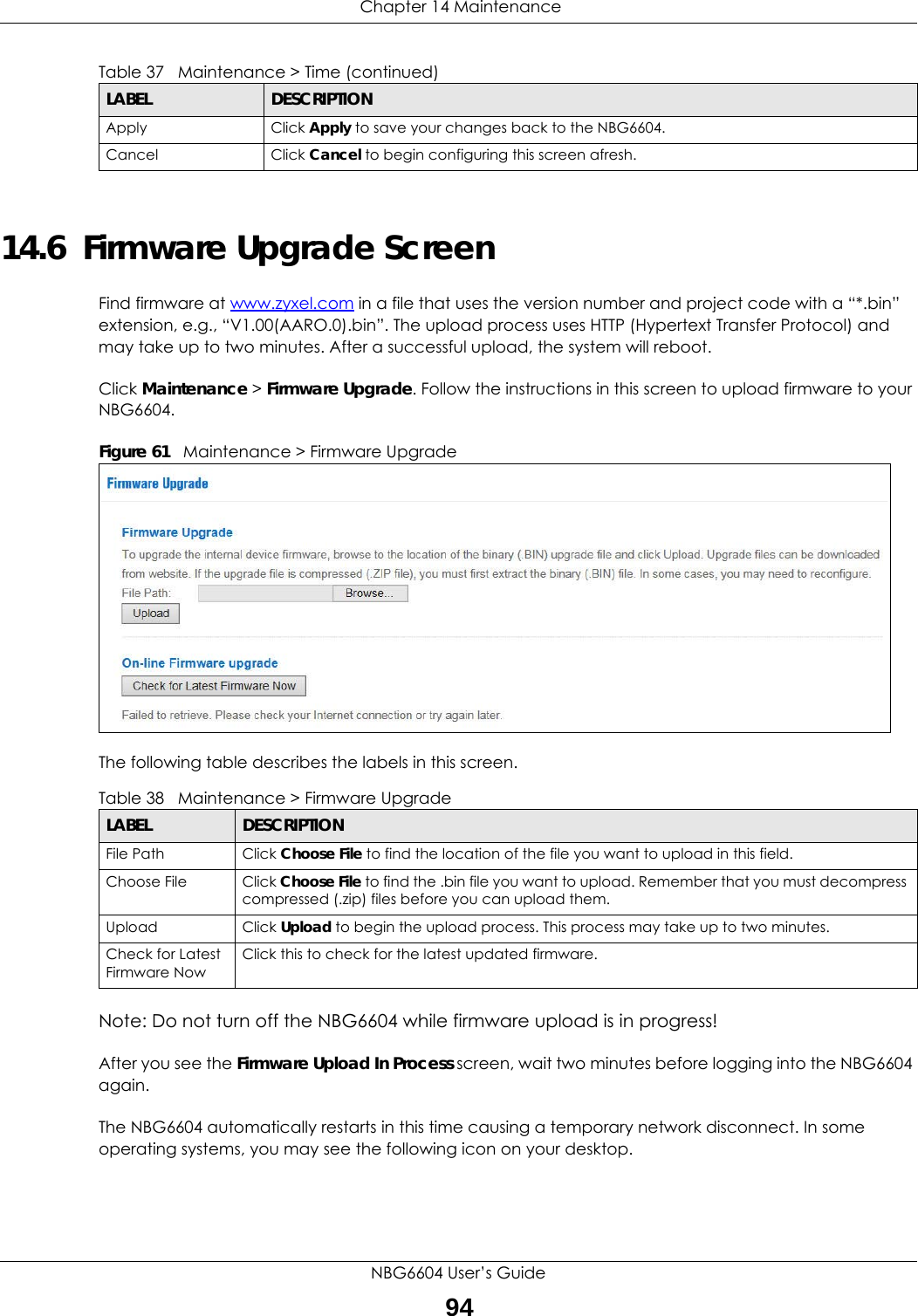
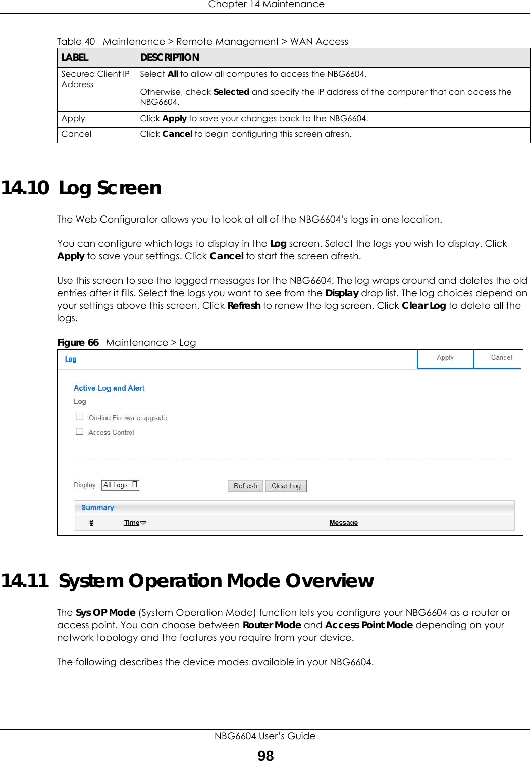
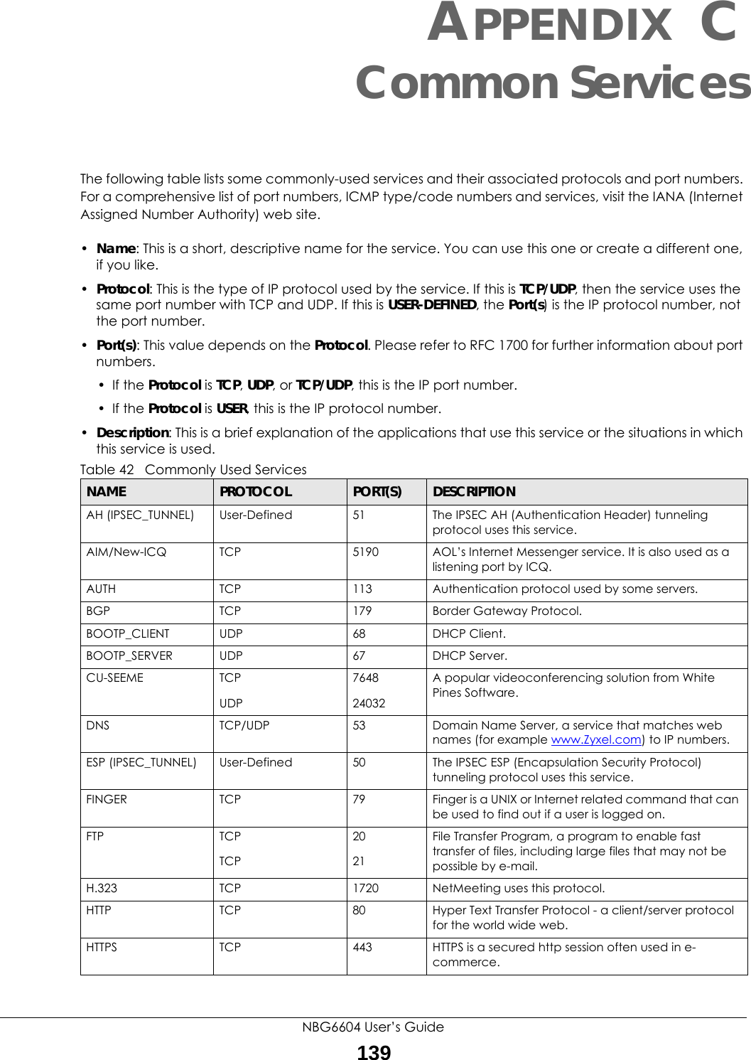
![Chapter 15 TroubleshootingNBG6604 User’s Guide1034Make sure your Internet browser does not block pop-up windows and has JavaScript and Java enabled. 5Make sure your computer is in the same subnet as the NBG6604. (If you know that there are routers between your computer and the NBG6604, skip this step.)• If there is a DHCP server on your network, make sure your computer is using a dynamic IP address. See Section 11.4 on page 81. • If there is no DHCP server on your network, make sure your computer’s IP address is in the same subnet as the NBG6604. See Section 11.4 on page 81.6Reset the device to its factory defaults, and try to access the NBG6604 with the default IP address. See Section 1.5 on page 10.7If the problem continues, contact the network administrator or vendor, or try one of the advanced suggestions.Advanced Suggestions• Try to access the NBG6604 using another service, such as Telnet. If you can access the NBG6604, check the remote management settings and firewall rules to find out why the NBG6604 does not respond to HTTP.• If your computer is connected to the WAN port or is connected wirelessly, use a computer that is connected to a LAN/ETHERNET port.I can see the Login screen, but I cannot log in to the NBG6604.1Make sure you have entered the password correctly. The default password is 1234. This field is case-sensitive, so make sure [Caps Lock] is not on. 2This can happen when you fail to log out properly from your last session. Try logging in again after 5 minutes.3Disconnect and re-connect the power adaptor or cord to the NBG6604. 4If this does not work, you have to reset the device to its factory defaults. See Section 15.5 on page 105.15.4 Internet AccessI cannot access the Internet.1Check the hardware connections, and make sure the LEDs are behaving as expected. See the Quick Start Guide.2Go to Maintenance > Operation Mode. Check your System Operation Mode setting.](https://usermanual.wiki/ZyXEL-Communications/NBG6604/User-Guide-3569384-Page-103.png)
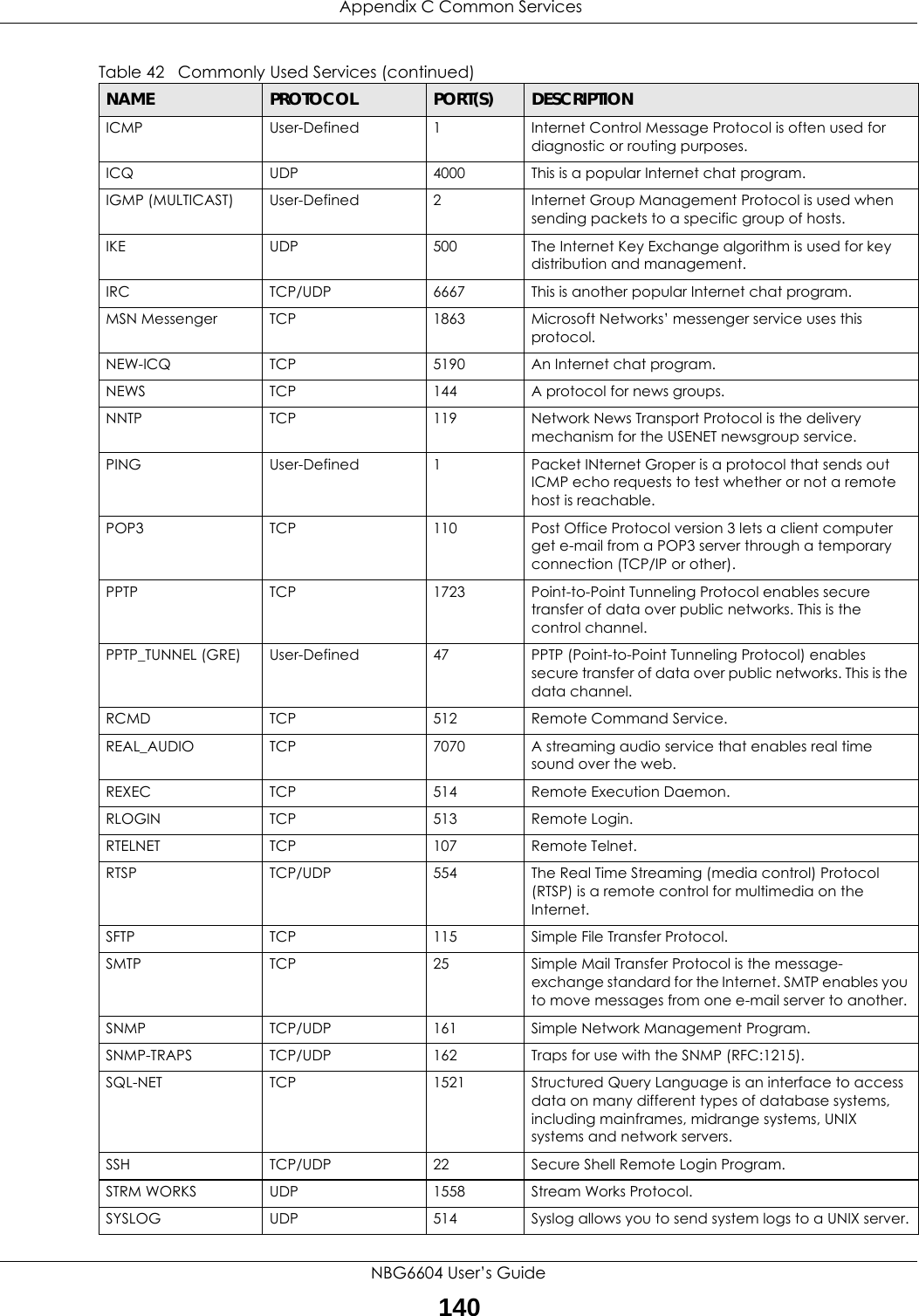
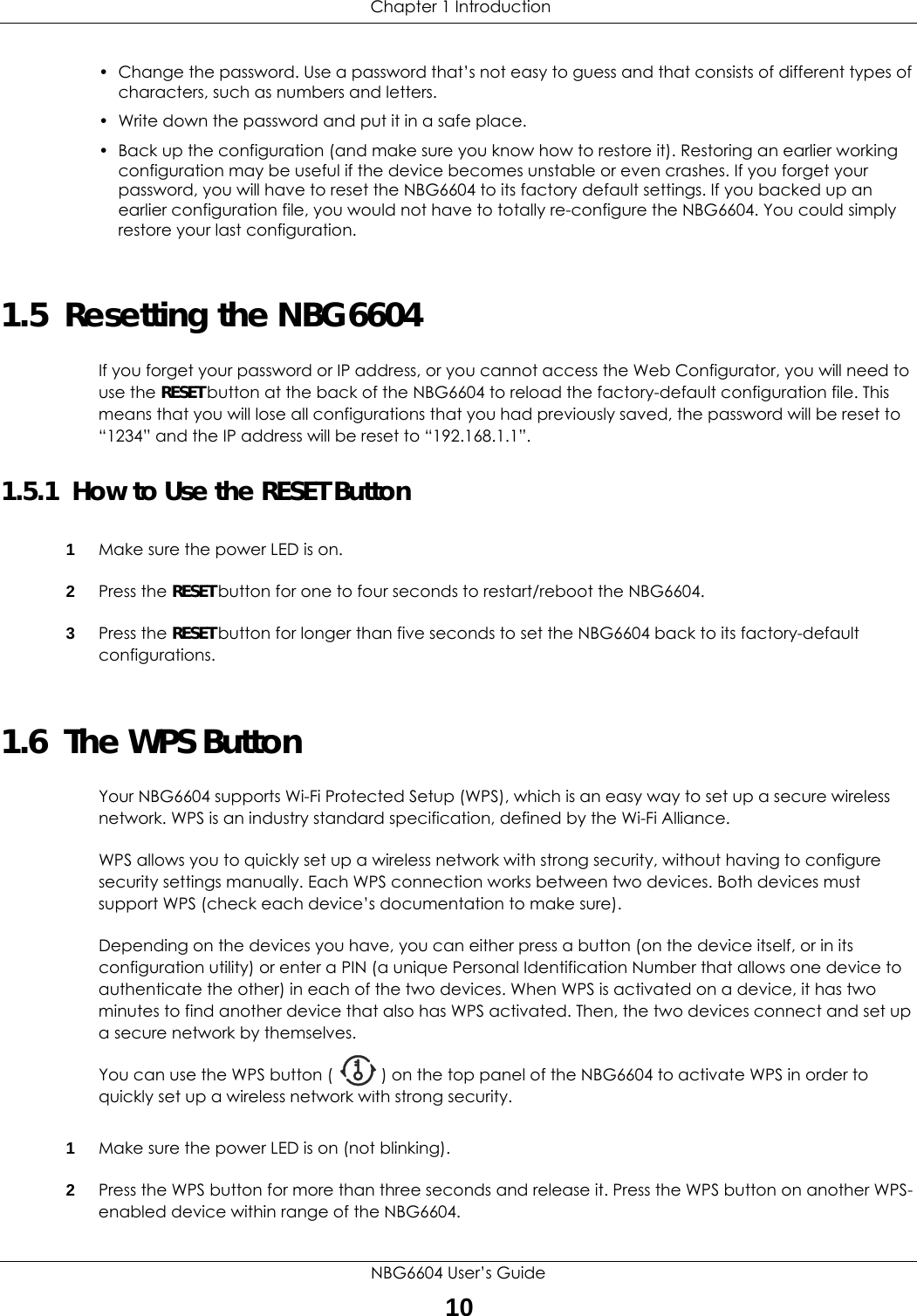
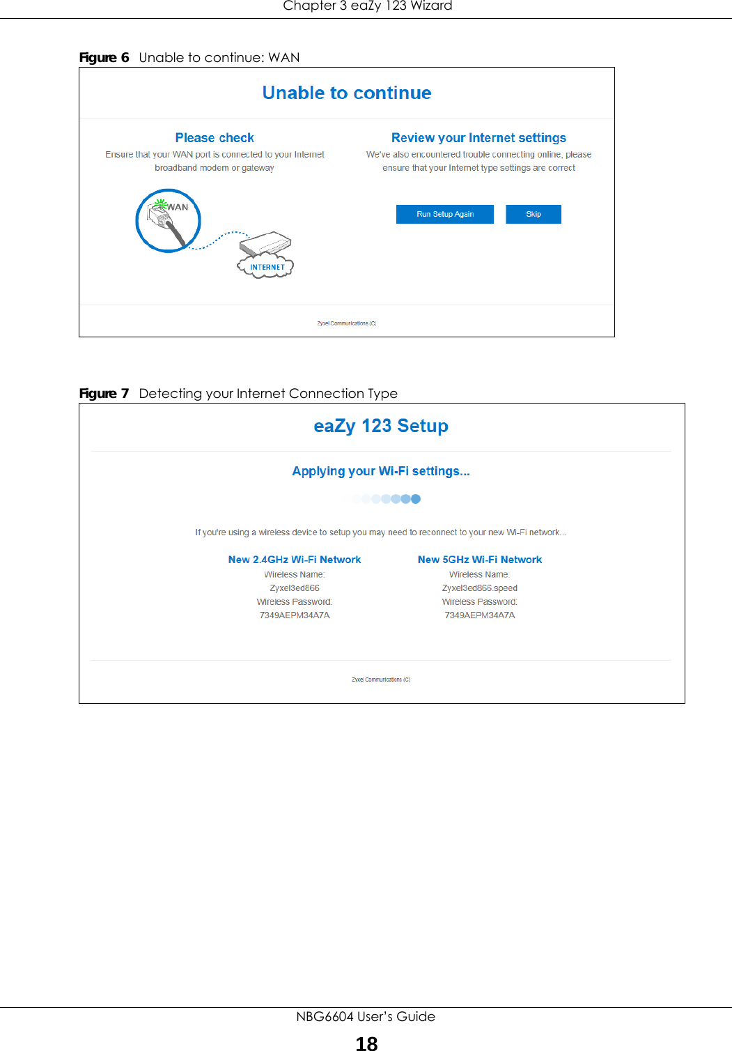
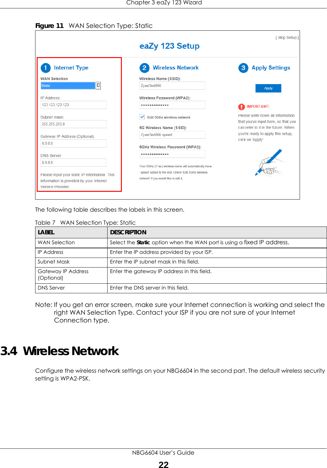
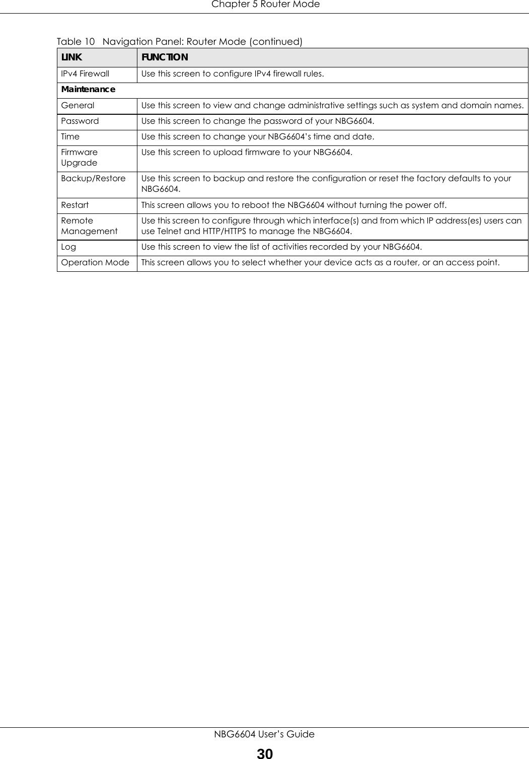
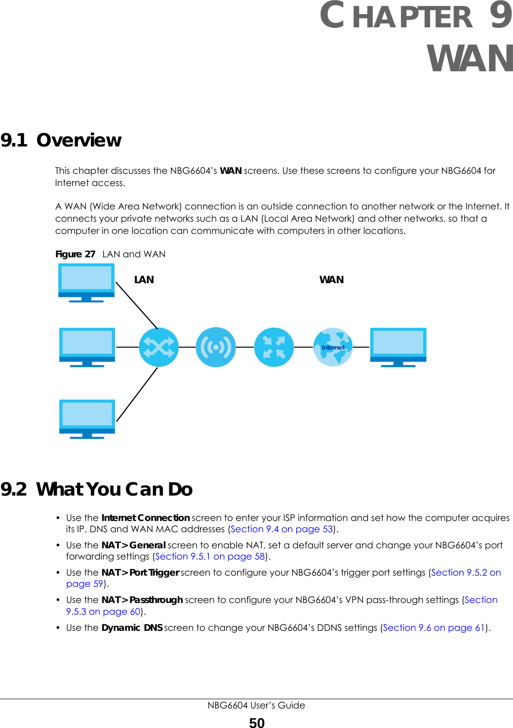
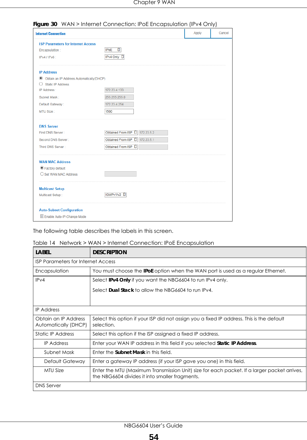
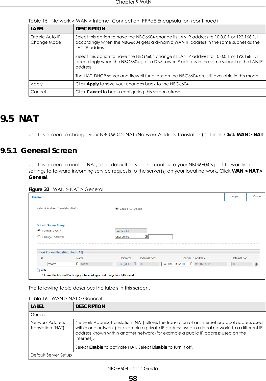
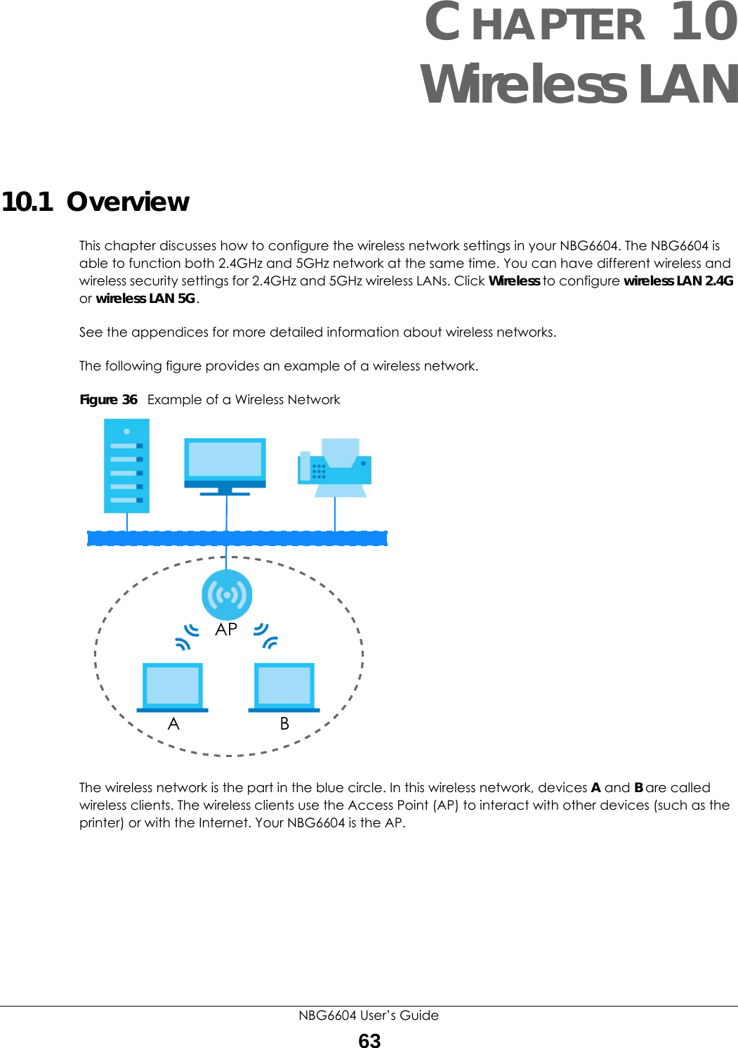
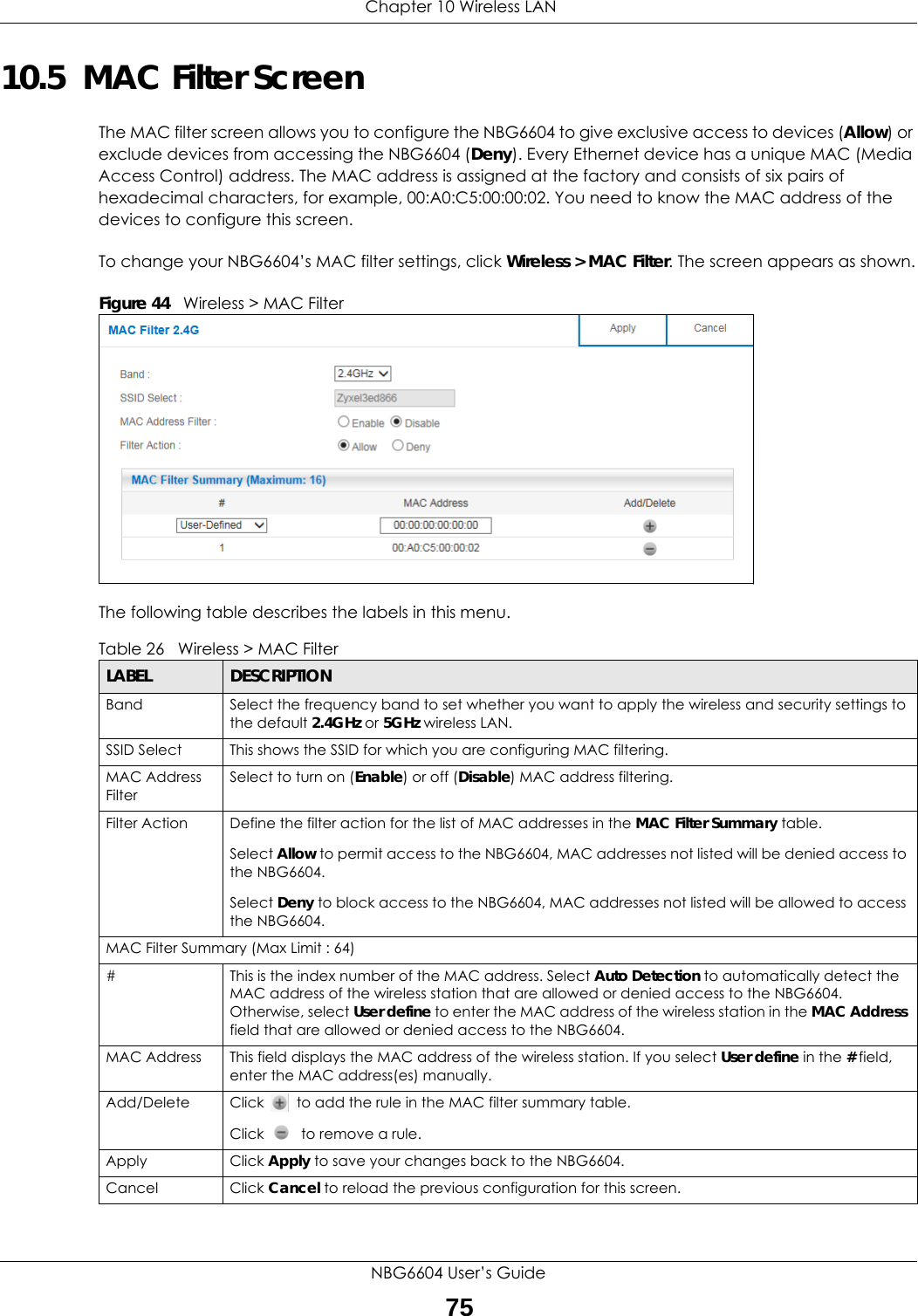
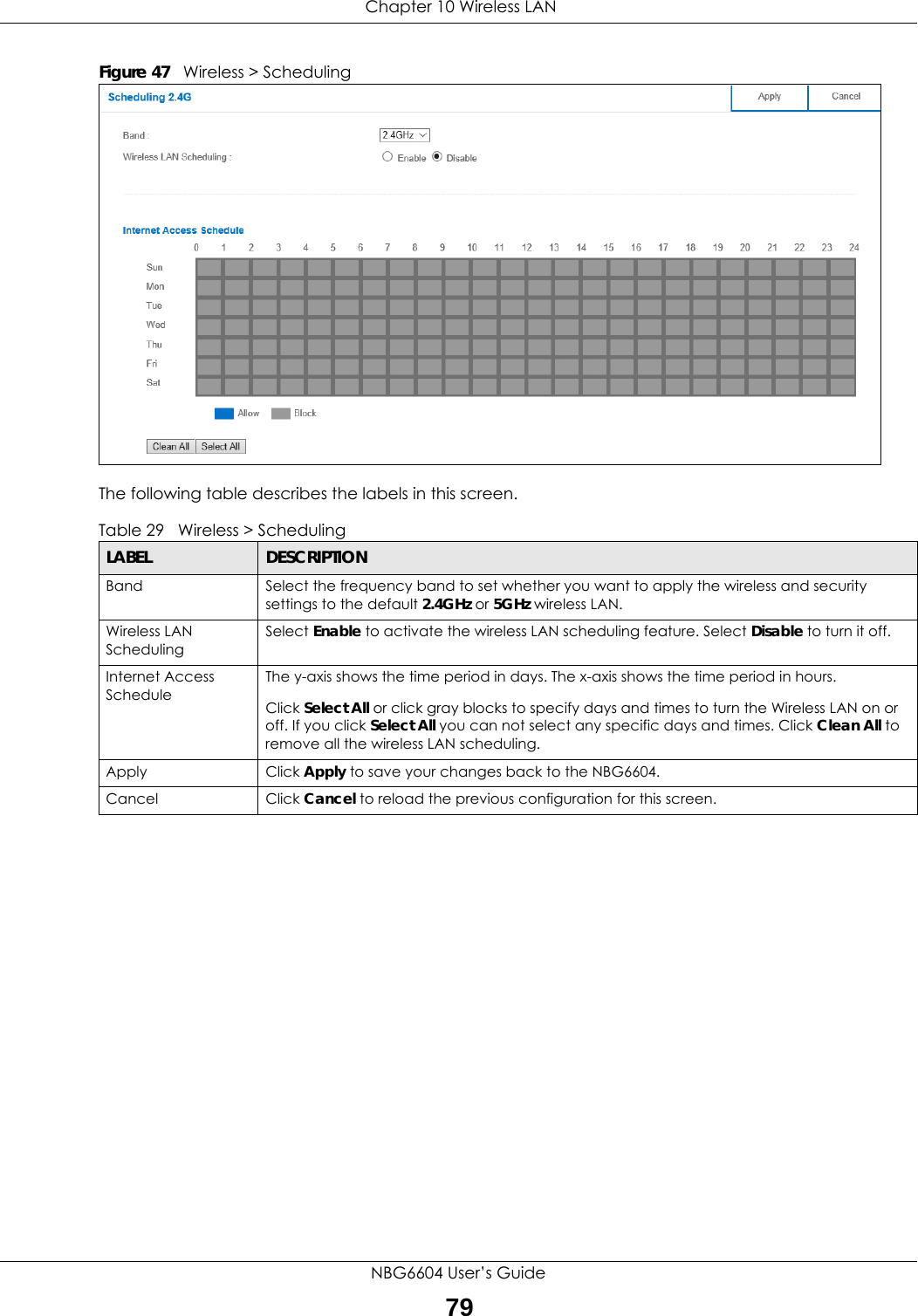
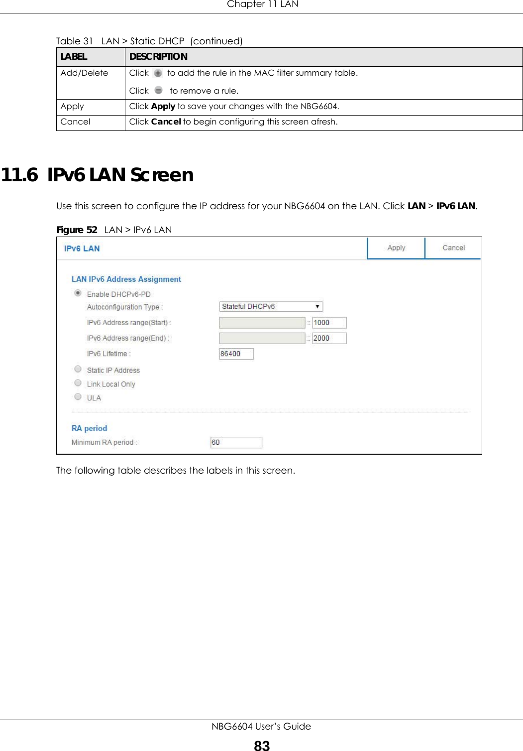
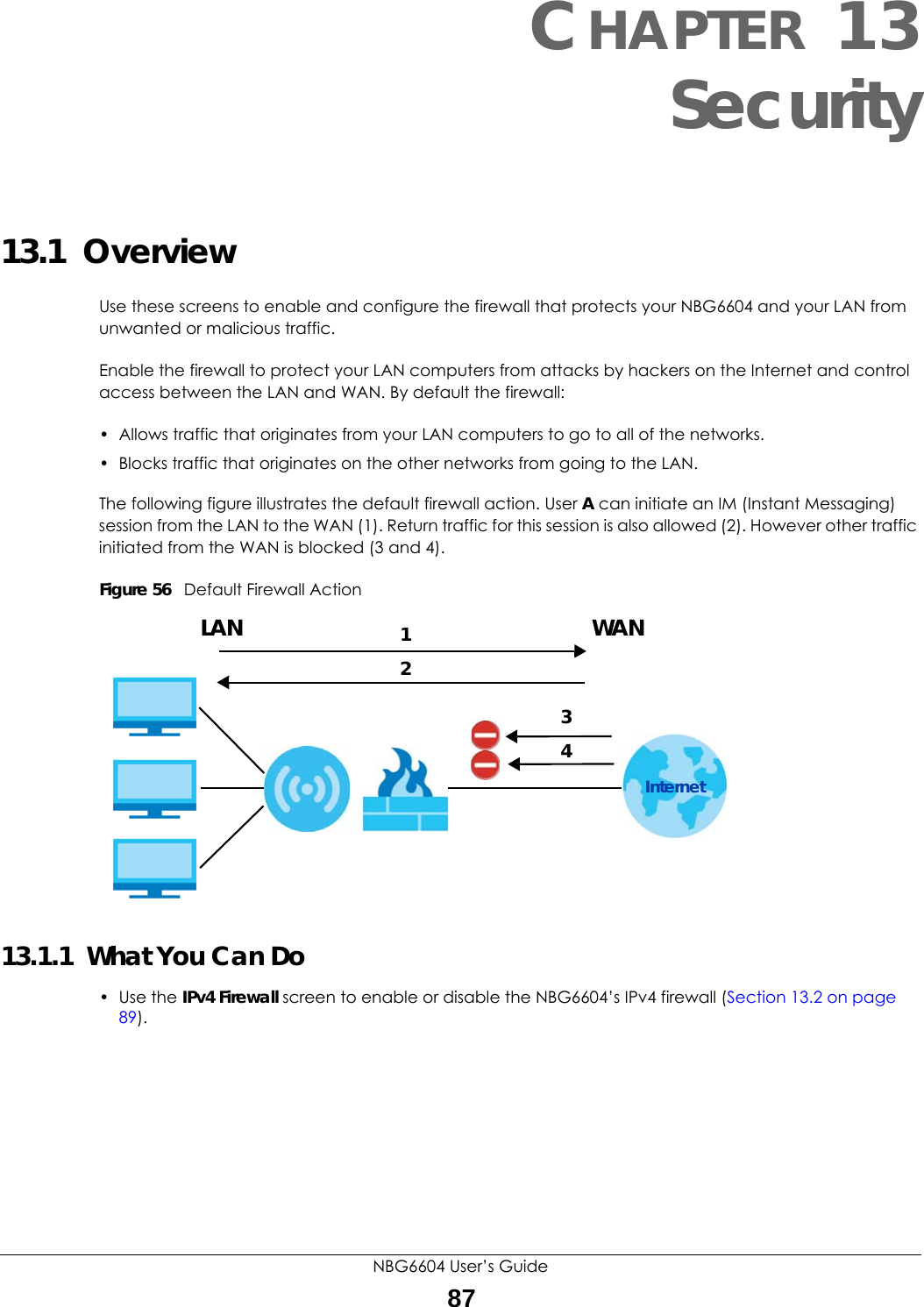
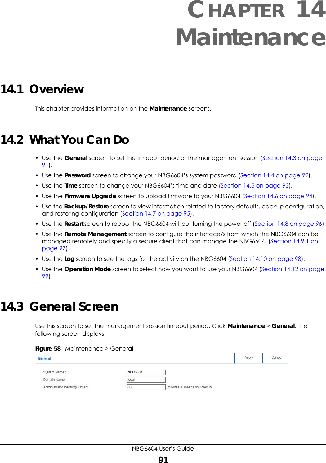
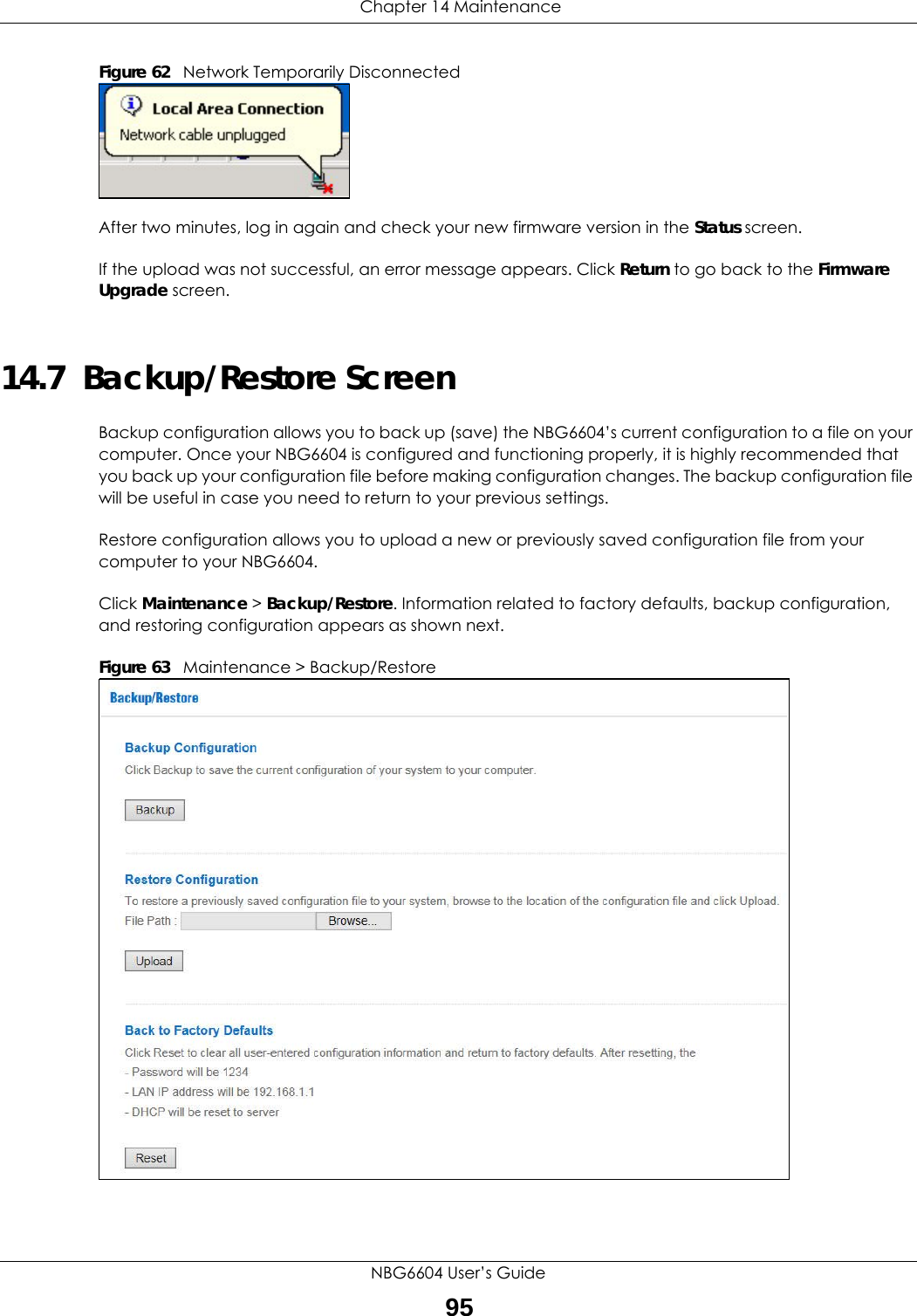
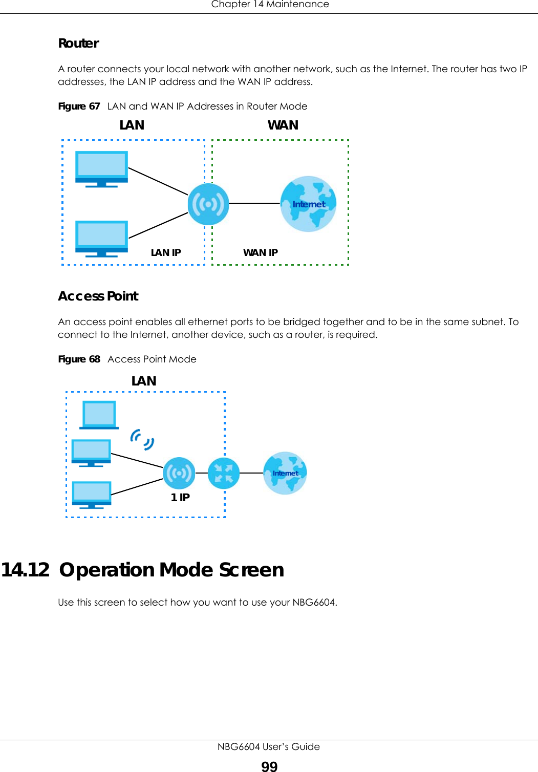
![Chapter 15 TroubleshootingNBG6604 User’s Guide104• If the NBG6604 is in Router Mode, make sure the WAN port is connected to a broadband modem or router with Internet access. Your computer and the NBG6604 should be in the same subnet.• If the NBG6604 is in Access Point Mode, make sure the WAN port is connected to a broadband modem or router with Internet access and your computer is set to obtain an dynamic IP address.3If the NBG6604 is in Router Mode, make sure you entered your ISP account information correctly in the wizard or the WAN screen. These fields are case-sensitive, so make sure [Caps Lock] is not on.4If you are trying to access the Internet wirelessly, make sure the wireless settings in the wireless client are the same as the settings in the AP.5Disconnect all the cables from your device, and follow the directions in the Quick Start Guide again. 6If the problem continues, contact your ISP.I cannot access the Internet anymore. I had access to the Internet (with the NBG6604), but my Internet connection is not available anymore.1Check the hardware connections, and make sure the LEDs are behaving as expected. See the Quick Start Guide and Section 1.7 on page 11. 2Reboot the NBG6604.3If the problem continues, contact your ISP. The Internet connection is slow or intermittent.1There might be a lot of traffic on the network. Look at the LEDs, and check Section 1.7 on page 11. If the NBG6604 is sending or receiving a lot of information, try closing some programs that use the Internet, especially peer-to-peer applications.2Check the signal strength. If the signal strength is low, try moving the NBG6604 closer to the AP if possible, and look around to see if there are any devices that might be interfering with the wireless network (for example, microwaves, other wireless networks, and so on).3Reboot the NBG6604.4If the problem continues, contact the network administrator or vendor, or try one of the advanced suggestions.Advanced Suggestion• Check the settings for QoS. If it is disabled, you might consider activating it.](https://usermanual.wiki/ZyXEL-Communications/NBG6604/User-Guide-3569384-Page-104.png)
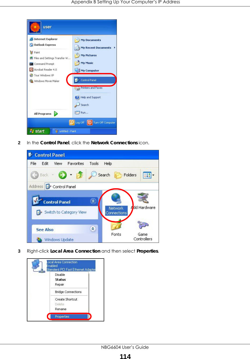
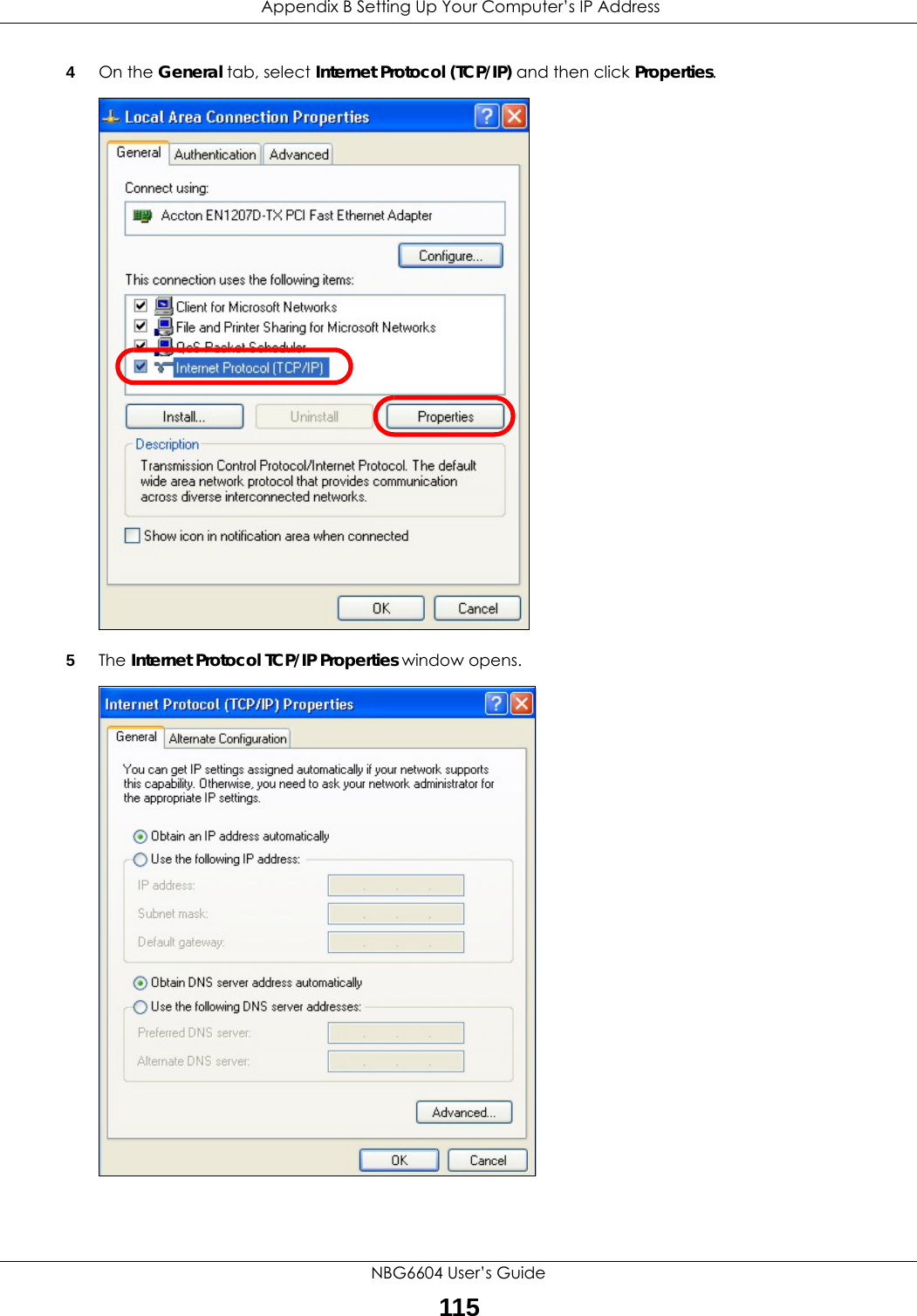
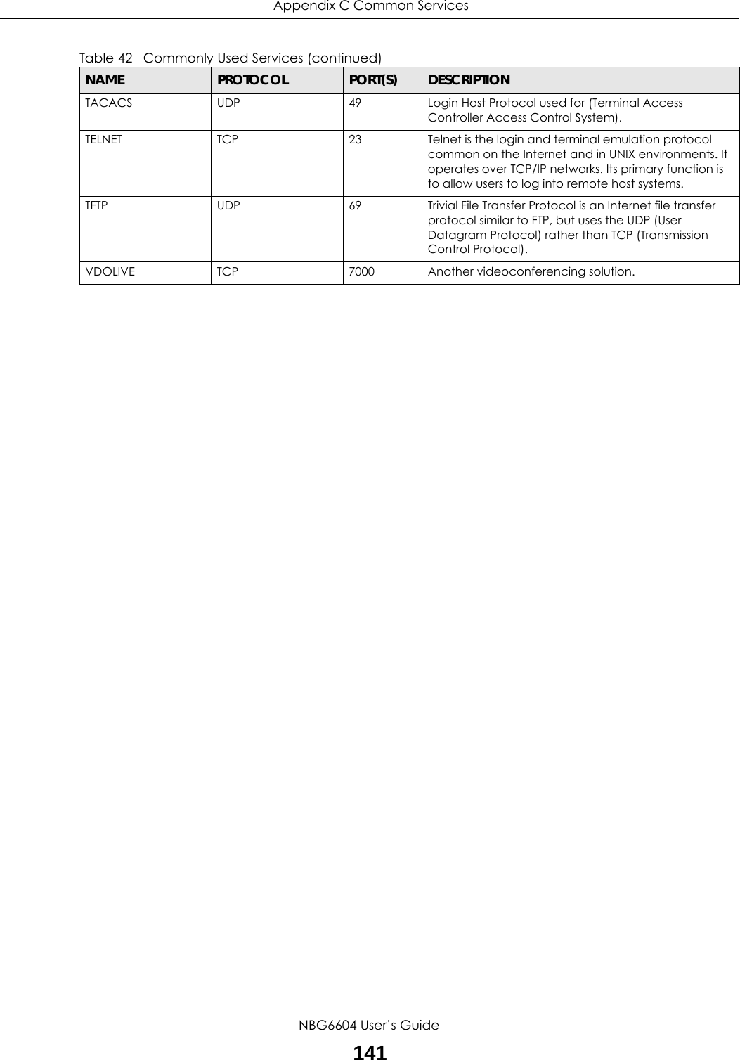
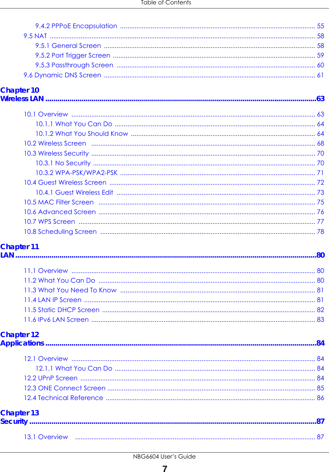
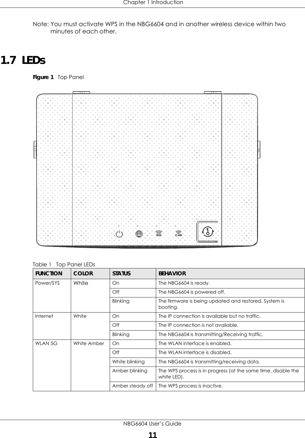
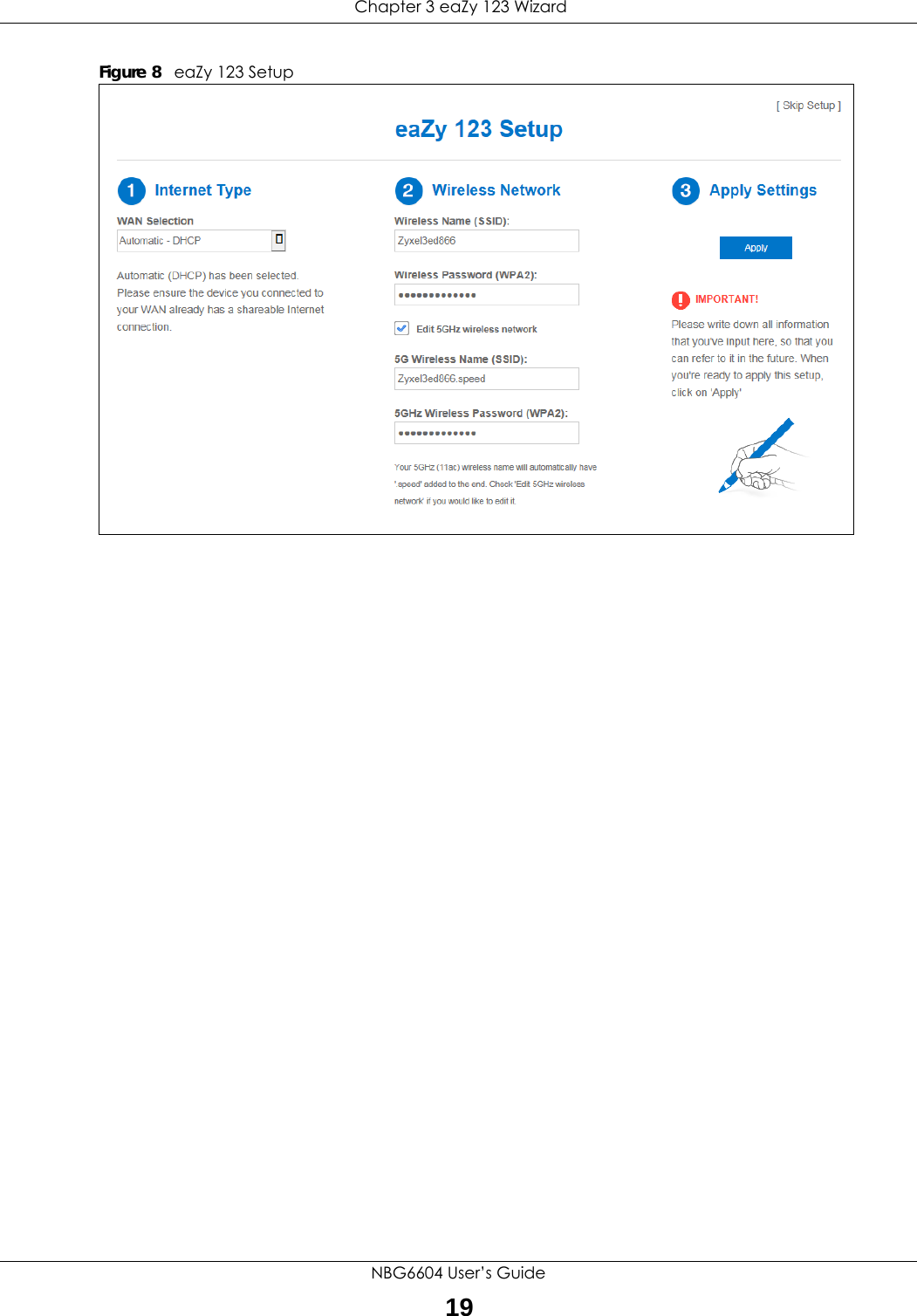
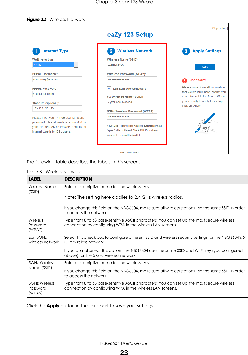
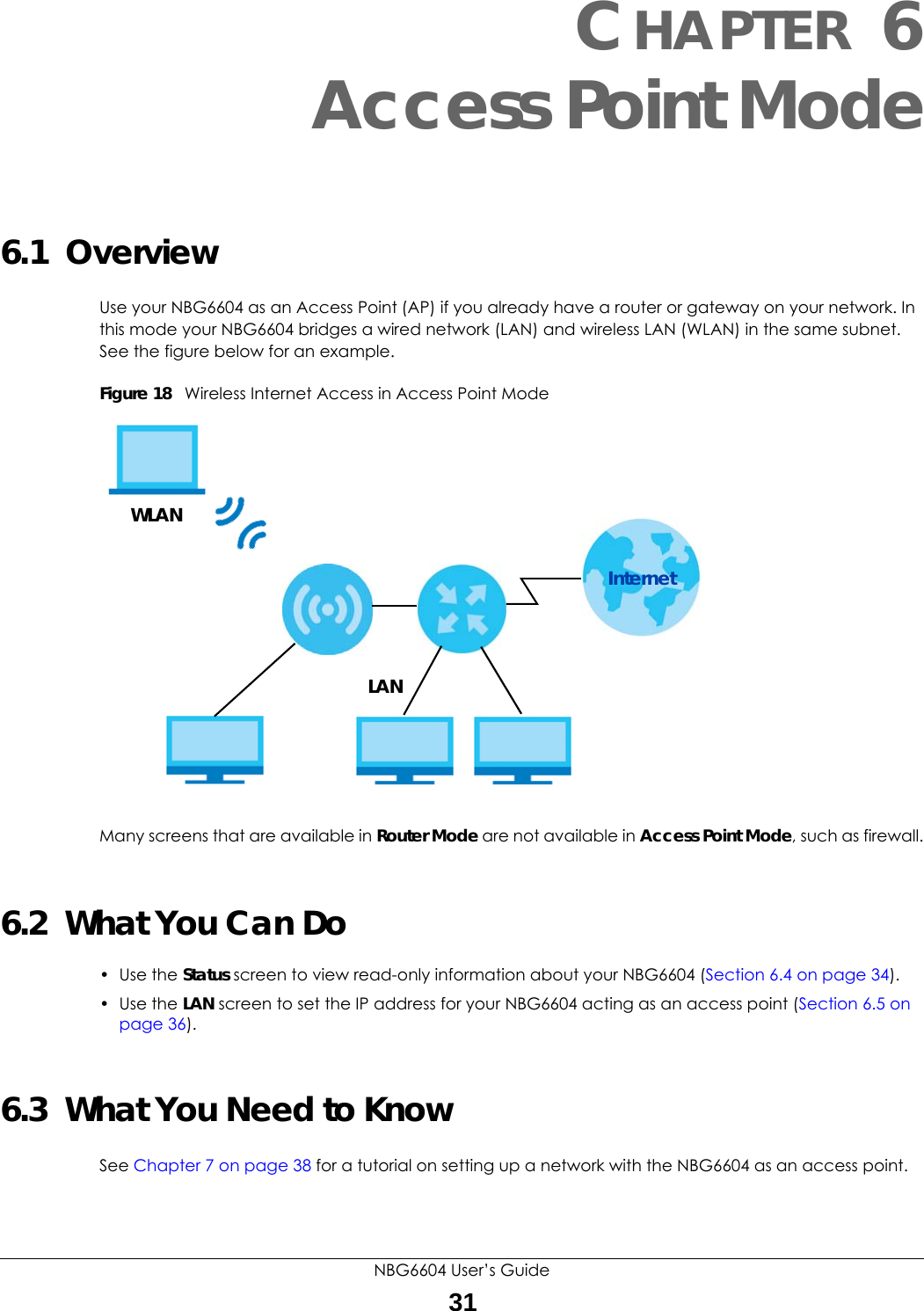
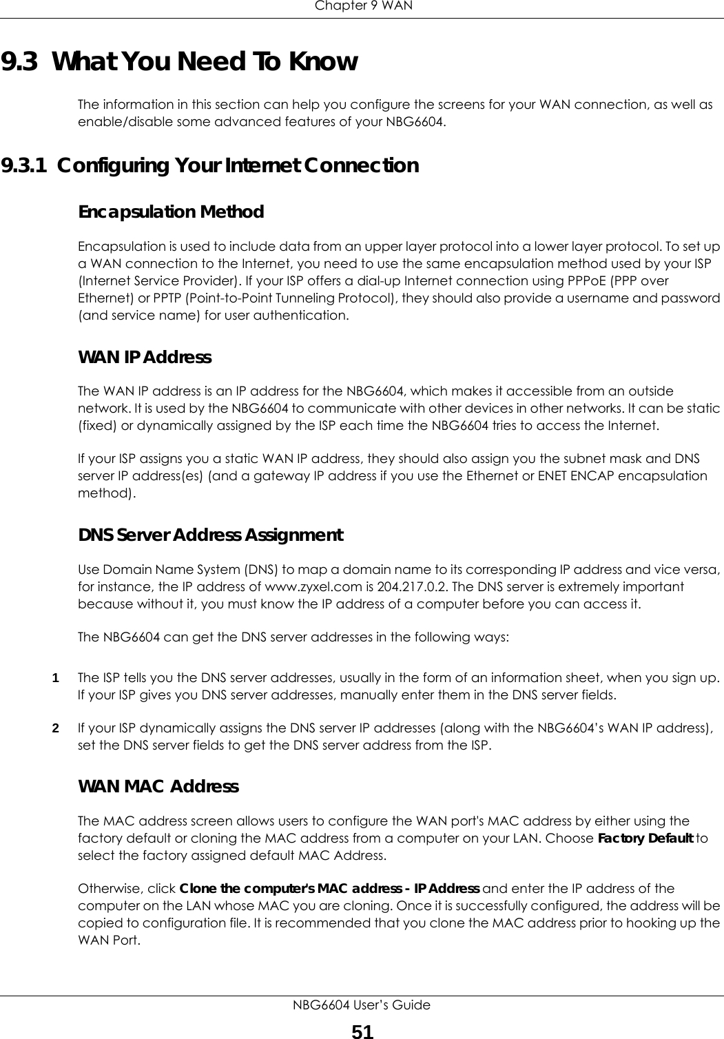
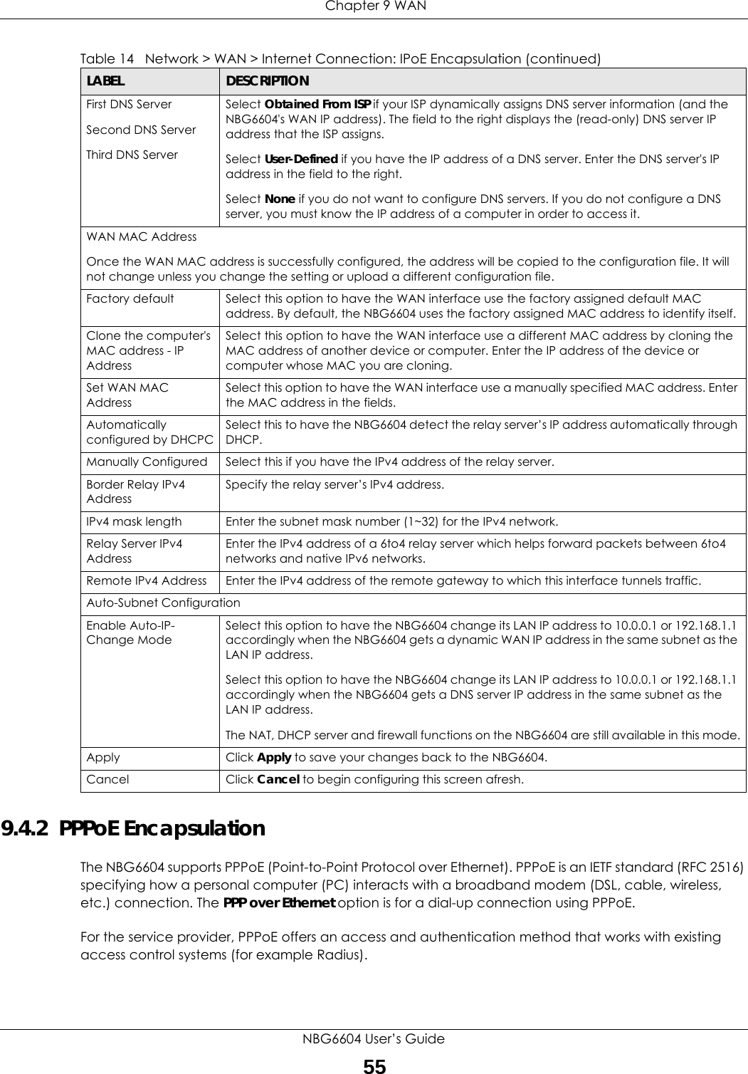
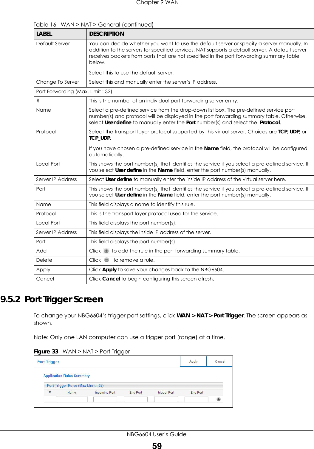
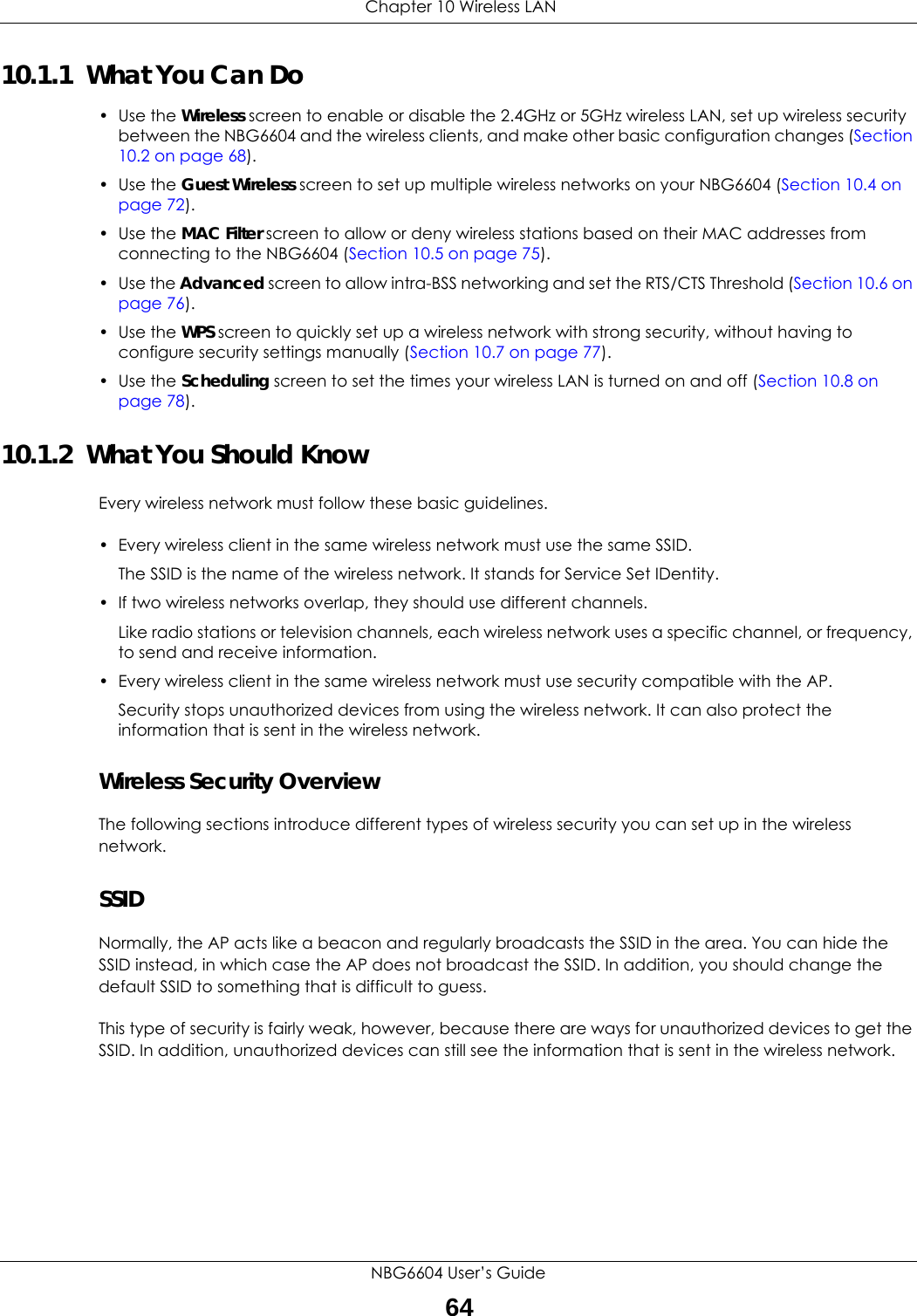
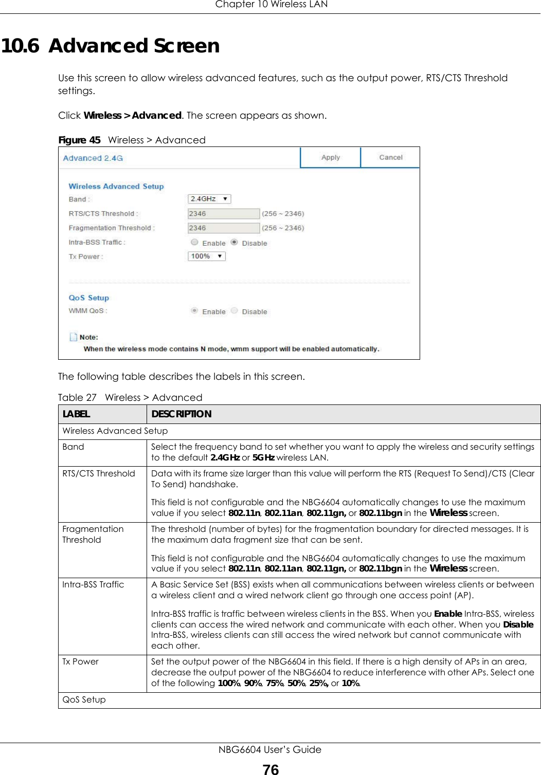
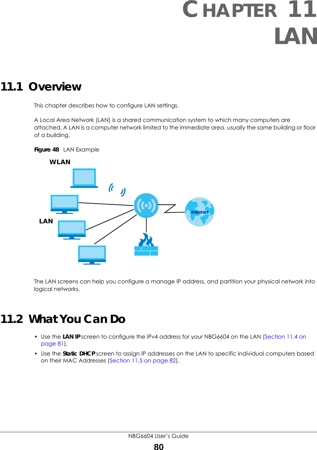
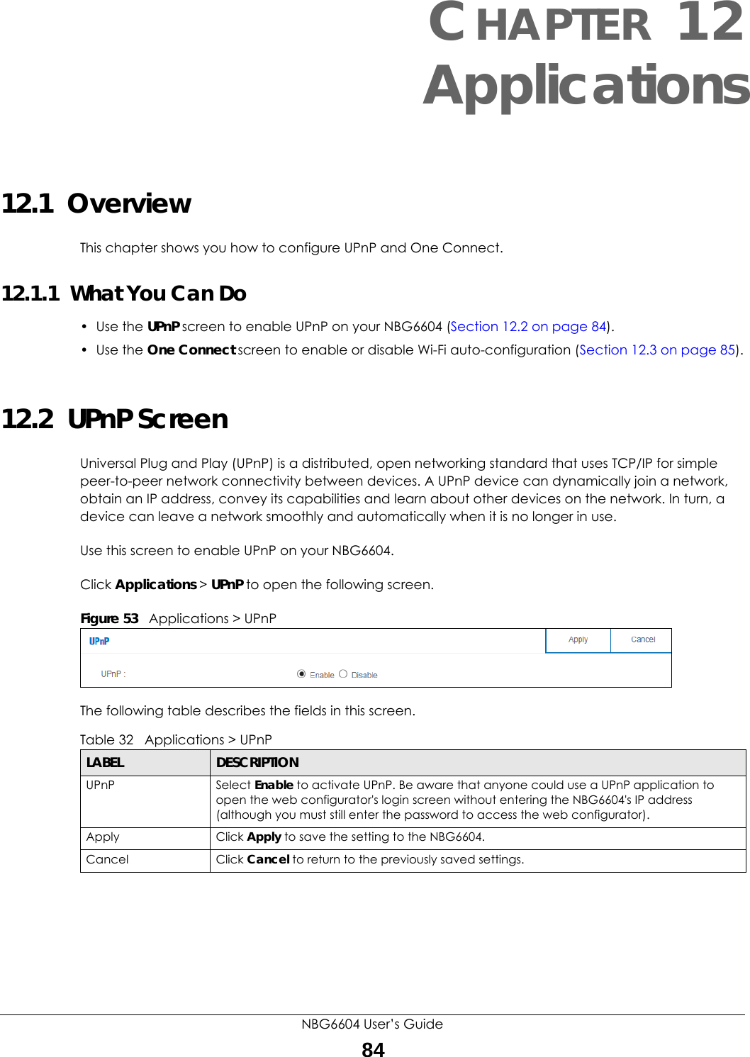
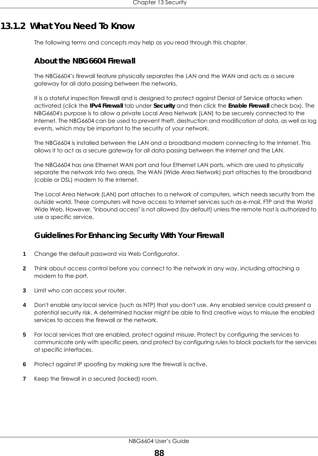
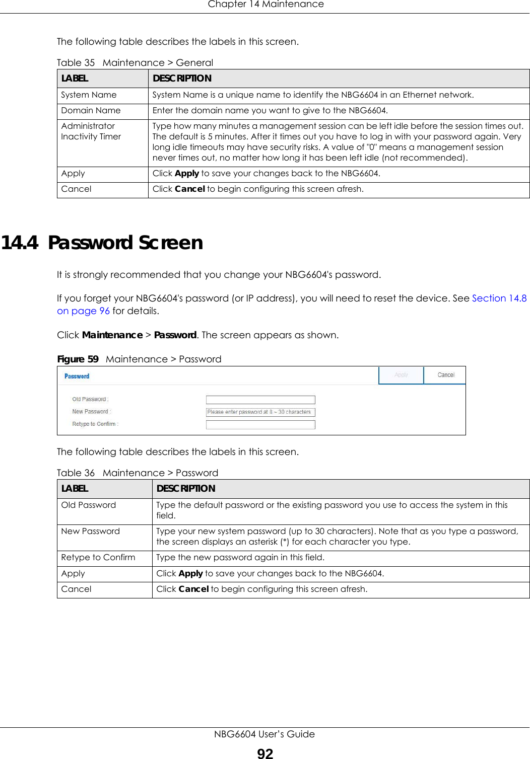
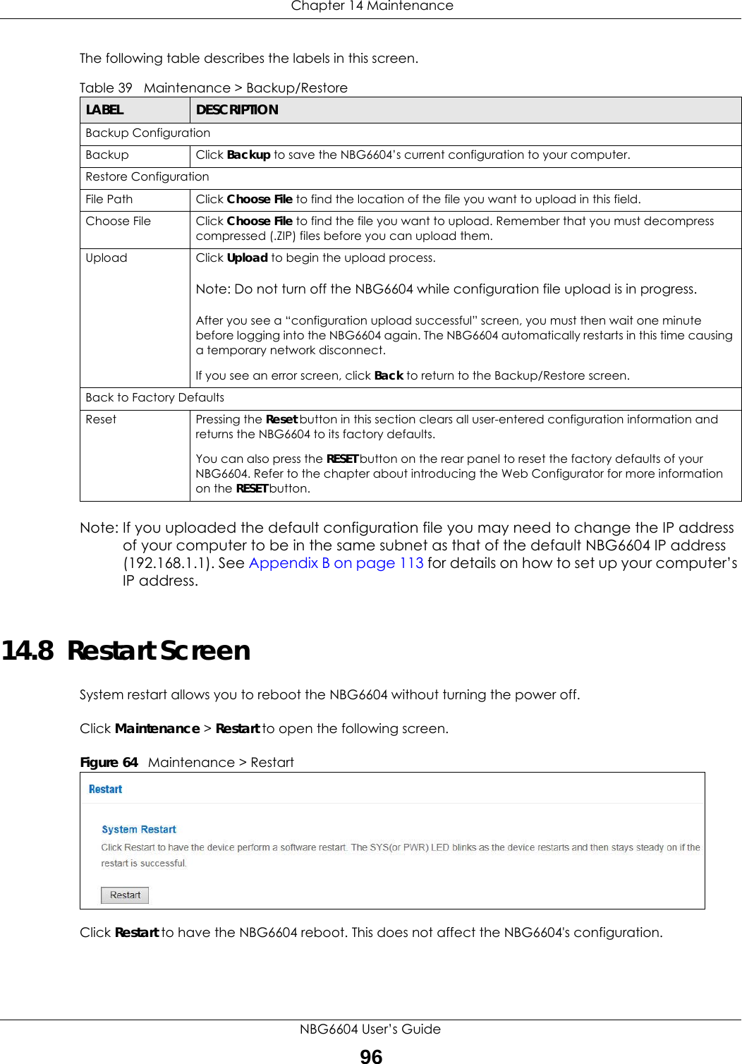
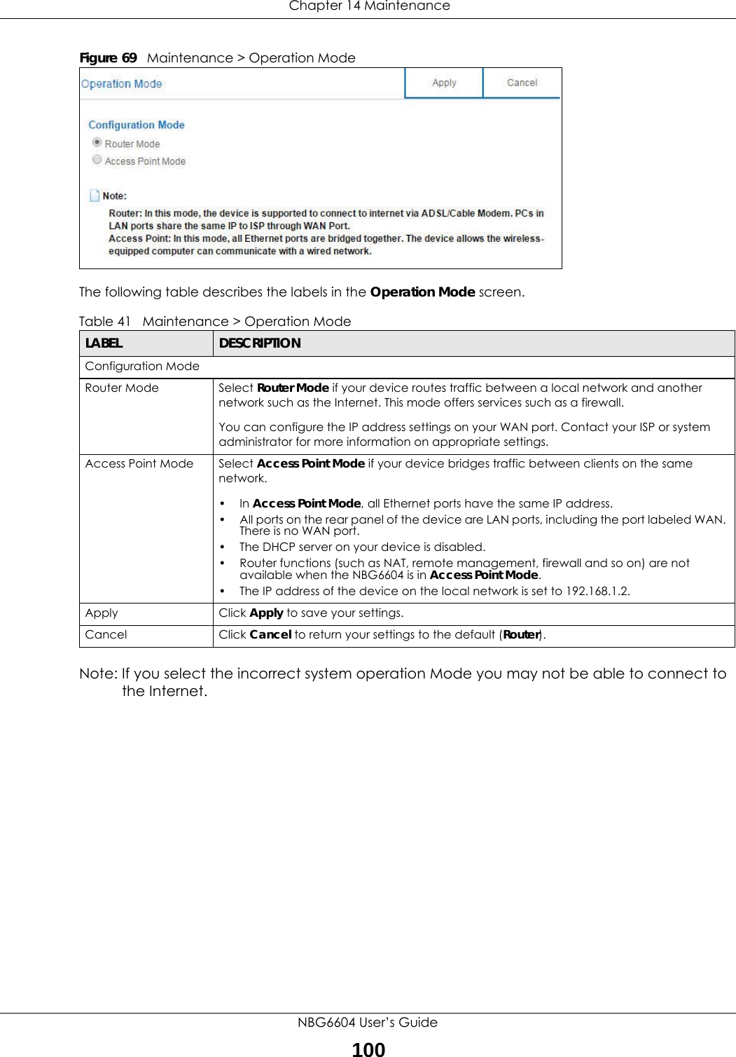
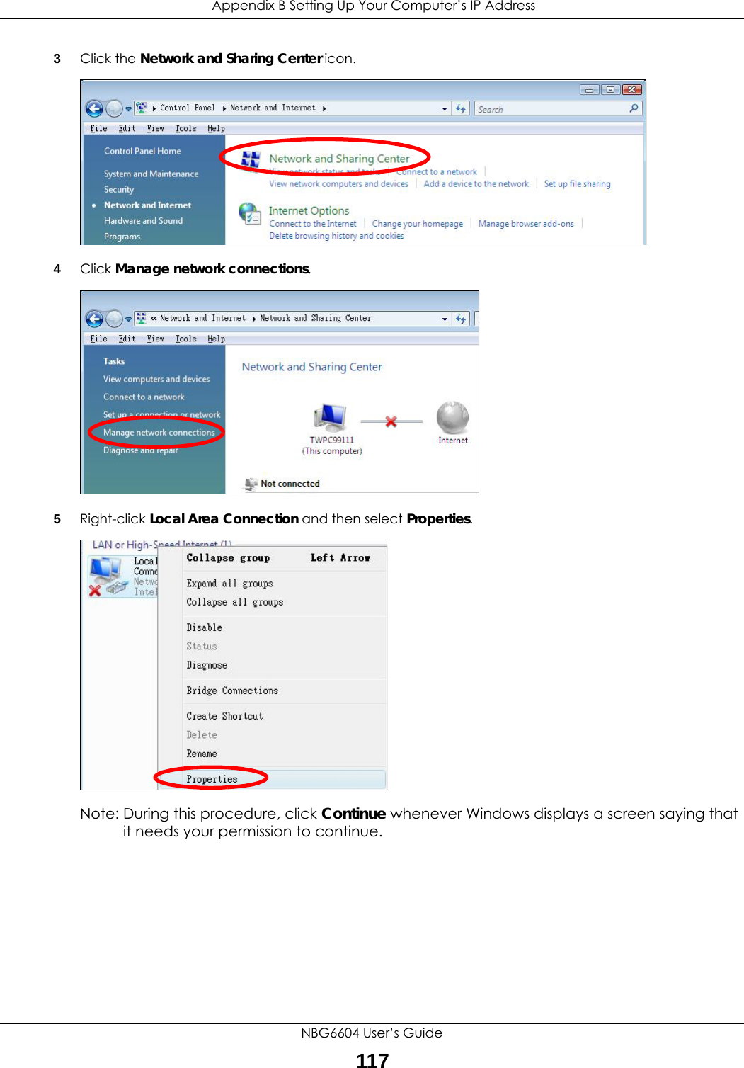
![Appendix B Setting Up Your Computer’s IP AddressNBG6604 User’s Guide1166Select Obtain an IP address automatically if your network administrator or ISP assigns your IP address dynamically.Select Use the following IP Address and fill in the IP address, Subnet mask, and Default gateway fields if you have a static IP address that was assigned to you by your network administrator or ISP. You may also have to enter a Preferred DNS server and an Alternate DNS server, if that information was provided.7Click OK to close the Internet Protocol (TCP/IP) Properties window.8Click OK to close the Local Area Connection Properties window.Verifying Settings1Click Start > All Programs > Accessories > Command Prompt.2In the Command Prompt window, type "ipconfig" and then press [ENTER]. You can also go to Start > Control Panel > Network Connections, right-click a network connection, click Status and then click the Support tab to view your IP address and connection information.Windows VistaThis section shows screens from Windows Vista Professional.1Click Start > Control Panel.2In the Control Panel, click the Network and Internet icon.](https://usermanual.wiki/ZyXEL-Communications/NBG6604/User-Guide-3569384-Page-116.png)
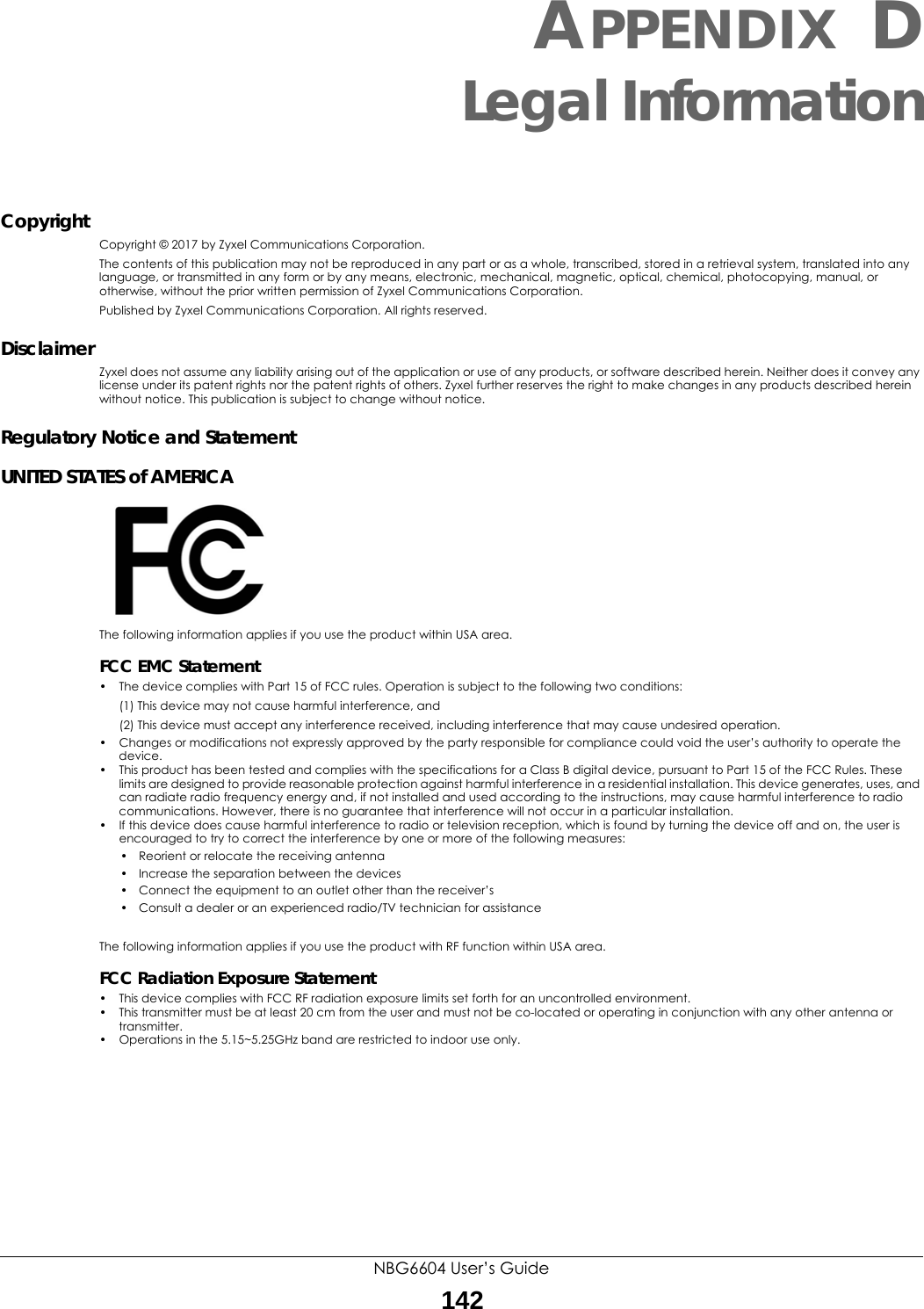
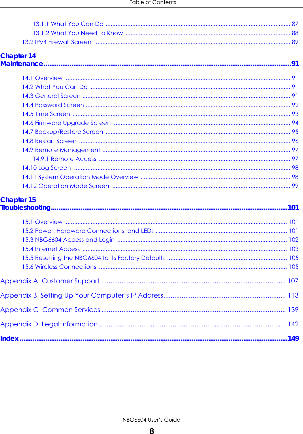
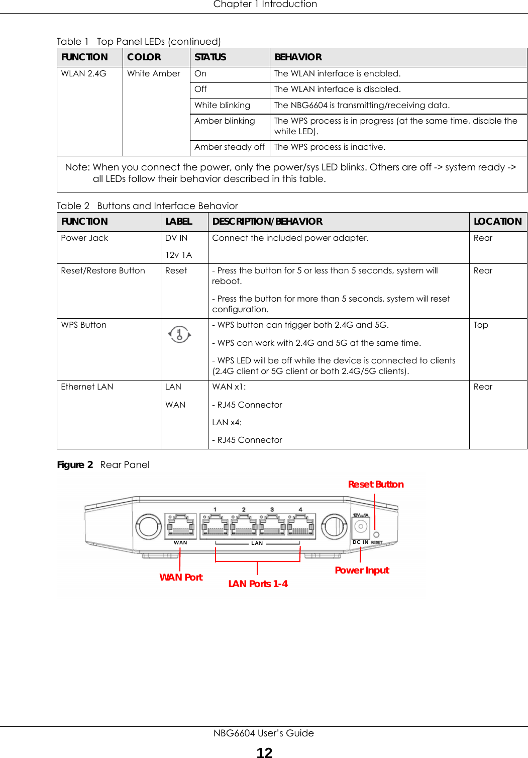
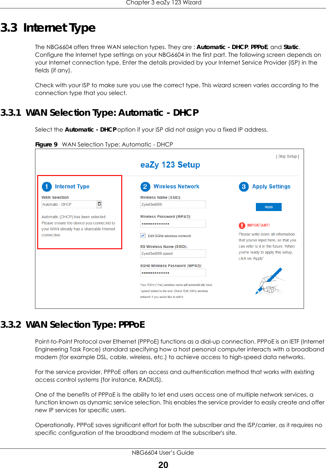
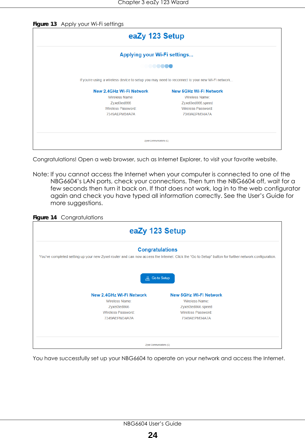
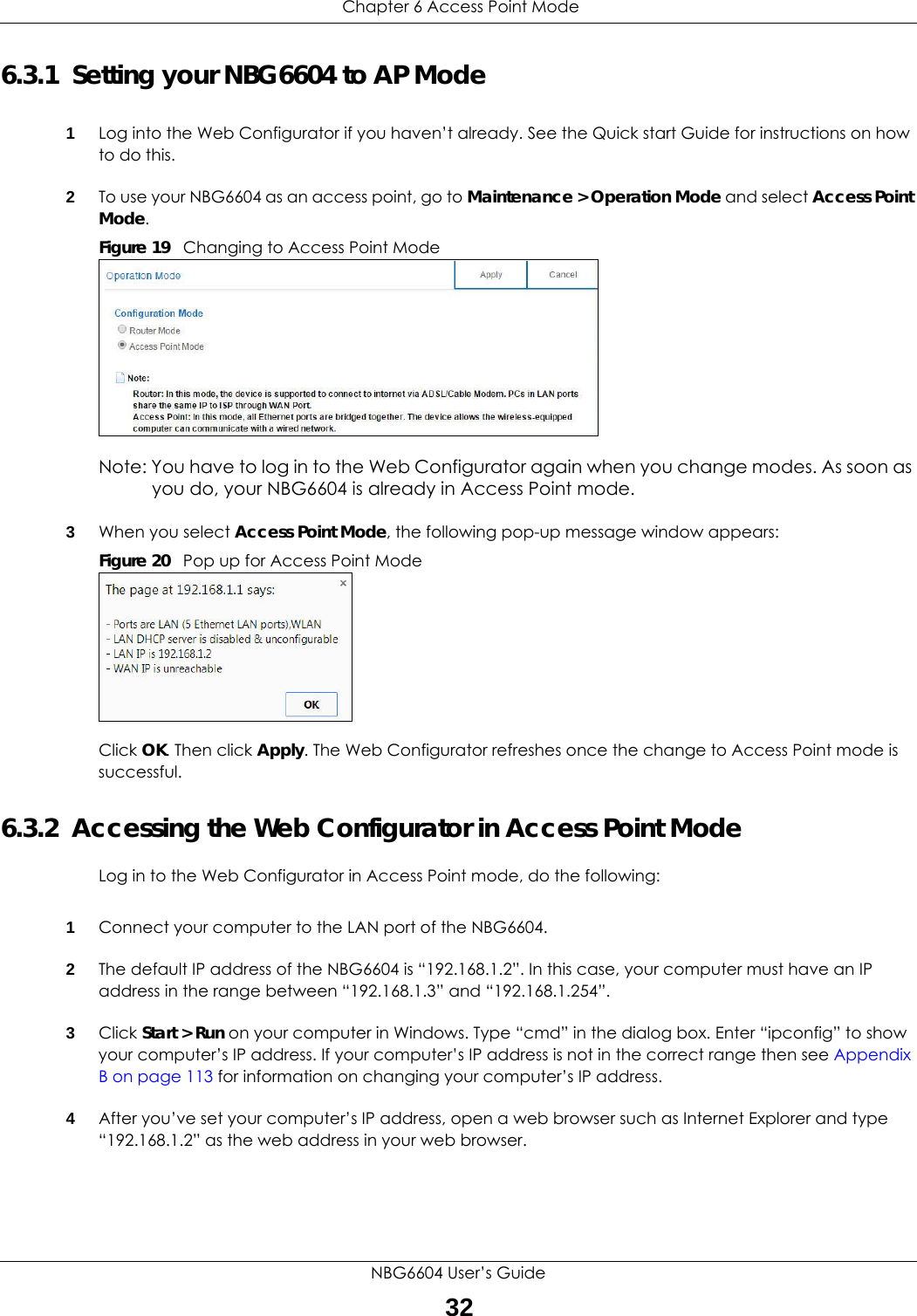
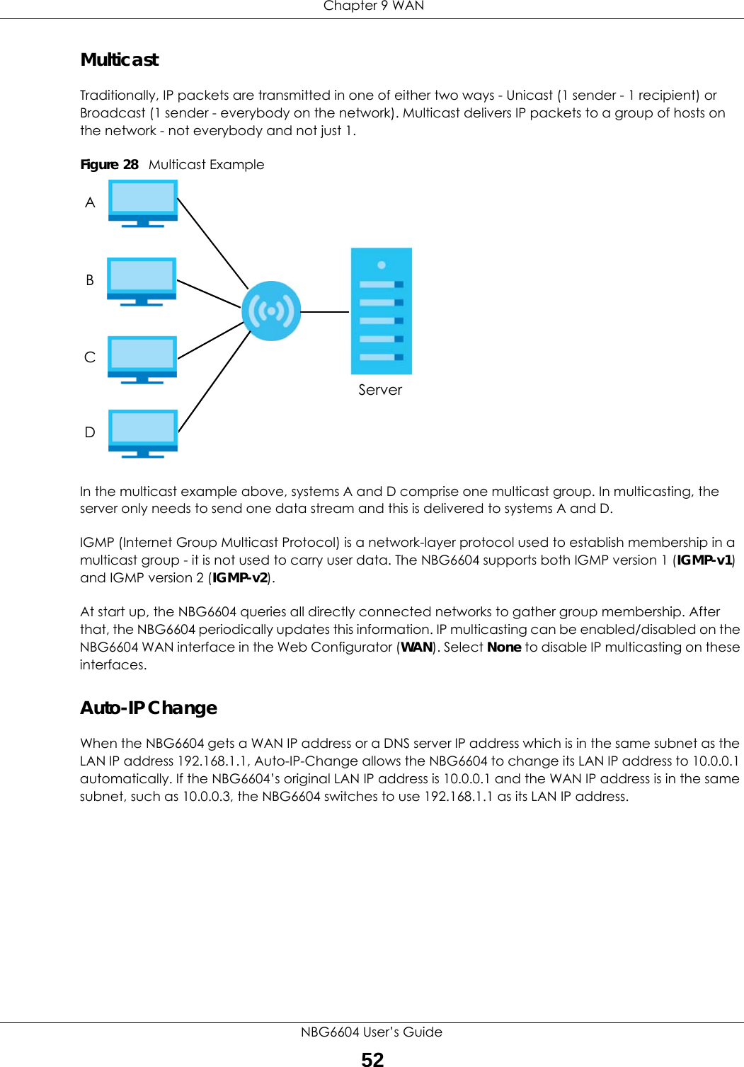
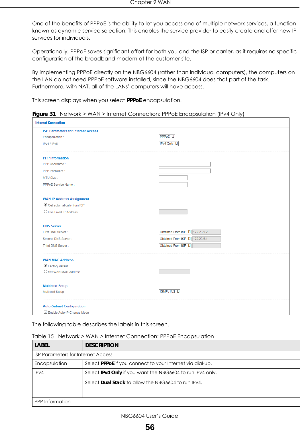
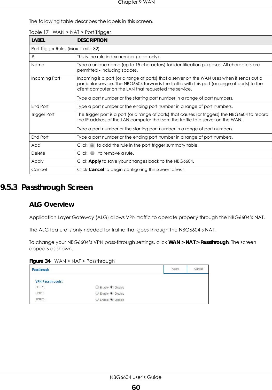
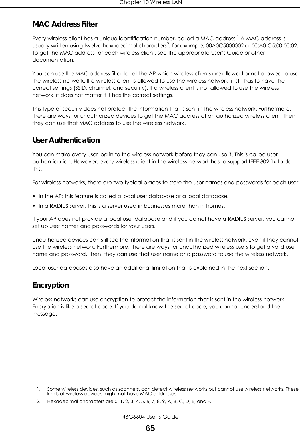
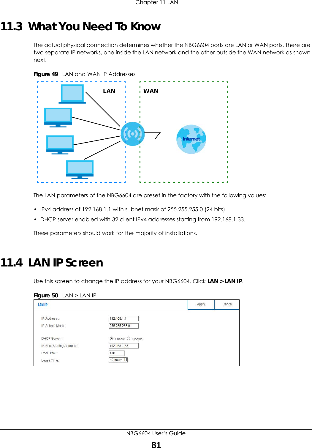
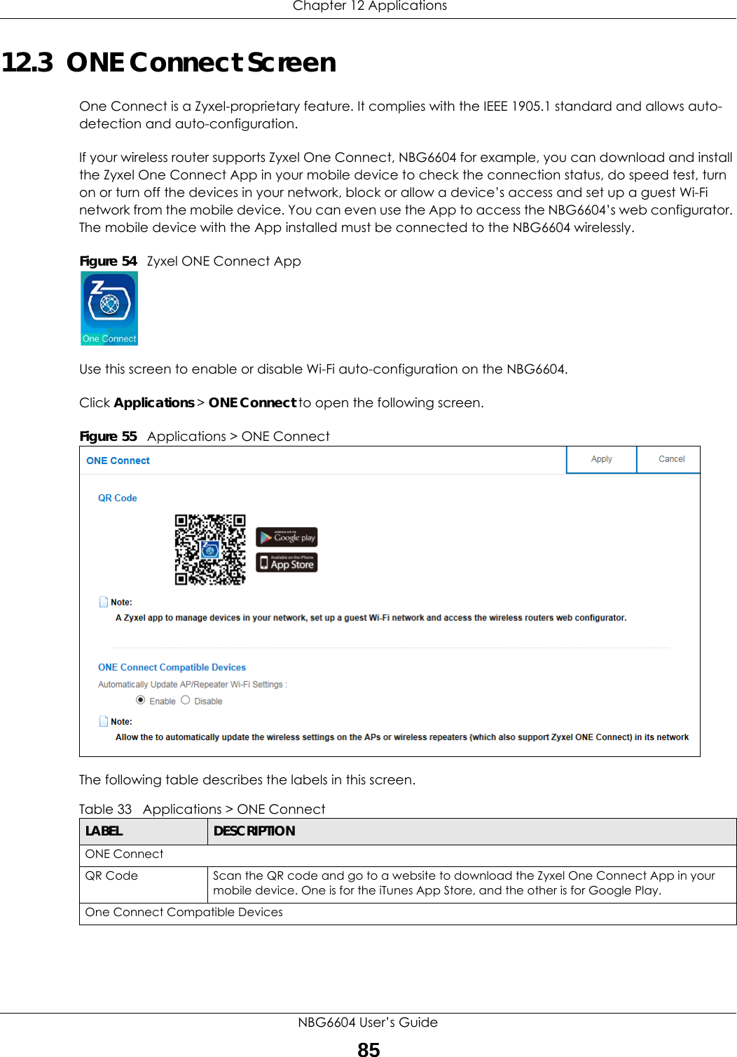
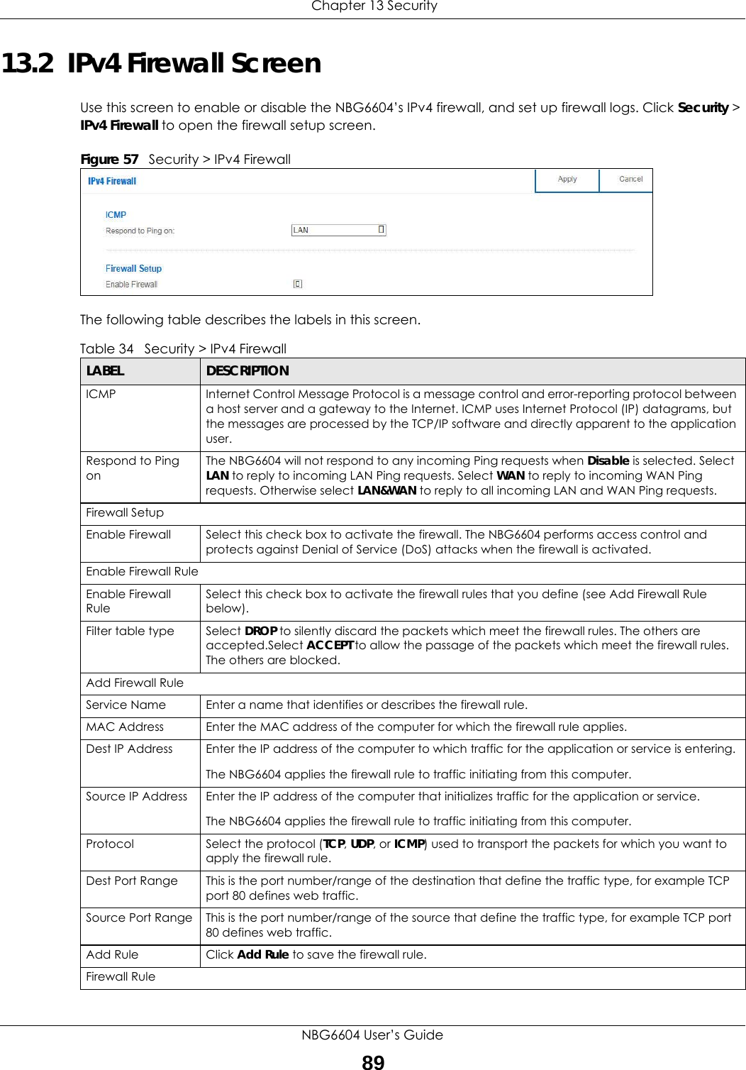
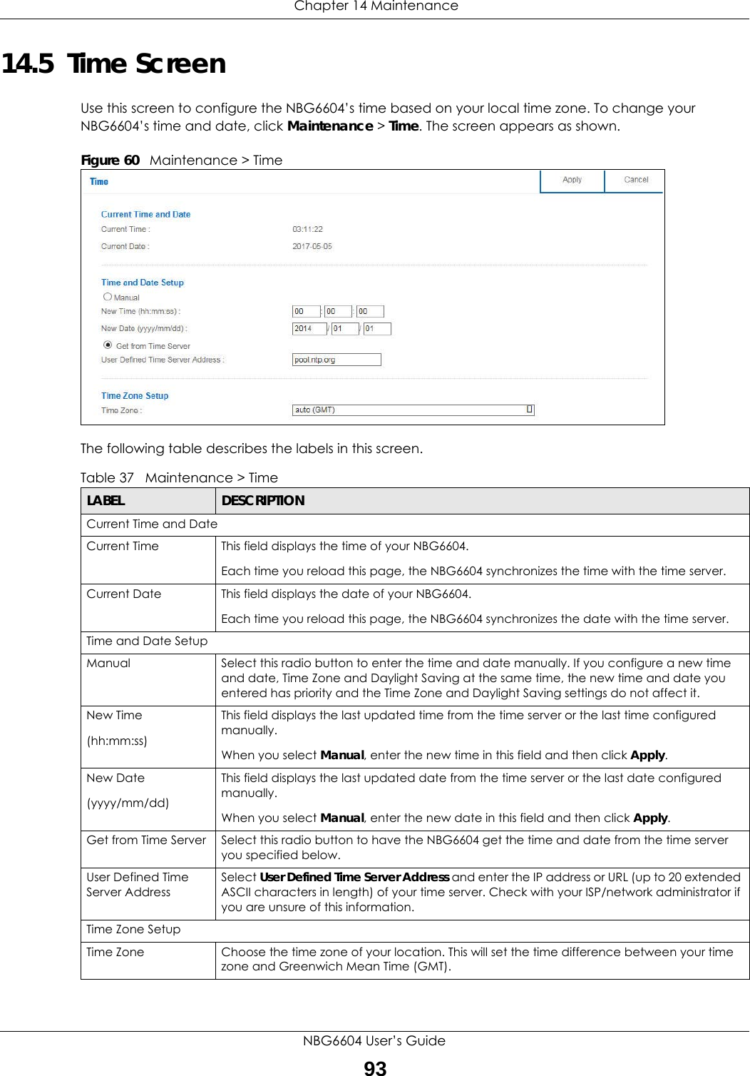
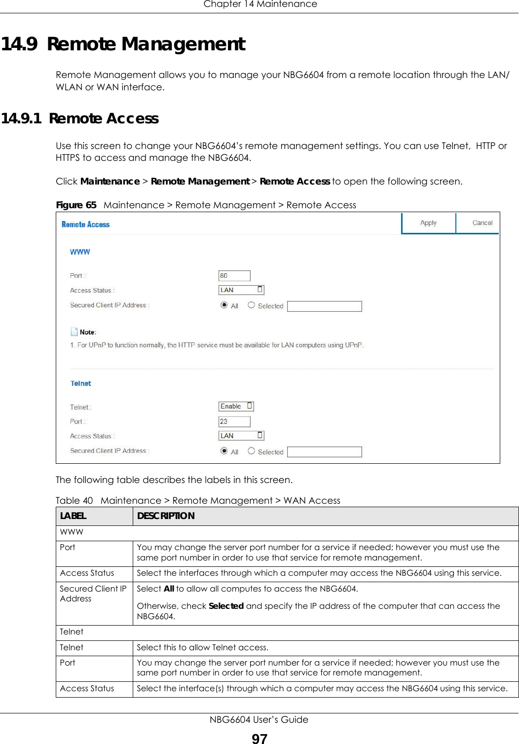
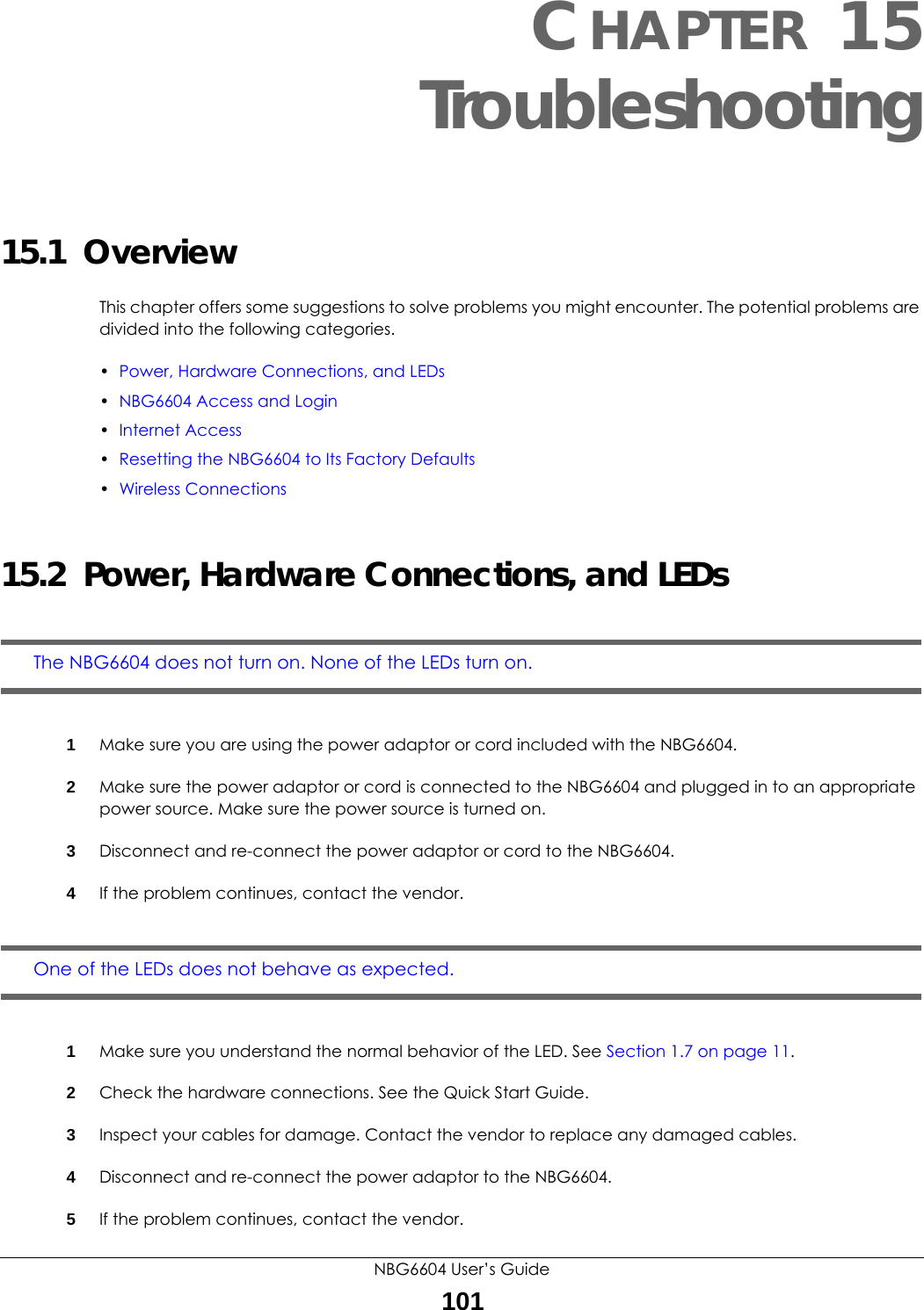
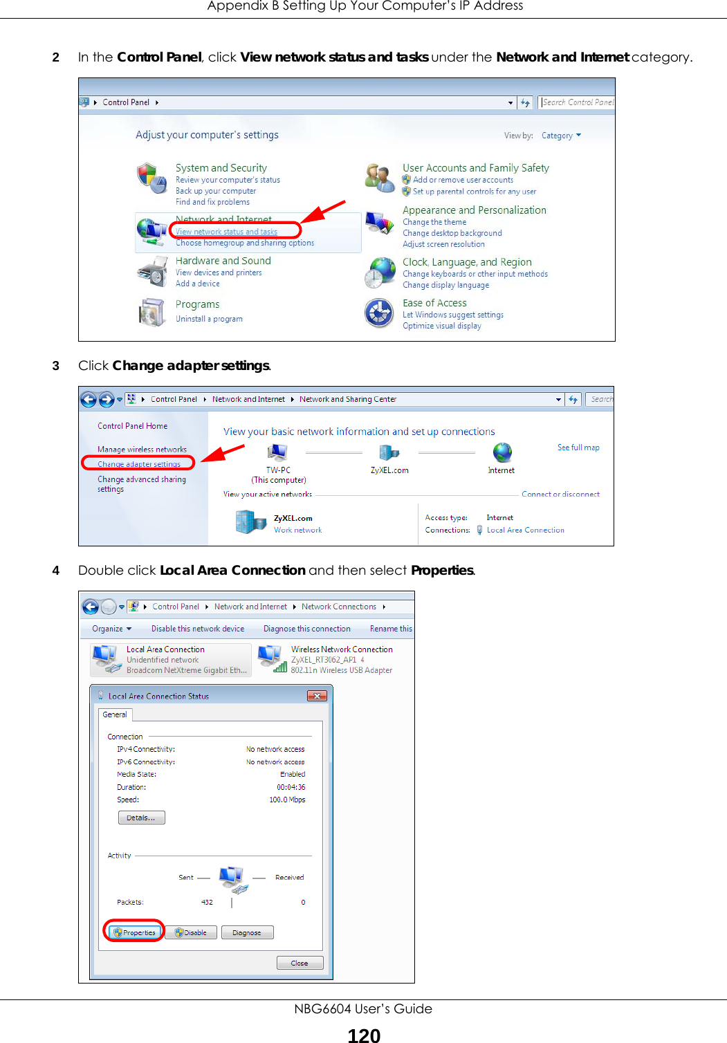
![Appendix B Setting Up Your Computer’s IP AddressNBG6604 User’s Guide1198Select Obtain an IP address automatically if your network administrator or ISP assigns your IP address dynamically.Select Use the following IP Address and fill in the IP address, Subnet mask, and Default gateway fields if you have a static IP address that was assigned to you by your network administrator or ISP. You may also have to enter a Preferred DNS server and an Alternate DNS server, if that information was provided.Click Advanced.9Click OK to close the Internet Protocol (TCP/IP) Properties window.10 Click OK to close the Local Area Connection Properties window.Verifying Settings1Click Start > All Programs > Accessories > Command Prompt.2In the Command Prompt window, type "ipconfig" and then press [ENTER]. You can also go to Start > Control Panel > Network Connections, right-click a network connection, click Status and then click the Support tab to view your IP address and connection information.Windows 7This section shows screens from Windows 7 Enterprise.1Click Start > Control Panel.](https://usermanual.wiki/ZyXEL-Communications/NBG6604/User-Guide-3569384-Page-119.png)
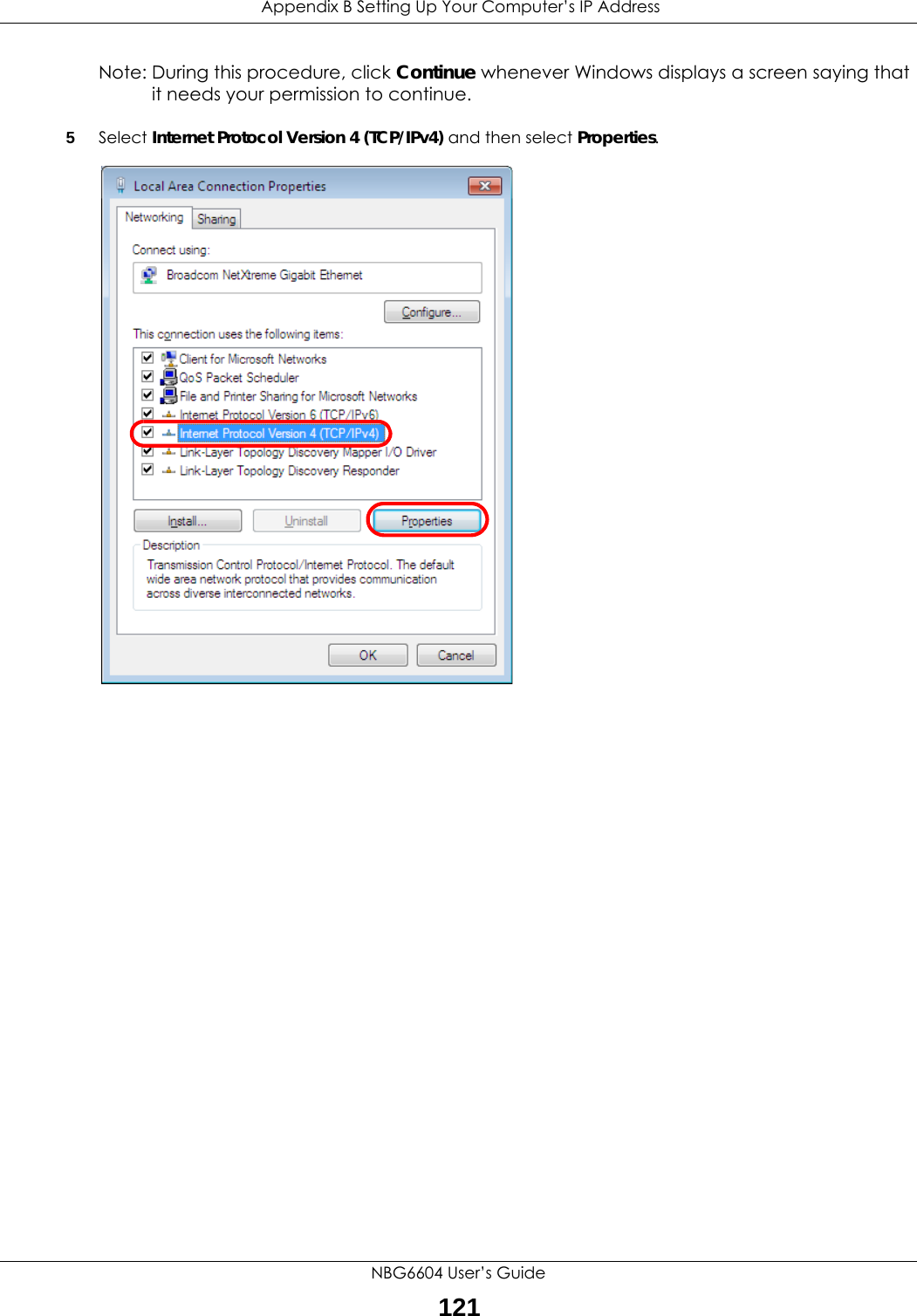
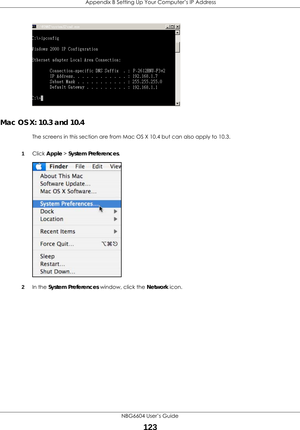
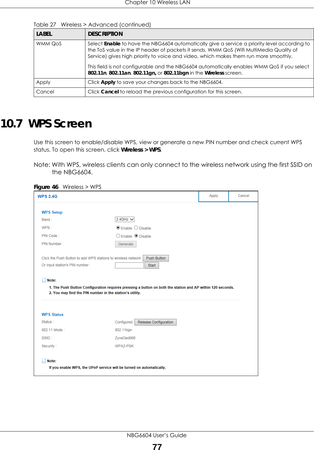
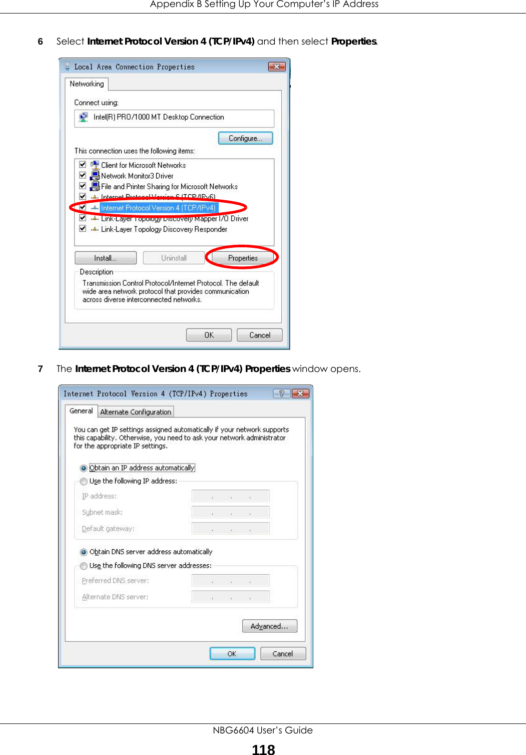
![Appendix B Setting Up Your Computer’s IP AddressNBG6604 User’s Guide1226The Internet Protocol Version 4 (TCP/IPv4) Properties window opens.7Select Obtain an IP address automatically if your network administrator or ISP assigns your IP address dynamically.Select Use the following IP Address and fill in the IP address, Subnet mask, and Default gateway fields if you have a static IP address that was assigned to you by your network administrator or ISP. You may also have to enter a Preferred DNS server and an Alternate DNS server, if that information was provided. Click Advanced if you want to configure advanced settings for IP, DNS and WINS. 8Click OK to close the Internet Protocol (TCP/IP) Properties window.9Click OK to close the Local Area Connection Properties window.Verifying Settings1Click Start > All Programs > Accessories > Command Prompt.2In the Command Prompt window, type "ipconfig" and then press [ENTER]. 3The IP settings are displayed as follows.](https://usermanual.wiki/ZyXEL-Communications/NBG6604/User-Guide-3569384-Page-122.png)