ZyXEL Communications NBG6616 Simultaneous Dual-Band Wireless AC1200 HD Media Router User Manual
ZyXEL Communications Corporation Simultaneous Dual-Band Wireless AC1200 HD Media Router
UserManual.wiki
>
ZyXEL Communications
>
NBG6616 User Manual
User Manual.pdf
Navigation menu
Upload a User Manual
Namespaces
Wiki Guide
HTML
PDF
Info
Views
User Manual
Discussion / Help
Navigation
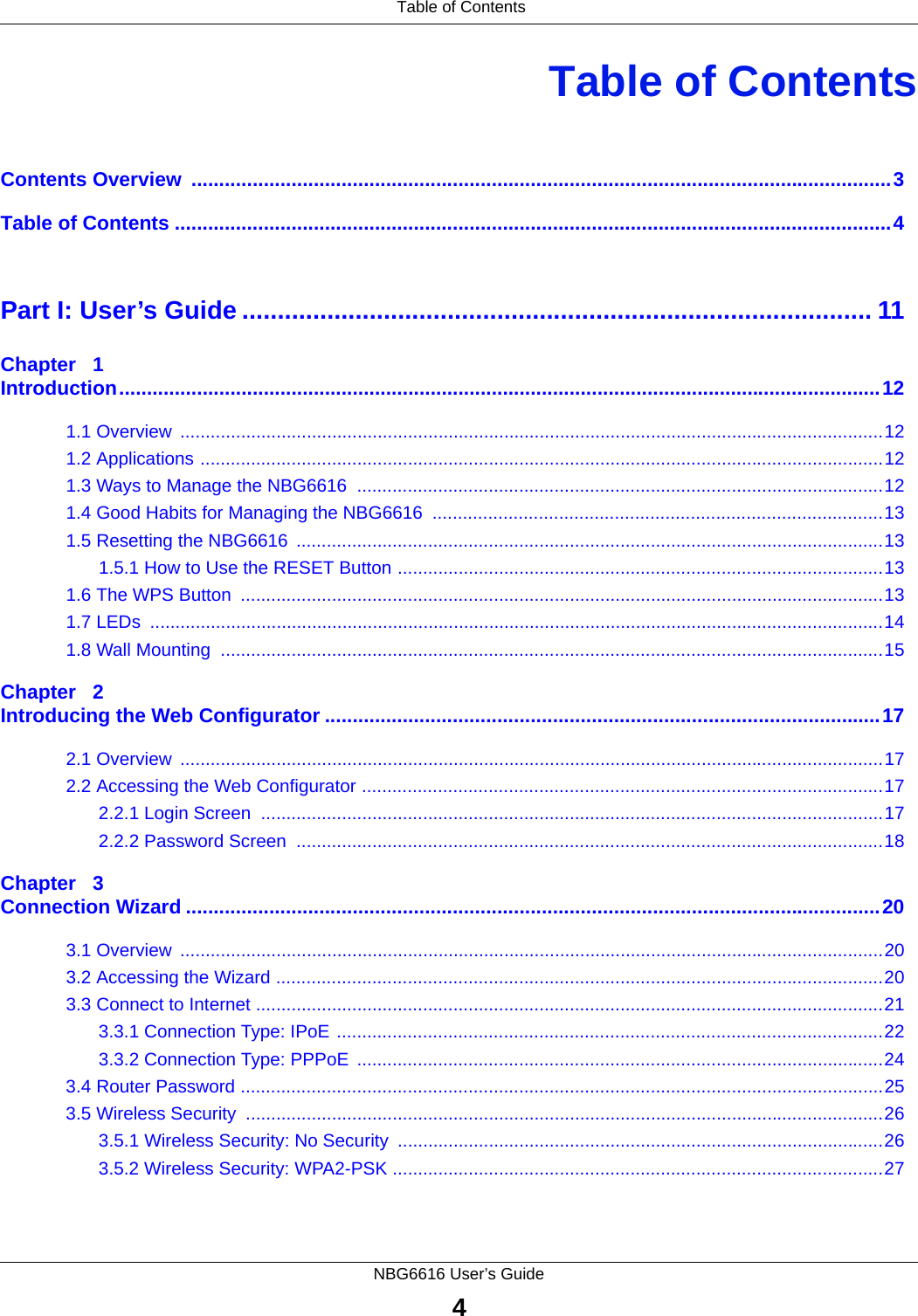
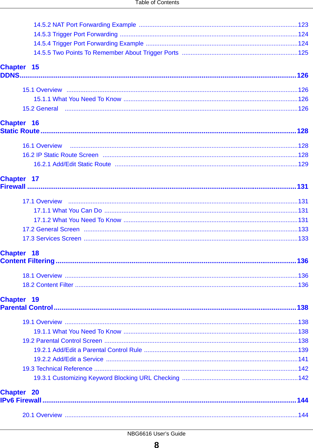
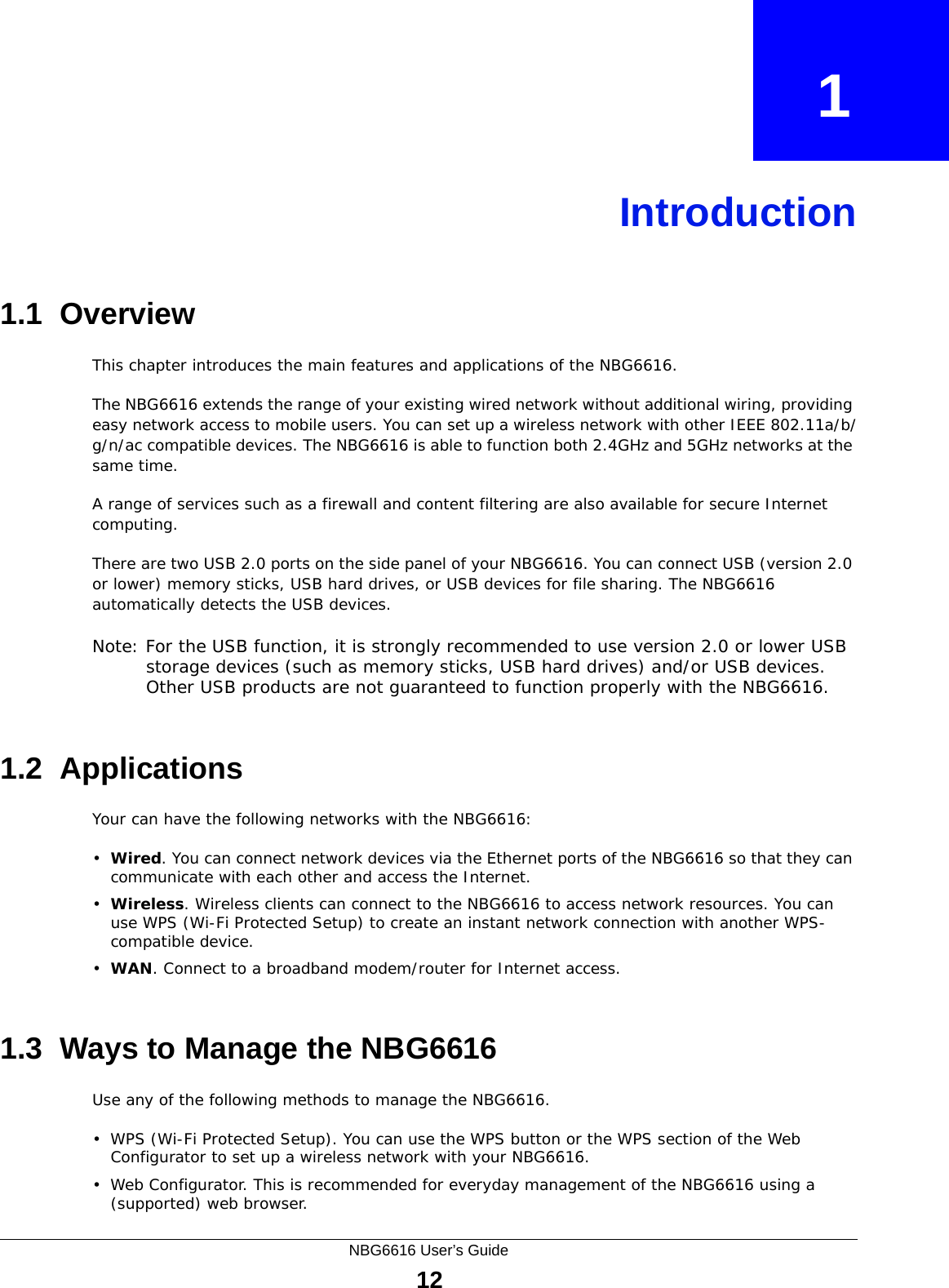
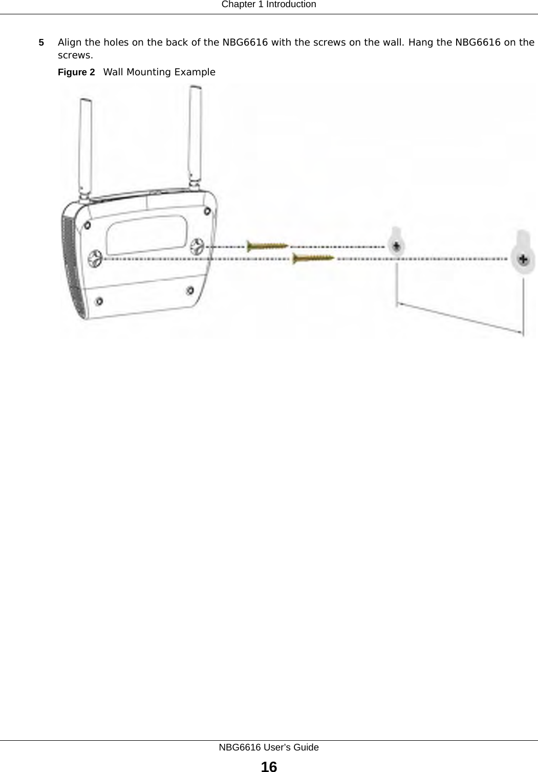
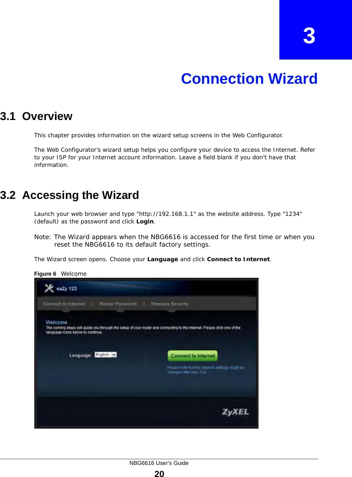
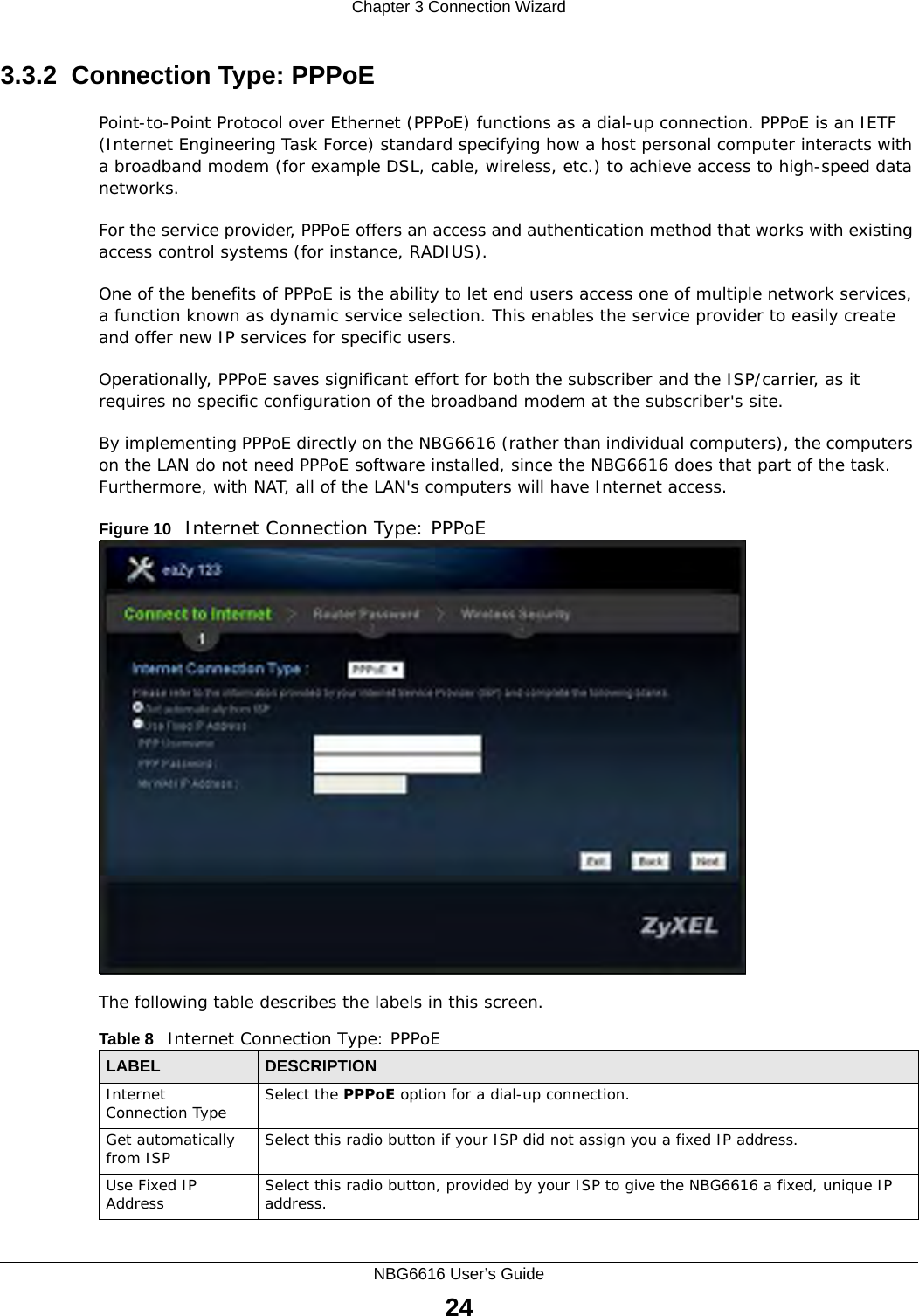
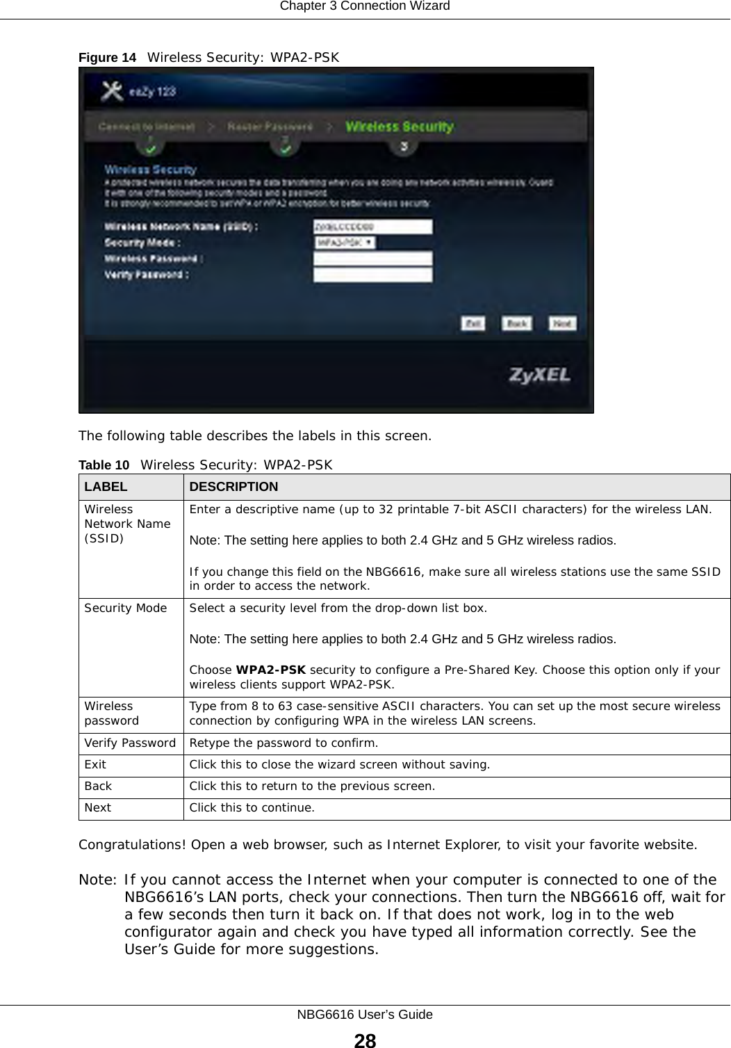
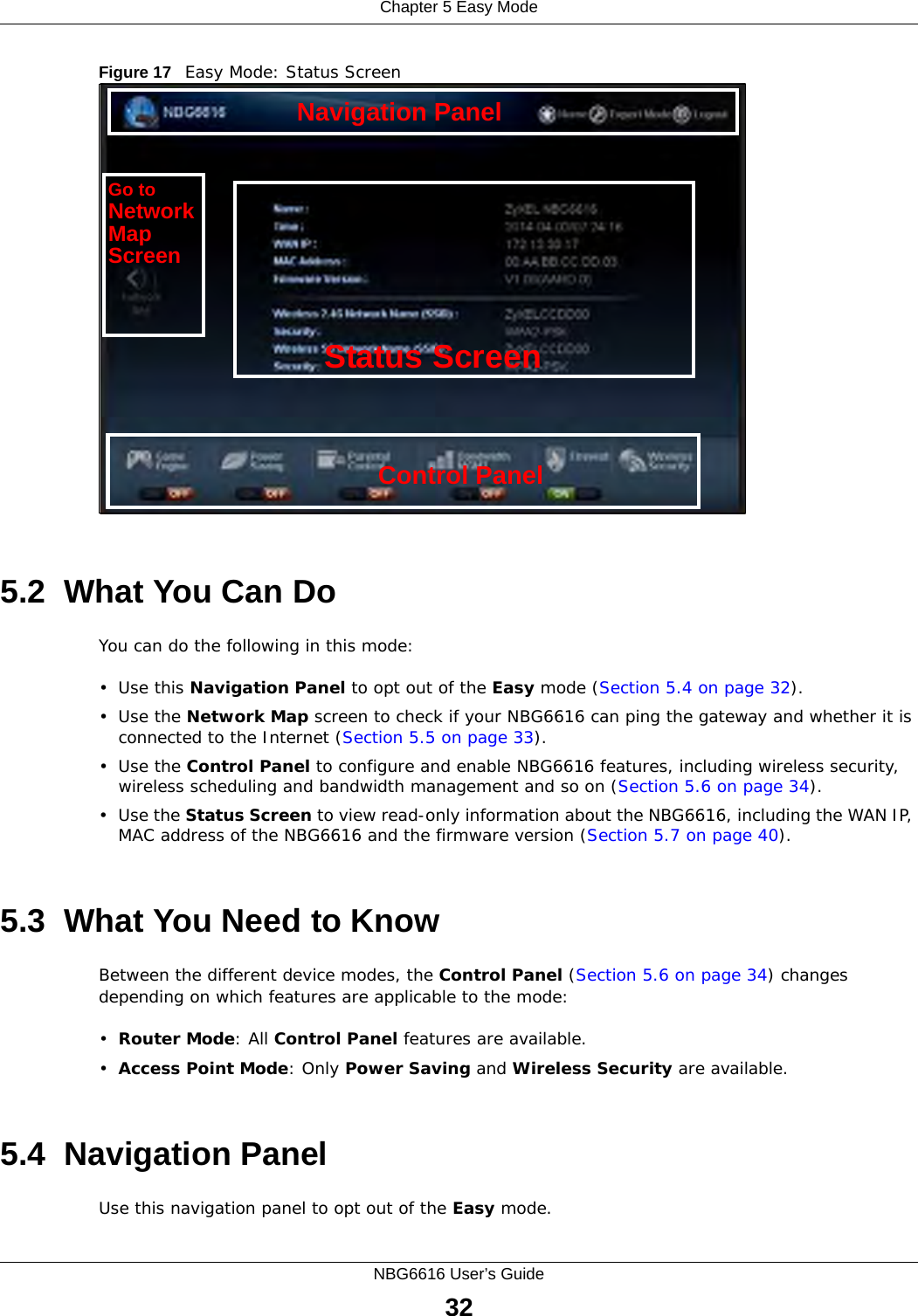
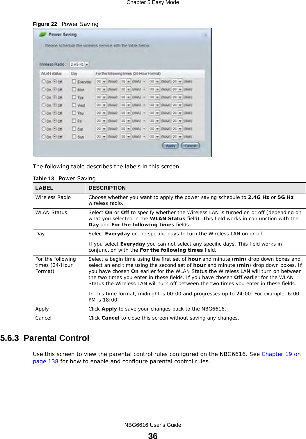
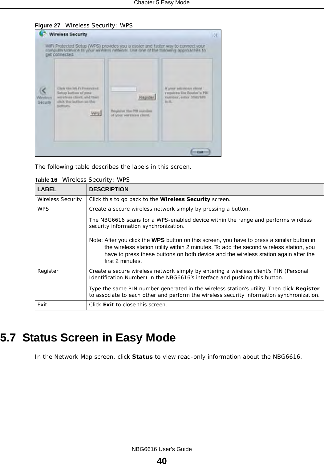
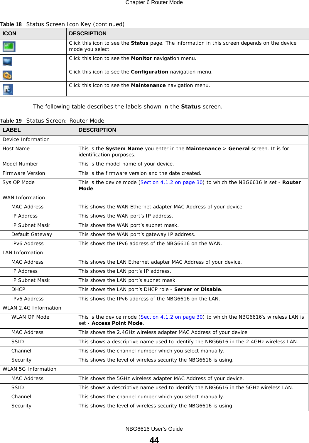
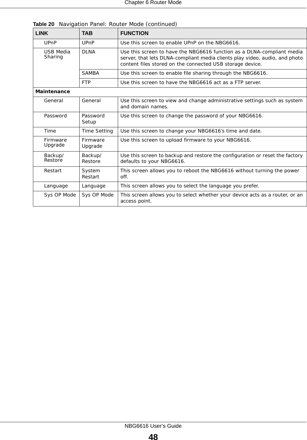
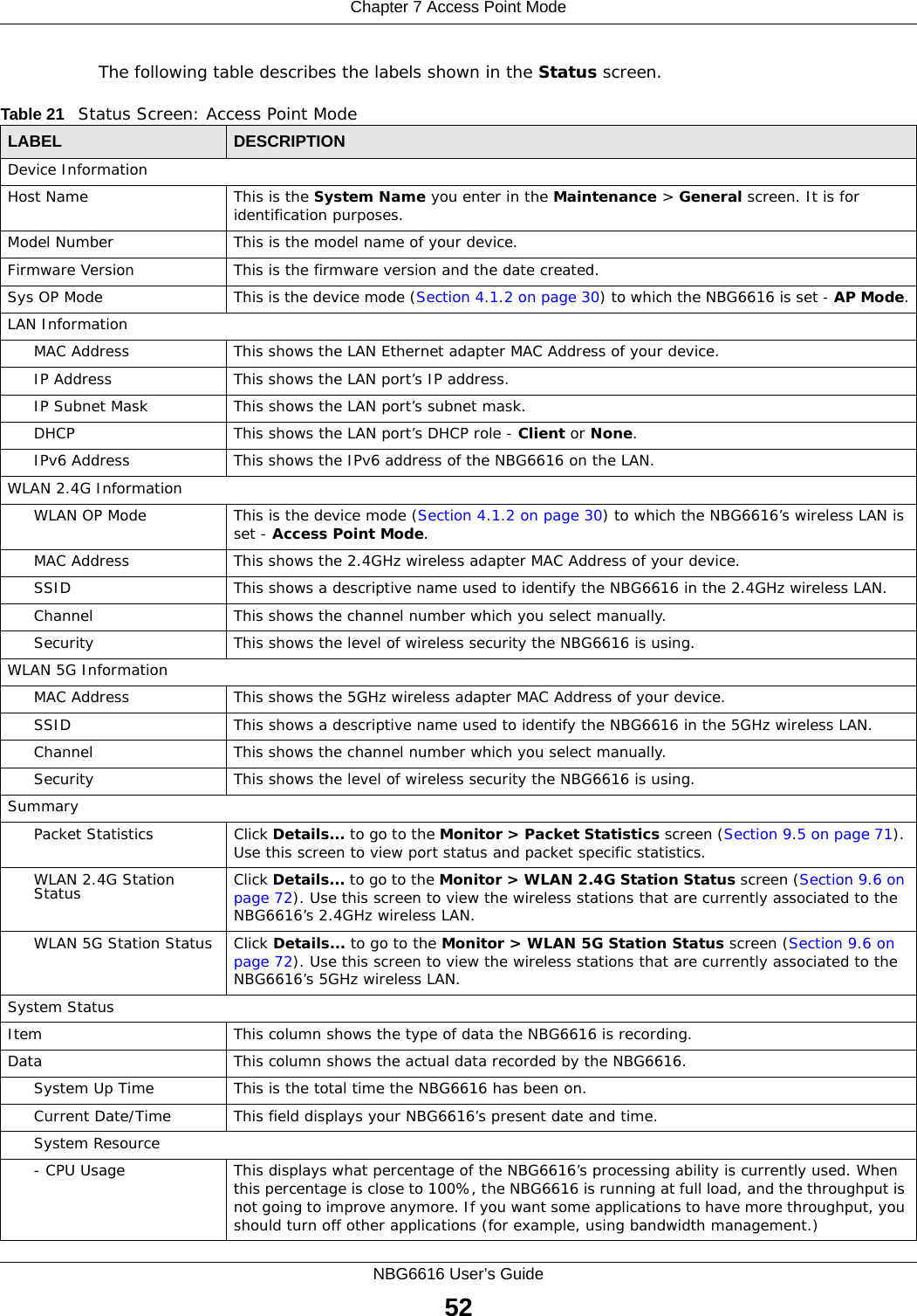
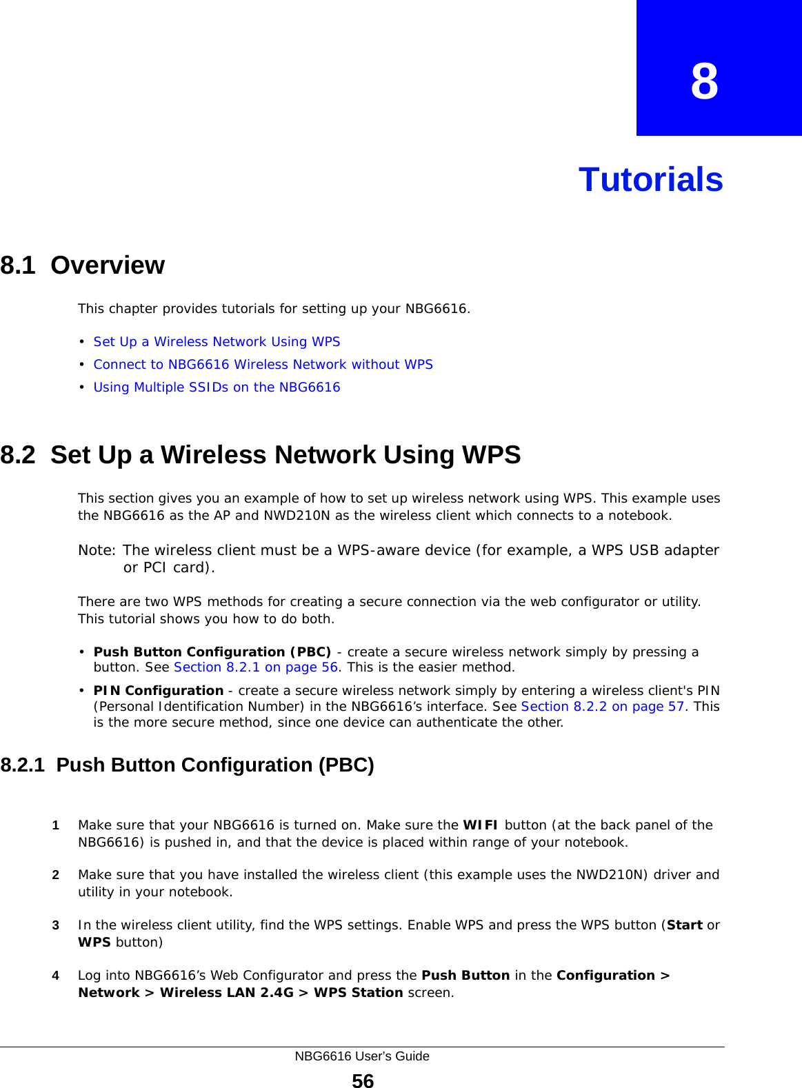

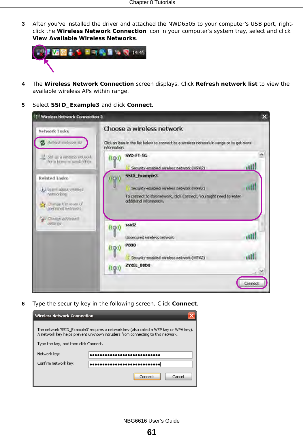
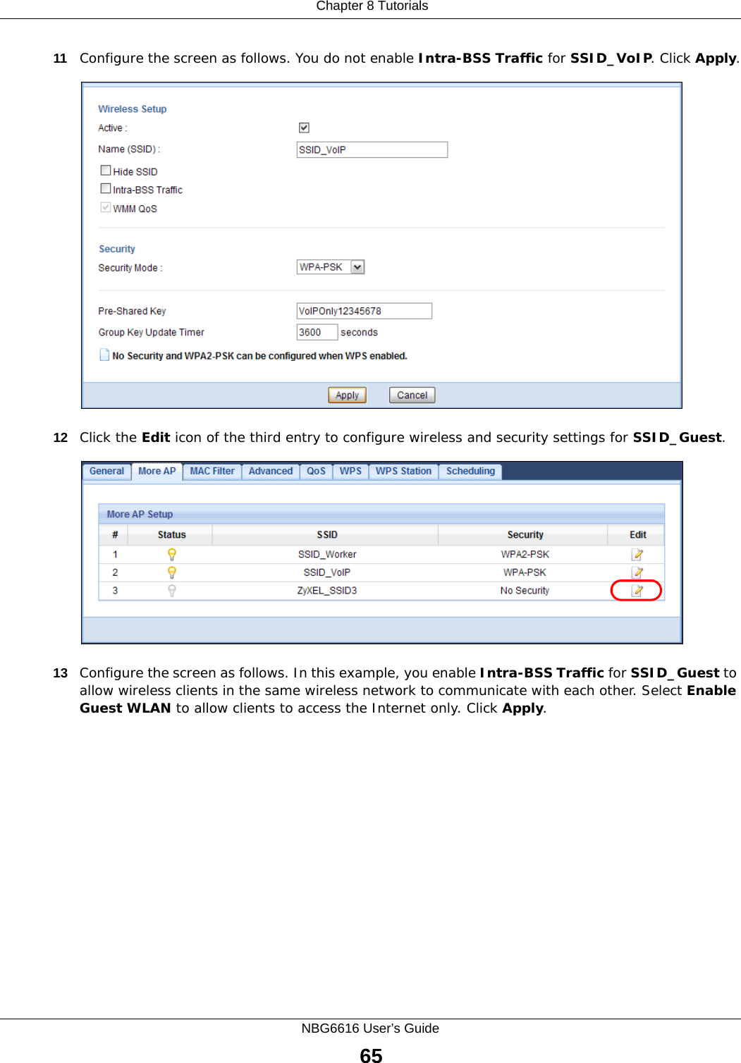
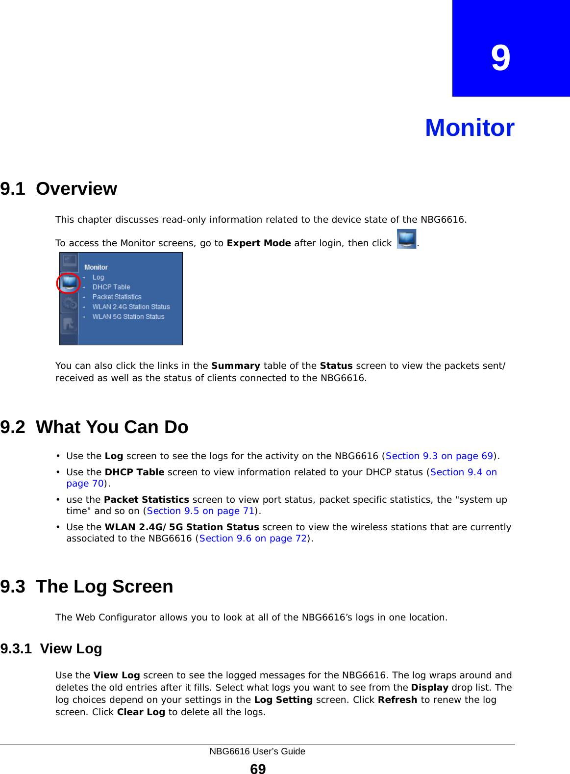
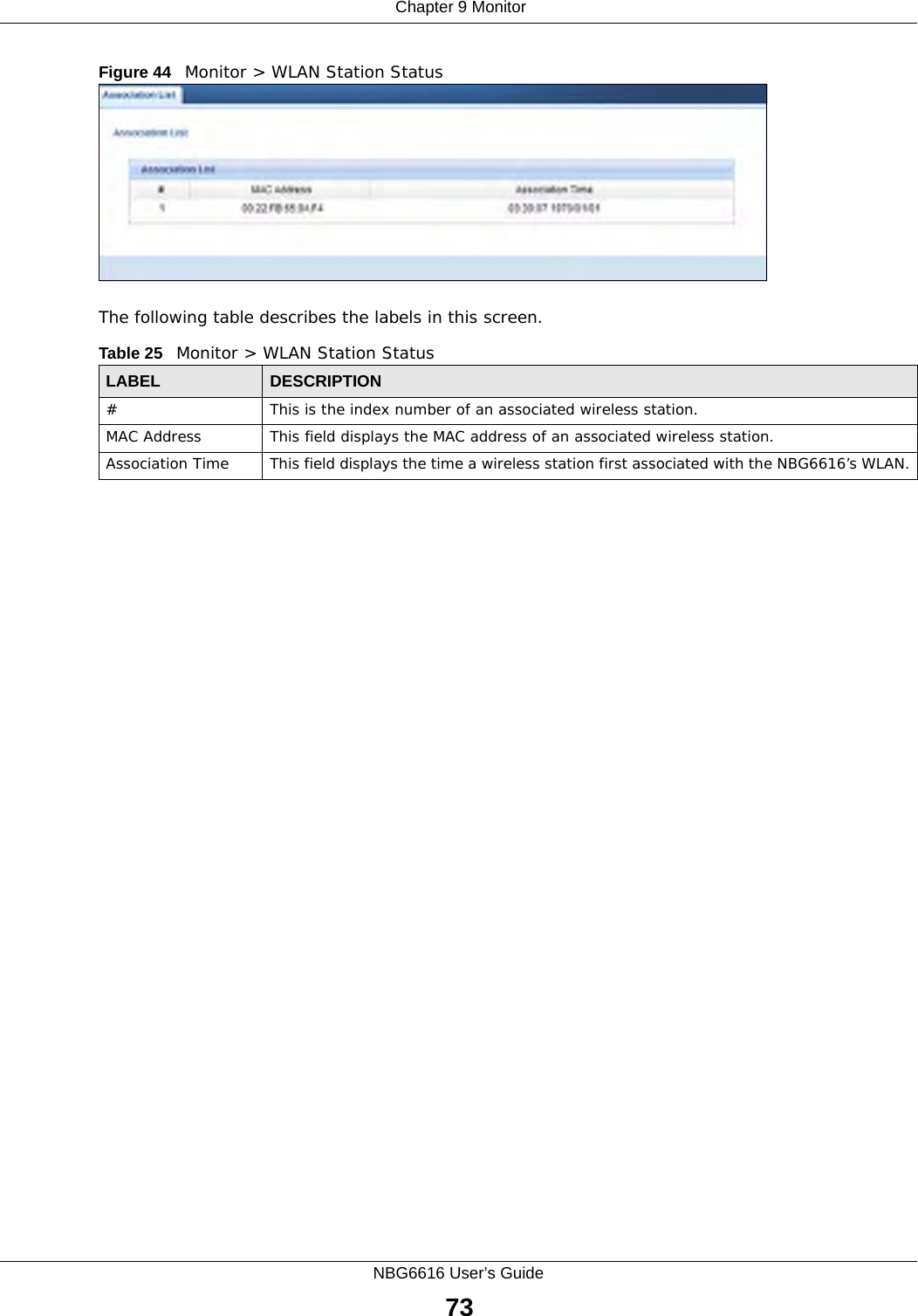
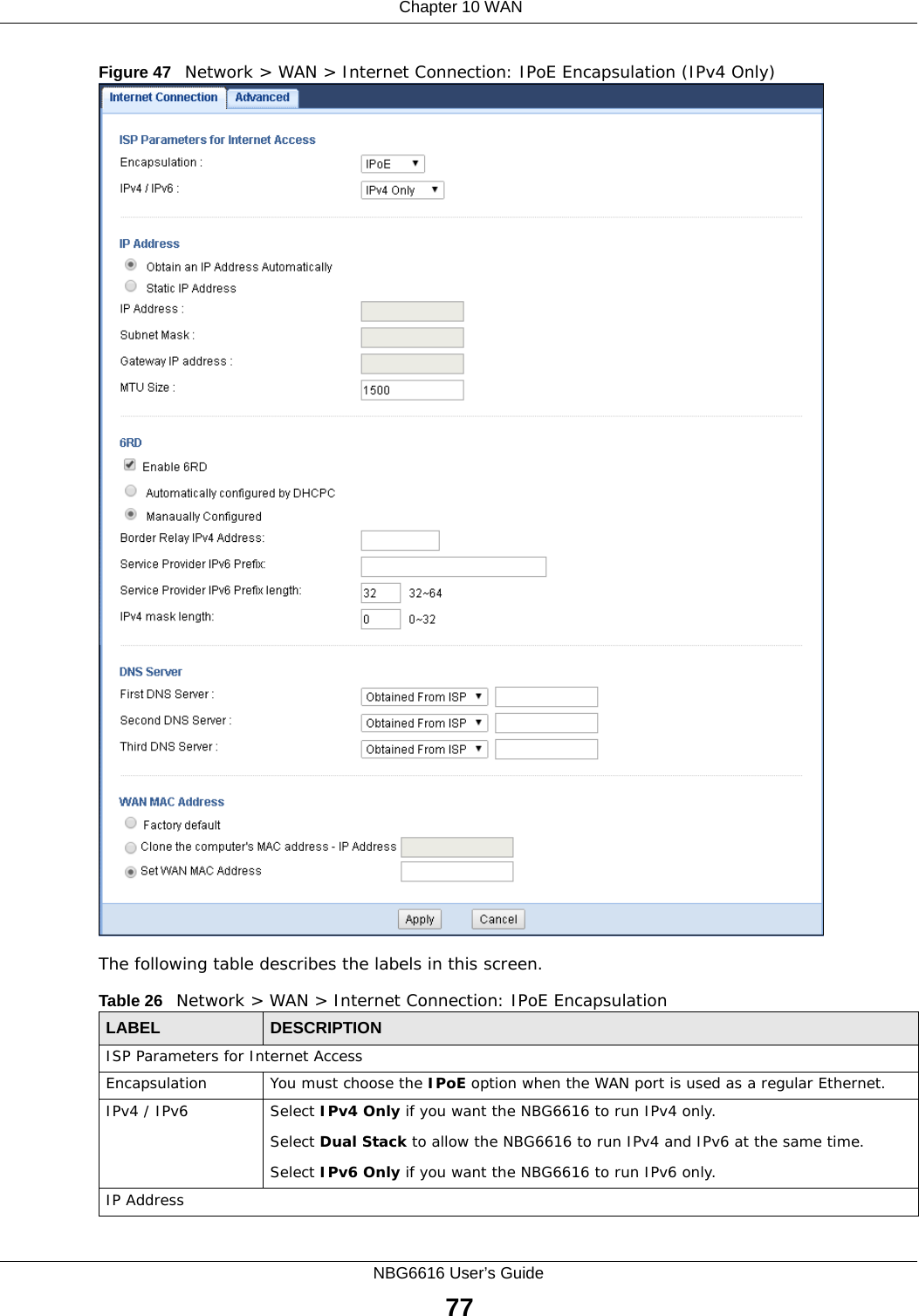
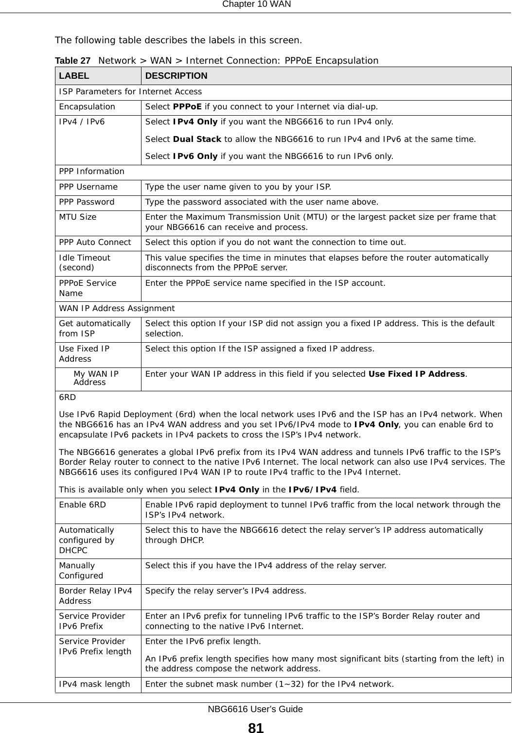
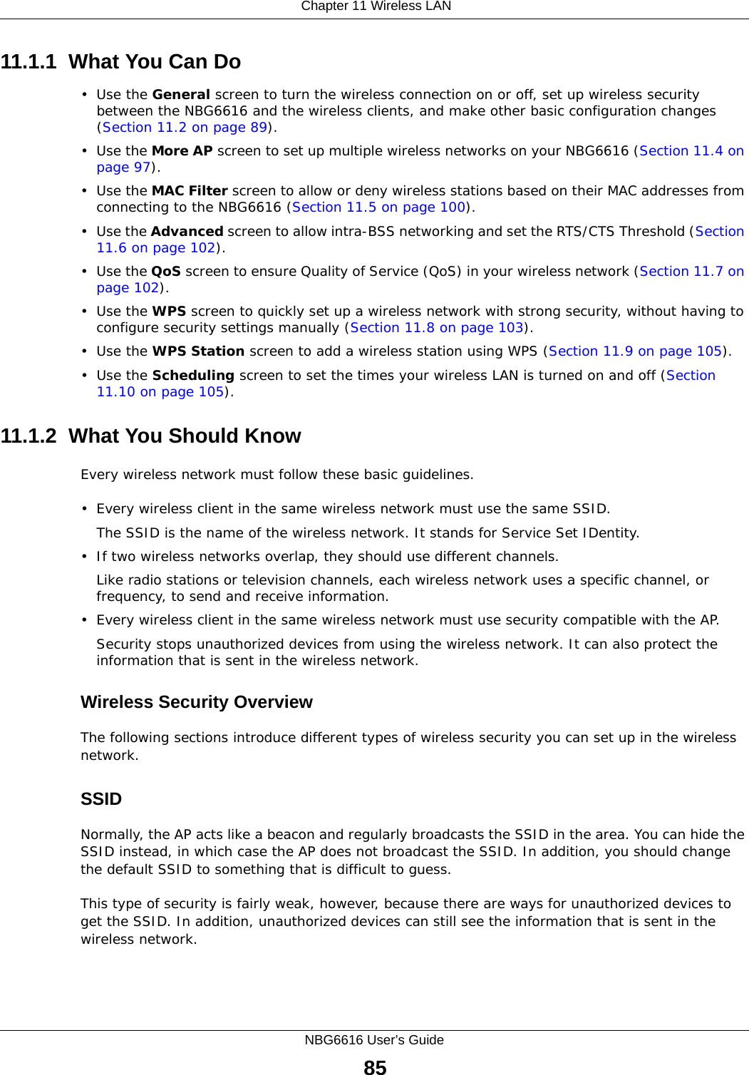
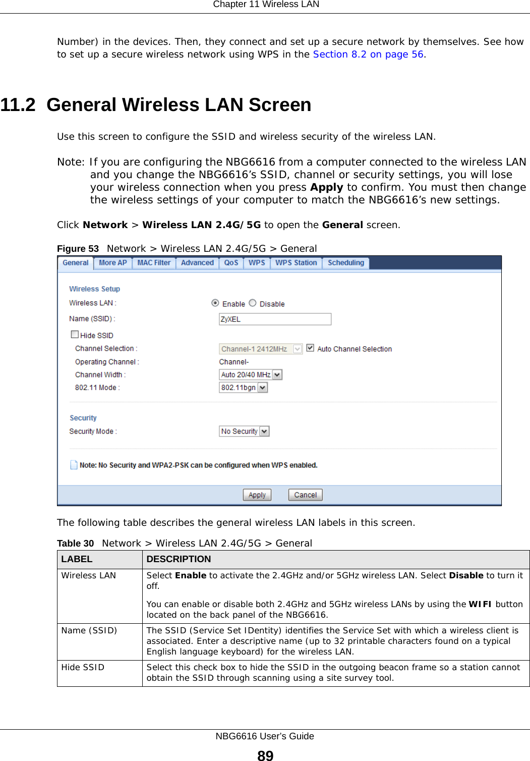
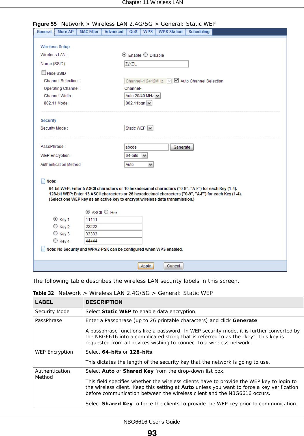
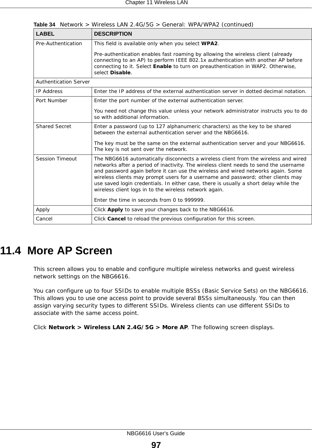
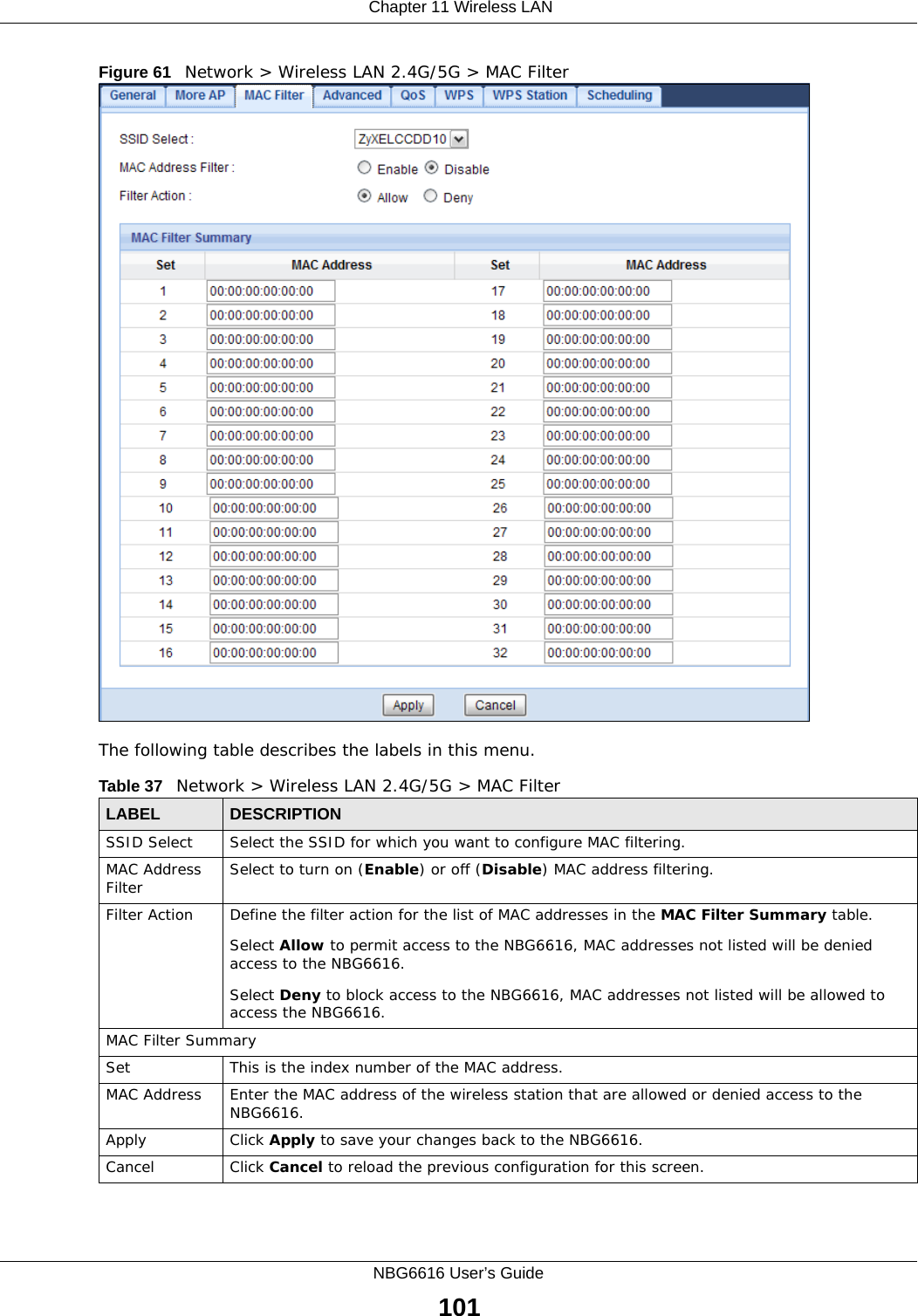
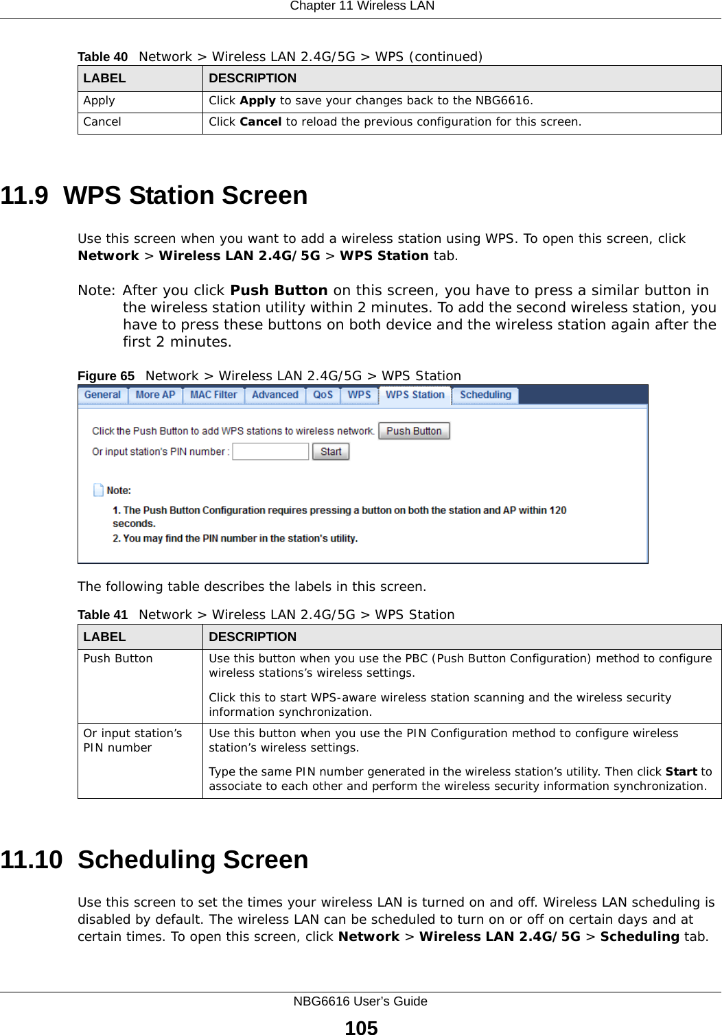
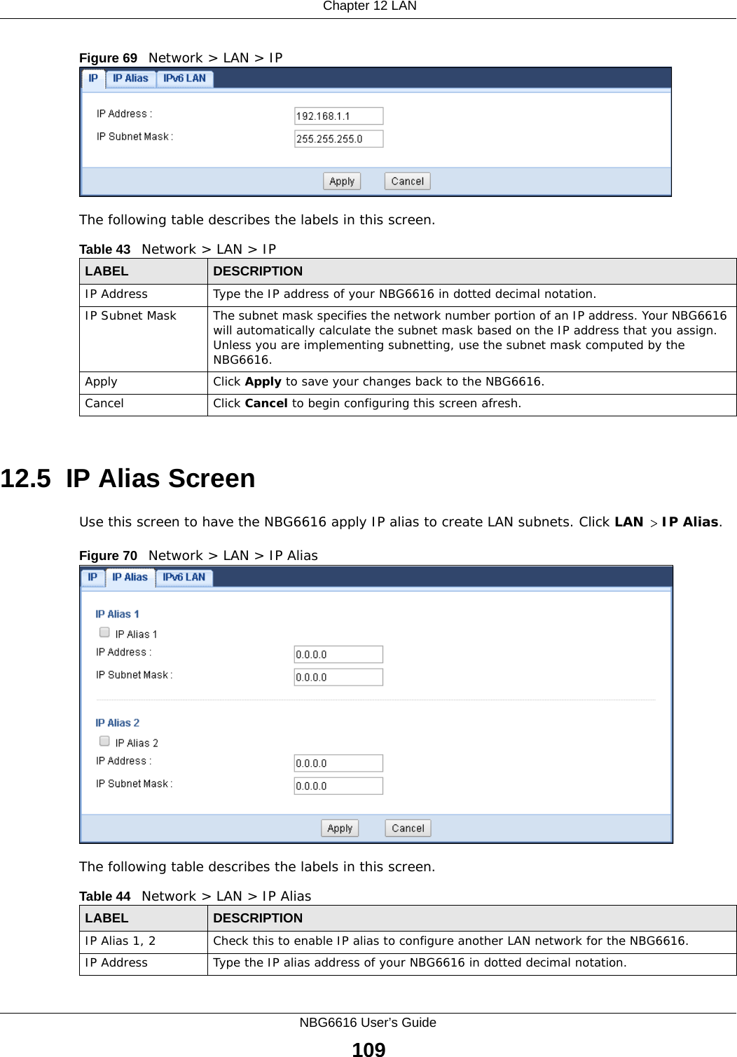
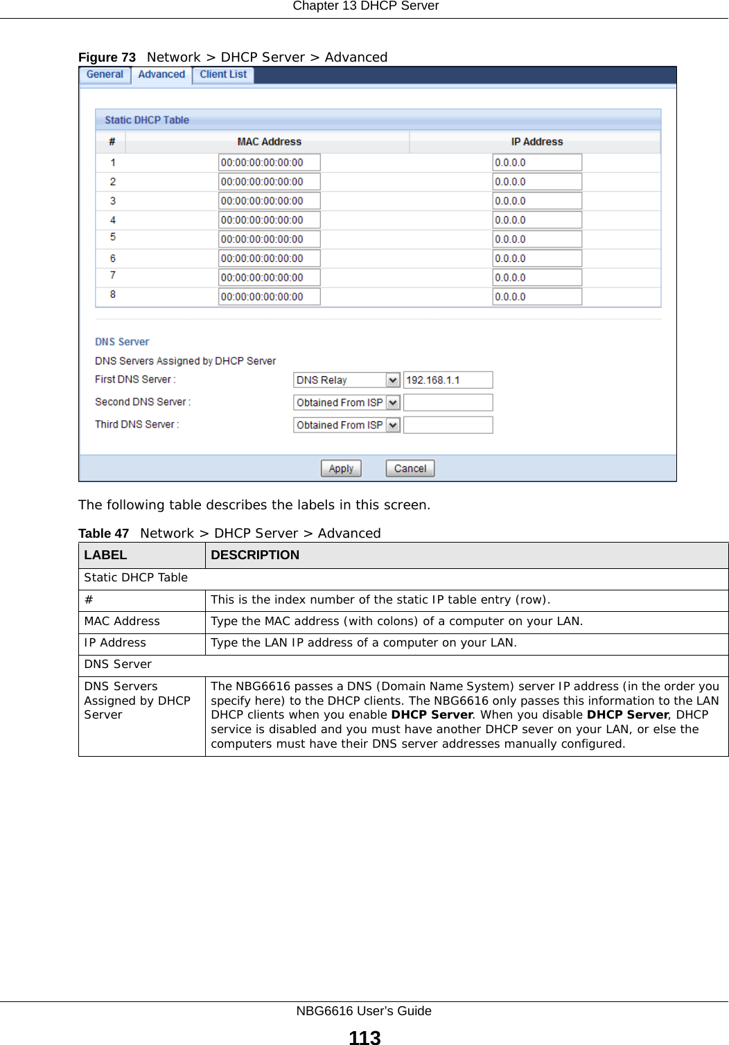
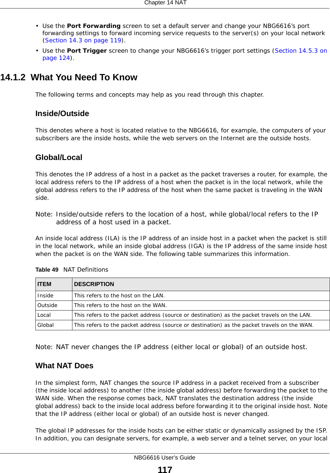
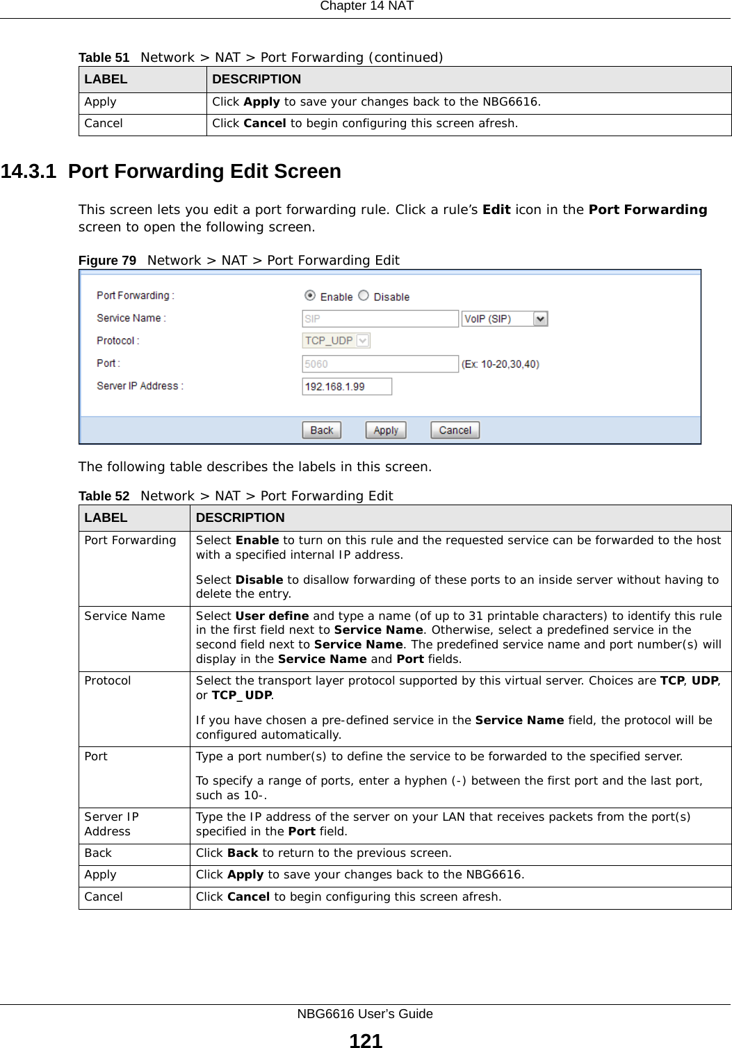
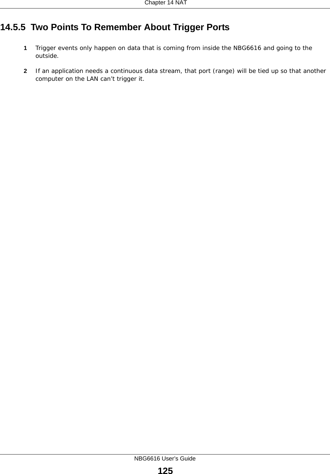
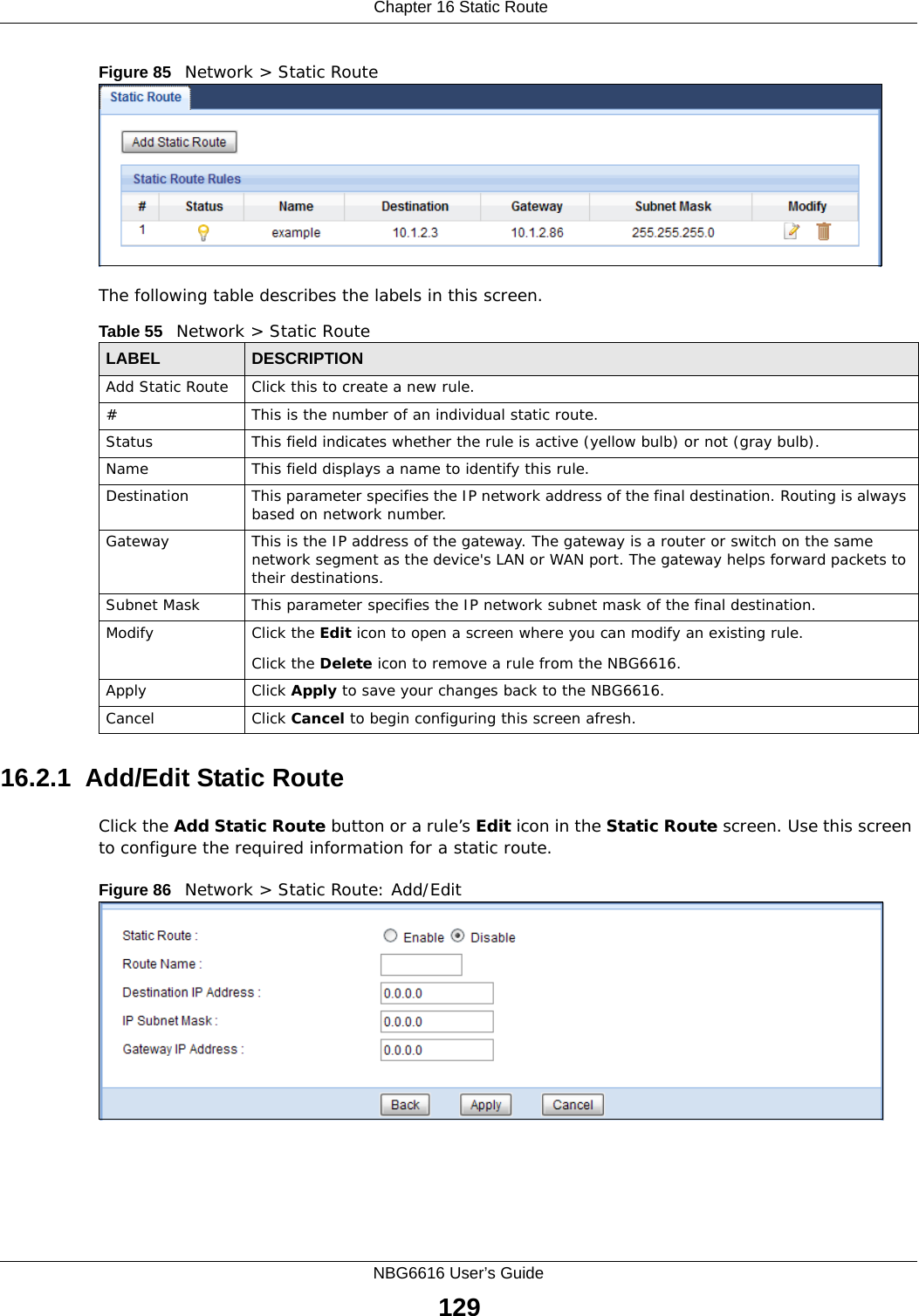
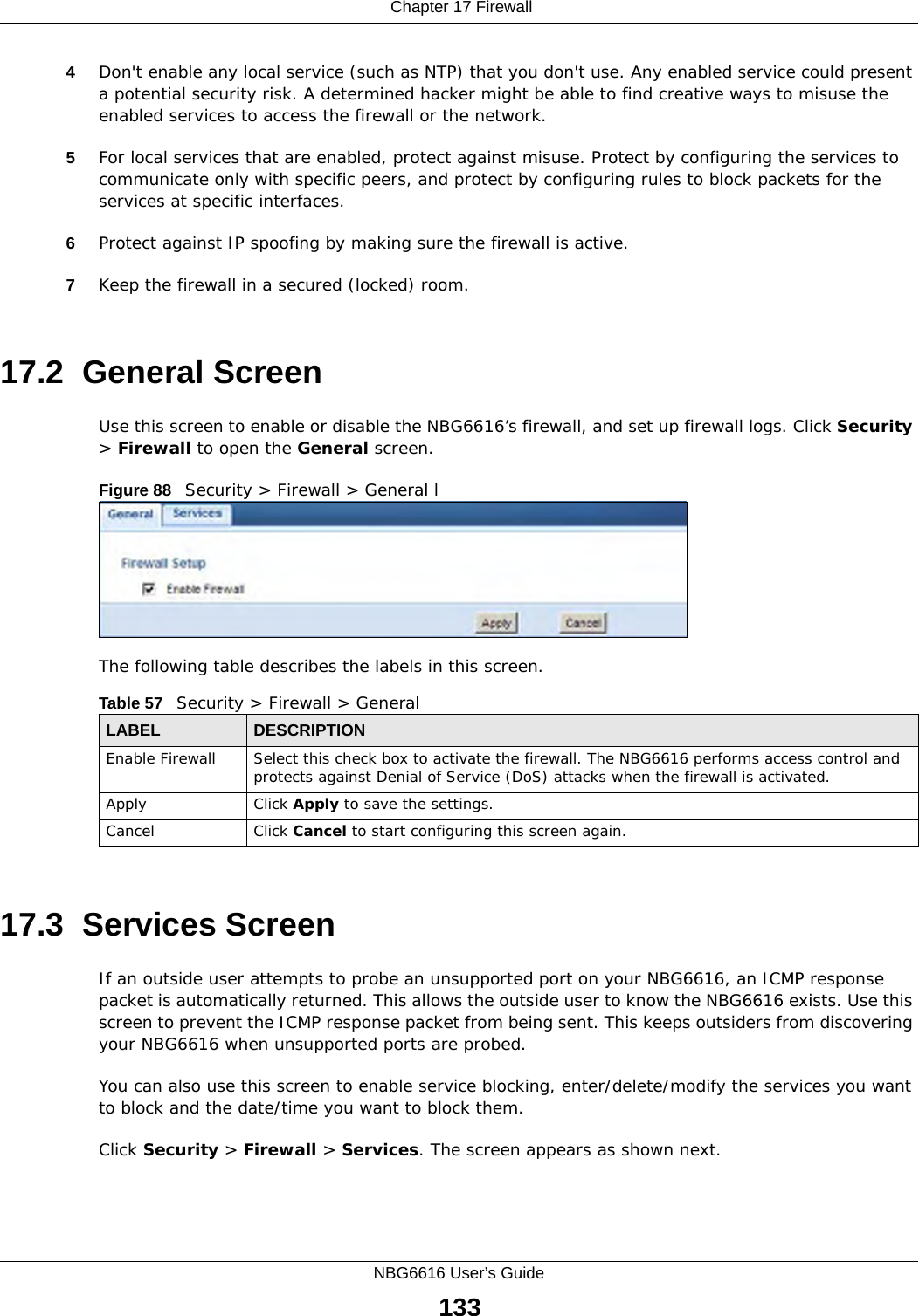
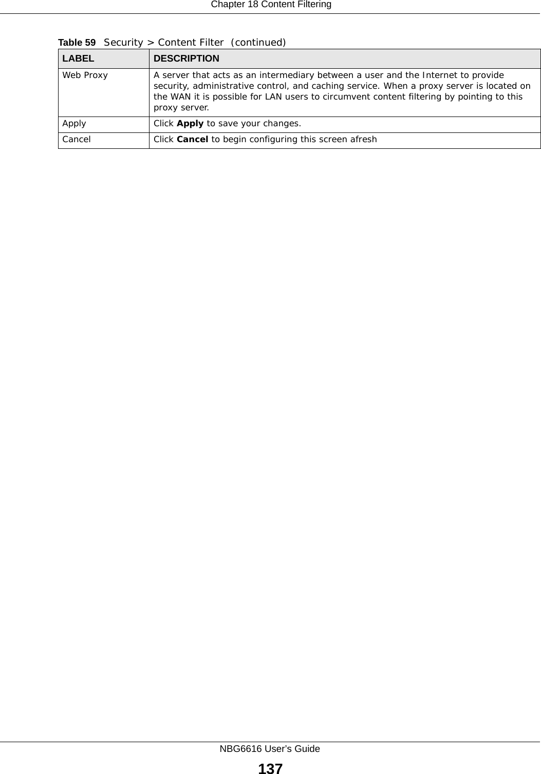
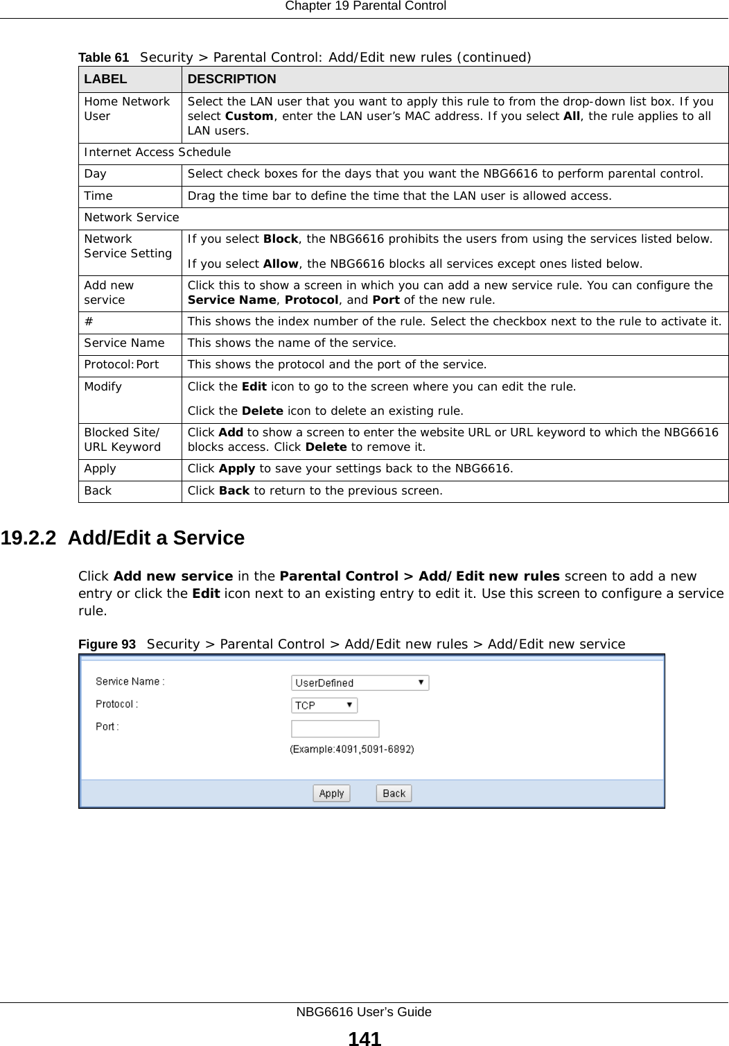
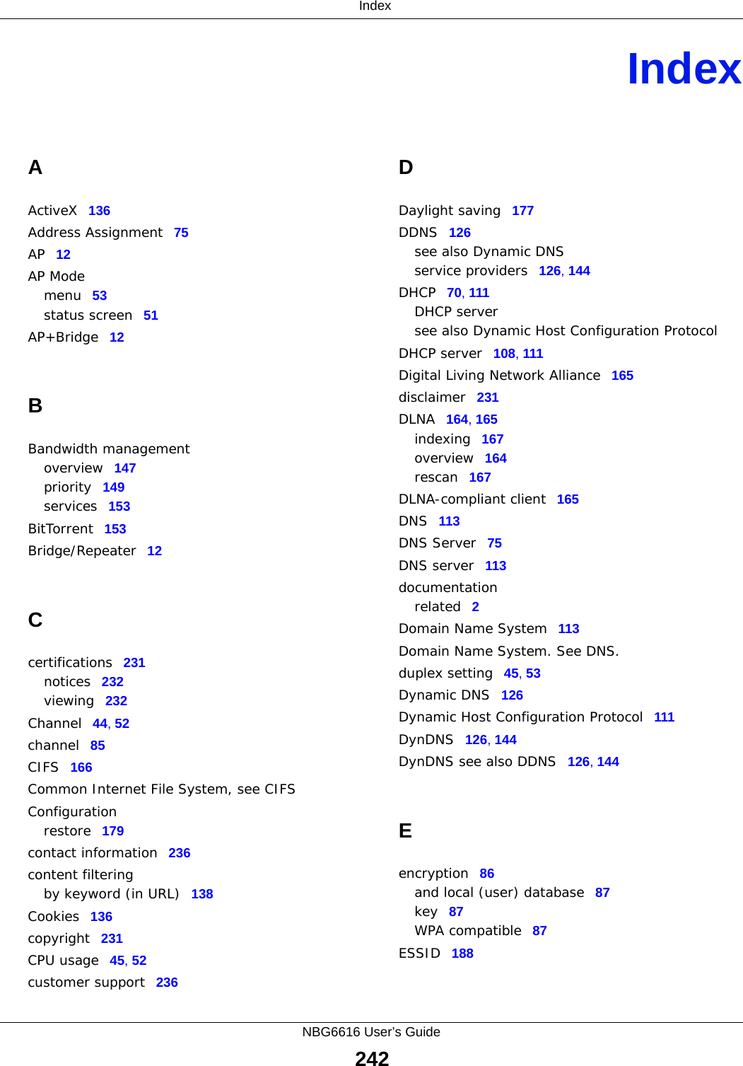
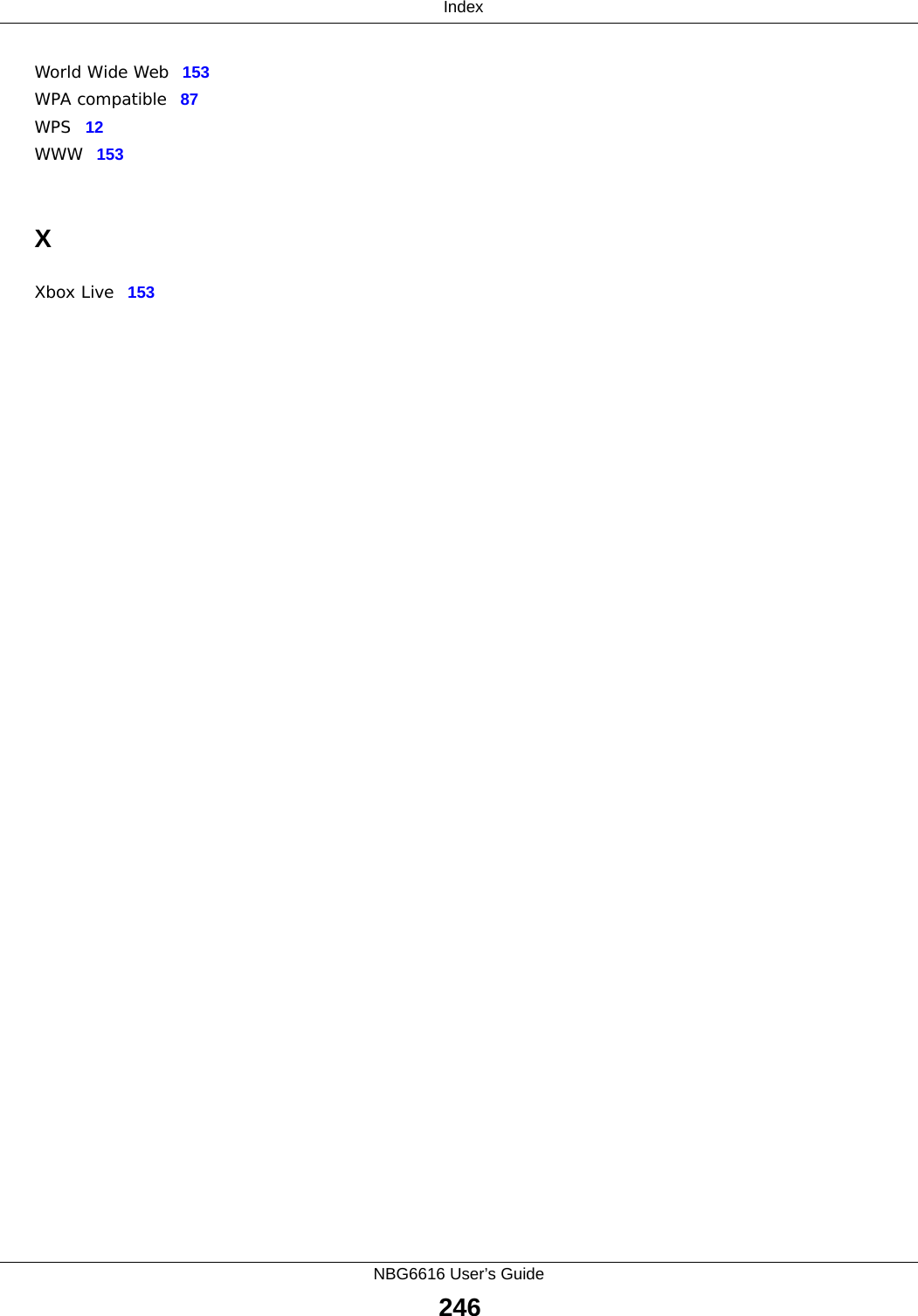
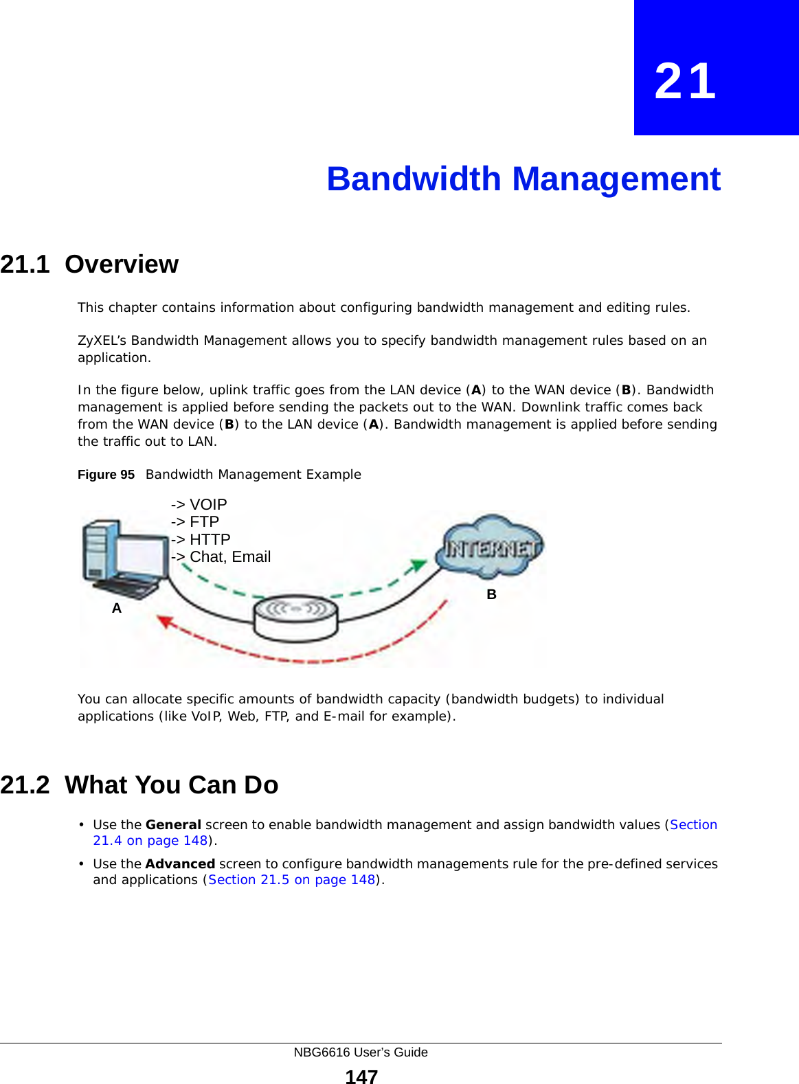
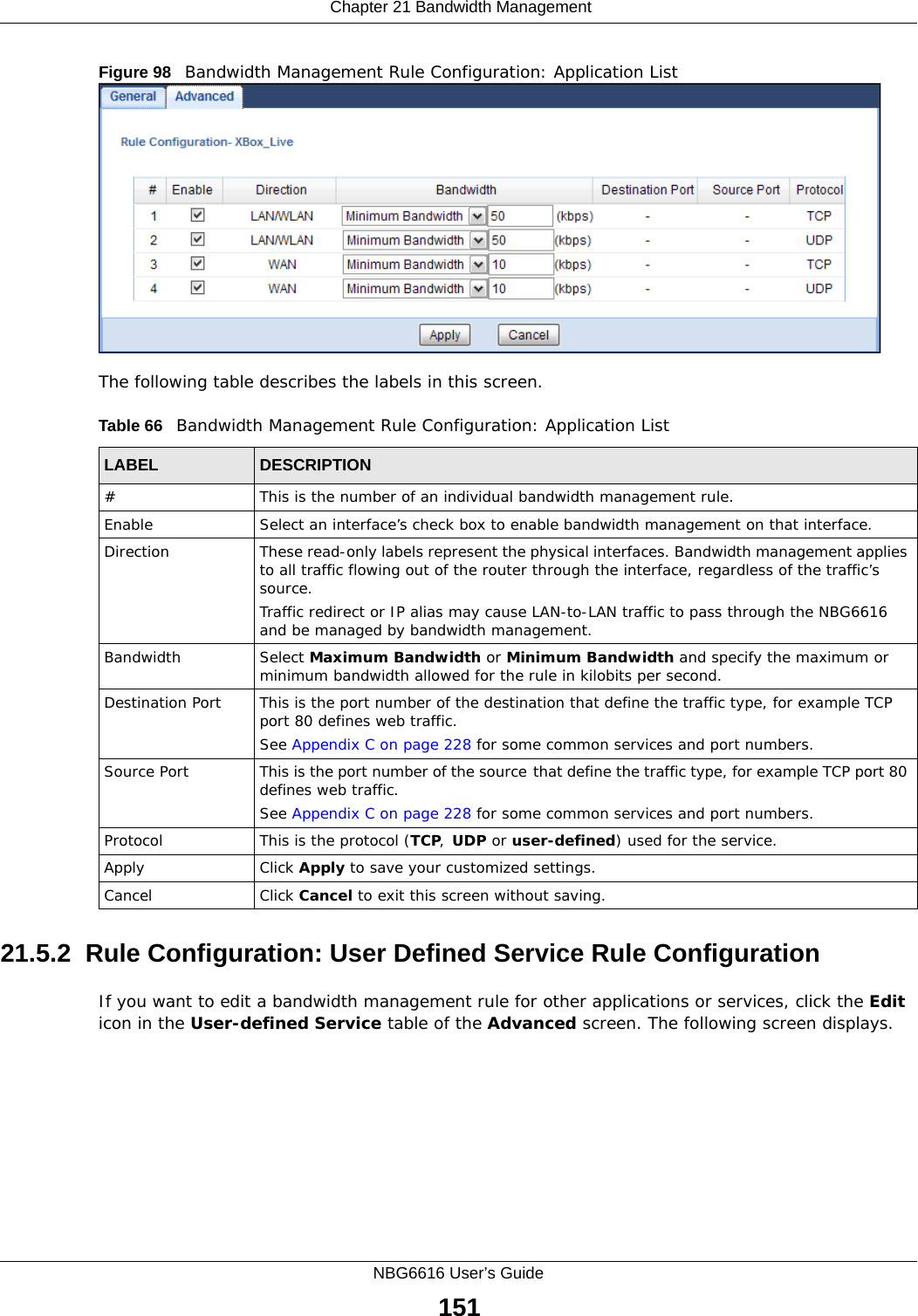
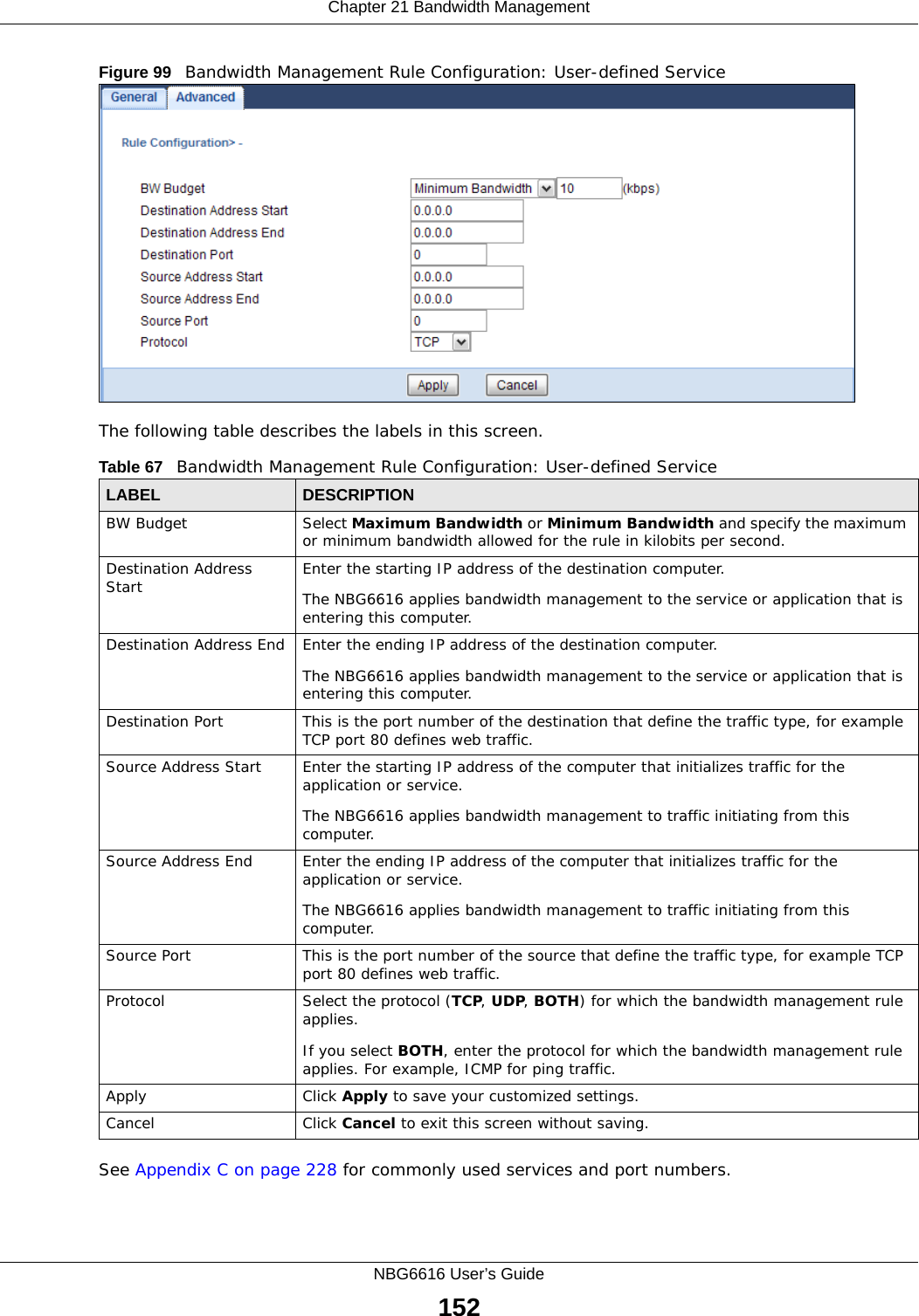
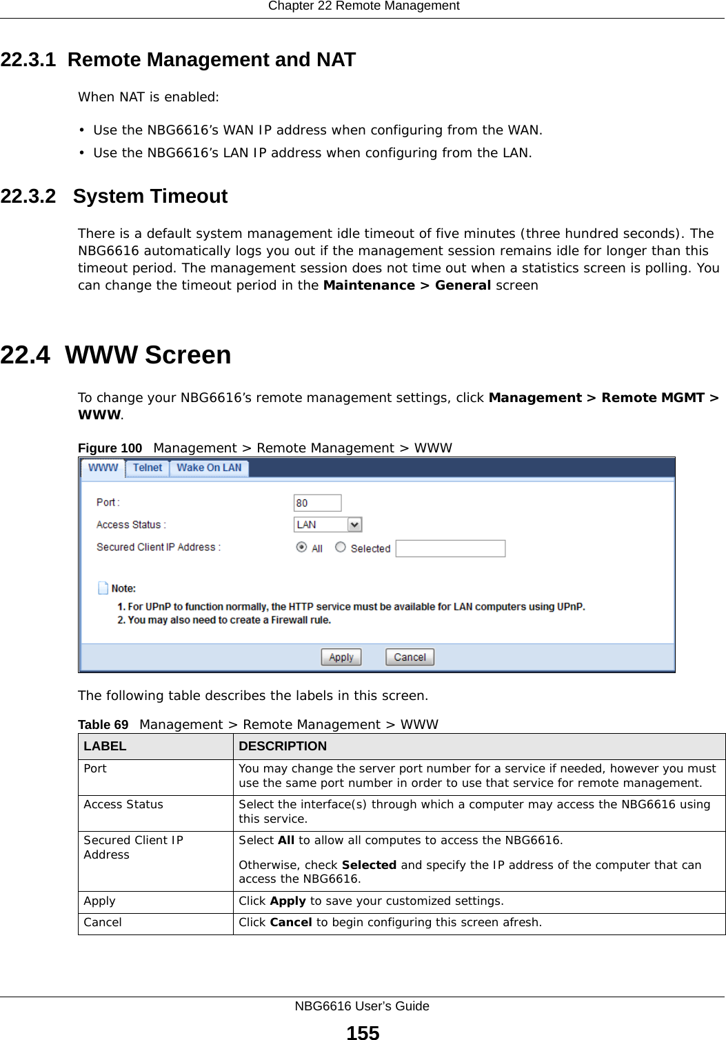
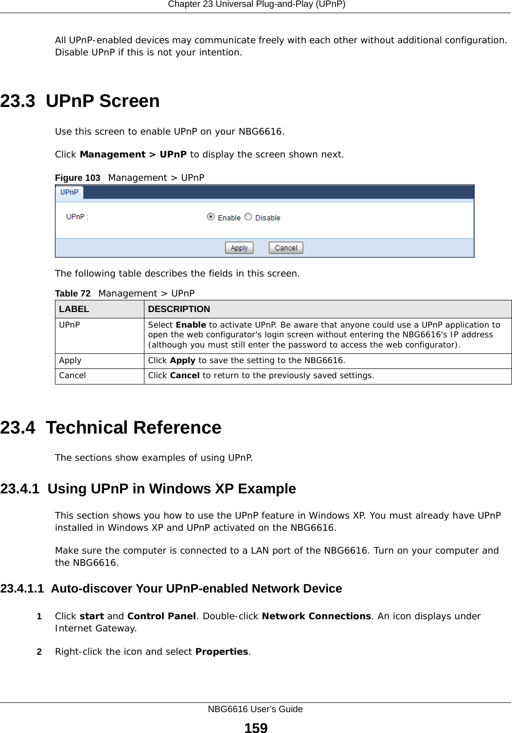
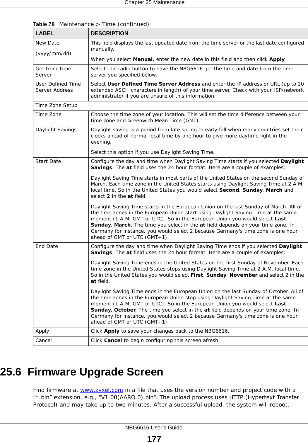
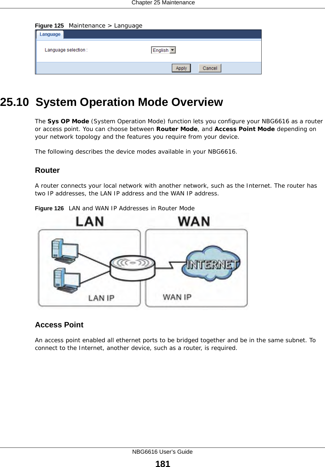
![Chapter 19 Parental ControlNBG6616 User’s Guide142The following table describes the fields in this screen. 19.3 Technical ReferenceThe following section contains additional technical information about the NBG6616 features described in this chapter.19.3.1 Customizing Keyword Blocking URL CheckingYou can use commands to set how much of a website’s URL the content filter is to check for keyword blocking. See the appendices for information on how to access and use the command interpreter.Domain Name or IP Address URL CheckingBy default, the NBG6616 checks the URL’s domain name or IP address when performing keyword blocking.This means that the NBG6616 checks the characters that come before the first slash in the URL.For example, with the URL www.zyxel.com.tw/news/pressroom.php, content filtering only searches for keywords within www.zyxel.com.tw.Full Path URL CheckingFull path URL checking has the NBG6616 check the characters that come before the last slash in the URL.For example, with the URL www.zyxel.com.tw/news/pressroom.php, full path URL checking searches for keywords within www.zyxel.com.tw/news/.Use the ip urlfilter customize actionFlags 6 [disable | enable] command to extend (or not extend) the keyword blocking search to include the URL's full path.Table 62 Security > Parental Control > Add/Edit new rules > Add/Edit new serviceLABEL DESCRIPTIONService Name Select the name of the service. Otherwise, select UserDefined and manually specify the protocol and the port of the service.Protocol Select the transport layer protocol used for the service. Choices are TCP, UDP, or TCP/UDP. If you have chosen a pre-defined service in the Service Name field, this field will not be configurable.Port Enter the port of the service. If you have chosen a pre-defined service in the Service Name field, this field will not be configurable.Apply Click Apply to save your settings with the NBG6616.Back Click Back to return to the previous screen.](https://usermanual.wiki/ZyXEL-Communications/NBG6616/User-Guide-2392470-Page-142.png)
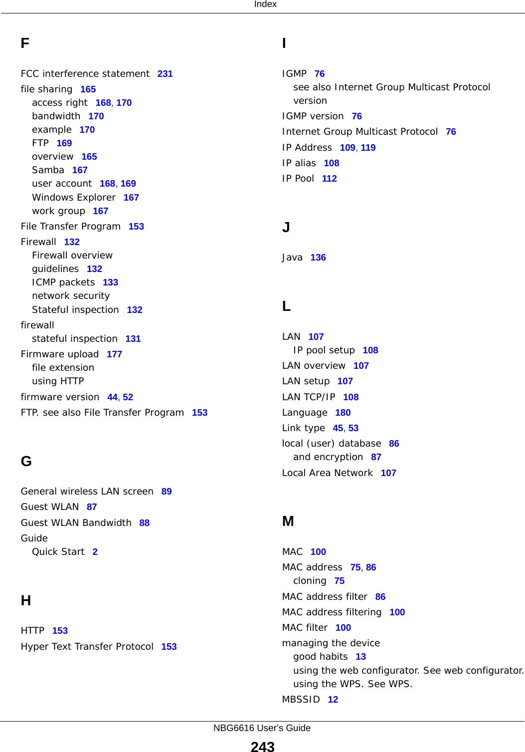
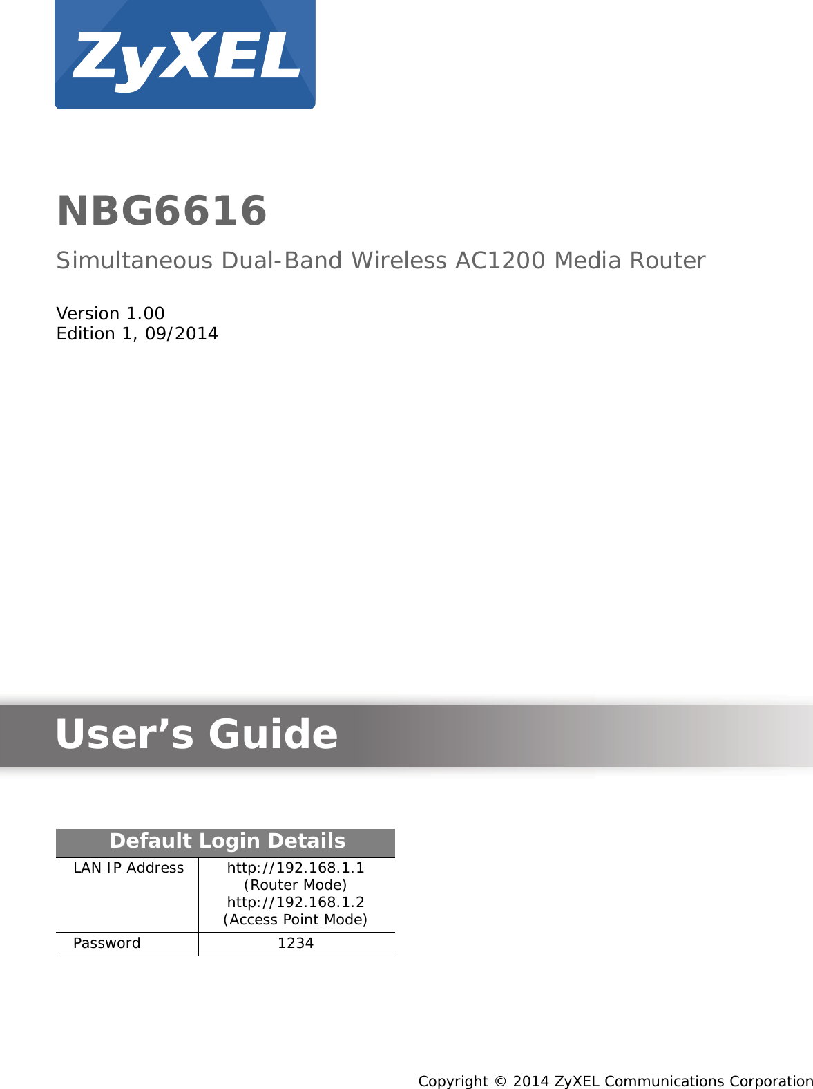
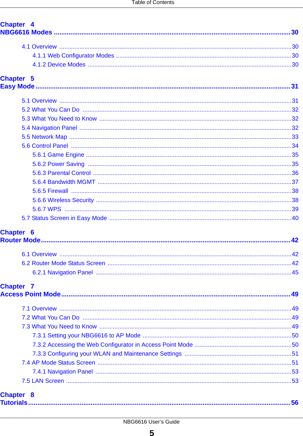
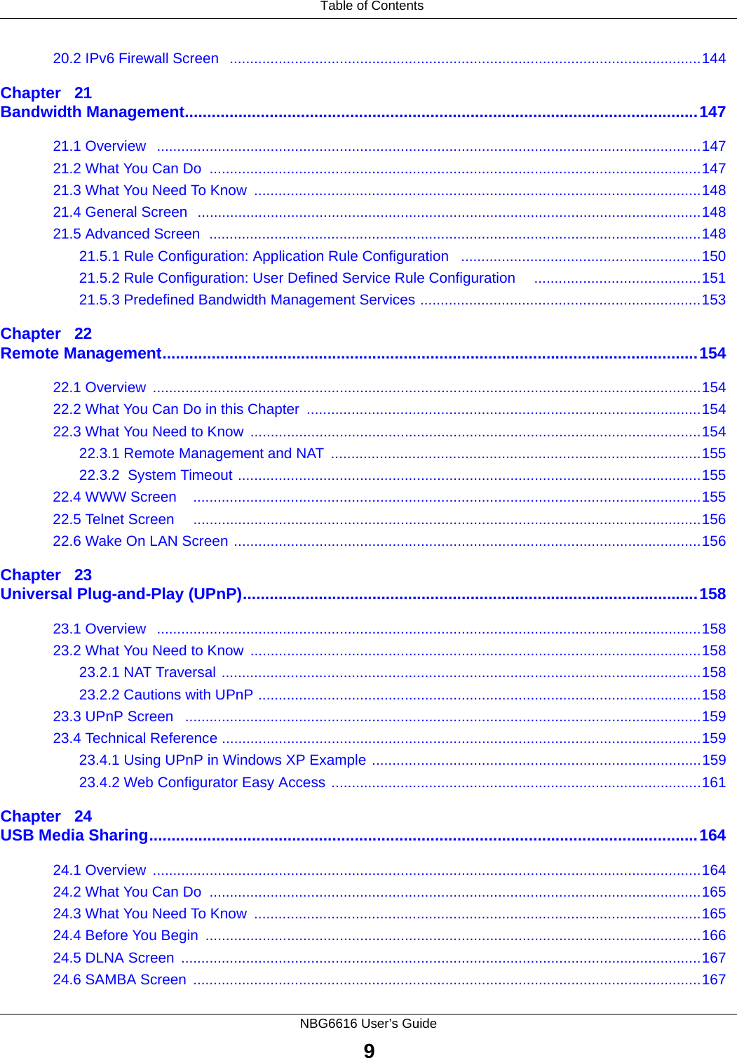
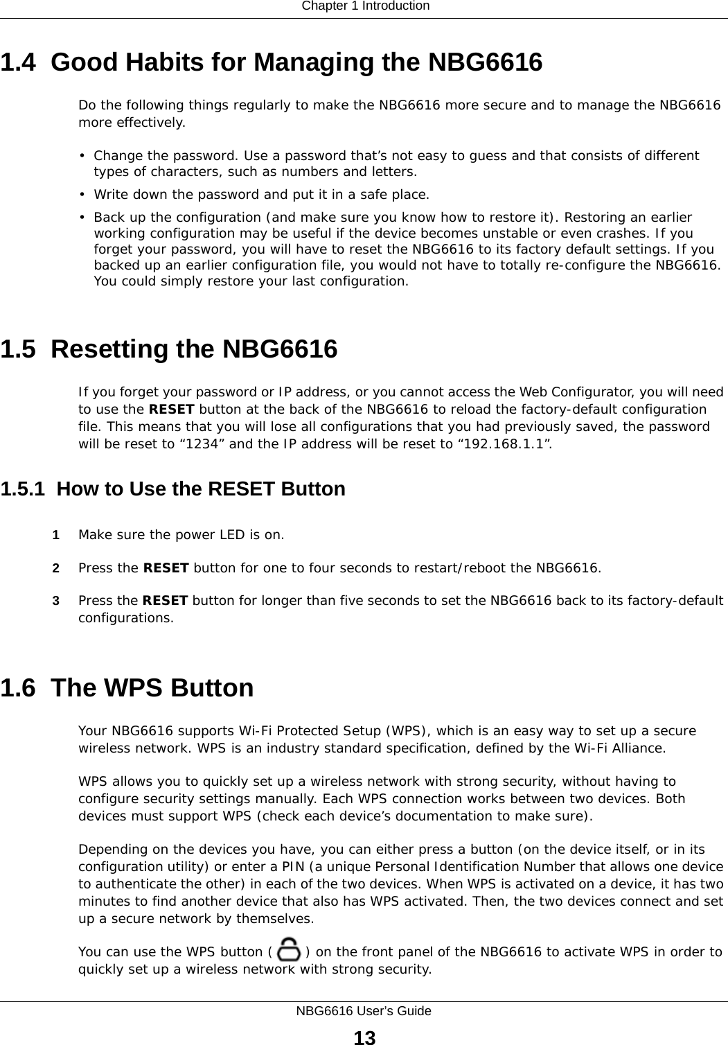
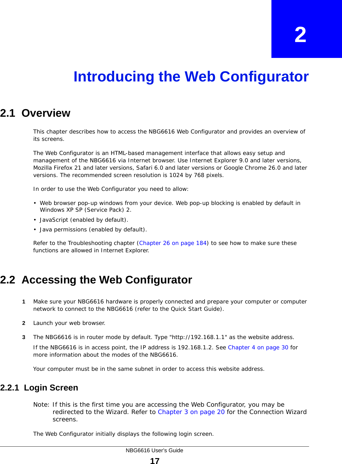
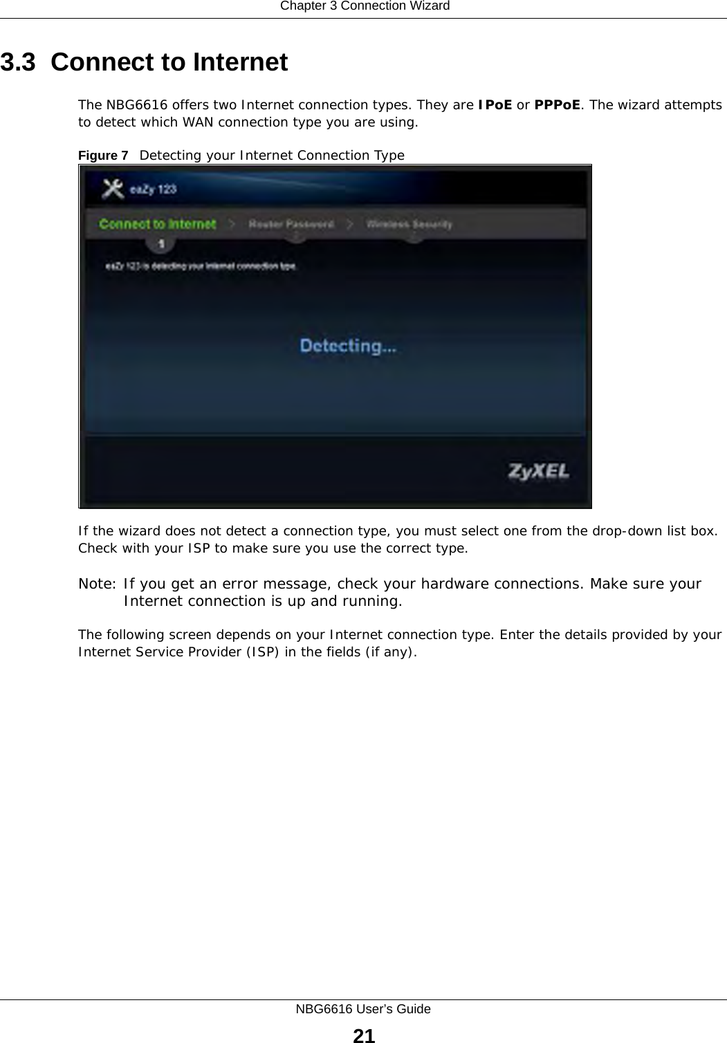
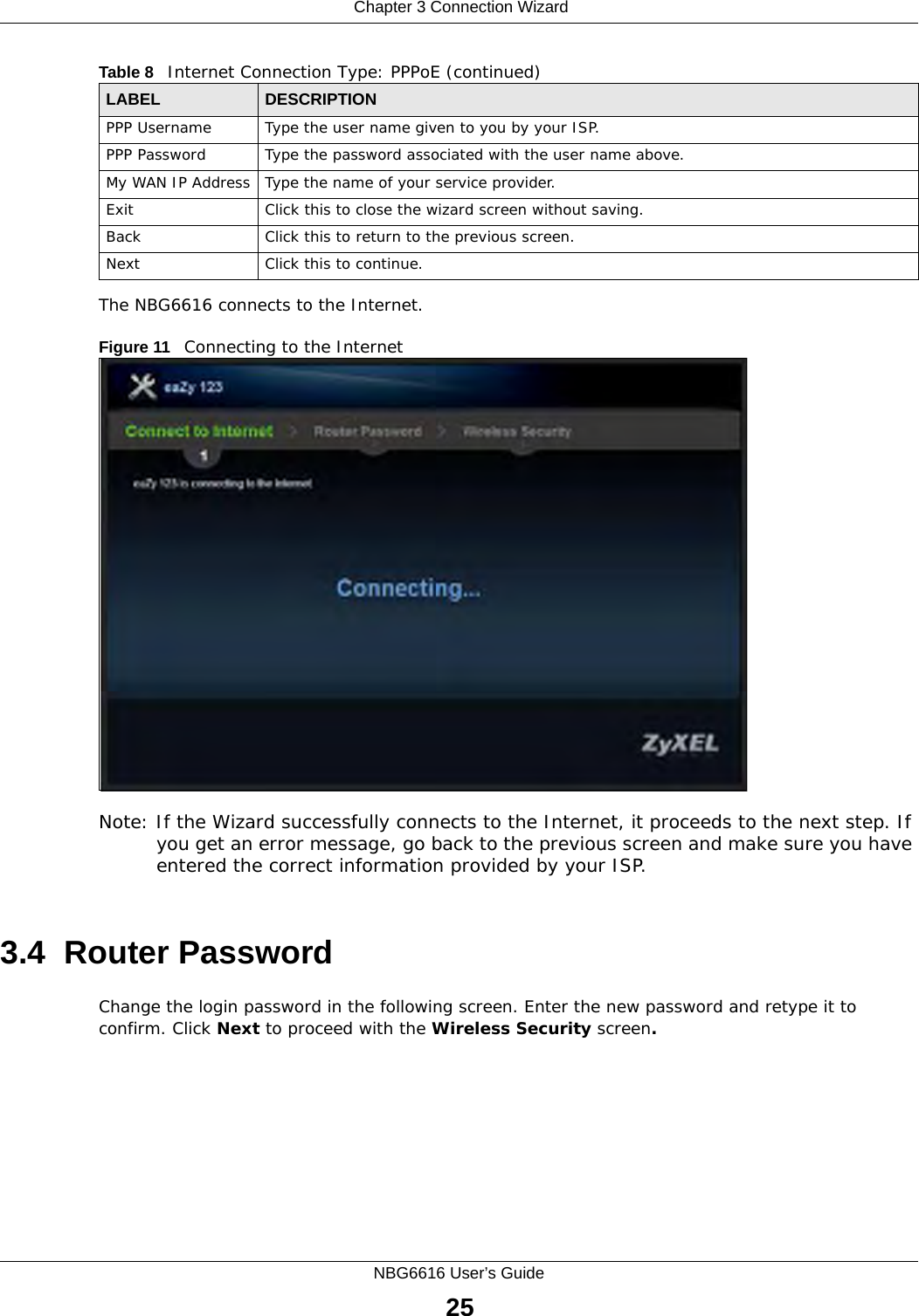
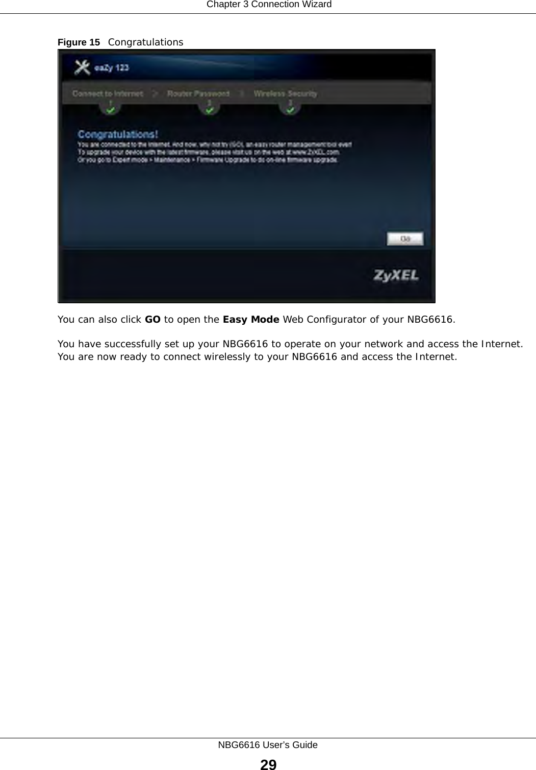
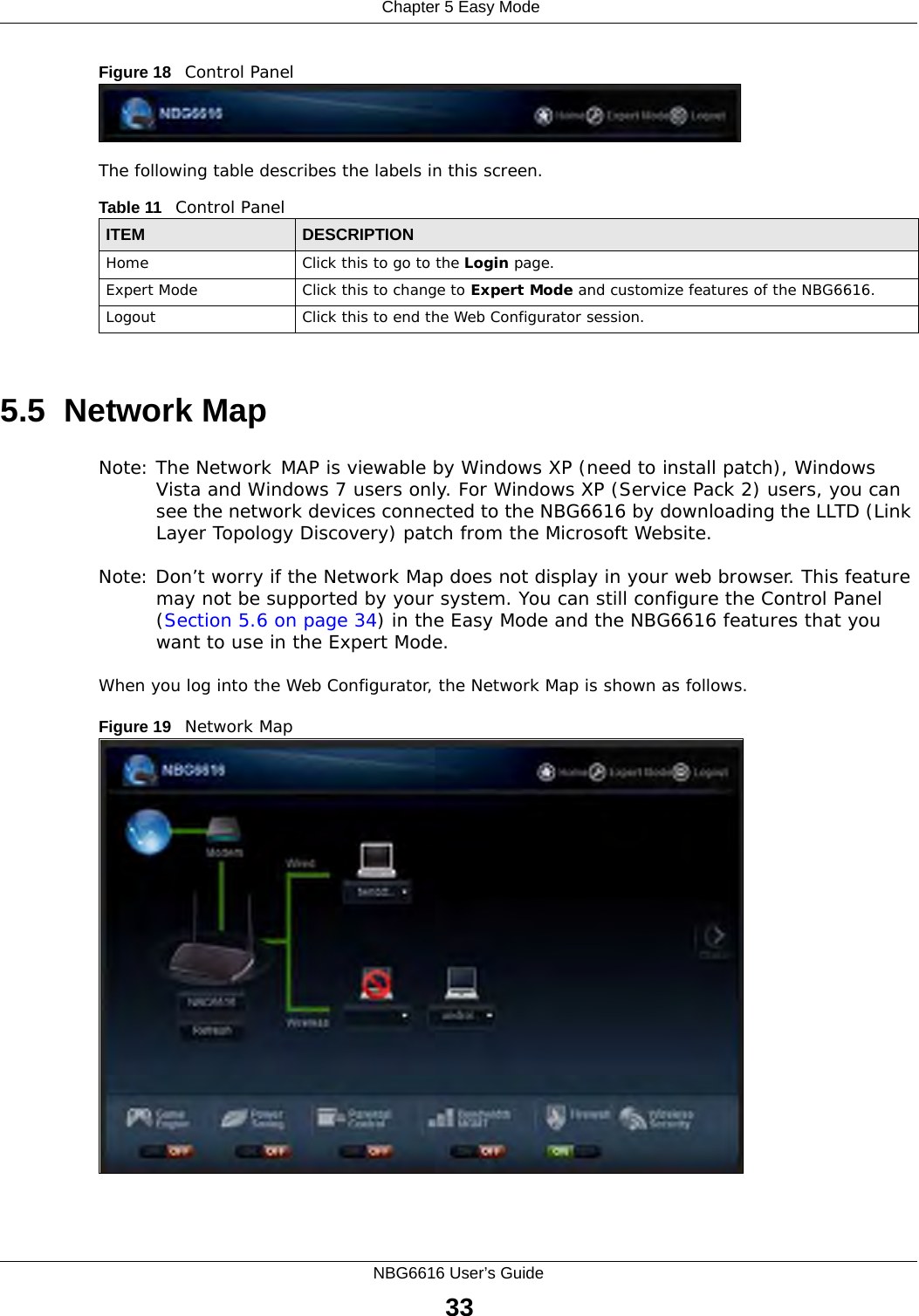
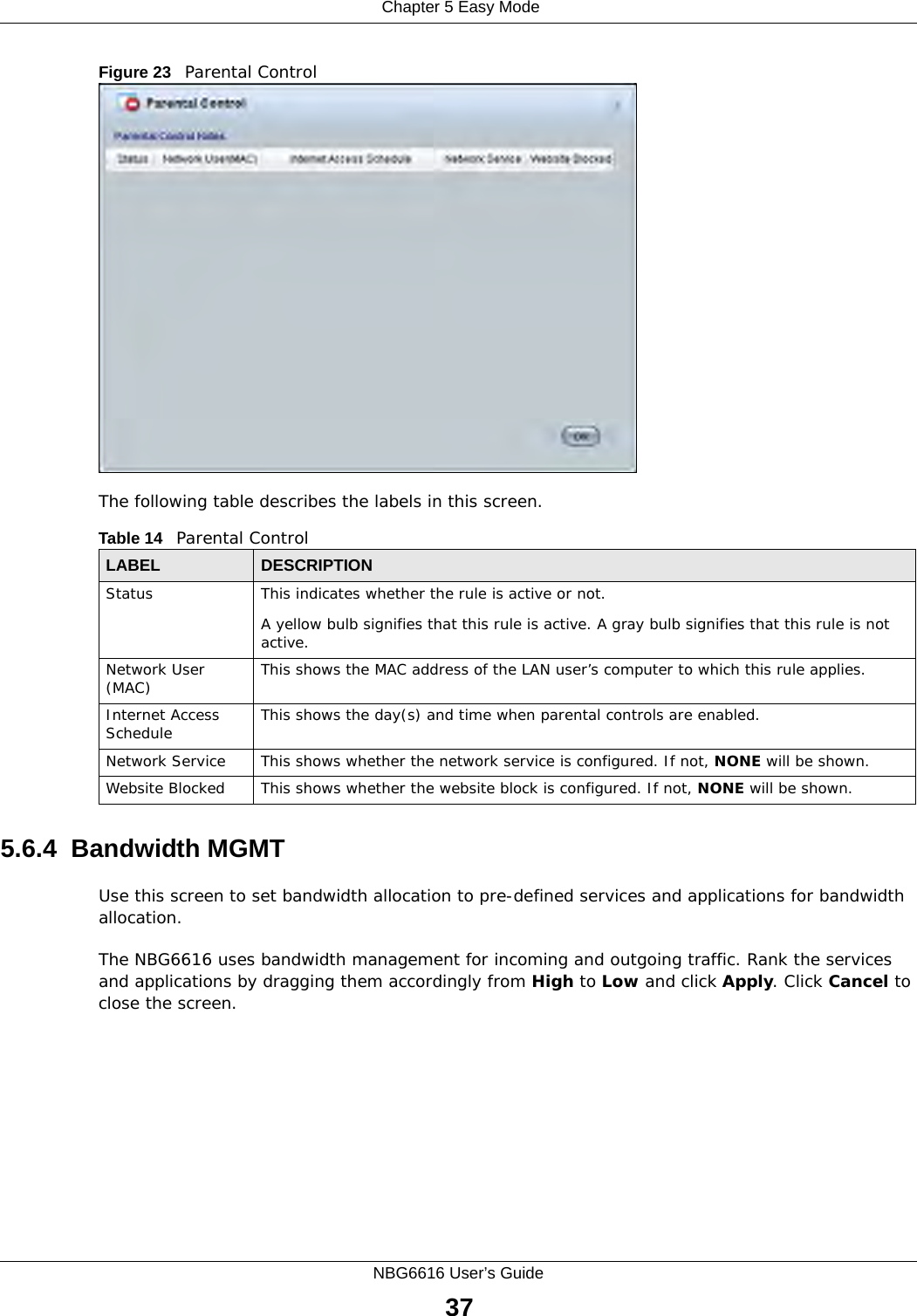
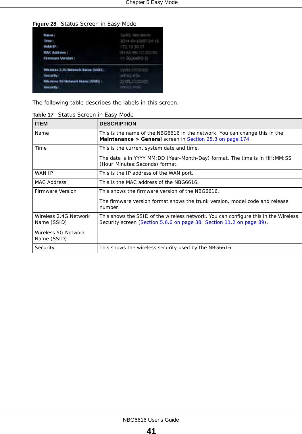
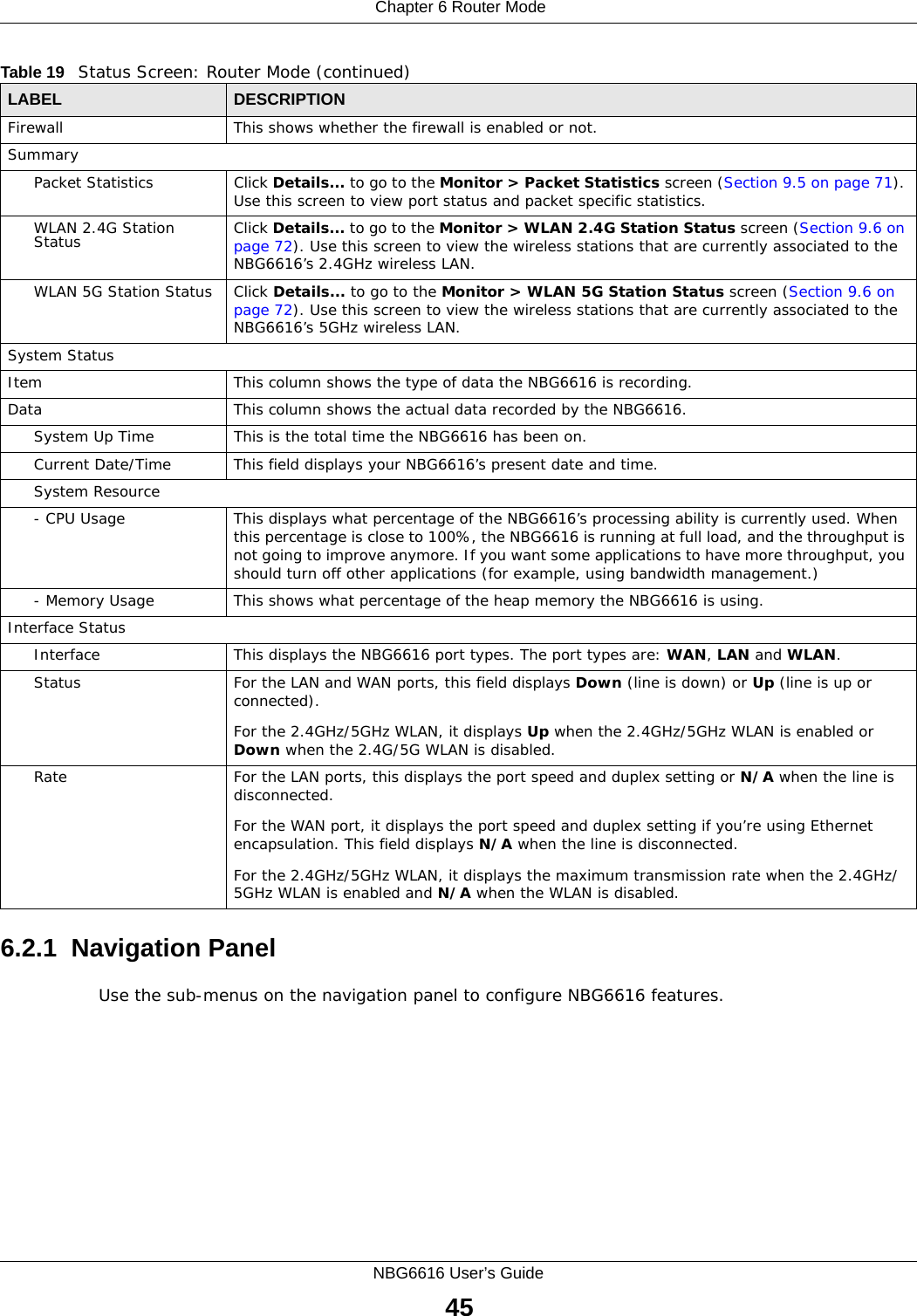
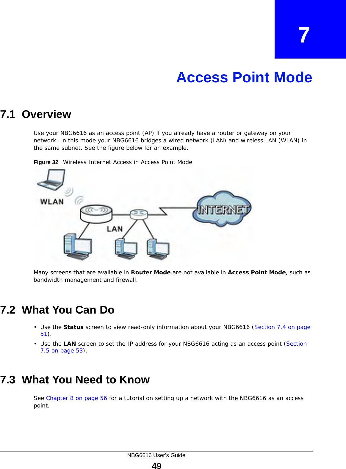
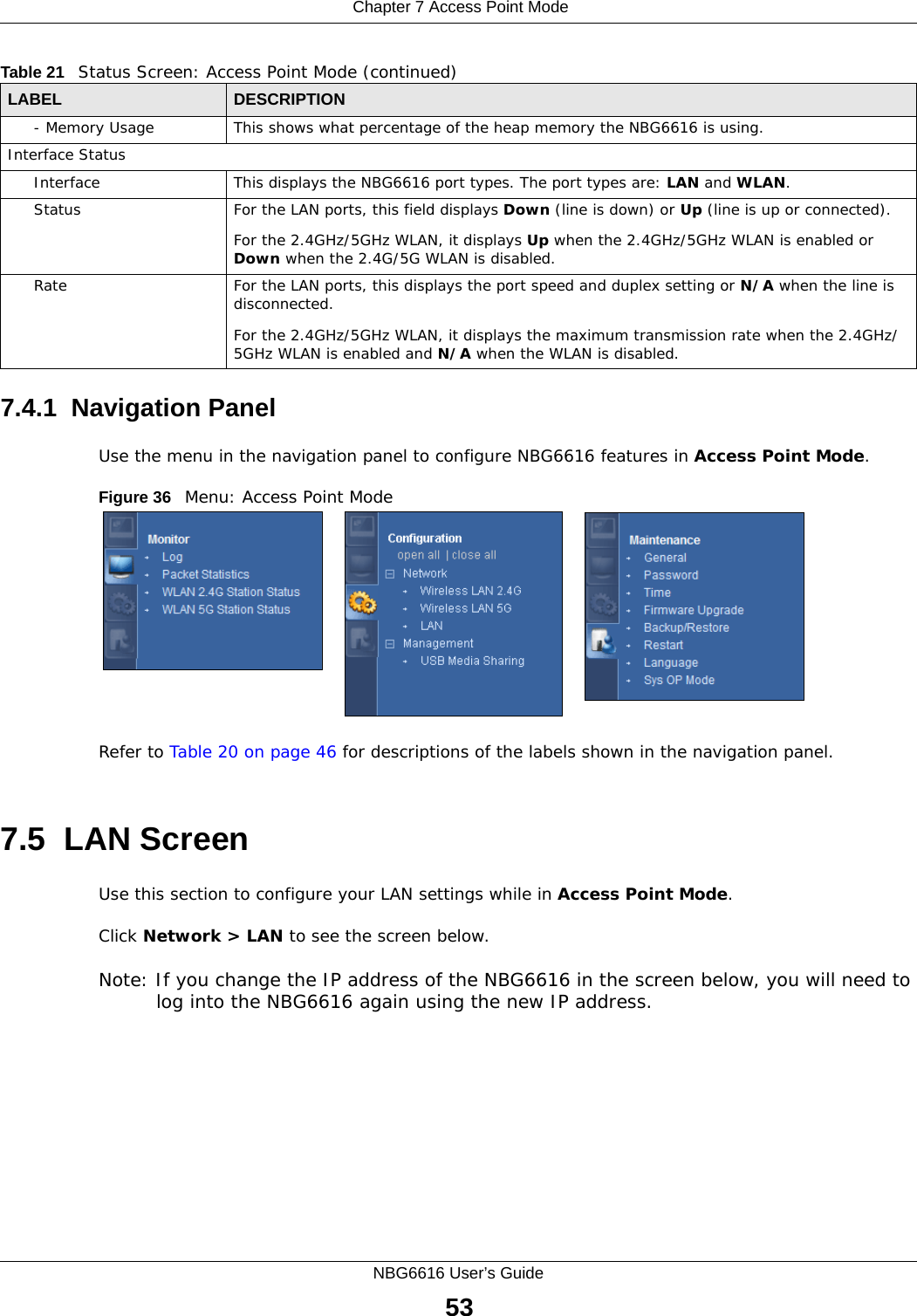
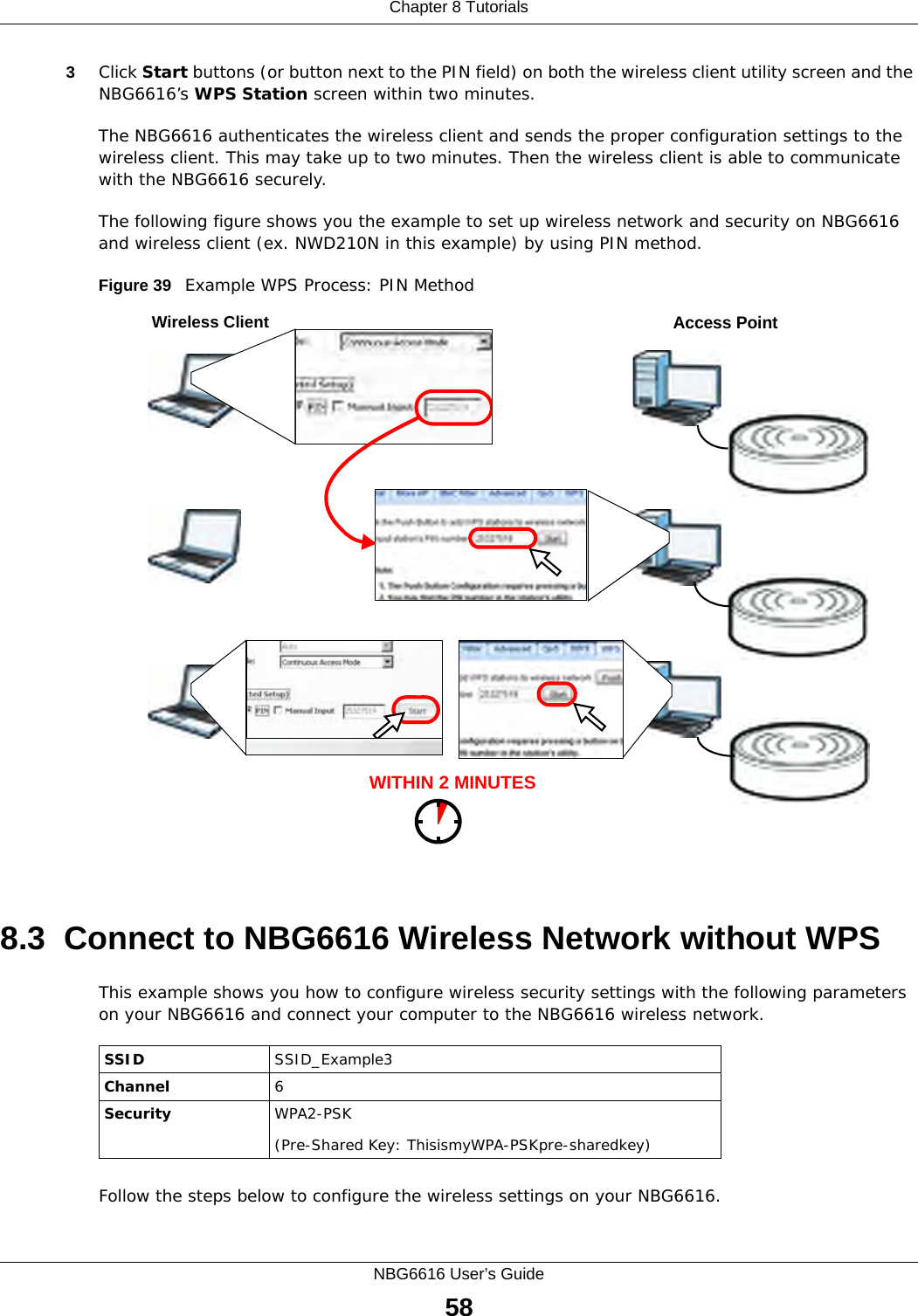
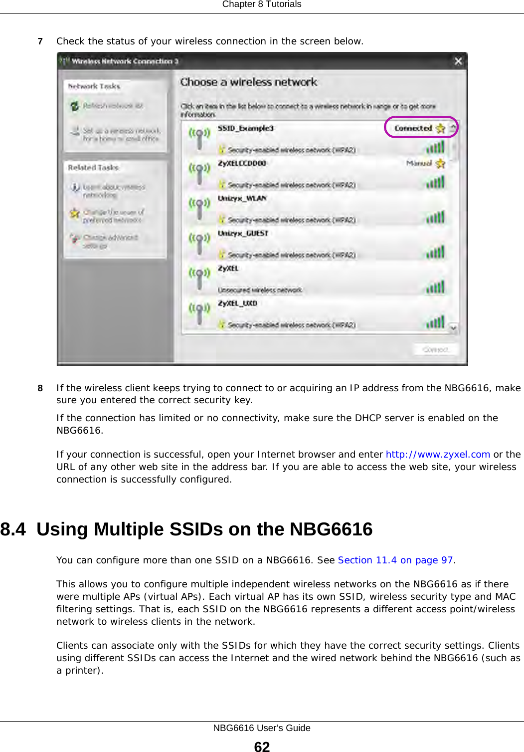
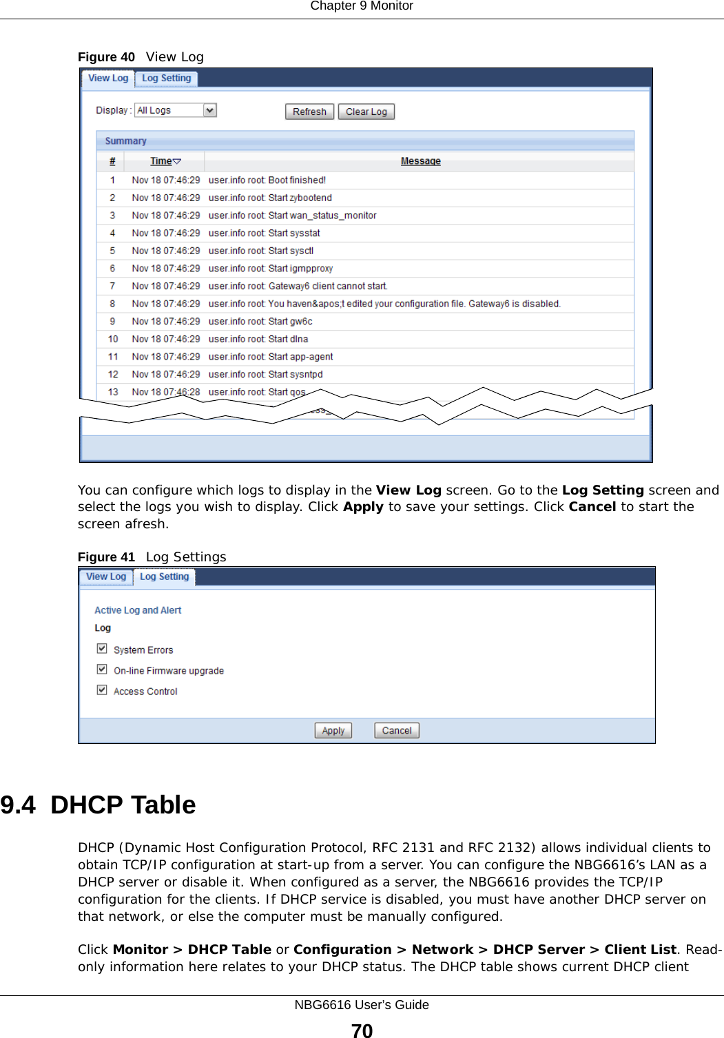
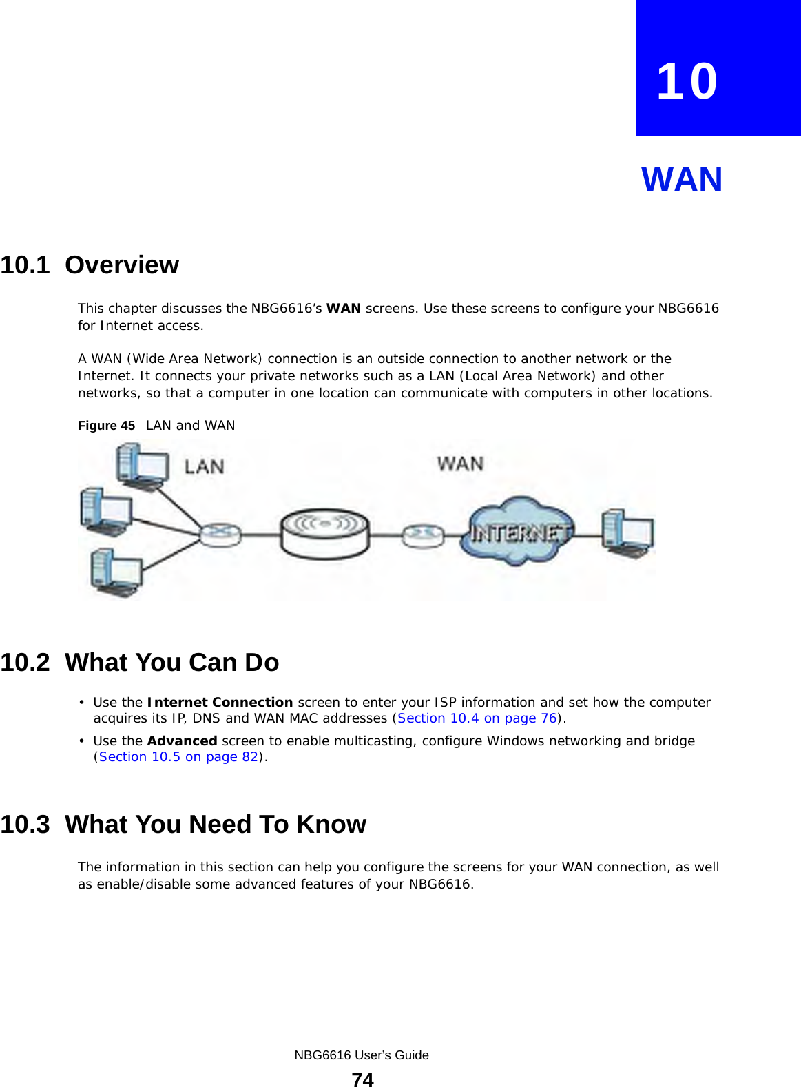
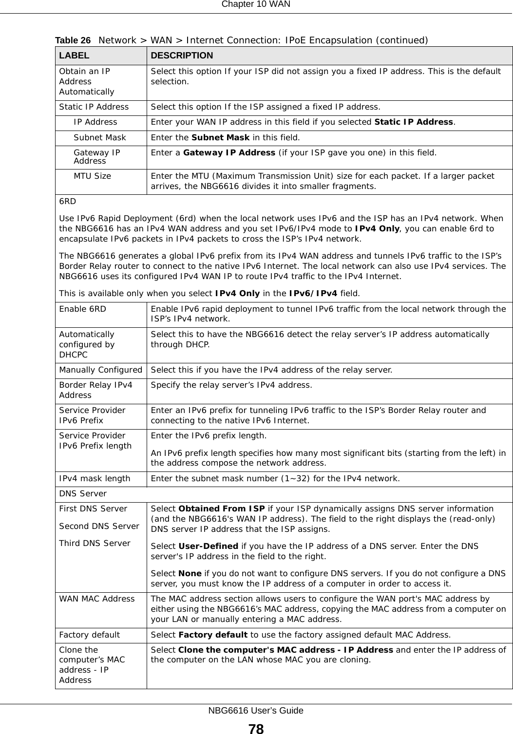
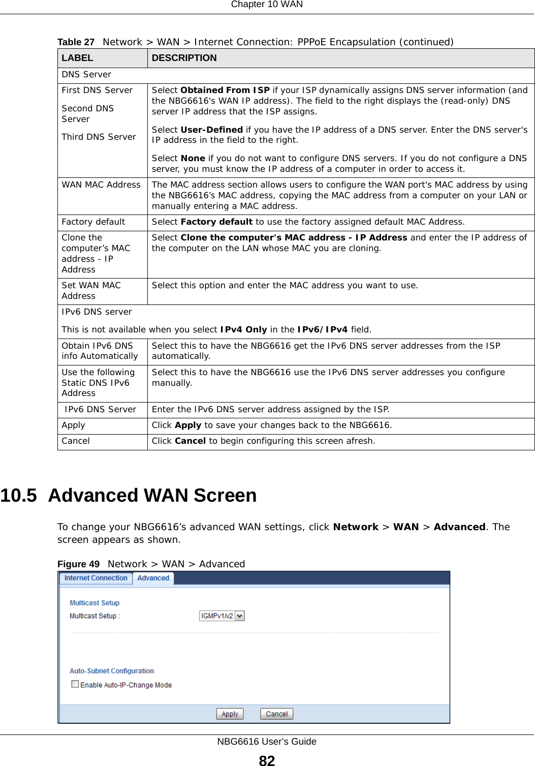
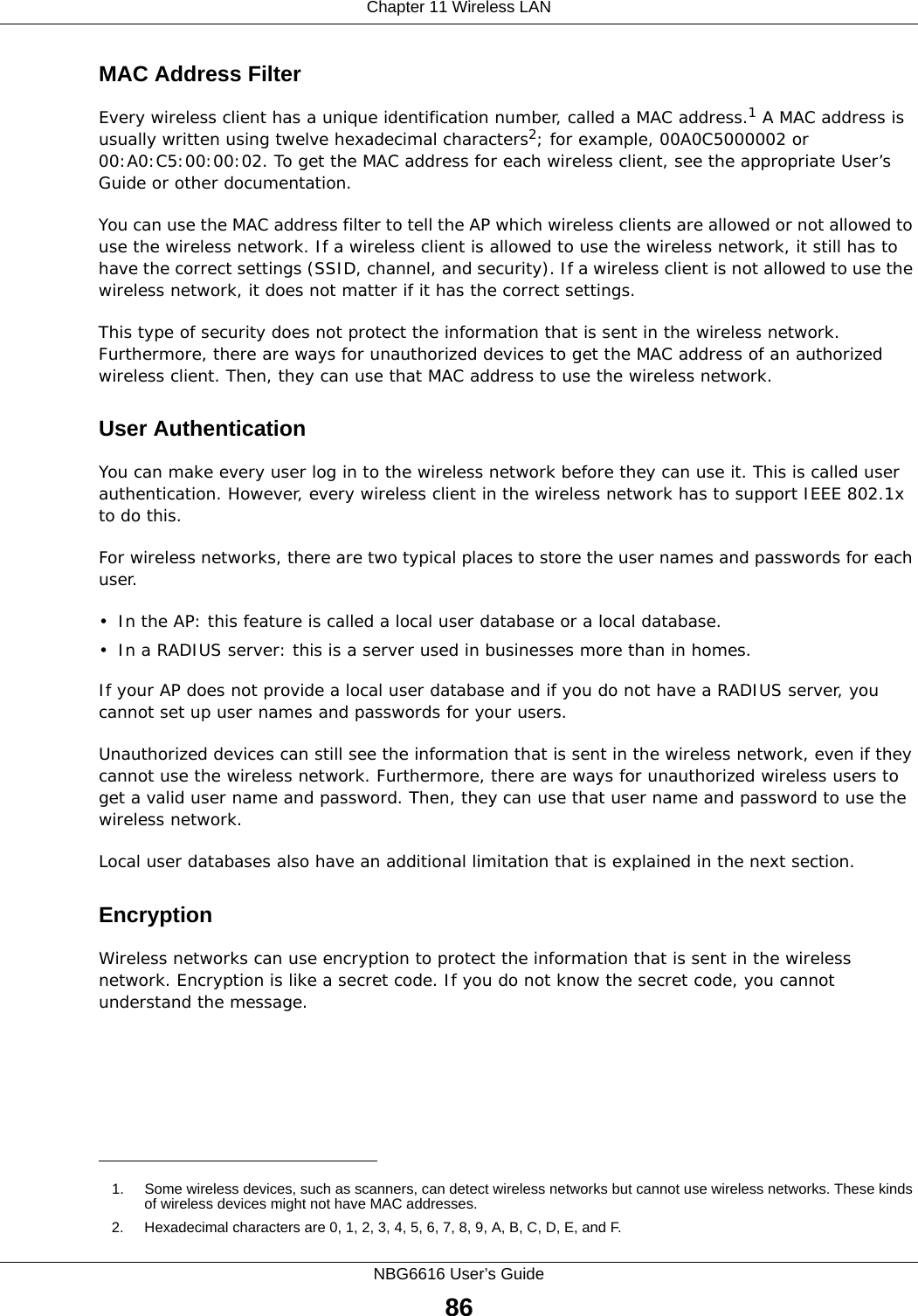
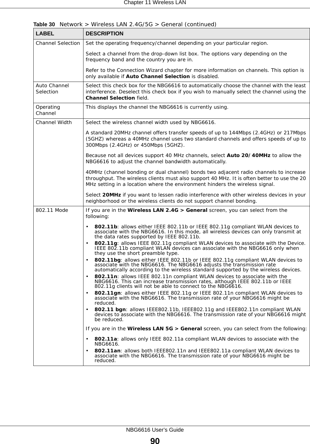
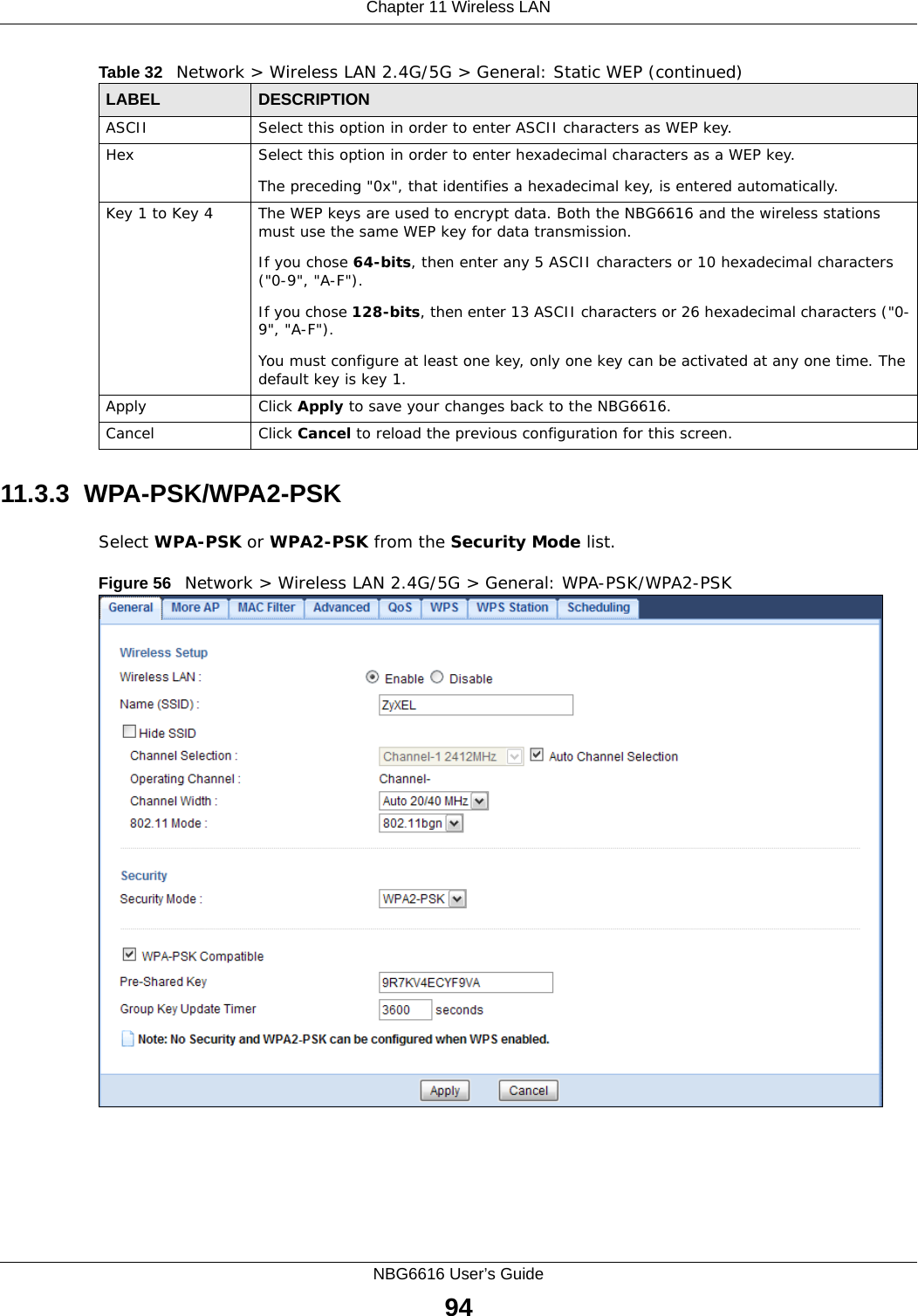
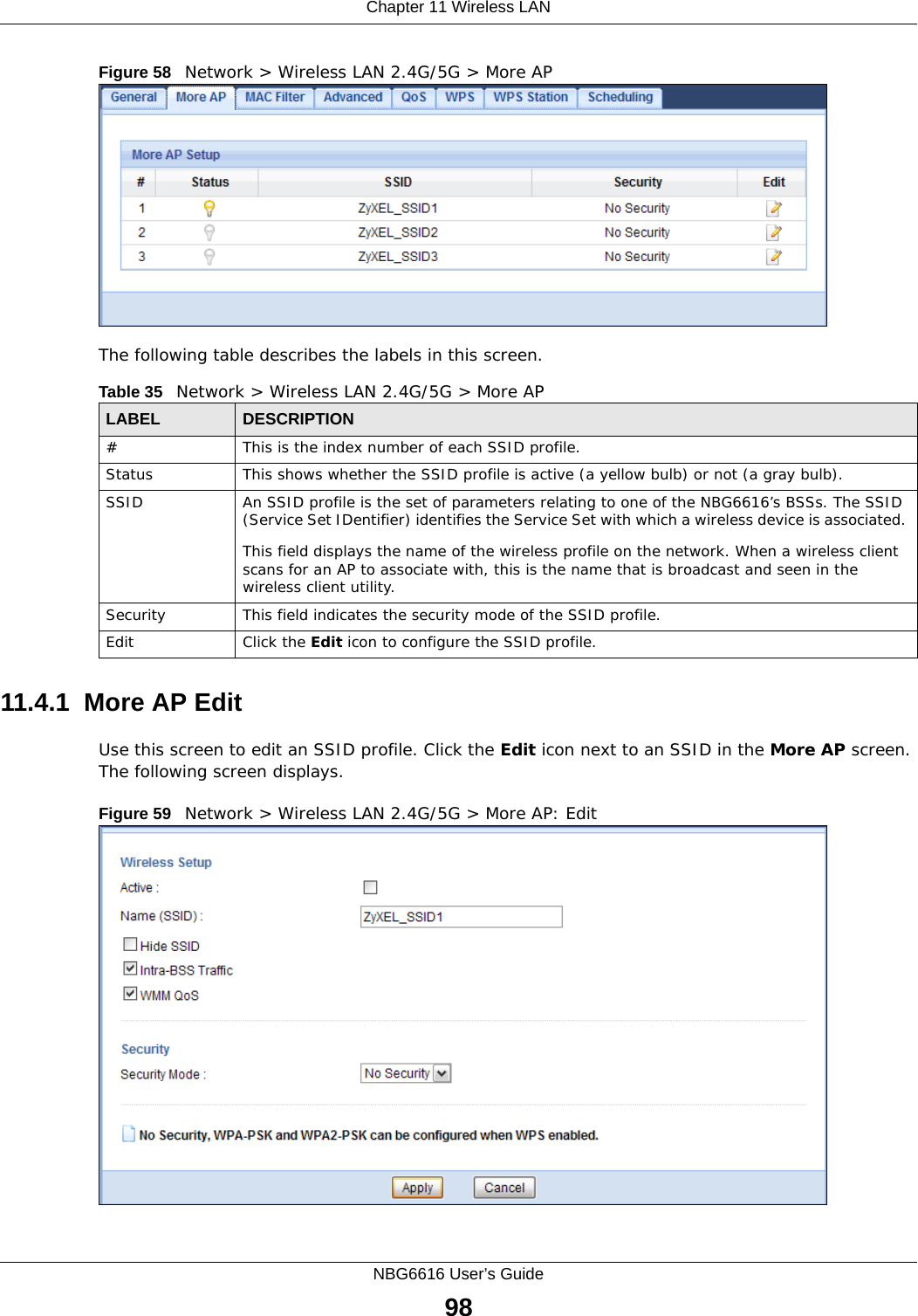
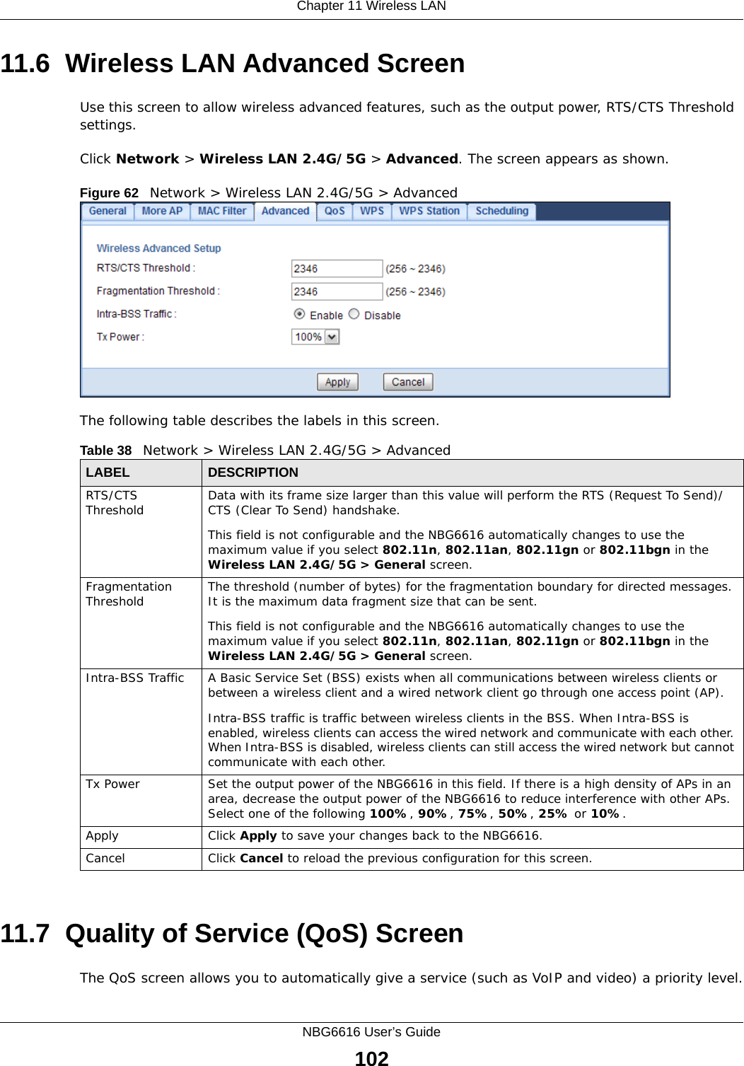
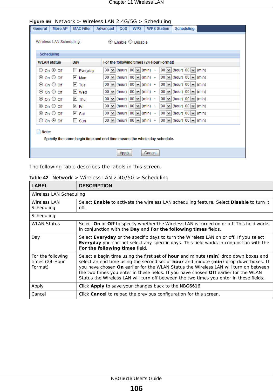
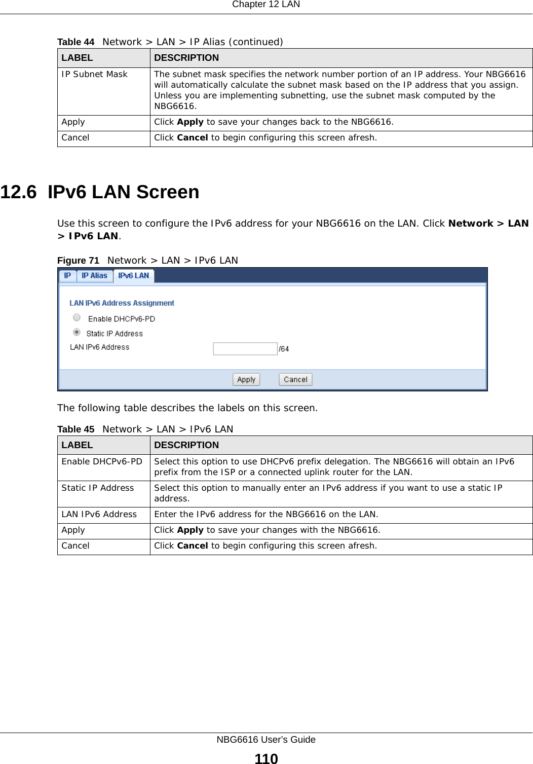
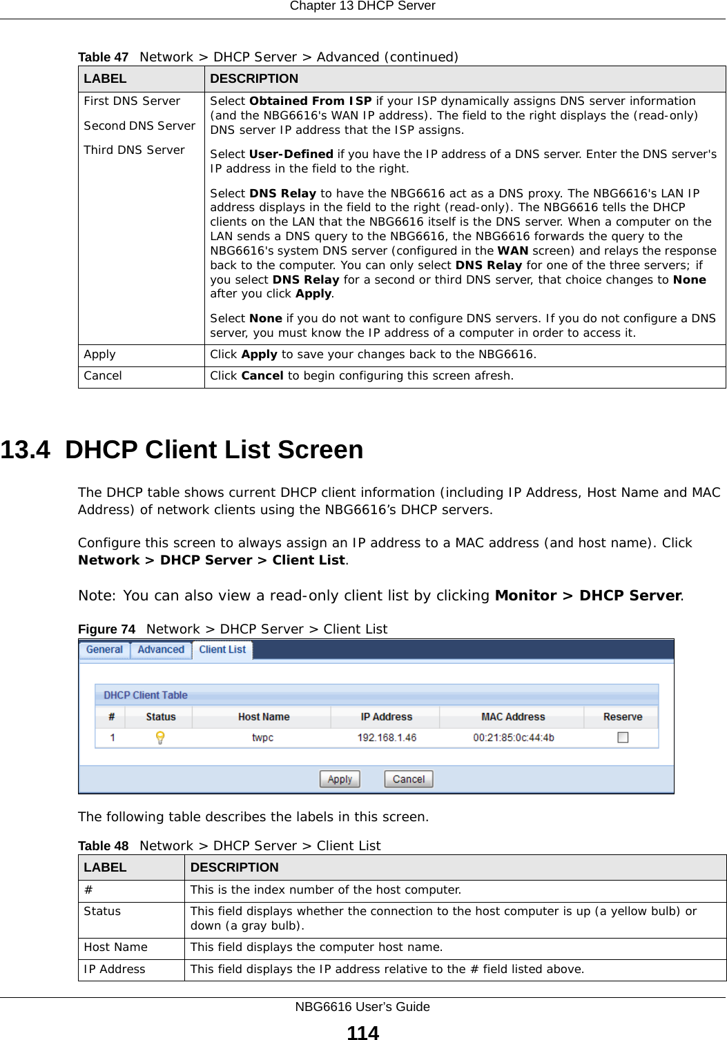
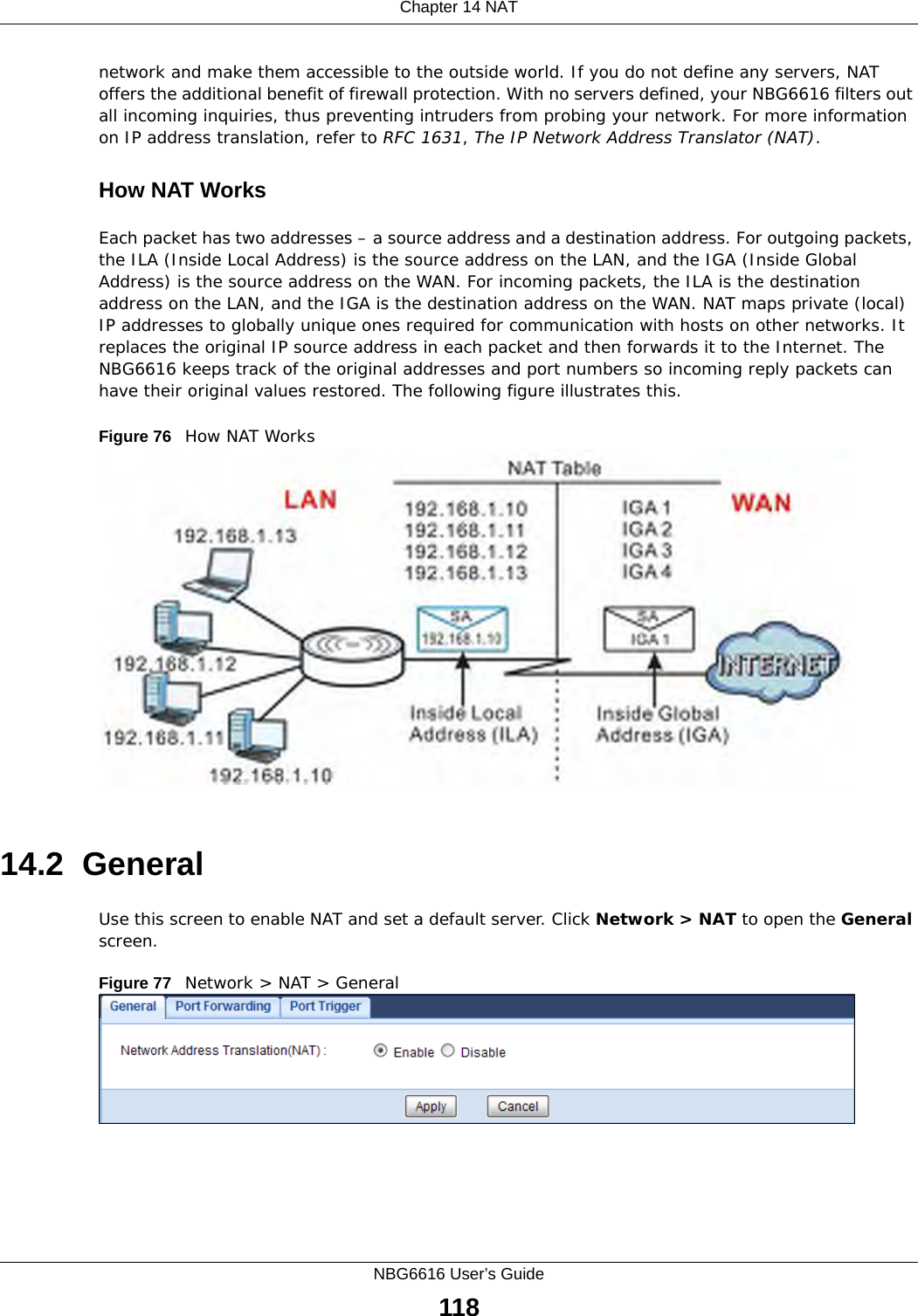
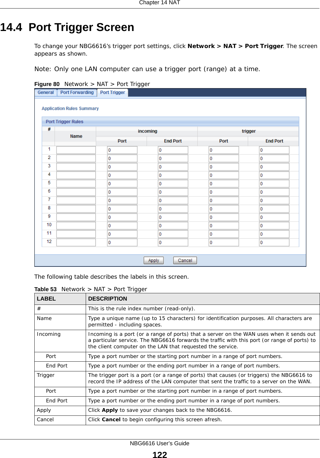
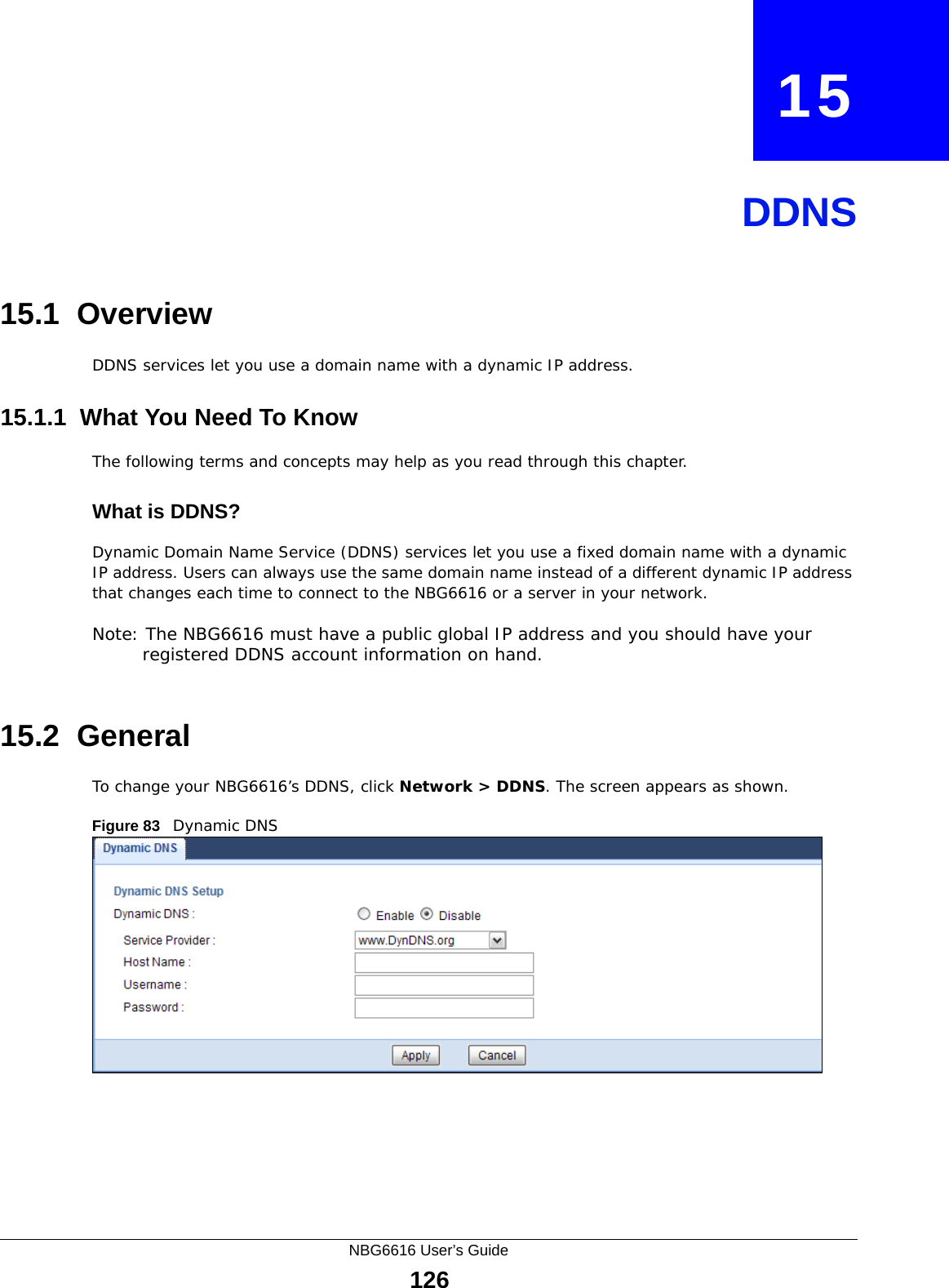
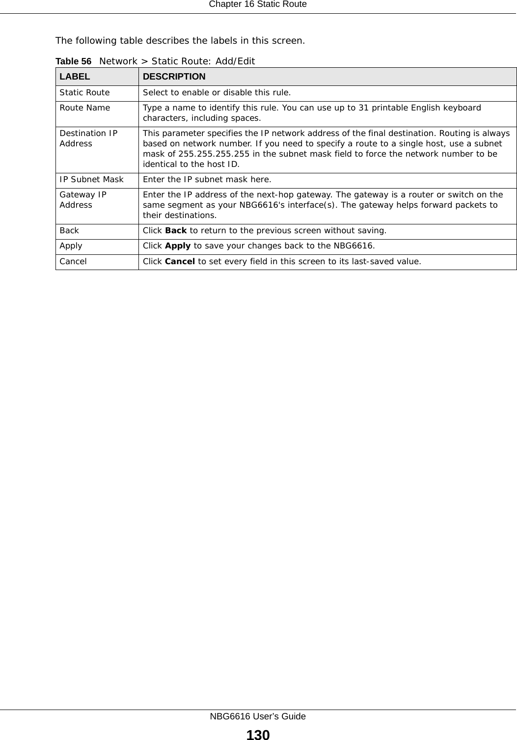
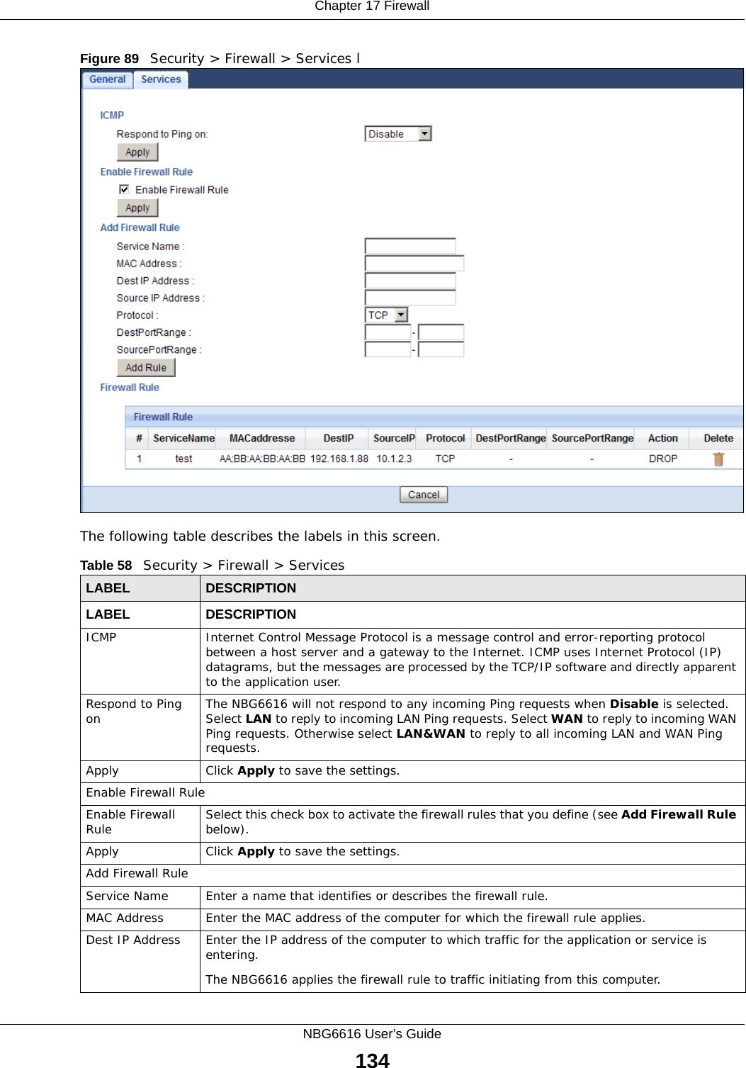
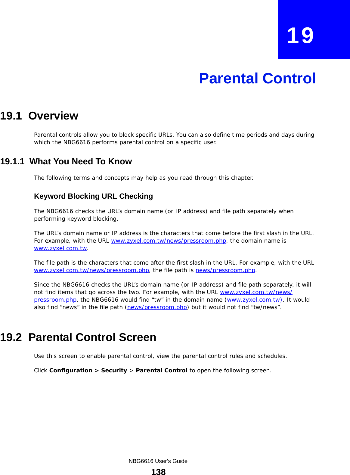
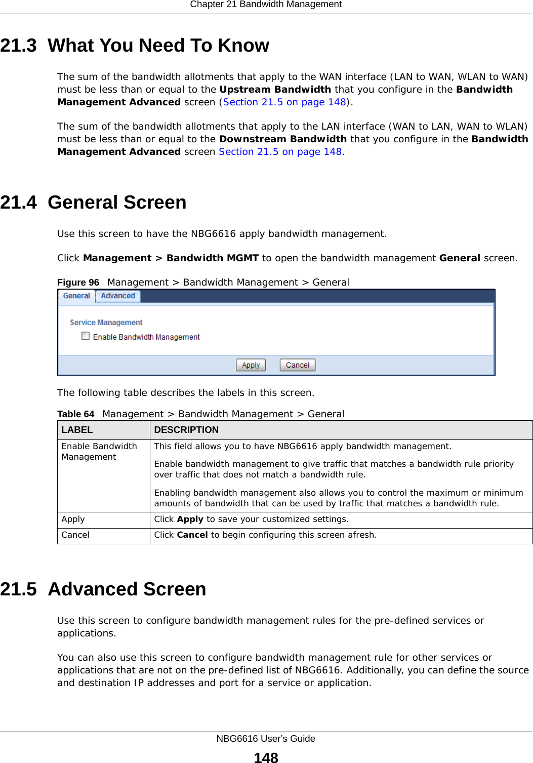
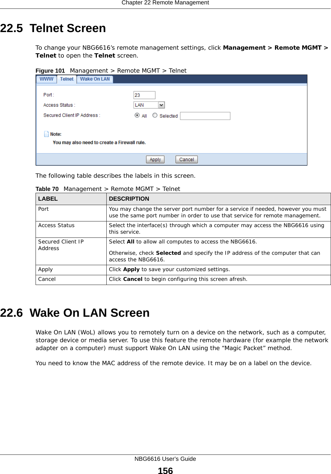
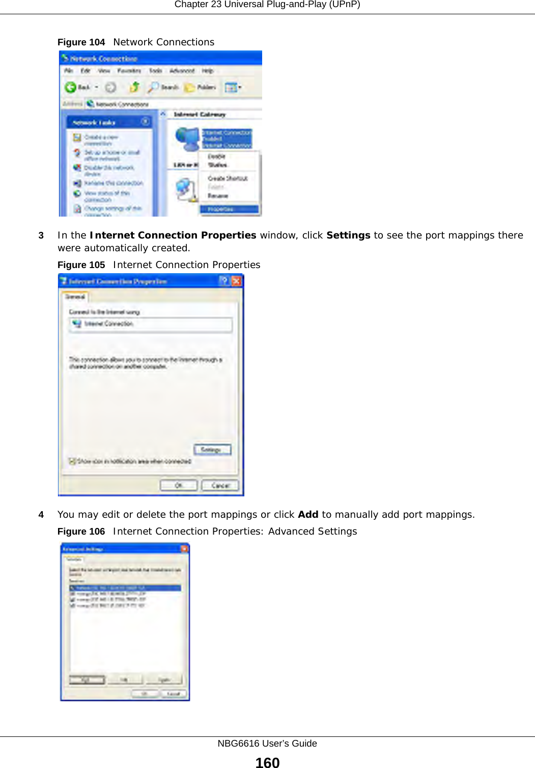
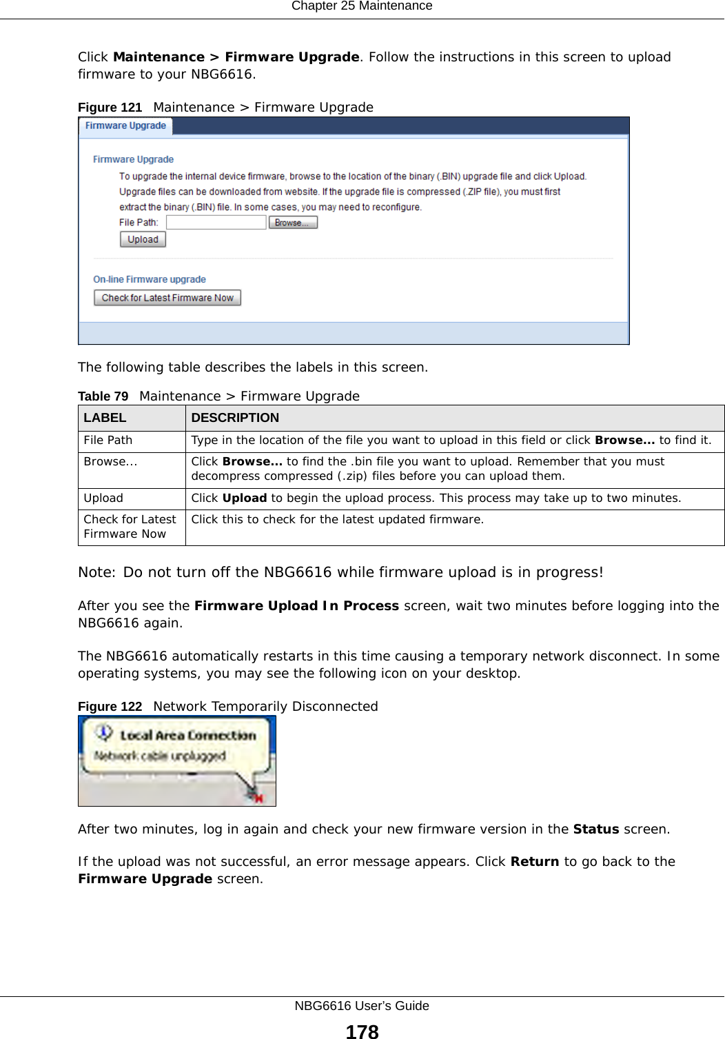
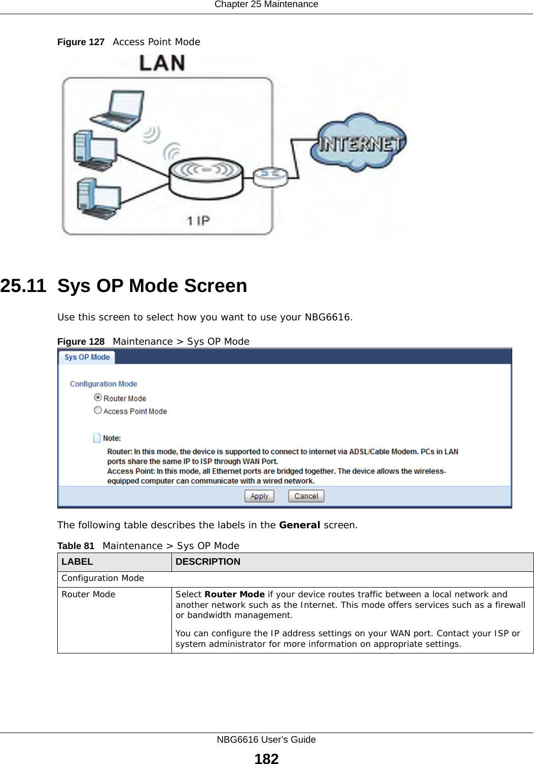
![Chapter 19 Parental ControlNBG6616 User’s Guide143File Name URL CheckingFilename URL checking has the NBG6616 check all of the characters in the URL.For example, filename URL checking searches for keywords within the URL www.zyxel.com.tw/news/pressroom.php.Use the ip urlfilter customize actionFlags 8 [disable | enable] command to extend (or not extend) the keyword blocking search to include the URL's complete filename.](https://usermanual.wiki/ZyXEL-Communications/NBG6616/User-Guide-2392470-Page-143.png)
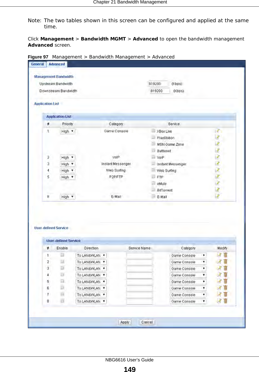
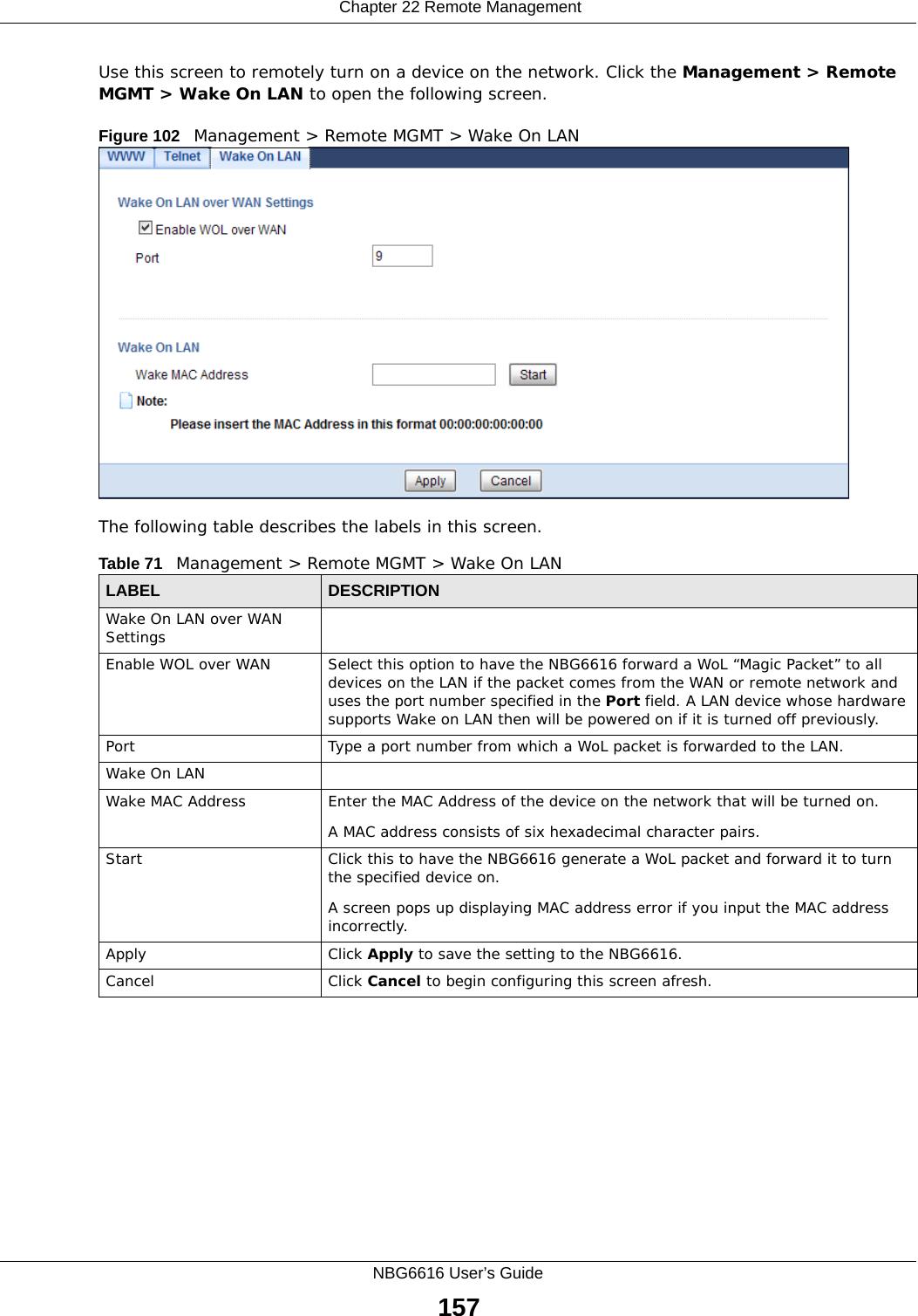
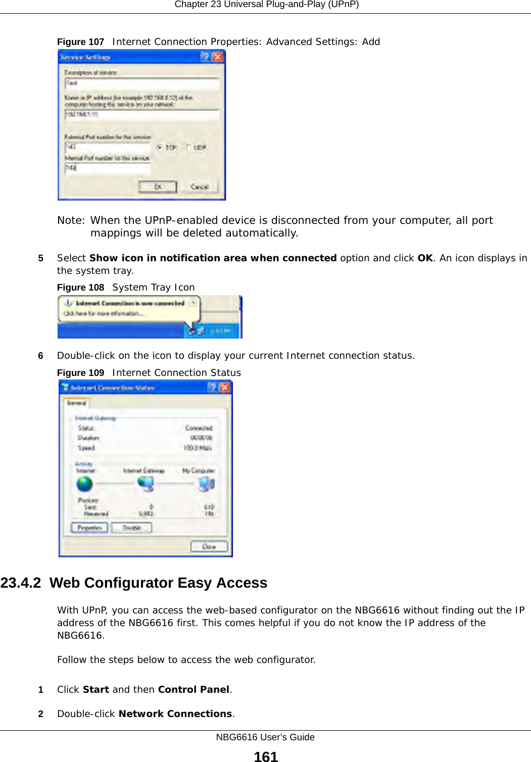
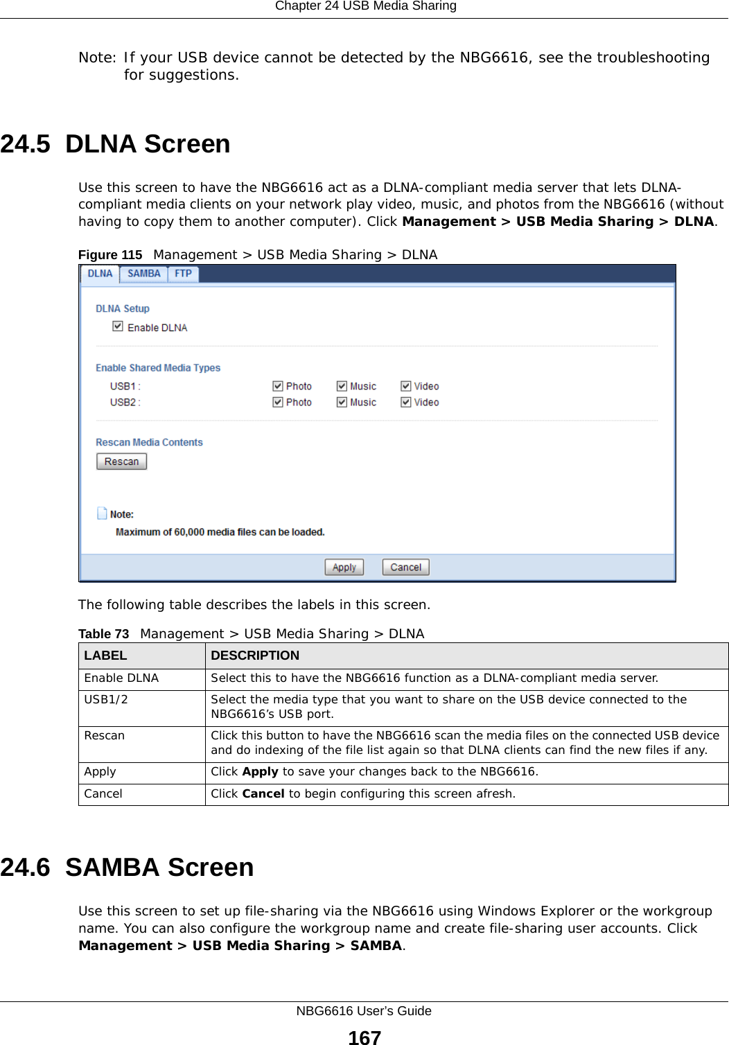
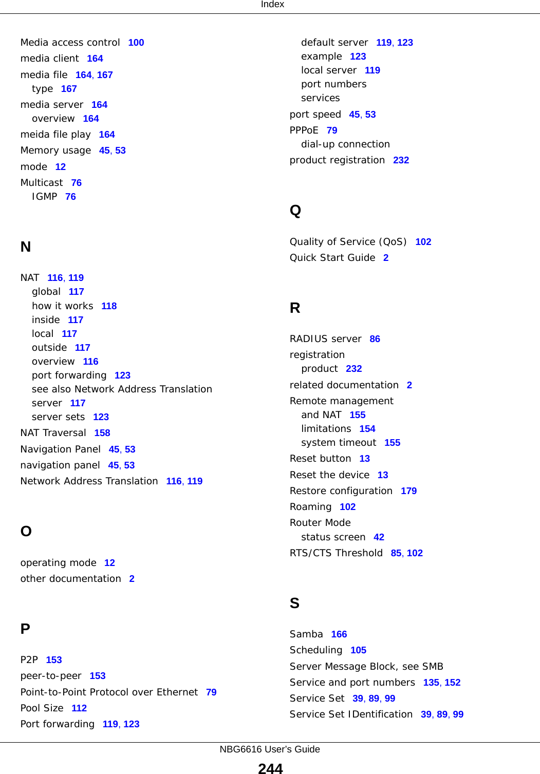
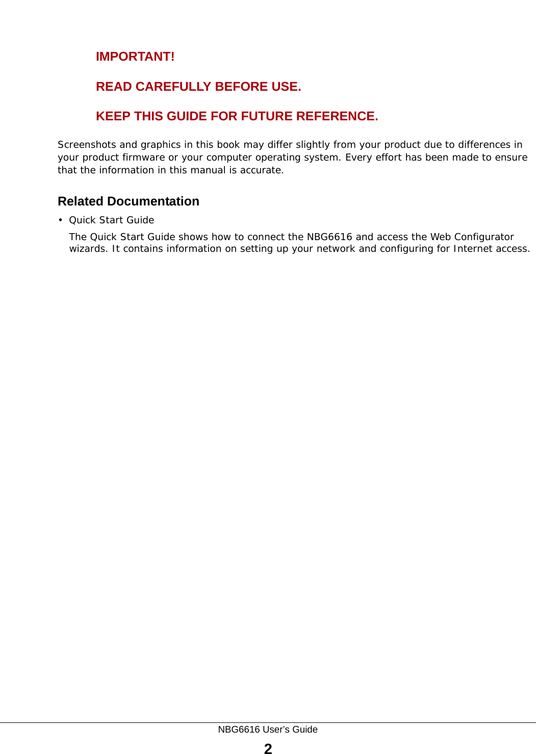
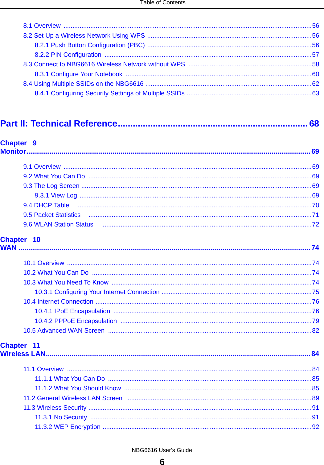
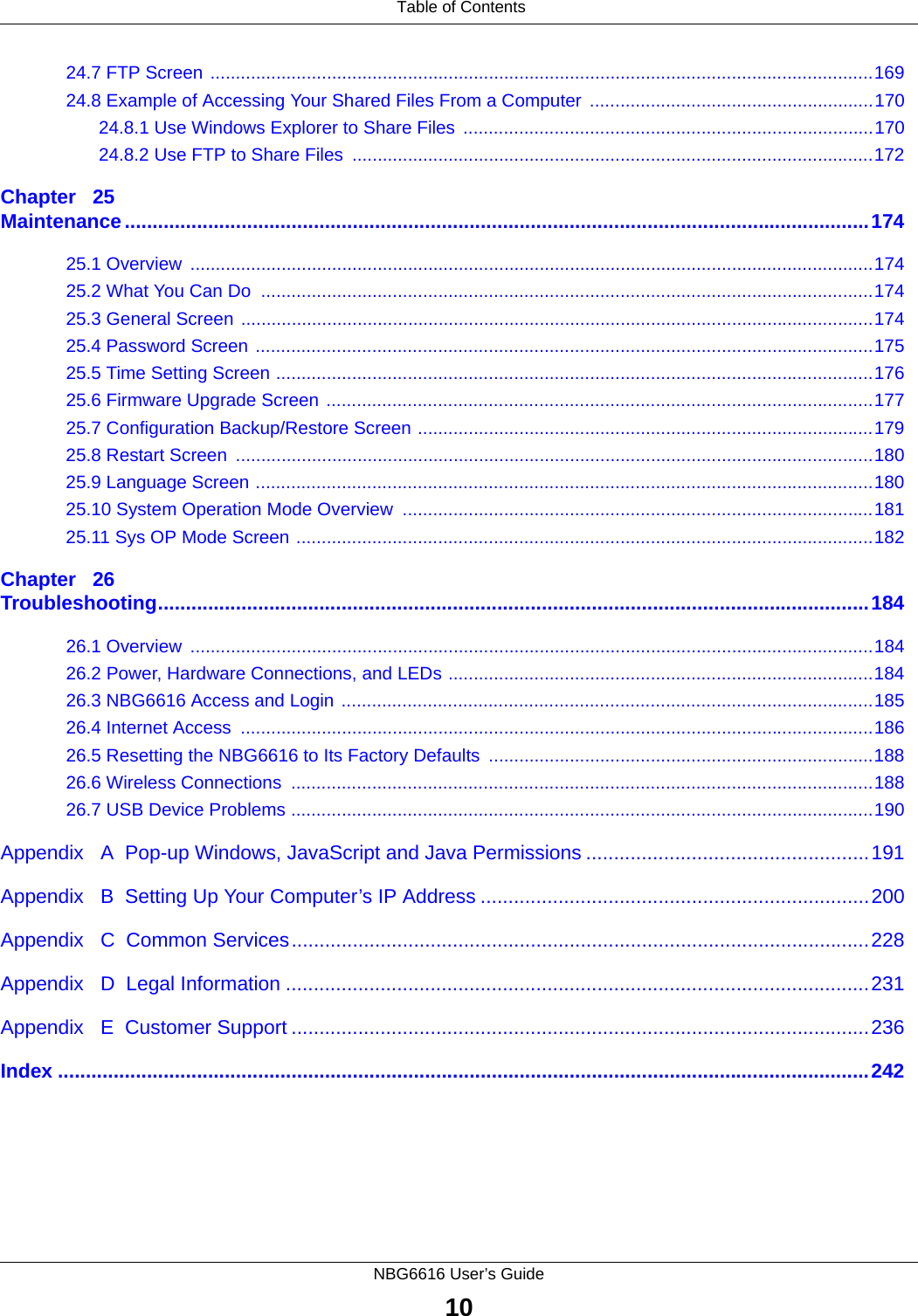
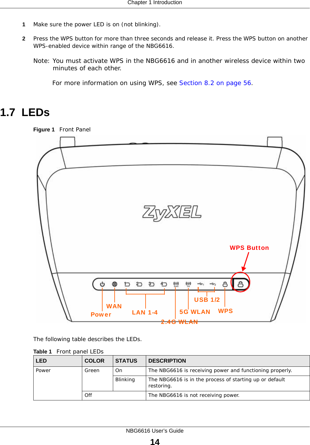
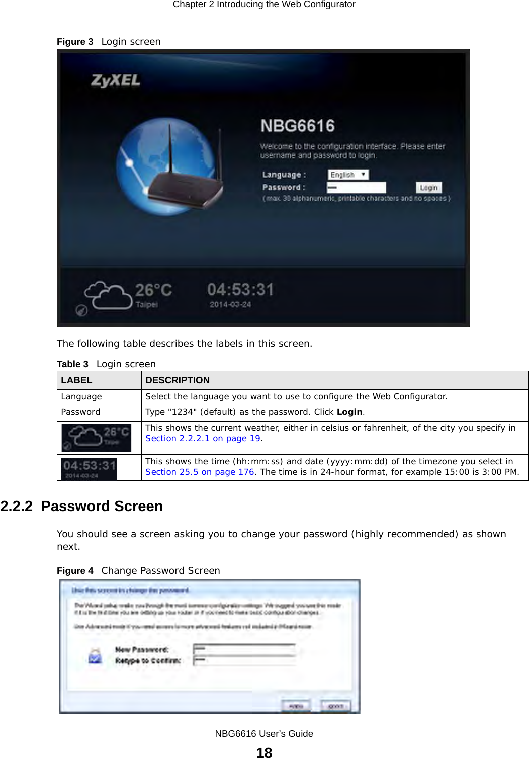
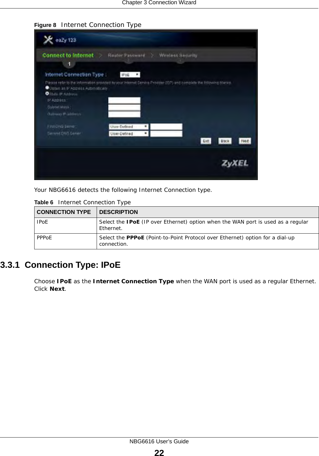
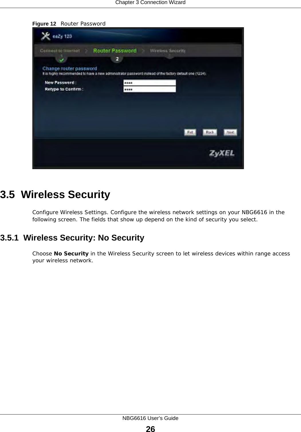
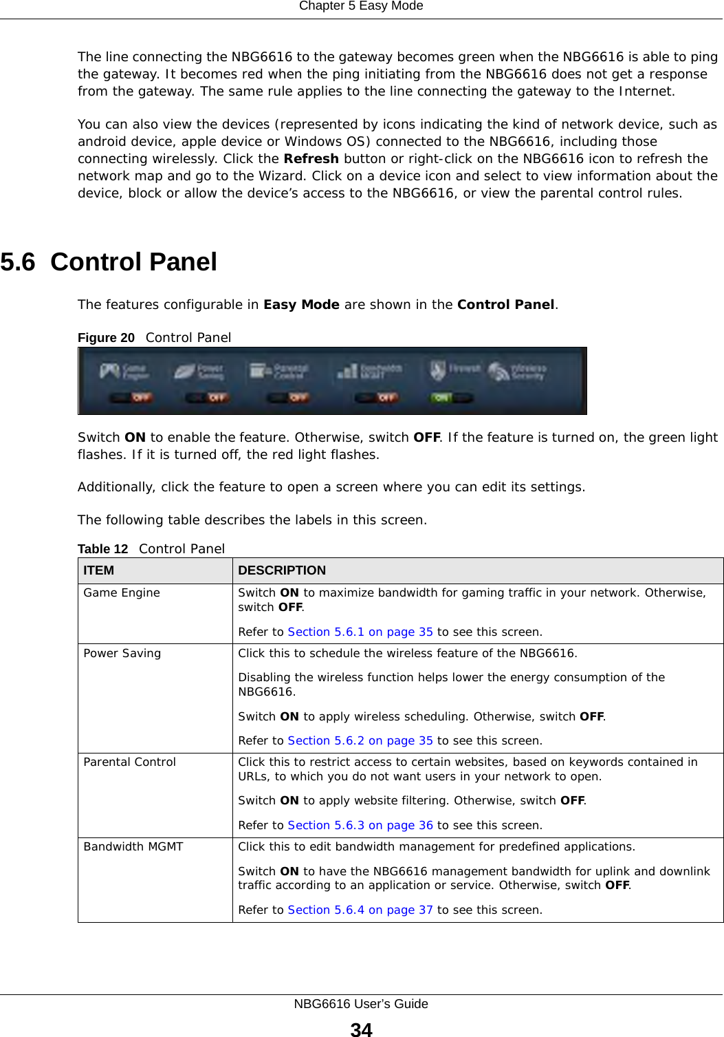
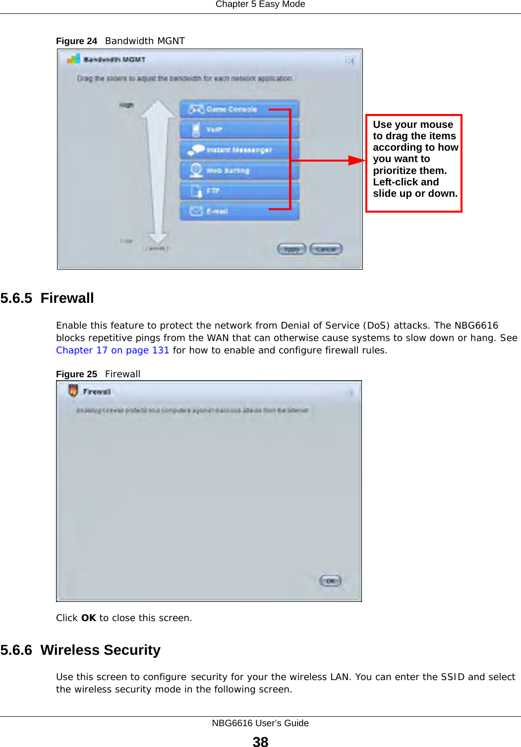
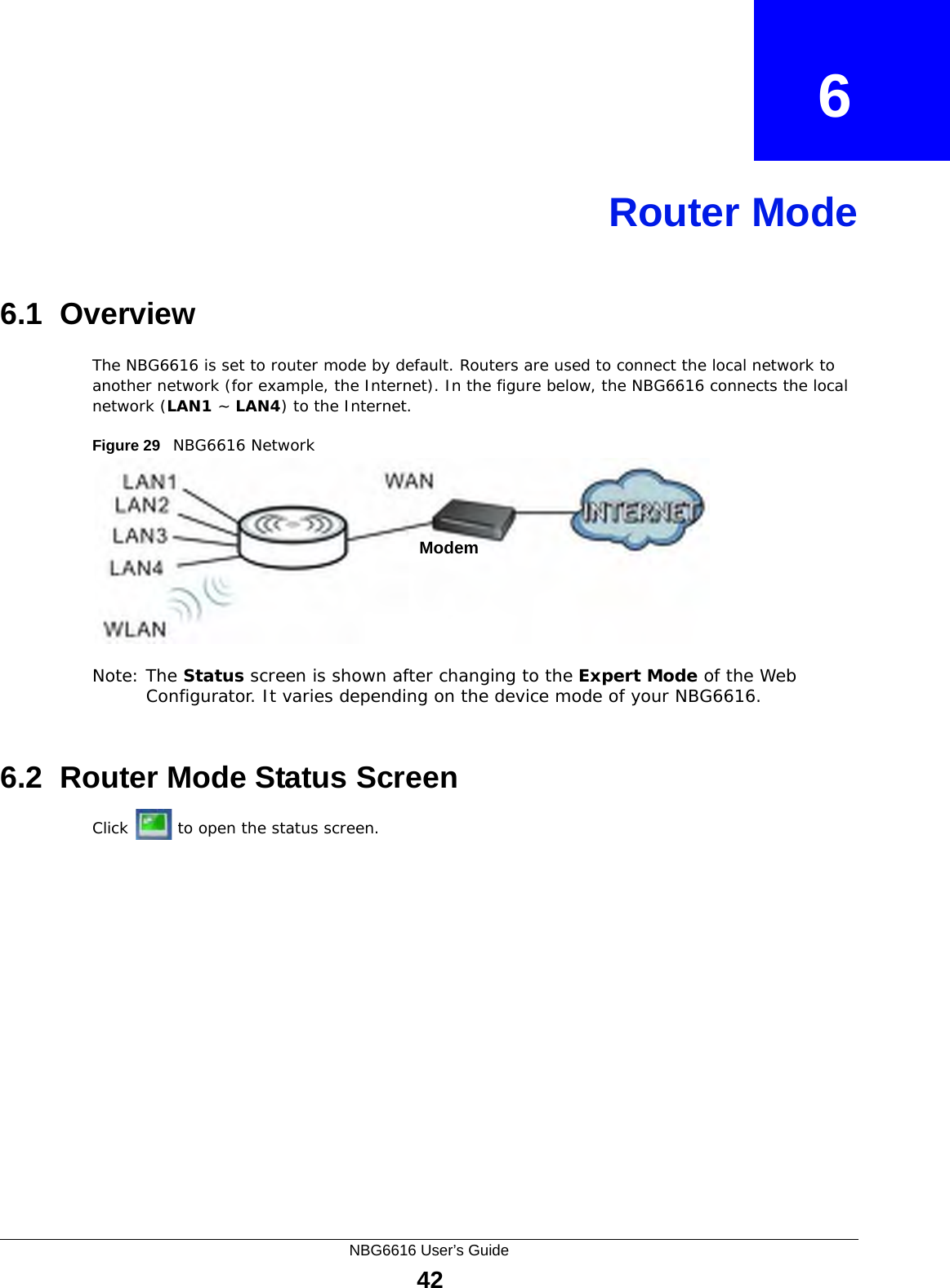
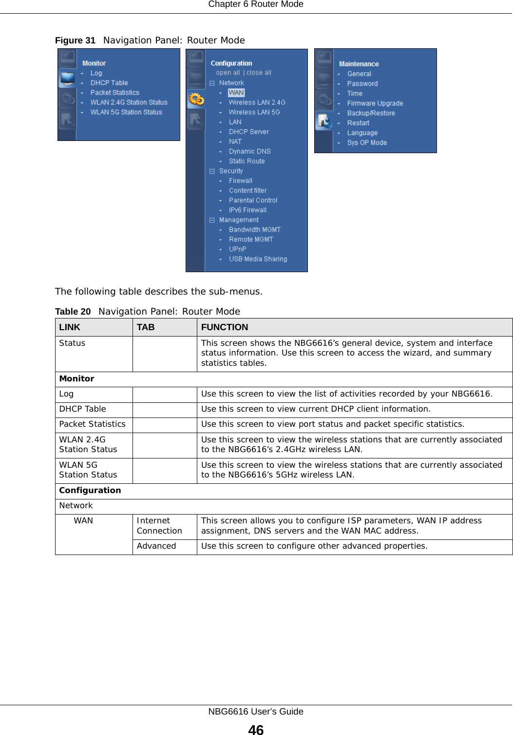
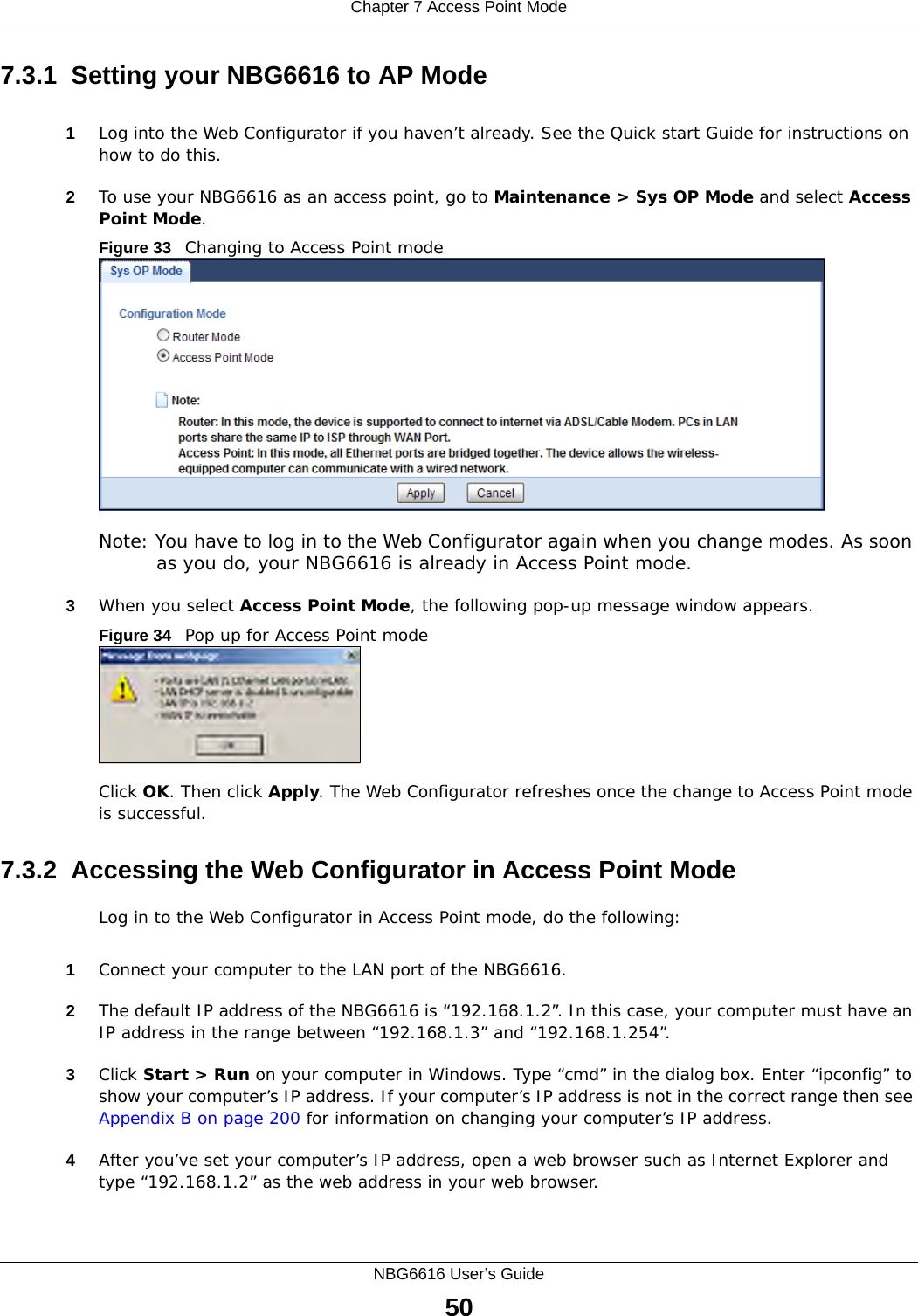
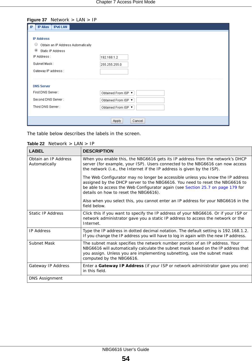
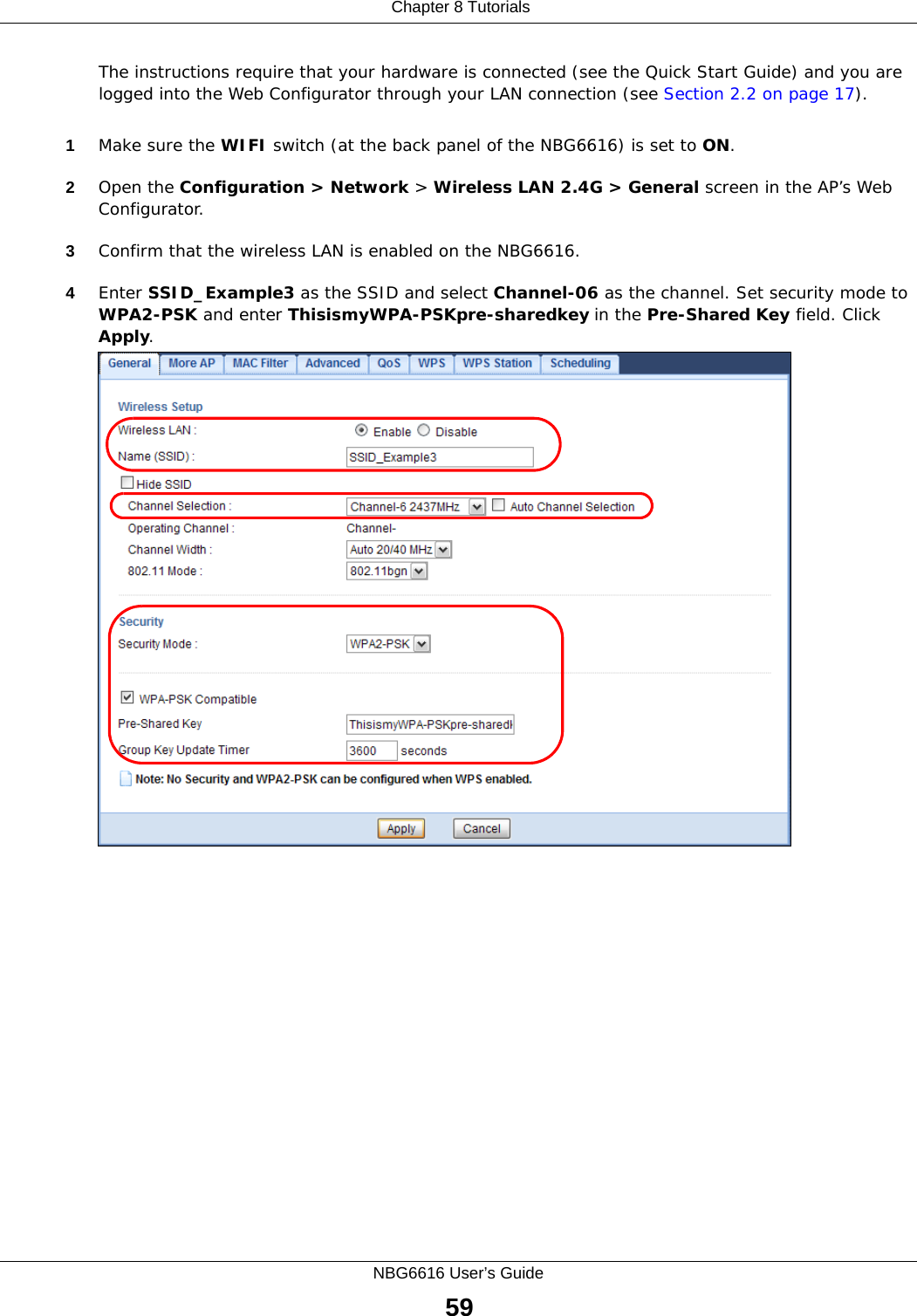
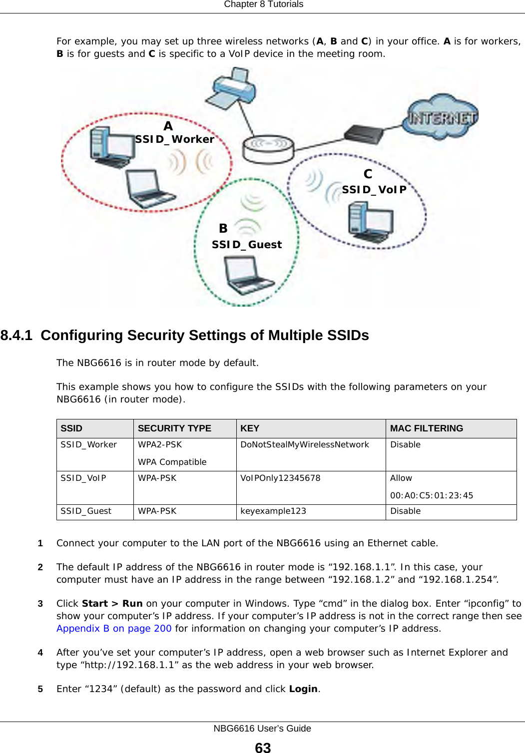
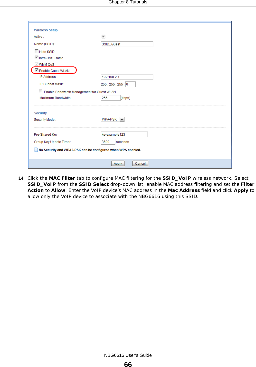
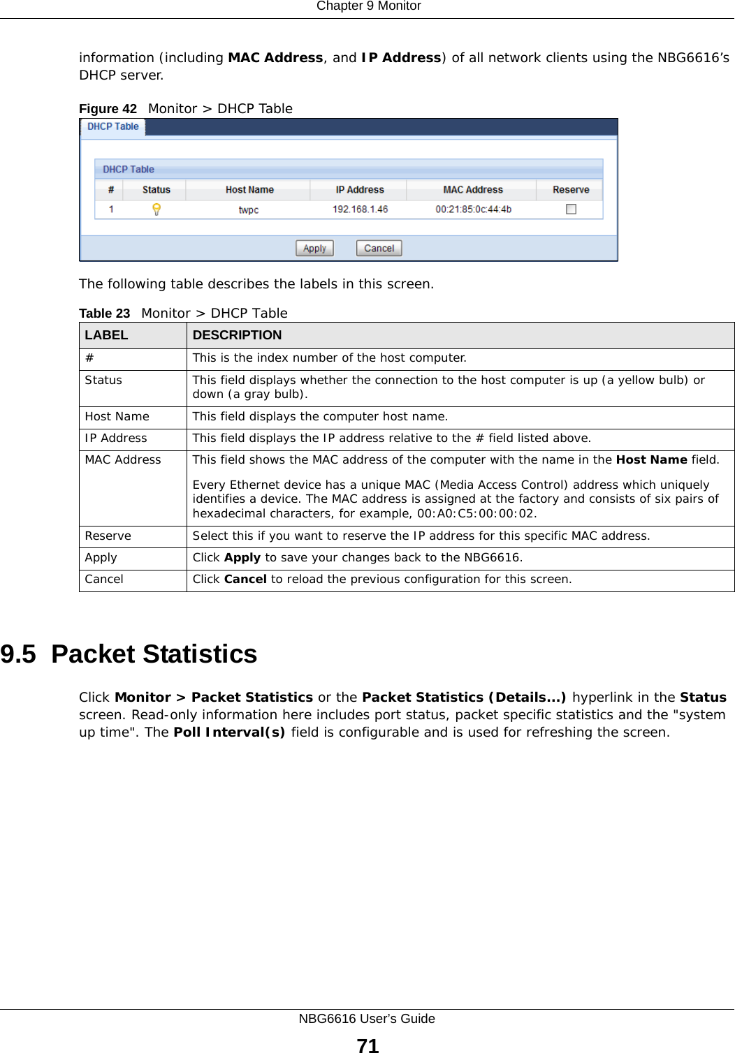
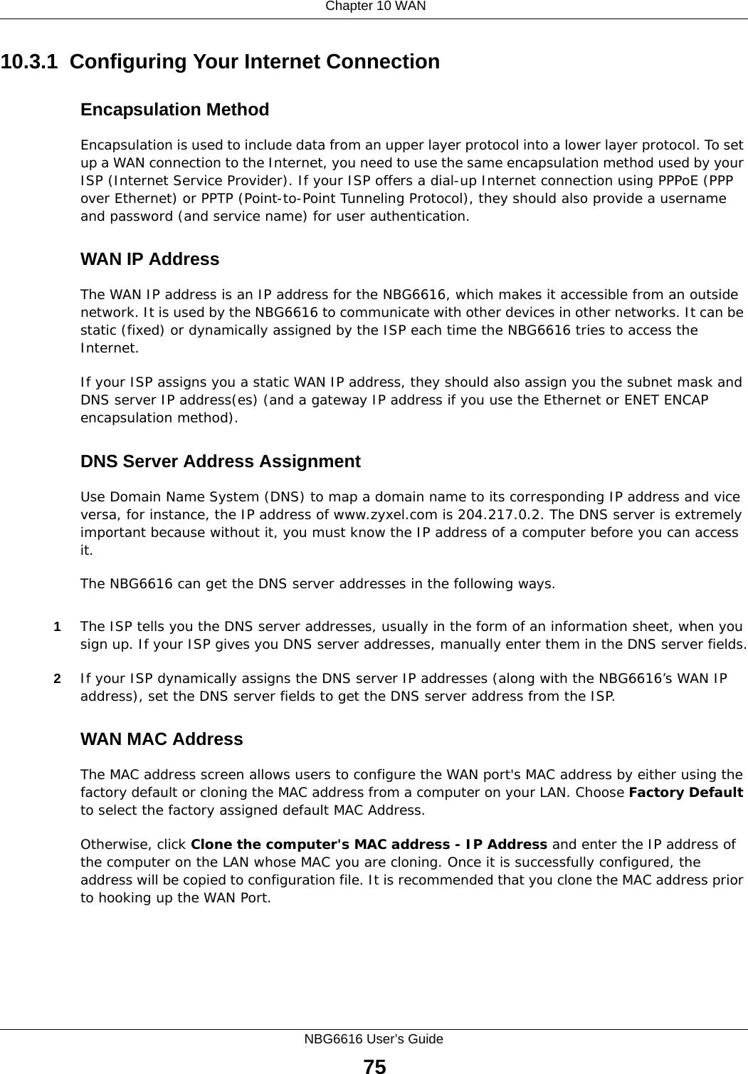
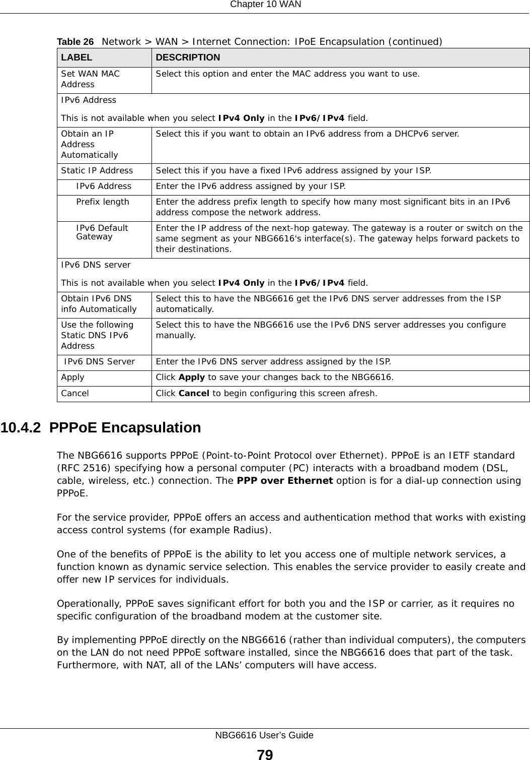
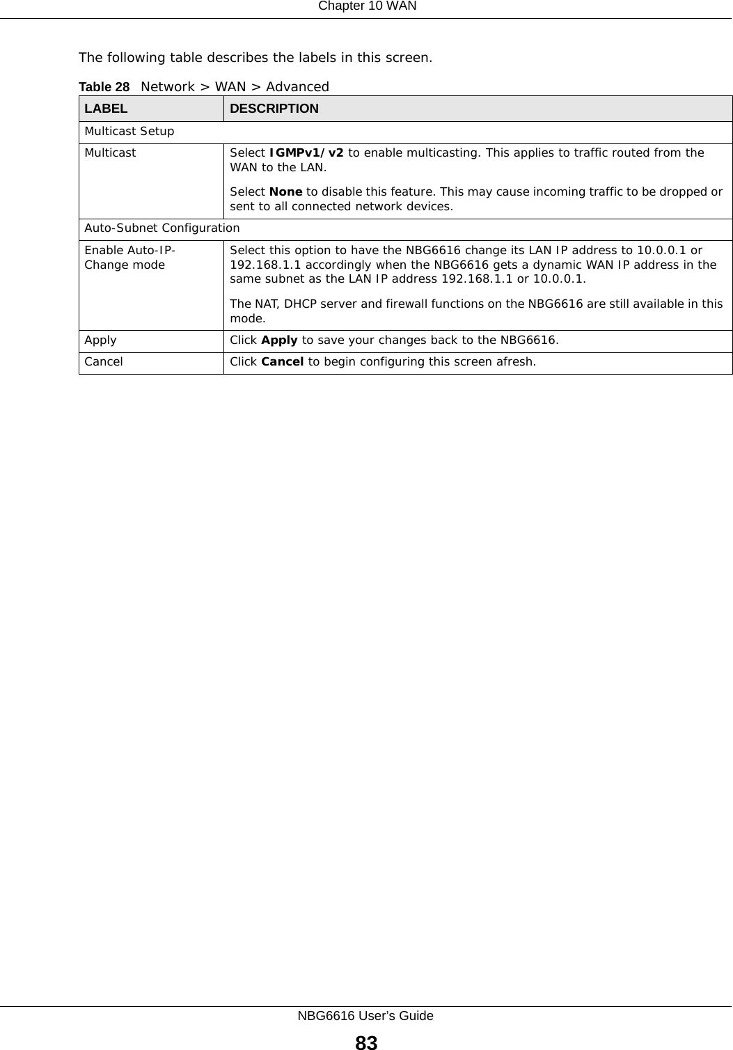
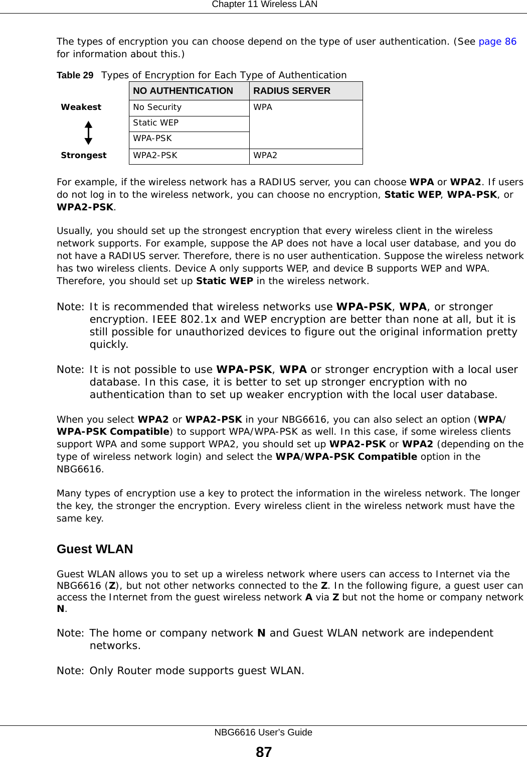
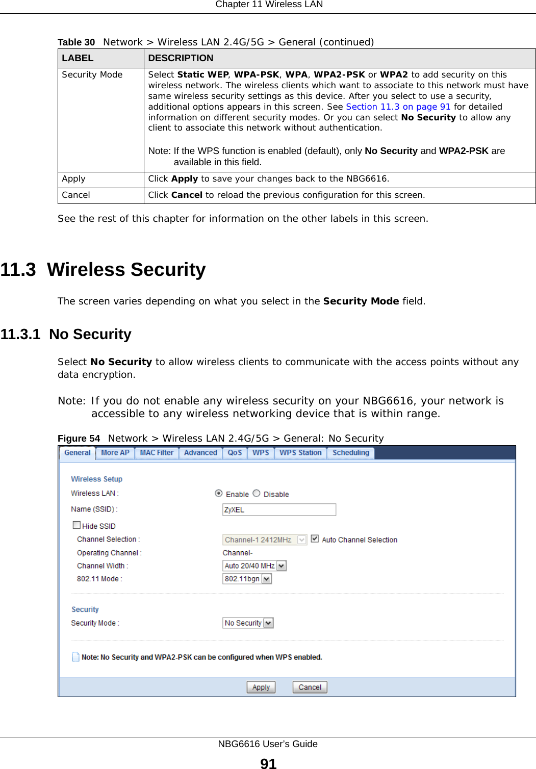
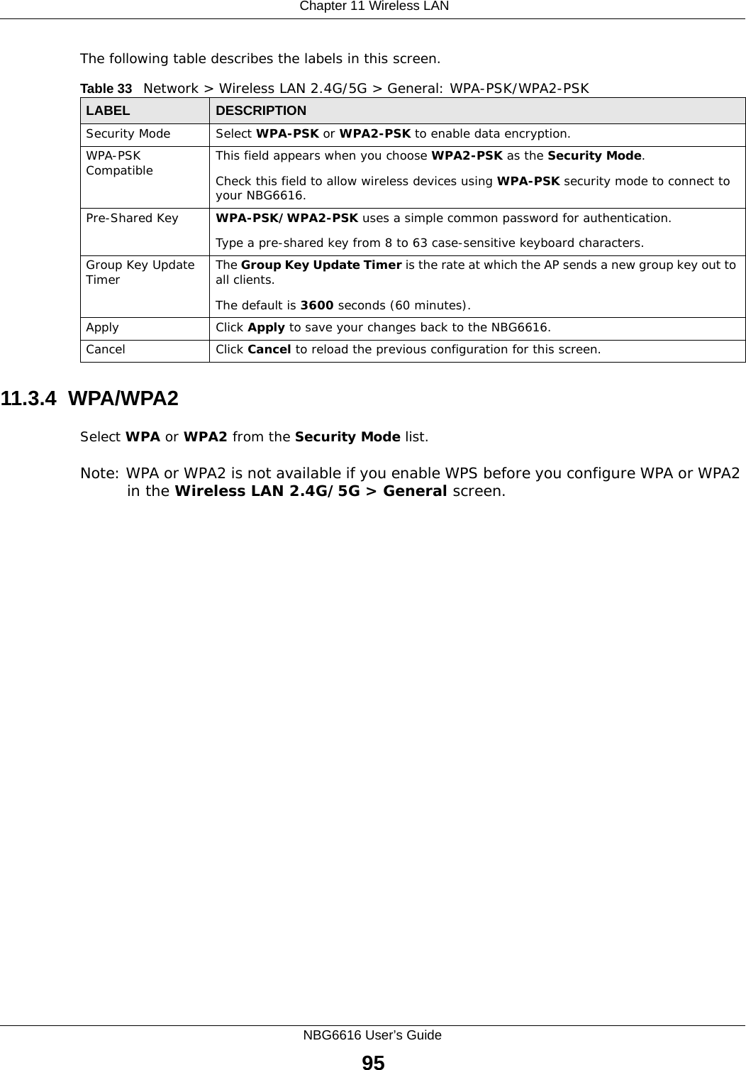
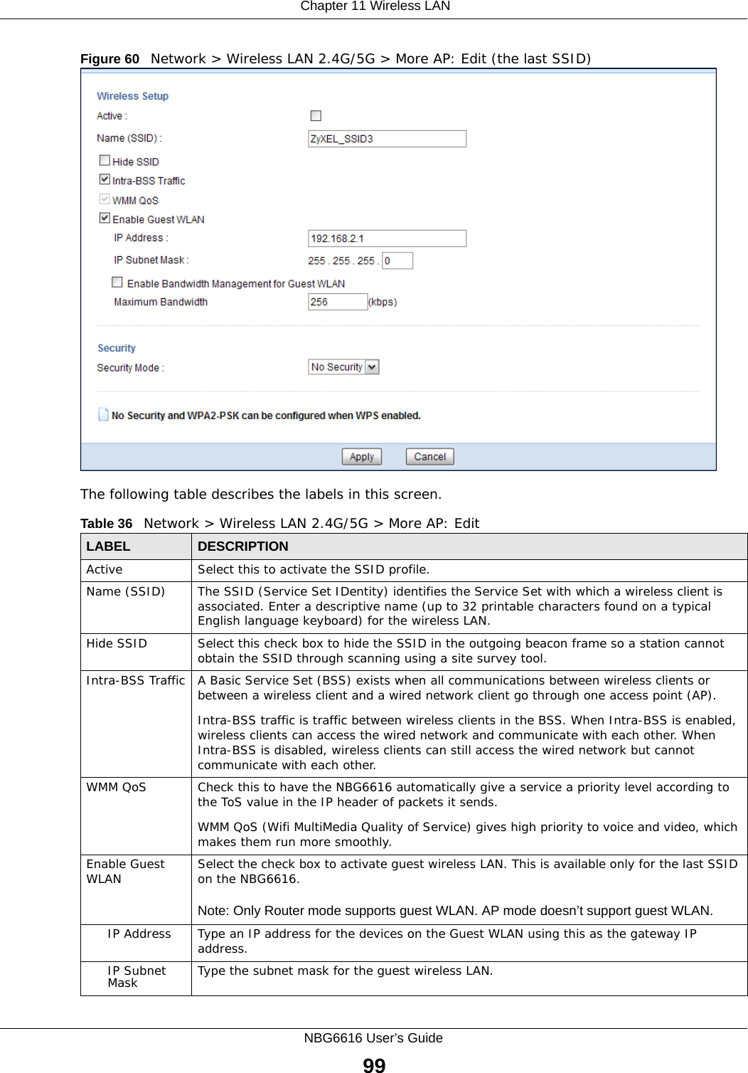
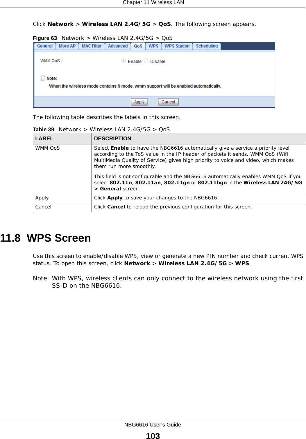
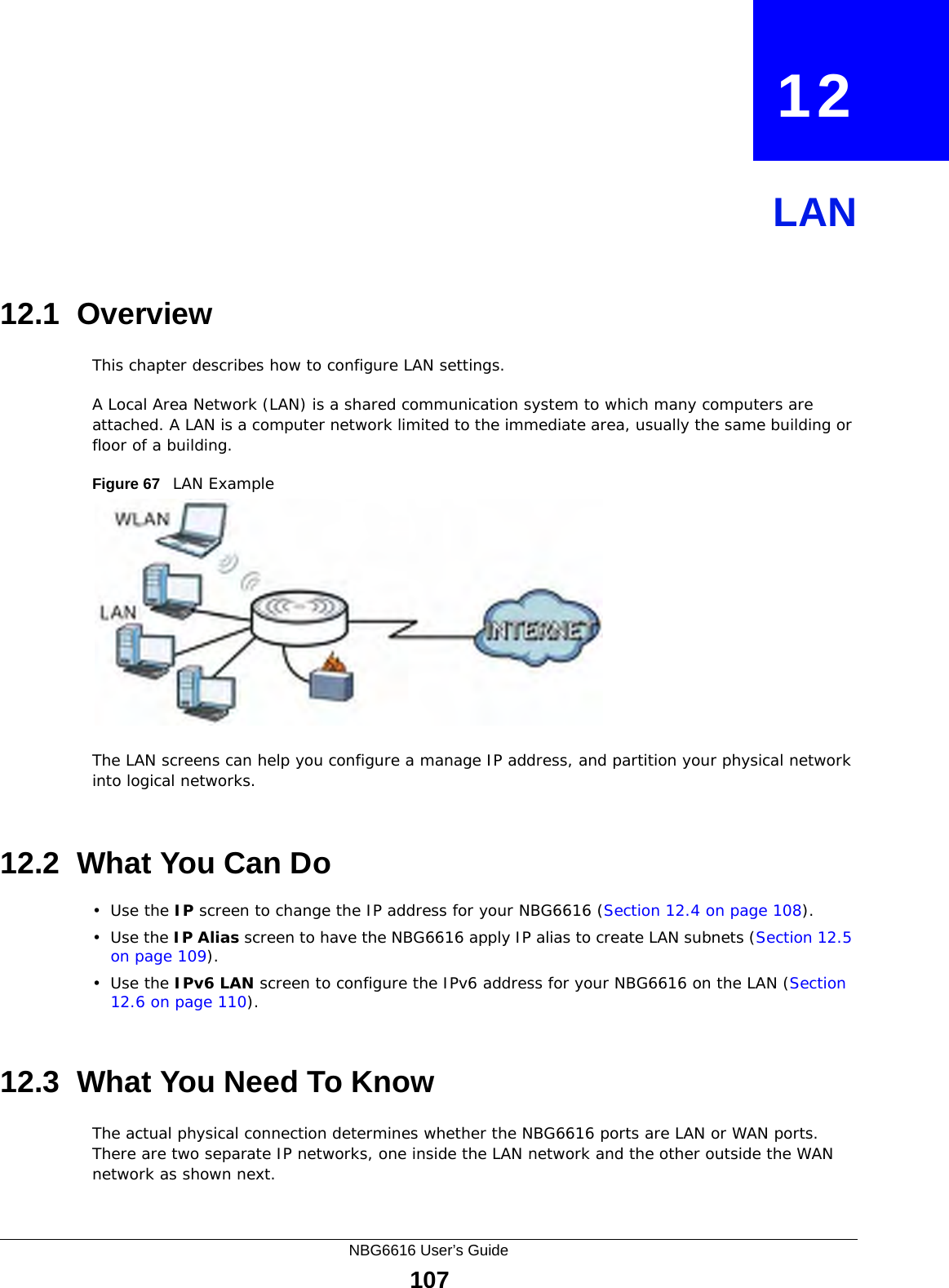
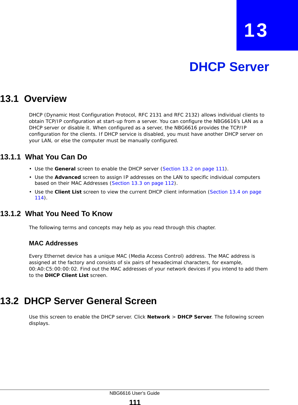
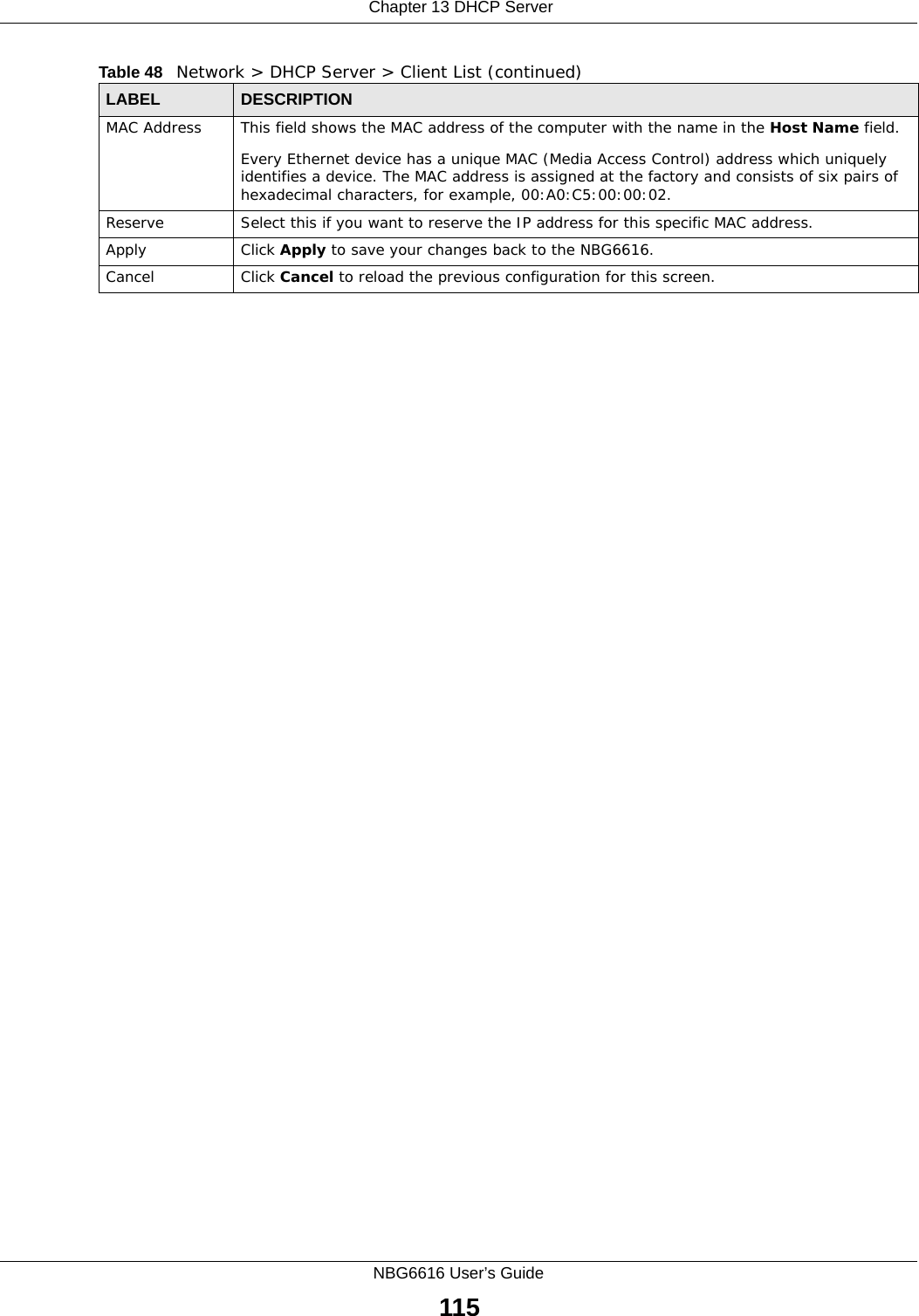
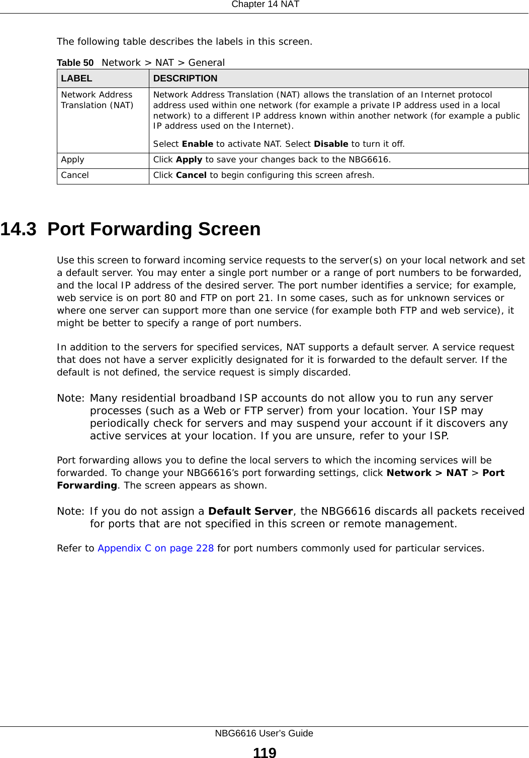
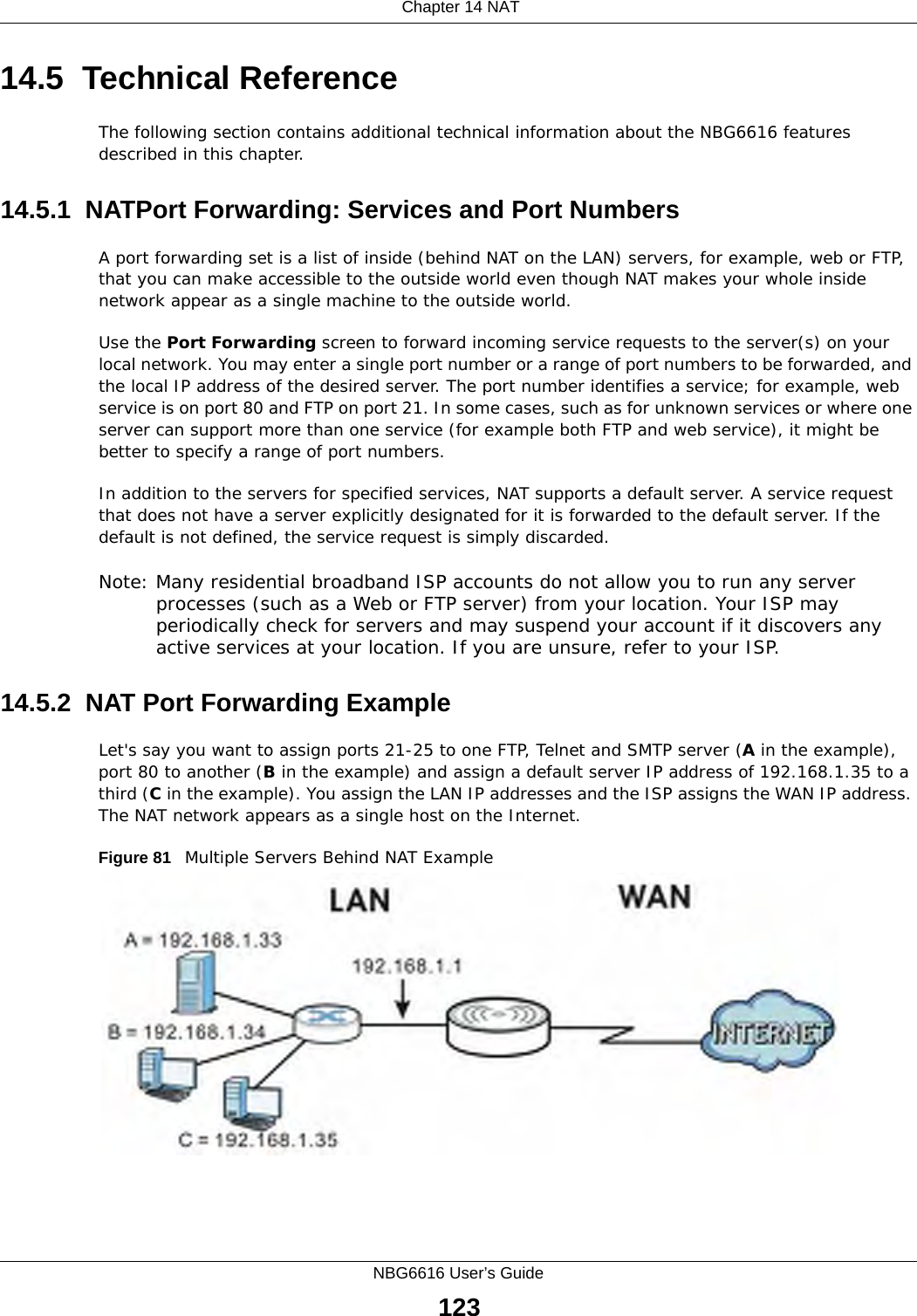
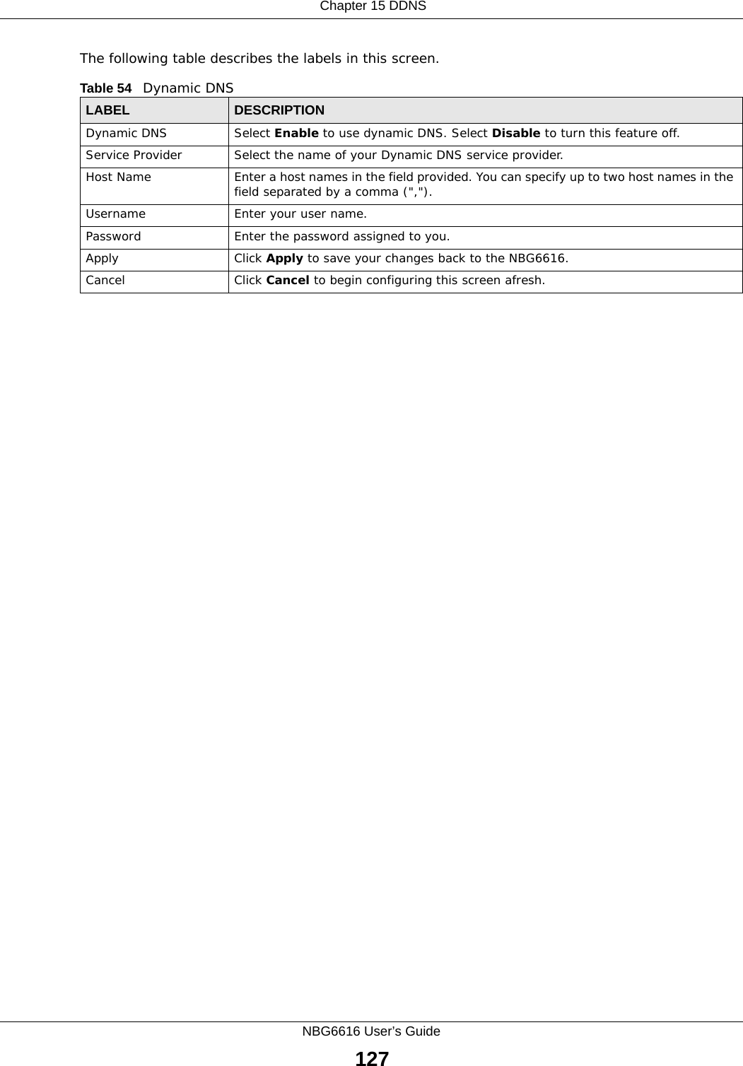
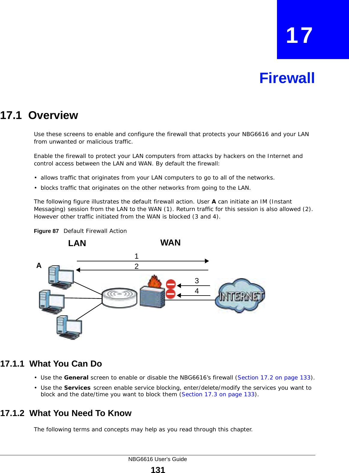
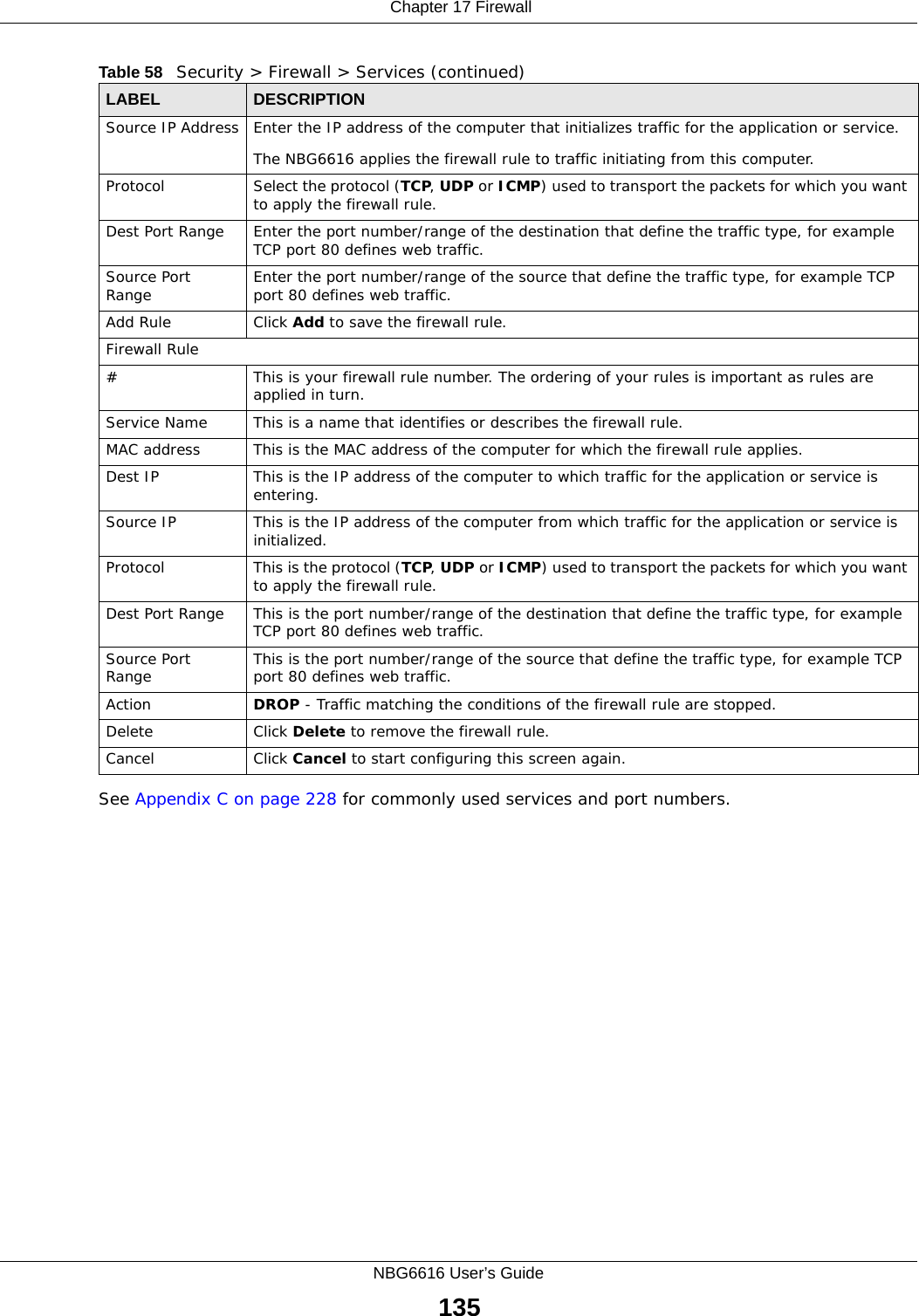
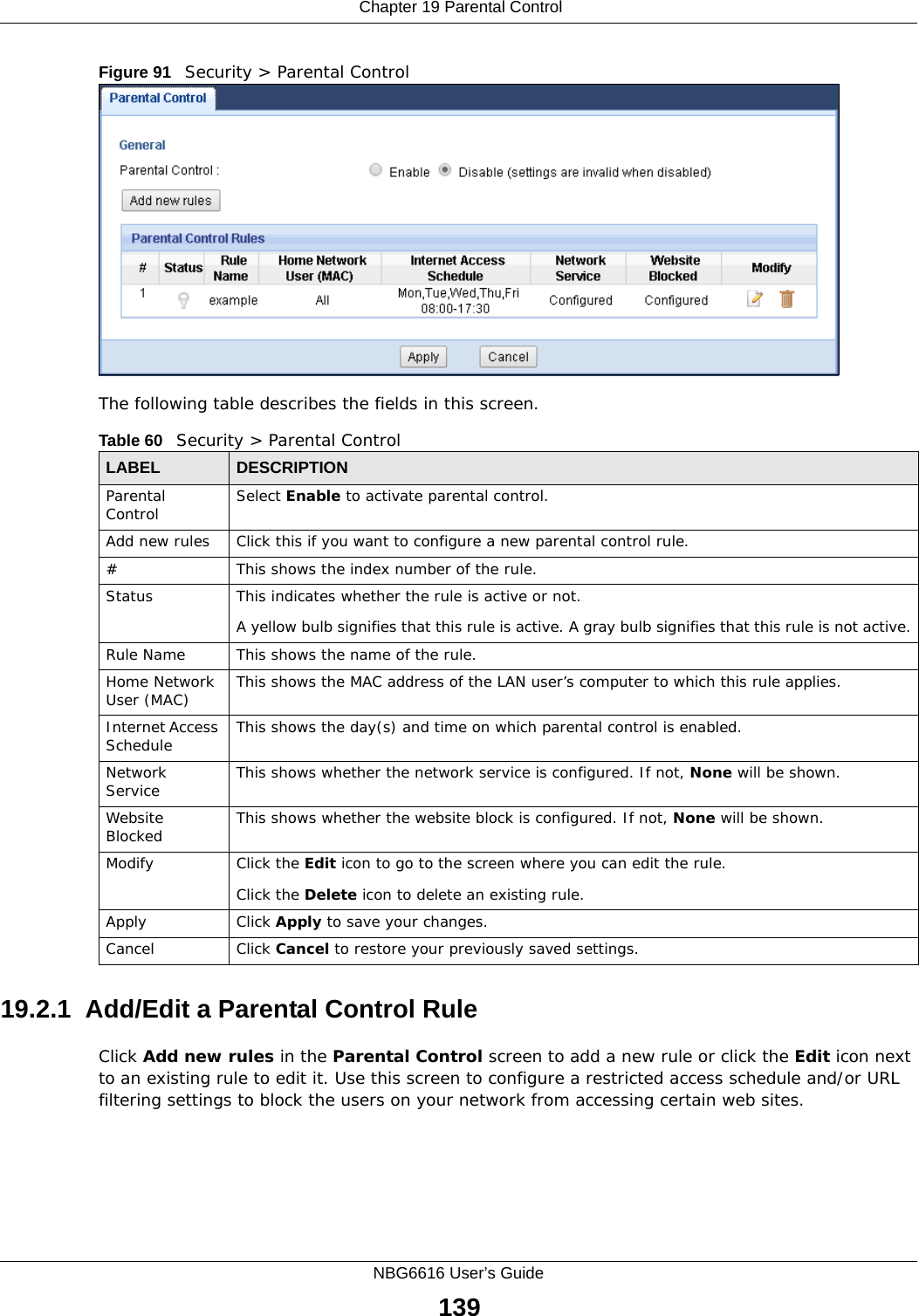
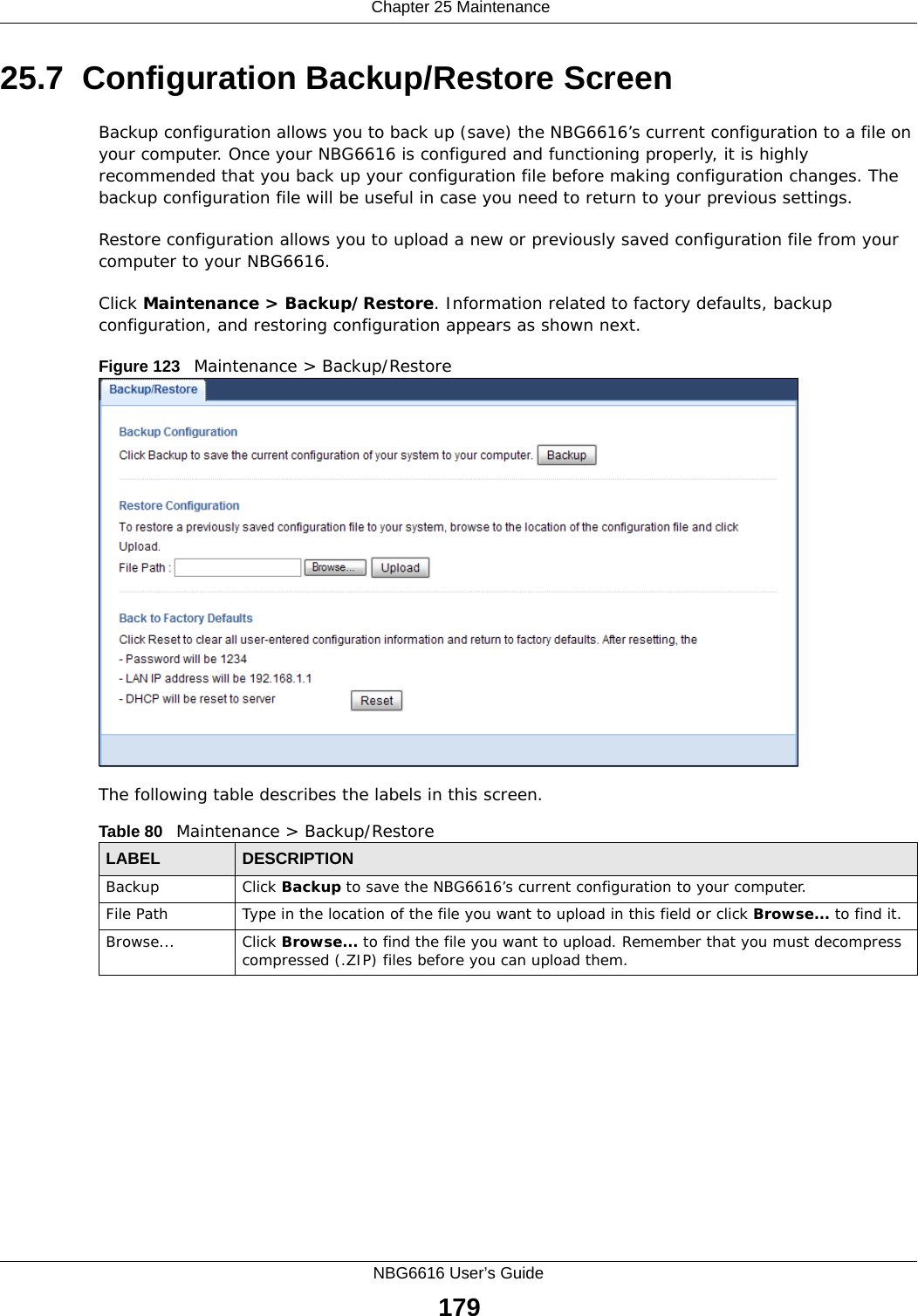
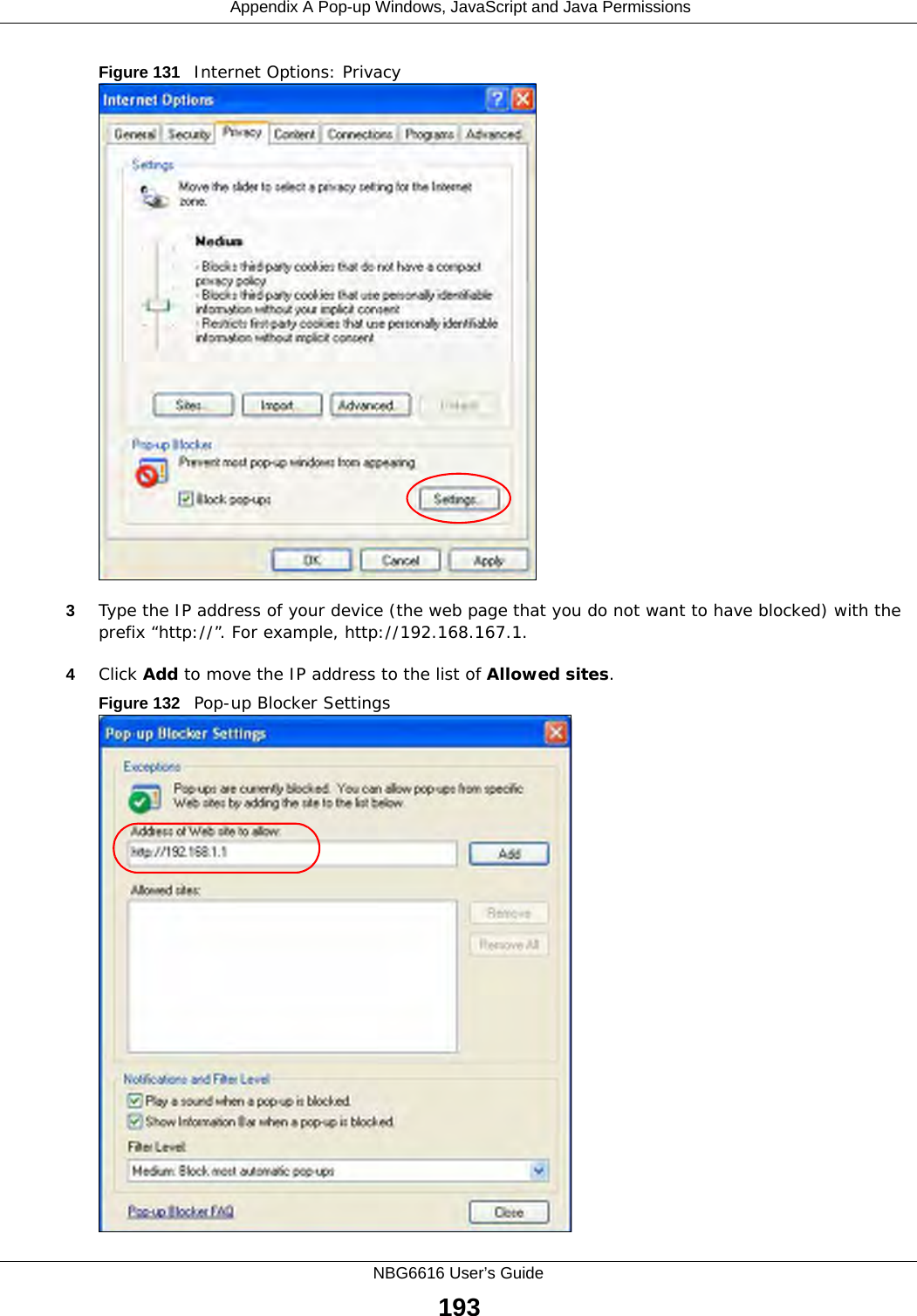
![Chapter 24 USB Media SharingNBG6616 User’s Guide1711In Windows Explorer’s Address bar type a double backslash “\\” followed by the IP address of the NBG6616 (the default IP address of the NBG6616 in router mode is 192.168.1.1) and press [ENTER]. A screen asking for password authentication appears. Type the user name and password (Bob and 1234 in this example) and click OK.Note: Once you log into the shared folder via your NBG6616, you do not have to relogin unless you restart your computer.](https://usermanual.wiki/ZyXEL-Communications/NBG6616/User-Guide-2392470-Page-171.png)
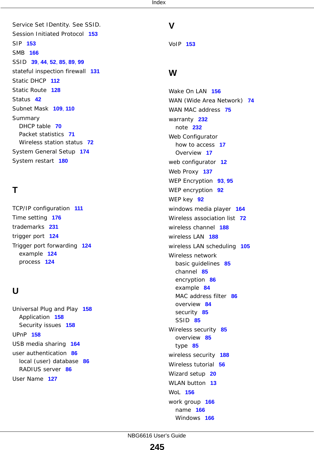
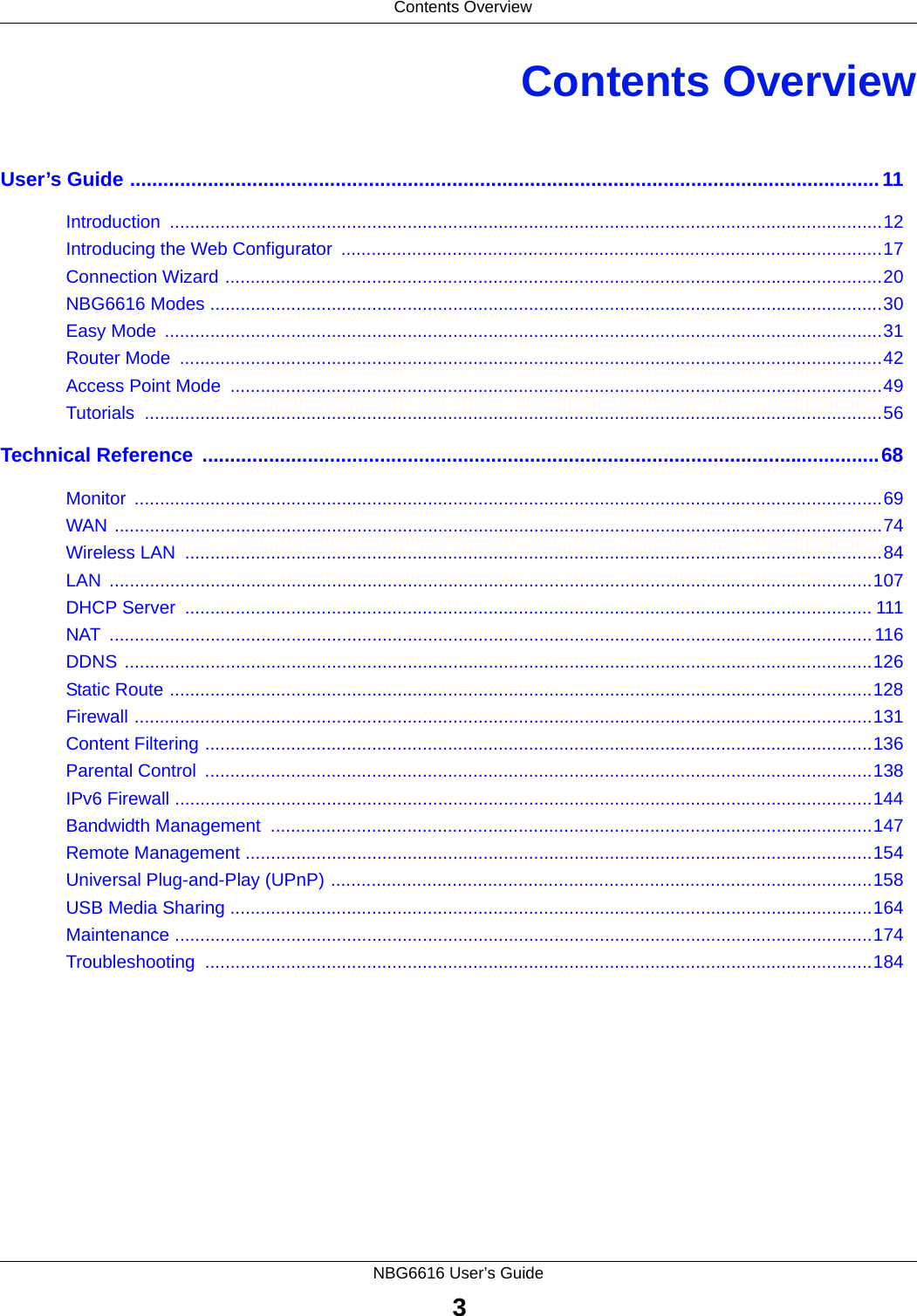
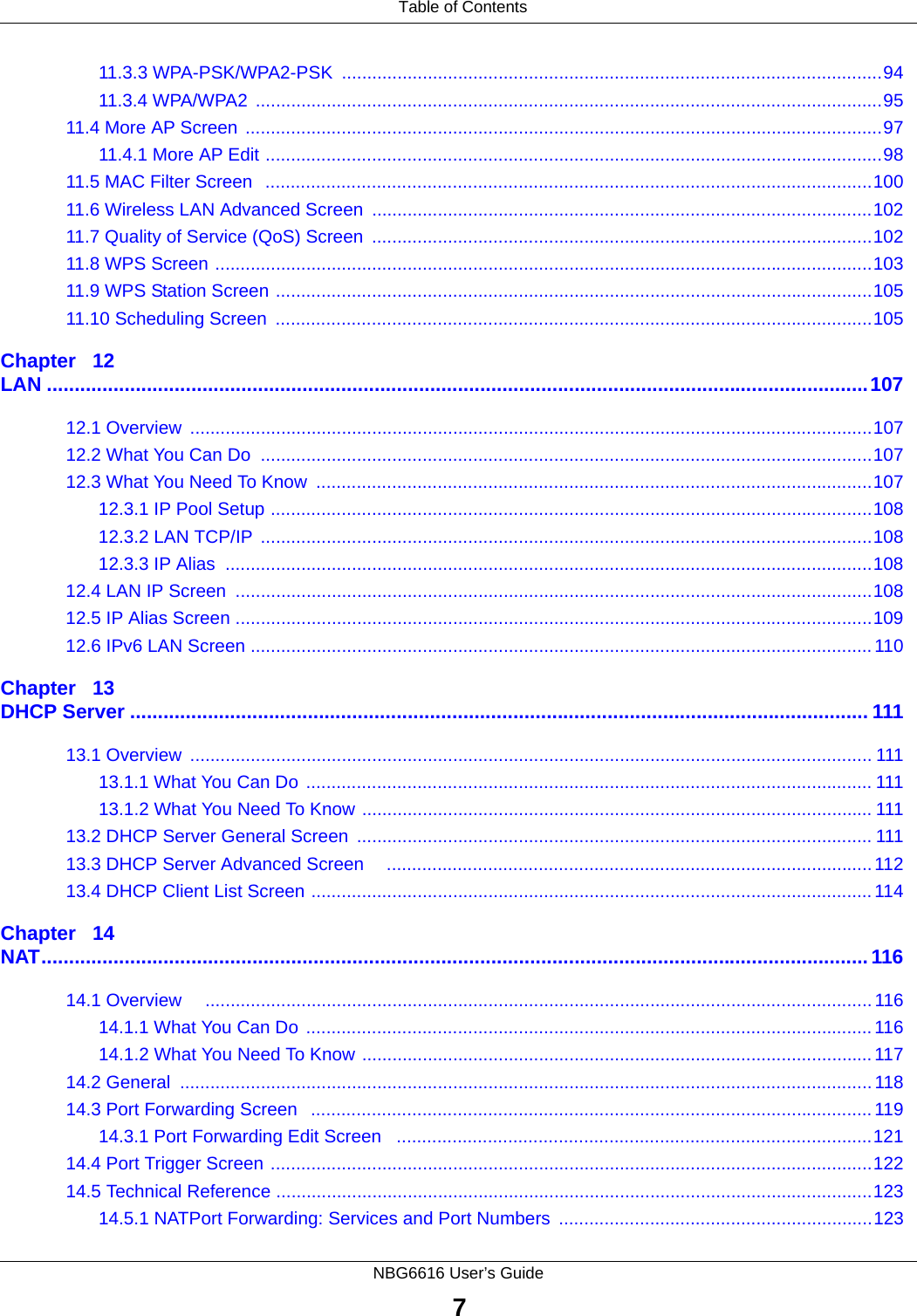
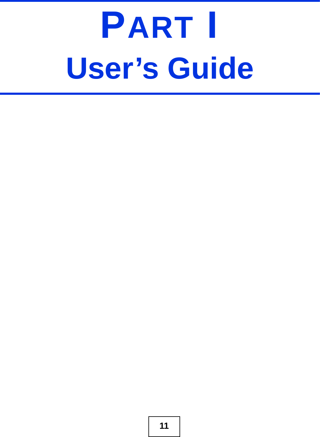
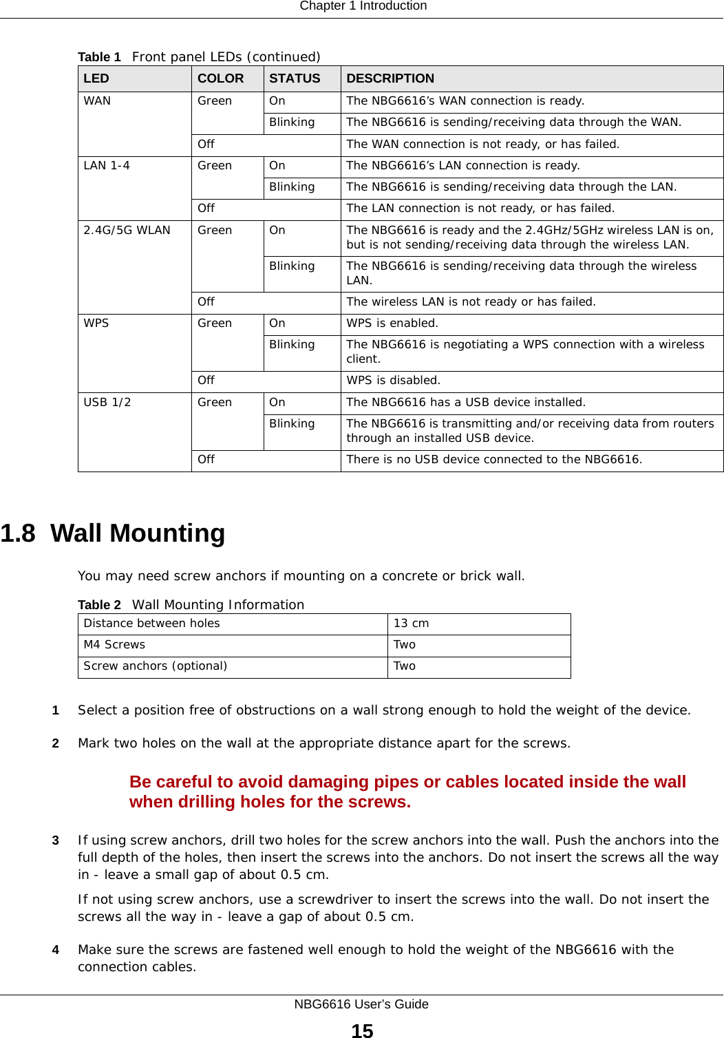
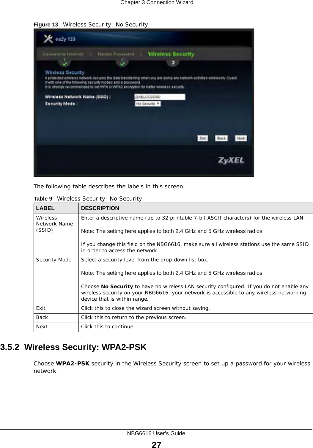
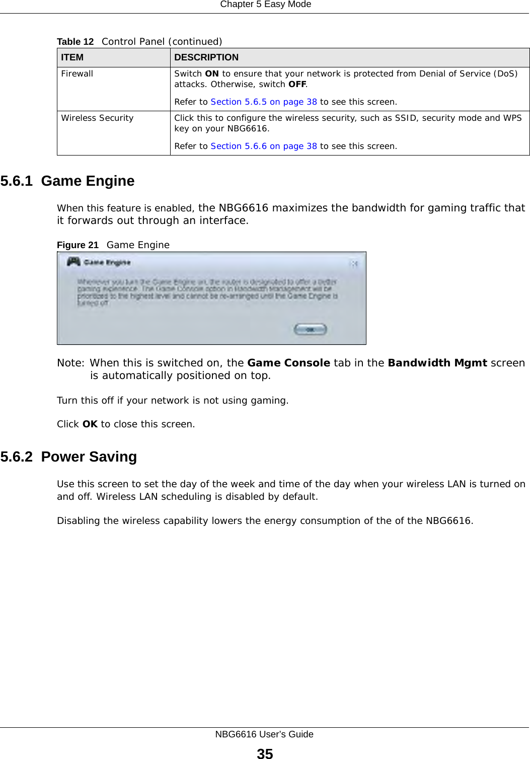
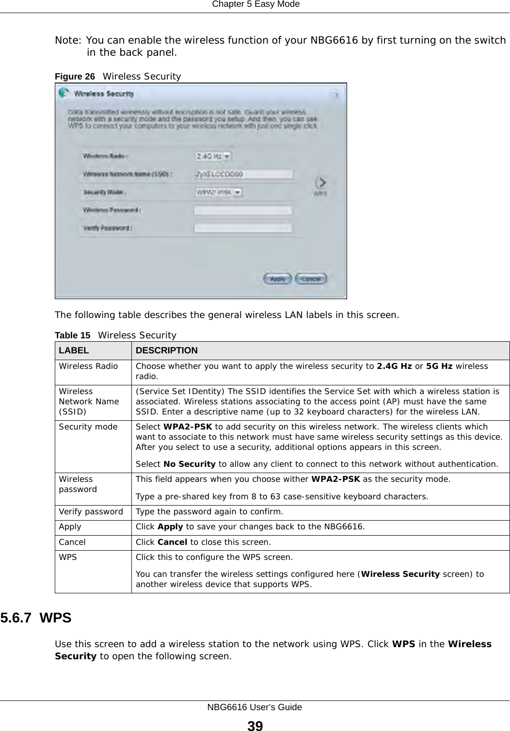
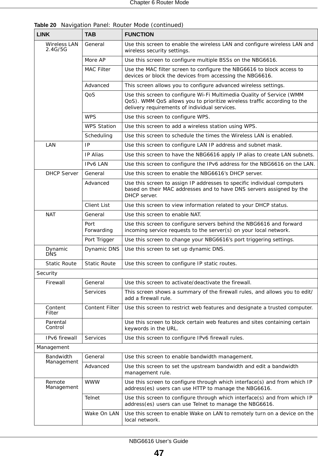
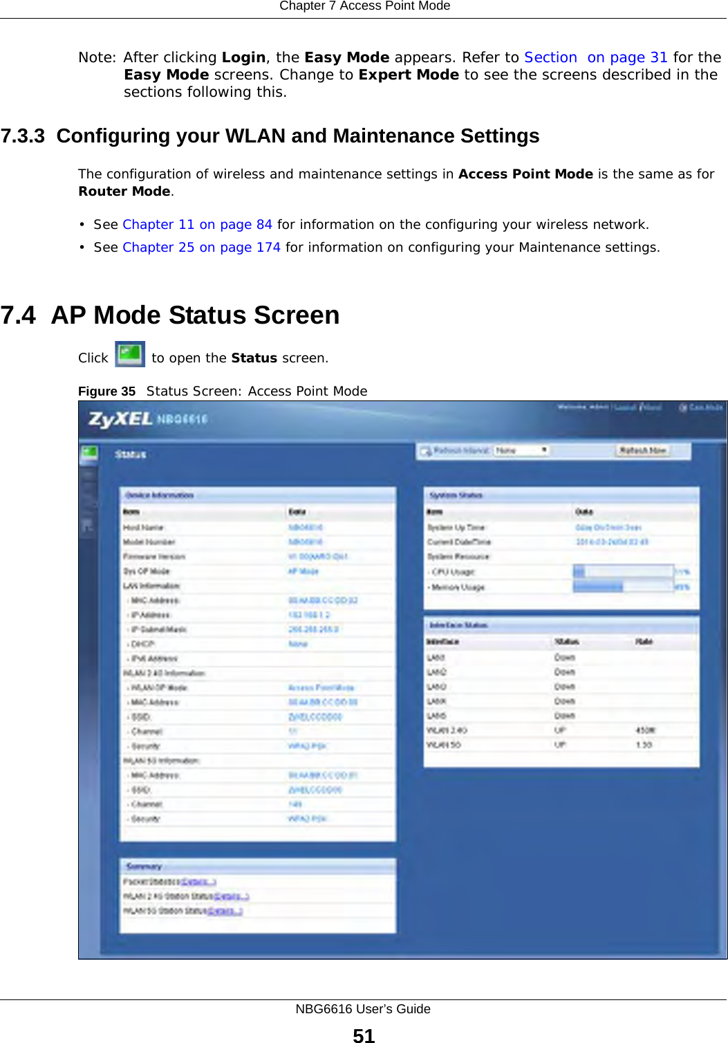
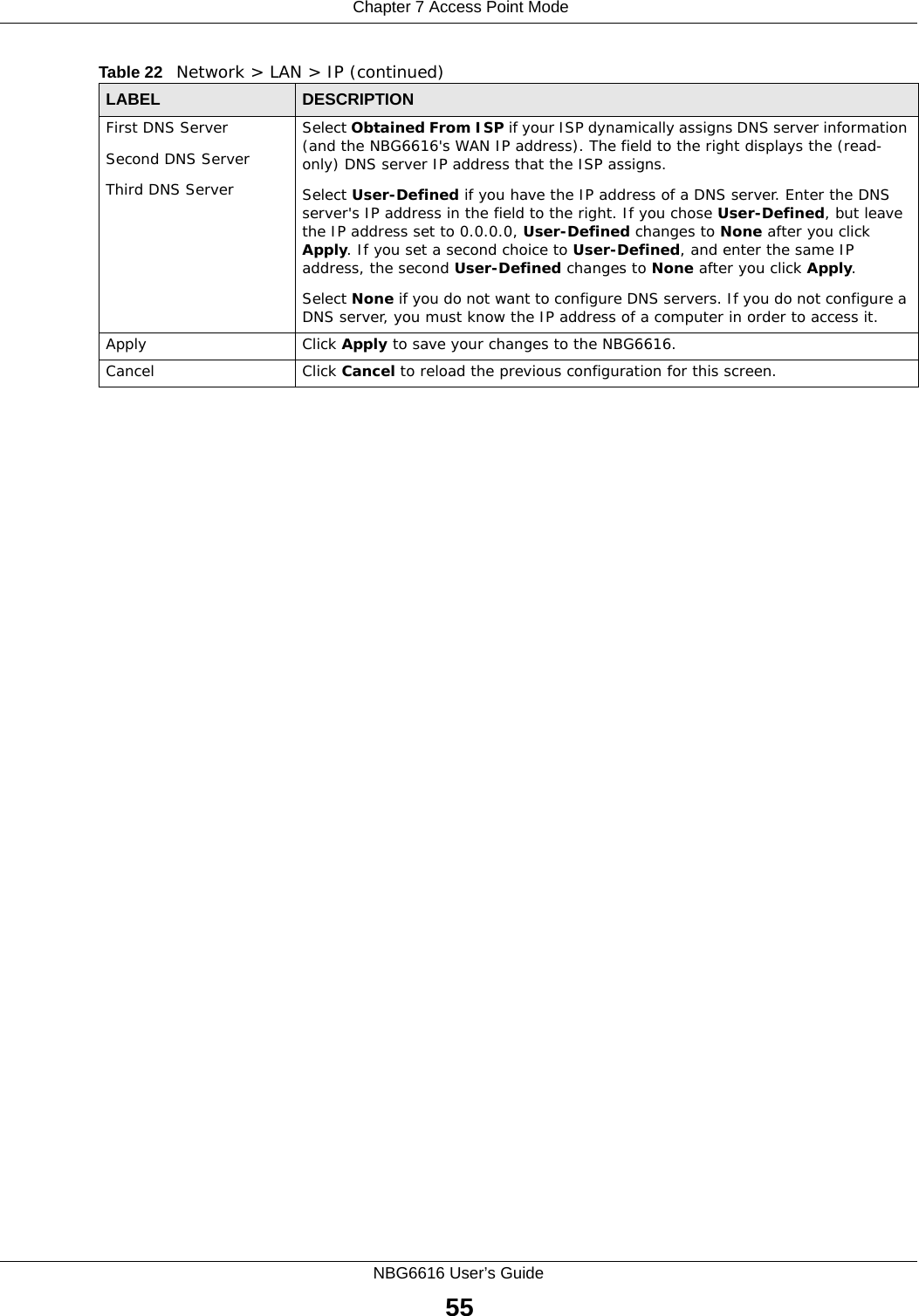
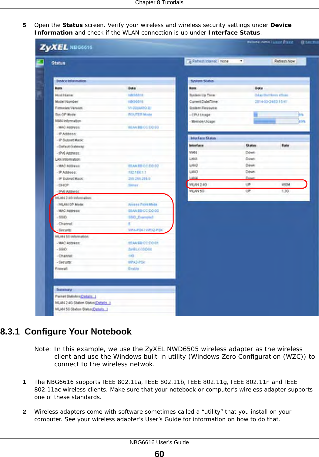
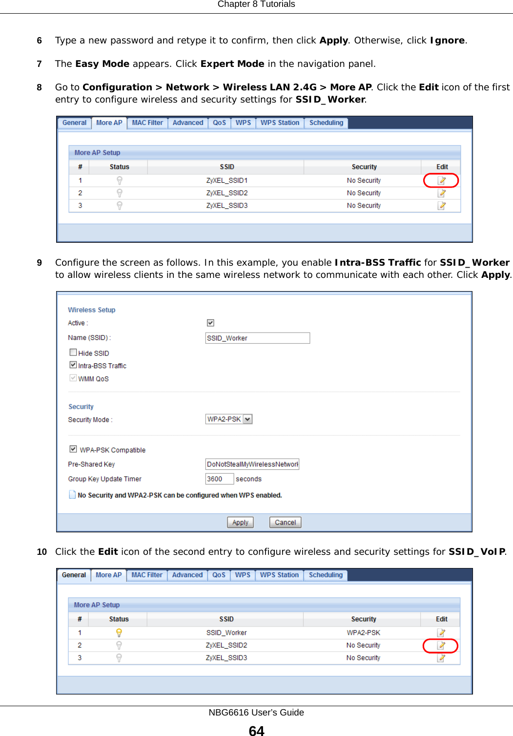
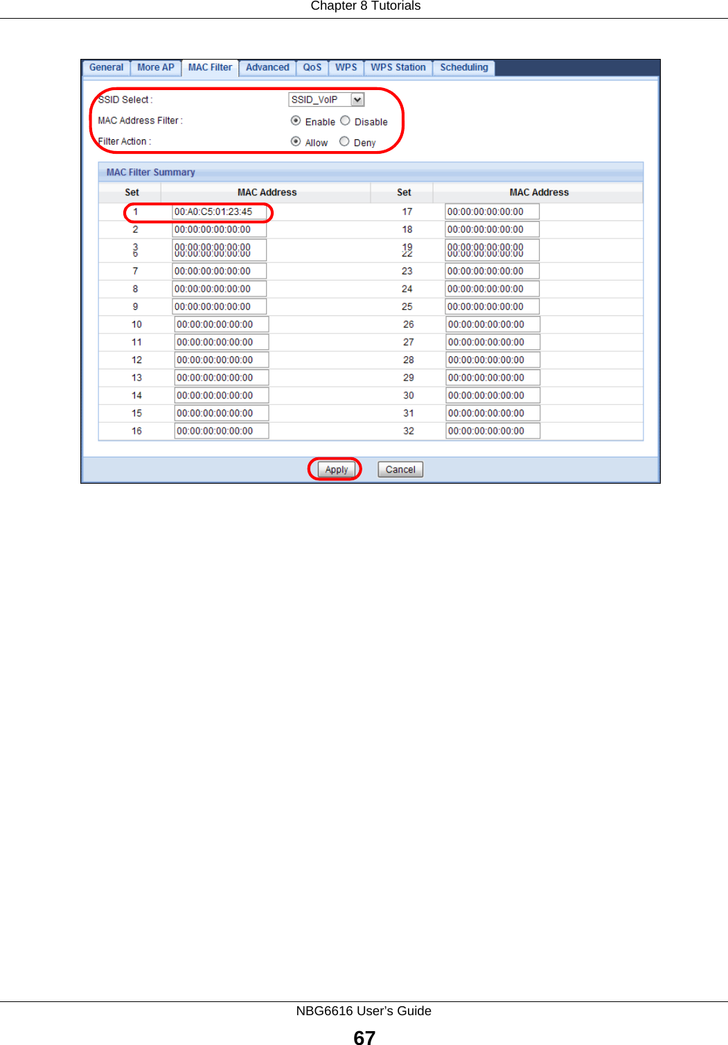
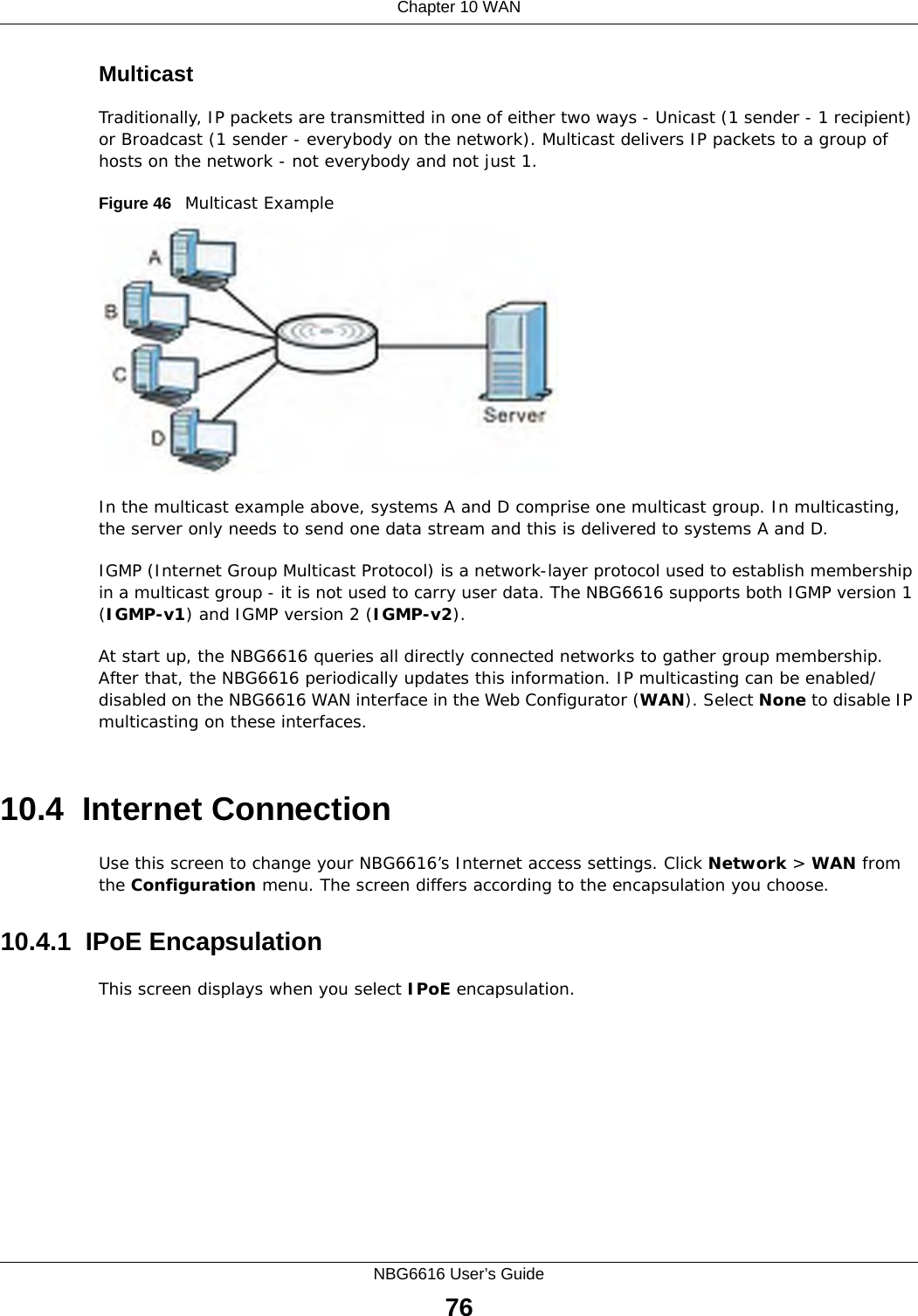
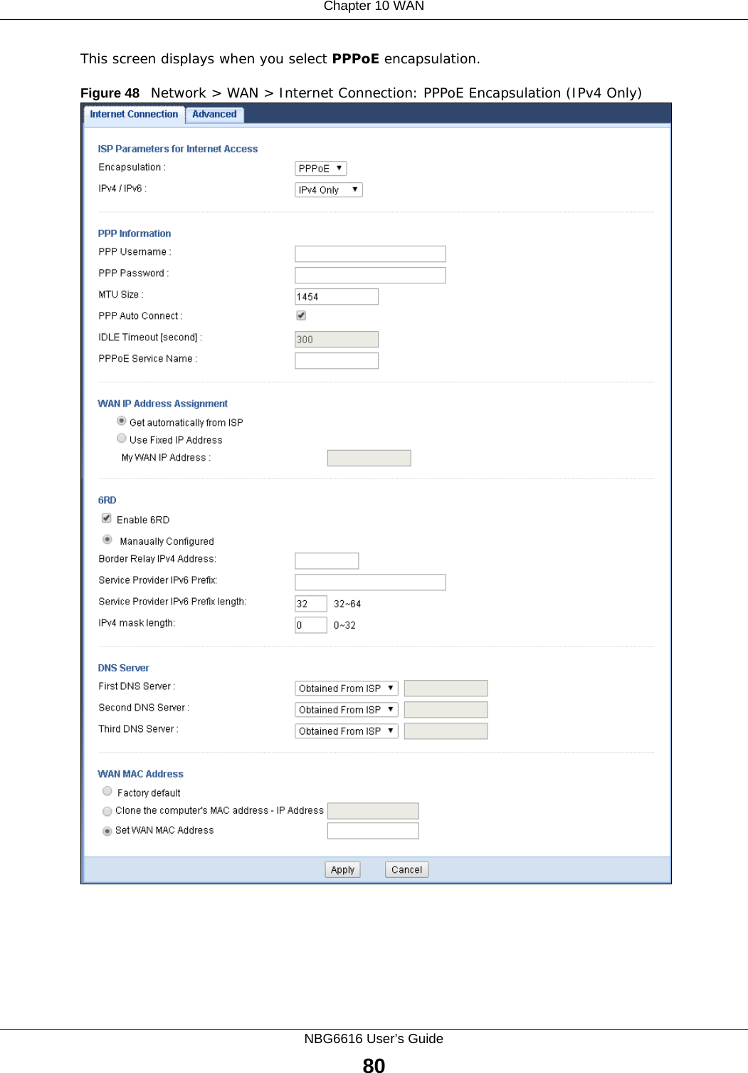
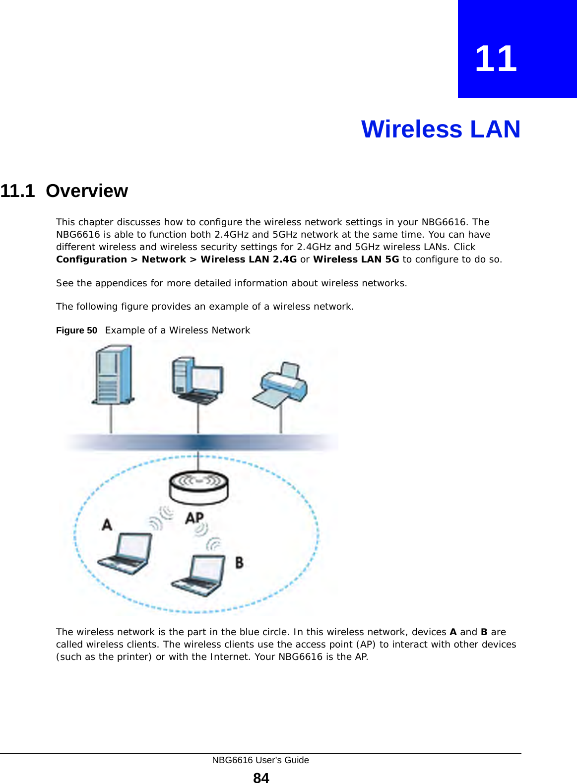
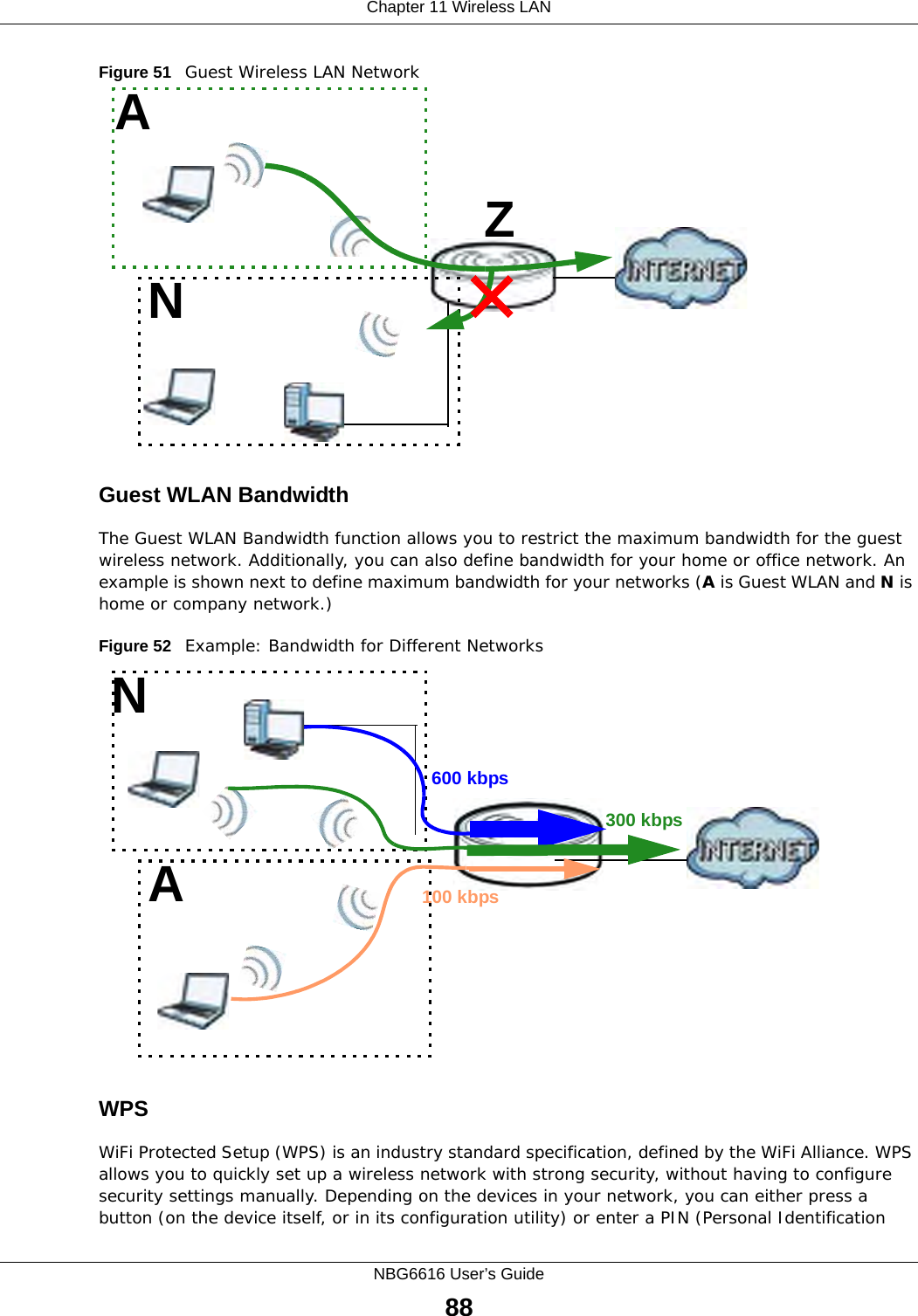
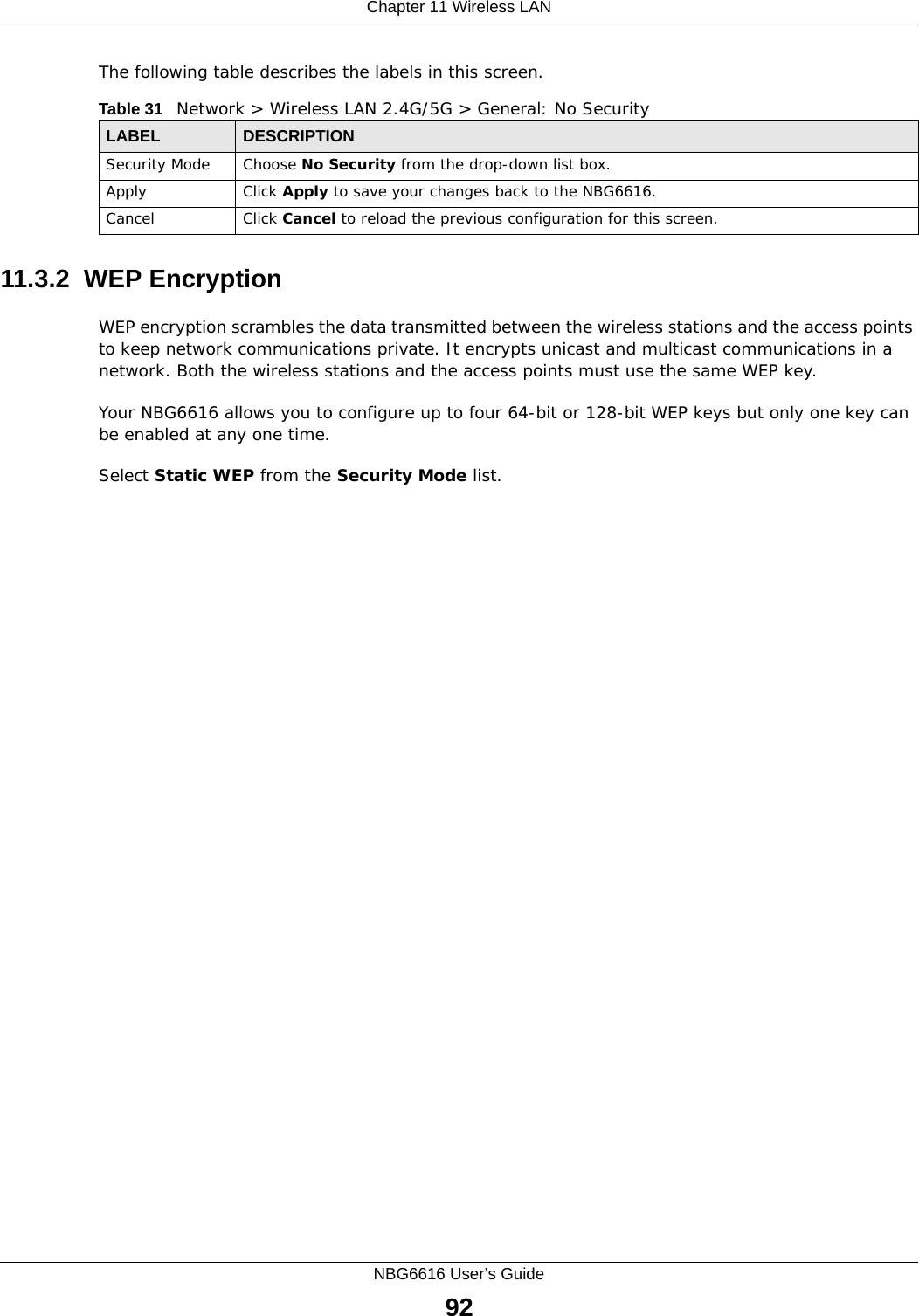
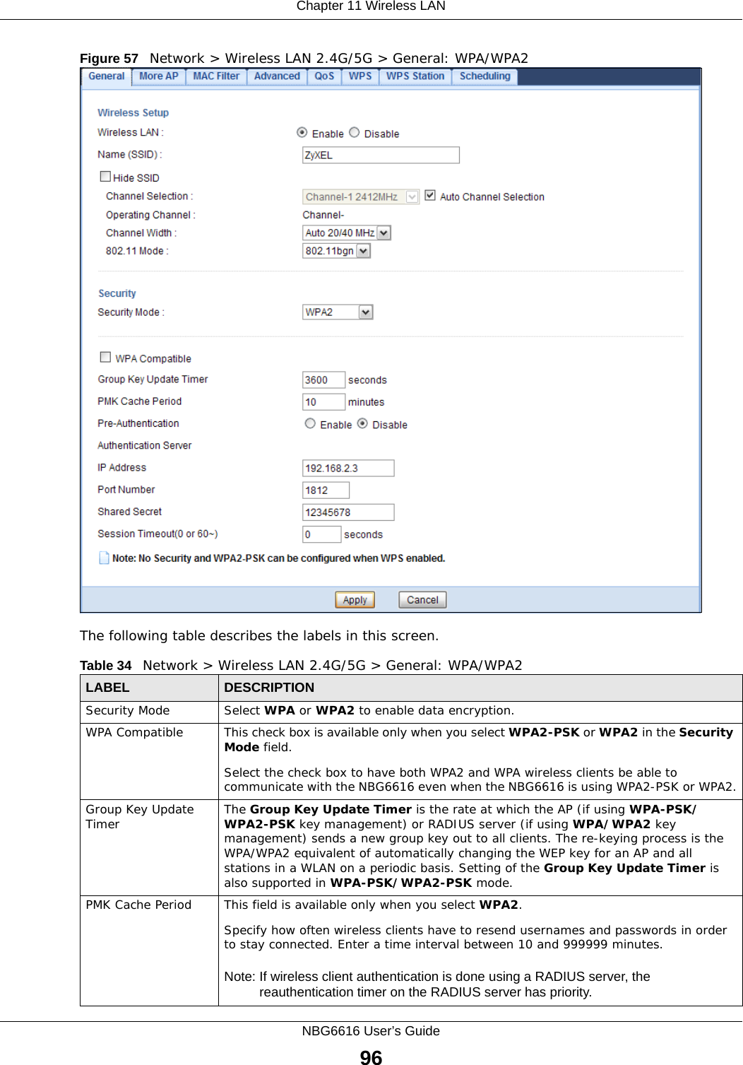
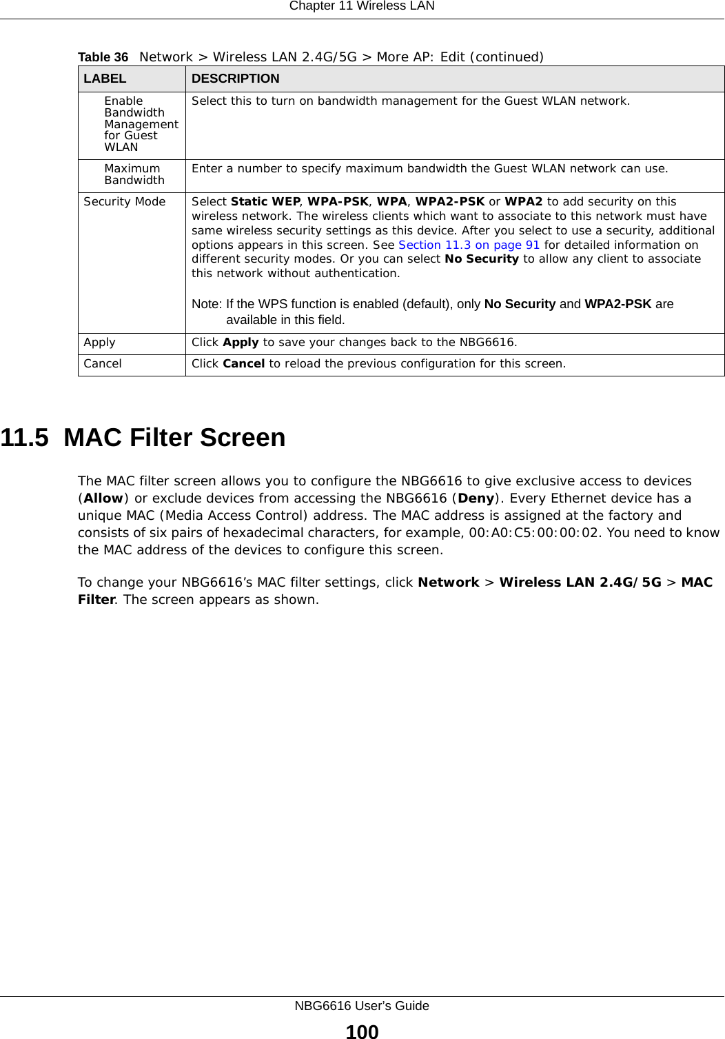
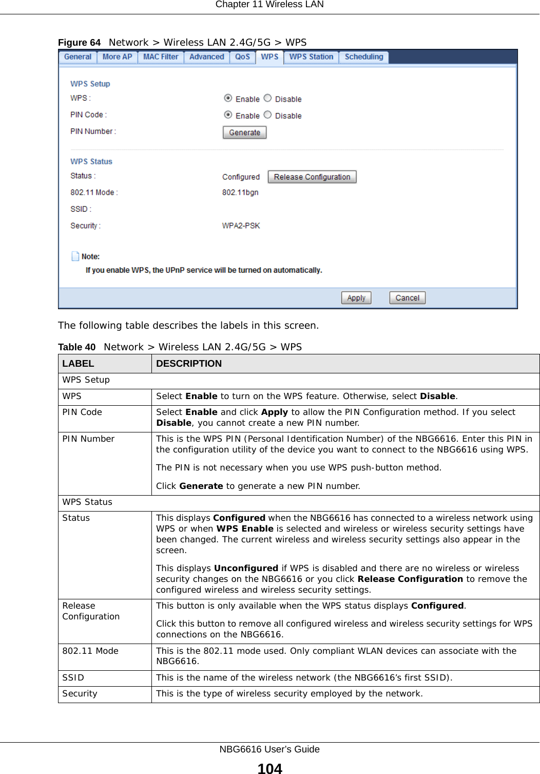
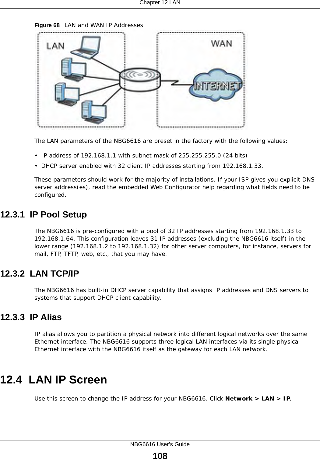
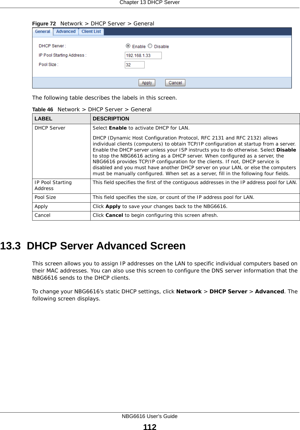
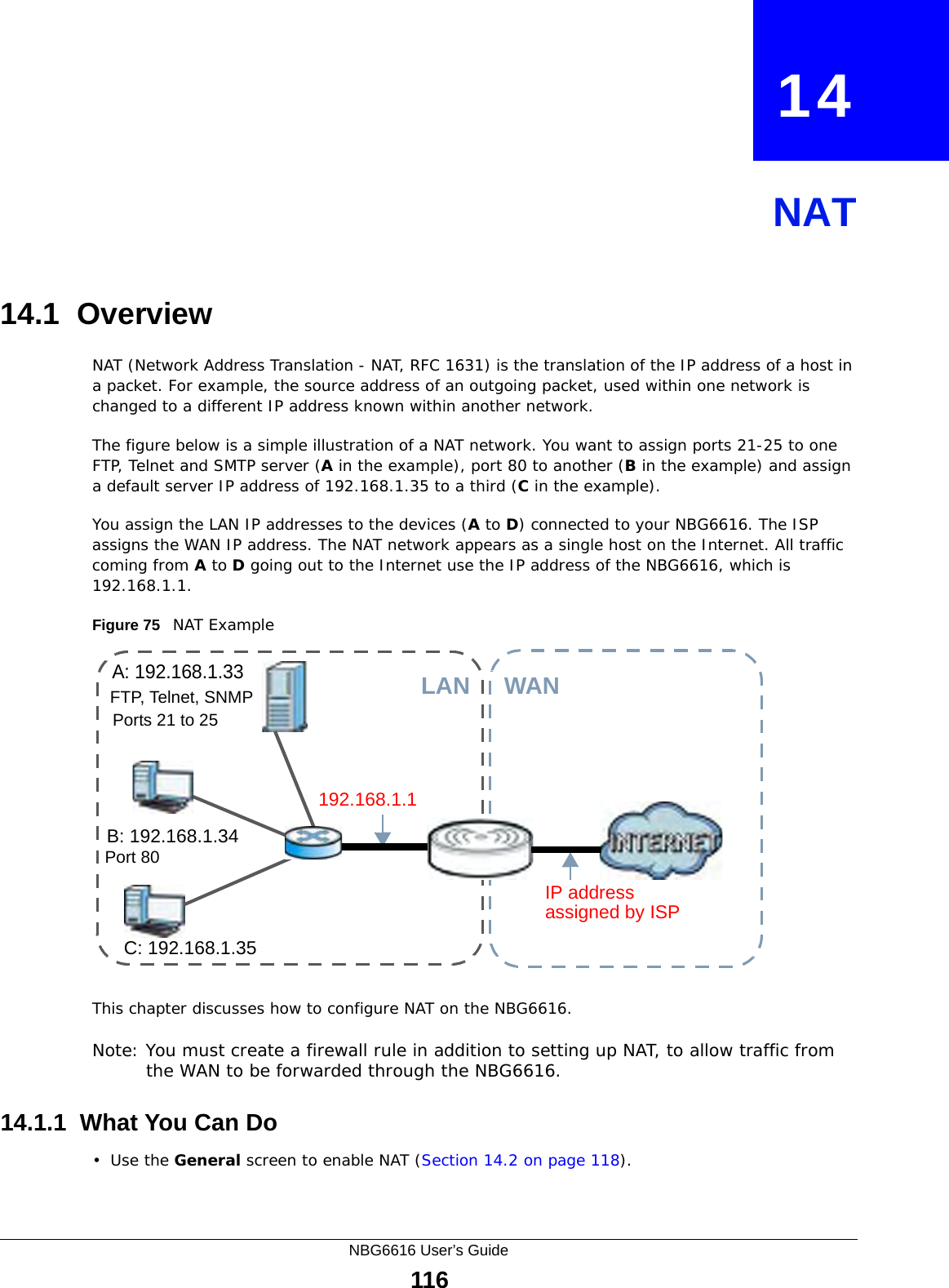
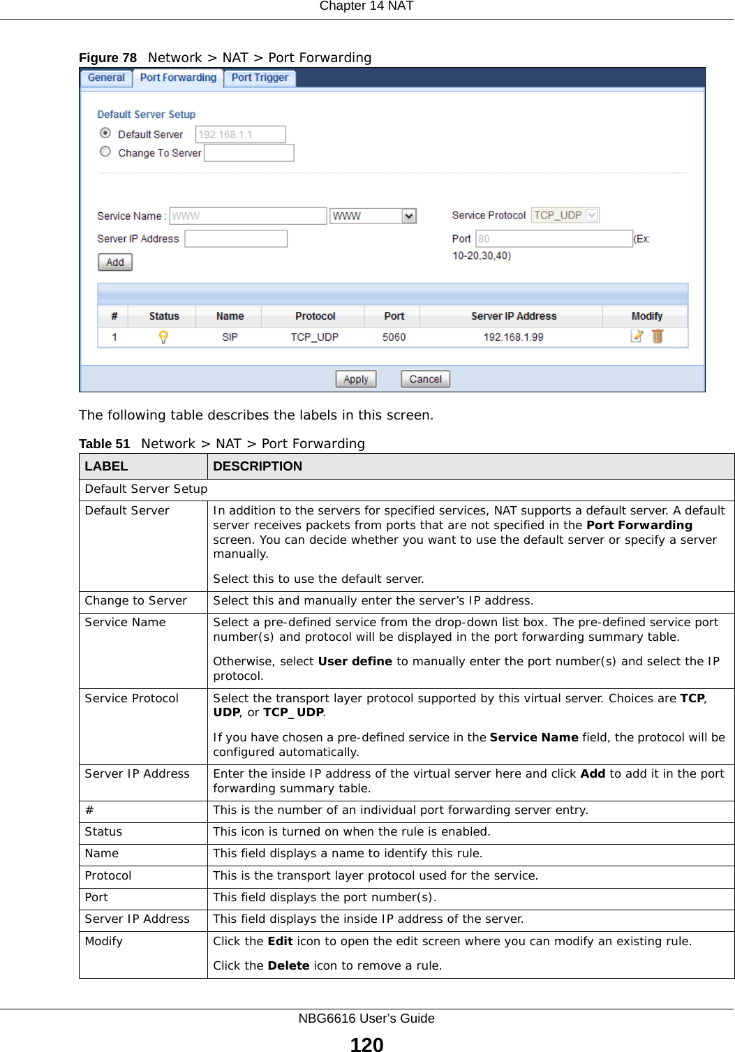
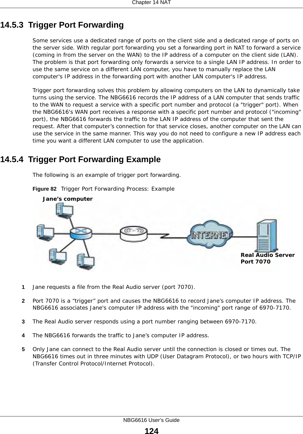
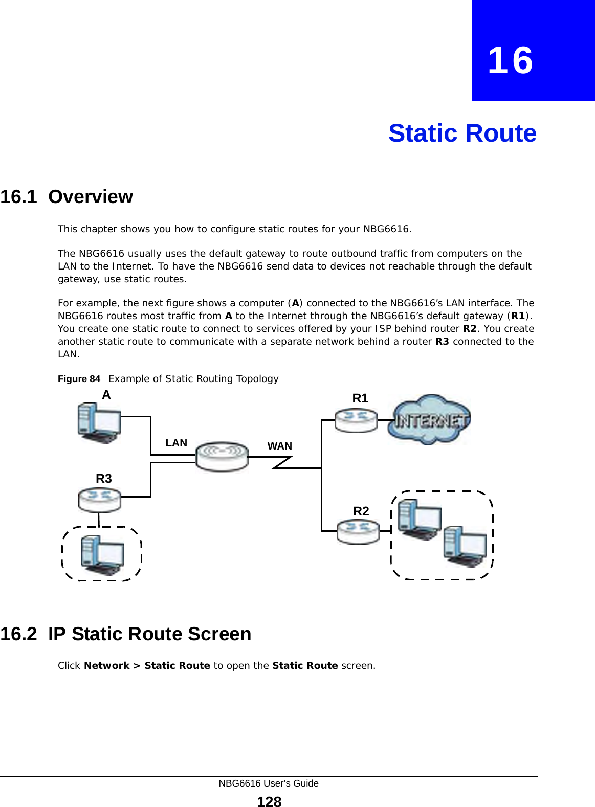
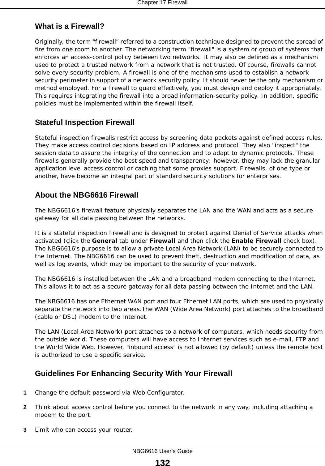
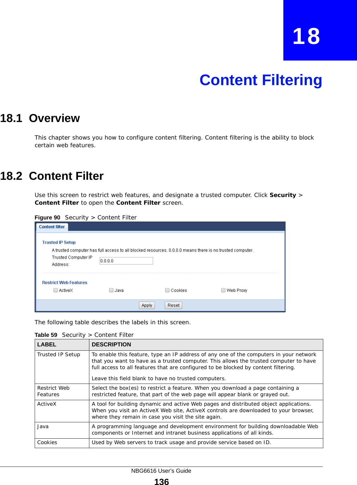
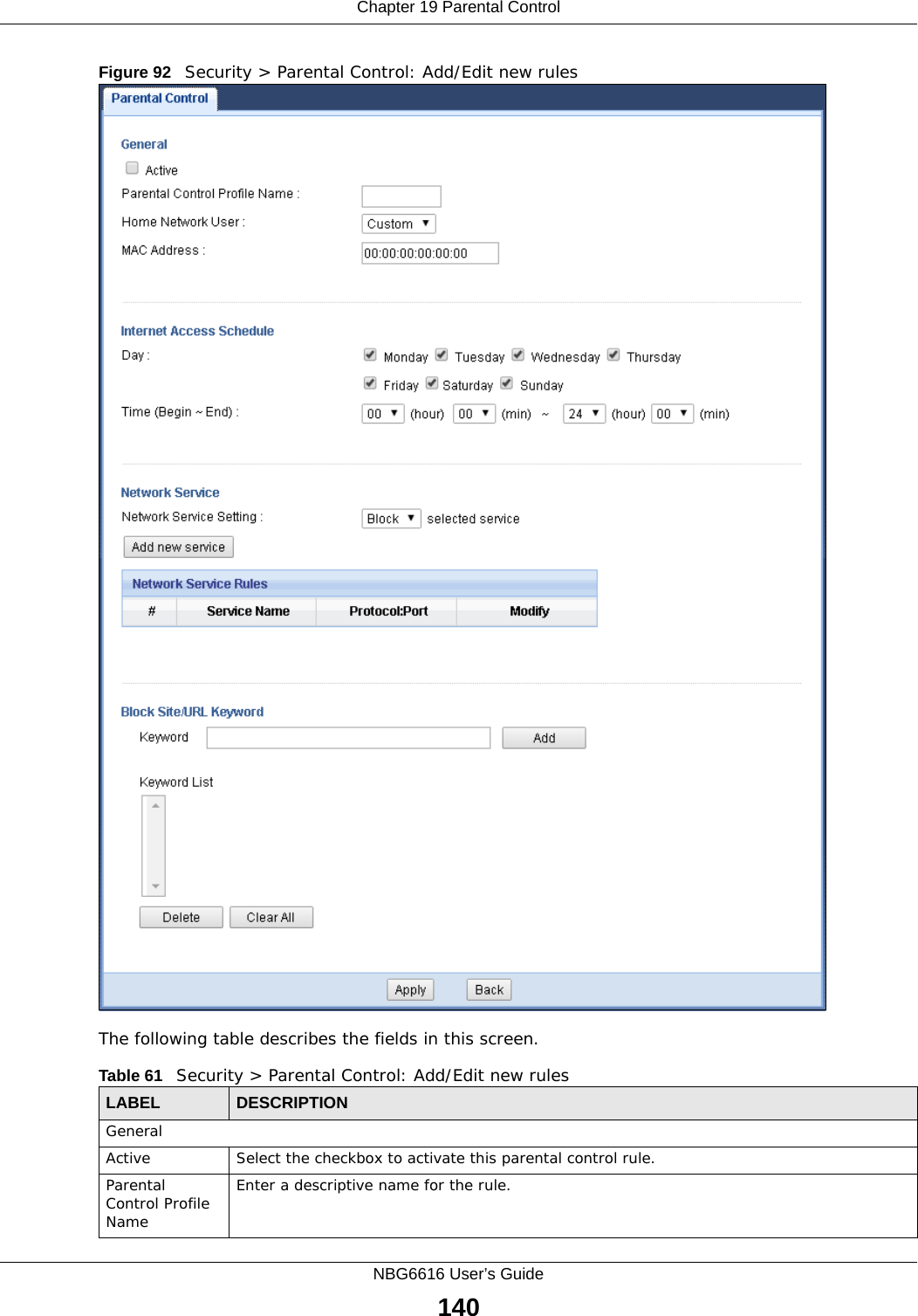
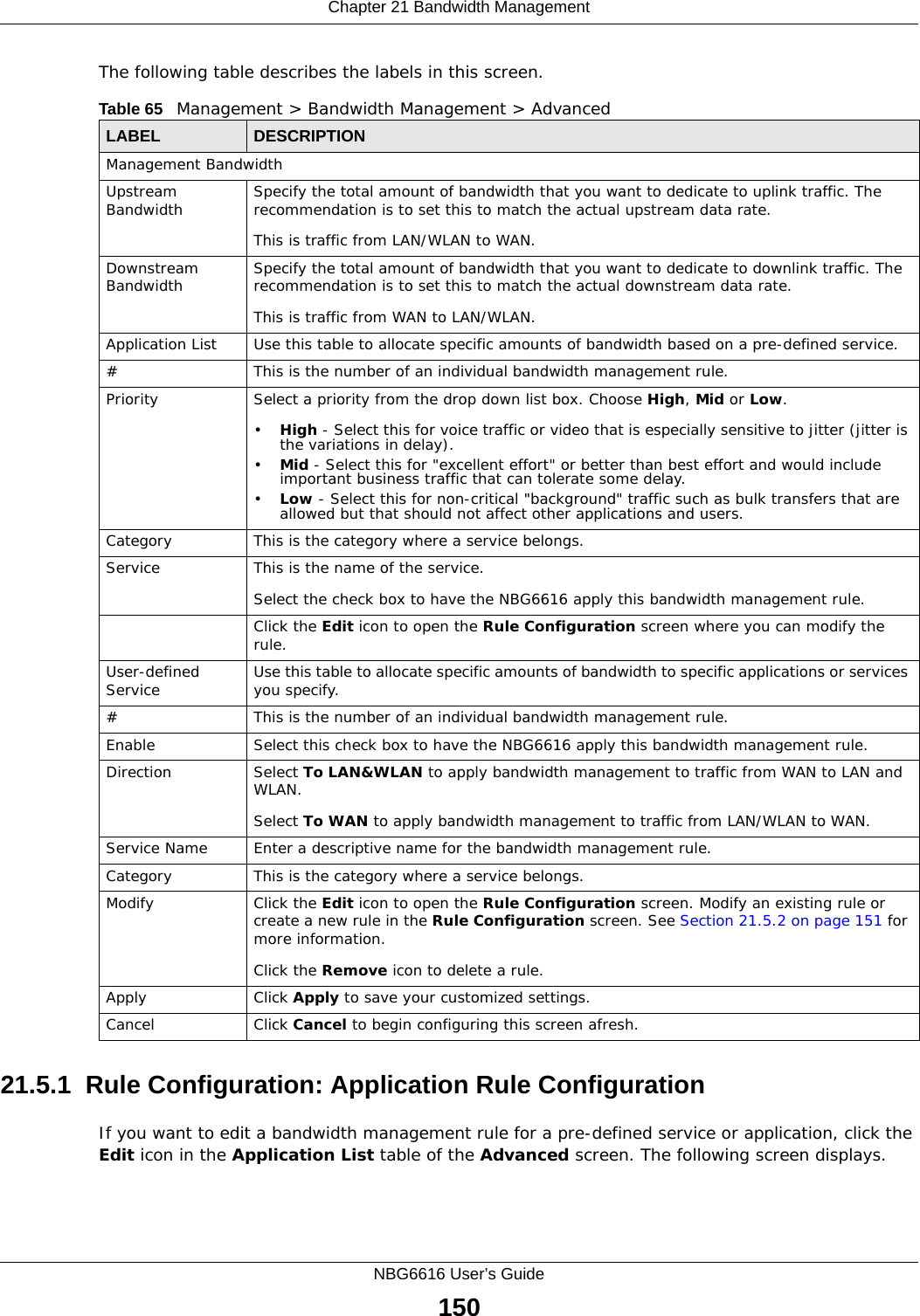
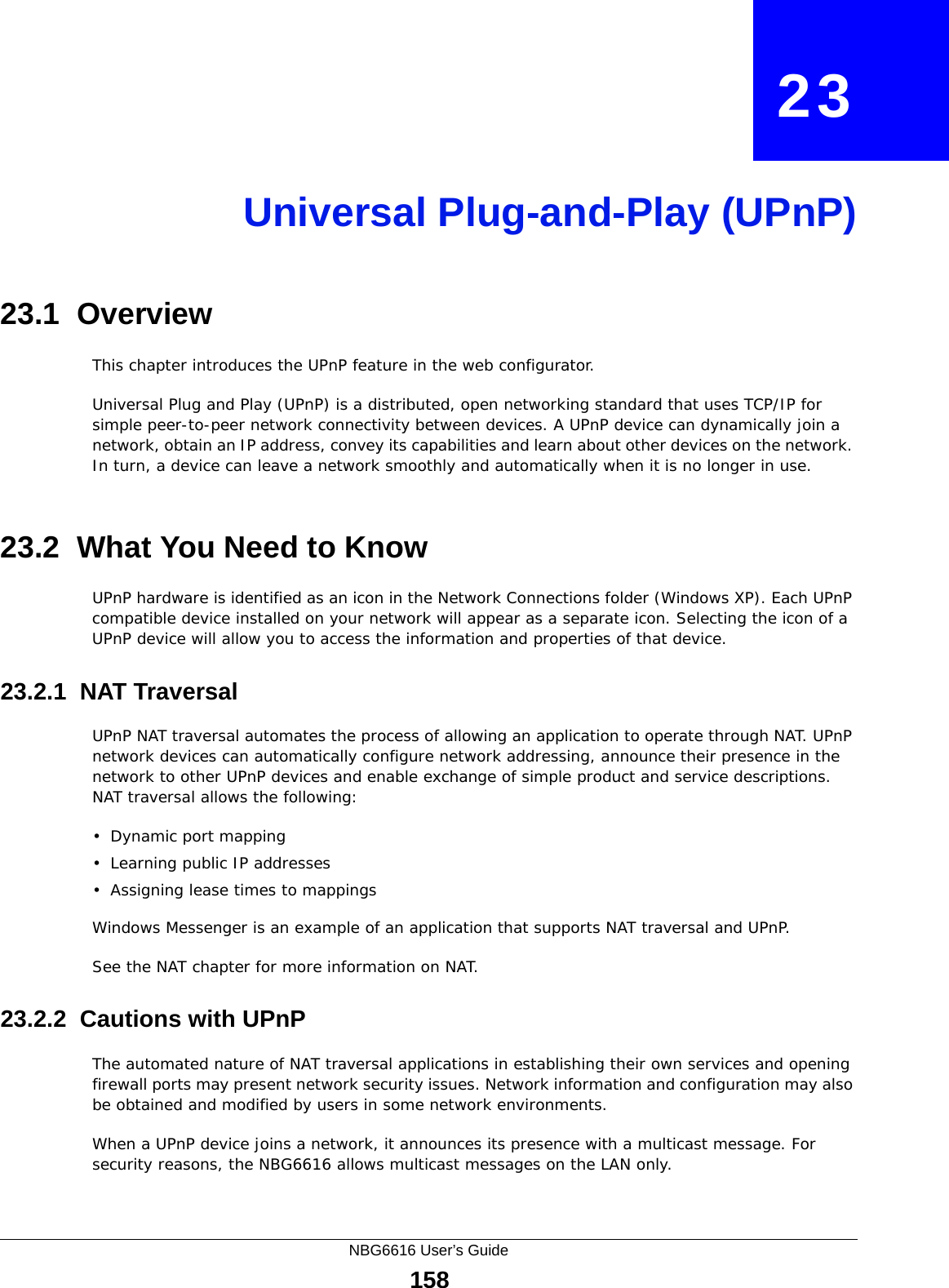
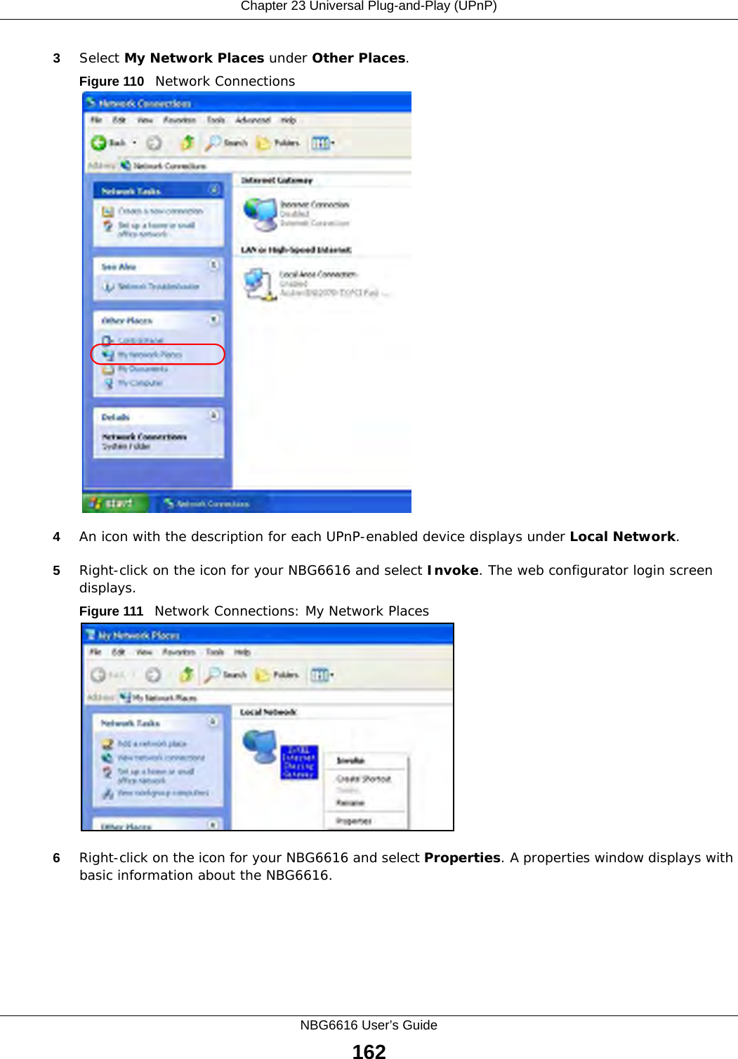
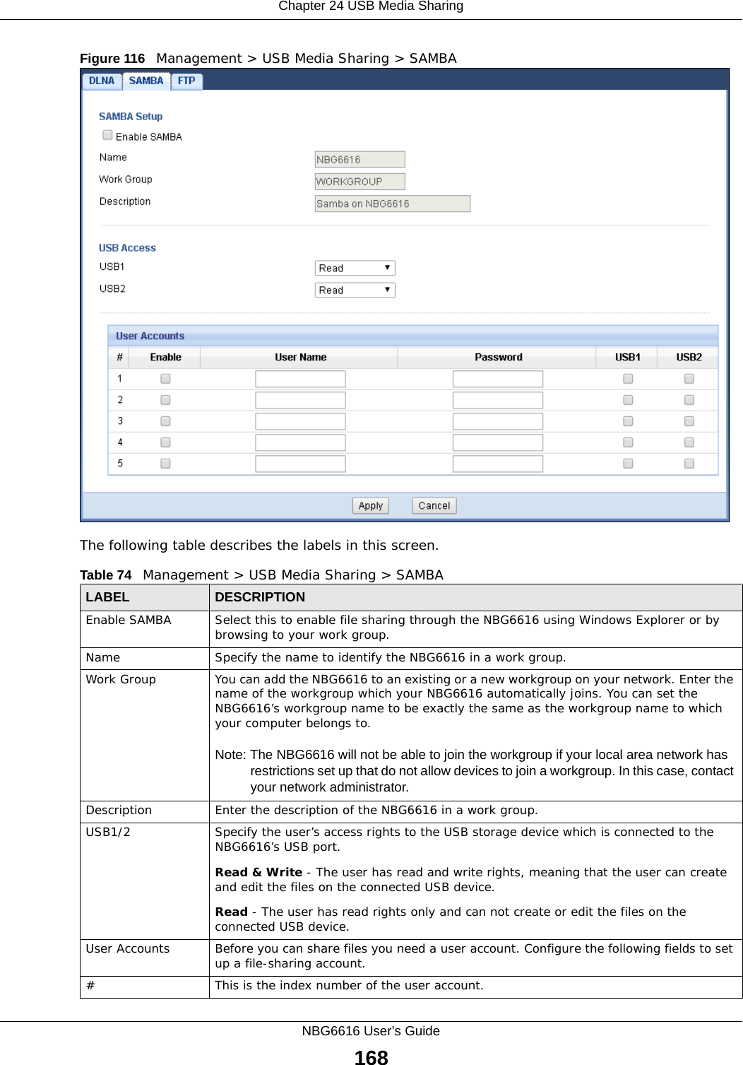
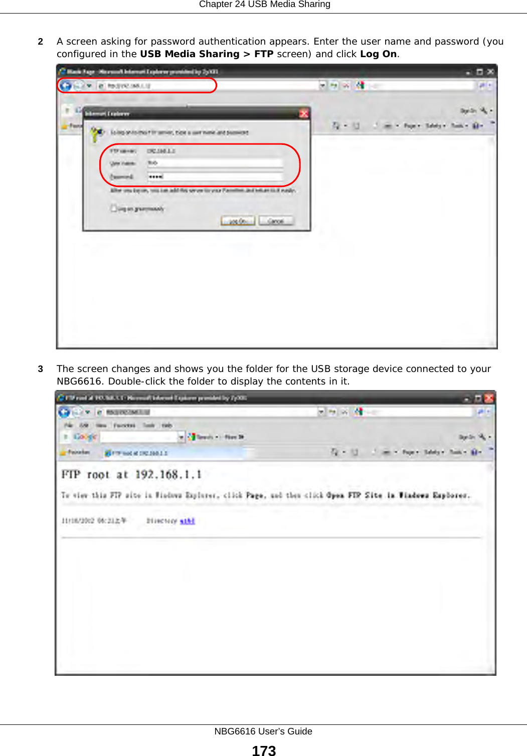
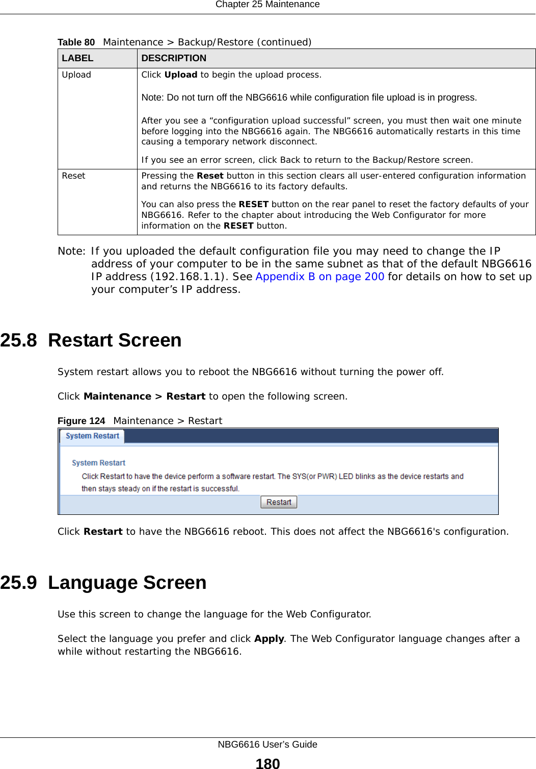
![Chapter 24 USB Media SharingNBG6616 User’s Guide1722You can also use the workgroup name to access files by browsing to the workgroup folder using the folder tree on the left side of the screen. It is located under My Network Places. In this example the workgroup name is the default “Workgroup”. 24.8.2 Use FTP to Share FilesYou can use FTP to access the USB storage devices connected to the NBG6616. In this example, we use the web browser to share files via FTP from the LAN. The way or screen you log into the FTP server (on the NBG6616) varies depending on your FTP client. See your FTP client documentation for more information. You should have enabled file sharing and create a user account (Bob/1234 for example) with read and write access to USB 1 in the USB Media Sharing > FTP screen.1In your web browser’s address or URL bar type “ftp://” followed by the IP address of the NBG6616 (the default LAN IP address of the NBG6616 in router mode is 192.168.1.1) and click Go or press [ENTER].](https://usermanual.wiki/ZyXEL-Communications/NBG6616/User-Guide-2392470-Page-172.png)
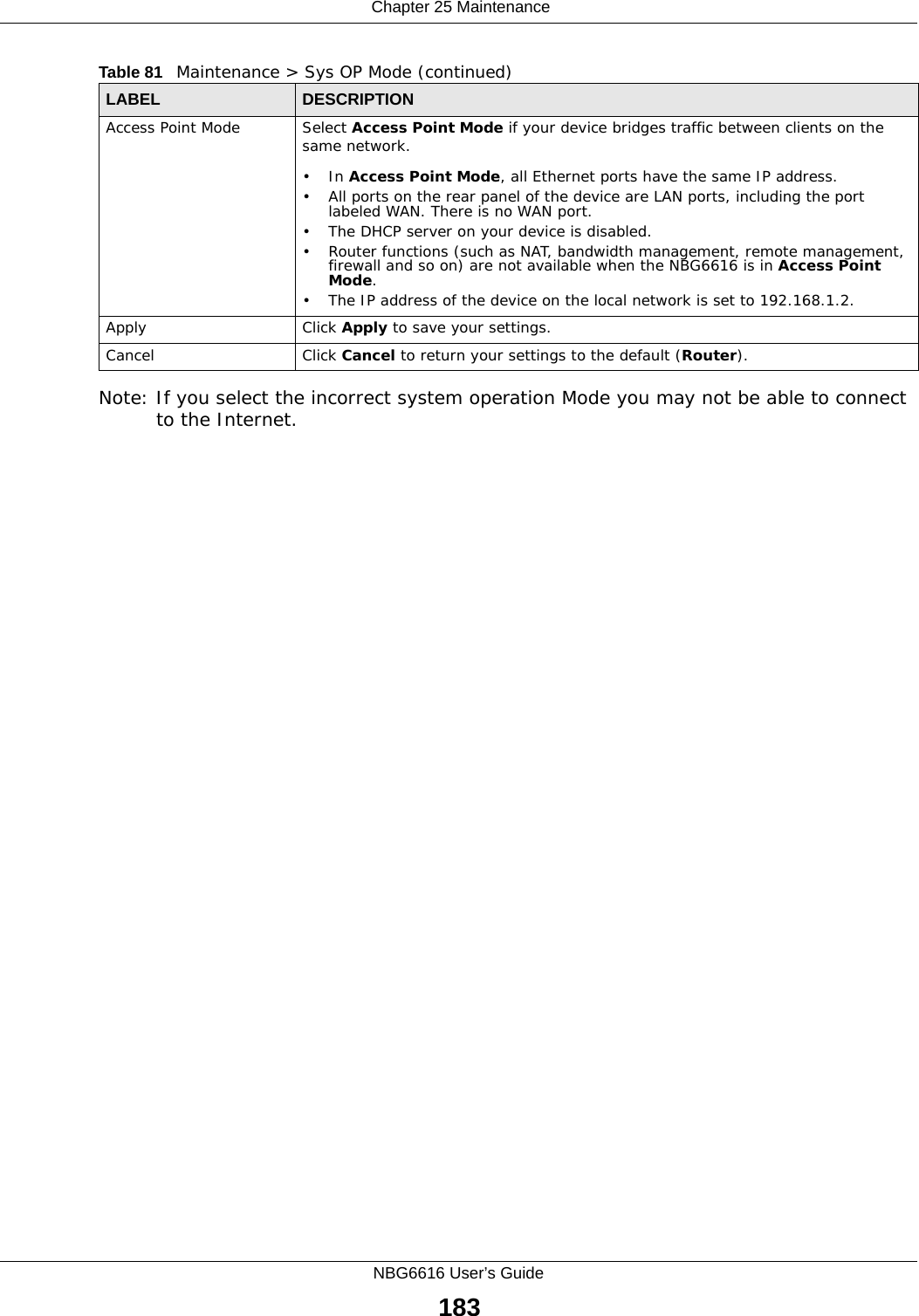
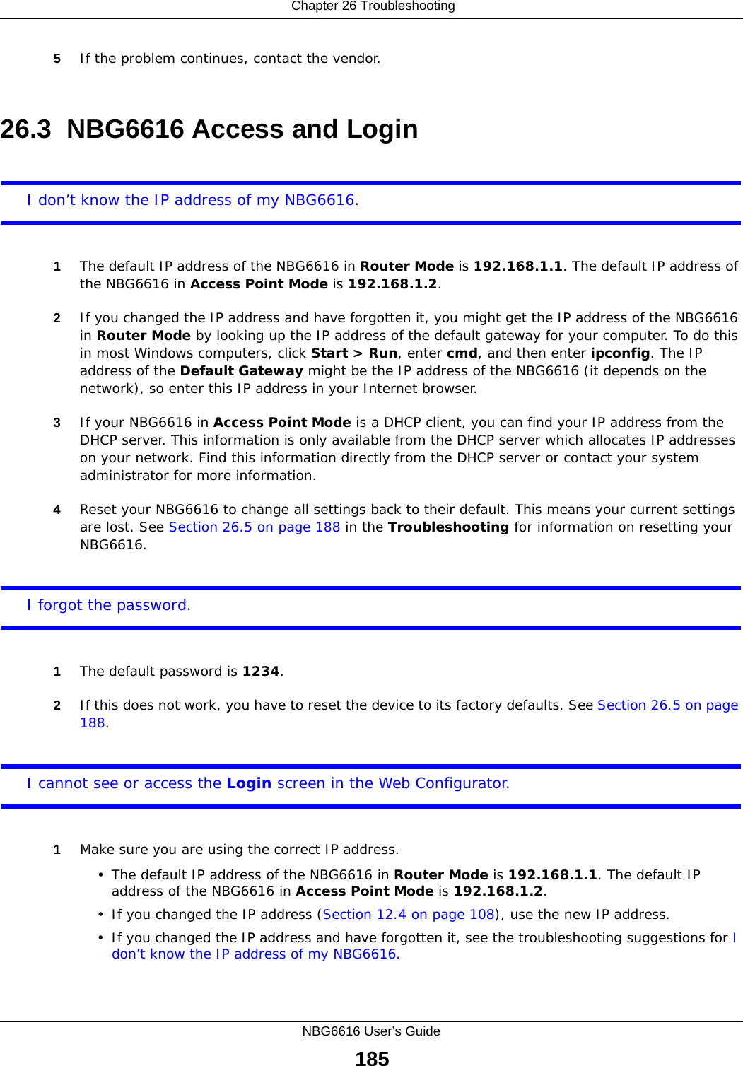
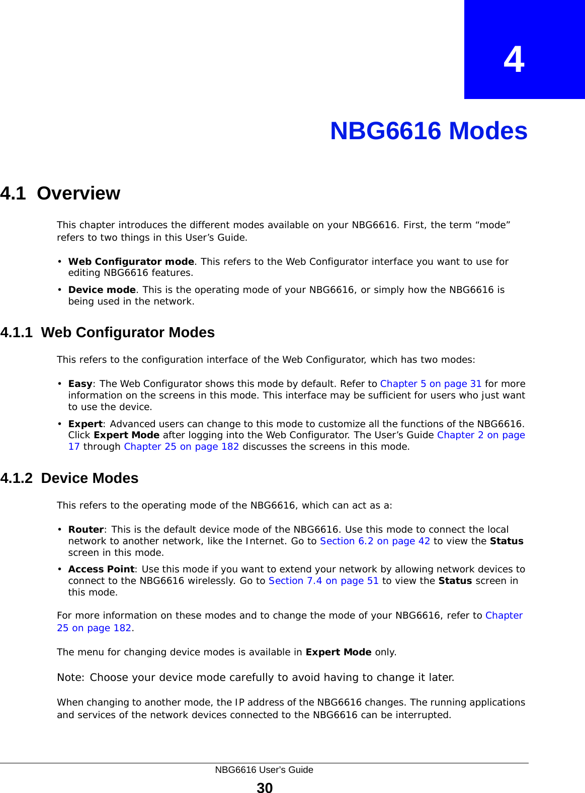
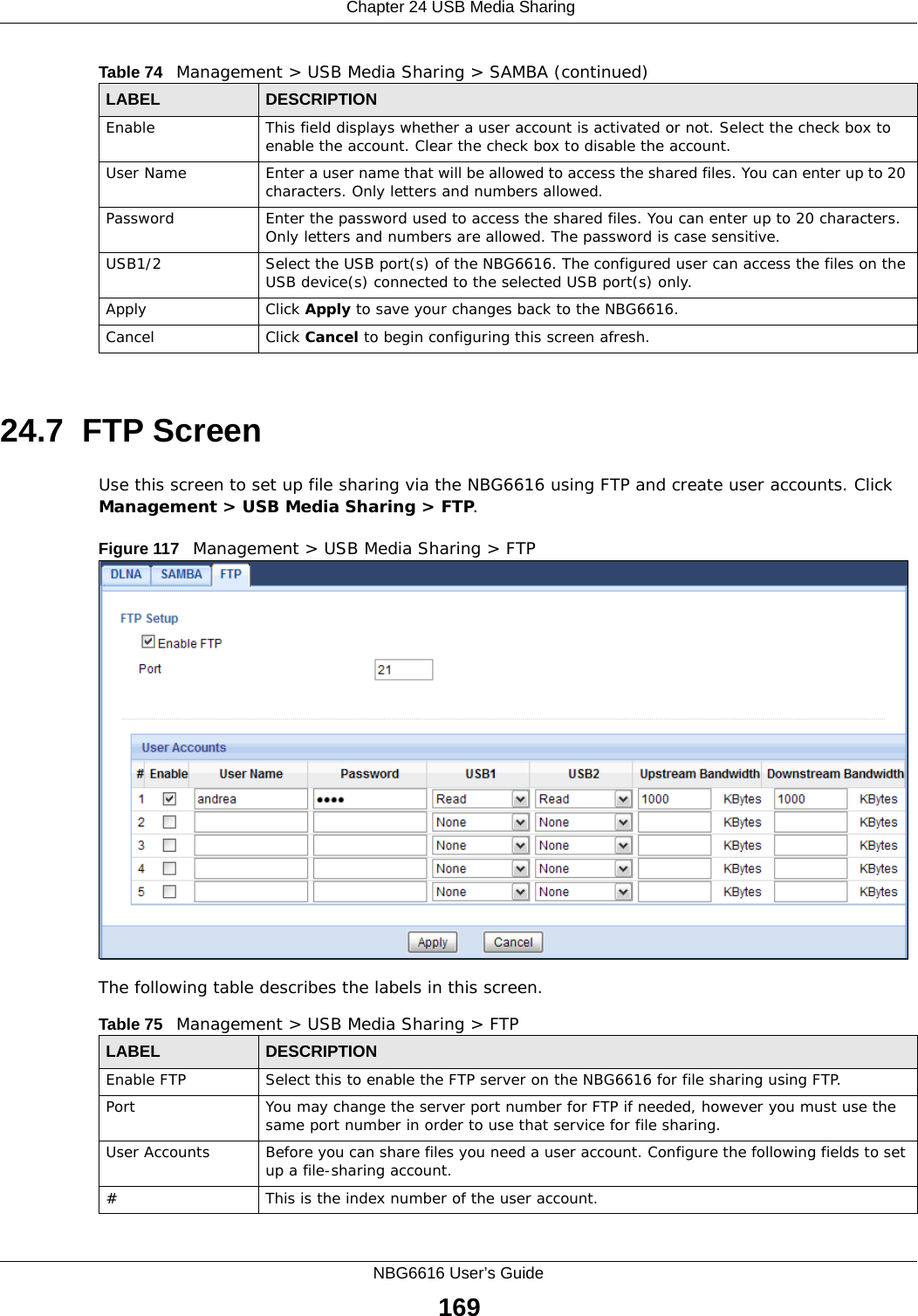
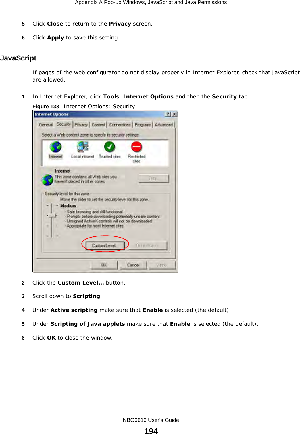
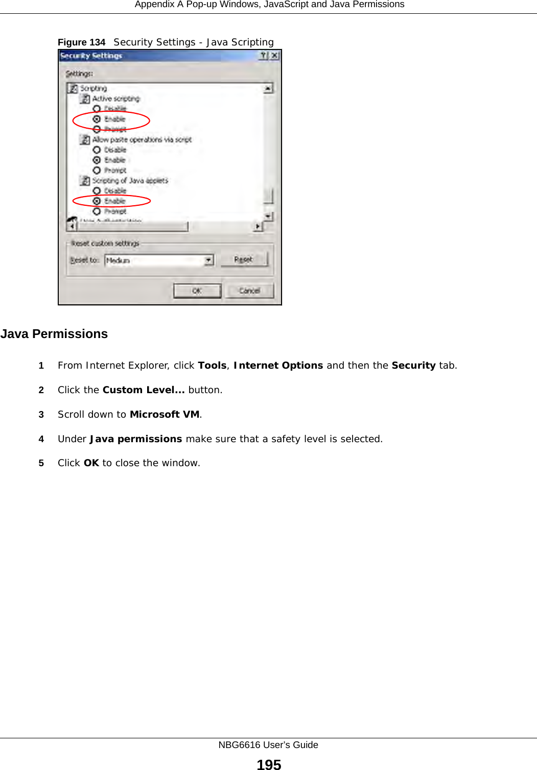
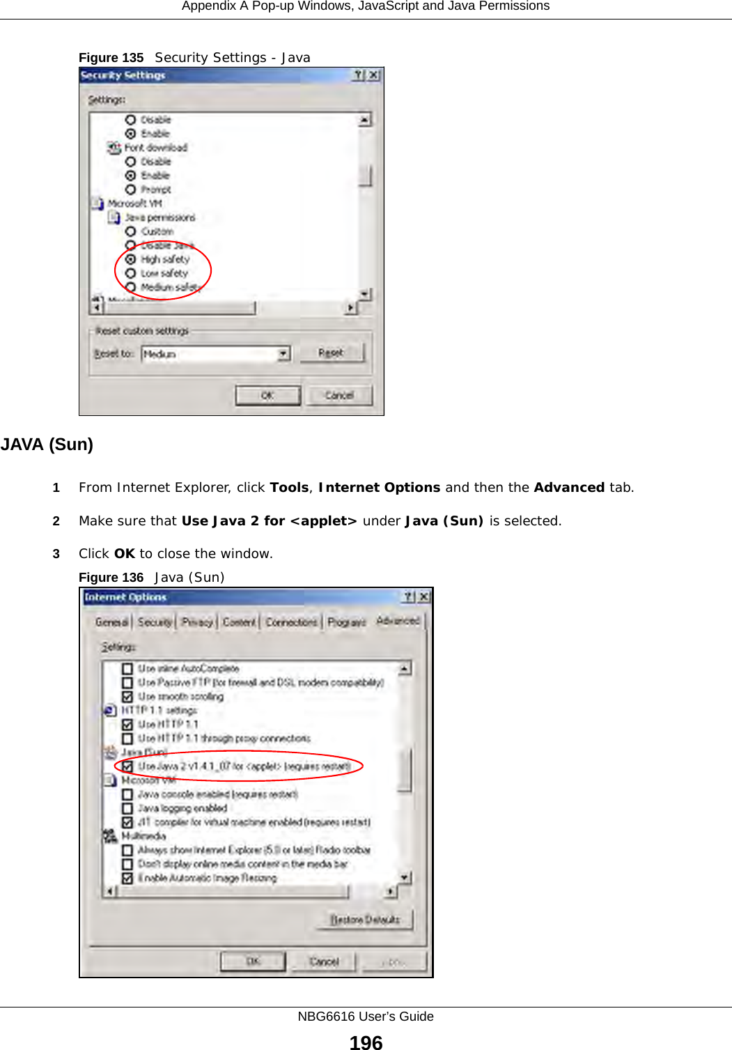
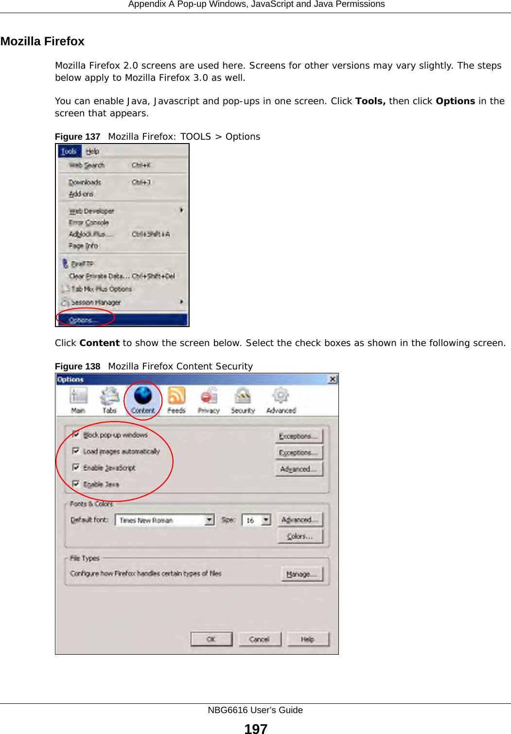
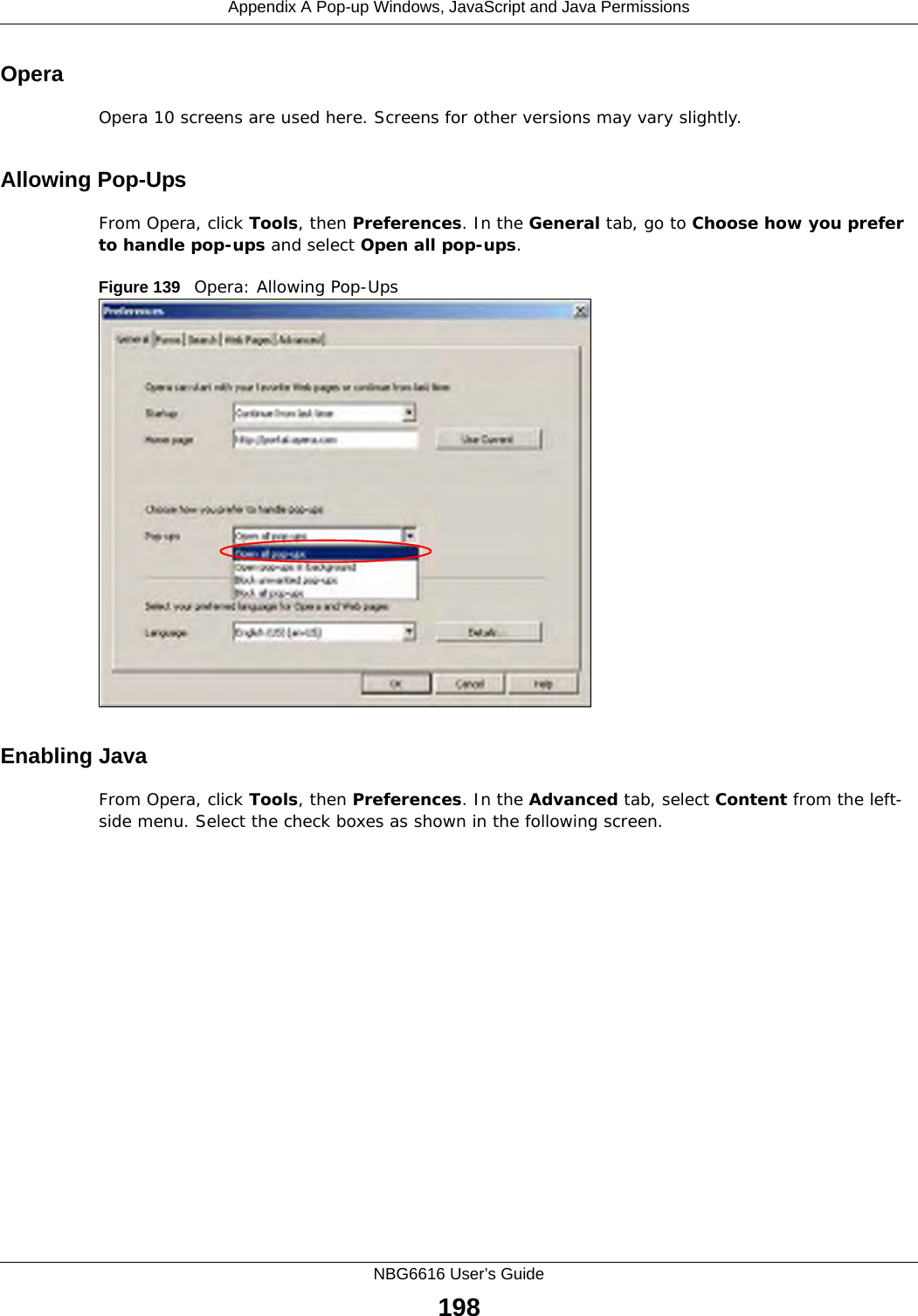
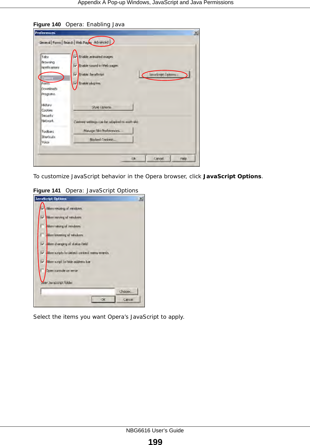
![Chapter 26 TroubleshootingNBG6616 User’s Guide1862Check the hardware connections, and make sure the LEDs are behaving as expected. See the Quick Start Guide. 3Make sure your Internet browser does not block pop-up windows and has JavaScript and Java enabled. See Appendix A on page 191.4Make sure your computer is in the same subnet as the NBG6616. (If you know that there are routers between your computer and the NBG6616, skip this step.)• If there is a DHCP server on your network, make sure your computer is using a dynamic IP address. See Section 12.4 on page 108. • If there is no DHCP server on your network, make sure your computer’s IP address is in the same subnet as the NBG6616. See Section 12.4 on page 108.5Reset the device to its factory defaults, and try to access the NBG6616 with the default IP address. See Section 1.5 on page 13.6If the problem continues, contact the network administrator or vendor, or try one of the advanced suggestions.Advanced Suggestions• Try to access the NBG6616 using another service, such as Telnet. If you can access the NBG6616, check the remote management settings and firewall rules to find out why the NBG6616 does not respond to HTTP.• If your computer is connected to the WAN port or is connected wirelessly, use a computer that is connected to a LAN/ETHERNET port.I can see the Login screen, but I cannot log in to the NBG6616.1Make sure you have entered the password correctly. The default password is 1234. This field is case-sensitive, so make sure [Caps Lock] is not on. 2This can happen when you fail to log out properly from your last session. Try logging in again after 5 minutes.3Disconnect and re-connect the power adaptor or cord to the NBG6616. 4If this does not work, you have to reset the device to its factory defaults. See Section 26.5 on page 188.26.4 Internet AccessI cannot access the Internet.](https://usermanual.wiki/ZyXEL-Communications/NBG6616/User-Guide-2392470-Page-186.png)
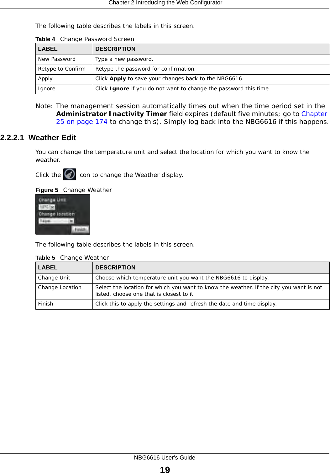
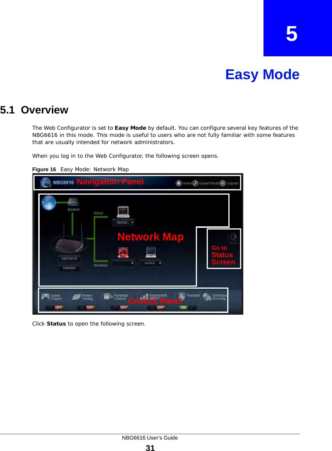
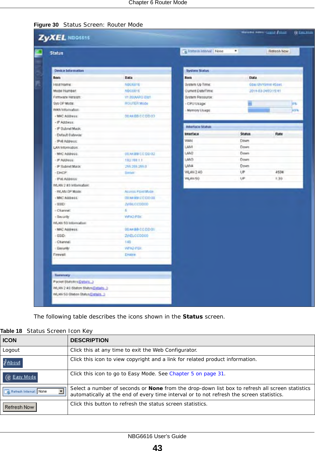
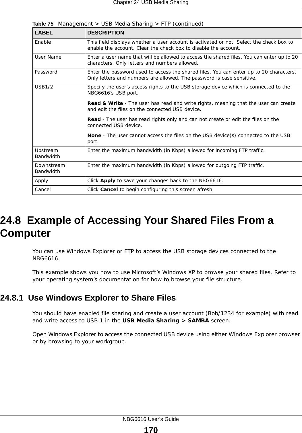
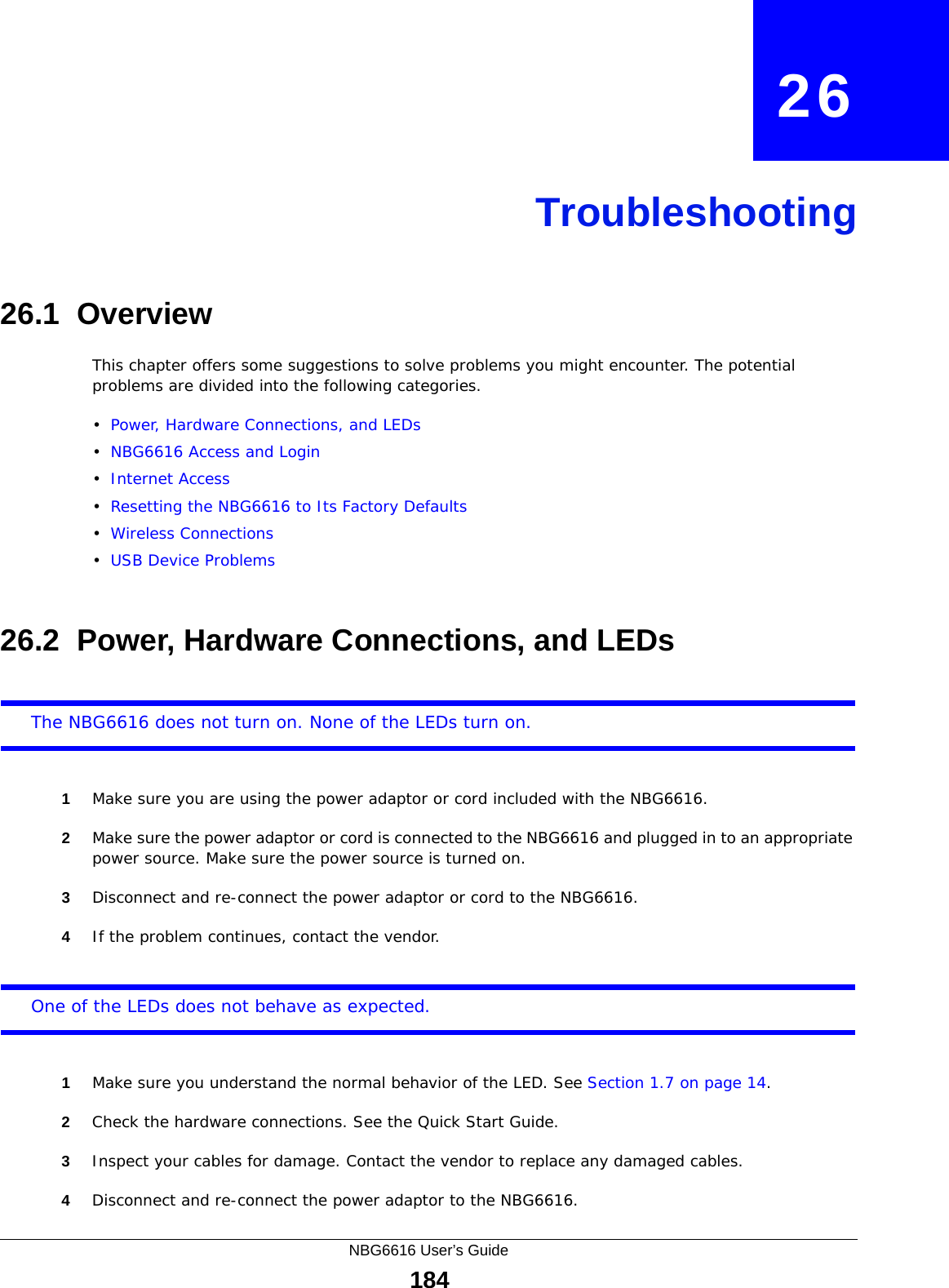
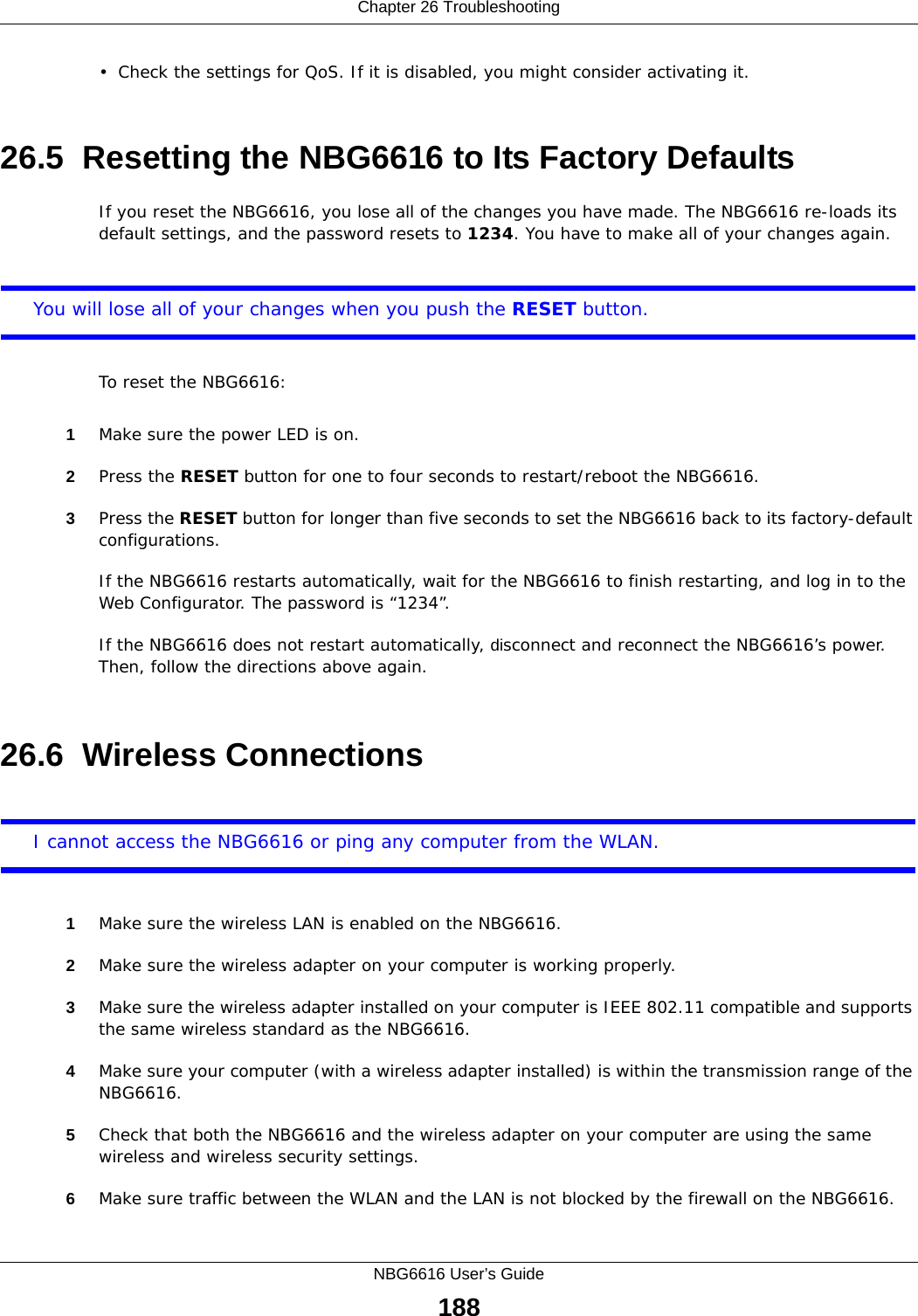
![Chapter 26 TroubleshootingNBG6616 User’s Guide1871Check the hardware connections, and make sure the LEDs are behaving as expected. See the Quick Start Guide.2Go to Maintenance > Sys OP Mode. Check your System Operation Mode setting. • If the NBG6616 is in Router Mode, make sure the WAN port is connected to a broadband modem or router with Internet access. Your computer and the NBG6616 should be in the same subnet.• If the NBG6616 is in Access Point Mode, make sure the WAN port is connected to a broadband modem or router with Internet access and your computer is set to obtain an dynamic IP address.3If the NBG6616 is in Router Mode, make sure you entered your ISP account information correctly in the wizard or the WAN screen. These fields are case-sensitive, so make sure [Caps Lock] is not on.4If you are trying to access the Internet wirelessly, make sure the wireless settings in the wireless client are the same as the settings in the AP.5Disconnect all the cables from your device, and follow the directions in the Quick Start Guide again. 6If the problem continues, contact your ISP.I cannot access the Internet anymore. I had access to the Internet (with the NBG6616), but my Internet connection is not available anymore.1Check the hardware connections, and make sure the LEDs are behaving as expected. See the Quick Start Guide and Section 1.7 on page 14. 2Reboot the NBG6616.3If the problem continues, contact your ISP. The Internet connection is slow or intermittent.1There might be a lot of traffic on the network. Look at the LEDs, and check Section 1.7 on page 14. If the NBG6616 is sending or receiving a lot of information, try closing some programs that use the Internet, especially peer-to-peer applications.2Check the signal strength. If the signal strength is low, try moving the NBG6616 closer to the AP if possible, and look around to see if there are any devices that might be interfering with the wireless network (for example, microwaves, other wireless networks, and so on).3Reboot the NBG6616.4If the problem continues, contact the network administrator or vendor, or try one of the advanced suggestions.Advanced Suggestion](https://usermanual.wiki/ZyXEL-Communications/NBG6616/User-Guide-2392470-Page-187.png)
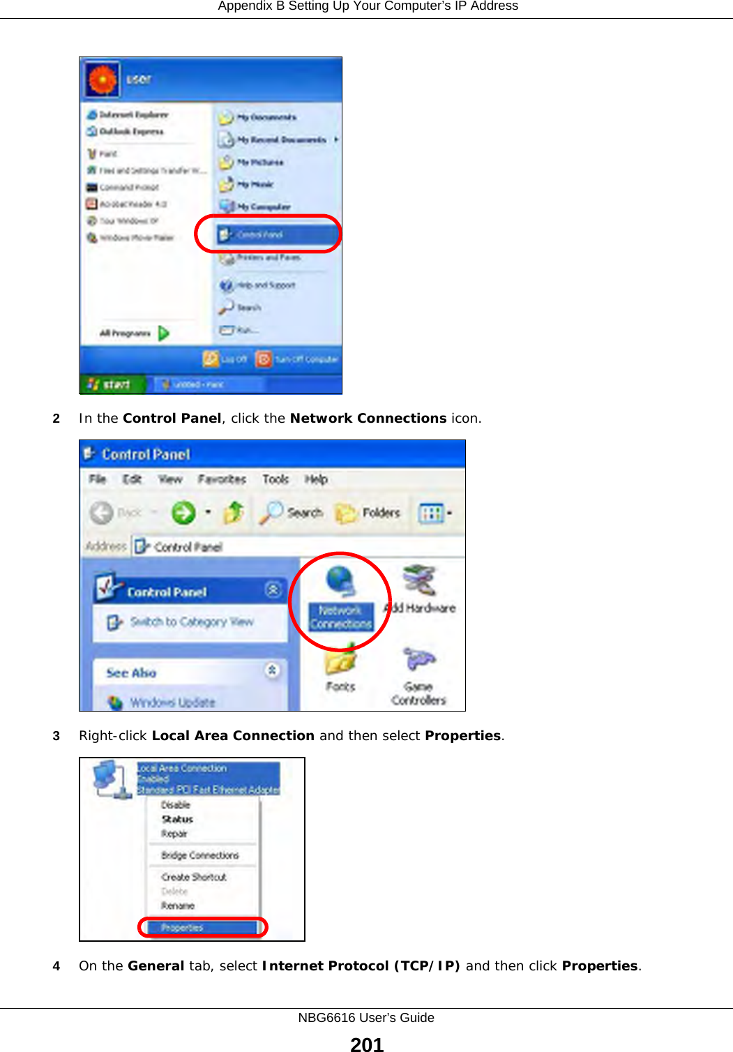
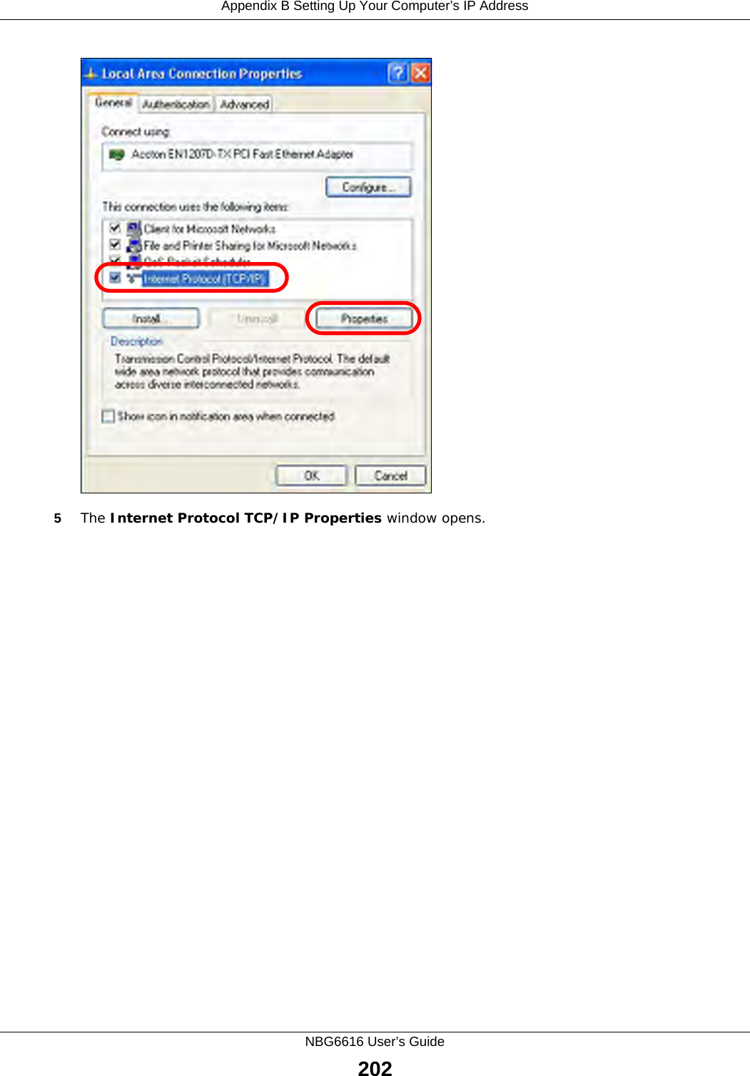
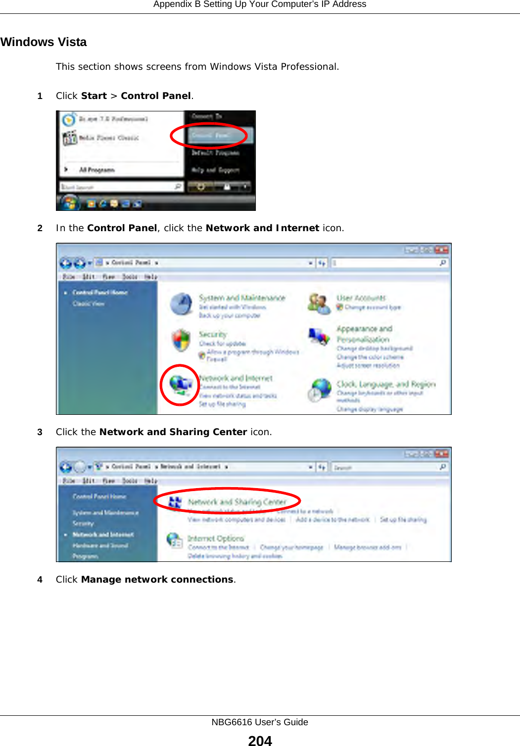
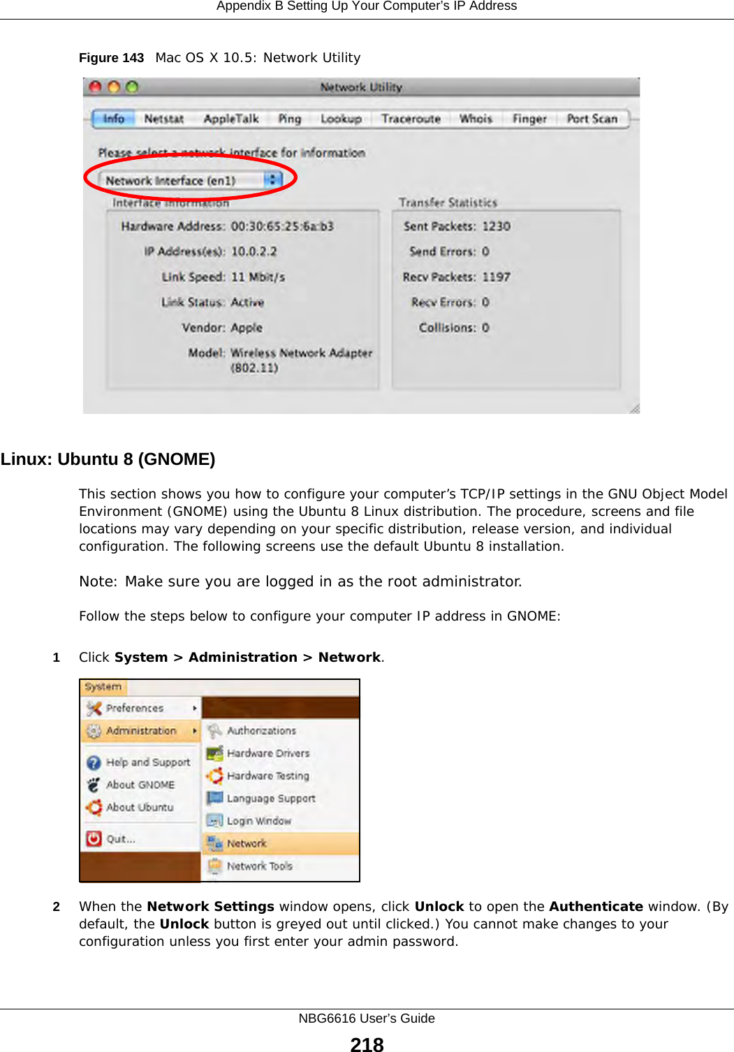
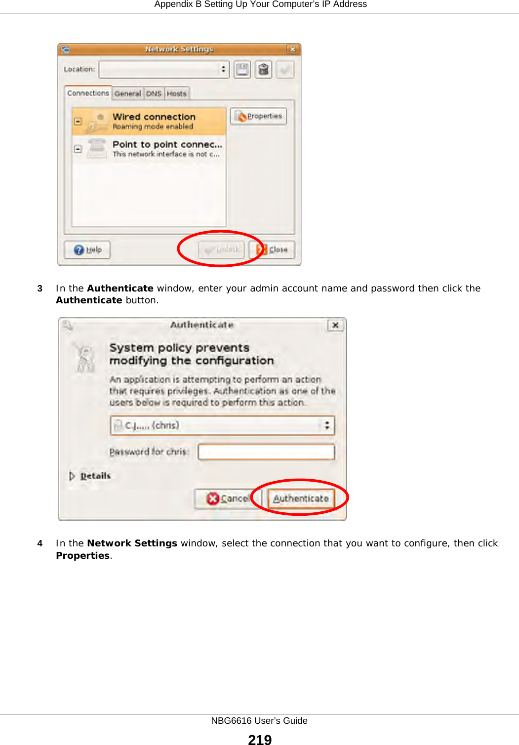
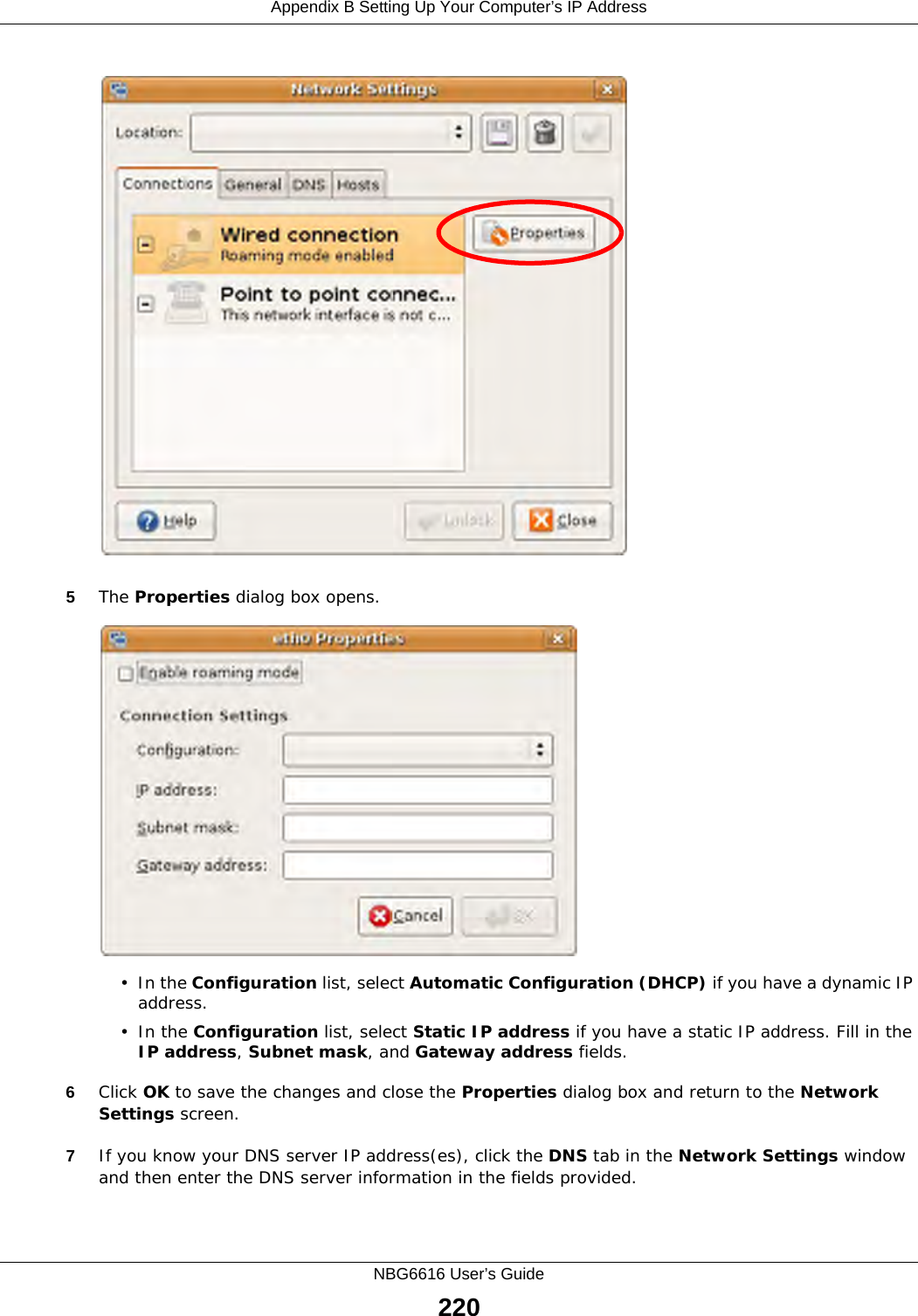
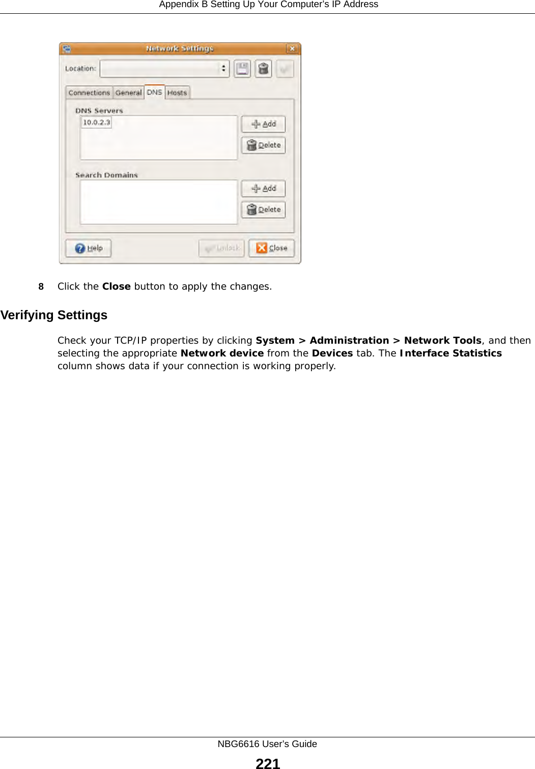
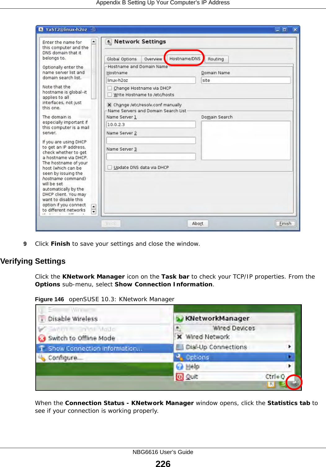
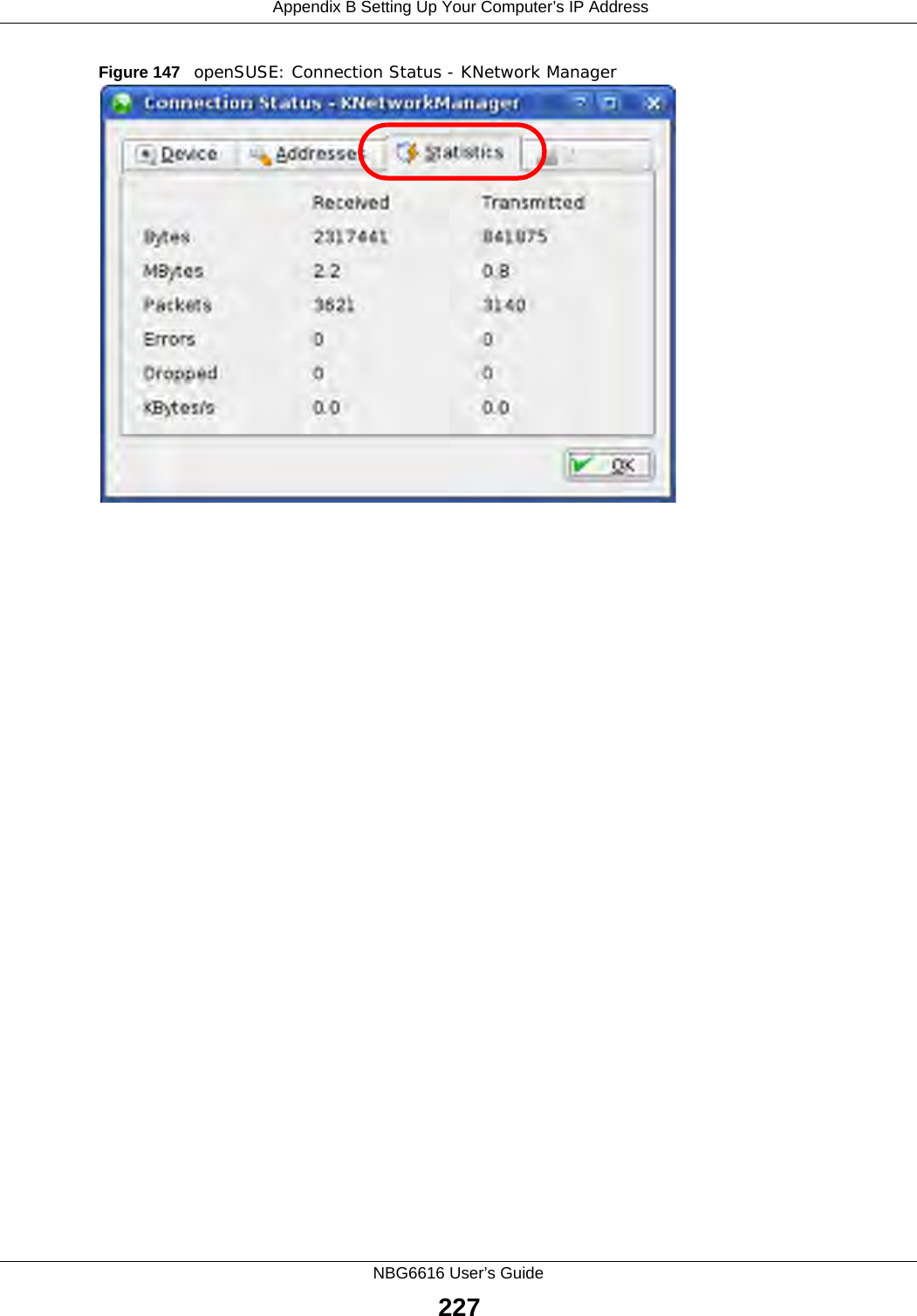
![Appendix B Setting Up Your Computer’s IP AddressNBG6616 User’s Guide2036Select Obtain an IP address automatically if your network administrator or ISP assigns your IP address dynamically.Select Use the following IP Address and fill in the IP address, Subnet mask, and Default gateway fields if you have a static IP address that was assigned to you by your network administrator or ISP. You may also have to enter a Preferred DNS server and an Alternate DNS server, if that information was provided.7Click OK to close the Internet Protocol (TCP/IP) Properties window.8Click OK to close the Local Area Connection Properties window.Verifying Settings1Click Start > All Programs > Accessories > Command Prompt.2In the Command Prompt window, type "ipconfig" and then press [ENTER]. You can also go to Start > Control Panel > Network Connections, right-click a network connection, click Status and then click the Support tab to view your IP address and connection information.](https://usermanual.wiki/ZyXEL-Communications/NBG6616/User-Guide-2392470-Page-203.png)
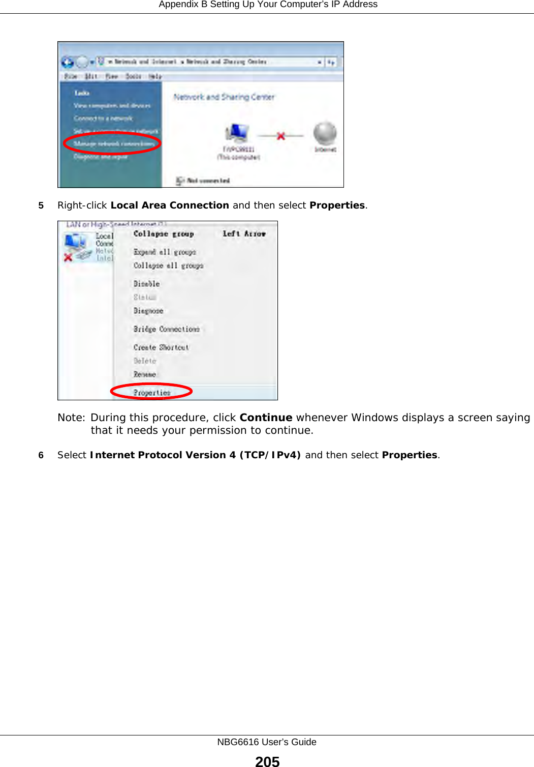
![Appendix B Setting Up Your Computer’s IP AddressNBG6616 User’s Guide2078Select Obtain an IP address automatically if your network administrator or ISP assigns your IP address dynamically.Select Use the following IP Address and fill in the IP address, Subnet mask, and Default gateway fields if you have a static IP address that was assigned to you by your network administrator or ISP. You may also have to enter a Preferred DNS server and an Alternate DNS server, if that information was provided.Click Advanced.9Click OK to close the Internet Protocol (TCP/IP) Properties window.10 Click OK to close the Local Area Connection Properties window.Verifying Settings1Click Start > All Programs > Accessories > Command Prompt.2In the Command Prompt window, type "ipconfig" and then press [ENTER]. You can also go to Start > Control Panel > Network Connections, right-click a network connection, click Status and then click the Support tab to view your IP address and connection information.](https://usermanual.wiki/ZyXEL-Communications/NBG6616/User-Guide-2392470-Page-207.png)
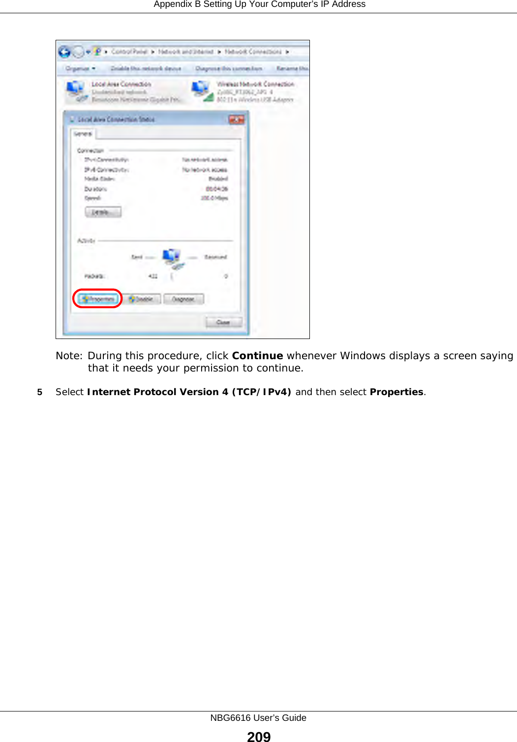
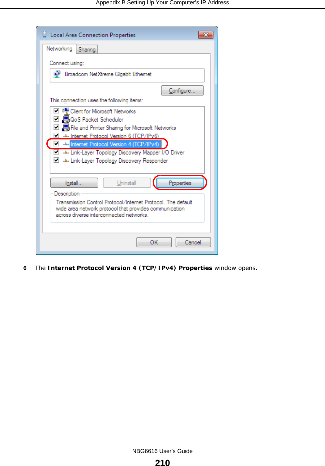
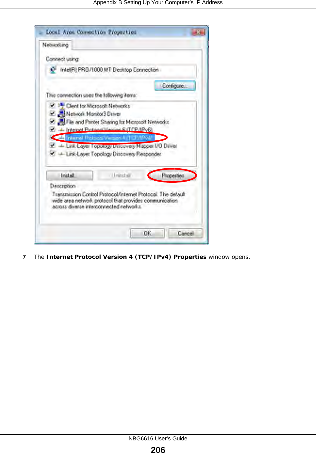
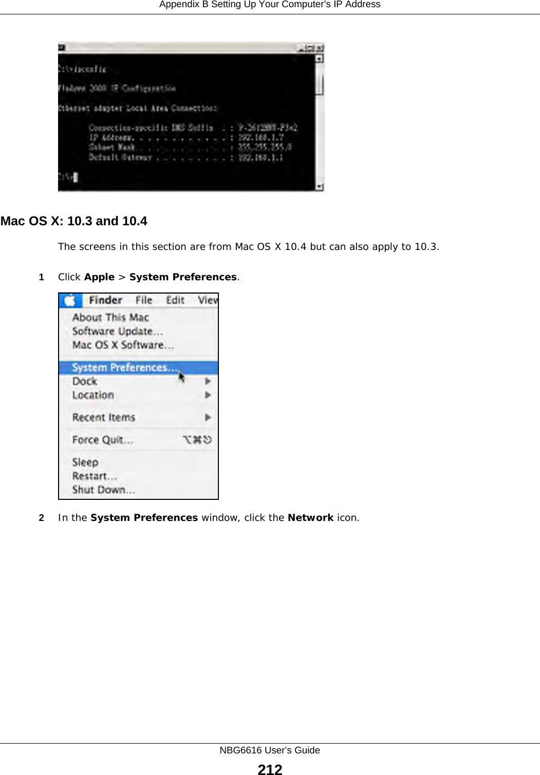
![Appendix B Setting Up Your Computer’s IP AddressNBG6616 User’s Guide2117Select Obtain an IP address automatically if your network administrator or ISP assigns your IP address dynamically.Select Use the following IP Address and fill in the IP address, Subnet mask, and Default gateway fields if you have a static IP address that was assigned to you by your network administrator or ISP. You may also have to enter a Preferred DNS server and an Alternate DNS server, if that information was provided. Click Advanced if you want to configure advanced settings for IP, DNS and WINS. 8Click OK to close the Internet Protocol (TCP/IP) Properties window.9Click OK to close the Local Area Connection Properties window.Verifying Settings1Click Start > All Programs > Accessories > Command Prompt.2In the Command Prompt window, type "ipconfig" and then press [ENTER]. 3The IP settings are displayed as follows.](https://usermanual.wiki/ZyXEL-Communications/NBG6616/User-Guide-2392470-Page-211.png)
![Appendix D Legal InformationNBG6616 User’s Guide232第十四條 低功率射頻電機之使用不得影響飛航安全及干擾合法通信;經發現有干擾現象時,應立即停用,並改善至無干擾時方得繼續使用。前項合法通信,指依電信規定作業之無線電信。低功率射頻電機須忍受合法通信或工業、科學及醫療用電波輻射性電機設備之干擾。 在 5.25 - 5.35 GHz 頻帶內操作之無線資訊傳輸設備,限於室內使用。電磁波曝露量 MPE 標準值 1mW/cm2,本產品使用時建議應距離人體 21 cm。Notices Changes or modifications not expressly approved by the party responsible for compliance could void the user's authority to operate the equipment.This Class B digital apparatus complies with Canadian ICES-003.Cet appareil numérique de la classe B est conforme à la norme NMB-003 du Canada.Viewing Certifications Go to http://www.zyxel.com to view this product’s documentation and certifications.ZyXEL Limited Warranty ZyXEL warrants to the original end user (purchaser) that this product is free from any defects in material or workmanship for a specific period (the Warranty Period) from the date of purchase. The Warranty Period varies by region. Check with your vendor and/or the authorized ZyXEL local distributor for details about the Warranty Period of this product. During the warranty period, and upon proof of purchase, should the product have indications of failure due to faulty workmanship and/or materials, ZyXEL will, at its discretion, repair or replace the defective products or components without charge for either parts or labor, and to whatever extent it shall deem necessary to restore the product or components to proper operating condition. Any replacement will consist of a new or re-manufactured functionally equivalent product of equal or higher value, and will be solely at the discretion of ZyXEL. This warranty shall not apply if the product has been modified, misused, tampered with, damaged by an act of God, or subjected to abnormal working conditions.NoteRepair or replacement, as provided under this warranty, is the exclusive remedy of the purchaser. This warranty is in lieu of all other warranties, express or implied, including any implied warranty of merchantability or fitness for a particular use or purpose. ZyXEL shall in no event be held liable for indirect or consequential damages of any kind to the purchaser.To obtain the services of this warranty, contact your vendor. You may also refer to the warranty policy for the region in which you bought the device at http://www.zyxel.com/web/support_warranty_info.php.RegistrationRegister your product online to receive e-mail notices of firmware upgrades and information at www.zyxel.com for global products, or at www.us.zyxel.com for North American products.Open Source Licenses This product contains in part some free software distributed under GPL license terms and/or GPL like licenses. Open source licenses are provided with the firmware package. You can download the latest firmware at www.zyxel.com. To obtain the source code covered under those Licenses, please contact support@zyxel.com.tw to get it. Regulatory Information European UnionThe following information applies if you use the product within the European Union. Declaration of Conformity with Regard to EU Directive 1999/5/EC (R&TTE Directive)Compliance Information for 2.4GHz and 5GHz Wireless Products Relevant to the EU and Other Countries Following the EU Directive 1999/5/EC (R&TTE Directive) [Czech] ZyXEL tímto prohlašuje, že tento zařízení je ve shodě se základními požadavky a dalšími příslušnými ustanoveními směrnice 1999/5/EC.[Danish] Undertegnede ZyXEL erklærer herved, at følgende udstyr udstyr overholder de væsentlige krav og øvrige relevante krav i direktiv 1999/5/EF.[German] Hiermit erklärt ZyXEL, dass sich das Gerät Ausstattung in Übereinstimmung mit den grundlegenden Anforderungen und den übrigen einschlägigen Bestimmungen der Richtlinie 1999/5/EU befindet.[Estonian] Käesolevaga kinnitab ZyXEL seadme seadmed vastavust direktiivi 1999/5/EÜ põhinõuetele ja nimetatud direktiivist tulenevatele teistele asjakohastele sätetele.English Hereby, ZyXEL declares that this equipment is in compliance with the essential requirements and other relevant provisions of Directive 1999/5/EC.[Spanish] Por medio de la presente ZyXEL declara que el equipo cumple con los requisitos esenciales y cualesquiera otras disposiciones aplicables o exigibles de la Directiva 1999/5/CE.[Greek] ΜΕ ΤΗΝ ΠΑΡΟΥΣΑ ZyXEL ΔΗΛΩΝΕΙ ΟΤΙ εξοπλισμός ΣΥΜΜΟΡΦΩΝΕΤΑΙ ΠΡΟΣ ΤΙΣ ΟΥΣΙΩΔΕΙΣ ΑΠΑΙΤΗΣΕΙΣ ΚΑΙ ΤΙΣ ΛΟΙΠΕΣ ΣΧΕΤΙΚΕΣ ΔΙΑΤΑΞΕΙΣ ΤΗΣ ΟΔΗΓΙΑΣ 1999/5/ΕC.[French] Par la présente ZyXEL déclare que l'appareil équipements est conforme aux exigences essentielles et aux autres dispositions pertinentes de la directive 1999/5/EC.](https://usermanual.wiki/ZyXEL-Communications/NBG6616/User-Guide-2392470-Page-232.png)
![Appendix D Legal InformationNBG6616 User’s Guide233National RestrictionsThis product may be used in all EU countries (and other countries following the EU directive 1999/5/EC) without any limitation except for the countries mentioned below:Ce produit peut être utilisé dans tous les pays de l’UE (et dans tous les pays ayant transposés la directive 1999/5/CE) sans aucune limitation, excepté pour les pays mentionnés ci-dessous:Questo prodotto è utilizzabile in tutte i paesi EU (ed in tutti gli altri paesi che seguono le direttive EU 1999/5/EC) senza nessuna limitazione, eccetto per i paesii menzionati di seguito:Das Produkt kann in allen EU Staaten ohne Einschränkungen eingesetzt werden (sowie in anderen Staaten die der EU Direktive 1995/5/CE folgen) mit Außnahme der folgenden aufgeführten Staaten:In the majority of the EU and other European countries, the 2, 4- and 5-GHz bands have been made available for the use of wireless local area networks (LANs). Later in this document you will find an overview of countries inwhich additional restrictions or requirements or both are applicable.The requirements for any country may evolve. ZyXEL recommends that you check with the local authorities for the latest status of their national regulations for both the 2,4- and 5-GHz wireless LANs.The following countries have restrictions and/or requirements in addition to those given in the table labeled “Overview of Regulatory Requirements for Wireless LANs”:.BelgiumThe Belgian Institute for Postal Services and Telecommunications (BIPT) must be notified of any outdoor wireless link having a range exceeding 300 meters. Please check http://www.bipt.be for more details.Draadloze verbindingen voor buitengebruik en met een reikwijdte van meer dan 300 meter dienen aangemeld te worden bij het Belgisch Instituut voor postdiensten en telecommunicatie (BIPT). Zie http://www.bipt.be voor meer gegevens.[Italian] Con la presente ZyXEL dichiara che questo attrezzatura è conforme ai requisiti essenziali ed alle altre disposizioni pertinenti stabilite dalla direttiva 1999/5/CE.[Latvian] Ar šo ZyXEL deklarē, ka iekārtas atbilst Direktīvas 1999/5/EK būtiskajām prasībām un citiem ar to saistītajiem noteikumiem.[Lithuanian] Šiuo ZyXEL deklaruoja, kad šis įranga atitinka esminius reikalavimus ir kitas 1999/5/EB Direktyvos nuostatas.[Dutch] Hierbij verklaart ZyXEL dat het toestel uitrusting in overeenstemming is met de essentiële eisen en de andere relevante bepalingen van richtlijn 1999/5/EC.[Maltese] Hawnhekk, ZyXEL, jiddikjara li dan tagħmir jikkonforma mal-ħtiġijiet essenzjali u ma provvedimenti oħrajn relevanti li hemm fid-Dirrettiva 1999/5/EC.[Hungarian] Alulírott, ZyXEL nyilatkozom, hogy a berendezés megfelel a vonatkozó alapvetõ követelményeknek és az 1999/5/EK irányelv egyéb elõírásainak.[Polish] Niniejszym ZyXEL oświadcza, że sprzęt jest zgodny z zasadniczymi wymogami oraz pozostałymi stosownymi postanowieniami Dyrektywy 1999/5/EC.[Portuguese] ZyXEL declara que este equipamento está conforme com os requisitos essenciais e outras disposições da Directiva 1999/5/EC.[Slovenian] ZyXEL izjavlja, da je ta oprema v skladu z bistvenimi zahtevami in ostalimi relevantnimi določili direktive 1999/5/EC.[Slovak] ZyXEL týmto vyhlasuje, že zariadenia spĺňa základné požiadavky a všetky príslušné ustanovenia Smernice 1999/5/EC.[Finnish] ZyXEL vakuuttaa täten että laitteet tyyppinen laite on direktiivin 1999/5/EY oleellisten vaatimusten ja sitä koskevien direktiivin muiden ehtojen mukainen.[Swedish] Härmed intygar ZyXEL att denna utrustning står I överensstämmelse med de väsentliga egenskapskrav och övriga relevanta bestämmelser som framgår av direktiv 1999/5/EC.[Bulgarian] С настоящото ZyXEL декларира, че това оборудване е в съответствие със съществените изисквания и другите приложими разпоредбите на Директива 1999/5/ЕC.[Icelandic] Hér með lýsir, ZyXEL því yfir að þessi búnaður er í samræmi við grunnkröfur og önnur viðeigandi ákvæði tilskipunar 1999/5/EC.[Norwegian] Erklærer herved ZyXEL at dette utstyret er I samsvar med de grunnleggende kravene og andre relevante bestemmelser I direktiv 1999/5/EF.[Romanian] Prin prezenta, ZyXEL declară că acest echipament este în conformitate cu cerinţele esenţiale şi alte prevederi relevante ale Directivei 1999/5/EC.Overview of Regulatory Requirements for Wireless LANs Frequency Band (MHz) Max Power Level(EIRP)1 (mW) Indoor ONLY Indoor and Outdoor 2400-2483.5 100 V 5150-5350 200 V 5470-5725 1000 V](https://usermanual.wiki/ZyXEL-Communications/NBG6616/User-Guide-2392470-Page-233.png)