ZyXEL Communications NBG6716 Simultaneous Dual-Band Wireless AC1750 HD Media Router User Manual Book
ZyXEL Communications Corporation Simultaneous Dual-Band Wireless AC1750 HD Media Router Book
Contents
- 1. User Manual Part 1.pdf
- 2. User Manual Part 2.pdf
User Manual Part 1.pdf
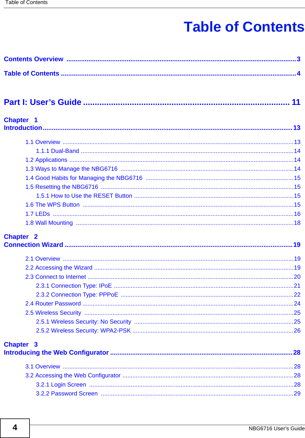
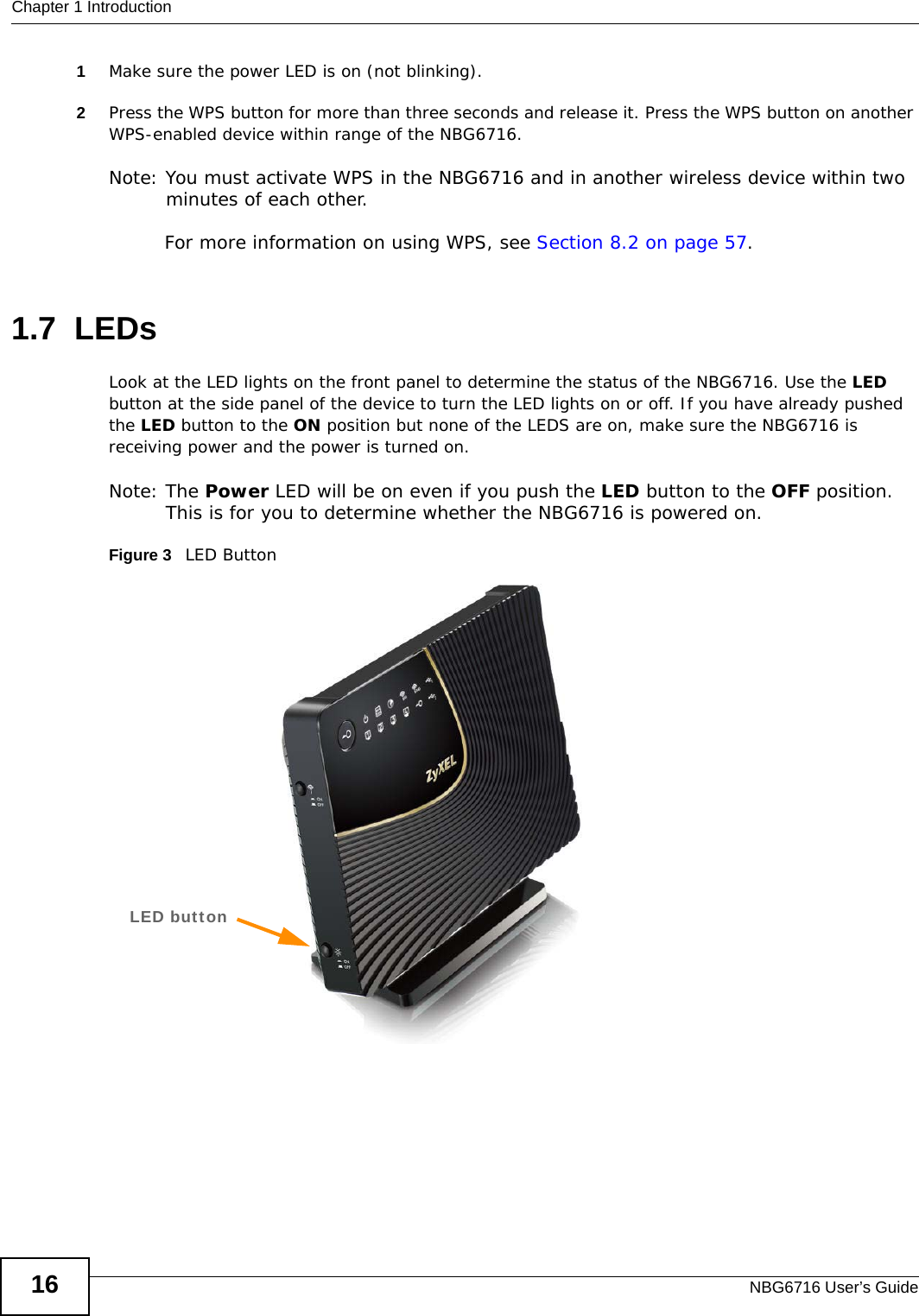

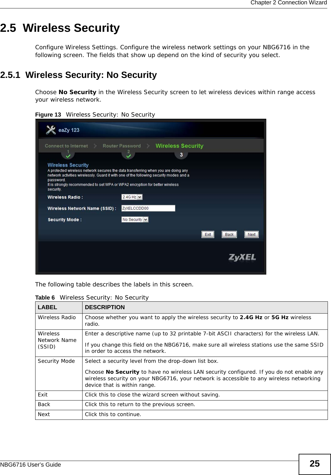
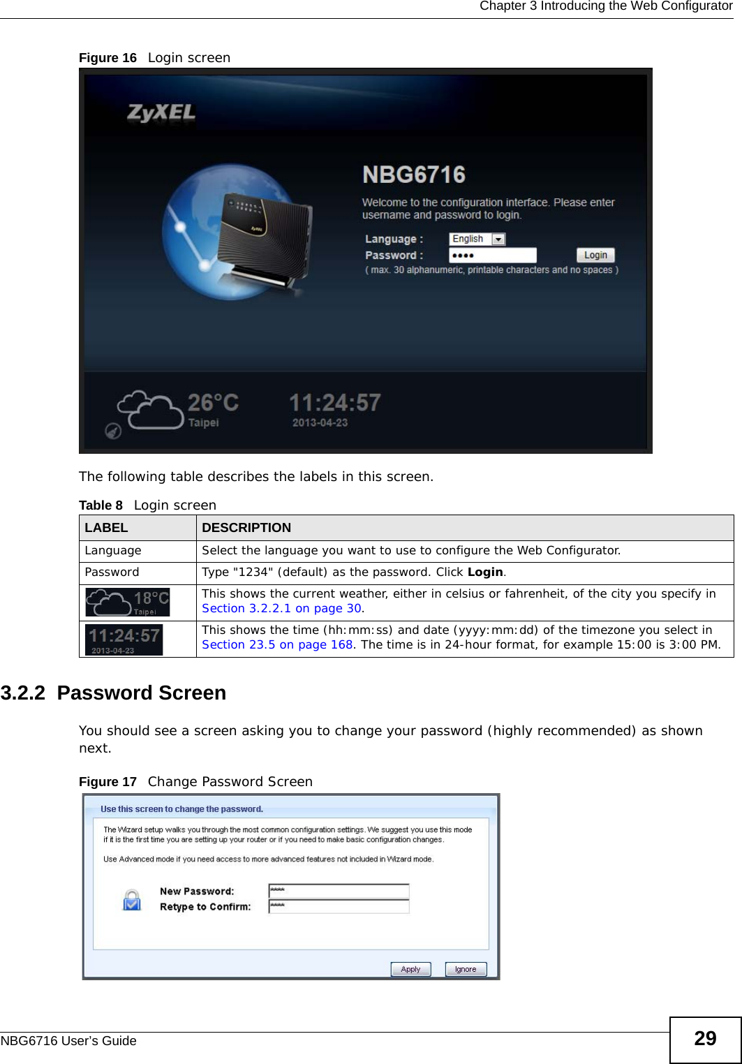
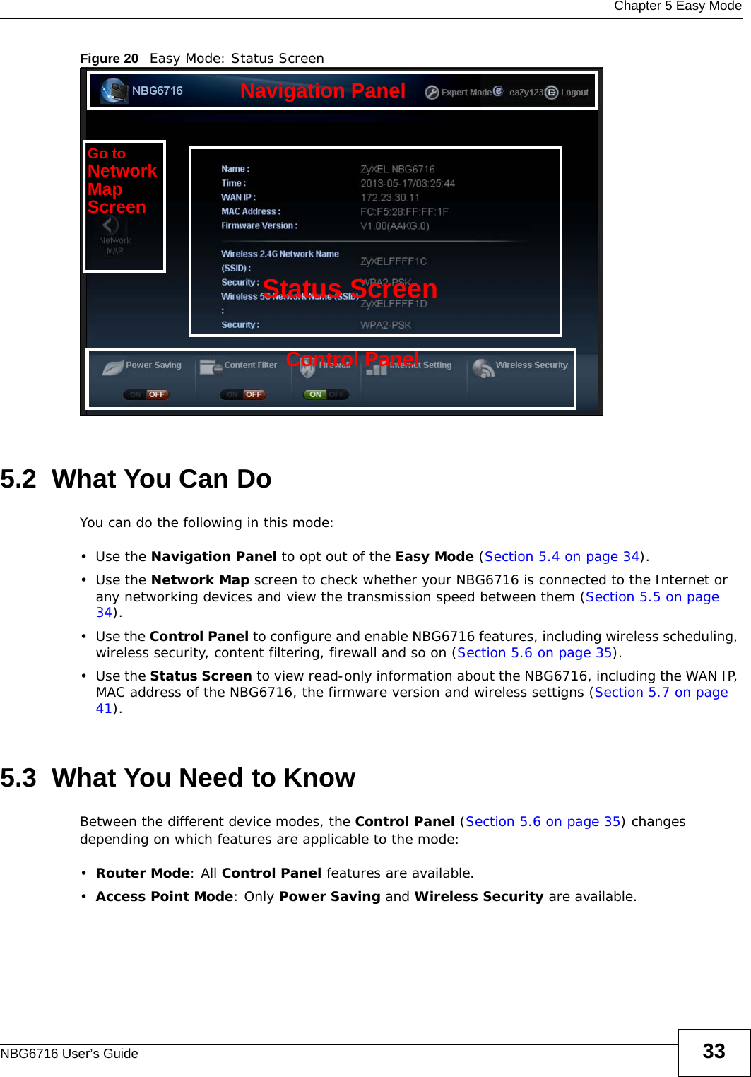
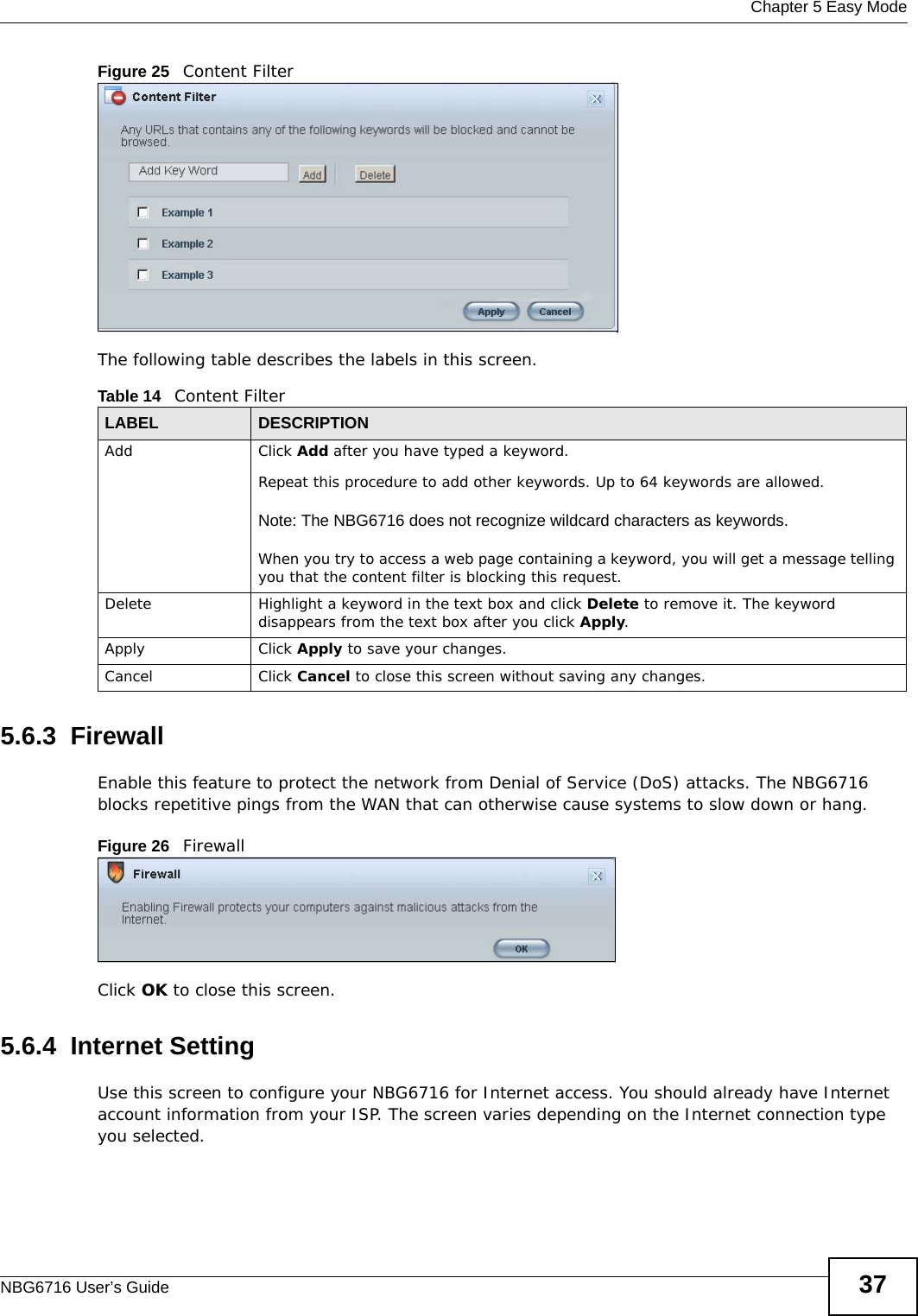
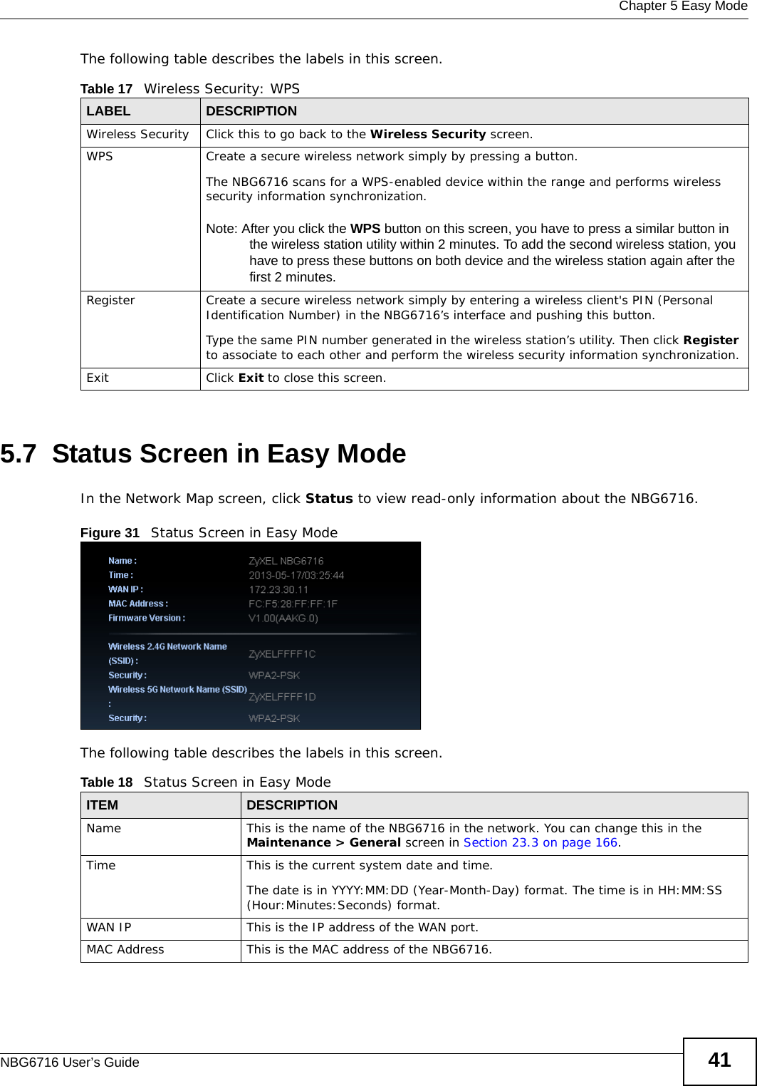
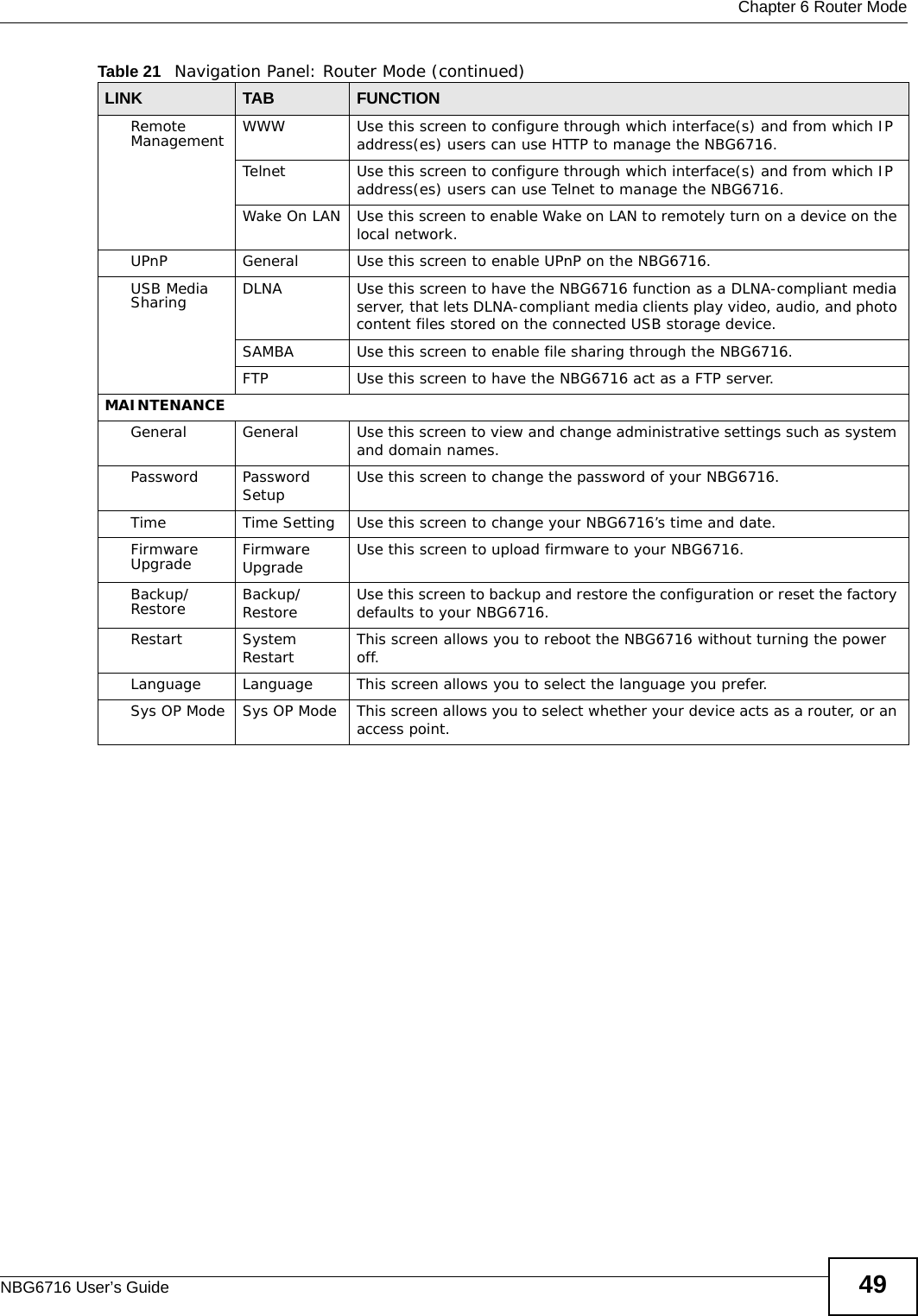
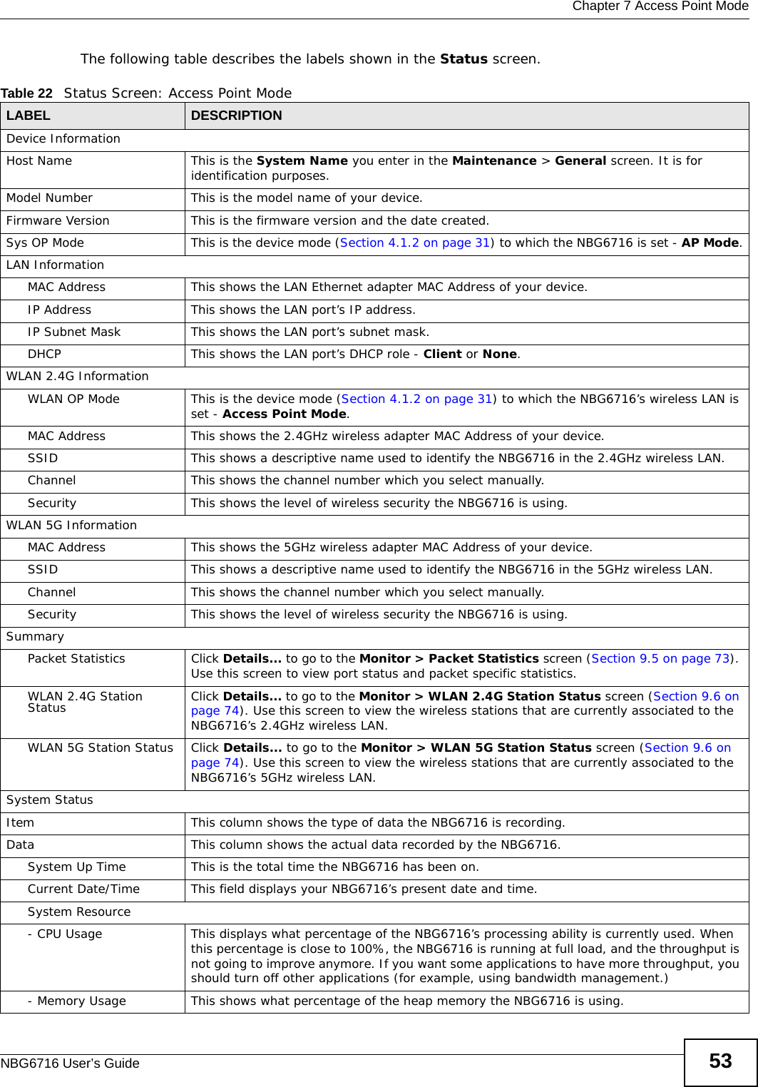
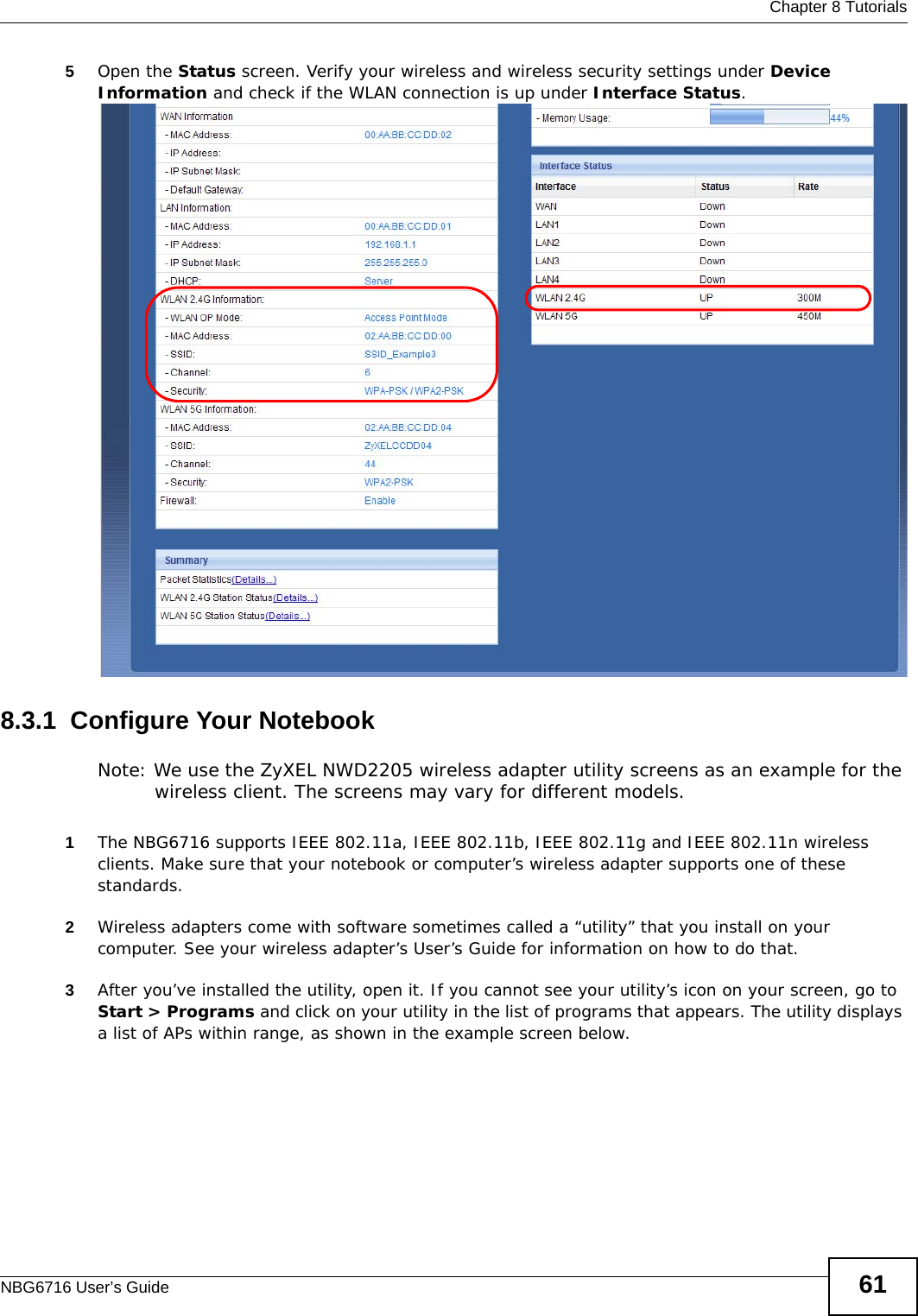
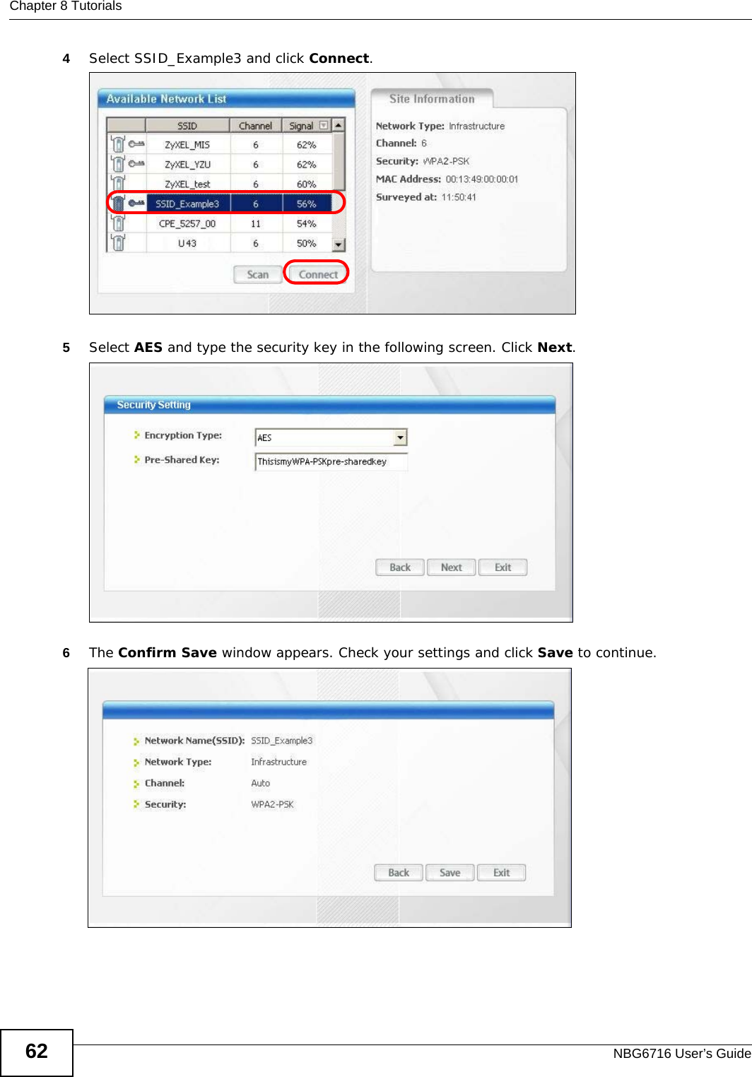
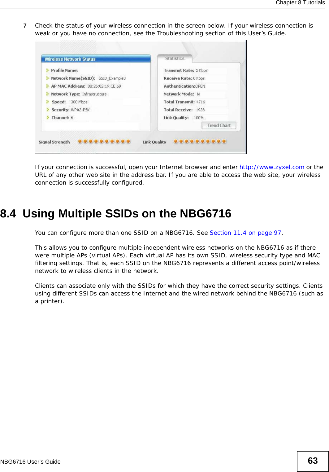
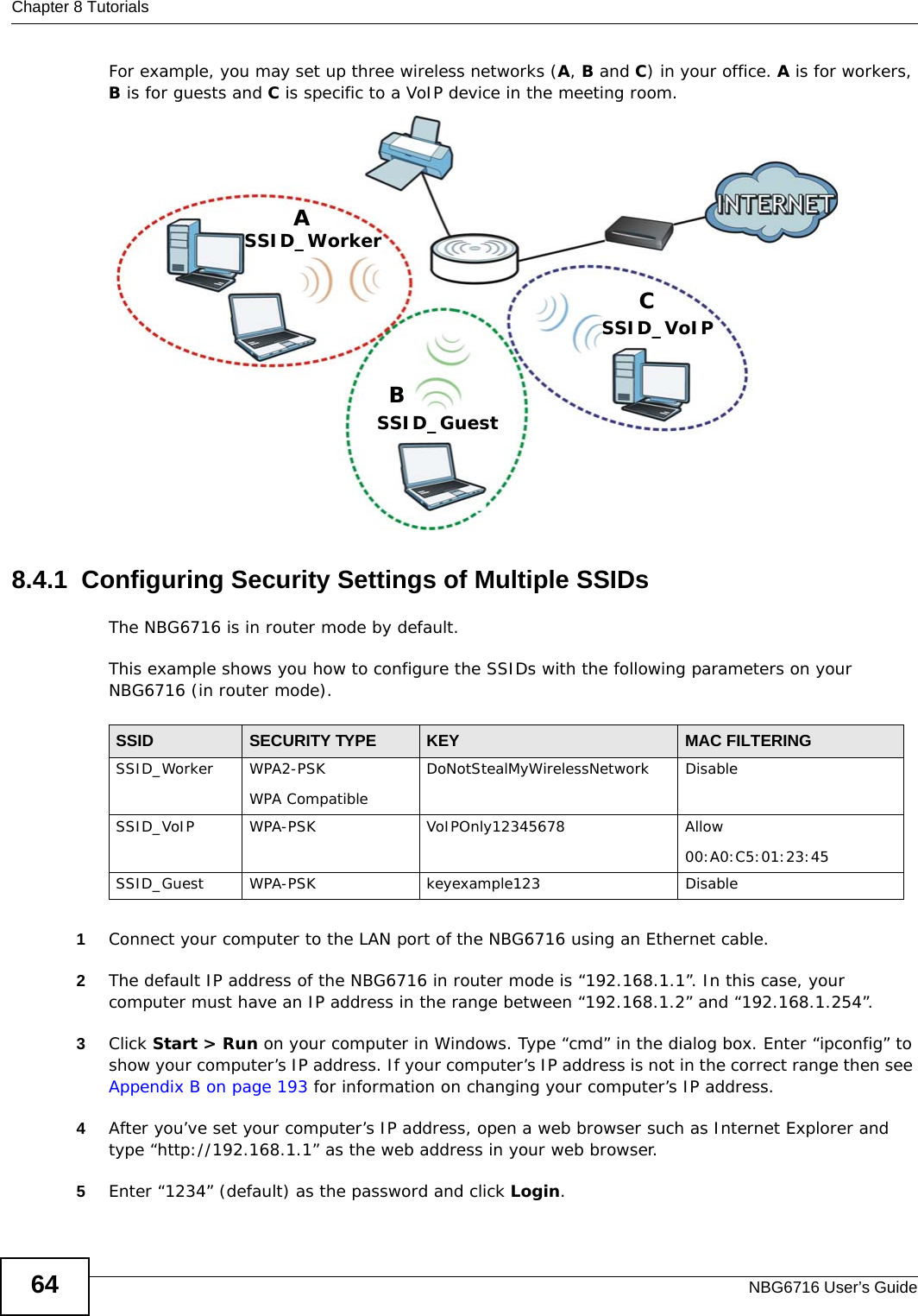

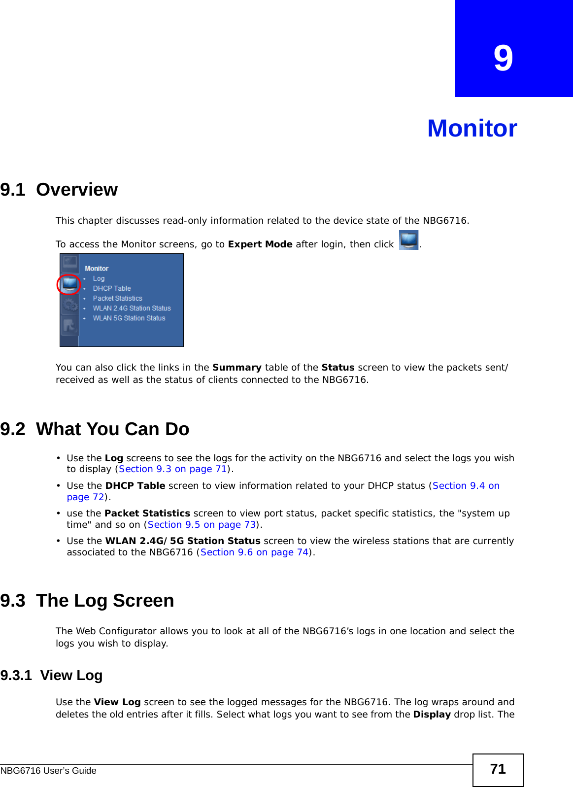
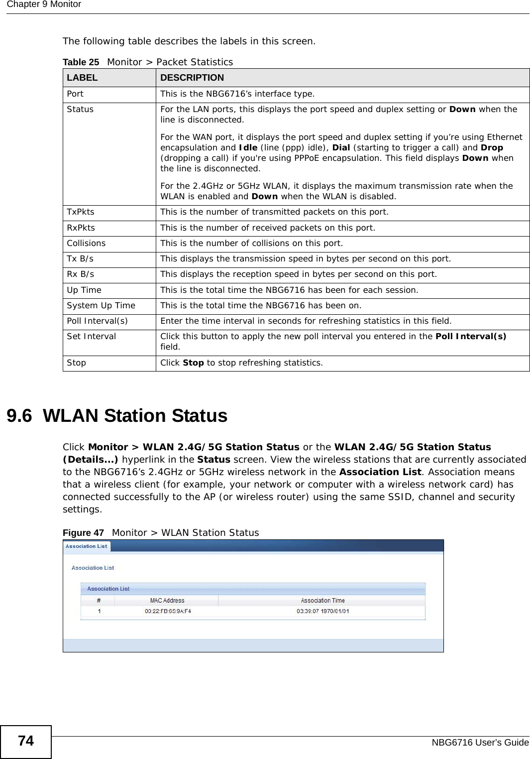
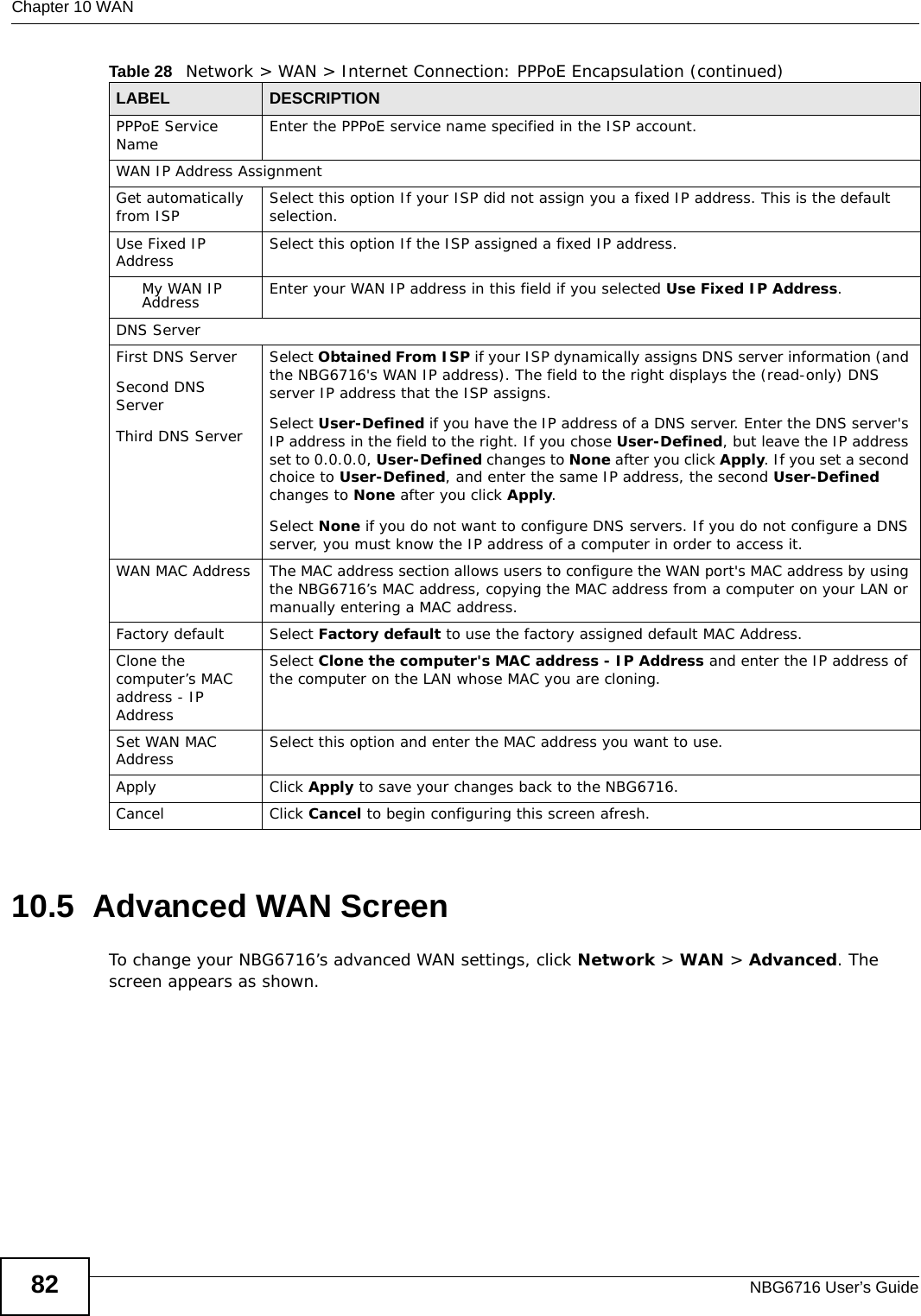
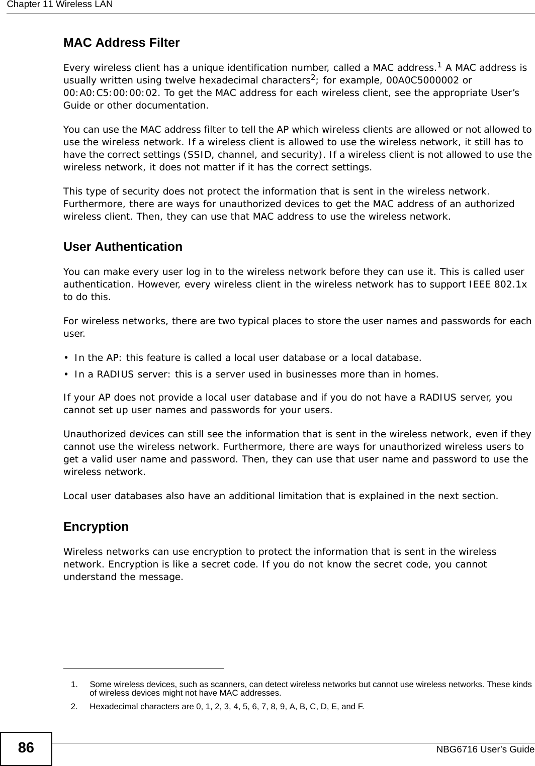
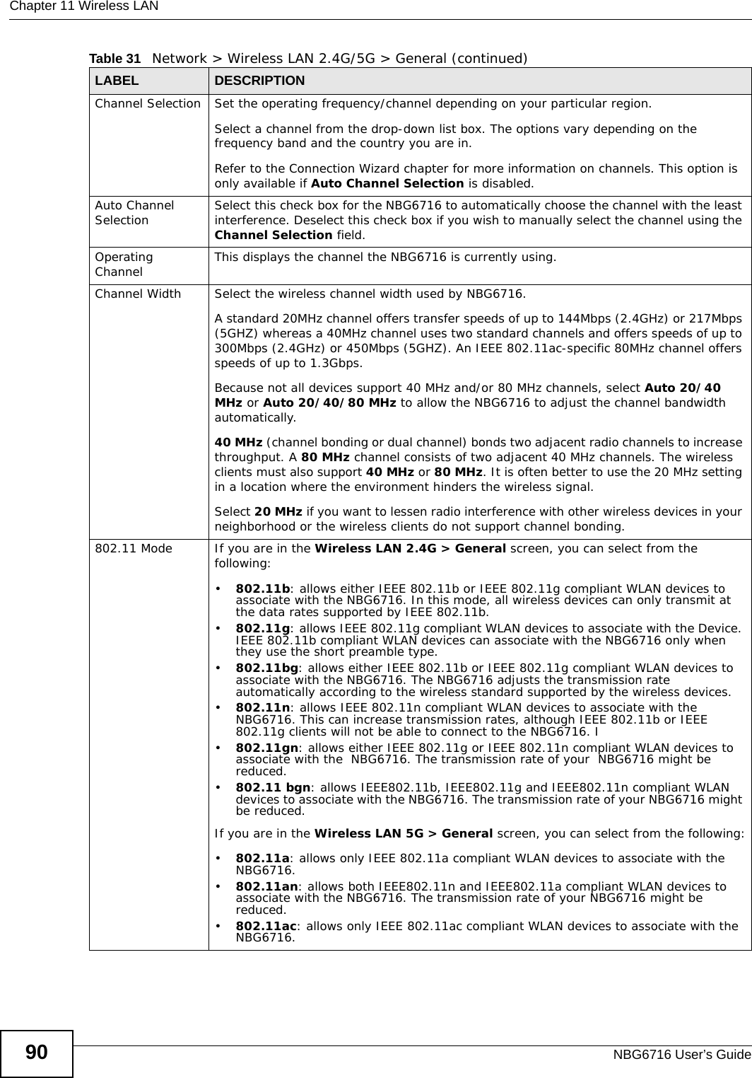
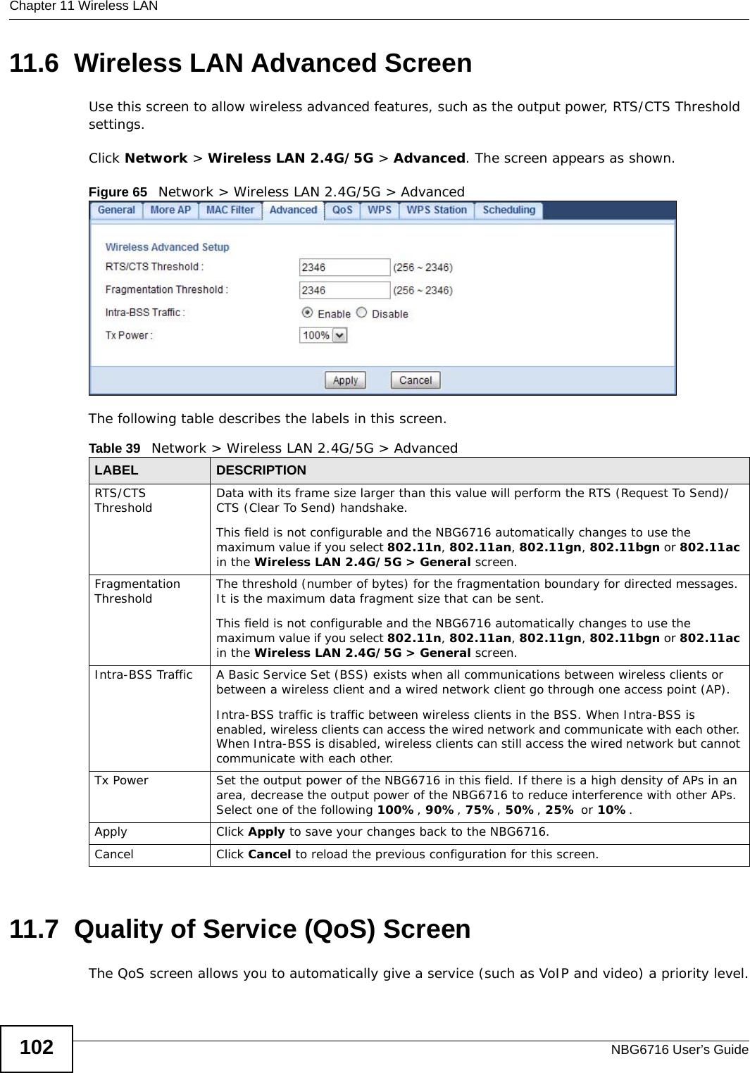
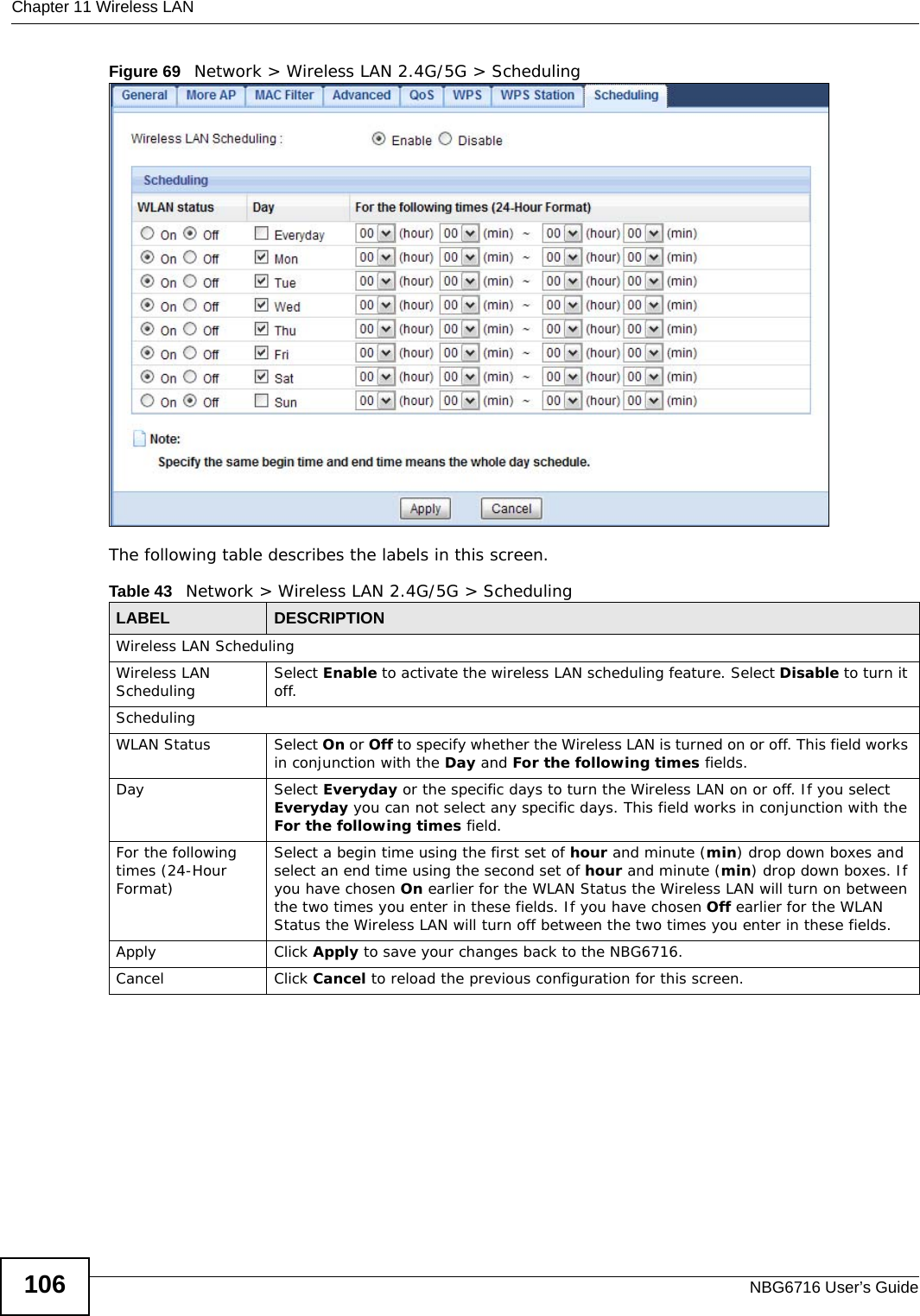

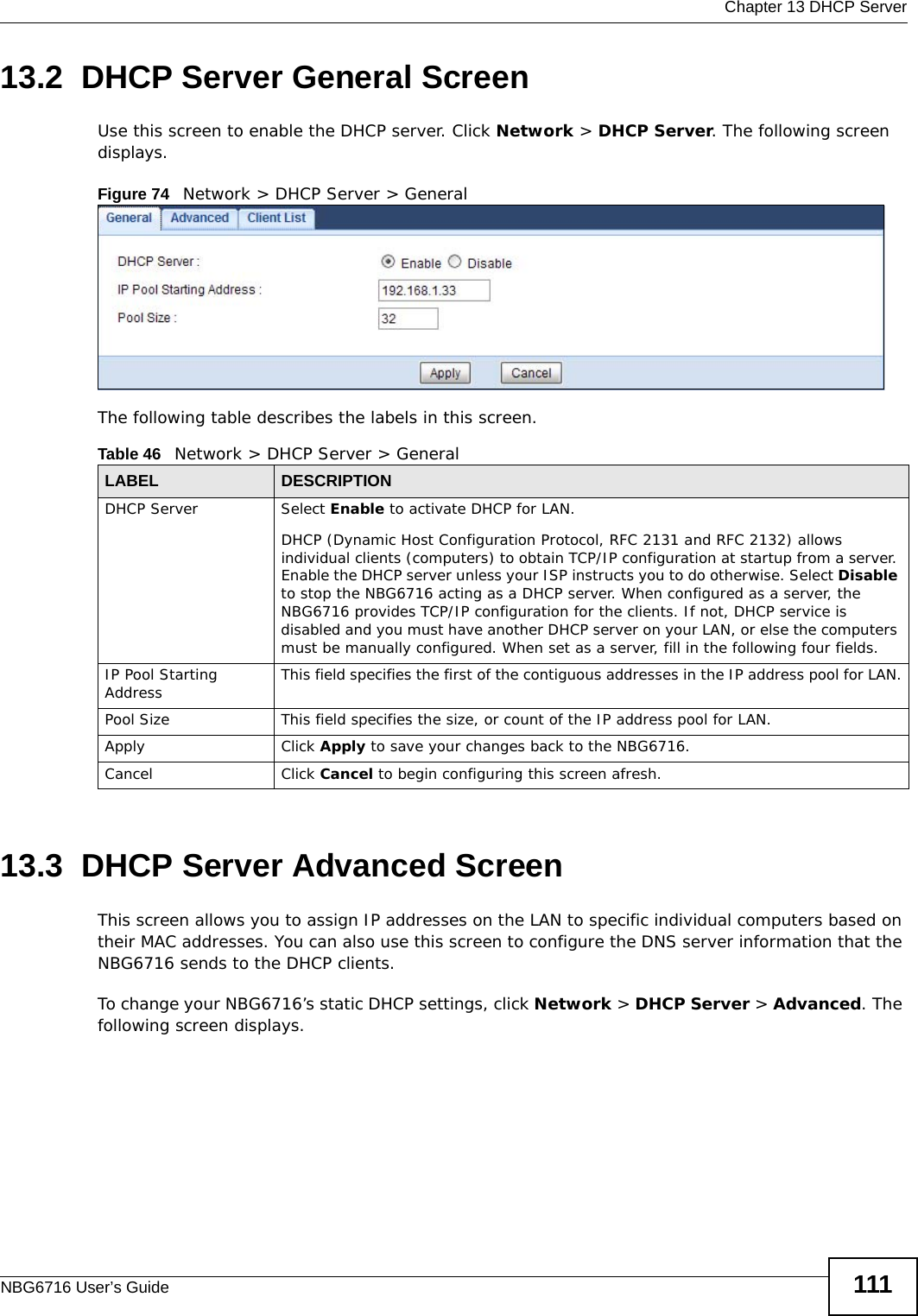
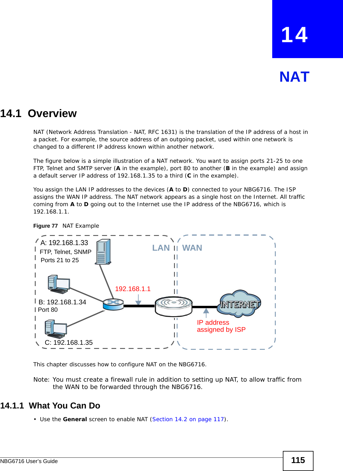
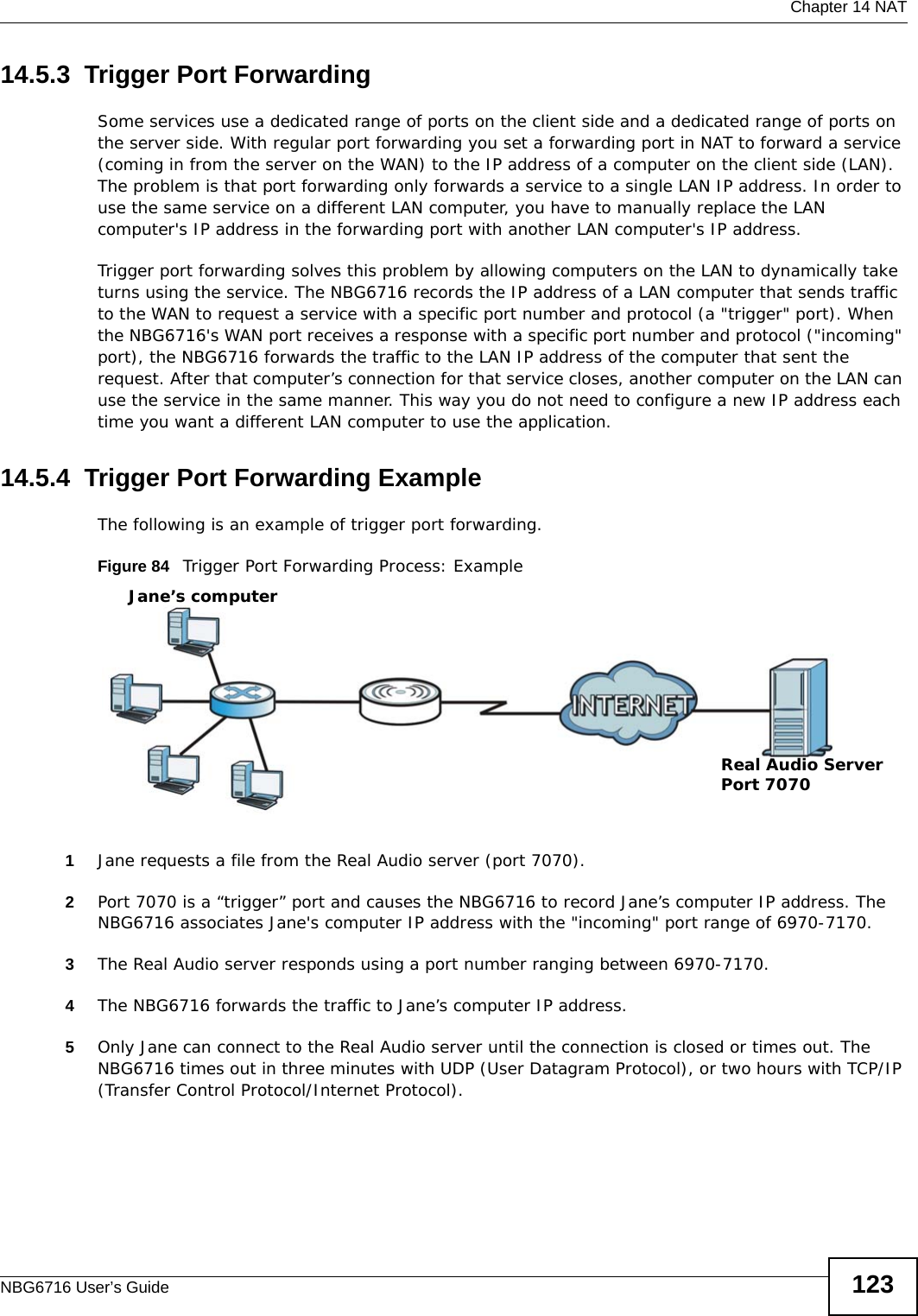

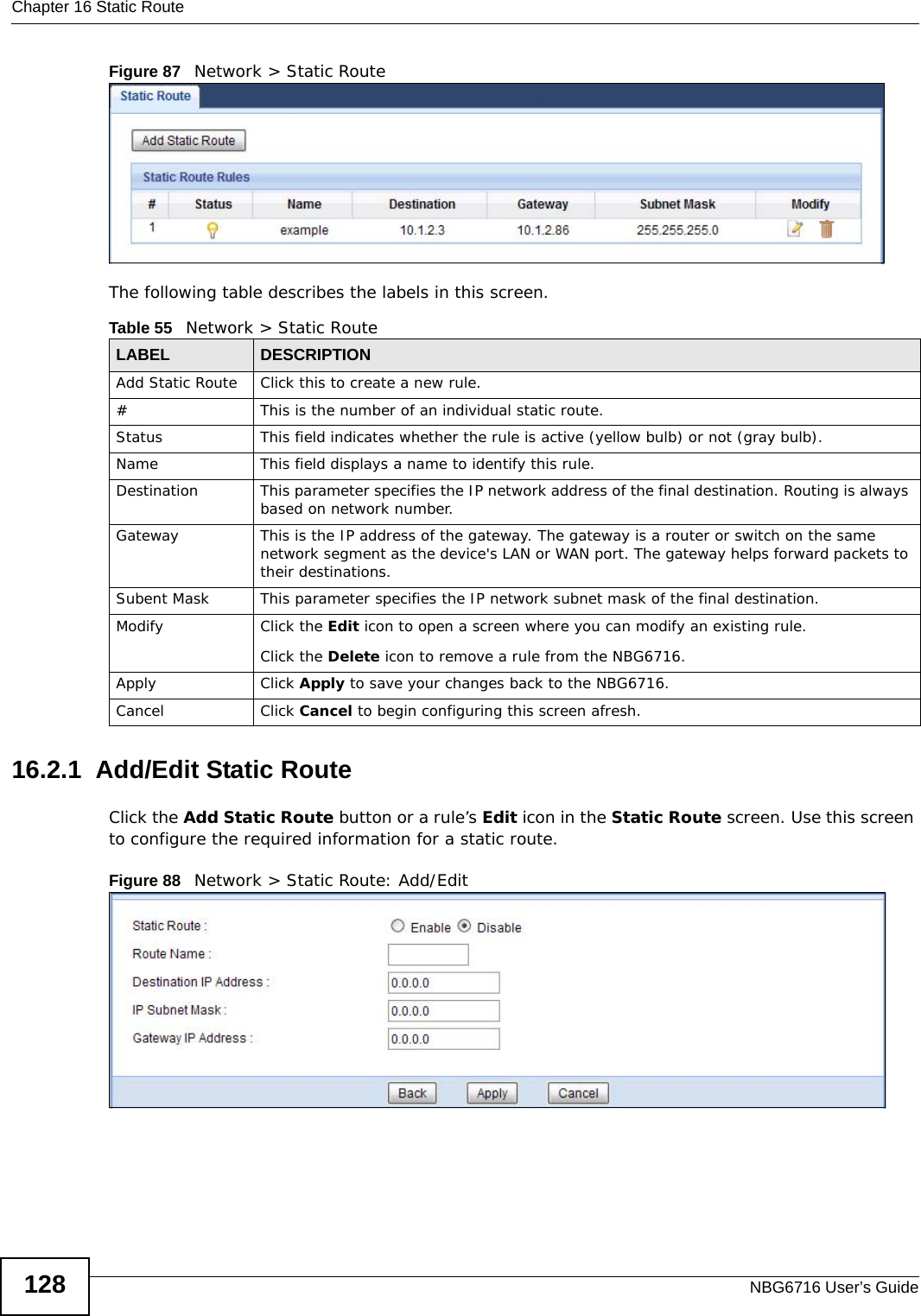
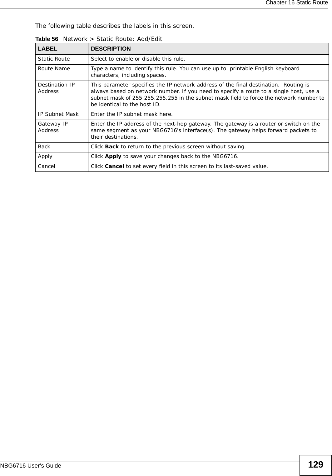
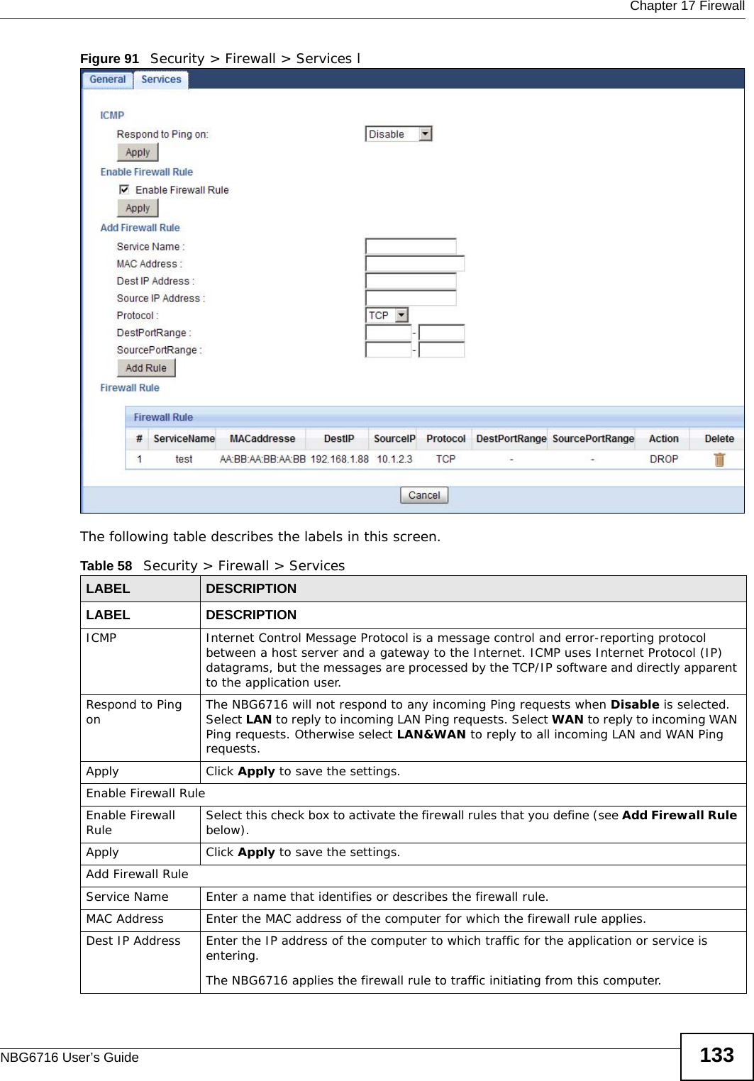
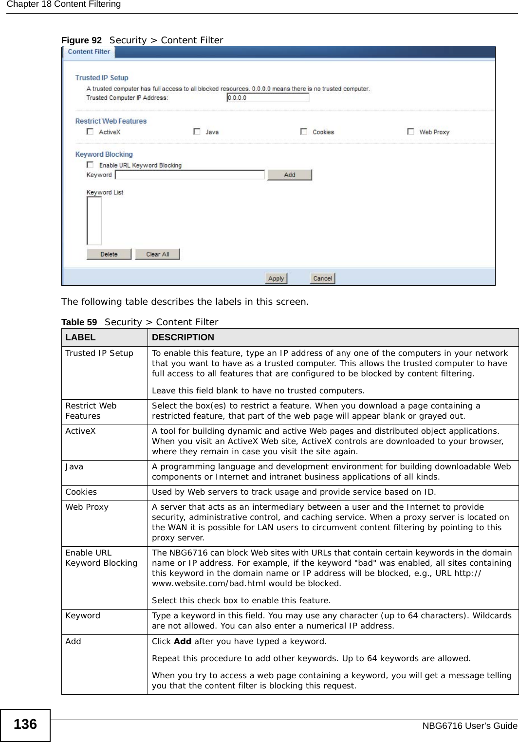
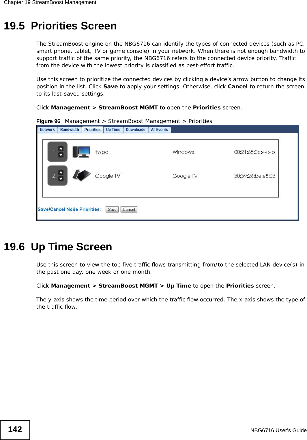
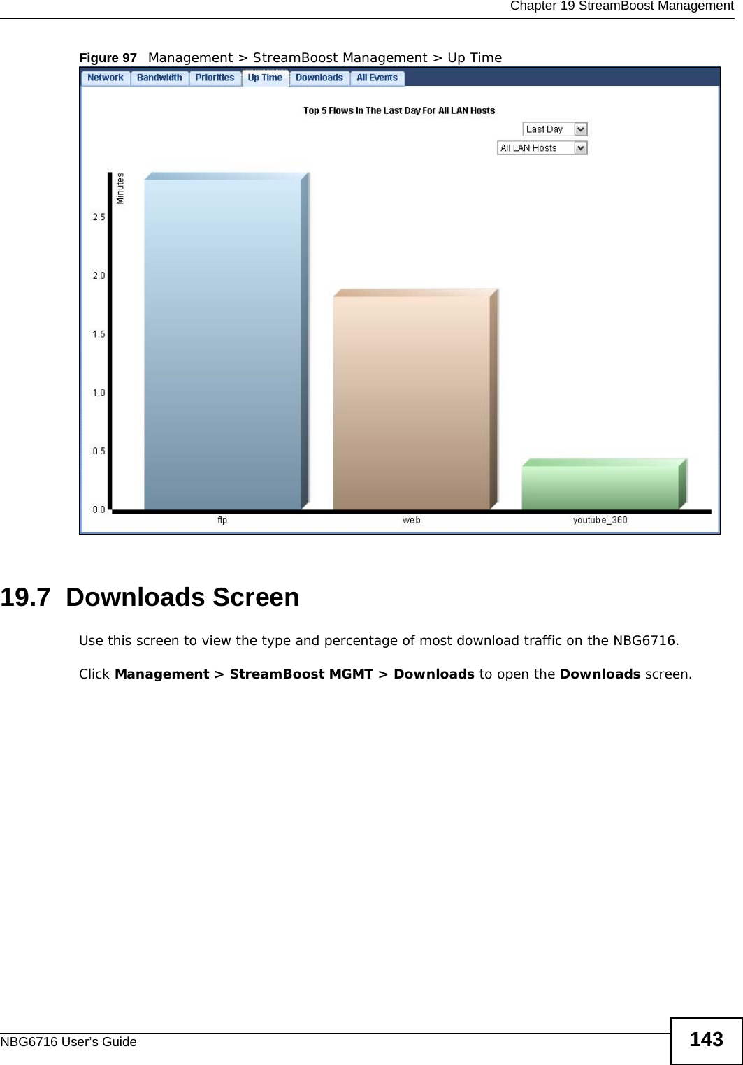
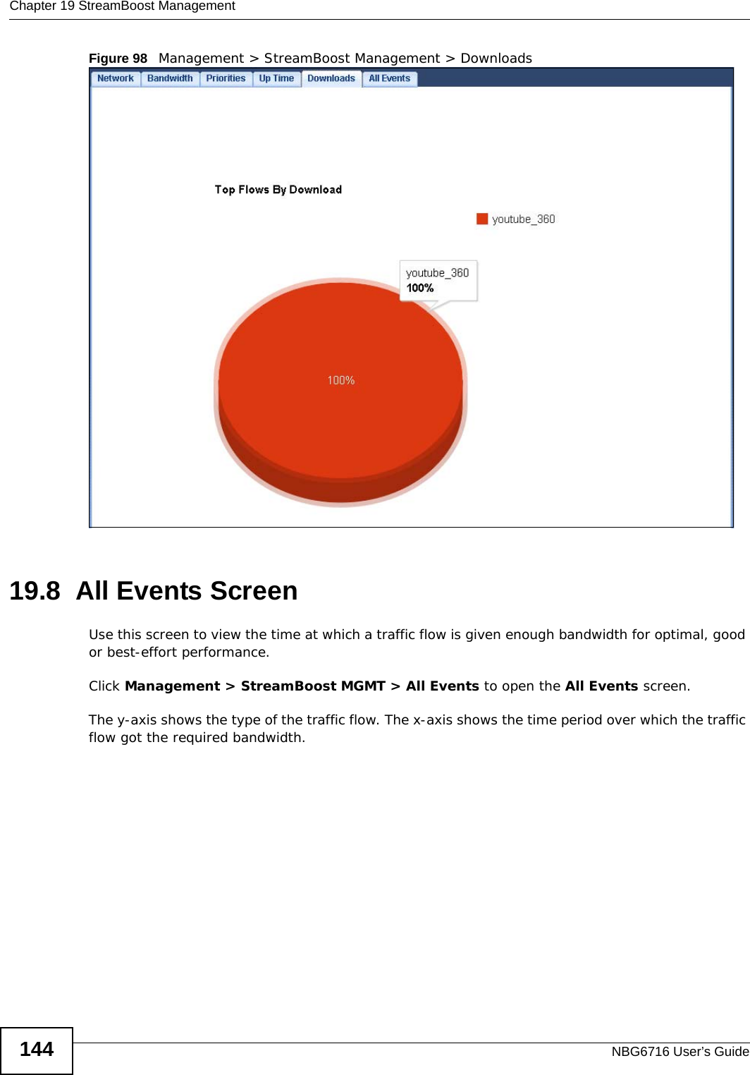
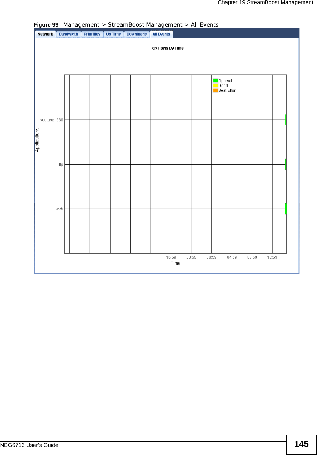
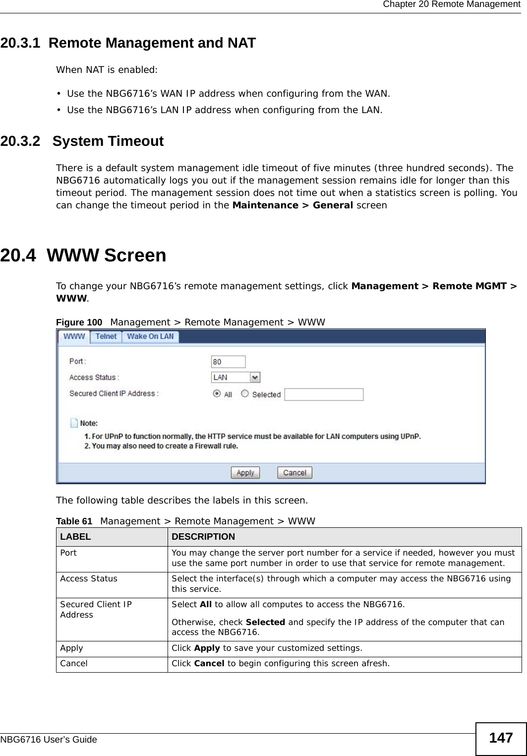
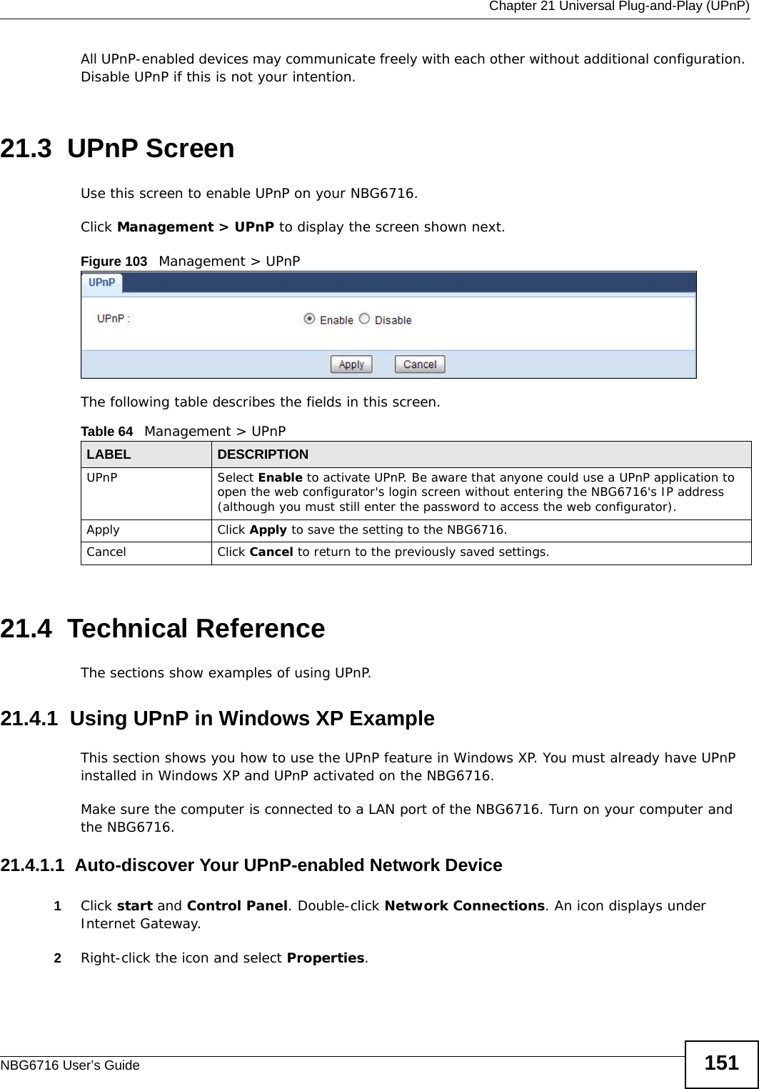
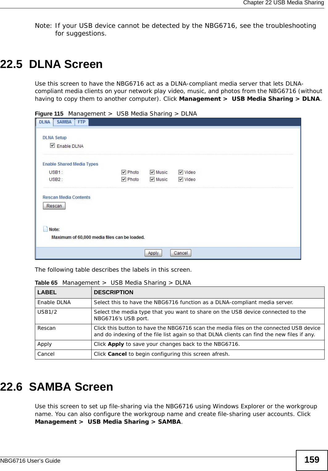
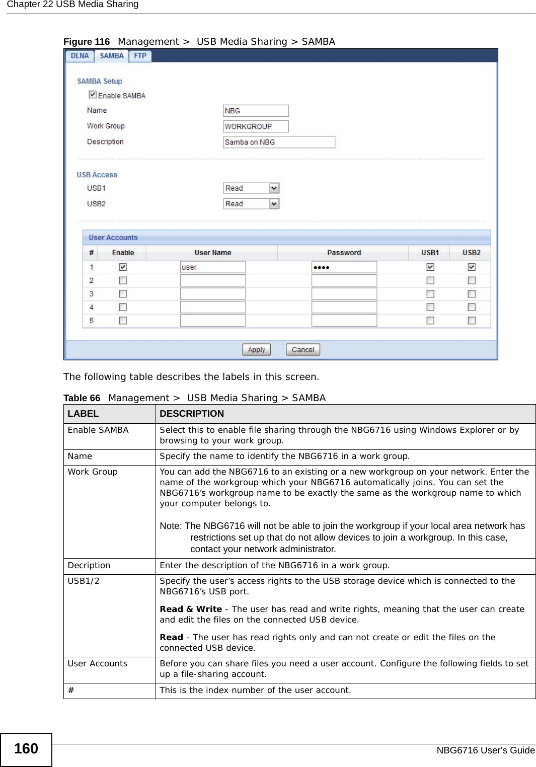
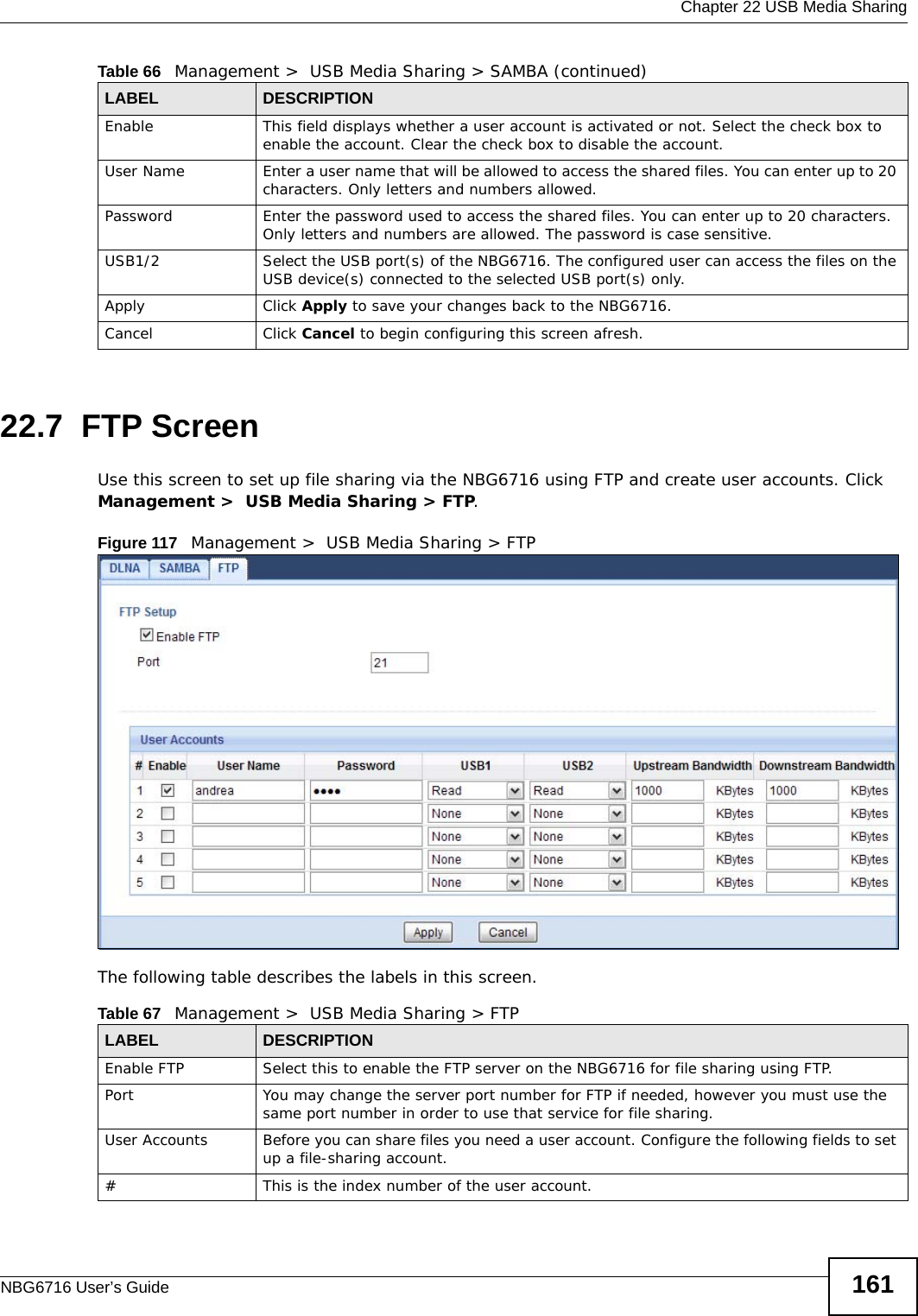
![Chapter 18 Content FilteringNBG6716 User’s Guide 13718.3 Technical ReferenceThe following section contains additional technical information about the NBG6716 features described in this chapter.18.3.1 Customizing Keyword Blocking URL CheckingYou can use commands to set how much of a website’s URL the content filter is to check for keyword blocking. See the appendices for information on how to access and use the command interpreter.Domain Name or IP Address URL CheckingBy default, the NBG6716 checks the URL’s domain name or IP address when performing keyword blocking.This means that the NBG6716 checks the characters that come before the first slash in the URL.For example, with the URL www.zyxel.com.tw/news/pressroom.php, content filtering only searches for keywords within www.zyxel.com.tw.Full Path URL CheckingFull path URL checking has the NBG6716 check the characters that come before the last slash in the URL.For example, with the URL www.zyxel.com.tw/news/pressroom.php, full path URL checking searches for keywords within www.zyxel.com.tw/news/.Use the ip urlfilter customize actionFlags 6 [disable | enable] command to extend (or not extend) the keyword blocking search to include the URL's full path.File Name URL CheckingFilename URL checking has the NBG6716 check all of the characters in the URL.For example, filename URL checking searches for keywords within the URL www.zyxel.com.tw/news/pressroom.php.Keyword List This list displays the keywords already added. Delete Highlight a keyword in the lower box and click Delete to remove it. The keyword disappears from the text box after you click Apply.Clear All Click this button to remove all of the listed keywords.Apply Click Apply to save your changes.Cancel Click Cancel to begin configuring this screen afreshTable 59 Security > Content Filter (continued)LABEL DESCRIPTION](https://usermanual.wiki/ZyXEL-Communications/NBG6716.User-Manual-Part-1-pdf/User-Guide-2039427-Page-137.png)
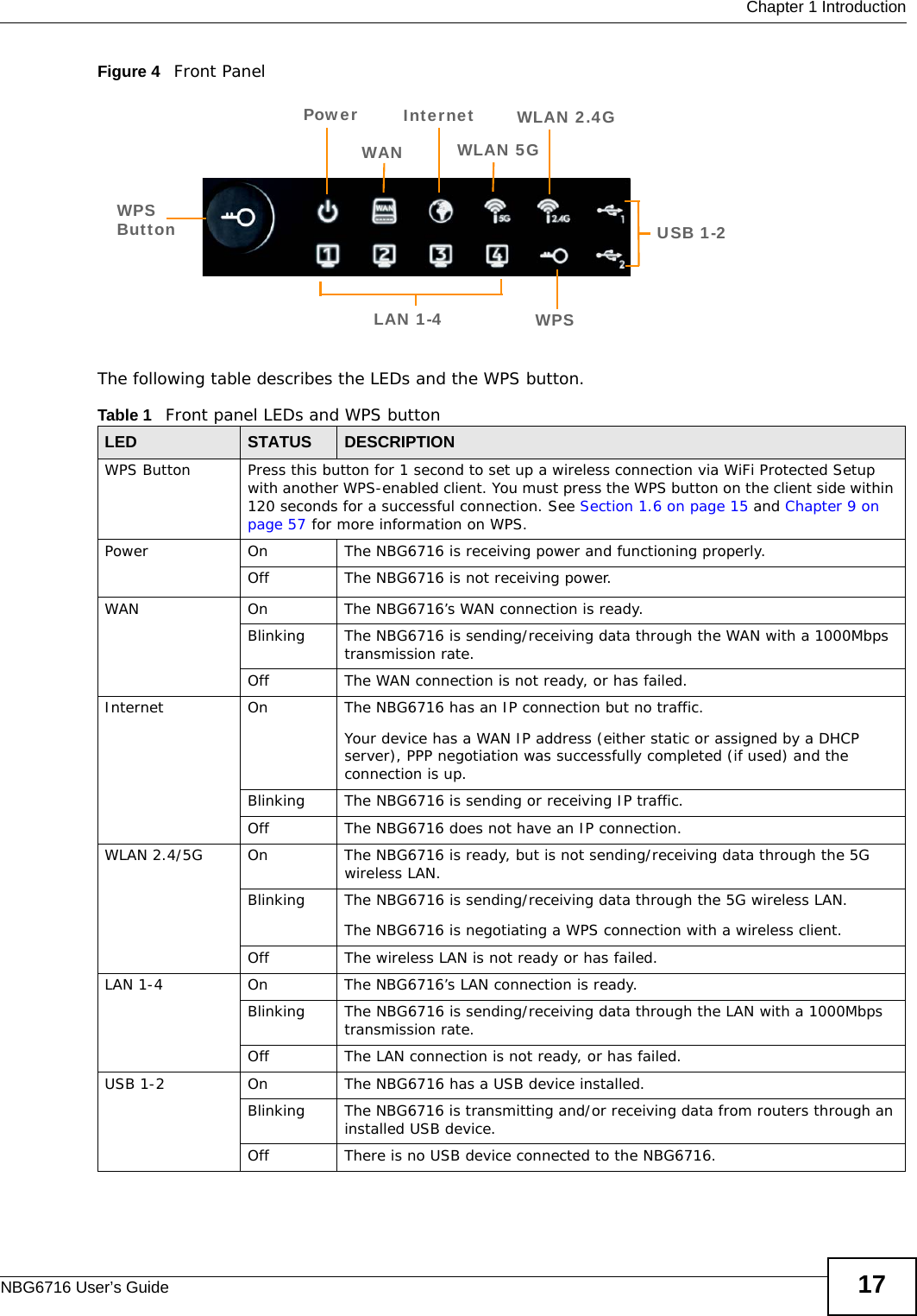
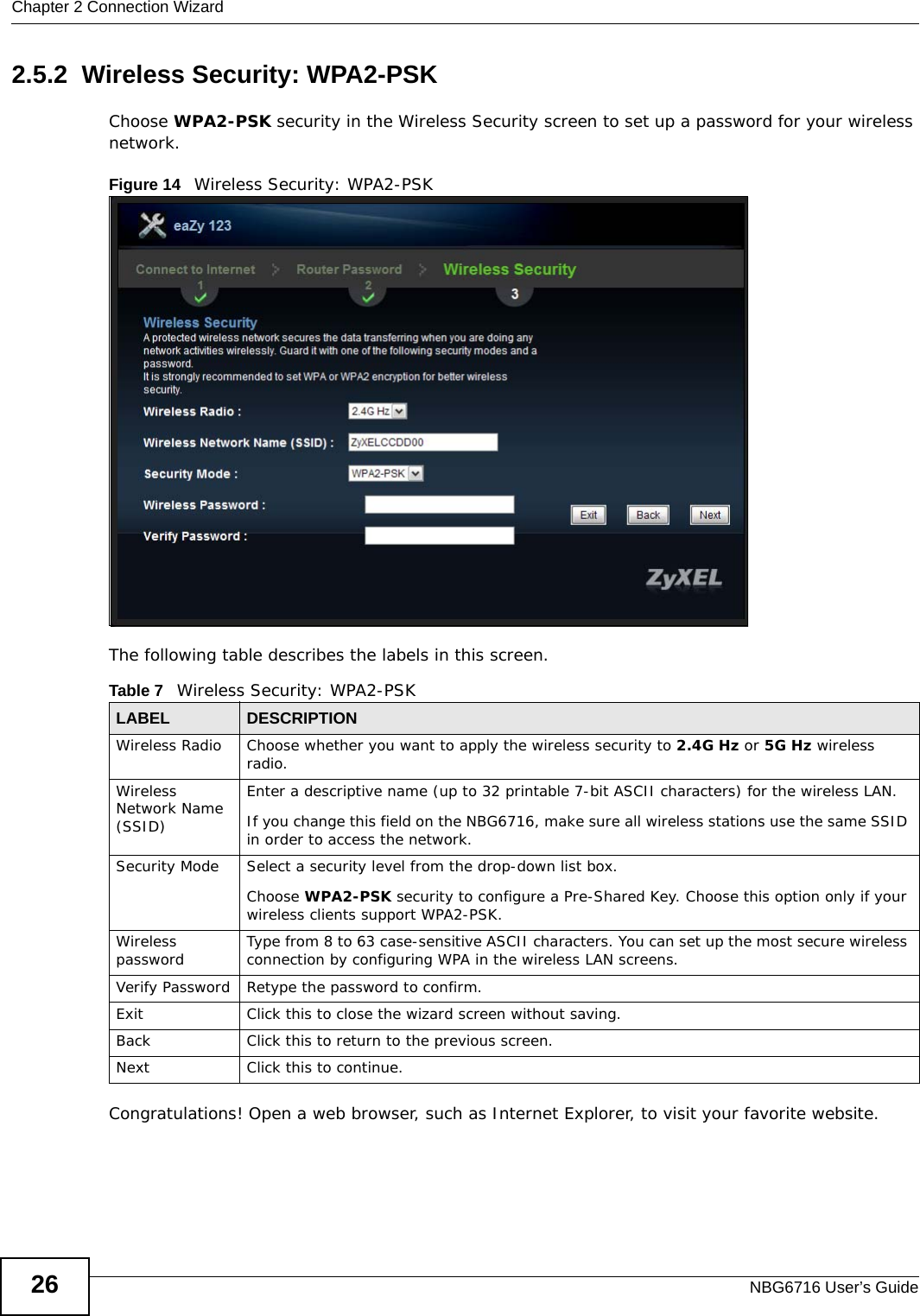
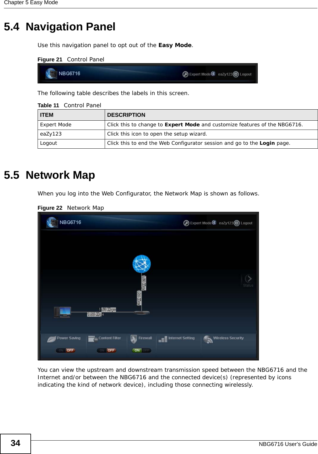
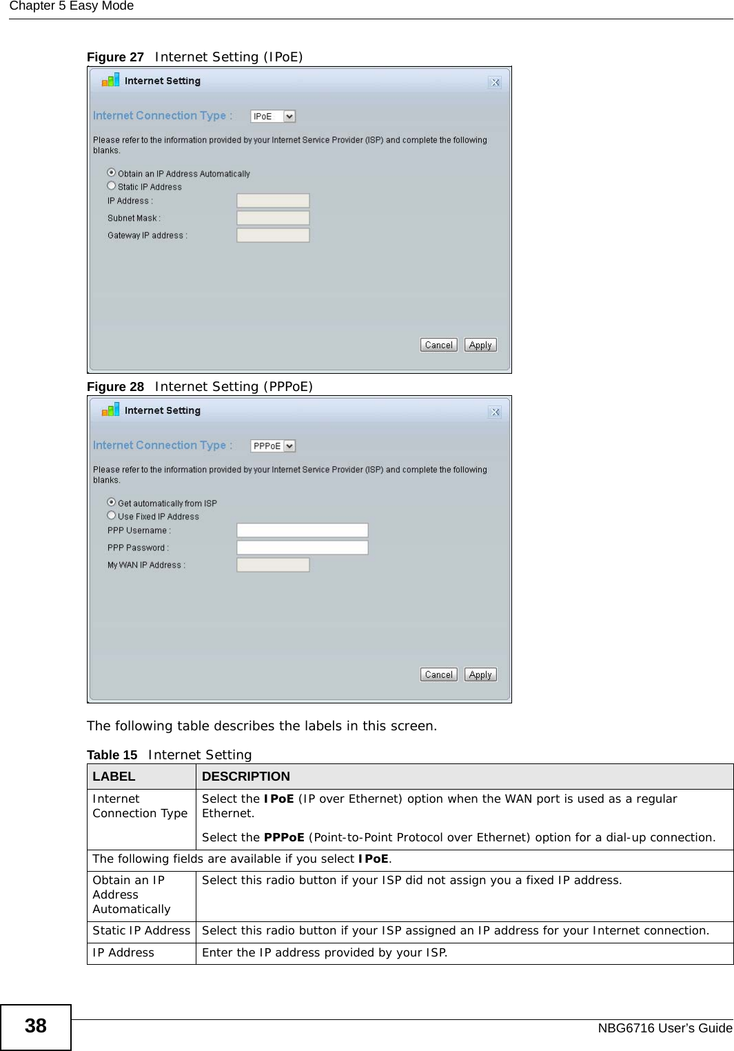
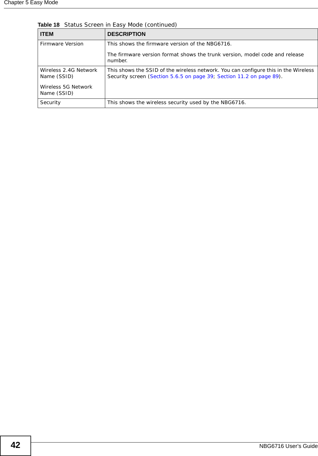
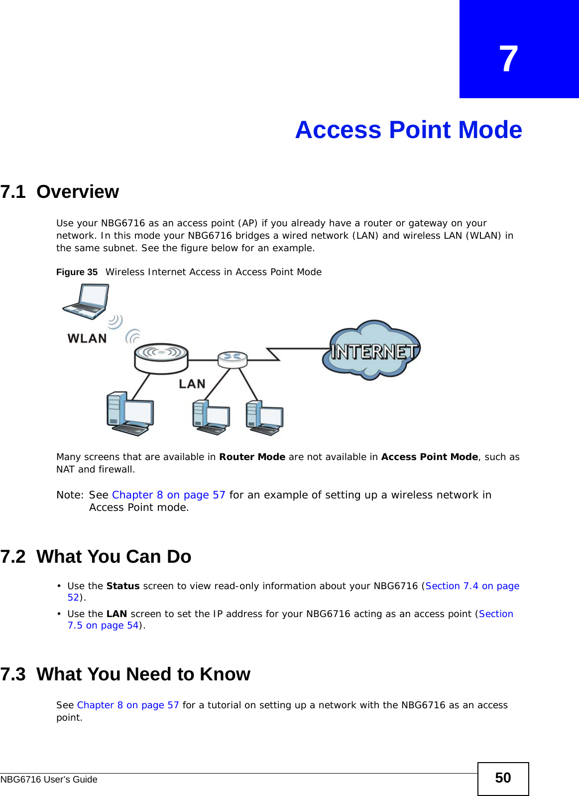
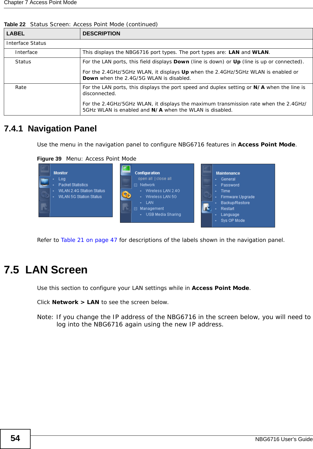
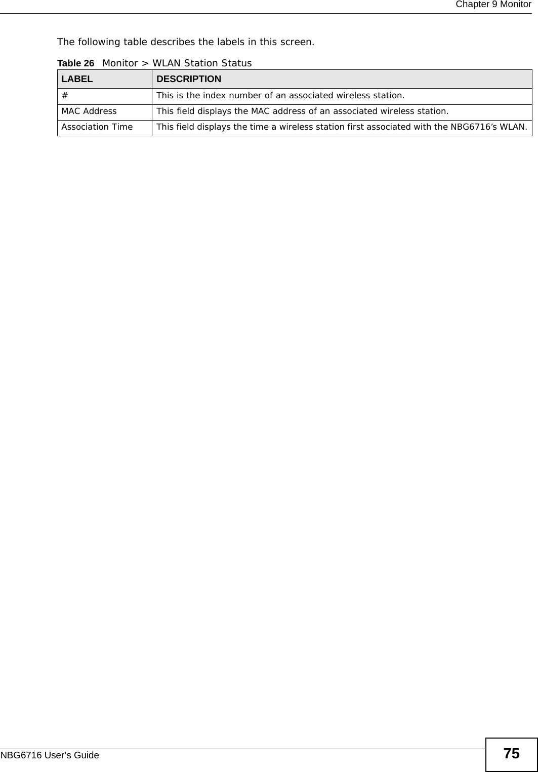
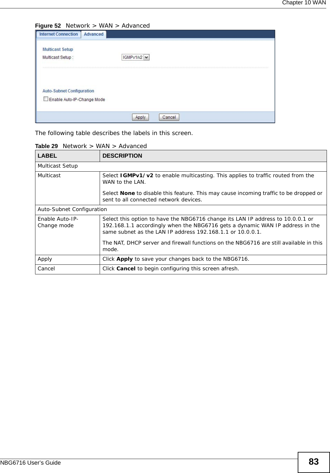
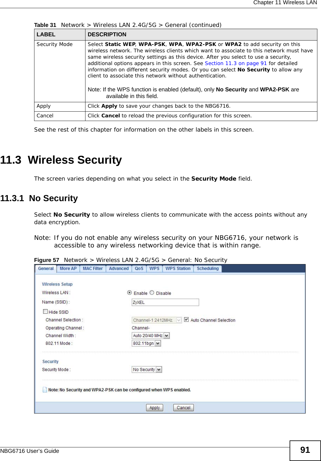
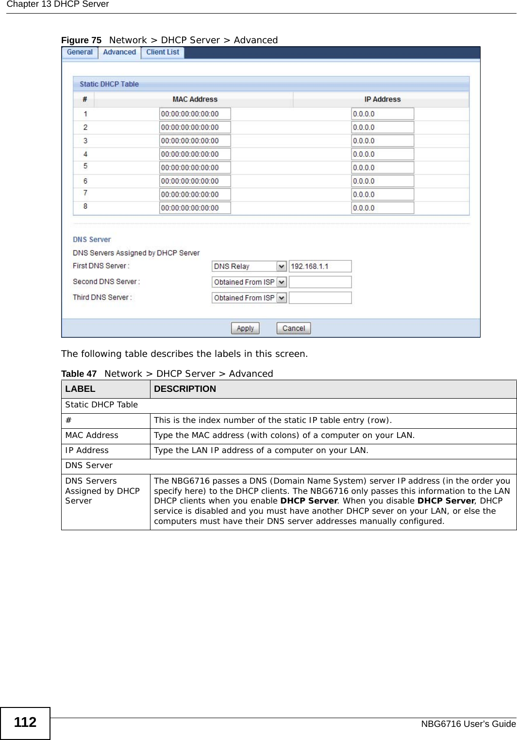
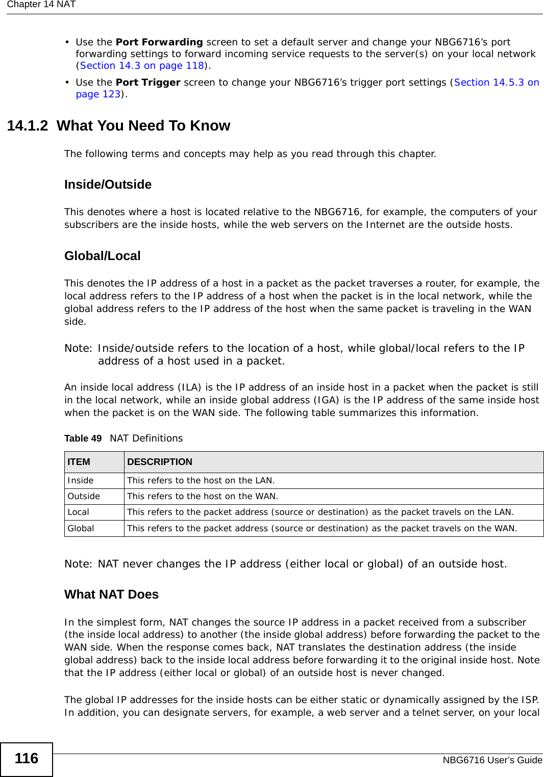
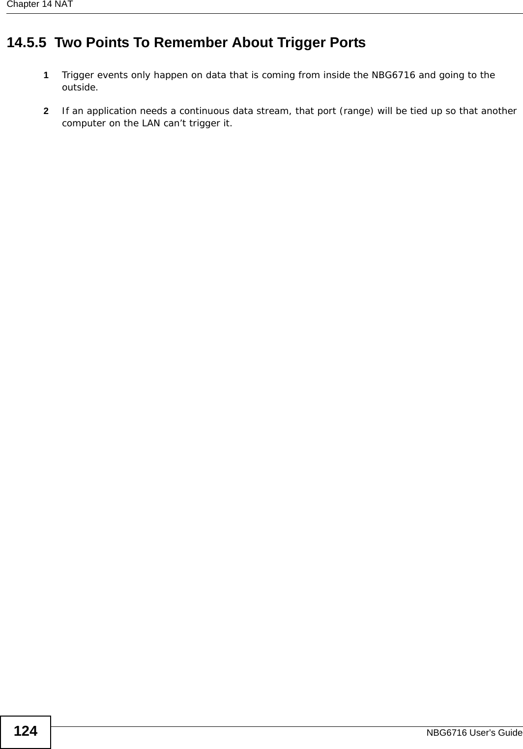
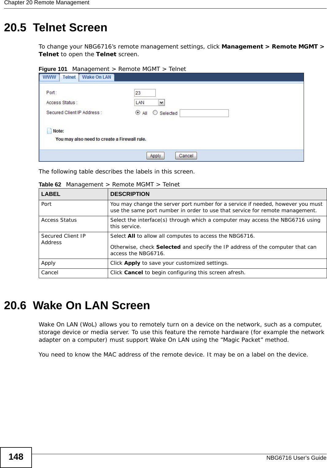
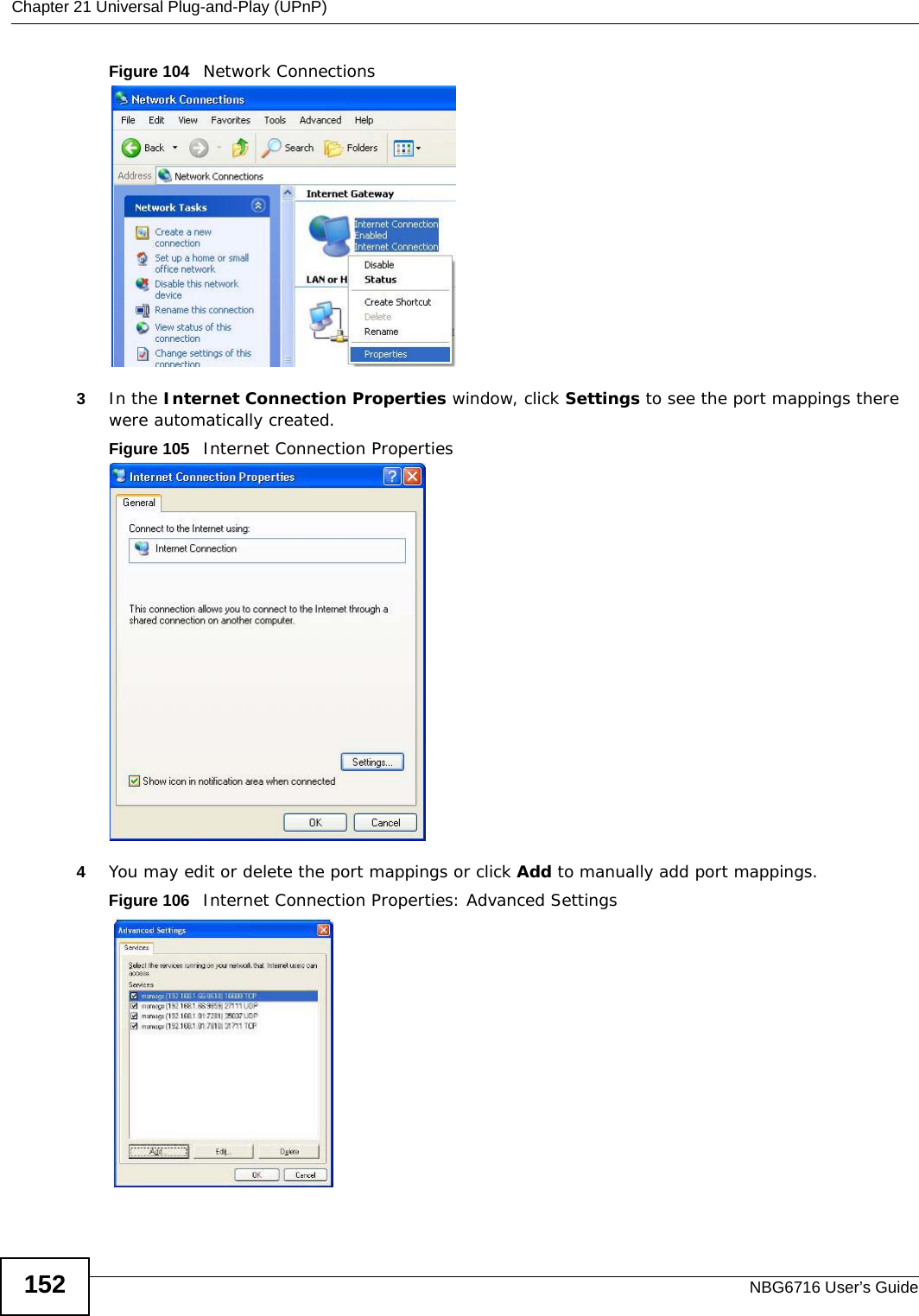
![Chapter 18 Content FilteringNBG6716 User’s Guide138Use the ip urlfilter customize actionFlags 8 [disable | enable] command to extend (or not extend) the keyword blocking search to include the URL's complete filename.](https://usermanual.wiki/ZyXEL-Communications/NBG6716.User-Manual-Part-1-pdf/User-Guide-2039427-Page-138.png)

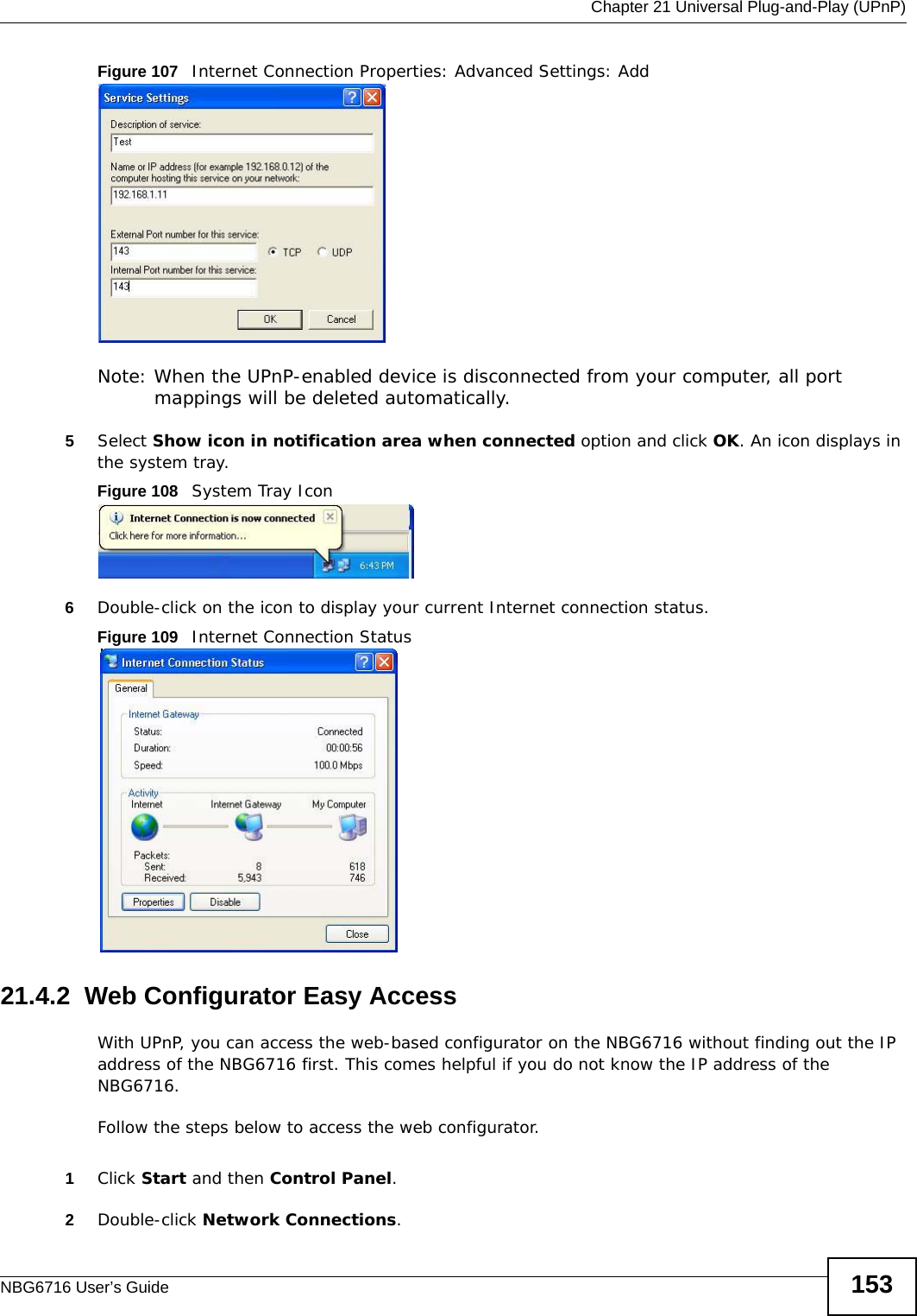
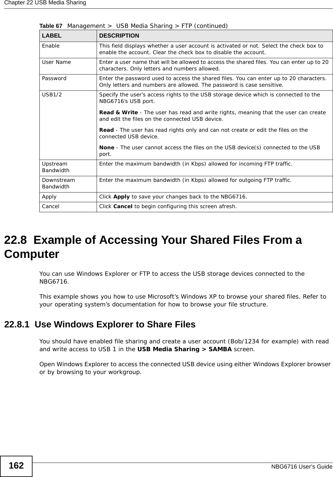
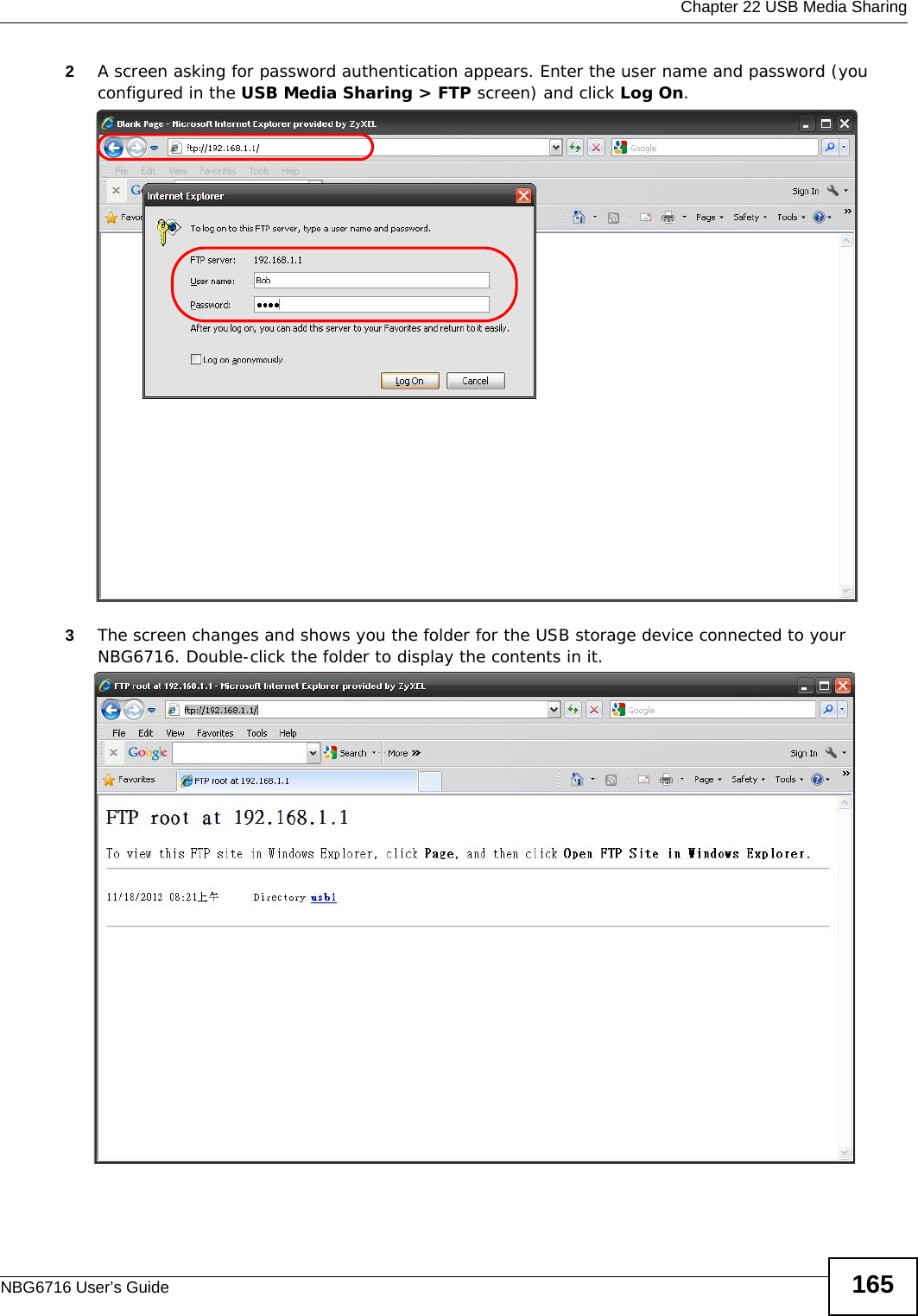
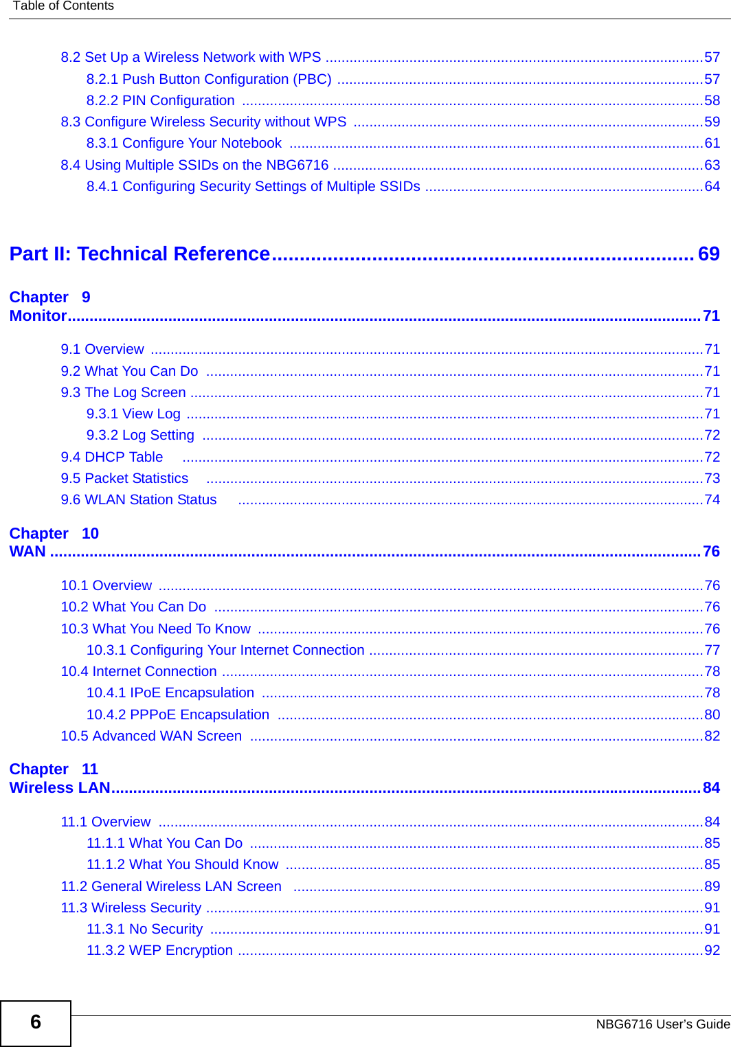
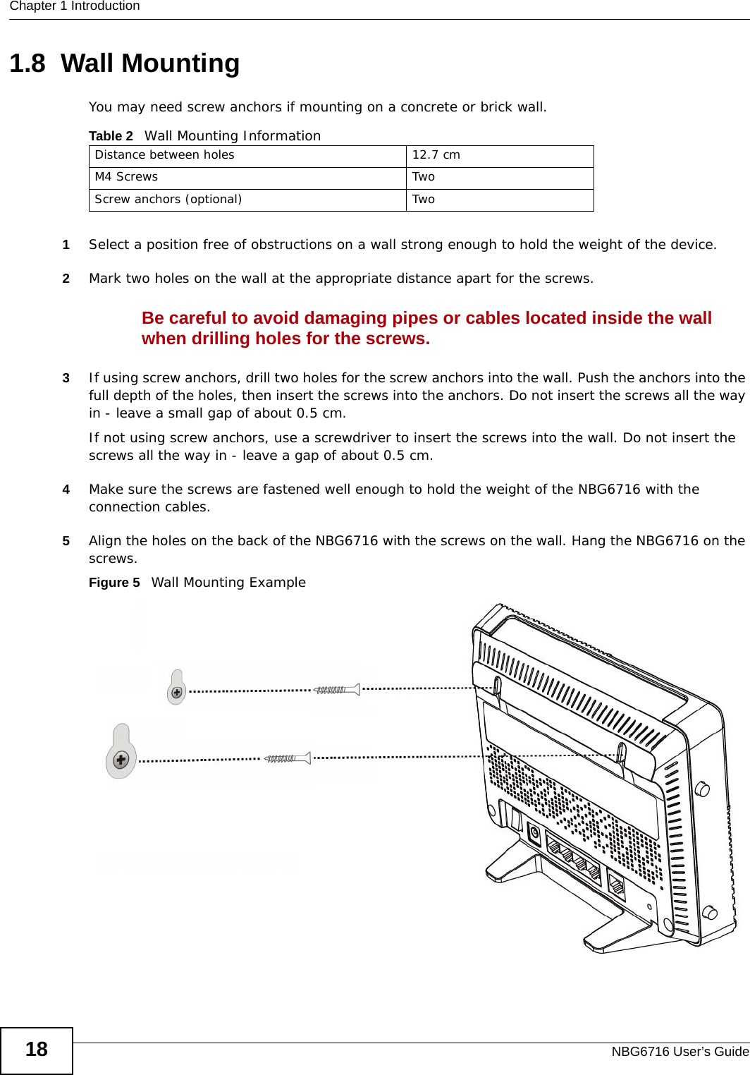
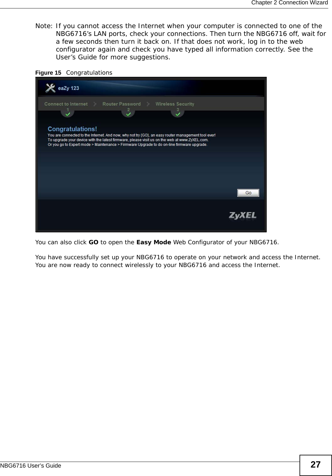
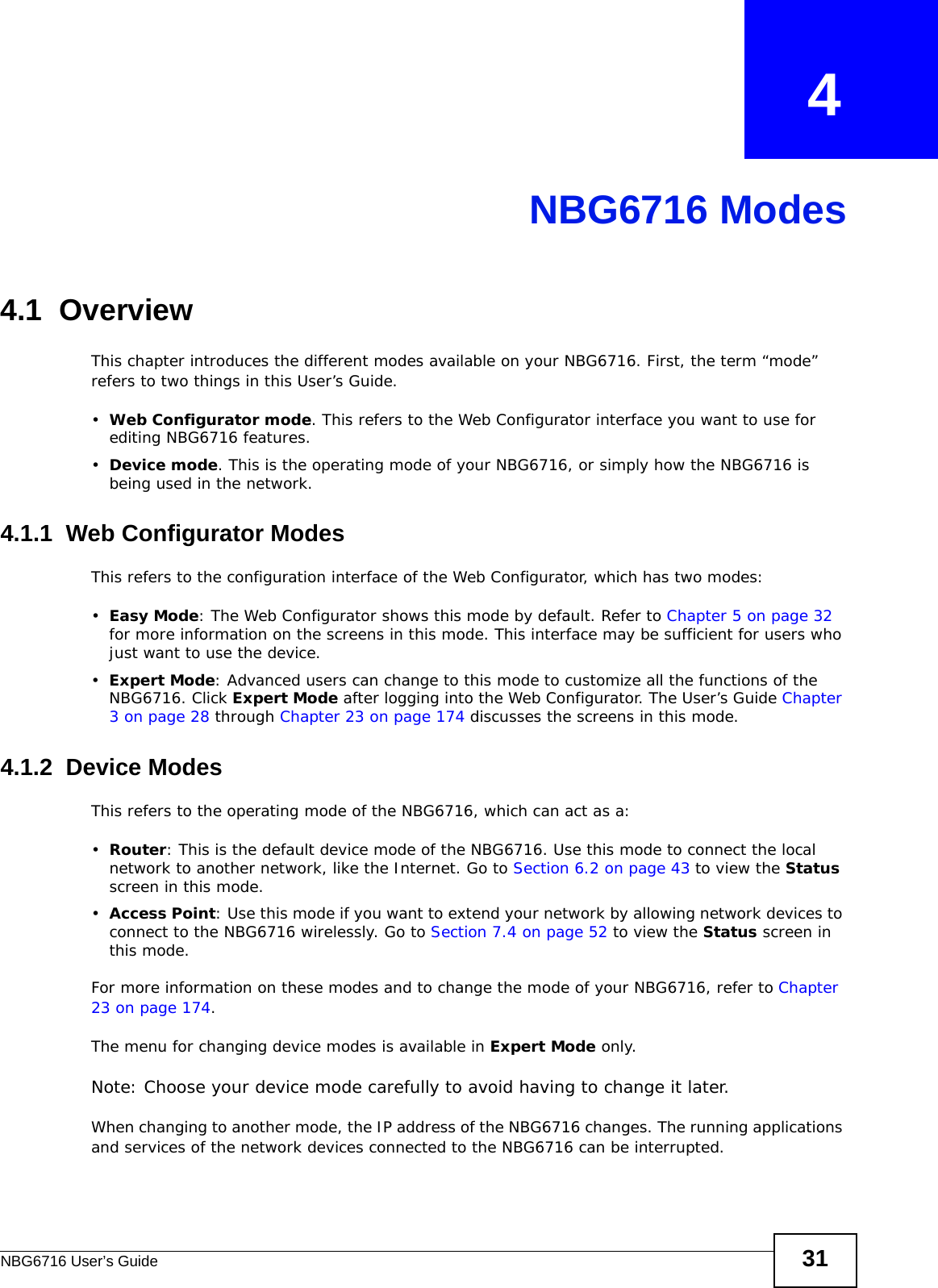
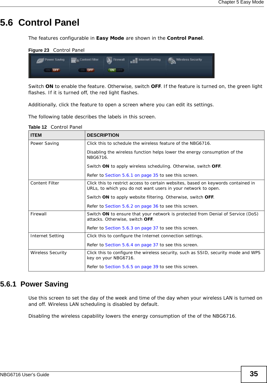
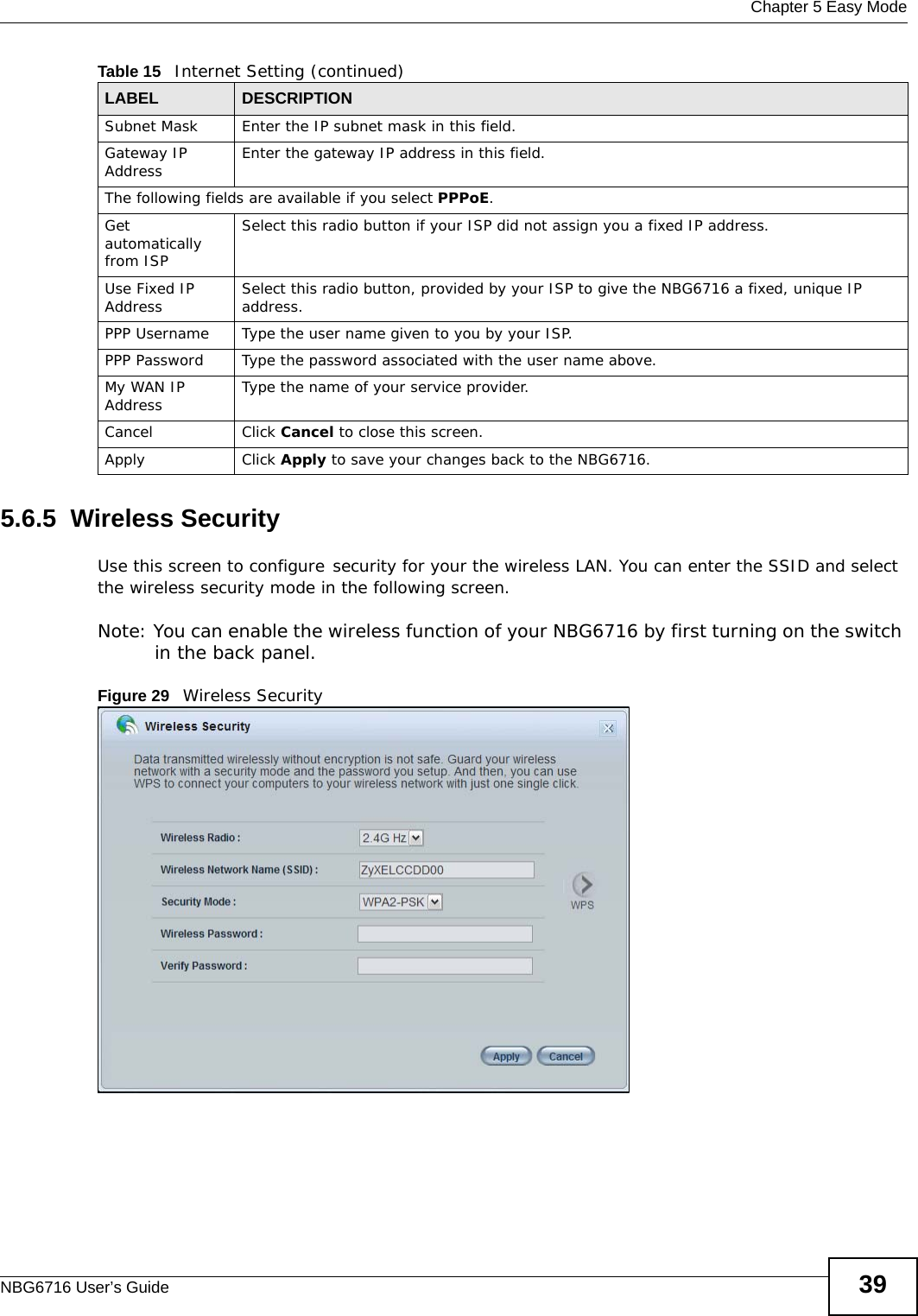
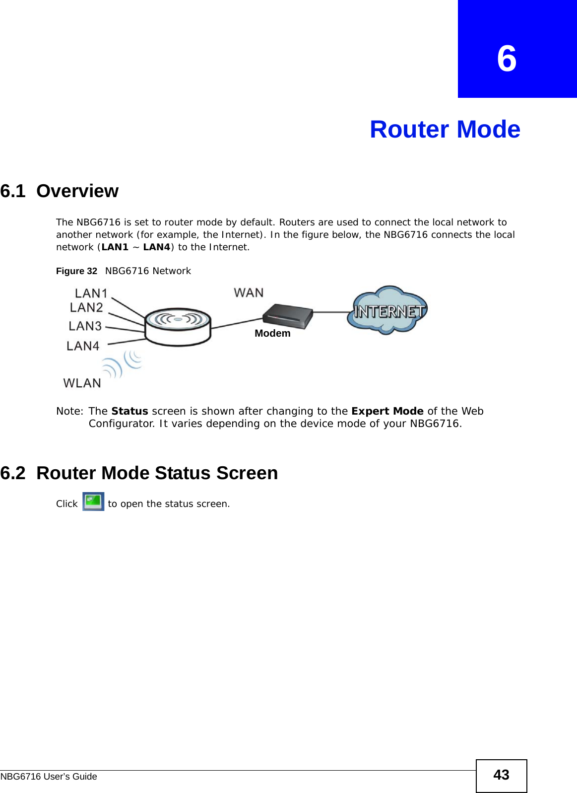
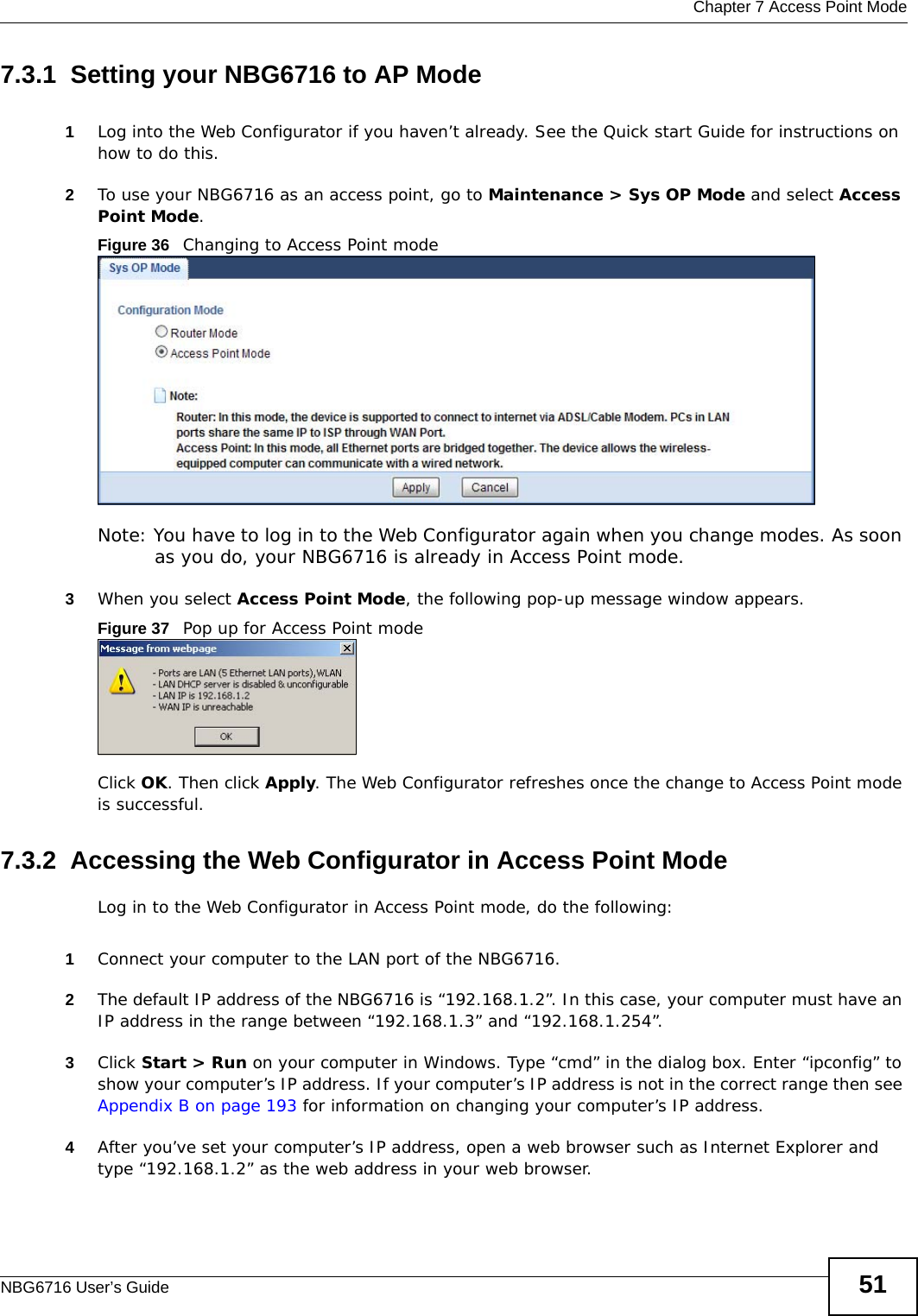
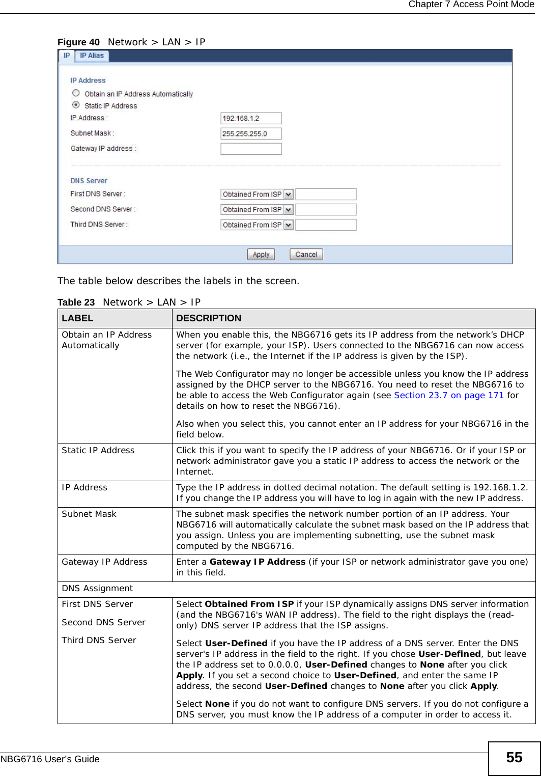
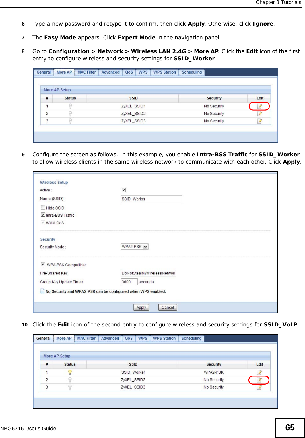
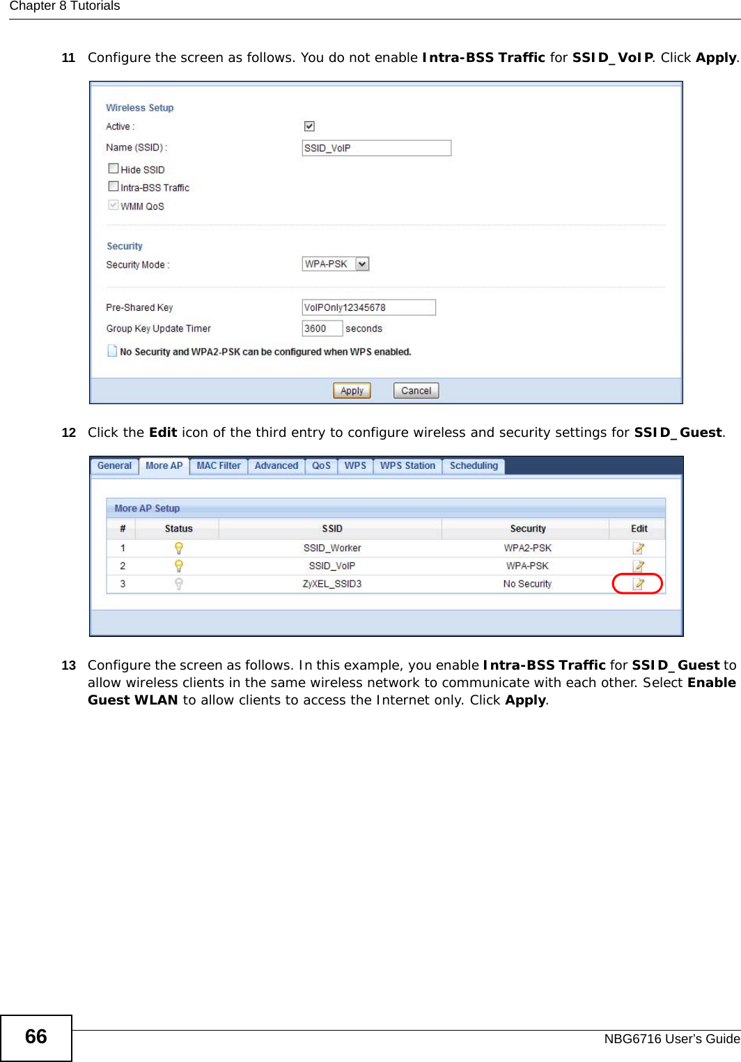
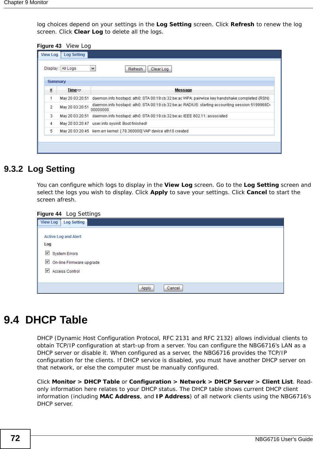
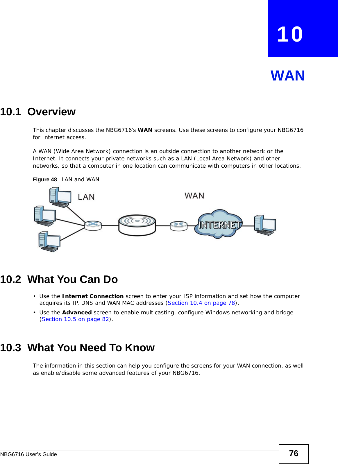
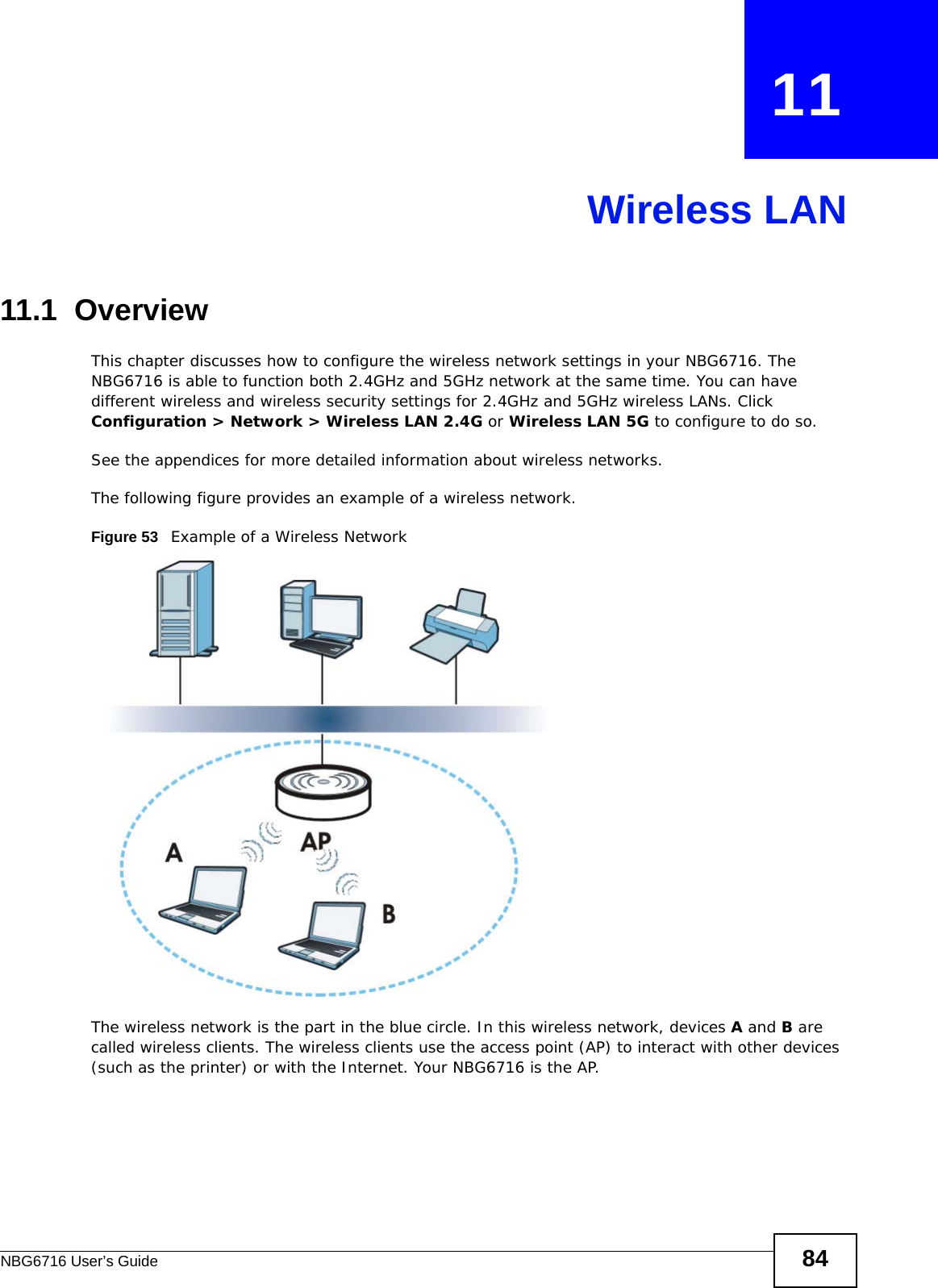
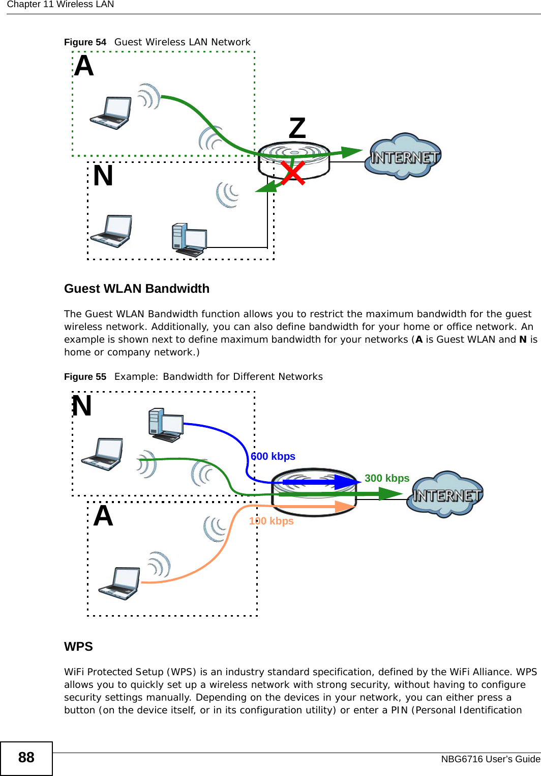
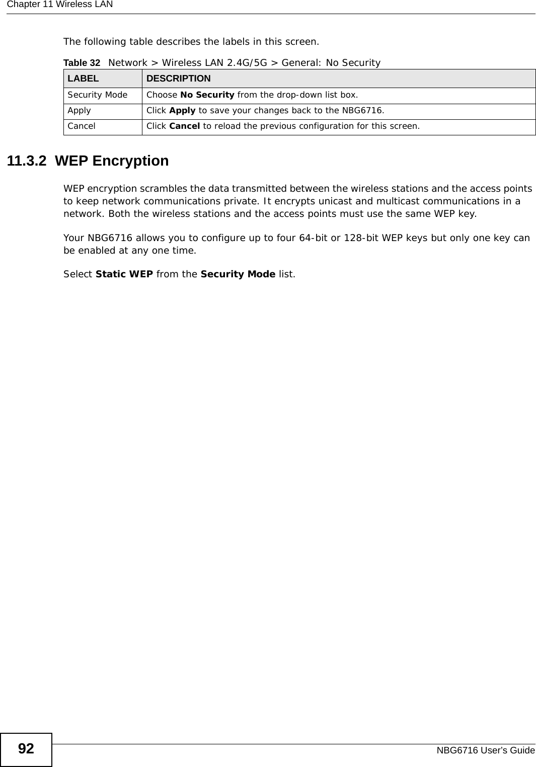
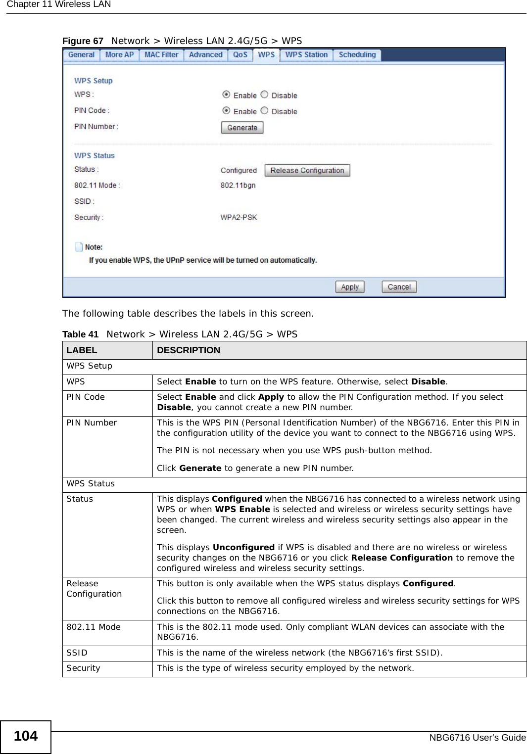
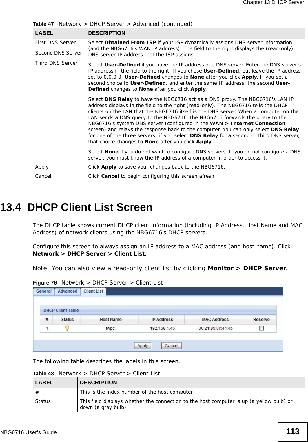
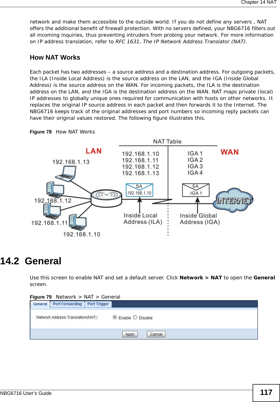
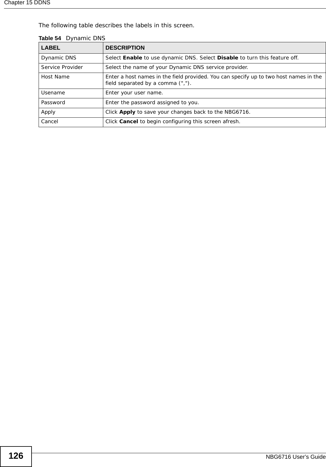
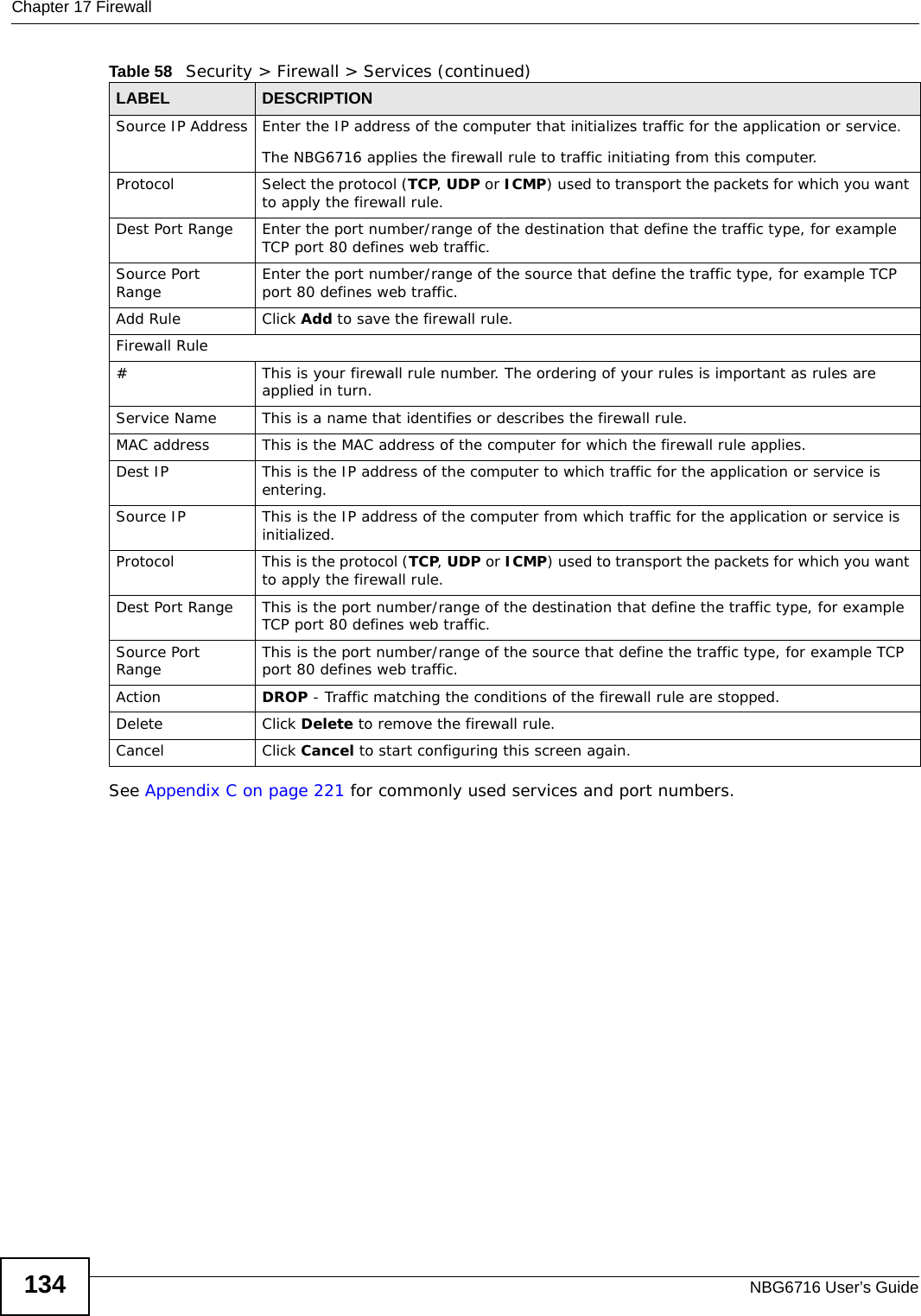
![Chapter 22 USB Media SharingNBG6716 User’s Guide 1631In Windows Explorer’s Address bar type a double backslash “\\” followed by the IP address of the NBG6716 (the default IP address of the NBG6716 in router mode is 192.168.1.1) and press [ENTER]. A screen asking for password authentication appears. Type the user name and password (Bob and 1234 in this example) and click OK.Note: Once you log into the shared folder via your NBG6716, you do not have to relogin unless you restart your computer.](https://usermanual.wiki/ZyXEL-Communications/NBG6716.User-Manual-Part-1-pdf/User-Guide-2039427-Page-163.png)
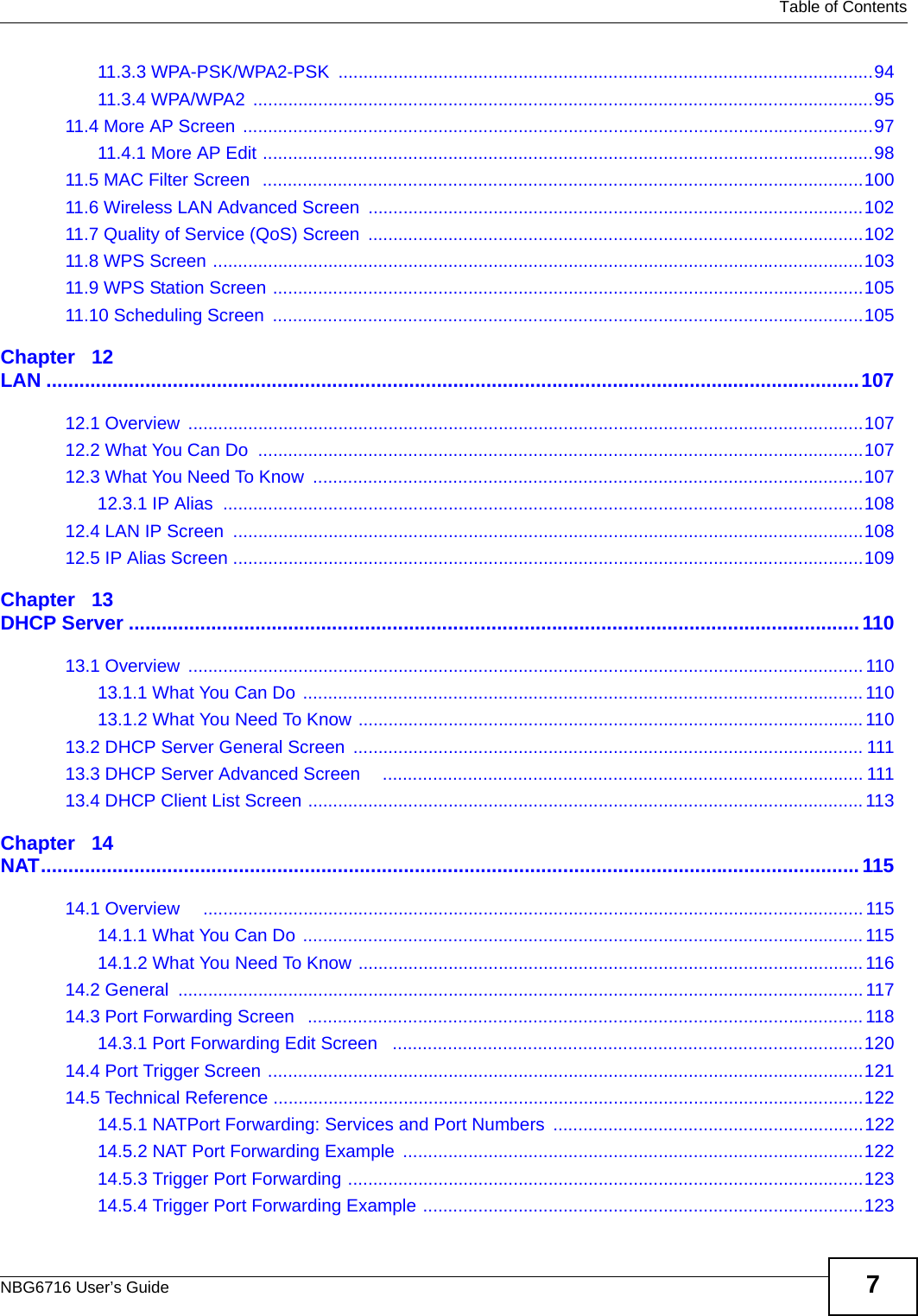
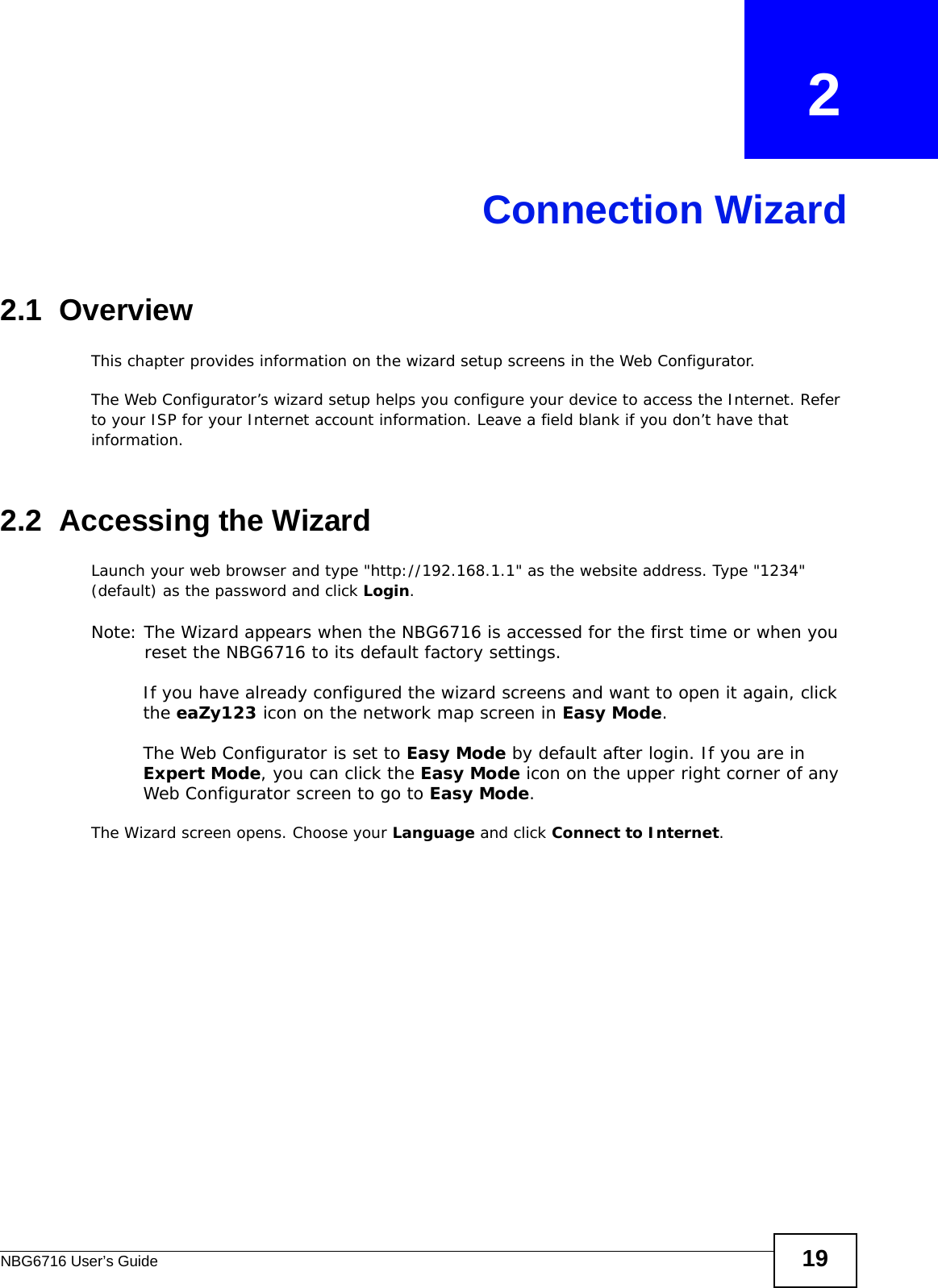
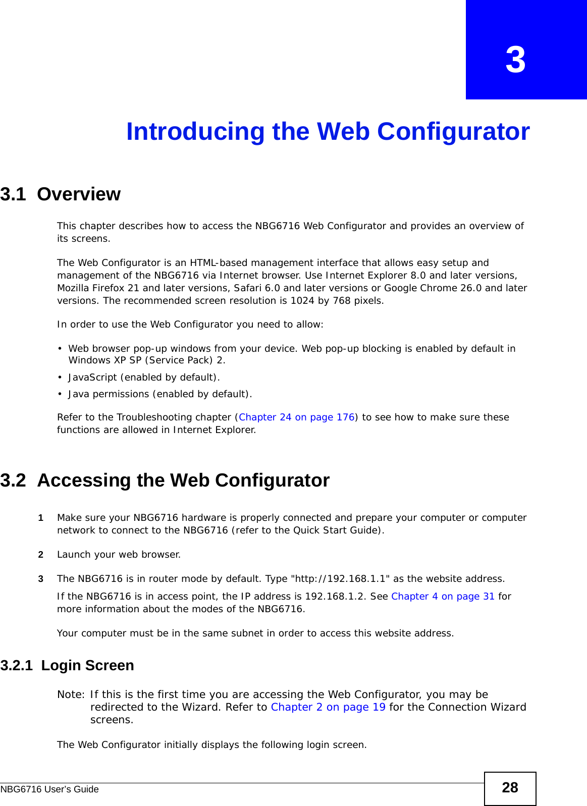
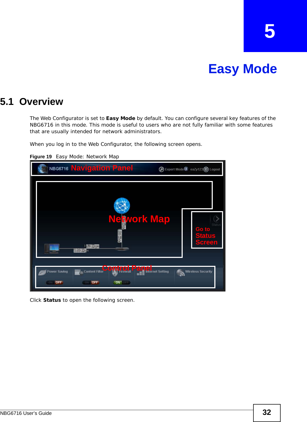
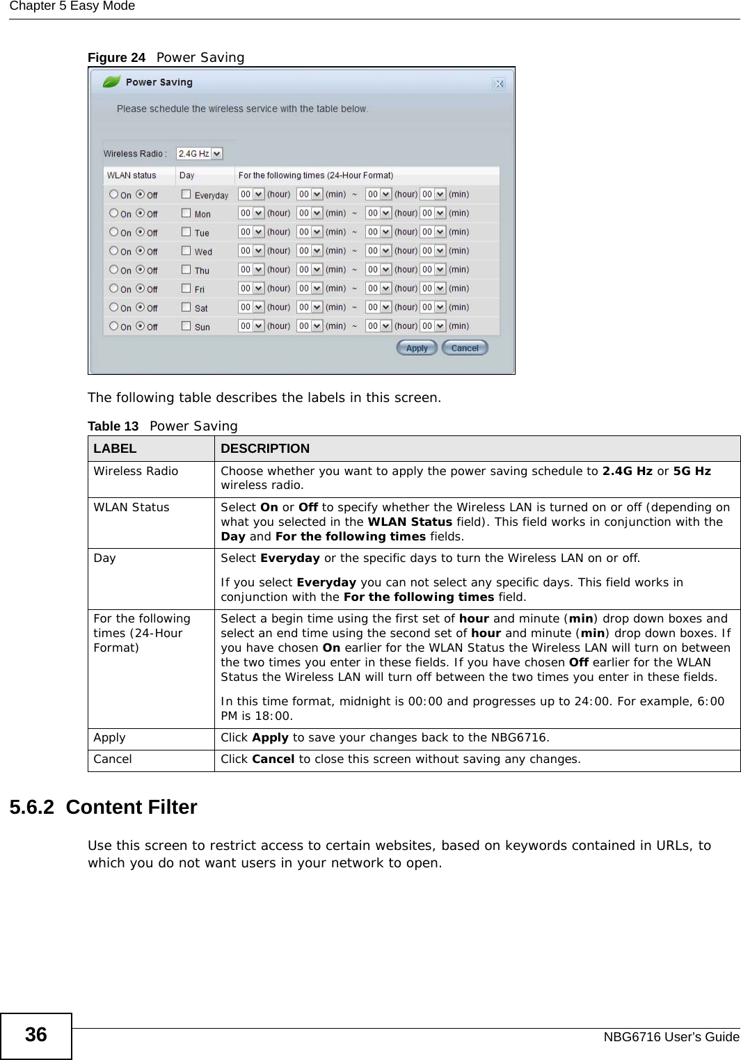
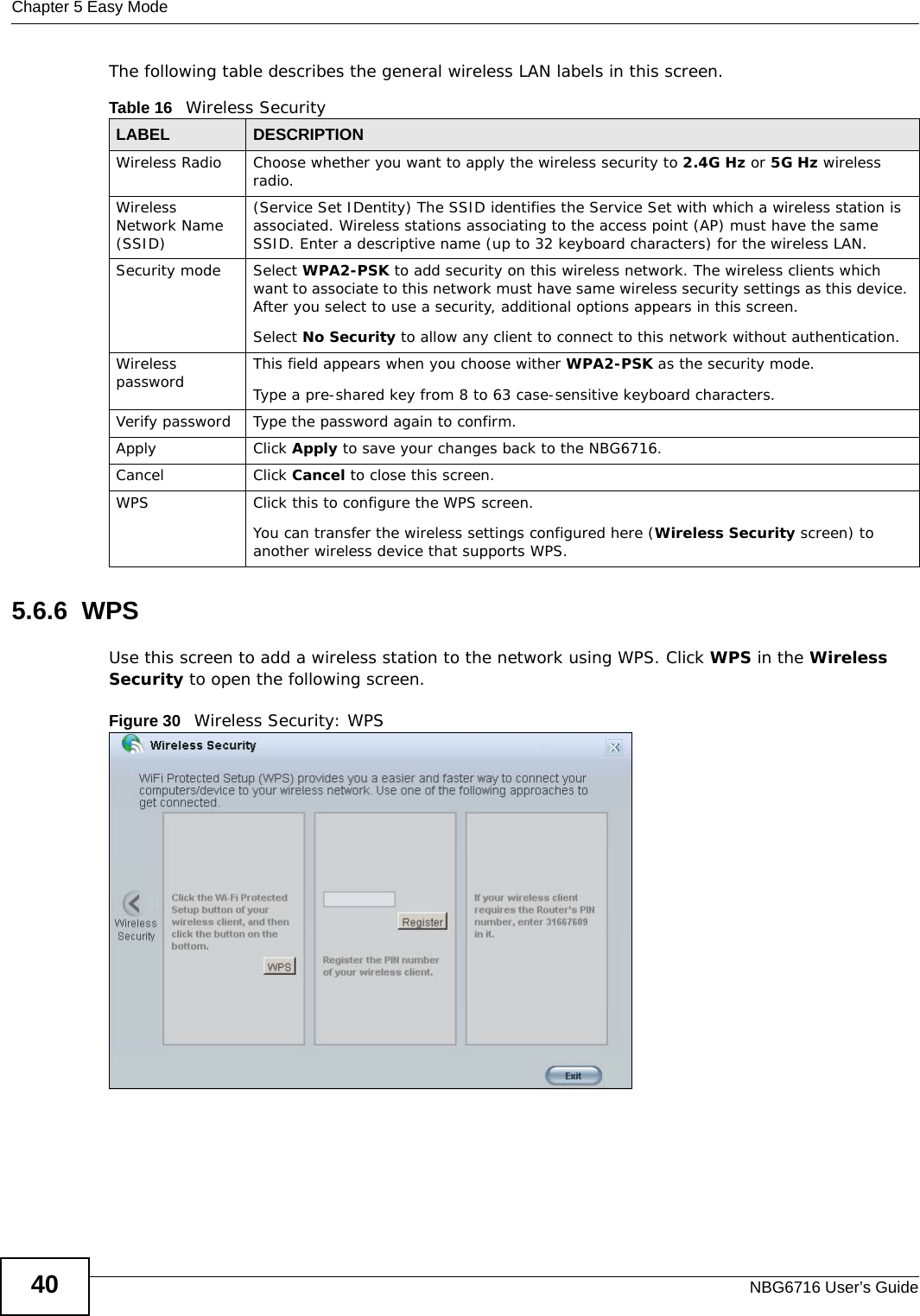
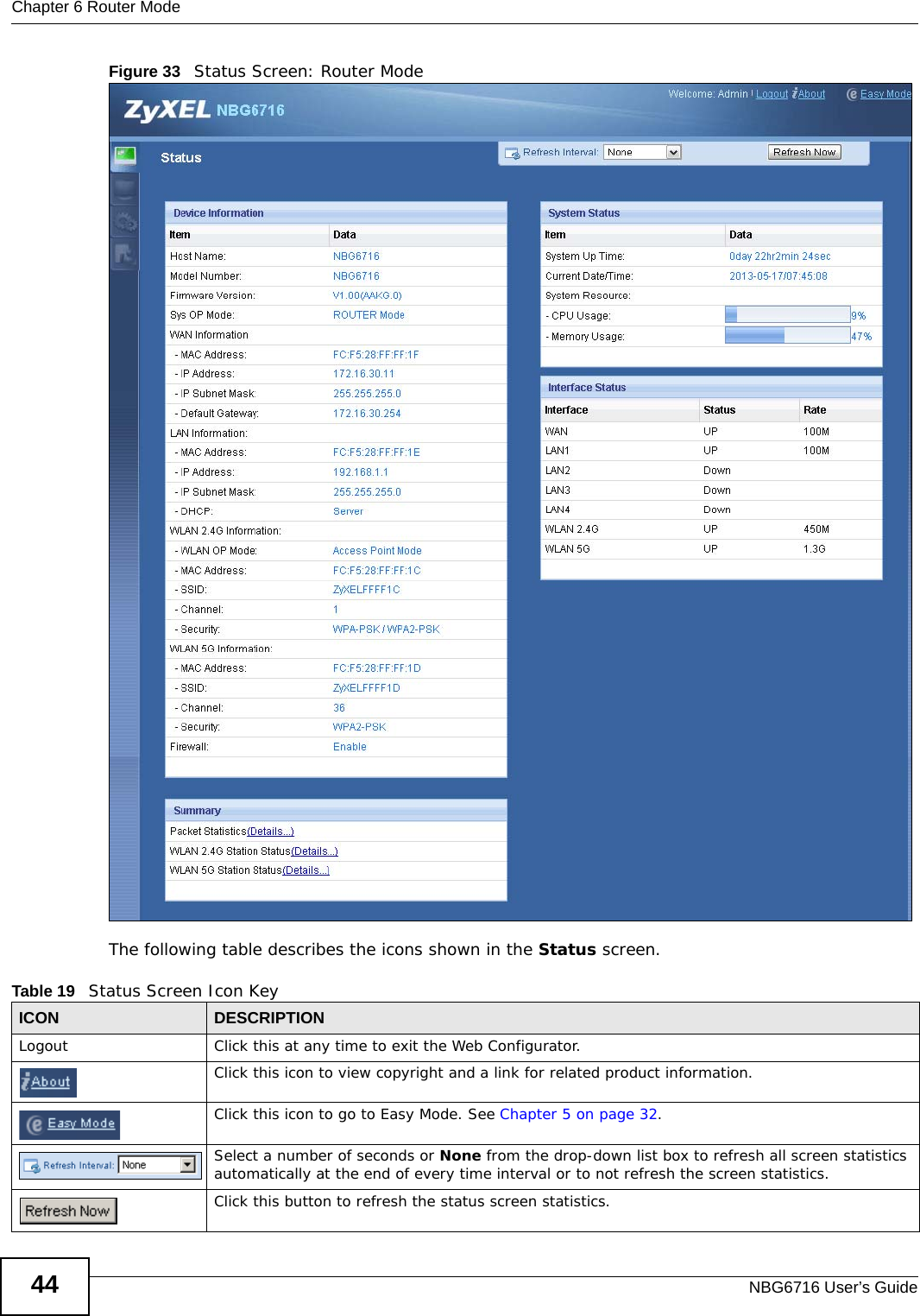
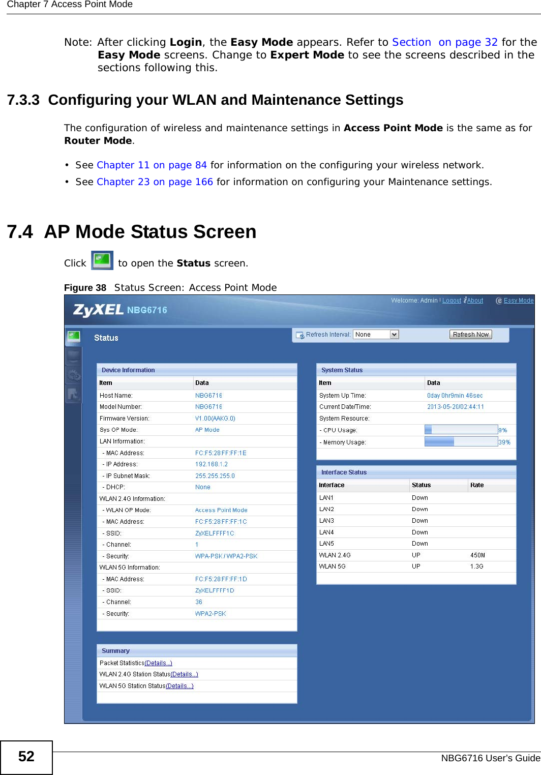
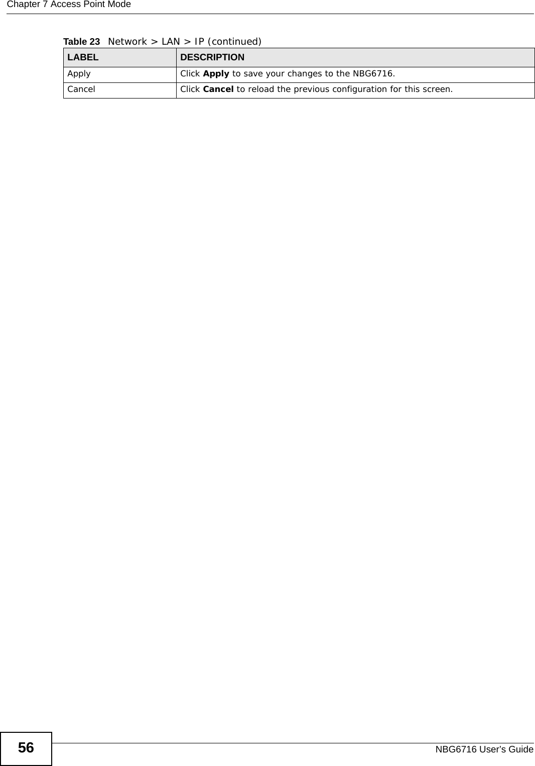
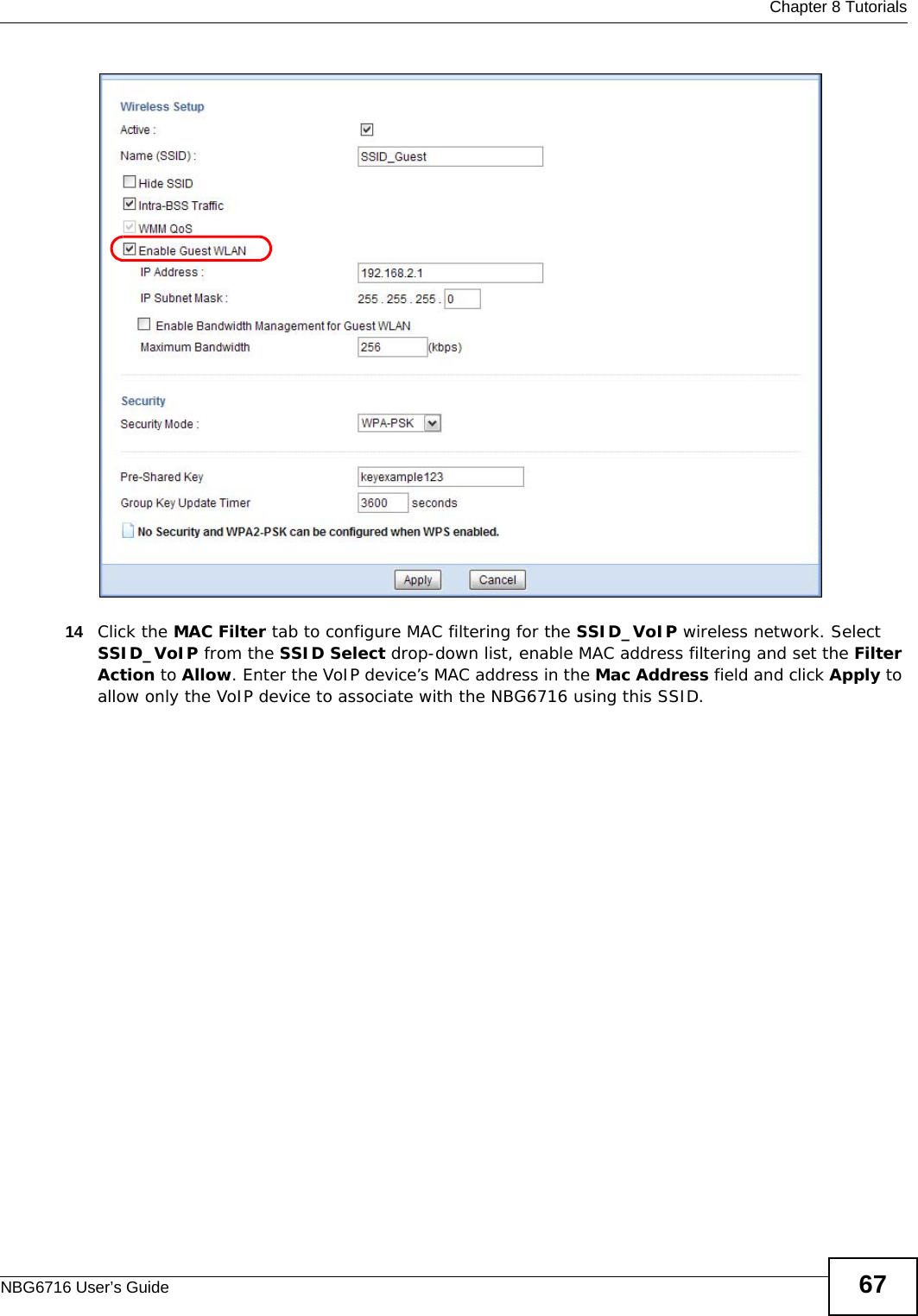
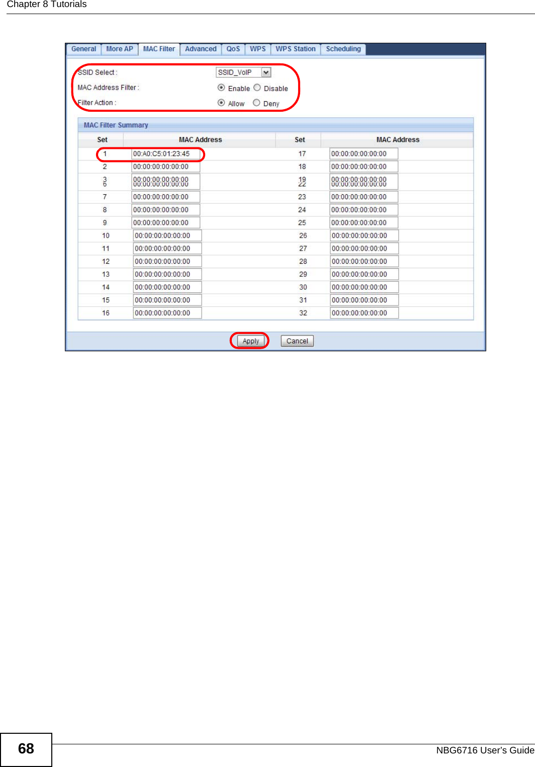
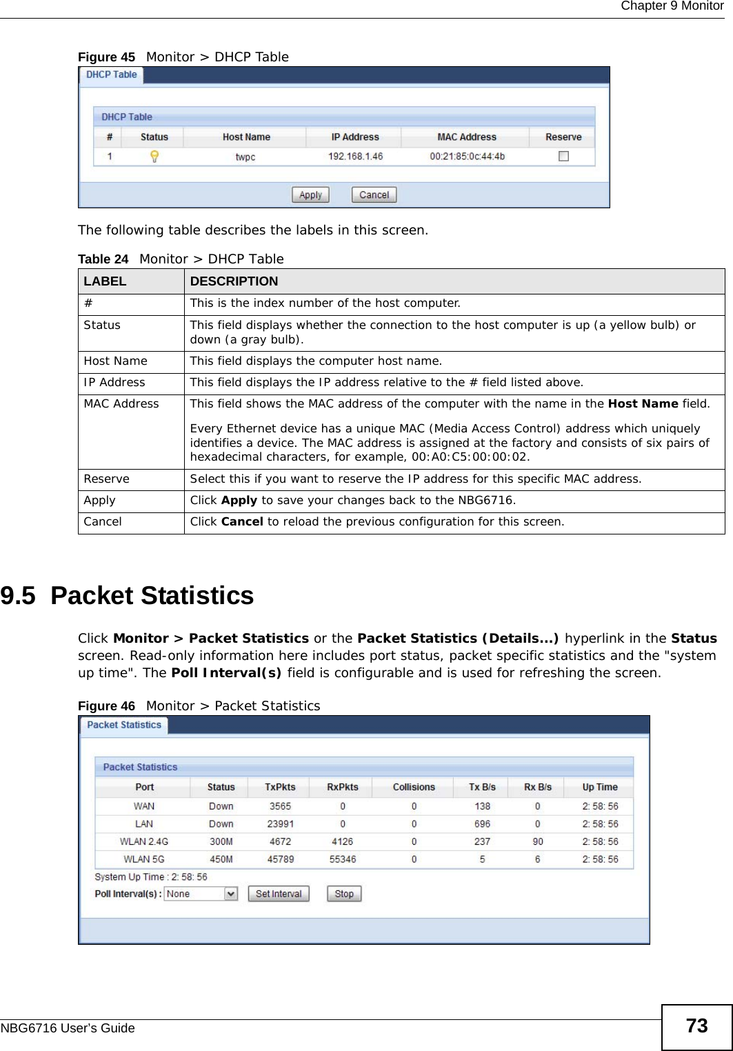
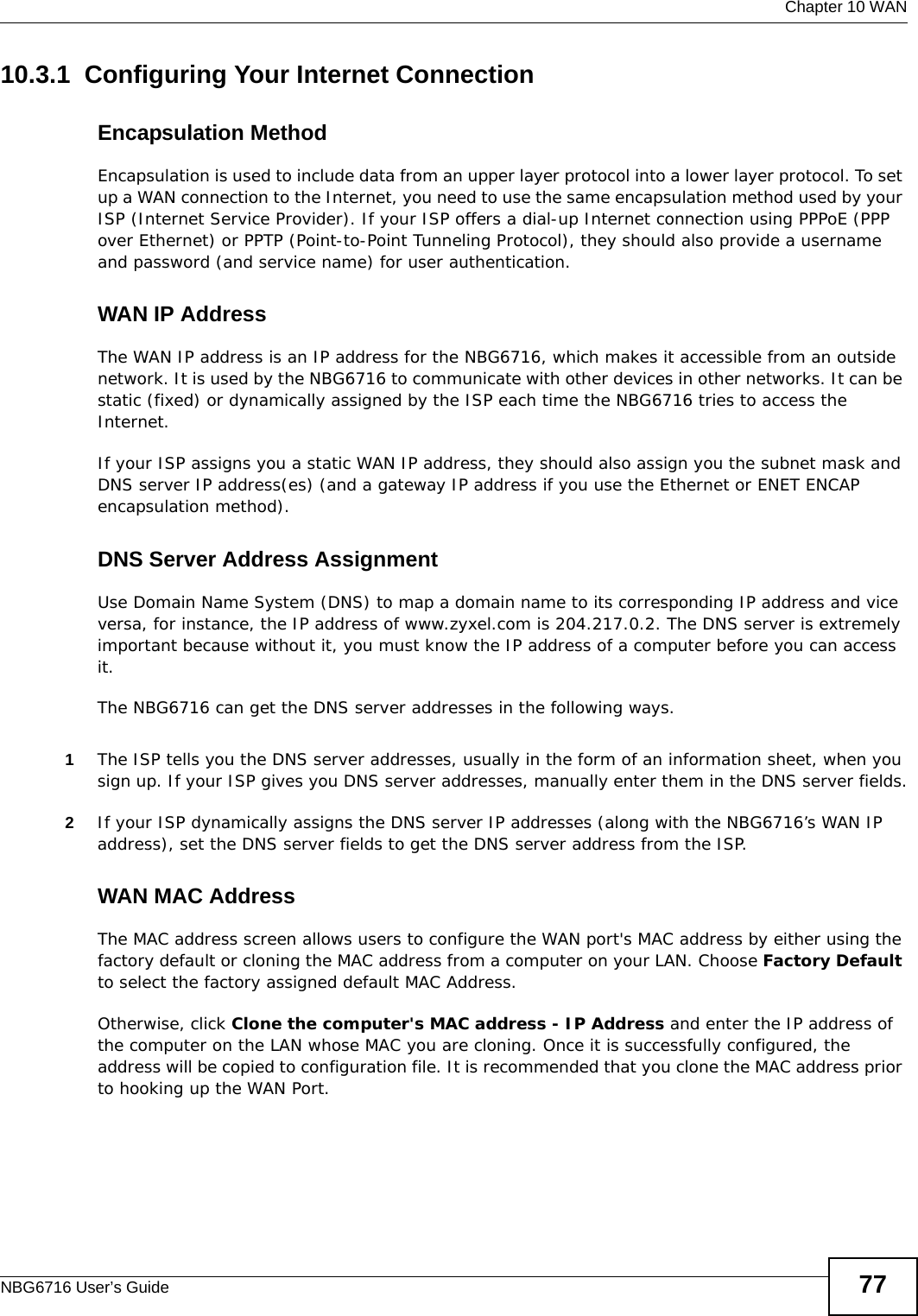
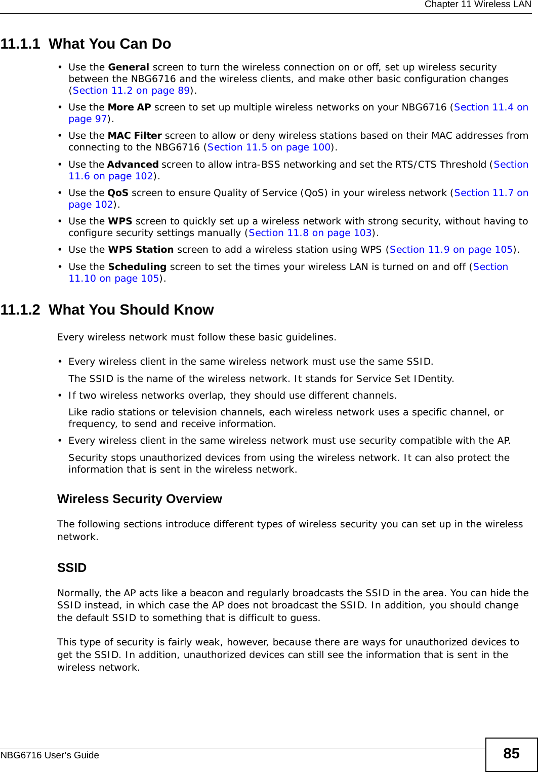
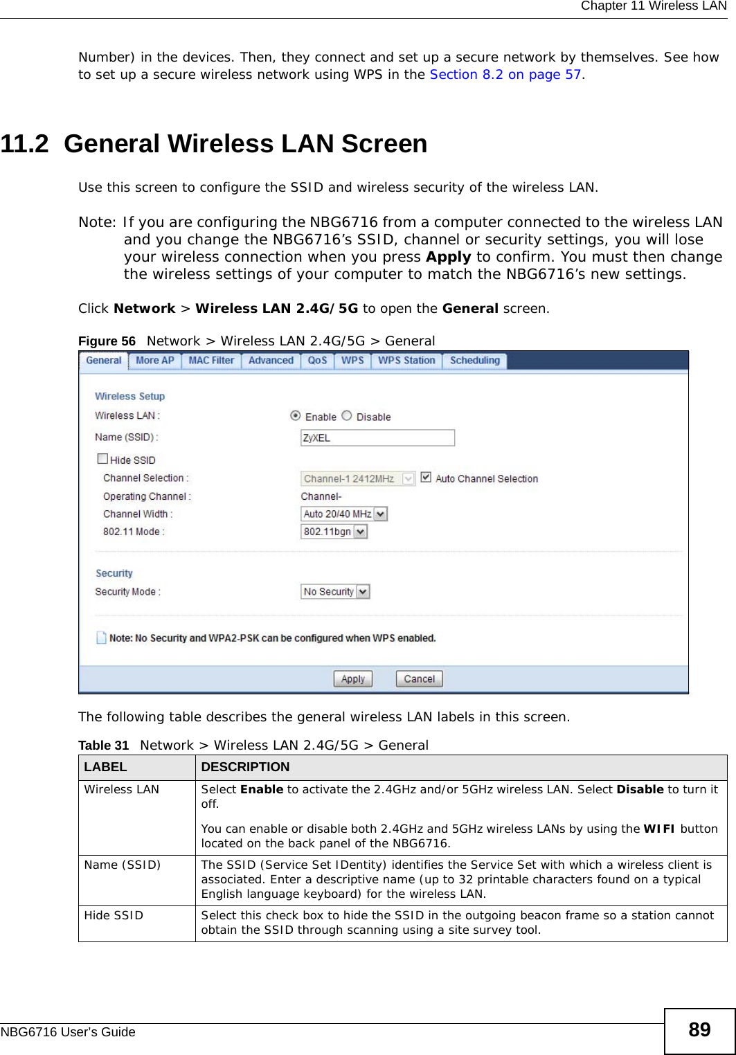
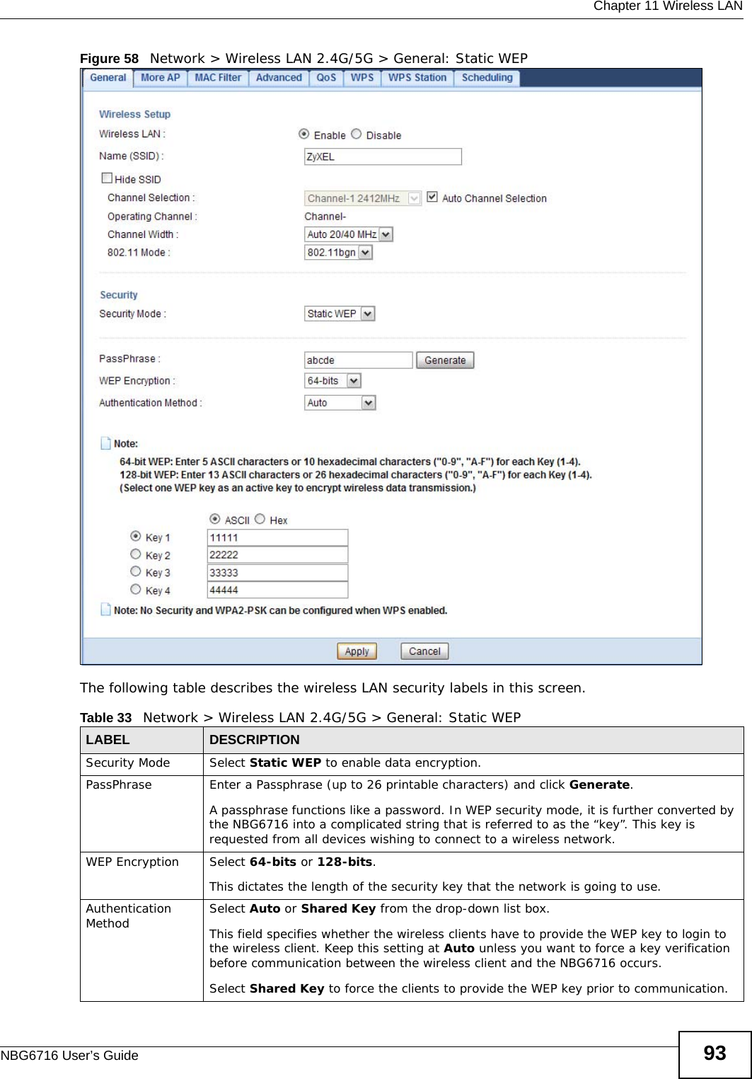
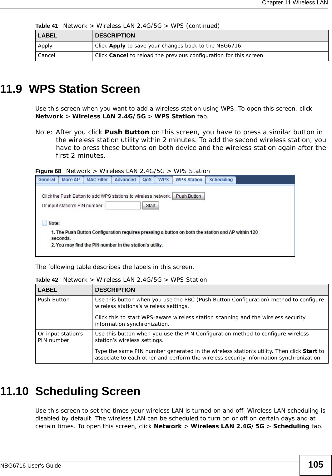
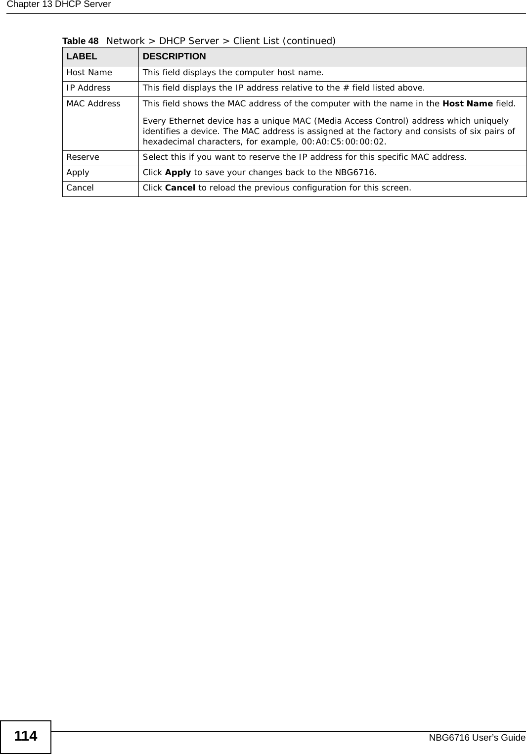
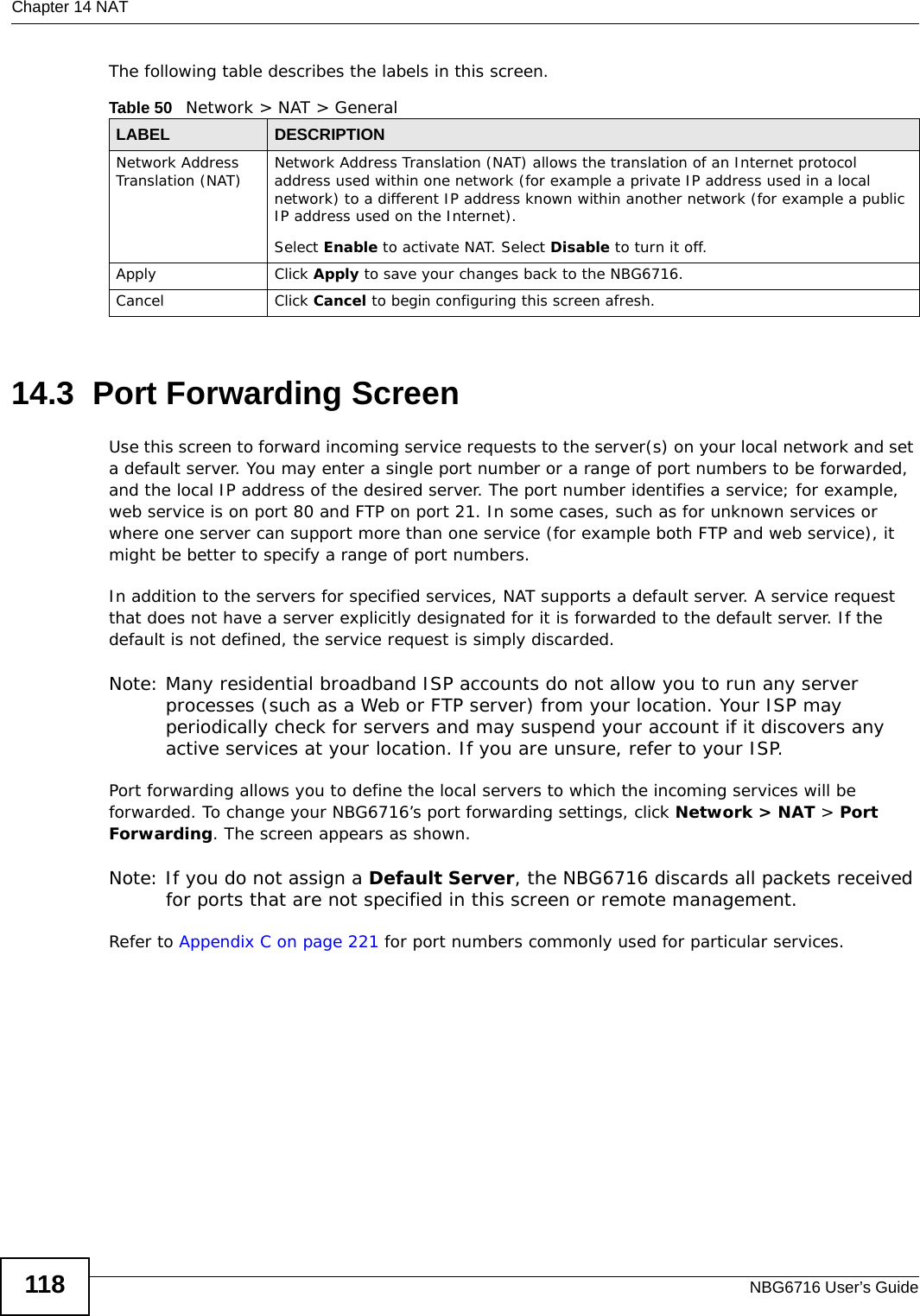
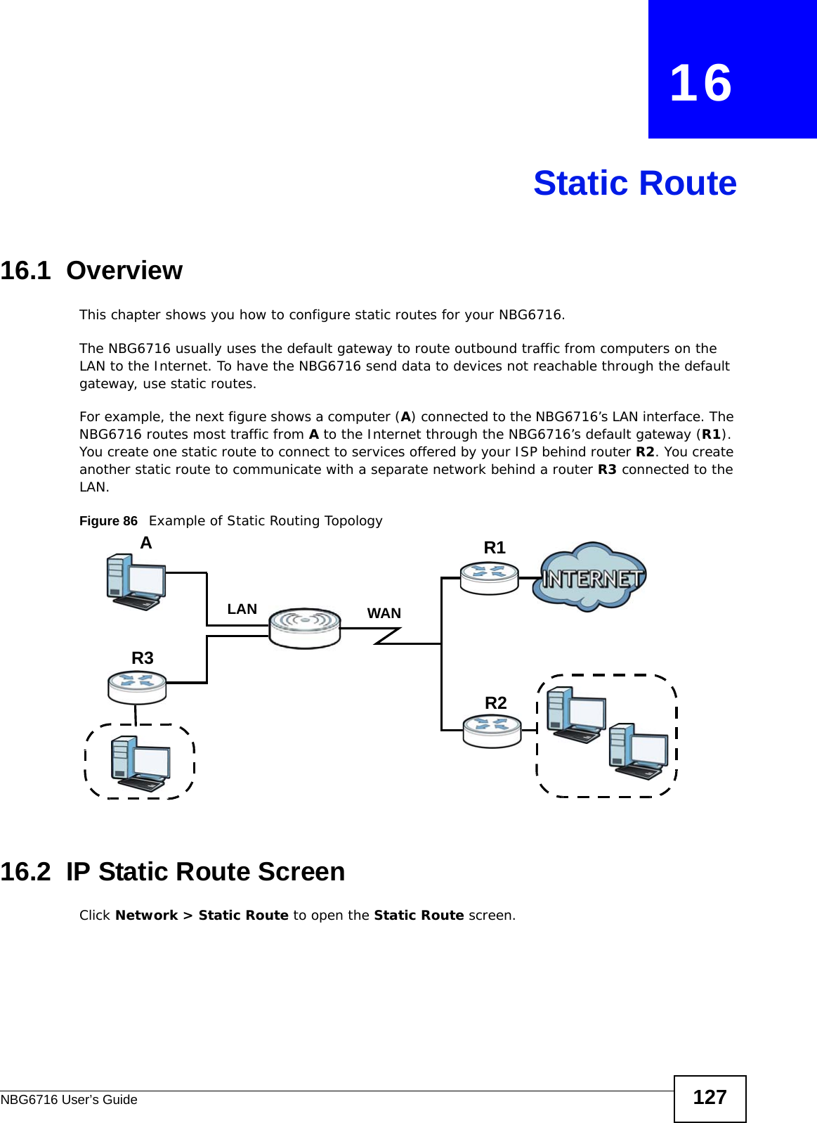
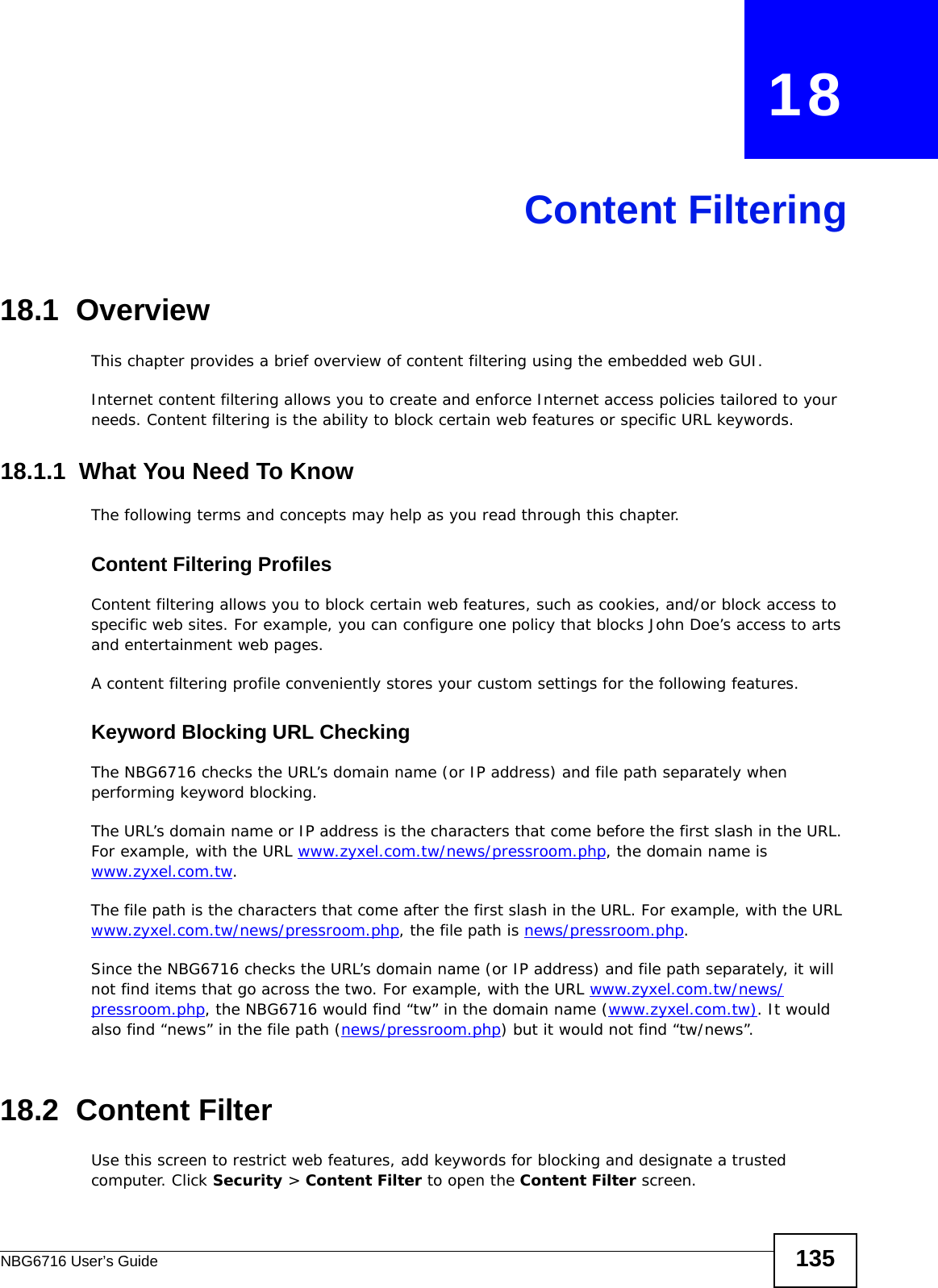
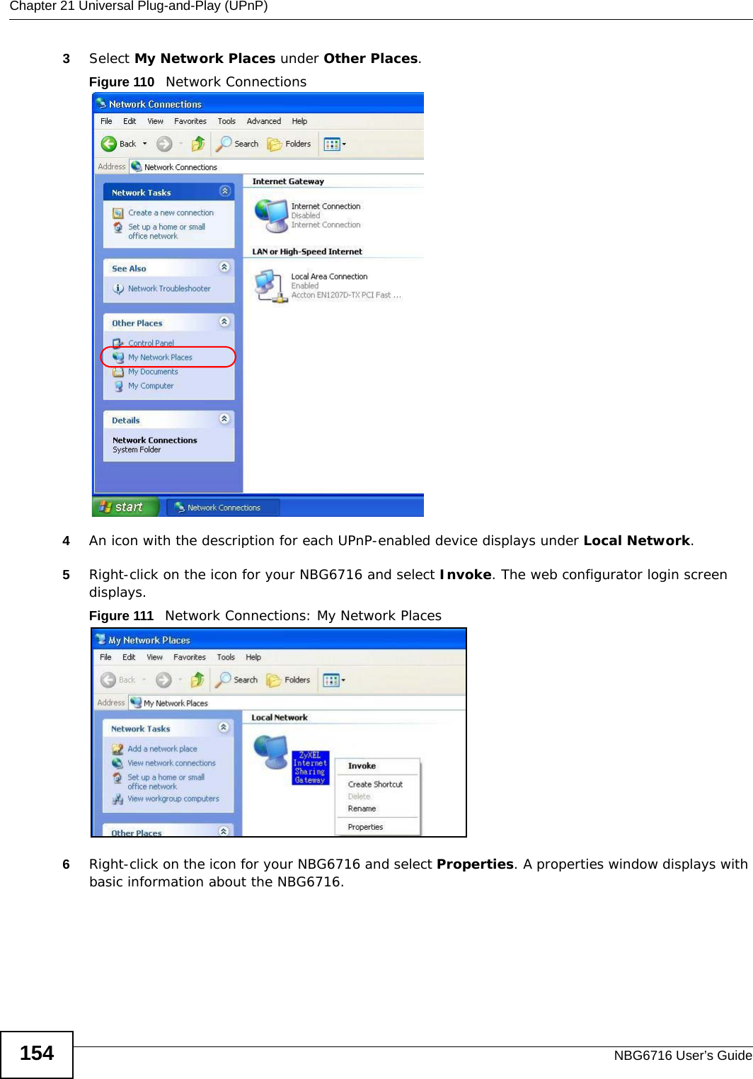
![Chapter 22 USB Media SharingNBG6716 User’s Guide1642You can also use the workgroup name to access files by browsing to the workgroup folder using the folder tree on the left side of the screen. It is located under My Network Places. In this example the workgroup name is the default “Workgroup”. 22.8.2 Use FTP to Share FilesYou can use FTP to access the USB storage devices connected to the NBG6716. In this example, we use the web browser to share files via FTP from the LAN. The way or screen you log into the FTP server (on the NBG6716) varies depending on your FTP client. See your FTP client documentation for more information. You should have enabled file sharing and create a user account (Bob/1234 for example) with read and write access to USB 1 in the USB Media Sharing > FTP screen.1In your web browser’s address or URL bar type “ftp://” followed by the IP address of the NBG6716 (the default LAN IP address of the NBG6716 in router mode is 192.168.1.1) and click Go or press [ENTER].](https://usermanual.wiki/ZyXEL-Communications/NBG6716.User-Manual-Part-1-pdf/User-Guide-2039427-Page-164.png)