ZyXEL Communications P660HNT1AV2 Wireless N-lite ADSL2+ 4-port Gateway User Manual
ZyXEL Communications Corporation Wireless N-lite ADSL2+ 4-port Gateway
UserManual.wiki
>
ZyXEL Communications
>
P660HNT1AV2 User Manual
User Manual
Navigation menu
Upload a User Manual
Namespaces
Wiki Guide
HTML
PDF
Info
Views
User Manual
Discussion / Help
Navigation
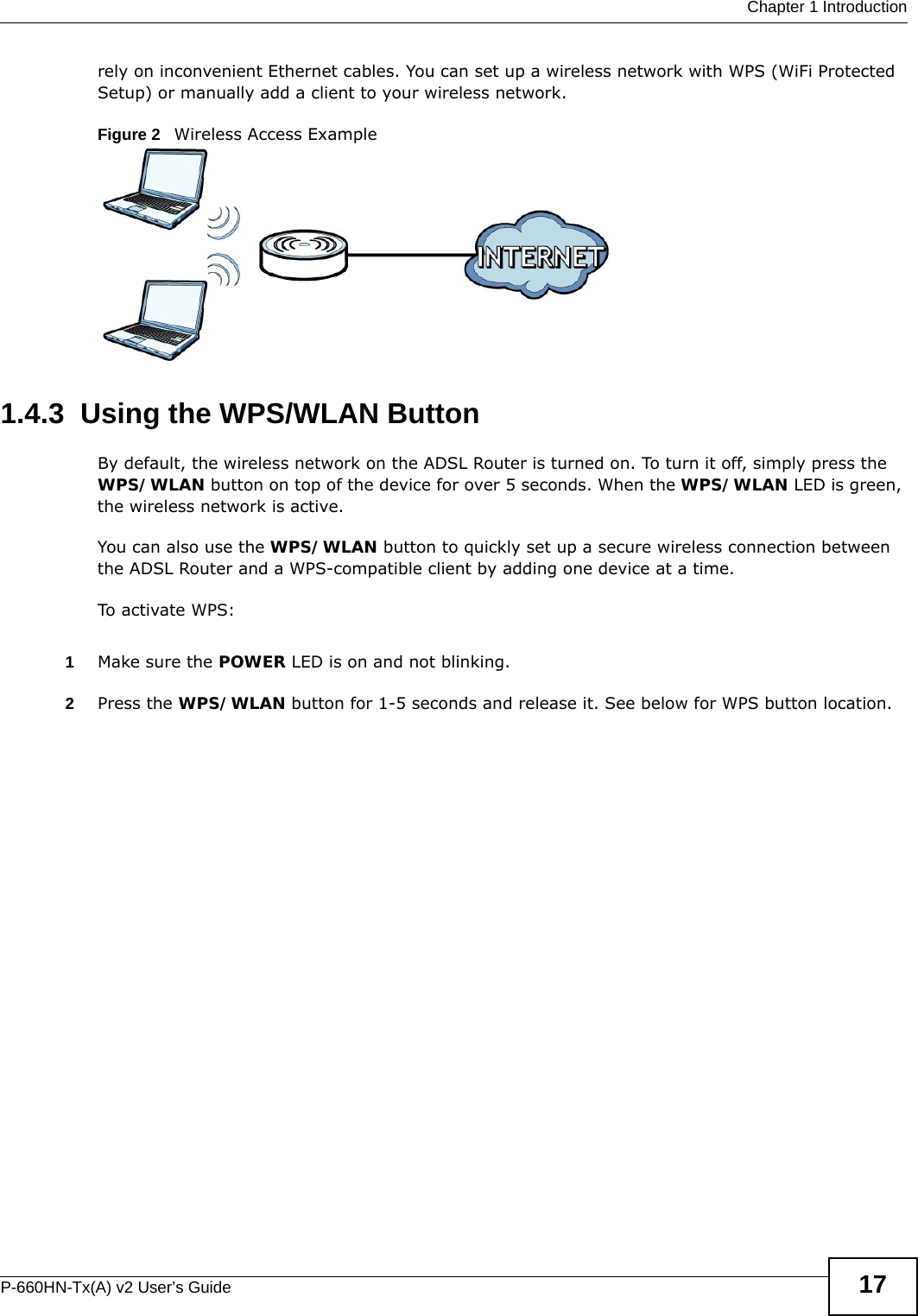

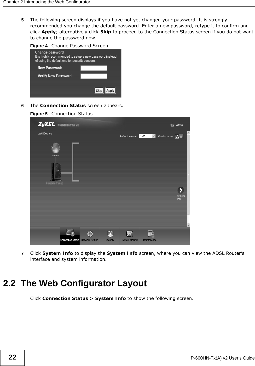
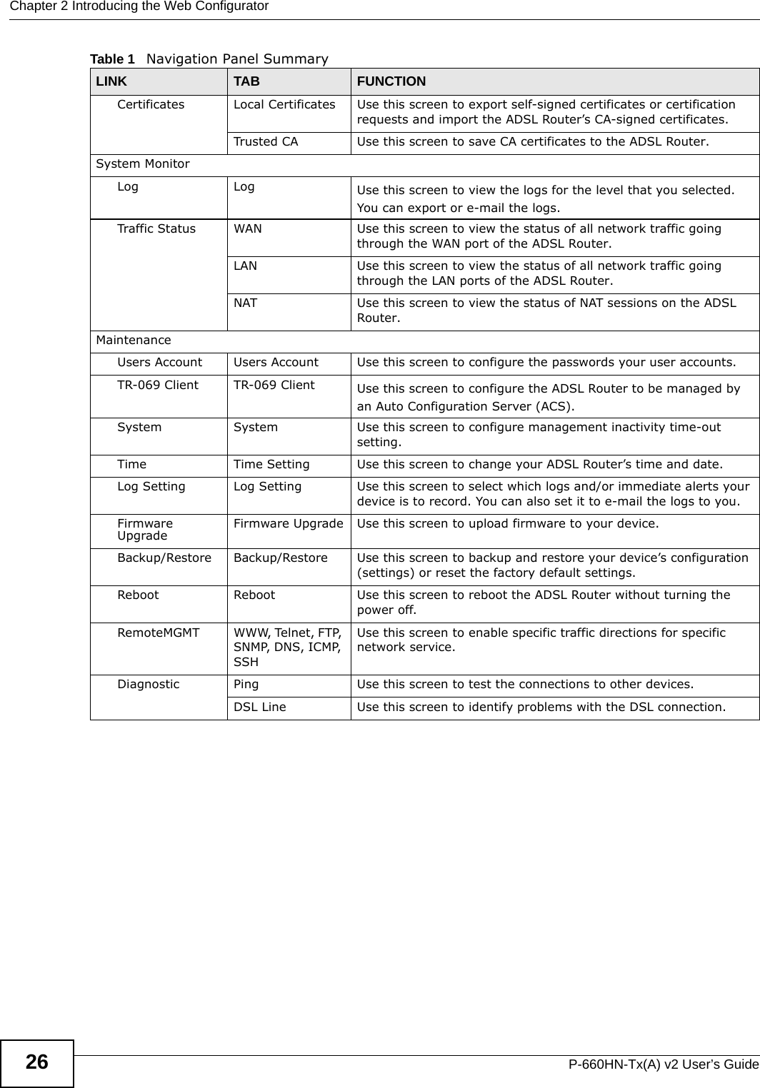

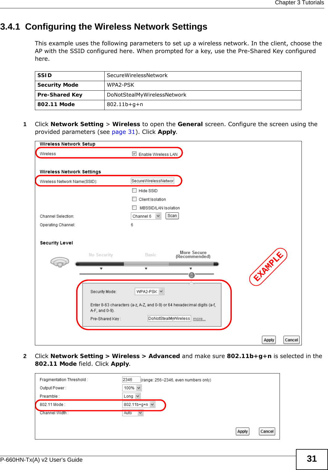
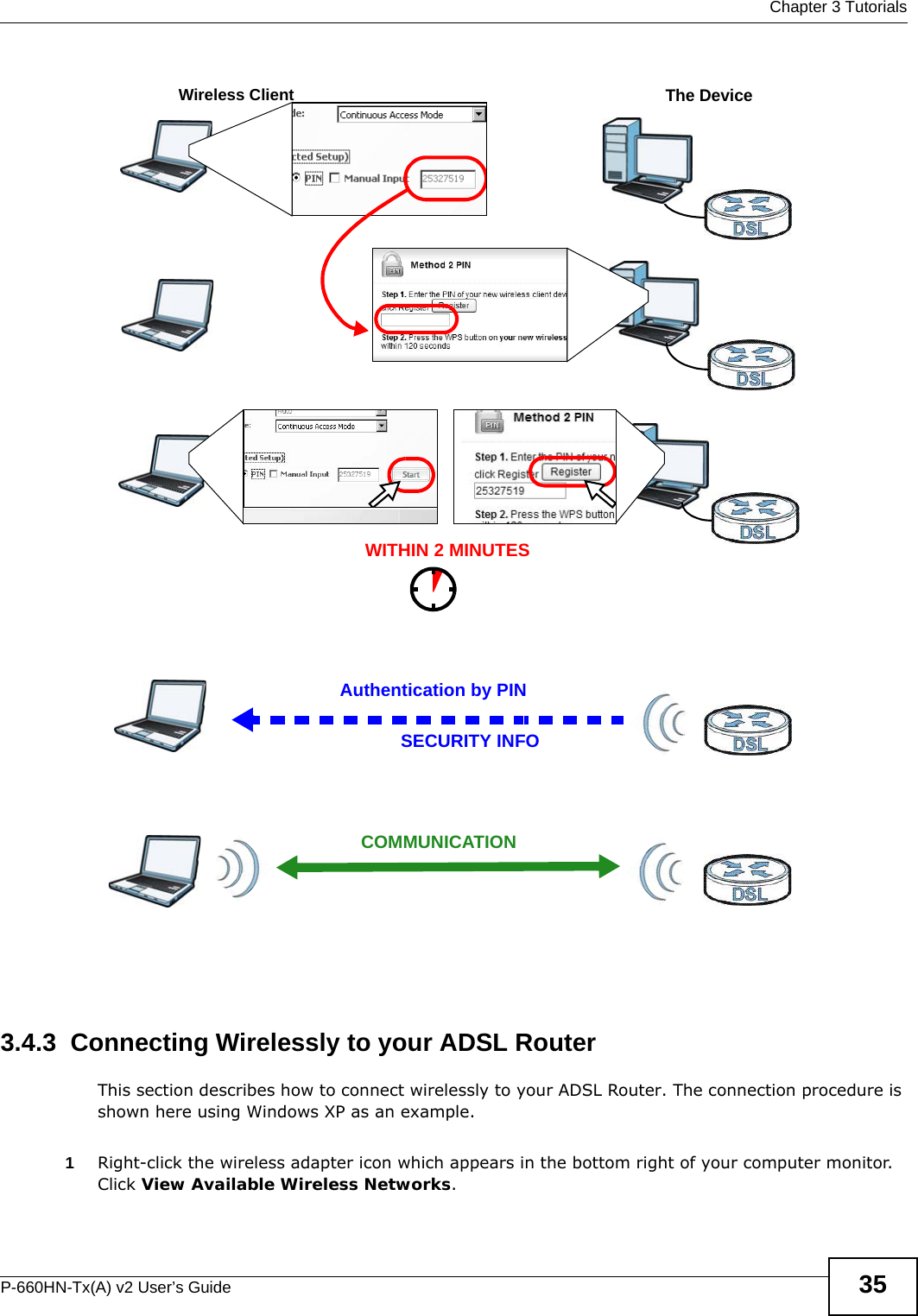
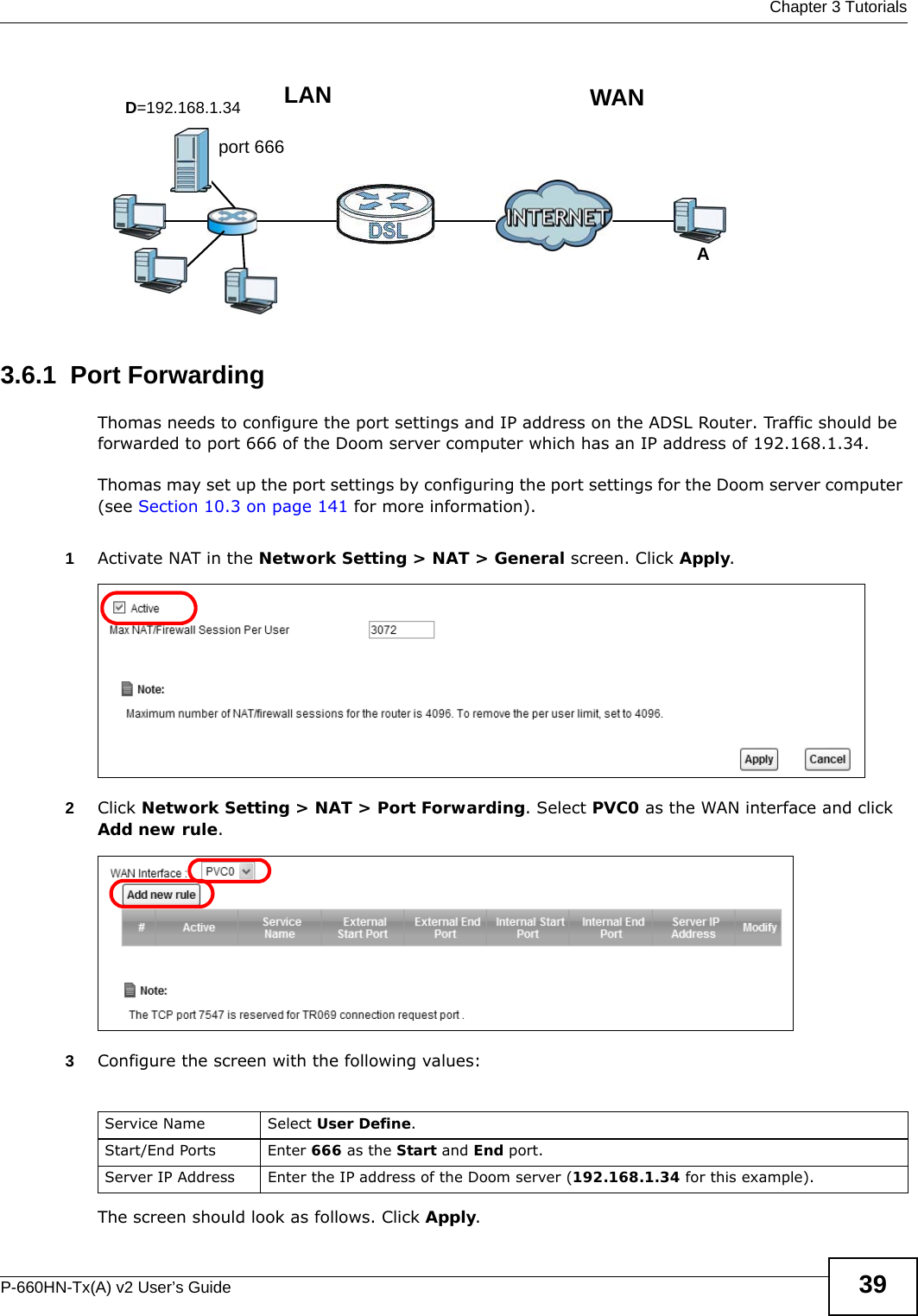
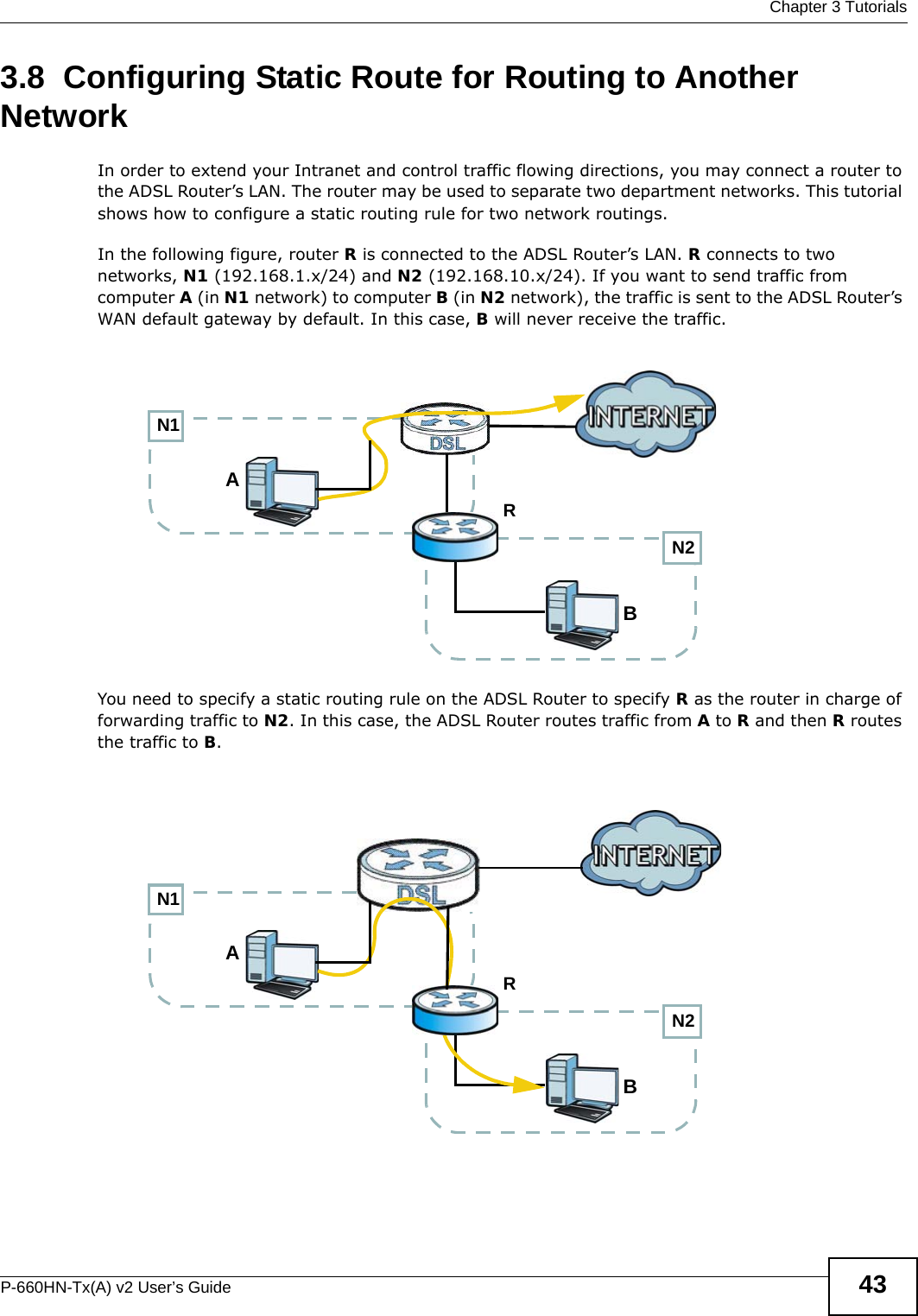
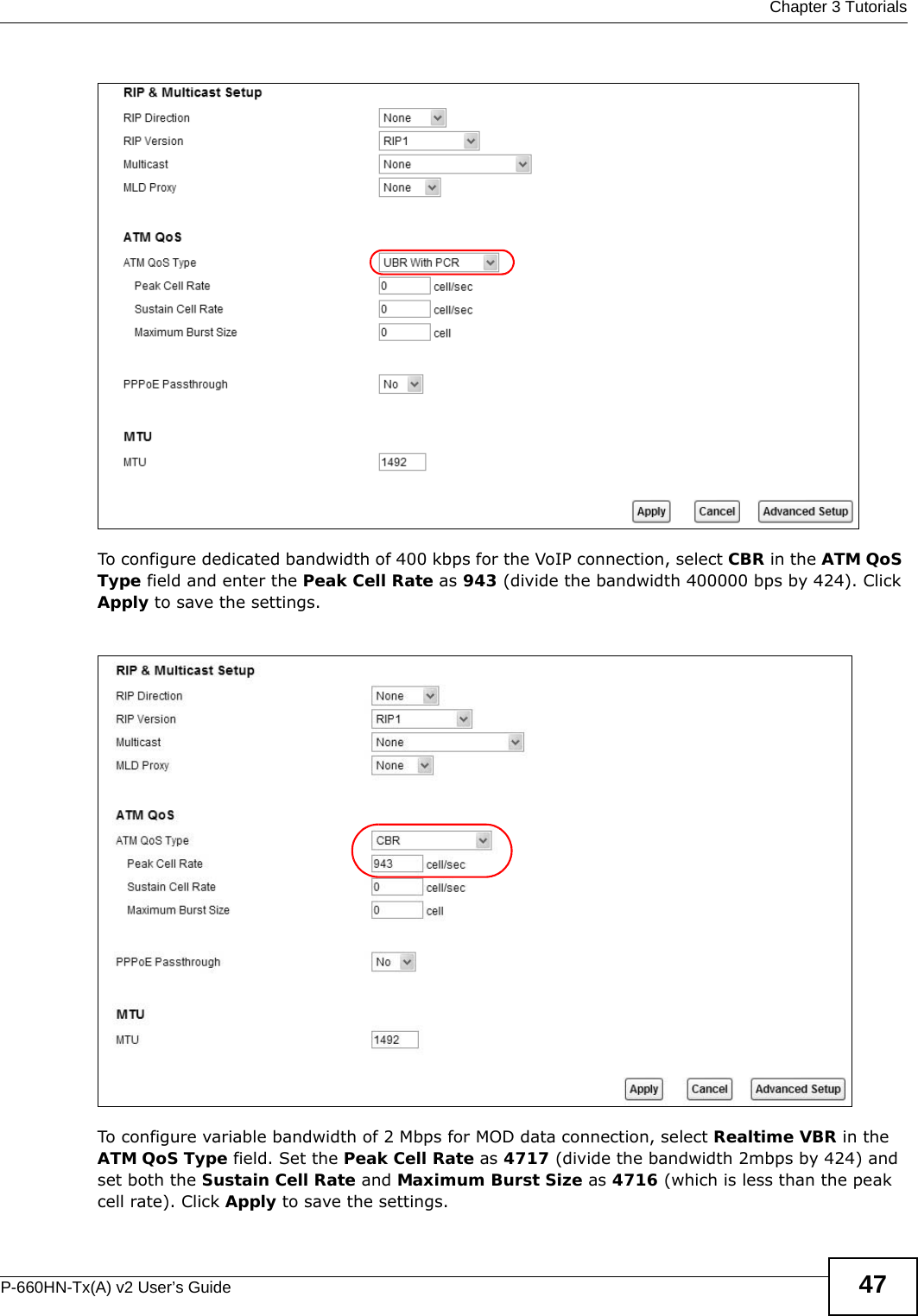
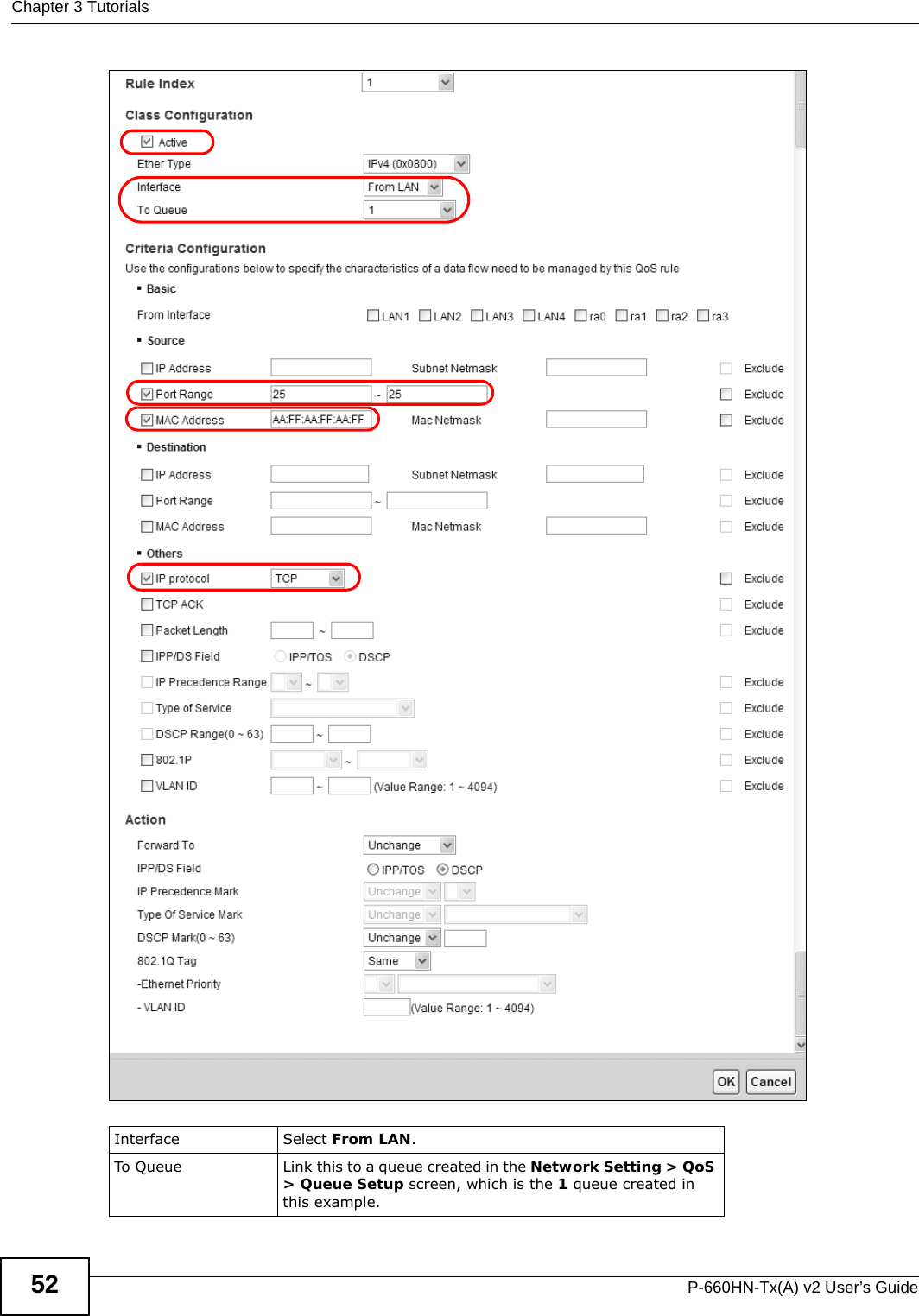
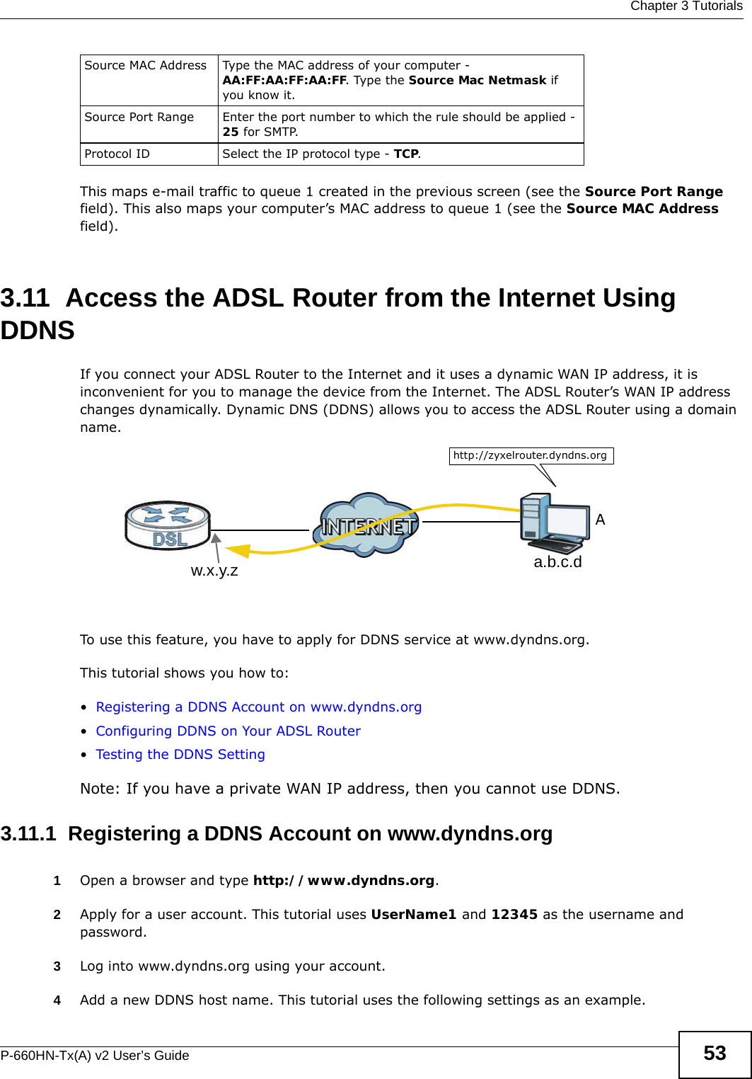
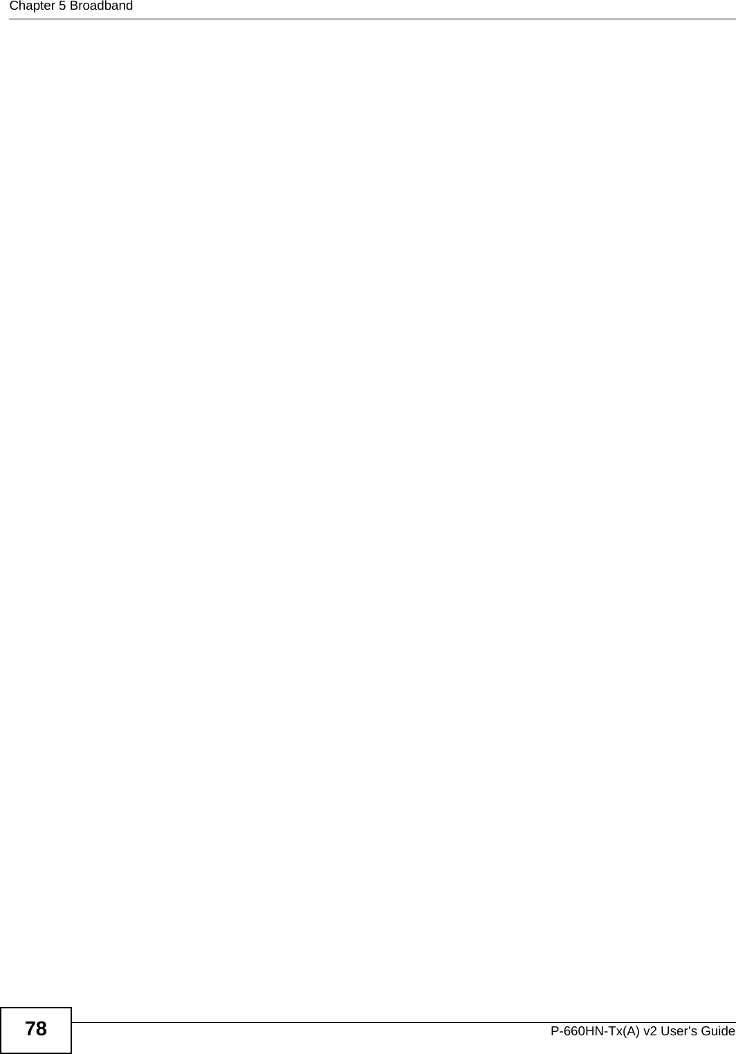
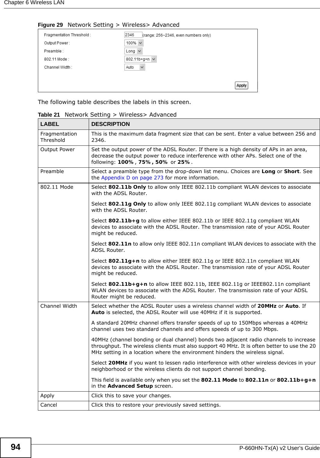
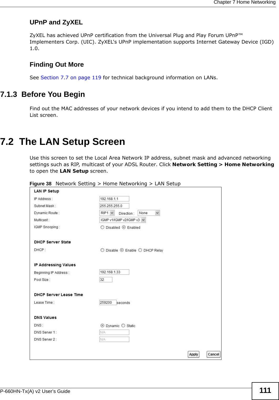
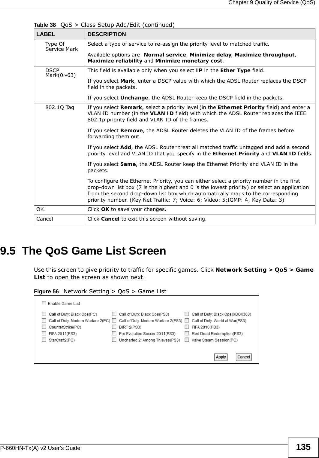
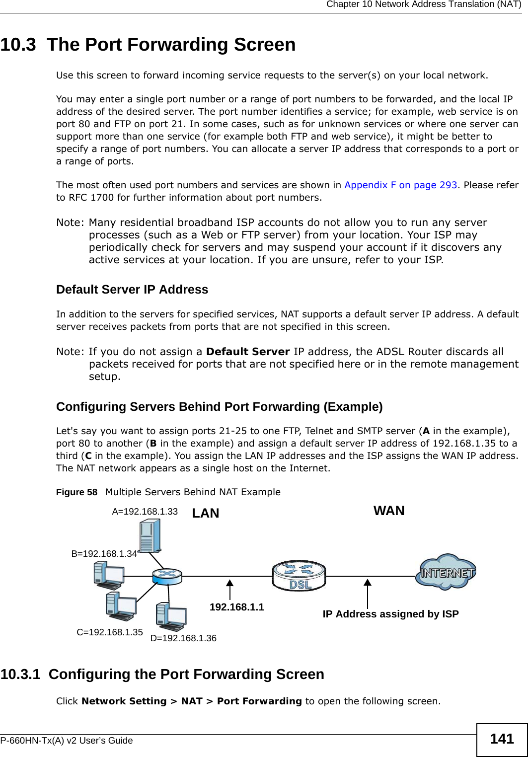
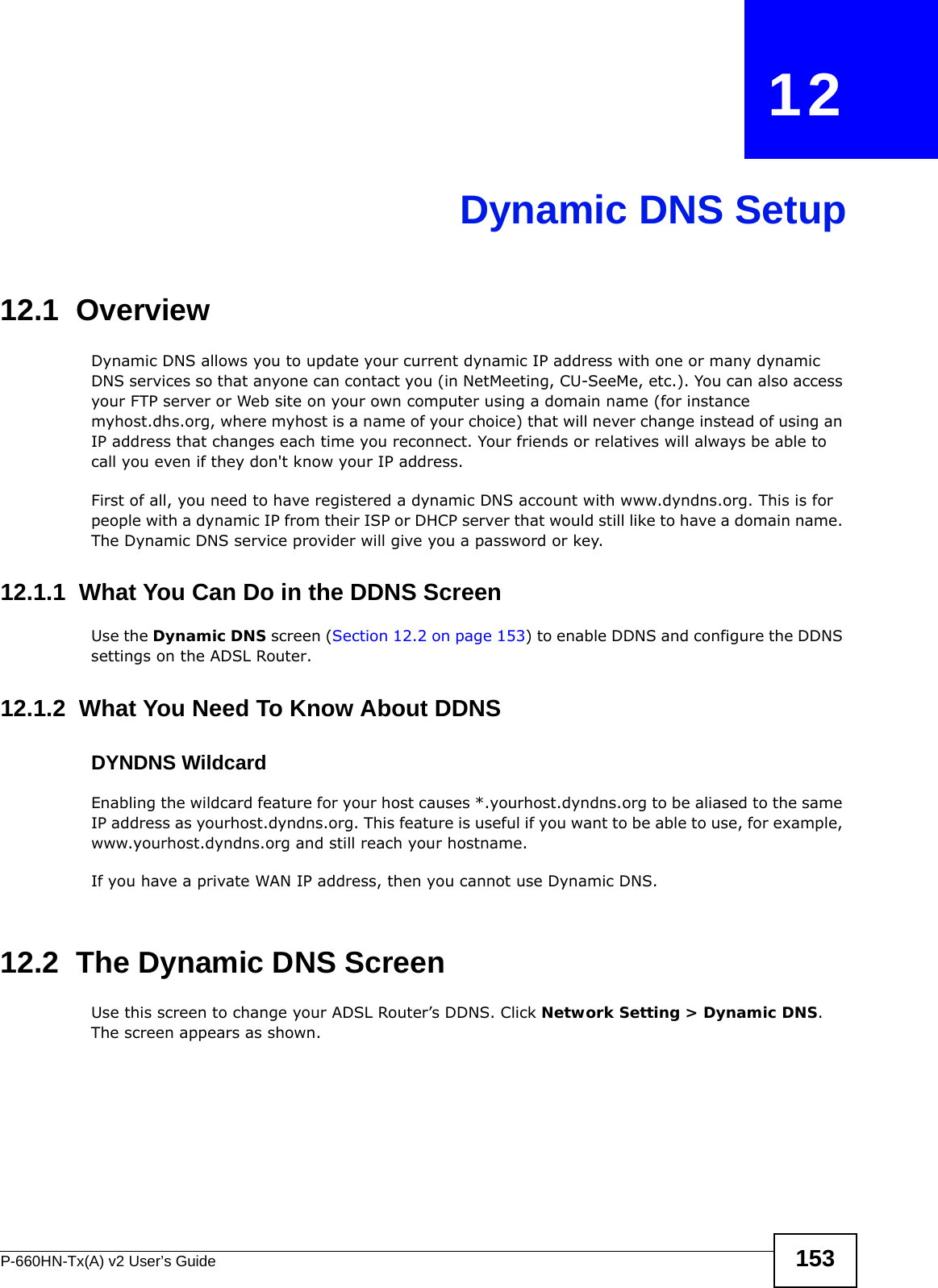
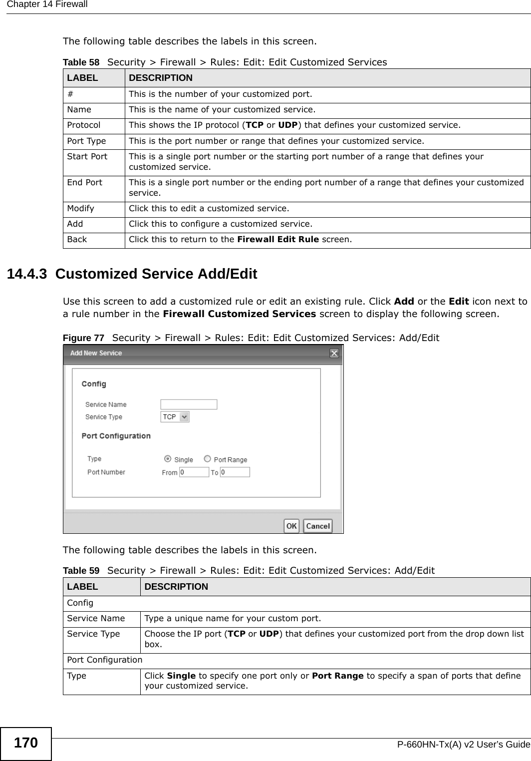
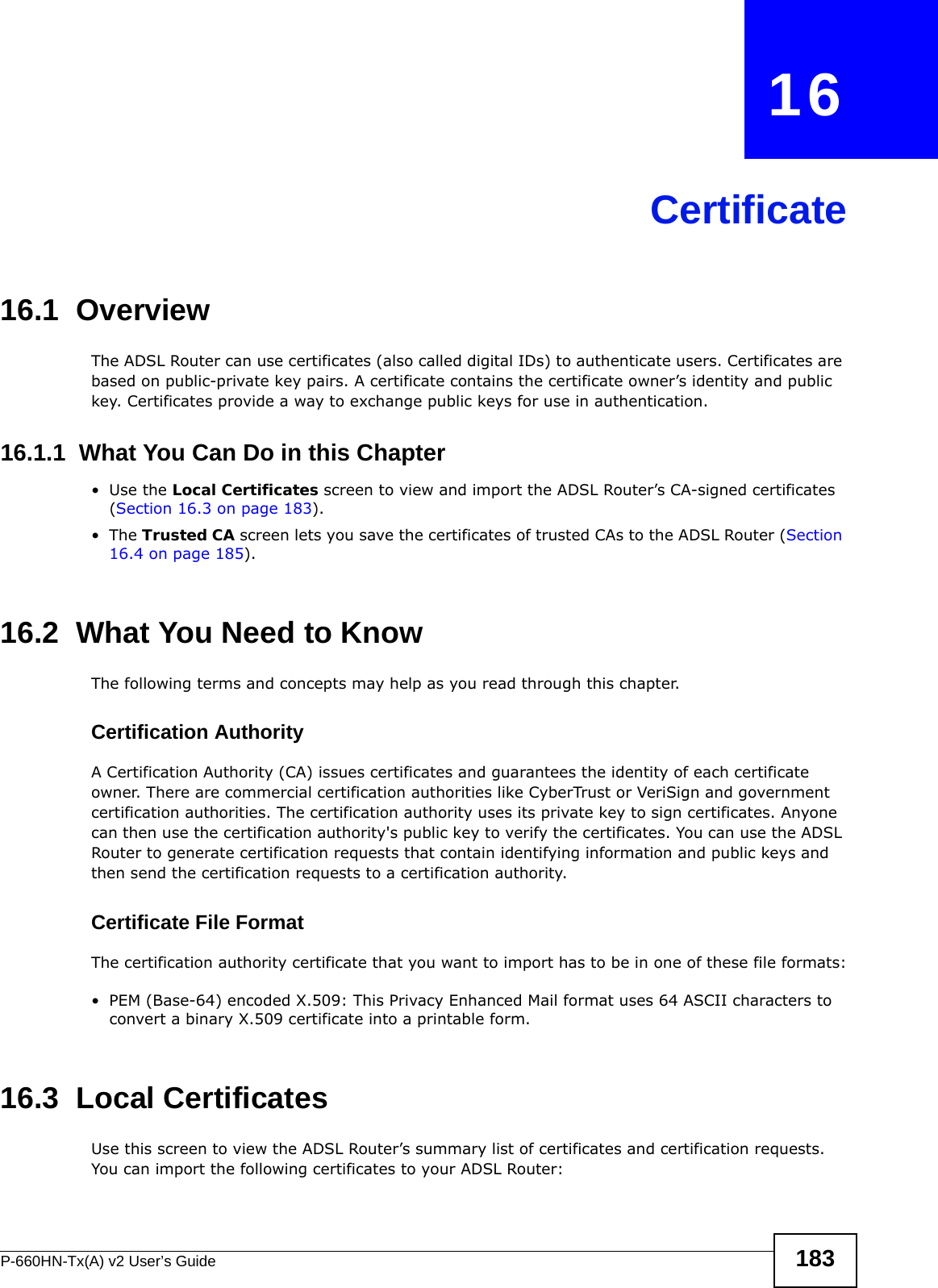
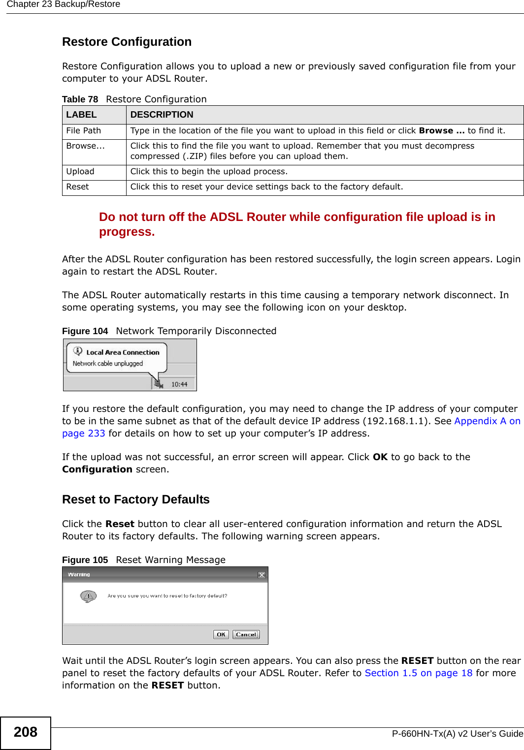
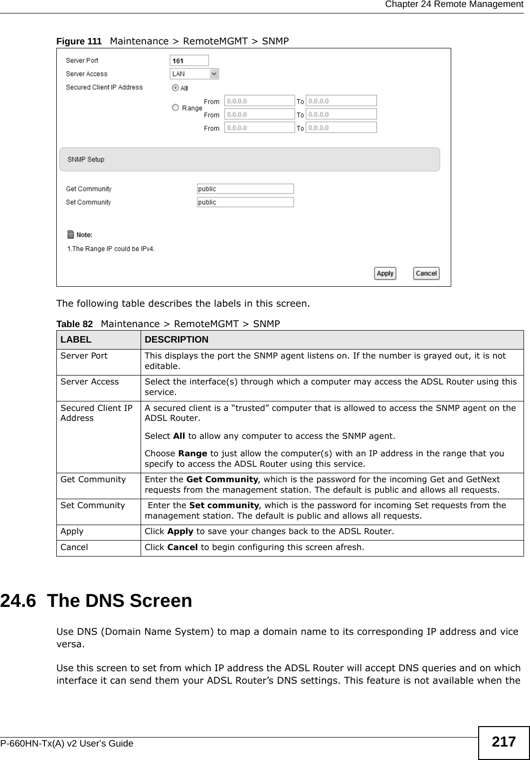
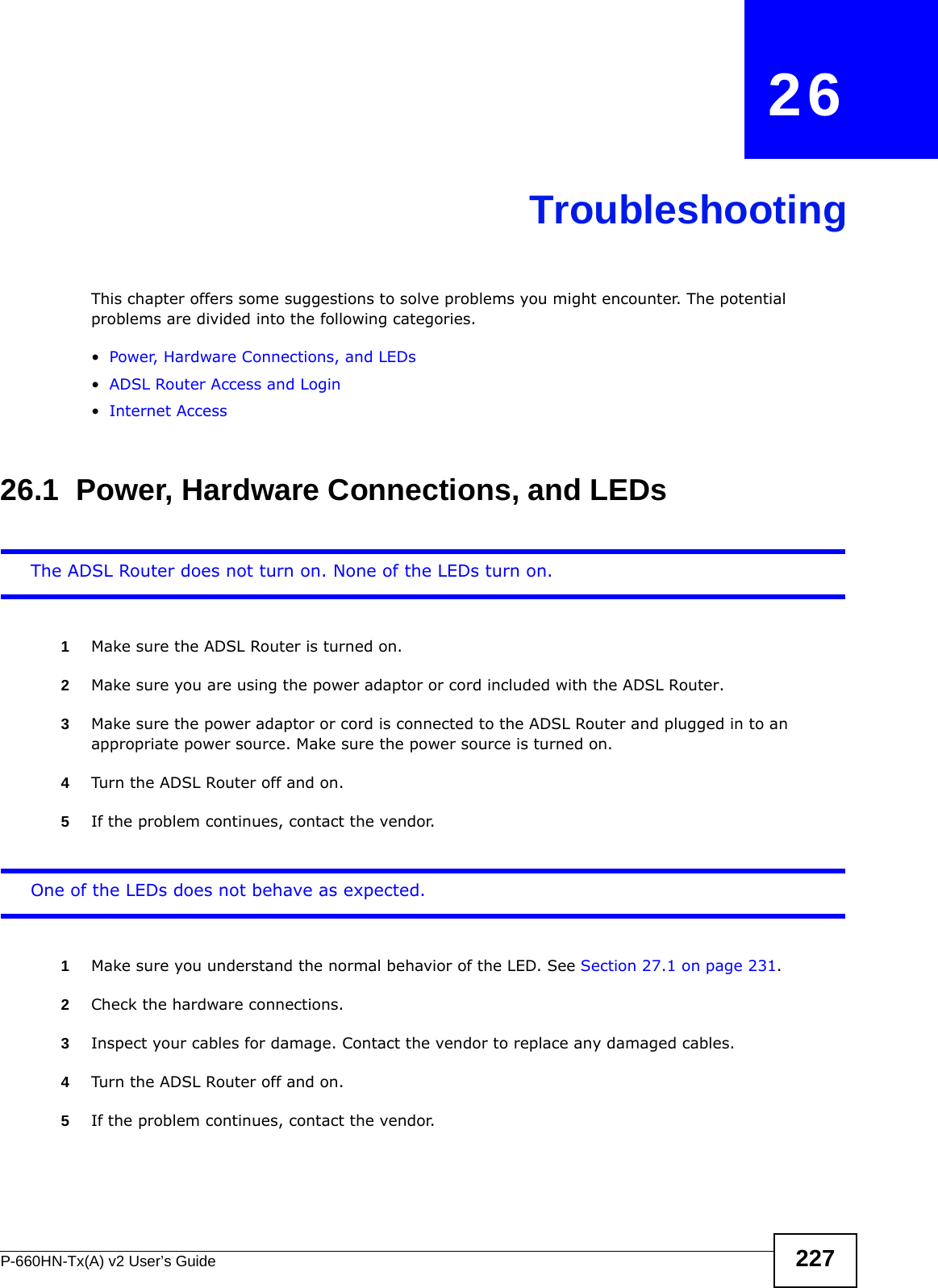
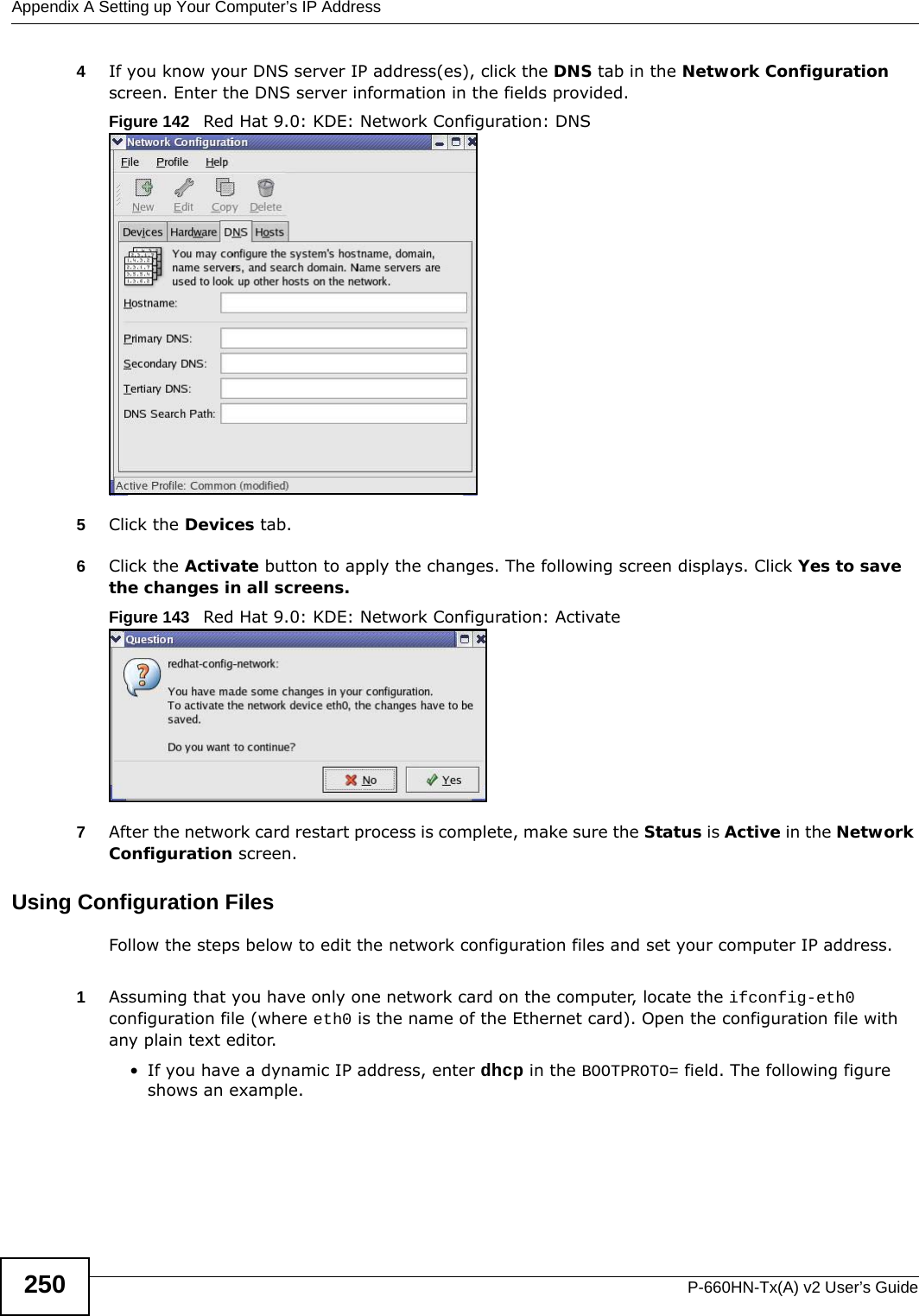
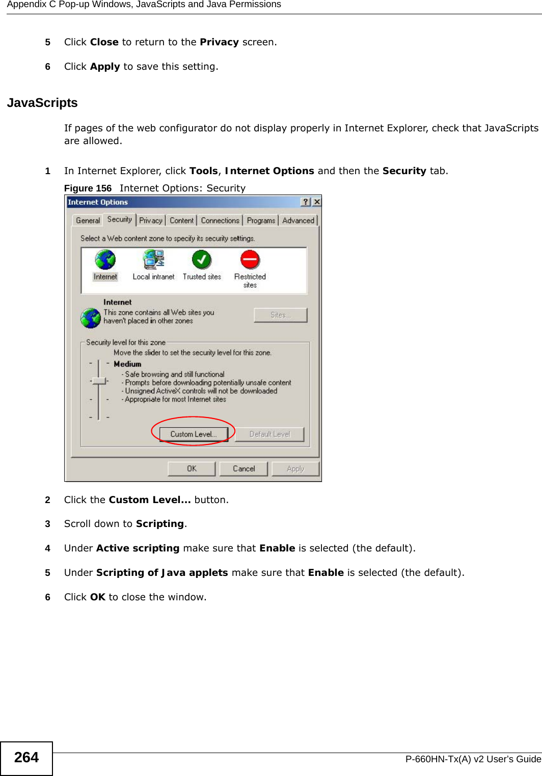
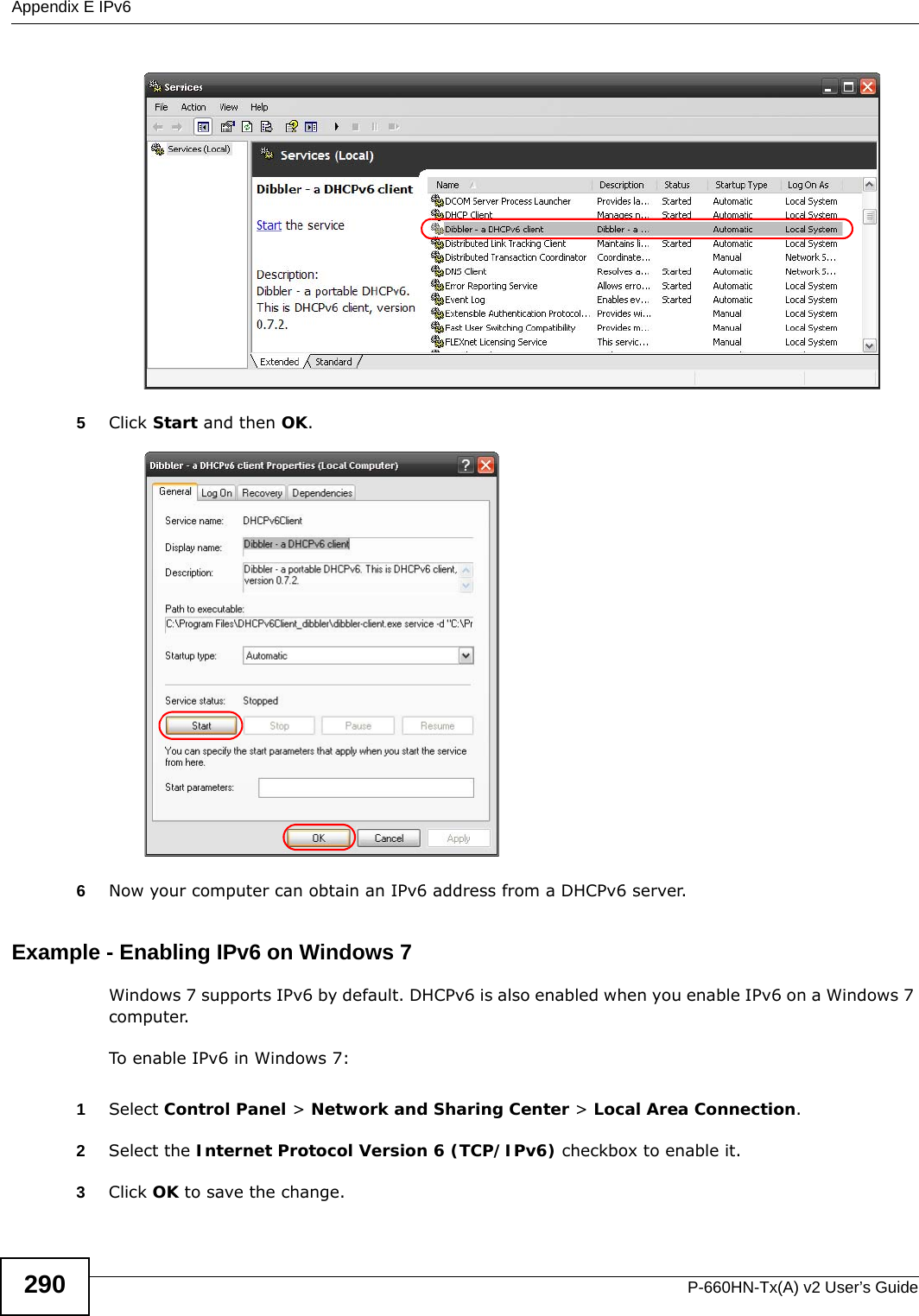
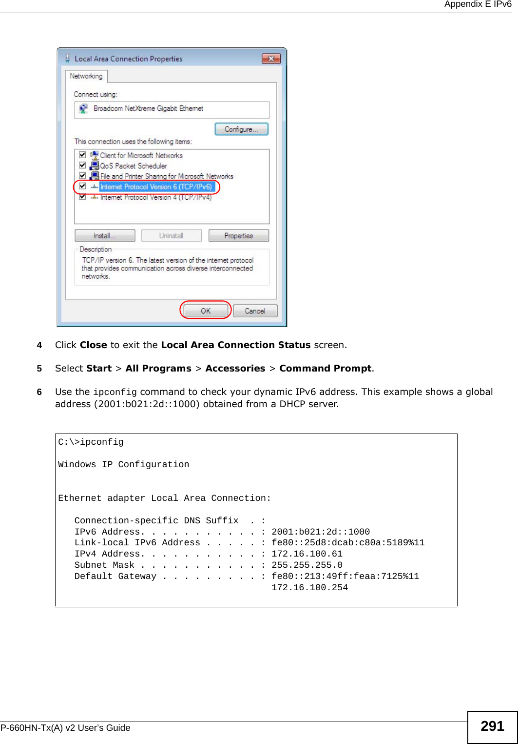
![Chapter 3 TutorialsP-660HN-Tx(A) v2 User’s Guide54•Hostname: zyxelrouter.dyndns.org•Service Type: Host with IP address• IP Address: Enter the WAN IP address that your ADSL Router is currently using. You can find the IP address on the ADSL Router’s web configurator Status page.Then you will need to configure the same account and host name on the ADSL Router later.3.11.2 Configuring DDNS on Your ADSL RouterConfigure the following settings in the Network Setting > Dynamic DNS screen.•Select Active Dynamic DNS.•Select www.dyndns.org in the Service Provider field.•Type zyxelrouter.dyndns.org in the Host Name field.• Enter the user name (UserName1) and password (12345).Click Apply.3.11.3 Testing the DDNS SettingNow you should be able to access the ADSL Router from the Internet. To test this:1Open a web browser on the computer (using the IP address a.b.c.d) that is connected to the Internet.2Type http://zyxelrouter.dyndns.org and press [Enter].3The ADSL Router’s login page should appear. You can then log into the ADSL Router and manage it.](https://usermanual.wiki/ZyXEL-Communications/P660HNT1AV2/User-Guide-1872984-Page-54.png)


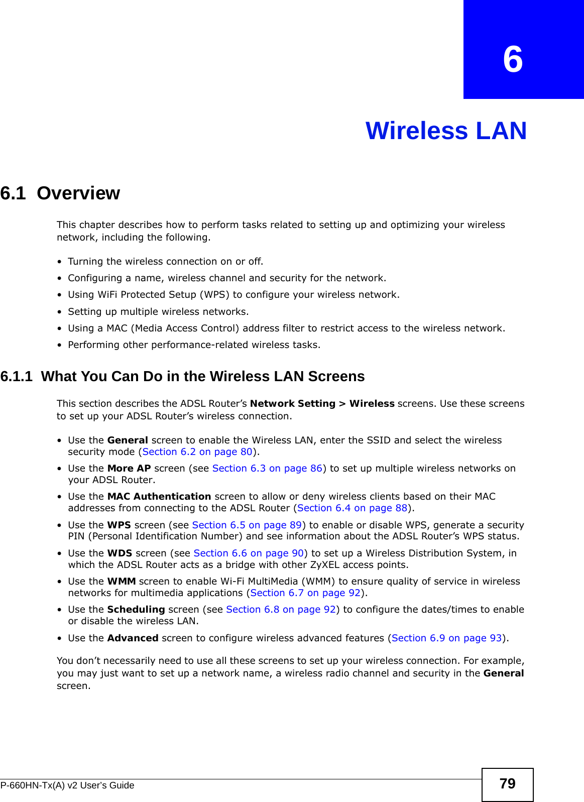
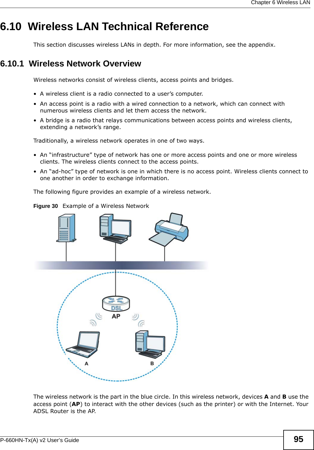

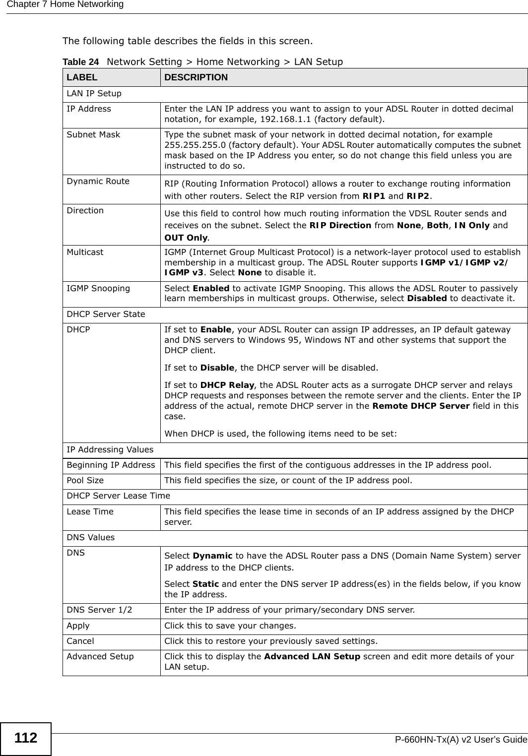
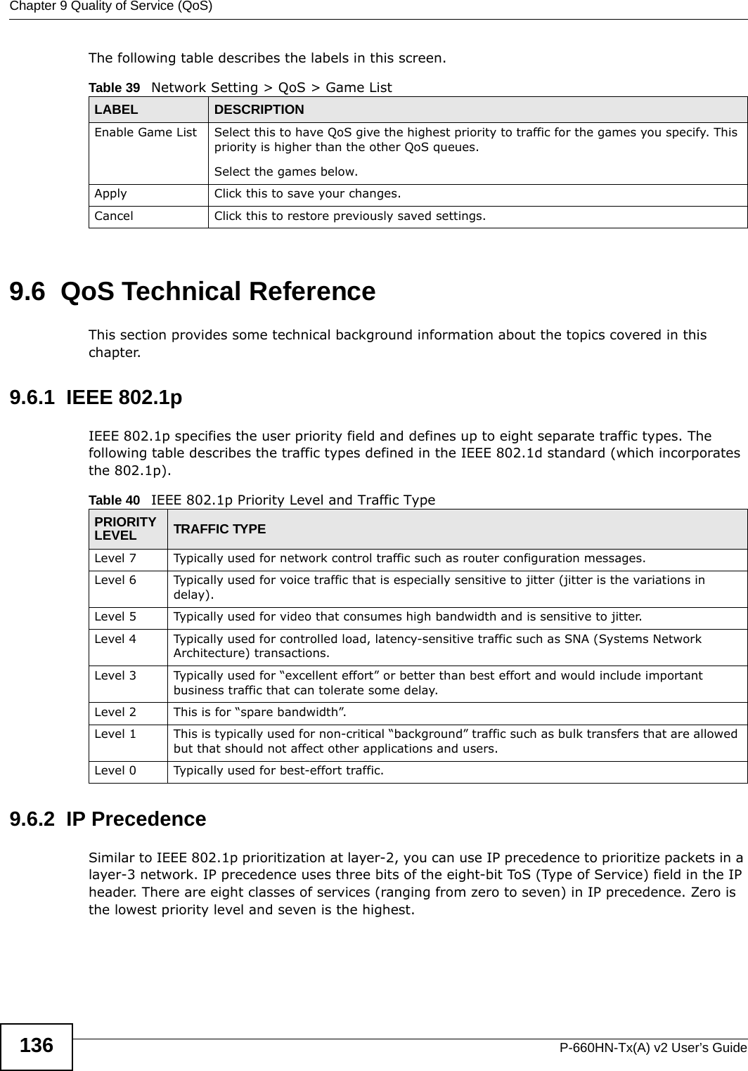


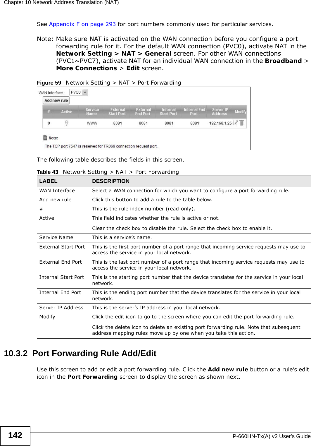
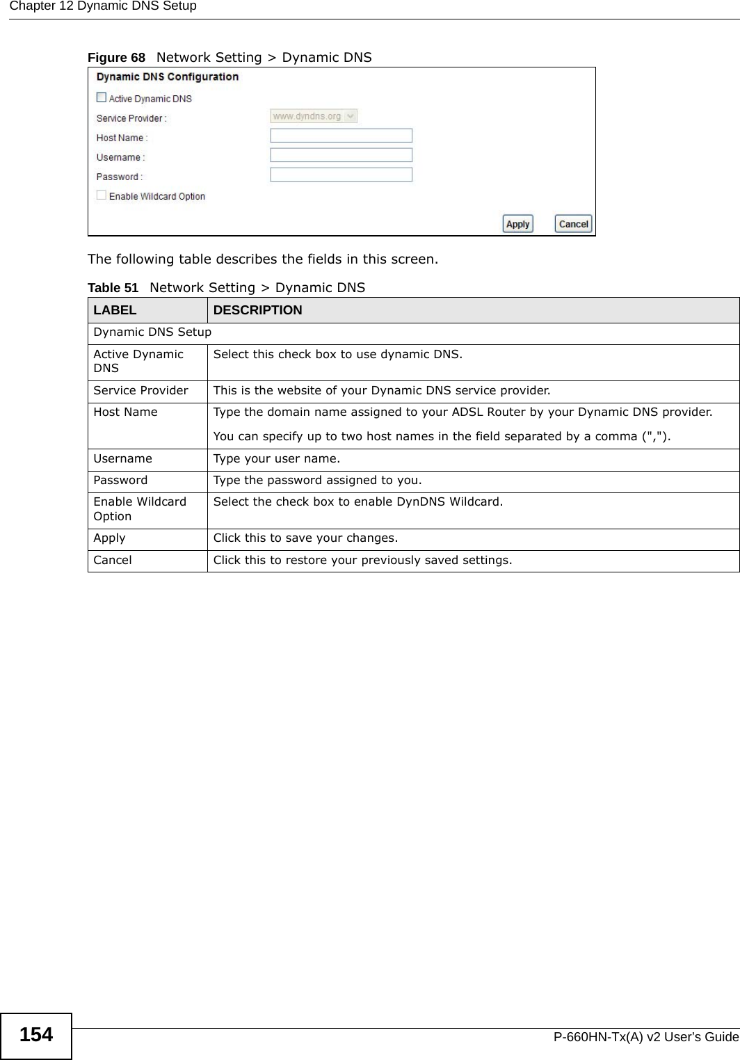

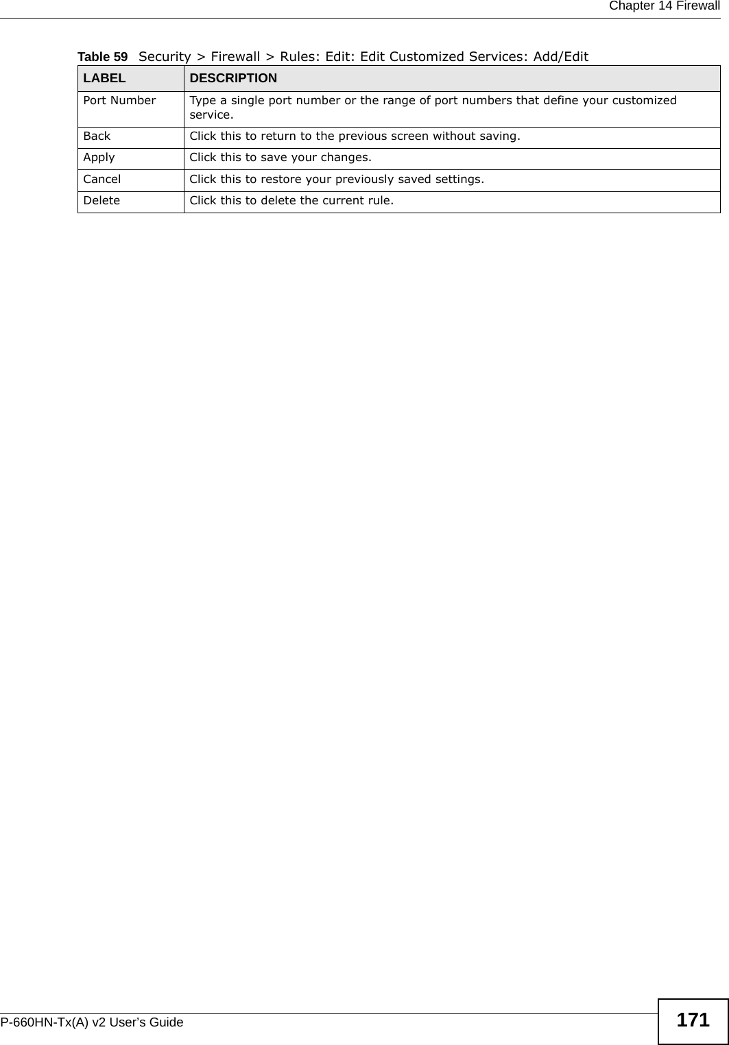

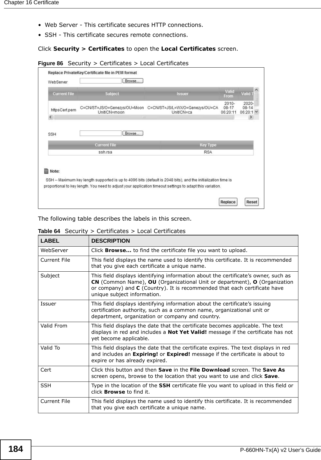


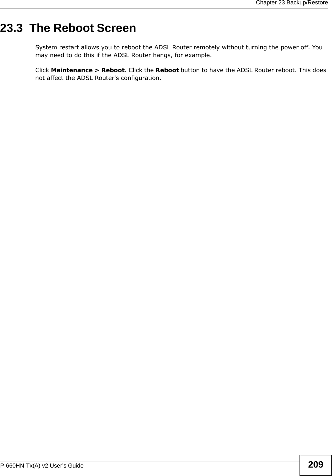

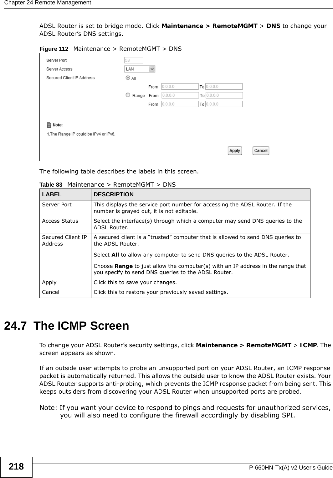


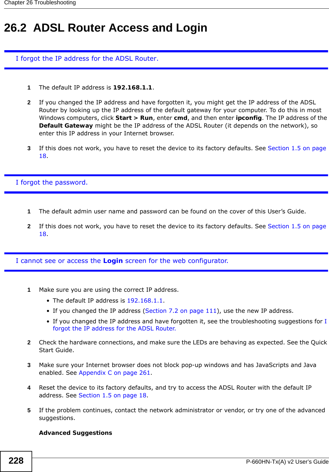
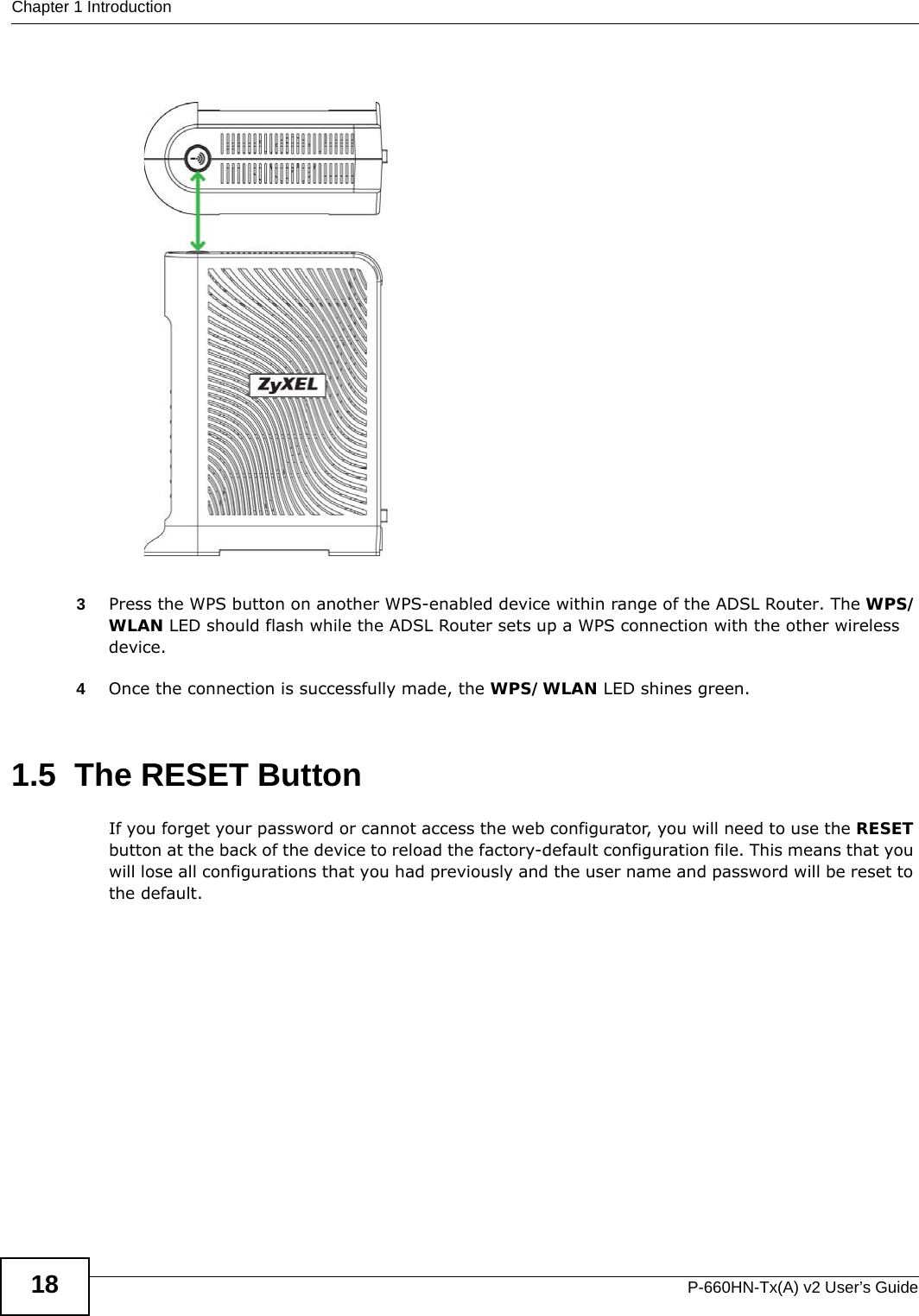
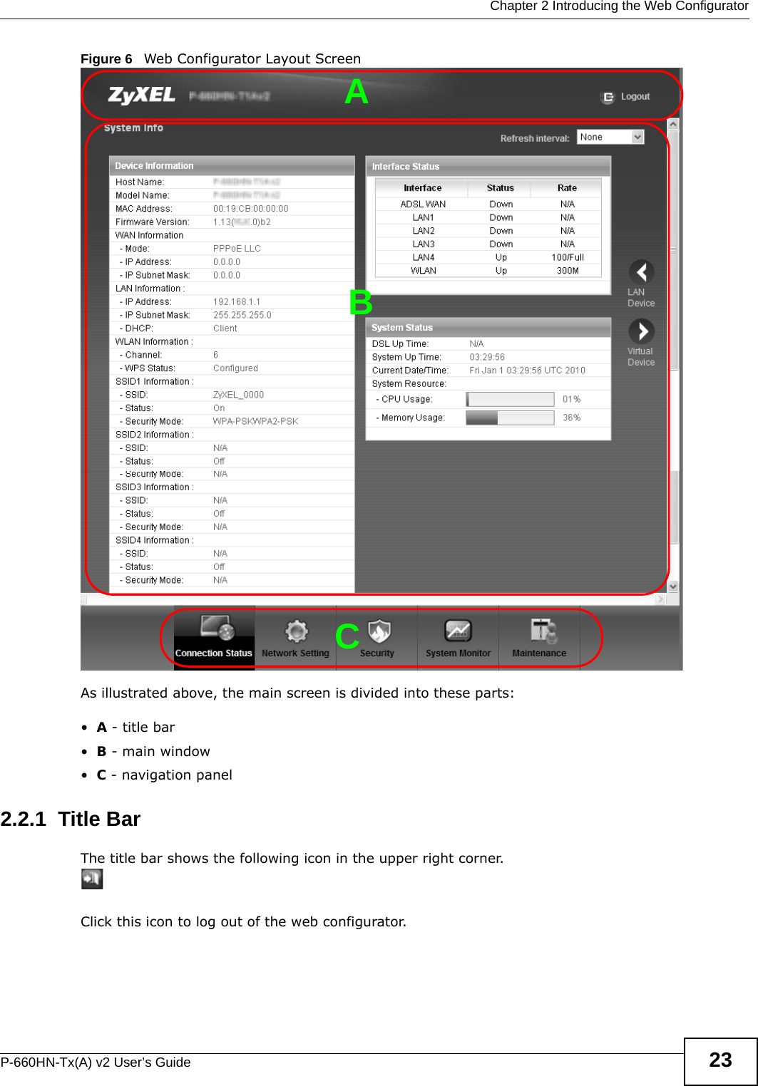
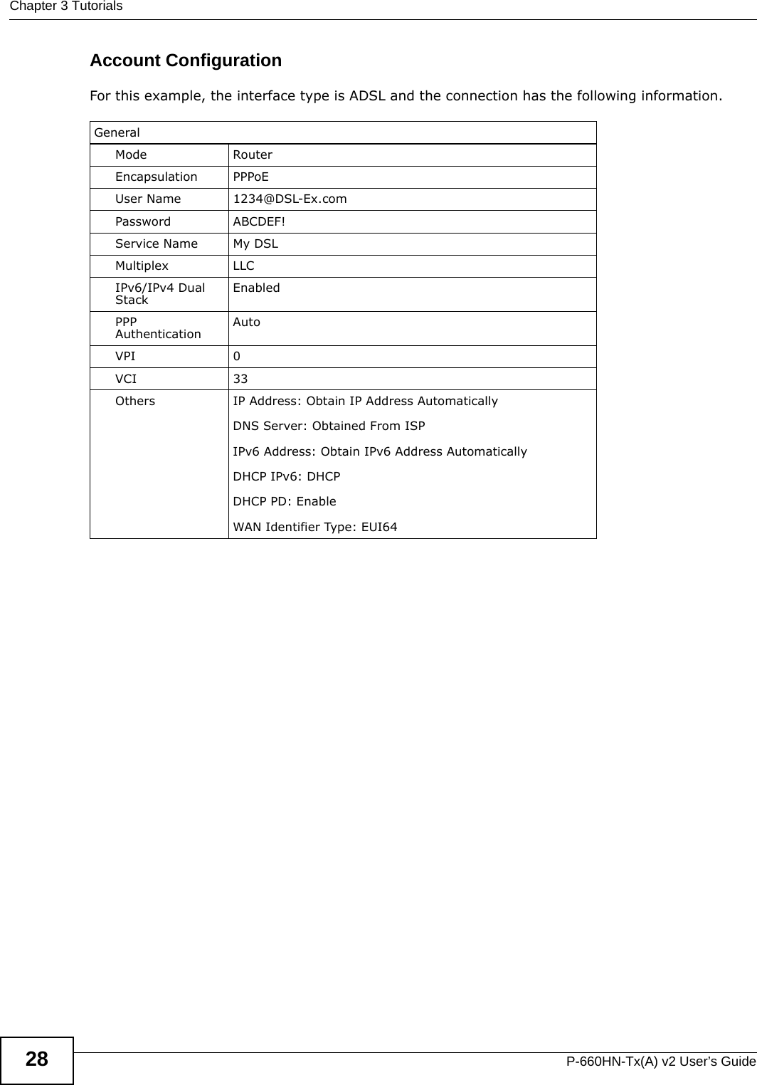
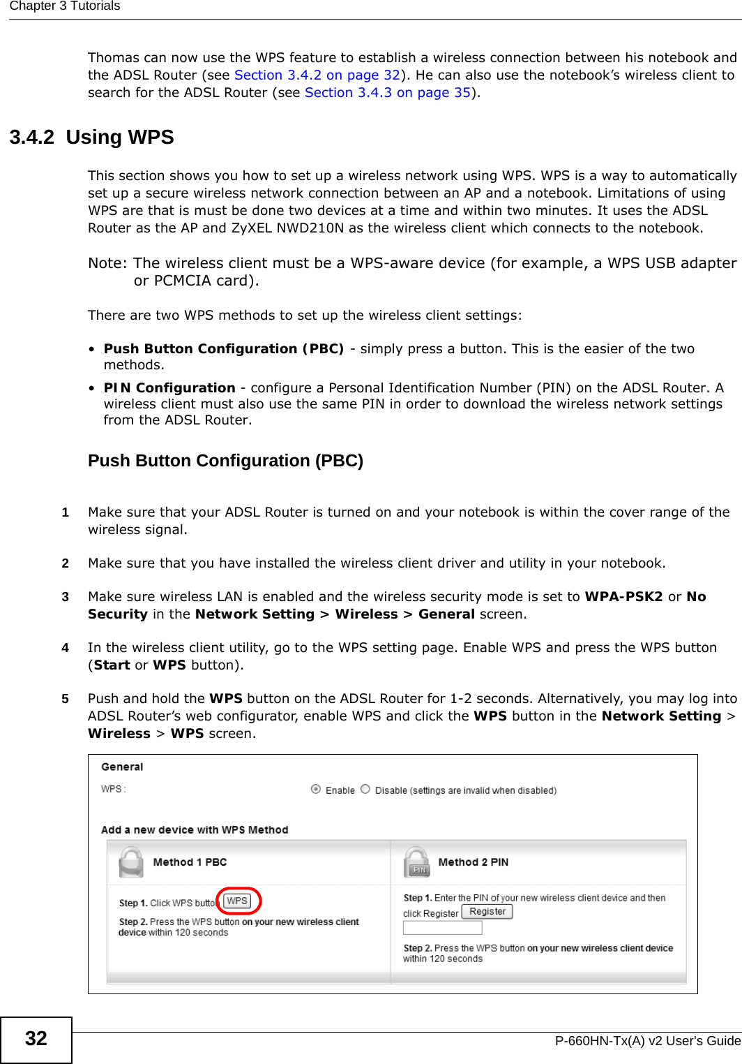
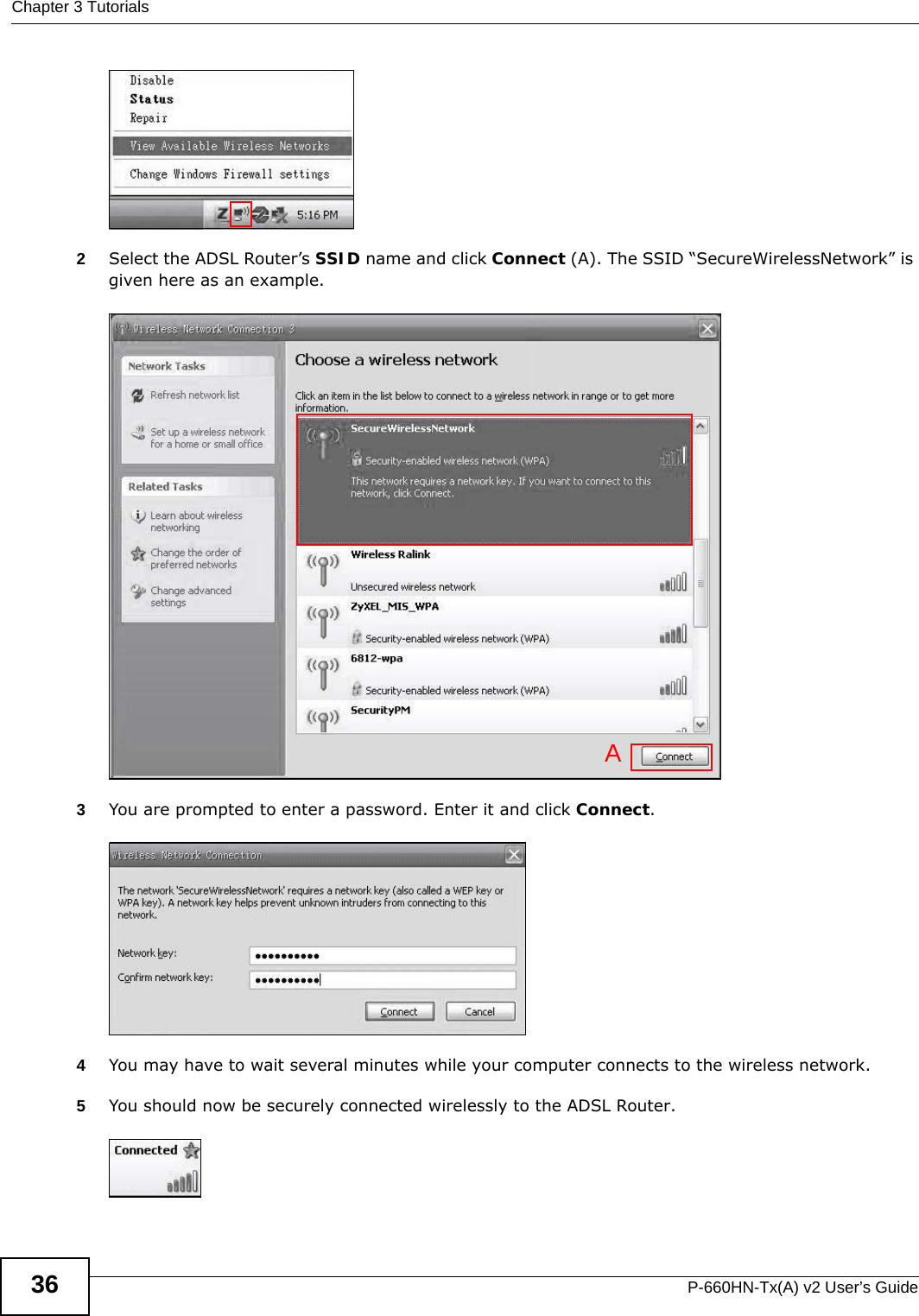
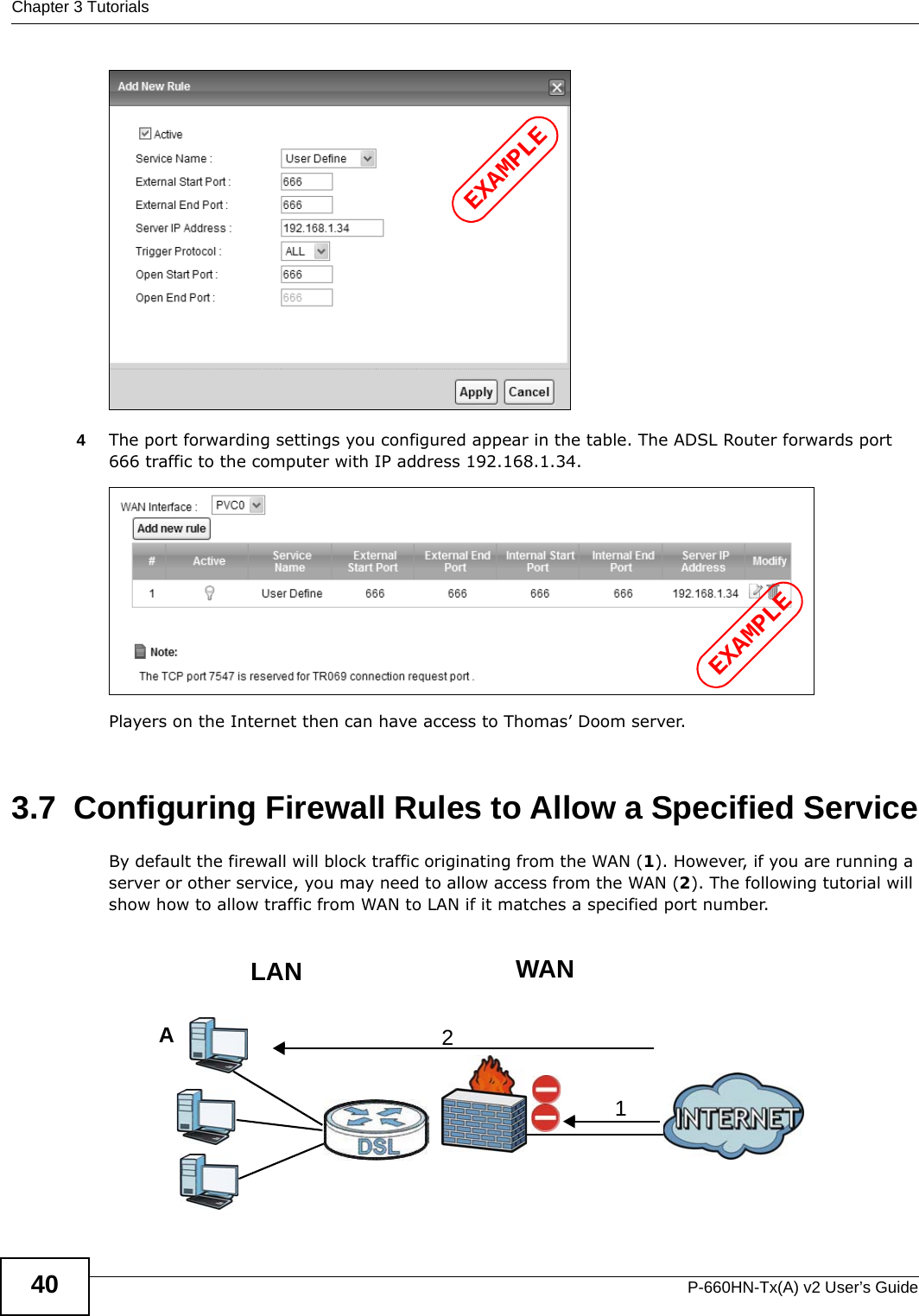
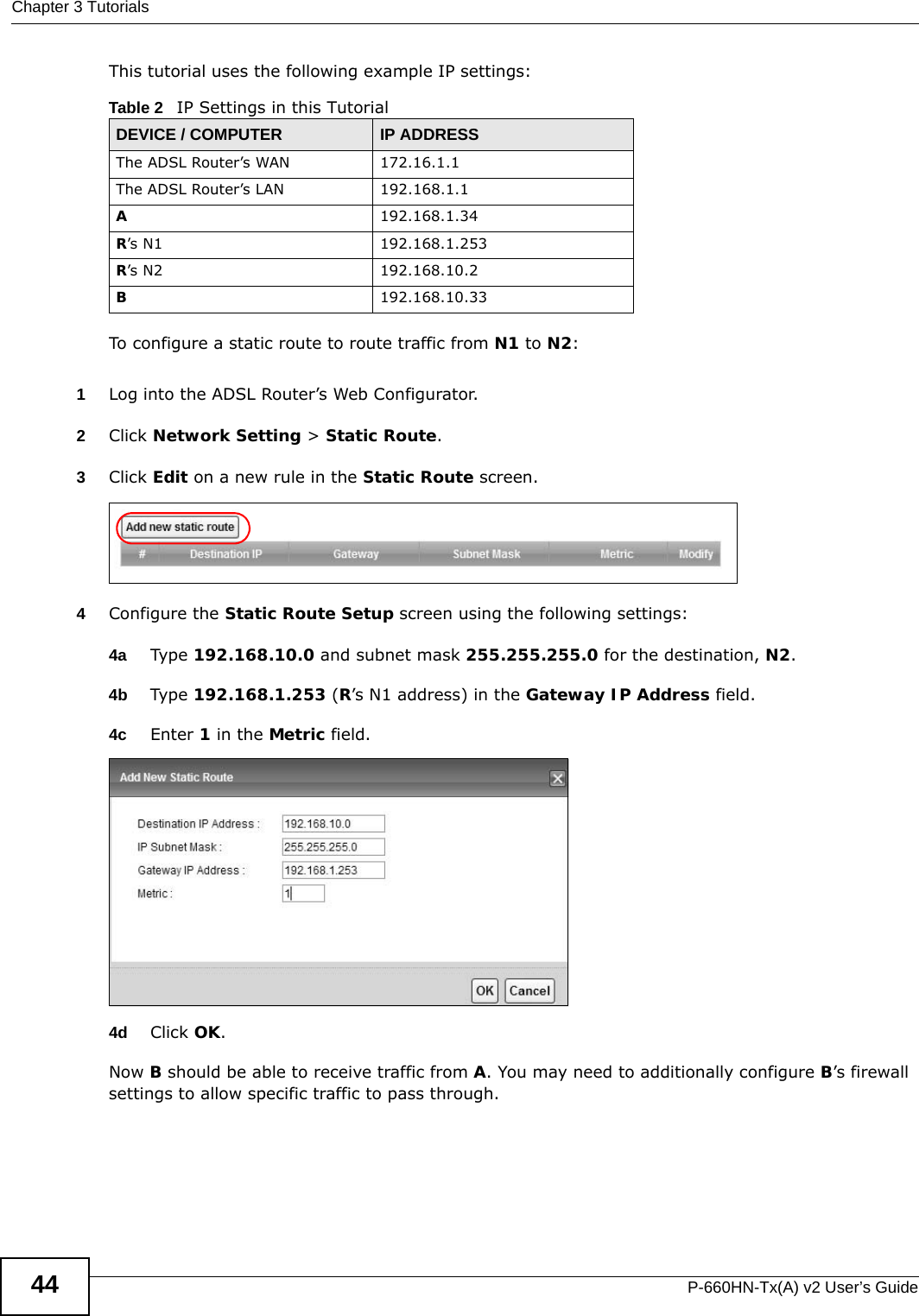
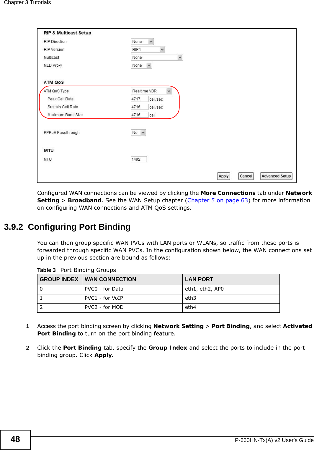
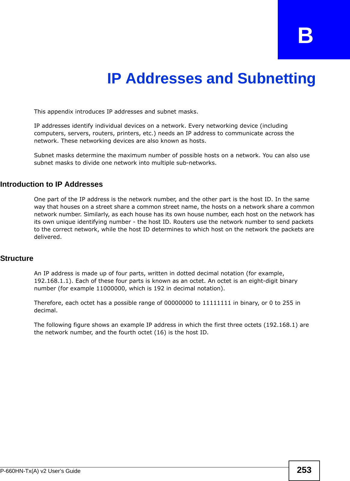
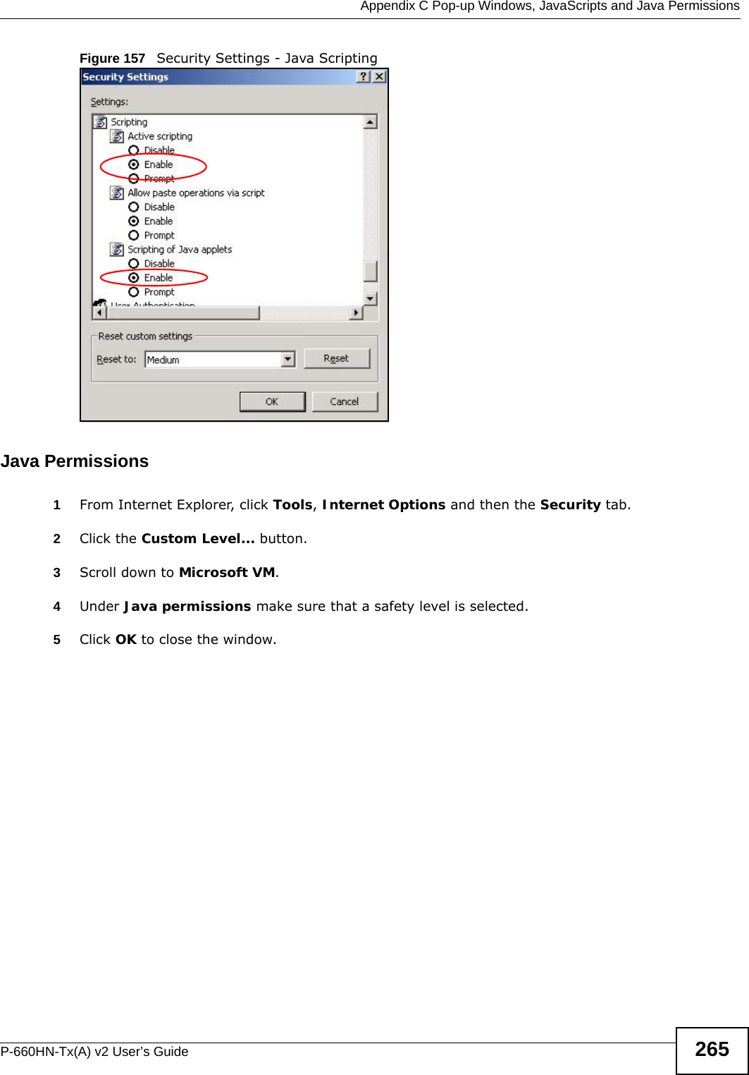
![Chapter 26 TroubleshootingP-660HN-Tx(A) v2 User’s Guide 229• Try to access the ADSL Router using another service, such as Telnet. If you can access the ADSL Router, check the remote management settings and firewall rules to find out why the ADSL Router does not respond to HTTP. • If your computer is connected to the DSL port or is connected wirelessly, use a computer that is connected to a ETHERNET port.I can see the Login screen, but I cannot log in to the ADSL Router.1Make sure you have entered the password correctly. The default user and default admin password can be found on the cover page of this User’s Guide. The field is case-sensitive, so make sure [Caps Lock] is not on. 2You cannot log in to the web configurator while someone is using Telnet to access the ADSL Router. Log out of the ADSL Router in the other session, or ask the person who is logged in to log out. 3Turn the ADSL Router off and on. 4If this does not work, you have to reset the device to its factory defaults. See Section 1.5 on page 18.I cannot Telnet to the ADSL Router.See the troubleshooting suggestions for I cannot see or access the Login screen for the web configurator. Ignore the suggestions about your browser.I cannot use FTP to upload / download the configuration file. / I cannot use FTP to upload new firmware.See the troubleshooting suggestions for I cannot see or access the Login screen for the web configurator. Ignore the suggestions about your browser.26.3 Internet AccessI cannot access the Internet.1Check the hardware connections, and make sure the LEDs are behaving as expected. See the Quick Start Guide and Section 27.1 on page 231.2Make sure you entered your ISP account information correctly in the wizard. These fields are case-sensitive, so make sure [Caps Lock] is not on.](https://usermanual.wiki/ZyXEL-Communications/P660HNT1AV2/User-Guide-1872984-Page-229.png)
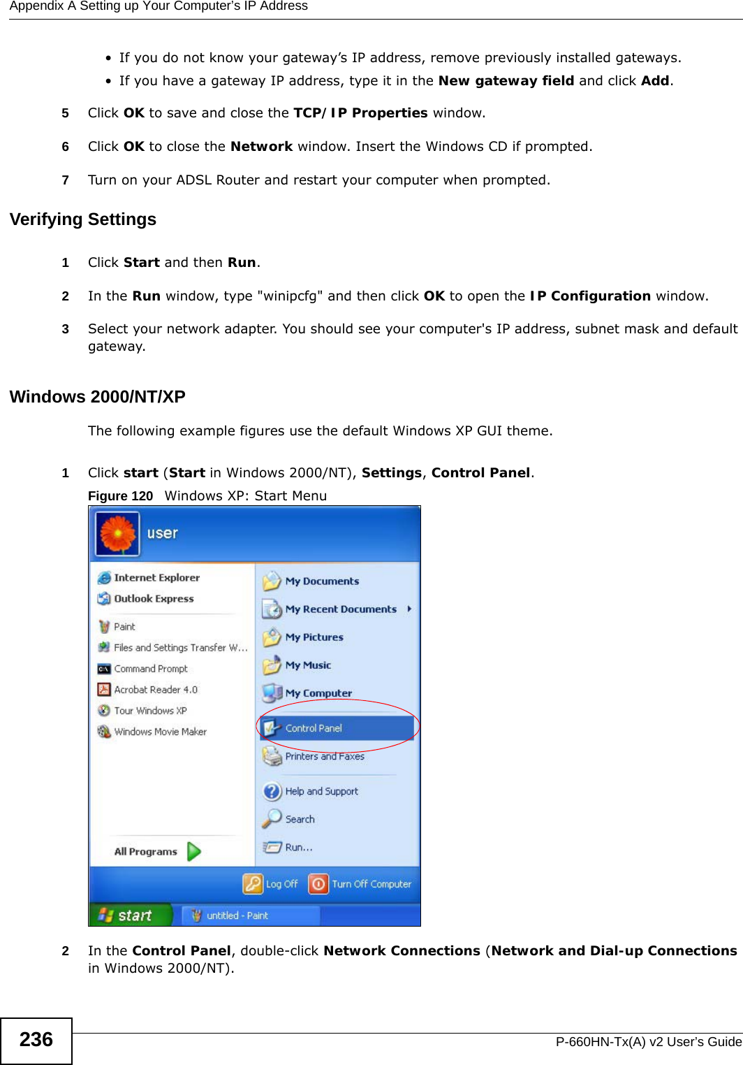
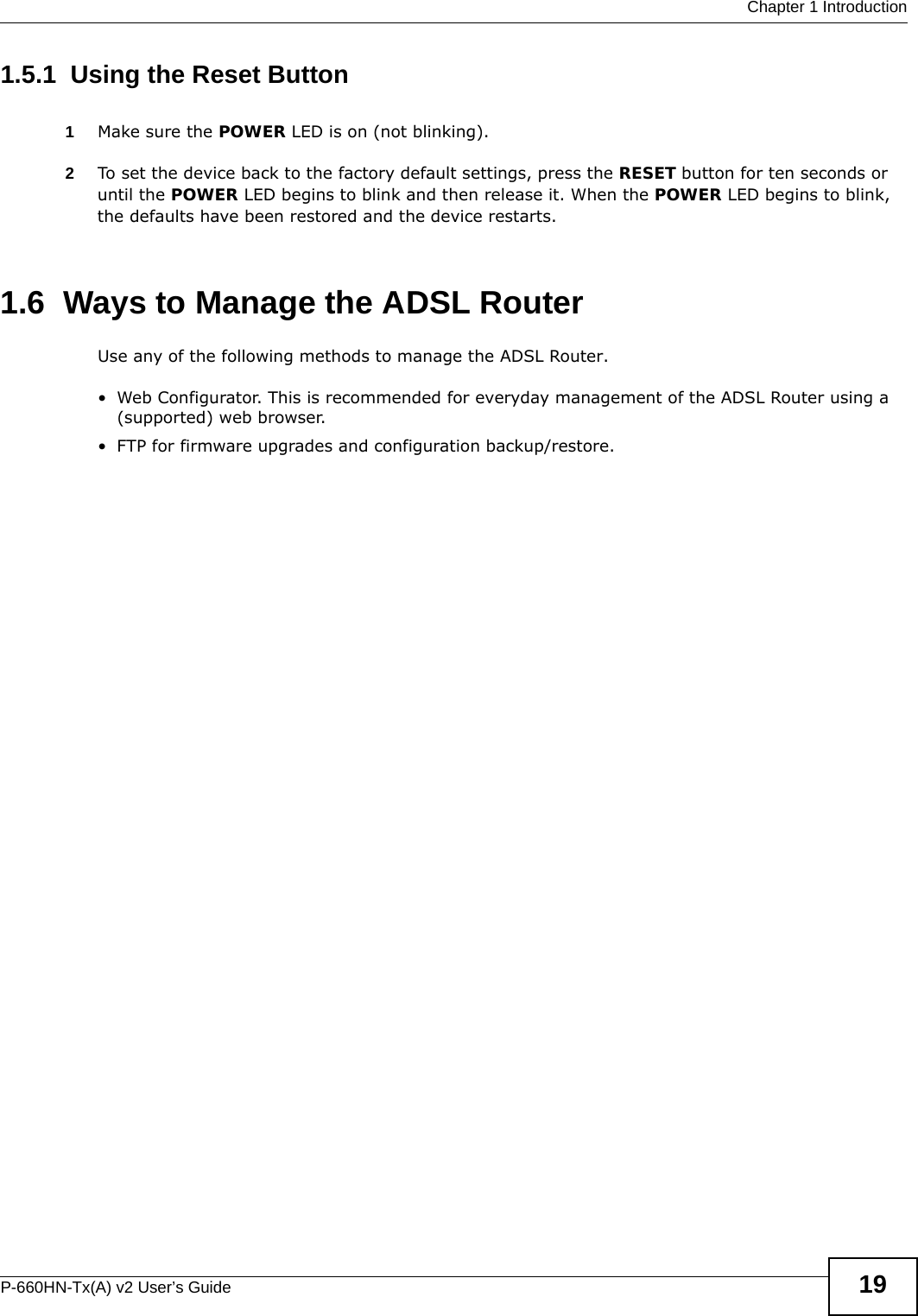
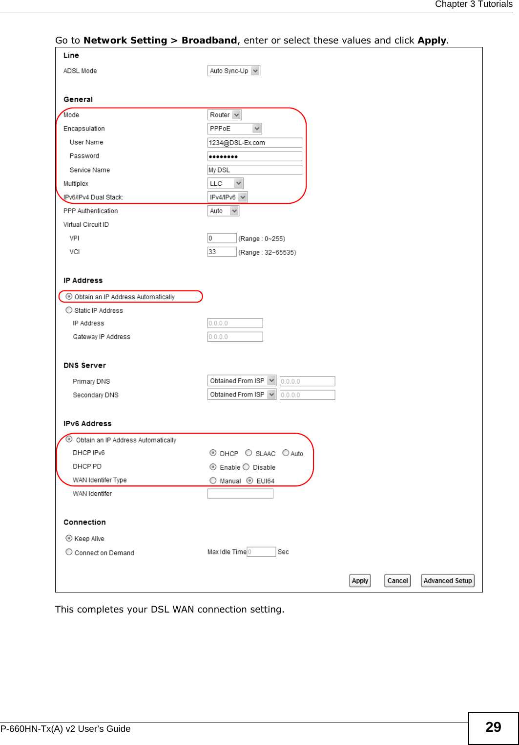
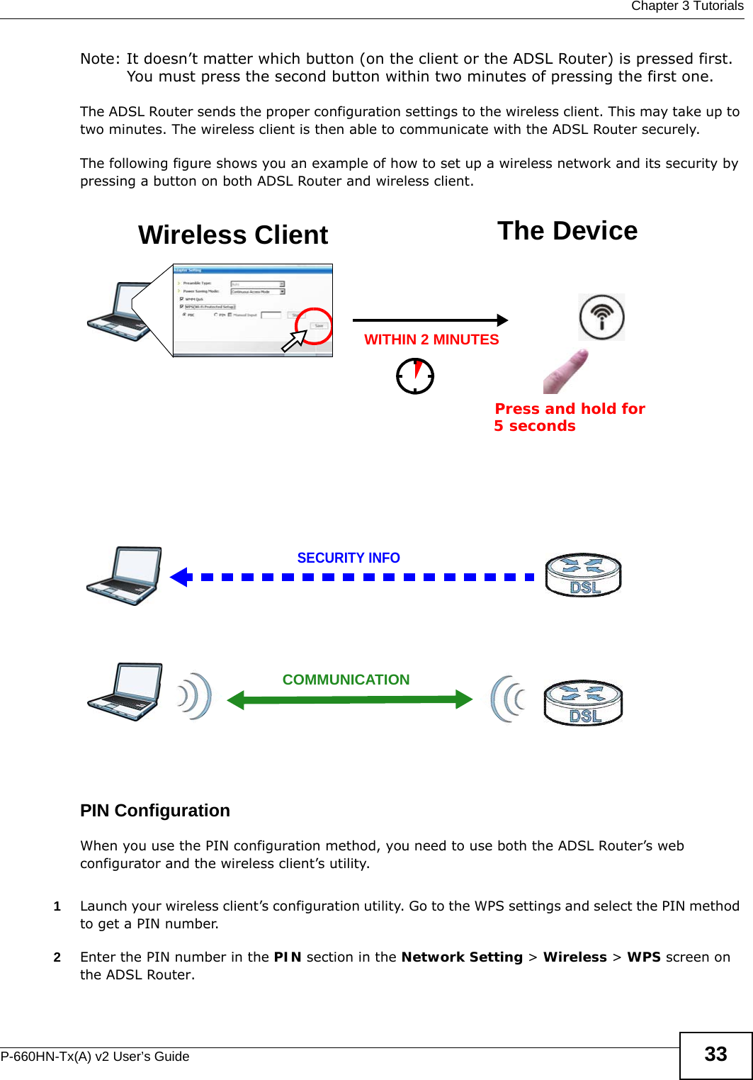
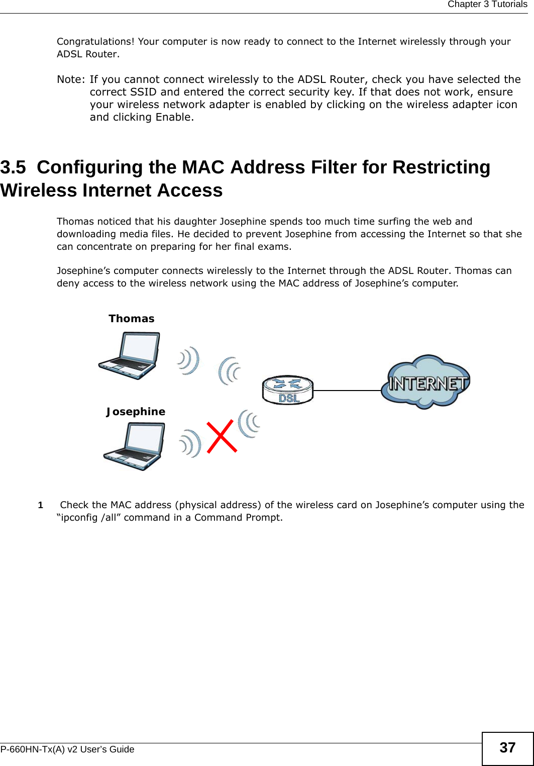
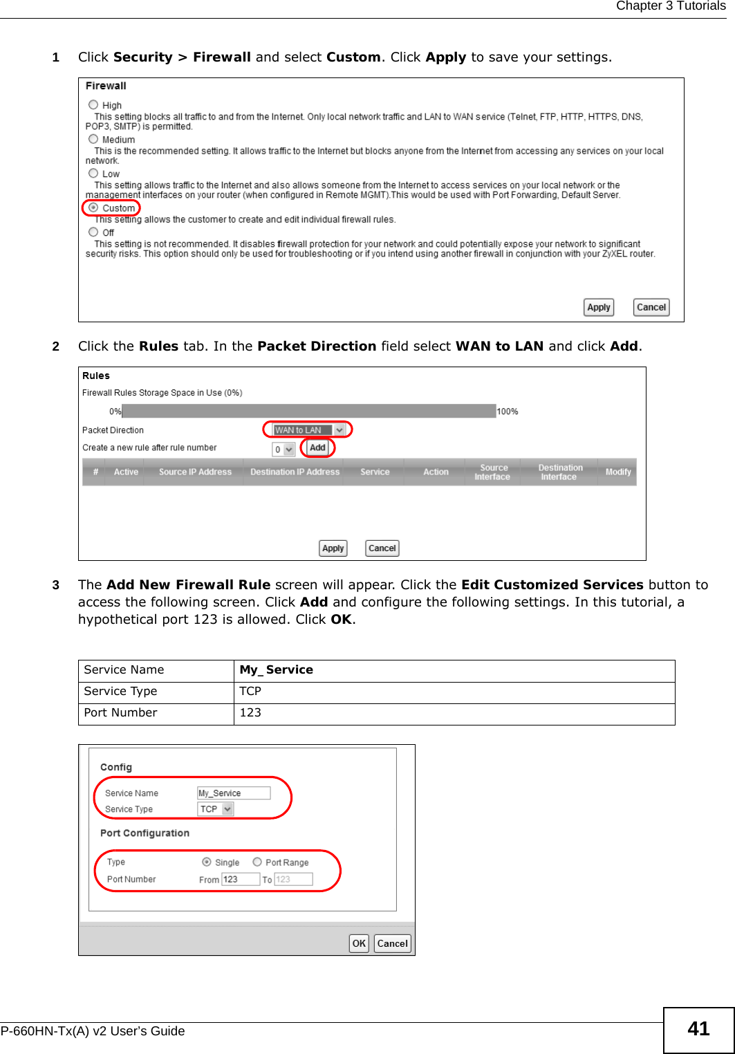
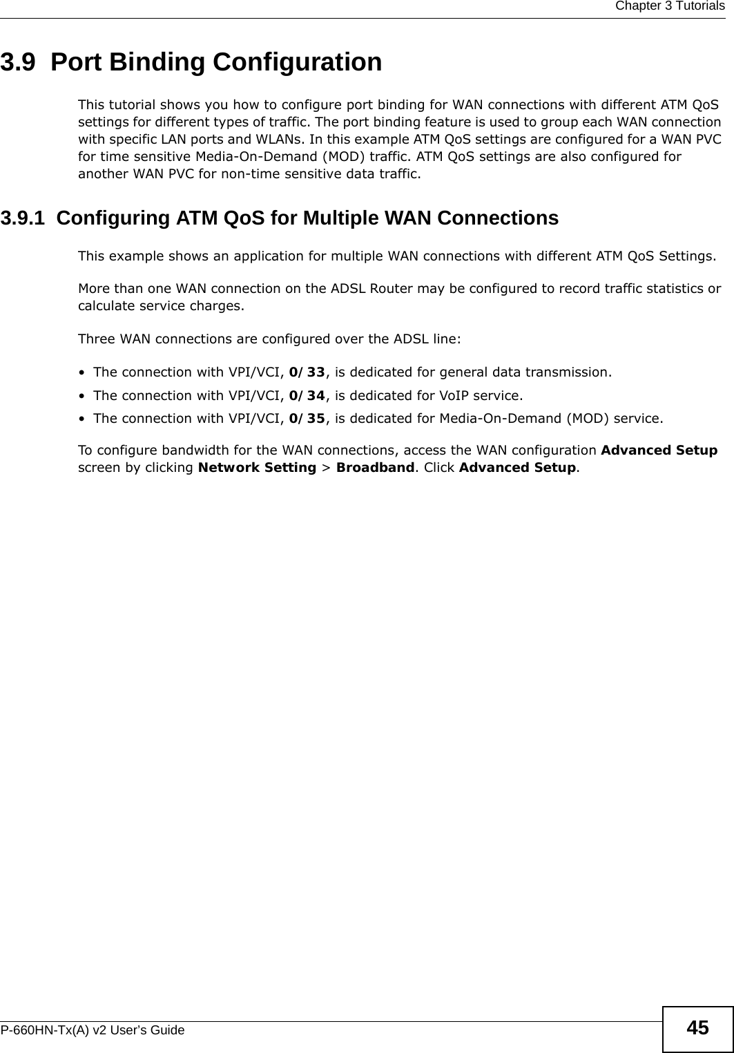
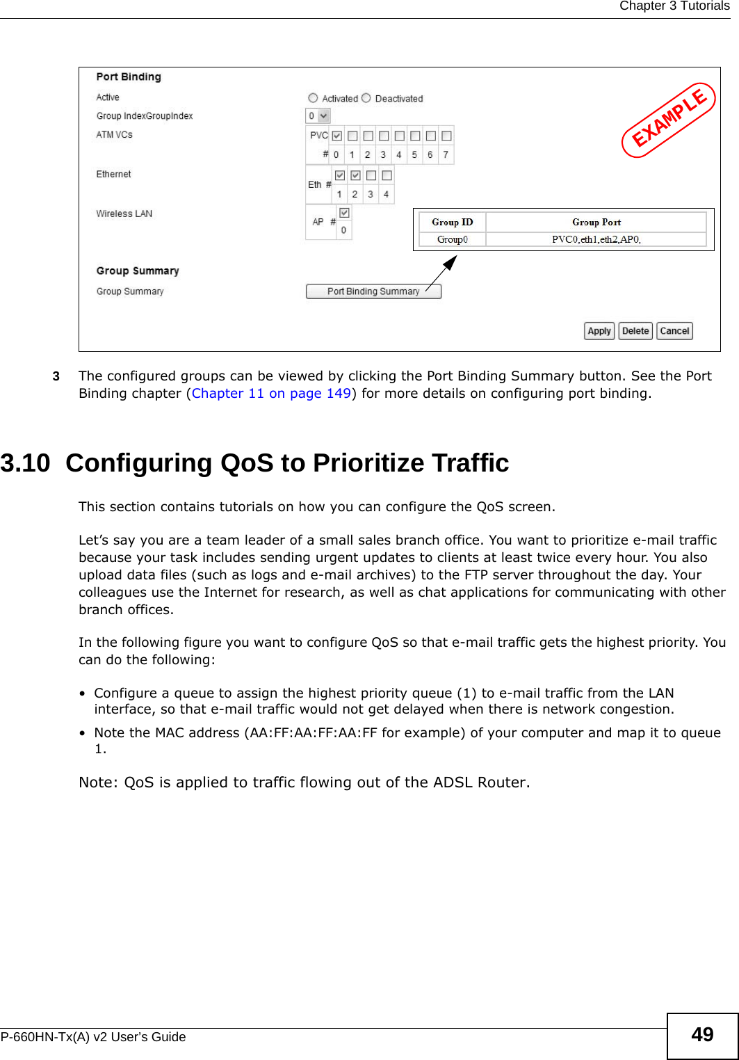
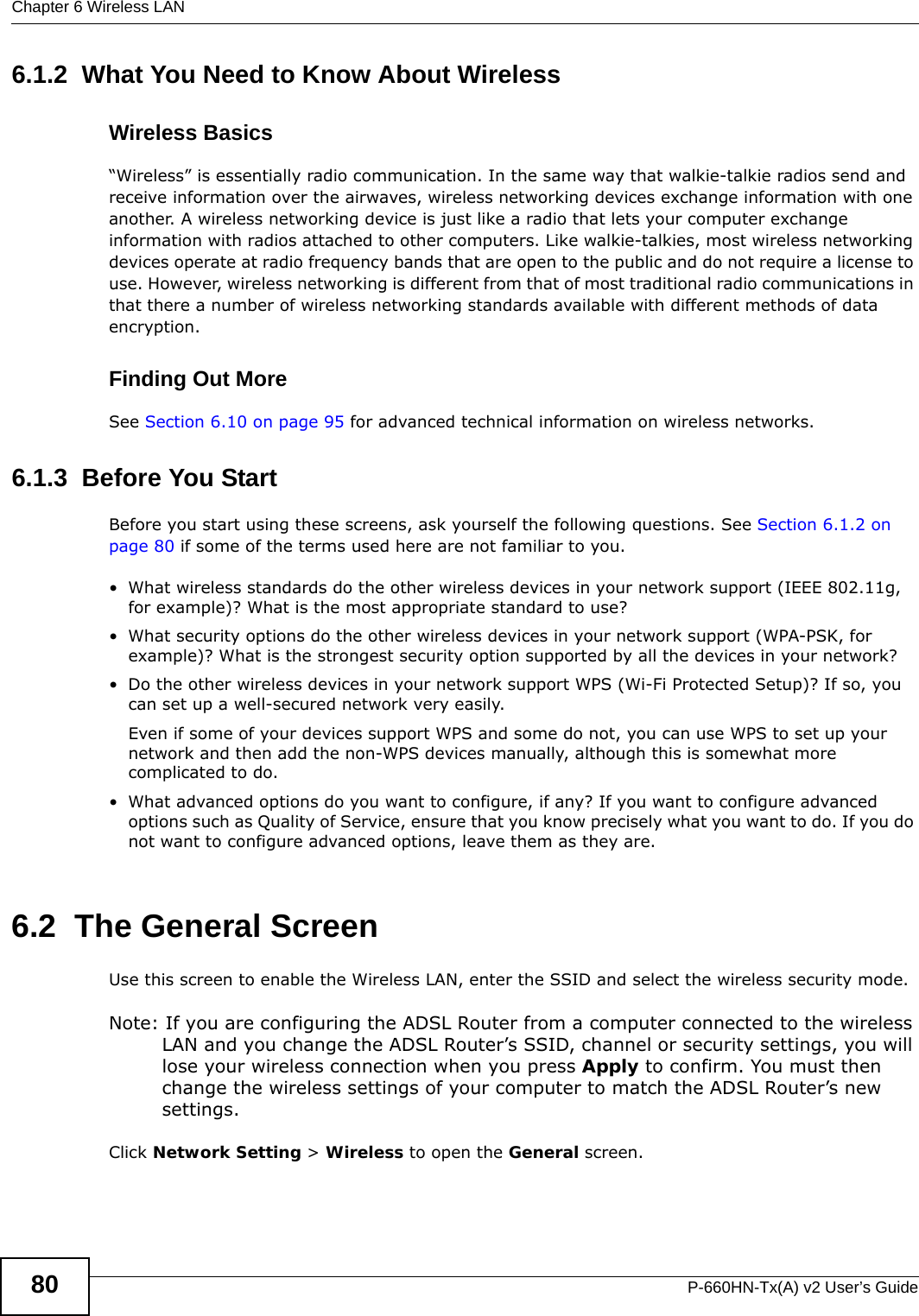
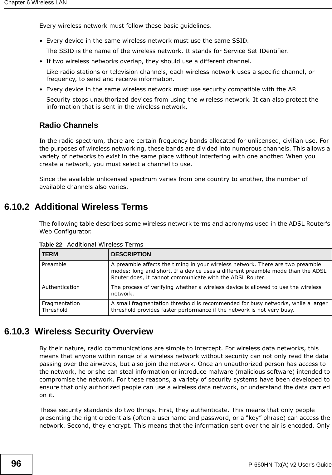
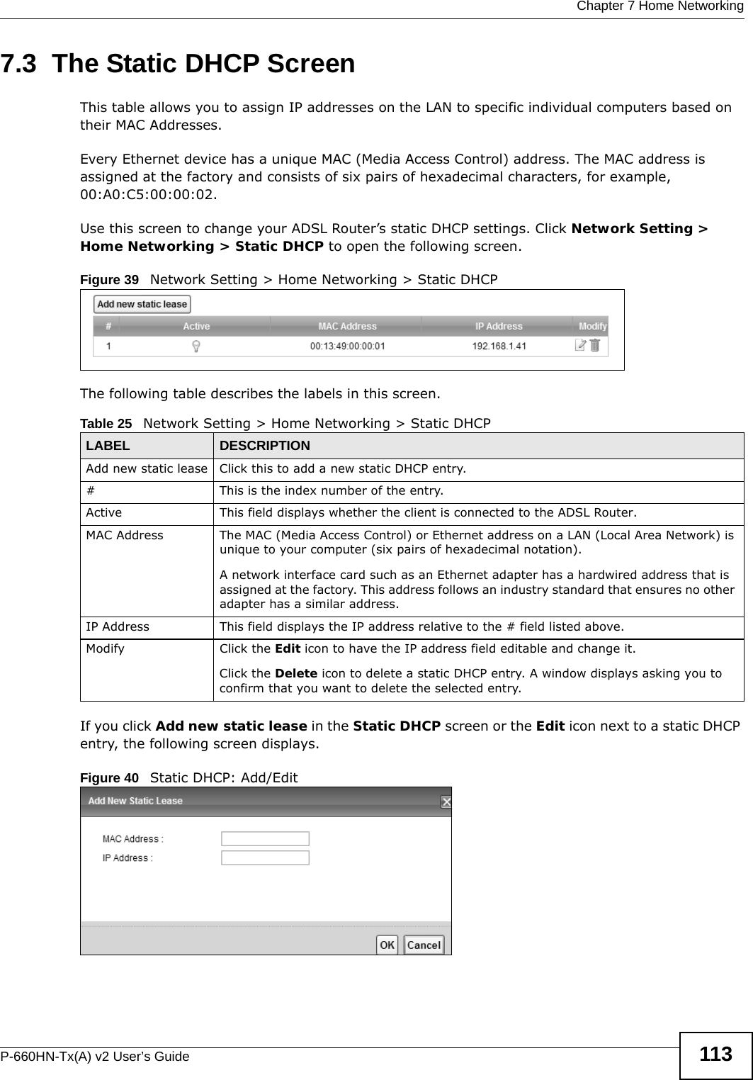
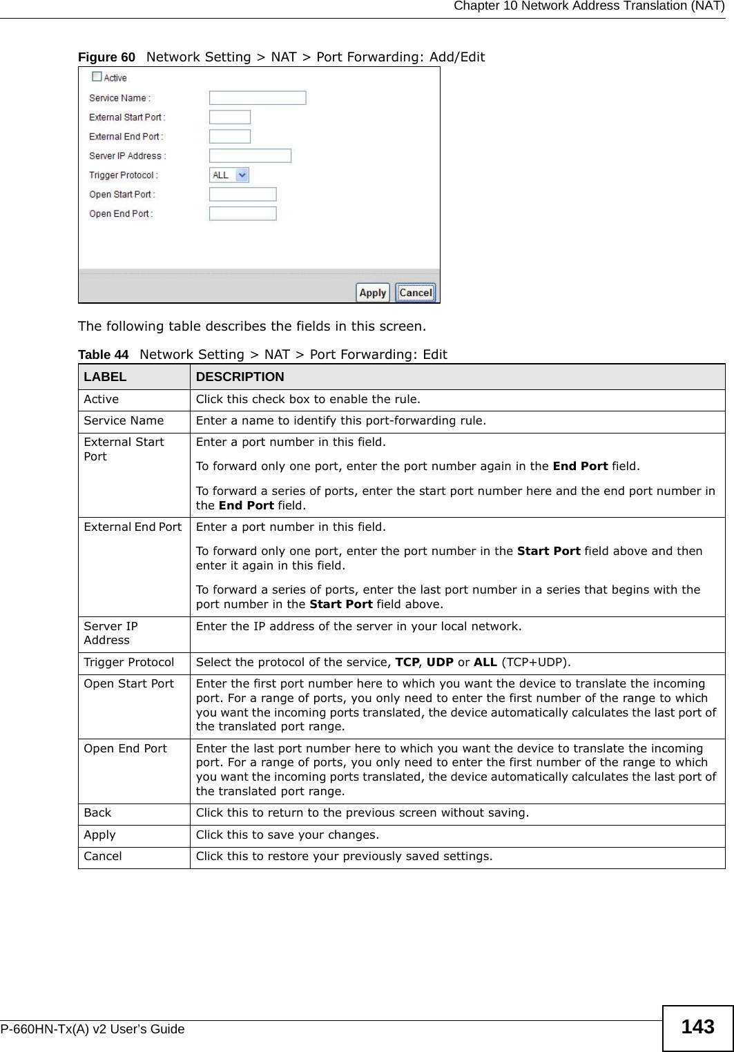
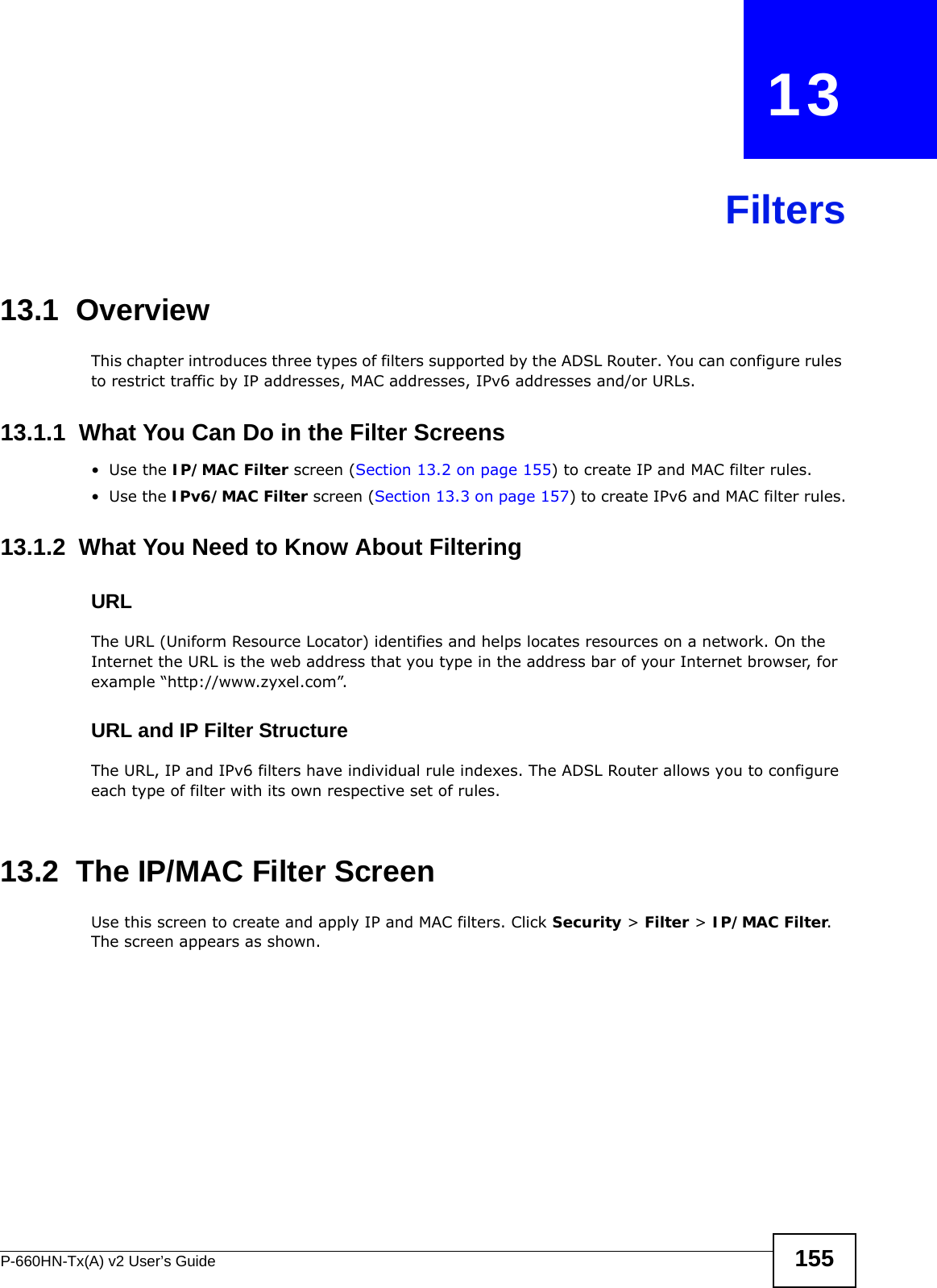
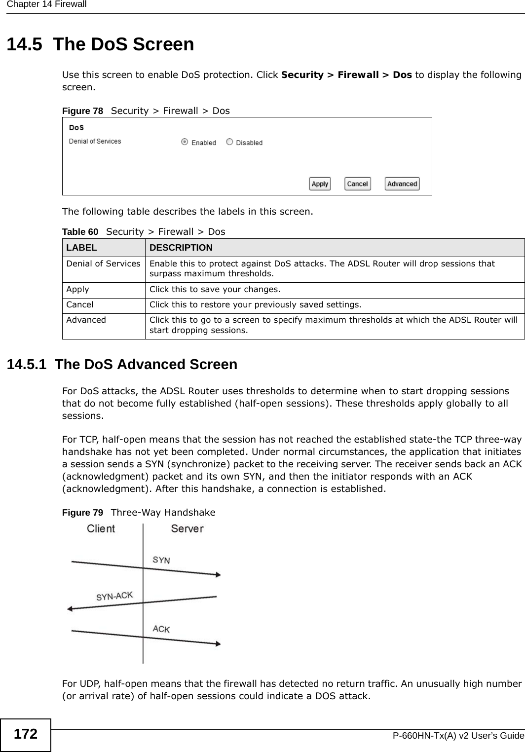
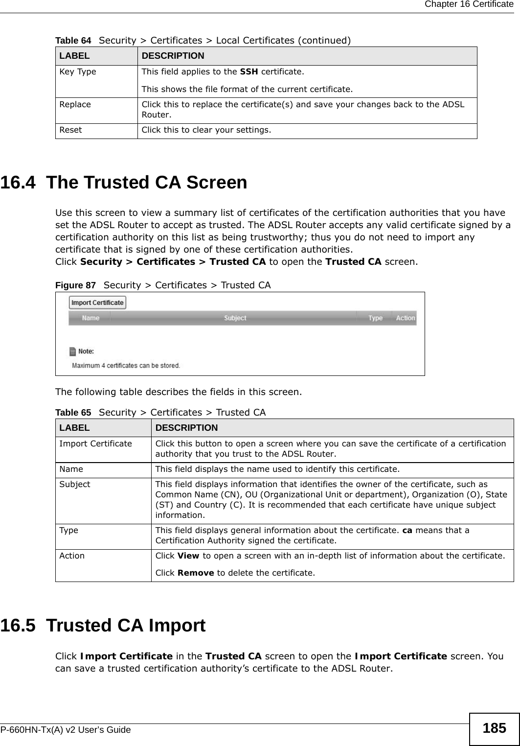
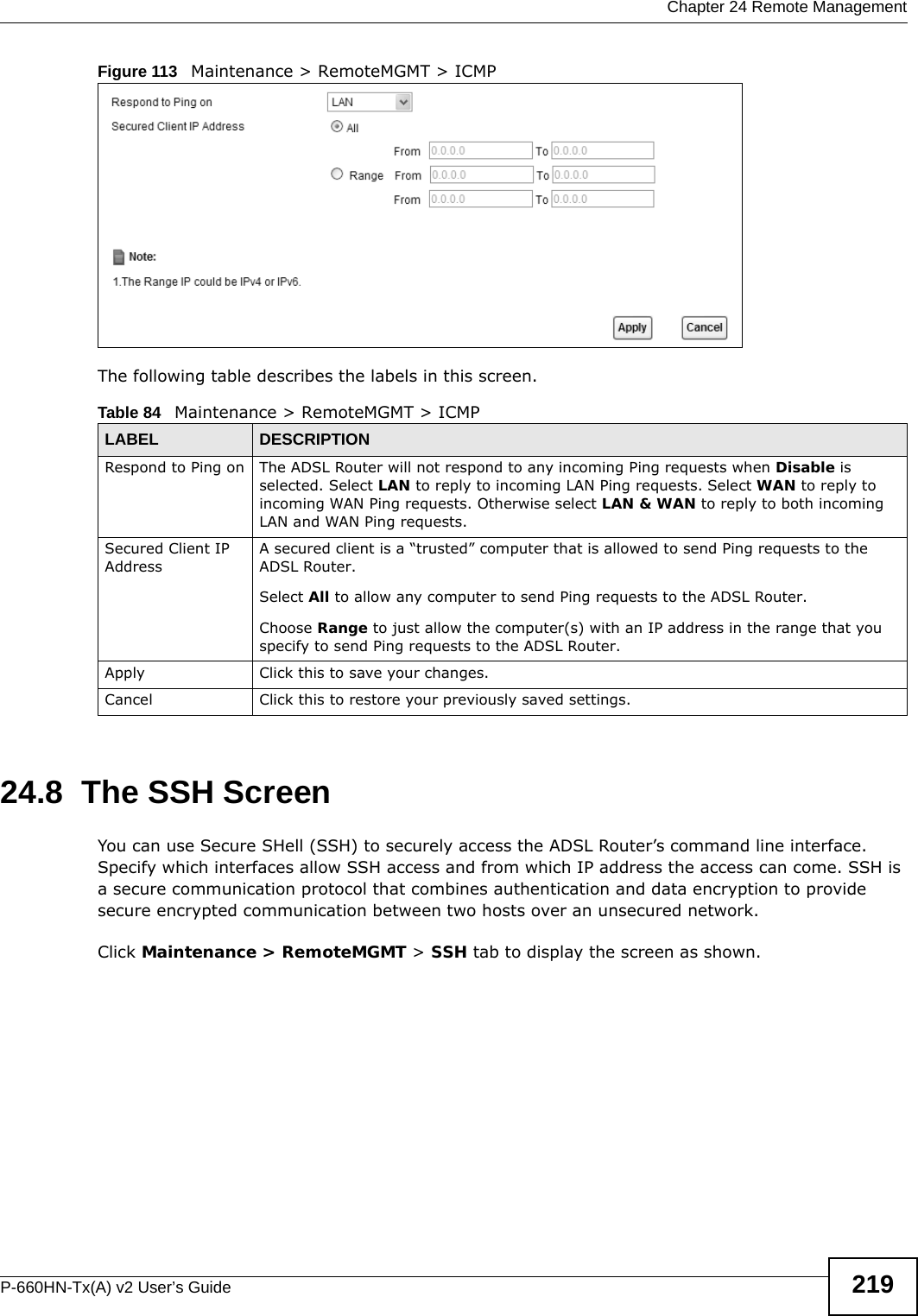
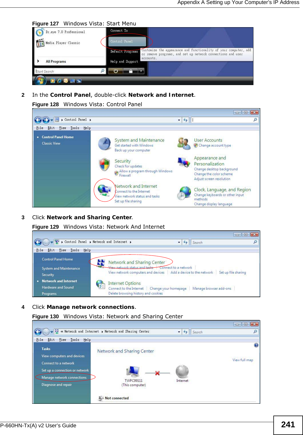
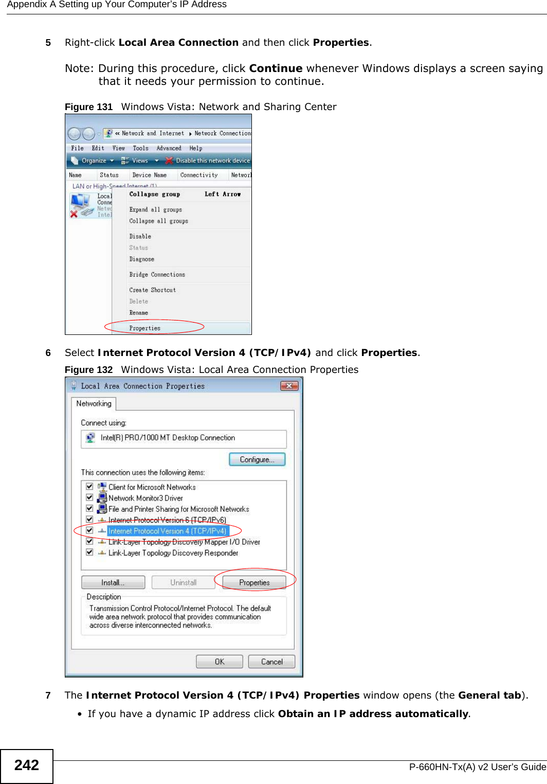
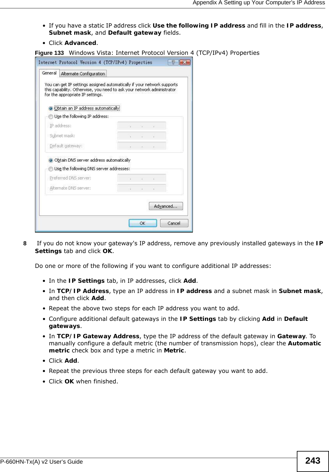
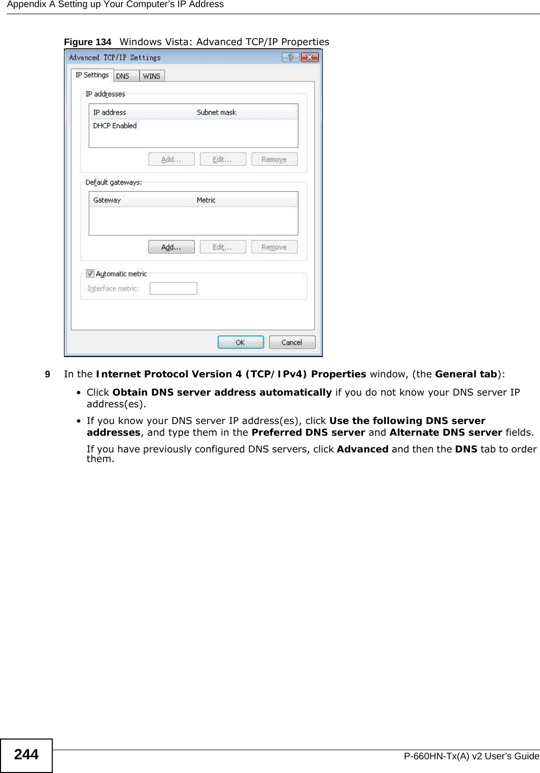
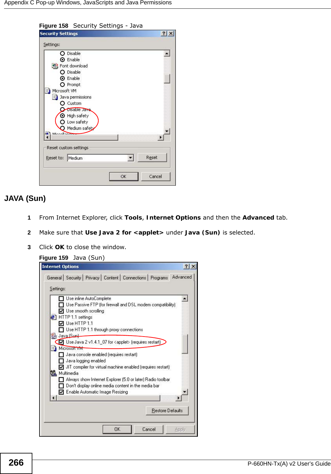
![Appendix A Setting up Your Computer’s IP AddressP-660HN-Tx(A) v2 User’s Guide240Figure 126 Windows XP: Internet Protocol (TCP/IP) Properties8Click OK to close the Internet Protocol (TCP/IP) Properties window.9Click Close (OK in Windows 2000/NT) to close the Local Area Connection Properties window.10 Close the Network Connections window (Network and Dial-up Connections in Windows 2000/NT).11 Turn on your ADSL Router and restart your computer (if prompted).Verifying Settings1Click Start, All Programs, Accessories and then Command Prompt.2In the Command Prompt window, type "ipconfig" and then press [ENTER]. You can also open Network Connections, right-click a network connection, click Status and then click the Support tab.Windows VistaThis section shows screens from Windows Vista Enterprise Version 6.0.1Click the Start icon, Control Panel.](https://usermanual.wiki/ZyXEL-Communications/P660HNT1AV2/User-Guide-1872984-Page-240.png)
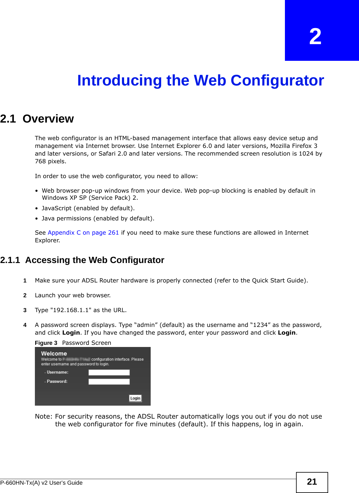
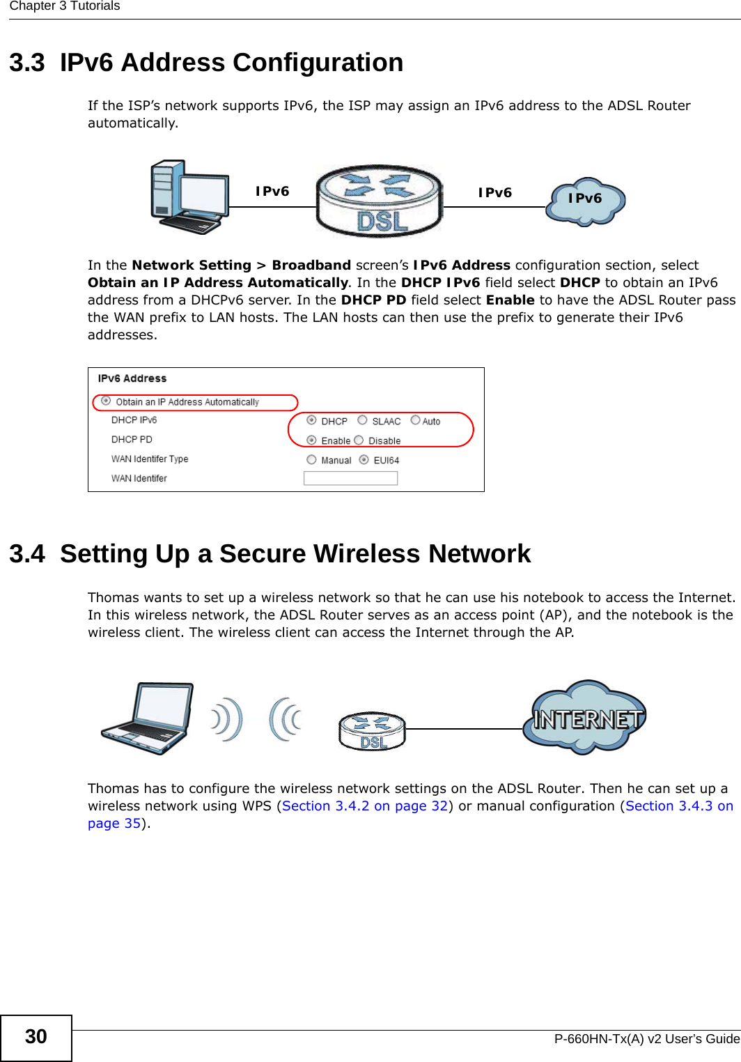
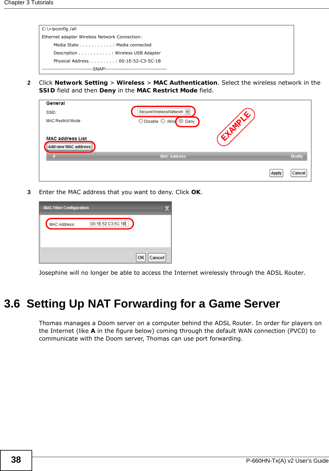
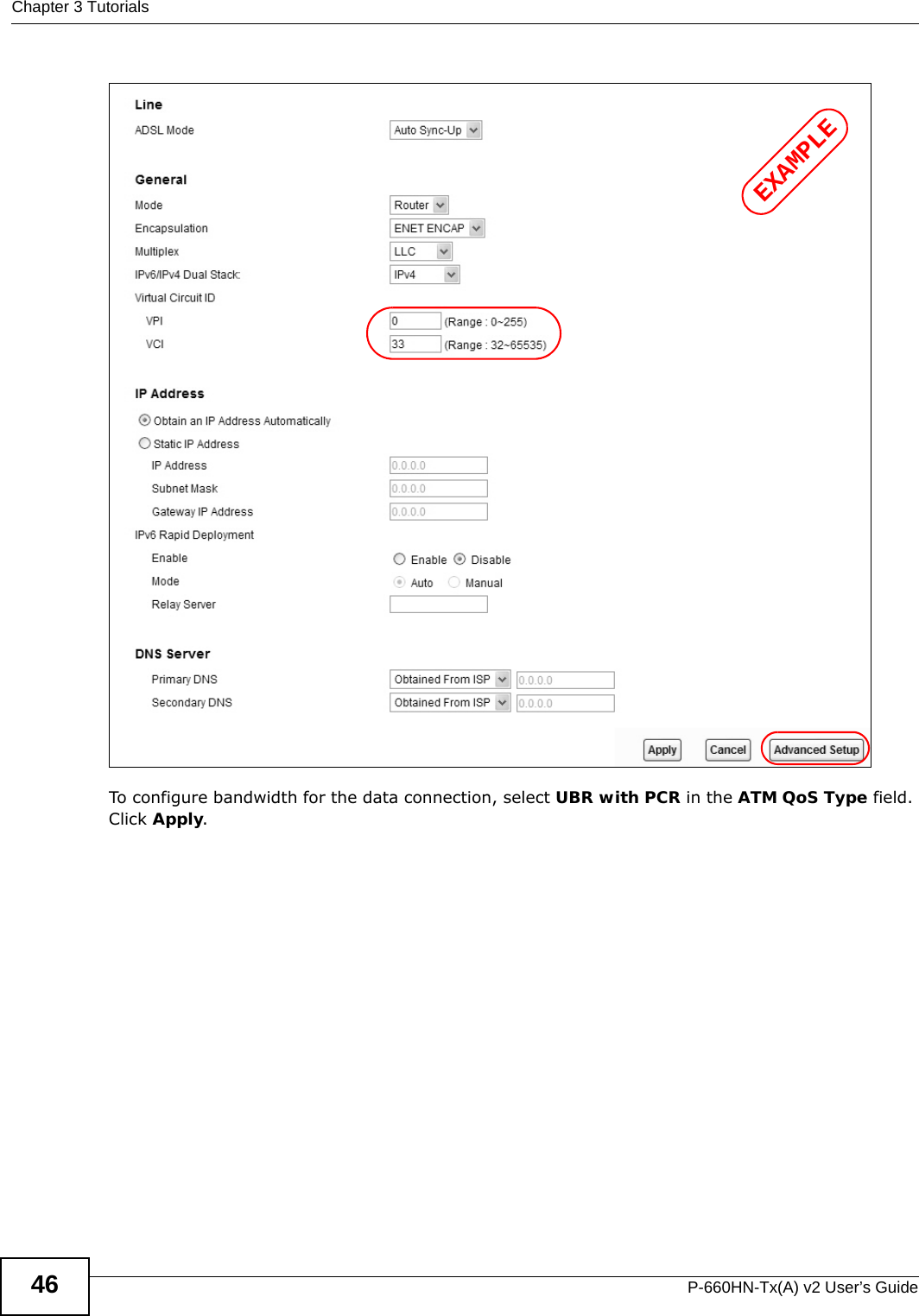
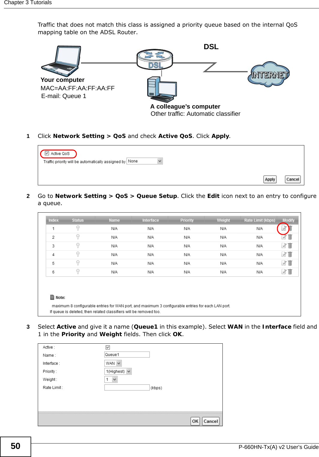
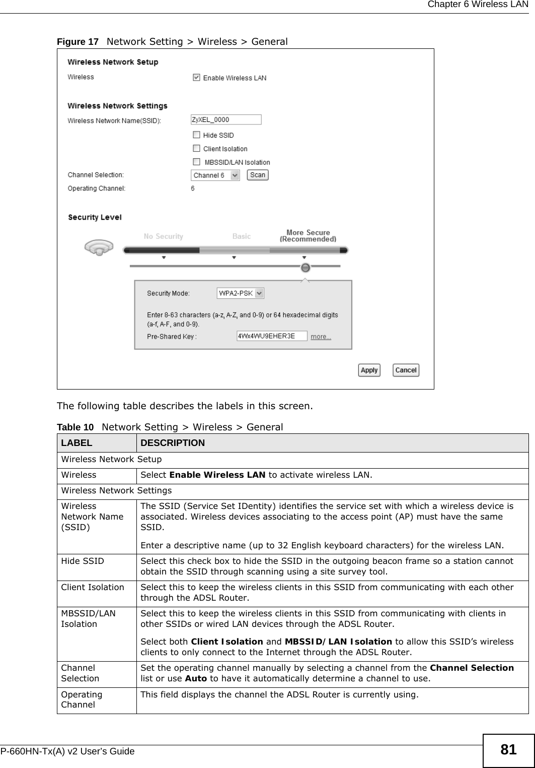
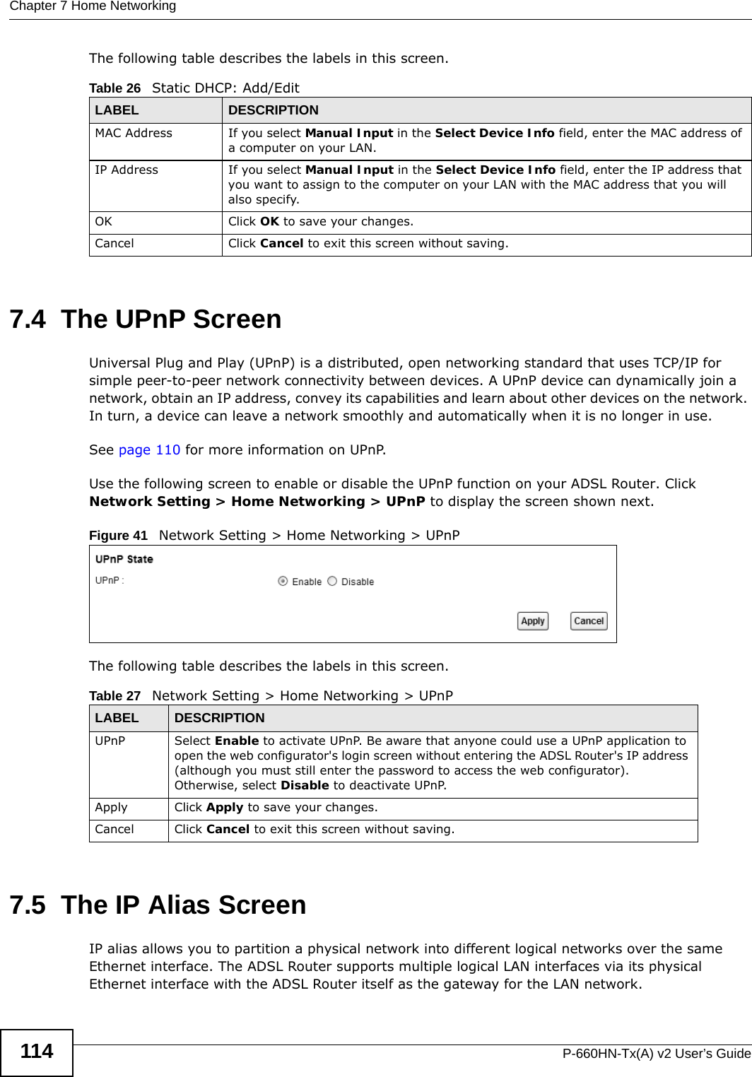
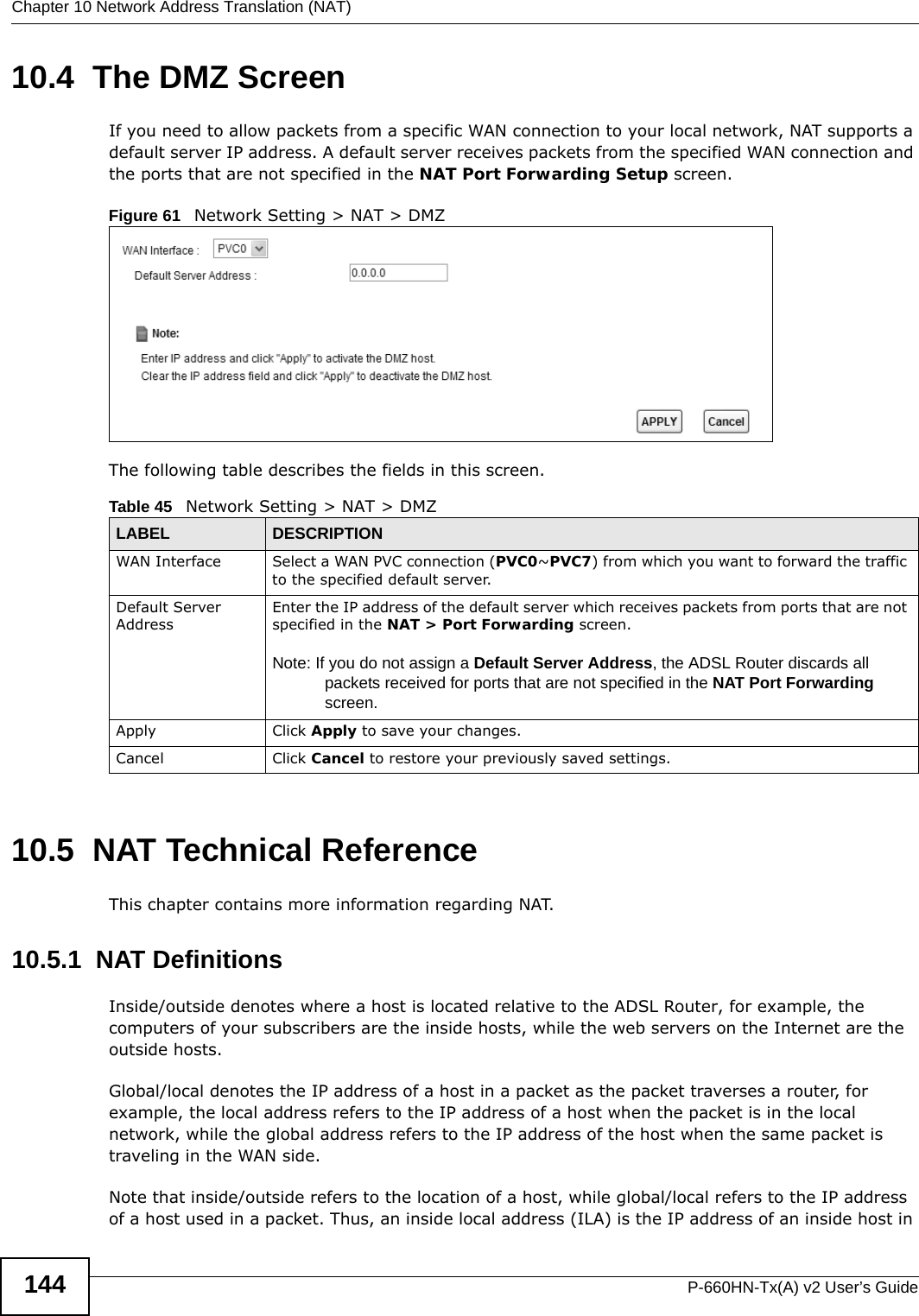
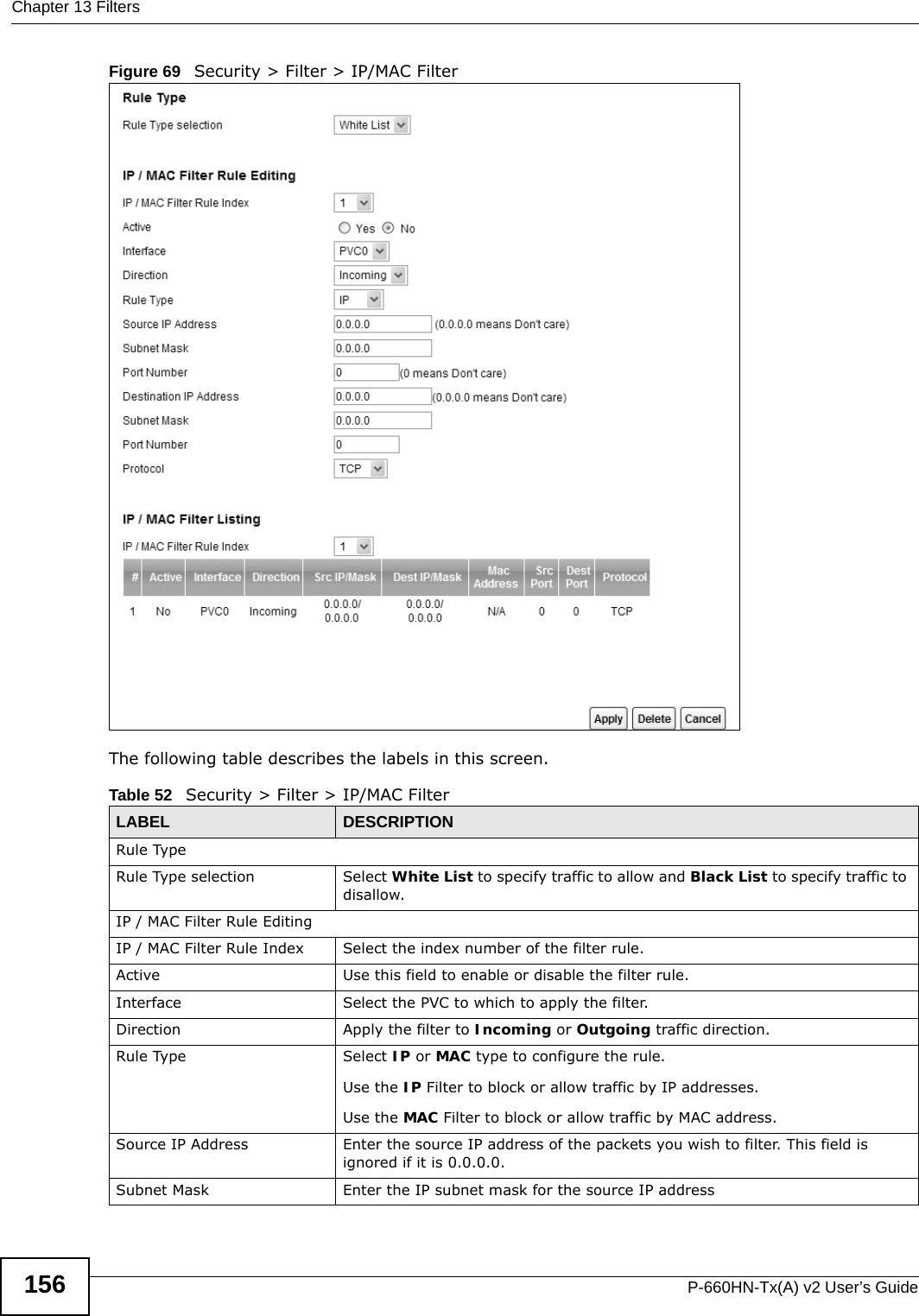
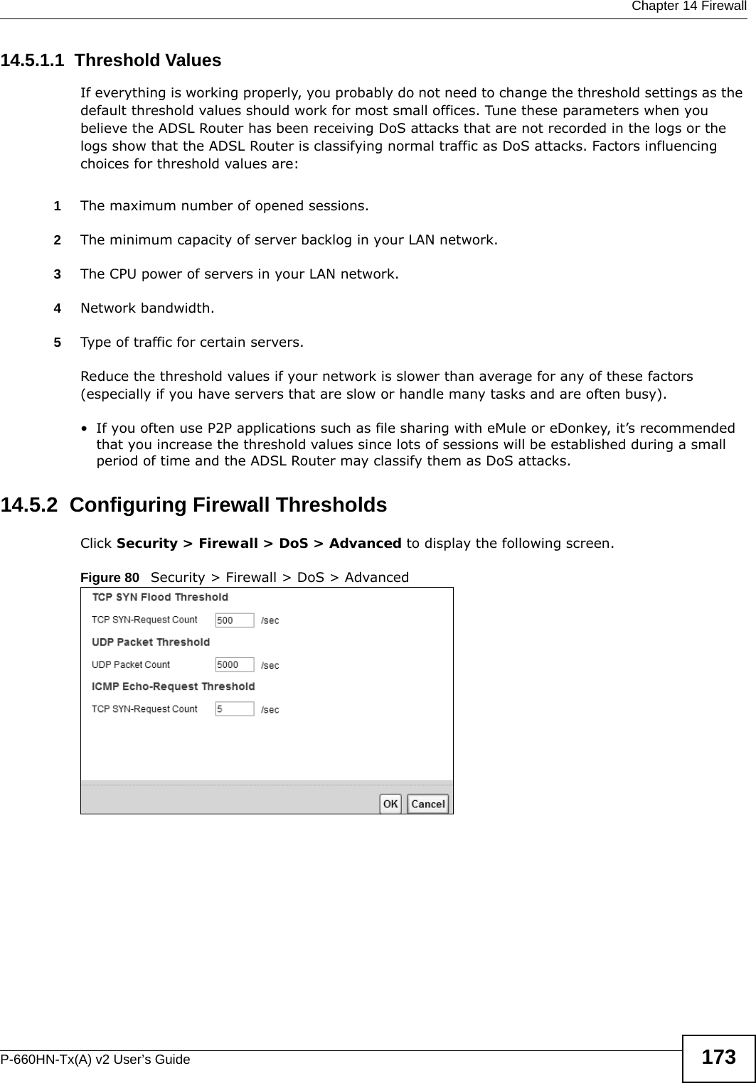
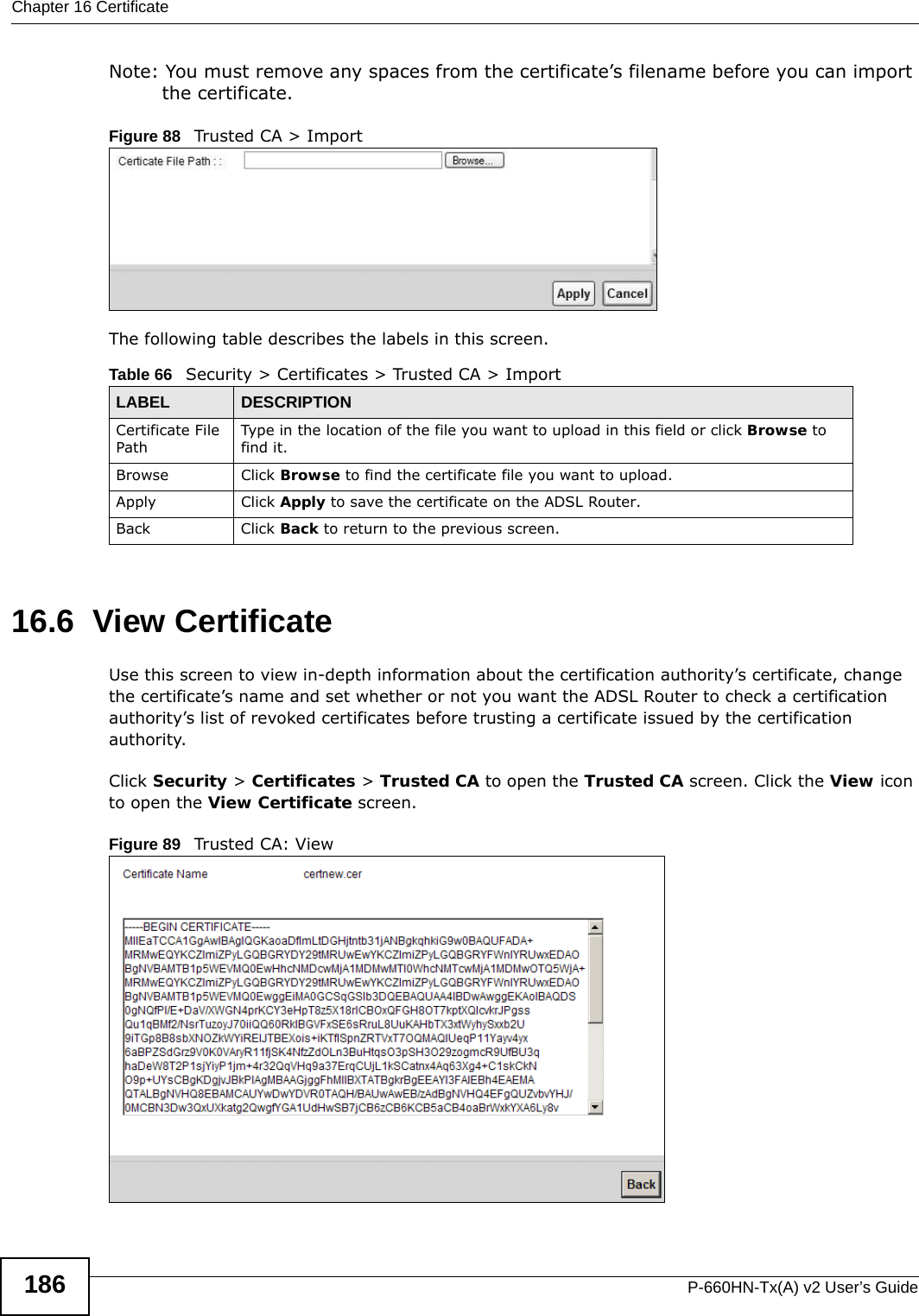
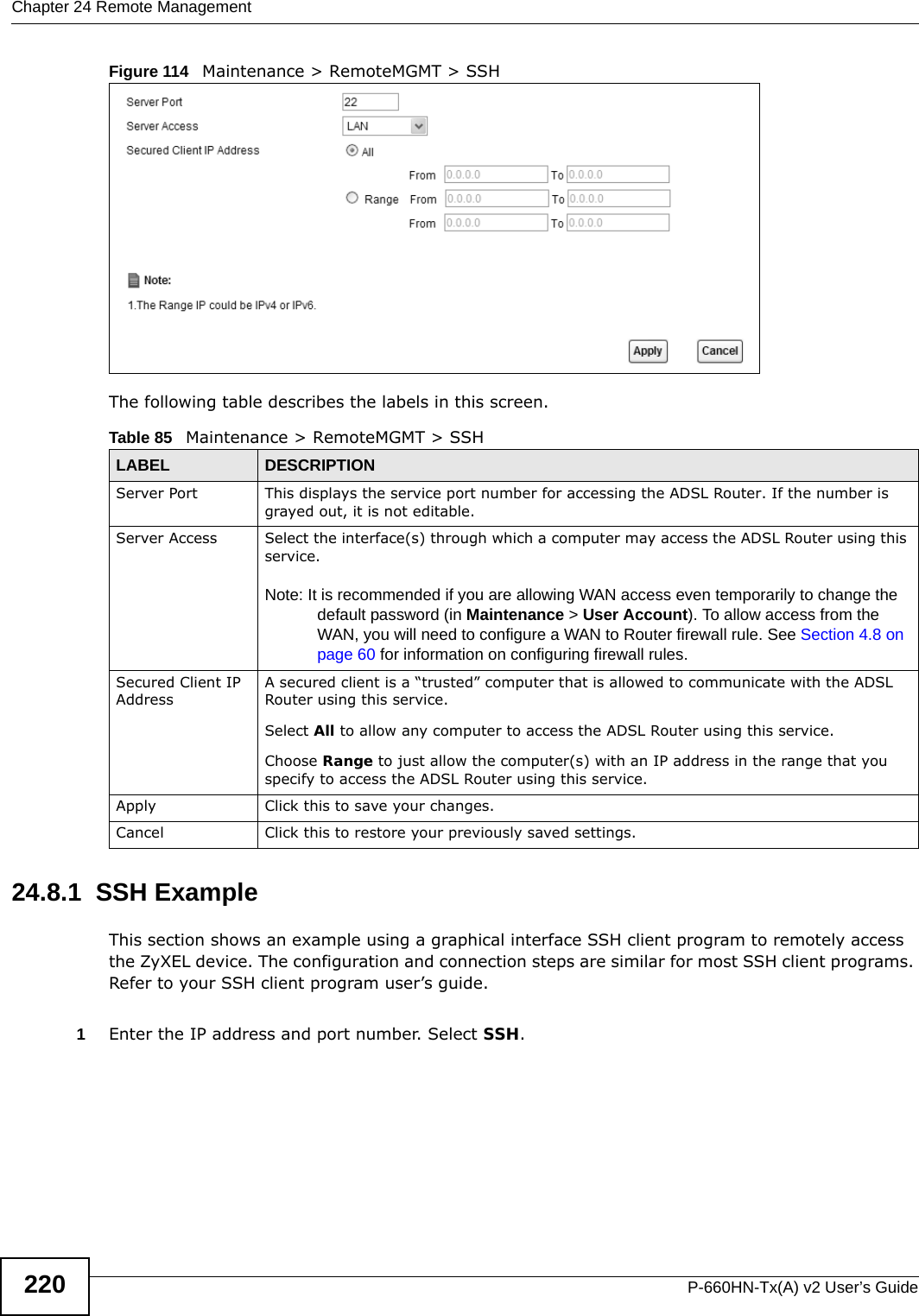
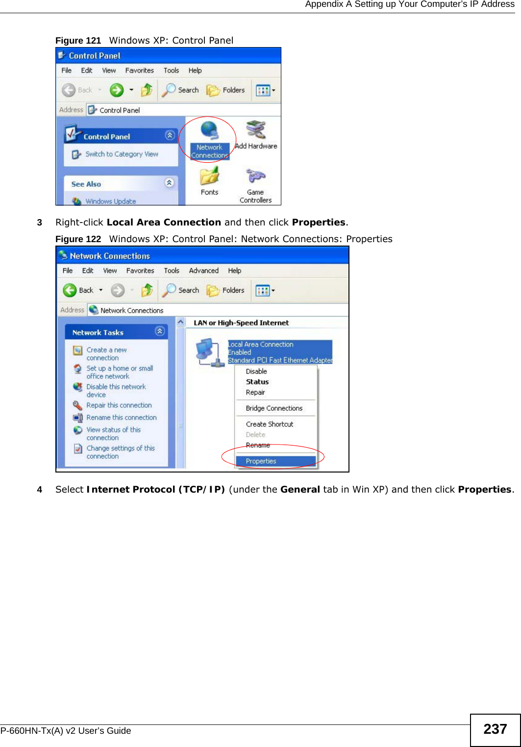
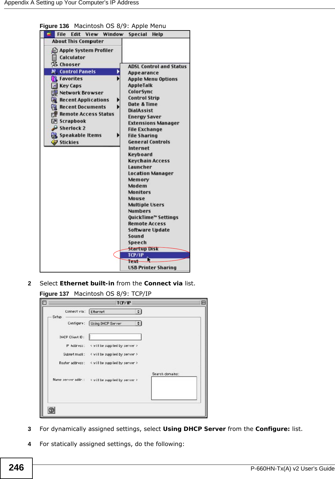
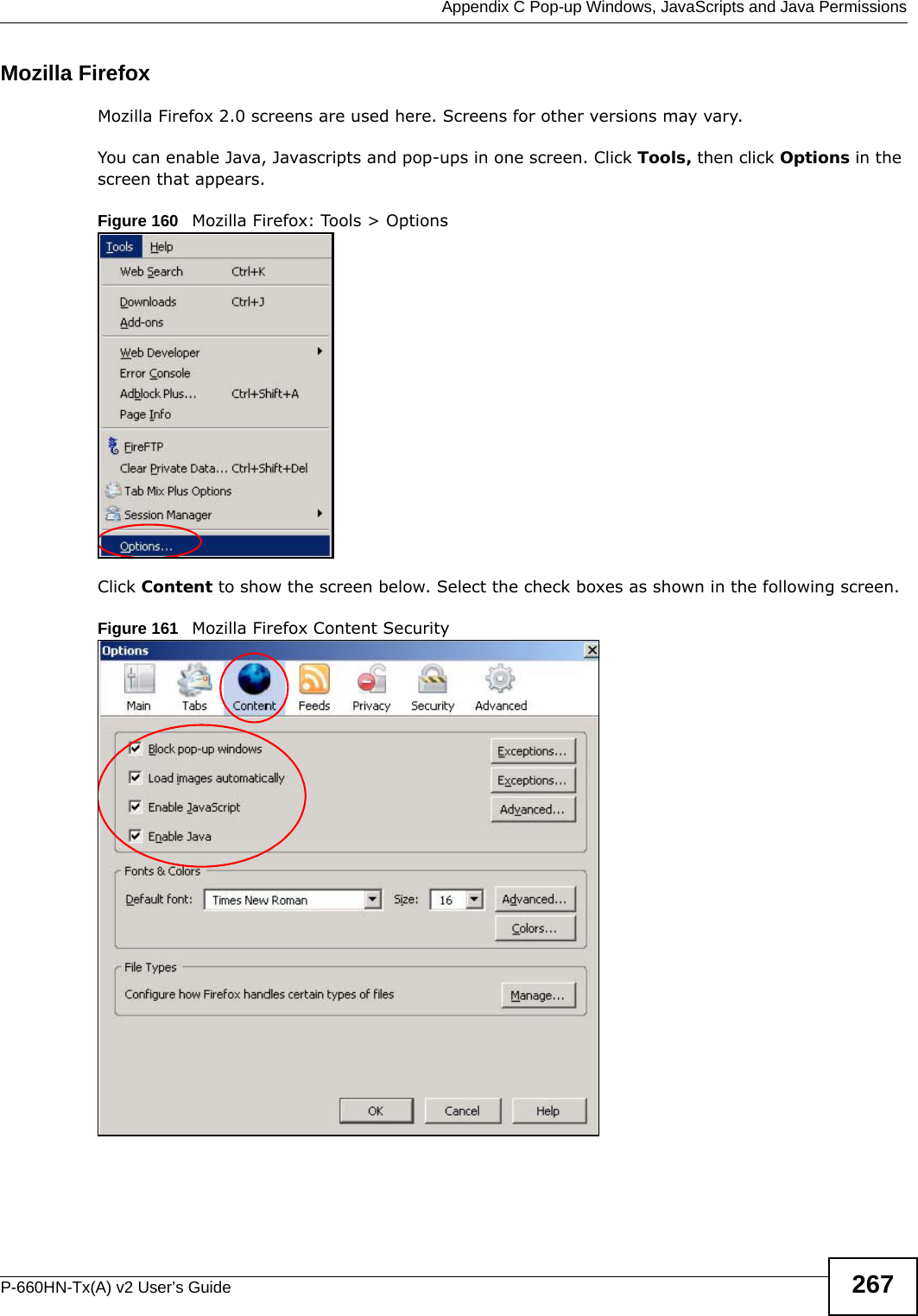
![Appendix A Setting up Your Computer’s IP AddressP-660HN-Tx(A) v2 User’s Guide 245Figure 135 Windows Vista: Internet Protocol Version 4 (TCP/IPv4) Properties10 Click OK to close the Internet Protocol Version 4 (TCP/IPv4) Properties window.11 Click Close to close the Local Area Connection Properties window.12 Close the Network Connections window.13 Turn on your ADSL Router and restart your computer (if prompted).Verifying Settings1Click Start, All Programs, Accessories and then Command Prompt.2In the Command Prompt window, type "ipconfig" and then press [ENTER]. You can also open Network Connections, right-click a network connection, click Status and then click the Support tab.Macintosh OS 8/9 1Click the Apple menu, Control Panel and double-click TCP/IP to open the TCP/IP Control Panel.](https://usermanual.wiki/ZyXEL-Communications/P660HNT1AV2/User-Guide-1872984-Page-245.png)
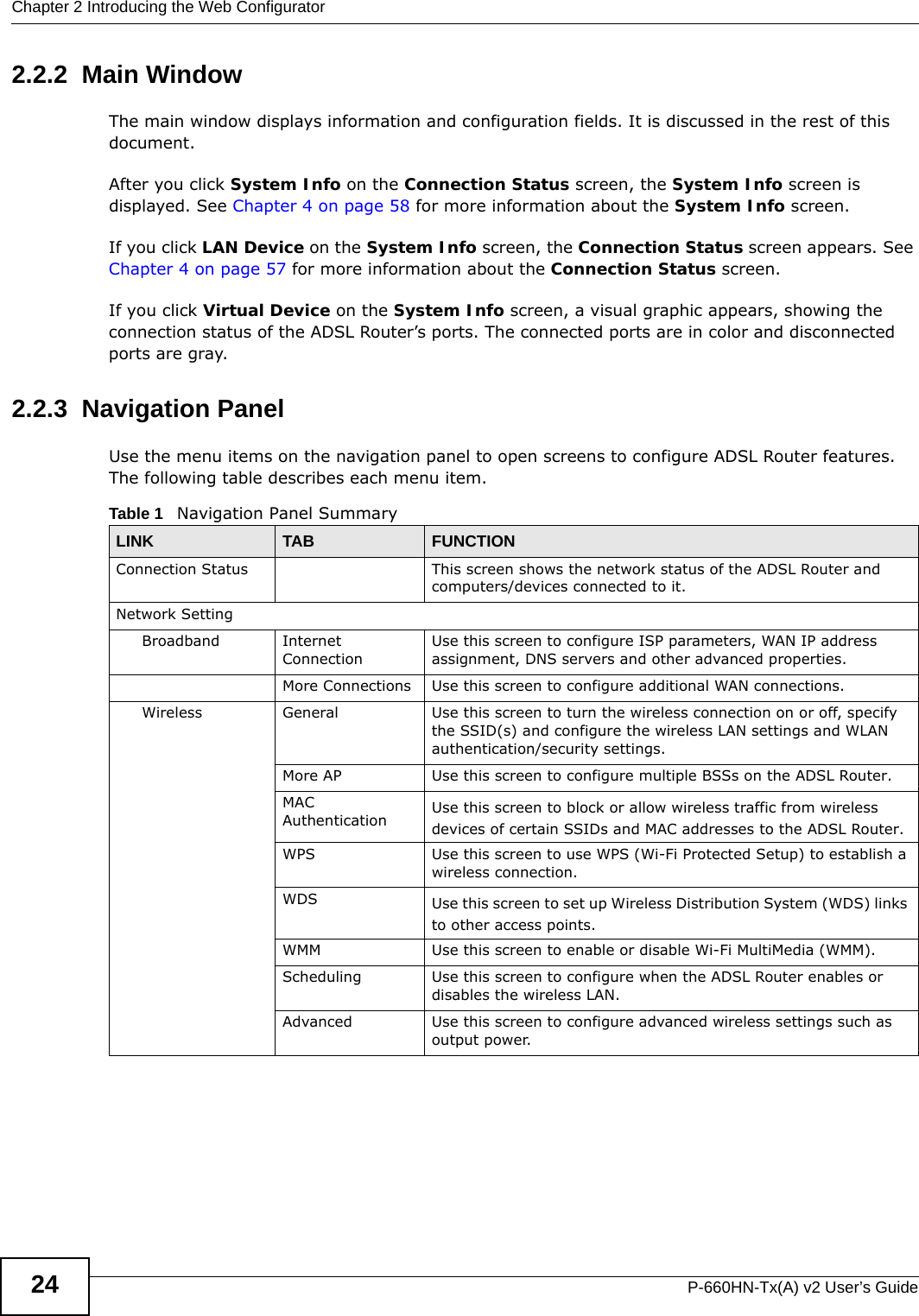
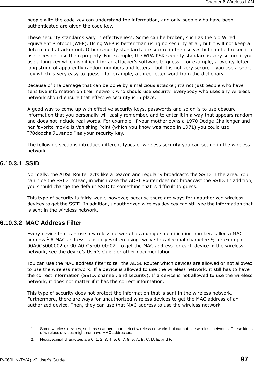
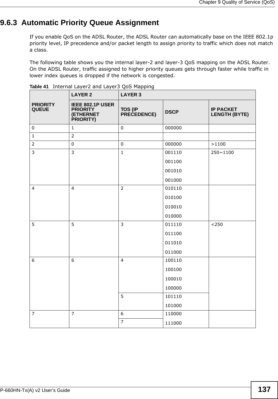
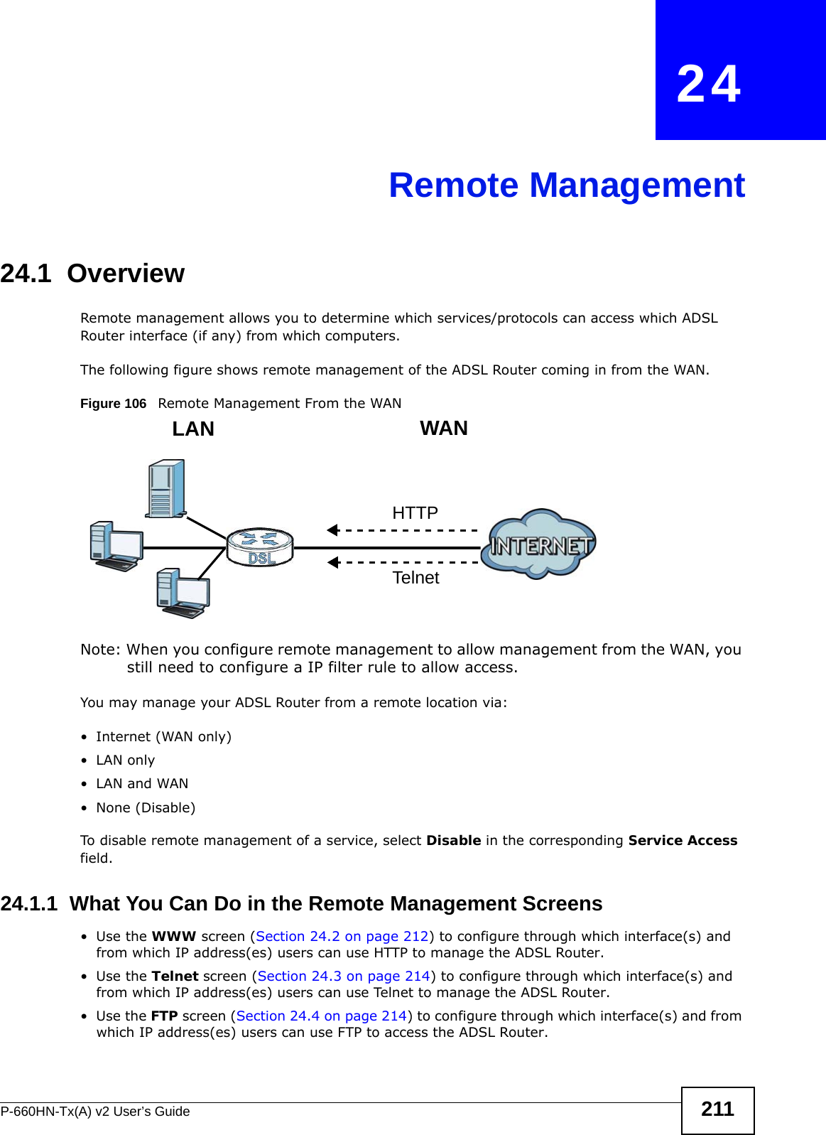
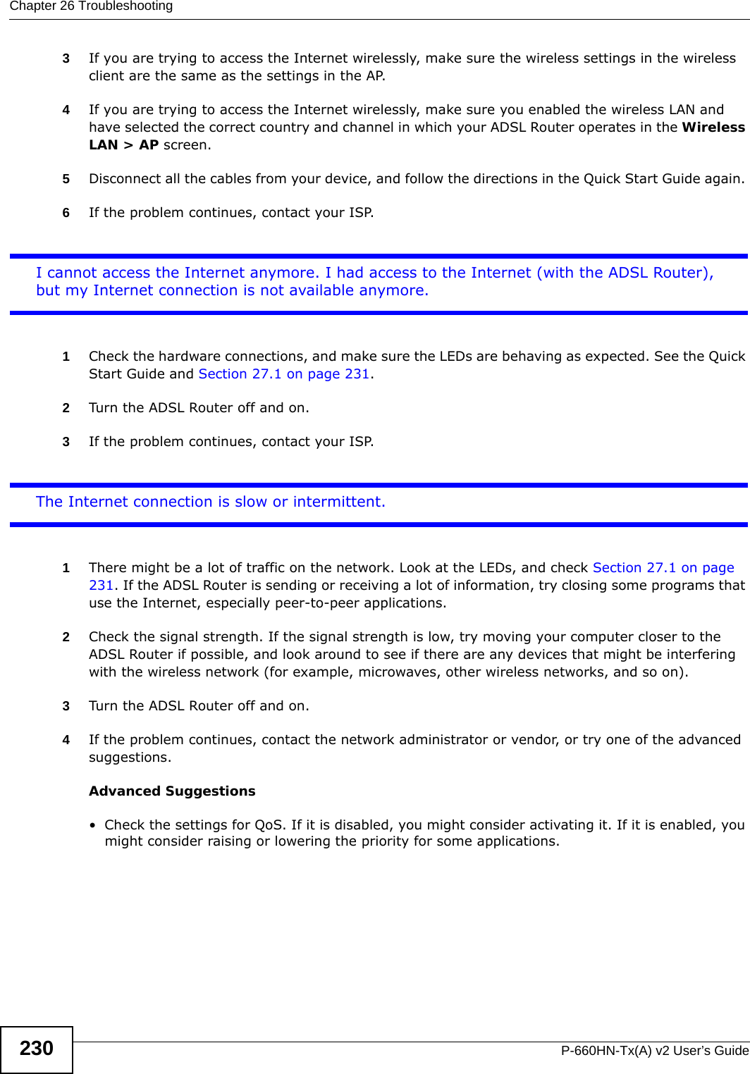
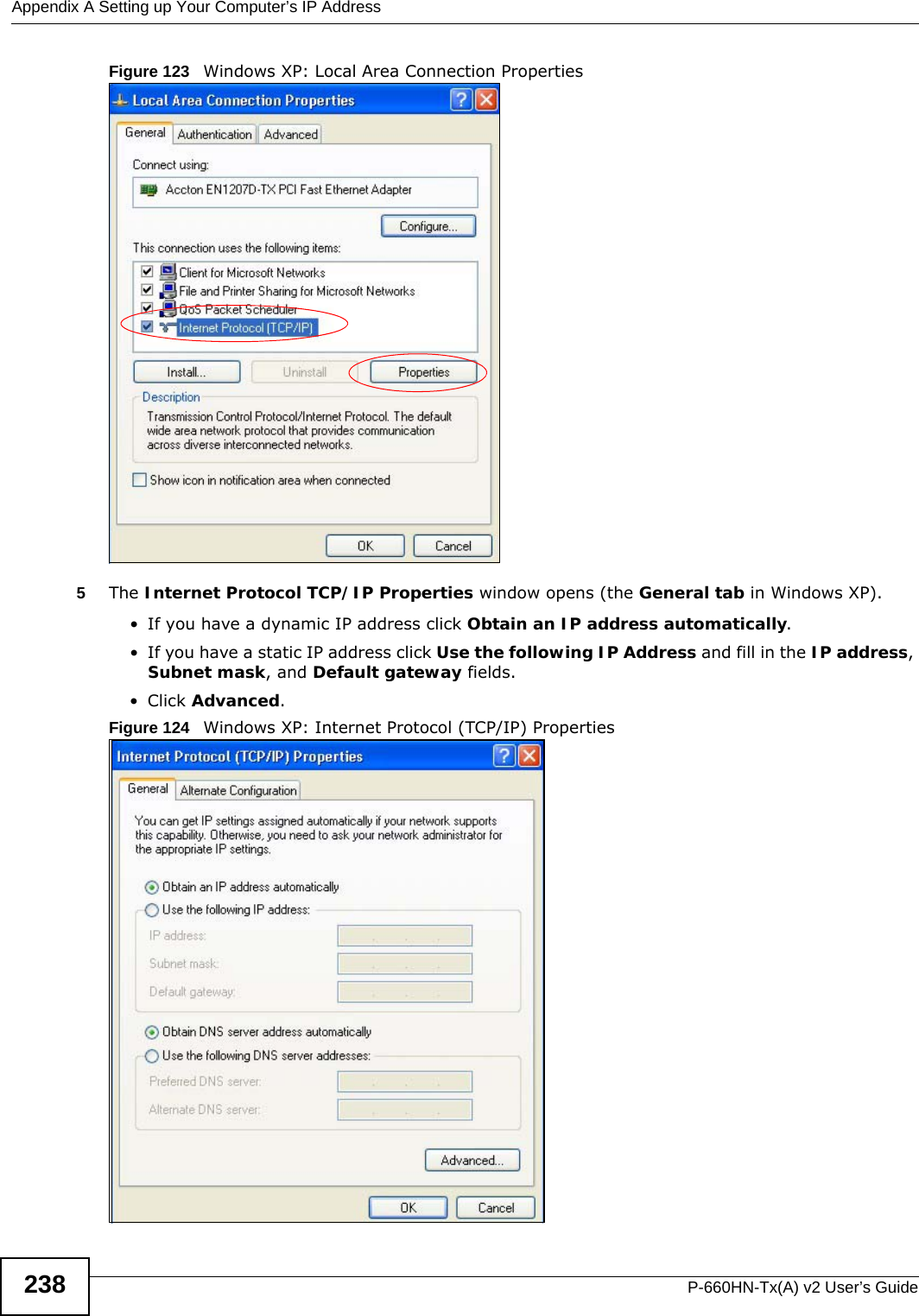
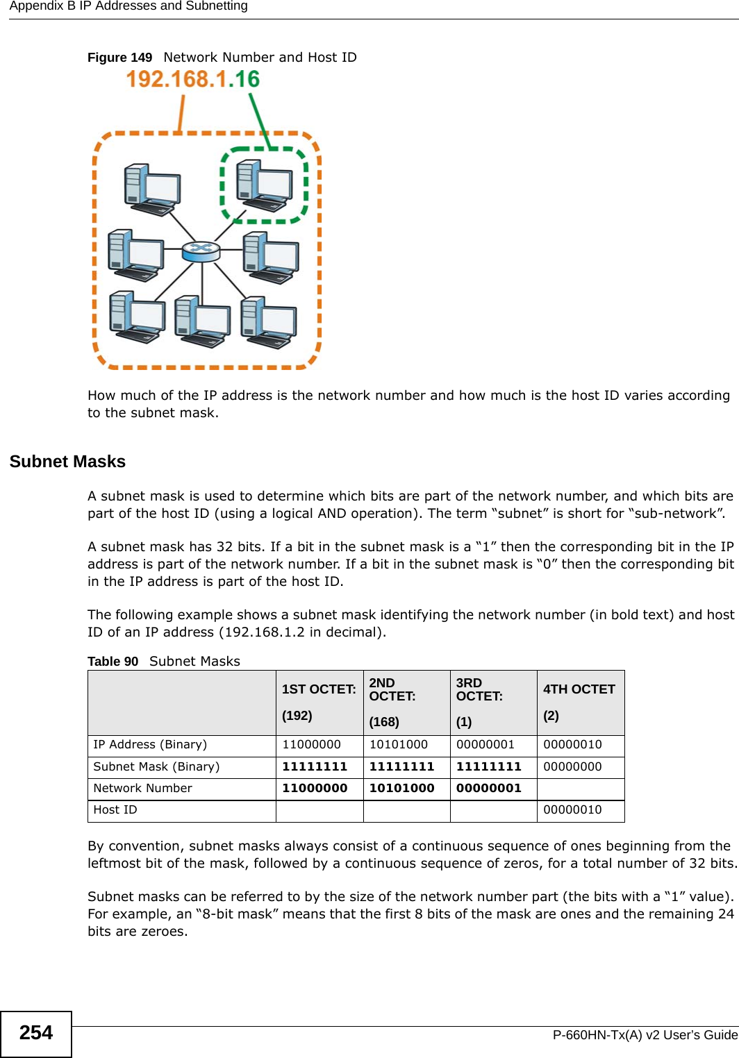
![Appendix A Setting up Your Computer’s IP AddressP-660HN-Tx(A) v2 User’s Guide 251Figure 144 Red Hat 9.0: Dynamic IP Address Setting in ifconfig-eth0 • If you have a static IP address, enter static in the BOOTPROTO= field. Type IPADDR= followed by the IP address (in dotted decimal notation) and type NETMASK= followed by the subnet mask. The following example shows an example where the static IP address is 192.168.1.10 and the subnet mask is 255.255.255.0. Figure 145 Red Hat 9.0: Static IP Address Setting in ifconfig-eth0 2If you know your DNS server IP address(es), enter the DNS server information in the resolv.conf file in the /etc directory. The following figure shows an example where two DNS server IP addresses are specified.Figure 146 Red Hat 9.0: DNS Settings in resolv.conf 3After you edit and save the configuration files, you must restart the network card. Enter ./network restart in the /etc/rc.d/init.d directory. The following figure shows an example.Figure 147 Red Hat 9.0: Restart Ethernet Card Verifying SettingsEnter ifconfig in a terminal screen to check your TCP/IP properties. DEVICE=eth0ONBOOT=yesBOOTPROTO=dhcpUSERCTL=noPEERDNS=yesTYPE=EthernetDEVICE=eth0ONBOOT=yesBOOTPROTO=staticIPADDR=192.168.1.10NETMASK=255.255.255.0USERCTL=noPEERDNS=yesTYPE=Ethernetnameserver 172.23.5.1nameserver 172.23.5.2[root@localhost init.d]# network restartShutting down interface eth0: [OK]Shutting down loopback interface: [OK]Setting network parameters: [OK]Bringing up loopback interface: [OK]Bringing up interface eth0: [OK]](https://usermanual.wiki/ZyXEL-Communications/P660HNT1AV2/User-Guide-1872984-Page-251.png)
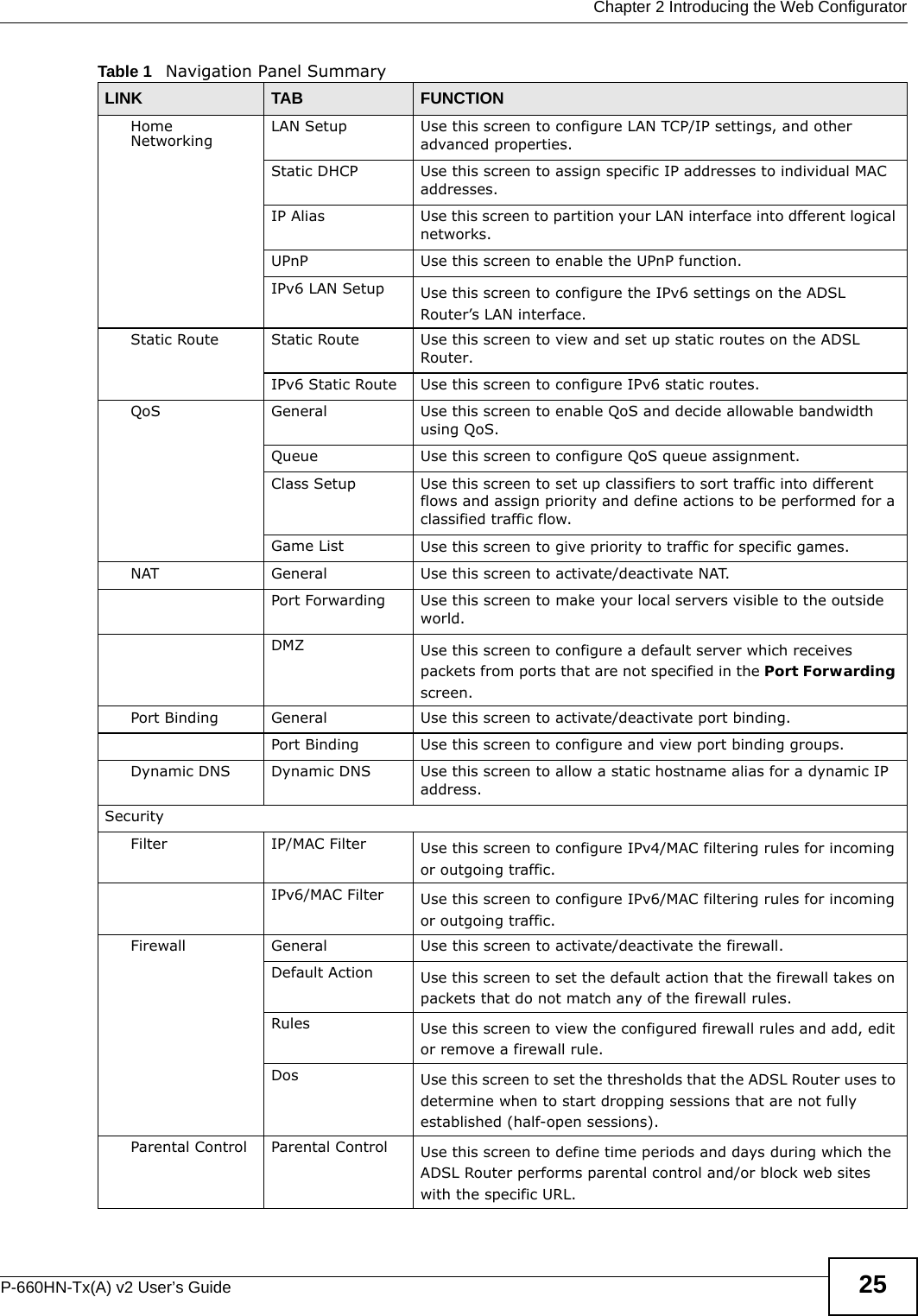
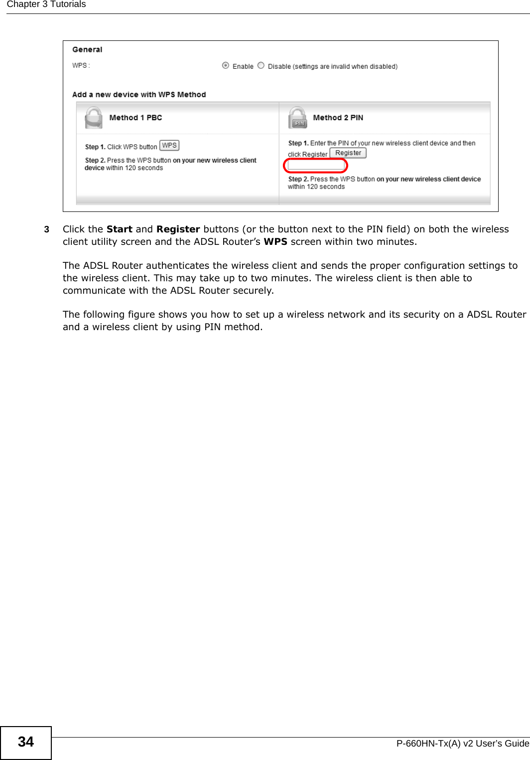
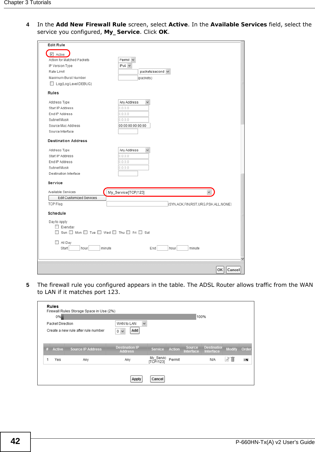
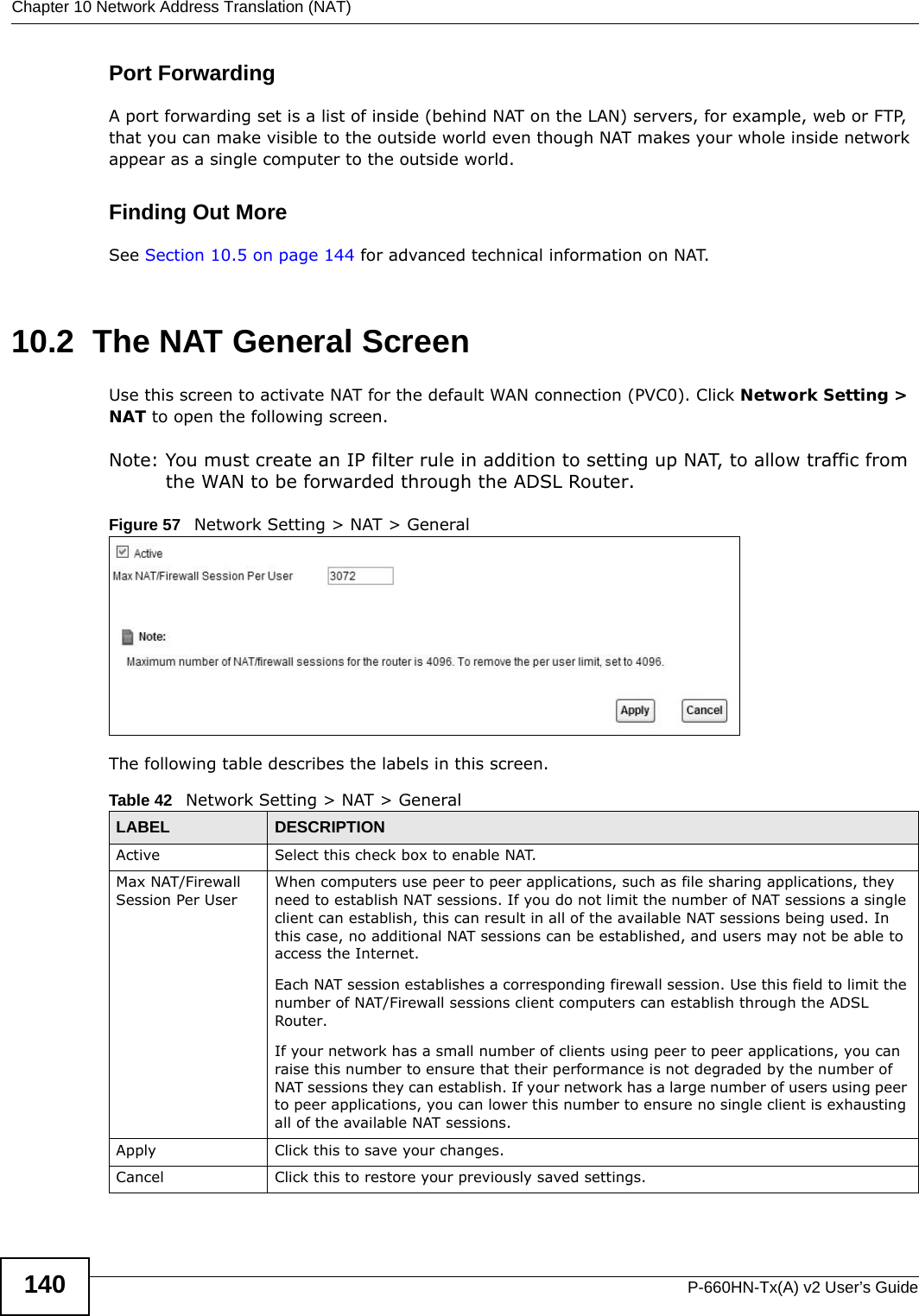
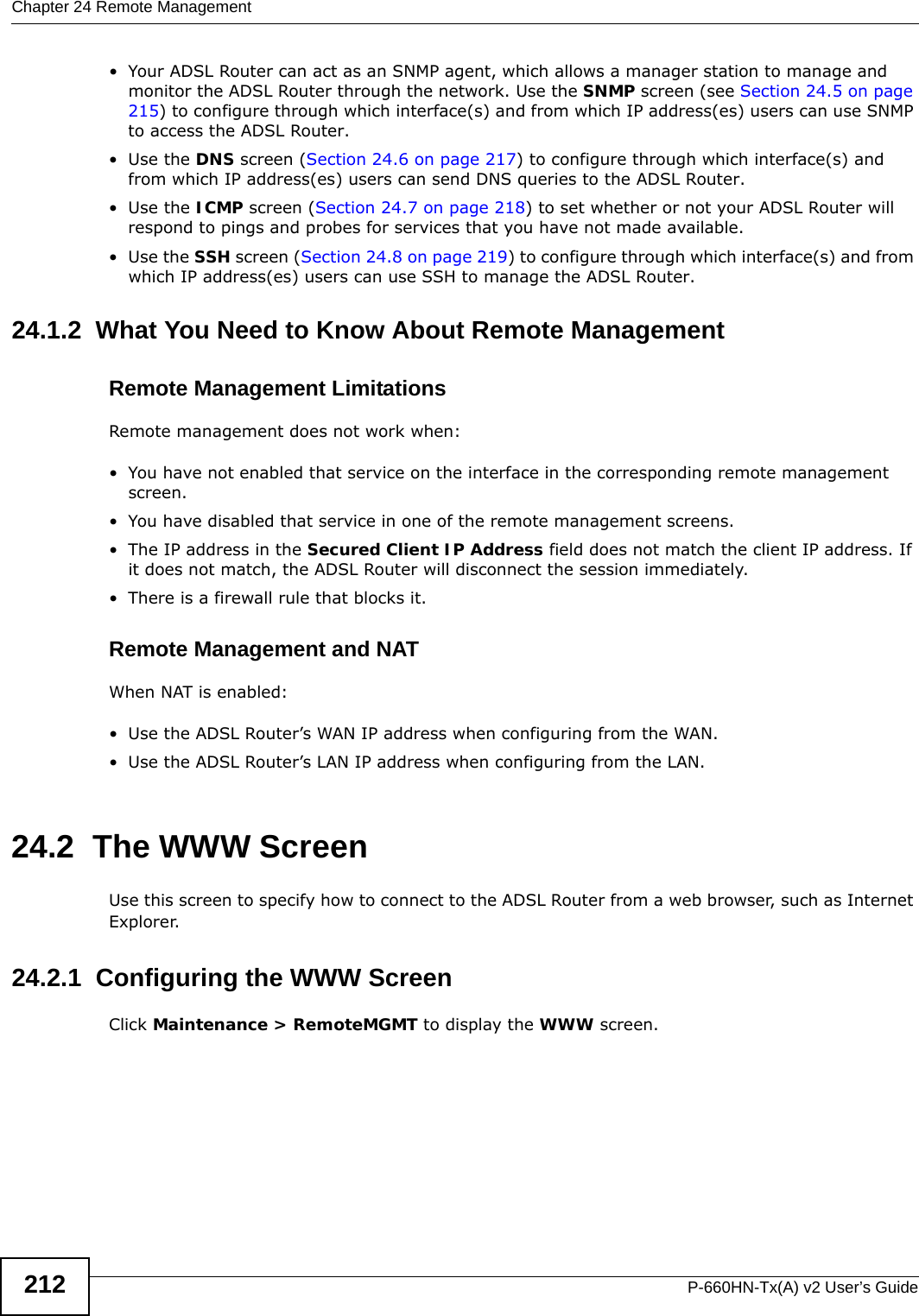
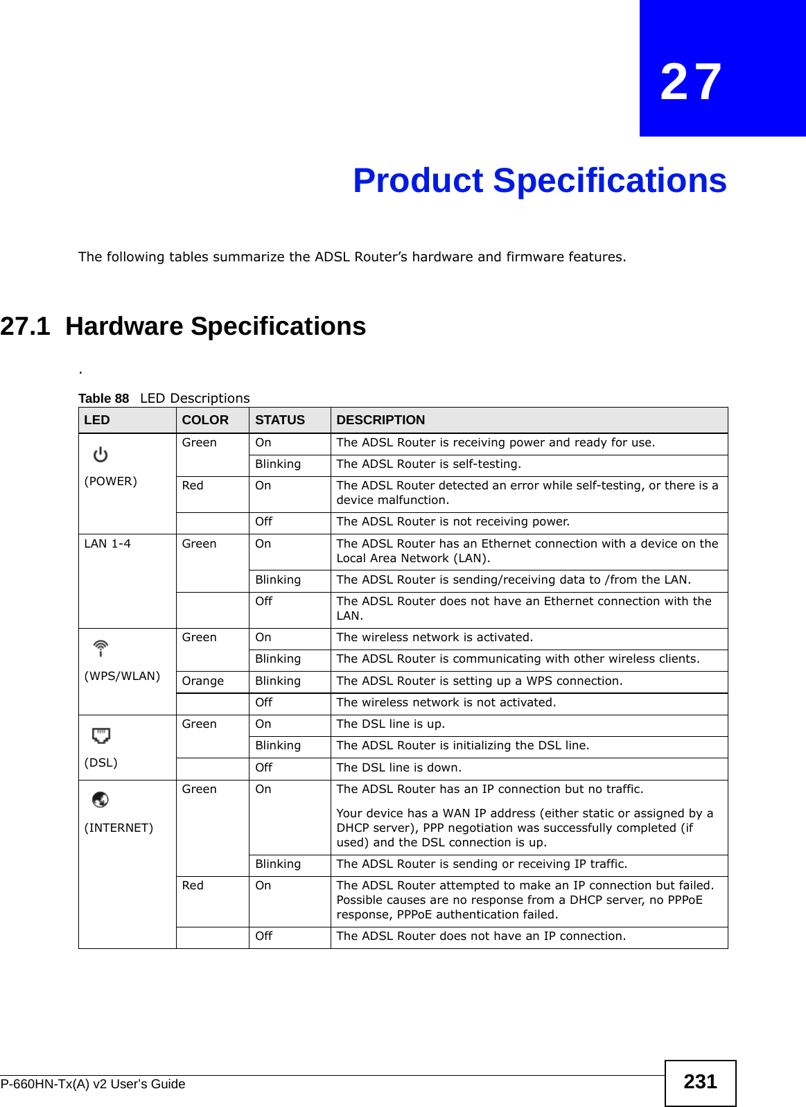
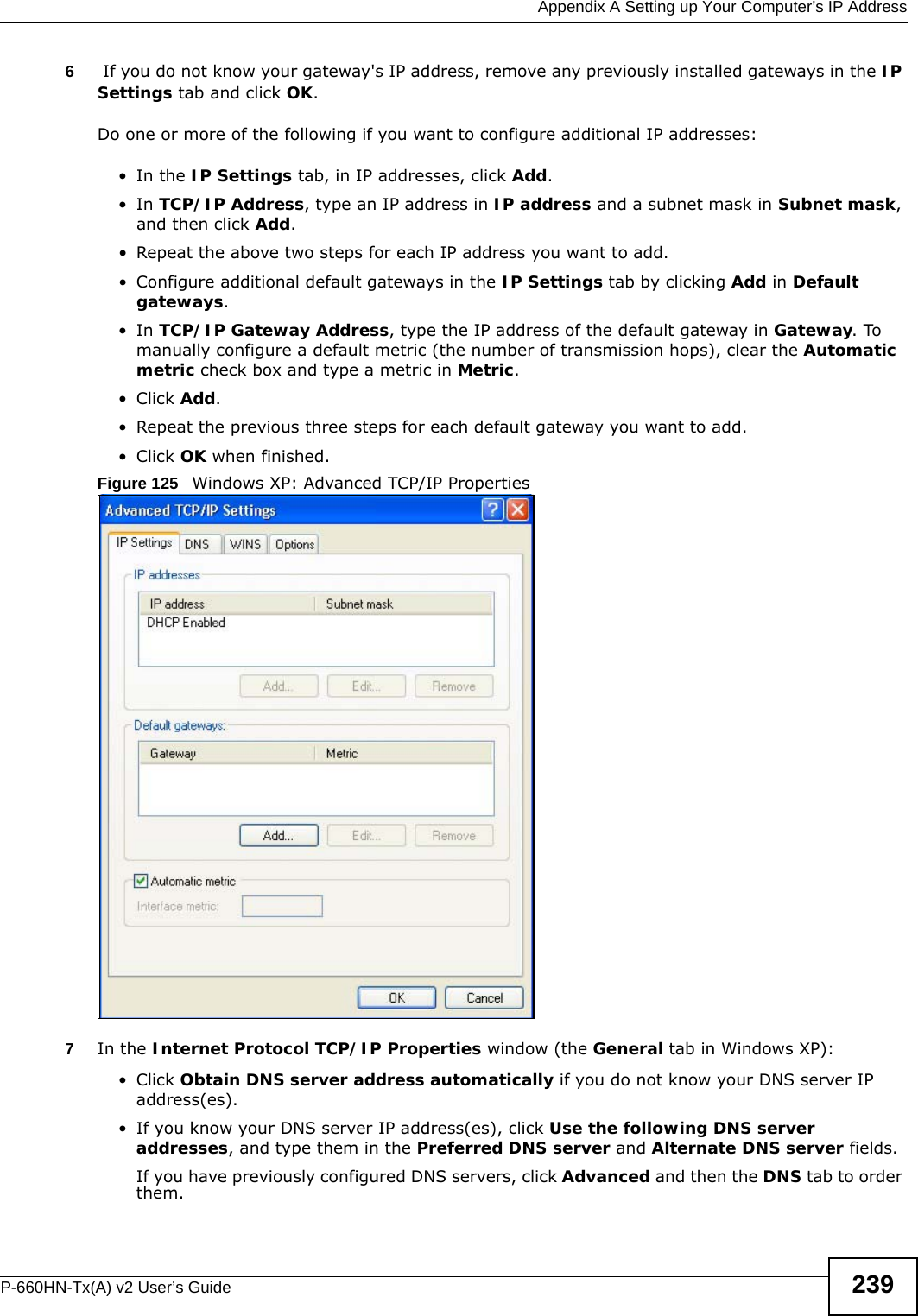
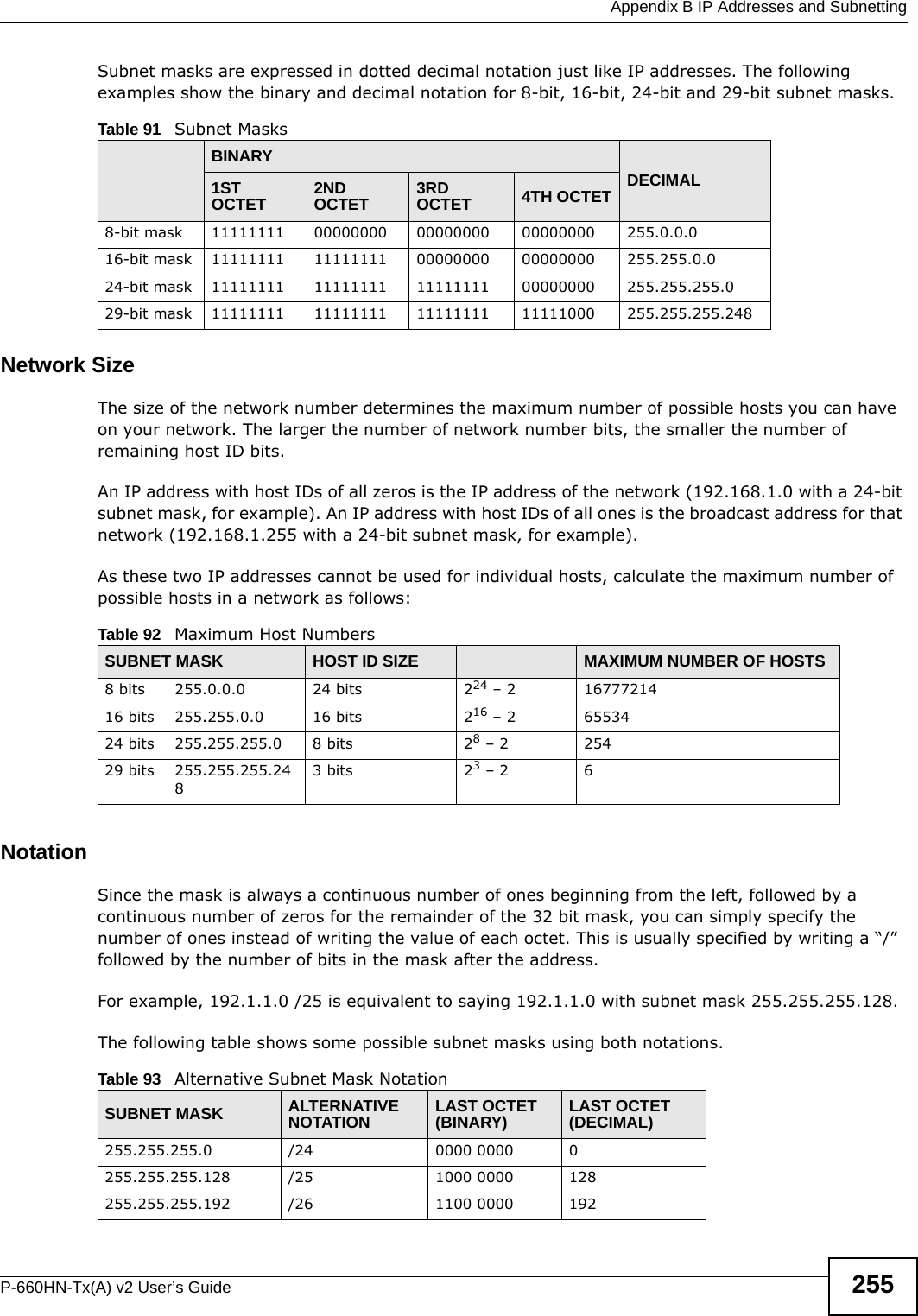
![Appendix A Setting up Your Computer’s IP AddressP-660HN-Tx(A) v2 User’s Guide252Figure 148 Red Hat 9.0: Checking TCP/IP Properties [root@localhost]# ifconfig eth0 Link encap:Ethernet HWaddr 00:50:BA:72:5B:44 inet addr:172.23.19.129 Bcast:172.23.19.255 Mask:255.255.255.0 UP BROADCAST RUNNING MULTICAST MTU:1500 Metric:1 RX packets:717 errors:0 dropped:0 overruns:0 frame:0 TX packets:13 errors:0 dropped:0 overruns:0 carrier:0 collisions:0 txqueuelen:100 RX bytes:730412 (713.2 Kb) TX bytes:1570 (1.5 Kb) Interrupt:10 Base address:0x1000 [root@localhost]#](https://usermanual.wiki/ZyXEL-Communications/P660HNT1AV2/User-Guide-1872984-Page-252.png)


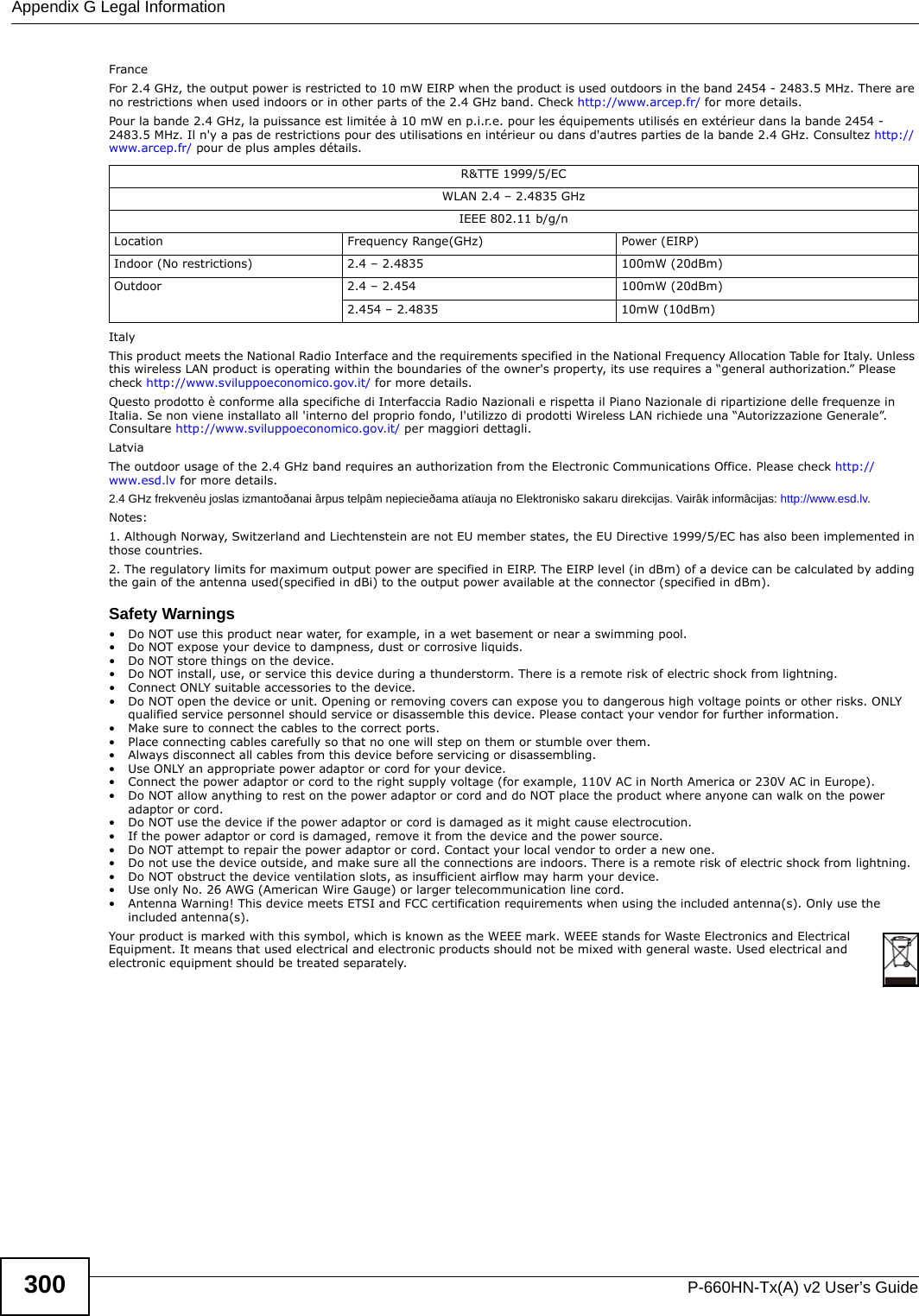
![Appendix G Legal InformationP-660HN-Tx(A) v2 User’s Guide298Notices Changes or modifications not expressly approved by the party responsible for compliance could void the user's authority to operate the equipment.This device has been designed for the WLAN 2.4 GHz network throughout the EC region and Switzerland, with restrictions in France. This Class B digital apparatus complies with Canadian ICES-003.Cet appareil numérique de la classe B est conforme à la norme NMB-003 du Canada.Viewing CertificationsGo to www.zyxel.com to view the product’s documents and certifications.ZyXEL Limited WarrantyZyXEL warrants to the original end user (purchaser) that this product is free from any defects in materials or workmanship for a period of up to two years from the date of purchase. During the warranty period, and upon proof of purchase, should the product have indications of failure due to faulty workmanship and/or materials, ZyXEL will, at its discretion, repair or replace the defective products or components without charge for either parts or labor, and to whatever extent it shall deem necessary to restore the product or components to proper operating condition. Any replacement will consist of a new or re-manufactured functionally equivalent product of equal or higher value, and will be solely at the discretion of ZyXEL. This warranty shall not apply if the product has been modified, misused, tampered with, damaged by an act of God, or subjected to abnormal working conditions.NoteRepair or replacement, as provided under this warranty, is the exclusive remedy of the purchaser. This warranty is in lieu of all other warranties, express or implied, including any implied warranty of merchantability or fitness for a particular use or purpose. ZyXEL shall in no event be held liable for indirect or consequential damages of any kind to the purchaser.To obtain the services of this warranty, contact ZyXEL's Service Center for your Return Material Authorization number (RMA). Products must be returned Postage Prepaid. It is recommended that the unit be insured when shipped. Any returned products without proof of purchase or those with an out-dated warranty will be repaired or replaced (at the discretion of ZyXEL) and the customer will be billed for parts and labor. All repaired or replaced products will be shipped by ZyXEL to the corresponding return address, Postage Paid. This warranty gives you specific legal rights, and you may also have other rights that vary from country to country.RegistrationRegister your product online to receive e-mail notices of firmware upgrades and information at www.zyxel.com for global products, or at www.us.zyxel.com for North American products.Regulatory InformationEuropean UnionThe following information applies if you use the product within the European Union.Declaration of Conformity with Regard to EU Directive 1999/5/EC (R&TTE Directive)Compliance Information for 2.4GHz and 5GHz Wireless Products Relevant to the EU and Other Countries Following the EU Directive 1999/5/EC (R&TTE Directive) [Czech] ZyXEL tímto prohlašuje, že tento zařízení je ve shodě se základními požadavky a dalšími příslušnými ustanoveními směrnice 1999/5/EC.[Danish] Undertegnede ZyXEL erklærer herved, at følgende udstyr udstyr overholder de væsentlige krav og øvrige relevante krav i direktiv 1999/5/EF.[German] Hiermit erklärt ZyXEL, dass sich das Gerät Ausstattung in Übereinstimmung mit den grundlegenden Anforderungen und den übrigen einschlägigen Bestimmungen der Richtlinie 1999/5/EU befindet.[Estonian] Käesolevaga kinnitab ZyXEL seadme seadmed vastavust direktiivi 1999/5/EÜ põhinõuetele ja nimetatud direktiivist tulenevatele teistele asjakohastele sätetele.English Hereby, ZyXEL declares that this equipment is in compliance with the essential requirements and other relevant provisions of Directive 1999/5/EC.[Spanish] Por medio de la presente ZyXEL declara que el equipo cumple con los requisitos esenciales y cualesquiera otras disposiciones aplicables o exigibles de la Directiva 1999/5/CE.[Greek] ΜΕ ΤΗΝ ΠΑΡΟΥΣΑ ZyXEL ΔΗΛΩΝΕΙ ΟΤΙ εξοπλισμός ΣΥΜΜΟΡΦΩΝΕΤΑΙ ΠΡΟΣ ΤΙΣ ΟΥΣΙΩΔΕΙΣ ΑΠΑΙΤΗΣΕΙΣ ΚΑΙ ΤΙΣ ΛΟΙΠΕΣ ΣΧΕΤΙΚΕΣ ΔΙΑΤΑΞΕΙΣ ΤΗΣ ΟΔΗΓΙΑΣ 1999/5/ΕC.[French] Par la présente ZyXEL déclare que l'appareil équipements est conforme aux exigences essentielles et aux autres dispositions pertinentes de la directive 1999/5/EC.[Italian] Con la presente ZyXEL dichiara che questo attrezzatura è conforme ai requisiti essenziali ed alle altre disposizioni pertinenti stabilite dalla direttiva 1999/5/CE.[Latvian] Ar šo ZyXEL deklarē, ka iekārtas atbilst Direktīvas 1999/5/EK būtiskajām prasībām un citiem ar to saistītajiem noteikumiem.[Lithuanian] Šiuo ZyXEL deklaruoja, kad šis įranga atitinka esminius reikalavimus ir kitas 1999/5/EB Direktyvos nuostatas.[Dutch] Hierbij verklaart ZyXEL dat het toestel uitrusting in overeenstemming is met de essentiële eisen en de andere relevante bepalingen van richtlijn 1999/5/EC.](https://usermanual.wiki/ZyXEL-Communications/P660HNT1AV2/User-Guide-1872984-Page-298.png)
![Appendix G Legal InformationP-660HN-Tx(A) v2 User’s Guide 299National RestrictionsThis product may be used in all EU countries (and other countries following the EU directive 1999/5/EC) without any limitation except for the countries mentioned below:Ce produit peut être utilisé dans tous les pays de l’UE (et dans tous les pays ayant transposés la directive 1999/5/CE) sans aucune limitation, excepté pour les pays mentionnés ci-dessous:Questo prodotto è utilizzabile in tutte i paesi EU (ed in tutti gli altri paesi che seguono le direttive EU 1999/5/EC) senza nessuna limitazione, eccetto per i paesii menzionati di seguito:Das Produkt kann in allen EU Staaten ohne Einschränkungen eingesetzt werden (sowie in anderen Staaten die der EU Direktive 1995/5/CE folgen) mit Außnahme der folgenden aufgeführten Staaten:In the majority of the EU and other European countries,the 2,4- and 5-GHz bands have been made available for the use of wireless local area networks (LANs). Later in this document you will find an overview of countries inwhich additional restrictions or requirements or both are applicable.The requirements for any country may evolve. ZyXEL recommends that you check with the local authorities for the latest status of their national regulations for both the 2,4- and 5-GHz wireless LANs.The following countries have restrictions and/or requirements in addition to those given in the table labeled “Overview of Regulatory Requirements for Wireless LANs”:.BelgiumThe Belgian Institute for Postal Services and Telecommunications (BIPT) must be notified of any outdoor wireless link having a range exceeding 300 meters. Please check http://www.bipt.be for more details.Draadloze verbindingen voor buitengebruik en met een reikwijdte van meer dan 300 meter dienen aangemeld te worden bij het Belgisch Instituut voor postdiensten en telecommunicatie (BIPT). Zie http://www.bipt.be voor meer gegevens.Les liaisons sans fil pour une utilisation en extérieur d’une distance supérieure à 300 mètres doivent être notifiées à l’Institut Belge des services Postaux et des Télécommunications (IBPT). Visitez http://www.ibpt.be pour de plus amples détails.DenmarkIn Denmark, the band 5150 - 5350 MHz is also allowed for outdoor usage.I Danmark må frekvensbåndet 5150 - 5350 også anvendes udendørs.[Maltese] Hawnhekk, ZyXEL, jiddikjara li dan tagħmir jikkonforma mal-ħtiġijiet essenzjali u ma provvedimenti oħrajn relevanti li hemm fid-Dirrettiva 1999/5/EC.[Hungarian] Alulírott, ZyXEL nyilatkozom, hogy a berendezés megfelel a vonatkozó alapvetõ követelményeknek és az 1999/5/EK irányelv egyéb elõírásainak.[Polish] Niniejszym ZyXEL oświadcza, że sprzęt jest zgodny z zasadniczymi wymogami oraz pozostałymi stosownymi postanowieniami Dyrektywy 1999/5/EC.[Portuguese] ZyXEL declara que este equipamento está conforme com os requisitos essenciais e outras disposições da Directiva 1999/5/EC.[Slovenian] ZyXEL izjavlja, da je ta oprema v skladu z bistvenimi zahtevami in ostalimi relevantnimi določili direktive 1999/5/EC.[Slovak] ZyXEL týmto vyhlasuje, že zariadenia spĺňa základné požiadavky a všetky príslušné ustanovenia Smernice 1999/5/EC.[Finnish] ZyXEL vakuuttaa täten että laitteet tyyppinen laite on direktiivin 1999/5/EY oleellisten vaatimusten ja sitä koskevien direktiivin muiden ehtojen mukainen.[Swedish] Härmed intygar ZyXEL att denna utrustning står I överensstämmelse med de väsentliga egenskapskrav och övriga relevanta bestämmelser som framgår av direktiv 1999/5/EC.[Bulgarian] С настоящото ZyXEL декларира, че това оборудване е в съответствие със съществените изисквания и другите приложими разпоредбите на Директива 1999/5/ЕC.[Icelandic] Hér með lýsir, ZyXEL því yfir að þessi búnaður er í samræmi við grunnkröfur og önnur viðeigandi ákvæði tilskipunar 1999/5/EC.[Norwegian] Erklærer herved ZyXEL at dette utstyret er I samsvar med de grunnleggende kravene og andre relevante bestemmelser I direktiv 1999/5/EF.[Romanian] Prin prezenta, ZyXEL declară că acest echipament este în conformitate cu cerinţele esenţiale şi alte prevederi relevante ale Directivei 1999/5/EC. Overview of Regulatory Requirements for Wireless LANs Frequency Band (MHz) Max Power Level(EIRP)1 (mW) Indoor ONLY Indoor and Outdoor 2400-2483.5 100 V 5150-5350 200 V 5470-5725 1000 V](https://usermanual.wiki/ZyXEL-Communications/P660HNT1AV2/User-Guide-1872984-Page-299.png)