ZyXEL Communications PLA4231 500Mbps Powerline Wireless N Extender User Manual Book
ZyXEL Communications Corporation 500Mbps Powerline Wireless N Extender Book
UserManual.wiki
>
ZyXEL Communications
>
PLA4231 User Manual
users manual
Navigation menu
Upload a User Manual
Namespaces
Wiki Guide
HTML
PDF
Info
Views
User Manual
Discussion / Help
Navigation
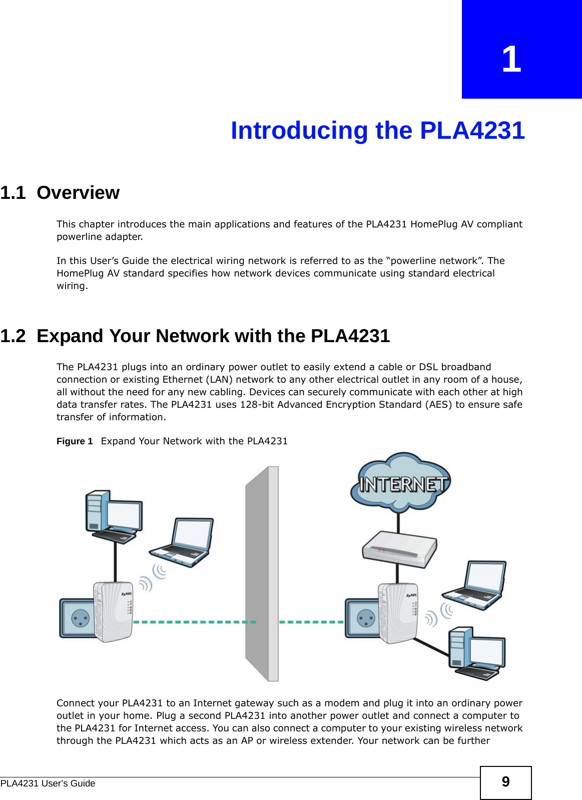


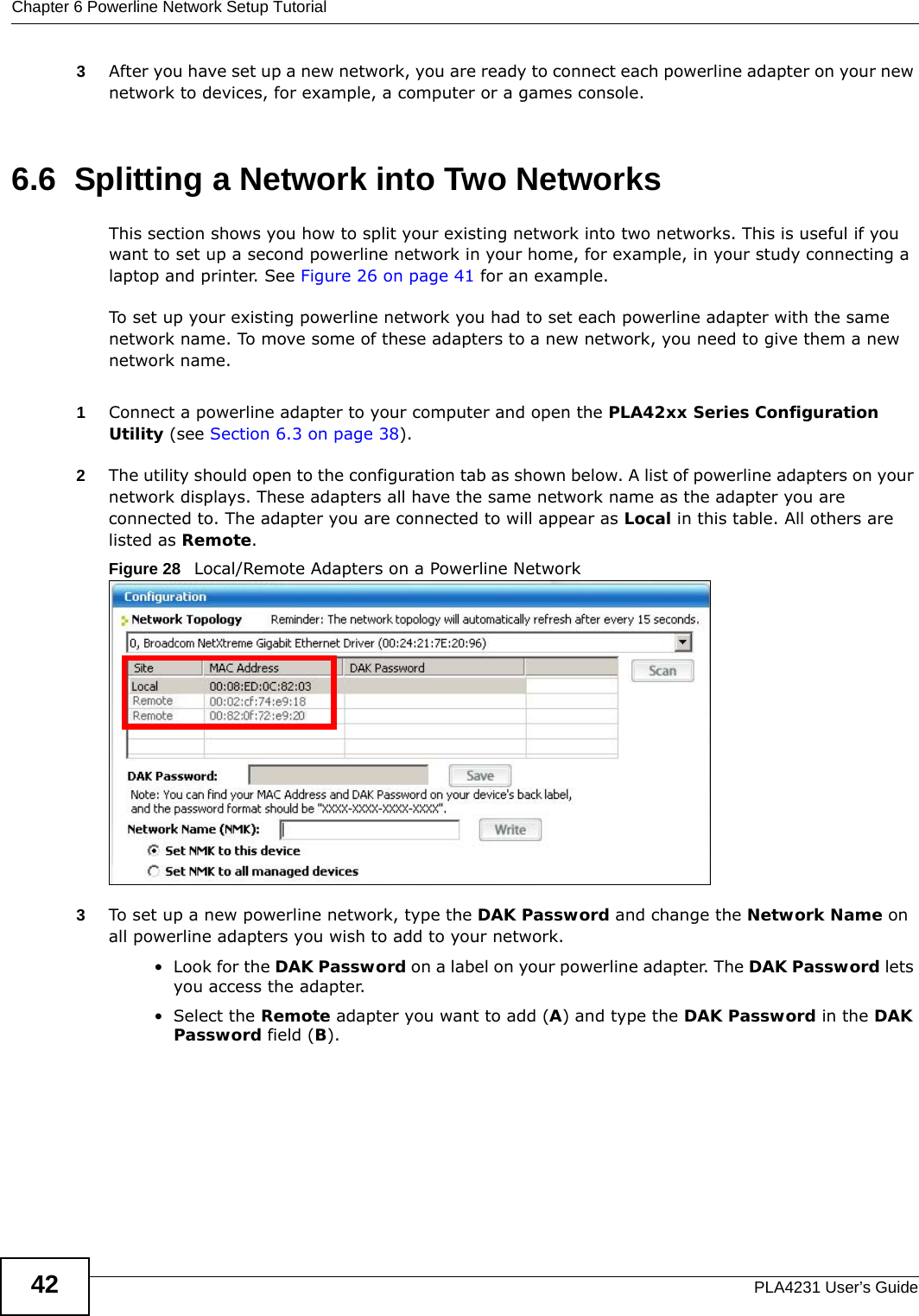


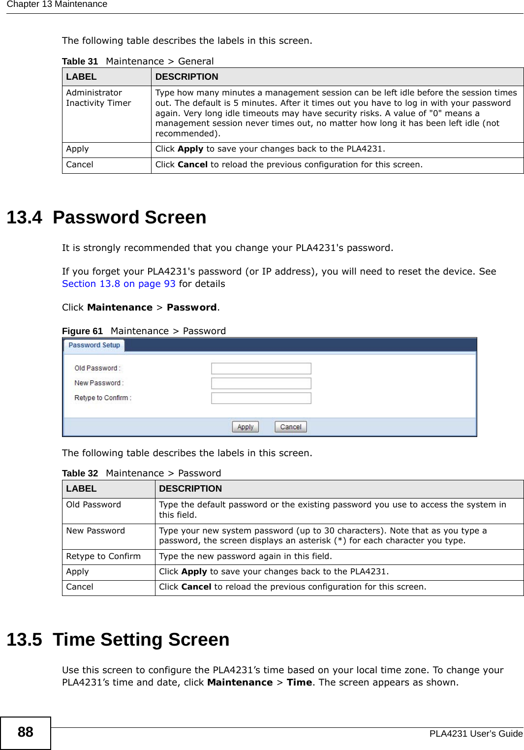
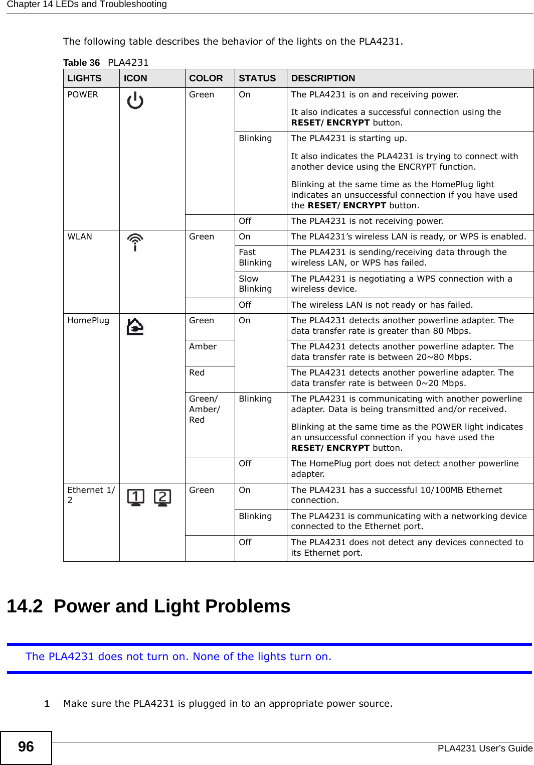
![Chapter 14 LEDs and TroubleshootingPLA4231 User’s Guide102I forgot the password.1The default password is 1234.2If this does not work, you have to reset the device to its factory defaults. See Section 1.7 on page 12.I cannot see or access the Login screen in the Web Configurator.1Make sure you are using the correct IP address.• The default IP address is 192.168.1.2.• If you changed the IP address (Section 11.4 on page 80), use the new IP address.• If you changed the IP address and have forgotten it, see the troubleshooting suggestions for I don’t know the IP address of my PLA4231.2Check the hardware connections, and make sure the LEDs are behaving as expected. See the Quick Start Guide. 3Make sure your Internet browser does not block pop-up windows and has JavaScripts and Java enabled. See Appendix A on page 105.4Make sure your computer is in the same subnet as the PLA4231. (If you know that there are routers between your computer and the PLA4231, skip this step.)• If there is a DHCP server on your network, make sure your computer is using a dynamic IP address. See Section 11.4 on page 102. • If there is no DHCP server on your network, make sure your computer’s IP address is in the same subnet as the PLA4231. 5Reset the device to its factory defaults, and try to access the PLA4231 with the default IP address. 6If the problem continues, contact the network administrator or vendor, or try one of the advanced suggestions.Advanced Suggestion• If your computer is connected wirelessly, use a computer that is connected to a LAN/Ethernet port.I can see the Login screen, but I cannot log in to the PLA4231.1Make sure you have entered the password correctly. The default password is 1234. This field is case-sensitive, so make sure [Caps Lock] is not on.](https://usermanual.wiki/ZyXEL-Communications/PLA4231/User-Guide-1863366-Page-102.png)


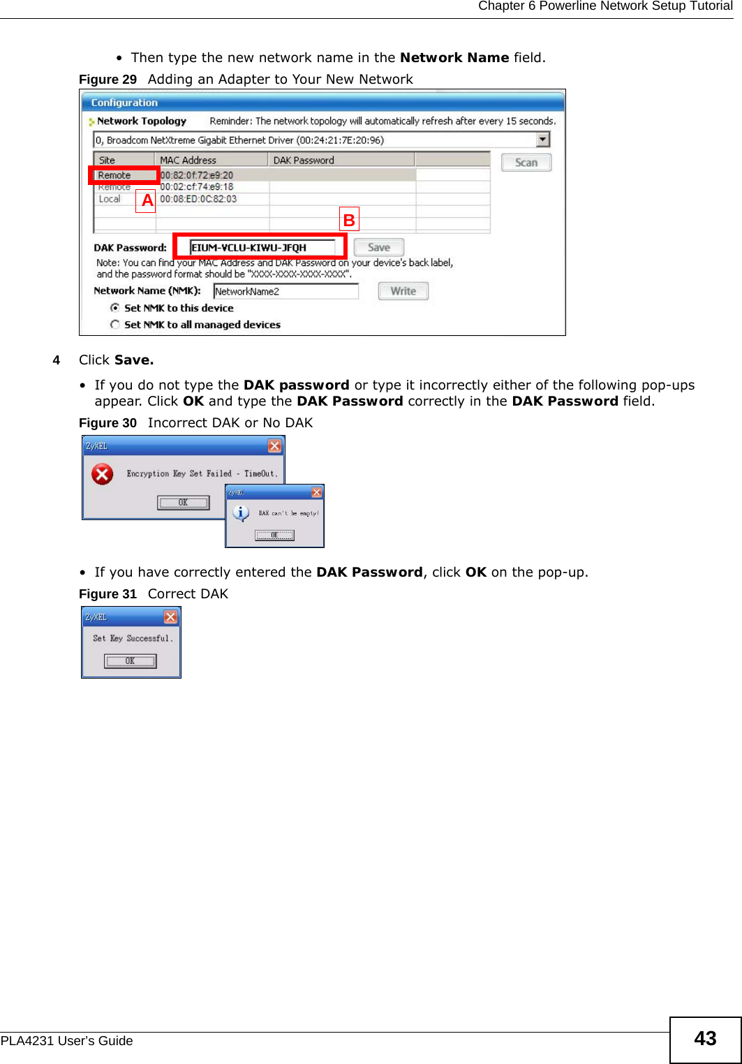
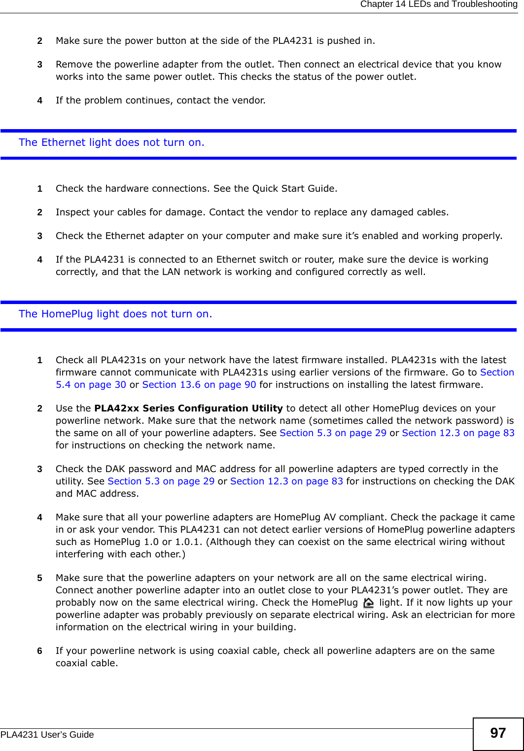
![Appendix B Legal InformationPLA4231 User’s Guide 117Declaration of Conformity with Regard to EU Directive 1999/5/EC (R&TTE Directive)Compliance Information for 2.4GHz and 5GHz Wireless Products Relevant to the EU and Other Countries Following the EU Directive 1999/5/EC (R&TTE Directive) National RestrictionsThis product may be used in all EU countries (and other countries following the EU directive 1999/5/EC) without any limitation except for the countries mentioned below:Ce produit peut être utilisé dans tous les pays de l’UE (et dans tous les pays ayant transposés la directive 1999/5/CE) sans aucune limitation, excepté pour les pays mentionnés ci-dessous:Questo prodotto è utilizzabile in tutte i paesi EU (ed in tutti gli altri paesi che seguono le direttive EU 1999/5/EC) senza nessuna limitazione, eccetto per i paesii menzionati di seguito:[Czech] ZyXEL tímto prohlašuje, že tento zařízení je ve shodě se základními požadavky a dalšími příslušnými ustanoveními směrnice 1999/5/EC.[Danish] Undertegnede ZyXEL erklærer herved, at følgende udstyr udstyr overholder de væsentlige krav og øvrige relevante krav i direktiv 1999/5/EF.[German] Hiermit erklärt ZyXEL, dass sich das Gerät Ausstattung in Übereinstimmung mit den grundlegenden Anforderungen und den übrigen einschlägigen Bestimmungen der Richtlinie 1999/5/EU befindet.[Estonian] Käesolevaga kinnitab ZyXEL seadme seadmed vastavust direktiivi 1999/5/EÜ põhinõuetele ja nimetatud direktiivist tulenevatele teistele asjakohastele sätetele.English Hereby, ZyXEL declares that this equipment is in compliance with the essential requirements and other relevant provisions of Directive 1999/5/EC.[Spanish] Por medio de la presente ZyXEL declara que el equipo cumple con los requisitos esenciales y cualesquiera otras disposiciones aplicables o exigibles de la Directiva 1999/5/CE.[Greek] ΜΕ ΤΗΝ ΠΑΡΟΥΣΑ ZyXEL ΔΗΛΩΝΕΙ ΟΤΙ εξοπλισμός ΣΥΜΜΟΡΦΩΝΕΤΑΙ ΠΡΟΣ ΤΙΣ ΟΥΣΙΩΔΕΙΣ ΑΠΑΙΤΗΣΕΙΣ ΚΑΙ ΤΙΣ ΛΟΙΠΕΣ ΣΧΕΤΙΚΕΣ ΔΙΑΤΑΞΕΙΣ ΤΗΣ ΟΔΗΓΙΑΣ 1999/5/ΕC.[French] Par la présente ZyXEL déclare que l'appareil équipements est conforme aux exigences essentielles et aux autres dispositions pertinentes de la directive 1999/5/EC.[Italian] Con la presente ZyXEL dichiara che questo attrezzatura è conforme ai requisiti essenziali ed alle altre disposizioni pertinenti stabilite dalla direttiva 1999/5/CE.[Latvian] Ar šo ZyXEL deklarē, ka iekārtas atbilst Direktīvas 1999/5/EK būtiskajām prasībām un citiem ar to saistītajiem noteikumiem.[Lithuanian] Šiuo ZyXEL deklaruoja, kad šis įranga atitinka esminius reikalavimus ir kitas 1999/5/EB Direktyvos nuostatas.[Dutch] Hierbij verklaart ZyXEL dat het toestel uitrusting in overeenstemming is met de essentiële eisen en de andere relevante bepalingen van richtlijn 1999/5/EC.[Maltese] Hawnhekk, ZyXEL, jiddikjara li dan tagħmir jikkonforma mal-ħtiġijiet essenzjali u ma provvedimenti oħrajn relevanti li hemm fid-Dirrettiva 1999/5/EC.[Hungarian] Alulírott, ZyXEL nyilatkozom, hogy a berendezés megfelel a vonatkozó alapvetõ követelményeknek és az 1999/5/EK irányelv egyéb elõírásainak.[Polish] Niniejszym ZyXEL oświadcza, że sprzęt jest zgodny z zasadniczymi wymogami oraz pozostałymi stosownymi postanowieniami Dyrektywy 1999/5/EC.[Portuguese] ZyXEL declara que este equipamento está conforme com os requisitos essenciais e outras disposições da Directiva 1999/5/EC.[Slovenian] ZyXEL izjavlja, da je ta oprema v skladu z bistvenimi zahtevami in ostalimi relevantnimi določili direktive 1999/5/EC.[Slovak] ZyXEL týmto vyhlasuje, že zariadenia spĺňa základné požiadavky a všetky príslušné ustanovenia Smernice 1999/5/EC.[Finnish] ZyXEL vakuuttaa täten että laitteet tyyppinen laite on direktiivin 1999/5/EY oleellisten vaatimusten ja sitä koskevien direktiivin muiden ehtojen mukainen.[Swedish] Härmed intygar ZyXEL att denna utrustning står I överensstämmelse med de väsentliga egenskapskrav och övriga relevanta bestämmelser som framgår av direktiv 1999/5/EC.[Bulgarian] С настоящото ZyXEL декларира, че това оборудване е в съответствие със съществените изисквания и другите приложими разпоредбите на Директива 1999/5/ЕC.[Icelandic] Hér með lýsir, ZyXEL því yfir að þessi búnaður er í samræmi við grunnkröfur og önnur viðeigandi ákvæði tilskipunar 1999/5/EC.[Norwegian] Erklærer herved ZyXEL at dette utstyret er I samsvar med de grunnleggende kravene og andre relevante bestemmelser I direktiv 1999/5/EF.[Romanian] Prin prezenta, ZyXEL declară că acest echipament este în conformitate cu cerinţele esenţiale şi alte prevederi relevante ale Directivei 1999/5/EC.](https://usermanual.wiki/ZyXEL-Communications/PLA4231/User-Guide-1863366-Page-117.png)