ZyXEL Communications PMG5318B20A Wireless N GPON HGU with 4-port GbE Switch User Manual GPT 2542GNU v2 UserMan
ZyXEL Communications Corporation Wireless N GPON HGU with 4-port GbE Switch GPT 2542GNU v2 UserMan
UserManual.wiki
>
ZyXEL Communications
>
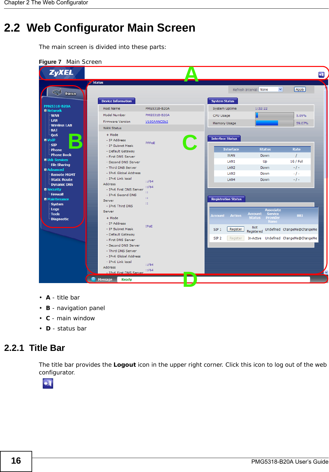
PMG5318B20A User Manual
(GPT-2542GNU v2)UserMan
Navigation menu
Upload a User Manual
Namespaces
Wiki Guide
HTML
PDF
Info
Views
User Manual
Discussion / Help
Navigation

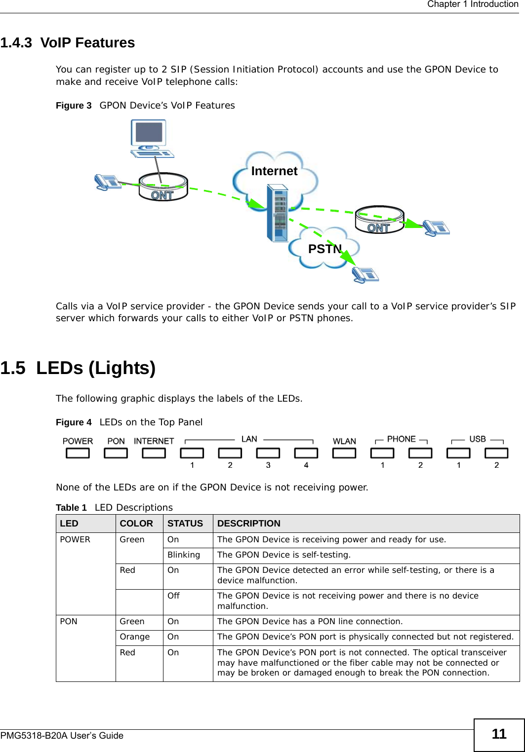

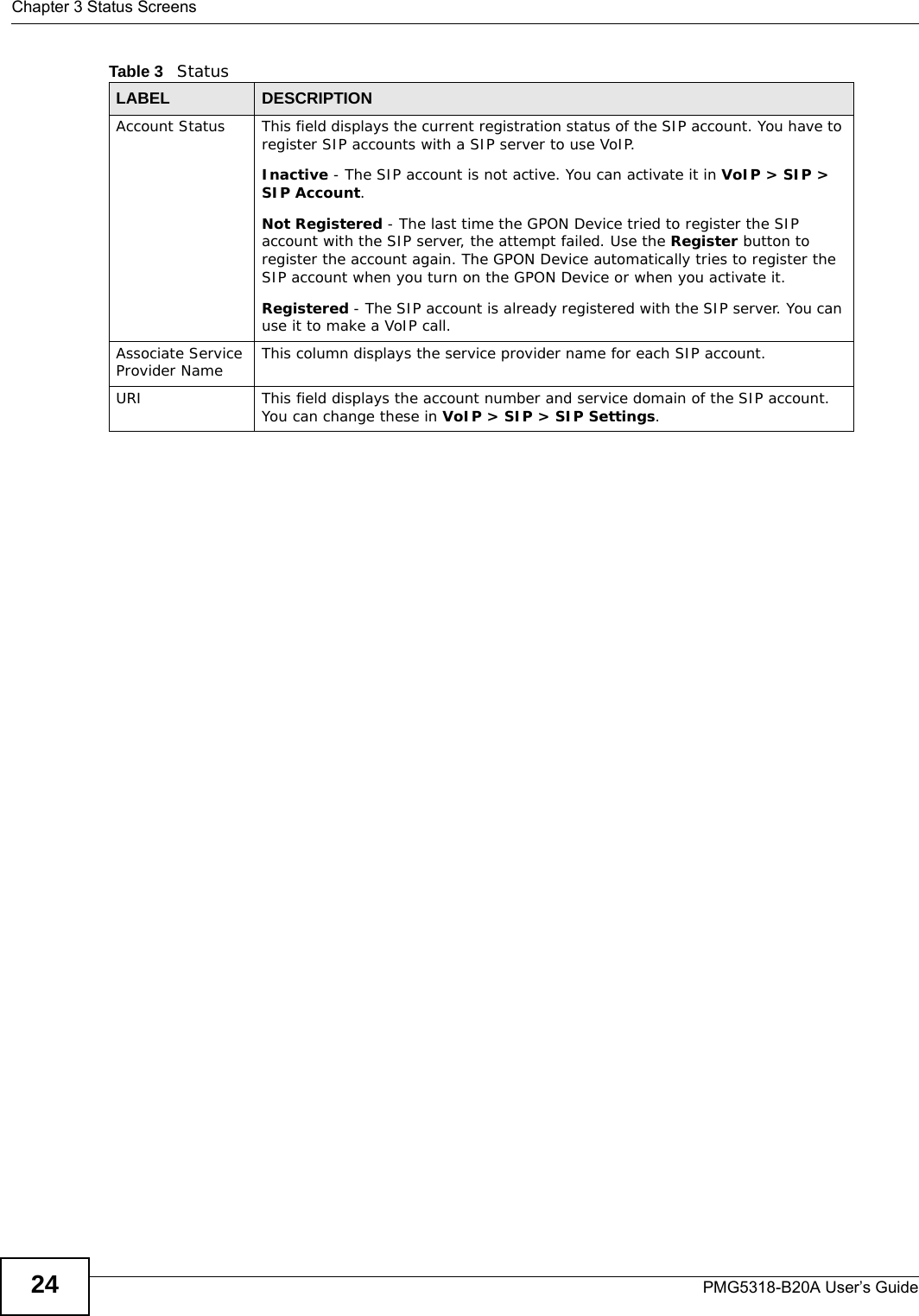

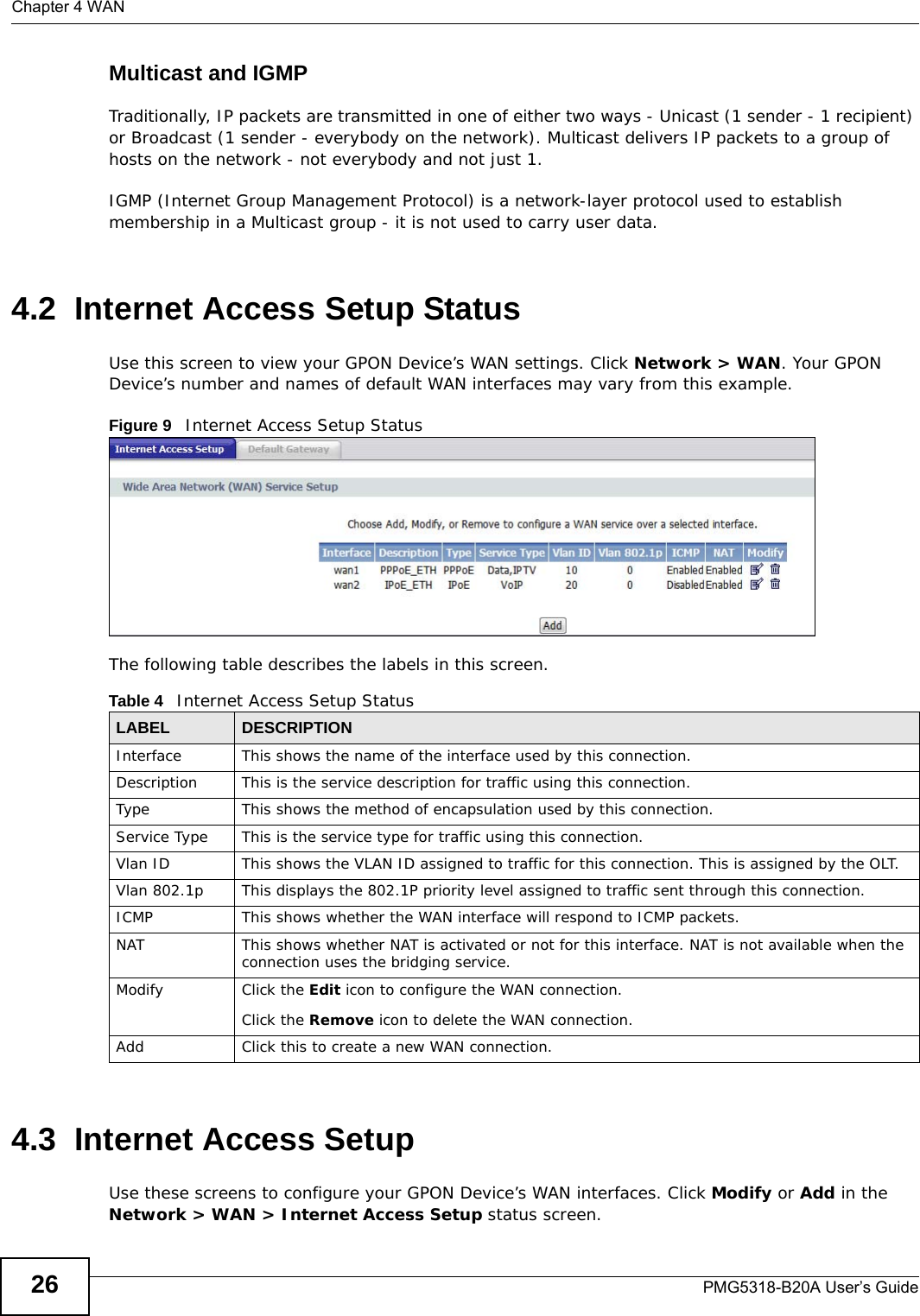
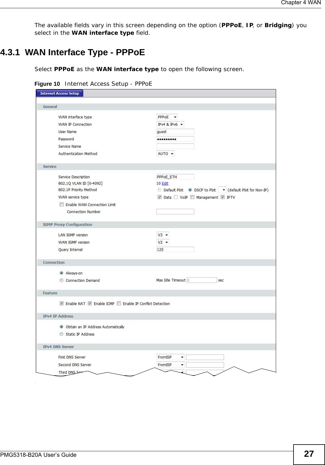
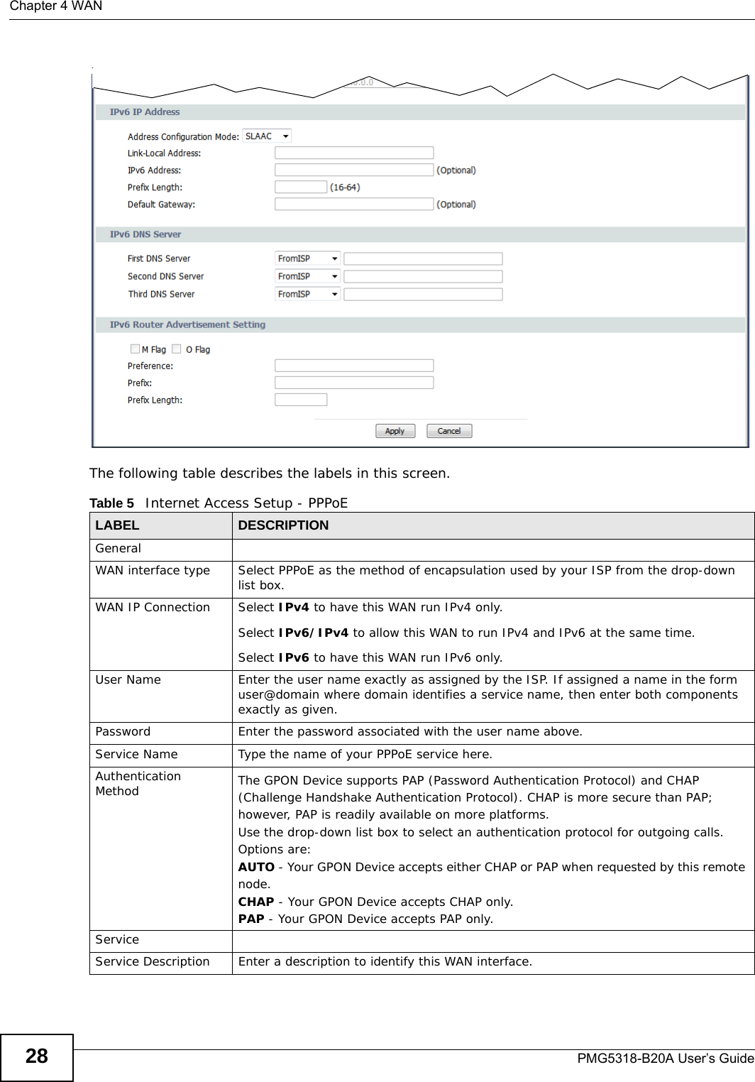
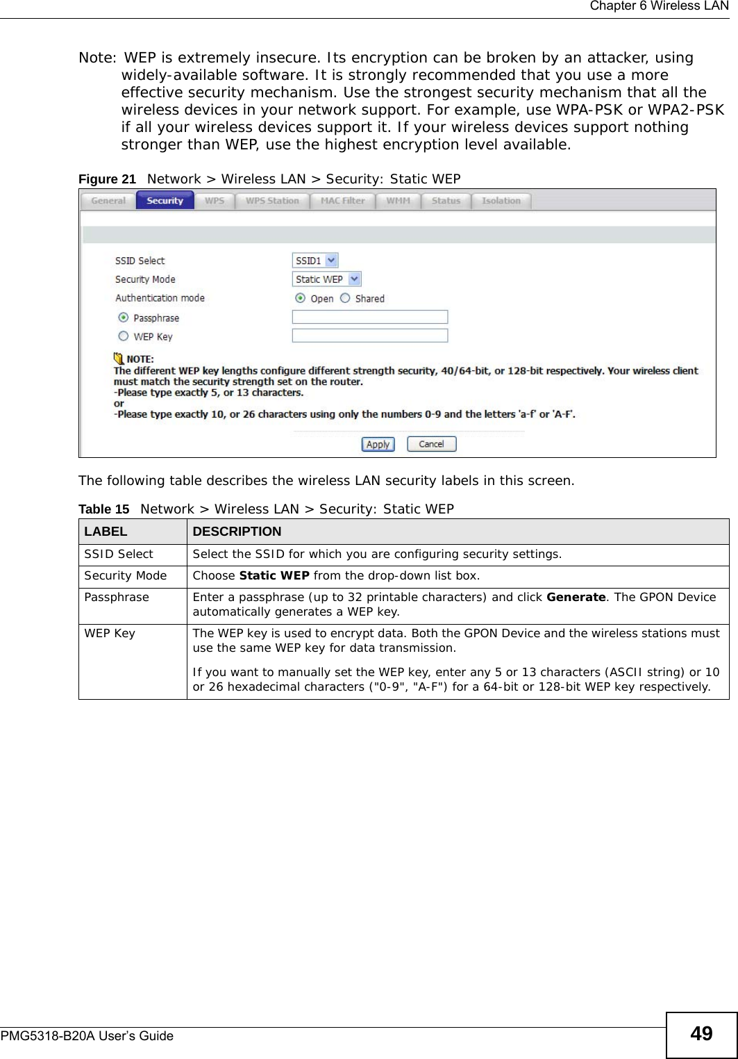
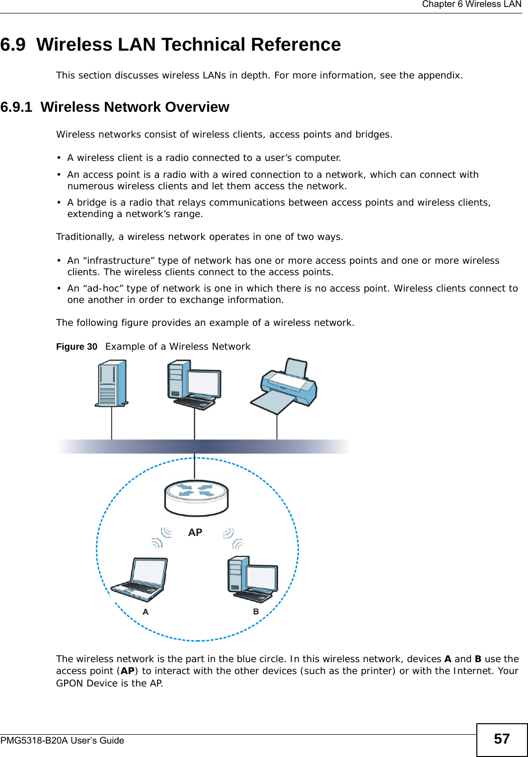
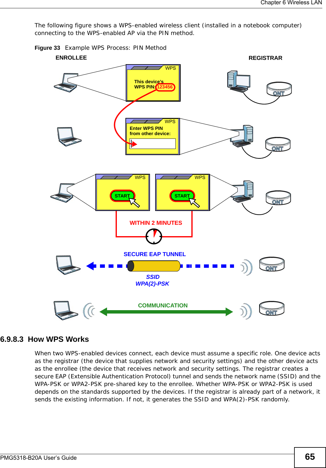


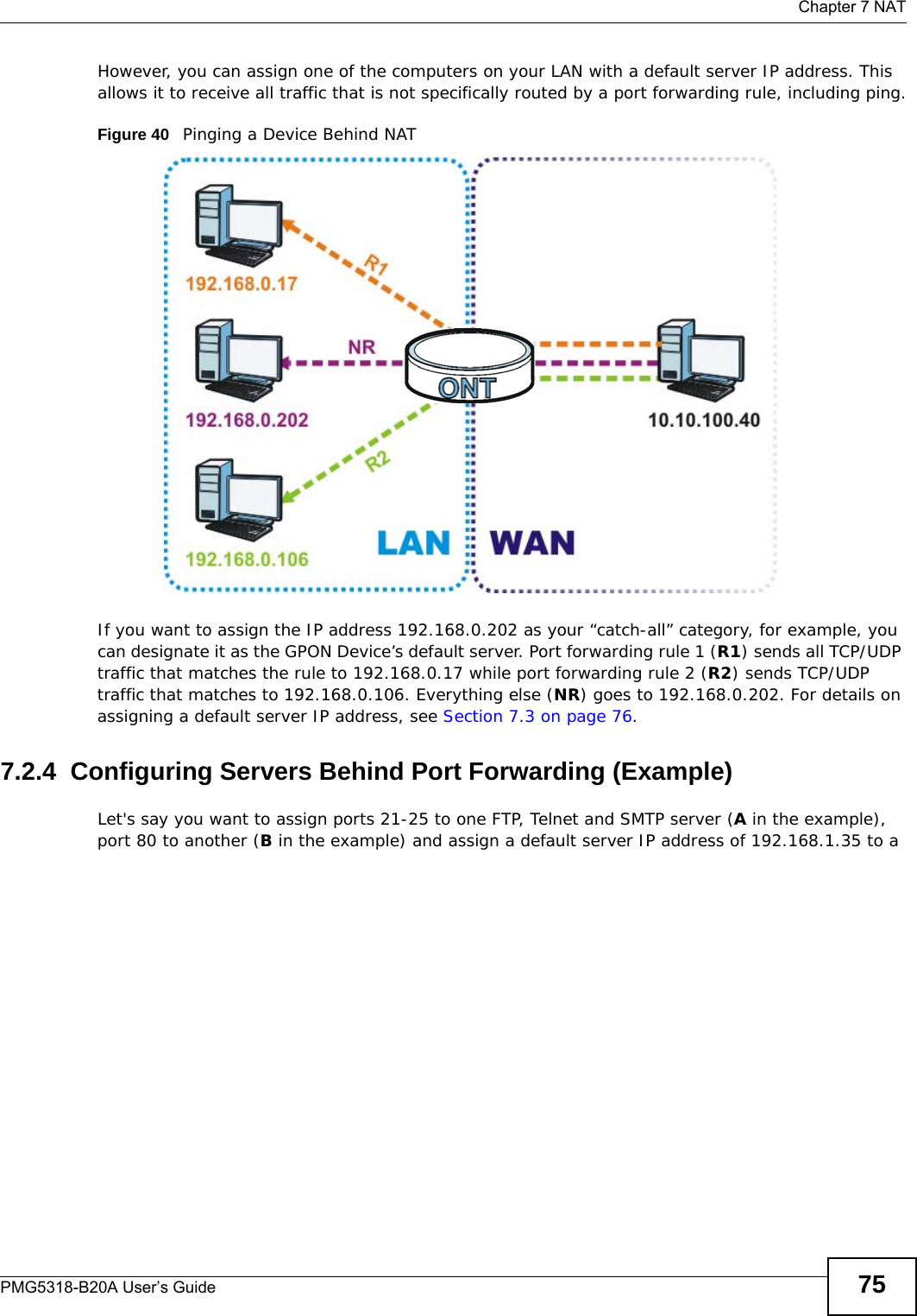
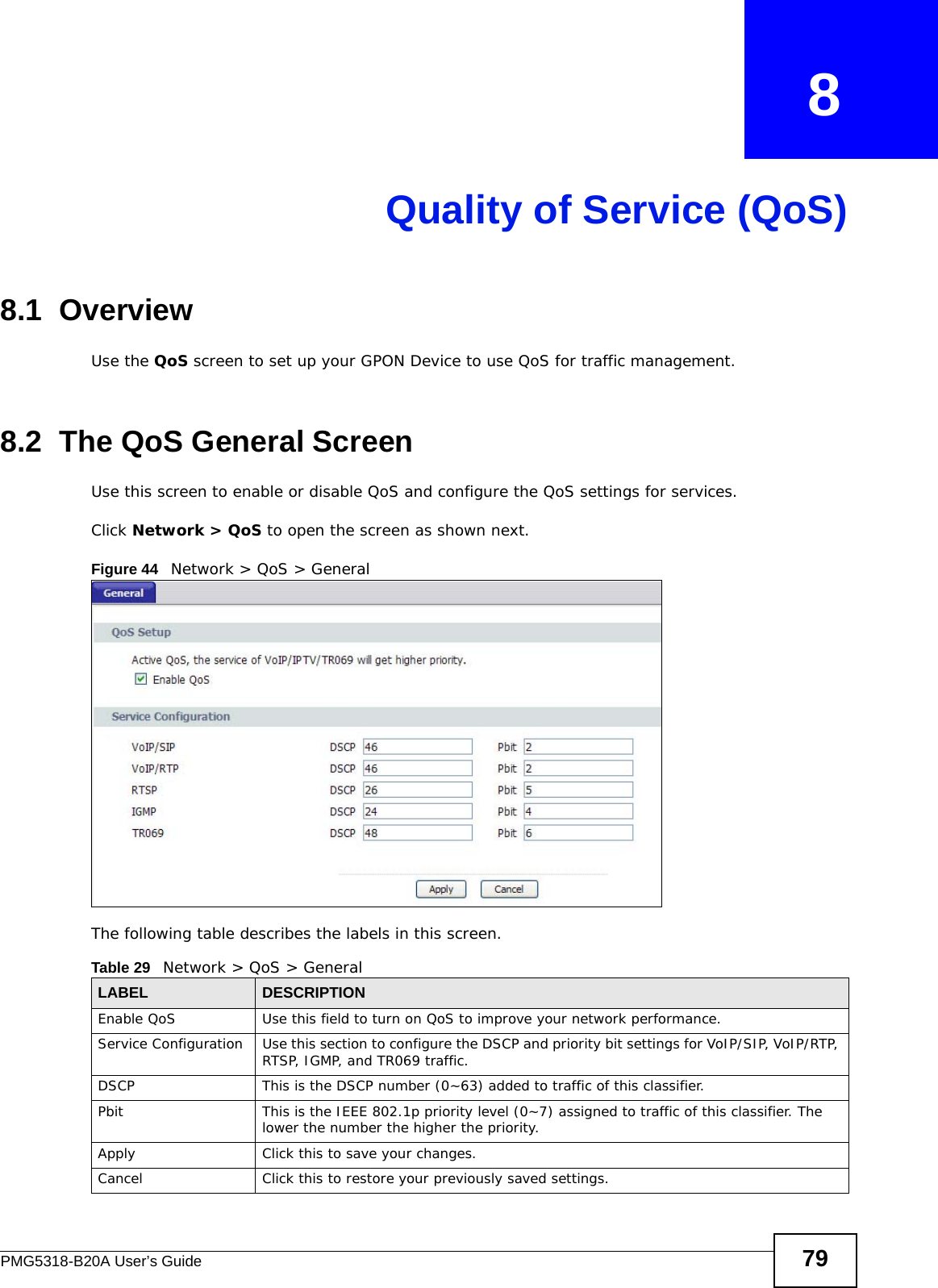

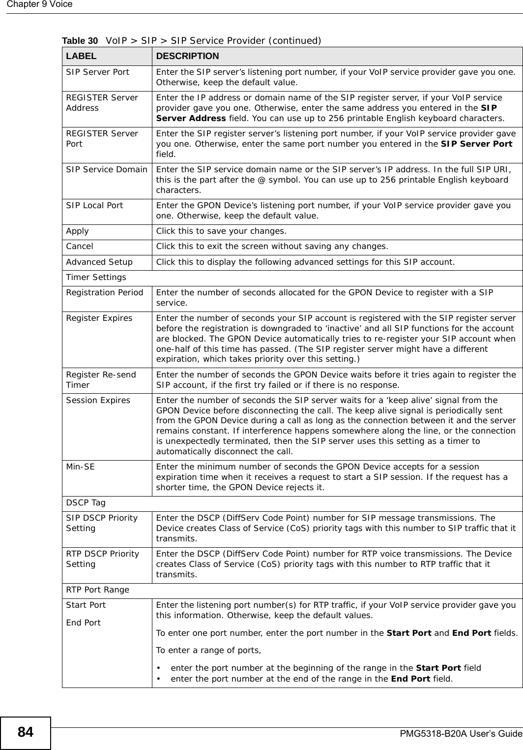
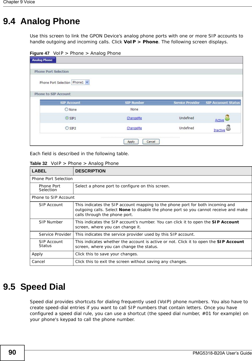
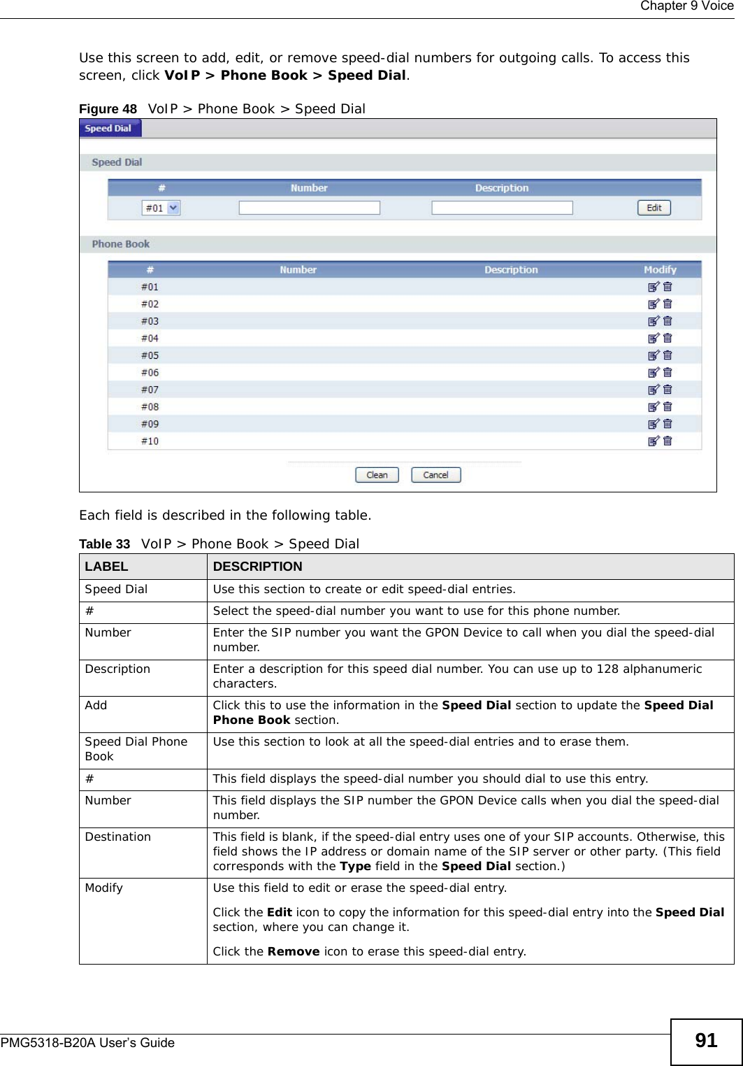
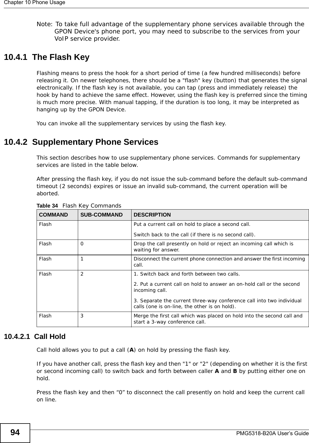
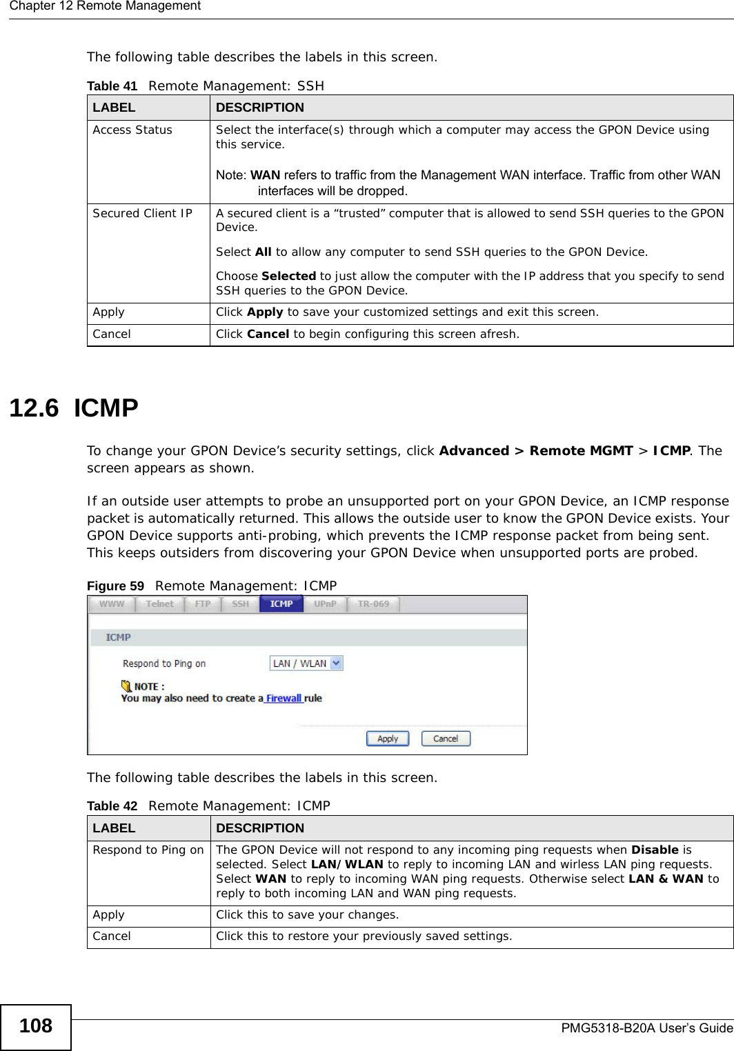
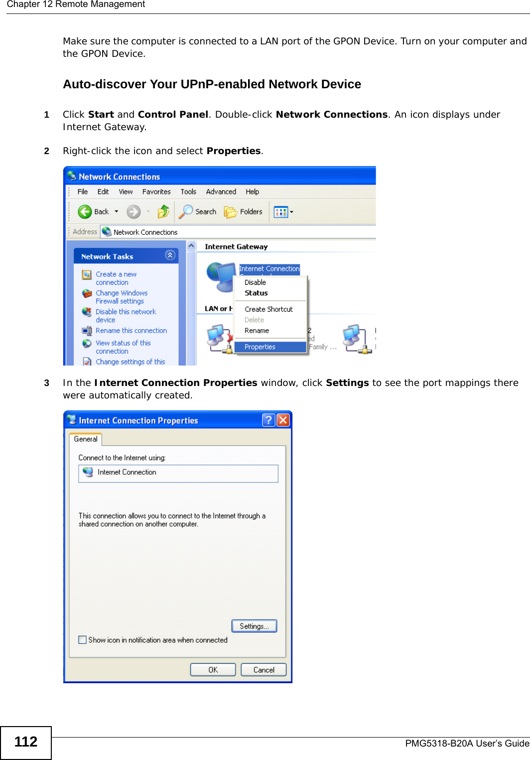
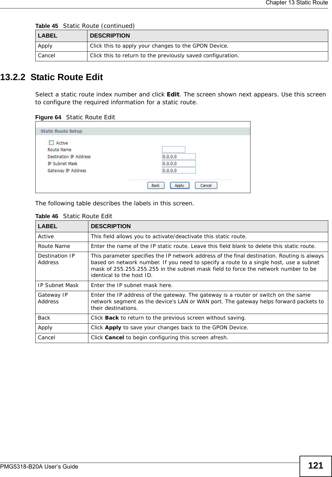
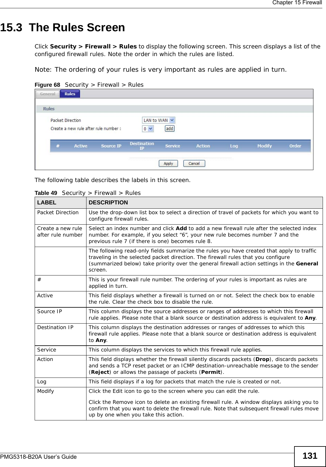
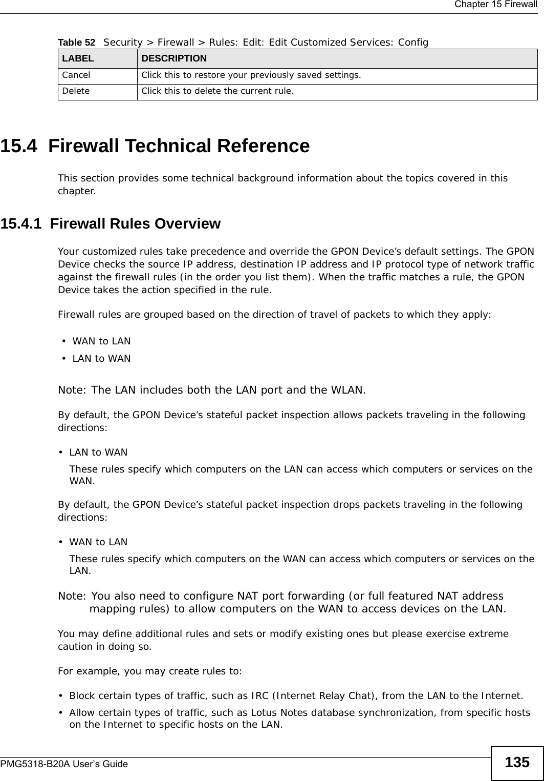
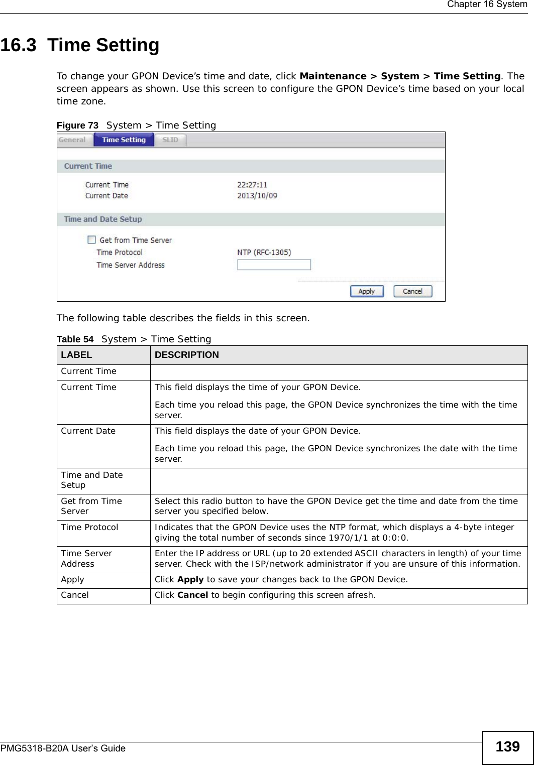
![Chapter 9 VoicePMG5318-B20A User’s Guide 859.2.1 Dial PlanA dial plan defines the dialing patterns, such as the length and range of the digits for a telephone number. It also includes country codes, access codes, area codes, local numbers, long distance numbers or international call prefixes. For example, the dial plan ([2-9]xxxxxx) does not allow a local number which begins with 1 or 0.Outbound ProxyActive Outbound Proxy Select this if the service provider has a SIP outbound server to handle voice calls. This allows the GPON Device to work with any type of NAT router and eliminates the need for STUN or a SIP ALG. Turn off any SIP ALG on a NAT router in front of the GPON Device to keep it from retranslating the IP address (since this is already handled by the outbound proxy server.Outbound Proxy Address Enter the IP address or domain name of the SIP outbound proxy server.Outbound Proxy Port Enter the outbound proxy server’s listening port, if your VoIP service provider gave you one. Otherwise, keep the default value.SIP Transport MethodSIP Transport Method Selection Select the transport layer protocol UDP or TCP (usually UDP) used for SIP.Dialing Interval SelectionDialing Interval Selection Select the number of seconds the GPON Device waits before placing a dialed call.DTMF MethodDTMF Mothod Selection Control how the GPON Device handles the alphanumeric keypad tones. You should use the same mode the VoIP service provider uses.RFC 2833 - send the DTMF tones in RTP packetsInBand - send the DTMF tones in the voice data stream. This method works best when you are using a codec that does not use compression. Codecs that use compression can distort the tones.SIP INFO - send the DTMF tones in SIP messages.Fax OptionG.711 FaxPassthrough Select this option to send and receive fax messages over the network or Internet using VoIP. By encoding fax data as audio data, faxes may be susceptible to packet loss and other errors. However, as this standard is considerably older than T.38, it is more compatible with older or obsolete systems.T.38 Fax Relay Select this option to send and received fax messages over the network or Internet using IP. This is the standard fax transmission protocol for sending faxes over networks rather than phone lines.Dialing PlanDialing Plan Create dialing plan rules here. See Section 9.2.1 on page 85 for more information. Click the Help icon to display guidelines for creating dialing plan rules.Apply Click this to save your changes.Cancel Click this to exit the screen without saving any changes.Basic Click this to hide the advanced settings on this screen.Table 30 VoIP > SIP > SIP Service Provider (continued)LABEL DESCRIPTION](https://usermanual.wiki/ZyXEL-Communications/PMG5318B20A/User-Guide-2157470-Page-85.png)
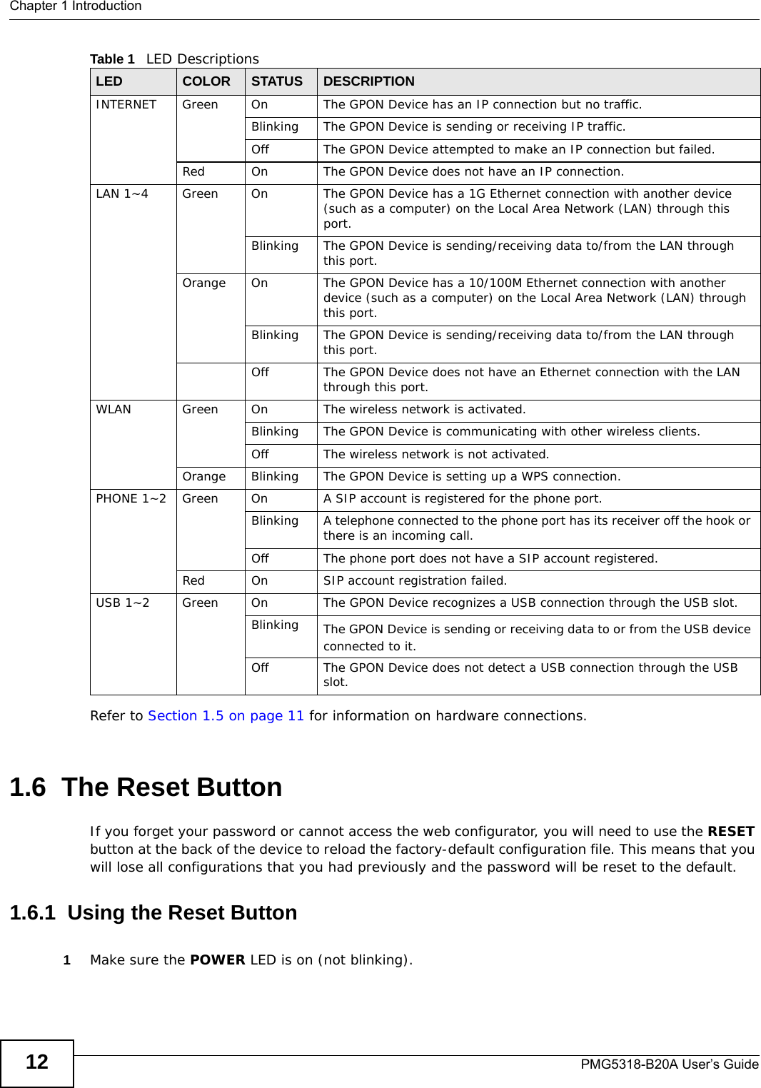
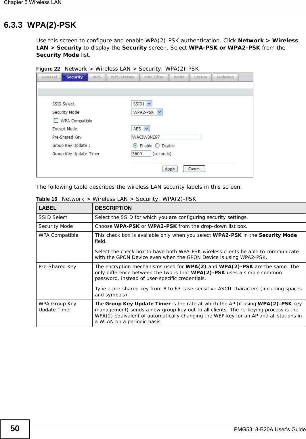
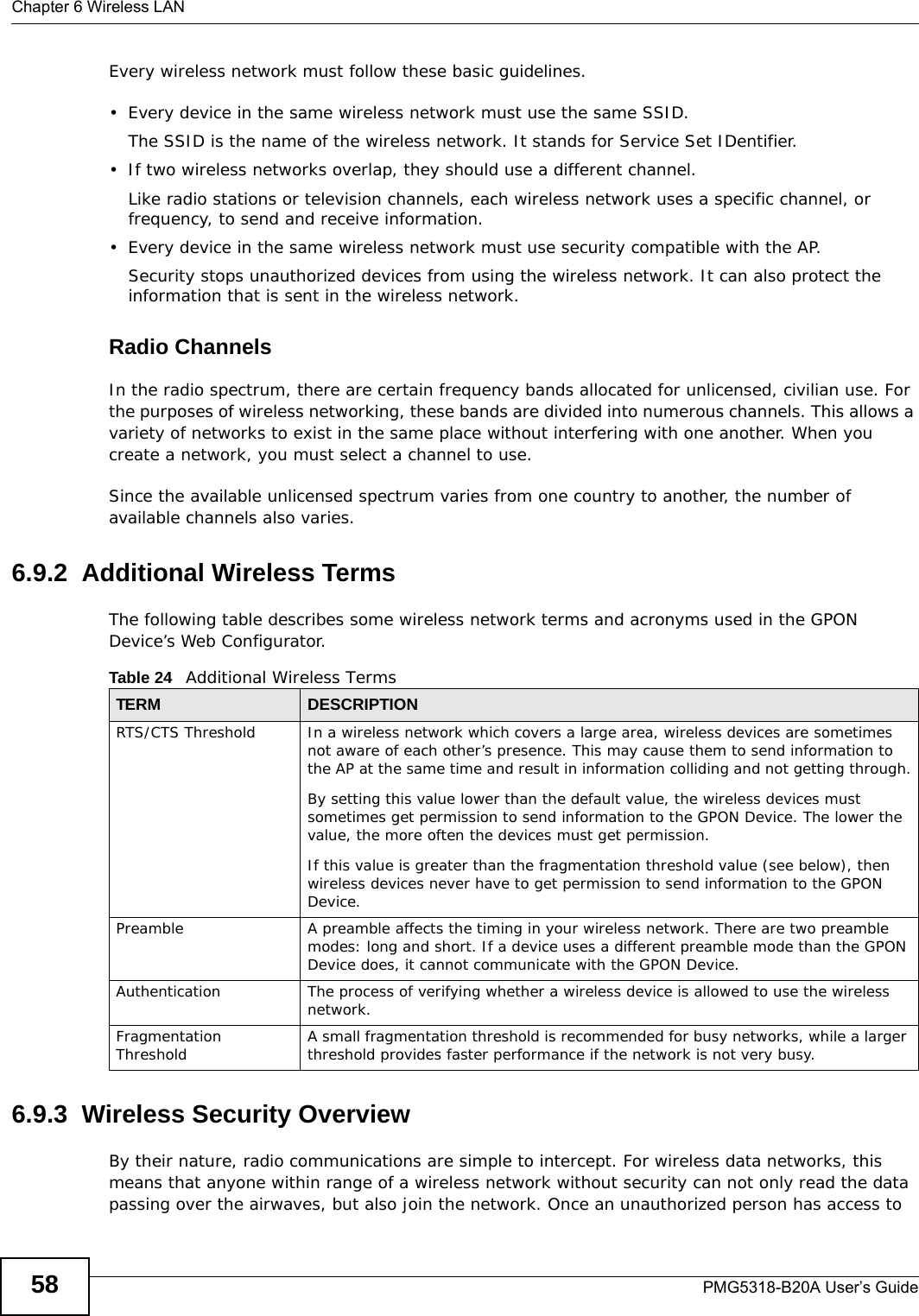
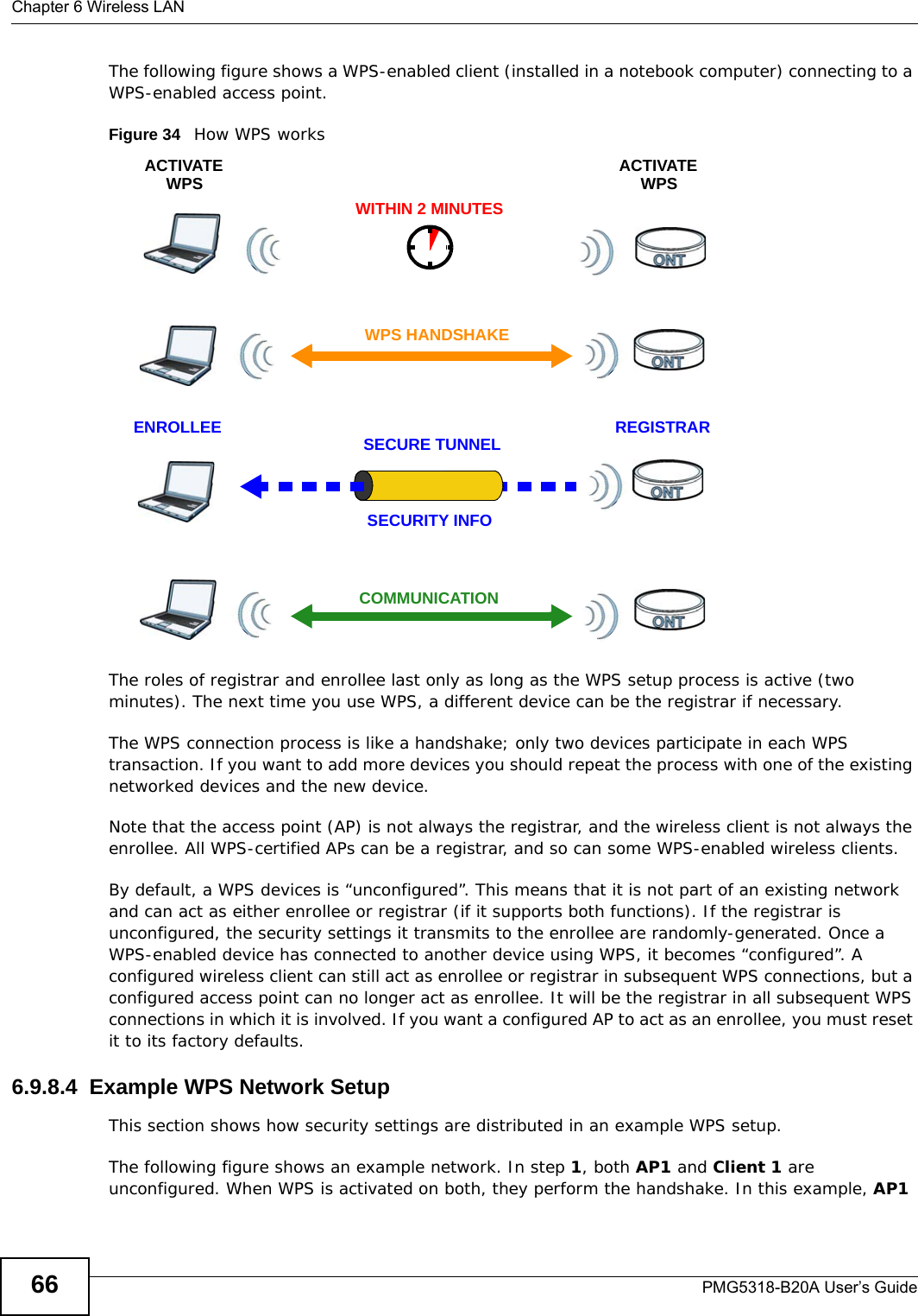
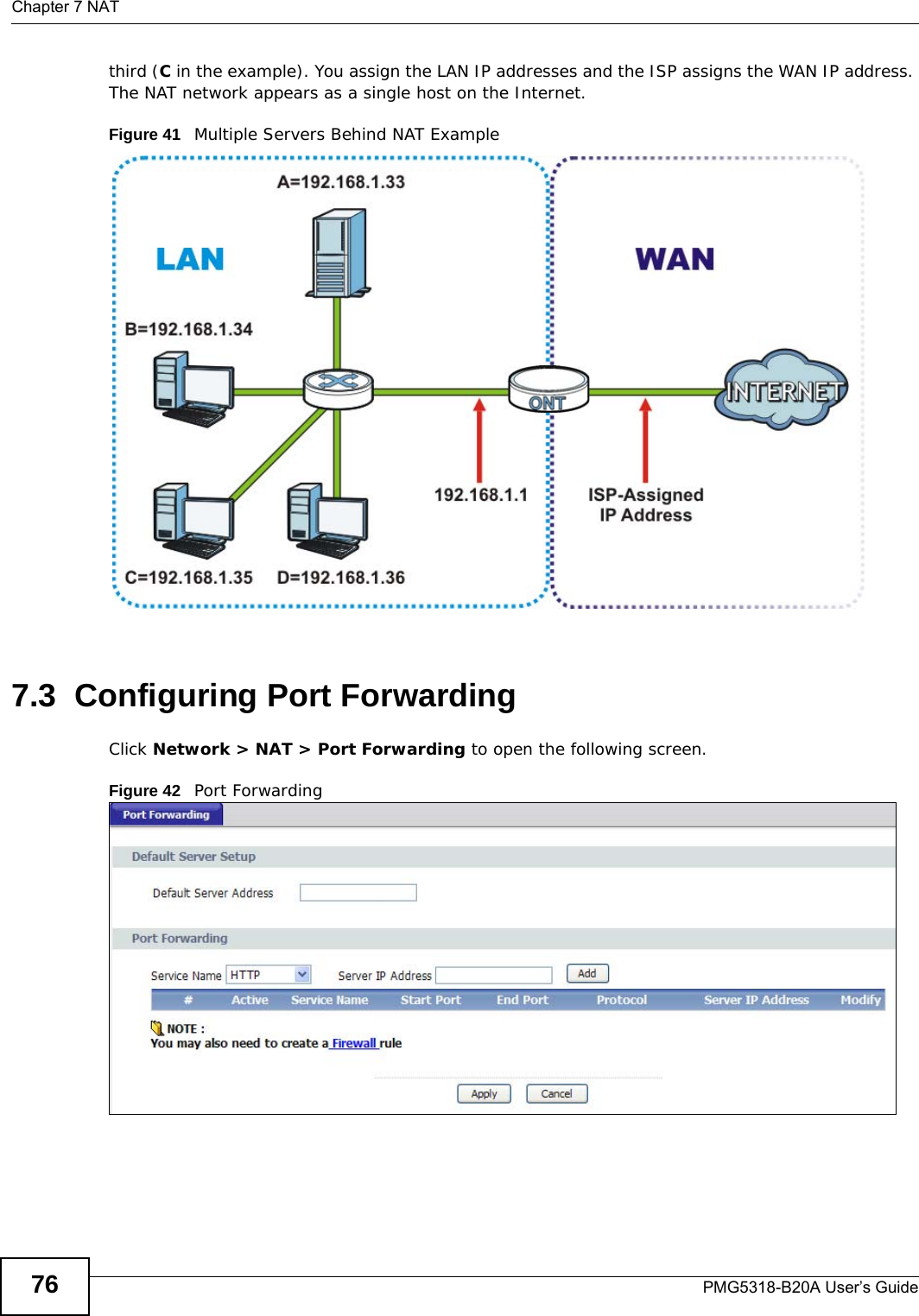
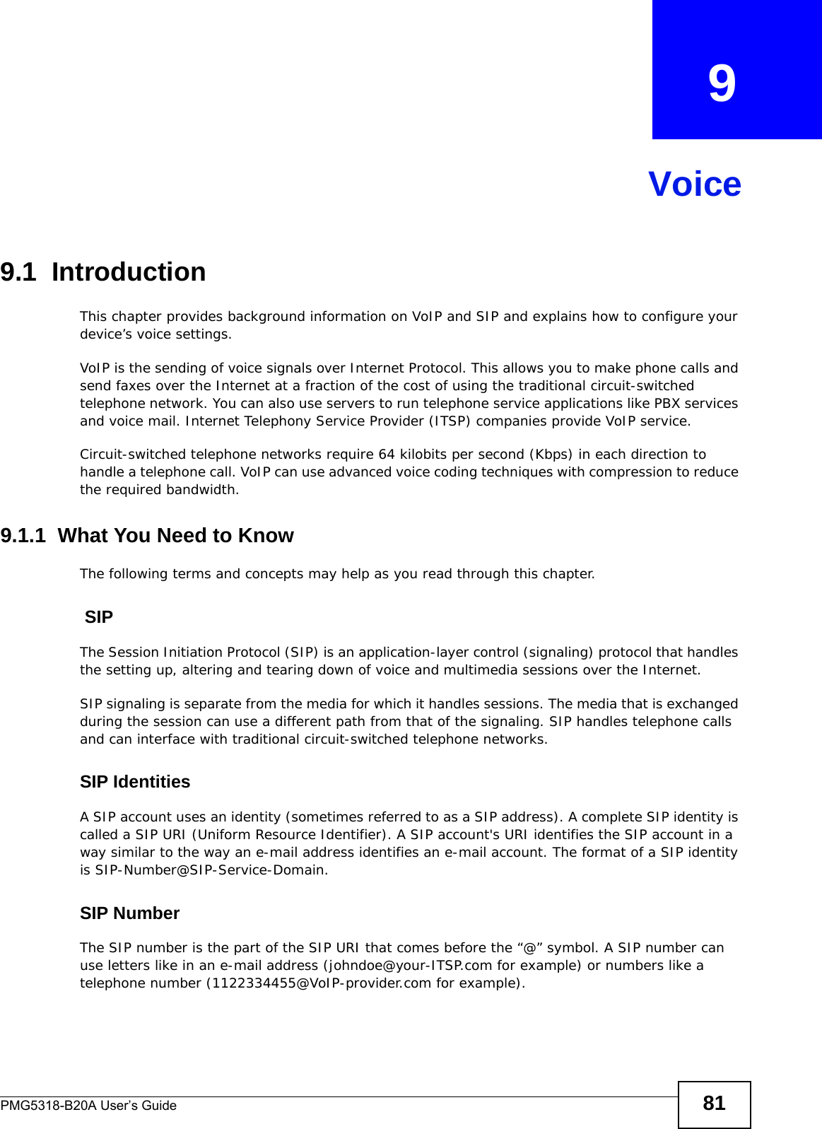
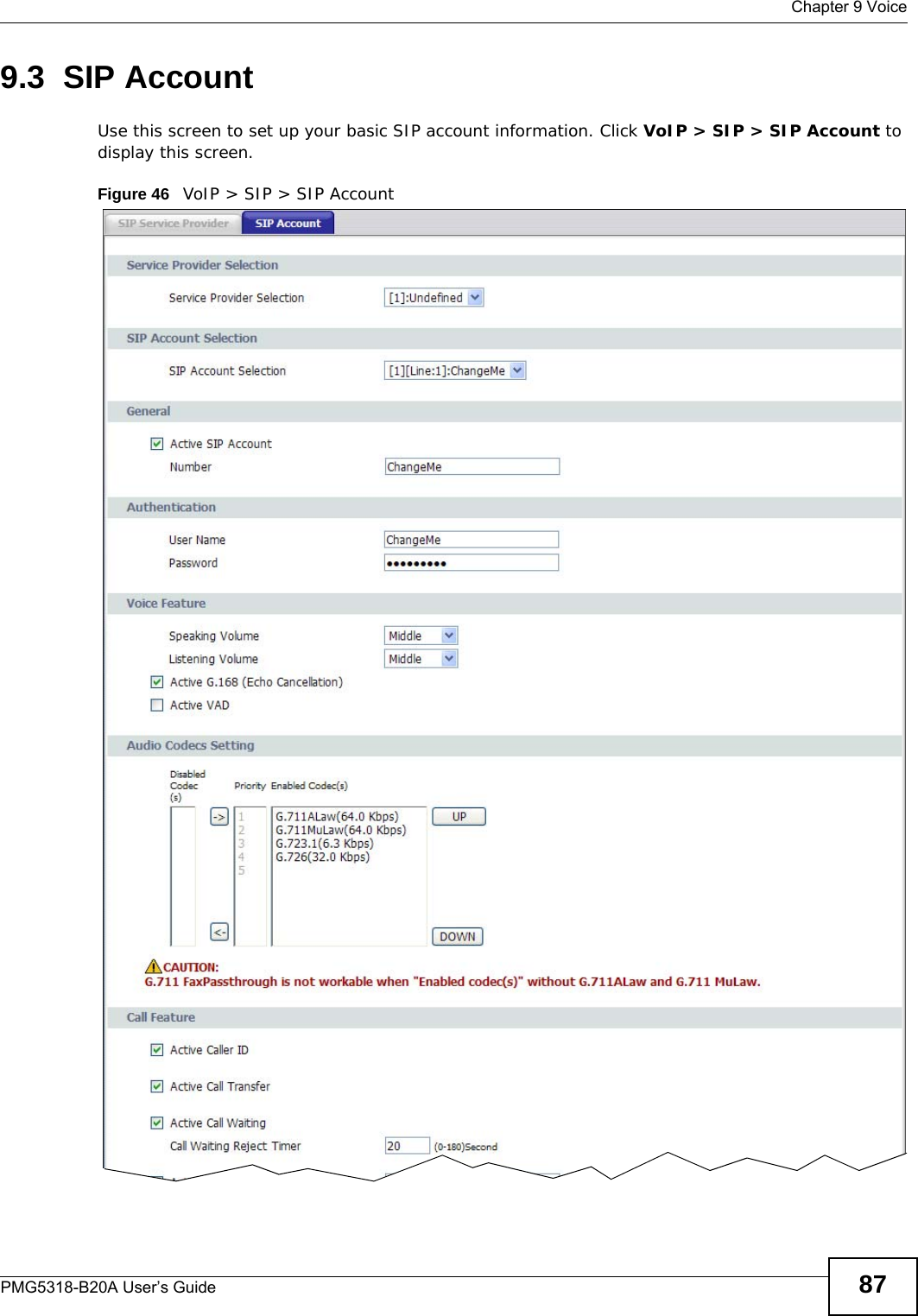
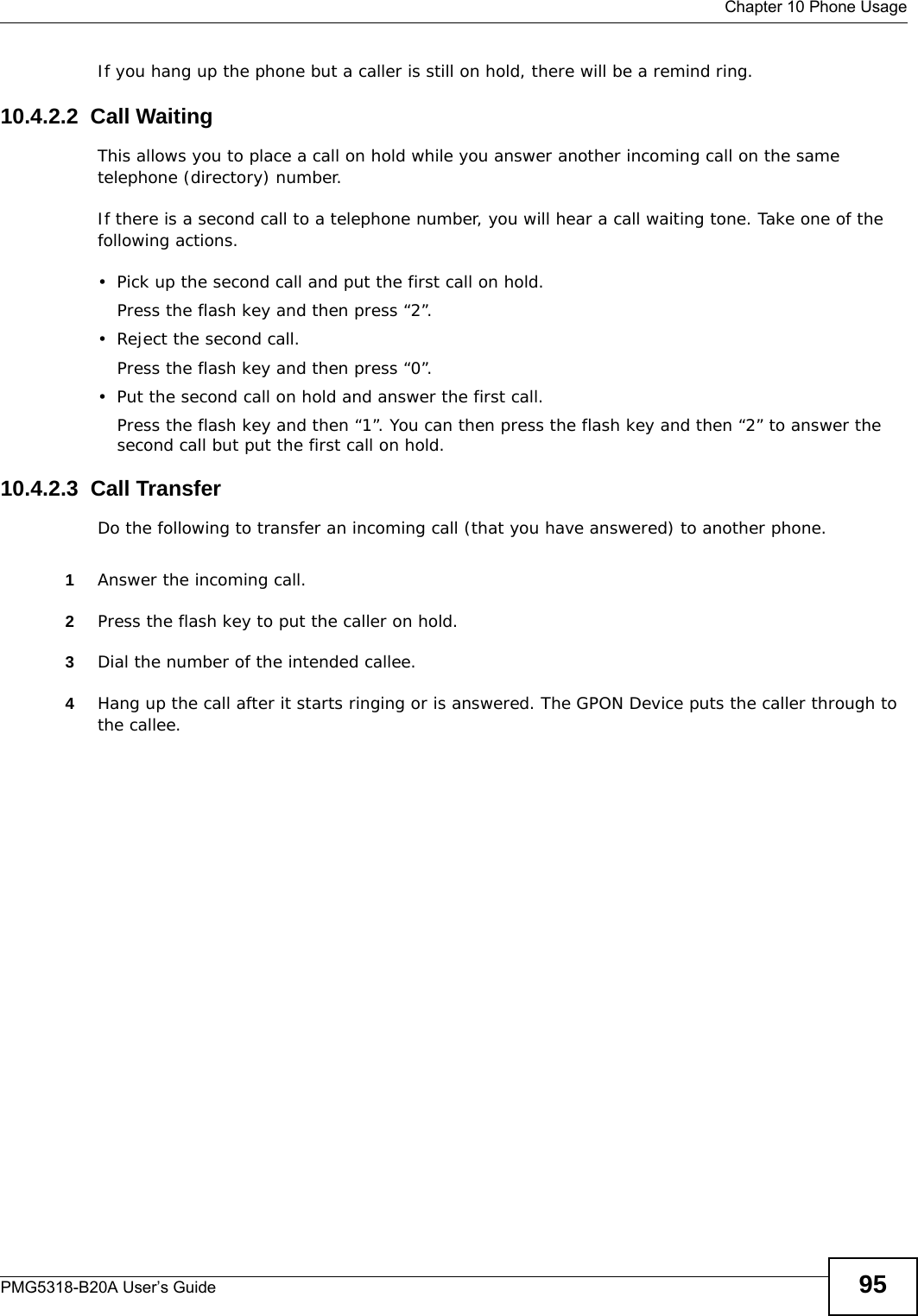
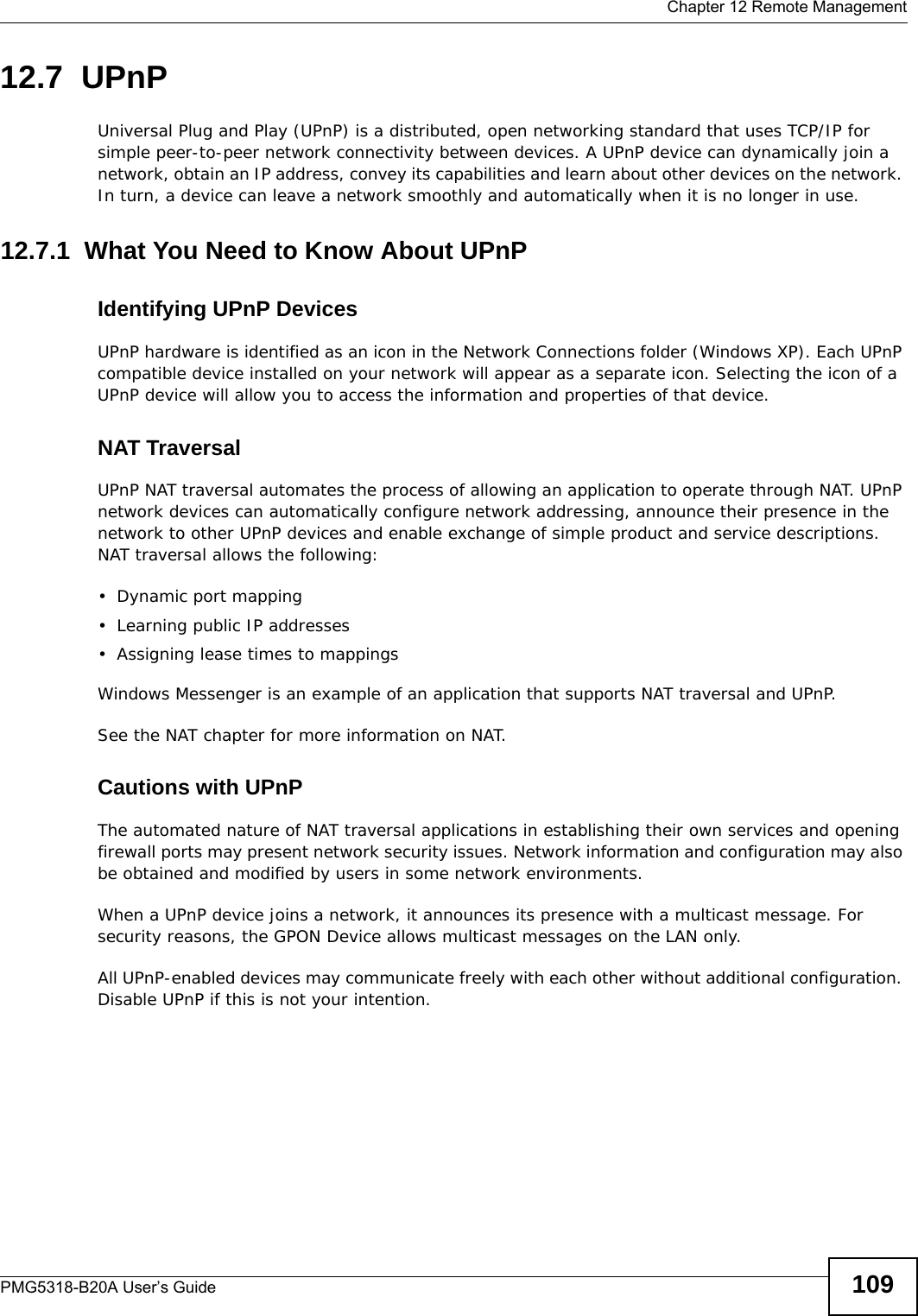
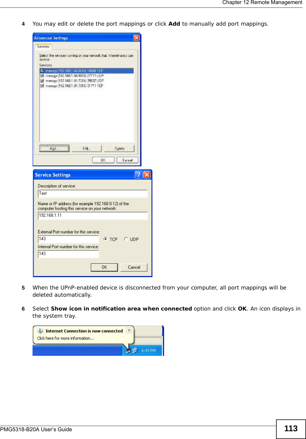
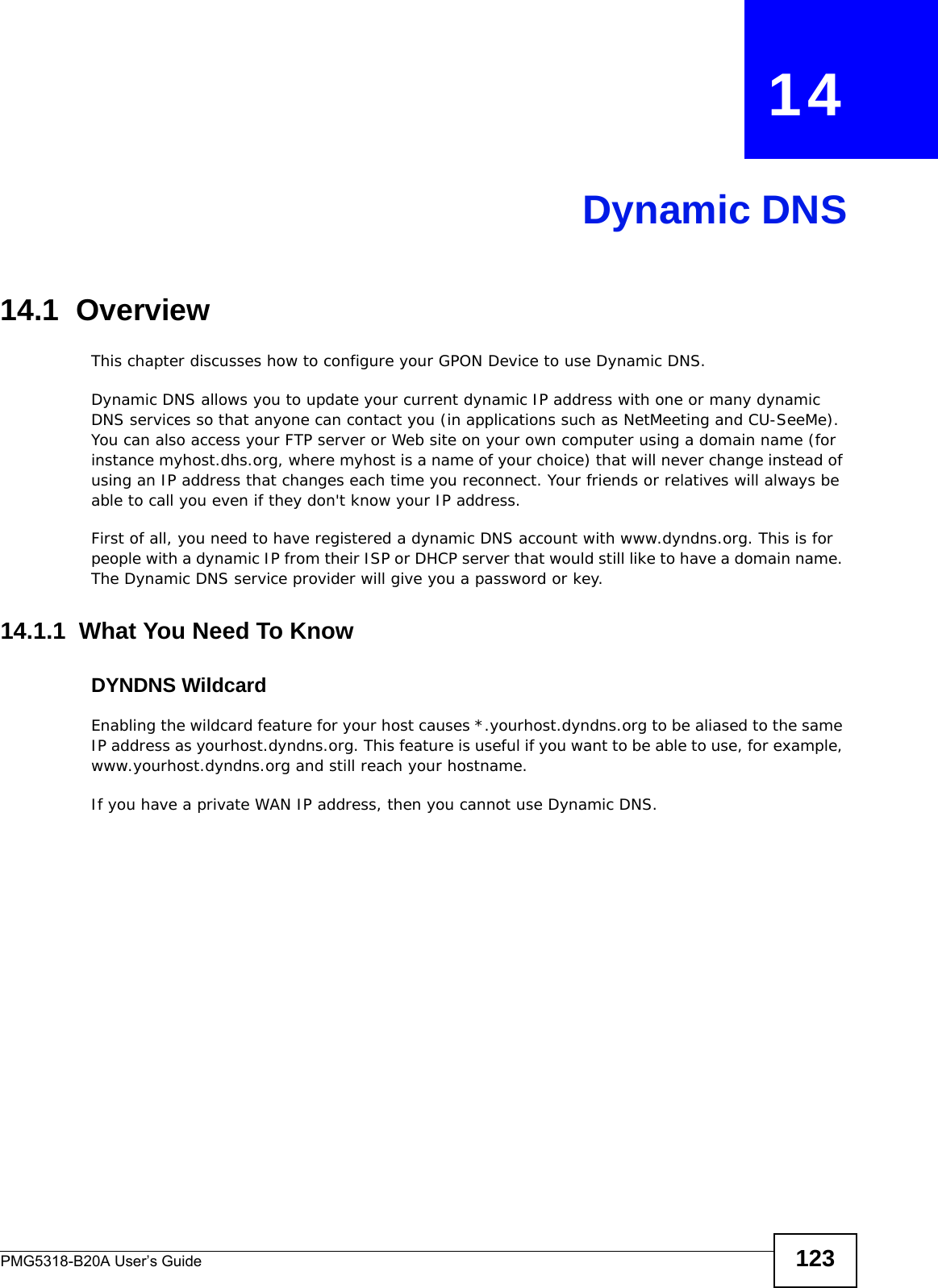
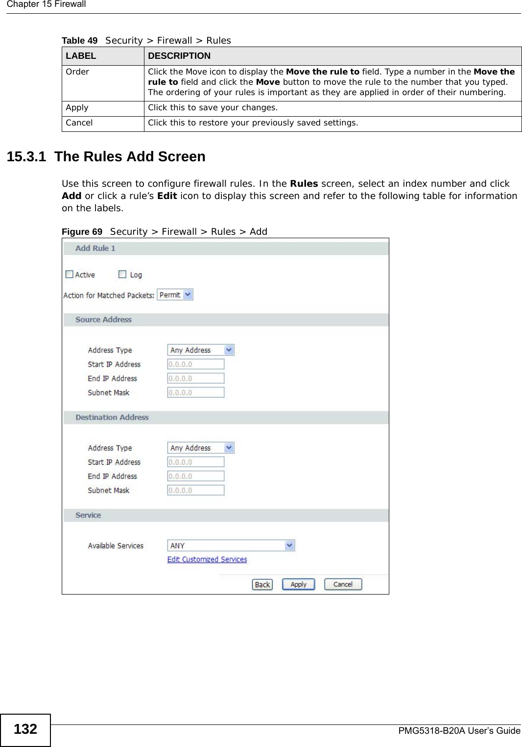
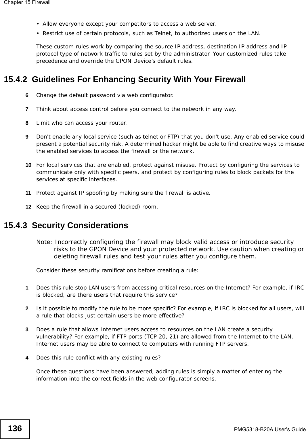
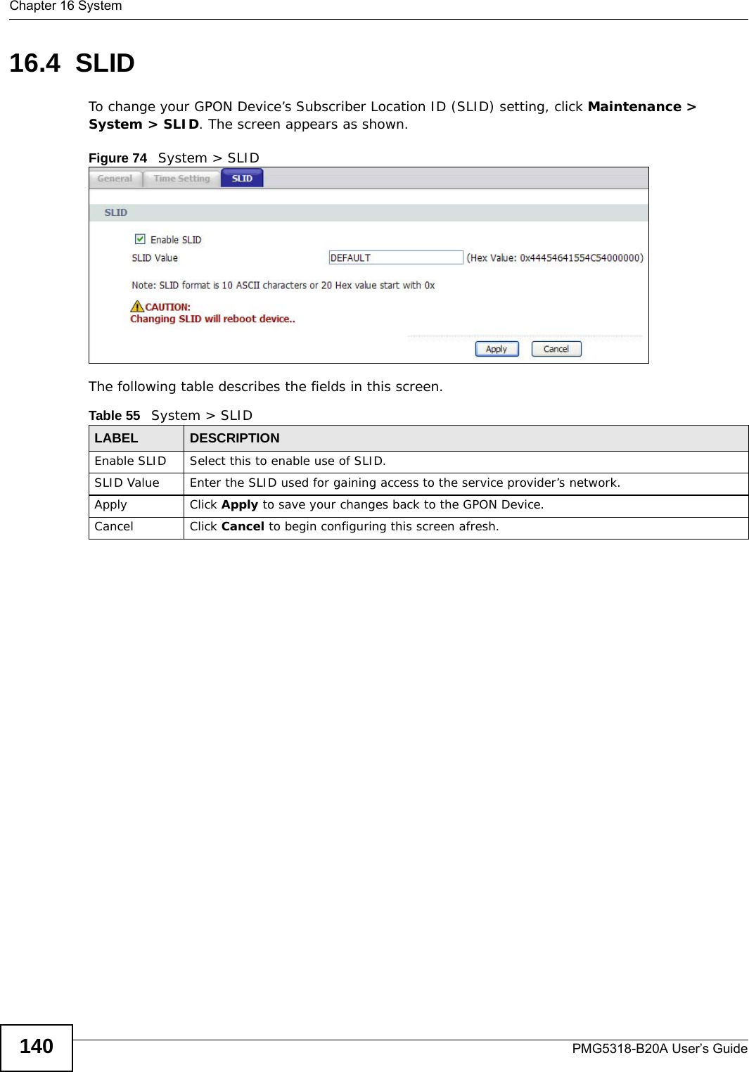
![Chapter 9 VoicePMG5318-B20A User’s Guide86Without a dial plan, users have to manually enter the whole callee’s number and wait for the specified dialing interval to time out or press a terminator key (usually the pound key on the phone keypad) before the GPON Device makes the call.The GPON Device initializes a call when the dialed number matches any one of the rules in the dial plan. Dial plan rules follow these conventions:• Rules are separated by the | (bar) symbol.• “x” stands for a wildcard and can be any digit from 0 to 9.• A subset of keys is in a square bracket []. Ranges are allowed.For example, [359] means a number matching this rule can be 3, 5 or 9. [26-8*] means a number matching this rule can be 2, 6, 7, 8 or *.• The dot “.” appended to a digit allows the digit to be ignored or repeated multiple times. Any digit (0~9, *, #) after the dot will be ignored.For example, (01.) means a number matching this rule can be 0, 01, 0111, 01111, and so on.• <dialed-number:translated-number> indicates the number after the colon replaces the number before the colon in an angle bracket <>. For example, (<:1212> xxxxxxx) means the GPON Device automatically prefixes the translated-number “1212” to the number you dialed before making the call. This can be used for local calls in the US.(<9:> xxx xxxxxxx) means the GPON Device automatically removes the specified prefix “9” from the number you dialed before making the call. This is always used for making outside calls from an office. (xx<123:456>xxxx) means the GPON Device automatically translates “123” to “456” in the number you dialed before making the call.• Calls with a number followed by the exclamation mark “!” will be dropped.• Calls with a number followed by the termination character “@” will be made immediately. Any digit (0~9, *, #) after the @ character will be ignored.• Gateway: Type “=gw0=” or “=gw3=” at the end of the rule. If the number matches the call will be transferred to a gateway (0: FXS port; 3: SIP). In this example dial plan (0 | [49]11 | 1 [2-9]xx xxxxxxx | 1 947 xxxxxxx !), you can dial “0” to call the local operator, call 411 or 911, or make a long distance call with an area code starting from 2 to 9 in the US. The calls with the area code 947 will be dropped.](https://usermanual.wiki/ZyXEL-Communications/PMG5318B20A/User-Guide-2157470-Page-86.png)

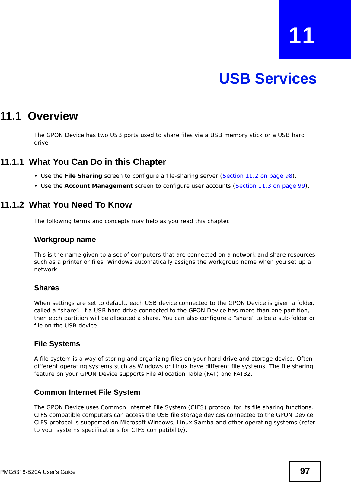

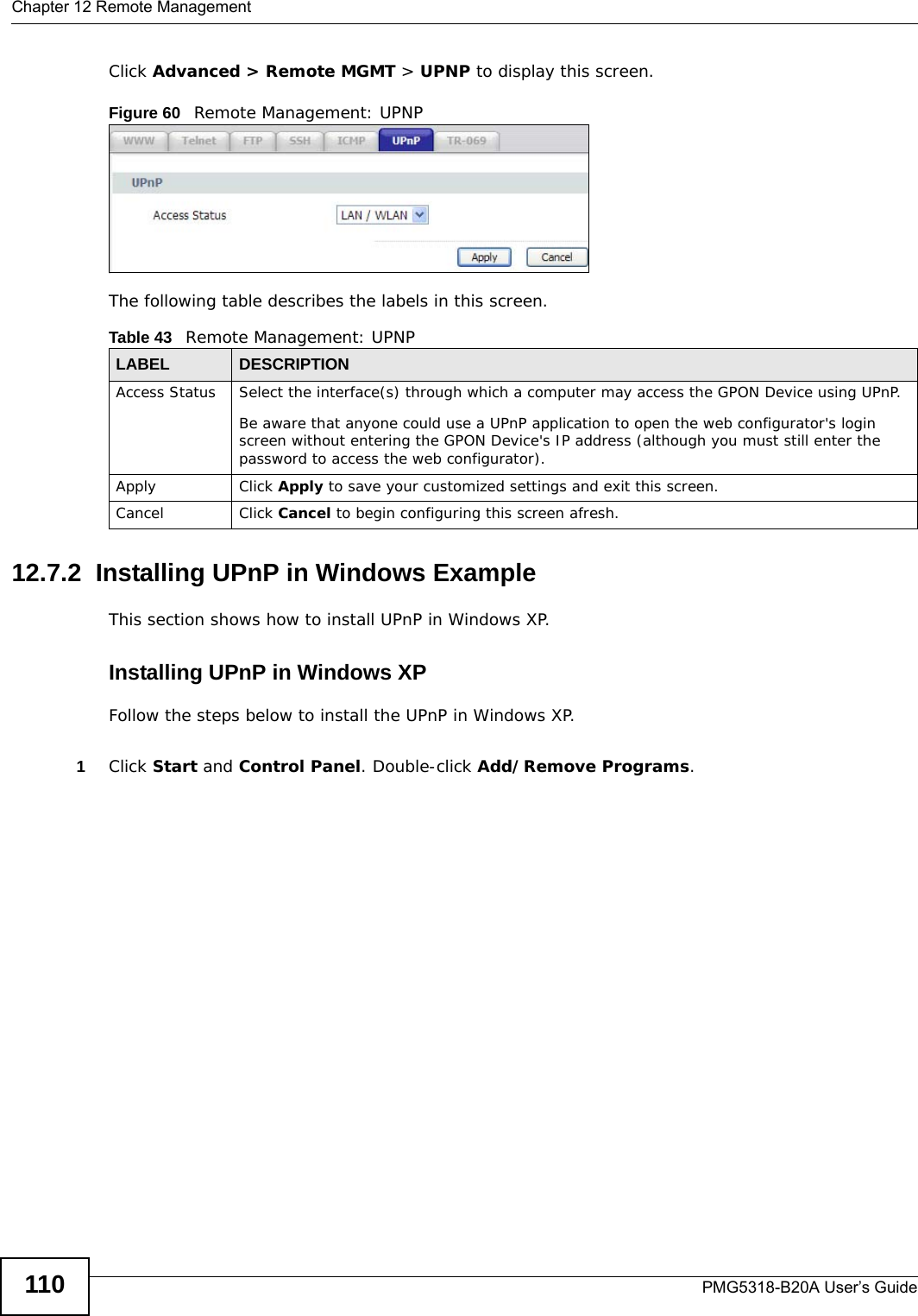
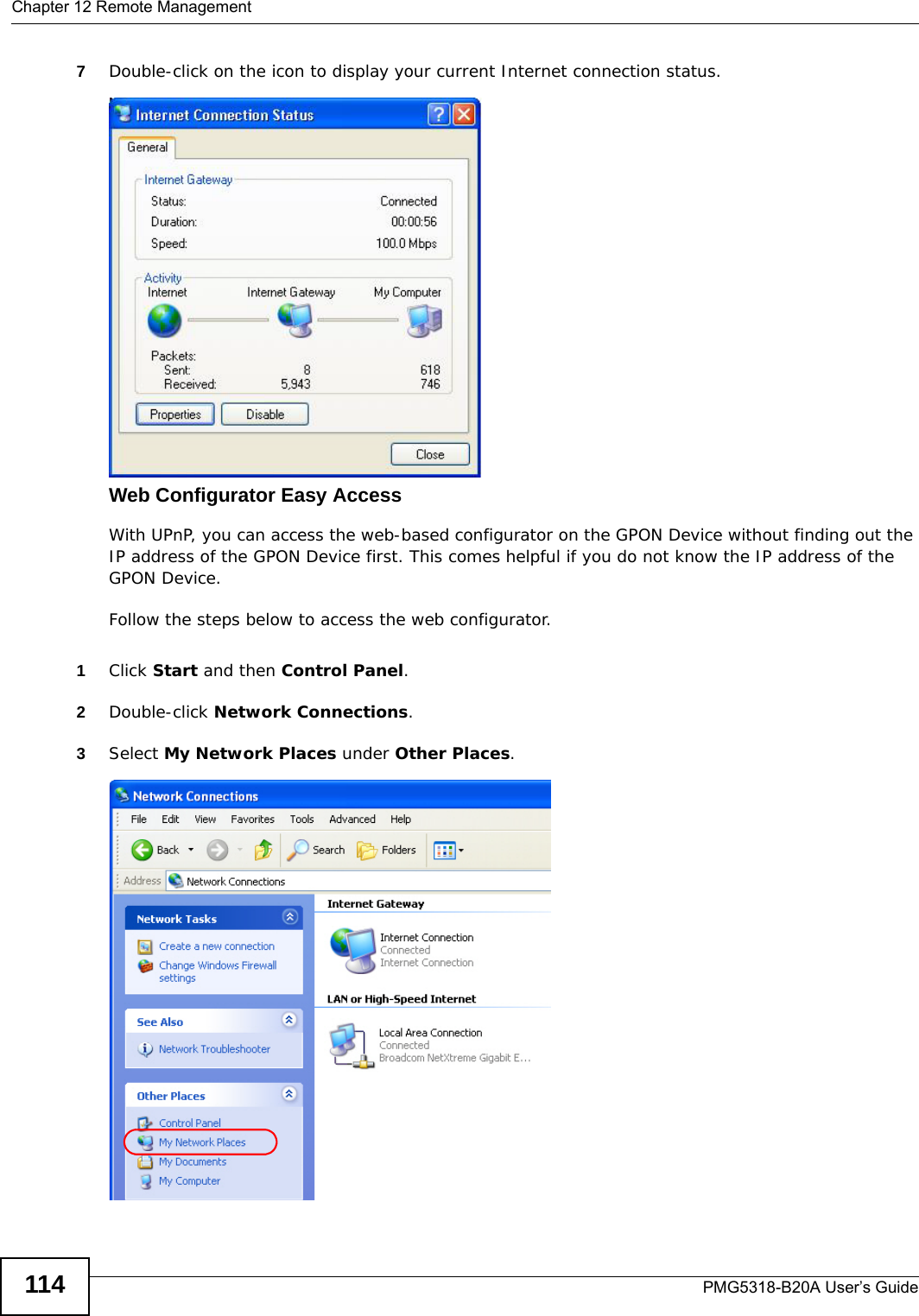


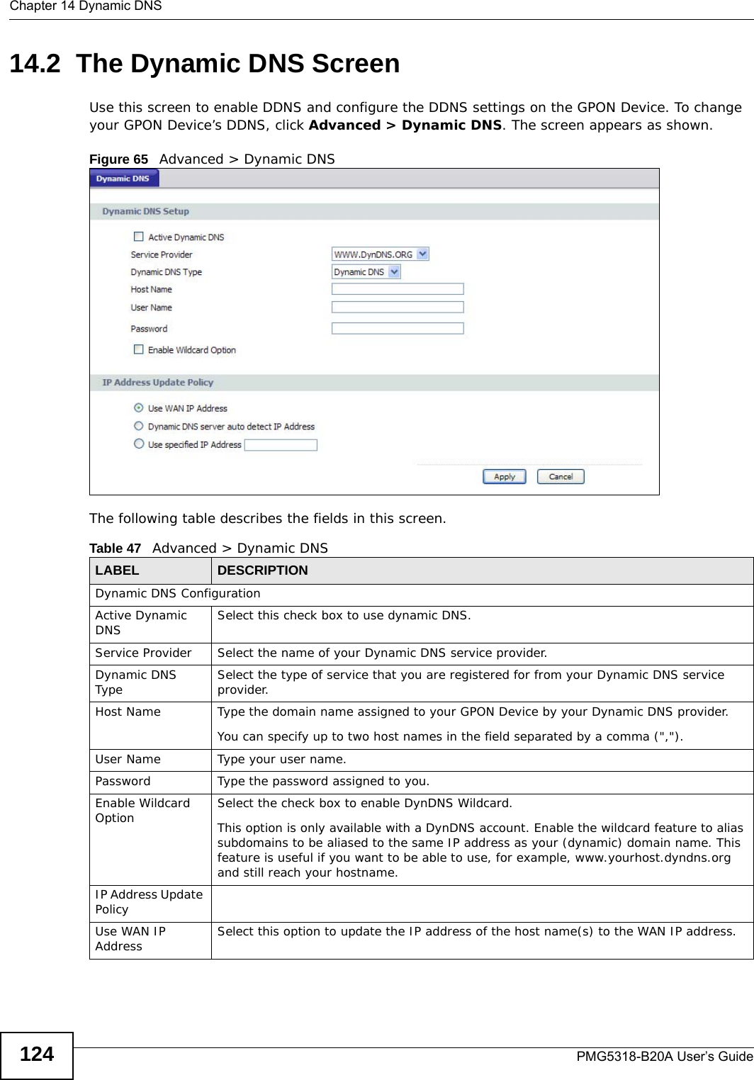

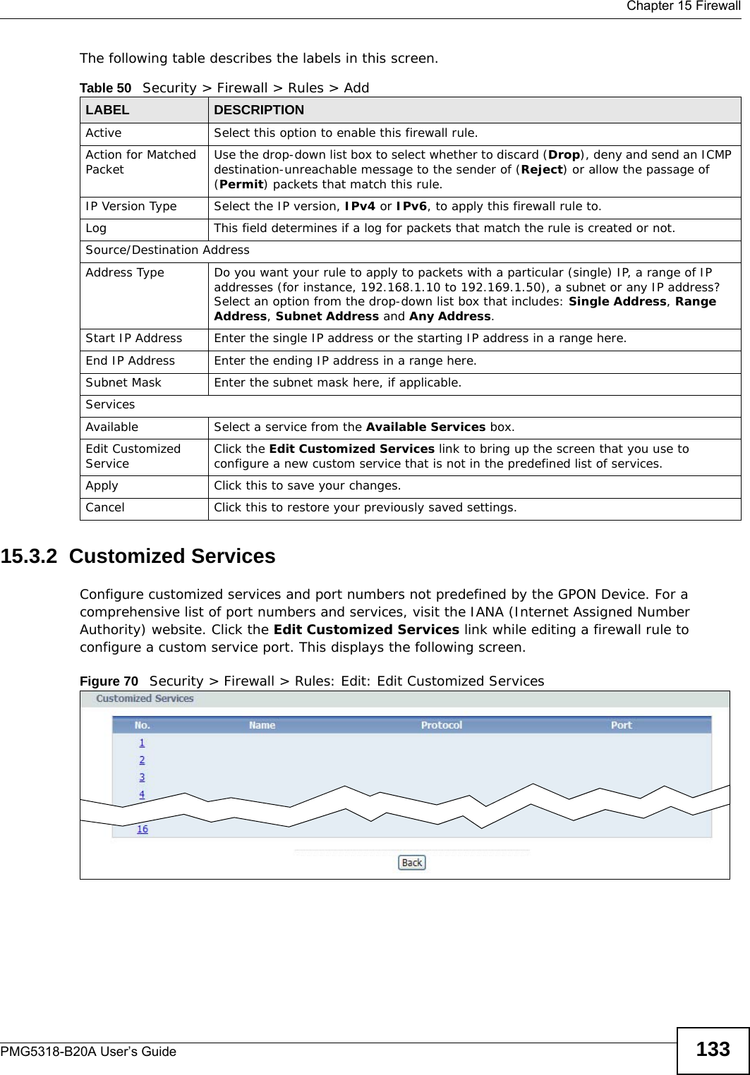
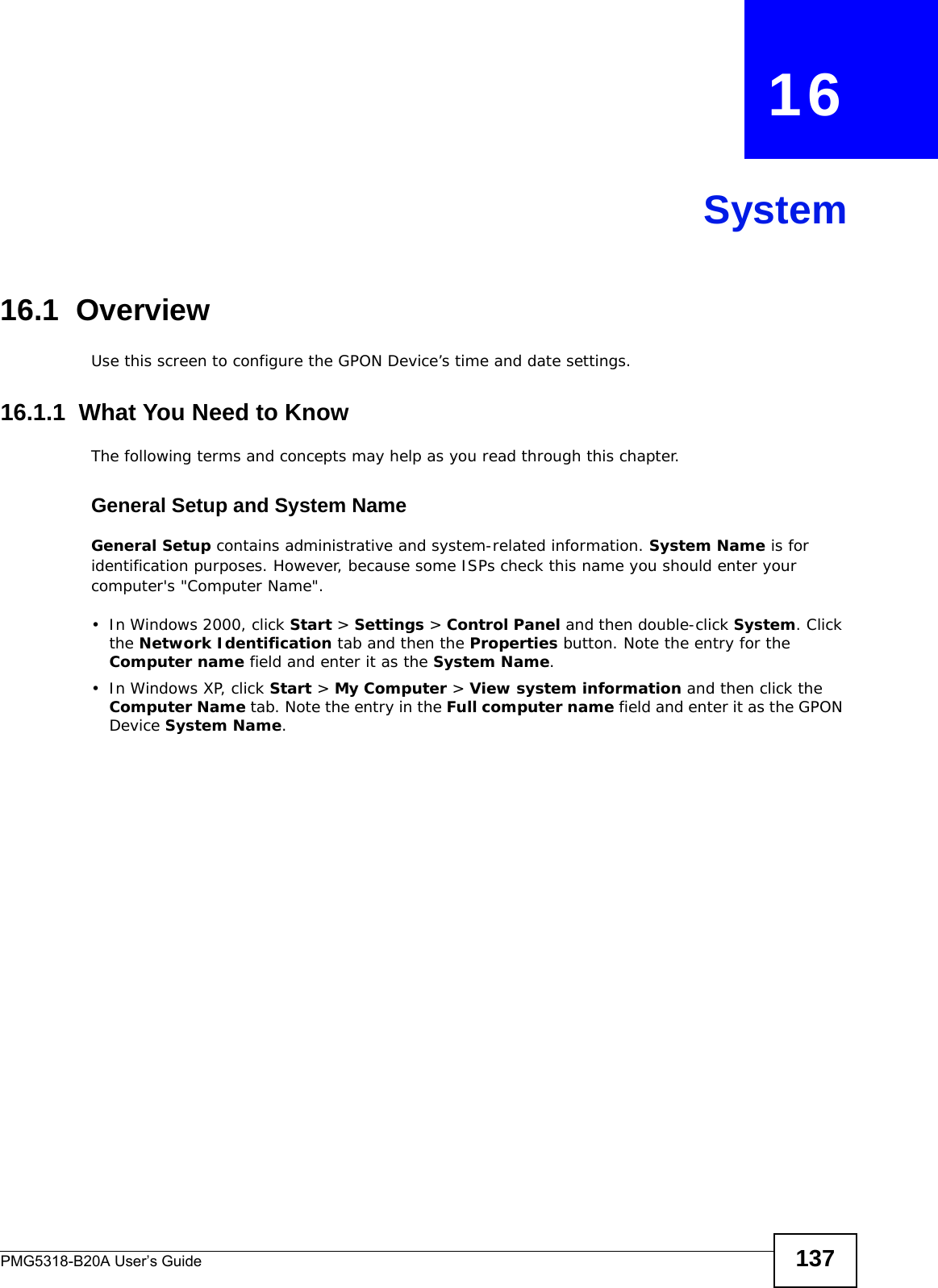
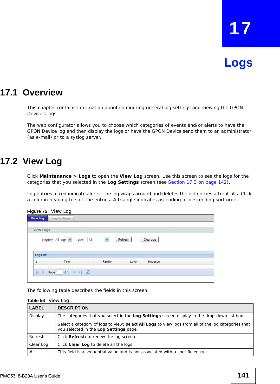
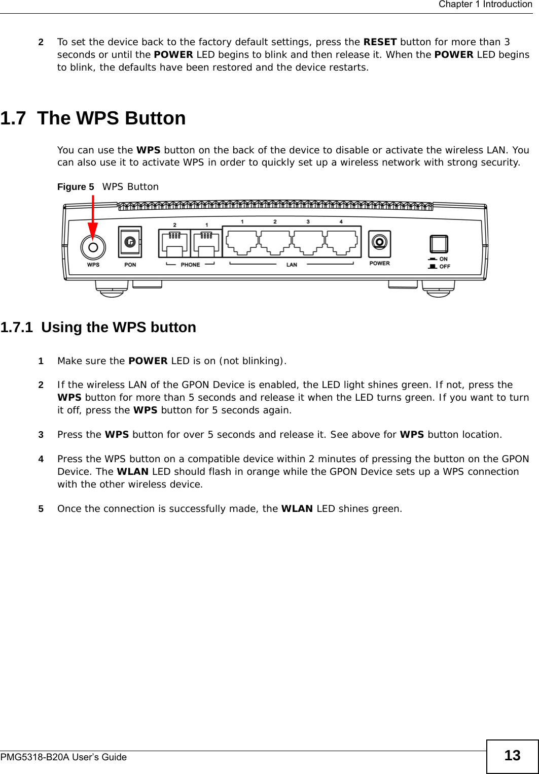
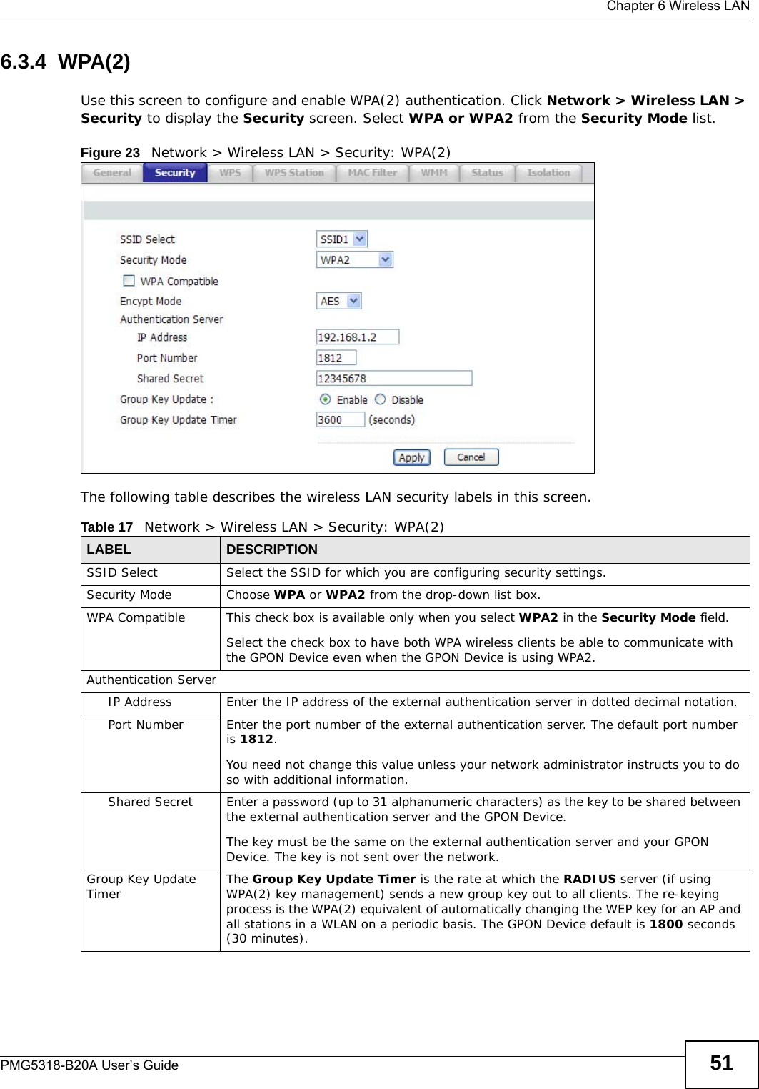
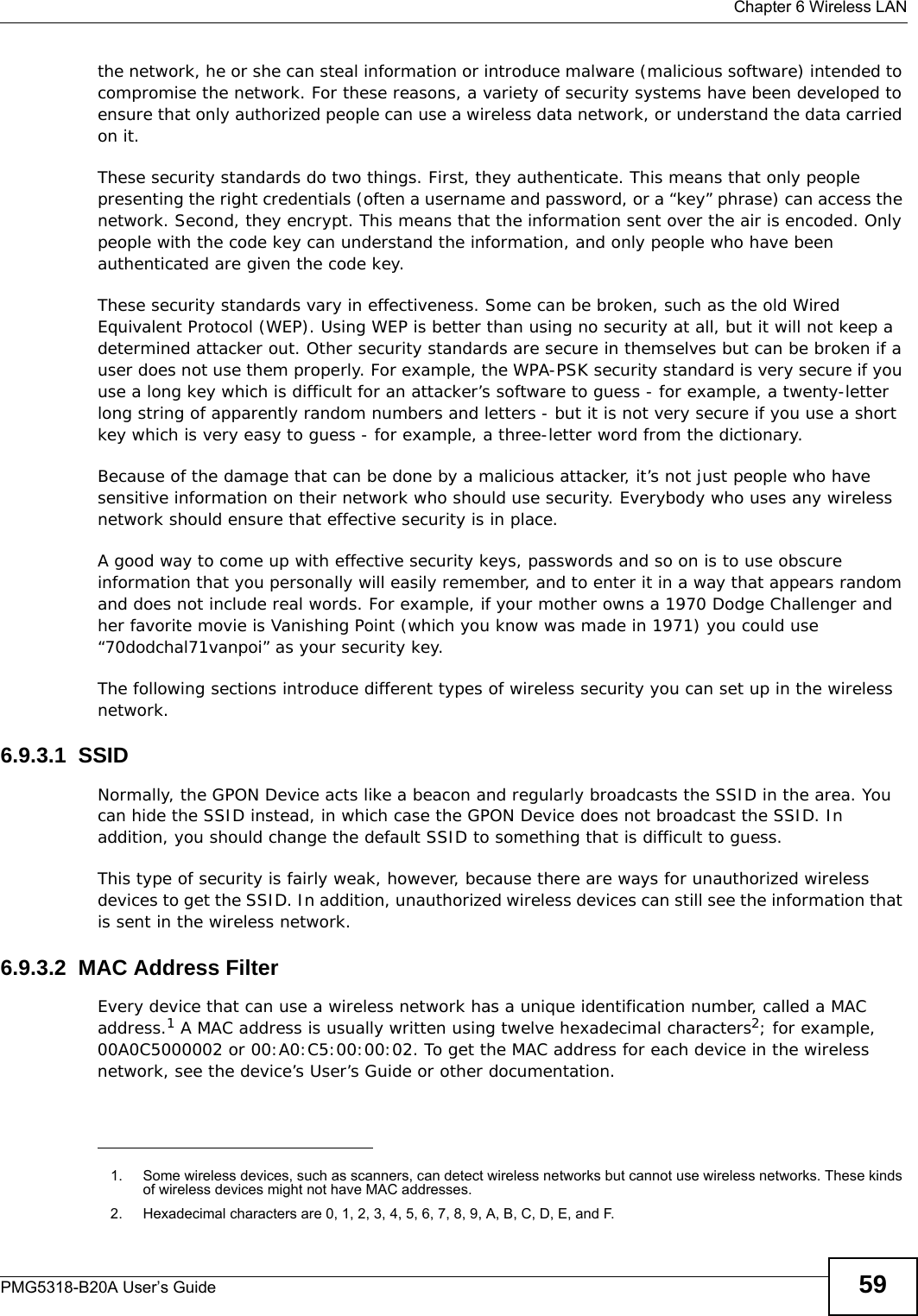
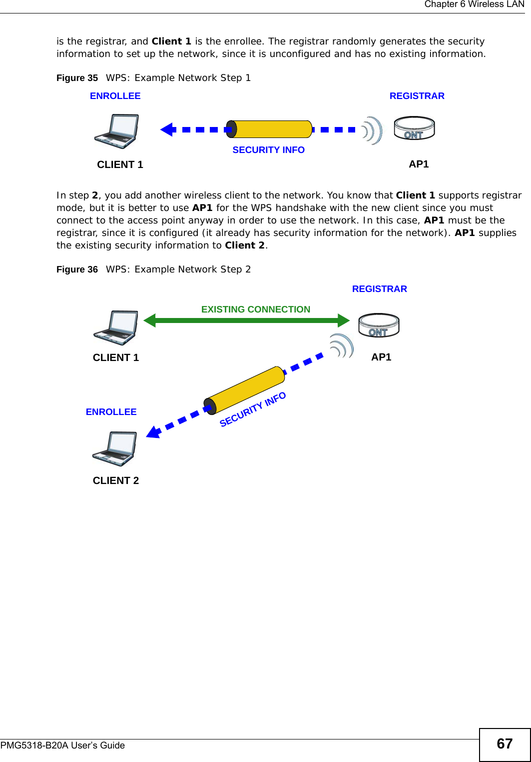
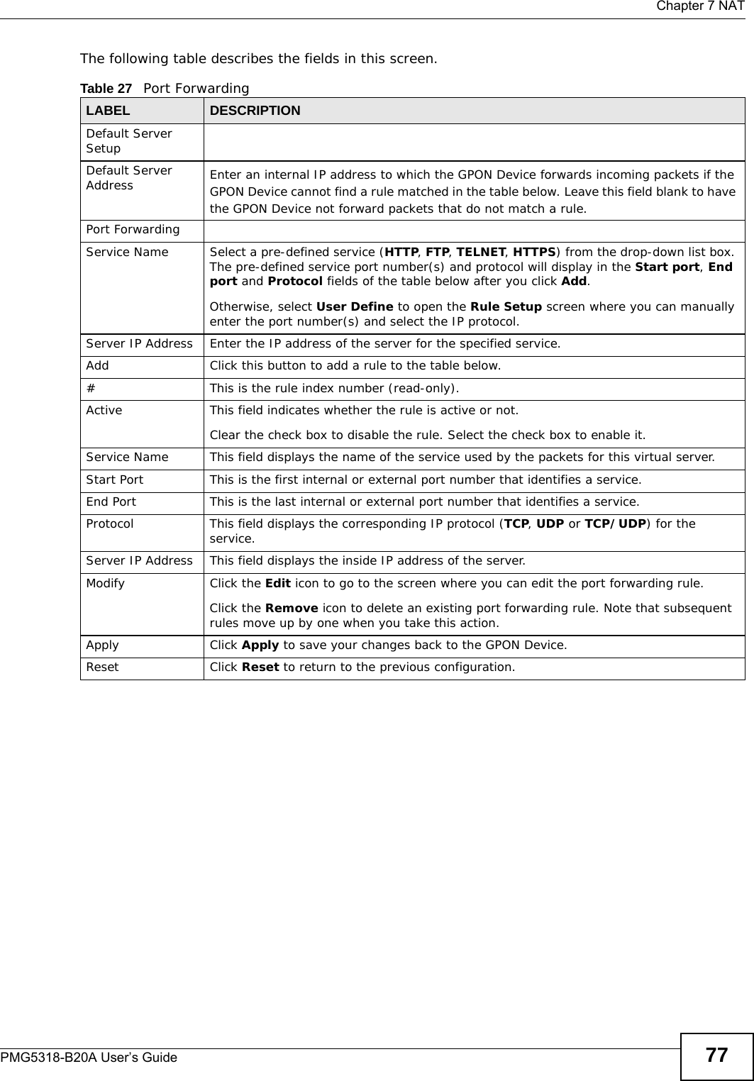
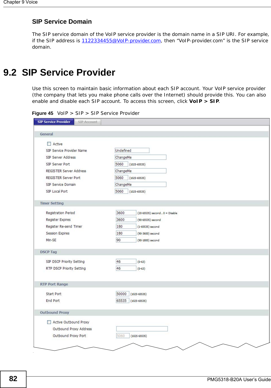
![Chapter 17 LogsPMG5318-B20A User’s Guide14217.3 Log Settings Use this screen to configure which logs to display on the View Logs screen (see Chapter 17 on page 141). Click Maintenance > Logs > Log Settings.Figure 76 Log SettingsTime This field displays the time the log was recorded. Facility This indicates the type of connection to the GPON Device.Facility types are as follows:•tr069 - This indicates a log from an external auto-configuration server.•ntpclient - This indicates a log from the ntpclient.•login - This indicates a message from the Web Configurator login information.•dhcp - This indicates a log message from the device’s DHCP server.•dnsmasq - This indicates a log message from the device’s DNS forwarder.•pppoe - This indicates a log message from the device’s Point-to-Point Protocol daemon.•kernel - This indicates a log message related to the device’s Central Processing Unit (CPU), memory, and I/O ports.•OMCI - This indicates a log message about the GPON OMCI Protocol daemon.•VoIP - This indicates a log a message from the SIP server.Level This indicates the log severity.Message This field states the reason for the log.First Click this to cycle to the first page of logs.Previous Click this to cycle to the previous page of logs.Page This indicates which page you are on, out of how many. You can enter a page number here and press [Enter] to jump directly to that page.Next Click this to cycle to the next page of logs.Last Click this to cycle to the last page of logsRefresh Click this to refresh the logs screen.Table 56 View LogLABEL DESCRIPTION](https://usermanual.wiki/ZyXEL-Communications/PMG5318B20A/User-Guide-2157470-Page-142.png)
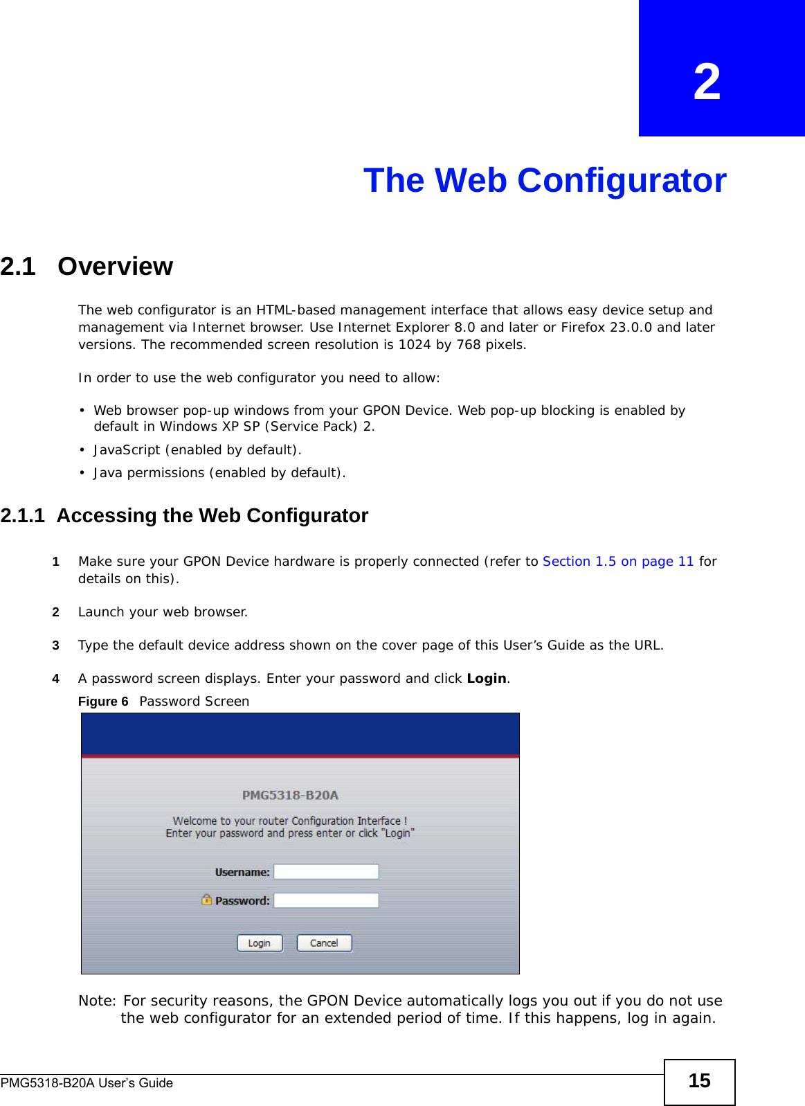
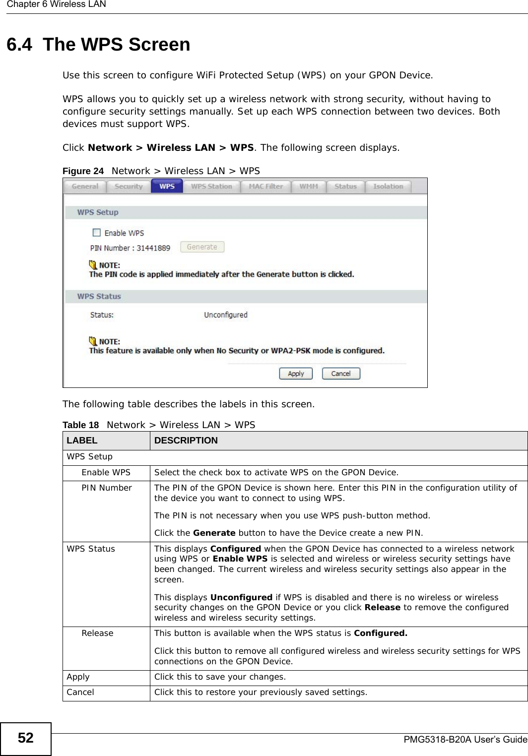
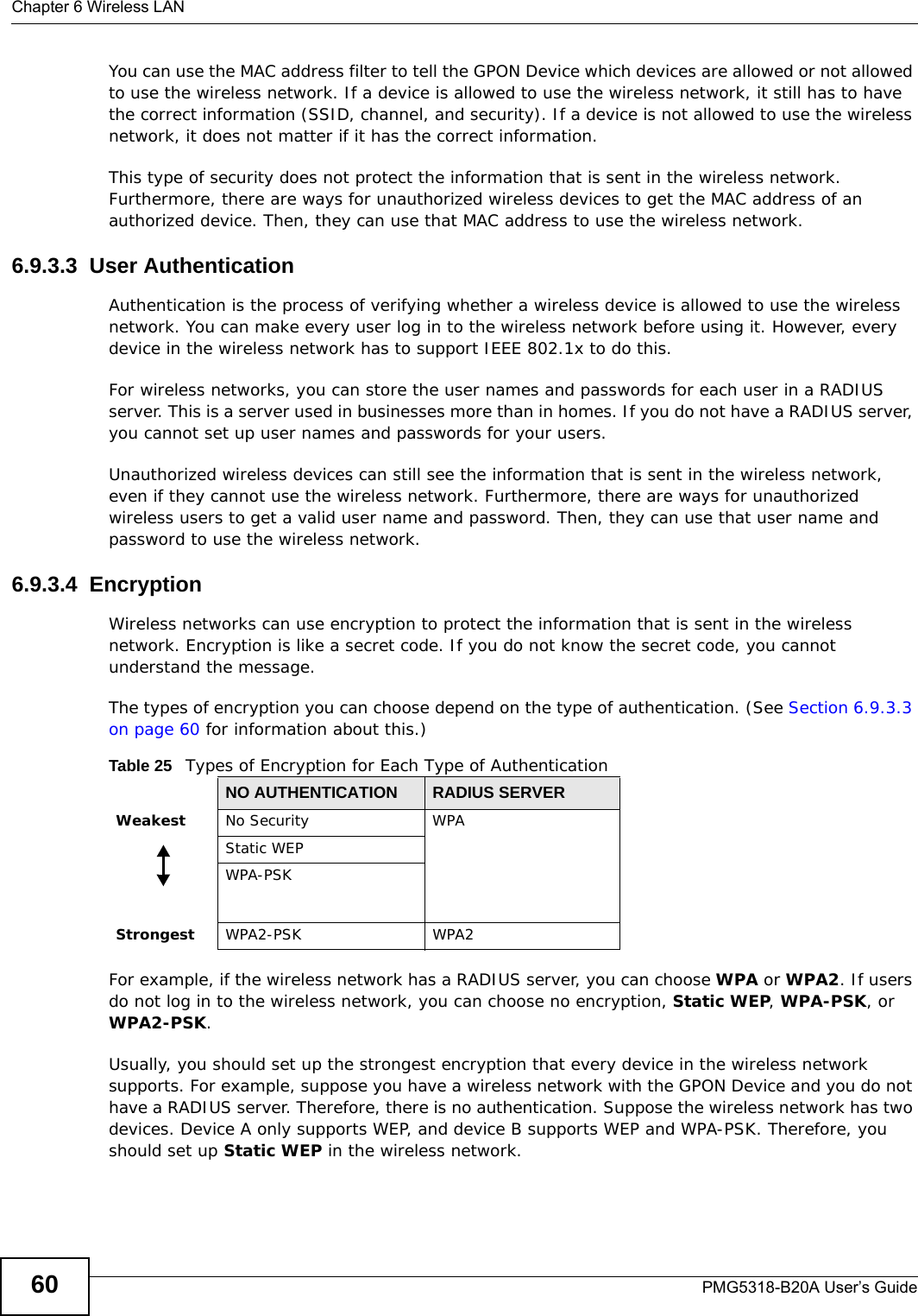
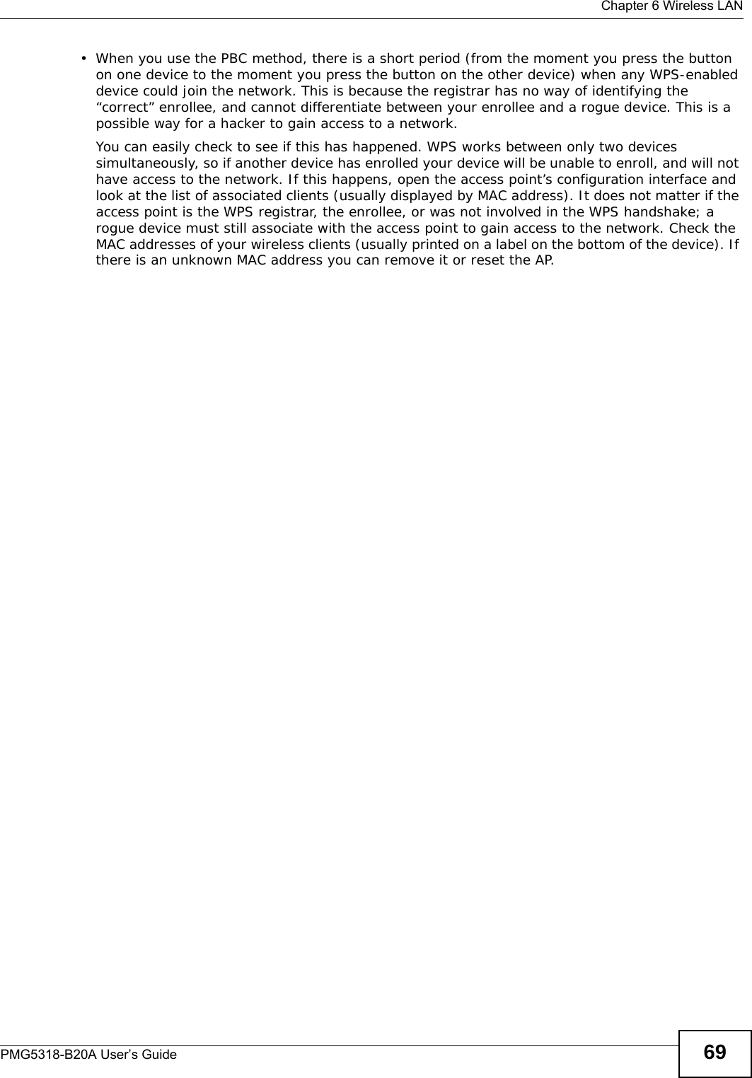
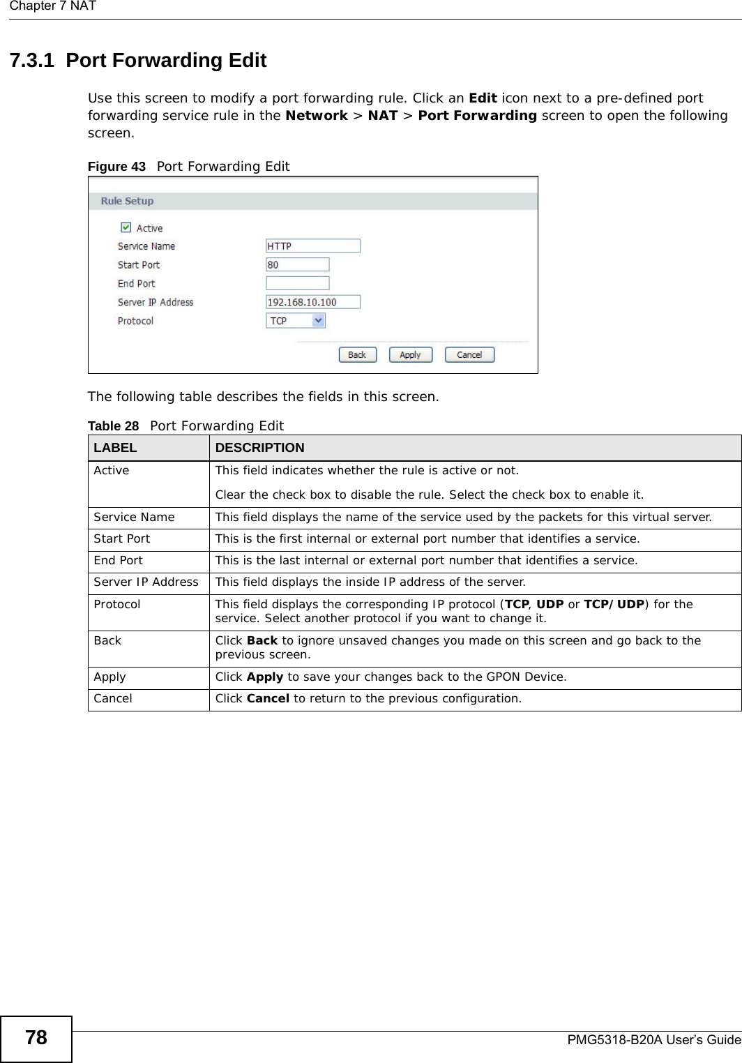
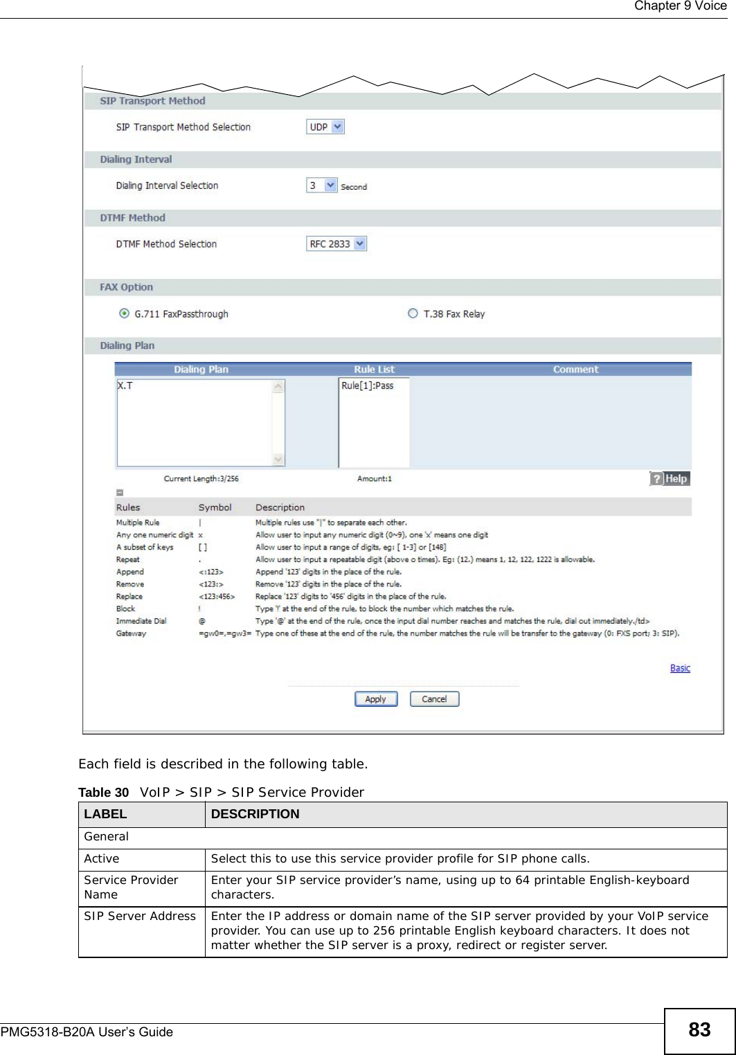
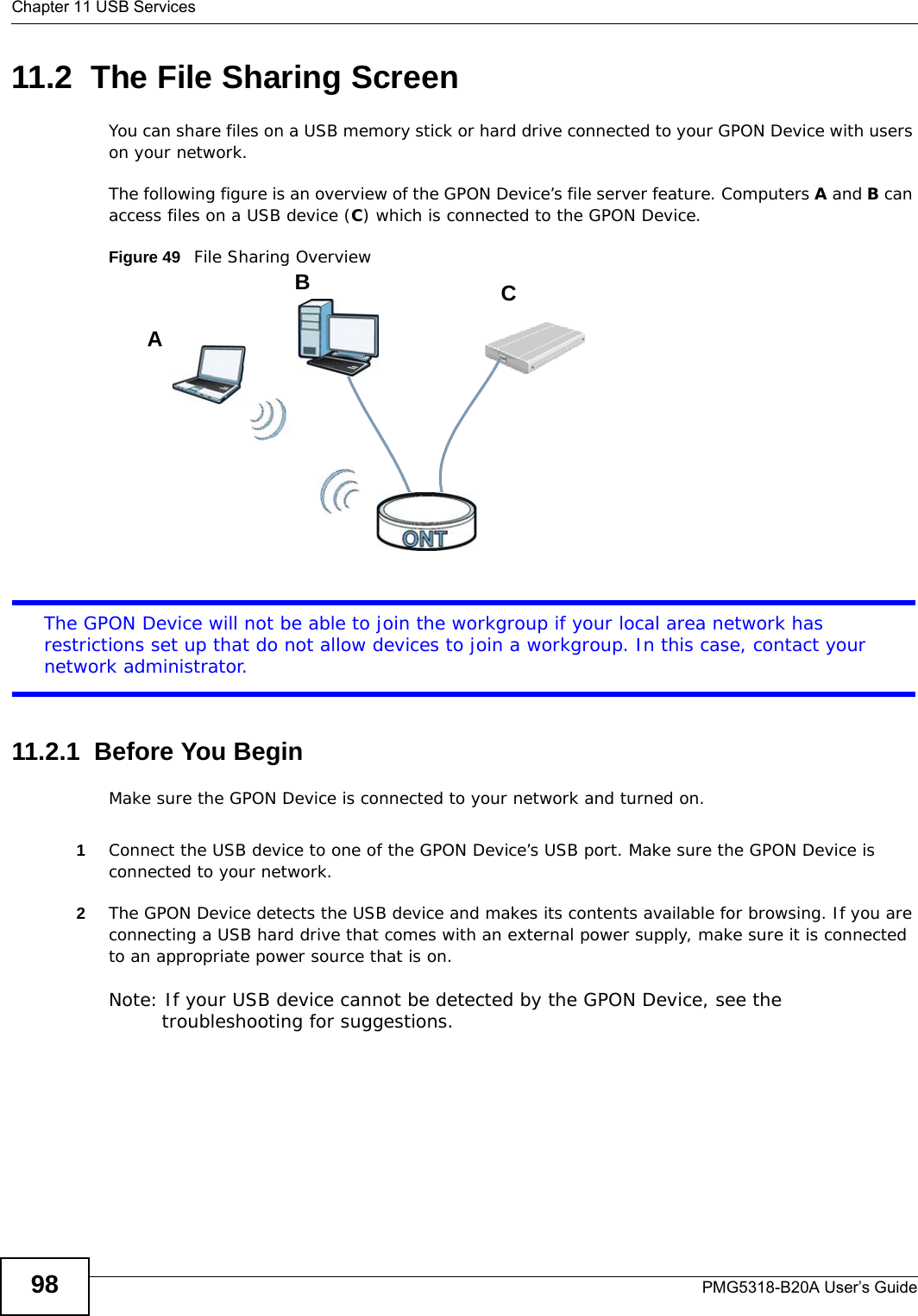
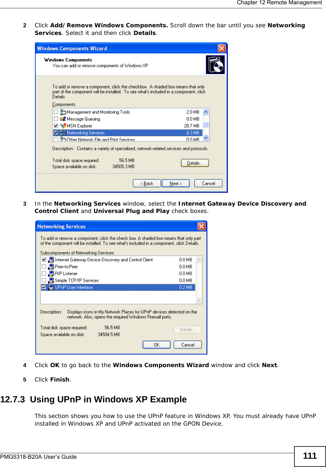
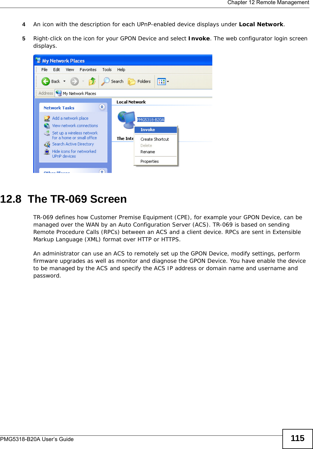
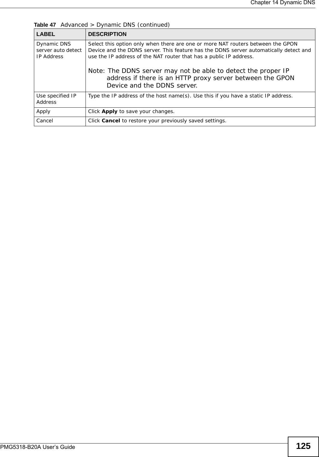
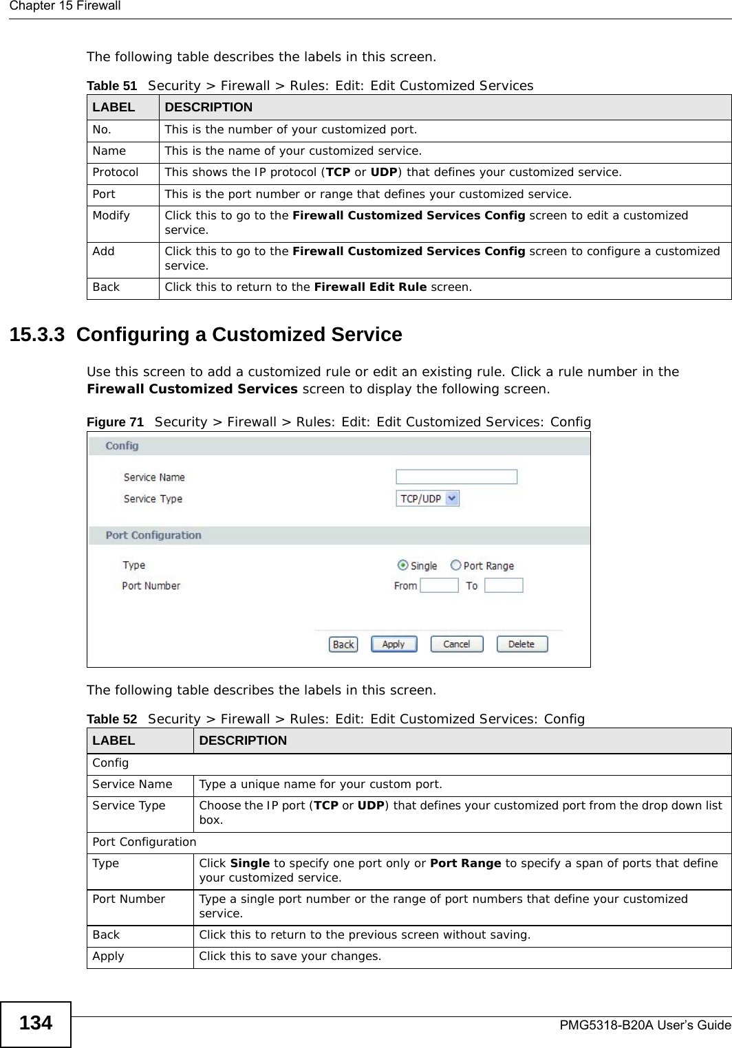
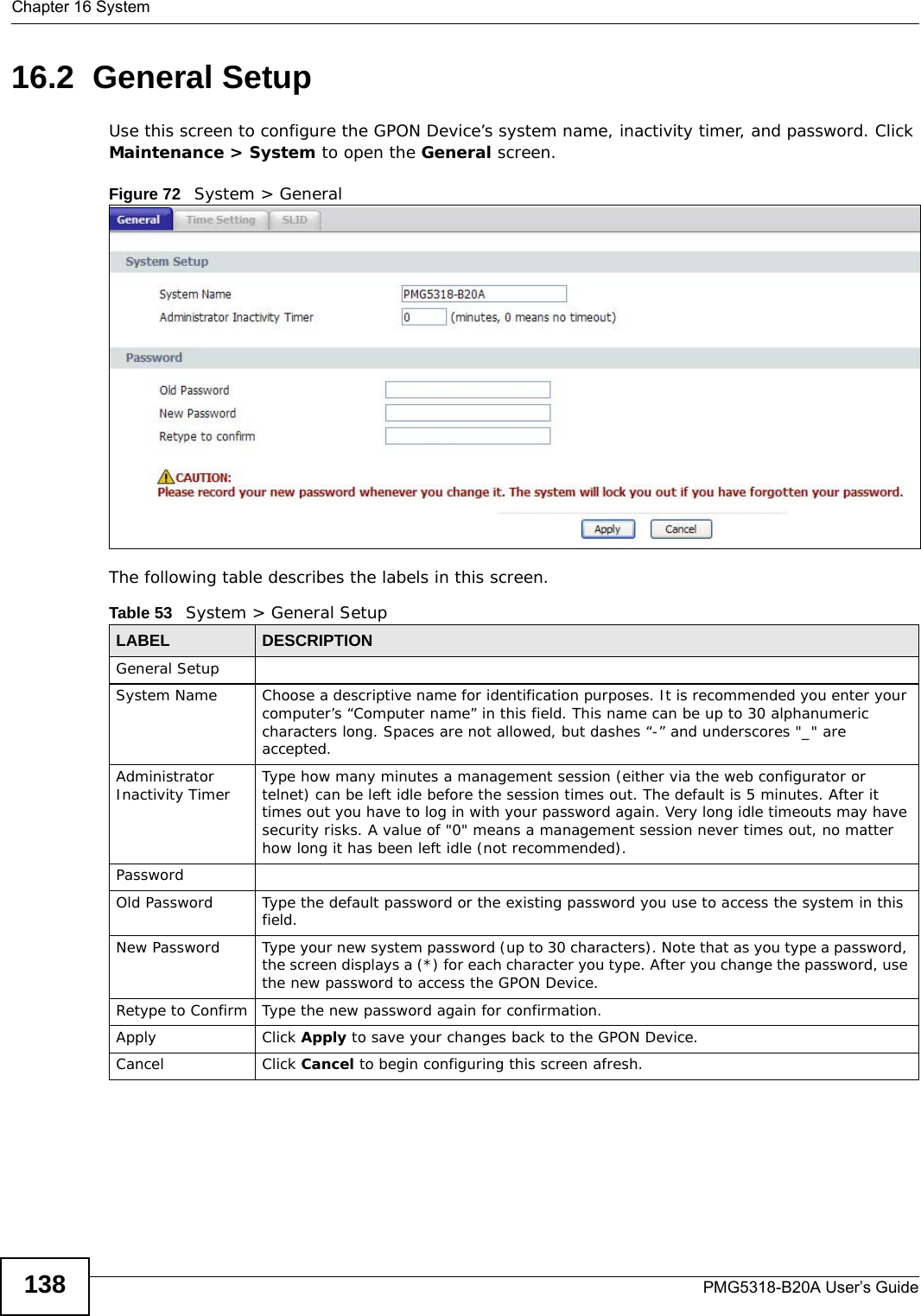
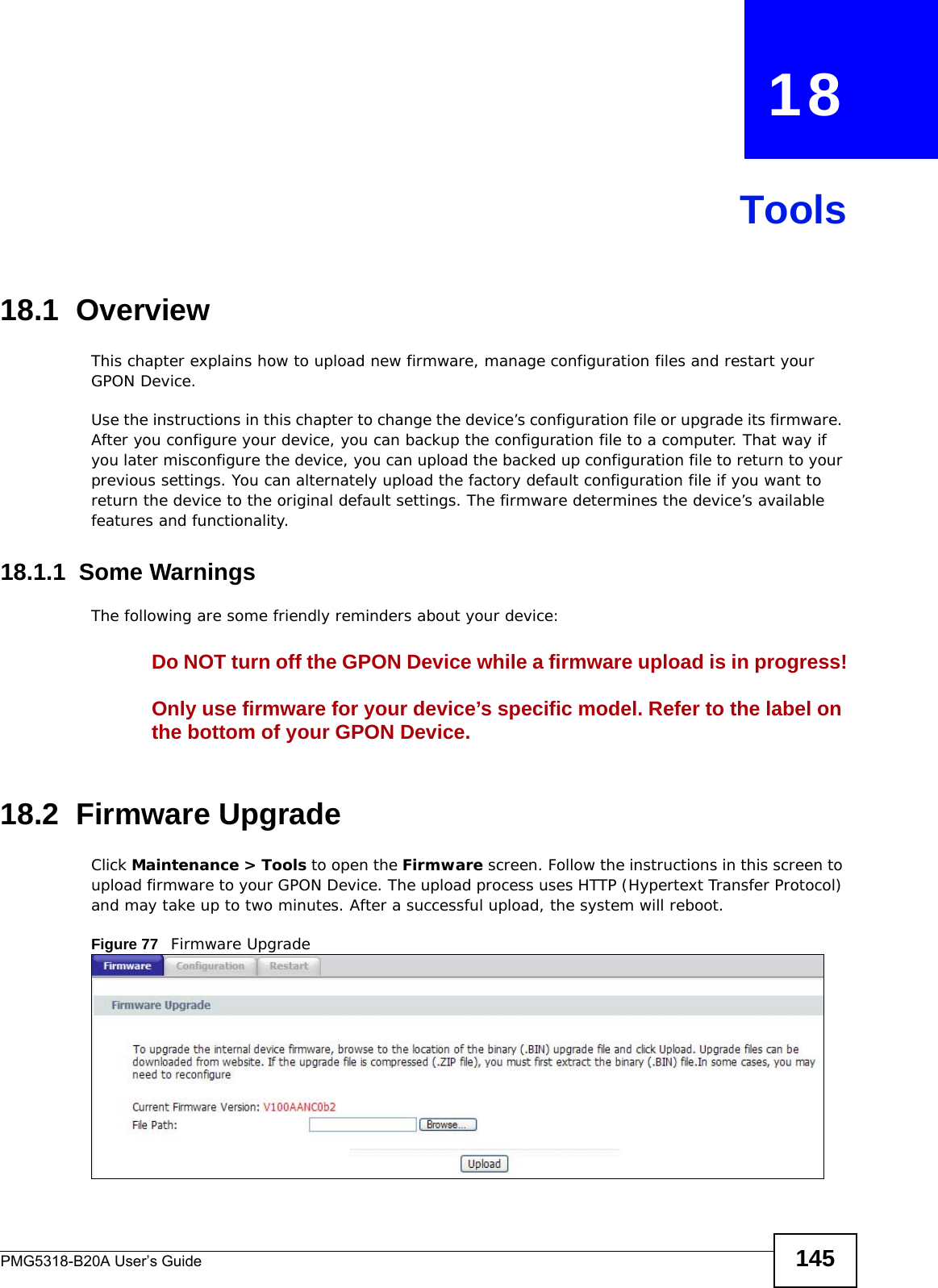
![Chapter 17 LogsPMG5318-B20A User’s Guide 143The following table describes the fields in this screen. Table 57 Log SettingsLABEL DESCRIPTIONActive Log[Log Type] Select the type of log you want to be displayed on the View Logs screen.Apply Click Apply to save your customized settings and exit this screen. Cancel Click Cancel to return to the previously saved settings.](https://usermanual.wiki/ZyXEL-Communications/PMG5318B20A/User-Guide-2157470-Page-143.png)


![Chapter 20 TroubleshootingPMG5318-B20A User’s Guide1524Turn the GPON Device off and on. 5If the problem continues, contact the vendor.20.3 GPON Device Access and LoginI forgot the IP address for the GPON Device.1The default IP address is 192.168.1.1.2If you changed the IP address and have forgotten it, reset the GPON Device to its factory defaults. See Section 1.6 on page 12.I cannot see or access the Login screen in the web configurator.1Make sure you are using the correct IP address.• The default IP address is 192.168.1.1.• If you changed the IP address, use the new IP address.• If you changed the IP address and have forgotten it, see the troubleshooting suggestions for I forgot the IP address for the GPON Device.2Check the hardware connections, and make sure the LEDs are behaving as expected. See Section 1.5 on page 11.3Make sure your Internet browser does not block pop-up windows and has Javascript and Java enabled.4Reset the device to its factory defaults, and try to access the GPON Device with the default IP address. See Section 1.6 on page 12. 5If the problem continues, contact the network administrator or vendor, or try one of the advanced suggestions.I can see the Login screen, but I cannot log in to the GPON Device.1Make sure you have entered the user name and password correctly. The default user name is admin. These fields are case-sensitive, so make sure [Caps Lock] is not on. 2You cannot log in to the web configurator while someone is using Telnet to access the GPON Device. Log out of the GPON Device in the other session, or ask the person who is logged in to log out.](https://usermanual.wiki/ZyXEL-Communications/PMG5318B20A/User-Guide-2157470-Page-152.png)
![Chapter 20 TroubleshootingPMG5318-B20A User’s Guide 1533Turn the GPON Device off and on. 4If this does not work, you have to reset the device to its factory defaults. See Section 20.2 on page 151.20.4 Internet AccessI cannot access the Internet.1Check the hardware connections, and make sure the LEDs are behaving as expected. The PON LED turns red if the optical transceiver has malfunctioned or the fiber cable is not connected or is broken or damaged enough to break the PON connection. The PON LED turns orange if the GPON Device’s PON port is physically connected but not registered. If the service provider gave you an SLID to use, make sure you entered the SLID correctly (see Section 16.4 on page 140). It is case-sensitive, so make sure [Caps Lock] is not on. See Section 1.5 on page 11 for details about the other LEDs. 2Make sure you entered the ISP account information correctly in the wizard. These fields are case-sensitive, so make sure [Caps Lock] is not on. 3Disconnect all the cables from your device, and follow the directions in Section 1.5 on page 11 again. 4If the problem continues, contact the ISP. I cannot access the Internet anymore. I had access to the Internet (with the GPON Device), but my Internet connection is not available anymore.1Check the hardware connections, and make sure the LEDs are behaving as expected. The PON LED turns red if the optical transceiver has malfunctioned or the fiber cable is not connected or is broken or damaged enough to break the PON connection. See Section 1.5 on page 11 for details about the other LEDs.2Turn the GPON Device off and on. 3If the problem continues, contact the ISP. The Internet connection is slow or intermittent.](https://usermanual.wiki/ZyXEL-Communications/PMG5318B20A/User-Guide-2157470-Page-153.png)