ZyXEL Communications V630 VoIP Wi-Fi Phone User Manual SMG 700 User s Guide V1 00 Nov 2004
ZyXEL Communications Corporation VoIP Wi-Fi Phone SMG 700 User s Guide V1 00 Nov 2004
UserManual.wiki
>
ZyXEL Communications
>
V630 User Manual
user manual
Navigation menu
Upload a User Manual
Namespaces
Wiki Guide
HTML
PDF
Info
Views
User Manual
Discussion / Help
Navigation

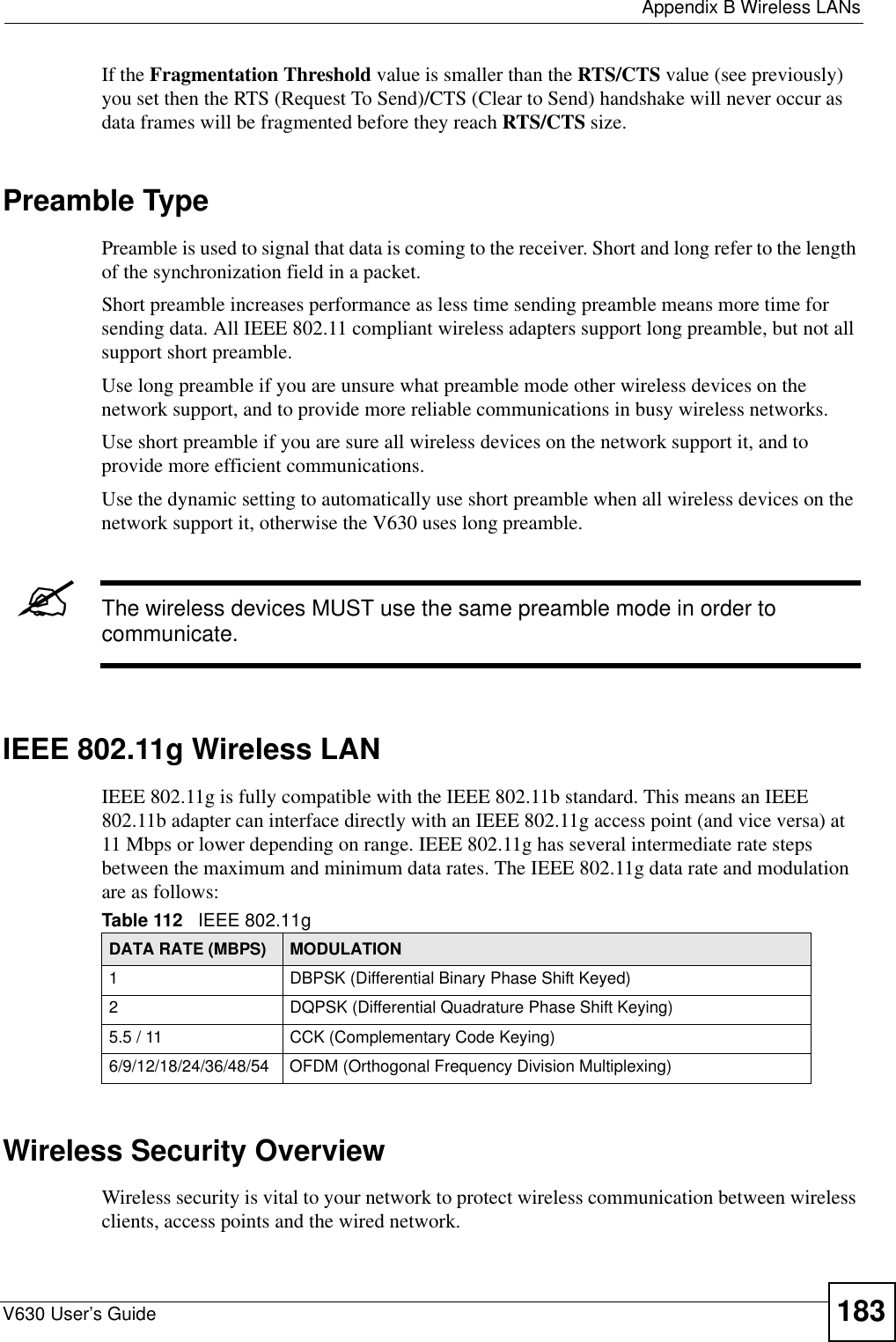
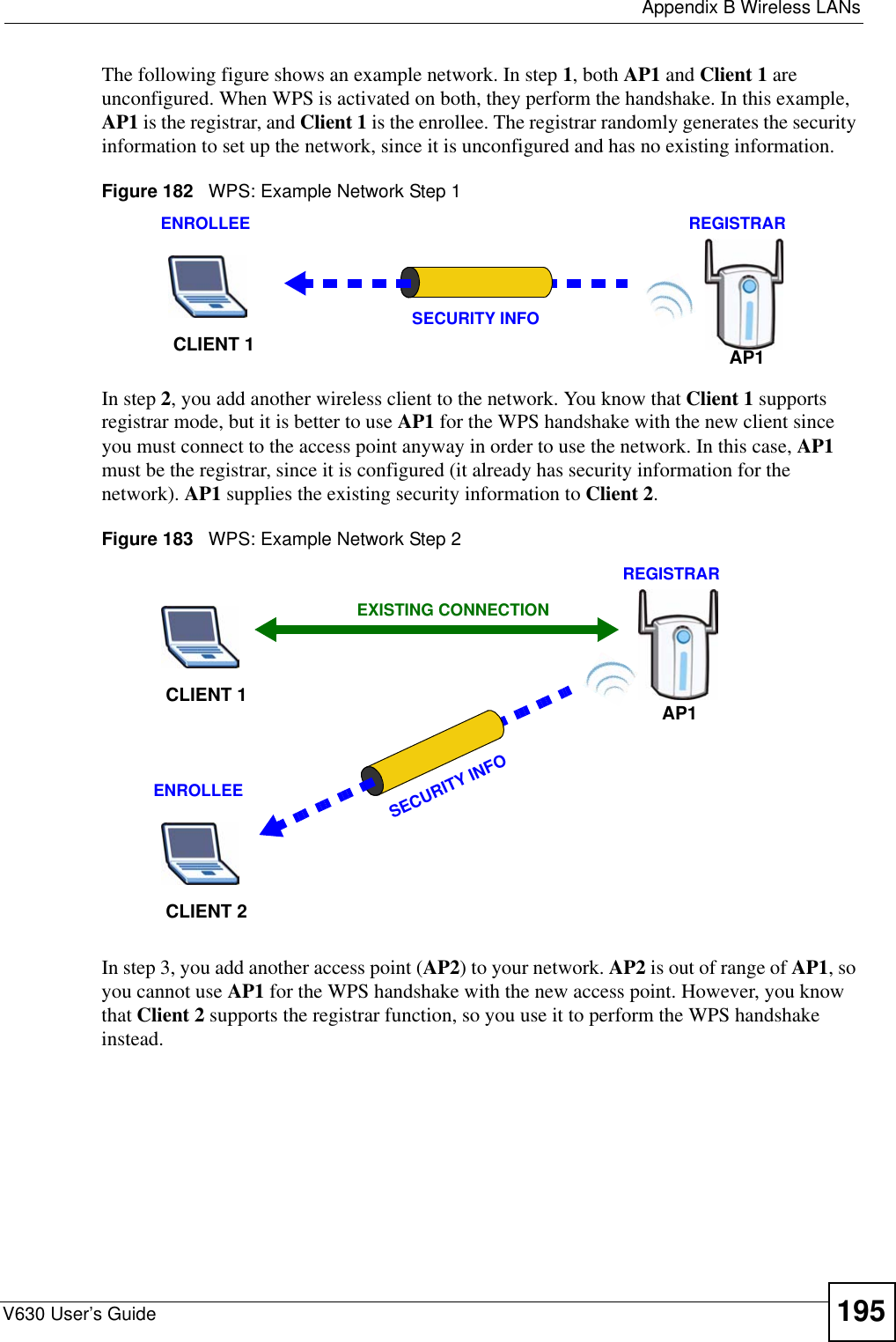
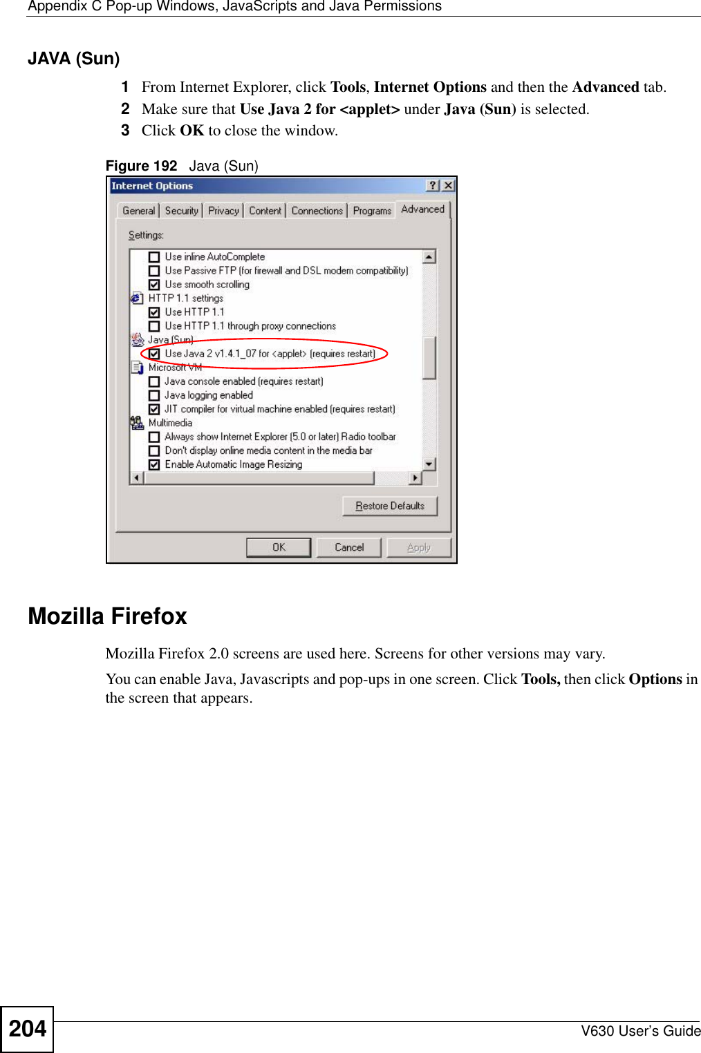
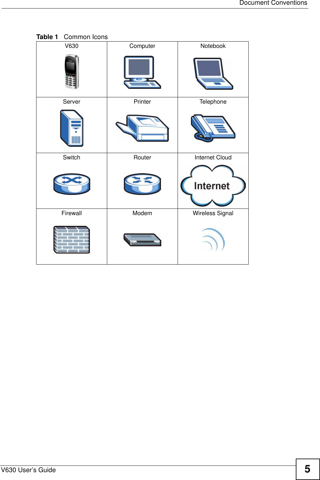
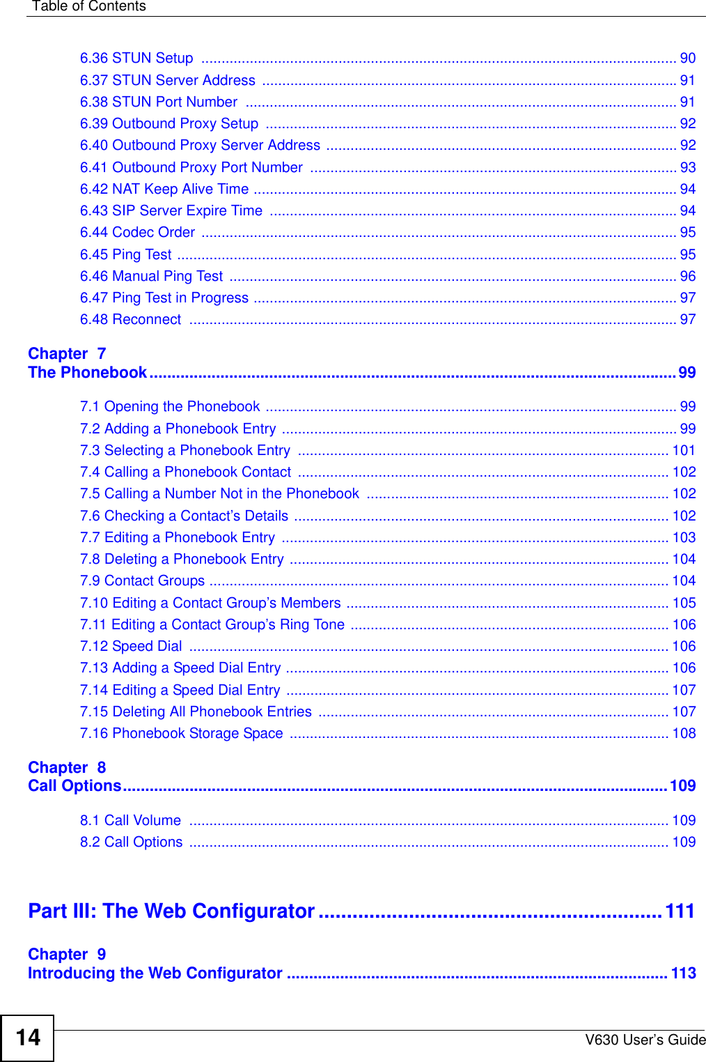
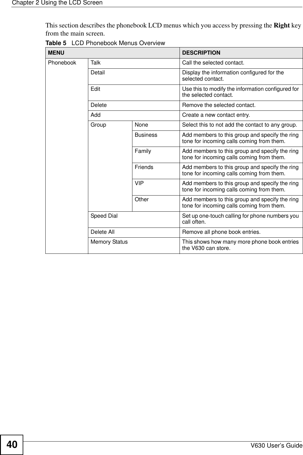
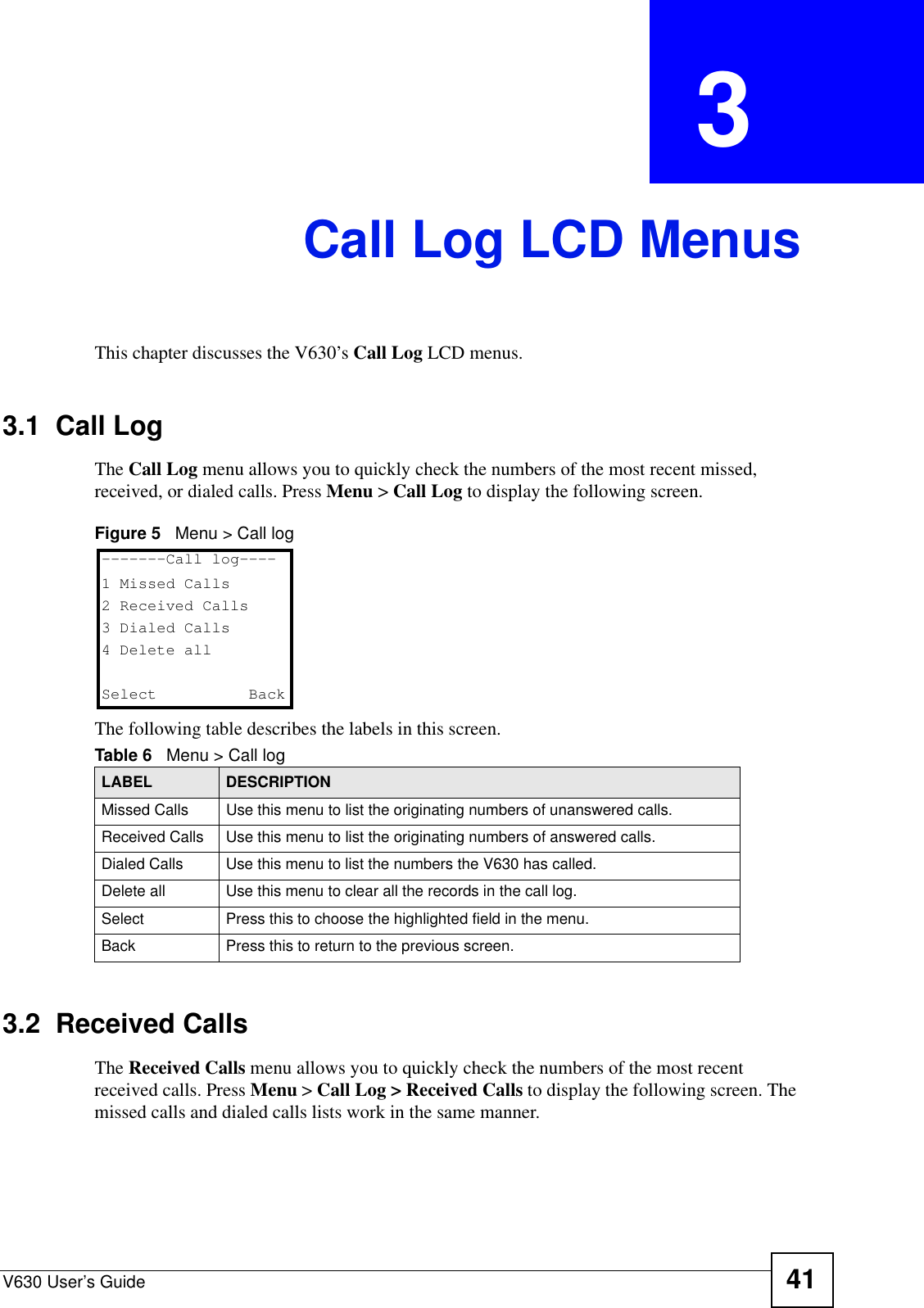
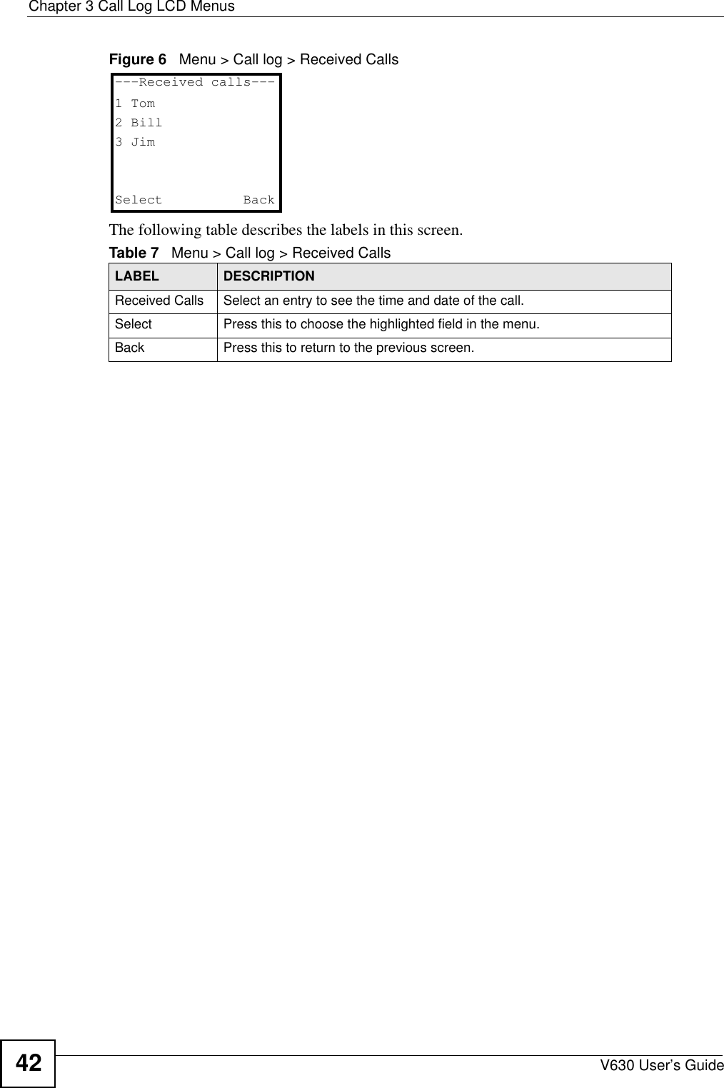
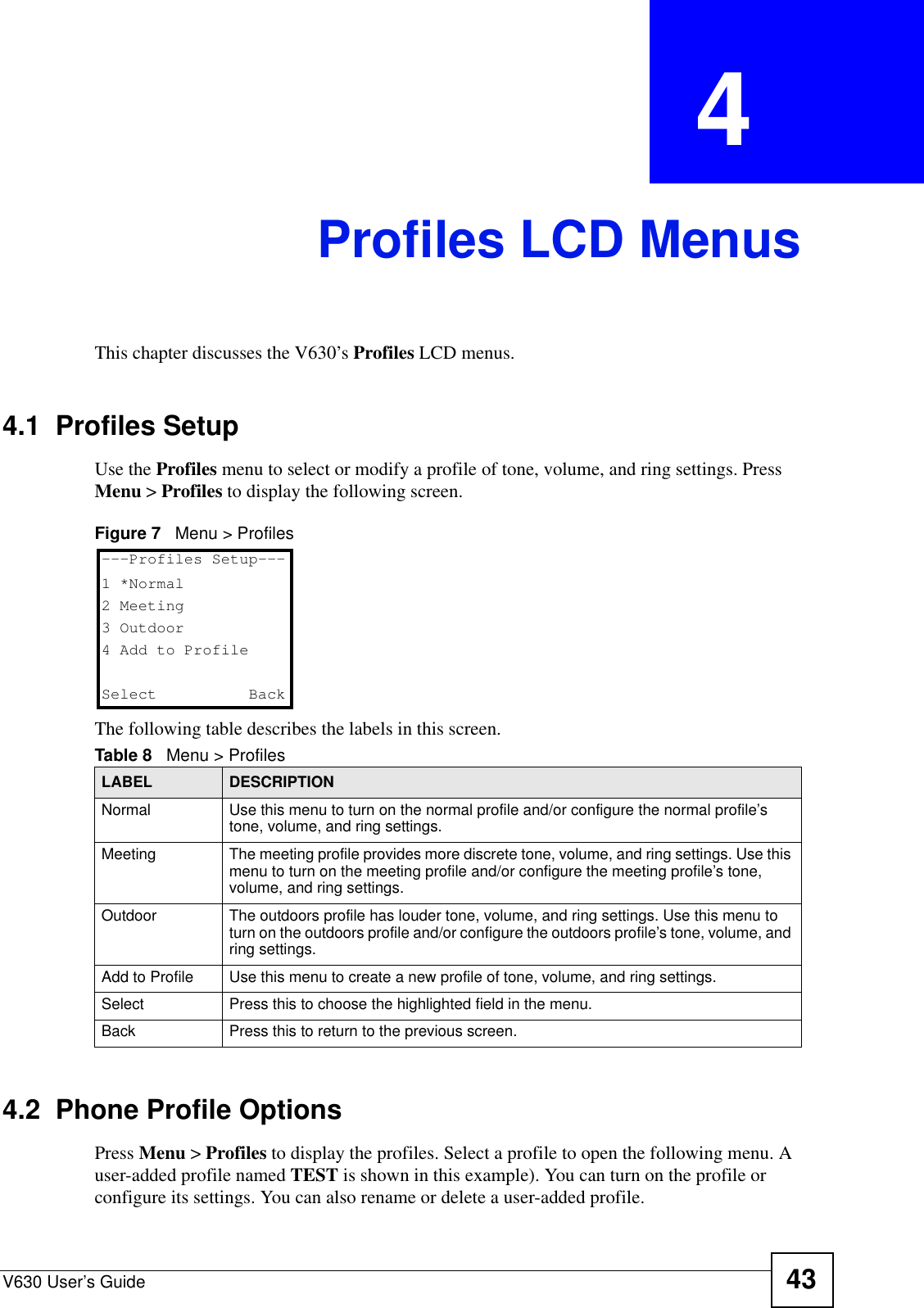
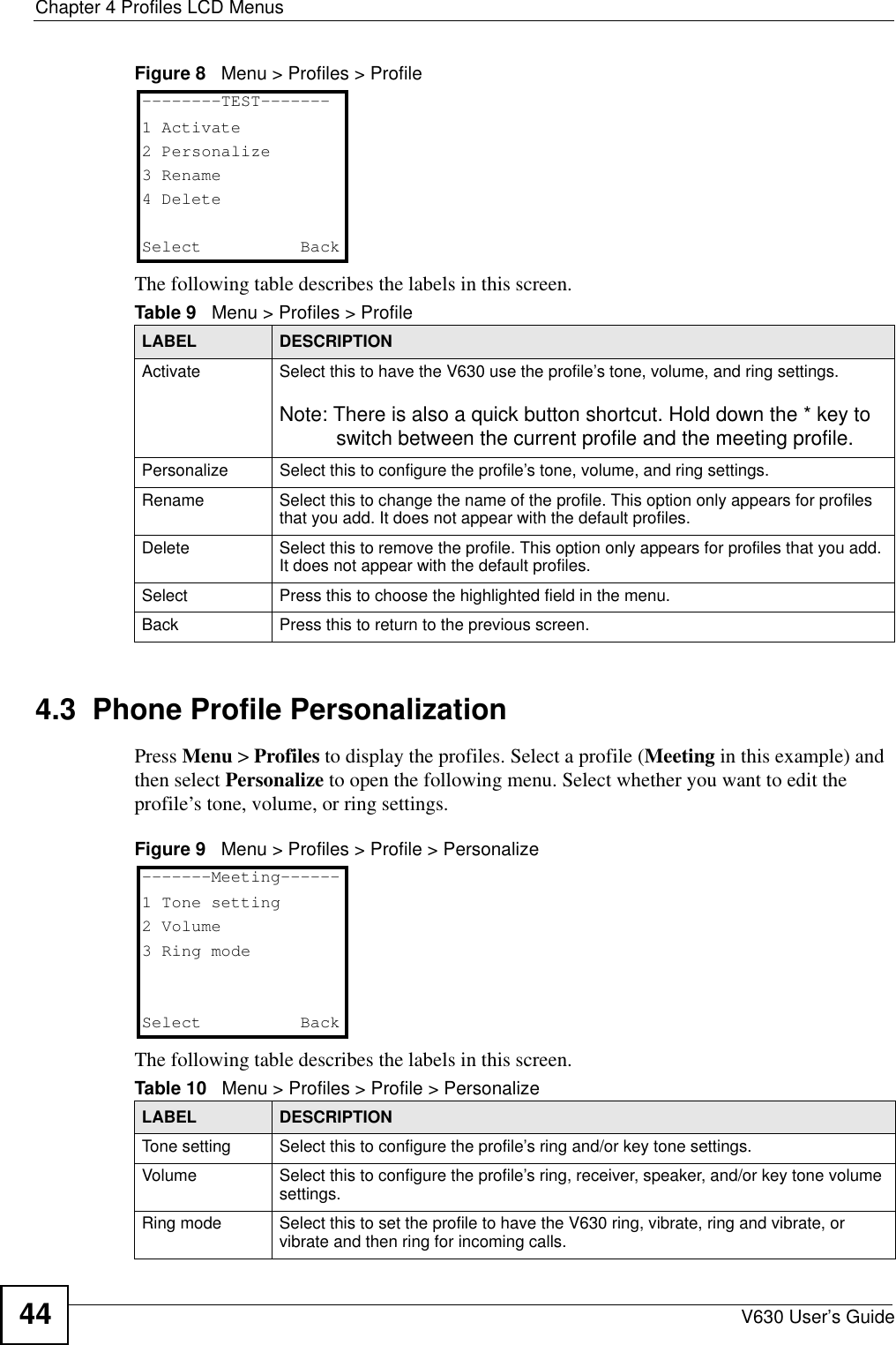
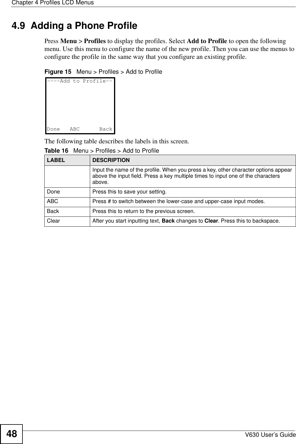
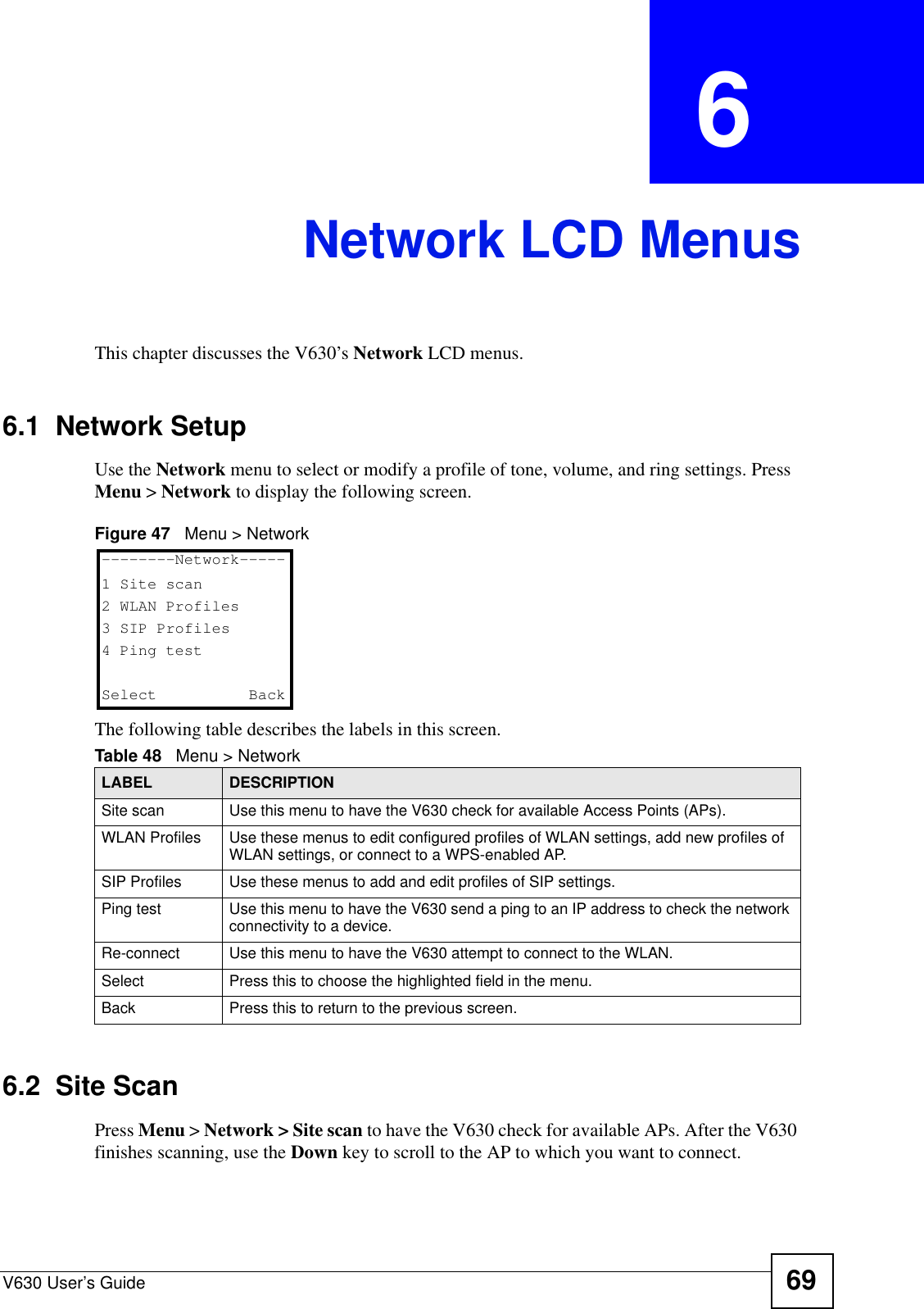
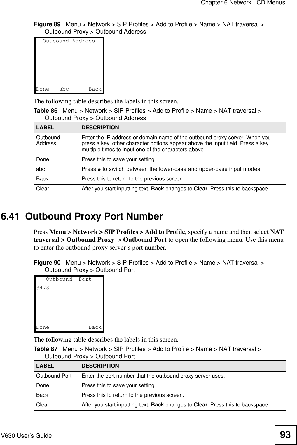
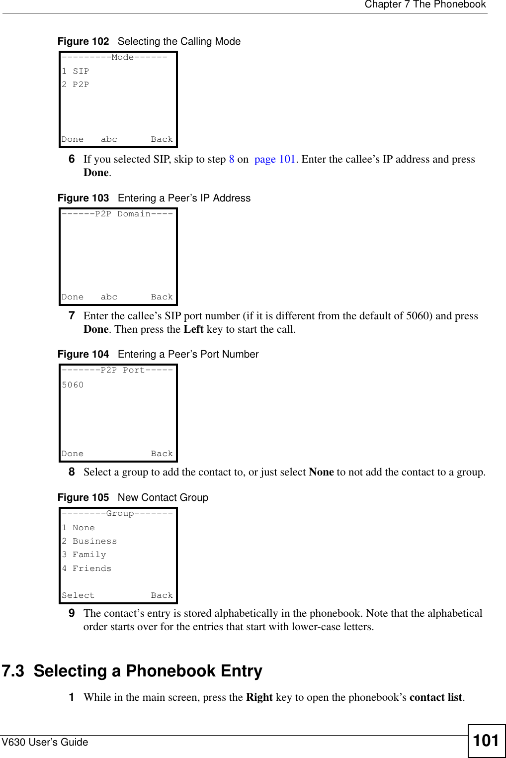
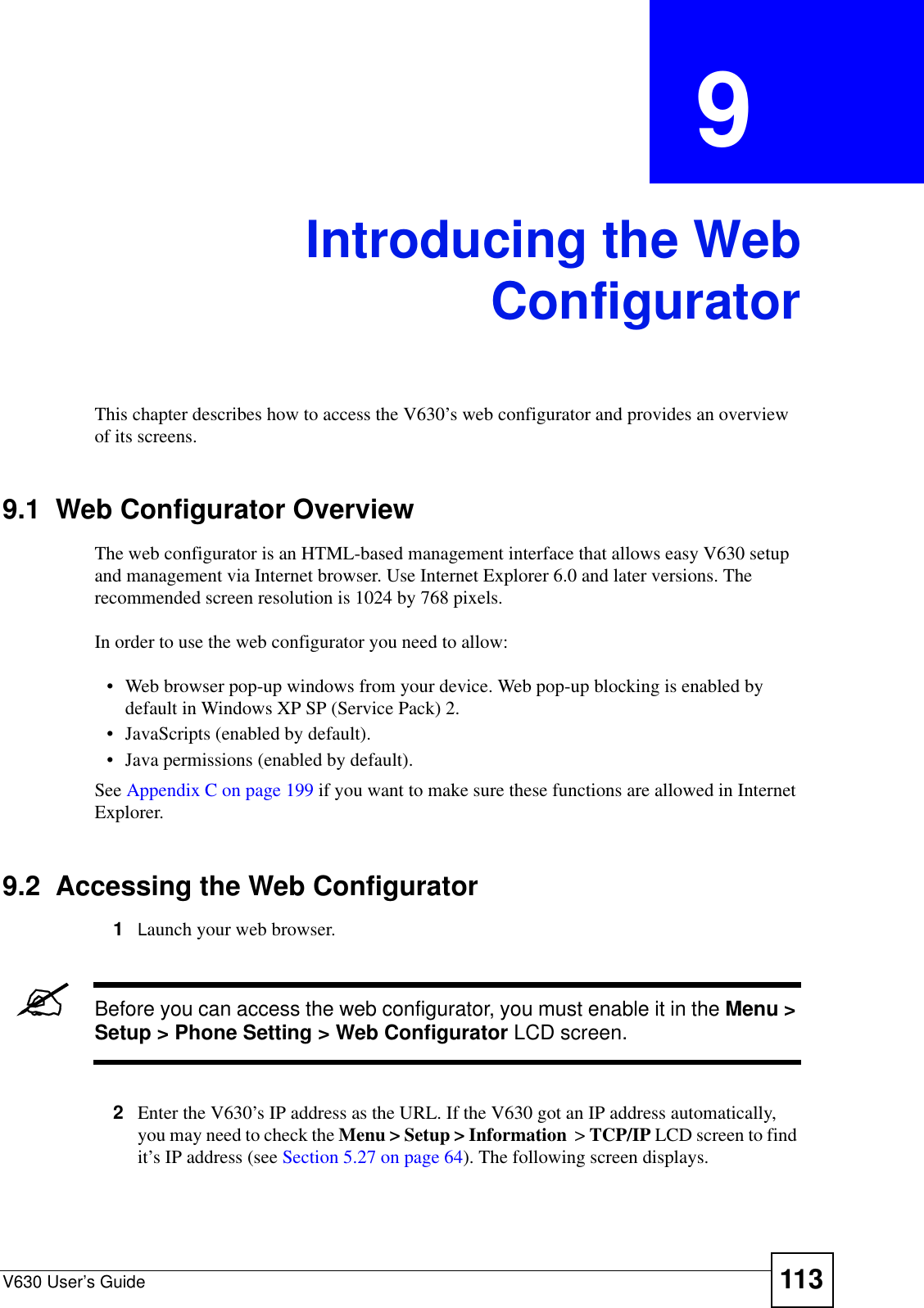
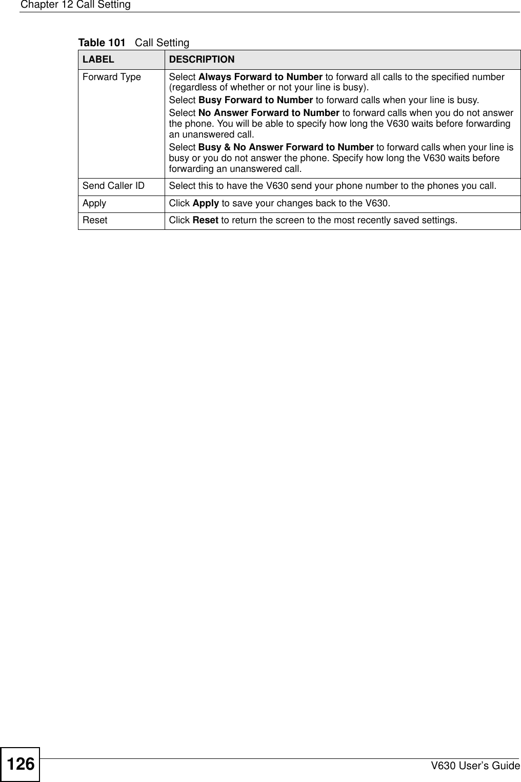
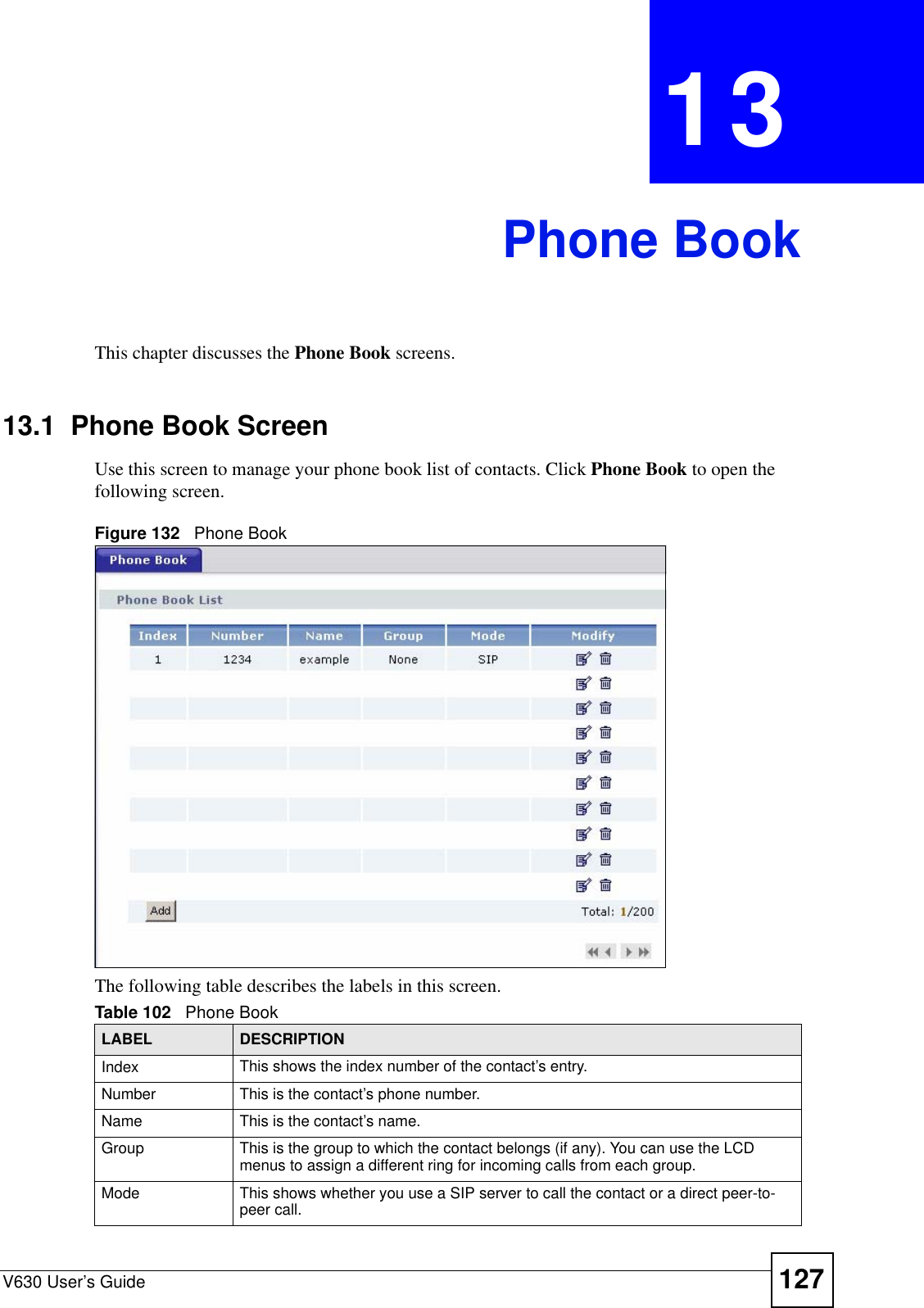
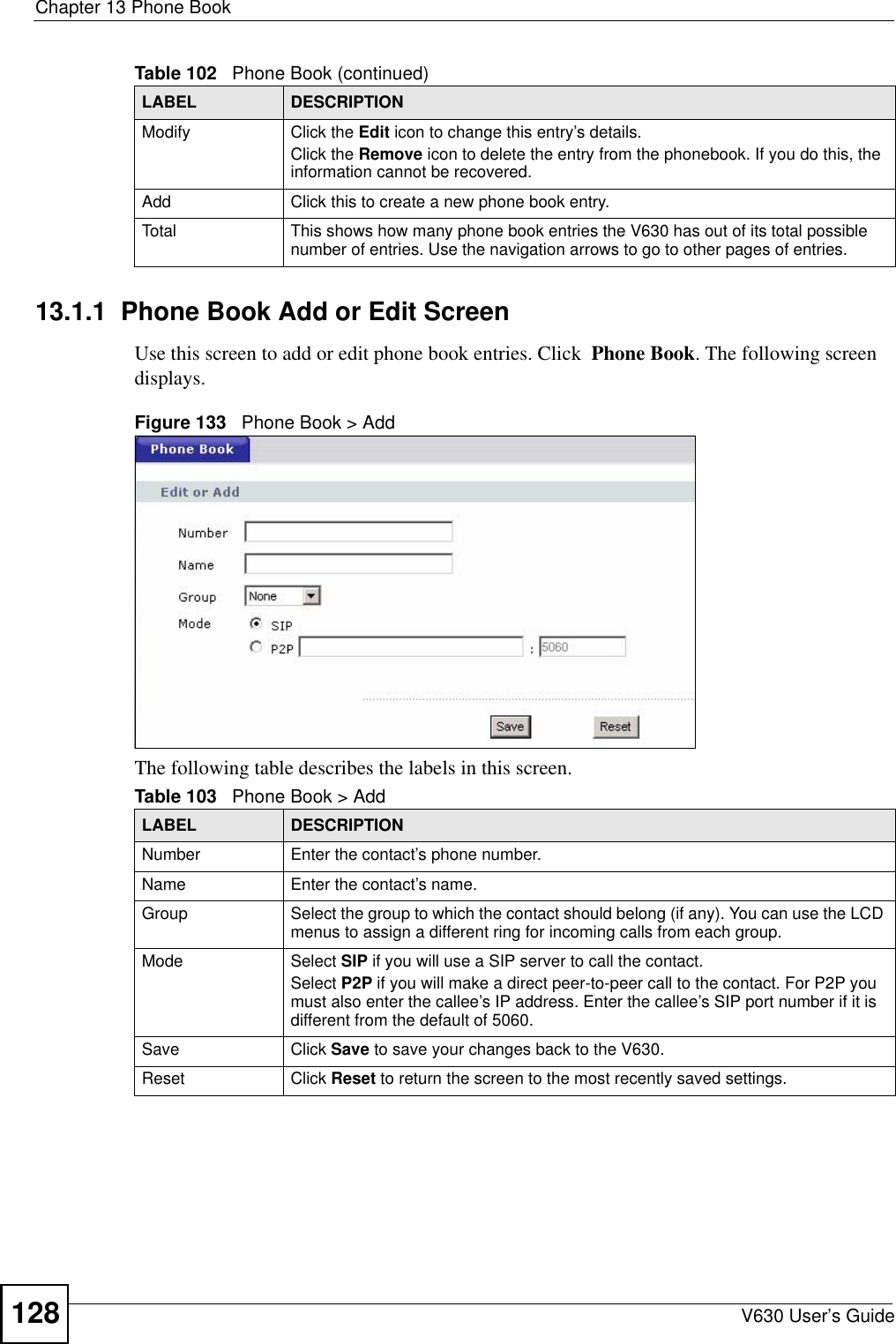
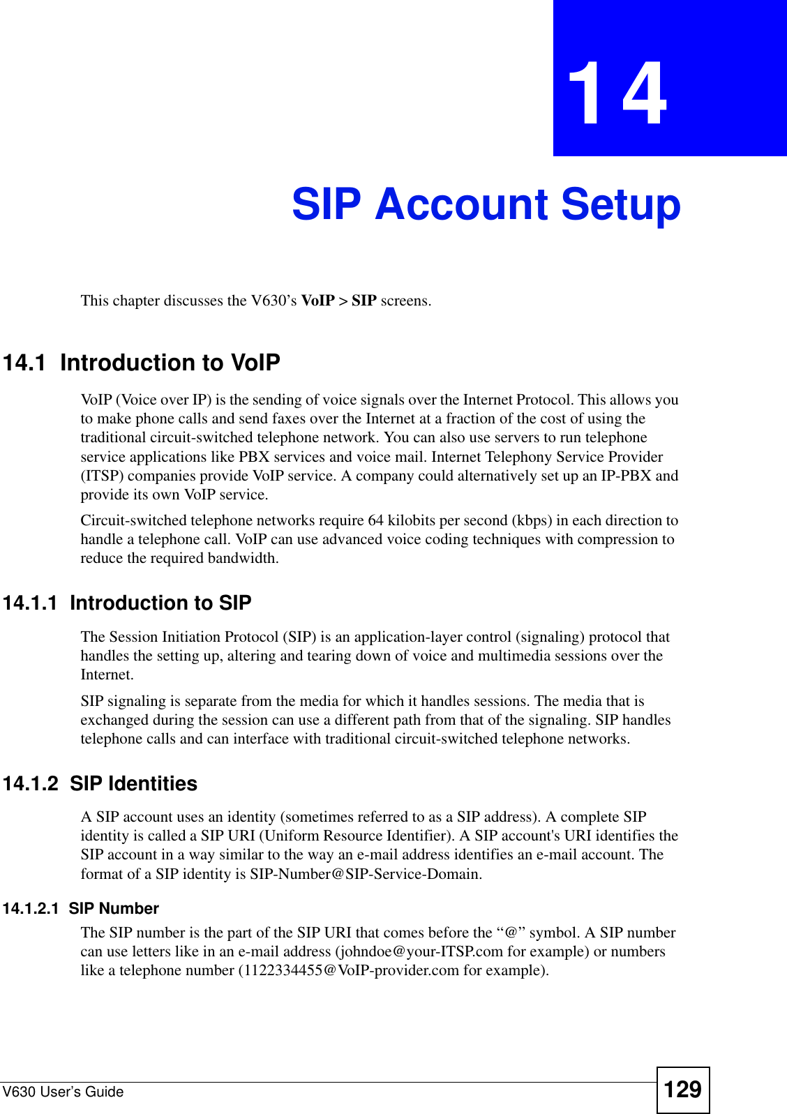
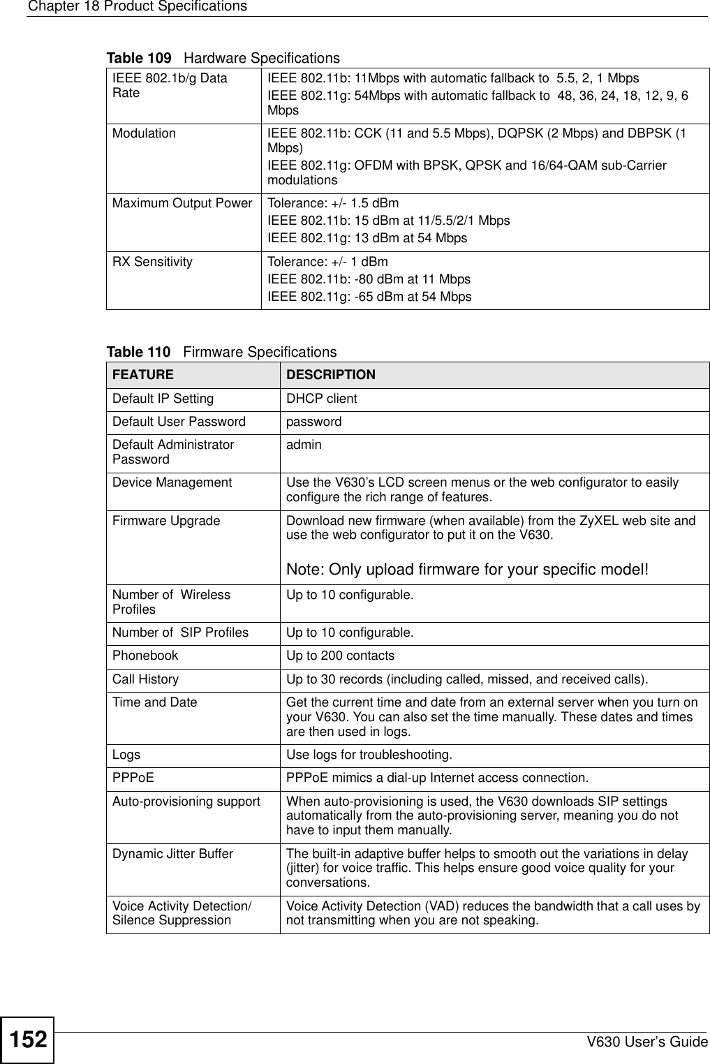
![Document ConventionsV630 User’s Guide4Document ConventionsWarnings and NotesThese are how warnings and notes are shown in this User’s Guide. 1Warnings tell you about things that could harm you or your V630."Notes tell you other important information (for example, other things you may need to configure or helpful tips) or recommendations.Syntax Conventions• The V630 may be referred to as the “V630”, the “device”, the “system” or the “product” in this User’s Guide.• Product labels, screen names, field labels and field choices are all in bold font.• A key stroke is denoted by square brackets and uppercase text, for example, [ENTER] means the “enter” or “return” key on your keyboard.• “Enter” means for you to type one or more characters and then press the [ENTER] key. “Select” or “choose” means for you to use one of the predefined choices.• A right angle bracket ( > ) within a screen name denotes a mouse click. For example, Maintenance > Log > Log Setting means you first click Maintenance in the navigation panel, then the Log sub menu and finally the Log Setting tab to get to that screen.• Units of measurement may denote the “metric” value or the “scientific” value. For example, “k” for kilo may denote “1000” or “1024”, “M” for mega may denote “1000000” or “1048576” and so on.• “e.g.,” is a shorthand for “for instance”, and “i.e.,” means “that is” or “in other words”.Icons Used in FiguresFigures in this User’s Guide may use the following generic icons. The V630 icon is not an exact representation of your V630.](https://usermanual.wiki/ZyXEL-Communications/V630/User-Guide-959740-Page-4.png)

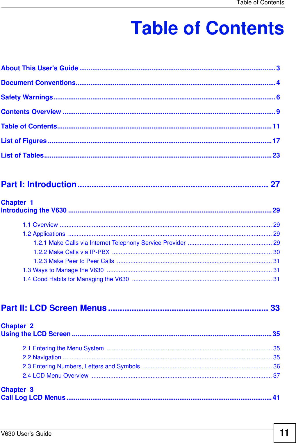
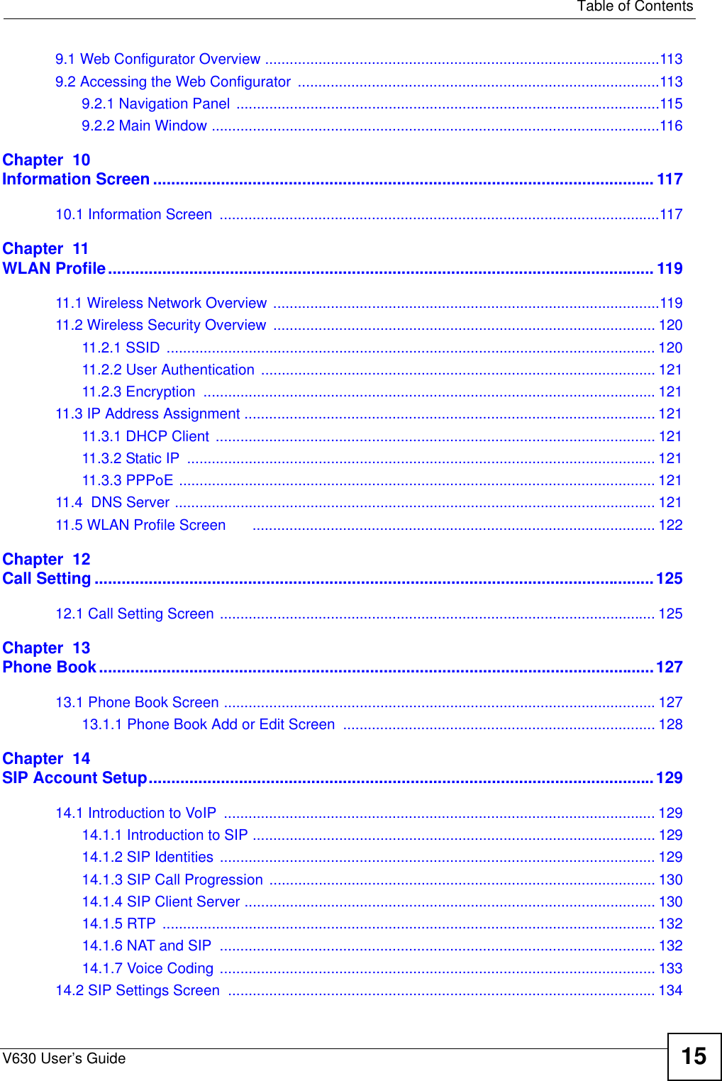
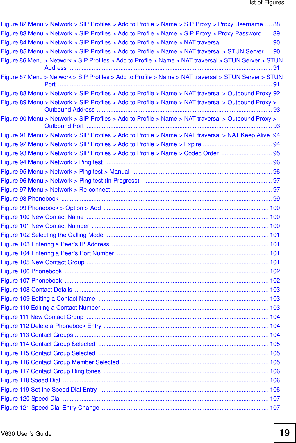

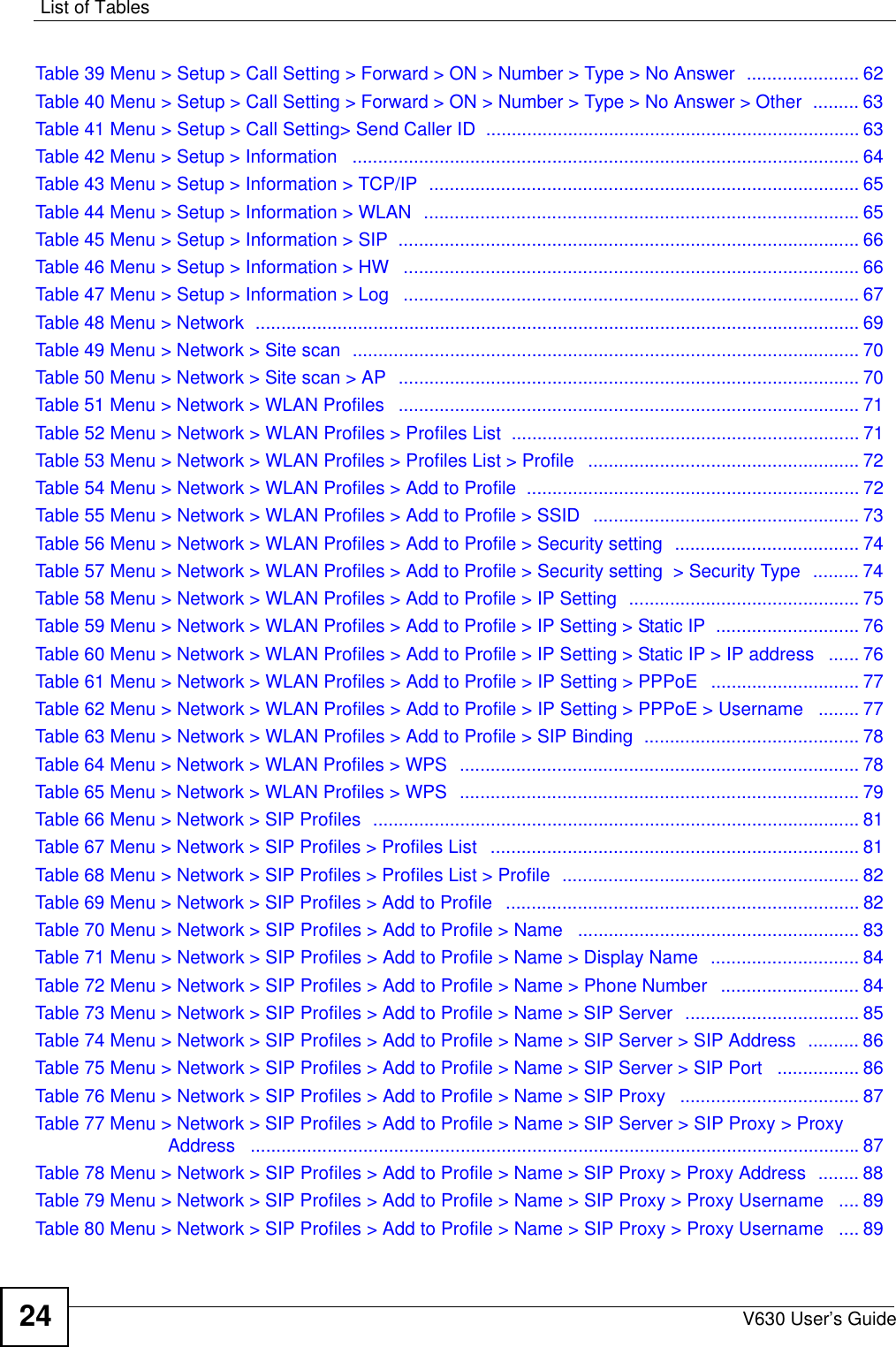

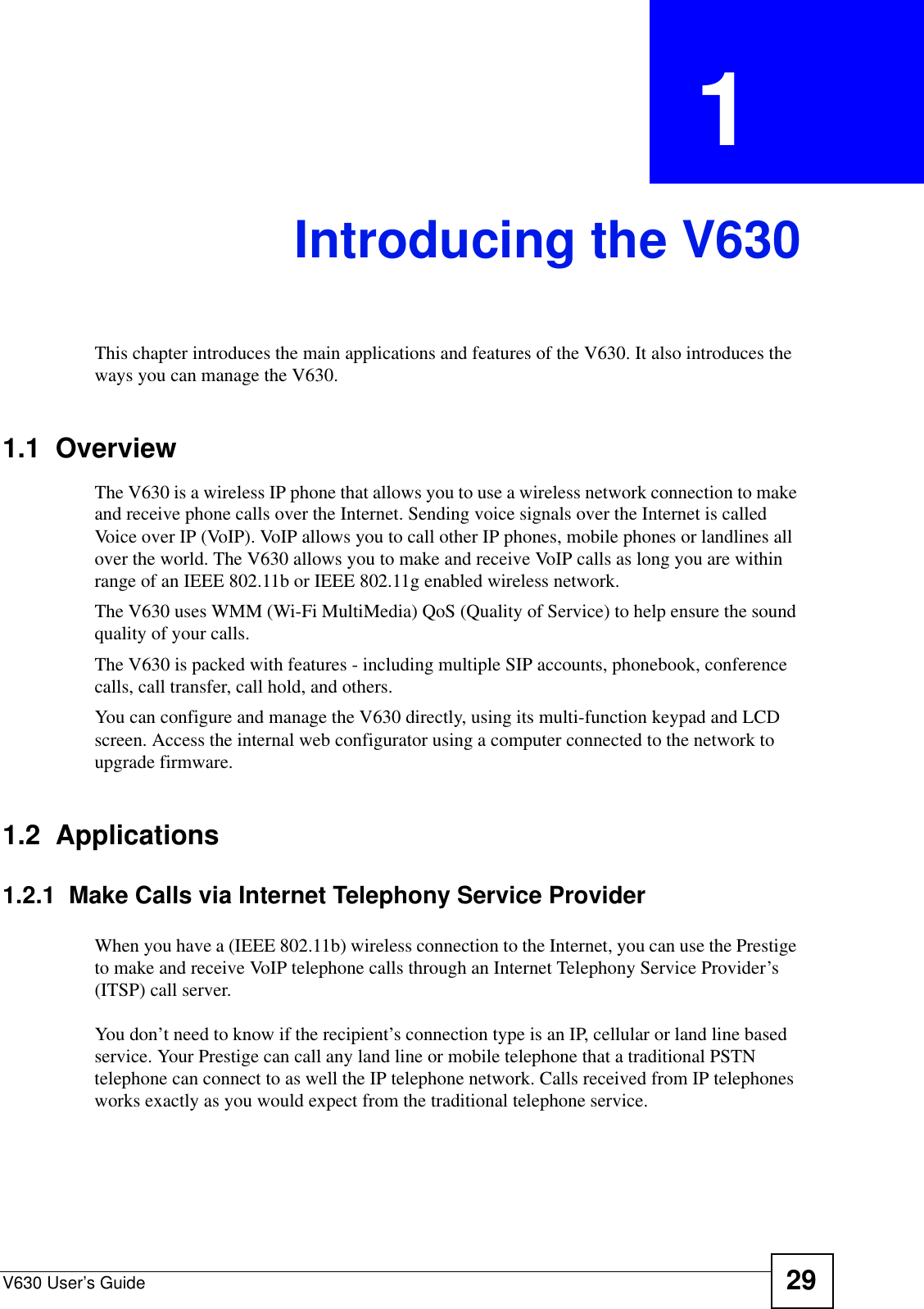


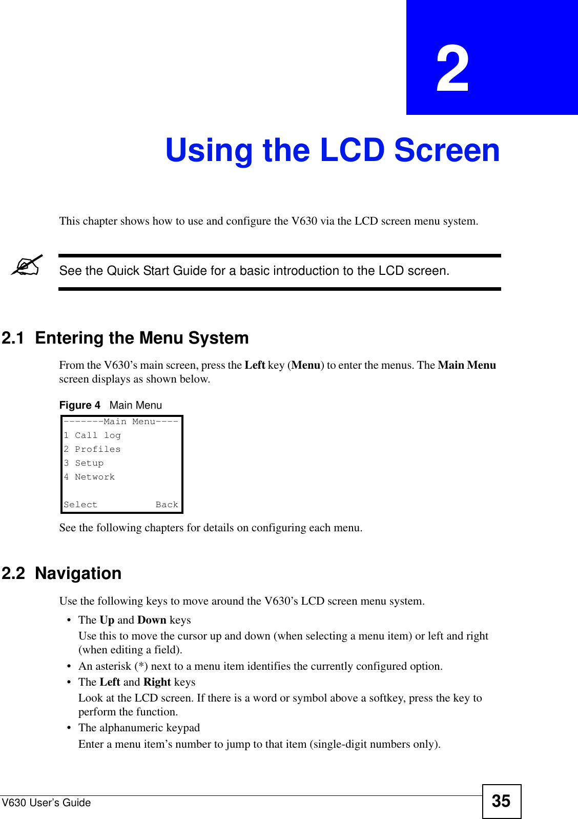
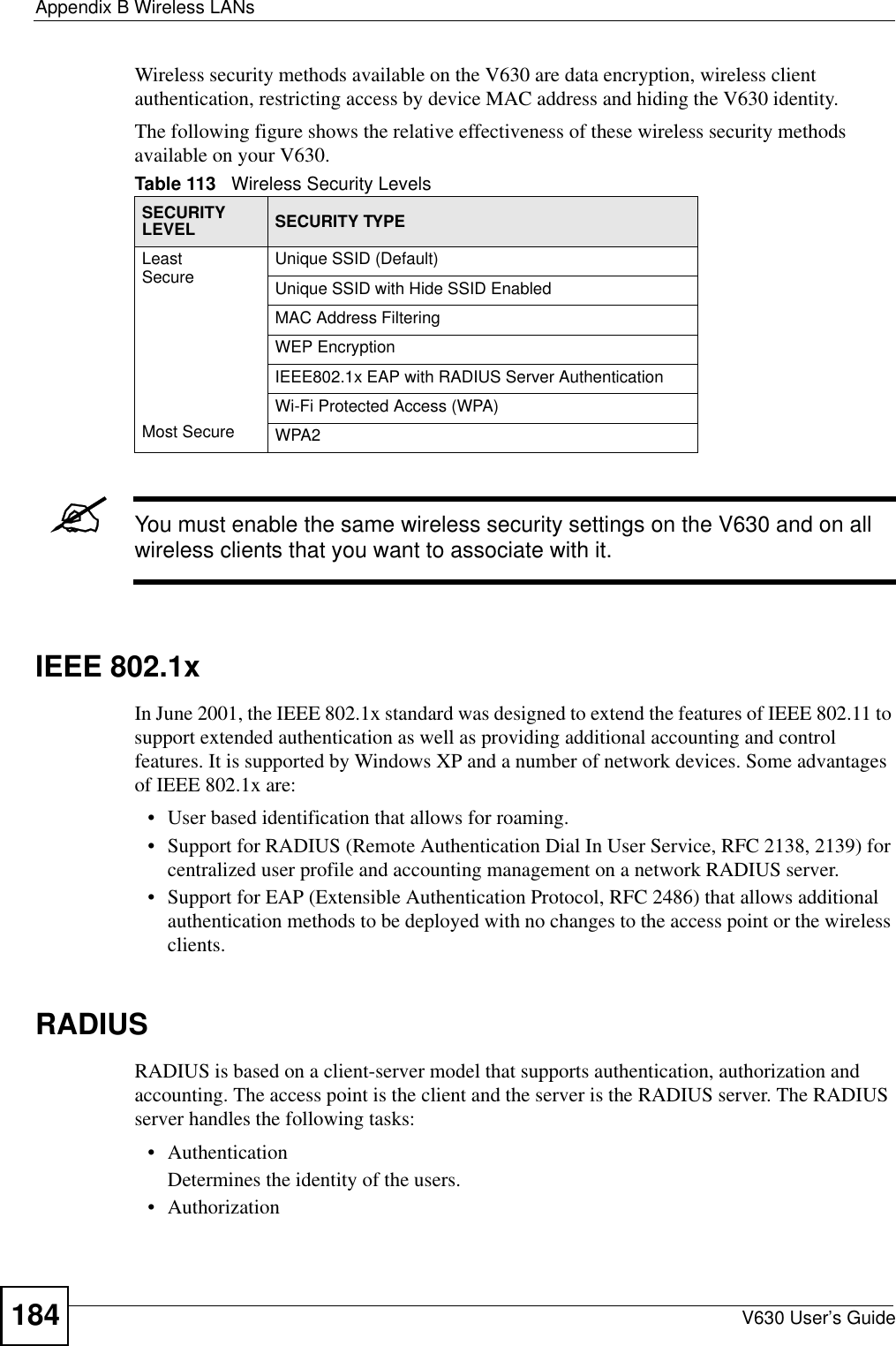
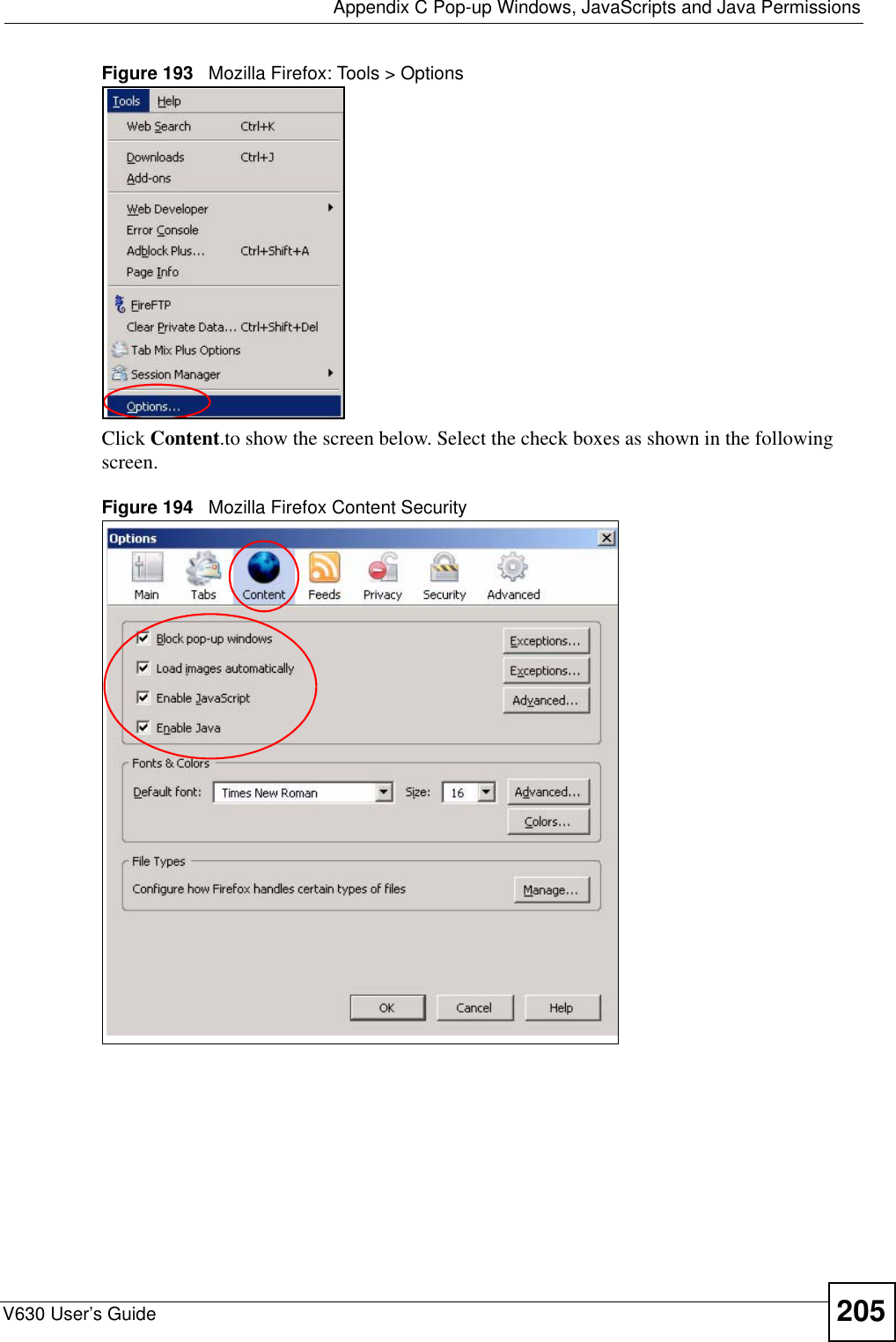
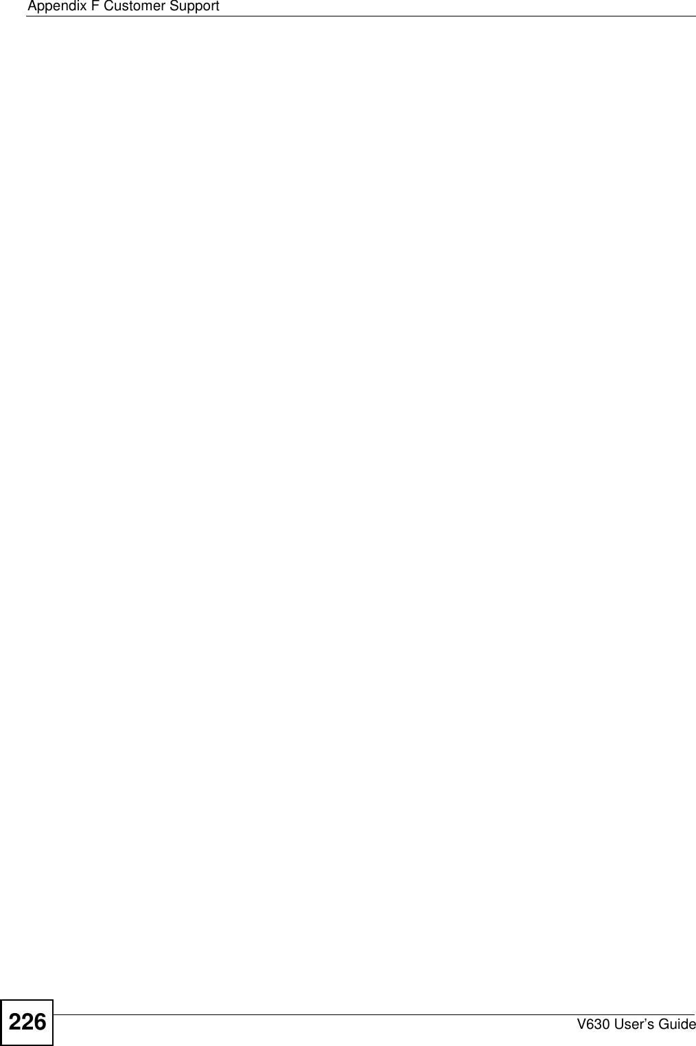
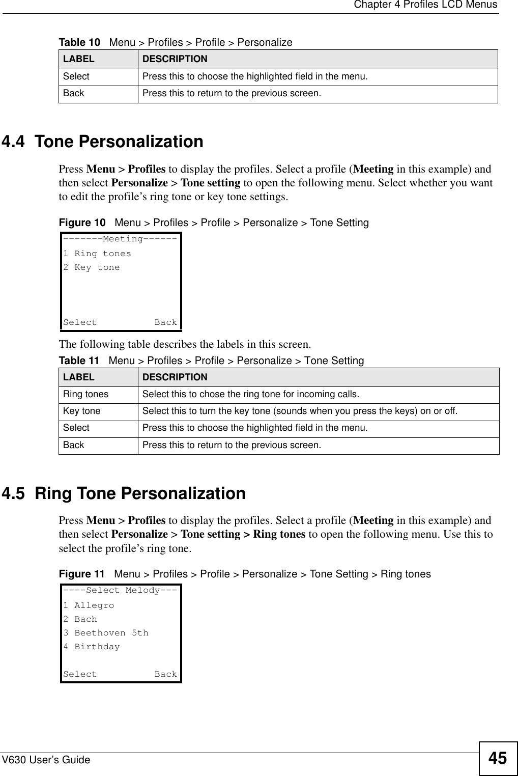
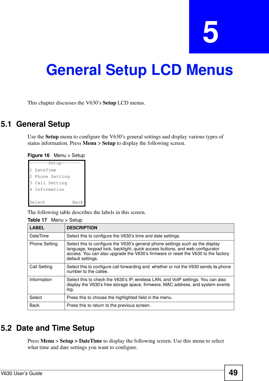
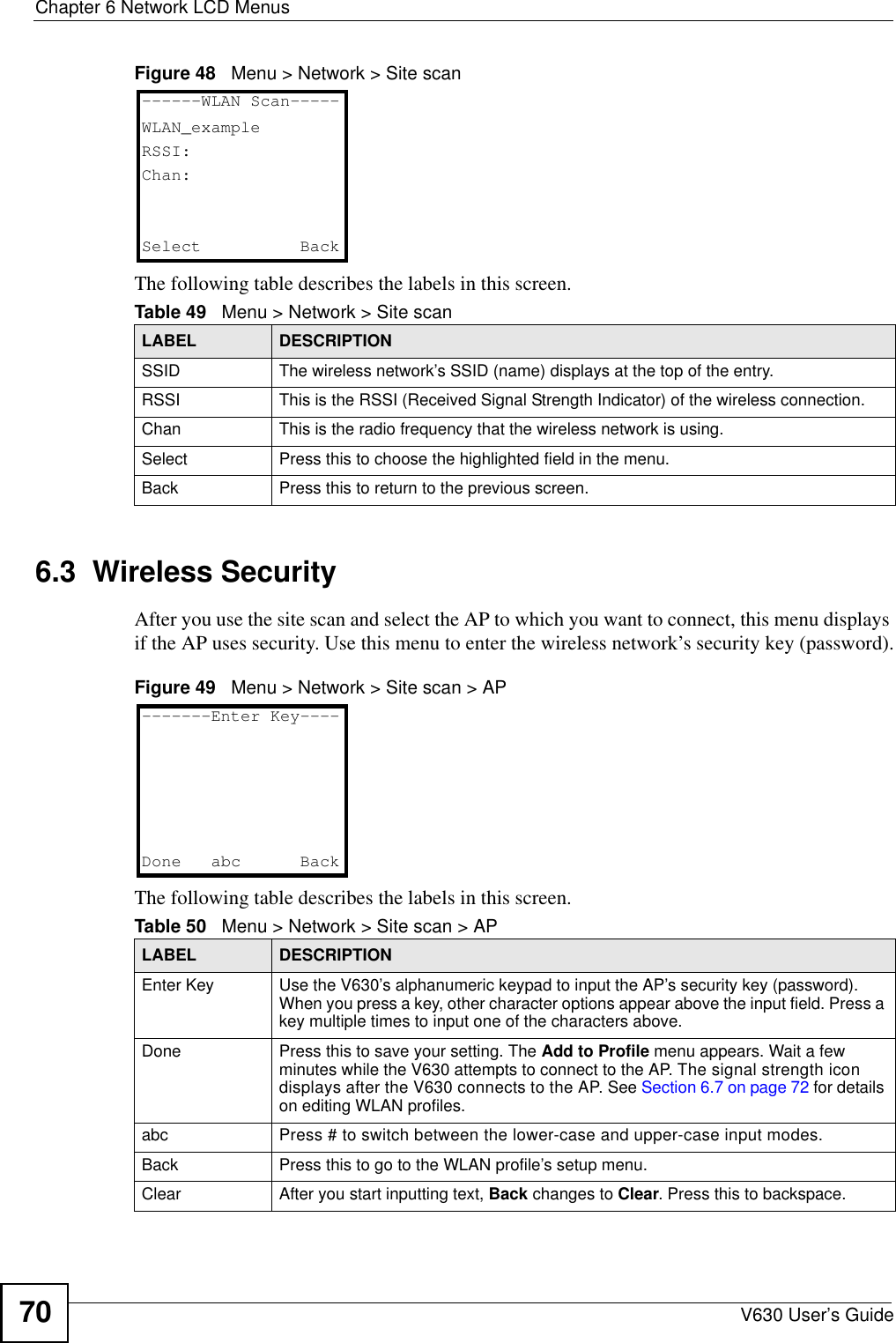
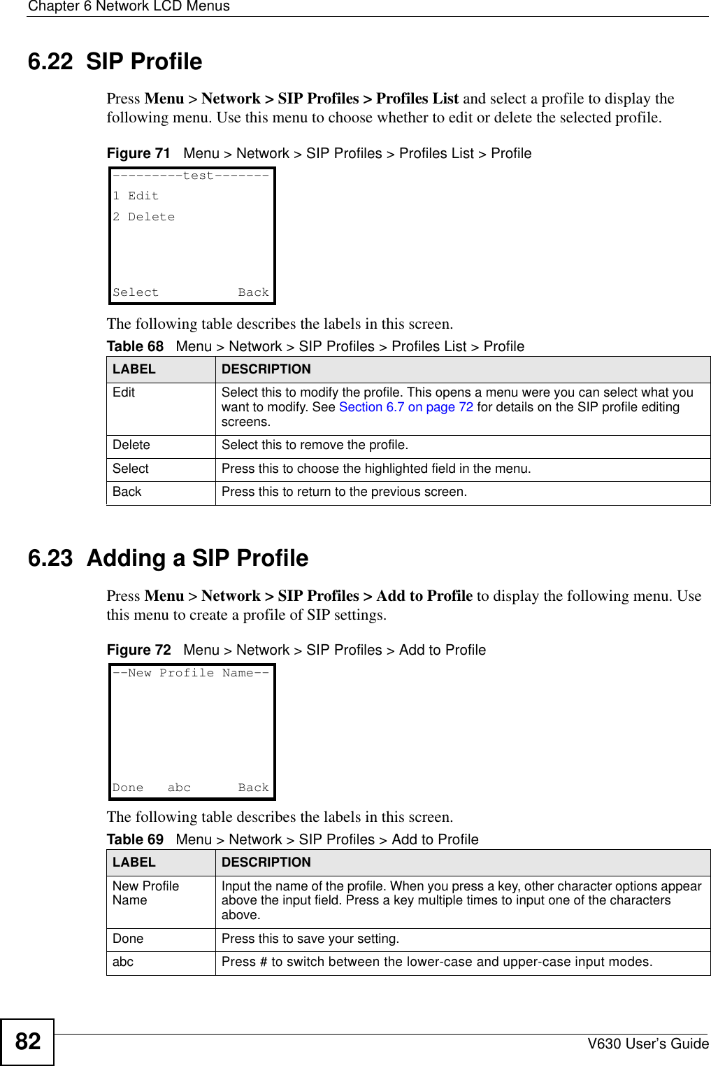
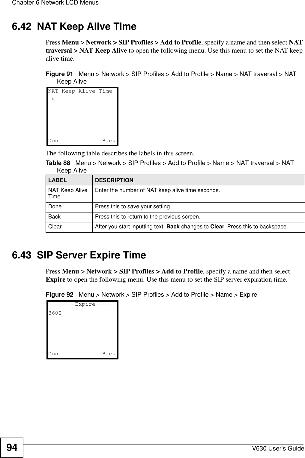
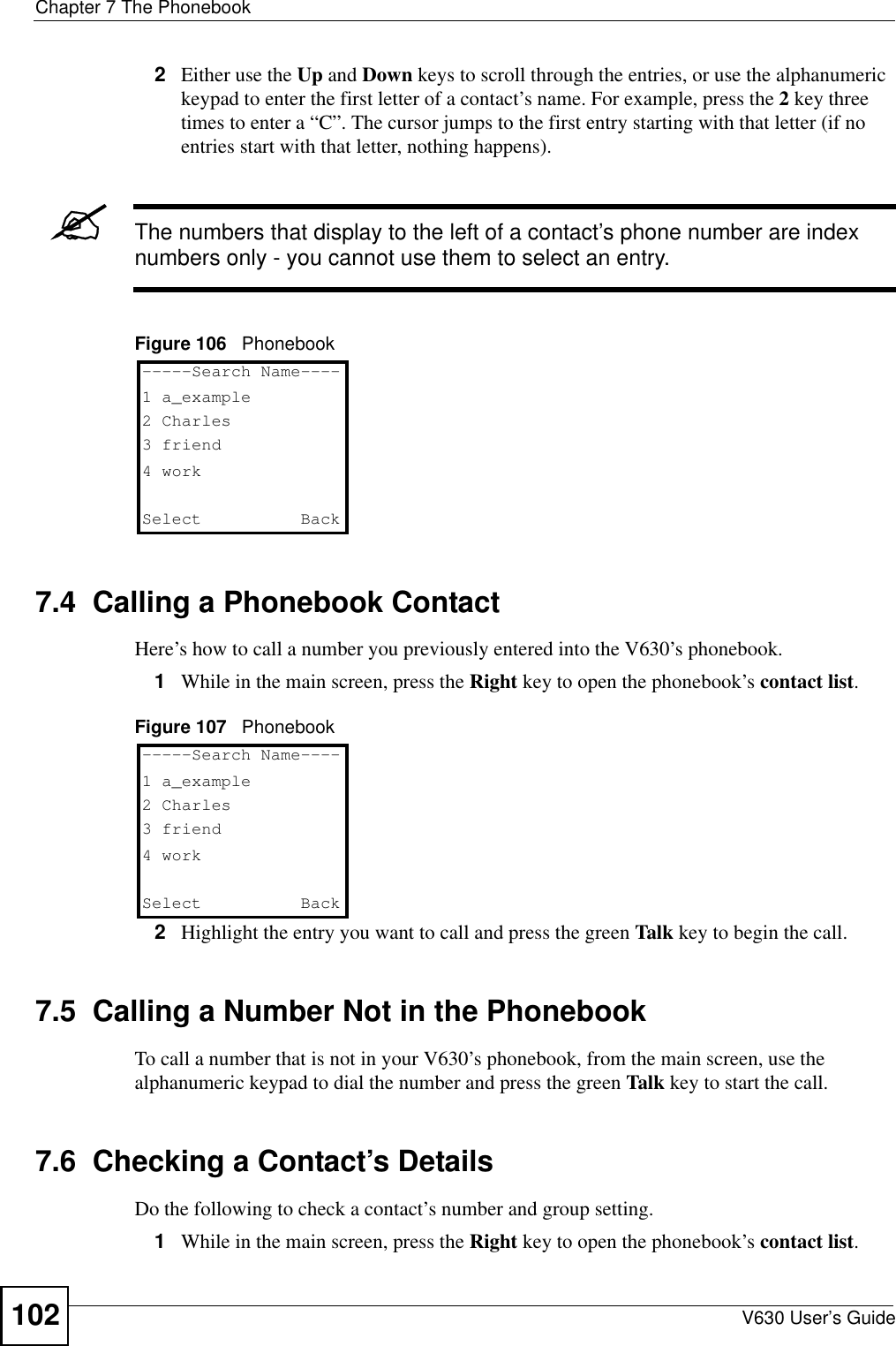
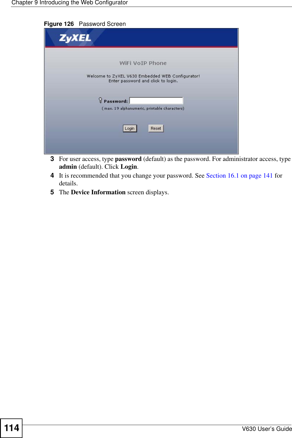
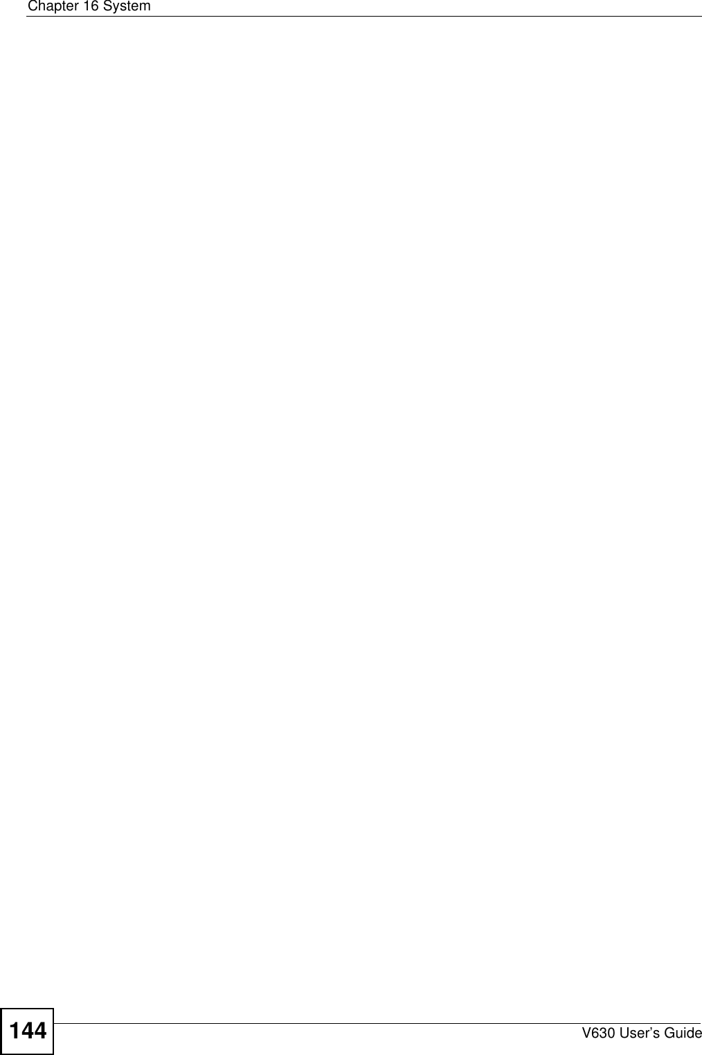
![Chapter 2 Using the LCD ScreenV630 User’s Guide362.3 Entering Numbers, Letters and SymbolsWhen you enter information into the V630 (when setting up a phonebook entry, for example) you may need to enter different kinds of characters. The alphanumeric keypad has these input modes: • Lowercase mode• Uppercase modeUse the # key to cycle between modes."Not all modes are available in all screens.When you press a key to enter a character, wait a short time until the cursor moves on to the next space. Press a key multiple times to access the different characters. For example, in Uppercase mode press 9 four times to enter “Z”.The following tables show the numbers, letters and symbols you can enter in each mode. Table 2 Lowercase Mode Keypad CharactersCharacter Entered for Each Number of Key Presses12 3 456 7 8910111213KEY1. , ‘ ?! - & #1_€ 2ab c 2àá â ãäåç3d e f 3 è é ê ë4g h i 4 ì í î ï5j k l 5 £6mn o 6ñò ó ôõöø7p q r s 7 ß $8t u v 8 ù ú û ü9wx y z 9 ý** @00,+space# [CYCLE MODE]](https://usermanual.wiki/ZyXEL-Communications/V630/User-Guide-959740-Page-36.png)
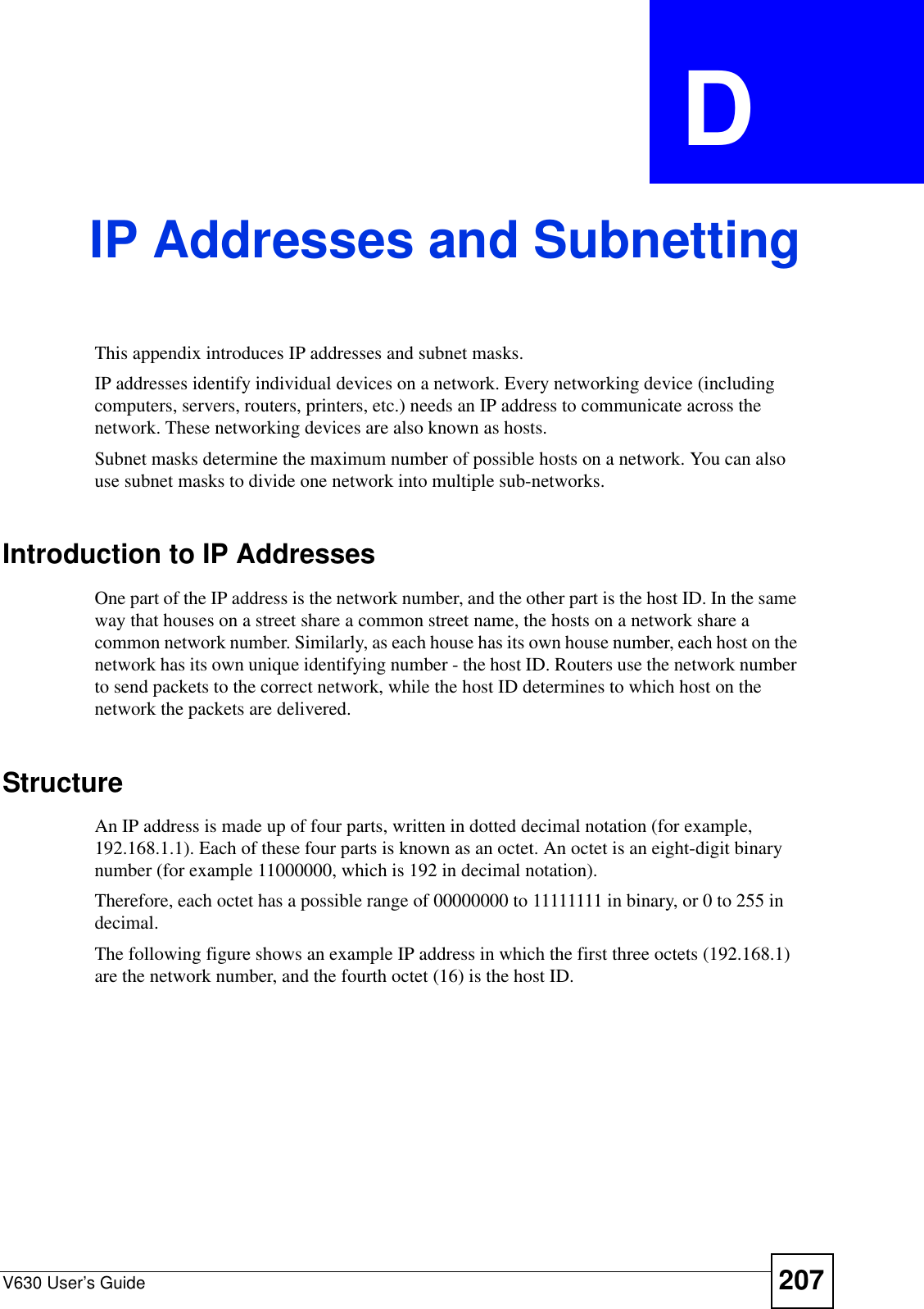
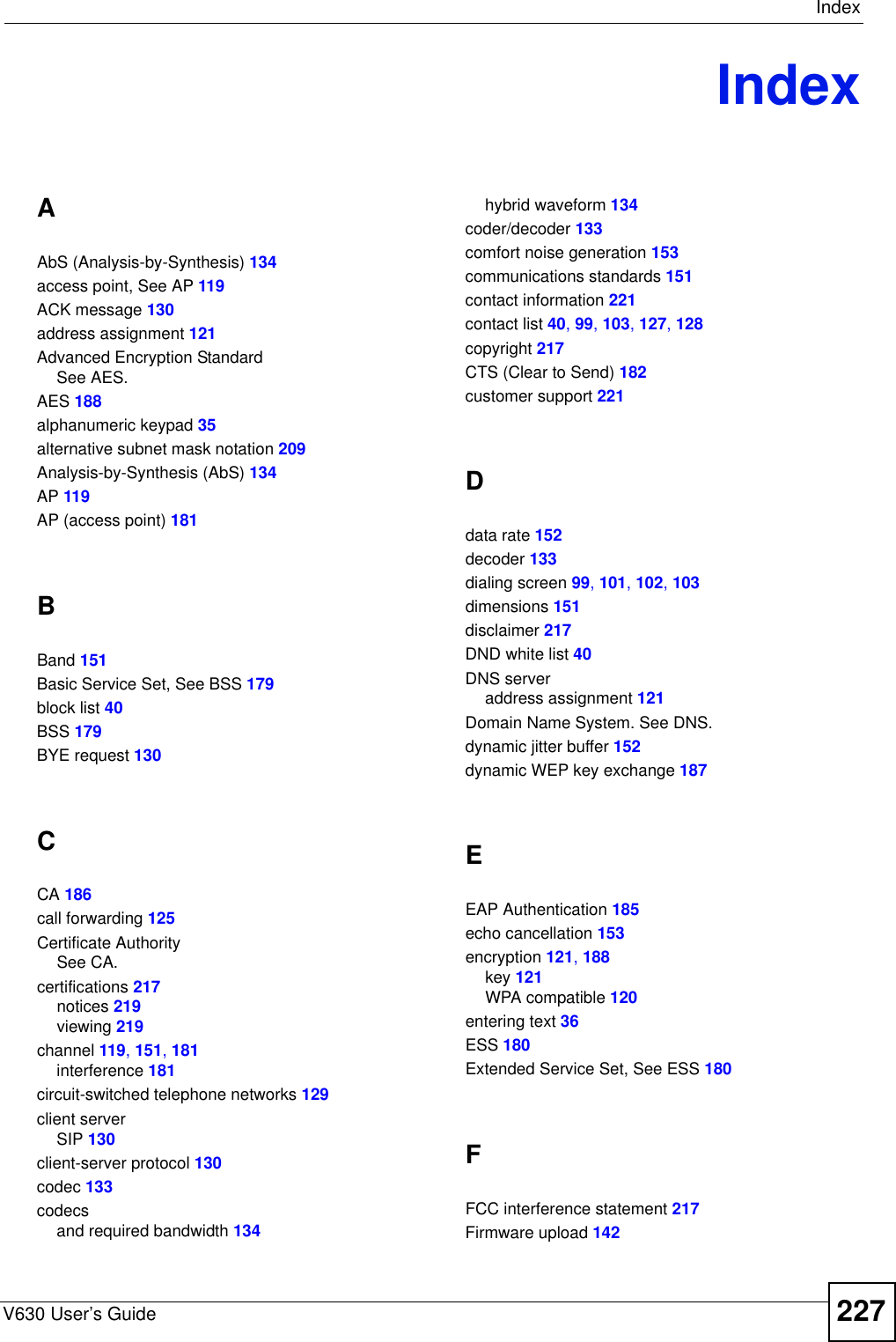
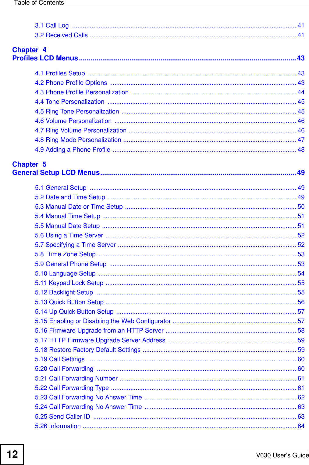
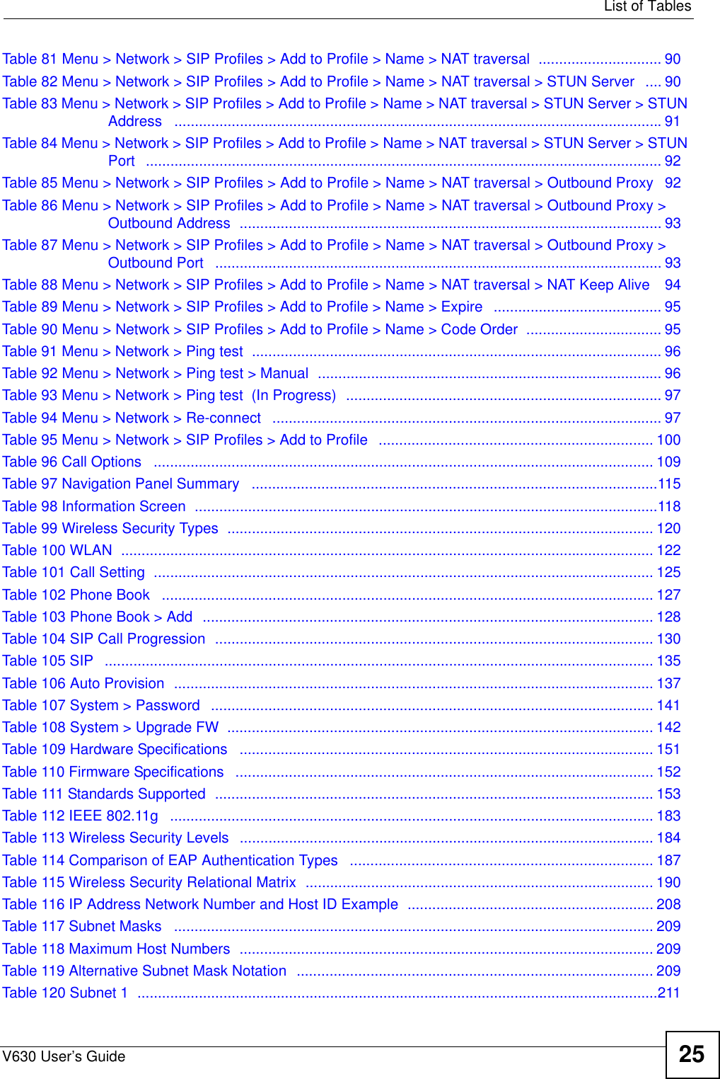
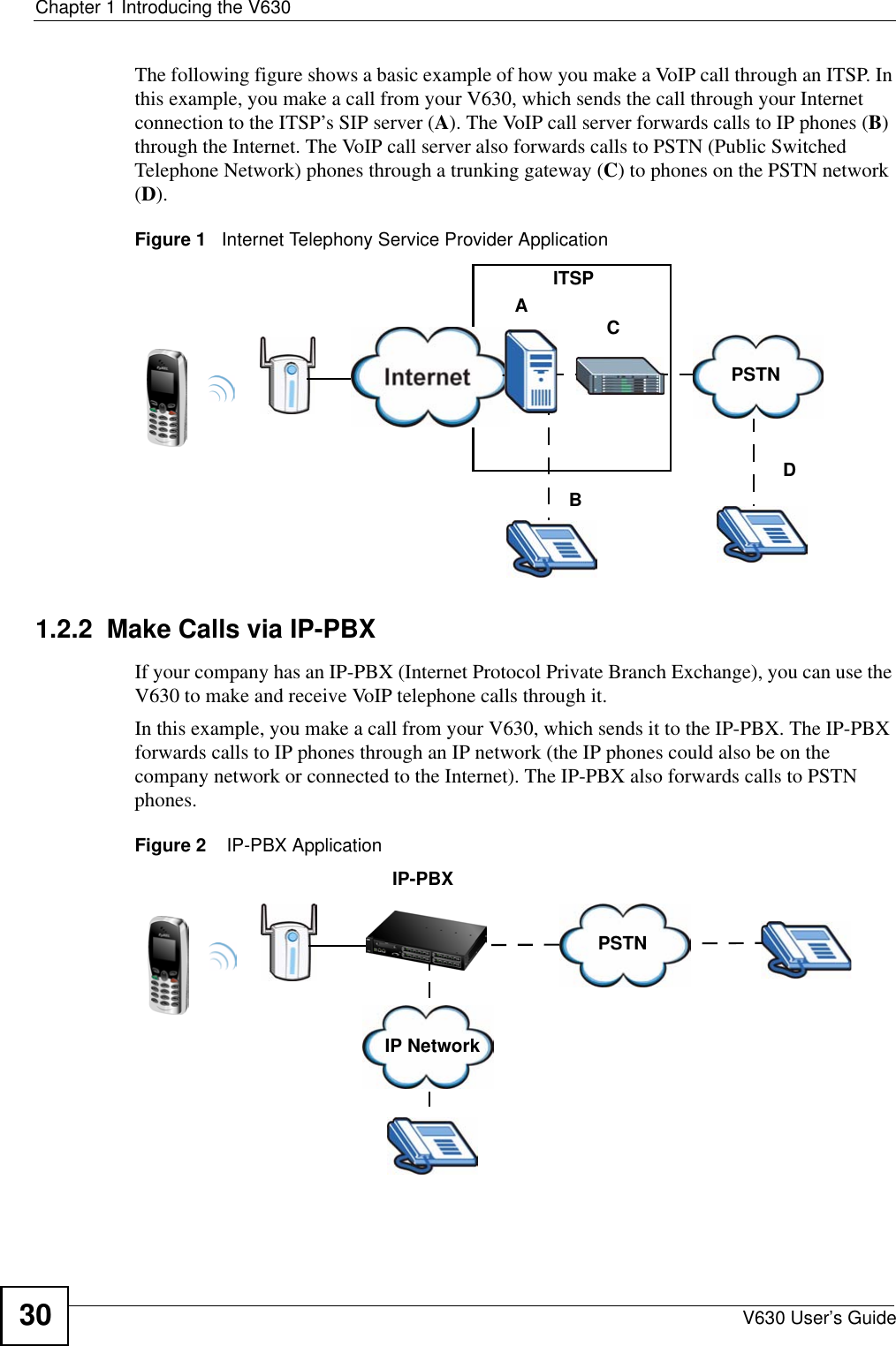
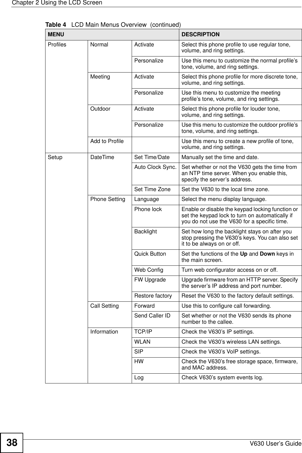
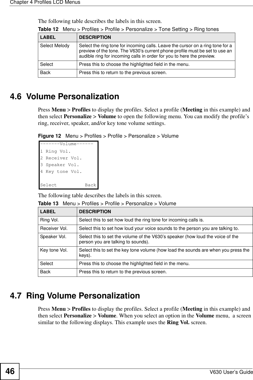
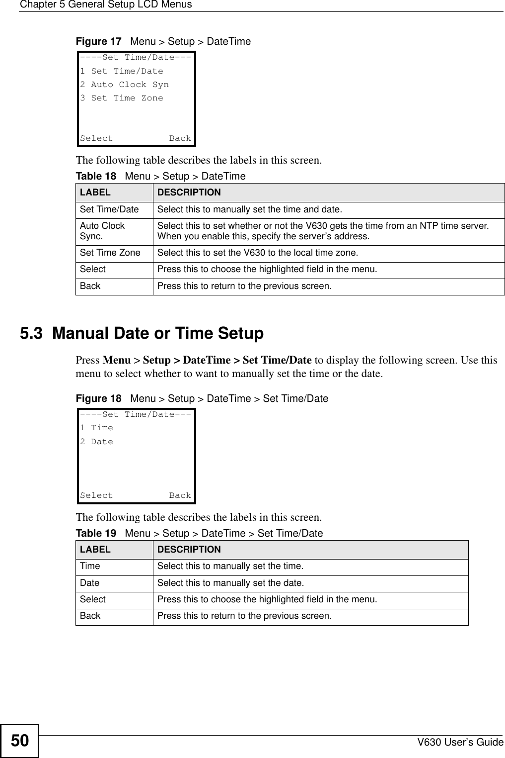
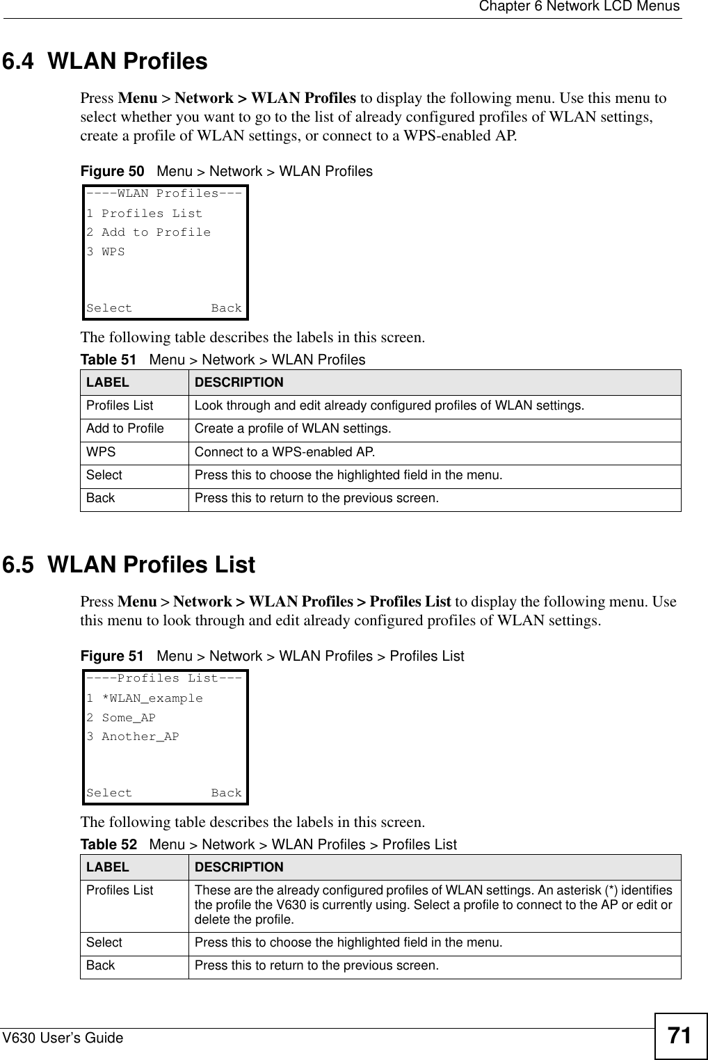
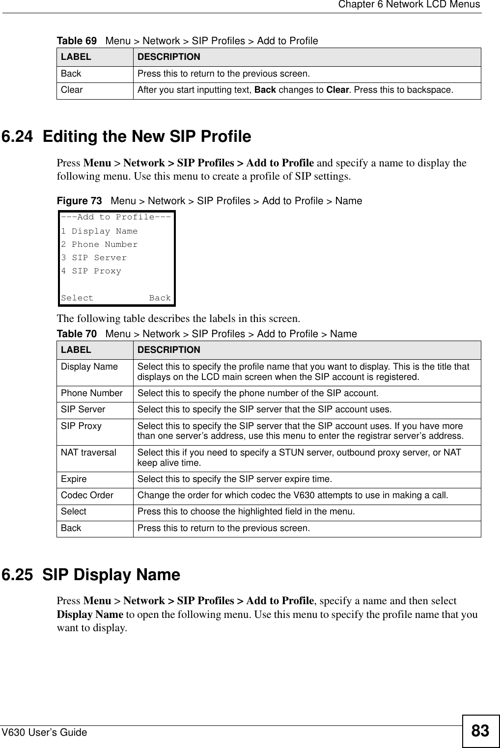
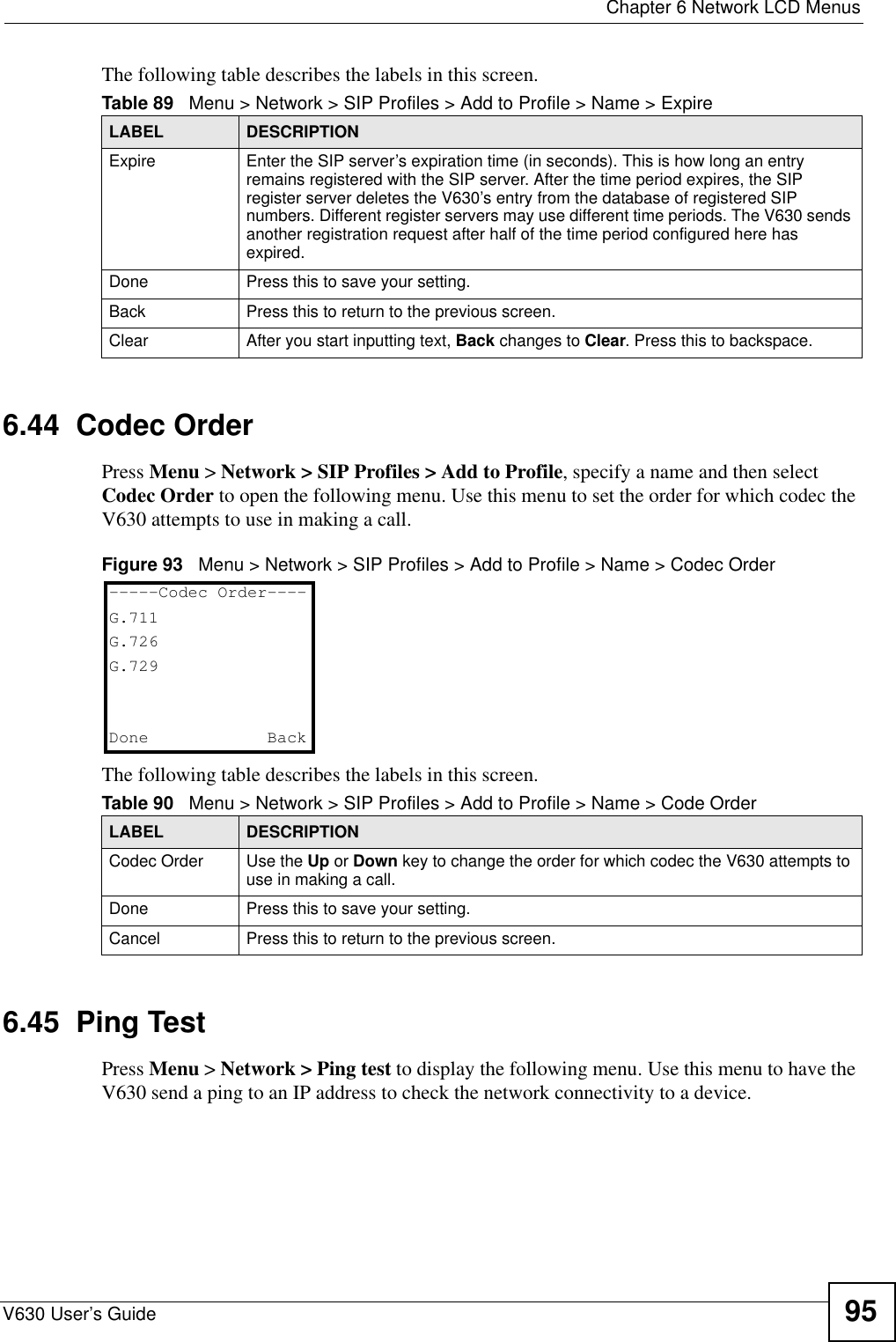
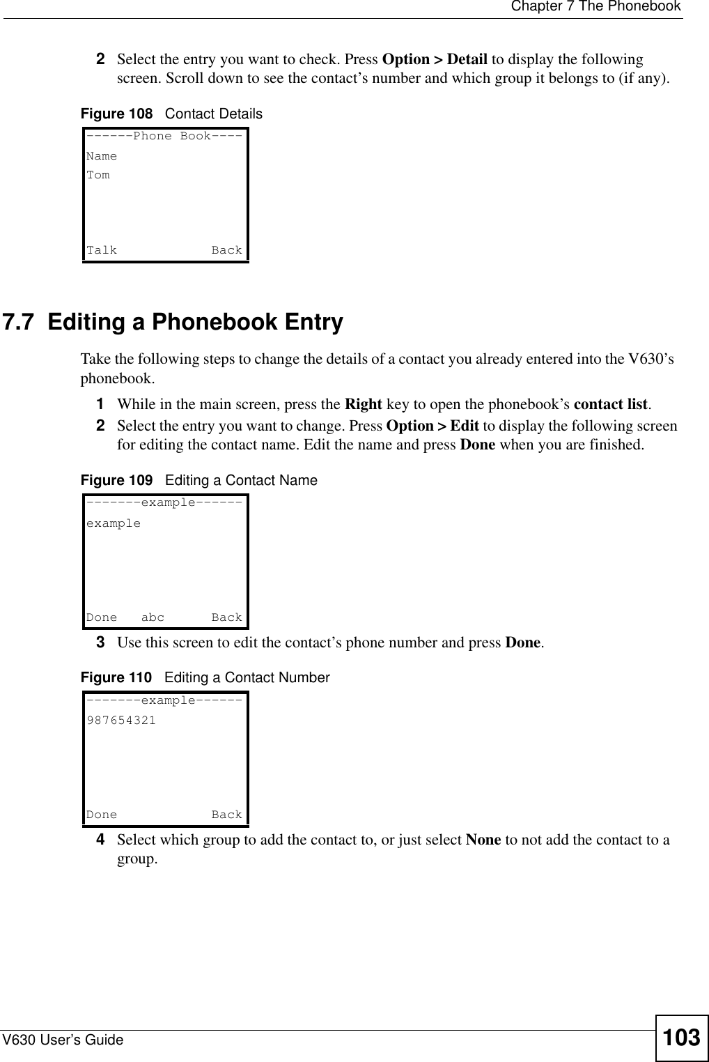
![Chapter 2 Using the LCD ScreenV630 User’s Guide 37 2.4 LCD Menu OverviewThis section shows the main LCD menus, and describes what you can do with each.Table 3 Uppercase Mode Keypad CharactersCharacter Entered for Each Number of Key Presses12 3 456 7 8910111213KEY1. , ‘ ?! - & #1_€ 2AB C 2ÀÁ Â ÃÄÅÇ3DE F 3 È É Ê Ë4GH I 4 Ì Í Î Ï5J K L 5 £6MN O 6 ÑÒ Ó ÔÕÖØ7P Q R S7 $8T U V 8 ÙÚ Û Ü9WX Y Z 9 ý** @00,+space# [CYCLE MODE]Table 4 LCD Main Menus Overview MENU DESCRIPTIONCall Log Missed Calls Use this menu to list the originating numbers of unanswered calls.Received Calls Use this menu to list the originating numbers of answered calls.Dialed Calls Use this menu to list the numbers the V630 has called.Delete all Use this menu to clear all the records in the call log.](https://usermanual.wiki/ZyXEL-Communications/V630/User-Guide-959740-Page-37.png)
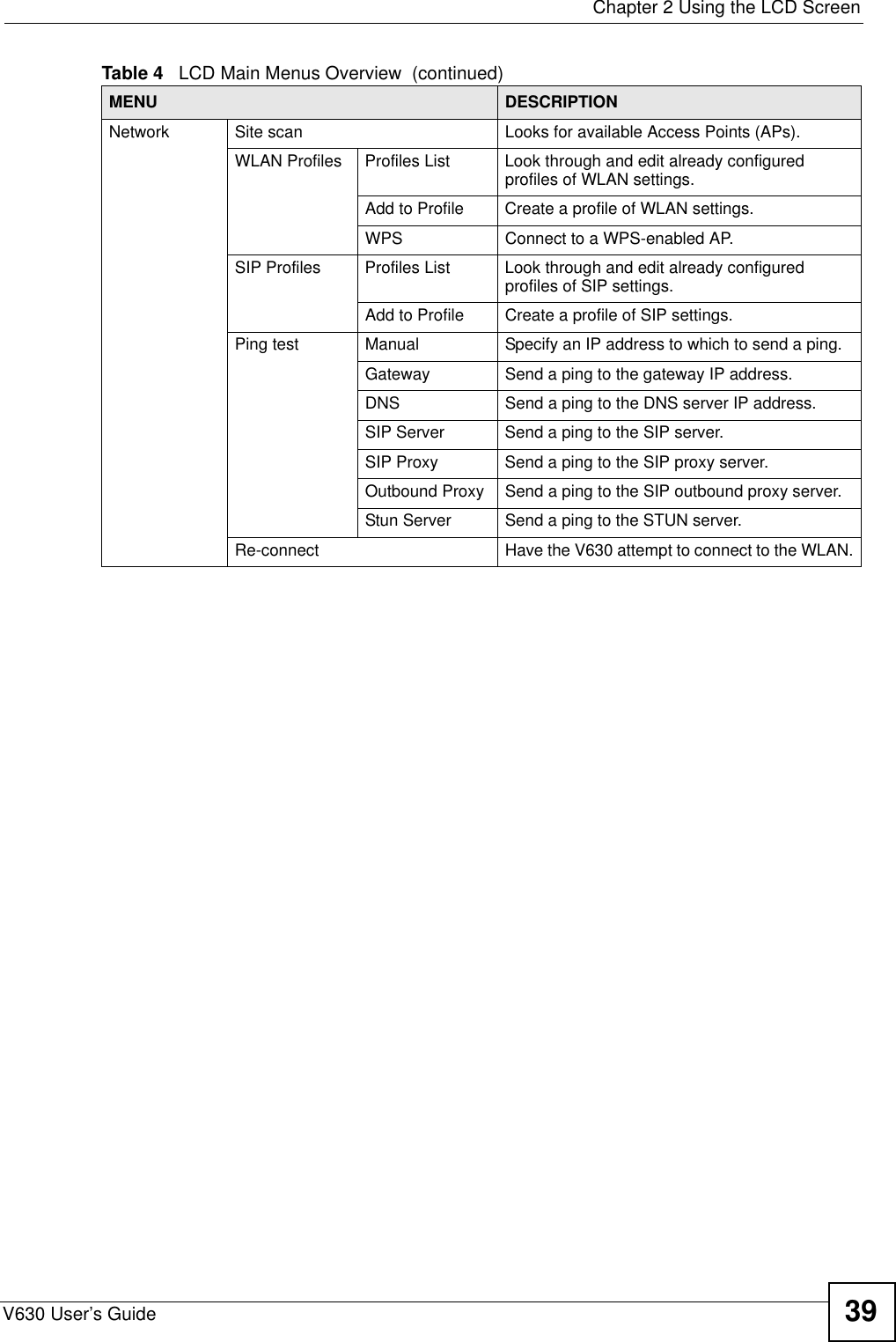
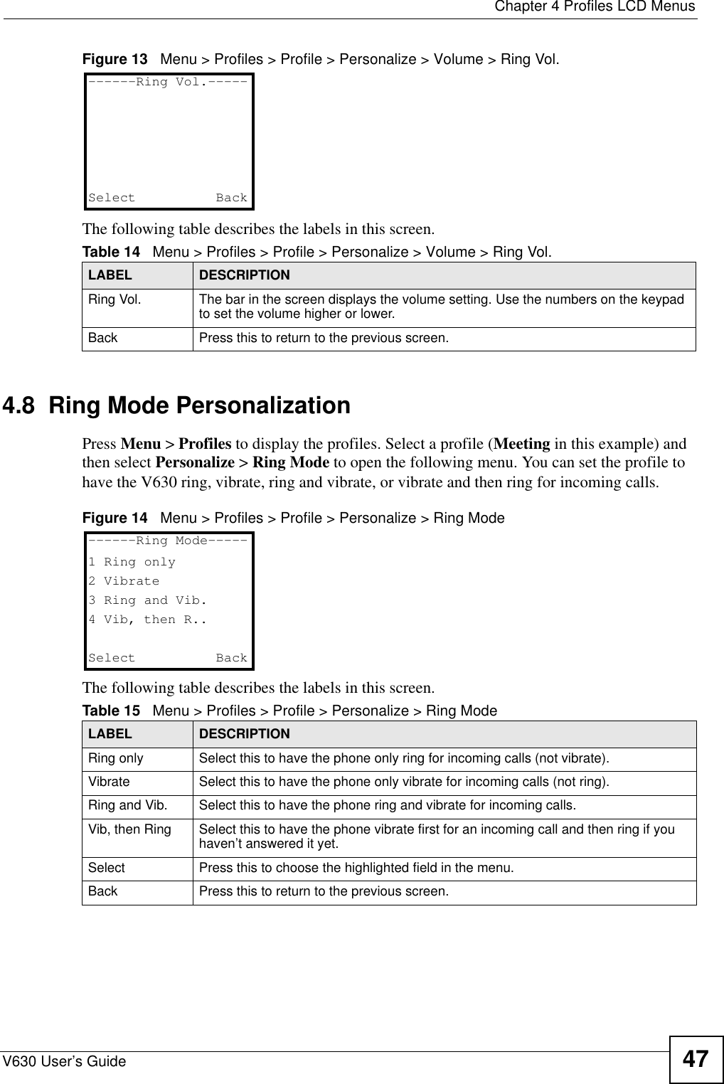
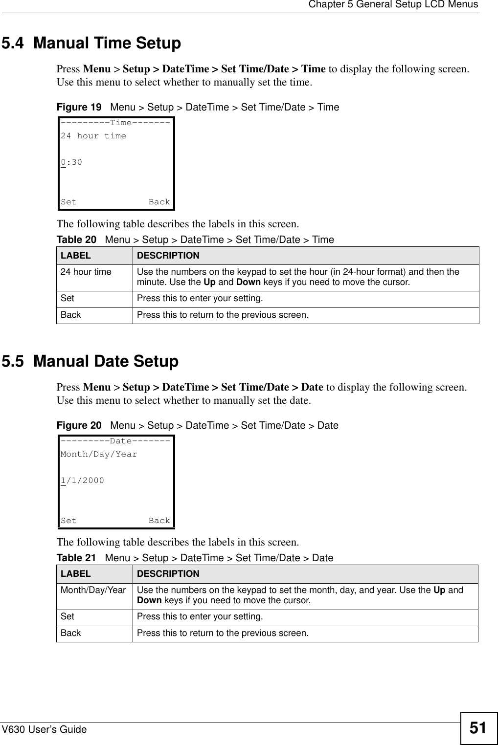
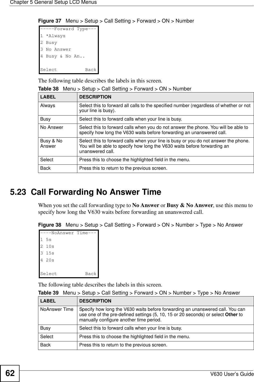

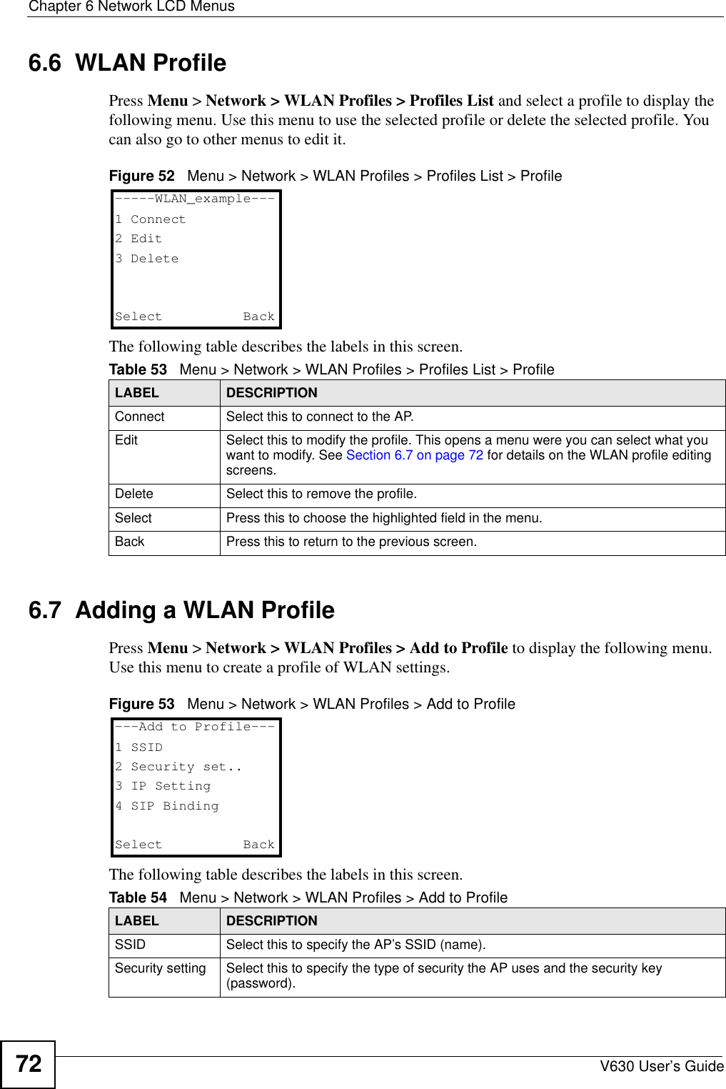
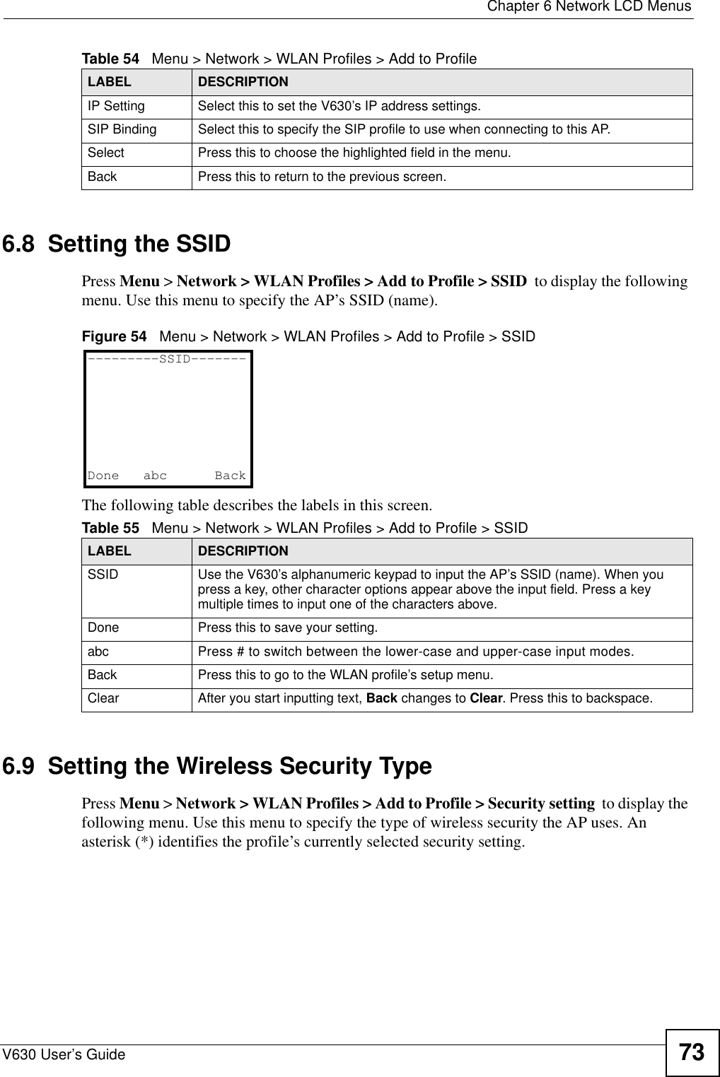
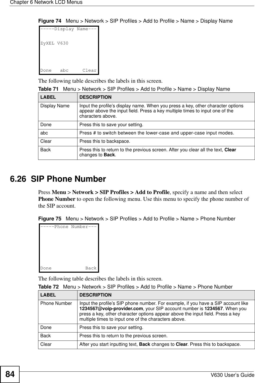
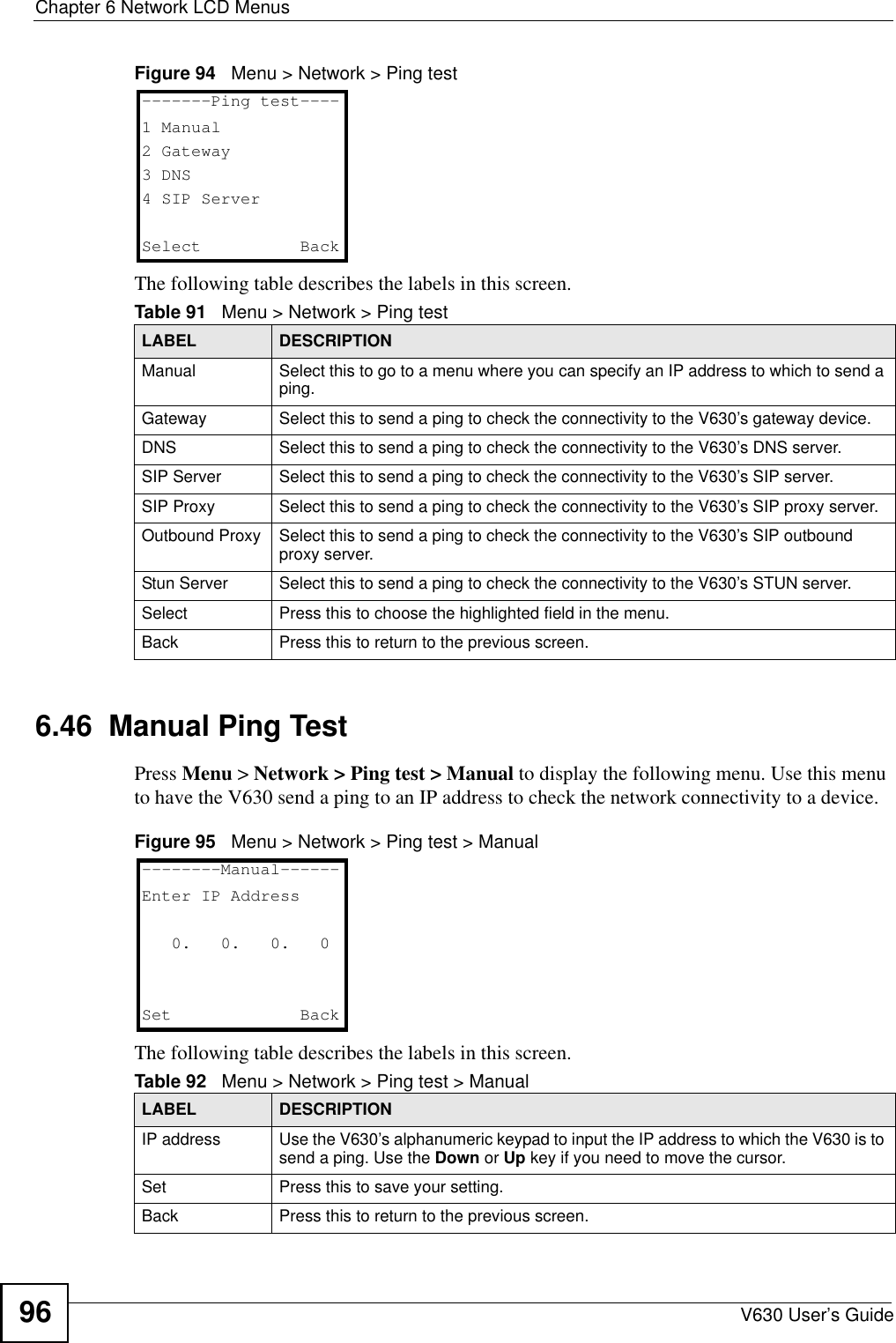
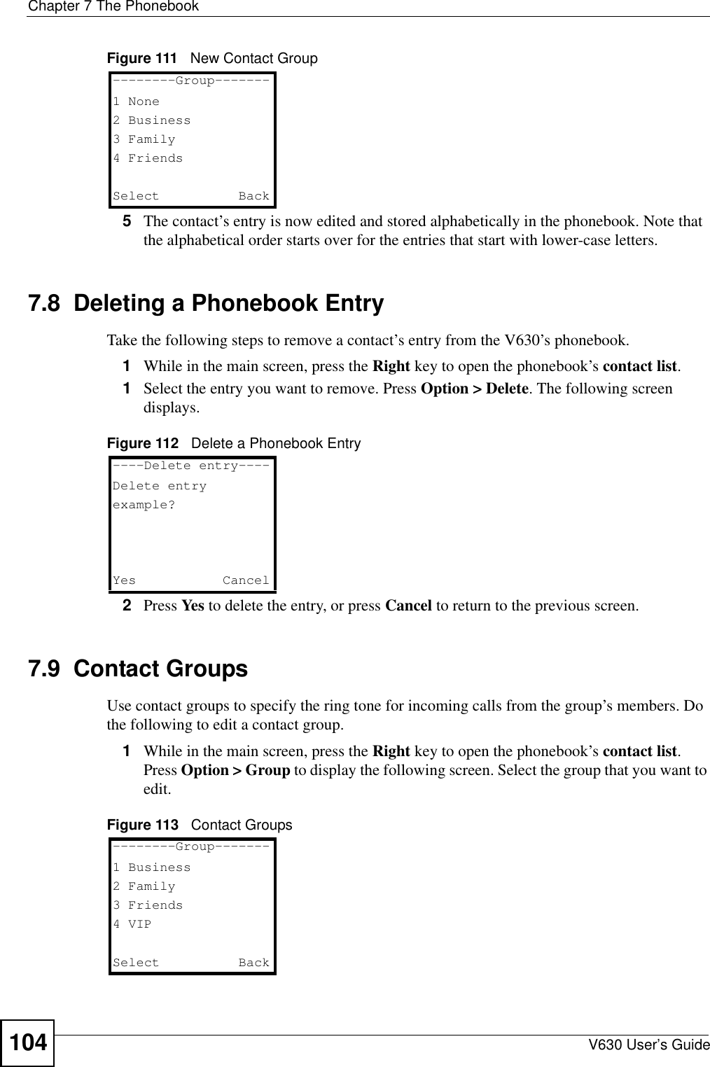
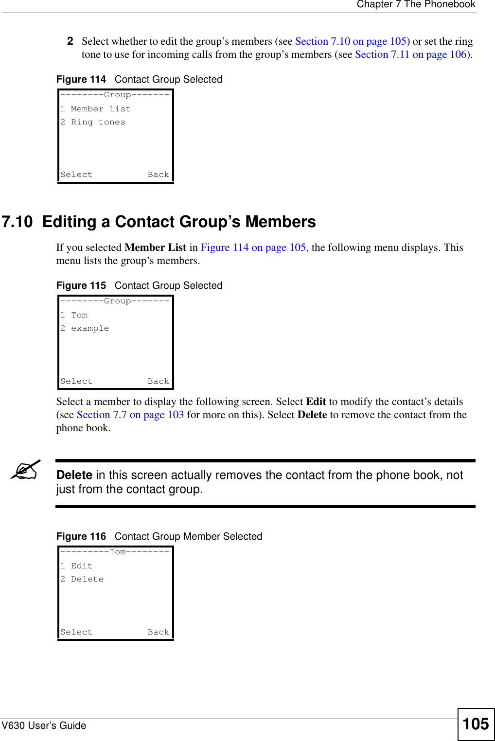
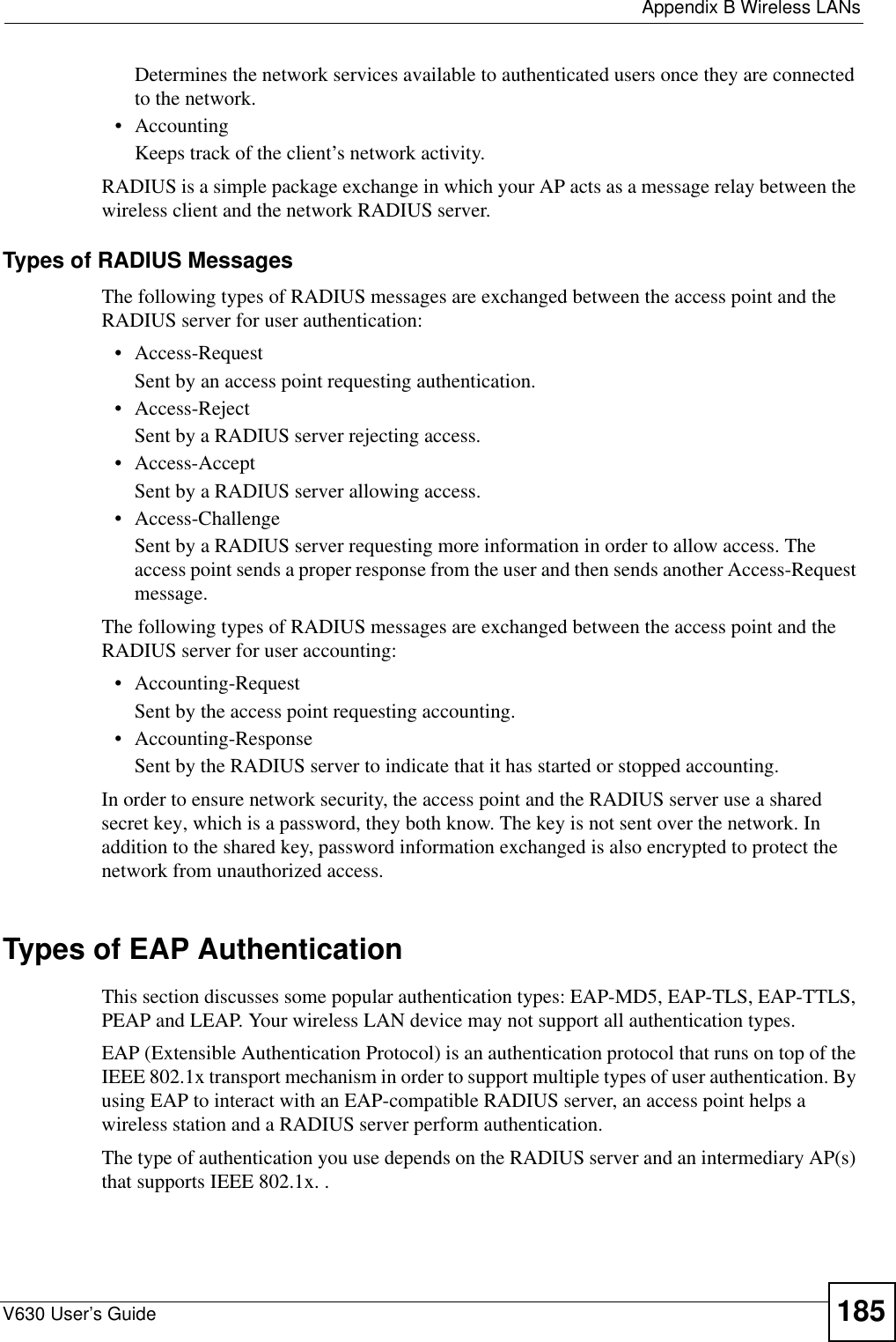
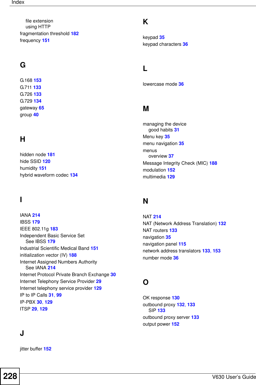
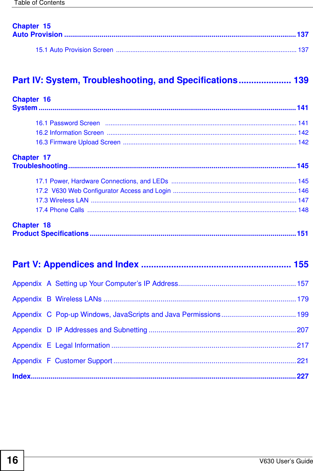
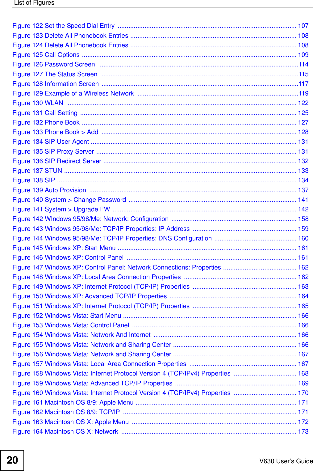
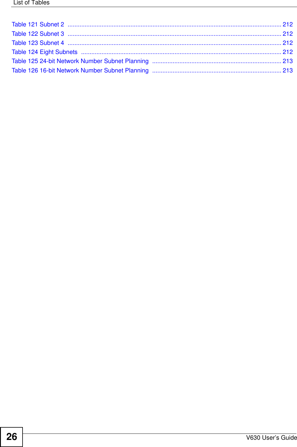
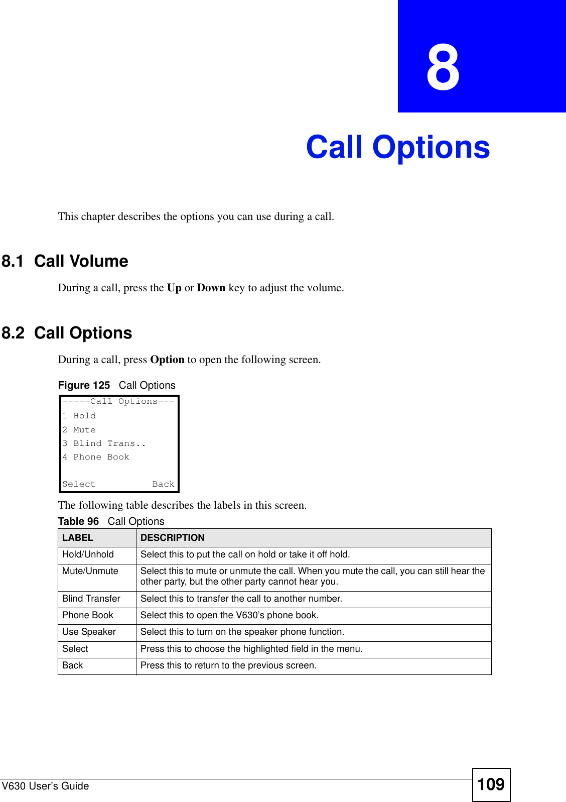
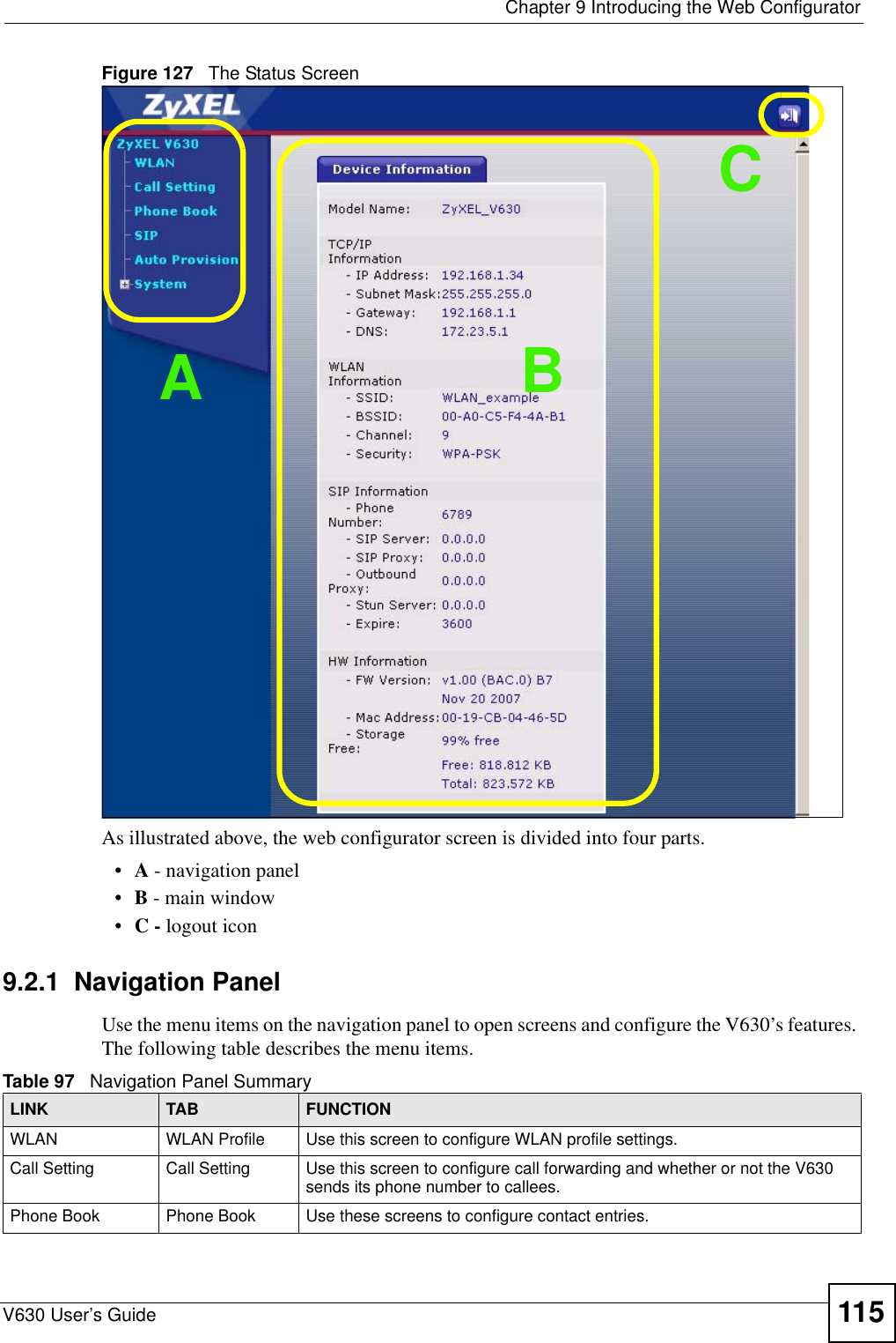
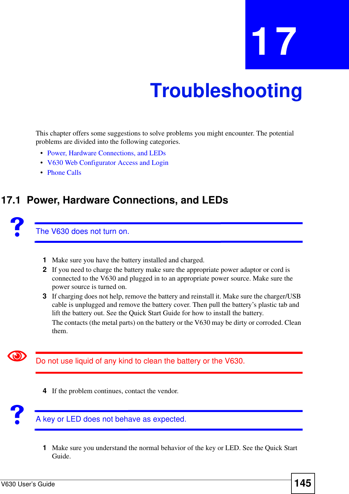
![Chapter 7 The PhonebookV630 User’s Guide1067.11 Editing a Contact Group’s Ring ToneIf you selected Ring tones in Figure 114 on page 105, the following menu displays. Select the ring tone for incoming calls from the selected contact group’s members.Figure 117 Contact Group Ring tones7.12 Speed DialSet up speed dial entries to be able to call someone by dialing a single number. 7.13 Adding a Speed Dial EntryDo the following to make an existing phonebook entry into a speed dial entry.1While in the main screen, press the Right key to open the phonebook’s contact list.2Select the entry you want to add to speed dial. Press Option > Speed Dial to display the following screen. Select for which key you want to create a speed dial entry. This example uses key 2.Figure 118 Speed Dial3The following screen displays. Select Yes to add the contact as a speed dial entry.Figure 119 Set the Speed Dial Entry----Select Melody---1 Allegro2 Bach3 Beethoven 5th4 BirthdaySelect Back------Speed Dial----1 Key1: [Empty]2 Key2: [Empty]3 Key3: [Empty]4 Key4: [Empty]Done abc Back--Set Speed Dial #2-1 Yes2 NoDone abc Back](https://usermanual.wiki/ZyXEL-Communications/V630/User-Guide-959740-Page-106.png)
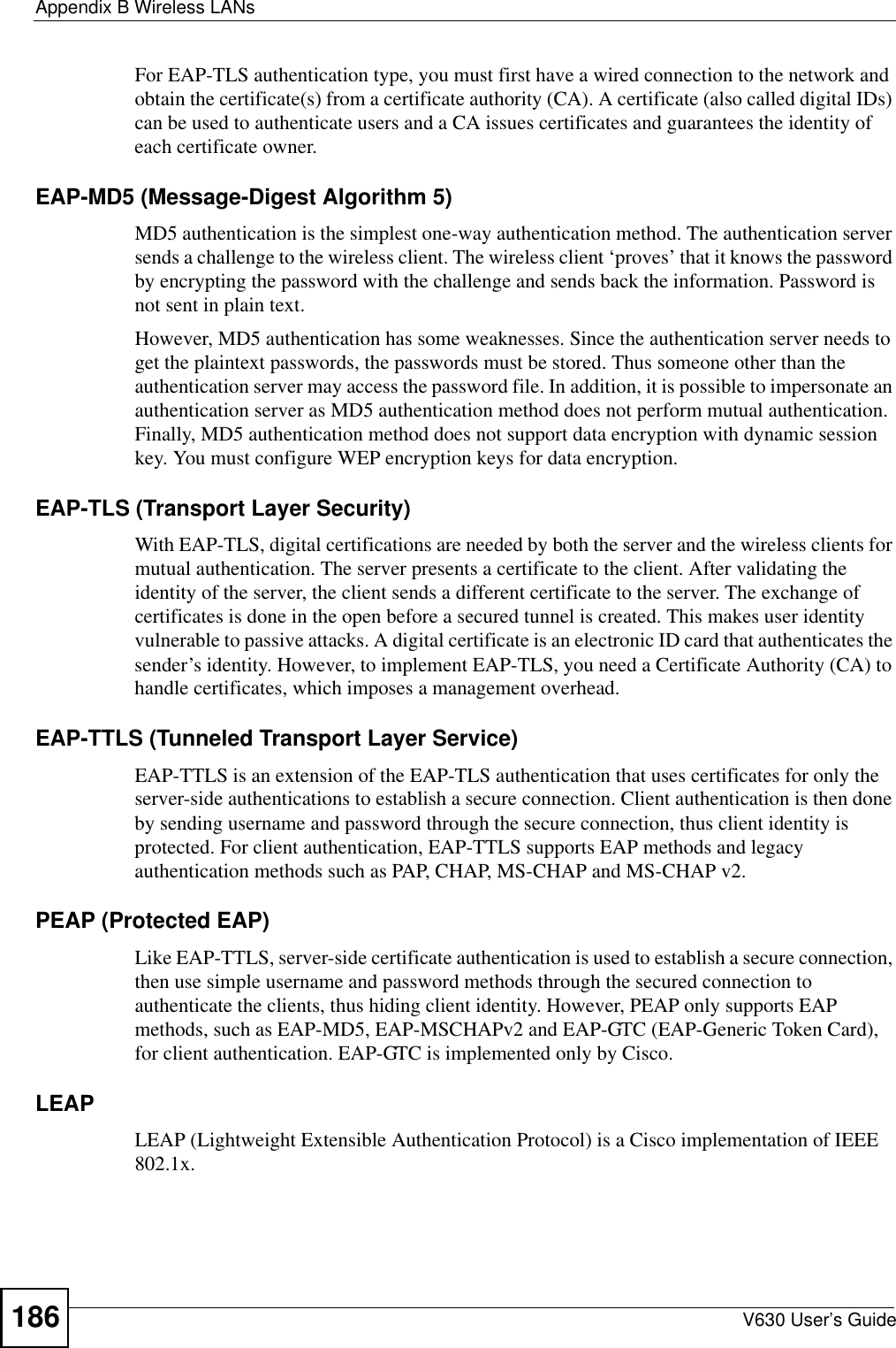
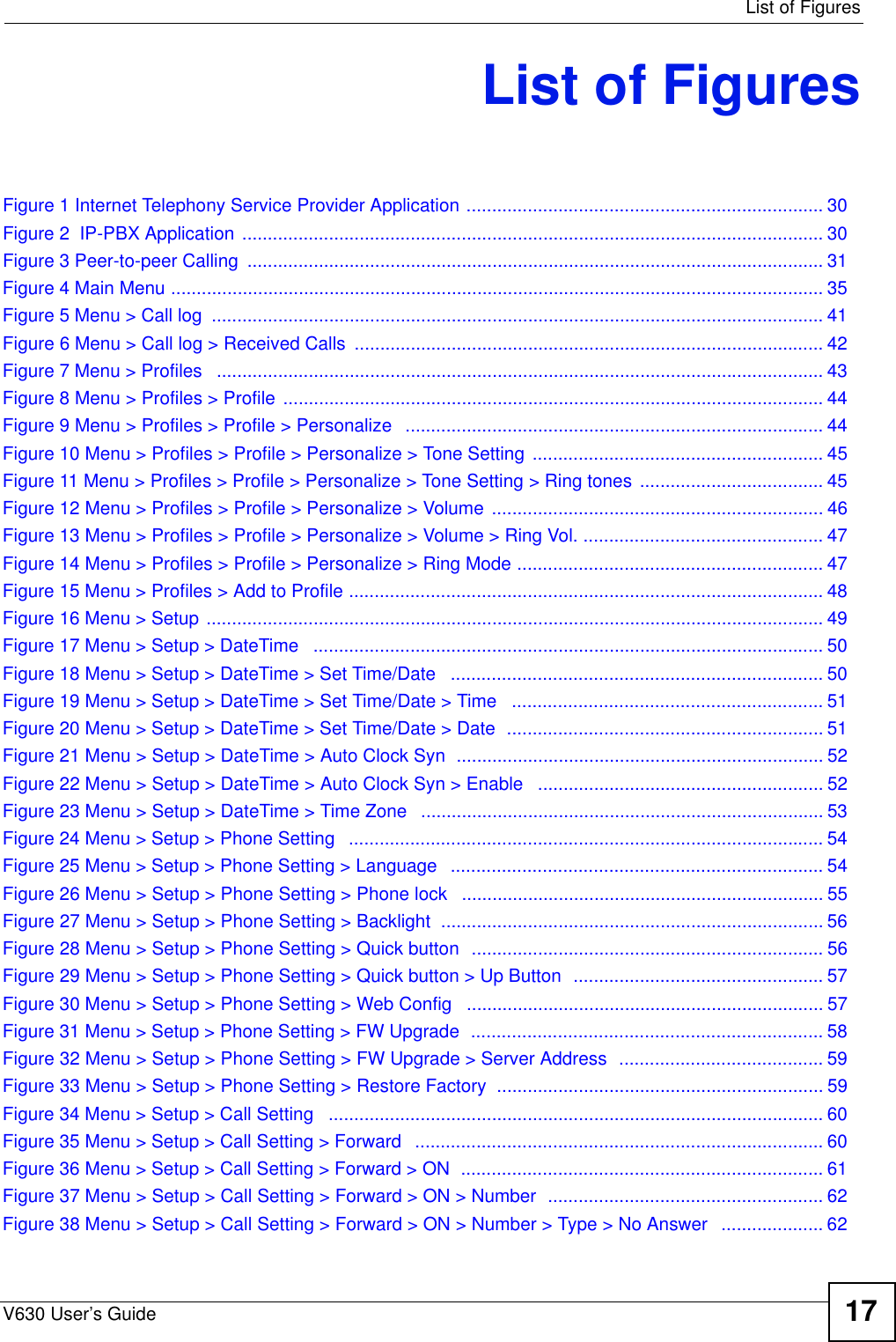
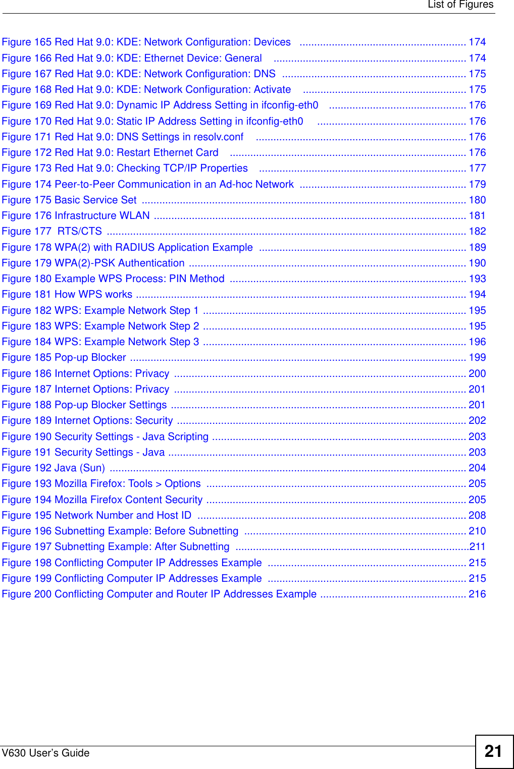
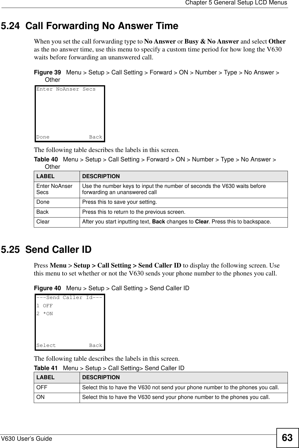
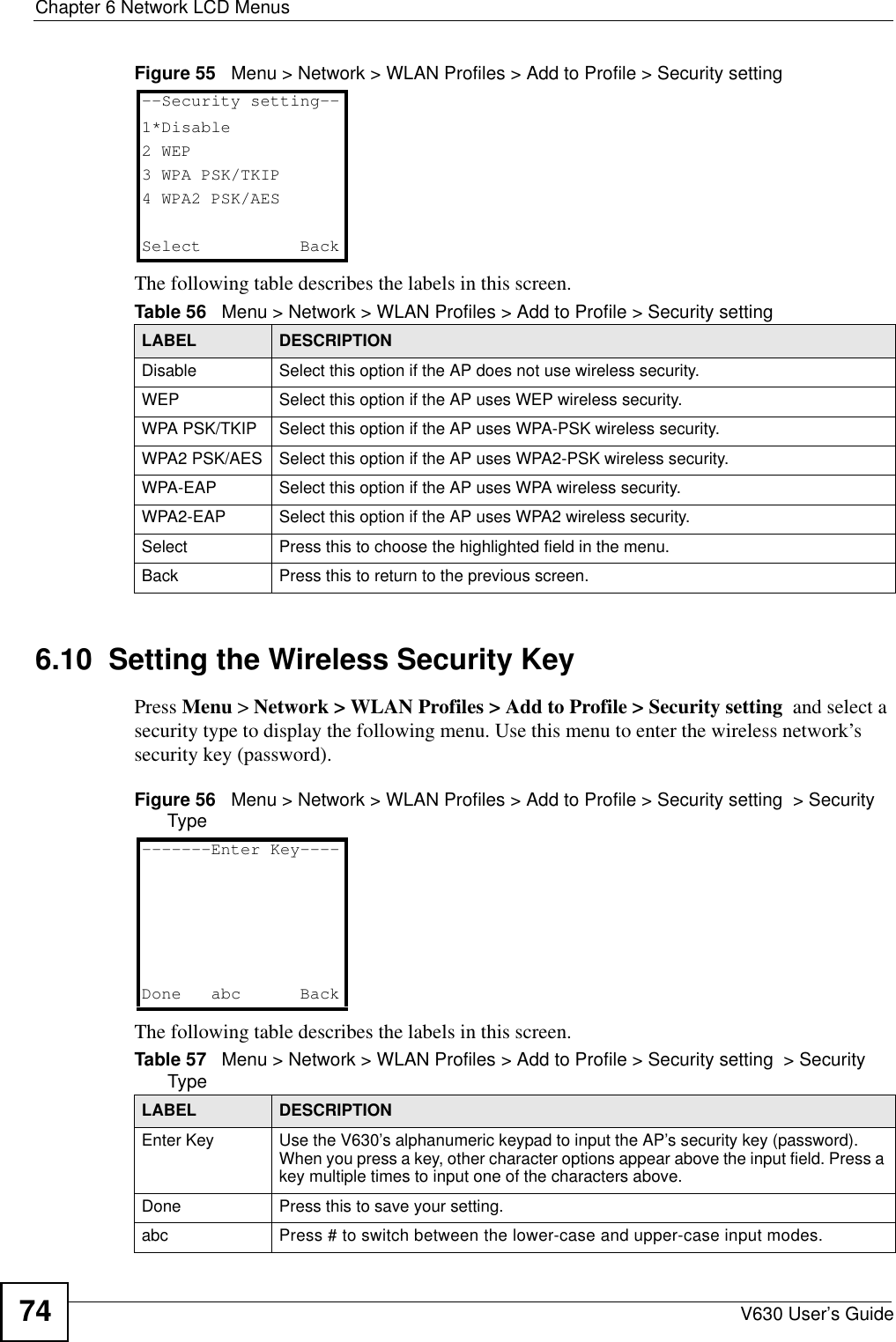
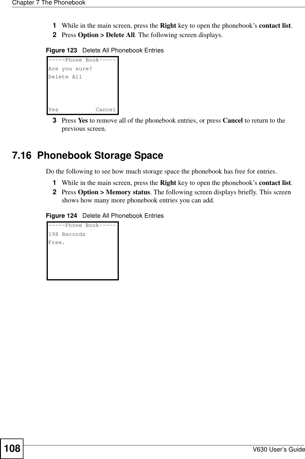
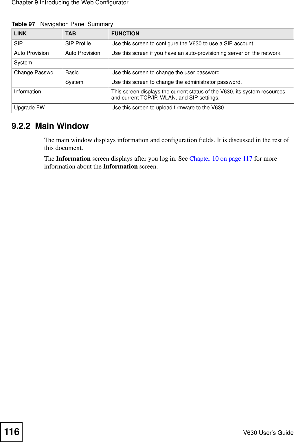
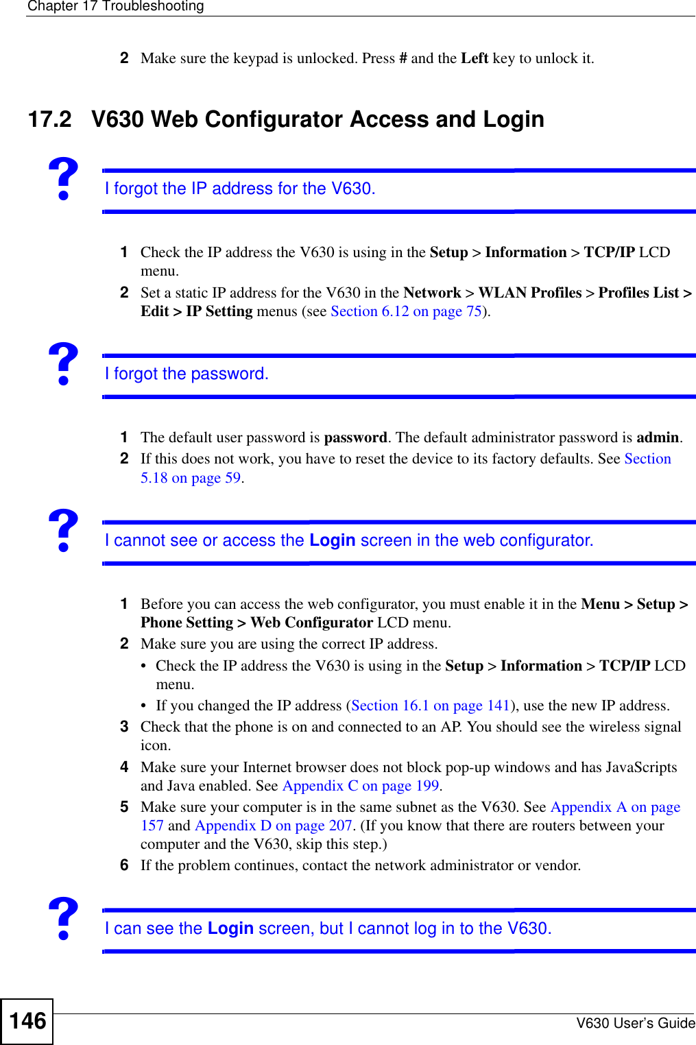
![Chapter 7 The PhonebookV630 User’s Guide 1077.14 Editing a Speed Dial EntryDo the following to edit an existing speed dial entry.1While in the main screen, press the Right key to open the phonebook’s contact list.2Select the entry you want to edit. Press Option > Speed Dial to display the following screen. Select the speed dial entry you want to edit. This example uses 2.Figure 120 Speed DialThe following screen displays. Select Change to set whether or not to use the contact as a speed dial entry. "Delete in this screen removes the contact from the phonebook, not just from the contact group.Figure 121 Speed Dial Entry Change3The following screen displays. Select No to not use the contact as a speed dial entry.Figure 122 Set the Speed Dial Entry7.15 Deleting All Phonebook EntriesTake the following steps to remove all of your contact entries from the V630’s phonebook.------Speed Dial----1 Key1: [Empty]2 Key2: [Example]3 Key3: [Empty]4 Key4: [Empty]Done abc Back---- Speed Dial #2--1 Change2 DeleteDone abc Back--Set Speed Dial #2-1 Yes2 NoDone abc Back](https://usermanual.wiki/ZyXEL-Communications/V630/User-Guide-959740-Page-107.png)


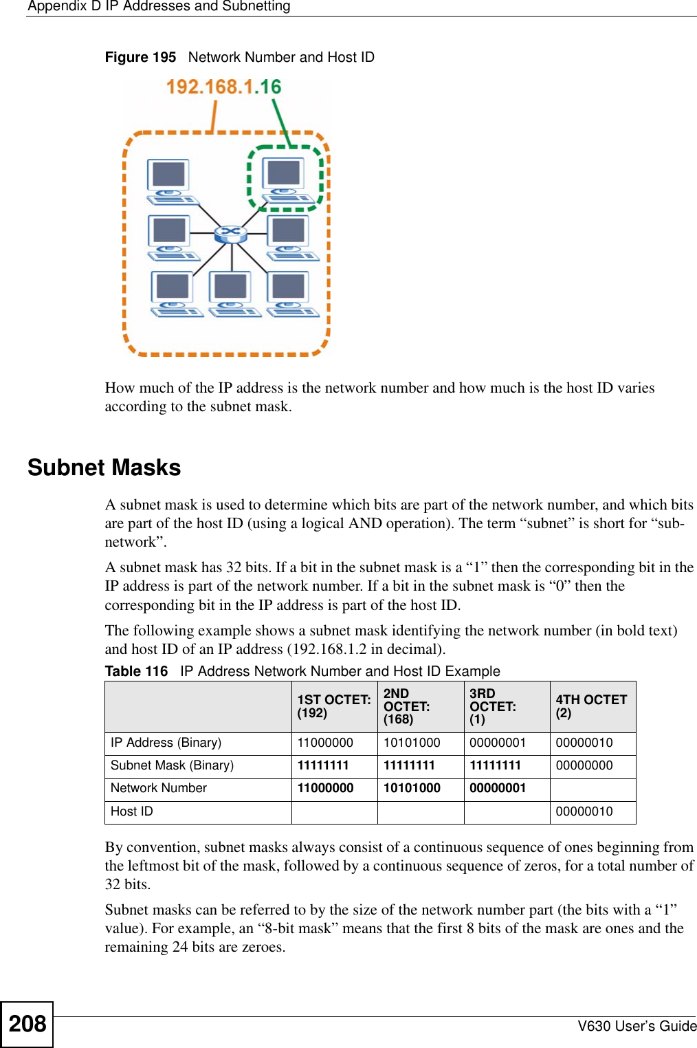
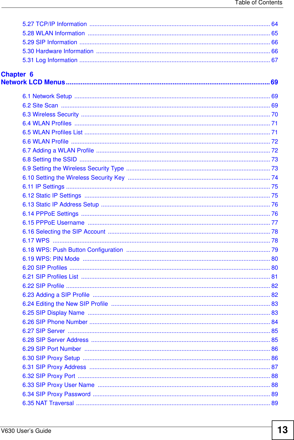
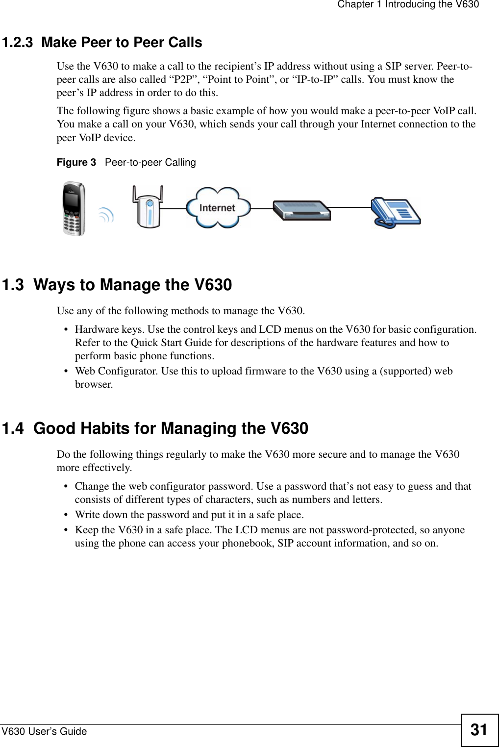
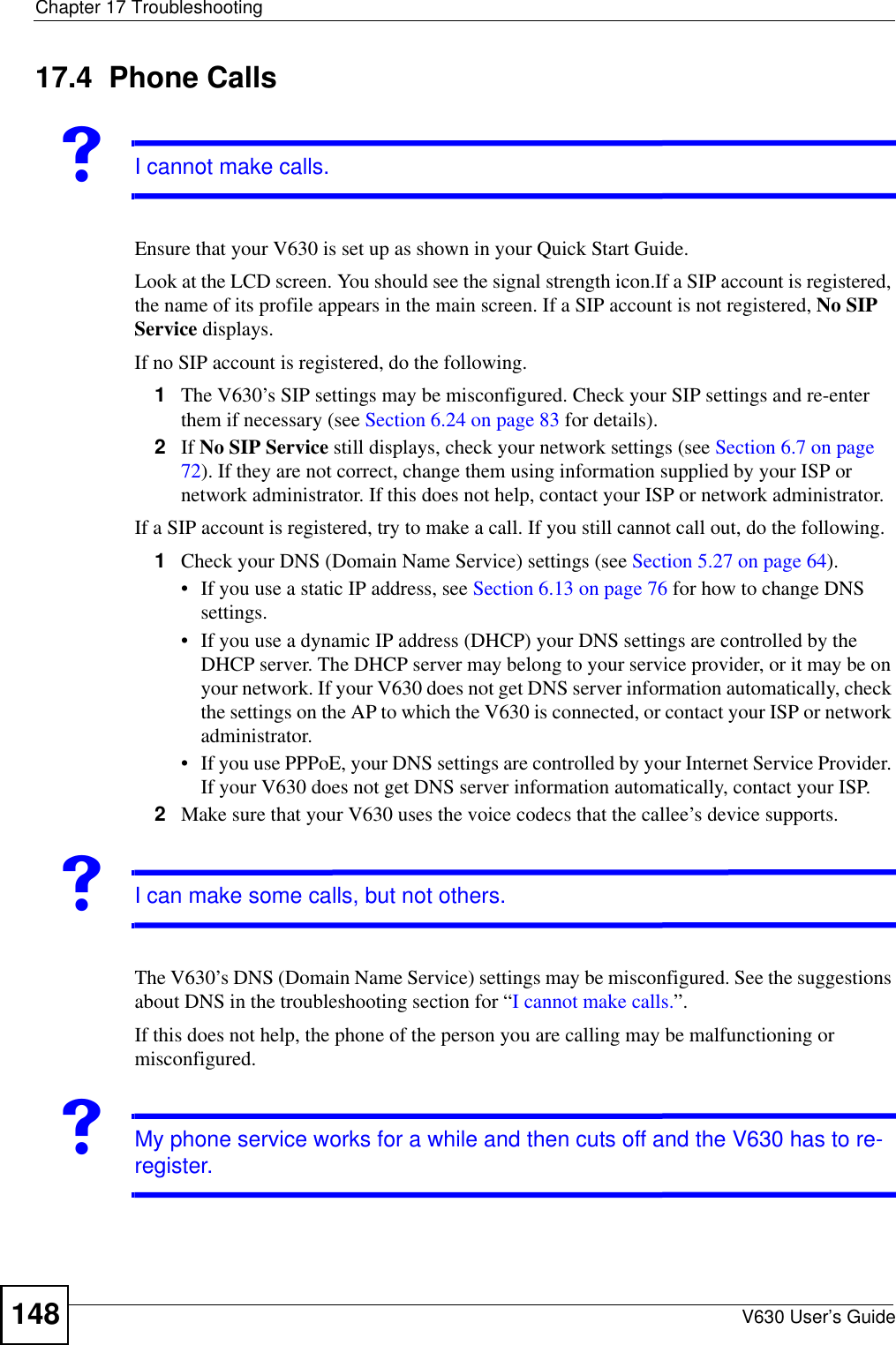
![Chapter 17 TroubleshootingV630 User’s Guide 1471Make sure you have entered the user name and password correctly. The default password is 1234. This field is case-sensitive, so make sure [Caps Lock] is not on.2Close your browser session and open a new one.You may also need to clear your Internet browser’s cache. In Internet Explorer, click Tools and then Internet Options to open the Internet Options screen. In the General tab, click Delete Files. In the pop-up window, select the Delete all offline content check box and click OK. Click OK in the Internet Options screen to close it.3Turn the phone off and on again. 17.3 Wireless LANVWhen I scan for an access point I can’t find one, or I can’t find the right one.If you scan for an access point (AP) and find none, either the V630 is out of the AP’s coverage area (out of range), or the AP is set to not broadcast its SSID (the network name). Move closer to the AP and try again. If the AP still does not show on the scan result, either:• Input the ESSID manually and try to connect.• Access the AP’s configuration interface and set it to broadcast the SSID.If other APs display when you scan, the V630 is working correctly. However, if you know that there are other APs in the area, and no APs display when you scan, you may have a hardware problem. In this case, contact your vendor.VI can’t connect to the access point. If you find the AP when you scan, but you cannot connect to it, there may be a problem with the wireless security settings. • Ensure that the V630 supports the security standard the AP uses.• Ensure that the V630 and the AP use exactly the same settings. • If you continue to experience difficulties, set the AP to use no security (disconnect it from the network first) and try to connect.• If you have another wireless client (a notebook wireless card, for example) try using it to connect. If it connects successfully, your V630 may have a hardware problem. Contact your vendor. If the other wireless client does not connect successfully, the AP may be malfunctioning or misconfigured.](https://usermanual.wiki/ZyXEL-Communications/V630/User-Guide-959740-Page-147.png)
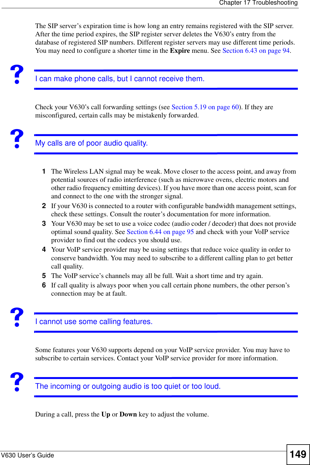

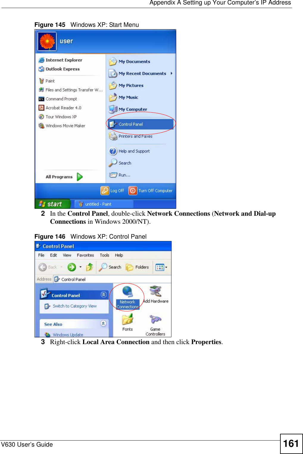
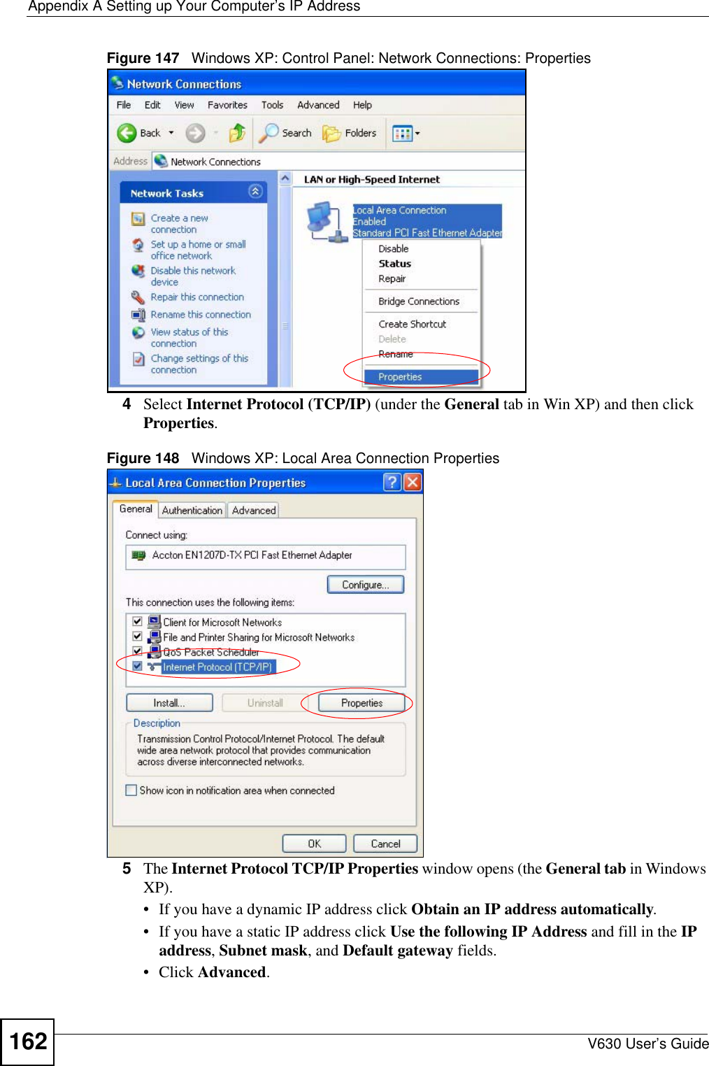
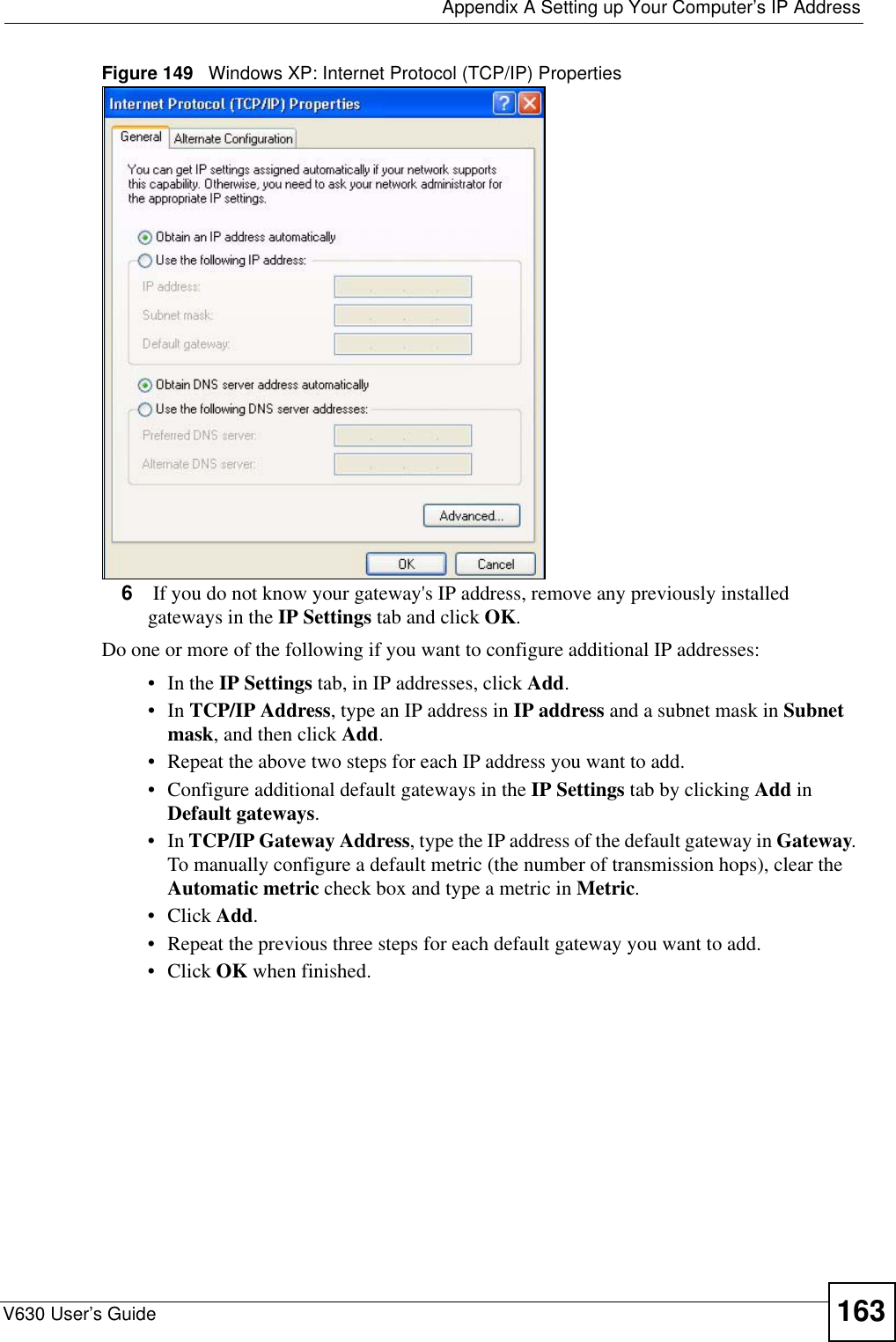
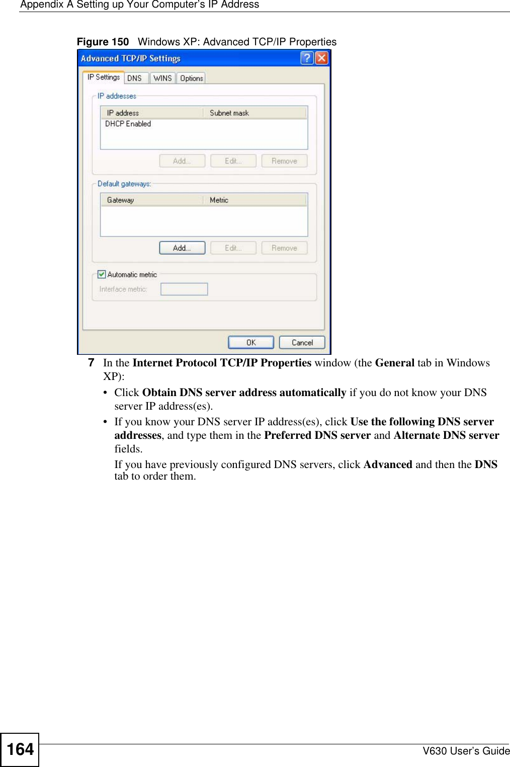
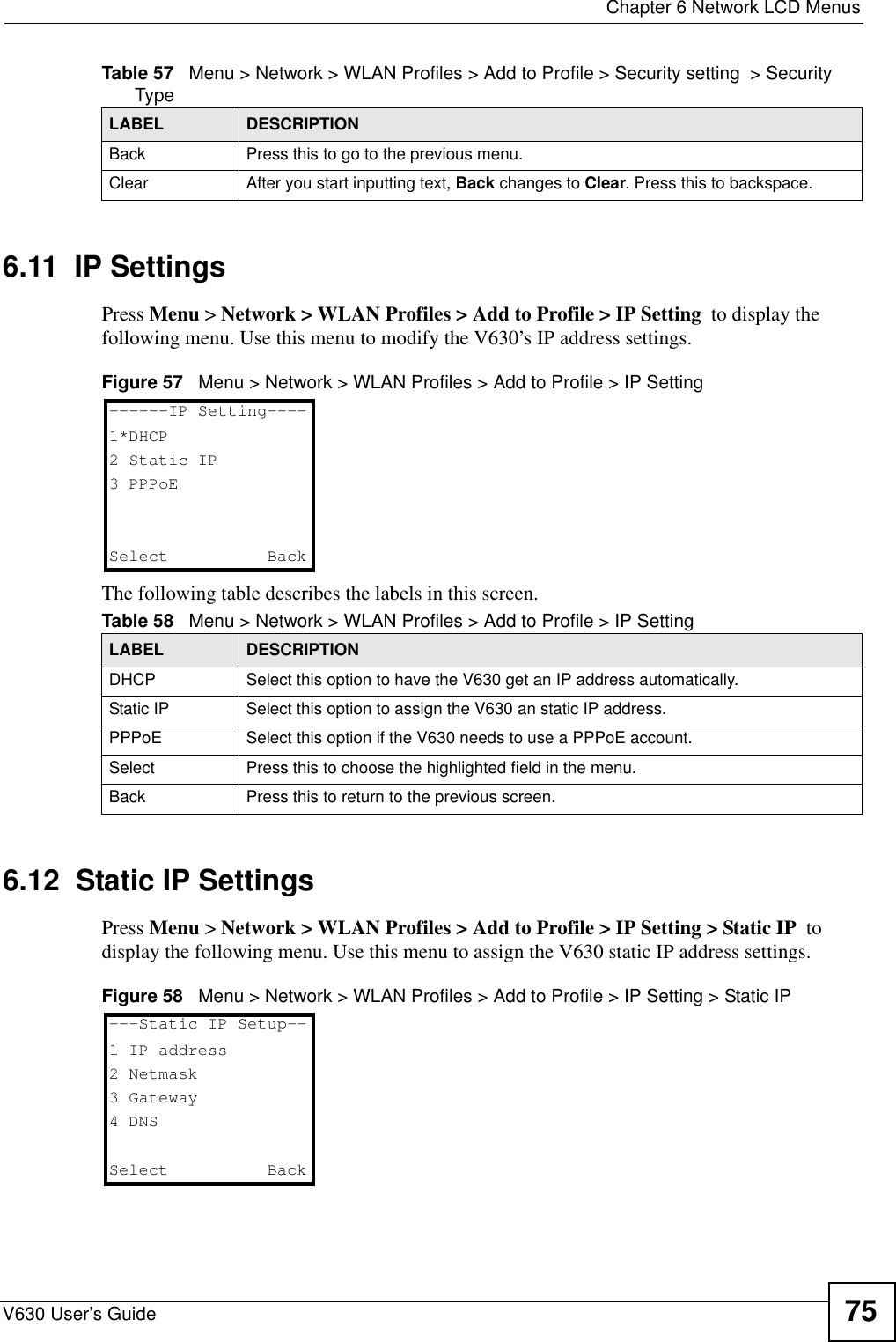
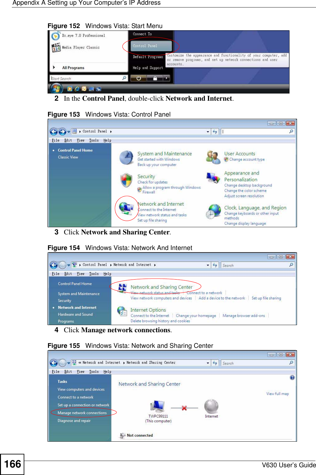
![Appendix A Setting up Your Computer’s IP AddressV630 User’s Guide 165Figure 151 Windows XP: Internet Protocol (TCP/IP) Properties8Click OK to close the Internet Protocol (TCP/IP) Properties window.9Click Close (OK in Windows 2000/NT) to close the Local Area Connection Properties window.10 Close the Network Connections window (Network and Dial-up Connections in Windows 2000/NT).11 Turn on your V630 and restart your computer (if prompted).Verifying Settings1Click Start, All Programs, Accessories and then Command Prompt.2In the Command Prompt window, type "ipconfig" and then press [ENTER]. You can also open Network Connections, right-click a network connection, click Status and then click the Support tab.Windows VistaThis section shows screens from Windows Vista Enterprise Version 6.0.1Click the Start icon, Control Panel.](https://usermanual.wiki/ZyXEL-Communications/V630/User-Guide-959740-Page-165.png)
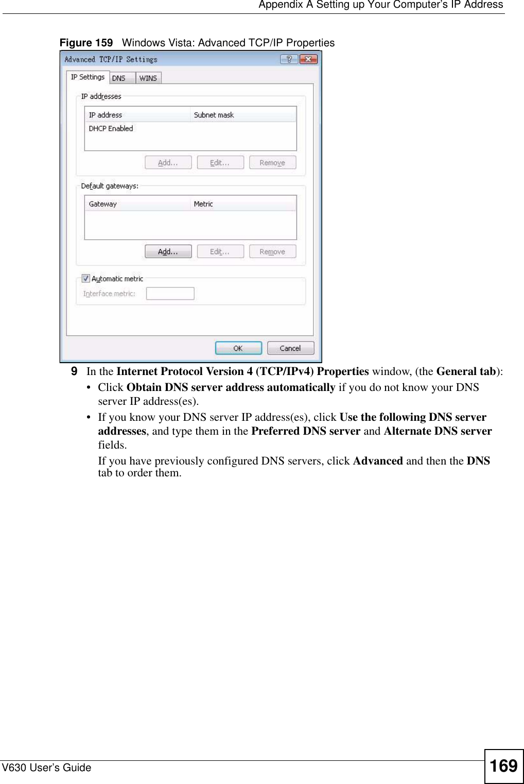
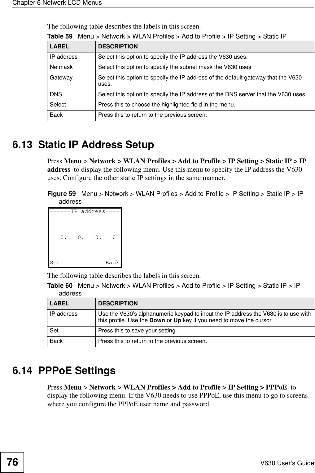
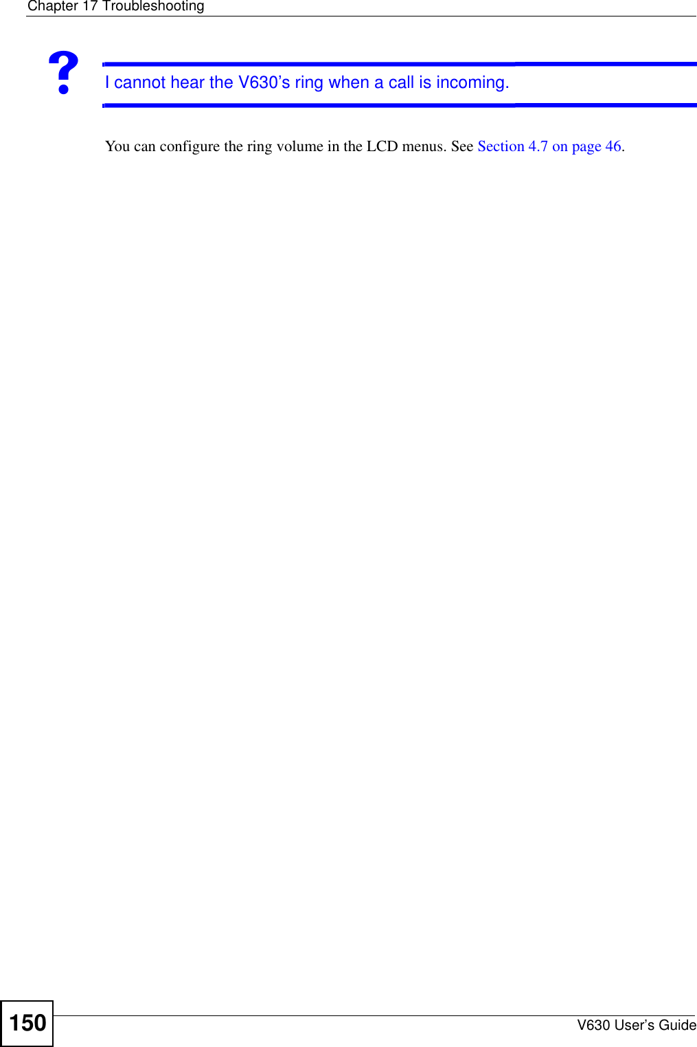
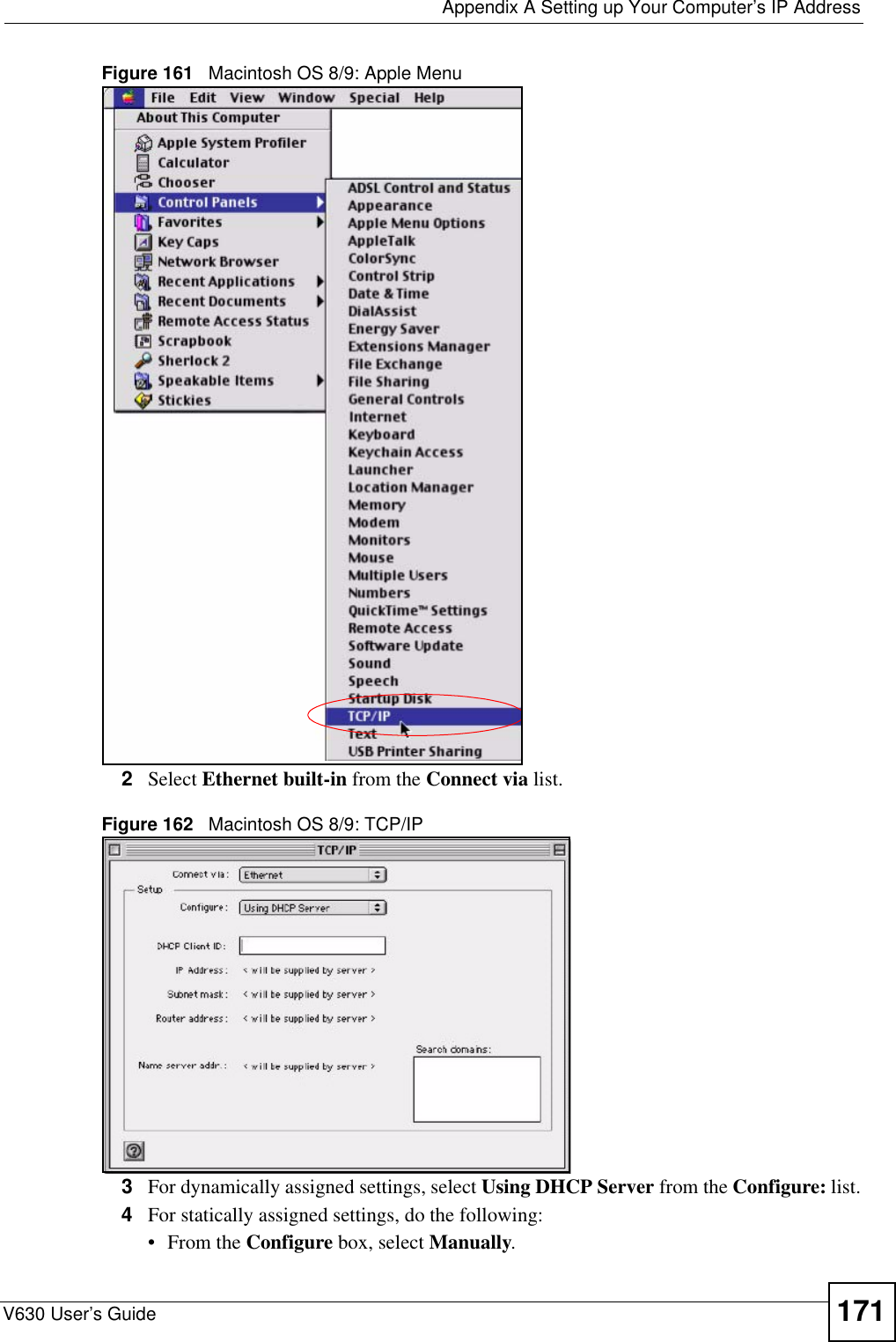
![Appendix A Setting up Your Computer’s IP AddressV630 User’s Guide170Figure 160 Windows Vista: Internet Protocol Version 4 (TCP/IPv4) Properties10 Click OK to close the Internet Protocol Version 4 (TCP/IPv4) Properties window.11 Click Close to close the Local Area Connection Properties window.12 Close the Network Connections window.13 Turn on your V630 and restart your computer (if prompted).Verifying Settings1Click Start, All Programs, Accessories and then Command Prompt.2In the Command Prompt window, type "ipconfig" and then press [ENTER]. You can also open Network Connections, right-click a network connection, click Status and then click the Support tab.Macintosh OS 8/9 1Click the Apple menu, Control Panel and double-click TCP/IP to open the TCP/IP Control Panel.](https://usermanual.wiki/ZyXEL-Communications/V630/User-Guide-959740-Page-170.png)
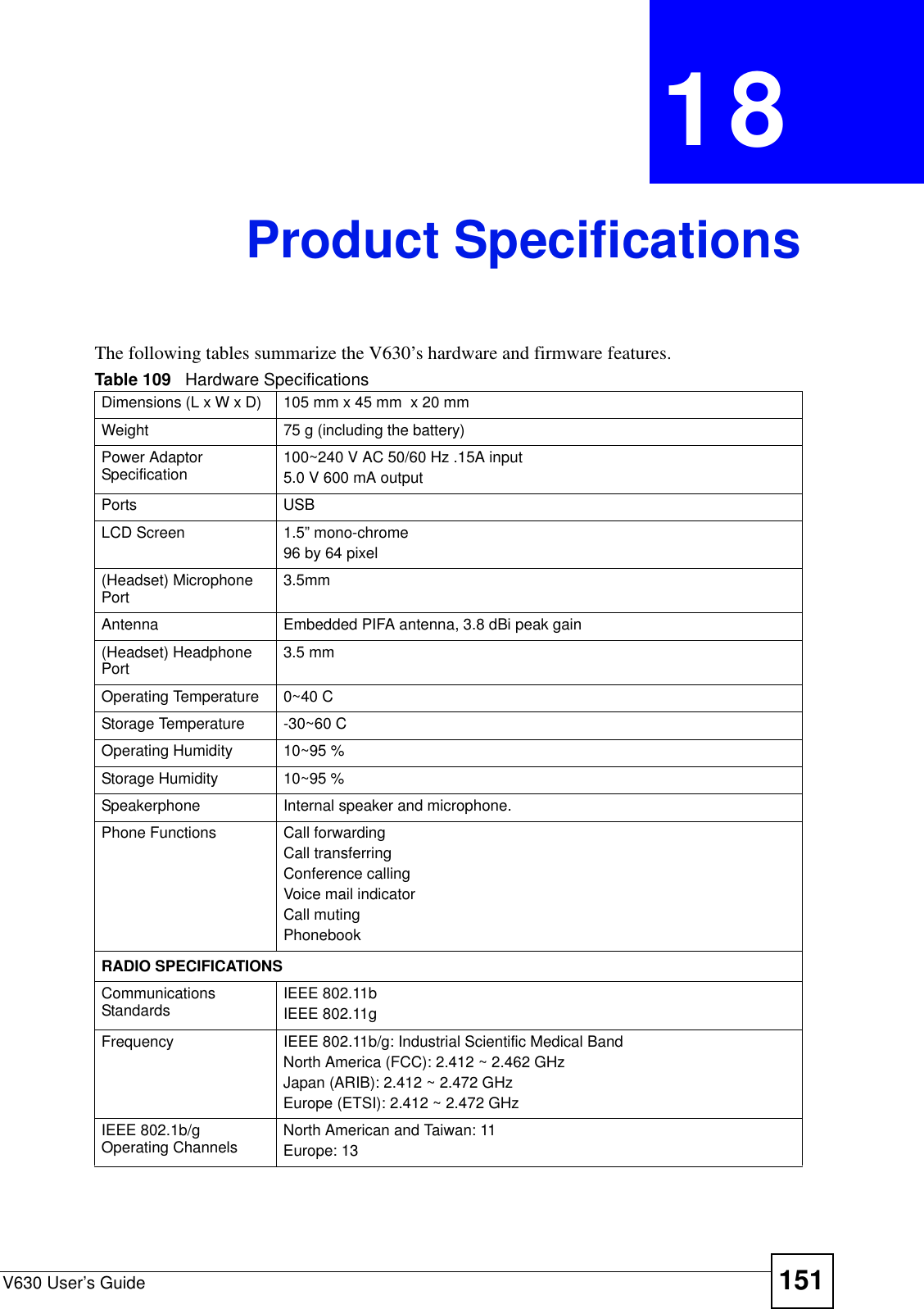
![Appendix A Setting up Your Computer’s IP AddressV630 User’s Guide176Figure 169 Red Hat 9.0: Dynamic IP Address Setting in ifconfig-eth0 • If you have a static IP address, enter static in the BOOTPROTO= field. Type IPADDR= followed by the IP address (in dotted decimal notation) and type NETMASK= followed by the subnet mask. The following example shows an example where the static IP address is 192.168.1.10 and the subnet mask is 255.255.255.0. Figure 170 Red Hat 9.0: Static IP Address Setting in ifconfig-eth0 2If you know your DNS server IP address(es), enter the DNS server information in the resolv.conf file in the /etc directory. The following figure shows an example where two DNS server IP addresses are specified.Figure 171 Red Hat 9.0: DNS Settings in resolv.conf 3After you edit and save the configuration files, you must restart the network card. Enter ./network restart in the /etc/rc.d/init.d directory. The following figure shows an example.Figure 172 Red Hat 9.0: Restart Ethernet Card DEVICE=eth0ONBOOT=yesBOOTPROTO=dhcpUSERCTL=noPEERDNS=yesTYPE=EthernetDEVICE=eth0ONBOOT=yesBOOTPROTO=staticIPADDR=192.168.1.10NETMASK=255.255.255.0USERCTL=noPEERDNS=yesTYPE=Ethernetnameserver 172.23.5.1nameserver 172.23.5.2[root@localhost init.d]# network restartShutting down interface eth0: [OK]Shutting down loopback interface: [OK]Setting network parameters: [OK]Bringing up loopback interface: [OK]Bringing up interface eth0: [OK]](https://usermanual.wiki/ZyXEL-Communications/V630/User-Guide-959740-Page-176.png)
![Appendix A Setting up Your Computer’s IP AddressV630 User’s Guide 177Verifying SettingsEnter ifconfig in a terminal screen to check your TCP/IP properties. Figure 173 Red Hat 9.0: Checking TCP/IP Properties [root@localhost]# ifconfig eth0 Link encap:Ethernet HWaddr 00:50:BA:72:5B:44 inet addr:172.23.19.129 Bcast:172.23.19.255 Mask:255.255.255.0 UP BROADCAST RUNNING MULTICAST MTU:1500 Metric:1 RX packets:717 errors:0 dropped:0 overruns:0 frame:0 TX packets:13 errors:0 dropped:0 overruns:0 carrier:0 collisions:0 txqueuelen:100 RX bytes:730412 (713.2 Kb) TX bytes:1570 (1.5 Kb) Interrupt:10 Base address:0x1000 [root@localhost]#](https://usermanual.wiki/ZyXEL-Communications/V630/User-Guide-959740-Page-177.png)