ZyXEL Communications VMG1312T10C Wireless N VDSL2 4-Port Gateway with USB User Manual
ZyXEL Communications Corporation Wireless N VDSL2 4-Port Gateway with USB
User Manual

Quick Start Guide
www.zyxel.com
VMG1312-T10C
Wireless 2x2 802.11n VDSL2 4-port Gateway with USB
Version 1.14
Edition 1, 7/2014
Copyright © 2014 ZyXEL Communications Corporation
User’s Guide
Default Login Details
LAN IP Address http://192.168.1.1
User Name admin
Password 1234

VMG1312-T10C User’s Guide2
IMPORTANT!
READ CAREFULLY BEFORE USE.
KEEP THIS GUIDE FOR FUTURE REFERENCE.
Screenshots and graphics in this book may differ slightly from your product due to differences in
your product firmware or your computer operating system. Every effort has been made to ensure
that the information in this manual is accurate.
Related Documentation
•Quick Start Guide
The Quick Start Guide shows how to connect the Device and get up and running right away.

Contents Overview
VMG1312-T10C User’s Guide 3
Contents Overview
User’s Guide .......................................................................................................................................13
Introduction .............................................................................................................................................15
Introducing the Web Configurator ...........................................................................................................21
Quick Start ...............................................................................................................................................25
Technical Reference ..........................................................................................................................27
Connection Status and System Info ........................................................................................................29
WAN Setup .............................................................................................................................................35
Wireless ..................................................................................................................................................55
Home Networking ....................................................................................................................................85
Static Route ........................................................................................................................................... 115
Quality of Service (QoS) ....................................................................................................................... 119
Network Address Translation (NAT) ......................................................................................................131
Port Binding ...........................................................................................................................................139
Dynamic DNS ........................................................................................................................................145
Filter ......................................................................................................................................................147
Firewall ..................................................................................................................................................153
Parental Control ....................................................................................................................................169
Certificates ............................................................................................................................................173
System Monitor .....................................................................................................................................181
User Account .........................................................................................................................................187
TR-069 Client ........................................................................................................................................189
System ..................................................................................................................................................191
Time Setting ..........................................................................................................................................193
Log Setting ...........................................................................................................................................195
Firmware Upgrade ................................................................................................................................199
Backup/Restore .....................................................................................................................................201
Remote Management ............................................................................................................................205
Diagnostic .............................................................................................................................................217
Troubleshooting ....................................................................................................................................223

Contents Overview
VMG1312-T10C User’s Guide
4

Table of Contents
VMG1312-T10C User’s Guide 5
Table of Contents
Contents Overview ..............................................................................................................................3
Table of Contents .................................................................................................................................5
Part I: User’s Guide ......................................................................................... 13
Chapter 1
Introduction.........................................................................................................................................15
1.1 Overview ...........................................................................................................................................15
1.2 Ways to Manage the Device .............................................................................................................15
1.3 Good Habits for Managing the Device ..............................................................................................15
1.4 Applications for the Device ................................................................................................................16
1.4.1 Internet Access ........................................................................................................................16
1.5 Wireless Access ................................................................................................................................16
1.5.1 Using the WLAN/WPS Button .................................................................................................17
1.6 The RESET Button ............................................................................................................................18
1.6.1 Using the Reset Button ............................................................................................................18
1.7 LEDs (Lights) ....................................................................................................................................18
Chapter 2
Introducing the Web Configurator ....................................................................................................21
2.1 Overview ...........................................................................................................................................21
2.1.1 Accessing the Web Configurator .............................................................................................21
2.2 The Web Configurator Layout ...........................................................................................................23
2.2.1 Title Bar ...................................................................................................................................23
2.2.2 Main Window ...........................................................................................................................24
Chapter 3
Quick Start...........................................................................................................................................25
3.1 Overview ...........................................................................................................................................25
3.2 Quick Start Setup ..............................................................................................................................25
Part II: Technical Reference............................................................................ 27
Chapter 4
Connection Status and System Info .................................................................................................29

Table of Contents
VMG1312-T10C User’s Guide
6
4.1 Overview ...........................................................................................................................................29
4.2 The Connection Status Screen .........................................................................................................29
4.3 The System Info Screen ....................................................................................................................30
Chapter 5
WAN Setup ..........................................................................................................................................35
5.1 Overview ...........................................................................................................................................35
5.1.1 What You Can Do in the WAN Screens ...................................................................................35
5.1.2 What You Need to Know About WAN ......................................................................................36
5.1.3 Before You Begin .....................................................................................................................38
5.2 The Internet Connection Screen .......................................................................................................38
5.2.1 Advanced Internet Connection ................................................................................................43
5.3 The More Connections Screen .........................................................................................................44
5.3.1 More Connections Edit ............................................................................................................45
5.3.2 Configuring More Connections Advanced Setup .....................................................................49
5.4 The 3G Backup Screen .....................................................................................................................50
5.5 WAN Technical Reference ................................................................................................................52
5.5.1 Encapsulation ..........................................................................................................................52
5.5.2 Multiplexing ..............................................................................................................................53
5.5.3 VPI and VCI .............................................................................................................................54
5.5.4 IP Address Assignment ...........................................................................................................54
Chapter 6
Wireless...............................................................................................................................................55
6.1 Overview ...........................................................................................................................................55
6.1.1 What You Can Do in this Chapter ............................................................................................55
6.1.2 Wireless Network Overview .....................................................................................................55
6.1.3 Before You Begin .....................................................................................................................57
6.2 Wireless General Screen .................................................................................................................57
6.2.1 No Security ..............................................................................................................................59
6.2.2 Basic (Static WEP/Shared WEP Encryption) ...........................................................................59
6.2.3 More Secure (WPA(2)-PSK) ....................................................................................................61
6.2.4 WPA(2) Authentication .............................................................................................................62
6.3 More AP Screen ................................................................................................................................63
6.3.1 Edit More AP ...........................................................................................................................65
6.4 MAC Authentication Screen ..............................................................................................................66
6.5 The WPS Screen ..............................................................................................................................67
6.6 The WDS Screen ..............................................................................................................................69
6.7 The WMM Screen .............................................................................................................................70
6.8 Scheduling Screen ...........................................................................................................................71
6.8.1 Add or Edit Schedule ...............................................................................................................72
6.9 Advanced Screen ..............................................................................................................................73
6.10 Technical Reference ........................................................................................................................74

Table of Contents
VMG1312-T10C User’s Guide 7
6.10.1 Additional Wireless Terms .....................................................................................................74
6.10.2 Wireless Security Overview ...................................................................................................74
6.10.3 Signal Problems ....................................................................................................................76
6.10.4 BSS .......................................................................................................................................77
6.10.5 MBSSID .................................................................................................................................77
6.10.6 Wireless Distribution System (WDS) .....................................................................................78
6.10.7 WiFi Protected Setup (WPS) .................................................................................................78
Chapter 7
Home Networking ...............................................................................................................................85
7.1 Overview ...........................................................................................................................................85
7.1.1 What You Can Do in this Chapter ............................................................................................85
7.1.2 What You Need To Know .........................................................................................................85
7.2 The LAN Setup Screen .....................................................................................................................88
7.3 The Static DHCP Screen ...................................................................................................................90
7.3.1 Before You Begin .....................................................................................................................90
7.4 The IP Alias Screen ..........................................................................................................................91
7.5 The UPnP Screen .............................................................................................................................92
7.6 The UPnP Rule Screen .....................................................................................................................92
7.7 The IPv6 LAN Setup Screen .............................................................................................................93
7.8 The File Sharing Screen ...................................................................................................................97
7.8.1 Before You Begin .....................................................................................................................97
7.8.2 Edit File Sharing User ..............................................................................................................99
7.9 The Printer Server Screen ..............................................................................................................100
7.9.1 Before You Begin ...................................................................................................................100
7.10 Technical Reference ......................................................................................................................101
7.11 Installing UPnP in Windows Example ...........................................................................................105
7.12 Using UPnP in Windows XP Example ..........................................................................................108
Chapter 8
Static Route.......................................................................................................................................115
8.1 Overview ........................................................................................................................................ 115
8.1.1 What You Can Do in this Chapter ..........................................................................................115
8.2 Configuring Static Route ................................................................................................................. 116
8.2.1 Add/Edit Static Route ........................................................................................................... 116
8.3 IPv6 Static Route ............................................................................................................................. 117
8.3.1 IPv6 Static Route Edit .......................................................................................................... 118
Chapter 9
Quality of Service (QoS)...................................................................................................................119
9.1 Overview ......................................................................................................................................... 119
9.1.1 What You Can Do in this Chapter ..........................................................................................119
9.1.2 What You Need to Know ........................................................................................................ 119

Table of Contents
VMG1312-T10C User’s Guide
8
9.2 The QoS General Screen ...............................................................................................................120
9.3 The Queue Setup Screen ...............................................................................................................121
9.3.1 Edit a QoS Queue ................................................................................................................122
9.4 The Class Setup Screen ...............................................................................................................122
9.4.1 Add/Edit QoS Class ..............................................................................................................124
9.5 The QoS Policer Setup Screen .......................................................................................................127
9.5.1 Add/Edit a QoS Policer .........................................................................................................128
9.6 The QoS Game List Screen ............................................................................................................129
9.7 QoS Technical Reference ...............................................................................................................130
9.7.1 DiffServ ..................................................................................................................................130
Chapter 10
Network Address Translation (NAT)................................................................................................131
10.1 Overview ......................................................................................................................................131
10.1.1 What You Can Do in this Chapter ........................................................................................131
10.1.2 What You Need To Know .....................................................................................................131
10.2 The General Screen ......................................................................................................................132
10.3 The Port Forwarding Screen ........................................................................................................132
10.3.1 The Port Forwarding Screen ...............................................................................................133
10.3.2 The Port Forwarding Add/Edit Screen .................................................................................134
10.4 The DMZ Screen ...........................................................................................................................135
10.5 The ALG Screen ...........................................................................................................................136
10.6 Technical Reference ......................................................................................................................136
10.6.1 NAT Definitions ....................................................................................................................137
10.6.2 What NAT Does ...................................................................................................................137
10.6.3 How NAT Works ..................................................................................................................137
Chapter 11
Port Binding ......................................................................................................................................139
11.1 Overview .......................................................................................................................................139
11.2 The Port Binding Screen ...............................................................................................................140
11.2.1 Port Binding Summary Screen .............................................................................................141
11.2.2 The Any Port Any Service Edit Screen ................................................................................143
Chapter 12
Dynamic DNS ....................................................................................................................................145
12.1 Overview ......................................................................................................................................145
12.1.1 What You Need To Know .....................................................................................................145
12.2 The Dynamic DNS Screen ............................................................................................................146
Chapter 13
Filter...................................................................................................................................................147
13.1 Overview ......................................................................................................................................147

Table of Contents
VMG1312-T10C User’s Guide 9
13.1.1 What You Can Do in the Filter Screens ...............................................................................147
13.2 The IP/MAC Filter Screen .............................................................................................................148
13.3 The IPv6/MAC Filter Screen .........................................................................................................150
Chapter 14
Firewall ..............................................................................................................................................153
14.1 Overview .......................................................................................................................................153
14.1.1 What You Can Do in the Firewall Screens ...........................................................................153
14.1.2 What You Need to Know About Firewall ..............................................................................154
14.2 Firewall General Screen ................................................................................................................155
14.3 Default Action Screen ...................................................................................................................156
14.4 Rules Screen .................................................................................................................................157
14.4.1 Rules Add Screen ................................................................................................................158
14.4.2 Customized Services ..........................................................................................................160
14.4.3 Customized Service Add/Edit .............................................................................................161
14.5 DoS Screen ...................................................................................................................................162
14.5.1 The DoS Advanced Screen .................................................................................................163
14.5.2 Configuring Firewall Thresholds ..........................................................................................164
14.6 Firewall Technical Reference ........................................................................................................165
14.6.1 Firewall Rules Overview ......................................................................................................165
14.6.2 Guidelines For Enhancing Security With Your Firewall .......................................................166
14.6.3 Security Considerations .......................................................................................................166
14.6.4 Triangle Route .....................................................................................................................167
Chapter 15
Parental Control................................................................................................................................169
15.1 Overview .......................................................................................................................................169
15.2 The Parental Control Screen .........................................................................................................169
15.2.1 Add/Edit a Parental Control Rule .........................................................................................170
Chapter 16
Certificates ........................................................................................................................................173
16.1 Overview .......................................................................................................................................173
16.1.1 What You Can Do in this Chapter ........................................................................................173
16.1.2 What You Need to Know ......................................................................................................173
16.1.3 Verifying a Certificate ...........................................................................................................174
16.2 Local Certificates ...........................................................................................................................175
16.3 Trusted CA ..................................................................................................................................177
16.4 Trusted CA Import .......................................................................................................................177
16.5 View Certificate .............................................................................................................................178
Chapter 17
System Monitor.................................................................................................................................181

Table of Contents
VMG1312-T10C User’s Guide
10
17.1 Overview .......................................................................................................................................181
17.1.1 What You Can Do in this Chapter ........................................................................................181
17.1.2 What You Need To Know .....................................................................................................181
17.2 The Log Screen .............................................................................................................................182
17.3 The WAN Traffic Status Screen ....................................................................................................183
17.4 The LAN Traffic Status Screen ......................................................................................................184
17.5 The NAT Traffic Status Screen ......................................................................................................185
Chapter 18
User Account ....................................................................................................................................187
18.1 Overview .......................................................................................................................................187
18.2 The User Account Screen .............................................................................................................187
Chapter 19
TR-069 Client.....................................................................................................................................189
19.1 Overview .......................................................................................................................................189
19.2 The TR-069 Client Screen ............................................................................................................189
Chapter 20
System...............................................................................................................................................191
20.1 Overview .......................................................................................................................................191
20.2 The System Screen .......................................................................................................................191
Chapter 21
Time Setting ......................................................................................................................................193
21.1 Overview .......................................................................................................................................193
21.2 The Time Setting Screen .............................................................................................................193
Chapter 22
Log Setting .......................................................................................................................................195
22.1 Overview ......................................................................................................................................195
22.2 The Log Setting Screen ................................................................................................................196
Chapter 23
Firmware Upgrade ............................................................................................................................199
23.1 Overview .......................................................................................................................................199
23.2 The Firmware Upgrade Screen .....................................................................................................199
Chapter 24
Backup/Restore ................................................................................................................................201
24.1 Overview .......................................................................................................................................201
24.2 The Backup/Restore Screen .........................................................................................................201
24.3 The Reboot Screen .......................................................................................................................203

Table of Contents
VMG1312-T10C User’s Guide 11
Chapter 25
Remote Management........................................................................................................................205
25.1 Overview .......................................................................................................................................205
25.1.1 What You Can Do in the Remote Management Screens ....................................................205
25.1.2 What You Need to Know About Remote Management ........................................................206
25.2 The WWW Screen ........................................................................................................................206
25.2.1 Configuring the WWW Screen .............................................................................................207
25.3 Telnet Screen ................................................................................................................................208
25.4 FTP Screen ...................................................................................................................................209
25.5 SNMP Screen ...............................................................................................................................209
25.5.1 Configuring SNMP ............................................................................................................... 211
25.6 DNS Screen .................................................................................................................................212
25.7 ICMP Screen .................................................................................................................................213
25.8 SSH Screen ..................................................................................................................................213
25.8.1 SSH Example ......................................................................................................................214
Chapter 26
Diagnostic .........................................................................................................................................217
26.1 Overview .......................................................................................................................................217
26.1.1 What You Can Do in the Diagnostic Screens ......................................................................217
26.2 The Ping Screen ...........................................................................................................................217
26.3 The DSL Line Screen ....................................................................................................................218
Chapter 27
Troubleshooting................................................................................................................................223
27.1 Overview .......................................................................................................................................223
27.2 Power, Hardware Connections, and LEDs ....................................................................................223
27.3 Device Access and Login ..............................................................................................................224
27.4 Internet Access .............................................................................................................................225
27.5 Wireless Internet Access ...............................................................................................................227
27.6 USB Device Connection ................................................................................................................228
27.7 UPnP .............................................................................................................................................228
Appendix A Customer Support ........................................................................................................229
Appendix B Legal Information..........................................................................................................235
Index ..................................................................................................................................................241

Table of Contents
VMG1312-T10C User’s Guide
12

13
PART I
User’s Guide

14

VMG1312-T10C User’s Guide 15
CHAPTER 1
Introduction
1.1 Overview
This VDSL2 router allows super-fast, secure Internet access over analog (POTS) telephone lines. It
supports both Packet Transfer Mode (PTM) and Asynchronous Transfer Mode (ATM). You can have
ADSL (ADSL, ADSL2, ADSL2+) connections or VDSL2 connections.
The Device integrates DSL and NAT for ease of installation and high-speed, shared Internet access.
It also provides a complete security solution with a robust firewall and content filtering. The product
name format indicates the following:
• “H” denotes an integrated 4-port hub (switch).
• “N” denotes IEEE 802.11n wireless networking support.
• “U” denotes a USB port used to set up a 3G WAN connection via a 3G wireless card or share files
via a USB memory stick or a USB hard drive. The Device can also function as a print server with
an USB printer connected.
Only use firmware for your Device’s specific model. Refer to the label on
the bottom of your Device.
1.2 Ways to Manage the Device
Use any of the following methods to manage the Device.
• Web Configurator. Use a (supported) web browser to manage the Device.
• FTP for firmware upgrades and configuration backup/restore.
• TR-069. This auto-configuration server remotely configures your device.
1.3 Good Habits for Managing the Device
Do the following things regularly to make the Device more secure and to manage the Device more
effectively.
• Change the password. Use a password that’s not easy to guess and that consists of different
types of characters, such as numbers and letters.
• Write down the password and put it in a safe place.
Chapter 1 Introduction
VMG1312-T10C User’s Guide
16
• Back up the configuration (and make sure you know how to restore it). Restoring an earlier
working configuration may be useful if the device becomes unstable or even crashes. If you
forget your password, you will have to reset the Device to its factory default settings. If you
backed up an earlier configuration file, you would not have to totally re-configure the Device. You
could simply restore your last configuration.
1.4 Applications for the Device
Here are some example uses for the Device.
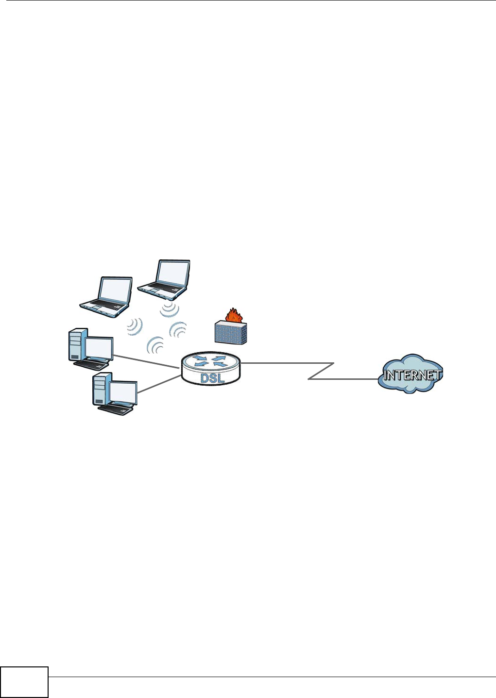
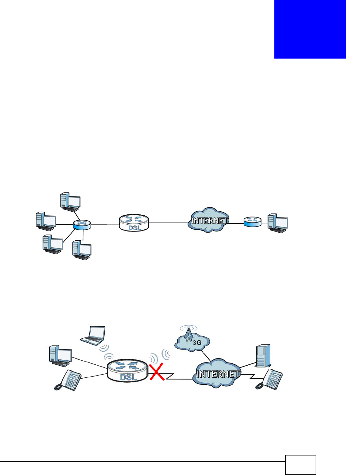
1.4.1 Internet Access
Your Device provides shared Internet access by connecting the DSL port to the DSL or MODEM
jack on a splitter or your telephone jack. Computers can connect to the Device’s LAN ports (or
wirelessly).
Figure 1 Device’s Router Features
Configure firewall and filtering features on the Device for secure Internet access. Set the firewall to
allow responses from the Internet for traffic initiated from your network and block traffic initiated
from the Internet. This blocks probes from the outside to your network, but lets you safely browse
the Internet and download files.
Use the filtering feature to block access to specific web sites or Internet applications such as MSN or
Yahoo Messenger. You can also configure IP/MAC filtering rules for incoming or outgoing traffic.
Use QoS to efficiently manage traffic on your network by giving priority to certain types of traffic
and/or to particular computers. For example, you could make sure that the Device gives voice over
Internet calls high priority, and/or limit bandwidth devoted to the boss’s excessive file downloading.
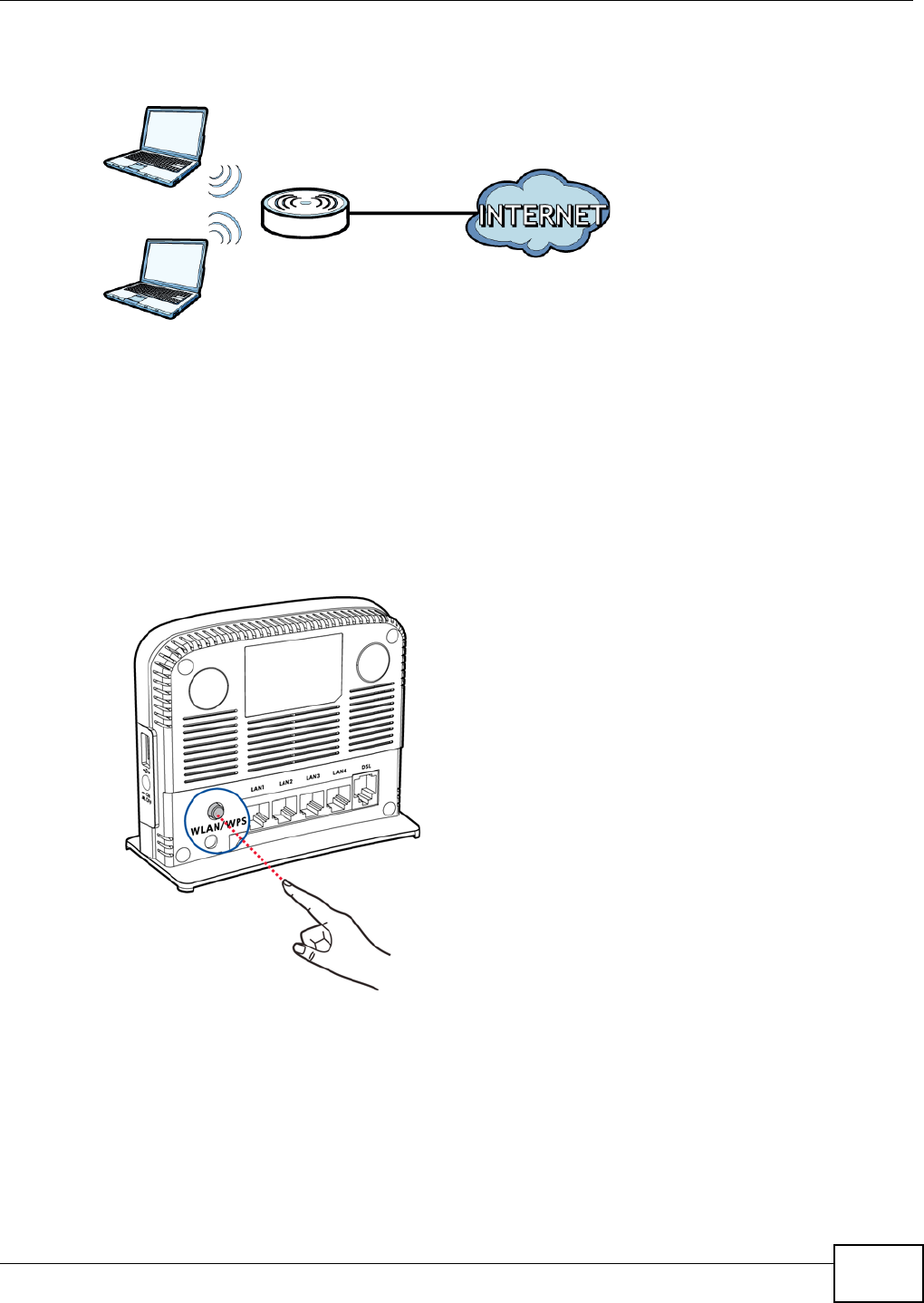
1.5 Wireless Access
The Device serves as a wireless Access Point (AP) to let wireless clients such as notebook
computers, smart phones, and tablets connect to the Internet without Ethernet cables.
DSL
LAN
Chapter 1 Introduction
VMG1312-T10C User’s Guide 17
Configure your wireless network through the Web Configurator, or the WPS button.
Figure 2 Wireless Access Example
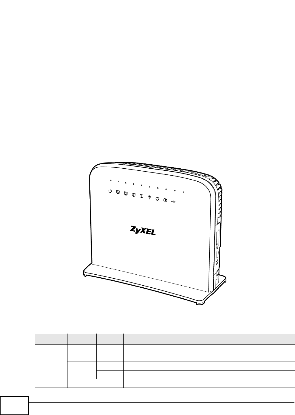
1.5.1 Using the WLAN/WPS Button
By default, the Device’s wireless network is enabled. To turn it off, simply press the WPS/WLAN
button on top of the Device for over 5 seconds. The WLAN/WPS LED turns off.
Use the WLAN/WPS button to quickly set up a secure wireless connection between the Device and
a WPS-compatible client by adding one device at a time. To activate WPS:
1With the POWER LED on steady, press the WLAN/WPS button for 1 second and release it.
2Within two minutes, press the WPS button on a WPS-enabled client within range of the Device. The
WPS/WLAN LED should flash while the Device sets up a WPS connection with the client.
3The WPS/WLAN LED shines green for a successful connection.
Chapter 1 Introduction
VMG1312-T10C User’s Guide
18
1.6 The RESET Button
If you forget your password or cannot access the web configurator, use the RESET button at the
back of the device to reload the factory-default configuration file. This means that you will lose all
configurations that you had previously and the user name and password will be reset to the default.
1.6.1 Using the Reset Button
With the POWER LED on steady, press the RESET button for ten seconds or until the POWER LED
begins to blink and then release it. When the POWER LED begins to blink, the defaults have been
restored and the device restarts.
1.7 LEDs (Lights)
The following graphic displays the labels of the LEDs.
Figure 3 LEDs
None of the LEDs are on if the Device is not receiving power.
Table 1 LED Descriptions
LED COLOR STATUS DESCRIPTION
POWER Green On The Device is receiving power and ready for use.
Blinking The Device is self-testing.
Red On The Device has hardware failure.
Blinking Firmware upgrade is in progress.
Off The Device is not receiving power.

Chapter 1 Introduction
VMG1312-T10C User’s Guide 19
Refer to the Quick Start Guide for information on hardware connections.
ETHERNET
1-4
Green On The Device has a successful 100 Mbps Ethernet connection with a
device on the Local Area Network (LAN).
Blinking The Device is sending or receiving data to/from the LAN at 100 Mbps.
Off The Device does not have an Ethernet connection with the LAN.
WLAN/WPS Green On The wireless network is activated.
Blinking The Device is communicating with other wireless clients.
Orange Blinking The Device is setting up a WPS connection.
Off The wireless network is not activated.
DSL Green On The DSL line is up.
Blinking The DSL line is initializing.
Off The DSL line is down.
INTERNET Green On The Device has an IP connection but no traffic.
Your device has a WAN IP address (either static or assigned by a DHCP
server), PPP negotiation was successfully completed (if used) and the
DSL connection is up.
Blinking The Device is sending or receiving IP traffic.
Off The Device does not have an IP connection.
Red On The Device attempted to make an IP connection but failed.
USB Green On The Device recognizes a USB connection through the USB slot.
Blinking The Device is sending or receiving data to or from the connected USB
device.
Off The Device does not detect a USB connection through the USB slot.
Table 1 LED Descriptions (continued)
LED COLOR STATUS DESCRIPTION

Chapter 1 Introduction
VMG1312-T10C User’s Guide
20
VMG1312-T10C User’s Guide 21
CHAPTER 2
Introducing the Web Configurator
2.1 Overview
The web configurator is an HTML-based management interface that allows easy device setup and
management via Internet browser. Use Internet Explorer 6.0 and later versions, Mozilla Firefox 3
and later versions, or Safari 2.0 and later versions. The recommended screen resolution is 1024 by
768 pixels.
In order to use the web configurator you need to allow:
• Web browser pop-up windows from your device. Web pop-up blocking is enabled by default in
Windows XP SP (Service Pack) 2.
• JavaScript (enabled by default).
• Java permissions (enabled by default).
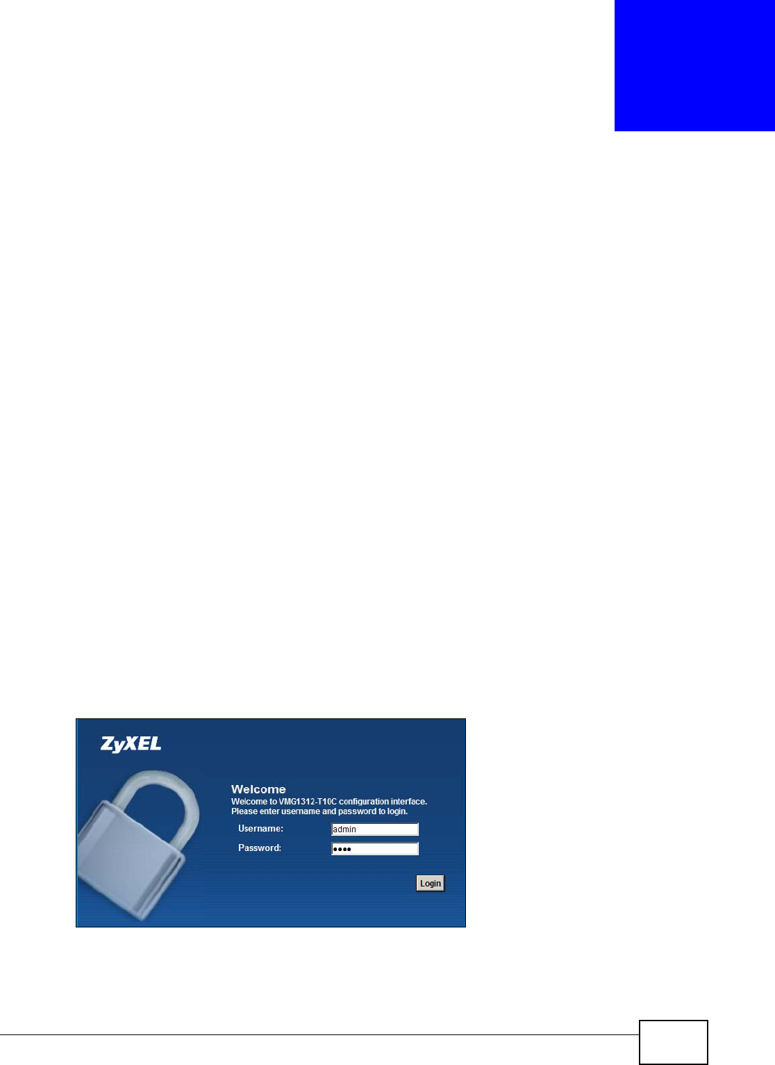
2.1.1 Accessing the Web Configurator
1Make sure your Device hardware is properly connected (refer to the Quick Start Guide).
2Launch your web browser.
3Type "192.168.1.1" as the URL.
4A password screen displays. Type “admin” as the default Username and “1234” as the default
password to access the device’s Web Configurator. Click Login. If you have changed the password,
enter your password and click Login.
Figure 4 Password Screen
Note: For security reasons, the Device automatically logs you out if you do not use the
web configurator for five minutes (default). If this happens, log in again.
Chapter 2 Introducing the Web Configurator
VMG1312-T10C User’s Guide
22
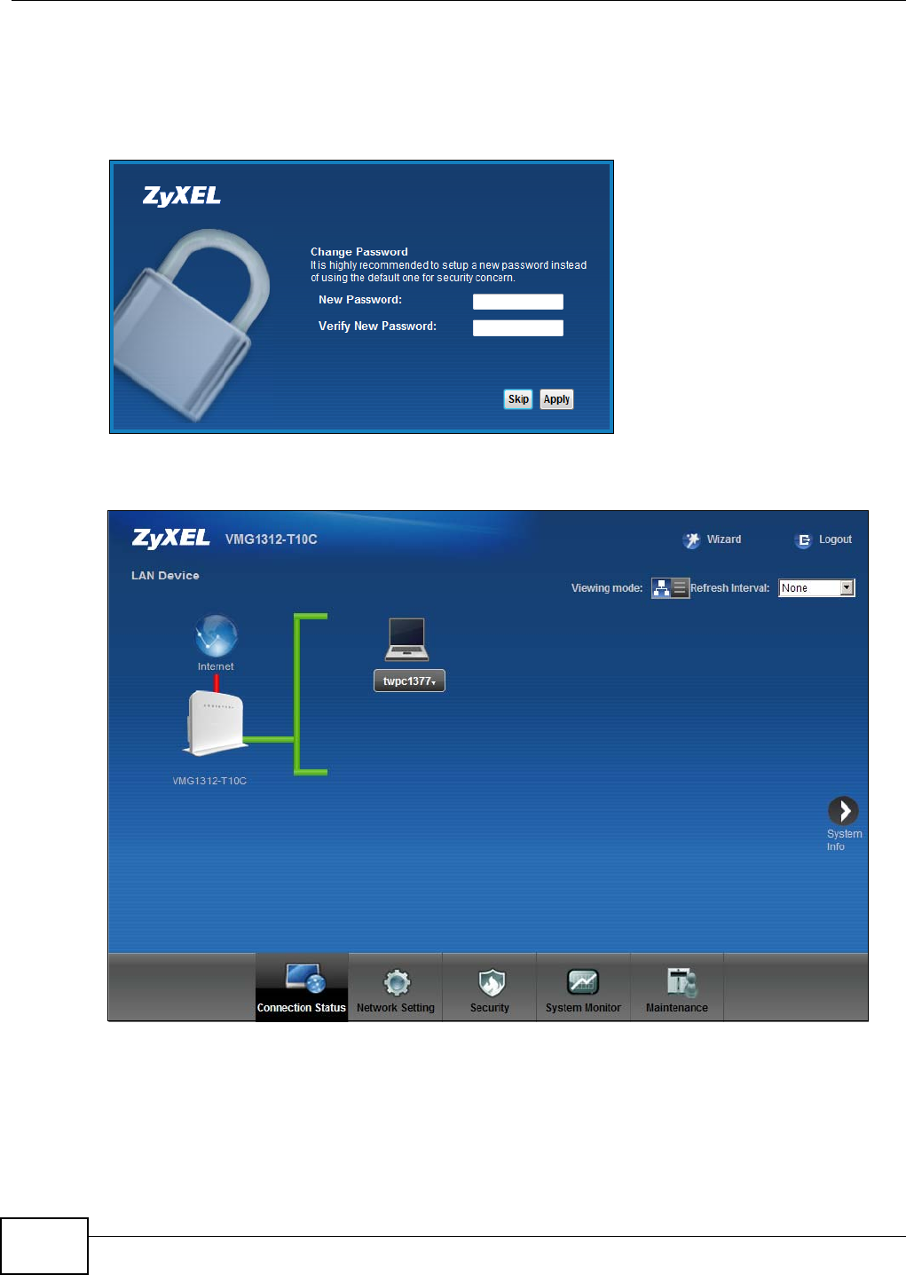
5The following screen displays if you have not yet changed your password. It is strongly
recommended you change the default password. Enter a new password, retype it to confirm and
click Apply; alternatively click Skip to proceed to the main menu if you do not want to change the
password now.
Figure 5 Change Password Screen
6The Connection Status screen appears.
Figure 6 Connection Status
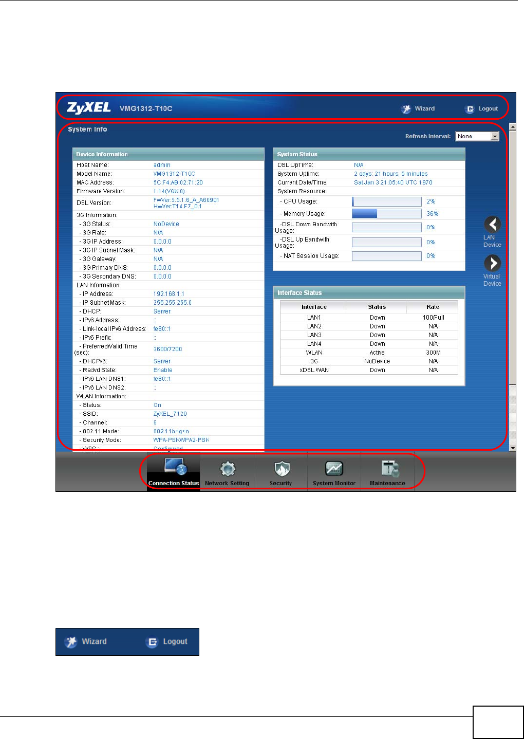
7Click System Info to display the System Info screen, where you can view the Device’s interface
and system information.
Chapter 2 Introducing the Web Configurator
VMG1312-T10C User’s Guide 23
2.2 The Web Configurator Layout
Click Connection Status > System Info to show the following screen.
Figure 7 Web Configurator Layout
As illustrated above, the main screen is divided into these parts:
•A - title bar
•B - main window
•C - navigation panel
2.2.1 Title Bar
The title bar shows the Wizard and Logout icons in the upper right corner.
B
C
A
a
b
Chapter 2 Introducing the Web Configurator
VMG1312-T10C User’s Guide
24
Click the Wizard icon to configure basic initial settings. Click the Logout icon to log out of the web
configurator.
2.2.2 Main Window
The main window displays information and configuration fields. It is discussed in the rest of this
document.
Click LAN Device on the System Info screen (a in Figure 7 on page 23) to display the
Connection Status screen. See Chapter 4 on page 30 for more information on the System Info
and Connection Status screens.
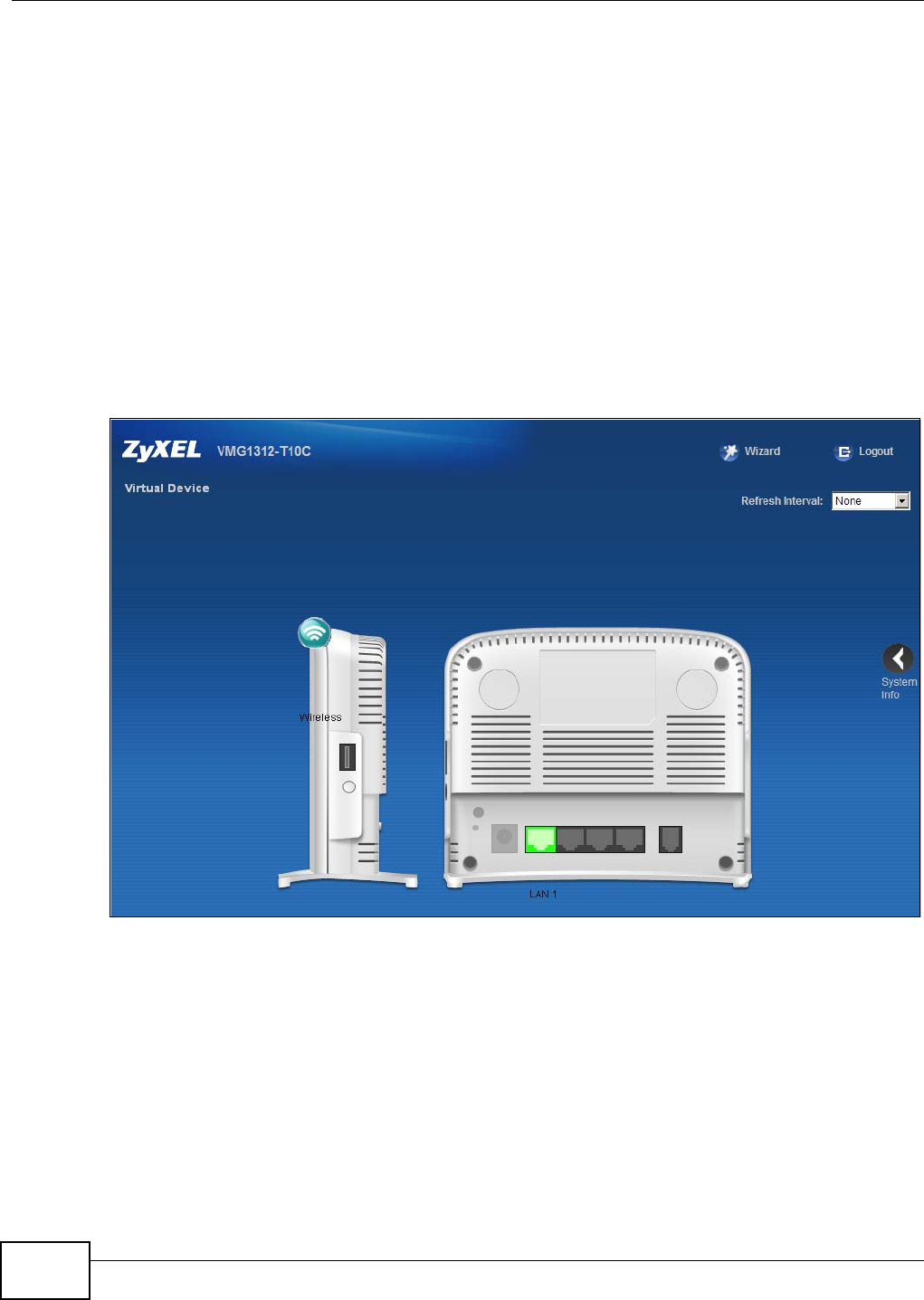
Click Virtual Device on the System Info screen (b in Figure 7 on page 23) to display a visual
graphic showing the connection status of the Device’s ports. The connected ports are in color and
disconnected ports are gray.
Figure 8 Virtual Device
VMG1312-T10C User’s Guide 25
CHAPTER 3
Quick Start
3.1 Overview
Use the Quick Start screens to configure the Device’s time zone, basic Internet access, and
wireless settings.
Note: See the rest of this guide for background information on the features in this
chapter.
3.2 Quick Start Setup
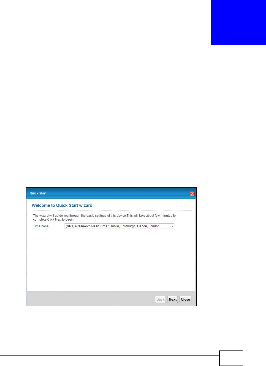
1The Quick Start Wizard appears automatically after login. Or you can click the Start icon in the
top right corner of the web configurator to open the quick start screens. Select the time zone of the
Device’s location and click Next.
Figure 9 Time Zone
Chapter 3 Quick Start
VMG1312-T10C User’s Guide
26
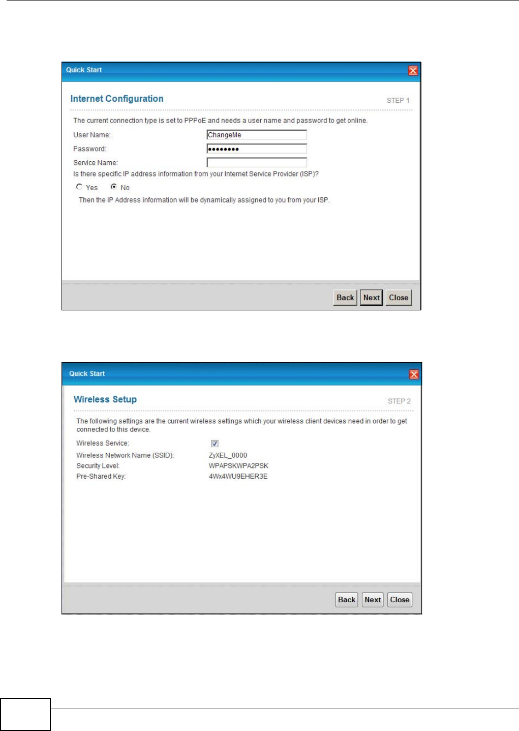
2Enter your Internet connection information in this screen. The screen and fields to enter may vary
depending on your current connection type. Click Next.
Figure 10 WAN Interface Selection
3Turn the wireless LAN on or off. If you keep it on, record the security settings so you can configure
your wireless clients to connect to the Device. Click Save.
Figure 11 Internet Connection
4Your Device saves your settings and attempts to connect to the Internet.

27
PART II
Technical Reference
The appendices provide general information. Some details may not apply to your Device.

28
VMG1312-T10C User’s Guide 29
CHAPTER 4
Connection Status and System Info
4.1 Overview
After you log into the web configurator, the Connection Status screen appears. This shows the
network connection status of the Device and clients connected to it.
Use the System Info screen to look at the current status of the device, system resources,
interfaces (LAN, WAN and WLAN), and SIP accounts. You can also register and unregister SIP
accounts.
If you click Virtual Device on the System Info screen, a visual graphic appears, showing the
connection status of the Device’s ports. See Section 2.2.2 on page 24 for more information.
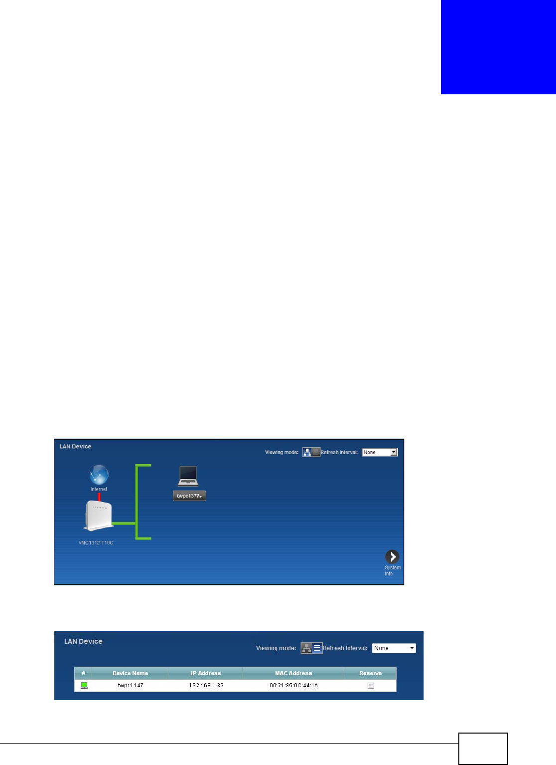
4.2 The Connection Status Screen
Use this screen to view the network connection status of the device and its clients. A warning
message appears if there is a connection problem. You can configure how often you want the
Device to update this screen in Refresh Interval.
Figure 12 Connection Status: Icon View
To view the connected LAN devices in a list, click List View in the Viewing mode selection box.
Figure 13 Connection Status: List View
Chapter 4 Connection Status and System Info
VMG1312-T10C User’s Guide
30
In Icon View, if you want to view information about a client, click the client’s name and Info.
In List View, you can also view the client’s information.
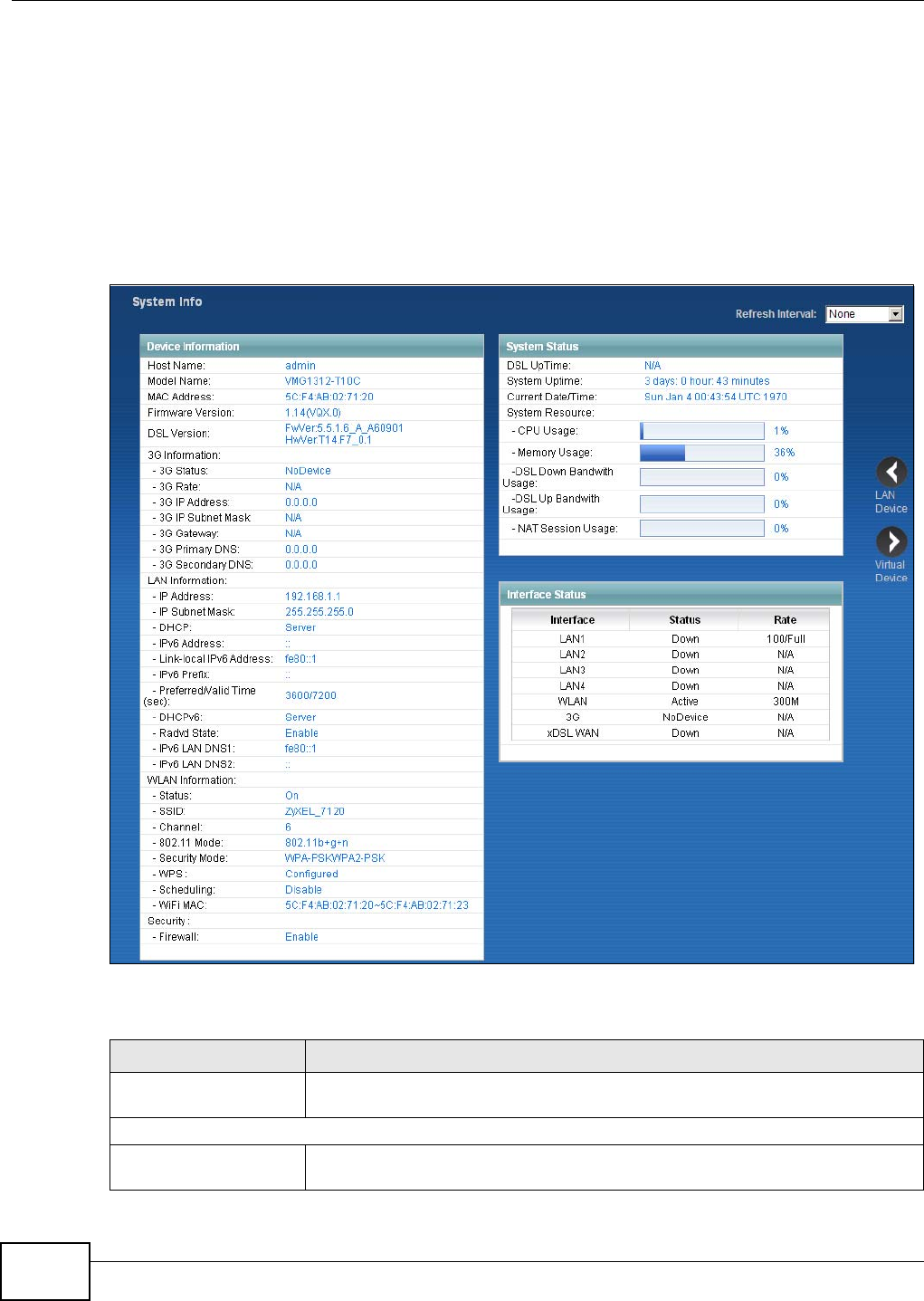
4.3 The System Info Screen
Click Connection Status > System Info to open this screen.
Figure 14 System Info Screen
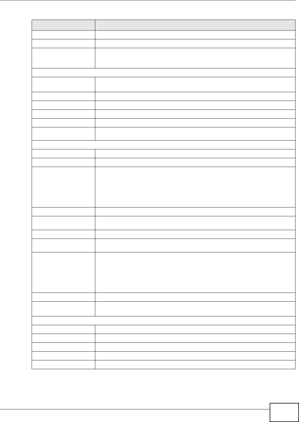
Each field is described in the following table.
Table 2 System Info Screen
LABEL DESCRIPTION
Refresh Interval Select how often you want the Device to update this screen from the drop-down
list box.
Device Information
Host Name This field displays the Device system name. It is used for identification. You can
change this in the Maintenance > System screen’s Host Name field.
Chapter 4 Connection Status and System Info
VMG1312-T10C User’s Guide 31
Model Name This is the model name of your device.
MAC Address This is the MAC (Media Access Control) or Ethernet address unique to your Device.
Firmware Version This field displays the current version of the firmware inside the device. It also
shows the date the firmware version was created. Go to the Maintenance >
Firmware Upgrade screen to change it.
3G Information
3G Status This shows the current status of your 3G connection. NoDevice is shown when no
3G card is inserted.
3G Rate This shows the rate of the 3G connection if it is available.
3G IP Address This shows the IP address for the 3G connection.
3G IP Subnet Mask This shows the current subnet mask for the 3G connection.
3G Gateway This shows the IP address of the 3G connection’s default gateway.
3G Primary/
Secondary DNS This shows the first and second DNS server address assigned by the ISP.
LAN Information
IP Address This field displays the current IP address of the Device in the LAN.
IP Subnet Mask This field displays the current subnet mask in the LAN.
DHCP This field displays what DHCP services the Device is providing to the LAN. Choices
are:
Server - The Device is a DHCP server in the LAN. It assigns IP addresses to other
computers in the LAN.
None - The Device is not providing any DHCP services to the LAN.
IPv6 Address This is the current IPv6 address of the Device in the LAN.
Link-local IPv6
Address This is the current LAN IPv6 link-local address of the Device.
IPv6 Prefix This is the current IPv6 prefix length in the LAN.
Preferred/Valid
Time(sec) This is the Preferred Lifetime and Valid Lifetime in the LAN.
DHCPv6 This field displays what DHCPv6 services the Device is providing to the LAN.
Choices are:
Server - The Device is a DHCPv6 server in the LAN. It assigns IP addresses to
other computers in the LAN.
None - The Device is not providing any DHCPv6 services to the LAN.
Radvd State This shows the status of RADVD.
IPv6 LAN DNS1/
DNS2 This is the first/second DNS server IPv6 address the Device passes to the DHCP
clients.
WLAN Information
Status This shows whether or not the wireless LAN is enabled (on).
SSID This is the descriptive name used to identify the Device in the wireless LAN.
Channel This is the channel number used by the Device now.
802.11 Mode This displays the type of 802.11 mode the Device is using in the wireless LAN.
Security Mode This displays the type of security the Device is using in the wireless LAN.
Table 2 System Info Screen (continued)
LABEL DESCRIPTION

Chapter 4 Connection Status and System Info
VMG1312-T10C User’s Guide
32
WPS Configured displays when a wireless client has connected to the Device or WPS is
enabled and wireless or wireless security settings have been configured.
Unconfigured displays if WPS wireless security settings have not been configured.
Off displays if WPS is disabled.
Scheduling This shows whether wireless scheduling is enabled or disabled.
WiFi MAC This is the MAC (Media Access Control) or Ethernet address unique to your Device’s
WiFi interface.
Security
Firewall This shows whether or not the firewall is enabled (on).
System Status
DSL UpTime This field displays how long the DSL connection has been active.
System Up Time This field displays how long the Device has been running since it last started up.
The Device starts up when you plug it in, when you restart it (Maintenance >
Reboot), or when you reset it (see Section 1.6 on page 18).
Current Date/Time This field displays the current date and time in the Device. You can change this in
Maintenance > Time Setting.
CPU Usage This field displays what percentage of the Device’s processing ability is currently
used. When this percentage is close to 100%, the Device is running at full load,
and the throughput is not going to improve anymore. If you want some
applications to have more throughput, you should turn off other applications.
Memory Usage This field displays what percentage of the Device’s memory is currently used.
Usually, this percentage should not increase much. If memory usage does get
close to 100%, the Device is probably becoming unstable, and you should restart
the device. See Chapter 24 on page 203, or turn off the device (unplug the power)
for a few seconds.
DSL Down Bandwith
Usage This field displays what percentage of the Device’s downstream DSL bandwidth is
currently used. When this percentage is close to 100%, the Device is running at
full load, and the throughput is not going to improve anymore. If you want some
applications to have more throughput, you should turn off other applications.
DSL Up Bandwith
Usage This field displays what percentage of the Device’s upstream DSL bandwidth is
currently used. When this percentage is close to 100%, the Device is running at
full load, and the throughput is not going to improve anymore. If you want some
applications to have more throughput, you should turn off other applications.
NAT Session Usage This field displays what percentage of the Device supported NAT sessions are
currently being used.
Interface Status
Interface This column displays each interface the Device has.
Table 2 System Info Screen (continued)
LABEL DESCRIPTION

Chapter 4 Connection Status and System Info
VMG1312-T10C User’s Guide 33
Status This field indicates whether or not the Device is using the interface.
For the LAN interfaces, this field displays Up when the Device is using the interface
and Down when the Device is not using the interface.
For the WLAN interface, it displays Active when WLAN is enabled or Down when
WLAN is disabled.
For the 3G USB interface, this field displays Up when using the interface and
NoDevice when no device is detected in any USB slot.
For the xDSL WAN interface, this field displays Down when the line is down or Up
when line is up or connected.
Rate For the LAN interface, this displays the port speed and duplex setting.
For the WLAN interface, it displays the maximum transmission rate when WLAN is
enabled or N/A when WLAN is disabled.
For the 3G interface, it displays the maximum transmission rate when 3G is
enabled or N/A when 3G is disabled.
For the xDSL WAN interface, it displays the downstream and upstream
transmission rate.
Table 2 System Info Screen (continued)
LABEL DESCRIPTION

Chapter 4 Connection Status and System Info
VMG1312-T10C User’s Guide
34
VMG1312-T10C User’s Guide 35
CHAPTER 5
WAN Setup
5.1 Overview
This chapter describes how to configure WAN settings from the WAN screens. Use these screens to
configure your Device for Internet access.
A WAN (Wide Area Network) connection connects to another network or the Internet. It connects
your private networks (such as a LAN (Local Area Network) and other networks, so that a computer
in one location can communicate with computers in other locations.
Figure 15 LAN and WAN
3G (third generation) standards for the sending and receiving of voice, video, and data in a mobile
environment.
You can attach a 3G wireless adapter to the USB port and set the Device to use this 3G connection
as your WAN or a backup when the wired WAN connection fails.
Figure 16 3G WAN Connection
5.1.1 What You Can Do in the WAN Screens
•Use the Internet Connection screen (Section 5.2 on page 38) to configure the WAN settings on
the Device for Internet access.
WAN
LAN

Chapter 5 WAN Setup
VMG1312-T10C User’s Guide
36
•Use the More Connections screen (Section 5.3 on page 44) to set up additional Internet access
connections.
•Use the 3G Backup screen to configure 3G WAN connection (Section 5.4 on page 50).
5.1.2 What You Need to Know About WAN
Encapsulation Method
Encapsulation includes data from an upper layer protocol into a lower layer protocol. To set up a
WAN connection to the Internet, you need to use the same encapsulation method used by your ISP
(Internet Service Provider). If your ISP offers a dial-up Internet connection using PPPoE (PPP over
Ethernet) or PPPoA, they should also provide a username and password (and service name) for user
authentication.
WAN IP Address
The Device uses its WAN IP address to connect to the Internet and communicate with devices in
other networks. It can be static (fixed) or dynamically assigned by the ISP when the Device
connects to the Internet.
If your ISP assigns you a static WAN IP address, they should also assign you the subnet mask and
DNS server IP address(es) (and a gateway IP address if you use the Ethernet or ENET ENCAP
encapsulation method).
Multicast
Traditionally, IP packets are transmitted in one of either two ways - Unicast (1 sender - 1 recipient)
or Broadcast (1 sender - everybody on the network). Multicast delivers IP packets to a group of
hosts on the network - not everybody and not just one.
IGMP
Devices use the IGMP (Internet Group Management Protocol) network-layer protocol to establish
membership in a multicast group - it does not carry user data. IGMP versions 2 and 3 offer
improvements over the widely-used version 1.
IPv6
IPv6 (Internet Protocol version 6) provides increased IP address space and enhanced features in
comparison to IPv4. The Device supports IPv4/IPv6 dual stack and can connect to IPv4 and IPv6
networks.
IPv6 Rapid Deployment
Use IPv6 Rapid Deployment (6rd) when the local network uses IPv6 and the ISP has an IPv4
network. When the Device has an IPv4 WAN address and you set IPv6/IPv4 Dual Stack to IPv4,
you can enable 6rd to encapsulate IPv6 packets in IPv4 packets to cross the ISP’s IPv4 network.
The Device generates a global IPv6 prefix from its IPv4 WAN address and tunnels IPv6 traffic to the
ISP’s Border Relay router (BR in the figure) to connect to the native IPv6 Internet. The local
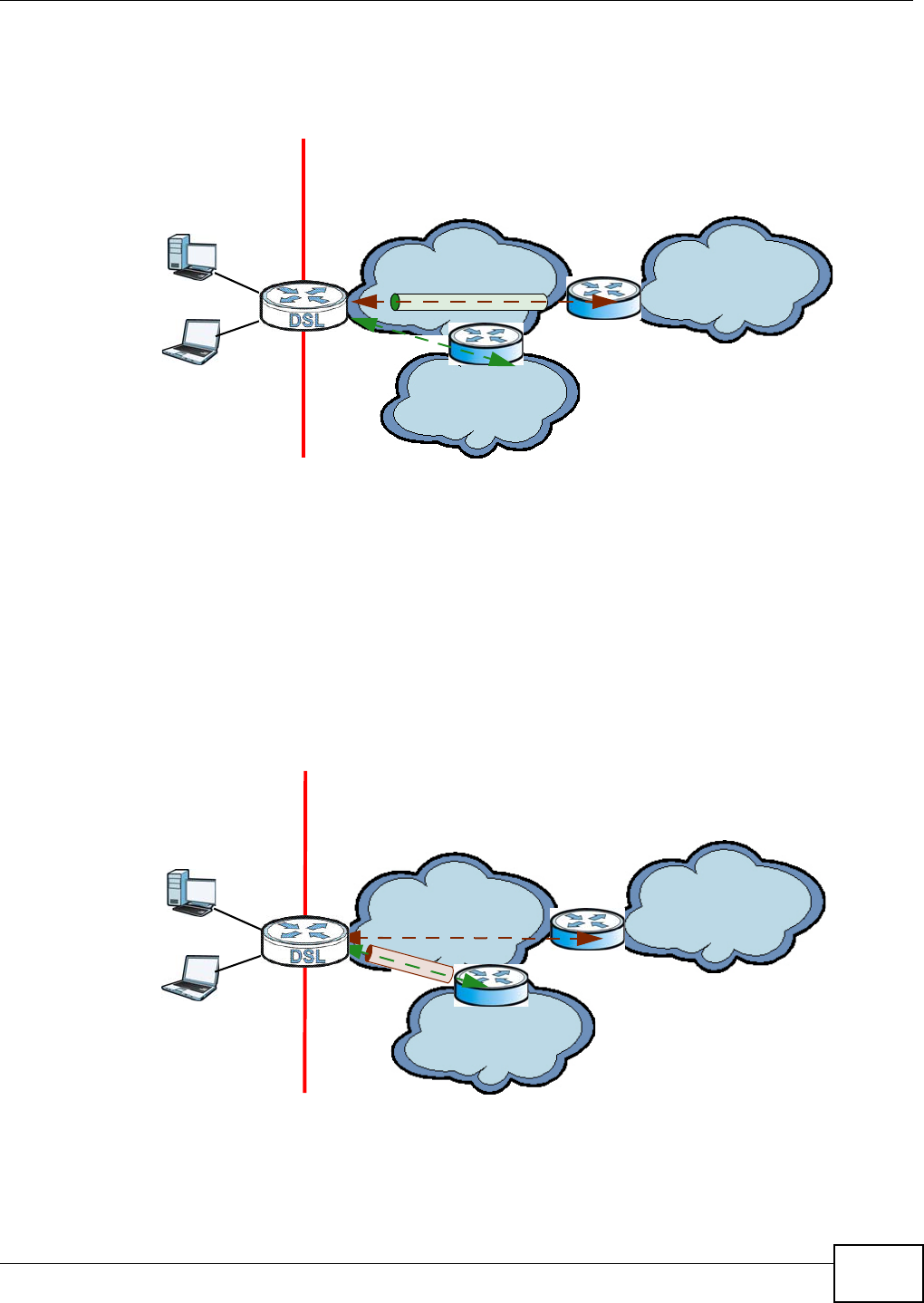
Chapter 5 WAN Setup
VMG1312-T10C User’s Guide 37
network can also use IPv4 services. The Device uses it’s configured IPv4 WAN IP to route IPv4
traffic to the IPv4 Internet.
Figure 17 IPv6 Rapid Deployment
Dual Stack Lite
Use Dual Stack Lite when local network computers use IPv4 and the ISP has an IPv6 network.
When the Device has an IPv6 WAN address and you set IPv6/IPv4 Dual Stack to IPv6, you can
enable Dual Stack Lite to use IPv4 computers and services.
The Device tunnels IPv4 packets inside IPv6 encapsulation packets to the ISP’s Address Family
Transition Router (AFTR in the graphic) to connect to the IPv4 Internet. The local network can also
use IPv6 services. The VDSL Router uses it’s configured IPv6 WAN IP to route IPv6 traffic to the
IPv6 Internet.
Figure 18 Dual Stack Lite
3G
3G (Third Generation) is a digital, packet-switched wireless technology. Bandwidth usage is
optimized as multiple users share the same channel and bandwidth is only allocated to users when
ISP (IPv4) IPv6 Internet
IPv4
IPv6
BR
IPv6 in IPv4
IPv4 Internet
IPv4
+
LAN
- IPv6
- IPv4
WAN
- IPv4
- IPv6 in IPv4
ISP (IPv6) IPv6 Internet
IPv6
AFTR
IPv4 in IPv6
IPv4 Internet
IPv6 IPv4
+
LAN
- IPv6
- IPv4
WAN
- IPv6
- IPv4 in IPv6

Chapter 5 WAN Setup
VMG1312-T10C User’s Guide
38
they send data. It allows fast transfer of voice and non-voice data and provides broadband Internet
access to mobile devices.
Finding Out More
See Section 5.5 on page 52 for technical background information on WAN.
5.1.3 Before You Begin
You need to know your Internet access settings such as encapsulation and WAN IP address. Get this
information from your ISP.
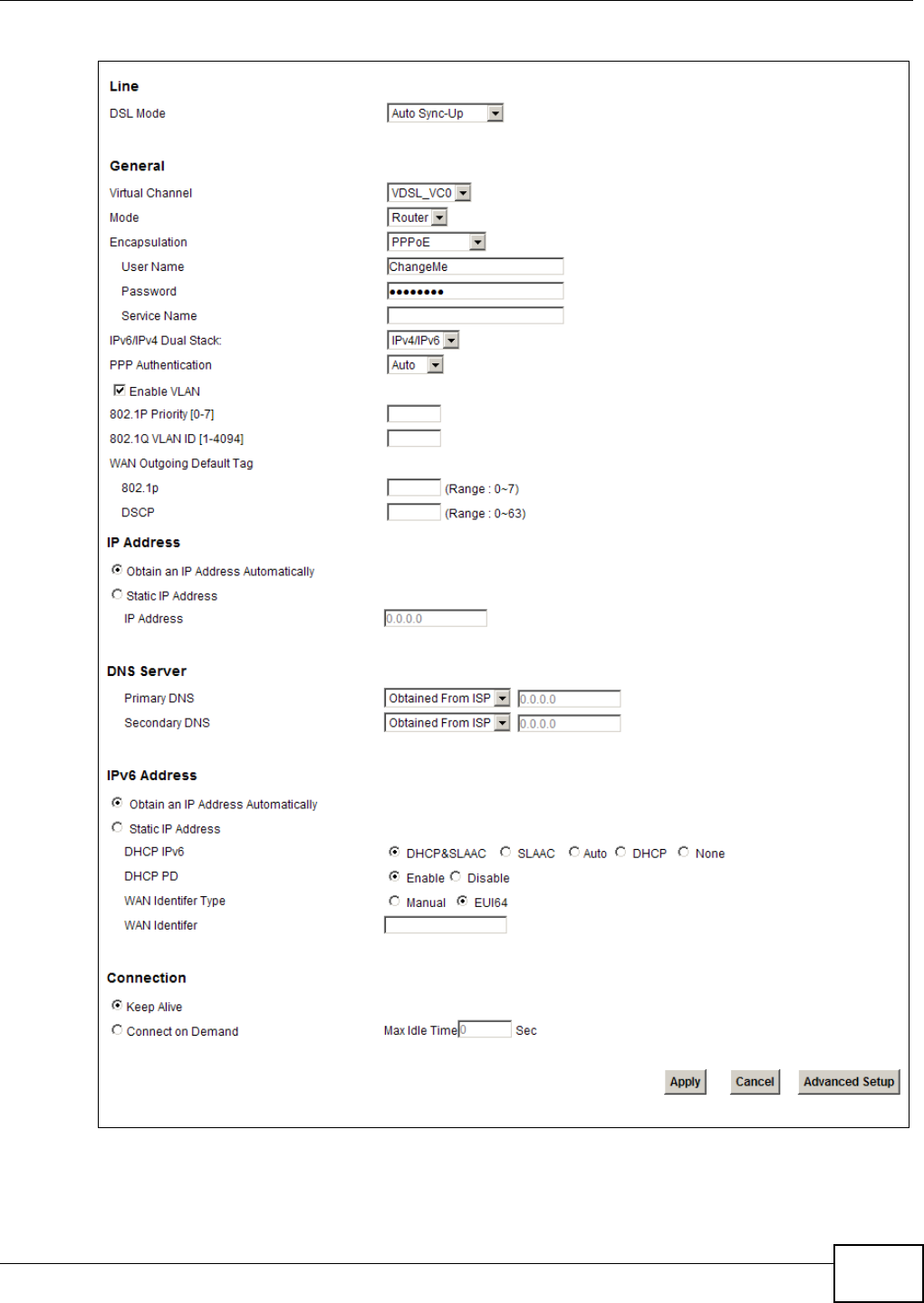
5.2 The Internet Connection Screen
Use this screen to change your Device’s WAN settings. Click Network Setting > Broadband >
Internet Connection. The screen differs by the mode and encapsulation you select.
Chapter 5 WAN Setup
VMG1312-T10C User’s Guide 39
Figure 19 Network Setting > Broadband >Internet Connection

Chapter 5 WAN Setup
VMG1312-T10C User’s Guide
40
The following table describes the labels in this screen.
Table 3 Network Setting > Broadband >Internet Connection
LABEL DESCRIPTION
Line
DSL Mode Select the kind of connection your Device uses to connect to the ISP.
Use Auto Sync-Up if you are not sure which type to choose.
Use VDSL2, ADSLT1.413, ADSLG.DMT, ADSLG.lite, ADSL2, ADSL2+,
ADSL2_AnnexM, ADSL2+_AnnexM, or READSL2 if you know the specific type of
DSL the Device uses to connect to the ISP.
Type Select the kind of connection your Device uses to connect to the ISP.
Use Auto Sync-Up if you are not sure which type to choose.
Use VDSL, ADSL2+, ADSL2, G.DMT, T1.413 or G.lite if you know the specific type
of DSL the Device uses to connect to the ISP.
Use Ethernet if you use an Ethernet port Device to connect to the ISP.
Note: Changing the line type between DSL and Ethernet causes the Device to restart.
Virtual Channel When you set DSL Mode to Auto Sync-Up, select whether to configure the ADSL
virtual circuit or the first VDSL virtual circuit.
When you set DSL Mode to ADSL or VDSL, this uses the virtual circuit of that type.
Mode Select Router (default) from the drop-down list box if your ISP gives you one IP
address only and you want multiple computers to share an Internet account. Select
Bridge when your ISP provides you more than one IP address and you want the
connected computers to get individual IP address from ISP’s DHCP server directly. If
you select Bridge, you cannot use Firewall, DHCP server and NAT on the Device.
Encapsulation Select the method of encapsulation used by your ISP from the drop-down list box.
Choices vary depending on the mode you select in the Mode field.
If you select Router in the Mode field, select ENET ENCAP, IPoA, PPPoE, or
PPPoA. IPoA and PPPoA are not available for VDSL virtual channel.
If you select Bridge in the Mode field, you do not configure the method of
encapsulation.
User Name (PPPoA and PPPoE encapsulation only) Enter the user name exactly as your ISP
assigned. If assigned a name in the form user@domain where domain identifies a
service name, then enter both components exactly as given.
Password (PPPoA and PPPoE encapsulation only) Enter the password associated with the user
name above.
Service Name (PPPoE only) Type the name of your PPPoE service here.
Multiplex This displays for an ADSL virtual channel. Select the method of multiplexing used by
your ISP from the drop-down list. Choices are VC-Mux or LLC.
IPv6/IPv4 Dual Stack This is not available if you select PPPoA in the Encapsulation field.
Select IPv4 to have the Device use only IPv4.
Select IPv4/IPv6 to let the Device connect to IPv4 and IPv6 networks and choose
the protocol for applications according to the address type.
Select IPv6 to have the Device use only IPv6.

Chapter 5 WAN Setup
VMG1312-T10C User’s Guide 41
PPP Authentication This is available if you select PPPoE or PPPoA in the Encapsulation field.
The Device supports PAP (Password Authentication Protocol) and CHAP (Challenge
Handshake Authentication Protocol). CHAP provides more security than PAP; however,
PAP has higher availability on more platforms.
Use the drop-down list box to select an authentication protocol for outgoing calls.
Options are:
Auto- Your Device accepts either CHAP or PAP when requested by this remote node.
CHAP - Your Device accepts CHAP only.
PAP - Your Device accepts PAP only.
Virtual Circuit ID VPI (Virtual Path Identifier) and VCI (Virtual Channel Identifier) define a virtual
circuit. Refer to the appendix for more information.
Enable VLAN This field is available only when you have a VDSL virtual channel.
Select this to add the IEEE 802.1q Virtual LAN (VLAN) tag you specify to the traffic
sent out through this connection.
802.1P Priority IEEE 802.1p defines up to 8 separate traffic types by inserting a tag into a MAC-layer
frame that contains bits to define class of service.
Enter the IEEE 802.1p priority level (from 0 to 7) to add to traffic through this
connection. The greater the number, the higher the priority level.
802.1Q VLAN ID Enter the VLAN ID number for traffic sent through this connection.
VPI Enter the VPI assigned to you (0 to 255).
VCI Enter the VCI assigned to you (32 to 65535).
WAN Outgoing
Default Tag
Enter the IEEE 802.1p priority level and DSCP value for the WAN interface.
802.1p This field is available only when VLAN is enabled.
Enter the IEEE 802.1p priority level for this WAN interface connection.
DSCP Enter a DSCP (DiffServ Code Point) value to have the Device add it in the packets sent
by this WAN interface.
IP Address You can use these options when you set the Mode field to Router and the IPv6/
IPv4 Dual Stack field to IPv4 or IPv4/IPv6.
Select Obtain an IP Address Automatically if the ISP assigns you a dynamic IP
address; otherwise select Static IP Address and type your ISP assigned IP address
in the IP Address field below.
Static IP Address Select this option If the ISP assigned a fixed IP address.
IP Address Enter the static IP address provided by your ISP.
IPv6 Tunnel Mode This is available if you select ENET ENCAP or PPPoE in the Encapsulation field and
IPv4 in the IPv6/IPv4 Dual Stack field.
Select 6rd to tunnel IPv6 traffic from the local network through the ISP’s IPv4
network.
Select 6to4 to enable IPv6 to IPv4 tunneling. This will encapsulate IPv6 packets in
IPv4 packets so they can travel through IPv4 networks.
Relay Server If you select 6to4 in the IPv6 Tunnel Mode field, enter the tunneling relay server's
IPv4 address in this field.
Via DHCP Option
212 Select this to have the Device detect it automatically through DHCP option 212.
Manual Select this to manually enter the following 6rd information.
Table 3 Network Setting > Broadband >Internet Connection (continued)
LABEL DESCRIPTION

Chapter 5 WAN Setup
VMG1312-T10C User’s Guide
42
6rd Prefix Enter an IPv6 prefix for tunneling IPv6 traffic to the ISP’s Border Relay router and
connecting to the native IPv6 Internet.
6rd Prefix Length Enter the IPv6 prefix length.
IPv4 Mask Length Enter the subnet mask number for the IPv4 network.
Relay Server Enter the relay server’s IPv4 address.
DNS Server
Primary / Secondary
DNS
Set how the Device gets the IP addresses of the DNS servers it uses.
UserDefined - enter a static IP address.
Obtained From ISP - when the Device gets its IP address automatically, you can
select this to have it also get the DNS server address.
None - the Device does not use the DNS server entry.
IPv6 Address
Obtain an IP Address
Automatically
Select this option to have the Device use the IPv6 prefix from the connected router’s
Router Advertisement (RA) to generate an IPv6 address.
Static IP Address When you set the Encapsulation field to ENET ENCAP, select the Static IP
Address option if you have a fixed IPv6 address assigned by your ISP.
DHCP IPv6 Select DHCP&SLAAC to have the use both DHCPv6 and SLAAC to get an IP address.
Select DHCP to obtain an IPv6 address from a DHCPv6 server. The IP address
assigned by a DHCPv6 server has priority over the IP address automatically generated
by the Device using the IPv6 prefix from an RA.
Select Auto to have the Device try to use DHCPv6 to get an IP address and then
SLAAC if DHCPv6 does not work.
Select SLAAC (Stateless address autoconfiguration) to have the Device use the prefix
to automatically generate a unique IP address that does not need to be maintained by
a DHCP server.
Select None if you do not want the Device to obtain an IPv6 address from a DHCPv6
server.
DHCP PD Select Enable to use DHCP PD (Prefix Delegation) to allow the Device to pass the
IPv6 prefix information to its LAN hosts. The hosts can then use the prefix to generate
their IPv6 addresses.
Dual Stack Lite The Dual Stack Lite fields display when you set the IPv6/IPv4 Dual Stack field to
IPv6. Enable Dual Stack Lite to let local computers use IPv4 through an ISP’s IPv6
network.
Mode Select Manual if you have the IPv6 address of the Address Family Transition Router
(AFTR), otherwise select Auto to have the Device detect it automatically through
DHCPv6.
Remote IPv6
Address When you set the Mode field to Manual, specify the AFTR IPv6 address.
IPv6 Address When you enable Static IP Address, enter the IPv6 address of the Device in the
WAN.
Prefix Length When you enable Static IP Address, enter the IPv6 prefix length in the WAN here.
IPv6 Default Gateway When you enable Static IP Address, enter the IPv6 address of the default gateway
here.
IPv6 DNS Server1 When you enable Static IP Address, enter the primary DNS server IPv6 address
here.
IPv6 DNS Server2 When you enable Static IP Address, enter the secondary DNS server IPv6 address
here.
Table 3 Network Setting > Broadband >Internet Connection (continued)
LABEL DESCRIPTION
Chapter 5 WAN Setup
VMG1312-T10C User’s Guide 43
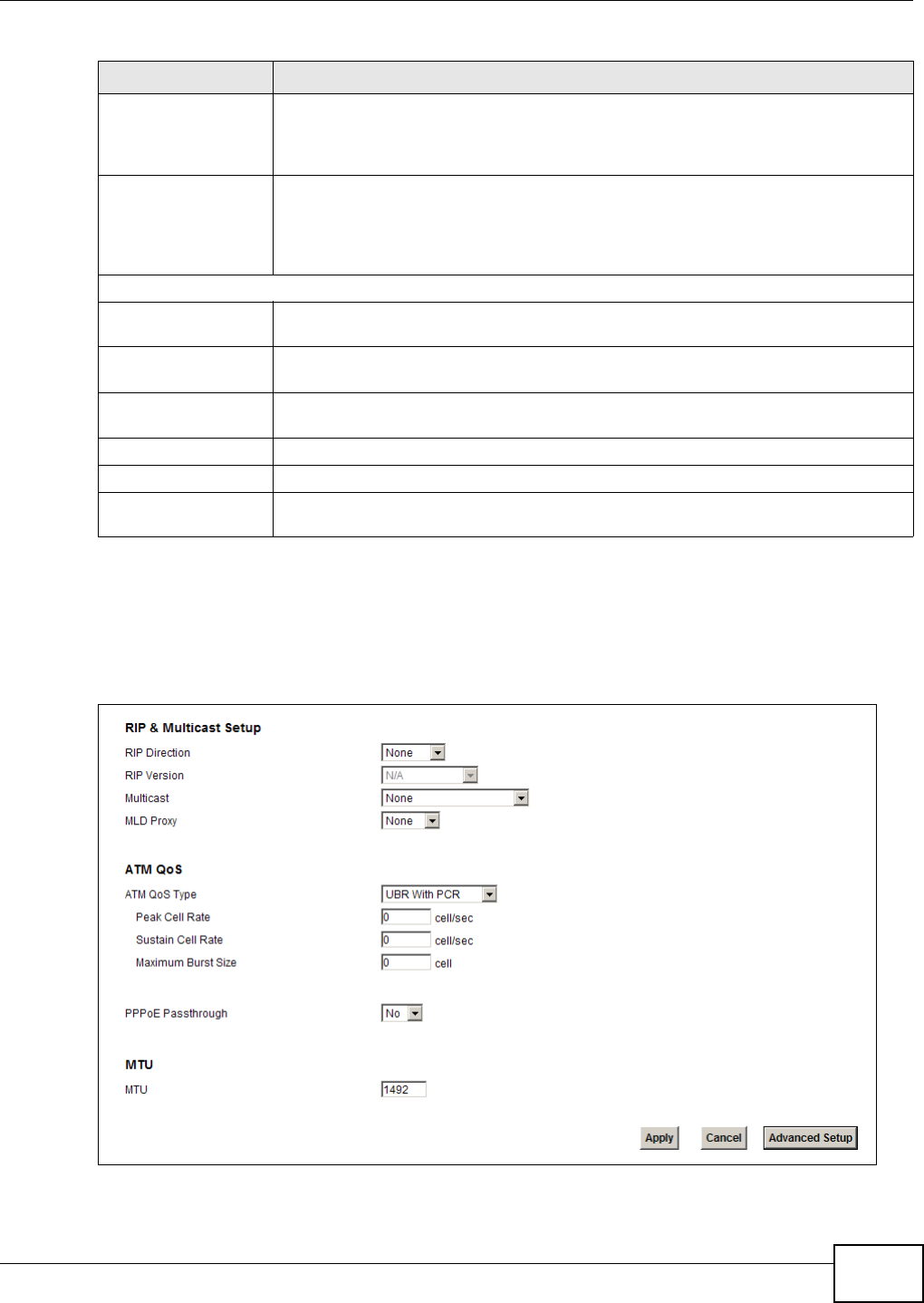
5.2.1 Advanced Internet Connection
Use this screen to edit your Device's advanced WAN settings. Click the Advanced Setup button in
the Internet Connection screen. The screen appears as shown.
Figure 20 Internet Connection: Advanced Setup
WAN Identifier Type Select Manual to manually enter a WAN Identifier as the interface ID to identify the
WAN interface. The Device appends the WAN Identifier to the IPv6 address prefix to
create the routable global IPv6 address. Select EUI64 to use the EUI-64 format to
generate an interface ID from the MAC address of the WAN interface.
WAN Identifier If you selected Manual, enter the WAN Identifier in this field. The WAN identifier
should be unique and 64 bits in hexadecimal form. Every 16 bit block should be
separated by a colon as in XXXX:XXXX:XXXX:XXXX where X represents a
hexadecimal character. Blocks of zeros can be represented with double colons as in
XXXX:XXXX::XXXX.
Connection (PPPoA and PPPoE encapsulation only)
Keep Alive Select Keep Alive when you want your connection up all the time. The Device will try
to bring up the connection automatically if it disconnects.
Connect on Demand Select Connect on Demand when you don't want the connection up all the time and
specify an idle time-out in the Max Idle Timeout field.
Max Idle Timeout Specify an idle time-out in the Max Idle Timeout field when you select Connect on
Demand. The default setting of 0 means the Internet session will not timeout.
Apply Click this to save your changes.
Cancel Click this to restore your previously saved settings.
Advanced Setup Click this to display the Advanced Internet Connection section and edit more
details of your WAN setup.
Table 3 Network Setting > Broadband >Internet Connection (continued)
LABEL DESCRIPTION

Chapter 5 WAN Setup
VMG1312-T10C User’s Guide
44
The following table describes the labels in this screen.
Table 4 Internet Connection: Advanced Setup
LABEL DESCRIPTION
RIP & Multicast Setup This section does not apply when you configure the Device to bridge mode.
RIP Direction RIP (Routing Information Protocol) allows a router to exchange routing information
with other routers. Use this field to control how much routing information the Device
sends and receives on the subnet.
Select the RIP direction from None, Both, In Only and Out Only.
RIP Version This field does not apply if you select None in the RIP Direction field.
Select the RIP version from RIP-1, RIP-2B/RIP-2M.
Multicast Multicast packets are sent to a group of computers on the LAN and are an alternative
to unicast packets (packets sent to one computer) and broadcast packets (packets
sent to every computer).
Devices use the IGMP (Internet Group Management Protocol) network-layer protocol
to establish membership in a multicast group. Select IGMP v1/IGMP v2/IGMP v3.
Select None to disable it.
MLD Proxy Select the version of MLD proxy (v1 or v2) to have the Device act as for this
connection. This allows the Device to get subscription information and maintain a
joined member list for each multicast group. It can reduce multicast traffic
significantly. Select None to turn off MLD proxy.
ATM QoS This section is available when the connection’s Virtual Channel field is set to an
ADSL option.
ATM QoS Type Select CBR (Continuous Bit Rate) to specify fixed (always-on) bandwidth for voice or
data traffic. Select UBR With PCR (Unspecified Bit Rate with Peak Cell Rate) for
applications that are non-time sensitive, such as e-mail. Select Non Realtime VBR
(Variable Bit Rate-non Real Time) or Realtime VBR (Variable Bit Rate-Real Time) for
bursty traffic and bandwidth sharing with other applications.
Peak Cell Rate Divide the DSL line rate (bps) by 424 (the size of an ATM cell) to find the Peak Cell
Rate (PCR). This is the maximum rate at which the sender can send cells. Type the
PCR here.
Sustain Cell Rate The Sustain Cell Rate (SCR) sets the average cell rate (long-term) that can be
transmitted. Type the SCR, which must be less than the PCR. Note that system default
is 0 cells/sec.
Maximum Burst
Size Maximum Burst Size (MBS) refers to the maximum number of cells that can be sent at
the peak rate. Type the MBS, which is less than 65535.
PPPoE Passthrough If the encapsulation type is PPPoE, select this to enable PPPoE Passthrough. In
addition to the Device’s built-in PPPoE client, you can select this to allow hosts on the
LAN to use PPPoE client software on their computers to connect to the ISP via the
device. Each host can have a separate account and a public WAN IP address.
MTU
MTU The Maximum Transmission Unit (MTU) defines the size of the largest packet allowed
on an interface or connection. Enter the MTU in this field.
For ENET ENCAP, the MTU value is 1500.
For PPPoE, the MTU value is 1492.
For PPPoA and RFC 1483, the MTU is 65535.
Apply Click this to save your changes.
Cancel Click this to restore your previously saved settings.
Advanced Setup Click this to close the Advanced Internet Connection section.
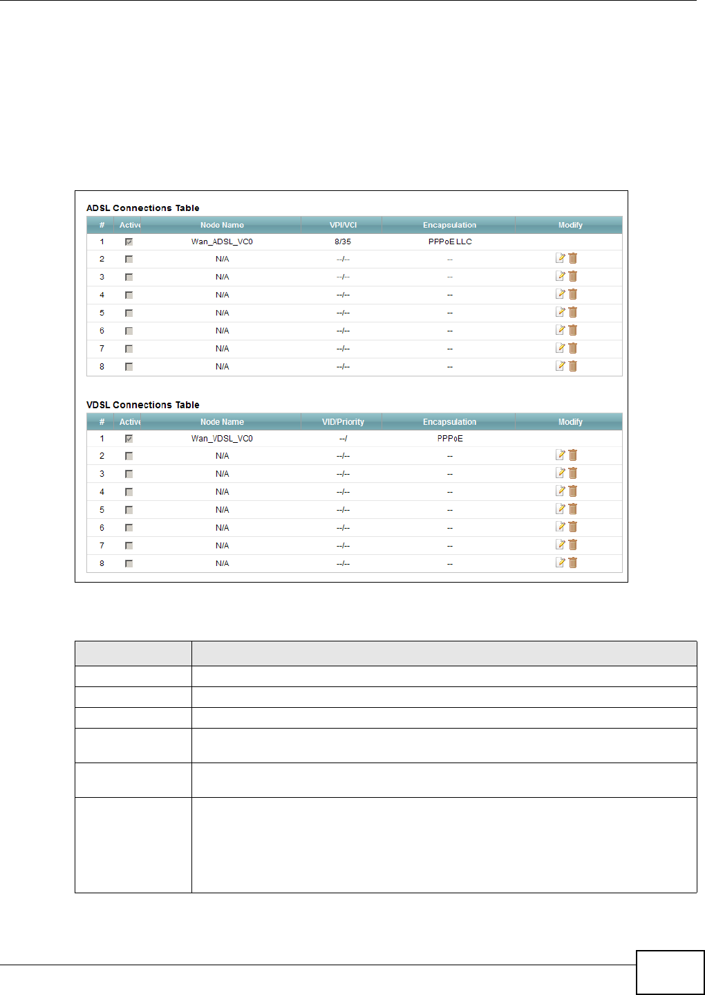
Chapter 5 WAN Setup
VMG1312-T10C User’s Guide 45
5.3 The More Connections Screen
The Device allows you to configure more than one Internet access connection. To configure
additional Internet access connections click Network Setting > Broadband > More
Connections. The screen differs by the encapsulation you select. When you use the Broadband >
Internet Connection screen to set up Internet access, you are configuring the first WAN
connection.
Figure 21 Network Setting > Broadband > More Connections
The following table describes the labels in this screen.
Table 5 Network Setting > Broadband > More Connections
LABEL DESCRIPTION
# This is an index number indicating the number of the corresponding connection.
Active This field indicates whether the connection is active or not. This field is read-only.
Node Name This is the name of the Internet connection.
VPI/VCI This field displays the Virtual Path Identifier (VPI) and Virtual Channel Identifier (VCI)
numbers configured for this WAN connection.
Encapsulation This field indicates the encapsulation method and multiplexing type the Internet
connection uses.
Modify The first (ISP) connection is read-only in this screen. Use the Broadband > Internet
Connection screen to edit it.
Click the Edit icon to edit the Internet connection settings. Click this icon on an empty
configuration to add a new Internet access setup.
Click the Remove icon to delete the Internet access setup from your connection list.
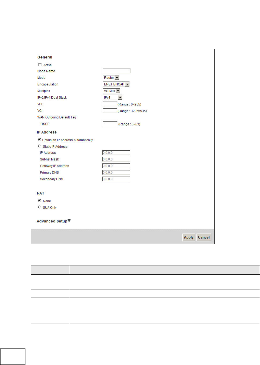
Chapter 5 WAN Setup
VMG1312-T10C User’s Guide
46
5.3.1 More Connections Edit
Use this screen to configure a connection. Click the Edit icon in the More Connections screen to
display the following screen.
Figure 22 More Connections: Edit
The following table describes the labels in this screen.
Table 6 More Connections: Edit
LABEL DESCRIPTION
General
Active Select the check box to activate or clear the check box to deactivate this connection.
Node Name Enter a unique, descriptive name of up to 13 ASCII characters for this connection.
Mode Select Router from the drop-down list box if your ISP allows multiple computers to share
an Internet account.
If you select Bridge, the Device will forward any packet that it does not route to this
remote node; otherwise, the packets are discarded.

Chapter 5 WAN Setup
VMG1312-T10C User’s Guide 47
Encapsulation Select the method of encapsulation used by your ISP from the drop-down list box. Choices
vary depending on the mode you select in the Mode field.
If you select Router in the Mode field, select ENET ENCAP, IPoA, PPPoE, or PPPoA.
IPoA and PPPoA are not available for VDSL virtual channel.
If you select Bridge in the Mode field, you do not configure the method of encapsulation.
User Name (PPPoA and PPPoE encapsulation only) Enter the user name exactly as your ISP assigned.
If assigned a name in the form user@domain where domain identifies a service name, then
enter both components exactly as given.
Password (PPPoA and PPPoE encapsulation only) Enter the password associated with the user name
above.
Service
Name (PPPoE only) Type the name of your PPPoE service here.
Multiplex Select the method of multiplexing used by your ISP from the drop-down list. Choices are
VC-Mux or LLC.
By prior agreement, a protocol is assigned a specific virtual circuit, for example, VC1 will
carry IP. If you select VC-mux, specify separate VPI and VCI numbers for each protocol.
For LLC-based multiplexing or PPP encapsulation, one VC carries multiple protocols with
protocol identifying information being contained in each packet header. In this case, only
one set of VPI and VCI numbers need be specified for all protocols.
IPv6/IPv4 Dual
Stack
Select IPv4 to have the Device use only IPv4.
Select IPv4/IPv6 to let the Device connect to IPv4 and IPv6 networks and choose the
protocol for applications according to the address type.
Select IPv6 to have the Device use only IPv6.
PPP
Authentication
The Device supports PAP (Password Authentication Protocol) and CHAP (Challenge
Handshake Authentication Protocol). CHAP is more secure than PAP; however, PAP is
readily available on more platforms.
Use the drop-down list box to select an authentication protocol for outgoing calls. Options
are:
AUTO - Your Device accepts either CHAP or PAP when requested by this remote node.
CHAP - Your Device accepts CHAP only.
PAP - Your Device accepts PAP only.
Virtual Circuit ID VPI (Virtual Path Identifier) and VCI (Virtual Channel Identifier) define a virtual circuit.
Refer to the appendix for more information.
Enable VLAN This field is available only for a VDSL virtual channel.
Select this to add the IEEE 802.1q Virtual LAN (VLAN) tag you specify to the traffic sent
out through this connection.
802.1P Priority IEEE 802.1p defines up to 8 separate traffic types by inserting a tag into a MAC-layer
frame that contains bits to define class of service.
Enter the IEEE 802.1p priority level (from 0 to 7) to add to traffic through this connection.
The greater the number, the higher the priority level.
802.1Q VLAN ID Enter the VLAN ID number for traffic sent through this connection.
VPI Enter the VPI assigned to you (0 to 255).
VCI Enter the VCI assigned to you (32 to 65535).
WAN Outgoing
Default Tag
Enter the IEEE 802.1p priority level and DSCP value for the WAN interface.
Table 6 More Connections: Edit (continued)
LABEL DESCRIPTION

Chapter 5 WAN Setup
VMG1312-T10C User’s Guide
48
802.1p This field is available only when VLAN is enabled.
Enter the IEEE 802.1p priority level for this WAN interface connection.
DSCP Enter a DSCP (DiffServ Code Point) value to have the Device add it in the packets sent by
this WAN interface.
IP Address You can use these options when you set the Mode field to Router and the IPv6/IPv4
Dual Stack field to IPv4 or IPv4/IPv6.
Select Obtain an IP Address Automatically if the ISP assigns you a dynamic IP
address; otherwise select Static IP Address and type your ISP assigned IP address in the
IP Address field below.
Static IP Address Select this option If the ISP assigned a fixed IP address.
IP Address Enter the static IP address provided by your ISP.
Subnet Mask Enter a subnet mask in dotted decimal notation.
Gateway IP
Address Specify a gateway IP address (supplied by your ISP).
Primary /
Secondary
DNS
Set how the Device gets the IP addresses of the DNS servers it uses.
UserDefined - enter a static IP address.
Obtained From ISP - when the Device gets its IP address automatically, you can select
this to have it also get the DNS server address.
None - the Device does not use the DNS server entry.
IPv6 Address
Obtain an IP
Address
Automatically
Select this option if you want to have the Device use the IPv6 prefix from the connected
router’s Router Advertisement (RA) to generate an IPv6 address.
Static IP Address Select this option if you have a fixed IPv6 address assigned by your ISP.
DHCP IPv6 Select DHCP if you want to obtain an IPv6 address from a DHCPv6 server.
The IP address assigned by a DHCPv6 server has priority over the IP address automatically
generated by the Device using the IPv6 prefix from an RA.
Select SLAAC (Stateless address autoconfiguration) to have the Device use the prefix to
automatically generate a unique IP address that does not need to be maintained by a
DHCP server.
DHCP PD Select Enable to use DHCP PD (Prefix Delegation) to allow the Device to pass the IPv6
prefix information to its LAN hosts. The hosts can then use the prefix to generate their
IPv6 addresses.
IPv6 Address With Static IP Address enabled, enter the IPv6 address of the Device in the WAN.
Prefix Length With Static IP Address enabled, enter the IPv6 prefix length in the WAN.
IPv6 Default
Gateway
With Static IP Address enabled, enter the IPv6 address of the default gateway
IPv6 DNS
Server1
With Static IP Address enabled, enter the primary DNS server IPv6 address for the
Device.
IPv6 DNS
Server2
With Static IP Address enabled, enter the secondary DNS server IPv6 address for the
Device.
Connection
Keep Alive Select Keep Alive when you want your connection up all the time. The Device will try to
bring up the connection automatically if it disconnects.
Connect on
Demand
Select Connect on Demand when you don't want the connection up all the time and
specify an idle time-out in the Max Idle Timeout field.
Table 6 More Connections: Edit (continued)
LABEL DESCRIPTION
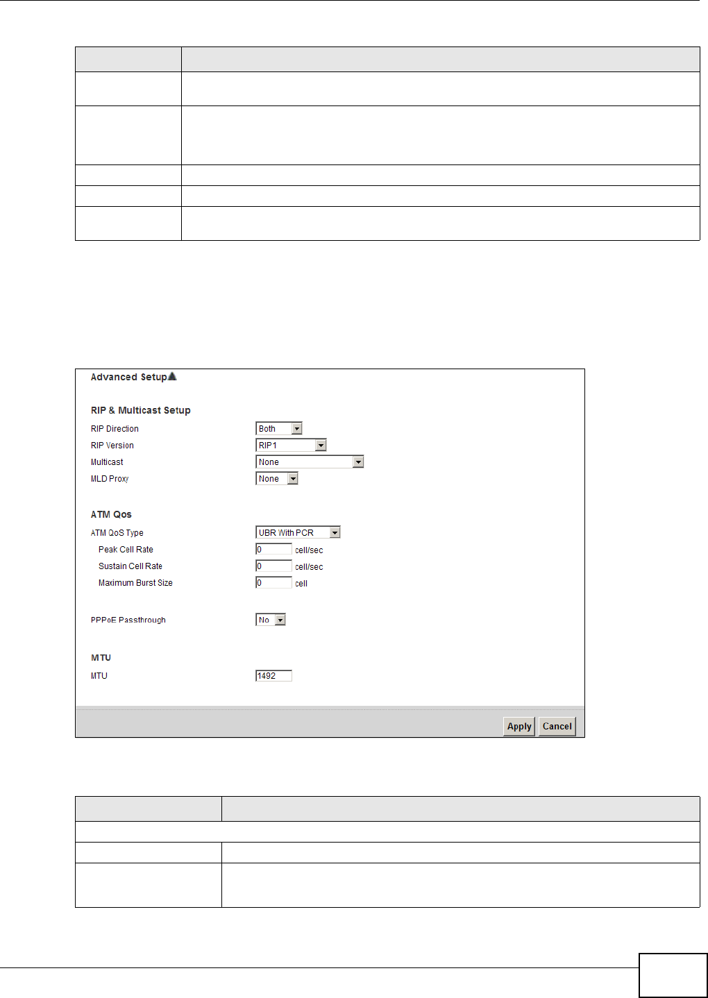
Chapter 5 WAN Setup
VMG1312-T10C User’s Guide 49
5.3.2 Configuring More Connections Advanced Setup
Use this screen to edit your Device's advanced WAN settings. Click the Advanced Setup button in
the More Connections Edit screen. The screen appears as shown.
Figure 23 More Connections: Edit: Advanced Setup
The following table describes the labels in this screen.
Max Idle
Timeout
Specify an idle time-out in the Max Idle Timeout field when you select Connect on
Demand. The default setting of 0 means the Internet session will not timeout.
NAT If you set the Mode field to Router, you can select SUA Only if you have one public IP
address and want to use NAT.
Otherwise, select None to disable NAT.
Back Click this to return to the previous screen without saving.
Apply Click this to save your changes.
Advanced Setup Click this to display the More Connections Advanced Setup screen and edit more
details of your WAN setup.
Table 6 More Connections: Edit (continued)
LABEL DESCRIPTION
Table 7 NeMore Connections: Edit: Advanced Setup
LABEL DESCRIPTION
RIP & Multicast Setup
RIP Direction Select the RIP Direction from None, Both, In Only and Out Only.
RIP Version You do not configure this field if you set the RIP Direction field to None.
Select the RIP Version from RIP-1, RIP-2B/RIP-2M.

Chapter 5 WAN Setup
VMG1312-T10C User’s Guide
50
5.4 The 3G Backup Screen
Use this screen to configure your 3G settings. Click Network Setting > Broadband > 3G
Backup.
Note: The actual data rate you obtain varies depending the 3G card you use, the signal
strength to the service provider’s base station, and so on.
Multicast Devices use the IGMP (Internet Group Management Protocol) network-layer
protocol to establish membership in a multicast group. Select IGMP v1/IGMP-v2/
IGMP-v3. Select None to disable it.
MLD Proxy Select the version of MLD proxy (v1 or v2) to have the Device act as for this
connection. This allows the Device to get subscription information and maintain a
joined member list for each multicast group. It can reduce multicast traffic
significantly. Select None to turn off MLD proxy.
ATM QoS
ATM QoS Type Select CBR (Continuous Bit Rate) to specify fixed (always-on) bandwidth for voice
or data traffic. Select UBR With PCR (Unspecified Bit Rate with Peak Cell Rate) for
applications that are non-time sensitive, such as e-mail. Select Non Realtime VBR
(Variable Bit Rate-non Real Time) or Realtime VBR (Variable Bit Rate-Real Time)
for bursty traffic and bandwidth sharing with other applications.
Peak Cell Rate Divide the DSL line rate (bps) by 424 (the size of an ATM cell) to find the Peak Cell
Rate (PCR). This sets the maximum rate at which the sender can send cells. Type
the PCR here.
Sustain Cell Rate The Sustain Cell Rate (SCR) sets the average cell rate (long-term) that can be
transmitted. Type the SCR, which must be less than the PCR. Note the system
default of 0 cells/sec.
Maximum Burst Size Maximum Burst Size (MBS) refers to the maximum number of cells that can be sent
at the peak rate. Type the MBS (less than 65535).
PPPoE Passthrough When using the PPPoE the encapsulation type, select this to enable PPPoE
passthrough. In addition to the Device’s built-in PPPoE client, this allows hosts on
the LAN to use PPPoE client software on their computers to connect to the ISP
through the Device. Each host can have a separate account and a public WAN IP
address.
MTU
MTU The Maximum Transmission Unit (MTU) defines the size of the largest packet
allowed on an interface or connection. Enter the MTU in this field.
For ENET ENCAP, the MTU value equals 1500.
For PPPoE, the MTU value equals 1492.
For PPPoA and RFC, the MTU equals 100-1500.
Apply Click this to save your changes.
Cancel Click this to restore your previously saved settings.
Table 7 NeMore Connections: Edit: Advanced Setup (continued)
LABEL DESCRIPTION
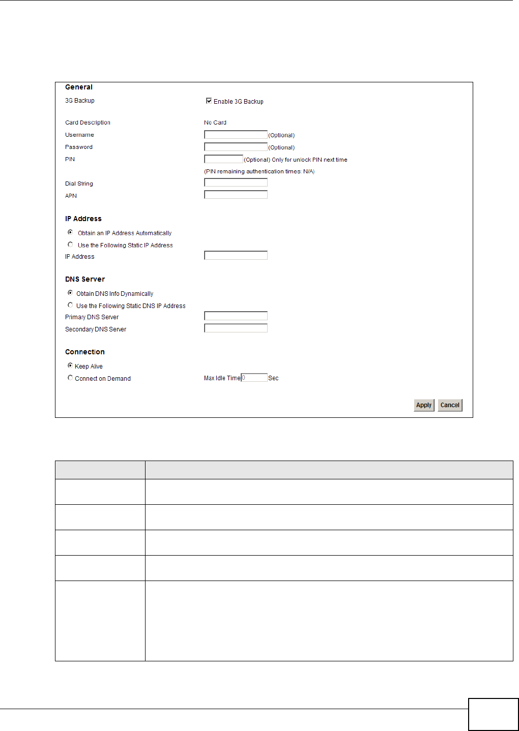
Chapter 5 WAN Setup
VMG1312-T10C User’s Guide 51
If the signal strength of a 3G network is too low, the 3G card may switch to an available 2.5G or
2.75G network. Refer to Section 5.5 on page 52 for a comparison between 2G, 2.5G, 2.75G and 3G
wireless technologies.
Figure 24 Network Setting > Broadband > 3G Backup
The following table describes the labels in this screen.
Table 8 Network Setting > Broadband > 3G Backup
LABEL DESCRIPTION
3G Backup Select Enable 3G Backup to have the Device use the 3G connection as your WAN or a
backup when the wired WAN connection fails.
Card Description This field displays the manufacturer and model name of your 3G card if you inserted
one in the Device. Otherwise, it displays N/A.
Username Type the user name (of up to 70 ASCII printable characters) given to you by your
service provider.
Password Type the password (of up to 70 ASCII printable characters) associated with the user
name above.
PIN A PIN (Personal Identification Number) code is a key to a 3G card. Without the PIN
code, you cannot use the 3G card.
If your ISP enabled PIN code authentication, enter the 4-digit PIN code (0000 for
example) provided by your ISP. If you enter the PIN code incorrectly, the 3G card may
be blocked by your ISP and you cannot use the account to access the Internet.
If your ISP disabled PIN code authentication, leave this field blank.

Chapter 5 WAN Setup
VMG1312-T10C User’s Guide
52
5.5 WAN Technical Reference
This section provides some technical background information about the topics covered in this
chapter.
5.5.1 Encapsulation
Be sure to use the encapsulation method required by your ISP. The Device supports the following
methods.
5.5.1.1 ENET ENCAP
The Device only implements the MAC Encapsulated Routing Link Protocol (ENET ENCAP) with the IP
network protocol. IP packets get routed between the Ethernet interface and the WAN interface and
then formatted to work in a bridged environment. For instance, it encapsulates routed Ethernet
Dial String Enter the phone number (dial string) used to dial up a connection to your service
provider’s base station. Your ISP should provide the phone number.
For example, *99# is the dial string to establish a GPRS or 3G connection in Taiwan.
APN Code Enter the APN (Access Point Name) provided by your service provider. Connections with
different APNs may provide different services (such as Internet access or MMS (Multi-
Media Messaging Service)) and charge method.
You can enter up to 31 ASCII printable characters. Spaces are allowed.
Obtain an IP
Address
Automatically
Select this option If your ISP did not assign you a fixed IP address.
Use the following
static IP address
Select this option If the ISP assigned a fixed IP address.
IP Address Enter your WAN IP address in this field if you selected Use the following static IP
address.
Obtain DNS info
dynamically
Select this to have the Device get the DNS server addresses from the ISP automatically.
Use the following
static DNS IP
address
Select this to have the Device use the DNS server addresses you configure manually.
Primary DNS
server Enter the first DNS server address assigned by the ISP.
Secondary DNS
server Enter the second DNS server address assigned by the ISP.
Connection Select Nailed-UP if you do not want the connection to time out.
Select On-Demand if you do not want the connection up all the time and specify an
idle time-out in the Max Idle Timeout field.
Max Idle Timeout This value specifies the time in minutes that elapses before the Device automatically
disconnects from the ISP.
Apply Click Apply to save your changes back to the Device.
Cancel Click Cancel to return to the previous configuration.
Table 8 Network Setting > Broadband > 3G Backup (continued)
LABEL DESCRIPTION

Chapter 5 WAN Setup
VMG1312-T10C User’s Guide 53
frames into bridged ATM cells. ENET ENCAP requires that you specify a gateway IP address in the
Gateway IP Address field in the wizard or WAN screen. You can get this information from your
ISP.
5.5.1.2 PPP over Ethernet
The Device supports PPPoE (Point-to-Point Protocol over Ethernet). PPPoE specifies how a personal
computer (PC) interacts with a broadband modem (DSL, cable, wireless, etc.) connection. The
PPPoE option provides a dial-up connection using PPPoE.
For the service provider, PPPoE offers an access and authentication method that works with existing
access control systems (for example RADIUS).
PPPoE lets you access one of multiple network services, a function known as dynamic service
selection. This enables the service provider to easily create and offer new IP services for
individuals.
Operationally, PPPoE saves significant effort for both you and the ISP or carrier, as it requires no
specific configuration of the broadband modem at the customer site.
By implementing PPPoE directly on the Device (rather than individual computers), the computers on
the LAN do not need PPPoE software installed, since the Device does that part of the task.
Furthermore, with NAT, all of the LANs’ computers will have access.
5.5.1.3 PPPoA
PPPoA stands for Point to Point Protocol over ATM Adaptation Layer 5 (AAL5). A PPPoA connection
functions like a dial-up Internet connection. The Device encapsulates the PPP session based on RFC
1483 and sends it through an ATM PVC (Permanent Virtual Circuit) to the Internet Service
Provider’s (ISP) DSLAM (Digital Subscriber Line (DSL) Access Multiplexer). Please refer to RFC 2364
for more information on PPPoA. Refer to RFC 1661 for more information on PPP.
5.5.1.4 RFC 1483
RFC 1483 describes two methods for Multiprotocol Encapsulation over ATM Adaptation Layer 5
(AAL5). The first method allows multiplexing of multiple protocols over a single ATM virtual circuit
(LLC-based multiplexing) and the second method assumes a separate ATM virtual circuit (VC-based
multiplexing) carries each protocol. Please refer to RFC 1483 for more detailed information.
5.5.2 Multiplexing
There are two conventions to identify what protocols the virtual circuit (VC) carries. Use the
multiplexing method required by your ISP.
VC-based Multiplexing
In this case, by prior mutual agreement, each protocol uses a specific virtual circuit; for example,
VC1 carries IP, etc. VC-based multiplexing may be dominant in environments where dynamic
creation of large numbers of ATM VCs is fast and economical.

Chapter 5 WAN Setup
VMG1312-T10C User’s Guide
54
LLC-based Multiplexing
In this case one VC carries multiple protocols with protocol identifying information being contained
in each packet header. Despite the extra bandwidth and processing overhead, this method may be
advantageous if it is not practical to have a separate VC for each carried protocol, for example, if
charging heavily depends on the number of simultaneous VCs.
5.5.3 VPI and VCI
Be sure to use the correct Virtual Path Identifier (VPI) and Virtual Channel Identifier (VCI) numbers
assigned to you. The valid range for the VPI is 0 to 255 and for the VCI is 32 to 65535 (0 to 31 is
reserved for local management of ATM traffic). Please see the appendix for more information.
5.5.4 IP Address Assignment
A static IP is a fixed IP that your ISP gives you. A dynamic IP is not fixed; the ISP assigns you a
different one each time. The Single User Account feature can be enabled or disabled if you have
either a dynamic or static IP. However the encapsulation method assigned influences your choices
for IP address and ENET ENCAP gateway.
IP Assignment with PPPoA or PPPoE Encapsulation
If you have a dynamic IP, then the IP Address and Gateway IP Address fields are not applicable
(N/A). If you have a Static IP Address assigned by your ISP, then they should also assign you a
Subnet Mask and a Gateway IP Address.
IP Assignment with RFC 1483 Encapsulation
In this case the IP address assignment must be static.
IP Assignment with ENET ENCAP Encapsulation
In this case you can have either a static or dynamic IP. For a static IP you must fill in all the IP
Address and Gateway IP Address fields as supplied by your ISP. However for a dynamic IP, the
Device acts as a DHCP client on the WAN port and so the IP Address and Gateway IP Address
fields are not applicable (N/A) as the DHCP server assigns them to the Device.

VMG1312-T10C User’s Guide 55
CHAPTER 6
Wireless
6.1 Overview
This chapter describes the Device’s Network Setting > Wireless screens. Use these screens to
set up your Device’s wireless connection.
6.1.1 What You Can Do in this Chapter
•Use the General screen to enable the wireless LAN, enter the SSID and select the wireless
security mode (Section 6.2 on page 57).
•Use the More AP screen to set up multiple wireless networks on your Device (Section 6.3 on
page 63).
•Use the MAC Authentication screen to allow or deny wireless clients based on their MAC
addresses from connecting to the Device (Section 6.4 on page 66).
•Use the WPS screen to enable or disable WPS, view or generate a security PIN (Personal
Identification Number) (Section 6.5 on page 67).
•Use the WDS screen (see Section 6.6 on page 69) to set up a Wireless Distribution System, in
which the Device acts as a bridge with other access points.
•Use the WMM screen to enable Wi-Fi MultiMedia (WMM) to ensure quality of service in wireless
networks for multimedia applications (Section 6.7 on page 70).
•Use the Scheduling screen to schedule a time period for the wireless LAN to operate each day
(Section 6.8 on page 71).
•Use the Advanced screen to configure advanced wireless features (Section 6.9 on page 73).
You don’t necessarily need to use all these screens to set up your wireless connection. For example,
you may just want to set up a network name, a wireless radio channel and some security in the
General screen.
6.1.2 Wireless Network Overview
Wireless networks consist of wireless clients, access points and bridges.
• A wireless client is a radio connected to a user’s computer.
• An access point is a radio with a wired connection to a network, which can connect with
numerous wireless clients and let them access the network.
• A bridge is a radio that relays communications between access points and wireless clients,
extending a network’s range.
Traditionally, a wireless network operates in one of two ways.
• An “infrastructure” type of network has one or more access points and one or more wireless
clients. The wireless clients connect to the access points.
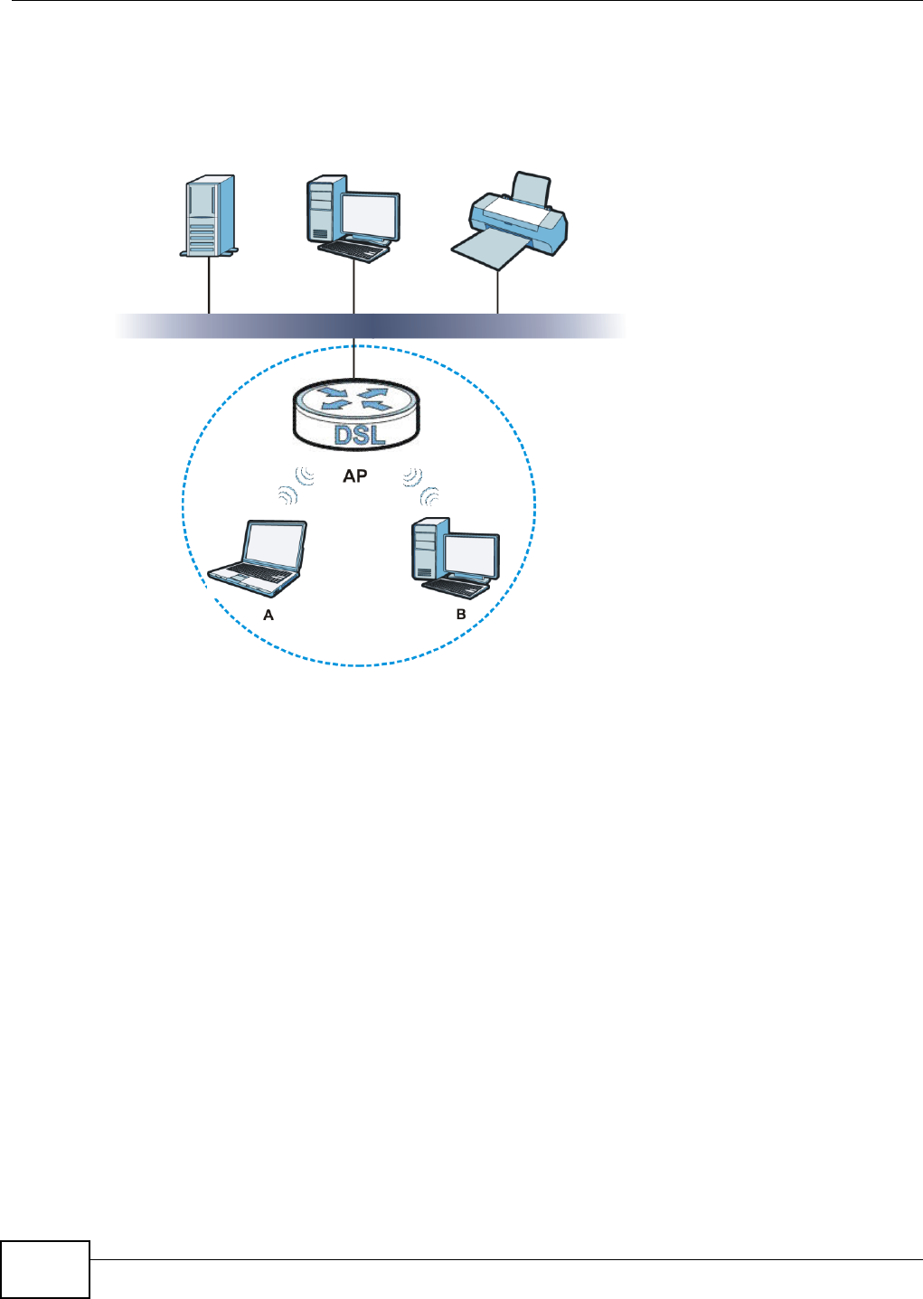
Chapter 6 Wireless
VMG1312-T10C User’s Guide
56
• An “ad-hoc” type of network is one in which there is no access point. Wireless clients connect to
one another in order to exchange information.
The following figure provides an example of a wireless network.
Figure 25 Example of a Wireless Network
The wireless network is the part in the blue circle. In this wireless network, devices A and B use the
access point (AP) to interact with the other devices (such as the printer) or with the Internet. Your
Device is the AP.
Every wireless network must follow these basic guidelines.
• Every device in the same wireless network must use the same SSID.
The SSID is the name of the wireless network. It stands for Service Set IDentifier.
• If two wireless networks overlap, they should use a different channel.
Like radio stations or television channels, each wireless network uses a specific channel, or
frequency, to send and receive information.
• Every device in the same wireless network must use security compatible with the AP.
• Security stops unauthorized devices from using the wireless network. It can also protect the
information that is sent in the wireless network.
Radio Channels
In the radio spectrum, there are certain frequency bands allocated for unlicensed, civilian use. For
the purposes of wireless networking, these bands are divided into numerous channels. This allows a
variety of networks to exist in the same place without interfering with one another. When you
create a network, you must select a channel to use.

Chapter 6 Wireless
VMG1312-T10C User’s Guide 57
Since the available unlicensed spectrum varies from one country to another, the number of
available channels also varies.
6.1.3 Before You Begin
Before you start using these screens, ask yourself the following questions. See Section 6.10 on
page 74 if some of the terms used here do not make sense to you.
• What wireless standards do the other wireless devices support (IEEE 802.11g, for example)?
What is the most appropriate standard to use?
• What security options do the other wireless devices support (WPA-PSK, for example)? What is
the best one to use?
• Do the other wireless devices support WPS (Wi-Fi Protected Setup)? If so, you can set up a well-
secured network very easily.
Even if some of your devices support WPS and some do not, you can use WPS to set up your
network and then add the non-WPS devices manually, although this is somewhat more
complicated to do.
• What advanced options do you want to configure, if any? If you want to configure advanced
options, ensure that you know precisely what you want to do. If you do not want to configure
advanced options, leave them alone.
6.2 Wireless General Screen
Use this screen to enable the Wireless LAN, enter the SSID and select the wireless security mode.
Note: If you are configuring the Device from a computer connected to the wireless LAN
and you change the Device’s SSID or security settings, you will lose your wireless
connection when you press Apply to confirm. You must then change the wireless
settings of your computer to match the Device’s new settings.
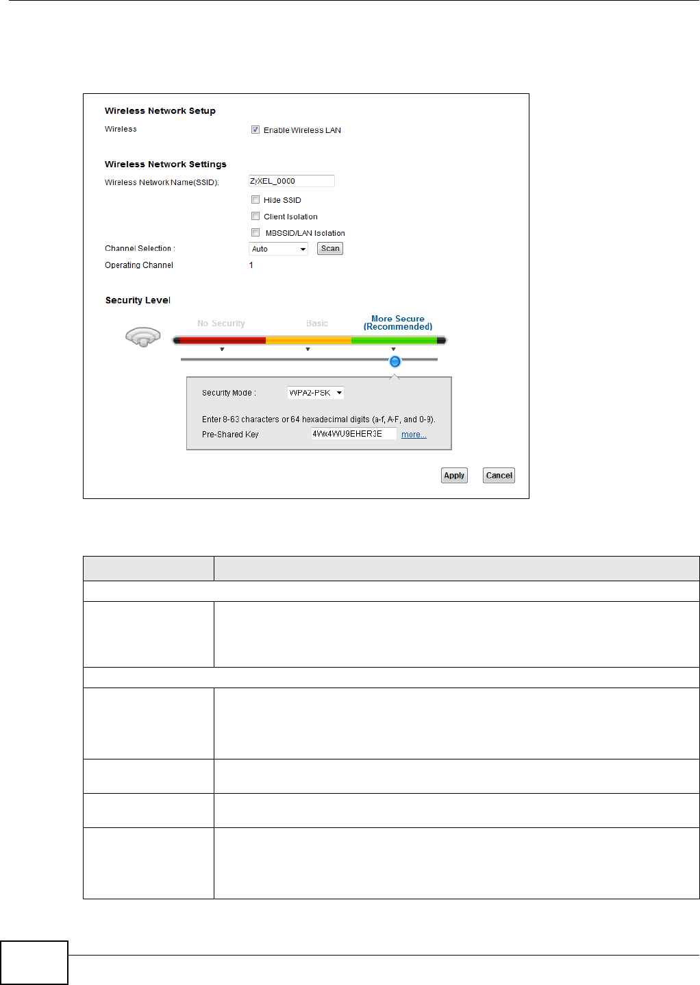
Chapter 6 Wireless
VMG1312-T10C User’s Guide
58
Click Network Setting > Wireless to open the General screen. Select the Enable Wireless LAN
checkbox to show the Wireless configurations.
Figure 26 Network Setting > Wireless > General
The following table describes the labels in this screen.
Table 9 Network > Wireless LAN > General
LABEL DESCRIPTION
Wireless Network Setup
Wireless Select the Enable Wireless LAN check box to activate the wireless LAN.
Note: You must also set the Device’s physical WLAN ON/OFF button to ON to use
wireless LAN. The WLAN LED should be on.
Wireless Network Settings
Wireless Network
Name (SSID)
The SSID (Service Set IDentity) identifies the service set with which a wireless device
is associated. Wireless devices associating to the access point (AP) must have the
same SSID.
Enter a descriptive name (up to 32 English keyboard characters) for the wireless LAN.
Hide SSID Select this check box to hide the SSID in the outgoing beacon frame so a station
cannot obtain the SSID through scanning using a site survey tool.
Client Isolation Select this to keep the wireless clients in this SSID from communicating with each
other directly through the Device.
MBSSID/LAN
Isolation
Select this to keep the wireless clients in this SSID from communicating with clients in
other SSIDs or wired LAN devices through the Device.
Select both Client Isolation and MBSSID/LAN Isolation to allow this SSID’s
wireless clients to only connect to the Internet through the Device.
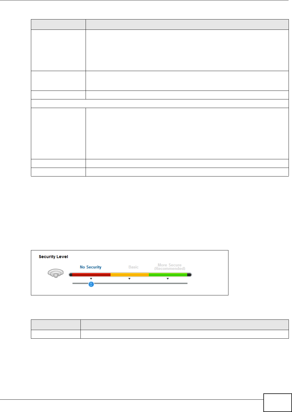
Chapter 6 Wireless
VMG1312-T10C User’s Guide 59
6.2.1 No Security
Select No Security to allow wireless stations to communicate with the access points without any
data encryption or authentication.
Note: If you do not enable any wireless security on your Device, your network is
accessible to any wireless networking device that is within range.
Figure 27 Wireless > General: No Security
The following table describes the labels in this screen.
6.2.2 Basic (Static WEP/Shared WEP Encryption)
WEP encryption scrambles the data transmitted between the wireless stations and the access points
(AP) to keep network communications private. Both the wireless stations and the access points
must use the same WEP key.
Channel Selection Set the channel depending on your particular region.
Select a channel or use Auto to have the Device automatically determine a channel to
use. If you are having problems with wireless interference, changing the channel may
help. Try to use a channel that is as many channels away from any channels used by
neighboring APs as possible. The channel number which the Device is currently using
then displays in the Operating Channel field.
Scan Click this button to have the Device immediately scan for and select a channel (which
is not used by another device) whenever the device reboots or the wireless setting is
changed.
Operating Channel This is the channel currently being used by your AP.
Security Level
Security Mode Select Basic or More Secure to add security on this wireless network. The wireless
clients which want to associate to this network must have same wireless security
settings as the Device. When you select to use a security, additional options appears
in this screen.
Or you can select No Security to allow any client to associate with this network
without any data encryption or authentication.
See the following sections for more details about wireless security modes.
Apply Click Apply to save your changes back to the Device.
Cancel Click Cancel to restore your previously saved settings.
Table 9 Network > Wireless LAN > General (continued)
LABEL DESCRIPTION
Table 10 Wireless > General: No Security
LABEL DESCRIPTION
Security Level Choose No Security from the sliding bar.
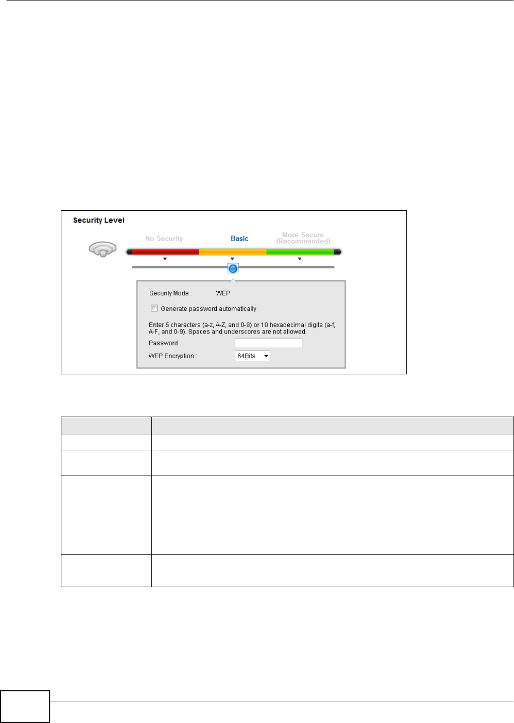
Chapter 6 Wireless
VMG1312-T10C User’s Guide
60
There are two types of WEP authentication namely, Open System (Static WEP) and Shared Key
(Shared WEP).
Open system is implemented for ease-of-use and when security is not an issue. The wireless station
and the AP or peer computer do not share a secret key. Thus the wireless stations can associate
with any AP or peer computer and listen to any transmitted data that is not encrypted.
Shared key mode involves a shared secret key to authenticate the wireless station to the AP or peer
computer. This requires you to enable the wireless LAN security and use same settings on both the
wireless station and the AP or peer computer.
In order to configure and enable WEP encryption, click Network Settings > Wireless to display
the General screen. Select Basic as the security level. Then select Static WEP or Shared WEP
from the Security Mode list.
Figure 28 Wireless > General: Basic (Static WEP/Shared WEP)
The following table describes the labels in this screen.
Table 11 Wireless > General: Basic (Static WEP/Shared WEP)
LABEL DESCRIPTION
Security Level Select Basic to enable WEP data encryption.
Generate password
automatically
Select this option to have the Device automatically generate a password. The password
field will not be configurable when you select this option.
Password 1~4 The password (WEP key) is used to encrypt data. Both the Device and the wireless
stations must use the same password (WEP key) for data transmission.
If you chose 64-bit WEP, then enter any 5 ASCII characters or 10 hexadecimal
characters ("0-9", "A-F").
If you chose 128-bit WEP, then enter 13 ASCII characters or 26 hexadecimal
characters ("0-9", "A-F").
WEP Encryption Select 64-bits or 128-bits.
This dictates the length of the security key that the network is going to use.
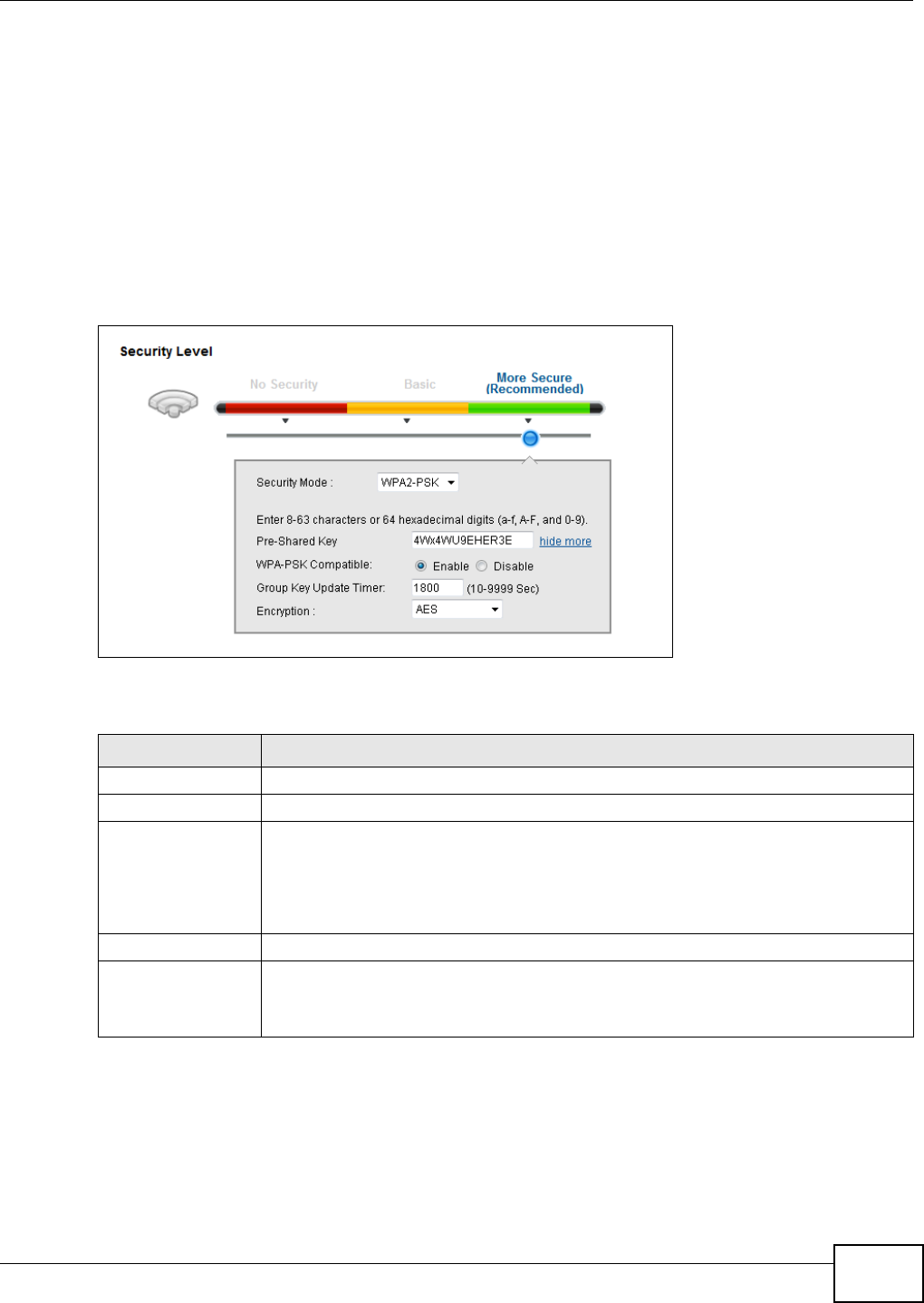
Chapter 6 Wireless
VMG1312-T10C User’s Guide 61
6.2.3 More Secure (WPA(2)-PSK)
The WPA-PSK security mode provides both improved data encryption and user authentication over
WEP. Using a Pre-Shared Key (PSK), both the Device and the connecting client share a common
password in order to validate the connection. This type of encryption, while robust, is not as strong
as WPA, WPA2 or even WPA2-PSK. The WPA2-PSK security mode is a newer, more robust version of
the WPA encryption standard. It offers slightly better security, although the use of PSK makes it
less robust than it could be.
Click Network Settings > Wireless to display the General screen. Select More Secure as the
security level. Then select WPA-PSK or WPA2-PSK from the Security Mode list.
Figure 29 Wireless > General: More Secure: WPA(2)-PSK
The following table describes the labels in this screen.
Table 12 Wireless > General: WPA(2)-PSK
LABEL DESCRIPTION
Security Level Select More Secure to enable WPA(2)-PSK data encryption.
Security Mode Select WPA-PSK or WPA2-PSK from the drop-down list box.
Pre-Shared Key The encryption mechanisms used for WPA/WPA2 and WPA-PSK/WPA2-PSK are the
same. The only difference between the two is that WPA-PSK/WPA2-PSK uses a
simple common password, instead of user-specific credentials.
Type a pre-shared key from 8 to 63 case-sensitive ASCII characters or 64 hexidecimal
digits.
more.../hide more Click more... to show more fields in this section. Click hide more to hide them.
WPA-PSK
Compatible
This appears when you choose WPA-PSK2 as the Security Mode.
Enable this to allow wireless devices using WPA-PSK security mode to connect to your
Device. The Device supports WPA-PSK and WPA2-PSK simultaneously.
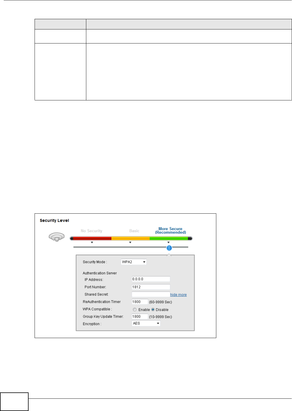
Chapter 6 Wireless
VMG1312-T10C User’s Guide
62
6.2.4 WPA(2) Authentication
The WPA2 security mode is currently the most robust form of encryption for wireless networks. It
requires a RADIUS server to authenticate user credentials and is a full implementation the security
protocol. Use this security option for maximum protection of your network. However, it is the least
backwards compatible with older devices.
The WPA security mode is a security subset of WPA2. It requires the presence of a RADIUS server
on your network in order to validate user credentials. This encryption standard is slightly older than
WPA2 and therefore is more compatible with older devices.
Click Network Settings > Wireless to display the General screen. Select More Secure as the
security level. Then select WPA or WPA2 from the Security Mode list.
Figure 30 Wireless > General: More Secure: WPA(2)
Group Key Update
Timer
The Group Key Update Timer is the rate at which the RADIUS server sends a new
group key out to all clients.
Encryption If the security mode is WPA-PSK, the encryption mode is set to TKIP to enable
Temporal Key Integrity Protocol (TKIP) security on your wireless network.
If the security mode is WPA-PSK2 and WPA-PSK Compatible is disabled, the
encryption mode is set to AES to enable Advanced Encryption System (AES) security
on your wireless network. AES provides superior security to TKIP.
If the security mode is WPA-PSK2 and WPA-PSK Compatible is enabled, the
encryption mode is set to TKIPAES MIX to allow both TKIP and AES types of security
in your wireless network.
Table 12 Wireless > General: WPA(2)-PSK (continued)
LABEL DESCRIPTION

Chapter 6 Wireless
VMG1312-T10C User’s Guide 63
The following table describes the labels in this screen.
6.3 More AP Screen
The Device can broadcast up to four wireless network names at the same time. This means that
users can connect to the Device using different SSIDs. You can secure the connection on each SSID
profile so that wireless clients connecting to the Device using different SSIDs cannot communicate
with each other.
This screen allows you to enable and configure multiple Basic Service Sets (BSSs) on the Device.
Table 13 Wireless > General: More Secure: WPA(2)
LABEL DESCRIPTION
Security Level Select More Secure to enable WPA(2)-PSK data encryption.
Security Mode Choose WPA or WPA2 from the drop-down list box.
Authentication Server
IP Address Enter the IP address of the external authentication server in dotted decimal notation.
Port Number Enter the port number of the external authentication server. The default port number is
1812.
You need not change this value unless your network administrator instructs you to do
so with additional information.
Shared Secret Enter a password (up to 128 alphanumeric characters) as the key to be shared between
the external authentication server and the Device.
The key must be the same on the external authentication server and your Device. The
key is not sent over the network.
more.../hide more Click more... to show more fields in this section. Click hide more to hide them.
ReAuthentication
Timer
Specify how often wireless stations have to resend user names and passwords in order
to stay connected.
The default value is 0, which means the reauthentication off.
Note: If wireless station authentication is done using a RADIUS server, the
reauthentication timer on the RADIUS server has priority.
WPA Compatible This field is only available for WPA2. Select this if you want the Device to support WPA
and WPA2 simultaneously.
Group Key Update
Timer
The Group Key Update Timer is the rate at which the RADIUS server sends a new
group key out to all clients.
If the value is set to “0”, the update timer function is disabled.
Encryption If the security mode is WPA, the encryption mode is set to TKIP to enable Temporal
Key Integrity Protocol (TKIP) security on your wireless network.
If the security mode is WPA2, the encryption mode is set to AES to enable Advanced
Encryption System (AES) security on your wireless network. AES provides superior
security to TKIP.
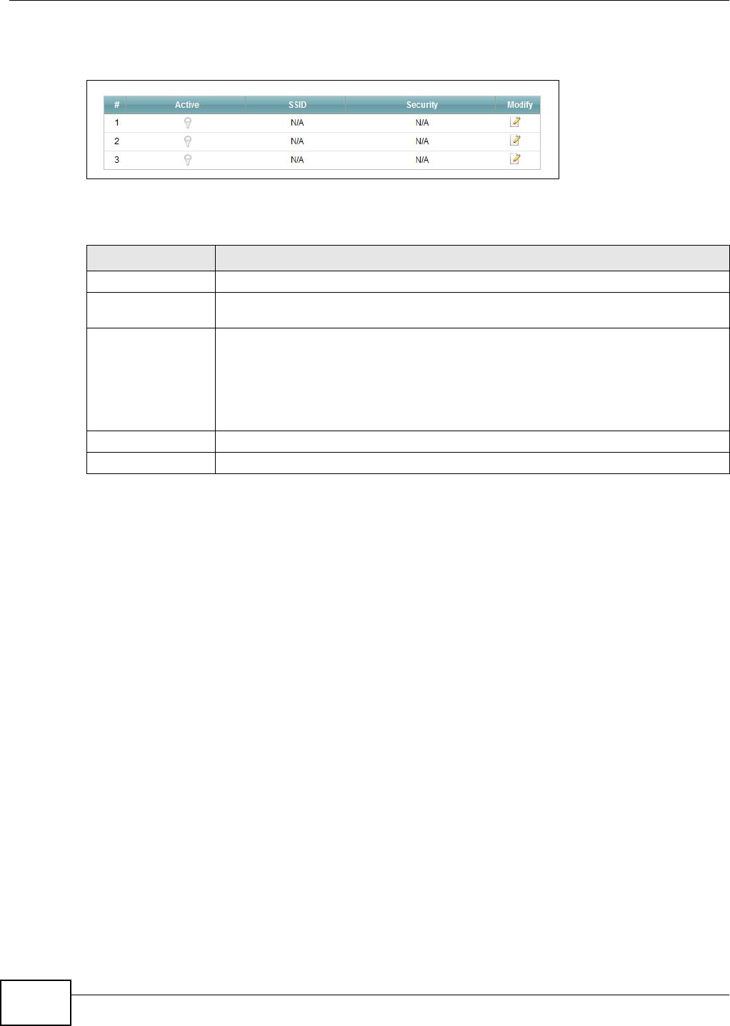
Chapter 6 Wireless
VMG1312-T10C User’s Guide
64
Click Network Settings > Wireless > More AP. The following screen displays.
Figure 31 Network Settings > Wireless > More AP
The following table describes the labels in this screen.
Table 14 Network Settings > Wireless > More AP
LABEL DESCRIPTION
# This is the index number of the entry.
Active This field indicates whether this SSID is active. A yellow bulb signifies that this SSID is
active. A gray bulb signifies that this SSID is not active.
SSID An SSID profile is the set of parameters relating to one of the Device’s BSSs. The SSID
(Service Set IDentifier) identifies the Service Set with which a wireless device is
associated.
This field displays the name of the wireless profile on the network. When a wireless
client scans for an AP to associate with, this is the name that is broadcast and seen in
the wireless client utility.
Security This field indicates the security mode of the SSID profile.
Modify Click the Edit icon to configure the SSID profile.
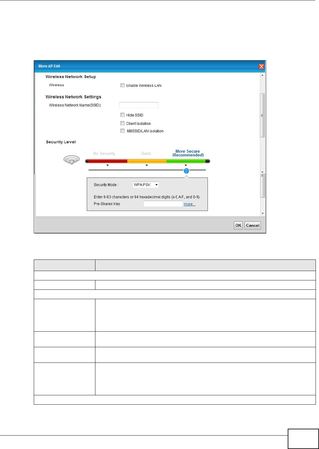
Chapter 6 Wireless
VMG1312-T10C User’s Guide 65
6.3.1 Edit More AP
Use this screen to edit an SSID profile. Click the Edit icon next to an SSID in the More AP screen.
The following screen displays.
Figure 32 Wireless > More AP: Edit
The following table describes the fields in this screen.
Table 15 Wireless > More AP: Edit
LABEL DESCRIPTION
Wireless Network Setup
Wireless Select the Enable Wireless LAN check box to activate the wireless LAN.
Wireless Network Settings
Wireless Network
Name (SSID)
The SSID (Service Set IDentity) identifies the service set with which a wireless device
is associated. Wireless devices associating to the access point (AP) must have the
same SSID.
Enter a descriptive name (up to 32 English keyboard characters) for the wireless LAN.
Hide SSID Select this check box to hide the SSID in the outgoing beacon frame so a station
cannot obtain the SSID through scanning using a site survey tool.
Client Isolation Select this to keep the wireless clients in this SSID from communicating with each
other directly through the Device.
MBSSID/LAN Isolation Select this to keep the wireless clients in this SSID from communicating with clients
in other SSIDs or wired LAN devices through the Device.
Select both Client Isolation and MBSSID/LAN Isolation to allow this SSID’s
wireless clients to only connect to the Internet through the Device.
Security Level
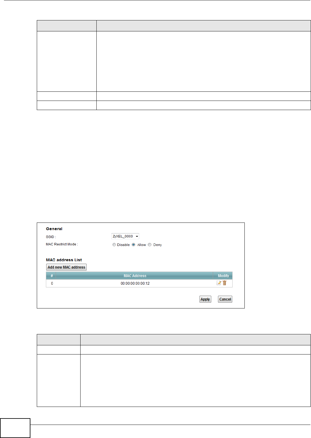
Chapter 6 Wireless
VMG1312-T10C User’s Guide
66
6.4 MAC Authentication Screen
Use this screen to configure the ZyXEL Device to give exclusive access to specific devices (Allow)
or exclude specific devices from accessing the ZyXEL Device (Deny). Every Ethernet device has a
unique MAC (Media Access Control) address. The MAC address is assigned at the factory and
consists of six pairs of hexadecimal characters, for example, 00:A0:C5:00:00:02. You need to know
the MAC addresses of the devices to configure this screen.
Use this screen to view your Device’s MAC filter settings and add new MAC filter rules. Click
Network Setting > Wireless > MAC Authentication. The screen appears as shown.
Figure 33 Wireless > MAC Authentication
The following table describes the labels in this screen.
Security Mode Select Basic (WEP) or More Secure (WPA(2)-PSK, WPA(2)) to add security on
this wireless network. Wireless clients must use the same wireless security settings
as the Device to connect to the wireless LAN. After you select to use security,
additional options appears in this screen.
Or you can select No Security to allow any client to connect to this network without
any data encryption or authentication.
See Section 6.2.1 on page 59 through Section 6.2.4 on page 62 for more details
about this field.
OK Click this to save your changes.
Cancel Click this to exit this screen without saving.
Table 15 Wireless > More AP: Edit (continued)
LABEL DESCRIPTION
Table 16 Wireless > MAC Authentication
LABEL DESCRIPTION
SSID Select the SSID for which you want to configure MAC filter settings.
MAC Restrict
Mode
Define the filter action for the list of MAC addresses in the MAC Address table.
Select Disable to turn off MAC filtering.
Select Deny to block access to the Device. MAC addresses not listed will be allowed to
access the Device.
Select Allow to permit access to the Device. MAC addresses not listed will be denied access
to the Device.
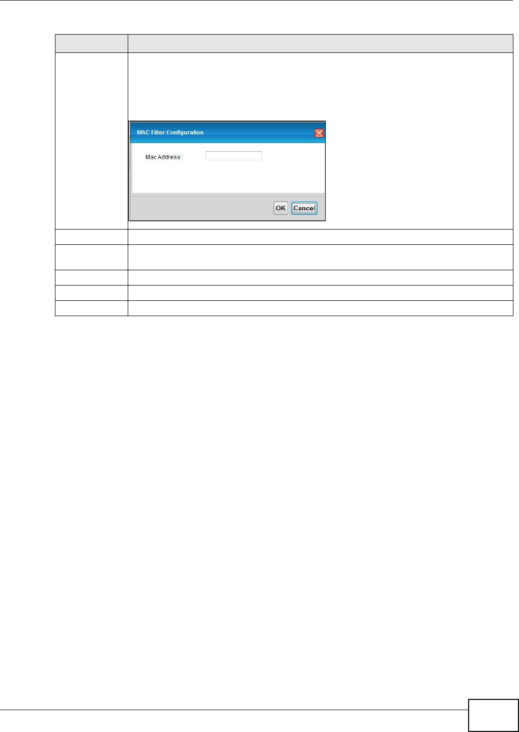
Chapter 6 Wireless
VMG1312-T10C User’s Guide 67
6.5 The WPS Screen
Use this screen to configure WiFi Protected Setup (WPS) on your Device.
WPS allows you to quickly set up a wireless network with strong security, without having to
configure security settings manually. Set up each WPS connection between two devices. Both
devices must support WPS. See Section 6.10.7.3 on page 80 for more information about WPS.
Note: The Device applies the security settings of the SSID1 profile (see Section 6.2 on
page 57). If you want to use the WPS feature, make sure you have set the security
mode of SSID1 to WPA2-PSK or WPA-PSK/WPA2-PSK mixed or no security.
Add new MAC
address
Click this if you want to add a new MAC address entry to the MAC filter list below.
Enter the MAC addresses of the wireless devices that are allowed or denied access to the
Device in these address fields. Enter the MAC addresses in a valid MAC address format, that
is, six hexadecimal character pairs, for example, 12:34:56:78:9a:bc.
Figure 34 Wireless > MAC Authentication > Add new MAC address
#This is the index number of the entry.
MAC Address This is the MAC addresses of the wireless devices that are allowed or denied access to the
Device.
Modify Click the Delete icon to delete the entry.
Apply Click Apply to save your changes.
Cancel Click Cancel to exit this screen without saving.
Table 16 Wireless > MAC Authentication (continued)
LABEL DESCRIPTION
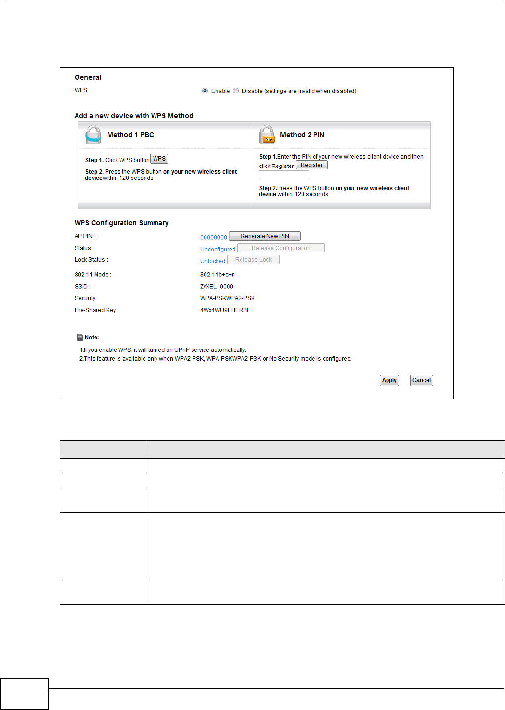
Chapter 6 Wireless
VMG1312-T10C User’s Guide
68
Click Network Setting > Wireless > WPS. The following screen displays. Select Enable and click
Apply to activate the WPS function. Then you can configure the WPS settings in this screen.
Figure 35 Network Setting > Wireless > WPS
The following table describes the labels in this screen.
Table 17 Network Setting > Wireless > WPS
LABEL DESCRIPTION
Enable WPS Select Enable and click Apply to activate WPS on the Device.
Add a new device with WPS Method - These fields display after you enable WPS and click Apply.
Method 1 PBC Use this section to set up a WPS wireless network using Push Button Configuration
(PBC).
WPS Click this button to add another WPS-enabled wireless device (within wireless range of
the Device) to your wireless network. This button may either be a physical button on
the outside of device, or a menu button similar to the WPS button on this screen.
Note: You must press the other wireless device’s WPS button within two minutes of
pressing this button.
Method 2 PIN Use this section to set up a WPS wireless network by entering the PIN (Personal
Identification Number) of the client into the Device.

Chapter 6 Wireless
VMG1312-T10C User’s Guide 69
6.6 The WDS Screen
An AP using the Wireless Distribution System (WDS) can function as a wireless network bridge
allowing you to wirelessly connect wired network segments. The WDS screen allows you to
configure the Device to connect to other APs wirelessly when WDS is enabled.
Use this screen to set up your WDS (Wireless Distribution System) links between the Device and
other wireless APs. You need to know the MAC address of the peer device. Once the security
settings of peer sides match one another, the connection between devices is made.
Note: WDS security is independent of the security settings between the Device and any
wireless clients.
Note: Not all APs support WDS links. Check your other AP’s documentation.
Click Network Setting > Wireless > WDS. The following screen displays.
Register Enter the PIN of the device that you are setting up a WPS connection with and click
Register to authenticate and add the wireless device to your wireless network.
You can find the PIN either on the outside of the device, or by checking the device’s
settings.
Note: You must also activate WPS on that device within two minutes to have it present its
PIN to the Device.
WPS Configuration Summary
AP PIN The PIN of the Device is shown here. Enter this PIN in the configuration utility of the
device you want to connect to using WPS.
The PIN is not necessary when you use WPS push-button method.
Click the Generate New PIN button to have the Device create a new PIN.
Status This displays Configured when the Device has connected to a wireless network using
WPS or Enable WPS is selected and wireless or wireless security settings have been
changed. The current wireless and wireless security settings also appear in the screen.
This displays Not Configured when there is no wireless or wireless security changes
on the Device or you click Release Configuration to remove the configured wireless
and wireless security settings.
Release
Configuration This button is available when the WPS status is Configured.
Click this button to remove all configured wireless and wireless security settings for
WPS connections on the Device.
802.11 Mode This is the 802.11 mode used. Only compliant WLAN devices can associate with the
Device.
SSID This is the name of the wireless network.
Security This is the type of wireless security employed by the network.
Pre-Shared Key This is the wireless LAN password.
Apply Click Apply to save your changes.
Cancel Click this to restore your previously saved settings.
Table 17 Network Setting > Wireless > WPS (continued)
LABEL DESCRIPTION
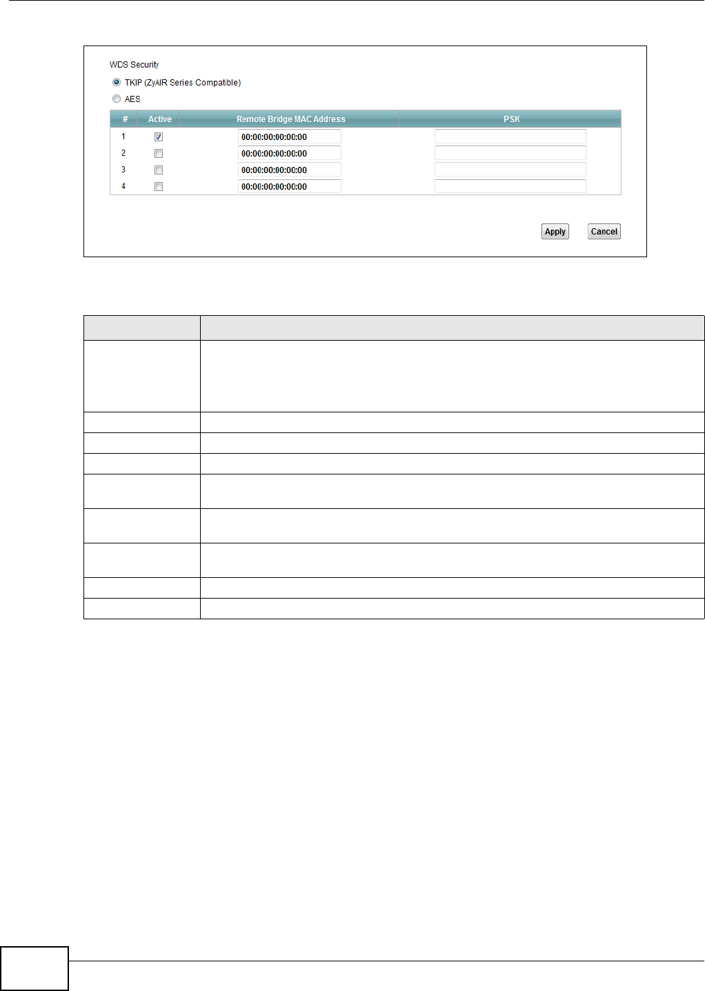
Chapter 6 Wireless
VMG1312-T10C User’s Guide
70
Figure 36 Network Setting > Wireless > WDS
The following table describes the labels in this screen.
6.7 The WMM Screen
Use this screen to enable or disable Wi-Fi MultiMedia (WMM) wireless networks for multimedia
applications.
Table 18 Network Setting > Wireless > WDS
LABEL DESCRIPTION
WDS Security Select the type of the key used to encrypt data between APs. All the wireless APs
(including the Device) must use the same pre-shared key for data transmission.
The option is available only when you set the security mode to WPA(2) or WPA(2)-
PSK in the Wireless > General screen.
TKIP Select this to use TKIP (Temporal Key Integrity Protocol) encryption.
AES Select this to use AES (Advanced Encryption Standard) encryption.
# This is the index number of the individual WDS link.
Active Select this to activate the link between the Device and the peer device to which this
entry refers. When you do not select the check box this link is down.
Remote Bridge
MAC Address
Type the MAC address of the peer device in a valid MAC address format (six hexadecimal
character pairs, for example 12:34:56:78:9a:bc).
PSK Enter a Pre-Shared Key (PSK) from 8 to 63 case-sensitive ASCII characters (including
spaces and symbols).
Apply Click this to save your changes.
Cancel Click this to restore your previously saved settings.
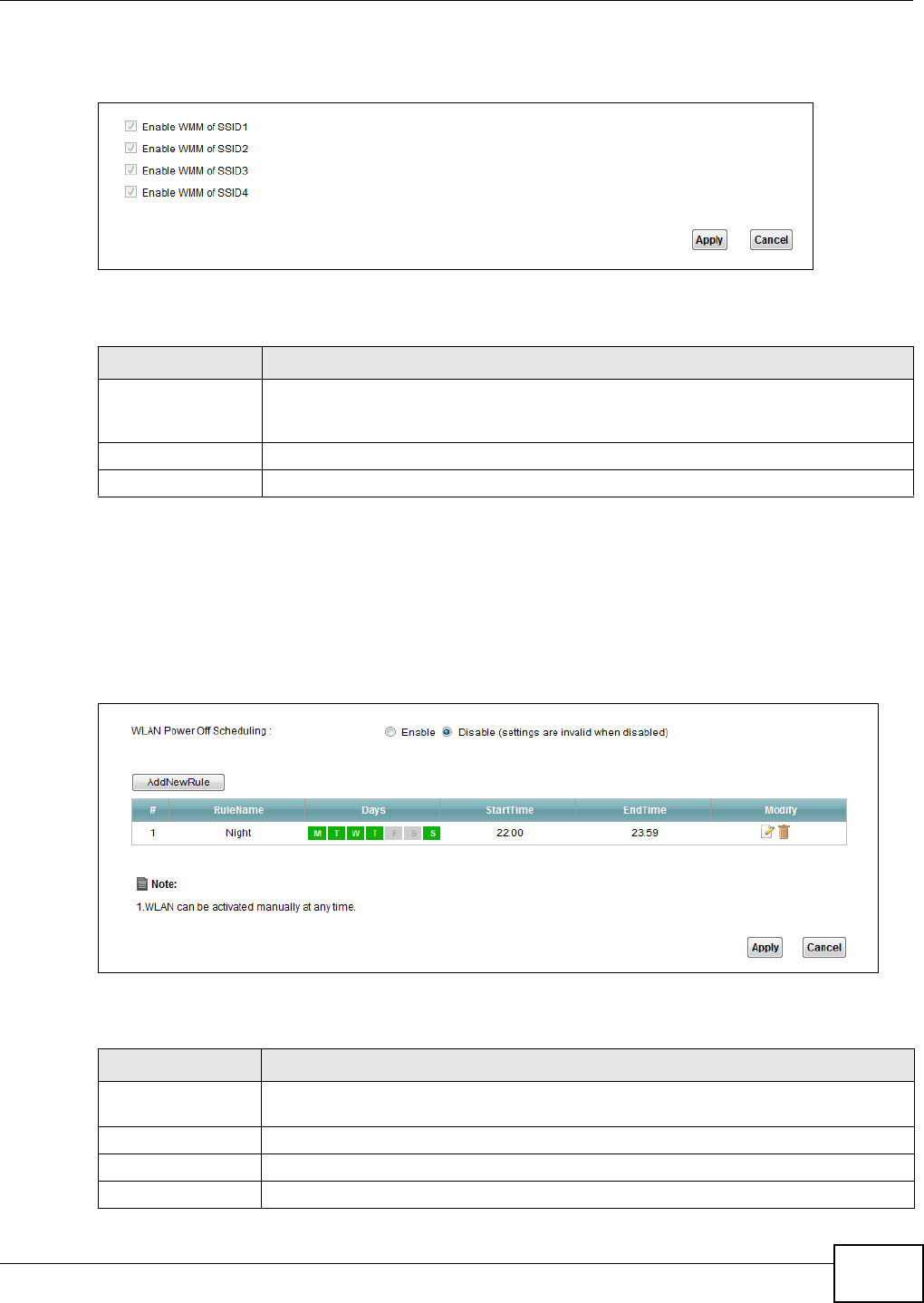
Chapter 6 Wireless
VMG1312-T10C User’s Guide 71
Click Network Setting > Wireless > WMM. The following screen displays.
Figure 37 Network Setting > Wireless > WMM
The following table describes the labels in this screen.
6.8 Scheduling Screen
Click Network Setting > Wireless > Scheduling to open the Wireless Scheduling screen. Use
this screen to manage schedules that turn off wireless service for power saving purposes.
Figure 38 Network Setting > Wireless > Scheduling
The following table describes the labels in this screen.
Table 19 Network Setting > Wireless > WMM
LABEL DESCRIPTION
Enable WMM of
SSID1~4
This enables the Device to automatically give a service a priority level according to the
ToS value in the IP header of packets it sends. WMM QoS (Wifi MultiMedia Quality of
Service) gives high priority to voice and video, which makes them run more smoothly.
Apply Click Apply to save your changes.
Cancel Click Cancel to restore your previously saved settings.
Table 20 Network Setting > Wireless > Scheduling
LABEL DESCRIPTION
Wireless LAN
Scheduling
Select Enable to activate wireless LAN scheduling on your Device.
Add New Rule Click this to create a new wireless LAN scheduling rule.
# This is the index number of the entry.
Rule Name This field shows the name configured for the scheduling rule.
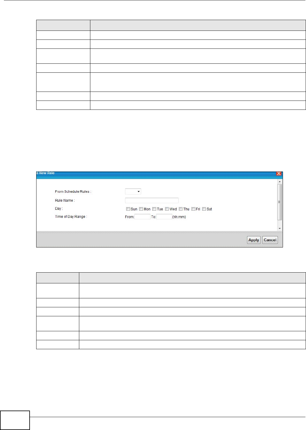
Chapter 6 Wireless
VMG1312-T10C User’s Guide
72
6.8.1 Add or Edit Schedule
Use this screen to add or edit a wireless LAN schedule. In the Network Setting > Wireless >
Scheduling screen, click Add New Rule or the Edit icon next to an existing schedule. The
following screen displays.
Figure 39 Network Setting > Wireless > Scheduling > Add New Rule
The following table describes the fields in this screen.
Days This field displays to which days of the week the schedule applies.
Start Time This field displays the time (in 24-hour time format) the rule turns off the wireless LAN.
End Time This field displays the time (in 24-hour time format) the rule turns the wireless LAN
back on.
Security This field indicates the security mode of the SSID profile.
Modify Click the Edit icon to configure the scheduling rule.
Click the Delete icon to remove the scheduling rule.
Apply Click Apply to save your changes.
Cancel Click Cancel to restore your previously saved settings.
Table 20 Network Setting > Wireless > Scheduling (continued)
LABEL DESCRIPTION
Table 21 Network Setting > Wireless > Scheduling > Add New Rule
LABEL DESCRIPTION
From Schedule
Rules
To create a new scheduling rule based off an existing one, select it here.
Rule Name Specify a descriptive name to identify the scheduling rule.
Day Select the days of the week to which to apply the schedule.
Time of Day
Range
Enter the wireless LAN service start and end times in 24-hour time format.
Apply Click Apply to save your changes.
Cancel Click Cancel to exit this screen without saving.
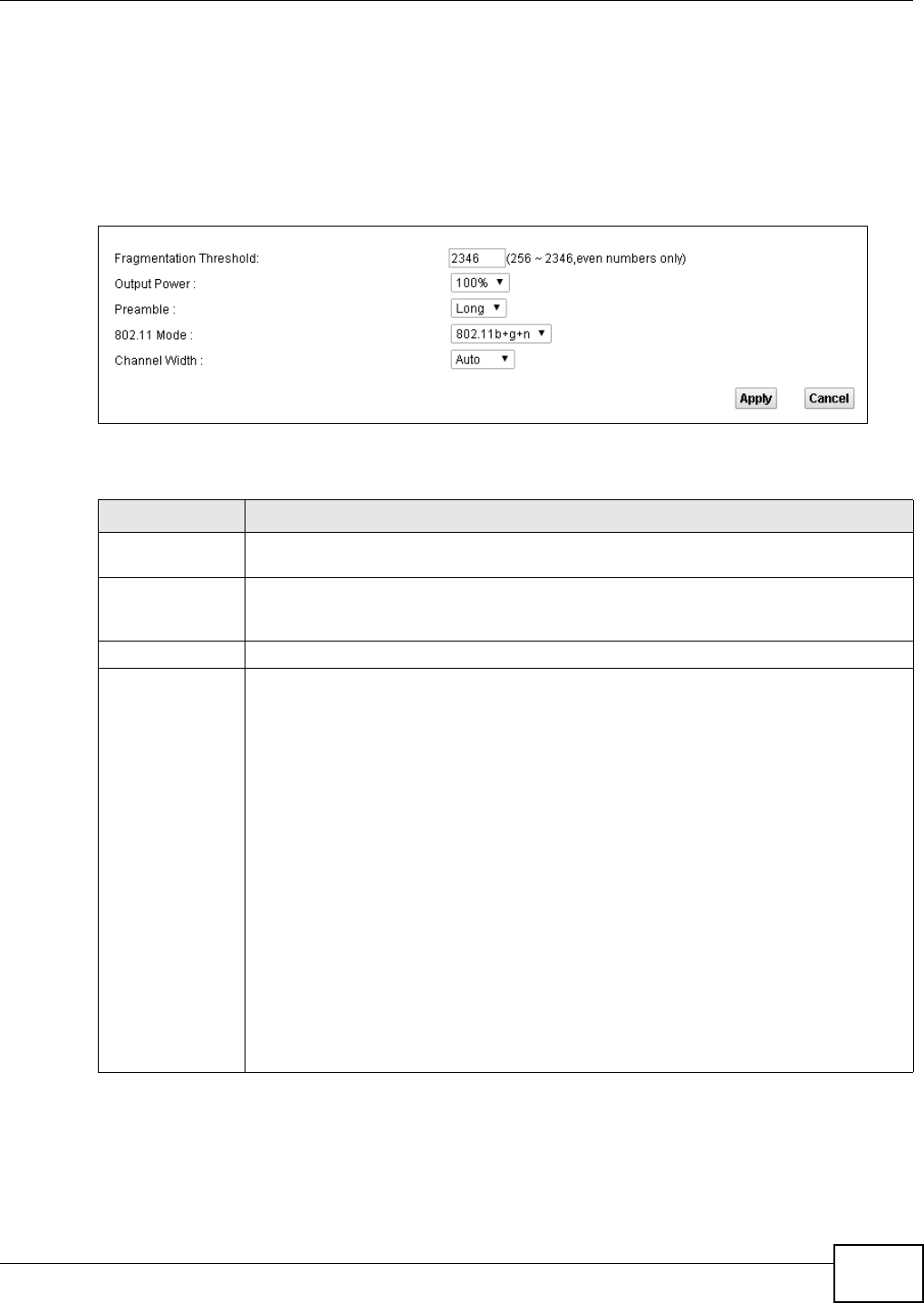
Chapter 6 Wireless
VMG1312-T10C User’s Guide 73
6.9 Advanced Screen
Use this screen to configure advanced wireless settings. Click Network Setting > Wireless >
Advanced, the screen appears as shown.
See Section 6.10.1 on page 74 for detailed definitions of the terms listed in this screen.
Figure 40 Network Setting > Wireless> Advanced
The following table describes the labels in this screen.
Table 22 Network Setting > Wireless> Advanced
LABEL DESCRIPTION
Fragmentation
Threshold
This is the maximum data fragment size that can be sent. Enter a value between 256 and
2346.
Output Power Set the output power of the Device. If there is a high density of APs in an area, decrease
the output power to reduce interference with other APs. Select one of the following:
100%, 75%, 50% or 25%.
Preamble Select a preamble type from the drop-down list menu. Choices are Long or Short.
802.11 Mode Select 802.11b to allow only IEEE 802.11b compliant WLAN devices to associate with the
Device.
Select 802.11g to allow only IEEE 802.11g compliant WLAN devices to associate with the
Device.
Select 802.11b+g to allow either IEEE 802.11b or IEEE 802.11g compliant WLAN
devices to associate with the Device. The transmission rate of your Device might be
reduced.
Select 802.11n to allow only IEEE 802.11n compliant WLAN devices to associate with the
Device.
Select 802.11g+n to allow either IEEE 802.11g or IEEE 802.11n compliant WLAN
devices to associate with the Device. The transmission rate of the Device might be
reduced when an 802.11g wireless client is associated with it.
Select 802.11b+g+n to allow IEEE 802.11b, IEEE 802.11g or IEEE 802.11n compliant
WLAN devices to associate with the Device. The transmission rate of the Device might be
reduced when an 802.11b or 802.11g wireless client is associated with it.
Note: The transmission rate varies depending on the mode the wireless client uses to
associate with the Device.
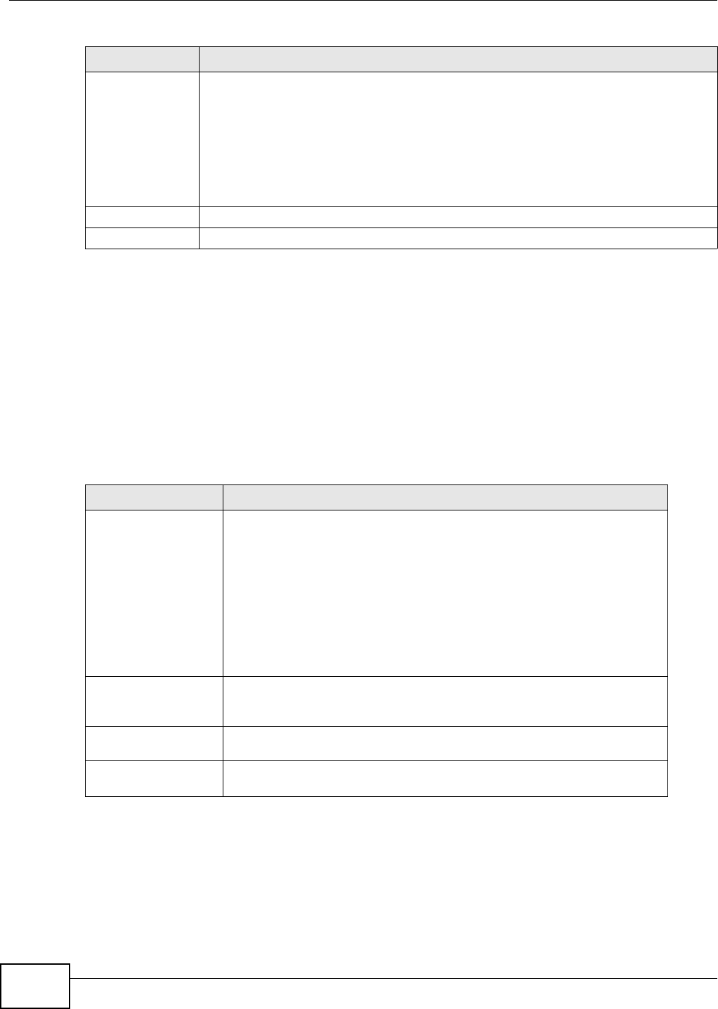
Chapter 6 Wireless
VMG1312-T10C User’s Guide
74
6.10 Technical Reference
This section discusses wireless LANs in depth.
6.10.1 Additional Wireless Terms
The following table describes some wireless network terms and acronyms used in the Device’s web
configurator.
6.10.2 Wireless Security Overview
By their nature, radio communications are simple to intercept. For wireless data networks, this
means that anyone within range of a wireless network without security can not only read the data
passing over the airwaves, but also join the network. Once an unauthorized person has access to
the network, he or she can steal information or introduce malware (malicious software) intended to
compromise the network. For these reasons, a variety of security systems have been developed to
Channel Width A standard 20MHz channel offers transfer speeds of up to 150Mbps whereas a 40MHz
channel uses two standard channels and offers speeds of up to 300 Mbps.
Select 20MHz if you want to lessen radio interference with other wireless devices in your
neighborhood or the wireless clients do not support channel bonding.
Select Auto to have the Device configure the wireless channel width automatically.
This field is available only when you set the 802.11 Mode to 802.11n or 802.11b+g+n
in the Advanced Setup screen.
Apply Click this to save your changes.
Cancel Click this to restore your previously saved settings.
Table 22 Network Setting > Wireless> Advanced (continued)
LABEL DESCRIPTION
Table 23 Additional Wireless Terms
TERM DESCRIPTION
RTS/CTS Threshold In a wireless network which covers a large area, wireless devices are
sometimes not aware of each other’s presence. This may cause them to
send information to the AP at the same time and result in information
colliding and not getting through.
By setting this value lower than the default value, the wireless devices must
sometimes get permission to send information to the Device. The lower the
value, the more often the devices must get permission.
If this value is greater than the fragmentation threshold value (see below),
then wireless devices never have to get permission to send information to
the Device.
Preamble A preamble affects the timing in your wireless network. There are two
preamble modes: long and short. If a device uses a different preamble mode
than the Device does, it cannot communicate with the Device.
Authentication The process of verifying whether a wireless device is allowed to use the
wireless network.
Fragmentation
Threshold
A small fragmentation threshold is recommended for busy networks, while a
larger threshold provides faster performance if the network is not very busy.

Chapter 6 Wireless
VMG1312-T10C User’s Guide 75
ensure that only authorized people can use a wireless data network, or understand the data carried
on it.
These security standards do two things. First, they authenticate. This means that only people
presenting the right credentials (often a username and password, or a “key” phrase) can access the
network. Second, they encrypt. This means that the information sent over the air is encoded. Only
people with the code key can understand the information, and only people who have been
authenticated are given the code key.
These security standards vary in effectiveness. Some can be broken, such as the old Wired
Equivalent Protocol (WEP). Using WEP is better than using no security at all, but it will not keep a
determined attacker out. Other security standards are secure in themselves but can be broken if a
user does not use them properly. For example, the WPA-PSK security standard is very secure if you
use a long key which is difficult for an attacker’s software to guess - for example, a twenty-letter
long string of apparently random numbers and letters - but it is not very secure if you use a short
key which is very easy to guess - for example, a three-letter word from the dictionary.
Because of the damage that can be done by a malicious attacker, it’s not just people who have
sensitive information on their network who should use security. Everybody who uses any wireless
network should ensure that effective security is in place.
A good way to come up with effective security keys, passwords and so on is to use obscure
information that you personally will easily remember, and to enter it in a way that appears random
and does not include real words. For example, if your mother owns a 1970 Dodge Challenger and
her favorite movie is Vanishing Point (which you know was made in 1971) you could use
“70dodchal71vanpoi” as your security key.
The following sections introduce different types of wireless security you can set up in the wireless
network.
6.10.2.1 SSID
Normally, the Device acts like a beacon and regularly broadcasts the SSID in the area. You can hide
the SSID instead, in which case the Device does not broadcast the SSID. In addition, you should
change the default SSID to something that is difficult to guess.
This type of security is fairly weak, however, because there are ways for unauthorized wireless
devices to get the SSID. In addition, unauthorized wireless devices can still see the information that
is sent in the wireless network.
6.10.2.2 User Authentication
Authentication is the process of verifying whether a wireless device is allowed to use the wireless
network. You can make every user log in to the wireless network before using it. However, every
device in the wireless network has to support IEEE 802.1x to do this.
For wireless networks, you can store the user names and passwords for each user in a RADIUS
server. This is a server used in businesses more than in homes. If you do not have a RADIUS server,
you cannot set up user names and passwords for your users.
Unauthorized wireless devices can still see the information that is sent in the wireless network,
even if they cannot use the wireless network. Furthermore, there are ways for unauthorized
wireless users to get a valid user name and password. Then, they can use that user name and
password to use the wireless network.
Chapter 6 Wireless
VMG1312-T10C User’s Guide
76
6.10.2.3 Encryption
Wireless networks can use encryption to protect the information that is sent in the wireless
network. Encryption is like a secret code. If you do not know the secret code, you cannot
understand the message.
The types of encryption you can choose depend on the type of authentication. (See Section
6.10.2.2 on page 75 for information about this.)
For example, if the wireless network has a RADIUS server, you can choose WPA or WPA2. If users
do not log in to the wireless network, you can choose no encryption, Static WEP, WPA-PSK, or
WPA2-PSK.
Usually, you should set up the strongest encryption that every device in the wireless network
supports. For example, suppose you have a wireless network with the Device and you do not have
a RADIUS server. Therefore, there is no authentication. Suppose the wireless network has two
devices. Device A only supports WEP, and device B supports WEP and WPA. Therefore, you should
set up Static WEP in the wireless network.
Note: It is recommended that wireless networks use WPA-PSK, WPA, or stronger
encryption. The other types of encryption are better than none at all, but it is still
possible for unauthorized wireless devices to figure out the original information
pretty quickly.
When you select WPA2 or WPA2-PSK in your Device, you can also select an option (WPA
compatible) to support WPA as well. In this case, if some of the devices support WPA and some
support WPA2, you should set up WPA2-PSK or WPA2 (depending on the type of wireless network
login) and select the WPA compatible option in the Device.
Many types of encryption use a key to protect the information in the wireless network. The longer
the key, the stronger the encryption. Every device in the wireless network must have the same key.
6.10.3 Signal Problems
Because wireless networks are radio networks, their signals are subject to limitations of distance,
interference and absorption.
Problems with distance occur when the two radios are too far apart. Problems with interference
occur when other radio waves interrupt the data signal. Interference may come from other radio
transmissions, such as military or air traffic control communications, or from machines that are
coincidental emitters such as electric motors or microwaves. Problems with absorption occur when
physical objects (such as thick walls) are between the two radios, muffling the signal.
Table 24 Types of Encryption for Each Type of Authentication
NO AUTHENTICATION RADIUS SERVER
Weakest No Security WPA
Static WEP
WPA-PSK
Strongest WPA2-PSK WPA2
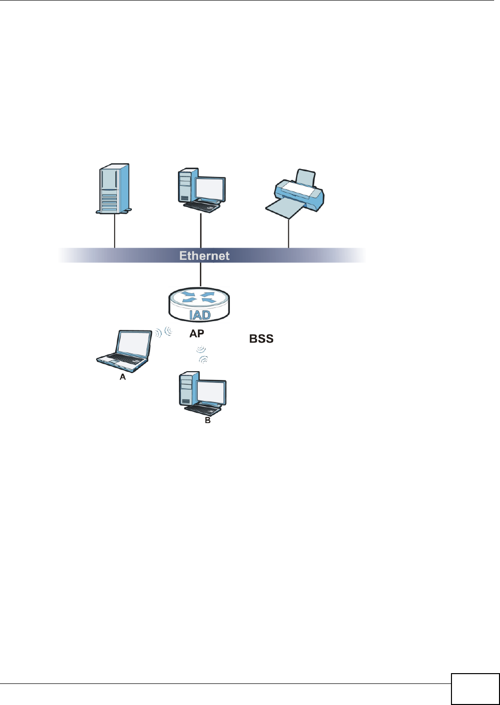
Chapter 6 Wireless
VMG1312-T10C User’s Guide 77
6.10.4 BSS
A Basic Service Set (BSS) exists when all communications between wireless stations or between a
wireless station and a wired network client go through one access point (AP).
Intra-BSS traffic is traffic between wireless stations in the BSS. When Intra-BSS traffic blocking is
disabled, wireless station A and B can access the wired network and communicate with each other.
When Intra-BSS traffic blocking is enabled, wireless station A and B can still access the wired
network but cannot communicate with each other.
Figure 41 Basic Service set
6.10.5 MBSSID
Traditionally, you need to use different APs to configure different Basic Service Sets (BSSs). As well
as the cost of buying extra APs, there is also the possibility of channel interference. The Device’s
MBSSID (Multiple Basic Service Set IDentifier) function allows you to use one access point to
provide several BSSs simultaneously. You can then assign varying QoS priorities and/or security
modes to different SSIDs.
Wireless devices can use different BSSIDs to associate with the same AP.
6.10.5.1 Notes on Multiple BSSs
• A maximum of eight BSSs are allowed on one AP simultaneously.
• You must use different keys for different BSSs. If two wireless devices have different BSSIDs
(they are in different BSSs), but have the same keys, they may hear each other’s
communications (but not communicate with each other).
• MBSSID should not replace but rather be used in conjunction with 802.1x security.
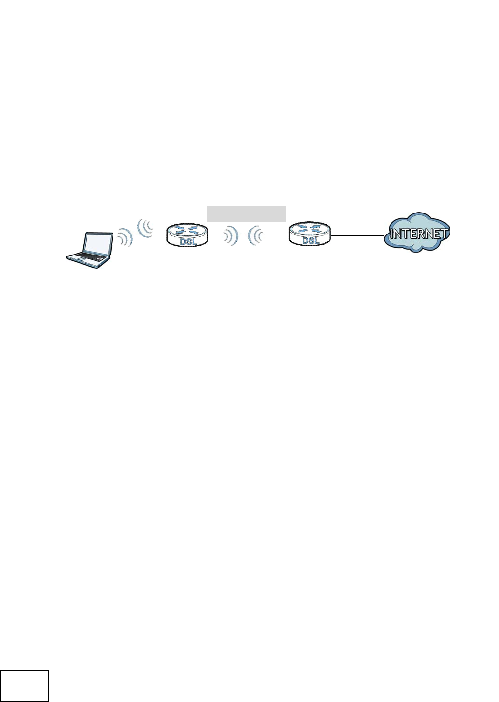
Chapter 6 Wireless
VMG1312-T10C User’s Guide
78
6.10.6 Wireless Distribution System (WDS)
The Device can act as a wireless network bridge and establish WDS (Wireless Distribution System)
links with other APs. You need to know the MAC addresses of the APs you want to link to. Once the
security settings of peer sides match one another, the connection between devices is made.
At the time of writing, WDS security is not compatible with all access points. Refer to your other
access point’s documentation for details.
The following figure illustrates how WDS link works between APs. Notebook computer A is a
wireless client connecting to access point AP 1. AP 1 has no wired Internet connection, but it can
establish a WDS link with access point AP 2, which has a wired Internet connection. When AP 1
has a WDS link with AP 2, the notebook computer can access the Internet through AP 2.
Figure 42 WDS Link Example
WDS
AP 2
AP 1
A
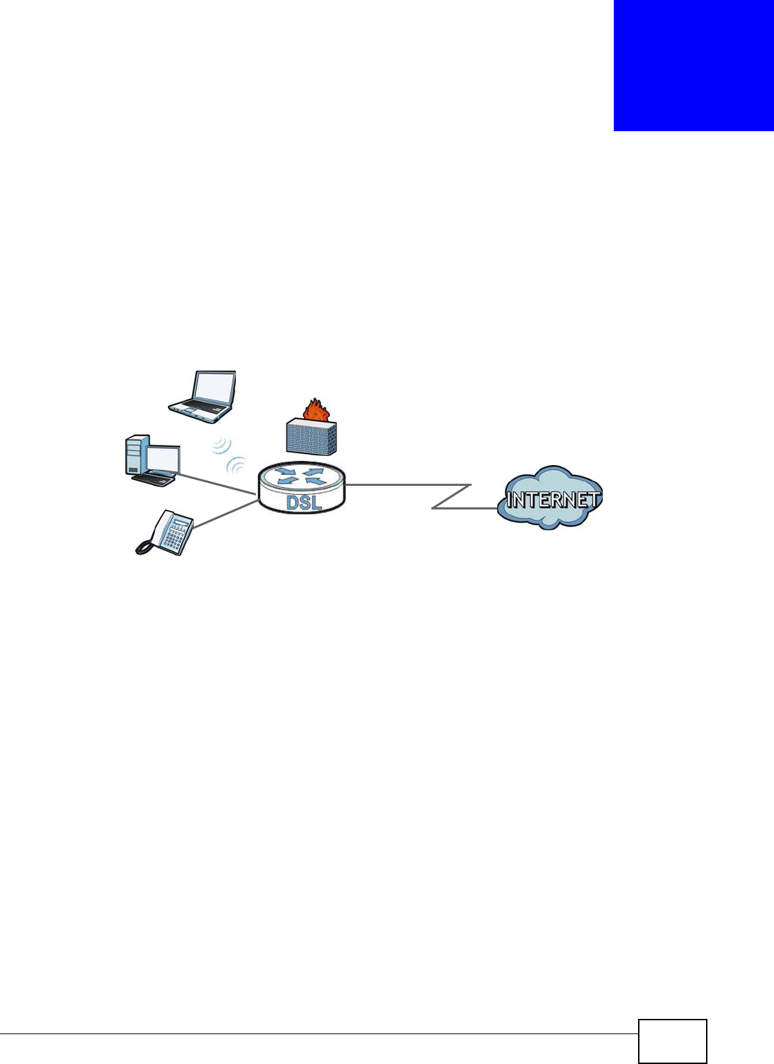
VMG1312-T10C User’s Guide 85
CHAPTER 7
Home Networking
7.1 Overview
A Local Area Network (LAN) is a shared communication system to which many computers are
attached. A LAN is usually located in one immediate area such as a building or floor of a building.
The LAN screens can help you configure a LAN DHCP server and manage IP addresses.
7.1.1 What You Can Do in this Chapter
•Use the LAN Setup screen to set the LAN IP address, subnet mask, and DHCP settings (Section
7.2 on page 88).
•Use the Static DHCP screen to assign IP addresses on the LAN to specific individual computers
based on their MAC Addresses (Section 7.3 on page 90).
•Use the IP Alias screen (Section 7.4 on page 91) to configure another logical network in the
physical LAN network.
•Use the UPnP screen to enable UPnP (Section 7.5 on page 92).
•Use the UPnP Rule screen to
•Use the IPv6 LAN Setup screen (Section 7.7 on page 93) to configure the IPv6 settings on your
Device’s LAN interface.
•Use the File Sharing screen to enable file-sharing server (Section 7.8 on page 97).
•Use the Printer Server screen to enable the print server (Section 7.9 on page 100).
7.1.2 What You Need To Know
The following terms and concepts may help as you read this chapter.
WAN
LAN

Chapter 7 Home Networking
VMG1312-T10C User’s Guide
86
7.1.2.1 About LAN
IP Address
Similar to the way houses on a street share a common street name, so too do computers on a LAN
share one common network number. This is known as an Internet Protocol address.
Subnet Mask
The subnet mask specifies the network number portion of an IP address. Your Device will compute
the subnet mask automatically based on the IP address that you entered. You don't need to change
the subnet mask computed by the Device unless you are instructed to do otherwise.
DHCP
DHCP (Dynamic Host Configuration Protocol) allows clients to obtain TCP/IP configuration at start-
up from a server. This Device has a built-in DHCP server capability that assigns IP addresses and
DNS servers to systems that support DHCP client capability.
DNS
DNS (Domain Name System) maps a domain name to its corresponding IP address and vice versa.
The DNS server is extremely important because without it, you must know the IP address of a
computer before you can access it. The DNS server addresses you enter when you set up DHCP are
passed to the client machines along with the assigned IP address and subnet mask.
7.1.2.2 About UPnP
How do I know if I'm using UPnP?
UPnP hardware is identified as an icon in the Network Connections folder (Windows XP). Each UPnP
compatible device installed on your network will appear as a separate icon. Selecting the icon of a
UPnP device will allow you to access the information and properties of that device.
Cautions with UPnP
The automated nature of NAT traversal applications in establishing their own services and opening
firewall ports may present network security issues. Network information and configuration may also
be obtained and modified by users in some network environments.
When a UPnP device joins a network, it announces its presence with a multicast message. For
security reasons, the Device allows multicast messages on the LAN only.
All UPnP-enabled devices may communicate freely with each other without additional configuration.
Disable UPnP if this is not your intention.
UPnP and ZyXEL
ZyXEL has achieved UPnP certification from the Universal Plug and Play Forum UPnP™
Implementers Corp. (UIC). ZyXEL's UPnP implementation supports Internet Gateway Device (IGD)
1.0.

Chapter 7 Home Networking
VMG1312-T10C User’s Guide 87
See Section 7.11 on page 105 for examples of installing and using UPnP.
7.1.2.3 About File Sharing
Workgroup name
This is the name given to a set of computers that are connected on a network and share resources
such as a printer or files. Windows automatically assigns the workgroup name when you set up a
network.
Shares
When settings are set to default, each USB device connected to the Device is given a folder, called
a “share”. If a USB hard drive connected to the Device has more than one partition, then each
partition will be allocated a share. You can also configure a “share” to be a sub-folder or file on the
USB device.
File Systems
A file system is a way of storing and organizing files on your hard drive and storage device. Often
different operating systems such as Windows or Linux have different file systems. The file sharing
feature on your Device supports FAT16, FAT32, NTFS, EXT2, and EXT3.
Common Internet File System
The Device uses Common Internet File System (CIFS) protocol for its file sharing functions. CIFS
compatible computers can access the USB file storage devices connected to the Device. CIFS
protocol is supported on Microsoft Windows, Linux Samba and other operating systems (refer to
your systems specifications for CIFS compatibility).
7.1.2.4 About Printer Server
Print Server
This is a computer or other device which manages one or more printers, and which sends print jobs
to each printer from the computer itself or other devices.
Operating System
An operating system (OS) is the interface which helps you manage a computer. Common examples
are Microsoft Windows, Mac OS or Linux.
TCP/IP
TCP/IP (Transmission Control Protocol/ Internet Protocol) is a set of communications protocols that
most of the Internet runs on.
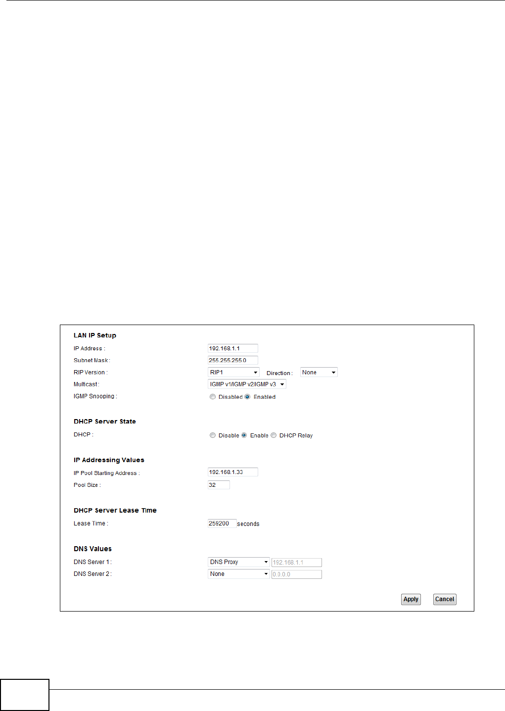
Chapter 7 Home Networking
VMG1312-T10C User’s Guide
88
Port
A port maps a network service such as http to a process running on your computer, such as a
process run by your web browser. When traffic from the Internet is received on your computer, the
port number is used to identify which process running on your computer it is intended for.
Supported OSs
Your operating system must support TCP/IP ports for printing and be compatible with the RAW (port
9100) protocol.
The following OSs support Device’s printer sharing feature.
• Microsoft Windows 95, Windows 98 SE (Second Edition), Windows Me, Windows NT 4.0, Windows
2000, Windows XP or Macintosh OS X.
7.2 The LAN Setup Screen
Click Network Setting > Home Networking to open the LAN Setup screen. Use this screen to
set the Local Area Network IP address and subnet mask of your Device and configure the DNS
server information that the Device sends to the DHCP client devices on the LAN.
Figure 48 Network Setting > Home Networking > LAN Setup
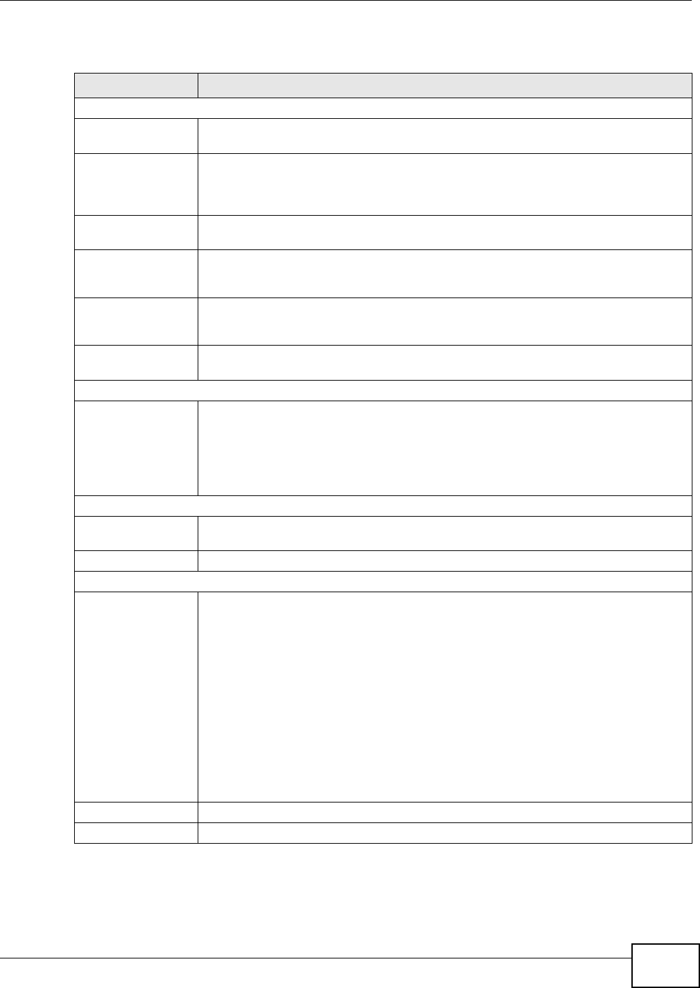
Chapter 7 Home Networking
VMG1312-T10C User’s Guide 89
The following table describes the fields in this screen.
Table 25 Network Setting > Home Networking > LAN Setup
LABEL DESCRIPTION
LAN IP Setup
IP Address Enter the LAN IP address you want to assign to your Device in dotted decimal notation,
for example, 192.168.1.1 (factory default).
IP Subnet Mask Type the subnet mask of your network in dotted decimal notation, for example
255.255.255.0 (factory default). Your Device automatically computes the subnet mask
based on the IP address you enter, so do not change this field unless you are instructed
to do so.
RIP Version RIP (Routing Information Protocol) allows a router to exchange routing information with
other routers. Select the RIP version from RIP-1 and RIP2-B/RIP2-M.
Direction Use this field to control how much routing information the VDSL Router sends and
receives on the subnet. Select the RIP Direction from None, Both, IN Only and OUT
Only.
Multicast IGMP (Internet Group Multicast Protocol) is a network-layer protocol used to establish
membership in a multicast group. The Device supports IGMP v1/IGMP v2/IGMP v3.
Select None to disable it.
IGMP Snooping Select Enabled to activate IGMP Snooping. This allows the Device to passively learn
memberships in multicast groups. Otherwise, select Disabled to deactivate it.
DHCP Server State
DHCP Select Enable to have your Device assign IP addresses, an IP default gateway and DNS
servers to LAN computers and other devices that are DHCP clients.
If you select Disable, you need to manually configure the IP addresses of the
computers and other devices on your LAN.
When DHCP is used, the following fields need to be set.
IP Addressing Values
IP Pool Starting
Address
This field specifies the first of the contiguous addresses in the IP address pool.
Pool Size This field specifies the size, or count of the IP address pool.
DNS Values
DNS Server 1-2 The Device supports DNS proxy by default. The Device sends out its own LAN IP
address to the DHCP clients as the first DNS server address. DHCP clients use this first
DNS server to send domain-name queries to the Device. The Device sends a response
directly if it has a record of the domain-name to IP address mapping. If it does not, the
Device queries an outside DNS server and relays the response to the DHCP client.
Select From ISP if your ISP dynamically assigns DNS server information (and the
Device's WAN IP address).
Select DNS Proxy to have the DHCP clients use the Device’s own LAN IP address. The
Device works as a DNS relay.
Select User-Defined if you have the IP address of a DNS server. Enter the DNS
server's IP address in the field to the right.
Select None to not configure extra DNS servers.
Apply Click Apply to save your changes.
Cancel Click Cancel to restore your previously saved settings.
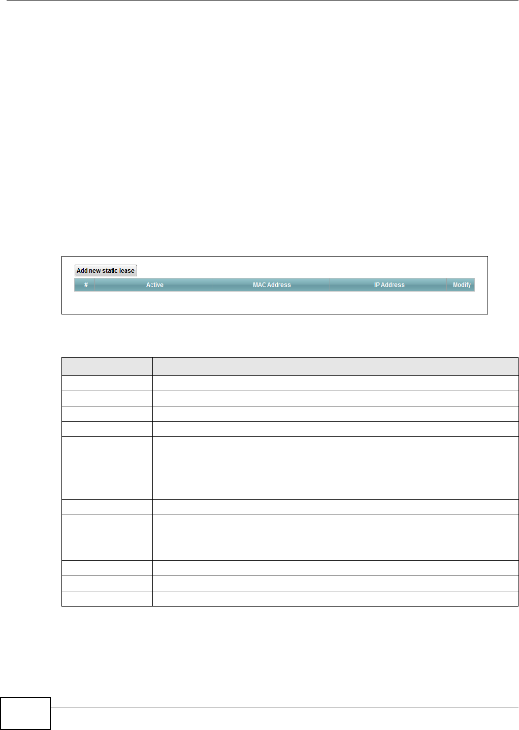
Chapter 7 Home Networking
VMG1312-T10C User’s Guide
90
7.3 The Static DHCP Screen
This table allows you to assign IP addresses on the LAN to specific individual computers based on
their MAC Addresses.
Every Ethernet device has a unique MAC (Media Access Control) address. The MAC address is
assigned at the factory and consists of six pairs of hexadecimal characters, for example,
00:A0:C5:00:00:02.
7.3.1 Before You Begin
Find out the MAC addresses of your network devices if you intend to add them to the Static DHCP
screen.
Use this screen to change your Device’s static DHCP settings. Click Network Setting > Home
Networking > Static DHCP to open the following screen.
Figure 49 Network Setting > Home Networking > Static DHCP
The following table describes the labels in this screen.
Table 26 Network Setting > Home Networking > Static DHCP
LABEL DESCRIPTION
Add new static lease Click this to add a new static DHCP entry.
# This is the index number of the entry.
Status This field displays whether the client is connected to the Device.
Host Name This field displays the client host name.
MAC Address The MAC (Media Access Control) or Ethernet address on a LAN (Local Area Network) is
unique to your computer (six pairs of hexadecimal notation).
A network interface card such as an Ethernet adapter has a hardwired address that is
assigned at the factory. This address follows an industry standard that ensures no other
adapter has a similar address.
IP Address This field displays the IP address relative to the # field listed above.
Reserve Select the check box in the heading row to automatically select all check boxes or select
individual entry check boxes in each entry to have the Device always assign the
selected entries's IP addresses to the corresponding MAC addresses and host names.
You can select up to 128 entries in this table.
Apply Click Apply to save your changes.
Cancel Click Cancel to restore your previously saved settings.
Refresh Click Refresh to reload the DHCP table.
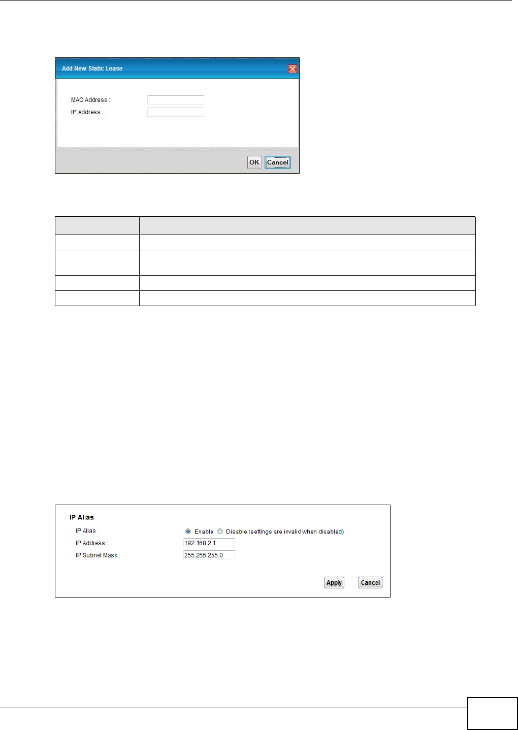
Chapter 7 Home Networking
VMG1312-T10C User’s Guide 91
If you click Add new static lease in the Static DHCP screen, the following screen displays.
Figure 50 Static DHCP: Add
The following table describes the labels in this screen.
7.4 The IP Alias Screen
IP alias allows you to partition a physical network into different logical networks over the same
Ethernet interface. The Device supports multiple logical LAN interfaces via its physical Ethernet
interface with the Device itself as the gateway for the LAN network.
When you use IP alias, you can also configure firewall rules to control access to the LAN's logical
network (subnet).
Use this screen to change your Device’s IP alias settings. Click Network Setting > Home
Networking > IP Alias to open the following screen.
Figure 51 Network Setting > Home Networking > IP Alias
Table 27 Static DHCP: Add
LABEL DESCRIPTION
MAC Address Enter the MAC address of a computer on your LAN.
IP Address Enter the IP address that you want to assign to the computer on your LAN with
the MAC address that you will also specify.
Apply Click Apply to save your changes.
Cancel Click Cancel to exit this screen without saving.
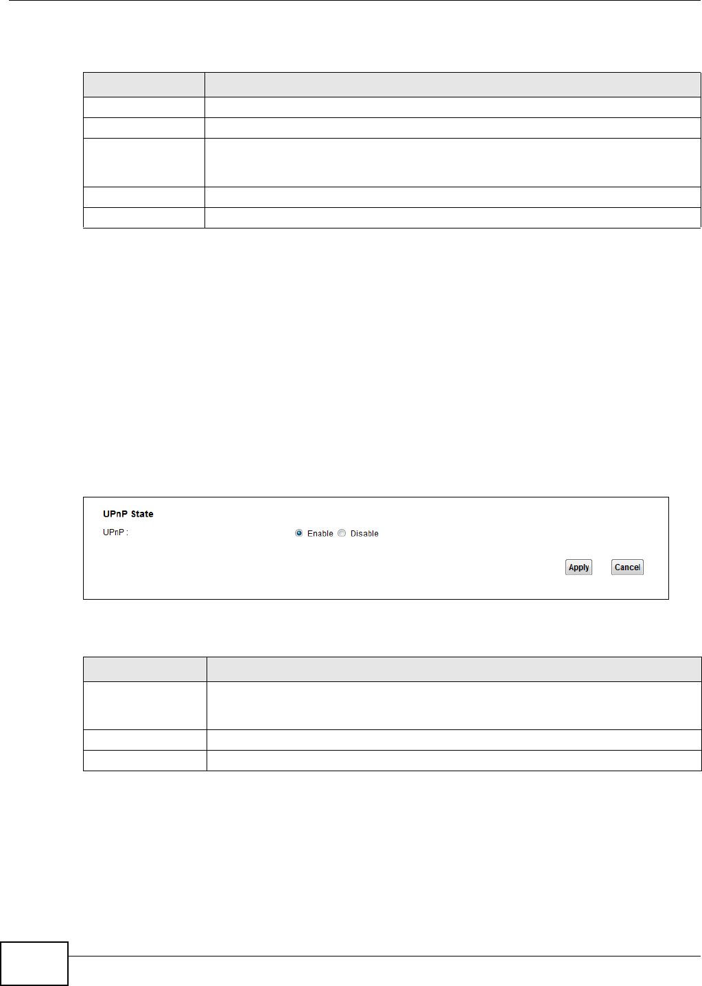
Chapter 7 Home Networking
VMG1312-T10C User’s Guide
92
The following table describes the labels in this screen.
7.5 The UPnP Screen
Universal Plug and Play (UPnP) is a distributed, open networking standard that uses TCP/IP for
simple peer-to-peer network connectivity between devices. A UPnP device can dynamically join a
network, obtain an IP address, convey its capabilities and learn about other devices on the network.
In turn, a device can leave a network smoothly and automatically when it is no longer in use.
See page 105 for more information on UPnP.
Use the following screen to configure the UPnP settings on your Device. Click Network Setting >
Home Networking > Static DHCP > UPnP to display the screen shown next.
Figure 52 Network Setting > Home Networking > UPnP
The following table describes the labels in this screen.
7.6 The UPnP Rule Screen
Table 28 Network Setting > Home Networking > IP Alias
LABEL DESCRIPTION
IP Alias Select Enable to configure a LAN network for the Device.
IP Address Enter the IP address of your Device in dotted decimal notation.
Subnet Mask Your Device will automatically calculate the subnet mask based on the IP address that
you assign. Unless you are implementing subnetting, use the subnet mask computed by
the Device.
Apply Click this to save your changes.
Cancel Click this to restore your previously saved settings.
Table 29 Network Settings > Home Networking > UPnP
LABEL DESCRIPTION
UPnP Select Enable to activate UPnP. Be aware that anyone could use a UPnP application to
open the web configurator's login screen without entering the Device's IP address
(although you must still enter the password to access the web configurator).
Apply Click Apply to save your changes.
Cancel Click this to restore your previously saved settings.
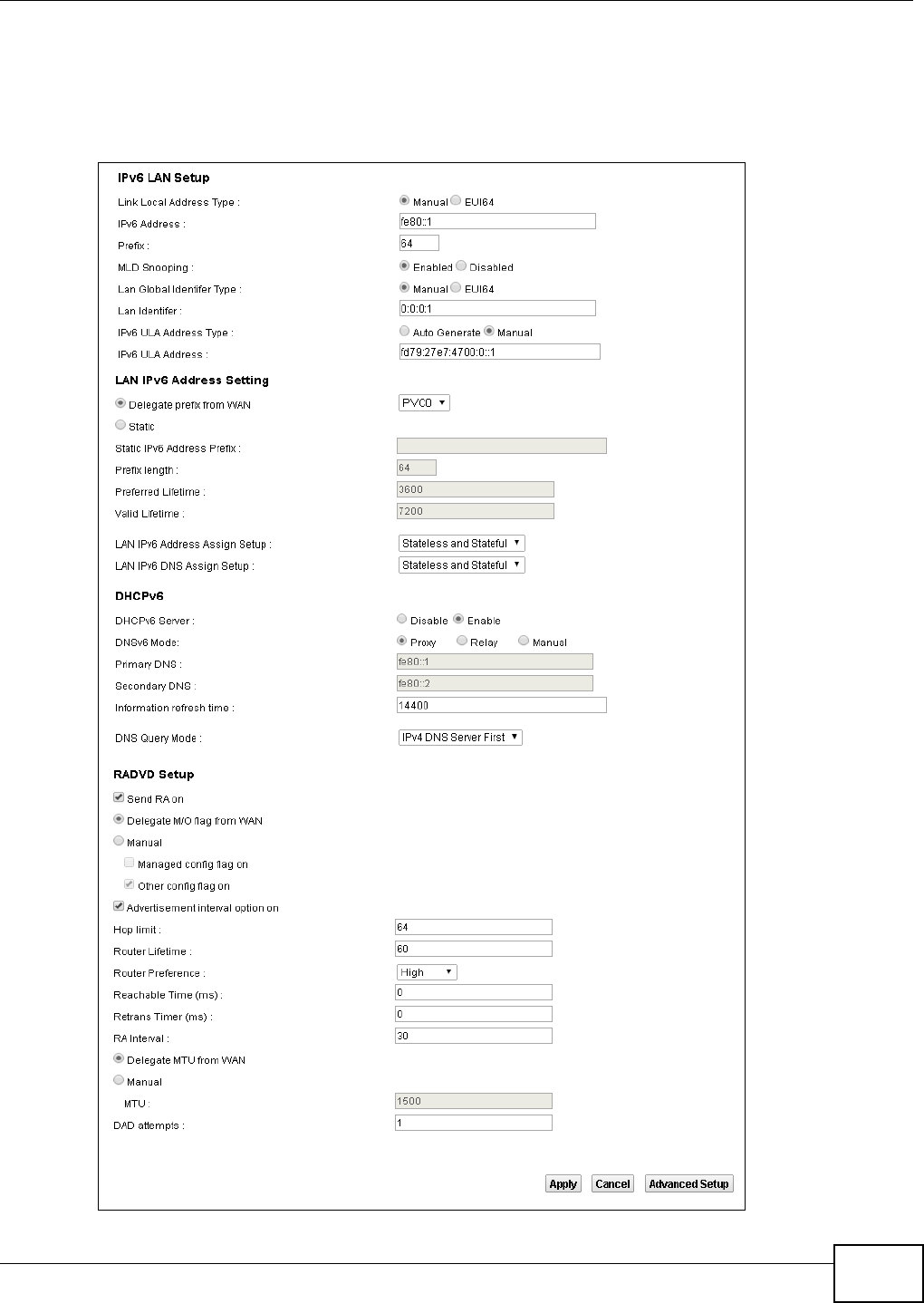
Chapter 7 Home Networking
VMG1312-T10C User’s Guide 93
7.7 The IPv6 LAN Setup Screen
Use this screen to configure the IPv6 settings for your Device’s LAN interface.
Figure 53 Network Setting > Home Networking > IPv6 LAN Setup

Chapter 7 Home Networking
VMG1312-T10C User’s Guide
94
The following table describes the labels in this screen.
Table 30 Network Setting > Home Networking > IPv6 LAN Setup
LABEL DESCRIPTION
IPv6 LAN Setup
Link Local Address
Type
Select Manual to manually enter a link local address. Select EUI64 to use the EUI-64
format to generate a link local address from the Ethernet MAC address.
IPv6 Address If you selected Manual in the Link Local Address Type field, enter the LAN IPv6
address you want to assign to your Device in hexadecimal notation, for example,
fe80::1 (factory default).
Prefix Enter the address prefix to specify how many most significant bits in an IPv6 address
compose the network address.
MLD Snooping Multicast Listener Discovery (MLD) allows an IPv6 switch or router to discover the
presence of MLD hosts who wish to receive multicast packets and the IP addresses of
multicast groups the hosts want to join on its network. Select Enabled to activate
MLD Snooping on the Device. This allows the Device to check MLD packets passing
through it and learn the multicast group membership. It helps reduce multicast traffic.
Lan Global Identifier
Type
Select Manual to manually enter a LAN Identifier as the interface ID to identify the
LAN interface. The LAN Identifier is appended to the IPv6 address prefix to create the
routable global IPv6 address. Select EUI64 to use the EUI-64 format to generate an
interface ID from the Ethernet MAC address.
Lan Identifier If you selected Manual, enter the LAN Identifier in this field. The LAN identifier should
be unique and 64 bits in hexadecimal form. Every 16 bit block should be separated by
a colon as in XXXX:XXXX:XXXX:XXXX where X is a hexadecimal character. Blocks of
zeros can be represented with double colons as in XXXX:XXXX::XXXX.
IPv6 ULA Address
Type
A unique local address (ULA) is a unique IPv6 address for use in private networks but
not routable in the global IPv6 Internet.
Select Auto Generate to have the Device automatically generate a globally unique
address for the LAN IPv6 address. Select Manual to enter a static IPv6 ULA address.
The address format is like fdxx:xxxx:xxxx:xxxx::/64.
IPv6 ULA Address If Manual is selected in the IPv6 ULA Address Type field, enter the IPv6 address
prefix that the Device uses for the LAN IPv6 address.
LAN IPv6 Address Setting
Delegate prefix from
WAN
Select this option to automatically obtain an IPv6 network prefix from the service
provider or an uplink router.
Static Select this option to configure a fixed IPv6 address for the Device’s LAN IPv6 address.
Static IPv6 Address
Prefix
If you select static IPv6 address, enter the IPv6 address prefix that the Device uses for
the LAN IPv6 address.
Prefix length If you select static IPv6 address, enter the IPv6 prefix length that the Device uses to
generate the LAN IPv6 address.
An IPv6 prefix length specifies how many most significant bits (starting from the left)
in the address compose the network address. This field displays the bit number of the
IPv6 subnet mask.
Preferred Lifetime Enter the preferred lifetime for the prefix.
Valid Lifetime Enter the valid lifetime for the prefix.
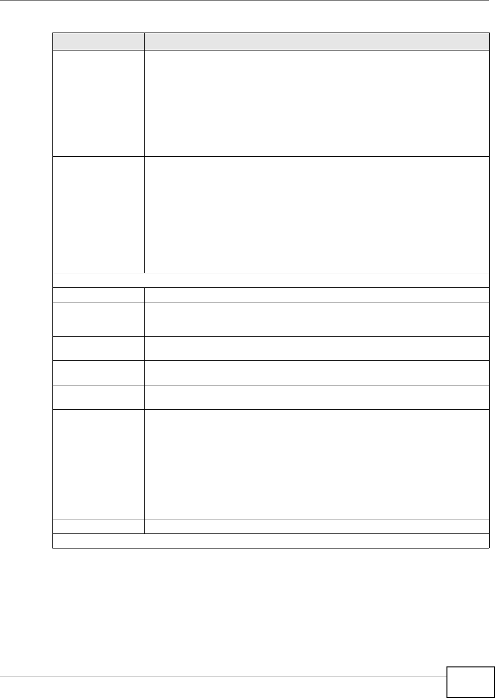
Chapter 7 Home Networking
VMG1312-T10C User’s Guide 95
LAN IPv6 Address
Assign Setup
Select how you want to obtain an IPv6 address:
•Stateless: The Device uses IPv6 stateless autoconfiguration. RADVD (Router
Advertisement Daemon) is enabled to have the Device send IPv6 prefix
information in router advertisements periodically and in response to router
solicitations. DHCPv6 server is disabled.
•Stateful: The Device uses IPv6 stateful autoconfiguration. The DHCPv6 server is
enabled to have the Device act as a DHCPv6 server and pass IPv6 addresses to
DHCPv6 clients.
•Stateless and Stateful: The Device uses both IPv6 stateless and stateful
autoconfiguration. The LAN IPv6 clients can obtain IPv6 addresses either through
router advertisements or through DHCPv6.
LAN IPv6 DNS Assign
Setup
Select how the Device provide DNS server and domain name information to the
clients:
•Stateless: The Device uses IPv6 stateless autoconfiguration. RADVD (Router
Advertisement Daemon) is enabled to have the Device send IPv6 prefix
information in router advertisements periodically and in response to router
solicitations. DHCPv6 server is disabled.
•Stateful: The Device uses IPv6 stateful autoconfiguration. The DHCPv6 server is
enabled to have the Device act as a DHCPv6 server and pass IPv6 addresses to
DHCPv6 clients.
•Stateless and Stateful: The Device uses both IPv6 stateless and stateful
autoconfiguration. The LAN IPv6 clients can obtain IPv6 addresses either through
router advertisements or through DHCPv6.
DHCPv6
DHCPv6 Server Use this field to Enable or Disable DHCPv6 server on the Device.
DNSv6 Mode Select the DNS role (Proxy or Relay) that you want the Device to act in the IPv6 LAN
network. Alternatively, select Manual and specify the DNS servers’ IPv6 address in
the fields below.
Primary DNS This field is available if you choose Manual as the DNSv6 mode. Enter the first DNS
server IPv6 address the Device passes to the DHCP clients.
Secondary DNS This field is available if you choose Manual as the DNSv6 mode. Enter the second DNS
server IPv6 address the Device passes to the DHCP clients.
Information refresh
time
Enter the number of seconds a DHCPv6 client should wait before refreshing
information retrieved from DHCPv6.
DNS Query Mode Select how the Device handles clients’ DNS information requests.
•IPv4 DNS Server First: The Device forwards the requests to the IPv4 DNS server
first and then the IPv6 DNS server. Then it sends clients the first DNS information
it receives.
•IPv6 DNS Server First: The Device forwards the requests to the IPv6 DNS server
first and then the IPv4 DNS server. Then it sends clients the first DNS information
it receives.
•IPv4 DNS Server Only: The Device forwards the requests to the IPv4 DNS server
and sends clients the DNS information it receives.
•IPv6 DNS Server Only: The Device forwards the requests to the IPv6 DNS server
and sends clients the DNS information it receives.
Advanced Setup Click this to open the IPv6 LAN Setup Advanced Setup section.
RADVD Setup
Table 30 Network Setting > Home Networking > IPv6 LAN Setup (continued)
LABEL DESCRIPTION

Chapter 7 Home Networking
VMG1312-T10C User’s Guide
96
Send RA on Select this to have the Device send router advertisement messages to the LAN hosts.
Router advertisement is a response to a router solicitation or a periodical multicast
advertisement from a router to advertise its presence and other parameters, such as
IPv6 prefix and DNS information.
Router solicitation is a request from a host to locate a router that can act as the
default router and forward packets.
Note: The LAN hosts neither generate global IPv6 addresses nor communicate with
other networks if you disable this feature.
Delegate M/O flag
from WAN
Select this to have the Device obtain the M/O (Managed/Other) flag setting from the
service provider or uplink router.
Manual Select this to specify the M/O flag setting manually.
Managed config
flag on Select this to have the Device indicate to hosts to obtain network settings (such as
prefix and DNS settings) through DHCPv6.
Clear this to have the Device indicate to hosts that DHCPv6 is not available and they
should use the prefix in the router advertisement message.
Other config flag
on Select this to have the Device indicate to hosts to obtain DNS information through
DHCPv6.
Clear this to have the Device indicate to hosts that DNS information is not available in
this network.
Advertisement
interval option on Select this to have the Router Advertisement messages the VDSL Router
sends specify the allowed interval between Router Advertisement messages.
Hop limit Enter the maximum number of network segments that a packet can cross before
reaching the destination. When forwarding an IPv6 packet, IPv6 routers are required
to decrease the Hop Limit by 1 and to discard the IPv6 packet when the Hop Limit is 0.
Possible value for this field are 0-255.
Router Lifetime Enter the time in seconds that hosts should consider the Device to be the default
router. Possible values for this field are 0-9000.
Router Preference Select the router preference (Low, Medium or High) for the Device. The Device
sends this preference in the router advertisements to tell hosts what preference they
should use for the Device. This helps hosts to choose their default router especially
when there are multiple IPv6 router in the network.
Note: Make sure the hosts also support router preference to make this function work.
Reachable Time (ms) Enter the time in milliseconds that can elapse before a neighbor is detected. Possible
values for this field are 0-3600000.
Retrans Timer (ms) Enter the time in milliseconds between neighbor solicitation packet retransmissions.
Possible values for this field are 1000-4294967295.
RA Interval Enter the time in seconds between router advertisement messages. Possible values for
this field are 4-1800.
Delegate MTU from
WAN
Select this to have the Device obtain the MTU setting from the service provider or
uplink router.
Manual Select this to specify the MTU manually.
MTU The Maximum Transmission Unit. Type the maximum size of each IPv6 data packet, in
bytes, that can move through this interface. If a larger packet arrives, the Device
divides it into smaller fragments.
DAD attempts Specify the number of DAD (Duplicate Address Detection) attempts before an IPv6
address is assigned to the Device LAN interface. Possible values for this field are 1-7.
Apply Click this to save your changes.
Table 30 Network Setting > Home Networking > IPv6 LAN Setup (continued)
LABEL DESCRIPTION
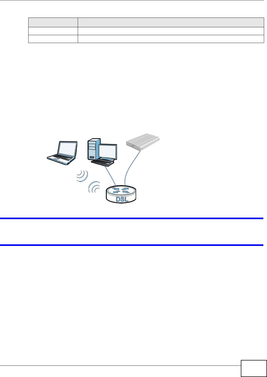
Chapter 7 Home Networking
VMG1312-T10C User’s Guide 97
7.8 The File Sharing Screen
You can share files on a USB memory stick or hard drive connected to your Device with users on
your network.
The following figure is an overview of the Device’s file server feature. Computers A and B can
access files on a USB device (C) which is connected to the Device.
Figure 54 File Sharing Overview
The Device will not be able to join the workgroup if your local area network has restrictions
set up that do not allow devices to join a workgroup. In this case, contact your network
administrator.
7.8.1 Before You Begin
Make sure the Device is connected to your network and turned on.
1Connect the USB device to one of the Device’s USB ports. Make sure the Device is connected to
your network.
2The Device detects the USB device and makes its contents available for browsing. If you are
connecting a USB hard drive that comes with an external power supply, make sure it is connected
to an appropriate power source that is on.
Note: If your USB device cannot be detected by the Device, see the troubleshooting for
suggestions.
Cancel Click this to restore your previously saved settings.
Advanced Setup Click this to close the IPv6 LAN Setup Advanced Setup section.
Table 30 Network Setting > Home Networking > IPv6 LAN Setup (continued)
LABEL DESCRIPTION
A
BC
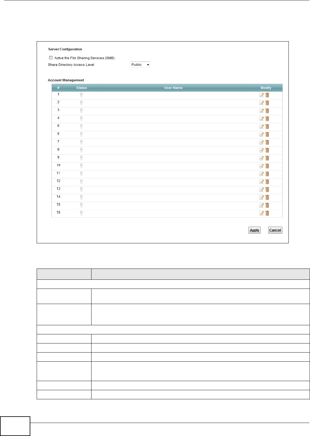
Chapter 7 Home Networking
VMG1312-T10C User’s Guide
98
Use this screen to set up file sharing using the Device. To access this screen, click Network
Setting > Home Networking > File Sharing.
Figure 55 Network Setting > Home Networking > File Sharing
Each field is described in the following table.
Table 31 Network Setting > Home Networking > File Sharing
LABEL DESCRIPTION
Server Configuration
File Sharing
Services (SMB)
Select Enable to activate file sharing through the Device.
Share Directory
Access Level
Select Public to allow all LAN users to access the shared folders. Select Security to
allow only the users added and activated in the Account Management section below
to access the shared folders.
Account Management
#This is the index number of the file sharing user account.
Status This shows whether or not the file sharing user account is activated.
User Name This field displays the user name of the file sharing user account.
Modify Click the Edit icon to configure a file sharing user account’s settings.
Click the Delete icon to delete this user account from the list.
Apply Click Apply to save your changes.
Cancel Click Cancel to restore your previously saved settings.
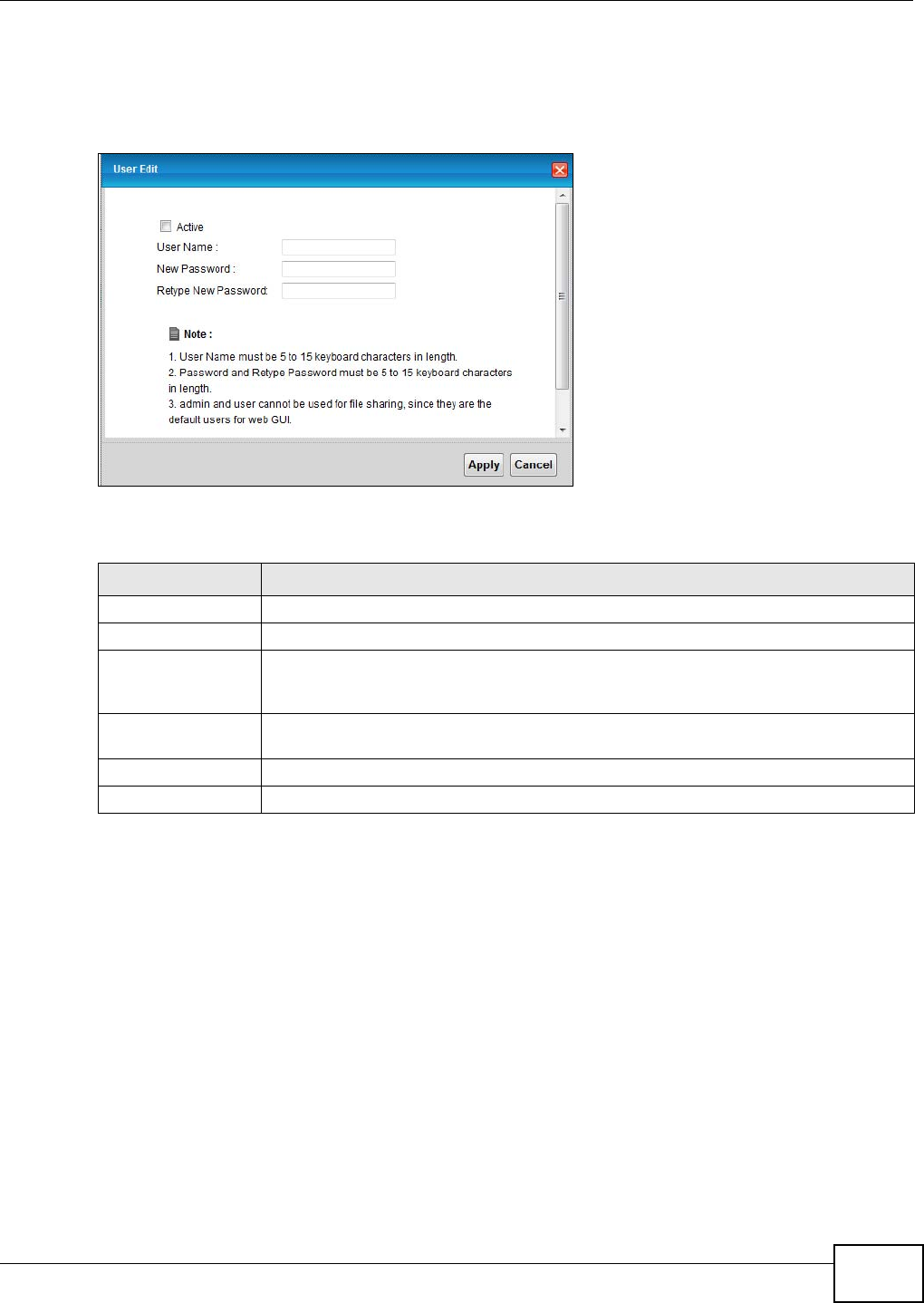
Chapter 7 Home Networking
VMG1312-T10C User’s Guide 99
7.8.2 Edit File Sharing User
Use this screen to edit a file sharing user on the Device. Click the Edit icon next to a user account.
Figure 56 File Sharing: Add/Edit
Each field is described in the following table.
Table 32 File Sharing: Add/Edit
LABEL DESCRIPTION
Active Select this to activate the file sharing user account.
User Name Type the user name for the account.
New Password Type your new system password (up to 30 characters). Note that as you type a
password, the screen displays a (*) for each character you type. After you change the
password, use the new password to access the Device.
Retype New
Password
Type the new password again for confirmation.
Apply Click Apply to save your changes.
Cancel Click Cancel to exit this screen without saving.
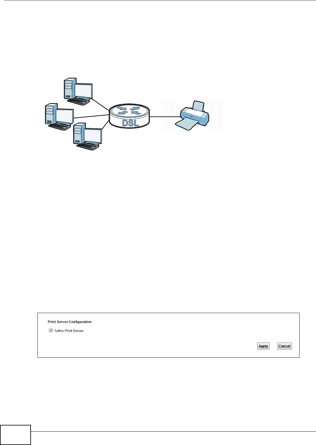
Chapter 7 Home Networking
VMG1312-T10C User’s Guide
100
7.9 The Printer Server Screen
The Device allows you to share a USB printer on your LAN. You can do this by connecting a USB
printer to one of the USB ports on the Device and then configuring a TCP/IP port on the computers
connected to your network.
Figure 57 Sharing a USB Printer
7.9.1 Before You Begin
To configure the print server you need the following:
• Your Device must be connected to your computer and any other devices on your network. The
USB printer must be connected to your Device.
• A USB printer with the driver already installed on your computer.
• The computers on your network must have the printer software already installed before they can
create a TCP/IP port for printing via the network. Follow your printer manufacturers instructions
on how to install the printer software on your computer.
Note: Your printer’s installation instructions may ask that you connect the printer to your
computer. Connect your printer to the Device instead.
Use this screen to enable or disable sharing of a USB printer via your Device.
To access this screen, click Network Setting > Home Networking > Printer Server.
Figure 58 Network Setting > Home Networking > Printer Server
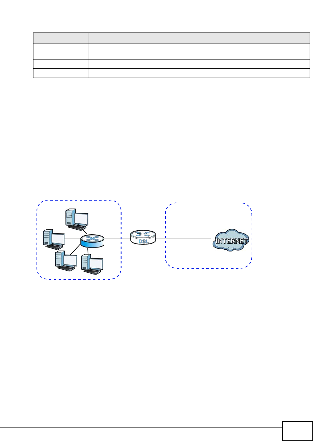
Chapter 7 Home Networking
VMG1312-T10C User’s Guide 101
The following table describes the labels in this menu.
7.10 Technical Reference
This section provides some technical background information about the topics covered in this
chapter.
LANs, WANs and the Device
The actual physical connection determines whether the Device ports are LAN or WAN ports. There
are two separate IP networks, one inside the LAN network and the other outside the WAN network
as shown next.
Figure 59 LAN and WAN IP Addresses
DHCP Setup
DHCP (Dynamic Host Configuration Protocol, RFC 2131 and RFC 2132) allows individual clients to
obtain TCP/IP configuration at start-up from a server. You can configure the Device as a DHCP
server or disable it. When configured as a server, the Device provides the TCP/IP configuration for
the clients. If you turn DHCP service off, you must have another DHCP server on your LAN, or else
the computer must be manually configured.
IP Pool Setup
The Device is pre-configured with a pool of IP addresses for the DHCP clients (DHCP Pool). See the
product specifications in the appendices. Do not assign static IP addresses from the DHCP pool to
your LAN computers.
Table 33 Network Setting > Home Networking > Print Server
LABEL DESCRIPTION
Active Printer
Server
Select this to have the Device share a USB printer.
Apply Click Apply to save your changes.
Cancel Click Cancel to restore your previously saved settings.
WAN
LAN

Chapter 7 Home Networking
VMG1312-T10C User’s Guide
102
LAN TCP/IP
The Device has built-in DHCP server capability that assigns IP addresses and DNS servers to
systems that support DHCP client capability.
IP Address and Subnet Mask
Similar to the way houses on a street share a common street name, so too do computers on a LAN
share one common network number.
Where you obtain your network number depends on your particular situation. If the ISP or your
network administrator assigns you a block of registered IP addresses, follow their instructions in
selecting the IP addresses and the subnet mask.
If the ISP did not explicitly give you an IP network number, then most likely you have a single user
account and the ISP will assign you a dynamic IP address when the connection is established. If this
is the case, it is recommended that you select a network number from 192.168.0.0 to
192.168.255.0 and you must enable the Network Address Translation (NAT) feature of the Device.
The Internet Assigned Number Authority (IANA) reserved this block of addresses specifically for
private use; please do not use any other number unless you are told otherwise. Let's say you select
192.168.1.0 as the network number; which covers 254 individual addresses, from 192.168.1.1 to
192.168.1.254 (zero and 255 are reserved). In other words, the first three numbers specify the
network number while the last number identifies an individual computer on that network.
Once you have decided on the network number, pick an IP address that is easy to remember, for
instance, 192.168.1.1, for your Device, but make sure that no other device on your network is
using that IP address.
The subnet mask specifies the network number portion of an IP address. Your Device will compute
the subnet mask automatically based on the IP address that you entered. You don't need to change
the subnet mask computed by the Device unless you are instructed to do otherwise.
Private IP Addresses
Every machine on the Internet must have a unique address. If your networks are isolated from the
Internet, for example, only between your two branch offices, you can assign any IP addresses to
the hosts without problems. However, the Internet Assigned Numbers Authority (IANA) has
reserved the following three blocks of IP addresses specifically for private networks:
• 10.0.0.0 — 10.255.255.255
• 172.16.0.0 — 172.31.255.255
• 192.168.0.0 — 192.168.255.255
You can obtain your IP address from the IANA, from an ISP or it can be assigned from a private
network. If you belong to a small organization and your Internet access is through an ISP, the ISP
can provide you with the Internet addresses for your local networks. On the other hand, if you are
part of a much larger organization, you should consult your network administrator for the
appropriate IP addresses.
Note: Regardless of your particular situation, do not create an arbitrary IP address;
always follow the guidelines above. For more information on address assignment,
please refer to RFC 1597, “Address Allocation for Private Internets” and RFC 1466,
“Guidelines for Management of IP Address Space”.
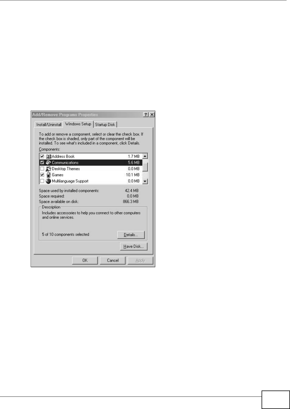
Chapter 7 Home Networking
VMG1312-T10C User’s Guide 103
7.11 Installing UPnP in Windows Example
This section shows how to install UPnP in Windows Me and Windows XP.
Installing UPnP in Windows Me
Follow the steps below to install the UPnP in Windows Me.
1Click Start and Control Panel. Double-click Add/Remove Programs.
2Click the Windows Setup tab and select Communication in the Components selection box. Click
Details.
Figure 60 Add/Remove Programs: Windows Setup: Communication
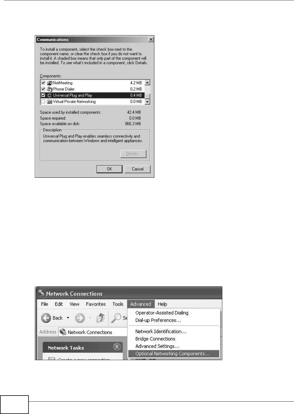
Chapter 7 Home Networking
VMG1312-T10C User’s Guide
104
3In the Communications window, select the Universal Plug and Play check box in the
Components selection box.
Figure 61 Add/Remove Programs: Windows Setup: Communication: Components
4Click OK to go back to the Add/Remove Programs Properties window and click Next.
5Restart the computer when prompted.
Installing UPnP in Windows XP
Follow the steps below to install the UPnP in Windows XP.
1Click Start and Control Panel.
2Double-click Network Connections.
3In the Network Connections window, click Advanced in the main menu and select Optional
Networking Components ….
Figure 62 Network Connections
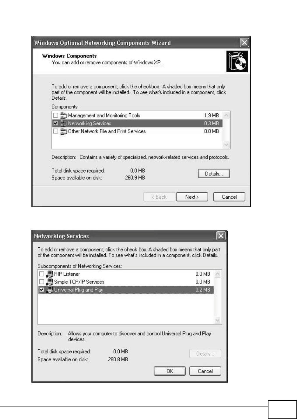
Chapter 7 Home Networking
VMG1312-T10C User’s Guide 105
4The Windows Optional Networking Components Wizard window displays. Select Networking
Service in the Components selection box and click Details.
Figure 63 Windows Optional Networking Components Wizard
5In the Networking Services window, select the Universal Plug and Play check box.
Figure 64 Networking Services
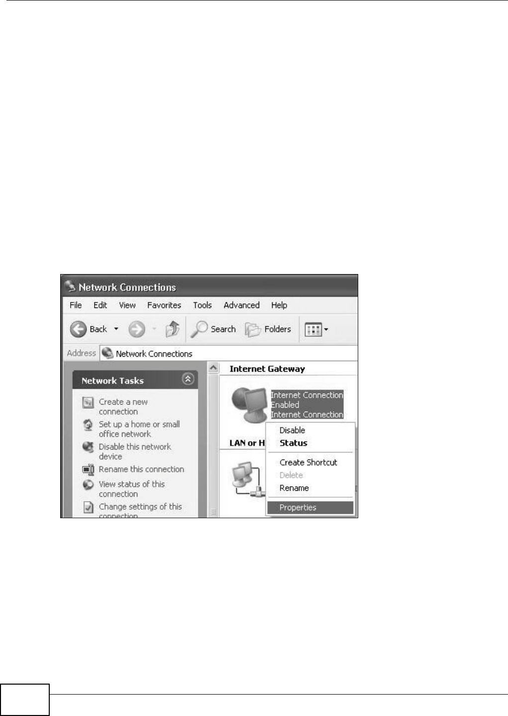
Chapter 7 Home Networking
VMG1312-T10C User’s Guide
106
6Click OK to go back to the Windows Optional Networking Component Wizard window and
click Next.
7.12 Using UPnP in Windows XP Example
This section shows you how to use the UPnP feature in Windows XP. You must already have UPnP
installed in Windows XP and UPnP activated on the Device.
Make sure the computer is connected to a LAN port of the Device. Turn on your computer and the
Device.
Auto-discover Your UPnP-enabled Network Device
1Click Start and Control Panel. Double-click Network Connections. An icon displays under
Internet Gateway.
2Right-click the icon and select Properties.
Figure 65 Network Connections
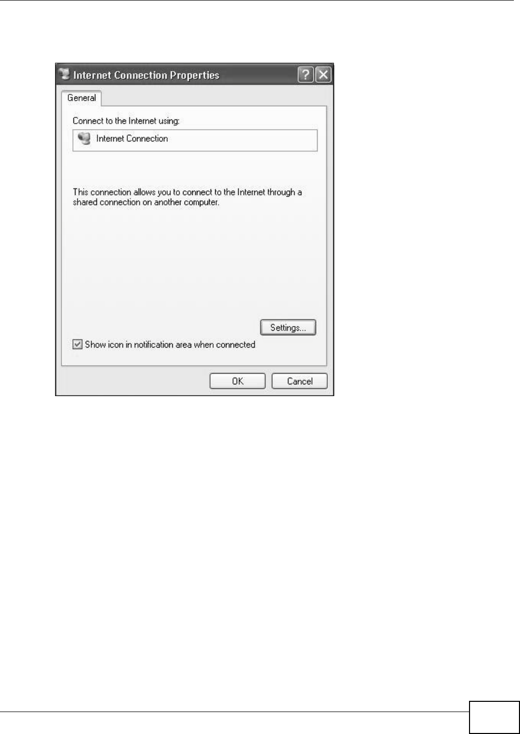
Chapter 7 Home Networking
VMG1312-T10C User’s Guide 107
3In the Internet Connection Properties window, click Settings to see the port mappings there
were automatically created.
Figure 66 Internet Connection Properties
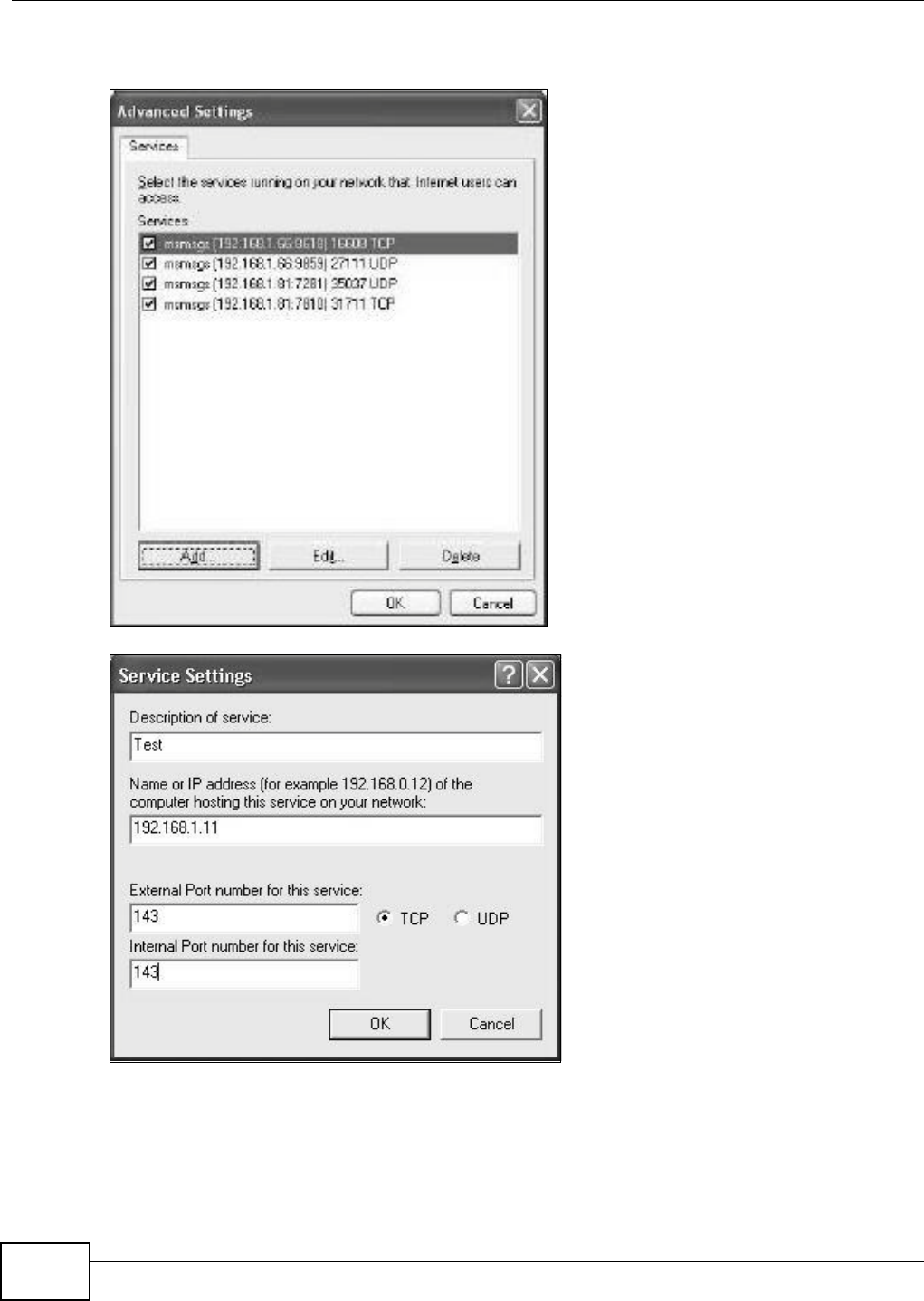
Chapter 7 Home Networking
VMG1312-T10C User’s Guide
108
4You may edit or delete the port mappings or click Add to manually add port mappings.
Figure 67 Internet Connection Properties: Advanced Settings
Figure 68 Internet Connection Properties: Advanced Settings: Add
5When the UPnP-enabled device is disconnected from your computer, all port mappings will be
deleted automatically.
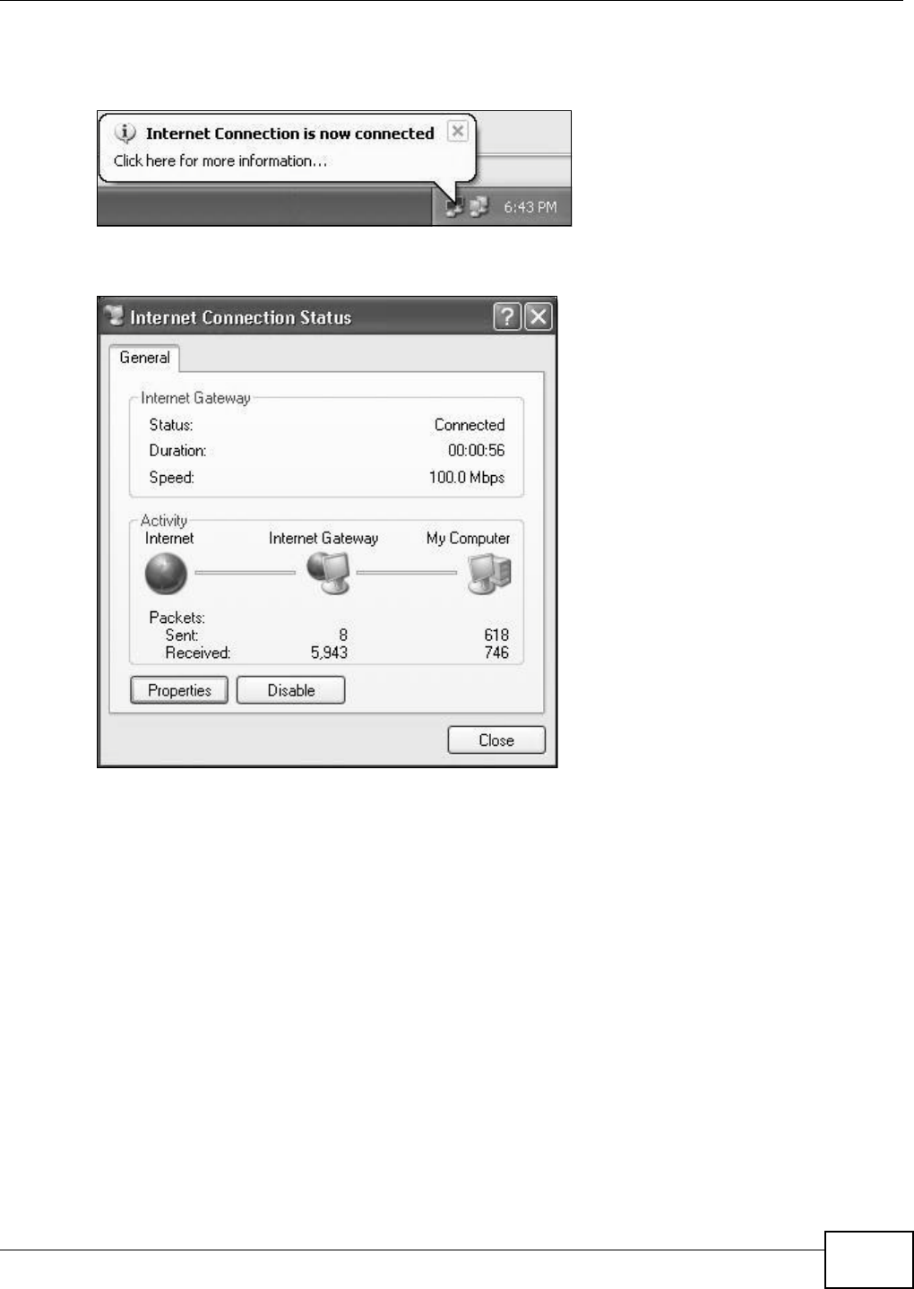
Chapter 7 Home Networking
VMG1312-T10C User’s Guide 109
6Select Show icon in notification area when connected option and click OK. An icon displays in
the system tray.
Figure 69 System Tray Icon
7Double-click on the icon to display your current Internet connection status.
Figure 70 Internet Connection Status
Web Configurator Easy Access
With UPnP, you can access the web-based configurator on the Device without finding out the IP
address of the Device first. This comes helpful if you do not know the IP address of the Device.
Follow the steps below to access the web configurator.
1Click Start and then Control Panel.
2Double-click Network Connections.

Chapter 7 Home Networking
VMG1312-T10C User’s Guide
110
3Select My Network Places under Other Places.
Figure 71 Network Connections
4An icon with the description for each UPnP-enabled device displays under Local Network.
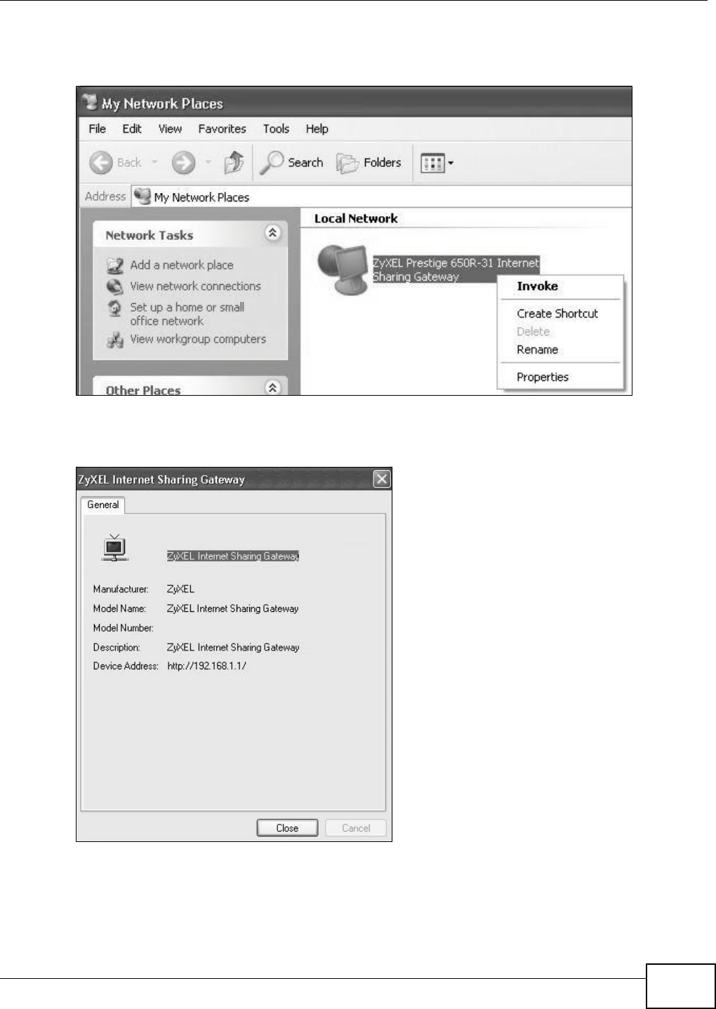
Chapter 7 Home Networking
VMG1312-T10C User’s Guide 111
5Right-click on the icon for your Device and select Invoke. The web configurator login screen
displays.
Figure 72 Network Connections: My Network Places
6Right-click on the icon for your Device and select Properties. A properties window displays with
basic information about the Device.
Figure 73 Network Connections: My Network Places: Properties: Example

Chapter 7 Home Networking
VMG1312-T10C User’s Guide
112
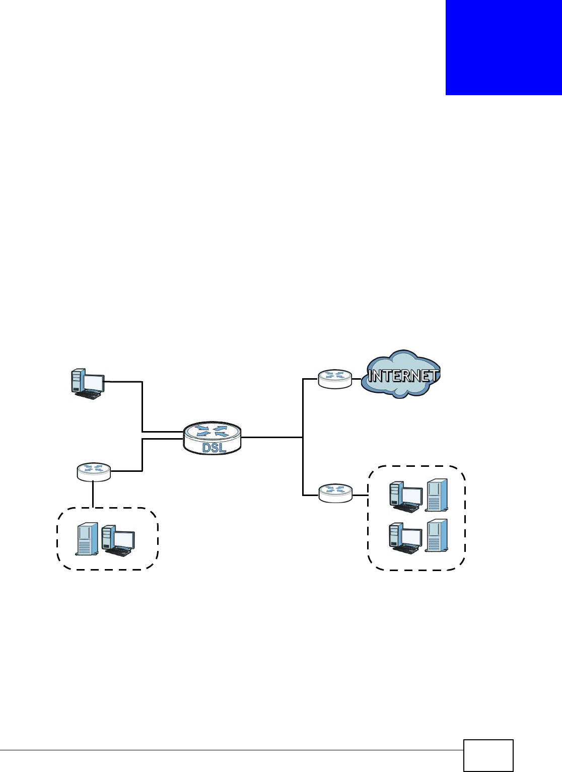
VMG1312-T10C User’s Guide 115
CHAPTER 8
Static Route
8.1 Overview
The Device usually uses the default gateway to route outbound traffic from computers on the LAN
to the Internet. To have the Device send data to devices not reachable through the default gateway,
use static routes.
For example, the next figure shows a computer (A) connected to the Device’s LAN interface. The
Device routes most traffic from A to the Internet through the Device’s default gateway (R1). You
create one static route to connect to services offered by your ISP behind router R2. You create
another static route to communicate with a separate network behind a router R3 connected to the
LAN.
Figure 74 Example of Static Routing Topology
8.1.1 What You Can Do in this Chapter
•Use the Static Route screens (Section 8.2 on page 116) to view and configure IP static routes
on the Device.
•Use the IPv6 Static Route screens (Section 8.3 on page 117) to view and configure IPv6 static
routes on the Device.
WAN
R1
R2
A
R3
LAN
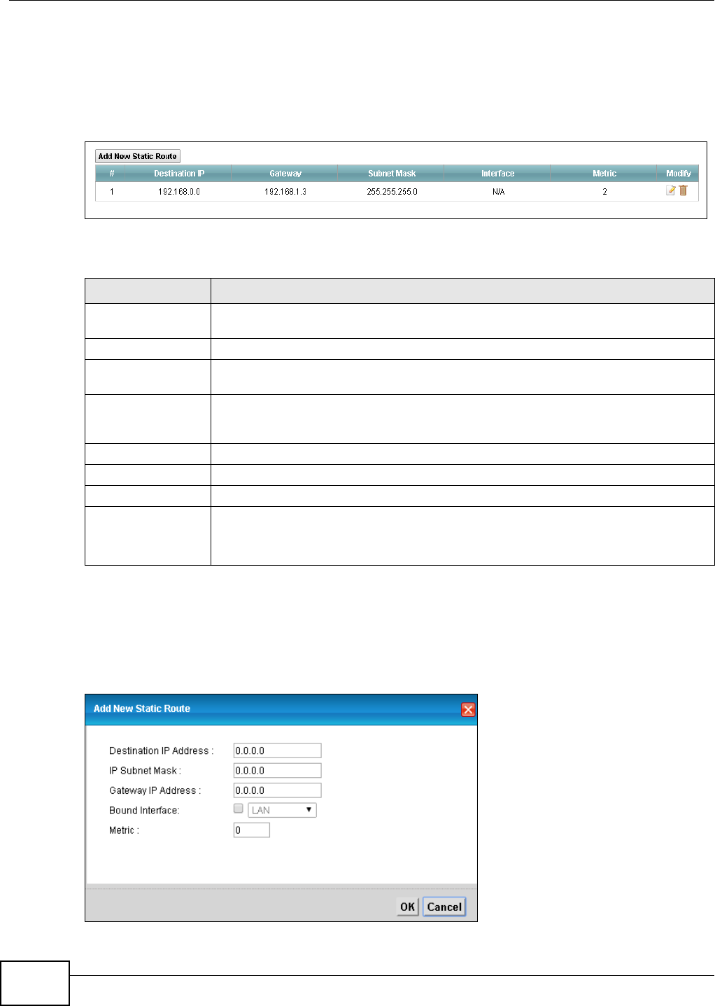
Chapter 8 Static Route
VMG1312-T10C User’s Guide
116
8.2 Configuring Static Route
Use this screen to view and configure IP static routes on the Device. Click Network Setting >
Static Route to open the following screen.
Figure 75 Network Setting > Static Route
The following table describes the labels in this screen.
8.2.1 Add/Edit Static Route
Click add new Static Route in the Routing screen or click the Edit icon next to a rule. The
following screen appears. Use this screen to configure the required information for a static route.
Figure 76 Routing: Add/Edit
Table 35 Network Setting > Static Route
LABEL DESCRIPTION
Add New Static
Route
Click this to set up a new static route on the Device.
#This is the number of an individual static route.
Destination IP This parameter specifies the IP network address of the final destination. Routing is
always based on network number.
Gateway This is the IP address of the gateway. The gateway is a router or switch on the same
network segment as the device's LAN or WAN port. The gateway helps forward packets
to their destinations.
Subnet Mask This parameter specifies the IP network subnet mask of the final destination.
Interface This is the WAN interface through which the traffic is routed.
Metric This is the “cost” of transmission for routing purposes.
Modify Click the Edit icon to go to the screen where you can set up a static route on the
Device.
Click the Delete icon to remove a static route from the Device.
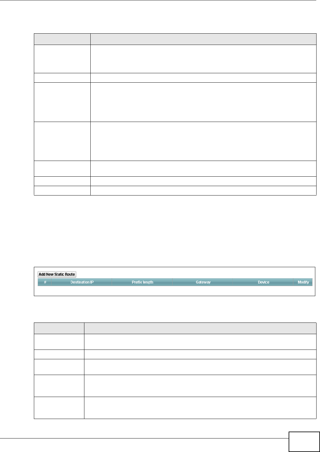
Chapter 8 Static Route
VMG1312-T10C User’s Guide 117
The following table describes the labels in this screen.
8.3 IPv6 Static Route
Use this screen to view the IPv6 static route rules. Click Network Setting > Static Route > IPv6
Static Route to open the IPv6 Static Route screen.
Figure 77 Network Setting > Static Route > IPv6 Static Route
The following table describes the labels in this screen.
Table 36 Routing: Add/Edit
LABEL DESCRIPTION
Destination IP
Address
This parameter specifies the IP network address of the final destination. Routing is
always based on network number. If you need to specify a route to a single host, use a
subnet mask of 255.255.255.255 in the subnet mask field to force the network number
to be identical to the host ID.
IP Subnet Mask Enter the IP subnet mask here.
Gateway IP Address You can decide if you want to forward packets to a gateway IP address or a bound
interface.
If you want to configure Gateway IP Address, enter the IP address of the next-hop
gateway. The gateway is a router or switch on the same network segment as the
device's LAN or WAN port. The gateway helps forward packets to their destinations.
Bound Interface You can decide if you want to forward packets to a gateway IP address or a bound
interface.
If you want to configure Bound Interface, select the check box and choose an
interface through which the traffic is sent. You must have the WAN interfaces already
configured in the Broadband screen.
Metric Enter the “cost” of transmission for routing purposes. IP routing uses hop count as the
measurement of cost, with a minimum of 1 for directly-connected networks.
OK Click this to save your changes.
Cancel Click this to exit this screen without saving.
Table 37 Network Setting > Static Route > IPv6 Static Route
LABEL DESCRIPTION
Add New Static
route
Click this to configure a new IPv6 static route.
# This is the number of an individual static route.
Destination IP This is the IP network address of the final destination. Routing is always based on network
number.
Prefix length An IPv6 prefix length specifies how many most significant bits (starting from the left) in
the address compose the network address. This field displays the bit number of the IPv6
subnet mask.
Gateway This is the IPv6 address of the gateway. The gateway is a router or switch on the same
network segment as the device's LAN or WAN port. The gateway has a route to the
destination network and helps forward packets to their destinations.
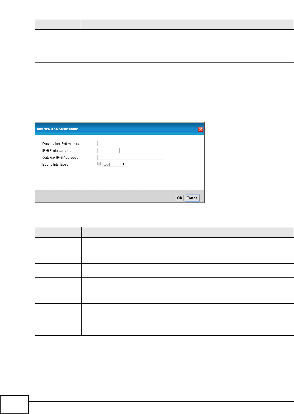
Chapter 8 Static Route
VMG1312-T10C User’s Guide
118
8.3.1 IPv6 Static Route Edit
Use this screen to configure the required information for an IPv6 static route. Click Add New
Static Route or select an IPv6 static route index number and click Edit. The screen shown next
appears.
Figure 78 Network Setting > Static Route > IPv6 Static Route: Add/Edit
The following table describes the labels in this screen.
Device This specifies the LAN or WAN PVC.
Modify Click the Edit icon to go to the screen where you can set up a static route on the Device.
Click the Remove icon to remove a static route from the Device. A window displays
asking you to confirm that you want to delete the route.
Table 37 Network Setting > Static Route > IPv6 Static Route (continued)
LABEL DESCRIPTION
Table 38 Network Setting > Static Route > IPv6 Static Route: Add/Edit
LABEL DESCRIPTION
Destination IPv6
Address
This parameter specifies the IP network address of the final destination. Routing is always
based on network number. If you need to specify a route to a single host, use a prefix
length of 128 in the prefix length field to force the network number to be identical to the
host ID.
IPv6 Prefix Length Enter the address prefix to specify how many most significant bits compose the network
address.
Gateway IPv6
Address
Enter the IPv6 address of the gateway. The gateway is a router or switch on the same
network segment as the device's LAN or WAN port. The gateway has a route to the
destination network and helps forward packets to their destinations. If a link local address
is used, the interface should also be specified.
Bound Interface If you want to forward IPv6 packets to a bound interface, select the interface through
which the traffic is sent.
OK Click this to save your changes.
Cancel Click this to restore your previously saved settings.

VMG1312-T10C User’s Guide 119
CHAPTER 9
Quality of Service (QoS)
9.1 Overview
This chapter discusses the Device’s QoS screens. Use these screens to set up your Device to use
QoS for traffic management.
Quality of Service (QoS) refers to both a network’s ability to deliver data with minimum delay, and
the networking methods used to control the use of bandwidth. QoS allows the Device to group and
prioritize application traffic and fine-tune network performance.
Without QoS, all traffic data is equally likely to be dropped when the network is congested. This can
cause a reduction in network performance and make the network inadequate for time-critical
application such as video-on-demand.
The Device assigns each packet a priority and then queues the packet accordingly. Packets assigned
a high priority are processed more quickly than those with low priority if there is congestion,
allowing time-sensitive applications to flow more smoothly. Time-sensitive applications include both
those that require a low level of latency (delay) and a low level of jitter (variations in delay) such as
Internet gaming, and those for which jitter alone is a problem such as Internet radio or streaming
video.
9.1.1 What You Can Do in this Chapter
•Use the General screen to enable QoS, set the bandwidth, and allow the Device to automatically
assign priority to upstream traffic according to the IP precedence or packet length (Section 9.2
on page 120).
•Use the Queue Setup screen to configure QoS queue assignment (Section 9.3 on page 121).
•Use the Class Setup screen to set up classifiers to sort traffic into different flows and assign
priority and define actions to be performed for a classified traffic flow (Section 9.4 on page 122).
•Use the Policer Setup screento add, edit or delete QoS policers (Section 9.5 on page 127).
•Use the Game List screen to to give priority to traffic for specific games (Section 9.6 on page
129).
9.1.2 What You Need to Know
The following terms and concepts may help as you read this chapter.
QoS versus Cos
QoS is used to prioritize source-to-destination traffic flows. All packets in the same flow are given
the same priority. CoS (class of service) is a way of managing traffic in a network by grouping
similar types of traffic together and treating each type as a class. You can use CoS to give different
priorities to different packet types.
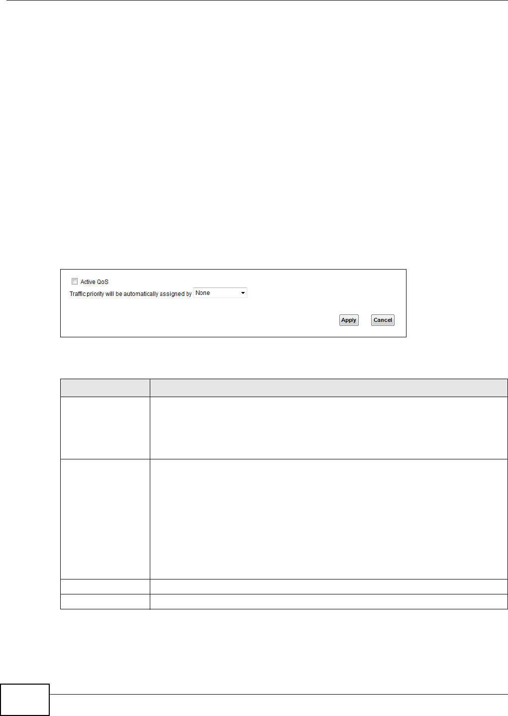
Chapter 9 Quality of Service (QoS)
VMG1312-T10C User’s Guide
120
CoS technologies includes DiffServ (Differentiated Services or DS). DiffServ is a new protocol and
defines a new DS field, which replaces the eight-bit ToS (Type of Service) field in the IP header.
Tagging and Marking
In a QoS class, you can configure whether to add or change the DSCP (DiffServ Code Point) value
ain a matched packet. When the packet passes through a compatible network, the networking
device, such as a backbone switch, can provide specific treatment or service based on the tag or
marker.
9.2 The QoS General Screen
Use this screen to enable or disable QoS, set the bandwidth, and select to have the Device
automatically assign priority to upstream traffic according to the IP precedence or packet length.
Click Network Setting > QoS to open the General screen.
Figure 79 Network Setting > QoS > General
The following table describes the labels in this screen.
Table 39 Network Setting > QoS > General
LABEL DESCRIPTION
Active QoS Select the check box to turn on QoS to improve your network performance.
You can give priority to traffic that the Device forwards out through the WAN interface.
Give high priority to voice and video to make them run more smoothly. Similarly, give
low priority to many large file downloads so that they do not reduce the quality of other
applications.
Traffic priority will
be automatically
assigned by
Select how the Device assigns priorities to various upstream traffic flows.
•None: Disables auto priority mapping and has the Device put packets into the
queues according to your classification rules. Traffic which does not match any of
the classification rules is mapped into the default queue with the lowest priority.
•Ethernet Priority: Automatically assign priority based on the IEEE 802.1p priority
level.
•IP Precedence: Automatically assign priority based on the first three bits of the
TOS field in the IP header.
•Packet Length: Automatically assign priority based on the packet size. Smaller
packets get higher priority since control, signaling, VoIP, internet gaming, or other
real-time packets are usually small while larger packets are usually best effort data
packets like file transfers.
Apply Click Apply to save your changes.
Cancel Click Cancel to restore your previously saved settings.
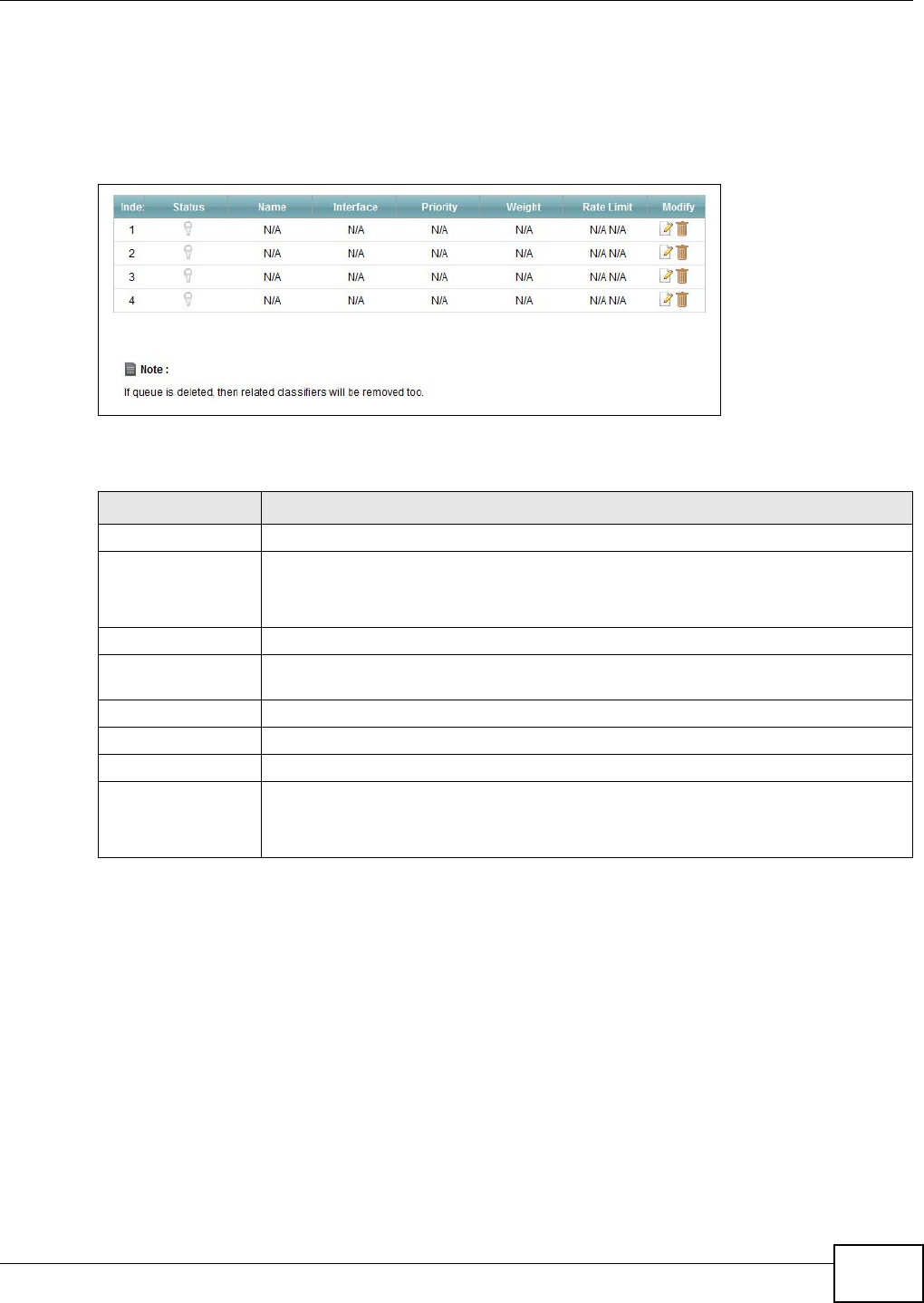
Chapter 9 Quality of Service (QoS)
VMG1312-T10C User’s Guide 121
9.3 The Queue Setup Screen
Use this screen to configure QoS queue assignment. Click Network Setting > QoS > Queue
Setup to open the screen as shown next.
Figure 80 Network Setting > QoS > Queue Setup
The following table describes the labels in this screen.
Table 40 Network Setting > QoS > Queue Setup
LABEL DESCRIPTION
Index This is the index number of this entry.
Status This indicates whether the queue is active or not.
A yellow bulb signifies that this queue is active. A gray bulb signifies that this queue is
not active.
Name This shows the descriptive name of this queue.
Interface This shows the name of the Device’s interface through which traffic in this queue
passes.
Priority This shows the priority of this queue.
Weight This shows the weight of this queue.
Rate Limit (kbps) This shows the maximum transmission rate allowed for traffic on this queue.
Modify Click the Edit icon to edit the queue.
Click the Delete icon to delete an existing queue. Note that subsequent rules move up
by one when you take this action.
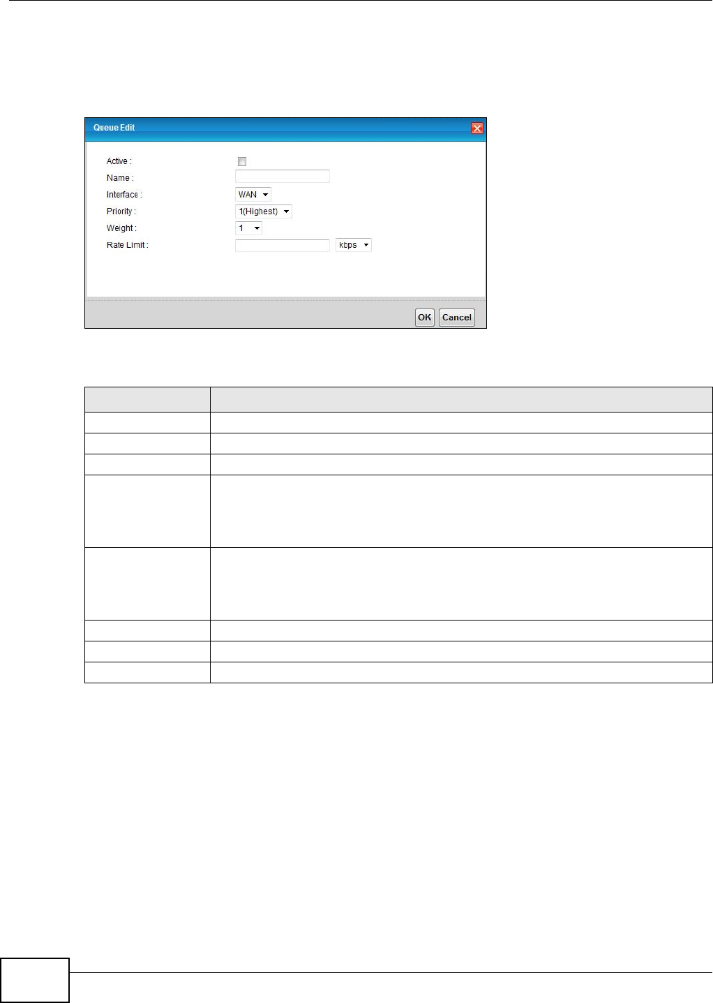
Chapter 9 Quality of Service (QoS)
VMG1312-T10C User’s Guide
122
9.3.1 Edit a QoS Queue
Use this screen to configure a queue. Click the Edit icon next to a QoS queue.
Figure 81 Queue Setup: Edit
The following table describes the labels in this screen.
9.4 The Class Setup Screen
Use this screen to add, edit or delete QoS classifiers. A classifier groups traffic into data flows
according to specific criteria such as the source address, destination address, source port number,
destination port number or incoming interface. For example, you can configure a classifier to select
traffic from the same protocol port (such as Telnet) to form a flow.
You can give different priorities to traffic that the Device forwards out through the WAN interface.
Give high priority to voice and video to make them run more smoothly. Similarly, give low priority
to many large file downloads so that they do not reduce the quality of other applications.
Table 41 Queue Setup: Edit
LABEL DESCRIPTION
Active Select to enable or disable this queue.
Name Enter the descriptive name of this queue.
Interface Select the interface of this queue.
Priority Select the priority level (from 1 to 7) of this queue.
The lower the number, the higher the priority level. Traffic assigned to higher priority
queues gets through faster while traffic in lower priority queues is dropped if the
network is congested.
Weight Select the weight (from 1 to 15) of this queue.
If two queues have the same priority level, the Device divides the bandwidth across the
queues according to their weights. Queues with larger weights get more bandwidth
than queues with smaller weights.
Rate Limit Specify the maximum transmission rate (in Kbps or %) allowed for traffic on this queue.
OK Click this to save your changes.
Cancel Click this to exit this screen without saving.
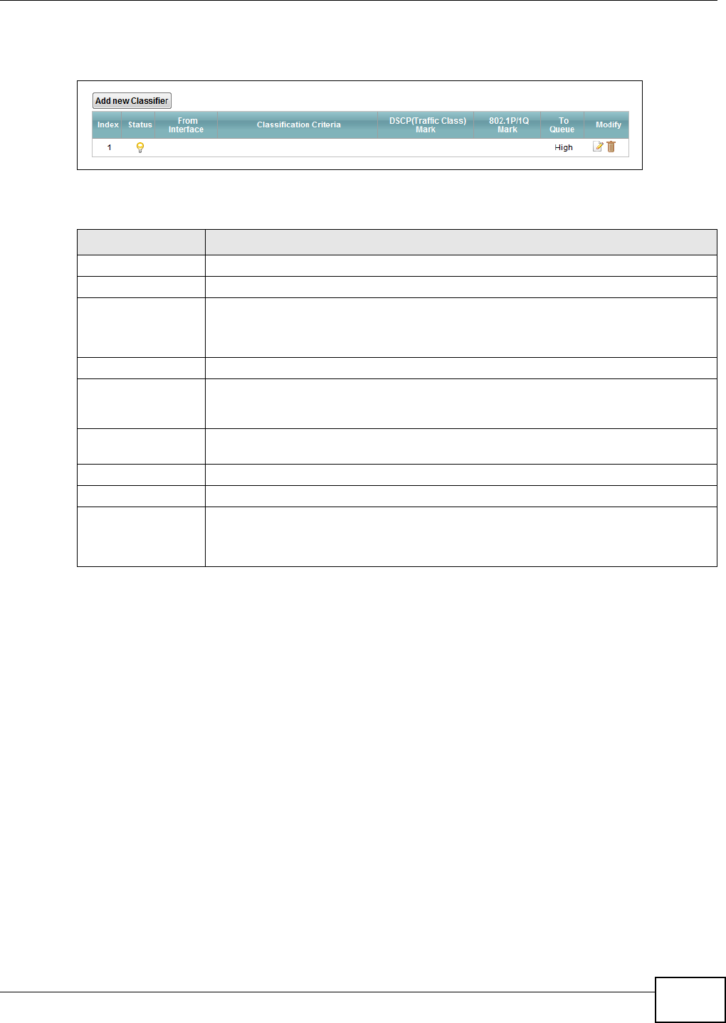
Chapter 9 Quality of Service (QoS)
VMG1312-T10C User’s Guide 123
Click Network Setting > QoS > Class Setup to open the following screen.
Figure 82 Network Setting > QoS > Class Setup
The following table describes the labels in this screen.
Table 42 Network Setting > QoS > Class Setup
LABEL DESCRIPTION
Add new Classifier Click this to create a new classifier.
Index This field displays the order number of the classifier.
Status This indicates whether the classifier is active or not.
A yellow bulb signifies that this classifier is active. A gray bulb signifies that this
classifier is not active.
From Interface If the classifier applies to traffic coming in through a specific interface, it displays here.
Classification
Criteria
This shows criteria specified in this classifier, for example the interface from which
traffic of this class should come and the source MAC address of traffic that matches this
classifier.
DSCP (Traffic Class)
Mark
This is the DSCP number added to traffic of this classifier.
802.1P/1Q Mark This is the IEEE 802.1p priority level assigned to traffic of this classifier.
To Queue This is the name of the queue in which traffic of this classifier is put.
Modify Click the Edit icon to edit the classifier.
Click the Delete icon to delete an existing classifier. Note that subsequent rules move
up by one when you take this action.
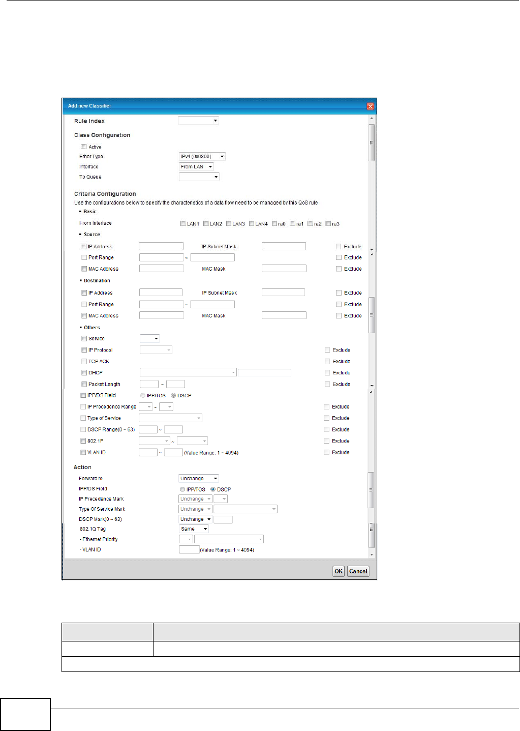
Chapter 9 Quality of Service (QoS)
VMG1312-T10C User’s Guide
124
9.4.1 Add/Edit QoS Class
Click Add new Classifier in the Class Setup screen or the Edit icon next to an existing classifier
to configure it.
Figure 83 Class Setup: Add/Edit
The following table describes the labels in this screen.
Table 43 Class Setup: Add/Edit
LABEL DESCRIPTION
Rule Index Select the (order) number of this rule.
Class Configuration

Chapter 9 Quality of Service (QoS)
VMG1312-T10C User’s Guide 125
Active Select to enable this classifier.
Ether Type Select the Ether type (IPv4, IPv6, ARP, or IEEE 802.1Q) to which this rule applies.
Interface Select whether to apply this class to traffic from the LAN or from the WAN.
To Queue Select a queue to apply to this class (available when you set Interface to From WAN).
You should have configured a queue in the Queue Setup screen already.
Criteria Configuration
Use the following fields to configure the criteria for traffic classification.
Basic
From Interface Select the interface from which the traffic class comes.
Source
IP Address Select the check box and enter the source IP address in dotted decimal notation. A
blank source IP address means any source IP address.
IP Subnet Mask Enter the source subnet mask.
Exclude Select this option to exclude the packets that match the specified criteria from this
classifier.
Port Range If you select TCP or UDP in the IP Protocol field, select the check box and enter the
port number(s) of the source.
Exclude Select this option to exclude the packets that match the specified criteria from this
classifier.
MAC Address Select the check box and enter the source MAC address of the packet.
MAC Mask Type the mask for the specified MAC address to determine which bits a packet’s MAC
address should match.
Enter “f” for each bit of the specified source MAC address that the traffic’s MAC address
should match. Enter “0“ for the bits of the matched traffic’s MAC address, which can be
of any hexadecimal characters. For example, if you set the MAC address to
00:13:49:00:00:00 and the mask to ff:ff:ff:00:00:00, a packet with a MAC address of
00:13:49:12:34:56 matches this criteria.
Exclude Select this option to exclude the packets that match the specified criteria from this
classifier.
Destination
IP Address Select the check box and enter the destination IP address in dotted decimal notation. A
blank source IP address means any source IP address.
IP Subnet Mask Enter the destination subnet mask.
Port Range If you select TCP or UDP in the IP Protocol field, select the check box and enter the
port number(s) of the source.
MAC Address Select the check box and enter the destination MAC address of the packet.
MAC Mask Type the mask for the specified MAC address to determine which bits a packet’s MAC
address should match.
Enter “f” for each bit of the specified source MAC address that the traffic’s MAC address
should match. Enter “0“ for the bit(s) of the matched traffic’s MAC address, which can
be of any hexadecimal character(s). For example, if you set the MAC address to
00:13:49:00:00:00 and the mask to ff:ff:ff:00:00:00, a packet with a MAC address of
00:13:49:12:34:56 matches this criteria.
Exclude Select this option to exclude the packets that match the specified criteria from this
classifier.
Others Some of the following fields can only be configured for certain Ether types.
Table 43 Class Setup: Add/Edit (continued)
LABEL DESCRIPTION

Chapter 9 Quality of Service (QoS)
VMG1312-T10C User’s Guide
126
Service Select the service classification of the traffic (FTP or SIP).
IP Protocol Select this option and select the protocol (service type) from TCP or UDP. If you select
User defined, enter the protocol (service type) number.
TCP ACK If you select this option, the matched TCP packets must contain the ACK (Acknowledge)
flag.
DHCP Select this option and select a DHCP option.
If you select Vendor Class ID (DHCP Option 60), enter the Class ID of the matched
traffic, such as the type of the hardware or firmware.
If you select ClientID (DHCP Option 61), enter the Type of the matched traffic and
Client ID of the DHCP client.
If you select User Class ID (DHCP Option 77), enter the User Class Data, which is
a string that identifies the user’s category or application type in the matched DHCP
packets.
If you select VendorSpecificIntro (DHCP Option 125), enter the Enterprise
Number of the software of the matched traffic and Vendor Class Data used by all the
DHCP clients.
Packet Length This field is available only when you select IPv4 (0x0800) in the Ether Type field.
Select this option and enter the minimum and maximum packet length (from 46 to
1504) in the fields provided.
IPP/DS Field Select IPP/TOS to specify an IP precedence range and type of services.
Select DSCP to specify a DiffServ Code Point (DSCP) range.
IP Precedence
Range Enter a range from 0 to 7 for IP precedence. 0 is the lowest priority and 7 is the
highest.
Type of Service Select a type of service from the drop-down list box.
DSCP Range (0
~ 63) Select this option and specify a DSCP (DiffServ Code Point) number between 0 and 63
in the field provided.
802.1P Select this option and select a priority level (between 0 and 7) from the drop-down list
box.
"0" is the lowest priority level and "7" is the highest.
VLAN ID Select this option and enter the source VLAN ID in this field.
Exclude Select this option to exclude the packets that match the specified criteria from this
classifier.
Action
Forward To Select the interface through which traffic that matches the rule is forwarded out. If you
select Unchange, the Device forwards traffic of this class according to the default
routing table.
If traffic of this class comes from a WAN interface and is in a queue that forwards traffic
through the LAN/WLAN interface, the Device ignores the setting here.
IPP/DS Field Select IPP/TOS to specify an IP precedence range and type of services.
Select DSCP to specify a DiffServ Code Point (DSCP) range.
IP Precedence
Mark Enter a range from 0 to 7 to re-assign IP precedence to matched traffic. 0 is the lowest
priority and 7 is the highest.
Type Of Service
Mark Select a type of service to re-assign the priority level to matched traffic.
Available options are: Normal service, Minimize delay, Maximize throughput,
Maximize reliability and Minimize monetary cost.
Table 43 Class Setup: Add/Edit (continued)
LABEL DESCRIPTION
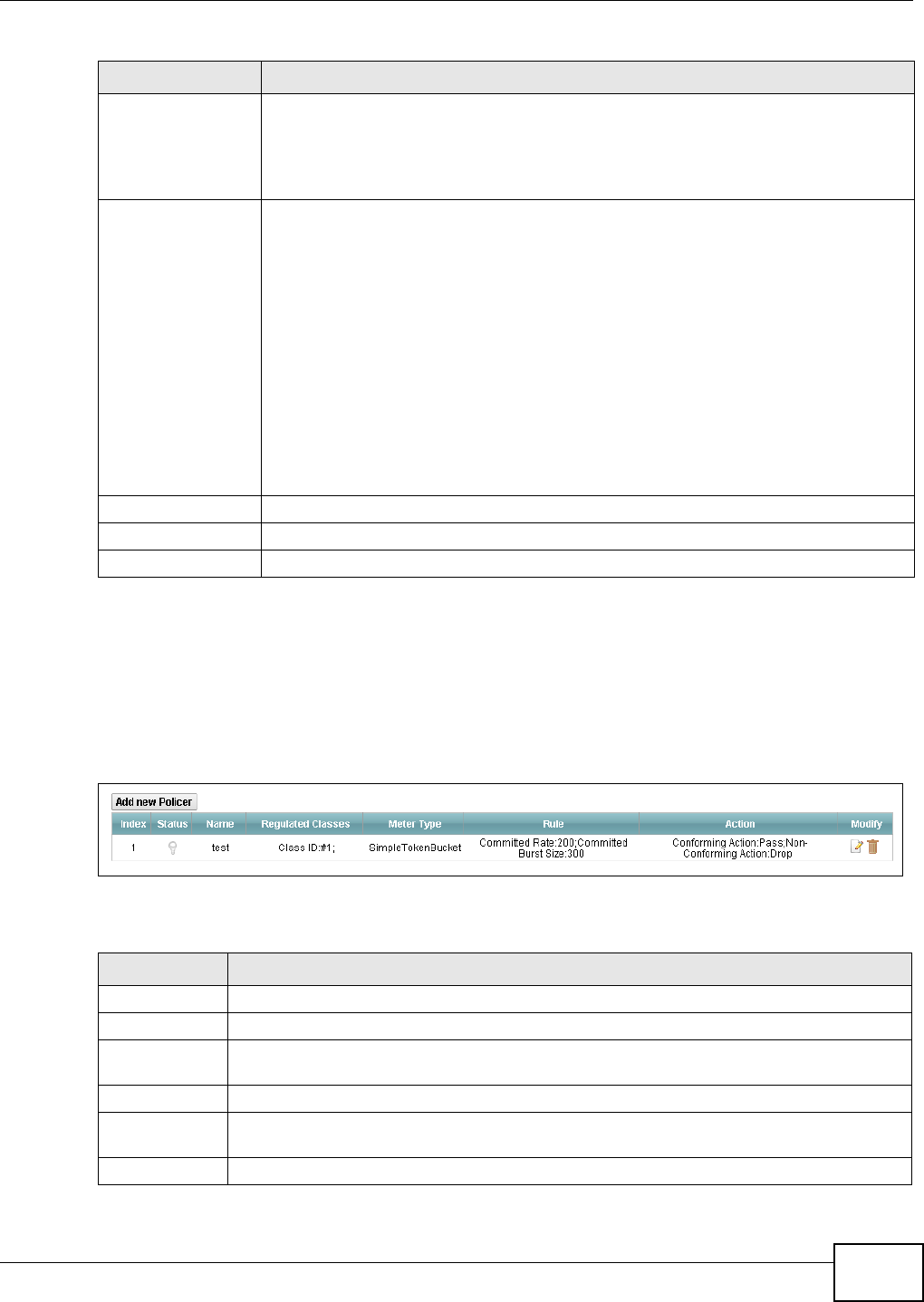
Chapter 9 Quality of Service (QoS)
VMG1312-T10C User’s Guide 127
9.5 The QoS Policer Setup Screen
Use this screen to configure QoS policers that allow you to limit the transmission rate of incoming
traffic. Click Network Setting > QoS > Policer Setup. The screen appears as shown.
Figure 84 Network Setting > QoS > Policer Setup
The following table describes the labels in this screen.
DSCP
Mark(0~63) This field is available only when you select IPv4 (0x0800) in the Ether Type field.
If you select Mark, enter a DSCP value with which the Device replaces the DSCP field in
the packets.
If you select Unchange, the Device keep the DSCP field in the packets.
802.1Q Tag If you select Remark, select a priority level (in the Ethernet Priority field) and enter a
VLAN ID number (in the VLAN ID field) with which the Device replaces the IEEE 802.1p
priority field and VLAN ID of the frames.
If you select Remove, the Device deletes the VLAN ID of the frames before forwarding
them out.
If you select Add, the Device treat all matched traffic untagged and add a second
priority level and VLAN ID that you specify in the Ethernet Priority and VLAN ID
fields.
If you select Same, the Device keep the Ethernet Priority and VLAN ID in the packets.
To configure the Ethernet Priority, you can either select a priority number in the first
drop-down list box (7 is the highest and 0 is the lowest priority) or select an application
from the second drop-down list box which automatically maps to the corresponding
priority number. (Key Net Traffic: 7; Voice: 6; Video: 5; IGMP: 4; Key Data: 3)
VLAN ID Select this option and enter the source VLAN ID in this field.
OK Click this to save your changes.
Cancel Click this to exit this screen without saving.
Table 43 Class Setup: Add/Edit (continued)
LABEL DESCRIPTION
Table 44 Network Setting > QoS > Policer Setup
LABEL DESCRIPTION
Add new Policer Click this to create a new entry.
#This is the index number of the entry.
Status This field displays whether the policer is active or not. A yellow bulb signifies that this
policer is active. A gray bulb signifies that this policer is not active.
Name This field displays the descriptive name of this policer.
Regulated
Classes
This field displays the name of a QoS classifier.
Meter Type This field displays the type of QoS metering algorithm used in this policer.
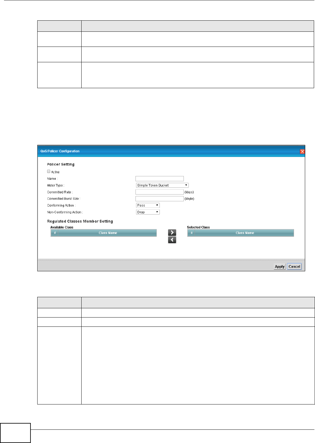
Chapter 9 Quality of Service (QoS)
VMG1312-T10C User’s Guide
128
9.5.1 Add/Edit a QoS Policer
Click Add new Policer in the Policer Setup screen or the Edit icon next to a policer to show the
following screen.
Figure 85 Policer Setup: Add/Edit
The following table describes the labels in this screen.
Rule These are the rates and burst sizes against which the policer checks the traffic of the
member QoS classes.
Action This shows the how the policer has the Device treat different types of traffic belonging to
the policer’s member QoS classes.
Modify Click the Edit icon to edit the policer.
Click the Delete icon to delete an existing policer. Note that subsequent rules move up by
one when you take this action.
Table 44 Network Setting > QoS > Policer Setup (continued)
LABEL DESCRIPTION
Table 45 Policer Setup: Add/Edit
LABEL DESCRIPTION
Active Select the check box to activate this policer.
Name Enter the descriptive name of this policer.
Meter Type This shows the traffic metering algorithm used in this policer.
The Simple Token Bucket algorithm uses tokens in a bucket to control when traffic can be
transmitted. Each token represents one byte. The algorithm allows bursts of up to b bytes
which is also the bucket size.
The Single Rate Three Color Marker (srTCM) is based on the token bucket filter and
identifies packets by comparing them to the Committed Information Rate (CIR), the
Committed Burst Size (CBS) and the Excess Burst Size (EBS).
The Two Rate Three Color Marker (trTCM) is based on the token bucket filter and
identifies packets by comparing them to the Committed Information Rate (CIR) and the
Peak Information Rate (PIR).
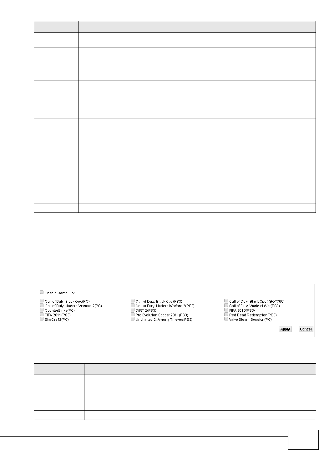
Chapter 9 Quality of Service (QoS)
VMG1312-T10C User’s Guide 129
9.6 The QoS Game List Screen
Use this screen to give priority to traffic for specific games. Click Advanced Setup > QoS > Game
List to open the screen as shown next.
Figure 86 Network Setting > QoS > Game List
The following table describes the labels in this screen.
Committed
Rate
Specify the committed rate. When the incoming traffic rate of the member QoS classes is
less than the committed rate, the device applies the conforming action to the traffic.
Committed
Burst Size
Specify the committed burst size for packet bursts. This must be equal to or less than the
peak burst size (two rate three color) or excess burst size (single rate three color) if it is also
configured.
This is the maximum size of the (first) token bucket in a traffic metering algorithm.
Conforming
Action
Specify what the Device does for packets within the committed rate and burst size (green-
marked packets).
•Pass: Send the packets without modification.
•DSCP Mark: Change the DSCP mark value of the packets. Enter the DSCP mark value to
use.
Non-
Conforming
Action
Specify what the Device does for packets that exceed the excess burst size or peak rate and
burst size (red-marked packets).
•Drop: Discard the packets.
•DSCP Mark: Change the DSCP mark value of the packets. Enter the DSCP mark value to
use. The packets may be dropped if there is congestion on the network.
Available Class
Selected Class
Select a QoS classifier to apply this QoS policer to traffic that matches the QoS classifier.
Highlight a QoS classifier in the Available Class box and use the > button to move it to the
Selected Class box.
To remove a QoS classifier from the Selected Class box, select it and use the < button.
Apply Click Apply to save your changes.
Cancel Click Cancel to exit this screen without saving.
Table 45 Policer Setup: Add/Edit (continued)
LABEL DESCRIPTION
Table 46 Network Setting > QoS > Game List
LABEL DESCRIPTION
Enable Game List Select this to have QoS give the highest priority to traffic for the games you specify. This
priority is higher than the other QoS queues.
Select the games below.
Apply Click this to save your changes.
Cancel Click this to restore your previously saved settings.

Chapter 9 Quality of Service (QoS)
VMG1312-T10C User’s Guide
130
9.7 QoS Technical Reference
This section provides some technical background information about the topics covered in this
chapter.
9.7.1 DiffServ
QoS is used to prioritize source-to-destination traffic flows. All packets in the flow are given the
same priority. You can use CoS (class of service) to give different priorities to different packet
types.
DiffServ (Differentiated Services) is a class of service (CoS) model that marks packets so that they
receive specific per-hop treatment at DiffServ-compliant network devices along the route based on
the application types and traffic flow. Packets are marked with DiffServ Code Points (DSCPs)
indicating the level of service desired. This allows the intermediary DiffServ-compliant network
devices to handle the packets differently depending on the code points without the need to
negotiate paths or remember state information for every flow. In addition, applications do not have
to request a particular service or give advanced notice of where the traffic is going.
DSCP and Per-Hop Behavior
DiffServ defines a new DS (Differentiated Services) field to replace the Type of Service (TOS) field
in the IP header. The DS field contains a 2-bit unused field and a 6-bit DSCP field which can define
up to 64 service levels. The following figure illustrates the DS field.
DSCP is backward compatible with the three precedence bits in the ToS octet so that non-DiffServ
compliant, ToS-enabled network device will not conflict with the DSCP mapping.
The DSCP value determines the forwarding behavior, the PHB (Per-Hop Behavior), that each packet
gets across the DiffServ network. Based on the marking rule, different kinds of traffic can be
marked for different kinds of forwarding. Resources can then be allocated according to the DSCP
values and the configured policies.
DSCP (6 bits) Unused (2 bits)

VMG1312-T10C User’s Guide 131
CHAPTER 10
Network Address Translation (NAT)
10.1 Overview
NAT (Network Address Translation - NAT, RFC 1631) is the translation of the IP address of a host in
a packet, for example, the source address of an outgoing packet, used within one network to a
different IP address known within another network.
10.1.1 What You Can Do in this Chapter
•Use the General screen to limit the number of concurrent NAT sessions each client can use
(Section 10.2 on page 132).
•Use the Port Forwarding screen to configure forward incoming service requests to the servers
on your local network (Section 10.3 on page 132).
•Use the DMZ screen to configure a default server (Section 10.4 on page 135).
•Use the ALG screen to enable or disable the SIP ALG (Section 10.5 on page 136).
10.1.2 What You Need To Know
The following terms and concepts may help as you read this chapter.
Inside/Outside and Global/Local
Inside/outside denotes where a host is located relative to the Device, for example, the computers
of your subscribers are the inside hosts, while the web servers on the Internet are the outside
hosts.
Global/local denotes the IP address of a host in a packet as the packet traverses a router, for
example, the local address refers to the IP address of a host when the packet is in the local
network, while the global address refers to the IP address of the host when the same packet is
traveling in the WAN side.
NAT
In the simplest form, NAT changes the source IP address in a packet received from a subscriber
(the inside local address) to another (the inside global address) before forwarding the packet to the
WAN side. When the response comes back, NAT translates the destination address (the inside
global address) back to the inside local address before forwarding it to the original inside host.
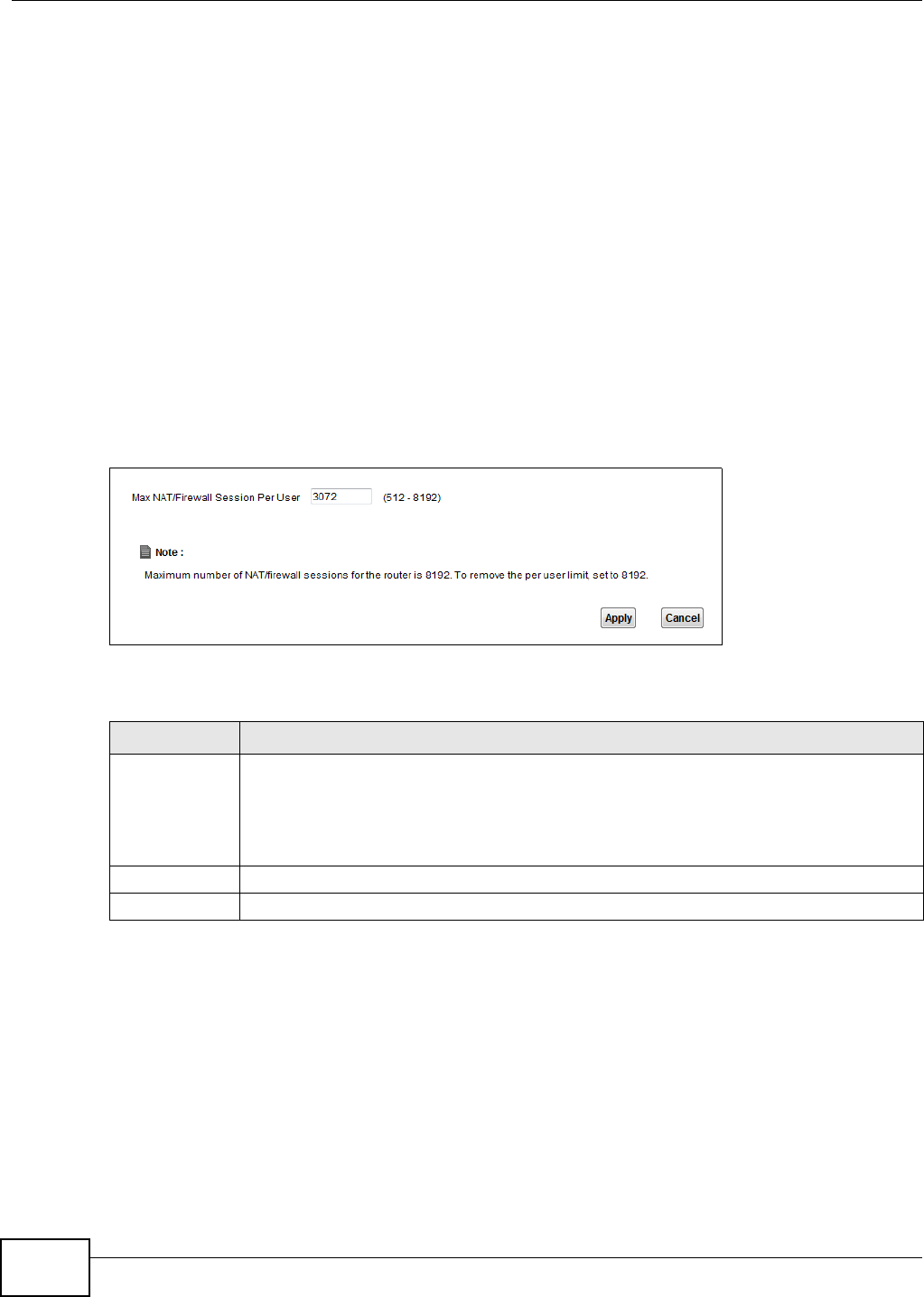
Chapter 10 Network Address Translation (NAT)
VMG1312-T10C User’s Guide
132
Port Forwarding
A port forwarding set is a list of inside (behind NAT on the LAN) servers, for example, web or FTP,
that you can make visible to the outside world even though NAT makes your whole inside network
appear as a single computer to the outside world.
Finding Out More
See Section 10.6 on page 136 for advanced technical information on NAT.
10.2 The General Screen
Use the General screen to limit the number of concurrent NAT sessions each client can use.
Click Network Setting > NAT > General to display the following screen.
Figure 87 Network Setting > NAT > General
The following table describes the fields in this screen.
10.3 The Port Forwarding Screen
Use the Port Forwarding screen to forward incoming service requests to the servers on your local
network.
You may enter a single port number or a range of port numbers to be forwarded, and the local IP
address of the desired server. The port number identifies a service; for example, web service is on
port 80 and FTP on port 21. In some cases, such as for unknown services or where one server can
support more than one service (for example both FTP and web service), it might be better to
Table 47 Network Setting > NAT > General
LABEL DESCRIPTION
Max NAT/
Firewall Session
Per User
Use this field to set a common limit to the number of concurrent NAT sessions each client
computer can have.
If only a few clients use peer to peer applications, you can raise this number to improve
their performance. With heavy peer to peer application use, lower this number to ensure no
single client uses too many of the available NAT sessions.
Apply Click Apply to save your changes.
Cancel Click Cancel to restore your previously saved settings.
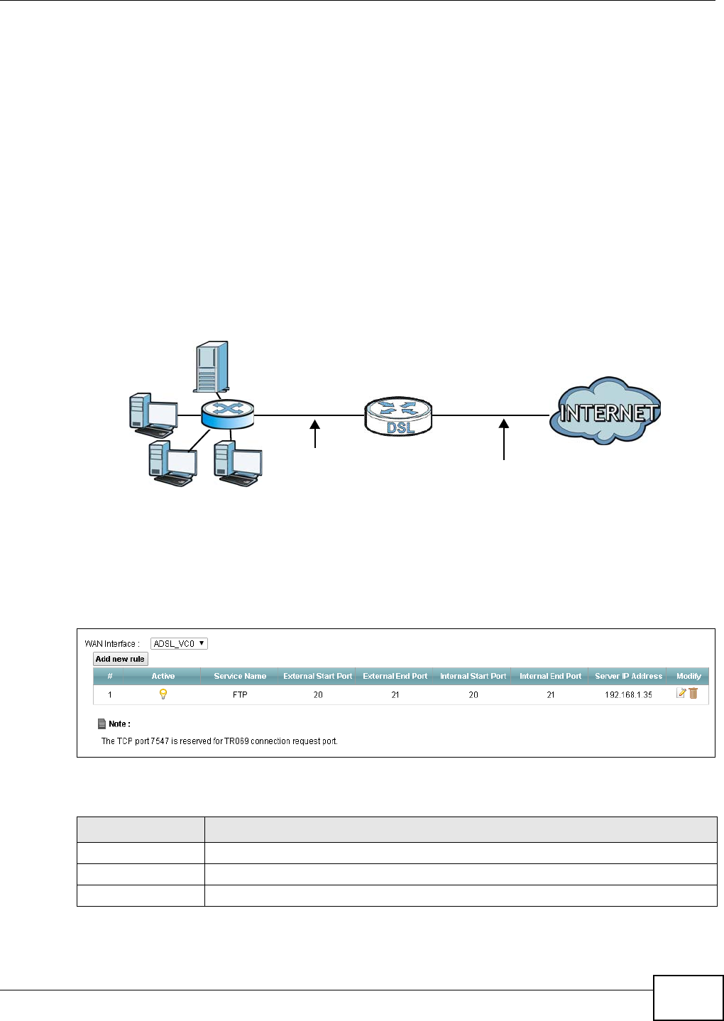
Chapter 10 Network Address Translation (NAT)
VMG1312-T10C User’s Guide 133
specify a range of port numbers. You can allocate a server IP address that corresponds to a port or
a range of ports. Please refer to RFC 1700 for further information about port numbers.
Note: Many residential broadband ISP accounts do not allow you to run any server
processes (such as a Web or FTP server) from your location. Your ISP may
periodically check for servers and may suspend your account if it discovers any
active services at your location. If you are unsure, refer to your ISP.
Configuring Servers Behind Port Forwarding (Example)
Let's say you want to assign ports 21-25 to one FTP, Telnet and SMTP server (A in the example),
port 80 to another (B in the example) and assign a default server IP address of 10.0.0.35 to a third
(C in the example). You assign the LAN IP addresses and the ISP assigns the WAN IP address. The
NAT network appears as a single host on the Internet.
Figure 88 Multiple Servers Behind NAT Example
10.3.1 The Port Forwarding Screen
Click Network Setting > NAT to open the Port Forwarding screen.
Figure 89 Network Setting > NAT > Port Forwarding
The following table describes the fields in this screen.
A=10.0.0.33
D=10.0.0.36
C=10.0.0.35
B=10.0.0.34
WAN
LAN
10.0.0.1 IP Address assigned by ISP
Table 48 Network Setting > NAT > Port Forwarding
LABEL DESCRIPTION
WAN Interface Select the WAN interface for which to configure NAT port forwarding rules.
Add new rule Click this to add a new port forwarding rule.
#This is the index number of the entry.
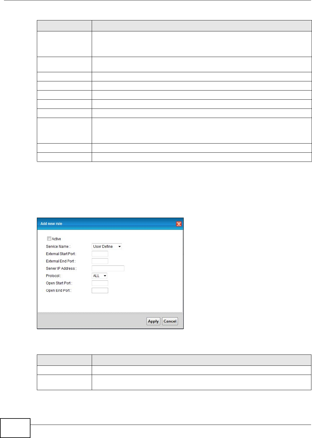
Chapter 10 Network Address Translation (NAT)
VMG1312-T10C User’s Guide
134
10.3.2 The Port Forwarding Add/Edit Screen
This screen lets you create or edit a port forwarding rule. Click Add new rule in the Port
Forwarding screen or the Edit icon next to an existing rule to open the following screen.
Figure 90 Port Forwarding: Add/Edit
The following table describes the labels in this screen.
Active This field indicates whether the rule is active or not.
A yellow bulb signifies that this rule is active. A gray bulb signifies that this rule is not
active.
Service Name This is the service’s name. This shows User Defined if you manually added a service.
You can change this by clicking the edit icon.
External Start Port This is the first external port number that identifies a service.
External End Port This is the last external port number that identifies a service.
Internal Start Port This is the first internal port number that identifies a service.
Internal End Port This is the last internal port number that identifies a service.
Server IP Address This is the server’s IP address.
Modify Click the Edit icon to edit the port forwarding rule.
Click the Delete icon to delete an existing port forwarding rule. Note that subsequent
address mapping rules move up by one when you take this action.
Apply Click Apply to save your changes.
Cancel Click Cancel to restore your previously saved settings.
Table 48 Network Setting > NAT > Port Forwarding (continued)
LABEL DESCRIPTION
Table 49 Port Forwarding: Add/Edit
LABEL DESCRIPTION
Active Select or clear this field to turn the port forwarding rule on or off.
Service Name Select a service to forward or select User Defined and enter a name in the field to the
right.
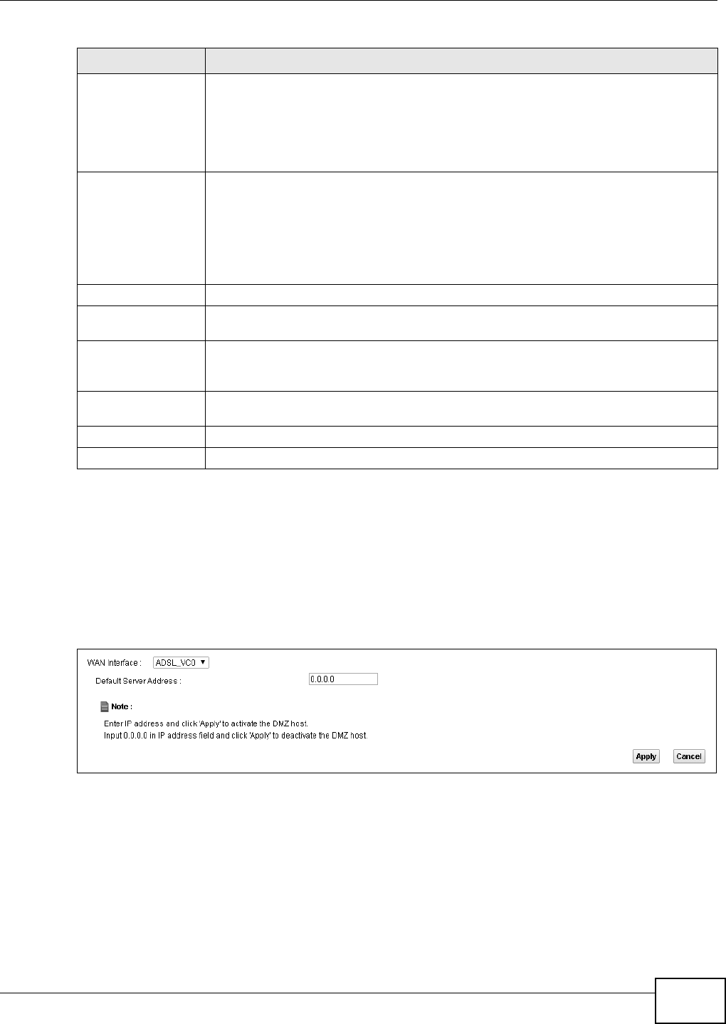
Chapter 10 Network Address Translation (NAT)
VMG1312-T10C User’s Guide 135
10.4 The DMZ Screen
Click Network Setting > NAT > DMZ to open the DMZ screen. Use this screen to specify the IP
address of a default server to receive packets from ports not specified in the Port Forwarding
screen.
Figure 91 Network Setting > NAT > DMZ
External Start Port Configure this for a user-defined entry. Enter the original destination port for the
packets.
To forward only one port, enter the port number again in the External End Port field.
To forward a series of ports, enter the start port number here and the end port number
in the External End Port field.
External End Port Configure this for a user-defined entry. Enter the last port of the original destination
port range.
To forward only one port, enter the port number in the External Start Port field above
and then enter it again in this field.
To forward a series of ports, enter the last port number in a series that begins with the
port number in the External Start Port field above.
Server IP Address Enter the inside IP address of the virtual server here.
Protocol Select the protocol supported by this virtual server. Choices are TCP, UDP, or TCP/
UDP.
Open Start Port Configure this for a user-defined entry. This shows the port number to which you want
the Device to translate the incoming port. For a range of ports, enter the first number
of the range to which you want the incoming ports translated.
Open End Port Configure this for a user-defined entry. This shows the last port of the translated port
range.
Apply Click this to save your changes.
Cancel Click this to exit this screen without saving.
Table 49 Port Forwarding: Add/Edit (continued)
LABEL DESCRIPTION
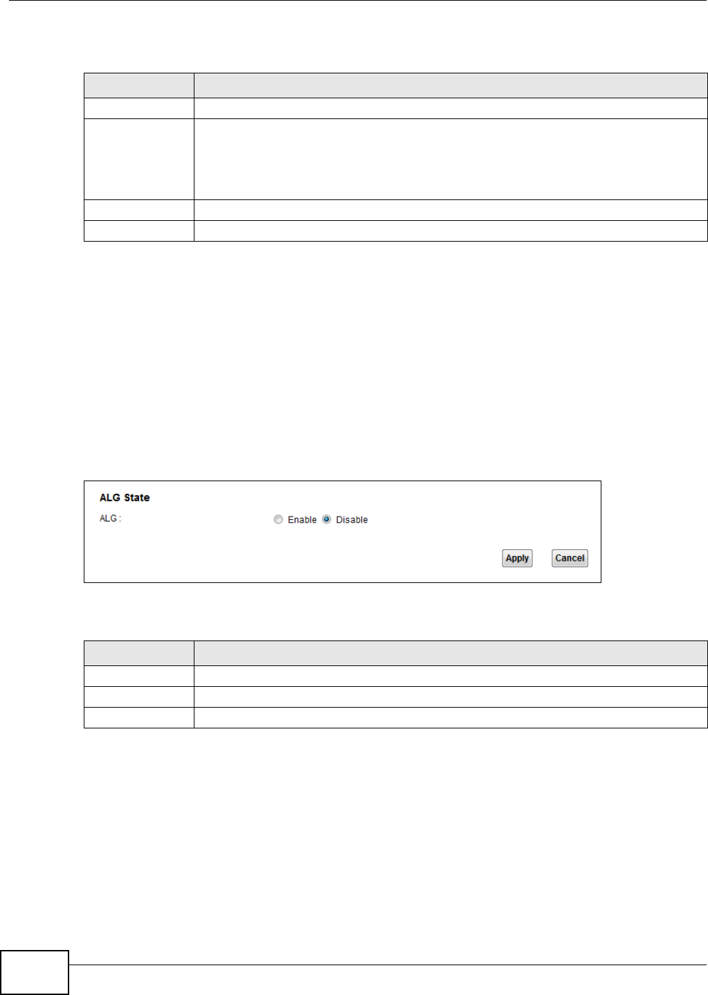
Chapter 10 Network Address Translation (NAT)
VMG1312-T10C User’s Guide
136
The following table describes the fields in this screen.
10.5 The ALG Screen
Click Network Setting > NAT > ALG to open the ALG screen. Use this screen to enable and
disable the NAT Application Layer Gateway (ALG) in the Device.
The SIP ALG allows SIP calls to pass through NAT by examining and translating IP addresses
embedded in the data stream. When the Device registers with the SIP register server, the SIP ALG
translates the Device’s private IP address inside the SIP data stream to a public IP address. You do
not need to use STUN or an outbound proxy if you enable the SIP ALG.
Figure 92 Network Setting > NAT > ALG
The following table describes the fields in this screen.
10.6 Technical Reference
This section provides some technical background information about the topics covered in this
chapter.
Table 50 Network Setting > NAT > DMZ
LABEL DESCRIPTION
WAN Interface Select the WAN interface for which to configure a default server.
Default Server
Address
Enter the IP address of the default server which receives packets from ports that are not
specified in the Port Forwarding screen.
Note: If you do not assign a default server, the Device discards all packets received for ports
not specified in the virtual server configuration.
Apply Click this to save your changes back to the Device.
Cancel Click Cancel to restore your previously saved settings.
Table 51 Network Setting > NAT > ALG
LABEL DESCRIPTION
SIP ALG Enable this to make sure SIP (VoIP) works correctly with port-forwarding.
Apply Click this to save your changes back to the Device.
Cancel Click Cancel to restore your previously saved settings.

Chapter 10 Network Address Translation (NAT)
VMG1312-T10C User’s Guide 137
10.6.1 NAT Definitions
Inside/outside denotes where a host is located relative to the Device, for example, the computers
of your subscribers are the inside hosts, while the web servers on the Internet are the outside
hosts.
Global/local denotes the IP address of a host in a packet as the packet traverses a router, for
example, the local address refers to the IP address of a host when the packet is in the local
network, while the global address refers to the IP address of the host when the same packet is
traveling in the WAN side.
Note that inside/outside refers to the location of a host, while global/local refers to the IP address
of a host used in a packet. Thus, an inside local address (ILA) is the IP address of an inside host in
a packet when the packet is still in the local network, while an inside global address (IGA) is the IP
address of the same inside host when the packet is on the WAN side. The following table
summarizes this information.
NAT never changes the IP address (either local or global) of an outside host.
10.6.2 What NAT Does
In the simplest form, NAT changes the source IP address in a packet received from a subscriber
(the inside local address) to another (the inside global address) before forwarding the packet to the
WAN side. When the response comes back, NAT translates the destination address (the inside
global address) back to the inside local address before forwarding it to the original inside host. Note
that the IP address (either local or global) of an outside host is never changed.
The global IP addresses for the inside hosts can be either static or dynamically assigned by the ISP.
In addition, you can designate servers, for example, a web server and a Telnet server, on your local
network and make them accessible to the outside world. If you do not define any servers, NAT
offers the additional benefit of firewall protection. With no servers defined, your Device filters out
all incoming inquiries, thus preventing intruders from probing your network. For more information
on IP address translation, refer to RFC 1631, The IP Network Address Translator (NAT).
10.6.3 How NAT Works
Each packet has two addresses – a source address and a destination address. For outgoing packets,
the ILA (Inside Local Address) is the source address on the LAN, and the IGA (Inside Global
Address) is the source address on the WAN. For incoming packets, the ILA is the destination
address on the LAN, and the IGA is the destination address on the WAN. NAT maps private (local)
IP addresses to globally unique ones required for communication with hosts on other networks. It
replaces the original IP source address (and TCP or UDP source port numbers for Many-to-One and
Table 52 NAT Definitions
ITEM DESCRIPTION
Inside This refers to the host on the LAN.
Outside This refers to the host on the WAN.
Local This refers to the packet address (source or destination) as the packet travels on the
LAN.
Global This refers to the packet address (source or destination) as the packet travels on the
WAN.
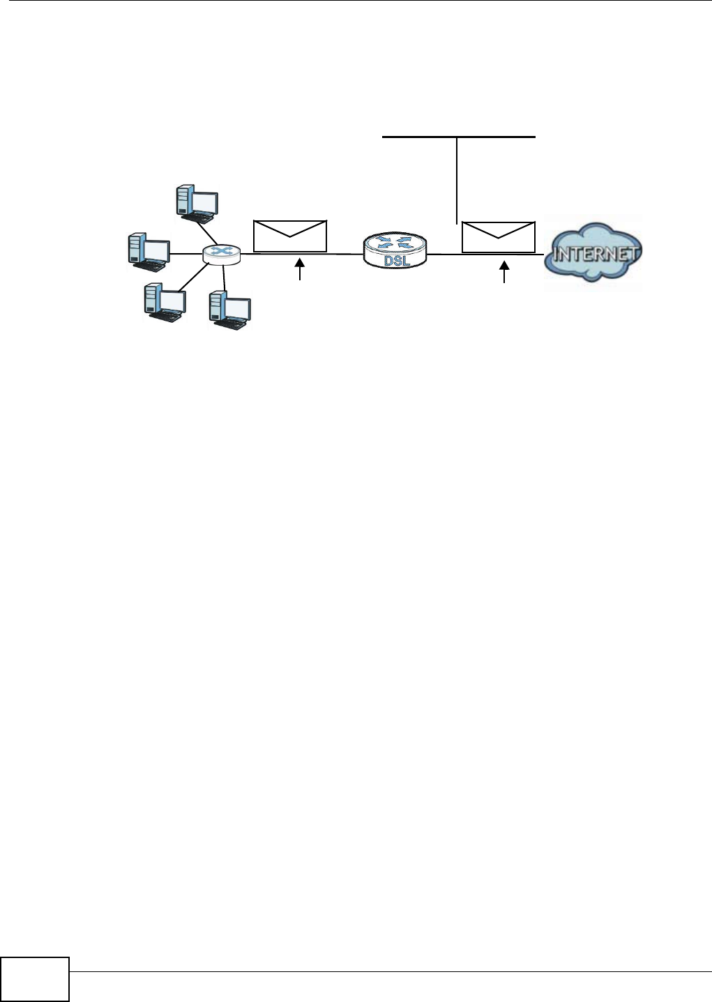
Chapter 10 Network Address Translation (NAT)
VMG1312-T10C User’s Guide
138
Many-to-Many Overload NAT mapping) in each packet and then forwards it to the Internet. The
Device keeps track of the original addresses and port numbers so incoming reply packets can have
their original values restored. The following figure illustrates this.
Figure 93 How NAT Works
192.168.1.13
192.168.1.10
192.168.1.11
192.168.1.12 SA
192.168.1.10
SA
IGA1
Inside Local
IP Address
192.168.1.10
192.168.1.11
192.168.1.12
192.168.1.13
Inside Global
IP Address
IGA 1
IGA 2
IGA 3
IGA 4
NAT Table
WAN
LAN
Inside Local
Address (ILA)
Inside Global
Address (IGA)
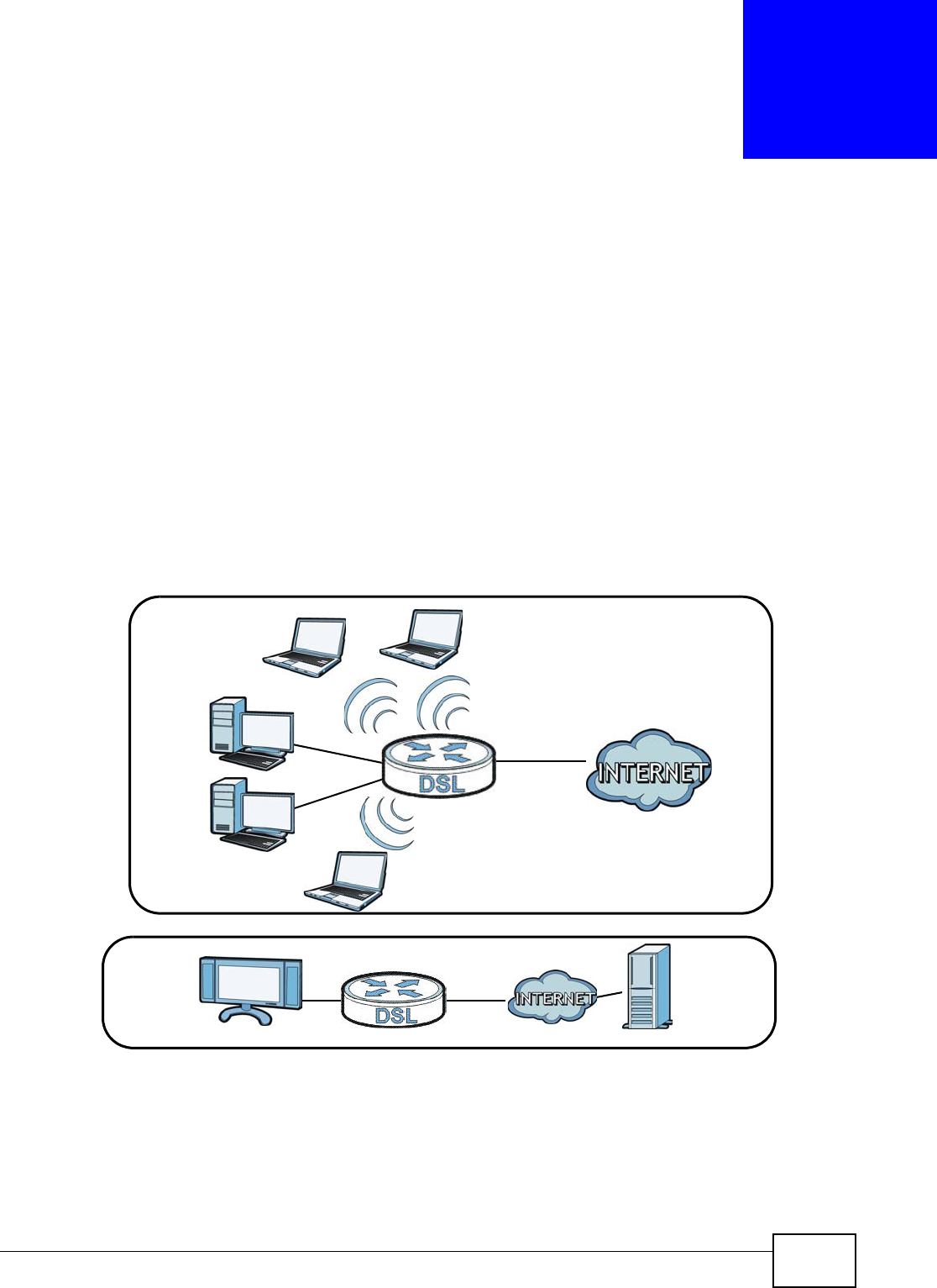
VMG1312-T10C User’s Guide 139
CHAPTER 11
Port Binding
11.1 Overview
Port binding aggregates port connections into logical groups. Bind WAN virtual channels (VCs) to
Ethernet ports and WLANs to specify how traffic is forwarded. The Device forwards traffic from an
Ethernet port only through the bound WAN virtual channel and vice versa. For ports not belonging
to a port binding group, the Device forwards traffic according to the routing table.
Additionally, specify ATM QoS settings for an ADSL virtual channel (PVC) to satisfy the bandwidth
requirements of the traffic the PVC carries. For example, create two port binding groups on the
device (R1) for two different WAN ATM PVC connections. The first PVC (PVC1) handles non time-
sensitive data traffic. The second PVC (PVC2) handle time sensitive Media-On-Demand (MOD) video
traffic.
Figure 94 Port Binding Groups
S2
R1
R1
MOD
Data
PVC1
PVC2
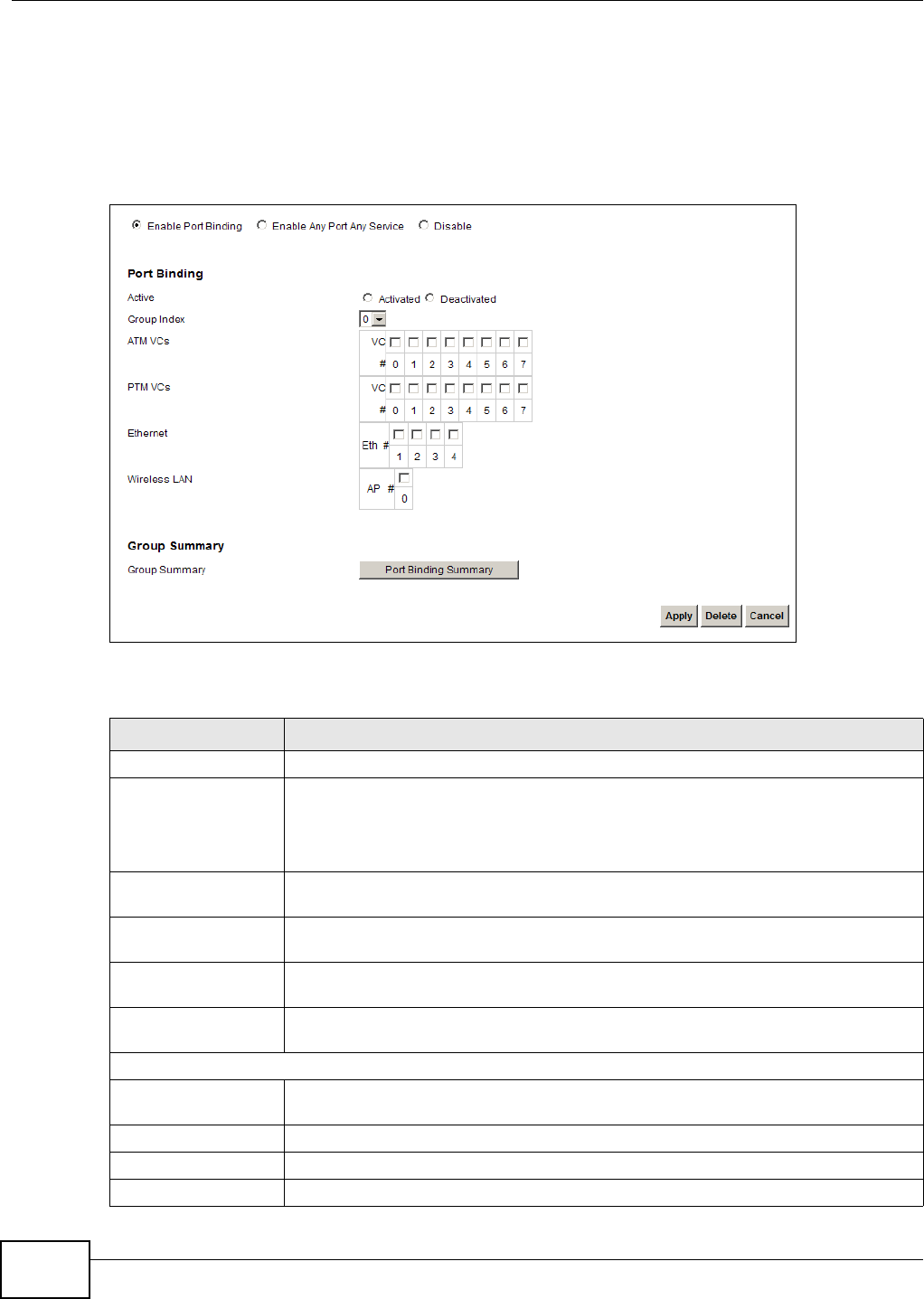
Chapter 11 Port Binding
VMG1312-T10C User’s Guide
140
11.2 The Port Binding Screen
Use this screen to enable or disable port binding or any port any service. Click Network Setting >
Port Binding. If you want to enable the port binding feature and configure port binding groups,
select Enable Port Binding.
Figure 95 Network Setting > Port Binding: Enable Port Binding
The following table describes the labels in this screen.
Table 53 Network Setting > Port Binding: Enable Port Binding
LABEL DESCRIPTION
Active Activate or deactivate the port binding group.
Group Index Select the index number for the port binding group.
When a port is assigned to a port binding group, traffic will be forwarded to the other
ports in the group, but not to ports in other groups. If a port is not included in any
groups, traffic will be forwarded according to the routing table.
ATM VCs Select the ATM VC (PVC) to include in the port binding group. Each ATM VC can only
be bound to one group.
PTM VCs Select the PTM VC to include in the port binding group. An individual PTM VC can be
bound to more than one group.
Ethernet Select the Ethernet (Eth) ports to include in the port binding group. Each Ethernet
port can only be bound to one group.
Wireless LAN Select the WLAN (AP) connections to include in the port binding group. Additional APs
can be enabled on the More AP screen (Section 6.3 on page 63).
Group Summary
Port Binding
Summary
Click this to view a summary of configured port binding groups.
Apply Add the selected port binding group configuration.
Delete Delete the selected port binding group configuration.
Cancel Click this to restore your previously saved settings.
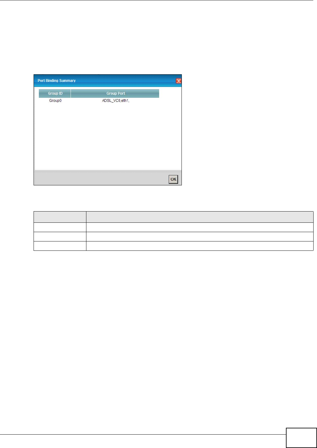
Chapter 11 Port Binding
VMG1312-T10C User’s Guide 141
11.2.1 Port Binding Summary Screen
Use this screen to view configured port binding groups.
In the Port Binding screen, click the Port Binding Summary button in the Group Summary
section to display the following screen.
Figure 96 Network Setting > Port Binding: Port Binding Summary
The following table describes the labels in this screen.
Table 54 Network Setting > Port Binding: Port Binding Summary
LABEL DESCRIPTION
Group ID This field displays the group index number.
Group Port This field displays the ports and virtual channels included in the group.
OK Click this to close the screen.
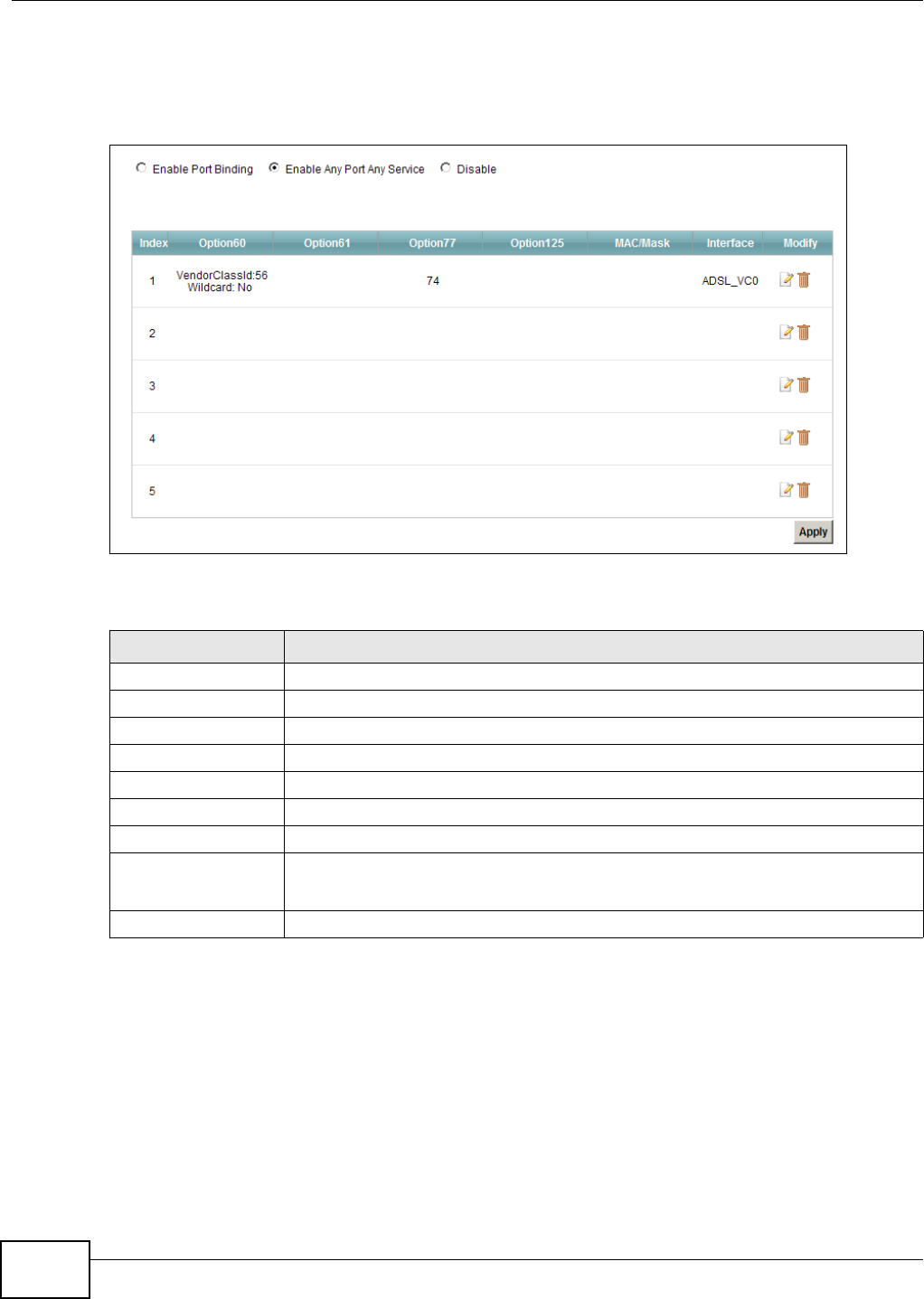
Chapter 11 Port Binding
VMG1312-T10C User’s Guide
142
If you want to enable the Any Port Any Service feature, select Enable Any Port Any Service. The
Device binds a LAN port with WAN interface per source MAC or DHCP options from the LAN host
dynamically. You can configure up to 5 dynamic port binding groups.
Figure 97 Network Setting > Port Binding: Any Port Any Service
The following table describes the labels in this screen.
Table 55 Network Setting > Port Binding: Any Port Any Service
LABEL DESCRIPTION
Index This is the index number for the port binding group.
Option60 This is the Vendor Class Identifier of the matched traffic.
Option61 This is the device identity of the matched traffic.
Option77 This is the User Class Identifier of the matched traffic
Option125 This is the vendor specific information of the matched traffic.
MAC/Mask This is the source MAC address and MAC mask of the matched traffic.
Interface This is the WAN interface of the port binding group.
Modify Click the Edit icon to edit the port binding group.
Click the Delete icon to delete an existing port binding group.
Apply Click this to apply the settings.
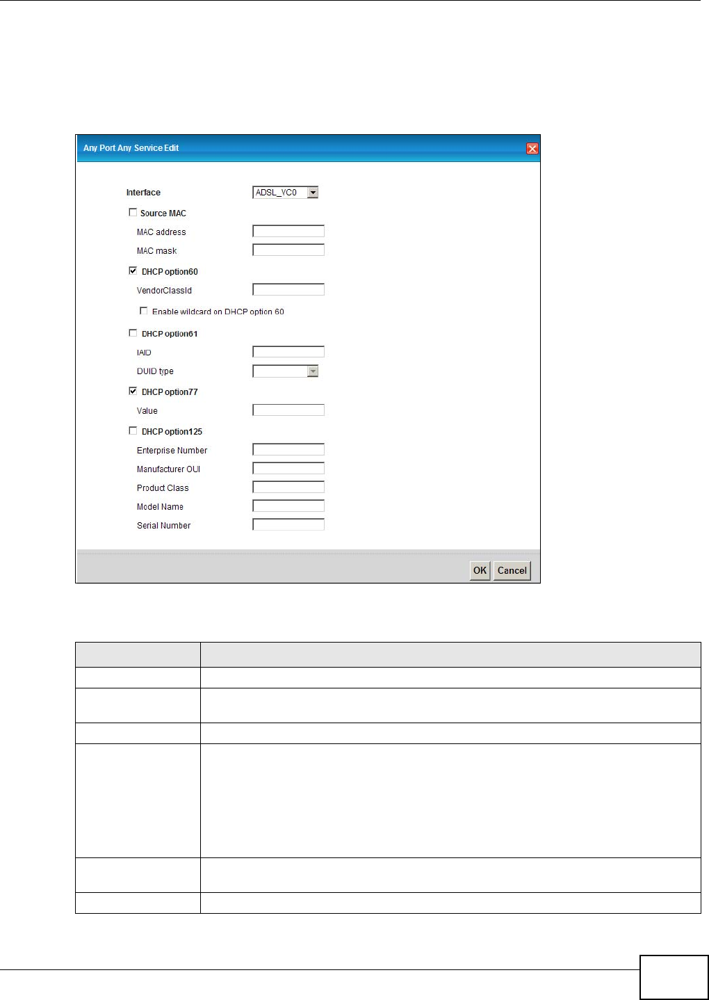
Chapter 11 Port Binding
VMG1312-T10C User’s Guide 143
11.2.2 The Any Port Any Service Edit Screen
This screen lets you create or edit a dynamic port binding group. Click the Edit icon of a port
binding group in the Port Binding: Any Port Any Service screen to open the following screen.
Figure 98 Any Port Any Service: Add/Edit
The following table describes the labels in this screen.
Table 56 Any Port Any Service: Add/Edit
LABEL DESCRIPTION
Interface Select the WAN interface of the port binding group.
Source MAC If you want to configure the port binding group by the source MAC address of the
packet, select this check box and enter the MAC address and MAC mask.
MAC address Enter the source MAC address of the packet.
MAC mask Type the mask for the specified MAC address to determine which bits a packet’s MAC
address should match.
Enter “f” for each bit of the specified source MAC address that the traffic’s MAC address
should match. Enter “0” for the bit(s) of the matched traffic’s MAC address, which can
be of any hexadecimal character(s). For example, if you set the MAC address to
00:13:49:00:00:00 and the mask to ff:ff:ff:00:00:00, a packet with a MAC address of
00:13:49:12:34:56 matches this criteria.
DHCP Option60 Select this option and enter the Vendor Class Identifier (Option 60) of the matched
traffic, such as the type of the hardware or firmware.
VendorClassId Enter the Vendor Class Identifier of the matched traffic.
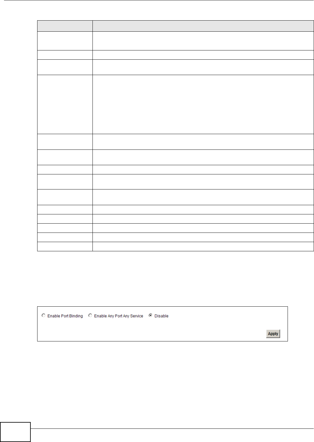
Chapter 11 Port Binding
VMG1312-T10C User’s Guide
144
If you want to disable the port binding feature on the Device, select Disable in the Port Binding
screen and click Apply.
It is suggested to reboot the Device after you have changed the port binding settings or WAN
encapsulation.
Figure 99 Network Setting > Port Binding: Disable
Enable wildcard
on DHCP option
60
Select this option to be able to use wildcards in the Vendor Class Identifier configured
for DHCP option 60.
DHCP option61 Select this and enter the device identity of the matched traffic.
IAID Enter the Identity Association Identifier (IAID) of the device, for example, the WAN
connection index number.
DUID type Select DUID-LLT (DUID Based on Link-layer Address Plus Time) to enter the hardware
type, a time value and the MAC address of the device.
Select DUID-EN (DUID Assigned by Vendor Based upon Enterprise Number) to enter
the vendor’s registered enterprise number.
Select DUID-LL (DUID Based on Link-layer Address) to enter the device’s hardware
type and hardware address (MAC address) in the following fields.
Select Other to enter any string that identifies the device in the DUID field.
DHCP option77 Select this and enter a string that identifies the user’s category or application type in
the matched DHCP packets.
Value Enter a string that identifies the user’s category or application type in the matched
DHCP packets
DHCP option125 Select this and enter vendor specific information of the matched traffic.
Enterprise
Number Enter the vendor’s 32-bit enterprise number registered with the IANA (Internet
Assigned Numbers Authority).
Manufacturer
OUI Specify the vendor’s OUI (Organization Unique Identifier). It is usually the first three
bytes of the MAC address.
Product Class Enter the product class of the device.
Model Name Enter the model name of the device.
Serial Number Enter the serial number of the device.
OK Click this to save your changes.
Cancel Click this to exit this screen without saving.
Table 56 Any Port Any Service: Add/Edit (continued)
LABEL DESCRIPTION

VMG1312-T10C User’s Guide 145
CHAPTER 12
Dynamic DNS
12.1 Overview
This chapter discusses how to configure your Device to use Dynamic DNS.
Dynamic DNS allows you to update your current dynamic IP address with one or many dynamic
DNS services so that anyone can contact you (in applications such as NetMeeting and CU-SeeMe).
You can also access your FTP server or Web site on your own computer using a domain name (for
instance myhost.dhs.org, where myhost is a name of your choice) that will never change instead of
using an IP address that changes each time you reconnect. Your friends or relatives will always be
able to call you even if they don't know your IP address.
First of all, you need to have registered a dynamic DNS account with www.dyndns.org. This is for
people with a dynamic IP from their ISP or DHCP server that would still like to have a domain name.
The Dynamic DNS service provider will give you a password or key.
12.1.1 What You Need To Know
DYNDNS Wildcard
Enabling the wildcard feature for your host causes *.yourhost.dyndns.org to be aliased to the same
IP address as yourhost.dyndns.org. This feature is useful if you want to be able to use, for example,
www.yourhost.dyndns.org and still reach your hostname.
If you have a private WAN IP address, then you cannot use Dynamic DNS.
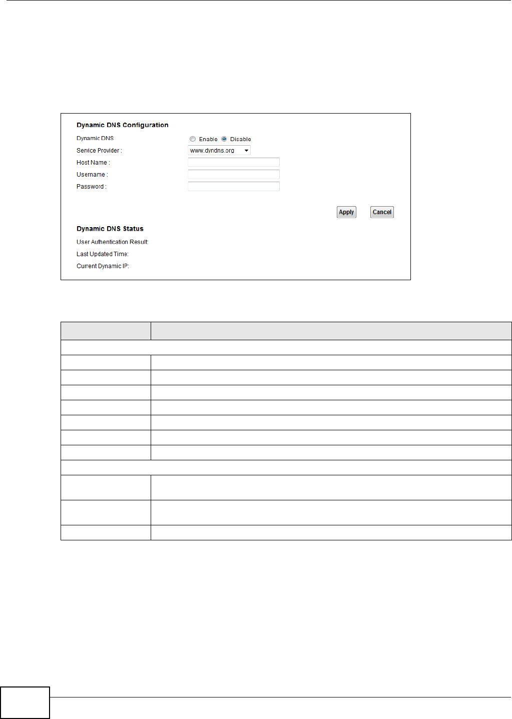
Chapter 12 Dynamic DNS
VMG1312-T10C User’s Guide
146
12.2 The Dynamic DNS Screen
Use the Dynamic DNS screen to enable DDNS and configure the DDNS settings on the Device. To
change your Device’s DDNS, click Network Setting > Dynamic DNS. The screen appears as
shown.
Figure 100 Network Setting > Dynamic DNS
The following table describes the fields in this screen.
Table 57 Network Setting > Dynamic DNS
LABEL DESCRIPTION
Dynamic DNS Configuration
Dynamic DNS Select Enable to use dynamic DNS.
Service Provider Select the name of your Dynamic DNS service provider.
Host Name Type the domain name assigned to your Device by your Dynamic DNS provider.
Username Type your user name for the Dynamic DNS service provider.
Password Type your password for the Dynamic DNS service provider.
Apply Click Apply to save your changes.
Cancel Click Cancel to restore your previously saved settings.
Dynamic DNS Status
User Authentication
Result
This field displays the results of the Device’s attempt to authenticate with the Dynamic
DNS service provider.
Last Updated Time This field displays when the Device last updated its WAN IP address to the Dynamic
DNS service provider.
Current Dynamic IP This field displays the Device’s current WAN IP address.
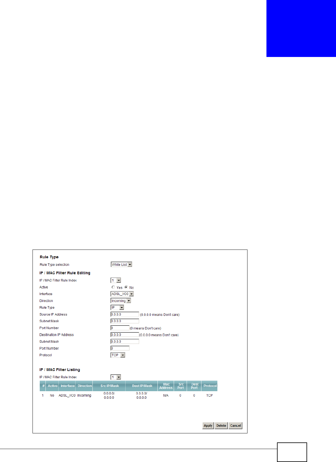
VMG1312-T10C User’s Guide 147
CHAPTER 13
Filter
13.1 Overview
This chapter introduces filter rules you can configure to restrict traffic by IPv4 and IPv6 addresses
and MAC addresses.
13.1.1 What You Can Do in the Filter Screens
•Use the IP/MAC Filter screen (Section 13.2 on page 148) to create IPv4/MAC filter rules.
•Use the IPv6/MAC Filter screen (Section 13.3 on page 150) to create IPv6/MAC filter rules.
13.2 The IP/MAC Filter Screen
Use this screen to create and apply IPv4/MAC filters. Click Security > Filter to display the screen
as shown.
Figure 101 Security > Filter

Chapter 13 Filter
VMG1312-T10C User’s Guide
148
The following table describes the labels in this screen.
Table 58 Security > Filter
LABEL DESCRIPTION
Rule Type
Rule Type selection Select White List to create a filter rule that allows traffic.
Select Black List to create a filter rule that blocks traffic.
IP/MAC Filter Rule Editing
IP/MAC Filter Rule
Index
Select the index number of the filter rule.
Active Use this field to enable or disable the rule.
Interface Select the interface to which to apply the filter.
Direction Apply the filter to Incoming or Outgoing traffic direction.
Rule Type Select IP to filter traffic by IP addresses.
Select MAC to filter traffic by MAC address.
Source IP Address Enter the source IP address of the packets you wish to filter. This field is ignored if it is
0.0.0.0.
Subnet Mask Enter the IP subnet mask for the source IP address.
Port Number Enter the source port of the packets that you wish to filter. The range of this field is 0 to
65535. This field is ignored if it is 0.
Destination IP
Address
Enter the destination IP address of the packets you wish to filter. This field is ignored if
it is 0.0.0.0.
Subnet Mask Enter the IP subnet mask for the destination IP address.
Port Number Enter the destination port of the packets that you wish to filter. The range of this field is
0 to 65535. This field is ignored if it is 0.
Protocol Select ICMP, TCP or UDP for the upper layer protocol.
Source MAC
Address
This field is only available when you select MAC in the Rule Type field.
Enter the MAC address of the packets you wish to filter.
IP / MAC Filter Listing
#This is the index number of the filter rule.
Active This field shows whether the rule is activated.
Interface This field shows the interface to which the filter rule applies.
Direction The filter rule applies to this traffic direction.
Src IP/Mask This is the source IP address and subnet mask when you select IP as the rule type.
This is the MAC address when you select MAC as the rule type.
Dest IP/Mask This is the destination IP address and subnet mask.
MAC Address For a MAC filter rule this field shows the MAC address of the packets to filter.
Src Port This is the source port number.
Dest Port This is the destination port number.
Protocol This is the upper layer protocol.
Apply Click this to save your changes.
Delete Click this to remove the filter rule selected in the IP / MAC Filter Rule Index field.
Cancel Click this to restore your previously saved settings.
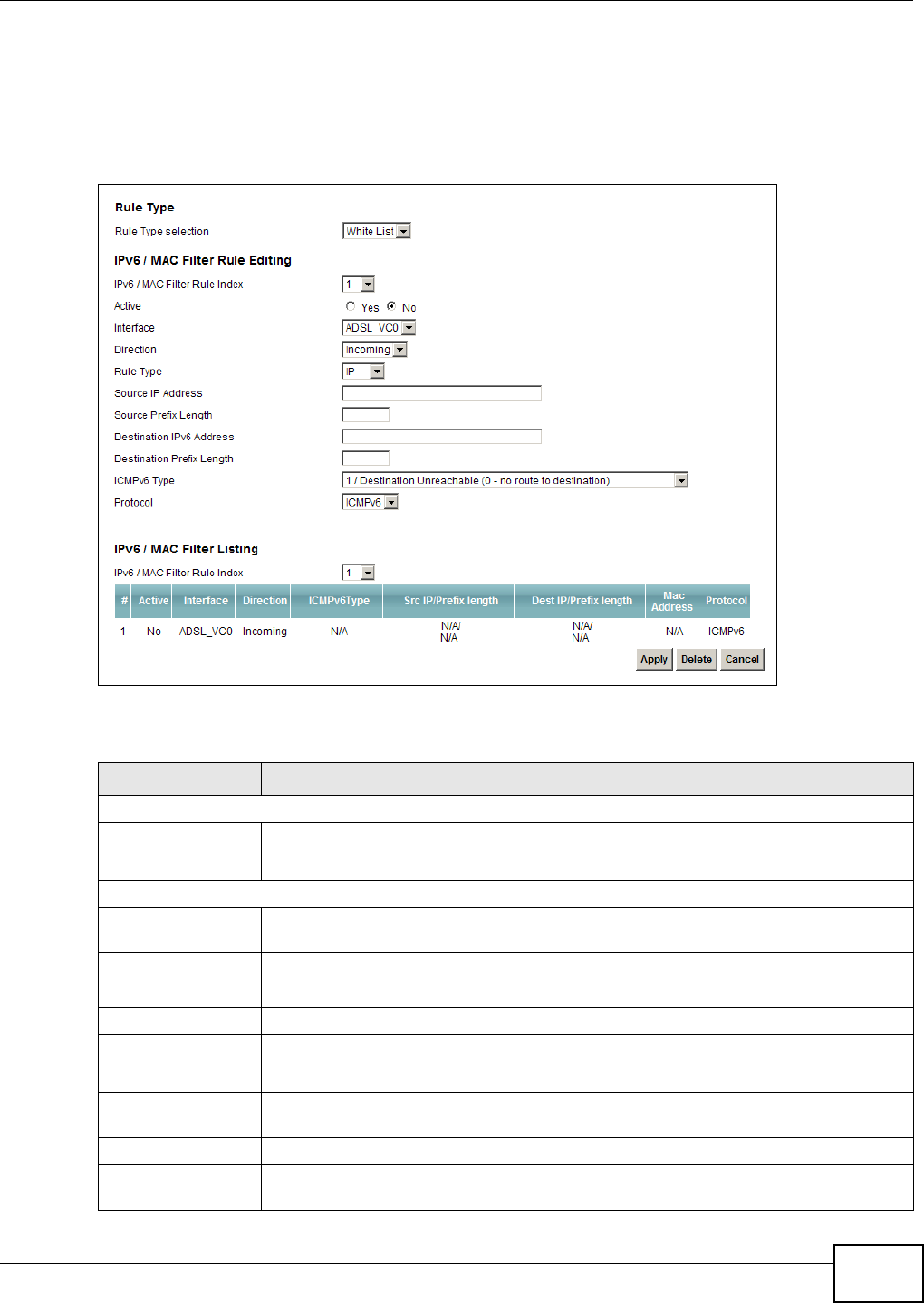
Chapter 13 Filter
VMG1312-T10C User’s Guide 149
13.3 The IPv6/MAC Filter Screen
Use this screen to create and apply IPv6/MAC filters. Click Security > Filter > IPv6/MAC Filter
to display the screen as shown.
Figure 102 Security > Filter > IPv6/MAC Filter
The following table describes the labels in this screen.
Table 59 Security > Filter > IPv6/MAC Filter
LABEL DESCRIPTION
Rule Type
Rule Type selection Select White List to create a filter rule that allows traffic.
Select Black List to create a filter rule that blocks traffic.
IPv6 / MAC Filter Rule Editing
IPv6 / MAC Filter
Rule Index
Select the index number of the filter rule.
Active Use this field to enable or disable the rule.
Interface Select the interface to which to apply the filter.
Direction Apply the filter to Incoming or Outgoing traffic direction.
Rule Type Select IP to filter traffic by IP addresses.
Select MAC to filter traffic by MAC address.
Source IP Address Enter the source IPv6 address of the packets you wish to filter. This field is ignored if it
is ::.
Subnet Mask Enter the IPv6 subnet mask for the source IPv6 address.
Source Prefix
Length
Enter the prefix length for the source IPv6 address.

Chapter 13 Filter
VMG1312-T10C User’s Guide
150
Destination IPv6
Address
Enter the destination IPv6 address of the packets you wish to filter. This field is ignored
if it is ::.
Destination Prefix
Length
Enter the prefix length for the destination IPv6 address.
ICMPv6 Type Select one of the following ICMPv6 message types to filter.
1 / Destination Unreachable: 0 - no route to destination; 1 - communication with
destination administratively prohibited; 3 - address unreachable; 4 - port unreachable
2 / Packet Too Big
3 / Time Exceeded: 0 - hop limit exceeded in transit; 1 - fragment reassembly time
exceeded
4 / Parameter Problem: 0 - erroneous header field encountered; 1 - unrecognized
Next Header type encountered; 2 - unrecognized IPv6 option encountered
128 / Echo Request
129 / Echo Response
130 / Listener Query - Multicast listener query
131 / Listener Report - Multicast listener report
132 / Listener Done - Multicast listener done
143 / Listener Reportv2 - Multicast listener report v2
133 / Router Solicitation
134 / Router Advertisement
135 / Neighbor Solicitation
136 / Neighbor Advertisement
137 / Redirect - Redirect message
Protocol This is the (upper layer) protocol that defines the service to which this rule applies. By
default it is ICMPv6.
Source MAC
Address
This field is only available when you select MAC in the Rule Type field.
Enter the MAC address of the packets you wish to filter.
IPv6 / MAC Filter Listing
IPv6 / MAC Filter
Rule Index
Select the index number of the filter set from the drop-down list box.
#This is the index number of the rule in a filter set.
Active This field shows whether the rule is activated.
Interface This is the interface that the rule applies to.
Direction The filter set applies to this traffic direction.
ICMPv6 Type The ICMPv6 message type to filter.
Src IP/PrefixLength This displays the source IPv6 address and prefix length.
Dest IP/
PrefixLength
This displays the destination IPv6 address and prefix length.
Mac Address This is the MAC address of the packets being filtered.
Protocol This is the (upper layer) protocol that defines the service to which this rule applies. By
default it is ICMPv6.
Apply Click this to save your changes.
Table 59 Security > Filter > IPv6/MAC Filter (continued)
LABEL DESCRIPTION

Chapter 13 Filter
VMG1312-T10C User’s Guide 151
Delete Click this to remove the filter rule selected in the IPv6 / MAC Filter Rule Index field.
Cancel Click this to restore your previously saved settings.
Table 59 Security > Filter > IPv6/MAC Filter (continued)
LABEL DESCRIPTION

Chapter 13 Filter
VMG1312-T10C User’s Guide
152
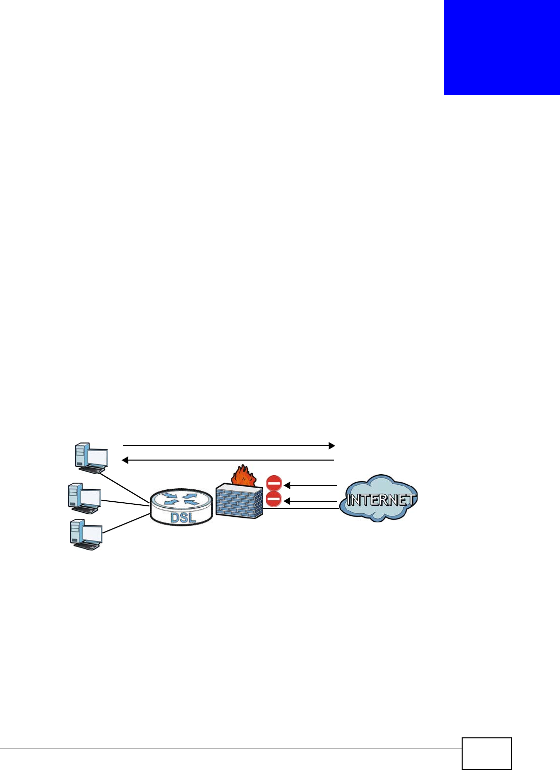
VMG1312-T10C User’s Guide 153
CHAPTER 14
Firewall
14.1 Overview
This chapter shows you how to enable the Device firewall. Use the firewall to protect your Device
and network from attacks by hackers on the Internet and control access to it. The firewall:
• allows traffic that originates from your LAN computers to go to all other networks.
• blocks traffic that originates on other networks from going to the LAN.
• blocks SYN and port scanner attacks.
By default, the Device blocks DDOS, LAND and Ping of Death attacks whether the firewall is enabled
or disabled.
The following figure illustrates the firewall action. User A can initiate an IM (Instant Messaging)
session from the LAN to the WAN (1). Return traffic for this session is also allowed (2). However
other traffic initiated from the WAN is blocked (3 and 4).
Figure 103 Default Firewall Action
14.1.1 What You Can Do in the Firewall Screens
•Use the General screen (Section 14.2 on page 155) to select the firewall protection level on the
Device.
•Use the Default Action screen (Section 14.3 on page 156) to set the default action that the
firewall takes on packets that do not match any of the firewall rules.
•Use the Rules screen (Section 14.4 on page 157) to view the configured firewall rules and add,
edit or remove a firewall rule.
WAN
LAN
3
4
1
2
A

Chapter 14 Firewall
VMG1312-T10C User’s Guide
154
•Use the Dos screen (Section 14.5 on page 162) to set the thresholds that the Device uses to
determine when to start dropping sessions that do not become fully established (half-open
sessions).
14.1.2 What You Need to Know About Firewall
SYN Attack
A SYN attack floods a targeted system with a series of SYN packets. Each packet causes the
targeted system to issue a SYN-ACK response. While the targeted system waits for the ACK that
follows the SYN-ACK, it queues up all outstanding SYN-ACK responses on a backlog queue. SYN-
ACKs are moved off the queue only when an ACK comes back or when an internal timer terminates
the three-way handshake. Once the queue is full, the system will ignore all incoming SYN requests,
making the system unavailable for legitimate users.
DoS
Denials of Service (DoS) attacks are aimed at devices and networks with a connection to the
Internet. Their goal is not to steal information, but to disable a device or network so users no longer
have access to network resources. The Device is pre-configured to automatically detect and thwart
all known DoS attacks.
DDoS
A Distributed DoS (DDoS) attack is one in which multiple compromised systems attack a single
target, thereby causing denial of service for users of the targeted system.
LAND Attack
In a Local Area Network Denial (LAND) attack, hackers flood SYN packets into the network with a
spoofed source IP address of the target system. This makes it appear as if the host computer sent
the packets to itself, making the system unavailable while the target system tries to respond to
itself.
Ping of Death
Ping of Death uses a "ping" utility to create and send an IP packet that exceeds the maximum
65,536 bytes of data allowed by the IP specification. This may cause systems to crash, hang or
reboot.
SPI
Stateful Packet Inspection (SPI) tracks each connection crossing the firewall and makes sure it is
valid. Filtering decisions are based not only on rules but also context. For example, traffic from the
WAN may only be allowed to cross the firewall in response to a request from the LAN.
RFC 4890 SPEC Traffic
RFC 4890 specifies the filtering policies for ICMPv6 messages. This is important for protecting
against security threats including DoS, probing, redirection attacks and renumbering attacks that
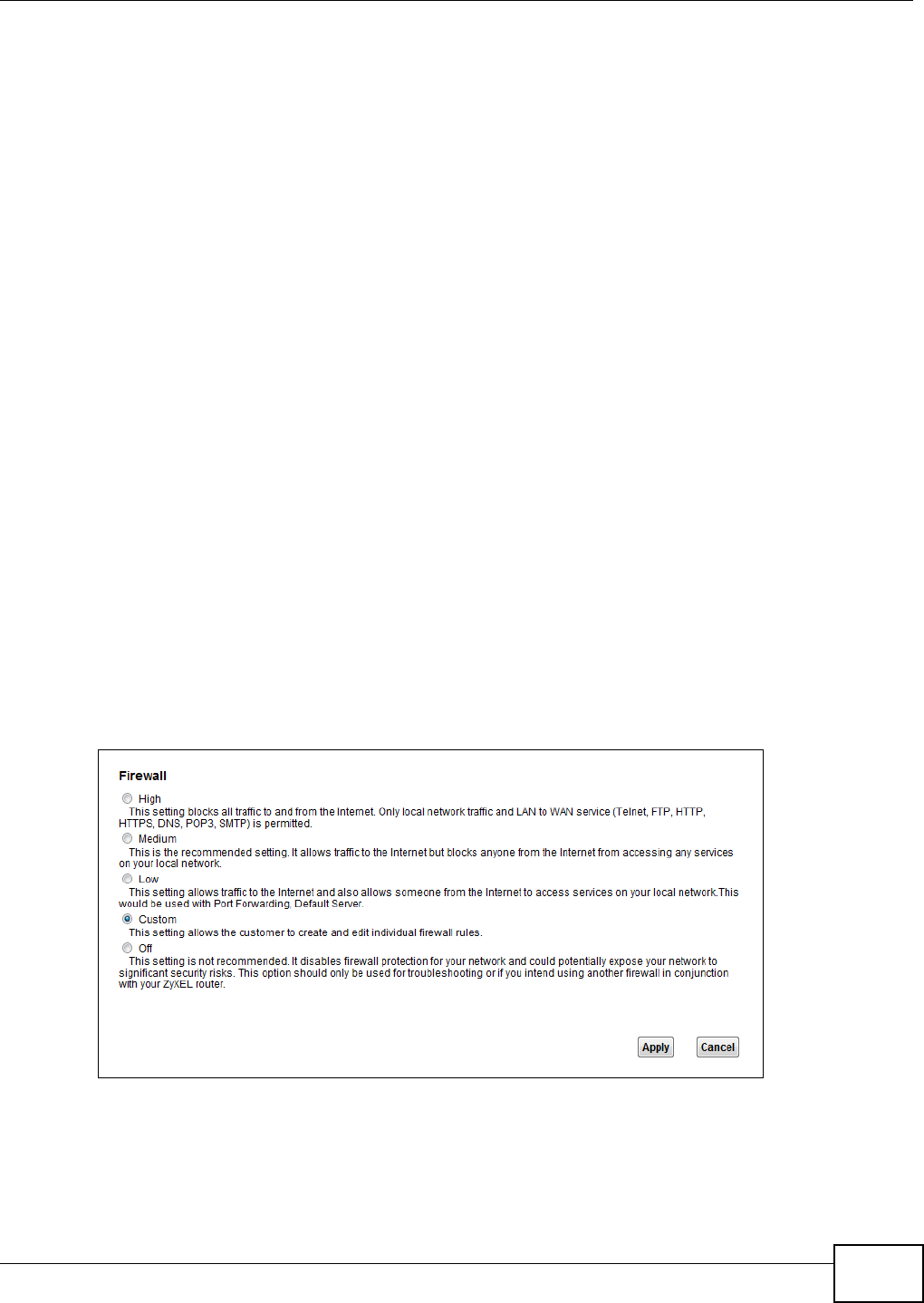
Chapter 14 Firewall
VMG1312-T10C User’s Guide 155
can be carried out through ICMPv6. Since ICMPv6 error messages are critical for establishing and
maintaining communications, filtering policy focuses on ICMPv6 informational messages.
Anti-Probing
If an outside user attempts to probe an unsupported port on your Device, an ICMP response packet
is automatically returned. This allows the outside user to know the Device exists. The Device
supports anti-probing, which prevents the ICMP response packet from being sent. This keeps
outsiders from discovering your Device when unsupported ports are probed.
ICMP
Internet Control Message Protocol (ICMP) is a message control and error-reporting protocol
between a host server and a gateway to the Internet. ICMP uses Internet Protocol (IP) datagrams,
but the messages are processed by the TCP/IP software and directly apparent to the application
user.
DoS Thresholds
For DoS attacks, the Device uses thresholds to determine when to drop sessions that do not
become fully established. These thresholds apply globally to all sessions. You can use the default
threshold values, or you can change them to values more suitable to your security requirements.
14.2 Firewall General Screen
Use this screen to select the firewall protection level on the Device. Click Security > Firewall >
General to display the following screen.
Figure 104 Security > Firewall > General
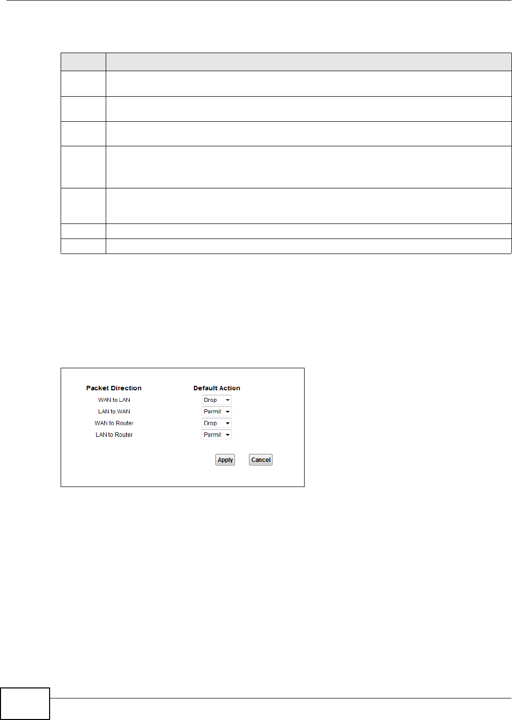
Chapter 14 Firewall
VMG1312-T10C User’s Guide
156
The following table describes the labels in this screen.
14.3 Default Action Screen
Use this screen to set the default action that the firewall takes on packets that do not match any of
the firewall rules. Click Security > Firewall > Default Action to display the following screen.
Figure 105 Security > Firewall > Default Action
Table 60 Security > Firewall > General
LABEL DESCRIPTION
High This setting blocks all traffic to and from the Internet. Only local network traffic and LAN to WAN
service (Telnet, FTP, HTTP, HTTPS, DNS, POP3, SMTP) is permitted.
Medium This is the recommended setting. It allows traffic to the Internet but blocks anyone from the
Internet from accessing any services on your local network.
Low This setting allows traffic to the Internet and also allows someone from the Internet to access
services on your local network. This would be used with Port Forwarding, Default Server.
Custom This setting allows the customer to create and edit individual firewall rules.
Firewall rules can be created in the Default Action screen (Section 14.3 on page 156) and Rules
screen (Section 14.4 on page 157).
Off This setting is not recommended. It disables firewall protection for your network and could
potentially expose your network to significant security risks. This option should only be used for
troubleshooting or if you intend using another firewall in conjunction with your router.
Apply Click this to save your changes.
Cancel Click this to restore your previously saved settings.
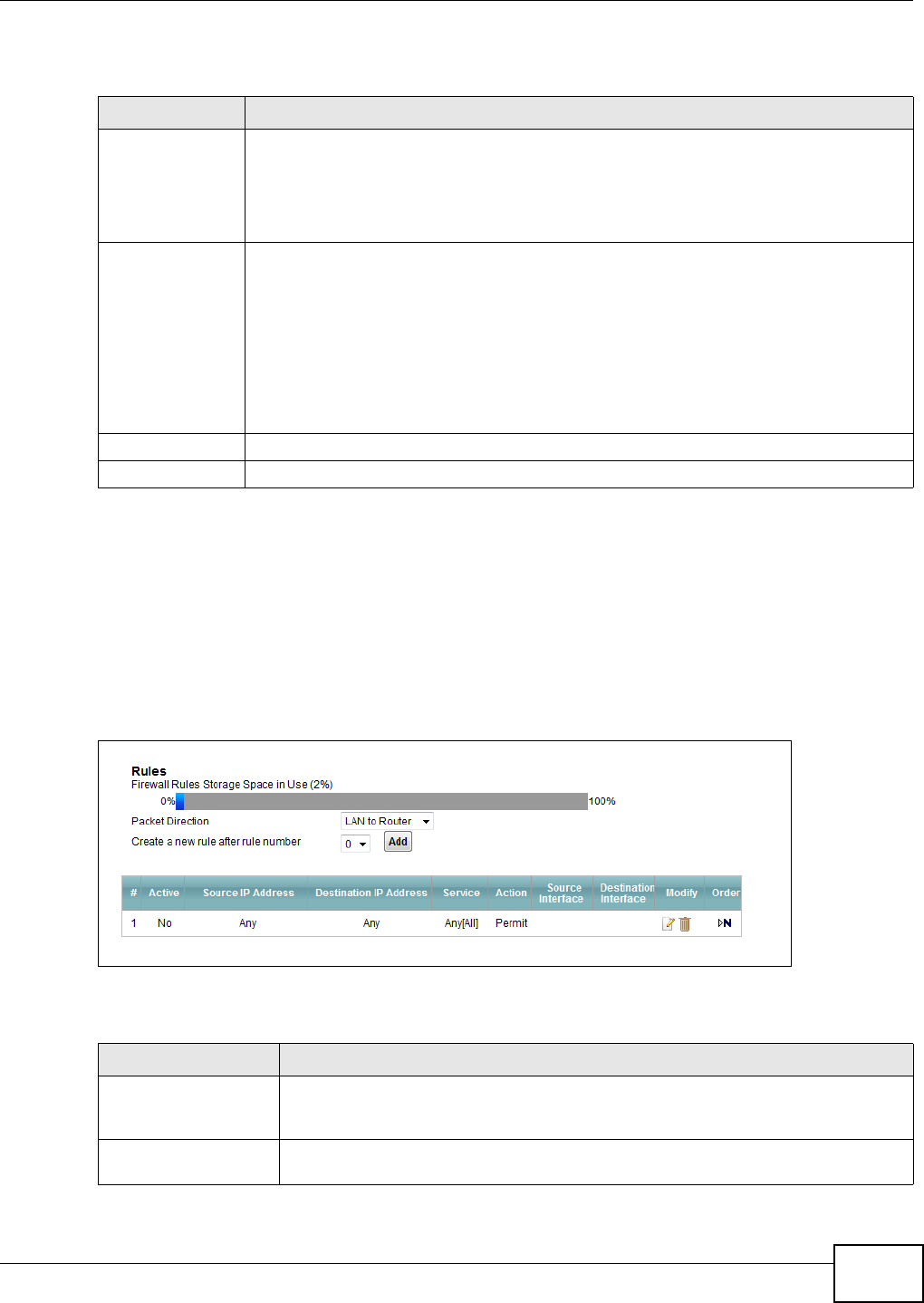
Chapter 14 Firewall
VMG1312-T10C User’s Guide 157
The following table describes the labels in this screen.
14.4 Rules Screen
Click Security > Firewall > Rules to display the following screen. This screen displays a list of the
configured firewall rules. Note the order in which the rules are listed.
Note: The ordering of your rules is very important as rules are applied in turn.
Figure 106 Security > Firewall > Rules
The following table describes the labels in this screen.
Table 61 Security > Firewall > Default Action
LABEL DESCRIPTION
Packet Direction This is the direction of travel of packets (WAN to LAN, LAN to WAN, WAN to Router,
LAN to Router).
Firewall rules are grouped based on the direction of travel of packets to which they apply.
For example, LAN to Router means packets traveling from a computer/subnet on the
LAN to the Device itself.
Default Action Use the drop-down list boxes to select the default action that the firewall is to take on
packets that are traveling in the selected direction and do not match any of the firewall
rules.
Select Drop to silently discard the packets without sending a TCP reset packet or an ICMP
destination-unreachable message to the sender.
Select Reject to deny the packets and send a TCP reset packet (for a TCP packet) or an
ICMP destination-unreachable message (for a UDP packet) to the sender.
Select Permit to allow the passage of the packets.
Apply Click this to save your changes.
Cancel Click this to restore your previously saved settings.
Table 62 Security > Firewall > Rules
LABEL DESCRIPTION
Firewall Rules Storage
Space in Use
This read-only bar shows how much of the Device's memory for recording firewall
rules it is currently using. When you are using 80% or less of the storage space, the
bar is green. When the amount of space used is over 80%, the bar is red.
Packet Direction Use the drop-down list box to select a direction of travel of packets for which you
want to configure firewall rules.

Chapter 14 Firewall
VMG1312-T10C User’s Guide
158
14.4.1 Rules Add Screen
Use this screen to configure firewall rules. In the Rules screen, select an index number and click
Add or click a rule’s Edit icon to display this screen and refer to the following table for information
on the labels.
Create a new rule
after rule number
Select an index number and click Add to add a new firewall rule after the selected
index number. For example, if you select “6”, your new rule becomes number 7 and
the previous rule 7 (if there is one) becomes rule 8.
The following read-only fields summarize the rules you have created that apply to
traffic traveling in the selected packet direction. The firewall rules that you configure
(summarized below) take priority over the general firewall action settings in the
General screen.
# This is your firewall rule number. The ordering of your rules is important as rules are
applied in turn.
Active This field displays whether a firewall is turned on or not. Select the check box to
enable the rule. Clear the check box to disable the rule.
Source IP Address This column displays the source addresses or ranges of addresses to which this
firewall rule applies. Please note that a blank source or destination address is
equivalent to Any.
Destination IP Address This column displays the destination addresses or ranges of addresses to which this
firewall rule applies. Please note that a blank source or destination address is
equivalent to Any.
Service This column displays the services to which this firewall rule applies.
Action This field displays whether the firewall silently discards packets (Drop), discards
packets and sends a TCP reset packet or an ICMP destination-unreachable message
to the sender (Reject) or allows the passage of packets (Permit).
Source Interface This column displays the source interface to which this firewall rule applies. This is
the interface through which the traffic entered the Device. Please note that a blank
source interface is equivalent to Any.
Destination Interface This column displays the destination interface to which this firewall rule applies. This
is the interface through which the traffic is destined to leave the Device. Please note
that a blank source interface is equivalent to Any.
Modify Click the Edit icon to go to the screen where you can edit the rule.
Click the Remove icon to delete an existing firewall rule. A window displays asking
you to confirm that you want to delete the firewall rule. Note that subsequent firewall
rules move up by one when you take this action.
Table 62 Security > Firewall > Rules (continued)
LABEL DESCRIPTION
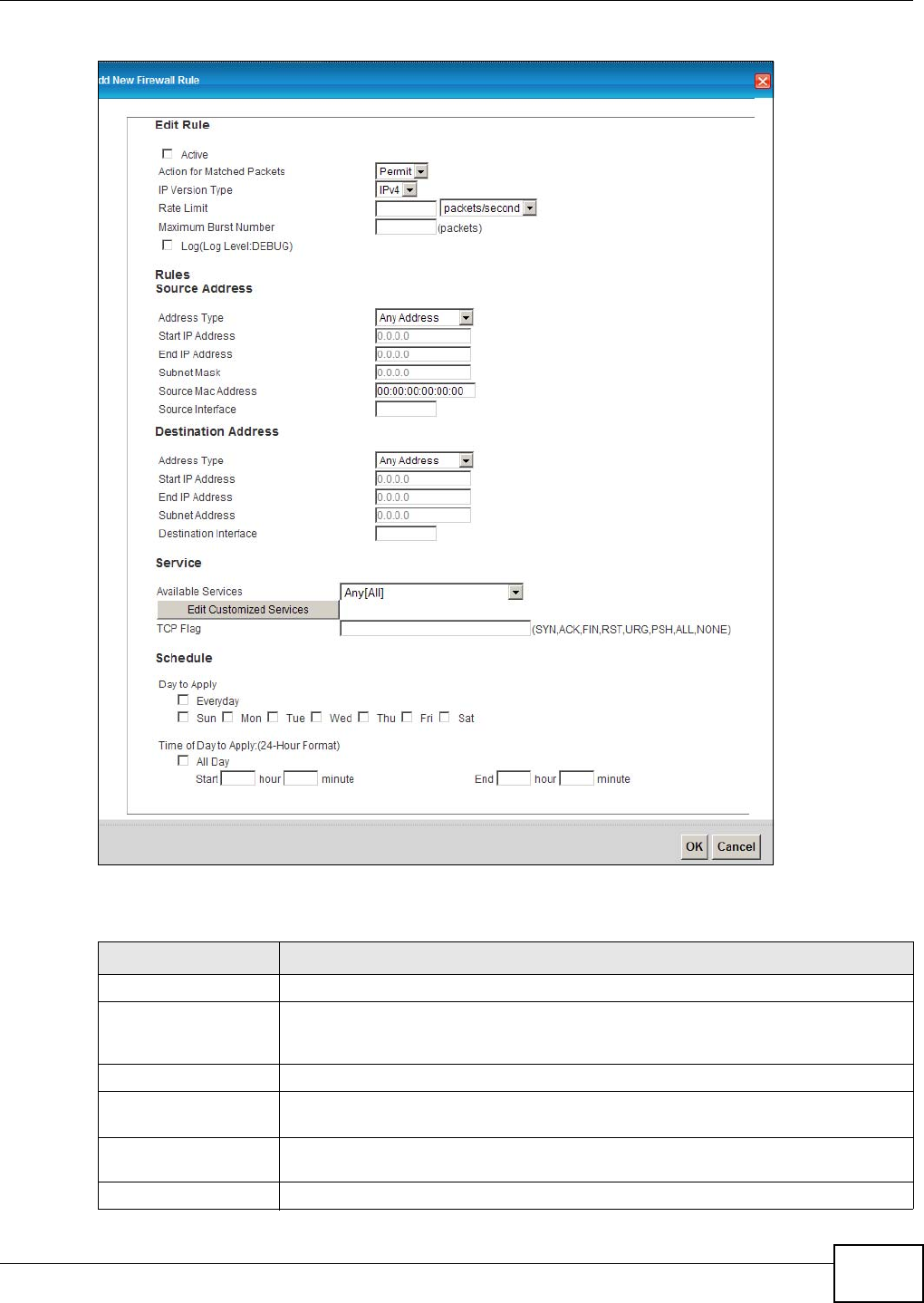
Chapter 14 Firewall
VMG1312-T10C User’s Guide 159
Figure 107 Security > Firewall > Rules > Add
The following table describes the labels in this screen.
Table 63 Security > Firewall > Rules > Add
LABEL DESCRIPTION
Active Select this option to enable this firewall rule.
Action for Matched
Packets
Use the drop-down list box to select whether to discard (Drop), deny and send an
ICMP destination-unreachable message to the sender of (Reject) or allow the
passage of (Permit) packets that match this rule.
IP Version Type Select the IP version, IPv4 or IPv6, to apply this firewall rule to.
Rate Limit Set a maximum number of packets per second, minute, or hour to limit the
throughput of traffic that matches this rule.
Maximum Burst
Number
Set the maximum number of packets that can be sent at the peak rate.
Log This field determines if a log for packets that match the rule is created or not.

Chapter 14 Firewall
VMG1312-T10C User’s Guide
160
14.4.2 Customized Services
Configure customized services and port numbers not predefined by the Device. For a
comprehensive list of port numbers and services, visit the IANA (Internet Assigned Number
Authority) website. Click the Edit Customized Services button while editing a firewall rule to
configure a custom service port. This displays the following screen.
Rules/Source Address
Address Type Do you want your rule to apply to packets with a particular (single) IP, a range of IP
addresses (for instance, 192.168.1.10 to 192.169.1.50), a subnet or any IP address?
Select an option from the drop-down list box that includes: Single Address, Range
Address, Subnet Address and Any Address.
Start IP Address Enter the single IP address or the starting IP address in a range here.
End IP Address Enter the ending IP address in a range here.
Subnet Mask Enter the subnet mask here, if applicable.
Source Mac Address Specify a source MAC address of traffic to which to apply this firewall rule applies.
Please note that a blank source MAC address is equivalent to any.
Destination Address
Address Type Do you want your rule to apply to packets with a particular (single) IP, a range of IP
addresses (for instance, 192.168.1.10 to 192.169.1.50), a subnet or any IP address?
Select an option from the drop-down list box that includes: Single Address, Range
Address, Subnet Address and Any Address.
Start IP Address Enter the single IP address or the starting IP address in a range here.
End IP Address Enter the ending IP address in a range here.
Subnet Mask Enter the subnet mask here, if applicable.
Source Interface Specify a source interface to which this firewall rule applies. This is the interface
through which the traffic entered the Device. Please note that a blank source
interface is equivalent to any.
Service
Available Services Select a service from the Available Services box.
Edit Customized
Services
Click the Edit Customized Service button to bring up the screen that you use to
configure a new custom service that is not in the predefined list of services.
TCP Flag Specify any TCP flag bits the firewall rule is to check for.
Schedule Select the days and time during which to apply the rule. Select Everyday and All
Day to always apply the rule.
OK Click this to save your changes.
Cancel Click this to exit this screen without saving.
Table 63 Security > Firewall > Rules > Add (continued)
LABEL DESCRIPTION
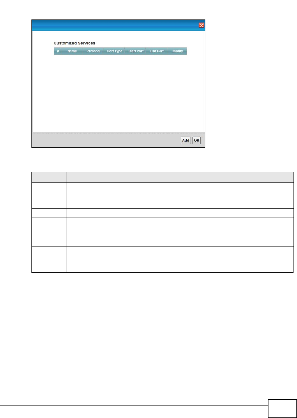
Chapter 14 Firewall
VMG1312-T10C User’s Guide 161
Figure 108 Security > Firewall > Rules: Edit: Edit Customized Services
The following table describes the labels in this screen.
14.4.3 Customized Service Add/Edit
Use this screen to add a customized rule or edit an existing rule. Click Add or the Edit icon next to
a rule number in the Firewall Customized Services screen to display the following screen.
Table 64 Security > Firewall > Rules: Edit: Edit Customized Services
LABEL DESCRIPTION
# This is the number of your customized port.
Name This is the name of your customized service.
Protocol This shows the IP protocol (TCP or UDP) that defines your customized service.
Port Type This is the port number or range that defines your customized service.
Start Port This is a single port number or the starting port number of a range that defines your
customized service.
End Port This is a single port number or the ending port number of a range that defines your customized
service.
Modify Click this to edit a customized service.
Add Click this to configure a customized service.
OK Click this to return to the Firewall Edit Rule screen.
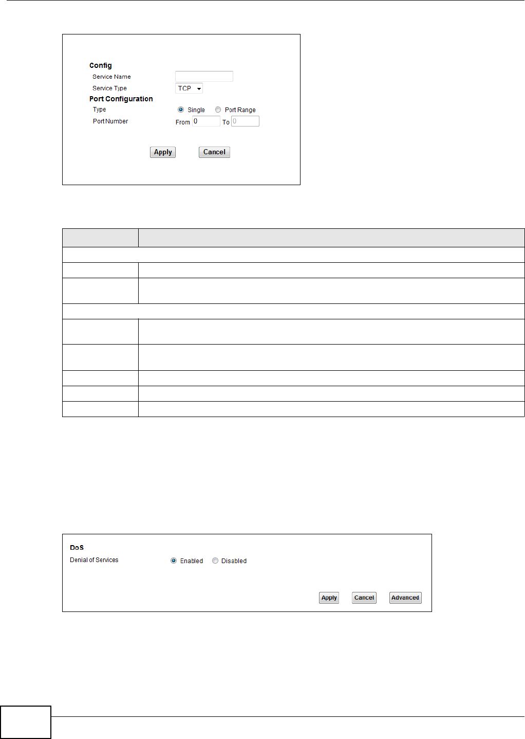
Chapter 14 Firewall
VMG1312-T10C User’s Guide
162
Figure 109 Security > Firewall > Rules: Edit: Edit Customized Services: Add/Edit
The following table describes the labels in this screen.
14.5 DoS Screen
Use this screen to enable DoS protection. Click Security > Firewall > Dos to display the following
screen.
Figure 110 Security > Firewall > Dos
Table 65 Security > Firewall > Rules: Edit: Edit Customized Services: Add/Edit
LABEL DESCRIPTION
Config
Service Name Type a unique name for your custom port.
Service Type Choose the IP port (TCP or UDP) that defines your customized port from the drop down list
box.
Port Configuration
Type Click Single to specify one port only or Port Range to specify a span of ports that define
your customized service.
Port Number Type a single port number or the range of port numbers that define your customized
service.
Back Click this to return to the previous screen without saving.
Apply Click this to save your changes.
Cancel Click this to exit this screen without saving.
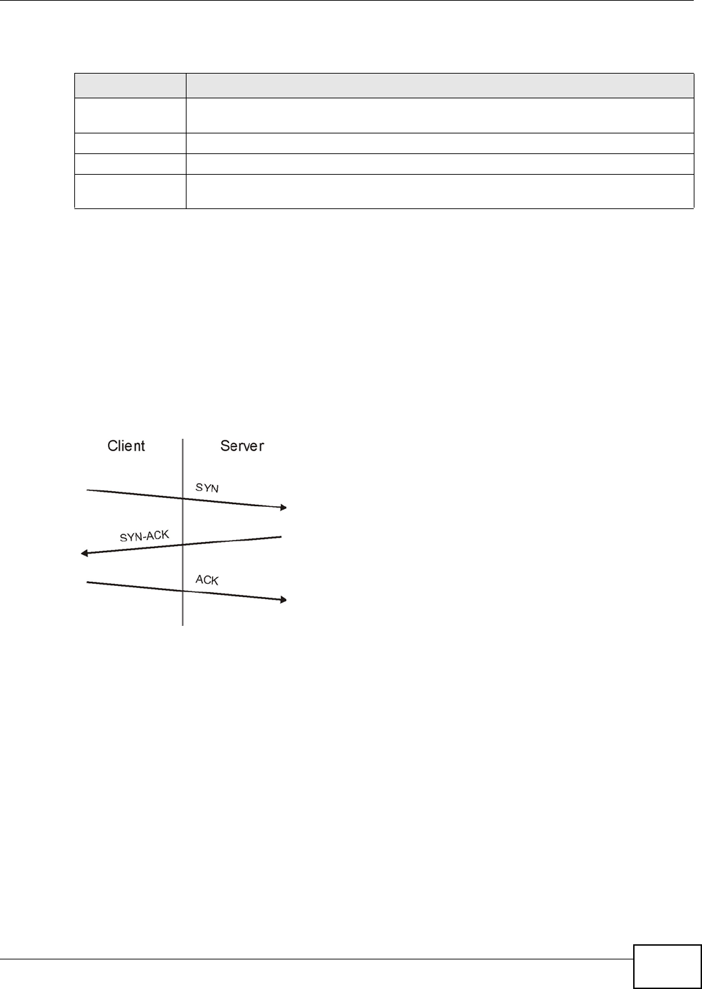
Chapter 14 Firewall
VMG1312-T10C User’s Guide 163
The following table describes the labels in this screen.
14.5.1 The DoS Advanced Screen
For DoS attacks, the Device uses thresholds to determine when to start dropping sessions that do
not become fully established (half-open sessions). These thresholds apply globally to all sessions.
For TCP, half-open means that the session has not reached the established state-the TCP three-way
handshake has not yet been completed. Under normal circumstances, the application that initiates
a session sends a SYN (synchronize) packet to the receiving server. The receiver sends back an ACK
(acknowledgment) packet and its own SYN, and then the initiator responds with an ACK
(acknowledgment). After this handshake, a connection is established.
Figure 111 Three-Way Handshake
For UDP, half-open means that the firewall has detected no return traffic. An unusually high number
(or arrival rate) of half-open sessions could indicate a DOS attack.
14.5.1.1 Threshold Values
If everything is working properly, you probably do not need to change the threshold settings as the
default threshold values should work for most small offices. Tune these parameters when you
believe the Device has been receiving DoS attacks that are not recorded in the logs or the logs
show that the Device is classifying normal traffic as DoS attacks. Factors influencing choices for
threshold values are:
1The maximum number of opened sessions.
2The minimum capacity of server backlog in your LAN network.
3The CPU power of servers in your LAN network.
Table 66 Security > Firewall > Dos
LABEL DESCRIPTION
Denial of Services Enable this to protect against DoS attacks. The Device will drop sessions that surpass
maximum thresholds.
Apply Click this to save your changes.
Cancel Click this to restore your previously saved settings.
Advanced Click this to go to a screen to specify maximum thresholds at which the Device will start
dropping sessions.
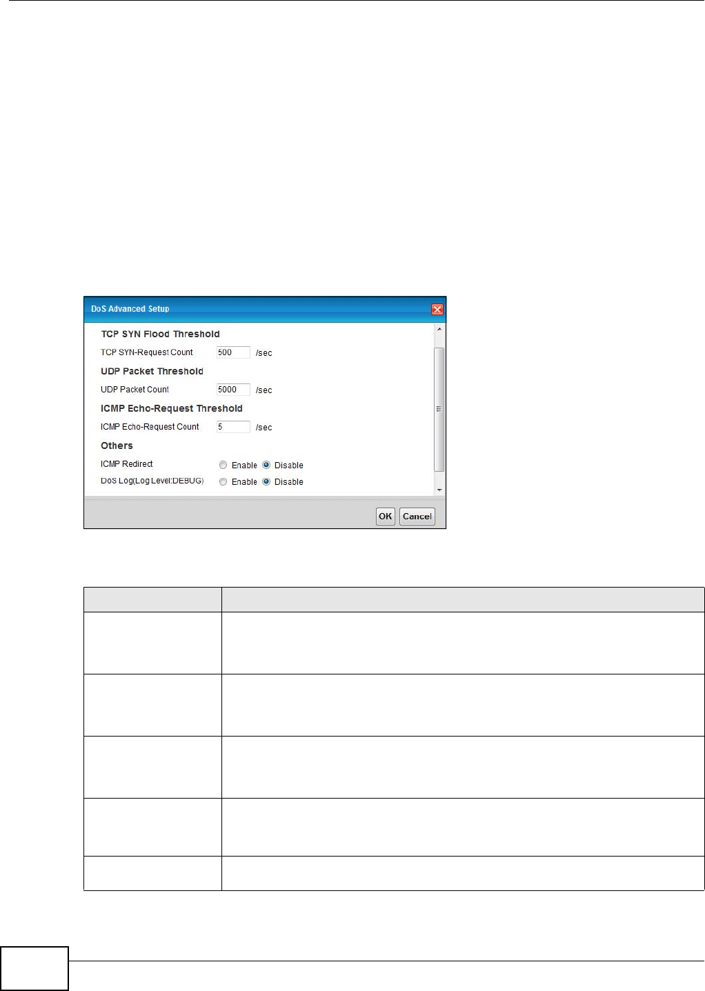
Chapter 14 Firewall
VMG1312-T10C User’s Guide
164
4Network bandwidth.
5Type of traffic for certain servers.
Reduce the threshold values if your network is slower than average for any of these factors
(especially if you have servers that are slow or handle many tasks and are often busy).
• If you often use P2P applications such as file sharing with eMule or eDonkey, it’s recommended
that you increase the threshold values since lots of sessions will be established during a small
period of time and the Device may classify them as DoS attacks.
14.5.2 Configuring Firewall Thresholds
Click Security > Firewall > DoS > Advanced to display the following screen.
Figure 112 Security > Firewall > DoS > Advanced
The following table describes the labels in this screen.
Table 67 Security > Firewall > DoS > Advanced
LABEL DESCRIPTION
TCP SYN-Request
Count
This is the rate of new TCP half-open sessions per second that causes the firewall to
start deleting half-open sessions. When the rate of new connection attempts rises
above this number, the Device deletes half-open sessions as required to
accommodate new connection attempts.
UDP Packet Count This is the rate of new UDP half-open sessions per second that causes the firewall to
start deleting half-open sessions. When the rate of new connection attempts rises
above this number, the Device deletes half-open sessions as required to
accommodate new connection attempts.
ICMP Echo-Request
Count
This is the rate of new ICMP Echo-Request half-open sessions per second that causes
the firewall to start deleting half-open sessions. When the rate of new connection
attempts rises above this number, the Device deletes half-open sessions as required
to accommodate new connection attempts.
ICMP Redirect Select Enable to monitor for and block ICMP redirect attacks.
An ICMP redirect attack is one where forged ICMP redirect messages can force the
client device to route packets for certain connections through an attacker’s host.
DoS Log(Log Level:
DEBUG)
Select Enable to log DoS attacks. See Section 17.2 on page 182 for information on
viewing logs.

Chapter 14 Firewall
VMG1312-T10C User’s Guide 165
14.6 Firewall Technical Reference
This section provides some technical background information about the topics covered in this
chapter.
14.6.1 Firewall Rules Overview
Your customized rules take precedence and override the Device’s default settings. The Device
checks the source IP address, destination IP address and IP protocol type of network traffic against
the firewall rules (in the order you list them). When the traffic matches a rule, the Device takes the
action specified in the rule.
Firewall rules are grouped based on the direction of travel of packets to which they apply:
Note: The LAN includes both the LAN port and the WLAN.
By default, the Device’s stateful packet inspection allows packets traveling in the following
directions:
•LAN to Router
These rules specify which computers on the LAN can manage the Device (remote management).
Note: You can also configure the remote management settings to allow only a specific
computer to manage the Device.
•LAN to WAN
These rules specify which computers on the LAN can access which computers or services on the
WAN.
By default, the Device’s stateful packet inspection drops packets traveling in the following
directions:
•WAN to LAN
These rules specify which computers on the WAN can access which computers or services on the
LAN.
Note: You also need to configure NAT port forwarding (or full featured NAT address
mapping rules) to allow computers on the WAN to access devices on the LAN.
OK Click this to save your changes.
Cancel Click this to exit this screen without saving.
Table 67 Security > Firewall > DoS > Advanced (continued)
LABEL DESCRIPTION
•LAN to Router •WAN to LAN
• LAN to WAN • WAN to Router

Chapter 14 Firewall
VMG1312-T10C User’s Guide
166
•WAN to Router
By default the Device stops computers on the WAN from managing the Device. You could
configure one of these rules to allow a WAN computer to manage the Device.
Note: You also need to configure the remote management settings to allow a WAN
computer to manage the Device.
You may define additional rules and sets or modify existing ones but please exercise extreme
caution in doing so.
For example, you may create rules to:
• Block certain types of traffic, such as IRC (Internet Relay Chat), from the LAN to the Internet.
• Allow certain types of traffic, such as Lotus Notes database synchronization, from specific hosts
on the Internet to specific hosts on the LAN.
• Allow everyone except your competitors to access a web server.
• Restrict use of certain protocols, such as Telnet, to authorized users on the LAN.
These custom rules work by comparing the source IP address, destination IP address and IP
protocol type of network traffic to rules set by the administrator. Your customized rules take
precedence and override the Device’s default rules.
14.6.2 Guidelines For Enhancing Security With Your Firewall
1Change the default password via web configurator.
2Think about access control before you connect to the network in any way.
3Limit who can access your router.
4Don't enable any local service (such as telnet or FTP) that you don't use. Any enabled service could
present a potential security risk. A determined hacker might be able to find creative ways to misuse
the enabled services to access the firewall or the network.
5For local services that are enabled, protect against misuse. Protect by configuring the services to
communicate only with specific peers, and protect by configuring rules to block packets for the
services at specific interfaces.
6Protect against IP spoofing by making sure the firewall is active.
7Keep the firewall in a secured (locked) room.
14.6.3 Security Considerations
Note: Incorrectly configuring the firewall may block valid access or introduce security
risks to the Device and your protected network. Use caution when creating or
deleting firewall rules and test your rules after you configure them.
Consider these security ramifications before creating a rule:
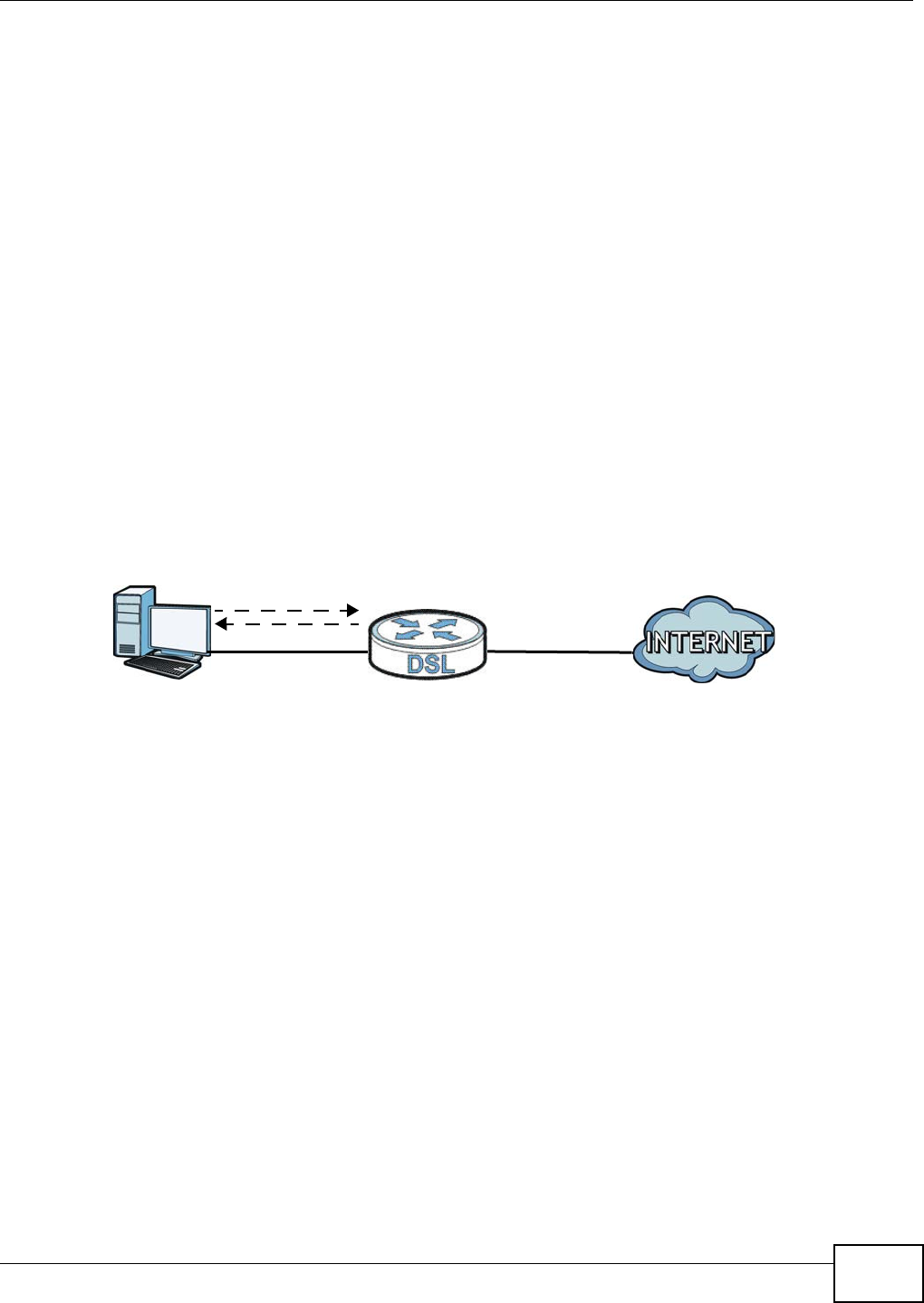
Chapter 14 Firewall
VMG1312-T10C User’s Guide 167
1Does this rule stop LAN users from accessing critical resources on the Internet? For example, if IRC
is blocked, are there users that require this service?
2Is it possible to modify the rule to be more specific? For example, if IRC is blocked for all users, will
a rule that blocks just certain users be more effective?
3Does a rule that allows Internet users access to resources on the LAN create a security
vulnerability? For example, if FTP ports (TCP 20, 21) are allowed from the Internet to the LAN,
Internet users may be able to connect to computers with running FTP servers.
4Does this rule conflict with any existing rules?
Once these questions have been answered, adding rules is simply a matter of entering the
information into the correct fields in the web configurator screens.
14.6.4 Triangle Route
When the firewall is on, your Device acts as a secure gateway between your LAN and the Internet.
In an ideal network topology, all incoming and outgoing network traffic passes through the Device
to protect your LAN against attacks.
Figure 113 Ideal Firewall Setup
14.6.4.1 The “Triangle Route” Problem
A traffic route is a path for sending or receiving data packets between two Ethernet devices. You
may have more than one connection to the Internet (through one or more ISPs). If an alternate
gateway is on the LAN (and its IP address is in the same subnet as the Device’s LAN IP address),
the “triangle route” (also called asymmetrical route) problem may occur. The steps below describe
the “triangle route” problem.
1A computer on the LAN initiates a connection by sending out a SYN packet to a receiving server on
the WAN.
2The Device reroutes the SYN packet through Gateway A on the LAN to the WAN.
3The reply from the WAN goes directly to the computer on the LAN without going through the
Device.
As a result, the Device resets the connection, as the connection has not been acknowledged.
1
2
WAN
LAN
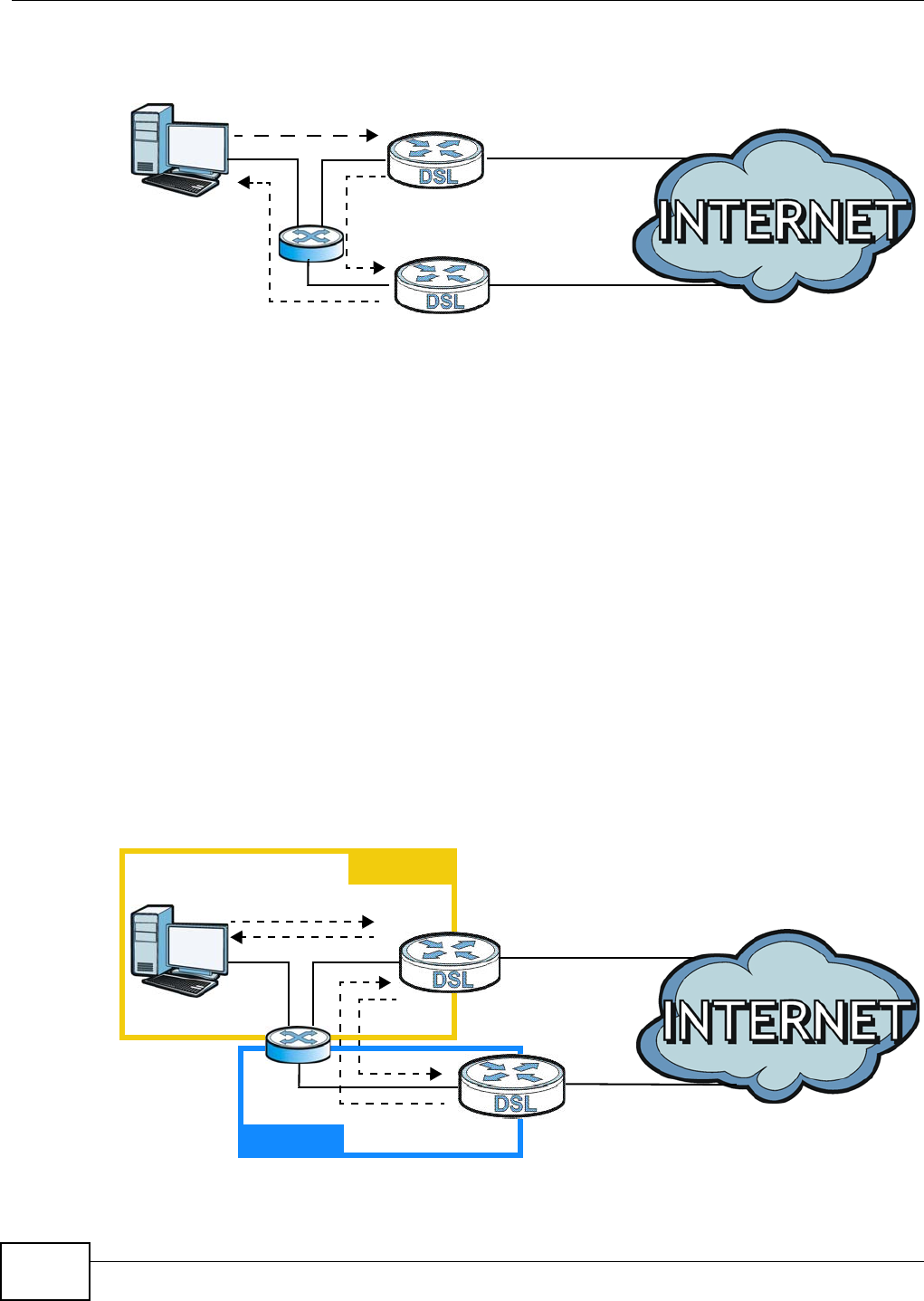
Chapter 14 Firewall
VMG1312-T10C User’s Guide
168
Figure 114 “Triangle Route” Problem
14.6.4.2 Solving the “Triangle Route” Problem
If you have the Device allow triangle route sessions, traffic from the WAN can go directly to a LAN
computer without passing through the Device and its firewall protection.
Another solution is to use IP alias. IP alias allows you to partition your network into logical sections
over the same Ethernet interface. Your Device supports up to three logical LAN interfaces with the
Device being the gateway for each logical network.
It’s like having multiple LAN networks that actually use the same physical cables and ports. By
putting your LAN and Gateway A in different subnets, all returning network traffic must pass
through the Device to your LAN. The following steps describe such a scenario.
1A computer on the LAN initiates a connection by sending a SYN packet to a receiving server on the
WAN.
2The Device reroutes the packet to Gateway A, which is in Subnet 2.
3The reply from the WAN goes to the Device.
4The Device then sends it to the computer on the LAN in Subnet 1.
Figure 115 IP Alias
1
2
3
WAN
LAN
A
ISP 1
ISP 2
1
2
3
LAN
A
ISP 1
ISP 2
4
WAN
Subnet 1
Subnet 2
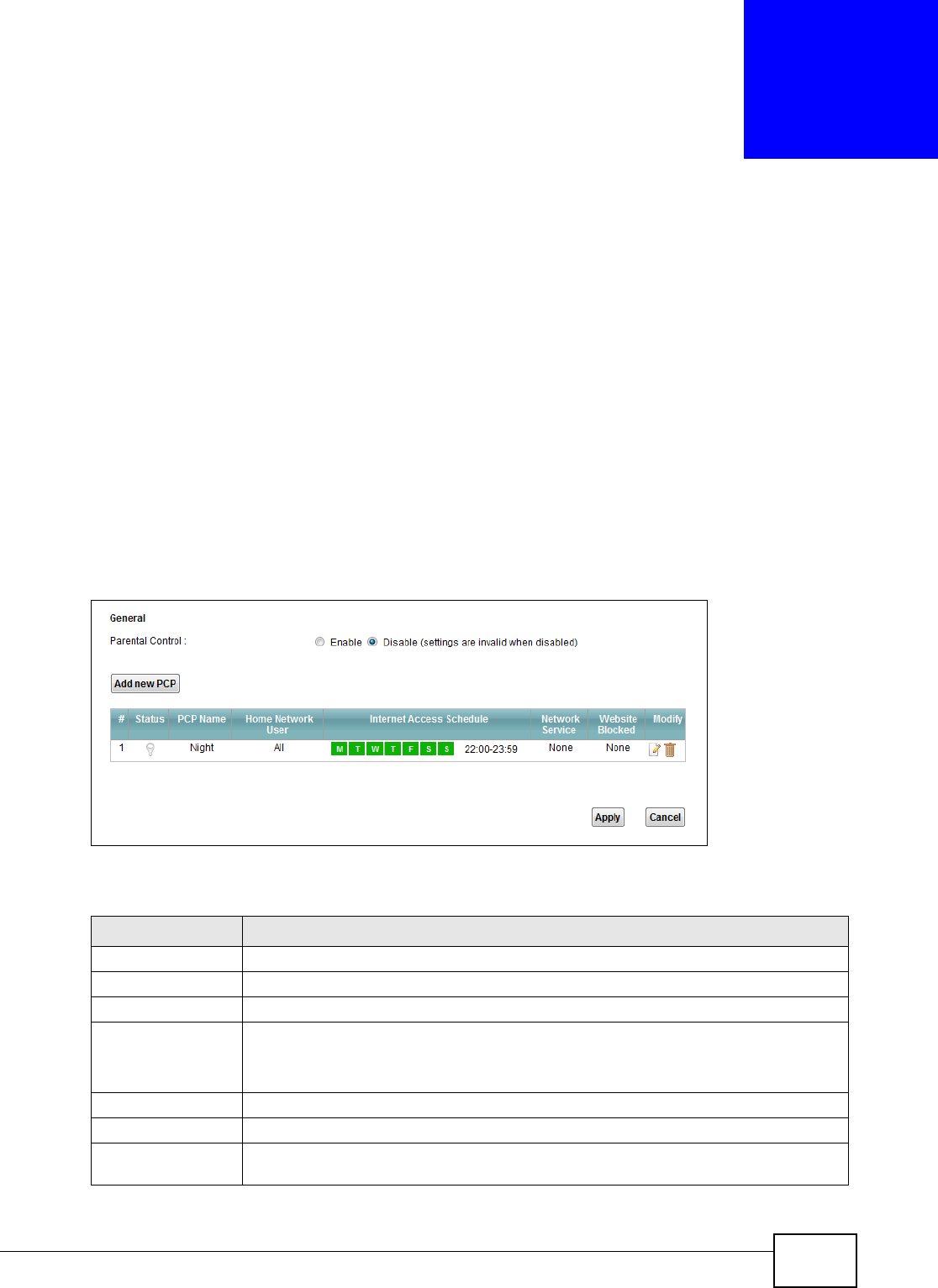
VMG1312-T10C User’s Guide 169
CHAPTER 15
Parental Control
15.1 Overview
Parental control allows you to block web sites with the specific URL. You can also define time
periods and days during which the Device performs parental control on a specific user.
15.2 The Parental Control Screen
Use this screen to enable parental control, view the parental control rules and schedules.
Click Security > Parental Control to open the following screen.
Figure 116 Security > Parental Control
The following table describes the fields in this screen.
Table 68 Parental Control > Parental Control
LABEL DESCRIPTION
Parental Control Select Enable to activate parental control.
Add new PCP Click this if you want to configure a new parental control rule.
#This shows the index number of the rule.
Status This indicates whether the rule is active or not.
A yellow bulb signifies that this rule is active. A gray bulb signifies that this rule is not
active.
PCP Name This shows the name of the rule.
Home Network User This shows the MAC address of the LAN user’s computer to which this rule applies.
Internet Access
Schedule
This shows the days and time on which parental control is enabled.

Chapter 15 Parental Control
VMG1312-T10C User’s Guide
170
15.2.1 Add/Edit a Parental Control Rule
Click Add new PCP in the Parental Control screen to add a new rule or click the Edit icon next to
an existing rule to edit it. Use this screen to configure a restricted access schedule and/or URL
filtering settings to block the users on your network from accessing certain web sites.
Figure 117 Add/Edit Parental Control Rule
Network Service This shows whether the network service is configured. If not, None will be shown.
Website Blocked This shows whether the website block is configured. If not, None will be shown.
Modify Click the Edit icon to go to the screen where you can edit the rule.
Click the Delete icon to delete an existing rule.
Add Click Add to create a new schedule.
Apply Click Apply to save your changes back to the Device.
Cancel Click Cancel to return your last saved settings.
Table 68 Parental Control > Parental Control (continued)
LABEL DESCRIPTION

Chapter 15 Parental Control
VMG1312-T10C User’s Guide 171
The following table describes the fields in this screen.
Table 69 Add/Edit Parental Control Rule
LABEL DESCRIPTION
General
Active Select the checkbox to activate this parental control rule.
Parental Control
Profile Name
Enter a descriptive name for the rule.
Home Network User Select the LAN user that you want to apply this rule to from the drop-down list box. If
you select Custom, enter the LAN user’s MAC address. If you select All, the rule
applies to all LAN users.
Internet Access Schedule
Day Select check boxes for the days that you want the Device to perform parental control.
Time of Day to Apply: (24-Hour Format)
Start Time
End Time
Enter the time period of each day, in 24-hour format, during which parental control
will be enforced.
Time Drag the time bar to define the time that the LAN user is allowed access.
Network Service
Network Service
Setting
If you select Block, the Device prohibits the users from viewing the Web sites with
the URLs listed below.
If you select Access, the Device blocks access to all URLs except ones listed below.
Add new service Click this to show a screen in which you can add a new service rule. You can configure
the Service Name, Protocol, and Name of the new rule.
Active Select the check box next to the service to apply this rule to the service. Clear the
check box to not apply this rule to it.
Service Name Select a service.
Protocol For services that support multiple protocols, select the protocol.
Port Specify the port number from 1 to 65535.
Modify Click the Edit icon to go to the screen where you can edit the rule.
Click the Delete icon to delete an existing rule.
Blocked Site/URL Specify web sites or URLs to which the Device blocks access.
Apply Click this button to save your settings back to the Device.
Cancel Click this to exit this screen without saving.

Chapter 15 Parental Control
VMG1312-T10C User’s Guide
172

VMG1312-T10C User’s Guide 173
CHAPTER 16
Certificates
16.1 Overview
The Device can use certificates (also called digital IDs) to authenticate users. Certificates are based
on public-private key pairs. A certificate contains the certificate owner’s identity and public key.
Certificates provide a way to exchange public keys for use in authentication.
16.1.1 What You Can Do in this Chapter
•Use the Local Certificates screen to view and import the Device’s CA-signed certificates
(Section 16.2 on page 175).
•Use the Trusted CA screen to save the certificates of trusted CAs to the Device. You can also
export the certificates to a computer (Section 16.3 on page 177).
16.1.2 What You Need to Know
The following terms and concepts may help as you read this chapter.
Certification Authorities
A Certification Authority (CA) issues certificates and guarantees the identity of each certificate
owner. There are commercial certification authorities like CyberTrust or VeriSign and government
certification authorities.
Public and Private Keys
When using public-key cryptology for authentication, each host has two keys. One key is public and
can be made openly available; the other key is private and must be kept secure. Public-key
encryption in general works as follows.
1Tim wants to send a private message to Jenny. Tim generates a public-private key pair. What is
encrypted with one key can only be decrypted using the other.
2Tim keeps the private key and makes the public key openly available.
3Tim uses his private key to encrypt the message and sends it to Jenny.
4Jenny receives the message and uses Tim’s public key to decrypt it.
5Additionally, Jenny uses her own private key to encrypt a message and Tim uses Jenny’s public key
to decrypt the message.

Chapter 16 Certificates
VMG1312-T10C User’s Guide
174
The Device uses certificates based on public-key cryptology to authenticate users attempting to
establish a connection. The method used to secure the data that you send through an established
connection depends on the type of connection. For example, a VPN tunnel might use the triple DES
encryption algorithm.
The certification authority uses its private key to sign certificates. Anyone can then use the
certification authority’s public key to verify the certificates.
Certification Path
A certification path is the hierarchy of certification authority certificates that validate a certificate.
The Device does not trust a certificate if any certificate on its path has expired or been revoked.
Certificate Directory Servers
Certification authorities maintain directory servers with databases of valid and revoked certificates.
A directory of certificates that have been revoked before the scheduled expiration is called a CRL
(Certificate Revocation List). The Device can check a peer’s certificate against a directory server’s
list of revoked certificates. The framework of servers, software, procedures and policies that
handles keys is called PKI (public-key infrastructure).
Advantages of Certificates
Certificates offer the following benefits.
• The Device only has to store the certificates of the certification authorities that you decide to
trust, no matter how many devices you need to authenticate.
• Key distribution is simple and very secure since you can freely distribute public keys and you
never need to transmit private keys.
Certificate File Format
The certification authority certificate that you want to import has to be in PEM (Base-64) encoded
X.509 file format. This Privacy Enhanced Mail format uses 64 ASCII characters to convert a binary
X.509 certificate into a printable form.
16.1.3 Verifying a Certificate
Before you import a trusted CA or trusted remote host certificate into the Device, you should verify
that you have the actual certificate. This is especially true of trusted CA certificates since the Device
also trusts any valid certificate signed by any of the imported trusted CA certificates.
You can use a certificate’s fingerprint to verify it. A certificate’s fingerprint is a message digest
calculated using the MD5 or SHA1 algorithms. The following procedure describes how to check a
certificate’s fingerprint to verify that you have the actual certificate.
1Browse to where you have the certificate saved on your computer.
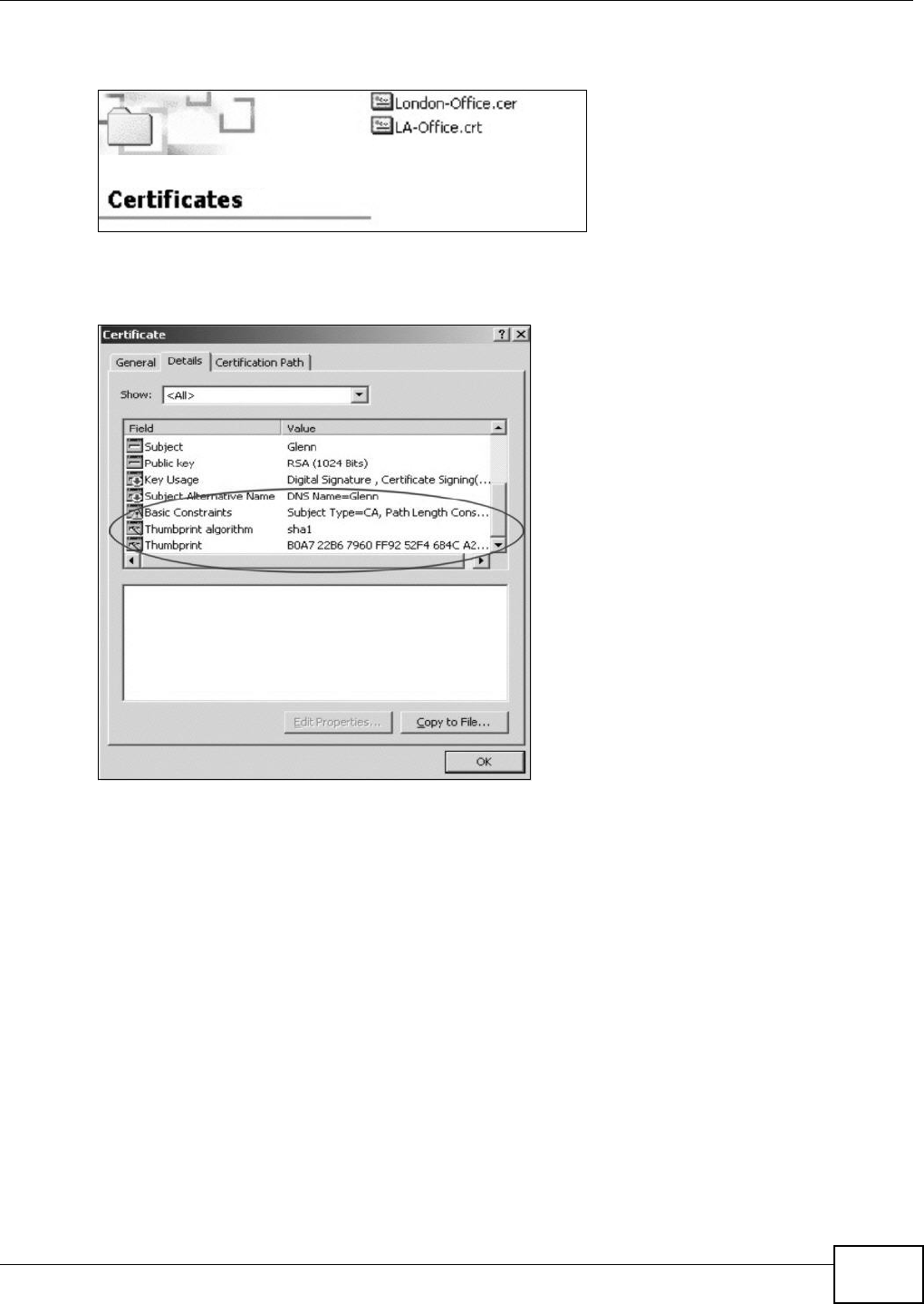
Chapter 16 Certificates
VMG1312-T10C User’s Guide 175
2Make sure that the certificate has a “.cer” or “.crt” file name extension.
Figure 118 Certificates on Your Computer
3Double-click the certificate’s icon to open the Certificate window. Click the Details tab and scroll
down to the Thumbprint Algorithm and Thumbprint fields.
Figure 119 Certificate Details
4Use a secure method to verify that the certificate owner has the same information in the
Thumbprint Algorithm and Thumbprint fields. The secure method may very based on your
situation. Possible examples would be over the telephone or through an HTTPS connection.
16.2 Local Certificates
Use this screen to view the Device’s summary list of certificates and certification requests. You can
import the following certificates to your Device:
• Web Server - This certificate secures HTTP connections.
• SIP TLS - This certificate secures VoIP connections.
• SSH/SCP/SFTP - This certificate secures remote connections.
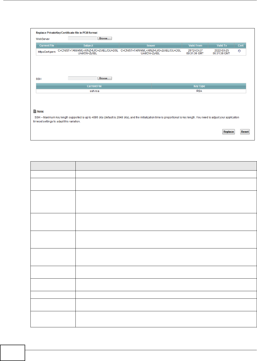
Chapter 16 Certificates
VMG1312-T10C User’s Guide
176
Click Security > Certificates to open the Local Certificates screen.
Figure 120 Security > Certificates > Local Certificates
The following table describes the labels in this screen.
Table 70 Security > Certificates > Local Certificates
LABEL DESCRIPTION
WebServer Click Browse... to find the certificate file you want to upload.
Current File This field displays the name used to identify this certificate. It is recommended that you
give each certificate a unique name.
Subject This field displays identifying information about the certificate’s owner, such as CN
(Common Name), OU (Organizational Unit or department), O (Organization or
company) and C (Country). It is recommended that each certificate have unique
subject information.
Issuer This field displays identifying information about the certificate’s issuing certification
authority, such as a common name, organizational unit or department, organization or
company and country.
Valid From This field displays the date that the certificate becomes applicable. The text displays in
red and includes a Not Yet Valid! message if the certificate has not yet become
applicable.
Valid To This field displays the date that the certificate expires. The text displays in red and
includes an Expiring! or Expired! message if the certificate is about to expire or has
already expired.
Cert Click this button and then Save in the File Download screen. The Save As screen
opens, browse to the location that you want to use and click Save.
SSH/SCP/SFTP Type in the location of the SSH /SCP/SFTP certificate file you want to upload in this
field or click Browse to find it.
Choose file Click this link to find the certificate file you want to upload.
Current File This field displays the name used to identify this certificate. It is recommended that you
give each certificate a unique name.
Key Type This field applies to the SSH/SCP/SFTP certificate.
This shows the file format of the current certificate.
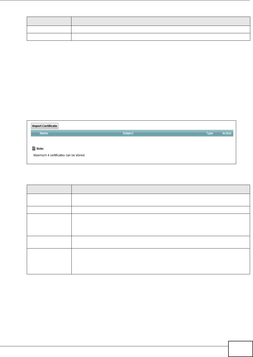
Chapter 16 Certificates
VMG1312-T10C User’s Guide 177
16.3 Trusted CA
Use this screen to view a summary list of certificates of the certification authorities that you have
set the Device to accept as trusted. The Device accepts any valid certificate signed by a certification
authority on this list as being trustworthy; thus you do not need to import any certificate that is
signed by one of these certification authorities.
Click Security > Certificates > Trusted CA to open the Trusted CA screen.
Figure 121 Security > Certificates > Trusted CA
The following table describes the labels in this screen.
16.4 Trusted CA Import
Click Import Certificate in the Trusted CA screen to open the Import Certificate screen. You
can save a trusted certification authority’s certificate to the Device.
Replace Click this to replace the certificates and save your changes back to the Device.
Reset Click this to clear your settings.
Table 70 Security > Certificates > Local Certificates (continued)
LABEL DESCRIPTION
Table 71 Security > Certificates > Trusted CA
LABEL DESCRIPTION
Import Certificate Click this button to open a screen where you can save the certificate of a certification
authority that you trust to the Device.
Name This field displays the name used to identify this certificate.
Subject This field displays information that identifies the owner of the certificate, such as
Common Name (CN), OU (Organizational Unit or department), Organization (O), State
(ST) and Country (C). It is recommended that each certificate have unique subject
information.
Type This field displays general information about the certificate. ca means that a
Certification Authority signed the certificate.
Action Click the View icon to open a screen with an in-depth list of information about the
certificate (or certification request).
Click the Delete icon to delete the certificate (or certification request). You cannot
delete a certificate that one or more features is configured to use.
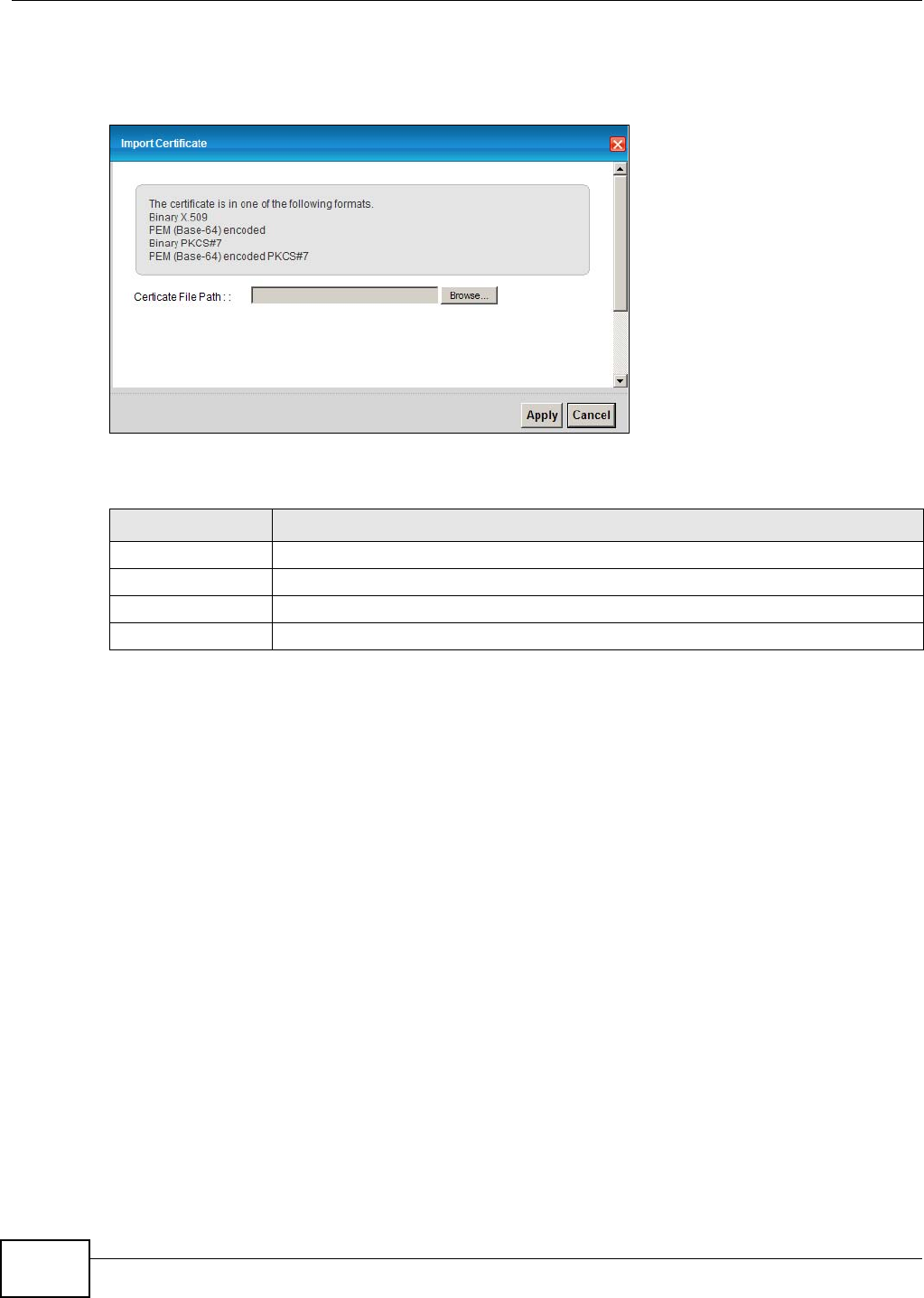
Chapter 16 Certificates
VMG1312-T10C User’s Guide
178
Note: You must remove any spaces from the certificate’s filename before you can import
the certificate.
Figure 122 Trusted CA > Import
The following table describes the labels in this screen.
16.5 View Certificate
Use this screen to view in-depth information about the certification authority’s certificate, change
the certificate’s name and set whether or not you want the Device to check a certification
authority’s list of revoked certificates before trusting a certificate issued by the certification
authority.
Table 72 Security > Certificates > Trusted CA > Import
LABEL DESCRIPTION
Certificate File Path Type in the location of the file you want to upload in this field or click Browse to find it.
Browse Click Browse to find the certificate file you want to upload.
Apply Click this to save the certificate on the Device.
Cancel Click this to exit this screen without saving.
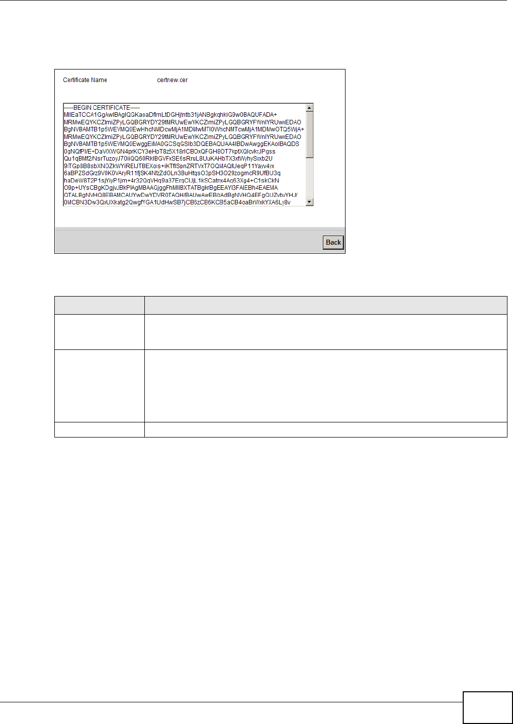
Chapter 16 Certificates
VMG1312-T10C User’s Guide 179
Click Security > Certificates > Trusted CA to open the Trusted CA screen. Click the View icon
to open the View Certificate screen.
Figure 123 Trusted CA: View
The following table describes the labels in this screen.
Table 73 Trusted CA: View
LABEL DESCRIPTION
Certificate Name This field displays the identifying name of this certificate. If you want to change the
name, type up to 31 characters to identify this key certificate. You may use any
character (not including spaces).
Certificate Detail This read-only text box displays the certificate or certification request in Privacy
Enhanced Mail (PEM) format. PEM uses 64 ASCII characters to convert the binary
certificate into a printable form.
You can copy and paste the certificate into an e-mail to send to friends or colleagues or
you can copy and paste the certificate into a text editor and save the file on a
management computer for later distribution (via floppy disk for example).
Back Click this to return to the previous screen.

Chapter 16 Certificates
VMG1312-T10C User’s Guide
180

VMG1312-T10C User’s Guide 181
CHAPTER 17
System Monitor
17.1 Overview
Use the Traffic Status screens to view status and log information.
17.1.1 What You Can Do in this Chapter
•Use the Log screen to see the system logs for the categories that you select (Section 17.2 on
page 182).
•Use the WAN Traffic Status screen to view the WAN traffic statistics (Section 17.3 on page
183).
•Use the LAN Traffic Status screen to view the LAN traffic statistics (Section 17.4 on page 184).
•Use the NAT Traffic Status screen to view the NAT status of the Device’s clients (Section 17.5
on page 185).
17.1.2 What You Need To Know
The following terms and concepts may help as you read this chapter.
Alerts and Logs
An alert is a type of log that warrants more serious attention. They include system errors, attacks
(access control) and attempted access to blocked web sites. Some categories such as System
Errors consist of both logs and alerts. You may differentiate them by their color in the View Log
screen. Alerts display in red and logs display in black.
Syslog Overview
The syslog protocol allows devices to send event notification messages across an IP network to
syslog servers that collect the event messages. A syslog-enabled device can generate a syslog
message and send it to a syslog server.
Syslog is defined in RFC 3164. The RFC defines the packet format, content and system log related
information of syslog messages. Each syslog message has a facility and severity level. The syslog
facility identifies a file in the syslog server. Refer to the documentation of your syslog program for
details. The following table describes the syslog severity levels.
Table 74 Syslog Severity Levels
CODE SEVERITY
0 Emergency: The system is unusable.
1 Alert: Action must be taken immediately.
2 Critical: The system condition is critical.
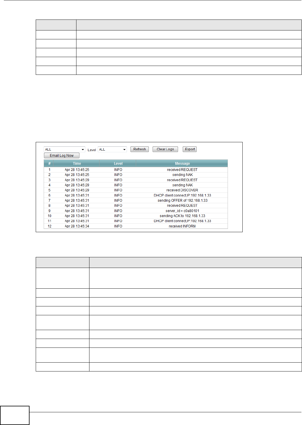
Chapter 17 System Monitor
VMG1312-T10C User’s Guide
182
17.2 The Log Screen
Click System Monitor > Log to open the Log screen. Use the Log screen to see the system logs
for the categories that you select in the upper left drop-down list box.
Figure 124 System Monitor > Log
The following table describes the fields in this screen.
3 Error: There is an error condition on the system.
4 Warning: There is a warning condition on the system.
5 Notice: There is a normal but significant condition on the system.
6 Informational: The syslog contains an informational message.
7 Debug: The message is intended for debug-level purposes.
Table 74 Syslog Severity Levels (continued)
CODE SEVERITY
Table 75 System Monitor > Log
LABEL DESCRIPTION
Level Select a severity level from the drop-down list box. This filters search results according
to the severity level you have selected. When you select a severity, the Device searches
through all logs of that severity or higher.
Refresh Click this to renew the log screen.
Clear Logs Click this to delete all the logs.
Export Click this to save a copy of the logs to your computer.
Email Log Now Click this to have the Device send the log to the email server you configured in the Log
Setting screen.
#This field is a sequential value and is not associated with a specific entry.
Time This field displays the time the log was recorded.
Level This field displays the severity level of the logs that the device is to send to this syslog
server.
Messages This field states the reason for the log.
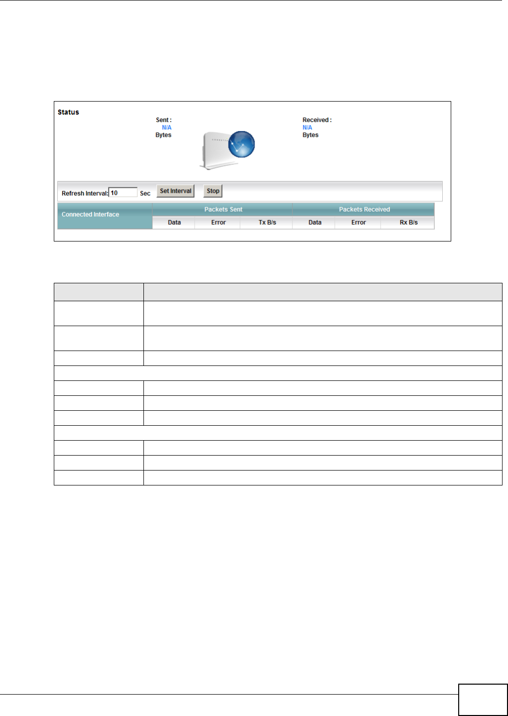
Chapter 17 System Monitor
VMG1312-T10C User’s Guide 183
17.3 The WAN Traffic Status Screen
Click System Monitor > Traffic Status to open the WAN Traffic Status screen. You can view
the WAN traffic statistics in this screen.
Figure 125 System Monitor > Traffic Status > WAN
The following table describes the fields in this screen.
Table 76 System Monitor > Traffic Status > WAN
LABEL DESCRIPTION
Status This shows the number of bytes sent and received through the WAN interface of the
Device.
Refresh Interval Specify how often you want the Device to update this screen and click Set Interval to
apply the change. Click Stop to halt updating of the screen.
Connected Interface This shows the name of the WAN interface that is currently connected.
Packets Sent
Data This indicates the number of transmitted packets on this interface.
Error This indicates the number of frames with errors transmitted on this interface.
Drop This indicates the number of outgoing packets dropped on this interface.
Packets Received
Data This indicates the number of received packets on this interface.
Error This indicates the number of frames with errors received on this interface.
Drop This indicates the number of received packets dropped on this interface.
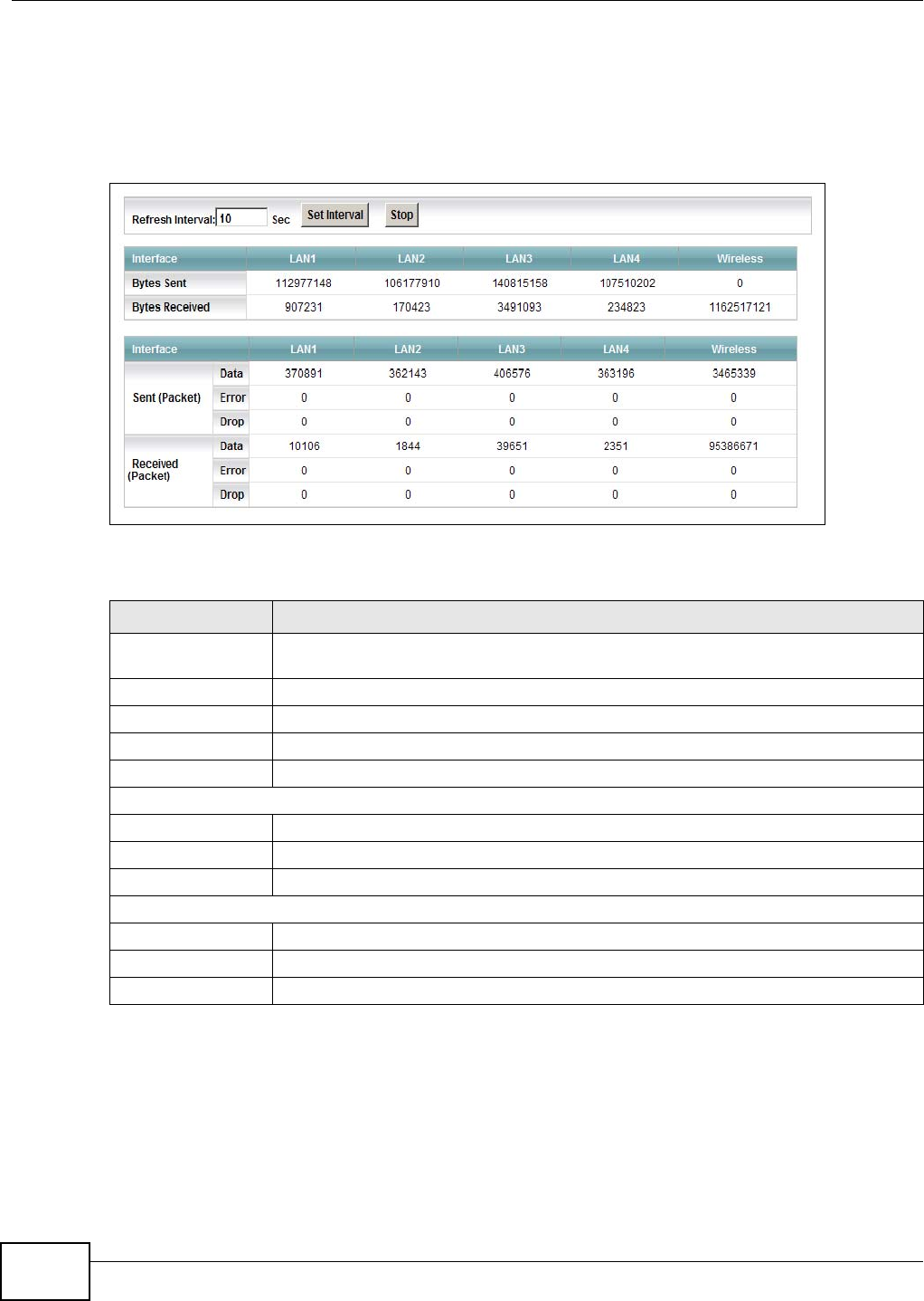
Chapter 17 System Monitor
VMG1312-T10C User’s Guide
184
17.4 The LAN Traffic Status Screen
Click System Monitor > Traffic Status > LAN to open the following screen. You can view the LAN
traffic statistics in this screen.
Figure 126 System Monitor > Traffic Status > LAN
The following table describes the fields in this screen.
Table 77 System Monitor > Traffic Status > LAN
LABEL DESCRIPTION
Refresh Interval Specify how often you want the Device to update this screen and click Set Interval to
apply the change. Click Stop to halt updating of the screen.
Interface This shows the LAN or WLAN interface.
Bytes Sent This indicates the number of bytes transmitted on this interface.
Bytes Received This indicates the number of bytes received on this interface.
Interface This shows the LAN or WLAN interface.
Sent (Packet)
Data This indicates the number of transmitted packets on this interface.
Error This indicates the number of frames with errors transmitted on this interface.
Drop This indicates the number of outgoing packets dropped on this interface.
Received (Packet)
Data This indicates the number of received packets on this interface.
Error This indicates the number of frames with errors received on this interface.
Drop This indicates the number of received packets dropped on this interface.
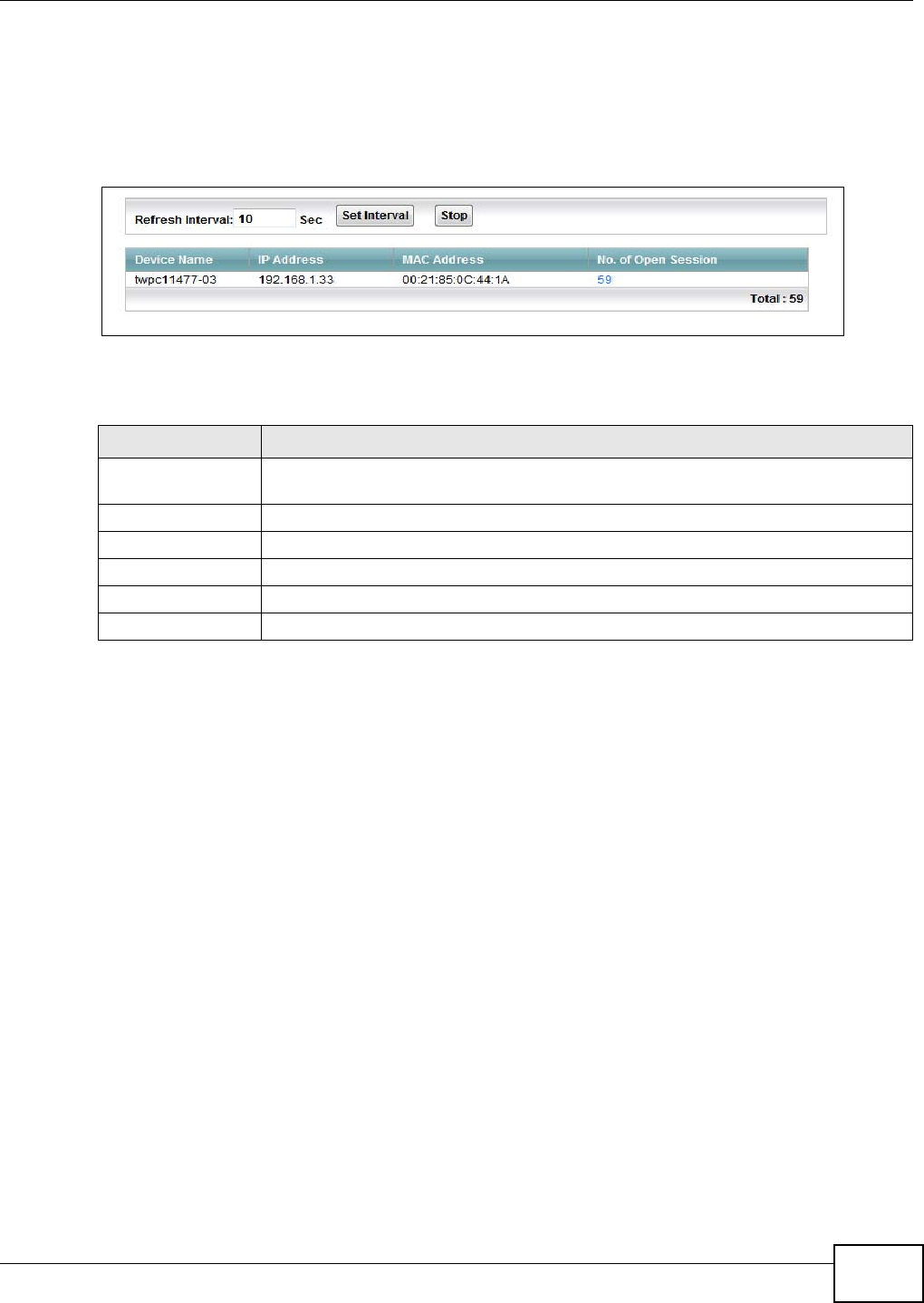
Chapter 17 System Monitor
VMG1312-T10C User’s Guide 185
17.5 The NAT Traffic Status Screen
Click System Monitor > Traffic Status > NAT to open the following screen. You can view the NAT
status of the Device’s clients in this screen.
Figure 127 System Monitor > Traffic Status > NAT
The following table describes the fields in this screen.
Table 78 System Monitor > Traffic Status > NAT
LABEL DESCRIPTION
Refresh Interval Specify how often you want the Device to update this screen and click Set Interval to
apply the change. Click Stop to halt updating of the screen.
Device Name This shows the name of the client.
IP Address This shows the IP address of the client.
MAC Address This shows the MAC address of the client.
No. of Open Session This shows the number of NAT sessions used by the client.
Total This shows the total number of NAT sessions currently open on the Device.

Chapter 17 System Monitor
VMG1312-T10C User’s Guide
186
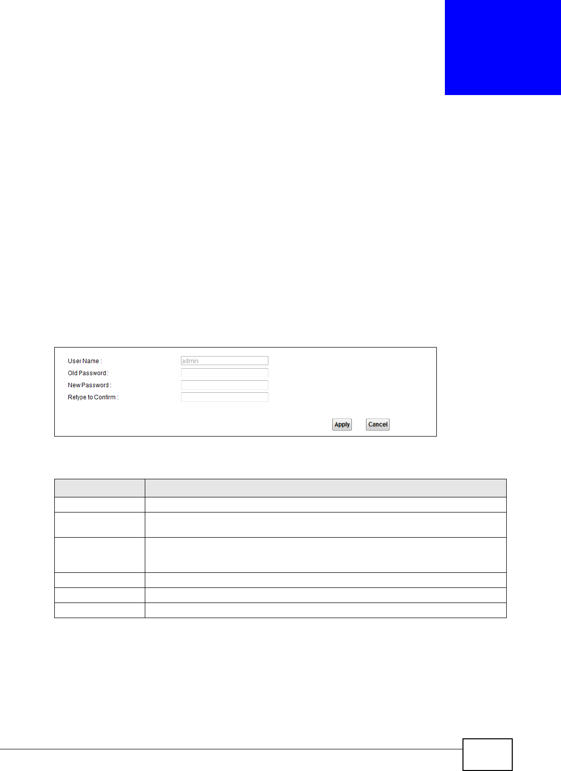
VMG1312-T10C User’s Guide 187
CHAPTER 18
User Account
18.1 Overview
You can configure the system password in the User Account screen.
18.2 The User Account Screen
Use the User Account screen to configure system password.
Click Maintenance > User Account to open the following screen.
Figure 128 Maintenance > User Account
The following table describes the labels in this screen.
Table 79 Maintenance > User Account
LABEL DESCRIPTION
User Name You can configure the password for the admin account.
Old Password Type the default password or the existing password you use to access the system in
this field.
New Password Type your new system password (up to 30 characters). Note that as you type a
password, the screen displays a (*) for each character you type. After you change the
password, use the new password to access the Device.
Retype to Confirm Type the new password again for confirmation.
Apply Click Apply to save your changes.
Cancel Click Cancel to restore your previously saved settings.

Chapter 18 User Account
VMG1312-T10C User’s Guide
188
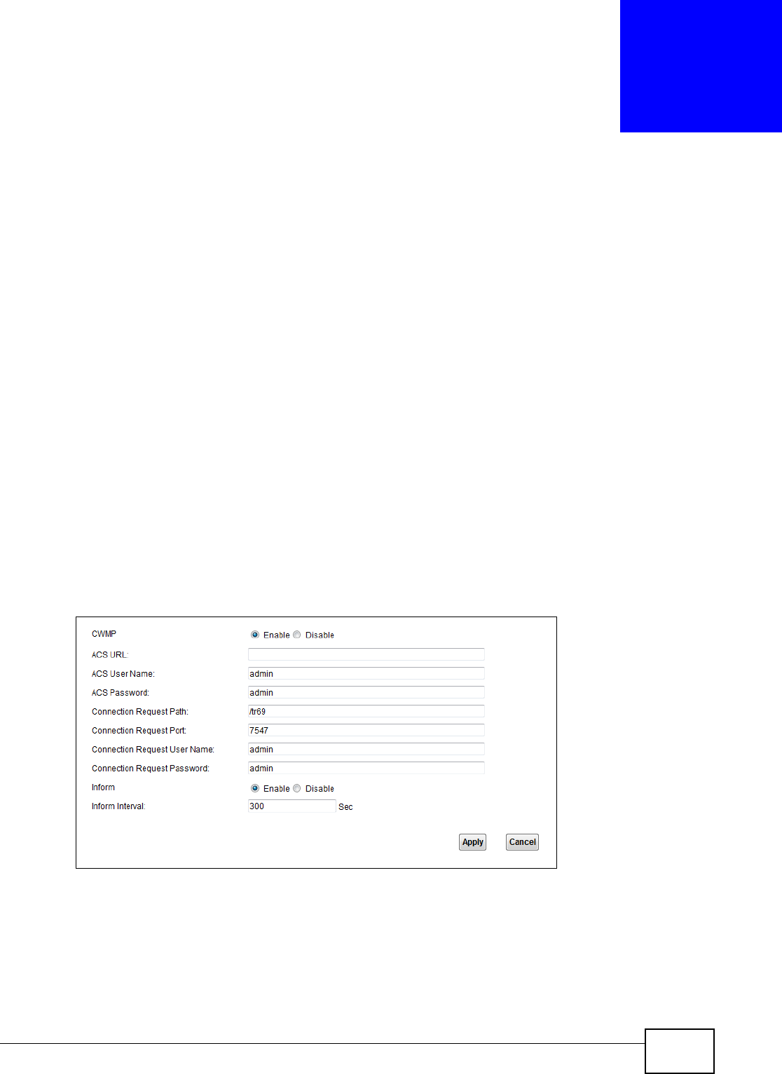
VMG1312-T10C User’s Guide 189
CHAPTER 19
TR-069 Client
19.1 Overview
This chapter explains how to configure the Device’s TR-069 auto-configuration settings.
19.2 The TR-069 Client Screen
TR-069 defines how Customer Premise Equipment (CPE), for example your Device, can be managed
over the WAN by an Auto Configuration Server (ACS). TR-069 is based on sending Remote
Procedure Calls (RPCs) between an ACS and a client device. RPCs are sent in Extensible Markup
Language (XML) format over HTTP or HTTPS.
An administrator can use an ACS to remotely set up the Device, modify settings, perform firmware
upgrades as well as monitor and diagnose the Device. You have to enable the device to be managed
by the ACS and specify the ACS IP address or domain name and username and password.
Click Maintenance > TR-069 Client to open the following screen. Use this screen to configure
your Device to be managed by an ACS.
Figure 129 Maintenance > TR-069 Client

Chapter 19 TR-069 Client
VMG1312-T10C User’s Guide
190
The following table describes the fields in this screen.
Table 80 Maintenance > TR-069 Client
LABEL DESCRIPTION
CWMP Select Enable to allow the Device to be managed by a management server. Otherwise,
select Disable to not allow the Device to be managed by a management server.
ACS URL Enter the URL or IP address of the auto-configuration server.
ACS User Name Enter the TR-069 user name for authentication with the auto-configuration server.
ACS Password Enter the TR-069 password for authentication with the auto-configuration server.
Connection
Request Path
Type the IP address or domain name of the Device. The management server uses this path
to verify the Device.
Connection
Request Port
The default port for access to the Device from the management server is the HTTP port, port
80. If you change it, make sure it does not conflict with another port on your network and it
is recommended to use a port number above 1024 (not a commonly used port). The
management server should use this port to connect to the Device. You may need to alter
your NAT port forwarding rules if they were already configured.
Connection
Request User
Name
Enter the connection request user name.
When the ACS makes a connection request to the Device, this user name is used to
authenticate the ACS.
Connection
Request
Password
Enter the connection request password.
When the ACS makes a connection request to the Device, this password is used to
authenticate the ACS.
Inform Select Enable for the Device to send periodic inform via TR-069 on the WAN. Otherwise,
select Disable.
Inform Interval Enter the time interval (in seconds) at which the Device sends information to the auto-
configuration server.
Apply Click Apply to save your changes.
Cancel Click Cancel to restore the screen’s last saved settings.

VMG1312-T10C User’s Guide 191
CHAPTER 20
System
20.1 Overview
You can configure system settings, including the host name, domain name and the inactivity time-
out interval in the System screen.
20.2 The System Screen
Use the System screen to configure the system’s inactivity time-out interval.
Click Maintenance > System to open the following screen.
Figure 130 Maintenance > System
The following table describes the labels in this screen.
Table 81 Maintenance > System
LABEL DESCRIPTION
Administrator
Inactivity Timer
Type how many minutes a management session (either via the web configurator) can
be left idle before the session times out. The default is 5 minutes. After it times out you
have to log in with your password again. Very long idle timeouts may have security
risks. A value of "0" means a management session never times out, no matter how long
it has been left idle (not recommended).
Apply Click this to save your changes back to the Device.
Cancel Click this to begin configuring this screen afresh.

Chapter 20 System
VMG1312-T10C User’s Guide
192
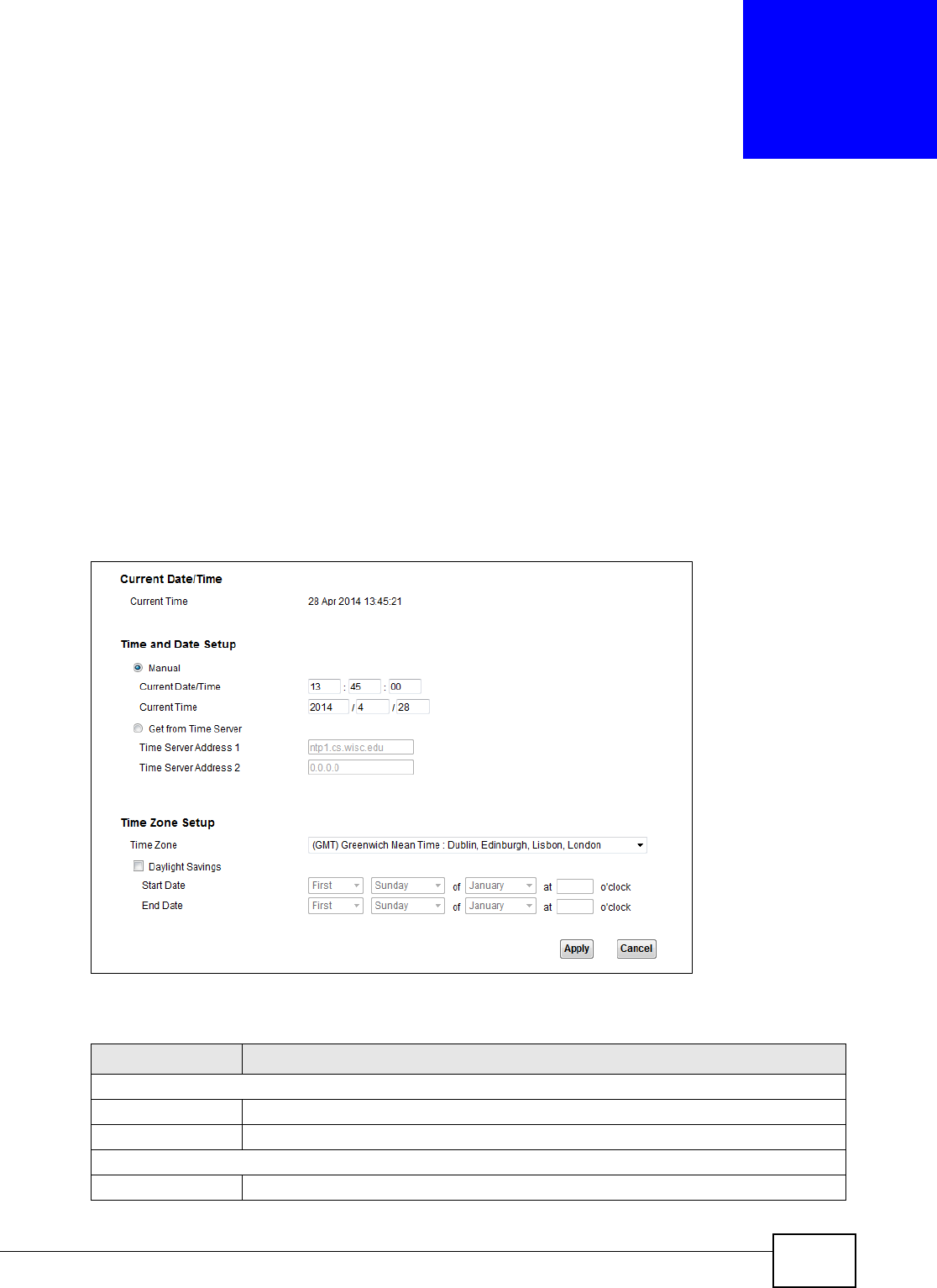
VMG1312-T10C User’s Guide 193
CHAPTER 21
Time Setting
21.1 Overview
You can configure the system’s time and date in the Time Setting screen.
21.2 The Time Setting Screen
To change your Device’s time and date, click Maintenance > Time. The screen appears as shown.
Use this screen to configure the Device’s time based on your local time zone.
Figure 131 Maintenance > Time Setting
The following table describes the fields in this screen.
Table 82 Maintenance > System > Time Setting
LABEL DESCRIPTION
Current Date/Time
Current Time This field displays the time of your Device.
Current Date This field displays the date of your Device.
Time and Date Setup
Manual Select this to enter the time and date manually in hh:mm:ss and yyyy/mm/dd format.

Chapter 21 Time Setting
VMG1312-T10C User’s Guide
194
Get from Time
Server
Select this to have the Device get the time automatically from a time server.
Time Server
Address 1, 2
Enter the IP address or URL (up to 31 extended ASCII characters in length) of your
time server. Check with your ISP/network administrator if you are unsure of this
information.
Time Zone Choose the time zone of your location. This will set the time difference between your
time zone and Greenwich Mean Time (GMT).
Daylight Savings Daylight saving is a period from late spring to early fall when many countries set their
clocks ahead of normal local time by one hour to give more daytime light in the
evening. Select this option if you use Daylight Saving Time.
Start Date Configure the day and time when Daylight Saving Time starts if you selected Daylight
Savings. The o'clock field uses the 24 hour format. Here are a couple of examples:
Daylight Saving Time starts in most parts of the United States on the second Sunday of
March. Each time zone in the United States starts using Daylight Saving Time at 2 A.M.
local time. So in the United States you would select Second, Sunday, March and type
2 in the o'clock field.
Daylight Saving Time starts in the European Union on the last Sunday of March. All of
the time zones in the European Union start using Daylight Saving Time at the same
moment (1 A.M. GMT or UTC). So in the European Union you would select Last,
Sunday, March. The time you type in the o'clock field depends on your time zone. In
Germany for instance, you would type 2 because Germany's time zone is one hour
ahead of GMT or UTC (GMT+1).
End Date Configure the day and time when Daylight Saving Time ends if you selected Daylight
Savings. The o'clock field uses the 24 hour format. Here are a couple of examples:
Daylight Saving Time ends in the United States on the first Sunday of November. Each
time zone in the United States stops using Daylight Saving Time at 2 A.M. local time.
So in the United States you would select First, Sunday, November and type 2 in the
o'clock field.
Daylight Saving Time ends in the European Union on the last Sunday of October. All of
the time zones in the European Union stop using Daylight Saving Time at the same
moment (1 A.M. GMT or UTC). So in the European Union you would select Last,
Sunday, October. The time you type in the o'clock field depends on your time zone.
In Germany for instance, you would type 2 because Germany's time zone is one hour
ahead of GMT or UTC (GMT+1).
Apply Click Apply to save your changes.
Cancel Click Cancel to restore the screen’s last saved settings.
Table 82 Maintenance > System > Time Setting (continued)
LABEL DESCRIPTION

VMG1312-T10C User’s Guide 195
CHAPTER 22
Log Setting
22.1 Overview
You can configure where the Device sends logs and which logs and/or immediate alerts the Device
records in the Log Setting screen.
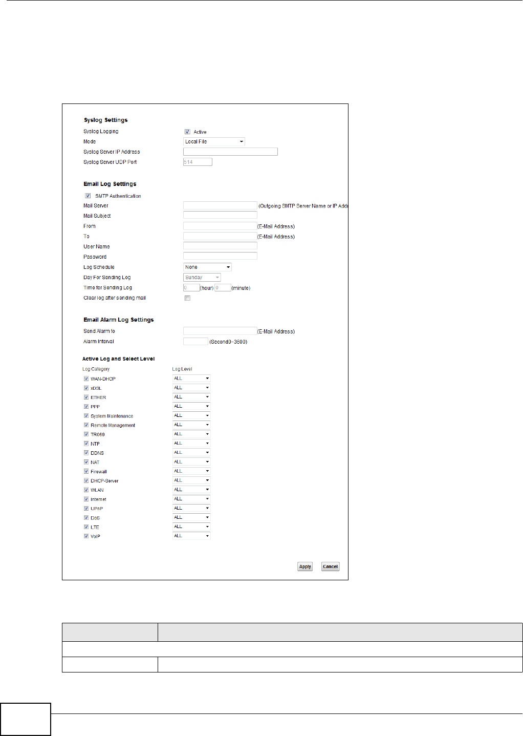
Chapter 22 Log Setting
VMG1312-T10C User’s Guide
196
22.2 The Log Setting Screen
To change your Device’s log settings, click Maintenance > Log Setting. The screen appears as
shown.
Figure 132 Maintenance > Log Setting
The following table describes the fields in this screen.
Table 83 Maintenance > Log Setting
LABEL DESCRIPTION
Syslog Setting
Syslog Logging Select the Active check box to enable syslog logging.

Chapter 22 Log Setting
VMG1312-T10C User’s Guide 197
Mode Select Local File to have the Device save the log file locally.
Select Local File and Remote to have the Device save the log file locally and send it
to an external syslog server.
Syslog Server IP
Address
Enter the server name or IP address of the syslog server that will log the selected
categories of logs.
Syslog Server UDP
Port
Enter the port number used by the syslog server.
E-mail Log Settings
SMTP Authentication SMTP (Simple Mail Transfer Protocol) is the message-exchange standard for the
Internet. SMTP enables you to move messages from one E-mail server to another.
Select the check box to activate SMTP authentication. If mail server authentication is
needed but this feature is disabled, you will not receive the E-mail logs.
Mail Server Enter the server name or the IP address of the mail server for the e-mail addresses
specified below. If this field is left blank, logs and alert messages will not be sent via
E-mail.
Mail Subject Type a title that you want to be in the subject line of the system log e-mail message
that the Device sends.
From Specify where the logs are sent from.
To The Device sends logs to the e-mail address specified in this field. If this field is left
blank, the Device does not send logs via E-mail.
User Name Enter the user name (up to 32 characters) (usually the user name of a mail account).
Password Enter the password associated with the user name above.
Log Schedule Specify the schedule for sending log. Specify days and times for sending logs in the
following fields.
Day For Sending Log Specify the day for sending log.
Time for Sending Log Specify the time for sending log.
Clear log after
sending mail
Select this to delete all the logs after the Device sends an E-mail of the logs.
E-mail Alarm Log Settings
Send Alarm to Alerts are real-time notifications that are sent as soon as an event, such as a DoS
attack, system error, or forbidden web access attempt occurs. Enter the E-mail
address where the alert messages will be sent. Alerts include system errors, attacks
and attempted access to blocked web sites. If this field is left blank, alert messages
will not be sent via E-mail.
Alarm Interval Specify the number of seconds between the sending of alarm log e-mails.
Active Log and Select Level
Log Category Select the categories of logs that you want to record.
Log Level Select the severity level of logs that you want to record. If you want to record all logs,
select ALL.
Apply Click Apply to save your changes.
Cancel Click Cancel to restore your previously saved settings.
Table 83 Maintenance > Log Setting (continued)
LABEL DESCRIPTION

Chapter 22 Log Setting
VMG1312-T10C User’s Guide
198
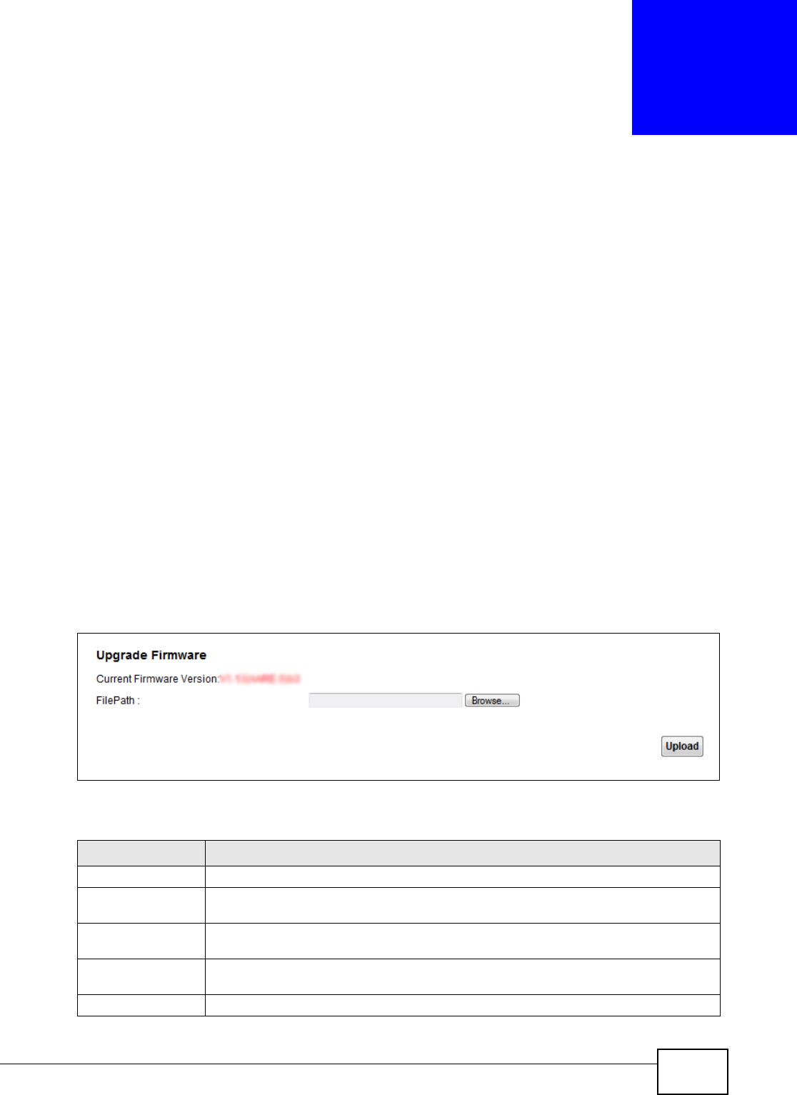
VMG1312-T10C User’s Guide 199
CHAPTER 23
Firmware Upgrade
23.1 Overview
This chapter explains how to upload new firmware to your Device. You can download new firmware
releases from your nearest ZyXEL FTP site (or www.zyxel.com) to use to upgrade your device’s
performance.
Only use firmware for your device’s specific model. Refer to the label on
the bottom of your Device.
23.2 The Firmware Upgrade Screen
Click Maintenance > Firmware Upgrade to open the following screen. The upload process uses
HTTP (Hypertext Transfer Protocol) and may take up to three minutes. After a successful upload,
the system will reboot.
Do NOT turn off the Device while firmware upload is in progress!
Figure 133 Maintenance > Firmware Upgrade
The following table describes the labels in this screen.
Table 84 Maintenance > Firmware Upgrade
LABEL DESCRIPTION
Upgrade Firmware Use these fields to upload firmware to the Device.
Current Firmware
Version
This is the present firmware version.
File Path Type in the location of the file you want to upload in this field or click Browse ... to find
it.
Browse... Click this to find the .bin file you want to upload. Remember that you must decompress
compressed (.zip) files before you can upload them.
Upload Click this to begin the upload process. This process may take up to three minutes.
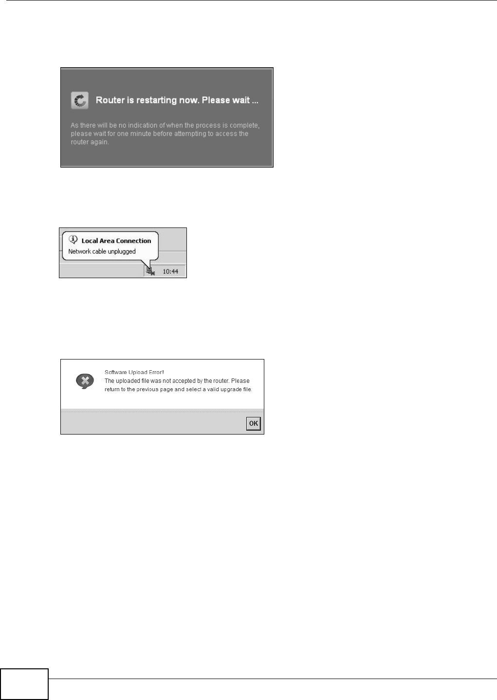
Chapter 23 Firmware Upgrade
VMG1312-T10C User’s Guide
200
After you see the firmware updating screen, wait a few minutes before logging into the Device
again.
Figure 134 Firmware Uploading
The Device automatically restarts in this time causing a temporary network disconnect. In some
operating systems, you may see the following icon on your desktop.
Figure 135 Network Temporarily Disconnected
After two minutes, log in again and check your new firmware version in the Status screen.
If the upload was not successful, an error screen will appear. Click OK to go back to the Firmware
Upgrade screen.
Figure 136 Error Message

VMG1312-T10C User’s Guide 201
CHAPTER 24
Backup/Restore
24.1 Overview
The Backup/Restore screen allows you to backup and restore device configurations. You can also
reset your device settings back to the factory default.
24.2 The Backup/Restore Screen
Click Maintenance > Backup/Restore. Information related to factory defaults, backup
configuration, and restoring configuration appears in this screen, as shown next.
Figure 137 Maintenance > Backup/Restore
Backup Configuration
Backup Configuration allows you to back up (save) the Device’s current configuration to a file on
your computer. Once your Device is configured and functioning properly, it is highly recommended
that you back up your configuration file before making configuration changes. The backup
configuration file will be useful in case you need to return to your previous settings.
Click Backup to save the Device’s current configuration to your computer.
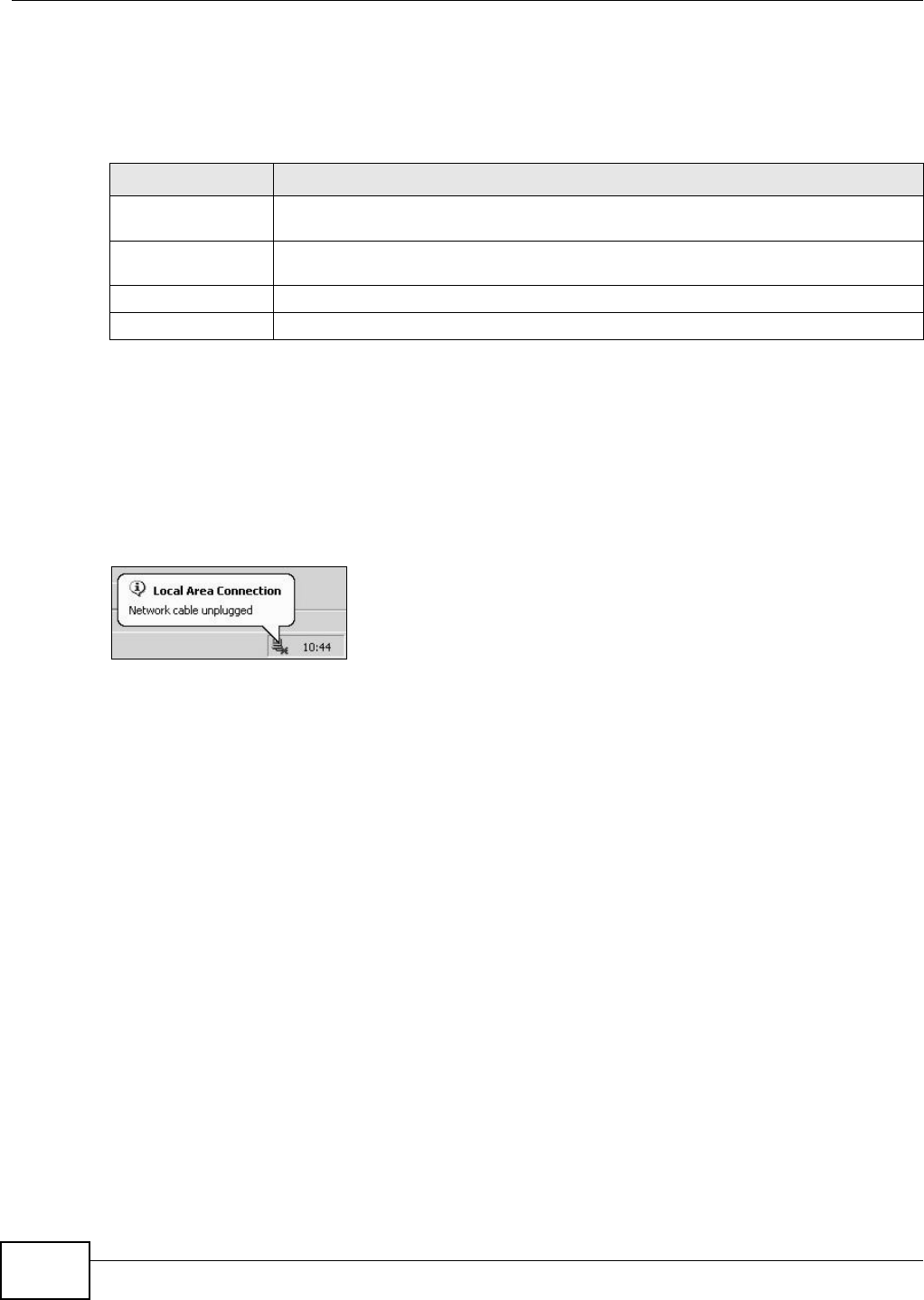
Chapter 24 Backup/Restore
VMG1312-T10C User’s Guide
202
Restore Configuration
Restore Configuration allows you to upload a new or previously saved configuration file from your
computer to your Device.
Do not turn off the Device while configuration file upload is in progress.
After the Device configuration has been restored successfully, the login screen appears. Login again
to restart the Device.
The Device automatically restarts in this time causing a temporary network disconnect. In some
operating systems, you may see the following icon on your desktop.
Figure 138 Network Temporarily Disconnected
If you restore the default configuration, you may need to change the IP address of your computer
to be in the same subnet as that of the default device IP address (192.168.1.1).
If the upload was not successful, an error screen will appear. Click OK to go back to the
Configuration screen.
Table 85 Restore Configuration
LABEL DESCRIPTION
File Path Type in the location of the file you want to upload in this field or click Browse ... to find
it.
Browse... Click this to find the file you want to upload. Remember that you must decompress
compressed (.ZIP) files before you can upload them.
Upload Click this to begin the upload process.
Reset Click this to reset your device settings back to the factory default.
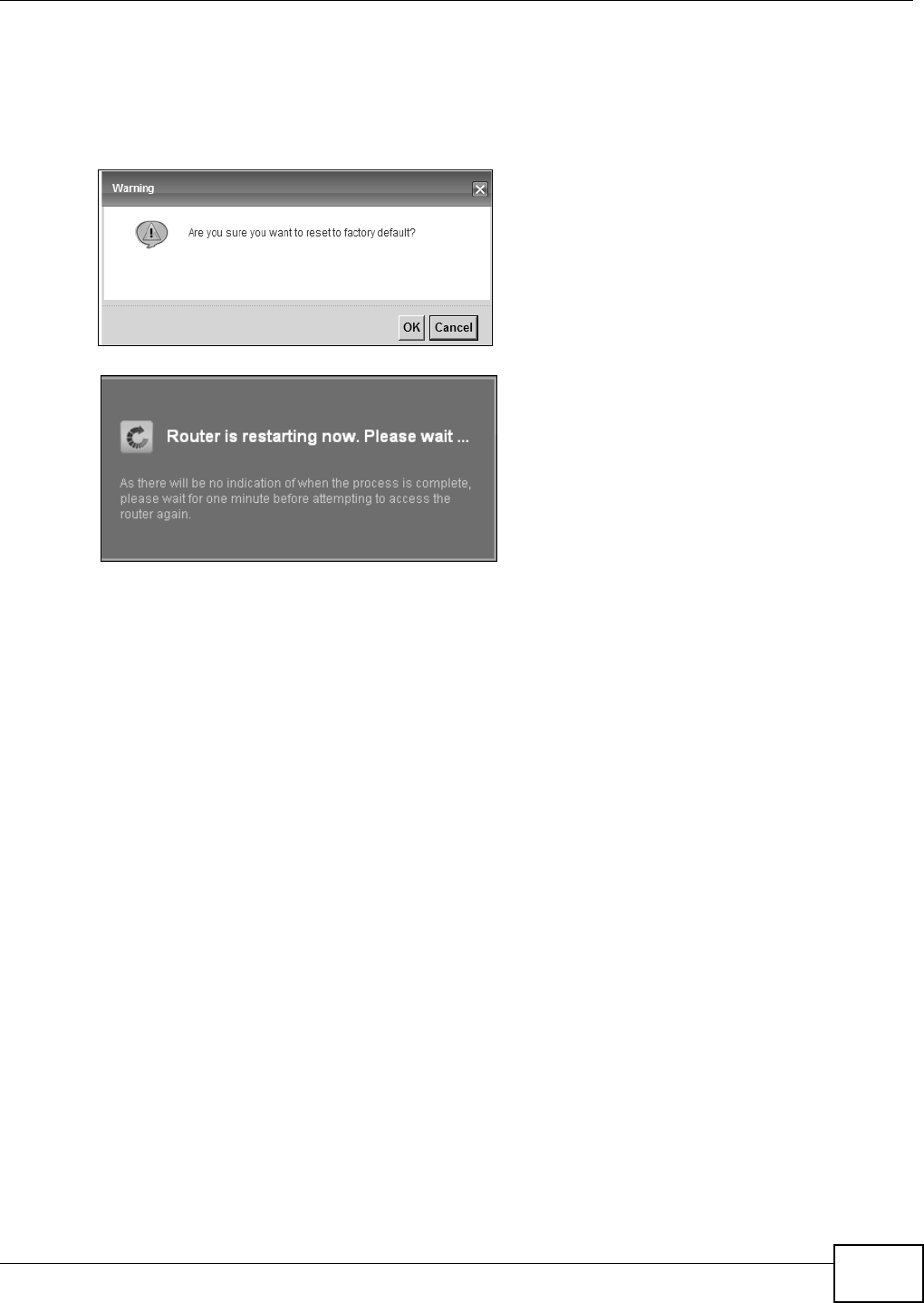
Chapter 24 Backup/Restore
VMG1312-T10C User’s Guide 203
Reset to Factory Defaults
Click the Reset button to clear all user-entered configuration information and return the Device to
its factory defaults. The following warning screen appears.
Figure 139 Reset Warning Message
Figure 140 Reset In Process Message
You can also press the RESET button on the back panel to reset the factory defaults of your Device.
Refer to Section 1.6 on page 18 for more information on the RESET button.
24.3 The Reboot Screen
System restart allows you to reboot the Device remotely without turning the power off. You may
need to do this if the Device hangs, for example.
Click Maintenance > Reboot. Click the Reboot button to have the Device reboot. This does not
affect the Device's configuration.

Chapter 24 Backup/Restore
VMG1312-T10C User’s Guide
204
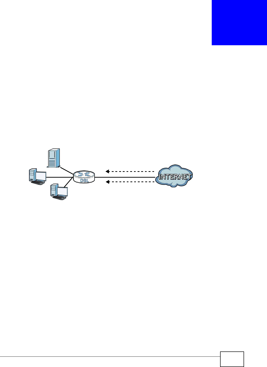
VMG1312-T10C User’s Guide 205
CHAPTER 25
Remote Management
25.1 Overview
Remote management allows you to determine which services/protocols can access which Device
interface (if any) from which computers.
The following figure shows remote management of the Device coming in from the WAN.
Figure 141 Remote Management From the WAN
Note: When you configure remote management to allow management from the WAN, you
still need to configure a IP filter rule to allow access.
You may manage your Device from a remote location via:
• Internet (WAN only)
•LAN only
•LAN and WAN
• None (Disable)
To disable remote management of a service, select Disable in the corresponding Service Access
field.
25.1.1 What You Can Do in the Remote Management Screens
•Use the WWW screen (Section 25.2 on page 206) to configure through which interfaces and
from which IP addresses users can use HTTP to manage the Device.
•Use the Telnet screen (Section 25.3 on page 208) to configure through which interfaces and
from which IP addresses users can use Telnet to manage the Device.
•Use the FTP screen (Section 25.4 on page 209) to configure through which interfaces and from
which IP addresses users can use FTP to access the Device.
LAN WAN
HTTP
Telnet

Chapter 25 Remote Management
VMG1312-T10C User’s Guide
206
• Your Device can act as an SNMP agent, which allows a manager station to manage and monitor
the Device through the network. Use the SNMP screen (see Section 25.5 on page 209) to
configure through which interfaces and from which IP addresses users can use SNMP to access
the Device.
•Use the DNS screen (Section 25.6 on page 212) to configure through which interfaces and from
which IP addresses users can send DNS queries to the Device.
•Use the ICMP screen (Section 25.7 on page 213) to set whether or not your Device will respond
to pings and probes for services that you have not made available.
•Use the SSH screen (Section 25.8 on page 213) to configure through which interfaces and from
which IP addresses users can use SSH to manage the Device.
25.1.2 What You Need to Know About Remote Management
Remote Management Limitations
• Remote management does not work when:
• You have not enabled that service on the interface in the corresponding remote management
screen.
• You have disabled that service in one of the remote management screens.
• The IP address in the Secured Client IP Address field does not match the client IP address. If
it does not match, the Device will disconnect the session immediately.
• There is a firewall rule that blocks it.
Remote Management and NAT
When NAT is enabled:
• Use the Device’s WAN IP address when configuring from the WAN.
• Use the Device’s LAN IP address when configuring from the LAN.
25.2 The WWW Screen
Use this screen to specify how to connect to the Device from a web browser, such as Internet
Explorer.
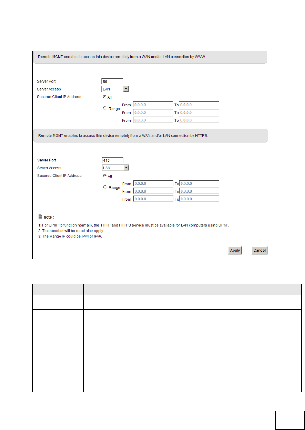
Chapter 25 Remote Management
VMG1312-T10C User’s Guide 207
25.2.1 Configuring the WWW Screen
Click Maintenance > Remote MGMT to display the WWW screen.
Figure 142 Maintenance > Remote MGMT > WWW
The following table describes the labels in this screen.
Table 86 Maintenance > Remote MGMT > WWW
LABEL DESCRIPTION
Server Port This displays the service port number for accessing the Device using HTTP or HTTPS. If
the number is grayed out, it is not editable.
Server Access Select the interfaces through which a computer may access the Device using this
service.
Note: It is recommended if you are allowing WAN access even temporarily to change the
default password (in Maintenance > User Account). To allow access from the
WAN, you will need to configure a WAN to Router firewall rule.
Secured Client IP
Address
A secured client is a “trusted” computer that is allowed to communicate with the Device
using this service.
Select All to allow any computer to access the Device using this service.
Choose Range to just allow the computers with an IP address in the range that you
specify to access the Device using this service.
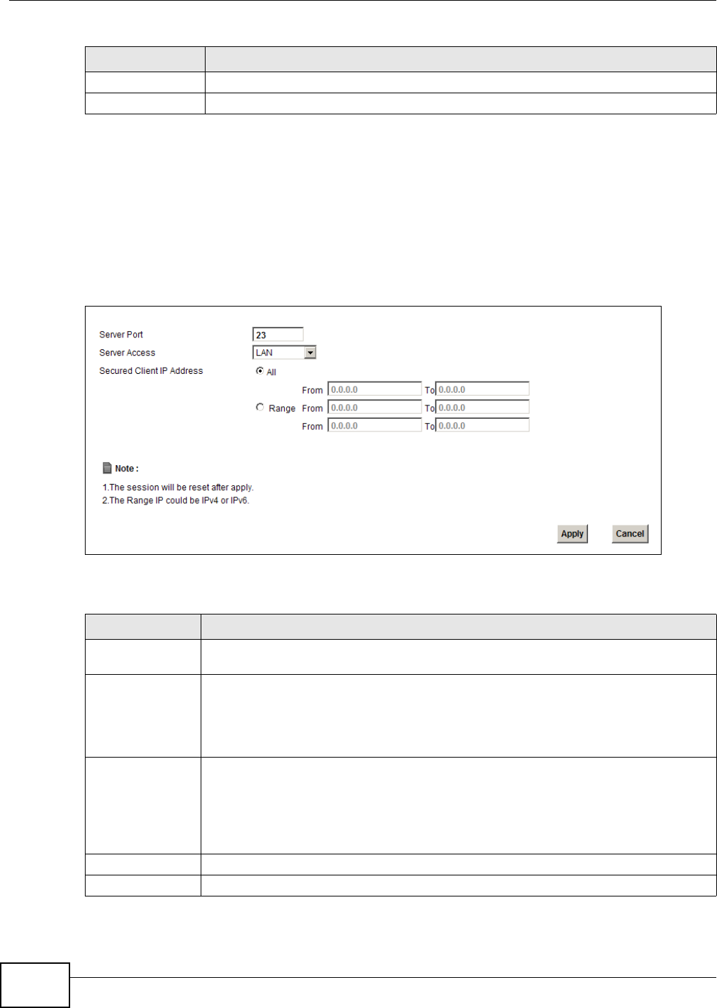
Chapter 25 Remote Management
VMG1312-T10C User’s Guide
208
25.3 Telnet Screen
You can use Telnet to access the Device’s command line interface. Specify which interfaces allow
Telnet access and from which IP address the access can come.
Click Maintenance > Remote MGMT > Telnet tab to display the screen as shown.
Figure 143 Maintenance > Remote MGMT > Telnet
The following table describes the labels in this screen.
Apply Click this to save your changes.
Cancel Click this to restore your previously saved settings.
Table 86 Maintenance > Remote MGMT > WWW (continued)
LABEL DESCRIPTION
Table 87 Maintenance > Remote MGMT > Telnet
LABEL DESCRIPTION
Server Port This displays the service port number for accessing the Device. If the number is grayed
out, it is not editable.
Server Access Select the interfaces through which a computer may access the Device using this service.
Note: It is recommended if you are allowing WAN access even temporarily to change the
default password (in Maintenance > User Account). To allow access from the
WAN, you will need to configure a WAN to Router firewall rule.
Secured Client IP
Address
A secured client is a “trusted” computer that is allowed to communicate with the Device
using this service.
Select All to allow any computer to access the Device using this service.
Choose Range to just allow the computers with an IP address in the range that you
specify to access the Device using this service.
Apply Click this to save your changes.
Cancel Click this to restore your previously saved settings.
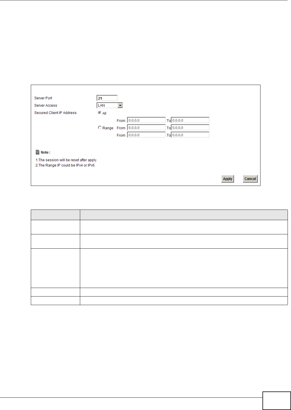
Chapter 25 Remote Management
VMG1312-T10C User’s Guide 209
25.4 FTP Screen
You can use FTP (File Transfer Protocol) to upload and download the Device’s firmware and
configuration files. To use this feature, your computer must have an FTP client.
Use this screen to specify which interfaces allow FTP access and from which IP address the access
can come. To change your Device’s FTP settings, click Maintenance > Remote MGMT > FTP. The
screen appears as shown.
Figure 144 Maintenance > Remote MGMT > FTP
The following table describes the labels in this screen.
25.5 SNMP Screen
Simple Network Management Protocol is a protocol used for exchanging management information
between network devices. Your Device supports SNMP agent functionality, which allows a manager
station to manage and monitor the Device through the network. The Device supports SNMP version
Table 88 Maintenance > Remote MGMT > FTP
LABEL DESCRIPTION
Server Port This displays the service port number for accessing the Device. If the number is grayed
out, it is not editable.
Server Access Select the interfaces through which a computer may access the Device using this
service.
Secured Client IP
Address
A secured client is a “trusted” computer that is allowed to communicate with the Device
using this service.
Select All to allow any computer to access the Device using this service.
Choose Range to just allow the computers with an IP address in the range that you
specify to access the Device using this service.
Apply Click this to save your changes.
Cancel Click this to restore your previously saved settings.
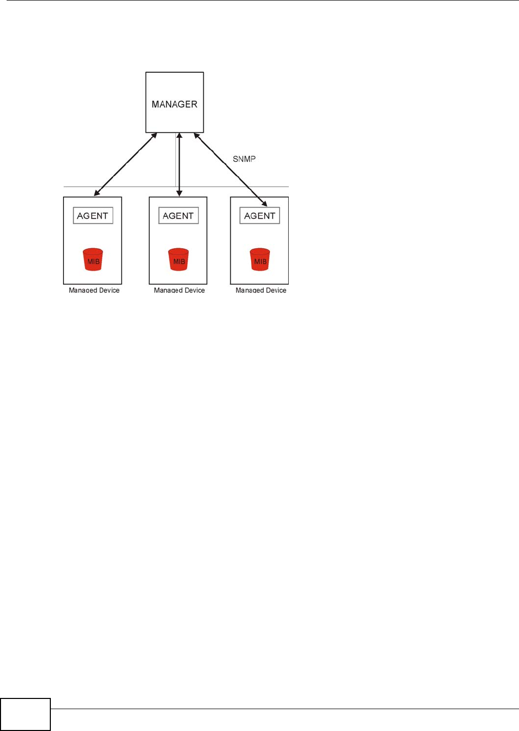
Chapter 25 Remote Management
VMG1312-T10C User’s Guide
210
one (SNMPv1) and version two (SNMPv2c). The next figure illustrates an SNMP management
operation.
Figure 145 SNMP Management Model
An SNMP managed network consists of two main types of component: agents and a manager.
An agent is a management software module that resides in a managed device (the Device). An
agent translates the local management information from the managed device into a form
compatible with SNMP. The manager is the console through which network administrators perform
network management functions. It executes applications that control and monitor managed
devices.
The managed devices contain object variables/managed objects that define each piece of
information to be collected about a device. Examples of variables include such as number of
packets received, node port status etc. A Management Information Base (MIB) is a collection of
managed objects. SNMP allows a manager and agents to communicate for the purpose of accessing
these objects.
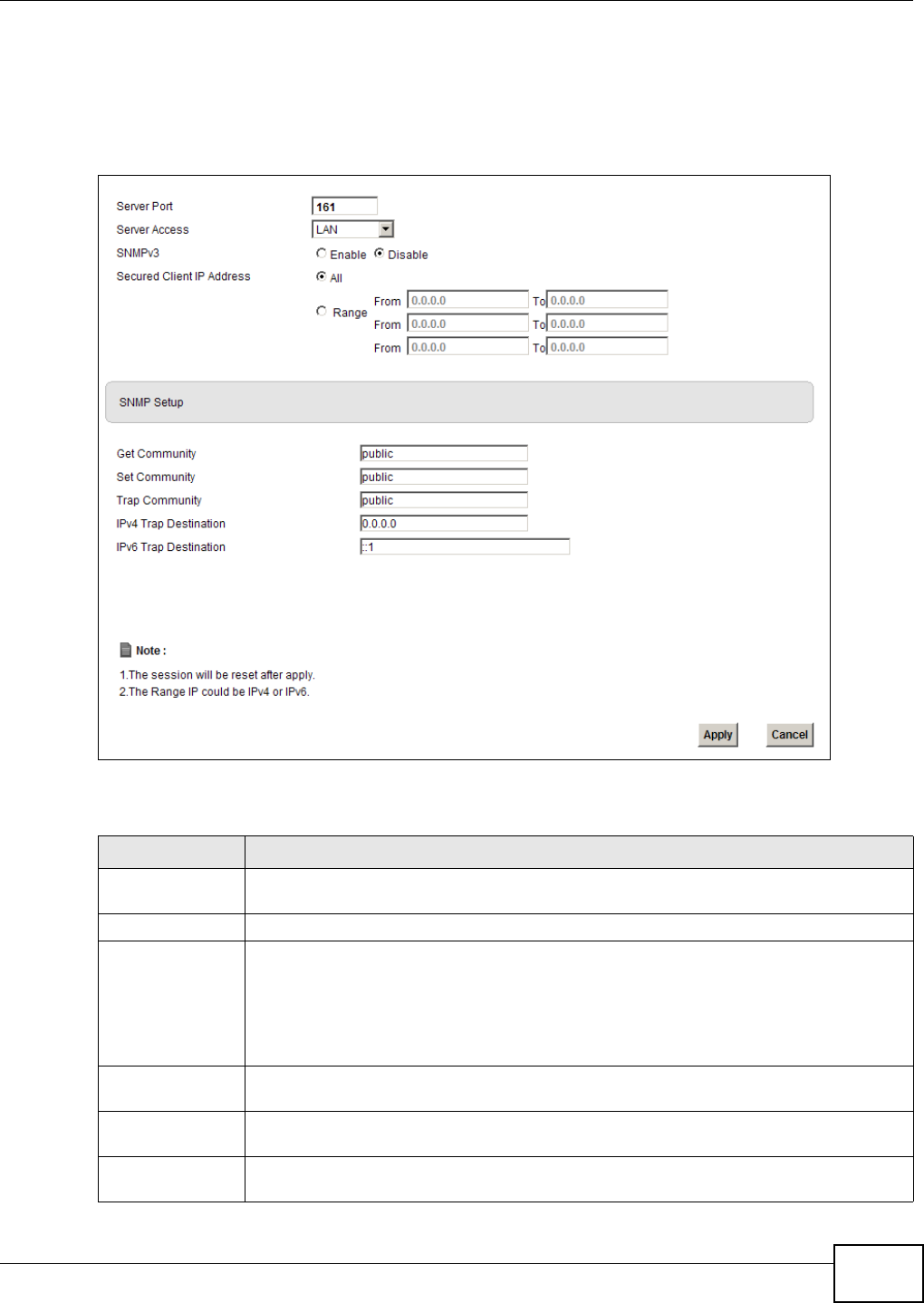
Chapter 25 Remote Management
VMG1312-T10C User’s Guide 211
25.5.1 Configuring SNMP
To change your Device’s SNMP settings, click Maintenance > Remote MGMT > SNMP tab. The
screen appears as shown.
Figure 146 Maintenance > Remote MGMT > SNMP
The following table describes the labels in this screen.
Table 89 Maintenance > Remote MGMT > SNMP
LABEL DESCRIPTION
Server Port This displays the port the SNMP agent listens on. If the number is grayed out, it is not
editable.
Server Access Select the interfaces through which a computer may access the Device using this service.
Secured Client IP
Address
A secured client is a “trusted” computer that is allowed to access the SNMP agent on the
Device.
Select All to allow any computer to access the SNMP agent.
Choose Range to just allow the computers with an IP address in the range that you
specify to access the Device using this service.
Get Community Enter the Get Community, which is the password for the incoming Get and GetNext
requests from the management station. The default is public and allows all requests.
Set Community Enter the Set community, which is the password for incoming Set requests from the
management station. The default is public and allows all requests.
Trap Community Type the trap community, which is the password sent with each trap to the SNMP
manager. The default is public and allows all requests.
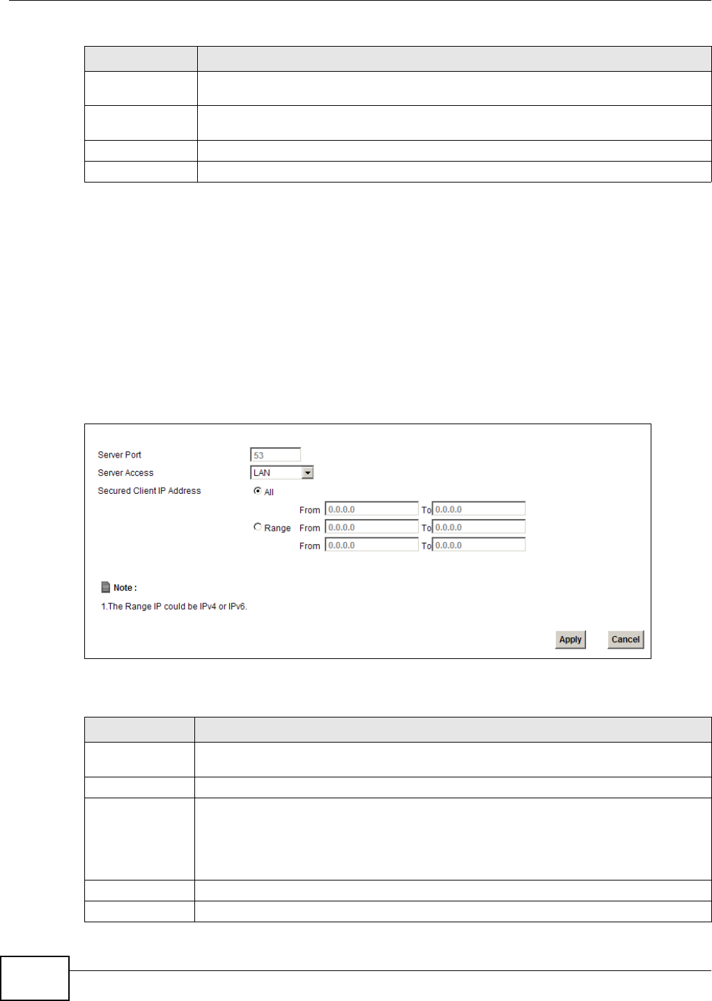
Chapter 25 Remote Management
VMG1312-T10C User’s Guide
212
25.6 DNS Screen
Use DNS (Domain Name System) to map a domain name to its corresponding IP address and vice
versa.
Use this screen to set from which IP address the Device will accept DNS queries and on which
interface it can send them your Device’s DNS settings. This feature is not available when the Device
is set to bridge mode. Click Maintenance > Remote MGMT > DNS to change your Device’s DNS
settings.
Figure 147 Maintenance > Remote MGMT > DNS
The following table describes the labels in this screen.
IPv4 Trap
Destination
Type the IPv4 IP address of the station to send your SNMP traps to.
IPv6 Trap
Destination
Type the IPv6 IP address of the station to send your SNMP traps to.
Apply Click Apply to save your changes back to the Device.
Cancel Click Cancel to begin configuring this screen afresh.
Table 89 Maintenance > Remote MGMT > SNMP (continued)
LABEL DESCRIPTION
Table 90 Maintenance > Remote MGMT > DNS
LABEL DESCRIPTION
Server Port This displays the service port number for accessing the Device. If the number is grayed
out, it is not editable.
Access Status Select the interfaces through which a computer may send DNS queries to the Device.
Secured Client IP
Address
A secured client is a “trusted” computer that is allowed to send DNS queries to the Device.
Select All to allow any computer to send DNS queries to the Device.
Choose Range to just allow the computers with an IP address in the range that you
specify to send DNS queries to the Device.
Apply Click this to save your changes.
Cancel Click this to restore your previously saved settings.
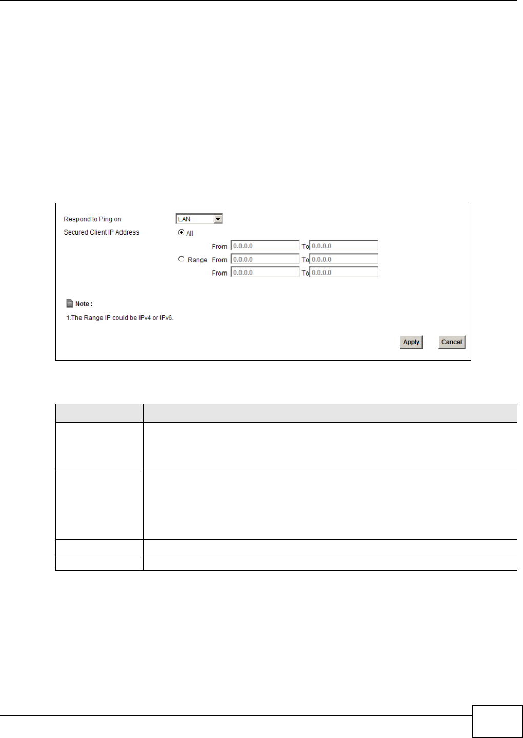
Chapter 25 Remote Management
VMG1312-T10C User’s Guide 213
25.7 ICMP Screen
To change your Device’s security settings, click Maintenance > Remote MGMT > ICMP. The
screen appears as shown.
If an outside user attempts to probe an unsupported port on your Device, an ICMP response packet
is automatically returned. This allows the outside user to know the Device exists. Your Device
supports anti-probing, which prevents the ICMP response packet from being sent. This keeps
outsiders from discovering your Device when unsupported ports are probed.
Note: If you want your device to respond to pings and requests for unauthorized services,
you will also need to configure the firewall accordingly by disabling SPI.
Figure 148 Maintenance > Remote MGMT > ICMP
The following table describes the labels in this screen.
25.8 SSH Screen
You can use Secure SHell (SSH) to securely access the Device’s command line interface. Specify
which interfaces allow SSH access and from which IP address the access can come. SSH is a secure
communication protocol that combines authentication and data encryption to provide secure
encrypted communication between two hosts over an unsecured network.
Table 91 Maintenance > Remote MGMT > ICMP
LABEL DESCRIPTION
Respond to Ping on The Device will not respond to any incoming Ping requests when Disable is selected.
Select LAN to reply to incoming LAN Ping requests. Select WAN to reply to incoming
WAN Ping requests. Otherwise select LAN & WAN to reply to both incoming LAN and
WAN Ping requests.
Secured Client IP
Address
A secured client is a “trusted” computer that is allowed to send Ping requests to the
Device.
Select All to allow any computer to send Ping requests to the Device.
Choose Range to just allow the computers with an IP address in the range that you
specify to send Ping requests to the Device.
Apply Click this to save your changes.
Cancel Click this to restore your previously saved settings.
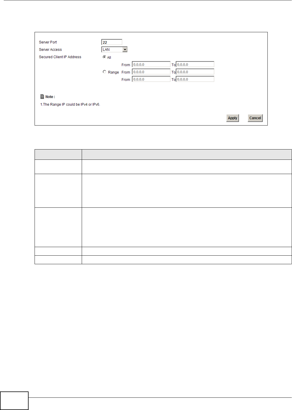
Chapter 25 Remote Management
VMG1312-T10C User’s Guide
214
Click Maintenance > Remote MGMT > SSH tab to display the screen as shown.
Figure 149 Maintenance > Remote MGMT > SSH
The following table describes the labels in this screen.
25.8.1 SSH Example
This section shows an example using a graphical interface SSH client program to remotely access
the ZyXEL device. The configuration and connection steps are similar for most SSH client programs.
Refer to your SSH client program user’s guide.
Table 92 Maintenance > Remote MGMT > SSH
LABEL DESCRIPTION
Server Port This displays the service port number for accessing the Device. If the number is grayed
out, it is not editable.
Server Access Select the interfaces through which a computer may access the Device using this service.
Note: It is recommended if you are allowing WAN access even temporarily to change the
default password (in Maintenance > User Account). To allow access from the
WAN, you will need to configure a WAN to Router firewall rule.
Secured Client IP
Address
A secured client is a “trusted” computer that is allowed to communicate with the Device
using this service.
Select All to allow any computer to access the Device using this service.
Choose Range to just allow the computers with an IP address in the range that you
specify to access the Device using this service.
Apply Click this to save your changes.
Cancel Click this to restore your previously saved settings.
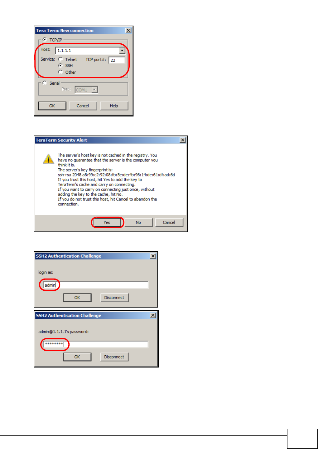
Chapter 25 Remote Management
VMG1312-T10C User’s Guide 215
1Enter the IP address and port number. Select SSH.
2 A window displays prompting you to store the host key in your computer. Click Yes to continue.
3Enter your user name and password.
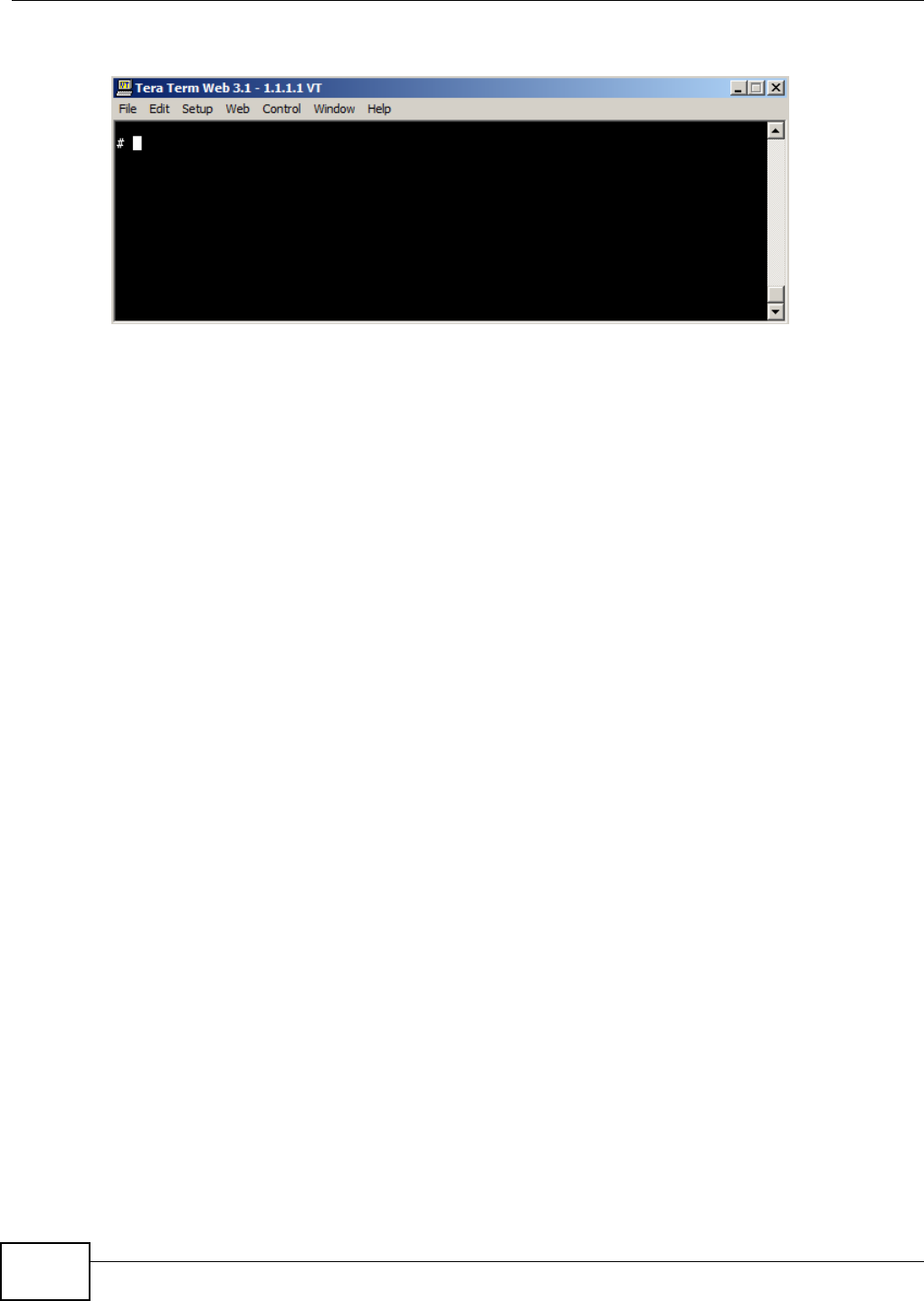
Chapter 25 Remote Management
VMG1312-T10C User’s Guide
216
4The command line interface displays.
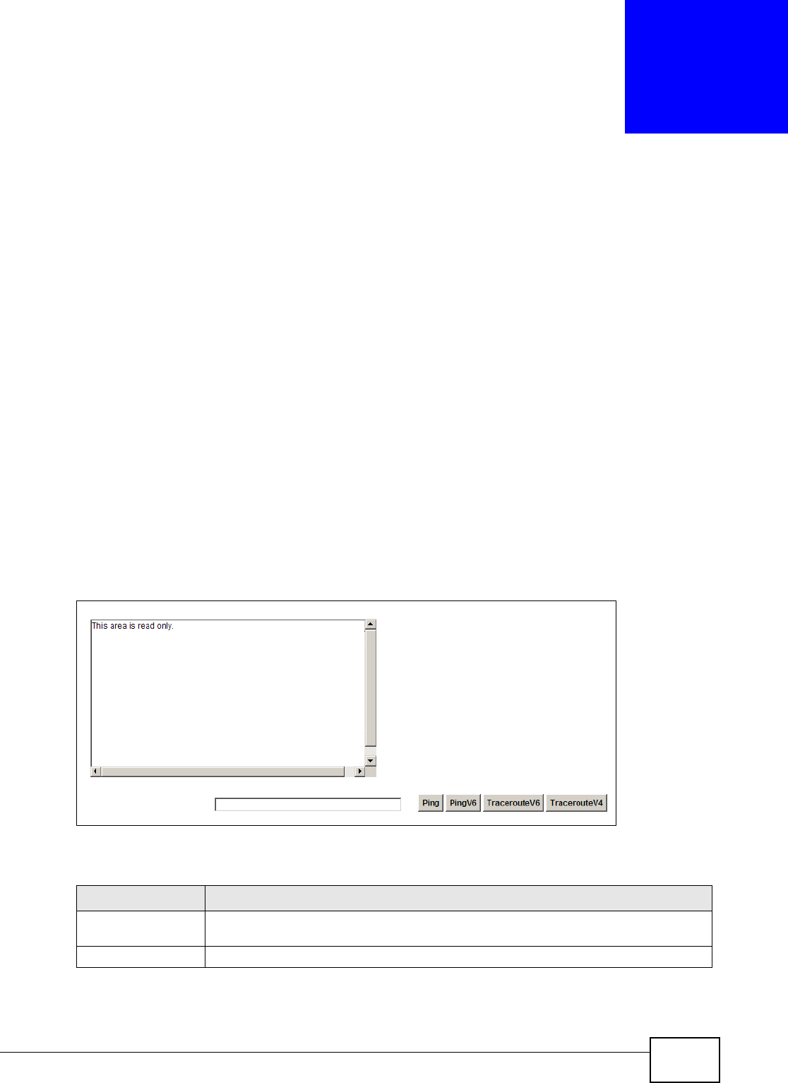
VMG1312-T10C User’s Guide 217
CHAPTER 26
Diagnostic
26.1 Overview
You can use different diagnostic methods to test a connection and see the detailed information.
These read-only screens display information to help you identify problems with the Device.
26.1.1 What You Can Do in the Diagnostic Screens
•Use the Ping screen (Section 26.2 on page 217) to ping an IP address.
•Use the DSL Line screen (Section 26.3 on page 218) to view the DSL line statistics and reset the
ADSL line.
26.2 The Ping Screen
Ping and traceroute help check availability of remote hosts and also help troubleshoot network or
Internet connections. Click Maintenance > Diagnostic to open the Ping screen shown next.
Figure 150 Maintenance > Diagnostic > Ping
The following table describes the fields in this screen.
Table 93 Maintenance > Diagnostic > Ping
LABEL DESCRIPTION
Ping Type the IP address of a computer that you want to ping in order to test a connection.
Click Ping and the ping statistics will show in the diagnostic .
PingV6 Click this to ping the IPv6 address that you entered.
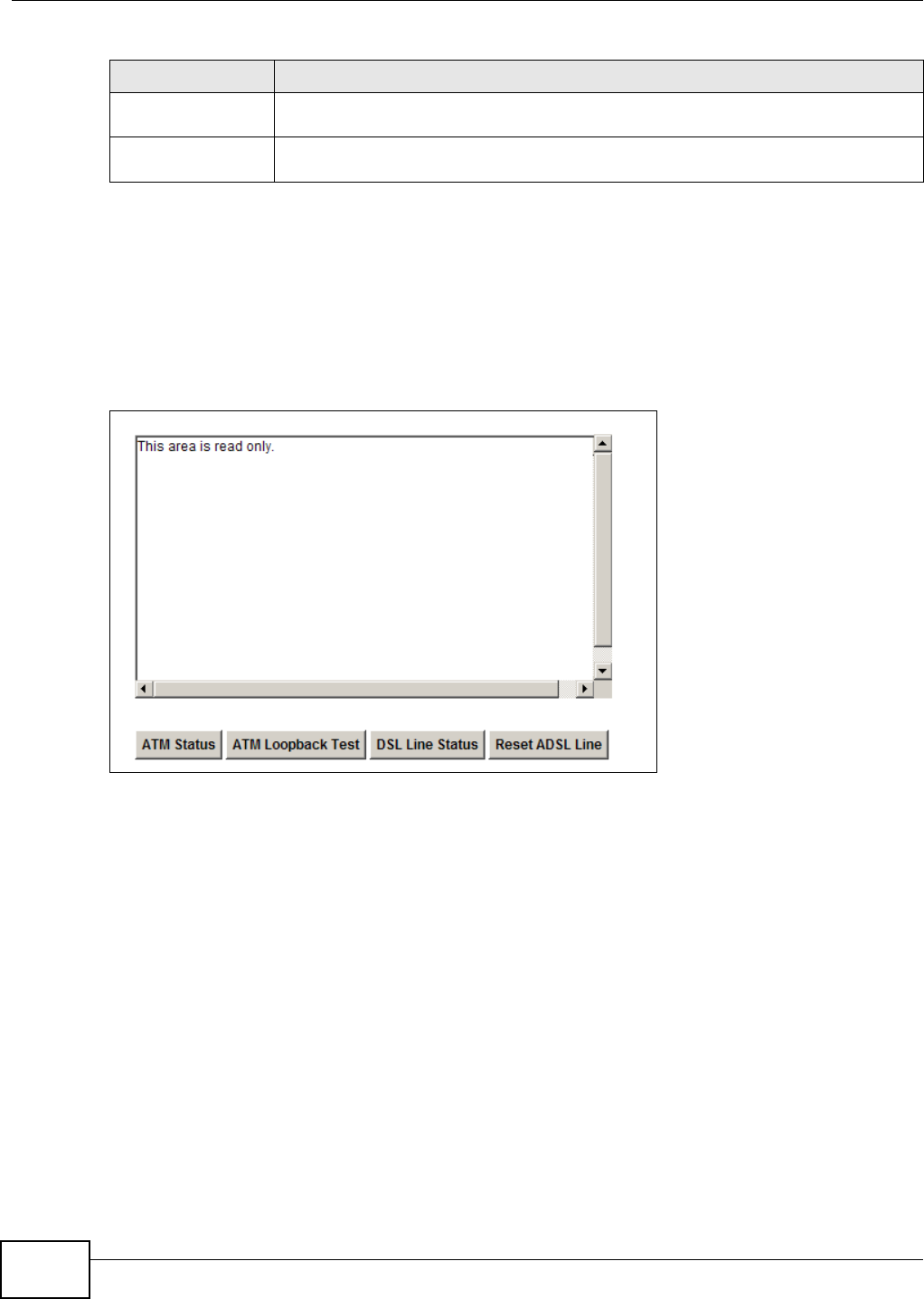
Chapter 26 Diagnostic
VMG1312-T10C User’s Guide
218
26.3 The DSL Line Screen
Use this screen to view the DSL line statistics and reset the DSL line. Click Maintenance >
Diagnostic > DSL Line. This screen is different for ADSL and VDSL connections. If your WAN
connection is ADSL, the screen is as shown.
Figure 151 Maintenance > Diagnostic > DSL Line: ADSL
TracerouteV6 Click this to show the path that packets take from the system to the IPv6 address that
you entered.
TraceRouteV4 Click this button to perform the traceroute function. This determines the path a packet
takes to the specified host.
Table 93 Maintenance > Diagnostic > Ping (continued)
LABEL DESCRIPTION

Chapter 26 Diagnostic
VMG1312-T10C User’s Guide 219
The following table describes the fields in this screen.
Table 94 Maintenance > Diagnostic > DSL Line: ADSL
LABEL DESCRIPTION
ATM Status Click this to view your DSL connection’s Asynchronous Transfer Mode (ATM) statistics.
ATM is a networking technology that provides high-speed data transfer. ATM uses fixed-
size packets of information called cells. With ATM, a high QoS (Quality of Service) can be
guaranteed.
The (Segmentation and Reassembly) SAR driver translates packets into ATM cells. It also
receives ATM cells and reassembles them into packets.
These counters are set back to zero whenever the device starts up.
inPkts is the number of good ATM cells that have been received.
inDiscards is the number of received ATM cells that were rejected.
outPkts is the number of ATM cells that have been sent.
outDiscards is the number of ATM cells sent that were rejected.
inF4Pkts is the number of ATM Operations, Administration, and Management (OAM) F4
cells that have been received. See ITU recommendation I.610 for more on OAM for ATM.
outF4Pkts is the number of ATM OAM F4 cells that have been sent.
inF5Pkts is the number of ATM OAM F5 cells that have been received.
outF5Pkts is the number of ATM OAM F5 cells that have been sent.
openChan is the number of times that the Device has opened a logical DSL channel.
closeChan is the number of times that the Device has closed a logical DSL channel.
txRate is the number of bytes transmitted per second.
rxRate is the number of bytes received per second.
ATM Loopback
Test
Click this to start the ATM loopback test. Make sure you have configured at least one PVC
with proper VPIs/VCIs before you begin this test. The Device sends an OAM F5 packet to
the DSLAM/ATM switch and then returns it (loops it back) to the Device. The ATM
loopback test is useful for troubleshooting problems with the DSLAM and ATM network.
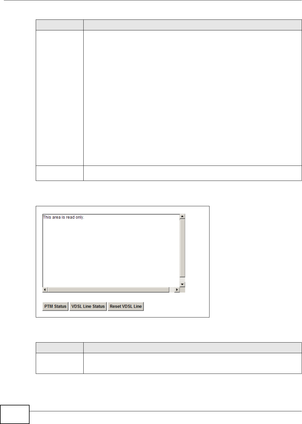
Chapter 26 Diagnostic
VMG1312-T10C User’s Guide
220
If your WAN connection is VDSL, the screen is as shown.
Figure 152 Maintenance > Diagnostic > DSL Line: VDSL
The following table describes the fields in this screen.
DSL Line Status Click this to view statistics about the DSL connections.
noise margin downstream is the signal to noise ratio for the downstream part of the
connection (coming into the Device from the ISP). It is measured in decibels. The higher
the number the more signal and less noise there is.
output power upstream is the amount of power (in decibels) that the Device is using to
transmit to the ISP.
attenuation downstream is the reduction in amplitude (in decibels) of the DSL signal
coming into the Device from the ISP.
Discrete Multi-Tone (DMT) modulation divides up a line’s bandwidth into sub-carriers
(sub-channels) of 4.3125 KHz each called tones. The rest of the display is the line’s bit
allocation. This is displayed as the number (in hexadecimal format) of bits transmitted for
each tone. This can be used to determine the quality of the connection, whether a given
sub-carrier loop has sufficient margins to support certain ADSL transmission rates, and
possibly to determine whether particular specific types of interference or line attenuation
exist. Refer to the ITU-T G.992.1 recommendation for more information on DMT.
The better (or shorter) the line, the higher the number of bits transmitted for a DMT tone.
The maximum number of bits that can be transmitted per DMT tone is 15. There will be
some tones without any bits as there has to be space between the upstream and
downstream channels.
Reset ADSL Line Click this to reinitialize the ADSL line. The large text box above then displays the progress
and results of this operation.
Table 95 Maintenance > Diagnostic > DSL Line: VDSL
LABEL DESCRIPTION
PTM Status Click this to view your DSL connection’s Packet Transfer Mode (PTM) statistics. PTM is a
packet-based (for example, for Ethernet packets, IP packets, etc.) transmission method
applied in VDSL2. It can highly increase the efficiency of packet transmission.
Table 94 Maintenance > Diagnostic > DSL Line: ADSL (continued)
LABEL DESCRIPTION
Chapter 26 Diagnostic
VMG1312-T10C User’s Guide 221
VDSL Line Status Click this to view your VDSL line connection status.
Reset VDSL Line Click this to reinitialize the VDSL line. The large text box above then displays the progress
and results of this operation.
Table 95 Maintenance > Diagnostic > DSL Line: VDSL (continued)
LABEL DESCRIPTION

Chapter 26 Diagnostic
VMG1312-T10C User’s Guide
222

VMG1312-T10C User’s Guide 223
CHAPTER 27
Troubleshooting
27.1 Overview
This chapter offers some suggestions to solve problems you might encounter. The potential
problems are divided into the following categories.
•Power, Hardware Connections, and LEDs
•Device Access and Login
•Internet Access
•Wireless Internet Access
•USB Device Connection
•UPnP
27.2 Power, Hardware Connections, and LEDs
The Device does not turn on. None of the LEDs turn on.
1Make sure the Device is turned on.
2Make sure you are using the power adaptor or cord included with the Device.
3Make sure the power adaptor or cord is connected to the Device and plugged in to an appropriate
power source. Make sure the power source is turned on.
4Turn the Device off and on.
5If the problem continues, contact the vendor.
One of the LEDs does not behave as expected.
1Make sure you understand the normal behavior of the LED. See Section 1.7 on page 18.
2Check the hardware connections. See the Quick Start Guide.
3Inspect your cables for damage. Contact the vendor to replace any damaged cables.

Chapter 27 Troubleshooting
VMG1312-T10C User’s Guide
224
4Turn the Device off and on.
5If the problem continues, contact the vendor.
27.3 Device Access and Login
I forgot the IP address for the Device.
1The default IP address is 192.168.1.1.
2If you changed the IP address and have forgotten it, you might get the IP address of the Device by
looking up the IP address of the default gateway for your computer. To do this in most Windows
computers, click Start > Run, enter cmd, and then enter ipconfig. The IP address of the Default
Gateway might be the IP address of the Device (it depends on the network), so enter this IP
address in your Internet browser.
3If this does not work, you have to reset the device to its factory defaults. See Section 1.6 on page
18.
I forgot the password.
1The default admin password is 1234 and the default user password is 1234.
2If you can’t remember the password, you have to reset the device to its factory defaults. See
Section 1.6 on page 18.
I cannot see or access the Login screen in the web configurator.
1Make sure you are using the correct IP address.
• The default IP address is 192.168.1.1.
• If you changed the IP address (Section on page 102), use the new IP address.
• If you changed the IP address and have forgotten it, see the troubleshooting suggestions for I
forgot the IP address for the Device.
2Check the hardware connections, and make sure the LEDs are behaving as expected. See the Quick
Start Guide.
3Make sure your Internet browser does not block pop-up windows and has JavaScript and Java
enabled.

Chapter 27 Troubleshooting
VMG1312-T10C User’s Guide 225
4Reset the device to its factory defaults, and try to access the Device with the default IP address.
See Section 1.6 on page 18.
5If the problem continues, contact the network administrator or vendor, or try one of the advanced
suggestions.
Advanced Suggestions
• Try to access the Device using another service, such as Telnet. If you can access the Device,
check the remote management settings and firewall rules to find out why the Device does not
respond to HTTP.
I can see the Login screen, but I cannot log in to the Device.
1Make sure you have entered the user name and password correctly. The default user name is
admin. These fields are case-sensitive, so make sure [Caps Lock] is not on.
2You cannot log in to the web configurator while someone is using Telnet to access the Device. Log
out of the Device in the other session, or ask the person who is logged in to log out.
3Turn the Device off and on.
4If this does not work, you have to reset the device to its factory defaults. See Section 27.2 on page
223.
I cannot Telnet to the Device.
See the troubleshooting suggestions for I cannot see or access the Login screen in the web
configurator. Ignore the suggestions about your browser.
I cannot use FTP to upload / download the configuration file. / I cannot use FTP to upload
new firmware.
See the troubleshooting suggestions for I cannot see or access the Login screen in the web
configurator. Ignore the suggestions about your browser.
27.4 Internet Access
I cannot access the Internet.

Chapter 27 Troubleshooting
VMG1312-T10C User’s Guide
226
1Check the hardware connections, and make sure the LEDs are behaving as expected. See the Quick
Start Guide and Section 1.7 on page 18.
2Make sure you entered your ISP account information correctly. These fields are case-sensitive, so
make sure [Caps Lock] is not on.
3If you are trying to access the Internet wirelessly, make sure the wireless settings in the wireless
client are the same as the settings in the AP.
4If you are trying to access the Internet wirelessly, make sure you have enabled the wireless LAN by
the WPS/WLAN button or the Network Setting > Wireless > General screen.
5Disconnect all the cables from your device, and follow the directions in the Quick Start Guide again.
6If the problem continues, contact your ISP.
I cannot access the Internet anymore. I had access to the Internet (with the Device), but my
Internet connection is not available anymore.
1Check the hardware connections, and make sure the LEDs are behaving as expected. See the Quick
Start Guide and Section 1.7 on page 18.
2Turn the Device off and on.
3If the problem continues, contact your ISP.
The Internet connection is slow or intermittent.
1There might be a lot of traffic on the network. Look at the LEDs, and check Section 1.7 on page 18.
If the Device is sending or receiving a lot of information, try closing some programs that use the
Internet, especially peer-to-peer applications.
2Turn the Device off and on.
3If the problem continues, contact the network administrator or vendor, or try one of the advanced
suggestions.
Advanced Suggestions
• Check the settings for QoS. If it is disabled, you might consider activating it. If it is enabled, you
might consider raising or lowering the priority for some applications.

Chapter 27 Troubleshooting
VMG1312-T10C User’s Guide 227
27.5 Wireless Internet Access
What factors may cause intermittent or unstabled wireless connection? How can I solve this
problem?
The following factors may cause interference:
• Obstacles: walls, ceilings, furniture, and so on.
• Building Materials: metal doors, aluminum studs.
• Electrical devices: microwaves, monitors, electric motors, cordless phones, and other wireless
devices.
To optimize the speed and quality of your wireless connection, you can:
• Move your wireless device closer to the AP if the signal strength is low.
• Reduce wireless interference that may be caused by other wireless networks or surrounding
wireless electronics such as cordless phones.
• Place the AP where there are minimum obstacles (such as walls and ceilings) between the AP and
the wireless client.
• Reduce the number of wireless clients connecting to the same AP simultaneously, or add
additional APs if necessary.
• Try closing some programs that use the Internet, especially peer-to-peer applications. If the
wireless client is sending or receiving a lot of information, it may have too many programs open
that use the Internet.
What wireless security modes does my Device support?
Wireless security is vital to your network. It protects communications between wireless stations,
access points and the wired network.
The available security modes in your ZyXEL device are as follows:
•WPA2-PSK: (recommended) This uses a pre-shared key with the WPA2 standard.
•WPA-PSK: This has the device use either WPA-PSK or WPA2-PSK depending on which security
mode the wireless client uses.
•WPA2: WPA2 (IEEE 802.11i) is a wireless security standard that defines stronger encryption,
authentication and key management than WPA. It requires the use of a RADIUS server and is
mostly used in business networks.
•WPA: Wi-Fi Protected Access (WPA) is a subset of the IEEE 802.11i standard. It requires the use
of a RADIUS server and is mostly used in business networks.
•WEP: Wired Equivalent Privacy (WEP) encryption scrambles the data transmitted between the
wireless stations and the access points to keep network communications private.

Chapter 27 Troubleshooting
VMG1312-T10C User’s Guide
228
27.6 USB Device Connection
The Device fails to detect my USB device.
1Disconnect the USB device.
2Reboot the Device.
3If you are connecting a USB hard drive that comes with an external power supply, make sure it is
connected to an appropriate power source that is on.
4Re-connect your USB device to the Device.
27.7 UPnP
When using UPnP and the Device reboots, my computer cannot detect UPnP and refresh My
Network Places > Local Network.
1Disconnect the Ethernet cable from the Device’s LAN port or from your computer.
2Re-connect the Ethernet cable.
The Local Area Connection icon for UPnP disappears in the screen.
Restart your computer.
I cannot open special applications such as white board, file transfer and video when I use the
MSN messenger.
1Wait more than three minutes.
2Restart the applications.

VMG1312-T10C User’s Guide 229
APPENDIX A
Customer Support
In the event of problems that cannot be solved by using this manual, you should contact your
vendor. If you cannot contact your vendor, then contact a ZyXEL office for the region in which you
bought the device. Regional websites are listed below (see also http://www.zyxel.com/
about_zyxel/zyxel_worldwide.shtml). Please have the following information ready when you
contact an office.
Required Information
• Product model and serial number.
• Warranty Information.
• Date that you received your device.
• Brief description of the problem and the steps you took to solve it.
Corporate Headquarters (Worldwide)
Taiwan
• ZyXEL Communications Corporation
• http://www.zyxel.com
Asia
China
• ZyXEL Communications (Shanghai) Corp.
ZyXEL Communications (Beijing) Corp.
ZyXEL Communications (Tianjin) Corp.
• http://www.zyxel.cn
India
• ZyXEL Technology India Pvt Ltd
• http://www.zyxel.in
Kazakhstan
•ZyXEL Kazakhstan
• http://www.zyxel.kz

Appendix A Customer Support
VMG1312-T10C User’s Guide
230
Korea
• ZyXEL Korea Corp.
• http://www.zyxel.kr
Malaysia
• ZyXEL Malaysia Sdn Bhd.
• http://www.zyxel.com.my
Pakistan
• ZyXEL Pakistan (Pvt.) Ltd.
• http://www.zyxel.com.pk
Philippines
• ZyXEL Philippines
• http://www.zyxel.com.ph
Singapore
• ZyXEL Singapore Pte Ltd.
• http://www.zyxel.com.sg
Taiwan
• ZyXEL Communications Corporation
• http://www.zyxel.com
Thailand
• ZyXEL Thailand Co., Ltd
• http://www.zyxel.co.th
Vietnam
• ZyXEL Communications Corporation-Vietnam Office
• http://www.zyxel.com/vn/vi
Europe
Austria
• ZyXEL Deutschland GmbH
• http://www.zyxel.de
Belarus
•ZyXEL BY
• http://www.zyxel.by

Appendix A Customer Support
VMG1312-T10C User’s Guide 231
Belgium
• ZyXEL Communications B.V.
• http://www.zyxel.com/be/nl/
Bulgaria
•ZyXEL България
• http://www.zyxel.com/bg/bg/
Czech
• ZyXEL Communications Czech s.r.o
• http://www.zyxel.cz
Denmark
• ZyXEL Communications A/S
• http://www.zyxel.dk
Estonia
•ZyXEL Estonia
• http://www.zyxel.com/ee/et/
Finland
• ZyXEL Communications
• http://www.zyxel.fi
France
•ZyXEL France
• http://www.zyxel.fr
Germany
• ZyXEL Deutschland GmbH
• http://www.zyxel.de
Hungary
• ZyXEL Hungary & SEE
• http://www.zyxel.hu
Latvia
•ZyXEL Latvia
• http://www.zyxel.com/lv/lv/homepage.shtml

Appendix A Customer Support
VMG1312-T10C User’s Guide
232
Lithuania
• ZyXEL Lithuania
• http://www.zyxel.com/lt/lt/homepage.shtml
Netherlands
•ZyXEL Benelux
• http://www.zyxel.nl
Norway
• ZyXEL Communications
• http://www.zyxel.no
Poland
• ZyXEL Communications Poland
• http://www.zyxel.pl
Romania
•ZyXEL Romania
• http://www.zyxel.com/ro/ro
Russia
• ZyXEL Russia
• http://www.zyxel.ru
Slovakia
• ZyXEL Communications Czech s.r.o. organizacna zlozka
• http://www.zyxel.sk
Spain
•ZyXEL Spain
• http://www.zyxel.es
Sweden
• ZyXEL Communications
• http://www.zyxel.se
Switzerland
•Studerus AG
• http://www.zyxel.ch/

Appendix A Customer Support
VMG1312-T10C User’s Guide 233
Turkey
•ZyXEL Turkey A.S.
• http://www.zyxel.com.tr
UK
• ZyXEL Communications UK Ltd.
• http://www.zyxel.co.uk
Ukraine
•ZyXEL Ukraine
• http://www.ua.zyxel.com
Latin America
Argentina
• ZyXEL Communication Corporation
• http://www.zyxel.com/ec/es/
Ecuador
• ZyXEL Communication Corporation
• http://www.zyxel.com/ec/es/
Middle East
Egypt
• ZyXEL Communication Corporation
• http://www.zyxel.com/homepage.shtml
Middle East
• ZyXEL Communication Corporation
• http://www.zyxel.com/homepage.shtml
North America
USA
• ZyXEL Communications, Inc. - North America Headquarters
• http://www.us.zyxel.com/

Appendix A Customer Support
VMG1312-T10C User’s Guide
234
Oceania
Australia
• ZyXEL Communications Corporation
• http://www.zyxel.com/au/en/
Africa
South Africa
• Nology (Pty) Ltd.
• http://www.zyxel.co.za

VMG1312-T10C User’s Guide 235
APPENDIX B
Legal Information
Copyright
Copyright © 2014 by ZyXEL Communications Corporation.
The contents of this publication may not be reproduced in any part or as a whole, transcribed, stored in a retrieval system, translated into
any language, or transmitted in any form or by any means, electronic, mechanical, magnetic, optical, chemical, photocopying, manual, or
otherwise, without the prior written permission of ZyXEL Communications Corporation.
Published by ZyXEL Communications Corporation. All rights reserved.
Disclaimer
ZyXEL does not assume any liability arising out of the application or use of any products, or software described herein. Neither does it
convey any license under its patent rights nor the patent rights of others. ZyXEL further reserves the right to make changes in any
products described herein without notice. This publication is subject to change without notice.
Your use of the Device is subject to the terms and conditions of any related service providers.
Trademarks
ZyNOS (ZyXEL Network Operating System) is a registered trademark of ZyXEL Communications, Inc. Other trademarks mentioned in this
publication are used for identification purposes only and may be properties of their respective owners.
Trademarks mentioned in this publication are used for identification purposes only and may be properties of their respective owners.
Certifications
Federal Communications Commission (FCC) Interference Statement
The device complies with Part 15 of FCC rules. Operation is subject to the following two conditions:
• This device may not cause harmful interference.
• This device must accept any interference received, including interference that may cause undesired operations.
This device has been tested and found to comply with the limits for a Class B digital device pursuant to Part 15 of the FCC Rules. These
limits are designed to provide reasonable protection against harmful interference in a residential installation. This device generates, uses,
and can radiate radio frequency energy, and if not installed and used in accordance with the instructions, may cause harmful interference
to radio communications. However, there is no guarantee that interference will not occur in a particular installation.
If this device does cause harmful interference to radio/television reception, which can be determined by turning the device off and on, the
user is encouraged to try to correct the interference by one or more of the following measures:
1Reorient or relocate the receiving antenna.
2Increase the separation between the equipment and the receiver.
3Connect the equipment into an outlet on a circuit different from that to which the receiver is connected.
4Consult the dealer or an experienced radio/TV technician for help.
FCC Caution: Any changes or modifications not expressly approved by the party responsible for compliance could void the user's authority
to operate this equipment.
FCC Radiation Exposure Statement
• This transmitter must not be co-located or operating in conjunction with any other antenna or transmitter.
• IEEE 802.11b, 802.11g or 802.11n (20MHz) operation of this product in the U.S.A. is firmware-limited to channels 1 through 11. IEEE
802.11n (40MHz) operation of this product in the U.S.A. is firmware-limited to channels 3 through 9.
• IEEE 802.11b or 802.11g operation of this product in the U.S.A. is firmware-limited to channels 1 through 11.
• To comply with FCC RF exposure compliance requirements, a separation distance of at least 20 cm must be maintained between the
antenna of this device and all persons.
IC Radiation Exposure Statement
This equipment complies with IC radiation exposure limits set forth for an uncontrolled environment. End users must follow the specific
operating instructions for satisfying RF exposure compliance.
Notices
Changes or modifications not expressly approved by the party responsible for compliance could void the user's authority to operate the
equipment.
This device is designed for the WLAN 2.4 GHz and/or 5 GHz networks throughout the EC region and Switzerland, with restrictions in
France.
Ce produit est conçu pour les bandes de fréquences 2,4 GHz et/ou 5 GHz conformément à la législation Européenne. En France
métropolitaine, suivant les décisions n°03-908 et 03-909 de l’ARCEP, la puissance d’émission ne devra pas dépasser 10 mW (10 dB) dans
le cadre d’une installation WiFi en extérieur pour les fréquences comprises entre 2454 MHz et 2483,5 MHz.

Appendix B Legal Information
VMG1312-T10C User’s Guide
236
Viewing Certifications
Go to http://www.zyxel.com to view this product’s documentation and certifications.
ZyXEL Limited Warranty
ZyXEL warrants to the original end user (purchaser) that this product is free from any defects in material or workmanship for a specific
period (the Warranty Period) from the date of purchase. The Warranty Period varies by region. Check with your vendor and/or the
authorized ZyXEL local distributor for details about the Warranty Period of this product. During the warranty period, and upon proof of
purchase, should the product have indications of failure due to faulty workmanship and/or materials, ZyXEL will, at its discretion, repair or
replace the defective products or components without charge for either parts or labor, and to whatever extent it shall deem necessary to
restore the product or components to proper operating condition. Any replacement will consist of a new or re-manufactured functionally
equivalent product of equal or higher value, and will be solely at the discretion of ZyXEL. This warranty shall not apply if the product has
been modified, misused, tampered with, damaged by an act of God, or subjected to abnormal working conditions.
Note
Repair or replacement, as provided under this warranty, is the exclusive remedy of the purchaser. This warranty is in lieu of all other
warranties, express or implied, including any implied warranty of merchantability or fitness for a particular use or purpose. ZyXEL shall in
no event be held liable for indirect or consequential damages of any kind to the purchaser.
To obtain the services of this warranty, contact your vendor. You may also refer to the warranty policy for the region in which you bought
the device at http://www.zyxel.com/web/support_warranty_info.php.
Registration
Register your product online to receive e-mail notices of firmware upgrades and information at www.zyxel.com for global products, or at
www.us.zyxel.com for North American products.
Open Source Licenses
This product contains in part some free software distributed under GPL license terms and/or GPL like licenses. Open source licenses are
provided with the firmware package. You can download the latest firmware at www.zyxel.com. If you cannot find it there, contact your
vendor or ZyXEL Technical Support at support@zyxel.com.tw. To obtain the source code covered under those Licenses, please contact
your vendor or ZyXEL Technical Support at support@zyxel.com.tw.
Regulatory Information
European Union
The following information applies if you use the product within the European Union.
Declaration of Conformity with Regard to EU Directive 1999/5/EC (R&TTE Directive)
Compliance Information for Wireless Products Relevant to the EU and Other Countries Following the EU Directive 1999/5/EC (R&TTE Directive)
[Czech] ZyXEL tímto prohlašuje, že tento zařízení je ve shodě se základními požadavky a dalšími příslušnými ustanoveními
směrnice 1999/5/EC.
[Danish] Undertegnede ZyXEL erklærer herved, at følgende udstyr udstyr overholder de væsentlige krav og øvrige relevante
krav i direktiv 1999/5/EF.
[German] Hiermit erklärt ZyXEL, dass sich das Gerät Ausstattung in Übereinstimmung mit den grundlegenden Anforderungen
und den übrigen einschlägigen Bestimmungen der Richtlinie 1999/5/EU befindet.
[Estonian] Käesolevaga kinnitab ZyXEL seadme seadmed vastavust direktiivi 1999/5/EÜ põhinõuetele ja nimetatud direktiivist
tulenevatele teistele asjakohastele sätetele.
[English] Hereby, ZyXEL declares that this equipment is in compliance with the essential requirements and other relevant
provisions of Directive 1999/5/EC.
[Spanish] Por medio de la presente ZyXEL declara que el equipo cumple con los requisitos esenciales y cualesquiera otras
disposiciones aplicables o exigibles de la Directiva 1999/5/CE.
[Greek] ΜΕ ΤΗΝ ΠΑΡΟΥΣΑ ZyXEL ΔΗΛΩΝΕΙ ΟΤΙ εξοπλισμός ΣΥΜΜΟΡΦΩΝΕΤΑΙ ΠΡΟΣ ΤΙΣ ΟΥΣΙΩΔΕΙΣ ΑΠΑΙΤΗΣΕΙΣ ΚΑΙ ΤΙΣ
ΛΟΙΠΕΣ ΣΧΕΤΙΚΕΣ ΔΙΑΤΑΞΕΙΣ ΤΗΣ ΟΔΗΓΙΑΣ 1999/5/ΕC.
[French] Par la présente ZyXEL déclare que l'appareil équipements est conforme aux exigences essentielles et aux autres
dispositions pertinentes de la directive 1999/5/EC.
[Italian] Con la presente ZyXEL dichiara che questo attrezzatura è conforme ai requisiti essenziali ed alle altre disposizioni
pertinenti stabilite dalla direttiva 1999/5/CE.
[Latvian] Ar šo ZyXEL deklarē, ka iekārtas atbilst Direktīvas 1999/5/EK būtiskajām prasībām un citiem ar to saistītajiem
noteikumiem.
[Lithuanian] Šiuo ZyXEL deklaruoja, kad šis įranga atitinka esminius reikalavimus ir kitas 1999/5/EB Direktyvos nuostatas.
[Dutch] Hierbij verklaart ZyXEL dat het toestel uitrusting in overeenstemming is met de essentiële eisen en de andere
relevante bepalingen van richtlijn 1999/5/EC.
[Maltese] Hawnhekk, ZyXEL, jiddikjara li dan tagħmir jikkonforma mal-ħtiġijiet essenzjali u ma provvedimenti oħrajn relevanti li
hemm fid-Dirrettiva 1999/5/EC.
[Hungarian] Alulírott, ZyXEL nyilatkozom, hogy a berendezés megfelel a vonatkozó alapvetõ követelményeknek és az 1999/5/EK
irányelv egyéb elõírásainak.

Appendix B Legal Information
VMG1312-T10C User’s Guide 237
National Restrictions
This product may be used in all EU countries (and other countries following the EU directive 1999/5/EC) without any limitation except for
the countries mentioned below:
Ce produit peut être utilisé dans tous les pays de l’UE (et dans tous les pays ayant transposés la directive 1999/5/CE) sans aucune
limitation, excepté pour les pays mentionnés ci-dessous:
Questo prodotto è utilizzabile in tutte i paesi EU (ed in tutti gli altri paesi che seguono le direttive EU 1999/5/EC) senza nessuna
limitazione, eccetto per i paesii menzionati di seguito:
Das Produkt kann in allen EU Staaten ohne Einschränkungen eingesetzt werden (sowie in anderen Staaten die der EU Direktive 1995/5/CE
folgen) mit Außnahme der folgenden aufgeführten Staaten:
In the majority of the EU and other European countries, the 2, 4- and 5-GHz bands have been made available for the use of wireless local
area networks (LANs). Later in this document you will find an overview of countries inwhich additional restrictions or requirements or both
are applicable.
The requirements for any country may evolve. ZyXEL recommends that you check with the local authorities for the latest status of their
national regulations for both the 2,4- and 5-GHz wireless LANs.
The following countries have restrictions and/or requirements in addition to those given in the table labeled “Overview of Regulatory
Requirements for Wireless LANs”:.
Belgium
The Belgian Institute for Postal Services and Telecommunications (BIPT) must be notified of any outdoor wireless link having a range
exceeding 300 meters. Please check http://www.bipt.be for more details.
Draadloze verbindingen voor buitengebruik en met een reikwijdte van meer dan 300 meter dienen aangemeld te worden bij het Belgisch
Instituut voor postdiensten en telecommunicatie (BIPT). Zie http://www.bipt.be voor meer gegevens.
Les liaisons sans fil pour une utilisation en extérieur d’une distance supérieure à 300 mètres doivent être notifiées à l’Institut Belge des
services Postaux et des Télécommunications (IBPT). Visitez http://www.ibpt.be pour de plus amples détails.
Denmark
In Denmark, the band 5150 - 5350 MHz is also allowed for outdoor usage.
I Danmark må frekvensbåndet 5150 - 5350 også anvendes udendørs.
France
For 2.4 GHz, the output power is restricted to 10 mW EIRP when the product is used outdoors in the band 2454 - 2483.5 MHz. There are
no restrictions when used indoors or in other parts of the 2.4 GHz band. Check http://www.arcep.fr/ for more details.
[Polish] Niniejszym ZyXEL oświadcza, że sprzęt jest zgodny z zasadniczymi wymogami oraz pozostałymi stosownymi
postanowieniami Dyrektywy 1999/5/EC.
[Portuguese] ZyXEL declara que este equipamento está conforme com os requisitos essenciais e outras disposições da Directiva
1999/5/EC.
[Slovenian] ZyXEL izjavlja, da je ta oprema v skladu z bistvenimi zahtevami in ostalimi relevantnimi določili direktive 1999/5/EC.
[Slovak] ZyXEL týmto vyhlasuje, že zariadenia spĺňa základné požiadavky a všetky príslušné ustanovenia Smernice 1999/5/EC.
[Finnish] ZyXEL vakuuttaa täten että laitteet tyyppinen laite on direktiivin 1999/5/EY oleellisten vaatimusten ja sitä koskevien
direktiivin muiden ehtojen mukainen.
[Swedish] Härmed intygar ZyXEL att denna utrustning står I överensstämmelse med de väsentliga egenskapskrav och övriga
relevanta bestämmelser som framgår av direktiv 1999/5/EC.
[Bulgarian] С настоящото ZyXEL декларира, че това оборудване е в съответствие със съществените изисквания и другите
приложими разпоредбите на Директива 1999/5/ЕC.
[Icelandic] Hér með lýsir, ZyXEL því yfir að þessi búnaður er í samræmi við grunnkröfur og önnur viðeigandi ákvæði tilskipunar
1999/5/EC.
[Norwegian] Erklærer herved ZyXEL at dette utstyret er I samsvar med de grunnleggende kravene og andre relevante
bestemmelser I direktiv 1999/5/EF.
[Romanian] Prin prezenta, ZyXEL declară că acest echipament este în conformitate cu cerinţele esenţiale şi alte prevederi
relevante ale Directivei 1999/5/EC.
Overview of Regulatory Requirements for Wireless LANs
Frequency Band (MHz) Max Power Level
(EIRP)1 (mW) Indoor ONLY Indoor and Outdoor
2400-2483.5 100 V
5150-5350 200 V
5470-5725 1000 V

Appendix B Legal Information
VMG1312-T10C User’s Guide
238
Pour la bande 2.4 GHz, la puissance est limitée à 10 mW en p.i.r.e. pour les équipements utilisés en extérieur dans la bande 2454 -
2483.5 MHz. Il n'y a pas de restrictions pour des utilisations en intérieur ou dans d'autres parties de la bande 2.4 GHz. Consultez http://
www.arcep.fr/ pour de plus amples détails.
Italy
This product meets the National Radio Interface and the requirements specified in the National Frequency Allocation Table for Italy. Unless
this wireless LAN product is operating within the boundaries of the owner's property, its use requires a “general authorization.” Please
check http://www.sviluppoeconomico.gov.it/ for more details.
Questo prodotto è conforme alla specifiche di Interfaccia Radio Nazionali e rispetta il Piano Nazionale di ripartizione delle frequenze in
Italia. Se non viene installato all 'interno del proprio fondo, l'utilizzo di prodotti Wireless LAN richiede una “Autorizzazione Generale”.
Consultare http://www.sviluppoeconomico.gov.it/ per maggiori dettagli.
Latvia
The outdoor usage of the 2.4 GHz band requires an authorization from the Electronic Communications Office. Please check http://
www.esd.lv for more details.
2.4 GHz frekvenèu joslas izmantoðanai ârpus telpâm nepiecieðama atïauja no Elektronisko sakaru direkcijas. Vairâk informâcijas: http://www.esd.lv.
Notes:
1. Although Norway, Switzerland and Liechtenstein are not EU member states, the EU Directive 1999/5/EC has also been implemented in
those countries.
2. The regulatory limits for maximum output power are specified in EIRP. The EIRP level (in dBm) of a device can be calculated by adding
the gain of the antenna used(specified in dBi) to the output power available at the connector (specified in dBm).
List of national codes
Safety Warnings
• Do NOT use this product near water, for example, in a wet basement or near a swimming pool.
• Do NOT expose your device to dampness, dust or corrosive liquids.
• Do NOT store things on the device.
• Do NOT install, use, or service this device during a thunderstorm. There is a remote risk of electric shock from lightning.
• Connect ONLY suitable accessories to the device.
• Do NOT open the device or unit. Opening or removing covers can expose you to dangerous high voltage points or other risks. ONLY
qualified service personnel should service or disassemble this device. Please contact your vendor for further information.
• Make sure to connect the cables to the correct ports.
• Place connecting cables carefully so that no one will step on them or stumble over them.
• Always disconnect all cables from this device before servicing or disassembling.
• Use ONLY an appropriate power adaptor or cord for your device. Connect it to the right supply voltage (for example, 110V AC in North
America or 230V AC in Europe).
R&TTE 1999/5/EC
WLAN 2.4 – 2.4835 GHz
IEEE 802.11 b/g/n
Location Frequency Range (GHz) Power (EIRP)
Indoor (No restrictions) 2.4 – 2.4835 100mW (20dBm)
Outdoor 2.4 – 2.454 100mW (20dBm)
2.454 – 2.4835 10mW (10dBm)
COUNTRY ISO 3166 2 LETTER CODE COUNTRY ISO 3166 2 LETTER CODE
Austria AT Malta MT
Belgium BE Netherlands NL
Cyprus CY Poland PL
Czech Republic CR Portugal PT
Denmark DK Slovakia SK
Estonia EE Slovenia SI
Finland FI Spain ES
France FR Sweden SE
Germany DE United Kingdom GB
Greece GR Iceland IS
Hungary HU Liechtenstein LI
Ireland IE Norway NO
Italy IT Switzerland CH
Latvia LV Bulgaria BG
Lithuania LT Romania RO
Luxembourg LU Turkey TR

Appendix B Legal Information
VMG1312-T10C User’s Guide 239
• Do NOT allow anything to rest on the power adaptor or cord and do NOT place the product where anyone can walk on the power
adaptor or cord.
• Do NOT use the device if the power adaptor or cord is damaged as it might cause electrocution.
• If the power adaptor or cord is damaged, remove it from the device and the power source.
• Do NOT attempt to repair the power adaptor or cord. Contact your local vendor to order a new one.
• Do not use the device outside, and make sure all the connections are indoors. There is a remote risk of electric shock from lightning.
• Do NOT obstruct the device ventilation slots, as insufficient airflow may harm your device.
• Use only No. 26 AWG (American Wire Gauge) or larger telecommunication line cord.
• Antenna Warning! This device meets ETSI and FCC certification requirements when using the included antenna(s). Only use the
included antenna(s).
• If you wall mount your device, make sure that no electrical lines, gas or water pipes will be damaged.
• This product is for indoor use only (utilisation intérieure exclusivement).
• Do not use this product near water for example, near a bathtub, washbowl, kitchen sink or laundry tub, in a wet basement or near a
swimming pool.
• Avoid using a telephone (other than a cordless type) during an electrical storm. There may be a remote risk of electric shock from
lightning.
• Do not use the telephone to report a gas leak in the vicinity of the leak.
Your product is marked with this symbol, which is known as the WEEE mark. WEEE stands for Waste Electronics and
Electrical Equipment. It means that used electrical and electronic products should not be mixed with general waste. Used
electrical and electronic equipment should be treated separately.

Appendix B Legal Information
VMG1312-T10C User’s Guide
240

Index
VMG1312-T10C User’s Guide 241
Index
A
ACS 189
activation
port binding 140
SSID 64
wireless LAN
scheduling 71
administrator password 21
anti-probing 155
Asynchronous Transfer Mode, see ATM
ATM 219, 220
MBS 44, 50
PCR 44, 50
QoS 44, 50
SCR 44, 50
status 219, 220
authentication 74, 75
RADIUS server 75
Auto Configuration Server, see ACS 189
automatic logout 21
B
backup
configuration 201
bandwidth management 119
Basic Service Set, see BSS
blinking LEDs 18
broadcast 36
BSS 77
example 77
C
CA 173
CBR 44, 50
certificate
factory default 176
certificates 173
CA 173
replacing 176
storage space 176
thumbprint algorithms 175
thumbprints 175
trusted CAs 177
verifying fingerprints 174
Certification Authority, see CA
certifications 235
notices 235
viewing 236
channel scan 59
channel, wireless LAN 56
CLI 15
client list 90
Command Line Interface, see CLI
compatibility, WDS 69
configuration 101
backup 201
IP alias 91
IP precedence 126
IP/MAC filter 148, 150
reset 203
restoring 202
static route 118
WAN 38
connection
on demand 48
contact information 229
copyright 235
CoS 130
CTS threshold 74
customer support 229
customized services 160, 162
D
data fragment threshold 73, 74

Index
VMG1312-T10C User’s Guide242
DDoS 154
default LAN IP address 21
Denials of Service, see DoS
DHCP 31, 86, 101, 102, 145
diagnostic 217
Differentiated Services, see DiffServ
DiffServ (Differentiated Services)
marking rule 130
DiffServ Code Point, see DSCP
disclaimer 235
DNS 86, 212
documentation
related 2
domain name system, see DNS
DoS 154
three-way handshake 163
thresholds 155, 163
DS (Differentiated Services) 130
DS field 130
DSCP 126, 130
DSL connections, status 220
dynamic DNS 145
Dynamic Host Configuration Protocol, see DHCP
DYNDNS wildcard 145
E
encapsulation 36, 40, 46
ENET ENCAP 52
PPPoA 53
PPPoE 53
RFC 1483 53
encryption 76
ENET ENCAP 40, 46, 52
Extended Service Set IDentification 58, 65
F
FCC interference statement 235
File Sharing 97
filters 147
IP/MAC 148, 150
IP/MAC filter
configuration 148, 150
MAC address 66
firewalls 153
actions 159
address types 160
anti-probing 155
customized services 160, 162
DDoS 154
default action 157
DoS 154
thresholds 155, 163
ICMP 155
LAND attack 154
logs 159
P2P 164
packet direction 157
Ping of Death 154
rules 165
security 166
SYN attack 154
three-way handshake 163
triangle route 167
solutions 168
firmware 199
fragmentation threshold 73, 74
FTP 15, 132, 209
G
Guide
Quick Start 2
H
host 187
host name 30
I
IANA 102
ICMP 155, 213
IGMP 36, 89

Index
VMG1312-T10C User’s Guide 243
importing trusted CAs 177
install UPnP 105
Windows Me 105
Windows XP 106
Internet
wizard setup 25
Internet access
wizard setup 25
Internet Assigned Numbers Authority
See IANA
Internet Control Message Protocol, see ICMP
Internet Group Management Protocol, see IGMP
IP address 31, 36, 49, 54, 102
default 21
IP alias 91
configuration 91
IP pool 89
IP pool setup 101
IP precedence 126
configuration 126
IP/MAC filter 148, 150
configuration 148, 150
L
LAN 85
and USB printer 100
client list 90
IP alias 91
configuration 91
MAC address 90
multicast 89
LAN TCP/IP 102
LAND attack 154
limitations
wireless LAN 76
WPS 83
Local Area Network, see LAN
login
passwords 21
logout 21
automatic 21
logs 195
firewalls 159
M
MAC 31, 32
MAC address 67, 90
filter 66
MAC authentication 66
Management Information Base (MIB) 210
Maximum Burst Size, see MBS
Maximum Transmission Unit, see MTU
MBS 44, 50
MBSSID 77
Media Access Control, see MAC Address
model name 31
MTU 44
multicast 36, 44, 89
IGMP 36
Multiple BSS, see MBSSID
multiplexing 40, 47, 53
LLC-based 54
VC-based 53
N
nailed-up connection 42, 48
NAT 49, 102, 133
default server 135
definitions 137
DMZ host 135
how it works 137
remote management 206
what it does 137
Network Address Translation, see NAT
O
other documentation 2
P
P2P 164
packet direction 157

Index
VMG1312-T10C User’s Guide244
passwords 21
PBC 78
PCR 44, 50
Peak Cell Rate, see PCR
PHB 130
PIN, WPS 79
example 80
Ping of Death 154
port binding 139
activation 140
summary screen 141
ports 18
PPPoA 40, 46, 53
PPPoE 40, 46, 53
preamble 73, 74
Printer Server 100
printer sharing
and LAN 100
requirements 100
probing, firewalls 155
product registration 236
push button 17
Push Button Configuration, see PBC
push button, WPS 78
Q
QoS 119, 130
DSCP 126
IP precedence 126
Quality of Service, see QoS
Quick Start Guide 2, 21
R
RADIUS server 75
registration
product 236
related documentation 2
remote management 205
DNS 212
FTP 209
ICMP 213
NAT 206
TR-069 189
WWW 207
Remote Procedure Calls, see RPCs 189
reset 18, 203
restart 203
restoring configuration 202
RFC 1483 40, 46, 53
RFC 1631 131
RFC 3164 181
RIP 43
Routing Information Protocol, see RIP
RPPCs 189
RTS threshold 74
S
scan 59
scheduling
wireless LAN 71
SCR 44, 50
security
network 166
wireless LAN 74
Security Parameter Index, see SPI
Service Set 58, 65
setup
IP alias 91
IP precedence 126
IP/MAC filter 148, 150
static route 118
WAN 38
Simple Network Management Protocol, see SNMP
SNMP 209
agents 210
Manager 210
managers 210
MIB 210
network components 210
versions 209
SPI 154
SSID 75
activation 64
MBSSID 77

Index
VMG1312-T10C User’s Guide 245
static route 115
configuration 118
status 29
ATM 219, 220
DSL connections 220
status indicators 18
subnet mask 102
Sustain Cell Rate, see SCR
SYN attack 154
syslog
protocol 181
severity levels 181
system
firmware 199
passwords 21
reset 18
status 29
System Info 30
system name 30
T
three-way handshake 163
thresholds
data fragment 73, 74
DoS 155, 163
P2P 164
RTS/CTS 74
TR-069 15, 189
ACS setup 189
trademarks 235
triangle route 167
solutions 168
trusted CAs, and certificates 177
U
UBR 44, 50
unicast 36
Universal Plug and Play, see UPnP
upgrading firmware 199
UPnP 92
forum 86
security issues 86
V
VBR-nRT 44, 50
VBR-RT 44, 50
VCI 40, 47, 54
version
firmware
version 31
Virtual Channel Identifier, see VCI
Virtual Path Identifier, see VPI
VPI 40, 47, 54
W
WAN 35
ATM QoS 44, 50
encapsulation 36, 40, 46
IGMP 36
IP address 36, 49, 54
mode 40, 46
MTU 44
multicast 36, 44
multiplexing 40, 47, 53
nailed-up connection 42, 48
NAT 49
RIP 43
setup 38
VCI 40, 47, 54
VPI 40, 47, 54
warranty 236
note 236
WDS 69, 78
compatibility 69
example 78
Web Configurator 21
web configurator 15
passwords 21
WEP 76
WEP Encryption 60, 61
Wide Area Network, see WAN
Wireless Distribution System, see WDS
wireless LAN 55

Index
VMG1312-T10C User’s Guide246
authentication 74, 75
BSS 77
example 77
channel 56
encryption 76
example 56
fragmentation threshold 73, 74
limitations 76
MAC address filter 66
MBSSID 77
preamble 73, 74
RADIUS server 75
RTS/CTS threshold 74
scheduling 71
security 74
SSID 75
activation 64
WDS 69, 78
compatibility 69
example 78
WEP 76
WPA 76
WPA-PSK 76
WPS 78, 80
example 81
limitations 83
PIN 79
push button 17, 78
wireless network
example 55
wizard setup
Internet 25
WLAN 55
auto-scan channel 59
scheduling 71
see also wireless.
WPA 76
WPA-PSK 76
WPS 78, 80
example 81
limitations 83
PIN 79
example 80
push button 17, 78