ZyXEL Communications VMG8324B10A Wireless N VDSL2 VoIP Combo WAN Gigabit IAD User Manual VMG8324 B10A UserMan 2 2013 12 09
ZyXEL Communications Corporation Wireless N VDSL2 VoIP Combo WAN Gigabit IAD VMG8324 B10A UserMan 2 2013 12 09
Contents
- 1. (VMG8324-B10A)UserMan(1) 2013-12-09
- 2. (VMG8324-B10A)UserMan(2) 2013-12-09
(VMG8324-B10A)UserMan(2) 2013-12-09
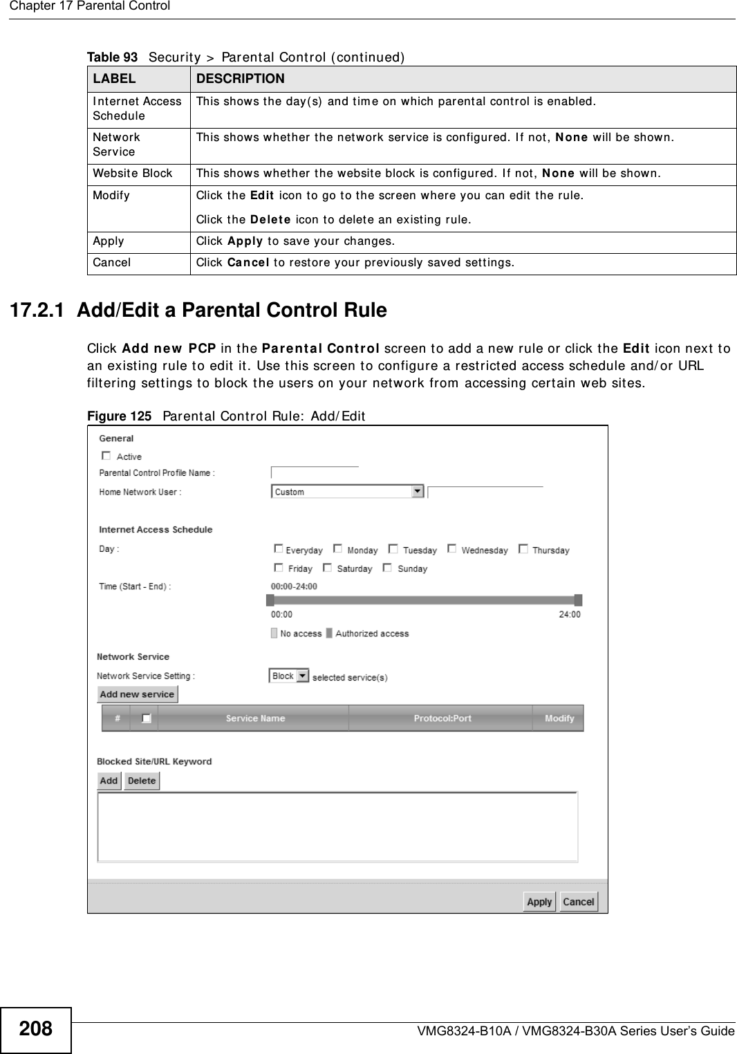
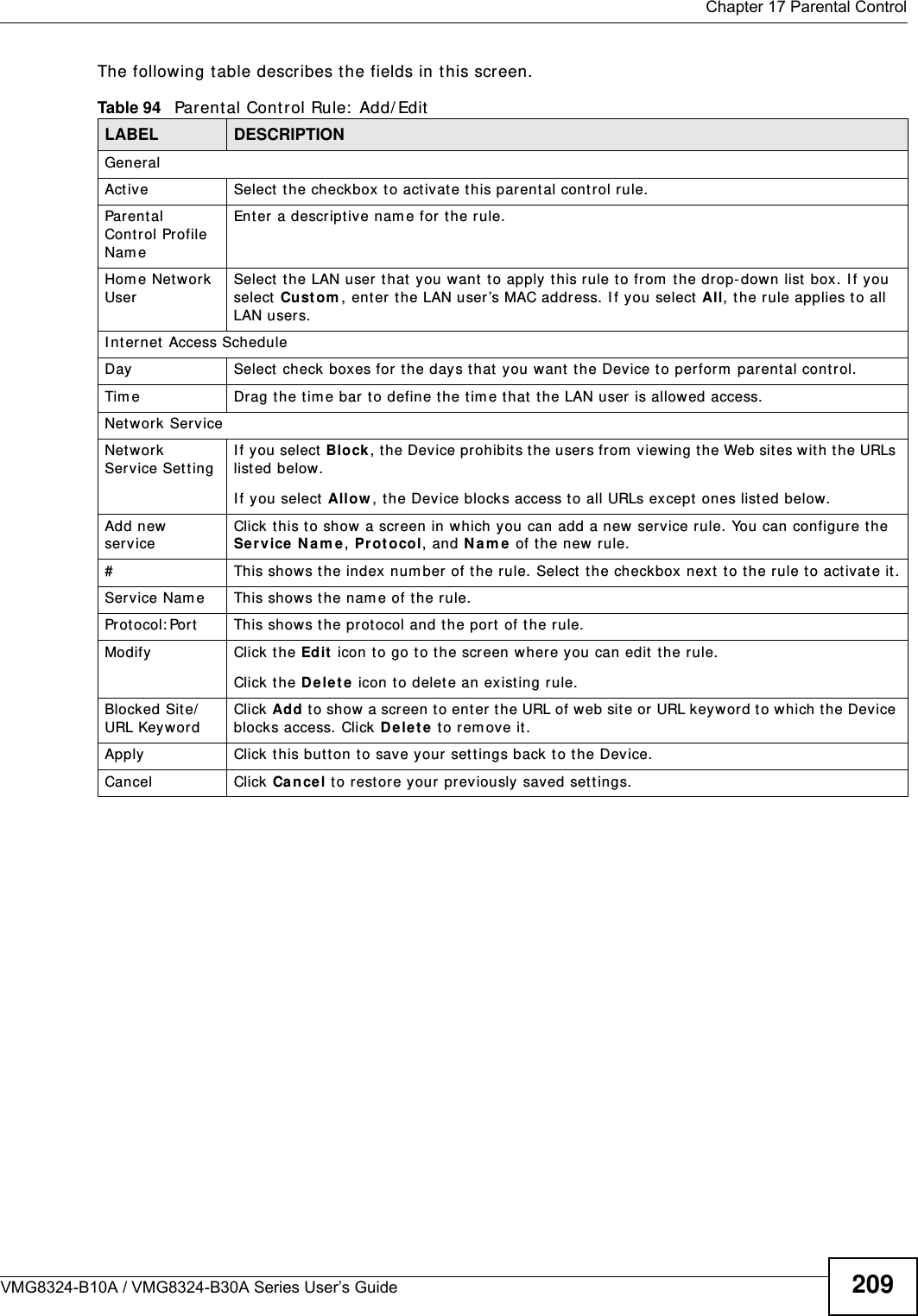

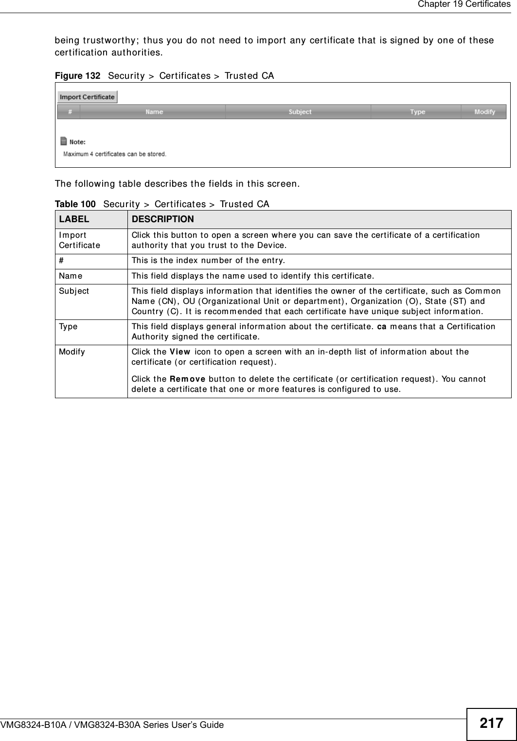


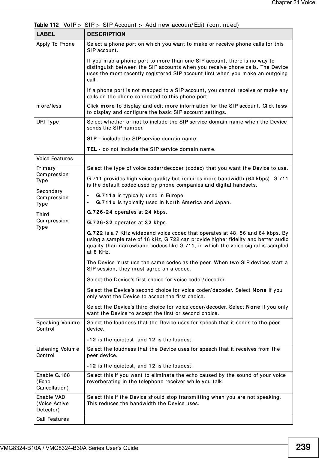
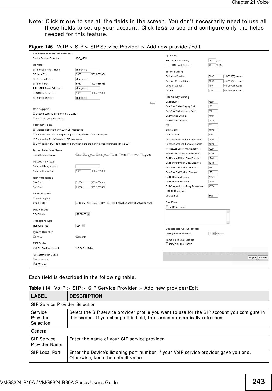
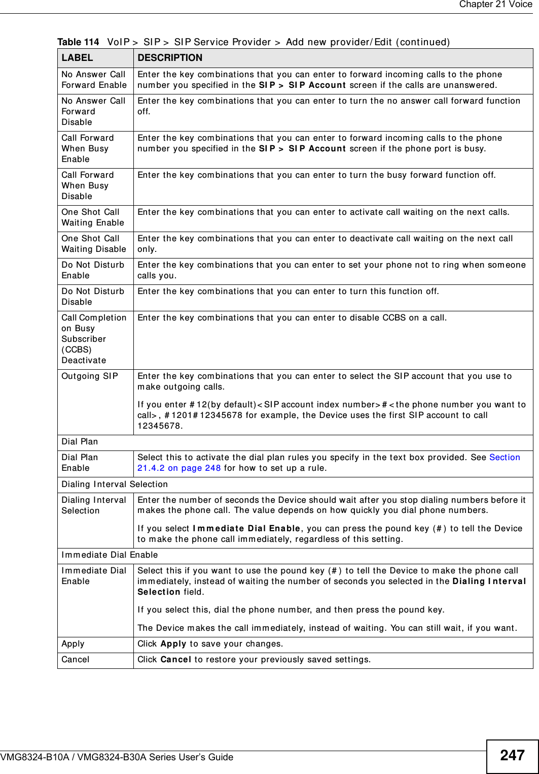
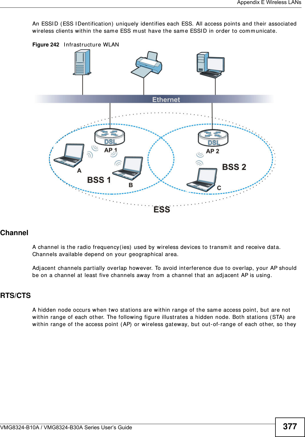
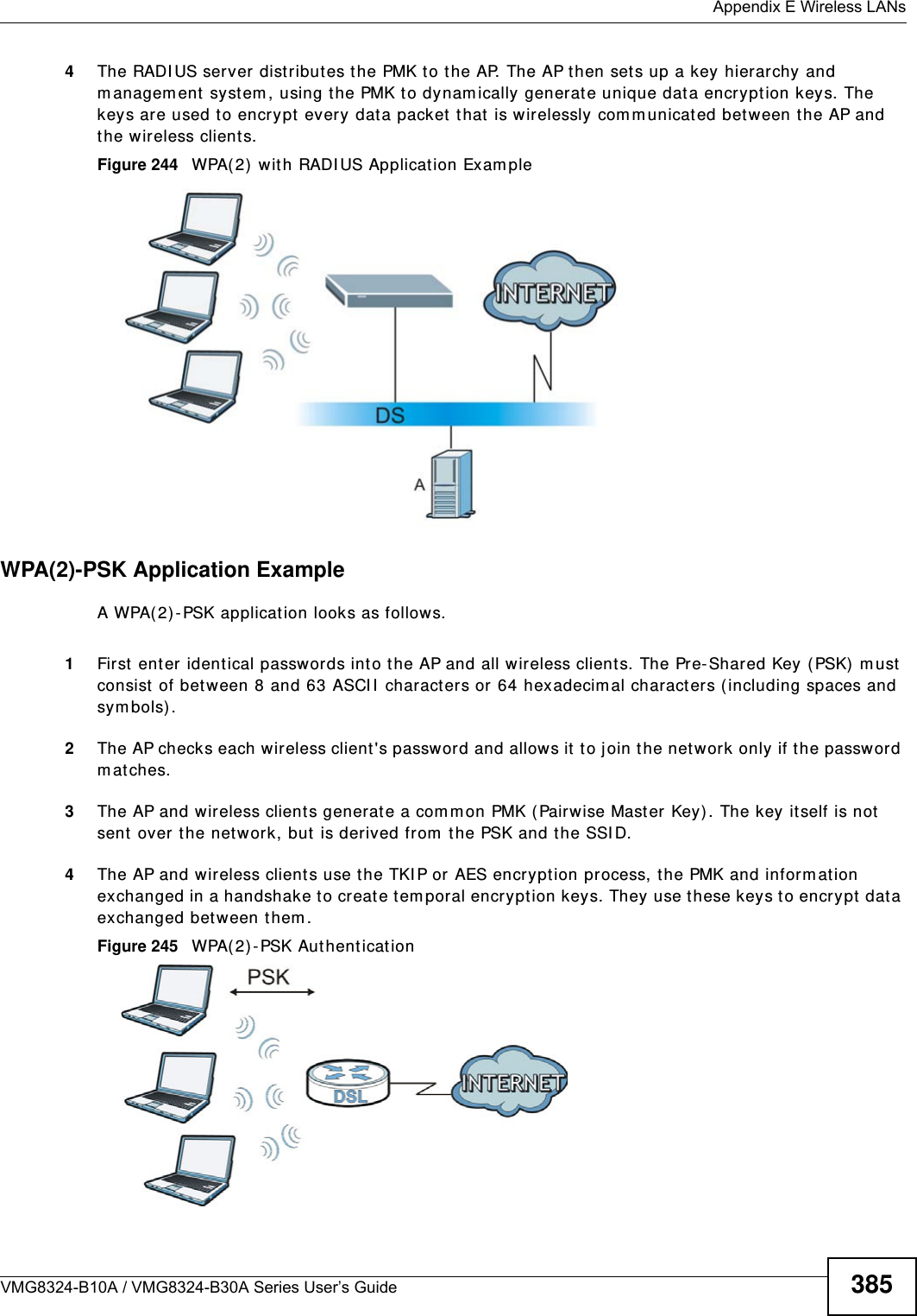
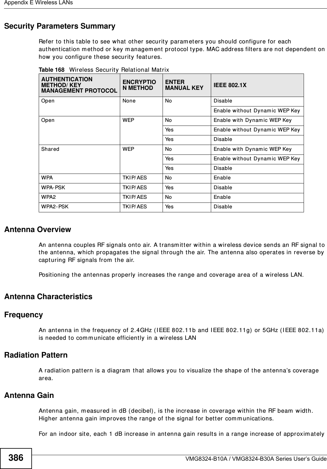
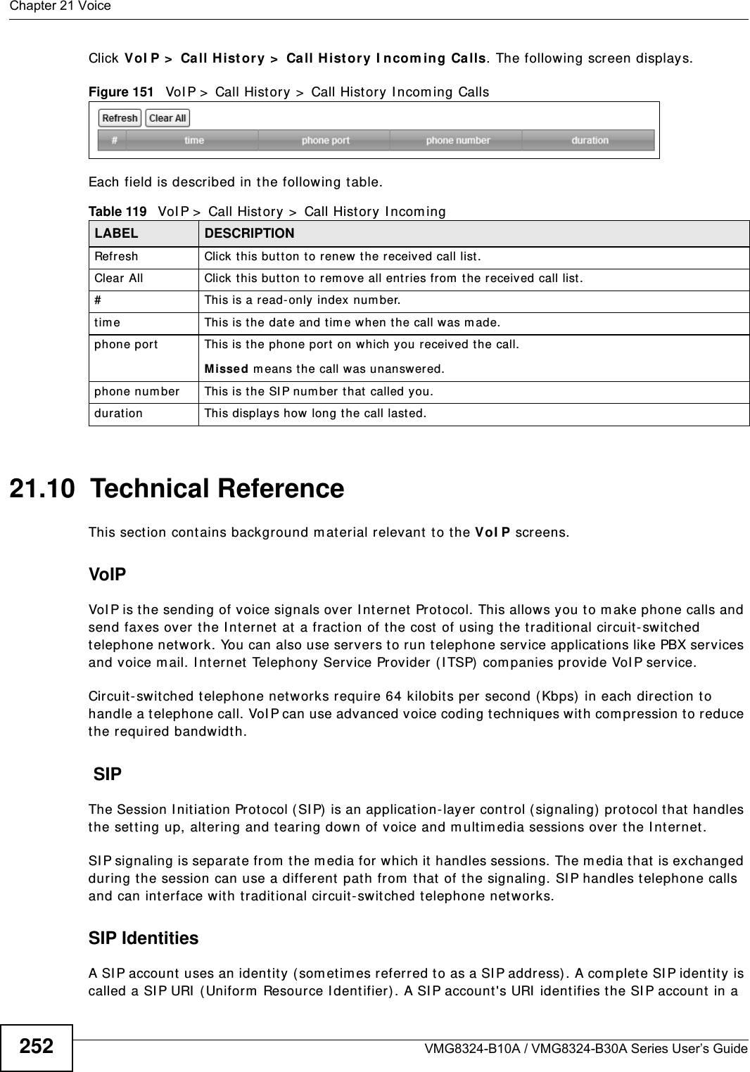
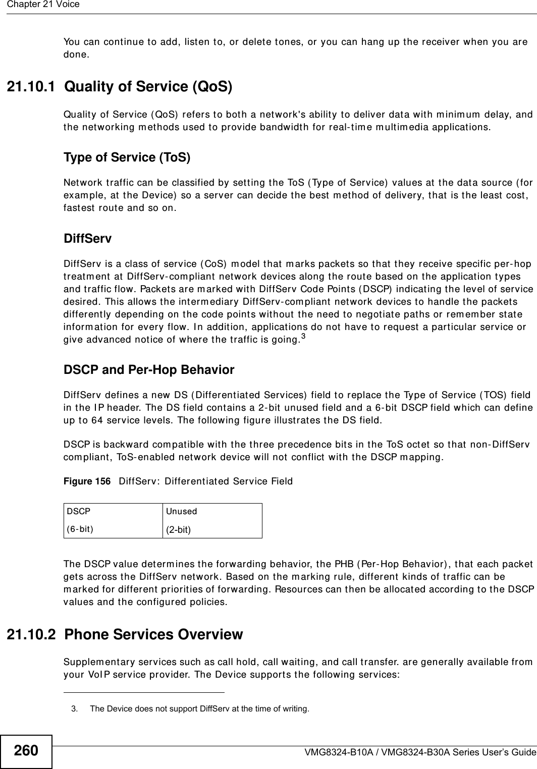
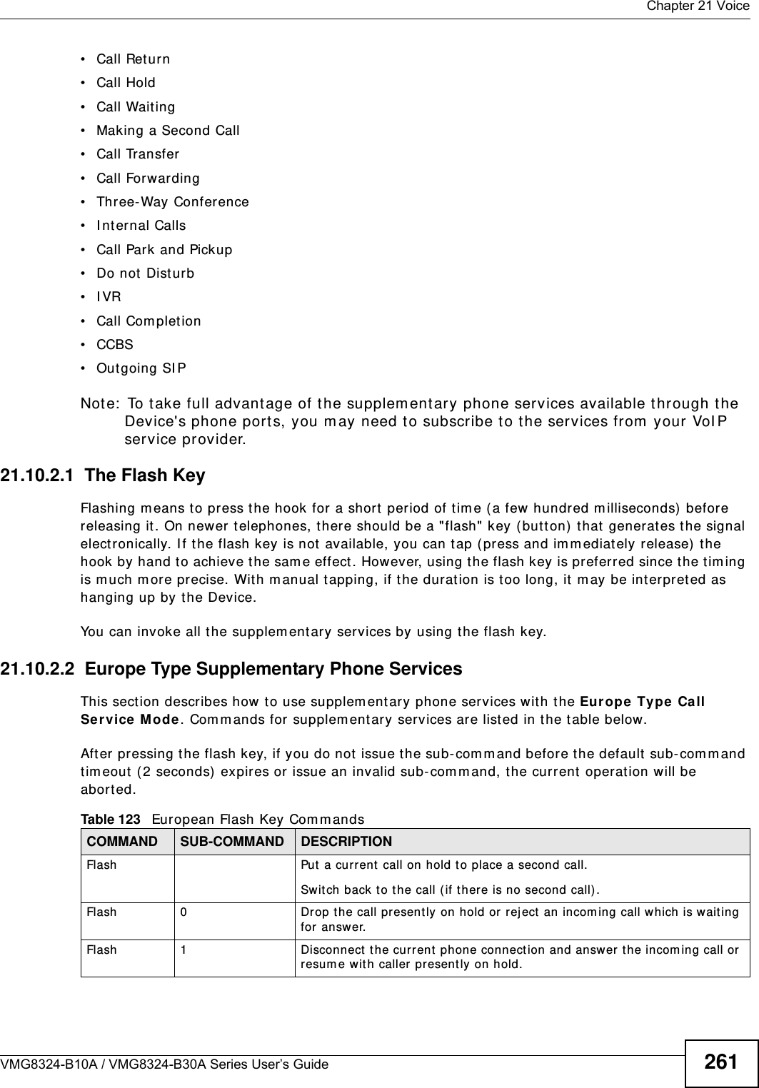
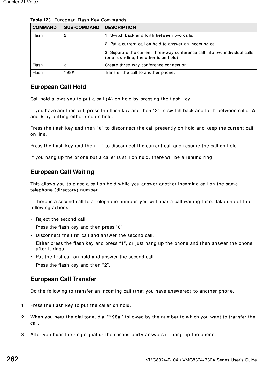
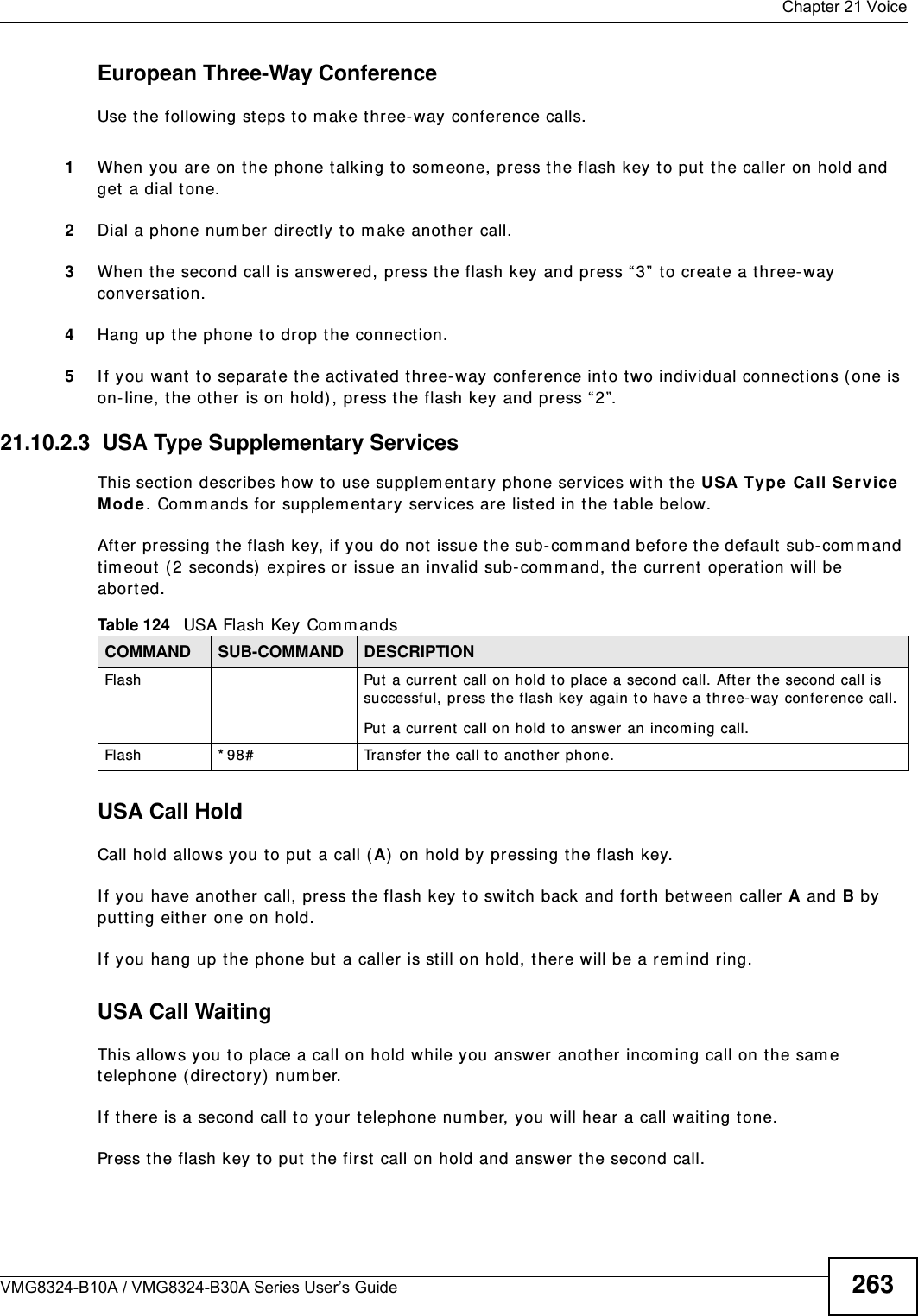
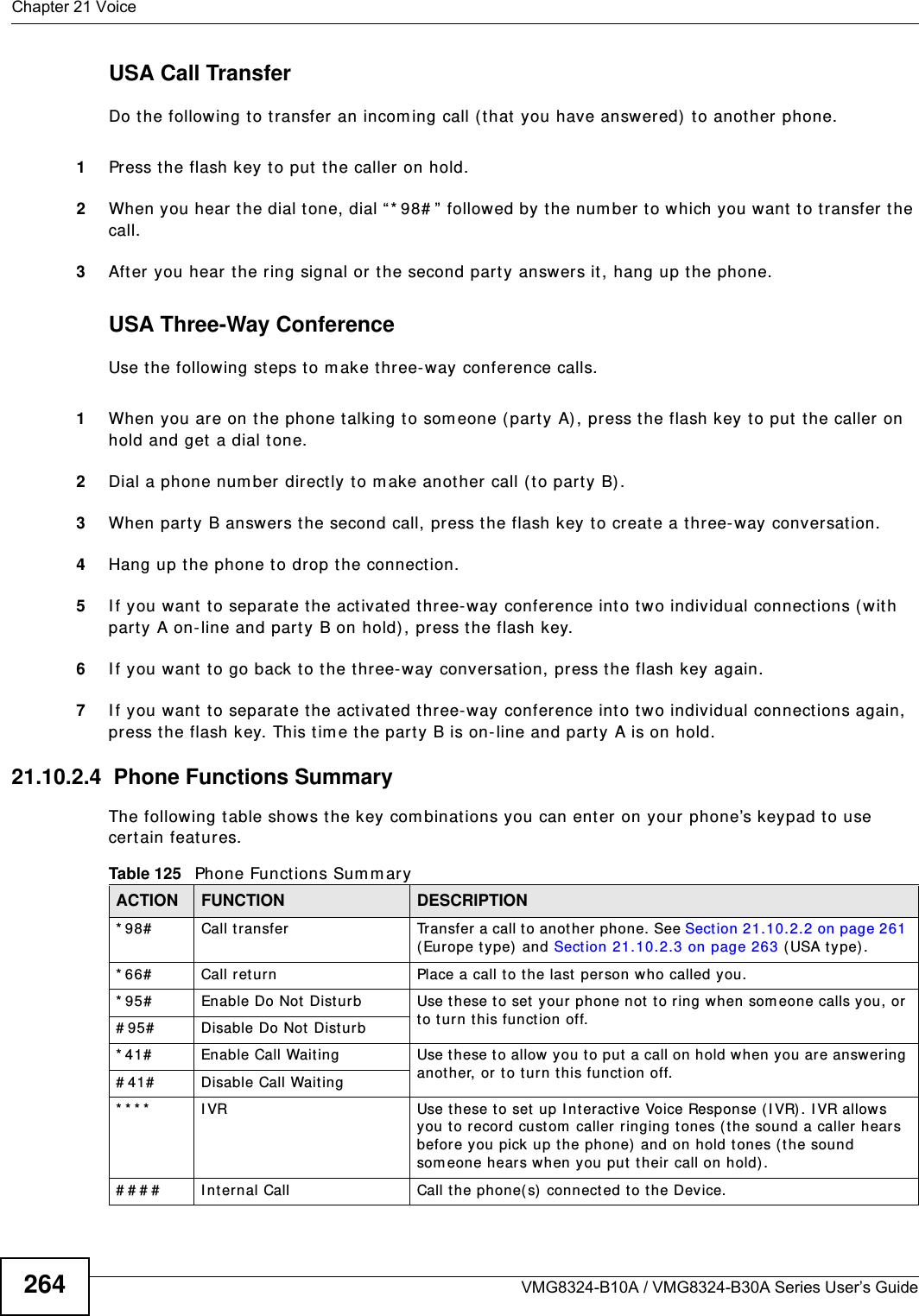
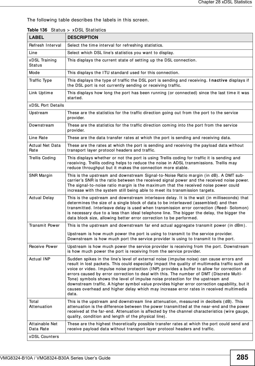
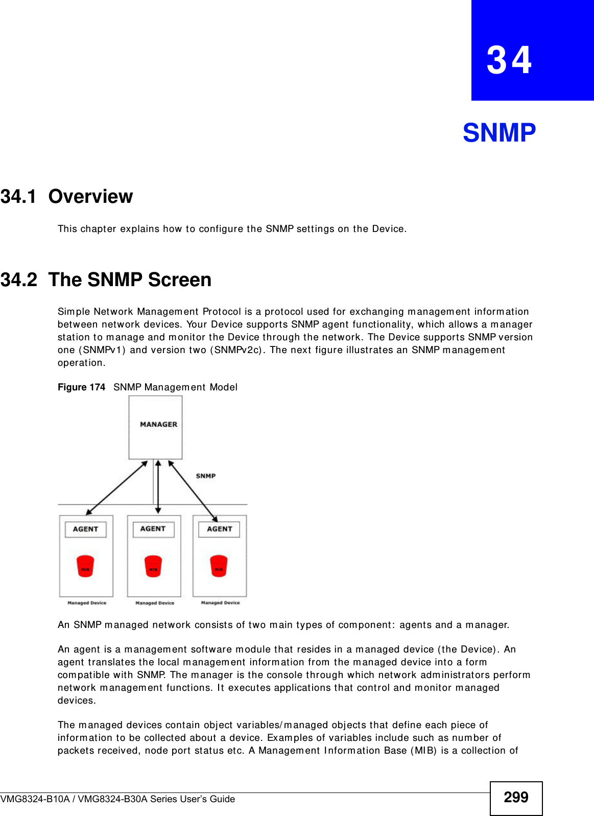
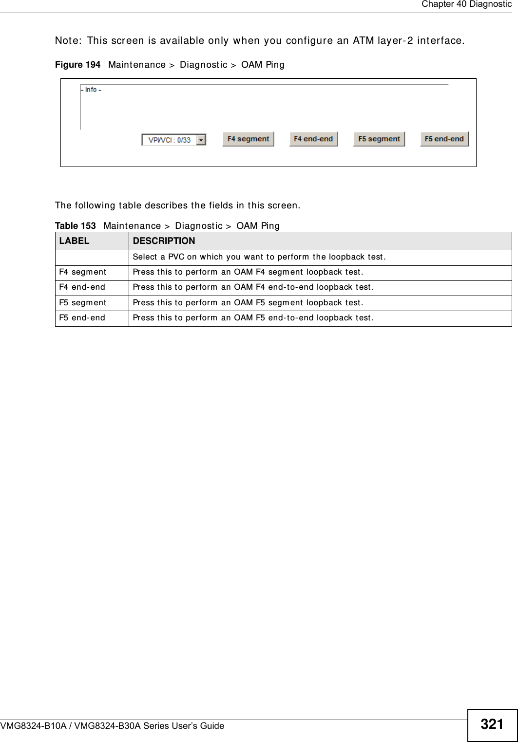
![Chapter 21 VoiceVMG8324-B10A / VMG8324-B30A Series User’s Guide24821.4.2 Dial Plan RulesA dial plan defines the dialing pat terns, such as t he length and range of the digit s for a telephone num ber. I t also includes count ry codes, access codes, area codes, local num bers, long dist ance num bers or international call prefixes. For exam ple, t he dial plan ( [ 2- 9] xxxxxx) does not allow a local num ber which begins with 1 or 0.Wit hout a dial plan, users have t o m anually enter t he whole callee’s num ber and wait for t he specified dialing interval t o t im e out or press a t erm inat or key (usually the pound key on the phone keypad) before the Device m akes the call.The Device init ializes a call when t he dialed num ber m atches any one of the rules in t he dial plan. Dial plan rules follow t hese conventions:• The collect ion of rules is in parentheses ( ).• Rules are separated by t he | (bar) sym bol.• “ x” st ands for a wildcard and can be any digit from 0 to 9.• A subset of keys is in a square bracket [ ] . Ranges are allowed.For exam ple, [ 359] m eans a num ber m at ching this rule can be 3, 5 or 9. [ 26- 8* ] m eans a num ber m at ching this rule can be 2, 6, 7, 8 or * .• The dot “.” appended t o a digit allows the digit t o be ignored or repeated m ult iple tim es. Any digit ( 0~ 9, * , # ) aft er t he dot w ill be ignored.For exam ple, (01.) m eans a num ber m at ching this rule can be 0, 01, 0111, 01111, and so on.• < dialed-num ber: translat ed-num ber> indicat es the num ber aft er t he colon replaces the num ber before t he colon in an angle bracket < > . For exam ple, ( < : 1212> xxxxxxx) means the Device aut om atically prefixes t he translat ed- num ber “1212” t o t he num ber you dialed before m aking the call. This can be used for local calls in t he US.( < 9: > xxx xxxxxxx) m eans the Device autom at ically rem oves t he specified prefix “ 9” from t he num ber you dialed before m aking t he call. This is always used for m aking outside calls from an office. ( xx< 123: 456> xxxx) m eans the Device aut om at ically translates “ 123” t o “456” in the num ber you dialed before m aking the call.• Calls with a num ber followed by the exclam ation m ark “ !” will be dropped.• Calls with a num ber followed by the term ination character “@” will be m ade im m ediat ely. Any digit ( 0~ 9, * , # ) aft er t he @ charact er will be ignored.I n t his exam ple dial plan ( 0 | [ 49] 11 | 1 [ 2-9] xx xxxxxxx | 1 947 xxxxxxx ! ), you can dial “0” t o call the local operat or, call 411 or 911, or m ake a long dist ance call with an area code st arting from 2 to 9 in t he US. The calls with the area code 947 will be dropped.](https://usermanual.wiki/ZyXEL-Communications/VMG8324B10A.VMG8324-B10A-UserMan-2-2013-12-09/User-Guide-2137566-Page-42.png)
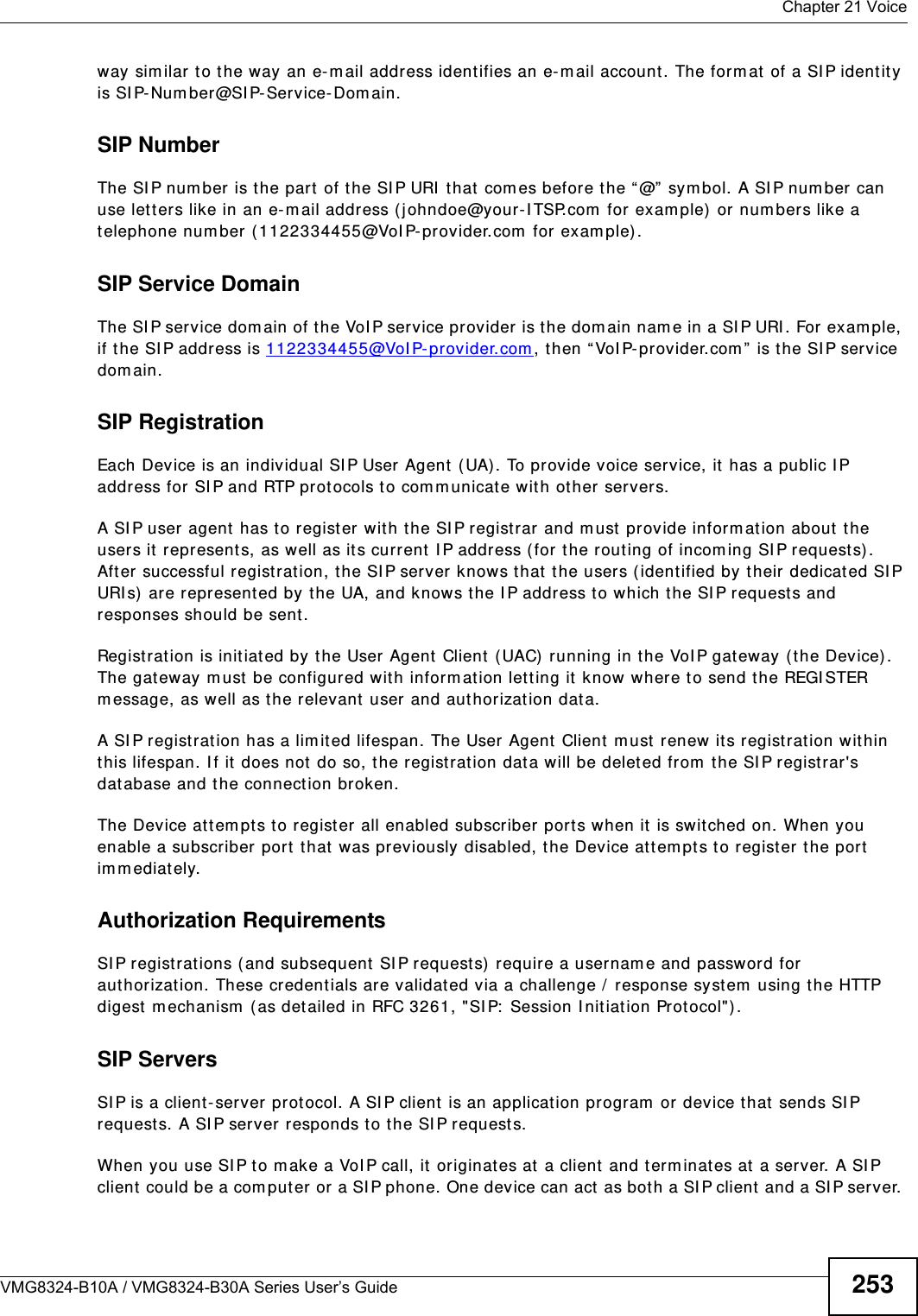
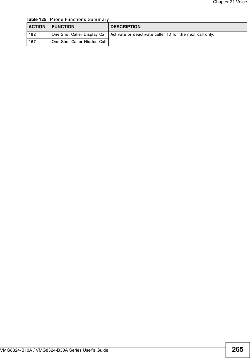

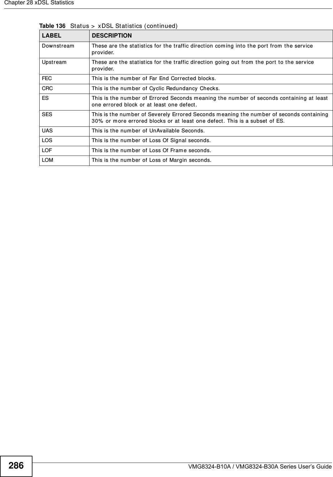


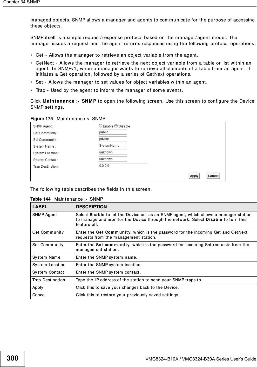


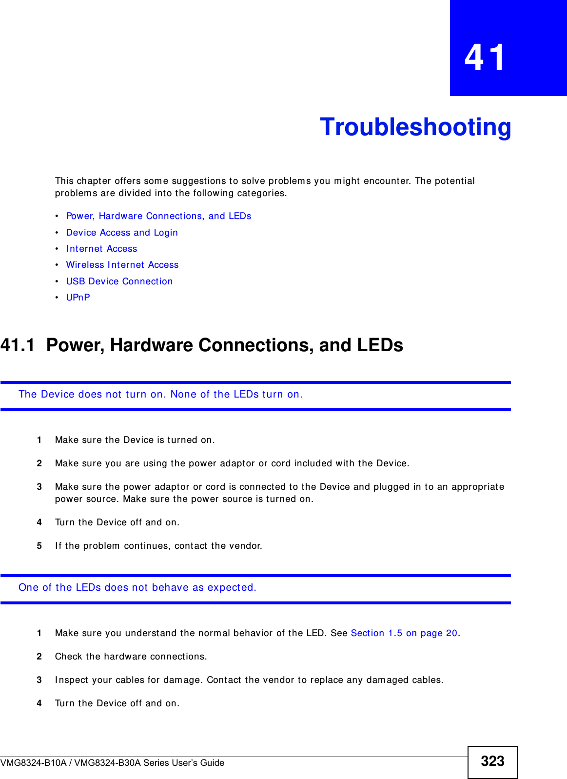
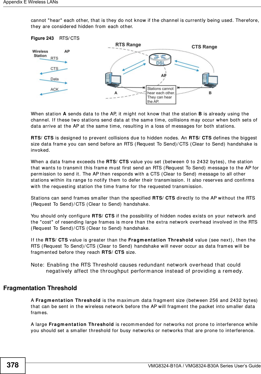
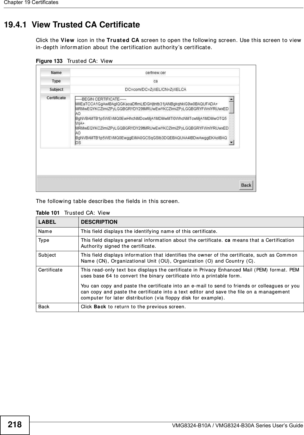
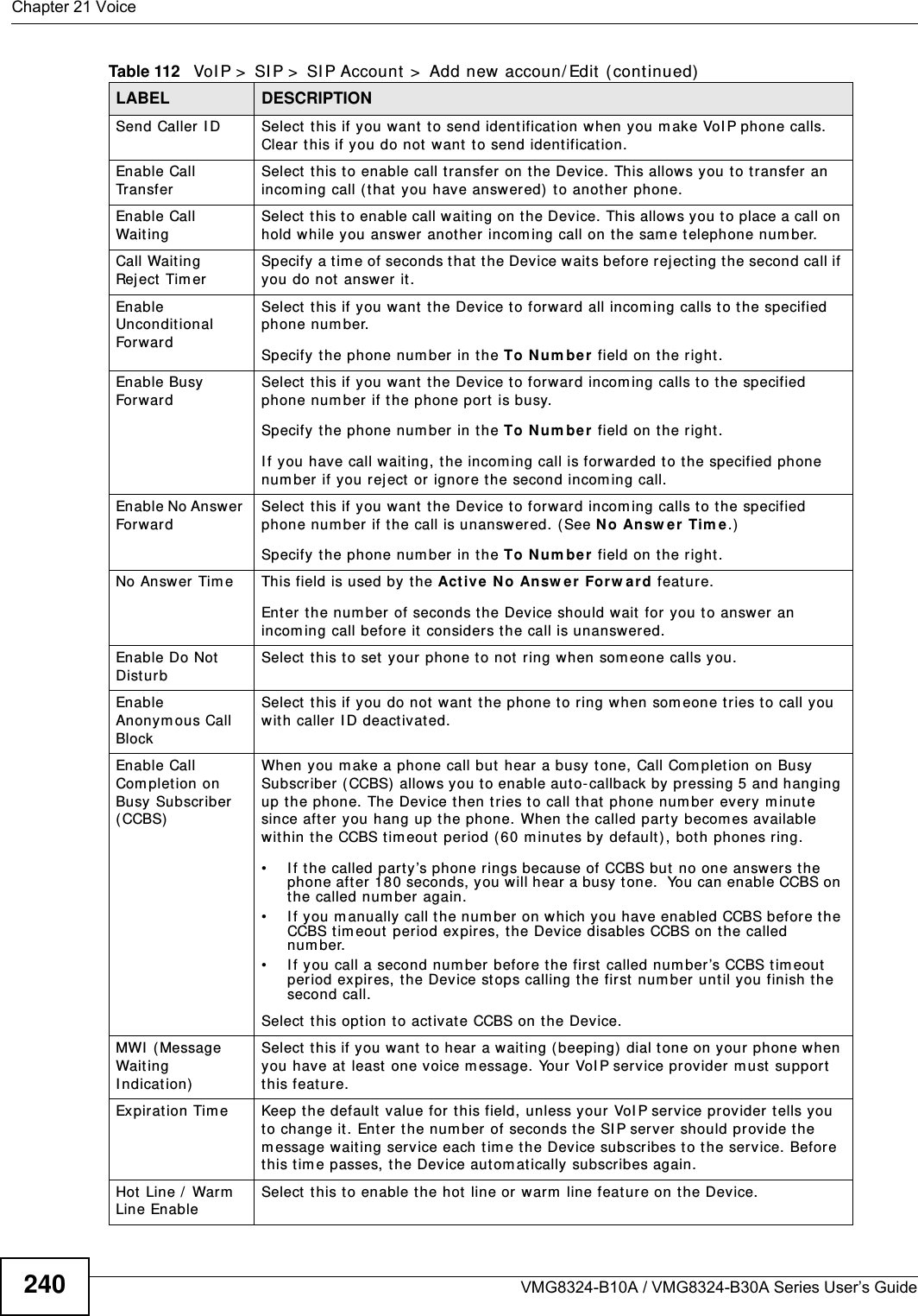
![Chapter 41 TroubleshootingVMG8324-B10A / VMG8324-B30A Series User’s Guide 3255Reset t he device t o it s factor y defaults, and try to access the Device w ith t he default I P address. See Section 1.6 on page 22.6I f the problem cont inues, contact the network administrator or vendor, or t ry one of the advanced suggest ions.Advan ced Sugge stions• Make sure you have logged out of any ear lier m anagem ent sessions using the sam e user account even if they were through a differ ent interface or using a different browser.• Try to access t he Device using another service, such as Telnet . I f you can access t he Device, check the r em ot e m anagem ent set tings and firewall rules to find out why t he Device does not respond to HTTP. I can see the Login screen, but I cannot log in to the Device.1Make sure you have entered t he passwor d correctly. The default adm in password is 1 2 3 4 . The field is case- sensit ive, so m ake sure [ Caps Lock] is not on. 2You cannot log in to the web configurator while som eone is using Telnet to access t he Device. Log out of the Device in the ot her session, or ask the person who is logged in to log out. 3Turn t he Device off and on. 4I f this does not work, you have to reset t he device to it s factory defaults. See Sect ion 41.1 on page 323.I cannot Telnet t o t he Device.See the t roubleshooting suggestions for I cannot see or access t he Login screen in the web configurat or. I gnore the suggestions about your browser.I cannot use FTP t o upload / download t he configuration file. / I cannot use FTP to upload new firm ware.See the t roubleshooting suggestions for I cannot see or access t he Login screen in the web configurat or. I gnore the suggestions about your browser.](https://usermanual.wiki/ZyXEL-Communications/VMG8324B10A.VMG8324-B10A-UserMan-2-2013-12-09/User-Guide-2137566-Page-119.png)
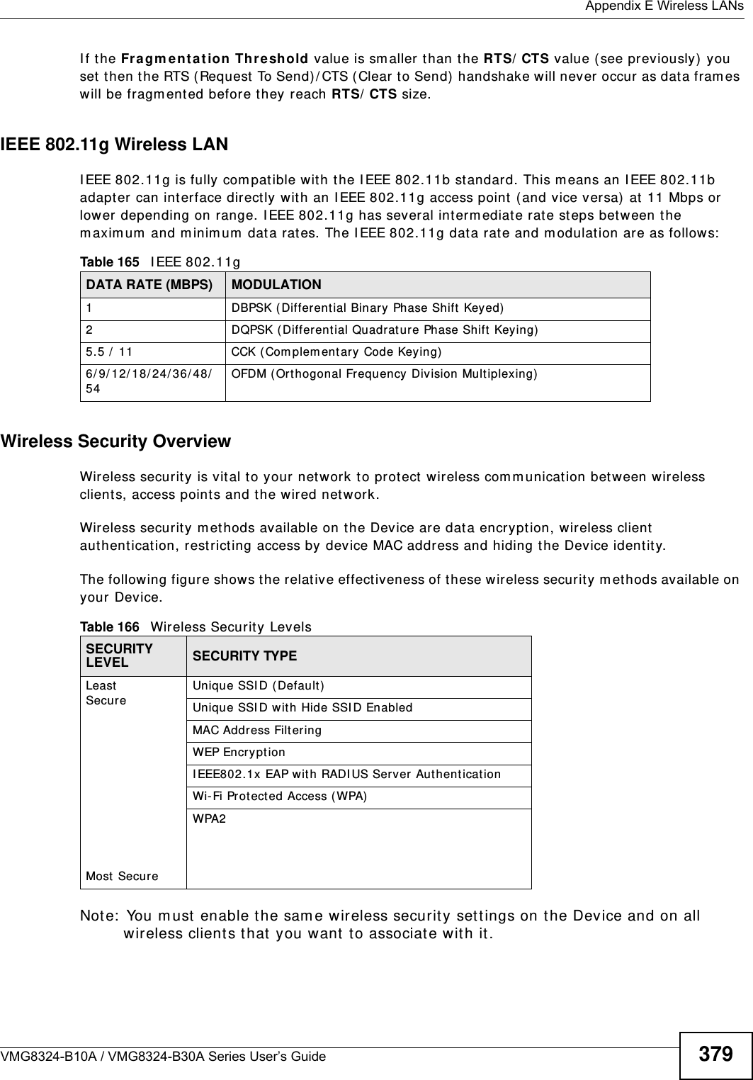
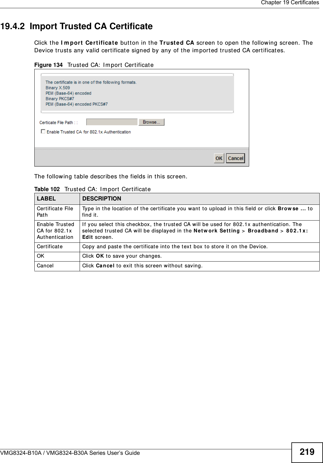
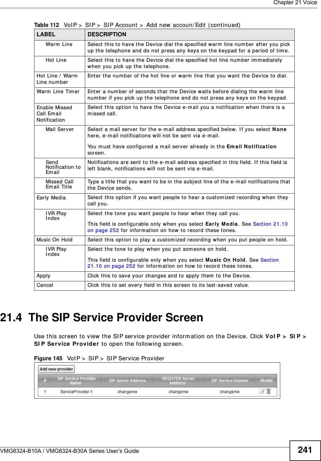
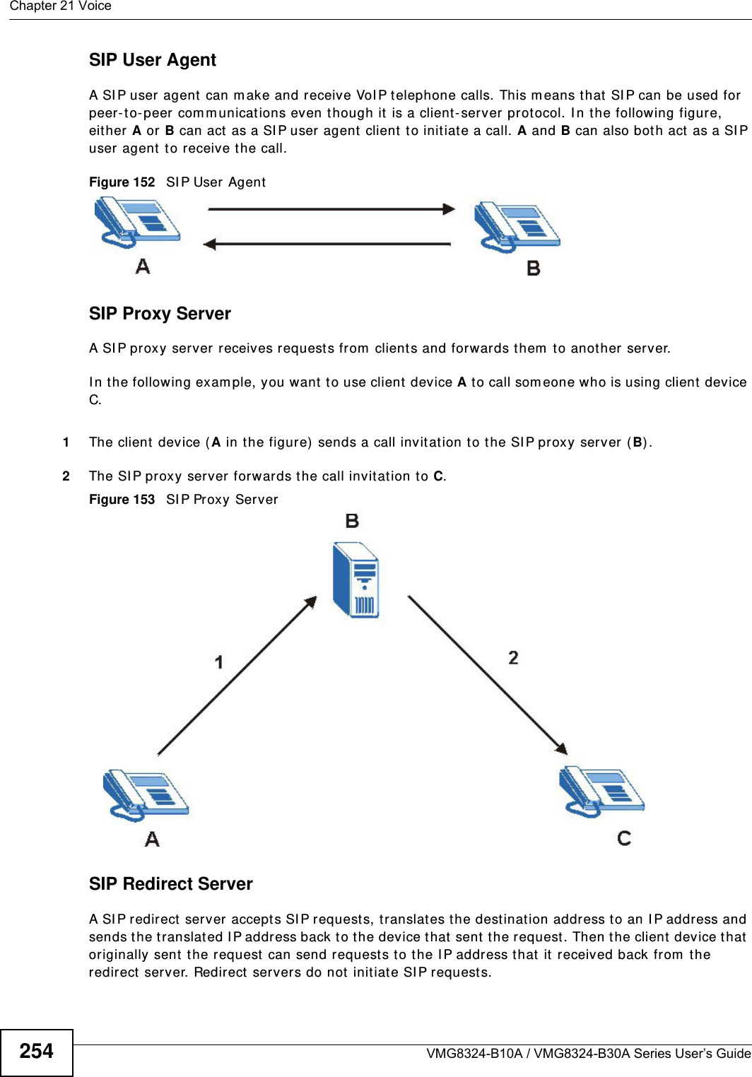
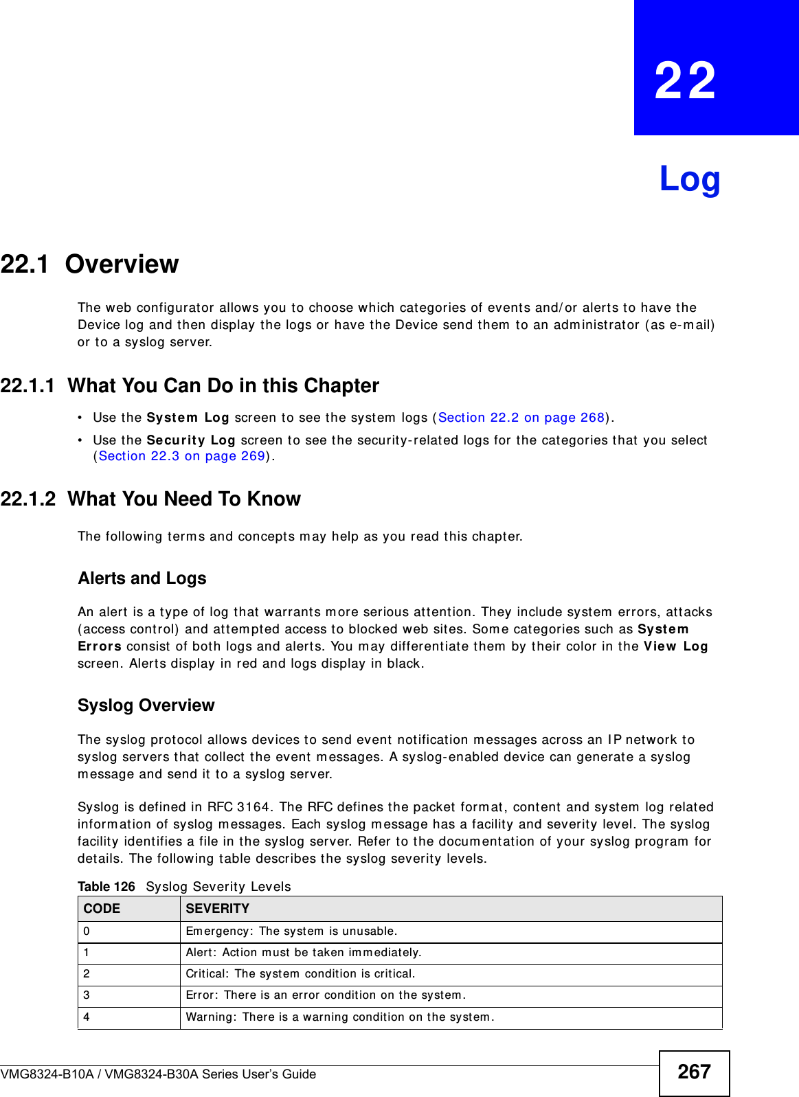
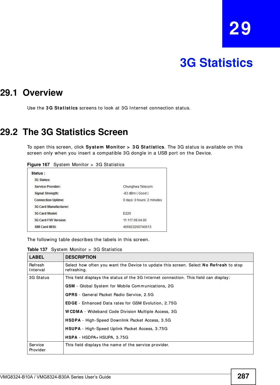
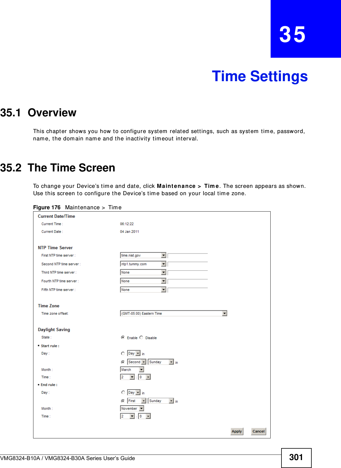
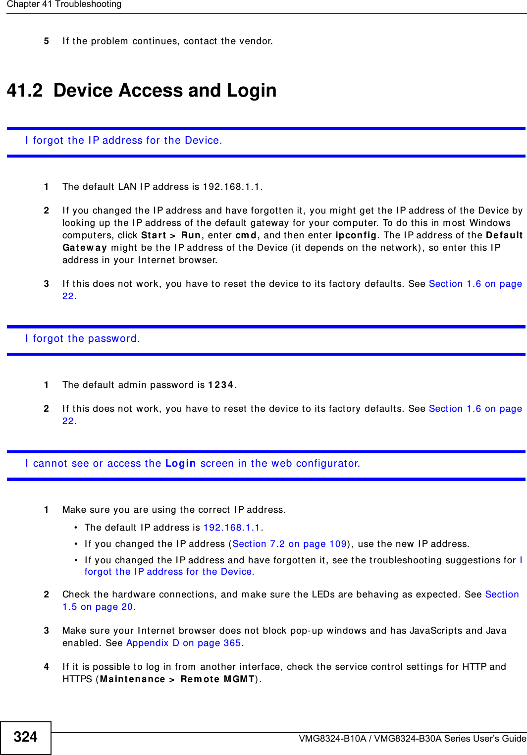
![Chapter 41 TroubleshootingVMG8324-B10A / VMG8324-B30A Series User’s Guide32641.3 Internet AccessI cannot access t he I nter net.1Check the hardware connect ions, and m ake sure the LEDs are behaving as expected. See t he Qu ick St a rt Guide and Sect ion 1.5 on page 20.2Make sure you entered your I SP account inform at ion correctly in t he N et w ork Set ting > Broadband screen. These fields are case-sensit ive, so m ake sure [ Caps Lock] is not on. 3I f you are trying to access t he I nt ernet wirelessly, m ake sure that you enabled the wir eless LAN in the Device and your wireless client and that the wireless set tings in the wireless client are the sam e as t he sett ings in the Device.4Disconnect all the cables from your device and reconnect them . 5I f the problem continues, contact your I SP. I cannot access t he I nter net t hrough a DSL connect ion.1Make sure you have t he D SL W AN port connected t o a telephone jack ( or the DSL or m odem jack on a split ter if you have one) .2Make sure you configured a proper DSL WAN int erface ( Net w ork Set ting > Broadband scr een) wit h the I nt ernet account inform ation provided by your I SP and t hat it is enabled.3Check t hat t he LAN int erface you are connected t o is in the sam e int erface group as t he DSL connect ion ( Ne tw ork Se t t ing > I nte rface Gr oup) .4I f you set up a WAN connect ion using bridging service, make sure you turn off t he DHCP feat ur e in the LAN screen to have the clients get WAN I P addresses directly from your I SP’s DHCP server.I cannot connect to the I nternet using a second DSL connection.ADSL and VDSL connections cannot w ork at t he sam e tim e. You can only use one t ype of DSL connection, either ADSL or VDSL connection at one t im e.I cannot access the I nternet anym ore. I had access to t he I nternet (wit h t he Device) , but m y I nt ernet connection is not available anym ore.1Your session wit h the Device m ay have expired. Try logging int o t he Device again.](https://usermanual.wiki/ZyXEL-Communications/VMG8324B10A.VMG8324-B10A-UserMan-2-2013-12-09/User-Guide-2137566-Page-120.png)
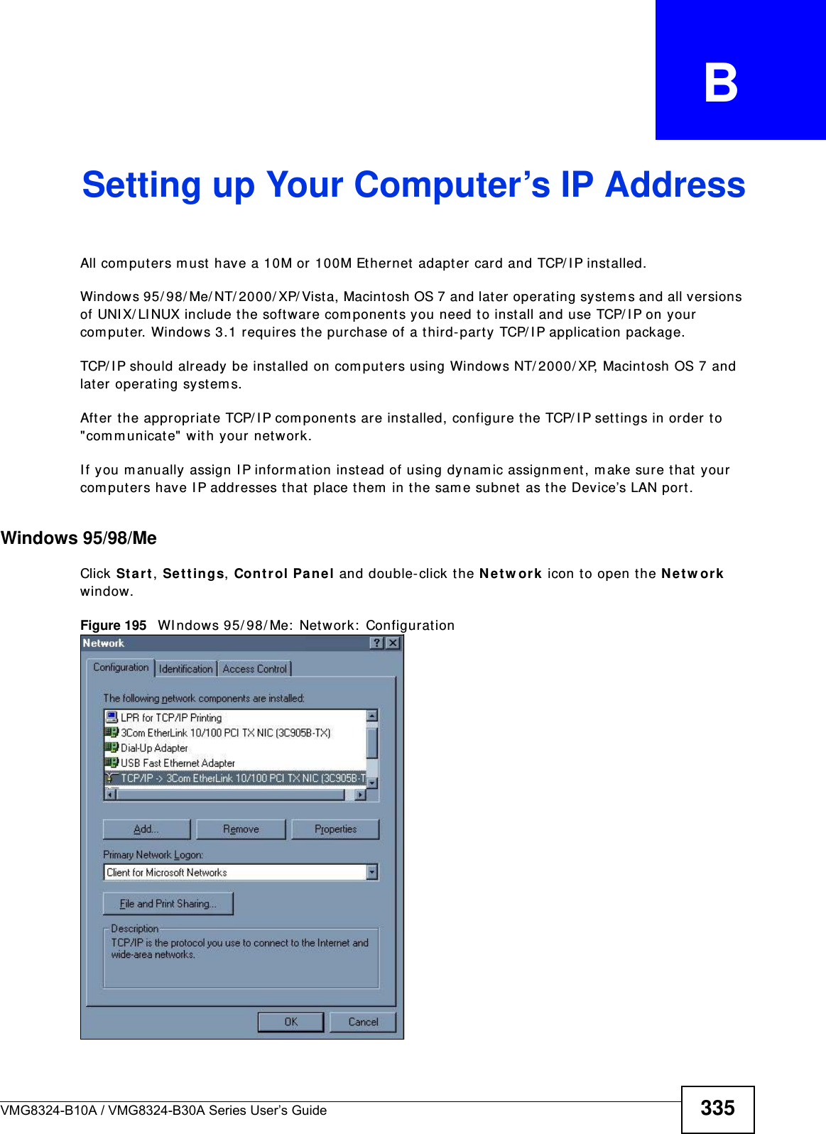
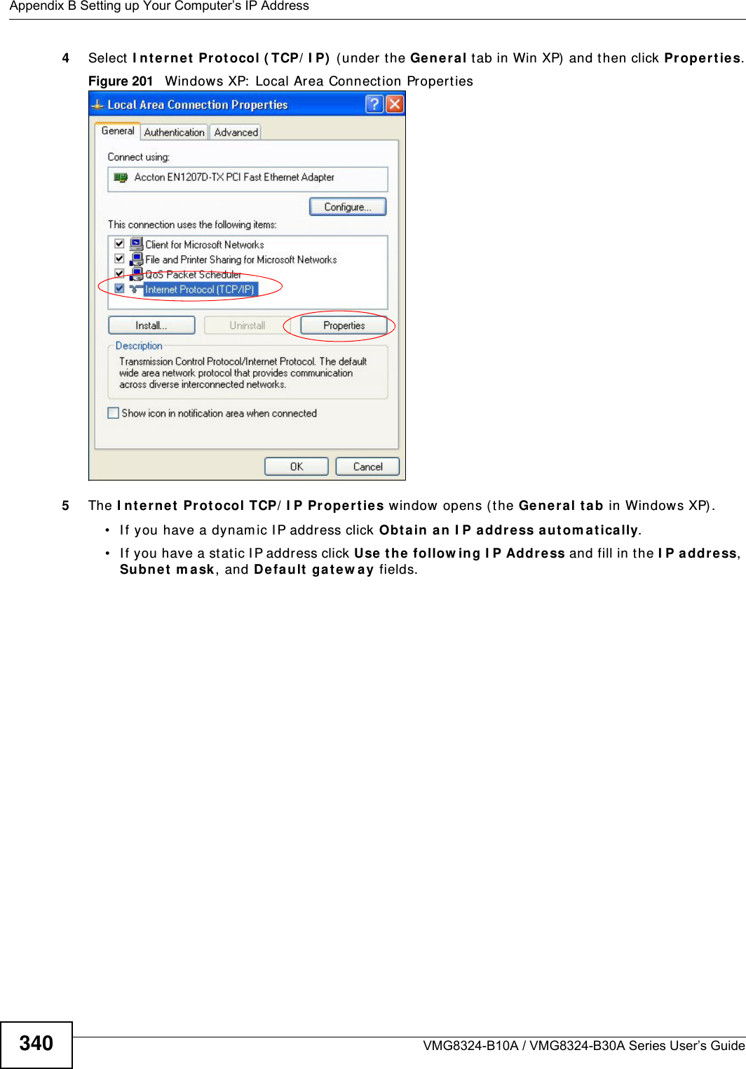
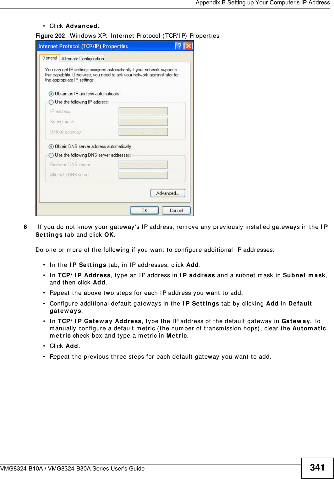
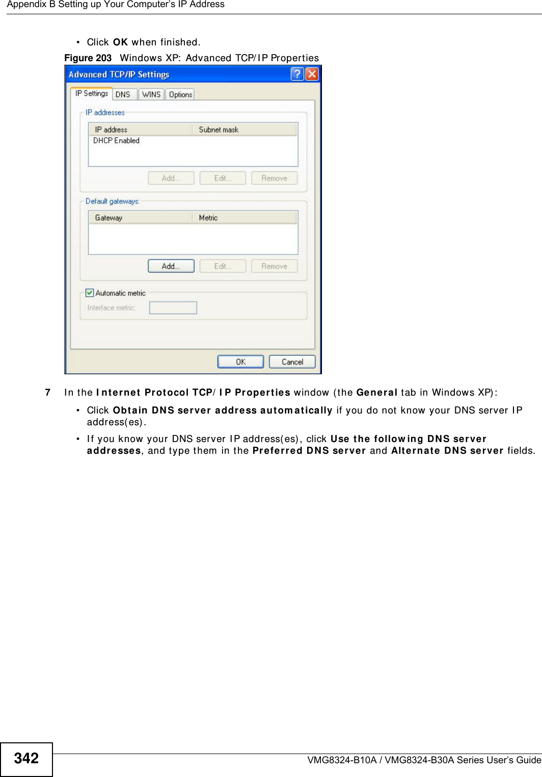
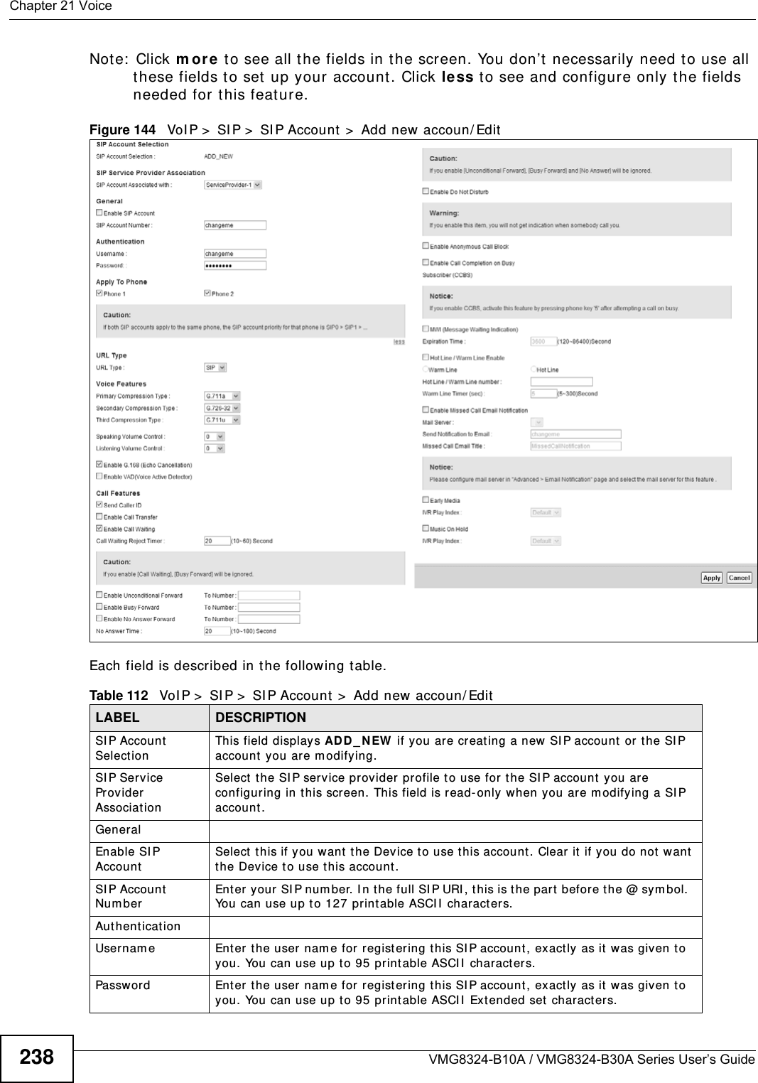
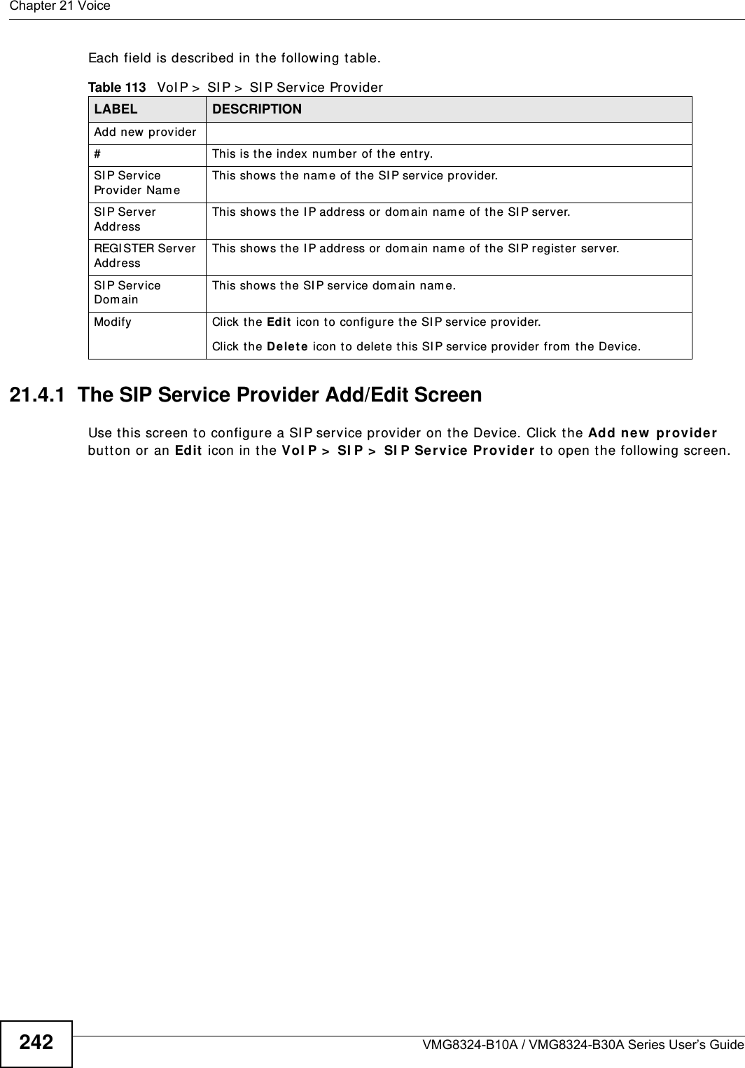
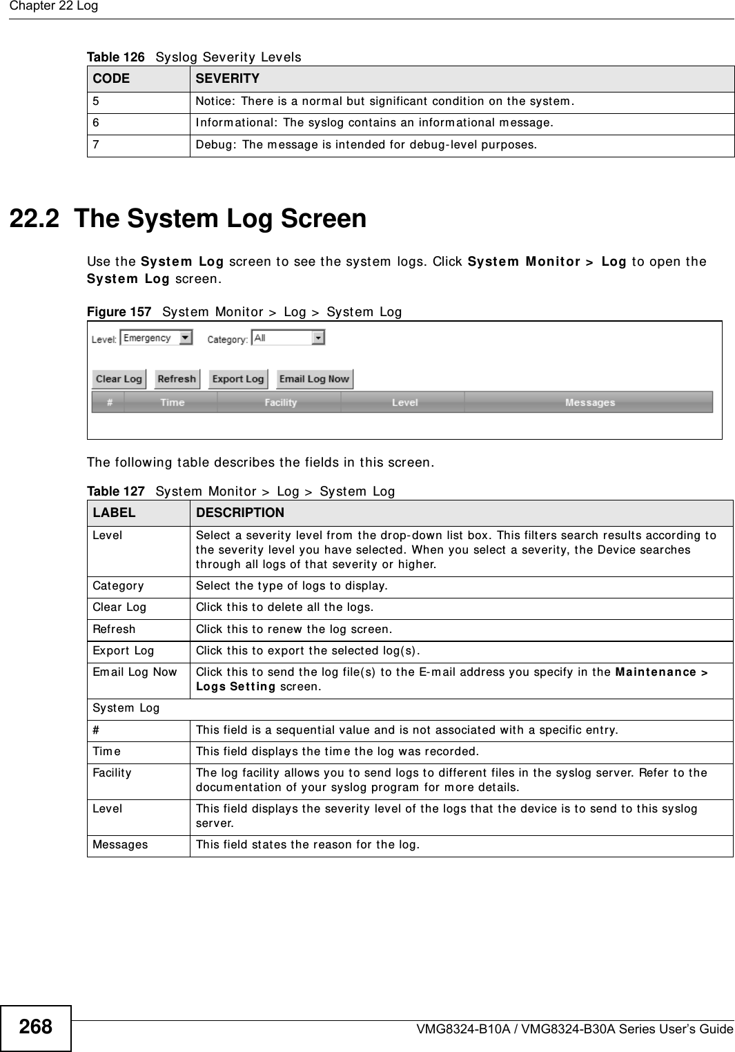
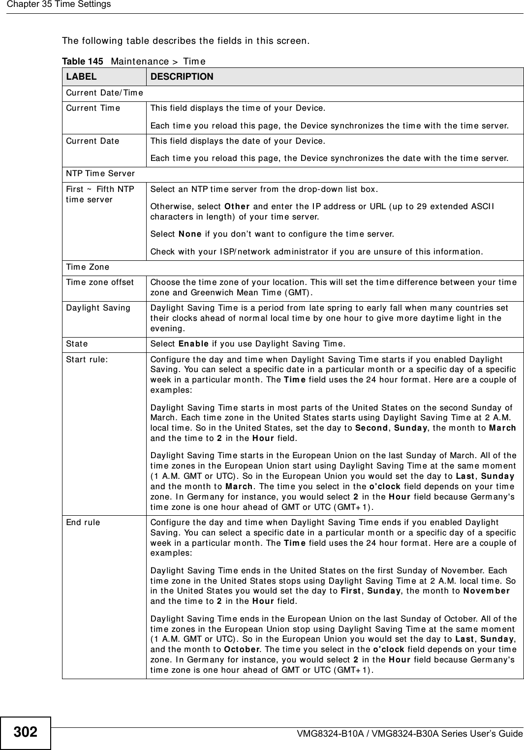
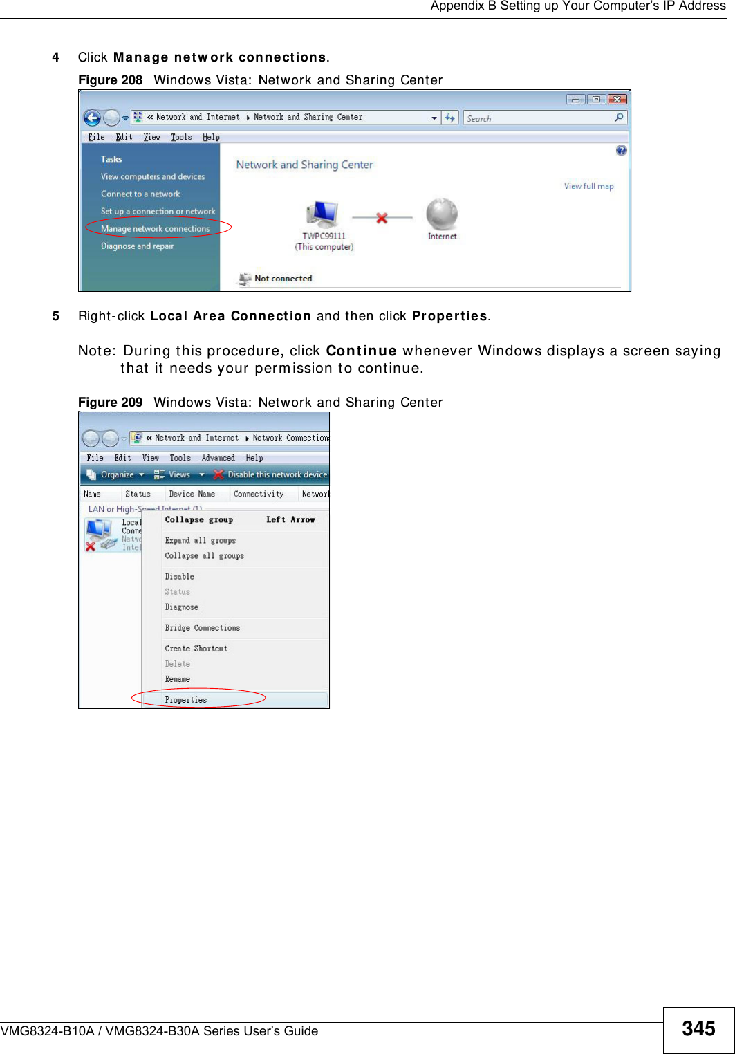
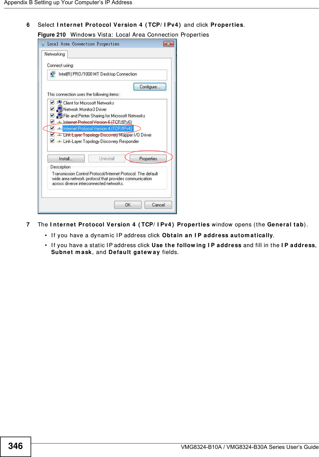
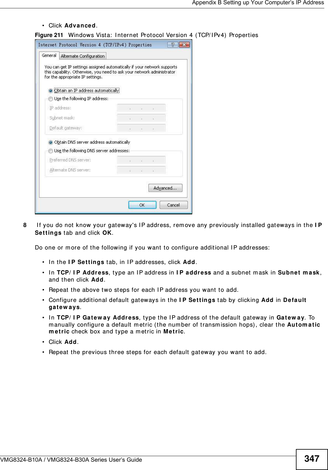
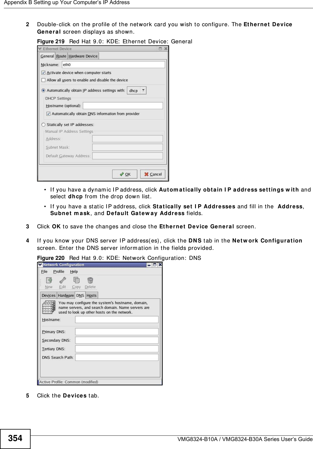
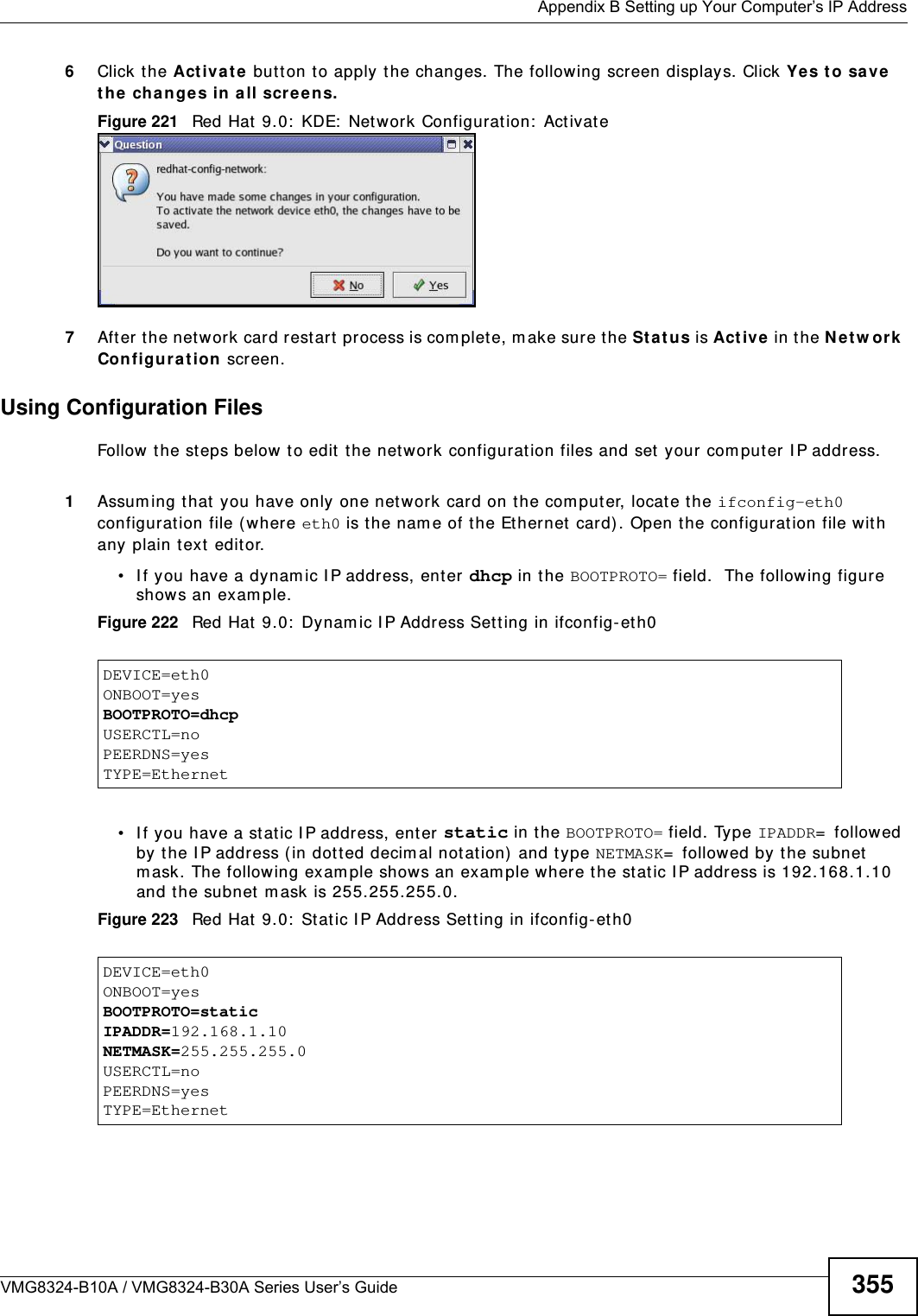
![Appendix B Setting up Your Computer’s IP AddressVMG8324-B10A / VMG8324-B30A Series User’s Guide 343I f you have previously configured DNS servers, click Adva nce d and then the DN S t ab to order t hem .Figure 204 Windows XP: I nt ernet Prot ocol ( TCP/ I P) Propert ies8Click OK t o close t he I nte rnet Prot ocol ( TCP/ I P) Propert ies window.9Click Close ( OK in Windows 2000/ NT) t o close the Loca l Area Connection Pr oper ties window.10 Close t he Ne tw ork Connect ions window ( Ne tw ork a nd Dial- up Con nections in Windows 200 0/ NT) .11 Turn on your Device and rest art your com put er ( if prom pted).Verifying Settings1Click St a r t , All Program s, Accessor ies and then Com m a nd Pr om pt.2I n t he Com m and Prom pt window, t ype "ipconfig" and t hen press [ ENTER] . You can also open N etw or k Conne ct ions, right- click a net work connection, click St a t u s and then click the Support tab.Windows VistaThis section shows screens from Windows Vista Enterprise Version 6.0.](https://usermanual.wiki/ZyXEL-Communications/VMG8324B10A.VMG8324-B10A-UserMan-2-2013-12-09/User-Guide-2137566-Page-137.png)
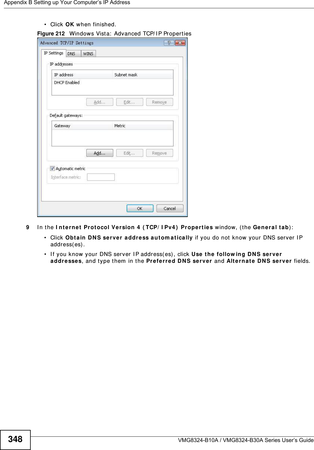
![Appendix B Setting up Your Computer’s IP AddressVMG8324-B10A / VMG8324-B30A Series User’s Guide 349I f you have previously configured DNS servers, click Adva nce d and then the DN S t ab to order t hem .Figure 213 Windows Vist a: I nternet Prot ocol Version 4 ( TCP/ I Pv4) Properties10 Click OK t o close t he I nte rnet Prot ocol Version 4 ( TCP/ I Pv4 ) Propert ie s window.11 Click Close t o close t he Local Are a Conne ct ion Propert ies window.12 Close t he Ne tw ork Connect ions window.13 Turn on your Device and rest art your com put er ( if prom pted).Verifying Settings1Click St a r t , All Program s, Accessor ies and then Com m a nd Pr om pt.2I n t he Com m and Prom pt window, t ype "ipconfig" and t hen press [ ENTER] . You can also open N etw or k Conne ct ions, right- click a net work connection, click St a t u s and then click the Support tab.](https://usermanual.wiki/ZyXEL-Communications/VMG8324B10A.VMG8324-B10A-UserMan-2-2013-12-09/User-Guide-2137566-Page-143.png)
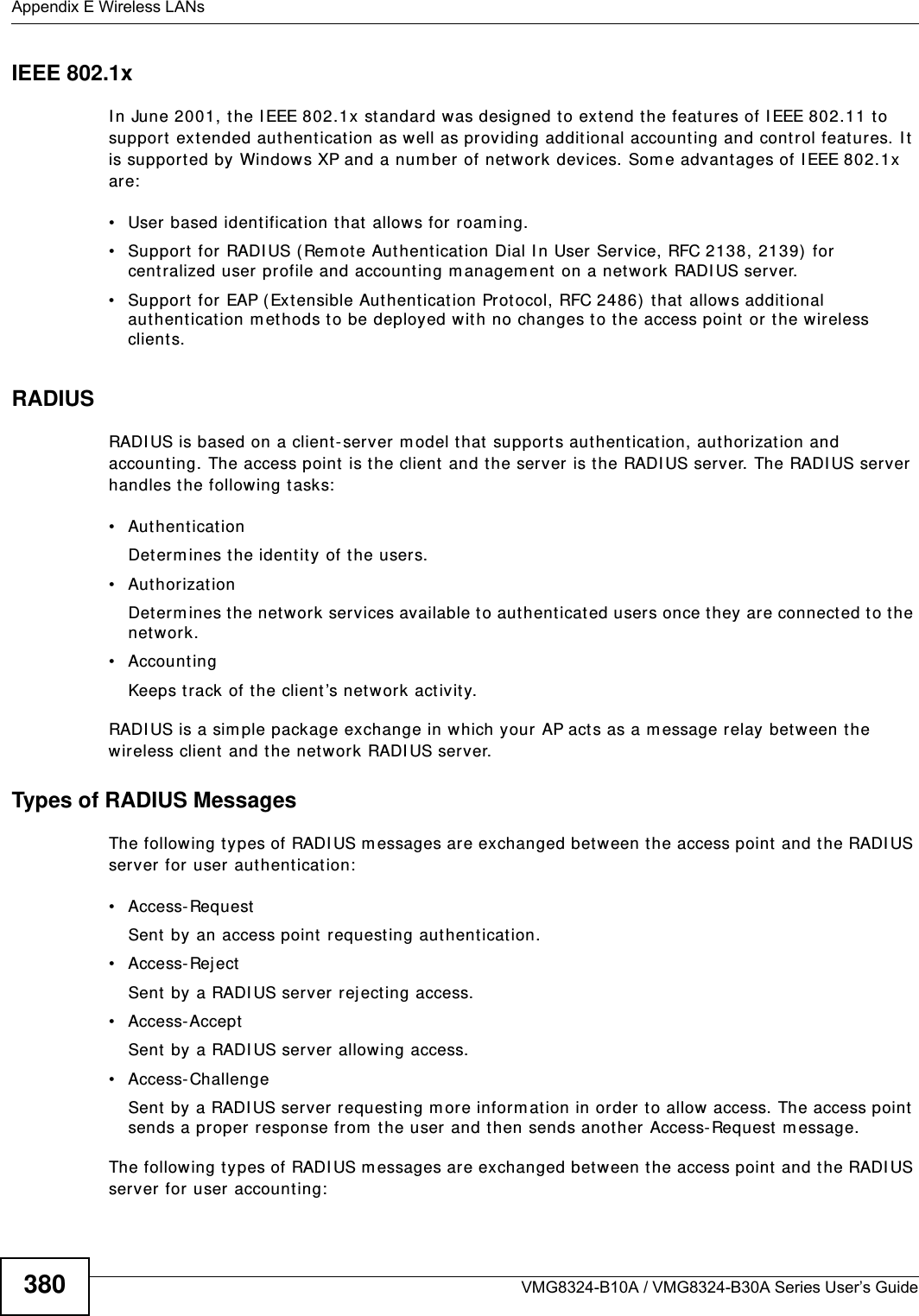
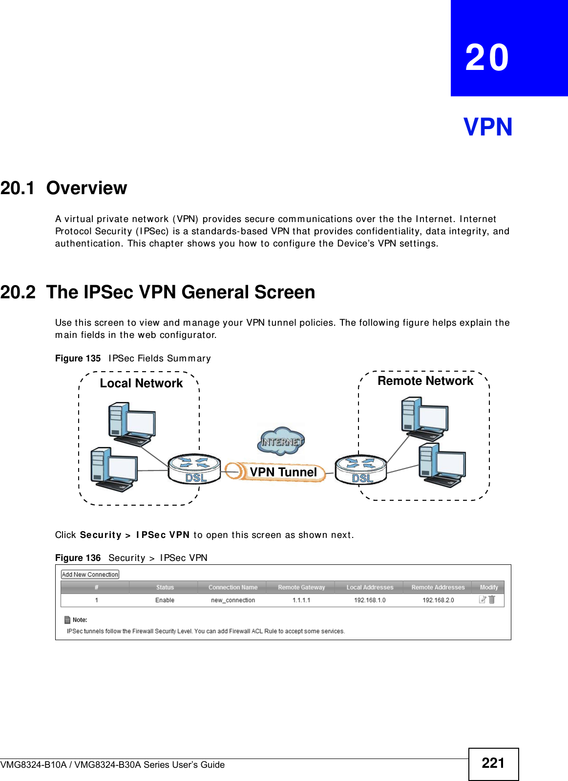
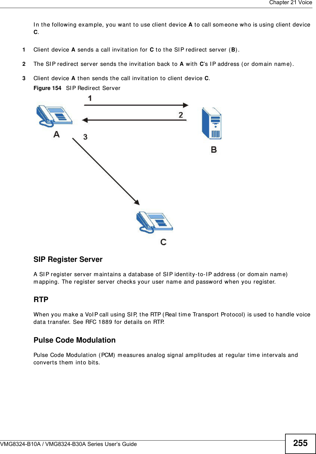
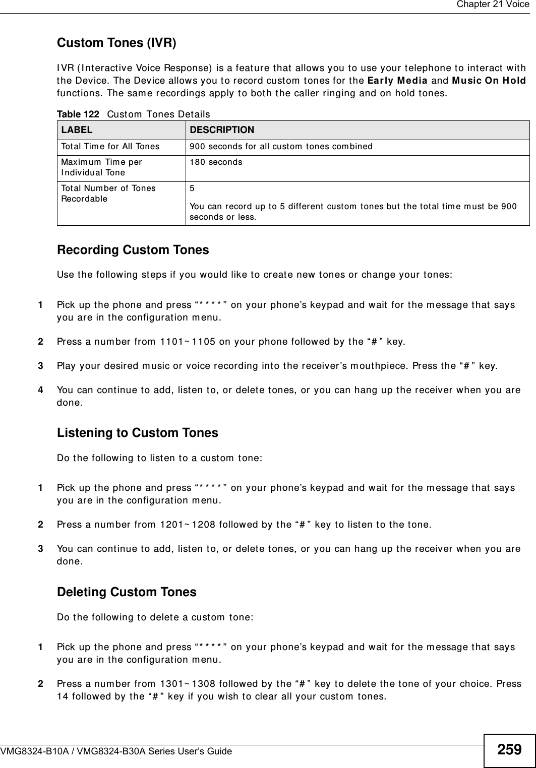
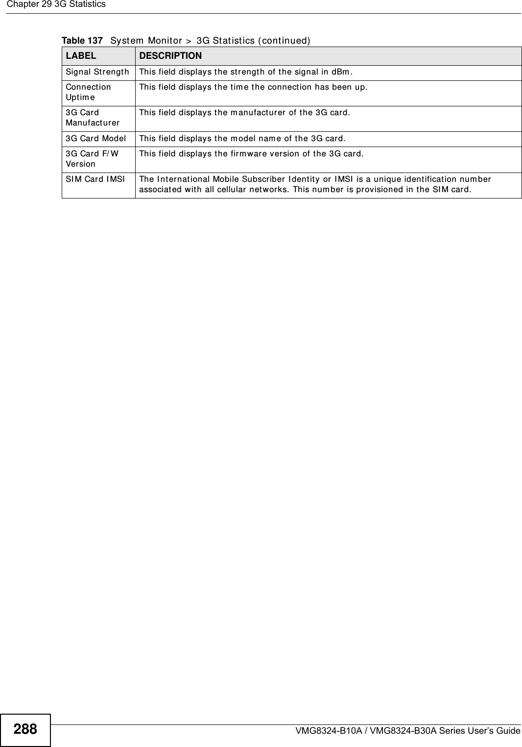
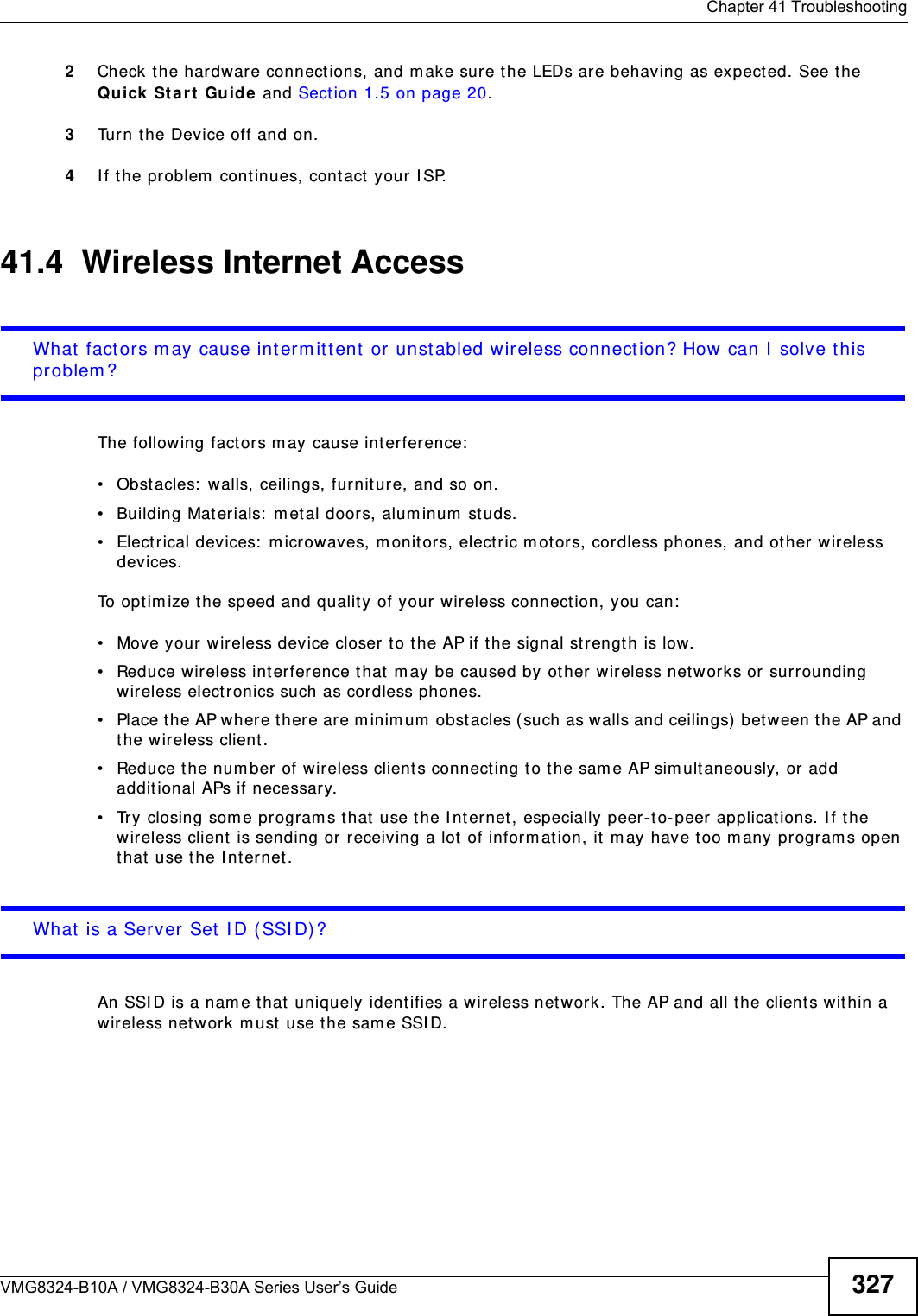
![Appendix B Setting up Your Computer’s IP AddressVMG8324-B10A / VMG8324-B30A Series User’s Guide3562I f you know your DNS server I P addr ess( es) , enter the DNS server inform at ion in the resolv.conf file in the /etc directory. The following figure shows an exam ple where t wo DNS server I P addresses are specified.Figure 224 Red Hat 9.0: DNS Sett ings in resolv.conf 3After you edit and save the configurat ion files, you m ust restart t he net work card. Enter ./network restart in the /etc/rc.d/init.d directory. The following figure shows an exam ple.Figure 225 Red Hat 9.0: Restart Ethernet Card Verifying SettingsEnter ifconfig in a t erm inal screen t o check your TCP/ I P properties. Figure 226 Red Hat 9.0: Checking TCP/ I P Pr operties nameserver 172.23.5.1nameserver 172.23.5.2[root@localhost init.d]# network restartShutting down interface eth0: [OK]Shutting down loopback interface: [OK]Setting network parameters: [OK]Bringing up loopback interface: [OK]Bringing up interface eth0: [OK][root@localhost]# ifconfig eth0 Link encap:Ethernet HWaddr 00:50:BA:72:5B:44 inet addr:172.23.19.129 Bcast:172.23.19.255 Mask:255.255.255.0 UP BROADCAST RUNNING MULTICAST MTU:1500 Metric:1 RX packets:717 errors:0 dropped:0 overruns:0 frame:0 TX packets:13 errors:0 dropped:0 overruns:0 carrier:0 collisions:0 txqueuelen:100 RX bytes:730412 (713.2 Kb) TX bytes:1570 (1.5 Kb) Interrupt:10 Base address:0x1000 [root@localhost]#](https://usermanual.wiki/ZyXEL-Communications/VMG8324B10A.VMG8324-B10A-UserMan-2-2013-12-09/User-Guide-2137566-Page-150.png)