ZyXEL Communications VMG8324B10A Wireless N VDSL2 VoIP Combo WAN Gigabit IAD User Manual VMG8324 B10A UserMan 2 2013 12 09
ZyXEL Communications Corporation Wireless N VDSL2 VoIP Combo WAN Gigabit IAD VMG8324 B10A UserMan 2 2013 12 09
Contents
- 1. (VMG8324-B10A)UserMan(1) 2013-12-09
- 2. (VMG8324-B10A)UserMan(2) 2013-12-09
(VMG8324-B10A)UserMan(2) 2013-12-09
VMG8324-B10A / VMG8324-B30A Series User’s Guide 207
CHAPTER 17
Parental Control
17.1 Overview
Parent al control allow s you to block web sites with t he specific URL. You can also define time
periods and days during which the Device perform s parent al control on a specific user.
17.2 The Parental Control Screen
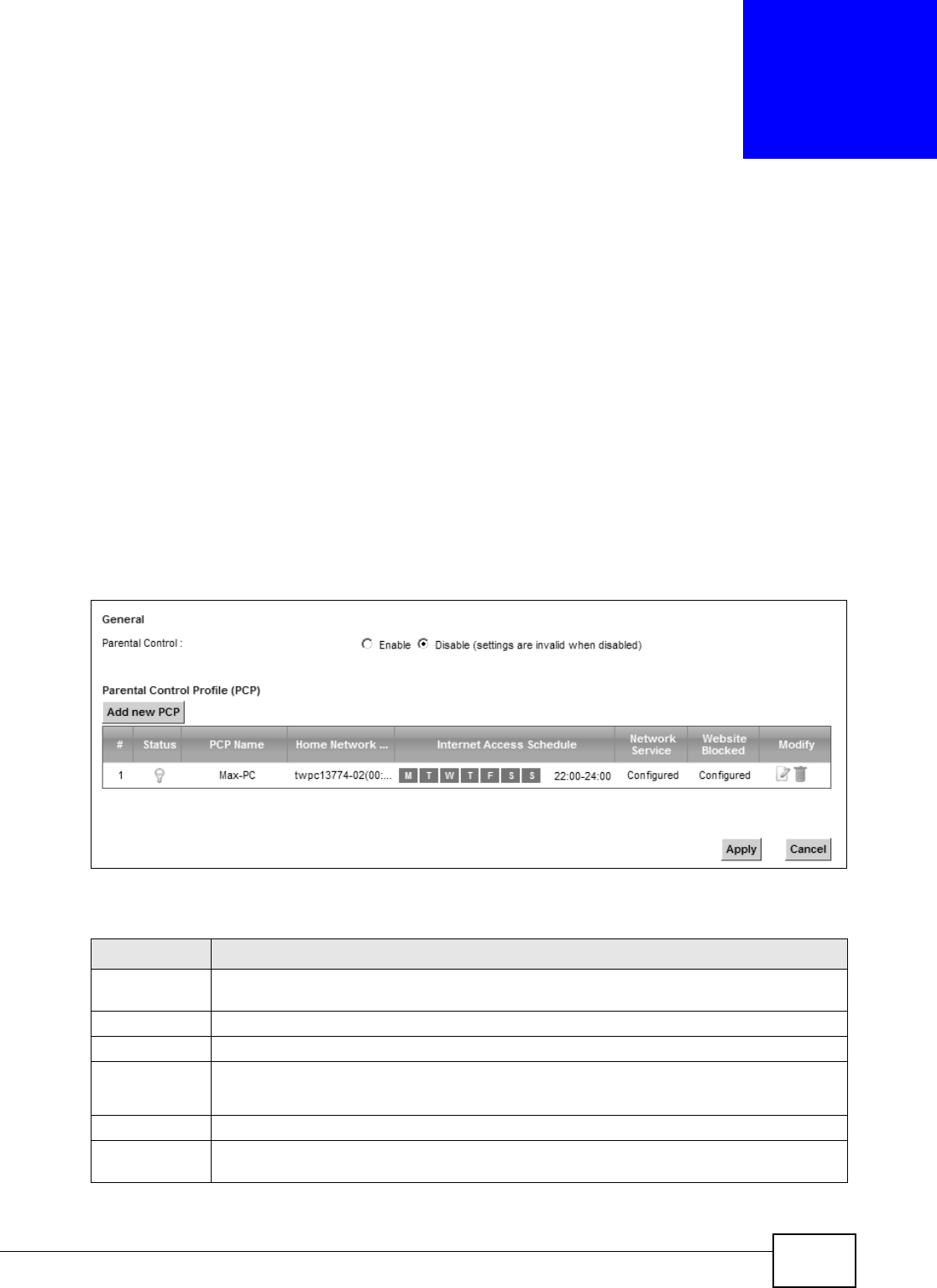
Use t his screen t o enable parent al cont rol, view t he parental cont rol rules and schedules.
Click Se cu r it y > Pa re nt al Contr ol t o open t he following screen.
Figure 124 Securit y > Parental Cont rol
The following t able describes the fields in this screen.
Table 93 Secur ity > Parental Control
LABEL DESCRIPTION
Parent al
Control
Select Enable t o activat e parental control.
Add new PCP Click t his if you want t o configure a new parent al control rule.
#This shows the index num ber of t he rule.
St atus This indicates w het her the rule is act ive or not.
A yellow bulb signifies that this rule is act ive. A gray bulb signifies t hat t his rule is not active.
PCP Nam e This shows the nam e of the rule.
Hom e Net work
User ( MAC)
This show s t he MAC address of the LAN user’s com put er t o which t his rule applies.
Chapter 17 Parental Control
VMG8324-B10A / VMG8324-B30A Series User’s Guide
208
17.2.1 Add/Edit a Parental Control Rule
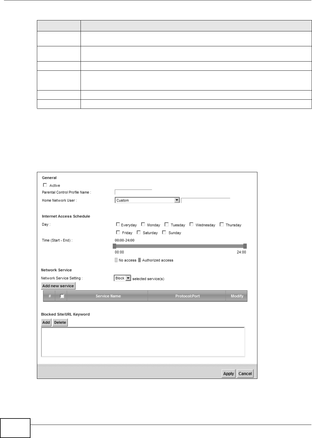
Click Add ne w PCP in t he Par ent al Cont rol screen to add a new rule or click t he Edit icon next to
an exist ing rule to edit it. Use this screen to configure a restricted access schedule and/ or URL
filtering set tings to block the users on your networ k fr om accessing cert ain web sit es.
Figure 125 Parent al Control Rule: Add/ Edit
I nternet Access
Schedule
This show s t he day( s) and tim e on w hich parent al control is enabled.
Net work
Service
This shows w het her the networ k service is configured. I f not , N o ne will be shown.
Web sit e Block This shows whether t he websit e block is configured. I f not , N o n e will be show n.
Modify Click the Edit icon t o go t o the screen where you can edit the rule.
Click the D ele t e icon t o delete an existing rule.
Apply Click Apply to save your changes.
Cancel Click Ca n cel t o restore your previously saved settings.
Table 93 Secur ity > Parental Control ( continued)
LABEL DESCRIPTION

Chapter 17 Parental Control
VMG8324-B10A / VMG8324-B30A Series User’s Guide 209
The following t able describes the fields in this screen.
Table 94 Parental Cont r ol Rule: Add/ Edit
LABEL DESCRIPTION
General
Act ive Select t he checkbox to activat e this parent al cont rol rule.
Parent al
Control Profile
Nam e
Enter a descriptive nam e for t he rule.
Hom e Net work
User
Select t he LAN user t hat you want t o apply t his r ule to from the drop- dow n list box. I f you
select Cust om , ent er t he LAN user ’s MAC address. I f you select All, t he rule applies t o all
LAN users.
I nt ernet Access Schedule
Day Select check boxes for the day s t hat you want t he Device t o perform parental cont r ol.
Tim e Drag the tim e bar to define the tim e t hat the LAN user is allowed access.
Net work Service
Net work
Service Set ting
I f you select Block, t he Device prohibits the users from view ing the Web sites with the URLs
list ed below.
I f y ou select Allow , t he Device blocks access t o all URLs except ones list ed below.
Add new
service
Click this t o show a screen in which you can add a new service rule. You can configure the
Service N am e, Pr ot o col, and N a m e of t he new rule.
#This shows the index num ber of the rule. Select the checkbox next to t he rule to act ivate it .
Service Nam e This shows the nam e of the rule.
Prot ocol: Port This shows the protocol and the port of t he rule.
Modify Click the Edit icon t o go t o the screen where you can edit the rule.
Click the D ele t e icon t o delete an existing rule.
Blocked Site/
URL Keyword
Click Add t o show a scr een to enter t he URL of web sit e or URL keyword t o which the Device
blocks access. Click D e le t e t o rem ove it .
Apply Click this but ton t o save your settings back t o t he Device.
Cancel Click Ca n cel t o restore your previously saved settings.

Chapter 17 Parental Control
VMG8324-B10A / VMG8324-B30A Series User’s Guide
210

VMG8324-B10A / VMG8324-B30A Series User’s Guide 211
CHAPTER 18
Scheduler Rule
18.1 Overview
You can define t im e periods and days during which the Device perform s scheduled rules of cert ain
feat ures ( such as Firewall Access Control) in the Scheduler Rule screen.
18.2 The Scheduler Rule Screen
Use t his screen t o view, add, or edit tim e schedule rules.
Click Security > Schedule r Rule to open the following screen.
Figure 126 Securit y > Scheduler Rule
The following t able describes the fields in this screen.
Table 95 Secur ity > Scheduler Rule
LABEL DESCRIPTION
Add new rule Click this t o cr eate a new rule.
#This is t he index num ber of the ent r y.
Rule Nam e This shows the nam e of the rule.
Day This shows the day(s) on which this rule is enabled.
Tim e This shows the period of tim e on which this r ule is enabled.
Descript ion This shows the description of t his rule.
Modify Click the Edit icon to edit the schedule.
Click t he Delete icon to delet e a scheduler rule.
Note: You cannot delete a scheduler rule once it is applied to a certain feature.
Chapter 18 Scheduler Rule
VMG8324-B10A / VMG8324-B30A Series User’s Guide
212
18.2.1 Add/Edit a Schedule
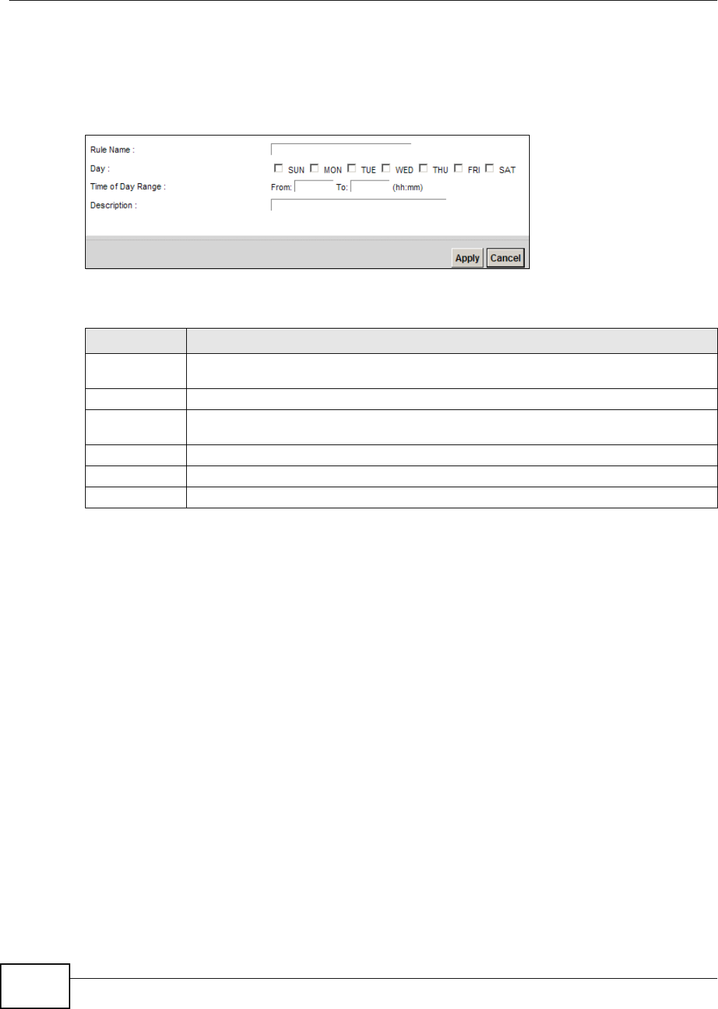
Click the Add but ton in the Scheduler Rule screen or click the Edit icon nex t t o a schedule rule t o
open the following screen. Use t his screen t o configur e a r estrict ed access schedule.
Figure 127 Scheduler Rule: Add/ Edit
The following t able describes the fields in this screen.
Table 96 Scheduler Rule: Add/ Edit
LABEL DESCRIPTION
Rule Nam e Enter a nam e (up t o 31 printable English keyboard characters, not including spaces) for t his
schedule.
Day Select check boxes for t he days that you want the Device t o perform t his scheduler rule.
Tim e if Day
Range
Enter the t im e period of each day, in 24-hour form at, during which t he rule will be enforced.
Descript ion Ent er a description for t his scheduler rule.
Apply Click Apply t o save your changes.
Cancel Click Cancel to ex it this scr een without saving.

VMG8324-B10A / VMG8324-B30A Series User’s Guide 213
CHAPTER 19
Certificates
19.1 Overview
The Device can use certificates ( also called digital I Ds) to aut henticate users. Cert ificates ar e based
on public- private key pairs. A cert ificat e cont ains the certificat e owner’s identit y and public key.
Cert ificat es provide a way to exchange public keys for use in aut hent icat ion.
19.1.1 What You Can Do in this Chapter
• The Loca l Cert ifica te s screen let s you generat e cert ificat ion request s and im port t he Device's
CA- signed certificates ( Sect ion 19.4 on page 216) .
• The Trust ed CA screen let s you save t he certificates of t rusted CAs t o t he Device (Section 19.4
on page 216) .
19.2 What You Need to Know
The following t erm s and concept s m ay help as you read t hr ough this chapter.
Certification Authority
A Cert ification Authority (CA) issues cert ificat es and guarant ees the ident ity of each certificat e
owner. There are com m ercial certificat ion aut horit ies like CyberTrust or VeriSign and governm ent
cert ification authorities. The cert ification authority uses it s private key to sign cert ificat es. Anyone
can then use the certificat ion authority's public key to verify the certificates. You can use the Device
to generat e certification requests that contain identifying inform at ion and public keys and t hen send
the certification requests t o a cert ificat ion authorit y.
19.3 The Local Certificates Screen
Click Secur it y > Ce r t ifica t e s to open the Loca l Ce rt ificat es screen. This is t he Device’s sum m ary
list of cert ificat es and cert ificat ion requests.
Figure 128 Securit y > Certificates > Local Cert ificat es
Chapter 19 Certificates
VMG8324-B10A / VMG8324-B30A Series User’s Guide
214
The following t able describes the labels in t his screen.
19.3.1 Create Certificate Request
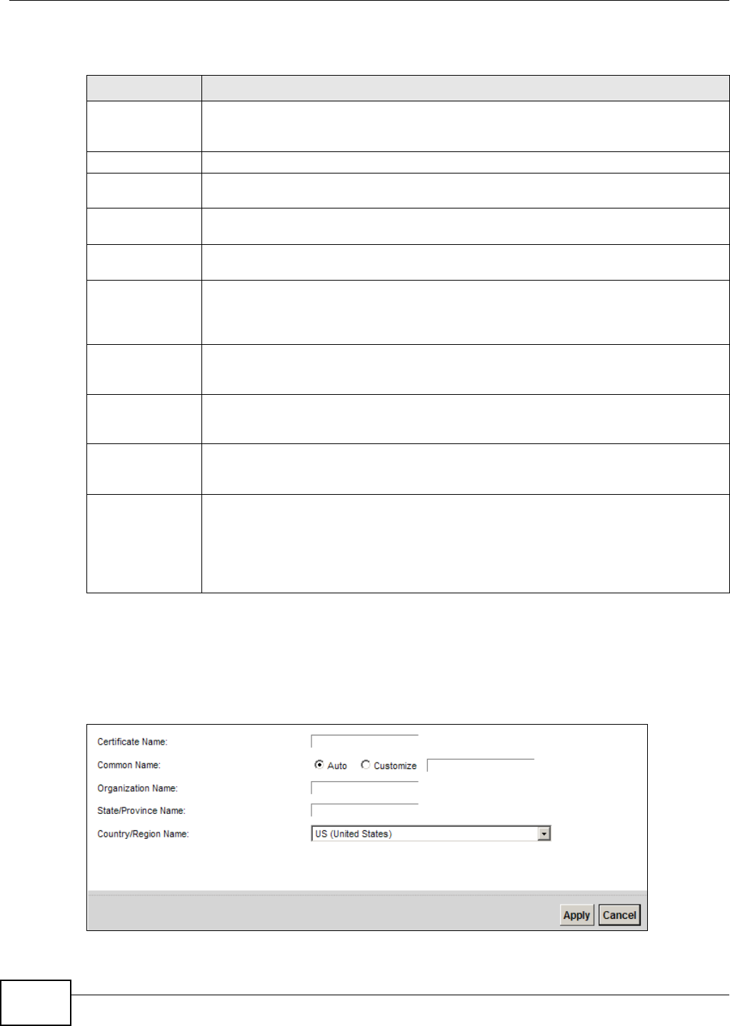
Click Se cu r it y > Ce rt if ica t e s > Loca l Cert ifica te s and then Cre at e Ce rtificat e Reque st to
open the following screen. Use t his screen to have the Device generate a cert ificat ion request .
Figure 129 Creat e Cert ificat e Request
Table 97 Secur ity > Cer t ificat es > Local Certificates
LABEL DESCRIPTION
Privat e Key is
protected by a
password
Select the checkbox and ent er t he privat e key int o the t ext box to st or e it on the Device.
The private key should not exceed 63 ASCII charact ers (not including spaces) .
Browse... Click this t o find t he cert ificat e file you want t o upload.
I m por t Certificate Click this but t on t o save the cert ificat e that you have enrolled from a certification
aut hority from your com put er t o the Device.
Create Certificate
Request
Click t his but ton to go t o the screen where you can have the Device generat e a
certification request .
Current File This field displays t he nam e used to identify t his certificat e. I t is r ecom m ended that you
give each certificat e a unique nam e.
Subj ect This field displays ident ifying inform at ion about the certificate’s ow ner, such as CN
( Com m on Nam e), OU (Organizational Unit or depart m ent ) , O ( Organizat ion or com pany)
and C ( Country). I t is recom m ended t hat each cert ificat e have unique subject
inform at ion.
I ssuer This field displays identifying inform at ion about t he certificate’s issuing certification
aut hority, such as a com m on nam e, organizat ional unit or depart m ent , or ganizat ion or
com pany and country.
Valid From This field displays the date t hat the certificate becom es applicable. The text displays in
red and includes a N ot Yet Valid! m essage if t he certificate has not yet becom e
applicable.
Valid To This field displays t he dat e that t he cert ificat e expires. The t ext displays in red and
includes an Ex pir ing! or Expired! m essage if the cert ificat e is about to expire or has
already expired.
Modify Click t he View icon to open a screen wit h an in- dept h list of inform at ion about the
certificate (or certification request).
For a cer t ificat ion request, click Load Signed to im port the signed cert ificate.
Click t he Rem ove icon to delete t he cer t ificat e ( or certificat ion request ) . You cannot
delete a certificat e that one or m ore feat ures is configured t o use.
Chapter 19 Certificates
VMG8324-B10A / VMG8324-B30A Series User’s Guide 215
The following t able describes the labels in t his screen.
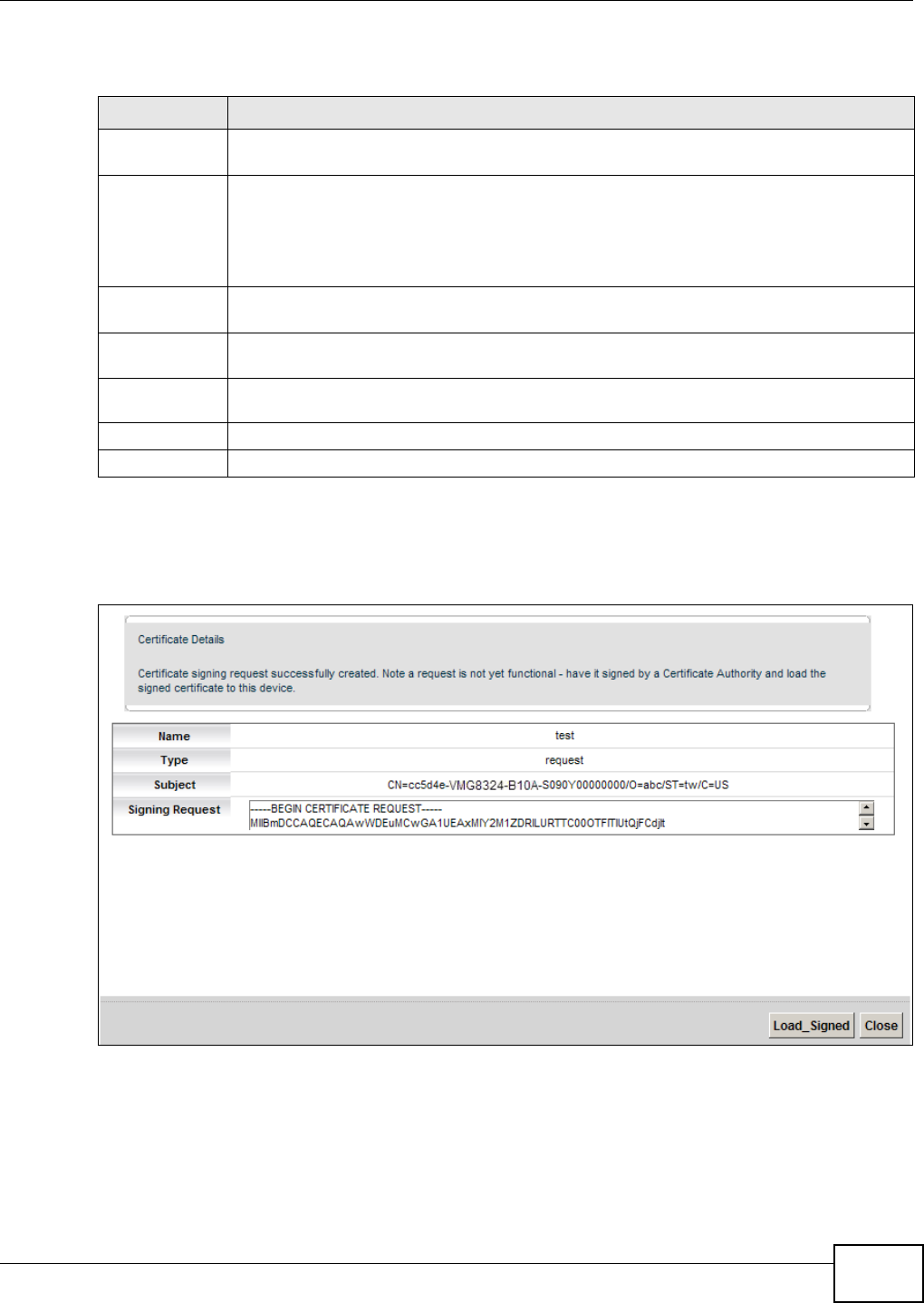
After you click Apply, t he following screen displays t o notify you that you need t o get the certificate
request signed by a Certificate Aut hority. I f you already have, click Loa d_ Signed to im port the
signed certificate into the Device. Ot herwise click Ba ck t o ret urn t o t he Local Ce rt ificat es screen.
Figure 130 Cert ificate Request Creat ed
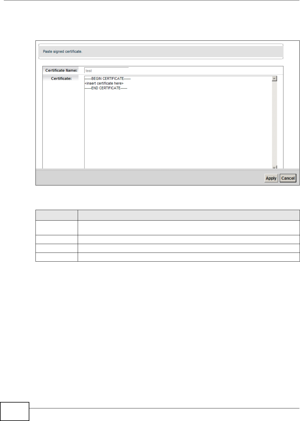
19.3.2 Load Signed Certificate
After you creat e a cert ificate request and have it signed by a Cert ificate Authority, in t he Loca l
Ce r t ifica t e s screen click the certificat e request’s Load Sign ed icon t o im port the signed cer t ificat e
into the Device.
Table 98 Creat e Certificat e Request
LABEL DESCRIPTION
Certificat e
Nam e
Type up t o 63 ASCI I characters ( not including spaces) to ident ify t his cer t ificat e.
Com m on Nam e Select Aut o t o have the Device configure this field aut om at ically. Or select Cust om i ze t o
ent er it m anually.
Type t he I P address ( in dott ed decim al notation), dom ain nam e or e- m ail address in t he
field provided. The dom ain nam e or e- m ail address can be up t o 63 ASCI I charact ers. The
dom ain nam e or e-m ail address is for ident ification purposes only and can be any string.
Organizat ion
Nam e
Type up t o 63 charact ers to identify t he com pany or group to w hich t he certificate owner
belongs. You m ay use any charact er, including spaces, but the Device drops t railing spaces.
St ate/ Province
Nam e
Type up t o 32 charact ers to identify t he state or province where the certificat e ow ner is
locat ed. You m ay use any character, including spaces, but t he Device drops trailing spaces.
Count ry/ Region
Nam e
Select a count ry t o identify the nat ion where the certificate ow ner is locat ed.
Apply Click Apply to save your changes.
Cancel Click Cance l t o exit this screen without saving.
Chapter 19 Certificates
VMG8324-B10A / VMG8324-B30A Series User’s Guide
216
Note: You m ust rem ove any spaces from the cert ificate’s filenam e before you can im port
it .
Figure 131 Load Signed Certificate
The following t able describes the labels in t his screen.
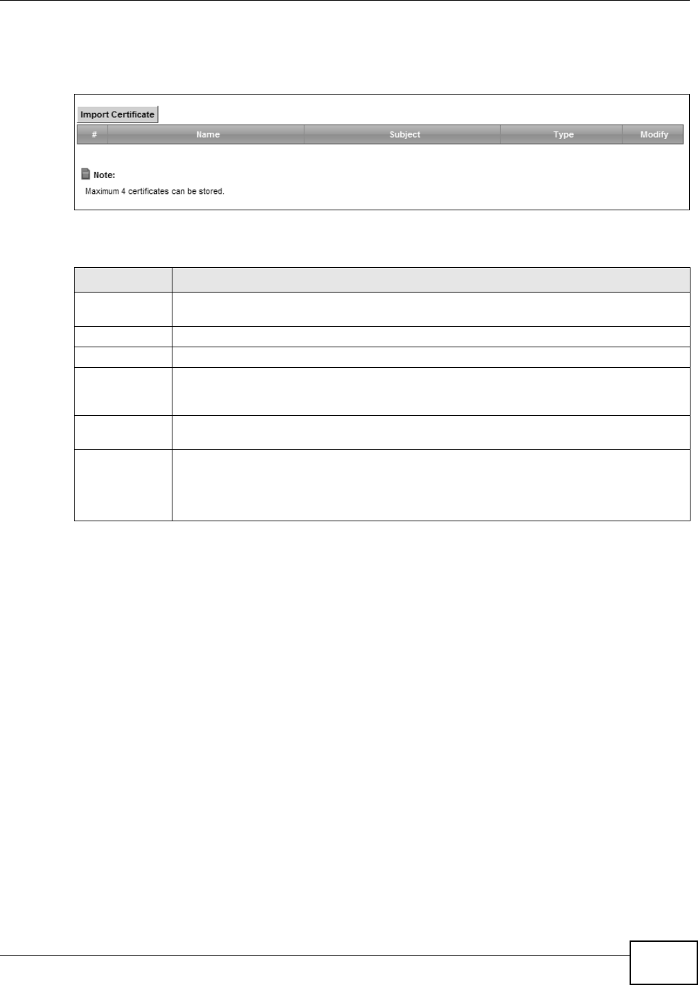
19.4 The Trusted CA Screen
Click Security > Cer tifica te s > Trust ed CA to open the following screen. This screen displays a
sum m ary list of certificates of t he cert ificat ion authorities t hat you have set the Device t o accept as
trust ed. The Device accept s any valid certificate signed by a cert ificat ion authority on t his list as
Table 99 Load Signed Cert ificate
LABEL DESCRIPTION
Certificat e
Nam e
This is t he nam e of the signed certificat e.
Cert ificate Copy and paste t he signed certificate int o the t ext box to st or e it on the Device.
Apply Click Apply t o save your changes.
Cancel Click Cance l t o exit t his screen wit hout saving.
Chapter 19 Certificates
VMG8324-B10A / VMG8324-B30A Series User’s Guide 217
being trustwort hy; t hus you do not need t o im port any cert ificat e t hat is signed by one of t hese
cert ificat ion authorities.
Figure 132 Securit y > Cert ificates > Trust ed CA
The following t able describes the fields in this screen.
Table 100 Security > Cert ificat es > Trusted CA
LABEL DESCRIPTION
I mport
Certificat e
Click this but t on to open a screen where you can save the certificat e of a certificat ion
aut hority that you trust t o the Device.
# This is t he index num ber of the ent ry.
Nam e This field displays t he nam e used to ident ify this certificate.
Subj ect This field displays inform at ion that identifies t he owner of t he certificate, such as Com m on
Nam e ( CN) , OU ( Organizat ional Unit or departm ent) , Or ganizat ion ( O), St at e (ST) and
Count ry (C) . I t is recom m ended that each certificate have unique subj ect inform at ion.
Type This field displays general inform ation about t he cert ificat e. ca means t hat a Certification
Authorit y signed t he certificate.
Modify Click the V iew icon t o open a screen wit h an in- depth list of inform ation about the
certificate ( or certification request ) .
Click the Rem ov e but ton to delete t he certificat e (or cert ification request ). You cannot
delete a certificat e that one or m ore feat ures is configured to use.
Chapter 19 Certificates
VMG8324-B10A / VMG8324-B30A Series User’s Guide
218
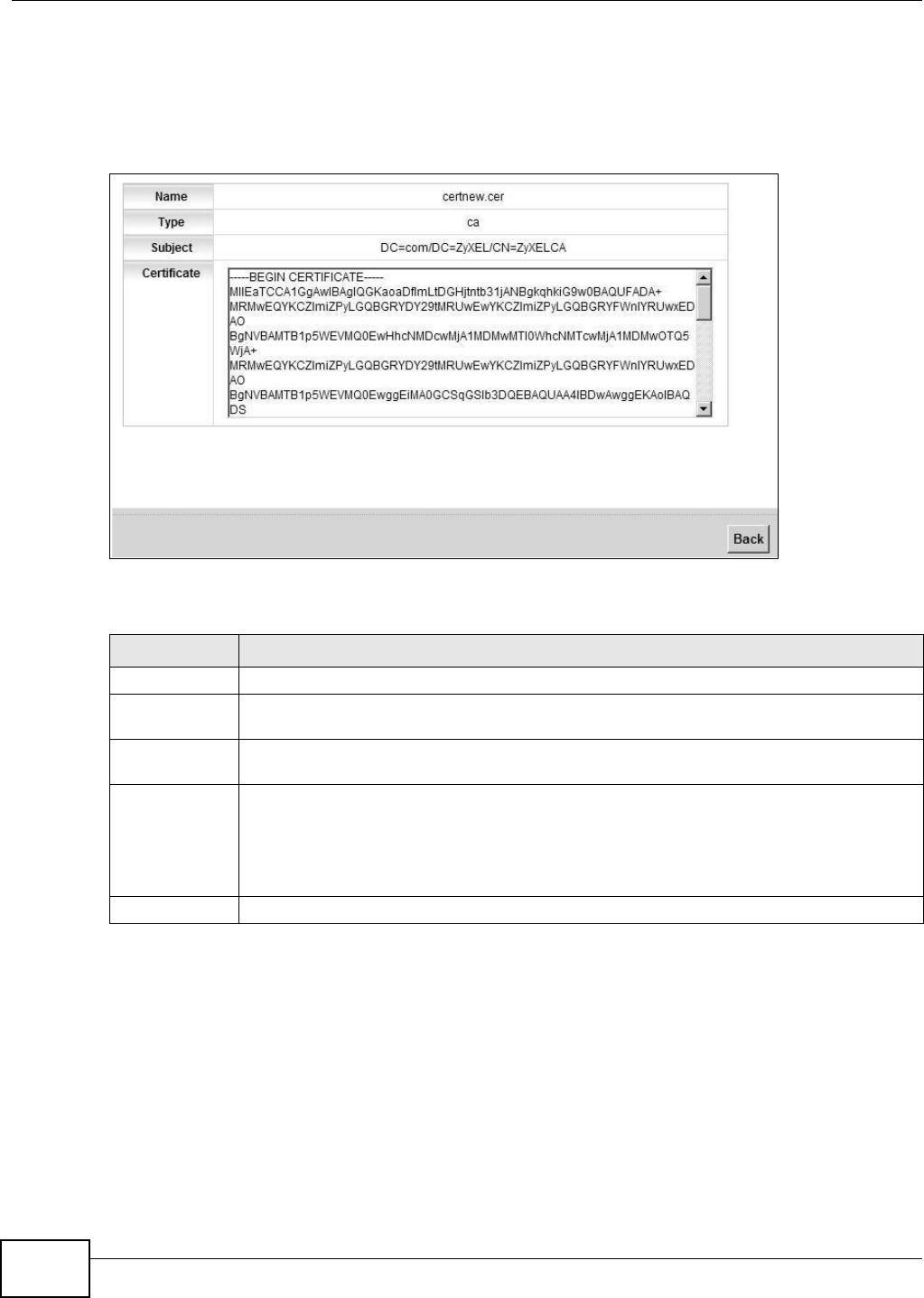
19.4.1 View Trusted CA Certificate
Click the View icon in t he Tr ust ed CA screen t o open t he following screen. Use t his screen t o view
in-dept h inform at ion about t he cert ificat ion authority’s certificate.
Figure 133 Tr u s t e d CA: Vi e w
The following t able describes the fields in this screen.
Table 101 Tr u s t e d CA : V i e w
LABEL DESCRIPTION
Nam e This field displays t he identifying nam e of this cert ificate.
Type This field displays general inform ation about t he cert ificat e. ca means t hat a Certification
Authorit y signed t he certificate.
Subj ect This field displays inform at ion that identifies t he owner of t he certificate, such as Com m on
Nam e ( CN) , Organizational Unit (OU) , Organizat ion ( O) and Country (C).
Certificate This read-only t ext box display s t he certificate in Privacy Enhanced Mail ( PEM) form at . PEM
uses base 64 to convert the binary cert ificat e into a print able form .
You can copy and past e t he cert ificate int o an e- m ail to send t o friends or colleagues or you
can copy and paste t he certificate into a t ext editor and save t he file on a m anagem ent
com puter for lat er dist ribution (via floppy disk for exam ple).
Back Click Back t o ret urn to t he pr evious screen.
Chapter 19 Certificates
VMG8324-B10A / VMG8324-B30A Series User’s Guide 219
19.4.2 Import Trusted CA Certificate
Click the I m por t Cert ifica te butt on in t he Tr uste d CA screen to open the following screen. The
Device t rusts any valid cert ificat e signed by any of the im port ed t rusted CA cert ificates.
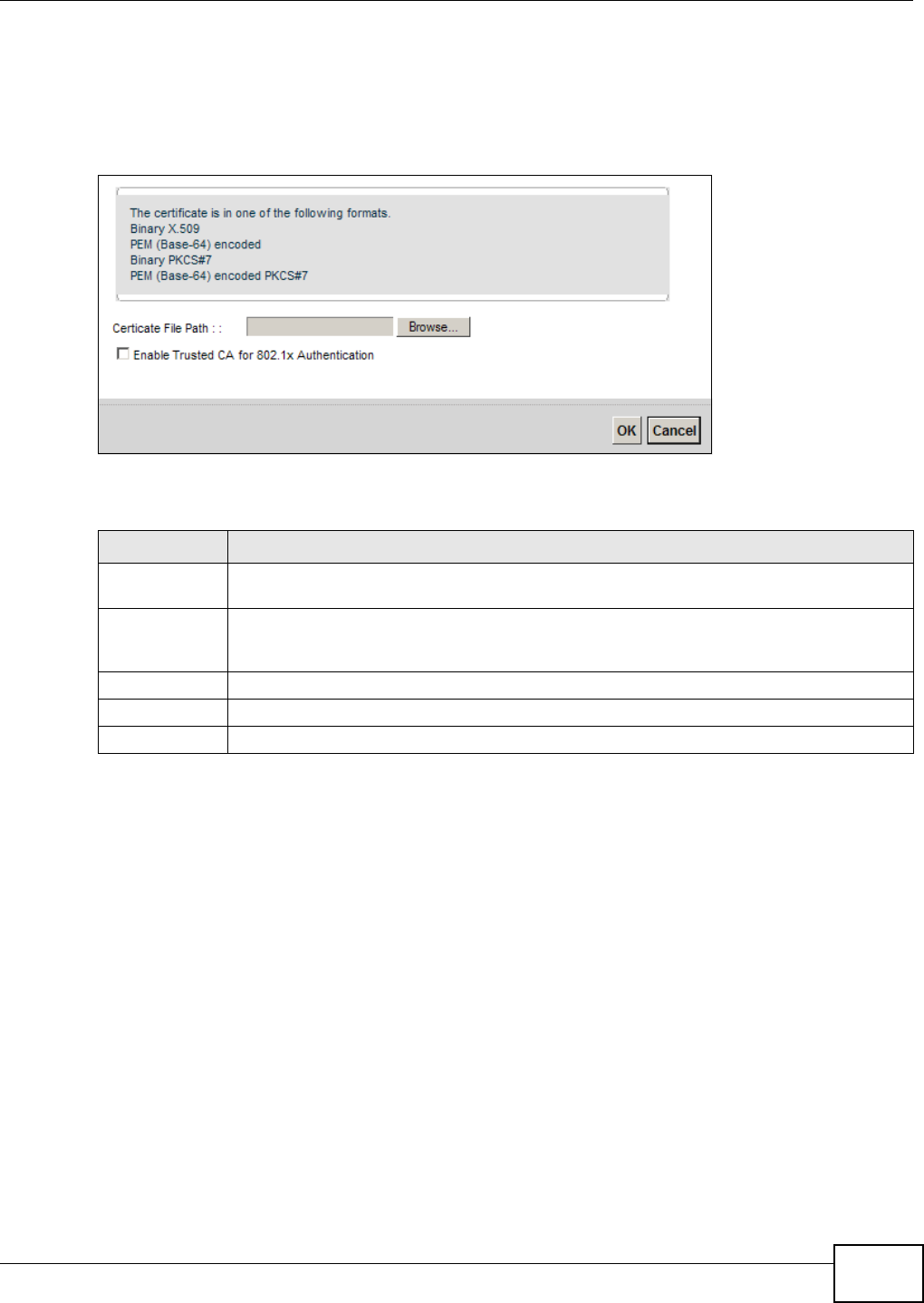
Figure 134 Trust ed CA: I m port Cert ificat e
The following t able describes the fields in this screen.
Table 102 Trust ed CA: I m port Certificate
LABEL DESCRIPTION
Cer t ificate File
Pat h
Type in the location of t he certificate you want to upload in this field or click Brow se ... t o
find it .
Enable Trusted
CA for 802.1x
Au t hent icat ion
I f y ou select t his checkbox, t he t rust ed CA will be used for 802.1x authentication. The
selected t rust ed CA w ill be displayed in the Net w ork Sett ing > Br oa d ba nd > 8 0 2 .1 x:
Edit screen.
Cert ificat e Copy and paste t he certificate into t he text box t o store it on t he Device.
OK Click OK to save your changes.
Cancel Click Cancel to exit t his scr een without sav ing.

Chapter 19 Certificates
VMG8324-B10A / VMG8324-B30A Series User’s Guide
220
VMG8324-B10A / VMG8324-B30A Series User’s Guide 221
CHAPTER 20
VPN
20.1 Overview
A virt ual privat e network (VPN) provides secure com m unications over t he the I nt ernet. I nt ernet
Protocol Securit y ( I PSec) is a st andards- based VPN that provides confident ialit y, dat a int egrit y, and
authent icat ion. This chapter shows you how t o configure the Device’s VPN sett ings.
20.2 The IPSec VPN General Screen
Use t his screen t o view and m anage your VPN tunnel policies. The following figure helps explain t he
m ain fields in the web configurat or.
Figure 135 I PSec Fields Sum mary
Click Secur it y > I PSec VPN t o open this screen as shown next .
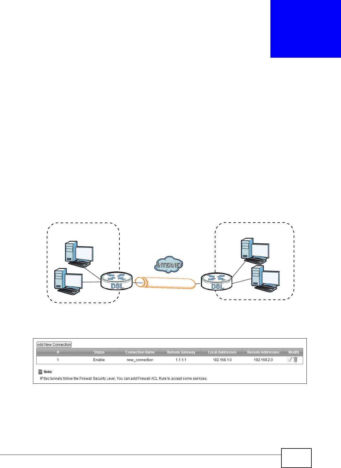
Figure 136 Securit y > I PSec VPN
Local Network Remote Network
VPN Tunnel

Chapter 20 VPN
VMG8324-B10A / VMG8324-B30A Series User’s Guide
222
This screen cont ains t he following fields:
20.3 The IPSec VPN Add/Edit Screen
Use t hese sett ings to add or edit VPN policies. Click the Add Ne w Conne ct ion butt on in t he
Secur it y > VPN screen t o open t his screen as shown next .
Table 103 Security > I PSec VPN
LABEL DESCRIPTION
Add New
Connection
Click t his but ton to add an it em t o the list .
# This display s t he index num ber of an entry.
St at us This displays whether t he VPN policy is enabled ( Enable) or not ( Disable) .
Connection Nam e The nam e of t he VPN policy.
Rem ote Gat eway This is t he IP address of the rem ot e I PSec router in the I KE SA.
Local Addresses This displays the I P address( es) on t he LAN behind y our Device.
Rem ot e
Addresses
This displays the I P address( es) on the LAN behind the rem ote I PSec’s r outer.
Delete Click t he Edit icon t o m odify t he VPN policy.
Click t he D e let e icon to delet e the VPN policy.
Chapter 20 VPN
VMG8324-B10A / VMG8324-B30A Series User’s Guide 223
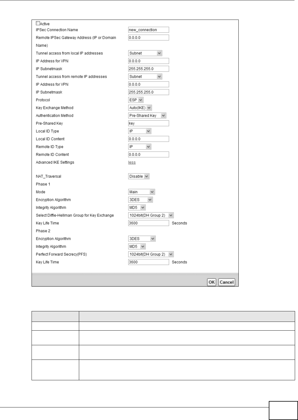
Figure 137 Securit y > I PSec VPN: Add/ Edit
This screen cont ains t he following fields:
Table 104 Security > I PSec VPN: Add/ Edit
LABEL DESCRIPTION
Active Select t his t o act ivate t his VPN policy.
I PSec Connection
Nam e
Enter the nam e of the VPN policy.
Rem ot e I PSec
Gateway Address
Enter the I P address of t he rem ot e I PSec rout er in t he I KE SA.
Tunnel access
fr om local I P
addresses
Select Single Address to have only one local LAN I P address use t he VPN t unnel. Select
Su bn e t t o specify local LAN I P addresses by their subnet m ask.

Chapter 20 VPN
VMG8324-B10A / VMG8324-B30A Series User’s Guide
224
I P Address for
VPN
I f Single Address is select ed, ent er a ( st at ic) I P address on the LAN behind your Device.
I f Subnet is select ed, specify I P addresses on a network by t heir subnet m ask by entering
a ( static) I P address on t he LAN behind your Device. Then ent er t he subnet m ask t o
identify the net work address.
I P Subnet m ask I f Su bnet is select ed, enter t he subnet m ask to ident ify t he net wor k address.
Tunnel access
from rem ot e I P
addresses
Select Single Address to have only one rem ote LAN I P address use t he VPN tunnel.
Select Sub net to specify rem ot e LAN I P addresses by t heir subnet m ask.
I P Address for
VPN
I f Single Addr e ss is select ed, enter a (st at ic) I P address on t he LAN behind t he rem ote
I PSec’s rout er.
I f Subnet is select ed, specify I P addresses on a network by t heir subnet m ask by entering
a ( st at ic) I P address on the LAN behind t he rem ote I PSec’s router. Then ent er the subnet
m ask to identify t he network address.
I P Subnet m ask I f Su bnet is select ed, enter t he subnet m ask to ident ify t he net wor k address.
Prot ocol Select which protocol you want t o use in the I PSec SA. Choices are:
AH ( RFC 2402) - provides integrity, aut hent icat ion, sequence integrit y (replay
resistance), and non- r epudiat ion but not encryption. I f you select AH , you m ust select an
I n t egr a t y Algor it h m .
ESP (RFC 2406) - provides encryption and the sam e serv ices offered by AH , but its
aut hent icat ion is weaker. I f you select ESP, y ou m ust select an Encryption Agorithm
and I ntegraty Algorit hm .
Bot h AH and ESP increase processing requirem ents and lat ency ( delay). The Device and
rem ote I PSec rout er m ust use the sam e active protocol.
Key Exchan g e
Method
Select t he key exchange m ethod:
Au t o( I KE) - Select this t o use autom atic I KE key m anagem ent VPN connect ion policy.
Ma nual - Select this option t o configure a VPN connection policy t hat uses a m anual key
instead of I KE k ey m anagem ent . This m ay be useful if you have pr oblem s wit h I KE key
m anagem ent.
Note: Only use manual key as a temporary solution, because it is not as secure as a regular
IPSec SA.
Authentication
Method
Select Pre- Shared Key to use a pre-shared key for aut henticat ion, and t ype in your pre-
shar ed key. A pre- shared key identifies a com m unicating part y during a phase 1 I KE
negotiation. I t is called " pre- shar ed" because you have to share it wit h another part y
befor e you can com m unicat e wit h t hem over a secure connection.
Select Cert ifica te ( X .5 0 9 ) t o use a cert ificat e for authenticat ion.
Pre-Shared Key Type your pre-shar ed key in this field. A pr e- shared key identifies a com m unicat ing par t y
during a phase 1 I KE negotiation.
Type from 8 t o 31 case- sensit ive ASCII characters or from 16 t o 62 hexadecim al ( "0- 9",
"A-F") characters. You m ust precede a hexadecim al key wit h a "0x” (zero x) , which is not
count ed as part of the 16 t o 62 character range for the key. For exam ple, in
"0x0123456789ABCDEF", “0x” denotes t hat t he key is hexadecim al and
“ 0123456789ABCDEF” is t he key it self.
Local I D Type Select I P t o ident ify the Device by it s I P address.
Select E- m a il to ident ify t his Device by an e- m ail address.
Select DNS t o ident ify t his Device by a dom ain nam e.
Select ASN 1 D N (Abstract Synt ax Notation one - Dist inguished Nam e) to t his Dev ice by
the subject field in a cert ificat e. This is used only with certificate-based authent ication.
Table 104 Security > I PSec VPN: Add/ Edit
LABEL DESCRIPTION

Chapter 20 VPN
VMG8324-B10A / VMG8324-B30A Series User’s Guide 225
Local I D Content When you select I P in the Local I D Type field, type t he I P address of your com put er in
this field. I f you configure t his field to 0.0.0.0 or leave it blank, t he Device aut om atically
uses the Pre- Sha re d Key ( r efer to t he Pr e- Shared Key field descript ion).
I t is recom m ended t hat you t ype an I P address ot her than 0.0.0.0 in t his field or use the
D N S or E- m ail type in the following sit uations.
• When t here is a NAT router bet ween the two I PSec routers.
• When you want t he rem ote I PSec rout er t o be able t o dist inguish bet ween VPN
connect ion request s t hat com e in from I PSec rout ers wit h dynam ic WAN I P addresses.
When you select D N S or E- m a il in the Loca l I D Type field, type a dom ain nam e or e-
m ail address by w hich t o ident ify this Device in t his field. Use up to 31 ASCI I charact ers
including spaces, alt hough trailing spaces are t runcat ed. The dom ain nam e or e- m ail
addr ess is for ident ificat ion purposes only and can be any st ring.
Rem ot e I D Ty pe Select I P t o ident ify t he rem ot e I PSec rout er by its I P address.
Select E- m a il to ident ify t he rem ote I PSec router by an e-m ail address.
Select DNS t o identify the rem ot e I PSec rout er by a dom ain nam e.
Select ASN 1 D N to ident ify t he rem ote I PSec router by t he subject field in a certificat e.
This is used only with certificat e- based authenticat ion.
Rem ot e I D
Content
The configurat ion of the rem ote content depends on t he rem ot e ID type.
For I P, type t he I P address of t he com put er wit h which you will m ak e t he VPN connect ion.
I f you configure this field to 0.0.0.0 or leave it blank , t he Device will use the address in
the Rem ote I PSec Gatew ay Addr e ss field (refer to t he Re m ote I PSec Ga t ew a y
Addr e ss field descript ion).
For D N S or E- m a il, t ype a dom ain nam e or e-m ail address by which to identify t he
rem ote I PSec router. Use up to 31 ASCI I charact ers including spaces, although t railing
spaces are t runcated. The dom ain nam e or e- m ail address is for ident ificat ion purposes
only and can be any string.
I t is recom m ended that you t ype an I P address ot her t han 0.0.0.0 or use t he D N S or E-
m ail I D type in t he following situat ions:
• When t here is a NAT router bet ween the two I PSec routers.
• When you want the Device t o distinguish bet ween VPN connect ion request s t hat com e
in from rem ot e I PSec rout ers wit h dynam ic WAN I P addresses.
Advanced I KE
Settings
Click m ore to display advanced set t ings. Click less to display basic set t ings only.
NAT_Traversal Select Ena ble if you want t o set up a VPN t unnel when t here ar e NAT routers bet w een the
Device and r em ote I PSec rout er. The rem ote I PSec router m ust also enable NAT t raver sal,
and the NAT rout ers have t o forwar d UDP por t 500 packet s t o the rem ote I PSec rout er
behind the NAT rout er. Ot herwise, select D isa ble .
Phase 1
Mode Select the negot iat ion m ode to use to negotiate the I KE SA. Choices ar e:
Ma in - this encrypts the Device’s and rem ot e I PSec rout er’s identities but t akes m ore
tim e t o est ablish t he I KE SA.
Aggr e ssive - t his is faster but does not encry pt t he identit ies.
The Device and the rem ote I PSec router m ust use t he sam e negotiation m ode.
Table 104 Security > I PSec VPN: Add/ Edit
LABEL DESCRIPTION

Chapter 20 VPN
VMG8324-B10A / VMG8324-B30A Series User’s Guide
226
Encryption
Algorithm
Select which key size and encrypt ion algorithm t o use in t he I KE SA. Choices are:
DES - a 56-bit key with the DES encryption algor it hm
3 DES - a 168-bit key with the DES encry ption algorit hm
AES - 1 2 8 - a 128- bit key w it h t he AES encryption algorit hm
AES - 1 9 6 - a 196- bit key w it h t he AES encryption algorit hm
AES - 2 5 6 - a 256- bit key w it h t he AES encryption algorit hm
The Device and the rem ote I PSec router m ust use the sam e key size and encryption
algorithm . Longer keys require m ore processing power, result ing in incr eased latency and
decr eased t hroughput.
I ntegrit y
Algorithm
Select which hash algorithm to use to authenticat e pack et data. Choices are M D5 , SHA1 .
SH A is generally considered stronger than M D5 , but it is also slower.
Select Diffie-
Hellm an Group
for Key Exchange
Select which Diffie- Hellm an key group you want t o use for encr ypt ion keys. Choices for
num ber of bits in the random num ber are: 768, 1024, 1536, 2048, 3072, 4096.
The longer the key, t he m ore secure t he encryption, but also t he longer it takes to encrypt
and decr ypt inform at ion. Bot h rout ers m ust use the sam e DH key group.
Key Life Tim e Define t he length of tim e before an I PSec SA autom atically r enegot iat es in t his field.
A shor t SA Life Tim e increases security by forcing t he two VPN gat eways to updat e the
encryption and authentication key s. However, every t im e the VPN tunnel renegot iates, all
users accessing rem ote resources ar e t em porarily disconnect ed.
Phase 2
Encryption
Algorithm
Select which key size and encrypt ion algorithm t o use in t he I KE SA. Choices are:
DES - a 56-bit key with the DES encryption algor it hm
3 DES - a 168-bit key with the DES encry ption algorit hm
AES - 1 2 8 - a 128- bit key wit h t he AES encrypt ion algorit hm
AES - 1 9 2 - a 196- bit key wit h t he AES encrypt ion algorit hm
AES - 2 5 6 - a 256- bit key wit h t he AES encrypt ion algorit hm
Select ESP_ N U LL to set up a t unnel wit hout encryption. When you select ESP_ N ULL,
you do not ent er an encryption key.
The Device and the rem ote I PSec router m ust use the sam e key size and encryption
algorithm . Longer keys require m ore processing power, result ing in incr eased latency and
decr eased t hroughput.
I ntegrit y
Algorithm
Select which hash algor it hm to use to authenticate packet data. Choices are M D5 and
SH A1 . SHA is generally considered st ronger than M D5 , but it is also slower.
Table 104 Security > I PSec VPN: Add/ Edit
LABEL DESCRIPTION

Chapter 20 VPN
VMG8324-B10A / VMG8324-B30A Series User’s Guide 227
Perfect Forward
Secrecy ( PFS)
Select whet her or not you want t o enable Perfect Forward Secrecy (PFS)
PFS changes t he root key t hat is used t o generate encrypt ion keys for each I PSec SA. The
longer t he key, t he m ore secure t he encryption, but also t he longer it takes to encry pt and
decr ypt inform ation. Both rout ers m ust use the sam e DH key group. Choices are:
N one - do not use any random num ber.
7 6 8 bit( DH Group1 ) - use a 768-bit random num ber
1 0 2 4 bit ( D H Gr oup2 ) - use a 1024-bit random num ber
1 5 3 6 bit ( D H Gr oup5 ) - use a 1536-bit random num ber
2 0 4 8 bit ( D H Gr oup1 4 ) - use a 2048- bit random num ber
3 0 7 2 bit ( D H Gr oup1 5 ) - use a 3072- bit random num ber
4 0 9 6 bit ( D H Gr oup1 6 ) - use a 4096- bit random num ber
Key Life Tim e Define t he length of tim e before an I PSec SA autom atically r enegot iat es in t his field.
A shor t SA Life Tim e increases security by forcing t he two VPN gat eways to updat e the
encryption and authentication key s. However, every t im e the VPN tunnel renegot iates, all
users accessing rem ote resources ar e t em porarily disconnect ed.
The following fields are available if you select Manual in t he Key Exchange Met hod field.
Encryption
Algor it hm
Select which key size and encrypt ion algorithm t o use in t he I KE SA. Choices are:
DES - a 56-bit key with the DES encryption algor it hm
3 DES - a 168-bit key with the DES encry ption algorit hm
EPS_ N ULL - no encryption key or algorithm
Encryption
Key
This field is applicable when you select an Encrypt ion Algorithm .
Enter the encryption key, which depends on t he encryption algorit hm .
DES - t ype a unique key 16 hexadecim al characters long
3 DES - type a unique key 48 hexadecim al charact ers long
Aut hent icat ion
Algor it hm
Select which hash algor it hm to use to authenticate packet data. Choices are MD5, SHA1.
SHA is generally considered st ronger than MD5, but it is also slower.
Aut hent icat ion
Key
Enter the authent ication key, which depends on the authent ication algorithm .
MD5 - t ype a unique key 32 hexadecim al charact er s long
SH A1 - type a unique key 40 hexadecim al charact ers long
SPI Type a unique SPI ( Securit y Param eter I ndex) in hexadecim al charact ers.
The SPI is used to identify the Device during authentication.
The Device and rem ote I PSec rout er m ust use the sam e SPI .
OK Click OK t o save your changes.
Cancel Click Cance l t o restore your pr eviously saved set t ings.
Table 104 Security > I PSec VPN: Add/ Edit
LABEL DESCRIPTION
Chapter 20 VPN
VMG8324-B10A / VMG8324-B30A Series User’s Guide
228
20.4 The IPSec VPN Monitor Screen
Use t his screen t o check your VPN t unnel’s current stat us. You can also m anually t rigger a VPN
tunnel to the r em ot e network. Click Se cur it y > I PSe c VPN > Monit or t o open this screen as
shown next.
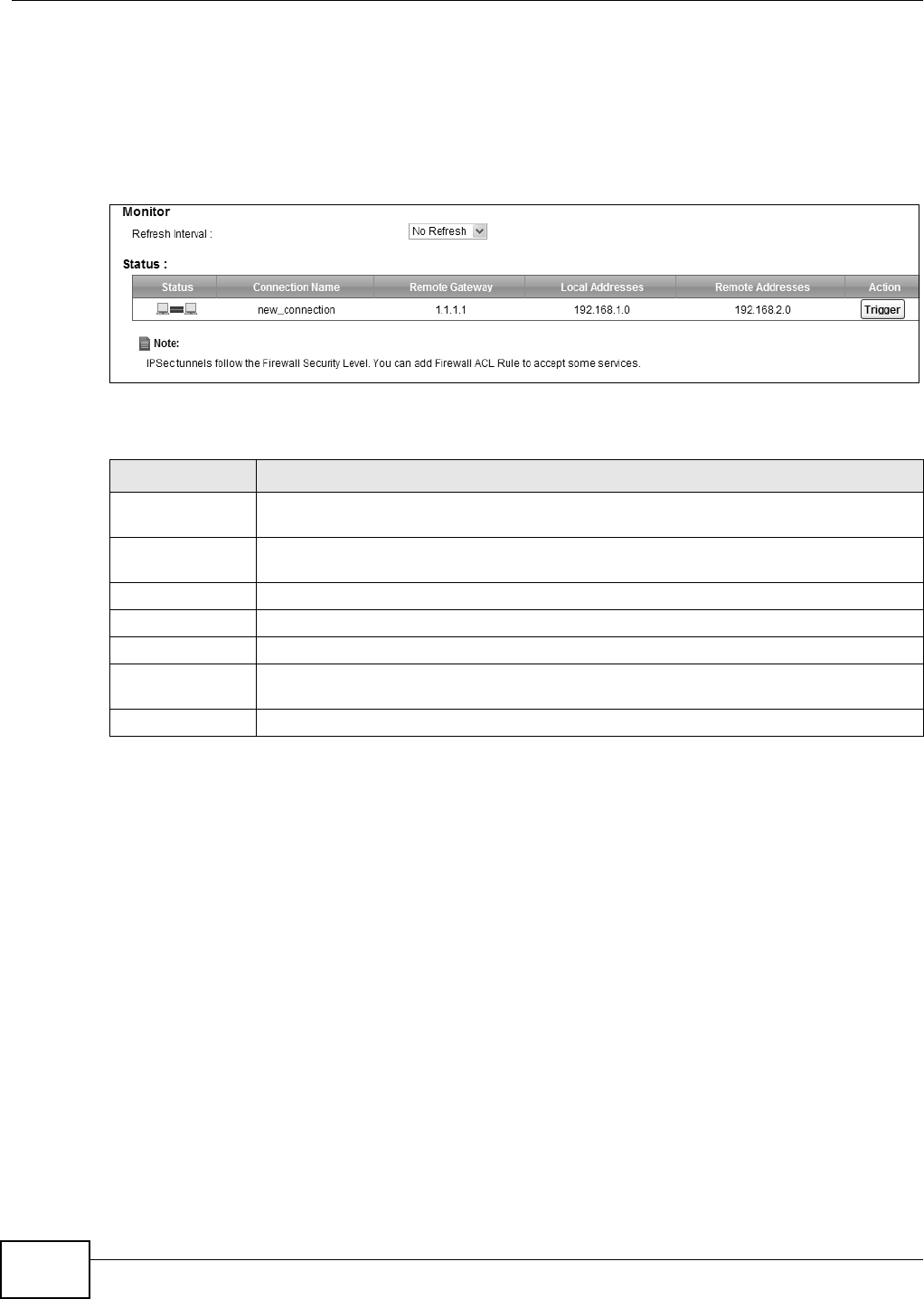
Figure 138 Securit y > I PSec VPN > Monitor
This screen cont ains t he following fields:
20.5 Technical Reference
This section provides som e technical background inform at ion about t he topics covered in this
section.
20.5.1 IPSec Architecture
The overall I PSec architecture is shown as follows.
Table 105 Security > I PSec VPN > Monit or
LABEL DESCRIPTION
Refresh I nterval Select how oft en you want t he Device t o update this screen. Select N o Re fr e sh t o have
the Device stop updating t he screen.
St at us This displays a green line between t w o hosts if the VPN tunnel has been est ablished
successfully. Otherwise, it displays a red line in between.
Connection Nam e This displays t he nam e of t he VPN policy.
Rem ote Gat eway This is t he IP address of the rem ot e I PSec router in the I KE SA.
Local Addresses This displays t he I P address( es) on t he LAN behind your Device.
Rem ot e
Addresses
This displays t he I P address( es) on the LAN behind t he rem ote I PSec router.
Act ion Click Trigger t o est ablish a VPN connect ion with the rem ot e network.
Chapter 20 VPN
VMG8324-B10A / VMG8324-B30A Series User’s Guide 229
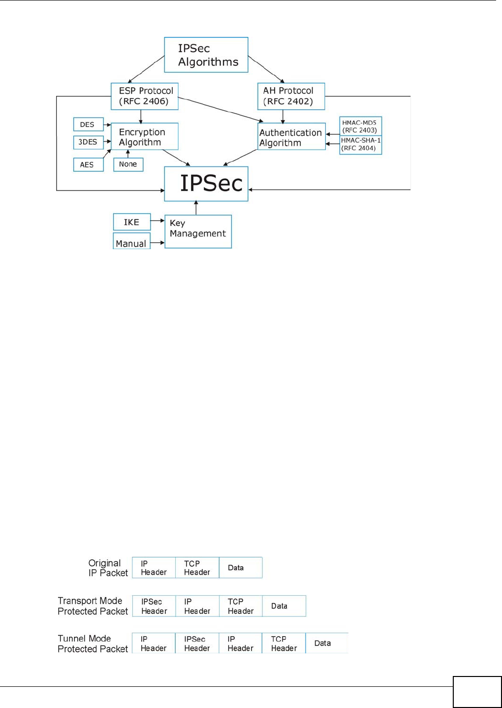
Figure 139 I PSec Archit ect ure
IPSec Algorithms
The ESP (Encapsulat ing Securit y Payload) Prot ocol ( RFC 2406) and AH ( Authenticat ion Header)
protocol ( RFC 2402) describe the packet form ats and t he default st andards for packet struct ur e
( including im plem entat ion algorit hm s).
The Encrypt ion Algorit hm describes the use of encryption techniques such as DES (Dat a Encrypt ion
St andard) and Triple DES algorithm s.
The Aut henticat ion Algorithm s, HMAC-MD5 ( RFC 2403) and HMAC-SHA- 1 (RFC 2404, provide an
authent icat ion m echanism for t he AH and ESP pr ot ocols.
Key Management
Key m anagem ent allows you t o det erm ine whet her to use I KE (I SAKMP) or m anual key
configurat ion in order to set up a VPN.
20.5.2 Encapsulation
The t wo m odes of operation for I PSec VPNs are Tr a nspo rt m ode and Tunne l m ode. At the t im e of
writ ing, t he Device supports Tunnel m ode only.
Figure 140 Transport and Tunnel Mode I PSec Encapsulation

Chapter 20 VPN
VMG8324-B10A / VMG8324-B30A Series User’s Guide
230
Transport Mode
Tr a n sp or t m ode is used t o protect upper layer protocols and only affect s the data in the I P packet.
I n Tra nspo rt m ode, t he I P packet contains the security protocol (AH or ESP) locat ed after the
original I P header and opt ions, but before any upper layer prot ocols contained in t he packet ( such
as TCP and UDP) .
Wit h ESP, prot ect ion is applied only t o t he upper layer prot ocols contained in t he packet . The I P
header inform ation and options are not used in t he authent icat ion process. Therefore, the
originat ing I P address cannot be verified for int egrit y against the data.
Wit h the use of AH as t he secur ity prot ocol, prot ect ion is ext ended forward into the I P header to
verify the int egrity of t he ent ire packet by use of port ions of the original I P header in the hashing
process.
Tunnel Mode
Tu nnel m ode encapsulates the entire I P packet t o transm it it securely. A Tunnel mode is required
for gateway services t o provide access t o int ernal system s. Tun nel m ode is fundam ent ally an I P
tunnel with aut hentication and encr yption. This is the m ost com mon m ode of operation. Tunnel
m ode is required for gateway t o gateway and host t o gateway com m unications. Tunne l m ode
com m unicat ions have two set s of I P headers:
•Ou tside he ader: The outside I P header cont ains the destinat ion I P address of t he VPN gat eway.
•I nside heade r: The inside I P header cont ains the dest inat ion I P address of t he final system
behind the VPN gateway. The security protocol appears after the outer I P header and before t he
inside I P header.
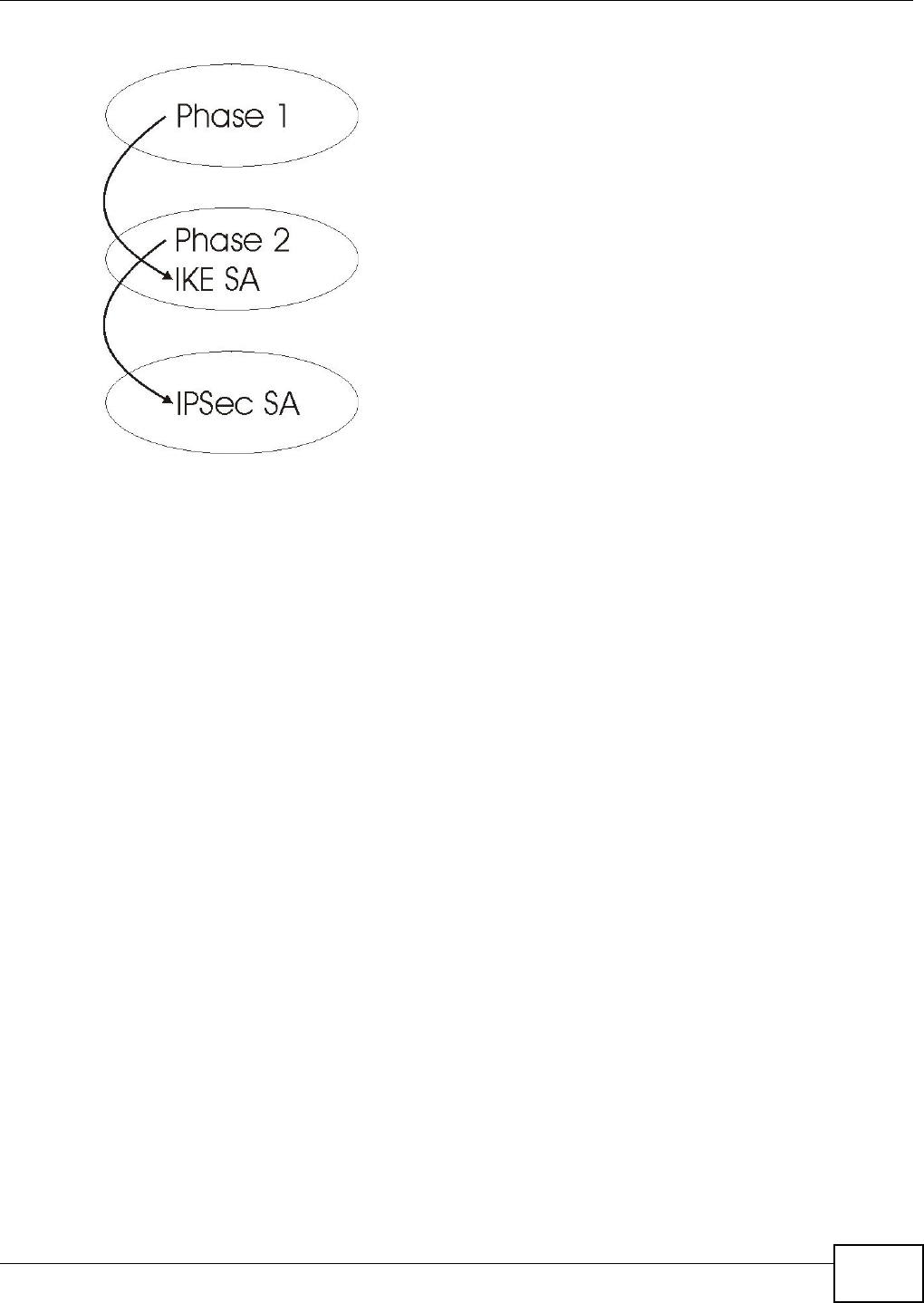
20.5.3 IKE Phases
There are two phases t o every I KE ( I nt ernet Key Exchange) negotiat ion – phase 1 (Aut hentication)
and phase 2 ( Key Exchange). A phase 1 exchange establishes an I KE SA and t he second one uses
that SA t o negot iate SAs for I PSec.
Chapter 20 VPN
VMG8324-B10A / VMG8324-B30A Series User’s Guide 231
Figure 141 Two Phases t o Set Up the I PSec SA
I n phase 1 you m ust:
• Choose a negotiat ion m ode.
• Authent icat e t he connection by ent ering a pre- shared key.
• Choose an encryption algorithm.
• Choose an aut hent ication algorit hm .
• Choose a Diffie- Hellm an public-key crypt ography key group.
• Set t he I KE SA lifet im e. This field allows you to determ ine how long an I KE SA should st ay up
before it tim es out. An I KE SA tim es out when the I KE SA lifet im e period expires. I f an I KE SA
tim es out when an I PSec SA is already established, the I PSec SA stays connect ed.
I n phase 2 you m ust:
• Choose an encryption algorithm.
• Choose an aut hent ication algorit hm
• Choose a Diffie- Hellm an public-key crypt ography key group.
• Set t he I PSec SA lifet im e. This field allows you t o determ ine how long the I PSec SA should stay
up before it t im es out. The Device aut om atically renegotiat es the I PSec SA if there is traffic when
the I PSec SA lifet im e period expir es. I f an I PSec SA t im es out, t hen the I PSec router m ust
renegotiate the SA the next tim e som eone at tem pt s to send t raffic.
20.5.4 Negotiation Mode
The phase 1 Ne got iat ion M ode you select determ ines how the Security Association ( SA) will be
est ablished for each connection through I KE negotiat ions.
•Ma in Mode ensures the highest level of security when t he com m unicat ing part ies are
negotiat ing aut hentication ( phase 1) . I t uses 6 m essages in three round trips: SA negotiat ion,
Diffie- Hellm an exchange and an exchange of nonces (a nonce is a random num ber). This m ode
feat ures identit y protection (your identity is not revealed in t he negot iation) .

Chapter 20 VPN
VMG8324-B10A / VMG8324-B30A Series User’s Guide
232
•Aggressiv e M ode is quicker than M ain Mode because it elim inates several st eps when t he
com m unicat ing parties are negotiat ing authenticat ion (phase 1) . However the trade- off is t hat
faster speed lim it s its negot iating power and it also does not provide ident ity protect ion. I t is
useful in rem ot e access situat ions where the address of t he initiat or is not know by the responder
and bot h part ies want t o use pre- shared key authent icat ion.
20.5.5 IPSec and NAT
Read this section if you are running I PSec on a host com put er behind t he Device.
NAT is incom pat ible wit h the AH protocol in both Transport and Tunnel m ode. An I PSec VPN using
the AH prot ocol digitally signs the outbound packet, bot h dat a payload and headers, with a hash
value appended to t he packet. When using AH protocol, packet cont ent s (t he dat a payload) ar e not
encrypt ed.
A NAT device in bet ween the I PSec endpoints will rewrit e eit her the source or dest inat ion address
wit h one of it s own choosing. The VPN device at t he receiving end will verify t he integrity of the
incom ing packet by com puting it s own hash value, and com plain that the hash value appended t o
the received packet doesn't m atch. The VPN device at the receiving end doesn't know about the
NAT in t he m iddle, so it assum es t hat t he dat a has been m aliciously alt ered.
I PSec using ESP in Tunnel m ode encapsulates t he ent ire original packet ( including headers) in a
new I P packet . The new I P packet 's source address is t he out bound address of t he sending VPN
gat eway, and its dest inat ion address is t he inbound address of t he VPN device at t he receiving end.
When using ESP prot ocol wit h authenticat ion, the packet contents ( in t his case, the entire original
packet ) are encrypted. The encrypted contents, but not the new headers, are signed wit h a hash
value appended t o t he packet .
Tu nnel m ode ESP w ith authent ication is com pat ible wit h NAT because int egrit y checks are
perform ed over t he com bination of the " original header plus original payload," which is unchanged
by a NAT device.
Tr a n sp or t m ode ESP wit h aut hentication is not com patible w ith NAT.
20.5.6 VPN, NAT, and NAT Traversal
NAT is incom pat ible with the AH prot ocol in both transport and tunnel m ode. An I PSec VPN using
the AH prot ocol digit ally signs t he outbound packet, bot h dat a payload and headers, with a hash
value appended t o t he packet, but a NAT device between t he I PSec endpoint s rew r ites the source or
destinat ion address. As a result , t he VPN device at the receiving end finds a m ism at ch between t he
hash value and the data and assum es that t he dat a has been m aliciously alt er ed.
NAT is not norm ally com patible with ESP in t ransport m ode eit her, but the Device’s N AT Tr aver sa l
feat ure provides a way to handle t his. NAT traversal allows you to set up an I KE SA when t here are
NAT routers bet ween the t wo I PSec routers.
Table 106 VPN and NAT
SECURITY PROTOCOL MODE NAT
AH Tr a n s p o r t N
AH Tunnel N
ESP Tr a n s p o r t N
ESP Tunnel Y
Chapter 20 VPN
VMG8324-B10A / VMG8324-B30A Series User’s Guide 233
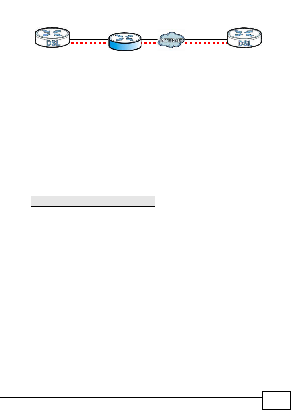
Figure 142 NAT Router Between I PSec Routers
Norm ally you cannot set up an I KE SA wit h a NAT rout er bet ween t he two I PSec rout ers because
the NAT router changes the header of the I PSec packet. NAT t raversal solves the problem by adding
a UDP port 500 header t o t he I PSec packet. The NAT rout er forwards the I PSec packet w ith t he UDP
port 500 header unchanged. I n the above figure, when I PSec router A t ries to est ablish an I KE SA,
I PSec rout er B checks t he UDP port 500 header, and I PSec routers A and B build the I KE SA.
For NAT traversal t o w ork, you m ust :
• Use ESP securit y protocol (in eit her transport or t unnel m ode) .
• Use IKE keying mode.
• Enable NAT t raversal on bot h I PSec endpoint s.
• Set t he NAT router to forward UDP port 500 t o I PSec rout er A.
Finally, NAT is com pat ible wit h ESP in t unnel m ode because int egrit y checks are perform ed over t he
com bination of the "original header plus original payload," which is unchanged by a NAT device. The
com patibilit y of AH and ESP wit h NAT in tunnel and t ransport m odes is sum m arized in t he following
table.
Y* - This is supported in the Device if you enable NAT t raversal.
20.5.7 ID Type and Content
Wit h aggressive negot iation m ode (see Sect ion 20.5.4 on page 231) , t he Device ident ifies incom ing
SAs by I D t ype and content since this identifying inform ation is not encrypted. This enables the
Device t o dist inguish between m ultiple rules for SAs t hat connect from rem ote I PSec rout ers that
have dynam ic WAN I P addresses.
Regardless of the I D type and cont ent configurat ion, t he Device does not allow you to save m ult iple
act ive rules wit h overlapping local and rem ot e I P addresses.
Wit h m ain m ode ( see Section 20.5.4 on page 231), the I D t ype and cont ent are encrypted to
provide identit y prot ect ion. I n t his case the Device can only dist inguish between up t o 12 different
incom ing SAs that connect from rem ote I PSec rout ers that have dynam ic WAN I P addresses. The
Device can distinguish up to 48 incom ing SAs because you can select bet ween three encryption
algorithm s (DES, 3DES and AES), two aut hentication algorithm s (MD5 and SHA1) and eight key
groups when you configure a VPN rule ( see Sect ion 20.2 on page 221). The I D type and cont ent act
as an extra level of ident ification for incom ing SAs.
Table 107 VPN and NAT
SECURITY PROTOCOL MODE NAT
AH Transport N
AH Tunnel N
ESP Transport Y*
ESP Tunnel Y
AB

Chapter 20 VPN
VMG8324-B10A / VMG8324-B30A Series User’s Guide
234
The t y pe of I D can be a dom ain nam e, an I P address or an e- m ail address. The content is t he I P
address, dom ain nam e, or e-m ail address.
20.5.7.1 ID Type and Content Examples
Two I PSec routers m ust have mat ching I D t ype and cont ent configuration in order t o set up a VPN
tunnel.
The t wo Devices in t his exam ple can com plet e negotiation and est ablish a VPN tunnel.
The t wo Devices in t his exam ple cannot com plet e t heir negotiation because Device B’s Loca l I D
Ty pe is I P, but Device A’s Rem ot e I D Type is set t o E- m ail. An “ I D m ism atched” m essage
displays in the I PSEC LOG.
20.5.8 Pre-Shared Key
A pre- shared key identifies a com m unicat ing party during a phase 1 I KE negot iation (see Sect ion
20.5.3 on page 230 for m ore on I KE phases) . I t is called “ pre- shared” because you have t o share it
wit h another party before you can com m unicate with them over a secure connection.
20.5.9 Diffie-Hellman (DH) Key Groups
Diffie- Hellm an (DH) is a public- key cryptography prot ocol that allow s two part ies to establish a
shared secret over an unsecured com m unicat ions channel. Diffie- Hellm an is used within I KE SA
set up t o establish session keys. Upon com pletion of t he Diffie- Hellm an exchange, the t wo peers
have a shared secret , but t he I KE SA is not aut henticated. For aut hentication, use pre-shared keys.
Table 108 Local I D Type and Cont ent Fields
LOCAL ID TYPE= CONTENT=
I P Type t he I P address of your com puter.
DNS Type a dom ain nam e (up t o 31 charact ers) by which t o ident ify this Device.
E- m ail Type an e-m ail address ( up to 31 charact ers) by which to identify this Device.
The dom ain nam e or e- m ail address that you use in the Loca l I D Con t ent field is used
for identification purposes only and does not need to be a real dom ain nam e or e-m ail
addr ess.
Table 109 Mat ching I D Type and Content Configuration Exam ple
Device A Device B
Local I D t ype: E- m ail Local I D type: I P
Local I D cont ent: t om @yourcom pany.com Local I D content : 1.1.1.2
Rem ot e I D type: I P Rem ote I D t ype: E-m ail
Rem ot e I D cont ent: 1.1.1.2 Rem ot e I D cont ent : t om @your company.com
Table 110 Mism atching I D Type and Cont ent Configur at ion Exam ple
DEVICE A DEVICE B
Local I D type: I P Local I D type: I P
Local I D cont ent: 1.1.1.10 Local I D content : 1.1.1.2
Rem ot e I D t y pe: E- m ail Rem ote I D t y pe: I P
Rem ot e I D content : aa@yahoo.com Rem ot e I D cont ent: 1.1.1.0

VMG8324-B10A / VMG8324-B30A Series User’s Guide 235
CHAPTER 21
Voice
21.1 Overview
Use t his chapt er to:
• Connect an analog phone t o the Device.
• Make phone calls over the I nt ernet, as well as the regular phone network.
• Configure sett ings such as speed dial.
• Configure network set tings t o opt im ize the voice quality of your phone calls.
21.1.1 What You Can Do in this Chapter
These screens allow you to configure your Device t o m ake phone calls over the I nt ernet and your
regular phone line, and to set up the phones you connect to the Device.
• Use the SI P Account screen ( Sect ion 21.3 on page 236) to set up informat ion about your SI P
account , cont rol which SI P accounts t he phones connected t o the Device use and configure audio
set tings such as volum e levels for the phones connect ed t o t he Device.
• Use the SI P Ser vice Pr ovide r screen ( Section 21.4 on page 241) to configure the SI P server
inform at ion, QoS for VoI P calls, t he num bers for certain phone funct ions, and dialing plan.
• Use the PhoneRe gion screen ( Section 21.5 on page 249) t o change set tings t hat depend on t he
country you are in.
• Use the Call Rule screen ( Sect ion 21.6 on page 249) t o set up shortcut s for dialing frequently-
used ( VoI P) phone num bers.
• Use the Call H ist or y Sum m a r y screen ( Sect ion 21.7 on page 250) t o view the sum m ary list of
received, dialed and m issed calls.
• Use the Call H ist or y Ou t going screen ( Sect ion 21.8 on page 251) t o view det ailed inform at ion
for each out going call you m ade.
• Use the Call Hist or y I ncom in g screen ( Sect ion 21.9 on page 251) to view detailed inform ation
for each incom ing call from som eone calling you.
You don’t necessarily need t o use all these screens t o set up your account. I n fact, if your service
provider did not supply inform ation on a part icular field in a screen, it is usually best t o leave it at
it s default sett ing.

Chapter 21 Voice
VMG8324-B10A / VMG8324-B30A Series User’s Guide
236
21.1.2 What You Need to Know About VoIP
VoIP
VoI P stands for Voice over I P. I P is the I nternet Prot ocol, which is t he m essage- carrying st andard
the I nt ernet runs on. So, Voice over I P is the sending of voice signals (speech) over the I nternet (or
another network that uses the I nt ernet Protocol).
SIP
SI P stands for Session I nit iation Prot ocol. SI P is a signalling standard t hat let s one network device
( like a com put er or the Device) send m essages to another. I n VoI P, t hese m essages are about
phone calls over the network. For exam ple, when you dial a num ber on your Device, it sends a SI P
m essage over the network asking t he ot her device ( the num ber you dialed) to take part in t he call.
SIP Accounts
A SI P account is a type of VoI P account. I t is an arrangem ent wit h a service pr ov ider that lets you
m ake phone calls over the I nternet. When you set the Device t o use your SI P account t o m ake
calls, t he Device is able t o send all t he inform at ion about t he phone call to your service provider on
the I nt ernet.
St rict ly speaking, you don’t need a SI P account . I t is possible for one SI P device ( like the Device) to
call anot her without involving a SI P service provider. However, the netw orking difficulties involved
in doing this m ake it t rem endously im practical under nor m al circum st ances. Your SI P account
provider rem oves t hese difficult ies by taking care of the call rout ing and setup - figuring out how t o
get your call to the right place in a way that you and the ot her person can t alk t o one anot her.
How to Find Out More
See Chapter 4 on page 37 for a tutorial showing how to set up t hese screens in an exam ple
scenario.
See Section 21.10 on page 252 for advanced t echnical inform at ion on SI P.
21.2 Before You Begin
• Before you can use these screens, you need t o have a VoI P account already set up. I f you don’t
have one yet , you can sign up wit h a VoI P service provider over the I nt ernet.
• You should have the inform ation your VoI P service provider gave you ready, before you start t o
configure t he Device.
21.3 The SIP Account Screen
The Device uses a SI P account to m ake outgoing VoI P calls and check if an incom ing call’s
destinat ion num ber m atches your SI P account ’s SI P num ber. I n order to m ake or r eceive a VoI P
Chapter 21 Voice
VMG8324-B10A / VMG8324-B30A Series User’s Guide 237
call, you need t o enable and configure a SI P account , and m ap it to a phone port. The SI P account
cont ains inform ation that allows your Device t o connect t o your VoI P service provider.
See Section 21.3.1 on page 237 for how to m ap a SI P account t o a phone port.
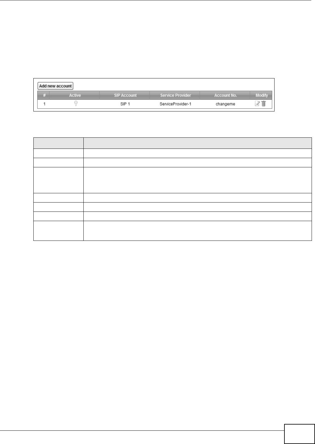
Use t his screen to view SI P account inform ation. You can also enable and disable each SI P account .
To access t his screen, click VoI P > SI P > SI P Accou nt.
Figure 143 VoI P > SI P > SI P Account
Each field is described in t he following table.
21.3.1 The SIP Account Add/Edit Screen
Use t his screen t o configure a SI P account and m ap it to a phone port . To access this screen, click
the Add new accou n t but ton or click the Edit icon of an entry in t he VoI P > SI P > SI P Account
screen.
Table 111 VoI P > SI P > SI P Account
LABEL DESCRIPTION
Add new account Click this to configur e a SI P account.
# This is t he index number of t he entry.
Active This show s whether t he SI P account is activat ed or not .
A yellow bulb signifies t hat t his SI P account is activat ed. A gray bulb signifies t hat t his SI P
account is not act ivated.
SI P Account This show s t he nam e of the SI P account.
Service Provider This show s t he nam e of the SI P service provider.
Account No. This show s t he SI P num ber.
Modify Click the Edit icon to configure the SI P account.
Click t he D e let e icon t o delet e this SI P account from t he Device.
Chapter 21 Voice
VMG8324-B10A / VMG8324-B30A Series User’s Guide
238
Note: Click m or e to see all the fields in the screen. You don’t necessarily need t o use all
these fields to set up your account. Click less t o see and configure only t he fields
needed for this feat ure.
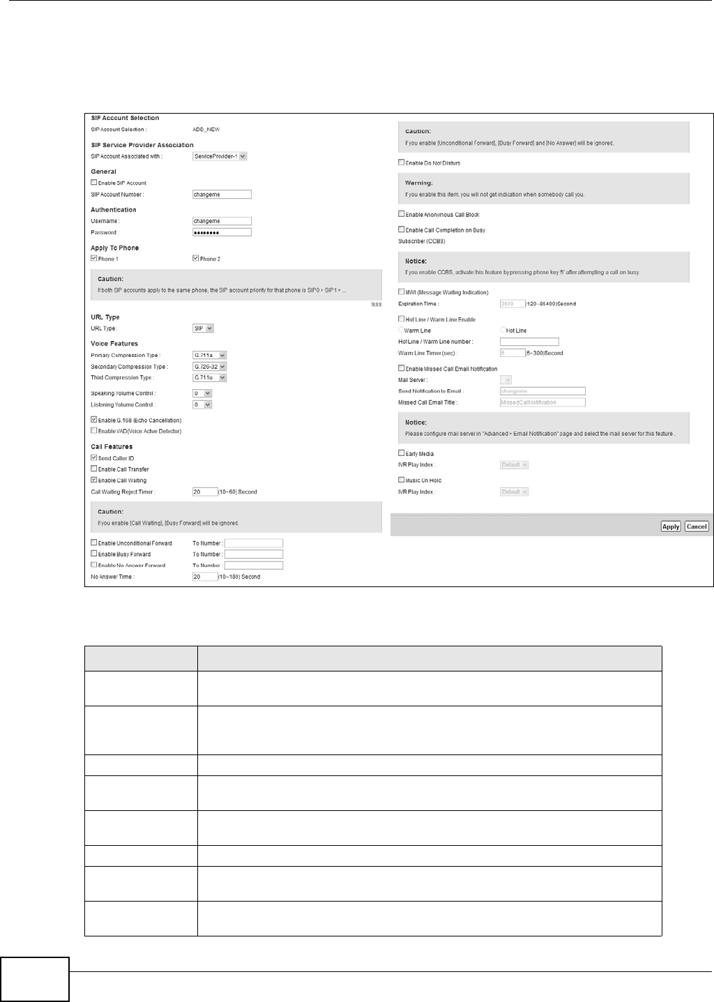
Figure 144 VoI P > SI P > SI P Account > Add new accoun/ Edit
Each field is described in t he following table.
Table 112 VoI P > SI P > SI P Account > Add new accoun/ Edit
LABEL DESCRIPTION
SI P Account
Selection
This field displays AD D _ N EW if you are creat ing a new SI P account or t he SI P
account you are m odifying.
SI P Service
Provider
Association
Select the SI P service provider profile to use for t he SI P account you are
configuring in this screen. This field is read- only when you are m odifying a SI P
account .
General
Enable SI P
Account
Select this if you want t he Device to use this account . Clear it if you do not w ant
the Device t o use t his account.
SI P Account
Nu m ber
Enter your SI P number. I n the full SI P URI, this is t he par t before t he @ sym bol.
You can use up to 127 print able ASCI I charact er s.
Au t hent icat ion
Usernam e Enter t he user nam e for regist ering t his SI P account , exact ly as it was given t o
you. You can use up to 95 printable ASCII charact ers.
Password Ent er the user nam e for registering this SI P account , exact ly as it was given to
you. You can use up t o 95 print able ASCII Extended set characters.

Chapter 21 Voice
VMG8324-B10A / VMG8324-B30A Series User’s Guide 239
Apply To Phone Select a phone port on which you want to m ake or receive phone calls for this
SI P account.
I f you m ap a phone port t o m ore than one SI P account , there is no way t o
dist inguish bet w een the SI P account s when you receive phone calls. The Device
uses t he m ost recent ly registered SI P account first when you m ake an outgoing
call.
I f a phone port is not m apped to a SI P account , you cannot receive or m ake any
calls on t he phone connected to t his phone port.
m or e/ less Click m or e to display and edit m ore inform at ion for t he SI P account. Click le ss
to display and configure the basic SI P account set tings.
URI Type Select whether or not to include the SI P service dom ain nam e when the Dev ice
sends the SI P num ber.
SI P - include t he SI P service dom ain nam e.
TEL - do not include the SI P service dom ain nam e.
Voice Featur es
Prim ary
Com pression
Ty p e
Secondary
Com pression
Ty p e
Third
Com pression
Ty p e
Select t he t ype of voice coder/ decoder ( codec) that you want t he Device to use.
G.711 provides high voice qualit y but requires m ore bandwidth (64 kbps) . G.711
is the default codec used by phone com panies and digit al handset s.
•G.7 1 1 a is t ypically used in Europe.
•G.7 1 1 u is typically used in Nort h America and Japan.
G.7 2 6 - 2 4 operates at 2 4 kbps.
G.7 2 6 - 3 2 operates at 3 2 kbps.
G.7 2 2 is a 7 KHz wideband voice codec t hat operat es at 48, 56 and 64 kbps. By
usi n g a sam p le r at e of 16 k Hz, G. 7 22 can provide higher fidelit y and better audio
quality than narrow band codecs like G.711, in which the voice signal is sam pled
at 8 KHz.
The Device m ust use the sam e codec as t he peer. When two SI P devices st art a
SI P session, they m ust agree on a codec.
Select the Device’s first choice for voice coder/ decoder.
Select the Device’s second choice for voice coder/ decoder. Select N one if you
only want t he Device t o accept t he first choice.
Select t he Device’s t hird choice for voice coder/ decoder. Select N o ne if you only
want t he Device t o accept t he first or second choice.
Speaking Volum e
Control
Select t he loudness that the Device uses for speech t hat it sends t o t he peer
device.
- 1 2 is t he quietest , and 1 2 is the loudest .
List ening Volum e
Control
Select t he loudness that the Device uses for speech t hat it receives from the
peer device.
- 1 2 is t he quietest , and 1 2 is the loudest .
Enable G.168
( Echo
Cancellat ion)
Select t his if you want t o elim inat e the echo caused by t he sound of your voice
reverberating in t he telephone receiver while you t alk.
Enable VAD
( Voice Active
Detector)
Select t his if the Device should stop transm itt ing when you are not speaking.
This reduces the bandwidth the Dev ice uses.
Call Feat ures
Table 112 VoI P > SI P > SI P Account > Add new accoun/ Edit ( continued)
LABEL DESCRIPTION

Chapter 21 Voice
VMG8324-B10A / VMG8324-B30A Series User’s Guide
240
Send Caller I D Select this if you want t o send ident ification when you m ake VoI P phone calls.
Clear t his if you do not want t o send ident ification.
Enable Call
Tr a n s f e r
Select this t o enable call t ransfer on the Device. This allow s you to t ransfer an
incom ing call (t hat you have answered) t o anot her phone.
Enable Call
Wait ing
Select t his to enable call wait ing on the Device. This allows you t o place a call on
hold while you answ er another incom ing call on the sam e telephone num ber.
Call Wait ing
Rej ect Tim er
Specify a tim e of seconds that t he Device wait s before reject ing t he second call if
you do not answer it.
Enable
Unconditional
Forward
Select this if you want t he Device t o forwar d all incom ing calls to the specified
phone num ber.
Specify t he phone num ber in t he To N u m be r field on the right .
Enable Busy
Forward
Select this if you want t he Device t o forward incom ing calls to t he specified
phone num ber if the phone port is busy.
Specify t he phone num ber in t he To N u m be r field on the right .
I f you have call waiting, the incom ing call is forwarded to t he specified phone
num ber if you reject or ignore the second incom ing call.
Enable No Answer
Forward
Select this if you want t he Device t o forward incom ing calls to t he specified
phone num ber if the call is unanswered. ( See N o An sw er Tim e.)
Specify t he phone num ber in t he To N u m be r field on the right .
No Answer Tim e This field is used by the Act ive N o Answ er For w a r d feature.
Enter the num ber of seconds t he Device should wait for you to answer an
incom ing call before it considers the call is unansw ered.
Enable Do Not
Dist urb
Select t his to set y our phone to not ring when som eone calls you.
Enable
Anonym ous Call
Block
Select this if you do not want the phone t o ring when som eone tries t o call you
with caller I D deactivat ed.
Enable Call
Com plet ion on
Busy Subscriber
( CCBS)
When you m ake a phone call but hear a busy tone, Call Com plet ion on Busy
Subscriber ( CCBS) allows you to enable auto-callback by pressing 5 and hanging
up t he phone. The Device then t r ies t o call that phone num ber every m inute
since after you hang up the phone. When the called part y becom es available
within t he CCBS tim eout period ( 60 m inut es by default ), bot h phones ring.
• I f t he called party’s phone rings because of CCBS but no one answers t he
phone after 180 seconds, you will hear a busy t one. You can enable CCBS on
the called num ber again.
• I f you m anually call t he num ber on which you have enabled CCBS before t he
CCBS t im eout period expires, t he Device disables CCBS on the called
num ber.
• I f you call a second num ber before the first called num ber’s CCBS t im eout
period expires, t he Device st ops calling t he first num ber until you finish the
second call.
Select t his opt ion t o activat e CCBS on t he Device.
MWI (Message
Wait ing
I ndicat ion)
Select t his if you want t o hear a wait ing ( beeping) dial t one on your phone when
you have at least one voice message. Your VoI P service provider m ust support
this feat ure.
Expirat ion Tim e Keep the default value for t his field, unless your VoI P service provider t ells you
to change it . Ent er the num ber of seconds the SI P ser ver should provide t he
m essage wait ing service each tim e the Device subscribes t o the service. Before
this t im e passes, t he Device autom atically subscribes again.
Hot Line / Warm
Line Enable
Select t his to enable t he hot line or warm line feature on t he Device.
Table 112 VoI P > SI P > SI P Account > Add new accoun/ Edit ( continued)
LABEL DESCRIPTION

Chapter 21 Voice
VMG8324-B10A / VMG8324-B30A Series User’s Guide 241
21.4 The SIP Service Provider Screen
Use t his screen t o view the SI P service provider inform at ion on t he Device. Click VoI P > SI P >
SI P Se rvice Provider t o open the following screen.
Figure 145 VoI P > SI P > SI P Service Provider
Warm Line Select this to hav e t he Device dial t he specified warm line num ber after you pick
up t he t elephone and do not press any keys on t he keypad for a period of t im e.
Hot Line Select this t o have the Device dial t he specified hot line num ber im m ediately
when you pick up the t elephone.
Hot Line / Warm
Line num ber
Enter the num ber of t he hot line or warm line that you want t he Device to dial.
Warm Line Tim er Ent er a number of seconds that the Device waits before dialing t he warm line
num ber if you pick up t he t elephone and do not press any keys on the keypad.
Enable Missed
Call Email
Not ification
Select t his opt ion to hav e t he Dev ice e- m ail you a not ificat ion when there is a
m issed call.
Mail Server Select a m ail server for t he e- m ail address specified below. I f you select N one
here, e-m ail not ificat ions will not be sent via e- m ail.
You m ust have configur ed a m ail server already in the Em ail Not ifica tion
screen.
Send
Not ification to
Em ail
Not ificat ions are sent to t he e- m ail address specified in this field. I f t his field is
left blank, not ificat ions w ill not be sent via e- m ail.
Missed Call
Em ail Tit le
Type a t it le t hat you want t o be in t he subject line of the e- m ail notificat ions that
the Device sends.
Early Media Select t his opt ion if you w ant people t o hear a custom ized recording when they
call you.
I VR Play
I ndex
Select the tone you want people to hear when t hey call you.
This field is configurable only when you select Early M edia. See Section 21.10
on page 252 for inform at ion on how to record these tones.
Music On Hold Select this option t o play a cust om ized recording w hen you put people on hold.
I VR Play
I ndex
Select the t one to play when you put som eone on hold.
This field is configurable only when you select Music On Hold. See Sect ion
21.10 on page 252 for inform ation on how to record these tones.
Apply Click t his t o save your changes and to apply them t o the Device.
Cancel Click this to set every field in t his screen t o it s last - saved value.
Table 112 VoI P > SI P > SI P Account > Add new accoun/ Edit ( continued)
LABEL DESCRIPTION

Chapter 21 Voice
VMG8324-B10A / VMG8324-B30A Series User’s Guide
242
Each field is described in t he following table.
21.4.1 The SIP Service Provider Add/Edit Screen
Use t his screen t o configure a SI P service provider on t he Device. Click t he Add ne w pr ovider
but t on or an Edit icon in t he V oI P > SI P > SI P Ser vice Provider t o open the following screen.
Table 113 VoI P > SI P > SI P Service Provider
LABEL DESCRIPTION
Add new provider
# This is t he index number of t he entry.
SI P Service
Provider Nam e
This show s t he nam e of the SI P service provider.
SI P Server
Address
This show s t he I P address or dom ain nam e of the SI P server.
REGI STER Server
Address
This shows t he I P address or dom ain nam e of the SI P register server.
SI P Service
Dom ain
This show s t he SI P service dom ain nam e.
Modify Click the Edit icon t o configure the SI P service provider.
Click t he D e let e icon t o delet e this SI P service pr ovider from t he Device.
Chapter 21 Voice
VMG8324-B10A / VMG8324-B30A Series User’s Guide 243
Note: Click m or e to see all the fields in the screen. You don’t necessarily need t o use all
these fields to set up your account. Click less t o see and configure only t he fields
needed for this feat ure.
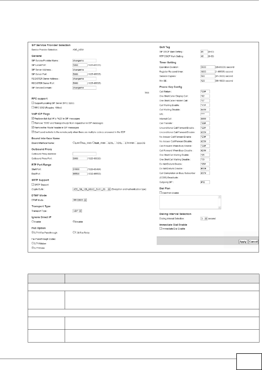
Figure 146 VoI P > SI P > SI P Service Provider > Add new provider/ Edit
Each field is described in t he following table.
Table 114 VoI P > SI P > SI P Service Provider > Add new provider/ Edit
LABEL DESCRIPTION
SI P Service Provider Selection
Service
Provider
Selection
Select the SI P service provider profile you want t o use for t he SI P account you configure in
this screen. I f you change t his field, t he screen autom atically refreshes.
General
SI P Service
Provider Nam e
Enter the nam e of your SI P ser vice provider.
SI P Local Port Enter the Device’s listening port num ber, if your VoI P service provider gave you one.
Ot herwise, keep t he default value.

Chapter 21 Voice
VMG8324-B10A / VMG8324-B30A Series User’s Guide
244
SI P Server
Address
Enter the I P address or dom ain nam e of t he SI P server provided by your VoI P service
provider. You can use up t o 95 printable ASCII characters. I t does not m at t er whet her the
SI P server is a proxy, redirect or regist er server.
SI P Server Port Enter the SI P server’s listening port num ber, if your VoI P service pr ovider gave you one.
Ot herwise, keep t he default value.
REGI STER
Server Address
Enter the I P address or dom ain nam e of t he SI P register server, if y our VoI P ser vice provider
gave you one. Ot herwise, ent er t he sam e address you ent ered in the SI P Se r v e r Addr e ss
field. You can use up to 95 print able ASCI I characters.
REGI STER
Server Port
Enter the SI P register server ’s listening port num ber, if your VoI P service provider gave you
one. Otherwise, enter t he sam e port num ber you ent ered in t he SI P Server Port field.
SI P Service
Dom ain
Enter the SI P service dom ain nam e. I n the full SI P URI , t his is the part aft er the @ sym bol.
You can use up to 127 print able ASCI I Extended set characters.
RFC Support
Support
Locating SI P
Server
( RFC32 63)
Select t his opt ion t o have t he Device use DNS procedures t o resolve t he SI P dom ain and
find t he SI P server’s I P address, por t num ber and supported t ransport prot ocol(s) .
The Device first uses DNS Nam e Authorit y Pointer (NAPTR) records t o determ ine t he
transport prot ocols suppor t ed by t he SI P server. It then perfor m s DNS Service ( SRV) query
to determ ine t he port num ber for t he prot ocol. The Device resolves t he SI P server ’s I P
addr ess by a st andard DNS address record lookup.
The SI P Se r ve r Port and REGI STER Se r ver Por t fields in t he General sect ion above are
grayed out and not applicable and t he Tr a n spor t Type can also be set to AUTO if you
select this opt ion.
RFC
3262( Require:
100rel)
PRACK ( RFC 3262) defines a m echanism t o provide reliable transm ission of SI P pr ovisional
response m essages, which convey infor m ation on the processing progress of t he request .
This uses the option tag 100rel and the Provisional Response ACKnowledgem ent ( PRACK)
m et hod.
Select this t o have the t he peer device requir e t he opt ion t ag 100rel t o send provisional
responses reliably.
VoI P I OP Flags Select t he VoI P int er- operabilit y set t ings you want to activate.
Replace dial
digit '# ' to
'% 23' in SI P
m essages
Replace a dial digit “# ” wit h “% 23” in the I NVI TE m essages.
Rem ove ‘: 5060’
and
't ransport= udp'
from request-
ur i in SI P
m essages
Rem ove “: 5060” and “ transport= udp” from t he “ Request-URI ” st r ing in t he REGI STER and
I NVI TE packet s.
Rem ove t he
'Rout e' header
in SI P
m essages
Rem ove the 'Route' header in SI P packets.
Don't send re-
I nvit e to t he
rem ot e part y
when t here are
m ult iple codecs
answ ered in t he
SDP
Do not send a re-I nvit e packet to t he rem ot e part y when the r em ote party answers t hat it
can support m ult iple codecs.
Bound I nterface Nam e
Table 114 VoI P > SI P > SI P Service Provider > Add new provider/ Edit ( continued)
LABEL DESCRIPTION

Chapter 21 Voice
VMG8324-B10A / VMG8324-B30A Series User’s Guide 245
Bound
I nt erface Nam e
I f you select LAN or Any_ W AN , the Dev ice aut om at ically activat es t he VoI P service when
any LAN or WAN connection is up.
I f you select M u lt i_ W AN , you also need to select t wo or m ore pre- configur ed WAN
int erfaces. The VoI P service is activat ed only when one of t he selected WAN connect ions is
up.
Outbound Proxy
Outbound
Proxy Address
Enter t he I P address or dom ain nam e of t he SI P outbound pr oxy server if your VoI P service
provider has a SI P outbound server t o handle voice calls. This allows t he Device to work
with any t ype of NAT r outer and elim inat es t he need for STUN or a SI P ALG. Turn off any SI P
ALG on a NAT rout er in front of t he Device t o keep it from re- t ranslating t he I P address
( since this is already handled by the out bound proxy ser ver) .
Outbound
Proxy Port
Enter t he SI P outbound pr oxy server’s list ening por t , if your VoI P service provider gave you
one. Otherwise, keep t he default value.
RTP Port Range
St art Port
End Port
Enter the list ening port num ber(s) for RTP traffic, if your VoI P serv ice provider gave you this
inform ation. Otherwise, keep t he default values.
To ent er one port number, enter the port num ber in the St art Port and End Port fields.
To ent er a range of ports,
• ent er t he port num ber at t he beginning of the range in the St art Por t field.
• ent er t he por t num ber at t he end of t he range in the End Por t field.
SRTP Support
SRTP Support When you m ake a VoI P call using SI P, the Real- tim e Transpor t Prot ocol ( RTP) is used to
handle voice dat a transfer. The Secure Real-tim e Transport Protocol (SRTP) is a security
profile of RTP. I t is designed to pr ovide encryption and aut henticat ion for the RTP data in
bot h unicast and m ulticast applicat ions.
The Dev ice suppor t s encryption using AES with a 128- bit key. To protect data integrity, SRTP
uses a Hash-based Message Aut henticat ion Code ( HMAC) calculat ion with Secure Hash
Algorithm ( SHA) - 1 to authenticat e dat a. HMAC SHA- 1 produces a 80 or 32- bit
aut hent icat ion t ag t hat is appended t o the packet.
Bot h the caller and callee should use t he sam e algorithm s t o est ablish an SRTP session.
Crypto Suite Select the encryption and aut henticat ion algor it hm set used by t he Device to set up an SRTP
m edia session wit h t he peer device.
Select AES_ CM_ 1 2 8 _ H M AC_ SH A1 _ 8 0 or AES_ CM_ 1 2 8 _ H MAC_ SH A1 _ 3 2 t o enable
bot h dat a encrypt ion and authentication for v oice dat a.
Select AES_ CM_ 1 2 8 _ N ULL to use 128-bit dat a encryption but disable data authenticat ion.
Select N ULL_ CI PHER_ H M AC_ SH A1 _ 8 0 t o disable encryption but require authenticat ion
using t he default 80- bit tag.
DTMF Mode
DTMF Mode Control how t he Device handles t he t ones that your t elephone m akes when you push it s
buttons. You should use the sam e m ode your VoI P service provider uses.
RFC2 8 3 3 - send t he DTMF t ones in RTP packet s.
PCM - send t h e DTMF t on es in t h e v oice dat a st r eam . This m et hod w or k s best w hen y ou ar e
using a codec that does not use com pression (like G.711). Codecs that use com pression
(like G.729 and G.726) can dist or t the t ones.
SI P I N FO - send the DTMF t ones in SI P m essages.
Tr a n sp o r t Ty p e
Tr a n sp o r t Ty p e Select the transport layer protocol UD P or TCP ( usually UDP) used for SI P.
Table 114 VoI P > SI P > SI P Service Provider > Add new provider/ Edit ( continued)
LABEL DESCRIPTION

Chapter 21 Voice
VMG8324-B10A / VMG8324-B30A Series User’s Guide
246
I gnor e Direct I P Select Ena ble t o have t he connect ed CPE devices accept SI P request s only from the SI P
proxy/ register server specified above. SI P requests sent from ot her I P addresses will be
ignored.
FAX Option This field controls how t he Device handles fax m essages.
G711 Fax
Passt h r ough
Select t his if the Device should use G.711 t o send fax m essages. You have to also select
which operat ing codec ( G. 7 1 1 M u la w or G.7 1 1 Ala w ) t o use for encoding/ decoding FAX
dat a. The peer devices m ust use the sam e set tings.
T38 Fax Relay Select this if t he Device should send fax m essages as UDP or TCP/ I P packet s t hrough I P
net wor ks. This prov ides bet ter qualit y, but it m ay have int er-operabilit y problem s. The peer
devices m ust also use T.38.
QoS Tag
SI P DSCP Mark
Setting
Enter the DSCP (DiffServ Code Point) num ber for SI P m essage transm issions. The Device
creat es Class of Ser vice ( CoS) pr iority t ags with this num ber to SI P t raffic t hat it transm its.
RTP DSCP Mar k
Setting
Enter the DSCP (DiffServ Code Point) num ber for RTP voice t ransm issions. The Device
creat es Class of Ser vice ( CoS) pr iority t ags with this num ber t o RTP traffic that it transm its.
Tim er Set t ing
Expirat ion
Durat ion
Enter the num ber of seconds your SI P account is regist ered wit h t he SI P register server
befor e it is deleted. The Device aut om atically t ries t o re- register your SI P account when
one- half of t his tim e has passed. ( The SI P regist er serv er m ight have a different expiration.)
Regist er Re-
send t im er
Enter the num ber of seconds t he Device wait s before it t ries again to regist er t he SI P
account , if t he first try failed or if t here is no response.
Session Expir es Enter the num ber of seconds t he Device let s a SI P session rem ain idle ( without t raffic)
befor e it aut om at ically disconnects the session.
Min-SE Ent er t he m inim um num ber of seconds t he Device let s a SI P session rem ain idle (without
traffic) before it aut om at ically disconnects the session. When two SI P devices start a SI P
session, they m ust agree on an expirat ion t im e for idle sessions. This field is the shor t est
expiration tim e that the Device accepts.
Phone Key
Config
Enter the key com binat ions for certain functions of t he SI P phone.
Call Ret urn Enter the key com binat ions that you can ent er t o place a call t o t he last num ber t hat called
you.
One Shot Caller
Display Call
Enter the key com binat ions t hat you can enter to activate caller I D for the next call only.
One Shot Caller
Hidden Call
Enter the key com binat ions t hat you can enter to deactivat e caller I D for t he next call only.
Call Wait ing
Enable
Enter the key com binat ions t hat you can enter to t urn on t he call waiting function.
Call Wait ing
Disable
Enter the key com binat ions t hat you can enter to t urn off the call wait ing funct ion.
I VR Enter the key com binat ions t hat you can enter to recor d cust om caller ringing t ones (t he
sound a caller hears before you pick up t he phone) and on hold tones (the sound som eone
hears when you put t heir call on hold) . I VR stands for Interactive Voice Response.
I nt ernal Call Enter t he key com binations t hat you can ent er to call t he phone( s) connected to t he Device.
Call Transfer Enter the key com binat ions t hat you can enter to t ransfer a call to another phone.
Unconditional
Call For ward
Enable
Enter the key com binat ions t hat you can enter to forward all incom ing calls t o t he phone
num ber you specified in the SI P > SI P Accou nt screen.
Unconditional
Call For ward
Disable
Enter the key com binat ions that you can ent er t o turn the uncondit ional call forward
function off.
Table 114 VoI P > SI P > SI P Service Provider > Add new provider/ Edit ( continued)
LABEL DESCRIPTION

Chapter 21 Voice
VMG8324-B10A / VMG8324-B30A Series User’s Guide 247
No Answer Call
Forward Enable
Enter the key com binat ions t hat you can enter to forward incom ing calls to t he phone
num ber you specified in the SI P > SI P Accou nt screen if t he calls are unanswer ed.
No Answer Call
Forward
Disable
Enter the key com binat ions t hat you can enter to t urn t he no answer call forward function
off.
Call For ward
When Busy
Enable
Enter the key com binat ions t hat you can enter to forward incom ing calls to t he phone
num ber you specified in the SI P > SI P Accou nt screen if the phone port is busy.
Call For ward
When Busy
Disable
Enter the key com binat ions t hat you can enter to t urn t he busy forward funct ion off.
One Shot Call
Wait ing Enable
Enter the key com binat ions t hat you can enter to activate call wait ing on t he next calls.
One Shot Call
Wait ing Disable
Enter the key com binat ions that you can ent er t o deactivat e call wait ing on t he next call
only.
Do Not Disturb
Enable
Enter t he key com binat ions t hat you can enter t o set your phone not to ring when som eone
calls you.
Do Not Disturb
Disable
Enter the key com binat ions t hat you can enter to t urn t his funct ion off.
Call Com plet ion
on Busy
Subscriber
( CCBS)
Deactivat e
Enter the key com binat ions that you can ent er t o disable CCBS on a call.
Outgoing SI P Enter the key com binations t hat you can enter to select the SI P account that you use to
m ake outgoing calls.
I f you ent er # 12( by default) < SI P account index num ber> # < t he phone num ber you want to
call> , # 1201# 12345678 for exam ple, t he Device uses t he first SI P account to call
12345678.
Dial Plan
Dial Plan
Enable
Select t his to activate t he dial plan rules you specify in the text box provided. See Section
21.4.2 on page 248 for how to set up a rule.
Dialing I nterval Select ion
Dialing I nt erval
Selection
Enter the num ber of seconds t he Device should wait after you st op dialing num bers before it
m akes t he phone call. The value depends on how quickly you dial phone num bers.
I f you select I m m e dia te Dia l Enable, you can press t he pound key ( # ) to t ell the Device
to m ake t he phone call imm ediately, regardless of t his sett ing.
I m m ediate Dial Enable
I m m ediate Dial
Enable
Select this if you want to use the pound key ( # ) to t ell t he Device to m ake the phone call
im m ediat ely, instead of w ait ing the num ber of seconds you selected in the D ialin g I nt e r va l
Sele ct ion field.
I f you select t his, dial t he phone num ber, and then pr ess t he pound key.
The Device makes t he call im m ediat ely, instead of waiting. You can still wait, if you want.
Apply Click Apply t o save your changes.
Cancel Click Cance l t o restore your pr eviously saved set t ings.
Table 114 VoI P > SI P > SI P Service Provider > Add new provider/ Edit ( continued)
LABEL DESCRIPTION

Chapter 21 Voice
VMG8324-B10A / VMG8324-B30A Series User’s Guide
248
21.4.2 Dial Plan Rules
A dial plan defines the dialing pat terns, such as t he length and range of the digit s for a telephone
num ber. I t also includes count ry codes, access codes, area codes, local num bers, long dist ance
num bers or international call prefixes. For exam ple, t he dial plan ( [ 2- 9] xxxxxx) does not allow a
local num ber which begins with 1 or 0.
Wit hout a dial plan, users have t o m anually enter t he whole callee’s num ber and wait for t he
specified dialing interval t o t im e out or press a t erm inat or key (usually the pound key on the phone
keypad) before the Device m akes the call.
The Device init ializes a call when t he dialed num ber m atches any one of the rules in t he dial plan.
Dial plan rules follow t hese conventions:
• The collect ion of rules is in parentheses ( ).
• Rules are separated by t he | (bar) sym bol.
• “ x” st ands for a wildcard and can be any digit from 0 to 9.
• A subset of keys is in a square bracket [ ] . Ranges are allowed.
For exam ple, [ 359] m eans a num ber m at ching this rule can be 3, 5 or 9. [ 26- 8* ] m eans a
num ber m at ching this rule can be 2, 6, 7, 8 or * .
• The dot “.” appended t o a digit allows the digit t o be ignored or repeated m ult iple tim es. Any digit
( 0~ 9, * , # ) aft er t he dot w ill be ignored.
For exam ple, (01.) m eans a num ber m at ching this rule can be 0, 01, 0111, 01111, and so on.
• < dialed-num ber: translat ed-num ber> indicat es the num ber aft er t he colon replaces the num ber
before t he colon in an angle bracket < > . For exam ple,
( < : 1212> xxxxxxx) means the Device aut om atically prefixes t he translat ed- num ber “1212” t o
t he num ber you dialed before m aking the call. This can be used for local calls in t he US.
( < 9: > xxx xxxxxxx) m eans the Device autom at ically rem oves t he specified prefix “ 9” from t he
num ber you dialed before m aking t he call. This is always used for m aking outside calls from an
office.
( xx< 123: 456> xxxx) m eans the Device aut om at ically translates “ 123” t o “456” in the num ber
you dialed before m aking the call.
• Calls with a num ber followed by the exclam ation m ark “ !” will be dropped.
• Calls with a num ber followed by the term ination character “@” will be m ade im m ediat ely. Any
digit ( 0~ 9, * , # ) aft er t he @ charact er will be ignored.
I n t his exam ple dial plan ( 0 | [ 49] 11 | 1 [ 2-9] xx xxxxxxx | 1 947 xxxxxxx ! ), you can dial “0” t o call
the local operat or, call 411 or 911, or m ake a long dist ance call with an area code st arting from 2 to
9 in t he US. The calls with the area code 947 will be dropped.
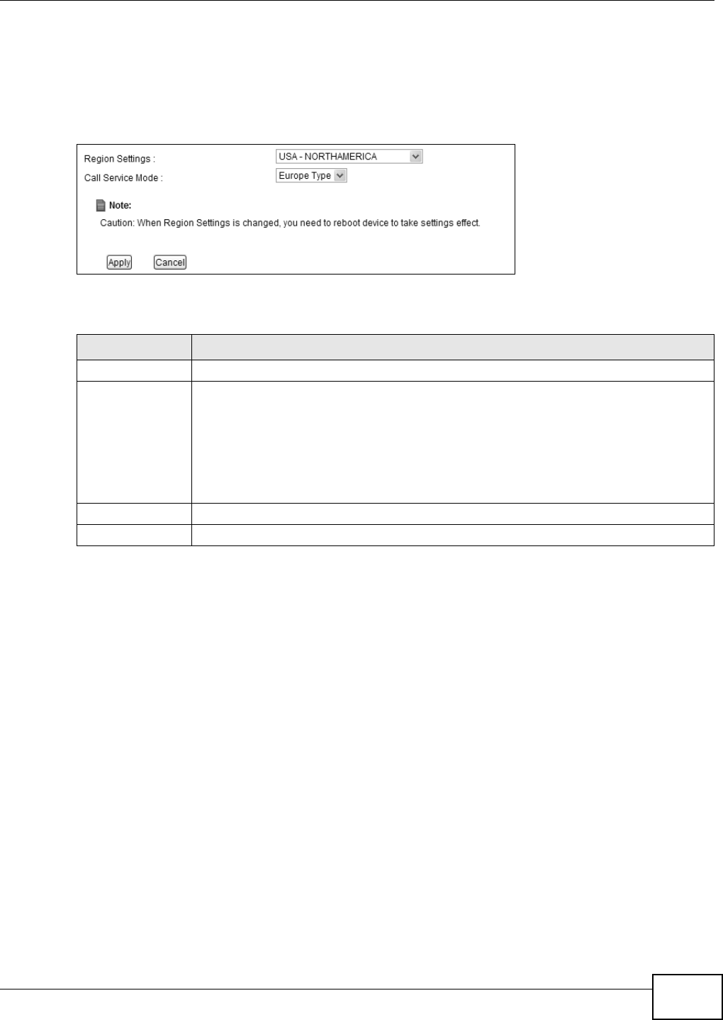
Chapter 21 Voice
VMG8324-B10A / VMG8324-B30A Series User’s Guide 249
21.5 The Phone Screen
Use t his screen t o m aint ain set tings t hat depend on which region of the w orld the Device is in. To
access t his screen, click VoI P > Phone.
Figure 147 VoI P > Ph one
Each field is described in t he following table.
21.6 The Call Rule Screen
Use t his screen t o add, edit , or rem ove speed-dial num bers for out going calls. Speed dial provides
short cuts for dialing frequently- used (VoI P) phone num bers. You also have t o create speed-dial
ent ries if you want to call SI P num bers t hat contain let ters. Once you have configured a speed dial
Table 115 VoI P > Phone
LABEL DESCRIPTION
Region Set t ings Select t he place in which the Device is locat ed.
Call Service Mode Select the mode for supplem entary phone services (call hold, call wait ing, call transfer
and three-way conference calls) that your VoI P ser vice prov ider supports.
Europe Type - use supplem ent ary phone services in European m ode
USA Type - use supplem ent ary phone services Am erican m ode
You m ight have to subscribe to t hese services t o use them . Cont act your VoI P service
provider.
Apply Click t his t o save your changes and to apply them t o the Device.
Cancel Click this to set every field in t his screen t o it s last - saved value.
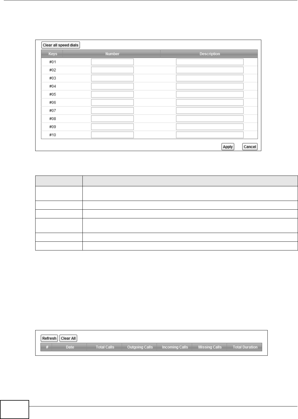
Chapter 21 Voice
VMG8324-B10A / VMG8324-B30A Series User’s Guide
250
rule, you can use a short cut (t he speed dial num ber, # 01 for exam ple) on your phone's keypad to
call t he phone num ber.
Figure 148 VoI P > Call Rule
Each field is described in t he following table.
21.7 The Call History Summary Screen
The Device logs calls from or to your SI P num bers. This screen allows you t o view the sum m ary of
received, dialed and m issed calls.
Click VoI P > Call H ist or y > Call H ist ory Sum m ar y. The following screen displays.
Figure 149 VoI P > Call Hist ory > Call Hist ory Sum m ary
Table 116 VoI P > Call Rule
LABEL DESCRIPTION
Clear all speed
dials
Click t his to erase all the speed- dial entries on this screen.
Keys This field displays the speed- dial num ber you should dial to use t his entry.
Num ber Enter the SI P num ber you want the Device to call when you dial the speed- dial num ber.
Descript ion Enter a nam e to ident ify t he par t y you call when you dial t he speed- dial num ber. You can
use up t o 127 print able ASCI I characters.
Apply Click t his t o save your changes and to apply them t o the Device.
Cancel Click this to set every field in t his screen t o it s last - saved value.
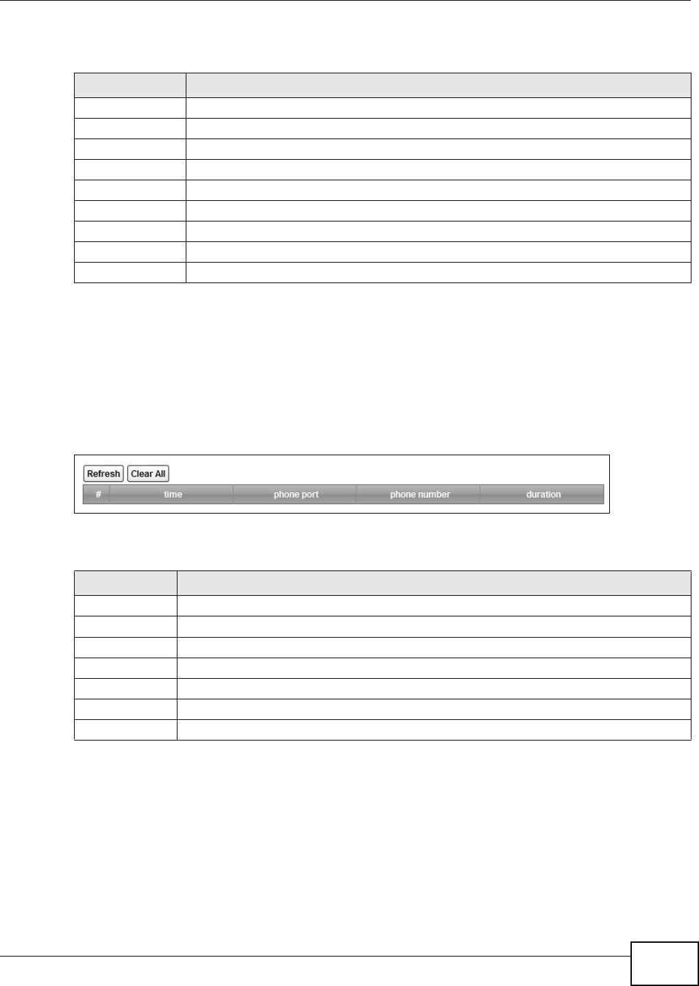
Chapter 21 Voice
VMG8324-B10A / VMG8324-B30A Series User’s Guide 251
Each field is described in t he following table.
21.8 The Call History Outgoing Calls Screen
Use t his screen t o see detailed inform ation for each out going call you m ade.
Click VoI P > Call H ist or y > Call H ist ory Out going. The following screen displays.
Figure 150 VoI P > Call Hist ory > Call Hist ory Out going
Each field is described in t he following table.
21.9 The Call History Incoming Calls Screen
Use t his screen t o see detailed inform ation for each incom ing call from som eone calling you.
Table 117 VoI P > Call History > Call History Sum m ary
LABEL DESCRIPTION
Refresh Click t his but ton to renew t he call hist ory list .
Clear All Click this but t on t o rem ove all entries from the call history list .
#This is a read- only index number.
Date This is t he date when t he calls were m ade.
Tot al Calls This displays t he total num ber of calls from or t o your SI P num bers that day.
Outgoing Calls This displays how m any calls originat ed from you that day.
I ncom ing Calls This displays how m any calls you r eceived that day.
Missing Calls This displays how m any incom ing calls were not answered that day.
To t a l D u r a t i o n This displays how long all calls last ed t hat day.
Table 118 VoI P > Call History > Call History Outgoing
LABEL DESCRIPTION
Refresh Click t his but ton to renew t he dialed call list.
Clear All Click this but t on t o rem ove all entries from the dialed call list .
#This is a read- only index num ber.
t im e This is the dat e and tim e when t he call was m ade.
phone port This is t he phone port on which you m ade t he call.
phone num ber This is the SI P num ber you called.
duration This displays how long t he call last ed.
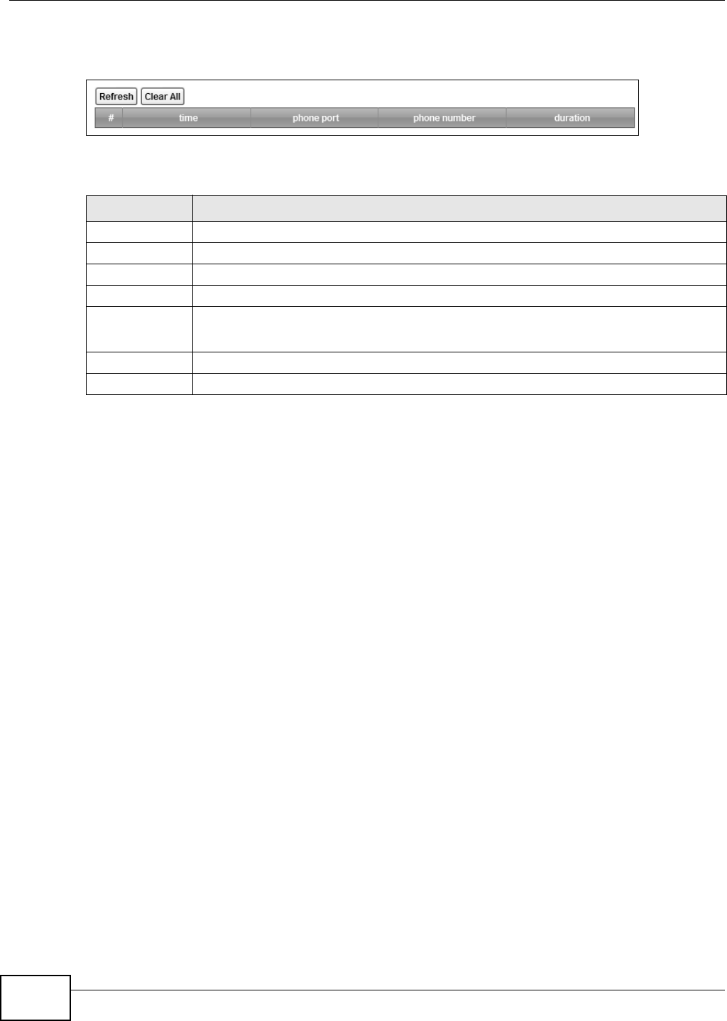
Chapter 21 Voice
VMG8324-B10A / VMG8324-B30A Series User’s Guide
252
Click VoI P > Call H ist or y > Call H ist ory I ncom ing Calls. The following screen displays.
Figure 151 VoI P > Call Hist ory > Call Hist ory I ncom ing Calls
Each field is described in t he following table.
21.10 Technical Reference
This section contains background m aterial relevant to t he VoI P screens.
VoIP
VoI P is the sending of voice signals over I nt ernet Prot ocol. This allows you t o m ake phone calls and
send faxes over t he I nt ernet at a fraction of the cost of using t he tradit ional circuit- swit ched
telephone net work. You can also use servers to run t elephone service applications like PBX services
and voice m ail. I nternet Telephony Service Provider (I TSP) com panies provide VoI P service.
Circuit-swit ched t elephone networks require 64 kilobits per second ( Kbps) in each direct ion t o
handle a telephone call. VoI P can use advanced voice coding techniques with com pr ession to reduce
the required bandwidth.
SIP
The Session I nitiat ion Protocol (SI P) is an application- layer cont rol (signaling) prot ocol t hat handles
the sett ing up, altering and tearing down of voice and m ult im edia sessions over the I nt ernet .
SI P signaling is separate from t he m edia for which it handles sessions. The m edia that is exchanged
during the session can use a different path from that of the signaling. SI P handles telephone calls
and can interface with tradit ional circuit- switched t elephone net works.
SIP Identities
A SI P account uses an identit y ( somet im es referred t o as a SI P address) . A com plet e SI P ident ity is
called a SI P URI (Uniform Resource I dent ifier) . A SI P account's URI identifies the SI P account in a
Table 119 VoI P > Call History > Call History I ncom ing
LABEL DESCRIPTION
Refresh Click t his but ton to renew t he r eceived call list .
Clear All Click this but t on t o rem ove all entries from t he received call list .
#This is a read- only index num ber.
t im e This is the dat e and tim e when t he call was m ade.
phone port This is t he phone port on which you received t he call.
Missed m eans the call was unanswered.
phone num ber This is the SI P num ber that called you.
duration This displays how long t he call last ed.

Chapter 21 Voice
VMG8324-B10A / VMG8324-B30A Series User’s Guide 253
way sim ilar to the way an e-m ail address identifies an e- mail account. The form at of a SI P identity
is SI P-Number@SI P-Service-Domain.
SIP Number
The SI P num ber is the part of t he SI P URI t hat com es before t he “ @” sym bol. A SI P num ber can
use let ters like in an e- m ail addr ess ( j ohndoe@your-I TSP.com for exam ple) or num bers like a
telephone num ber (1122334455@VoI P-provider.com for exam ple) .
SIP Service Domain
The SI P service dom ain of the VoI P ser vice provider is t he dom ain nam e in a SI P URI . For exam ple,
if t he SI P address is 1122 33 4455@VoI P- prov ider.com , then “ VoI P-provider.com ” is t he SI P service
dom ain.
SIP Registration
Each Device is an individual SI P User Agent ( UA). To provide voice service, it has a public I P
address for SI P and RTP protocols t o com m unicate wit h other servers.
A SI P user agent has to register with the SI P registrar and m ust provide inform ation about the
users it represent s, as well as its current I P address ( for t he rout ing of incom ing SI P requests).
After successful registration, the SI P server knows t hat the users ( ident ified by their dedicat ed SI P
URI s) are represent ed by the UA, and knows the I P address to which t he SI P requests and
responses should be sent .
Registration is init iated by the User Agent Client (UAC) running in t he VoI P gat eway (t he Device) .
The gateway m ust be configured wit h inform at ion let ting it know where t o send the REGI STER
m essage, as well as t he relevant user and authorization dat a.
A SI P regist ration has a lim it ed lifespan. The User Agent Client m ust renew its registrat ion wit hin
this lifespan. I f it does not do so, the regist rat ion dat a w ill be deleted from the SI P regist rar 's
dat abase and the connection broken.
The Device at tem pt s to register all enabled subscriber ports w hen it is swit ched on. When you
enable a subscriber port t hat was previously disabled, the Device at tem pts t o regist er t he port
im m ediately.
Authorization Requirements
SI P r egistrations ( and subsequent SI P requests) require a usernam e and password for
authorizat ion. These credentials are validat ed via a challenge / response syst em using t he HTTP
digest m echanism ( as det ailed in RFC 3261, "SI P: Session I nitiat ion Protocol") .
SIP Servers
SI P is a client- server prot ocol. A SI P client is an application program or device that sends SI P
request s. A SI P server responds t o t he SI P requests.
When you use SI P to m ake a VoI P call, it originates at a client and t erm inat es at a server. A SI P
client could be a com puter or a SI P phone. One device can act as both a SI P client and a SI P server.
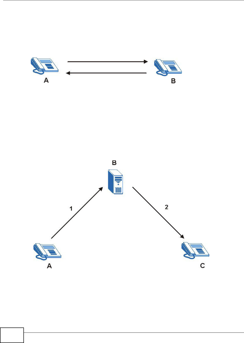
Chapter 21 Voice
VMG8324-B10A / VMG8324-B30A Series User’s Guide
254
SIP User Agent
A SI P user agent can m ake and receive VoI P t elephone calls. This m eans that SI P can be used for
peer-t o- peer com m unications even t hough it is a client-server protocol. I n the following figure,
either A or B can act as a SI P user agent client t o init iate a call. A and B can also bot h act as a SI P
user agent t o receive t he call.
Figure 152 SI P User Agent
SIP Proxy Server
A SI P proxy server receives request s from clients and forwards them t o anot her server.
I n t he following exam ple, you want to use client device A to call som eone who is using client device
C.
1The client device ( A in the figure) sends a call invitat ion t o t he SI P proxy server (B) .
2The SI P proxy server forwards the call invit ation to C.
Figure 153 SI P Proxy Server
SIP Redirect Server
A SI P redirect server accept s SI P requests, t ranslates t he destinat ion address t o an I P address and
sends the t ranslat ed I P address back to t he device t hat sent t he request . Then the client device t hat
originally sent t he request can send requests t o the I P address that it received back from the
redirect server. Redir ect servers do not initiat e SI P request s.
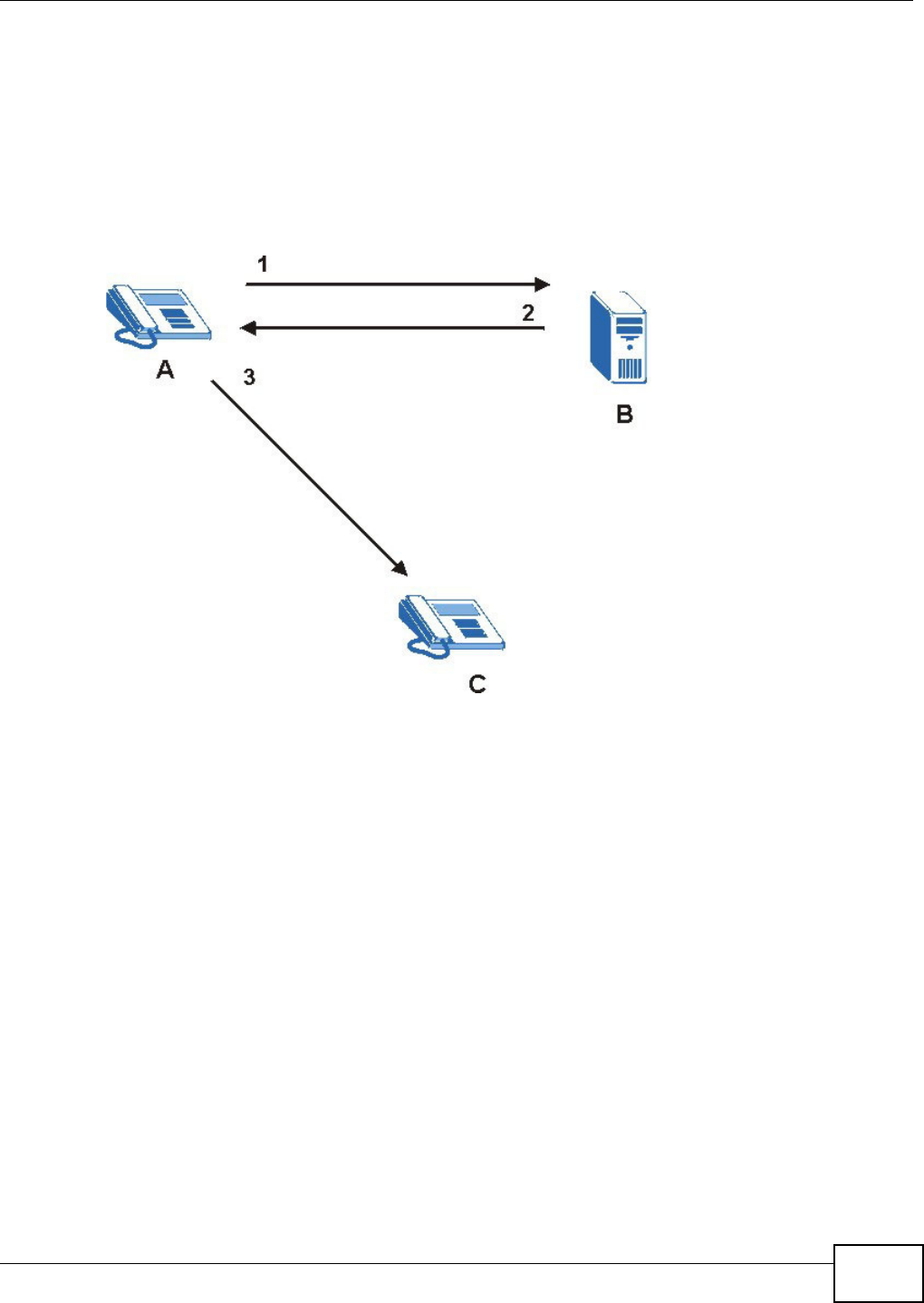
Chapter 21 Voice
VMG8324-B10A / VMG8324-B30A Series User’s Guide 255
I n t he following exam ple, you want to use client device A to call som eone who is using client device
C.
1Client device A sends a call invitat ion for C to the SI P redirect server (B) .
2The SI P redirect server sends the invit at ion back to A with C’s I P address (or dom ain nam e).
3Client device A then sends t he call invitat ion to client device C.
Figure 154 SI P Redirect Server
SIP Register Server
A SI P regist er server m aintains a database of SI P identit y- to- I P address ( or dom ain nam e)
m apping. The register server checks your user nam e and passw ord when you regist er.
RTP
When you m ake a VoI P call using SI P, the RTP ( Real tim e Transport Prot ocol) is used to handle voice
dat a t ransfer. See RFC 1889 for det ails on RTP.
Pulse Code Modulation
Pulse Code Modulat ion ( PCM) m easures analog signal am plitudes at regular tim e intervals and
convert s them into bits.
Chapter 21 Voice
VMG8324-B10A / VMG8324-B30A Series User’s Guide
256
SIP Call Progression
The following figure displays t he basic st eps in t he setup and tear down of a SI P call. A calls B.
1 A sends a SI P I NVI TE request to B. This m essage is an invit ation for B to par t icipat e in a SI P
telephone call.
2 B sends a response indicating that t he telephone is ringing.
3 B sends an OK response aft er t he call is answered.
4 A then sends an ACK m essage t o acknow ledge that B has answered t he call.
5Now A and B exchange voice m edia (t alk).
6After talking, A hangs up and sends a BYE request .
7 B replies wit h an OK response confirm ing receipt of t he BYE request and the call is t erm inat ed.
SIP Call Progression Through Proxy Servers
Usually, the SI P UAC sets up a phone call by sending a request t o t he SI P proxy server. Then, the
proxy server looks up t he dest ination to which t he call should be forwarded ( according t o t he URI
request ed by the SI P UAC). The request m ay be forwarded t o m ore than one proxy server before
arriving at its dest ination.
The response t o the request goes t o all the proxy servers t hrough which t he request passed, in
rever se sequence. Once t he session is set up, session traffic is sent between t he UAs directly,
bypassing all t he proxy servers in bet ween.
Table 120 SI P Call Progression
A B
1. I NVI TE
2. Ringing
3. OK
4. ACK
5.Dialogue (voice t raffic)
6. BYE
7. OK
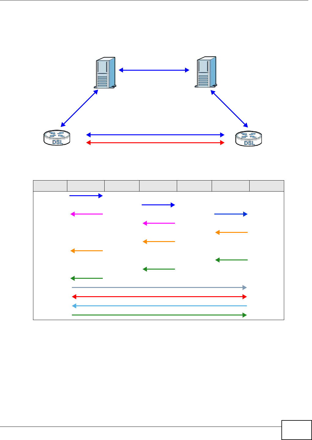
Chapter 21 Voice
VMG8324-B10A / VMG8324-B30A Series User’s Guide 257
The following figure shows the SI P and session traffic flow between t he user agent s (UA 1 and UA
2) and the proxy servers ( this exam ple shows t wo proxy servers, PROXY 1 and PROXY 2 ) .
Figure 155 SI P Call Thr ough Proxy Servers
The following t able shows the SI P call progression.
1Use r Age nt 1 sends a SI P I NVI TE request t o Prox y 1 . This m essage is an invitat ion t o User
Agent 2 t o participat e in a SI P telephone call. Proxy 1 sends a response indicat ing t hat it is trying
to com plet e the request.
2Pr ox y 1 sends a SI P I NVI TE request to Proxy 2 . Proxy 2 sends a response indicating t hat it is
trying t o com plet e t he request .
3Pr ox y 2 sends a SI P I NVI TE request to Use r Age nt 2 .
4Use r Age n t 2 sends a response back t o Proxy 2 indicat ing t hat t he phone is ringing. The response
is relayed back to Use r Agen t 1 via Prox y 1 .
Table 121 SI P Call Progression
UA 1 PROXY 1 PROXY 2 UA 2
I nvit e
I nvit e
100 Tr ying I nvit e
100 Trying
180 Ringing
180 Ringing
180 Ringing
200 OK
200 OK
200 OK
ACK
RTP RTP
BYE
200 OK
UA 1 UA 2
PROXY 1 PROXY 2
SIP
SIP
SIP
SIP & RTP

Chapter 21 Voice
VMG8324-B10A / VMG8324-B30A Series User’s Guide
258
5Use r Age nt 2 sends an OK response t o Proxy 2 after the call is answered. This is also relayed
back t o Use r Age nt 1 via Proxy 1 .
6Use r Age nt 1 and Use r Age nt 2 exchange RTP packet s cont aining voice dat a directly, without
involving t he proxies.
7When Use r Agent 2 hangs up, he sends a BYE request .
8Use r Age nt 1 replies wit h an OK response confirm ing receipt of t he BYE request, and t he call is
t erm inat ed.
Voice Coding
A codec (coder/ decoder) codes analog voice signals int o digit al signals and decodes t he digit al
signals back int o analog voice signals. The Device supports the following codecs.
• G.711 is a Pulse Code Modulation (PCM) waveform codec. PCM m easures analog signal
am plitudes at regular t im e intervals and convert s them int o digit al sam ples. G.711 provides very
good sound quality but requires 64 kbps of bandwidth.
• G.726 is an Adaptive Different ial PCM (ADPCM) waveform codec that uses a lower bitrat e than
st andard PCM conversion. ADPCM convert s analog audio int o digital signals based on the
difference bet ween each audio sam ple and a prediction based on previous sam ples. The m or e
similar t he audio sam ple is to t he predict ion, t he less space needed t o describe it . G.726 operat es
at 16, 24, 32 or 40 kbps.
• G.729 is an Analysis- by- Synt hesis ( AbS) hybrid waveform codec t hat uses a filter based on
inform at ion about how t he hum an vocal tract produces sounds. G.729 provides good sound
qualit y and reduces t he required bandwidt h to 8 kbps.
Voice Activity Detection/Silence Suppression
Voice Act ivity Detection (VAD) detects whether or not speech is present. This lets the Device reduce
the bandwidth t hat a call uses by not t ransm it ting “ silent packet s” when you are not speaking.
Comfort Noise Generation
When using VAD, the Device generates com fort noise when the ot her party is not speaking. The
com fort noise let s you know that t he line is still connected as t otal silence could easily be m ist aken
for a lost connection.
Echo Cancellation
G.168 is an I TU-T st andard for elim inat ing t he echo caused by the sound of your voice
rever berat ing in the t elephone receiver while you talk.
MWI (Message Waiting Indication)
Enable Message Waiting I ndication (MWI ) enables your phone t o give you a m essage–waiting
( beeping) dial tone when you have a voice m essage( s) . Your VoI P service provider m ust have a
m essaging system that sends m essage wait ing stat us SI P packets as defined in RFC 3842.

Chapter 21 Voice
VMG8324-B10A / VMG8324-B30A Series User’s Guide 259
Custom Tones (IVR)
I VR ( I nteract ive Voice Response) is a feature that allows you to use your t elephone t o int eract w ith
the Device. The Device allows you to record cust om t ones for the Ear ly M edia and Music On Hold
funct ions. The sam e recordings apply t o bot h the caller ringing and on hold t ones.
Recording Custom Tones
Use t he following steps if you would like t o create new tones or change your t ones:
1Pick up t he phone and press “ * * * * ” on your phone’s keypad and wait for the m essage t hat says
you are in the configurat ion m enu.
2Press a num ber from 1101~ 1105 on your phone followed by t he “# ” key.
3Play your desired m usic or voice recording int o the receiver ’s m out hpiece. Press the “ # ” key.
4You can cont inue t o add, listen t o, or delete tones, or you can hang up t he receiver when you are
done.
Listening to Custom Tones
Do the following t o list en to a custom tone:
1Pick up t he phone and press “ * * * * ” on your phone’s keypad and wait for the m essage t hat says
you are in the configurat ion m enu.
2Press a num ber from 1201~ 1208 followed by t he “ # ” key to list en to the tone.
3You can cont inue t o add, listen t o, or delete tones, or you can hang up t he receiver when you are
done.
Deleting Custom Tones
Do the following t o delete a custom tone:
1Pick up t he phone and press “ * * * * ” on your phone’s keypad and wait for the m essage t hat says
you are in the configurat ion m enu.
2Press a num ber from 1301~ 1308 follow ed by the “ # ” key t o delete the t one of your choice. Press
14 followed by t he “# ” key if you wish to clear all your cust om t ones.
Table 122 Custom Tones Details
LABEL DESCRIPTION
Tot al Tim e for All Tones 900 seconds for all custom t ones com bined
Maxim um Tim e per
I ndiv idual Tone
180 seconds
To t a l N u m b e r o f To n e s
Recordable
5
You can record up to 5 different cust om t ones but t he t ot al tim e m ust be 900
seconds or less.

Chapter 21 Voice
VMG8324-B10A / VMG8324-B30A Series User’s Guide
260
You can cont inue t o add, listen t o, or delete tones, or you can hang up t he receiver when you are
done.
21.10.1 Quality of Service (QoS)
Quality of Service ( QoS) refers t o both a network's ability to deliver dat a wit h m inim um delay, and
the net working m et hods used t o provide bandwidth for real- t im e m ultim edia applications.
Type of Service (ToS)
Net work traffic can be classified by sett ing the ToS ( Type of Service) values at the data source ( for
exam ple, at the Device) so a ser ver can decide the best m et hod of delivery, t hat is the least cost ,
fastest route and so on.
DiffServ
DiffServ is a class of service (CoS) m odel that m arks packet s so that they receive specific per-hop
treat m ent at DiffServ- com pliant net work devices along t he route based on the applicat ion t ypes
and traffic flow. Packet s are m arked wit h DiffServ Code Points ( DSCP) indicat ing the level of service
desired. This allows the int erm ediary DiffServ-com pliant networ k devices to handle t he packet s
different ly depending on t he code points without the need to negotiate pat hs or rem em ber st ate
inform at ion for every flow. I n addit ion, applications do not have to request a particular service or
give advanced notice of w here t he traffic is going.3
DSCP and Per-Hop Behavior
DiffServ defines a new DS (Differ ent iated Services) field t o replace t he Type of Service ( TOS) field
in t he I P header. The DS field cont ains a 2-bit unused field and a 6- bit DSCP field which can define
up to 64 service levels. The following figure illustrates t he DS field.
DSCP is backward com pat ible wit h the t hree precedence bit s in t he ToS octet so that non- DiffSer v
com pliant, ToS- enabled network device will not conflict with t he DSCP m apping.
Figure 156 DiffServ: Different iated Service Field
The DSCP value determ ines t he forwarding behavior, the PHB (Per- Hop Behavior), that each packet
get s across the DiffServ net work. Based on the m arking rule, different kinds of t raffic can be
m arked for different priorities of forwarding. Resources can t hen be allocat ed according t o t he DSCP
values and t he configured policies.
21.10.2 Phone Services Overview
Supplem ent ary services such as call hold, call wait ing, and call transfer. are generally available from
your VoI P service pr ov ider. The Device supports t he following services:
3. The Device does not support DiffServ at the time of writing.
DSCP
( 6- bit )
Unused
(2-bit)

Chapter 21 Voice
VMG8324-B10A / VMG8324-B30A Series User’s Guide 261
• Call Return
• Call Hold
• Call Wait ing
• Making a Second Call
• Call Transfer
• Call Forwarding
• Three- Way Conference
• I nternal Calls
• Call Park and Pickup
• Do not Disturb
• IVR
• Call Completion
• CCBS
• Outgoing SI P
Note: To t ake full advant age of the supplem entary phone services available through t he
Device's phone port s, you m ay need t o subscribe to t he services from your VoI P
service provider.
21.10.2.1 The Flash Key
Flashing m eans to press the hook for a short period of tim e (a few hundred m illiseconds) before
releasing it . On newer telephones, t here should be a "flash" key (button) t hat generat es the signal
elect ronically. I f the flash key is not available, you can t ap (press and im m ediat ely r elease) the
hook by hand to achieve t he sam e effect . However, using t he flash key is preferred since the tim ing
is m uch m ore precise. With m anual t apping, if t he duration is too long, it m ay be int erpret ed as
hanging up by t he Device.
You can invoke all t he supplem ent ary services by using the flash key.
21.10.2.2 Europe Type Supplementary Phone Services
This section describes how t o use supplem entary phone services wit h the Europe Ty pe Call
Ser vice Mode . Com m ands for supplem entary services are listed in the t able below.
After pressing the flash key, if you do not issue t he sub- com m and before the default sub- com m and
tim eout ( 2 seconds) expires or issue an invalid sub- com m and, the current operat ion will be
aborted.
Table 123 European Flash Key Com m ands
COMMAND SUB-COMMAND DESCRIPTION
Flash Put a current call on hold t o place a second call.
Switch back to t he call ( if t here is no second call) .
Flash 0 Drop t he call presently on hold or rej ect an incom ing call which is waiting
for answer.
Flash 1 Disconnect the current phone connection and answer t he incom ing call or
resum e wit h caller pr esently on hold.

Chapter 21 Voice
VMG8324-B10A / VMG8324-B30A Series User’s Guide
262
European Call Hold
Call hold allows you to put a call ( A) on hold by pressing the flash key.
I f you have anot her call, press the flash key and t hen “ 2” to sw itch back and forth between caller A
and B by put ting eit her one on hold.
Press the flash key and then “ 0” t o disconnect t he call presently on hold and keep t he current call
on line.
Press the flash key and then “ 1” t o disconnect the current call and resum e t he call on hold.
I f you hang up t he phone but a caller is st ill on hold, there w ill be a rem ind ring.
European Call Waiting
This allows you to place a call on hold while you answer anot her incom ing call on t he sam e
telephone (direct ory) num ber.
I f there is a second call t o a telephone num ber, you will hear a call waiting t one. Take one of the
following act ions.
• Reject the second call.
Press the flash key and then press “ 0”.
• Disconnect the first call and answer t he second call.
Eit her press the flash key and press “ 1”, or j ust hang up t he phone and then answer t he phone
after it rings.
• Put t he first call on hold and answer the second call.
Press the flash key and then “ 2”.
European Call Transfer
Do the following t o t ransfer an incom ing call ( that you have answered) to another phone.
1Press the flash key to put t he caller on hold.
2When you hear the dial tone, dial “* 98# ” followed by the num ber to which you want to t ransfer t he
call.
3After you hear the ring signal or the second par t y answers it, hang up t he phone.
Flash 2 1. Sw it ch back and forth between t w o calls.
2. Put a cur rent call on hold t o answer an incom ing call.
3. Separat e the curr ent t hree- way conference call int o two individual calls
( one is on-line, the other is on hold) .
Flash 3 Creat e t hree-way conference connect ion.
Flash * 98# Transfer the call t o anot her phone.
Table 123 European Flash Key Com m ands
COMMAND SUB-COMMAND DESCRIPTION

Chapter 21 Voice
VMG8324-B10A / VMG8324-B30A Series User’s Guide 263
European Three-Way Conference
Use t he following st eps to m ake t hree- way conference calls.
1When you are on t he phone t alking to som eone, press the flash key t o put t he caller on hold and
get a dial t one.
2Dial a phone num ber directly to m ake another call.
3When the second call is answ ered, press t he flash key and press “3” t o create a t hree- way
conversat ion.
4Hang up the phone to drop the connection.
5I f you want to separat e the activated t hree-way conference int o two individual connect ions (one is
on-line, the ot her is on hold), press t he flash key and press “ 2”.
21.10.2.3 USA Type Supplementary Services
This section describes how t o use supplem entary phone services wit h the USA Type Ca ll Service
Mode. Com m ands for supplem entary services are list ed in the t able below.
After pressing the flash key, if you do not issue t he sub- com m and before the default sub- com m and
tim eout ( 2 seconds) expires or issue an invalid sub- com m and, the current operat ion will be
aborted.
USA Call Hold
Call hold allows you to put a call ( A) on hold by pressing the flash key.
I f you have another call, press t he flash key t o swit ch back and forth between caller A and B by
put t ing either one on hold.
I f you hang up t he phone but a caller is st ill on hold, there w ill be a rem ind ring.
USA Call Waiting
This allows you to place a call on hold while you answer anot her incom ing call on t he sam e
telephone (direct ory) num ber.
I f there is a second call t o your t elephone num ber, you will hear a call wait ing tone.
Press the flash key to put t he first call on hold and answer the second call.
Table 124 USA Flash Key Com m ands
COMMAND SUB-COMMAND DESCRIPTION
Flash Put a curr ent call on hold t o place a second call. After t he second call is
successful, press the flash k ey again t o have a t hree- way conference call.
Put a current call on hold to answer an incom ing call.
Flash * 98# Transfer the call t o anot her phone.

Chapter 21 Voice
VMG8324-B10A / VMG8324-B30A Series User’s Guide
264
USA Call Transfer
Do the following t o t ransfer an incom ing call ( that you have answered) to another phone.
1Press the flash key to put t he caller on hold.
2When you hear the dial tone, dial “* 98# ” followed by the num ber to which you want to t ransfer t he
call.
3After you hear the ring signal or the second par t y answers it, hang up t he phone.
USA Three-Way Conference
Use t he following st eps to m ake t hree- way conference calls.
1When you are on t he phone t alking t o som eone ( part y A), press t he flash key to put the caller on
hold and get a dial tone.
2Dial a phone num ber directly to m ake another call (t o party B) .
3When party B answers the second call, press t he flash key t o create a t hree- way conversation.
4Hang up the phone to drop the connection.
5I f you want to separat e the activated t hree-way conference int o two individual connect ions (wit h
part y A on- line and part y B on hold) , press the flash key.
6I f you want to go back t o t he three-way conversation, press t he flash key again.
7I f you want to separat e the activated t hree-way conference int o two individual connect ions again,
press the flash key. This tim e the party B is on- line and party A is on hold.
21.10.2.4 Phone Functions Summary
The following t able shows the key com binations you can ent er on your phone’s keypad t o use
cert ain features.
Table 125 Phone Funct ions Sum m ary
ACTION FUNCTION DESCRIPTION
* 98# Call transfer Transfer a call t o anot her phone. See Section 21.10.2.2 on page 261
( Europe t ype) and Sect ion 21.10.2.3 on page 263 (USA type) .
* 66# Call retur n Place a call t o the last person who called you.
* 95# Enable Do Not Disturb Use t hese to set your phone not to ring w hen som eone calls you, or
to t urn t his funct ion off.
# 95# Disable Do Not Disturb
* 41# Enable Call Waiting Use these to allow you to put a call on hold when you are answering
anot her, or to turn this funct ion off.
# 41# Disable Call Waiting
* * * * I VR Use t hese t o set up I nteractive Voice Response (I VR) . I VR allows
you to record cust om caller ringing tones ( the sound a caller hears
before you pick up the phone) and on hold tones ( the sound
som eone hears when you put their call on hold) .
# # # # I nt ernal Call Call the phone(s) connect ed t o the Device.

Chapter 21 Voice
VMG8324-B10A / VMG8324-B30A Series User’s Guide 265
* 82 One Shot Caller Display Call Activat e or deactivat e caller I D for the next call only.
* 67 One Shot Caller Hidden Call
Table 125 Phone Funct ions Sum m ary
ACTION FUNCTION DESCRIPTION

Chapter 21 Voice
VMG8324-B10A / VMG8324-B30A Series User’s Guide
266

VMG8324-B10A / VMG8324-B30A Series User’s Guide 267
CHAPTER 22
Log
22.1 Overview
The web configurat or allows you to choose which cat egories of events and/ or alerts t o have the
Device log and then display the logs or have the Device send them to an adm inistrat or ( as e-m ail)
or to a syslog server.
22.1.1 What You Can Do in this Chapter
• Use the System Log screen t o see t he system logs ( Section 22.2 on page 268) .
• Use the Security Log screen t o see t he security- relat ed logs for t he cat egories t hat you select
(Section 22.3 on page 269) .
22.1.2 What You Need To Know
The following t erm s and concept s m ay help as you read this chapt er.
Alerts and Logs
An alert is a t ype of log t hat warrant s more serious att ention. They include system errors, at tacks
( access cont rol) and at tem pted access t o blocked web sit es. Som e categories such as Syst em
Er rors consist of both logs and alerts. You may differentiate them by their color in t he V iew Log
screen. Alert s display in red and logs display in black.
Syslog Overview
The syslog protocol allows devices t o send event not ificat ion m essages across an I P net work t o
syslog servers t hat collect the event m essages. A syslog- enabled device can generat e a syslog
m essage and send it to a syslog server.
Syslog is defined in RFC 3164. The RFC defines t he packet form at , content and syst em log relat ed
inform at ion of syslog m essages. Each syslog m essage has a facility and severit y level. The syslog
facilit y ident ifies a file in the syslog server. Refer to the docum ent ation of your syslog program for
det ails. The follow ing t able describes the syslog sever ity levels.
Table 126 Syslog Severit y Levels
CODE SEVERITY
0 Em ergency : The system is unusable.
1 Alert: Action m ust be taken im mediat ely.
2 Critical: The syst em condit ion is critical.
3 Error: There is an error condit ion on the system .
4 Warning: There is a warning condition on the syst em .
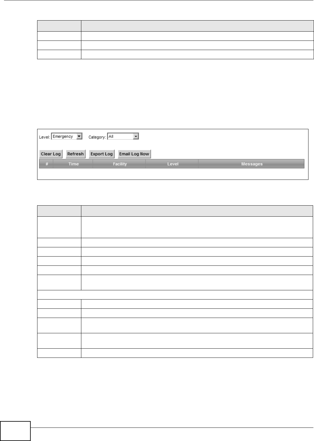
Chapter 22 Log
VMG8324-B10A / VMG8324-B30A Series User’s Guide
268
22.2 The System Log Screen
Use t he System Log screen to see t he syst em logs. Click Syste m Monit or > Log t o open t he
Syste m Log screen.
Figure 157 Syst em Monit or > Log > Syst em Log
The following t able describes the fields in this screen.
5 Not ice: There is a norm al but significant condition on the system .
6 I nform ational: The syslog contains an inform at ional m essage.
7 Debug: The message is int ended for debug- level purposes.
Table 126 Syslog Severit y Levels
CODE SEVERITY
Table 127 System Monitor > Log > System Log
LABEL DESCRIPTION
Level Select a severit y level from t he drop-down list box. This filt ers search results according to
t he severity level you have select ed. When you select a sever ity, the Device searches
through all logs of t hat severit y or higher.
Category Select t he t ype of logs to display.
Clear Log Click this t o delet e all t he logs.
Refresh Click t his t o renew the log screen.
Export Log Click this t o ex por t the selected log( s).
Em ail Log Now Click this t o send the log file( s) to t he E-m ail address you specify in t he M aintenance >
Logs Se t ting screen.
Syst em Log
#This field is a sequential value and is not associated wit h a specific entry.
Tim e This field displays the t im e the log was recorded.
Facility The log facilit y allows you t o send logs to different files in the syslog server. Refer to t he
docum ent at ion of your syslog program for m or e det ails.
Level This field displays the severit y level of the logs t hat t he device is t o send to this sy slog
server.
Messages This field stat es the reason for the log.
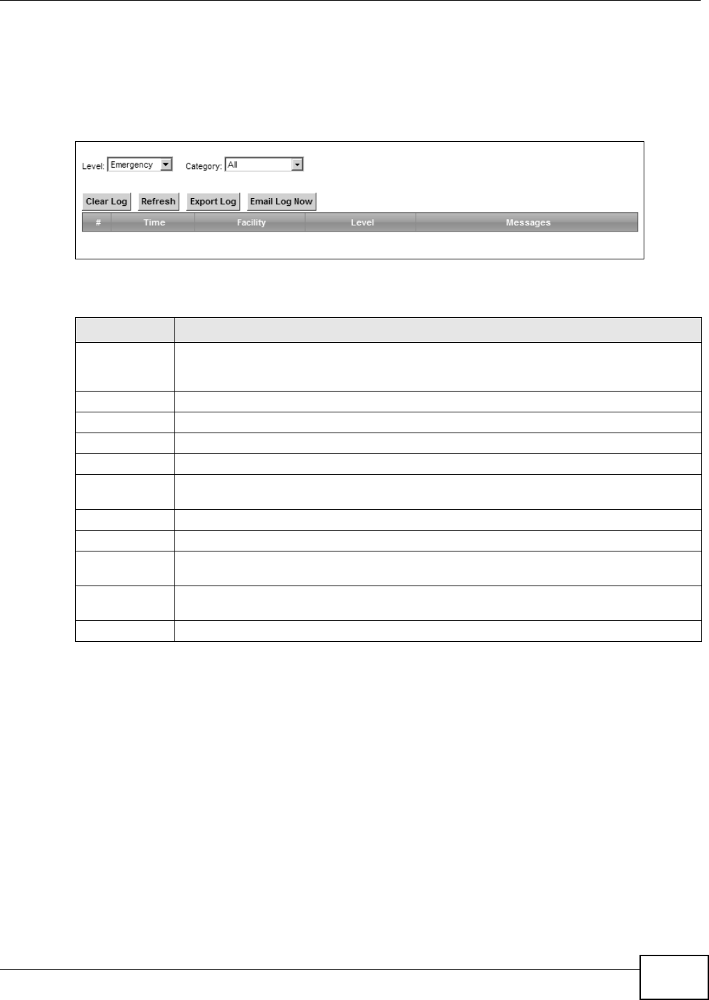
Chapter 22 Log
VMG8324-B10A / VMG8324-B30A Series User’s Guide 269
22.3 The Security Log Screen
Use t he Security Log screen to see the security-relat ed logs for t he cat egories t hat you select .
Click Syst e m Monit or > Log > Se cur it y Log to open t he following screen.
Figure 158 Syst em Monit or > Log > Security Log
The following t able describes the fields in this screen.
Table 128 System Monitor > Log > Securit y Log
LABEL DESCRIPTION
Level Select a severit y level from t he drop-down list box. This filt ers search results according to
t he severity level you have select ed. When you select a sever ity, the Device searches
through all logs of t hat severit y or higher.
Category Select t he t ype of logs to display.
Clear Log Click this t o delet e all t he logs.
Refresh Click t his t o renew the log screen.
Export Log Click this t o ex por t the selected log( s).
Em ail Log Now Click this t o send the log file( s) to t he E-m ail address you specify in t he M aintenance >
Logs Se t ting screen.
#This field is a sequential value and is not associated wit h a specific entry.
Tim e This field displays the t im e the log was recorded.
Facility The log facilit y allows you t o send logs to different files in the syslog server. Refer to t he
docum ent at ion of your syslog program for m or e det ails.
Level This field displays the severit y level of the logs t hat t he device is t o send to this sy slog
server.
Messages This field stat es the reason for the log.

Chapter 22 Log
VMG8324-B10A / VMG8324-B30A Series User’s Guide
270
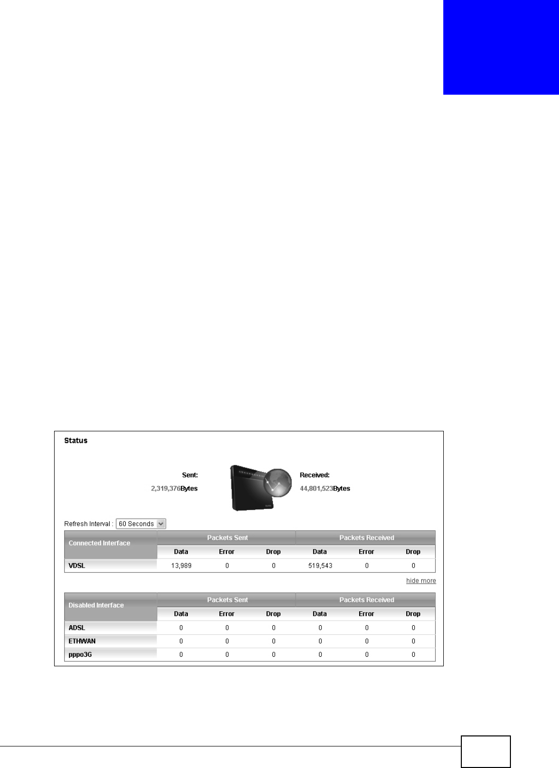
VMG8324-B10A / VMG8324-B30A Series User’s Guide 271
CHAPTER 23
Traffic Status
23.1 Overview
Use t he Traffic St a tus screens to look at net work t raffic st atus and stat ist ics of the WAN, LAN
interfaces and NAT.
23.1.1 What You Can Do in this Chapter
• Use the W AN screen t o view t he WAN traffic stat ist ics ( Sect ion 23.2 on page 271) .
• Use the LAN screen to view t he LAN traffic stat ist ics (Section 23.3 on page 273) .
• Use the N AT scr een to view t he NAT stat us of the Device’s client (s) (Sect ion 23.4 on page 274)
23.2 The WAN Status Screen
Click Syste m Monit or > Tra ffic St at us t o open the W AN screen. The figure in t his screen shows
the num ber of byt es received and sent on the Device.
Figure 159 Syst em Monit or > Traffic St atus > WAN

Chapter 23 Traffic Status
VMG8324-B10A / VMG8324-B30A Series User’s Guide
272
The following t able describes the fields in this screen.
Table 129 System Monitor > Traffic Stat us > WAN
LABEL DESCRIPTION
Connected
I nt erface
This shows the nam e of the WAN interface t hat is current ly connect ed.
Packet s Sent
Data This indicates the num ber of transm it t ed packet s on t his interface.
Error This indicates the num ber of fram es with errors transm itted on this interface.
Drop This indicates the num ber of out going packet s dropped on t his inter face.
Packet s Received
Data This indicates the num ber of received packet s on this interface.
Error This indicat es the num ber of fram es wit h error s received on this interface.
Drop This indicat es t he num ber of received packet s dr opped on t his int erface.
m or e...hide
m ore
Click m ore... to show m ore inform ation. Click h ide m or e to hide t hem .
Disabled
I nt er face
This shows t he nam e of the WAN interface t hat is currently disconnected.
Packet s Sent
Data This indicates the num ber of transm it t ed packet s on t his interface.
Error This indicates the num ber of fram es with errors transm itted on this interface.
Drop This indicates the num ber of out going packet s dropped on t his inter face.
Packet s Received
Data This indicates the num ber of received packet s on this interface.
Error This indicat es the num ber of fram es wit h error s received on this interface.
Drop This indicat es t he num ber of received packet s dr opped on t his int erface.
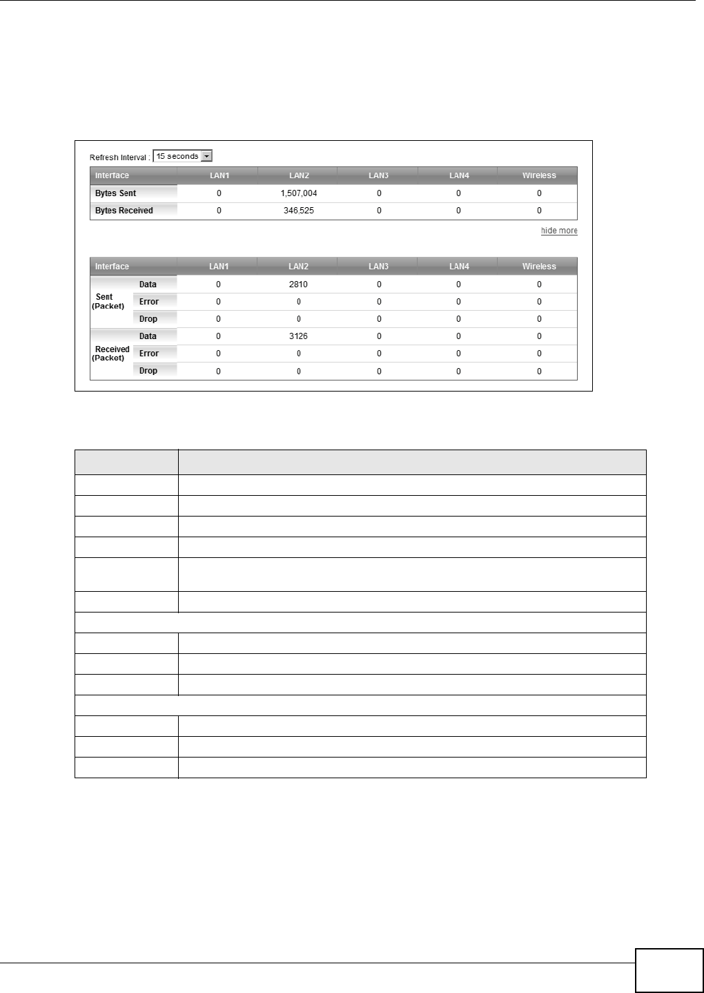
Chapter 23 Traffic Status
VMG8324-B10A / VMG8324-B30A Series User’s Guide 273
23.3 The LAN Status Screen
Click Syst e m Monit or > Tr a ffic St at us > LAN t o open t he following screen. The figure in t his
screen shows t he interface that is current ly connected on t he Device.
Figure 160 Syst em Monit or > Traffic St atus > LAN
The following t able describes t he fields in t his screen.
Table 130 System Monitor > Traffic Stat us > LAN
LABEL DESCRIPTION
Refresh I nt erval Select how often you want t he Device t o update t his screen.
I nt er face This shows the LAN or WLAN inter face.
Bytes Sent This indicat es t he num ber of byt es t ransm itted on this int erface.
By t es Received This indicat es t he num ber of byt es received on this interface.
m or e...hide
m ore
Click m ore... to show more inform at ion. Click hide m ore to hide them .
I nt er face This shows the LAN or WLAN inter face.
Sent (Packet s)
Data This indicates the num ber of transm it t ed packet s on t his int erface.
Error This indicates the num ber of fram es wit h errors t ransm it ted on t his int erface.
Drop This indicates the num ber of out going packet s dropped on t his int erface.
Received ( Packet s)
Data This indicates the num ber of received packets on this interface.
Error This indicates the num ber of fram es wit h errors r eceived on this interface.
Drop This indicates the num ber of received packets dropped on this interface.
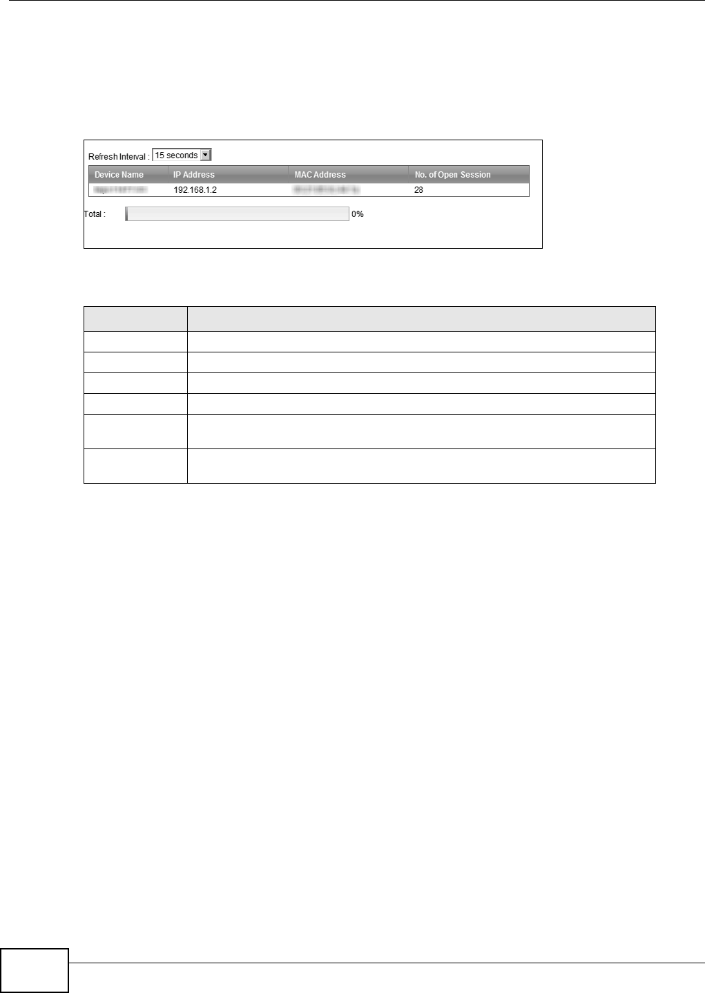
Chapter 23 Traffic Status
VMG8324-B10A / VMG8324-B30A Series User’s Guide
274
23.4 The NAT Status Screen
Click Syst e m Monit or > Tr a ffic St at us > NAT t o open t he following screen. The figure in t his
screen shows t he NAT session stat ist ics for hosts currently connect ed on t he Device.
Figure 161 Syst em Monit or > Traffic St atus > NAT
The following t able describes the fields in this screen.
Table 131 System Monitor > Traffic Stat us > NAT
LABEL DESCRIPTION
Refresh I nt erval Select how often you want t he Device t o update t his screen.
Device Nam e This displays the nam e of t he connect ed host.
I P Address This displays the I P address of t he connected host .
MAC Addr ess This displays t he MAC address of the connect ed host.
No. of Open
Session
This displays t he num ber of NAT sessions current ly opened for t he connected
host.
To t a l This displays what percentage of NAT sessions the Device can support is current ly
being used by all connected host s.
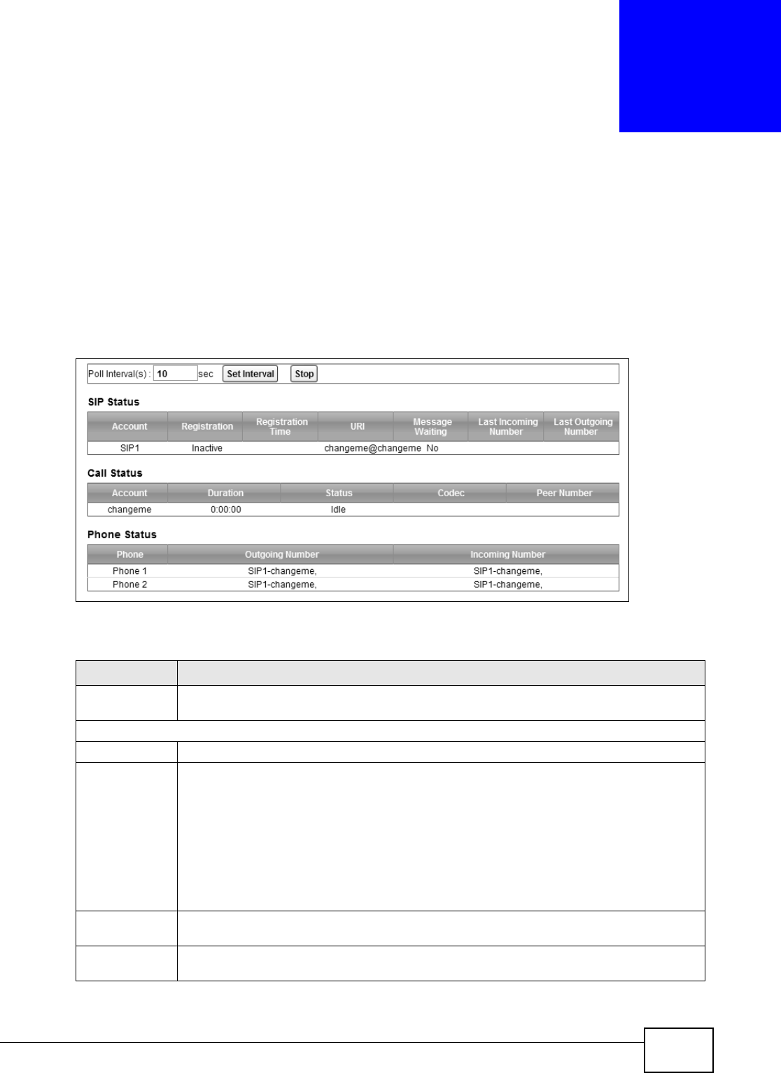
VMG8324-B10A / VMG8324-B30A Series User’s Guide 275
CHAPTER 24
VoIP Status
24.1 The VoIP Status Screen
Click Syst e m Monit or > VoI P St at us t o open t he following screen. You can view the VoI P
registrat ion, current call st atus and phone num bers in this screen.
Figure 162 Syst em Monit or > VoI P St atus
The following t able describes the fields in this screen.
Table 132 Syst em Monit or > VoI P Stat us
LABEL DESCRIPTION
Poll I nt erval( s) Enter the num ber of seconds t he Device needs t o wait before updat ing this screen and then
click Se t I nterval. Click St op to have the Device stop updat ing this screen.
SI P Status
Account This column displays each SI P account in the Device.
Registrat ion This field displays the curr ent registrat ion stat us of t he SI P account . You can change t his in
the St a t u s scr een.
Registered - The SI P account is registered wit h a SI P ser ver.
N ot Re gist e r e d - The last t im e t he Device tried to regist er t he SI P account wit h t he SI P
server, the attem pt failed. The Device aut om at ically t ries t o regist er t he SI P account when
you t urn on the Device or w hen you act ivat e it.
I n act iv e - The SI P account is not act ive. You can activate it in V oI P > SI P > SI P
Account.
Regist rat ion
Tim e
This field displays the last tim e the Device successfully r egistered the SI P account. The field
is blank if t he Device has never successfully regist ered this account .
URI This field displays the account num ber and service dom ain of the SI P account. You can
change these in t he VoI P > SI P screens.

Chapter 24 VoIP Status
VMG8324-B10A / VMG8324-B30A Series User’s Guide
276
Message
Wait in g
This field indicat es whet her or not ther e ar e any m essages wait ing for t he SI P account .
Last Incom ing
Nu m ber
This field displays the last num ber that called the SI P account . The field is blank if no
num ber has ever dialed the SI P account.
Last Out going
Nu m ber
This field displays the last num ber the SI P account called. The field is blank if t he SI P
account has never dialed a number.
Call St at us
Account This colum n displays each SI P account in the Device.
Durat ion This field displays how long the current call has last ed.
St at us This field displays the current state of the phone call.
I dle - There are no current VoI P calls, incom ing calls or out going calls being m ade.
Dia l - The callee’s phone is ringing.
Rin g - The phone is ringing for an incom ing VoI P call.
Pr oce ss - There is a VoI P call in progr ess.
DI SC - The callee’s line is busy, the callee hung up or your phone was left off the hook.
Codec This field displays what voice codec is being used for a current VoI P call t hrough a phone
port .
Peer Num ber This field displays the SI P num ber of t he part y t hat is current ly engaged in a VoI P call
through a phone port.
Phone Status
Phone This field displays the nam e of a phone port on the Device.
Outgoing
Num ber
This field displays the SI P num ber that you use t o m ake calls on t his phone por t .
I ncom ing
Num ber
This field displays the SI P num ber that you use to receive calls on t his phone port .
Table 132 System Monitor > VoI P Stat us ( cont inued)
LABEL DESCRIPTION

VMG8324-B10A / VMG8324-B30A Series User’s Guide 277
CHAPTER 25
ARP Table
25.1 Overview
Address Resolution Prot ocol ( ARP) is a prot ocol for m apping an I nternet Protocol address ( I P
address) to a physical m achine address, also known as a Media Access Control or MAC address, on
the local area net work.
An I P (version 4) address is 32 bits long. I n an Et hernet LAN, MAC addresses are 48 bit s long. The
ARP Table m aint ains an associat ion bet ween each MAC address and its corresponding I P address.
25.1.1 How ARP Works
When an incom ing packet dest ined for a host device on a local area netw ork arrives at t he device,
the device's ARP program looks in the ARP Table and, if it finds t he address, sends it to the device.
I f no entry is found for the I P address, ARP broadcast s the request to all the devices on t he LAN.
The device fills in its ow n MAC and I P address in t he sender address fields, and puts t he known I P
address of the t arget in t he target I P address field. I n addit ion, t he device puts all ones in t he target
M A C f i e l d ( F F. FF. FF. FF. F F. FF i s t h e Et h e r n e t b r o a d c a s t address) . The r eplying device ( which is either
the I P address of t he device being sought or the router that knows the way) replaces the broadcast
address wit h t he target 's MAC address, swaps t he sender and target pairs, and unicasts t he answer
directly back t o the requesting m achine. ARP updat es the ARP Table for future reference and t hen
sends t he packet to the MAC address t hat replied.
25.2 ARP Table Screen
Use t he ARP t able to view I P- to- MAC address m apping( s) . To open this screen, click Syst em
M on it o r > ARP Ta ble.
Figure 163 Syst em Monitor > ARP Table

Chapter 25 ARP Table
VMG8324-B10A / VMG8324-B30A Series User’s Guide
278
The following t able describes the labels in t his screen.
Table 133 System Monitor > ARP Table
LABEL DESCRIPTION
# This is the ARP table entry num ber.
I Pv4/ I Pv6
Address
This is the learned I Pv4 or I Pv 6 I P address of a device connect ed to a port.
MAC Addr ess This is the MAC address of t he device with the listed I P address.
Device This is t he t ype of interface used by t he device. You can click on the device t y pe to go t o its
configuration screen.
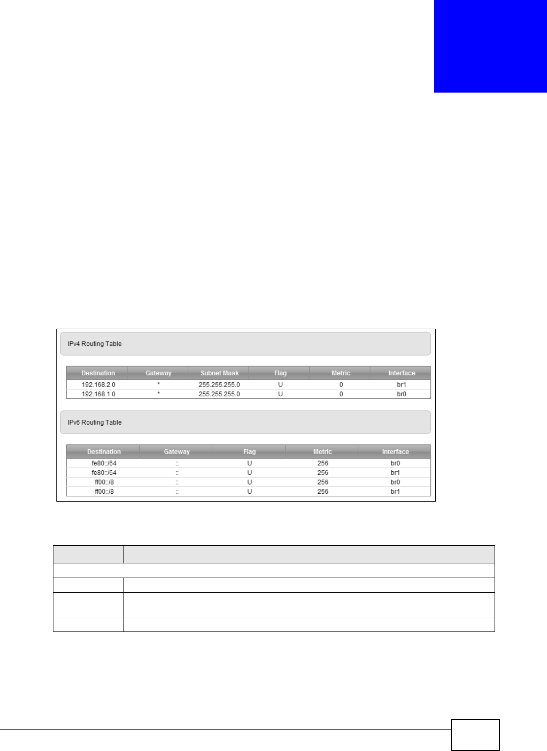
VMG8324-B10A / VMG8324-B30A Series User’s Guide 279
CHAPTER 26
Routing Table
26.1 Overview
Routing is based on the destinat ion address only and the Device t akes the shortest path to forward
a packet .
26.2 The Routing Table Screen
Click Syst e m Monit or > Rout ing Table t o open t he following screen.
Figure 164 Syst em Monit or > Routing Table
The following t able describes the labels in t his screen.
Table 134 Sy st em Monit or > Rout ing Table
LABEL DESCRIPTION
I Pv4/ I Pv6 Rout ing Table
Dest inat ion This indicates the dest inat ion I Pv4 address or I Pv6 address and prefix of this rout e.
Gateway This indicat es the I Pv 4 address or I Pv6 addr ess of the gateway t hat helps forward t his
rout e’s t raffic.
Subnet Mask This indicat es t he dest ination subnet m ask of t he I Pv4 rout e.

Chapter 26 Routing Table
VMG8324-B10A / VMG8324-B30A Series User’s Guide
280
Flag This indicat es t he route status.
U- Up : The rout e is up.
!- Re j e ct : The route is blocked and will force a r oute lookup to fail.
G- Ga tew a y: The rout e uses a gateway t o forward traffic.
H - H ost : The target of t he route is a host.
R- Rei nst a t e: The rout e is reinstat ed for dynam ic rout ing.
D- Dyn a m ic ( r e dir e ct) : The rout e is dynam ically inst alled by a routing daem on or redir ect .
M- Modified ( redir e ct) : The route is m odified fr om a routing daem on or redirect.
Metric The metric represents t he "cost of t ransm ission". A router det erm ines t he best route for
t ransm ission by choosing a path with t he lowest "cost". The sm aller t he num ber, t he lower
the "cost " .
Service This indicates the nam e of t he service used t o forward the route.
I nt erface This indicat es t he nam e of t he int erface through which t he r oute is for warded.
brx indicates a LAN interface where x can be 0~ 3 t o represent LAN1 t o LAN4 respectively.
ptm 0 indicat es a WAN interface using I PoE or in bridge m ode.
ppp0 indicat es a WAN interface using PPPoE.
Table 134 Syst em Monit or > Routing Table ( continued)
LABEL DESCRIPTION
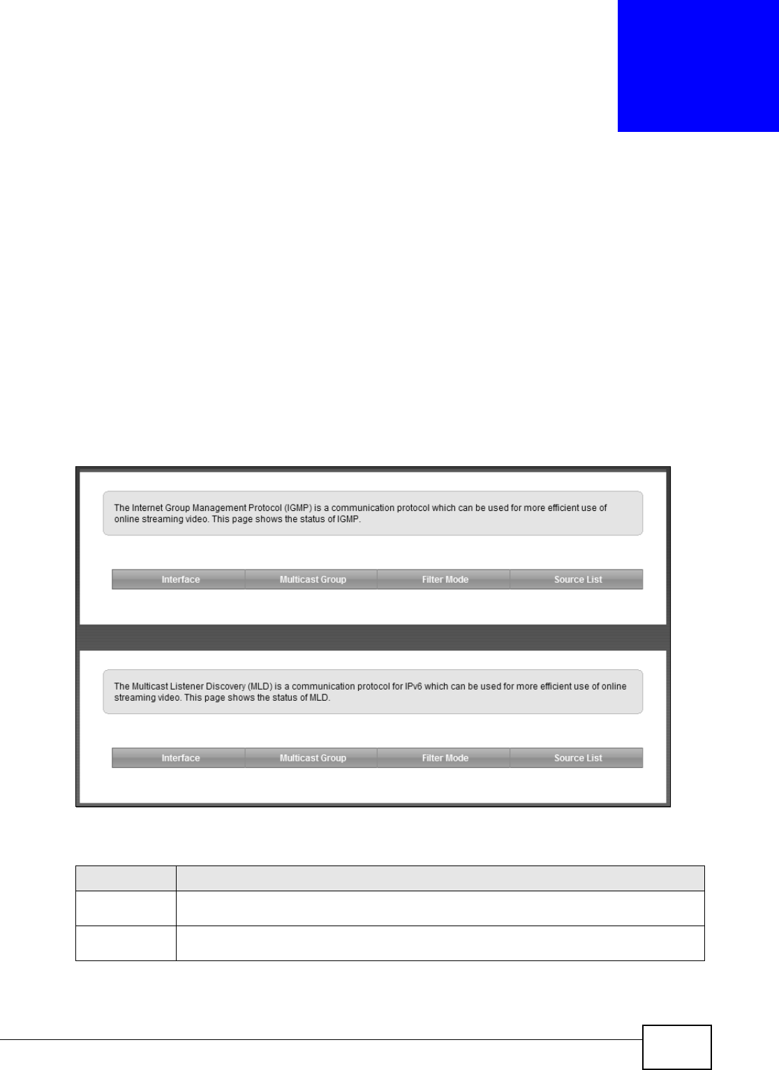
VMG8324-B10A / VMG8324-B30A Series User’s Guide 281
CHAPTER 27
IGMP/MLD Status
27.1 Overview
Use t he I GM P St at us screens to look at I GMP/ MLD group stat us and traffic stat ist ics.
27.2 The IGMP/MLD Group Status Screen
Use t his screen t o look at the current list of m ult icast groups the Device has j oined and which ports
have joined it . To open this screen, click Syste m Monit or > I GM P/ M LD Gr oup Sta tus.
Figure 165 Syst em Monit or > I GMP/ MLD Group St atus
The following t able describes the labels in t his screen.
Table 135 System Monitor > I GMP/ MLD Group Stat us
LABEL DESCRIPTION
I nt erface This field displays the nam e of an interface on t he Device that belongs t o an I GMP or MLD
m ult icast group.
Multicast Group This field displays t he nam e of the IGMP or MLD m ult icast group to which the interface
belongs.

Chapter 27 IGMP/MLD Status
VMG8324-B10A / VMG8324-B30A Series User’s Guide
282
Filt er Mode I N CLU D E m eans t hat only t he I P addresses in t he Source List get t o receive the m ulticast
group’s traffic.
EXCLUD E m eans that the I P addresses in the Source List are not allow ed to r eceive t he
m ult icast group’s traffic but ot her I P addresses can.
Source List This is the list of I P addresses that are allow ed or not allow ed to receive the m ulticast
group’s traffic depending on the filt er m ode.
Table 135 System Monitor > I GMP/ MLD Group Stat us ( cont inued)
LABEL DESCRIPTION
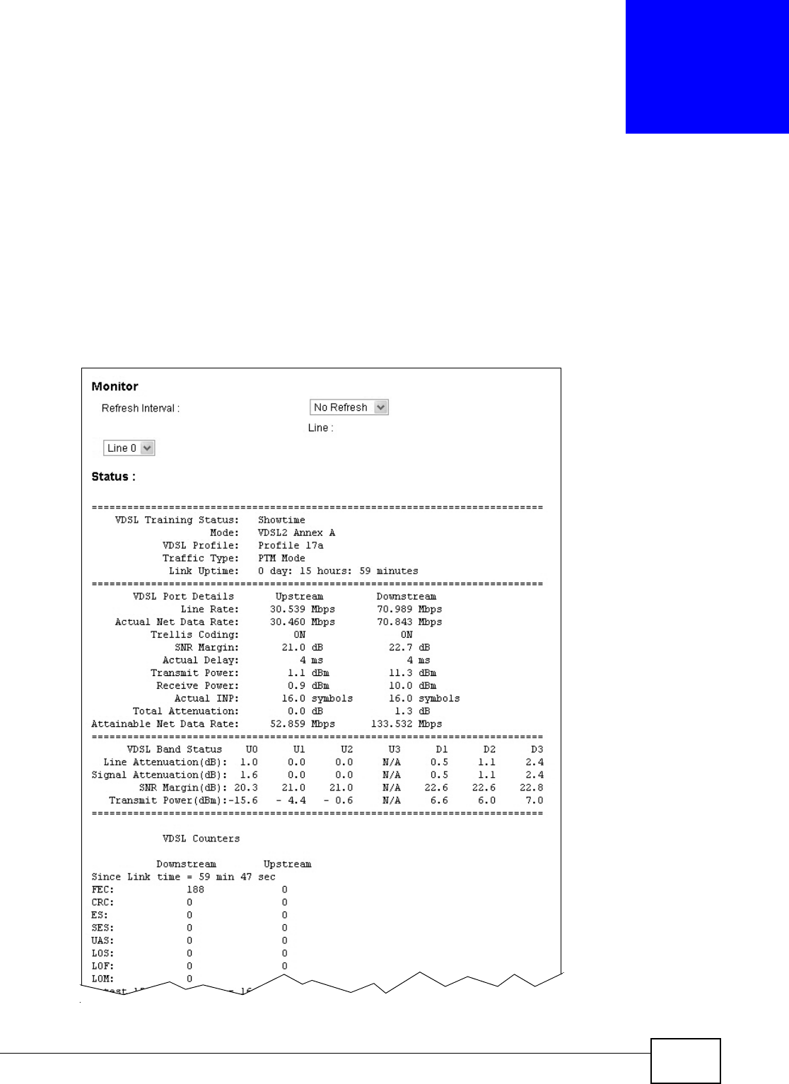
VMG8324-B10A / VMG8324-B30A Series User’s Guide 283
CHAPTER 28
xDSL Statistics
28.1 The xDSL Statistics Screen
Use t his screen to view det ailed DSL st atistics. Click Syst em M onitor > xD SL St at ist ics to open
the following screen.
Figure 166 Syst em Monit or > xDSL St atistics
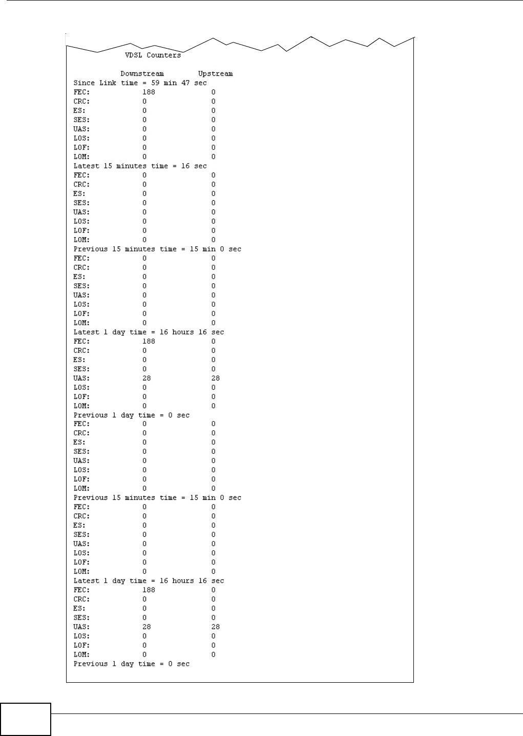
Chapter 28 xDSL Statistics
VMG8324-B10A / VMG8324-B30A Series User’s Guide
284

Chapter 28 xDSL Statistics
VMG8324-B10A / VMG8324-B30A Series User’s Guide 285
The following t able describes the labels in t his screen.
Table 136 Stat us > xDSL St atistics
LABEL DESCRIPTION
Refresh I nt erval Select the tim e int erval for refreshing statistics.
Line Select which DSL line’s statist ics you want t o display.
xDSL Training
St atus
This displays the current st at e of sett ing up the DSL connect ion.
Mode This displays the I TU st andard used for t his connect ion.
Traffic Type This displays t he t ype of t raffic t he DSL port is sending and receiving. I na ct ive displays if
the DSL port is not curr ently sending or receiving traffic.
Link Upt im e This displays how long the port has been running (or connect ed) since the last tim e it was
st art ed.
xDSL Port Det ails
Upst ream These are the st atist ics for t he traffic direct ion going out fr om t he port to t he service
provider.
Downstream These are the st at istics for the traffic direct ion com ing into t he port from t he service
provider.
Line Rate These are t he data t ransfer rates at which the port is sending and receiving dat a.
Actual Net Dat a
Rat e
These are t he rat es at which the port is sending and receiving the payload dat a wit hout
transpor t layer protocol headers and traffic.
Trellis Coding This displays whether or not the port is using Trellis coding for traffic it is sending and
receiv ing. Tr ellis coding helps t o reduce t he noise in ADSL transm issions. Tr ellis may
reduce thr oughput but it m akes t he connect ion m ore stable.
SNR Margin This is the upstream and downstream Signal- to-Noise Rat io m argin ( in dB) . A DMT sub-
carrier’s SNR is the rat io bet w een the received signal power and the received noise pow er.
The signal- t o- noise ratio m argin is t he m axim um that t he received noise power could
increase wit h the system st ill being able t o m eet it s t ransm ission targets.
Actual Delay This is t he upstream and downst ream interleave delay. I t is t he wait ( in m illiseconds) that
det erm ines the size of a single block of dat a to be interleaved ( assem bled) and then
t ransm it ted. I nt erleave delay is used when t ransm ission error correct ion ( Reed- Solom on)
is necessary due to a less than ideal t elephone line. The bigger t he delay, t he bigger t he
dat a block size, allowing bet t er error correction to be perform ed.
Transm it Power This is t he upstream and downstream far end actual aggregat e transm it pow er ( in dBm ).
Upstream is how m uch power t he port is using t o t ransm it t o the service provider.
Downstream is how m uch port the serv ice provider is using t o transm it t o the port.
Receive Power Upstream is how m uch power the service provider is receiving from the port. Downst ream
is how m uch power the port is receiv ing from the ser vice provider.
Actual I NP Sudden spikes in the line’s level of ext ernal noise ( im pulse noise) can cause errors and
result in lost packets. This could especially im pact the qualit y of m ult im edia traffic such as
voice or video. Im pulse noise protect ion (I NP) provides a buffer t o allow for correct ion of
errors caused by err or correction to deal w it h this. The num ber of DMT (Discret e Multi-
Tone) sym bols show s t he level of im pulse noise pr ot ect ion for the upstream and
downstream traffic. A higher sym bol value provides higher error correction capability, but it
causes overhead and higher delay which m ay increase error rat es in received m ultim edia
dat a.
To t a l
At t enuat ion
This is t he upstream and downstream line at tenuation, m easured in decibels (dB). This
att enuat ion is t he difference bet ween t he power t ransm it t ed at the near- end and t he pow er
received at the far-end. Att enuat ion is affect ed by t he channel charact eristics ( w ir e gauge,
qualit y, condition and length of the physical line) .
At t ainable Net
Data Rat e
These are t he highest t heoret ically possible t ransfer rates at which t he por t could send and
receive payload dat a without t ransport layer protocol headers and traffic.
xDSL Counters

Chapter 28 xDSL Statistics
VMG8324-B10A / VMG8324-B30A Series User’s Guide
286
Downstream These are the st at istics for the traffic direct ion com ing into t he port from t he service
provider.
Upst ream These are the st atist ics for t he traffic direct ion going out fr om t he port to t he service
provider.
FEC This is the num ber of Far End Cor rect ed block s.
CRC This is t he num ber of Cyclic Redundancy Checks.
ES This is t he num ber of Errored Seconds m eaning t he num ber of seconds containing at least
one errored block or at least one defect.
SES This is the num ber of Severely Errored Seconds m eaning the num ber of seconds cont aining
30% or m ore er rored blocks or at least one defect. This is a subset of ES.
UAS This is t he num ber of UnAvailable Seconds.
LOS This is t he num ber of Loss Of Signal seconds.
LOF This is the num ber of Loss Of Fram e seconds.
LOM This is the num ber of Loss of Margin seconds.
Table 136 St atus > xDSL Stat ist ics (cont inued)
LABEL DESCRIPTION
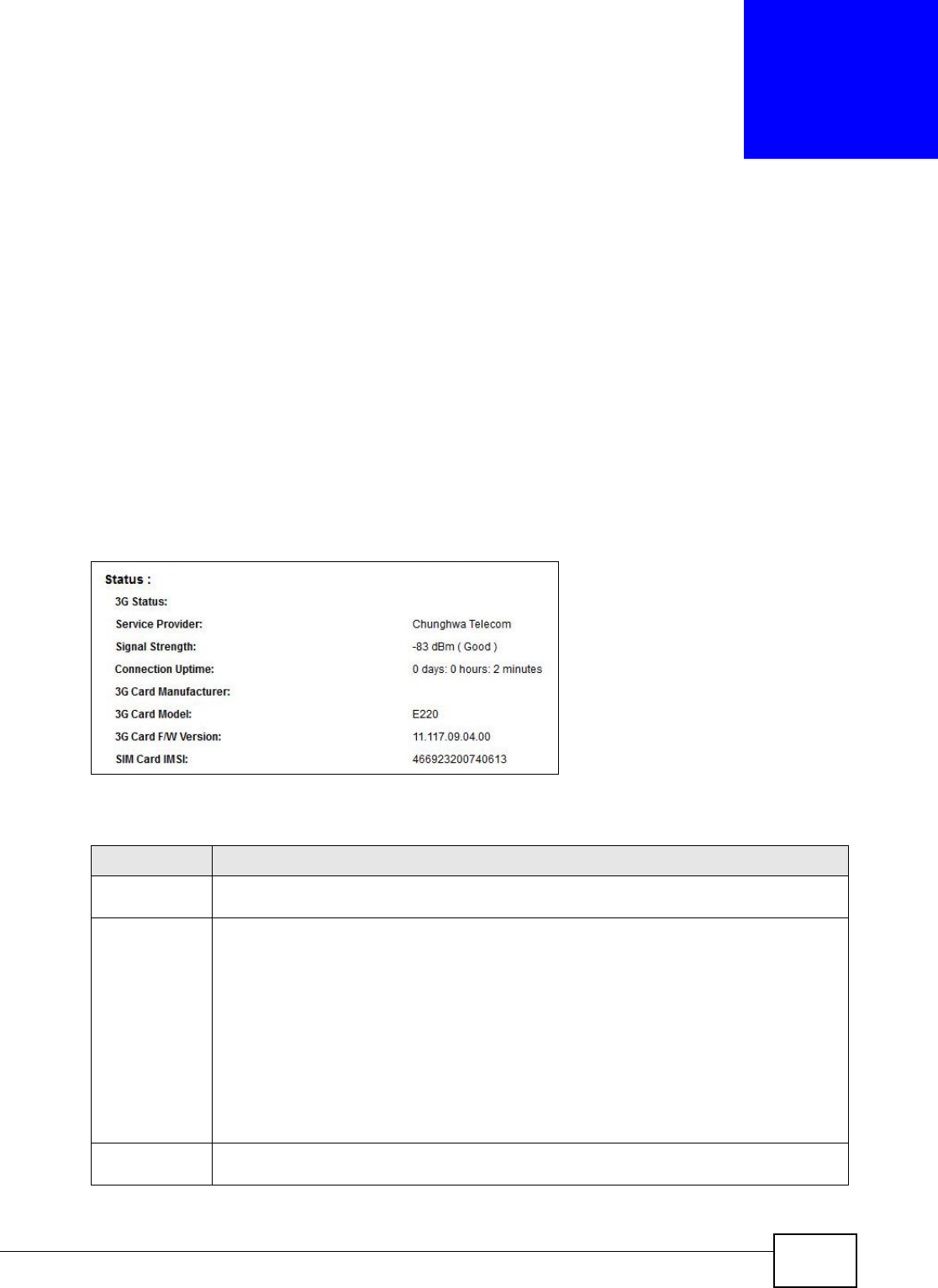
VMG8324-B10A / VMG8324-B30A Series User’s Guide 287
CHAPTER 29
3G Statistics
29.1 Overview
Use t he 3 G St at istics screens t o look at 3G I nt er net connect ion stat us.
29.2 The 3G Statistics Screen
To open this screen, click Sy st em M on it or > 3 G St at istics. The 3G st at us is available on this
screen only when you insert a com pat ible 3G dongle in a USB port on the Device.
Figure 167 Syst em Monit or > 3G St atistics
The following t able describes the labels in t his screen.
Table 137 System Monitor > 3G Stat ist ics
LABEL DESCRIPTION
Refresh
I nt erval
Select how oft en you want t he Device to updat e this screen. Select No Refr esh to stop
refreshing.
3G St at us This field displays the st at us of the 3G Internet connect ion. This field can display:
GSM - Global System for Mobile Com m unicat ions, 2G
GPRS - General Packet Radio Service, 2.5G
ED GE - Enhanced Data rates for GSM Evolut ion, 2.75G
W CDM A - Wideband Code Div ision Mult iple Access, 3G
HSDPA - High- Speed Dow nlink Packet Access, 3.5G
HSUPA - High- Speed Uplink Packet Access, 3.75G
HSPA - HSDPA+ HSUPA, 3.75G
Service
Provider
This field displays the nam e of the service prov ider.

Chapter 29 3G Statistics
VMG8324-B10A / VMG8324-B30A Series User’s Guide
288
Signal Strengt h This field displays t he st rength of the signal in dBm .
Connection
Upt im e
This field displays the tim e the connect ion has been up.
3G Card
Man ufact ur er
This field displays the manufacturer of t he 3G card.
3G Card Model This field displays the model nam e of the 3G card.
3G Card F/ W
Ve r sion
This field displays t he firm ware version of t he 3G card.
SI M Card I MSI The I nt ernational Mobile Subscriber I dent ity or I MSI is a unique ident ification num ber
associat ed with all cellular net w orks. This num ber is prov isioned in t he SI M card.
Table 137 System Monitor > 3G St atistics ( continued)
LABEL DESCRIPTION
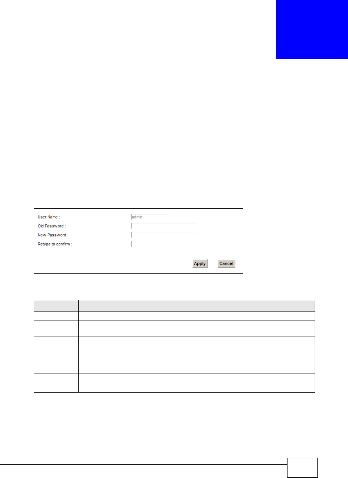
VMG8324-B10A / VMG8324-B30A Series User’s Guide 289
CHAPTER 30
User Account
30.1 Overview
I n t he Users Account screen, you can change t he password of the “adm in” user account that you
used to log in the Device.
30.2 The User Account Screen
Click Ma int ena nce > User Accoun t to open t he following screen.
Figure 168 Maintenance > User Account
The following t able describes the labels in t his screen.
Table 138 Maint enance > User Account
LABEL DESCRIPTION
User Nam e This field displays t he nam e of t he account t hat you used t o log in the syst em .
Old Password Type t he default password or t he exist ing password you use to access the system in this
field.
New Passw ord Type your new sy stem password (up t o 256 characters) . Not e t hat as you type a password,
the screen displays a ( * ) for each character you t ype. Aft er you change the passw ord, use
the new passwor d t o access the Device.
Ret ype t o
confirm
Type t he new passwor d again for confirm ation.
Apply Click Ap ply t o save your changes.
Cancel Click Cance l t o restore your pr eviously saved set t ings.

Chapter 30 User Account
VMG8324-B10A / VMG8324-B30A Series User’s Guide
290
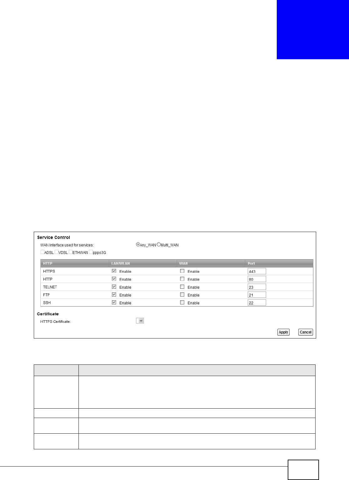
VMG8324-B10A / VMG8324-B30A Series User’s Guide 291
CHAPTER 31
Remote Management
31.1 Overview
Rem ote m anagem ent controls t hrough which interface( s) , which services can access the Device.
Note: The Device is m anaged using the Web Configurat or.
31.2 The Remote MGMT Screen
Use t his screen t o configure through which interface(s), which services can access t he Device. You
can also specify t he port num bers the services m ust use to connect t o t he Device. Click
Ma int ena nce > Rem ote MGM T to open the follow ing screen.
Figure 169 Maintenance > Rem ot e MGMT
The following t able describes the fields in this screen.
Table 139 Maint enance > Rem ote MGMT
LABEL DESCRIPTION
WAN I nterface
used for
services
Select An y W AN t o have t he Device aut om at ically activat e the rem ot e m anagem ent service
when any WAN connect ion is up.
Select M u lt i W AN and t hen select one or m ore WAN connections t o have t he Device
act ivate t he r em ote m anagem ent service when the select ed WAN connections are up.
HTTP This is t he service you m ay use to access the Device.
LAN/ WLAN Select t he En a ble check box for the correspond in g ser v ices t h at you want to allow access t o
t he Device from the LAN/ WLAN.
WAN Select the Enable check box for t he correspond in g ser vices t h at y ou w ant to allow access to
t he Device from the WAN.
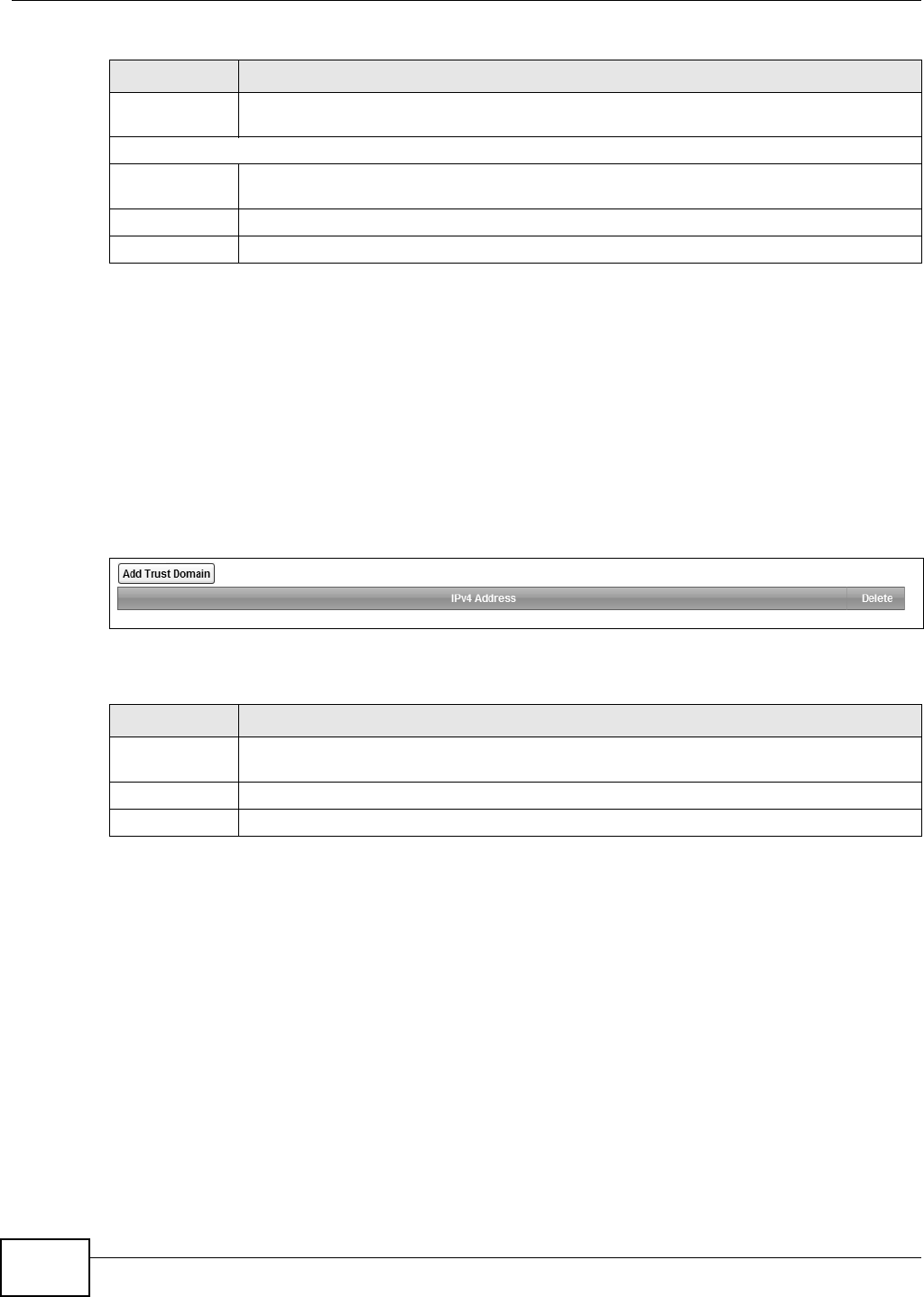
Chapter 31 Remote Management
VMG8324-B10A / VMG8324-B30A Series User’s Guide
292
31.3 The Trust Domain Screen
Use t his screen t o view a list of public I P addresses which are allowed to access t he Device through
the services configured in the M ainten ance > Re m ot e M GM T screen. Click Ma int ena nce >
Re m ote MGM T > Turst Dom ain to open the following screen.
Note: I f this list is em pt y, all public I P addresses can access the Device from the WAN
through the specified services.
Figure 170 Maintenance > Rem ot e MGMT > Trust Dom ain
The following t able describes the fields in this screen.
Port You m ay change t he server port num ber for a service if needed, however you m ust use the
sam e port num ber in order t o use that service for rem ot e managem ent.
Certificat e
HTTPS
Certificat e
Select a certificat e the HTTPS server ( t he Device) uses to aut henticat e it self t o the HTTPS
client. You m ust have cert ificat es already configured in t he Ce r t if ica t e s screen.
Apply Click Apply to save your changes back t o t he Device.
Cancel Click Ca n cel t o restore your previously saved settings.
Table 139 Maint enance > Rem ote MGMT ( cont inued)
LABEL DESCRIPTION
Table 140 Maint enance > Rem ote MGMT > Tr ust Dom ain
LABEL DESCRIPTION
Add Tr ust
Dom ain
Click this t o add a trusted host I P address.
I Pv4 Address This field shows a trust ed host IP address.
Delete Click t he De le t e icon t o rem ove the t rust I P address.
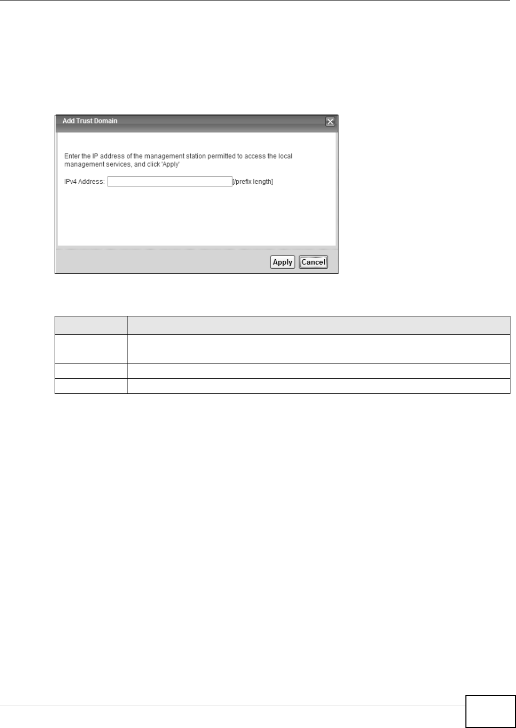
Chapter 31 Remote Management
VMG8324-B10A / VMG8324-B30A Series User’s Guide 293
31.4 The Add Trust Domain Screen
Use t his screen to configure a public I P address w hich is allowed to access t he Device. Click the Add
Tr ust Dom a in butt on in t he Ma int enan ce > Re m ote MGM T > Tur st Dom ain screen t o open t he
following screen.
Figure 171 Maintenance > Rem ot e MGMT > Trust Dom ain > Add Trust Dom ain
The following t able describes the fields in this screen.
Table 141 Maint enance > Rem ote MGMT > Trust Dom ain > Add Trust Dom ain
LABEL DESCRIPTION
I Pv4 Address Enter a public I Pv4 I P address which is allowed to access t he serv ice on t he Device from the
WAN.
Apply Click Apply to save your changes back t o t he Device.
Cancel Click Ca n cel t o restore your previously saved settings.

Chapter 31 Remote Management
VMG8324-B10A / VMG8324-B30A Series User’s Guide
294
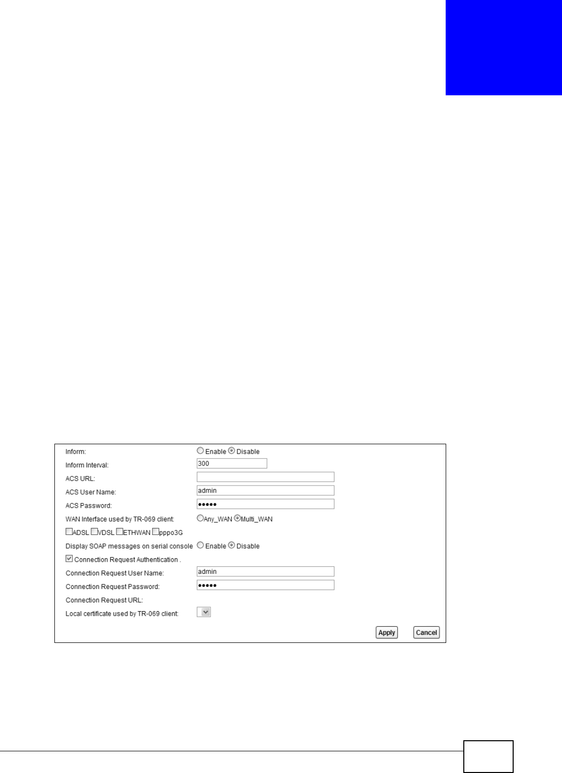
VMG8324-B10A / VMG8324-B30A Series User’s Guide 295
CHAPTER 32
TR-069 Client
32.1 Overview
This chapt er explains how to configure t he Device’s TR- 069 aut o-configurat ion set tings.
32.2 The TR-069 Client Screen
TR- 069 defines how Custom er Pr em ise Equipm ent ( CPE) , for exam ple your Device, can be m anaged
over t he WAN by an Auto Configurat ion Ser ver ( ACS) . TR-069 is based on sending Rem ote
Procedure Calls ( RPCs) bet ween an ACS and a client device. RPCs are sent in Extensible Markup
Language (XML) form at over HTTP or HTTPS.
An adm inist rat or can use an ACS to rem otely set up the Device, m odify set tings, perform firm ware
upgrades as well as m onit or and diagnose t he Device. You have to enable t he device t o be m anaged
by the ACS and specify t he ACS I P address or dom ain nam e and usernam e and password.
Click Ma int ena nce > TR- 0 6 9 Client t o open t he following screen. Use this screen to configure
your Device t o be m anaged by an ACS.
Figure 172 Maintenance > TR- 069 Client

Chapter 32 TR-069 Client
VMG8324-B10A / VMG8324-B30A Series User’s Guide
296
The following t able describes the fields in this screen.
Table 142 Maint enance > TR-069 Client
LABEL DESCRIPTION
I nform Select Enable for the Device to send periodic infor m via TR- 069 on the WAN. Ot herwise,
select Disa ble .
I nfor m I nt erval Ent er t he t im e int erval (in seconds) at which the Device sends inform at ion t o the auto-
configuration server.
ACS URL Enter t he URL or I P address of the aut o-configuration server.
ACS User Nam e Enter the TR- 069 user nam e for authentication with the auto- configurat ion server.
ACS Password Ent er t he TR-069 passwor d for authentication with the auto-configuration server.
WAN I nterface
used by TR- 069
client
Select a WAN int erface t hrough which t he TR- 069 t raffic passes.
I f you select Any_ W AN , the Device autom at ically passes the TR- 069 t raffic when any WAN
connection is up.
I f y ou select M u lt i_ W AN , you also need t o select two or m ore pre-configured WAN
interfaces. The Device aut om at ically passes t he TR-069 t raffic when one of the select ed WAN
connections is up.
Display SOAP
m essages on
serial console
Select Enable to show t he SOAP m essages on the console.
Connection
Request
Au t hent icat ion
Select t his opt ion to enable authentication when t her e is a connection request from the ACS.
Connection
Request User
Nam e
Enter the connect ion request user nam e.
When t he ACS m akes a connection request t o t he Device, t his user nam e is used to
aut henticat e the ACS.
Connection
Request
Passw ord
Enter the connection request passw ord.
When t he ACS m akes a connect ion request t o t he Device, t his password is used to
aut henticat e the ACS.
Connection
Request URL
This shows the connection request URL.
The ACS can use this URL to m ake a connect ion request t o the Device.
Local cert ificat e
used by TR- 069
client
You can choose a local cert ificat e used by TR- 069 client. The local certificat e should be
im ported in t he Se cu r it y > Certificates > Loca l Ce r t ificat e s screen.
Apply Click Apply to save your changes.
Cancel Click Ca n cel t o exit t his screen wit hout saving.
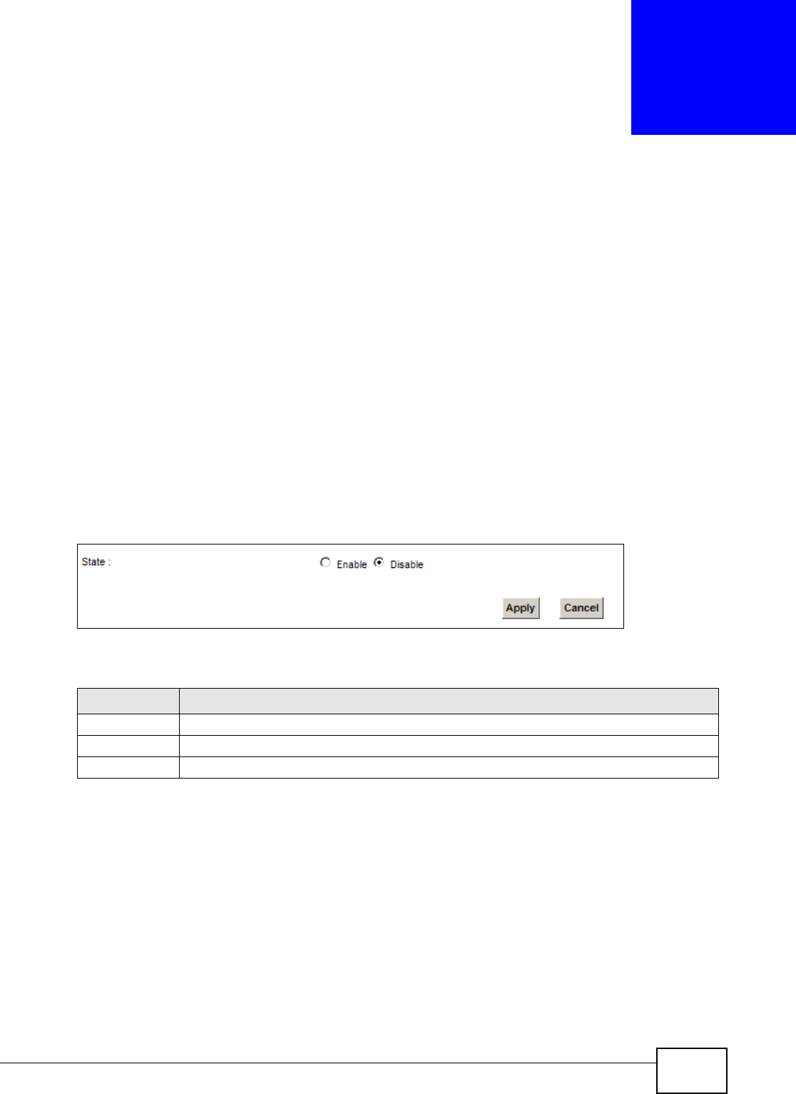
VMG8324-B10A / VMG8324-B30A Series User’s Guide 297
CHAPTER 33
TR-064
33.1 Overview
This chapt er explains how to configure t he Device’s TR- 064 aut o-configurat ion set tings.
33.2 The TR-064 Screen
TR- 064 is a LAN- Side DSL CPE Configuration prot ocol defined by the DSL Forum . TR- 064 is built on
top of UPnP. I t allows t he users to use a TR- 064 com pliant CPE m anagem ent application on t heir
com puters fr om t he LAN t o discover t he CPE and configure user- specific param eters, such as t he
usernam e and password.
Click Ma int ena nce > TR- 0 6 4 to open the following screen.
Figure 173 Maintenance > TR- 064
The following t able describes the fields in this screen.
Table 143 Maint enance > TR-064
LABEL DESCRIPTION
St at e Select Enable to activate m anagem ent v ia TR- 064 on the LAN.
Apply Click Apply to save your changes.
Cancel Click Ca n cel t o exit t his screen wit hout saving.

Chapter 33 TR-064
VMG8324-B10A / VMG8324-B30A Series User’s Guide
298
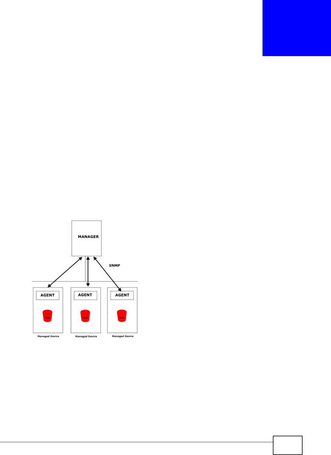
VMG8324-B10A / VMG8324-B30A Series User’s Guide 299
CHAPTER 34
SNMP
34.1 Overview
This chapt er explains how to configure t he SNMP sett ings on t he Device.
34.2 The SNMP Screen
Sim ple Network Managem ent Prot ocol is a prot ocol used for exchanging m anagem ent inform ation
bet ween net work devices. Your Device supports SNMP agent funct ionality, which allow s a m anager
st ation to m anage and m onitor t he Device t hrough the network. The Device support s SNMP version
one ( SNMPv1) and version t wo (SNMPv2c) . The next figure illustrates an SNMP managem ent
operat ion.
Figure 174 SNMP Managem ent Model
An SNMP m anaged network consist s of tw o m ain t y pes of com ponent : agents and a m anager.
An agent is a m anagem ent software m odule t hat resides in a m anaged device (t he Device) . An
agent translat es the local m anagem ent inform at ion from the m anaged device int o a form
com patible with SNMP. The m anager is t he console t hrough which network adm inistrators perform
net work m anagem ent funct ions. I t executes applications t hat control and monit or managed
devices.
The m anaged devices cont ain object variables/ m anaged objects t hat define each piece of
inform at ion t o be collected about a device. Exam ples of variables include such as num ber of
packets received, node port stat us et c. A Managem ent I nform ation Base ( MI B) is a collect ion of
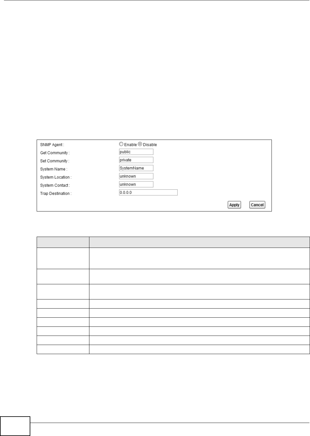
Chapter 34 SNMP
VMG8324-B10A / VMG8324-B30A Series User’s Guide
300
m anaged obj ect s. SNMP allows a m anager and agents t o com m unicate for the purpose of accessing
these obj ect s.
SNMP it self is a sim ple request / response prot ocol based on t he m anager/ agent m odel. The
m anager issues a request and the agent ret urns responses using the following protocol operations:
• Get - Allows t he m anager t o ret rieve an obj ect variable from t he agent.
• GetNext - Allows the m anager t o ret rieve t he next obj ect variable from a t able or list wit hin an
agent. I n SNMPv1, when a m anager wants t o ret rieve all elem ents of a t able from an agent, it
initiat es a Get operat ion, followed by a series of GetNext operat ions.
• Set - Allows t he m anager to set values for obj ect variables within an agent.
• Trap - Used by t he agent to inform the m anager of som e event s.
Click Ma int ena nce > SNM P to open the following screen. Use this screen t o configur e the Device
SNMP sett ings.
Figure 175 Maintenance > SNMP
The following t able describes the fields in this screen.
Table 144 Maint enance > SNMP
LABEL DESCRIPTION
SNMP Agent Select Ena ble t o let t he Device act as an SNMP agent , which allows a m anager station
t o m anage and m onitor t he Device through t he net wor k. Select D isa ble to t urn this
feat ure off.
Get Com m unity Enter t he Get Com m unit y, which is the passw ord for t he incom ing Get and Get Next
request s from t he m anagem ent station.
Set Com m unity Enter t he Set com m unity, which is the passw ord for incom ing Set request s from the
m anagem ent st at ion.
Syst em Nam e Enter t he SNMP syst em nam e.
Syst em Locat ion Enter the SNMP system location.
Syst em Cont act Enter the SNMP system cont act.
Trap Dest ination Type t he I P address of the stat ion t o send your SNMP t raps t o.
Apply Click this t o save your changes back to t he Device.
Cancel Click t his to r estore your previously saved sett ings.
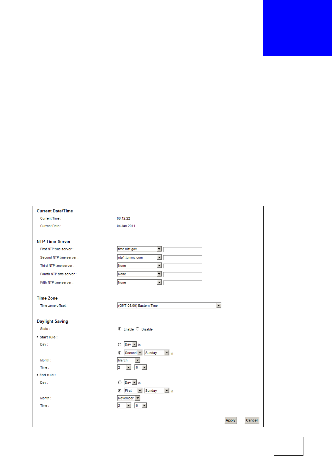
VMG8324-B10A / VMG8324-B30A Series User’s Guide 301
CHAPTER 35
Time Settings
35.1 Overview
This chapt er shows you how t o configure system relat ed set tings, such as syst em t im e, passwor d,
name, the dom ain nam e and the inactivity tim eout interval.
35.2 The Time Screen
To change your Device’s tim e and date, click M ainte nance > Tim e . The screen appears as shown.
Use t his screen t o configure the Device’s t im e based on your local t im e zone.
Figure 176 Maintenance > Tim e

Chapter 35 Time Settings
VMG8324-B10A / VMG8324-B30A Series User’s Guide
302
The following t able describes the fields in this screen.
Table 145 Maint enance > Tim e
LABEL DESCRIPTION
Current Dat e/ Tim e
Current Tim e This field displays t he t im e of your Device.
Each tim e you reload t his page, the Device synchronizes the tim e with t he t im e server.
Current Dat e This field displays t he dat e of your Device.
Each t im e you reload this page, the Device synchronizes t he dat e wit h t he tim e server.
NTP Tim e Server
First ~ Fift h NTP
tim e server
Select an NTP t im e server from the drop- dow n list box.
Ot herw ise, select Ot he r and enter t he I P address or URL ( up to 29 extended ASCI I
charact ers in lengt h) of your tim e server.
Select N on e if you don’t want to configure t he tim e server.
Check wit h your I SP/ net work adm inistrat or if you are unsure of t his inform ation.
Tim e Zone
Tim e zone offset Choose t he t im e zone of your location. This w ill set the tim e difference bet w een your t im e
zone and Greenwich Mean Tim e ( GMT) .
Daylight Saving Daylight Saving Tim e is a period fr om lat e spring to early fall when m any countries set
their clocks ahead of norm al local t im e by one hour t o give m ore daytim e light in the
evening.
St ate Select Enable if you use Daylight Saving Tim e.
St art rule: Configure t he day and t im e when Daylight Saving Tim e st arts if you enabled Daylight
Saving. You can select a specific dat e in a particular m onth or a specific day of a specific
week in a particular m ont h. The Tim e field uses t he 24 hour form at. Here are a couple of
exam ples:
Daylight Saving Tim e starts in m ost par t s of the Unit ed States on t he second Sunday of
March. Each t im e zone in t he Unit ed St at es st ar t s using Daylight Saving Tim e at 2 A.M.
local t im e. So in t he United Stat es, set t he day t o Se cond, Sunda y, the m ont h t o M a rch
and t he t ime to 2 in t he Hour field.
Daylight Saving Tim e st arts in t he European Union on the last Sunday of Mar ch. All of t he
t im e zones in t he European Union st art using Daylight Saving Tim e at t he sam e m om ent
( 1 A.M. GMT or UTC). So in t he European Union you w ould set the day t o La st , Sunday
and the mont h t o March. The tim e you select in t he o'clock field depends on your tim e
zone. In Germ any for instance, you would select 2 in t he H our field because Germ any's
tim e zone is one hour ahead of GMT or UTC (GMT+ 1) .
End rule Configure the day and tim e when Daylight Saving Tim e ends if you enabled Daylight
Saving. You can select a specific dat e in a particular m onth or a specific day of a specific
week in a particular m onth. The Tim e field uses t he 24 hour form at. Here are a couple of
exam ples:
Daylight Saving Tim e ends in t he United St at es on the first Sunday of Novem ber. Each
t im e zone in the United Stat es st ops using Daylight Saving Tim e at 2 A.M. local tim e. So
in the United Stat es you would set the day to First , Sunday, the mont h t o Novem ber
and t he t ime to 2 in t he Hour field.
Day lig h t Sav in g Ti m e en d s in t h e Eu r op ean Un i on on t h e last Sun day of Oct ob er. Al l of t he
t im e zones in the Eur opean Union st op using Daylight Saving Tim e at t he sam e m om ent
( 1 A.M. GMT or UTC). So in t he European Union you would set the day t o La st , Sunday,
and the mont h t o Oct ob e r. The tim e you select in t he o'clo ck field depends on your tim e
zone. In Germ any for instance, you would select 2 in t he H our field because Germ any's
tim e zone is one hour ahead of GMT or UTC (GMT+ 1) .

Chapter 35 Time Settings
VMG8324-B10A / VMG8324-B30A Series User’s Guide 303
Apply Click Apply to save your changes.
Cancel Click Ca ncel to exit t his screen wit hout saving.
Table 145 Maint enance > Tim e (continued)
LABEL DESCRIPTION

Chapter 35 Time Settings
VMG8324-B10A / VMG8324-B30A Series User’s Guide
304

VMG8324-B10A / VMG8324-B30A Series User’s Guide 305
CHAPTER 36
E-mail Notification
36.1 Overview
A m ail server is an applicat ion or a com put er that runs such an applicat ion t o receive, forward and
deliver e-m ail m essages.
To have the Device send report s, logs or notifications via e-m ail, you m ust specify an e- m ail server
and the e- m ail addresses of the sender and receiver.
36.2 The Email Notification Screen
Click Ma int enance > Em a il Not ificat ion t o open the Em a il Not ifica tion screen. Use this screen
to view, rem ove and add mail server inform at ion on the Device.
Figure 177 Maintenance > Em ail Not ification
The following t able describes the labels in t his screen.
Table 146 Maint enance > Em ail Notificat ion
LABEL DESCRIPTION
Add New Em ail Click this button to creat e a new ent ry.
Mail Server
Address
This field displays t he server nam e or the I P address of the m ail server.
Usernam e This field displays t he user nam e of the sender’s m ail account.
Passw ord This field displays the passw ord of t he sender ’s m ail account .
Em ail Address This field displays the e- m ail address t hat you want to be in the from / sender line of the e-
m ail t hat t he Device sends.
Delet e Click t his but t on t o delet e the selected ent ry(ies) .
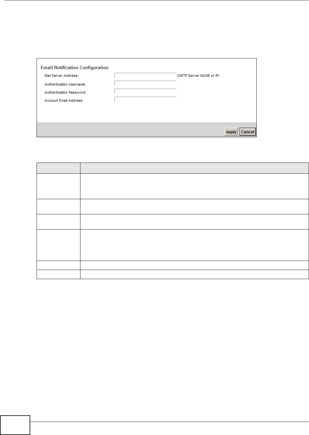
Chapter 36 E-mail Notification
VMG8324-B10A / VMG8324-B30A Series User’s Guide
306
36.2.1 Email Notification Edit
Click the Add but t on in the Em ail Notificat ion scr een. Use this screen to configure t he required
inform at ion for sending e-m ail via a m ail server.
Figure 178 Em ail Not ificat ion > Add
The following t able describes the labels in t his screen.
Table 147 Email Notification > Add
LABEL DESCRIPTION
Mail Server
Address
Enter the server nam e or t he I P address of t he m ail server for t he e- m ail address specified
in the Accoun t Em a il Address field.
I f t his field is left blank, repor t s, logs or notifications will not be sent via e-m ail.
Authentication
Usernam e
Enter the user nam e (up t o 32 charact ers) . This is usually t he user nam e of a m ail account
you specified in t he Account Em ail Address field.
Authentication
Passw ord
Enter the passwor d associated w it h the user nam e above.
Account Email
Address
Enter t he e- m ail address t hat y ou want t o be in t he from / sender line of t he e- m ail
notification t hat t he Device sends.
I f you act ivat e SSL/ TLS aut hent ication, t he e- m ail address m ust be able to be authenticated
by the m ail server as well.
Apply Click t his butt on t o save your changes and return to t he previous screen.
Cancel Click t his but t on t o begin configuring this screen afresh.

VMG8324-B10A / VMG8324-B30A Series User’s Guide 307
CHAPTER 37
Logs Setting
37.1 Overview
You can configure w here the Device sends logs and which logs and/ or im m ediate alerts t he Device
records in t he Logs Set t ing screen.
37.2 The Log Settings Screen
To change your Device’s log sett ings, click M ain ten ance > Logs Set t in g. The screen appears as
shown.
Figure 179 Maintenance > Logs Set ting

Chapter 37 Logs Setting
VMG8324-B10A / VMG8324-B30A Series User’s Guide
308
The following t able describes the fields in this screen.
37.2.1 Example E-mail Log
An "End of Log" m essage displays for each m ail in which a com plete log has been sent. The
following is an exam ple of a log sent by e- m ail.
• You m ay edit the subj ect t itle.
• The date form at here is Day-Mont h-Year.
• The date form at here is Mont h-Day-Year. The tim e form at is Hour-Minute- Second.
Table 148 Maint enance > Logs Sett ing
LABEL DESCRIPTION
Syslog Sett ing
Syslog Logging The Device sends a log t o an ext ernal syslog server. Select Enable t o enable syslog logging.
Mode Select t he syslog destinat ion from t he drop-down list box.
I f you select Re m o t e, the log( s) will be sent to a rem ote syslog server. I f you select Local
File, t he log( s) will be saved in a local file. I f you want t o send t he log( s) t o a rem ot e syslog
server and save it in a local file, select Local File and Re m ot e.
Syslog Server Ent er t he server nam e or I P address of the syslog server t hat will log the select ed cat egories
of logs.
UDP Port Ent er t he port num ber used by the syslog ser ver.
E-m ail Log Sett ings
Mail Server Enter the server nam e or t he I P address of t he m ail server for t he e- m ail addresses
specified below. I f t his field is left blank, logs and alert m essages will not be sent via E-m ail.
Syst em Log
Mail Subject
Type a tit le that you want t o be in the subj ect line of the syst em log e- mail m essage that
the Device sends.
Security Log
Mail Subject
Type a tit le that you want to be in the subj ect line of t he securit y log e- m ail m essage that
the Device sends.
Send Log t o The Device sends logs t o the e-m ail address specified in t his field. I f t his field is left blank,
the Device does not send logs via E-m ail.
Send Alarm t o Alert s are real- t im e not ificat ions t hat are sent as soon as an event , such as a DoS at tack,
syst em error, or for bidden web access attem pt occurs. Ent er t he E- m ail address where t he
alert m essages will be sent . Alerts include syst em error s, attacks and attem pted access to
blocked web sit es. I f t his field is left blank, alert m essages will not be sent via E-m ail.
Alarm I nt erval Specify how often the alarm should be updated.
Allowed
Capacity Before
Em ail
Set what percent of t he Device’s log st orage space can be filled befor e the Device sends a
log e- mail.
Clear log after
sending m ail
Select t his t o delete all the logs after the Device sends an E-m ail of the logs.
Active Log and Alert
Syst em Log Select the cat egories of syst em logs that you want t o record.
Security Log Select t he categories of securit y logs t hat you want t o record.
Send
im m ediat e alert
Select log categories for which you want the Device t o send E-m ail alerts im m ediately.
Apply Click Apply t o save your changes.
Cancel Click Ca nce l to r est ore your previously saved sett ings.

Chapter 37 Logs Setting
VMG8324-B10A / VMG8324-B30A Series User’s Guide 309
• "End of Log" m essage shows t hat a com plete log has been sent .
Figure 180 E- m ail Log Exam ple
Subject:
Firewall Alert From
Date:
Fri, 07 Apr 2000 10:05:42
From:
user@zyxel.com
To:
user@zyxel.com
1|Apr 7 00 |From:192.168.1.1 To:192.168.1.255 |default policy |forward
| 09:54:03 |UDP src port:00520 dest port:00520 |<1,00> |
2|Apr 7 00 |From:192.168.1.131 To:192.168.1.255 |default policy |forward
| 09:54:17 |UDP src port:00520 dest port:00520 |<1,00> |
3|Apr 7 00 |From:192.168.1.6 To:10.10.10.10 |match |forward
| 09:54:19 |UDP src port:03516 dest port:00053 |<1,01> |
……………………………..{snip}…………………………………..
……………………………..{snip}…………………………………..
126|Apr 7 00 |From:192.168.1.1 To:192.168.1.255 |match |forward
| 10:05:00 |UDP src port:00520 dest port:00520 |<1,02> |
127|Apr 7 00 |From:192.168.1.131 To:192.168.1.255 |match |forward
| 10:05:17 |UDP src port:00520 dest port:00520 |<1,02> |
128|Apr 7 00 |From:192.168.1.1 To:192.168.1.255 |match |forward
| 10:05:30 |UDP src port:00520 dest port:00520 |<1,02> |
End of Firewall Log

Chapter 37 Logs Setting
VMG8324-B10A / VMG8324-B30A Series User’s Guide
310
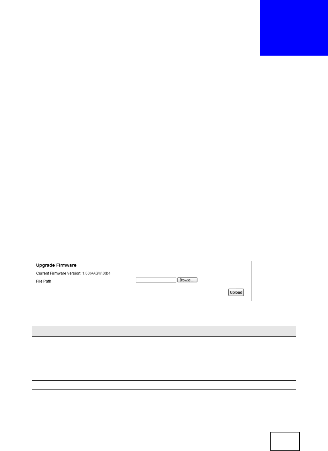
VMG8324-B10A / VMG8324-B30A Series User’s Guide 311
CHAPTER 38
Firmware Upgrade
38.1 Overview
This chapt er explains how to upload new firm ware t o your Device. You can download new firm ware
releases from your nearest ZyXEL FTP sit e ( or ww w.zyxel.com ) t o use to upgrade your device’s
perform ance.
Only use firmware for your device’s specific model. Refer to the label on
the bottom of your Device.
38.2 The Firmware Screen
Click Ma int ena nce > Firm w a re Upgr ade to open the following screen. The upload process uses
HTTP (Hyper t ext Transfer Protocol) and m ay t ake up to t wo m inutes. After a successful upload, t he
system will reboot.
Do NOT turn off the Device while firmware upload is in progress!
Figure 181 Maintenance > Firm ware Upgrade
The following t able describes the labels in t his screen.
Table 149 Maint enance > Firm ware Upgrade
LABEL DESCRIPTION
Current
Firm ware
Ve r sion
This is t he present Fir m ware version and the dat e creat ed.
File Path Type in t he locat ion of t he file you want to upload in this field or click Brow se ... t o find it .
Br owse... Click t his to find t he .bin file you want t o upload. Rem em ber t hat you m ust decom press
com pressed ( .zip) files before you can upload them .
Upload Click t his to begin t he upload process. This process m ay t ake up t o two m inutes.

Chapter 38 Firmware Upgrade
VMG8324-B10A / VMG8324-B30A Series User’s Guide
312
After you see the firm ware updat ing screen, wait t wo m inutes before logging into the Device again.
Figure 182 Firm ware Uploading
The Device autom at ically restart s in this t im e causing a t em porary net work disconnect. I n som e
operat ing syst em s, you may see the following icon on your deskt op.
Figure 183 Net work Tem porarily Disconnected
After two m inut es, log in again and check your new firm ware version in t he St a t u s screen.
I f the upload was not successful, t he following screen will appear. Click OK t o go back to t he
Firm w are Upgra de screen.
Figure 184 Error Message

VMG8324-B10A / VMG8324-B30A Series User’s Guide 313
CHAPTER 39
Configuration
39.1 Overview
The Configur at ion screen allows you to backup and rest ore device configurat ions. You can also
reset your device set tings back to the factory default.
39.2 The Configuration Screen
Click M a in t en ance > Configu rat ion. I nform ation related t o fact ory defaults, backup
configurat ion, and rest oring configurat ion appears in t his screen, as shown next .
Figure 185 Maintenance > Configurat ion
Backup Configuration
Backup Configuration allows you t o back up (save) the Device’s current configuration to a file on
your com puter. Once your Device is configured and funct ioning properly, it is highly recom m ended
that you back up your configuration file before m aking configurat ion changes. The backup
configurat ion file will be useful in case you need to return to your previous sett ings.
Click Backu p t o save the Device’s current configuration to your com put er.
Chapter 39 Configuration
VMG8324-B10A / VMG8324-B30A Series User’s Guide
314
Restore Configuration
Rest ore Configuration allows you t o upload a new or previously saved configurat ion file from your
com puter t o your Device.
Do not turn off the Device while configuration file upload is in progress.
After the Device configuration has been rest ored successfully, t he login screen appears. Login again
to rest art t he Device.
The Device autom at ically restart s in this t im e causing a t em porary net work disconnect. I n som e
operat ing syst em s, you may see the following icon on your deskt op.
Figure 186 Net work Tem porarily Disconnected
I f you uploaded the default configuration file you m ay need to change the I P address of your
com puter t o be in the sam e subnet as that of the default device I P address ( 192.168.1.1) . See
Appendix B on page 335 for details on how t o set up your com put er ’s I P address.
I f the upload was not successful, t he following screen will appear. Click OK t o go back to t he
Configu ra t ion screen.
Figure 187 Configurat ion Upload Error
Table 150 Restore Configuration
LABEL DESCRIPTION
File Path Type in t he locat ion of the file you want to upload in t his field or click Brow se ... t o find it .
Br owse... Click this t o find t he file you want t o upload. Rem em ber t hat you m ust decom press
com pressed ( .ZI P) files before you can upload them .
Upload Click t his to begin the upload process.
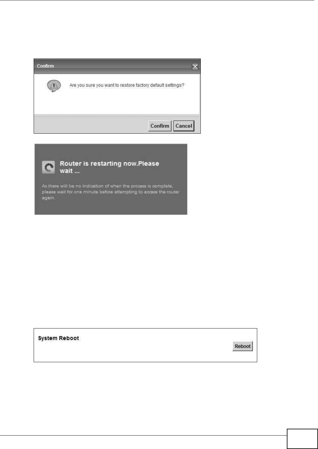
Chapter 39 Configuration
VMG8324-B10A / VMG8324-B30A Series User’s Guide 315
Reset to Factory Defaults
Click the Re se t butt on to clear all user-entered configuration inform ation and ret urn the Device to
it s factory defaults. The following warning screen appears.
Figure 188 Reset Warning Message
Figure 189 Reset I n Pr ocess Message
You can also press the RESET butt on on t he rear panel to reset t he factory defaults of your Device.
Refer t o Sect ion 1.6 on page 22 for m ore inform ation on the RESET butt on.
39.3 The Reboot Screen
Syst em restart allows you to reboot t he Device rem ot ely without t ur ning the power off. You may
need t o do this if t he Device hangs, for exam ple.
Click Ma int ena nce > Reboot. Click Reboo t to have the Device reboot. This does not affect t he
Device's configurat ion.
Figure 190 Maintenance > Reboot

Chapter 39 Configuration
VMG8324-B10A / VMG8324-B30A Series User’s Guide
316

VMG8324-B10A / VMG8324-B30A Series User’s Guide 317
CHAPTER 40
Diagnostic
40.1 Overview
The D ia g nost ic screens display inform ation to help you identify problem s w ith t he Device.
The route bet ween a CO VDSL switch and one of it s CPE m ay go through swit ches owned by
independent organizations. A connectivit y fault point generally t akes t im e t o discover and im pacts
subscriber’s net work access. I n order to elim inate the m anagem ent and m aint enance efforts, I EEE
802.1ag is a Connectivit y Fault Managem ent (CFM) specificat ion which allows net work
adm inistrators to identify and m anage connect ion fault s. Through discover y and verification of the
pat h, CFM can det ect , analyze and isolat e connectivit y faults in bridged LANs.
40.1.1 What You Can Do in this Chapter
• The Ping & TraceRout e & N sLook up screen let s you ping an I P address or t race t he rout e
packets t ake to a host (Section 40.3 on page 318) .
• The 8 0 2 .1 ag screen lets you perform CFM actions ( Sect ion 40.5 on page 320) .
• The OAM Ping scr een let s you send an ATM OAM (Operation, Adm inistration and Maint enance)
packet to verify the connectivit y of a specific PVC. (Sect ion 40.5 on page 320) .
40.2 What You Need to Know
The following t erm s and concept s m ay help as you read t hr ough this chapter.
How CFM Works
A Maint enance Association (MA) defines a VLAN and associated Maint enance End Point ( MEP) port s
on t he device under a Maint enance Dom ain (MD) level. An MEP port has t he abilit y t o send
Connect ivity Check Messages ( CCMs) and get other MEP port s inform at ion from neighbor devices’
CCMs wit hin an MA.
CFM provides t wo test s to discover connectivity faults.
• Loopback test - checks if the MEP port receives its Loop Back Response ( LBR) from its t arget
after it sends t he Loop Back Message ( LBM). I f no response is received, ther e m ight be a
connectivity fault bet ween them .
• Link t race t est - provides additional connect ivity fault analysis to get m ore inform ation on where
the fault is. I f an MEP port does not respond to the source MEP, this m ay indicat e a fault .
Adm inistrat ors can t ake furt her act ion to check and resum e services from the fault according t o
the line connect ivity st atus report .
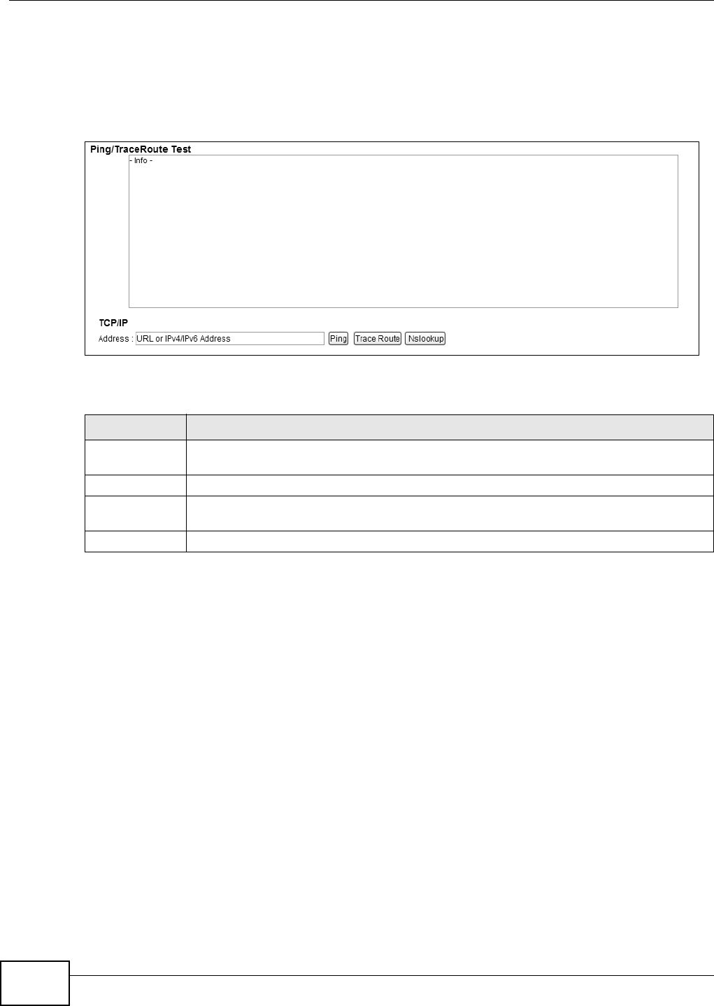
Chapter 40 Diagnostic
VMG8324-B10A / VMG8324-B30A Series User’s Guide
318
40.3 Ping & TraceRoute & NsLookup
Use t his screen t o ping, traceroute, or nslookup an I P address. Click M ain te nance > Diagnost ic >
Ping& Trace Rou t e& N sLook up to open the screen show n next .
Figure 191 Maintenance > Diagnost ic > Ping &TraceRoute&NsLookup
The following t able describes the fields in this screen.
Table 151 Maint enance > Diagnostic > Ping & TraceRoute & NsLookup
LABEL DESCRIPTION
URL or I P
Address
Type t he IP address of a com put er t hat you want t o perform ping, traceroute, or nslookup in
order t o test a connect ion.
Ping Click t his to ping the I P address that you ent ered.
Tr a c e Ro u t e Click t his butt on t o perfor m t he t raceroute funct ion. This det erm ines t he pat h a packet
takes t o the specified com put er.
Nslookup Click t his but t on t o perform a DNS lookup on the I P address of a com put er you ent er.
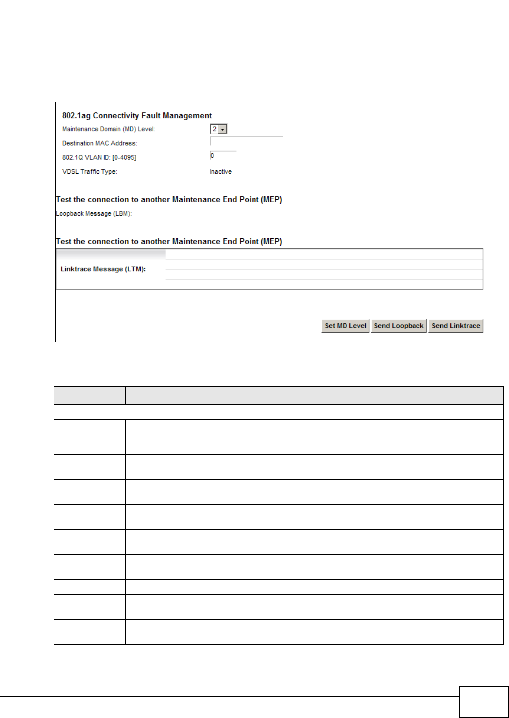
Chapter 40 Diagnostic
VMG8324-B10A / VMG8324-B30A Series User’s Guide 319
40.4 802.1ag
Click Ma int ena nce > Dia gnost ic > 8 .2 .1 a g to open the following screen. Use t his screen t o
perform CFM actions.
Figure 192 Maintenance > Diagnostic > 802.1ag
The following t able describes the fields in this screen.
Table 152 Maint enance > Diagnost ic > 802.1ag
LABEL DESCRIPTION
802.1ag Connectivity Fault Managem ent
Maint enance
Dom ain ( MD)
Level
Select a level ( 0- 7) under which you want t o create an MA.
Destinat ion
MAC Addr ess
Enter the target device’s MAC address t o which the Device perform s a CFM loopback t est.
802.1Q VLAN
I D
Type a VLAN I D ( 0-4095) for t his MA.
VDSL Traffic
Ty p e
This shows whether the VDSL t raffic is activat ed.
Loopback
Message (LBM)
This show s how m any Loop Back Messages ( LBMs) are sent and if t here is any inor der or
out order Loop Back Response (LBR) received from a rem ot e MEP.
Linktrace
Message (LTM)
This show s t he destinat ion MAC address in the Link Trace Response ( LTR) .
Set MD Level Click t his but t on t o configur e t he MD (Maint enance Dom ain) level.
Send Loopback Click t his but t on t o have t he select ed MEP send t he LBM (Loop Back Message) to a specified
rem ot e end point .
Send Linktrace Click t his but t on t o have t he select ed MEP send the LTMs ( Link Trace Messages) t o a
specified rem ote end point .
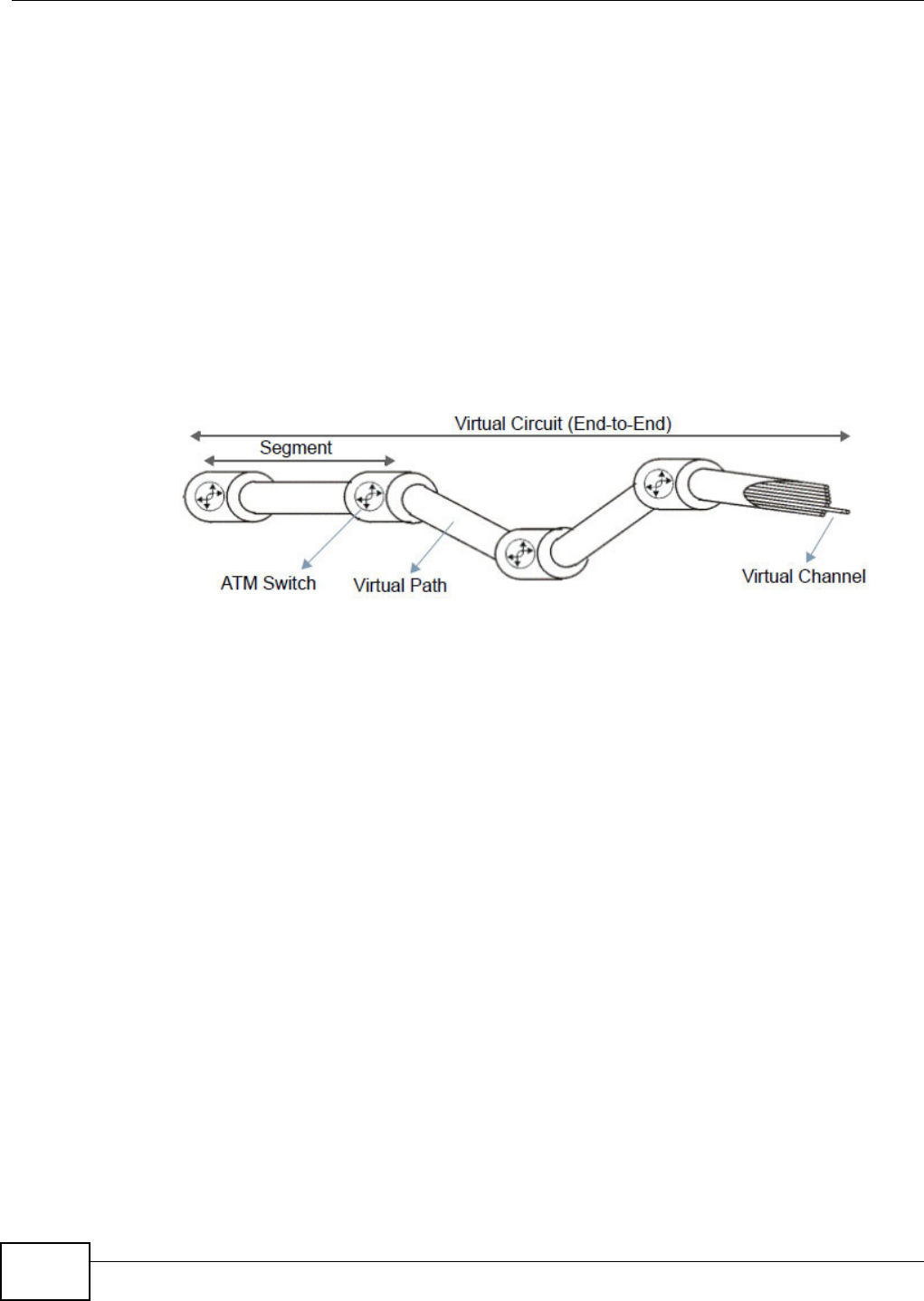
Chapter 40 Diagnostic
VMG8324-B10A / VMG8324-B30A Series User’s Guide
320
40.5 OAM Ping
Click Ma int enan ce > D iagnost ic > OAM Ping t o open t he screen shown next. Use this screen t o
perform an OAM ( Operat ion, Adm inist rat ion and Maintenance) F4 or F5 loopback t est on a PVC. The
Device sends an OAM F4 or F5 packet to the DSLAM or ATM swit ch and then ret urns it to t he
Device. The t est result t hen displays in t he text box.
ATM set s up virtual circuit s over which end system s com m unicate. The term inology for virt ual
circuits is as follows:
Figure 193 Virt ual Circuit Topology
Think of a virt ual pat h as a cable that cont ains a bundle of wires. The cable connect s two point s and
wires wit hin the cable provide individual circuit s bet w een t he tw o points. I n an ATM cell header, a
VPI ( Virt ual Path I dentifier) identifies a link form ed by a virt ual path; a VCI (Virtual Channel
I dentifier) identifies a channel within a virtual pat h. A series of virt ual pat hs m ake up a virt ual
circuit.
F4 cells operat e at t he virt ual pat h ( VP) level, while F5 cells operat e at t he virtual channel (VC)
level. F4 cells use t he sam e VPI as the user dat a cells on VP connections, but use different
predefined VCI values. F5 cells use t he sam e VPI and VCI as the user dat a cells on the VC
connect ions, and are distinguished from data cells by a predefinded Payload Type I dent ifier ( PTI ) in
the cell header. Bot h F4 flows and F5 flows are bidirectional and have t wo t ypes.
• segm ent F4 flows ( VCI = 3)
• end-t o- end F4 flow s (VCI = 4)
• segm ent F5 flows (PTI = 100)
• end- t o- end F5 flows ( PTI = 101)
OAM F4 or F5 t ests are used to check virt ual pat h or virtual channel availabilit y bet ween two DSL
devices. Segment flows are t erm inat ed at the connecting point which term inates a VP or VC
segm ent. End- to- end flow s are t erm inat ed at the end point of a VP or VC connection, where an ATM
link is term inated. Segm ent loopback t ests allow you to verify int egrit y of a PVC to the nearest
neighboring ATM device. End-t o-end loopback t ests allow you t o verify int egrit y of an end-t o-end
PVC.
Note: The DSLAM to which t he Device is connect ed m ust also support ATM F4 and/ or F5
t o use t his t est.
• Virt ual Channel ( VC) Logical connect ions between ATM devices
• Virt ual Pat h ( VP) A bundle of virtual channels
• Virtual Circuits A series of virt ual paths bet w een circuit end point s
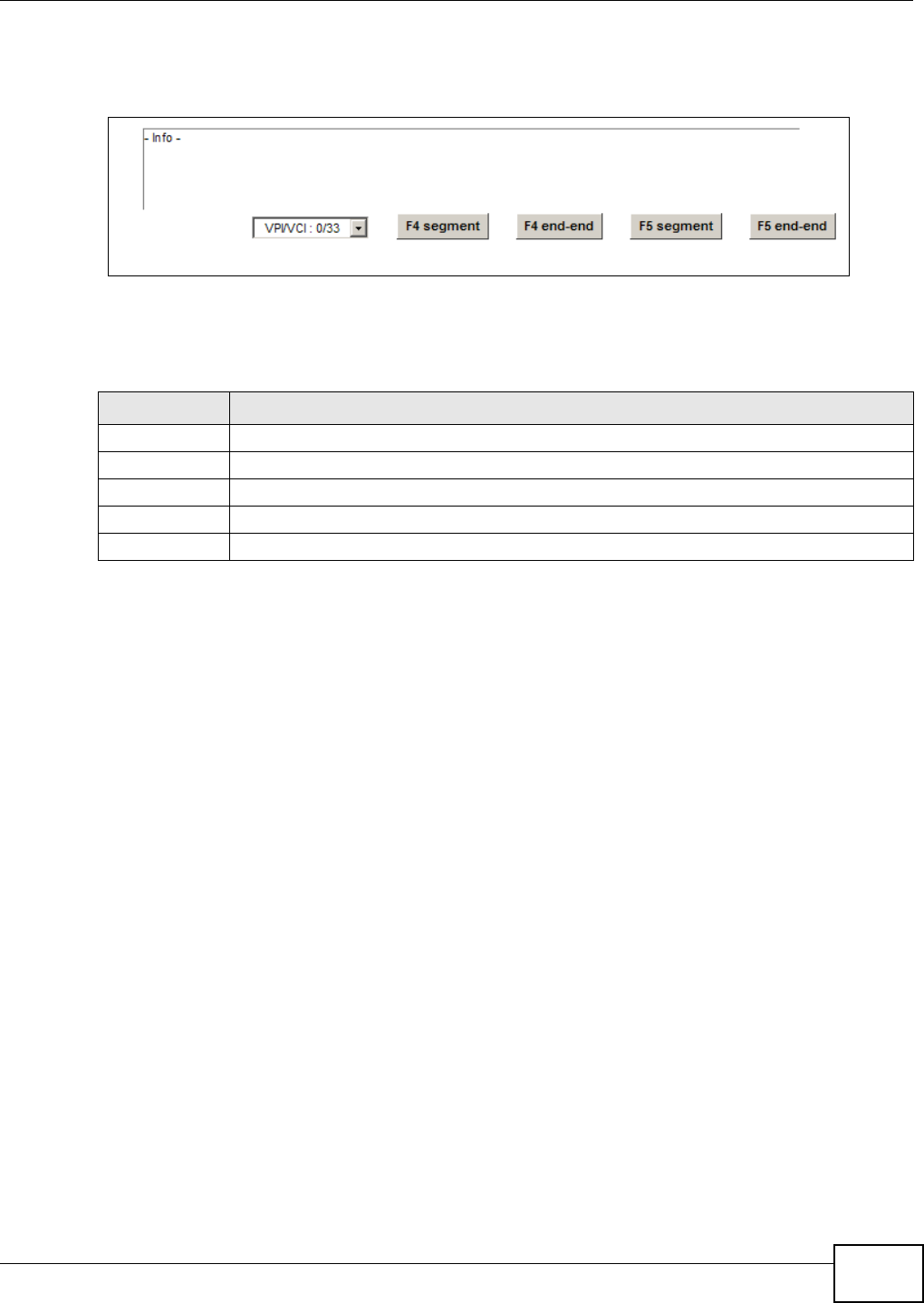
Chapter 40 Diagnostic
VMG8324-B10A / VMG8324-B30A Series User’s Guide 321
Note: This screen is available only when you configure an ATM layer-2 int erface.
Figure 194 Maintenance > Diagnost ic > OAM Ping
The following t able describes the fields in this screen.
Table 153 Maint enance > Diagnostic > OAM Ping
LABEL DESCRIPTION
Select a PVC on w hich you want to perfor m t he loopback t est.
F4 segment Press t his to per form an OAM F4 segm ent loopback test.
F4 end-end Press this t o perform an OAM F4 end- t o-end loopback t est .
F5 segment Press t his to per form an OAM F5 segm ent loopback test.
F5 end-end Press this t o perform an OAM F5 end- t o-end loopback t est .

Chapter 40 Diagnostic
VMG8324-B10A / VMG8324-B30A Series User’s Guide
322

VMG8324-B10A / VMG8324-B30A Series User’s Guide 323
CHAPTER 41
Troubleshooting
This chapt er offers som e suggestions t o solve problem s you m ight encount er. The potential
problem s are divided int o t he following cat egories.
•Power, Hardware Connections, and LEDs
•Device Access and Login
•I nternet Access
•Wireless I nt ernet Access
•USB Device Connection
•UPnP
41.1 Power, Hardware Connections, and LEDs
The Device does not turn on. None of the LEDs t urn on.
1Make sur e the Device is turned on.
2Make sur e you are using the power adapt or or cord included with the Device.
3Make sur e the power adaptor or cord is connected to the Device and plugged in t o an appropriat e
power source. Make sure the power source is turned on.
4Turn t he Device off and on.
5I f the problem continues, contact the vendor.
One of the LEDs does not behave as expected.
1Make sur e you underst and t he norm al behavior of the LED. See Sect ion 1.5 on page 20.
2Check the hardware connect ions.
3I nspect your cables for dam age. Contact the vendor to replace any dam aged cables.
4Turn t he Device off and on.

Chapter 41 Troubleshooting
VMG8324-B10A / VMG8324-B30A Series User’s Guide
324
5I f the problem continues, contact the vendor.
41.2 Device Access and Login
I forgot t he I P address for t he Device.
1The default LAN I P address is 192.168.1.1.
2I f you changed t he I P address and have forgott en it, you m ight get the I P address of the Device by
looking up the I P address of the default gat eway for your com puter. To do this in m ost Windows
com puters, click St ar t > Run, enter cm d, and then enter ipcon fig. The I P address of the De fault
Gat e w a y m ight be t he I P address of the Device ( it depends on t he net work), so ent er t his I P
address in your I nternet browser.
3I f this does not w ork, you have to reset t he device t o its fact ory defaults. See Sect ion 1.6 on page
22.
I forgot t he password.
1The default adm in password is 1 2 3 4 .
2I f this does not w ork, you have to reset t he device t o its fact ory defaults. See Sect ion 1.6 on page
22.
I cannot see or access the Login screen in the web configurat or.
1Make sur e you are using the correct I P address.
• The default I P address is 192.168.1.1.
• I f you changed t he I P address (Section 7.2 on page 109) , use the new I P address.
• I f you changed t he I P address and have forgott en it , see the t roubleshoot ing suggestions for I
forgot t he I P address for the Device.
2Check the hardware connect ions, and m ake sure the LEDs are behaving as expected. See Section
1.5 on page 20.
3Make sure your I nt ernet browser does not block pop- up windows and has JavaScript s and Java
enabled. See Appendix D on page 365.
4I f it is possible t o log in from another int erface, check the service control set tings for HTTP and
HTTPS ( Maint enan ce > Rem ot e M GMT) .

Chapter 41 Troubleshooting
VMG8324-B10A / VMG8324-B30A Series User’s Guide 325
5Reset t he device t o it s factor y defaults, and try to access the Device w ith t he default I P address.
See Section 1.6 on page 22.
6I f the problem cont inues, contact the network administrator or vendor, or t ry one of the advanced
suggest ions.
Advan ced Sugge stions
• Make sure you have logged out of any ear lier m anagem ent sessions using the sam e user account
even if they were through a differ ent interface or using a different browser.
• Try to access t he Device using another service, such as Telnet . I f you can access t he Device,
check the r em ot e m anagem ent set tings and firewall rules to find out why t he Device does not
respond to HTTP.
I can see the Login screen, but I cannot log in to the Device.
1Make sure you have entered t he passwor d correctly. The default adm in password is 1 2 3 4 . The field
is case- sensit ive, so m ake sure [ Caps Lock] is not on.
2You cannot log in to the web configurator while som eone is using Telnet to access t he Device. Log
out of the Device in the ot her session, or ask the person who is logged in to log out.
3Turn t he Device off and on.
4I f this does not work, you have to reset t he device to it s factory defaults. See Sect ion 41.1 on page
323.
I cannot Telnet t o t he Device.
See the t roubleshooting suggestions for I cannot see or access t he Login screen in the web
configurat or. I gnore the suggestions about your browser.
I cannot use FTP t o upload / download t he configuration file. / I cannot use FTP to upload
new firm ware.
See the t roubleshooting suggestions for I cannot see or access t he Login screen in the web
configurat or. I gnore the suggestions about your browser.

Chapter 41 Troubleshooting
VMG8324-B10A / VMG8324-B30A Series User’s Guide
326
41.3 Internet Access
I cannot access t he I nter net.
1Check the hardware connect ions, and m ake sure the LEDs are behaving as expected. See t he
Qu ick St a rt Guide and Sect ion 1.5 on page 20.
2Make sure you entered your I SP account inform at ion correctly in t he N et w ork Set ting >
Broadband screen. These fields are case-sensit ive, so m ake sure [ Caps Lock] is not on.
3I f you are trying to access t he I nt ernet wirelessly, m ake sure that you enabled the wir eless LAN in
the Device and your wireless client and that the wireless set tings in the wireless client are the sam e
as t he sett ings in the Device.
4Disconnect all the cables from your device and reconnect them .
5I f the problem continues, contact your I SP.
I cannot access t he I nter net t hrough a DSL connect ion.
1Make sure you have t he D SL W AN port connected t o a telephone jack ( or the DSL or m odem jack
on a split ter if you have one) .
2Make sure you configured a proper DSL WAN int erface ( Net w ork Set ting > Broadband scr een)
wit h the I nt ernet account inform ation provided by your I SP and t hat it is enabled.
3Check t hat t he LAN int erface you are connected t o is in the sam e int erface group as t he DSL
connect ion ( Ne tw ork Se t t ing > I nte rface Gr oup) .
4I f you set up a WAN connect ion using bridging service, make sure you turn off t he DHCP feat ur e in
the LAN screen to have the clients get WAN I P addresses directly from your I SP’s DHCP server.
I cannot connect to the I nternet using a second DSL connection.
ADSL and VDSL connections cannot w ork at t he sam e tim e. You can only use one t ype of DSL
connection, either ADSL or VDSL connection at one t im e.
I cannot access the I nternet anym ore. I had access to t he I nternet (wit h t he Device) , but m y
I nt ernet connection is not available anym ore.
1Your session wit h the Device m ay have expired. Try logging int o t he Device again.

Chapter 41 Troubleshooting
VMG8324-B10A / VMG8324-B30A Series User’s Guide 327
2Check the hardware connect ions, and m ake sure the LEDs are behaving as expected. See t he
Qu ick St a rt Guide and Sect ion 1.5 on page 20.
3Turn t he Device off and on.
4I f the problem continues, contact your I SP.
41.4 Wireless Internet Access
What factors m ay cause interm itt ent or unstabled wireless connection? How can I solve t his
problem ?
The following fact ors m ay cause interference:
• Obstacles: walls, ceilings, furniture, and so on.
• Building Materials: m et al doors, alum inum studs.
• Electrical devices: m icrowaves, m onit ors, electric motors, cordless phones, and other wireless
devices.
To optim ize the speed and quality of your wir eless connect ion, you can:
• Move your wireless device closer t o t he AP if the signal st rength is low.
• Reduce wireless int erference that m ay be caused by ot her wireless netw orks or surrounding
wireless elect ronics such as cordless phones.
• Place the AP where there are m inim um obstacles ( such as walls and ceilings) bet ween the AP and
the wireless client.
• Reduce the num ber of wireless clients connecting to the sam e AP sim ult aneously, or add
additional APs if necessary.
• Try closing som e program s t hat use the I nt ernet, especially peer- to- peer applicat ions. I f the
wireless client is sending or receiving a lot of inform ation, it m ay have too m any program s open
that use the I nt ernet.
What is a Server Set I D (SSI D) ?
An SSI D is a nam e t hat uniquely identifies a wireless net work. The AP and all t he client s within a
wireless net work m ust use t he sam e SSI D.

Chapter 41 Troubleshooting
VMG8324-B10A / VMG8324-B30A Series User’s Guide
328
41.5 USB Device Connection
The Device fails to detect m y USB device.
1Disconnect the USB device.
2Reboot t he Device.
3I f you are connecting a USB hard drive that com es wit h an external power supply, m ake sure it is
connected t o an appropriat e power source t hat is on.
4Re-connect your USB device to the Device.
41.6 UPnP
When using UPnP and the Device reboot s, m y com puter cannot detect UPnP and refresh M y
N et w ork Pla ces > Local N e tw ork.
1Disconnect the Ethernet cable from t he Device’s LAN port or fr om your com puter.
2Re-connect the Ethernet cable.
The Loca l Area Conn ect ion icon for UPnP disappears in the screen.
Rest art your com puter.
I cannot open special applicat ions such as white board, file transfer and video when I use the
MSN m essenger.
1Wait m ore t han three m inut es.
2Rest art the applications.

VMG8324-B10A / VMG8324-B30A Series User’s Guide 329
APPENDIX A
Customer Support
I n t he event of problem s that cannot be solved by using this m anual, you should cont act your
vendor. I f you cannot contact your vendor, then cont act a ZyXEL office for the region in which you
bought t he device. Regional websit es are listed below (see also htt p: / / www.zyxel.com /
about _zyxel/ zyxel_w or ldwide.shtm l) . Please have the following inform at ion ready when you
cont act an office.
Required Information
• Product m odel and serial num ber.
• Warranty I nform at ion.
• Date that you received your device.
• Brief descript ion of the problem and the steps you t ook t o solve it .
Corporate Headquarters (Worldwide)
Taiwan
• ZyXEL Com m unications Corporation
• htt p: / / www.zyxel.com
Asia
China
• ZyXEL Com m unications ( Shanghai) Cor p.
ZyXEL Com m unicat ions (Beijing) Corp.
ZyXEL Com m unicat ions (Tianj in) Corp.
• htt p: / / www.zyxel.cn
India
• ZyXEL Technology I ndia Pvt Ltd
• htt p: / / www.zyxel.in
Kazakhstan
• ZyXEL Kazakhstan
• htt p: / / www.zyxel.kz

Appendix A Customer Support
VMG8324-B10A / VMG8324-B30A Series User’s Guide
330
Korea
• ZyXEL Korea Corp.
• htt p: / / www.zyxel.kr
Malaysia
• ZyXEL Malaysia Sdn Bhd.
• htt p: / / www.zyxel.com .m y
Pakistan
• ZyXEL Pakistan (Pvt .) Ltd.
• htt p: / / www.zyxel.com .pk
Philippines
• ZyXEL Philippines
• htt p: / / www.zyxel.com .ph
Singapore
• ZyXEL Singapore Pt e Lt d.
• htt p: / / www.zyxel.com .sg
Taiwan
• ZyXEL Com m unications Corporation
• htt p: / / www.zyxel.com
Thailand
• ZyXEL Thailand Co., Lt d
• htt p: / / www.zyxel.co.th
Vietnam
• ZyXEL Com m unications Corporat ion- Vietnam Office
• htt p: / / www.zyxel.com / vn/ vi
Europe
Austria
• ZyXEL Deutschland GmbH
• htt p: / / www.zyxel.de
Belarus
• ZyXEL BY
• htt p: / / www.zyxel.by

Appendix A Customer Support
VMG8324-B10A / VMG8324-B30A Series User’s Guide 331
Belgium
• ZyXEL Com m unications B.V.
• htt p: / / www.zyxel.com / be/ nl/
Bulgaria
• ZyXEL България
• htt p: / / www.zyxel.com / bg/ bg/
Czech
• ZyXEL Com m unicat ions Czech s.r.o
• htt p: / / www.zyxel.cz
Denmark
• ZyXEL Com m unications A/ S
• htt p: / / www.zyxel.dk
Estonia
• ZyXEL Estonia
• htt p: / / www.zyxel.com / ee/ et /
Finland
• ZyXEL Com m unicat ions
• htt p: / / www.zyxel.fi
France
• ZyXEL France
• htt p: / / www.zyxel.fr
Germany
• ZyXEL Deutschland GmbH
• htt p: / / www.zyxel.de
Hungary
• ZyXEL Hungary & SEE
• htt p: / / www.zyxel.hu
Latvia
• ZyXEL Latvia
• htt p: / / www.zyxel.com / lv/ lv/ hom epage.shtm l

Appendix A Customer Support
VMG8324-B10A / VMG8324-B30A Series User’s Guide
332
Lithuania
• ZyXEL Lit huania
• htt p: / / www.zyxel.com / lt/ lt / hom epage.sht m l
Netherlands
• ZyXEL Benelux
• htt p: / / www.zyxel.nl
Norway
• ZyXEL Com m unicat ions
• htt p: / / www.zyxel.no
Poland
• ZyXEL Com m unications Poland
• htt p: / / www.zyxel.pl
Romania
• ZyXEL Romania
• htt p: / / www.zyxel.com / ro/ ro
Russia
• ZyXEL Russia
• htt p: / / www.zyxel.ru
Slovakia
• ZyXEL Com m unicat ions Czech s.r.o. organizacna zlozka
• htt p: / / www.zyxel.sk
Spain
• ZyXEL Spain
• htt p: / / www.zyxel.es
Sweden
• ZyXEL Com m unications
• htt p: / / www.zyxel.se
Switzerland
• Studerus AG
• htt p: / / www.zyxel.ch/

Appendix A Customer Support
VMG8324-B10A / VMG8324-B30A Series User’s Guide 333
Turkey
• ZyXEL Turkey A.S.
• htt p: / / www.zyxel.com .t r
UK
• ZyXEL Com m unications UK Lt d.
• htt p: / / www.zyxel.co.uk
Ukraine
• ZyXEL Ukraine
• htt p: / / www.ua.zyxel.com
Latin America
Argentina
• ZyXEL Com m unication Corporat ion
• htt p: / / www.zyxel.com / ec/ es/
Ecuador
• ZyXEL Com m unication Corporat ion
• htt p: / / www.zyxel.com / ec/ es/
Middle East
Egypt
• ZyXEL Com m unication Corporat ion
• htt p: / / www.zyxel.com / hom epage.sht m l
Middle East
• ZyXEL Com m unication Corporat ion
• htt p: / / www.zyxel.com / hom epage.sht m l
North America
USA
• ZyXEL Com m unications, I nc. - Nort h Am erica Headquart ers
• htt p: / / www.us.zyxel.com /

Appendix A Customer Support
VMG8324-B10A / VMG8324-B30A Series User’s Guide
334
Oceania
Australia
• ZyXEL Com m unications Corporation
• htt p: / / www.zyxel.com / au/ en/
Africa
South Africa
• Nology (Pty) Ltd.
• htt p: / / www.zyxel.co.za
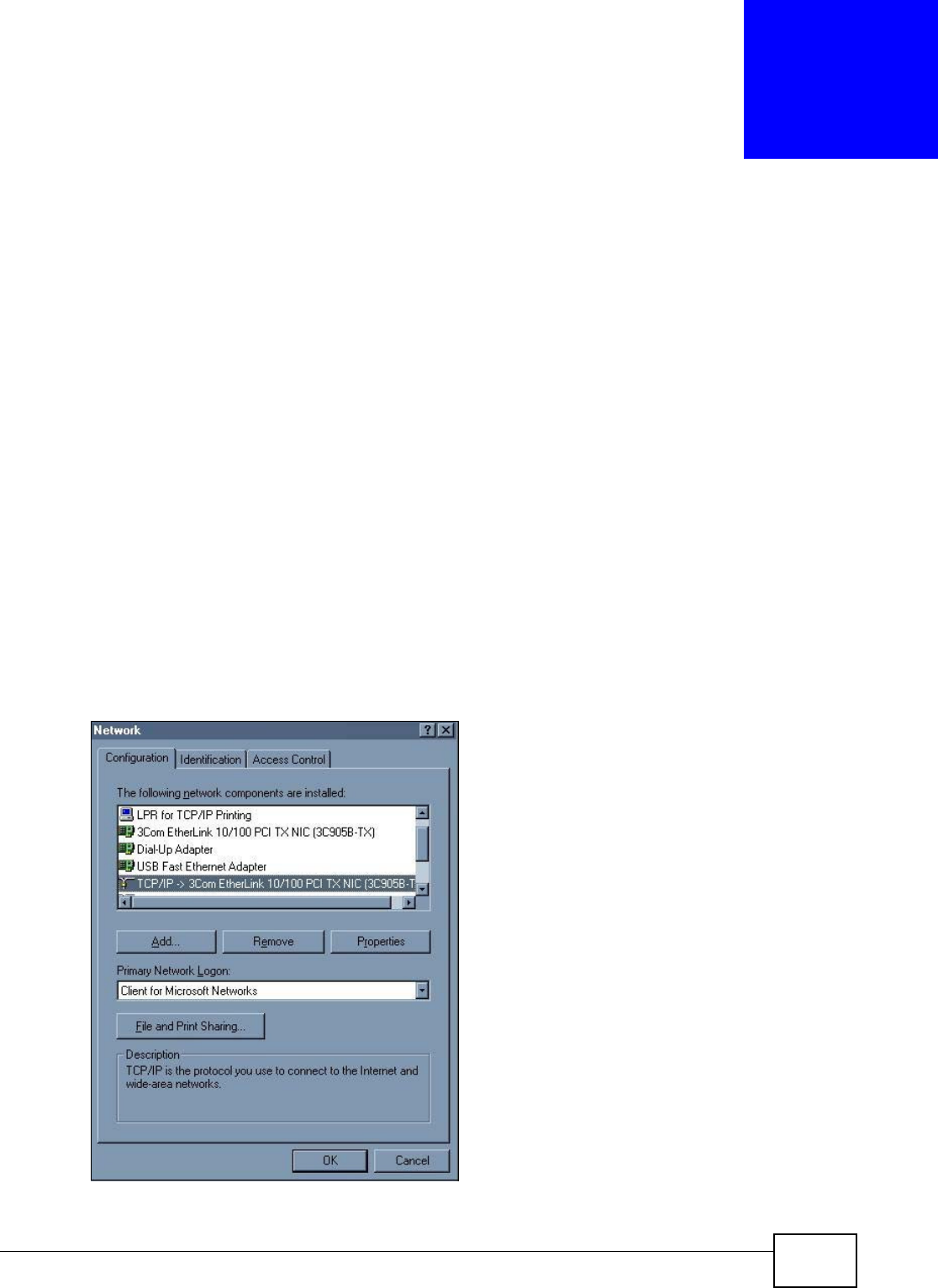
VMG8324-B10A / VMG8324-B30A Series User’s Guide 335
APPENDIX B
Setting up Your Computer’s IP Address
All com puters m ust have a 10M or 100M Ethernet adapt er card and TCP/ I P installed.
Windows 95/ 98/ Me/ NT/ 2000/ XP/ Vist a, Macintosh OS 7 and later operating syst em s and all versions
of UNI X/ LI NUX include the software com ponents you need t o install and use TCP/ I P on your
com puter. Windows 3.1 requires the purchase of a t hird-party TCP/ I P applicat ion package.
TCP/ I P should already be installed on com puters using Windows NT/ 2000/ XP, Macint osh OS 7 and
lat er operat ing syst em s.
After the appropriat e TCP/ I P com ponents ar e inst alled, configur e the TCP/ I P set tings in order t o
"com m unicat e" with your net work.
I f you m anually assign I P inform ation instead of using dynam ic assignm ent , m ake sure t hat your
com puters have I P addresses t hat place them in the sam e subnet as the Device’s LAN port.
Windows 95/98/Me
Click St a r t , Se t t in gs, Contr ol Pane l and double-click t he N e t w ork icon to open the N et w or k
window.
Figure 195 WI ndows 95/ 98/ Me: Net work: Configurat ion

Appendix B Setting up Your Computer’s IP Address
VMG8324-B10A / VMG8324-B30A Series User’s Guide
336
Installing Components
The N e t w or k window Con fig ur at ion t ab displays a list of inst alled com ponents. You need a
net work adapt er, the TCP/ I P prot ocol and Client for Microsoft Networ ks.
I f you need t he adapt er:
1I n t he N e t w or k window, click Add.
2Select Ada pt er and then click Add.
3Select the m anufact urer and m odel of your net work adapt er and then click OK.
I f you need TCP/ I P:
1I n t he N e t w or k window, click Add.
2Select Pr ot ocol and t hen click Add.
3Select Micr osoft from the list of m a nu fa ct ur er s.
4Select TCP/ I P from t he list of net work prot ocols and t hen click OK.
I f you need Client for Microsoft Networks:
1Click Add.
2Select Client and t hen click Add.
3Select M icr osoft from t he list of m anufact urers.
4Select Client for M icrosoft N et w or ks from the list of net work clients and then click OK.
5Rest art your com put er so t he changes you m ade take effect.
Configuring
1I n t he N etw or k window Con figura t ion tab, select your net work adapt er's TCP/ I P ent ry and click
Pr oper t ie s
2Click the I P Address t ab.
• I f your I P address is dynam ic, select Obta in a n I P address a utom at ically.
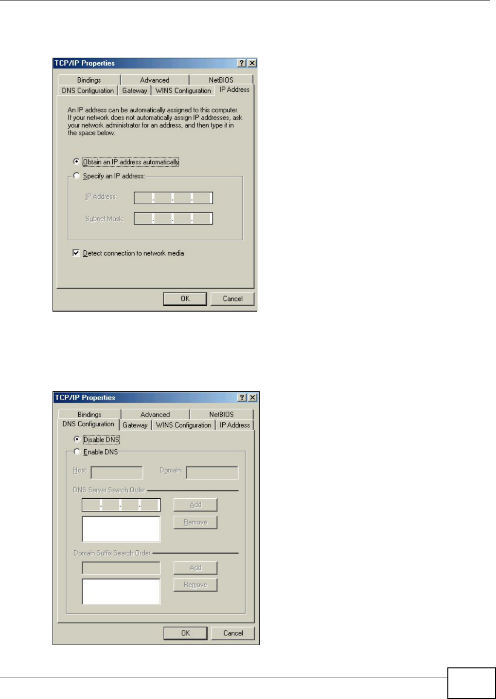
Appendix B Setting up Your Computer’s IP Address
VMG8324-B10A / VMG8324-B30A Series User’s Guide 337
• I f you have a stat ic I P address, select Specify a n I P addre ss and t ype your inform at ion into
the I P Addr ess and Subnet M ask fields.
Figure 196 Windows 95/ 98/ Me: TCP/ I P Properties: I P Address
3Click the D N S Configurat ion t ab.
• I f you do not know your DNS inform at ion, select D isable DN S.
• I f you know your DNS inform at ion, select Enable D NS and t ype the inform ation in t he fields
below ( you m ay not need to fill them all in).
Figure 197 Windows 95/ 98/ Me: TCP/ I P Properties: DNS Configurat ion
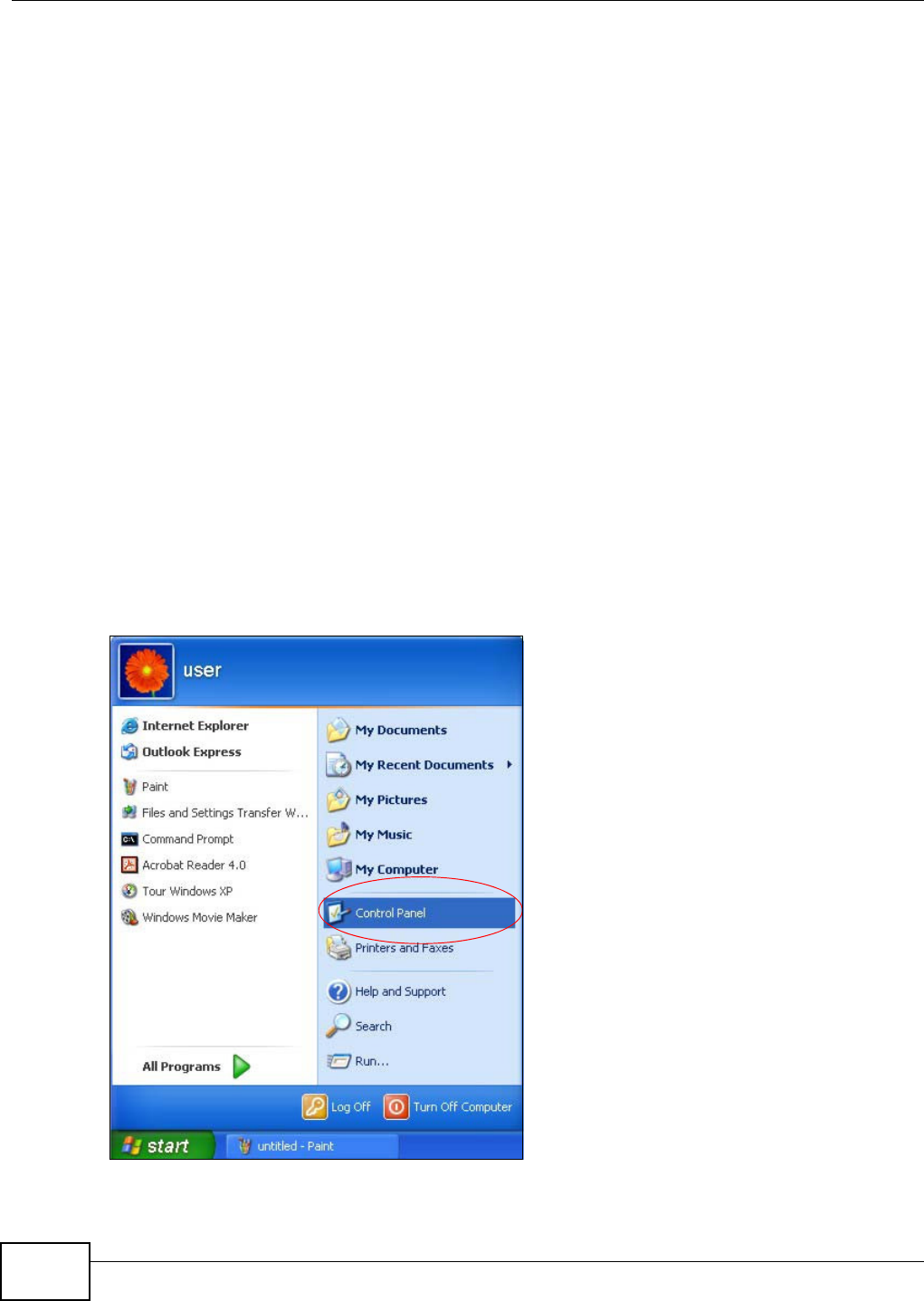
Appendix B Setting up Your Computer’s IP Address
VMG8324-B10A / VMG8324-B30A Series User’s Guide
338
4Click the Ga t e w a y tab.
• I f you do not know your gateway’s I P addr ess, rem ove previously inst alled gat eways.
• I f you have a gateway I P address, type it in the N ew ga te w ay field and click Add.
5Click OK t o save and close the TCP/ I P Pr ope r t ies window.
6Click OK t o close t he Ne tw ork window. I nsert t he Windows CD if prom pted.
7Turn on your Device and restart your com put er when pr om pt ed.
Verifying Settings
1Click St a r t and then Ru n.
2I n t he Run window, t ype "winipcfg" and t hen click OK t o open the I P Con figura tion window.
3Select your net work adapt er. You should see your com put er's I P address, subnet m ask and default
gat eway.
Windows 2000/NT/XP
The following exam ple figures use t he default Windows XP GUI t hem e.
1Click st a r t ( St ar t in Window s 2000/ NT), Se t t in gs, Cont rol Pane l.
Figure 198 Windows XP: Start Menu
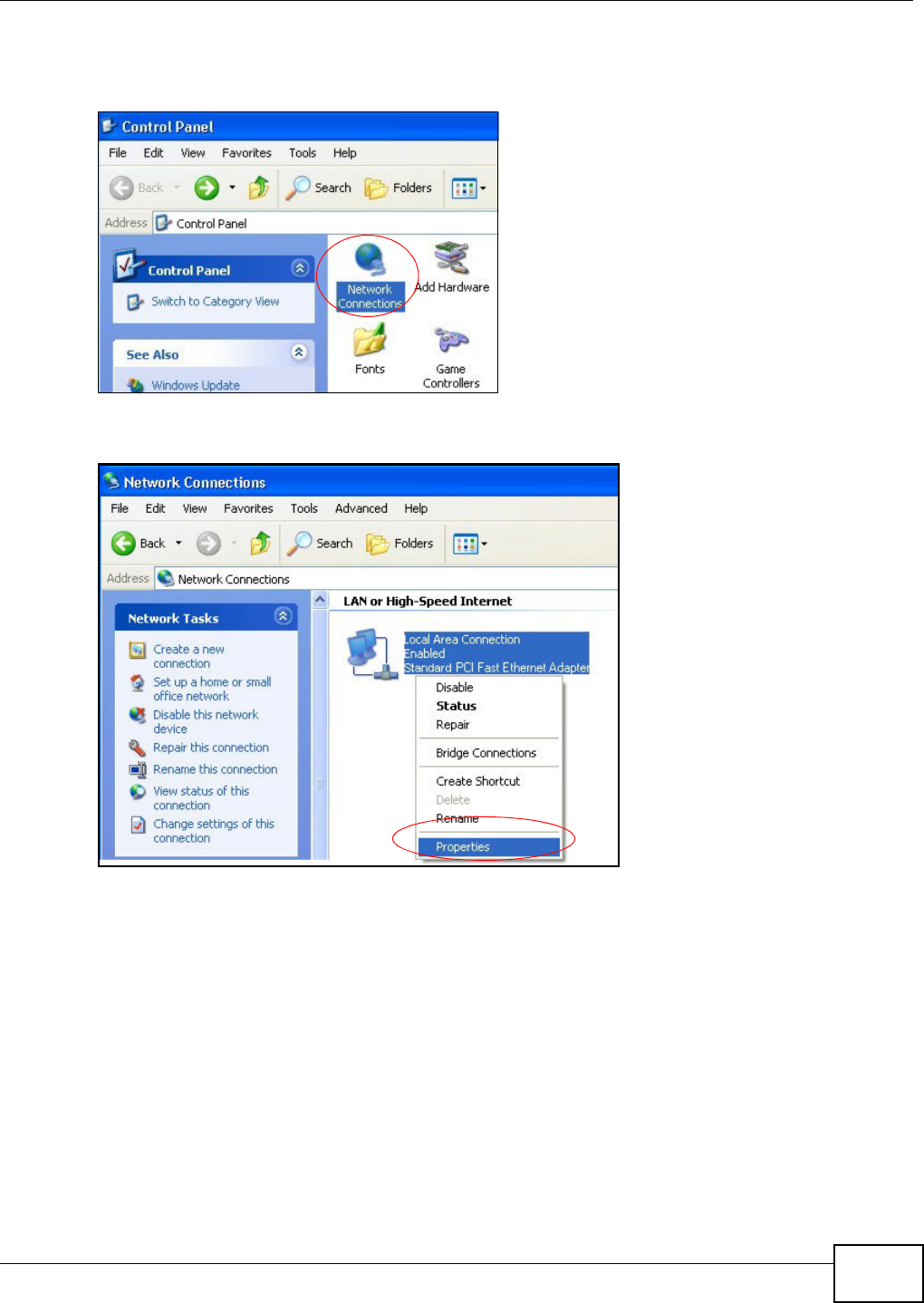
Appendix B Setting up Your Computer’s IP Address
VMG8324-B10A / VMG8324-B30A Series User’s Guide 339
2I n t he Contr ol Pa nel, double-click N et w ork Connect ions ( N et w ork and Dia l- up Conne ct ions
in Windows 2000/ NT).
Figure 199 Windows XP: Control Panel
3Right-click Local Are a Conne ct ion and t hen click Prop er t ie s.
Figure 200 Windows XP: Control Panel: Network Connect ions: Propert ies
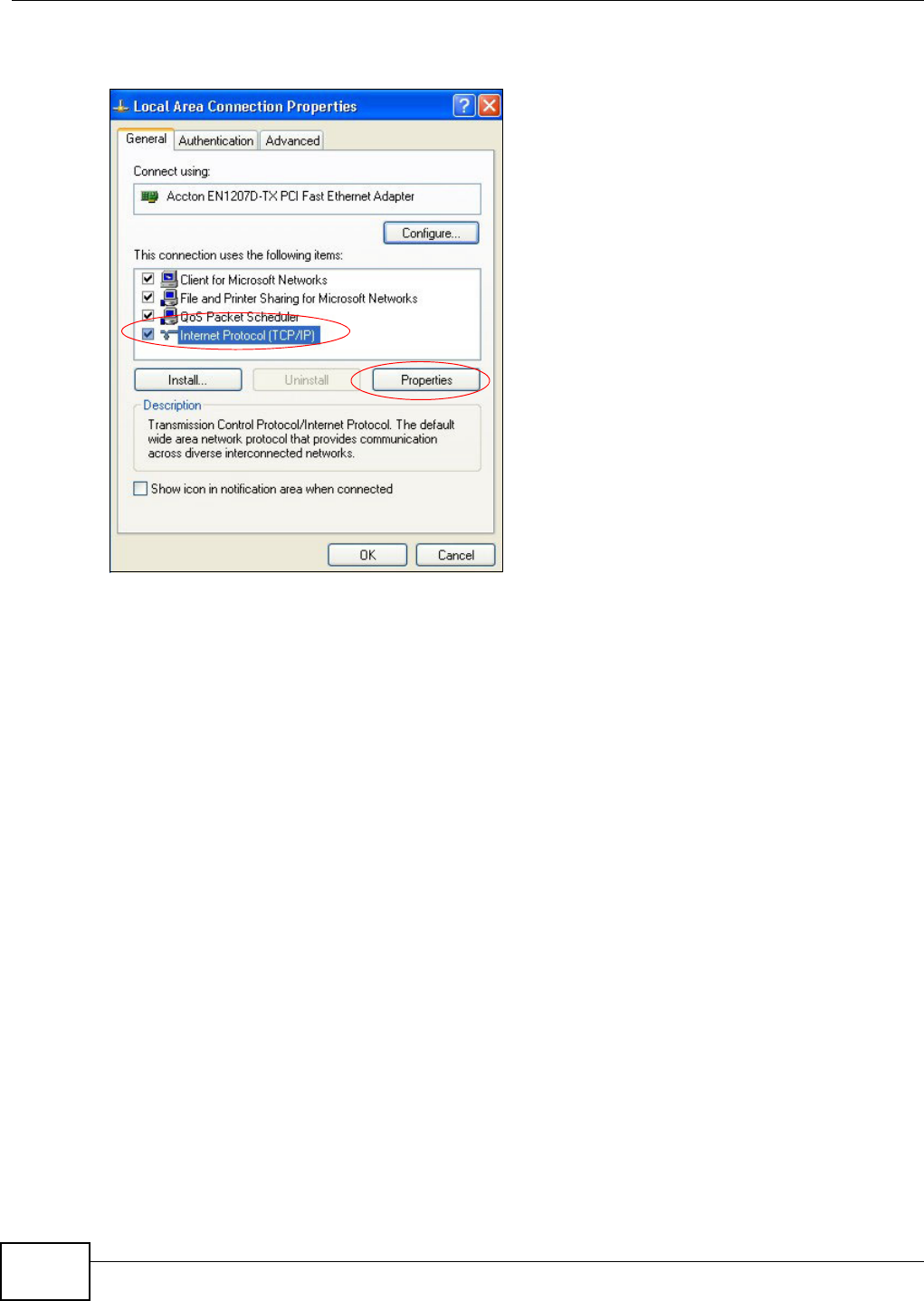
Appendix B Setting up Your Computer’s IP Address
VMG8324-B10A / VMG8324-B30A Series User’s Guide
340
4Select I nte rnet Protocol ( TCP/ I P) (under the Gen era l tab in Win XP) and t hen click Pr ope rt ie s.
Figure 201 Windows XP: Local Area Connection Proper t ies
5The I nt erne t Prot ocol TCP/ I P Pr oper ties window opens ( the Ge nera l ta b in Windows XP) .
• I f you have a dynam ic I P address click Obta in an I P a ddr ess au tom a tica lly.
• I f you have a st atic I P address click Use the follow ing I P Addre ss and fill in the I P a ddr ess,
Subnet m a sk , and Default ga te w ay fields.
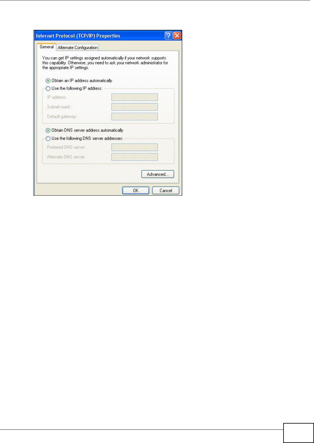
Appendix B Setting up Your Computer’s IP Address
VMG8324-B10A / VMG8324-B30A Series User’s Guide 341
• Click Advan ce d.
Figure 202 Windows XP: I nt ernet Prot ocol ( TCP/ I P) Propert ies
6 I f you do not know your gat eway's I P address, rem ove any previously inst alled gat eways in t he I P
Se t t in gs tab and click OK.
Do one or m ore of t he following if you want t o configur e addit ional I P addresses:
• In the I P Set t in gs tab, in I P addresses, click Add.
• In TCP/ I P Address, type an I P address in I P address and a subnet m ask in Subne t m a sk ,
and then click Add.
• Repeat t he above t wo steps for each I P address you want t o add.
• Configure additional default gateways in t he I P Se tt ings t ab by clicking Add in Defa ult
ga t ew a y s.
• In TCP/ I P Gat ew ay Address, t ype the I P address of t he default gateway in Gat e w a y. To
m anually configure a default m etric ( the number of transm ission hops) , clear the Autom a t ic
m e t r ic check box and type a m et ric in M e t ric.
• Click Add.
• Repeat t he previous three st eps for each default gateway you want t o add.
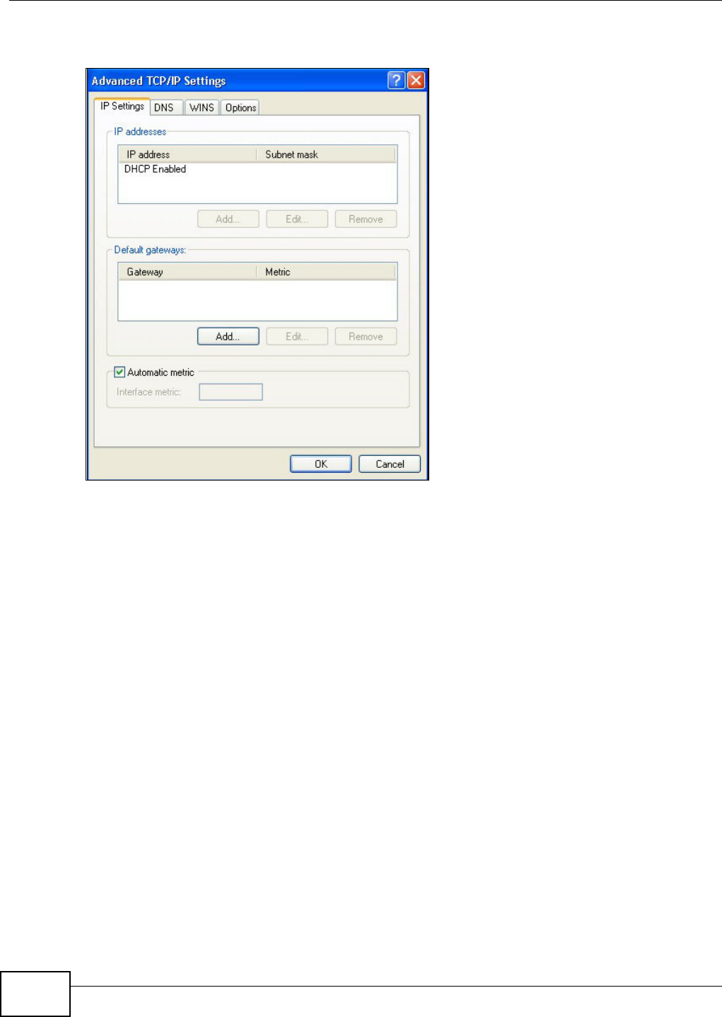
Appendix B Setting up Your Computer’s IP Address
VMG8324-B10A / VMG8324-B30A Series User’s Guide
342
• Click OK when finished.
Figure 203 Windows XP: Advanced TCP/ I P Properties
7I n t he I nt e rne t Prot ocol TCP/ I P Pr ope r ties window ( the Gen era l t ab in Windows XP) :
• Click Obt ain D NS se rver addre ss aut om at ically if you do not know your DNS server I P
address( es) .
• I f you know your DNS server I P address( es) , click Use the follow ing D NS se rver
addre sse s, and t ype them in t he Pre ferr ed D NS se rver and Alte rna te DN S ser ver fields.
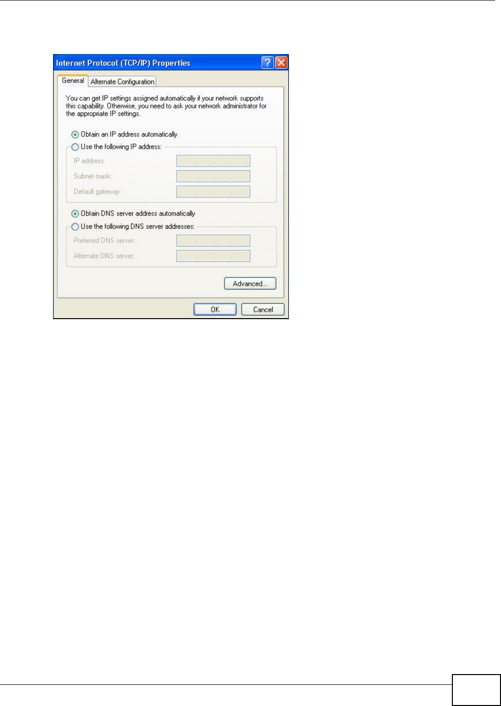
Appendix B Setting up Your Computer’s IP Address
VMG8324-B10A / VMG8324-B30A Series User’s Guide 343
I f you have previously configured DNS servers, click Adva nce d and then the DN S t ab to order
t hem .
Figure 204 Windows XP: I nt ernet Prot ocol ( TCP/ I P) Propert ies
8Click OK t o close t he I nte rnet Prot ocol ( TCP/ I P) Propert ies window.
9Click Close ( OK in Windows 2000/ NT) t o close the Loca l Area Connection Pr oper ties window.
10 Close t he Ne tw ork Connect ions window ( Ne tw ork a nd Dial- up Con nections in Windows
200 0/ NT) .
11 Turn on your Device and rest art your com put er ( if prom pted).
Verifying Settings
1Click St a r t , All Program s, Accessor ies and then Com m a nd Pr om pt.
2I n t he Com m and Prom pt window, t ype "ipconfig" and t hen press [ ENTER] . You can also open
N etw or k Conne ct ions, right- click a net work connection, click St a t u s and then click the Support
tab.
Windows Vista
This section shows screens from Windows Vista Enterprise Version 6.0.
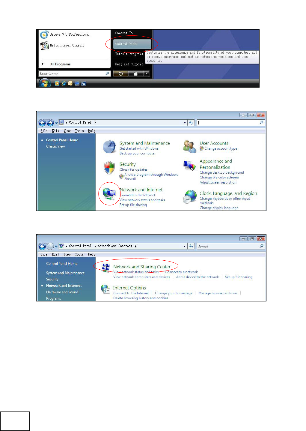
Appendix B Setting up Your Computer’s IP Address
VMG8324-B10A / VMG8324-B30A Series User’s Guide
344
1Click the St a r t icon, Cont rol Pane l.
Figure 205 Windows Vist a: St art Menu
2I n t he Contr ol Pa nel, double-click N et w ork and I nt ern e t.
Figure 206 Windows Vist a: Cont rol Panel
3Click N et w or k and Sha rin g Cent er.
Figure 207 Windows Vist a: Net work And I nternet
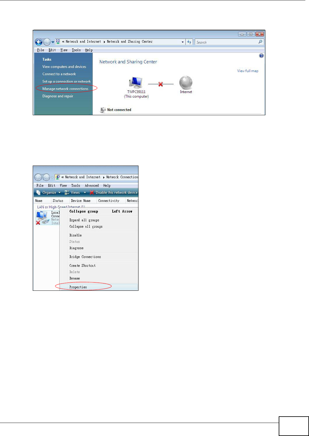
Appendix B Setting up Your Computer’s IP Address
VMG8324-B10A / VMG8324-B30A Series User’s Guide 345
4Click Ma nage net w ork conne ct ions.
Figure 208 Windows Vist a: Net work and Sharing Center
5Right-click Local Are a Conne ct ion and t hen click Prop er t ie s.
Note: During this procedure, click Cont inue whenever Windows displays a screen saying
that it needs your perm ission t o cont inue.
Figure 209 Windows Vist a: Net work and Sharing Center
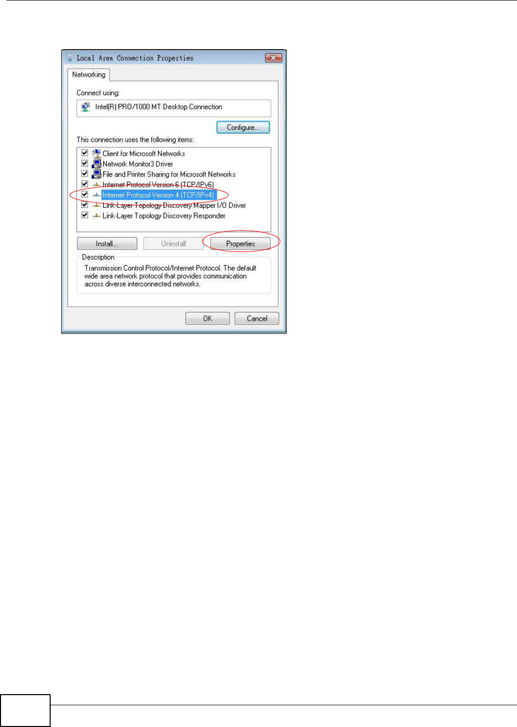
Appendix B Setting up Your Computer’s IP Address
VMG8324-B10A / VMG8324-B30A Series User’s Guide
346
6Select I nt e rne t Protocol Ve rsion 4 ( TCP/ I Pv4 ) and click Pr op ert ie s.
Figure 210 Windows Vist a: Local Area Connect ion Propert ies
7The I nt erne t Prot ocol Ve rsion 4 ( TCP/ I Pv4 ) Pr oper ties window opens (t he Ge nera l t ab) .
• I f you have a dynam ic I P address click Obta in an I P a ddr ess au tom a tica lly.
• I f you have a st at ic I P address click Use the follow ing I P a ddr ess and fill in the I P addre ss,
Subnet m a sk , and Default ga te w ay fields.
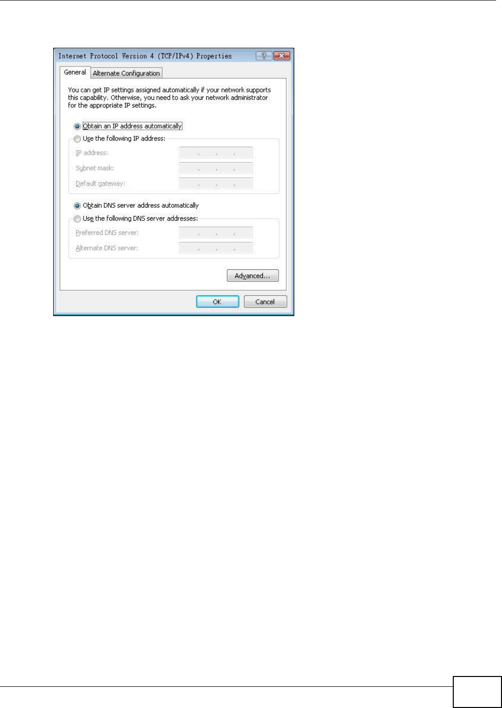
Appendix B Setting up Your Computer’s IP Address
VMG8324-B10A / VMG8324-B30A Series User’s Guide 347
• Click Advan ce d.
Figure 211 Windows Vista: I nt ernet Prot ocol Version 4 ( TCP/ I Pv4) Properties
8 I f you do not know your gat eway's I P address, rem ove any previously inst alled gat eways in t he I P
Se t t in gs tab and click OK.
Do one or m ore of t he following if you want t o configur e addit ional I P addresses:
• In the I P Set t in gs tab, in I P addresses, click Add.
• In TCP/ I P Address, type an I P address in I P address and a subnet m ask in Subne t m a sk ,
and then click Add.
• Repeat t he above t wo steps for each I P address you want t o add.
• Configure additional default gateways in t he I P Se tt ings t ab by clicking Add in Defa ult
ga t ew a y s.
• In TCP/ I P Gat ew ay Address, t ype the I P address of t he default gateway in Gat e w a y. To
m anually configure a default m etric ( the number of transm ission hops) , clear the Autom a t ic
m e t r ic check box and type a m et ric in M e t ric.
• Click Add.
• Repeat t he previous three st eps for each default gateway you want t o add.
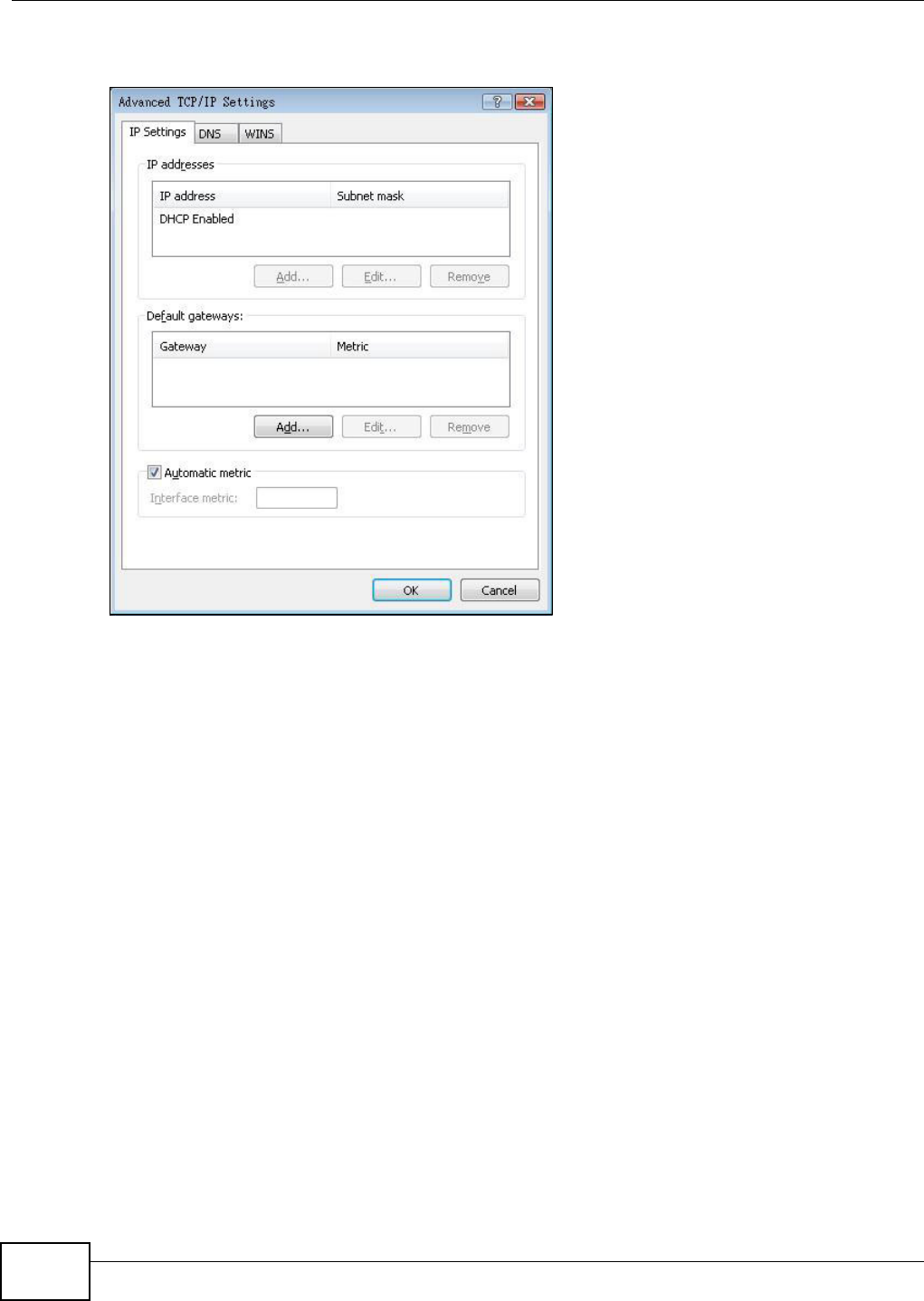
Appendix B Setting up Your Computer’s IP Address
VMG8324-B10A / VMG8324-B30A Series User’s Guide
348
• Click OK when finished.
Figure 212 Windows Vist a: Advanced TCP/ I P Properties
9I n t he I nt e rne t Prot ocol Ve rsion 4 ( TCP/ I Pv4 ) Pr oper ties window, ( the Ge nera l ta b) :
• Click Obt ain D NS se rver addre ss aut om at ically if you do not know your DNS server I P
address( es) .
• I f you know your DNS server I P address( es) , click Use the follow ing D NS se rver
addre sse s, and t ype them in t he Pre ferr ed D NS se rver and Alte rna te DN S ser ver fields.
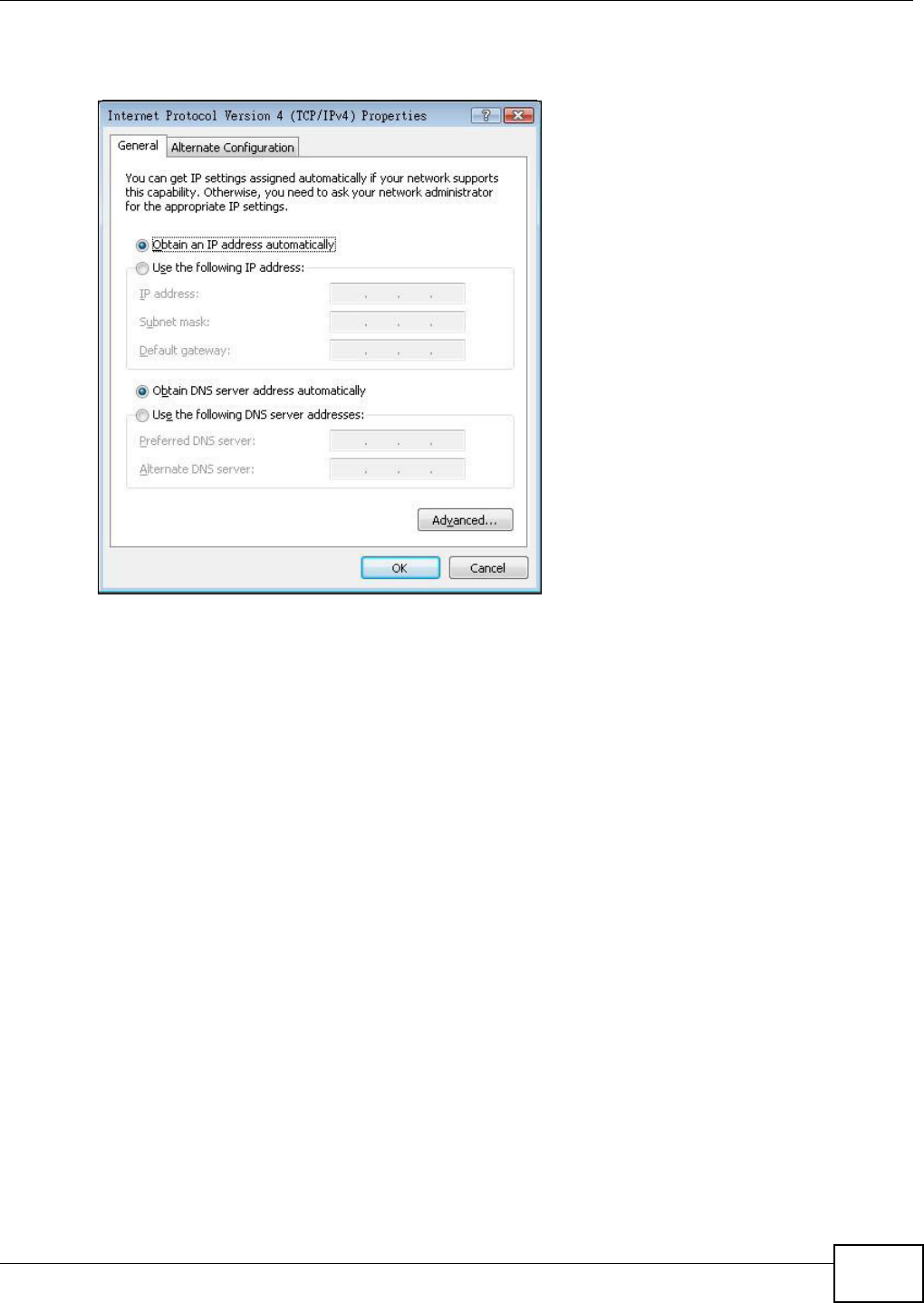
Appendix B Setting up Your Computer’s IP Address
VMG8324-B10A / VMG8324-B30A Series User’s Guide 349
I f you have previously configured DNS servers, click Adva nce d and then the DN S t ab to order
t hem .
Figure 213 Windows Vist a: I nternet Prot ocol Version 4 ( TCP/ I Pv4) Properties
10 Click OK t o close t he I nte rnet Prot ocol Version 4 ( TCP/ I Pv4 ) Propert ie s window.
11 Click Close t o close t he Local Are a Conne ct ion Propert ies window.
12 Close t he Ne tw ork Connect ions window.
13 Turn on your Device and rest art your com put er ( if prom pted).
Verifying Settings
1Click St a r t , All Program s, Accessor ies and then Com m a nd Pr om pt.
2I n t he Com m and Prom pt window, t ype "ipconfig" and t hen press [ ENTER] . You can also open
N etw or k Conne ct ions, right- click a net work connection, click St a t u s and then click the Support
tab.
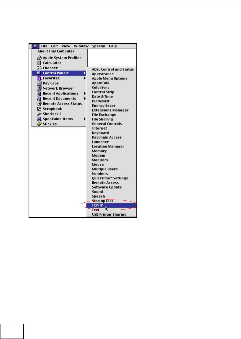
Appendix B Setting up Your Computer’s IP Address
VMG8324-B10A / VMG8324-B30A Series User’s Guide
350
Macintosh OS 8/9
1Click the Apple m enu, Cont rol Pan el and double- click TCP/ I P t o open t he TCP/ I P Cont rol
Pa nel.
Figure 214 Macint osh OS 8/ 9: Apple Menu
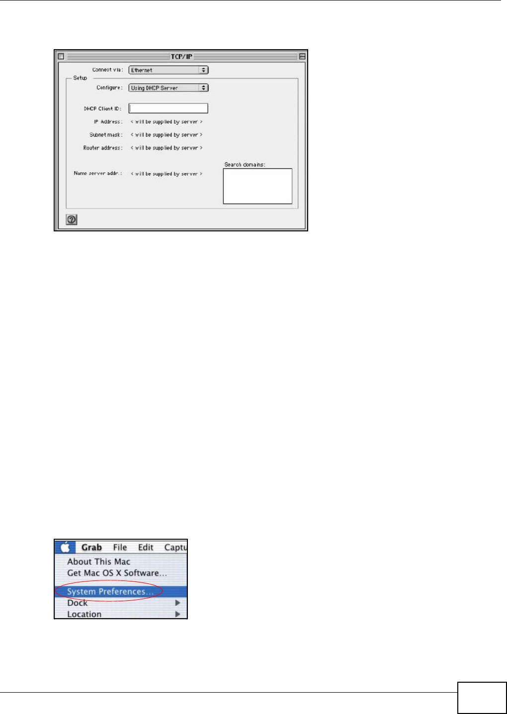
Appendix B Setting up Your Computer’s IP Address
VMG8324-B10A / VMG8324-B30A Series User’s Guide 351
2Select Et her net built - in from the Connect via list .
Figure 215 Macint osh OS 8/ 9: TCP/ I P
3For dynam ically assigned sett ings, select Using DH CP Ser ver from the Configur e: list.
4For stat ically assigned set tings, do t he following:
• From the Configure box, select M anua lly.
• Type your I P address in t he I P Address box.
• Type your subnet m ask in t he Subnet m ask box.
• Type the I P address of your Device in t he Route r a ddre ss box.
5Close t he TCP/ I P Cont rol Panel.
6Click Save if prom pt ed, to save changes to your configurat ion.
7Turn on your Device and rest art your com put er ( if prom pted).
Verifying Settings
Check your TCP/ I P properties in the TCP/ I P Contr ol Pa nel window.
Macintosh OS X
1Click the Apple m enu, and click Syst em Prefere nce s to open t he Syste m Prefer ence s window.
Figure 216 Macint osh OS X: Apple Menu
2Click N e t w ork in t he icon bar.
• Select Au t om a t ic from the Loca t ion list.
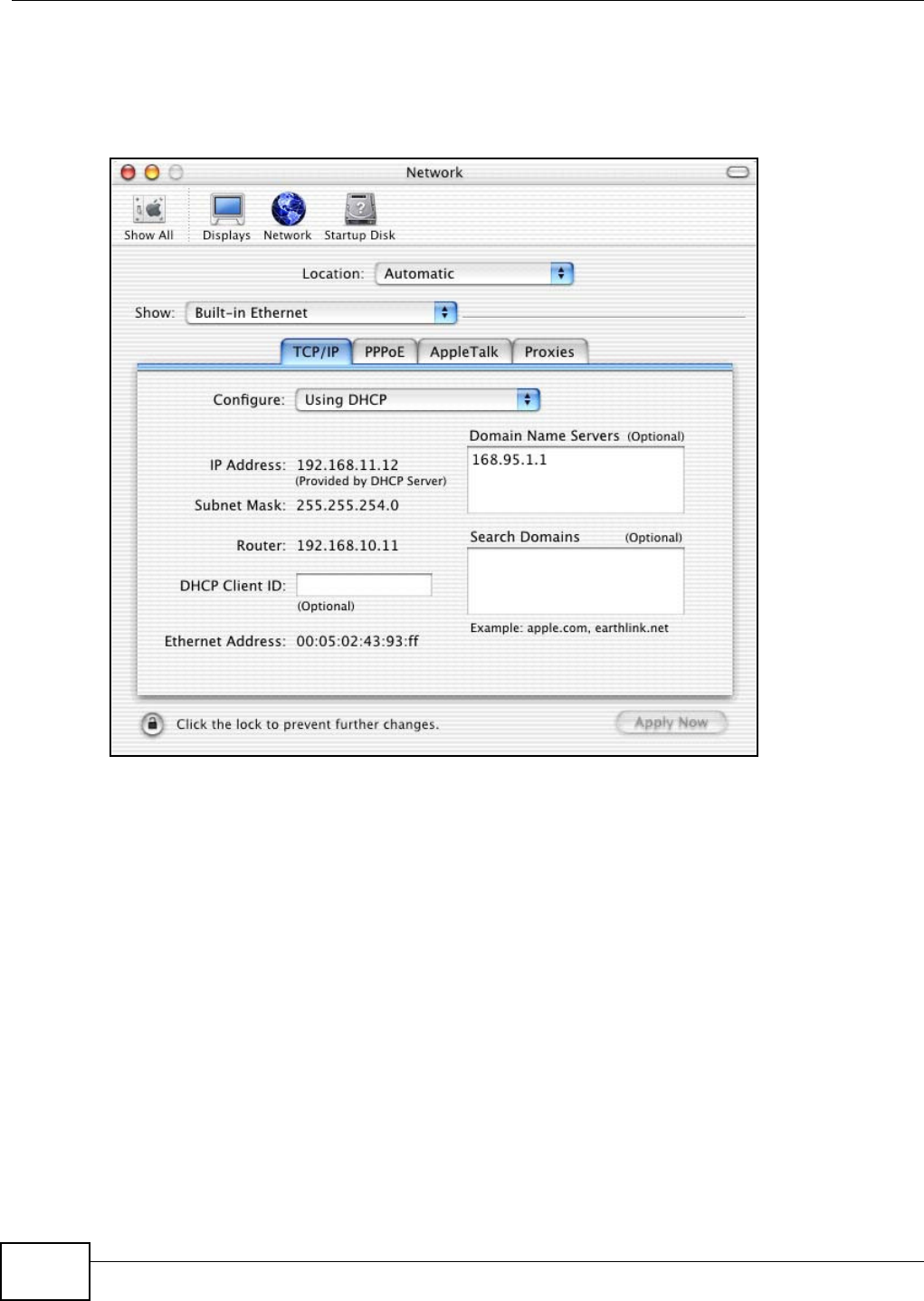
Appendix B Setting up Your Computer’s IP Address
VMG8324-B10A / VMG8324-B30A Series User’s Guide
352
• Select Built- in Eth erne t from the Sh ow list.
• Click the TCP/ I P t ab.
3For dynam ically assigned sett ings, select Using DH CP from the Configure list.
Figure 217 Macint osh OS X: Network
4For stat ically assigned set tings, do t he following:
• From the Configure box, select M anua lly.
• Type your I P address in t he I P Address box.
• Type your subnet m ask in t he Subnet m ask box.
• Type the I P address of your Device in t he Route r a ddre ss box.
5Click Apply Now and close the window.
6Turn on your Device and rest art your com put er ( if prom pted).
Verifying Settings
Check your TCP/ I P properties in the N et w ork window.
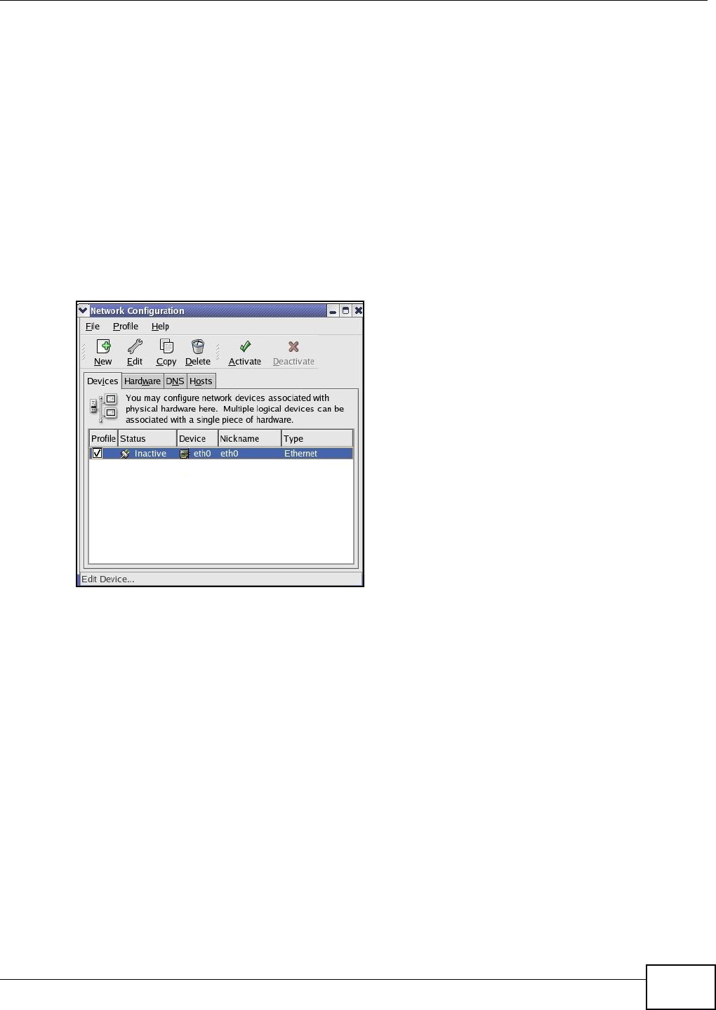
Appendix B Setting up Your Computer’s IP Address
VMG8324-B10A / VMG8324-B30A Series User’s Guide 353
Linux
This section shows you how t o configure your computer’s TCP/ I P set tings in Red Hat Linux 9.0.
Procedure, screens and file locat ion m ay vary depending on your Linux dist ribution and release
version.
Note: Make sure you are logged in as the root adm inistrat or.
Using the K Desktop Environment (KDE)
Follow the st eps below to configure your com puter I P address using the KDE.
1Click the Red Hat but ton ( located on t he bot tom left corner), select Syst e m Se t t ing and click
N e t w ork .
Figure 218 Red Hat 9.0: KDE: Net work Configuration: Devices
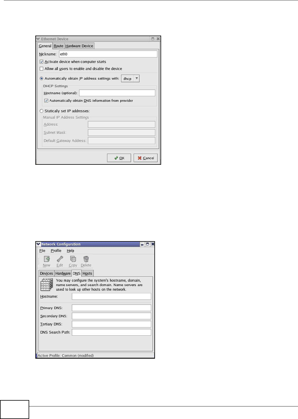
Appendix B Setting up Your Computer’s IP Address
VMG8324-B10A / VMG8324-B30A Series User’s Guide
354
2Double- click on the profile of the network card you w ish t o configure. The Et her net D e vice
Gene ral screen displays as shown.
Figure 219 Red Hat 9.0: KDE: Ethernet Device: General
• I f you have a dynam ic I P address, click Aut om at ically obta in I P address set tin gs w it h and
select dhcp from t he drop down list.
• I f you have a stat ic I P address, click St at ica lly se t I P Addr esse s and fill in t he Addr ess,
Subnet m a sk , and Default Ga t ew ay Address fields.
3Click OK t o save t he changes and close the Et her net D e vice Gener al screen.
4I f you know your DNS server I P address(es), click t he DN S tab in the N et w ork Configura tion
screen. Enter the DNS server inform ation in t he fields provided.
Figure 220 Red Hat 9.0: KDE: Net work Configuration: DNS
5Click the D evice s tab.
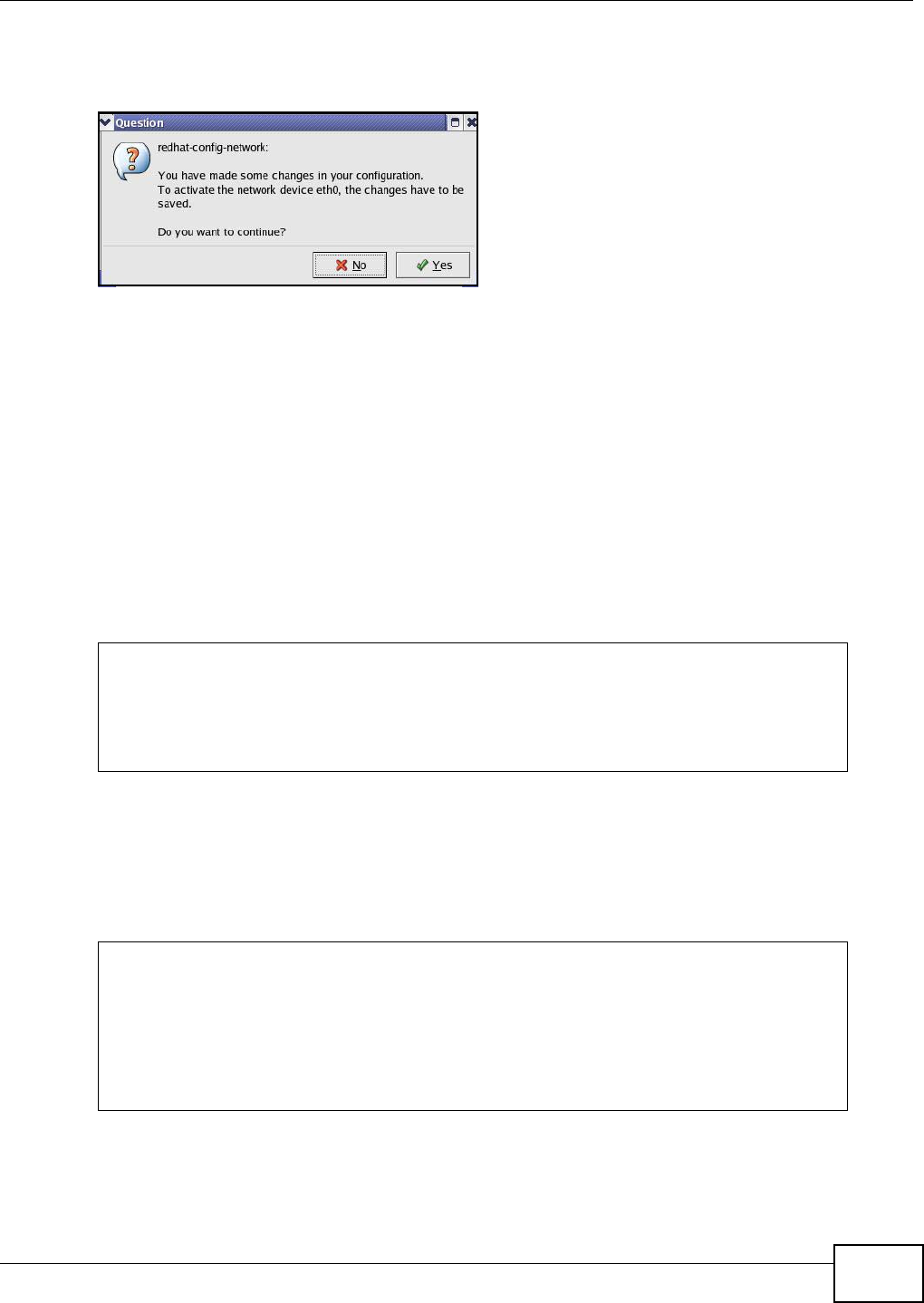
Appendix B Setting up Your Computer’s IP Address
VMG8324-B10A / VMG8324-B30A Series User’s Guide 355
6Click the Act iva t e but ton t o apply the changes. The following scr een displays. Click Yes t o save
t he cha n ges in all scre ens.
Figure 221 Red Hat 9.0: KDE: Net work Configuration: Act ivate
7After the network card restart process is com plet e, m ake sure the St a t u s is Act ive in the Net w ork
Configu ra t ion screen.
Using Configuration Files
Follow the st eps below to edit t he net work configurat ion files and set your com puter I P address.
1Assum ing that you have only one net work card on the com puter, locat e t he ifconfig-eth0
configurat ion file ( w here eth0 is t he nam e of t he Ethernet card). Open t he configurat ion file with
any plain text editor.
• I f you have a dynam ic I P address, ent er dhcp in the BOOTPROTO= field. The following figure
shows an exam ple.
Figure 222 Red Hat 9.0: Dynam ic I P Address Sett ing in ifconfig-et h0
• I f you have a stat ic I P address, enter static in the BOOTPROTO= field. Type IPADDR= follow ed
by the I P addr ess ( in dot ted decim al notat ion) and t ype NETMASK= followed by t he subnet
m ask. The following exam ple shows an exam ple where t he st atic I P address is 192.168.1.10
and the subnet m ask is 255.255.255.0.
Figure 223 Red Hat 9.0: St atic I P Address Sett ing in ifconfig-et h0
DEVICE=eth0
ONBOOT=yes
BOOTPROTO=dhcp
USERCTL=no
PEERDNS=yes
TYPE=Ethernet
DEVICE=eth0
ONBOOT=yes
BOOTPROTO=static
IPADDR=192.168.1.10
NETMASK=255.255.255.0
USERCTL=no
PEERDNS=yes
TYPE=Ethernet

Appendix B Setting up Your Computer’s IP Address
VMG8324-B10A / VMG8324-B30A Series User’s Guide
356
2I f you know your DNS server I P addr ess( es) , enter the DNS server inform at ion in the resolv.conf
file in the /etc directory. The following figure shows an exam ple where t wo DNS server I P
addresses are specified.
Figure 224 Red Hat 9.0: DNS Sett ings in resolv.conf
3After you edit and save the configurat ion files, you m ust restart t he net work card. Enter ./network
restart in the /etc/rc.d/init.d directory. The following figure shows an exam ple.
Figure 225 Red Hat 9.0: Restart Ethernet Card
Verifying Settings
Enter ifconfig in a t erm inal screen t o check your TCP/ I P properties.
Figure 226 Red Hat 9.0: Checking TCP/ I P Pr operties
nameserver 172.23.5.1
nameserver 172.23.5.2
[root@localhost init.d]# network restart
Shutting down interface eth0: [OK]
Shutting down loopback interface: [OK]
Setting network parameters: [OK]
Bringing up loopback interface: [OK]
Bringing up interface eth0: [OK]
[root@localhost]# ifconfig
eth0 Link encap:Ethernet HWaddr 00:50:BA:72:5B:44
inet addr:172.23.19.129 Bcast:172.23.19.255 Mask:255.255.255.0
UP BROADCAST RUNNING MULTICAST MTU:1500 Metric:1
RX packets:717 errors:0 dropped:0 overruns:0 frame:0
TX packets:13 errors:0 dropped:0 overruns:0 carrier:0
collisions:0 txqueuelen:100
RX bytes:730412 (713.2 Kb) TX bytes:1570 (1.5 Kb)
Interrupt:10 Base address:0x1000
[root@localhost]#

VMG8324-B10A / VMG8324-B30A Series User’s Guide 357
APPENDIX C
IP Addresses and Subnetting
This appendix int roduces I P addresses and subnet m asks.
I P addresses identify individual devices on a network. Every net working device ( including
com puters, servers, rout ers, print ers, et c.) needs an I P address to comm unicat e across t he
net work. These net working devices are also known as hosts.
Subnet m asks determ ine t he m axim um num ber of possible hosts on a network. You can also use
subnet m asks t o divide one net work int o m ultiple sub- net works.
Introduction to IP Addresses
One part of t he I P address is t he net work num ber, and t he other part is t he host I D. I n t he sam e
way t hat houses on a st reet share a com m on st reet nam e, t he host s on a net work share a com m on
net work num ber. Sim ilarly, as each house has its own house num ber, each host on t he net work has
it s own unique identifying num ber - the host I D. Rout ers use t he net work num ber t o send packet s
to t he correct net work, while the host I D determ ines to which host on t he net work the packets are
delivered.
Structure
An I P address is m ade up of four parts, writ ten in dott ed decim al notat ion ( for exam ple,
192.168.1.1). Each of t hese four parts is known as an oct et . An oct et is an eight- digit binary
num ber ( for exam ple 11000000, which is 192 in decim al not ation) .
Therefore, each octet has a possible range of 00000000 to 11111111 in binary, or 0 to 255 in
decim al.
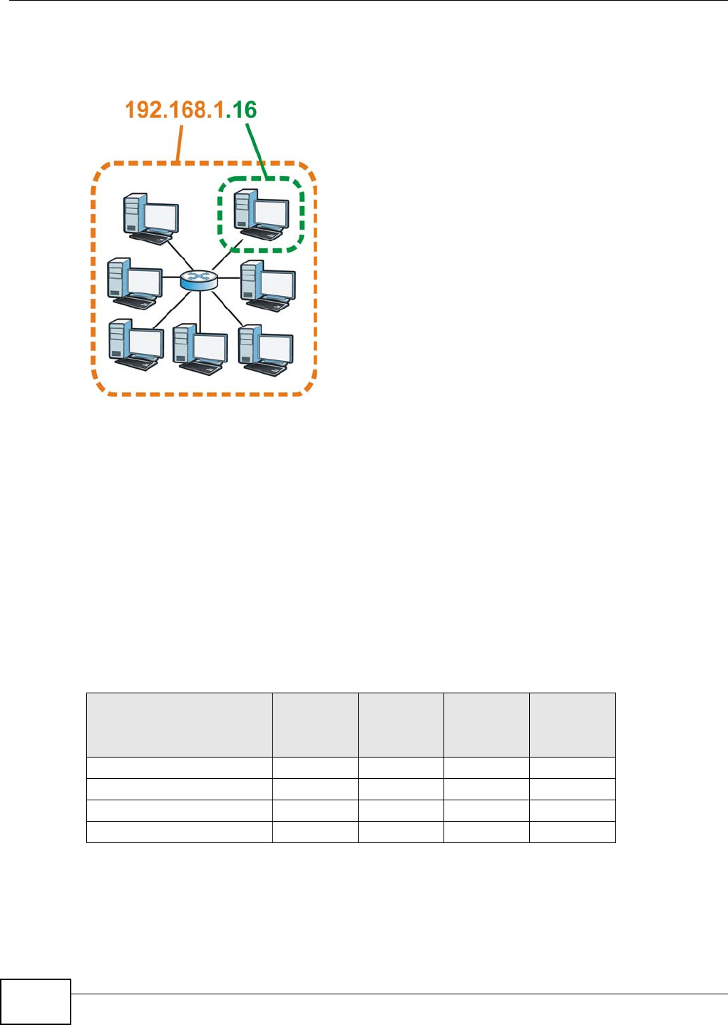
Appendix C IP Addresses and Subnetting
VMG8324-B10A / VMG8324-B30A Series User’s Guide
358
The following figure shows an exam ple I P address in which t he first t hree oct et s (192.168.1) are
the net work num ber, and the fourth oct et ( 16) is the host I D.
Figure 227 Net work Num ber and Host I D
How m uch of the I P address is the network num ber and how m uch is t he host I D varies according
to t he subnet m ask.
Subnet Masks
A subnet m ask is used to det erm ine which bits are part of the network num ber, and which bits are
part of the host I D ( using a logical AND operation). The term “ subnet ” is short for “sub-network”.
A subnet m ask has 32 bit s. I f a bit in t he subnet mask is a “ 1” t hen t he corresponding bit in t he I P
address is part of the network num ber. I f a bit in the subnet m ask is “0” t hen t he corresponding bit
in t he I P address is par t of the host I D.
The following exam ple shows a subnet m ask identifying the net work num ber ( in bold text ) and host
I D of an I P address (192.168.1.2 in decim al) .
By convent ion, subnet m asks always consist of a continuous sequence of ones beginning from the
leftm ost bit of the m ask, follow ed by a continuous sequence of zeros, for a tot al num ber of 32 bits.
Table 154 Subnet Masks
1ST OCTET:
(192)
2ND
OCTET:
(168)
3RD
OCTET:
(1)
4TH OCTET
(2)
I P Address ( Binary) 11000000 10101000 00000001 00000010
Subnet Mask (Binary) 1 1 1 1 1 1 1 1 1 1 1 1 1 1 1 1 1 1 1 1 1 1 1 1 00000000
Net work Num ber 1 1 0 0 0 0 0 0 1 0 1 0 1 0 0 0 0 0 0 0 0 0 0 1
Host I D 00000010
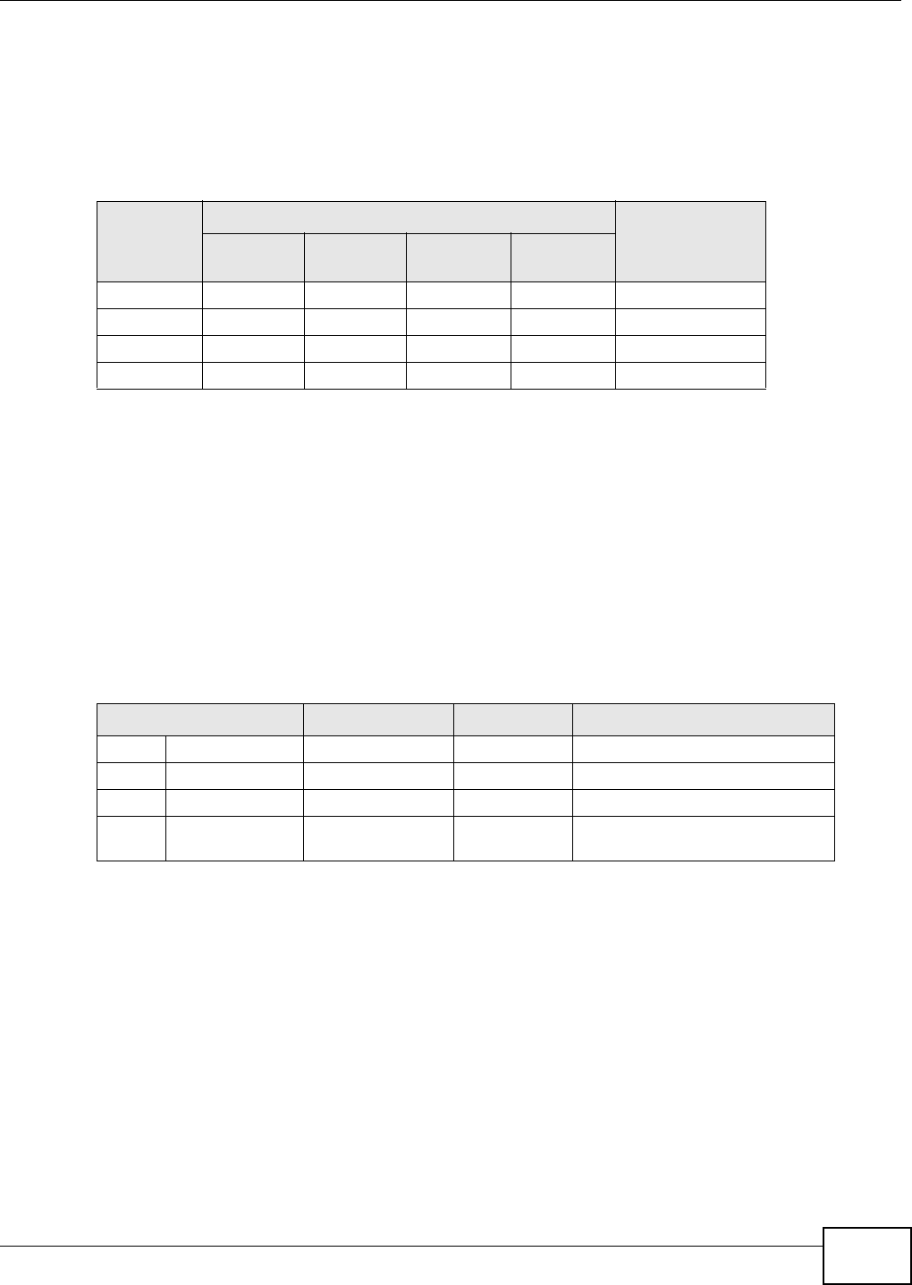
Appendix C IP Addresses and Subnetting
VMG8324-B10A / VMG8324-B30A Series User’s Guide 359
Subnet m asks can be referred to by the size of the net work num ber part ( the bits wit h a “1” value).
For exam ple, an “ 8- bit m ask” m eans t hat t he first 8 bits of the m ask are ones and t he rem aining 24
bits are zeroes.
Subnet m asks are expressed in dott ed decim al not ation just like I P addresses. The following
exam ples show t he binary and decim al notation for 8-bit, 16- bit , 24-bit and 29- bit subnet m asks.
Network Size
The size of the net w ork num ber det erm ines t he m axim um num ber of possible hosts you can have
on your net w ork. The larger t he num ber of network num ber bit s, the sm aller the num ber of
rem aining host I D bits.
An I P address wit h host I Ds of all zeros is t he I P address of the networ k ( 192.168.1.0 wit h a 24-bit
subnet m ask, for exam ple) . An I P address wit h host I Ds of all ones is the broadcast address for that
net work ( 192.168.1.255 wit h a 24- bit subnet m ask, for exam ple).
As t hese t wo I P addresses cannot be used for individual host s, calculat e t he m axim um num ber of
possible hosts in a networ k as follows:
Notation
Since the m ask is always a continuous num ber of ones beginning from the left, followed by a
cont inuous num ber of zeros for the rem ainder of the 32 bit m ask, you can sim ply specify the
num ber of ones instead of writ ing the value of each oct et. This is usually specified by writing a “ / ”
followed by the num ber of bit s in the m ask after the address.
For exam ple, 192.1.1.0 / 25 is equivalent to saying 192.1.1.0 wit h subnet m ask 255.255.255.128.
Table 155 Subnet Masks
BINARY
DECIMAL
1ST
OCTET
2ND
OCTET
3RD
OCTET 4TH OCTET
8- bit mask 11111111 00000000 00000000 00000000 255.0.0.0
16- bit m ask 11111111 11111111 00000000 00000000 255.255.0.0
24- bit m ask 11111111 11111111 11111111 00000000 255.255.255.0
29- bit m ask 11111111 11111111 11111111 11111000 255.255.255.248
Table 156 Maxim um Host Num bers
SUBNET MASK HOST ID SIZE MAXIMUM NUMBER OF HOSTS
8 bit s 255.0.0.0 24 bits 224 – 2 16777214
16 bits 255.255.0.0 16 bit s 216 – 2 65534
24 bits 255.255.255.0 8 bits 28 – 2 254
29 bits 255.255.255.24
8
3 bit s 23 – 2 6
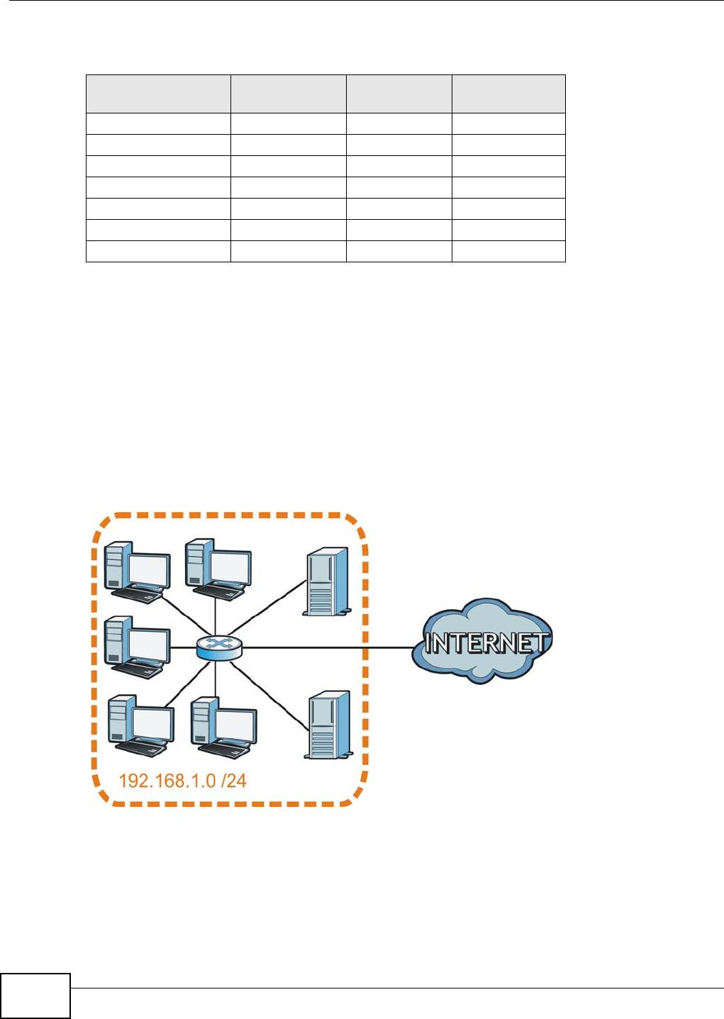
Appendix C IP Addresses and Subnetting
VMG8324-B10A / VMG8324-B30A Series User’s Guide
360
The following t able shows some possible subnet m asks using both notat ions.
Subnetting
You can use subnett ing to divide one net work int o mult iple sub-networks. I n t he following exam ple
a net work adm inistrat or creates t wo sub- net works to isolate a group of servers from t he rest of t he
com pany net work for securit y reasons.
I n t his exam ple, t he com pany net work address is 192.168.1.0. The first t hree oct ets of t he address
( 192.168.1) ar e the net work num ber, and the rem aining oct et is the host I D, allowing a m axim um
of 28 – 2 or 254 possible host s.
The following figure shows the com pany network before subnet ting.
Figure 228 Subnet ting Exam ple: Before Subnett ing
You can “ borrow” one of t he host I D bit s to divide the net work 192.168.1.0 into tw o separate sub-
net works. The subnet m ask is now 25 bit s (255.255.255.128 or / 25).
The “ borrowed” host I D bit can have a value of eit her 0 or 1, allow ing two subnets; 192.168.1.0 / 25
and 192.168.1.128 / 25.
Table 157 Alternative Subnet Mask Not ation
SUBNET MASK ALTERNATIVE
NOTATION
LAST OCTET
(BINARY)
LAST OCTET
(DECIMAL)
255.255.255.0 / 24 0000 0000 0
255.255.255.128 / 25 1000 0000 128
255.255.255.192 / 26 1100 0000 192
255.255.255.224 / 27 1110 0000 224
255.255.255.240 / 28 1111 0000 240
255.255.255.248 / 29 1111 1000 248
255.255.255.252 / 30 1111 1100 252
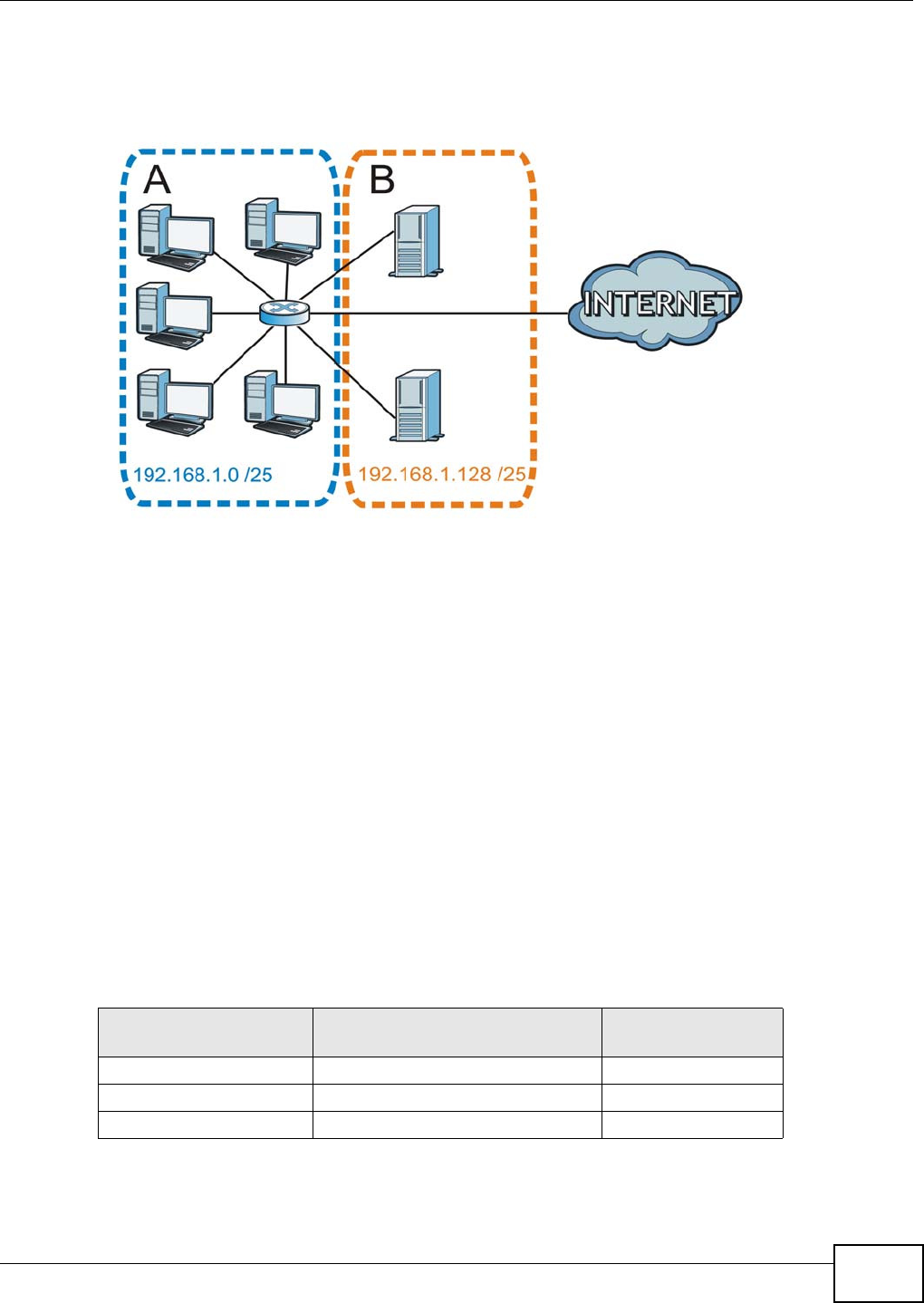
Appendix C IP Addresses and Subnetting
VMG8324-B10A / VMG8324-B30A Series User’s Guide 361
The following figure shows the com pany network aft er subnett ing. There are now t wo sub-
net works, A and B.
Figure 229 Subnet ting Exam ple: Aft er Subnet ting
I n a 25- bit subnet t he host I D has 7 bits, so each sub- net work has a maxim um of 27 – 2 or 126
possible hosts ( a host I D of all zeroes is t he subnet’s address it self, all ones is the subnet ’s
broadcast address).
192.168.1.0 wit h m ask 255.255.255.128 is subnet A itself, and 192.168.1.127 wit h m ask
255.255.255.128 is its br oadcast address. Therefore, the low est I P address t hat can be assigned t o
an act ual host for subnet A is 192.168.1.1 and t he highest is 192.168.1.126.
Sim ilar ly, the host I D range for subnet B is 192.168.1.129 t o 192.168.1.254.
Example: Four Subnets
The previous exam ple illustrated using a 25- bit subnet m ask t o divide a 24- bit address int o two
subnet s. Sim ilarly, to divide a 24- bit address int o four subnet s, you need t o “ borrow” two host I D
bits to give four possible com binat ions (00, 01, 10 and 11) . The subnet m ask is 26 bit s
(11111111.11111111.11111111.1 1 000000) or 255.255.255.192.
Each subnet cont ains 6 host I D bit s, giving 26 - 2 or 62 host s for each subnet (a host I D of all
zeroes is the subnet itself, all ones is the subnet’s broadcast address) .
Table 158 Subnet 1
IP/SUBNET MASK NETWORK NUMBER LAST OCTET BIT
VALUE
I P Address ( Decim al) 192.168.1. 0
I P Address ( Binary) 11000000.10101000.00000001. 0 0 000000
Subnet Mask (Binary) 11111111.11111111.11111111. 1 1 000000
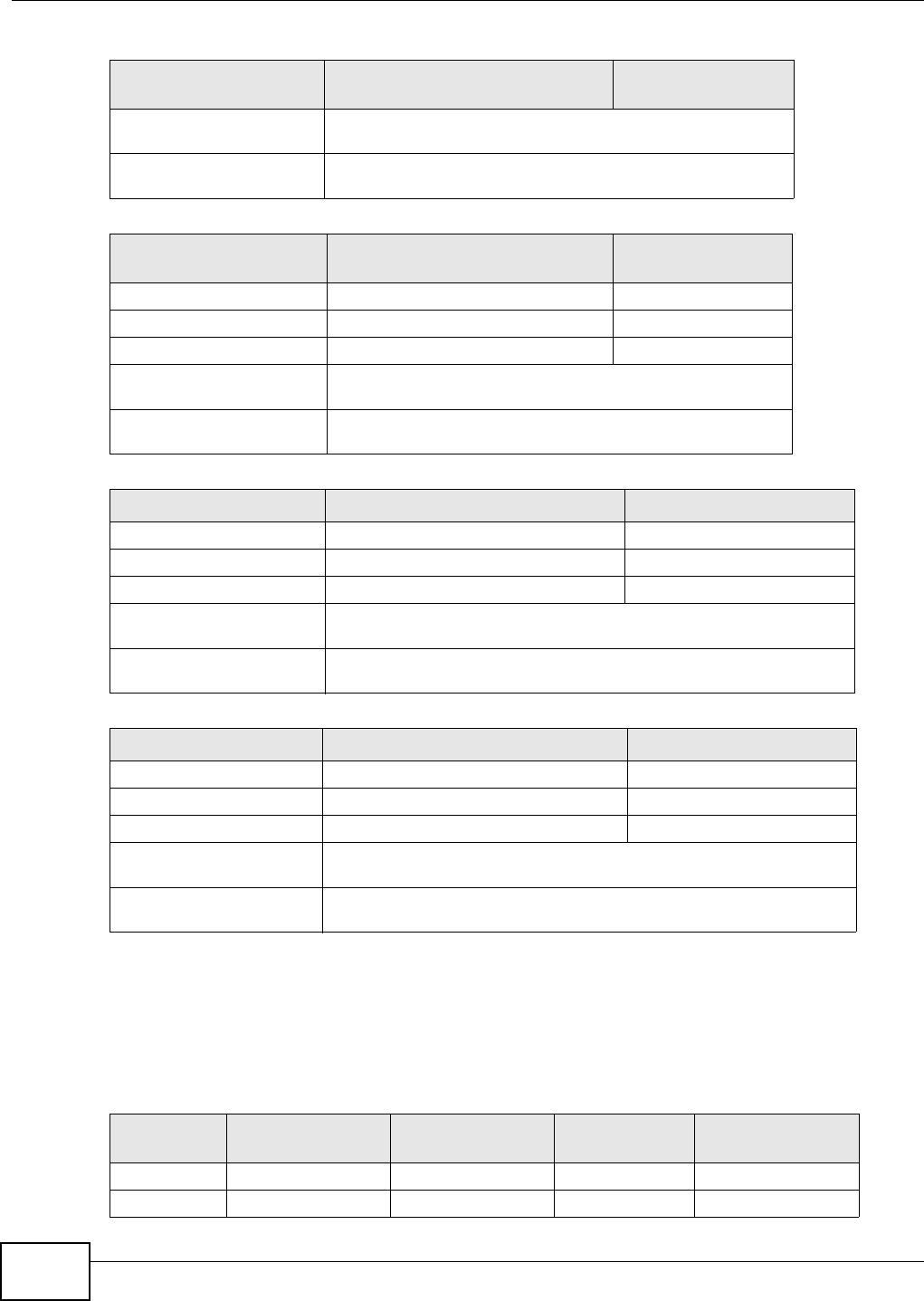
Appendix C IP Addresses and Subnetting
VMG8324-B10A / VMG8324-B30A Series User’s Guide
362
Example: Eight Subnets
Sim ilarly, use a 27-bit m ask to create eight subnets ( 000, 001, 010, 011, 100, 101, 110 and 111).
The following t able shows I P address last octet values for each subnet .
Subnet Address:
192.168.1.0
Lowest Host I D: 192.168.1.1
Broadcast Address:
192.168.1.63
Highest Host I D: 192.168.1.62
Table 159 Subnet 2
IP/SUBNET MASK NETWORK NUMBER LAST OCTET BIT
VALUE
I P Address 192.168.1. 64
I P Address ( Binary) 11000000.10101000.00000001. 0 1 000000
Subnet Mask (Binary) 11111111.11111111.11111111. 1 1 000000
Subnet Address:
192.168.1.64
Lowest Host I D: 192.168.1.65
Broadcast Address:
192.168.1.127
Highest Host I D: 192.168.1.126
Table 160 Subnet 3
IP/SUBNET MASK NETWORK NUMBER LAST OCTET BIT VALUE
I P Address 192.168.1. 128
I P Address ( Binary) 11000000.10101000.00000001. 1 0 000000
Subnet Mask (Binary) 11111111.11111111.11111111. 1 1 000000
Subnet Address:
192.168.1.128
Lowest Host I D: 192.168.1.129
Broadcast Address:
192.168.1.191
Highest Host I D: 192.168.1.190
Table 161 Subnet 4
IP/SUBNET MASK NETWORK NUMBER LAST OCTET BIT VALUE
I P Address 192.168.1. 192
I P Address ( Binary) 11000000.10101000.00000001. 1 1 000000
Subnet Mask (Binary) 11111111.11111111.11111111. 1 1 000000
Subnet Address:
192.168.1.192
Lowest Host I D: 192.168.1.193
Broadcast Address:
192.168.1.255
Highest Host I D: 192.168.1.254
Table 158 Subnet 1 (cont inued)
IP/SUBNET MASK NETWORK NUMBER LAST OCTET BIT
VALUE
Table 162 Eight Subnet s
SUBNET SUBNET
ADDRESS FIRST ADDRESS LAST
ADDRESS
BROADCAST
ADDRESS
1 0 1 30 31
232 33 62 63
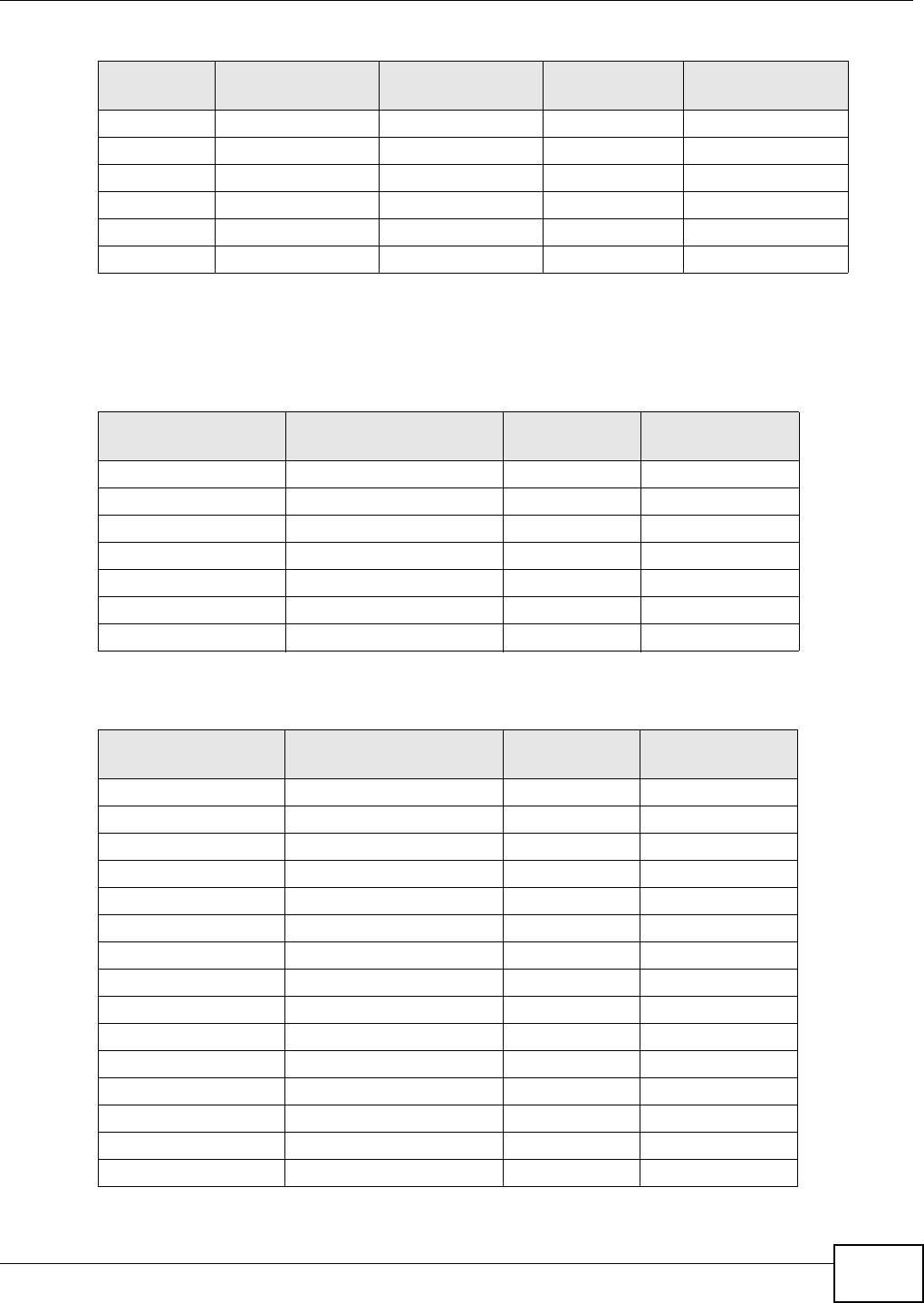
Appendix C IP Addresses and Subnetting
VMG8324-B10A / VMG8324-B30A Series User’s Guide 363
Subnet Planning
The following t able is a sum m ary for subnet planning on a network wit h a 24- bit network num ber.
The following t able is a sum m ary for subnet planning on a network wit h a 16- bit network num ber.
364 65 94 95
496 97 126 127
5128 129 158 159
6160 161 190 191
7192 193 222 223
8224 225 254 255
Table 162 Eight Subnet s (cont inued)
SUBNET SUBNET
ADDRESS FIRST ADDRESS LAST
ADDRESS
BROADCAST
ADDRESS
Table 163 24-bit Net work Num ber Subnet Planning
NO. “BORROWED”
HOST BITS SUBNET MASK NO. SUBNETS NO. HOSTS PER
SUBNET
1255.255.255.128 ( / 25) 2126
2255.255.255.192 ( / 26) 462
3255.255.255.224 ( / 27) 830
4255.255.255.240 ( / 28) 16 14
5255.255.255.248 ( / 29) 32 6
6255.255.255.252 ( / 30) 64 2
7255.255.255.254 ( / 31) 128 1
Table 164 16-bit Net work Num ber Subnet Planning
NO. “BORROWED”
HOST BITS SUBNET MASK NO. SUBNETS NO. HOSTS PER
SUBNET
1255.255.128.0 ( / 17) 232766
2255.255.192.0 ( / 18) 416382
3255.255.224.0 ( / 19) 88190
4255.255.240.0 ( / 20) 16 4094
5255.255.248.0 ( / 21) 32 2046
6255.255.252.0 ( / 22) 64 1022
7255.255.254.0 ( / 23) 128 510
8255.255.255.0 ( / 24) 256 254
9255.255.255.128 ( / 25) 512 126
10 255.255.255.192 (/ 26) 1024 62
11 255.255.255.224 (/ 27) 2048 30
12 255.255.255.240 (/ 28) 4096 14
13 255.255.255.248 (/ 29) 8192 6
14 255.255.255.252 (/ 30) 16384 2
15 255.255.255.254 (/ 31) 32768 1

Appendix C IP Addresses and Subnetting
VMG8324-B10A / VMG8324-B30A Series User’s Guide
364
Configuring IP Addresses
Where you obtain your network num ber depends on your particular situation. I f the I SP or your
net work adm inist rat or assigns you a block of registered I P addresses, follow their inst r uctions in
selecting t he I P addresses and t he subnet m ask.
I f t he I SP did not explicit ly give you an I P net work num ber, t hen m ost likely you have a single user
account and t he I SP will assign you a dynam ic I P address when t he connect ion is established. I f this
is t he case, it is recom m ended that you select a netw ork num ber from 192.168.0.0 to
192.168.255.0. The I nternet Assigned Num ber Authorit y ( I ANA) reserved this block of addresses
specifically for private use; please do not use any ot her num ber unless you are t old otherwise. You
m ust also enable Net work Address Translat ion ( NAT) on the Device.
Once you have decided on the network num ber, pick an I P address for your Device that is easy to
rem em ber (for instance, 192.168.1.1) but m ake sure that no other device on your networ k is using
that I P address.
The subnet m ask specifies the network num ber port ion of an I P address. Your Device w ill com put e
the subnet m ask aut om atically based on the I P address that you ent ered. You don't need to change
the subnet m ask com put ed by the Device unless you are inst ruct ed t o do otherwise.
Private IP Addresses
Every m achine on t he I nt ernet m ust have a unique address. I f your networks are isolated from t he
I nternet ( running only bet ween two branch offices, for exam ple) you can assign any I P addresses to
the hosts wit hout problem s. However, t he I nt ernet Assigned Num bers Aut horit y ( I ANA) has
reserved t he following three blocks of I P addresses specifically for privat e net works:
• 10.0.0.0 — 10.255.255.255
• 172.16.0.0 — 172.31.255.255
• 192.168.0.0 — 192.168.255.255
You can obtain your I P address from the I ANA, from an I SP, or it can be assigned from a private
net work. I f you belong to a sm all organization and your I nternet access is t hrough an I SP, the I SP
can provide you wit h t he I nt ernet addresses for your local networks. On t he other hand, if you are
part of a m uch lar ger organizat ion, you should consult your network adm inistrator for t he
appropriat e I P addresses.
Regardless of your part icular sit uat ion, do not create an arbit rary I P address; always follow t he
guidelines above. For m ore inform ation on address assignment, please refer t o RFC 1597, Address
Allocat ion for Privat e I nternet s and RFC 1466, Guidelines for Managem ent of I P Address Space.
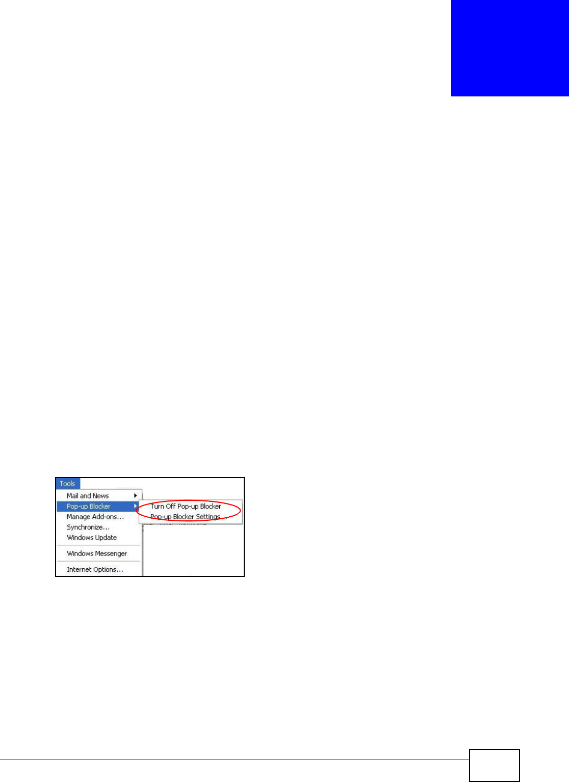
VMG8324-B10A / VMG8324-B30A Series User’s Guide 365
APPENDIX D
Pop-up Windows, JavaScripts and Java
Permissions
I n order t o use the web configurator you need t o allow:
• Web browser pop- up windows from your device.
• JavaScripts ( enabled by default) .
• Java perm issions ( enabled by default ).
Note: I nternet Explorer 6 screens are used here. Screens for ot her I nternet Explorer
ver sions m ay vary.
Internet Explorer Pop-up Blockers
You m ay have t o disable pop- up blocking t o log int o your device.
Eit her disable pop- up blocking ( enabled by default in Windows XP SP (Service Pack) 2) or allow
pop- up blocking and creat e an exception for your device’s I P address.
Disable Pop-up Blockers
1I n I nternet Explorer, select Tools, Pop- up Blocke r and t hen select Tur n Off Pop- up Blocke r.
Figure 230 Pop- up Blocker
You can also check if pop- up blocking is disabled in the Pop- up Blocke r sect ion in the Privacy t ab.
1I n I nternet Explorer, select Tools, I nter net Opt ions, Privacy.
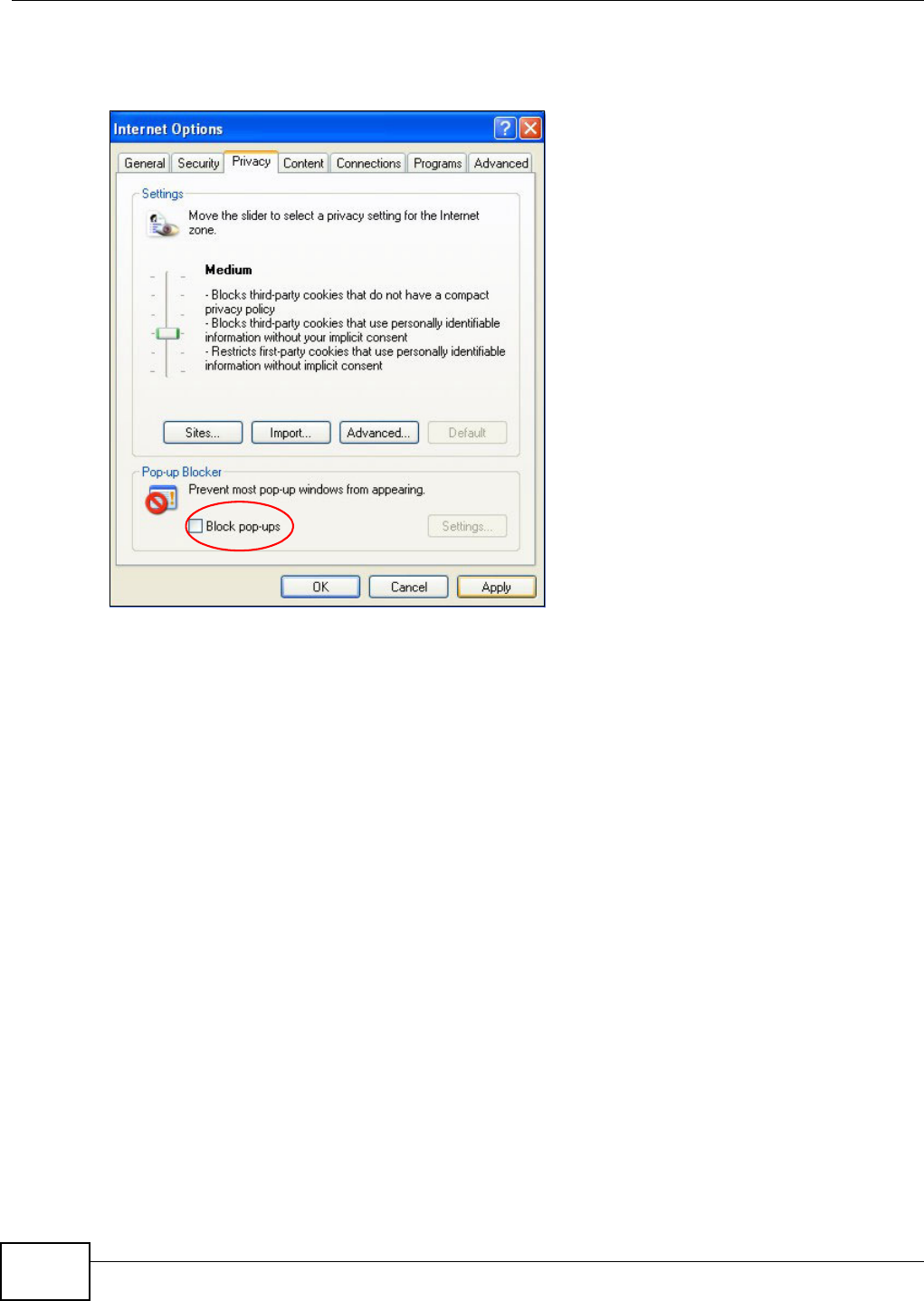
Appendix D Pop-up Windows, JavaScripts and Java Permissions
VMG8324-B10A / VMG8324-B30A Series User’s Guide
366
2Clear t he Block pop- ups check box in the Pop- up Blocke r sect ion of t he screen. This disables any
web pop- up blocker s you m ay have enabled.
Figure 231 I nt ernet Options: Privacy
3Click Apply to save t his set ting.
Enable Pop-up Blockers with Exceptions
Alt ernat ively, if you only want t o allow pop-up w indows from your device, see t he following st eps.
1I n I nternet Explorer, select Tools, I nter net Opt ions and then the Pr ivacy tab.
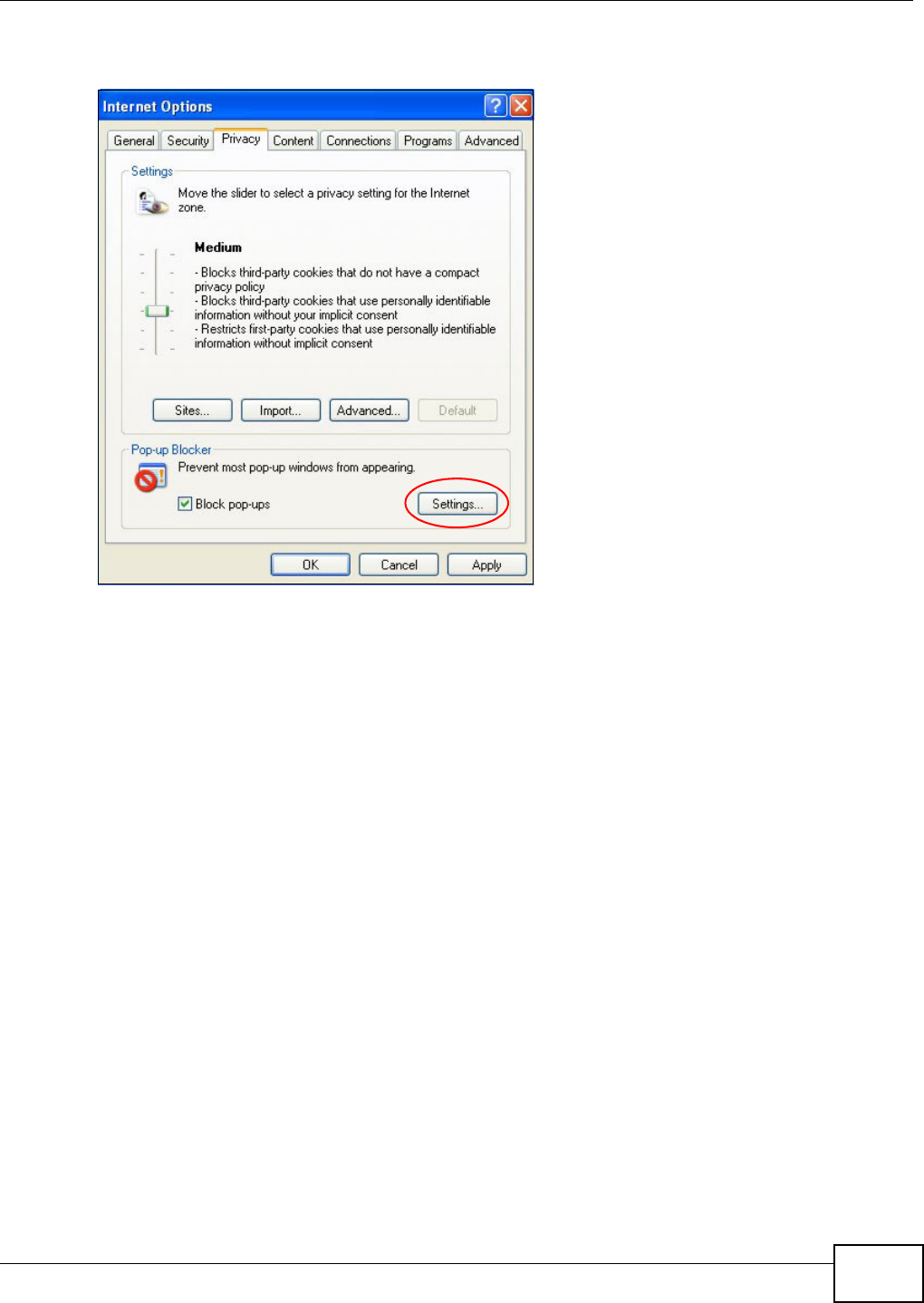
Appendix D Pop-up Windows, JavaScripts and Java Permissions
VMG8324-B10A / VMG8324-B30A Series User’s Guide 367
2Select Se t t in gs…t o open t he Pop- up Block er Set tings screen.
Figure 232 I nt ernet Options: Privacy
3Type t he I P address of your device (t he web page that you do not want to have blocked) wit h t he
prefix “htt p: / / ”. For exam ple, ht tp: / / 192.168.167.1.
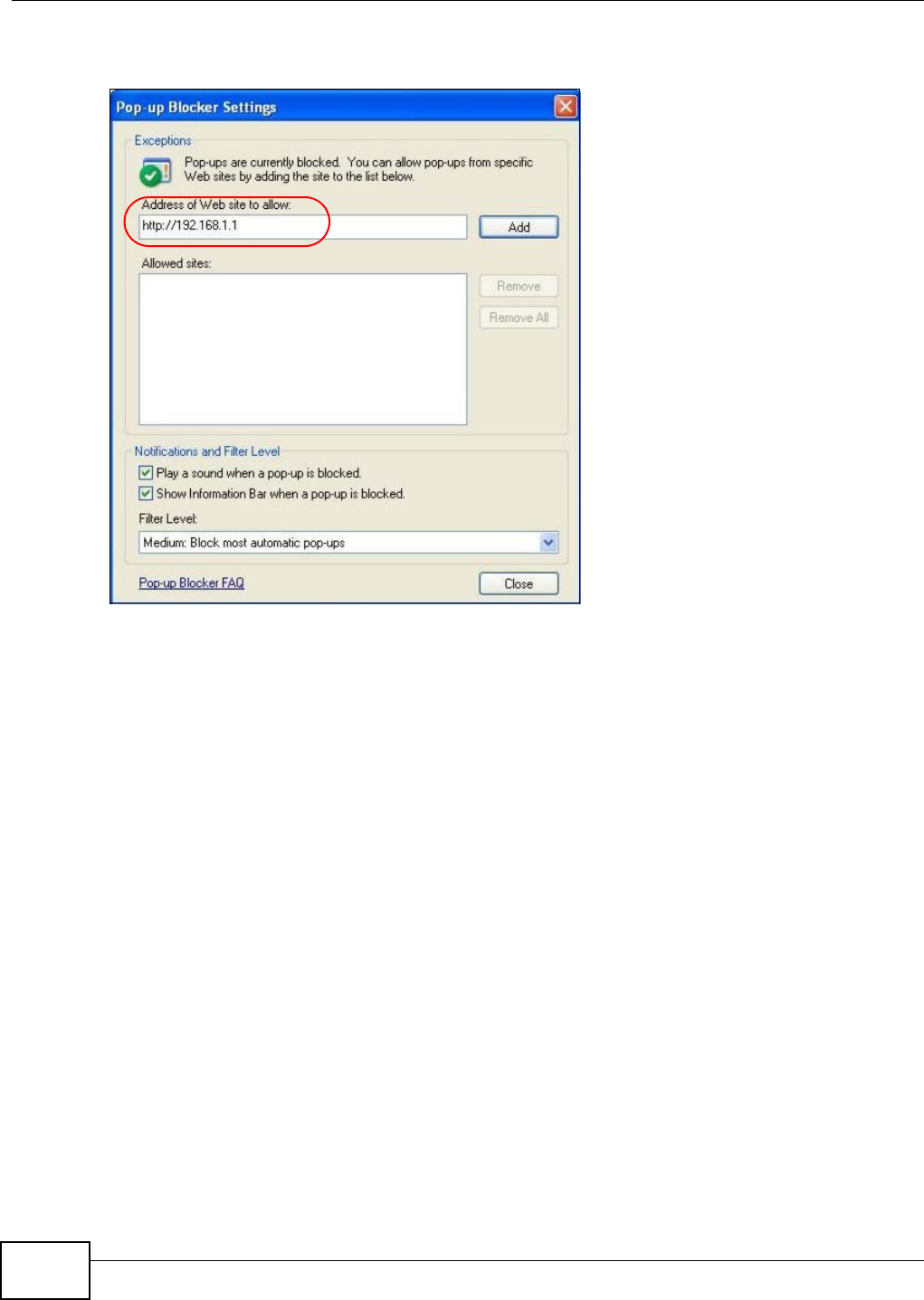
Appendix D Pop-up Windows, JavaScripts and Java Permissions
VMG8324-B10A / VMG8324-B30A Series User’s Guide
368
4Click Add t o m ove the I P address to the list of Allow e d sit es.
Figure 233 Pop-up Blocker Sett ings
5Click Close t o return t o t he Privacy screen.
6Click Apply to save t his set ting.
JavaScripts
I f pages of t he web configurator do not display properly in I nternet Explorer, check t hat JavaScript s
are allowed.
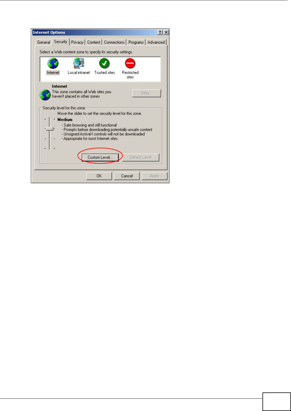
Appendix D Pop-up Windows, JavaScripts and Java Permissions
VMG8324-B10A / VMG8324-B30A Series User’s Guide 369
1I n I nternet Explorer, click Tools, I nte rnet Opt ions and then the Se cur it y t ab.
Figure 234 I nt ernet Options: Security
2Click the Custom Le vel... but ton.
3Scroll down to Scr ip t in g.
4Under Act ive scr ipt ing m ake sure that En able is select ed (t he default) .
5Under Scripting of Ja va applet s m ake sure t hat Enable is select ed (t he default) .
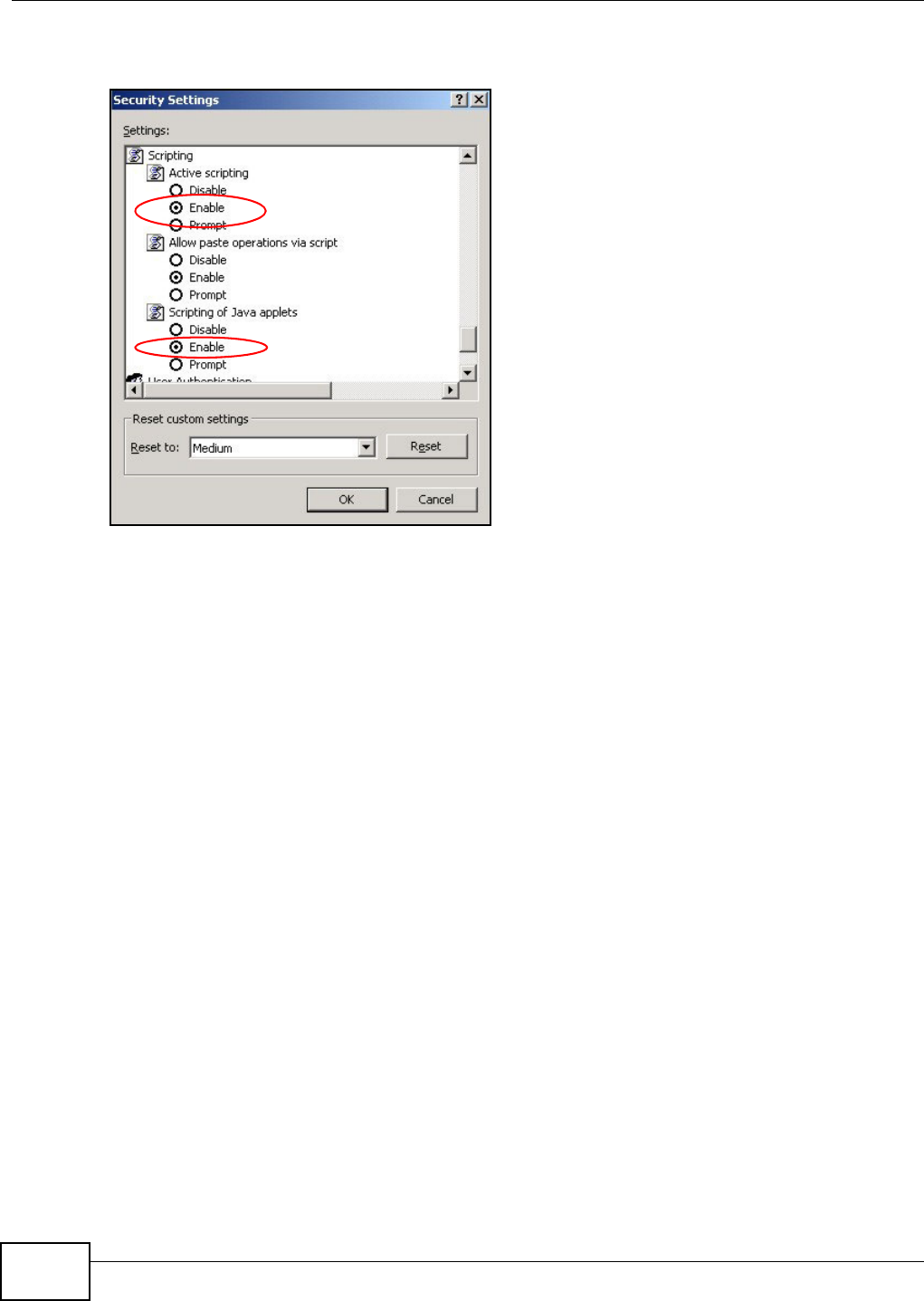
Appendix D Pop-up Windows, JavaScripts and Java Permissions
VMG8324-B10A / VMG8324-B30A Series User’s Guide
370
6Click OK t o close t he window.
Figure 235 Securit y Set tings - Java Script ing
Java Permissions
1From I nt ernet Explorer, click Tools, I nt ernet Options and t hen t he Securit y t ab.
2Click the Custom Le vel... but ton.
3Scroll down to Micr osoft VM .
4Under Ja va pe rm ission s m ake sur e that a safety level is selected.
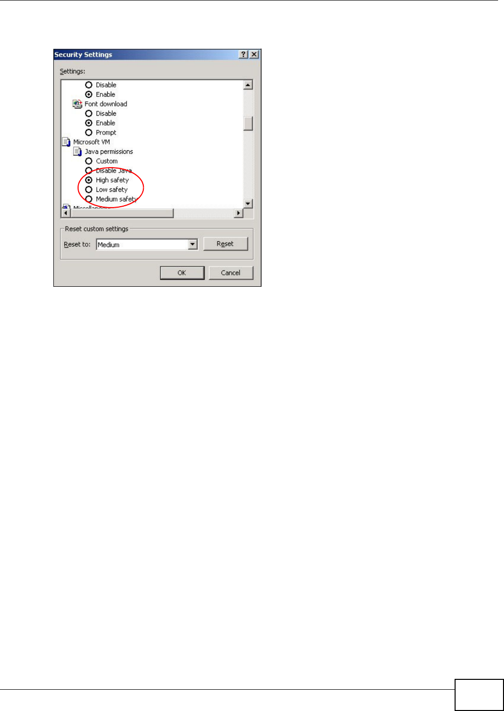
Appendix D Pop-up Windows, JavaScripts and Java Permissions
VMG8324-B10A / VMG8324-B30A Series User’s Guide 371
5Click OK t o close t he window.
Figure 236 Securit y Set tings - Java
JAVA (Sun)
1From I nt ernet Explorer, click Tools, I nt ernet Options and t hen t he Advanced t ab.
2Make sure t hat Use Java 2 for < a pplet > under Java ( Su n) is selected.
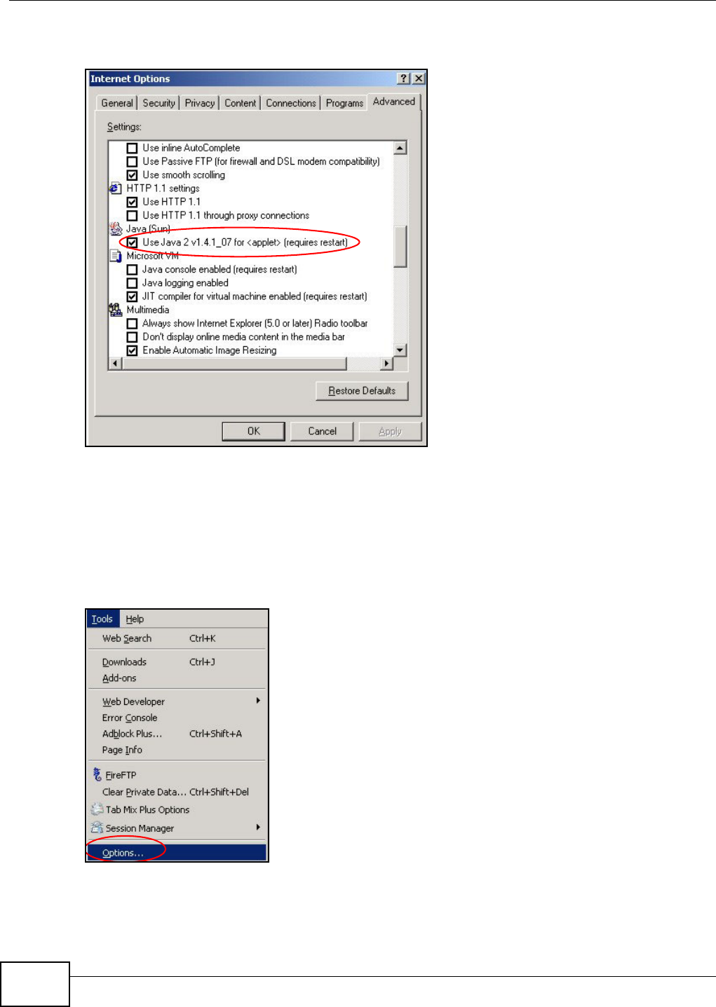
Appendix D Pop-up Windows, JavaScripts and Java Permissions
VMG8324-B10A / VMG8324-B30A Series User’s Guide
372
3Click OK t o close t he window.
Figure 237 Java (Sun)
Mozilla Firefox
Mozilla Firefox 2.0 screens ar e used here. Screens for ot her versions m ay vary.
You can enable Java, Javascript s and pop- ups in one screen. Click Tools, t hen click Opt ions in t he
screen that appears.
Figure 238 Mozilla Firefox: Tools > Options
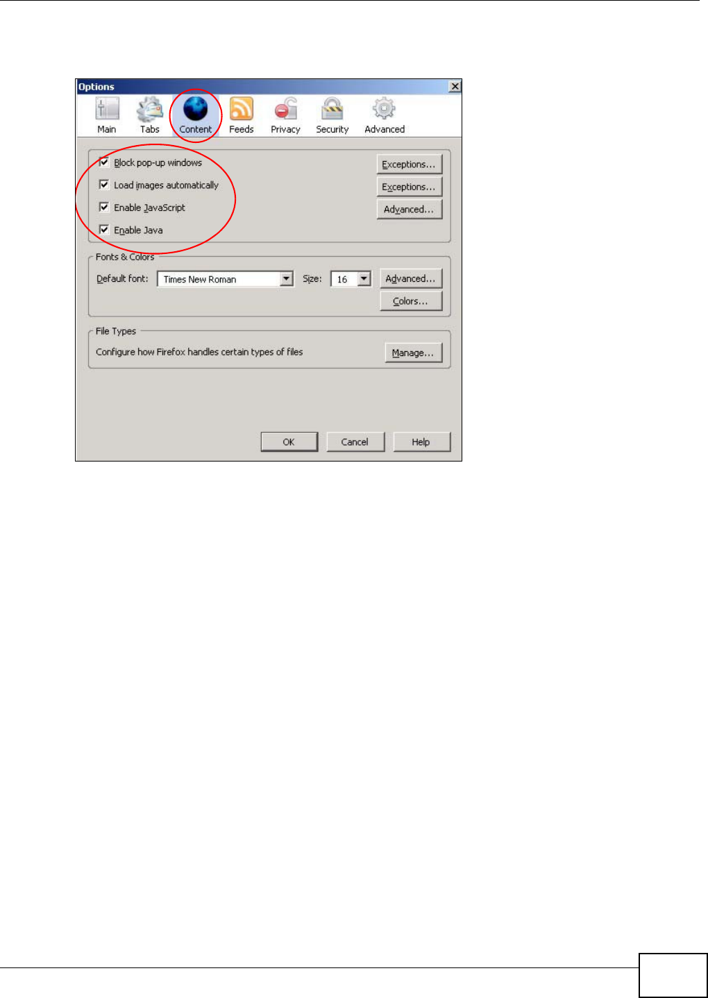
Appendix D Pop-up Windows, JavaScripts and Java Permissions
VMG8324-B10A / VMG8324-B30A Series User’s Guide 373
Click Cont ent .to show the screen below. Select t he check boxes as shown in t he following screen.
Figure 239 Mozilla Firefox Cont ent Security

Appendix D Pop-up Windows, JavaScripts and Java Permissions
VMG8324-B10A / VMG8324-B30A Series User’s Guide
374
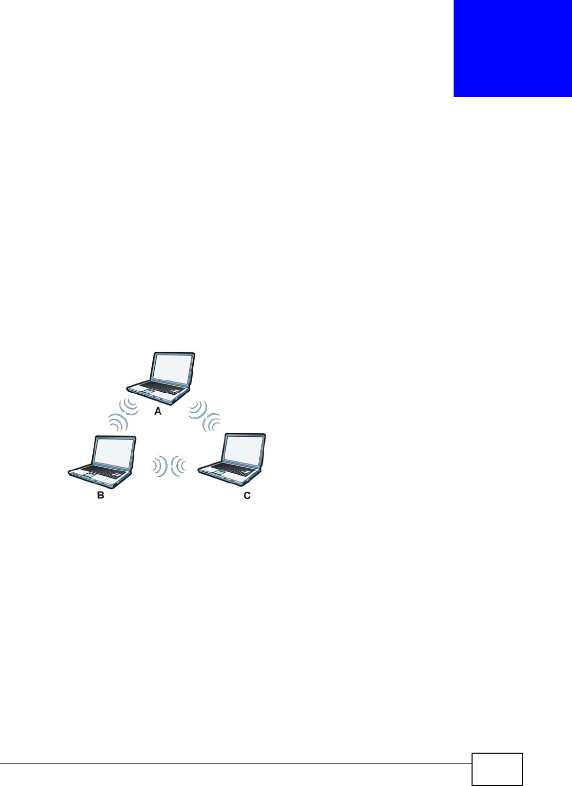
VMG8324-B10A / VMG8324-B30A Series User’s Guide 375
APPENDIX E
Wireless LANs
Wireless LAN Topologies
This section discusses ad- hoc and infrastruct ure wireless LAN topologies.
Ad-hoc Wireless LAN Configuration
The sim plest WLAN configurat ion is an independent ( Ad- hoc) WLAN that connects a set of
com puters wit h wireless adapt ers (A, B, C) . Any t im e t wo or m ore wireless adapters are wit hin
range of each other, they can set up an independent net work, which is com m only referred to as an
ad- hoc net work or I ndependent Basic Service Set (I BSS) . The following diagram shows an exam ple
of not ebook com put ers using wireless adapt ers to form an ad-hoc wireless LAN.
Figure 240 Peer- to- Peer Com m unicat ion in an Ad- hoc Net work
BSS
A Basic Service Set ( BSS) exist s when all com m unicat ions bet ween wireless clients or between a
wireless client and a wired network client go through one access point ( AP).
I ntra-BSS traffic is t raffic bet ween wireless clients in t he BSS. When I ntra-BSS is enabled, wireless
client A and B can access the w ired net w ork and com m unicat e wit h each ot her. When I nt ra- BSS is
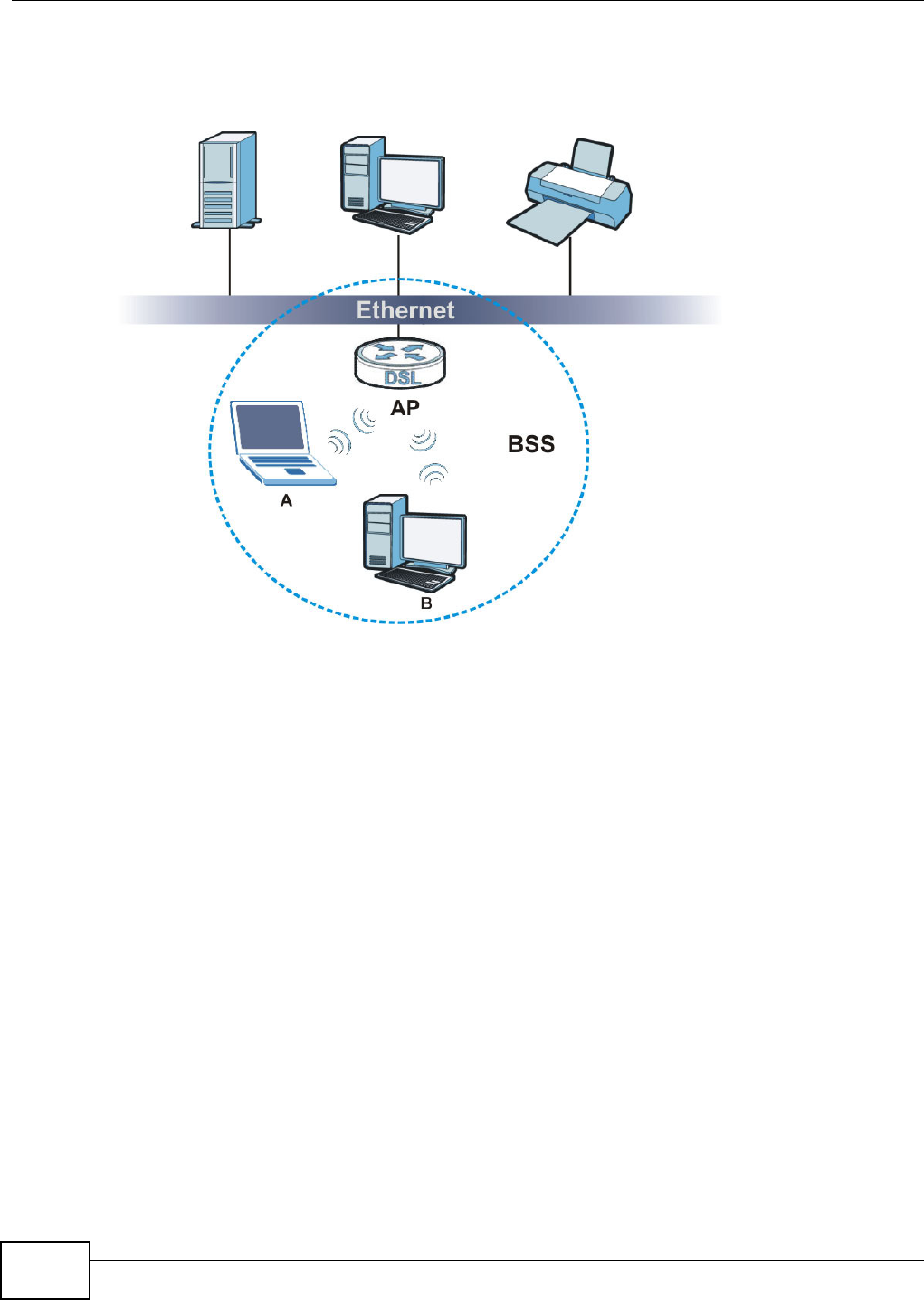
Appendix E Wireless LANs
VMG8324-B10A / VMG8324-B30A Series User’s Guide
376
disabled, wireless client A and B can st ill access t he wired network but cannot com m unicat e wit h
each other.
Figure 241 Basic Service Set
ESS
An Extended Service Set (ESS) consists of a series of overlapping BSSs, each cont aining an access
point , with each access point connected toget her by a wired network. This wired connection
bet ween APs is called a Distribution System (DS).
This type of wireless LAN t opology is called an I nfrastructure WLAN. The Access Point s not only
provide com m unication with the wired network but also m ediate wireless network t raffic in the
im m ediat e neighborhood.
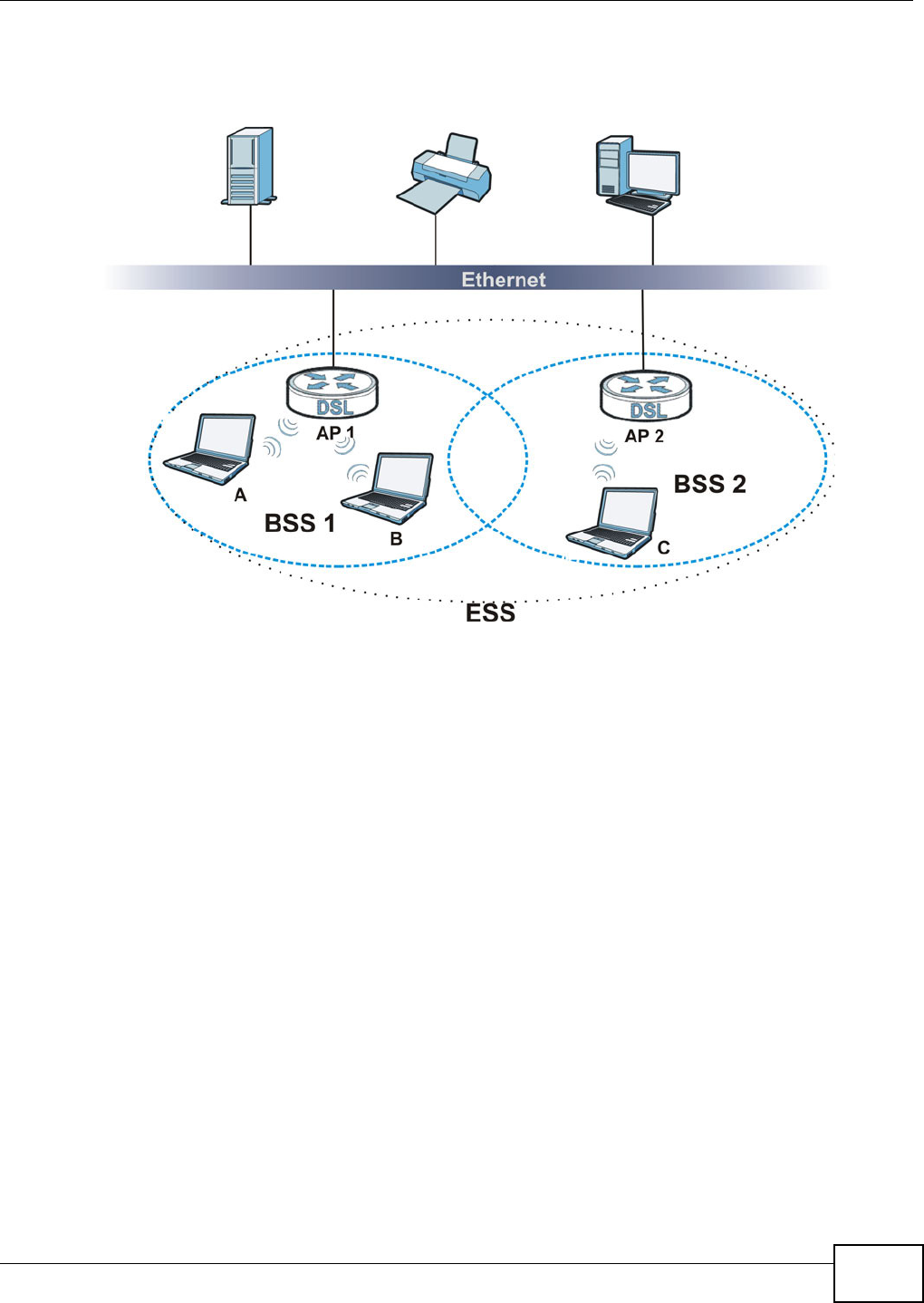
Appendix E Wireless LANs
VMG8324-B10A / VMG8324-B30A Series User’s Guide 377
An ESSI D (ESS I Dentification) uniquely ident ifies each ESS. All access points and t heir associat ed
wireless clients within t he sam e ESS m ust have the sam e ESSI D in order to com m unicat e.
Figure 242 I nfrastruct ure WLAN
Channel
A channel is the radio frequency( ies) used by wireless devices to transm it and receive data.
Channels available depend on your geographical area.
Adjacent channels part ially overlap however. To avoid interference due to overlap, your AP should
be on a channel at least five channels away from a channel that an adj acent AP is using.
RTS/CTS
A hidden node occurs when two st at ions are within range of t he sam e access point , but are not
wit hin range of each other. The following figure illust rat es a hidden node. Bot h st ations ( STA) ar e
wit hin range of t he access point ( AP) or wireless gateway, but out- of- range of each other, so they
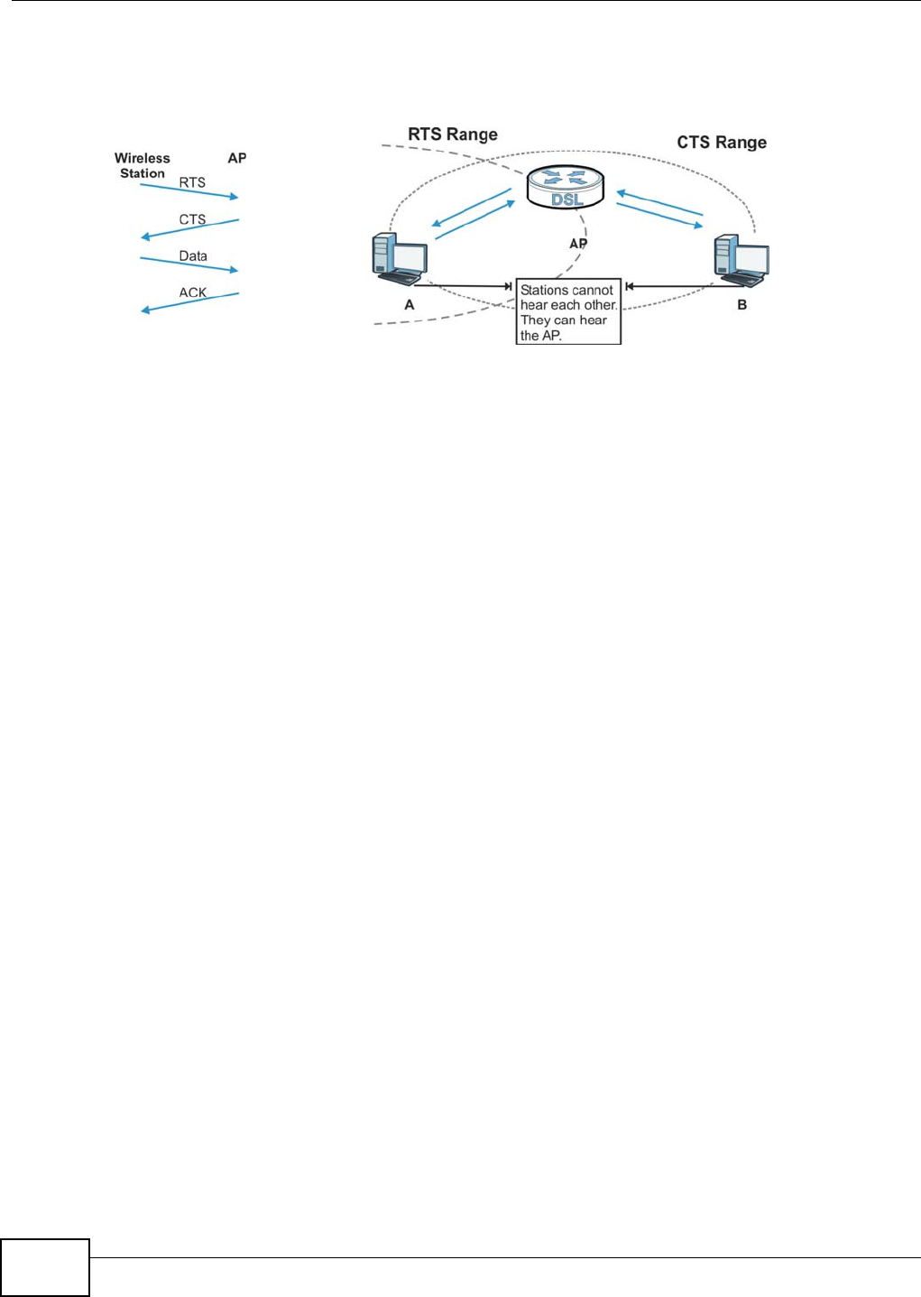
Appendix E Wireless LANs
VMG8324-B10A / VMG8324-B30A Series User’s Guide
378
cannot "hear" each other, that is they do not know if the channel is currently being used. Therefore,
they ar e considered hidden from each ot her.
Figure 243 RTS/ CTS
When st at ion A sends dat a t o the AP, it m ight not know t hat t he st ation B is already using the
channel. I f these two stat ions send dat a at t he sam e tim e, collisions m ay occur when both sets of
dat a arrive at the AP at the sam e t im e, result ing in a loss of m essages for bot h st ations.
RTS/ CTS is designed to prevent collisions due to hidden nodes. An RTS/ CTS defines the biggest
size data fram e you can send before an RTS (Request To Send) / CTS (Clear to Send) handshake is
invoked.
When a data fram e exceeds the RTS/ CTS value you set (between 0 to 2432 bytes), the stat ion
that want s to t ransm it t his fram e m ust first send an RTS ( Request To Send) m essage to the AP for
perm ission to send it . The AP then responds wit h a CTS ( Clear t o Send) m essage to all ot her
st ations wit hin it s range t o not ify them t o defer t heir transm ission. I t also reserves and confirm s
wit h the requesting stat ion t he tim e fram e for the requested t ransm ission.
St ations can send fram es sm aller t han the specified RTS/ CTS direct ly t o t he AP wit hout t he RTS
( Request To Send) / CTS ( Clear to Send) handshake.
You should only configure RTS/ CTS if the possibility of hidden nodes exists on your net work and
the "cost" of resending large fram es is m ore t han t he extra netw ork overhead involved in the RTS
( Request To Send) / CTS ( Clear to Send) handshake.
I f t he RTS/ CTS value is great er than t he Fr agm e nt at ion Threshold value ( see next) , then the
RTS (Request To Send) / CTS ( Clear to Send) handshake w ill never occur as data fram es will be
fragm ented before they reach RTS/ CTS size.
Note: Enabling t he RTS Threshold causes redundant network overhead that could
negat ively affect the throughput perform ance inst ead of providing a rem edy.
Fragmentation Threshold
A Fra gm en t a tion Thr eshold is the m axim um data fragm ent size ( bet ween 256 and 2432 byt es)
that can be sent in t he wireless network before the AP will fragment t he packet into sm aller data
fram es.
A large Fra gm ent at ion Thr eshold is r ecom m ended for net works not prone to interference while
you should set a sm aller threshold for busy net works or networks that are prone to int erference.
Appendix E Wireless LANs
VMG8324-B10A / VMG8324-B30A Series User’s Guide 379
I f t he Fragm ent a t ion Thr eshold value is sm aller than t he RTS/ CTS value (see previously) you
set t hen the RTS ( Request To Send) / CTS (Clear to Send) handshake will never occur as dat a fram es
will be fragm ent ed before t hey reach RTS/ CTS size.
IEEE 802.11g Wireless LAN
I EEE 802.11g is fully com patible w ith t he I EEE 802.11b standard. This m eans an I EEE 802.11b
adapter can int erface dir ectly wit h an I EEE 802.11g access point ( and vice versa) at 11 Mbps or
lower depending on range. I EEE 802.11g has several int erm ediate rat e steps between t he
m axim um and m inim um data rat es. The I EEE 802.11g data rat e and m odulat ion are as follows:
Wireless Security Overview
Wireless security is vit al t o your net work t o prot ect wireless com m unication bet ween wireless
client s, access point s and the wir ed net work.
Wireless security m ethods available on the Device are dat a encryption, wireless client
authent icat ion, rest rict ing access by device MAC address and hiding t he Device ident ity.
The following figure shows the relat ive effectiveness of these wireless security m ethods available on
your Dev ice.
Note: You m ust enable the sam e wireless securit y set tings on t he Device and on all
wireless client s that you want to associate with it.
Table 165 I EEE 802.11g
DATA RATE (MBPS) MODULATION
1 DBPSK ( Differential Binary Phase Shift Keyed)
2 DQPSK ( Differential Quadrature Phase Shift Key ing)
5.5 / 11 CCK (Com plem ent ary Code Keying)
6/9/12/18/24/36/48/
54
OFDM ( Ort hogonal Frequency Division Mult iplexing)
Table 166 Wireless Security Levels
SECURITY
LEVEL SECURITY TYPE
Least
Secure
Most Secure
Unique SSI D (Default)
Unique SSI D with Hide SSI D Enabled
MAC Address Filtering
WEP Encr ypt ion
I EEE802.1x EAP with RADI US Ser ver Aut hent ication
Wi-Fi Protected Access ( WPA)
WPA2

Appendix E Wireless LANs
VMG8324-B10A / VMG8324-B30A Series User’s Guide
380
IEEE 802.1x
I n June 2001, t he I EEE 802.1x standard was designed t o extend the feat ures of I EEE 802.11 t o
support extended authent ication as well as providing addit ional accounting and cont r ol features. I t
is support ed by Windows XP and a num ber of network devices. Som e advant ages of I EEE 802.1x
are:
• User based identification that allows for roam ing.
• Support for RADI US ( Rem ote Authent icat ion Dial I n User Service, RFC 2138, 2139) for
centralized user profile and accounting m anagem ent on a net work RADI US server.
• Support for EAP (Extensible Authent ication Prot ocol, RFC 2486) t hat allows addit ional
authent icat ion m ethods to be deployed with no changes t o the access point or the wireless
client s.
RADIUS
RADI US is based on a client- server m odel that support s aut hentication, aut hor izat ion and
account ing. The access point is the client and t he server is the RADI US server. The RADI US server
handles the follow ing t asks:
• Authent icat ion
Determ ines the ident ity of t he users.
• Authorization
Determ ines the network services available t o authent icated users once they are connected t o the
net work.
• Accounting
Keeps t rack of the client ’s network act ivity.
RADI US is a sim ple package exchange in which your AP acts as a m essage relay bet ween the
wireless client and the network RADI US server.
Types of RADIUS Messages
The following t ypes of RADI US m essages are exchanged bet ween the access point and t he RADI US
server for user authent icat ion:
• Access- Requ est
Sent by an access point requesting authent icat ion.
• Access- Rej ect
Sent by a RADI US server rejecting access.
• Access-Accept
Sent by a RADI US server allowing access.
• Access- Challenge
Sent by a RADI US ser ver r equest ing m ore inform at ion in order to allow access. The access point
sends a proper response from t he user and then sends anot her Access- Request m essage.
The following t ypes of RADI US m essages are exchanged bet ween the access point and t he RADI US
server for user accounting:

Appendix E Wireless LANs
VMG8324-B10A / VMG8324-B30A Series User’s Guide 381
• Accou nt ing- Requ est
Sent by the access point requesting account ing.
• Accou nt ing- Response
Sent by the RADI US server t o indicat e t hat it has st arted or st opped accounting.
I n order to ensure network securit y, t he access point and t he RADI US server use a shared secret
key, which is a password, they both know. The key is not sent over t he net work. I n addit ion t o the
shared key, password inform ation exchanged is also encrypt ed to prot ect t he net work from
unauthorized access.
Types of EAP Authentication
This section discusses som e popular authent icat ion t ypes: EAP- MD5, EAP-TLS, EAP-TTLS, PEAP and
LEAP. Your w ireless LAN device m ay not support all authent icat ion t y pes.
EAP (Extensible Aut hentication Prot ocol) is an authent icat ion protocol that runs on t op of t he I EEE
802.1x t ransport m echanism in order to support m ultiple types of user authentication. By using EAP
to interact wit h an EAP- com patible RADI US server, an access point helps a wireless stat ion and a
RADI US server perform authent icat ion.
The t y pe of aut henticat ion you use depends on the RADI US server and an int erm ediary AP( s) t hat
support s I EEE 802.1x.
For EAP-TLS aut hentication type, you m ust first have a wired connection to the network and obtain
the certificate( s) from a certificate aut hority (CA) . A cert ificat e ( also called digital I Ds) can be used
to authent icat e users and a CA issues certificates and guarantees t he identit y of each cert ificat e
owner.
EAP-MD5 (Message-Digest Algorithm 5)
MD5 authentication is the sim plest one- way authent icat ion m ethod. The authent icat ion server
sends a challenge to t he wireless client. The wireless client ‘proves’ that it knows t he password by
encrypt ing the password wit h the challenge and sends back the inform at ion. Password is not sent in
plain text .
However, MD5 authentication has som e weaknesses. Since t he authent icat ion server needs t o get
the plaintext passwords, t he passwords m ust be st ored. Thus som eone ot her than t he
authent icat ion server m ay access t he password file. I n addit ion, it is possible to im personate an
authent icat ion server as MD5 authent icat ion m ethod does not perform m utual authentication.
Finally, MD5 aut hentication m ethod does not support data encryption w ith dynam ic session key. You
m ust configure WEP encrypt ion keys for dat a encryption.
EAP-TLS (Transport Layer Security)
Wit h EAP-TLS, digital cert ificat ions are needed by bot h the server and the wireless client s for
m ut ual authent icat ion. The server present s a certificat e t o t he client . After validat ing t he ident ity of
the server, the client sends a different cert ificat e t o the server. The exchange of cert ificates is done
in t he open before a secured tunnel is creat ed. This m akes user ident ity vulnerable t o passive
att acks. A digit al certificate is an elect ronic I D card t hat authenticates t he sender’s identity.
However, to im plem ent EAP-TLS, you need a Certificat e Aut hority (CA) t o handle cert ificates, which
im poses a m anagem ent overhead.

Appendix E Wireless LANs
VMG8324-B10A / VMG8324-B30A Series User’s Guide
382
EAP-TTLS (Tunneled Transport Layer Service)
EAP-TTLS is an ext ension of the EAP-TLS aut hentication that uses cert ificat es for only the server-
side aut hentications t o est ablish a secure connection. Client authenticat ion is t hen done by sending
usernam e and password through t he secure connection, t hus client identity is protected. For client
authent icat ion, EAP-TTLS supports EAP m et hods and legacy authent icat ion m ethods such as PAP,
CHAP, MS-CHAP and MS-CHAP v2.
PEAP (Protected EAP)
Like EAP-TTLS, server- side cert ificate aut hent icat ion is used t o establish a secure connect ion, then
use sim ple usernam e and password m ethods t hr ough the secured connection to aut hent icat e the
client s, t hus hiding client ident ity. However, PEAP only support s EAP m ethods, such as EAP-MD5,
EAP- MSCHAPv2 and EAP- GTC ( EAP- Generic Token Card), for client aut hentication. EAP- GTC is
im plem ented only by Cisco.
LEAP
LEAP (Light weight Ext ensible Authent icat ion Protocol) is a Cisco im plem ent at ion of I EEE 802.1x.
Dynamic WEP Key Exchange
The AP maps a unique key that is generat ed with the RADI US server. This key expir es w hen t he
wireless connection tim es out , disconnect s or r eaut hentication tim es out. A new WEP key is
generat ed each t im e reauthentication is perform ed.
I f this feature is enabled, it is not necessary to configure a default encr yption key in t he wireless
security configurat ion screen. You m ay st ill configure and stor e keys, but they will not be used while
dynam ic WEP is enabled.
Note: EAP- MD5 cannot be used wit h Dynam ic WEP Key Exchange
For added security, certificat e-based authent ications ( EAP-TLS, EAP-TTLS and PEAP) use dynam ic
keys for dat a encryption. They are often deployed in corporate environm ents, but for public
deploym ent , a sim ple user nam e and password pair is m ore pract ical. The following t able is a
com parison of the feat ures of authent ication t ypes.
Table 167 Com parison of EAP Authent icat ion Types
EAP-MD5 EAP-TLS EAP-TTLS PEAP LEAP
Mut ual Authentication No Yes Yes Ye s Yes
Cer t ificat e – Client No Yes Opt ional Optional No
Cert ificate – Server No Yes Ye s Yes No
Dynam ic Key Exchange No Yes Ye s Yes Ye s
Credential I ntegrit y None St rong St rong Strong Moderate
Deploym ent Difficult y Easy Hard Moderat e Moderat e Moderat e
Client I dent it y Pr ot ection No No Ye s Ye s No

Appendix E Wireless LANs
VMG8324-B10A / VMG8324-B30A Series User’s Guide 383
WPA and WPA2
Wi- Fi Prot ect ed Access ( WPA) is a subset of the I EEE 802.11i st andard. WPA2 (I EEE 802.11i) is a
wireless securit y standard t hat defines st ronger encryption, aut hent icat ion and key m anagem ent
than WPA.
Key differences bet ween WPA or WPA2 and WEP are im proved dat a encryption and user
authent icat ion.
I f both an AP and t he wireless clients support WPA2 and you have an external RADI US server, use
WPA2 for st ronger data encrypt ion. I f you don't have an external RADI US server, you should use
WPA2- PSK (WPA2- Pre- Shared Key) t hat only requires a single ( identical) passw ord ent ered int o
each access point , wireless gat eway and wireless client. As long as the passwords mat ch, a wireless
client will be granted access t o a WLAN.
I f the AP or the wireless clients do not support WPA2, just use WPA or WPA- PSK depending on
whet her you have an external RADI US server or not .
Select WEP only when the AP and/ or wireless clients do not support WPA or WPA2. WEP is less
secure t han WPA or WPA2.
Encryption
WPA im proves data encryption by using Tem poral Key I ntegrity Prot ocol (TKI P) , Message I ntegrit y
Check ( MI C) and I EEE 802.1x. WPA2 also uses TKI P when required for com patibility reasons, but
offers stronger encrypt ion t han TKI P wit h Advanced Encr yption St andard ( AES) in t he Count er
m ode wit h Cipher block chaining Message authentication code Protocol (CCMP) .
TKI P uses 128- bit keys that are dynam ically generated and distributed by t he aut hentication server.
AES (Advanced Encrypt ion St andard) is a block cipher that uses a 256-bit m athem atical algorit hm
called Rij ndael. They both include a per- packet key m ixing funct ion, a Message I nt egrit y Check
( MI C) nam ed Michael, an ext ended init ialization vect or ( I V) with sequencing rules, and a re-keying
m echanism .
WPA and WPA2 regularly change and rotate the encrypt ion keys so t hat t he sam e encrypt ion key is
never used twice.
The RADI US server distributes a Pairwise Mast er Key ( PMK) key t o the AP that then set s up a key
hierarchy and m anagem ent system , using the PMK t o dynam ically generat e unique data encrypt ion
keys t o encrypt every dat a packet that is wirelessly com m unicat ed between t he AP and t he wireless
client s. This all happens in t he background aut om at ically.
The Message I ntegrity Check ( MI C) is designed t o prevent an att acker from capt uring data packets,
alt ering t hem and resending them . The MI C provides a st rong m athem atical function in which t he
receiver and the t ransm itt er each com pute and t hen com par e the MI C. I f they do not m at ch, it is
assum ed that the data has been t am pered wit h and t he packet is dropped.
By generating unique dat a encryption keys for every dat a packet and by creating an int egrity
checking m echanism (MI C) , wit h TKI P and AES it is m ore difficult t o decrypt data on a Wi- Fi
net work than WEP and difficult for an intruder to break into the network.
The encryption m echanism s used for WPA(2) and WPA(2) -PSK ar e the sam e. The only difference
bet ween the t wo is that WPA(2) -PSK uses a sim ple com m on password, instead of user- specific
credent ials. The com m on-password approach m akes WPA( 2)- PSK suscept ible to brut e-force

Appendix E Wireless LANs
VMG8324-B10A / VMG8324-B30A Series User’s Guide
384
passwor d- guessing at tacks but it ’s st ill an im provem ent over WEP as it em ploys a consistent,
single, alphanumeric password to derive a PMK which is used t o generate unique tem poral
encrypt ion keys. This prevent all wireless devices shar ing t he sam e encrypt ion keys. ( a weakness of
WEP)
User Authentication
WPA and WPA2 apply I EEE 802.1x and Ext ensible Aut henticat ion Prot ocol ( EAP) t o aut henticate
wireless clients using an ext ernal RADI US dat abase. WPA2 reduces t he num ber of key exchange
m essages from six to four (CCMP 4- way handshake) and short ens the t im e required t o connect to a
net work. Other WPA2 authent icat ion feat ures t hat are different from WPA include key caching and
pre- aut hentication. These two feat ures are opt ional and m ay not be supported in all wir eless
devices.
Key caching allows a wireless client t o store the PMK it derived through a successful authent icat ion
wit h an AP. The w ireless client uses t he PMK when it tries t o connect to the sam e AP and does not
need t o go with t he authent icat ion process again.
Pre- aut henticat ion enables fast roam ing by allowing the wireless client ( already connect ing t o an
AP) to perform I EEE 802.1x authent icat ion wit h anot her AP befor e connecting t o it .
Wireless Client WPA Supplicants
A wireless client supplicant is the soft ware t hat runs on an operat ing syst em instruct ing t he wireless
client how t o use WPA. At the tim e of writ ing, the most widely available supplicant is t he WPA patch
for Windows XP, Funk Software's Odyssey client.
The Windows XP patch is a free download that adds WPA capabilit y t o Windows XP's built-in "Zero
Configurat ion" wireless client . However, you m ust run Windows XP to use it .
WPA(2) with RADIUS Application Example
To set up WPA( 2), you need t he I P address of t he RADI US server, its port num ber ( default is 1812),
and the RADI US shared secret . A WPA( 2) application example with an ext ernal RADI US server
looks as follows. " A" is the RADI US server. "DS" is t he distribution syst em .
1The AP passes the wireless client 's aut hentication request t o t he RADI US server.
2The RADI US server t hen checks the user's identificat ion against it s dat abase and grant s or denies
net work access accordingly.
3A 256- bit Pairwise Mast er Key (PMK) is derived from t he aut hentication process by t he RADI US
server and t he client .
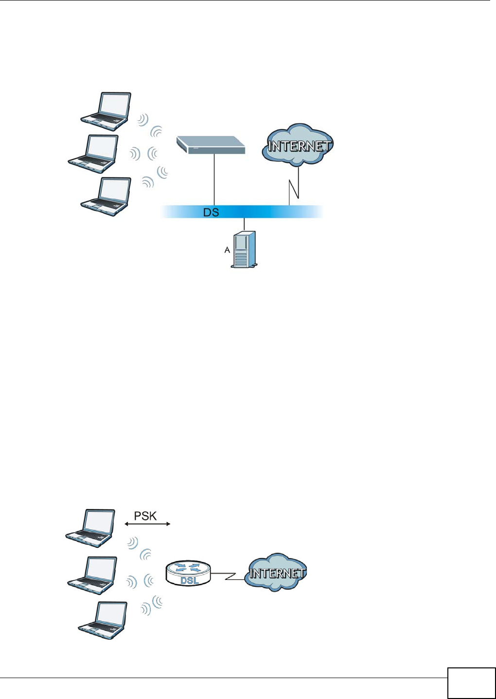
Appendix E Wireless LANs
VMG8324-B10A / VMG8324-B30A Series User’s Guide 385
4The RADI US server distributes the PMK t o the AP. The AP then set s up a key hierarchy and
m anagem ent system , using t he PMK to dynam ically generat e unique dat a encryption keys. The
keys are used to encrypt every dat a packet that is wirelessly com m unicated between t he AP and
the wireless clients.
Figure 244 WPA(2) wit h RADI US Application Exam ple
WPA(2)-PSK Application Example
A WPA( 2) -PSK applicat ion looks as follows.
1First ent er ident ical passwords int o t he AP and all wireless clients. The Pre-Shared Key ( PSK) m ust
consist of between 8 and 63 ASCI I characters or 64 hexadecim al characters ( including spaces and
sy m bols) .
2The AP checks each wireless client's password and allows it to j oin t he network only if the password
m at ches.
3The AP and w ireless clients generate a com m on PMK (Pairwise Mast er Key). The key it self is not
sent over t he net work, but is derived from the PSK and the SSI D.
4The AP and wireless clients use t he TKI P or AES encryption process, t he PMK and inform ation
exchanged in a handshake to creat e t em poral encr yption keys. They use t hese keys to encrypt data
exchanged bet ween them .
Figure 245 WPA(2) -PSK Authent icat ion

Appendix E Wireless LANs
VMG8324-B10A / VMG8324-B30A Series User’s Guide
386
Security Parameters Summary
Refer to this t able to see what other security param eters you should configure for each
authent icat ion m et hod or key m anagem ent prot ocol type. MAC address filters are not dependent on
how you configure these securit y features.
Antenna Overview
An ant enna couples RF signals ont o air. A transm it ter w ithin a wireless device sends an RF signal t o
the ant enna, which propagates t he signal t hrough the air. The antenna also operates in rever se by
capturing RF signals from t he air.
Positioning the antennas properly increases the range and coverage area of a wireless LAN.
Antenna Characteristics
Frequency
An ant enna in the frequency of 2.4GHz ( I EEE 802.11b and I EEE 802.11g) or 5GHz (I EEE 802.11a)
is needed t o com m unicate efficiently in a wireless LAN
Radiation Pattern
A radiat ion patt ern is a diagram that allow s you to visualize the shape of t he antenna’s coverage
area.
Antenna Gain
Antenna gain, m easured in dB ( decibel) , is t he increase in coverage wit hin the RF beam width.
Higher antenna gain im proves the range of the signal for bet ter com m unications.
For an indoor site, each 1 dB increase in antenna gain results in a range incr ease of approxim at ely
Table 168 Wireless Securit y Relat ional Matrix
AUTHENTICATION
METHOD/ KEY
MANAGEMENT PROTOCOL
ENCRYPTIO
N METHOD
ENTER
MANUAL KEY IEEE 802.1X
Open None No Disable
Enable wit hout Dynam ic WEP Key
Open WEP No Enable wit h Dynam ic WEP Key
Yes Enable w it hout Dynam ic WEP Key
Yes Disable
Shared WEP No Enable with Dynam ic WEP Key
Yes Enable w it hout Dynam ic WEP Key
Yes Disable
WPA TKI P/ AES No Enable
WPA-PSK TKI P/ AES Ye s Disable
WPA2 TKI P/ AES No Enable
WPA2-PSK TKI P/ AES Ye s Disable

Appendix E Wireless LANs
VMG8324-B10A / VMG8324-B30A Series User’s Guide 387
2.5% . For an unobst ructed out door sit e, each 1dB increase in gain results in a range increase of
approxim ately 5% . Actual results m ay vary depending on the net work environm ent.
Antenna gain is som etim es specified in dBi, which is how m uch t he ant enna increases t he signal
power compared to using an isot ropic ant enna. An isot ropic antenna is a t heoret ical perfect antenna
that sends out radio signals equally well in all direct ions. dBi represents the t r ue gain t hat t he
antenna provides.

Appendix E Wireless LANs
VMG8324-B10A / VMG8324-B30A Series User’s Guide
388

VMG8324-B10A / VMG8324-B30A Series User’s Guide 389
APPENDIX F
IPv6
Overview
I Pv6 (I nternet Prot ocol version 6) , is designed t o enhance I P address size and features. The
increase in I Pv6 address size t o 128 bits ( from t he 32- bit I Pv4 address) allows up t o 3.4 x 1038 I P
addresses.
IPv6 Addressing
The 128- bit I Pv6 address is writt en as eight 16-bit hexadecim al blocks separated by colons (: ) . This
is an exam ple I Pv6 address 2001:0db8:1a2b:0015:0000:0000:1a2f:0000.
I Pv6 addresses can be abbreviated in t wo ways:
• Leading zeros in a block can be om it ted. So 2001:0db8:1a2b:0015:0000:0000:1a2f:0000 can
be writ ten as 2001:db8:1a2b:15:0:0:1a2f:0.
• Any number of consecutive blocks of zer os can be replaced by a double colon. A double colon can
only appear once in an I Pv6 address. So 2001:0db8:0000:0000:1a2f:0000:0000:0015 can be
writ ten as 2001:0db8::1a2f:0000:0000:0015, 2001:0db8:0000:0000:1a2f::0015,
2001:db8::1a2f:0:0:15 or 2001:db8:0:0:1a2f::15.
Prefix and Prefix Length
Sim ilar t o an I Pv4 subnet m ask, I Pv6 uses an addr ess pr efix to repr esent t he net work address. An
I Pv6 prefix lengt h specifies how m any m ost significant bits ( st art from t he left ) in t he address
com pose the net work address. The prefix length is writ ten as “/ x” where x is a num ber. For
exam ple,
2001:db8:1a2b:15::1a2f:0/32
m eans t hat the first 32 bits ( 2001:db8) is the subnet prefix.
Link-local Address
A link-local address uniquely ident ifies a device on t he local netw ork ( the LAN) . I t is sim ilar to a
“ private I P address” in I Pv4. You can have the sam e link-local address on m ult iple interfaces on a
device. A link- local unicast address has a predefined prefix of fe80: : / 10. The link- local unicast
address form at is as follows.
Table 169 Link-local Unicast Address Form at
1111 1110 10 0 I nterface I D
10 bits 54 bit s 64 bit s

Appendix F IPv6
VMG8324-B10A / VMG8324-B30A Series User’s Guide
390
Global Address
A global address uniquely identifies a device on t he I nt ernet . I t is sim ilar to a “ public I P address” in
I Pv4. A global unicast address st arts wit h a 2 or 3.
Unspecified Address
An unspecified address (0: 0: 0: 0: 0: 0: 0: 0 or : : ) is used as t he source address when a device does
not have it s own address. I t is sim ilar to “ 0.0.0.0” in I Pv4.
Loopback Address
A loopback address (0: 0: 0: 0: 0: 0: 0: 1 or : : 1) allow s a host t o send packets t o itself. I t is sim ilar to
“ 127.0.0.1” in I Pv4.
Multicast Address
I n I Pv6, m ulticast addresses provide t he sam e funct ionality as I Pv4 broadcast addresses.
Broadcasting is not support ed in I Pv6. A m ult icast address allows a host t o send packet s to all hosts
in a m ulticast group.
Multicast scope allows you to det erm ine the size of t he m ulticast group. A m ulticast address has a
predefined prefix of ff00: : / 8. The following t able describes som e of the predefined m ult icast
addresses.
The following t able describes the m ulticast addresses which are reserved and can not be assigned
to a m ulticast group.
Table 170 Predefined Mult icast Address
MULTICAST ADDRESS DESCRIPTION
FF01:0:0:0:0:0:0:1 All hosts on a local node.
FF01:0:0:0:0:0:0:2 All routers on a local node.
FF02:0:0:0:0:0:0:1 All hosts on a local connect ed link.
FF02:0:0:0:0:0:0:2 All routers on a local connected link.
FF05:0:0:0:0:0:0:2 All rout ers on a local site.
FF05:0:0:0:0:0:1:3 All DHCP severs on a local site.
Table 171 Reserved Multicast Address
MULTICAST ADDRESS
FF00:0:0:0:0:0:0:0
FF01:0:0:0:0:0:0:0
FF02:0:0:0:0:0:0:0
FF03:0:0:0:0:0:0:0
FF04:0:0:0:0:0:0:0
FF05:0:0:0:0:0:0:0
FF06:0:0:0:0:0:0:0
FF07:0:0:0:0:0:0:0
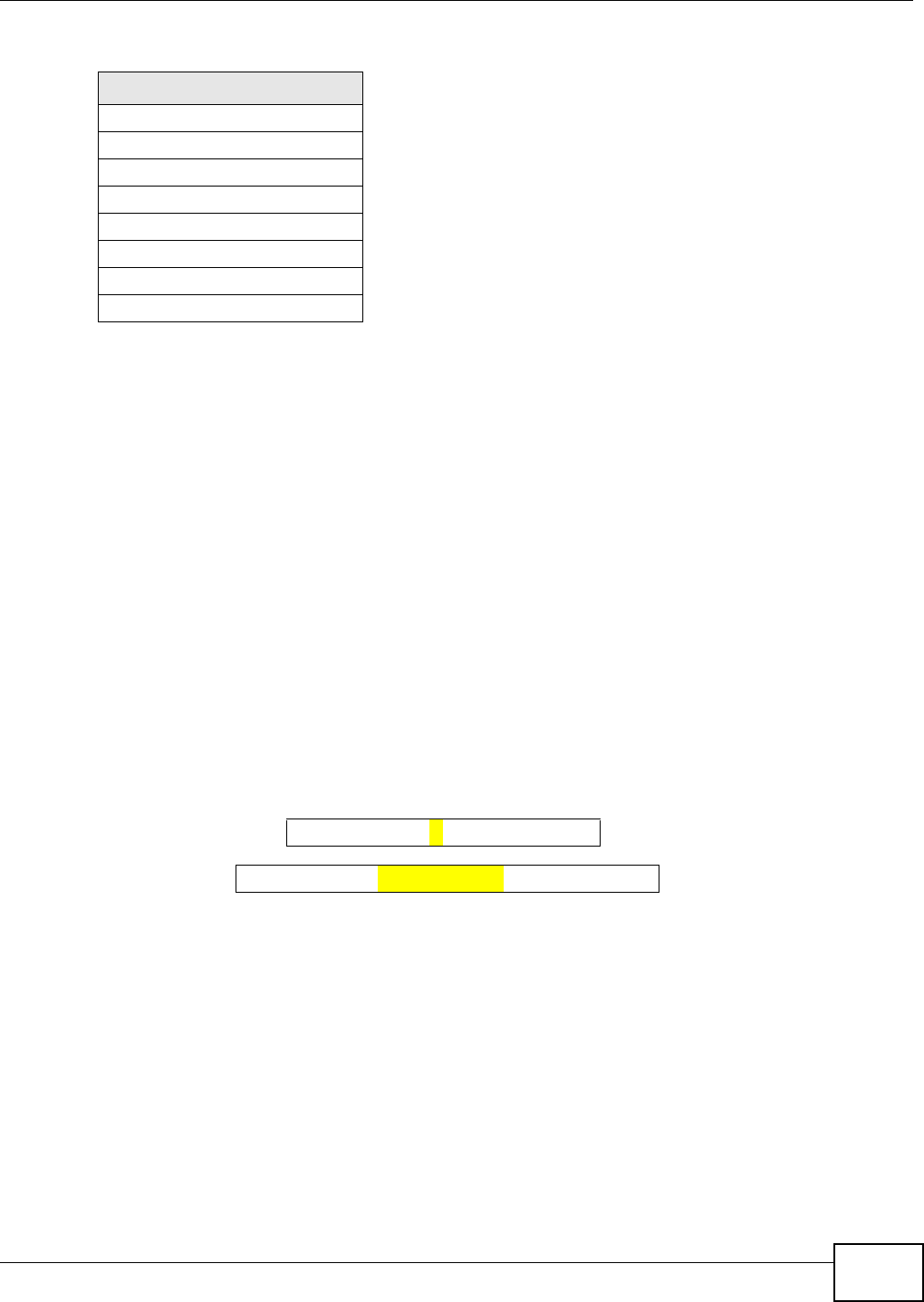
Appendix F IPv6
VMG8324-B10A / VMG8324-B30A Series User’s Guide 391
Subnet Masking
Bot h an I Pv6 address and I Pv6 subnet m ask com pose of 128- bit binary digit s, which are divided
into eight 16- bit blocks and writt en in hexadecim al notat ion. Hexadecim al uses four bit s for each
charact er ( 1 ~ 10, A ~ F). Each block’s 16 bits are then represent ed by four hexadecim al
charact ers. For exam ple, FFFF: FFFF: FFFF: FFFF: FC00: 0000: 0000: 0000.
Interface ID
I n I Pv6, an interface I D is a 64-bit ident ifier. I t identifies a physical interface (for exam ple, an
Et hernet port ) or a virtual interface ( for exam ple, the m anagem ent I P address for a VLAN). One
interface should have a unique interface I D.
EUI-64
The EUI- 64 ( Extended Unique I dentifier) defined by t he I EEE ( I nstit ut e of Elect rical and Electronics
Engineers) is an int erface I D form at designed t o adapt wit h I Pv6. I t is derived from the 48- bit ( 6-
byt e) Et hernet MAC address as shown next. EUI - 64 inserts t he hex digit s fffe bet ween the t hird and
fourt h byt es of the MAC address and com plem ent s the sevent h bit of t he first byt e of t he MAC
address. See t he following exam ple.
Identity Association
An I dentit y Associat ion ( I A) is a collection of addresses assigned to a DHCP client, through which
the server and client can m anage a set of relat ed I P addresses. Each I A m ust be associated wit h
exact ly one int erface. The DHCP client uses t he I A assigned t o an interface t o obt ain configuration
from a DHCP server for t hat int erface. Each I A consist s of a unique I AI D and associated I P
infor m at ion.
The I A t ype is the t ype of address in the I A. Each I A holds one type of address. I A_NA m eans an
identity associat ion for non-t em porary addresses and I A_TA is an identit y association for t em porary
addresses. An I A_NA option contains the T1 and T2 fields, but an I A_TA opt ion does not . The
DHCPv6 server uses T1 and T2 t o control the t im e at which the client cont acts with t he server t o
extend the lifet im es on any addresses in t he I A_NA befor e the lifet im es expire. After T1, the client
sends t he server (S1 ) ( from which the addresses in t he I A_NA were obt ained) a Renew m essage. I f
FF08:0:0:0:0:0:0:0
FF09:0:0:0:0:0:0:0
FF0A:0:0:0:0:0:0:0
FF0B:0:0:0:0:0:0:0
FF0C:0:0:0:0:0:0:0
FF0D:0:0:0:0:0:0:0
FF0E:0:0:0:0:0:0:0
FF0F:0:0:0:0:0:0:0
Table 171 Reserved Multicast Address ( continued)
MULTICAST ADDRESS
MAC 00 : 13 : 49 : 12 : 34 : 56
EUI -6 4 02: 13 : 49 :FF :FE : 12 : 34 : 56

Appendix F IPv6
VMG8324-B10A / VMG8324-B30A Series User’s Guide
392
the tim e T2 is reached and the server does not respond, t he client sends a Rebind m essage to any
available server (S2 ) . For an I A_TA, t h e client m ay send a Renew or Rebind m essage at t he client 's
discret ion.
DHCP Relay Agent
A DHCP relay agent is on t he sam e net work as t he DHCP clients and helps forward m essages
bet ween the DHCP server and client s. When a client cannot use its link- local address and a well-
known m ult icast address t o locat e a DHCP server on its netw ork, it t hen needs a DHCP relay agent
to send a message t o a DHCP server t hat is not at t ached to the sam e network.
The DHCP relay agent can add the rem ot e ident ification ( rem ot e-I D) option and t he interface-I D
option t o the Relay-Forward DHCPv6 m essages. The rem ot e-I D opt ion carries a user- defined string,
such as the system nam e. The interface-I D opt ion provides slot num ber, port inform at ion and the
VLAN I D to the DHCPv6 server. The r em ot e-I D opt ion ( if any) is st ripped from t he Relay-Reply
m essages before the relay agent sends the packets t o the clients. The DHCP server copies t he
interface-I D option from the Relay-Forward m essage int o the Relay- Reply m essage and sends it to
the relay agent . The interface- I D should not change even after the relay agent rest ar t s.
Prefix Delegation
Prefix delegat ion enables an I Pv6 rout er to use t he I Pv6 prefix ( net work addr ess) received from t he
I SP ( or a connected uplink router) for it s LAN. The Device uses the received I Pv6 prefix (for
exam ple, 2001: db2: : / 48) t o generate it s LAN I P address. Through sending Router Advertisem ent s
( RAs) regularly by m ult icast, the Device passes the I Pv6 prefix inform ation to it s LAN host s. The
host s t hen can use the prefix to generate their I Pv6 addresses.
ICMPv6
I nternet Control Message Protocol for I Pv6 (I CMPv6 or I CMP for I Pv6) is defined in RFC 4443.
I CMPv6 has a preceding Next Header value of 58, which is different from t he value used to ident ify
I CMP for I Pv4. I CMPv6 is an integral part of I Pv6. I Pv6 nodes use I CMPv6 t o report errors
encount ered in packet processing and perform ot her diagnost ic funct ions, such as " ping".
Neighbor Discovery Protocol (NDP)
The Neighbor Discovery Protocol (NDP) is a prot ocol used to discover other I Pv6 devices and track
neighbor ’s reachability in a net w ork. An I Pv6 device uses the following I CMPv6 m essages types:
• Neighbor solicit at ion: A request from a host to det erm ine a neighbor’s link- layer address ( MAC
address) and detect if the neighbor is st ill reachable. A neighbor being “reachable” m eans it
responds to a neighbor solicitat ion m essage ( from the host) with a neighbor advert isem ent
m essage.
T1
T2
Renew Rebind
Rebind
to S1
Renew
to S1
Renew
to S1
Renew
to S1
Renew
to S1
Renew
to S1
to S2
to S2

Appendix F IPv6
VMG8324-B10A / VMG8324-B30A Series User’s Guide 393
• Neighbor advert isem ent: A response from a node t o announce its link-layer address.
• Router solicit at ion: A request from a host t o locat e a rout er t hat can act as the default router and
forward packets.
• Router advertisem ent : A response to a rout er solicitat ion or a periodical m ulticast advertisem ent
from a rout er t o advert ise it s presence and other param eters.
IPv6 Cache
An I Pv6 host is required to have a neighbor cache, destinat ion cache, prefix list and default router
list. The Device m aint ains and updates its I Pv6 caches constant ly using the inform ation from
response m essages. I n I Pv6, t he Device configures a link- local address aut om atically, and t hen
sends a neighbor solicit ation m essage t o check if the address is unique. I f there is an address t o be
resolved or verified, t he Device also sends out a neighbor solicit ation m essage. When the Device
receives a neighbor advert isem ent in response, it st ores the neighbor’s link-layer address in the
neighbor cache. When t he Device uses a rout er solicit ation m essage t o query for a rout er and
receives a rout er advert isem ent m essage, it adds the r out er’s inform ation to t he neighbor cache,
prefix list and destination cache. The Device creat es an ent ry in the default router list cache if the
router can be used as a default router.
When the Device needs t o send a packet, it first consults the dest ination cache to det erm ine the
next hop. I f there is no m atching entry in t he destination cache, the Device uses t he prefix list t o
det erm ine whet her the dest inat ion address is on-link and can be reached directly wit hout passing
through a router. I f the address is unlink, t he address is considered as the next hop. Ot herwise, t he
Device det erm ines the next-hop from t he default rout er list or rout ing table. Once the next hop I P
address is known, t he Device looks int o the neighbor cache to get t he link- layer address and sends
the packet when t he neighbor is reachable. I f the Device cannot find an entry in t he neighbor cache
or the st ate for t he neighbor is not reachable, it start s the address resolut ion process. This helps
reduce the num ber of I Pv6 solicit ation and advert isem ent m essages.
Multicast Listener Discovery
The Mult icast List ener Discovery (MLD) prot ocol ( defined in RFC 2710) is derived fr om I Pv4's
I nternet Group Managem ent Prot ocol version 2 (I GMPv2). MLD uses I CMPv6 m essage t ypes, rather
than I GMP message t ypes. MLDv1 is equivalent t o I GMPv2 and MLDv2 is equivalent t o I GMPv3.
MLD allows an I Pv6 swit ch or router to discover t he presence of MLD listeners who wish t o receive
m ulticast packets and the I P addresses of mult icast groups the host s want t o j oin on its networ k.
MLD snooping and MLD proxy ar e analogous to I GMP snooping and I GMP proxy in I Pv4.
MLD filtering cont rols which m ulticast groups a port can j oin.
MLD Messages
A m ulticast router or swit ch periodically sends general queries t o MLD hosts t o updat e the m ult icast
forwarding t able. When an MLD host wants to join a m ulticast group, it sends an MLD Report
m essage for t hat address.
An MLD Done m essage is equivalent t o an I GMP Leave m essage. When an MLD host wants t o leave
a m ult icast group, it can send a Done m essage t o t he rout er or switch. The router or switch t hen
sends a group-specific query to the port on which the Done m essage is received to det erm ine if
ot her devices connected t o t his port should rem ain in the group.

Appendix F IPv6
VMG8324-B10A / VMG8324-B30A Series User’s Guide
394
Example - Enabling IPv6 on Windows XP/2003/Vista
By default , Windows XP and Windows 2003 support I Pv6. This exam ple shows you how t o use the
ipv6 install com m and on Windows XP/ 2003 t o enable I Pv6. This also displays how t o use the
ipconfig com m and to see aut o-generated I P addresses.
I Pv6 is inst alled and enabled by default in Windows Vista. Use the ipconfig com m and t o check
your autom at ic configured I Pv6 address as well. You should see at least one I Pv6 address available
for t he interface on your com puter.
Example - Enabling DHCPv6 on Windows XP
Windows XP does not support DHCPv6. I f your net work uses DHCPv6 for I P address assignm ent ,
you have to addit ionally inst all a DHCPv6 client software on your Windows XP. (Note: I f you use
st atic I P addresses or Router Advertisem ent for I Pv6 address assignm ent in your net work, ignore
this sect ion.)
This exam ple uses Dibbler as the DHCPv6 client. To enable DHCPv6 client on your com puter:
1I nst all Dibbler and select the DHCPv6 client opt ion on your com put er.
2After the installat ion is com plete, select St a r t > All Program s > D ibbler - DHCPv6 > Clien t
I nsta ll as se rvice.
3Select St a r t > Cont rol Pan e l > Adm in istr at ive Tools > Se rvices.
C:\>ipv6 install
Installing...
Succeeded.
C:\>ipconfig
Windows IP Configuration
Ethernet adapter Local Area Connection:
Connection-specific DNS Suffix . :
IP Address. . . . . . . . . . . . : 10.1.1.46
Subnet Mask . . . . . . . . . . . : 255.255.255.0
IP Address. . . . . . . . . . . . : fe80::2d0:59ff:feb8:103c%4
Default Gateway . . . . . . . . . : 10.1.1.254
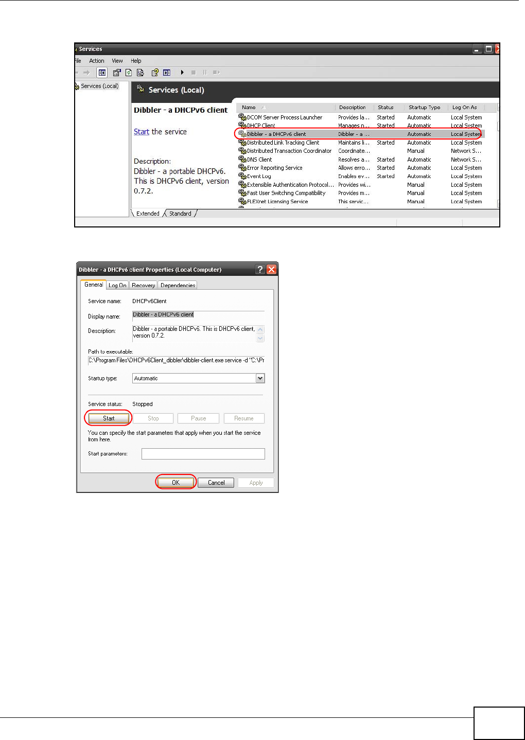
Appendix F IPv6
VMG8324-B10A / VMG8324-B30A Series User’s Guide 395
4Double click Dibbler - a D HCPv6 client .
5Click St a r t and then OK.
6Now your com puter can obtain an I Pv6 address from a DHCPv6 server.
Example - Enabling IPv6 on Windows 7
Windows 7 supports I Pv6 by default. DHCPv6 is also enabled when you enable I Pv6 on a Windows 7
com puter.
To enable I Pv6 in Windows 7:
1Select Contr ol Pane l > N et w or k and Sha ring Cent er > Loca l Area Connection .
2Select the I nt er net Pr ot ocol Version 6 ( TCP/ I Pv6 ) checkbox to enable it.
3Click OK t o save t he change.
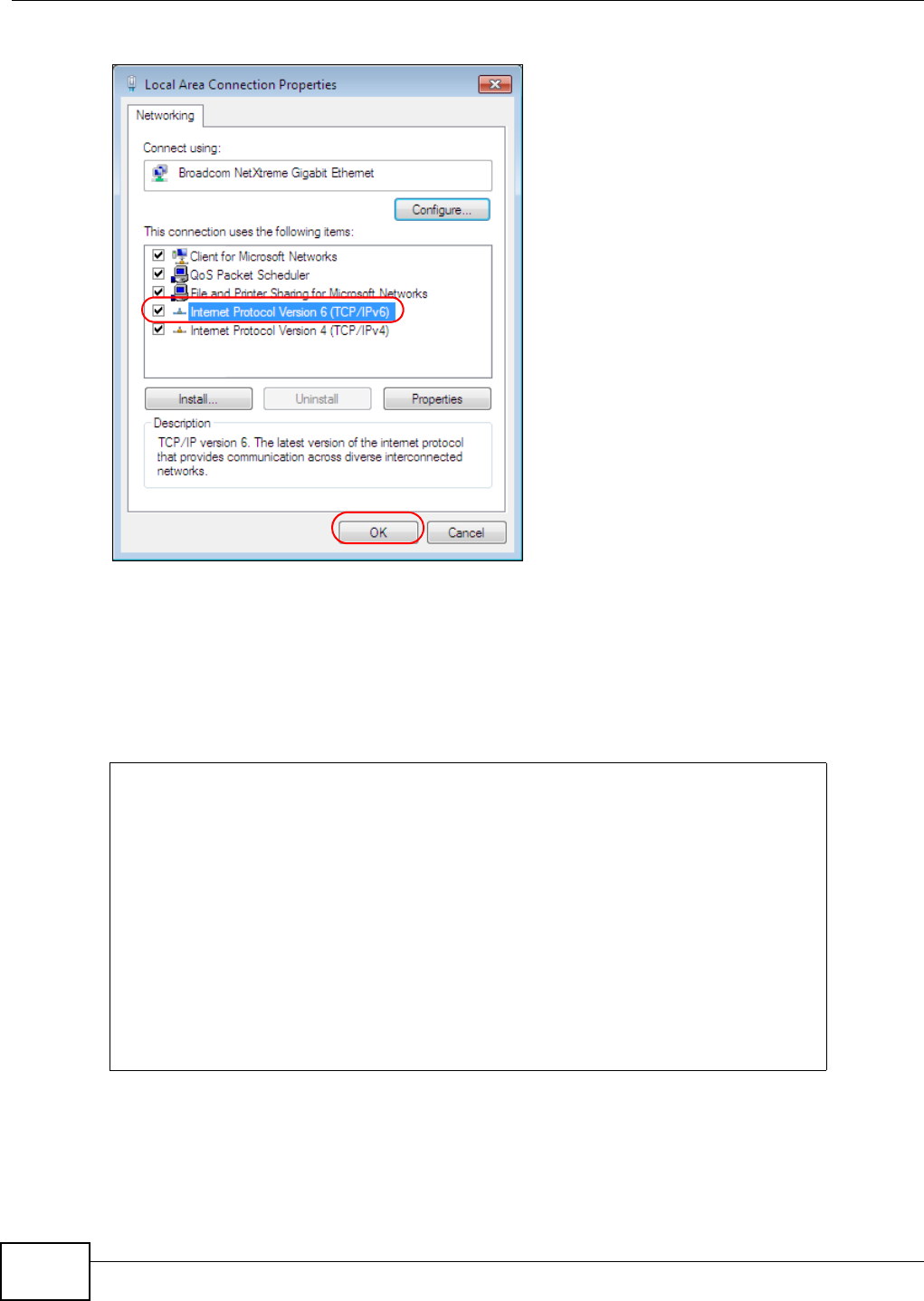
Appendix F IPv6
VMG8324-B10A / VMG8324-B30A Series User’s Guide
396
4Click Close t o exit t he Loca l Are a Con n ect ion St at us screen.
5Select St a r t > All Progr am s > Accessorie s > Com m a nd Pr om pt.
6Use t he ipconfig com m and to check your dynam ic I Pv6 address. This exam ple shows a global
address ( 2001: b021: 2d: : 1000) obtained from a DHCP server.
C:\>ipconfig
Windows IP Configuration
Ethernet adapter Local Area Connection:
Connection-specific DNS Suffix . :
IPv6 Address. . . . . . . . . . . : 2001:b021:2d::1000
Link-local IPv6 Address . . . . . : fe80::25d8:dcab:c80a:5189%11
IPv4 Address. . . . . . . . . . . : 172.16.100.61
Subnet Mask . . . . . . . . . . . : 255.255.255.0
Default Gateway . . . . . . . . . : fe80::213:49ff:feaa:7125%11
172.16.100.254

VMG8324-B10A / VMG8324-B30A Series User’s Guide 397
APPENDIX G
Services
The following t able list s som e com m only-used services and t heir associated protocols and port
num ber s.
•N a m e : This is a short , descriptive nam e for t he service. You can use this one or create a
different one, if you like.
•Pr ot ocol: Th is is t h e t y p e of I P p r ot oco l u sed by t h e ser v ice. I f t h is is TCP/ UDP, then the service
uses the sam e port num ber wit h TCP and UDP. I f t his is USER- D EFI N ED, t he Po rt ( s) is t he I P
protocol num ber, not the port num ber.
•Po rt ( s) : This value depends on the Pr ot ocol.
• If the Pr ot ocol is TCP, UD P, or TCP/ UDP, t his is the I P port num ber.
• If the Pr ot ocol is USER, t his is the I P protocol num ber.
•D e scr ip t ion : This is a brief explanation of t he applicat ions that use t his service or t he situations
in which this service is used.

Appendix G Services
VMG8324-B10A / VMG8324-B30A Series User’s Guide
398
Table 172 Exam ples of Services
NAME PROTOCOL PORT(S) DESCRIPTION
AH ( I PSEC_TUNNEL) User-Defined 51 The I PSEC AH (Authenticat ion Header)
tunneling prot ocol uses this service.
AI M TCP 5190 AOL’s I nternet Messenger service.
AUTH TCP 113 Authenticat ion prot ocol used by som e
server s.
BGP TCP 179 Border Gateway Protocol.
BOOTP_CLI ENT UDP 68 DHCP Client.
BOOTP_SERVER UDP 67 DHCP Server.
CU- SEEME TCP/ UDP
TCP/ UDP
7648
24032
A popular videoconferencing solution from
Whit e Pines Software.
DNS TCP/ UDP 53 Dom ain Nam e Server, a service t hat
m at ches web nam es ( for instance
www.zyxel.com ) to I P num bers.
ESP
( I PSEC_TUNNEL)
User-Defined 50 The I PSEC ESP (Encapsulation Secur ity
Prot ocol) tunneling pr ot ocol uses this
service.
FI NGER TCP 79 Finger is a UNI X or I nternet related
com m and that can be used to find out if a
user is logged on.
FTP TCP
TCP
20
21
File Transfer Protocol, a program to enable
fast t ransfer of files, including large files
that m ay not be possible by e- m ail.
H.323 TCP 1720 NetMeeting uses this prot ocol.
HTTP TCP 80 Hyper Text Transfer Prot ocol - a client/
server prot ocol for the wor ld wide web.
HTTPS TCP 443 HTTPS is a secured ht t p session oft en used
in e-com m erce.
I CMP User-Defined 1I nternet Cont rol Message Protocol is often
used for diagnost ic purposes.
I CQ UDP 4000 This is a popular I nter net chat program .
I GMP (MULTI CAST) User-Defined 2I nt ernet Group Mult icast Protocol is used
when sending packet s t o a specific group
of hosts.
I KE UDP 500 The I nter net Key Exchange algorithm is
used for key dist ribution and m anagem ent.
I MAP4 TCP 143 The I nt ernet Message Access Pr ot ocol is
used for e-m ail.
I MAP4S TCP 993 This is a m ore secure v ersion of I MAP4 t hat
runs over SSL.
I RC TCP/ UDP 6667 This is anot her popular I nternet chat
pr ogram .
MSN Messenger TCP 1863 Microsoft Networ ks’ m essenger serv ice
uses t his protocol.
Net BI OS TCP/ UDP
TCP/ UDP
TCP/ UDP
TCP/ UDP
137
138
139
445
The Network Basic I nput/ Out put System is
used for com m unication between
com put ers in a LAN.

Appendix G Services
VMG8324-B10A / VMG8324-B30A Series User’s Guide 399
NEW- I CQ TCP 5190 An I nter net chat program .
NEWS TCP 144 A prot ocol for news groups.
NFS UDP 2049 Network File Syst em - NFS is a client/
server dist ributed file serv ice t hat prov ides
transpar ent file sharing for net w ork
env iron m ent s.
NNTP TCP 119 Net w ork News Transport Protocol is the
delivery m echanism for the USENET
newsgroup service.
PI NG User-Defined 1Packet I Nt ernet Groper is a pr ot ocol t hat
sends out I CMP echo request s t o test
whet her or not a rem ot e host is reachable.
POP3 TCP 110 Post Office Protocol version 3 lets a client
com puter get e- m ail from a POP3 ser ver
through a t em porary connect ion ( TCP/ IP or
ot her ) .
POP3S TCP 995 This is a m ore secure version of POP3 t hat
runs over SSL.
PPTP TCP 1723 Point-to-Point Tunneling Protocol enables
secure transfer of data over public
net works. This is the control channel.
PPTP_TUNNEL (GRE) User- Defined 47 PPTP (Point- to-Point Tunneling Protocol)
enables secure transfer of dat a over public
net works. This is the data channel.
RCMD TCP 512 Rem ote Com m and Service.
REAL_AUDI O TCP 7070 A stream ing audio service that enables real
tim e sound over t he web.
REXEC TCP 514 Rem ot e Execut ion Daem on.
RLOGI N TCP 513 Rem ot e Login.
ROADRUNNER TCP/ UDP 1026 This is an I SP that provides services mainly
for cable m odem s.
RTELNET TCP 107 Rem ot e Teln et.
RTSP TCP/ UDP 554 The Real Tim e St ream ing (m edia control)
Prot ocol ( RTSP) is a rem ot e control for
m ultim edia on t he I nt ernet.
SFTP TCP 115 The Sim ple File Transfer Prot ocol is an old
way of t ransferr ing files bet ween
com pu t er s.
SMTP TCP 25 Sim ple Mail Transfer Prot ocol is the
m essage- exchange standard for the
I nt ernet . SMTP enables you t o m ove
m essages from one e-m ail server t o
anot her.
SMTPS TCP 465 This is a m ore secure version of SMTP t hat
runs over SSL.
SNMP TCP/ UDP 161 Sim ple Network Managem ent Program .
SNMP-TRAPS TCP/ UDP 162 Traps for use wit h the SNMP (RFC: 1215) .
Table 172 Exam ples of Services (continued)
NAME PROTOCOL PORT(S) DESCRIPTION

Appendix G Services
VMG8324-B10A / VMG8324-B30A Series User’s Guide
400
SQL-NET TCP 1521 Structur ed Query Language is an interface
t o access data on m any different types of
dat abase syst em s, including m ainfram es,
m idrange syst em s, UNI X syst em s and
net work servers.
SSDP UDP 1900 The Sim ple Service Discovery Prot ocol
suppor t s Universal Plug-and- Play ( UPnP).
SSH TCP/ UDP 22 Secure Shell Rem ote Login Program .
STRM WORKS UDP 1558 Stream Works Prot ocol.
SYSLOG UDP 514 Sy slog allows you t o send syst em logs t o a
UNI X server.
TACACS UDP 49 Login Host Protocol used for (Term inal
Access Cont roller Access Control Sy stem ) .
TELNET TCP 23 Telnet is t he login and t erm inal em ulation
protocol com m on on t he I nt ernet and in
UNI X env ironm ents. I t operat es over TCP/
I P networks. I ts prim ary function is to
allow users t o log int o rem ote host
sy stem s.
VDOLI VE TCP
UDP
7000
user-
defined
A videoconfer encing solution. The UDP port
num ber is specified in t he applicat ion.
Table 172 Exam ples of Services (continued)
NAME PROTOCOL PORT(S) DESCRIPTION

VMG8324-B10A / VMG8324-B30A Series User’s Guide 401
APPENDIX H
Legal Information
Copyright
Copyright © 2013 by ZyXEL Com municat ions Corporation.
The cont ent s of t his publication m ay not be reproduced in any part or as a whole, transcribed,
st ored in a retrieval syst em , translated int o any language, or t ransm itt ed in any form or by any
m eans, electronic, m echanical, m agnet ic, opt ical, chem ical, photocopying, m anual, or otherwise,
wit hout t he prior writ ten perm ission of ZyXEL Com m unicat ions Corporation.
Published by ZyXEL Com m unications Corporation. All rights reserved.
Disclaimer
ZyXEL does not assum e any liability ar ising out of the application or use of any product s, or
soft ware described herein. Neit her does it convey any license under it s patent right s nor t he pat ent
right s of ot hers. ZyXEL furt her reserves the right to m ake changes in any products described herein
wit hout notice. This publication is subj ect t o change wit hout notice.
Certifications
Federal Communications Commission (FCC) Interference Statement
The device com plies with Part 15 of FCC rules. Operation is subj ect t o t he following two condit ions:
• This device m ay not cause harm ful interference.
• This device m ust accept any int erference received, including interference that m ay cause
undesired operations.
This device has been test ed and found to com ply with t he lim it s for a Class B digital device pursuant
to Part 15 of t he FCC Rules. These lim it s are designed t o provide reasonable prot ect ion against
harm ful int erference in a resident ial installat ion. This device generates, uses, and can radiate radio
frequency energy, and if not inst alled and used in accordance with the inst ructions, m ay cause
harm ful int erference to radio com m unicat ions. However, there is no guarantee t hat int erfer ence will
not occur in a part icular installation.
I f this device does cause harm ful interference t o radio/ television recept ion, which can be
det erm ined by t urning t he device off and on, the user is encouraged to try to correct the
interfer ence by one or m ore of the follow ing m easures:
1Reorient or r elocat e t he receiving antenna.
2I ncrease the separation bet ween the equipm ent and the receiver.

Appendix H Legal Information
VMG8324-B10A / VMG8324-B30A Series User’s Guide
402
3Connect t he equipm ent int o an out let on a circuit different from that t o which t he receiver is
connect ed.
4Consult t he dealer or an experienced radio/ TV technician for help.
FCC Radiation Exposure Statement
• This transm it t er m ust not be co-locat ed or operat ing in conjunct ion wit h any other ant enna or
transm it ter.
• I EEE 802.11b or 802.11g operation of t his product in t he U.S.A. is firm ware- lim it ed to channels 1
through 11.
• To com ply with FCC RF exposure com pliance requirem ent s, a separation dist ance of at least 20
cm m ust be m aintained bet ween t he antenna of t his device and all persons.
注意 !
依據 低率電波輻射性電機管理辦法
第十二條 經型式認證合格之低率射頻電機,非經許可,公司商號或使用
者均不得擅自變更頻率大率或變更原設計之特性及能
第十四條 低率射頻電機之使用不得影響飛航安及干擾合法通信;經發現
有干擾現象時,應立即停用,並改善至無干擾時方得繼續使用
前項合法通信,指依電信規定作業之無線電信低率射頻電機須忍
受合法通信或工業科學及醫療用電波輻射性電機設備之干擾
本機限在不干擾合法電臺與不受被干擾保障條件下於室使用
減少電磁波影響,請妥適使用
Notices
Changes or m odifications not expressly approved by t he part y responsible for com pliance could
void the user's aut horit y t o operate the equipm ent.
This Class B digit al apparatus complies wit h Canadian I CES-003.
Cet appareil num érique de la classe B est conform e à la norm e NMB- 003 du Canada.
ZyXEL Limited Warranty
ZyXEL warrant s to the original end user ( purchaser) that this product is free from any defects in
m aterials or workm anship for a period of up t o t wo years from t he dat e of purchase. During t he
warranty period, and upon proof of purchase, should t he product have indicat ions of failure due t o
fault y workm anship and/ or m aterials, ZyXEL will, at it s discret ion, repair or replace t he defect ive
product s or com ponent s without charge for either part s or labor, and t o whatever ext ent it shall
deem necessary t o restore the product or com ponent s to proper operating condit ion. Any
replacem ent will consist of a new or re- m anufact ured funct ionally equivalent product of equal or
higher value, and will be solely at the discret ion of ZyXEL. This warrant y shall not apply if the

Appendix H Legal Information
VMG8324-B10A / VMG8324-B30A Series User’s Guide 403
product has been m odified, m isused, tam pered wit h, dam aged by an act of God, or subj ect ed to
abnorm al working conditions.
Note
Repair or replacem ent, as provided under this warranty, is the exclusive rem edy of the purchaser.
This warranty is in lieu of all ot her warrant ies, express or im plied, including any im plied warranty of
m erchantability or fit ness for a particular use or purpose. ZyXEL shall in no event be held liable for
indirect or consequential dam ages of any kind to the purchaser.
To obt ain t he services of this warrant y, cont act ZyXEL's Service Center for your Return Mat erial
Authorization num ber (RMA) . Products m ust be returned Post age Prepaid. I t is recom mended that
the unit be insured when shipped. Any ret urned products without proof of purchase or t hose w ith
an out-dated warrant y will be repaired or replaced ( at the discretion of ZyXEL) and t he cust om er
will be billed for part s and labor. All repaired or replaced products will be shipped by ZyXEL t o the
cor r esponding ret urn address, Postage Paid. This warrant y gives you specific legal right s, and you
m ay also have ot her rights t hat vary from count ry t o count ry.
Registration
Register your product online t o receive e- m ail not ices of firm war e upgrades and informat ion at
www.zyxel.com for global products, or at www.us.zyxel.com for North Am erican product s.
Open Source Licenses
This product cont ains in part som e free software dist ribut ed under GPL license term s and/ or GPL
like licenses. Open source licenses are provided wit h t he fir m ware package. You can download the
lat est firmware at www.zyxel.com . I f you cannot find it t here, contact your vendor or ZyXEL
Technical Support at support@zyxel.com .t w. To obt ain the source code covered under those
Licenses, please cont act your vendor or ZyXEL Technical Support at support@zyxel.com .tw.
Safety Warnings
• Do NOT use t his product near water, for exam ple, in a w et basem ent or near a swim m ing pool.
• Do NOT expose your device to dam pness, dust or corrosive liquids.
• Do NOT store things on t he device.
• Do NOT inst all, use, or service this device during a thunderst orm . There is a rem ot e risk of electric shock
from lightning.
• Connect ONLY suitable accessor ies t o the device.
• The RJ-45 LAN and WAN port j acks are not used for telephone line connection.
• Do NOT open t he device or unit . Opening or rem oving cover s can expose you to dangerous high volt age
points or other risks. ONLY qualified service personnel should service or disassem ble this device. Please
contact your vendor for further inform at ion.
• Mak e sur e t o connect the cables t o the correct ports.
• Place connect ing cables carefully so t hat no one will step on them or stum ble over them .
• Alway s disconnect all cables from this device before servicing or disassem bling.
• Use ONLY an appropriat e power adapt or or cord for your dev ice.
• Connect the power adaptor or cord t o the right supply voltage ( for exam ple, 110V AC in North Am erica or
230V AC in Europe) .
• Do NOT allow anyt hing to r est on the power adaptor or cord and do NOT place the product where anyone can
walk on t he pow er adaptor or cord.
• Do NOT use t he device if the power adapt or or cor d is dam aged as it m ight cause electrocution.
• If the power adapt or or cord is dam aged, rem ove it from the device and the power source.
• Do NOT at t em pt to repair the power adaptor or cord. Contact your local vendor to order a new one.

Appendix H Legal Information
VMG8324-B10A / VMG8324-B30A Series User’s Guide
404
• Do not use t he device out side, and m ake sure all t he connect ions ar e indoors. There is a rem ote risk of
electric shock from lightning.
• Do NOT obst ruct t he device ventilat ion slots, as insufficient air flow m ay harm your device.
• Use only No. 26 AWG (Am erican Wir e Gauge) or larger t elecom m unication line cord.
• Ant enna Warning! This device meets ETSI and FCC certification requirem ent s w hen using the included
ant enna( s) . Only use t he included antenna( s) .
Your product is m arked w it h t his symbol, w hich is k nown as t he WEEE m ark. WEEE st ands for Waste
Elect ronics and Elect rical Equipm ent. I t m eans t hat used electrical and elect ronic products should not be
m ixed with general wast e. Used electrical and elect ronic equipm ent should be treat ed separately.

Index
VMG8324-B10A / VMG8324-B30A Series User’s Guide 405
Index
A
ACK m essage 256
ACL r ule 202
ACS 295
act ivat ion
firewalls 199
m edia server 191
SI P ALG 166
SSI D 82
Address Resolution Prot ocol 277
adm inistrator password 26
AH 229
algorithm s 229
alt ernative subnet m ask not ation 360
antenna
gain 386
applications
I nternet access 18
m edia server 190
act ivat ion 191
iTunes server 190
applications, NAT 173
ARP Table 277, 279
authent icat ion 94, 95
RADI US server 95
Auto Configuration Server, see ACS 295
B
backup
configurat ion 313
Basic Service Set, See BSS 375
Basic Service Set, see BSS
blinking LEDs 20
Broadband 43
broadcast 68
BSS 97, 375
exam ple 97
BYE request 256
C
CA 213, 381
call hist ory 250
incom ing calls 251
outgoing calls 251
call hold 262, 263
call service m ode 261, 263
call t ransfer 262, 264
call wait ing 262, 263
Canonical Form at I ndicat or See CFI
CCMs 317
cert ificat e
factory default 214
Cert ificate Authority
See CA.
cert ificat es 213
authent icat ion 213
CA
creat ing 214
public key 213
replacing 214
st orage space 214
Cert ificat ion Authorit y 213
Cert ificat ion Authorit y. see CA
cert ifications 401
notices 402
CFI 68
CFM 317
CCMs 317
link t race test 317
loopback t est 317
MA 317
MD 317
MEP 317
MI P 317
channel 377
channel, wireless LAN 93

VMG8324-B10A / VMG8324-B30A Series User’s Guide406
Index
Class of Service 260
Class of Service, see CoS
client list 113
client- server prot ocol 253
com fort noise generat ion 258
com patibilit y, WDS 88
configurat ion
backup 313
firewalls 199
reset 315
rest oring 314
st atic rout e 63, 133, 134, 177
Connect ivity Check Messages, see CCMs
cont act inform at ion 329
copyright 401
CoS 152, 260
CoS technologies 140
creat ing certificates 214
CTS ( Clear t o Send) 378
CTS t hreshold 90, 94
cust om er support 329
D
dat a fragm ent threshold 90, 94
DDoS 198
default server address 165
Denials of Service, see DoS
DH 234
DHCP 108, 128
different iated services 260
Differentiat ed Services, see DiffServ 152
Diffie- Hellm an key groups 234
DiffServ 152
m arking rule 153
DiffServ (Different iated Services) 260
code points 260
m arking rule 260
digit al I Ds 213
disclaim er 401
DLNA 190
DMZ 165
DNS 108, 128
DNS server address assignm ent 68
docum ent at ion
related 2
Dom ain Nam e 173
Dom ain Nam e Syst em , see DNS
Dom ain Nam e Syst em . See DNS.
DoS 198
DS field 153, 260
DS, dee differentiated services
DSCP 152, 260
dynam ic DNS 175
wildcard 176
Dynam ic Host Configurat ion Prot ocol, see DHCP
dynam ic WEP key exchange 382
DYNDNS wildcard 176
E
EAP Authent icat ion 381
ECHO 173
echo cancellat ion 258
e- m ail
log exam ple 308
Encapsulation 64
MER 64
PPP over Et hernet 65
encapsulation 44, 229
RFC 1483 65
encrypt ion 96, 383
ESP 229
ESS 376
Europe type call service m ode 261
Ext ended Service Set I Dentification 74, 84
Ext ended Service Set, See ESS 376
F
FCC interference st atem ent 401
file shar ing 19
filters
MAC address 85, 95
Finger 173

Index
VMG8324-B10A / VMG8324-B30A Series User’s Guide 407
firewalls 197
add protocols 199
configurat ion 199
DDoS 198
DoS 198
LAND att ack 198
Ping of Deat h 198
SYN at tack 198
firm war e 311
version 39
flash key 261
flashing 261
forwarding port s 158
fragm entat ion t hreshold 90, 94, 378
FTP 158, 173
G
G.168 258
General wireless LAN screen 72
Guide
Quick St art 2
H
hidden node 377
HTTP 173
I
I ANA 364
I nternet Assigned Num bers Authorit y
see I ANA
I BSS 375
I D type and content 233
I EEE 802.11g 379
I EEE 802.1Q 68
I GA 171
I GMP 68
m ulticast group list 281
version 68
I KE phases 230
I LA 171
I ndependent Basic Service Set
See I BSS 375
initializat ion vector (I V) 383
I nside Global Address, see I GA
inside header 230
I nside Local Address, see I LA
interface group 179
I nternet
wizar d setup 33
I nternet access 18
wizar d setup 33
I nternet Key Exchange 230
I nternet Prot ocol version 6 45
I nternet Prot ocol version 6, see I Pv6
I nternet Service Pr ovider, see I SP
I P address 108, 129
ping 318
privat e 129
WAN 45
I P Address Assignm ent 67
I P alias
NAT applicat ions 173
I PSec
algorithm s 229
archit ecture 228
NAT 232
I PSec VPN 221
I Pv6 45, 389
addressing 45, 69, 389
EUI - 6 4 391
global address 390
interface I D 391
link-local address 389
Neighbor Discovery Prot ocol 389
ping 389
prefix 46, 69, 389
prefix delegat ion 47
prefix length 46, 69, 389
unspecified address 390
I SP 44
iTunes server 190
I TU-T 258

VMG8324-B10A / VMG8324-B30A Series User’s Guide408
Index
K
key com binations 264
keypad 264
L
LAN 107
and USB print er 192
client list 113
DHCP 108, 128
DNS 108, 128
I P address 108, 109, 129
MAC address 113
st atus 39
subnet m ask 108, 109, 129
LAND att ack 198
LAN-Side DSL CPE Configuration 297
LBR 317
lim it at ions
wireless LAN 96
WPS 104
link t race 317
Link Trace Message, see LTM
Link Trace Response, see LTR
listening port 245
login 25
passwor ds 25, 26
logs 267, 271, 281, 287, 307
Loop Back Response, see LBR
loopback 317
LTM 317
LTR 317
M
MA 317
MAC address 85, 113
filter 85, 95
MAC aut hentication 85
Mac filt er 205
Maintenance Association, see MA
Maintenance Dom ain, see MD
Maintenance End Point , see MEP
Managem ent I nform ation Base ( MI B) 299
m anaging the device
good habits 17
Maxim um Burst Size ( MBS) 66
MBSSI D 97
MD 317
m edia server 190
act ivat ion 191
iTunes server 190
MEP 317
MTU ( Multi-Tenant Unit) 67
m ulticast 68
m ultim edia 252
Multiple BSS, see MBSSI D
m ultiplexing 65
LLC- based 65
VC- based 65
m ultiprotocol encapsulation 65
N
NAT 157, 158, 159, 170, 171, 364
applications 173
I P alias 173
exam ple 172
global 171
I GA 171
I LA 171
inside 171
I PSec 232
local 171
outside 171
port forwarding 158
port num ber 173
services 173
SI P ALG 166
act ivat ion 166
traversal 232
NAT exam ple 174
negotiat ion m ode 231
Net work Address Translat ion
see NAT
Net work Address Translat ion, see NAT
Net work Map 37

Index
VMG8324-B10A / VMG8324-B30A Series User’s Guide 409
net work m ap 29
NNTP 173
non- proxy calls 249
O
OK response 256, 258
ot her docum entat ion 2
outside header 230
P
Pairwise Mast er Key ( PMK) 383, 385
passwor ds 25, 26
PBC 99
Peak Cell Rat e ( PCR) 66
peer- to- peer calls 249
Per- Hop Beh avior, see PHB 153
PHB 153, 260
phone book
speed dial 249
phone functions 264
PI N, WPS 99
exam ple 101
Ping of Deat h 198
Point-t o-Point Tunneling Pr otocol 173
POP3 173
port forwarding 158
ports 20
Power Mgm t 193
Power Mgm t Add 195
PPP over Ethernet , see PPPoE
PPPoE 44, 65
Benefits 65
PPTP 173
pr eam ble 91, 94
pream ble m ode 98
prefix delegat ion 47
pre- shared key 234
Print er Server 191
print er sharing
and LAN 192
requirem ent s 191
privat e I P address 129
product registration 403
protocol 44
PSK 383
push butt on 22
Push Butt on Configurat ion, see PBC
push butt on, WPS 99
Q
QoS 139, 152, 260
m arking 140
set up 139
tagging 140
versus CoS 139
Quality of Service, see QoS
Quick St art Guide 2
R
RADI US 380
m essage types 380
m essages 380
shared secret key 381
RADI US server 95
Real tim e Transport Prot ocol, see RTP
registration
product 403
related docum entat ion 2
rem ote m anagem ent
TR- 0 69 295
Rem ote Procedure Calls, see RPCs 295
reset 22, 315
rest art 315
rest oring configurat ion 314
RFC 1058. See RI P.
RFC 1389. See RI P.
RFC 1483 65
RFC 1889 255
RFC 3164 267
RI P 137

VMG8324-B10A / VMG8324-B30A Series User’s Guide410
Index
router feat ures 18
Routing I nform ation Protocol. See RI P
RPPCs 295
RTP 255
RTS (Request To Send) 378
threshold 377, 378
RTS t h reshold 90, 94
S
security
wireless LAN 94
Secur ity Log 269
Securit y Param eter I ndex, see SPI
service access control 291, 292, 293
Service Set 74, 84
Services 173
Session I nit iation Prot ocol, see SI P
set up
firewalls 199
st atic rout e 63, 133, 134, 177
silence suppression 258
Sim ple Network Managem ent Prot ocol, see SNMP
Single Rat e Three Color Marker, see srTCM
SI P 252
account 252
call progression 256
client 253
identities 252
I NVI TE request 256, 257
num ber 253
OK response 258
proxy server 254
redirect server 254
register server 255
servers 253
service dom ain 253
URI 252
user agent 254
SI P ALG 166
act ivat ion 166
SMTP 173
SNMP 173, 299, 300
agents 299
Get 300
GetNext 300
Manager 299
m anagers 299
MI B 299
net work com ponents 299
Set 300
Tr a p 300
versions 299
SNMP t rap 173
speed dial 249
SPI 198
srTCM 155
SSI D 95
act ivat ion 82
MBSSI D 97
st atic rout e 131, 137, 305
configurat ion 63, 133, 134, 177
exam ple 131
st atic VLAN
st atus 37
firm ware version 39
LAN 39
WAN 39
wireless LAN 39
st atus indicators 20
subnet 357
subnet m ask 108, 129, 358
subnett ing 360
supplem entary services 260
Sust ained Cell Rate ( SCR) 66
SYN at tack 198
syslog
protocol 267
severit y levels 267
system
firm war e 311
version 39
passwor ds 25, 26
reset 22
st atus 37
LAN 39
WAN 39
wireless LAN 39
t im e 301

Index
VMG8324-B10A / VMG8324-B30A Series User’s Guide 411
T
Tag Cont rol I nform at ion See TCI
Tag Protocol I dentifier See TPI D
TCI
The 45
three-way confer ence 263, 264
thresholds
dat a fragm ent 90, 94
RTS/ CTS 90, 94
t im e 301
To S 260
TPI D 68
TR- 0 64 297
TR- 0 69 295
ACS set up 295
authent icat ion 296
traffic shaping 66
transport m ode 230
trTCM 155
tunnel m ode 230
Two Rat e Three Color Marker, see t rTCM
Type of Service, see ToS
U
unicast 68
Uniform Resource I dent ifier 252
Universal Plug and Play, see UPnP
upgrading firm ware 311
UPnP 114
caut ions 109
exam ple 115
inst allation 115
NAT t raversal 108
USA t ype call service m ode 263
USB feat ures 19
V
VAD 258
VI D
Virt ual Circuit ( VC) 65
Virt ual Local Area Netw ork See VLAN
VLAN 67
I ntroduction 67
num ber of possible VI Ds
priority fram e
st atic
VLAN I D 68
VLAN I dent ifier See VI D
VLAN tag 68
voice act ivity det ect ion 258
voice coding 258
VoI P 252
peer- to- peer calls 249
VoI P st at u s 275
W
WAN
st atus 39
Wide Area Net work, see WAN 43
warning
wall m ounting 23
warrant y
note 403
WDS 88, 98
com pat ibility 88
exam ple 98
web configurat or 25
login 25
passwor ds 25, 26
WEP 96
WEP Encrypt ion 76, 77, 79
WEP encryption 75
WEP key 75
Wi- Fi Prot ect ed Access 383
wireless client WPA supplicant s 384
Wireless Dist ribution Syst em , see WDS
wireless LAN 71, 92
authent icat ion 94, 95
BSS 97
exam ple 97
channel 93
encrypt ion 96
exam ple 93

VMG8324-B10A / VMG8324-B30A Series User’s Guide412
Index
fragm entat ion t hreshold 90, 94
lim it at ions 96
MAC address filter 85, 95
MBSSI D 97
pr eam ble 91, 94
RADI US server 95
RTS/ CTS t hreshold 90, 94
security 94
SSI D 95
act ivat ion 82
st atus 39
WDS 88, 98
com pat ibilit y 88
exam ple 98
WEP 96
WPA 96
WPA- PSK 96
WPS 98, 101
exam ple 102
lim it at ions 104
PI N 99
push butt on 22, 99
wireless securit y 379
wizard set up
I nternet 33
WLAN
security param et ers 386
WPA 96, 383
key caching 384
pre- aut henticat ion 384
user aut hent ication 384
vs WPA- PSK 383
wireless client supplicant 384
wit h RADI US applicat ion exam ple 384
WPA2 383
user aut hent ication 384
vs WPA2- PSK 383
wireless client supplicant 384
wit h RADI US applicat ion exam ple 384
WPA2- Pre-Shared Key 383
WPA2 - PSK 383
application exam ple 385
WPA- PSK 96, 383
application exam ple 385
WPS 98, 101
exam ple 102
lim it at ions 104
PI N 99
exam ple 101
push butt on 22, 99