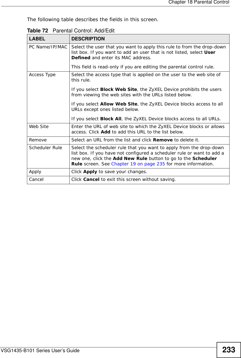
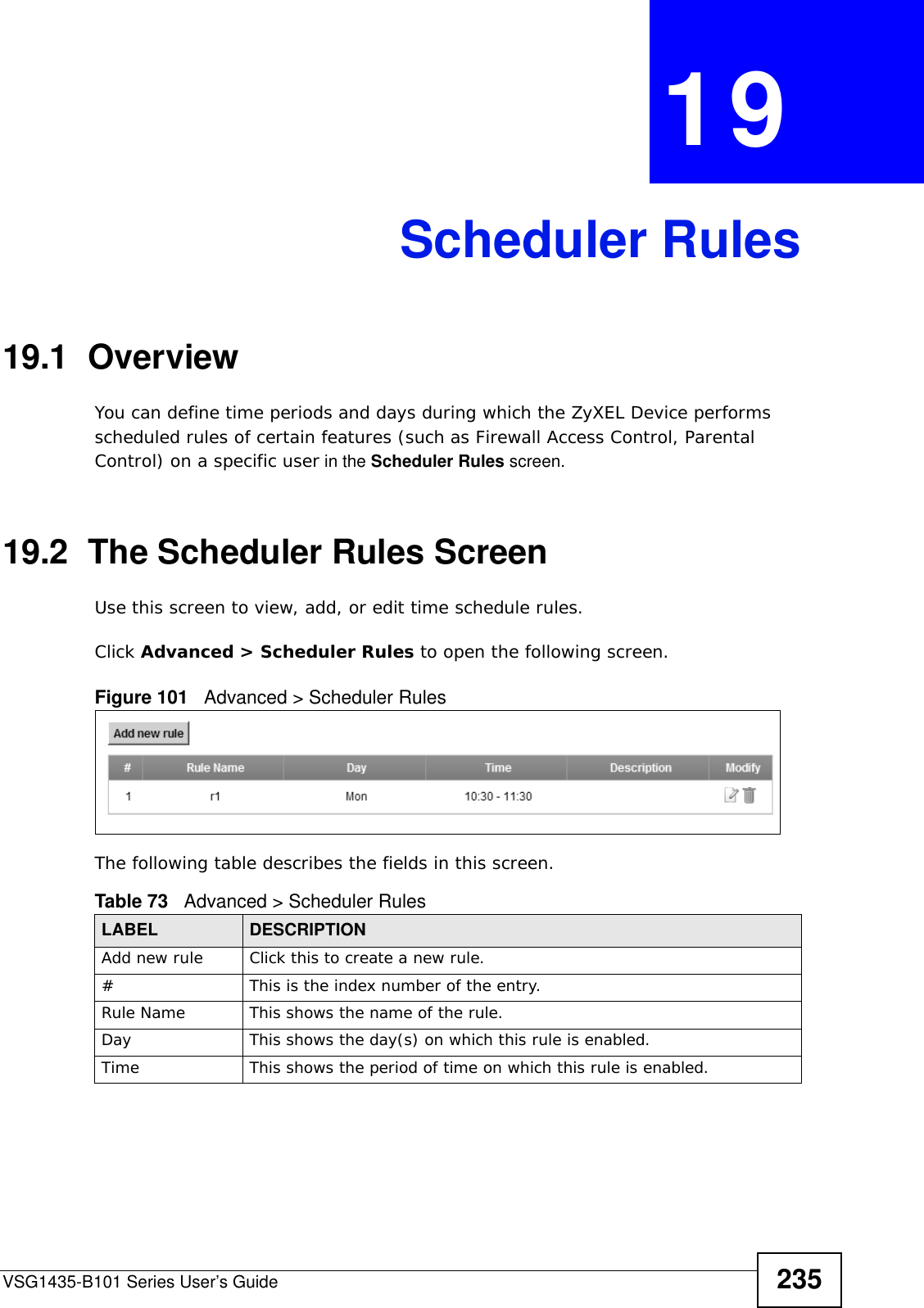
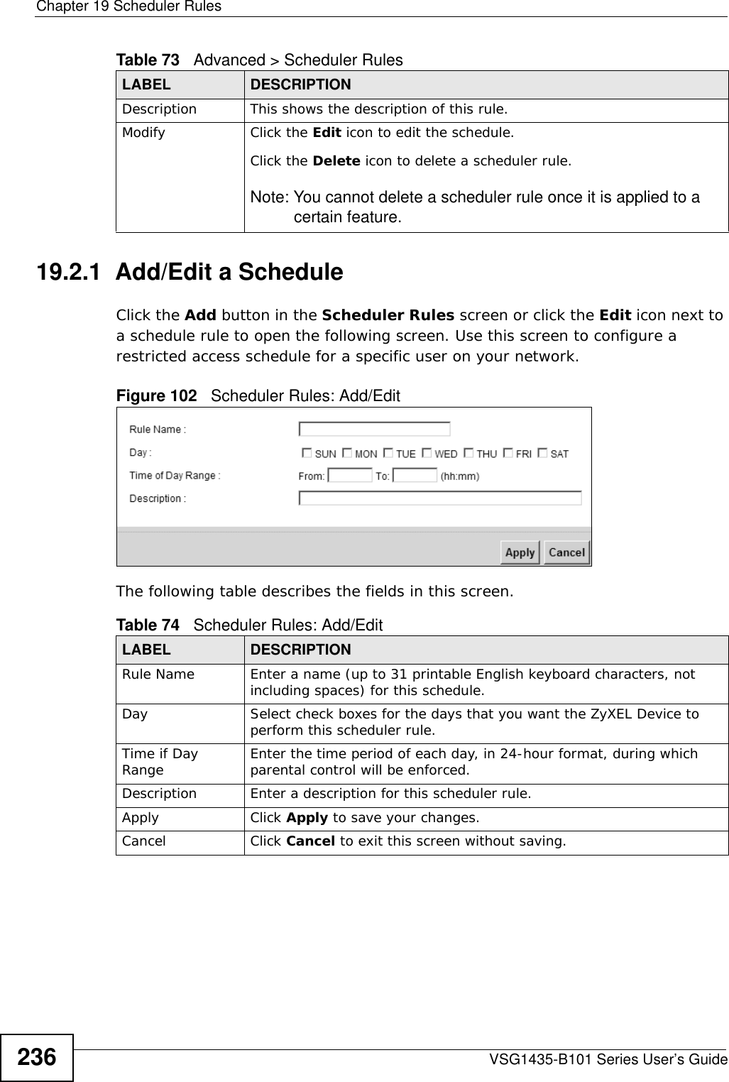
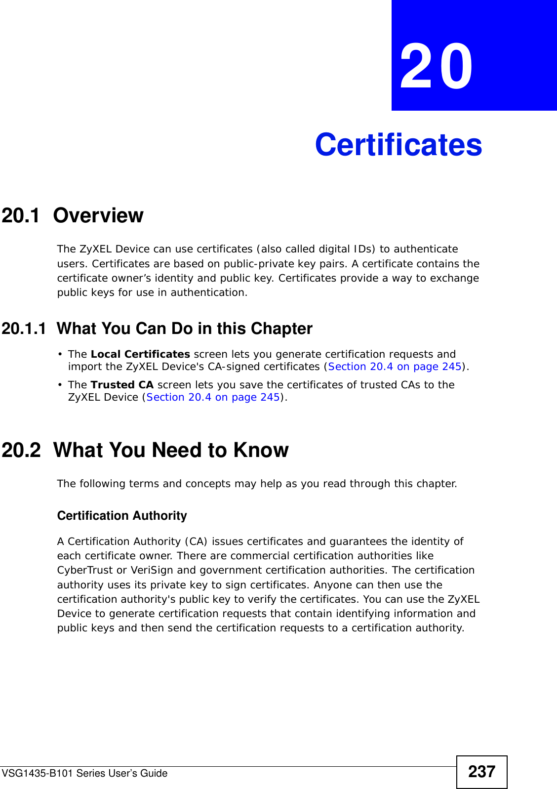
ZyXEL Communications VSG1435B101 802.11n Wireless VDSL2 4-Port Gateway with HPNA3.1 User Manual
ZyXEL Communications Corporation 802.11n Wireless VDSL2 4-Port Gateway with HPNA3.1
UserManual.wiki
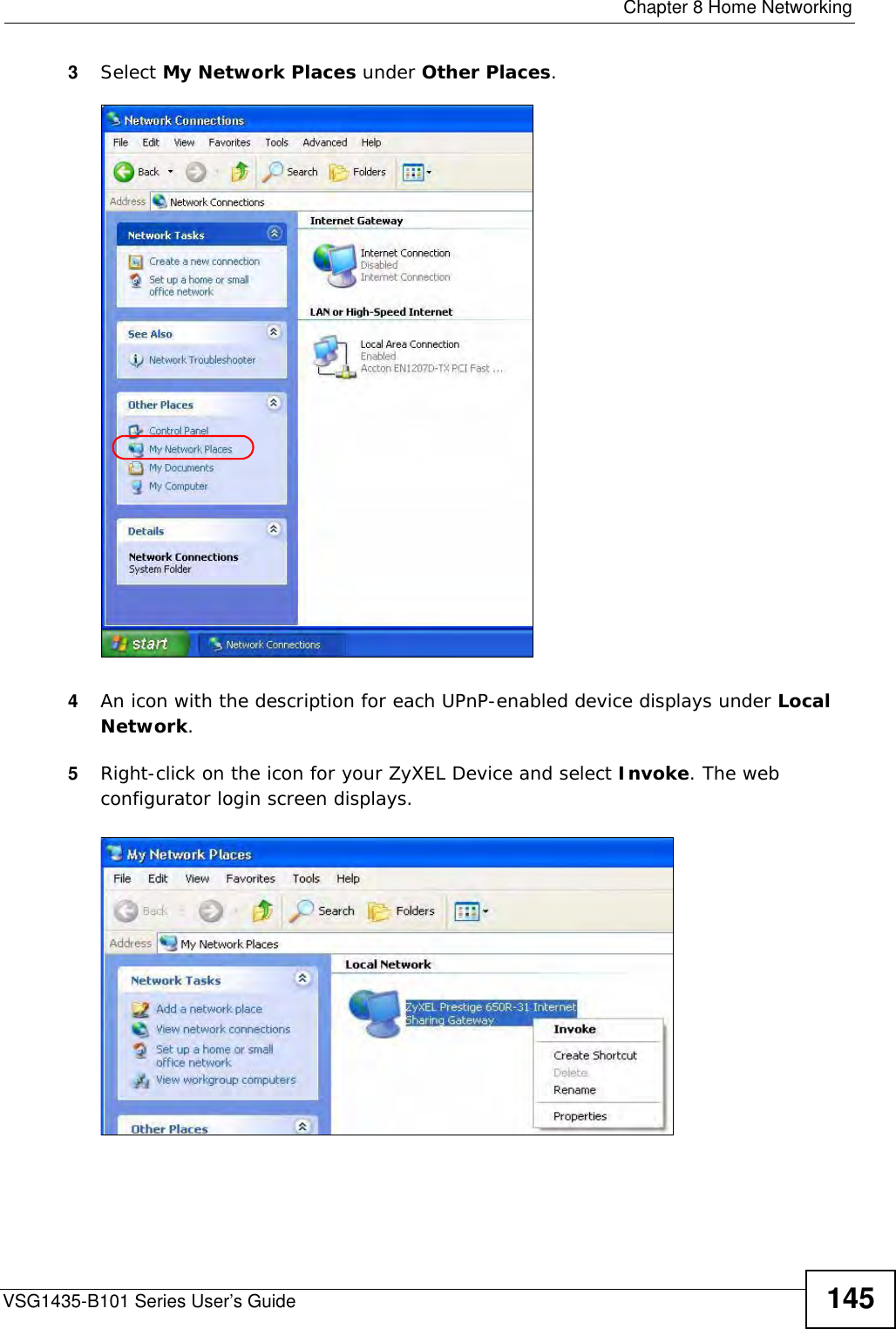
>
ZyXEL Communications
>
VSG1435B101 User Manual
User Manual
Navigation menu
Upload a User Manual
Namespaces
Wiki Guide
HTML
PDF
Info
Views
User Manual
Discussion / Help
Navigation
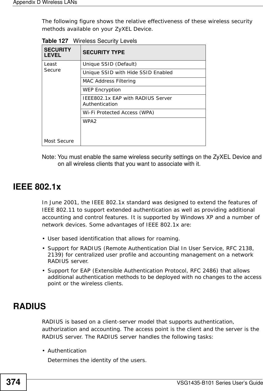
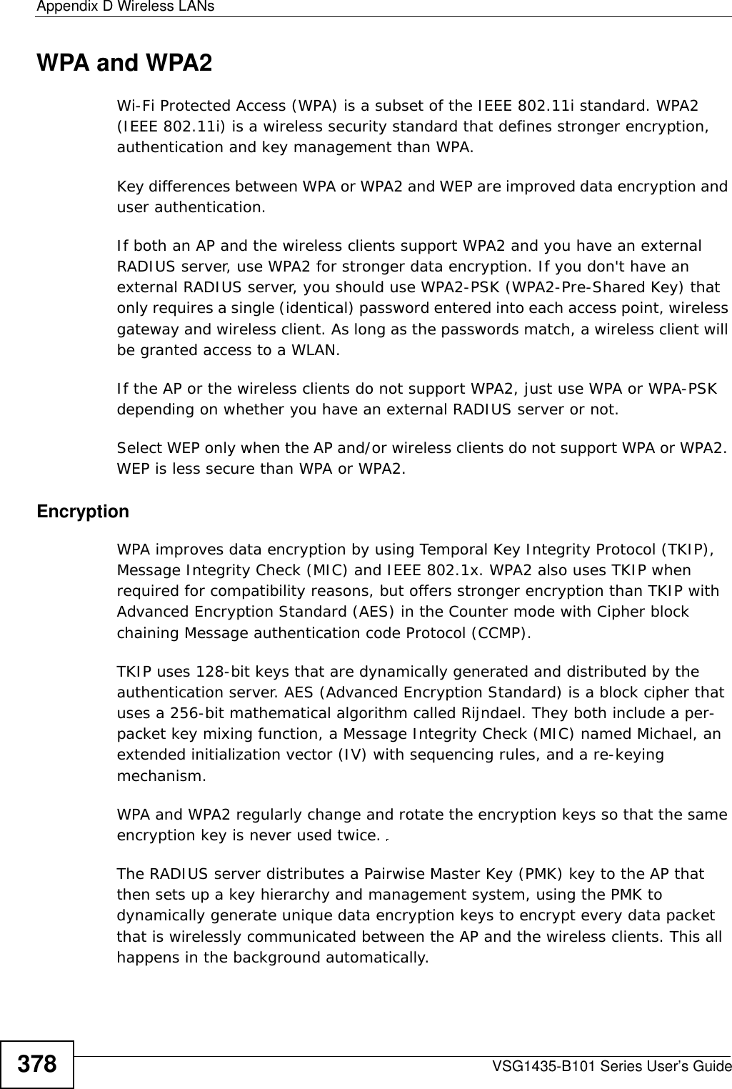
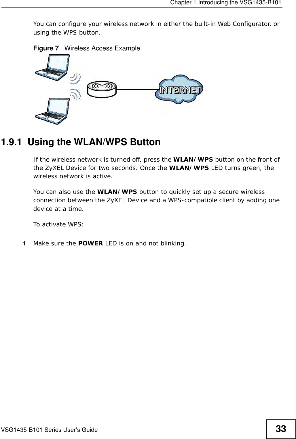
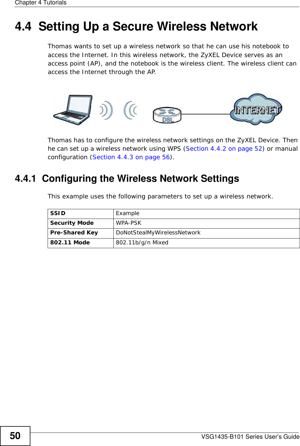
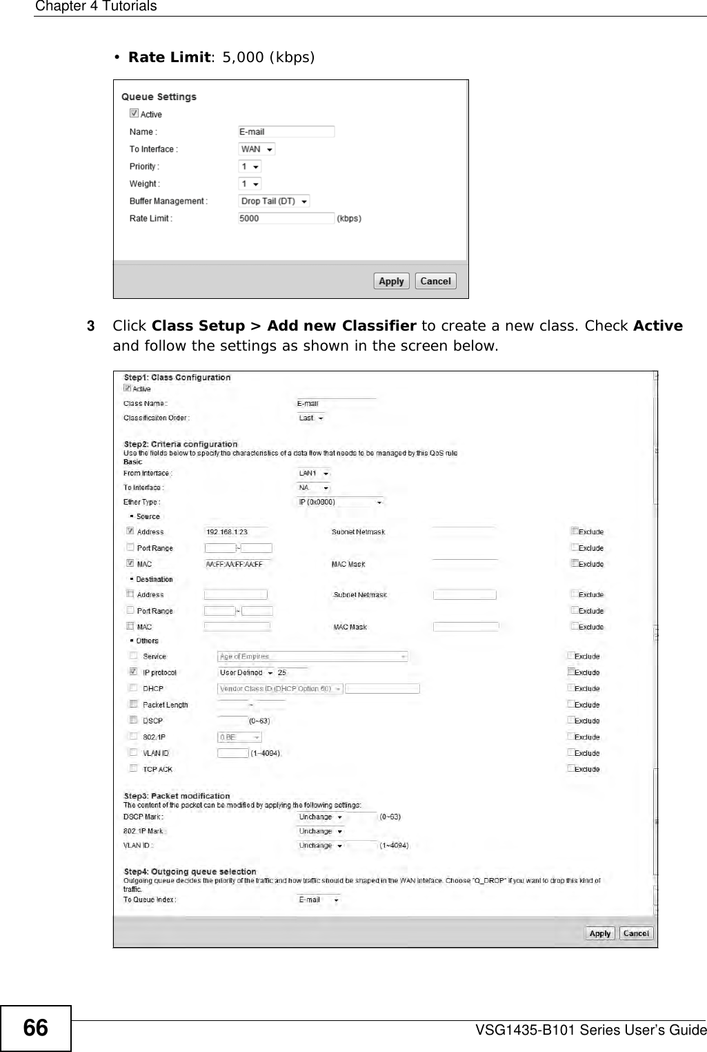
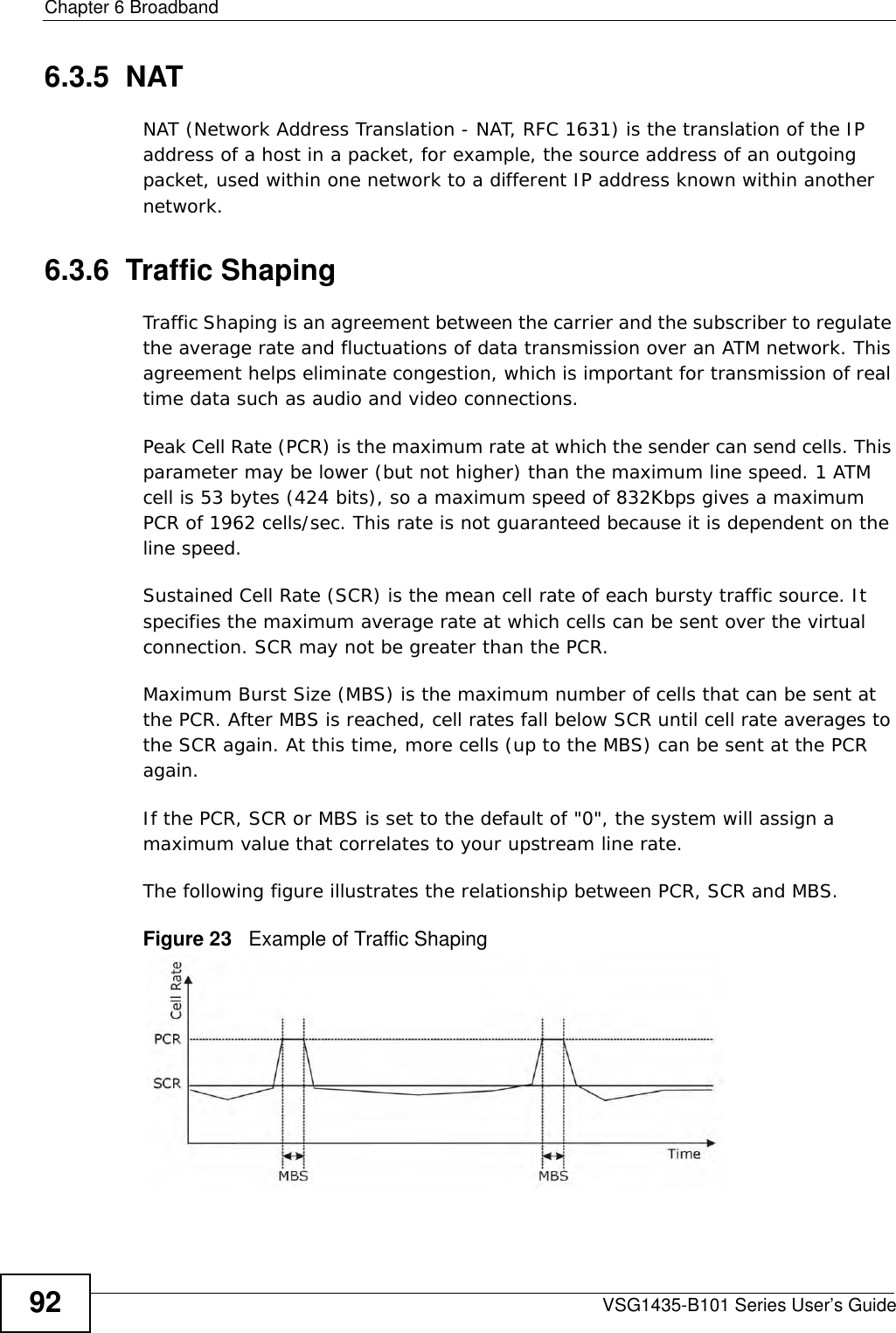
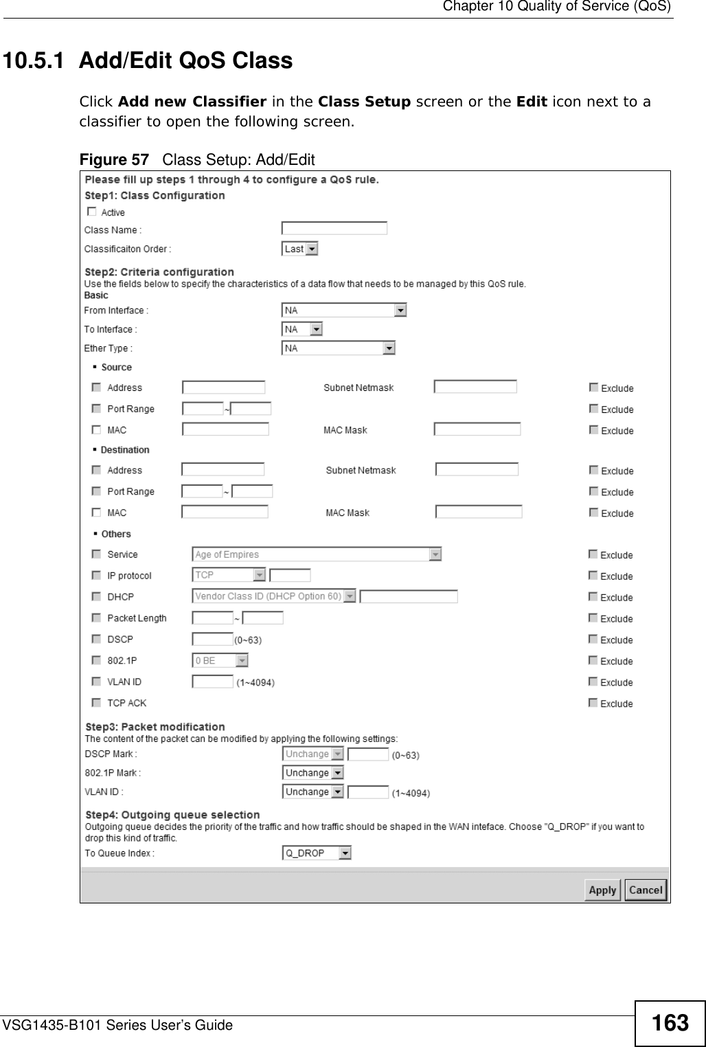
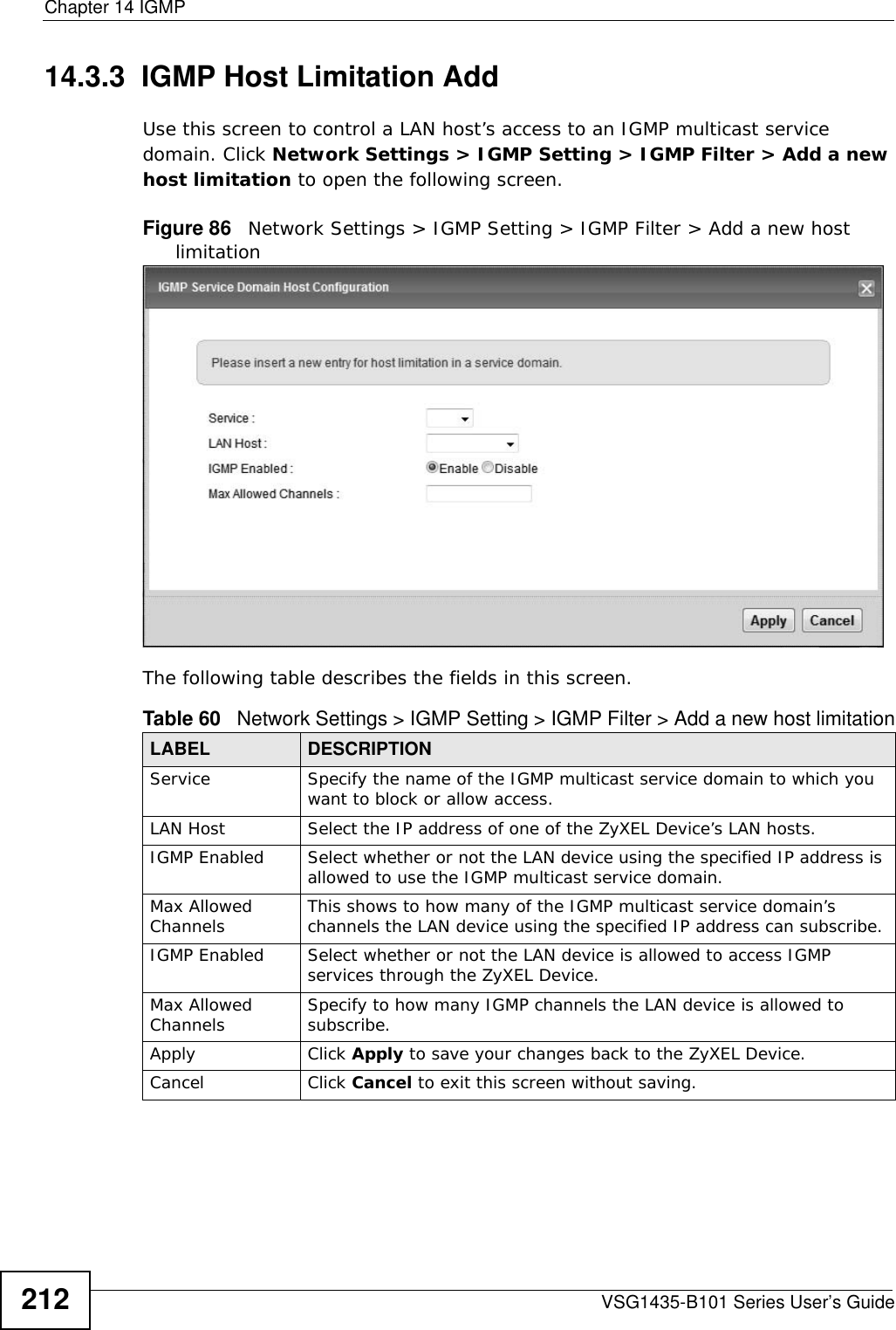
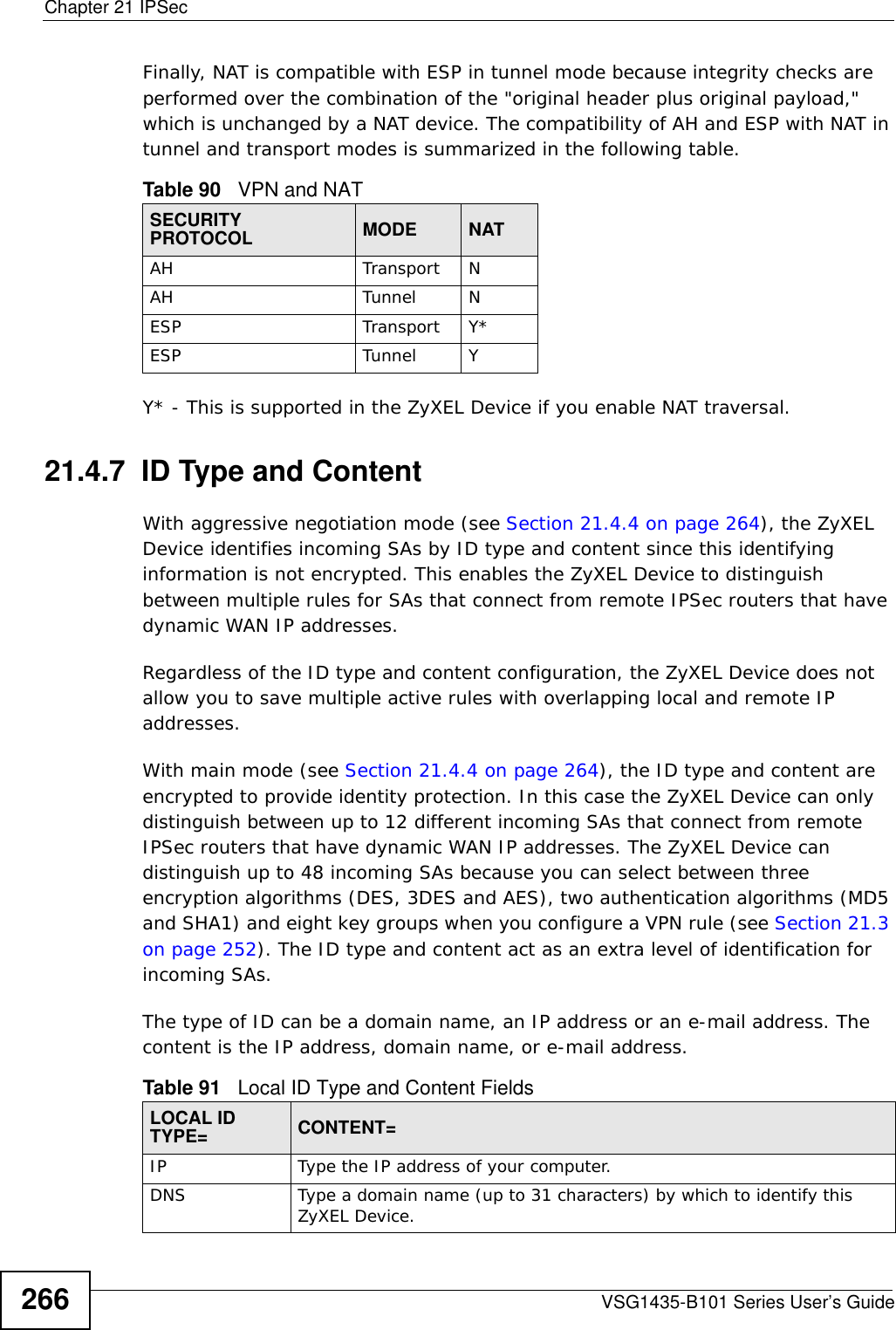
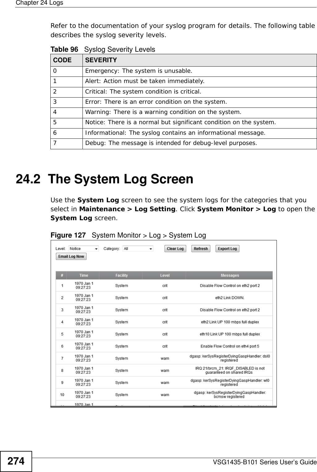
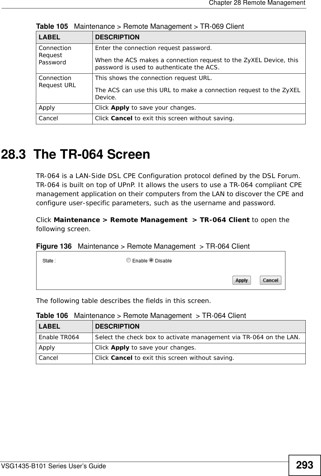
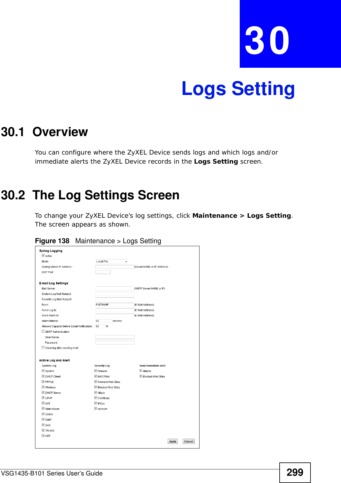
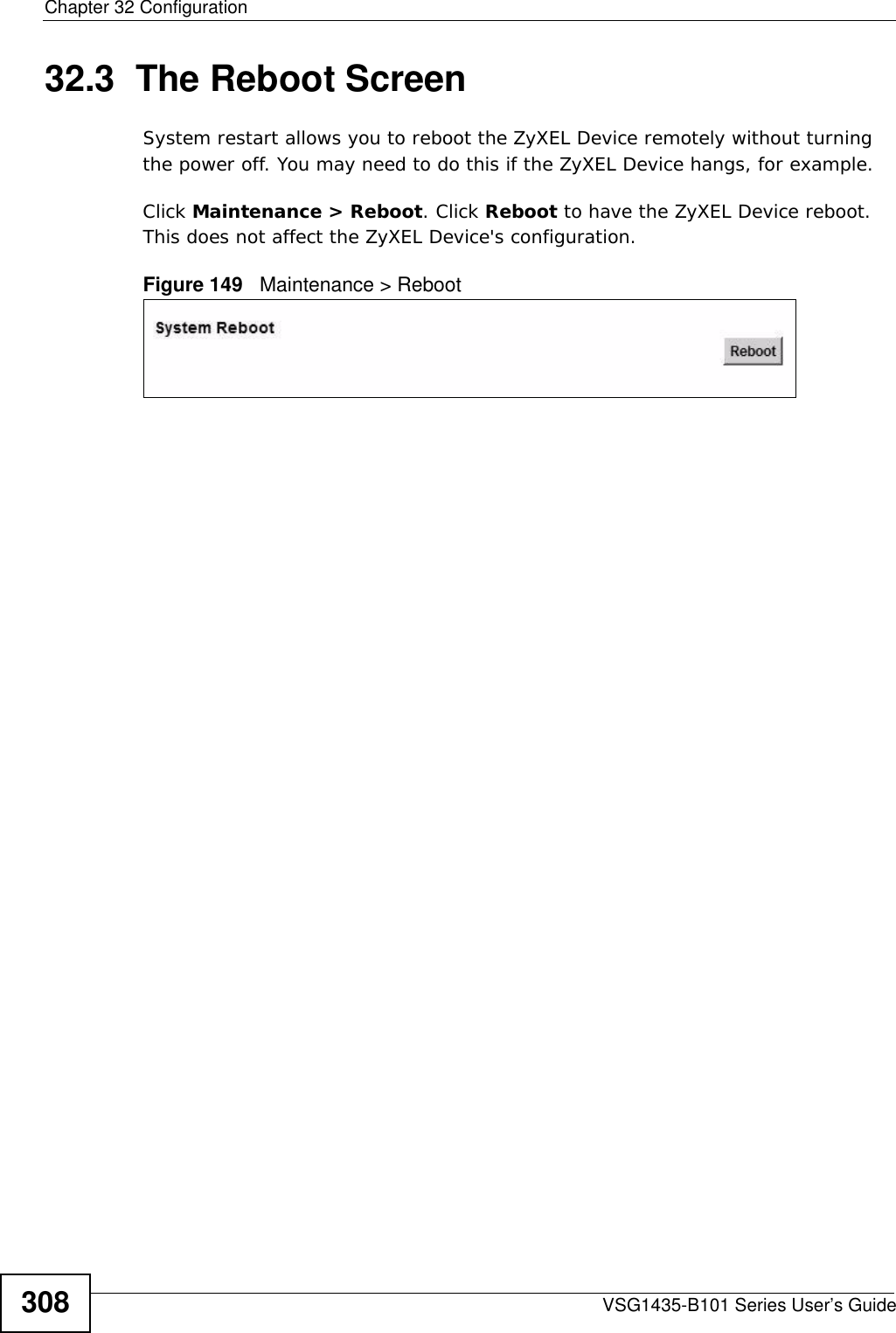
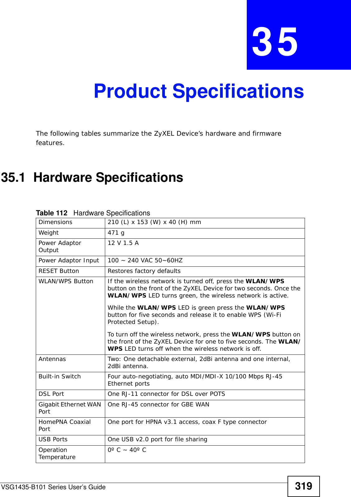
![Document ConventionsVSG1435-B101 Series User’s Guide 5Document ConventionsWarnings and NotesThese are how warnings and notes are shown in this User’s Guide. Warnings tell you about things that could harm you or your device.Note: Notes tell you other important information (for example, other things you may need to configure or helpful tips) or recommendations.Syntax Conventions• The VSG1435-B101 may be referred to as the “ZyXEL Device”, the “device”, the “system” or the “product” in this User’s Guide.• Product labels, screen names, field labels and field choices are all in bold font.• A key stroke is denoted by square brackets and uppercase text, for example, [ENTER] means the “enter” or “return” key on your keyboard.• “Enter” means for you to type one or more characters and then press the [ENTER] key. “Select” or “choose” means for you to use one of the predefined choices.• A right angle bracket ( > ) within a screen name denotes a mouse click. For example, Maintenance > Log > Log Setting means you first click Maintenance in the navigation panel, then the Log sub menu and finally the Log Setting tab to get to that screen.• Units of measurement may denote the “metric” value or the “scientific” value. For example, “k” for kilo may denote “1000” or “1024”, “M” for mega may denote “1000000” or “1048576” and so on.• “e.g.,” is a shorthand for “for instance”, and “i.e.,” means “that is” or “in other words”.](https://usermanual.wiki/ZyXEL-Communications/VSG1435B101/User-Guide-1359663-Page-5.png)

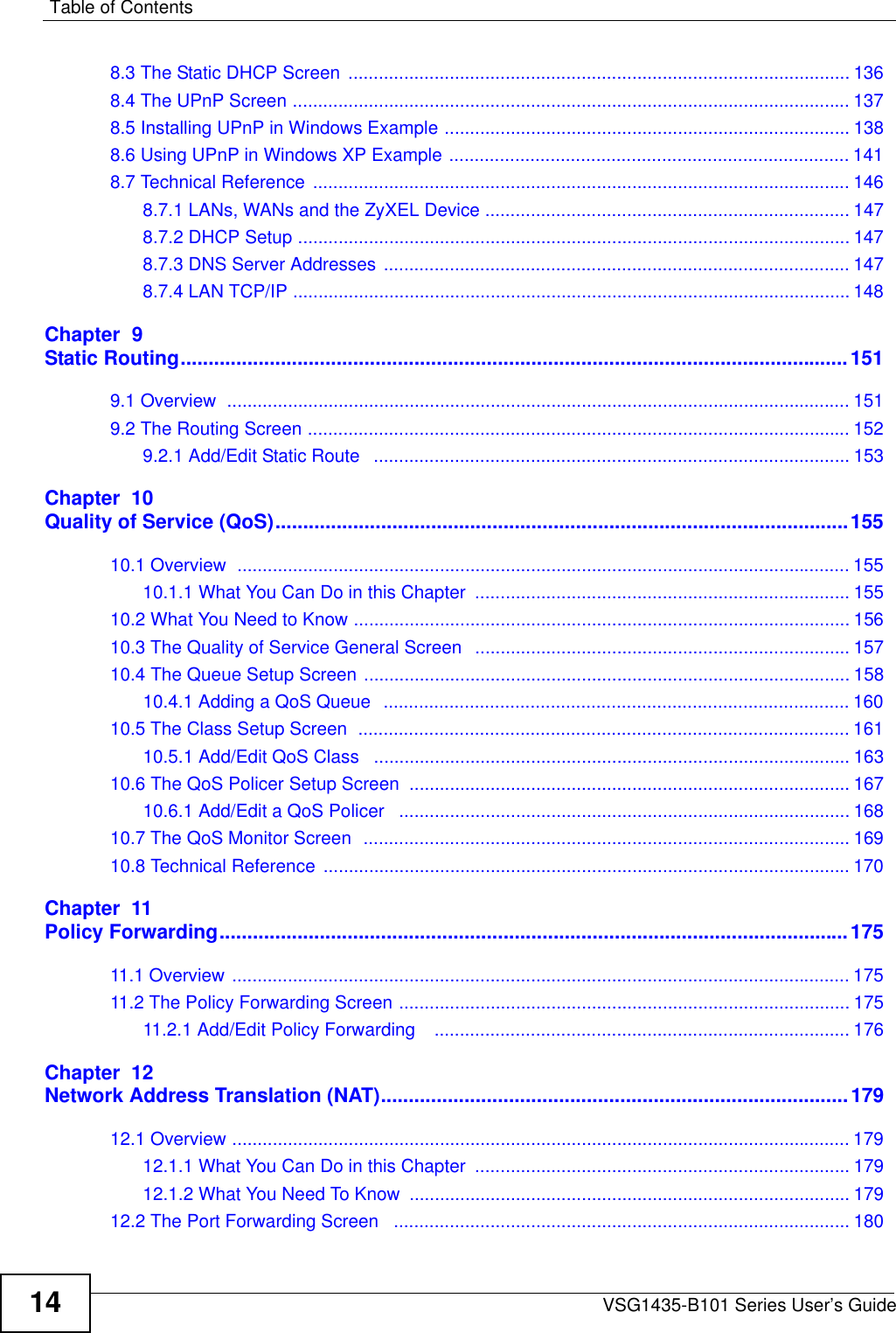
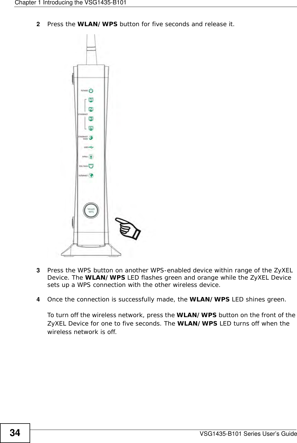

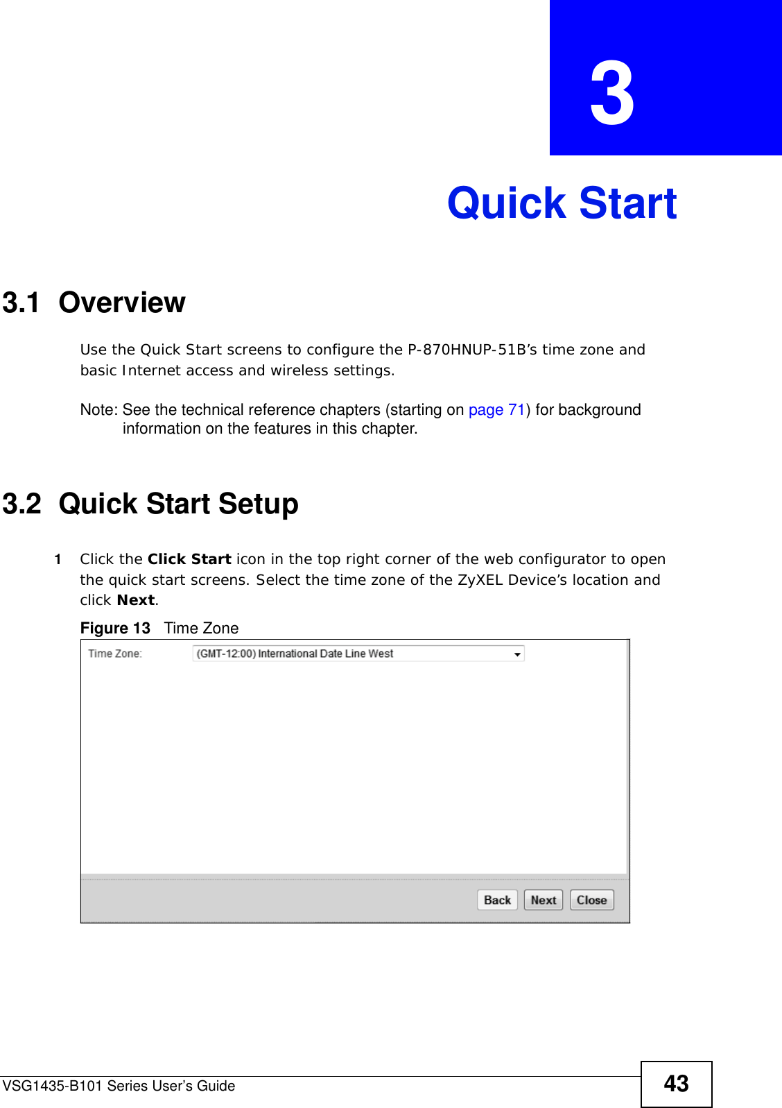
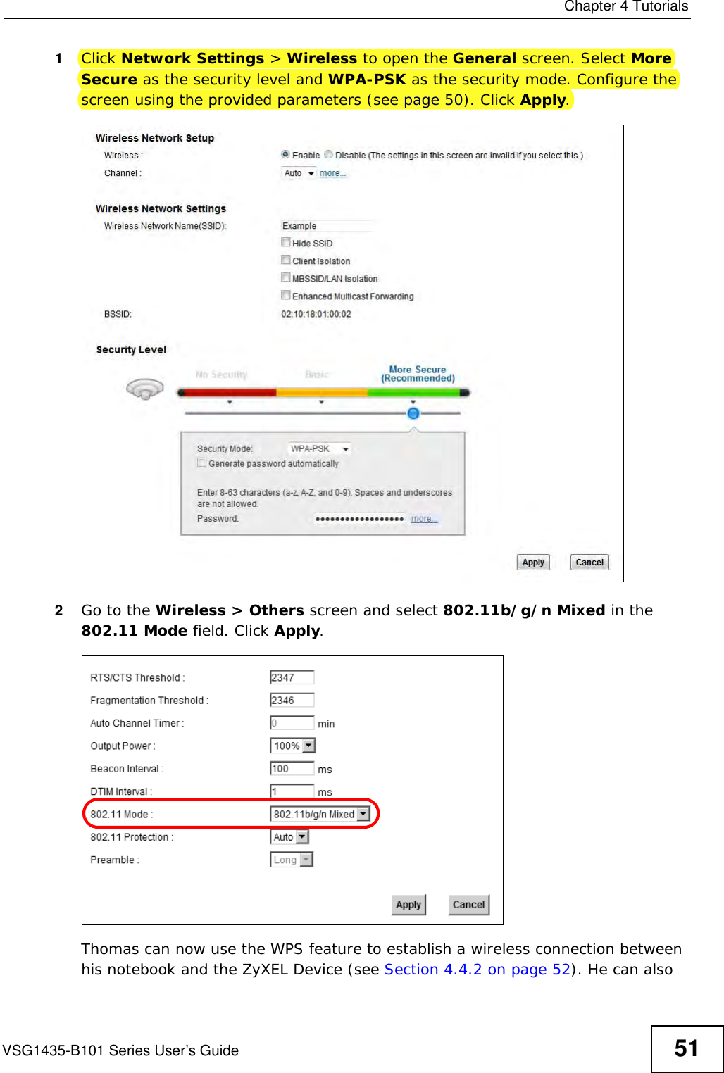
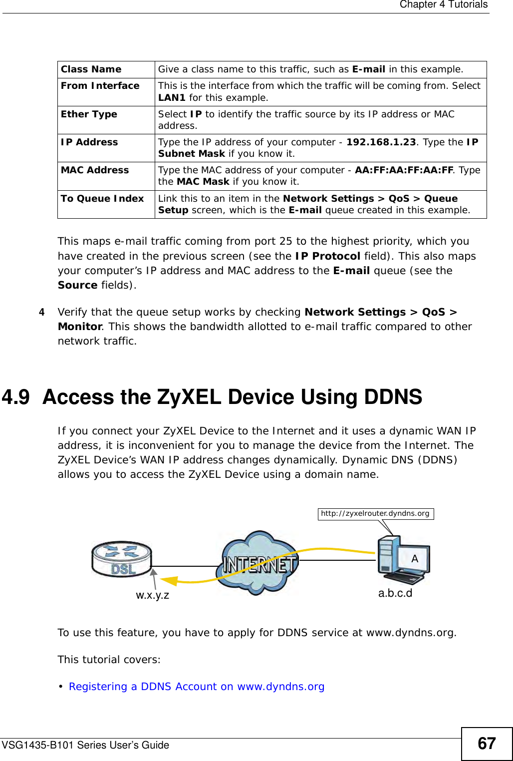
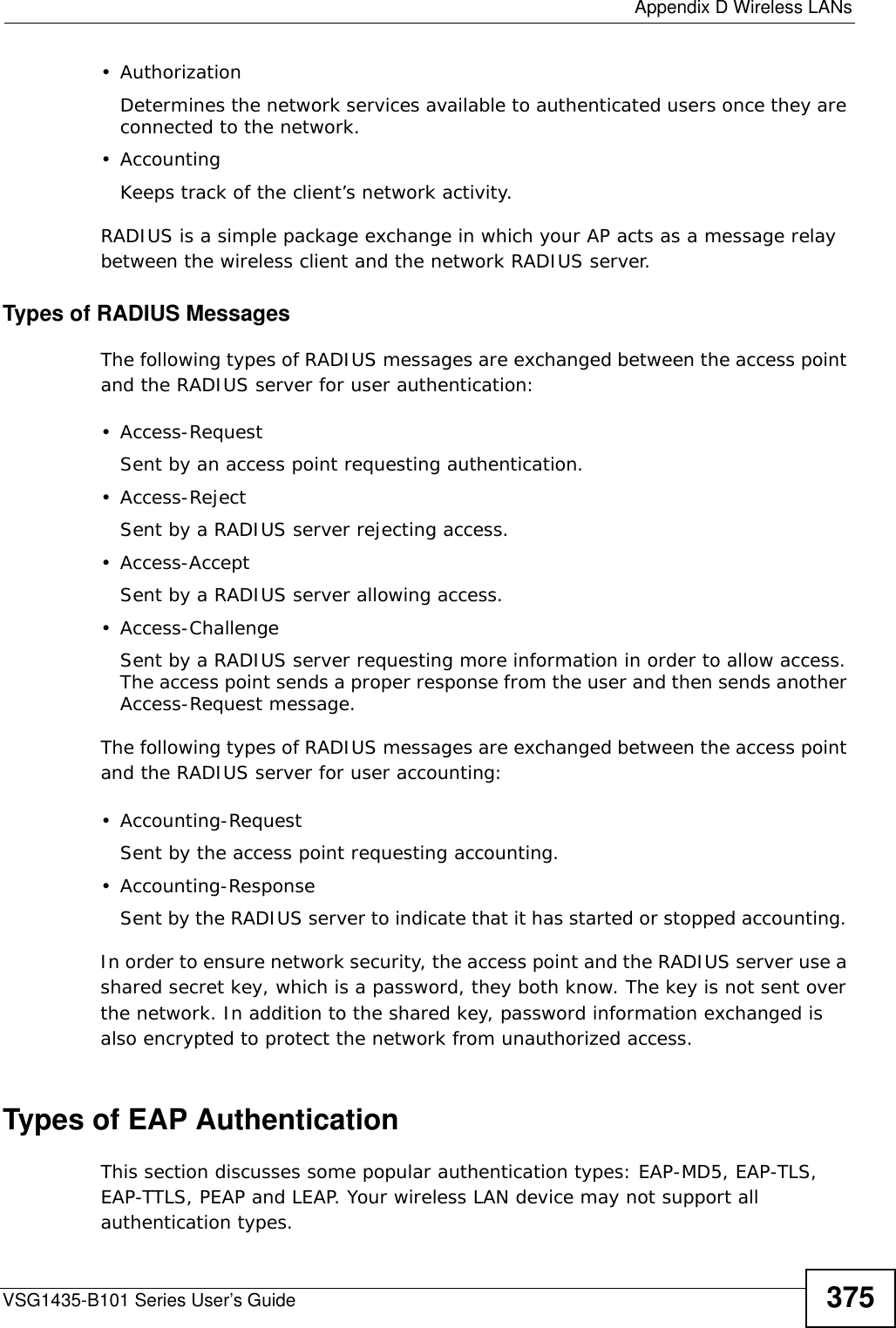
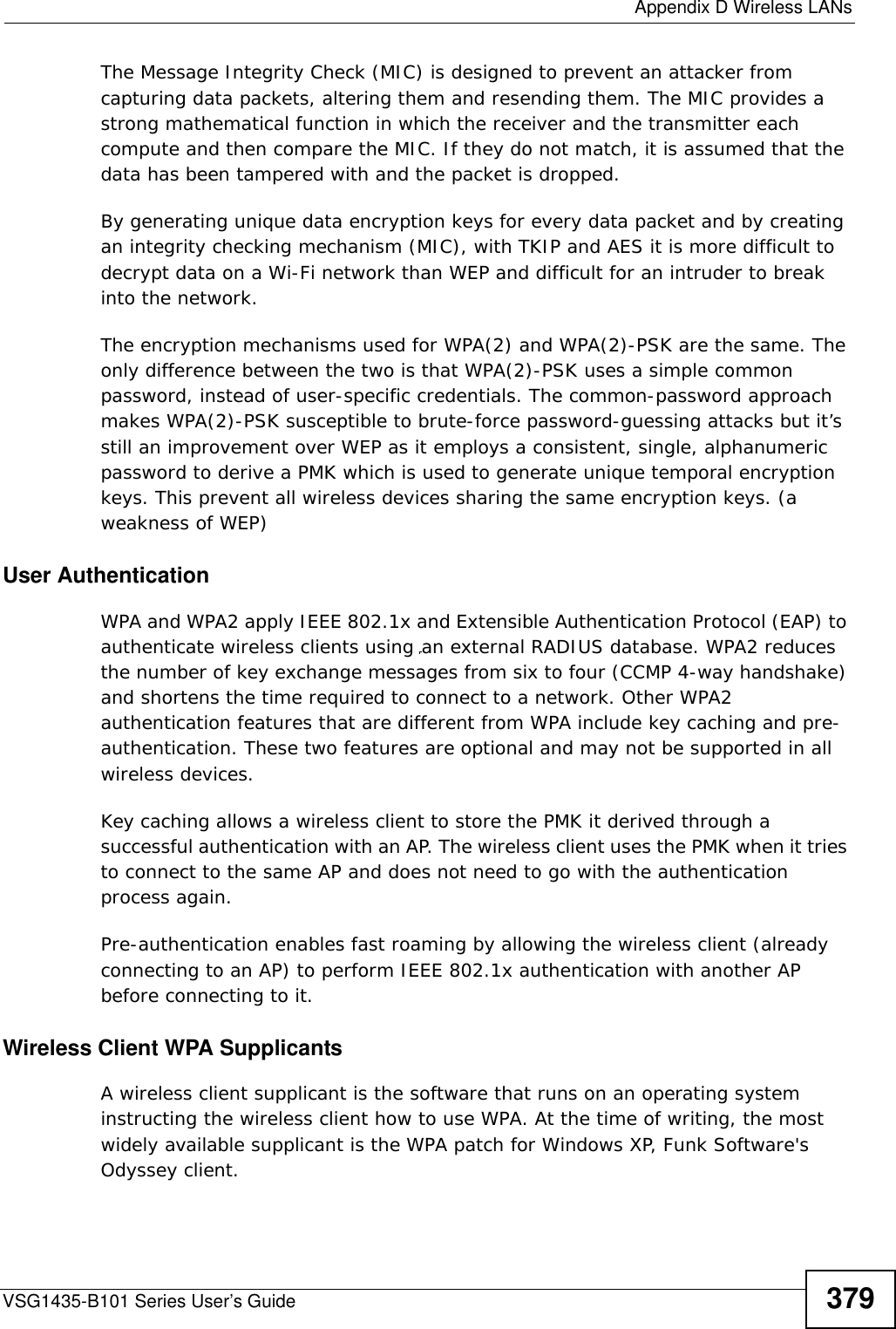
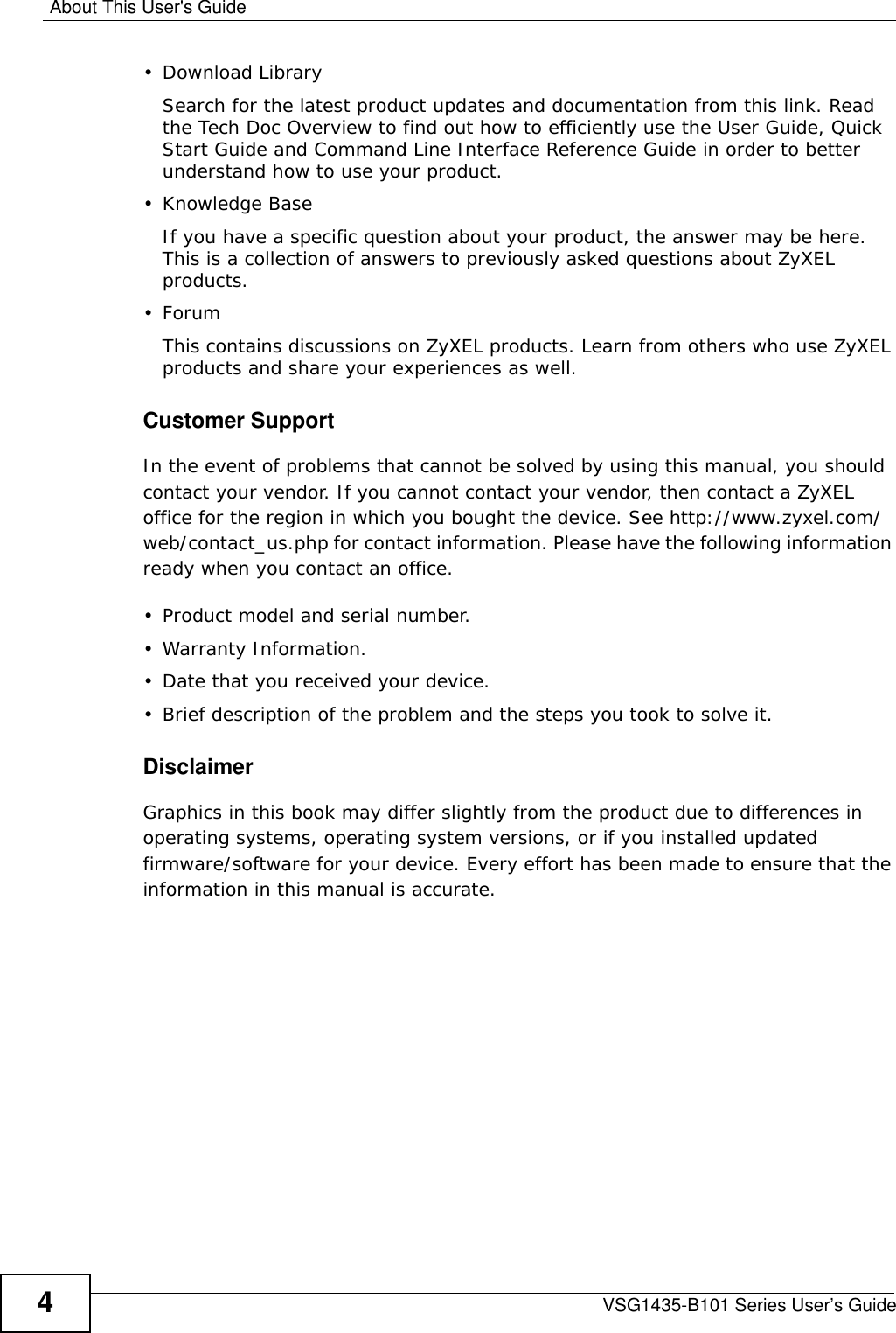
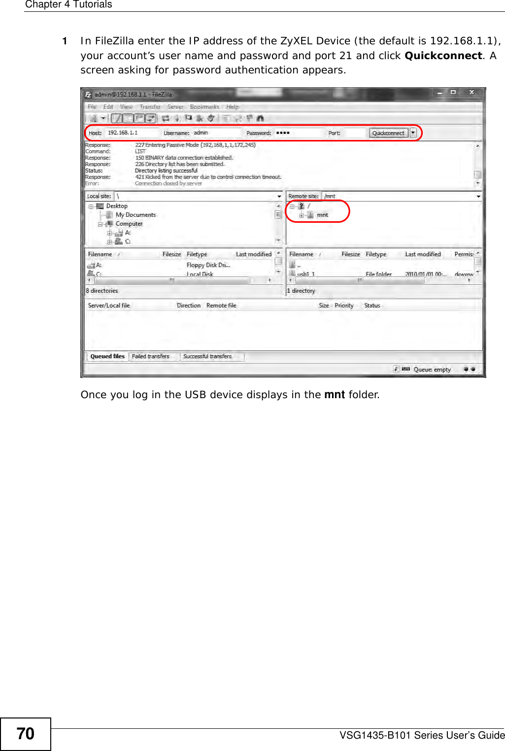
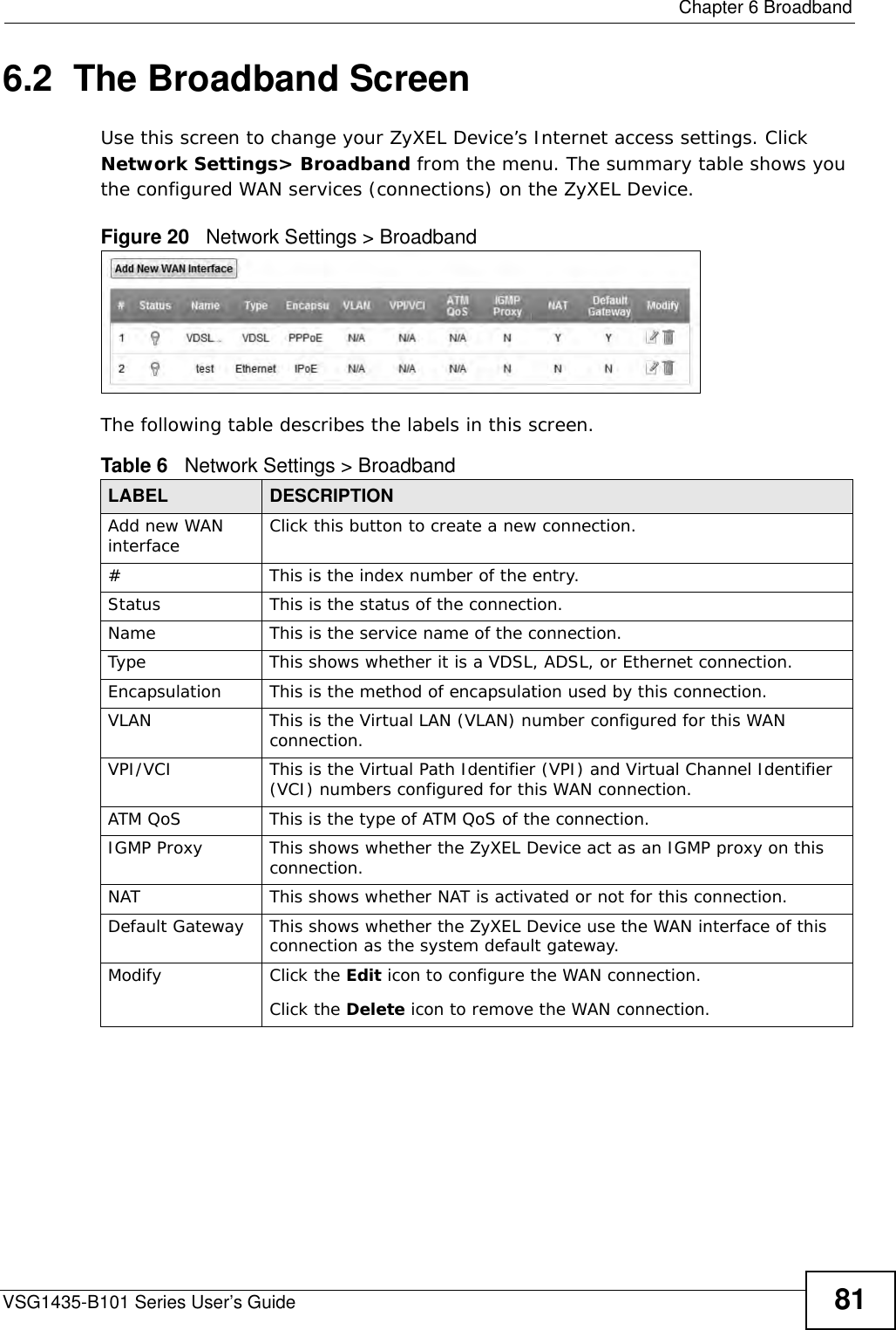
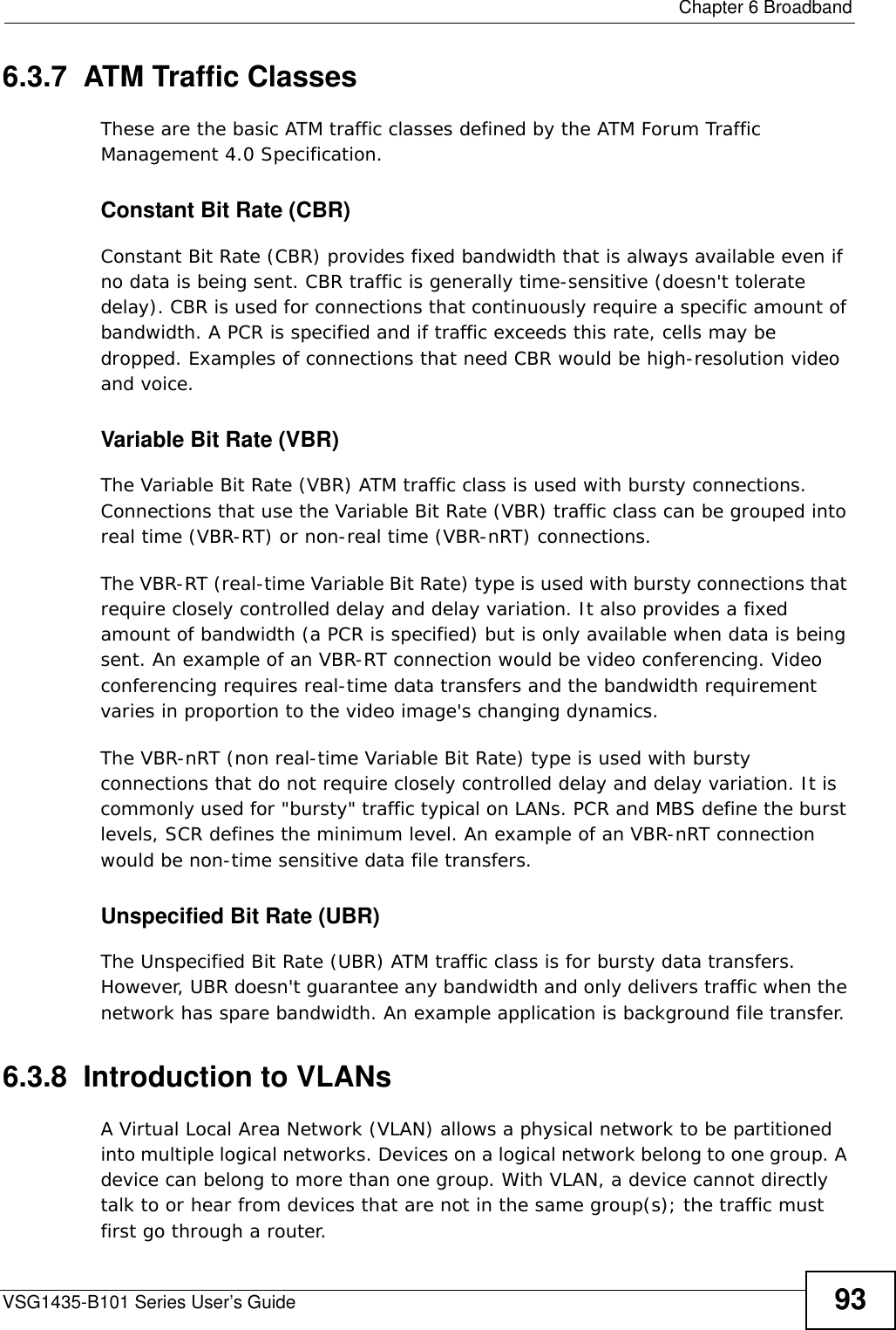
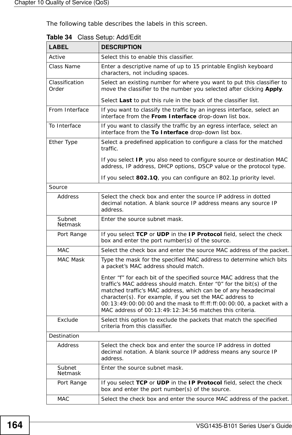
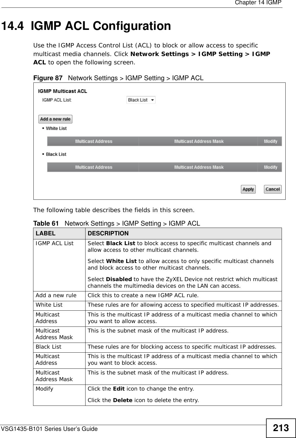
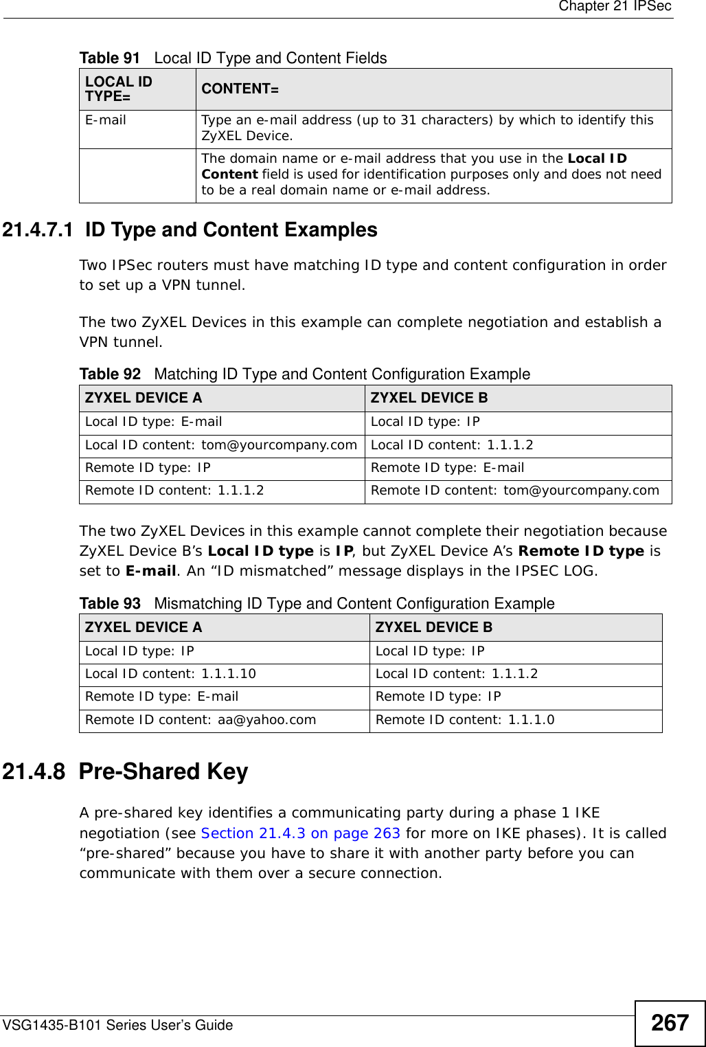
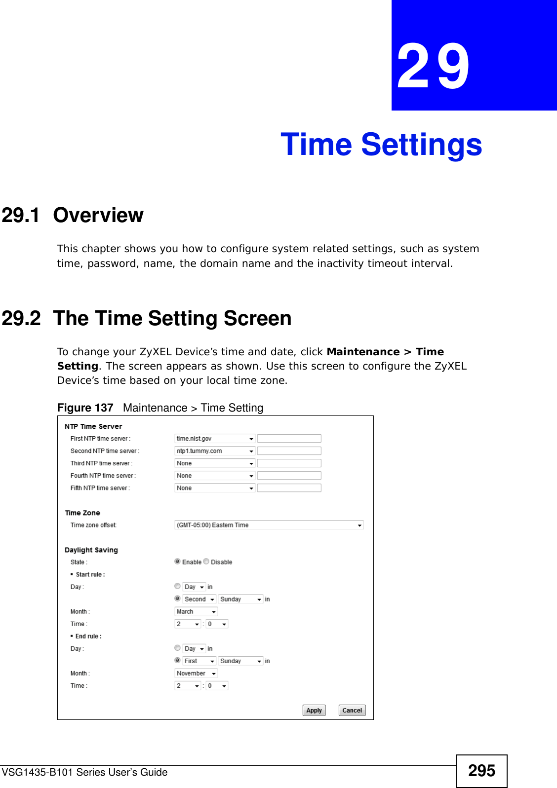
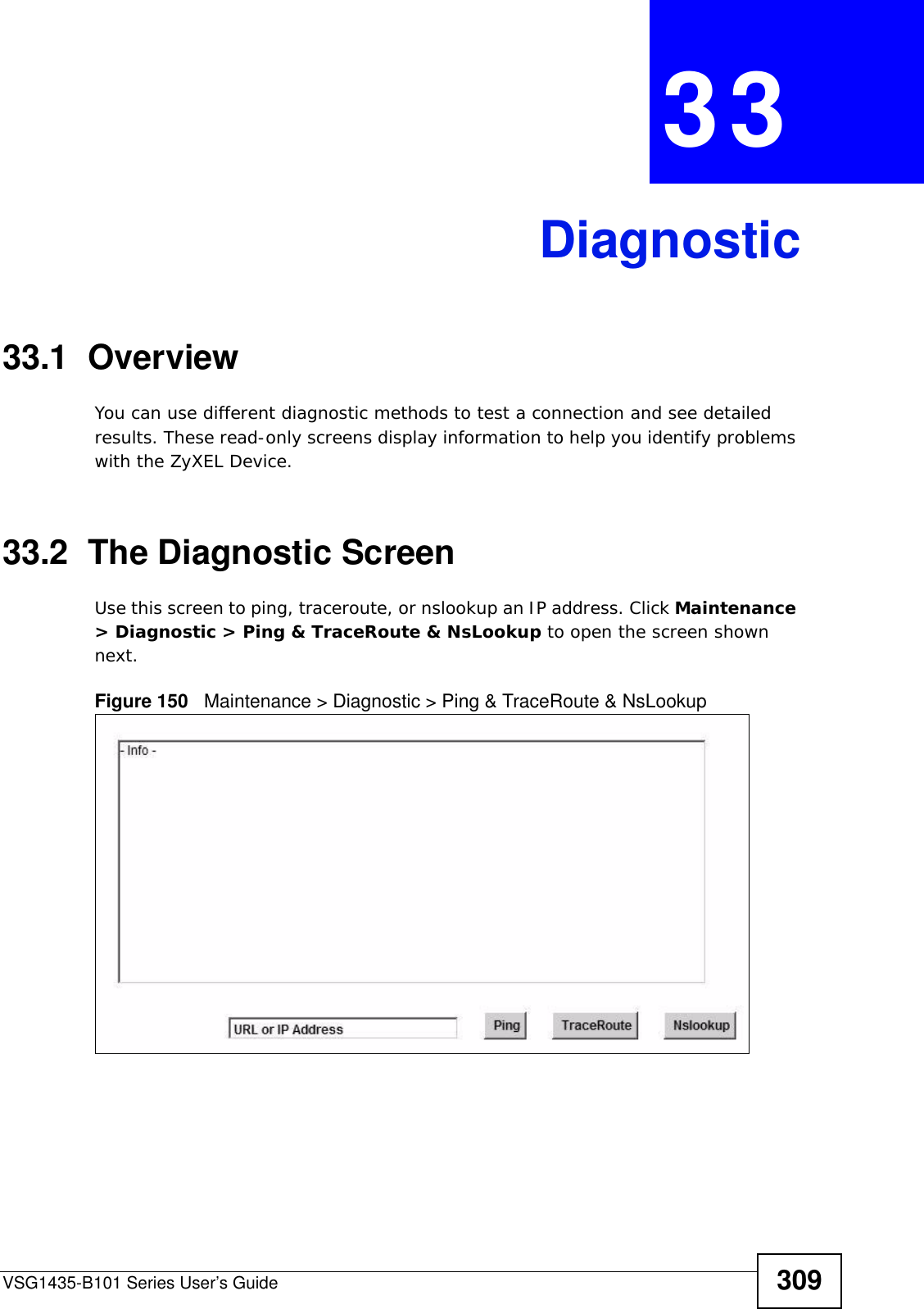
![Chapter 4 TutorialsVSG1435-B101 Series User’s Guide 69• Enter the user name (UserName1) and password (12345).Click Apply.4.9.3 Testing the DDNS SettingNow you should be able to access the ZyXEL Device from the Internet. To test this:1Open a web browser on the computer (using the IP address a.b.c.d) that is connected to the Internet.2Type http://zyxelrouter.dyndns.org and press [Enter].3The ZyXEL Device’s login page should appear. You can then log into the ZyXEL Device and manage it.4.10 Access Your Shared Files From a Computer Here is how to use an FTP program to access a file storage device connected to the ZyXEL Device’s USB port.Note: This example uses the FileZilla FTP program to browse your shared files.](https://usermanual.wiki/ZyXEL-Communications/VSG1435B101/User-Guide-1359663-Page-69.png)

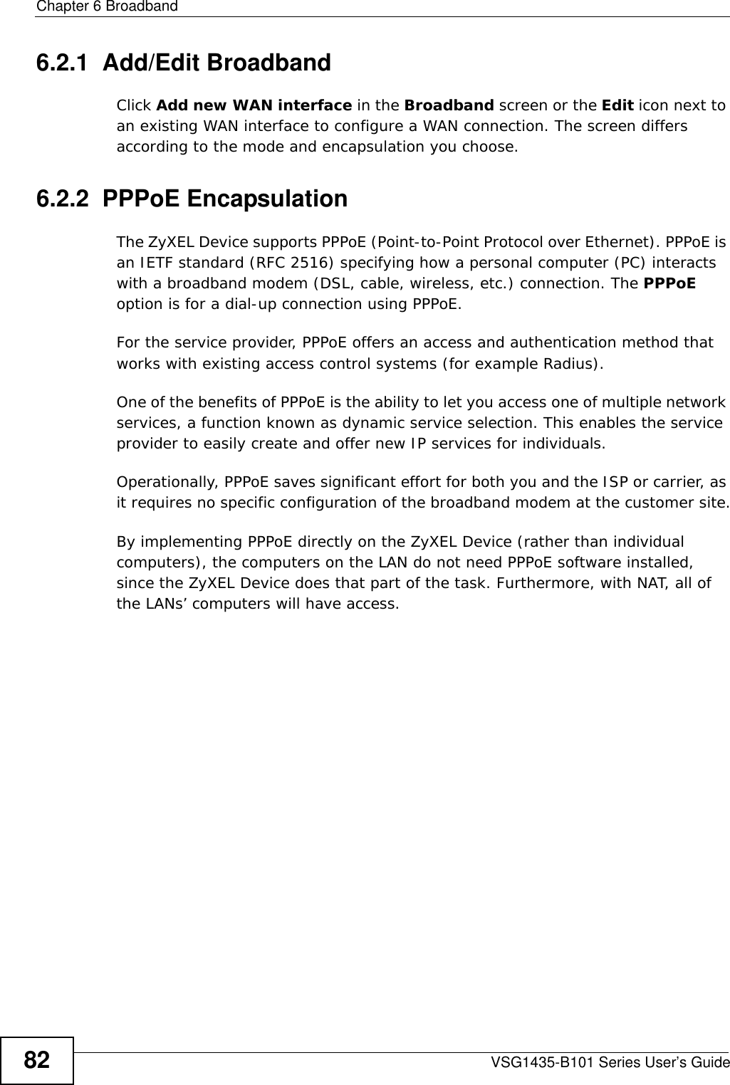
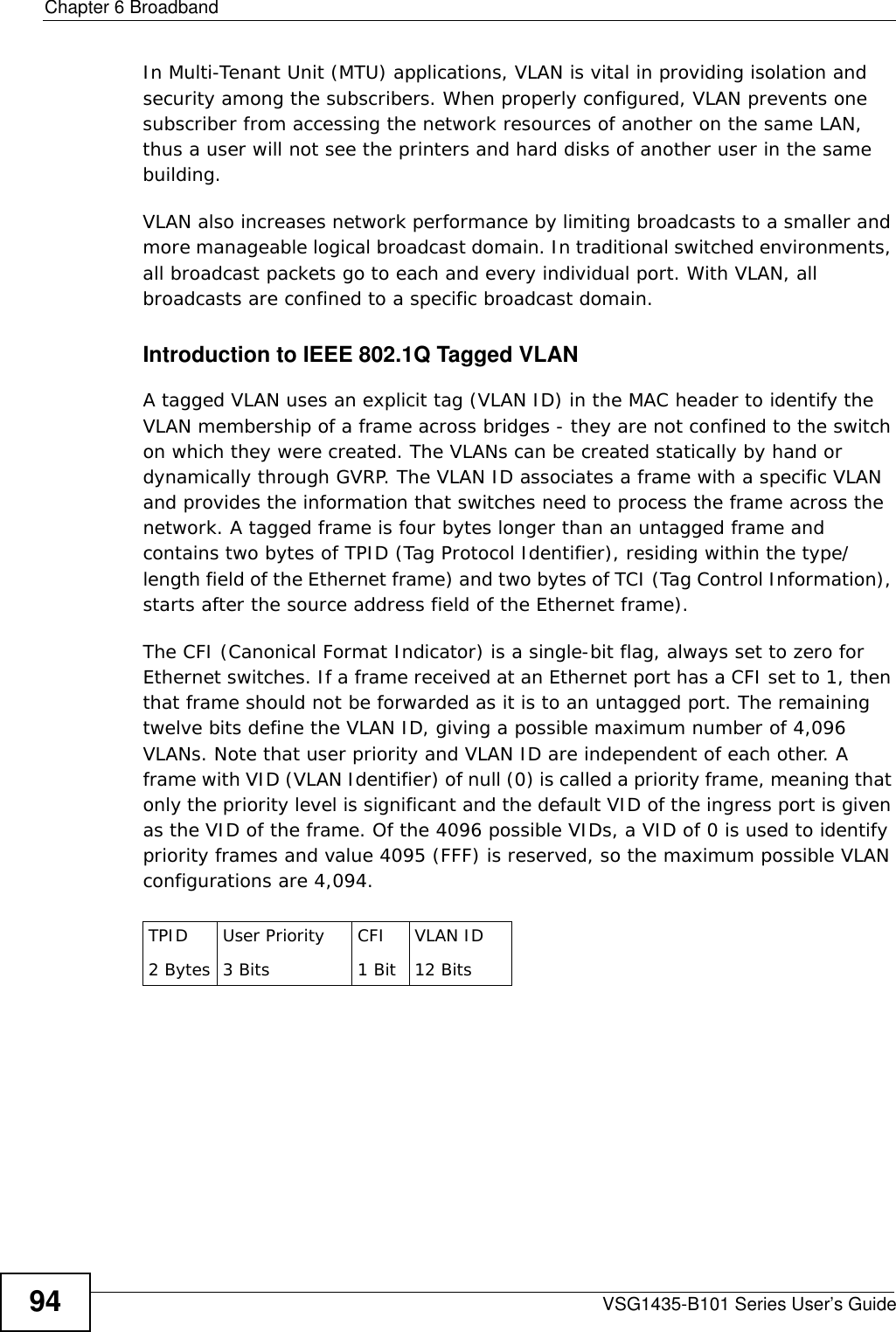


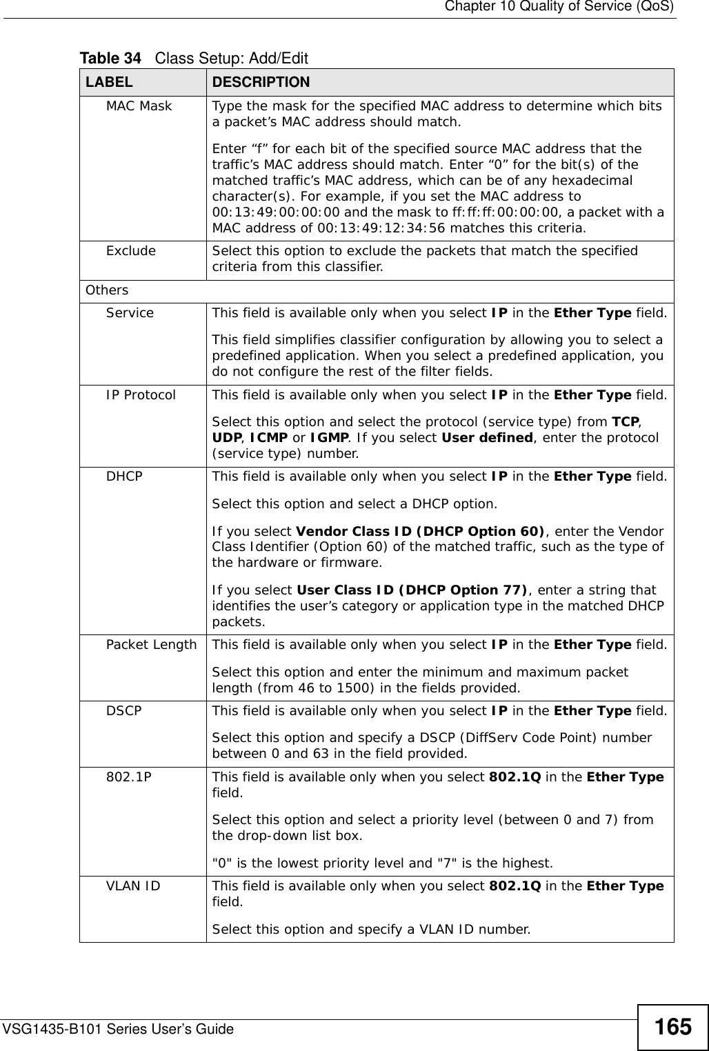

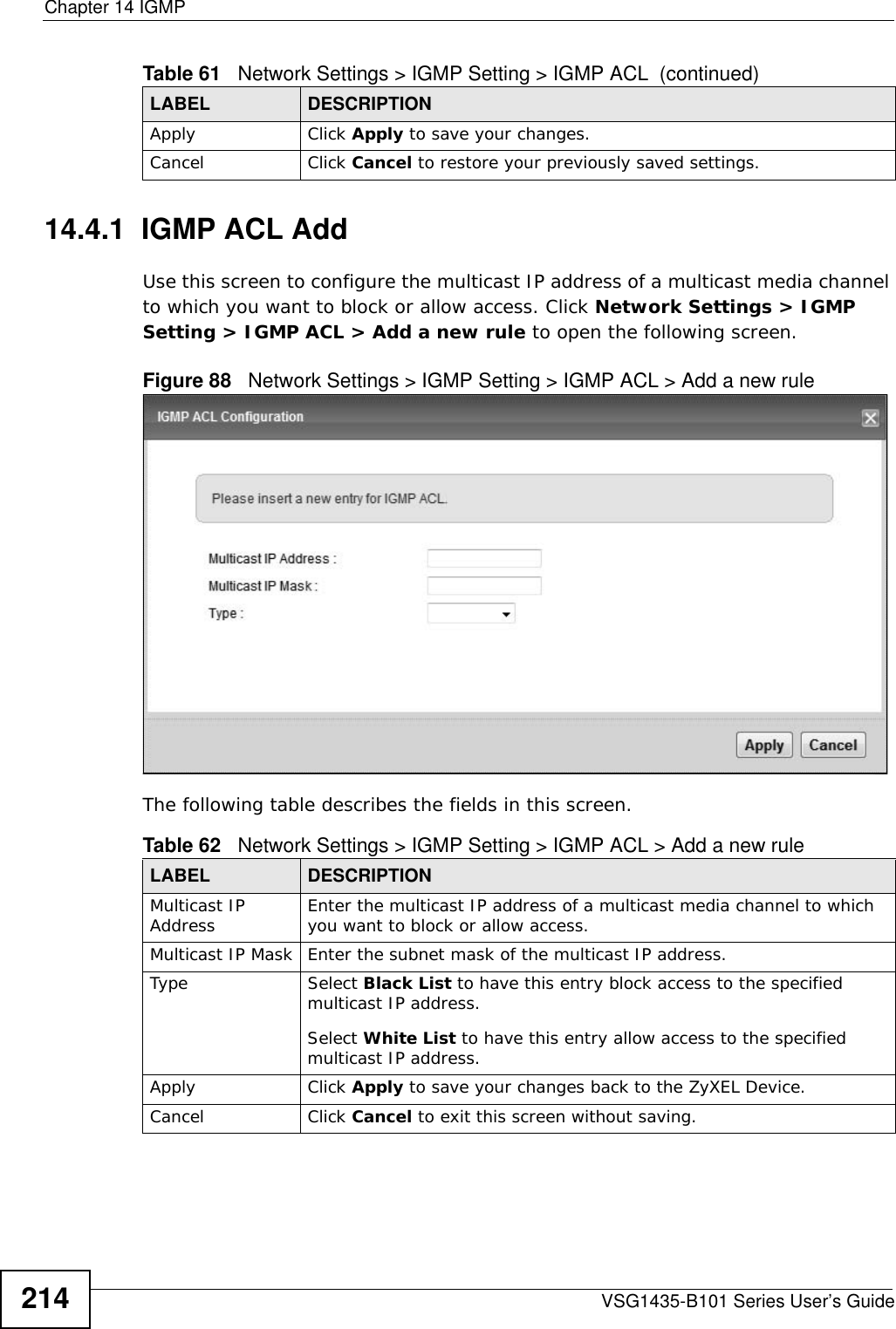


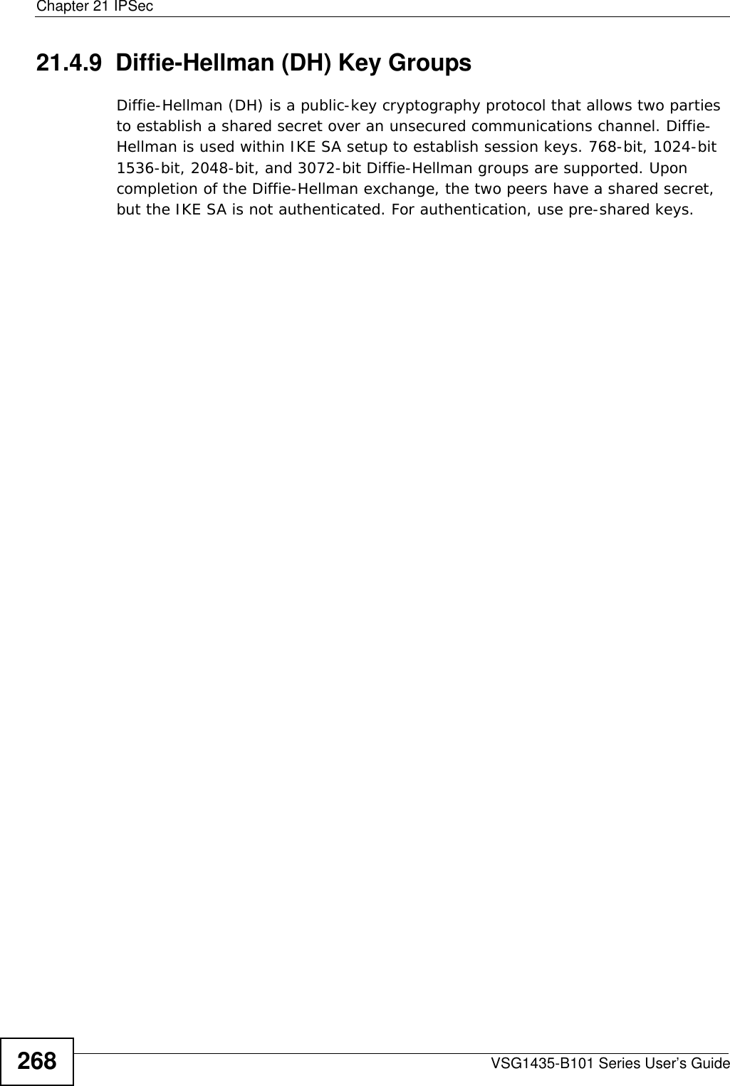


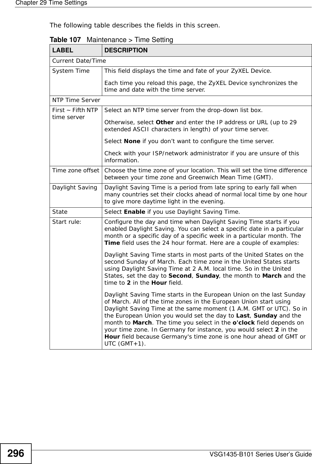


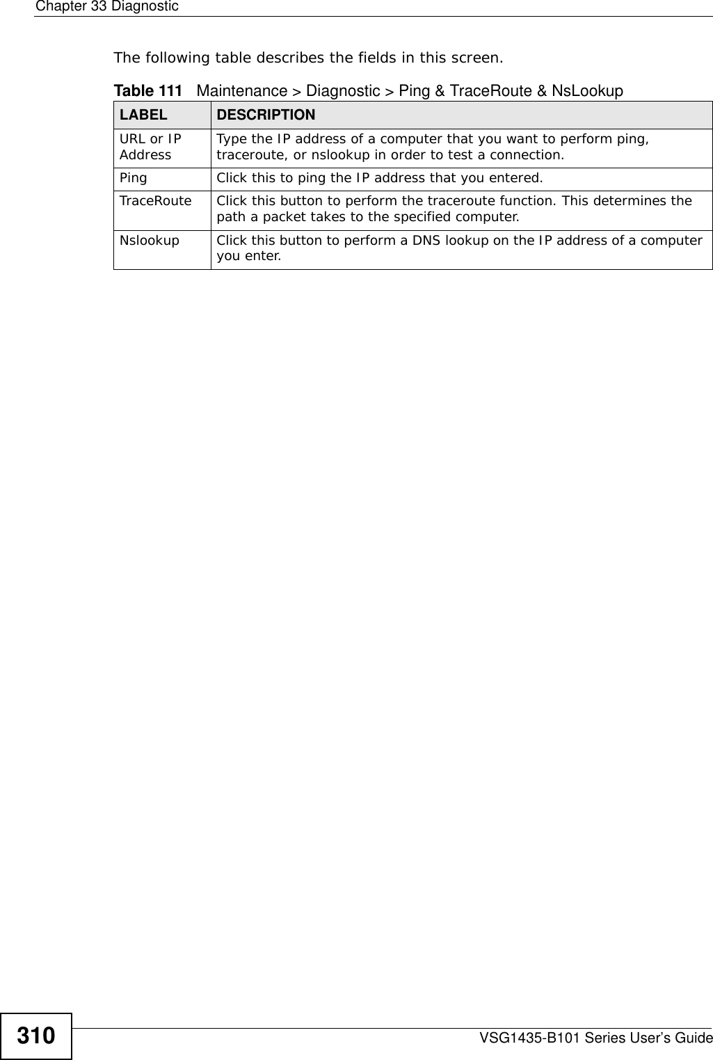
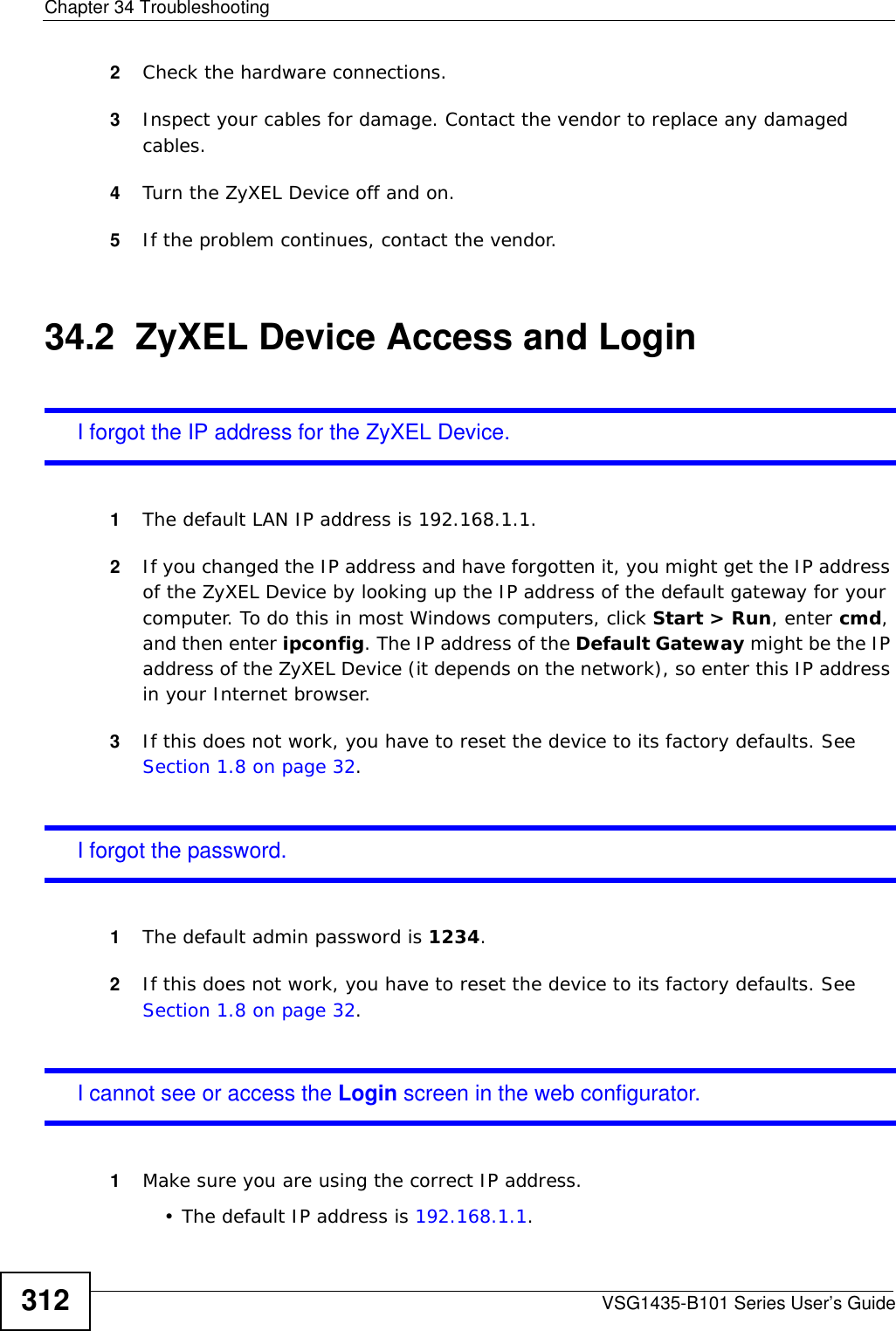
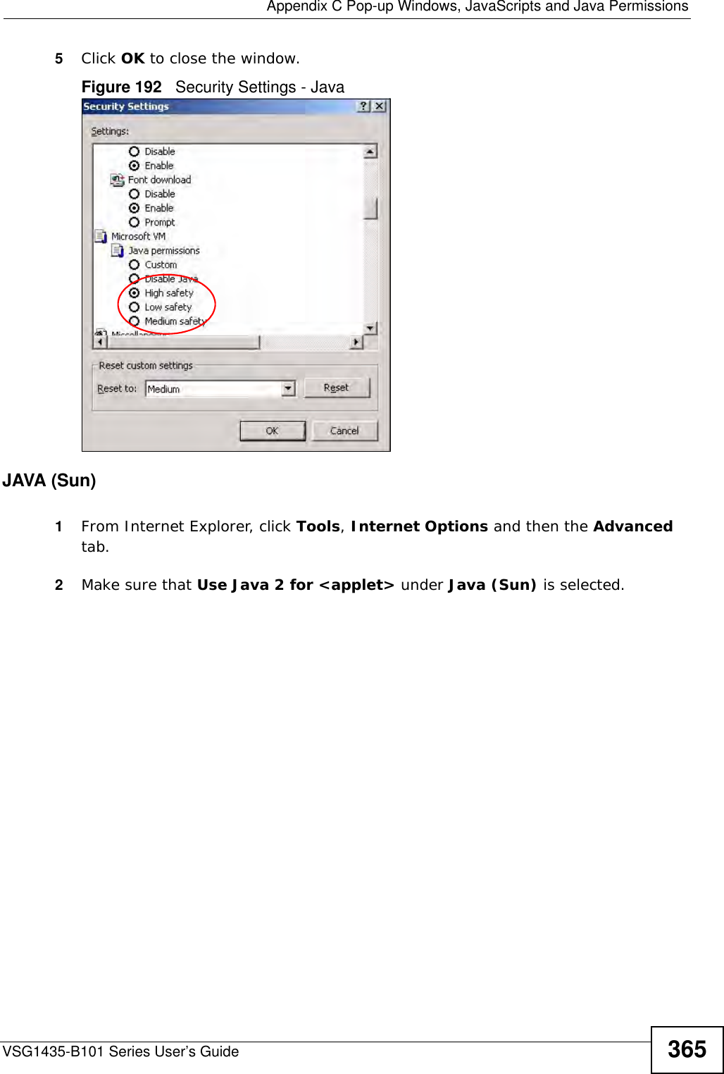
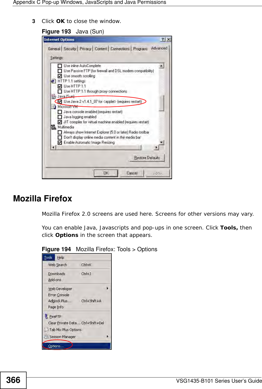
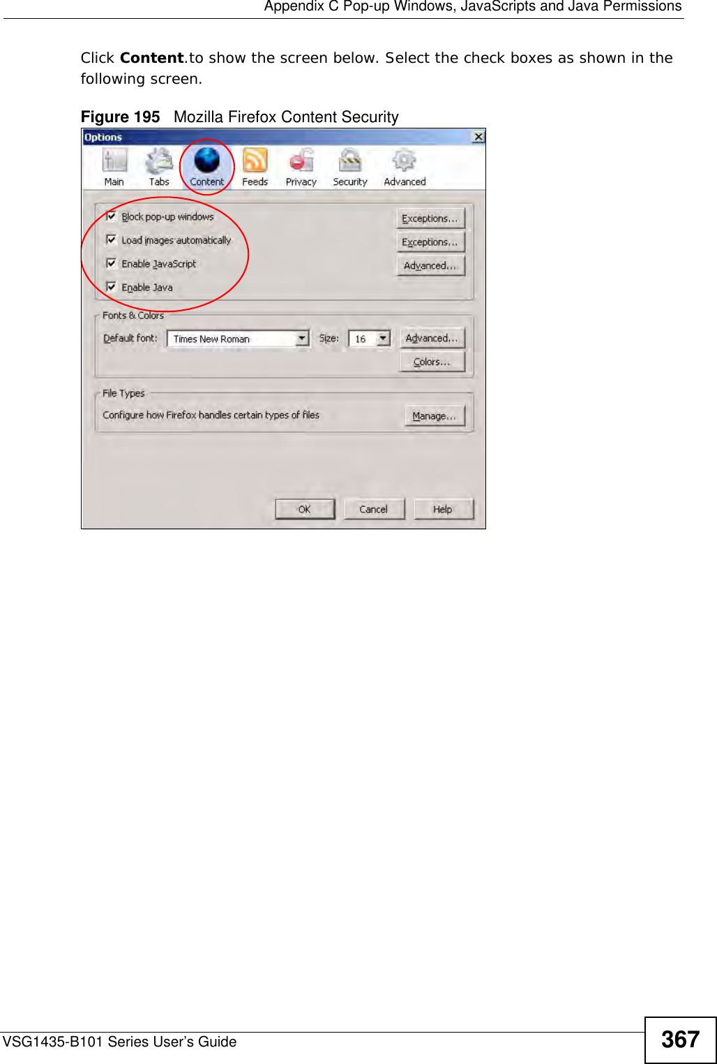
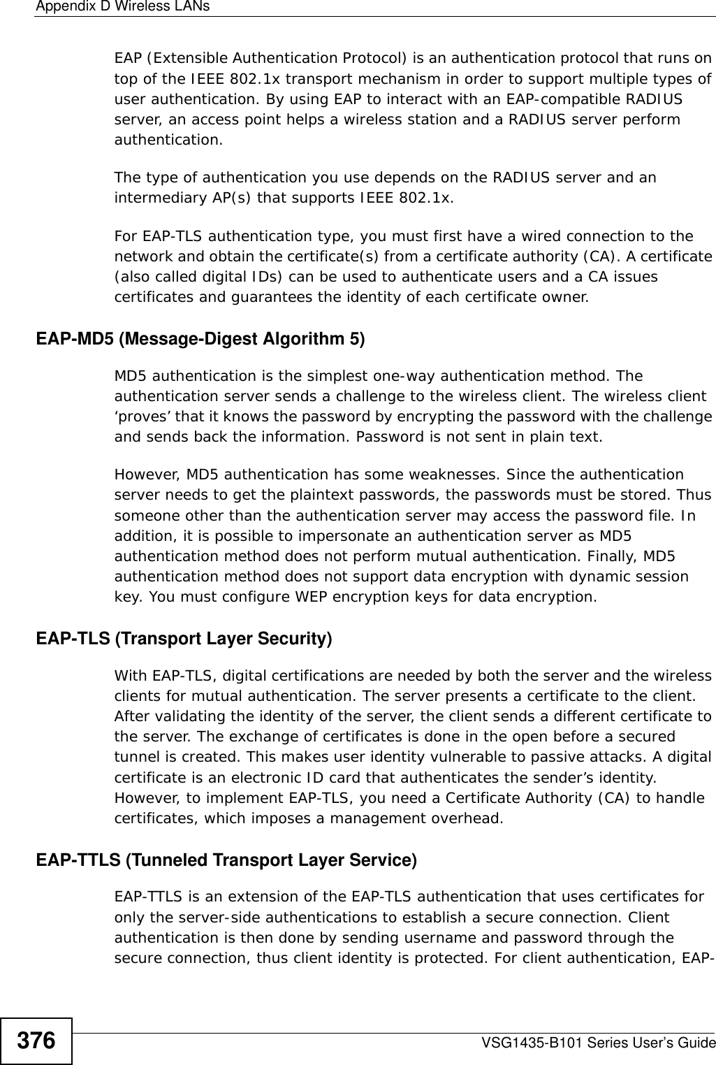
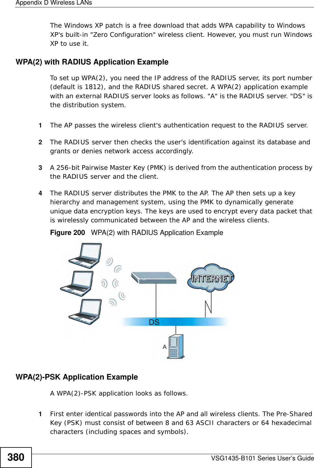
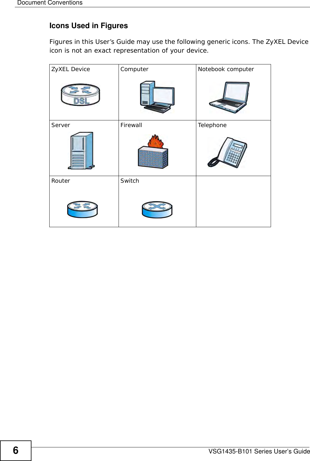
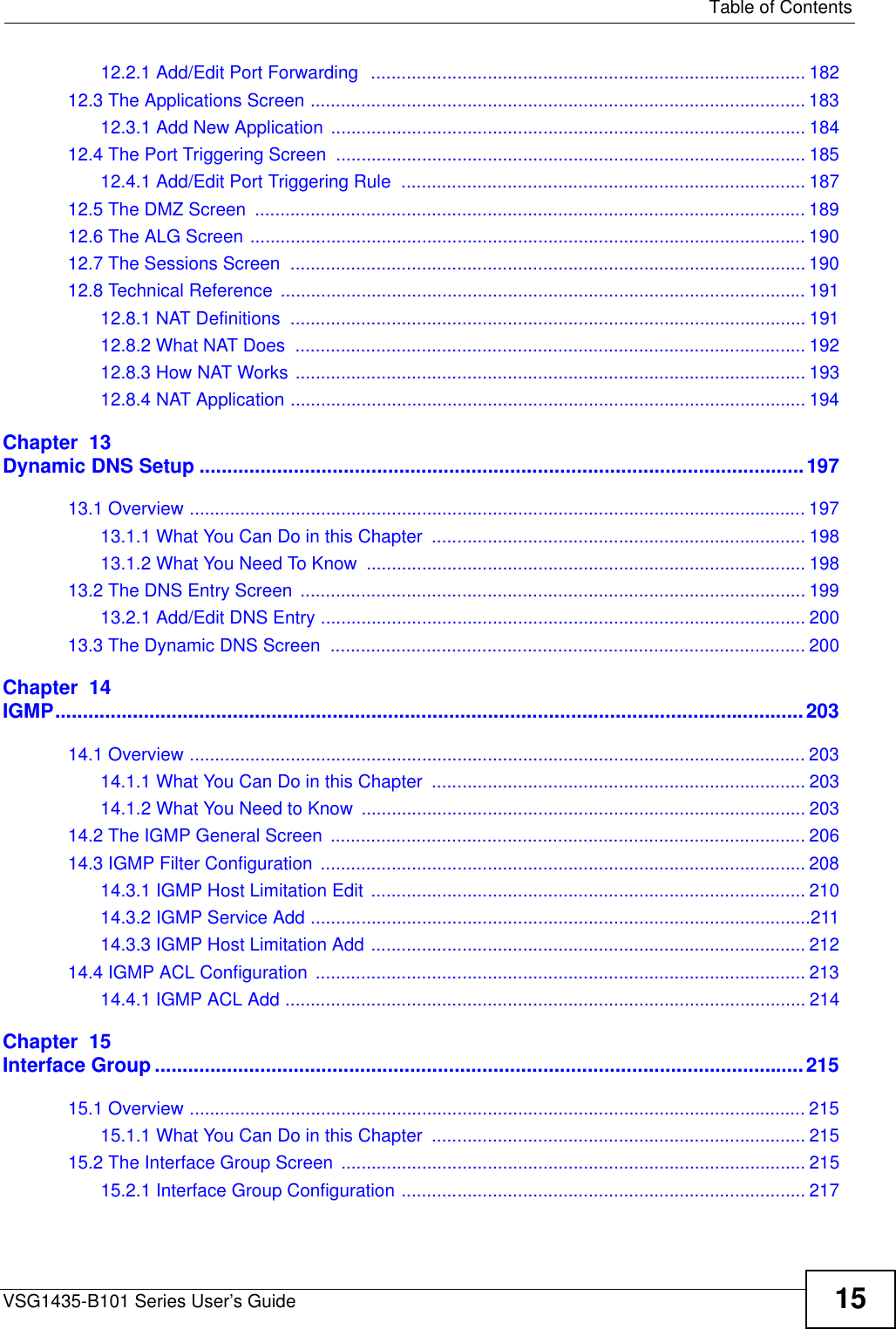
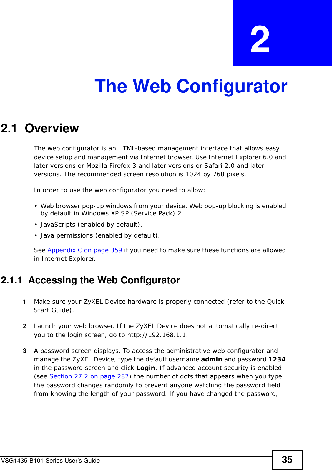
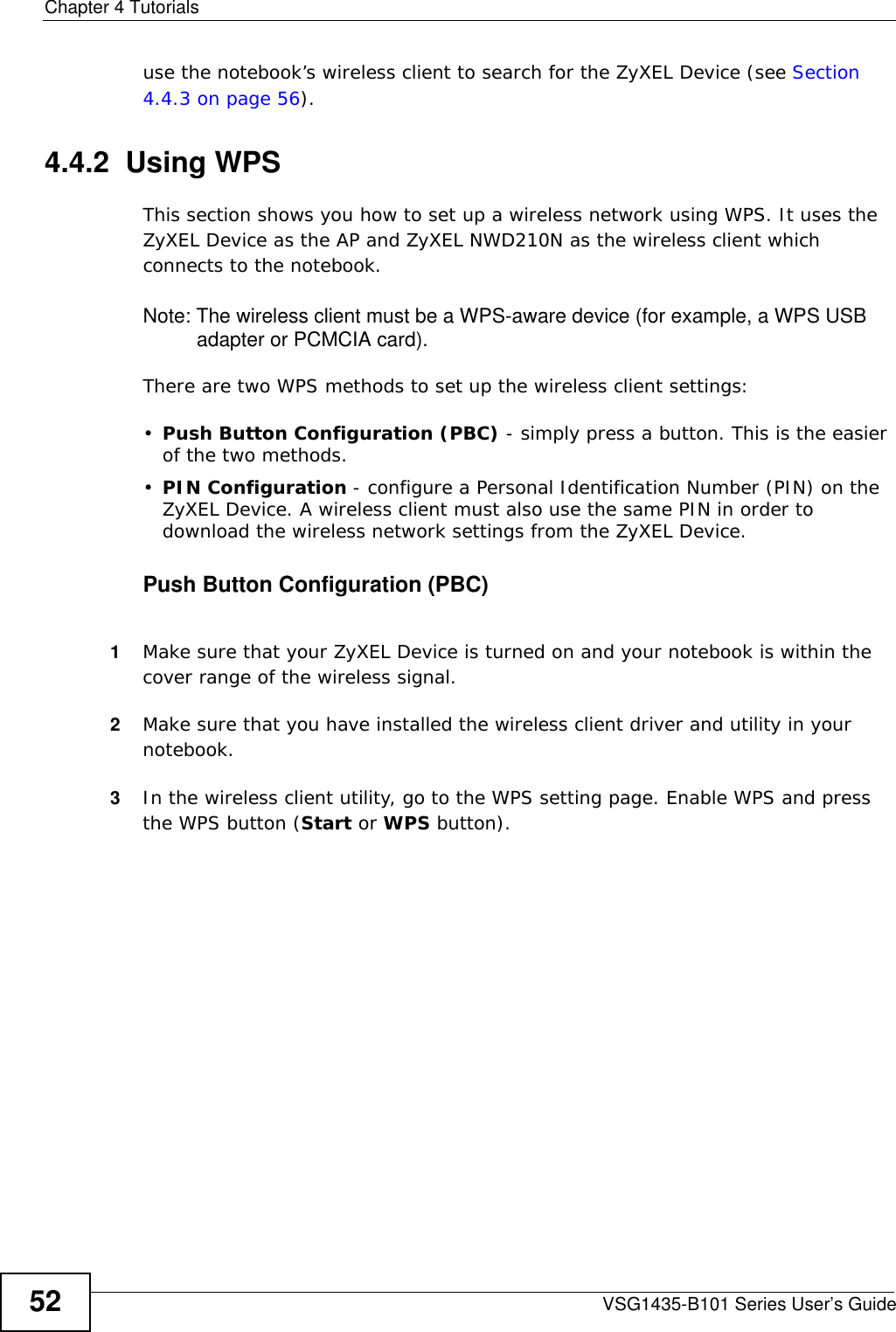
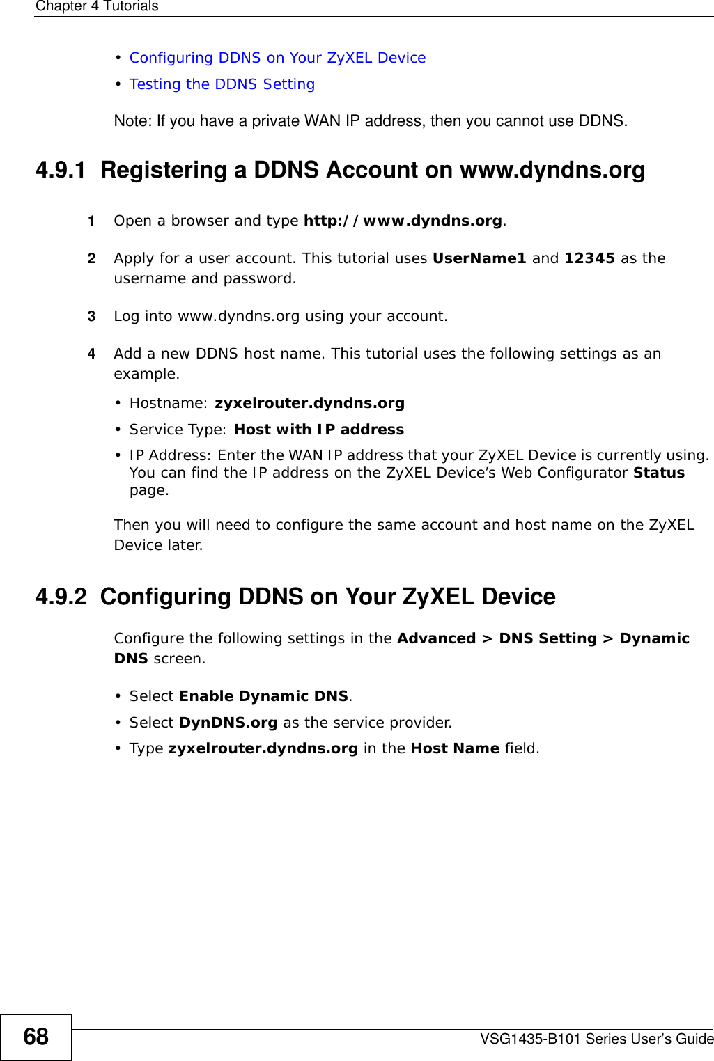
![Chapter 34 TroubleshootingVSG1435-B101 Series User’s Guide 313• If you changed the IP address (Section 8.2 on page 134), use the new IP address.• If you changed the IP address and have forgotten it, see the troubleshooting suggestions for I forgot the IP address for the ZyXEL Device.2Check the hardware connections, and make sure the LEDs are behaving as expected. See Section 1.6 on page 29.3Make sure your Internet browser does not block pop-up windows and has JavaScripts and Java enabled. See Appendix C on page 359.4If it is possible to log in from another interface, check the service control settings for HTTP and HTTPS (Security Settings > Service Control).5Reset the device to its factory defaults, and try to access the ZyXEL Device with the default IP address. See Section 1.8 on page 32.6If the problem continues, contact the network administrator or vendor, or try one of the advanced suggestions.Advanced Suggestions• Make sure you have logged out of any earlier management sessions using the same user account even if they were through a different interface or using a different browser.• Try to access the ZyXEL Device using another service, such as Telnet. If you can access the ZyXEL Device, check the remote management settings and firewall rules to find out why the ZyXEL Device does not respond to HTTP. • If your computer is connected to the WAN port or is connected wirelessly, use a computer that is connected to an ETHERNET port.\I can see the Login screen, but I cannot log in to the ZyXEL Device.1Make sure you have entered the password correctly. The default admin password is 1234. The field is case-sensitive, so make sure [Caps Lock] is not on. 2You cannot log in to the web configurator while someone is using Telnet to access the ZyXEL Device. Log out of the ZyXEL Device in the other session, or ask the person who is logged in to log out. 3Turn the ZyXEL Device off and on. 4If this does not work, you have to reset the device to its factory defaults. See Section 34.1 on page 311.](https://usermanual.wiki/ZyXEL-Communications/VSG1435B101/User-Guide-1359663-Page-313.png)
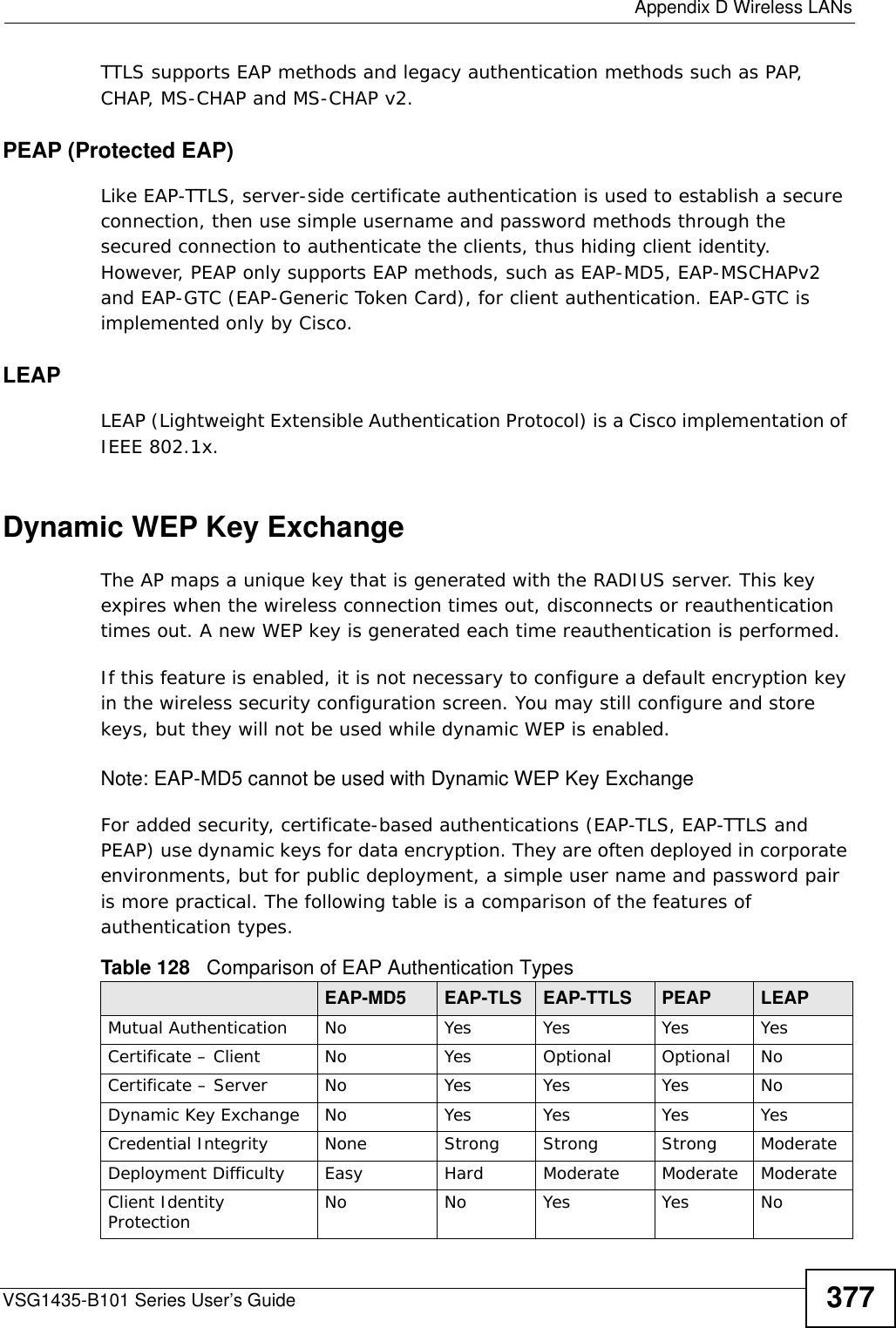
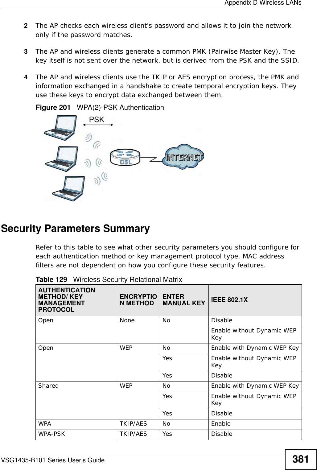
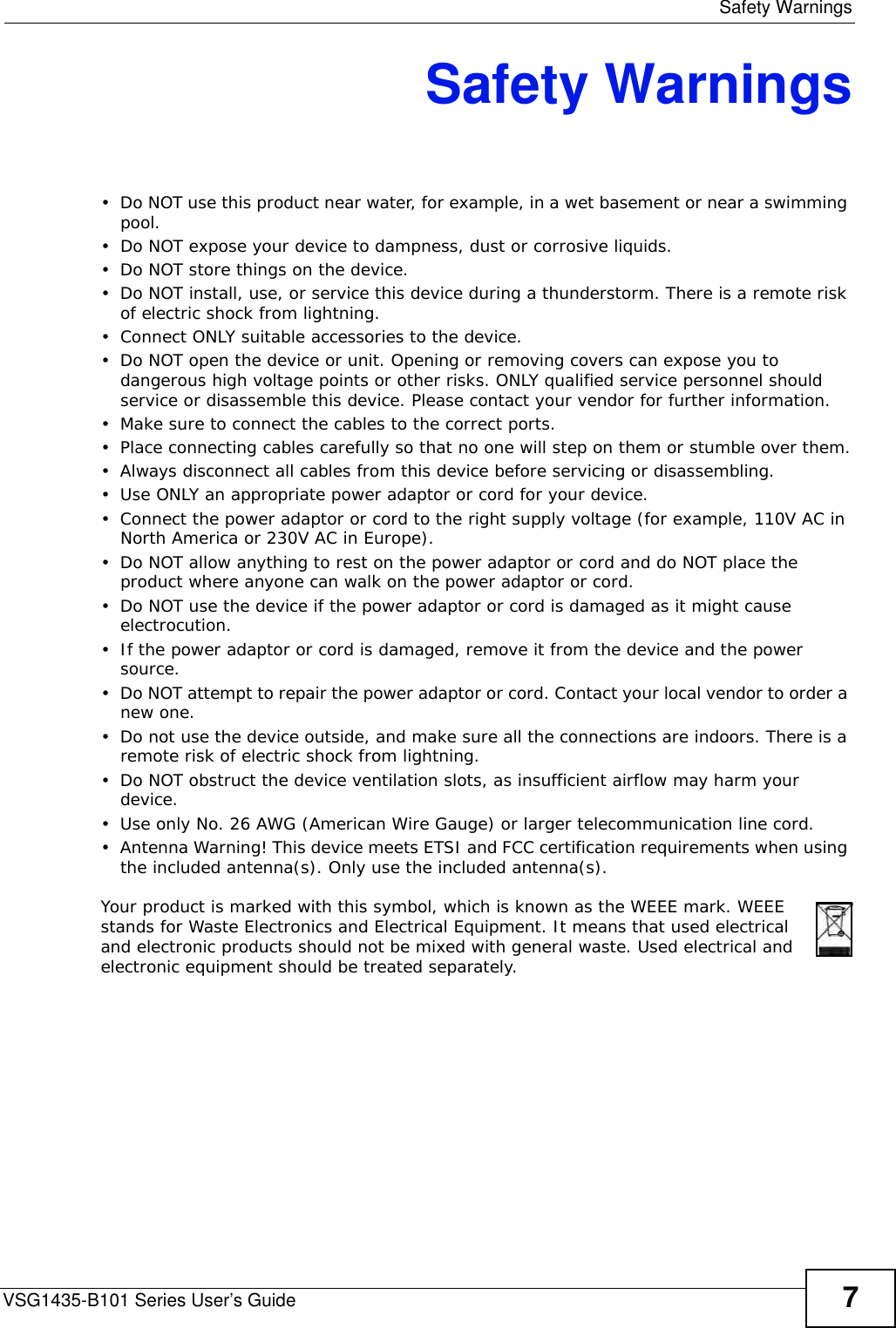
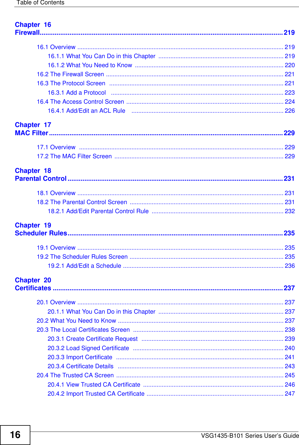
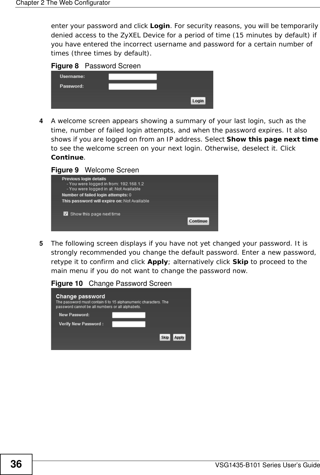
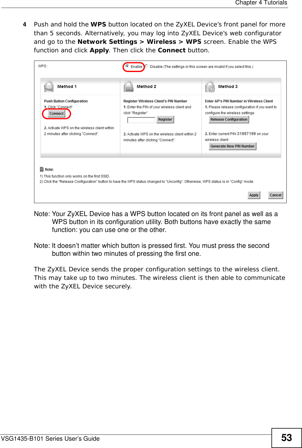
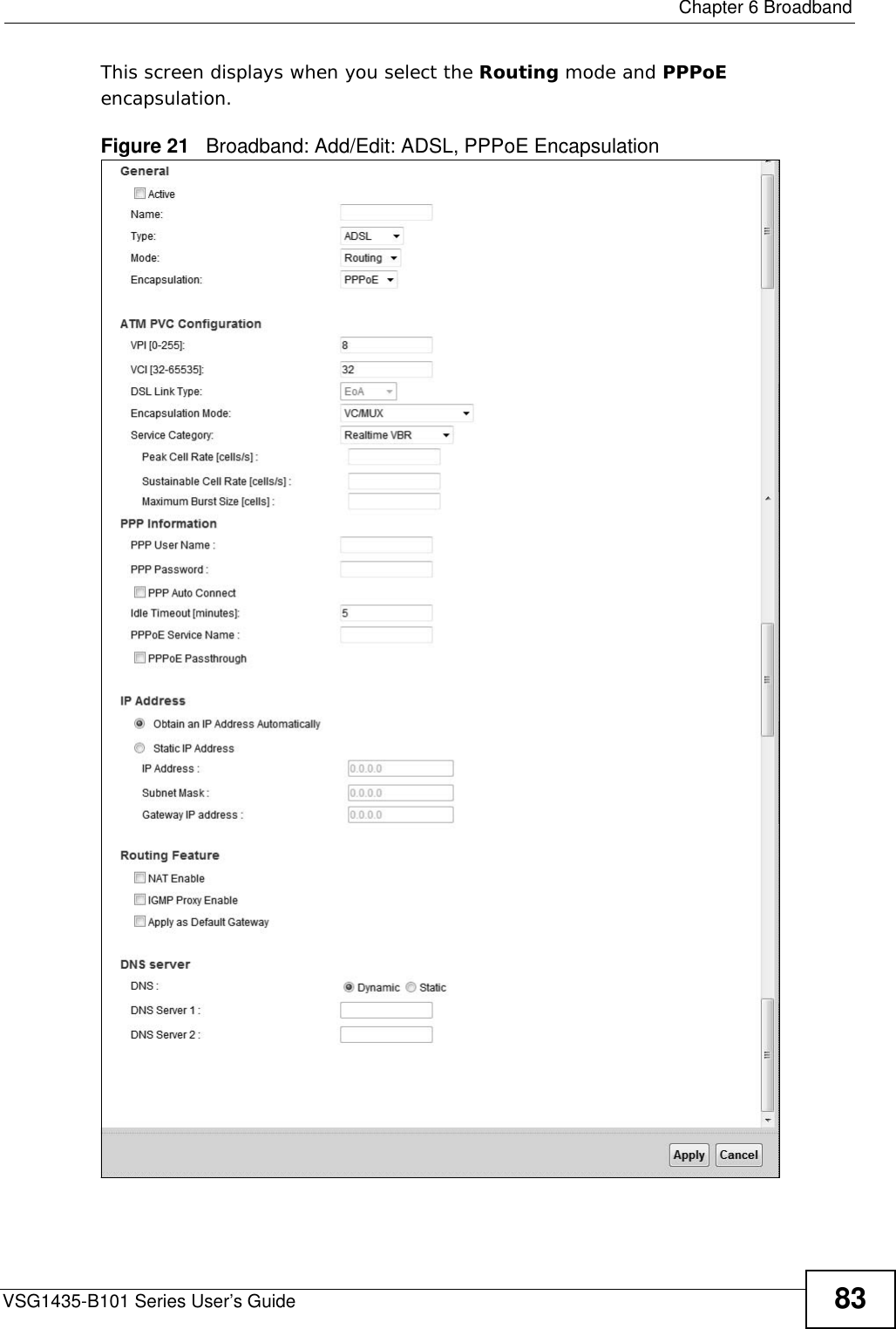
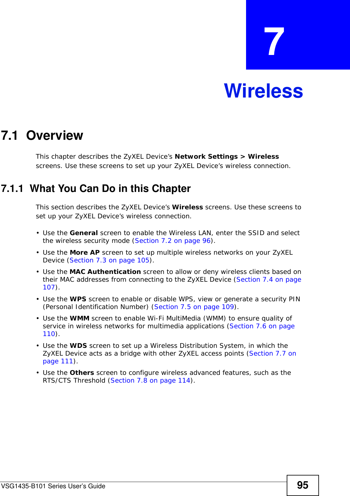
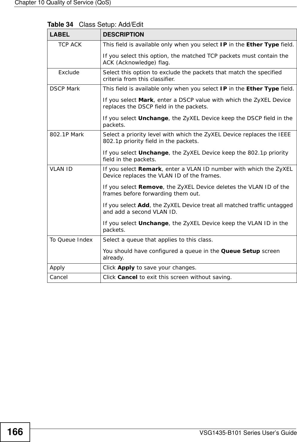
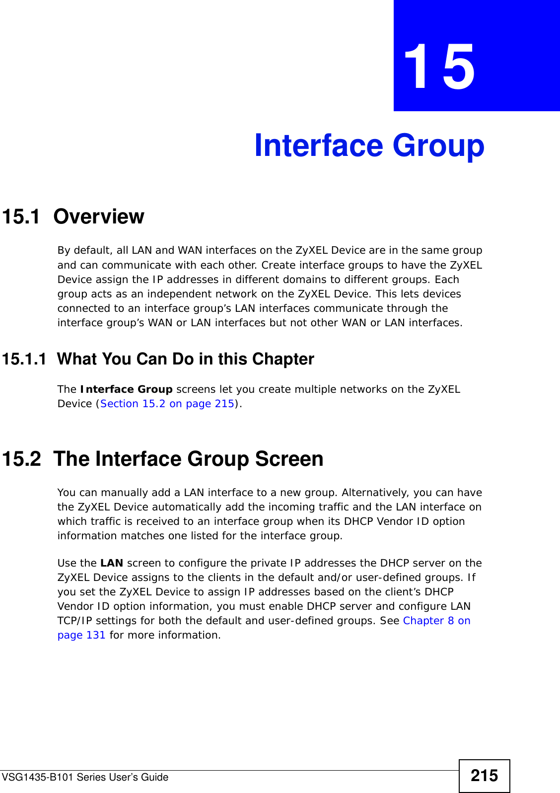
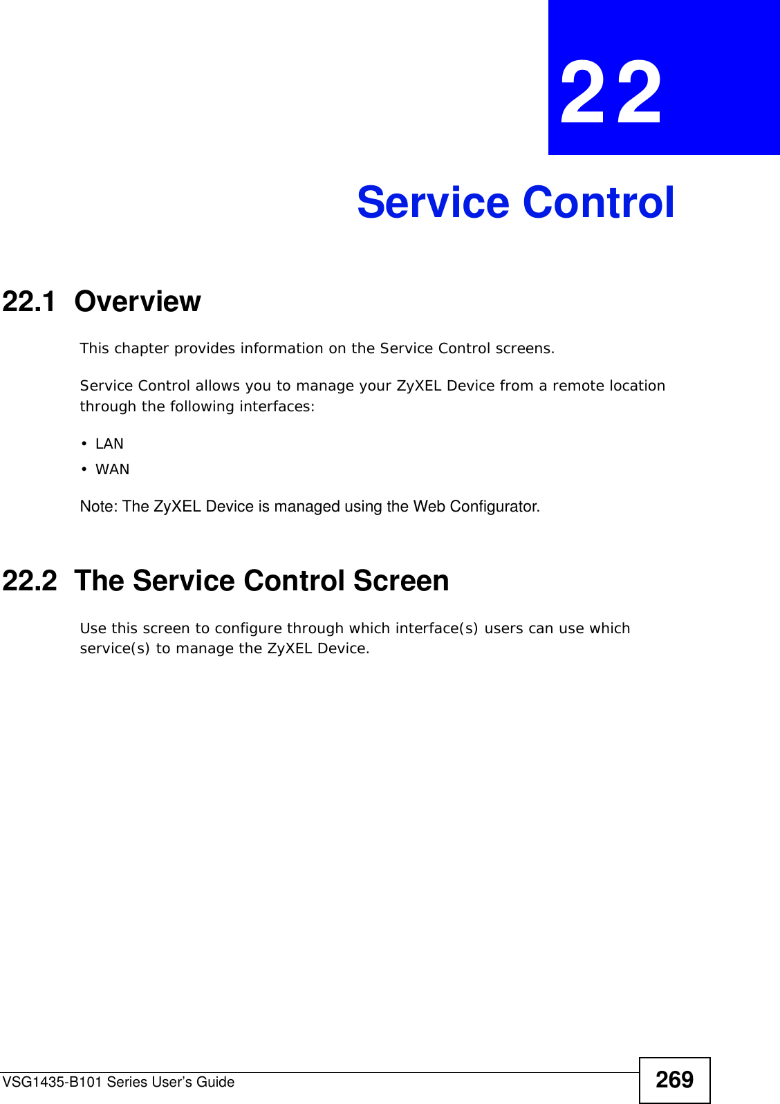
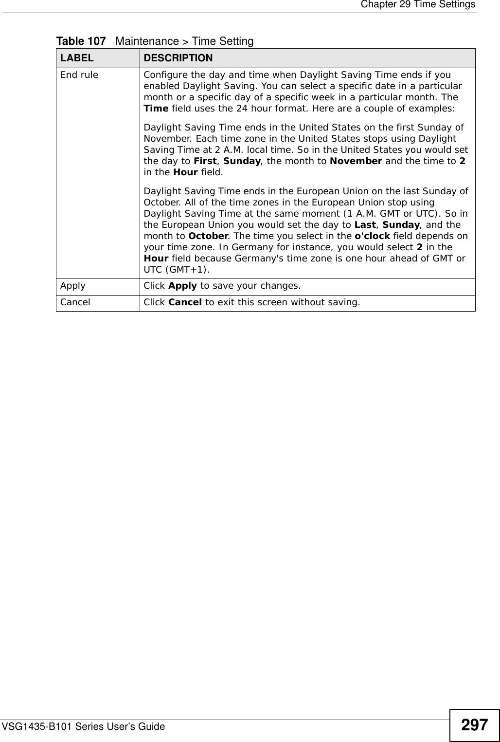
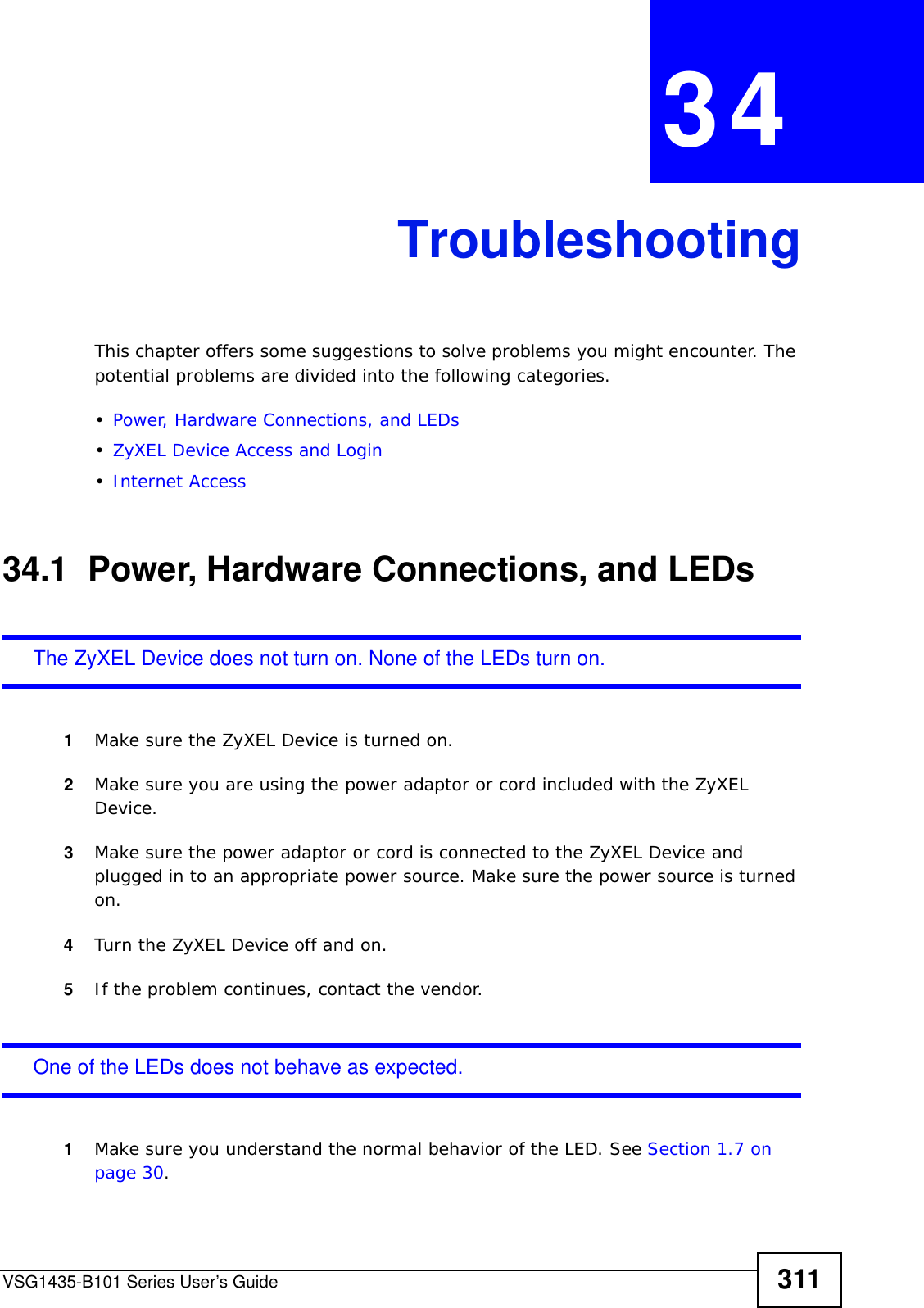
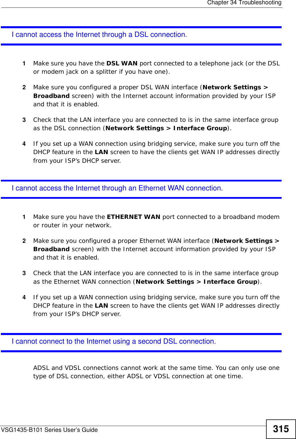
![Chapter 34 TroubleshootingVSG1435-B101 Series User’s Guide314I cannot Telnet to the ZyXEL Device.1See the troubleshooting suggestions for I cannot see or access the Login screen in the web configurator. Ignore the suggestions about your browser.2Check the service control settings for Telnet. See Chapter 22 on page 269.I cannot use FTP to upload / download the configuration file. / I cannot use FTP to upload new firmware.1See the troubleshooting suggestions for I cannot see or access the Login screen in the web configurator. Ignore the suggestions about your browser.2Check the service control settings for FTP. See Chapter 22 on page 269.34.3 Internet AccessI cannot access the Internet.1Check the hardware connections, and make sure the LEDs are behaving as expected. See Section 1.6 on page 29 and Section 1.7 on page 30.2Make sure you entered your ISP account information correctly in the Network Settings > Broadband screen. These fields are case-sensitive, so make sure [Caps Lock] is not on. 3If you are trying to access the Internet wirelessly, make sure that you enabled the wireless LAN in the ZyXEL Device and your wireless client and that the wireless settings in the wireless client are the same as the settings in the ZyXEL Device.4Disconnect all the cables from your device, and follow the directions in Section 1.6 on page 29 again. 5If the problem continues, contact your ISP.](https://usermanual.wiki/ZyXEL-Communications/VSG1435B101/User-Guide-1359663-Page-314.png)
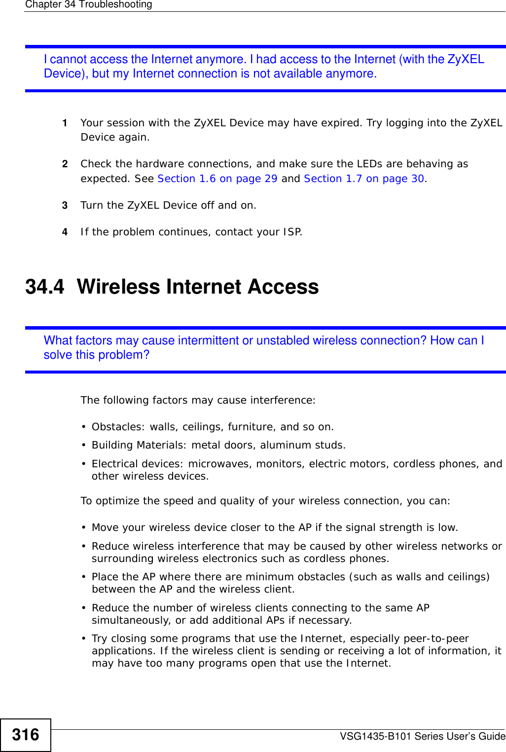

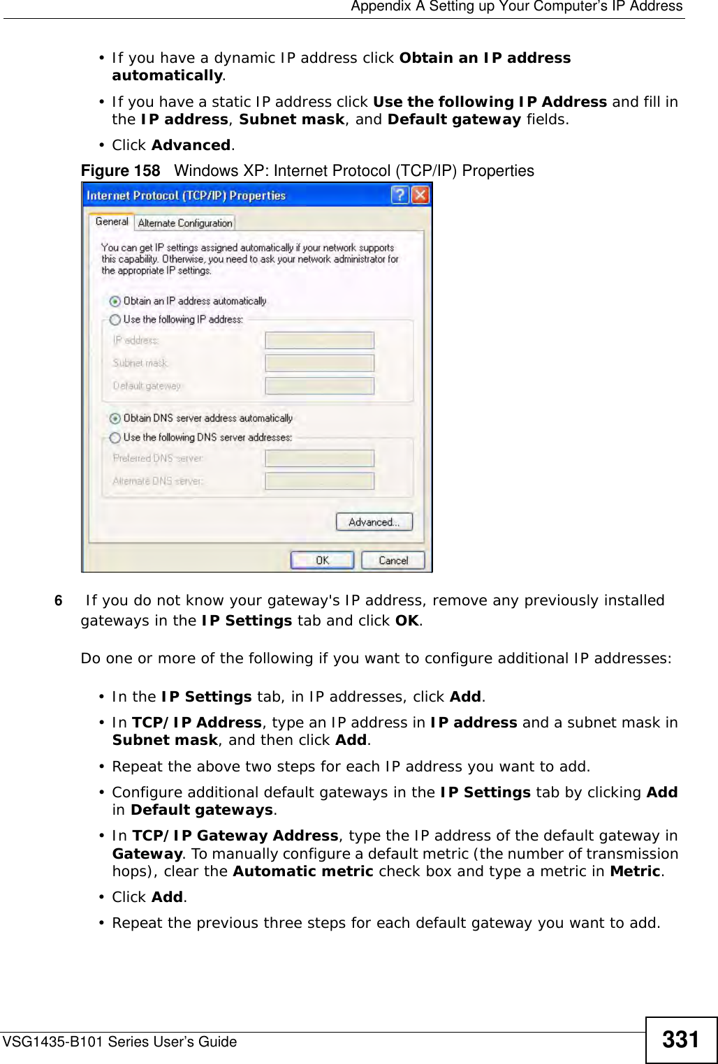
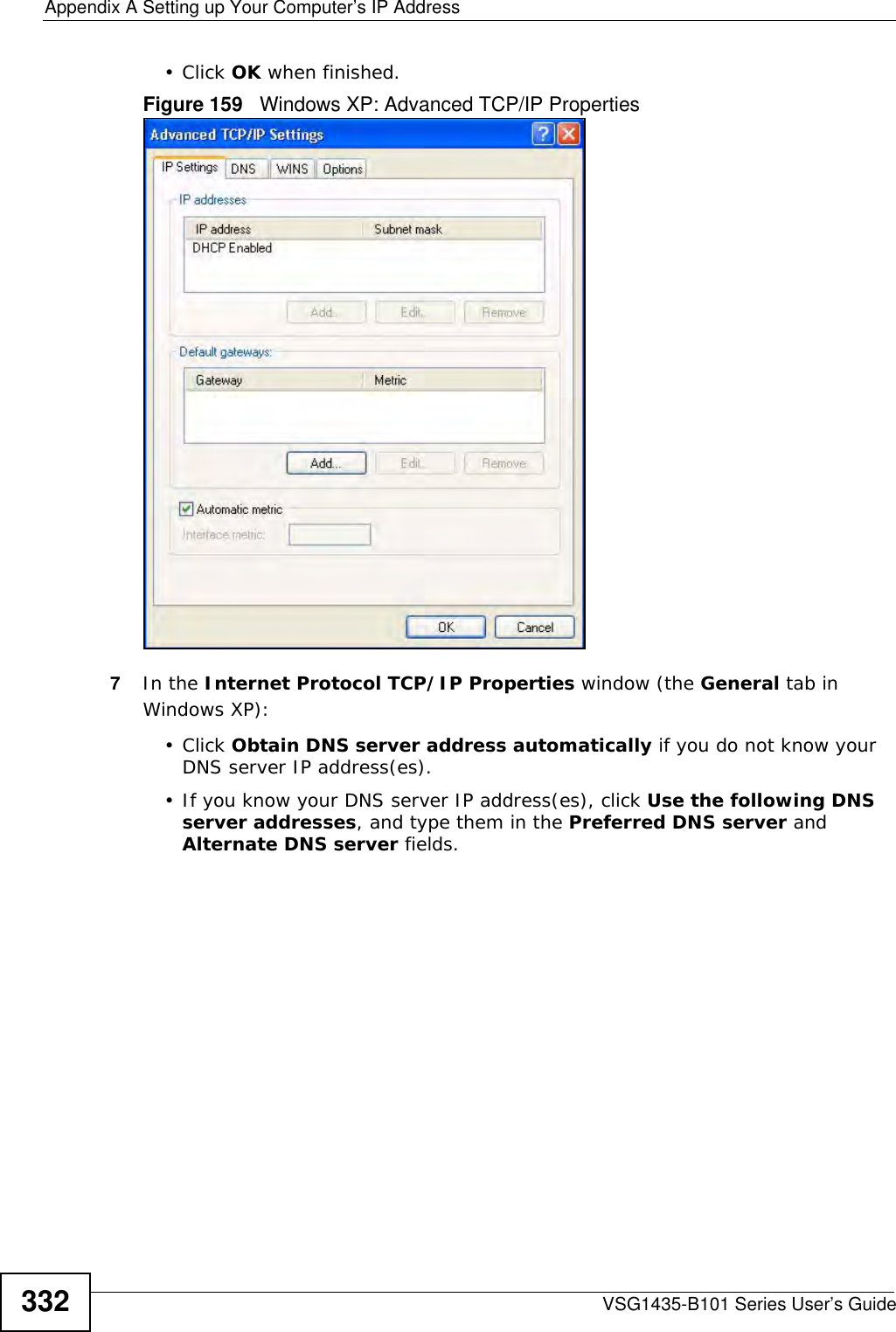
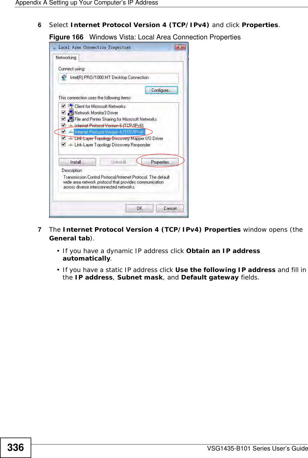
![Appendix A Setting up Your Computer’s IP AddressVSG1435-B101 Series User’s Guide 333If you have previously configured DNS servers, click Advanced and then the DNS tab to order them.Figure 160 Windows XP: Internet Protocol (TCP/IP) Properties8Click OK to close the Internet Protocol (TCP/IP) Properties window.9Click Close (OK in Windows 2000/NT) to close the Local Area Connection Properties window.10 Close the Network Connections window (Network and Dial-up Connections in Windows 2000/NT).11 Turn on your ZyXEL Device and restart your computer (if prompted).Verifying Settings1Click Start, All Programs, Accessories and then Command Prompt.2In the Command Prompt window, type "ipconfig" and then press [ENTER]. You can also open Network Connections, right-click a network connection, click Status and then click the Support tab.Windows VistaThis section shows screens from Windows Vista Enterprise Version 6.0.](https://usermanual.wiki/ZyXEL-Communications/VSG1435B101/User-Guide-1359663-Page-333.png)
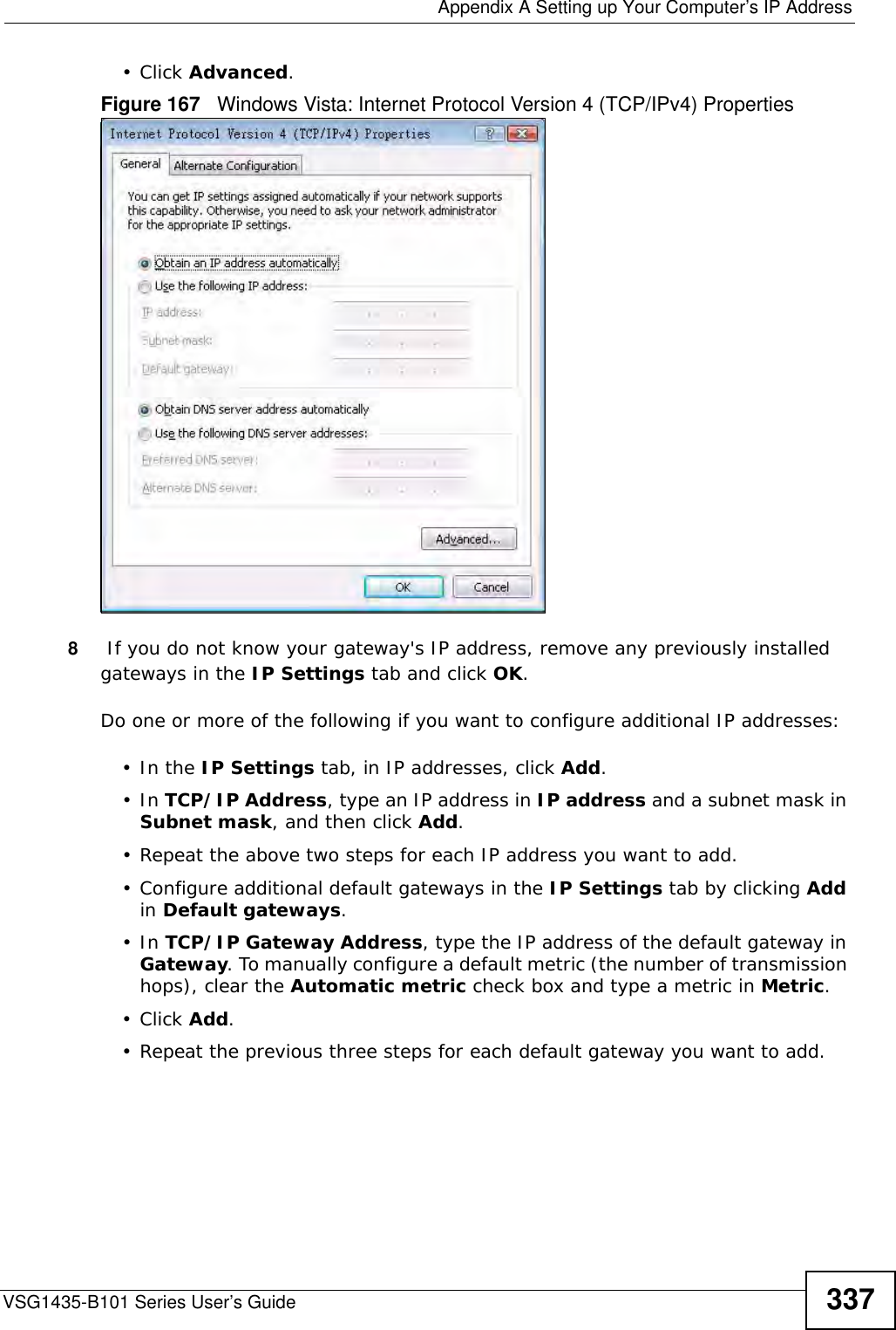
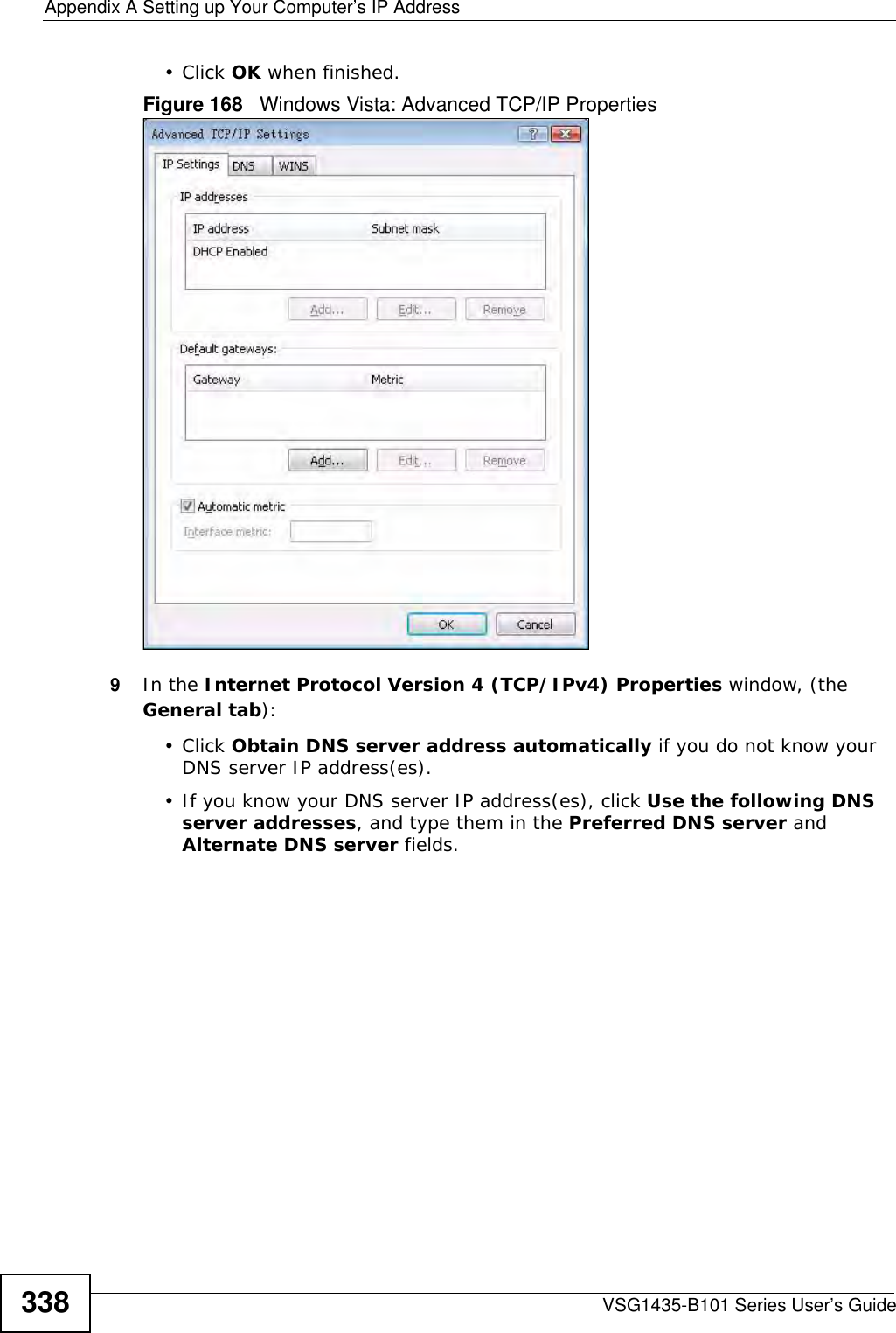
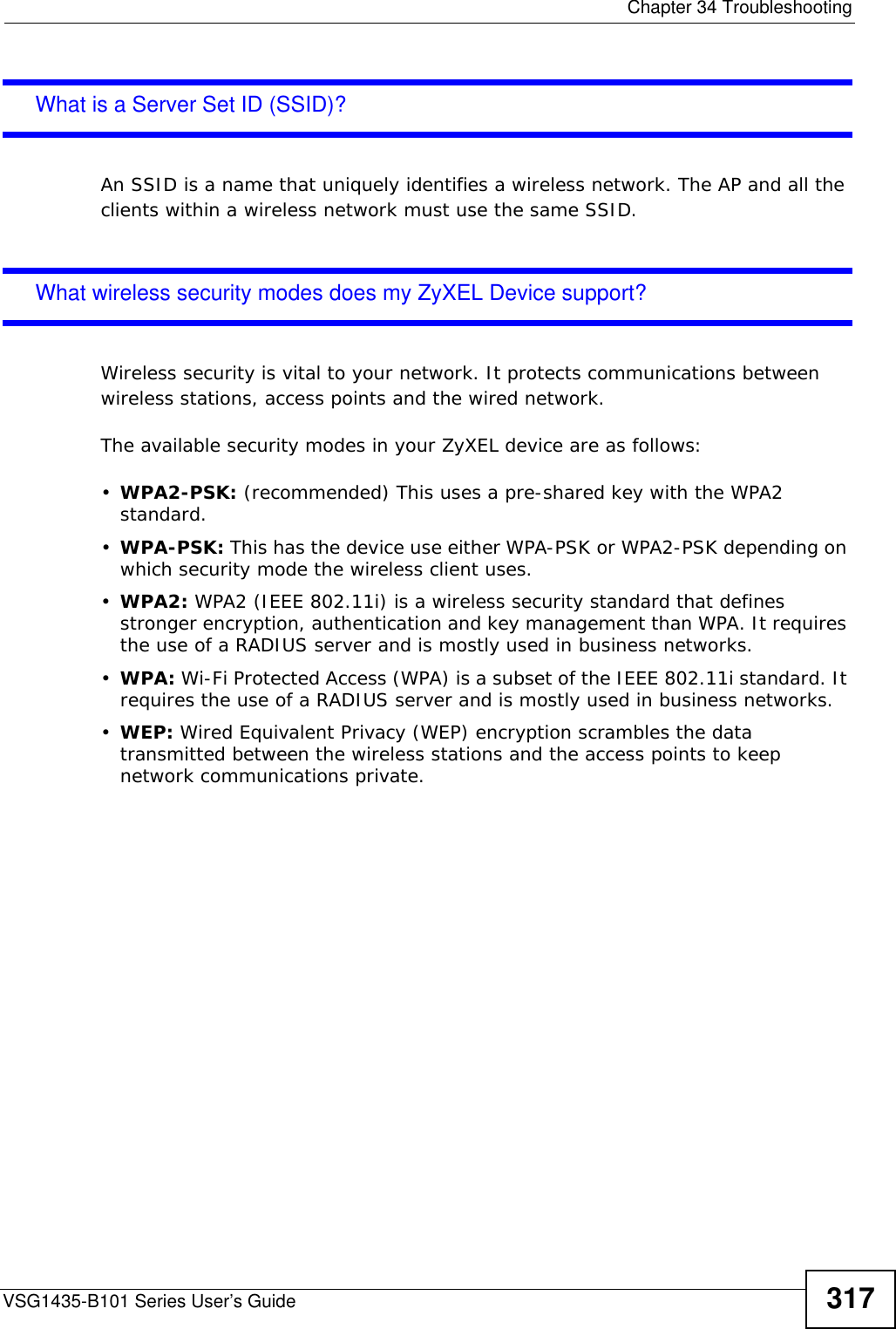
![Appendix A Setting up Your Computer’s IP AddressVSG1435-B101 Series User’s Guide 339If you have previously configured DNS servers, click Advanced and then the DNS tab to order them.Figure 169 Windows Vista: Internet Protocol Version 4 (TCP/IPv4) Properties10 Click OK to close the Internet Protocol Version 4 (TCP/IPv4) Properties window.11 Click Close to close the Local Area Connection Properties window.12 Close the Network Connections window.13 Turn on your ZyXEL Device and restart your computer (if prompted).Verifying Settings1Click Start, All Programs, Accessories and then Command Prompt.2In the Command Prompt window, type "ipconfig" and then press [ENTER]. You can also open Network Connections, right-click a network connection, click Status and then click the Support tab.](https://usermanual.wiki/ZyXEL-Communications/VSG1435B101/User-Guide-1359663-Page-339.png)
![Appendix A Setting up Your Computer’s IP AddressVSG1435-B101 Series User’s Guide346• If you have a static IP address, enter static in the BOOTPROTO= field. Type IPADDR= followed by the IP address (in dotted decimal notation) and type NETMASK= followed by the subnet mask. The following example shows an example where the static IP address is 192.168.1.10 and the subnet mask is 255.255.255.0. Figure 179 Red Hat 9.0: Static IP Address Setting in ifconfig-eth0 2If you know your DNS server IP address(es), enter the DNS server information in the resolv.conf file in the /etc directory. The following figure shows an example where two DNS server IP addresses are specified.Figure 180 Red Hat 9.0: DNS Settings in resolv.conf 3After you edit and save the configuration files, you must restart the network card. Enter ./network restart in the /etc/rc.d/init.d directory. The following figure shows an example.Figure 181 Red Hat 9.0: Restart Ethernet Card DEVICE=eth0ONBOOT=yesBOOTPROTO=staticIPADDR=192.168.1.10NETMASK=255.255.255.0USERCTL=noPEERDNS=yesTYPE=Ethernetnameserver 172.23.5.1nameserver 172.23.5.2[root@localhost init.d]# network restartShutting down interface eth0: [OK]Shutting down loopback interface: [OK]Setting network parameters: [OK]Bringing up loopback interface: [OK]Bringing up interface eth0: [OK]](https://usermanual.wiki/ZyXEL-Communications/VSG1435B101/User-Guide-1359663-Page-346.png)
![Appendix A Setting up Your Computer’s IP AddressVSG1435-B101 Series User’s Guide 347Verifying SettingsEnter ifconfig in a terminal screen to check your TCP/IP properties. Figure 182 Red Hat 9.0: Checking TCP/IP Properties [root@localhost]# ifconfig eth0 Link encap:Ethernet HWaddr 00:50:BA:72:5B:44 inet addr:172.23.19.129 Bcast:172.23.19.255 Mask:255.255.255.0 UP BROADCAST RUNNING MULTICAST MTU:1500 Metric:1 RX packets:717 errors:0 dropped:0 overruns:0 frame:0 TX packets:13 errors:0 dropped:0 overruns:0 carrier:0 collisions:0 txqueuelen:100 RX bytes:730412 (713.2 Kb) TX bytes:1570 (1.5 Kb) Interrupt:10 Base address:0x1000 [root@localhost]#](https://usermanual.wiki/ZyXEL-Communications/VSG1435B101/User-Guide-1359663-Page-347.png)