ZyXEL Communications WAP3205V3 Wireless N300 Access Point User Manual
ZyXEL Communications Corporation Wireless N300 Access Point
UserManual.wiki
>
ZyXEL Communications
>
WAP3205V3 User Manual
User Manual
Navigation menu
Upload a User Manual
Namespaces
Wiki Guide
HTML
PDF
Info
Views
User Manual
Discussion / Help
Navigation


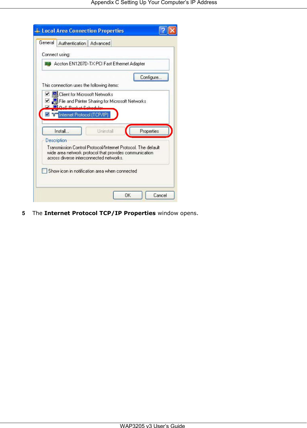
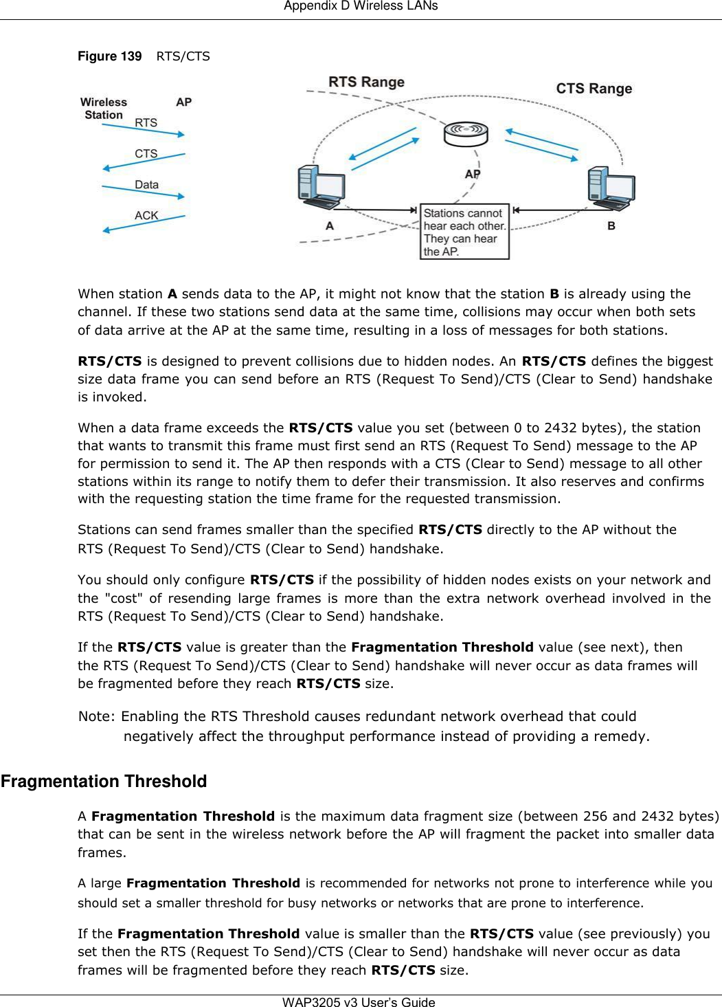
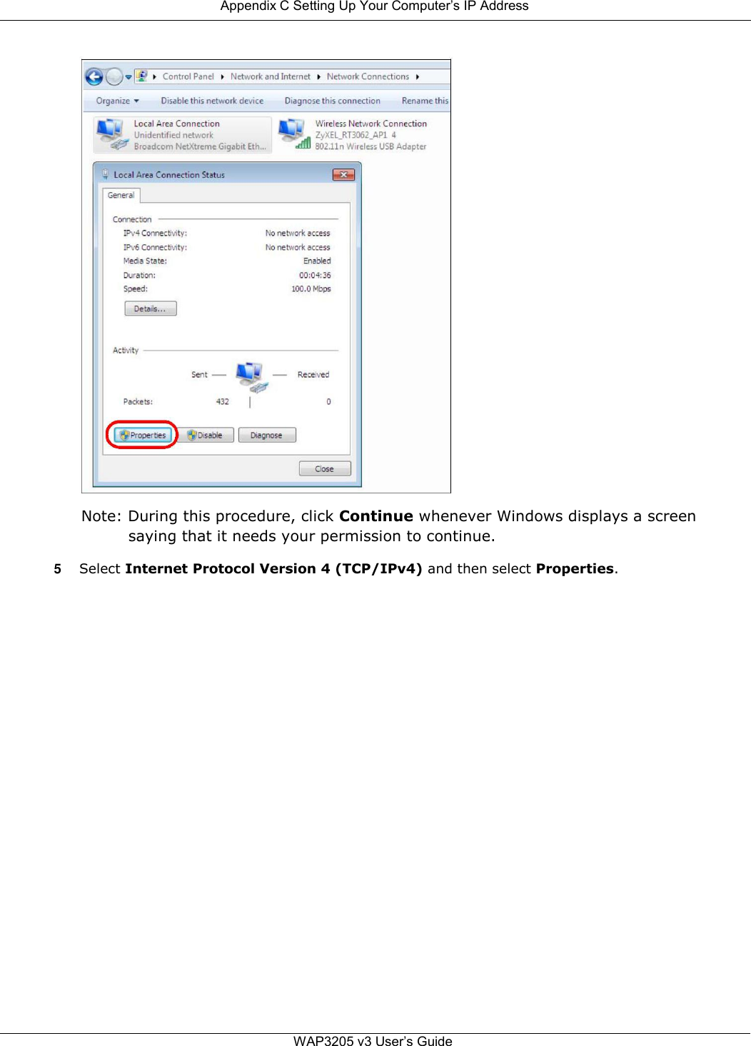
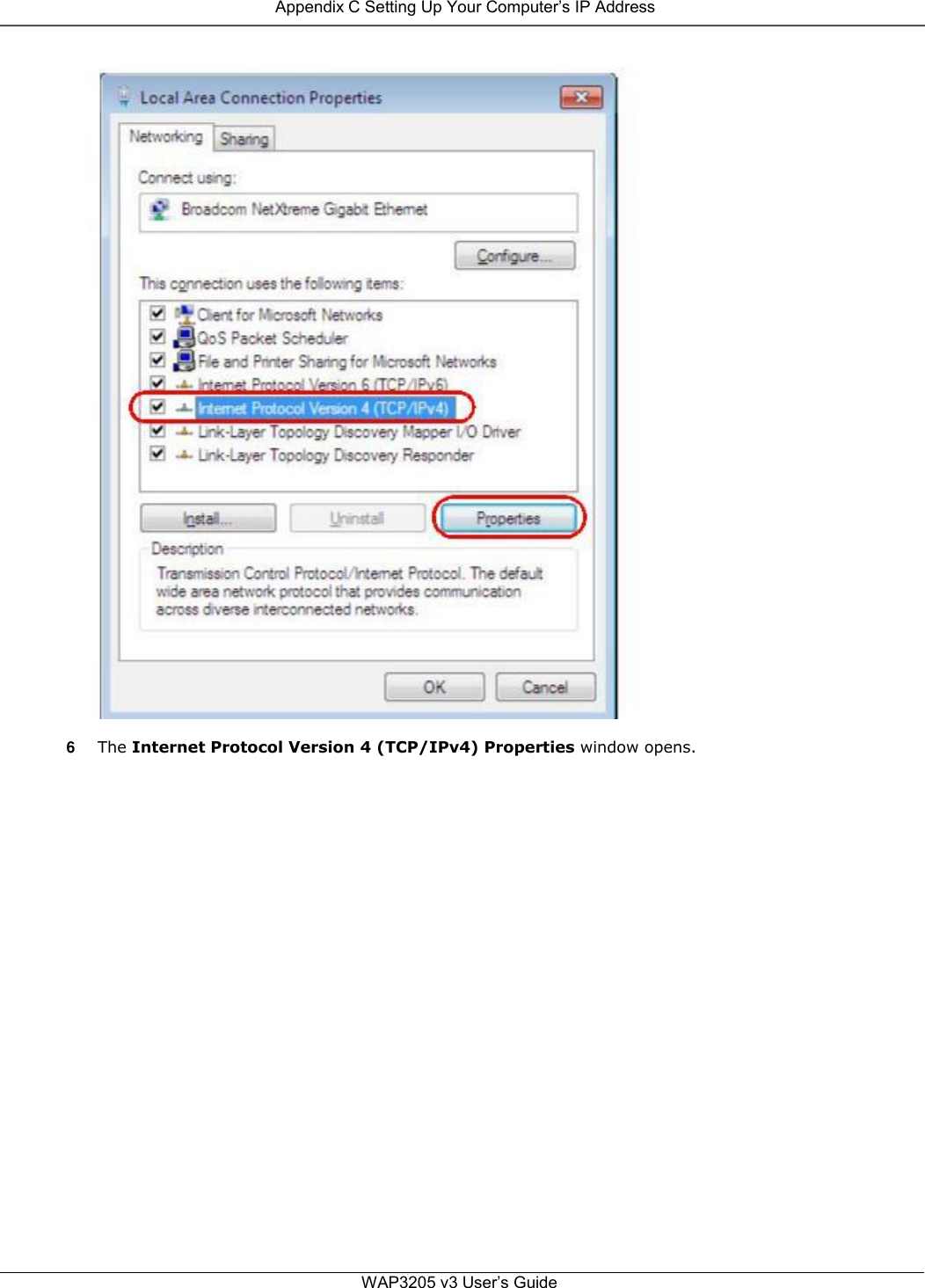
![Appendix C Setting Up Your Computer’s IP Address 6 Select Obtain an IP address automatically if your network administrator or ISP assigns your IP address dynamically. Select Use the following IP Address and fill in the IP address, Subnet mask, and Default gateway fields if you have a static IP address that was assigned to you by your network administrator or ISP. You may also have to enter a Preferred DNS server and an Alternate DNS server, if that information was provided. 7 Click OK to close the Internet Protocol (TCP/IP) Properties window. 8 Click OK to close the Local Area Connection Properties window. Verifying Settings 1 Click Start > All Programs > Accessories > Command Prompt. 2 In the Command Prompt window, type "ipconfig" and then press [ENTER]. You can also go to Start > Control Panel > Network Connections, right-click a network connection, click Status and then click the Support tab to view your IP address and connection information. WAP3205 v3 User’s Guide](https://usermanual.wiki/ZyXEL-Communications/WAP3205V3/User-Guide-3019741-Page-63.png)

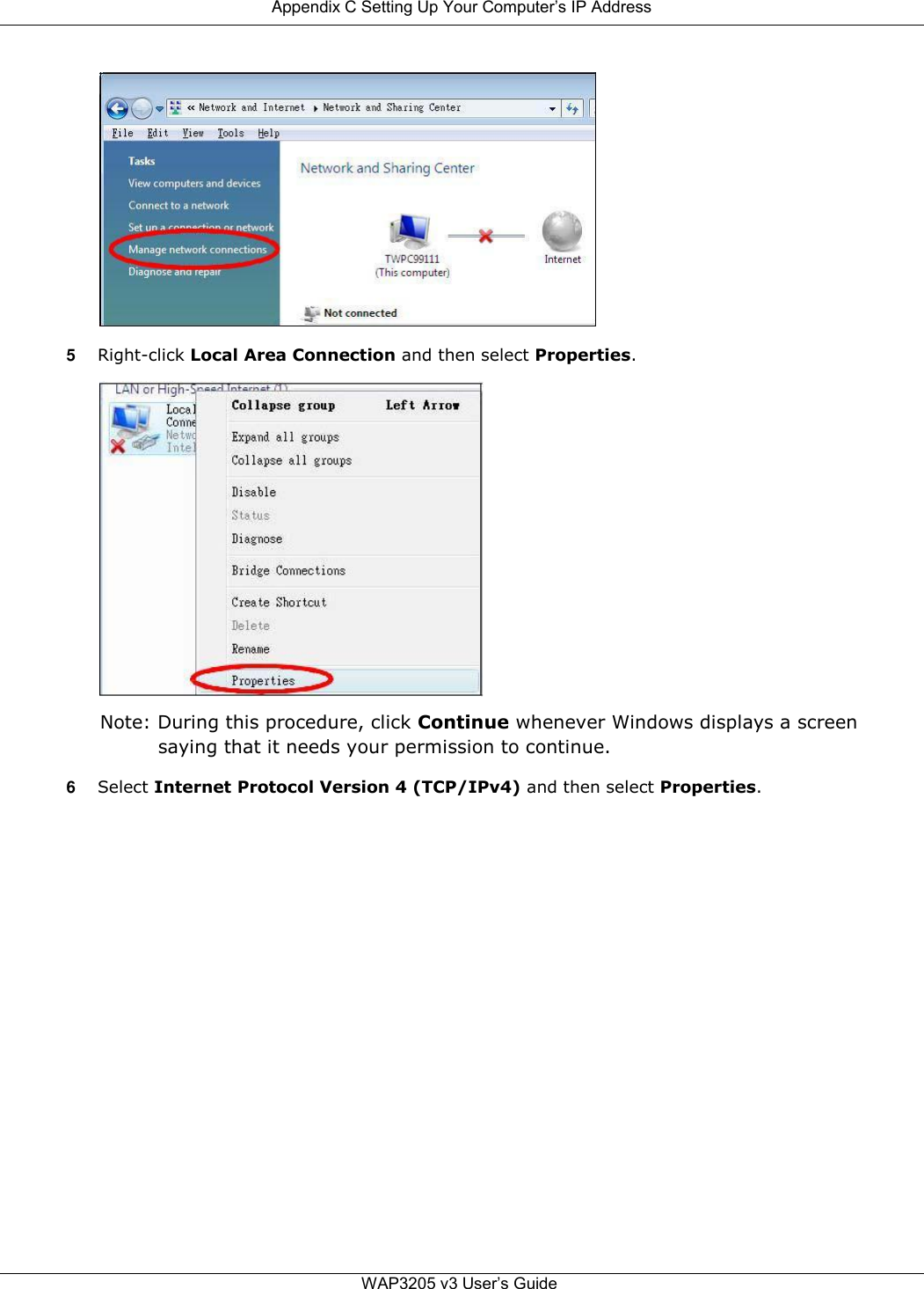
![Appendix C Setting Up Your Computer’s IP Address 8 Select Obtain an IP address automatically if your network administrator or ISP assigns your IP address dynamically. Select Use the following IP Address and fill in the IP address, Subnet mask, and Default gateway fields if you have a static IP address that was assigned to you by your network administrator or ISP. You may also have to enter a Preferred DNS server and an Alternate DNS server, if that information was provided.Click Advanced. 9 Click OK to close the Internet Protocol (TCP/IP) Properties window. 10 Click OK to close the Local Area Connection Properties window. Verifying Settings 1 Click Start > All Programs > Accessories > Command Prompt. 2 In the Command Prompt window, type "ipconfig" and then press [ENTER]. You can also go to Start > Control Panel > Network Connections, right-click a network connection, click Status and then click the Support tab to view your IP address and connection information. WAP3205 v3 User’s Guide](https://usermanual.wiki/ZyXEL-Communications/WAP3205V3/User-Guide-3019741-Page-67.png)
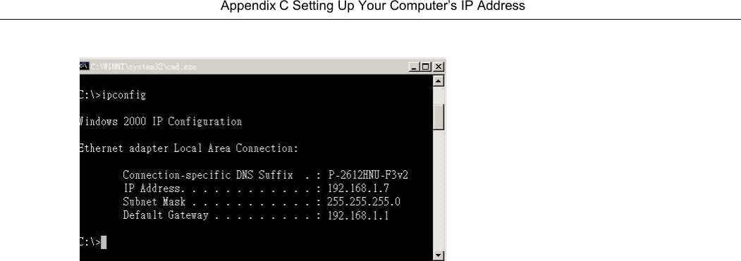
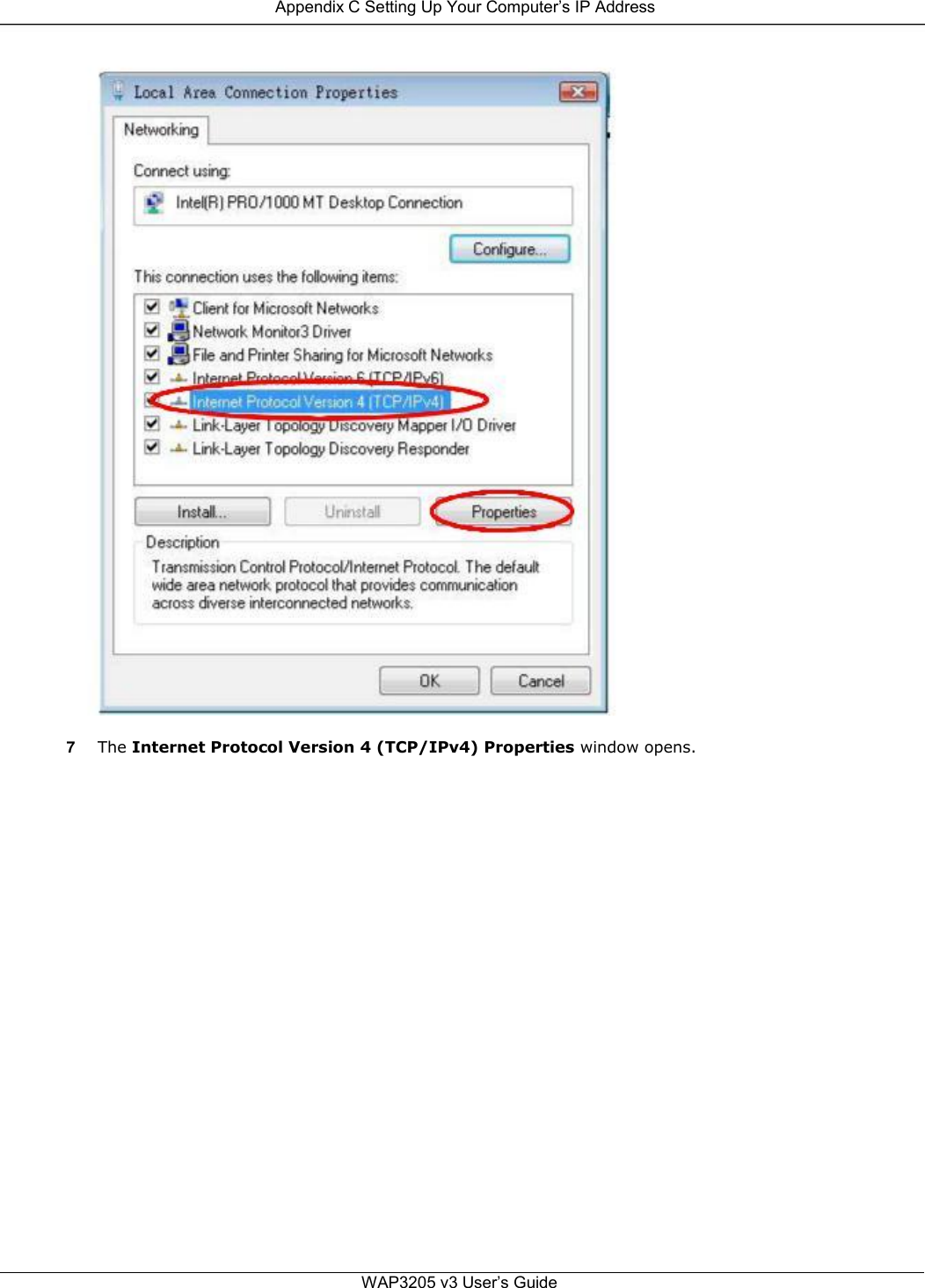
![Appendix C Setting Up Your Computer’s IP Address 7 Select Obtain an IP address automatically if your network administrator or ISP assigns your IP address dynamically. Select Use the following IP Address and fill in the IP address, Subnet mask, and Default gateway fields if you have a static IP address that was assigned to you by your network administrator or ISP. You may also have to enter a Preferred DNS server and an Alternate DNS server, if that information was provided. Click Advanced if you want to configure advanced settings for IP, DNS and WINS. 8 Click OK to close the Internet Protocol (TCP/IP) Properties window. 9 Click OK to close the Local Area Connection Properties window. Verifying Settings 1 Click Start > All Programs > Accessories > Command Prompt. 2 In the Command Prompt window, type "ipconfig" and then press [ENTER]. 3 The IP settings are displayed as follows. WAP3205 v3 User’s Guide](https://usermanual.wiki/ZyXEL-Communications/WAP3205V3/User-Guide-3019741-Page-71.png)