ZyXEL Communications WAP6804 Dual-Band AC2100 Gigabit Wireless Bridge User Manual Book
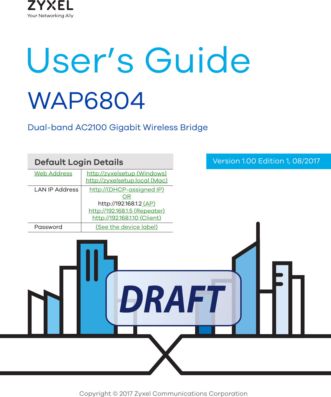
ZyXEL Communications Corporation Dual-Band AC2100 Gigabit Wireless Bridge Book
UserManual.wiki
>
ZyXEL Communications
>
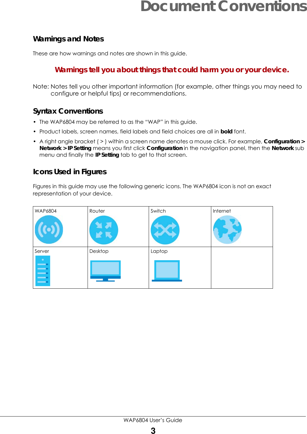
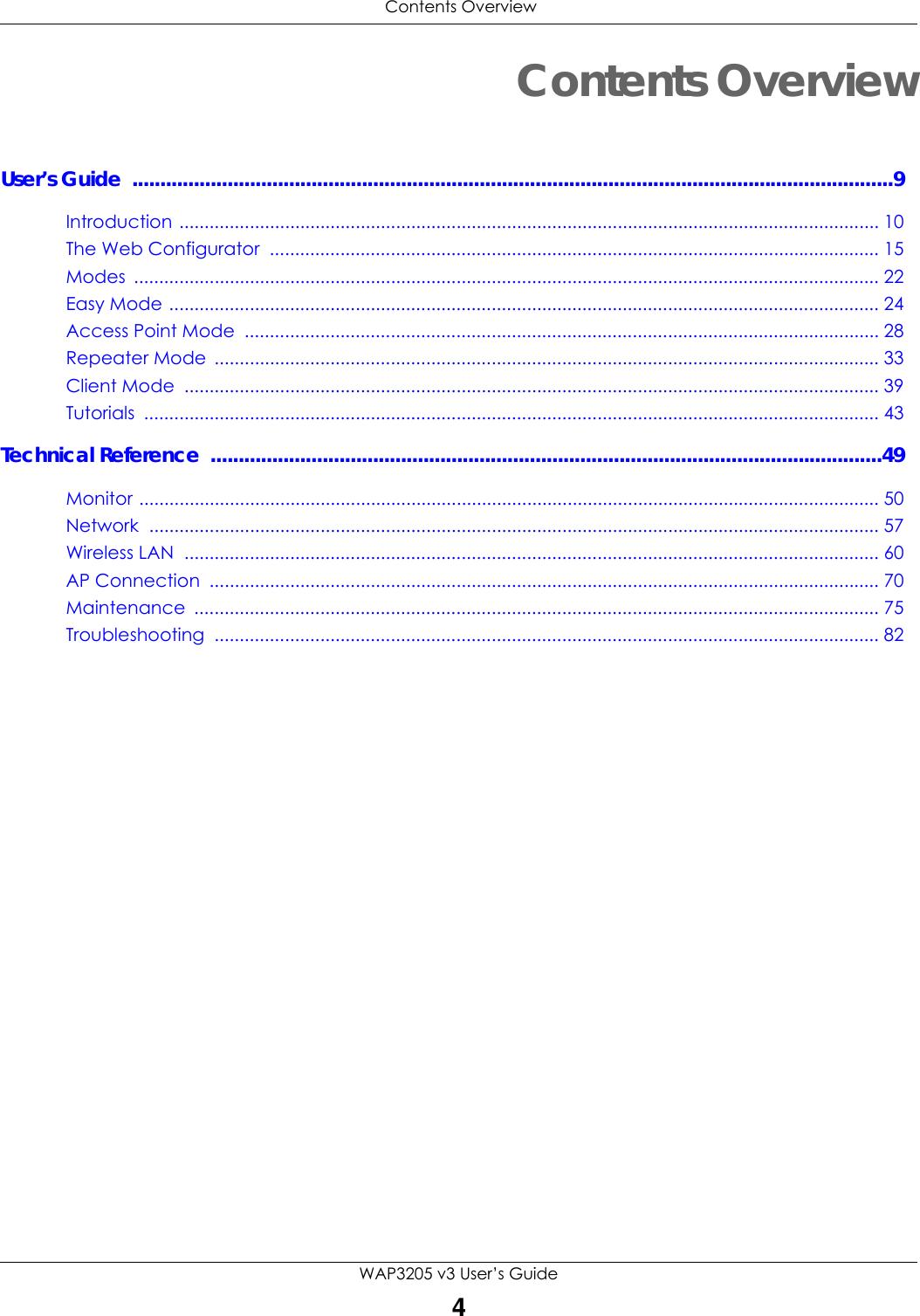
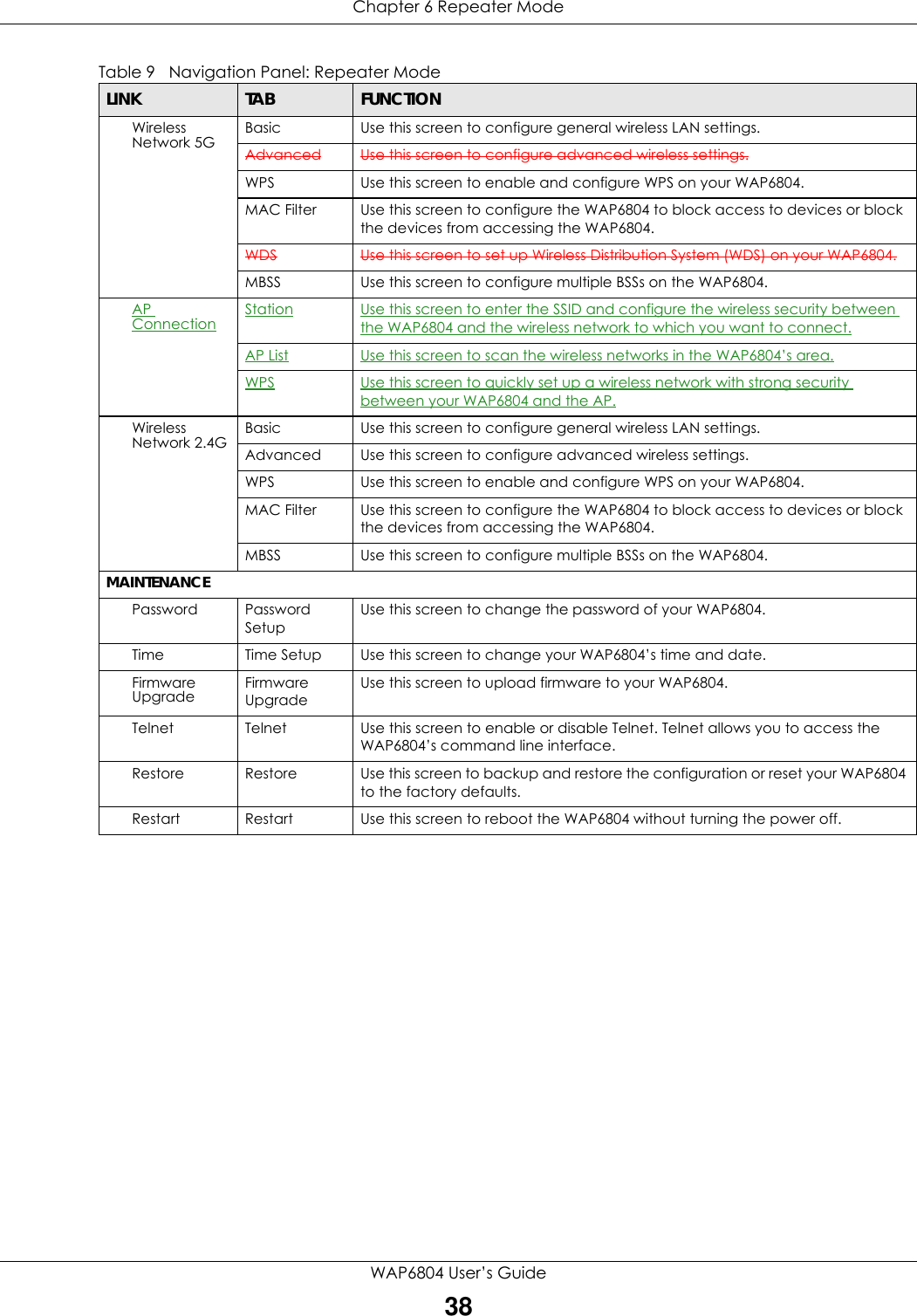
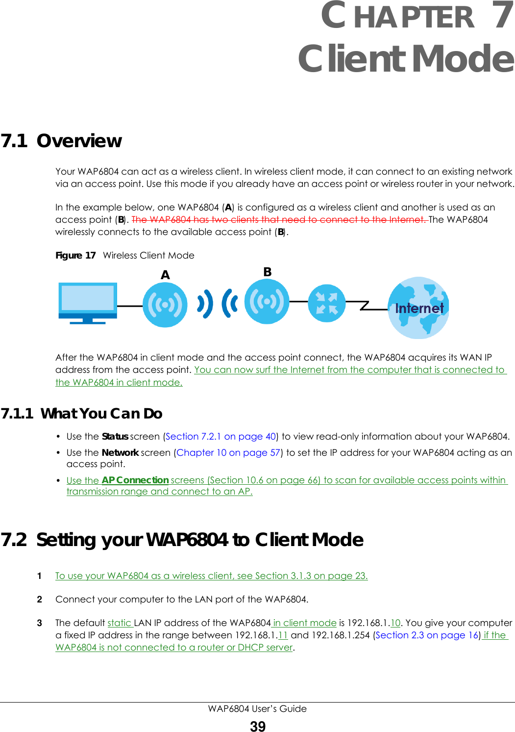
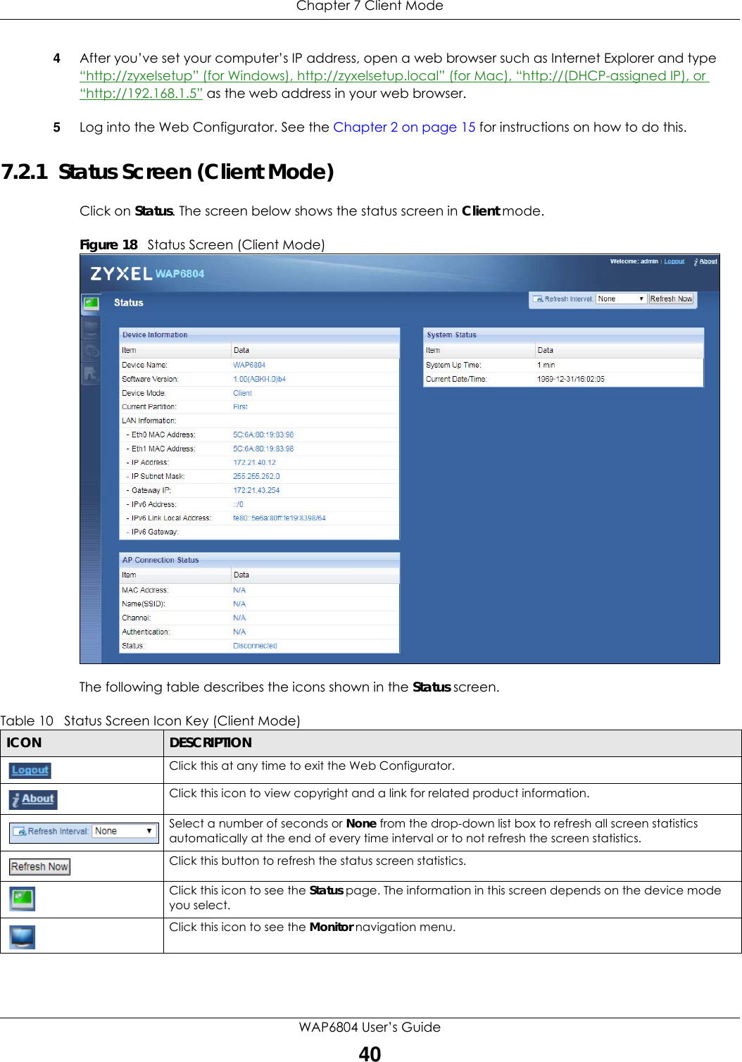
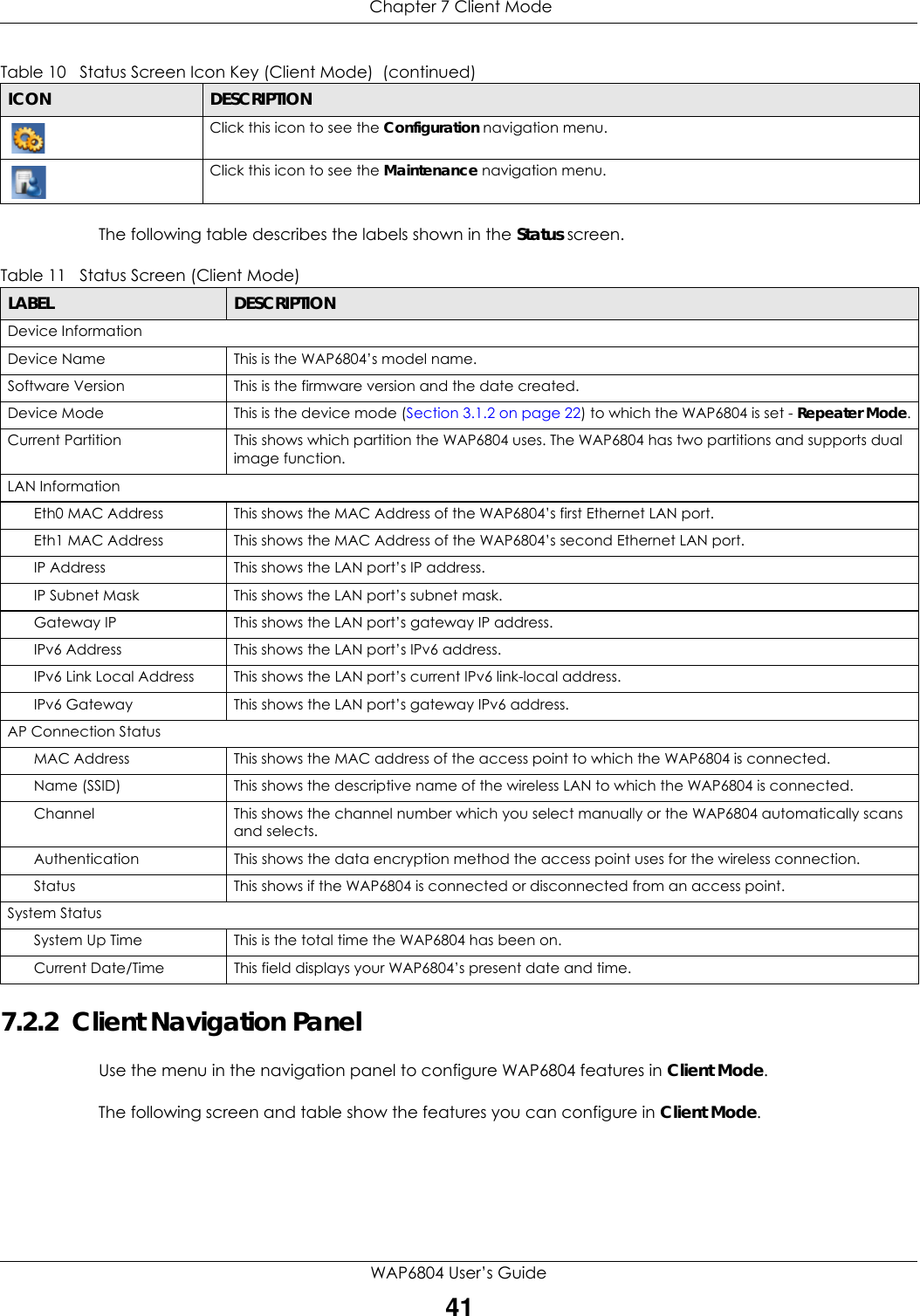
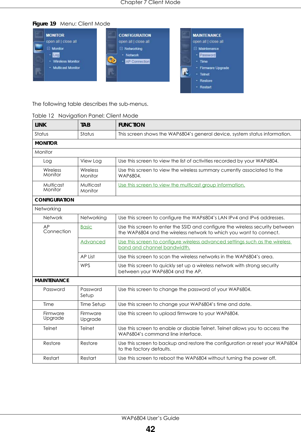
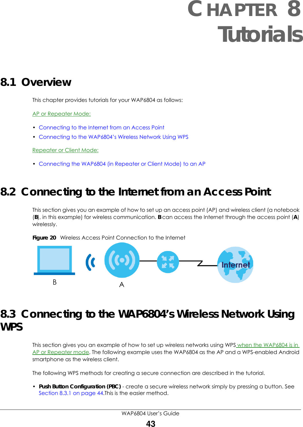
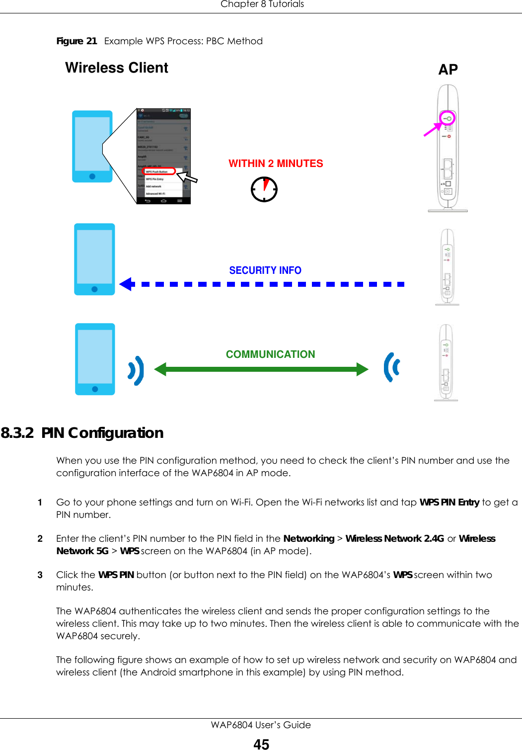
WAP6804 User Manual
Users Manual
Navigation menu
Upload a User Manual
Namespaces
Wiki Guide
HTML
PDF
Info
Views
User Manual
Discussion / Help
Navigation