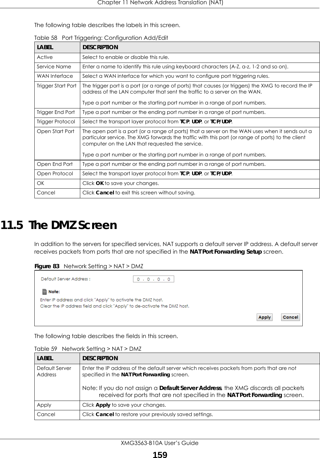
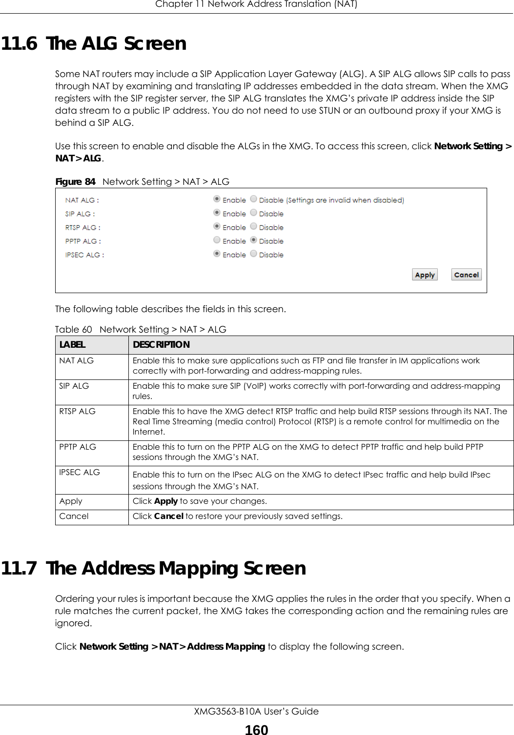
ZyXEL Communications XMG3563-B10A Dual-Band Wireless AC/N VDSL2 Combo WAN Gigabit IAD User Manual Book
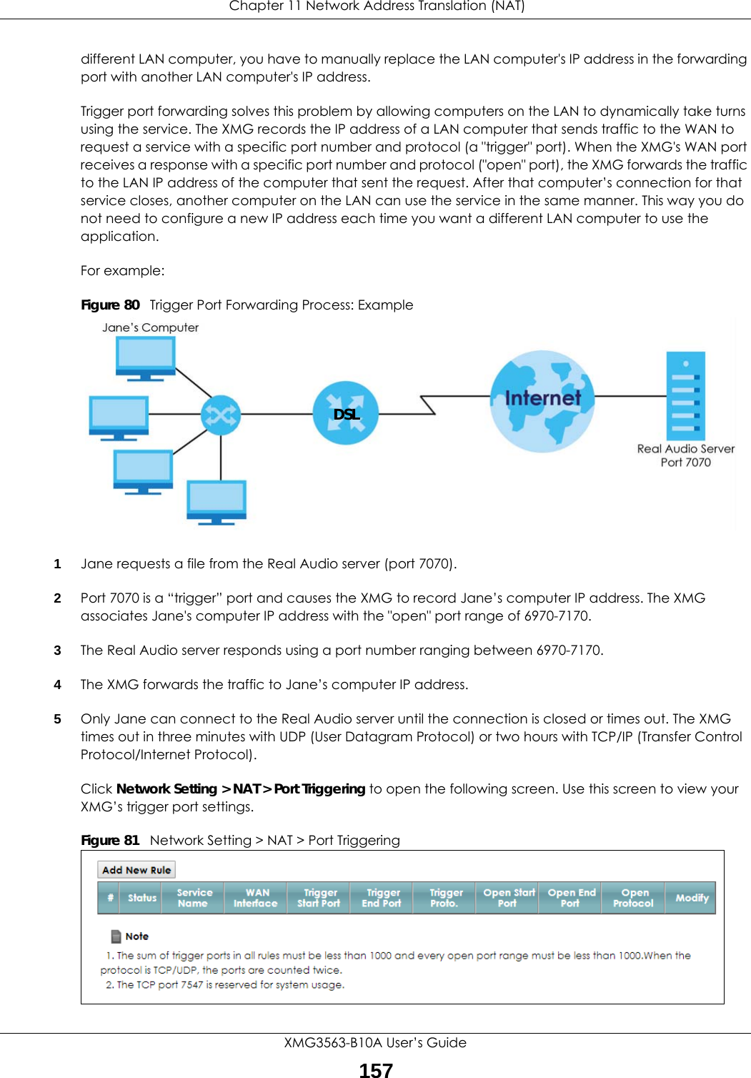
ZyXEL Communications Corporation Dual-Band Wireless AC/N VDSL2 Combo WAN Gigabit IAD Book
Contents
- 1. Users Manual-1
- 2. Users Manual-2
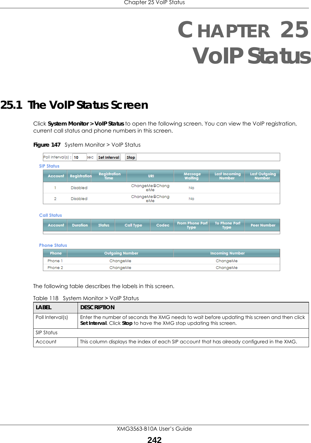
Users Manual-2
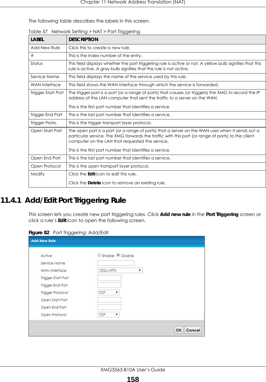


![Chapter 41 TroubleshootingXMG3563-B10A User’s Guide2846If the problem continues, contact the network administrator or vendor, or try one of the advanced suggestions.Advanced Suggestions• Make sure you have logged out of any earlier management sessions using the same user account even if they were through a different interface or using a different browser.• Try to access the XMG using another service, such as Telnet. If you can access the XMG, check the remote management settings and firewall rules to find out why the XMG does not respond to HTTP. I can see the Login screen, but I cannot log in to the XMG.1Make sure you have entered the password correctly. See the cover page for the default login names and associated passwords. The field is case-sensitive, so make sure [Caps Lock] is not on. 2You cannot log in to the web configurator while someone is using Telnet to access the XMG. Log out of the XMG in the other session, or ask the person who is logged in to log out. 3Turn the XMG off and on. 4If this does not work, you have to reset the device to its factory defaults. See Section 41.1 on page 282.I cannot Telnet to the XMG.See the troubleshooting suggestions for I cannot see or access the Login screen in the web configurator. Ignore the suggestions about your browser.I cannot use FTP to upload / download the configuration file. / I cannot use FTP to upload new firmware.See the troubleshooting suggestions for I cannot see or access the Login screen in the web configurator. Ignore the suggestions about your browser.41.3 Internet AccessI cannot access the Internet.1Check the hardware connections, and make sure the LEDs are behaving as expected. See the Quick Start Guide and Section 1.4 on page 21.](https://usermanual.wiki/ZyXEL-Communications/XMG3563-B10A.Users-Manual-2/User-Guide-3641225-Page-132.png)
![Chapter 41 TroubleshootingXMG3563-B10A User’s Guide2852Make sure you entered your ISP account information correctly in the Network Setting > Broadband screen. These fields are case-sensitive, so make sure [Caps Lock] is not on. 3If you are trying to access the Internet wirelessly, make sure that you enabled the wireless LAN in the XMG and your wireless client and that the wireless settings in the wireless client are the same as the settings in the XMG.4Disconnect all the cables from your device and reconnect them. 5If the problem continues, contact your ISP. I cannot access the Internet through a DSL connection.1Make sure you have the DSL WAN port connected to a telephone jack (or the DSL or modem jack on a splitter if you have one).2Make sure you configured a proper DSL WAN interface (Network Setting > Broadband screen) with the Internet account information provided by your ISP and that it is enabled.3Check that the LAN interface you are connected to is in the same interface group as the DSL connection (Network Setting > Interface Grouping).4If you set up a WAN connection using bridging service, make sure you turn off the DHCP feature in the LAN screen to have the clients get WAN IP addresses directly from your ISP’s DHCP server.I cannot connect to the Internet using a second DSL connection.ADSL and VDSL connections cannot work at the same time. You can only use one type of DSL connection, either ADSL or VDSL connection at one time.I cannot connect to the Internet using an Ethernet connection.1Make sure you have the Ethernet WAN port connected to a modem or router.2Make sure you converted LAN port number four as WAN. Click Enable in Network Setting > Broadband > Ethernet WAN screen.3Make sure you configured a proper Ethernet WAN interface (Network Setting > Broadband screen) with the Internet account information provided by your ISP and that it is enabled.4Check that the LAN interface you are connected to is in the same interface group as the Ethernet WAN connection (Network Setting > Interface Grouping).5If you set up a WAN connection using bridging service, make sure you turn off the DHCP feature in the LAN screen to have the clients get WAN IP addresses directly from your ISP’s DHCP server.](https://usermanual.wiki/ZyXEL-Communications/XMG3563-B10A.Users-Manual-2/User-Guide-3641225-Page-133.png)