Zykronix Branch GLX7 Touchscreen Controller User Manual TD 000508 01 TSC 7T indd
Zykronix Inc. Taiwan Branch Touchscreen Controller TD 000508 01 TSC 7T indd
UserManual.wiki
>
Zykronix Branch
>
GLX7 User Manual
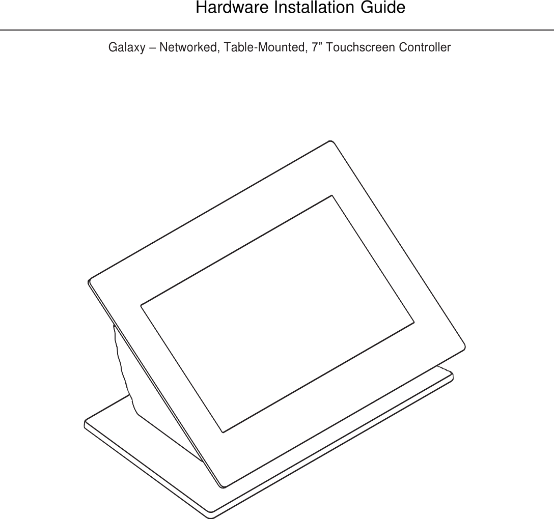
User Manual
Navigation menu
Upload a User Manual
Namespaces
Wiki Guide
HTML
PDF
Info
Views
User Manual
Discussion / Help
Navigation