Zyxel P 334 Users Manual ZyBook
P-334 to the manual fffd58bb-e68a-468f-92f7-2ec61ce192f3
2015-01-23
: Zyxel Zyxel-P-334-Users-Manual-309906 zyxel-p-334-users-manual-309906 zyxel pdf
Open the PDF directly: View PDF ![]() .
.
Page Count: 366 [warning: Documents this large are best viewed by clicking the View PDF Link!]
- User’s Guide
- Copyright
- Federal Communications Commission (FCC) Interference Statement
- ZyXEL Limited Warranty
- Customer Support
- Table of Contents
- List of Figures
- List of Tables
- Preface
- Getting to Know Your Prestige
- 1.1 Prestige Internet Security Gateway Overview
- 1.2 Prestige Features
- 1.2.1 Physical Features
- 1.2.2 Non-Physical Features
- 1.2.2.1 Trend Micro Security Services
- 1.2.2.2 IPSec VPN Capability
- 1.2.2.3 Firewall
- 1.2.2.4 Content Filtering
- 1.2.2.5 Brute-Force Password Guessing Protection
- 1.2.2.6 Packet Filtering
- 1.2.2.7 Universal Plug and Play (UPnP)
- 1.2.2.8 Call Scheduling
- 1.2.2.9 PPPoE
- 1.2.2.10 PPTP Encapsulation
- 1.2.2.11 Dynamic DNS Support
- 1.2.2.12 IP Multicast
- 1.2.2.13 IP Alias
- 1.2.2.14 SNMP
- 1.2.2.15 Network Address Translation (NAT)
- 1.2.2.16 Traffic Redirect
- 1.2.2.17 Port Forwarding
- 1.2.2.18 DHCP (Dynamic Host Configuration Protocol)
- 1.2.2.19 Full Network Management
- 1.2.2.20 RoadRunner Support
- 1.2.2.21 Logging and Tracing
- 1.2.2.22 Upgrade Prestige Firmware via LAN
- 1.2.2.23 Embedded FTP and TFTP Servers
- 1.3 Applications for the Prestige
- Introducing the Web Configurator
- Wizard Setup
- System Screens
- LAN Screens
- WAN Screens
- Network Address Translation (NAT) Screens
- Static Route Screens
- UPnP
- Trend Micro Security Services
- Firewall
- Content Filtering
- Remote Management Screens
- Introduction to IPSec
- VPN Screens
- 15.1 VPN/IPSec Overview
- 15.2 IPSec Algorithms
- 15.3 My IP Address
- 15.4 Secure Gateway Address
- 15.5 Summary Screen
- 15.6 Keep Alive
- 15.7 NAT Traversal
- 15.8 ID Type and Content
- 15.9 Pre-Shared Key
- 15.10 Editing VPN Rules
- 15.11 IKE Phases
- 15.12 Configuring Advanced IKE Settings
- 15.13 Manual Key Setup
- 15.14 Configuring Manual Key
- 15.15 Viewing SA Monitor
- 15.16 Configuring Global Setting
- 15.17 Telecommuter VPN/IPSec Examples
- 15.18 VPN and Remote Management
- Centralized Logs
- Maintenance
- Introducing the SMT
- Menu 1 General Setup
- Menu 2 WAN Setup
- Menu 3 LAN Setup
- Internet Access
- Remote Node Configuration
- Static Route Setup
- Network Address Translation (NAT)
- Enabling the Firewall
- Filter Configuration
- SNMP Configuration
- System Information and Diagnosis
- Firmware and Configuration File Maintenance
- 30.1 Filename Conventions
- 30.2 Backup Configuration
- 30.2.1 Backup Configuration
- 30.2.2 Using the FTP Command from the Command Line
- 30.2.3 Example of FTP Commands from the Command Line
- 30.2.4 GUI-based FTP Clients
- 30.2.5 TFTP and FTP over WAN Management Limitations
- 30.2.6 Backup Configuration Using TFTP
- 30.2.7 TFTP Command Example
- 30.2.8 GUI-based TFTP Clients
- 30.3 Restore Configuration
- 30.4 Uploading Firmware and Configuration Files
- System Maintenance
- Remote Management
- Call Scheduling
- VPN/IPSec Setup
- SA Monitor
- Appendix
- Index

Prestige 334
Broadband Router with Firewall
User’s Guide
Version 3.60
12/2004

Prestige 334 User’s Guide
Copyright 2
Copyright
Copyright © 2004 by ZyXEL Communications Corporation.
The contents of this publication may not be reproduced in any part or as a whole, transcribed,
stored in a retrieval system, translated into any language, or transmitted in any form or by any
means, electronic, mechanical, magnetic, optical, chemical, photocopying, manual, or
otherwise, without the prior written permission of ZyXEL Communications Corporation.
Published by ZyXEL Communications Corporation. All rights reserved.
Disclaimer
ZyXEL does not assume any liability arising out of the application or use of any products, or
software described herein. Neither does it convey any license under its patent rights nor the
patent rights of others. ZyXEL further reserves the right to make changes in any products
described herein without notice. This publication is subject to change without notice.
Trademarks
ZyNOS (ZyXEL Network Operating System) is a registered trademark of ZyXEL
Communications, Inc. Other trademarks mentioned in this publication are used for
identification purposes only and may be properties of their respective owners.

Prestige 334 User’s Guide
3 Federal Communications Commission (FCC) Interference Statement
Federal Communications
Commission (FCC) Interference
Statement
This device complies with Part 15 of FCC rules. Operation is subject to the following two
conditions:
• This device may not cause harmful interference.
• This device must accept any interference received, including interference that may cause
undesired operations.
This equipment has been tested and found to comply with the limits for a Class B digital
device pursuant to Part 15 of the FCC Rules. These limits are designed to provide reasonable
protection against harmful interference in a commercial environment. This equipment
generates, uses, and can radiate radio frequency energy, and if not installed and used in
accordance with the instructions, may cause harmful interference to radio communications.
If this equipment does cause harmful interference to radio/television reception, which can be
determined by turning the equipment off and on, the user is encouraged to try to correct the
interference by one or more of the following measures:
• Reorient or relocate the receiving antenna.
• Increase the separation between the equipment and the receiver.
• Connect the equipment into an outlet on a circuit different from that to which the receiver
is connected.
• Consult the dealer or an experienced radio/TV technician for help.
Notice 1
Changes or modifications not expressly approved by the party responsible for compliance
could void the user's authority to operate the equipment.
Certifications
Go to www.zyxel.com
1Select your product from the drop-down list box on the ZyXEL home page to go to that
product's page.
2Select the certification you wish to view from this page

Prestige 334 User’s Guide
ZyXEL Limited Warranty 4
ZyXEL Limited Warranty
ZyXEL warrants to the original end user (purchaser) that this product is free from any defects
in materials or workmanship for a period of up to two years from the date of purchase. During
the warranty period, and upon proof of purchase, should the product have indications of failure
due to faulty workmanship and/or materials, ZyXEL will, at its discretion, repair or replace the
defective products or components without charge for either parts or labor, and to whatever
extent it shall deem necessary to restore the product or components to proper operating
condition. Any replacement will consist of a new or re-manufactured functionally equivalent
product of equal value, and will be solely at the discretion of ZyXEL. This warranty shall not
apply if the product is modified, misused, tampered with, damaged by an act of God, or
subjected to abnormal working conditions.
Note
Repair or replacement, as provided under this warranty, is the exclusive remedy of the
purchaser. This warranty is in lieu of all other warranties, express or implied, including any
implied warranty of merchantability or fitness for a particular use or purpose. ZyXEL shall in
no event be held liable for indirect or consequential damages of any kind of character to the
purchaser.
To obtain the services of this warranty, contact ZyXEL's Service Center for your Return
Material Authorization number (RMA). Products must be returned Postage Prepaid. It is
recommended that the unit be insured when shipped. Any returned products without proof of
purchase or those with an out-dated warranty will be repaired or replaced (at the discretion of
ZyXEL) and the customer will be billed for parts and labor. All repaired or replaced products
will be shipped by ZyXEL to the corresponding return address, Postage Paid. This warranty
gives you specific legal rights, and you may also have other rights that vary from country to
country.
Safety Warnings
1To reduce the risk of fire, use only No. 26 AWG or larger telephone wire.
2Do not use this product near water, for example, in a wet basement or near a swimming
pool.
3Avoid using this product during an electrical storm. There may be a remote risk of
electric shock from lightening.

Prestige 334 User’s Guide
5ZyXEL Limited Warranty

Prestige 334 User’s Guide
Customer Support 6
Customer Support
Please have the following information ready when you contact customer support.
• Product model and serial number.
• Warranty Information.
• Date that you received your device.
• Brief description of the problem and the steps you took to solve it.
METHOD
LOCATION
SUPPORT E-MAIL TELEPHONEAWEB SITE
REGULAR MAIL
SALES E-MAIL FAX FTP SITE
WORLDWIDE
support@zyxel.com.tw +886-3-578-3942 www.zyxel.com
www.europe.zyxel.com
ZyXEL Communications Corp.
6 Innovation Road II
Science Park
Hsinchu 300
Tai w a n
sales@zyxel.com.tw +886-3-578-2439 ftp.zyxel.com
ftp.europe.zyxel.com
NORTH
AMERICA
support@zyxel.com +1-800-255-4101
+1-714-632-0882
www.us.zyxel.com ZyXEL Communications Inc.
1130 N. Miller St.
Anaheim
CA 92806-2001
U.S.A.
sales@zyxel.com +1-714-632-0858 ftp.us.zyxel.com
GERMANY
support@zyxel.de +49-2405-6909-0 www.zyxel.de ZyXEL Deutschland GmbH.
Adenauerstr. 20/A2 D-52146
Wuerselen
Germany
sales@zyxel.de +49-2405-6909-99
FRANCE
info@zyxel.fr +33 (0)4 72 52 97 97 www.zyxel.fr Z y XEL F r a n c e
1 rue des Vergers
Bat. 1 / C
69760 Limonest
France
+33 (0)4 72 52 19 20
SPAIN
support@zyxel.es +34 902 195 420 www.zyxel.es Z y XE L C o m mu n i c a ti o n s
A l e j a n d r o V i l l e g a s 3 3
1 º , 2 8 0 4 3 M a d r i d
Spain
sales@zyxel.es +34 913 005 345
DENMARK
support@zyxel.dk +45 39 55 07 00 www.zyxel.dk Z y X E L C o m m u n i c a t i o n s A / S
Columbusvej 5
2860 Soeborg
Denmark
sales@zyxel.dk +45 39 55 07 07
NORWAY
support@zyxel.no +47 22 80 61 80 www.zyxel.no Z y X E L C o m m u n i c a t i o n s A / S
Nils Hansens vei 13
0667 Oslo
Norway
sales@zyxel.no +47 22 80 61 81
SWEDEN
support@zyxel.se +46 31 744 7700 www.zyxel.se ZyXEL Communications A/S
Sjöporten 4, 41764 Göteborg
Sweden
sales@zyxel.se +46 31 744 7701
FINLAND
support@zyxel.fi +358 9 4780 8411 www.zyxel.fi Z yX E L C om m u n i ca t i o n s Oy
Malminkaari 10
00700 Helsinki
Finland
sales@zyxel.fi +358 9 4780 8448

Prestige 334 User’s Guide
7Customer Support
a. “+” is the (prefix) number you enter to make an international telephone call.

Prestige 334 User’s Guide
Table of Contents 8
Table of Contents
Copyright .................................................................................................................. 2
Federal Communications Commission (FCC) Interference Statement ............... 3
ZyXEL Limited Warranty.......................................................................................... 4
Customer Support.................................................................................................... 6
Preface .................................................................................................................... 30
Chapter 1
Getting to Know Your Prestige ............................................................................. 32
1.1 Prestige Internet Security Gateway Overview ....................................................32
1.2 Prestige Features ...............................................................................................32
1.2.1 Physical Features .....................................................................................32
1.2.1.1 10/100M Auto-negotiating Ethernet/Fast Ethernet Interface(s) .......32
1.2.1.2 Auto-crossover 10/100 Mbps Ethernet Interface(s) .........................32
1.2.1.3 4-Port Switch ...................................................................................32
1.2.1.4 Time and Date .................................................................................32
1.2.1.5 Reset Button ...................................................................................33
1.2.2 Non-Physical Features .............................................................................33
1.2.2.1 Trend Micro Security Services ........................................................33
1.2.2.2 IPSec VPN Capability ......................................................................33
1.2.2.3 Firewall ............................................................................................33
1.2.2.4 Content Filtering ..............................................................................33
1.2.2.5 Brute-Force Password Guessing Protection ...................................33
1.2.2.6 Packet Filtering ...............................................................................33
1.2.2.7 Universal Plug and Play (UPnP) .....................................................34
1.2.2.8 Call Scheduling ...............................................................................34
1.2.2.9 PPPoE .............................................................................................34
1.2.2.10 PPTP Encapsulation .....................................................................34
1.2.2.11 Dynamic DNS Support ..................................................................34
1.2.2.12 IP Multicast ....................................................................................34
1.2.2.13 IP Alias ..........................................................................................34
1.2.2.14 SNMP ............................................................................................35
1.2.2.15 Network Address Translation (NAT) ..............................................35
1.2.2.16 Traffic Redirect ..............................................................................35

Prestige 334 User’s Guide
9Table of Contents
1.2.2.17 Port Forwarding .............................................................................35
1.2.2.18 DHCP (Dynamic Host Configuration Protocol) ..............................35
1.2.2.19 Full Network Management ............................................................35
1.2.2.20 RoadRunner Support ....................................................................35
1.2.2.21 Logging and Tracing ......................................................................35
1.2.2.22 Upgrade Prestige Firmware via LAN .............................................36
1.2.2.23 Embedded FTP and TFTP Servers ...............................................36
1.3 Applications for the Prestige ..............................................................................36
1.3.1 Secure Broadband Internet Access via Cable or DSL Modem .................36
1.3.2 VPN Application ........................................................................................36
Chapter 2
Introducing the Web Configurator........................................................................ 38
2.1 Web Configurator Overview ...............................................................................38
2.2 Accessing the Prestige Web Configurator .........................................................38
2.3 Resetting the Prestige ........................................................................................39
2.3.1 Procedure To Use The Reset Button ........................................................39
2.3.2 Navigating the Prestige Web Configurator ...............................................39
2.3.3 Navigation Panel .......................................................................................40
Chapter 3
Wizard Setup .......................................................................................................... 44
3.1 Wizard Setup Overview ......................................................................................44
3.2 Wizard Setup: General Setup and System Name ..............................................44
3.2.1 Domain Name ...........................................................................................44
3.3 Wizard Setup: Screen 2 .....................................................................................45
3.3.1 Ethernet ....................................................................................................45
3.3.2 PPPoE Encapsulation ...............................................................................47
3.3.3 PPTP Encapsulation .................................................................................48
3.4 Wizard Setup: Screen 3 .....................................................................................50
3.4.1 WAN IP Address Assignment ...................................................................50
3.4.2 IP Address and Subnet Mask ...................................................................50
3.4.3 DNS Server Address Assignment .............................................................51
3.4.4 WAN MAC Address ..................................................................................51
3.5 Basic Setup Complete ........................................................................................53
Chapter 4
System Screens ..................................................................................................... 56
4.1 System Overview ...............................................................................................56
4.2 Configuring General Setup .................................................................................56
4.3 Dynamic DNS .....................................................................................................58
4.3.1 DynDNS Wildcard .....................................................................................58
4.4 Configuring Dynamic DNS .................................................................................58

Prestige 334 User’s Guide
Table of Contents 10
4.5 Configuring Password ........................................................................................60
4.6 Configuring Time Setting ....................................................................................60
Chapter 5
LAN Screens........................................................................................................... 64
5.1 LAN Overview ....................................................................................................64
5.2 DHCP Setup .......................................................................................................64
5.2.1 IP Pool Setup ............................................................................................64
5.2.2 System DNS Servers ................................................................................64
5.3 LAN TCP/IP ........................................................................................................64
5.3.1 Factory LAN Defaults ................................................................................64
5.3.2 IP Address and Subnet Mask ...................................................................65
5.3.3 RIP Setup .................................................................................................65
5.3.4 Multicast ....................................................................................................65
5.4 Configuring IP ....................................................................................................66
5.5 Configuring Static DHCP ....................................................................................69
5.6 Configuring IP Alias ............................................................................................70
Chapter 6
WAN Screens.......................................................................................................... 72
6.1 WAN Overview ...................................................................................................72
6.2 TCP/IP Priority (Metric) ......................................................................................72
6.3 Configuring Route ..............................................................................................72
6.4 Configuring WAN ISP .........................................................................................73
6.4.1 Ethernet Encapsulation .............................................................................73
6.4.2 PPPoE Encapsulation ...............................................................................74
6.4.3 PPTP Encapsulation .................................................................................77
6.5 Configuring WAN IP ...........................................................................................78
6.6 Configuring WAN MAC .......................................................................................81
6.7 Traffic Redirect ...................................................................................................82
6.8 Configuring Traffic Redirect ................................................................................83
Chapter 7
Network Address Translation (NAT) Screens ...................................................... 86
7.1 NAT Overview ....................................................................................................86
7.1.1 NAT Definitions .........................................................................................86
7.1.2 What NAT Does ........................................................................................87
7.1.3 How NAT Works .......................................................................................87
7.1.4 NAT Application ........................................................................................88
7.1.5 NAT Mapping Types .................................................................................89
7.2 Using NAT ..........................................................................................................90
7.2.1 SUA (Single User Account) Versus NAT ..................................................90
7.3 SUA Server ........................................................................................................90

Prestige 334 User’s Guide
11 Table of Contents
7.3.1 Default Server IP Address ........................................................................91
7.3.2 Port Forwarding: Services and Port Numbers ..........................................91
7.3.3 Configuring Servers Behind SUA (Example) ............................................92
7.4 Configuring SUA Server ....................................................................................93
7.5 Configuring Address Mapping ............................................................................95
7.5.1 Configuring Address Mapping ..................................................................96
7.6 Trigger Port Forwarding .....................................................................................98
7.6.1 Trigger Port Forwarding Example .............................................................98
7.6.2 Two Points To Remember About Trigger Ports .........................................99
7.7 Configuring Trigger Port Forwarding ..................................................................99
Chapter 8
Static Route Screens ........................................................................................... 102
8.1 Static Route Overview ......................................................................................102
8.2 Configuring IP Static Route ..............................................................................102
8.2.1 Configuring Route Entry .........................................................................103
Chapter 9
UPnP...................................................................................................................... 106
9.1 Universal Plug and Play Overview ..................................................................106
9.1.1 How Do I Know If I'm Using UPnP? ........................................................106
9.1.2 NAT Traversal .........................................................................................106
9.1.3 Cautions with UPnP ................................................................................106
9.2 UPnP and ZyXEL .............................................................................................107
9.3 Configuring UPnP ............................................................................................107
9.4 Installing UPnP in Windows Example ..............................................................108
9.4.1 Installing UPnP in Windows Me ..............................................................109
9.4.2 Installing UPnP in Windows XP ..............................................................110
9.5 Using UPnP in Windows XP Example ............................................................. 111
9.5.1 Auto-discover Your UPnP-enabled Network Device ...............................112
9.5.2 Web Configurator Easy Access ..............................................................113
9.5.3 Web Configurator Easy Access ..............................................................114
Chapter 10
Trend Micro Security Services............................................................................ 116
10.1 Trend Micro Security Service Overview .........................................................116
10.2 Configuring Service Settings ..........................................................................116
10.3 Virus Protection ..............................................................................................118
10.4 Configuring Virus Protection ..........................................................................118
10.5 Parental Controls ...........................................................................................120
10.6 Parental Controls Configuration .....................................................................120
10.6.1 Parental Controls Statistics ...................................................................124

Prestige 334 User’s Guide
Table of Contents 12
Chapter 11
Firewall.................................................................................................................. 126
11.1 Introduction .....................................................................................................126
11.1.1 What is a Firewall? ................................................................................126
11.1.2 Stateful Inspection Firewall. ..................................................................126
11.1.3 About the Prestige Firewall ...................................................................126
11.1.4 Guidelines For Enhancing Security With Your Firewall .........................127
11.2 Firewall Settings Screen .................................................................................127
11.3 The Firewall, NAT and Remote Management ................................................129
11.3.1 LAN-to-WAN rules .................................................................................129
11.3.2 WAN-to-LAN rules .................................................................................129
11.4 Services .........................................................................................................130
Chapter 12
Content Filtering ................................................................................................. 134
12.1 Introduction to Content Filtering .....................................................................134
12.2 Restrict Web Features ...................................................................................134
12.3 Days and Times .............................................................................................134
12.4 Configure Content Filtering ............................................................................134
Chapter 13
Remote Management Screens ............................................................................ 138
13.1 Remote Management Overview .....................................................................138
13.1.1 Remote Management Limitations .........................................................138
13.1.2 Remote Management and NAT ............................................................139
13.1.3 System Timeout ...................................................................................139
13.2 Configuring WWW ..........................................................................................139
13.3 Configuring Telnet ..........................................................................................140
13.4 Configuring TELNET ......................................................................................141
13.5 Configuring FTP .............................................................................................142
13.6 SNMP .............................................................................................................143
13.6.1 Supported MIBs ....................................................................................144
13.6.2 SNMP Traps .........................................................................................144
13.6.3 Configuring SNMP ................................................................................144
13.7 Configuring DNS ............................................................................................146
13.8 Configuring Security .......................................................................................147
Chapter 14
Introduction to IPSec ........................................................................................... 150
14.1 VPN Overview ................................................................................................150
14.1.1 IPSec ....................................................................................................150
14.1.2 Security Association .............................................................................150
14.1.3 Other Terminology ................................................................................150

Prestige 334 User’s Guide
13 Table of Contents
14.1.3.1 Encryption ...................................................................................150
14.1.3.2 Data Confidentiality .....................................................................151
14.1.3.3 Data Integrity ...............................................................................151
14.1.3.4 Data Origin Authentication ..........................................................151
14.1.4 VPN Applications ..................................................................................151
14.2 IPSec Architecture .........................................................................................151
14.2.1 IPSec Algorithms ..................................................................................152
14.2.2 Key Management ..................................................................................152
14.3 Encapsulation .................................................................................................152
14.3.1 Transport Mode ....................................................................................153
14.3.2 Tunnel Mode .........................................................................................153
14.4 IPSec and NAT ...............................................................................................153
Chapter 15
VPN Screens....................................................................................................... 156
15.1 VPN/IPSec Overview .....................................................................................156
15.2 IPSec Algorithms ............................................................................................156
15.2.1 AH (Authentication Header) Protocol ....................................................156
15.2.2 ESP (Encapsulating Security Payload) Protocol ..................................156
15.3 My IP Address ................................................................................................157
15.4 Secure Gateway Address ..............................................................................157
15.4.1 Dynamic Secure Gateway Address ......................................................158
15.5 Summary Screen ...........................................................................................158
15.6 Keep Alive ......................................................................................................160
15.7 NAT Traversal ................................................................................................160
15.7.1 NAT Traversal Configuration .................................................................160
15.7.2 Remote DNS Server .............................................................................161
15.8 ID Type and Content ......................................................................................162
15.8.1 ID Type and Content Examples ............................................................163
15.9 Pre-Shared Key ..............................................................................................163
15.10 Editing VPN Rules ........................................................................................164
15.11 IKE Phases ..................................................................................................167
15.11.1 Negotiation Mode ................................................................................168
15.11.2 Diffie-Hellman (DH) Key Groups .........................................................168
15.11.3 Perfect Forward Secrecy (PFS) ..........................................................168
15.12 Configuring Advanced IKE Settings .............................................................169
15.13 Manual Key Setup ........................................................................................174
15.13.1 Security Parameter Index (SPI) ..........................................................175
15.14 Configuring Manual Key ...............................................................................175
15.15 Viewing SA Monitor ......................................................................................178
15.16 Configuring Global Setting ...........................................................................179
15.17 Telecommuter VPN/IPSec Examples ...........................................................180
15.17.1 Telecommuters Sharing One VPN Rule Example ..............................180

Prestige 334 User’s Guide
Table of Contents 14
15.17.2 Telecommuters Using Unique VPN Rules Example ...........................181
15.18 VPN and Remote Management ...................................................................182
Chapter 16
Centralized Logs .................................................................................................. 184
16.1 View Log ........................................................................................................184
16.2 Log Settings ...................................................................................................186
Chapter 17
Maintenance ......................................................................................................... 190
17.1 Maintenance Overview ...................................................................................190
17.2 Status Screen .................................................................................................190
17.2.1 System Statistics ...................................................................................192
17.3 DHCP Table Screen .......................................................................................192
17.4 F/W Upload Screen ........................................................................................193
17.4.1 Preparing your Prestige for Firmware Upload ......................................194
17.5 Configuration Screen .....................................................................................196
17.5.1 Backup Configuration ...........................................................................196
17.5.2 Restore Configuration ..........................................................................197
17.5.3 Back to Factory Defaults .......................................................................198
17.6 Restart Screen ...............................................................................................198
Chapter 18
Introducing the SMT ............................................................................................ 200
18.1 SMT Introduction ............................................................................................200
18.1.1 Procedure for SMT Configuration via Telnet .........................................200
18.1.2 Entering Password ................................................................................200
18.1.3 Prestige SMT Menu Overview ..............................................................201
18.2 Navigating the SMT Interface .........................................................................201
18.2.1 System Management Terminal Interface Summary ..............................203
18.3 Changing the System Password ....................................................................204
Chapter 19
Menu 1 General Setup ......................................................................................... 206
19.1 General Setup ................................................................................................206
19.2 Procedure To Configure Menu 1 ....................................................................206
19.2.1 Procedure to Configure Dynamic DNS .................................................208
Chapter 20
Menu 2 WAN Setup .............................................................................................. 210
20.1 Introduction to WAN .......................................................................................210
20.2 WAN Setup .....................................................................................................210

Prestige 334 User’s Guide
15 Table of Contents
Chapter 21
Menu 3 LAN Setup ............................................................................................... 212
21.1 LAN Setup ......................................................................................................212
21.1.1 General Ethernet Setup ........................................................................212
21.2 Protocol Dependent Ethernet Setup ..............................................................213
21.3 TCP/IP Ethernet Setup and DHCP ................................................................213
21.3.1 IP Alias Setup .......................................................................................215
Chapter 22
Internet Access .................................................................................................... 218
22.1 Introduction to Internet Access Setup ............................................................218
22.2 Ethernet Encapsulation ..................................................................................218
22.3 Configuring the PPTP Client ..........................................................................220
22.4 Configuring the PPPoE Client ........................................................................221
22.5 Basic Setup Complete ....................................................................................222
Chapter 23
Remote Node Configuration ............................................................................... 224
23.1 Introduction to Remote Node Setup ...............................................................224
23.2 Remote Node Profile Setup ...........................................................................224
23.2.1 Ethernet Encapsulation .........................................................................224
23.2.2 PPPoE Encapsulation ...........................................................................226
23.2.2.1 Outgoing Authentication Protocol ................................................226
23.2.2.2 Nailed-Up Connection .................................................................227
23.2.3 PPTP Encapsulation .............................................................................227
23.3 Edit IP .............................................................................................................228
23.4 Remote Node Filter ........................................................................................230
23.4.1 Traffic Redirect Setup ...........................................................................231
Chapter 24
Static Route Setup ............................................................................................... 234
24.1 IP Static Route Setup .....................................................................................234
Chapter 25
Network Address Translation (NAT) ................................................................... 236
25.1 Using NAT ......................................................................................................236
25.1.1 SUA (Single User Account) Versus NAT ..............................................236
25.2 Applying NAT .................................................................................................236
25.3 NAT Setup ......................................................................................................238
25.3.1 Address Mapping Sets ..........................................................................239
25.3.1.1 User-Defined Address Mapping Sets ..........................................240
25.3.1.2 Ordering Your Rules ....................................................................241
25.4 Configuring a Server behind NAT ..................................................................243

Prestige 334 User’s Guide
Table of Contents 16
25.5 General NAT Examples ..................................................................................244
25.5.1 Example 1: Internet Access Only ..........................................................245
25.5.2 Example 2: Internet Access with an Inside Server ...............................245
25.5.3 Example 3: Multiple Public IP Addresses With Inside Servers .............246
25.5.4 Example 4: NAT Unfriendly Application Programs ...............................250
25.6 Configuring Trigger Port Forwarding .............................................................252
Chapter 26
Enabling the Firewall ........................................................................................... 254
26.1 Remote Management and the Firewall ..........................................................254
26.2 Access Methods .............................................................................................254
26.3 Enabling the Firewall ......................................................................................254
Chapter 27
Filter Configuration.............................................................................................. 256
27.1 Introduction to Filters ......................................................................................256
27.1.1 The Filter Structure of the Prestige .......................................................257
27.2 Configuring a Filter Set ..................................................................................258
27.2.1 Configuring a Filter Rule .......................................................................260
27.2.2 Configuring a TCP/IP Filter Rule ..........................................................260
27.2.3 Configuring a Generic Filter Rule .........................................................263
27.3 Example Filter ................................................................................................265
27.4 Filter Types and NAT ......................................................................................267
27.5 Firewall Versus Filters ....................................................................................268
27.6 Applying a Filter ............................................................................................268
27.6.1 Applying LAN Filters .............................................................................268
27.6.2 Applying Remote Node Filters ..............................................................269
Chapter 28
SNMP Configuration ............................................................................................ 270
28.1 About SNMP ..................................................................................................270
28.2 Supported MIBs ............................................................................................271
28.3 SNMP Configuration ......................................................................................271
28.4 SNMP Traps ...................................................................................................272
Chapter 29
System Information and Diagnosis .................................................................... 274
29.1 System Status ................................................................................................274
29.2 System Information ........................................................................................276
29.2.1 System Information ...............................................................................276
29.2.2 Console Port Speed ..............................................................................277
29.3 Log and Trace ................................................................................................278
29.3.1 Syslog Logging .....................................................................................278

Prestige 334 User’s Guide
17 Table of Contents
29.3.1.1 CDR ............................................................................................279
29.3.1.2 Packet triggered ..........................................................................279
29.3.1.3 Filter log .....................................................................................280
29.3.1.4 PPP log ......................................................................................280
29.3.1.5 Firewall log ..................................................................................281
29.3.2 Call-Triggering Packet ..........................................................................281
29.4 Diagnostic ......................................................................................................282
29.4.1 WAN DHCP ..........................................................................................283
Chapter 30
Firmware and Configuration File Maintenance ................................................. 286
30.1 Filename Conventions ...................................................................................286
30.2 Backup Configuration .....................................................................................287
30.2.1 Backup Configuration ...........................................................................287
30.2.2 Using the FTP Command from the Command Line ..............................288
30.2.3 Example of FTP Commands from the Command Line .........................289
30.2.4 GUI-based FTP Clients .........................................................................289
30.2.5 TFTP and FTP over WAN Management Limitations .............................289
30.2.6 Backup Configuration Using TFTP .......................................................290
30.2.7 TFTP Command Example ....................................................................290
30.2.8 GUI-based TFTP Clients ......................................................................291
30.3 Restore Configuration ....................................................................................291
30.3.1 Restore Using FTP ...............................................................................291
30.3.2 Restore Using FTP Session Example ..................................................293
30.4 Uploading Firmware and Configuration Files .................................................293
30.4.1 Firmware File Upload ............................................................................293
30.4.2 Configuration File Upload .....................................................................294
30.4.3 FTP File Upload Command from the DOS Prompt Example ................294
30.4.4 FTP Session Example of Firmware File Upload ...................................295
30.4.5 TFTP File Upload ..................................................................................295
30.4.6 TFTP Upload Command Example ........................................................296
Chapter 31
System Maintenance............................................................................................ 298
31.1 Command Interpreter Mode ...........................................................................298
31.1.1 Command Syntax .................................................................................298
31.1.2 Command Usage ..................................................................................299
31.2 Call Control Support .......................................................................................299
31.2.1 Budget Management ............................................................................299
31.2.2 Call History ...........................................................................................300
31.3 Time and Date Setting ....................................................................................301
31.3.1 Resetting the Time ................................................................................304

Prestige 334 User’s Guide
Table of Contents 18
Chapter 32
Remote Management ........................................................................................... 306
32.1 Remote Management .....................................................................................306
32.1.1 Remote Management Limitations .........................................................307
Chapter 33
Call Scheduling .................................................................................................... 310
33.1 Introduction to Call Scheduling ......................................................................310
Chapter 34
VPN/IPSec Setup .................................................................................................. 314
34.1 VPN/IPSec Overview .....................................................................................314
34.2 IPSec Summary Screen .................................................................................315
34.3 IKE Setup .......................................................................................................321
34.4 Manual Setup .................................................................................................323
34.4.0.1 Active Protocol ............................................................................324
34.4.0.2 Security Parameter Index (SPI) ..................................................324
Chapter 35
SA Monitor ............................................................................................................ 326
35.1 SA Monitor Overview .....................................................................................326
35.2 Using SA Monitor ...........................................................................................326
Appendix A
Troubleshooting................................................................................................... 330
35.3 Problems with the Password ..........................................................................331
35.4 Problems with Remote Management .............................................................331
Appendix B
PPPoE ................................................................................................................... 332
Appendix C
PPTP...................................................................................................................... 334
Appendix D
NetBIOS Filter Commands .................................................................................. 338
Appendix E
Log Descriptions.................................................................................................. 340
Appendix F
Setting up Your Computer’s IP Address............................................................ 342
Appendix G
Brute-Force Password Guessing Protection..................................................... 354

Prestige 334 User’s Guide
19 Table of Contents
Appendix H
TMSS ..................................................................................................................... 356
Appendix I
Triangle Route ...................................................................................................... 360

Prestige 334 User’s Guide
List of Figures 20
List of Figures
Figure 1 Secure Internet Access via Cable, DSL or Wireless Modem ................................ 36
Figure 2 VPN Application .................................................................................................... 37
Figure 3 Change Password Screen .................................................................................... 39
Figure 4 The MAIN MENU Screen of the Web Configurator ............................................... 40
Figure 5 Wizard 1: General Setup ....................................................................................... 45
Figure 6 Wizard 2: Ethernet Encapsulation ......................................................................... 46
Figure 7 Wizard 2: PPPoE Encapsulation ........................................................................... 48
Figure 8 Wizard 2: PPTP Encapsulation ............................................................................. 49
Figure 9 Wizard 3: WAN Setup ........................................................................................... 52
Figure 10 Wizard Finish ...................................................................................................... 54
Figure 11 System General Setup ....................................................................................... 57
Figure 12 DDNS .................................................................................................................. 59
Figure 13 Password ............................................................................................................ 60
Figure 14 Time Setting ........................................................................................................ 61
Figure 15 LAN IP ................................................................................................................. 67
Figure 16 Static DHCP ........................................................................................................ 70
Figure 17 IP Alias ................................................................................................................ 71
Figure 18 WAN: Route ........................................................................................................ 73
Figure 19 Ethernet Encapsulation ....................................................................................... 74
Figure 20 PPPoE Encapsulation ......................................................................................... 76
Figure 21 PPTP Encapsulation ........................................................................................... 77
Figure 22 WAN: IP .............................................................................................................79
Figure 23 MAC Setup .......................................................................................................... 81
Figure 24 Traffic Redirect WAN Setup ................................................................................ 82
Figure 25 Traffic Redirect LAN Setup ................................................................................. 83
Figure 26 WAN: Traffic Redirect .......................................................................................... 83
Figure 27 How NAT Works .................................................................................................. 88
Figure 28 NAT Application With IP Alias ............................................................................. 89
Figure 29 Multiple Servers Behind NAT Example ............................................................... 93
Figure 30 SUA/NAT Setup .................................................................................................. 94
Figure 31 Address Mapping ................................................................................................ 95
Figure 32 Address Mapping Edit ......................................................................................... 97
Figure 33 Trigger Port Forwarding Process: Example ........................................................ 98
Figure 34 Trigger Port .........................................................................................................99
Figure 35 Example of Static Routing Topology ................................................................... 102
Figure 36 Static Route .........................................................................................................103

Prestige 334 User’s Guide
21 List of Figures
Figure 37 Static Route: Edit ................................................................................................ 104
Figure 38 Configuring UPnP ............................................................................................... 108
Figure 39 Service Settings .................................................................................................. 117
Figure 40 Virus Protection ................................................................................................... 119
Figure 41 Parental Controls License Status ........................................................................ 121
Figure 42 Parental Controls ................................................................................................ 122
Figure 43 Parental Controls Statistics ................................................................................. 125
Figure 44 Firewall: Settings ................................................................................................. 128
Figure 45 Firewall Rule Directions ...................................................................................... 129
Figure 46 Firewall: Service .................................................................................................. 131
Figure 47 Content Filter ...................................................................................................... 135
Figure 48 Remote Management: WWW ............................................................................. 140
Figure 49 Telnet Configuration on a TCP/IP Network ......................................................... 141
Figure 50 Remote Management: Telnet .............................................................................. 141
Figure 51 Remote Management: FTP ................................................................................. 142
Figure 52 SNMP Management Model ................................................................................. 143
Figure 53 Remote Management: SNMP ............................................................................. 145
Figure 54 Remote Management: DNS ................................................................................ 146
Figure 55 Security ............................................................................................................... 147
Figure 56 Encryption and Decryption .................................................................................. 151
Figure 57 IPSec Architecture .............................................................................................. 152
Figure 58 Transport and Tunnel Mode IPSec Encapsulation .............................................. 153
Figure 59 IPSec Summary Fields ....................................................................................... 158
Figure 60 VPN: Summary ................................................................................................... 159
Figure 61 NAT Router Between IPSec Routers .................................................................. 160
Figure 62 VPN Host using Intranet DNS Server Example .................................................. 161
Figure 63 Mismatching ID Type and Content Configuration Example ................................ 163
Figure 64 VPN: Rule Setup (Basic) ..................................................................................... 164
Figure 65 Two Phases to Set Up the IPSec SA .................................................................. 167
Figure 66 VPN IKE: Advanced ............................................................................................ 170
Figure 67 Setup: Manual ..................................................................................................... 176
Figure 68 SA Monitor .......................................................................................................... 179
Figure 69 VPN: Global Setting ............................................................................................ 180
Figure 70 Telecommuters Sharing One VPN Rule Example ............................................... 181
Figure 71 Telecommuters Using Unique VPN Rules Example ........................................... 182
Figure 72 View Logs ........................................................................................................... 185
Figure 73 Log Settings ........................................................................................................ 187
Figure 74 Maintenance Status ............................................................................................ 191
Figure 75 Maintenance System Statistics ........................................................................... 192
Figure 76 Maintenance DHCP Table ................................................................................... 193
Figure 77 Maintenance Firmware Upload ........................................................................... 194
Figure 78 Upgrade Tool ....................................................................................................... 195
Figure 79 Upload Warning .................................................................................................. 195

Prestige 334 User’s Guide
List of Figures 22
Figure 80 Network Temporarily Disconnected .................................................................... 195
Figure 81 Maintenance Configuration ................................................................................. 196
Figure 82 Configuration Restore Successful ....................................................................... 197
Figure 83 Temporarily Disconnected ................................................................................... 197
Figure 84 Configuration Restore Error ................................................................................ 198
Figure 85 Factory Defaults .................................................................................................. 198
Figure 86 System Restart ................................................................................................... 199
Figure 87 Login Screen ....................................................................................................... 201
Figure 88 SMT Menu Overview .......................................................................................... 201
Figure 89 SMT Main Menu .................................................................................................. 203
Figure 90 Menu 23 System Password ................................................................................ 204
Figure 91 Menu 1 General Setup. ....................................................................................... 207
Figure 92 Menu 1.1 Configure Dynamic DNS .................................................................... 208
Figure 93 Menu 2 WAN Setu .............................................................................................. 210
Figure 94 Menu 3 LAN Setup .............................................................................................. 212
Figure 95 Menu 3.1 LAN Port Filter Setup. ......................................................................... 212
Figure 96 Menu 3.2 TCP/IP and DHCP Ethernet Setup ..................................................... 213
Figure 97 Physical Network & Partitioned Logical Networks .............................................. 215
Figure 98 Menu 3.2.1: IP Alias Setup ................................................................................. 215
Figure 99 Menu 4 Internet Access Setup ............................................................................ 219
Figure 100 Internet Access Setup (PPTP) ......................................................................... 221
Figure 101 Internet Access Setup (PPPoE) ........................................................................ 222
Figure 102 Menu 11.1 Remote Node Profile for Ethernet Encapsulation ............................ 225
Figure 103 Menu 11.1 Remote Node Profile for PPPoE Encapsulation .............................. 226
Figure 104 Menu 11.1 Remote Node Profile for PPTP Encapsulation ................................ 228
Figure 105 Menu 11.3 Remote Node Network Layer Options for Ethernet Encapsulation . 229
Figure 106 Menu 11.5: Remote Node Filter (Ethernet Encapsulation) ................................ 231
Figure 107 Menu 11.5: Remote Node Filter (PPPoE or PPTP Encapsulation) ................... 231
Figure 108 Menu 11.6: Traffic Redirect Setup .................................................................... 232
Figure 109 Menu 12 IP Static Route Setup ........................................................................ 234
Figure 110 Menu12.1 Edit IP Static Route .......................................................................... 235
Figure 111 Menu 4 Applying NAT for Internet Access ......................................................... 237
Figure 112 Menu 11.3 Applying NAT to the Remote Node .................................................. 238
Figure 113 Menu 15 NAT Setup .......................................................................................... 239
Figure 114 Menu 15.1 Address Mapping Sets .................................................................... 239
Figure 115 Menu 15.1.255 SUA Address Mapping Rules .................................................. 240
Figure 116 Menu 15.1.1 First Set ........................................................................................ 241
Figure 117 Menu 15.1.1.1 Editing/Configuring an Individual Rule in a Set ......................... 243
Figure 118 Menu 15.2.1 NAT Server Setup ........................................................................ 244
Figure 119 Multiple Servers Behind NAT Example ............................................................. 244
Figure 120 NAT Example 1 ................................................................................................. 245
Figure 121 Menu 4 Internet Access & NAT Example ......................................................... 245
Figure 122 NAT Example 2 ................................................................................................. 246

Prestige 334 User’s Guide
23 List of Figures
Figure 123 Menu 15.2.1 Specifying an Inside Server ......................................................... 246
Figure 124 NAT Example 3 ................................................................................................. 247
Figure 125 NAT Example 3: Menu 11.3 .............................................................................. 248
Figure 126 Example 3: Menu 15.1.1.1 ............................................................................... 249
Figure 127 Example 3: Final Menu 15.1.1 .......................................................................... 249
Figure 128 Example 3: Menu 15.2 ...................................................................................... 250
Figure 129 NAT Example 4 ................................................................................................. 251
Figure 130 Example 4: Menu 15.1.1.1 Address Mapping Rule. .......................................... 251
Figure 131 Example 4: Menu 15.1.1 Address Mapping Rules ............................................ 252
Figure 132 Menu 15.3 Trigger Port Setup ........................................................................... 253
Figure 133 Menu 21.2 Firewall Setup ................................................................................. 255
Figure 134 Outgoing Packet Filtering Process .................................................................... 256
Figure 135 Filter Rule Process ............................................................................................ 258
Figure 136 Menu 21: Filter and Firewall Setup ................................................................... 259
Figure 137 Menu 21.1: Filter Set Configuration .................................................................. 259
Figure 138 Menu 21.1.1.1 TCP/IP Filter Rule. .................................................................... 261
Figure 139 Executing an IP Filter ........................................................................................ 263
Figure 140 Menu 21.1.4.1 Generic Filter Rule .................................................................... 264
Figure 141 Telnet Filter Example ........................................................................................ 265
Figure 142 Example Filter: Menu 21.1.3.1 .......................................................................... 266
Figure 143 Example Filter Rules Summary: Menu 21.1.3 .................................................. 267
Figure 144 Protocol and Device Filter Sets ......................................................................... 268
Figure 145 Filtering LAN Traffic .......................................................................................... 269
Figure 146 Filtering Remote Node Traffic ........................................................................... 269
Figure 147 SNMP Management Model ............................................................................... 270
Figure 148 Menu 22 SNMP Configuration .......................................................................... 272
Figure 149 Menu 24 System Maintenance ......................................................................... 274
Figure 150 Menu 24.1 System Maintenance : Status ......................................................... 275
Figure 151 Menu 24.2 System Information and Console Port Speed ............................... 276
Figure 152 Menu 24.2.1 System Maintenance : Information ............................................. 277
Figure 153 Menu 24.2.2 System Maintenance : Change Console Port Speed ................... 278
Figure 154 Menu 24.3.2 System Maintenance : Syslog Logging ........................................ 278
Figure 155 Call-Triggering Packet Example ........................................................................ 282
Figure 156 Menu 24.4 System Maintenance : Diagnostic ................................................... 283
Figure 157 LAN & WAN DHCP ........................................................................................... 283
Figure 158 Telnet in Menu 24.5 ........................................................................................... 288
Figure 159 FTP Session Example ...................................................................................... 289
Figure 160 Telnet into Menu 24.6. ....................................................................................... 292
Figure 161 Restore Using FTP Session Example ............................................................... 293
Figure 162 Telnet Into Menu 24.7.1 Upload System Firmware ........................................... 294
Figure 163 Telnet Into Menu 24.7.2 System Maintenance . ................................................ 294
Figure 164 FTP Session Example of Firmware File Upload ............................................... 295
Figure 165 Command Mode in Menu 24 ............................................................................. 298

Prestige 334 User’s Guide
List of Figures 24
Figure 166 Valid Commands ............................................................................................... 299
Figure 167 Menu 24.9 System Maintenance : Call Control ................................................. 299
Figure 168 Budget Management ......................................................................................... 300
Figure 169 Menu 24.9.2 - Call History ................................................................................ 301
Figure 170 Menu 24: System Maintenance ....................................................................... 302
Figure 171 Menu 24.10 System Maintenance: Time and Date Setting ............................... 303
Figure 172 Menu 24.11 – Remote Management Control .................................................... 307
Figure 173 Menu 26 Schedule Setup .................................................................................. 310
Figure 174 Menu 26.1 Schedule Set Setup ....................................................................... 311
Figure 175 Applying Schedule Set(s) to a Remote Node (PPPoE) .................................... 312
Figure 176 VPN SMT Menu Tree ........................................................................................ 314
Figure 177 Menu 27 VPN/IPSec Setup ............................................................................... 315
Figure 178 Menu 27 ............................................................................................................ 315
Figure 179 Menu 27.1.1 IPSec Setup ................................................................................. 318
Figure 180 Menu 27.1.1.1 IKE Setup .................................................................................. 322
Figure 181 Menu 27.1.1.2 Manual Setup ............................................................................ 324
Figure 182 Menu 27.2 SA Monitor ...................................................................................... 327
Figure 183 Single-Computer per Router Hardware Configuration ...................................... 333
Figure 184 Prestige as a PPPoE Client .............................................................................. 333
Figure 185 Transport PPP frames over Ethernet ............................................................... 334
Figure 186 PPTP Protocol Overview .................................................................................. 335
Figure 187 Example Message Exchange between Computer and an ANT ........................ 336
Figure 188 WIndows 95/98/Me: Network: Configuration ..................................................... 343
Figure 189 Windows 95/98/Me: TCP/IP Properties: IP Address ......................................... 344
Figure 190 Windows 95/98/Me: TCP/IP Properties: DNS Configuration ............................ 345
Figure 191 Windows XP: Start Menu .................................................................................. 346
Figure 192 Windows XP: Control Panel .............................................................................. 346
Figure 193 Windows XP: Control Panel: Network Connections: Properties ....................... 347
Figure 194 Windows XP: Local Area Connection Properties .............................................. 347
Figure 195 Windows XP: Advanced TCP/IP Settings ......................................................... 348
Figure 196 Windows XP: Internet Protocol (TCP/IP) Properties ......................................... 349
Figure 197 Macintosh OS 8/9: Apple Menu ........................................................................ 350
Figure 198 Macintosh OS 8/9: TCP/IP ................................................................................ 351
Figure 199 Macintosh OS X: Apple Menu ........................................................................... 351
Figure 200 Macintosh OS X: Network ................................................................................. 352
Figure 201 Enable TMSS ................................................................................................... 356
Figure 202 TMSS Welcome Screen .................................................................................... 357
Figure 203 Download ActiveX Control ................................................................................ 357
Figure 204 Home Network Security Services Dashboard ................................................... 358
Figure 205 Ideal Setup ........................................................................................................ 360
Figure 206 “Triangle Route” Problem .................................................................................. 361
Figure 207 IP Alias .............................................................................................................. 362
Figure 208 Gateways on the WAN Side .............................................................................. 362

Prestige 334 User’s Guide
25 List of Figures

Prestige 334 User’s Guide
List of Tables 26
List of Tables
Table 1 Screens Summary ................................................................................................. 41
Table 2 Wizard 2: Ethernet Encapsulation ......................................................................... 46
Table 3 Wizard 2: PPPoE Encapsulation ........................................................................... 48
Table 4 Wizard 2: PPTP Encapsulation ............................................................................. 49
Table 5 Private IP Address Ranges ................................................................................... 50
Table 6 Example of Network Properties for LAN Servers with Fixed IP Addresses ........... 52
Table 7 Wizard 3: WAN Setup ............................................................................................ 52
Table 8 System General Setup .......................................................................................... 57
Table 9 DDNS .................................................................................................................... 59
Table 10 Password .............................................................................................................60
Table 11 Time Setting .........................................................................................................61
Table 12 LAN IP ................................................................................................................. 67
Table 13 Static DHCP ......................................................................................................... 70
Table 14 IP Alias ................................................................................................................ 71
Table 15 WAN: Route ......................................................................................................... 73
Table 16 Ethernet Encapsulation ....................................................................................... 74
Table 17 PPPoE Encapsulation ......................................................................................... 76
Table 18 PPTP Encapsulation ............................................................................................ 77
Table 19 WAN: IP ............................................................................................................... 79
Table 20 Traffic Redirect .................................................................................................... 83
Table 21 NAT Definitions .................................................................................................... 86
Table 22 NAT Mapping Types ............................................................................................ 90
Table 23 Services and Port Numbers ................................................................................. 92
Table 24 SUA/NAT Setup ................................................................................................... 94
Table 25 Address Mapping ................................................................................................. 95
Table 26 Address Mapping Edit ......................................................................................... 97
Table 27 Trigger Port .......................................................................................................... 99
Table 28 Static Route .........................................................................................................103
Table 29 Static Route: Edit ................................................................................................. 104
Table 30 Configuring UPnP ................................................................................................ 108
Table 31 Service Settings ................................................................................................... 117
Table 32 Virus Protection ................................................................................................... 119
Table 33 Parental Controls ................................................................................................. 122
Table 34 Parental Controls Statistics .................................................................................. 125
Table 35 Firewall: Settings ................................................................................................. 128
Table 36 Firewall: Service .................................................................................................. 131

Prestige 334 User’s Guide
27 List of Tables
Table 37 Content Filter .......................................................................................................135
Table 38 Remote Management: WWW .............................................................................. 140
Table 39 Remote Management: Telnet .............................................................................. 141
Table 40 Remote Management: FTP ................................................................................. 142
Table 41 SNMP Traps ........................................................................................................ 144
Table 42 Remote Management: SNMP .............................................................................. 145
Table 43 Remote Management: DNS ................................................................................ 146
Table 44 Security ................................................................................................................ 147
Table 45 VPN and NAT ...................................................................................................... 154
Table 46 AH and ESP ........................................................................................................ 157
Table 47 VPN: Summary .................................................................................................... 159
Table 48 Local ID Type and Content Fields ....................................................................... 162
Table 49 Peer ID Type and Content Fields ........................................................................ 162
Table 50 Matching ID Type and Content Configuration Example ....................................... 163
Table 51 VPN: Rule Setup (Basic) ..................................................................................... 164
Table 52 VPN IKE: Advanced ............................................................................................ 171
Table 53 Rule Setup: Manual ............................................................................................. 176
Table 54 SA Monitor ...........................................................................................................179
Table 55 VPN: Global Setting ............................................................................................. 180
Table 56 Telecommuter and Headquarters Configuration Example ................................... 181
Table 57 View Logs ............................................................................................................185
Table 58 Log Settings .........................................................................................................187
Table 59 Maintenance Status ............................................................................................. 191
Table 60 Maintenance System Statistics ............................................................................ 192
Table 61 Maintenance DHCP Table ................................................................................... 193
Table 62 Maintenance Restore Configuration .................................................................... 197
Table 63 Main Menu Commands ....................................................................................... 202
Table 64 Main Menu Summary .......................................................................................... 203
Table 65 Menu 1 General Setup ........................................................................................ 207
Table 66 Menu 1.1 Configure Dynamic DNS ..................................................................... 208
Table 67 Menu 2 WAN Setup ............................................................................................. 210
Table 68 DHCP Ethernet Setup Fields ............................................................................... 213
Table 69 Menu 3.2: LAN TCP/IP Setup Fields ................................................................... 214
Table 70 Menu 3.2.1: IP Alias Setup .................................................................................. 215
Table 71 Internet Access Setup (Ethernet ......................................................................... 219
Table 72 New Fields in Menu 4 (PPTP) Screen ................................................................. 221
Table 73 New Fields in Menu 4 (PPPoE) screen ............................................................... 222
Table 74 Menu 11.1 Remote Node Profile for Ethernet Encapsulation .............................. 225
Table 75 Fields in Menu 11.1 (PPPoE Encapsulation Specific) ......................................... 227
Table 76 Menu 11.1 Remote Node Profile for PPTP Encapsulation .................................. 228
Table 77 Remote Node Network Layer Options ................................................................. 229
Table 78 Menu 11.6: Traffic Redirect Setup ....................................................................... 232
Table 79 Menu12.1 Edit IP Static Route ............................................................................. 235

Prestige 334 User’s Guide
List of Tables 28
Table 80 Applying NAT in Menus 4 & 11.3 ......................................................................... 238
Table 81 SUA Address Mapping Rules .............................................................................. 240
Table 82 Menu 15.1.1 First Set .......................................................................................... 242
Table 83 Menu 15.1.1.1 Editing/Configuring an Individual Rule in a Set ........................... 243
Table 84 Menu 15.3 Trigger Port Setup ............................................................................. 253
Table 85 Abbreviations Used in the Filter Rules Summary Menu ...................................... 259
Table 86 Rule Abbreviations Used ..................................................................................... 260
Table 87 TCP/IP Filter Rule ................................................................................................ 261
Table 88 Generic Filter Rule Menu Fields .......................................................................... 264
Table 89 Menu 22 SNMP Configuration ............................................................................. 272
Table 90 SNMP Traps ........................................................................................................ 272
Table 91 Ports and Permanent Virtual Circuits ................................................................... 273
Table 92 System Maintenance: Status Menu Fields .......................................................... 275
Table 93 Menu 24.2.1 System Maintenance : Information ................................................. 277
Table 94 Menu 24.3.2 System Maintenance : Syslog and Accounting .............................. 278
Table 95 System Maintenance Menu Diagnostic ............................................................... 283
Table 96 Filename Conventions ......................................................................................... 287
Table 97 General Commands for GUI-based FTP Clients ................................................. 289
Table 98 General Commands for GUI-based TFTP Clients ............................................... 291
Table 99 Menu 24.9.1 - Budget Management .................................................................... 300
Table 100 Call History Fields .............................................................................................. 301
Table 101 Time and Date Setting Fields ............................................................................ 303
Table 102 Menu 24.11 – Remote Management Control ..................................................... 307
Table 103 Menu 26.1 Schedule Set Setup ......................................................................... 311
Table 104 Menu 27.1 IPSec Summary ............................................................................... 315
Table 105 Menu 27.1.1 IPSec Setup .................................................................................. 318
Table 106 Menu 27.1.1.1 IKE Setup .................................................................................. 322
Table 107 Active Protocol: Encapsulation and Security Protocol ....................................... 324
Table 108 Menu 27.1.1.2 Manual Setup ............................................................................ 324
Table 109 Menu 27.2 SA Monitor ....................................................................................... 327
Table 110 Troubleshooting ................................................................................................. 330
Table 111 Troubleshooting the Password ........................................................................... 331
Table 112 Troubleshooting Telnet ....................................................................................... 331
Table 113 NetBIOS Filter Default Settings ......................................................................... 339
Table 114 System Error logs .............................................................................................. 340
Table 115 System Maintenance Logs ................................................................................ 340
Table 116 UPnP Logs ......................................................................................................... 341
Table 117 ICMP Type and Code Explanations ................................................................... 341
Table 118 Brute-Force Password Guessing Protection Commands .................................. 354

Prestige 334 User’s Guide
29 List of Tables
Prestige 334 User’s Guide
Preface 30
Preface
Congratulations on your purchase of the Prestige 334 Broadband Router with Firewall. This
manual is designed to guide you through the configuration of your Prestige for its various
applications.
This manual may refer to the Prestige 334 or Broadband Router with Firewall as the Prestige.
About This User's Guide
This User’s Guide is designed to guide you through the configuration of your Prestige using
the web configurator or the SMT. The web configurator parts of this guide contain
background information on features configurable by web configurator. The SMT parts of this
guide contain background information solely on features not configurable by web configurator
Related Documentation
• Supporting Disk
Refer to the included CD for support documents.
• Compact Guide
The Compact Guide is designed to help you get up and running right away. They contain
connection information and instructions on getting started.
• Web Configurator Online Help
Embedded web help for descriptions of individual screens and supplementary
information.
• ZyXEL Glossary and Web Site
Please refer to www.zyxel.com for an online glossary of networking terms and additional
support documentation.
Note: Use the web configurator, System Management Terminal
(SMT) or command interpreter interface to configure your Prestige.
Not all features can be configured through all interfaces.
Note: Register your product online to receive e-mail notices of
firmware upgrades and information at www.zyxel.com for global
products, or at www.us.zyxel.com for North American products.
Note: Use the web configurator, System Management Terminal
(SMT) or command interpreter interface to configure your
Prestige. Not all features can be configured through all
interfaces.

Prestige 334 User’s Guide
31 Preface
User Guide Feedback
Help us help you! E-mail all User Guide-related comments, questions or suggestions for
improvement to techwriters@zyxel.com.tw or send regular mail to The Technical Writing
Team, ZyXEL Communications Corp., 6 Innovation Road II, Science-Based Industrial Park,
Hsinchu, 300, Taiwan. Thank you!
Syntax Conventions
• “Enter” means for you to type one or more characters. “Select” or “Choose” means for
you to use one predefined choices.
• The SMT menu titles and labels are in Bold Times New Roman font. Predefined field
choices are in Bold Arial font. Command and arrow keys are enclosed in square
brackets. [ENTER] means the Enter, or carriage return key; [ESC] means the Escape key
and [SPACE BAR] means the Space Bar.
• Mouse action sequences are denoted using a comma. For example, “click the Apple icon,
Control Panels and then Modem” means first click the Apple icon, then point your
mouse pointer to Control Panels and then click Modem.
• For brevity’s sake, we will use “e.g.,” as a shorthand for “for instance”, and “i.e.,” for
“that is” or “in other words” throughout this manual.
Graphics Icons Key
Prestige Computer Notebook computer
Server DSLAM Firewall
Modem Switch Router

Prestige 334 User’s Guide
Chapter 1 Getting to Know Your Prestige 32
CHAPTER 1
Getting to Know Your Prestige
This chapter introduces the main features and applications of the Prestige.
1.1 Prestige Internet Security Gateway Overview
The Prestige is the ideal secure gateway for all data passing between the Internet and LAN’s.
By integrating NAT, firewall, media bandwidth management and VPN capability, ZyXEL’s
Prestige is a complete security solution that protects your Intranet and efficiently manages data
traffic on your network.
The embedded web configurator is easy to operate.
1.2 Prestige Features
The following sections describe Prestige features.
1.2.1 Physical Features
1.2.1.1 10/100M Auto-negotiating Ethernet/Fast Ethernet Interface(s)
This auto-negotiation feature allows the Prestige to detect the speed of incoming transmissions
and adjust appropriately without manual intervention. It allows data transfer of either 10 Mbps
or 100 Mbps in either half-duplex or full-duplex mode depending on your Ethernet network.
1.2.1.2 Auto-crossover 10/100 Mbps Ethernet Interface(s)
These interfaces automatically adjust to either a crossover or straight-through Ethernet cable.
1.2.1.3 4-Port Switch
A combination of switch and router makes your Prestige a cost-effective and viable network
solution. You can add up to four computers to the Prestige without the cost of a hub. Add more
than four computers to your LAN by using a hub.
1.2.1.4 Time and Date
The Prestige allows you to get the current time and date from an external server when you turn
on your Prestige. You can also set the time manually.

Prestige 334 User’s Guide
33 Chapter 1 Getting to Know Your Prestige
1.2.1.5 Reset Button
The Prestige reset button is built into the rear panel. Use this button to restore the factory
default password to 1234; IP address to 192.168.1.1, subnet mask to 255.255.255.0 and DHCP
server enabled with a pool of 32 IP addresses starting at 192.168.1.33.
1.2.2 Non-Physical Features
1.2.2.1 Trend Micro Security Services
Trend Micro Security Services (TMSS) are a range of services including virus protection
and parental controls, designed to address the security needs of computers on a network that
access the Internet via broadband routers. Computers that are connected to the Internet via
broadband connection increase the risk of attacks such as viruses, hackers, spyware and spam.
When TMSS is enabled you can configure how often the TMSS Web page displays and select
the computers in your network that you want this service to apply.
1.2.2.2 IPSec VPN Capability
Establish a Virtual Private Network (VPN) to connect with business partners and branch
offices using data encryption and the Internet to provide secure communications without the
expense of leased site-to-site lines. The Prestige VPN is based on the IPSec standard and is
fully interoperable with other IPSec-based VPN products.
1.2.2.3 Firewall
The Prestige is a stateful inspection firewall with DoS (Denial of Service) protection. By
default, when the firewall is activated, all incoming traffic from the WAN to the LAN is
blocked unless it is initiated from the LAN. The Prestige firewall supports TCP/UDP
inspection, DoS detection and prevention, real time alerts, reports and logs.
1.2.2.4 Content Filtering
The Prestige can also block access to web sites containing keywords that you specify. You can
define time periods and days during which content filtering is enabled and include or exclude a
range of users on the LAN from content filtering.
1.2.2.5 Brute-Force Password Guessing Protection
The Prestige has a special protection mechanism to discourage brute-force password guessing
attacks on the Prestige’s management interfaces. You can specify a wait-time that must expire
before entering a fourth password after three incorrect passwords have been entered. Please
see the appendices for details about this feature.
1.2.2.6 Packet Filtering
The packet filtering mechanism blocks unwanted traffic from entering/leaving your network.

Prestige 334 User’s Guide
Chapter 1 Getting to Know Your Prestige 34
1.2.2.7 Universal Plug and Play (UPnP)
Using the standard TCP/IP protocol, the Prestige and other UPnP enabled devices can
dynamically join a network, obtain an IP address and convey its capabilities to other devices
on the network.
1.2.2.8 Call Scheduling
Configure call time periods to restrict and allow access for users on remote nodes.
1.2.2.9 PPPoE
PPPoE facilitates the interaction of a host with an Internet modem to achieve access to high-
speed data networks via a familiar "dial-up networking" user interface.
1.2.2.10 PPTP Encapsulation
Point-to-Point Tunneling Protocol (PPTP) is a network protocol that enables secure transfer of
data from a remote client to a private server, creating a Virtual Private Network (VPN) using a
TCP/IP-based network.
PPTP supports on-demand, multi-protocol and virtual private networking over public
networks, such as the Internet. The Prestige supports one PPTP server connection at any given
time.
1.2.2.11 Dynamic DNS Support
With Dynamic DNS (Domain Name System) support, you can have a static hostname alias for
a dynamic IP address, allowing the host to be more easily accessible from various locations on
the Internet. You must register for this service with a Dynamic DNS service provider.
1.2.2.12 IP Multicast
Deliver IP packets to a specific group of hosts using IP multicast. IGMP (Internet Group
Management Protocol) is the protocol used to support multicast groups. The latest version is
version 2 (see RFC 2236); the Prestige supports both versions 1 and 2.
1.2.2.13 IP Alias
IP Alias allows you to partition a physical network into logical networks over the same
Ethernet interface. The Prestige supports three logical LAN interfaces via its single physical
Ethernet LAN interface with the Prestige itself as the gateway for each LAN network.

Prestige 334 User’s Guide
35 Chapter 1 Getting to Know Your Prestige
1.2.2.14 SNMP
SNMP (Simple Network Management Protocol) is a protocol used for exchanging
management information between network devices. SNMP is a member of the TCP/IP
protocol suite. Your Prestige supports SNMP agent functionality, which allows a manager
station to manage and monitor the Prestige through the network. The Prestige supports SNMP
version one (SNMPv1) and version two (SNMPv2).
1.2.2.15 Network Address Translation (NAT)
Network Address Translation (NAT) allows the translation of an Internet protocol address
used within one network (for example a private IP address used in a local network) to a
different IP address known within another network (for example a public IP address used on
the Internet).
1.2.2.16 Traffic Redirect
Traffic Redirect forwards WAN traffic to a backup gateway on the LAN when the Prestige
cannot connect to the Internet, thus acting as an auxiliary backup when your regular WAN
connection fails.
1.2.2.17 Port Forwarding
Use this feature to forward incoming service requests to a server on your local network. You
may enter a single port number or a range of port numbers to be forwarded, and the local IP
address of the desired server.
1.2.2.18 DHCP (Dynamic Host Configuration Protocol)
DHCP (Dynamic Host Configuration Protocol) allows the individual client computers to
obtain the TCP/IP configuration at start-up from a centralized DHCP server. The Prestige has
built-in DHCP server capability, enabled by default, which means it can assign IP addresses,
an IP default gateway and DNS servers to all systems that support the DHCP client.
1.2.2.19 Full Network Management
The embedded web configurator is an all-platform web-based utility that allows you to easily
access the Prestige’s management settings and configure the firewall. Most functions of the
Prestige are also software configurable via the SMT (System Management Terminal)
interface. The SMT is a menu-driven interface that you can access over a telnet connection.
1.2.2.20 RoadRunner Support
In addition to standard cable modem services, the Prestige supports Time Warner’s
RoadRunner Service.
1.2.2.21 Logging and Tracing
• Built-in message logging and packet tracing.
Prestige 334 User’s Guide
Chapter 1 Getting to Know Your Prestige 36
• Unix syslog facility support.
• Firewall logs.
• Content filtering logs.
1.2.2.22 Upgrade Prestige Firmware via LAN
The firmware of the Prestige can be upgraded via the LAN (refer to Maintenance- F/W
Upload Screen).
1.2.2.23 Embedded FTP and TFTP Servers
The Prestige’s embedded FTP and TFTP Servers enable fast firmware upgrades as well as
configuration file backups and restoration.
1.3 Applications for the Prestige
Here are some examples of what you can do with your Prestige.
1.3.1 Secure Broadband Internet Access via Cable or DSL Modem
You can connect a cable modem, DSL or wireless modem to the Prestige for broadband
Internet access via an Ethernet or a wireless port on the modem. The Prestige guarantees not
only high speed Internet access, but secure internal network protection and traffic management
as well.
Figure 1 Secure Internet Access via Cable, DSL or Wireless Modem
1.3.2 VPN Application
Prestige VPN is an ideal cost-effective way to connect branch offices and business partners
over the Internet without the need (and expense) for leased lines between sites.
Prestige 334 User’s Guide
37 Chapter 1 Getting to Know Your Prestige
Figure 2 VPN Application

Prestige 334 User’s Guide
Chapter 2 Introducing the Web Configurator 38
CHAPTER 2
Introducing the Web
Configurator
This chapter describes how to access the Prestige web configurator and provides an overview
of its screens.
2.1 Web Configurator Overview
The embedded web configurator allows you to manage the Prestige from anywhere through a
browser such as Microsoft Internet Explorer or Netscape Navigator. Use Internet Explorer 6.0
and later or Netscape Navigator 7.0 and later versions with JavaScript enabled. It is
recommended that you set your screen resolution to 1024 by 768 pixels. The screens you see
in the web configurator may vary somewhat from the ones shown in this document due to
differences between individual Prestige models or firmware versions.
2.2 Accessing the Prestige Web Configurator
1Make sure your Prestige hardware is properly connected and prepare your computer/
computer network to connect to the Prestige (refer to the Quick Start Guide).
2Launch your web browser.
3Type "192.168.1.1" as the URL.
4Type "1234" (default) as the password and click Login. In some versions, the default
password appears automatically - if this is the case, click Login.
5You should see a screen asking you to change your password (highly recommended) as
shown next. Type a new password (and retype it to confirm) and click Apply or click
Ignore.
Prestige 334 User’s Guide
39 Chapter 2 Introducing the Web Configurator
Figure 3 Change Password Screen
You should now see the MAIN MENU screen)
2.3 Resetting the Prestige
If you forget your password or cannot access the web configurator, you will need to use the
RESET button at the back of the Prestige to reload the factory-default configuration file. This
means that you will lose all configurations that you had previously and the password will be
reset to “1234”.
2.3.1 Procedure To Use The Reset Button
1Make sure the PWR LED is on (not blinking).
2Press the RESET button for ten seconds or until the PWR LED begins to blink and then
release it. When the PWR LED begins to blink, the defaults have been restored and the
Prestige restarts.
2.3.2 Navigating the Prestige Web Configurator
The following summarizes how to navigate the web configurator from the SITE MAP screen.
• Click WIZARD for initial configuration including general setup, ISP parameters for
Internet Access and WAN IP/DNS Server/MAC address assignment.
• Click a link under ADVANCED to configure advanced Prestige features.
Note: The management session automatically times out when
the time period set in the Administrator Inactivity Timer field
expires (default five minutes). Simply log back into the Prestige
if this happens to you
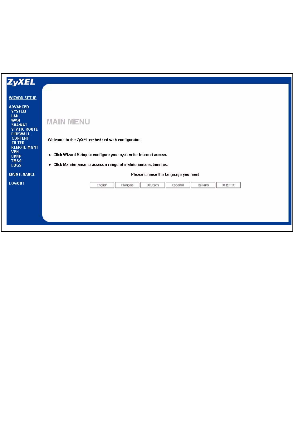
Prestige 334 User’s Guide
Chapter 2 Introducing the Web Configurator 40
• Click to view the web configurator in the language of your choice.
• Click LOGOUT at any time to exit the web configurator.
• Click MAINTENANCE to view information about your Prestige or upgrade
configuration/firmware files. Maintenance includes Status (Statistics), DHCP Table, F/
W (firmware) Upload, Configuration (Backup, Restore, Defaults) and Restart.
Figure 4 The MAIN MENU Screen of the Web Configurator
2.3.3 Navigation Panel
After you enter the password, use the sub-menus on the navigation panel to configure Prestige
features.

Prestige 334 User’s Guide
41 Chapter 2 Introducing the Web Configurator
The following table describes the sub-menus.
Table 1 Screens Summary
LINK TAB FUNCTION
WIZARD SETUP Use these screens for initial configuration including general
setup, ISP parameters for Internet Access and WAN IP/DNS
Server/MAC address assignment.
SYSTEM General This screen contains administrative and system-related
information.
DDNS Use this screen to set up dynamic DNS.
Password Use this screen to change your password.
Time Zone Use this screen to change your Prestige’s time and date.
LAN IP Use this screen to configure LAN DHCP, TCP/IP settings and to
enable Any IP.
Static DHCP Use this screen to assign IP addresses on the LAN to specific
individual computers based on their MAC Addresses.
IP Alias Use this screen to partition your LAN interface into subnets.
WAN Route This screen allows you to configure route priority.
WAN ISP Use this screen to change your Prestige’s WAN ISP settings.
WAN IP Use this screen to change your Prestige’s WAN IP settings.
WAN MAC Use this screen to change your Prestige’s WAN MAC settings.
Traffic Redirect Use this screen to configure your traffic redirect properties and
parameters.
SUA/NAT SUA Server Use this screen to configure servers behind the Prestige.
Address
Mapping
Use this screen to configure network address translation
mapping rules.
Trigger Port Use this screen to change your Prestige’s trigger port settings.
STATIC ROUTE IP Static Route Use this screen to configure IP static routes.
FIREWALL Settings Use this screen to activate/deactivate the firewall and log packets
related to firewall rules.
Services Use this screen to enable service blocking.
CONTENT
FILTERING
Filter This screen allows you to block sites containing certain keywords
in the URL and set the days and times for the Prestige to perform
content filtering.

Prestige 334 User’s Guide
Chapter 2 Introducing the Web Configurator 42
REMOTE MGMT TELNET Use this screen to configure through which interface(s) and from
which IP address(es) users can use Telnet to manage the
Prestige.
FTP Use this screen to configure through which interface(s) and from
which IP address(es) users can use FTP to access the Prestige.
WWW Use this screen to configure through which interface(s) and from
which IP address(es) users can use HTTP to manage the
Prestige.
SNMP Use this screen to configure your Prestige’s settings for Simple
Network Management Protocol management.
DNS Use this screen to configure through which interface(s) and from
which IP address(es) users can send DNS queries to the
Prestige.
Security Use this screen to change your anti-probing settings.
VPN Summary Use this screen to view the rule summary.
Rule Setup Use this screen to configure VPN connections.
SA Monitor Use this screen to display and manage active VPN connections.
Global Setting Use this screen to allow NetBIOS packets through the VPN
connections.
UPnP UPnP Use this screen to enable UPnP on the Prestige.
TMSS Service Settings Use this screen to decide which computers in the network you
can apply TMSS.
Antivirus
Protection
This screen allows you to check the computers in your network
for Trend Micro Internet Security.
Parental
Controls
This screen allows a parent (LAN administrator) to control a LAN
user's Internet access privileges by blocking specified website
categories.
LOGS View Log Use this screen to view the logs for the categories that you
selected.
Log Settings Use this screen to change your Prestige’s log settings.
MAINTENANCE Status This screen contains administrative and system-related
information.
DHCP Table This screen displays DHCP (Dynamic Host Configuration
Protocol) related information and is READ-ONLY.
Any IP Use this screen to allow a computer to access the Internet
without changing the network settings of the computer, when the
IP addresses of the computer and the Prestige are not in the
same subnet.
F/W Upload Use this screen to upload firmware to your Prestige.
Configuration Use this screen to backup and restore the configuration or reset
the factory defaults to your Prestige.
Restart This screen allows you to reboot the Prestige without turning the
power off.
LOGOUT Click this label to exit the web configurator.
Table 1 Screens Summary
LINK TAB FUNCTION

Prestige 334 User’s Guide
43 Chapter 2 Introducing the Web Configurator

Prestige 334 User’s Guide
Chapter 3 Wizard Setup 44
CHAPTER 3
Wizard Setup
This chapter provides information on the Wizard Setup screens in the web configurator.
3.1 Wizard Setup Overview
The web configurator’s setup wizard helps you configure your device to access the Internet.
The second screen has three variations depending on what encapsulation type you use. Refer
to your ISP checklist in the Quick Start Guide to know what to enter in each field. Leave a
field blank if you don’t have that information.
3.2 Wizard Setup: General Setup and System Name
General Setup contains administrative and system-related information. System Name is for
identification purposes. However, because some ISPs check this name you should enter your
computer's "Computer Name".
• In Windows 95/98 click Start, Settings, Control Panel, Network. Click the
Identification tab, note the entry for the Computer Name field and enter it as the System
Name.
• In Windows 2000, click Start, Settings and Control Panel and then double-click
System. Click the Network Identification tab and then the Properties button. Note the
entry for the Computer name field and enter it as the System Name.
• In Windows XP, click Start, My Computer, View system information and then click
the Computer Name tab. Note the entry in the Full computer name field and enter it as
the Prestige System Name.
3.2.1 Domain Name
The Domain Name entry is what is propagated to the DHCP clients on the LAN. If you leave
this blank, the domain name obtained by DHCP from the ISP is used. While you must enter
the host name (System Name) on each individual computer, the domain name can be assigned
from the Prestige via DHCP.
Click Next to configure the Prestige for Internet access.
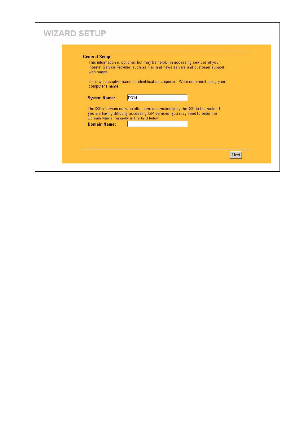
Prestige 334 User’s Guide
45 Chapter 3 Wizard Setup
Figure 5 Wizard 1: General Setup
3.3 Wizard Setup: Screen 2
The Prestige offers three choices of encapsulation. They are Ethernet, PPP over Ethernet or
PPTP.
3.3.1 Ethernet
Choose Ethernet when the WAN port is used as a regular Ethernet.
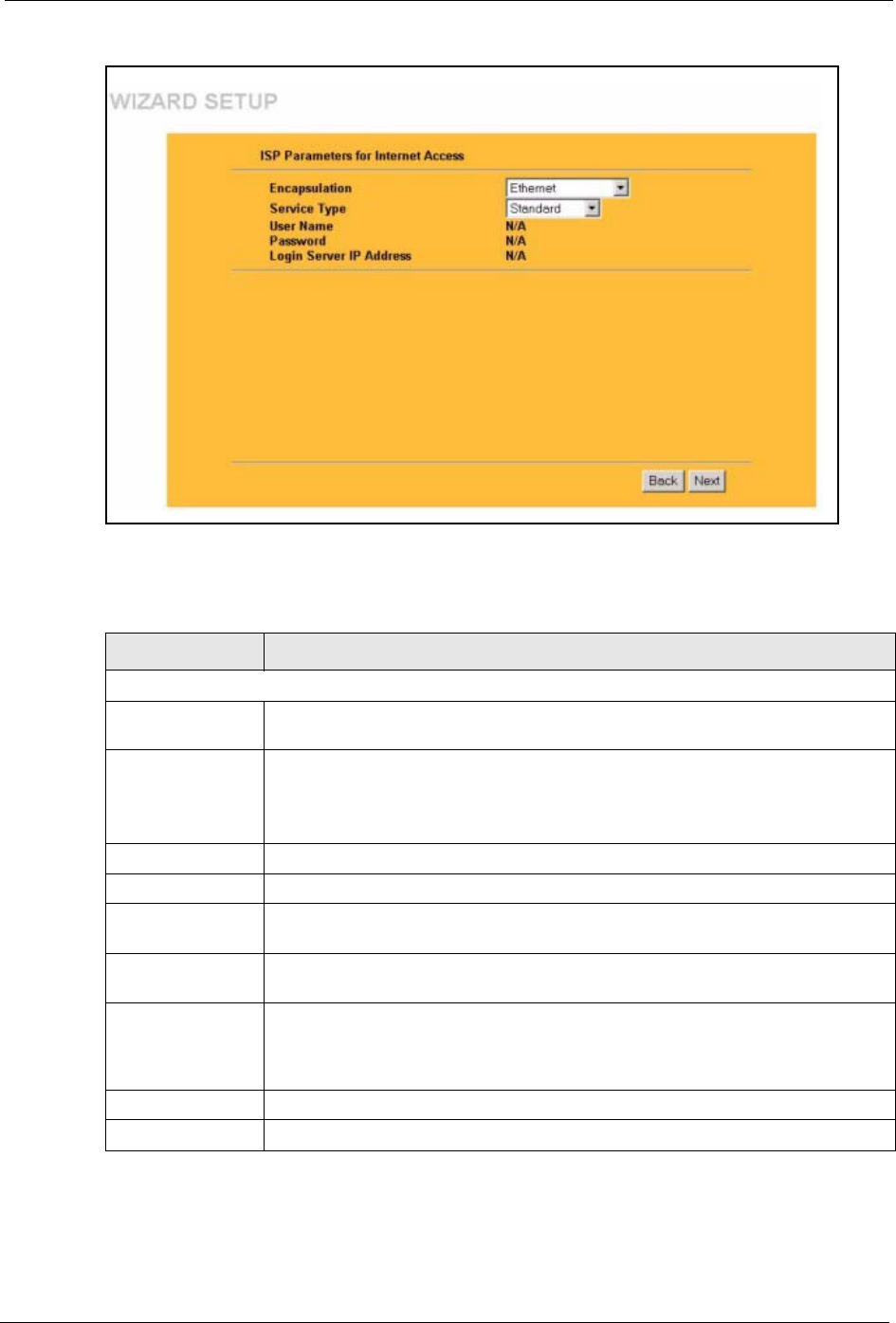
Prestige 334 User’s Guide
Chapter 3 Wizard Setup 46
Figure 6 Wizard 2: Ethernet Encapsulation
The following table describes the labels in this screen.
Table 2 Wizard 2: Ethernet Encapsulation
LABEL DESCRIPTION
ISP Parameters for Internet Access
Encapsulation You must choose the Ethernet option when the WAN port is used as a regular
Ethernet. Otherwise, choose PPP over Ethernet or PPTP for a dial-up connection.
Service Type Choose from Standard, Telstra (RoadRunner Telstra authentication method), RR-
Manager (Roadrunner Manager authentication method), RR-Toshiba
(Roadrunner Toshiba authentication method) or Telia Login.
The following fields are not applicable (N/A) for the Standard service type.
User Name Type the user name given to you by your ISP.
Password Type the password associated with the user name above.
Login Server IP
Address
Type the authentication server IP address here if your ISP gave you one.
Login Server This field only applies when you select Telia Login in the Service Type field. Type
the domain name of the Telia login server, for example “login1.telia.com”.
Relogin Every
(min)
This field only applies when you select Telia Login in the Service Type field. The
Telia server logs the Prestige out if the Prestige does not log in periodically. Type
the number of minutes from 1 to 59 (30 default) for the Prestige to wait between
logins.
Back Click Back to return to the previous screen.
Next Click Next to continue.

Prestige 334 User’s Guide
47 Chapter 3 Wizard Setup
3.3.2 PPPoE Encapsulation
Point-to-Point Protocol over Ethernet (PPPoE) functions as a dial-up connection. PPPoE is an
IETF (Internet Engineering Task Force) draft standard specifying how a host personal
computer interacts with a broadband modem (for example DSL, cable, wireless, etc.) to
achieve access to high-speed data networks.
For the service provider, PPPoE offers an access and authentication method that works with
existing access control systems (for instance, Radius). For the user, PPPoE provides a login
and authentication method that the existing Microsoft Dial-Up Networking software can
activate, and therefore requires no new learning or procedures for Windows users.
One of the benefits of PPPoE is the ability to let end users access one of multiple network
services, a function known as dynamic service selection. This enables the service provider to
easily create and offer new IP services for specific users.
Operationally, PPPoE saves significant effort for both the subscriber and the ISP/carrier, as it
requires no specific configuration of the broadband modem at the subscriber’s site.
By implementing PPPoE directly on the Prestige (rather than individual computers), the
computers on the LAN do not need PPPoE software installed, since the Prestige does that part
of the task. Furthermore, with NAT, all of the LAN's computers will have Internet access.
Refer to the appendix for more information on PPPoE.
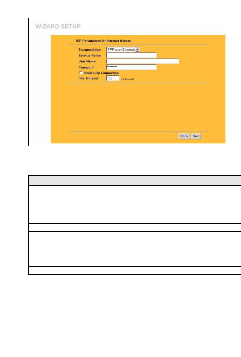
Prestige 334 User’s Guide
Chapter 3 Wizard Setup 48
Figure 7 Wizard 2: PPPoE Encapsulation
The following table describes the labels in this screen.
3.3.3 PPTP Encapsulation
Point-to-Point Tunneling Protocol (PPTP) is a network protocol that enables transfers of data
from a remote client to a private server, creating a Virtual Private Network (VPN) using TCP/
IP-based networks.
PPTP supports on-demand, multi-protocol, and virtual private networking over public
networks, such as the Internet.
Table 3 Wizard 2: PPPoE Encapsulation
LABEL DESCRIPTION
ISP Parameter for Internet Access
Encapsulation Choose PPP over Ethernet from the pull-down list box. PPPoE forms a dial-up
connection.
Service Name Type the name of your service provider.
User Name Type the user name given to you by your ISP.
Password Type the password associated with the user name above.
Nailed-Up
Connection
Select Nailed-Up Connection if you do not want the connection to time out.
Idle Timeout Type the time in seconds that elapses before the router automatically disconnects
from the PPPoE server. The default time is 100 seconds.
Next Click Next to continue.
Back Click Back to return to the previous screen.
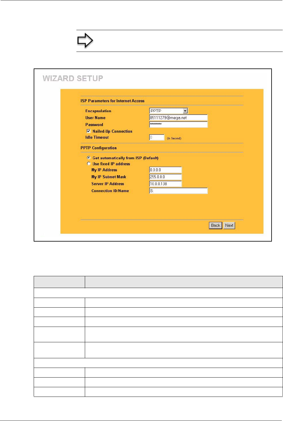
Prestige 334 User’s Guide
49 Chapter 3 Wizard Setup
Refer to the appendix for more information on PPTP.
Figure 8 Wizard 2: PPTP Encapsulation
The following table describes the fields in this screen
Note: The PRESTIGE supports one PPTP server connection at
any given time.
Table 4 Wizard 2: PPTP Encapsulation
LABEL DESCRIPTION
ISP Parameters for Internet Access
Encapsulation Select PPTP from the drop-down list box.
User Name Type the user name given to you by your ISP.
Password Type the password associated with the User Name above.
Nailed-Up
Connection
Select Nailed-Up Connection if you do not want the connection to time out.
Idle Timeout Type the time in seconds that elapses before the router automatically disconnects
from the PPTP server. The default is 100 seconds.
PPTP Configuration
My IP Address Type the (static) IP address assigned to you by your ISP.
My IP Subnet Mask Type the subnet mask assigned to you by your ISP (if given).
Server IP Address Type the IP address of the PPTP server.
Prestige 334 User’s Guide
Chapter 3 Wizard Setup 50
3.4 Wizard Setup: Screen 3
The fifth wizard screen allows you to configure WAN IP address assignment, DNS server
address assignment and the WAN MAC address.
3.4.1 WAN IP Address Assignment
Every computer on the Internet must have a unique IP address. If your networks are isolated
from the Internet, for instance, only between your two branch offices, you can assign any IP
addresses to the hosts without problems. However, the Internet Assigned Numbers Authority
(IANA) has reserved the following three blocks of IP addresses specifically for private
networks.
You can obtain your IP address from the IANA, from an ISP or have it assigned by a private
network. If you belong to a small organization and your Internet access is through an ISP, the
ISP can provide you with the Internet addresses for your local networks. On the other hand, if
you are part of a much larger organization, you should consult your network administrator for
the appropriate IP addresses.
3.4.2 IP Address and Subnet Mask
Similar to the way houses on a street share a common street name, so too do computers on a
LAN share one common network number.
Connection ID/
Name
Enter the connection ID or connection name in this field. It must follow the "c:id"
and "n:name" format. For example, C:12 or N:My ISP.
This field is optional and depends on the requirements of your ISP.
Back Click Back to return to the previous screen.
Next Click Next to continue.
Table 4 Wizard 2: PPTP Encapsulation
LABEL DESCRIPTION
Table 5 Private IP Address Ranges
10.0.0.0 -10.255.255.255
172.16.0.0 -172.31.255.255
192.168.0.0 -192.168.255.255
Note: Regardless of your particular situation, do not create an
arbitrary IP address; always follow the guidelines above. For
more information on address assignment, please refer to RFC
1597, Address Allocation for Private Internets and RFC 1466,
Guidelines for Management of IP Address Space.

Prestige 334 User’s Guide
51 Chapter 3 Wizard Setup
Where you obtain your network number depends on your particular situation. If the ISP or
your network administrator assigns you a block of registered IP addresses, follow their
instructions in selecting the IP addresses and the subnet mask.
If the ISP did not explicitly give you an IP network number, then most likely you have a single
user account and the ISP will assign you a dynamic IP address when the connection is
established. The Internet Assigned Number Authority (IANA) reserved this block of addresses
specifically for private use; please do not use any other number unless you are told otherwise.
Let's say you select 192.168.1.0 as the network number; which covers 254 individual
addresses, from 192.168.1.1 to 192.168.1.254 (zero and 255 are reserved). In other words, the
first three numbers specify the network number while the last number identifies an individual
computer on that network.
Once you have decided on the network number, pick an IP address that is easy to remember,
for instance, 192.168.1.1, for your Prestige, but make sure that no other device on your
network is using that IP address.
The subnet mask specifies the network number portion of an IP address. Your Prestige will
compute the subnet mask automatically based on the IP address that you entered. You don't
need to change the subnet mask computed by the Prestige unless you are instructed to do
otherwise.
3.4.3 DNS Server Address Assignment
Use DNS (Domain Name System) to map a domain name to its corresponding IP address and
vice versa, for instance, the IP address of www.zyxel.com is 204.217.0.2. The DNS server is
extremely important because without it, you must know the IP address of a computer before
you can access it.
The Prestige can get the DNS server addresses in the following ways.
1The ISP tells you the DNS server addresses, usually in the form of an information sheet,
when you sign up. If your ISP gives you DNS server addresses, enter them in the DNS
Server fields in DHCP Setup.
2If the ISP did not give you DNS server information, leave the DNS Server fields in
DHCP Setup set to 0.0.0.0 for the ISP to dynamically assign the DNS server IP addresses.
3.4.4 WAN MAC Address
Every Ethernet device has a unique MAC (Media Access Control) address. The MAC address
is assigned at the factory and consists of six pairs of hexadecimal characters, for example,
00:A0:C5:00:00:02.
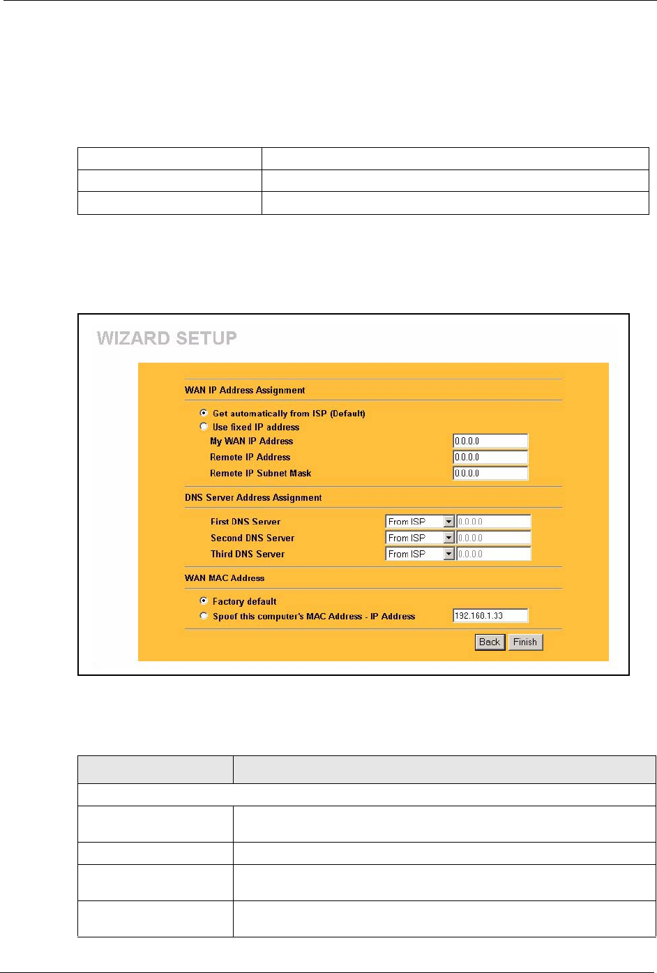
Prestige 334 User’s Guide
Chapter 3 Wizard Setup 52
You can configure the WAN port's MAC address by either using the factory default or cloning
the MAC address from a computer on your LAN. Once it is successfully configured, the
address will be copied to the "rom" file (ZyNOS configuration file). It will not change unless
you change the setting or upload a different "rom" file.
The fifth wizard screen varies according to the type of encapsulation that you select in the
third wizard screen.
Figure 9 Wizard 3: WAN Setup
The following table describes the labels in this screen
Table 6 Example of Network Properties for LAN Servers with Fixed IP Addresses
Choose an IP address 192.168.1.2-192.168.1.32; 192.168.1.65-192.168.1.254.
Subnet mask 255.255.255.0
Gateway (or default route) 192.168.1.1(Prestige LAN IP)
Table 7 Wizard 3: WAN Setup
LABEL DESCRIPTION
WAN IP Address Assignment
Get automatically from
ISP
Select this option If your ISP did not assign you a fixed IP address. This is
the default selection.
Use fixed IP address Select this option If the ISP assigned a fixed IP address.
My WAN IP Address Enter your WAN IP address in this field if you selected Use Fixed IP
Address.
My WAN Subnet Mask Type your IP subnet mask in this field when you selected Use Fixed IP
Address.

Prestige 334 User’s Guide
53 Chapter 3 Wizard Setup
3.5 Basic Setup Complete
Click Back to return to the previous screen or click Finish to complete and save the wizard
setup.
Gateway IP Address Type the IP address of the gateway. The gateway is an immediate
neighbour of your Prestige that will forward the packet to the destination.
The gateway must be a router on the same segment as your Prestige's
LAN or WAN port.
System DNS Server Address Assignment (if applicable)
DNS (Domain Name System) is for mapping a domain name to its corresponding IP address and vice
versa. The DNS server is extremely important because without it, you must know the IP address of a
computer before you can access it. The Prestige uses a system DNS server (in the order you specify
here) to resolve domain names for VPN, DDNS and the time server.
First DNS Server
Second DNS Server
Third DNS Server
Select From ISP if your ISP dynamically assigns DNS server information
(and the Prestige's WAN IP address). The field to the right displays the
(read-only) DNS server IP address that the ISP assigns.
Select User-Defined if you have the IP address of a DNS server. Enter the
DNS server's IP address in the field to the right.
Select None if you do not want to configure DNS servers. If you do not
configure a system DNS server, you must use IP addresses when
configuring VPN, DDNS and the time server.
WAN MAC Address The MAC address field allows you to configure the WAN port's MAC
Address by either using the factory default or cloning the MAC address
from a computer on your LAN.
Factory Default Select this option to use the factory assigned default MAC Address.
Spoof this Computer's
MAC address - IP Address
Select this option and enter the IP address of the computer on the LAN
whose MAC you are cloning. Once it is successfully configured, the
address will be copied to the rom file (ZyNOS configuration file). It will not
change unless you change the setting or upload a different rom file. It is
advisable to clone the MAC address from a computer on your LAN even if
your ISP does not presently require MAC address authentication.
Back Click Back to return to the previous screen.
Next Click Next to continue.
Table 7 Wizard 3: WAN Setup
LABEL DESCRIPTION
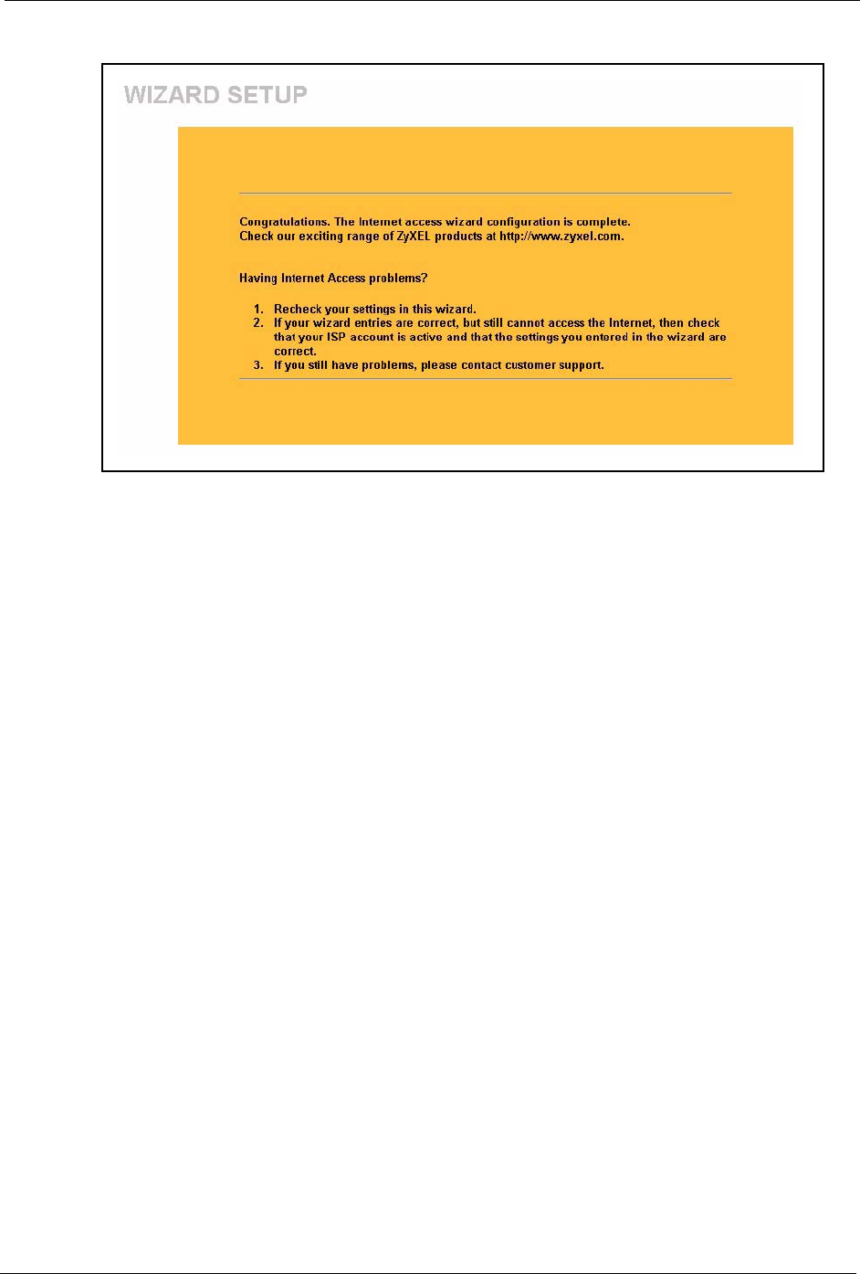
Prestige 334 User’s Guide
Chapter 3 Wizard Setup 54
Figure 10 Wizard Finish
Well done! You have successfully set up your Prestige to operate on your network and access
the Internet.

Prestige 334 User’s Guide
55 Chapter 3 Wizard Setup

Prestige 334 User’s Guide
Chapter 4 System Screens 56
CHAPTER 4
System Screens
This chapter provides information on the System screens.
4.1 System Overview
See the Wizard Setup chapter for more information on the next few screens.
4.2 Configuring General Setup
Click SYSTEM to open the General screen.
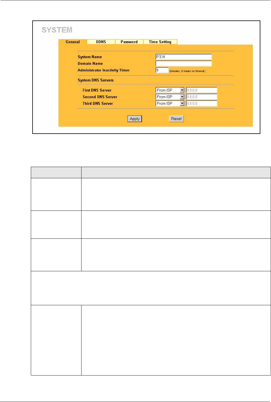
Prestige 334 User’s Guide
57 Chapter 4 System Screens
Figure 11 System General Setup
The following table describes the labels in this screen.
Table 8 System General Setup
LABEL DESCRIPTION
System Name Choose a descriptive name for identification purposes. It is recommended you
enter your computer’s “Computer name” in this field (see the Wizard Setup
chapter for how to find your computer’s name). This name can be up to 30
alphanumeric characters long. Spaces are not allowed, but dashes “-” and
underscores "_" are accepted.
Domain Name Enter the domain name (if you know it) here. If you leave this field blank, the ISP
may assign a domain name via DHCP.
The domain name entered by you is given priority over the ISP assigned domain
name.
Administrator
Inactivity Timer
Type how many minutes a management session (either via the web configurator
or SMT) can be left idle before the session times out. The default is 5 minutes.
After it times out you have to log in with your password again. Very long idle
timeouts may have security risks. A value of "0" means a management session
never times out, no matter how long it has been left idle (not recommended).
System DNS Servers (if applicable)
DNS (Domain Name System) is for mapping a domain name to its corresponding IP address and vice
versa. The DNS server is extremely important because without it, you must know the IP address of a
computer before you can access it. The Prestige uses a system DNS server (in the order you specify
here) to resolve domain names for VPN, DDNS and the time server.
First DNS Server
Second DNS Server
Third DNS Server
Select From ISP if your ISP dynamically assigns DNS server information (and the
Prestige's WAN IP address). The field below displays the (read-only) DNS server
IP address that the ISP assigns.
Select User-Defined if you have the IP address of a DNS server. Enter the DNS
server's IP address in the field below. If you chose User-Defined, but leave the IP
address set to 0.0.0.0, User-Defined changes to None after you click Apply. If
you set a second choice to User-Defined, and enter the same IP address, the
second User-Defined changes to None after you click Apply.
Select None if you do not want to configure DNS servers. If you do not configure
a system DNS server, you must use IP addresses when configuring VPN, DDNS
and the time server.
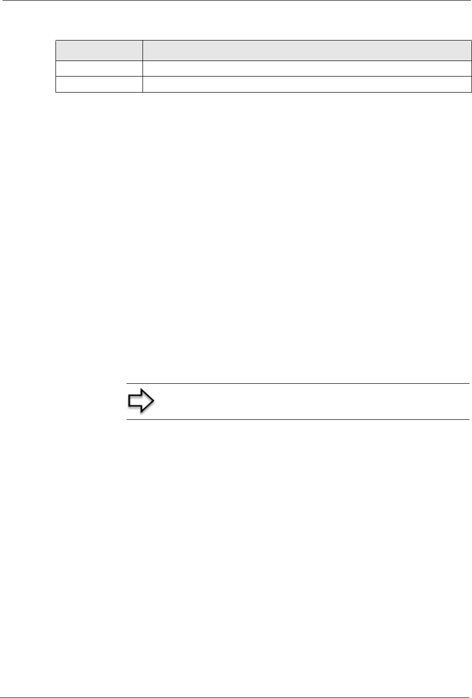
Prestige 334 User’s Guide
Chapter 4 System Screens 58
4.3 Dynamic DNS
Dynamic DNS allows you to update your current dynamic IP address with one or many
dynamic DNS services so that anyone can contact you (in NetMeeting, CU-SeeMe, etc.). You
can also access your FTP server or Web site on your own computer using a domain name (for
instance myhost.dhs.org, where myhost is a name of your choice) that will never change
instead of using an IP address that changes each time you reconnect. Your friends or relatives
will always be able to call you even if they don't know your IP address.
First of all, you need to have registered a dynamic DNS account with www.dyndns.org. This is
for people with a dynamic IP from their ISP or DHCP server that would still like to have a
domain name. The Dynamic DNS service provider will give you a password or key.
4.3.1 DynDNS Wildcard
Enabling the wildcard feature for your host causes *.yourhost.dyndns.org to be aliased to the
same IP address as yourhost.dyndns.org. This feature is useful if you want to be able to use,
for example, www.yourhost.dyndns.org and still reach your hostname.
4.4 Configuring Dynamic DNS
To change your Prestige’s DDNS, click SYSTEM, then the DDNS tab. The screen appears as
shown.
Apply Click Apply to save your changes back to the Prestige.
Reset Click Reset to begin configuring this screen afresh.
Table 8 System General Setup
LABEL DESCRIPTION
Note: If you have a private WAN IP address, then you cannot
use Dynamic DNS.
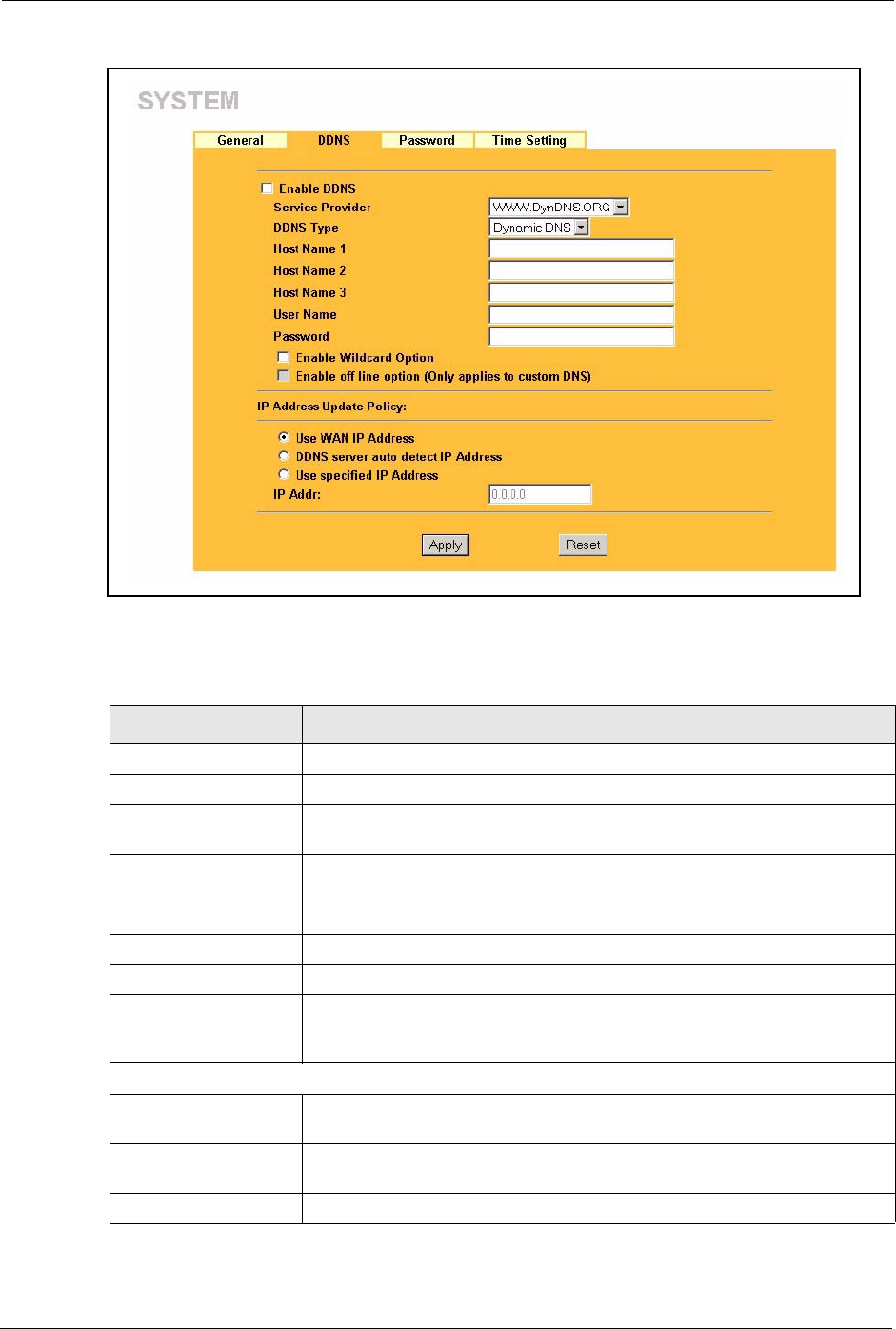
Prestige 334 User’s Guide
59 Chapter 4 System Screens
Figure 12 DDNS
The following table describes the labels in this screen.
Table 9 DDNS
LABEL DESCRIPTION
Active Select this check box to use dynamic DNS.
Service Provider Select the name of your Dynamic DNS service provider.
DDNS Type Select the type of service that you are registered for from your Dynamic DNS
service provider.
Host Names 1~3 Enter the host names in the three fields provided. You can specify up to two
host names in each field separated by a comma (",").
User Enter your user name.
Password Enter the password assigned to you.
Enable Wildcard Select the check box to enable DynDNS Wildcard.
Off Line This option is available when CustomDNS is selected in the DDNS Type
field. Check with your Dynamic DNS service provider to have traffic
redirected to a URL (that you can specify) while you are off line.
Edit Update IP Address:
Server Auto Detect Select this option to update the IP address of the host name(s) automatically
by the DDNS server. It is recommended that you select this option.
User Specify Select this option to update the IP address of the host name(s) to the IP
address specified below. Use this option if you have a static IP address.
IP Addr Enter the IP address if you select the User Specify option.
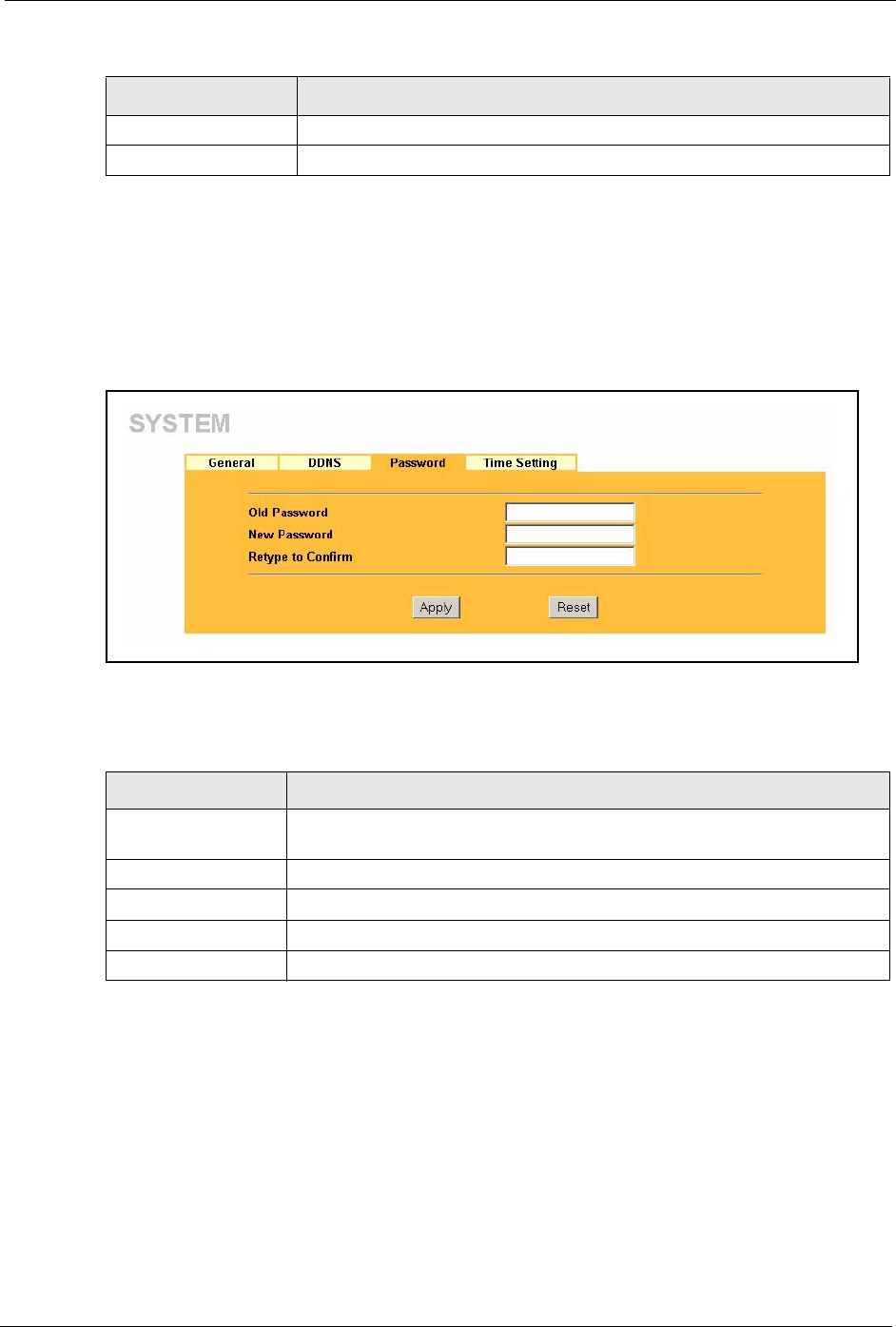
Prestige 334 User’s Guide
Chapter 4 System Screens 60
4.5 Configuring Password
To change your Prestige’s password (recommended), click SYSTEM, then the Password tab.
The screen appears as shown. This screen allows you to change the Prestige’s password.
Figure 13 Password
The following table describes the labels in this screen.
4.6 Configuring Time Setting
To change your Prestige’s time and date, click SYSTEM, then the Time Setting tab. The
screen appears as shown. Use this screen to configure the Prestige’s time based on your local
time zone.
Apply Click Apply to save your changes back to the Prestige.
Reset Click Reset to begin configuring this screen afresh.
Table 9 DDNS
LABEL DESCRIPTION
Table 10 Password
LABEL DESCRIPTION
Old Password Type the default password or the existing password you use to access the
system in this field.
New Password Type the new password in this field.
Retype to Confirm Type the new password again in this field.
Apply Click Apply to save your changes back to the Prestige.
Reset Click Reset to begin configuring this screen afresh.
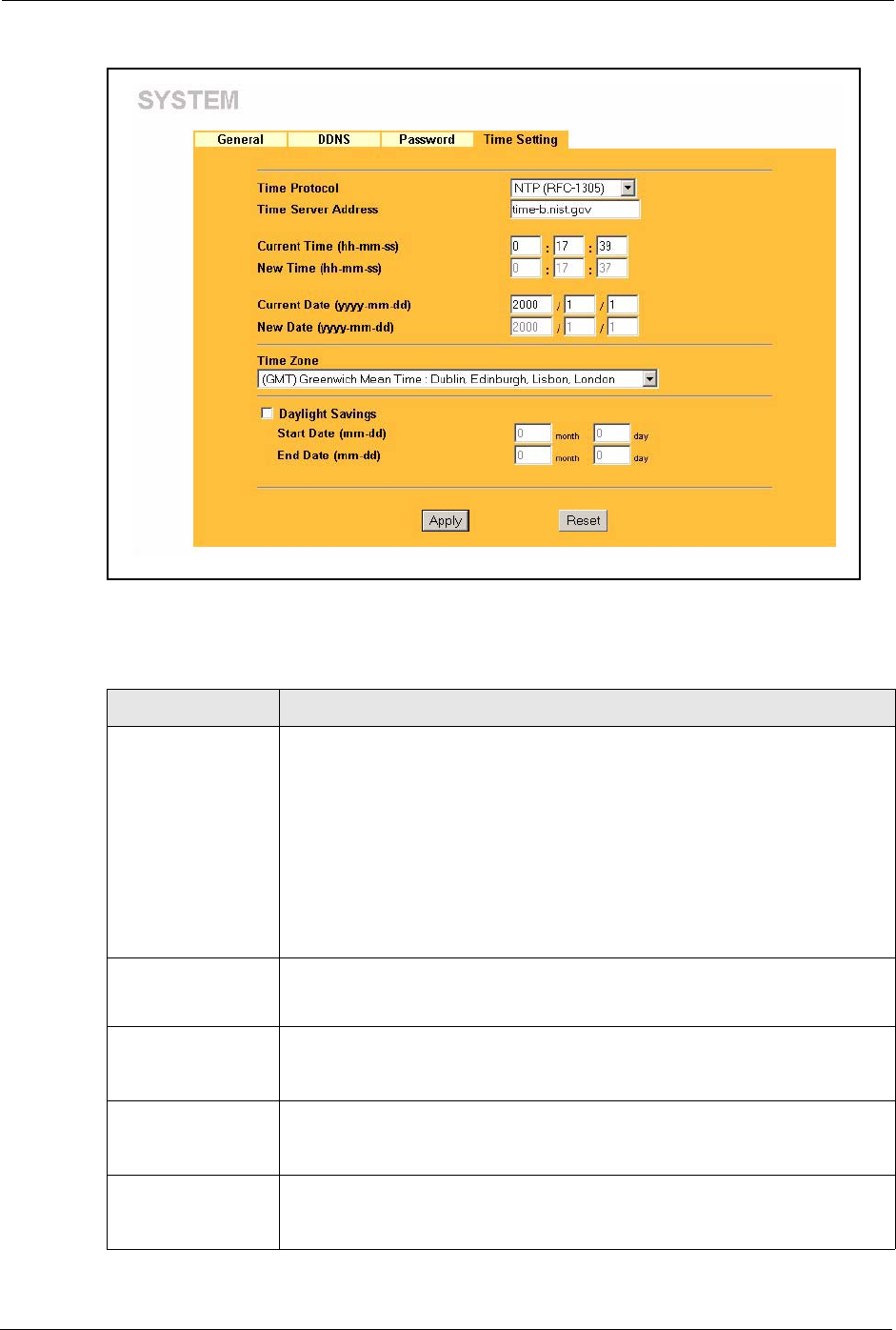
Prestige 334 User’s Guide
61 Chapter 4 System Screens
Figure 14 Time Setting
The following table describes the labels in this screen.
Table 11 Time Setting
LABEL DESCRIPTION
Use Time Server
when Bootup
Select the time service protocol that your time server sends when you turn on
the Prestige. Not all time servers support all protocols, so you may have to
check with your ISP/network administrator or use trial and error to find a protocol
that works.
The main difference between them is the format.
Daytime (RFC 867) format is day/month/year/time zone of the server.
Time (RFC 868) format displays a 4-byte integer giving the total number of
seconds since 1970/1/1 at 0:0:0.
The default, NTP (RFC 1305), is similar to Time (RFC 868).
Select None to enter the time and date manually.
Time Server
Address
Enter the IP address or URL (up to 20 extended ASCII characters in length) of
your time server. Check with your ISP/network administrator if you are unsure of
this information.
Current Time This field displays the time of your Prestige.
Each time you reload this page, the Prestige synchronizes the time with the time
server.
New Time This field displays the last updated time from the time server.
When you select None in the Time Protocol field, enter the new time in this
field and then click Apply.
Current Date This field displays the date of your Prestige.
Each time you reload this page, the Prestige synchronizes the time with the time
server.

Prestige 334 User’s Guide
Chapter 4 System Screens 62
New Date This field displays the last updated date from the time server.
When you select None in the Time Protocol field, enter the new date in this
field and then click Apply.
Time Zone Choose the Time Zone of your location. This will set the time difference between
your time zone and Greenwich Mean Time (GMT).
Daylight Savings Select this option if you use daylight savings time. Daylight saving is a period
from late spring to early fall when many countries set their clocks ahead of
normal local time by one hour to give more daytime light in the evening.
Start Date Enter the month and day that your daylight-savings time starts on if you selected
Daylight Savings.
End Date Enter the month and day that your daylight-savings time ends on if you selected
Daylight Savings.
Apply Click Apply to save your changes back to the Prestige.
Reset Click Reset to begin configuring this screen afresh.
Table 11 Time Setting
LABEL DESCRIPTION

Prestige 334 User’s Guide
63 Chapter 4 System Screens

Prestige 334 User’s Guide
Chapter 5 LAN Screens 64
CHAPTER 5
LAN Screens
This chapter describes how to configure LAN settings.
5.1 LAN Overview
Local Area Network (LAN) is a shared communication system to which many computers are
attached. The LAN screens can help you configure a LAN DHCP server, manage IP addresses,
and partition your physical network into logical networks.
5.2 DHCP Setup
DHCP (Dynamic Host Configuration Protocol, RFC 2131 and RFC 2132) allows individual
clients to obtain TCP/IP configuration at start-up from a server. You can configure the Prestige
as a DHCP server or disable it. When configured as a server, the Prestige provides the TCP/IP
configuration for the clients. If DHCP service is disabled, you must have another DHCP server
on your LAN, or else the computer must be manually configured.
5.2.1 IP Pool Setup
The Prestige is pre-configured with a pool of 32 IP addresses starting from 192.168.1.33 to
192.168.1.64. This configuration leaves 31 IP addresses (excluding the Prestige itself) in the
lower range for other server computers, for instance, servers for mail, FTP, TFTP, web, etc.,
that you may have.
5.2.2 System DNS Servers
Refer to the IP Address and Subnet Mask section in the Wizard Setup chapter.
5.3 LAN TCP/IP
The Prestige has built-in DHCP server capability that assigns IP addresses and DNS servers to
systems that support DHCP client capability.
5.3.1 Factory LAN Defaults
The LAN parameters of the Prestige are preset in the factory with the following values:

Prestige 334 User’s Guide
65 Chapter 5 LAN Screens
• IP address of 192.168.1.1 with subnet mask of 255.255.255.0 (24 bits)
• DHCP server enabled with 32 client IP addresses starting from 192.168.1.33.
These parameters should work for the majority of installations. If your ISP gives you explicit
DNS server address(es), read the embedded web configurator help regarding what fields need
to be configured.
5.3.2 IP Address and Subnet Mask
Refer to the IP Address and Subnet Mask section in the Wizard Setup chapter for this
information.
5.3.3 RIP Setup
RIP (Routing Information Protocol, RFC 1058 and RFC 1389) allows a router to exchange
routing information with other routers. RIP Direction controls the sending and receiving of
RIP packets. When set to Both or Out Only, the Prestige will broadcast its routing table
periodically. When set to Both or In Only, it will incorporate the RIP information that it
receives; when set to None, it will not send any RIP packets and will ignore any RIP packets
received.
RIP Version controls the format and the broadcasting method of the RIP packets that the
Prestige sends (it recognizes both formats when receiving). RIP-1 is universally supported;
but RIP-2 carries more information. RIP-1 is probably adequate for most networks, unless you
have an unusual network topology.
Both RIP-2B and RIP-2M send routing data in RIP-2 format; the difference being that RIP-
2B uses subnet broadcasting while RIP-2M uses multicasting. Multicasting can reduce the
load on non-router machines since they generally do not listen to the RIP multicast address
and so will not receive the RIP packets. However, if one router uses multicasting, then all
routers on your network must use multicasting, also.
By default, RIP Direction is set to Both and RIP Version to RIP-1.
5.3.4 Multicast
Traditionally, IP packets are transmitted in one of either two ways - Unicast (1 sender - 1
recipient) or Broadcast (1 sender - everybody on the network). Multicast delivers IP packets to
a group of hosts on the network - not everybody and not just 1.
IGMP (Internet Group Multicast Protocol) is a network-layer protocol used to establish
membership in a Multicast group - it is not used to carry user data. IGMP version 2 (RFC
2236) is an improvement over version 1 (RFC 1112) but IGMP version 1 is still in wide use. If
you would like to read more detailed information about interoperability between IGMP
version 2 and version 1, please see sections 4 and 5 of RFC 2236. The class D IP address is
used to identify host groups and can be in the range 224.0.0.0 to 239.255.255.255. The address

Prestige 334 User’s Guide
Chapter 5 LAN Screens 66
224.0.0.0 is not assigned to any group and is used by IP multicast computers. The address
224.0.0.1 is used for query messages and is assigned to the permanent group of all IP hosts
(including gateways). All hosts must join the 224.0.0.1 group in order to participate in IGMP.
The address 224.0.0.2 is assigned to the multicast routers group.
The Prestige supports both IGMP version 1 (IGMP-v1) and IGMP version 2 (IGMP-v2). At
start up, the Prestige queries all directly connected networks to gather group membership.
After that, the Prestige periodically updates this information. IP multicasting can be enabled/
disabled on the Prestige LAN and/or WAN interfaces in the web configurator (LAN; WAN ).
Select None to disable IP multicasting on these interfaces.
5.4 Configuring IP
Click LAN to open the IP screen.
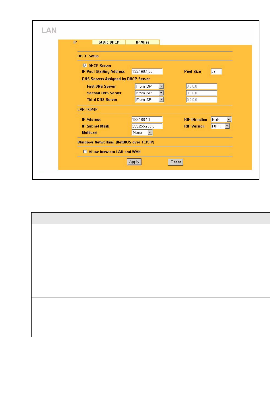
Prestige 334 User’s Guide
67 Chapter 5 LAN Screens
Figure 15 LAN IP
The following table describes the labels in this screen.
Table 12 LAN IP
LABEL DESCRIPTION
DHCP Server DHCP (Dynamic Host Configuration Protocol, RFC 2131 and RFC 2132) allows
individual clients (computers) to obtain TCP/IP configuration at startup from a
server. Leave the DHCP Server check box selected unless your ISP instructs
you to do otherwise. Clear it to disable the Prestige acting as a DHCP server.
When configured as a server, the Prestige provides TCP/IP configuration for the
clients. If not, DHCP service is disabled and you must have another DHCP server
on your LAN, or else the computers must be manually configured. When set as a
server, fill in the following four fields.
IP Pool Starting
Address
This field specifies the first of the contiguous addresses in the IP address pool.
Pool Size This field specifies the size, or count of the IP address pool.
DNS Servers Assigned by DHCP Server
The Prestige passes a DNS (Domain Name System) server IP address (in the order you specify here)
to the DHCP clients. The Prestige only passes this information to the LAN DHCP clients when you
select the DHCP Server check box. When you clear the DHCP Server check box, DHCP service is
disabled and you must have another DHCP sever on your LAN, or else the computers must have their
DNS server addresses manually configured.

Prestige 334 User’s Guide
Chapter 5 LAN Screens 68
First DNS Server
Second DNS Server
Third DNS Server
Select From ISP if your ISP dynamically assigns DNS server information (and
the Prestige's WAN IP address). The field to the right displays the (read-only)
DNS server IP address that the ISP assigns.
Select User-Defined if you have the IP address of a DNS server. Enter the DNS
server's IP address in the field to the right. If you chose User-Defined, but leave
the IP address set to 0.0.0.0, User-Defined changes to None after you click
Apply. If you set a second choice to User-Defined, and enter the same IP
address, the second User-Defined changes to None after you click Apply.
Select DNS Relay to have the Prestige act as a DNS proxy. The Prestige's LAN
IP address displays in the field to the right (read-only). The Prestige tells the
DHCP clients on the LAN that the Prestige itself is the DNS server. When a
computer on the LAN sends a DNS query to the Prestige, the Prestige forwards
the query to the Prestige's system DNS server (configured in the SYSTEM
General screen) and relays the response back to the computer. You can only
select DNS Relay for one of the three servers; if you select DNS Relay for a
second or third DNS server, that choice changes to None after you click Apply.
Select None if you do not want to configure DNS servers. If you do not configure
a DNS server, you must know the IP address of a computer in order to access it.
LAN TCP/IP
IP Address Type the IP address of your Prestige in dotted decimal notation 192.168.1.1
(factory default).
IP Subnet Mask The subnet mask specifies the network number portion of an IP address. Your
Prestige will automatically calculate the subnet mask based on the IP address
that you assign. Unless you are implementing subnetting, use the subnet mask
computed by the Prestige 255.255.255.0.
RIP Direction RIP (Routing Information Protocol, RFC1058 and RFC 1389) allows a router to
exchange routing information with other routers. The RIP Direction field controls
the sending and receiving of RIP packets. Select the RIP direction from Both/In
Only/Out Only/None. When set to Both or Out Only, the Prestige will broadcast
its routing table periodically. When set to Both or In Only, it will incorporate the
RIP information that it receives; when set to None, it will not send any RIP
packets and will ignore any RIP packets received. Both is the default.
RIP Version The RIP Version field controls the format and the broadcasting method of the
RIP packets that the Prestige sends (it recognizes both formats when receiving).
RIP-1 is universally supported but RIP-2 carries more information. RIP-1 is
probably adequate for most networks, unless you have an unusual network
topology. Both RIP-2B and RIP-2M sends the routing data in RIP-2 format; the
difference being that RIP-2B uses subnet broadcasting while RIP-2M uses
multicasting. Multicasting can reduce the load on non-router machines since they
generally do not listen to the RIP multicast address and so will not receive the
RIP packets. However, if one router uses multicasting, then all routers on your
network must use multicasting, also. By default, RIP direction is set to Both and
the Version set to RIP-1.
Multicast Select IGMP V-1 or IGMP V-2 or None. IGMP (Internet Group Multicast Protocol)
is a network-layer protocol used to establish membership in a Multicast group - it
is not used to carry user data. IGMP version 2 (RFC 2236) is an improvement
over version 1 (RFC 1112) but IGMP version 1 is still in wide use. If you would
like to read more detailed information about interoperability between IGMP
version 2 and version 1, please see sections 4 and 5 of RFC 2236.
Windows Networking (NetBIOS over TCP/IP): NetBIOS (Network Basic Input/Output System) are TCP
or UDP broadcast packets that enable a computer to connect to and communicate with a LAN. For
some dial-up services such as PPPoE or PPTP, NetBIOS packets cause unwanted calls. However it
may sometimes be necessary to allow NetBIOS packets to pass through to the WAN in order to find a
computer on the WAN.
Table 12 LAN IP
LABEL DESCRIPTION

Prestige 334 User’s Guide
69 Chapter 5 LAN Screens
5.5 Configuring Static DHCP
This table allows you to assign IP addresses on the LAN to specific individual computers
based on their MAC Addresses.
Every Ethernet device has a unique MAC (Media Access Control) address. The MAC address
is assigned at the factory and consists of six pairs of hexadecimal characters, for example,
00:A0:C5:00:00:02.
To change your Prestige’s Static DHCP settings, click LAN, then the Static DHCP tab. The
screen appears as shown.
Allow between LAN
and WAN
Select this check box to forward NetBIOS packets from the LAN to the WAN and
from the WAN to the LAN. If your firewall is enabled with the default policy set to
block WAN to LAN traffic, you also need to enable the default WAN to LAN
firewall rule that forwards NetBIOS traffic.
Clear this check box to block all NetBIOS packets going from the LAN to the
WAN and from the WAN to the LAN.
Apply Click Apply to save your changes back to the Prestige.
Reset Click Reset to begin configuring this screen afresh.
Table 12 LAN IP
LABEL DESCRIPTION
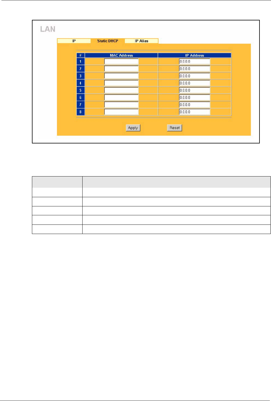
Prestige 334 User’s Guide
Chapter 5 LAN Screens 70
Figure 16 Static DHCP
The following table describes the labels in this screen.
5.6 Configuring IP Alias
IP Alias allows you to partition a physical network into different logical networks over the
same Ethernet interface. The Prestige supports three logical LAN interfaces via its single
physical Ethernet interface with the Prestige itself as the gateway for each LAN network.
To change your Prestige’s IP Alias settings, click LAN, then the IP Alias tab. The screen
appears as shown.
Table 13 Static DHCP
LABEL DESCRIPTION
#This is the index number of the Static IP table entry (row).
MAC Address Type the MAC address (with colons) of a computer on your LAN.
IP Address This field specifies the size, or count of the IP address pool.
Apply Click Apply to save your changes back to the Prestige.
Reset Click Reset to begin configuring this screen afresh.
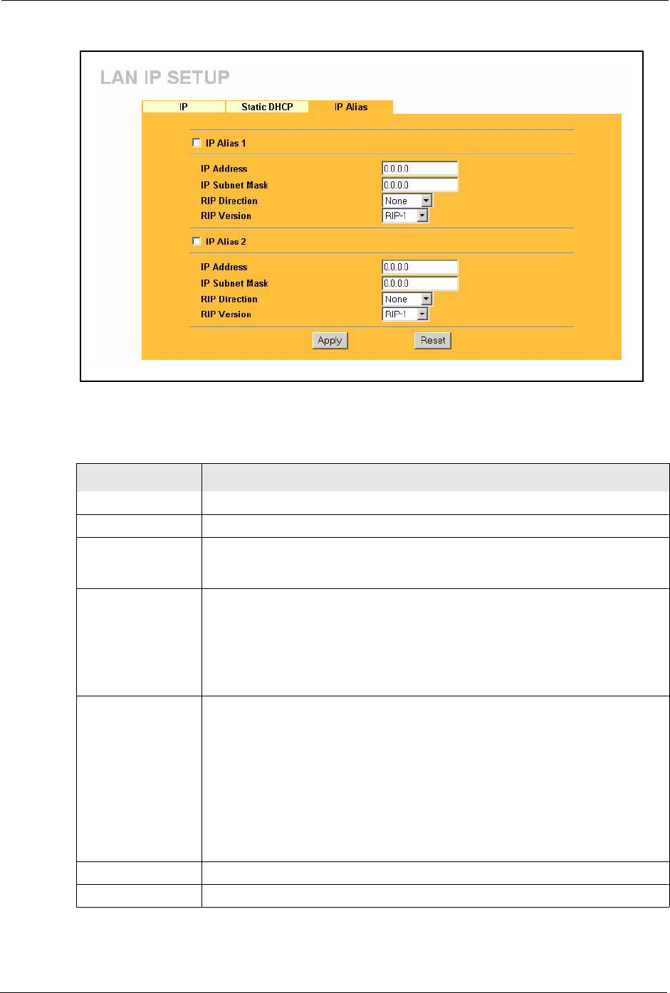
Prestige 334 User’s Guide
71 Chapter 5 LAN Screens
Figure 17 IP Alias
The following table describes the labels in this screen.
Table 14 IP Alias
LABEL DESCRIPTION
IP Alias 1,2 Select the check box to configure another LAN network for the Prestige.
IP Address Enter the IP address of your Prestige in dotted decimal notation.
IP Subnet Mask Your Prestige will automatically calculate the subnet mask based on the IP
address that you assign. Unless you are implementing subnetting, use the subnet
mask computed by the Prestige.
RIP Direction RIP (Routing Information Protocol, RFC1058 and RFC 1389) allows a router to
exchange routing information with other routers. The RIP Direction field controls
the sending and receiving of RIP packets. Select the RIP direction from Both/In
Only/Out Only/None. When set to Both or Out Only, the Prestige will broadcast
its routing table periodically. When set to Both or In Only, it will incorporate the
RIP information that it receives; when set to None, it will not send any RIP
packets and will ignore any RIP packets received.
RIP Version The RIP Version field controls the format and the broadcasting method of the
RIP packets that the Prestige sends (it recognizes both formats when receiving).
RIP-1 is universally supported but RIP-2 carries more information. RIP-1 is
probably adequate for most networks, unless you have an unusual network
topology. Both RIP-2B and RIP-2M sends the routing data in RIP-2 format; the
difference being that RIP-2B uses subnet broadcasting while RIP-2M uses
multicasting. Multicasting can reduce the load on non-router machines since they
generally do not listen to the RIP multicast address and so will not receive the RIP
packets. However, if one router uses multicasting, then all routers on your
network must use multicasting, also. By default, RIP direction is set to Both and
the Version set to RIP-1.
Apply Click Apply to save your changes back to the Prestige.
Reset Click Reset to begin configuring this screen afresh.

Prestige 334 User’s Guide
Chapter 6 WAN Screens 72
CHAPTER 6
WAN Screens
This chapter describes how to configure WAN settings.
6.1 WAN Overview
See the Wizard Setup chapter for more information on the fields in the WAN screens.
6.2 TCP/IP Priority (Metric)
The metric represents the "cost of transmission". A router determines the best route for
transmission by choosing a path with the lowest "cost". RIP routing uses hop count as the
measurement of cost, with a minimum of "1" for directly connected networks. The number
must be between "1" and "15"; a number greater than "15" means the link is down. The
smaller the number, the lower the "cost".
The metric sets the priority for the Prestige’s routes to the Internet. If the routes have the same
metric, the Prestige uses the following pre-defined priorities:
1WAN : designated by the ISP or a static route (see the IP Static Route Setup chapter)
2Traffic Redirect (see the Configuring Traffic Redirect section )
For example, if WA N has a metric of "1" and Traffic Redirect has a metric of "2", the WA N
connection acts as the primary default route. If the WA N route fails to connect to the Internet,
the Prestige tries Traffic Redirect next.
6.3 Configuring Route
Click WA N to open the Route screen.
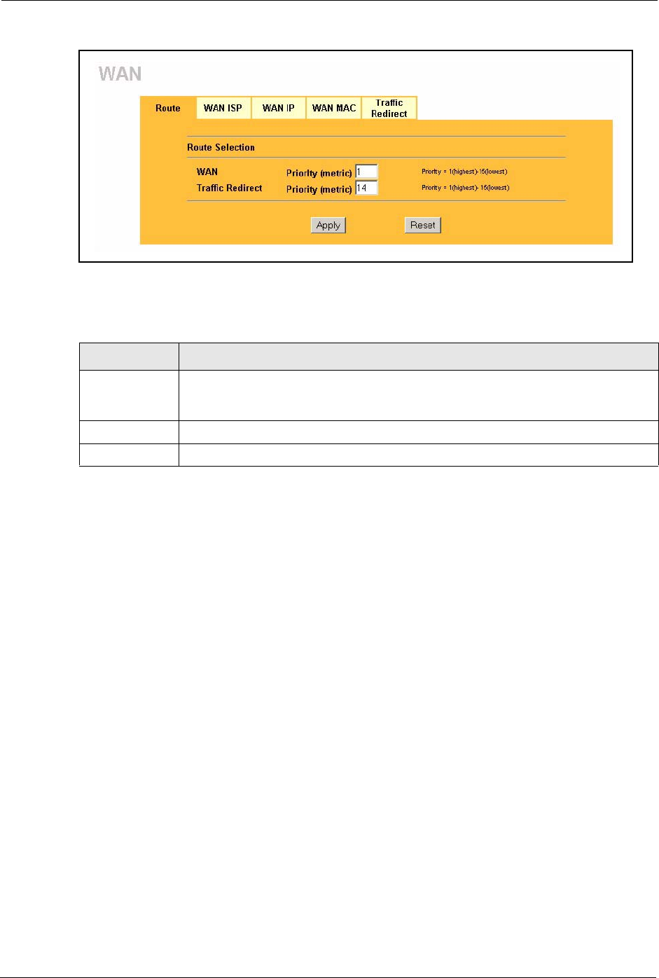
Prestige 334 User’s Guide
73 Chapter 6 WAN Screens
Figure 18 WAN: Route
The following table describes the labels in this screen.
6.4 Configuring WAN ISP
To change your Prestige’s WAN ISP settings, click WA N , then the WAN I S P tab. The screen
differs by the encapsulation.
6.4.1 Ethernet Encapsulation
The screen shown next is for Ethernet encapsulation.
Table 15 WAN: Route
LABEL DESCRIPTION
WAN Traffic
Redirect
The default WAN connection is "1' as your broadband connection via the WAN port
should always be your preferred method of accessing the WAN. The default priority
of the routes is WAN and then Traffic Redirect.
Apply Click Apply to save your changes back to the Prestige.
Reset Click Reset to begin configuring this screen afresh.
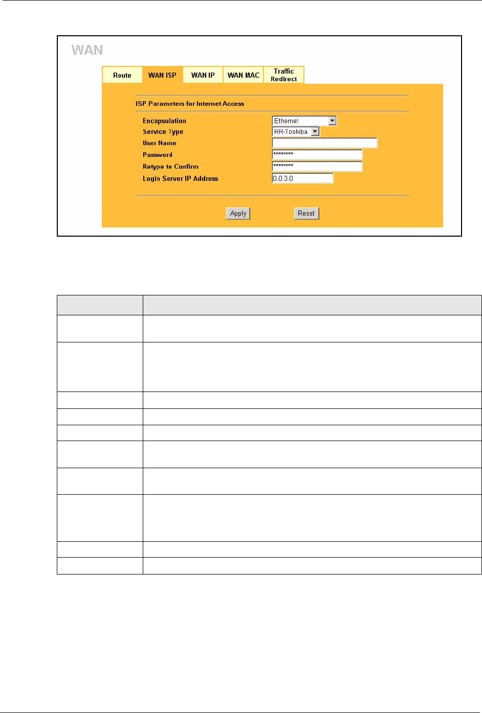
Prestige 334 User’s Guide
Chapter 6 WAN Screens 74
Figure 19 Ethernet Encapsulation
The following table describes the labels in this screen.
6.4.2 PPPoE Encapsulation
The Prestige supports PPPoE (Point-to-Point Protocol over Ethernet). PPPoE is an IETF Draft
standard (RFC 2516) specifying how a personal computer (PC) interacts with a broadband
modem (DSL, cable, wireless, etc.) connection. The PPP over Ethernet option is for a dial-
up connection using PPPoE.
Table 16 Ethernet Encapsulation
LABEL DESCRIPTION
Encapsulation You must choose the Ethernet option when the WAN port is used as a regular
Ethernet.
Service Type Choose from Standard, Telstra (RoadRunner Telstra authentication method),
RR-Manager (Roadrunner Manager authentication method), RR-Toshiba
(Roadrunner Toshiba authentication method) or Telia Login.
The following fields do not appear with the Standard service type.
User Name Type the user name given to you by your ISP.
Password Type the password associated with the user name above.
Retype to Confirm Type the password again to make sure that you have entered it correctly.
Login Server IP
Address
Type the authentication server IP address here if your ISP gave you one.
Login Server This field only applies when you select Telia Login in the Service Type field.
Type the domain name of the Telia login server, for example “login1.telia.com”.
Relogin Every(min) This field only applies when you select Telia Login in the Service Type field. The
Telia server logs the Prestige out if the Prestige does not log in periodically. Type
the number of minutes from 1 to 59 (30 default) for the Prestige to wait between
logins.
Apply Click Apply to save your changes back to the Prestige.
Reset Click Reset to begin configuring this screen afresh.

Prestige 334 User’s Guide
75 Chapter 6 WAN Screens
For the service provider, PPPoE offers an access and authentication method that works with
existing access control systems (for example Radius). PPPoE provides a login and
authentication method that the existing Microsoft Dial-Up Networking software can activate,
and therefore requires no new learning or procedures for Windows users.
One of the benefits of PPPoE is the ability to let you access one of multiple network services,
a function known as dynamic service selection. This enables the service provider to easily
create and offer new IP services for individuals.
Operationally, PPPoE saves significant effort for both you and the ISP or carrier, as it requires
no specific configuration of the broadband modem at the customer site.
By implementing PPPoE directly on the Prestige (rather than individual computers), the
computers on the LAN do not need PPPoE software installed, since the Prestige does that part
of the task. Furthermore, with NAT, all of the LANs’ computers will have access.
The screen shown next is for PPPoE encapsulation.
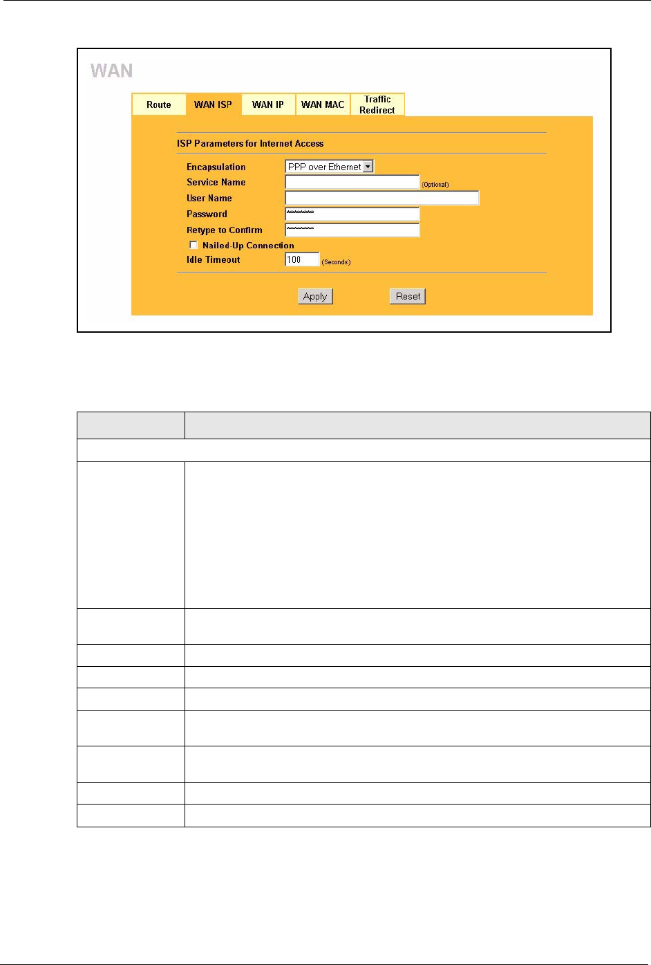
Prestige 334 User’s Guide
Chapter 6 WAN Screens 76
Figure 20 PPPoE Encapsulation
The following table describes the labels in this screen.
Table 17 PPPoE Encapsulation
LABEL DESCRIPTION
ISP Parameters for Internet Access
Encapsulation The PPP over Ethernet choice is for a dial-up connection using PPPoE. The
Prestige supports PPPoE (Point-to-Point Protocol over Ethernet). PPPoE is an
IETF Draft standard (RFC 2516) specifying how a personal computer (PC) interacts
with a broadband modem (i.e. xDSL, cable, wireless, etc.) connection.
Operationally, PPPoE saves significant effort for both the end user and ISP/carrier,
as it requires no specific configuration of the broadband modem at the customer
site. By implementing PPPoE directly on the router rather than individual
computers, the computers on the LAN do not need PPPoE software installed, since
the router does that part of the task. Further, with NAT, all of the LAN's computers
will have access.
Service Name Type the PPPoE service name provided to you. PPPoE uses a service name to
identify and reach the PPPoE server.
User Name Type the User Name given to you by your ISP.
Password Type the password associated with the User Name above.
Retype to Confirm Type your password again to make sure that you have entered is correctly.
Nailed-Up
Connection
Select Nailed-Up Connection if you do not want the connection to time out.
Idle Timeout This value specifies the time in seconds that elapses before the router automatically
disconnects from the PPPoE server.
Apply Click Apply to save your changes back to the Prestige.
Reset Click Reset to begin configuring this screen afresh.
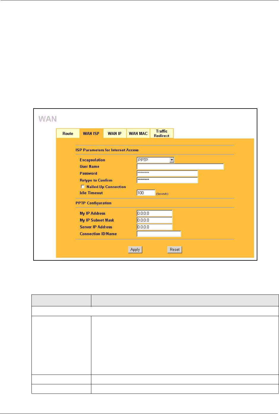
Prestige 334 User’s Guide
77 Chapter 6 WAN Screens
6.4.3 PPTP Encapsulation
Point-to-Point Tunneling Protocol (PPTP) is a network protocol that enables secure transfer of
data from a remote client to a private server, creating a Virtual Private Network (VPN) using
TCP/IP-based networks.
PPTP supports on-demand, multi-protocol and virtual private networking over public
networks, such as the Internet.
The screen shown next is for PPTP encapsulation.
Figure 21 PPTP Encapsulation
The following table describes the labels in this screen.
Table 18 PPTP Encapsulation
LABEL DESCRIPTION
ISP Parameters for Internet Access
Encapsulation Point-to-Point Tunneling Protocol (PPTP) is a network protocol that enables
secure transfer of data from a remote client to a private server, creating a
Virtual Private Network (VPN) using TCP/IP-based networks. PPTP supports
on-demand, multi-protocol, and virtual private networking over public
networks, such as the Internet. The Prestige supports only one PPTP server
connection at any given time.
To configure a PPTP client, you must configure the User Name and
Password fields for a PPP connection and the PPTP parameters for a PPTP
connection.
User Name Type the user name given to you by your ISP.
Password Type the password associated with the User Name above.

Prestige 334 User’s Guide
Chapter 6 WAN Screens 78
6.5 Configuring WAN IP
To change your Prestige’s WAN IP settings, click WA N , then the WA N I P tab. This screen
varies according to the type of encapsulation you select.
If your ISP did not assign you a fixed IP address, click Get automatically from ISP
(Default);otherwise click Use fixed IP Address and enter the IP address in the field provided.
Retype to Confirm Type your password again to make sure that you have entered is correctly.
Nailed-up Connection Select Nailed-Up Connection if you do not want the connection to time out.
Idle Timeout This value specifies the time in seconds that elapses before the Prestige
automatically disconnects from the PPTP server.
PPTP Configuration
My IP Address Type the (static) IP address assigned to you by your ISP.
My IP Subnet Mask Your Prestige will automatically calculate the subnet mask based on the IP
address that you assign. Unless you are implementing subnetting, use the
subnet mask computed by the Prestige.
Server IP Address Type the IP address of the PPTP server.
Connection ID/Name Type your identification name for the PPTP server.
Apply Click Apply to save your changes back to the Prestige.
Reset Click Reset to begin configuring this screen afresh.
Table 18 PPTP Encapsulation
LABEL DESCRIPTION
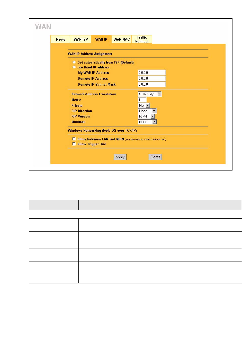
Prestige 334 User’s Guide
79 Chapter 6 WAN Screens
Figure 22 WAN: IP
The following table describes the labels in this screen.
Table 19 WAN: IP
LABEL DESCRIPTION
WAN IP Address Assignment
Get automatically from
ISP
Select this option If your ISP did not assign you a fixed IP address. This is the
default selection.
Use fixed IP address Select this option If the ISP assigned a fixed IP address.
My WAN IP Address Enter your WAN IP address in this field if you selected Use Fixed IP Address.
My WAN IP Subnet
Mask (Ethernet only)
Type your network's IP subnet Mask.
Remote IP Address Enter the Remote IP Address (if your ISP gave you one) in this field.
Gateway/Remote IP
Address
Enter the gateway IP address (if your ISP gave you one) in this field if you
selected Use Fixed IP Address.

Prestige 334 User’s Guide
Chapter 6 WAN Screens 80
Network Address
Translation
Network Address Translation (NAT) allows the translation of an Internet
protocol address used within one network (for example a private IP address
used in a local network) to a different IP address known within another network
(for example a public IP address used on the Internet).
Choose None to disable NAT.
Choose SUA Only if you have a single public IP address. SUA (Single User
Account) is a subset of NAT that supports two types of mapping: Many-to-One
and Server.
Choose Full Feature if you have multiple public IP addresses. Full Feature
mapping types include: One-to-One, Many-to-One (SUA/PAT), Many-to-
Many Overload, Many- One-to-One and Server. When you select Full
Feature you must configure at least one address mapping set!
For more information about NAT refer to the NAT chapter in this User's Guide.
Metric (PPPoE and
PPTP only)
This field sets this route's priority among the routes the Prestige uses.
The metric represents the "cost of transmission". A router determines the best
route for transmission by choosing a path with the lowest "cost". RIP routing
uses hop count as the measurement of cost, with a minimum of "1" for directly
connected networks. The number must be between "1" and "15"; a number
greater than "15" means the link is down. The smaller the number, the lower
the "cost".
Private (PPPoE and
PPTP only)
This parameter determines if the Prestige will include the route to this remote
node in its RIP broadcasts. If set to Yes, this route is kept private and not
included in RIP broadcast. If No, the route to this remote node will be
propagated to other hosts through RIP broadcasts.
RIP Direction RIP (Routing Information Protocol) allows a router to exchange routing
information with other routers. The RIP Direction field controls the sending
and receiving of RIP packets.
Choose Both, None, In Only or Out Only.
When set to Both or Out Only, the Prestige will broadcast its routing table
periodically.
When set to Both or In Only, the Prestige will incorporate RIP information that
it receives.
When set to None, the Prestige will not send any RIP packets and will ignore
any RIP packets received.
By default, RIP Direction is set to Both.
RIP Version The RIP Version field controls the format and the broadcasting method of the
RIP packets that the Prestige sends (it recognizes both formats when
receiving).
Choose RIP-1, RIP-2B or RIP-2M.
RIP-1 is universally supported; but RIP-2 carries more information. RIP-1 is
probably adequate for most networks, unless you have an unusual network
topology. Both RIP-2B and RIP-2M sends the routing data in RIP-2 format; the
difference being that RIP-2B uses subnet broadcasting while RIP-2M uses
multicasting. Multicasting can reduce the load on non-router machines since
they generally do not listen to the RIP multicast address and so will not receive
the RIP packets. However, if one router uses multicasting, then all routers on
your network must use multicasting, also. By default, the RIP Version field is
set to RIP-1.
Table 19 WAN: IP
LABEL DESCRIPTION

Prestige 334 User’s Guide
81 Chapter 6 WAN Screens
6.6 Configuring WAN MAC
To change your Prestige’s WAN MAC settings, click WA N , then the WAN MAC tab. The
screen appears as shown.
Figure 23 MAC Setup
The MAC address screen allows users to configure the WAN port's MAC address by either
using the factory default or cloning the MAC address from a computer on your LAN. Choose
Factory Default to select the factory assigned default MAC Address.
Multicast Choose None (default), IGMP-V1 or IGMP-V2. IGMP (Internet Group Multicast
Protocol) is a network-layer protocol used to establish membership in a
Multicast group - it is not used to carry user data. IGMP version 2 (RFC 2236)
is an improvement over version 1 (RFC 1112) but IGMP version 1 is still in
wide use. If you would like to read more detailed information about
interoperability between IGMP version 2 and version 1, please see sections 4
and 5 of RFC 2236.
Windows Networking (NetBIOS over TCP/IP):
NetBIOS (Network Basic Input/Output System) are TCP or UDP broadcast packets that enable a
computer to connect to and communicate with a LAN. For some dial-up services such as PPPoE or
PPTP, NetBIOS packets cause unwanted calls. However it may sometimes be necessary to allow
NetBIOS packets to pass through to the WAN in order to find a computer on the WAN.
Allow between WAN
and LAN
Select this check box to forward NetBIOS packets from the LAN to the WAN
and from the WAN to the LAN. If your firewall is enabled with the default policy
set to block WAN to LAN traffic, you also need to enable the default WAN to
LAN firewall rule that forwards NetBIOS traffic.
Clear this check box to block all NetBIOS packets going from the LAN to the
WAN and from the WAN to the LAN.
Allow Trigger Dial Select this option to allow NetBIOS packets to initiate calls.
Apply Click Apply to save your changes back to the Prestige.
Reset Click Reset to begin configuring this screen afresh.
Table 19 WAN: IP
LABEL DESCRIPTION
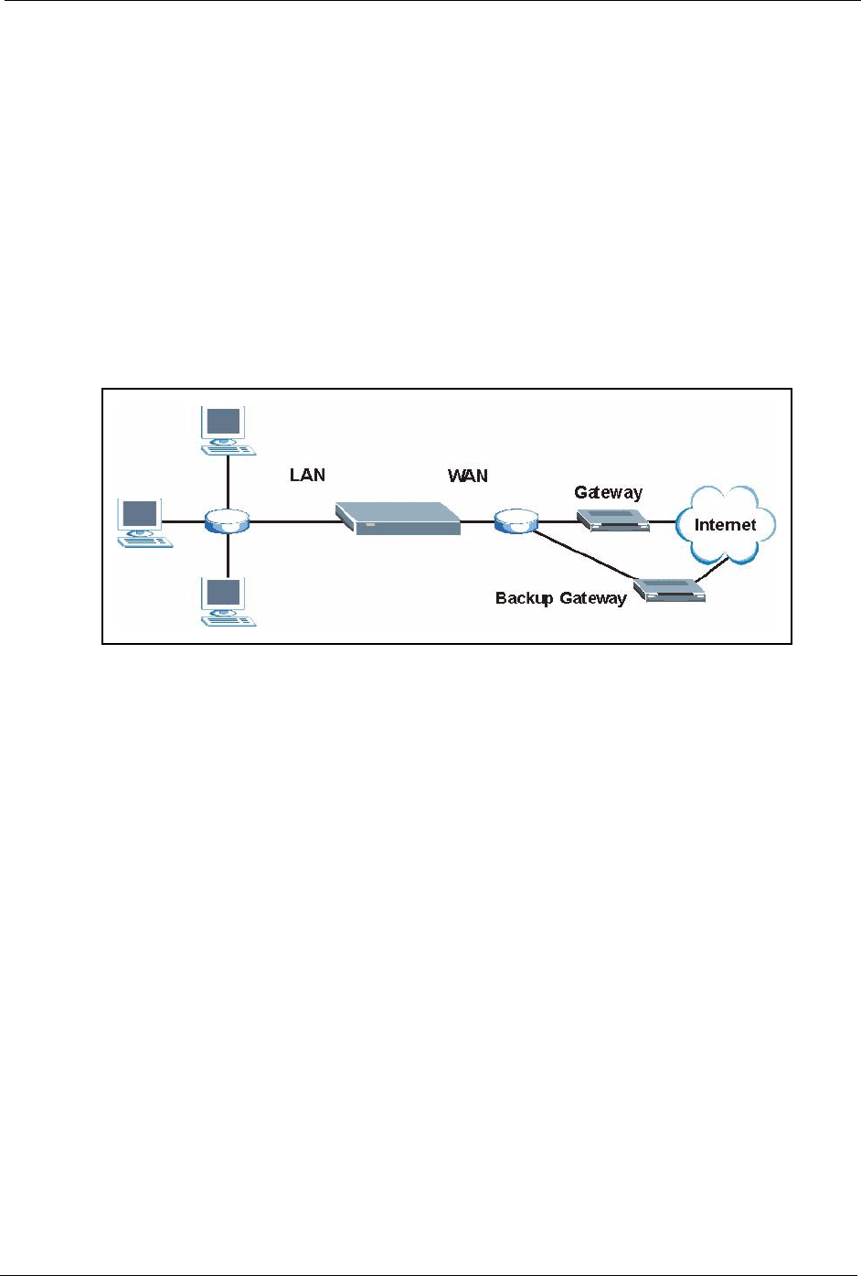
Prestige 334 User’s Guide
Chapter 6 WAN Screens 82
Otherwise, click Spoof this computer's MAC address - IP Address and enter the IP address
of the computer on the LAN whose MAC you are cloning. Once it is successfully configured,
the address will be copied to the rom file (ZyNOS configuration file). It will not change unless
you change the setting or upload a different ROM file. It is recommended that you clone the MAC
address prior to hooking up the WAN Port.
6.7 Traffic Redirect
Traffic redirect forwards WAN traffic to a backup gateway when the Prestige cannot connect
to the Internet through its normal gateway. Connect the backup gateway on the WAN so that
the Prestige still provides firewall protection.
Figure 24 Traffic Redirect WAN Setup
The following network topology allows you to avoid triangle route security issues (see the
Appendices) when the backup gateway is connected to the LAN. Use IP alias to configure the
LAN into two or three logical networks with the Prestige itself as the gateway for each LAN
network. Put the protected LAN in one subnet (Subnet 1 in the following figure) and the
backup gateway in another subnet (Subnet 2). Configure a LAN to LAN/Prestige firewall rule
that forwards packets from the protected LAN (Subnet 1) to the backup gateway (Subnet 2).

Prestige 334 User’s Guide
83 Chapter 6 WAN Screens
Figure 25 Traffic Redirect LAN Setup
6.8 Configuring Traffic Redirect
To change your Prestige’s Traffic Redirect settings, click WA N , then the Traffic Redirect
tab. The screen appears as shown.
Figure 26 WAN: Traffic Redirect
The following table describes the labels in this screen.
Table 20 Traffic Redirect
LABEL DESCRIPTION
Active Select this check box to have the Prestige use traffic redirect if the normal WAN
connection goes down.
Backup
Gateway IP
Address
Type the IP address of your backup gateway in dotted decimal notation. The Prestige
automatically forwards traffic to this IP address if the Prestige's Internet connection
terminates.

Prestige 334 User’s Guide
Chapter 6 WAN Screens 84
Metric This field sets this route's priority among the routes the Prestige uses.
The metric represents the "cost of transmission". A router determines the best route
for transmission by choosing a path with the lowest "cost". RIP routing uses hop count
as the measurement of cost, with a minimum of "1" for directly connected networks.
The number must be between "1" and "15"; a number greater than "15" means the link
is down. The smaller the number, the lower the "cost".
Check WAN IP
Address
Configuration of this field is optional. If you do not enter an IP address here, the
Prestige will use the default gateway IP address. Configure this field to test your
Prestige's WAN accessibility. Type the IP address of a reliable nearby computer (for
example, your ISP's DNS server address). If you are using PPTP or PPPoE
Encapsulation, type "0.0.0.0" to configure the Prestige to check the PVC (Permanent
Virtual Circuit) or PPTP tunnel.
Fail Tolerance Type the number of times your Prestige may attempt and fail to connect to the Internet
before traffic is forwarded to the backup gateway.
Period
(seconds)
Type the number of seconds for the Prestige to wait between checks to see if it can
connect to the WAN IP address (Check WAN IP Address field) or default gateway.
Allow more time if your destination IP address handles lots of traffic.
Timeout
(seconds)
Type the number of seconds for your Prestige to wait for a ping response from the IP
Address in the Check WAN IP Address field before it times out. The WAN connection
is considered "down" after the Prestige times out the number of times specified in the
Fail Tolerance field. Use a higher value in this field if your network is busy or
congested.
Apply Click Apply to save your changes back to the Prestige.
Reset Click Reset to begin configuring this screen afresh.
Table 20 Traffic Redirect
LABEL DESCRIPTION

Prestige 334 User’s Guide
85 Chapter 6 WAN Screens

Prestige 334 User’s Guide
Chapter 7 Network Address Translation (NAT) Screens 86
CHAPTER 7
Network Address Translation
(NAT) Screens
This chapter discusses how to configure NAT on the Prestige.
7.1 NAT Overview
NAT (Network Address Translation - NAT, RFC 1631) is the translation of the IP address of a
host in a packet. For example, the source address of an outgoing packet, used within one
network is changed to a different IP address known within another network.
7.1.1 NAT Definitions
Inside/outside denotes where a host is located relative to the Prestige. For example, the
computers of your subscribers are the inside hosts, while the web servers on the Internet are
the outside hosts.
Global/local denotes the IP address of a host in a packet as the packet traverses a router. For
example, the local address refers to the IP address of a host when the packet is in the local
network, while the global address refers to the IP address of the host when the same packet is
traveling in the WAN side.
Note that inside/outside refers to the location of a host, while global/local refers to the IP
address of a host used in a packet. Thus, an inside local address (ILA) is the IP address of an
inside host in a packet when the packet is still in the local network, while an inside global
address (IGA) is the IP address of the same inside host when the packet is on the WAN side.
The following table summarizes this information.
Table 21 NAT Definitions
TERM DESCRIPTION
Inside This refers to the host on the LAN.
Outside This refers to the host on the WAN.
Local This refers to the packet address (source or destination) as the packet travels on the LAN.
Global This refers to the packet address (source or destination) as the packet travels on the
WAN.

Prestige 334 User’s Guide
87 Chapter 7 Network Address Translation (NAT) Screens
7.1.2 What NAT Does
In the simplest form, NAT changes the source IP address in a packet received from a
subscriber (the inside local address) to another (the inside global address) before forwarding
the packet to the WAN side. When the response comes back, NAT translates the destination
address (the inside global address) back to the inside local address before forwarding it to the
original inside host. Note that the IP address (either local or global) of an outside host is never
changed.
The global IP addresses for the inside hosts can be either static or dynamically assigned by the
ISP. In addition, you can designate servers (for example a web server and a telnet server) on
your local network and make them accessible to the outside world. If you do not define any
servers (for Many-to-One and Many-to-Many Overload mapping), NAT offers the additional
benefit of firewall protection. With no servers defined, your Prestige filters out all incoming
inquiries, thus preventing intruders from probing your network. For more information on IP
address translation, refer to RFC 1631, The IP Network Address Translator (NAT).
7.1.3 How NAT Works
Each packet has two addresses – a source address and a destination address. For outgoing
packets, the ILA (Inside Local Address) is the source address on the LAN, and the IGA (Inside
Global Address) is the source address on the WAN. For incoming packets, the ILA is the
destination address on the LAN, and the IGA is the destination address on the WAN. NAT
maps private (local) IP addresses to globally unique ones required for communication with
hosts on other networks. It replaces the original IP source address (and TCP or UDP source
port numbers for Many-to-One and Many-to-Many Overload NAT mapping) in each packet
and then forwards it to the Internet. The Prestige keeps track of the original addresses and port
numbers so incoming reply packets can have their original values restored. The following
figure illustrates this.
Note: NAT never changes the IP address (either local or global)
of an outside host.
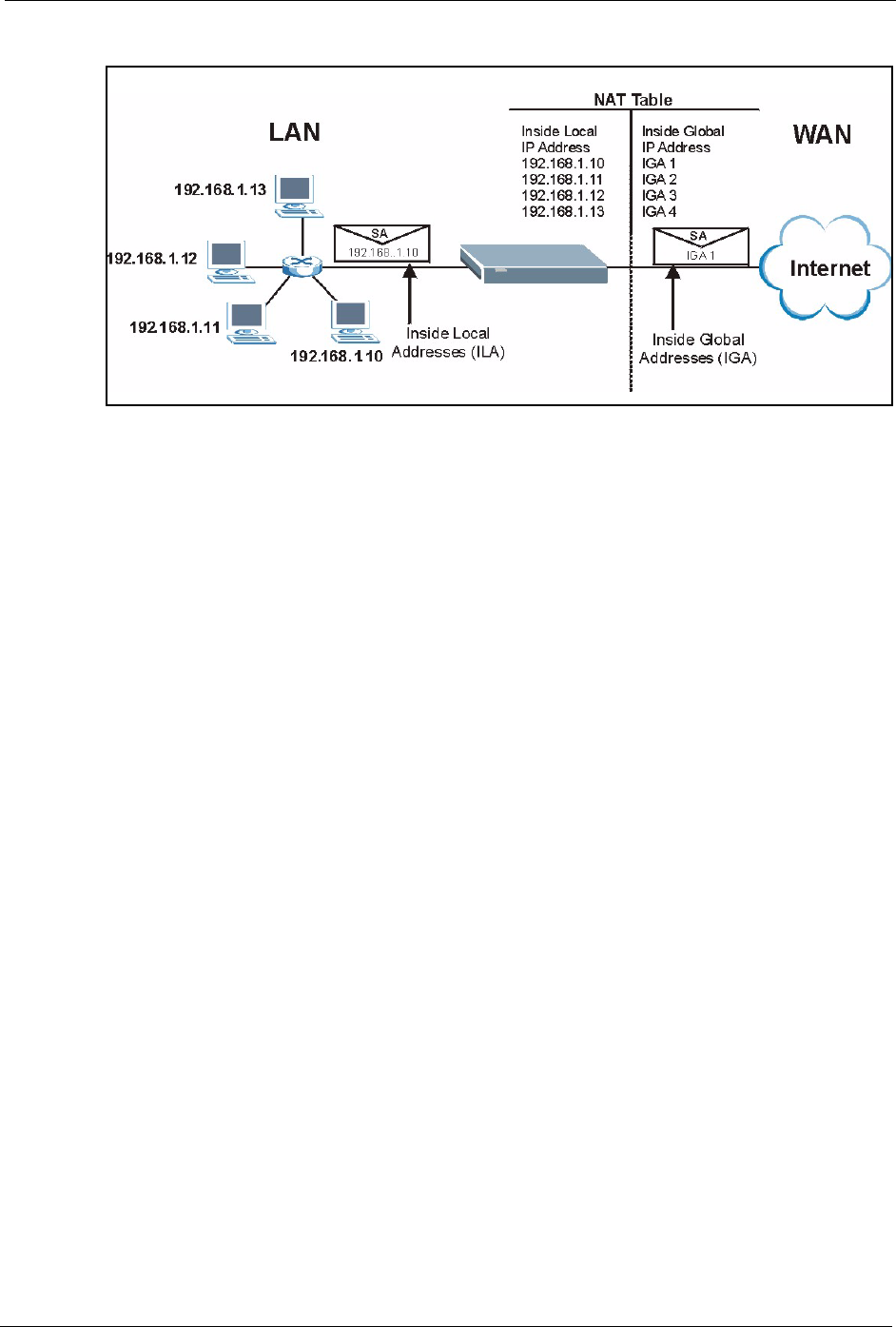
Prestige 334 User’s Guide
Chapter 7 Network Address Translation (NAT) Screens 88
Figure 27 How NAT Works
7.1.4 NAT Application
The following figure illustrates a possible NAT application, where three inside LANs (logical
LANs using IP Alias) behind the Prestige can communicate with three distinct WAN
networks. More examples follow at the end of this chapter.
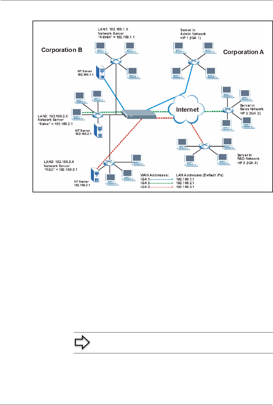
Prestige 334 User’s Guide
89 Chapter 7 Network Address Translation (NAT) Screens
Figure 28 NAT Application With IP Alias
7.1.5 NAT Mapping Types
NAT supports five types of IP/port mapping. They are:
•One to One: In One-to-One mode, the Prestige maps one local IP address to one global
IP address.
•Many to One: In Many-to-One mode, the Prestige maps multiple local IP addresses to
one global IP address. This is equivalent to SUA (i.e., PAT, port address translation),
ZyXEL’s Single User Account feature (the SUA Only option).
•Many-to-Many Overload: In Many-to-Many Overload mode, the Prestige maps the
multiple local IP addresses to shared global IP addresses.
•Many One-to-One: In Many-One-to-One mode, the Prestige maps each local IP address
to a unique global IP address.
•Server: This type allows you to specify inside servers of different services behind the
NAT to be accessible to the outside world.
Note: Port numbers do not change for One-to-One and Many
One-to-One NAT mapping types.
Prestige 334 User’s Guide
Chapter 7 Network Address Translation (NAT) Screens 90
The following table summarizes these types.
7.2 Using NAT
7.2.1 SUA (Single User Account) Versus NAT
SUA (Single User Account) is a ZyNOS implementation of a subset of NAT that supports two
types of mapping, Many-to-One and Server. The Prestige also supports Full Feature NAT to
map multiple global IP addresses to multiple private LAN IP addresses of clients or servers
using mapping types. Select either SUA Only or Full Feature in the WAN IP screen.
7.3 SUA Server
A SUA server set is a list of inside (behind NAT on the LAN) servers, for example, web or
FTP, that you can make visible to the outside world even though SUA makes your whole
inside network appear as a single computer to the outside world.
Table 22 NAT Mapping Types
TYPE IP MAPPING SMT ABBREVIATION
One-to-One ILA1ÅÆ IGA1 1-1
Many-to-One (SUA/PAT) ILA1ÅÆ IGA1
ILA2ÅÆ IGA1
…
M-1
Many-to-Many Overload ILA1ÅÆ IGA1
ILA2ÅÆ IGA2
ILA3ÅÆ IGA1
ILA4ÅÆ IGA2
…
M-M Ov
Many One-to-One ILA1ÅÆ IGA1
ILA2ÅÆ IGA2
ILA3ÅÆ IGA3
…
M-1-1
Server Server 1 IPÅÆ IGA1
Server 2 IPÅÆ IGA1
Server 3 IPÅÆ IGA1
Server
Note: You must create a firewall rule in addition to setting up
SUA/NAT, to allow traffic from the WAN to be forwarded
through the Prestige.
Prestige 334 User’s Guide
91 Chapter 7 Network Address Translation (NAT) Screens
You may enter a single port number or a range of port numbers to be forwarded, and the local
IP address of the desired server. The port number identifies a service; for example, web
service is on port 80 and FTP on port 21. In some cases, such as for unknown services or
where one server can support more than one service (for example both FTP and web service),
it might be better to specify a range of port numbers. You can allocate a server IP address that
corresponds to a port or a range of ports.
Many residential broadband ISP accounts do not allow you to run any server processes (such
as a Web or FTP server) from your location. Your ISP may periodically check for servers and
may suspend your account if it discovers any active services at your location. If you are
unsure, refer to your ISP.
7.3.1 Default Server IP Address
In addition to the servers for specified services, NAT supports a default server IP address. A
default server receives packets from ports that are not specified in this screen
7.3.2 Port Forwarding: Services and Port Numbers
A NAT server set is a list of inside (behind NAT on the LAN) servers, for example, web or
FTP, that you can make accessible to the outside world even though NAT makes your whole
inside network appear as a single machine to the outside world.
Use the SUA Server page to forward incoming service requests to the server(s) on your local
network. You may enter a single port number or a range of port numbers to be forwarded, and
the local IP address of the desired server. The port number identifies a service; for example,
web service is on port 80 and FTP on port 21. In some cases, such as for unknown services or
where one server can support more than one service (for example both FTP and web service),
it might be better to specify a range of port numbers.
In addition to the servers for specified services, NAT supports a default server. A service
request that does not have a server explicitly designated for it is forwarded to the default
server. If the default is not defined, the service request is simply discarded.
Note: If you do not assign a Default Server IP Address, the
Prestige discards all packets received for ports that are not
specified in this screen or remote management.
Note: Many residential broadband ISP accounts do not allow
you to run any server processes (such as a Web or FTP server)
from your location. Your ISP may periodically check for servers
and may suspend your account if it discovers any active
services at your location. If you are unsure, refer to your ISP.

Prestige 334 User’s Guide
Chapter 7 Network Address Translation (NAT) Screens 92
The most often used port numbers are shown in the following table. Please refer to RFC 1700
for further information about port numbers. Please also refer to the Supporting CD for more
examples and details on SUA/NAT.
7.3.3 Configuring Servers Behind SUA (Example)
Let's say you want to assign ports 21-25 to one FTP, Telnet and SMTP server (A in the
example), port 80 to another (B in the example) and assign a default server IP address of
192.168.1.35 to a third (C in the example). You assign the LAN IP addresses and the ISP
assigns the WAN IP address. The NAT network appears as a single host on the Internet
Table 23 Services and Port Numbers
SERVICES PORT NUMBER
ECHO 7
FTP (File Transfer Protocol) 21
SMTP (Simple Mail Transfer Protocol) 25
DNS (Domain Name System) 53
Finger 79
HTTP (Hyper Text Transfer protocol or WWW, Web) 80
POP3 (Post Office Protocol) 110
NNTP (Network News Transport Protocol) 119
SNMP (Simple Network Management Protocol) 161
SNMP trap 162
PPTP (Point-to-Point Tunneling Protocol) 1723
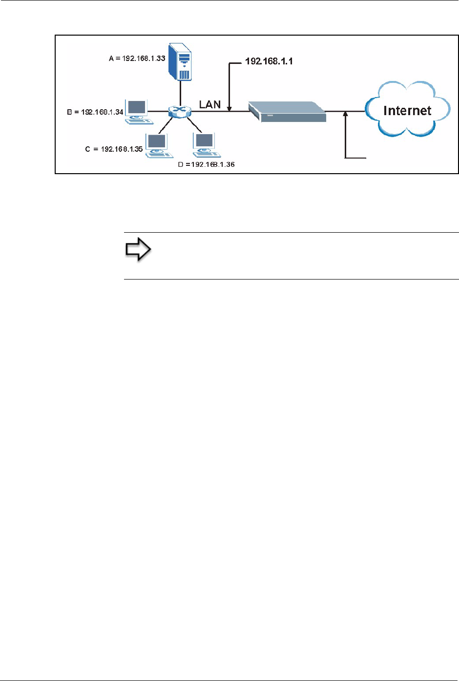
Prestige 334 User’s Guide
93 Chapter 7 Network Address Translation (NAT) Screens
Figure 29 Multiple Servers Behind NAT Example
7.4 Configuring SUA Server
Click SUA/NAT to open the SUA Server screen.
Refer to Table 23 for port numbers commonly used for particular services.
Note: If you do not assign a Default Server IP Address, the
Prestige discards all packets received for ports that are not
specified in this screen or remote management.
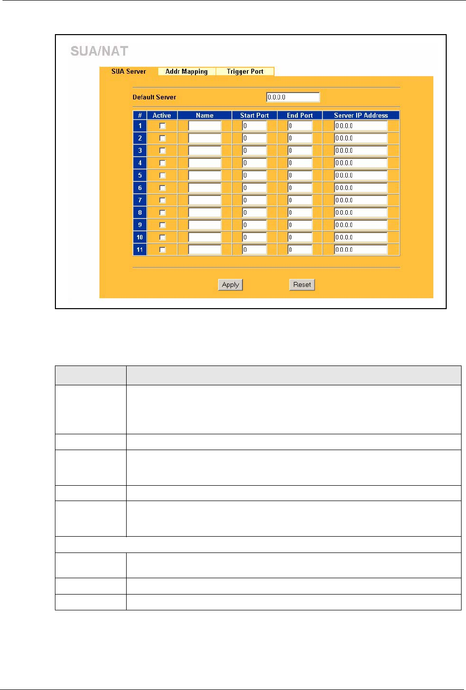
Prestige 334 User’s Guide
Chapter 7 Network Address Translation (NAT) Screens 94
Figure 30 SUA/NAT Setup
The following table describes the labels in this screen.
Table 24 SUA/NAT Setup
LABEL DESCRIPTION
Default Server In addition to the servers for specified services, NAT supports a default server. A
default server receives packets from ports that are not specified in this screen.
If you do not assign a Default Server IP Address, the Prestige discards all packets
received for ports that are not specified in this screen or remote management.
#Number of an individual SUA server entry.
Active Select this check box to enable the SUA server entry. Clear this checkbox to
disallow forwarding of these ports to an inside server without having to delete the
entry.
Name Enter a name to identify this port-forwarding rule.
Start Port Enter a port number here. To forward only one port, enter it again in the End Port
field. To specify a range of ports, enter the last port to be forwarded in the End Port
field.
End Port
Server IP
Address
Enter the inside IP address of the server here.
Apply Click Apply to save your changes back to the Prestige.
Reset Click Reset to begin configuring this screen afresh.
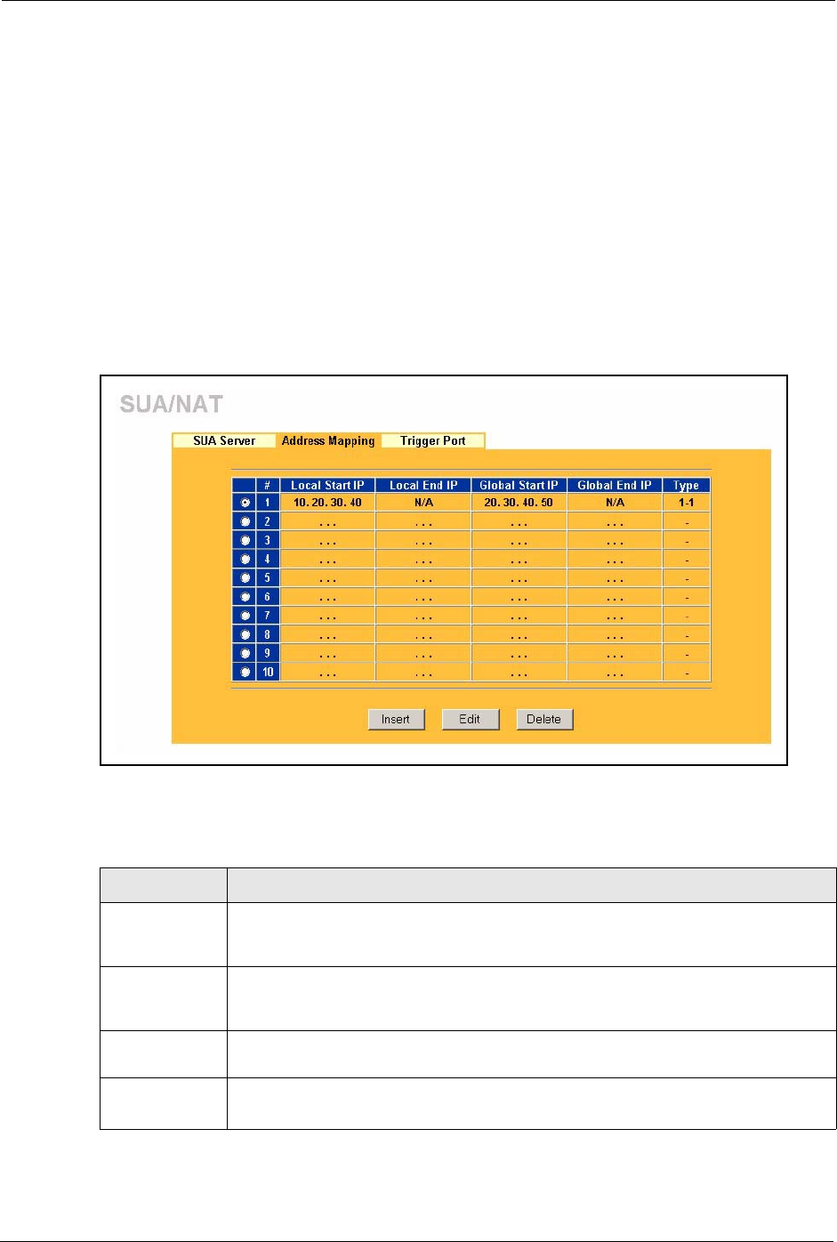
Prestige 334 User’s Guide
95 Chapter 7 Network Address Translation (NAT) Screens
7.5 Configuring Address Mapping
Ordering your rules is important because the Prestige applies the rules in the order that you
specify. When a rule matches the current packet, the Prestige takes the corresponding action
and the remaining rules are ignored. If there are any empty rules before your new configured
rule, your configured rule will be pushed up by that number of empty rules. For example, if
you have already configured rules 1 to 6 in your current set and now you configure rule
number 9. In the set summary screen, the new rule will be rule 7, not 9. Now if you delete rule
4, rules 5 to 7 will be pushed up by 1 rule, so old rules 5, 6 and 7 become new rules 4, 5 and 6.
To change your Prestige’s Address Mapping settings, click SUA/NAT, then the Address
Mapping tab. The screen appears as shown.
Figure 31 Address Mapping
The following table describes the labels in this screen.
Table 25 Address Mapping
LABEL DESCRIPTION
Local Start IP This refers to the Inside Local Address (ILA), which is the starting local IP address. If
the rule is for all local IP addresses, then this field displays 0.0.0.0 as the Local Start
IP address. Local IP addresses are N/A for Server port mapping.
Local End IP This is the end Inside Local Address (ILA). If the rule is for all local IP addresses, then
this field displays 255.255.255.255 as the Local End IP address. This field is N/A for
One-to-One and Server mapping types.
Global Start IP This refers to the Inside Global IP Address (IGA). 0.0.0.0 is for a dynamic IP address
from your ISP with Many-to-One and Server mapping types.
Global End IP This is the end Inside Global Address (IGA).
This field is N/A for One-to-One, Many-to-One and Server mapping types.

Prestige 334 User’s Guide
Chapter 7 Network Address Translation (NAT) Screens 96
7.5.1 Configuring Address Mapping
To edit an address mapping rule, select the radio button of a rule and click the Edit button to
display the screen shown next.
Type 1. One-to-One mode maps one local IP address to one global IP address. Note that
port numbers do not change for the One-to-one NAT mapping type.
2. Many-to-One mode maps multiple local IP addresses to one global IP address.
This is equivalent to SUA (i.e., PAT, port address translation), ZyXEL's Single User
Account feature that previous ZyXEL routers supported only.
3. Many-to-Many Overload mode maps multiple local IP addresses to shared global
IP addresses.
4. Many One-to-One mode maps each local IP address to unique global IP
addresses.
5. Server allows you to specify inside servers of different services behind the NAT to
be accessible to the outside world.
Insert Click Insert to insert a new mapping rule before an existing one.
Edit Click Edit to go to the Address Mapping Rule screen.
Delete Click Delete to delete an address mapping rule.
Table 25 Address Mapping
LABEL DESCRIPTION
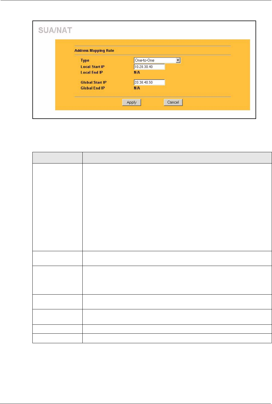
Prestige 334 User’s Guide
97 Chapter 7 Network Address Translation (NAT) Screens
Figure 32 Address Mapping Edit
The following table describes the labels in this screen.
Table 26 Address Mapping Edit
LABEL DESCRIPTION
Type Choose the port mapping type from one of the following.
1. One-to-One: One-to-one mode maps one local IP address to one global IP
address. Note that port numbers do not change for One-to-one NAT mapping
type.
2. Many-to-One: Many-to-One mode maps multiple local IP addresses to one
global IP address. This is equivalent to SUA (i.e., PAT, port address translation),
ZyXEL's Single User Account feature.
3. Many-to-Many Overload: Many-to-Many Overload mode maps multiple local
IP addresses to shared global IP addresses.
4. Many One-to-One: Many One-to-one mode maps each local IP address to
unique global IP addresses.
5. Server: This type allows you to specify inside servers of different services
behind the NAT to be accessible to the outside world.
Local Start IP This is the starting Inside Local IP Address (ILA). Local IP addresses are N/A for
Server port mapping.
Local End IP This is the end Inside Local IP Address (ILA). If your rule is for all local IP
addresses, then enter 0.0.0.0 as the Local Start IP address and
255.255.255.255 as the Local End IP address.
This field is N/A for One-to-One and Server mapping types.
Global Start IP This is the starting Inside Global IP Address (IGA). Enter 0.0.0.0 here if you have
a dynamic IP address from your ISP.
Global End IP This is the ending Inside Global IP Address (IGA). This field is N/A for One-to-
One, Many-to-One and Server mapping types.
Apply Click Apply to save your changes back to the Prestige.
Cancel Click Cancel to return to the previous screen and not save your changes.
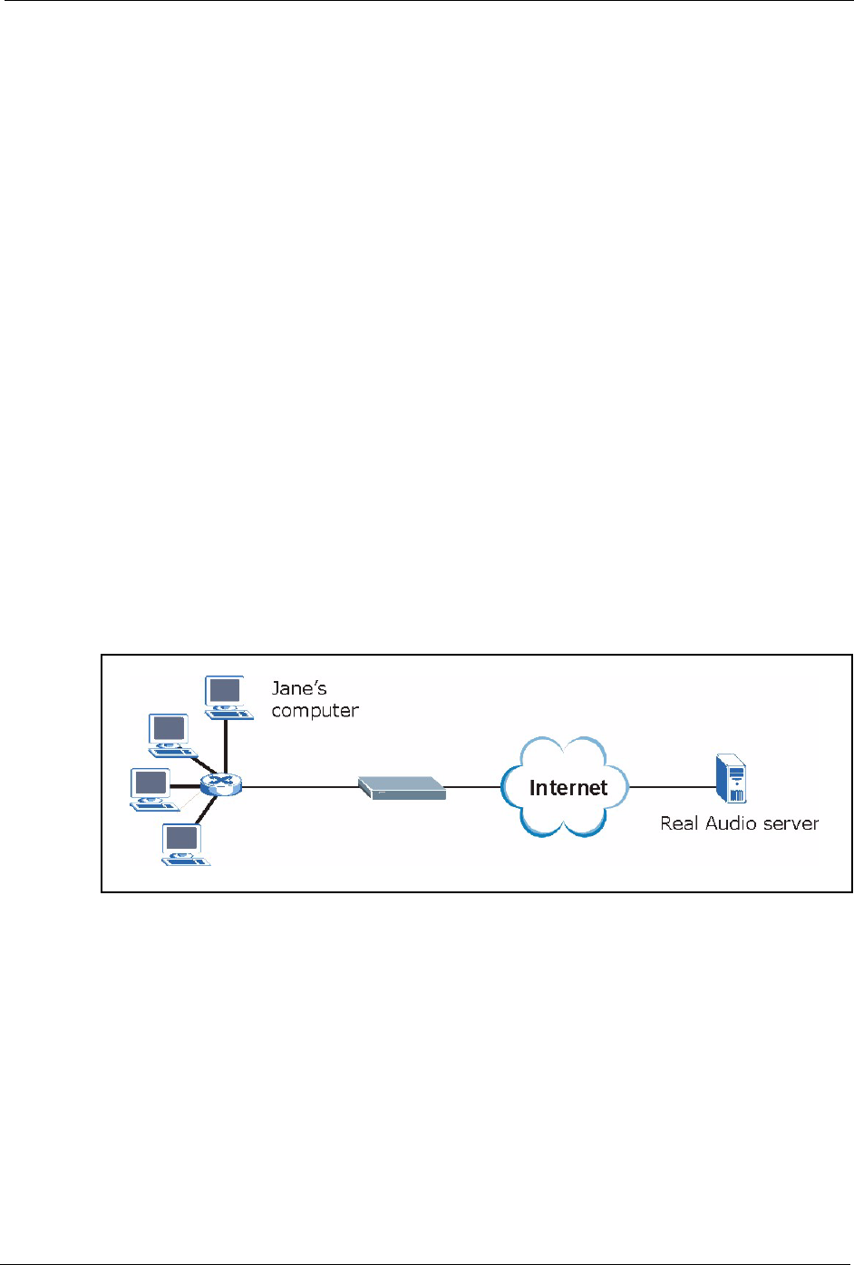
Prestige 334 User’s Guide
Chapter 7 Network Address Translation (NAT) Screens 98
7.6 Trigger Port Forwarding
Some services use a dedicated range of ports on the client side and a dedicated range of ports
on the server side. With regular port forwarding you set a forwarding port in NAT to forward a
service (coming in from the server on the WAN) to the IP address of a computer on the client
side (LAN). The problem is that port forwarding only forwards a service to a single LAN IP
address. In order to use the same service on a different LAN computer, you have to manually
replace the LAN computer's IP address in the forwarding port with another LAN computer's IP
address,
Trigger port forwarding solves this problem by allowing computers on the LAN to
dynamically take turns using the service. The Prestige records the IP address of a LAN
computer that sends traffic to the WAN to request a service with a specific port number and
protocol (a "trigger" port). When the Prestige's WAN port receives a response with a specific
port number and protocol ("incoming" port), the Prestige forwards the traffic to the LAN IP
address of the computer that sent the request. After that computer’s connection for that service
closes, another computer on the LAN can use the service in the same manner. This way you do
not need to configure a new IP address each time you want a different LAN computer to use
the application.
7.6.1 Trigger Port Forwarding Example
The following is an example of trigger port forwarding.
Figure 33 Trigger Port Forwarding Process: Example
1Jane requests a file from the Real Audio server (port 7070).
2Port 7070 is a “trigger” port and causes the Prestige to record Jane’s computer IP address.
The Prestige associates Jane's computer IP address with the "incoming" port range of
6970-7170.
3The Real Audio server responds using a port number ranging between 6970-7170.
4The Prestige forwards the traffic to Jane’s computer IP address.
5Only Jane can connect to the Real Audio server until the connection is closed or times
out. The Prestige times out in three minutes with UDP (User Datagram Protocol), or two
hours with TCP/IP (Transfer Control Protocol/Internet Protocol).

Prestige 334 User’s Guide
99 Chapter 7 Network Address Translation (NAT) Screens
7.6.2 Two Points To Remember About Trigger Ports
1Trigger events only happen on data that is going coming from inside the Prestige and
going to the outside.
2If an application needs a continuous data stream, that port (range) will be tied up so that
another computer on the LAN can’t trigger it.
7.7 Configuring Trigger Port Forwarding
To change your Prestige’s trigger port settings, click SUA/NAT and the Trigger Port tab. The
screen appears as shown.
Figure 34 Trigger Port
The following table describes the labels in this screen.
Note: Only one LAN computer can use a trigger port (range) at
a time
Table 27 Trigger Port
LABEL DESCRIPTION
#This is the rule index number (read-only).
Name Type a unique name (up to 15 characters) for identification purposes. All characters
are permitted - including spaces.

Prestige 334 User’s Guide
Chapter 7 Network Address Translation (NAT) Screens 100
Incoming Incoming is a port (or a range of ports) that a server on the WAN uses when it sends
out a particular service. The Prestige forwards the traffic with this port (or range of
ports) to the client computer on the LAN that requested the service.
Start Port Type a port number or the starting port number in a range of port numbers.
End Port Type a port number or the ending port number in a range of port numbers.
Trigger The trigger port is a port (or a range of ports) that causes (or triggers) the Prestige to
record the IP address of the LAN computer that sent the traffic to a server on the WAN.
Start Port Type a port number or the starting port number in a range of port numbers.
End Port Type a port number or the ending port number in a range of port numbers.
Apply Click Apply to save your changes back to the Prestige.
Reset Click Reset to begin configuring this screen afresh.
Table 27 Trigger Port
LABEL DESCRIPTION

Prestige 334 User’s Guide
101 Chapter 7 Network Address Translation (NAT) Screens
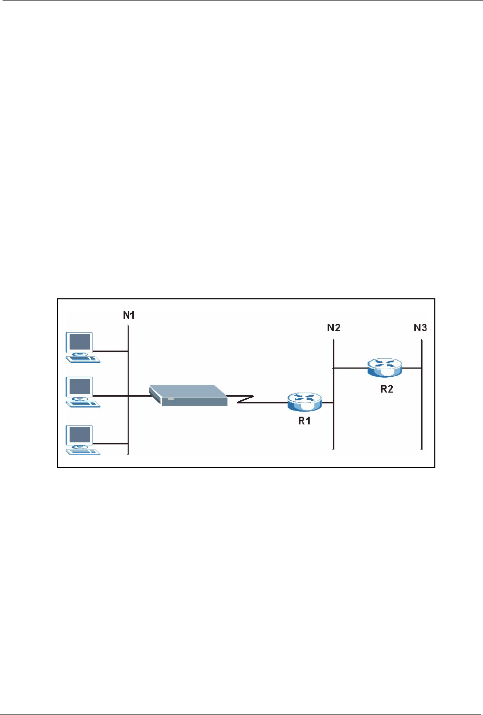
Prestige 334 User’s Guide
Chapter 8 Static Route Screens 102
CHAPTER 8
Static Route Screens
This chapter shows you how to configure static routes for your Prestige.
8.1 Static Route Overview
Each remote node specifies only the network to which the gateway is directly connected, and
the Prestige has no knowledge of the networks beyond. For instance, the Prestige knows about
network N2 in the following figure through remote node router R1. However, the Prestige is
unable to route a packet to network N3 because it doesn't know that there is a route through the
same remote node router R1 (via gateway router R2). The static routes are for you to tell the
Prestige about the networks beyond the remote nodes.
Figure 35 Example of Static Routing Topology
8.2 Configuring IP Static Route
Click STATIC ROUTE to open the screen as shown next.
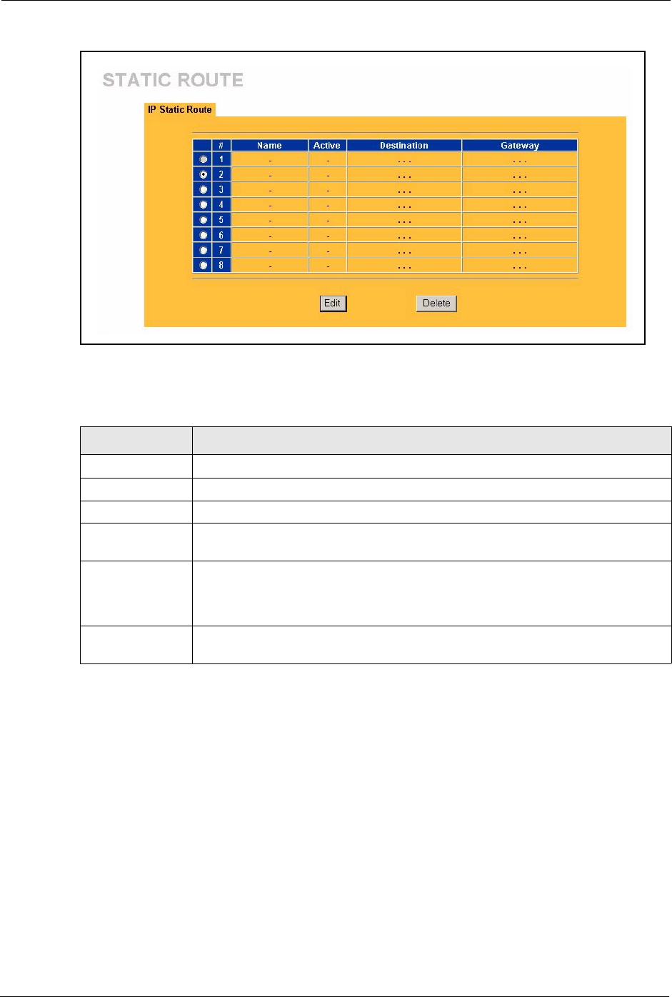
Prestige 334 User’s Guide
103 Chapter 8 Static Route Screens
Figure 36 Static Route
The following table describes the labels in this screen.
8.2.1 Configuring Route Entry
Select a static route index number and click Edit. The screen shown next appears. Fill in the
required information for each static route.
Table 28 Static Route
LABEL DESCRIPTION
#Number of an individual static route.
Name Name that describes or identifies this route.
Active This field shows whether this static route is active (Yes) or not (No).
Destination This parameter specifies the IP network address of the final destination. Routing is
always based on network number.
Gateway This is the IP address of the gateway. The gateway is an immediate neighbor of
your Prestige that will forward the packet to the destination. On the LAN, the
gateway must be a router on the same segment as your Prestige; over the WAN,
the gateway must be the IP address of one of the remote nodes.
Edit Select a static route index number and then click Edit to set up a static route on the
Prestige.
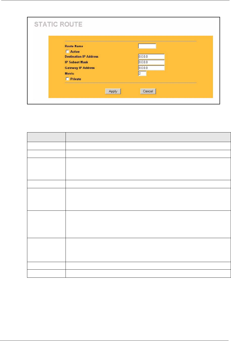
Prestige 334 User’s Guide
Chapter 8 Static Route Screens 104
Figure 37 Static Route: Edit
The following table describes the labels in this screen.
Table 29 Static Route: Edit
LABEL DESCRIPTION
Route Name Enter the name of the IP static route. Leave this field blank to delete this static route.
Active This field allows you to activate/deactivate this static route.
Destination IP
Address
This parameter specifies the IP network address of the final destination. Routing is
always based on network number. If you need to specify a route to a single host, use
a subnet mask of 255.255.255.255 in the subnet mask field to force the network
number to be identical to the host ID.
IP Subnet Mask Enter the IP subnet mask here.
Gateway IP
Address
Enter the IP address of the gateway. The gateway is an immediate neighbor of your
Prestige that will forward the packet to the destination. On the LAN, the gateway
must be a router on the same segment as your Prestige; over the WAN, the gateway
must be the IP address of one of the Remote Nodes.
Metric Metric represents the “cost” of transmission for routing purposes. IP routing uses
hop count as the measurement of cost, with a minimum of 1 for directly connected
networks. Enter a number that approximates the cost for this link. The number need
not be precise, but it must be between 1 and 15. In practice, 2 or 3 is usually a good
number.
Private This parameter determines if the Prestige will include this route to a remote node in
its RIP broadcasts.
Select this check box to keep this route private and not included in RIP broadcasts.
Clear this checkbox to propagate this route to other hosts through RIP broadcasts.
Apply Click Apply to save your changes back to the Prestige.
Cancel Click Cancel to return to the previous screen and not save your changes.

Prestige 334 User’s Guide
105 Chapter 8 Static Route Screens

Prestige 334 User’s Guide
Chapter 9 UPnP 106
CHAPTER 9
UPNP
This chapter introduces the Universal Plug and Play feature.
9.1 Universal Plug and Play Overview
Universal Plug and Play (UPnP) is a distributed, open networking standard that uses TCP/IP
for simple peer-to-peer network connectivity between devices. A UPnP device can
dynamically join a network, obtain an IP address, convey its capabilities and learn about other
devices on the network. In turn, a device can leave a network smoothly and automatically
when it is no longer in use.
9.1.1 How Do I Know If I'm Using UPnP?
UPnP hardware is identified as an icon in the Network Connections folder (Windows XP).
Each UPnP compatible device installed on your network will appear as a separate icon.
Selecting the icon of a UPnP device will allow you to access the information and properties of
that device.
9.1.2 NAT Traversal
UPnP NAT traversal automates the process of allowing an application to operate through
NAT. UPnP network devices can automatically configure network addressing, announce their
presence in the network to other UPnP devices and enable exchange of simple product and
service descriptions. NAT traversal allows the following:
1Dynamic port mapping
2Learning public IP addresses
3Assigning lease times to mappings
Windows Messenger is an example of an application that supports NAT traversal and UPnP.
See the SUA/NAT chapter for further information about NAT.
9.1.3 Cautions with UPnP
The automated nature of NAT traversal applications in establishing their own services and
opening firewall ports may present network security issues. Network information and
configuration may also be obtained and modified by users in some network environments.

Prestige 334 User’s Guide
107 Chapter 9 UPnP
All UPnP-enabled devices may communicate freely with each other without additional
configuration. Disable UPnP if this is not your intention.
9.2 UPnP and ZyXEL
ZyXEL has achieved UPnP certification from the Universal Plug and Play Forum Creates
UPnP™ Implementers Corp. (UIC). ZyXEL's UPnP implementation supports IGD 1.0
(Internet Gateway Device). At the time of writing ZyXEL's UPnP implementation supports
Windows Messenger 4.6 and 4.7 while Windows Messenger 5.0 and Xbox are still being
tested.
UPnP broadcasts are only allowed on the LAN.
Please see later in this User’s Guide for examples of installing UPnP in Windows XP and
Windows Me as well as an example of using UPnP in Windows.
9.3 Configuring UPnP
Click UPnP to display the screen shown next.
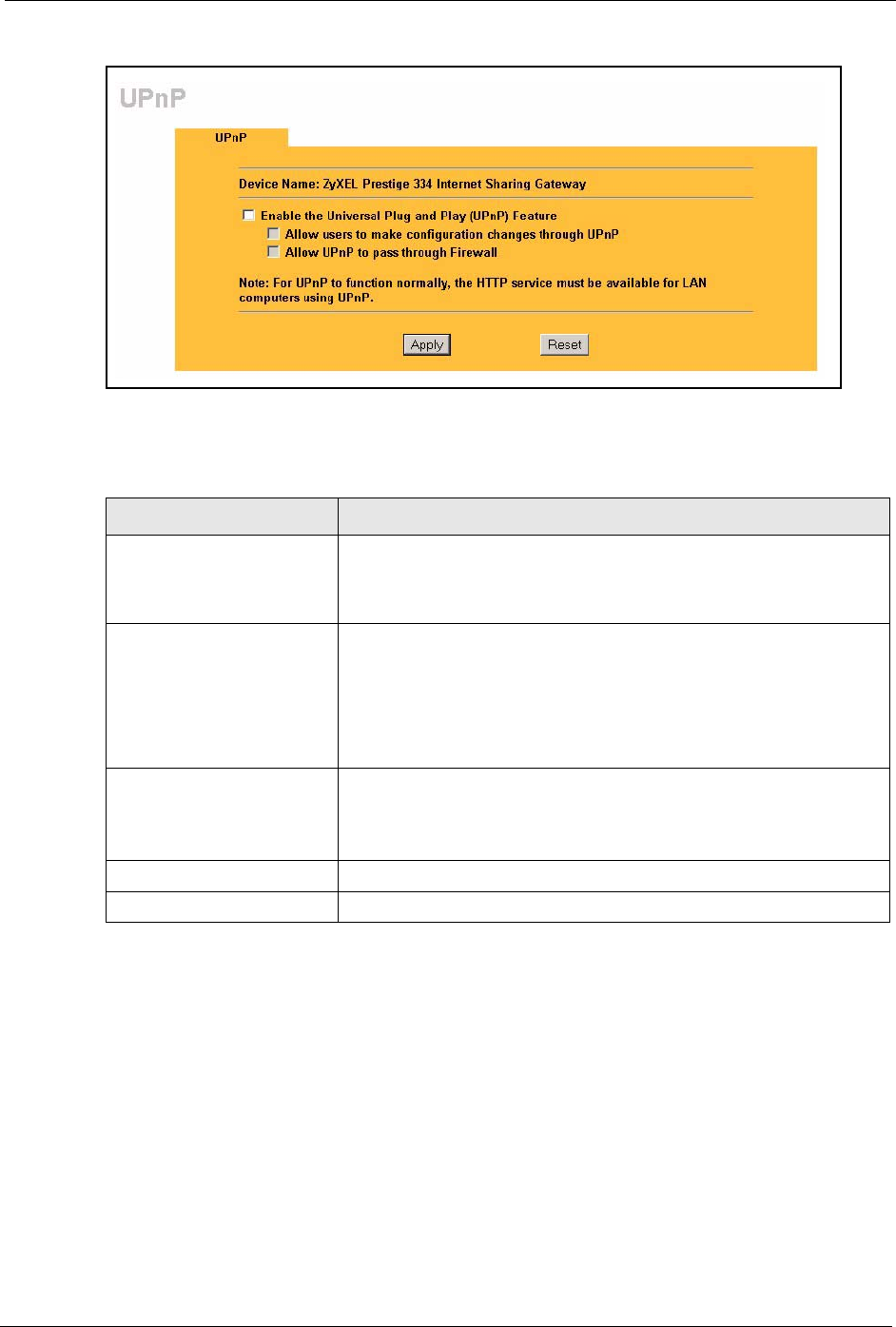
Prestige 334 User’s Guide
Chapter 9 UPnP 108
Figure 38 Configuring UPnP
The following table describes the labels in this screen.
9.4 Installing UPnP in Windows Example
This section shows how to install UPnP in Windows Me and Windows XP.
Table 30 Configuring UPnP
LABEL DESCRIPTION
Enable the Universal Plug
and Play (UPnP) feature
Select this checkbox to activate UPnP. Be aware that anyone could use
a UPnP application to open the web configurator's login screen without
entering the Prestige's IP address (although you must still enter the
password to access the web configurator).
Allow users to make
configuration changes
through UPnP
Select this check box to allow UPnP-enabled applications to
automatically configure the Prestige so that they can communicate
through the Prestige, for example by using NAT traversal, UPnP
applications automatically reserve a NAT forwarding port in order to
communicate with another UPnP enabled device; this eliminates the
need to manually configure port forwarding for the UPnP enabled
application.
Allow UPnP to pass through
firewall
Select this check box to allow traffic from UPnP-enabled applications to
bypass the firewall.
Clear this check box to have the firewall block all UPnP application
packets (for example, MSN packets).
Apply Click Apply to save your changes back to the Prestige.
Reset Click Reset to begin configuring this screen afresh.
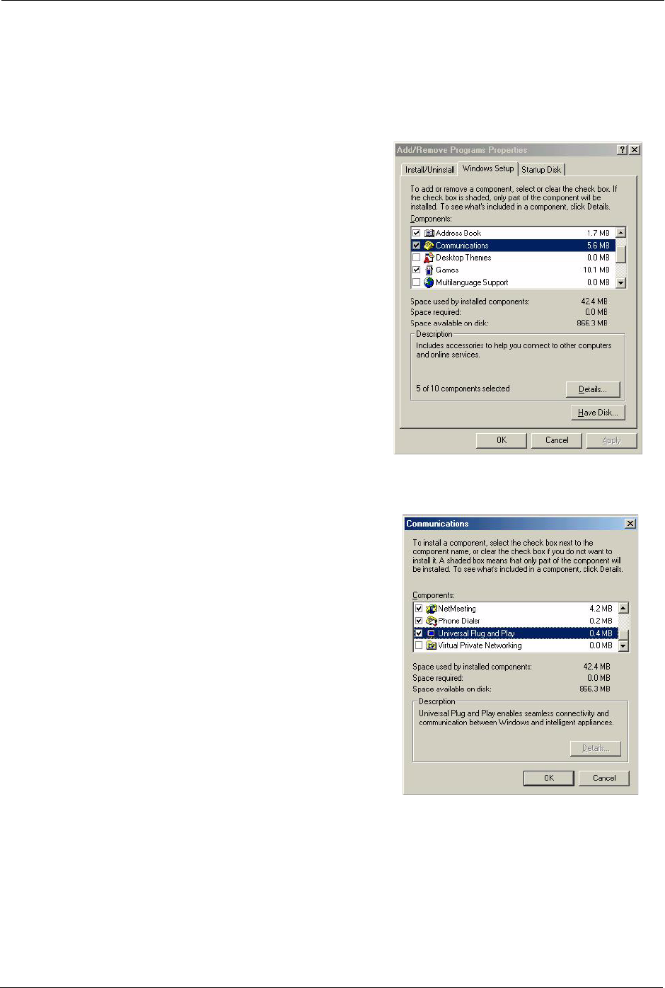
Prestige 334 User’s Guide
109 Chapter 9 UPnP
9.4.1 Installing UPnP in Windows Me
Follow the steps below to install UPnP in Windows Me.
1Click Start and Control Panel. Double-
click Add/Remove Programs.
2Click on the Windows Setup tab and
select Communication in the
Components selection box. Click
Details.
3In the Communications window, select
the Universal Plug and Play check box
in the Components selection box.
4Click OK to go back to the Add/
Remove Programs Properties window
and click Next.
5Restart the computer when prompted.
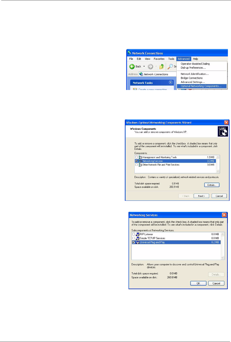
Prestige 334 User’s Guide
Chapter 9 UPnP 110
9.4.2 Installing UPnP in Windows XP
Follow the steps below to install UPnP in Windows XP.
1Click Start and Control Panel.
2Double-click Network Connections.
3In the Network Connections
window, click Advanced in the main
menu and select Optional
Networking Components ….
4The Windows Optional Networking
Components Wizard window
displays.
5Select Networking Service in the
Components selection box and click
Details.
6In the Networking Services window,
select the Universal Plug and Play
check box.
7Click OK to go back to the Windows
Optional Networking Component
Wizard window and click Next.

Prestige 334 User’s Guide
111 Chapter 9 UPnP
9.5 Using UPnP in Windows XP Example
This section shows you how to use the UPnP feature in Windows XP. You must already have
UPnP installed in Windows XP and UPnP activated on the ZyXEL device.
Make sure the computer is connected to a LAN port of the ZyXEL device. Turn on your
computer and the ZyXEL device.
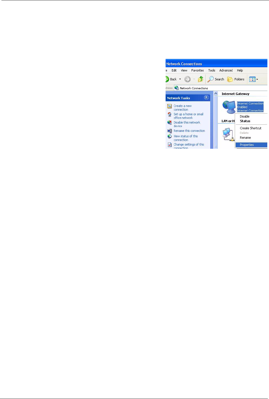
Prestige 334 User’s Guide
Chapter 9 UPnP 112
9.5.1 Auto-discover Your UPnP-enabled Network Device
1Click Start and Control Panel. Double-click
Network Connections. An icon displays
under Internet Gateway.
2Right-click the icon and select Properties.
3In the Internet Connection Properties
window, click Settings to see the port
mappings that were automatically created.
4You may edit or delete the port
mappings or click Add to
manually add port mappings.
Note: When the UPnP-enabled device is disconnected from your computer, all port
mappings will be deleted automatically.
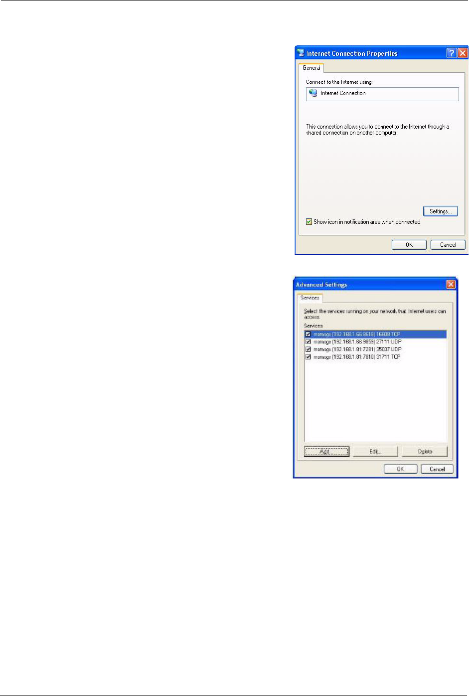
Prestige 334 User’s Guide
113 Chapter 9 UPnP
9.5.2 Web Configurator Easy Access
With UPnP, you can access the web-based configurator on the ZyXEL device without finding
out the IP address of the ZyXEL device first. This is helpful if you do not know the IP address
of the ZyXEL device.
Follow the steps below to access the web configurator.
5Select the Show icon in notification area
when connected check box and click OK. An
icon displays in the system tray
6Double-click the icon to display your current
Internet connection status.
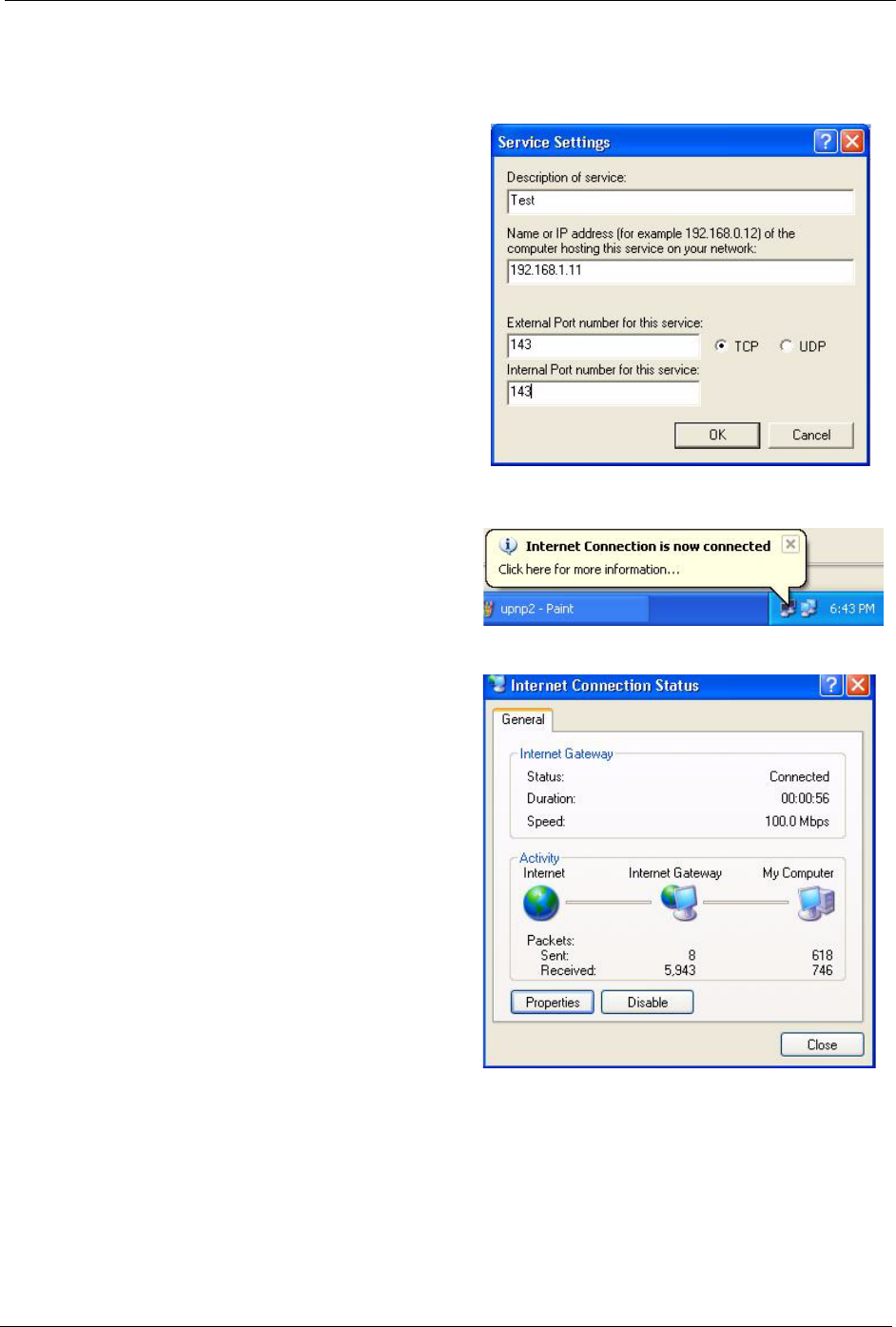
Prestige 334 User’s Guide
Chapter 9 UPnP 114
9.5.3 Web Configurator Easy Access
With UPnP, you can access the web-based configurator on the ZyXEL device without finding
out the IP address of the ZyXEL device first. This is helpful if you do not know the IP address
of the ZyXEL device.
1Click Start and then Control Panel.
2Double-click Network Connections.
3Select My Network Places under
Other Places.
4An icon with the description for each
UPnP-enabled device displays under
Local Network.
5Right-click the icon for your ZyXEL
device and select Invoke. The web
configurator login screen displays.
6Right-click the icon for your ZyXEL
device and select Properties. A
properties window displays with
basic information about the ZyXEL
device.
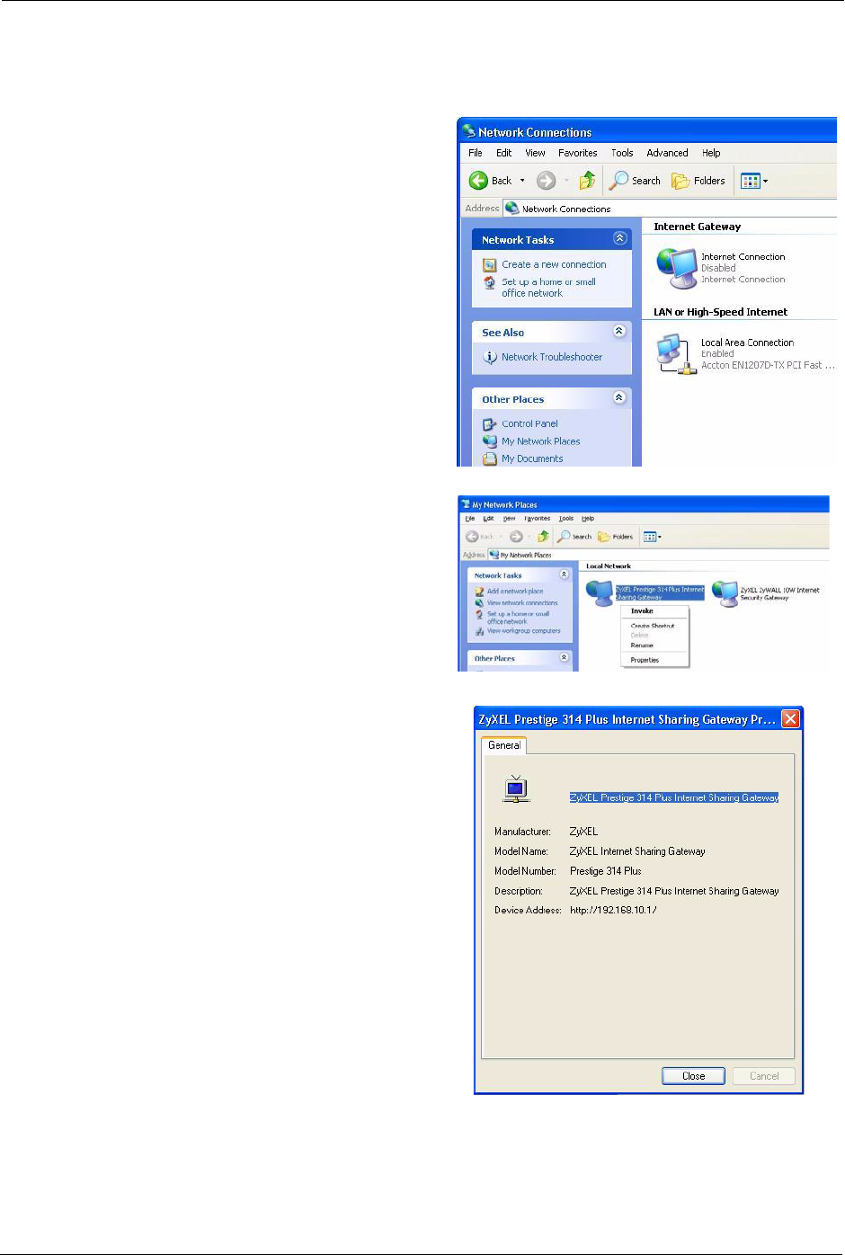
Prestige 334 User’s Guide
115 Chapter 9 UPnP
Follow the steps below to access the web configurator.
1Click Start and then Control Panel.
2Double-click Network Connections.
3 Select My Network Places under
Other Places.
4An icon with the description for each
UPnP-enabled device displays under
Local Network.
5Right-click the icon for your ZyXEL
device and select Invoke. The web
configurator login screen displays.
6Right-click the icon for your ZyXEL
device and select Properties. A
properties window displays with
basic information about the ZyXEL
device.
Prestige 334 User’s Guide
Chapter 10 Trend Micro Security Services 116
CHAPTER 10
Trend Micro Security Services
This chapter contains information about configuring Trend Micro Security Services settings,
virus protection, parental controls and customization.
10.1 Trend Micro Security Service Overview
Trend Micro Security Services (TMSS) are a range of services including virus protection and
parental controls designed to address the security needs of computers on a network that access
the Internet via broadband routers.
Computers that are connected to the Internet via broadband connection increase the risk of
attacks such as viruses, hackers, spyware and spam.
This screen allows you to enable TMSS, configure how often the TMSS Web page displays
and select the computers in your network that you want this service to apply.
10.2 Configuring Service Settings
Click TMSS under ADVANCED to open the Service Settings screen, where you can decide
which computers in the network you can apply TMSS.
Note: When you enable TMSS on your Prestige, it is freely available
for an initial home trial period. To continue to use TMSS after the
initial home trial you must extend this period. See the Trend Micro
website for information on how to do this.
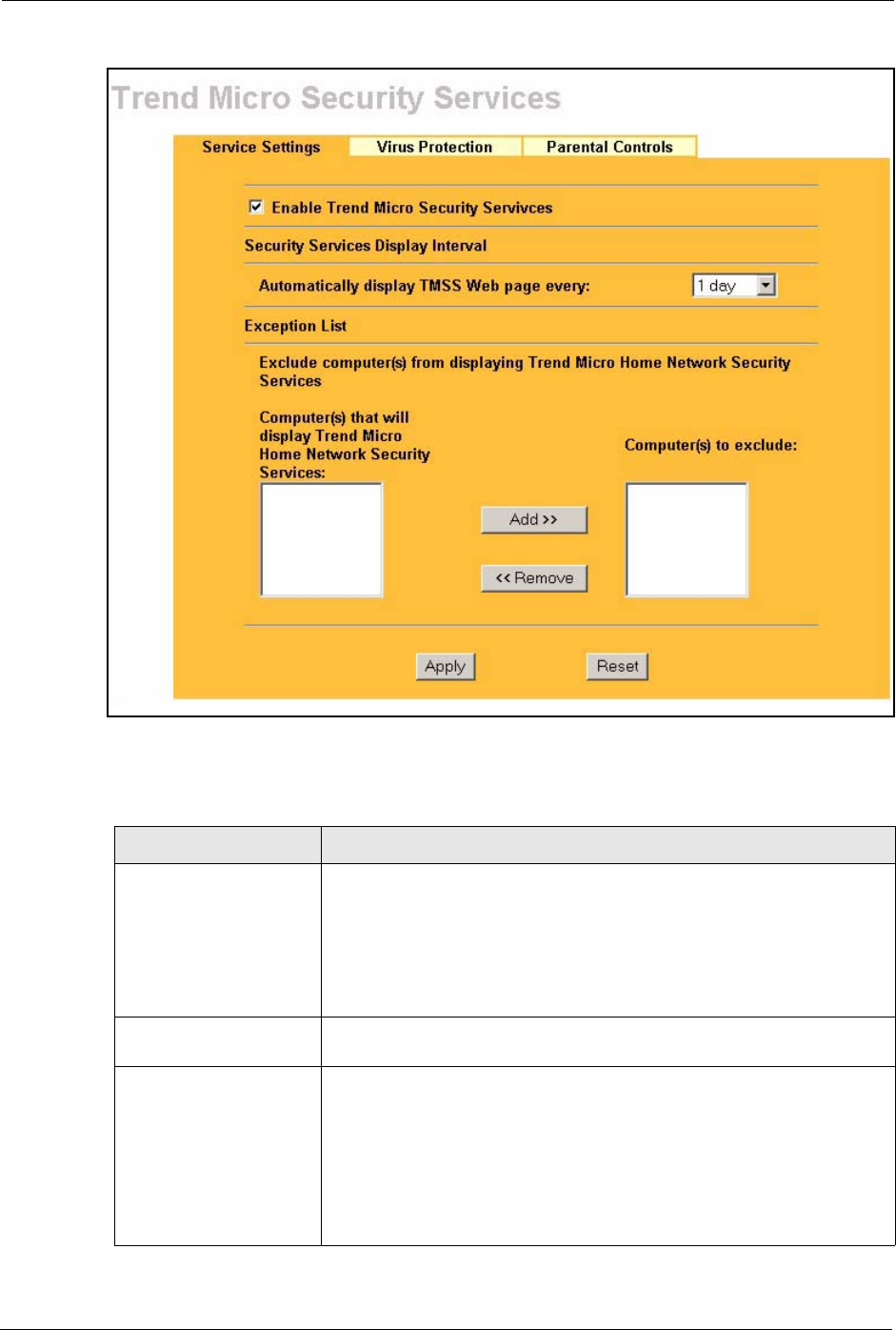
Prestige 334 User’s Guide
117 Chapter 10 Trend Micro Security Services
Figure 39 Service Settings
The following table describes the labels in this screen.
Table 31 Service Settings
LABEL DESCRIPTION
Enable Trend Micro
Security Services
Select the checkbox to enable Trend Micro Security Services on your
Prestige.
Note: Make sure that you have not restricted access to
ActiveX, Cookies or Web Proxy features in the Advanced
Filter screen. If you restrict Web access to these features you
will not be able to use TMSS.
Security Services Display
Interval
You can control the times at which the security services page
automatically appears.
Automatically display
TMSS Web page every:
Select a time from the drop-down list box.
The choices are:
•1 day
• 3 days
• 1 week
• 2 weeks
•1 month
Prestige 334 User’s Guide
Chapter 10 Trend Micro Security Services 118
10.3 Virus Protection
This screen allows you to check the computers in the network for Trend Micro Internet
Security. You can also select antivirus component update time intervals and monitor the virus
protection status on each client computer in your network.
Trend Micro Antivirus software can be downloaded to each computer in your network from
the Trend Micro website.
10.4 Configuring Virus Protection
Select the Virus Protection tab in TMSS under ADVANCED to display the following screen.
Exception List You can specify on which computer(s) the TMSS Web page will not be
displayed. The default setting is to have all computers display the Web
page.
Computer(s) that will
display Trend Micro
Home Network Security
Services:
This box displays the IP addresses of the computers that are enabled with
TMSS on your network. The client issues an http request through the
Prestige to have the IP address of their computer displayed in this box.
Note: A maximum of 10 client IP addresses are displayed in
this box.
Computer(s) to exclude: This box displays all of the chosen IP address(es) of the computer(s) with
TMSS disabled on your network.
Click Add>> to copy a computer's IP address from the list of Computer(s)
that will display Trend Micro Home Network Security Services to the
Computer(s) to exclude list.
Click <<Remove to delete a computer's IP address from the Computer(s)
to exclude list.
Apply Click Apply to save your customized settings.
Reset Click Reset to begin configuring this screen afresh.
Table 31 Service Settings
LABEL DESCRIPTION
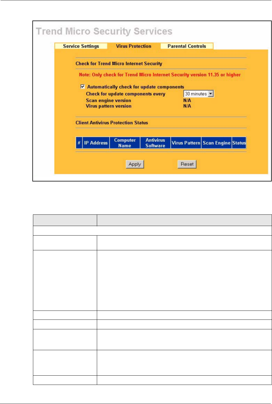
Prestige 334 User’s Guide
119 Chapter 10 Trend Micro Security Services
Figure 40 Virus Protection
The following table describes the labels in this screen.
Table 32 Virus Protection
LABEL DESCRIPTION
Check for Trend Micro Internet Security
Automatically check for
update components
Select the checkbox to have the Prestige download the latest scan engine
version and virus pattern version from the Trend Micro website.
Check for update
components every
Choose when to automatically check the Trend Micro Active Update server
for updated components. Options include:
• 10 minutes
• 20 minutes
• 30 minutes
• 1 hours
• 2 hours
• 3 hours
Scan engine version This field displays the version number of the virus scan program.
Virus pattern version This field displays the version number of the pattern file.
Client Antivirus Protection
Status
This table provides information of all the computers on the network
including whether the client has installed the antivirus software and the
status of the update components.
#This field displays the index number of a client computer on the network.
Note: A maximum of 10 client IP addresses are displayed in
this box.
IP Address This field displays the IP address of a client computer.
Prestige 334 User’s Guide
Chapter 10 Trend Micro Security Services 120
10.5 Parental Controls
Parental Controls lets a parent (LAN administrator) control a LAN user's Internet access
privileges by blocking specified categories. You can define time periods and days during
which Parental Controls are enabled and block Web pages depending on which filter
categories they are included.
10.6 Parental Controls Configuration
Select the Parental Controls tab in TMSS under ADVANCED to configure parental
controls.
If your Trend Micro license is invalid, the following screen is displayed. Proceed to the
Appendix for instructions on how to register with Trend Micro Security Services.
Computer Name This field displays the name of a client computer.
Antivirus Software This field displays the current antivirus software on a client computer.
Virus Pattern This field displays the current version number of the pattern file on a client
computer.
Scan Engine This field displays the current virus scan program of the client computer.
Status This field displays the Trend Micro antivirus version status on a client’s
computer.
Potential Threat:
• A request has been sent from the Prestige to check the antivirus
version on the clients’ computer. The Prestige is waiting for a response.
• There is currently no Trend Micro antivirus installed on the client
computer.
• The clients’ computer has a UNIX operating system.
Needs Update:
• The Trend Micro antivirus version on the client computer is older than
the Prestige Trend Micro antivirus version displayed in the
Automatically check for update components section.
Up to date:
• The Trend Micro antivirus version on the client computer is the same
Prestige Trend Micro antivirus version displayed in the Automatically
check for update components section.
Apply Click Apply to save the settings.
Reset Click Reset to begin configuring this screen afresh.
Table 32 Virus Protection
LABEL DESCRIPTION
Note: You must register or renew your license in the TM
Security Services web page to view the Parental Controls
configuration screen.
Prestige 334 User’s Guide
121 Chapter 10 Trend Micro Security Services
Figure 41 Parental Controls License Status
If you have registered with TMSS and your license is valid, you can configure the Parental
Controls configuration screen.
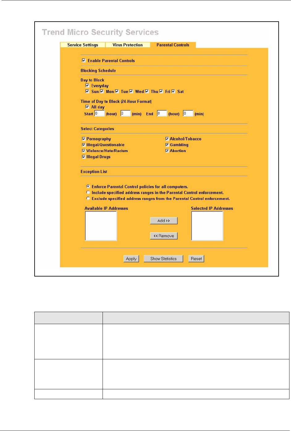
Prestige 334 User’s Guide
Chapter 10 Trend Micro Security Services 122
Figure 42 Parental Controls
The following table describes the labels in this screen.
Table 33 Parental Controls
LABEL DESCRIPTION
Enable Parental Controls Select the check box to enable this feature on your Prestige.
Note: The Prestige automatically checks the status of your
Trend Micro license. If the license becomes invalid, Parental
Controls is disabled and Figure 41 is shown.
Blocking Schedule Note: If configuration changes are made in this section, the
same section in the CONTENT FILTER screen will also
display these changes and vice versa.
Day to Block Select everyday or the day(s) of the week to activate web page blocking

Prestige 334 User’s Guide
123 Chapter 10 Trend Micro Security Services
Time of Day to Block (24-
Hour Format)
Select the time of day you want web page blocking to take effect.
Configure blocking to take effect all day by selecting the All Day check
box. You can also configure specific times by entering the start time in the
Start (hr) and Start (min) fields and the end time in the End (hr) and End
(min) fields. Enter times in 24-hour format; for example, "3:00pm" should
be entered as "15:00". Enter the hours from a minimum of 00:00 to a
maximum of 23:00.
Select Categories
Pornography Selecting this category excludes pages that contain sexually explicit
material for the purpose of arousing a sexual or prurient interest.
Illegal/Questionable Selecting this category excludes pages that advocate or give advice on
performing illegal acts such as service theft, evading law enforcement,
fraud, burglary techniques and plagiarism. It also includes pages that
provide or sell questionable educational materials, such as term papers.
Note: This category includes sites identified as being
malicious in any way (such as having viruses, spyware and
etc.).
Violence/Hate/Racism Selecting this category excludes pages that depict extreme physical harm
to people or property, or that advocate or provide instructions on how to
cause such harm. It also includes pages that advocate, depict hostility or
aggression toward, or denigrate an individual or group on the basis of race,
religion, gender, nationality, ethnic origin, or other characteristics.
Illegal Drugs Selecting this category excludes pages that promote, offer, sell, supply,
encourage or otherwise advocate the illegal use, cultivation, manufacture,
or distribution of drugs, pharmaceuticals, intoxicating plants or chemicals
and their related paraphernalia.
Alcohol/Tobacco Selecting this category excludes pages that promote or offer the sale
alcohol/tobacco products, or provide the means to create them. It also
includes pages that glorify, tout, or otherwise encourage the consumption
of alcohol/tobacco. It does not include pages that sell alcohol or tobacco
as a subset of other products.
Gambling Selecting this category excludes pages where a user can place a bet or
participate in a betting pool (including lotteries) online. It also includes
pages that provide information, assistance, recommendations, or training
on placing bets or participating in games of chance. It does not include
pages that sell gambling related products or machines. It also does not
include pages for offline casinos and hotels (as long as those pages do not
meet one of the above requirements).
Abortion Selecting this category excludes pages that provide information or
arguments in favor of or against abortion, describe abortion procedures,
offer help in obtaining or avoiding abortion, or provide information on the
effects, or lack thereof, of abortion.
Exception List Use the Exception List to specify which computers that are not to be
restricted by Parental Controls. The default setting is to have Parental
Controls enabled on all computers.
Enforce Parental Control
policies for all computers
Select the radio button to have Parental Controls enabled on all
computers. This is the default setting.
Include specified address
ranges in the Parental
Control enforcement.
Select the radio button to apply Parental Controls to the computers with IP
addresses displayed in the Selected IP Addresses box.
Table 33 Parental Controls
LABEL DESCRIPTION
Prestige 334 User’s Guide
Chapter 10 Trend Micro Security Services 124
10.6.1 Parental Controls Statistics
The Prestige can display a record of attempted entries to Web pages or actual entries to Web
pages from a list of content filtering categories.
Exclude specified address
ranges from the Parental
Control enforcement.
Select the radio button to apply Parental Controls to all of the computers in
the network except those displayed in the Selected IP Addresses box.
Available IP Addresses This box displays the IP addresses of all computers in the network.
Note: A maximum of 10 client IP addresses are displayed in
this box.
Selected IP Addresses This box displays the IP addresses of the computer(s) chosen from the
Available IP Addresses box, to which you want to apply or exclude from
Parental Controls.
Select Add>> to copy a computer's IP address from the Address box to the
Selected IP Addresses box.
Select <<Remove to delete a computer's IP address from the Selected IP
Addresses box.
Apply Click Apply to save the settings.
Show Statistics Click Statistics to view a record of access attempts and successes to web
pages belonging to each category.
Reset Click Reset to begin configuring this screen afresh.
Table 33 Parental Controls
LABEL DESCRIPTION
Prestige 334 User’s Guide
125 Chapter 10 Trend Micro Security Services
Figure 43 Parental Controls Statistics
The following table describes the labels in this screen.
Table 34 Parental Controls Statistics
LABEL DESCRIPTION
Category All categories are displayed including;
Pornography, Illegal/Questionable, Violence/Hate/Racism, Illegal
Drugs, Alcohol/Tobacco, Gambling and Abortion.
Access Attempts This field displays the number of times an attempt has been made to
access a web page from a category of restricted web pages. These
attempts may be successful or blocked attempts.
Actual Accesses This field displays the number of times access has been successful to a
web page from a category of web pages.
Reset Click Reset to clear all of the fields in this screen.
Refresh Click Refresh to renew the statistics screen.
If a category has
been selected in
the previous screen
a blocked attempt
is displayed.
If a category has
not been selected
in the previous
screen, attempts
aand accesses to
Web pages within
those categories
are displayed.

Prestige 334 User’s Guide
Chapter 11 Firewall 126
CHAPTER 11
Firewall
This chapter gives some background information on firewalls and explains how to get started
with the Prestige firewall.
11.1 Introduction
11.1.1 What is a Firewall?
Originally, the term firewall referred to a construction technique designed to prevent the
spread of fire from one room to another. The networking term "firewall" is a system or group
of systems that enforces an access-control policy between two networks. It may also be
defined as a mechanism used to protect a trusted network from an untrusted network. Of
course, firewalls cannot solve every security problem. A firewall is one of the mechanisms
used to establish a network security perimeter in support of a network security policy. It
should never be the only mechanism or method employed. For a firewall to guard effectively,
you must design and deploy it appropriately. This requires integrating the firewall into a broad
information-security policy. In addition, specific policies must be implemented within the
firewall itself.
11.1.2 Stateful Inspection Firewall.
Stateful inspection firewalls restrict access by screening data packets against defined access
rules. They make access control decisions based on IP address and protocol. They also
"inspect" the session data to assure the integrity of the connection and to adapt to dynamic
protocols. These firewalls generally provide the best speed and transparency; however, they
may lack the granular application level access control or caching that some proxies support.
Firewalls, of one type or another, have become an integral part of standard security solutions
for enterprises.
11.1.3 About the Prestige Firewall
The Prestige firewall is a stateful inspection firewall and is designed to protect against Denial
of Service attacks when activated (click FIREWALL and then click the Enable Firewall
check box). The Prestige's purpose is to allow a private Local Area Network (LAN) to be
securely connected to the Internet. The Prestige can be used to prevent theft, destruction and
modification of data, as well as log events, which may be important to the security of your
network.
The Prestige is installed between the LAN and a broadband modem connecting to the Internet.
This allows it to act as a secure gateway for all data passing between the Internet and the LAN.

Prestige 334 User’s Guide
127 Chapter 11 Firewall
The Prestige has one Ethernet WAN port and four Ethernet LAN ports, which are used to
physically separate the network into two areas.The WAN (Wide Area Network) port attaches
to the broadband (cable or DSL) modem to the Internet.
The LAN (Local Area Network) port attaches to a network of computers, which needs security
from the outside world. These computers will have access to Internet services such as e-mail,
FTP and the World Wide Web. However, "inbound access" is not allowed (by default) unless
the remote host is authorized to use a specific service.
11.1.4 Guidelines For Enhancing Security With Your Firewall
1Change the default password via web configurator.
2Think about access control before you connect to the network in any way, including
attaching a modem to the port.
3Limit who can access your router.
4Don't enable any local service (such as SNMP or NTP) that you don't use. Any enabled
service could present a potential security risk. A determined hacker might be able to find
creative ways to misuse the enabled services to access the firewall or the network.
5For local services that are enabled, protect against misuse. Protect by configuring the
services to communicate only with specific peers, and protect by configuring rules to
block packets for the services at specific interfaces.
6Protect against IP spoofing by making sure the firewall is active.
7Keep the firewall in a secured (locked) room.
11.2 Firewall Settings Screen
From the MAIN MENU, click FIREWALL to open the Settings screen.
Prestige 334 User’s Guide
Chapter 11 Firewall 128
Figure 44 Firewall: Settings
The following table describes the labels in this screen.
Table 35 Firewall: Settings
LABEL DESCRIPTION
Enable Firewall Select this check box to activate the firewall. The Prestige performs access control
and protects against Denial of Service (DoS) attacks when the firewall is activated.
Bypass Triangle
Route
Select this check box to have the Prestige firewall ignore the use of triangle route
topology on the network. See the appendix for more on triangle route topology.
LAN to WAN To log packets related to firewall rules, make sure that Access Control under Log
is selected in the Logs, Log Settings screen.
Packets to Log Choose what LAN to WAN packets to log. Choose from:
No Log
Log Blocked (blocked LAN to WAN services appear in the Blocked Services
textbox in the Services screen (with Enable Services Blocking selected))
Log All (log all LAN to WAN packets)
WAN to LAN To log packets related to firewall rules, make sure that Access Control under Log
is selected in the Logs, Log Settings screen.
Packets to Log Choose what WAN to LAN and WAN to WAN/Prestige packets to log. Choose
from:
No Log
Log Forwarded (see how to forward WAN to LAN traffic in the next section)
Log All (log all WAN to LAN packets).
Trusted Computer
IP Address
You can allow a specific computer to access all Internet resources without
restriction. Enter the IP address of the trusted computer in this field.
Apply Click Apply to save the settings.
Reset Click Reset to start configuring this screen again.
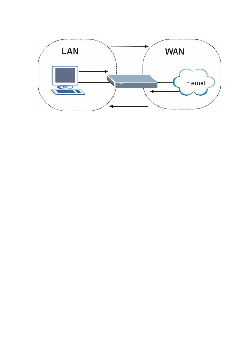
Prestige 334 User’s Guide
129 Chapter 11 Firewall
11.3 The Firewall, NAT and Remote Management
Figure 45 Firewall Rule Directions
11.3.1 LAN-to-WAN rules
LAN-to-WAN rules are local network to Internet firewall rules. The default is to forward all
traffic from your local network to the Internet.
How can you block certain LAN to WAN traffic?
You may choose to block certain LAN-to-WAN traffic in the Services screen (click the
Services tab). All services displayed in the Blocked Services list box are LAN-to-WAN
firewall rules that block those services originating from the LAN.
Blocked LAN-to-WAN packets are considered alerts. Alerts are “higher priority logs” that
include system errors, attacks and attempted access to blocked web sites. Alerts appear in red
in the View Log screen. You may choose to have alerts e-mailed immediately in the Log
Settings screen.
LAN-to-LAN/Prestige means the LAN to the Prestige LAN interface. This is always allowed,
as this is how you manage the Prestige from your local computer.
11.3.2 WAN-to-LAN rules
WAN-to-LAN rules are Internet to your local network firewall rules. The default is to block
all traffic from the Internet to your local network.
How can you forward certain WAN to LAN traffic? You may allow traffic originating from
the WAN to be forwarded to the LAN by:
• Configuring NAT port forwarding rules in the web configurator SUA Server screen or
SMT NAT menus.
• Configuring One-to-One and Many-One-to-One NAT mapping rules in the web
configurator Address Mapping screen or SMT NAT menus.

Prestige 334 User’s Guide
Chapter 11 Firewall 130
• Configuring WAN or LAN & WAN access for services in the Remote Management
screens or SMT menus. When you allow remote management from the WAN, you are
actually configuring WAN-to-WAN/Prestige firewall rules. WAN-to-WAN/Prestige
firewall rules are Internet to the Prestige WAN interface firewall rules. The default is to
block all such traffic. When you decide what WAN-to-LAN packets to log, you are in
fact deciding what WAN-to-LAN and WAN-to-WAN/Prestige packets to log.
• Allow NetBIOS traffic from the WAN to the LAN using the WAN I P web screen or
SMT menu 24.8 commands.
Forwarded WAN-to-LAN packets are not considered alerts.
11.4 Services
Click on the Services tab. The screen appears as shown next. Use this screen to enable service
blocking, enter/delete/modify the services you want to block and the date/time you want to
block them.
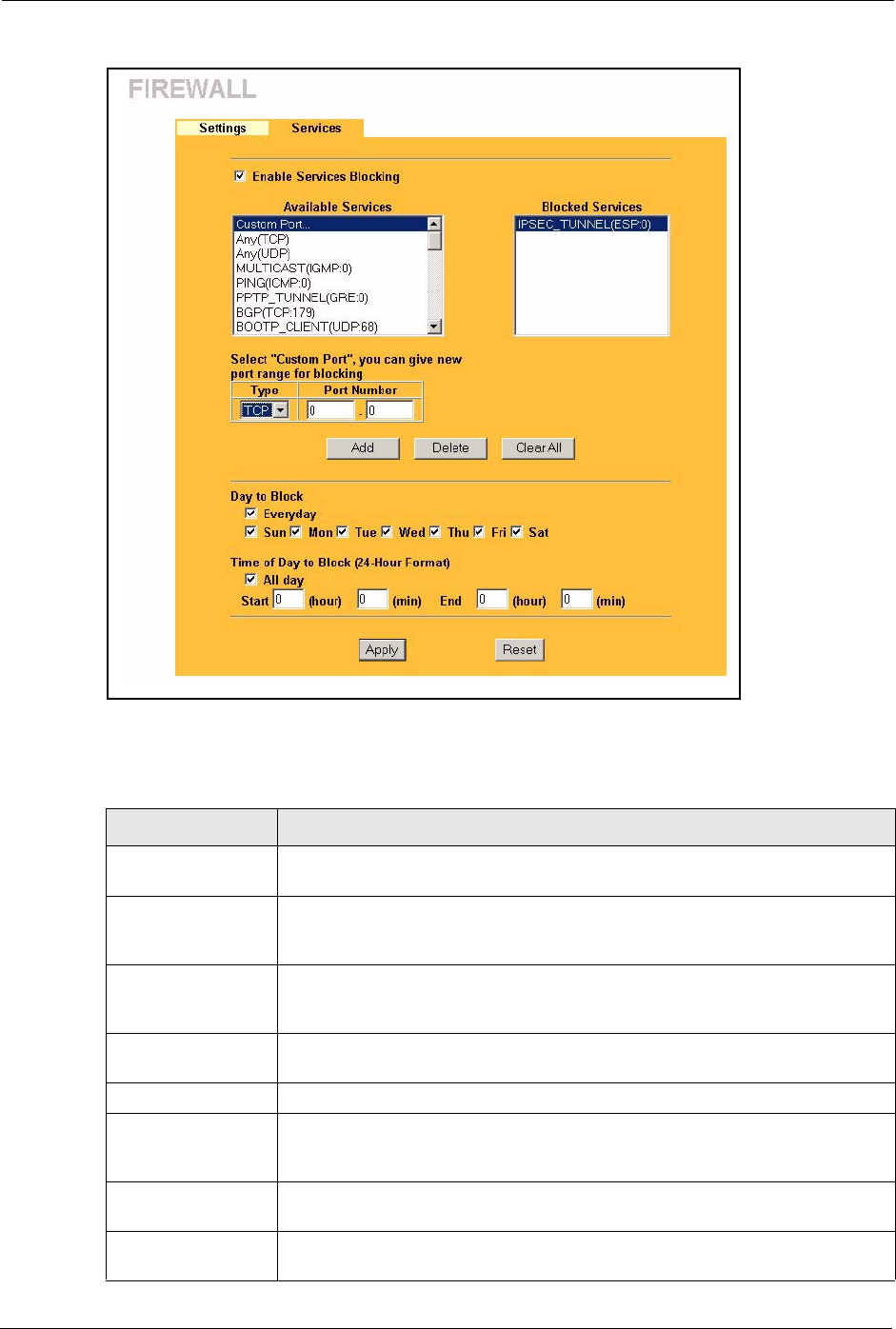
Prestige 334 User’s Guide
131 Chapter 11 Firewall
Figure 46 Firewall: Service
The following table describes the labels in this screen.
Table 36 Firewall: Service
LABEL DESCRIPTION
Enable Services
Blocking
Select this check box to enable this feature.
Available Service This is a list of pre-defined services (ports) you may prohibit your LAN
computers from using. Select the port you want to block using the drop-down list
and click Add to add the port to the Blocked Service field.
Blocked Service This is a list of services (ports) that will be inaccessible to computers on your
LAN once you enable service blocking. Choose the IP port (TCP, UDP or TCP/
UDP) that defines your customized port from the drop down list box.
Custom Port A custom port is a service that is not available in the pre-defined Available
Services list and you must define using the next two fields.
Type Services are either TCP and/or UDP. Select from either TCP or UDP.
Port Number Enter the port number range that defines the service. For example, suppose you
want to define the Gnutella service. Select TCP type and enter a port range from
6345-6349.
Add Select a service from the Available Services drop-down list and then click Add
to add a service to the Blocked Service.
Delete Select a service from the Blocked Services List and then click Delete to
remove this service from the list.

Prestige 334 User’s Guide
Chapter 11 Firewall 132
Clear All Click Clear All to empty the Blocked Service.
Day to Block: Select a check box to configure which days of the week (or everyday) you want
the content filtering to be active.
Time of Day to Block
(24-Hour Format)
Select the time of day you want service blocking to take effect. Configure
blocking to take effect all day by selecting the All Day check box. You can also
configure specific times that by entering the start time in the Start (hr) and Start
(min) fields and the end time in the End (hr) and End (min) fields. Enter times in
24-hour format, for example, "3:00pm" should be entered as "15:00".
Apply Click Apply to save the settings.
Reset Click Reset to start configuring this screen again.
Table 36 Firewall: Service
LABEL DESCRIPTION

Prestige 334 User’s Guide
133 Chapter 11 Firewall

Prestige 334 User’s Guide
Chapter 12 Content Filtering 134
CHAPTER 12
Content Filtering
This chapter provides a brief overview of content filtering using the embedded WebGUI.
12.1 Introduction to Content Filtering
Internet content filtering allows you to create and enforce Internet access policies tailored to
their needs. Content filtering is the ability to block certain web features or specific URL
keywords and should not be confused with packet filtering via SMT menu 21.1. To access
these functions, from the Main Menu, click Content Filter to expand the Content Filter
menus.
12.2 Restrict Web Features
The Prestige can block web features such as ActiveX controls, Java applets, cookies and
disable web proxies.
12.3 Days and Times
The Prestige also allows you to define time periods and days during which the Prestige
performs content filtering.
12.4 Configure Content Filtering
Click Content Filter on the navigation panel, to open the following screen.
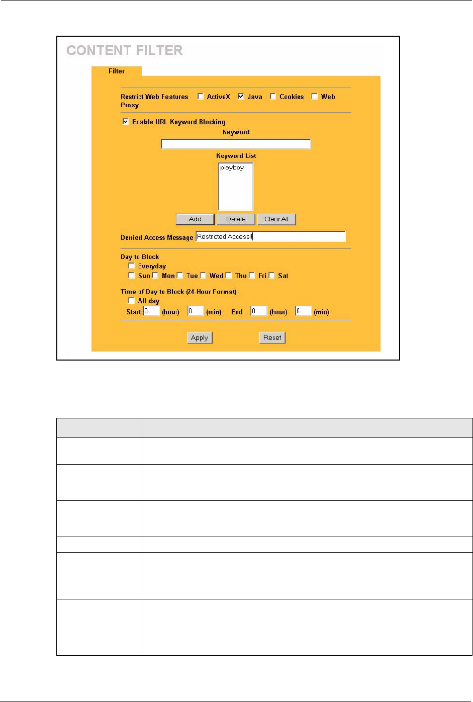
Prestige 334 User’s Guide
135 Chapter 12 Content Filtering
Figure 47 Content Filter
The following table describes the labels in this screen.
Table 37 Content Filter
LABEL DESCRIPTION
Restrict Web
Features
Select the box(es) to restrict a feature. When you download a page containing a
restricted feature, that part of the web page will appear blank or grayed out.
ActiveX A tool for building dynamic and active Web pages and distributed object
applications. When you visit an ActiveX Web site, ActiveX controls are
downloaded to your browser, where they remain in case you visit the site again.
Java A programming language and development environment for building
downloadable Web components or Internet and intranet business applications of
all kinds.
Cookies Used by Web servers to track usage and provide service based on ID.
Web Proxy A server that acts as an intermediary between a user and the Internet to provide
security, administrative control, and caching service. When a proxy server is
located on the WAN it is possible for LAN users to circumvent content filtering by
pointing to this proxy server.
Enable URL
Keyword Blocking
The Prestige can block Web sites with URLs that contain certain keywords in the
domain name or IP address. For example, if the keyword "bad" was enabled, all
sites containing this keyword in the domain name or IP address will be blocked,
e.g., URL http://www.website.com/bad.html would be blocked. Select this check
box to enable this feature.

Prestige 334 User’s Guide
Chapter 12 Content Filtering 136
Keyword Type a keyword in this field. You may use any character (up to 64 characters).
Wildcards are not allowed. You can also enter a numerical IP address.
Keyword List This list displays the keywords already added.
Add Click Add after you have typed a keyword.
Repeat this procedure to add other keywords. Up to 64 keywords are allowed.
When you try to access a web page containing a keyword, you will get a message
telling you that the content filter is blocking this request.
Delete Highlight a keyword in the lower box and click Delete to remove it. The keyword
disappears from the text box after you click Apply.
Clear All Click this button to remove all of the listed keywords.
Day to Block Select check boxes for the days that you want the Prestige to perform content
filtering. Select the Everyday check box to have content filtering turned on all
days of the week.
Time of Day to
Block
Time of Day to Block allows the administrator to define during which time periods
content filtering is enabled. Time of Day to Block restrictions only apply to the
keywords (see above). Restrict web server data, such as ActiveX, Java, Cookies
and Web Proxy are not affected.
Enter the time period, in 24-hour format, during which content filtering will be
enforced. Select the All Day check box to have content filtering always active on
the days selected in Day to Block with time of day limitations not enforced.
Apply Click Apply to save your changes.
Reset Click Reset to begin configuring this screen afresh
Table 37 Content Filter
LABEL DESCRIPTION

Prestige 334 User’s Guide
137 Chapter 12 Content Filtering
Prestige 334 User’s Guide
Chapter 13 Remote Management Screens 138
CHAPTER 13
Remote Management Screens
This chapter provides information on the Remote Management screens.
13.1 Remote Management Overview
Remote management allows you to determine which services/protocols can access which
Prestige interface (if any) from which computers.
You may manage your Prestige from a remote location via:
To disable remote management of a service, select Disable in the corresponding Server
Access field.
You may only have one remote management session running at a time. The Prestige
automatically disconnects a remote management session of lower priority when another
remote management session of higher priority starts. The priorities for the different types of
remote management sessions are as follows.
1Telnet
2HTTP
13.1.1 Remote Management Limitations
Remote management over LAN or WAN will not work when:
1A filter in SMT menu 3.1 (LAN) or in menu 11.5 (WAN) is applied to block a Telnet,
FTP or Web service.
Note: When you configure remote management to allow
management from the WAN, you still need to configure a
firewall rule to allow access. See the firewall chapters for details
on configuring firewall rules
• Internet (WAN only) • ALL (LAN and WAN)
• LAN only • Neither (Disable).
Note: When you Choose WAN only or ALL (LAN & WAN), you
still need to configure a firewall rule to allow access.

Prestige 334 User’s Guide
139 Chapter 13 Remote Management Screens
2You have disabled that service in one of the remote management screens.
3The IP address in the Secured Client IP field does not match the client IP address. If it
does not match, the Prestige will disconnect the session immediately.
4There is already another remote management session with an equal or higher priority
running. You may only have one remote management session running at one time.
5There is a firewall rule that blocks it.
13.1.2 Remote Management and NAT
When NAT is enabled:
• Use the Prestige’s WAN IP address when configuring from the WAN.
• Use the Prestige’s LAN IP address when configuring from the LAN.
13.1.3 System Timeout
There is a default system management idle timeout of five minutes (three hundred seconds).
The Prestige automatically logs you out if the management session remains idle for longer
than this timeout period. The management session does not time out when a statistics screen is
polling. You can change the timeout period in the System screen
13.2 Configuring WWW
To change your Prestige’s World Wide Web settings, click REMOTE MGMT to display the
WWW screen.
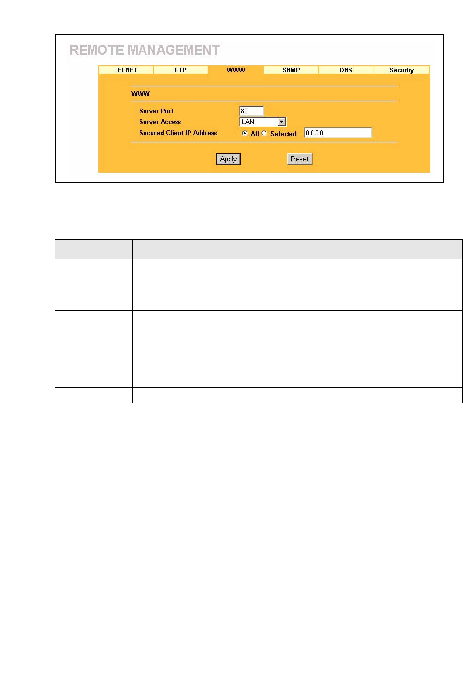
Prestige 334 User’s Guide
Chapter 13 Remote Management Screens 140
Figure 48 Remote Management: WWW
The following table describes the labels in this screen.
13.3 Configuring Telnet
You can configure your Prestige for remote Telnet access as shown next. The administrator
uses Telnet from a computer on a remote network to access the Prestige.
Table 38 Remote Management: WWW
LABEL DESCRIPTION
Server Port You may change the server port number for a service if needed, however you must
use the same port number in order to use that service for remote management.
Server Access Select the interface(s) through which a computer may access the Prestige using
this service.
Secured Client IP
Address
A secured client is a “trusted” computer that is allowed to communicate with the
Prestige using this service.
Select All to allow any computer to access the Prestige using this service.
Choose Selected to just allow the computer with the IP address that you specify to
access the Prestige using this service.
Apply Click Apply to save your customized settings and exit this screen.
Reset Click Reset to begin configuring this screen afresh.
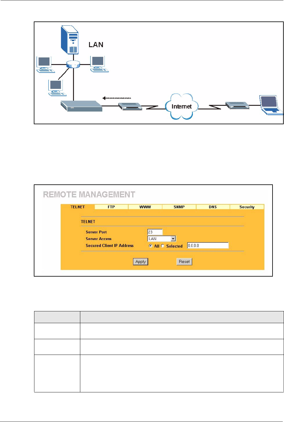
Prestige 334 User’s Guide
141 Chapter 13 Remote Management Screens
Figure 49 Telnet Configuration on a TCP/IP Network
13.4 Configuring TELNET
Click REMOTE MGMT and the TELNET tab to display the screen as shown.
Figure 50 Remote Management: Telnet
The following table describes the labels in this screen.
Table 39 Remote Management: Telnet
LABEL DESCRIPTION
Server Port You may change the server port number for a service if needed, however you must
use the same port number in order to use that service for remote management.
Server Access Select the interface(s) through which a computer may access the Prestige using this
service.
Secured Client IP
Address
A secured client is a “trusted” computer that is allowed to communicate with the
Prestige using this service.
Select All to allow any computer to access the Prestige using this service.
Choose Selected to just allow the computer with the IP address that you specify to
access the Prestige using this service.
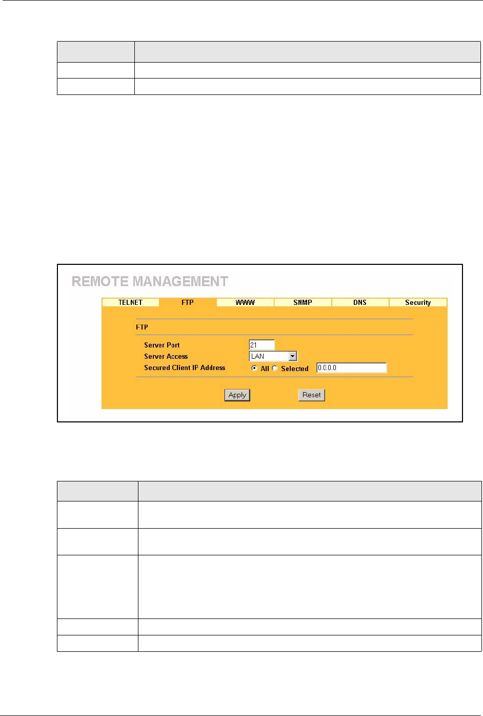
Prestige 334 User’s Guide
Chapter 13 Remote Management Screens 142
13.5 Configuring FTP
You can upload and download the Prestige’s firmware and configuration files using FTP,
please see the chapter on firmware and configuration file maintenance for details. To use this
feature, your computer must have an FTP client.
To change your Prestige’s FTP settings, click REMOTE MGMT, then the FTP tab. The
screen appears as shown.
Figure 51 Remote Management: FTP
The following table describes the labels in this screen.
Apply Click Apply to save your customized settings and exit this screen.
Reset Click Reset to begin configuring this screen afresh.
Table 39 Remote Management: Telnet
LABEL DESCRIPTION
Table 40 Remote Management: FTP
LABEL DESCRIPTION
Server Port You may change the server port number for a service if needed, however you must
use the same port number in order to use that service for remote management.
Server Access Select the interface(s) through which a computer may access the Prestige using
this service.
Secured Client IP
Address
A secured client is a “trusted” computer that is allowed to communicate with the
Prestige using this service.
Select All to allow any computer to access the Prestige using this service.
Choose Selected to just allow the computer with the IP address that you specify to
access the Prestige using this service.
Apply Click Apply to save your customized settings and exit this screen.
Reset Click Reset to begin configuring this screen afresh.
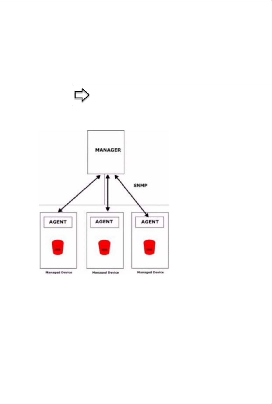
Prestige 334 User’s Guide
143 Chapter 13 Remote Management Screens
13.6 SNMP
Simple Network Management Protocol (SNMP) is a protocol used for exchanging
management information between network devices. SNMP is a member of the TCP/IP
protocol suite. Your Prestige supports SNMP agent functionality, which allows a manager
station to manage and monitor the Prestige through the network. The Prestige supports SNMP
version one (SNMPv1) and version two (SNMPv2). The next figure illustrates an SNMP
management operation. SNMP is only available if TCP/IP is configured.
Figure 52 SNMP Management Model
An SNMP managed network consists of two main types of component: agents and a manager.
An agent is a management software module that resides in a managed device (the Prestige).
An agent translates the local management information from the managed device into a form
compatible with SNMP. The manager is the console through which network administrators
perform network management functions. It executes applications that control and monitor
managed devices.
The managed devices contain object variables/managed objects that define each piece of
information to be collected about a device. Examples of variables include such as number of
packets received, node port status etc. A Management Information Base (MIB) is a collection
of managed objects. SNMP allows a manager and agents to communicate for the purpose of
accessing these objects.
Note: SNMP is only available if TCP/IP is configured.

Prestige 334 User’s Guide
Chapter 13 Remote Management Screens 144
SNMP itself is a simple request/response protocol based on the manager/agent model. The
manager issues a request and the agent returns responses using the following protocol
operations:
• Get - Allows the manager to retrieve an object variable from the agent.
• GetNext - Allows the manager to retrieve the next object variable from a table or list
within an agent. In SNMPv1, when a manager wants to retrieve all elements of a table
from an agent, it initiates a Get operation, followed by a series of GetNext operations.
• Set - Allows the manager to set values for object variables within an agent.
• Trap - Used by the agent to inform the manager of some events.
13.6.1 Supported MIBs
The Prestige supports MIB II that is defined in RFC-1213 and RFC-1215. The focus of the
MIBs is to let administrators collect statistical data and monitor status and performance.
13.6.2 SNMP Traps
The Prestige will send traps to the SNMP manager when any one of the following events
occurs:
13.6.3 Configuring SNMP
To change your Prestige’s SNMP settings, click REMOTE MGMT, then the SNMP tab. The
screen appears as shown.
Table 41 SNMP Traps
TRAP # TRAP NAME DESCRIPTION
0coldStart (defined in RFC-1215)A trap is sent after booting (power on).
1warmStart (defined in RFC-1215)A trap is sent after booting (software reboot).
4authenticationFailure (defined in
RFC-1215)
A trap is sent to the manager when receiving any
SNMP get or set requirements with the wrong
community (password).
6whyReboot (defined in ZYXEL-
MIB)
A trap is sent with the reason of restart before
rebooting when the system is going to restart (warm
start).
6a For intentional reboot : A trap is sent with the message "System reboot by
user!" if reboot is done intentionally, (for example,
download new files, CI command "sys reboot", etc.).
6b For fatal error : A trap is sent with the message of the fatal code if the
system reboots because of fatal errors.
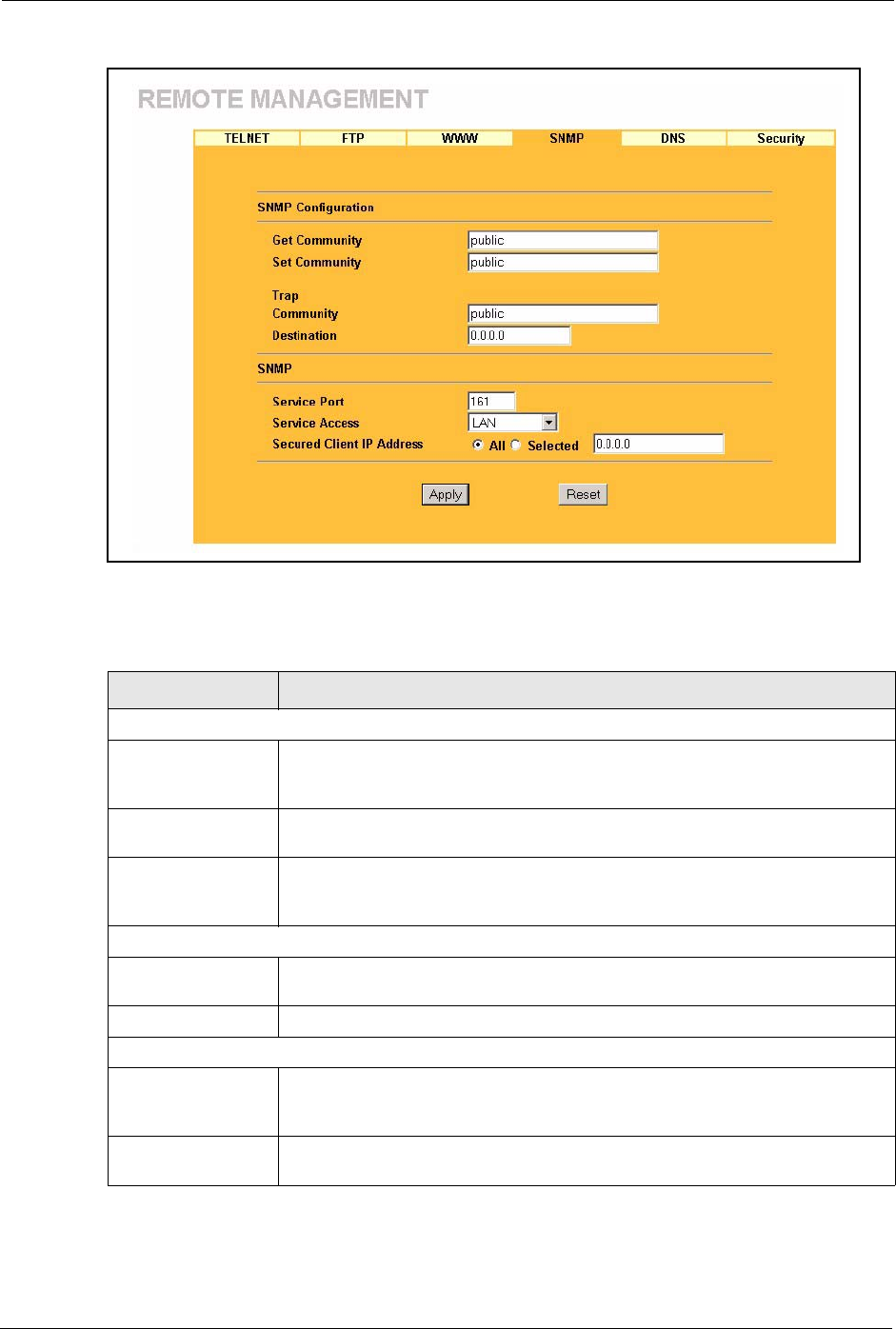
Prestige 334 User’s Guide
145 Chapter 13 Remote Management Screens
Figure 53 Remote Management: SNMP
The following table describes the labels in this screen.
Table 42 Remote Management: SNMP
LABEL DESCRIPTION
SNMP Configuration
Get Community Enter the Get Community, which is the password for the incoming Get and
GetNext requests from the management station. The default is public and allows
all requests.
Set Community Enter the Set community, which is the password for incoming Set requests from
the management station. The default is public and allows all requests.
Trusted Host If you enter a trusted host, your Prestige will only respond to SNMP messages
from this address. A blank (default) field means your Prestige will respond to all
SNMP messages it receives, regardless of source.
Trap
Community Type the trap community, which is the password sent with each trap to the
SNMP manager. The default is public and allows all requests.
Destination Type the IP address of the station to send your SNMP traps to.
SNMP
Service Port You may change the server port number for a service if needed, however you
must use the same port number in order to use that service for remote
management.
Service Access Select the interface(s) through which a computer may access the Prestige using
this service.
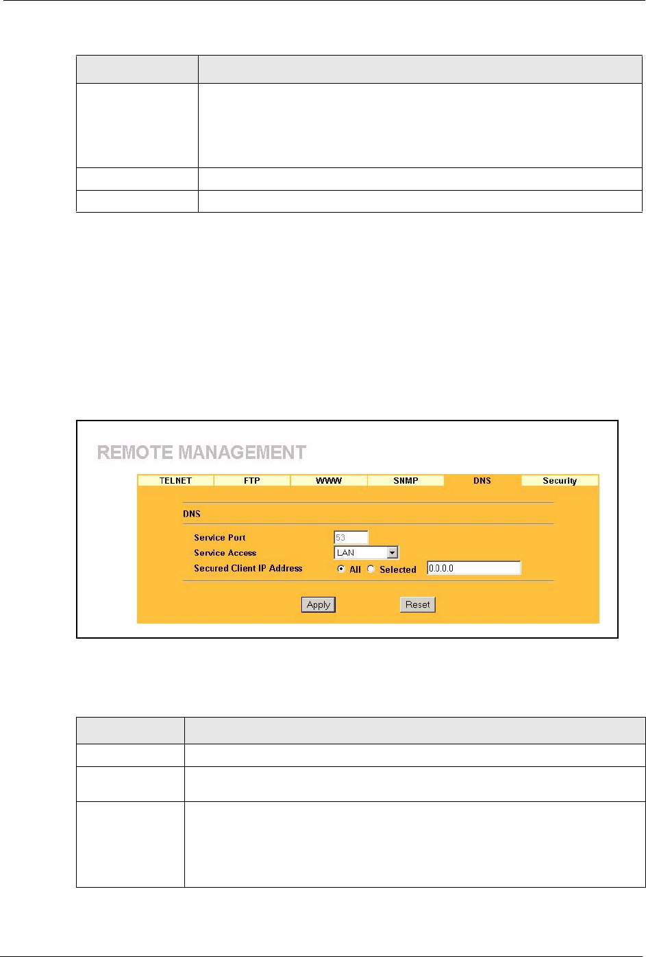
Prestige 334 User’s Guide
Chapter 13 Remote Management Screens 146
13.7 Configuring DNS
Use DNS (Domain Name System) to map a domain name to its corresponding IP address and
vice versa. Refer to the chapter on Wizard Setup for background information.
To change your Prestige’s DNS settings, click REMOTE MGMT, then the DNS tab. The
screen appears as shown.
Figure 54 Remote Management: DNS
The following table describes the labels in this screen.
Secured Client IP
Address
A secured client is a “trusted” computer that is allowed to communicate with the
Prestige using this service.
Select All to allow any computer to access the Prestige using this service.
Choose Selected to just allow the computer with the IP address that you specify
to access the Prestige using this service.
Apply Click Apply to save your customized settings and exit this screen.
Reset Click Reset to begin configuring this screen afresh.
Table 42 Remote Management: SNMP
LABEL DESCRIPTION
Table 43 Remote Management: DNS
LABEL DESCRIPTION
Server Port The DNS service port number is 53 and cannot be changed here.
Server Access Select the interface(s) through which a computer may send DNS queries to the
Prestige.
Secured Client IP
Address
A secured client is a “trusted” computer that is allowed to send DNS queries to the
Prestige.
Select All to allow any computer to send DNS queries to the Prestige.
Choose Selected to just allow the computer with the IP address that you specify to
send DNS queries to the Prestige.
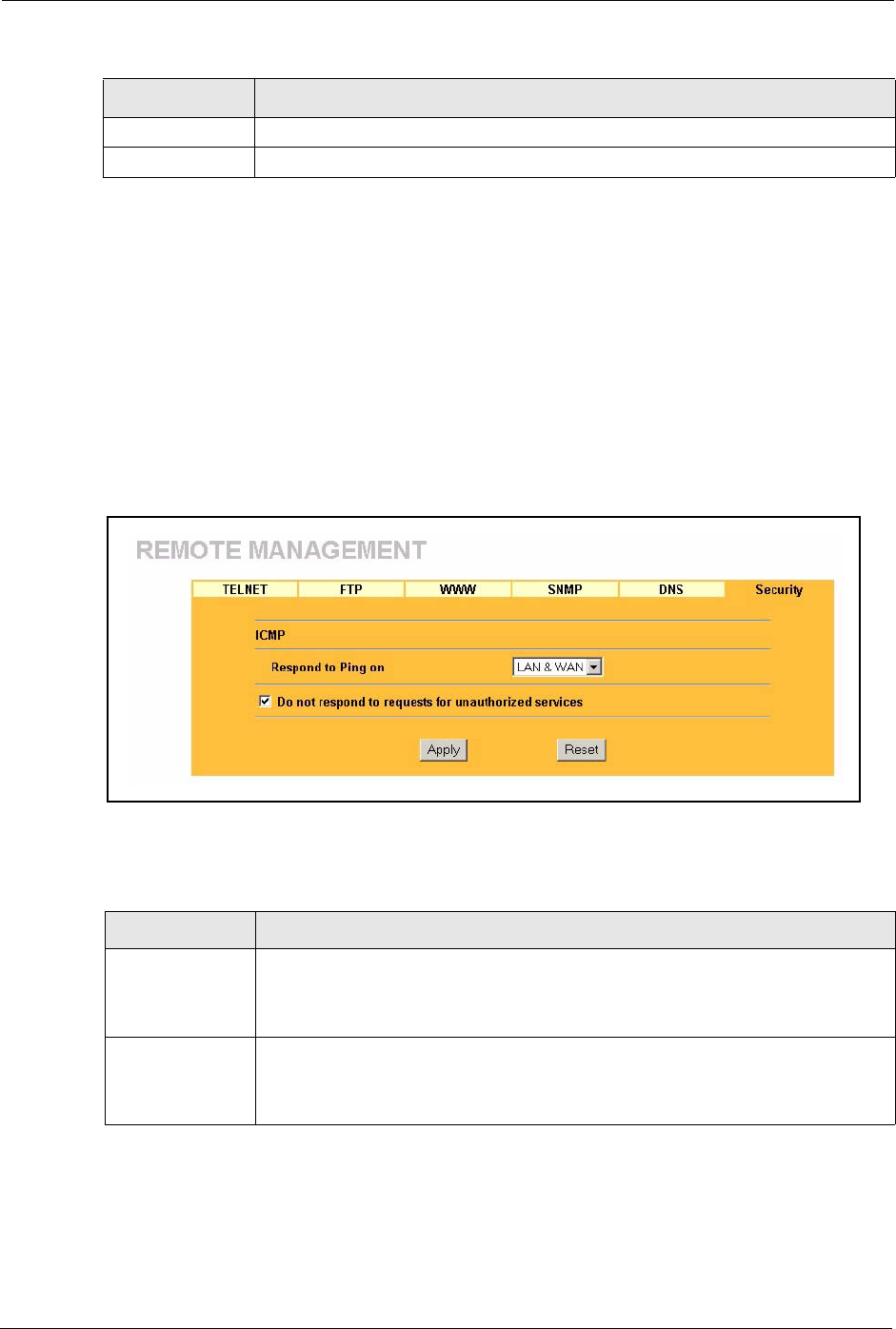
Prestige 334 User’s Guide
147 Chapter 13 Remote Management Screens
13.8 Configuring Security
To change your Prestige’s security settings, click REMOTE MGMT, then the Security tab.
The screen appears as shown.
If an outside user attempts to probe an unsupported port on your Prestige, an ICMP response
packet is automatically returned. This allows the outside user to know the Prestige exists.
Your Prestige supports anti-probing, which prevents the ICMP response packet from being
sent. This keeps outsiders from discovering your Prestige when unsupported ports are probed.
Figure 55 Security
The following table describes the labels in this screen.
Apply Click Apply to save your customized settings and exit this screen.
Reset Click Reset to begin configuring this screen afresh.
Table 43 Remote Management: DNS
LABEL DESCRIPTION
Table 44 Security
LABEL DESCRIPTION
ICMP Internet Control Message Protocol is a message control and error-reporting
protocol between a host server and a gateway to the Internet. ICMP uses Internet
Protocol (IP) datagrams, but the messages are processed by the TCP/IP software
and directly apparent to the application user.
Respond to Ping
on
The Prestige will not respond to any incoming Ping requests when Disable is
selected. Select LAN to reply to incoming LAN Ping requests. Select WAN to reply
to incoming WAN Ping requests. Otherwise select LAN & WAN to reply to both
incoming LAN and WAN Ping requests.

Prestige 334 User’s Guide
Chapter 13 Remote Management Screens 148
Do not respond to
requests for
unauthorized
services
Select this option to prevent hackers from finding the Prestige by probing for
unused ports. If you select this option, the Prestige will not respond to port
request(s) for unused ports, thus leaving the unused ports and the Prestige unseen.
By default this option is not selected and the Prestige will reply with an ICMP Port
Unreachable packet for a port probe on its unused UDP ports, and a TCP Reset
packet for a port probe on its unused TCP ports.
Note that the probing packets must first traverse the Prestige's firewall mechanism
before reaching this anti-probing mechanism. Therefore if the firewall mechanism
blocks a probing packet, the Prestige reacts based on the firewall policy, which by
default, is to send a TCP reset packet for a blocked TCP packet. You can use the
command "sys firewall tcprst rst [on|off]" to change this policy. When the firewall
mechanism blocks a UDP packet, it drops the packet without sending a response
packet.
Apply Click Apply to save your customized settings and exit this screen.
Reset Click Reset to begin configuring this screen afresh.
Table 44 Security
LABEL DESCRIPTION

Prestige 334 User’s Guide
149 Chapter 13 Remote Management Screens

Prestige 334 User’s Guide
Chapter 14 Introduction to IPSec 150
CHAPTER 14
Introduction to IPSec
This chapter introduces the basics of IPSec VPNs
14.1 VPN Overview
A VPN (Virtual Private Network) provides secure communications between sites without the
expense of leased site-to-site lines. A secure VPN is a combination of tunneling, encryption,
authentication, access control and auditing technologies/services used to transport traffic over
the Internet or any insecure network that uses the TCP/IP protocol suite for communication.
14.1.1 IPSec
Internet Protocol Security (IPSec) is a standards-based VPN that offers flexible solutions for
secure data communications across a public network like the Internet. IPSec is built around a
number of standardized cryptographic techniques to provide confidentiality, data integrity and
authentication at the IP layer.
14.1.2 Security Association
A Security Association (SA) is a contract between two parties indicating what security
parameters, such as keys and algorithms they will use.
14.1.3 Other Terminology
14.1.3.1 Encryption
Encryption is a mathematical operation that transforms data from "plaintext" (readable) to
"ciphertext" (scrambled text) using a "key". The key and clear text are processed by the
encryption operation, which leads to the data scrambling that makes encryption secure.
Decryption is the opposite of encryption: it is a mathematical operation that transforms
“ciphertext” to plaintext. Decryption also requires a key.
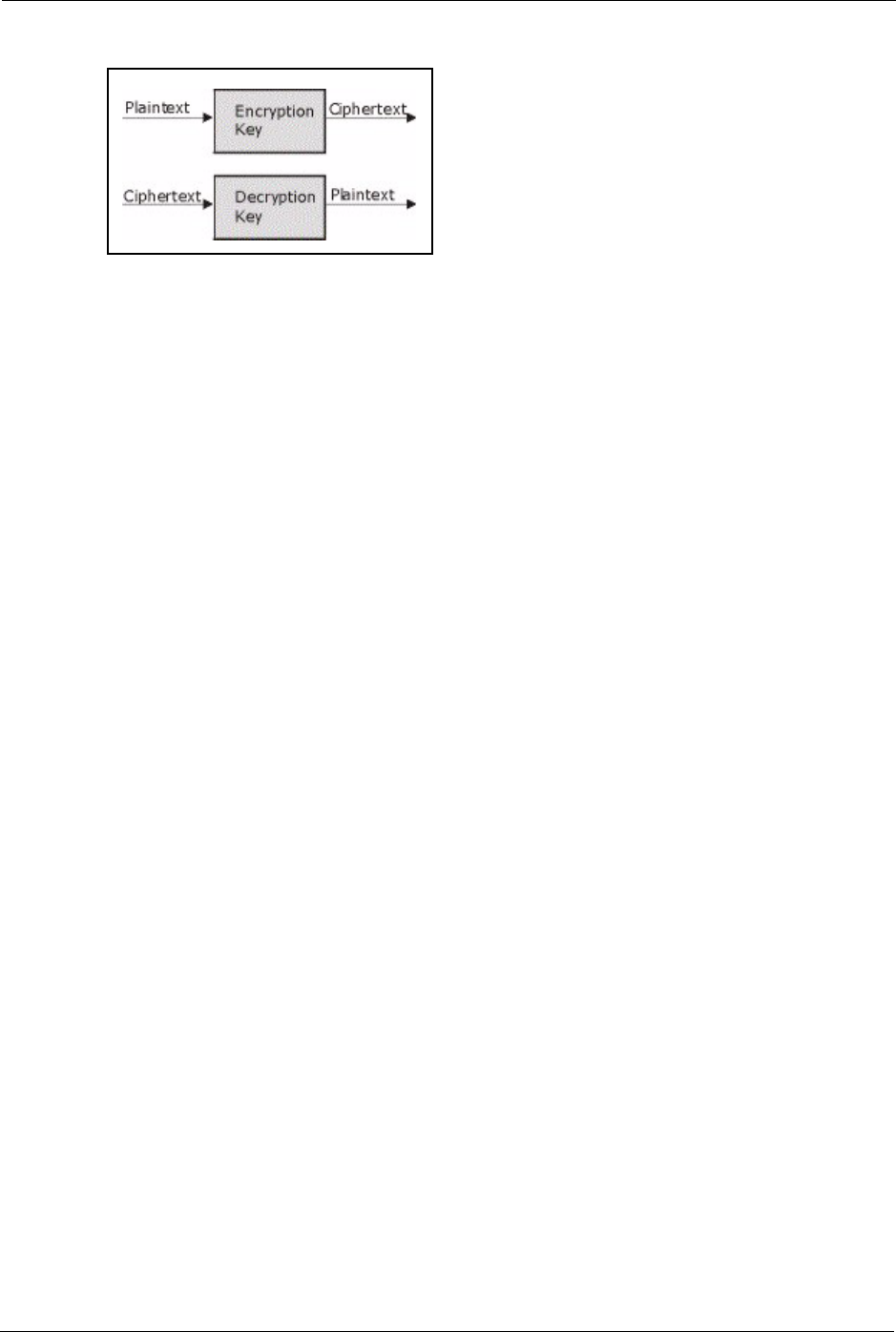
Prestige 334 User’s Guide
151 Chapter 14 Introduction to IPSec
Figure 56 Encryption and Decryption
14.1.3.2 Data Confidentiality
The IPSec sender can encrypt packets before transmitting them across a network.
14.1.3.3 Data Integrity
The IPSec receiver can validate packets sent by the IPSec sender to ensure that the data has not
been altered during transmission.
14.1.3.4 Data Origin Authentication
The IPSec receiver can verify the source of IPSec packets. This service depends on the data
integrity service.
14.1.4 VPN Applications
The Prestige supports the following VPN applications.
• Linking Two or More Private Networks Together
Connect branch offices and business partners over the Internet with significant cost
savings and improved performance when compared to leased lines between sites.
• Accessing Network Resources When NAT Is Enabled
When NAT is enabled, remote users are not able to access hosts on the LAN unless the
host is designated a public LAN server for that specific protocol. Since the VPN tunnel
terminates inside the LAN, remote users will be able to access all computers that use
private IP addresses on the LAN.
• Unsupported IP Applications
A VPN tunnel may be created to add support for unsupported emerging IP applications.
See the chapter on Getting to Know Your Prestige for an example of a VPN application.
14.2 IPSec Architecture
The overall IPSec architecture is shown as follows.
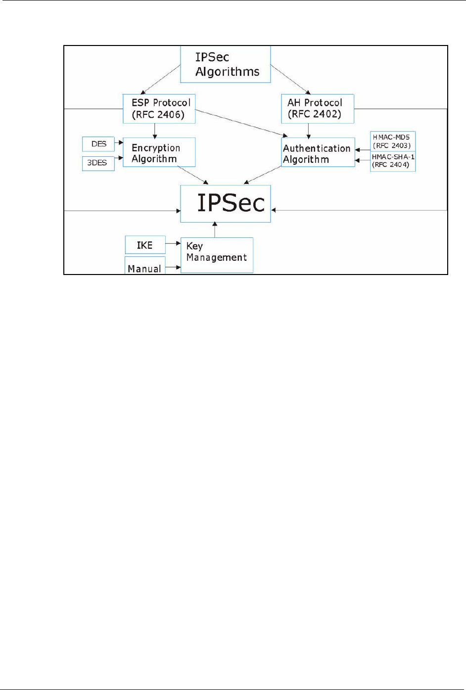
Prestige 334 User’s Guide
Chapter 14 Introduction to IPSec 152
Figure 57 IPSec Architecture
14.2.1 IPSec Algorithms
The ESP (Encapsulating Security Payload) Protocol (RFC 2406) and AH (Authentication
Header) protocol (RFC 2402) describe the packet formats and the default standards for packet
structure (including implementation algorithms).
The Encryption Algorithm describes the use of encryption techniques such as DES (Data
Encryption Standard) and Triple DES algorithms.
The Authentication Algorithms, HMAC-MD5 (RFC 2403) and HMAC-SHA-1 (RFC 2404,
provide an authentication mechanism for the AH and ESP protocols. Please the IPSec
Algorithms section for more information.
14.2.2 Key Management
Key management allows you to determine whether to use IKE (ISAKMP) or manual key
configuration in order to set up a VPN.
14.3 Encapsulation
The two modes of operation for IPSec VPNs are Transport mode and Tunnel mode.
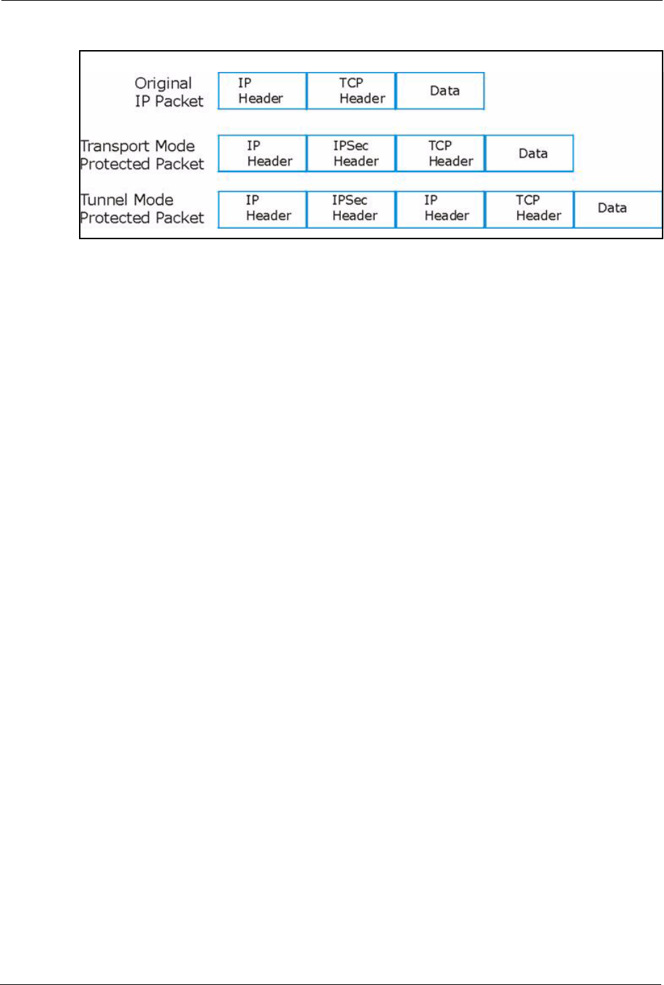
Prestige 334 User’s Guide
153 Chapter 14 Introduction to IPSec
Figure 58 Transport and Tunnel Mode IPSec Encapsulation
14.3.1 Transport Mode
Transport mode is used to protect upper layer protocols and only affects the data in the IP
packet. In Transport mode, the IP packet contains the security protocol (AH or ESP) located
after the original IP header and options, but before any upper layer protocols contained in the
packet (such as TCP and UDP).
With ESP, protection is applied only to the upper layer protocols contained in the packet. The
IP header information and options are not used in the authentication process. Therefore, the
originating IP address cannot be verified for integrity against the data.
With the use of AH as the security protocol, protection is extended forward into the IP header
to verify the integrity of the entire packet by use of portions of the original IP header in the
hashing process.
14.3.2 Tunnel Mode
Tunnel mode encapsulates the entire IP packet to transmit it securely. A Tunnel mode is
required for gateway services to provide access to internal systems. Tunnel mode is
fundamentally an IP tunnel with authentication and encryption. This is the most common
mode of operation. Tunnel mode is required for gateway to gateway and host to gateway
communications. Tunnel mode communications have two sets of IP headers:
•Outside header: The outside IP header contains the destination IP address of the VPN
gateway.
•Inside header: The inside IP header contains the destination IP address of the final
system behind the VPN gateway. The security protocol appears after the outer IP header
and before the inside IP header.
14.4 IPSec and NAT
Read this section if you are running IPSec on a host computer behind the Prestige.

Prestige 334 User’s Guide
Chapter 14 Introduction to IPSec 154
NAT is incompatible with the AH protocol in both Transport and Tunnel mode. An IPSec
VPN using the AH protocol digitally signs the outbound packet, both data payload and
headers, with a hash value appended to the packet. When using AH protocol, packet contents
(the data payload) are not encrypted.
A NAT device in between the IPSec endpoints will rewrite either the source or destination
address with one of its own choosing. The VPN device at the receiving end will verify the
integrity of the incoming packet by computing its own hash value, and complain that the hash
value appended to the received packet doesn't match. The VPN device at the receiving end
doesn't know about the NAT in the middle, so it assumes that the data has been maliciously
altered.
IPSec using ESP in Tunnel mode encapsulates the entire original packet (including headers)
in a new IP packet. The new IP packet's source address is the outbound address of the sending
VPN gateway, and its destination address is the inbound address of the VPN device at the
receiving end. When using ESP protocol with authentication, the packet contents (in this case,
the entire original packet) are encrypted. The encrypted contents, but not the new headers, are
signed with a hash value appended to the packet.
Tunnel mode ESP with authentication is compatible with NAT because integrity checks are
performed over the combination of the "original header plus original payload," which is
unchanged by a NAT device. Transport mode ESP with authentication is not compatible with
NAT, although NAT traversal provides a way to use Transport mode ESP when there is a
NAT router between the IPSec endpoints ( the NAT Traversal section for details).
Table 45 VPN and NAT
SECURITY PROTOCOL MODE NAT
AH Transport N
AH Tunnel N
ESP Transport N
ESP Tunnel Y

Prestige 334 User’s Guide
155 Chapter 14 Introduction to IPSec

Prestige 334 User’s Guide
Chapter 15 VPN Screens 156
CHAPTER 15
VPN Screens
This chapter introduces the VPN Web Configurator. See the Logs chapter for information on
viewing logs and the Appendices for IPSec log descriptions.
15.1 VPN/IPSec Overview
Use the screens documented in this chapter to configure rules for VPN connections and
manage VPN connections.
15.2 IPSec Algorithms
The ESP and AH protocols are necessary to create a Security Association (SA), the
foundation of an IPSec VPN. An SA is built from the authentication provided by the AH and
ESP protocols. The primary function of key management is to establish and maintain the SA
between systems. Once the SA is established, the transport of data may commence.
15.2.1 AH (Authentication Header) Protocol
AH protocol (RFC 2402) was designed for integrity, authentication, sequence integrity (replay
resistance), and non-repudiation but not for confidentiality, for which the ESP was designed.
In applications where confidentiality is not required or not sanctioned by government
encryption restrictions, an AH can be employed to ensure integrity. This type of
implementation does not protect the information from dissemination but will allow for
verification of the integrity of the information and authentication of the originator.
15.2.2 ESP (Encapsulating Security Payload) Protocol
The ESP protocol (RFC 2406) provides encryption as well as some of the services offered by
AH. ESP authenticating properties are limited compared to the AH due to the non-inclusion of
the IP header information during the authentication process. However, ESP is sufficient if
only the upper layer protocols need to be authenticated.

Prestige 334 User’s Guide
157 Chapter 15 VPN Screens
An added feature of the ESP is payload padding, which further protects communications by
concealing the size of the packet being transmitted.
15.3 My IP Address
My IP Address is the WAN IP address of the Prestige. If this field is configured as 0.0.0.0,
then the Prestige will use the current Prestige WAN IP address (static or dynamic) to set up the
VPN tunnel. The Prestige has to rebuild the VPN tunnel if the My IP Address changes after
setup.
15.4 Secure Gateway Address
Secure Gateway Address is the WAN IP address or domain name of the remote IPSec router
(secure gateway).
If the remote secure gateway has a static WAN IP address, enter it in the Secure Gateway
Address field. You may alternatively enter the remote secure gateway’s domain name (if it
has one) in the Secure Gateway Address field.
You can also enter a remote secure gateway’s domain name in the Secure Gateway Address
field if the remote secure gateway has a dynamic WAN IP address and is using DDNS. The
Prestige has to rebuild the VPN tunnel each time the remote secure gateway’s WAN IP
address changes (there may be a delay until the DDNS servers are updated with the remote
gateway’s new WAN IP address).
Table 46 AH and ESP
ESP AH
DES (default)
Data Encryption Standard (DES) is a widely used method
of data encryption using a secret key. DES applies a 56-bit
key to each 64-bit block of data.
MD5 (default)
MD5 (Message Digest 5) produces a 128-
bit digest to authenticate packet data.
3DES
Triple DES (3DES) is a variant of DES, which iterates three
times with three separate keys (3 x 56 = 168 bits),
effectively doubling the strength of DES.
SHA1
SHA1 (Secure Hash Algorithm) produces
a 160-bit digest to authenticate packet
data.
Select DES for minimal security and 3DES for maximum. Select MD5 for minimal security and SHA-
1 for maximum security.
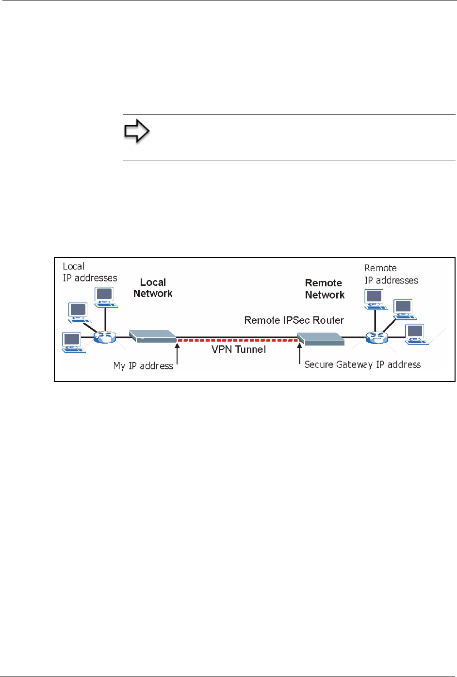
Prestige 334 User’s Guide
Chapter 15 VPN Screens 158
15.4.1 Dynamic Secure Gateway Address
If the remote secure gateway has a dynamic WAN IP address and does not use DDNS, enter
0.0.0.0 as the secure gateway’s address. In this case only the remote secure gateway can
initiate SAs. This may be useful for telecommuters initiating a VPN tunnel to the company
network.
15.5 Summary Screen
The following figure helps explain the main fields in the web configurator.
Figure 59 IPSec Summary Fields
Local and remote IP addresses must be static.
Click VPN to open the Summary screen. This is a read-only menu of your IPSec rules
(tunnels). Edit or create an IPSec rule by selecting an index number and then clicking Edit to
configure the associated submenus.
Note: The Secure Gateway IP Address may be configured as
0.0.0.0 only when using IKE key management and not Manual
key management.
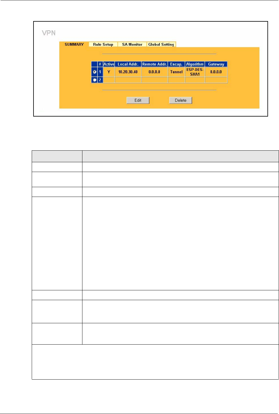
Prestige 334 User’s Guide
159 Chapter 15 VPN Screens
Figure 60 VPN: Summary
The following table describes the labels in this screen.
Table 47 VPN: Summary
LABEL DESCRIPTION
#The VPN policy index number.
Active This field displays whether the VPN policy is active or not. A Y signifies that this
VPN policy is active. N signifies that this VPN policy is not active.
Local Addr. This is the IP address of the computer on your local network behind your Prestige.
Remote Addr. This is the IP address(es) of computer(s) on the remote network behind the
remote IPSec router.
A single (static) IP address is displayed when the Remote Address Start and
Remote Address End/Mask fields in the Rule Setup IKE (or Manual) screen are
both configured to the same IP address.
The beginning and ending (static) IP addresses, in a range of computers are
displayed when the Remote Address Start and Remote Address End/Mask
fields in the Rule Setup IKE (or Manual) screen are configured for a range of IP
addresses.
A (static) IP address and a subnet mask are displayed when the Remote Address
Start and Remote Address End/Mask fields in the Rule Setup IKE (or Manual)
screen are configured for a subnet.
This field displays 0.0.0.0 when the Secure Gateway Address field is set to
0.0.0.0. In this case only the remote IPSec router can initiate the VPN.
Encap. This field displays Tunnel or Transport mode (Tunnel is the default selection).
Algorithm This field displays the security protocols used for an SA.
Both AH and ESP increase Prestige processing requirements and
communications latency (delay).
Gateway This is the static WAN IP address or URL of the remote IPSec router. This field
displays 0.0.0.0 when you configure the Secure Gateway Addr field in the Rule
Setup IKE screen to 0.0.0.0.
Select the radio button next to a VPN index number and then click Edit to edit a specific VPN policy.
Click the radio button next to an empty VPN policy index number and then Edit to add a new VPN
policy.
Select the radio button next to a VPN policy number you want to delete and then click Delete. When a
VPN policy is deleted, subsequent policies do not move up in the list.
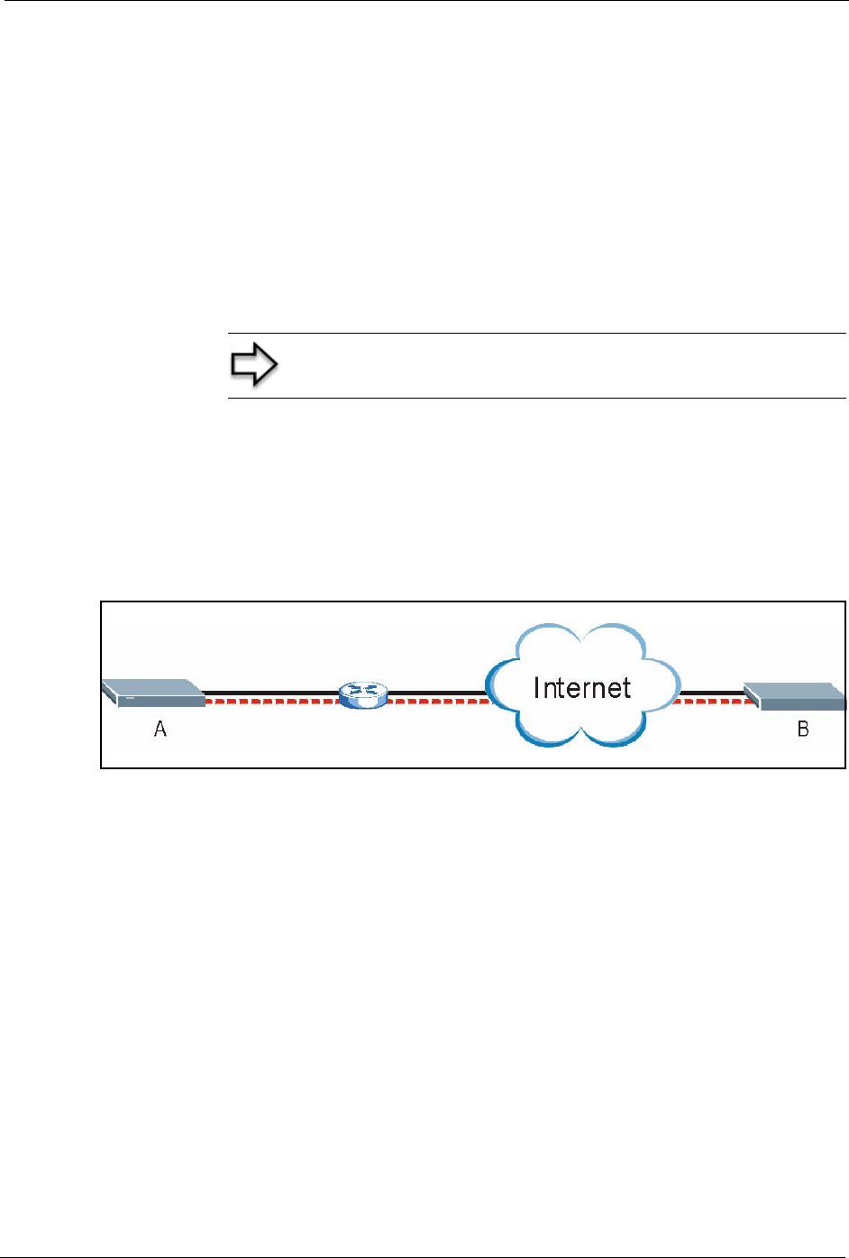
Prestige 334 User’s Guide
Chapter 15 VPN Screens 160
15.6 Keep Alive
When you initiate an IPSec tunnel with keep alive enabled, the Prestige automatically
renegotiates the tunnel when the IPSec SA lifetime period expires ( the IPSec Algorithms
section for more on the IPSec SA lifetime). In effect, the IPSec tunnel becomes an “always
on” connection after you initiate it. Both IPSec routers must have a Prestige-compatible keep
alive feature enabled in order for this feature to work.
If the Prestige has its maximum number of simultaneous IPSec tunnels connected to it and
they all have keep alive enabled, then no other tunnels can take a turn connecting to the
Prestige because the Prestige never drops the tunnels that are already connected.
15.7 NAT Traversal
NAT traversal allows you to set up a VPN connection when there are NAT routers between
IPSec routers A and B.
Figure 61 NAT Router Between IPSec Routers
Normally you cannot set up a VPN connection with a NAT router between the two IPSec
routers because the NAT router changes the header of the IPSec packet. In the previous figure,
IPSec router A sends an IPSec packet in an attempt to initiate a VPN. The NAT router changes
the IPSec packet’s header so it does not match the header for which IPSec router B is
checking. Therefore, IPSec router B does not respond and the VPN connection cannot be built.
NAT traversal solves the problem by adding a UDP port 500 header to the IPSec packet. The
NAT router forwards the IPSec packet with the UDP port 500 header unchanged. IPSec router
B checks the UDP port 500 header and responds. IPSec routers A and B build a VPN
connection.
15.7.1 NAT Traversal Configuration
For NAT traversal to work you must:
• Use ESP security protocol (in either transport or tunnel mode).
• Use IKE keying mode.
Note: When there is outbound traffic with no inbound traffic, the
Prestige automatically drops the tunnel after two minutes.
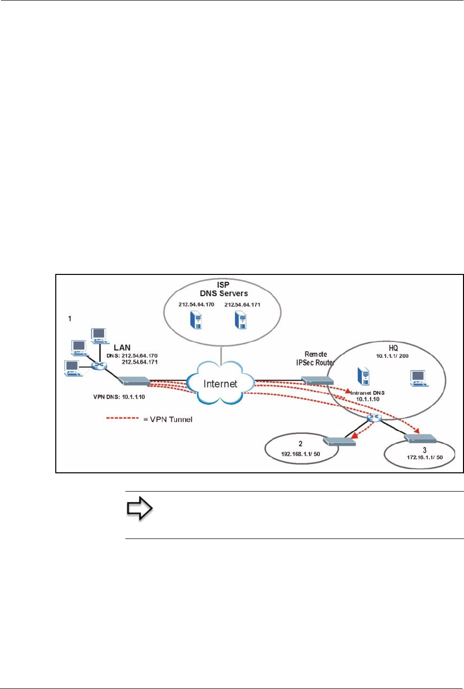
Prestige 334 User’s Guide
161 Chapter 15 VPN Screens
• Enable NAT traversal on both IPSec endpoints.
In order for IPSec router A (see the figure) to receive an initiating IPSec packet from IPSec
router B, set the NAT router to forward UDP port 500 to IPSec router A.
15.7.2 Remote DNS Server
In cases where you want to use domain names to access Intranet servers on a remote network
that has a DNS server, you must identify that DNS server. You cannot use DNS servers on the
LAN or from the ISP since these DNS servers cannot resolve domain names to private IP
addresses on the remote network
The following figure depicts an example where three VPN tunnels are created from Prestige
A; one to branch office 2, one to branch office 3 and another to headquarters. In order to
access computers that use private domain names on the headquarters (HQ) network, the
Prestige at branch office 1 uses the Intranet DNS server in headquarters. The DNS server
feature for VPN does not work with Windows 2000 or Windows XP.
Figure 62 VPN Host using Intranet DNS Server Example
Note: If you do not specify an Intranet DNS server on the
remote network, then the VPN host must use IP addresses to
access the computers on the remote network.
Prestige 334 User’s Guide
Chapter 15 VPN Screens 162
15.8 ID Type and Content
With aggressive negotiation mode (see Section Negotiation Mode), the Prestige identifies
incoming SAs by ID type and content since this identifying information is not encrypted. This
enables the Prestige to distinguish between multiple rules for SAs that connect from remote
IPSec routers that have dynamic WAN IP addresses. Telecommuters can use separate
passwords to simultaneously connect to the Prestige from IPSec routers with dynamic IP
addresses (see the Telecommuter VPN/IPSec Examples section for a telecommuter
configuration example).
With main mode (see Section Negotiation Mode), the ID type and content are encrypted to
provide identity protection. In this case the Prestige can only distinguish between up to eight
different incoming SAs that connect from remote IPSec routers that have dynamic WAN IP
addresses. The Prestige can distinguish up to eight incoming SAs because you can select
between three encryption algorithms (DES and 3DES), two authentication algorithms (MD5
and SHA1) and two key groups (DH1 and DH2) when you configure a VPN rule ( the
Configuring Advanced IKE Settings section ). The ID type and content act as an extra level of
identification for incoming SAs.
The type of ID can be a domain name, an IP address or an e-mail address. The content is the IP
address, domain name, or e-mail address.
Note: Regardless of the ID type and content configuration, the
Prestige does not allow you to save multiple active rules with
overlapping local and remote IP addresses.
Table 48 Local ID Type and Content Fields
LOCAL ID TYPE CONTENT
IP Type the IP address of your computer or leave the field blank to have the Prestige
automatically use its own IP address.
DNS Type a domain name (up to 31 characters) by which to identify this Prestige.
E-mail Type an e-mail address (up to 31 characters) by which to identify this Prestige.
The domain name or e-mail address that you use in the Content field is used for identification purposes
only and does not need to be a real domain name or e-mail address.
Table 49 Peer ID Type and Content Fields
PEER ID TYPE CONTENT
IP Type the IP address of the computer with which you will make the VPN connection or
leave the field blank to have the Prestige automatically use the address in the Secure
Gateway Address field.
DNS Type a domain name (up to 31 characters) by which to identify the remote IPSec
router.
Prestige 334 User’s Guide
163 Chapter 15 VPN Screens
15.8.1 ID Type and Content Examples
Two IPSec routers must have matching ID type and content configuration in order to set up a
VPN tunnel.
The two Prestiges in this example can complete negotiation and establish a VPN tunnel
The two Prestiges in this example cannot complete their negotiation because Prestige B’s
Local ID type is IP, but Prestige A’s Peer ID type is set to E-mail. An “ID mismatched”
message displays in the IPSEC LOG.
15.9 Pre-Shared Key
A pre-shared key identifies a communicating party during a phase 1 IKE negotiation (see
Section IKE Phases for more on IKE phases). It is called “pre-shared” because you have to
share it with another party before you can communicate with them over a secure connection.
E-mail Type an e-mail address (up to 31 characters) by which to identify the remote IPSec
router.
The domain name or e-mail address that you use in the Content field is used for identification purposes
only and does not need to be a real domain name or e-mail address. The domain name also does not
have to match the remote router’s IP address or what you configure in the Secure Gateway Address
field below.
Table 49 Peer ID Type and Content Fields
PEER ID TYPE CONTENT
Table 50 Matching ID Type and Content Configuration Example
PRESTIGE A PRESTIGE B
Local ID type: E-mail Local ID type: IP
Local ID content: tom@yourcompany.com Local ID content: 1.1.1.2
Peer ID type: IP Peer ID type: E-mail
Peer ID content: 1.1.1.2 Peer ID content: tom@yourcompany.com
Figure 63 Mismatching ID Type and Content Configuration Example
PRESTIGE A PRESTIGE B
Local ID type: IP Local ID type: IP
Local ID content: 1.1.1.10 Local ID content: 1.1.1.10
Peer ID type: E-mail Peer ID type: IP
Peer ID content: aa@yahoo.com Peer ID content: N/A
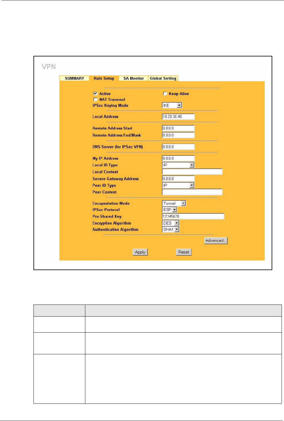
Prestige 334 User’s Guide
Chapter 15 VPN Screens 164
15.10 Editing VPN Rules
Click Edit on the Summary screen or click the Rule Setup tab to edit VPN rules.
Figure 64 VPN: Rule Setup (Basic)
The following table describes the labels in this screen.
Table 51 VPN: Rule Setup (Basic)
LABEL DESCRIPTION
Active Select this check box to activate this VPN tunnel. This option determines whether
a VPN rule is applied before a packet leaves the firewall.
Keep Alive Select this check box to have the Prestige automatically re-initiate the SA after
the SA lifetime times out, even if there is no traffic. The remote IPSec router must
also have keep alive enabled in order for this feature to work.
NAT Traversal Select this check box to enable NAT traversal. NAT traversal allows you to set up
a VPN connection when there are NAT routers between the two IPSec routers.
The remote IPSec router must also have NAT traversal enabled.
You can use NAT traversal with ESP protocol using Transport or Tunnel mode,
but not with AH protocol nor with manual key management. In order for an IPSec
router behind a NAT router to receive an initiating IPSec packet, set the NAT
router to forward UDP port 500 to the IPSec router behind the NAT router.

Prestige 334 User’s Guide
165 Chapter 15 VPN Screens
IPSec Keying Mode Select IKE or Manual from the drop-down list box. IKE provides more protection
so it is generally recommended. Manual is a useful option for troubleshooting.
Local Address The local IP address must be static and correspond to the remote IPSec router's
configured remote IP addresses.
Two active SAs can have the same local or remote IP address, but not both. You
can configure multiple SAs between the same local and remote IP addresses, as
long as only one is active at any time.
Remote Address
Start
Remote IP addresses must be static and correspond to the remote IPSec
router's configured local IP addresses. The remote address fields do not apply
when the Secure Gateway Address field is configured to 0.0.0.0. In this case
only the remote IPSec router can initiate the VPN.
Two active SAs cannot have the local and remote IP address(es) both the same.
Two active SAs can have the same local or remote IP address, but not both. You
can configure multiple SAs between the same local and remote IP addresses, as
long as only one is active at any time.
Enter a (static) IP address on the network behind the remote IPSec router.
Remote Address
End/Mask
When the remote IP address is a single address, type it a second time here.
When the remote IP address is a range, enter the end (static) IP address, in a
range of computers on the network behind the remote IPSec router.
When the remote IP address is a subnet address, enter a subnet mask on the
network behind the remote IPSec router.
DNS Server (for
IPSec VPN)
If there is a private DNS server that services the VPN, type its IP address here.
The Prestige assigns this additional DNS server to the Prestige’s DHCP clients
that have IP addresses in this IPSec rule's range of local addresses. A DNS
server allows clients on the VPN to find other computers and servers on the VPN
by their (private) domain names.
My IP Address Enter the WAN IP address of your Prestige. The Prestige uses its current WAN
IP address (static or dynamic) in setting up the VPN tunnel if you leave this field
as 0.0.0.0.
The VPN tunnel has to be rebuilt if this IP address changes.
Local ID Type Select IP to identify this Prestige by its IP address.
Select DNS to identify this Prestige by a domain name.
Select E-mail to identify this Prestige by an e-mail address.
Local Content When you select IP in the Local ID Type field, type the IP address of your
computer in the local Content field. The Prestige automatically uses the IP
address in the My IP Address field (refer to the My IP Address field description)
if you configure the local Content field to 0.0.0.0 or leave it blank.
It is recommended that you type an IP address other than 0.0.0.0 in the local
Content field or use the DNS or E-mail ID type in the following situations.
When there is a NAT router between the two IPSec routers.
When you want the remote IPSec router to be able to distinguish between VPN
connection requests that come in from IPSec routers with dynamic WAN IP
addresses.
When you select DNS or E-mail in the Local ID Type field, type a domain name
or e-mail address by which to identify this Prestige in the local Content field. Use
up to 31 ASCII characters including spaces, although trailing spaces are
truncated. The domain name or e-mail address is for identification purposes only
and can be any string.
Table 51 VPN: Rule Setup (Basic)
LABEL DESCRIPTION

Prestige 334 User’s Guide
Chapter 15 VPN Screens 166
Secure Gateway
Address
Type the WAN IP address or the URL (up to 31 characters) of the IPSec router
with which you're making the VPN connection. Set this field to 0.0.0.0 if the
remote IPSec router has a dynamic WAN IP address (the IPSec Keying Mode
field must be set to IKE). The remote address fields do not apply when the
Secure Gateway Address field is configured to 0.0.0.0. In this case only the
remote IPSec router can initiate the VPN.
Peer ID Type Select IP to identify the remote IPSec router by its IP address.
Select DNS to identify the remote IPSec router by a domain name.
Select E-mail to identify the remote IPSec router by an e-mail address.
Peer Content The configuration of the peer content depends on the peer ID type.
For IP, type the IP address of the computer with which you will make the VPN
connection. If you configure this field to 0.0.0.0 or leave it blank, the Prestige will
use the address in the Secure Gateway Address field (refer to the Secure
Gateway Address field description).
For DNS or E-mail, type a domain name or e-mail address by which to identify
the remote IPSec router. Use up to 31 ASCII characters including spaces,
although trailing spaces are truncated. The domain name or e-mail address is for
identification purposes only and can be any string.
It is recommended that you type an IP address other than 0.0.0.0 or use the DNS
or E-mail ID type in the following situations:
When there is a NAT router between the two IPSec routers.
When you want the Prestige to distinguish between VPN connection requests
that come in from remote IPSec routers with dynamic WAN IP addresses.
Encapsulation
Mode
Select Tunnel mode or Transport mode from the drop-down list box.
IPSec Protocol Select ESP if you want to use ESP (Encapsulation Security Payload). The ESP
protocol (RFC 2406) provides encryption as well as some of the services offered
by AH. If you select ESP here, you must select options from the Encryption
Algorithm and Authentication Algorithm fields (described next).
Select AH if you want to use AH (Authentication Header Protocol). The AH
protocol (RFC 2402) was designed for integrity, authentication, sequence
integrity (replay resistance), and non-repudiation but not for confidentiality, for
which the ESP was designed. If you select AH here, you must select options
from the Authentication Algorithm field (described later).
Pre-Shared Key Type your pre-shared key in this field. A pre-shared key identifies a
communicating party during a phase 1 IKE negotiation. It is called "pre-shared"
because you have to share it with another party before you can communicate
with them over a secure connection.
Type from 8 to 31 case-sensitive ASCII characters or from 16 to 62 hexadecimal
("0-9", "A-F") characters. You must precede a hexadecimal key with a "0x” (zero
x), which is not counted as part of the 16 to 62 character range for the key. For
example, in "0x0123456789ABCDEF", “0x” denotes that the key is hexadecimal
and “0123456789ABCDEF” is the key itself.
Both ends of the VPN tunnel must use the same pre-shared key. You will receive
a “PYLD_MALFORMED” (payload malformed) packet if the same pre-shared key
is not used on both ends
Encryption
Algorithm
Select DES or 3DES from the drop-down list box. The Prestige’s encryption
algorithm should be identical to the secure remote gateway. When DES is used
for data communications, both sender and receiver must know the same secret
key, which can be used to encrypt and decrypt the message. The DES
encryption algorithm uses a 56-bit key. Triple DES (3DES) is a variation on DES
that uses a 168-bit key. As a result, 3DES is more secure than DES. It also
requires more processing power, resulting in increased latency and decreased
throughput.
Table 51 VPN: Rule Setup (Basic)
LABEL DESCRIPTION
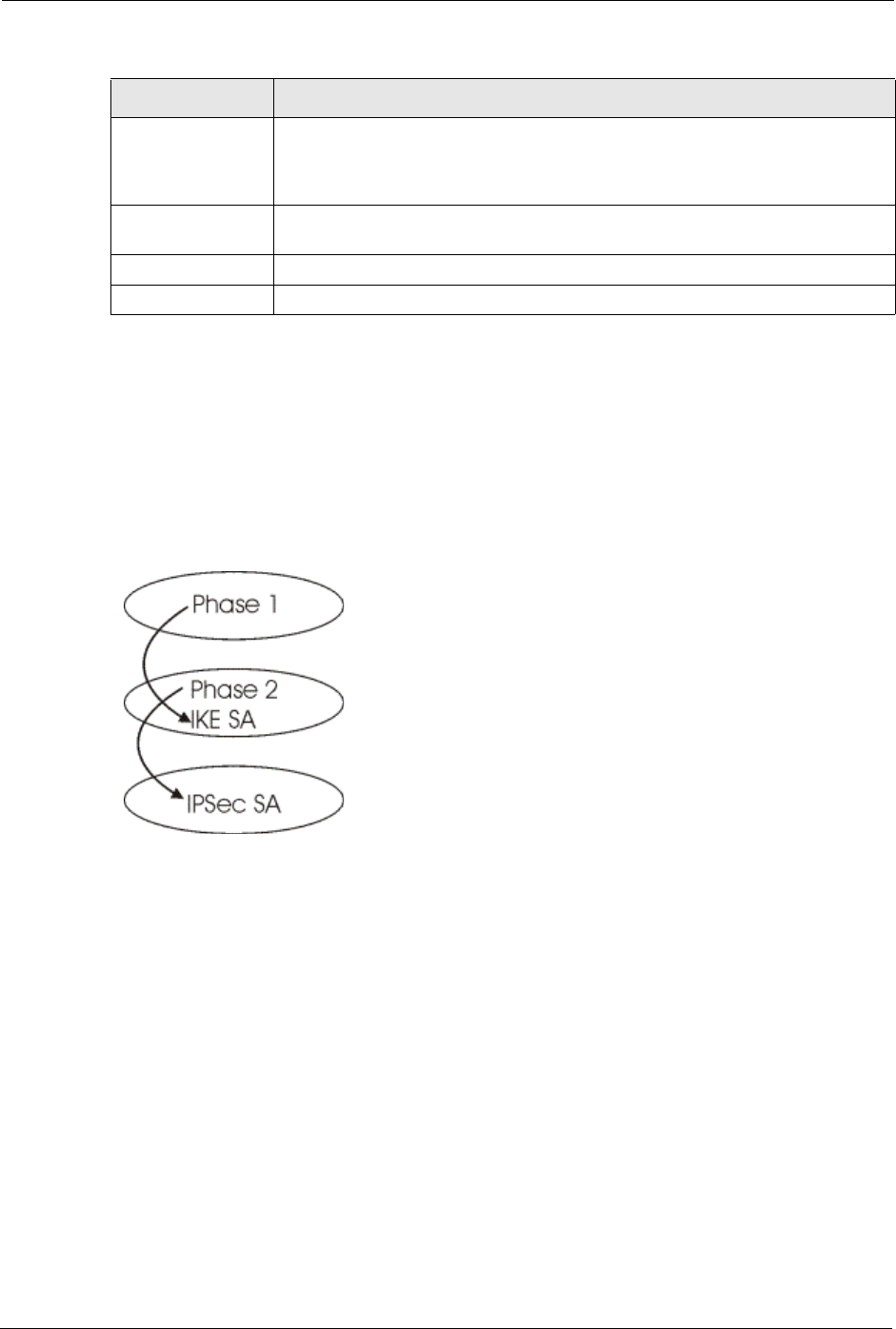
Prestige 334 User’s Guide
167 Chapter 15 VPN Screens
15.11 IKE Phases
There are two phases to every IKE (Internet Key Exchange) negotiation – phase 1
(Authentication) and phase 2 (Key Exchange). A phase 1 exchange establishes an IKE SA and
the second one uses that SA to negotiate SAs for IPSec.
Figure 65 Two Phases to Set Up the IPSec SA
In phase 1 you must:
• Choose a negotiation mode.
• Authenticate the connection by entering a pre-shared key.
• Choose an encryption algorithm.
• Choose an authentication algorithm.
• Choose a Diffie-Hellman public-key cryptography key group (DH1 or DH2).
Set the IKE SA lifetime. This field allows you to determine how long an IKE SA should stay
up before it times out. An IKE SA times out when the IKE SA lifetime period expires. If an
IKE SA times out when an IPSec SA is already established, the IPSec SA stays connected.
In phase 2 you must:
• Choose which protocol to use (ESP or AH) for the IKE key exchange.
Authentication
Algorithm
Select SHA1 or MD5 from the drop-down list box. MD5 (Message Digest 5) and
SHA1 (Secure Hash Algorithm) are hash algorithms used to authenticate packet
data. The SHA1 algorithm is generally considered stronger than MD5, but is
slower. Select MD5 for minimal security and SHA-1 for maximum security.
Advanced Click Advanced to configure more detailed settings of your IKE key
management.
Apply Click Apply to save your changes back to the Prestige.
Reset Click Reset to begin configuring this screen afresh.
Table 51 VPN: Rule Setup (Basic)
LABEL DESCRIPTION

Prestige 334 User’s Guide
Chapter 15 VPN Screens 168
• Choose an encryption algorithm.
• Choose an authentication algorithm
• Choose whether to enable Perfect Forward Secrecy (PFS) using Diffie-Hellman public-
key cryptography – see Section Perfect Forward Secrecy (PFS). Select None (the default)
to disable PFS.
Choose Tunnel mode or Transport mode.
Set the IPSec SA lifetime. This field allows you to determine how long the IPSec SA should
stay up before it times out. The Prestige automatically renegotiates the IPSec SA if there is
traffic when the IPSec SA lifetime period expires. The Prestige also automatically renegotiates
the IPSec SA if both IPSec routers have keep alive enabled, even if there is no traffic. If an
IPSec SA times out, then the IPSec router must renegotiate the SA the next time someone
attempts to send traffic.
15.11.1 Negotiation Mode
The phase 1 Negotiation Mode you select determines how the Security Association (SA) will
be established for each connection through IKE negotiations.
•Main Mode ensures the highest level of security when the communicating parties are
negotiating authentication (phase 1). It uses 6 messages in three round trips: SA
negotiation, Diffie-Hellman exchange and an exchange of nonces (a nonce is a random
number). This mode features identity protection (your identity is not revealed in the
negotiation).
•Aggressive Mode is quicker than Main Mode because it eliminates several steps when
the communicating parties are negotiating authentication (phase 1). However the trade-
off is that faster speed limits its negotiating power and it also does not provide identity
protection. It is useful in remote access situations where the address of the initiator is not
know by the responder and both parties want to use pre-shared key authentication.
15.11.2 Diffie-Hellman (DH) Key Groups
Diffie-Hellman (DH) is a public-key cryptography protocol that allows two parties to establish
a shared secret over an unsecured communications channel. Diffie-Hellman is used within
IKE SA setup to establish session keys. 768-bit (Group 1 - DH1) and 1024-bit (Group 2 –
DH2) Diffie-Hellman groups are supported. Upon completion of the Diffie-Hellman
exchange, the two peers have a shared secret, but the IKE SA is not authenticated. For
authentication, use pre-shared keys.
15.11.3 Perfect Forward Secrecy (PFS)
Enabling PFS means that the key is transient. The key is thrown away and replaced by a brand
new key using a new Diffie-Hellman exchange for each new IPSec SA setup. With PFS
enabled, if one key is compromised, previous and subsequent keys are not compromised,
because subsequent keys are not derived from previous keys. The (time-consuming) Diffie-
Hellman exchange is the trade-off for this extra security.

Prestige 334 User’s Guide
169 Chapter 15 VPN Screens
This may be unnecessary for data that does not require such security, so PFS is disabled
(None) by default in the Prestige. Disabling PFS means new authentication and encryption
keys are derived from the same root secret (which may have security implications in the long
run) but allows faster SA setup (by bypassing the Diffie-Hellman key exchange).
15.12 Configuring Advanced IKE Settings
Select Advanced at the bottom of the Rule Setup IKE screen. This is the Rule Setup IKE-
Advanced screen as shown next.
Prestige 334 User’s Guide
Chapter 15 VPN Screens 170
Figure 66 VPN IKE: Advanced

Prestige 334 User’s Guide
171 Chapter 15 VPN Screens
The following table describes the labels in this screen.
Table 52 VPN IKE: Advanced
LABEL DESCRIPTION
Active Select this check box to activate this VPN policy.
Keep Alive Select this check box to turn on the Keep Alive feature for this SA.
Turn on Keep Alive to have the Prestige automatically reinitiate the SA after
the SA lifetime times out, even if there is no traffic. The remote IPSec router
must also have keep alive enabled in order for this feature to work.
NAT Traversal Select this check box to enable NAT traversal. NAT traversal allows you to set
up a VPN connection when there are NAT routers between the two IPSec
routers.
The remote IPSec router must also have NAT traversal enabled.
You can use NAT traversal with ESP protocol using Transport or Tunnel
mode, but not with AH protocol nor with manual key management. In order for
an IPSec router behind a NAT router to receive an initiating IPSec packet, set
the NAT router to forward UDP port 500 to the IPSec router behind the NAT
router.
IPSec Keying Mode The advanced configuration page is only available with the IKE IPSec keying
mode.
Click the Basic button below in order to be able to choose the Manual IPSec
keying mode.
Make sure the remote gateway has the same configuration in this field.
Protocol Number Enter 1 for ICMP, 6 for TCP, 17 for UDP, etc. 0 is the default and signifies any
protocol.
Enable Replay
Detection
As a VPN setup is processing intensive, the system is vulnerable to Denial of
Service (DOS) attacks The IPSec receiver can detect and reject old or
duplicate packets to protect against replay attacks. Enable replay detection by
setting this field to Yes.
Local Address The local IP address must be static and correspond to the remote IPSec
router's configured remote IP addresses.
Two active SAs can have the same local or remote IP address, but not both.
You can configure multiple SAs between the same local and remote IP
addresses, as long as only one is active at any time.
Local Port Start 0 is the default and signifies any port. Type a port number from 0 to 65535.
Some of the most common IP ports are: 21, FTP; 53, DNS; 23, Telnet; 80,
HTTP; 25, SMTP; 110, POP3
Local Port End Enter a port number in this field to define a port range. This port number must
be greater than that specified in the previous field (or equal to it for configuring
an individual port).
Remote Address Start Remote IP addresses must be static and correspond to the remote IPSec
router's configured local IP addresses. The remote address fields do not apply
when the Secure Gateway Address field is configured to 0.0.0.0. In this case
only the remote IPSec router can initiate the VPN.
Two active SAs cannot have the local and remote IP address(es) both the
same. Two active SAs can have the same local or remote IP address, but not
both. You can configure multiple SAs between the same local and remote IP
addresses, as long as only one is active at any time.
Enter a (static) IP address on the network behind the remote IPSec router.

Prestige 334 User’s Guide
Chapter 15 VPN Screens 172
Remote Address End/
Mask
When the remote IP address is a single address, type it a second time here.
When the remote IP address is a range, enter the end (static) IP address, in a
range of computers on the network behind the remote IPSec router.
When the remote IP address is a subnet address, enter a subnet mask on the
network behind the remote IPSec router.
Remote Port Start 0 is the default and signifies any port. Type a port number from 0 to 65535.
Some of the most common IP ports are: 21, FTP; 53, DNS; 23, Telnet; 80,
HTTP; 25, SMTP; 110, POP3
Remote Port End Enter a port number in this field to define a port range. This port number must
be greater than that specified in the previous field (or equal to it for configuring
an individual port).
DNS Server (for IPSec
VPN)
If there is a private DNS server that services the VPN, type its IP address here.
The Prestige assigns this additional DNS server to the Prestige’s DHCP
clients that have IP addresses in this IPSec rule's range of local addresses. A
DNS server allows clients on the VPN to find other computers and servers on
the VPN by their (private) domain names.
My IP Address Enter the WAN IP address of your Prestige. The Prestige uses its current WAN
IP address (static or dynamic) in setting up the VPN tunnel if you leave this
field as 0.0.0.0. The VPN tunnel has to be rebuilt if this IP address changes.
Local ID Type Select IP to identify this Prestige by its IP address.
Select DNS to identify this Prestige by a domain name.
Select E-mail to identify this Prestige by an e-mail address.
Local Content When you select IP in the Local ID Type field, type the IP address of your
computer in the local Content field. The Prestige automatically uses the IP
address in the My IP Address field (refer to the My IP Address field
description) if you configure the local Content field to 0.0.0.0 or leave it blank.
It is recommended that you type an IP address other than 0.0.0.0 in the local
Content field or use the DNS or E-mail ID type in the following situations.
• When there is a NAT router between the two IPSec routers.
• When you want the remote IPSec router to be able to distinguish between
VPN connection requests that come in from IPSec routers with dynamic
WAN IP addresses.
When you select DNS or E-mail in the Local ID Type field, type a domain
name or e-mail address by which to identify this Prestige in the local Content
field. Use up to 31 ASCII characters including spaces, although trailing spaces
are truncated. The domain name or e-mail address is for identification
purposes only and can be any string.
Secure Gateway
Address
Type the WAN IP address or the URL (up to 31 characters) of the remote
secure gateway with which you're making the VPN connection. Set this field to
0.0.0.0 if the remote secure gateway has a dynamic WAN IP address (the
IPSec Keying Mode field must be set to IKE).
Peer ID Type Select IP to identify the remote IPSec router by its IP address.
Select DNS to identify the remote IPSec router by a domain name.
Select E-mail to identify the remote IPSec router by an e-mail address.
Table 52 VPN IKE: Advanced
LABEL DESCRIPTION

Prestige 334 User’s Guide
173 Chapter 15 VPN Screens
Peer Content The configuration of the peer content depends on the peer ID type.
•For IP, type the IP address of the computer with which you will make the
VPN connection. If you configure this field to 0.0.0.0 or leave it blank, the
Prestige will use the address in the Secure Gateway Address field (refer
to the Secure Gateway Address field description).
•For DNS or E-mail, type a domain name or e-mail address by which to
identify the remote IPSec router. Use up to 31 ASCII characters including
spaces, although trailing spaces are truncated. The domain name or e-mail
address is for identification purposes only and can be any string.
It is recommended that you type an IP address other than 0.0.0.0 or use the
DNS or E-mail ID type in the following situations:
• When there is a NAT router between the two IPSec routers.
When you want the Prestige to distinguish between VPN connection requests
that come in from remote IPSec routers with dynamic WAN IP addresses.
IKE Phase 1 A phase 1 exchange establishes an IKE SA (Security Association).
Negotiation Mode Select Main or Aggressive from the drop-down list box. The Prestige's
negotiation mode should be identical to that on the remote secure gateway.
Encryption Algorithm Select DES or 3DES from the drop-down list box. The Prestige's encryption
algorithm should be identical to the secure remote gateway. When DES is
used for data communications, both sender and receiver must know the same
secret key, which can be used to encrypt and decrypt the message. The DES
encryption algorithm uses a 56-bit key. Triple DES (3DES) is a variation on
DES that uses a 168-bit key. As a result, 3DES is more secure than DES. It
also requires more processing power, resulting in increased latency and
decreased throughput.
Authentication
Algorithm
Select SHA1 or MD5 from the drop-down list box. The Prestige's
authentication algorithm should be identical to the secure remote gateway.
MD5 (Message Digest 5) and SHA1 (Secure Hash Algorithm) are hash
algorithms used to authenticate the source and integrity of packet data. The
SHA1 algorithm is generally considered stronger than MD5, but is slower.
Select SHA-1 for maximum security.
SA Life Time Define the length of time before an IKE SA automatically renegotiates in this
field. It may range from 60 to 3,000,000 seconds (almost 35 days). A short SA
Life Time increases security by forcing the two VPN gateways to update the
encryption and authentication keys. However, every time the VPN tunnel
renegotiates, all users accessing remote resources are temporarily
disconnected.
Key Group You must choose a key group for phase 1 IKE setup. DH1 (default) refers to
Diffie-Hellman Group 1 a 768 bit random number. DH2 refers to Diffie-Hellman
Group 2 a 1024 bit (1Kb) random number.
Pre-Shared Key Type your pre-shared key in this field. A pre-shared key identifies a
communicating party during a phase 1 IKE negotiation. It is called "pre-
shared" because you have to share it with another party before you can
communicate with them over a secure connection.
IKE Phase 2 A phase 2 exchange uses the IKE SA established in phase 1 to negotiate the
SA for IPSec.
Encapsulation Mode Select Tunnel mode or Transport mode from the drop down list-box. The
Prestige's encapsulation mode should be identical to the secure remote
gateway.
Table 52 VPN IKE: Advanced
LABEL DESCRIPTION

Prestige 334 User’s Guide
Chapter 15 VPN Screens 174
15.13 Manual Key Setup
Manual key management is useful if you have problems with IKE key management.
IPSec Protocol Select ESP or AH from the drop-down list box. The Prestige's IPSec Protocol
should be identical to the secure remote gateway. The ESP (Encapsulation
Security Payload) protocol (RFC 2406) provides encryption as well as the
authentication offered by AH. If you select ESP here, you must select options
from the Encryption Algorithm and Authentication Algorithm fields (described
below). The AH protocol (Authentication Header Protocol) (RFC 2402) was
designed for integrity, authentication, sequence integrity (replay resistance),
and non-repudiation but not for confidentiality, for which the ESP was
designed. If you select AH here, you must select options from the
Authentication Algorithm field.
Encryption Algorithm The encryption algorithm for the Prestige and the secure remote gateway
should be identical. When DES is used for data communications, both sender
and receiver must know the same secret key, which can be used to encrypt
and decrypt the message. The DES encryption algorithm uses a 56-bit key.
Triple DES (3DES) is a variation on DES that uses a 168-bit key. As a result,
3DES is more secure than DES. It also requires more processing power,
resulting in increased latency and decreased throughput.
Authentication
Algorithm
Select SHA1 or MD5 from the drop-down list box. MD5 (Message Digest 5)
and SHA1 (Secure Hash Algorithm) are hash algorithms used to authenticate
packet data. The SHA1 algorithm is generally considered stronger than MD5,
but is slower. Select MD5 for minimal security and SHA-1 for maximum
security.
SA Life Time Define the length of time before an IKE SA automatically renegotiates in this
field. It may range from 60 to 3,000,000 seconds (almost 35 days). A short SA
Life Time increases security by forcing the two VPN gateways to update the
encryption and authentication keys. However, every time the VPN tunnel
renegotiates, all users accessing remote resources are temporarily
disconnected.
Perfect Forward
Secrecy (PFS)
Perfect Forward Secrecy (PFS) is disabled (None) by default in phase 2 IPSec
SA setup. This allows faster IPSec setup, but is not so secure. Choose from
DH1 or DH2 to enable PFS. DH1 refers to Diffie-Hellman Group 1, a 768 bit
random number. DH2 refers to Diffie-Hellman Group 2, a 1024 bit (1Kb)
random number (more secure, yet slower).
Basic Select Basic to go to the previous VPN configuration screen.
Apply Click Apply to save your changes.
Reset Click Reset to begin configuring this screen afresh.
Table 52 VPN IKE: Advanced
LABEL DESCRIPTION
Prestige 334 User’s Guide
175 Chapter 15 VPN Screens
15.13.1 Security Parameter Index (SPI)
An SPI is used to distinguish different SAs terminating at the same destination and using the
same IPSec protocol. This data allows for the multiplexing of SAs to a single gateway. The
SPI (Security Parameter Index) along with a destination IP address uniquely identify a
particular Security Association (SA). The SPI is transmitted from the remote VPN gateway to
the local VPN gateway. The local VPN gateway then uses the network, encryption and key
values that the administrator associated with the SPI to establish the tunnel.
15.14 Configuring Manual Key
You only configure VPN Manual Key when you select Manual in the IPSec Keying Mode
field on the Rule Setup IKE screen. This is the Rule Setup Manual screen as shown next.
Note: Current ZyXEL implementation assumes identical
outgoing and incoming SPIs
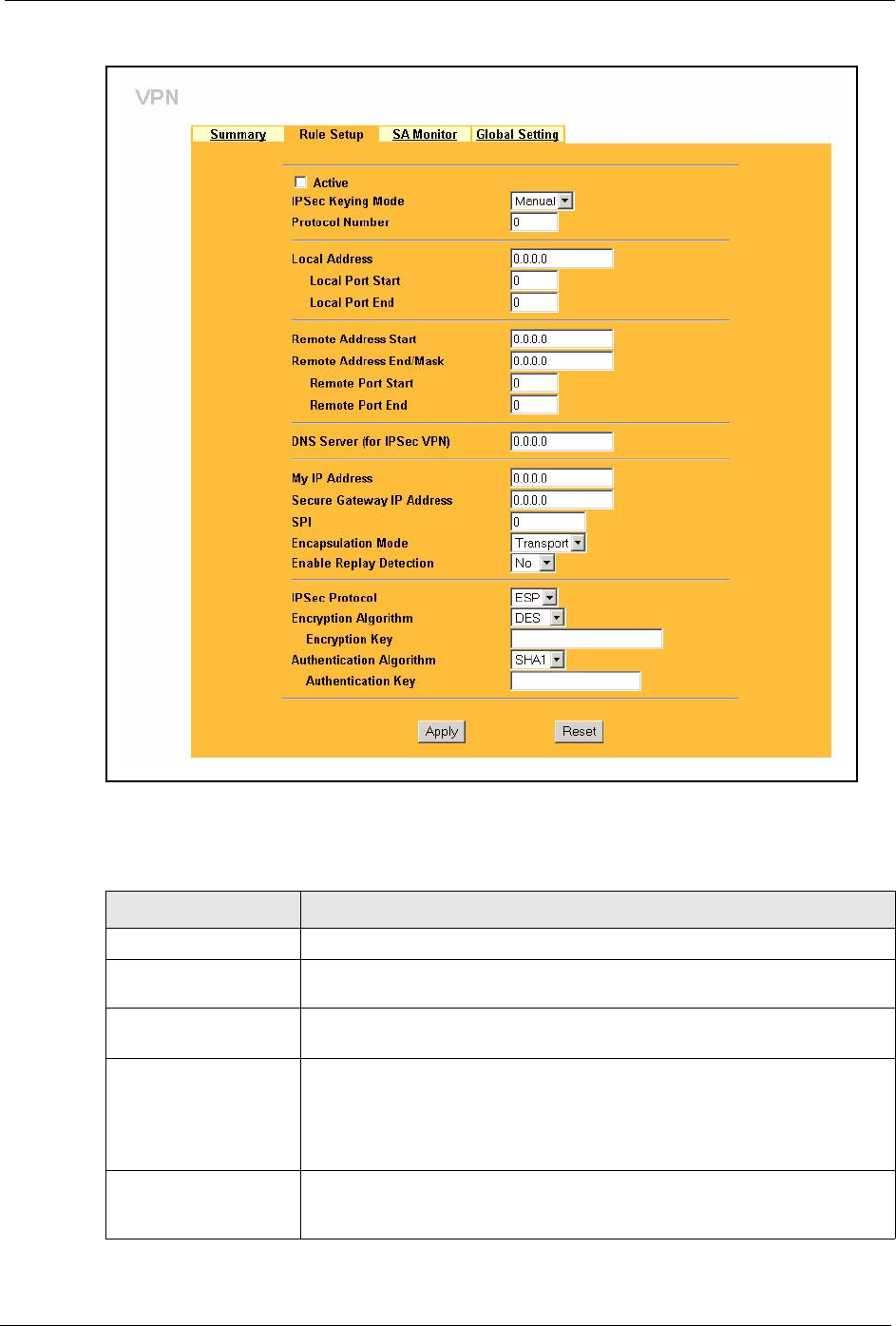
Prestige 334 User’s Guide
Chapter 15 VPN Screens 176
Figure 67 Setup: Manual
The following table describes the labels in this screen.
Table 53 Rule Setup: Manual
LABEL DESCRIPTION
Active Select this check box to activate this VPN policy.
IPSec Keying Mode Select IKE or Manual from the drop-down list box. Manual is a useful option
for troubleshooting if you have problems using IKE key management.
Protocol Number Enter 1 for ICMP, 6 for TCP, 17 for UDP, etc. 0 is the default and signifies any
protocol.
Local Address The Local IP address must be static and correspond to the remote IPSec
router's configured remote IP addresses.
Two active SAs can have the same local or remote IP address, but not both.
You can configure multiple SAs between the same local and remote IP
addresses, as long as only one is active at any time.
Local Port Start "0" is the default and signifies any port. Type a port number from 0 to 65535.
Some of the most common IP ports are: 21, FTP; 53, DNS; 23, Telnet; 80,
HTTP; 25, SMTP; 110, POP3.

Prestige 334 User’s Guide
177 Chapter 15 VPN Screens
Local Port End Type a port number in this field to define a port range. This port number must
be greater than that specified in the previous field. If Local Port Start is left at
0, Local Port End will also remain at 0.
Remote Address Start Remote IP addresses must be static and correspond to the remote IPSec
router's configured local IP addresses. The remote address fields do not
apply when the Secure Gateway IP Address field is configured to 0.0.0.0. In
this case only the remote IPSec router can initiate the VPN.
Two active SAs cannot have the local and remote IP address(es) both the
same. Two active SAs can have the same local or remote IP address, but not
both. You can configure multiple SAs between the same local and remote IP
addresses, as long as only one is active at any time.
Enter a (static) IP address on the network behind the remote IPSec router.
Remote Address End/
Mask
When the remote IP address is a single address, type it a second time here.
When the remote IP address is a range, enter the end (static) IP address, in a
range of computers on the network behind the remote IPSec router.
When the remote IP address is a subnet address, enter a subnet mask on the
network behind the remote IPSec router.
Remote Port Start "0" is the default and signifies any port. Type a port number from 0 to 65535.
Some of the most common IP ports are: 21, FTP; 53, DNS; 23, Telnet; 80,
HTTP; 25, SMTP; 110, POP3.
Remote Port End Enter a port number in this field to define a port range. This port number must
be greater than that specified in the previous field. If Remote Port Start is left
at 0, Remote Port End will also remain at 0.
DNS Server (for IPSec
VPN)
If there is a private DNS server that services the VPN, type its IP address
here. The Prestige assigns this additional DNS server to the Prestige’s DHCP
clients that have IP addresses in this IPSec rule's range of local addresses. A
DNS server allows clients on the VPN to find other computers and servers on
the VPN by their (private) domain names.
My IP Address Enter the WAN IP address of your Prestige. The Prestige uses its current
WAN IP address (static or dynamic) in setting up the VPN tunnel if you leave
this field as 0.0.0.0. The VPN tunnel has to be rebuilt if this IP address
changes.
Secure Gateway IP
Address
Type the WAN IP address or the URL (up to 31 characters) of the IPSec
router with which you're making the VPN connection.
SPI Type a number (base 10) from 1 to 999999 for the Security Parameter Index.
Encapsulation Mode Select Tunnel mode or Transport mode from the drop-down list box.
Enable Replay
Detection
As a VPN setup is processing intensive, the system is vulnerable to Denial of
Service (DoS) attacks The IPSec receiver can detect and reject old or
duplicate packets to protect against replay attacks. Select YES from the drop-
down menu to enable replay detection, or select NO to disable it.
IPSec Protocol Select ESP if you want to use ESP (Encapsulation Security Payload). The
ESP protocol (RFC 2406) provides encryption as well as some of the services
offered by AH. If you select ESP here, you must select options from the
Encryption Algorithm and Authentication Algorithm fields (described
next).
Select AH if you want to use AH (Authentication Header Protocol). The AH
protocol (RFC 2402) was designed for integrity, authentication, sequence
integrity (replay resistance), and non-repudiation but not for confidentiality, for
which the ESP was designed. If you select AH here, you must select options
from the Authentication Algorithm field (described later).
Table 53 Rule Setup: Manual
LABEL DESCRIPTION
Prestige 334 User’s Guide
Chapter 15 VPN Screens 178
15.15 Viewing SA Monitor
In the web configurator, click VPN and the SA Monitor tab. Use this screen to display and
manage active VPN connections.
A Security Association (SA) is the group of security settings related to a specific VPN tunnel.
This screen displays active VPN connections. Use Refresh to display active VPN
connections. This screen is read-only. The following table describes the labels in this tab.
Encryption Algorithm Select DES or 3DES from the drop-down list box. The Prestige's encryption
algorithm should be identical to the secure remote gateway. When DES is
used for data communications, both sender and receiver must know the same
secret key, which can be used to encrypt and decrypt the message. The DES
encryption algorithm uses a 56-bit key. Triple DES (3DES) is a variation on
DES that uses a 168-bit key. As a result, 3DES is more secure than DES. It
also requires more processing power, resulting in increased latency and
decreased throughput.
Authentication
Algorithm
Select SHA1 or MD5 from the drop-down list box. MD5 (Message Digest 5)
and SHA1 (Secure Hash Algorithm) are hash algorithms used to authenticate
packet data. The SHA1 algorithm is generally considered stronger than MD5,
but is slower. Select MD5 for minimal security and SHA-1 for maximum
security.
Encryption Key (Only
with ESP)
With DES, type a unique key 8 characters long. With 3DES, type a unique
key 24 characters long. Any characters may be used, including spaces, but
trailing spaces are truncated.
Authentication Key Type a unique authentication key to be used by IPSec if applicable. Enter 16
characters for MD5 authentication or 20 characters for SHA-1 authentication.
Any characters may be used, including spaces, but trailing spaces are
truncated.
Apply Click Apply to save your changes back to the Prestige.
Reset Click Reset to begin configuring this screen afresh.
Table 53 Rule Setup: Manual
LABEL DESCRIPTION
Note: When there is outbound traffic but no inbound traffic, the
SA times out automatically after two minutes. A tunnel with no
outbound or inbound traffic is "idle" and does not timeout until
the SA lifetime period expires.See the Keep Alive section to
have the Prestige renegotiate an IPSec SA when the SA
lifetime expires, even if there is no traffic.
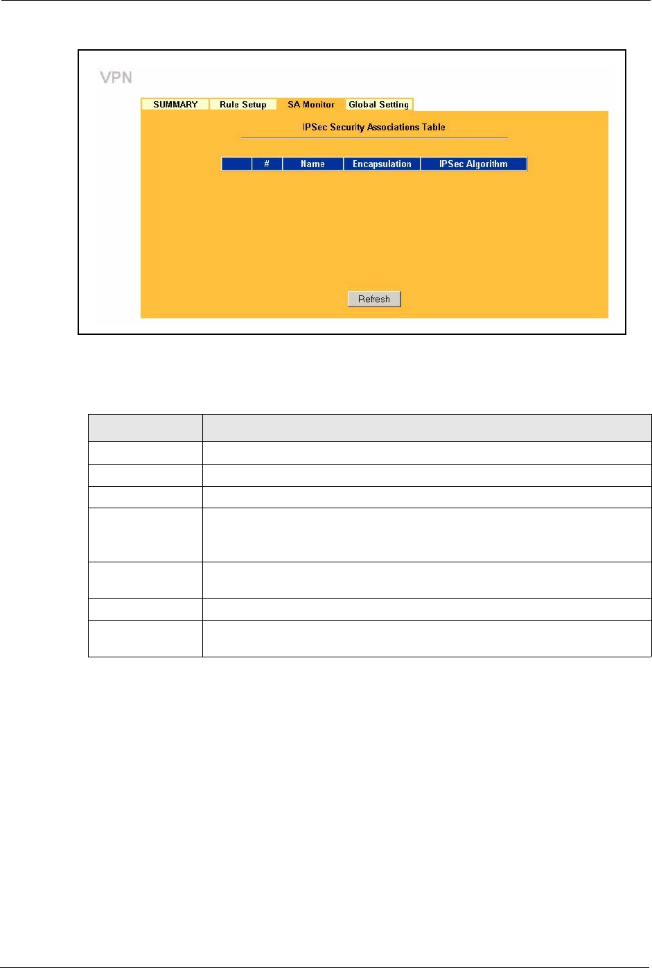
Prestige 334 User’s Guide
179 Chapter 15 VPN Screens
Figure 68 SA Monitor
The following table describes the labels in this screen.
15.16 Configuring Global Setting
To change your Prestige’s Global Settings, click VPN, then the Global Setting tab. The
screen appears as shown.
Table 54 SA Monitor
LABEL DESCRIPTION
#This is the security association index number.
Name This field displays the identification name for this VPN policy.
Encapsulation This field displays Tunnel or Transport mode.
IPSec Algorithm This field displays the security protocols used for an SA.
Both AH and ESP increase Prestige processing requirements and
communications latency (delay).
Previous Page
(If applicable)
Click Previous Page to view more items in the summary.
Refresh Click Refresh to display the current active VPN connection(s).
Next Page
(If applicable)
Click Next Page to view more items in the summary.

Prestige 334 User’s Guide
Chapter 15 VPN Screens 180
Figure 69 VPN: Global Setting
The following table describes the labels in this screen.
15.17 Telecommuter VPN/IPSec Examples
The following examples show how multiple telecommuters can make VPN connections to a
single Prestige at headquarters from remote IPSec routers that use dynamic WAN IP
addresses.
15.17.1 Telecommuters Sharing One VPN Rule Example
Multiple telecommuters can use one VPN rule to simultaneously access a Prestige at
headquarters. They must all use the same IPSec parameters (including the pre-shared key) but
the local IP addresses (or ranges of addresses) cannot overlap. See the following table and
figure for an example.
Table 55 VPN: Global Setting
LABEL DESCRIPTION
Windows Networking
(NetBIOS over TCP/IP)
NetBIOS (Network Basic Input/Output System) are TCP or UDP broadcast
packets that enable a computer to find other computers. It may sometimes
be necessary to allow NetBIOS packets to pass through VPN tunnels in
order to allow local computers to find computers on the remote network and
vice versa.
Allow Through IP/Sec
Tunnel
Select this check box to send NetBIOS packets through the VPN
connection.
Apply Click Apply to save your changes back to the Prestige.
Reset Click Reset to begin configuring this screen afresh.
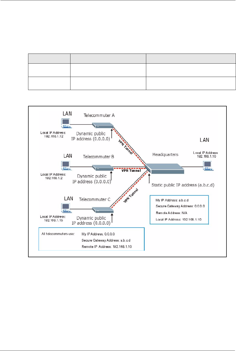
Prestige 334 User’s Guide
181 Chapter 15 VPN Screens
Having everyone use the same pre-shared key may create a vulnerability. If the pre-shared key
is compromised, all of the VPN connections using that VPN rule are at risk. A recommended
alternative is to use a different VPN rule for each telecommuter and identify them by unique
IDs (see the Telecommuters Using Unique VPN Rules Example section )..
Figure 70 Telecommuters Sharing One VPN Rule Example
15.17.2 Telecommuters Using Unique VPN Rules Example
With aggressive negotiation mode (see section Negotiation Mode), the Prestige can use the ID
types and contents to distinguish between VPN rules. Telecommuters can each use a separate
VPN rule to simultaneously access a Prestige at headquarters. They can use different IPSec
parameters (including the pre-shared key) and the local IP addresses (or ranges of addresses)
can overlap.
Table 56 Telecommuter and Headquarters Configuration Example
TELECOMMUTER HEADQUARTERS
My IP Address: 0.0.0.0 (dynamic IP address
assigned by the ISP)
Public static IP address
Secure Gateway
IP Address:
Public static IP address or domain
name.
0.0.0.0 With this IP address only the
telecommuter can initiate the IPSec tunnel.
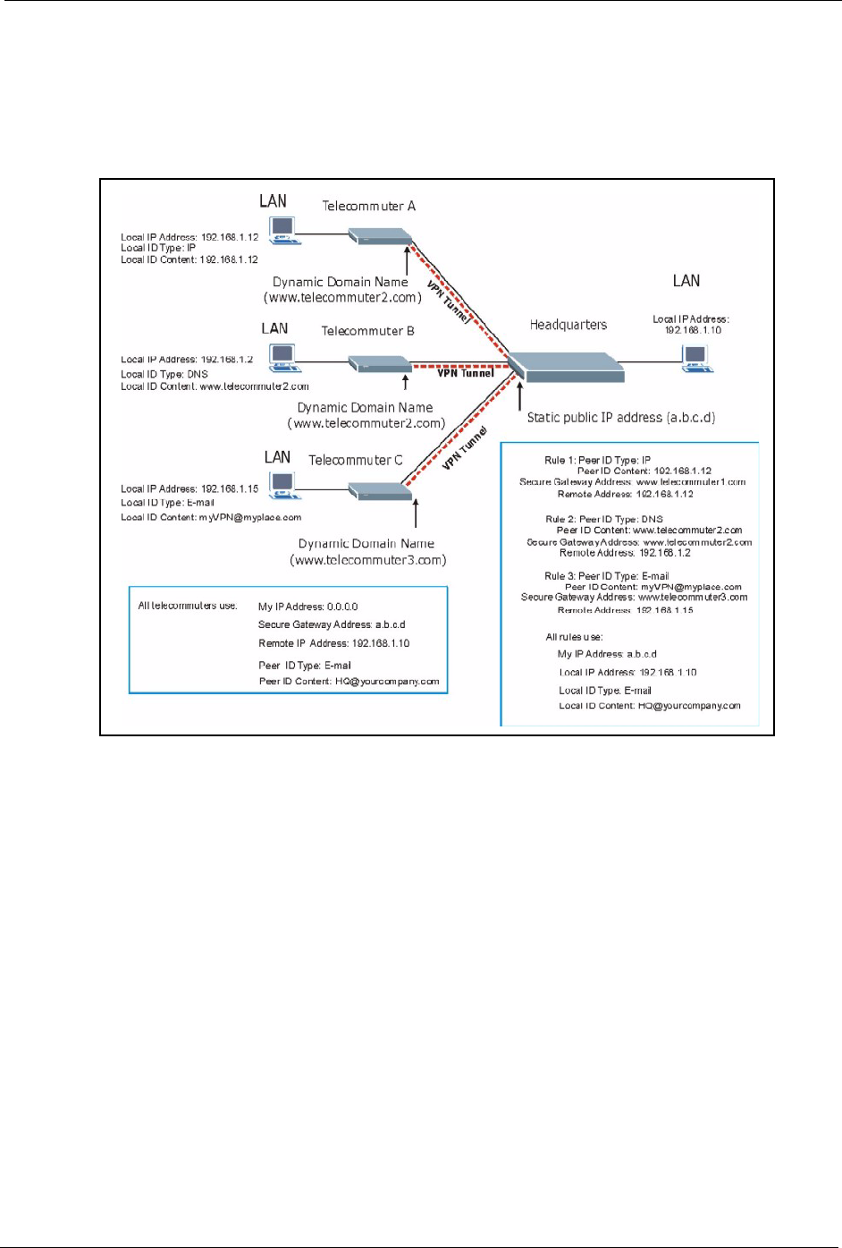
Prestige 334 User’s Guide
Chapter 15 VPN Screens 182
See the following graphic for an example where three telecommuters each use a different VPN
rule to initiate a VPN connection to a Prestige located at headquarters. The Prestige at
headquarters identifies each by its secure gateway address (a dynamic domain name) and uses
the appropriate VPN rule to establish the VPN connection.
Figure 71 Telecommuters Using Unique VPN Rules Example
15.18 VPN and Remote Management
If a VPN tunnel uses a remote management service port (Telnet, FTP, WWW SNMP, DNS or
ICMP) and terminates at the Prestige’s LAN or WAN port, configure remote management
(REMOTE MGNT) to allow access for that service.
If the VPN tunnel terminates at the Prestige’s LAN IP address, configure remote management
for LAN, WAN server access or LAN & WAN.
If the VPN tunnel terminates at the Prestige’s WAN IP address, configure remote management
for WAN server access or LAN & WAN.

Prestige 334 User’s Guide
183 Chapter 15 VPN Screens

Prestige 334 User’s Guide
Chapter 16 Centralized Logs 184
CHAPTER 16
Centralized Logs
This chapter contains information about configuring general log settings and viewing the
Prestige’s logs. Refer to the appendices for example log message explanations.
16.1 View Log
The web configurator allows you to look at all of the Prestige’s logs in one location.
Click the LOGS in the navigation panel to open the View Log screen.
Use the View Log screen to see the logs for the categories that you selected in the Log
Settings screen (see the Log Settings section ). Options include logs about system
maintenance, system errors, access control, allowed or blocked web sites, blocked web
features (such as ActiveX controls, java and cookies), attacks (such as DoS) and IPSec.
Log entries in red indicate system error logs. The log wraps around and deletes the old entries
after it fills. Click a column heading to sort the entries. A triangle indicates ascending or
descending sort order.
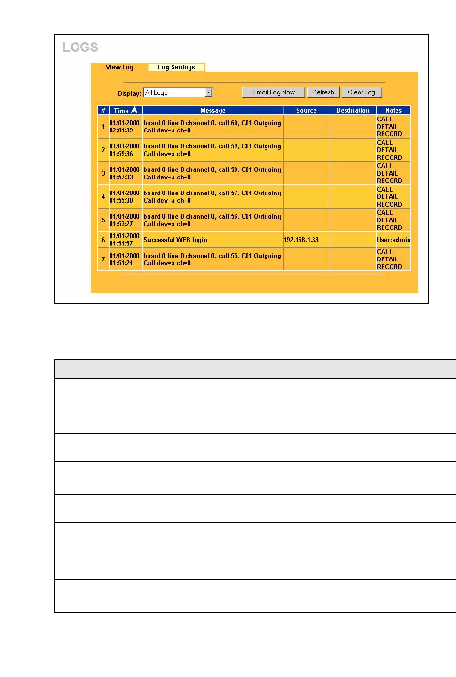
Prestige 334 User’s Guide
185 Chapter 16 Centralized Logs
Figure 72 View Logs
The following table describes the labels in this screen.
Table 57 View Logs
LABEL DESCRIPTION
Display The categories that you select in the Log Settings page (see section ) display in
the drop-down list box.
Select a category of logs to view; select All Logs to view logs from all of the log
categories that you selected in the Log Settings page.
Time This field displays the time the log was recorded. See the chapter on system
maintenance and information to configure the Prestige’s time and date.
Message This field states the reason for the log.
Source This field lists the source IP address and the port number of the incoming packet.
Destination This field lists the destination IP address and the port number of the incoming
packet.
Note This field displays additional information about the log entry.
Email Log Now Click Email Log Now to send the log screen to the e-mail address specified in the
Log Settings page (make sure that you have first filled in the Address Info fields
in Log Settings, see section ).
Refresh Click Refresh to renew the log screen.
Clear Log Click Clear Log to delete all the logs.

Prestige 334 User’s Guide
Chapter 16 Centralized Logs 186
16.2 Log Settings
You can configure the Prestige’s general log settings in one location.
Click the LOGS in the navigation panel and then the Log Settings tab to open the Log
Settings screen.
Use the Log Settings screen to configure to where the Prestige is to send logs; the schedule for
when the Prestige is to send the logs and which logs and/or immediate alerts the Prestige to
send.
An alert is a type of log that warrants more serious attention. They include system errors,
attacks (access control) and attempted access to blocked web sites or web sites with restricted
web features such as cookies, active X and so on. Some categories such as System Errors
consist of both logs and alerts. You may differentiate them by their color in the View Log
screen. Alerts display in red and logs display in black.
Alerts are e-mailed as soon as they happen. Logs may be e-mailed as soon as the log is full
(see Log Schedule). Selecting many alert and/or log categories (especially Access Control)
may result in many e-mails being sent
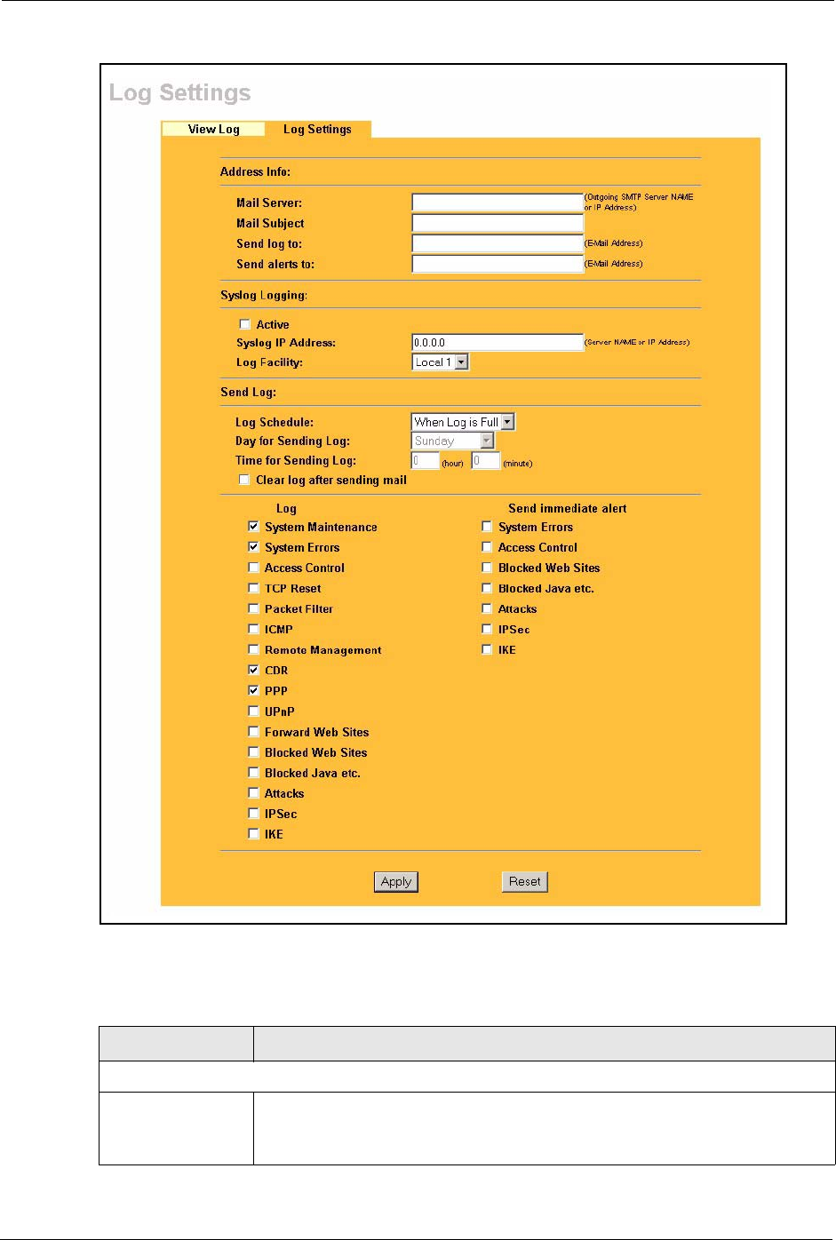
Prestige 334 User’s Guide
187 Chapter 16 Centralized Logs
Figure 73 Log Settings
The following table describes the labels in this screen.
Table 58 Log Settings
LABEL DESCRIPTION
Address Info
Mail Server Enter the server name or the IP address of the mail server for the e-mail
addresses specified below. If this field is left blank, logs and alert messages will
not be sent via e-mail.

Prestige 334 User’s Guide
Chapter 16 Centralized Logs 188
Mail Subject Type a title that you want to be in the subject line of the log e-mail message that
the Prestige sends. Not all Prestige models have this field.
Send Log To The Prestige sends logs to the e-mail address specified in this field. If this field is
left blank, the Prestige does not send logs via e-mail.
Send Alerts To Alerts are real-time notifications that are sent as soon as an event, such as a DoS
attack, system error, or forbidden web access attempt occurs. Enter the e-mail
address where the alert messages will be sent. Alerts include system errors,
attacks and attempted access to blocked web sites. If this field is left blank, alert
messages will not be sent via e-mail.
Syslog Logging The Prestige sends a log to an external syslog server.
Active Click Active to enable syslog logging.
Syslog Server IP
Address
Enter the server name or IP address of the syslog server that will log the selected
categories of logs.
Log Facility Select a location from the drop down list box. The log facility allows you to log the
messages to different files in the syslog server. Refer to the syslog server manual
for more information.
Send Log
Log Schedule This drop-down menu is used to configure the frequency of log messages being
sent as E-mail:
•Daily
• Weekly
•Hourly
• When Log is Full
• None.
If you select Weekly or Daily, specify a time of day when the E-mail should be
sent. If you select Weekly, then also specify which day of the week the E-mail
should be sent. If you select When Log is Full, an alert is sent when the log fills
up. If you select None, no log messages are sent
Day for Sending
Log
Use the drop down list box to select which day of the week to send the logs.
Time for Sending
Log
Enter the time of the day in 24-hour format (for example 23:00 equals 11:00 pm)
to send the logs.
Log Select the categories of logs that you want to record.
Send Immediate
Alert
Select log categories for which you want the Prestige to send e-mail alerts
immediately.
Apply Click Apply to save your changes.
Reset Click Reset to begin configuring this screen afresh.
Table 58 Log Settings
LABEL DESCRIPTION

Prestige 334 User’s Guide
189 Chapter 16 Centralized Logs

Prestige 334 User’s Guide
Chapter 17 Maintenance 190
CHAPTER 17
Maintenance
This chapter displays system information such as ZyNOS firmware, port IP addresses and port
traffic statistics.
17.1 Maintenance Overview
The maintenance screens can help you view system information, upload new firmware,
manage configuration and restart your Prestige.
17.2 Status Screen
Click MAINTENANCE to open the Status screen, which you can use to monitor your
Prestige. Note that these fields are READ-ONLY and only for diagnostic purposes.
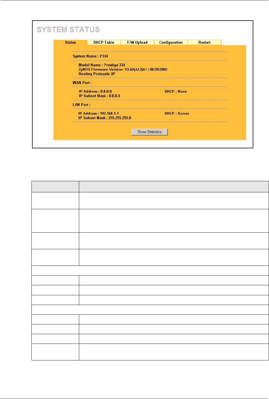
Prestige 334 User’s Guide
191 Chapter 17 Maintenance
Figure 74 Maintenance Status
The following table describes the labels in this screen.
Table 59 Maintenance Status
LABEL DESCRIPTION
System Name This is the System Name you chose in the first Internet Access Wizard screen. It
is for identification purposes
Model Name The model name identifies your device type. The model name should also be on a
sticker on your Prestige. If you are uploading firmware, be sure to upload firmware
for this exact model name. This field is not available on all models.
ZyNOS Firmware
Version
This is the ZyNOS Firmware version and the date created. ZyNOS is ZyXEL's
proprietary Network Operating System design.
Routing Protocols This shows the routing protocol - IP for which the Prestige is configured. This field
is not configurable in all Prestige router models.
WAN Port
IP Address This is the WAN port IP address.
IP Subnet Mask This is the WAN port subnet mask.
DHCP This is the WAN port DHCP role - Client or None.
LAN Port
IP Address This is the LAN port IP address.
IP Subnet Mask This is the LAN port subnet mask.
DHCP This is the LAN port DHCP role - Server, Relay or None.
Show Statistics Click Show Statistics to display the real-time system statistics. Refer to Section
for more information.
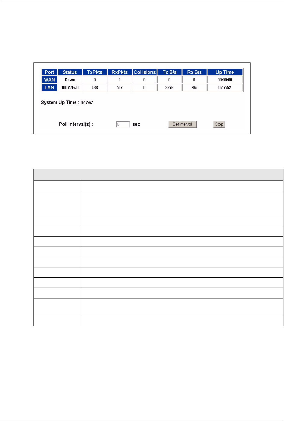
Prestige 334 User’s Guide
Chapter 17 Maintenance 192
17.2.1 System Statistics
Read-only information here includes port status and packet specific statistics. Also provided
are "system up time" and "poll interval(s)". The Poll Interval(s) field is configurable.
Figure 75 Maintenance System Statistics
The following table describes the labels in this screen.
17.3 DHCP Table Screen
DHCP (Dynamic Host Configuration Protocol, RFC 2131 and RFC 2132) allows individual
clients to obtain TCP/IP configuration at start-up from a server. You can configure the Prestige
as a DHCP server or disable it. When configured as a server, the Prestige provides the TCP/IP
configuration for the clients. If set to None, DHCP service will be disabled and you must have
another DHCP server on your LAN, or else the computer must be manually configured.
Table 60 Maintenance System Statistics
LABEL DESCRIPTION
Port This is the WAN, LAN port.
Status This displays the port speed and duplex setting if you're using Ethernet
encapsulation and down (line is down), idle (line (ppp) idle), dial (starting to trigger
a call) and drop (dropping a call) if you're using PPPoE encapsulation.
TxPkts This is the number of transmitted packets on this port.
RxPkts This is the number of received packets on this port.
Collisions This is the number of collisions on this port.
Tx B/s This displays the transmission speed in bytes per second on this port.
Rx B/s This displays the reception speed in bytes per second on this port.
Up Time This is the total amount of time the line has been up.
System Up Time This is the total time the Prestige has been on.
Poll Interval(s) Enter the time interval for refreshing statistics in this field.
Set Interval Click this button to apply the new poll interval you entered in the Poll Interval(s)
field.
Stop Click Stop to stop refreshing statistics, click Stop.
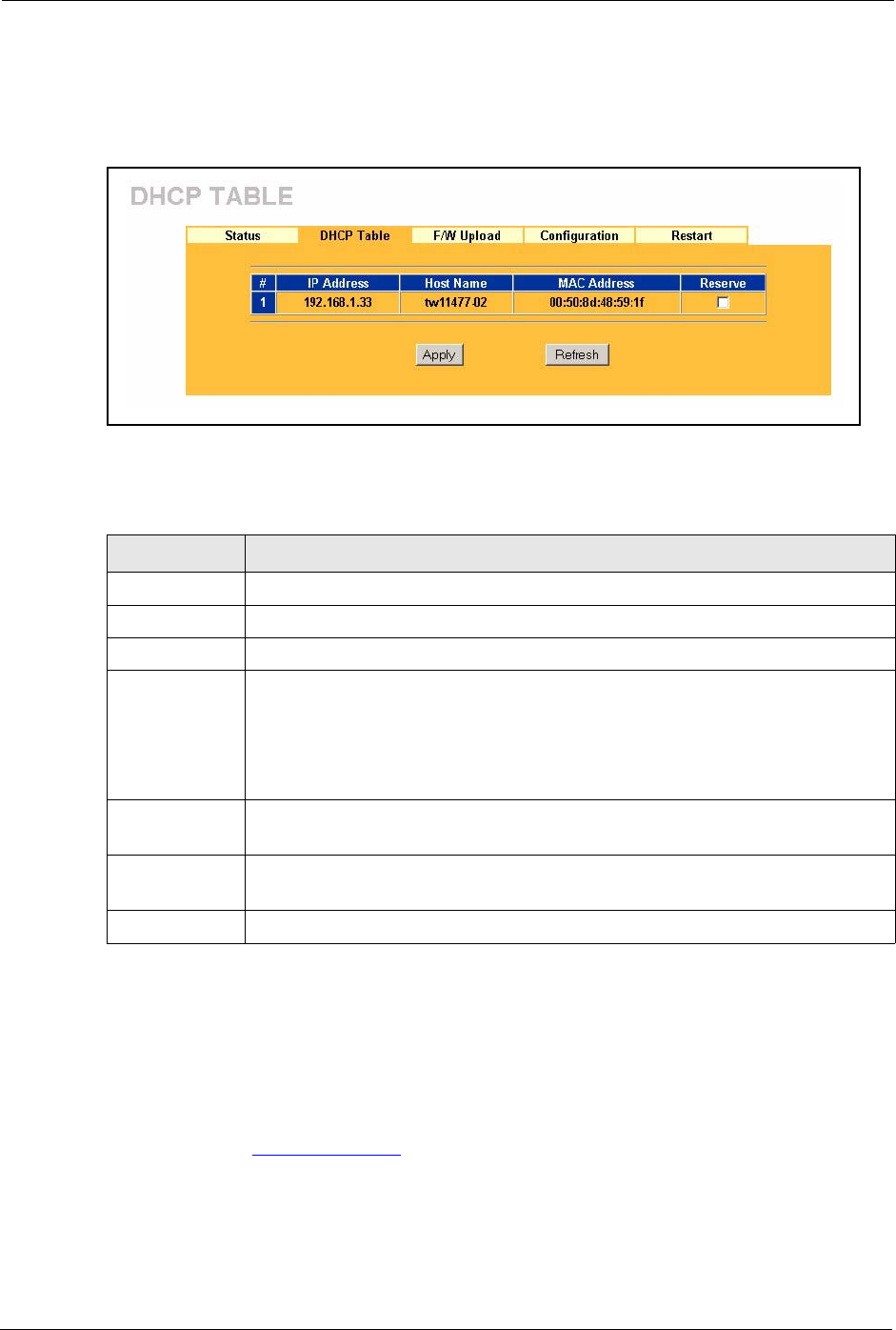
Prestige 334 User’s Guide
193 Chapter 17 Maintenance
Click MAINTENANCE, and then the DHCP Table tab. Read-only information here relates
to your DHCP status. The DHCP table shows current DHCP Client information (including IP
Address, Host Name and MAC Address) of all network clients using the DHCP server.
Figure 76 Maintenance DHCP Table
The following table describes the labels in this screen.
17.4 F/W Upload Screen
Click MAINTENANCE, and then the F/W Upload tab. You must use a firmware upgrade
tool to upload firmware to your Prestige.
Find firmware at www.zyxel.com in a file that (usually) uses the system model name with a
"*.ZIP" extension, for example, "360JJ3B2.ZIP". Download this file to your computer and
unzip it.
Table 61 Maintenance DHCP Table
LABEL DESCRIPTION
# This is the index number of the host computer.
IP Address This field displays the IP address relative to the # field listed above.
Host Name This field displays the computer host name.
MAC Address This field shows the MAC address of the computer with the name in the Host Name
field.
Every Ethernet device has a unique MAC (Media Access Control) address. The MAC
address is assigned at the factory and consists of six pairs of hexadecimal
characters, for example, 00:A0:C5:00:00:02.
Reserve Select this check box to have the Prestige always assign this IP address to this MAC
address (and host name).
Apply Click Apply to have the MAC address and IP address also display in the LAN Static
DHCP screen (where you can edit them).
Refresh Click Refresh to renew the screen.

Prestige 334 User’s Guide
Chapter 17 Maintenance 194
Use the upgrade tool file with a "*.exe" extension found in the ZIP file and follow the
steps to begin the firmware upgrade.
17.4.1 Preparing your Prestige for Firmware Upload
1Change the login password of the Prestige to the factory default password of “1234”.
2Change the IP address of the Prestige to the factory default IP address of “192.168.1.1”
and make sure that your computer can connect to the Prestige.
• If your computer’s IP address is dynamically assigned by the
Prestige, release your computer’s IP address and renew it.
• If your computer’s IP address is statically assigned, make sure that
the IP address is in the same subnet as the Prestige, for example: set
your computer’s IP address to 192.168.1.33.
3Logout of the Prestige.
Figure 77 Maintenance Firmware Upload
4To open the upgrade tool double-click the upgrade tool file.
5Run the upgrade tool and wait about six minutes for the firmware upgrade to complete.
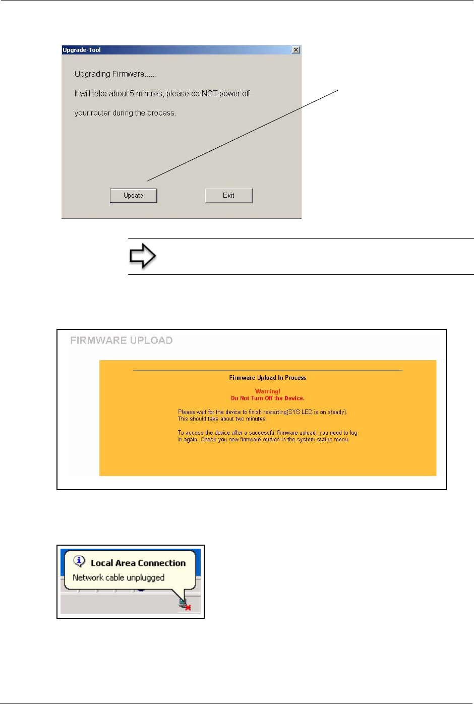
Prestige 334 User’s Guide
195 Chapter 17 Maintenance
Figure 78 Upgrade Tool
If you log into your Prestige before the upgrade is complete, the following screen is displayed.
Figure 79 Upload Warning
6The Prestige automatically restarts in this time causing a temporary network disconnect.
In some operating systems, you may see the following icon on your desktop.
Figure 80 Network Temporarily Disconnected
7After a successful upload, the system will reboot. See the Firmware and Configuration
File Maintenance chapter for upgrading firmware using FTP/TFTP commands.
Note: Do not turn off the Prestige while firmware upload is in
progress!
Click Upgrade to start
uploading the new
firmware file.
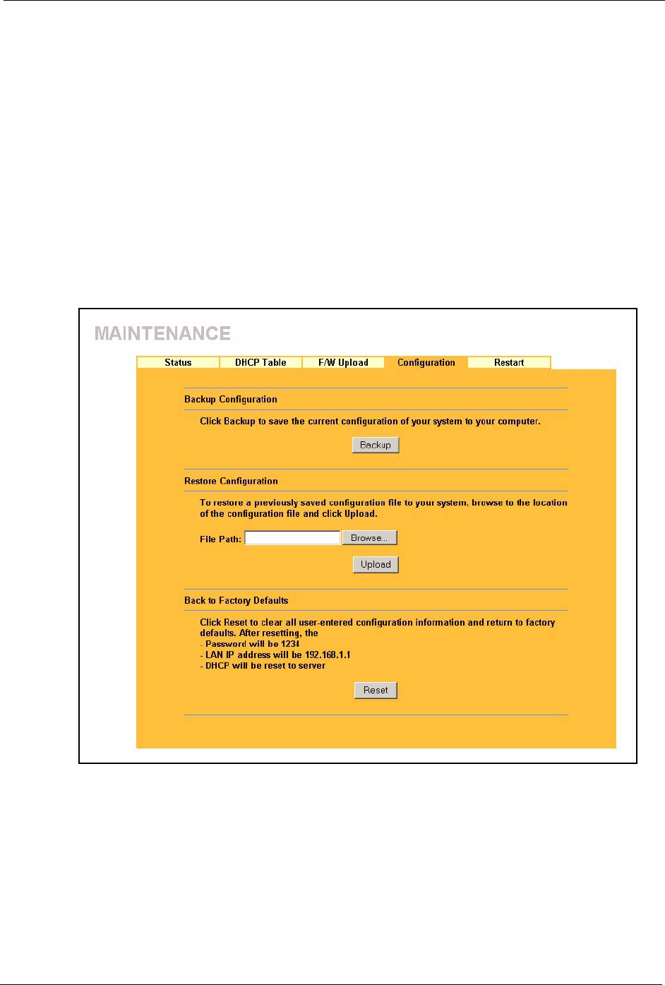
Prestige 334 User’s Guide
Chapter 17 Maintenance 196
• Change your Prestige password and IP address back to your preferred
setting.
8Log in again and check your new firmware version in the System Status screen.
17.5 Configuration Screen
See the Firmware and Configuration File Maintenance chapter for transferring configuration
files using FTP/TFTP commands.
Click MAINTENANCE, and then the Configuration tab. Information related to factory
defaults, backup configuration, and restoring configuration appears as shown next.
Figure 81 Maintenance Configuration
17.5.1 Backup Configuration
Backup configuration allows you to back up (save) the Prestige’s current configuration to a
file on your computer. Once your Prestige is configured and functioning properly, it is highly
recommended that you back up your configuration file before making configuration changes.
The backup configuration file will be useful in case you need to return to your previous
settings.
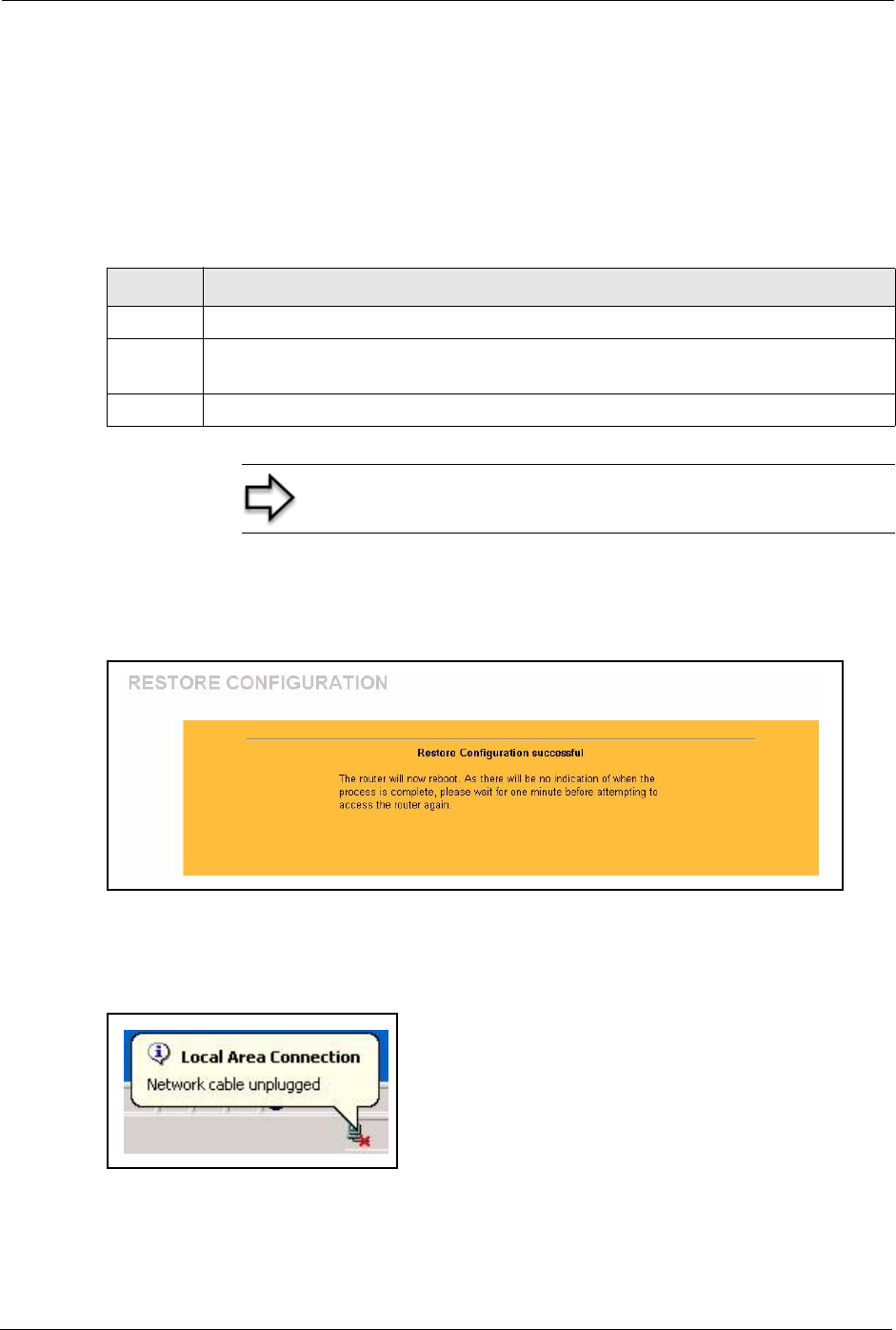
Prestige 334 User’s Guide
197 Chapter 17 Maintenance
Click Backup to save the Prestige’s current configuration to your computer
17.5.2 Restore Configuration
Restore configuration allows you to upload a new or previously saved configuration file from
your computer to your Prestige.
After you see a “configuration upload successful” screen, you must then wait one minute
before logging into the Prestige again.
Figure 82 Configuration Restore Successful
The Prestige automatically restarts in this time causing a temporary network disconnect. In
some operating systems, you may see the following icon on your desktop.
Figure 83 Temporarily Disconnected
If you uploaded the default configuration file you may need to change the IP address of your
computer to be in the same subnet as that of the default Prestige IP address (192.168.1.1). See
your Quick Start Guide for details on how to set up your computer’s IP address.
Table 62 Maintenance Restore Configuration
LABEL DESCRIPTION
File Path Type in the location of the file you want to upload in this field or click Browse ... to find it.
Browse... Click Browse... to find the file you want to upload. Remember that you must decompress
compressed (.ZIP) files before you can upload them.
Upload Click Upload to begin the upload process.
Note: Do not turn off the Prestige while configuration file upload
is in progress
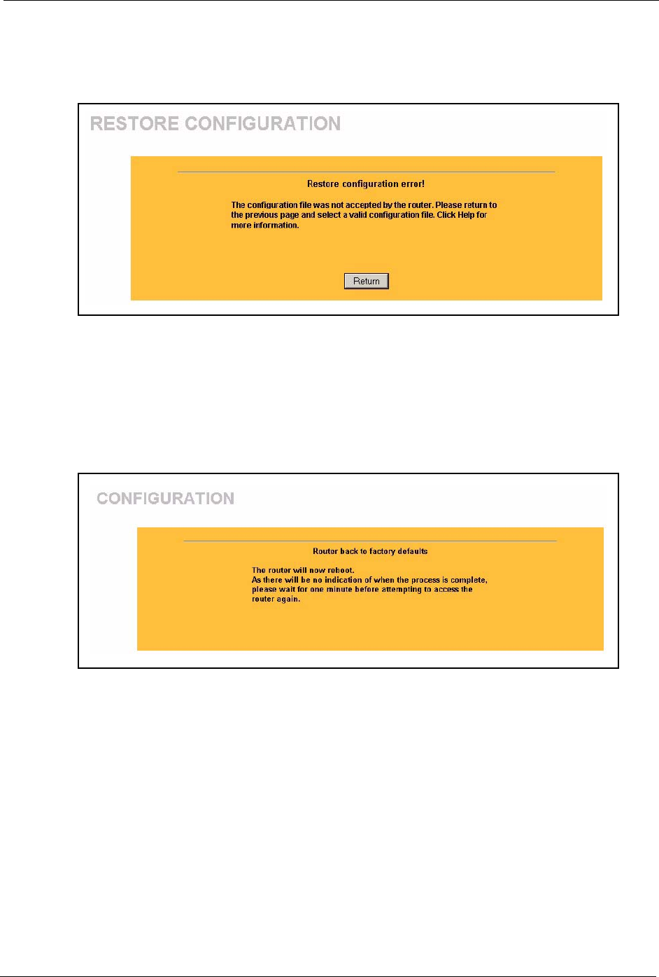
Prestige 334 User’s Guide
Chapter 17 Maintenance 198
If the upload was not successful, the following screen will appear. Click Return to go back to
the Configuration screen.
Figure 84 Configuration Restore Error
17.5.3 Back to Factory Defaults
Pressing the Reset button in this section clears all user-entered configuration information and
returns the Prestige to its factory defaults as shown on the screen. The following warning
screen will appear.
Figure 85 Factory Defaults
You can also press the RESET button on the rear panel to reset the factory defaults of your
Prestige. Refer to the Hardware Installation chapter for more information on the RESET
button.
17.6 Restart Screen
System restart allows you to reboot the Prestige without turning the power off.
Click MAINTENANCE, and then Restart. Click Restart to have the Prestige reboot. This
does not affect the Prestige's configuration.
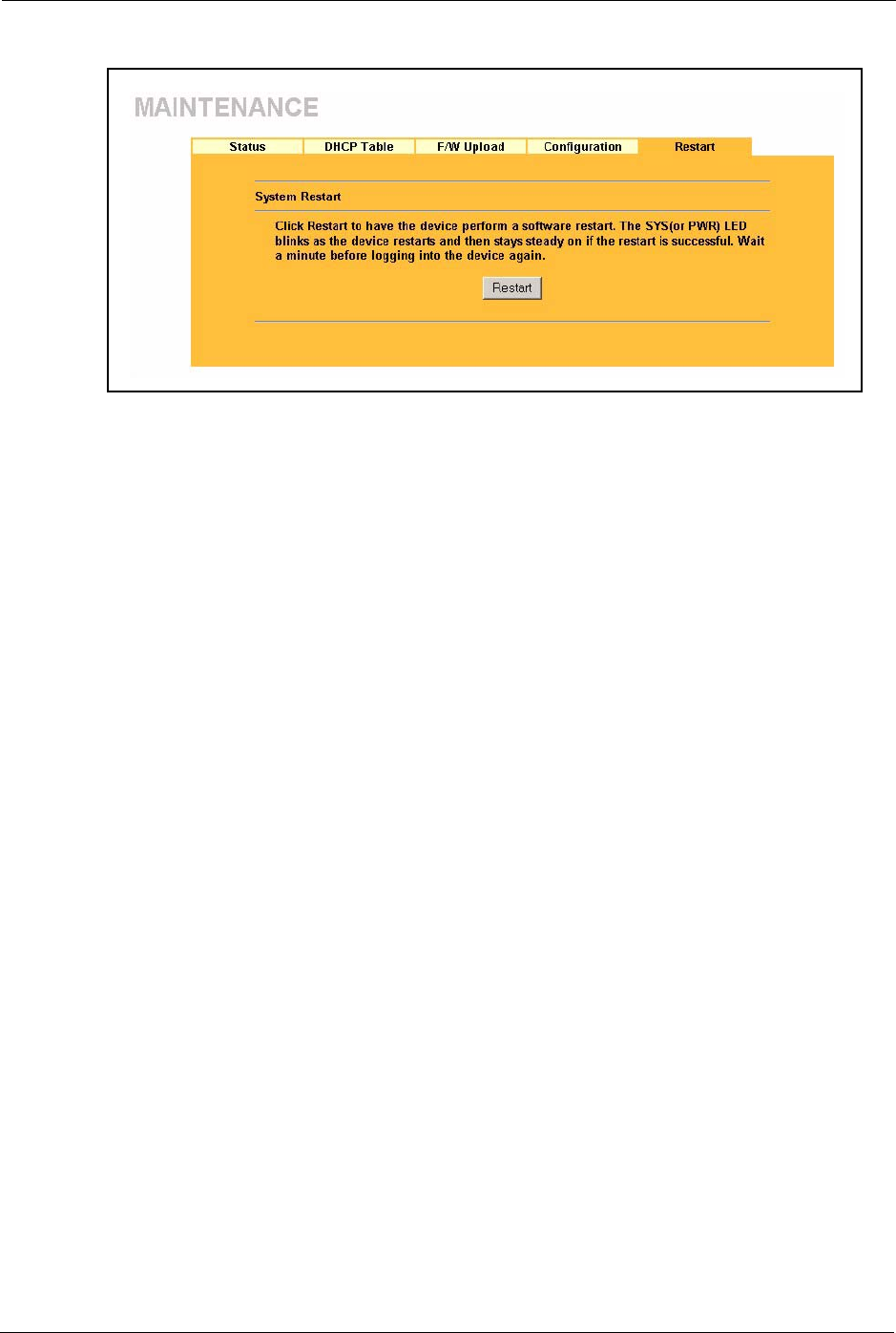
Prestige 334 User’s Guide
199 Chapter 17 Maintenance
Figure 86 System Restart

Prestige 334 User’s Guide
Chapter 18 Introducing the SMT 200
CHAPTER 18
Introducing the SMT
This chapter explains how to access and navigate the System Management Terminal and gives
an overview of its menus.
18.1 SMT Introduction
The Prestige’s SMT (System Management Terminal) is a menu-driven interface that you can
access from a terminal emulator through the console port or over a telnet connection. This
chapter shows you how to access the SMT (System Management Terminal) menus via console
port, how to navigate the SMT and how to configure SMT menus.
18.1.1 Procedure for SMT Configuration via Telnet
The following procedure details how to telnet into your Prestige.
1In Windows, click Start (usually in the bottom left corner), Run and then type “telnet
192.168.1.1” (the default IP address) and click OK.
2Enter “1234” in the Password field.
3After entering the password you will see the main menu.
Please note that if there is no activity for longer than five minutes (default timeout period)
after you log in, your Prestige will automatically log you out. You will then have to telnet into
the Prestige again.
18.1.2 Entering Password
The login screen appears after you press [ENTER], prompting you to enter the password, as
shown next.
For your first login, enter the default password “1234”. As you type the password, the screen
displays an asterisk “*” for each character you type.
Please note that if there is no activity for longer than five minutes after you log in, your
Prestige will automatically log you out.
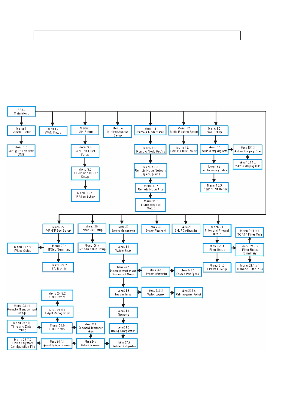
Prestige 334 User’s Guide
201 Chapter 18 Introducing the SMT
Figure 87 Login Screen
18.1.3 Prestige SMT Menu Overview
The following figure gives you an overview of the various SMT menu screens of your
Prestige.
Figure 88 SMT Menu Overview
18.2 Navigating the SMT Interface
The SMT(System Management Terminal) is the interface that you use to configure your
Prestige.
Enter Password : ****

Prestige 334 User’s Guide
Chapter 18 Introducing the SMT 202
Several operations that you should be familiar with before you attempt to modify the
configuration are listed in the table below.
After you enter the password, the SMT displays the main menu, as shown next.
Table 63 Main Menu Commands
OPERATION KEYSTROKE DESCRIPTION
Move down to
another menu
[ENTER] To move forward to a submenu, type in the number of the
desired submenu and press [ENTER].
Move up to a
previous menu
[ESC] Press [ESC] to move back to the previous menu.
Move to a “hidden”
menu
Press [SPACE
BAR] to change No
to Yes then press
[ENTER].
Fields beginning with “Edit” lead to hidden menus and have
a default setting of No. Press [SPACE BAR] once to change
No to Yes, and then press [ENTER] to go to the “hidden”
menu.
Move the cursor [ENTER] or [UP]/
[DOWN] arrow
keys.
Within a menu, press [ENTER] to move to the next field. You
can also use the [UP]/[DOWN] arrow keys to move to the
previous and the next field, respectively.
Entering
information
Type in or press
[SPACE BAR],
then press
[ENTER].
You need to fill in two types of fields. The first requires you to
type in the appropriate information. The second allows you
to cycle through the available choices by pressing [SPACE
BAR].
Required fields <? > or ChangeMe All fields with the symbol <?> must be filled in order to be
able to save the new configuration.
All fields with ChangeMe must not be left blank in order to
be able to save the new configuration.
N/A fields <N/A> Some of the fields in the SMT will show a <N/A>. This
symbol refers to an option that is Not Applicable.
Save your
configuration
[ENTER] Save your configuration by pressing [ENTER] at the
message “Press ENTER to confirm or ESC to cancel”.
Saving the data on the screen will take you, in most cases to
the previous menu.
Exit the SMT Type 99, then
press [ENTER].
Type 99 at the main menu prompt and press [ENTER] to exit
the SMT interface.

Prestige 334 User’s Guide
203 Chapter 18 Introducing the SMT
Figure 89 SMT Main Menu
18.2.1 System Management Terminal Interface Summary
The following table describes the fields in the previous screen.
Copyright (c) 1994 - 2004 ZyXEL Communications Corp.
Prestige 334 Main Menu
Getting Started Advanced Management
1. General Setup 21. Filter and Firewall Setup
2. WAN Setup 22. SNMP Configuration
3. LAN Setup 23. System Password
4. Internet Access Setup 24. System Maintenance
26. Schedule Setup
27. VPN/IPSec Setup
Advanced Applications
11. Remote Node Setup
12. Static Routing Setup
15. NAT Setup
99. Exit
Enter Menu Selection Number:
Table 64 Main Menu Summary
#MENU TITLE DESCRIPTION
1General Setup Use this menu to set up your general information.
2WAN Setup Use this menu to clone a MAC address from a computer on your
LAN.
3LAN Setup Use this menu to set up your LAN connection.
4Internet Access Setup Configure your Internet Access setup (Internet address, gateway,
login, etc.) with this menu.
11 Remote Node Setup Use this menu to configure detailed remote node settings (your
ISP is also a remote node) as well as apply WAN filters.
12 Static Routing Setup Use this menu to set up static routes.
15 NAT Setup Use this menu to specify inside servers when NAT is enabled.
21 Filter and Firewall Setup Use this menu to configure filters, activate/deactivate the firewall
and view the firewall log.
22 SNMP Configuration Use this menu to set up SNMP related parameters.
23 System Security Use this menu to change your password.
24 System Maintenance This menu provides system status, diagnostics, software upload,
etc.
26 Schedule Setup Use this menu to schedule outgoing calls.
27 VPN/ IPSec Setup Use this menu to configure VPN connections.
99 Exit Use this to exit from SMT and return to a blank screen.
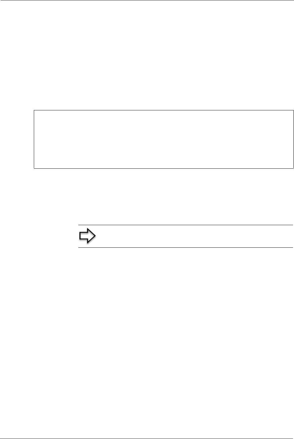
Prestige 334 User’s Guide
Chapter 18 Introducing the SMT 204
18.3 Changing the System Password
Change the Prestige default password by following the steps shown next.
1Enter 23.1 in the main menu to display Menu 23.1 - System Security - Change
Password.
2Type your existing system password in the Old Password field, for example “1234”, and
press [ENTER]
Figure 90 Menu 23 System Password
3Type your new system password in the New Password field (up to 30 characters), and
press [ENTER].
4Re-type your new system password in the Retype to confirm field for confirmation and
press [ENTER].
Menu 23.1 - System Security - Change Password
Old Password= ?
New Password= ?
Retype to confirm= ?
Enter here to CONFIRM or ESC to CANCEL:
Note: When you type in a password, the screen displays an “*”
for each character typed

Prestige 334 User’s Guide
205 Chapter 18 Introducing the SMT

Prestige 334 User’s Guide
Chapter 19 Menu 1 General Setup 206
CHAPTER 19
Menu 1 General Setup
Menu 1 - General Setup contains administrative and system-related information.
19.1 General Setup
Menu 1 — General Setup contains administrative and system-related information (shown
next). The System Name field is for identification purposes. However, because some ISPs
check this name you should enter your computer's "Computer Name".
In Windows 95/98 click Start, Settings, Control Panel, Network. Click the Identification
tab, note the entry for the Computer name field and enter it as the Prestige System Name.
In Windows 2000 click Start, Settings, Control Panel and then double-click System. Click
the Network Identification tab and then the Properties button. Note the entry for the
Computer name field and enter it as the Prestige System Name.
In Windows XP, click start, My Computer, View system information and then click the
Computer Name tab. Note the entry in the Full computer name field and enter it as the
Prestige System Name.
The Domain Name entry is what is propagated to the DHCP clients on the LAN. If you leave
this blank, the domain name obtained by DHCP from the ISP is used. While you must enter
the host name (System Name) on each individual computer, the domain name can be assigned
from the Prestige via DHCP.
19.2 Procedure To Configure Menu 1
1Enter 1 in the Main Menu to open Menu 1 — General Setup (shown next)

Prestige 334 User’s Guide
207 Chapter 19 Menu 1 General Setup
Figure 91 Menu 1 General Setup.
2Fill in the required fields. Refer to the table shown next for more information about these
fields.
Menu 1 - General Setup
System Name=
Domain Name= zyxel.com.tw
First System DNS Server= From ISP
IP Address= N/A
Second System DNS Server= From ISP
IP Address= N/A
Third System DNS Server= From ISP
IP Address= N/A
Edit Dynamic DNS= No
Press ENTER to Confirm or ESC to Cancel:
Table 65 Menu 1 General Setup
FIELD DESCRIPTION
System Name Choose a descriptive name for identification purposes. It is recommended you
enter your computer’s “Computer name” in this field. This name can be up to 30
alphanumeric characters long. Spaces are not allowed, but dashes “-” and
underscores "_" are accepted.
Domain Name Enter the domain name (if you know it) here. If you leave this field blank, the ISP
may assign a domain name via DHCP. You can go to menu 24.8 and type "sys
domain name" to see the current domain name used by your router.
The domain name entered by you is given priority over the ISP assigned domain
name. If you want to clear this field just press [SPACE BAR] and then [ENTER].
First System DNS
Server
Second System
DNS Server
Third System DNS
Server
DNS (Domain Name System) is for mapping a domain name to its corresponding
IP address and vice versa. The DNS server is extremely important because
without it, you must know the IP address of a machine before you can access it.
The Prestige uses a system DNS server (in the order you specify here) to resolve
domain names for VPN, DDNS and the time server.
Press [SPACE BAR] and then [ENTER] to select an option. Select From ISP if
your ISP dynamically assigns DNS server information (and the Prestige's WAN IP
address). The IP Address field below displays the (read-only) DNS server IP
address that the ISP assigns.
Select User-Defined if you have the IP address of a DNS server. Enter the DNS
server's IP address in the IP Address field. If you select User-Defined, but leave
the IP address set to 0.0.0.0, User-Defined changes to None after you save your
changes. If you set a second choice to User-Defined, and enter the same IP
address, the second User-Defined changes to None after you save your
changes.
Select None if you do not want to configure DNS servers. If you do not configure
a system DNS server, you must use IP addresses when configuring VPN, DDNS
and the time server.
Edit Dynamic DNS Press [SPACE BAR] and then [ENTER] to select Yes or No (default). Select Yes
to configure Menu 1.1: Configure Dynamic DNS discussed next.
When you have completed this menu, press [ENTER] at the prompt “Press ENTER to Confirm…” to
save your configuration, or press [ESC] at any time to cancel.
Prestige 334 User’s Guide
Chapter 19 Menu 1 General Setup 208
19.2.1 Procedure to Configure Dynamic DNS
To configure Dynamic DNS, go to Menu 1 — General Setup and select Yes in the Edit
Dynamic DNS field. Press [ENTER] to display Menu 1.1— Configure Dynamic DNS as
shown next.
Figure 92 Menu 1.1 Configure Dynamic DNS
Follow the instructions in the next table to configure Dynamic DNS parameters.
Note: If you have a private WAN IP address, then you cannot
use Dynamic DNS
Menu 1.1 - Configure Dynamic DNS
Service Provider= WWW.DynDNS.ORG
Active= Yes
DDNSType= DynamicDNS
Host1=
Host2=
Host3=
USER=
Password= ********
Enable Wildcard= No
Offline= N/A
Edit Update IP Address:
Use Server Detected IP= No
User Specified IP Address= No
IP Address= N/A
Press ENTER to Confirm or ESC to Cancel:
Table 66 Menu 1.1 Configure Dynamic DNS
FIELD DESCRIPTION
Service Provider This is the name of your Dynamic DNS service provider.
Active Press [SPACE BAR] to select Yes and then press [ENTER] to make dynamic DNS
active.
DDNS Type Press [SPACE BAR] and then [ENTER] to select DynamicDNS if you have a
dynamic IP address(es). Select StaticDNS if you have a static IP address(s).
Select CustomDNS to have dyns.org provide DNS service for a domain name that
you already have from a source other than dyndns.org.
Host 1- 3 Enter your host name(s) in the fields provided. You can specify up to two host
names separated by a comma in each field.
User Enter your user name.
Password Enter the password assigned to you.
Enable
Wildcards
Your Prestige supports DYNDNS Wildcard. Press [SPACE BAR] and then [ENTER]
to select Yes or No This field is N/A when you choose DDNS client as your service
provider.
Prestige 334 User’s Guide
209 Chapter 19 Menu 1 General Setup
Offline This field is only available when CustomDNS is selected in the DDNS Type field.
Press [SPACE BAR] and then [ENTER] to select Yes. When Yes is selected, http:/
/www.dyndns.org/ traffic is redirected to a URL that you have previously specified
(see www.dyndns.org for details).
Edit Update IP Address:
You can select Yes in either the Use Server Detected IP field (recommended) or the User Specified
IP Addr field, but not both.
With the Use Server Detected IP and User Specified IP Addr fields both set to No, the DDNS server
automatically updates the IP address of the host name(s) with the Prestige’s WAN IP address.
DDNS does not work with a private IP address. When both fields are set to No, the Prestige must have
a public WAN IP address in order for DDNS to work.
Use Server
Detected IP
Press [SPACE BAR] to select Yes and then press [ENTER] to have the DDNS
server automatically update the IP address of the host name(s) with the public IP
address that the Prestige uses or is behind.
You can set this field to Yes whether the IP address is public or private, static or
dynamic.
User Specified IP
Address
Press [SPACE BAR] to select Yes and then press [ENTER] to update the IP
address of the host name(s) to the IP address specified below.
Only select Yes if the Prestige uses or is behind a static public IP address.
IP Address Enter the static public IP address if you select Yes in the User Specified IP Addr
field.
When you have completed this menu, press [ENTER] at the prompt “Press ENTER to Confirm…” to
save your configuration, or press [ESC] at any time to cancel.
Note: The IP address updates when you reconfigure menu 1 or
perform DHCP client renewal
Table 66 Menu 1.1 Configure Dynamic DNS
FIELD DESCRIPTION
Prestige 334 User’s Guide
Chapter 20 Menu 2 WAN Setup 210
CHAPTER 20
Menu 2 WAN Setup
This chapter describes how to configure the WAN using menu 2.
20.1 Introduction to WAN
This chapter explains how to configure settings for your WAN port.
20.2 WAN Setup
From the main menu, enter 2 to open menu 2.
Figure 93 Menu 2 WAN Setu
The following table describes the fields in this menu.
Menu 2 - WAN Setup
MAC Address:
Assigned By= Factory default
IP Address= N/A
Press ENTER to Confirm or ESC to Cancel:
Table 67 Menu 2 WAN Setup
FIELD DESCRIPTION
MAC Address
Assigned By Press [SPACE BAR] and then [ENTER] to choose one of two methods to assign a
MAC Address. Choose Factory Default to select the factory assigned default
MAC Address. Choose IP address attached on LAN to use the MAC Address of
that computer whose IP you give in the following field.
IP Address This field is applicable only if you choose the IP address attached on LAN
method in the Assigned By field. Enter the IP address of the computer on the
LAN whose MAC you are cloning.
When you have completed this menu, press [ENTER] at the prompt “Press ENTER to Confirm…” to
save your configuration, or press [ESC] at any time to cancel.

Prestige 334 User’s Guide
211 Chapter 20 Menu 2 WAN Setup

Prestige 334 User’s Guide
Chapter 21 Menu 3 LAN Setup 212
CHAPTER 21
Menu 3 LAN Setup
This chapter covers how to configure your wired Local Area Network (LAN) settings.
21.1 LAN Setup
This section describes how to configure the Ethernet using Menu 3 — LAN Setup. From the
main menu, enter 3 to display menu 3.
Figure 94 Menu 3 LAN Setup
21.1.1 General Ethernet Setup
This menu allows you to specify filter set(s) that you wish to apply to the Ethernet traffic. You
seldom need to filter Ethernet traffic; however, the filter sets may be useful to block certain
packets, reduce traffic and prevent security breaches
Figure 95 Menu 3.1 LAN Port Filter Setup.
If you need to define filters, please read the Filter Set Configuration chapter first, then return
to this menu to define the filter sets.
Menu 3 - LAN Setup
1. LAN Port Filter Setup
2. TCP/IP and DHCP Setup
Enter Menu Selection Number:
Menu 3.1 - LAN Port Filter Setup
Input Filter Sets:
protocol filters=
device filters=
Output Filter Sets:
protocol filters=
device filters=
Press ENTER to Confirm or ESC to Cancel:

Prestige 334 User’s Guide
213 Chapter 21 Menu 3 LAN Setup
21.2 Protocol Dependent Ethernet Setup
Depending on the protocols for your applications, you need to configure the respective
Ethernet Setup, as outlined below.
• For TCP/IP Ethernet setup refer to the Internet Access Application chapter.
• For bridging Ethernet setup refer to the Bridging Setup chapter.
21.3 TCP/IP Ethernet Setup and DHCP
Use menu 3.2 to configure your Prestige for TCP/IP.
To edit menu 3.2, enter 3 from the main menu to display Menu 3 — LAN Setup. When menu
3 appears, press 2 and press [ENTER] to display Menu 3.2 — TCP/IP and DHCP Ethernet
Setup, as shown next:
Figure 96 Menu 3.2 TCP/IP and DHCP Ethernet Setup
Follow the instructions in the next table on how to configure the DHCP fields.
Menu 3.2 - TCP/IP and DHCP Ethernet Setup
DHCP= Server TCP/IP Setup:
Client IP Pool:
Starting Address= 192.168.1.33 IP Address= 192.168.1.1
Size of Client IP Pool= 32 IP Subnet Mask= 255.255.255.0
First DNS Server= From ISP RIP Direction= Both
IP Address= N/A Version= RIP-1
Second DNS Server= From ISP Multicast= None
IP Address= N/A Edit IP Alias= No
Third DNS Server= DNS Relay
IP Address= N/A
DHCP Server Address= N/A
Press ENTER to Confirm or ESC to Cancel:
Table 68 DHCP Ethernet Setup Fields
FIELD DESCRIPTION
DHCP This field enables/disables the DHCP server.
If set to Server, your Prestige will act as a DHCP server.
If set to None, the DHCP server will be disabled.
If set to Relay the Prestige acts as a surrogate DHCP server and relays requests
and responses between the remote server and the clients.
When set to Server, the following items need to be set:
Client IP Pools
Starting Address This field specifies the first of the contiguous addresses in the IP address pool.
Prestige 334 User’s Guide
Chapter 21 Menu 3 LAN Setup 214
Use the instructions in the following table to configure TCP/IP parameters for the LAN port.
Size of Client IP
Pool
This field specifies the size, or count of the IP address pool.
First DNS Server
Second DNS
Server
Third DNS Server
The Prestige passes a DNS (Domain Name System) server IP address (in the order
you specify here) to the DHCP clients.
Select From ISP if your ISP dynamically assigns DNS server information (and the
Prestige's WAN IP address). The IP Address field below displays the (read-only)
DNS server IP address that the ISP assigns.
Select User-Defined if you have the IP address of a DNS server. Enter the DNS
server's IP address in the IP Address field below. If you chose User-Defined, but
leave the IP address set to 0.0.0.0, User-Defined changes to None after you save
your changes. If you set a second choice to User-Defined, and enter the same IP
address, the second User-Defined changes to None after you save your changes.
Select DNS Relay to have the Prestige act as a DNS proxy. The Prestige's LAN IP
address displays in the IP Address field below (read-only). The Prestige tells the
DHCP clients on the LAN that the Prestige itself is the DNS server. When a
computer on the LAN sends a DNS query to the Prestige, the Prestige forwards the
query to the Prestige's system DNS server (configured in menu 1) and relays the
response back to the computer. You can only select DNS Relay for one of the three
servers; if you select DNS Relay for a second or third DNS server, that choice
changes to None after you save your changes.
Select None if you do not want to configure DNS servers. If you do not configure a
DNS server, you must know the IP address of a machine in order to access it.
DHCP Server
Address
If Relay is selected in the DHCP field above, then type the IP address of the actual,
remote DHCP server here.
Table 69 Menu 3.2: LAN TCP/IP Setup Fields
FIELD DESCRIPTION
TCP/IP Setup:
IP Address Enter the IP address of your Prestige in dotted decimal notation
IP Subnet Mask Your Prestige will automatically calculate the subnet mask based on the IP
address that you assign. Unless you are implementing subnetting, use the
subnet mask computed by the Prestige.
RIP Direction Press [SPACE BAR] and then [ENTER] to select the RIP direction. Options are:
Both, In Only, Out Only or None.
Version Press [SPACE BAR] and then [ENTER] to select the RIP version. Options are:
RIP-1, RIP-2B or RIP-2M.
Multicast IGMP (Internet Group Multicast Protocol) is a session-layer protocol used to
establish membership in a Multicast group. The Prestige supports both IGMP
version 1 (IGMP-v1) and version 2 (IGMP-v2). Press [SPACE BAR] and then
[ENTER] to enable IP Multicasting or select None (default) to disable it.
Edit IP Alias The Prestige supports three logical LAN interfaces via its single physical
Ethernet interface with the Prestige itself as the gateway for each LAN network.
Press [SPACE BAR] to select Yes and then press [ENTER] to display menu
3.2.1
When you have completed this menu, press [ENTER] at the prompt [Press ENTER to Confirm…] to
save your configuration, or press [ESC] at any time to cancel.
Table 68 DHCP Ethernet Setup Fields
FIELD DESCRIPTION
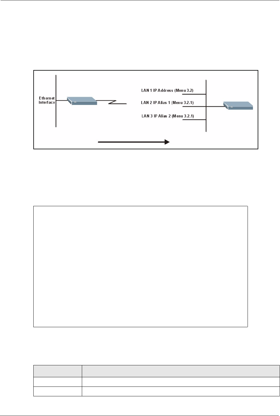
Prestige 334 User’s Guide
215 Chapter 21 Menu 3 LAN Setup
21.3.1 IP Alias Setup
IP alias allows you to partition a physical network into different logical networks over the
same Ethernet interface. The Prestige supports three logical LAN interfaces via its single
physical Ethernet interface with the Prestige itself as the gateway for each LAN network.
Figure 97 Physical Network & Partitioned Logical Networks
You must use menu 3.2 to configure the first network. Move the cursor to the Edit IP Alias field, press
[SPACE BAR] to choose Yes and press [ENTER] to configure the second and third network.
Press [ENTER] to open Menu 3.2.1 - IP Alias Setup, as shown next.
Figure 98 Menu 3.2.1: IP Alias Setup
Use the instructions in the following table to configure IP alias parameters.
Menu 3.2.1 - IP Alias Setup
IP Alias 1= Yes
IP Address=
IP Subnet Mask= 0.0.0.0
RIP Direction= None
Version= RIP-1
Incoming protocol filters=
Outgoing protocol filters=
IP Alias 2= No
IP Address= N/A
IP Subnet Mask= N/A
RIP Direction= N/A
Version= N/A
Incoming protocol filters= N/A
Outgoing protocol filters= N/A
Enter here to CONFIRM or ESC to CANCEL:
Table 70 Menu 3.2.1: IP Alias Setup
FIELD DESCRIPTION
IP Alias 1, 2 Choose Yes to configure the LAN network for the Prestige.
IP Address Enter the IP address of your Prestige in dotted decimal notation.

Prestige 334 User’s Guide
Chapter 21 Menu 3 LAN Setup 216
IP Subnet Mask Your Prestige will automatically calculate the subnet mask based on the IP
address that you assign. Unless you are implementing subnetting, use the subnet
mask computed by the Prestige.
RIP Direction Press [SPACE BAR] and then [ENTER] to select the RIP direction. Options are
Both, In Only, Out Only or None.
Version Press [SPACE BAR] and then [ENTER] to select the RIP version. Options are RIP-
1, RIP-2B or RIP-2M.
Incoming Protocol
Filters
Enter the filter set(s) you wish to apply to the incoming traffic between this node
and the Prestige.
Outgoing Protocol
Filters
Enter the filter set(s) you wish to apply to the outgoing traffic between this node
and the Prestige.
When you have completed this menu, press [ENTER] at the prompt [Press ENTER to Confirm…] to
save your configuration, or press [ESC] at any time to cancel.
Table 70 Menu 3.2.1: IP Alias Setup
FIELD DESCRIPTION

Prestige 334 User’s Guide
217 Chapter 21 Menu 3 LAN Setup

Prestige 334 User’s Guide
Chapter 22 Internet Access 218
CHAPTER 22
Internet Access
This chapter shows you how to configure your Prestige for Internet access .
22.1 Introduction to Internet Access Setup
Use information from your ISP along with the instructions in this chapter to set up your
Prestige to access the Internet. There are three different menu 4 screens depending on whether
you chose Ethernet, PPTP or PPPoE Encapsulation. Contact your ISP to determine what
encapsulation type you should use.
22.2 Ethernet Encapsulation
From the main menu, type 4 to display Menu 4 - Internet Access Setup.
If you choose Ethernet in menu 4 you will see the next menu.

Prestige 334 User’s Guide
219 Chapter 22 Internet Access
Figure 99 Menu 4 Internet Access Setup
The following table describes the fields in this menu.
Menu 4 - Internet Access Setup
ISP's Name= MyISP
Encapsulation= Ethernet
Service Type= Standard
My Login= N/A
My Password= N/A
Retype to Confirm= N/A
Login Server= N/A
Relogin Every (min)= N/A
IP Address Assignment= Dynamic
IP Address= N/A
IP Subnet Mask= N/A
Gateway IP Address= N/A
Network Address Translation= SUA Only
Press ENTER to Confirm or ESC to Cancel:
Table 71 Internet Access Setup (Ethernet
FIELD DESCRIPTION
ISP’s Name Enter the name of your Internet Service Provider, e.g., myISP. This
information is for identification purposes only.
Encapsulation Press [SPACE BAR] and then press [ENTER] to choose Ethernet. The
encapsulation method influences your choices for the IP Address field.
Service Type Press [SPACE BAR] and then [ENTER] to select Standard, RR-Toshiba
(RoadRunner Toshiba authentication method), RR-Manager (RoadRunner
Manager authentication method), RR-Telstra or Telia Login. Choose a
RoadRunner flavor if your ISP is Time Warner's RoadRunner; otherwise
choose Standard.
Note: DSL users must choose the Standard option only. The My Login, My Password and Login
Server fields are not applicable in this case.
My Login Enter the login name given to you by your ISP.
My Password Type your password again for confirmation.
Retype to Confirm Enter your password again to make sure that you have entered is correctly.
Login Server The Prestige will find the RoadRunner Server IP if this field is left blank. If it
does not, then you must enter the authentication server IP address.
Relogin Every (min) This field is available when you select Telia Login in the Service Type field.
The Telia server logs the Prestige out if the Prestige does not log in
periodically. Type the number of minutes from 1 to 59 (30 recommended) for
the Prestige to wait between logins.
IP Address Assignment If your ISP did not assign you a fixed IP address, press [SPACE BAR] and
then [ENTER] to select Dynamic, otherwise select Static and enter the IP
address and subnet mask in the following fields.
IP Address Enter the (fixed) IP address assigned to you by your ISP (static IP address
assignment is selected in the previous field).
IP Subnet Mask Enter the subnet mask associated with your static IP.
Prestige 334 User’s Guide
Chapter 22 Internet Access 220
22.3 Configuring the PPTP Client
To configure a PPTP client, you must configure the My Login and Password fields for a PPP
connection and the PPTP parameters for a PPTP connection.
After configuring My Login and Password for PPP connection, press [SPACE BAR] and
then [ENTER] in the Encapsulation field in Menu 4 -Internet Access Setup to choose
PPTP as your encapsulation option. This brings up the following screen.
Gateway IP Address Enter the gateway IP address associated with your static IP.
Network Address
Translation
Network Address Translation (NAT) allows the translation of an Internet
protocol address used within one network (for example a private IP address
used in a local network) to a different IP address known within another
network (for example a public IP address used on the Internet).
Choose None to disable NAT.
Choose SUA Only if you have a single public IP address. SUA (Single User
Account) is a subset of NAT that supports two types of mapping: Many-to-
One and Server.
Choose Full Feature if you have multiple public IP addresses. Full Feature
mapping types include: One-to-One, Many-to-One (SUA/PAT), Many-to-
Many Overload, Many- One-to-One and Server. When you select Full
Feature you must configure at least one address mapping set!
Please see the NAT chapter for a more detailed discussion on the Network
Address Translation feature.
When you have completed this menu, press [ENTER] at the prompt “Press ENTER to Confirm…” to
save your configuration, or press [ESC] at any time to cancel.
Table 71 Internet Access Setup (Ethernet
Note: The Prestige supports only one PPTP server connection at any
given time
Prestige 334 User’s Guide
221 Chapter 22 Internet Access
Figure 100 Internet Access Setup (PPTP)
The following table contains instructions about the new fields when you choose PPTP in the
Encapsulation field in menu 4.
22.4 Configuring the PPPoE Client
If you enable PPPoE in menu 4, you will see the next screen. For more information on PPPoE,
please see the appendix.
Menu 4 - Internet Access Setup
ISP's Name= MyISP
Encapsulation= PPTP
Service Type= N/A
My Login=
My Password= ********
Retype to Confirm= ********
Idle Timeout= 100
IP Address Assignment= Dynamic
IP Address= N/A
IP Subnet Mask= N/A
Gateway IP Address= N/A
Network Address Translation= SUA Only
Press ENTER to Confirm or ESC to Cancel:
Table 72 New Fields in Menu 4 (PPTP) Screen
FIELD DESCRIPTION
Encapsulation Press [SPACE BAR] and then press [ENTER] to choose PPTP. The encapsulation
method influences your choices for the IP Address field.
Idle Timeout This value specifies the time, in seconds, that elapses before the Prestige
automatically disconnects from the PPTP server.
Prestige 334 User’s Guide
Chapter 22 Internet Access 222
Figure 101 Internet Access Setup (PPPoE)
The following table contains instructions about the new fields when you choose PPPoE in the
Encapsulation field in menu 4.
If you need a PPPoE service name to identify and reach the PPPoE server, please go to menu
11 and enter the PPPoE service name provided to you in the Service Name field.
22.5 Basic Setup Complete
Well done! You have successfully connected, installed and set up your Prestige to operate on
your network as well as access the Internet.
You may deactivate the firewall in menu 21.2 or via the Prestige embedded web configurator.
You may also define additional firewall rules or modify existing ones but please exercise
extreme caution in doing so. See the chapters on firewall for more information on the firewall.
Menu 4 - Internet Access Setup
ISP's Name= MyISP
Encapsulation= PPPoE
Service Type= N/A
My Login=
My Password= ********
Retype to Confirm= ********
Idle Timeout= 100
IP Address Assignment= Dynamic
IP Address= N/A
IP Subnet Mask= N/A
Gateway IP Address= N/A
Network Address Translation= SUA Only
Press ENTER to Confirm or ESC to Cancel:
Table 73 New Fields in Menu 4 (PPPoE) screen
FIELD DESCRIPTION
Encapsulation Press [SPACE BAR] and then press [ENTER] to choose PPPoE. The
encapsulation method influences your choices in the IP Address field.
Idle Timeout This value specifies the time in seconds that elapses before the Prestige
automatically disconnects from the PPPoE server.
Note: When the firewall is activated, the default policy allows all
communications to the Internet that originate from the LAN, and
blocks all traffic to the LAN that originates from the Internet.

Prestige 334 User’s Guide
223 Chapter 22 Internet Access

Prestige 334 User’s Guide
Chapter 23 Remote Node Configuration 224
CHAPTER 23
Remote Node Configuration
This chapter covers remote node configuration.
23.1 Introduction to Remote Node Setup
A remote node is required for placing calls to a remote gateway. A remote node represents
both the remote gateway and the network behind it across a WAN connection. Note that when
you use menu 4 to set up Internet access, you are actually configuring a remote node. The
following describes how to configure Menu 11.1 Remote Node Profile, Menu 11.3 - Remote
Node Network Layer Options, Menu 11.5 - Remote Node Filter and Menu 11.6 - Traffic
Redirect Setup.
23.2 Remote Node Profile Setup
From the main menu, select menu option 11 to open Menu 11 Remote Node Profile (shown
below).
The following explains how to configure the remote node profile menu.
23.2.1 Ethernet Encapsulation
There are two variations of menu 11 depending on whether you choose Ethernet
Encapsulation or PPPoE Encapsulation. You must choose the Ethernet option when the
WAN port is used as a regular Ethernet. The first menu 11.1 screen you see is for Ethernet
encapsulation shown next.

Prestige 334 User’s Guide
225 Chapter 23 Remote Node Configuration
Figure 102 Menu 11.1 Remote Node Profile for Ethernet Encapsulation
The following table describes the fields in this menu.
Menu 11.1 - Remote Node Profile
Rem Node Name= MyISP Route= IP
Active= Yes
Encapsulation= Ethernet Edit IP= No
Service Type= Standard Session Options:
Service Name= N/A Edit Filter Sets= No
Outgoing:
My Login= N/A
My Password= N/A Edit Traffic Redirect= No
Retype to Confirm= N/A
Server= N/A
Relogin Every (min)= N/A
Press ENTER to Confirm or ESC to Cancel:
Table 74 Menu 11.1 Remote Node Profile for Ethernet Encapsulation
FIELD DESCRIPTION
Rem Node Name Enter a descriptive name for the remote node. This field can be up to eight
characters.
Active Press [SPACE BAR] and then [ENTER] to select Yes (activate remote node) or
No (deactivate remote node).
Encapsulation Ethernet is the default encapsulation. Press [SPACE BAR] and then [ENTER] to
change to PPPoE or PPTP encapsulation.
Service Type Press [SPACE BAR] and then [ENTER] to select from Standard, RR-Toshiba
(RoadRunner Toshiba authentication method), RR-Manager (RoadRunner
Manager authentication method), RR-Telstra or Telia Login. Choose one of the
RoadRunner methods if your ISP is Time Warner's RoadRunner; otherwise
choose Standard.
Outgoing
My Login This field is applicable for PPPoE encapsulation only. Enter the login name
assigned by your ISP when the Prestige calls this remote node. Some ISPs
append this field to the Service Name field above (e.g., jim@poellc) to access the
PPPoE server.
My Password Enter the password assigned by your ISP when the Prestige calls this remote
node. Valid for PPPoE encapsulation only.
Retype to Confirm Type your password again to make sure that you have entered it correctly.
Server This field is valid only when RoadRunner is selected in the Service Type field.
The Prestige will find the RoadRunner Server IP automatically if this field is left
blank. If it does not, then you must enter the authentication server IP address
here.
Relogin Every
(min)
This field is available when you select Telia Login in the Service Type field.
The Telia server logs the Prestige out if the Prestige does not log in periodically.
Type the number of minutes from 1 to 59 (30 recommended) for the Prestige to
wait between logins.
Route This field refers to the protocol that will be routed by your Prestige – IP is the only
option for the Prestige.

Prestige 334 User’s Guide
Chapter 23 Remote Node Configuration 226
23.2.2 PPPoE Encapsulation
The Prestige supports PPPoE (Point-to-Point Protocol over Ethernet). You can only use
PPPoE encapsulation when you’re using the Prestige with a DSL modem as the WAN device.
If you change the Encapsulation to PPPoE, then you will see the next screen. Please see the
appendix for more information on PPPoE.
Figure 103 Menu 11.1 Remote Node Profile for PPPoE Encapsulation
23.2.2.1 Outgoing Authentication Protocol
Generally speaking, you should employ the strongest authentication protocol possible, for
obvious reasons. However, some vendor’s implementation includes a specific authentication
protocol in the user profile. It will disconnect if the negotiated protocol is different from that in
the user profile, even when the negotiated protocol is stronger than specified. If you encounter
a case where the peer disconnects right after a successful authentication, please make sure that
you specify the correct authentication protocol when connecting to such an implementation.
Edit IP This field leads to a “hidden” menu. Press [SPACE BAR] to select Yes and press
[ENTER] to go to Menu 11.3 - Remote Node Network Layer Options.
Session Options
Edit Filter Sets This field leads to another “hidden” menu. Use [SPACE BAR] to select Yes and
press [ENTER] to open menu 11.5 to edit the filter sets. See the Remote Node
Filter section for more details.
Edit Traffic
Redirect
Press [SPACE BAR] to select Yes or No.
Select Yes and press [ENTER] to configure Menu 11.6 Traffic Redirect Setup.
Select No (default) if you do not want to configure this feature.
Once you have configured this menu, press [ENTER] at the message “Press ENTER to Confirm...” to
save your configuration, or press [ESC] at any time to cancel.
Table 74 Menu 11.1 Remote Node Profile for Ethernet Encapsulation
FIELD DESCRIPTION
Menu 11.1 - Remote Node Profile
Rem Node Name= MyISP Route= IP
Active= Yes
Encapsulation= PPPoE Edit IP= No
Service Type= Standard Telco Option:
Service Name= Allocated Budget(min)= 0
Outgoing: Period(hr)= 0
My Login= Schedules=
My Password= ******** Nailed-Up Connection= No
Retype to Confirm= ********
Authen= CHAP/PAP
Session Options:
Edit Filter Sets= No
Idle Timeout(sec)= 100
Edit Traffic Redirect= No
Press ENTER to Confirm or ESC to Cancel:

Prestige 334 User’s Guide
227 Chapter 23 Remote Node Configuration
23.2.2.2 Nailed-Up Connection
A nailed-up connection is a dial-up line where the connection is always up regardless of traffic
demand. The Prestige does two things when you specify a nailed-up connection. The first is
that idle timeout is disabled. The second is that the Prestige will try to bring up the connection
when turned on and whenever the connection is down. A nailed-up connection can be very
expensive for obvious reasons.
Do not specify a nailed-up connection unless your telephone company offers flat-rate service
or you need a constant connection and the cost is of no concern.
The following table describes the fields not already described in Table 74 .
23.2.3 PPTP Encapsulation
If you change the Encapsulation to PPTP in menu 11.1, then you will see the next screen.
Please see the appendix for information on PPTP.
Table 75 Fields in Menu 11.1 (PPPoE Encapsulation Specific)
FIELD DESCRIPTION
Service Name If you are using PPPoE encapsulation, then type the name of your PPPoE service
here. Only valid with PPPoE encapsulation.
Authen This field sets the authentication protocol used for outgoing calls.
Options for this field are:
•CHAP/PAP - Your Prestige will accept either CHAP or PAP when requested by
this remote node.
•CHAP- accept CHAP only.
•PAP- accept PAP only.
Telco Option
Allocated Budget The field sets a ceiling for outgoing call time for this remote node. The default for
this field is 0 meaning no budget control.
Period(hr) This field is the time period that the budget should be reset. For example, if we are
allowed to call this remote node for a maximum of 10 minutes every hour, then the
Allocated Budget is (10 minutes) and the Period(hr) is 1 (hour).
Schedules You can apply up to four schedule sets here. For more details please refer to the
Call Schedule Setup chapter.
Nailed-Up
Connection
This field specifies if you want to make the connection to this remote node a nailed-
up connection. More details are given earlier in this section.
Session Options
Idle Timeout Type the length of idle time (when there is no traffic from the Prestige to the remote
node) in seconds that can elapse before the Prestige automatically disconnects the
PPPoE connection. This option only applies when the Prestige initiates the call.
Prestige 334 User’s Guide
Chapter 23 Remote Node Configuration 228
Figure 104 Menu 11.1 Remote Node Profile for PPTP Encapsulation
The next table shows how to configure fields in menu 11.1 not previously discussed.
23.3 Edit IP
Move the cursor to the Edit IP field in menu 11.1, then press [SPACE BAR] to select Yes.
Press [ENTER] to open Menu 11.3 - Remote Node Network Layer Options.
Menu 11.1 - Remote Node Profile
Rem Node Name= MyISP Route= IP
Active= Yes
Apply Alias= None
Encapsulation= PPTP Edit IP= No
Service Type= Standard Telco Option:
Service Name= N/A Allocated Budget(min)= 0
Outgoing: Period(hr)= 0
My Login= Schedules=
My Password= ******** Nailed-Up Connection= No
Retype to Confirm= ********
Authen= CHAP/PAP
PPTP: Session Options:
My IP Addr= Edit Filter Sets= No
My IP Mask= Idle Timeout(sec)= 100
Server IP Addr=
Connection ID/Name= Edit Traffic Redirect= No
Press ENTER to Confirm or ESC to Cancel:
Table 76 Menu 11.1 Remote Node Profile for PPTP Encapsulation
FIELD DESCRIPTION
Encapsulation Press [SPACE BAR] and then [ENTER] to select PPTP. You must also go to menu
11.3 to check the IP Address setting once you have selected the encapsulation
method.
My IP Addr Enter the IP address of the WAN Ethernet port.
My IP Mask Enter the subnet mask of the WAN Ethernet port.
Server IP Addr Enter the IP address of the ANT modem.
Connection ID/
Name
Enter the connection ID or connection name in the ANT. It must follow the “c:id” and
“n:name” format.
This field is optional and depends on the requirements of your DSL modem.
Prestige 334 User’s Guide
229 Chapter 23 Remote Node Configuration
Figure 105 Menu 11.3 Remote Node Network Layer Options for Ethernet Encapsulation
This menu displays the My WAN Addr field for PPPoE and PPTP encapsulations and
Gateway IP Addr field for Ethernet encapsulation. The following table describes the fields
in this menu.
Menu 11.3 - Remote Node Network Layer Options
IP Address Assignment= Dynamic
IP Address= N/A
IP Subnet Mask= N/A
Gateway IP Addr= N/A
Network Address Translation= SUA Only
Metric= 1
Private= N/A
RIP Direction= None
Version= N/A
Multicast= None
Enter here to CONFIRM or ESC to CANCEL:
Table 77 Remote Node Network Layer Options
FIELD DESCRIPTION
IP Address
Assignment
If your ISP did not assign you an explicit IP address, press [SPACE BAR] and then
[ENTER] to select Dynamic; otherwise select Static and enter the IP address &
subnet mask in the following fields.
(Rem) IP
Address
If you have a static IP Assignment, enter the IP address assigned to you by your ISP.
(Rem) IP
Subnet Mask
If you have a static IP Assignment, enter the subnet mask assigned to you.
Gateway IP
Addr
This field is applicable to Ethernet encapsulation only. Enter the gateway IP address
assigned to you if you are using a static IP address.
My WAN Addr This field is applicable to PPPoE and PPTP encapsulations only. Some
implementations, especially the UNIX derivatives, require the WAN link to have a
separate IP network number from the LAN and each end must have a unique
address within the WAN network number. If this is the case, enter the IP address
assigned to the WAN port of your Prestige.
Note that this is the address assigned to your local Prestige, not the remote router.
Network
Address
Translation
Network Address Translation (NAT) allows the translation of an Internet protocol
address used within one network (for example a private IP address used in a local
network) to a different IP address known within another network (for example a public
IP address used on the Internet).
Choose None to disable NAT.
Choose SUA Only if you have a single public IP address. SUA (Single User Account)
is a subset of NAT that supports two types of mapping: Many-to-One and Server.
Choose Full Feature if you have multiple public IP addresses. Full Feature mapping
types include: One-to-One, Many-to-One (SUA/PAT), Many-to-Many Overload,
Many- One-to-One and Server. When you select Full Feature you must configure at
least one address mapping set!
See the NAT chapter for a full discussion on this feature.
Prestige 334 User’s Guide
Chapter 23 Remote Node Configuration 230
23.4 Remote Node Filter
Move the cursor to the field Edit Filter Sets in menu 11.1, and then press [SPACE BAR] to
set the value to Yes. Press [ENTER] to open Menu 11.5 - Remote Node Filter.
Use menu 11.5 to specify the filter set(s) to apply to the incoming and outgoing traffic between
this remote node and the Prestige to prevent certain packets from triggering calls. You can
specify up to 4 filter sets separated by commas, for example, 1, 5, 9, 12, in each filter field.
Note that spaces are accepted in this field. For more information on defining the filters, please
refer to the Filters chapter. For PPPoE or PPTP encapsulation, you have the additional option
of specifying remote node call filter sets.
Metric Enter a number from 1 to 15 to set this route’s priority among the Prestige’s routes
(see the Metric section in the WAN and Dial Backup Setup chapter) The smaller the
number, the higher priority the route has.
Private This field is valid only for PPTP/PPPoE encapsulation. This parameter determines if
the Prestige will include the route to this remote node in its RIP broadcasts. If set to
Yes, this route is kept private and not included in RIP broadcast. If No, the route to
this remote node will be propagated to other hosts through RIP broadcasts.
RIP Direction Press [SPACE BAR] and then [ENTER] to select the RIP direction from Both/ None/
In Only/Out Only. See the LAN Setup chapter for more information on RIP. The
default for RIP on the WAN side is None. It is recommended that you do not change
this setting.
Version Press [SPACE BAR] and then [ENTER] to select the RIP version from RIP-1/RIP-2B/
RIP-2M or None.
Multicast IGMP (Internet Group Multicast Protocol) is a network-layer protocol used to
establish membership in a Multicast group. The Prestige supports both IGMP version
1 (IGMP-v1) and version 2 (IGMP-v2). Press [SPACE BAR] to enable IP Multicasting
or select None to disable it. See the LAN Setup chapter for more information on this
feature.
Once you have completed filling in Menu 11.3 Remote Node Network Layer Options, press [ENTER]
at the message “Press ENTER to Confirm...” to save your configuration and return to menu 11, or press
[ESC] at any time to cancel.
Table 77 Remote Node Network Layer Options
FIELD DESCRIPTION

Prestige 334 User’s Guide
231 Chapter 23 Remote Node Configuration
Figure 106 Menu 11.5: Remote Node Filter (Ethernet Encapsulation)
Figure 107 Menu 11.5: Remote Node Filter (PPPoE or PPTP Encapsulation)
23.4.1 Traffic Redirect Setup
Configure parameters that determine when the Prestige will forward WAN traffic to the
backup gateway using Menu 11.6 — Traffic Redirect Setup.
Menu 11.5 - Remote Node Filter
Input Filter Sets:
protocol filters=
device filters=
Output Filter Sets:
protocol filters=
device filters=
Enter here to CONFIRM or ESC to CANCEL:
Menu 11.5 - Remote Node Filter
Input Filter Sets:
protocol filters=
device filters=
Output Filter Sets:
protocol filters=
device filters=
Call Filter Sets:
protocol filters=
device filters=
Enter here to CONFIRM or ESC to CANCEL:

Prestige 334 User’s Guide
Chapter 23 Remote Node Configuration 232
Figure 108 Menu 11.6: Traffic Redirect Setup
The following table describes the fields in this screen.
Menu 11.6 - Traffic Redirect Setup
Active= Yes
Configuration:
Backup Gateway IP Address= 0.0.0.0
Metric= 15
Check WAN IP Address= 0.0.0.0
Fail Tolerance= 2
Period(sec)= 5
Timeout(sec)= 3
Press ENTER to Confirm or ESC to Cancel:
Table 78 Menu 11.6: Traffic Redirect Setup
FIELD DESCRIPTION
Active Press [SPACE BAR] and select Yes (to enable) or No (to disable) traffic redirect
setup. The default is No.
Configuration:
Backup
Gateway IP
Address
Enter the IP address of your backup gateway in dotted decimal notation.
The Prestige automatically forwards traffic to this IP address if the Prestige’s Internet
connection terminates.
Metric Enter a number from 1 to 15 to set this route’s priority among the Prestige’s routes
(see the Metric section in the WAN and Dial Backup Setup chapter) The smaller the
number, the higher priority the route has.
Check WAN IP
Address
Enter the IP address of a reliable nearby computer (for example, your ISP’s DNS
server address) to test your Prestige’s WAN accessibility.
The Prestige uses the default gateway IP address if you do not enter an IP address
here.
If you are using PPTP or PPPoE Encapsulation, enter “0.0.0.0” to configure the
Prestige to check the PVC (Permanent Virtual Circuit) or PPTP tunnel.
Fail Tolerance Enter the number of times your Prestige may attempt and fail to connect to the
Internet before traffic is forwarded to the backup gateway. Two to five is usually a
good number.
Period (sec) Enter the time interval (in seconds) between WAN connection checks. Five to 60 is
usually a good number.
Timeout (sec) Enter the number of seconds the Prestige waits for a ping response from the IP
Address in the Check WAN IP Address field before it times out. The number in this
field should be less than the number in the Period field. Three to 50 is usually a good
number.
The WAN connection is considered “down” after the Prestige times out the number of
times specified in the Fail Tolerance field.
When you have completed this menu, press [ENTER] at the prompt “Press [ENTER] to confirm or
[ESC] to cancel” to save your configuration or press [ESC] to cancel and go back to the previous screen

Prestige 334 User’s Guide
233 Chapter 23 Remote Node Configuration

Prestige 334 User’s Guide
Chapter 24 Static Route Setup 234
CHAPTER 24
Static Route Setup
This chapter shows how to setup IP static routes.
24.1 IP Static Route Setup
To configure an IP static route, use Menu 12 – Static Routing Setup (shown next).
Figure 109 Menu 12 IP Static Route Setup
Now, type the route number of a static route you want to configure.
Menu 12 - IP Static Route Setup
1. ________
2. ________
3. ________
4. ________
5. ________
6. ________
7. ________
8. ________
Enter selection number:

Prestige 334 User’s Guide
235 Chapter 24 Static Route Setup
Figure 110 Menu12.1 Edit IP Static Route
The following table describes the fields for Menu 12.1 – Edit IP Static Route Setup.
Menu 12.1 - Edit IP Static Route
Route #: 1
Route Name= ?
Active= No
Destination IP Address= ?
IP Subnet Mask= ?
Gateway IP Address= ?
Metric= 2
Private= No
Press ENTER to Confirm or ESC to Cancel:
Table 79 Menu12.1 Edit IP Static Route
FIELD DESCRIPTION
Route # This is the index number of the static route that you chose in menu 12.1.
Route Name Type a descriptive name for this route. This is for identification purpose only.
Active This field allows you to activate/deactivate this static route.
Destination IP Address This parameter specifies the IP network address of the final destination.
Routing is always based on network number. If you need to specify a route to
a single host, use a subnet mask of 255.255.255.255 in the subnet mask field
to force the network number to be identical to the host ID.
IP Subnet Mask Type the subnet mask for this destination. Follow the discussion on IP
Subnet Mask in this manual.
Gateway IP Address Type the IP address of the gateway. The gateway is an immediate neighbor
of your Prestige that will forward the packet to the destination. On the LAN,
the gateway must be a router on the same segment as your Prestige; over
WAN, the gateway must be the IP address of one of the remote nodes.
Metric Metric represents the “cost” of transmission for routing purposes. IP routing
uses hop count as the measurement of cost, with a minimum of 1 for directly
connected networks. Type a number that approximates the cost for this link.
The number need not be precise, but it must be between 1 and 15. In
practice, 2 or 3 is usually a good number.
Private This parameter determines if the Prestige will include the route to this remote
node in its RIP broadcasts. If set to Yes, this route is kept private and is not
included in RIP broadcasts. If No, the route to this remote node will be
propagated to other hosts through RIP broadcasts.
When you have completed this menu, press [ENTER] at the prompt “Press ENTER to confirm or ESC
to cancel” to save your configuration or press [ESC] to cancel and go back to the previous screen.
Prestige 334 User’s Guide
Chapter 25 Network Address Translation (NAT) 236
CHAPTER 25
Network Address Translation
(NAT)
This chapter discusses how to configure NAT on the Prestige.
25.1 Using NAT
25.1.1 SUA (Single User Account) Versus NAT
SUA (Single User Account) is a ZyNOS implementation of a subset of NAT that supports two
types of mapping, Many-to-One and Server. See section Address Mapping Sets for a
detailed description of the NAT set for SUA. The Prestige also supports Full Feature NAT to
map multiple global IP addresses to multiple private LAN IP addresses of clients or servers
using mapping types.
25.2 Applying NAT
You apply NAT via menus 4 or 11.3 as displayed next. The next figure shows you how to
apply NAT for Internet access in menu 4. Enter 4 from the main menu to go to Menu 4 -
Internet Access Setup.
Note: You must create a firewall rule in addition to setting up
SUA/NAT, to allow traffic from the WAN to be forwarded
through the Prestige
Note: Choose SUA Only if you have just one public WAN IP
address for your Prestige.
Note: Choose Full Feature if you have multiple public WAN IP
addresses for your Prestige.

Prestige 334 User’s Guide
237 Chapter 25 Network Address Translation (NAT)
Figure 111 Menu 4 Applying NAT for Internet Access
The following figure shows how you apply NAT to the remote node in menu 11.1.
1Enter 11 from the main menu.
2When menu 11 appears, as shown in the following figure, type the number of the remote
node that you want to configure.
3Move the cursor to the Edit IP field, press [SPACE BAR] to select Yes and then press
[ENTER] to bring up Menu 11.3 - Remote Node Network Layer Options.
Menu 4 - Internet Access Setup
ISP's Name= MyISP
Encapsulation= Ethernet
Service Type= Standard
My Login= N/A
My Password= N/A
Retype to Confirm= N/A
Login Server= N/A
Relogin Every (min)= N/A
IP Address Assignment= Dynamic
IP Address= N/A
IP Subnet Mask= N/A
Gateway IP Address= N/A
Network Address Translation= SUA Only
Press ENTER to Confirm or ESC to Cancel:
Prestige 334 User’s Guide
Chapter 25 Network Address Translation (NAT) 238
Figure 112 Menu 11.3 Applying NAT to the Remote Node
The following table describes the options for Network Address Translation.
25.3 NAT Setup
Use the address mapping sets menus and submenus to create the mapping table used to assign
global addresses to computers on the LAN. Set 255 is used for SUA. When you select Full
Feature in menu 4 or 11.3, the SMT will use Set 1. When you select SUA Only, the SMT
will use the pre-configured Set 255 (read only).
The server set is a list of LAN servers mapped to external ports. To use this set, a server rule
must be set up inside the NAT address mapping set. Please see the section on port forwarding
in the chapter on NAT web configurator screens for further information on these menus. To
configure NAT, enter 15 from the main menu to bring up the following screen.
Menu 11.3 - Remote Node Network Layer Options
IP Address Assignment= Dynamic
IP Address= N/A
IP Subnet Mask= N/A
Gateway IP Addr= N/A
Network Address Translation= SUA Only
Metric= 1
Private= N/A
RIP Direction= None
Version= N/A
Multicast= None
Enter here to CONFIRM or ESC to CANCEL:
Table 80 Applying NAT in Menus 4 & 11.3
FIELD DESCRIPTION
NAT Press [SPACE BAR] and then [ENTER] to select Full Feature if you have multiple
public WAN IP addresses for your Prestige. The SMT uses the address mapping set
that you configure and enter in the Address Mapping Set field (menu 15.1 - see
section ).
Select None to disable NAT.
When you select SUA Only, the SMT uses Address Mapping Set 255 (menu 15.1 - see
section ). Choose SUA Only if you have just one public WAN IP address for your
Prestige.

Prestige 334 User’s Guide
239 Chapter 25 Network Address Translation (NAT)
Figure 113 Menu 15 NAT Setup
25.3.1 Address Mapping Sets
Enter 1 to bring up Menu 15.1 — Address Mapping Sets.
Figure 114 Menu 15.1 Address Mapping Sets
Enter 255 to display the next screen (see the SUA (Single User Account) Versus NAT section ).
The fields in this menu cannot be changed.
Menu 15 - NAT Setup
1. Address Mapping Sets
2. Port Forwarding Setup
3. Trigger Port Setup
Enter Menu Selection Number:
Menu 15.1 - Address Mapping Sets
1. NAT_SET
255. SUA (read only)
Enter Menu Selection Number:
Prestige 334 User’s Guide
Chapter 25 Network Address Translation (NAT) 240
Figure 115 Menu 15.1.255 SUA Address Mapping Rules
The following table explains the fields in this menu.
25.3.1.1 User-Defined Address Mapping Sets
Now let’s look at option 1 in menu 15.1. Enter 1 to bring up this menu. We’ll just look at the
differences from the previous menu. Note the extra Action and Select Rule fields mean you
can configure rules in this screen. Note also that the [?] in the Set Name field means that this
is a required field and you must enter a name for the set.
Menu 15.1.255 - Address Mapping Rules
Set Name= SUA
Idx Local Start IP Local End IP Global Start IP Global End IP Type
--- -------------- --------------- --------------- --------------- ------
1. 0.0.0.0 255.255.255.255 0.0.0.0 M-1
2. 0.0.0.0 Server
3.
4.
5.
6.
7.
8.
9.
10.
Press ENTER to Confirm or ESC to Cancel:
Table 81 SUA Address Mapping Rules
FIELD DESCRIPTION
Set Name This is the name of the set you selected in menu 15.1 or enter the name of a new
set you want to create.
Idx This is the index or rule number.
Local Start IP Local Start IP is the starting local IP address (ILA).
Local End IP Local End IP is the ending local IP address (ILA). If the rule is for all local IPs,
then the Start IP is 0.0.0.0 and the End IP is 255.255.255.255.
Global Start IP This is the starting global IP address (IGA). If you have a dynamic IP, enter
0.0.0.0 as the Global Start IP.
Global End IP This is the ending global IP address (IGA).
Type These are the mapping types. Server allows us to specify multiple servers of
different types behind NAT to this machine. See later for some examples.
When you have completed this menu, press [ENTER] at the prompt “Press ENTER to confirm or ESC to
cancel” to save your configuration or press [ESC] to cancel and go back to the previous screen.
Note: Menu 15.1.255 is read-only.
Prestige 334 User’s Guide
241 Chapter 25 Network Address Translation (NAT)
Figure 116 Menu 15.1.1 First Set
25.3.1.2 Ordering Your Rules
Ordering your rules is important because the Prestige applies the rules in the order that you
specify. When a rule matches the current packet, the Prestige takes the corresponding action
and the remaining rules are ignored. If there are any empty rules before your new configured
rule, your configured rule will be pushed up by that number of empty rules. For example, if
you have already configured rules 1 to 6 in your current set and now you configure rule
number 9. In the set summary screen, the new rule will be rule 7, not 9.
Menu 15.1.1 - Address Mapping Rules
Set Name= NAT_SET
Idx Local Start IP Local End IP Global Start IP Global End IP Type
--- --------------- -------------- --------------- --------------- ------
1.
2.
3.
4.
5.
6.
7.
8.
9.
10.
Action= Edit Select Rule=
Press ENTER to Confirm or ESC to Cancel:
Note: If the Set Name field is left blank, the entire set will be
deleted.
Note: The Type, Local and Global Start/End IPs are configured
in menu 15.1.1.1 (described later) and the values are displayed
here

Prestige 334 User’s Guide
Chapter 25 Network Address Translation (NAT) 242
Now if you delete rule 4, rules 5 to 7 will be pushed up by 1 rule, so as old rule 5 becomes rule
4, old rule 6 becomes rule 5 and old rule 7 becomes rule 6.
Selecting Edit in the Action field and then selecting a rule brings up the following menu,
Menu 15.1.1.1 - Address Mapping Rule in which you can edit an individual rule and
configure the Type, Local and Global Start/End IPs.
Table 82 Menu 15.1.1 First Set
FIELD DESCRIPTION
Set Name Enter a name for this set of rules. This is a required field. If this field is left blank, the
entire set will be deleted.
Action The default is Edit. Edit means you want to edit a selected rule (see following field).
Insert Before means to insert a rule before the rule selected. The rules after the
selected rule will then be moved down by one rule. Delete means to delete the
selected rule and then all the rules after the selected one will be advanced one rule.
None disables the Select Rule item.
Select Rule When you choose Edit, Insert Before or Delete in the previous field the cursor jumps
to this field to allow you to select the rule to apply the action in question.
Note: You must press [ENTER] at the bottom of the screen to
save the whole set. You must do this again if you make any
changes to the set – including deleting a rule. No changes to
the set take place until this action is taken
Note: An End IP address must be numerically greater than its
corresponding IP Start address

Prestige 334 User’s Guide
243 Chapter 25 Network Address Translation (NAT)
Figure 117 Menu 15.1.1.1 Editing/Configuring an Individual Rule in a Set
The following table explains the fields in this menu.
25.4 Configuring a Server behind NAT
Follow these steps to configure a server behind NAT:
1Enter 15 in the main menu to go to Menu 15 - NAT Setup.
2Enter 2 to display Menu 15.2 - NAT Server Setup as shown next.
Menu 15.1.1.1 Address Mapping Rule
Type= One-to-One
Local IP:
Start= 0.0.0.0
End = N/A
Global IP:
Start= 0.0.0.0
End = N/A
Press ENTER to Confirm or ESC to Cancel:
Table 83 Menu 15.1.1.1 Editing/Configuring an Individual Rule in a Set
FIELD DESCRIPTION
Type Press [SPACE BAR] and then [ENTER] to select from a total of five types. These are
the mapping types discussed in the chapter on NAT web configurator screens. Server
allows you to specify multiple servers of different types behind NAT to this computer.
See section for an example.
Local IP Only local IP fields are N/A for server; Global IP fields MUST be set for Server.
Start This is the starting local IP address (ILA).
End This is the ending local IP address (ILA). If the rule is for all local IPs, then put the Start
IP as 0.0.0.0 and the End IP as 255.255.255.255. This field is N/A for One-to-One and
Server types.
Global IP
Start This is the starting inside global IP address (IGA). If you have a dynamic IP, enter
0.0.0.0 as the Global IP Start. Note that Global IP Start can be set to 0.0.0.0 only if
the types are Many-to-One or Server.
End This is the ending inside global IP address (IGA). This field is N/A for One-to-One,
Many-to-One and Server types.
When you have completed this menu, press [ENTER] at the prompt “Press ENTER to confirm or ESC
to cancel” to save your configuration or press [ESC] to cancel and go back to the previous screen.
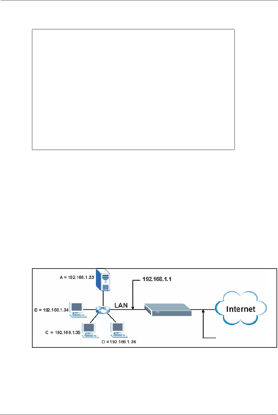
Prestige 334 User’s Guide
Chapter 25 Network Address Translation (NAT) 244
Figure 118 Menu 15.2.1 NAT Server Setup
3Enter a port number in an unused Start Port No field. To forward only one port, enter it
again in the End Port No field. To specify a range of ports, enter the last port to be
forwarded in the End Port No field.
4Enter the inside IP address of the server in the IP Address field. In the following figure,
you have a computer acting as an FTP, Telnet and SMTP server (ports 21, 23 and 25) at
192.168.1.33.
5Press [ENTER] at the “Press ENTER to confirm …” prompt to save your configuration
after you define all the servers or press [ESC] at any time to cancel.
You assign the private network IP addresses. The NAT network appears as a single host on the
Internet. A is the FTP/Telnet/SMTP server.
Figure 119 Multiple Servers Behind NAT Example
25.5 General NAT Examples
The following are some examples of NAT configuration.
Menu 15.2 - NAT Server Setup
Rule Start Port No. End Port No. IP Address
---------------------------------------------------
1. Default Default 0.0.0.0
2. 21 25 192.168.1.33
3. 0 0 0.0.0.0
4. 0 0 0.0.0.0
5. 0 0 0.0.0.0
6. 0 0 0.0.0.0
7. 0 0 0.0.0.0
8. 0 0 0.0.0.0
9. 0 0 0.0.0.0
10. 0 0 0.0.0.0
11. 0 0 0.0.0.0
12. 0 0 0.0.0.0
Press ENTER to Confirm or ESC to Cancel:
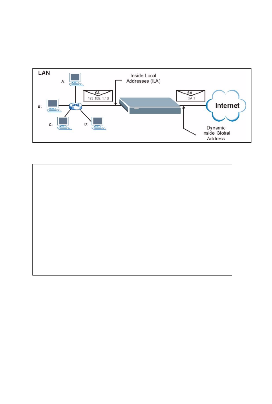
Prestige 334 User’s Guide
245 Chapter 25 Network Address Translation (NAT)
25.5.1 Example 1: Internet Access Only
In the following Internet access example, you only need one rule where the ILAs (Inside Local
Addresses) of computers A through D map to one dynamic IGA (Inside Global Address)
assigned by your ISP.
Figure 120 NAT Example 1
Figure 121 Menu 4 Internet Access & NAT Example
From menu 4, choose the SUA Only option from the Network Address Translation field.
This is the Many-to-One mapping discussed in section General NAT Examples. The SUA
Only read-only option from the Network Address Translation field in menus 4 and 11.3 is
specifically pre-configured to handle this case.
25.5.2 Example 2: Internet Access with an Inside Server
The dynamic Inside Global Address is assigned by the ISP.
Menu 4 - Internet Access Setup
ISP's Name= MyISP
Encapsulation= Ethernet
Service Type= Standard
My Login= N/A
My Password= N/A
Retype to Confirm= N/A
Login Server= N/A
Relogin Every (min)= N/A
IP Address Assignment= Dynamic
IP Address= N/A
IP Subnet Mask= N/A
Gateway IP Address= N/A
Network Address Translation = SUA Only
Press ENTER to Confirm or ESC to Cancel:
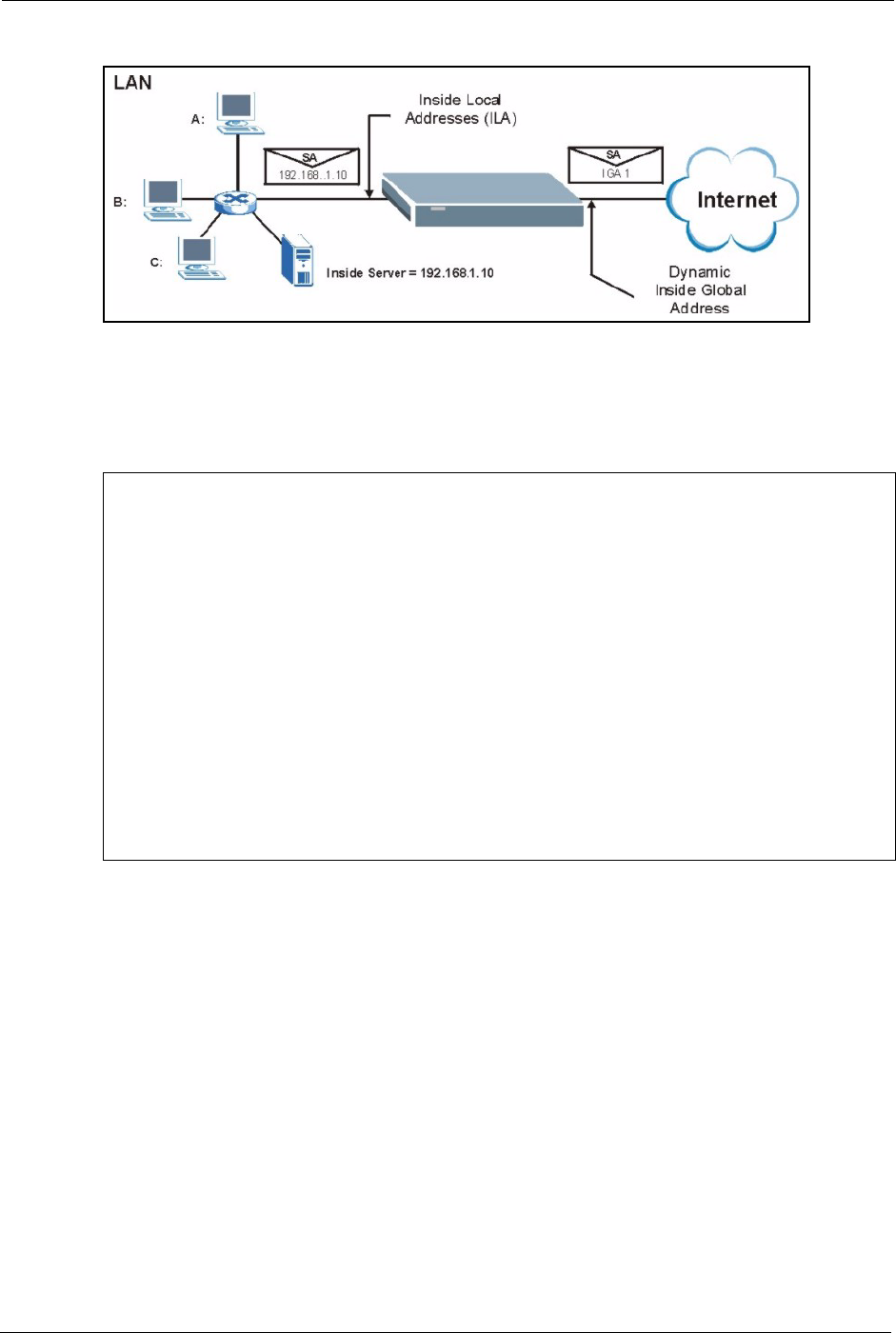
Prestige 334 User’s Guide
Chapter 25 Network Address Translation (NAT) 246
Figure 122 NAT Example 2
In this case, you do exactly as above (use the convenient pre-configured SUA Only set) and
also go to menu 15.2 to specify the Inside Server behind the NAT as shown in the next figure.
Figure 123 Menu 15.2.1 Specifying an Inside Server
25.5.3 Example 3: Multiple Public IP Addresses With Inside Servers
In this example, there are 3 IGAs from our ISP. There are many departments but two have
their own FTP server. All departments share the same router. The example will reserve one
IGA for each department with an FTP server and all departments use the other IGA. Map the
FTP servers to the first two IGAs and the other LAN traffic to the remaining IGA. Map the
third IGA to an inside web server and mail server. Four rules need to be configured, two bi-
directional and two unidirectional as follows.
1Map the first IGA to the first inside FTP server for FTP traffic in both directions (1 : 1
mapping, giving both local and global IP addresses).
2Map the second IGA to our second inside FTP server for FTP traffic in both directions (1
: 1 mapping, giving both local and global IP addresses).
3Map the other outgoing LAN traffic to IGA3 (Many : 1 mapping).
Menu 15.2.1 - NAT Server Setup
Rule Start Port No. End Port No. IP Address
---------------------------------------------------
1. Default Default 192.168.1.10
2. 0 0 0.0.0.0
3. 0 0 0.0.0.0
4. 0 0 0.0.0.0
5. 0 0 0.0.0.0
6. 0 0 0.0.0.0
7. 0 0 0.0.0.0
8. 0 0 0.0.0.0
9. 0 0 0.0.0.0
10. 0 0 0.0.0.0
11. 0 0 0.0.0.0
12. 0 0 0.0.0.0
Press ENTER to Confirm or ESC to Cancel:
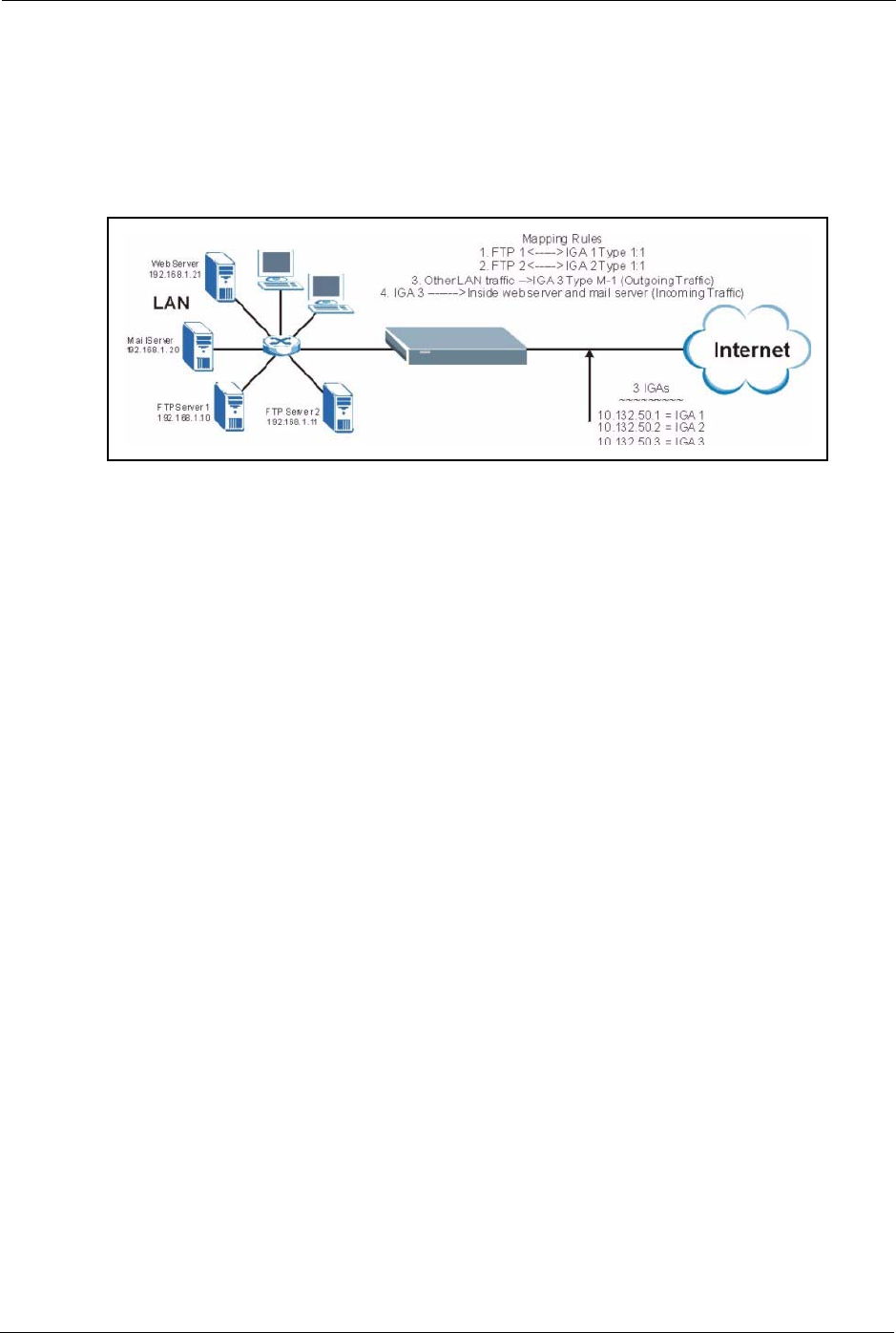
Prestige 334 User’s Guide
247 Chapter 25 Network Address Translation (NAT)
4You also map your third IGA to the web server and mail server on the LAN. Type
Server allows you to specify multiple servers, of different types, to other computers
behind NAT on the LAN.
The example situation looks somewhat like this:
Figure 124 NAT Example 3
1In this case you need to configure Address Mapping Set 1 from Menu 15.1 - Address
Mapping Sets. Therefore you must choose the Full Feature option from the Network
Address Translation field (in menu 4 or menu 11.3) see Figure 105.
2Then enter 15 from the main menu.
3Enter 1 to configure the Address Mapping Sets.
4Enter 1 to begin configuring this new set. Enter a Set Name, choose the Edit Action and
then enter 1 for the Select Rule field. Press [ENTER] to confirm.
5Select Type as One-to-One (direct mapping for packets going both ways), and enter the
local Start IP as 192.168.1.10 (the IP address of FTP Server 1), the global Start IP as
10.132.50.1 (our first IGA) see Figure 126.
6Repeat the previous step for rules 2 to 4 as outlined above.
7When finished, menu 15.1.1.1 should look like as shown in Example 3: Final Menu
15.1.1.

Prestige 334 User’s Guide
Chapter 25 Network Address Translation (NAT) 248
Figure 125 NAT Example 3: Menu 11.3
The following figures show how to configure the first rule.
Menu 11.3 - Remote Node Network Layer Options
IP Address Assignment= Dynamic
IP Address= N/A
IP Subnet Mask= N/A
Gateway IP Addr= N/A
Network Address Translation = Full Feature
Metric= 1
Private= N/A
RIP Direction= None
Version= N/A
Multicast= None
Enter here to CONFIRM or ESC to CANCEL:

Prestige 334 User’s Guide
249 Chapter 25 Network Address Translation (NAT)
Figure 126 Example 3: Menu 15.1.1.1
Figure 127 Example 3: Final Menu 15.1.1
Now configure the IGA3 to map to our web server and mail server on the LAN.
8Enter 15 from the main menu.
9Enter 2 in Menu 15 - NAT Setup.
10Enter 1 in Menu 15.2 - NAT Server Setup to see the following menu. Configure it as
shown.
Menu 15.1.1.1 Address Mapping Rule
Type= One-to-One
Local IP:
Start= 192.168.1.10
End = N/A
Global IP:
Start= 10.132.50.1
End = N/A
Press ENTER to Confirm or ESC to Cancel:
Press Space Bar to Toggle.
Menu 15.1.1 - Address Mapping Rules
Set Name= NAT_SET
Idx Local Start IP Local End IP Global Start IP Global End IP Type
--- --------------- -------------- --------------- --------------- ------
1. 192.168.1.10 10.132.50.1 1-1
2. 192.168.1.11 10.132.50.2 1-1
3. 0.0.0.0 255.255.255.255 10.132.50.3 M-1
4. 10.132.50.3 Server
5.
6.
7.
8.
9.
10.
Action= None Select Rule= N/A
Press ENTER to Confirm or ESC to Cancel:

Prestige 334 User’s Guide
Chapter 25 Network Address Translation (NAT) 250
Figure 128 Example 3: Menu 15.2
25.5.4 Example 4: NAT Unfriendly Application Programs
Some applications do not support NAT Mapping using TCP or UDP port address translation.
In this case it is better to use Many-to-Many No Overload mapping as port numbers do not
change for Many-to-Many No Overload (and One-to-One) NAT mapping types. The
following figure illustrates this.
Menu 15.2 - NAT Server Setup
Rule Start Port No. End Port No. IP Address
---------------------------------------------------
1. Default Default 0.0.0.0
2. 80 80 192.168.1.21
3. 25 25 192.168.1.20
4. 0 0 0.0.0.0
5. 0 0 0.0.0.0
6. 0 0 0.0.0.0
7. 0 0 0.0.0.0
8. 0 0 0.0.0.0
9. 0 0 0.0.0.0
10. 0 0 0.0.0.0
11. 0 0 0.0.0.0
12. 0 0 0.0.0.0
Press ENTER to Confirm or ESC to Cancel:
HTTP:80 FTP:21 Telnet:23 SMTP:25 POP3:110 PPTP:1723
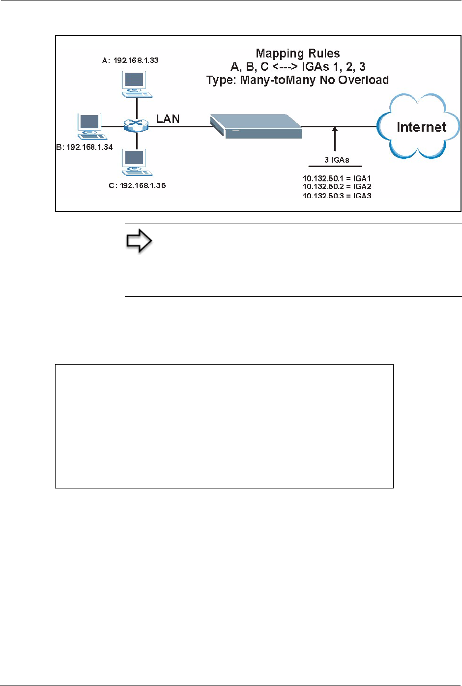
Prestige 334 User’s Guide
251 Chapter 25 Network Address Translation (NAT)
Figure 129 NAT Example 4
Follow the steps outlined in example 3 to configure these two menus as follows
Figure 130 Example 4: Menu 15.1.1.1 Address Mapping Rule.
After you’ve configured your rule, you should be able to check the settings in menu 15.1.1 as
shown next.
Note: Other applications such as some gaming programs are
NAT unfriendly because they embed addressing information in
the data stream. These applications won’t work through NAT
even when using One-to-One and Many-to-Many No Overload
mapping types.
Menu 15.1.1.1 Address Mapping Rule
Type= Many-One-to-One
Local IP:
Start= 192.168.1.10
End = 192.168.1.12
Global IP:
Start= 10.132.50.1
End = 10.132.50.3
Press ENTER to Confirm or ESC to Cancel:
Prestige 334 User’s Guide
Chapter 25 Network Address Translation (NAT) 252
Figure 131 Example 4: Menu 15.1.1 Address Mapping Rules
25.6 Configuring Trigger Port Forwarding
Enter 3 in menu 15 to display Menu 15.3 — Trigger Port Setup, shown next.
Menu 15.1.1 - Address Mapping Rules
Set Name= Example4
Idx Local Start IP Local End IP Global Start IP Global End IP Type
--- -------------- -------------- --------------- --------------- ------
1. 192.168.1.10 192.168.1.12 10.132.50.1 10.132.50.3 M:M NO OV
2.
3.
4.
5.
6.
7.
8.
9.
10.
Action= Edit Select Rule=
Press ENTER to Confirm or ESC to Cancel:
Note: Only one LAN computer can use a trigger port (range) at
a time.
Prestige 334 User’s Guide
253 Chapter 25 Network Address Translation (NAT)
Figure 132 Menu 15.3 Trigger Port Setup
The following table describes the fields in this screen.
Menu 15.3 - Trigger Port Setup
Incoming Trigger
Rule Name Start Port End Port Start Port End Port
----------------------------------------------------------------------
1. Real Audio 6970 7170 7070 7070
2. 0 0 0 0
3. 0 0 0 0
4. 0 0 0 0
5. 0 0 0 0
6. 0 0 0 0
7. 0 0 0 0
8. 0 0 0 0
9. 0 0 0 0
10. 0 0 0 0
11. 0 0 0 0
12. 0 0 0 0
Press ENTER to Confirm or ESC to Cancel:
Table 84 Menu 15.3 Trigger Port Setup
FIELD DESCRIPTION
Rule This is the rule index number.
Name Enter a unique name for identification purposes. You may enter up to 15 characters in
this field. All characters are permitted - including spaces.
Incoming Incoming is a port (or a range of ports) that a server on the WAN uses when it sends
out a particular service. The Prestige forwards the traffic with this port (or range of
ports) to the client computer on the LAN that requested the service.
Start Port Enter a port number or the starting port number in a range of port numbers.
End Port Enter a port number or the ending port number in a range of port numbers.
Trigger The trigger port is a port (or a range of ports) that causes (or triggers) the Prestige to
record the IP address of the LAN computer that sent the traffic to a server on the
WAN.
Start Port Enter a port number or the starting port number in a range of port numbers.
End Port Enter a port number or the ending port number in a range of port numbers.
Press [ENTER] at the message “Press ENTER to Confirm...” to save your configuration, or press [ESC]
at any time to cancel.

Prestige 334 User’s Guide
Chapter 26 Enabling the Firewall 254
CHAPTER 26
Enabling the Firewall
This chapter shows you how to get started with the Prestige firewall.
26.1 Remote Management and the Firewall
When SMT menu 24.11 is configured to allow management (see the Remote Management
chapter) and the firewall is enabled:
• The firewall blocks remote management from the WAN unless you configure a firewall
rule to allow it.
• The firewall allows remote management from the LAN.
26.2 Access Methods
The web configurator is, by far, the most comprehensive firewall configuration tool your
Prestige has to offer. For this reason, it is recommended that you configure your firewall using
the web configurator, see the following chapters for instructions. SMT screens allow you to
activate the firewall and view firewall logs.
26.3 Enabling the Firewall
From the main menu enter 21 to go to Menu 21 - Filter and Firewall Setup to display the
screen shown next.
Enter option 2 in this menu to bring up the following screen. Press [SPACE BAR] and then
[ENTER] to select Yes in the Active field to activate the firewall. The firewall must be active
to protect against Denial of Service (DoS) attacks. Additional rules may be configured using
the web configurator.
Prestige 334 User’s Guide
255 Chapter 26 Enabling the Firewall
Figure 133 Menu 21.2 Firewall Setup
Menu 21.2 - Firewall Setup
The firewall protects against Denial of Service (DoS) attacks when
it is active.
Your network is vulnerable to attacks when the firewall is turned off.
Refer to the User's Guide for details about the firewall default
policies.
You may define additional Policy rules or modify existing ones but
please exercise extreme caution in doing so.
Active: No
You can use the Web Configurator to configure the firewall.
Press ENTER to Confirm or ESC to Cancel:
Note: Use the web configurator or the command interpreter to
configure the firewall rules.
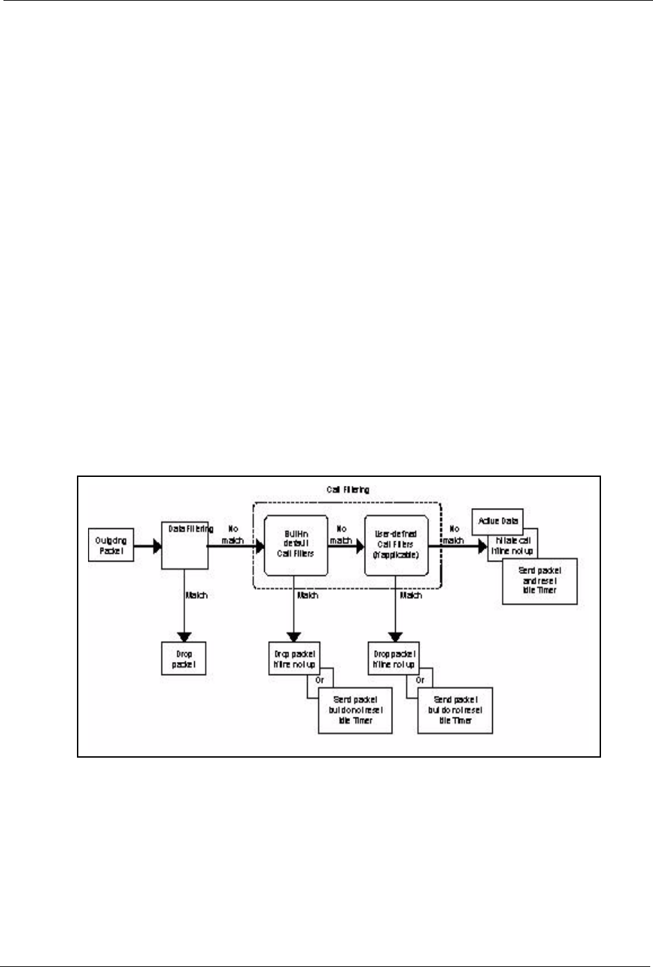
Prestige 334 User’s Guide
Chapter 27 Filter Configuration 256
CHAPTER 27
Filter Configuration
This chapter shows you how to create and apply filters.
27.1 Introduction to Filters
Your Prestige uses filters to decide whether to allow passage of a data packet and/or to make a
call. There are two types of filter applications: data filtering and call filtering. Filters are
subdivided into device and protocol filters, which are discussed later.
Data filtering screens the data to determine if the packet should be allowed to pass. Data filters
are divided into incoming and outgoing filters, depending on the direction of the packet
relative to a port. Data filtering can be applied on either the WAN side or the LAN side. Call
filtering is used to determine if a packet should be allowed to trigger a call. Remote node call
filtering is only applicable when using PPPoE encapsulation. Outgoing packets must undergo
data filtering before they encounter call filtering as shown in the following figure.
Figure 134 Outgoing Packet Filtering Process
For incoming packets, your Prestige applies data filters only. Packets are processed depending
upon whether a match is found. The following sections describe how to configure filter sets.

Prestige 334 User’s Guide
257 Chapter 27 Filter Configuration
27.1.1 The Filter Structure of the Prestige
A filter set consists of one or more filter rules. Usually, you would group related rules, e.g., all
the rules for NetBIOS, into a single set and give it a descriptive name. The Prestige allows you
to configure up to twelve filter sets with six rules in each set, for a total of 72 filter rules in the
system. You cannot mix device filter rules and protocol filter rules within the same set. You
can apply up to four filter sets to a particular port to block multiple types of packets. With each
filter set having up to six rules, you can have a maximum of 24 rules active for a single port.
Sets of factory default filter rules have been configured in menu 21 to prevent NetBIOS traffic
from triggering calls and to prevent incoming telnet sessions. A summary of their filter rules is
shown in the figures that follow.
The following figure illustrates the logic flow when executing a filter rule. See also Figure
139 for the logic flow when executing an IP filter.
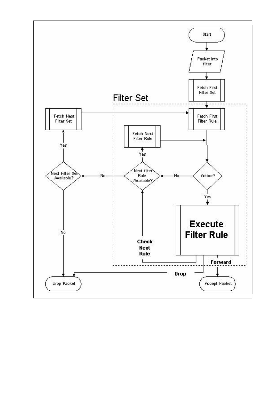
Prestige 334 User’s Guide
Chapter 27 Filter Configuration 258
Figure 135 Filter Rule Process
You can apply up to four filter sets to a particular port to block multiple types of packets. With
each filter set having up to six rules, you can have a maximum of 24 rules active for a single
port.
27.2 Configuring a Filter Set
The Prestige includes filtering for NetBIOS over TCP/IP packets by default. To configure
another filter set, follow the procedure below.
1Enter 21 in the main menu to open menu 21.

Prestige 334 User’s Guide
259 Chapter 27 Filter Configuration
Figure 136 Menu 21: Filter and Firewall Setup
2Enter 1 to bring up the following menu.
Figure 137 Menu 21.1: Filter Set Configuration
3Select the filter set you wish to configure (1-12) and press [ENTER].
4Enter a descriptive name or comment in the Edit Comments field and press [ENTER].
5Press [ENTER] at the message [Press ENTER to confirm] to open Menu 21.1.1 - Filter
Rules Summary.
This screen shows the summary of the existing rules in the filter set. The following tables
contain a brief description of the abbreviations used in the previous menus.
Menu 21 - Filter and Firewall Setup
1. Filter Setup
2. Firewall Setup
Enter Menu Selection Number:
Menu 21.1 - Filter Set Configuration
Filter Filter
Set # Comments Set # Comments
------ ----------------- ------ -----------------
1 _______________ 7 _______________
2 _______________ 8 _______________
3 _______________ 9 _______________
4 _______________ 10 _______________
5 _______________ 11 _______________
6 _______________ 12 _______________
Enter Filter Set Number to Configure= 0
Edit Comments= N/A
Press ENTER to Confirm or ESC to Cancel:
Table 85 Abbreviations Used in the Filter Rules Summary Menu
FIELD DESCRIPTION
#The filter rule number: 1 to 6.
AActive: “Y” means the rule is active. “N” means the rule is inactive.
Type The type of filter rule: “GEN” for Generic, “IP” for TCP/IP.
Filter Rules These parameters are displayed here.
MMore.
“Y” means there are more rules to check which form a rule chain with the present rule. An
action cannot be taken until the rule chain is complete.
“N” means there are no more rules to check. You can specify an action to be taken i.e.,
forward the packet, drop the packet or check the next rule. For the latter, the next rule is
independent of the rule just checked.
Prestige 334 User’s Guide
Chapter 27 Filter Configuration 260
The protocol dependent filter rules abbreviation are listed as follows:
Refer to the next section for information on configuring the filter rules.
27.2.1 Configuring a Filter Rule
To configure a filter rule, type its number in Menu 21.1.1 - Filter Rules Summary and press
[ENTER] to open menu 21.1.1.1 for the rule.
To speed up filtering, all rules in a filter set must be of the same class, i.e., protocol filters or
generic filters. The class of a filter set is determined by the first rule that you create. When
applying the filter sets to a port, separate menu fields are provided for protocol and device
filter sets. If you include a protocol filter set in a device filter field or vice versa, the Prestige
will warn you and will not allow you to save.
27.2.2 Configuring a TCP/IP Filter Rule
This section shows you how to configure a TCP/IP filter rule. TCP/IP rules allow you to base
the rule on the fields in the IP and the upper layer protocol, for example, UDP and TCP
headers.
mAction Matched.
“F” means to forward the packet immediately and skip checking the remaining rules.
“D” means to drop the packet.
“N“ means to check the next rule.
nAction Not Matched
“F” means to forward the packet immediately and skip checking the remaining rules.
“D” means to drop the packet.
“N” means to check the next rule.
Table 86 Rule Abbreviations Used
ABBREVIATION DESCRIPTION
IP
Pr Protocol
SA Source Address
SP Source Port number
DA Destination Address
DP Destination Port number
GEN
Off Offset
Len Length
Table 85 Abbreviations Used in the Filter Rules Summary Menu
FIELD DESCRIPTION
Prestige 334 User’s Guide
261 Chapter 27 Filter Configuration
To configure TCP/IP rules, select TCP/IP Filter Rule from the Filter Type field and press
[ENTER] to open Menu 21.1.1.1 - TCP/IP Filter Rule, as shown next
Figure 138 Menu 21.1.1.1 TCP/IP Filter Rule.
The following table describes how to configure your TCP/IP filter rule.
Menu 21.1.1.1 - TCP/IP Filter Rule
Filter #: 1,1
Filter Type= TCP/IP Filter Rule
Active= Yes
IP Protocol= 0 IP Source Route= No
Destination: IP Addr= 0.0.0.0
IP Mask= 0.0.0.0
Port #= 137
Port # Comp= Equal
Source: IP Addr= 0.0.0.0
IP Mask= 0.0.0.0
Port #=
Port # Comp= None
TCP Estab= N/A
More= No Log= None
Action Matched= Check Next Rule
Action Not Matched= Check Next Rule
Press ENTER to Confirm or ESC to Cancel:
Table 87 TCP/IP Filter Rule
FIELD DESCRIPTION OPTIONS
Active Press [SPACE BAR] and then [ENTER] to select Yes to activate
the filter rule or No to deactivate it.
Yes
No
IP Protocol Protocol refers to the upper layer protocol, e.g., TCP is 6, UDP is
17 and ICMP is 1. Type a value between 0 and 255. A value of 0
matches ANY protocol.
0-255
IP Source Route Press [SPACE BAR] and then [ENTER] to select Yes to apply
the rule to packets with an IP source route option. Otherwise the
packets must not have a source route option. The majority of IP
packets do not have source route.
Yes
No
Destination
IP Address Enter the destination IP Address of the packet you wish to filter.
This field is ignored if it is 0.0.0.0.
0.0.0.0
IP Mask Enter the IP mask to apply to the Destination: IP Addr.0.0.0.0
Port # Enter the destination port of the packets that you wish to filter.
The range of this field is 0 to 65535. This field is ignored if it is 0.
0-65535
Port # Comp Press [SPACE BAR] and then [ENTER] to select the comparison
to apply to the destination port in the packet against the value
given in Destination: Port #.
None
Less
Greater
Equal
Not Equal

Prestige 334 User’s Guide
Chapter 27 Filter Configuration 262
The following figure illustrates the logic flow of an IP filter.
Source
IP Address Enter the source IP Address of the packet you wish to filter. This
field is ignored if it is 0.0.0.0.
0.0.0.0
IP Mask Enter the IP mask to apply to the Source: IP Addr.0.0.0.0
Port # Enter the source port of the packets that you wish to filter. The
range of this field is 0 to 65535. This field is ignored if it is 0.
0-65535
Port # Comp Press [SPACE BAR] and then [ENTER] to select the comparison
to apply to the source port in the packet against the value given
in Source: Port #.
None
Less
Greater
Equal
Not Equal
TCP Estab This field is applicable only when the IP Protocol field is 6, TCP.
Press [SPACE BAR] and then [ENTER] to select Yes, to have
the rule match packets that want to establish a TCP connection
(SYN=1 and ACK=0); if No, it is ignored.
Yes
No
More Press [SPACE BAR] and then [ENTER] to select Yes or No. If
Yes, a matching packet is passed to the next filter rule before an
action is taken; if No, the packet is disposed of according to the
action fields.
If More is Yes, then Action Matched and Action Not Matched
will be N/A.
Yes
No
Log Press [SPACE BAR] and then [ENTER] to select a logging
option from the following:
None – No packets will be logged.
Action Matched - Only packets that match the rule parameters
will be logged.
Action Not Matched - Only packets that do not match the rule
parameters will be logged.
Both – All packets will be logged.
None
Action
Matched
Action Not
Matched
Both
Action Matched Press [SPACE BAR] and then [ENTER] to select the action for a
matching packet.
Check Next
Rule
Forward
Drop
Action Not Matched Press [SPACE BAR] and then [ENTER] to select the action for a
packet not matching the rule.
Check Next
Rule
Forward
Drop
When you have Menu 21.1.1.1 - TCP/IP Filter Rule configured, press [ENTER] at the message “Press
ENTER to Confirm” to save your configuration, or press [ESC] to cancel. This data will now be
displayed on Menu 21.1.1 - Filter Rules Summary.
Table 87 TCP/IP Filter Rule
FIELD DESCRIPTION OPTIONS
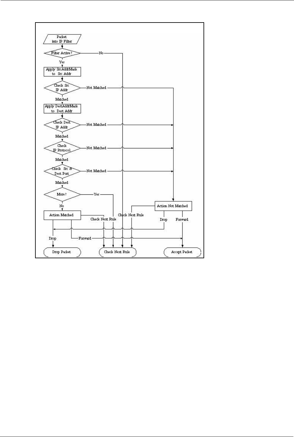
Prestige 334 User’s Guide
263 Chapter 27 Filter Configuration
Figure 139 Executing an IP Filter
27.2.3 Configuring a Generic Filter Rule
This section shows you how to configure a generic filter rule. The purpose of generic rules is
to allow you to filter non-IP packets. For IP, it is generally easier to use the IP rules directly.
For generic rules, the Prestige treats a packet as a byte stream as opposed to an IP or IPX
packet. You specify the portion of the packet to check with the Offset (from 0) and the Length
fields, both in bytes. The Prestige applies the Mask (bit-wise ANDing) to the data portion
before comparing the result against the Value to determine a match. The Mask and Value are
specified in hexadecimal numbers. Note that it takes two hexadecimal digits to represent a
byte, so if the length is 4, the value in either field will take 8 digits, for example, FFFFFFFF.
To configure a generic rule, select Generic Filter Rule in the Filter Type field in menu
21.1.4.1 and press [ENTER] to open Generic Filter Rule, as shown below.

Prestige 334 User’s Guide
Chapter 27 Filter Configuration 264
Figure 140 Menu 21.1.4.1 Generic Filter Rule
The following table describes the fields in the Generic Filter Rule menu.
Menu 21.1.4.1 - Generic Filter Rule
Filter #: 4,1
Filter Type= Generic Filter Rule
Active= No
Offset= 0
Length= 0
Mask= N/A
Value= N/A
More= No Log= None
Action Matched= Check Next Rule
Action Not Matched= Check Next Rule
Press ENTER to Confirm or ESC to Cancel:
Table 88 Generic Filter Rule Menu Fields
FIELD DESCRIPTION OPTIONS
Filter # This is the filter set, filter rule co-ordinates, i.e., 2,3 refers to the
second filter set and the third rule of that set.
Filter Type Use [SPACE BAR] and then [ENTER] to select a rule type.
Parameters displayed below each type will be different. TCP/IP filter
rules are used to filter IP packets while generic filter rules allow
filtering of non-IP packets.
Generic Filter
Rule
TCP/IP Filter
Rule
Active Select Yes to turn on the filter rule or No to turn it off. Yes / No
Offset Enter the starting byte of the data portion in the packet that you wish
to compare. The range for this field is from 0 to 255.
0-255
Length Enter the byte count of the data portion in the packet that you wish
to compare. The range for this field is 0 to 8.
0-8
Mask Enter the mask (in Hexadecimal notation) to apply to the data
portion before comparison.
Value Enter the value (in Hexadecimal notation) to compare with the data
portion.
More If Yes, a matching packet is passed to the next filter rule before an
action is taken; else the packet is disposed of according to the
action fields.
If More is Yes, then Action Matched and Action Not Matched will be
No.
Yes
No
Log Select the logging option from the following:
None - No packets will be logged.
Action Matched - Only packets that match the rule parameters will
be logged.
Action Not Matched - Only packets that do not match the rule
parameters will be logged.
Both – All packets will be logged.
None
Action Matched
Action Not
Matched
Both
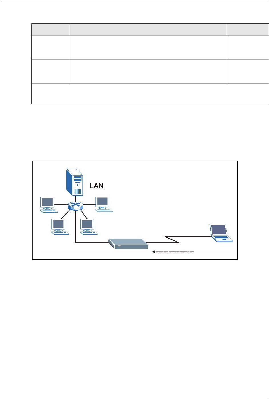
Prestige 334 User’s Guide
265 Chapter 27 Filter Configuration
27.3 Example Filter
Let’s look at an example to block outside users from accessing the Prestige via telnet.
Figure 141 Telnet Filter Example
1Enter 21 from the main menu to open Menu 21 - Filter and Firewall Setup.
2Enter 1 to open Menu 21.1 - Filter Set Configuration.
3Enter the index of the filter set you wish to configure (say 3) and press [ENTER].
4Enter a descriptive name or comment in the Edit Comments field and press [ENTER].
5Press [ENTER] at the message [Press ENTER to confirm] to open Menu 21.1.3 - Filter
Rules Summary
6Enter 1 to configure the first filter rule (the only filter rule of this set). Make the entries in
this menu as shown in the following figure.
Action
Matched
Select the action for a packet matching the rule. Check Next Rule
Forward
Drop
Action Not
Matched
Select the action for a packet not matching the rule. Check Next Rule
Forward
Drop
Once you have completed filling in Menu 21.4.1.1 - Generic Filter Rule, press [ENTER] at the
message “Press ENTER to Confirm” to save your configuration, or press [ESC] to cancel. This data will
now be displayed on Menu 21.1.1 - Filter Rules Summary.
Table 88 Generic Filter Rule Menu Fields
FIELD DESCRIPTION OPTIONS

Prestige 334 User’s Guide
Chapter 27 Filter Configuration 266
Figure 142 Example Filter: Menu 21.1.3.1
• Select Ye s from the Active field to activate this rule.
•6 is the TCP IP Protocol.
•The Port # for the telnet service (TCP protocol) is 23. See RFC 1060 for port numbers of
well-known services.
• Select Equal from the Port # Comp field as you are looking for packets going to port 23
only.
• Select Drop in the Action Matched field so that the packet will be dropped if its
destination is the telnet port.
• Select Forward from the Action Not Matched field so that the packet will be forwarded
if its destination is not the telnet port.
• Press [SPACE BAR] and then [ENTER] to choose this filter rule type. The first filter rule
type determines all subsequent filter types within a set.
When you press [ENTER] to confirm, you will see the following screen. Note that there is
only one filter rule in this set.
Menu 21.1.3.1 - TCP/IP Filter Rule
Filter #: 3,1
Filter Type= TCP/IP Filter Rule
Active= Yes
IP Protocol= 6 IP Source Route= No
Destination: IP Addr= 0.0.0.0
IP Mask= 0.0.0.0
Port #= 23
Port # Comp= Equal
Source: IP Addr= 0.0.0.0
IP Mask= 0.0.0.0
Port #= 0
Port # Comp= None
TCP Estab= No
More= No Log= None
Action Matched= Drop
Action Not Matched= Forward
Press ENTER to Confirm or ESC to Cancel:
Press Space Bar to Toggle.

Prestige 334 User’s Guide
267 Chapter 27 Filter Configuration
Figure 143 Example Filter Rules Summary: Menu 21.1.3
This shows you that you have configured and activated (A = Y) a TCP/IP filter rule (Type =
IP, Pr = 6) for destination telnet ports (DP = 23).
M = N means an action can be taken immediately. The action is to drop the packet (m = D) if
the action is matched and to forward the packet immediately (n = F) if the action is not
matched no matter whether there are more rules to be checked (there aren’t in this example).
After you’ve created the filter set, you must apply it.
1Enter 11 from the main menu to go to menu 11.
2Go to the Edit Filter Sets field, press [SPACE BAR] to select Yes and press [ENTER].
3This brings you to menu 11.5. Apply a filter set (our example filter set 3).
4Press [ENTER] to confirm after you enter the set numbers and to leave menu 11.5.
27.4 Filter Types and NAT
There are two classes of filter rules, Generic Filter (Device) rules and protocol filter (TCP/
IP) rules. Generic filter rules act on the raw data from/to LAN and WAN. Protocol filter rules
act on the IP packets. Generic and TCP/IP filter rules are discussed in more detail in the next
section. When NAT (Network Address Translation) is enabled, the inside IP address and port
number are replaced on a connection-by-connection basis, which makes it impossible to know
the exact address and port on the wire. Therefore, the Prestige applies the protocol filters to the
“native” IP address and port number before NAT for outgoing packets and after NAT for
incoming packets. On the other hand, the generic, or device filters are applied to the raw
packets that appear on the wire. They are applied at the point when the Prestige is receiving
and sending the packets; i.e. the interface. The interface can be an Ethernet port or any other
hardware port. The following diagram illustrates this.
Menu 21.1.3 - Filter Rules Summary
# A Type Filter Rules M m n
- - ---- --------------------------------------------------------- - - -
1 Y IP Pr=6, SA=0.0.0.0, DA=0.0.0.0, DP=23 N D F
2 N
3 N
4 N
5 N
6 N
Enter Filter Rule Number (1-6) to Configure:
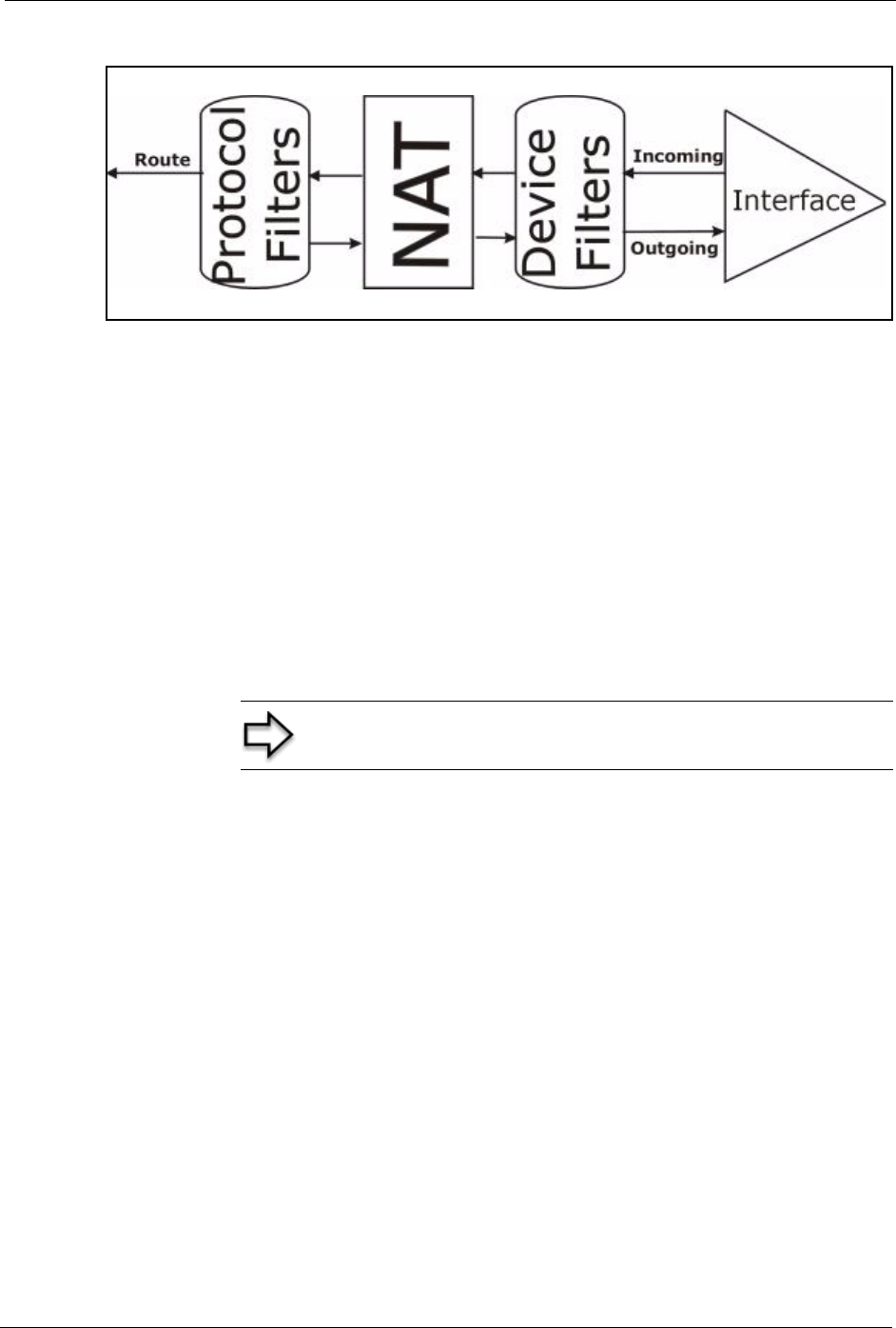
Prestige 334 User’s Guide
Chapter 27 Filter Configuration 268
Figure 144 Protocol and Device Filter Sets
27.5 Firewall Versus Filters
Firewall configuration is discussed in the firewall chapters of this manual. Further
comparisons are also made between filtering, NAT and the firewall.
27.6 Applying a Filter
This section shows you where to apply the filter(s) after you design it (them). The Prestige
already has filters to prevent NetBIOS traffic from triggering calls, and block incoming telnet,
FTP and HTTP connections.
27.6.1 Applying LAN Filters
LAN traffic filter sets may be useful to block certain packets, reduce traffic and prevent
security breaches. Go to menu 3.1 (shown next) and enter the number(s) of the filter set(s) that
you want to apply as appropriate. You can choose up to four filter sets (from twelve) by
entering their numbers separated by commas, e.g., 3, 4, 6, 11. Input filter sets filter incoming
traffic to the Prestige and output filter sets filter outgoing traffic from the Prestige. For PPPoE
or PPTP encapsulation, you have the additional option of specifying remote node call filter
sets.
Note: If you do not activate the firewall, it is advisable to apply filters

Prestige 334 User’s Guide
269 Chapter 27 Filter Configuration
Figure 145 Filtering LAN Traffic
27.6.2 Applying Remote Node Filters
Go to menu 11.5 (shown below – note that call filter sets are only present for PPPoE
encapsulation) and enter the number(s) of the filter set(s) as appropriate. You can cascade up
to four filter sets by entering their numbers separated by commas. The Prestige already has
filters to prevent NetBIOS traffic from triggering calls.
Figure 146 Filtering Remote Node Traffic
Menu 3.1 - LAN Port Filter Setup
Input Filter Sets:
protocol filters=
device filters=
Output Filter Sets:
protocol filters=
device filters=
Press ENTER to Confirm or ESC to Cancel:
Menu 11.5 - Remote Node Filter
Input Filter Sets:
protocol filters=
device filters=
Output Filter Sets:
protocol filters=
device filters=
Enter here to CONFIRM or ESC to CANCEL:
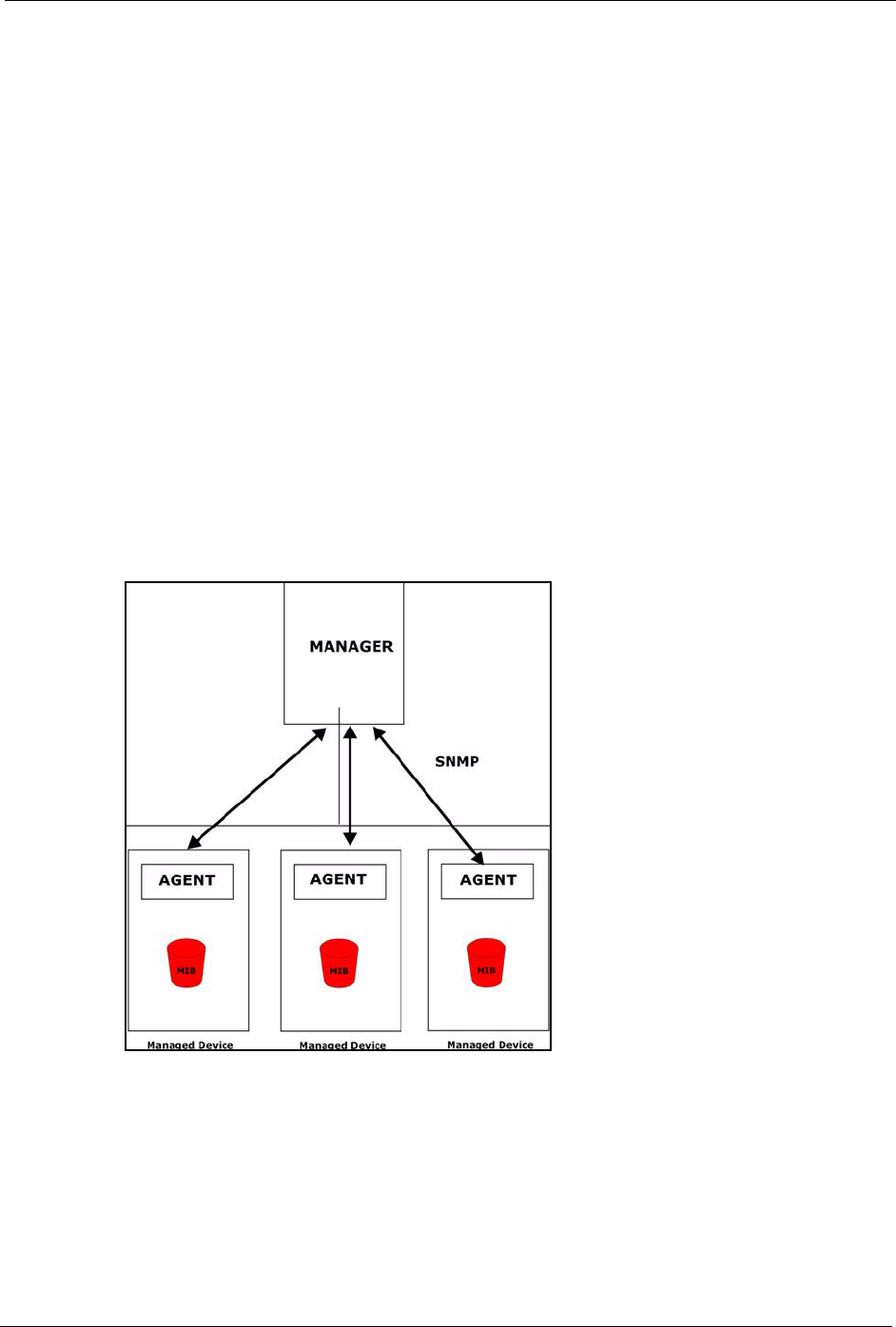
Prestige 334 User’s Guide
Chapter 28 SNMP Configuration 270
CHAPTER 28
SNMP Configuration
This chapter explains SNMP Configuration menu 22.
28.1 About SNMP
Simple Network Management Protocol is a protocol used for exchanging management
information between network devices. SNMP is a member of the TCP/IP protocol suite. Your
Prestige supports SNMP agent functionality, which allows a manager station to manage and
monitor the Prestige through the network. The Prestige supports SNMP version one
(SNMPv1) and version two c (SNMPv2c). The next figure illustrates an SNMP management
operation. SNMP is only available if TCP/IP is configured.
Figure 147 SNMP Management Model
An SNMP managed network consists of two main components: agents and a manager.
An agent is a management software module that resides in a managed device (the Prestige).
An agent translates the local management information from the managed device into a form
compatible with SNMP. The manager is the console through which network administrators
perform network management functions. It executes applications that control and monitor
managed devices.

Prestige 334 User’s Guide
271 Chapter 28 SNMP Configuration
The managed devices contain object variables/managed objects that define each piece of
information to be collected about a device. Examples of variables include the number of
packets received, node port status etc. A Management Information Base (MIB) is a collection
of managed objects. SNMP allows a manager and agents to communicate for the purpose of
accessing these objects.
SNMP itself is a simple request/response protocol based on the manager/agent model. The
manager issues a request and the agent returns responses using the following protocol
operations:
1Get - Allows the manager to retrieve an object variable from the agent.
2GetNext - Allows the manager to retrieve the next object variable from a table or list
within an agent. In SNMPv1, when a manager wants to retrieve all elements of a table
from an agent, it initiates a Get operation, followed by a series of GetNext operations.
3Set - Allows the manager to set values for object variables within an agent.
4Trap - Used by the agent to inform the manager of some events.
28.2 Supported MIBs
The Prestige supports RFC-1215 and MIB II as defined in RFC-1213 as well as ZyXEL
private MIBs. The focus of the MIBs is to let administrators collect statistic data and monitor
status and performance.
28.3 SNMP Configuration
To configure SNMP, select option 22 from the main menu to open Menu 22 — SNMP
Configuration as shown next. The “community” for Get, Set and Trap fields is SNMP
terminology for password.
Prestige 334 User’s Guide
Chapter 28 SNMP Configuration 272
Figure 148 Menu 22 SNMP Configuration
The following table describes the SNMP configuration parameters.
28.4 SNMP Traps
The Prestige will send traps to the SNMP manager when any one of the following events
occurs:
Menu 22 - SNMP Configuration
SNMP:
Get Community= public
Set Community= public
Trusted Host= 0.0.0.0
Trap:
Community= public
Destination= 0.0.0.0
Press ENTER to Confirm or ESC to Cancel:
Table 89 Menu 22 SNMP Configuration
FIELD DESCRIPTION
SNMP:
Get Community Type the Get Community, which is the password for the incoming Get- and
GetNext requests from the management station.
Set Community Type the Set community, which is the password for incoming Set requests from
the management station.
Trusted Host If you enter a trusted host, your Prestige will only respond to SNMP messages
from this address. A blank (default) field means your Prestige will respond to all
SNMP messages it receives, regardless of source.
Trap:
Community Type the trap community, which is the password sent with each trap to the SNMP
manager.
Destination Type the IP address of the station to send your SNMP traps to.
When you have completed this menu, press [ENTER] at the prompt “Press ENTER to confirm or ESC
to cancel” to save your configuration or press [ESC] to cancel and go back to the previous screen.
Table 90 SNMP Traps
TRAP # TRAP NAME DESCRIPTION
1coldStart (defined in RFC-1215)A trap is sent after booting (power on).
2warmStart (defined in RFC-1215)A trap is sent after booting (software reboot).
3linkDown (defined in RFC-1215)A trap is sent with the port number when any of the
links are down. See the following table.

Prestige 334 User’s Guide
273 Chapter 28 SNMP Configuration
The port number is its interface index under the interface group.
4linkUp (defined in RFC-1215)A trap is sent with the port number.
5authenticationFailure (defined in
RFC-1215)
A trap is sent to the manager when receiving any
SNMP gets or sets requirements with wrong
community (password).
6whyReboot (defined in ZYXEL-MIB) A trap is sent with the reason of restart before
rebooting when the system is going to restart (warm
start).
6a For intentional reboot : A trap is sent with the message "System reboot by
user!" if reboot is done intentionally, (for example,
download new files, CI command "sys reboot", etc.).
Table 91 Ports and Permanent Virtual Circuits
PORT PVC (PERMANENT
VIRTUAL CIRCUIT)
1Ethernet LAN
2 1
3 2
… …
13 12
14 xDSL
Table 90 SNMP Traps
TRAP # TRAP NAME DESCRIPTION

Prestige 334 User’s Guide
Chapter 29 System Information and Diagnosis 274
CHAPTER 29
System Information and
Diagnosis
This chapter covers the information and diagnostic tools in SMT menus 24.1 to 24.4.
These tools include updates on system status, port status, log and trace capabilities and
upgrades for the system software. This chapter describes how to use these tools in detail.
Type 24 in the main menu to open Menu 24 – System Maintenance, as shown in the
following figure.
Figure 149 Menu 24 System Maintenance
29.1 System Status
The first selection, System Status gives you information on the status and statistics of the
ports, as shown next Figure 150 . System Status is a tool that can be used to monitor your
Prestige. Specifically, it gives you information on your ADSL telephone line status, number of
packets sent and received.
To get to System Status, type 24 to go to Menu 24 — System Maintenance. From this menu,
type 1. System Status. There are two commands in Menu 24.1 — System Maintenance —
Status. Entering 1 resets the counters; [ESC] takes you back to the previous screen.
The following table describes the fields present in Menu 24.1 — System Maintenance —
Status which are read-only and meant for diagnostic purposes.
Menu 24 - System Maintenance
1. System Status
2. System Information and Console Port Speed
3. Log and Trace
4. Diagnostic
5. Backup Configuration
6. Restore Configuration
7. Upload Firmware
8. Command Interpreter Mode
9. Call Control
10. Time and Date Setting
11. Remote Management Setup

Prestige 334 User’s Guide
275 Chapter 29 System Information and Diagnosis
Figure 150 Menu 24.1 System Maintenance : Status
The following table describes the fields present in Menu 24.1 — System Maintenance —
Status. These fields are READ-ONLY and meant for diagnostic purposes. The upper right
corner of the screen shows the time and date according to the format you set in menu 24.10.
Menu 24.1 - System Maintenance - Status 00:49:12
Sat. Jan. 01, 2000
Port Status TxPkts RxPkts Cols Tx B/s Rx B/s Up Time
WAN Down 0 0 0 0 0 0:00:00
LAN 100M/Full 0 0 0 0 0 0:49:10
Port Ethernet Address IP Address IP Mask DHCP
WAN 00:A0:C5:01:23:46 0.0.0.0 0.0.0.0 Client
LAN 00:A0:C5:01:23:45 192.168.1.1 255.255.255.0 Server
System up Time: 0:49:15
Name: P334
Routing: IP
ZyNOS F/W Version: V3.60(JJ.3)b1 | 08/20/2004
Press Command:
COMMANDS: 1-Drop WAN 9-Reset Counters ESC-Exit
Table 92 System Maintenance: Status Menu Fields
FIELD DESCRIPTION
Port Identifies a port (WAN, LAN) on the Prestige.
Status Shows the port speed and duplex setting if you’re using Ethernet
Encapsulation and Down (line is down), idle (line (ppp) idle), dial (starting to
trigger a call) and drop (dropping a call) if you’re using PPPoE Encapsulation.
TxPkts The number of transmitted packets on this port.
RxPkts The number of received packets on this port.
Cols The number of collisions on this port.
Tx B/s Shows the transmission speed in Bytes per second on this port.
Rx B/s Shows the reception speed in Bytes per second on this port.
Up Time Total amount of time the line has been up.
Ethernet Address The Ethernet address of the port listed on the left.
IP Address The IP address of the port listed on the left.
IP Mask The IP mask of the port listed on the left.
DHCP The DHCP setting of the port listed on the left.
System up Time The total time the Prestige has been on.
Name This is the Prestige's system name + domain name assigned in menu 1. For
example, System Name= xxx; Domain Name= baboo.mickey.com
Name= xxx.baboo.mickey.com
Routing Refers to the routing protocol used.
Prestige 334 User’s Guide
Chapter 29 System Information and Diagnosis 276
29.2 System Information
To get to the System Information:
1Enter 24 to display Menu 24 — System Information and Console Port Speed.
2Enter 2 to display Menu 24.2 — System Information.
3From this menu you have two choices as shown in the next figure:
Figure 151 Menu 24.2 System Information and Console Port Speed
29.2.1 System Information
Enter 1 in menu 24.2 to display the screen shown next
ZyNOS F/W Version The ZyNOS Firmware version and the date created.
You may enter 1 to drop the WAN connection, 9 to reset the counters or [ESC] to return to menu 24.
Table 92 System Maintenance: Status Menu Fields
FIELD DESCRIPTION
Menu 24.2 - System Information and Console Port Speed
System Information
Console Port Speed
Please enter selection:
Prestige 334 User’s Guide
277 Chapter 29 System Information and Diagnosis
Figure 152 Menu 24.2.1 System Maintenance : Information
The following table describes the fields in this menu.
29.2.2 Console Port Speed
You can set up different port speeds for the console port through Menu 24.2.2 – System
Maintenance – Console Port Speed. Your Prestige supports 9600 (default), 19200, 38400,
57600 and 115200 bps. Press [SPACE BAR] and then [ENTER] to select the desired speed in
menu 24.2.2, as shown in the following figure.
Menu 24.2.1 - System Maintenance - Information
Name: P334
Routing: IP
ZyNOS F/W Version: V3.60(JJ.3)b1 | 08/20/2004
LAN
Ethernet Address: 00:A0:C5:01:23:45
IP Address: 192.168.1.1
IP Mask: 255.255.255.0
DHCP: Server
Press ESC or RETURN to Exit:
Table 93 Menu 24.2.1 System Maintenance : Information
FIELD DESCRIPTION
Name Displays the system name of your Prestige. This information can be changed
in Menu 1 – General Setup.
Routing Refers to the routing protocol used.
ZyNOS F/W Version Refers to the ZyNOS (ZyXEL Network Operating System) system firmware
version. ZyNOS is a registered trademark of ZyXEL Communications
Corporation.
LAN
Ethernet Address Refers to the Ethernet MAC (Media Access Control) of your Prestige.
IP Address This is the IP address of the Prestige in dotted decimal notation.
IP Mask This shows the subnet mask of the Prestige.
DHCP This field shows the DHCP setting (None, Relay or Server) of the Prestige.

Prestige 334 User’s Guide
Chapter 29 System Information and Diagnosis 278
Figure 153 Menu 24.2.2 System Maintenance : Change Console Port Speed
29.3 Log and Trace
There are two logging facilities in the Prestige. The first is the error logs and trace records that
are stored locally. The second is the syslog facility for message logging.
29.3.1 Syslog Logging
The Prestige uses the syslog facility to log the CDR (Call Detail Record) and system messages
to a syslog server. Syslog and accounting can be configured in Menu 24.3.2 — System
Maintenance - Syslog Logging, as shown next.
Figure 154 Menu 24.3.2 System Maintenance : Syslog Logging
You need to configure the syslog parameters described in the following table to activate syslog
then choose what you want to log.
Your Prestige sends five types of syslog messages. Some examples (not all Prestige specific)
of these syslog messages with their message formats are shown next:
Menu 24.2.2 – System Maintenance – Change Console Port Speed
Console Port Speed: 9600
Press ENTER to Confirm or ESC to Cancel:
Menu 24.3.2 - System Maintenance - Syslog Logging
Syslog:
Active= No
Syslog Server IP Address= 0.0.0.0
Log Facility= Local 1
Press ENTER to Confirm or ESC to Cancel:
Table 94 Menu 24.3.2 System Maintenance : Syslog and Accounting
PARAMETER DESCRIPTION
Syslog:
Active Press [SPACE BAR] and then [ENTER] to turn syslog on or off.
Syslog Server IP
Address
Enter the IP Address of the server that will log the CDR (Call Detail Record) and
system messages i.e., the syslog server.
Log Facility Press [SPACE BAR] and then [ENTER] to select a Local option. The log facility
allows you to log the message to different files in the server. Please refer to the
documentation of your syslog program for more details.
When finished configuring this screen, press [ENTER] to confirm or [ESC] to cancel.

Prestige 334 User’s Guide
279 Chapter 29 System Information and Diagnosis
29.3.1.1 CDR
29.3.1.2 Packet triggered
CDR Message Format
SdcmdSyslogSend ( SYSLOG_CDR, SYSLOG_INFO, String);
String = board xx line xx channel xx, call xx, str
board = the hardware board ID
line = the WAN ID in a board
Channel = channel ID within the WAN
call = the call reference number which starts from 1 and increments by 1 for each new
call
str = C01 Outgoing Call dev xx ch xx (dev:device No. ch:channel No.)
C01 Incoming Call xxxxBps xxxxx (L2TP, xxxxx = Remote Call ID)
C01 Incoming Call xxxx (= connected speed) xxxxx (= Remote Call ID)
L02 Tunnel Connected (L2TP)
C02 OutCall Connected xxxx (= connected speed) xxxxx (= Remote Call ID)
C02 CLID call refused
L02 Call Terminated
C02 Call Terminated
Jul 19 11:19:27 192.168.102.2 ZYXEL: board 0 line 0 channel 0, call 1, C01 Outgoing
Call dev=2 ch=0 40002
Jul 19 11:19:32 192.168.102.2 ZYXEL: board 0 line 0 channel 0, call 1, C02 OutCall
Connected 64000 40002
Jul 19 11:20:06 192.168.102.2 ZYXEL: board 0 line 0 channel 0, call 1, C02 Call
Terminated
Packet triggered Message Format
SdcmdSyslogSend( SYSLOG_PKTTRI, SYSLOG_NOTICE, String );
Sring = Packet trigger: Protocol=xx Data=xxxxxxxxxx…..x
Protocol: (1:IP 2:IPX 3:IPXHC 4:BPDU 5:ATALK 6:IPNG)
Data: We will send forty-eight Hex characters to the server
Jul 19 11:28:39 192.168.102.2 ZyXEL: Packet Trigger: Protocol=1,
Data=4500003c100100001f010004c0a86614ca849a7b08004a5c020001006162636465666768696a6b6c
6d6e6f7071727374
Jul 19 11:28:56 192.168.102.2 ZyXEL: Packet Trigger: Protocol=1,
Data=4500002c1b0140001f06b50ec0a86614ca849a7b0427001700195b3e00000000600220008cd40000
020405b4
Jul 19 11:29:06 192.168.102.2 ZyXEL: Packet Trigger: Protocol=1,
Data=45000028240140001f06ac12c0a86614ca849a7b0427001700195b451d1430135004000077600000

Prestige 334 User’s Guide
Chapter 29 System Information and Diagnosis 280
29.3.1.3 Filter log
29.3.1.4 PPP log
Filter log Message Format
SdcmdSyslogSend(SYSLOG_FILLOG, SYSLOG_NOTICE, String );
String = IP[Src=xx.xx.xx.xx Dst=xx.xx.xx.xx prot spo=xxxx dpo=xxxx] S04>R01mD
IP[…] is the packet header and S04>R01mD means filter set 4 (S) and rule 1 (R), match
(m) drop (D).
Src: Source Address
Dst: Destination Address
prot: Protocol (“TCP”,”UDP”,”ICMP”)
spo: Source port
dpo: Destination port
Mar 03 10:39:43 202.132.155.97 ZyXEL:
GEN[fffffffffffnordff0080] }S05>R01mF
Mar 03 10:41:29 202.132.155.97 ZyXEL:
GEN[00a0c5f502fnord010080] }S05>R01mF
Mar 03 10:41:34 202.132.155.97 ZyXEL:
IP[Src=192.168.2.33 Dst=202.132.155.93 ICMP]}S04>R01mF
Mar 03 11:59:20 202.132.155.97 ZyXEL:
GEN[00a0c5f502fnord010080] }S05>R01mF
Mar 03 12:00:52 202.132.155.97 ZyXEL:
GEN[ffffffffffff0080] }S05>R01mF
Mar 03 12:00:57 202.132.155.97 ZyXEL:
GEN[00a0c5f502010080] }S05>R01mF
Mar 03 12:01:06 202.132.155.97 ZyXEL:
IP[Src=192.168.2.33 Dst=202.132.155.93 TCP spo=01170 dpo=00021]}S04>R01mF
PPP Log Message Format
SdcmdSyslogSend( SYSLOG_PPPLOG, SYSLOG_NOTICE, String );
String = ppp:Proto Starting / ppp:Proto Opening / ppp:Proto Closing / ppp:Proto
Shutdown
Proto = LCP / ATCP / BACP / BCP / CBCP / CCP / CHAP/ PAP / IPCP /
IPXCP
Jul 19 11:42:44 192.168.102.2 ZyXEL: ppp:LCP Closing
Jul 19 11:42:49 192.168.102.2 ZyXEL: ppp:IPCP Closing
Jul 19 11:42:54 192.168.102.2 ZyXEL: ppp:CCP Closing

Prestige 334 User’s Guide
281 Chapter 29 System Information and Diagnosis
29.3.1.5 Firewall log
29.3.2 Call-Triggering Packet
Call-Triggering Packet displays information about the packet that triggered a dial-out call in
an easy readable format. Equivalent information is available in menu 24.1 in hex format. An
example is shown next.
Firewall Log Message Format
SdcmdSyslogSend(SYSLOG_FIREWALL, SYSLOG_NOTICE, buf);
buf = IP[Src=xx.xx.xx.xx : spo=xxxx Dst=xx.xx.xx.xx : dpo=xxxx | prot | rule | action]
Src: Source Address
spo: Source port (empty means no source port information)
Dst: Destination Address
dpo: Destination port (empty means no destination port information)
prot: Protocol (“TCP”,”UDP”,”ICMP”, ”IGMP”, ”GRE”, ”ESP”)
rule: <a,b> where a means "set" number; b means "rule" number.
Action: nothing(N) block (B) forward (F)
08-01-200011:48:41Local1.Notice192.168.10.10RAS: FW 172.21.1.80 :137 -
>172.21.1.80 :137 |UDP|default permit:<2,0>|B
08-01-200011:48:41Local1.Notice192.168.10.10RAS: FW 192.168.77.88 :520 -
>192.168.77.88 :520 |UDP|default permit:<2,0>|B
08-01-200011:48:39Local1.Notice192.168.10.10RAS: FW 172.21.1.50 ->172.21.1.50
|IGMP<2>|default permit:<2,0>|B
08-01-200011:48:39Local1.Notice192.168.10.10RAS: FW 172.21.1.25 ->172.21.1.25
|IGMP<2>|default permit:<2,0>|B

Prestige 334 User’s Guide
Chapter 29 System Information and Diagnosis 282
Figure 155 Call-Triggering Packet Example
29.4 Diagnostic
The diagnostic facility allows you to test the different aspects of your Prestige to determine if
it is working properly. Menu 24.4 allows you to choose among various types of diagnostic
tests to evaluate your system, as shown in the following figure.
Follow the procedure next to get to Diagnostic:
1From the main menu, type 24 to open Menu 24 – System Maintenance.
2From this menu, type 4 to open Menu 24.4 – System Maintenance – Diagnostic.
IP Frame: ENET0-RECV Size: 44/ 44 Time: 17:02:44.262
Frame Type:
IP Header:
IP Version = 4
Header Length = 20
Type of Service = 0x00 (0)
Total Length = 0x002C (44)
Identification = 0x0002 (2)
Flags = 0x00
Fragment Offset = 0x00
Time to Live = 0xFE (254)
Protocol = 0x06 (TCP)
Header Checksum = 0xFB20 (64288)
Source IP = 0xC0A80101 (192.168.1.1)
Destination IP = 0x00000000 (0.0.0.0)
TCP Header:
Source Port = 0x0401 (1025)
Destination Port = 0x000D (13)
Sequence Number = 0x05B8D000 (95997952)
Ack Number = 0x00000000 (0)
Header Length = 24
Flags = 0x02 (....S.)
Window Size = 0x2000 (8192)
Checksum = 0xE06A (57450)
Urgent Ptr = 0x0000 (0)
Options =
0000: 02 04 02 00
RAW DATA:
0000: 45 00 00 2C 00 02 00 00-FE 06 FB 20 C0 A8 01 01 E......... ....
0010: 00 00 00 00 04 01 00 0D-05 B8 D0 00 00 00 00 00 ................
0020: 60 02 20 00 E0 6A 00 00-02 04 02 00
Press any key to continue...
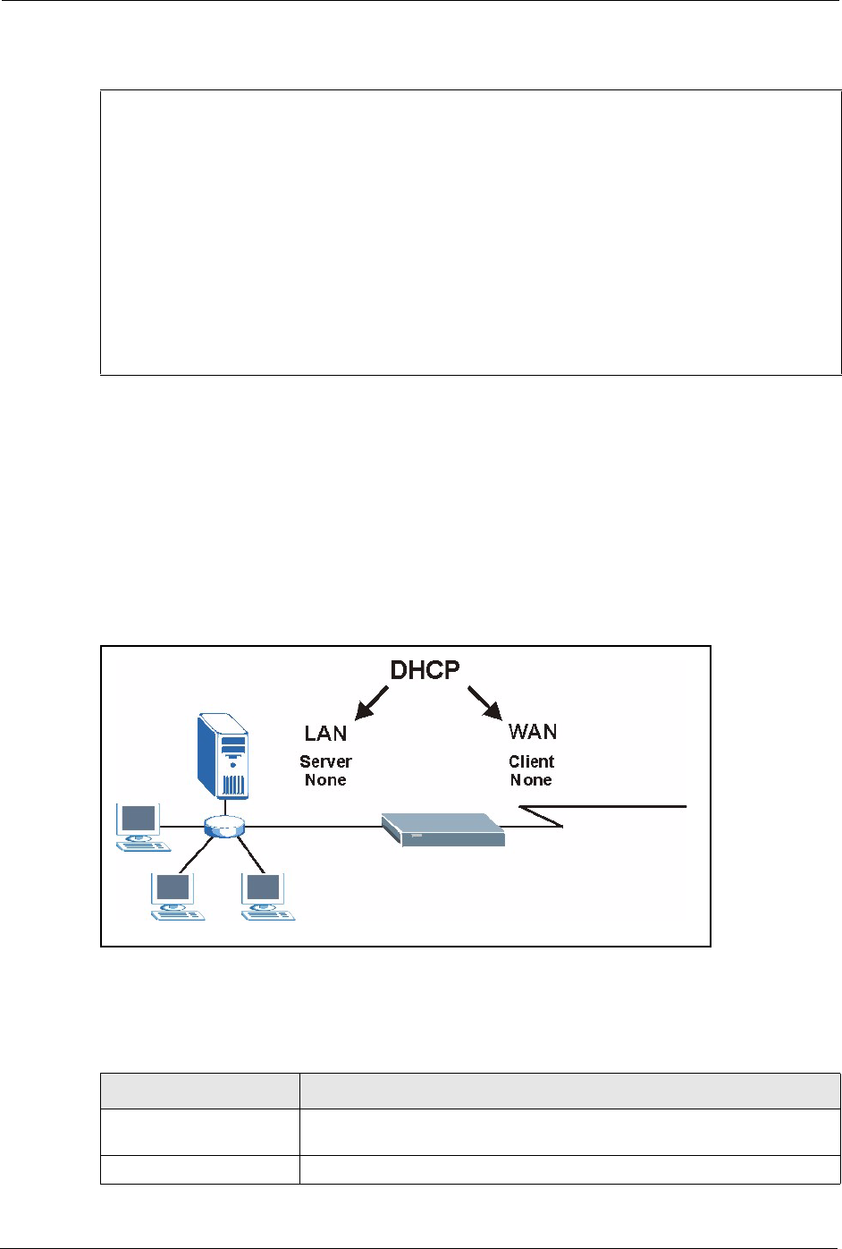
Prestige 334 User’s Guide
283 Chapter 29 System Information and Diagnosis
Figure 156 Menu 24.4 System Maintenance : Diagnostic
29.4.1 WAN DHCP
DHCP functionality can be enabled on the LAN or WAN as shown in LAN & WAN DHCP.
LAN DHCP has already been discussed. The Prestige can act either as a WAN DHCP client
(IP Address Assignment field in menu 4 or menu 11.3 is Dynamic and the Encapsulation
field in menu 4 or menu 11 is Ethernet) or None, (when you have a static IP). The WAN
Release and Renewal fields in menu 24.4 conveniently allow you to release and/or renew the
assigned WAN IP address, subnet mask and default gateway in a fashion similar to winipcfg.
Figure 157 LAN & WAN DHCP
The following table describes the diagnostic tests available in menu 24.4 for your Prestige and
associated connections.
Menu 24.4 - System Maintenance - Diagnostic
TCP/IP
1. Ping Host
2. WAN DHCP Release
3. WAN DHCP Renewal
4. Internet Setup Test
System
11. Reboot System
Enter Menu Selection Number:
Host IP Address= N/A
Table 95 System Maintenance Menu Diagnostic
FIELD DESCRIPTION
Ping Host Enter 1 to ping any machine (with an IP address) on your LAN or WAN.
Enter its IP address in the Host IP Address field below.
WAN DHCP Release Enter 2 to release your WAN DHCP settings.

Prestige 334 User’s Guide
Chapter 29 System Information and Diagnosis 284
WAN DHCP Renewal Enter 3 to renew your WAN DHCP settings.
Internet Setup Test Enter 4 to test the Internet setup. You can also test the Internet setup in
Menu 4 - Internet Access. Please refer to the Internet Access chapter for
more details. This feature is only available for dial-up connections using
PPPoE or PPTP encapsulation.
Reboot System Enter 11 to reboot the Prestige.
Host IP Address= If you entered 1 in Ping Host, then enter the IP address of the computer
you want to ping in this field.
Enter the number of the selection you would like to perform or press [ESC] to cancel.
Table 95 System Maintenance Menu Diagnostic
FIELD DESCRIPTION

Prestige 334 User’s Guide
285 Chapter 29 System Information and Diagnosis
Prestige 334 User’s Guide
Chapter 30 Firmware and Configuration File Maintenance 286
CHAPTER 30
Firmware and Configuration File
Maintenance
This chapter tells you how to backup and restore your configuration file as well as upload new
firmware and configuration files.
30.1 Filename Conventions
The configuration file (often called the romfile or rom-0) contains the factory default settings
in the menus such as password, DHCP Setup, TCP/IP Setup, etc. It arrives from ZyXEL with a
“rom” filename extension. Once you have customized the Prestige's settings, they can be
saved back to your computer under a filename of your choosing.
ZyNOS (ZyXEL Network Operating System sometimes referred to as the “ras” file) is the
system firmware and has a “bin” filename extension. With many FTP and TFTP clients, the
filenames are similar to those seen next.
ftp> put firmware.bin ras
This is a sample FTP session showing the transfer of the computer file " firmware.bin" to the
Prestige.
ftp> get rom-0 config.cfg
This is a sample FTP session saving the current configuration to the computer file
“config.cfg”.
If your (T)FTP client does not allow you to have a destination filename different than the
source, you will need to rename them as the Prestige only recognizes “rom-0” and “ras”. Be
sure you keep unaltered copies of both files for later use.
Note: Only use firmware for your Prestige’s specific model. Refer to
the label on the bottom of your Prestige

Prestige 334 User’s Guide
287 Chapter 30 Firmware and Configuration File Maintenance
The following table is a summary. Please note that the internal filename refers to the filename
on the Prestige and the external filename refers to the filename not on the Prestige, that is, on
your computer, local network or FTP site and so the name (but not the extension) may vary.
After uploading new firmware, see the ZyNOS F/W Version field in Menu 24.2.1 – System
Maintenance – Information to confirm that you have uploaded the correct firmware version.
The AT command is the command you enter after you press “y” when prompted in the SMT
menu to go into debug mode.
30.2 Backup Configuration
Option 5 from Menu 24 – System Maintenance allows you to backup the current Prestige
configuration to your computer. Backup is highly recommended once your Prestige is
functioning properly. FTP is the preferred methods for backing up your current configuration
to your computer since they are faster.
Please note that terms “download” and “upload” are relative to the computer. Download
means to transfer from the Prestige to the computer, while upload means from your computer
to the Prestige.
30.2.1 Backup Configuration
Follow the instructions as shown in the next screen.
Table 96 Filename Conventions
FILE TYPE INTERNAL NAME EXTERNAL NAME DESCRIPTION
Configuration
File
Rom-0 This is the configuration filename on the
Prestige. Uploading the rom-0 file replaces
the entire ROM file system, including your
Prestige configurations, system-related data
(including the default password), the error
log and the trace log.
*.rom
Firmware Ras This is the generic name for the ZyNOS
firmware on the Prestige.
*.bin

Prestige 334 User’s Guide
Chapter 30 Firmware and Configuration File Maintenance 288
Figure 158 Telnet in Menu 24.5
30.2.2 Using the FTP Command from the Command Line
1Launch the FTP client on your computer.
2Enter “open”, followed by a space and the IP address of your Prestige.
3Press [ENTER] when prompted for a username.
4Enter your password as requested (the default is “1234”).
5Enter “bin” to set transfer mode to binary.
6Use “get” to transfer files from the Prestige to the computer, for example, “get rom-0
config.rom” transfers the configuration file on the Prestige to your computer and renames
it “config.rom”. See earlier in this chapter for more information on filename conventions.
7Enter “quit” to exit the ftp prompt.
Menu 24.5 - System Maintenance - Backup Configuration
To transfer the configuration file to your workstation, follow the procedure
below:
1. Launch the FTP client on your workstation.
2. Type "open" and the IP address of your Prestige. Then type "root" and
SMT password as requested.
3. Locate the 'rom-0' file.
4. Type 'get rom-0' to back up the current Prestige configuration to
your workstation.
For details on FTP commands, please consult the documentation of your FTP
client program. For details on backup using TFTP (note that you must remain
in this menu to back up using TFTP), please see your Prestige manual.
Press ENTER to Exit:

Prestige 334 User’s Guide
289 Chapter 30 Firmware and Configuration File Maintenance
30.2.3 Example of FTP Commands from the Command Line
Figure 159 FTP Session Example
30.2.4 GUI-based FTP Clients
The following table describes some of the commands that you may see in GUI-based FTP
clients.
30.2.5 TFTP and FTP over WAN Management Limitations
TFTP, FTP and Telnet over WAN will not work when:
• You have disabled Telnet service in menu 24.11.
• You have applied a filter in menu 3.1 (LAN) or in menu 11.5 (WAN) to block Telnet
service.
• The IP address in the Secured Client IP field in menu 24.11 does not match the client IP.
If it does not match, the Prestige will disconnect the Telnet session immediately.
• You have an SMT console session running.
331 Enter PASS command
Password:
230 Logged in
ftp> bin
200 Type I OK
ftp> get rom-0 zyxel.rom
200 Port command okay
150 Opening data connection for STOR ras
226 File received OK
ftp: 16384 bytes sent in 1.10Seconds 297.89Kbytes/sec.
ftp> quit
Table 97 General Commands for GUI-based FTP Clients
COMMAND DESCRIPTION
Host Address Enter the address of the host server.
Login Type Anonymous.
This is when a user I.D. and password is automatically supplied to the
server for anonymous access. Anonymous logins will work only if your ISP
or service administrator has enabled this option.
Normal.
The server requires a unique User ID and Password to login.
Transfer Type Transfer files in either ASCII (plain text format) or in binary mode.
Configuration and firmware files should be transferred in binary mode.
Initial Remote Directory Specify the default remote directory (path).
Initial Local Directory Specify the default local directory (path).

Prestige 334 User’s Guide
Chapter 30 Firmware and Configuration File Maintenance 290
30.2.6 Backup Configuration Using TFTP
The Prestige supports the up/downloading of the firmware and the configuration file using
TFTP (Trivial File Transfer Protocol) over LAN. Although TFTP should work over WAN as
well, it is not recommended.
To use TFTP, your computer must have both telnet and TFTP clients. To backup the
configuration file, follow the procedure shown next.
1Use telnet from your computer to connect to the Prestige and log in. Because TFTP does
not have any security checks, the Prestige records the IP address of the telnet client and
accepts TFTP requests only from this address.
2Put the SMT in command interpreter (CI) mode by entering 8 in Menu 24 – System
Maintenance.
3Enter command “sys stdio 0” to disable the SMT timeout, so the TFTP transfer will not
be interrupted. Enter command “sys stdio 5” to restore the five-minute SMT timeout
(default) when the file transfer is complete.
4Launch the TFTP client on your computer and connect to the Prestige. Set the transfer
mode to binary before starting data transfer.
5Use the TFTP client (see the example below) to transfer files between the Prestige and the
computer. The file name for the configuration file is “rom-0” (rom-zero, not capital o).
Note that the telnet connection must be active and the SMT in CI mode before and during the
TFTP transfer. For details on TFTP commands (see following example), please consult the
documentation of your TFTP client program. For UNIX, use “get” to transfer from the
Prestige to the computer and “binary” to set binary transfer mode.
30.2.7 TFTP Command Example
The following is an example TFTP command:
tftp [-i] host get rom-0 config.rom
where “i” specifies binary image transfer mode (use this mode when transferring binary files),
“host” is the Prestige IP address, “get” transfers the file source on the Prestige (rom-0, name of
the configuration file on the Prestige) to the file destination on the computer and renames it
config.rom.
Prestige 334 User’s Guide
291 Chapter 30 Firmware and Configuration File Maintenance
30.2.8 GUI-based TFTP Clients
The following table describes some of the fields that you may see in GUI-based TFTP clients.
30.3 Restore Configuration
This section shows you how to restore a previously saved configuration. Note that this
function erases the current configuration before restoring a previous back up configuration;
please do not attempt to restore unless you have a backup configuration file stored on disk.
FTP is the preferred method for restoring your current computer configuration to your Prestige
since FTP is faster. Please note that you must wait for the system to automatically restart after
the file transfer is complete.
30.3.1 Restore Using FTP
For details about backup using (T)FTP please refer to earlier sections on FTP and TFTP file
upload in this chapter
Table 98 General Commands for GUI-based TFTP Clients
COMMAND DESCRIPTION
Host Enter the IP address of the Prestige. 192.168.1.1 is the Prestige’s default IP address
when shipped.
Send/Fetch Use “Send” to upload the file to the Prestige and “Fetch” to back up the file on your
computer.
Local File Enter the path and name of the firmware file (*.bin extension) or configuration file
(*.rom extension) on your computer.
Remote File This is the filename on the Prestige. The filename for the firmware is “ras” and for the
configuration file, is “rom-0”.
Binary Transfer the file in binary mode.
Abort Stop transfer of the file.
Note: WARNING! Do not interrupt the file transfer process as this
may PERMANENTLY DAMAGE YOUR Prestige.

Prestige 334 User’s Guide
Chapter 30 Firmware and Configuration File Maintenance 292
Figure 160 Telnet into Menu 24.6.
1Launch the FTP client on your computer.
2Enter “open”, followed by a space and the IP address of your Prestige.
3Press [ENTER] when prompted for a username.
4Enter your password as requested (the default is “1234”).
5Enter “bin” to set transfer mode to binary.
6Find the “rom” file (on your computer) that you want to restore to your Prestige.
7Use “put” to transfer files from the Prestige to the computer, for example, “put
config.rom rom-0” transfers the configuration file “config.rom” on your computer to the
Prestige. See earlier in this chapter for more information on filename conventions.
8Enter “quit” to exit the ftp prompt. The Prestige will automatically restart after a
successful restore process.
Menu 24.6 -- System Maintenance - Restore Configuration
To transfer the firmware and configuration file to your workstation, follow
the procedure below:
1. Launch the FTP client on your workstation.
2. Type "open" and the IP address of your Prestige. Then type "root" and
SMT password as requested.
3. Type "put backupfilename rom-0" where backupfilename is the name of
your backup configuration file on your workstation and rom-0 is the
remote file name on the Prestige. This restores the configuration to
your Prestige.
4. The system reboots automatically after a successful file transfer
For details on FTP commands, please consult the documentation of your FTP
client program. For details on backup using TFTP (note that you must remain
in this menu to back up using TFTP), please see your Prestige manual.
Press ENTER to Exit:
Prestige 334 User’s Guide
293 Chapter 30 Firmware and Configuration File Maintenance
30.3.2 Restore Using FTP Session Example
Figure 161 Restore Using FTP Session Example
30.4 Uploading Firmware and Configuration Files
This section shows you how to upload firmware and configuration files. You can upload
configuration files by following the procedure in the previous Restore Configuration section
or by following the instructions in Menu 24.7.2 – System Maintenance – Upload System
Configuration File.
30.4.1 Firmware File Upload
FTP is the preferred method for uploading the firmware and configuration. To use this feature,
your computer must have an FTP client.
When you telnet into the Prestige, you will see the following screens for uploading firmware
and the configuration file using FTP.
ftp> put config.rom rom-0
200 Port command okay
150 Opening data connection for STOR rom-0
226 File received OK
221 Goodbye for writing flash
ftp: 16384 bytes sent in 0.06Seconds 273.07Kbytes/sec.
ftp>quit
Note: WARNING! Do not interrupt the file transfer process as this
may PERMANENTLY DAMAGE YOUR Prestige.

Prestige 334 User’s Guide
Chapter 30 Firmware and Configuration File Maintenance 294
Figure 162 Telnet Into Menu 24.7.1 Upload System Firmware
30.4.2 Configuration File Upload
You see the following screen when you telnet into menu 24.7.2
Figure 163 Telnet Into Menu 24.7.2 System Maintenance .
To upload the firmware and the configuration file, follow these examples
30.4.3 FTP File Upload Command from the DOS Prompt Example
1Launch the FTP client on your computer.
2Enter “open”, followed by a space and the IP address of your Prestige.
3Press [ENTER] when prompted for a username.
Menu 24.7.1 - System Maintenance - Upload System Firmware
To upload the system firmware, follow the procedure below:
1. Launch the FTP client on your workstation.
2. Type "open" and the IP address of your system. Then type "root" and
SMT password as requested.
3. Type "put firmware filename ras" where "firmwarefilename" is the name
of your firmware upgrade file on your workstation and "ras" is the
remote file name on the system.
4. The system reboots automatically after a successful firmware upload.
For details on FTP commands, please consult the documentation of your FTP
client program. For details on uploading system firmware using TFTP (note
that you must remain on this menu to upload system firmware using TFTP),
please see your manual.
Press ENTER to Exit:
Menu 24.7.2 - System Maintenance - Upload System Configuration File
To upload the system configuration file, follow the procedure below:
1. Launch the FTP client on your workstation.
2. Type "open" and the IP address of your system. Then type "root" and
SMT password as requested.
3. Type "put configuration filename rom-0" where "configurationfilename"
is the name of your system configuration file on your workstation, which
will be transferred to the "rom-0" file on the system.
4. The system reboots automatically after the upload system configuration
file process is complete.
For details on FTP commands, please consult the documentation of your FTP
client program. For details on uploading system firmware using TFTP (note
that you must remain on this menu to upload system firmware using TFTP),
please see your manual.
Press ENTER to Exit:
Prestige 334 User’s Guide
295 Chapter 30 Firmware and Configuration File Maintenance
4Enter your password as requested (the default is “1234”).
5Enter “bin” to set transfer mode to binary.
6Use “put” to transfer files from the computer to the Prestige, for example, “put
firmware.bin ras” transfers the firmware on your computer (firmware.bin) to the Prestige
and renames it “ras”. Similarly, “put config.rom rom-0” transfers the configuration file
on your computer (config.rom) to the Prestige and renames it “rom-0”. Likewise “get
rom-0 config.rom” transfers the configuration file on the Prestige to your computer and
renames it “config.rom.” See earlier in this chapter for more information on filename
conventions.
7Enter “quit” to exit the ftp prompt.
30.4.4 FTP Session Example of Firmware File Upload
Figure 164 FTP Session Example of Firmware File Upload
More commands (found in GUI-based FTP clients) are listed earlier in this chapter.
30.4.5 TFTP File Upload
The Prestige also supports the uploading of firmware files using TFTP (Trivial File Transfer
Protocol) over LAN. Although TFTP should work over WAN as well, it is not recommended.
To use TFTP, your computer must have both telnet and TFTP clients. To transfer the firmware
and the configuration file, follow the procedure shown next.
1Use telnet from your computer to connect to the Prestige and log in. Because TFTP does
not have any security checks, the Prestige records the IP address of the telnet client and
accepts TFTP requests only from this address.
2Put the SMT in command interpreter (CI) mode by entering 8 in Menu 24 – System
Maintenance.
Note: The Prestige automatically restarts after a successful file
upload.
331 Enter PASS command
Password:
230 Logged in
ftp> bin
200 Type I OK
ftp> put firmware.bin ras
200 Port command okay
150 Opening data connection for STOR ras
226 File received OK
ftp: 1103936 bytes sent in 1.10Seconds 297.89Kbytes/sec.
ftp> quit

Prestige 334 User’s Guide
Chapter 30 Firmware and Configuration File Maintenance 296
3Enter the command “sys stdio 0” to disable the console timeout, so the TFTP transfer will
not be interrupted. Enter “command sys stdio 5” to restore the five-minute console
timeout (default) when the file transfer is complete.
4Launch the TFTP client on your computer and connect to the Prestige. Set the transfer
mode to binary before starting data transfer.
5Use the TFTP client (see the example below) to transfer files between the Prestige and the
computer. The file name for the firmware is “ras”.
Note that the telnet connection must be active and the Prestige in CI mode before and during
the TFTP transfer. For details on TFTP commands (see following example), please consult the
documentation of your TFTP client program. For UNIX, use “get” to transfer from the
Prestige to the computer, “put” the other way around, and “binary” to set binary transfer mode.
30.4.6 TFTP Upload Command Example
The following is an example TFTP command:
tftp [-i] host put firmware.bin ras
where “i” specifies binary image transfer mode (use this mode when transferring binary files),
“host” is the Prestige’s IP address and “put” transfers the file source on the computer
(firmware.bin – name of the firmware on the computer) to the file destination on the remote
host (ras - name of the firmware on the Prestige).
Commands that you may see in GUI-based TFTP clients are listed earlier in this chapter.

Prestige 334 User’s Guide
297 Chapter 30 Firmware and Configuration File Maintenance

Prestige 334 User’s Guide
Chapter 31 System Maintenance 298
CHAPTER 31
System Maintenance
This chapter leads you through SMT menus 24.8 to 24.10.
31.1 Command Interpreter Mode
The Command Interpreter (CI) is a part of the main system firmware. The CI provides much of
the same functionality as the SMT, while adding some low-level setup and diagnostic
functions. Enter the CI from the SMT by selecting menu 24.8. See the included disk or the
zyxel.com web site for more detailed information on CI commands. Enter 8 from Menu 24 —
System Maintenance. A list of valid commands can be found by typing help or ? at the
command prompt. Type “exit” to return to the SMT main menu when finished.
Figure 165 Command Mode in Menu 24
31.1.1 Command Syntax
• The command keywords are in courier new font.
• Enter the command keywords exactly as shown, do not abbreviate.
• The required fields in a command are enclosed in angle brackets <>.
• The optional fields in a command are enclosed in square brackets [].
•The |symbol means “or”.
• For example,
• sys filter netbios config <type> <on|off>
• means that you must specify the type of netbios filter and whether to turn it on or off.
Menu 24 - System Maintenance
1. System Status
2. System Information and Console Port Speed
3. Log and Trace
4. Diagnostic
5. Backup Configuration
6. Restore Configuration
7. Firmware Update
8. Command Interpreter Mode
9. Call Control
10. Time and Date Setting
11. Remote Management Setup
Enter Menu Selection Number:
Prestige 334 User’s Guide
299 Chapter 31 System Maintenance
31.1.2 Command Usage
A list of commands can be found by typing help or ? at the command prompt. Always type
the full command. Type exit to return to the SMT main menu when finished.
Figure 166 Valid Commands
31.2 Call Control Support
The Prestige provides two call control functions: budget management and call history. Please
note that this menu is only applicable when Encapsulation is set to PPPoE in menu 4 or
menu 11.1.
The budget management function allows you to set a limit on the total outgoing call time of
the Prestige within certain times. When the total outgoing call time exceeds the limit, the
current call will be dropped and any future outgoing calls will be blocked.
To access the call control menu, select option 9 in menu 24 to go to Menu 24.9 — System
Maintenance — Call Control, as shown in the next table.
Figure 167 Menu 24.9 System Maintenance : Call Control
31.2.1 Budget Management
Menu 24.9.1 shows the budget management statistics for outgoing calls. Enter 1 from Menu
24.9 - System Maintenance - Call Control to bring up the following menu.
Copyright (c) 1994 - 2004 ZyXEL Communications Corp.
P334> ?
Valid commands are:
sys exit device ether
poe pptp config ip
ipsec ppp
P334>
Menu 24.9 - System Maintenance - Call Control
1. Budget Management
2. Call History
Enter Menu Selection Number:
Prestige 334 User’s Guide
Chapter 31 System Maintenance 300
Figure 168 Budget Management
The total budget is the time limit on the accumulated time for outgoing calls to a remote node.
When this limit is reached, the call will be dropped and further outgoing calls to that remote
node will be blocked. After each period, the total budget is reset. The default for the total
budget is 0 minutes and the period is 0 hours, meaning no budget control. You can reset the
accumulated connection time in this menu by entering the index of a remote node. Enter 0 to
update the screen. The budget and the reset period can be configured in menu 11.1 for the
remote node.
31.2.2 Call History
This is the second option in Menu 24.9 - System Maintenance - Call Control. It displays
information about past incoming and outgoing calls. Enter 2 from Menu 24.9 - System
Maintenance - Call Control to bring up the following menu.
Menu 24.9.1 - Budget Management
Remote Node Connection Time/Total Budget Elapsed Time/Total Period
1.MyISP No Budget No Budget
Table 99 Menu 24.9.1 - Budget Management
FIELD DESCRIPTION
Remote Node Enter the index number of the remote node you want to reset (just one in this
case)
Connection Time/Total
Budget
This is the total connection time that has gone by (within the allocated budget
that you set in menu 11.1).
Elapsed Time/Total
Period
The period is the time cycle in hours that the allocation budget is reset (see
menu 11.1.) The elapsed time is the time used up within this period.
Enter “0” to update the screen or press [ESC] to return to the previous screen.
Prestige 334 User’s Guide
301 Chapter 31 System Maintenance
Figure 169 Menu 24.9.2 - Call History
The following table describes the fields in this menu.
31.3 Time and Date Setting
The Real Time Chip (RTC) keeps track of the time and date (not available on all models).
There is also a software mechanism to set the time manually or get the current time and date
from an external server when you turn on your Prestige. Menu 24.10 allows you to update the
time and date settings of your Prestige. The real time is then displayed in the Prestige error
logs and firewall logs.
Select menu 24 in the main menu to open Menu 24 - System Maintenance, as shown next.
Menu 24.9.2 - Call History
Phone Number Dir Rate #call Max Min Total
1.
2.
3.
4.
5.
6.
7.
8.
9.
10.
Enter Entry to Delete(0 to exit):
Table 100 Call History Fields
FIELD DESCRIPTION
Phone Number The PPPoE service names are shown here.
Dir This shows whether the call was incoming or outgoing.
Rate This is the transfer rate of the call.
#call This is the number of calls made to or received from that telephone number.
Max This is the length of time of the longest telephone call.
Min This is the length of time of the shortest telephone call.
Tot a l This is the total length of time of all the telephone calls to/from that telephone
number.
You may enter an entry number to delete it or ‘”0” to exit.

Prestige 334 User’s Guide
Chapter 31 System Maintenance 302
Figure 170 Menu 24: System Maintenance
Enter 10 to go to Menu 24.10 - System Maintenance - Time and Date Setting to update the
time and date settings of your Prestige as shown in the following screen.
Menu 24 - System Maintenance
1. System Status
2. System Information and Console Port Speed
3. Log and Trace
4. Diagnostic
5. Backup Configuration
6. Restore Configuration
7. Upload Firmware
8. Command Interpreter Mode
9. Call Control
10. Time and Date Setting
11. Remote Management Setup
Enter Menu Selection Number:

Prestige 334 User’s Guide
303 Chapter 31 System Maintenance
Figure 171 Menu 24.10 System Maintenance: Time and Date Setting
The following table describes the fields in this screen.
Menu 24.10 - System Maintenance - Time and Date Setting
Time Protocol= NTP (RFC-1305)
Time Server Address= time-b.nist.gov
Current Time: 08 : 07 : 14
New Time (hh:mm:ss): 08 : 06 : 48
Current Date: 2003 - 12 - 24
New Date (yyyy-mm-dd): 2003 - 12 - 24
Time Zone= GMT
Daylight Saving= No
Start Date (mm-dd): 01 - 01
End Date (mm-dd): 01 - 01
Press ENTER to Confirm or ESC to Cancel:
Table 101 Time and Date Setting Fields
FIELD DESCRIPTION
Time Protocol Enter the time service protocol that your timeserver sends when you turn on the
Prestige. Not all timeservers support all protocols, so you may have to check with
your ISP/network administrator or use trial and error to find a protocol that works.
The main differences between them are the format.
Daytime (RFC 867) format is day/month/year/time zone of the server.
Time (RFC-868) format displays a 4-byte integer giving the total number of
seconds since 1970/1/1 at 0:0:0.
NTP (RFC-1305) the default, is similar to Time (RFC-868).
None enter the time manually.
Time Server
Address
Enter the IP address or domain name of your timeserver. Check with your ISP/
network administrator if you are unsure of this information. The default is
tick.stdtime.gov.tw
Current Time This field displays an updated time only when you reenter this menu.
New Time Enter the new time in hour, minute and second format.
Current Date This field displays an updated date only when you reenter this menu.
New Date Enter the new date in year, month and day format.
Time Zone Press [SPACE BAR] and then [ENTER] to set the time difference between your
time zone and Greenwich Mean Time (GMT).
Daylight Saving Daylight Saving Time is a period from late spring to early fall when many countries
set their clocks ahead of normal local time by one hour to give more daylight time in
the evenings. If you use daylight savings time, then choose Yes.
Start Date Enter the month and day that your daylight-savings time starts on if you selected
Yes in the Daylight Saving field.

Prestige 334 User’s Guide
Chapter 31 System Maintenance 304
31.3.1 Resetting the Time
The Prestige resets the time in three instances:
1On leaving menu 24.10 after making changes.
2When the Prestige starts up, if there is a timeserver configured in menu 24.10.
324-hour intervals after starting.
End Date Enter the month and day that your daylight-savings time ends on if you selected
Yes in the Daylight Saving field.
Once you have filled in this menu, press [ENTER] at the message “Press ENTER to Confirm or ESC to
Cancel“ to save your configuration, or press [ESC] to cancel.
Table 101 Time and Date Setting Fields
FIELD DESCRIPTION

Prestige 334 User’s Guide
305 Chapter 31 System Maintenance
Prestige 334 User’s Guide
Chapter 32 Remote Management 306
CHAPTER 32
Remote Management
This chapter covers remote management (SMT menu 24.11).
32.1 Remote Management
Remote management allows you to determine which services/protocols can access which
Prestige interface (if any) from which computers.
You may manage your Prestige from a remote location via:
To disable remote management of a service, select Disable in the corresponding Server
Access field.
Enter 11 from menu 24 to bring up Menu 24.11 – Remote Management Control.
• Internet (WAN only) • ALL (LAN and WAN)
• LAN only • Neither (Disable).
Note: When you Choose WAN only or ALL (LAN & WAN), you still
need to configure a firewall rule to allow access.
Prestige 334 User’s Guide
307 Chapter 32 Remote Management
Figure 172 Menu 24.11 – Remote Management Control
The following table describes the fields in this screen.
32.1.1 Remote Management Limitations
Remote management over LAN or WAN will not work when:
1A filter in menu 3.1 (LAN) or in menu 11.5 (WAN) is applied to block a Telnet, FTP or
Web service.
2You have disabled that service in menu 24.11.
Menu 24.11 - Remote Management Control
TELNET Server: Port = 23 Access = ALL
Secure Client IP = 0.0.0.0
FTP Server: Port = 21 Access = ALL
Secure Client IP = 0.0.0.0
Web Server: Port = 80 Access = ALL
Secure Client IP = 0.0.0.0
SNMP Service: Port = 161 Access = LAN only
Secure Client IP = 0.0.0.0
DNS Service: Port = 53 Access = LAN only
Secure Client IP = 0.0.0.0
Press ENTER to Confirm or ESC to Cancel:
Table 102 Menu 24.11 – Remote Management Control
FIELD DESCRIPTION
Telnet Server
FTP Server
Web Server
SNMP Service
DNS Service
Each of these read-only labels denotes a service or protocol.
Port This field shows the port number for the service or protocol. You may change the
port number if needed, but you must use the same port number to access the
Prestige.
Access Select the access interface (if any) by pressing [SPACE BAR], then [ENTER] to
choose from: LAN only, WAN only, ALL or Disable.
Secure Client IP The default 0.0.0.0 allows any client to use this service or protocol to access the
Prestige. Enter an IP address to restrict access to a client with a matching IP
address.
Once you have filled in this menu, press [ENTER] at the message "Press ENTER to Confirm or ESC to
Cancel" to save your configuration, or press [ESC] to cancel.

Prestige 334 User’s Guide
Chapter 32 Remote Management 308
3The IP address in the Secure Client IP field (menu 24.11) does not match the client IP
address. If it does not match, the Prestige will disconnect the session immediately.
4There is an SMT console session running.
5There is already another remote management session with an equal or higher priority
running. You may only have one remote management session running at one time.
6There is a firewall rule that blocks it.

Prestige 334 User’s Guide
Chapter 33 Call Scheduling 310
CHAPTER 33
Call Scheduling
Call scheduling (applicable for PPPoA or PPPoE encapsulation only) allows you to dictate
when a remote node should be called and for how long.
33.1 Introduction to Call Scheduling
The call scheduling feature allows the Prestige to manage a remote node and dictate when a
remote node should be called and for how long. This feature is similar to the scheduler in a
videocassette recorder (you can specify a time period for the VCR to record). You can apply
up to 4 schedule sets in Menu 11.1 — Remote Node Profile. From the main menu, enter 26
to access Menu 26 — Schedule Setup as shown next.
Figure 173 Menu 26 Schedule Setup
Lower numbered sets take precedence over higher numbered sets thereby avoiding scheduling
conflicts. For example, if sets 1, 2 ,3 and 4 in are applied in the remote node then set 1 will
take precedence over set 2, 3 and 4 as the Prestige, by default, applies the lowest numbered set
first. Set 2 will take precedence over set 3 and 4, and so on.
Menu 26 - Schedule Setup
Schedule Schedule
Set # Name Set # Name
------ ------------------- ------ ----------------
1 ______________ 7 ______________
2 ______________ 8 ______________
3 ______________ 9 ______________
4 ______________ 10 ______________
5 ______________ 11 ______________
6 ______________ 12 ______________
Enter Schedule Set Number to Configure= 0
Edit Name= N/A
Press ENTER to Confirm or ESC to Cancel:
Prestige 334 User’s Guide
311 Chapter 33 Call Scheduling
You can design up to 12 schedule sets but you can only apply up to four schedule sets for a
remote node.
To setup a schedule set, select the schedule set you want to setup from menu 26 (1-12) and
press [ENTER] to see Menu 26.1 — Schedule Set Setup as shown next.
Figure 174 Menu 26.1 Schedule Set Setup
If a connection has been already established, your Prestige will not drop it. Once the
connection is dropped manually or it times out, then that remote node can't be triggered up
until the end of the Duration.
Note: To delete a schedule set, enter the set number and press
[SPACE BAR] and then [ENTER] (or delete) in the Edit Name field.
Menu 26.1 - Schedule Set Setup
Active= Yes
Start Date(yyyy/mm/dd) = 2000 – 01 - 01
How Often= Once
Once:
Date(yyyy/mm/dd)= 2000 – 01 - 01
Weekdays:
Sunday= N/A
Monday= N/A
Tuesday= N/A
Wednesday= N/A
Thursday= N/A
Friday= N/A
Saturday= N/A
Start Time (hh:mm)= 00 : 00
Duration (hh:mm)= 00 : 00
Action= Forced On
Press ENTER to Confirm or ESC to Cancel:
Table 103 Menu 26.1 Schedule Set Setup
FIELD DESCRIPTION
Active Press [SPACE BAR] to select Yes or No. Choose Yes and press [ENTER] to activate
the schedule set.
Start Date Enter the start date when you wish the set to take effect in year -month-date format.
Valid dates are from the present to 2036-February-5.
How Often Should this schedule set recur weekly or be used just once only? Press the [SPACE
BAR] and then [ENTER] to select Once or Weekly. Both these options are mutually
exclusive. If Once is selected, then all weekday settings are N/A. When Once is
selected, the schedule rule deletes automatically after the scheduled time elapses.
Once:
Date
If you selected Once in the How Often field above, then enter the date the set should
activate here in year-month-date format.
Weekday:
Day
If you selected Weekly in the How Often field above, then select the day(s) when the
set should activate (and recur) by going to that day(s) and pressing [SPACE BAR] to
select Yes, then press [ENTER].

Prestige 334 User’s Guide
Chapter 33 Call Scheduling 312
Once your schedule sets are configured, you must then apply them to the desired remote
node(s). Enter 11 from the Main Menu and then enter the target remote node index. Using
[SPACE BAR], select PPPoE or PPPoA in the Encapsulation field and then press
[ENTER] to make the schedule sets field available as shown next.
Figure 175 Applying Schedule Set(s) to a Remote Node (PPPoE)
You can apply up to four schedule sets, separated by commas, for one remote node. Change
the schedule set numbers to your preference(s).
Start Time Enter the start time when you wish the schedule set to take effect in hour-minute format.
Duration Enter the maximum length of time this connection is allowed in hour-minute format.
Action Forced On means that the connection is maintained whether or not there is a demand
call on the line and will persist for the time period specified in the Duration field.
Forced Down means that the connection is blocked whether or not there is a demand
call on the line.
Enable Dial-On-Demand means that this schedule permits a demand call on the line.
Disable Dial-On-Demand means that this schedule prevents a demand call on the line.
When you have completed this menu, press [ENTER] at the prompt “Press ENTER to confirm or ESC
to cancel” to save your configuration or press [ESC] to cancel and go back to the previous screen.
Menu 11.1 - Remote Node Profile
Rem Node Name= MyISP Route= IP
Active= Yes
Encapsulation= PPPoE Edit IP= No
Service Type= Standard Telco Option:
Service Name= Allocated Budget(min)= 0
Outgoing: Period(hr)= 0
My Login= Schedules= 1,2,3,4
My Password= ******** Nailed-Up Connection= No
Retype to Confirm= ********
Authen= CHAP/PAP
Session Options:
Edit Filter Sets= No
Idle Timeout(sec)= 100
Edit Traffic Redirect= No
Press ENTER to Confirm or ESC to Cancel:
Table 103 Menu 26.1 Schedule Set Setup
FIELD DESCRIPTION

Prestige 334 User’s Guide
313 Chapter 33 Call Scheduling
Prestige 334 User’s Guide
Chapter 34 VPN/IPSec Setup 314
CHAPTER 34
VPN/IPSec Setup
This chapter introduces the VPN SMT menus.
34.1 VPN/IPSec Overview
The VPN/IPSec main SMT menu has these main submenus:
1Define VPN policies in menu 27.1 submenus, including security policies, endpoint IP
addresses, peer IPSec router IP address and key management.
2Menu 27.2 - SA Monitor allows you to manage (refresh or disconnect) your SA
connections.
This is an overview of the VPN menu tree.
Figure 176 VPN SMT Menu Tree
From the main menu, enter 27 to display the first VPN menu (shown next).

Prestige 334 User’s Guide
315 Chapter 34 VPN/IPSec Setup
Figure 177 Menu 27 VPN/IPSec Setup
34.2 IPSec Summary Screen
Type 1 in menu 27 and then press [ENTER] to display Menu 27.1 IPSec Summary. This is a
summary read-only menu of your IPSec rules (tunnels). Edit or create an IPSec rule by
selecting an index number and then configuring the associated submenus.
Figure 178 Menu 27
Menu 27 - VPN/IPSec Setup
1. IPSec Summary
2. SA Monitor
Enter Menu Selection Number:
Menu 27.1 – IPSec Summary
#
-
001
002
003
Name
Key Mgt
---------
Taiwan
IKE
zw50
IKE
China
IKE
A
-
Y
N
N
Local Addr Start
Remote Addr Start
-----------------
-
192.168.1.35
172.16.2.40
1.1.1.1
4.4.4.4
192.168.1.40
N/A
- Local Addr End
- Remote Addr End
-------------------
-
192.168.1.38
172.16.2.46
1.1.1.1
255.255.0.0
192.168.1.42
N/A
Encap
------
Tunnel
Tunnel
Tunnel
IPSec Algorithm
Secure GW Addr
------------------
ESP DES MD5
193.81.13.2
AH SHA1
zw50test.zyxel.
ESP DES MD5
0.0.0.0
Select Command= NoneSelect Rule= N/A
Press ENTER to Confirm or ESC to Cancel:
Table 104 Menu 27.1 IPSec Summary
FIELD DESCRIPTION
#This is the VPN policy index number.
Name This field displays the unique identification name for this VPN rule. The name may be
up to 32 characters long but only 10 characters will be displayed here.
AY signifies that this VPN rule is active.

Prestige 334 User’s Guide
Chapter 34 VPN/IPSec Setup 316
Local Addr
Start
When the Addr Type field in Menu 27.1.1 IPSec Setup is configured to Single, this is a
static IP address on the LAN behind your Prestige.
When the Addr Type field in Menu 27.1.1 IPSec Setup is configured to Range, this is
the beginning (static) IP address, in a range of computers on the LAN behind your Pres-
tige.
When the Addr Type field in Menu 27.1.1 IPSec Setup is configured to SUBNET, this
is a static IP address on the LAN behind your Prestige.
Local Addr
End
When the Addr Type field in Menu 27.1.1 IPSec Setup is configured to Single, this is
the same (static) IP address as in the Local Addr Start field.
When the Addr Type field in Menu 27.1.1 IPSec Setup is configured to Range, this is
the end (static) IP address, in a range of computers on the LAN behind your Prestige.
When the Addr Type field in Menu 27.1.1 IPSec Setup is configured to SUBNET, this
is a subnet mask on the LAN behind your Prestige.
Encap This field displays Tunnel mode or Transport mode. See earlier for a discussion of
these. You need to finish configuring the VPN policy in menu 27.1.1.1 or 27.1.1.2 if ???
is displayed.
IPSec
Algorithm
This field displays the security protocols used for an SA. ESP provides confidentiality
and integrity of data by encrypting the data and encapsulating it into IP packets. Encryp-
tion methods include 56-bit DES and 168-bit 3DES. NULL denotes a tunnel without
encryption.
AH (Authentication Header) provides strong integrity and authentication by adding
authentication information to IP packets. This authentication information is calculated
using header and payload data in the IP packet. This provides an additional level of
security. AH choices are MD5 (default - 128 bits) and SHA -1(160 bits).
Both AH and ESP increase the Prestige’s processing requirements and communica-
tions latency (delay).
You need to finish configuring the VPN policy in menu 27.1.1.1 or 27.1.1.2 if ??? is
displayed.
Key Mgt This field displays the SA’s type of key management, (IKE or Manual).
Remote Addr
Start
When the Addr Type field in Menu 27.1.1 IPSec Setup is configured to Single, this is a
static IP address on the network behind the remote IPSec router.
When the Addr Type field in Menu 27.1.1 IPSec Setup is configured to Range, this is
the beginning (static) IP address, in a range of computers on the network behind the
remote IPSec router.
When the Addr Type field in Menu 27.1.1 IPSec Setup is configured to SUBNET, this
is a static IP address on the network behind the remote IPSec router.
This field displays N/A when you configure the Secure Gateway Addr field in SMT
27.1.1 to 0.0.0.0.
Table 104 Menu 27.1 IPSec Summary
FIELD DESCRIPTION

Prestige 334 User’s Guide
317 Chapter 34 VPN/IPSec Setup
Remote Addr
End
When the Addr Type field in Menu 27.1.1 IPSec Setup is configured to Single, this is
the same (static) IP address as in the Remote Addr Start field.
When the Addr Type field in Menu 27.1.1 IPSec Setup is configured to Range, this is
the end (static) IP address, in a range of computers on the network behind the remote
IPSec router.
When the Addr Type field in Menu 27.1.1 IPSec Setup is configured to SUBNET, this
is a subnet mask on the network behind the remote IPSec router.
This field displays N/A when you configure the Secure Gateway Addr field in SMT
27.1.1 to 0.0.0.0.
Secure GW
Addr
This is the WAN IP address or the domain name (up to the first 15 characters are
displayed) of the IPSec router with which you are making the VPN connection. This field
displays 0.0.0.0 when you configure the Secure Gateway Addr field in SMT 27.1.1 to
0.0.0.0.
Select
Command
Press [SPACE BAR] to choose from None, Edit, Delete, Go To Rule, Next Page or
Previous Page and then press [ENTER]. You must select a rule in the next field when
you choose the Edit, Delete or Go To commands.
Select None and then press [ENTER] to go to the “Press ENTER to Confirm…” prompt.
Use Edit to create or edit a rule. Use Delete to remove a rule. To edit or delete a rule,
first make sure you are on the correct page. When a VPN rule is deleted, subsequent
rules do not move up in the page list.
Use Go To Rule to view the page where your desired rule is listed.
Select Next Page or Previous Page to view the next or previous page of rules
(respectively).
Select Rule Type the VPN rule index number you wish to edit or delete and then press [ENTER].
When you have completed this menu, press [ENTER] at the prompt “Press ENTER to Confirm…” to
save your configuration, or press [ESC] at any time to cancel.
Table 104 Menu 27.1 IPSec Summary
FIELD DESCRIPTION

Prestige 334 User’s Guide
Chapter 34 VPN/IPSec Setup 318
Figure 179 Menu 27.1.1 IPSec Setup
The following table describes the fields in this menu.
Menu 27.1.1 – IPSec Setup
Index= 1 Name= Taiwan
Active= Yes Keep Alive= No Nat Traversal= No
Local ID type Content=
My IP Addr= 0.0.0.0
Peer ID type= IP Content=
Secure Gateway Address= zw50test.zyxel.com.tw
Protocol= 0 DNS Server= 0.0.0.0
Local:
Remote:
Addr Type= SINGLE
Local IP Addr= 1.1.1.1
Port Start= 0
Addr Type= SUBNET
IP Addr Start= 4.4.4.4
Port Start= 0
End= N/A
End/Subnet Mask= 255.255.0.0
End= N/A
Enable Replay Detection = No
Key Management= IKE
Edit Key Management Setup= No
Press ENTER to Confirm or ESC to Cancel:
Table 105 Menu 27.1.1 IPSec Setup
FIELD DESCRIPTION
Index This is the VPN rule index number you selected in the previous menu.
Name Enter a unique identification name for this VPN rule. The name may be up to 32
characters long but only 10 characters will be displayed in Menu 27.1 - IPSec
Summary.
Active Press [SPACE BAR] to choose either Yes or No. Choose Yes and press [ENTER] to
activate the VPN tunnel. This field determines whether a VPN rule is applied before a
packet leaves the firewall.
Keep Alive Press [SPACE BAR] to choose either Yes or No. Choose Yes and press [ENTER] to
have the Prestige automatically re-initiate the SA after the SA lifetime times out, even if
there is no traffic. The remote IPSec router must also have keep alive enabled in order
for this feature to work.
Nat Traversal Select this check box to enable NAT traversal. NAT traversal allows you to set up a
VPN connection when there are NAT routers between the two IPSec routers.
The remote IPSec router must also have NAT traversal enabled. You can use NAT tra-
versal with ESP protocol using Transport or Tunnel mode, but not with AH protocol
nor with Manual key management.
In order for an IPSec router behind a NAT router to receive an initiating IPSec packet,
set the NAT router to forward UDP port 500 to the IPSec router behind the NAT router.
Local ID type Press [SPACE BAR] to choose IP, DNS, or E-mail and press [ENTER].
Select IP to identify this Prestige by its IP address.
Select DNS to identify this Prestige by a domain name.
Select E-mail to identify this Prestige by an e-mail address.

Prestige 334 User’s Guide
319 Chapter 34 VPN/IPSec Setup
Content When you select IP in the Local ID Type field, type the IP address of your computer or
leave the field blank to have the Prestige automatically use its own IP address.
When you select DNS in the Local ID Type field, type a domain name (up to 31 char-
acters) by which to identify this Prestige.
When you select E-mail in the Local ID Type field, type an e-mail address (up to 31
characters) by which to identify this Prestige.
The domain name or e-mail address that you use in the Content field is used for
identification purposes only and does not need to be a real domain name or e-mail
address.
My IP Addr Enter the IP address of your Prestige. The Prestige uses its current WAN IP address
(static or dynamic) in setting up the VPN tunnel if you leave this field as 0.0.0.0.
The VPN tunnel has to be rebuilt if this IP address changes.
Peer ID type Press [SPACE BAR] to choose IP, DNS, or E-mail and press [ENTER].
Select IP to identify the remote IPSec router by its IP address.
Select DNS to identify the remote IPSec router by a domain name.
Select E-mail to identify the remote IPSec router by an e-mail address.
Content When you select IP in the Peer ID Type field, type the IP address of the computer with
which you will make the VPN connection or leave the field blank to have the Prestige
automatically use the address in the Secure Gateway Address field.
When you select DNS in the Peer ID Type field, type a domain name (up to 31 charac-
ters) by which to identify the remote IPSec router.
When you select E-mail in the Peer ID Type field, type an e-mail address (up to 31
characters) by which to identify the remote IPSec router.
The domain name or e-mail address that you use in the Content field is used for
identification purposes only and does not need to be a real domain name or e-mail
address. The domain name also does not have to match the remote router’s IP
address or what you configure in the Secure Gateway Address field below.
Secure
Gateway
Address
Type the IP address or the domain name (up to 31 characters) of the IPSec router with
which you’re making the VPN connection.
Set this field to 0.0.0.0 if the remote IPSec router has a dynamic WAN IP address (the
Key Management field must be set to IKE, see later).
Protocol Enter 1 for ICMP, 6 for TCP, 17 for UDP, etc. 0 is the default and signifies any protocol.
Local Local IP addresses must be static and correspond to the remote IPSec router’s config-
ured remote IP addresses.
Two active SAs cannot have the local and remote IP address(es) both the same. Two
active SAs can have the same local or remote IP address, but not both. You can
configure multiple SAs between the same local and remote IP addresses, as long as
only one is active at any time.
Addr Type This field displays SINGLE for a single IP address.
Local IP Addr Enter a static IP address on the LAN behind your Prestige.
Table 105 Menu 27.1.1 IPSec Setup
FIELD DESCRIPTION

Prestige 334 User’s Guide
Chapter 34 VPN/IPSec Setup 320
Port Start 0 is the default and signifies any port. Type a port number from 0 to 65535. You cannot
create a VPN tunnel if you try to connect using a port number that does not match this
port number or range of port numbers.
Some of the most common IP ports are: 21, FTP; 53, DNS; 23, Telnet; 80, HTTP; 25,
SMTP; 110, POP3
End Enter a port number in this field to define a port range. This port number must be
greater than that specified in the previous field. This field is N/A when 0 is configured in
the Port Start field.
Remote Remote IP addresses must be static and correspond to the remote IPSec router’s con-
figured local IP addresses. The remote fields are N/A when the Secure Gateway
Address field is configured to 0.0.0.0.
Two active SAs cannot have the local and remote IP address(es) both the same. Two
active SAs can have the same local or remote IP address, but not both. You can
configure multiple SAs between the same local and remote IP addresses, as long as
only one is active at any time.
Addr Type Press [SPACE BAR] to choose SINGLE, RANGE, or SUBNET and press [ENTER].
Select SINGLE with a single IP address. Use RANGE for a specific range of IP
addresses. Use SUBNET to specify IP addresses on a network by their subnet mask.
IP Addr Start When the Addr Type field is configured to Single, enter a static IP address on the net-
work behind the remote IPSec router.
When the Addr Type field is configured to Range, enter the beginning (static) IP
address, in a range of computers on the network behind the remote IPSec router.
When the Addr Type field is configured to SUBNET, enter a static IP address on the
network behind the remote IPSec router.
This field displays N/A when you configure the Secure Gateway Address field to
0.0.0.0.
End/Subnet
Mask
When the Addr Type field is configured to Single, this field is N/A.
When the Addr Type field is configured to Range, enter the end (static) IP address, in
a range of computers on the network behind the remote IPSec router.
When the Addr Type field is configured to SUBNET, enter a subnet mask on the net-
work behind the remote IPSec router.
This field displays N/A when you configure the Secure Gateway Address field to
0.0.0.0.
Port Start 0 is the default and signifies any port. Type a port number from 0 to 65535. Someone
behind the remote IPSec router cannot create a VPN tunnel when attempting to con-
nect using a port number that does not match this port number or range of port num-
bers.
Some of the most common IP ports are: 21, FTP; 53, DNS; 23, Telnet; 80, HTTP; 25,
SMTP; 110, POP3.
End Enter a port number in this field to define a port range. This port number must be
greater than that specified in the previous field. This field is N/A when 0 is configured in
the Port Start field.
Table 105 Menu 27.1.1 IPSec Setup
FIELD DESCRIPTION

Prestige 334 User’s Guide
321 Chapter 34 VPN/IPSec Setup
34.3 IKE Setup
To edit this menu, the Key Management field in Menu 27.1.1 – IPSec Setup must be set to
IKE. Move the cursor to the Edit Key Management Setup field in Menu 27.1.1 – IPSec
Setup; press [SPACE BAR] to select Yes and then press [ENTER] to display Menu 27.1.1.1
– IKE Setup.
Enable Replay
Detection
As a VPN setup is processing intensive, the system is vulnerable to Denial of Service
(DoS) attacks The IPSec receiver can detect and reject old or duplicate packets to pro-
tect against replay attacks. Enable replay detection by setting this field to Yes.
Press [SPACE BAR] to select Yes or No. Choose Yes and press [ENTER] to enable
replay detection.
Key
Management
Press [SPACE BAR] to choose either IKE or Manual and then press [ENTER]. Manual
is useful for troubleshooting if you have problems using IKE key management.
Edit Key
Management
Setup
Press [SPACE BAR] to change the default No to Yes and then press [ENTER] to go to
a key management menu for configuring your key management setup (described
later). If you set the Key Management field to IKE, this will take you to Menu 27.1.1.1
– IKE Setup. If you set the Key Management field to Manual, this will take you to
Menu 27.1.1.2 – Manual Setup.
When you have completed this menu, press [ENTER] at the prompt “Press ENTER to Confirm…” to
save your configuration, or press [ESC] at any time to cancel.
Table 105 Menu 27.1.1 IPSec Setup
FIELD DESCRIPTION

Prestige 334 User’s Guide
Chapter 34 VPN/IPSec Setup 322
Figure 180 Menu 27.1.1.1 IKE Setup
The following table describes the fields in this menu.
Menu 27.1.1.1 - IKE Setup
Phase 1
Negotiation Mode= Main
Pre-Shared Key= ?
Encryption Algorithm= DES
Authentication Algorithm= MD5
SA Life Time (Seconds)= 28800
Key Group= DH1
Phase 2
Active Protocol= ESP
Encryption Algorithm= DES
Authentication Algorithm= SHA1
SA Life Time (Seconds)= 28800
Encapsulation= Tunnel
Perfect Forward Secrecy (PFS)= None
Press ENTER to Confirm or ESC to Cancel:
Press Space Bar to Toggle.
Table 106 Menu 27.1.1.1 IKE Setup
FIELD DESCRIPTION
Phase 1
Negotiation
Mode
Press [SPACE BAR] to choose from Main or Aggressive and then press [ENTER].
See earlier for a discussion of these modes. Multiple SAs connecting through a
secure gateway must have the same negotiation mode.
PSK Prestige gateways authenticate an IKE VPN session by matching pre-shared keys.
Pre-shared keys are best for small networks with fewer than ten nodes. Enter your
pre-shared key here. Enter up to 31 characters. Any character may be used, includ-
ing spaces, but trailing spaces are truncated.
Both ends of the VPN tunnel must use the same pre-shared key. You will receive a
“PYLD_MALFORMED” (payload malformed) packet if the same pre-shared key is
not used on both ends.
Encryption
Algorithm
When DES is used for data communications, both sender and receiver must know
the same secret key, which can be used to encrypt and decrypt the message or to
generate and verify a message authentication code. Prestige DES encryption algo-
rithm uses a 56-bit key.
Triple DES (3DES), is a variation on DES that uses a 168-bit key. As a result, 3DES
is more secure than DES. It also requires more processing power, resulting in
slightly increased latency and decreased throughput.
Press [SPACE BAR] to choose from 3DES or DES and then press [ENTER].

Prestige 334 User’s Guide
323 Chapter 34 VPN/IPSec Setup
34.4 Manual Setup
You only configure Menu 27.1.1.2 – Manual Setup when you select Manual in the Key
Management field in Menu 27.1.1 – IPSec Setup. Manual key management is useful if you
have problems with IKE key management.
Authentication
Algorithm
MD5 (Message Digest 5) and SHA1 (Secure Hash Algorithm) are hash algorithms
used to authenticate packet data. The SHA1 algorithm is generally considered stron-
ger than MD5, but is slightly slower.
Press [SPACE BAR] to choose from SHA1 or MD5 and then press [ENTER].
SA Life Time
(Seconds)
Define the length of time before an IKE Security Association automatically renegoti-
ates in this field. It may range from 60 to 3,000,000 seconds (almost 35 days).
A short SA Life Time increases security by forcing the two VPN gateways to update
the encryption and authentication keys. However, every time the VPN tunnel
renegotiates, all users accessing remote resources are temporarily disconnected.
Key Group You must choose a key group for phase 1 IKE setup. DH1 (default) refers to Diffie-
Hellman Group 1 a 768 bit random number. DH2 refers to Diffie-Hellman Group 2 a
1024 bit (1Kb) random number.
Phase 2
Active Protocol Press [SPACE BAR] to choose from ESP or AH and then press [ENTER]. See
earlier for a discussion of these protocols.
Encryption
Algorithm
Press [SPACE BAR] to choose from NULL, 3DES or DES and then press [ENTER].
Select NULL to set up a tunnel without encryption.
Authentication
Algorithm
Press [SPACE BAR] to choose from SHA1 or MD5 and then press [ENTER].
SA Life Time
(Seconds)
Define the length of time before an IPSec Security Association automatically
renegotiates in this field. It may range from 60 to 3,000,000 seconds (almost 35
days).
Encapsulation Press [SPACE BAR] to choose from Tunnel mode or Transport mode and then
press [ENTER]. See earlier for a discussion of these.
Perfect Forward
Secrecy (PFS)
Perfect Forward Secrecy (PFS) is disabled (None) by default in phase 2 IPSec SA
setup. This allows faster IPSec setup, but is not so secure. Press [SPACE BAR] and
choose from DH1 or DH2 to enable PFS. DH1 refers to Diffie-Hellman Group 1 a 768
bit random number. DH2 refers to Diffie-Hellman Group 2 a 1024 bit (1Kb) random
number (more secure, yet slower).
When you have completed this menu, press [ENTER] at the prompt “Press ENTER to Confirm…” to
save your configuration, or press [ESC] at any time to cancel.
Table 106 Menu 27.1.1.1 IKE Setup
FIELD DESCRIPTION

Prestige 334 User’s Guide
Chapter 34 VPN/IPSec Setup 324
34.4.0.1 Active Protocol
This field is a combination of mode and security protocols used for the VPN. See the Web
Configurator part on VPN for more information on these parameters.
34.4.0.2 Security Parameter Index (SPI)
To edit this menu, move the cursor to the Edit Manual Setup field in Menu 27.1.1 – IPSec
Setup press [SPACE BAR] to select Yes and then press [ENTER] to go to Menu 27.1.1.2 –
Manual Setup.
Figure 181 Menu 27.1.1.2 Manual Setup
The following table describes the fields in this menu.
Table 107 Active Protocol: Encapsulation and Security Protocol
MODE SECURITY PROTOCOL
Tunnel ESP
Transport AH
Menu 27.1.1.2 – Manual Setup
Active Protocol= ESP Tunnel
ESP Setup
SPI (Decimal)=
Encryption Algorithm= DES
Key1=
Key2= N/A
Key3= N/A
Authentication Algorithm= MD5
Key= N/A
AH Setup
SPI (Decimal)= N/A
Authentication Algorithm= N/A
Key=
Press ENTER to Confirm or ESC to Cancel:
Table 108 Menu 27.1.1.2 Manual Setup
FIELD DESCRIPTION
Active Protocol Press [SPACE BAR] to choose from ESP Tunnel, ESP Transport, AH Tunnel or AH
Transport and then press [ENTER]. Choosing an ESP combination causes the AH
Setup fields to be non-applicable (N/A)
ESP Setup The ESP Setup fields are N/A if you chose an AH Active Protocol.
SPI (Decimal) The SPI must be unique and from one to four integers ("0" to "9").

Prestige 334 User’s Guide
325 Chapter 34 VPN/IPSec Setup
Encryption
Algorithm
Press [SPACE BAR] to choose from NULL, 3DES or DES and then press [ENTER].
Fill in the Key1 field below when you choose DES and fill in fields Key1 to Key3 when
you choose 3DES. Select NULL to set up a tunnel without encryption. When you
select NULL, you do not enter any encryption keys.
Key1 Enter a unique eight-character key. Any character may be used, including spaces, but
trailing spaces are truncated.
Fill in the Key1 field when you choose DES and fill in fields Key1 to Key3 when you
choose 3DES.
Key2 Enter a unique eight-character key. It can be comprised of any character including
spaces (but trailing spaces are truncated).
Key3 Enter a unique eight-character key. It can be comprised of any character including
spaces (but trailing spaces are truncated).
Authentication
Algorithm
Press [SPACE BAR] to choose from MD5 or SHA1 and then press [ENTER].
Key Enter the authentication key to be used by IPSec if applicable. The key must be
unique. Enter 16 characters for MD5 authentication and 20 characters for SHA-1
authentication. Any character may be used, including spaces, but trailing spaces are
truncated.
AH Setup The AH Setup fields are N/A if you chose an ESP Active Protocol.
SPI (Decimal) The SPI must be from one to four unique decimal characters ("0" to "9") long.
Authentication
Algorithm
Press [SPACE BAR] to choose from MD5 or SHA1 and then press [ENTER].
Key Enter the authentication key to be used by IPSec if applicable. The key must be
unique. Enter 16 characters for MD5 authentication and 20 characters for SHA-1
authentication. Any character may be used, including spaces, but trailing spaces are
truncated.
When you have completed this menu, press [ENTER] at the prompt “Press ENTER to Confirm…” to
save your configuration, or press [ESC] at any time to cancel.
Table 108 Menu 27.1.1.2 Manual Setup
FIELD DESCRIPTION
Prestige 334 User’s Guide
Chapter 35 SA Monitor 326
CHAPTER 35
SA Monitor
This chapter teaches you how to manage your SAs by using the SA Monitor in SMT menu
27.2.
35.1 SA Monitor Overview
A Security Association (SA) is the group of security settings related to a specific VPN tunnel.
This menu (shown next) displays active VPN connections.
35.2 Using SA Monitor
1. Use the Refresh function to display active VPN connections.
2. Use the Disconnect function to cut off active connections.
3. Type 2 in Menu 27 - VPN/IPSec Setup, and then press [ENTER] to go to Menu
27.2 - SA Monitor.
Note: When there is outbound traffic but no inbound traffic, the SA
times out automatically after two minutes. A tunnel with no outbound
or inbound traffic is "idle" and does not timeout until the SA lifetime
period expires. See the Web configurator part on keep alive to have
the Prestige renegotiate an IPSec SA when the SA lifetime expires,
even if there is no traffic.

Prestige 334 User’s Guide
327 Chapter 35 SA Monitor
Figure 182 Menu 27.2 SA Monitor
The following table describes the fields in this menu.
Menu 27.2 - SA Monitor
#
---
001
002
003
004
005
006
007
008
009
010
Name
--------------------------------
Taiwan : 3.3.3.1 – 3.3.3.3.100
Encap.
---------
Tunnel
IPSec ALgorithm
----------------
ESP DES MD5
Select Command= Refresh
Select Connection= N/A
Press ENTER to Confirm or ESC to Cancel:
Table 109 Menu 27.2 SA Monitor
FIELD DESCRIPTION
#This is the security association index number.
Name This field displays the identification name for this VPN policy. This name is unique for
each connection where the secure gateway IP address is a public static IP address.
When the secure gateway IP address is 0.0.0.0 (as discussed in the last chapter), there
may be different connections using this same VPN rule. In this case, the name is followed
by the remote IP address as configured in Menu 27.1.1. – IPSec Setup. Individual
connections using the same VPN rule may be terminated without affecting other
connections using the same rule.
Encap. This field displays Tunnel mode or Transport mode. See previous for discussion.
IPSec
ALgorithm
This field displays the security protocols used for an SA. ESP provides confidentiality and
integrity of data by encrypting the data and encapsulating it into IP packets. Encryption
methods include 56-bit DES and 168-bit 3DES. NULL denotes a tunnel without encryp-
tion.
An incoming SA may have an AH in addition to ESP. The Authentication Header provides
strong integrity and authentication by adding authentication information to IP packets.
This authentication information is calculated using header and payload data in the IP
packet. This provides an additional level of security. AH choices are MD5 (default - 128
bits) and SHA -1(160 bits).
Both AH and ESP increase Prestige processing requirements and communications
latency (delay).

Prestige 334 User’s Guide
Appendix A Troubleshooting 330
Appendix A
Troubleshooting
This chapter covers potential problems and possible remedies. After each problem description,
some instructions are provided to help you to diagnose and to solve the problem. Please see
our included disk for further information.
Table 110 Troubleshooting
PROBLEM CORRECTIVE ACTION
None of the LEDs turn on
when you turn on the
Prestige.
Make sure that you have the correct power adapter connected to the
Prestige and plugged in to an appropriate power source. Check all cable
connections.If the LEDs still do not turn on, you may have a hardware
problem. In this case, you should contact your local vendor.
Cannot access the Prestige
from the LAN.
Check the cable connection between the Prestige and your computer or
hub. Refer to the Rear Panel section for details. Ping the Prestige from a
LAN computer. Make sure your computer Ethernet card is installed and
functioning properly.
Cannot ping any computer
on the LAN.
If the 10/100M LAN LEDs are off, check the cable connections between
the Prestige and your LAN computers.Verify that the IP address and
subnet mask of the Prestige and the LAN computers are in the same IP
address range.
Cannot get a WAN IP
address from the ISP.
The WAN IP is provided after the ISP verifies the MAC address, host
name or user ID.Find out the verification method used by your ISP and
configure the corresponding fields.
If the ISP checks the WAN MAC address, you should clone the MAC
address from a LAN computer. Click WAN and then the MAC tab, select
Spoof this Computer's MAC address - IP Address and enter the IP
address of the computer on the LAN whose MAC address you are
cloning.
If the ISP checks the host name, enter your computer’s name (refer to the
Wizard Setup section in the User’s Guide) in the System Name field in the
first screen of the WIZARD.
If the ISP checks the user ID, click WAN and then the ISP tab. Check your
service type, user name, and password.
Cannot access the Internet. Check the Prestige’s connection to the cable/DSL device.
Check whether your cable/DSL device requires a crossover or straight-
through cable.
Click WAN to verify your settings.
Access to a restricted web
page is not blocked.
Make sure that the Enable Parental Control check box is selected in the
Parental Control screen.
Make sure that you select a category in the Parental Control screen to
restrict access to web pages relevant to that category. For example,
select the Gambling check box to prevent access to
www.onlinegambling.com.
Make sure that the Blocking Schedule configured in the Parental Control
screen restricts access at the scheduled time.
Prestige 334 User’s Guide
331 Appendix A Troubleshooting
35.3 Problems with the Password
35.4 Problems with Remote Management
Access to a web page with
a URL containing a
forbidden keyword is not
blocked.
Make sure that you select the Keyword Blocking check box in the Content
Filtering screen. Make sure that the keywords that you type are listed in
the Keyword List.
If a keyword that is listed in the Keyword List is not blocked when it is
found in a URL, customize the keyword blocking using commands. See
the Customizing Keyword Blocking URL Checking section in the Content
Filter chapter.
Parental Control is
configured correctly, but I
can still access restricted
web pages.
Restart the device to clear the cache.
The content filter server may be unavailable. The View Logs screen can
display content filtering log messages. See the Log Descriptions
appendix for a list of possible log messages. In the View Logs screen
copy and paste the log messages and e-mail them to customer support
with an explanation of the problem.
If you still have problems, contact your vendor or customer support for
further advice.
Table 110 Troubleshooting
PROBLEM CORRECTIVE ACTION
Table 111 Troubleshooting the Password
PROBLEM CORRECTIVE ACTION
Cannot access the
Prestige.
The password field is case sensitive. Make sure that you enter the correct
password using the proper casing.
Use the Reset button to restore the factory default configuration file. This will
restore all of the factory defaults including the password, see Chapter 2
Introducing the Web Configurator for details.
Table 112 Troubleshooting Telnet
PROBLEM CORRECTIVE ACTION
Cannot access the
Prestige from the
LAN or WAN.
Refer to “Remote Management Limitations in Chapter 16 Remote Management
Screens for scenarios when remote management may not be possible.
When NAT is enabled:
• Use the Prestige's WAN IP address when configuring from the WAN.
• Use the Prestige's LAN IP address when configuring from the LAN.

Prestige 334 User’s Guide
Appendix B PPPoE 332
Appendix B
PPPoE
PPPoE in Action
An ADSL modem bridges a PPP session over Ethernet (PPP over Ethernet, RFC 2516) from
your computer to an ATM PVC (Permanent Virtual Circuit) which connects to a DSL Access
Concentrator where the PPP session terminates (see the next figure). One PVC can support
any number of PPP sessions from your LAN. PPPoE provides access control and billing
functionality in a manner similar to dial-up services using PPP.
Benefits of PPPoE
PPPoE offers the following benefits:
• It provides you with a familiar dial-up networking (DUN) user interface.
• It lessens the burden on the carriers of provisioning virtual circuits all the way to the ISP
on multiple switches for thousands of users. For GSTN (PSTN and ISDN), the switching
fabric is already in place.
• It allows the ISP to use the existing dial-up model to authenticate and (optionally) to
provide differentiated services.
Traditional Dial-up Scenario
The following diagram depicts a typical hardware configuration where the computers use
traditional dial-up networking.
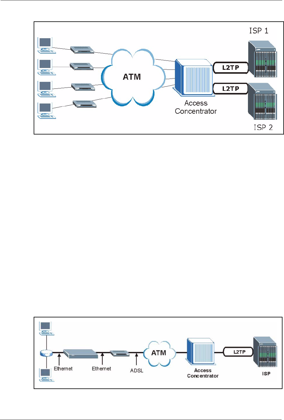
Prestige 334 User’s Guide
333 Appendix B PPPoE
Figure 183 Single-Computer per Router Hardware Configuration
How PPPoE Works
The PPPoE driver makes the Ethernet appear as a serial link to the computer and the computer
runs PPP over it, while the modem bridges the Ethernet frames to the Access Concentrator
(AC). Between the AC and an ISP, the AC is acting as a L2TP (Layer 2 Tunneling Protocol)
LAC (L2TP Access Concentrator) and tunnels the PPP frames to the ISP. The L2TP tunnel is
capable of carrying multiple PPP sessions.
With PPPoE, the VC (Virtual Circuit) is equivalent to the dial-up connection and is between
the modem and the AC, as opposed to all the way to the ISP. However, the PPP negotiation is
between the computer and the ISP.
Prestige as a PPPoE Client
When using the Prestige as a PPPoE client, the computers on the LAN see only Ethernet and
are not aware of PPPoE. This alleviates the administrator from having to manage the PPPoE
clients on the individual computers.
Figure 184 Prestige as a PPPoE Client
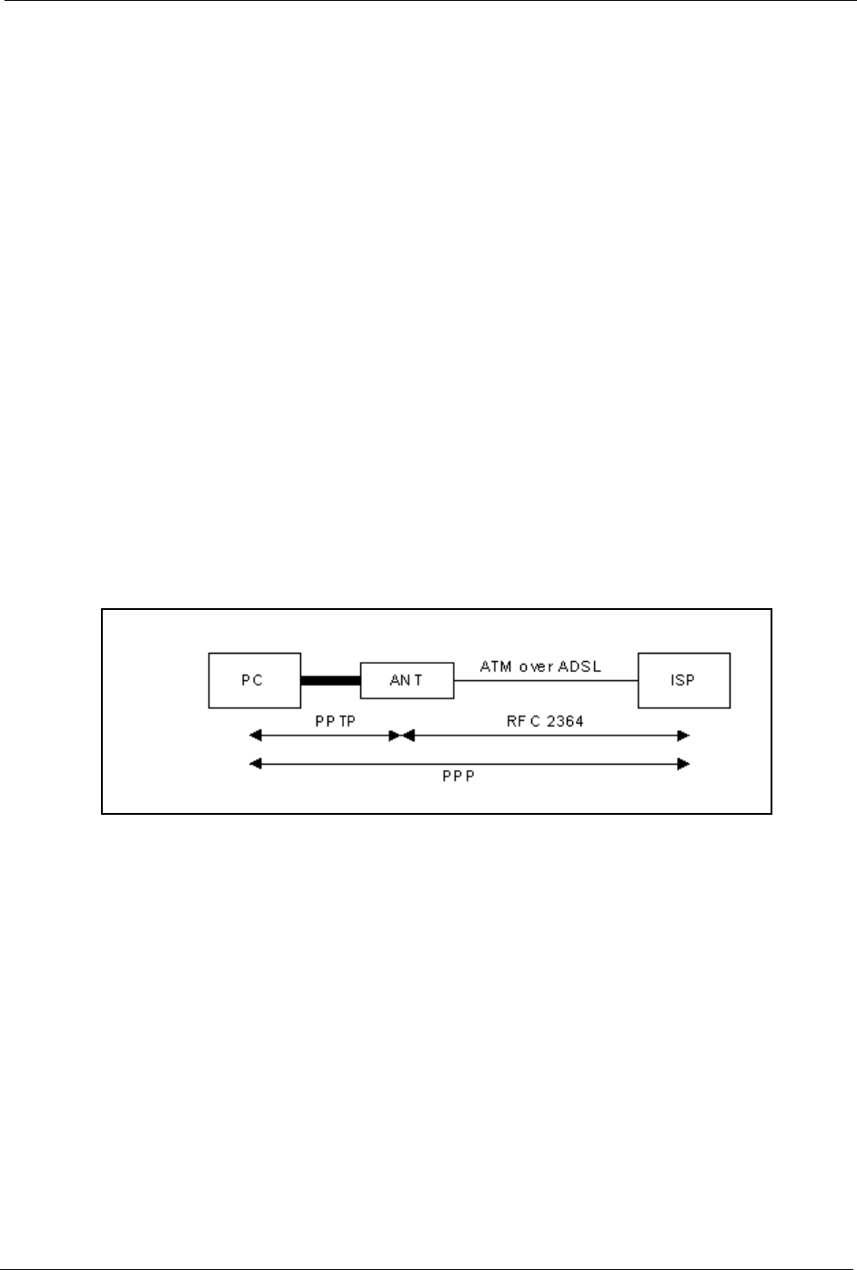
Prestige 334 User’s Guide
Appendix C PPTP 334
Appendix C
PPTP
What is PPTP?
PPTP (Point-to-Point Tunneling Protocol) is a Microsoft proprietary protocol (RFC 2637 for
PPTP is informational only) to tunnel PPP frames.
How can we transport PPP frames from a computer to a broadband
modem over Ethernet?
A solution is to build PPTP into the ANT (ADSL Network Termination) where PPTP is used
only over the short haul between the computer and the modem over Ethernet. For the rest of
the connection, the PPP frames are transported with PPP over AAL5 (RFC 2364) The PPP
connection, however, is still between the computer and the ISP. The various connections in
this setup are depicted in the following diagram. The drawback of this solution is that it
requires one separate ATM VC per destination.
Figure 185 Transport PPP frames over Ethernet
PPTP and the Prestige
When the Prestige is deployed in such a setup, it appears as a computer to the ANT.
In Windows VPN or PPTP Pass-Through feature, the PPTP tunneling is created from
Windows 95, 98 and NT clients to an NT server in a remote location. The pass-through feature
allows users on the network to access a different remote server using the Prestige's Internet
connection. In SUA/NAT mode, the Prestige is able to pass the PPTP packets to the internal
PPTP server (i.e. NT server) behind the NAT. You need to configure port forwarding for port
1723 to have the Prestige forward PPTP packets to the server. In the case above as the remote
PPTP Client initializes the PPTP connection, the user must configure the PPTP clients. The
Prestige initializes the PPTP connection hence; there is no need to configure the remote PPTP
clients.

Prestige 334 User’s Guide
335 Appendix C PPTP
PPTP Protocol Overview
PPTP is very similar to L2TP, since L2TP is based on both PPTP and L2F (Cisco’s Layer 2
Forwarding). Conceptually, there are three parties in PPTP, namely the PNS (PPTP Network
Server), the PAC (PPTP Access Concentrator) and the PPTP user. The PNS is the box that
hosts both the PPP and the PPTP stacks and forms one end of the PPTP tunnel. The PAC is the
box that dials/answers the phone calls and relays the PPP frames to the PNS. The PPTP user is
not necessarily a PPP client (can be a PPP server too). Both the PNS and the PAC must have IP
connectivity; however, the PAC must in addition have dial-up capability. The phone call is
between the user and the PAC and the PAC tunnels the PPP frames to the PNS. The PPTP user
is unaware of the tunnel between the PAC and the PNS.
Figure 186 PPTP Protocol Overview
Microsoft includes PPTP as a part of the Windows OS. In Microsoft’s implementation, the
computer, and hence the Prestige, is the PNS that requests the PAC (the ANT) to place an
outgoing call over AAL5 to an RFC 2364 server.
Control & PPP Connections
Each PPTP session has distinct control connection and PPP data connection.
Call Connection
The control connection runs over TCP. Similar to L2TP, a tunnel control connection is first
established before call control messages can be exchanged. Please note that a tunnel control
connection supports multiple call sessions.
The following diagram depicts the message exchange of a successful call setup between a
computer and an ANT.
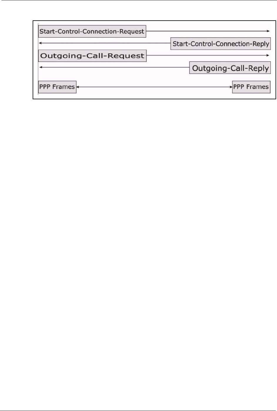
Prestige 334 User’s Guide
Appendix C PPTP 336
Figure 187 Example Message Exchange between Computer and an ANT
PPP Data Connection
The PPP frames are tunneled between the PNS and PAC over GRE (General Routing
Encapsulation, RFC 1701, 1702). The individual calls within a tunnel are distinguished using
the Call ID field in the GRE header.

Prestige 334 User’s Guide
337 Appendix C PPTP

Prestige 334 User’s Guide
Appendix D NetBIOS Filter Commands 338
Appendix D
NetBIOS Filter Commands
The following describes the NetBIOS packet filter commands.
Introduction
NetBIOS (Network Basic Input/Output System) are TCP or UDP broadcast packets that
enable a computer to connect to and communicate with a LAN.
For some dial-up services such as PPPoE or PPTP, NetBIOS packets cause unwanted calls.
You can configure NetBIOS filters to do the following :
• Allow or disallow the sending of NetBIOS packets from the LAN to the WAN and from
the WAN to the LAN.
• Allow or disallow the sending of NetBIOS packets through VPN connections.
• Allow or disallow NetBIOS packets to initiate calls.
Display NetBIOS Filter Settings
This command gives a read-only list of the current NetBIOS filter modes for The Prestige.
NetBIOS Display Filter Settings Command Example
Syntax: sys filter netbios disp
=========== NetBIOS Filter Status ===========
Between LAN and WAN: Block
Between LAN and DMZ: Block
Between WAN and DMZ: Block
IPSec Packets: Forward
Trigger Dial: Disabled

Prestige 334 User’s Guide
339 Appendix D NetBIOS Filter Commands
The filter types and their default settings are as follows.
NetBIOS Filter Configuration
Syntax:sys filter netbios config <type> <on|off>
where
Table 113 NetBIOS Filter Default Settings
NAME DESCRIPTION EXAMPLE
Between LAN
and WAN
This field displays whether NetBIOS packets are blocked or forwarded
between the LAN and the WAN.
Block
IPSec
Packets
This field displays whether NetBIOS packets sent through a VPN
connection are blocked or forwarded.
Forward
Trigger
dial
This field displays whether NetBIOS packets are allowed to initiate
calls. Disabled means that NetBIOS packets are blocked from initiating
calls.
Disabled
<type> = Identify which NetBIOS filter (numbered 0-3) to configure.
0 = Between LAN and WAN
3 = IPSec packet pass through
4 = Trigger Dial
<on|off> = For type 0 and 1, use on to enable the filter and block NetBIOS packets.
Use off to disable the filter and forward NetBIOS packets.
For type 3, use on to block NetBIOS packets from being sent through a VPN
connection. Use off to allow NetBIOS packets to be sent through a VPN
connection.
For type 4, use on to allow NetBIOS packets to initiate dial backup calls.
Use off to block NetBIOS packets from initiating dial backup calls.
Example commands
sys filter netbios
config 0 on
This command blocks LAN to WAN and WAN to LAN NetBIOS packets.
sys filter netbios
config 3 on
This command blocks IPSec NetBIOS packets.
sys filter netbios
config 4 off
This command stops NetBIOS commands from initiating calls.

Prestige 334 User’s Guide
Appendix E Log Descriptions 340
Appendix E
Log Descriptions
Configure centralized logs using the embedded web configurator; see online help for details.
This appendix provides descriptions of example log messages.
Table 114 System Error logs
LOG MESSAGE DESCRIPTION
%s exceeds the max. number
of session per host!
This attempt to create a NAT session exceeds the maximum
number of NAT session table entries allowed to be created per
host.
Table 115 System Maintenance Logs
LOG MESSAGE DESCRIPTION
Time calibration is
successful
The router has adjusted its time based on information from the
time server.
Time calibration failed The router failed to get information from the time server.
DHCP client gets %s A DHCP client got a new IP address from the DHCP server.
DHCP client IP expired A DHCP client's IP address has expired.
DHCP server assigns %s The DHCP server assigned an IP address to a client.
SMT Login Successfully Someone has logged on to the router's SMT interface.
SMT Login Fail Someone has failed to log on to the router's SMT interface.
WEB Login Successfully Someone has logged on to the router's web configurator
interface.
WEB Login Fail Someone has failed to log on to the router's web configurator
interface.
TELNET Login Successfully Someone has logged on to the router via telnet.
TELNET Login Fail Someone has failed to log on to the router via telnet.
FTP Login Successfully Someone has logged on to the router via ftp.
FTP Login Fail Someone has failed to log on to the router via ftp.
NAT Session Table is Full! The maximum number of NAT session table entries has been
exceeded and the table is full.
!! Phase 1 ID type mismatch The ID type of an incoming packet does not match the local's
peer ID type.
!! Phase 1 ID content
mismatch
The ID content of an incoming packet does not match the
local's peer ID content.
!! No known phase 1 ID type
found
The ID type of an incoming packet does not match any known
ID type.

Prestige 334 User’s Guide
341 Appendix E Log Descriptions
Table 116 UPnP Logs
LOG MESSAGE DESCRIPTION
UPnP pass through Firewall UPnP packets can pass through the firewall.
Table 117 ICMP Type and Code Explanations
TYPE CODE DESCRIPTION
0Echo Reply
0Echo reply message
3Destination Unreachable
0Net unreachable
1Host unreachable
2Protocol unreachable
3Port unreachable
4A packet that needed fragmentation was dropped because it was set to Don't
Fragment (DF)
5Source route failed
4Source Quench
0A gateway may discard internet datagrams if it does not have the buffer space
needed to queue the datagrams for output to the next network on the route to the
destination network.
5Redirect
0Redirect datagrams for the Network
1Redirect datagrams for the Host
2Redirect datagrams for the Type of Service and Network
3Redirect datagrams for the Type of Service and Host
8Echo
0Echo message
11 Time Exceeded
0Time to live exceeded in transit
1Fragment reassembly time exceeded
12 Parameter Problem
0Pointer indicates the error
13 Timestamp
0Timestamp request message
14 Timestamp Reply
0Timestamp reply message
15 Information Request
0Information request message
16 Information Reply
0Information reply message

Prestige 334 User’s Guide
Appendix F Setting up Your Computer’s IP Address 342
Appendix F
Setting up Your Computer’s IP Address
All computers must have a 10M or 100M Ethernet adapter card and TCP/IP installed.
Windows 95/98/Me/NT/2000/XP, Macintosh OS 7 and later operating systems and all versions
of UNIX/LINUX include the software components you need to install and use TCP/IP on your
computer. Windows 3.1 requires the purchase of a third-party TCP/IP application package.
TCP/IP should already be installed on computers using Windows NT/2000/XP, Macintosh OS
7 and later operating systems.
After the appropriate TCP/IP components are installed, configure the TCP/IP settings in order
to "communicate" with your network.
If you manually assign IP information instead of using dynamic assignment, make sure that
your computers have IP addresses that place them in the same subnet as the Prestige’s LAN
port.
Windows 95/98/Me
Click Start, Settings, Control Panel and double-click the Network icon to open the Network
window
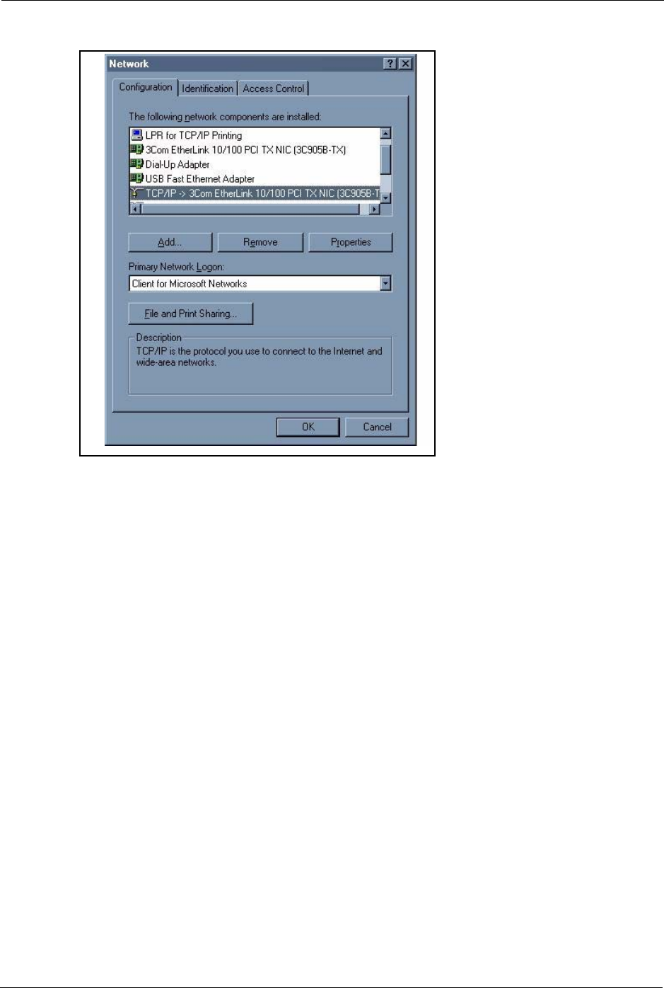
Prestige 334 User’s Guide
343 Appendix F Setting up Your Computer’s IP Address
Figure 188 WIndows 95/98/Me: Network: Configuration
Installing Components
The Network window Configuration tab displays a list of installed components. You need a
network adapter, the TCP/IP protocol and Client for Microsoft Networks.
If you need the adapter:
1In the Network window, click Add.
2Select Adapter and then click Add.
3Select the manufacturer and model of your network adapter and then click OK.
If you need TCP/IP:
1In the Network window, click Add.
2Select Protocol and then click Add.
3Select Microsoft from the list of manufacturers.
4Select TCP/IP from the list of network protocols and then click OK.
If you need Client for Microsoft Networks:
1Click Add.
2Select Client and then click Add.
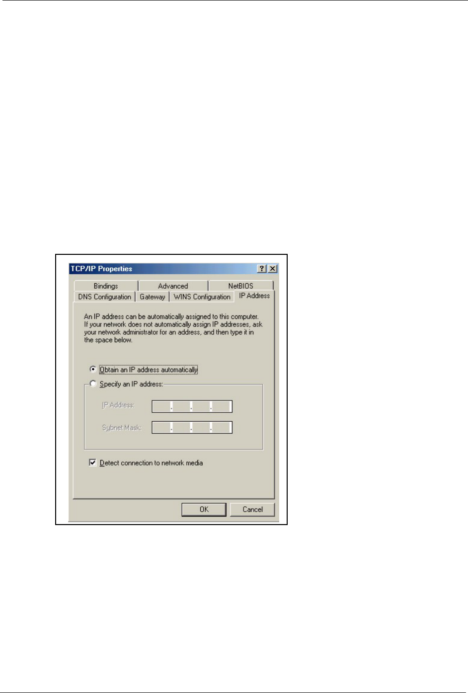
Prestige 334 User’s Guide
Appendix F Setting up Your Computer’s IP Address 344
3Select Microsoft from the list of manufacturers.
4Select Client for Microsoft Networks from the list of network clients and then click
OK.
5Restart your computer so the changes you made take effect.
Configuring
1In the Network window Configuration tab, select your network adapter's TCP/IP entry
and click Properties
2Click the IP Address tab.
• If your IP address is dynamic, select Obtain an IP address
automatically.
• If you have a static IP address, select Specify an IP address and type
your information into the IP Address and Subnet Mask fields.
Figure 189 Windows 95/98/Me: TCP/IP Properties: IP Address
3Click the DNS Configuration tab.
• If you do not know your DNS information, select Disable DNS.
• If you know your DNS information, select Enable DNS and type the
information in the fields below (you may not need to fill them all in).
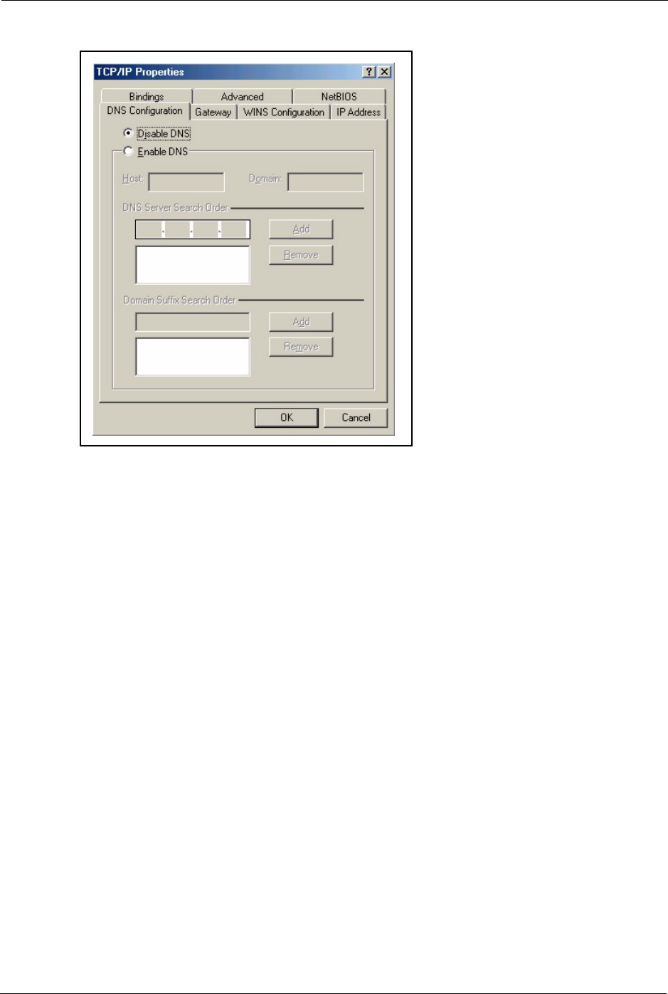
Prestige 334 User’s Guide
345 Appendix F Setting up Your Computer’s IP Address
Figure 190 Windows 95/98/Me: TCP/IP Properties: DNS Configuration
4Click the Gateway tab.
• If you do not know your gateway’s IP address, remove previously
installed gateways.
• If you have a gateway IP address, type it in the New gateway field
and click Add.
5Click OK to save and close the TCP/IP Properties window.
6Click OK to close the Network window. Insert the Windows CD if prompted.
7Turn on your Prestige and restart your computer when prompted.
Verifying Settings
1Click Start and then Run.
2In the Run window, type "winipcfg" and then click OK to open the IP Configuration
window.
3Select your network adapter. You should see your computer's IP address, subnet mask and
default gateway.
Windows 2000/NT/XP
1For Windows XP, click start, Control Panel. In Windows 2000/NT, click Start,
Settings, Control Panel.
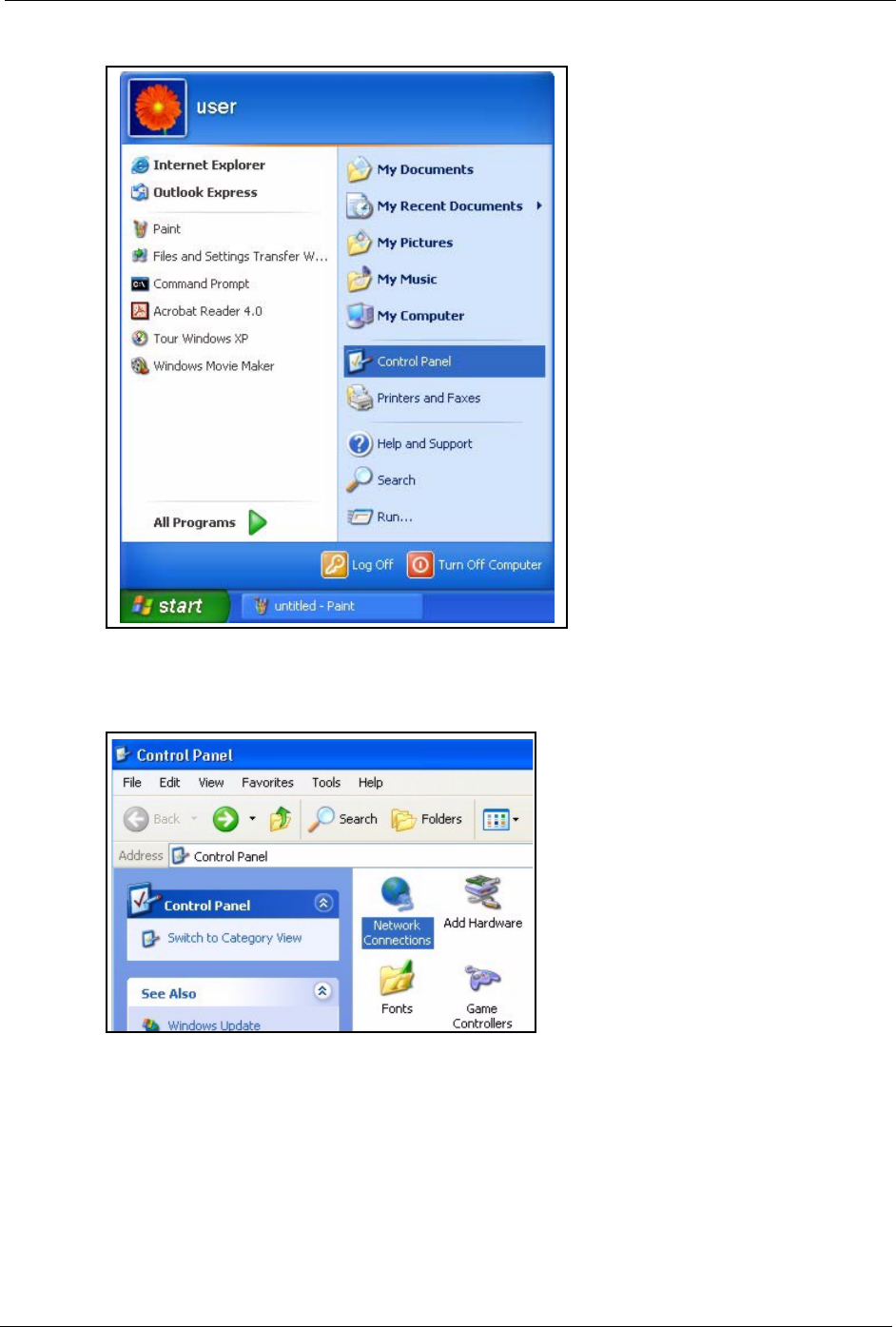
Prestige 334 User’s Guide
Appendix F Setting up Your Computer’s IP Address 346
Figure 191 Windows XP: Start Menu
2For Windows XP, click Network Connections. For Windows 2000/NT, click Network
and Dial-up Connections.
Figure 192 Windows XP: Control Panel
3Right-click Local Area Connection and then click Properties.
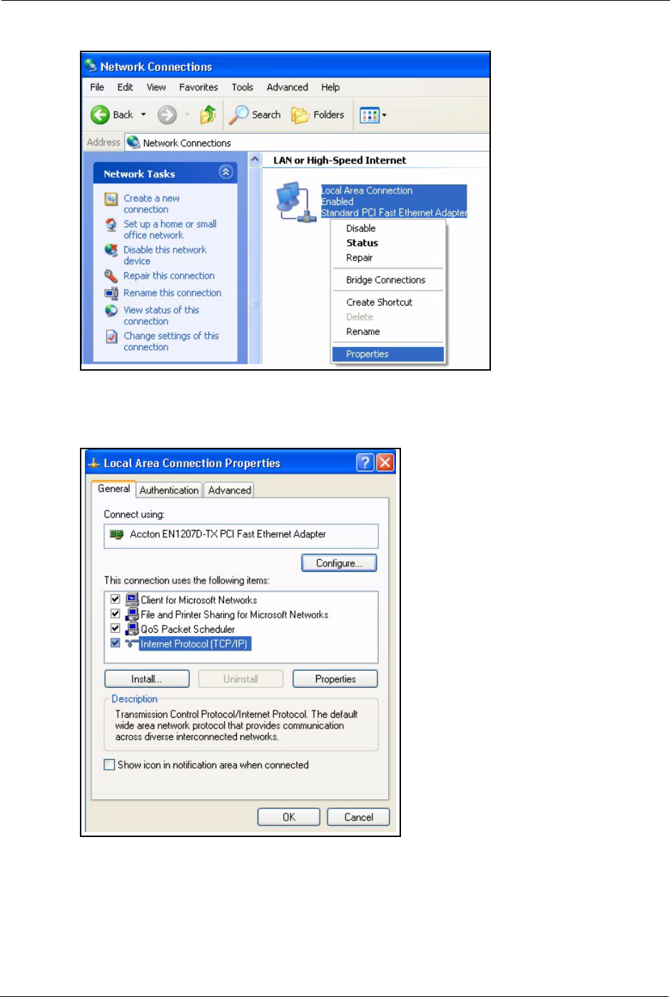
Prestige 334 User’s Guide
347 Appendix F Setting up Your Computer’s IP Address
Figure 193 Windows XP: Control Panel: Network Connections: Properties
4Select Internet Protocol (TCP/IP) (under the General tab in Win XP) and click
Properties.
Figure 194 Windows XP: Local Area Connection Properties
5The Internet Protocol TCP/IP Properties window opens (the General tab in Windows
XP).
• If you have a dynamic IP address click Obtain an IP address
automatically.
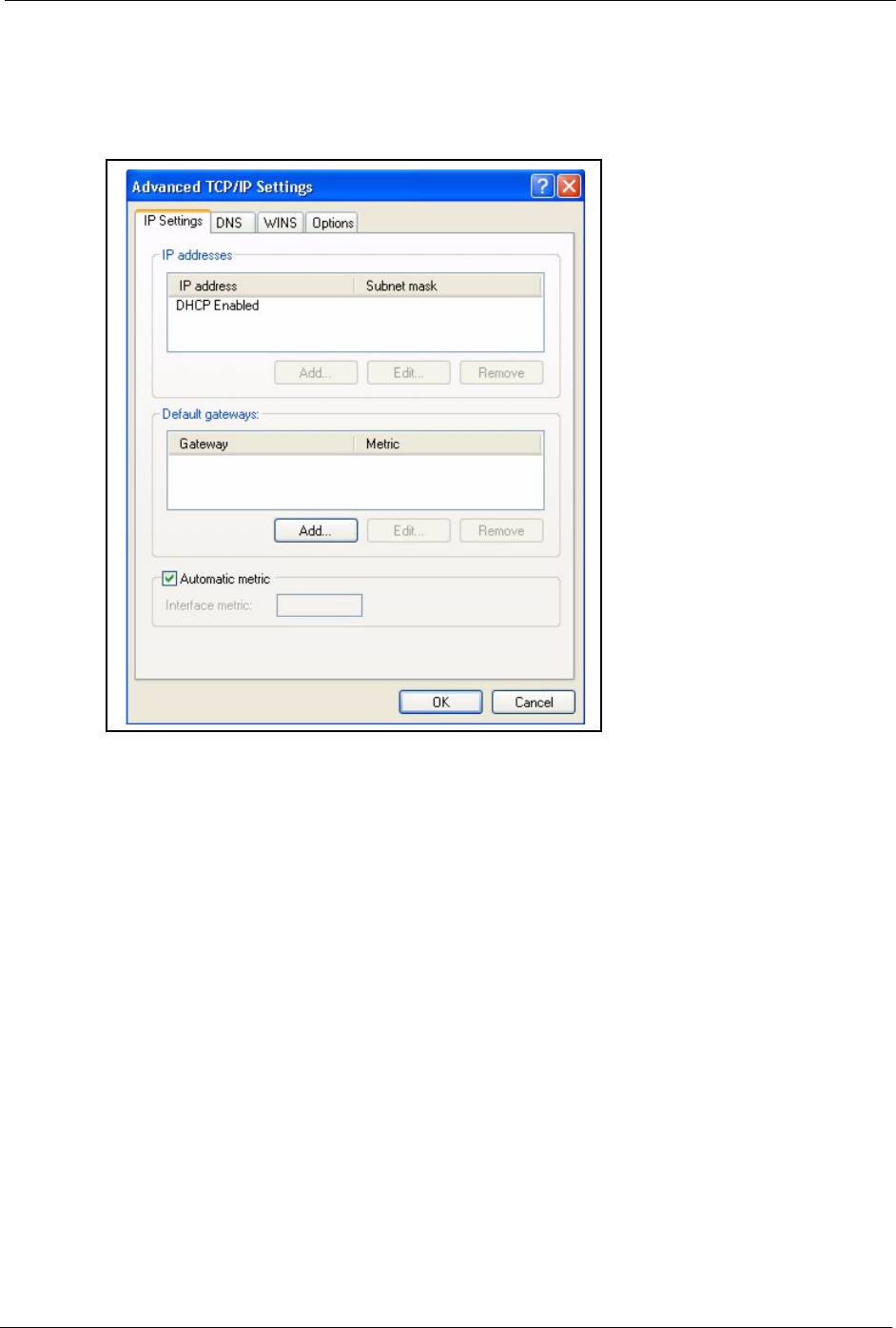
Prestige 334 User’s Guide
Appendix F Setting up Your Computer’s IP Address 348
• If you have a static IP address click Use the following IP Address
and fill in the IP address, Subnet mask, and Default gateway fields.
Click Advanced.
Figure 195 Windows XP: Advanced TCP/IP Settings
6If you do not know your gateway's IP address, remove any previously installed gateways
in the IP Settings tab and click OK.
Do one or more of the following if you want to configure additional IP addresses:
•In the IP Settings tab, in IP addresses, click Add.
•In TCP/IP Address, type an IP address in IP address and a subnet
mask in Subnet mask, and then click Add.
• Repeat the above two steps for each IP address you want to add.
• Configure additional default gateways in the IP Settings tab by
clicking Add in Default gateways.
•In TCP/IP Gateway Address, type the IP address of the default
gateway in Gateway. To manually configure a default metric (the
number of transmission hops), clear the Automatic metric check box
and type a metric in Metric.
• Click Add.
• Repeat the previous three steps for each default gateway you want to
add.
• Click OK when finished.
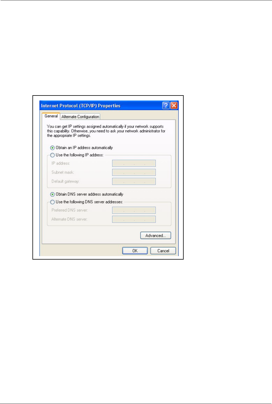
Prestige 334 User’s Guide
349 Appendix F Setting up Your Computer’s IP Address
7In the Internet Protocol TCP/IP Properties window (the General tab in Windows XP):
• Click Obtain DNS server address automatically if you do not know
your DNS server IP address(es).
• If you know your DNS server IP address(es), click Use the following
DNS server addresses, and type them in the Preferred DNS server
and Alternate DNS server fields.
If you have previously configured DNS servers, click Advanced and
then the DNS tab to order them.
Figure 196 Windows XP: Internet Protocol (TCP/IP) Properties
8Click OK to close the Internet Protocol (TCP/IP) Properties window.
9Click OK to close the Local Area Connection Properties window.
10Turn on your Prestige and restart your computer (if prompted).
Verifying Settings
1Click Start, All Programs, Accessories and then Command Prompt.
2In the Command Prompt window, type "ipconfig" and then press [ENTER]. You can
also open Network Connections, right-click a network connection, click Status and then
click the Support tab.
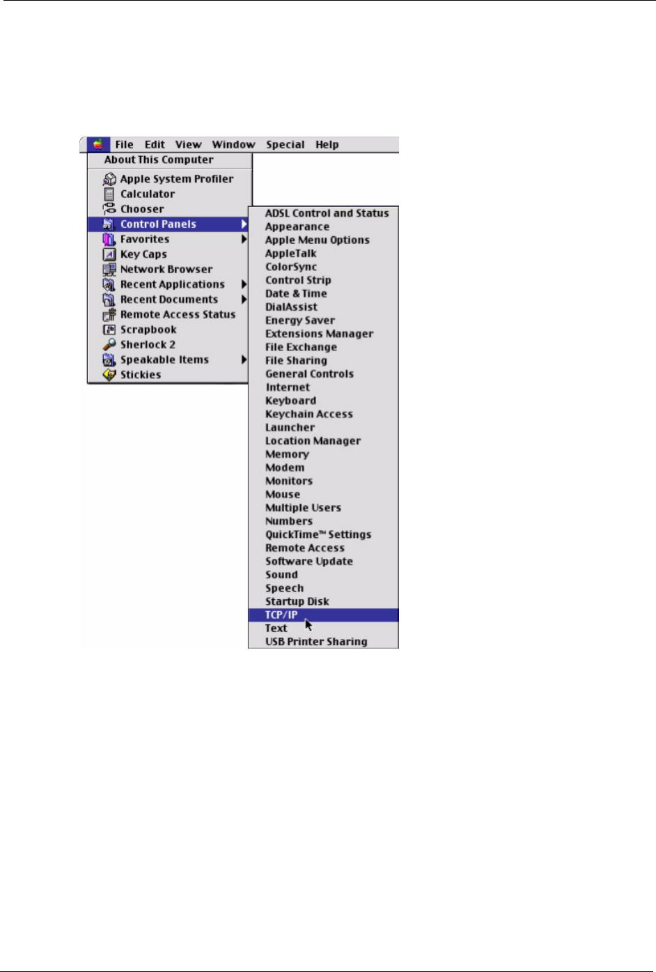
Prestige 334 User’s Guide
Appendix F Setting up Your Computer’s IP Address 350
Macintosh OS 8/9
1Click the Apple menu, Control Panel and double-click TCP/IP to open the TCP/IP
Control Panel.
Figure 197 Macintosh OS 8/9: Apple Menu
2Select Ethernet built-in from the Connect via list.
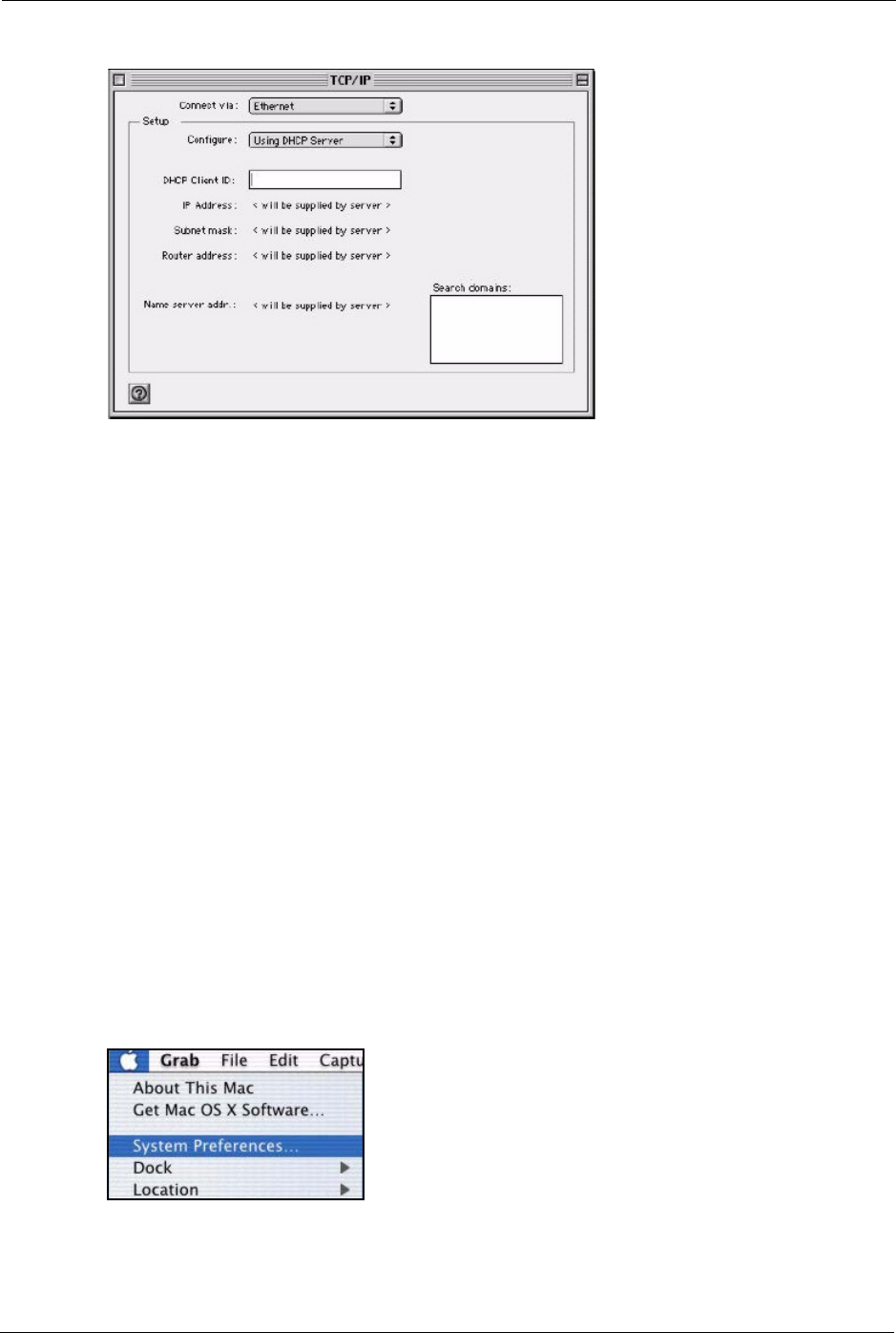
Prestige 334 User’s Guide
351 Appendix F Setting up Your Computer’s IP Address
Figure 198 Macintosh OS 8/9: TCP/IP
3For dynamically assigned settings, select Using DHCP Server from the Configure: list.
4For statically assigned settings, do the following:
•From the Configure box, select Manually.
• Type your IP address in the IP Address box.
• Type your subnet mask in the Subnet mask box.
• Type the IP address of your Prestige in the Router address box.
5Close the TCP/IP Control Panel.
6Click Save if prompted, to save changes to your configuration.
7Turn on your Prestige and restart your computer (if prompted).
Verifying Settings
Check your TCP/IP properties in the TCP/IP Control Panel window.
Macintosh OS X
1Click the Apple menu, and click System Preferences to open the System Preferences
window.
Figure 199 Macintosh OS X: Apple Menu
2Click Network in the icon bar.
• Select Automatic from the Location list.
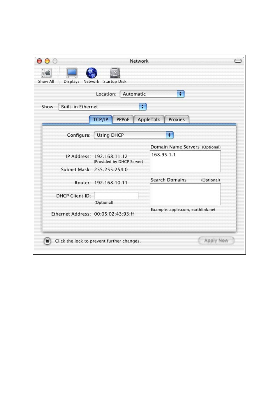
Prestige 334 User’s Guide
Appendix F Setting up Your Computer’s IP Address 352
• Select Built-in Ethernet from the Show list.
• Click the TCP/IP tab.
3For dynamically assigned settings, select Using DHCP from the Configure list.
Figure 200 Macintosh OS X: Network
4For statically assigned settings, do the following:
•From the Configure box, select Manually.
• Type your IP address in the IP Address box.
• Type your subnet mask in the Subnet mask box.
• Type the IP address of your Prestige in the Router address box.
5Click Apply Now and close the window.
6Turn on your Prestige and restart your computer (if prompted).
Verifying Settings
Check your TCP/IP properties in the Network window.

Prestige 334 User’s Guide
353 Appendix F Setting up Your Computer’s IP Address
Prestige 334 User’s Guide
Appendix G Brute-Force Password Guessing Protection 354
Appendix G
Brute-Force Password Guessing
Protection
The following describes the commands for enabling, disabling and configuring the brute-force
password guessing protection mechanism for the password.
Example
sys pwderrtm 5
This command sets the password protection to block all access attempts for five minutes after
the third time an incorrect password is entered.
Table 118 Brute-Force Password Guessing Protection Commands
COMMAND DESCRIPTION
sys pwderrtm This command displays the brute-force guessing password protection settings.
sys pwderrtm 0 This command turns off the password’s protection from brute-force guessing. The
brute-force password guessing protection is turned off by default.
sys pwderrtm N This command sets the password protection to block all access attempts for N (a
number from 1 to 60) minutes after the third time an incorrect password is entered.

Prestige 334 User’s Guide
355 Appendix G Brute-Force Password Guessing Protection
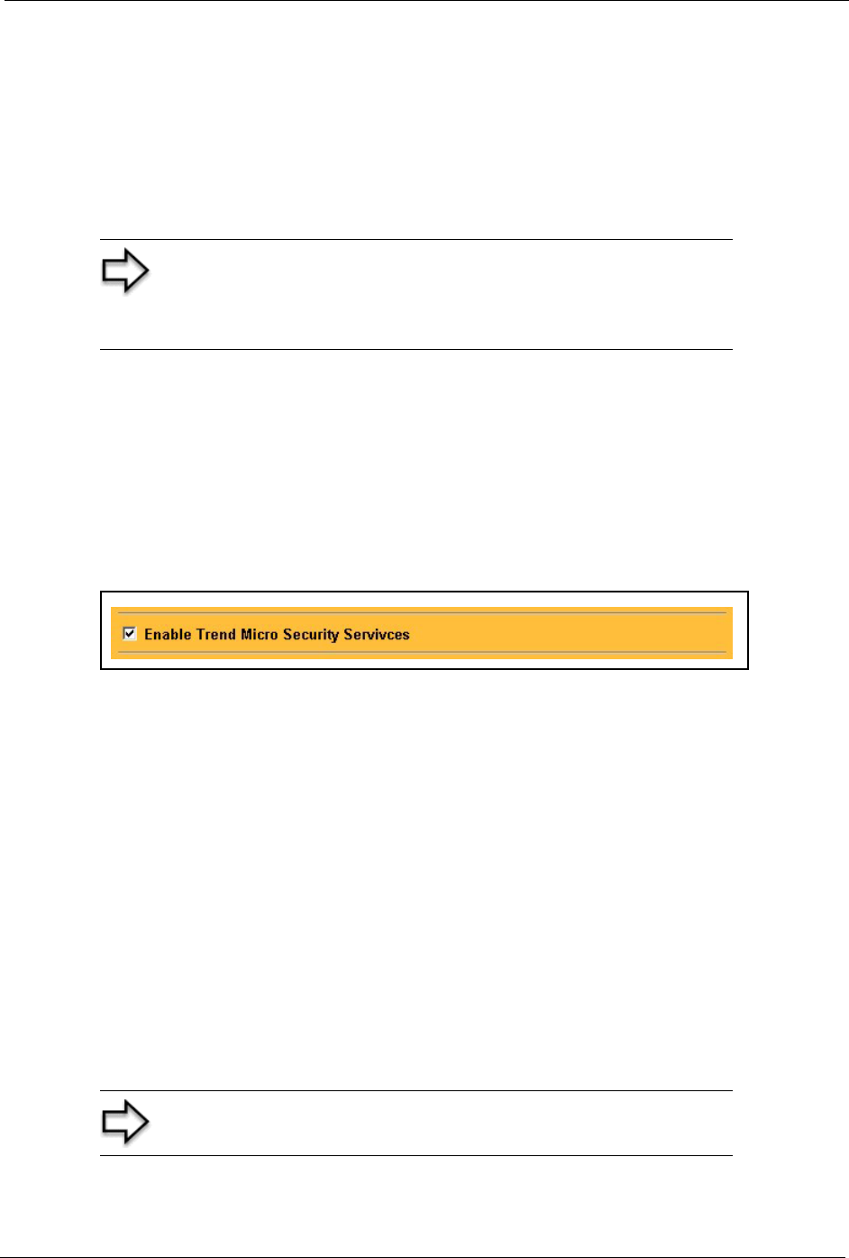
Prestige 334 User’s Guide
Appendix H TMSS 356
Appendix H
TMSS
This appendix discusses Trend Micro Security Services setup and access. Please see your
TMSS user guide for more information.
To view the TMSS dashboard, follow the steps below.
1Click TMSS under ADVANCED in the web configurator.
2Select the Service Settings tab.
3Select the Enable Trend Micro Security Services check box.
4Click Apply to save your settings.
Figure 201 Enable TMSS
5After you successfully configure your Prestige to connect to the Internet, open your web
browser and enter a URL.
6A web page automatically appears allowing you to download ActiveX control from the
Trend Micro website. ActiveX control should be downloaded to each computer in your
network.
The TMSS Web page may not appear when you enable TMSS if you are using instant
messaging software other than MSN Messenger, for example, ICQ or you have installed
software that blocks pop-up browsers, for example, a Google toolbar or Windows XP Service
Pack.
You must disable the SP2 pop-up blocker or type the URL http://tmss.trendmicro.com to view
the TMSS Web page and manually start the Active X control installation. Once the TMSS
Active X control has been installed, access the TMSS Web page by clicking the Internet
Explorer TMSS toolbar icon or launch “Trend Micro Security Services” from the Windows
Start menu.
Note: Make sure that you have not restricted access to ActiveX,
Cookies or Web Proxy features in the Advanced Firewall Filter
screen. If you restrict Web access to these features you will not
be able to use TMSS.
Note: The following screens appear only when you first access the
Internet with TMSS enabled on your Prestige.
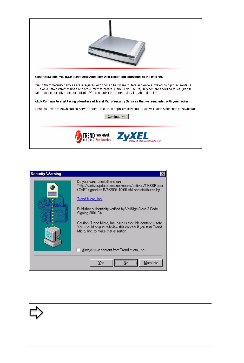
Prestige 334 User’s Guide
357 Appendix H TMSS
Figure 202 TMSS Welcome Screen
7Click Continue>> to proceed to download ActiveX control.
Figure 203 Download ActiveX Control
8Select Yes to install and run ActiveX control.
9Once the installation is complete the Home Network Security Services dashboard
appears. From this screen you can take advantage of all TMSS features.
Note: The following screen appears when you
• Click the Trend Micro icon on your Web browser tool bar
• Click the Security Services link in your Windows Start menu
• Set a display interval timing in your Prestige TMSS Service
Settings configuration screen.
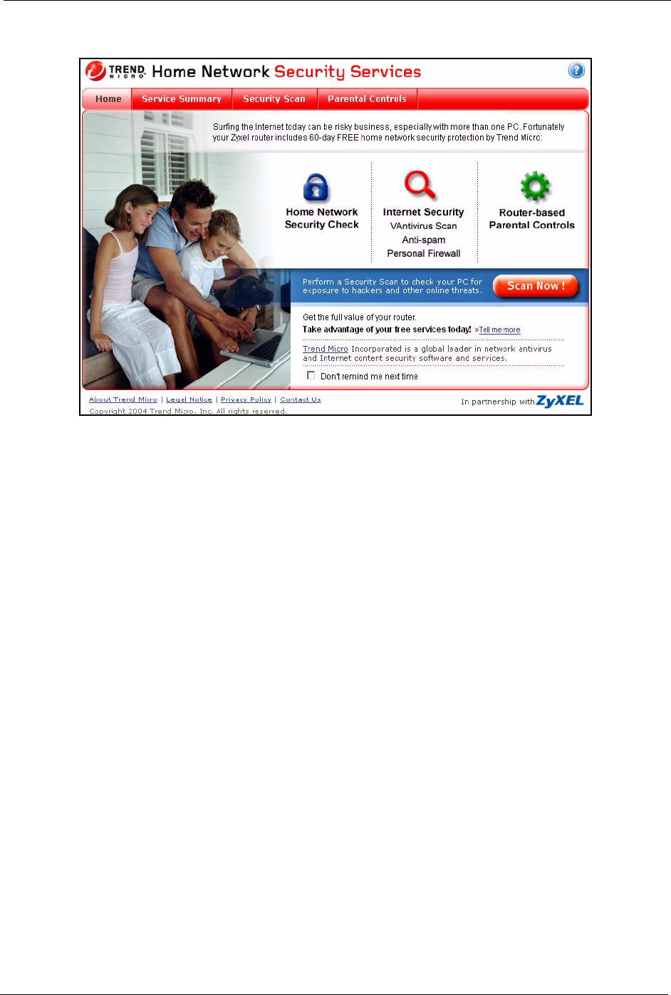
Prestige 334 User’s Guide
Appendix H TMSS 358
Figure 204 Home Network Security Services Dashboard
10 See the Trend Micro User’s Guide for information on TMSS.

Prestige 334 User’s Guide
359 Appendix H TMSS
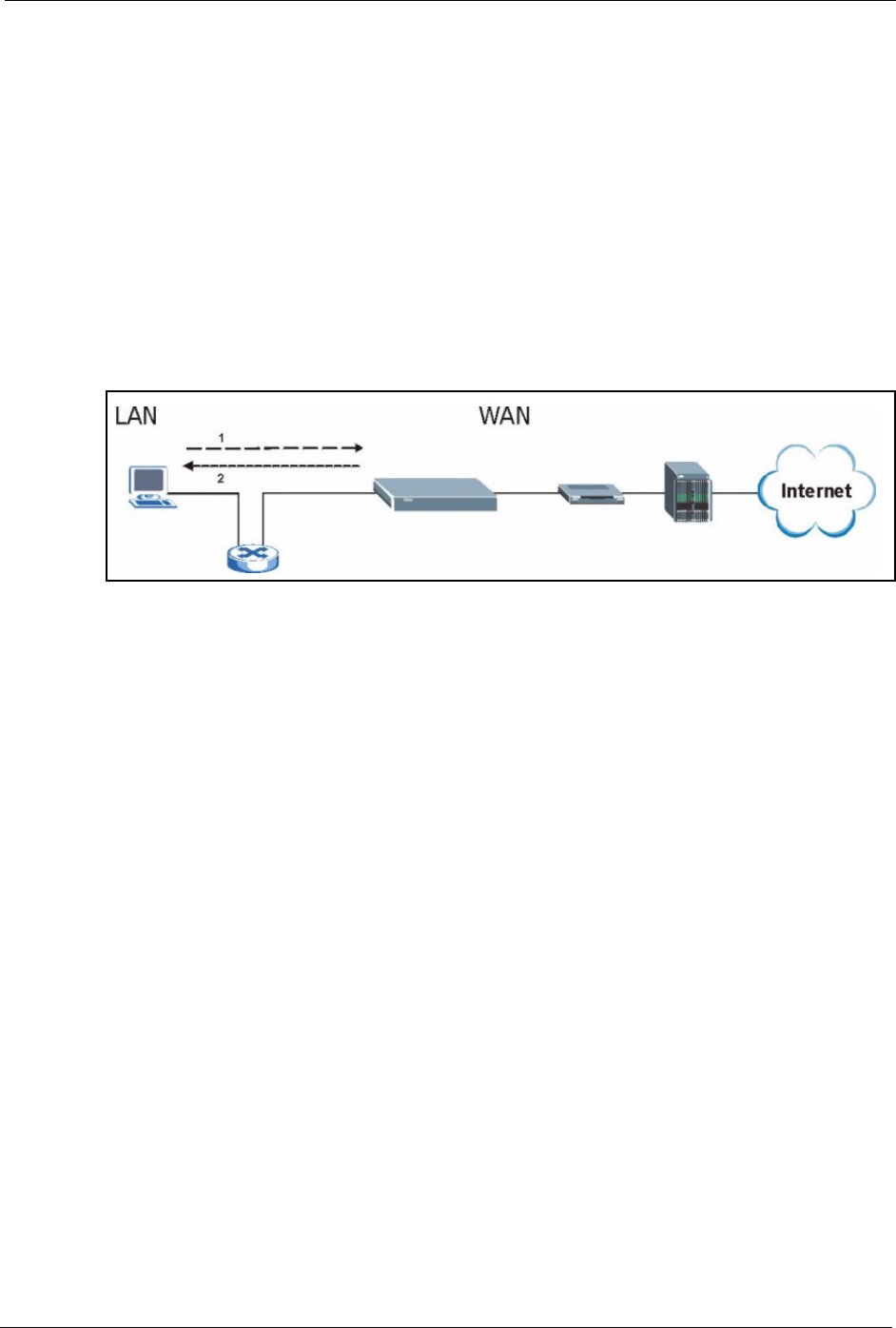
Prestige 334 User’s Guide
Appendix I Triangle Route 360
Appendix I
Triangle Route
The Ideal Setup
When the firewall is on, your Prestige acts as a secure gateway between your LAN and the
Internet. In an ideal network topology, all incoming and outgoing network traffic passes
through the Prestige to protect your LAN against attacks.
Figure 205 Ideal Setup
The “Triangle Route” Problem
A traffic route is a path for sending or receiving data packets between two Ethernet devices.
Some companies have more than one alternate route to one or more ISPs. If the LAN and
ISP(s) are in the same subnet, the “triangle route” problem may occur. The steps below
describe the “triangle route” problem.
1A computer on the LAN initiates a connection by sending out a SYN packet to a
receiving server on the WAN.
2The Prestige reroutes the SYN packet through Gateway B on the LAN to the WAN.
3The reply from the WAN goes directly to the computer on the LAN without going
through the Prestige.
As a result, the Prestige resets the connection, as the connection has not been acknowledged.

Prestige 334 User’s Guide
361 Appendix I Triangle Route
Figure 206 “Triangle Route” Problem
The “Triangle Route” Solutions
This section presents you two solutions to the “triangle route” problem.
IP Aliasing
IP alias allows you to partition your network into logical sections over the same Ethernet
interface. Your Prestige supports up to three logical LAN interfaces with the Prestige being the
gateway for each logical network. By putting your LAN and Gateway B in different subnets,
all returning network traffic must pass through the Prestige to your LAN. The following steps
describe such a scenario.
1A computer on the LAN initiates a connection by sending a SYN packet to a receiving
server on the WAN.
2The Prestige reroutes the packet to Gateway B, which is in the 192.168.2.1 to
192.168.2.24 subnet.
3The reply from WAN goes through the Prestige to the computer on the LAN in the
192.168.1.1 to 192.168.1.24 subnet.
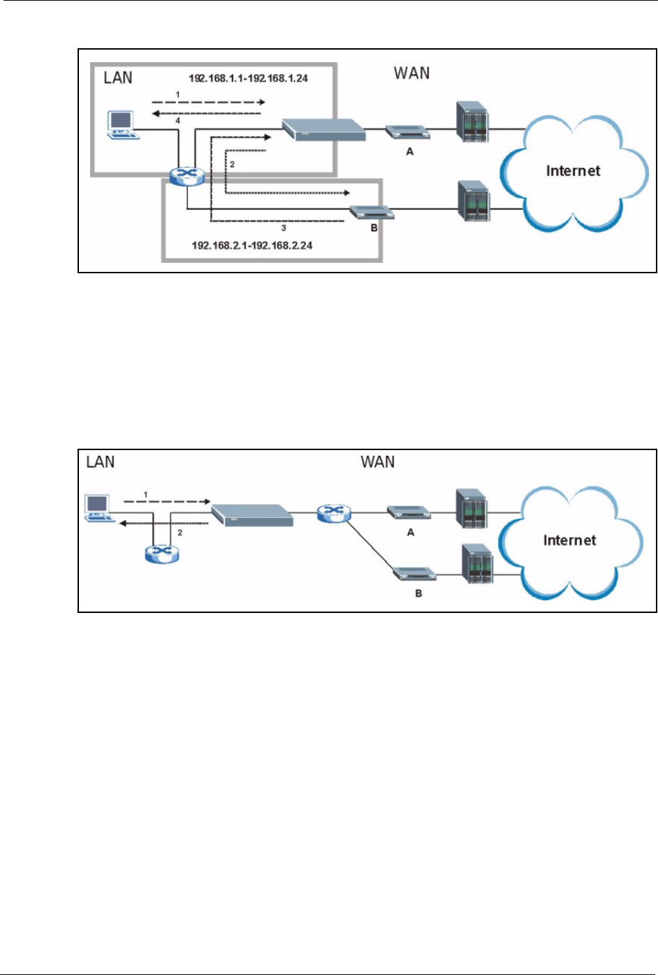
Prestige 334 User’s Guide
Appendix I Triangle Route 362
Figure 207 IP Alias
Gateways on the WAN Side
A second solution to the “triangle route” problem is to put all of your network gateways on the
WAN side as the following figure shows. This ensures that all incoming network traffic passes
through your Prestige to your LAN. Therefore your LAN is protected.
Figure 208 Gateways on the WAN Side
How To Configure Triangle Route
1From the SMT main menu, enter 24.
2Enter “8” in menu 24 to enter CI command mode.
3Use the following command to allow triangle route:
sys firewall ignore triangle all on
or this command to disallow triangle route:
sys firewall ignore triangle all off

Prestige 334 User’s Guide
363 Appendix I Triangle Route

Prestige 334 User’s Guide
Index 364
Index
A
Active 225
ActiveX 135
Allocated Budget 227
AT command 287
Authen 227
Authentication Protocol 226
B
Backup 196, 287
Budget Management 299, 300
C
Call Control 299
Call History 300
Call Scheduling 310
Maximum Number of Schedule Sets 310
PPPoE 312
Precedence 310
Precedence Example 310
Call-Trigerring Packet 281
CDR 279
CDR (Call Detail Record) 278
Command Interpreter Mode 298
Community 271
Computer Name 206
Conditions that prevent TFTP and FTP from working
over WAN 289
Configuration 64, 192
Connection ID/Name 228
Content Filtering 134
Days and Times 134
Restrict Web Features 134
Cookies 135
Cost Of Transmission 235
D
Default 198
Denial of Service 254
DHCP 58, 64, 65, 67, 192, 193, 277
DNS 146
DNS Server
For VPN Host 161
Domain Name 92
Dynamic DNS 58, 207
DYNDNS Wildcard 58
E
ECHO 92
Edit IP 226
Encapsulation 225, 228
Ethernet Encapsulation 91, 224, 225
F
Factory LAN Defaults 64
Fail Tolerance 232
Filename Conventions 286
Filter 212, 230
Applying 268
Example 265
Generic Filter Rule 263
Generic Rule 264
NAT 267
Remote Node 269
Structure 257
Finger 92
Firewall 126, 127
Access Methods 254
Remote Management 254
SMT Menus 254
Firmware File
Maintenance 195, 196

Prestige 334 User’s Guide
365 Index
FTP 58, 64, 90, 91, 92, 138, 142, 307
FTP File Transfer 293
FTP Restrictions 138, 289, 307
FTP Server 247
G
Gateway 235
Gateway IP Addr 229
Gateway IP Address 220
General Setup 56
Global 86
H
Hidden Menus 202
Hop Count 235
Host 60
HTTP 92, 320
I
Idle Timeout 227
IGMP 65, 66
Inside 86
Inside Global Address 86
Inside Local Address 86
Internet Access 218
ISP's Name 219
Internet access 218
Internet Access Setup 219, 236
Introduction to Filters 256
IP Address 65, 68, 91, 93, 94, 214, 219, 229, 235, 277
IP Address Assignment 229
IP Pool 67, 214
IP Pool Setup 64
IP Ports 320
IP Static Route Setup 234
J
Java 135
L
LAN Setup 64, 72
LAN TCP/IP 64
Local 86
Log Facility 278
Login Name 219
M
MAC Address 210
Management Information Base (MIB) 143, 271
Many to Many No Overload 89
Many to Many Overload 89
Many to One 89
Message Logging 278
Metric 72, 104, 230, 235
Multicast 65, 68, 214, 230
My IP Addr 228
My Login 225
My Login Name 219
My Password 219, 225
My Server IP Addr 228
N
Nailed-Up Connection 227
Nailed-up Connection 227
NAT 90, 91, 92, 229, 267
Applying NAT in the SMT Menus 236
Configuring 238
Definitions 86
Examples 244
How NAT Works 87
Mapping Types 89
Non NAT Friendly Application Programs 250
Ordering Rules 241
Server Sets 91
What NAT does 87
Network Address Translation (NAT) 236
Network Management 92
NNTP 92

Prestige 334 User’s Guide
Index 366
O
One to One 89
Outside 86
P
Password 60, 200, 204, 219, 271
Period(hr) 227
Ping 283
Point-to-Point Tunneling Protocol 77, 92
POP3 92
Port Numbers 92
PPPoE 332
PPPoE Encapsulation 222, 224, 227
PPTP 92
Private 104, 230, 235
R
RAS 277
Related Documentation 30
Rem Node Name 225
Remote Management
Firewall 254
Remote Management and NAT 139
Remote Management Limitations 138, 307
Remote Node Filter 230
Required fields 202
Resetting the Time 304
Restore 197
Restore Configuration 291
Restrict Web Features 135
RIP 65, 230
Version 230
Route 225
RTC 301
S
SA Monitor 326
Schedule Sets
Duration 311
Schedules 227
Security Association 326
Server 61, 89, 90, 219, 225, 238, 240, 243, 245, 246,
247, 303
Server IP 225
Service Name 227
Service Type 219, 225
Services 91, 92, 130
setup a schedule 311
SMT Menu Overview 201
SMTP 92
SNMP 92, 127, 143
Community 272
Configuration 271
Get 271
Manager 143, 270
MIBs 144, 271
Trap 271
Trusted Host 272
Stateful Inspection 126
Static Route 102
SUA 90, 92
SUA (Single User Account) 90
Subnet Mask 65, 68, 214, 219, 229, 235, 277
Syntax Conventions 31
Syslog 278
Syslog IP Address 278
Syslog Server 278
System
Console Port Speed 277
Diagnostic 282
Log and Trace 278
Syslog and Accounting 278
System Information 276
System Information 276
System Information & Diagnosis 274
System Maintenance 185, 274, 276, 283, 287, 290, 295,
298, 299, 300, 303
System Name 207
System Timeout 139
T
TCP/IP 68, 260, 261, 267
TCP/IP filter rule 260
Tel n e t 140
TFTP File Transfer 295
TFTP Restrictions 138, 289, 307
Time and Date Setting 301, 302, 303
Time Zone 304
Timeout 221, 222, 227

Prestige 334 User’s Guide
367 Index
Trace Records 278
Traffic Redirect 82, 83
Trigger Port Forwarding 252
Process 98
U
Universal Plug and Play (UPnP) 106
UNIX Syslog 278
Upload Firmware 293
URL Keyword Blocking 135
Use Server Detected IP 209
User Name 59, 208
User Specified IP Addr 209
V
VPN 77
W
WAN DHCP 283, 284
WAN Setup 210
Web 139
Web Configurator 255
Web Proxy 135
www.dyndns.org 209
Z
ZyNOS 276, 287
ZyNOS F/W Version 276, 287
