Adobe Illustrator CC (2015) Help 2015 En
User Manual: adobe Illustrator - CC (2015) - Help Free User Guide for Adobe Illustrator Software, Manual
Open the PDF directly: View PDF ![]() .
.
Page Count: 556 [warning: Documents this large are best viewed by clicking the View PDF Link!]
- Legal notices
- Contents
- Chapter 1: What's new
- New features summary
- What's new and changed
- Linked Assets in Creative Cloud Libraries
- Adobe Stock
- 10x faster zoom, pan, scroll
- 10x greater zoom magnification
- Safe Mode
- Recover data in your files
- Integration with Creative Cloud mobile apps
- Creative Cloud Charts (Preview)
- GPU Performance
- Touch workspace enhancements
- Tool enhancements
- Other important enhancements
- New features summary
- Chapter 2: Workspace
- Workspace basics
- Customizing the workspace
- Tools
- Tool galleries
- Improved User Interface
- Safe Mode
- Recover document data after a crash
- Touch Workspace
- Artboard overview
- Rulers, grids, guides, and cropmarks
- Custom Tools Panels
- Viewing artwork
- Setting preferences
- Slicing and cutting tool gallery
- Using multiple artboards
- Recovery, undo, and automation
- Working with ConnectNow
- Files and templates
- Import and export Illustrator CC settings
- File Info dialog
- Chapter 3: Drawing
- Drawing basics
- Drawing with the Pen, Pencil, or Flare tool
- Drawing simple lines and shapes
- Editing paths
- Drawing pixel-aligned paths forweb workflows
- Adjust path segments
- Move straight segments
- Adjust the length or angle of straight segments
- Adjust the position or shape of curved segments
- Delete a segment
- Extend an open path
- Connect two open paths
- Join two endpoints
- Join two or more paths
- Move or nudge anchor points or segments using the keyboard
- Stretch parts of a path without distorting its overall shape
- Pen tool rubberband preview
- Curvature Tool
- Using Image Trace
- Enhanced Pencil Tool
- Anchor Point enhancements
- Symbols
- Symbolism tools and symbol sets
- Perspective drawing
- About Perspective Grid
- Using Live Trace | CS5 and earlier
- Automatic corner generation | Illustrator CC
- Creating arrows and arrowheads in Illustrator
- Chapter 4: Color
- About color
- Selecting colors
- Using and creating swatches
- Color groups (harmonies)
- About color groups
- Color Guide panel overview
- Edit Colors/Recolor Artwork dialog box overview
- Create color groups
- Edit colors in the Edit Colors dialog box
- Save changes to a color group
- Edit a color group using a color wheel
- Reorder colors in a color group
- Edit an individual color in a color group
- Edit colors in a color group using the Color Picker
- Randomly change color order or saturation and brightness
- Globally edit saturation, brightness, temperature, or luminosity
- Add or remove colors in a color group
- Delete a color group
- Assign colors to your artwork
- Reduce colors in your artwork
- Create color themes with Kuler
- Color Themes panel
- Adjusting colors
- Shift an out-of-gamut color to a printable color
- Shift a color to a web-safe color
- Blend colors
- Change a color to its inverse or complement
- Change the tint of a color
- Invert multiple colors
- Adjust color balance of one or more colors
- Change the color mode of a document
- Display and output spot colors using Lab values
- Convert color to grayscale and vice versa
- Adjust the saturation of multiple colors
- Mix overlapping colors
- Chapter 5: Painting
- About painting
- Painting with fills and strokes
- Painting methods
- About fills and strokes
- Apply a fill color to an object
- Draw and merge paths with the Blob Brush tool
- Convert strokes to compound paths
- Remove the fill or stroke from an object
- Select objects with the same fill and stroke
- Create multiple fills and strokes
- Create strokes with variable widths
- Live Paint groups
- Brushes
- Transparency and blending modes
- Gradients
- Gradient panel and Gradient tool overview
- Patterns
- Meshes
- Stroke an object
- Create and edit patterns
- Apply or edit a gradient
- Images in brushes | Illustrator CC
- Chapter 6: Selecting and arranging objects
- Selecting objects
- Selection options and preferences
- Isolate artwork for editing
- Select behind objects
- Select the next object in the stacking order
- Select objects using the Layers panel
- Select an object with the Selection, Lasso, or Magic Wand tool
- Select filled objects
- Select groups and objects in a group
- Select faces and edges in a Live Paint group
- Select objects by characteristic
- Repeat, invert, or save a selection
- Grouping and expanding objects
- Moving, aligning, and distributing objects
- Rotating and reflecting objects
- Layers
- Locking, hiding, and deleting objects
- Duplicating objects
- Stacking objects
- Selecting objects
- Chapter 7: Reshaping objects
- Transforming objects
- Scaling, shearing, and distorting objects
- Reshape using envelopes
- Combining objects
- Cutting and dividing objects
- Clipping masks
- Building new shapes using the Shape Buildertool
- Live Rectangles and Rounded Rectangles
- Working with Live Corners
- Blending objects
- Enhanced reshape workflows with touch support
- Reshaping objects with effects
- Creating 3D objects
- Touch-based tools and enhancements | Illustrator CC
- Creating shapes using Shape BuilderTool
- Chapter 8: Importing, exporting, and saving
- Importing artwork files
- About linked and embedded artwork
- Place (import) files
- Embedded and linked artwork in the Links panel
- Links panel overview
- File status options for the Links panel
- Work with the Links panel
- View and save metadata via the Links panel
- View file information about linked or embedded artwork
- Update modified links
- Restore a single missing link or replace link with a different source file
- Set placement options for linked artwork
- Embed a linked file
- Unembed or relink an embedded file
- Edit original artwork
- Importing bitmap images
- Importing Adobe PDF files
- Importing EPS, DCS, and AutoCADfiles
- Importing artwork from Photoshop
- Saving artwork
- Package files
- Unembed images
- Share on Behance
- Creating Adobe PDF files
- Adobe PDF options
- Exporting artwork
- File information and metadata
- Export SVG graphics styles in CSS | Illustrator CC
- Extract CSS | Illustrator CC
- Links information
- Place multiple files | Illustrator CC
- Importing artwork files
- Chapter 9: Type
- Importing and exporting text
- Creating text
- Creating type on a path
- Scaling and rotating type
- Spelling and language dictionaries
- Fonts
- Find missing fonts (Typekit workflow)
- Text enhancements
- Working with Typekit Fonts
- Arabic and Hebrew type
- Line and character spacing
- Tabs
- Special characters
- About character sets and alternate glyphs
- Glyphs panel overview
- Insert or replace a character using the Glyphs panel
- OpenType panel overview
- Highlight alternate glyphs in the text
- Use ligatures and contextual alternates
- Use swashes, titling alternates, or stylistic alternates
- Show or hide nonprinting characters
- Formatting Asian characters
- Display Asian type options
- Set Asian OpenType font attributes
- Replace Asian characters with a different glyph form
- Specify how leading is measured in Asian type
- Rotate half-width characters in vertical text
- Use tate-chu-yoko
- Use aki
- Use warichu
- Align Asian characters with mojisoroe
- Use mojikumi
- Use kinsoku
- Specify a burasagari option
- Use kurikaeshi moji shori
- Formatting type
- Selecting type
- Find and replace text
- Change the color and appearance of characters
- Character panel overview
- Underline or strike through text
- Apply all caps and small caps
- Change capitalization styles
- Specify curly or straight quotes
- Set anti-aliasing options for type
- Creating superscripts or subscripts
- Convert type to outlines
- Choose a number style in OpenType fonts
- Format fractions and ordinals in OpenType fonts
- Use smart punctuation
- Formatting paragraphs
- Hyphenation and line breaks
- Updating text from Illustrator10
- Character and paragraph styles
- Creating composite fonts
- Indic support with new Composers | Illustrator CC
- Chapter 10: Creating special effects
- Appearance attributes
- About appearance attributes
- Appearance panel overview
- Specify how appearance attributes are applied to new objects
- Targeting items for appearance attributes
- Manage appearance attributes
- Edit or add an appearance attribute
- Duplicate an appearance attribute
- Change the stacking order of appearance attributes
- Remove or hide appearance attributes
- Copy appearance attributes between objects
- Copy appearance attributes by dragging
- Copy appearance attributes using the Eyedropper tool
- Copy attributes from the desktop using the Eyedropper tool
- Specify which attributes you can copy with the Eyedropper tool
- Working with effects
- Summary of effects
- Create a drop shadow
- Drop shadows, glows, and feathering
- Creating sketches and mosaics
- Graphic styles
- Appearance attributes
- Chapter 11: Web graphics
- Chapter 12: Printing
- Setting up documents for printing
- Change the page size and orientation
- Printing color separations
- Printer’s marks and bleeds
- PostScript printing
- Printing with color management
- Printing and saving transparentartwork
- About flattening
- File formats that retain transparency
- Set transparency flattening options for printing
- Transparency Flattener options
- Preview which areas of artwork will be flattened
- Flattener Preview panel overview
- About transparency flattener presets
- Create or edit a transparency flattener preset
- Export and import a custom transparency flattener preset
- Rename or delete a custom transparency flattener preset
- Flatten transparency for individual objects
- Rasterize all artwork during printing
- Printing gradients, meshes, andcolor blends
- Overprinting
- Trapping
- Print presets
- Specify crop marks for trimming or aligning
- White Overprint | Illustrator CC
- Chapter 13: Automating tasks
- Automation with actions
- Automation with scripts
- Data-driven graphics through templates andvariables
- Chapter 14: Graphs
- Creative Cloud Charts (Preview)
- Graphs
- Creating graphs
- Create a graph
- Adjust column width or decimal precision
- Adjust the width of columns
- Adjust the decimal precision for cells
- Enter graph data
- Use graph labels and data sets
- Enter labels
- Enter data sets for scatter graphs
- Enter data sets for pie graphs
- Enter data sets for column, bar, line, area, and radar graphs
- Formatting graphs
- Formatting and customizing graphs
- Change the graph type
- Format a graph’s axes
- Assign different scales to the value axes
- Format columns, bars, and lines
- General graph options
- Add drop shadows
- Change the position of a legend
- Format pie graphs
- Pie graph options
- Combine different graph types
- Select parts of a graph
- Format the text in a graph
- Adding pictures and symbols to graphs
- Creating graphs
- Chapter 15: Keyboard shortcuts
- Customizing keyboard shortcuts
- Default keyboard shortcuts
- Keys for selecting tools
- Keys for viewing artwork
- Keys for drawing
- Keys for drawing in perspective
- Keys for selecting
- Keys for moving selections
- Keys for editing shapes
- Keys for painting objects
- Keys for working with Live Paint groups
- Keys for transforming objects
- Keys for creating variable width points
- Keys for working with type
- Keys for using panels
- Keys for the Actions panel
- Keys for the Brushes panel
- Keys for the Character and Paragraph panels
- Keys for the Color panel
- Keys for the Gradient panel
- Keys for the Layers panel
- Keys for the Swatches panel
- Keys for the Transform panel
- Keys for the Transparency panel
- Function keys

Adobe® Illustrator®
CC
Help


iii
Last updated 6/5/2015
Contents
Chapter 1: What's new
New features summary . . . . . . . . . . . . . . . . . . . . . . . . . . . . . . . . . . . . . . . . . . . . . . . . . . . . . . . . . . . . . . . . . . . . . . . . . . . . . . . . . . . . . . . . . . . . . . . . .1
Chapter 2: Workspace
Workspace basics . . . . . . . . . . . . . . . . . . . . . . . . . . . . . . . . . . . . . . . . . . . . . . . . . . . . . . . . . . . . . . . . . . . . . . . . . . . . . . . . . . . . . . . . . . . . . . . . . . . . . . .7
Customizing the workspace . . . . . . . . . . . . . . . . . . . . . . . . . . . . . . . . . . . . . . . . . . . . . . . . . . . . . . . . . . . . . . . . . . . . . . . . . . . . . . . . . . . . . . . . . . 11
Tools . . . . . . . . . . . . . . . . . . . . . . . . . . . . . . . . . . . . . . . . . . . . . . . . . . . . . . . . . . . . . . . . . . . . . . . . . . . . . . . . . . . . . . . . . . . . . . . . . . . . . . . . . . . . . . . . . 17
Tool galleries . . . . . . . . . . . . . . . . . . . . . . . . . . . . . . . . . . . . . . . . . . . . . . . . . . . . . . . . . . . . . . . . . . . . . . . . . . . . . . . . . . . . . . . . . . . . . . . . . . . . . . . . . 20
Improved User Interface . . . . . . . . . . . . . . . . . . . . . . . . . . . . . . . . . . . . . . . . . . . . . . . . . . . . . . . . . . . . . . . . . . . . . . . . . . . . . . . . . . . . . . . . . . . . . . 30
Safe Mode . . . . . . . . . . . . . . . . . . . . . . . . . . . . . . . . . . . . . . . . . . . . . . . . . . . . . . . . . . . . . . . . . . . . . . . . . . . . . . . . . . . . . . . . . . . . . . . . . . . . . . . . . . . 33
Recover document data after a crash . . . . . . . . . . . . . . . . . . . . . . . . . . . . . . . . . . . . . . . . . . . . . . . . . . . . . . . . . . . . . . . . . . . . . . . . . . . . . . . . . . 37
Touch Workspace . . . . . . . . . . . . . . . . . . . . . . . . . . . . . . . . . . . . . . . . . . . . . . . . . . . . . . . . . . . . . . . . . . . . . . . . . . . . . . . . . . . . . . . . . . . . . . . . . . . . . 39
Artboard overview . . . . . . . . . . . . . . . . . . . . . . . . . . . . . . . . . . . . . . . . . . . . . . . . . . . . . . . . . . . . . . . . . . . . . . . . . . . . . . . . . . . . . . . . . . . . . . . . . . . 43
Rulers, grids, guides, and cropmarks . . . . . . . . . . . . . . . . . . . . . . . . . . . . . . . . . . . . . . . . . . . . . . . . . . . . . . . . . . . . . . . . . . . . . . . . . . . . . . . . . . 45
Custom Tools Panels . . . . . . . . . . . . . . . . . . . . . . . . . . . . . . . . . . . . . . . . . . . . . . . . . . . . . . . . . . . . . . . . . . . . . . . . . . . . . . . . . . . . . . . . . . . . . . . . . . 49
Viewing artwork . . . . . . . . . . . . . . . . . . . . . . . . . . . . . . . . . . . . . . . . . . . . . . . . . . . . . . . . . . . . . . . . . . . . . . . . . . . . . . . . . . . . . . . . . . . . . . . . . . . . . . 51
Setting preferences . . . . . . . . . . . . . . . . . . . . . . . . . . . . . . . . . . . . . . . . . . . . . . . . . . . . . . . . . . . . . . . . . . . . . . . . . . . . . . . . . . . . . . . . . . . . . . . . . . . 55
Slicing and cutting tool gallery . . . . . . . . . . . . . . . . . . . . . . . . . . . . . . . . . . . . . . . . . . . . . . . . . . . . . . . . . . . . . . . . . . . . . . . . . . . . . . . . . . . . . . . . 56
Using multiple artboards . . . . . . . . . . . . . . . . . . . . . . . . . . . . . . . . . . . . . . . . . . . . . . . . . . . . . . . . . . . . . . . . . . . . . . . . . . . . . . . . . . . . . . . . . . . . . 57
Recovery, undo, and automation . . . . . . . . . . . . . . . . . . . . . . . . . . . . . . . . . . . . . . . . . . . . . . . . . . . . . . . . . . . . . . . . . . . . . . . . . . . . . . . . . . . . . . 62
Working with ConnectNow . . . . . . . . . . . . . . . . . . . . . . . . . . . . . . . . . . . . . . . . . . . . . . . . . . . . . . . . . . . . . . . . . . . . . . . . . . . . . . . . . . . . . . . . . . . 63
Files and templates . . . . . . . . . . . . . . . . . . . . . . . . . . . . . . . . . . . . . . . . . . . . . . . . . . . . . . . . . . . . . . . . . . . . . . . . . . . . . . . . . . . . . . . . . . . . . . . . . . . 63
Import and export Illustrator CC settings . . . . . . . . . . . . . . . . . . . . . . . . . . . . . . . . . . . . . . . . . . . . . . . . . . . . . . . . . . . . . . . . . . . . . . . . . . . . . . 68
File Info dialog . . . . . . . . . . . . . . . . . . . . . . . . . . . . . . . . . . . . . . . . . . . . . . . . . . . . . . . . . . . . . . . . . . . . . . . . . . . . . . . . . . . . . . . . . . . . . . . . . . . . . . . 69
Chapter 3: Drawing
Drawing basics . . . . . . . . . . . . . . . . . . . . . . . . . . . . . . . . . . . . . . . . . . . . . . . . . . . . . . . . . . . . . . . . . . . . . . . . . . . . . . . . . . . . . . . . . . . . . . . . . . . . . . . 71
Drawing with the Pen, Pencil, or Flare tool . . . . . . . . . . . . . . . . . . . . . . . . . . . . . . . . . . . . . . . . . . . . . . . . . . . . . . . . . . . . . . . . . . . . . . . . . . . . . 76
Drawing simple lines and shapes . . . . . . . . . . . . . . . . . . . . . . . . . . . . . . . . . . . . . . . . . . . . . . . . . . . . . . . . . . . . . . . . . . . . . . . . . . . . . . . . . . . . . . 84
Editing paths . . . . . . . . . . . . . . . . . . . . . . . . . . . . . . . . . . . . . . . . . . . . . . . . . . . . . . . . . . . . . . . . . . . . . . . . . . . . . . . . . . . . . . . . . . . . . . . . . . . . . . . . 88
Drawing pixel-aligned paths forweb workflows . . . . . . . . . . . . . . . . . . . . . . . . . . . . . . . . . . . . . . . . . . . . . . . . . . . . . . . . . . . . . . . . . . . . . . . . 94
Adjust path segments . . . . . . . . . . . . . . . . . . . . . . . . . . . . . . . . . . . . . . . . . . . . . . . . . . . . . . . . . . . . . . . . . . . . . . . . . . . . . . . . . . . . . . . . . . . . . . . . 97
Pen tool rubberband preview . . . . . . . . . . . . . . . . . . . . . . . . . . . . . . . . . . . . . . . . . . . . . . . . . . . . . . . . . . . . . . . . . . . . . . . . . . . . . . . . . . . . . . . . 101
Curvature Tool . . . . . . . . . . . . . . . . . . . . . . . . . . . . . . . . . . . . . . . . . . . . . . . . . . . . . . . . . . . . . . . . . . . . . . . . . . . . . . . . . . . . . . . . . . . . . . . . . . . . . . 101
Using Image Trace . . . . . . . . . . . . . . . . . . . . . . . . . . . . . . . . . . . . . . . . . . . . . . . . . . . . . . . . . . . . . . . . . . . . . . . . . . . . . . . . . . . . . . . . . . . . . . . . . . . 102
Enhanced Pencil Tool . . . . . . . . . . . . . . . . . . . . . . . . . . . . . . . . . . . . . . . . . . . . . . . . . . . . . . . . . . . . . . . . . . . . . . . . . . . . . . . . . . . . . . . . . . . . . . . . 104
Anchor Point enhancements . . . . . . . . . . . . . . . . . . . . . . . . . . . . . . . . . . . . . . . . . . . . . . . . . . . . . . . . . . . . . . . . . . . . . . . . . . . . . . . . . . . . . . . . . 106
Symbols . . . . . . . . . . . . . . . . . . . . . . . . . . . . . . . . . . . . . . . . . . . . . . . . . . . . . . . . . . . . . . . . . . . . . . . . . . . . . . . . . . . . . . . . . . . . . . . . . . . . . . . . . . . . 109
Symbolism tools and symbol sets . . . . . . . . . . . . . . . . . . . . . . . . . . . . . . . . . . . . . . . . . . . . . . . . . . . . . . . . . . . . . . . . . . . . . . . . . . . . . . . . . . . . 116
Perspective drawing . . . . . . . . . . . . . . . . . . . . . . . . . . . . . . . . . . . . . . . . . . . . . . . . . . . . . . . . . . . . . . . . . . . . . . . . . . . . . . . . . . . . . . . . . . . . . . . . . 120
About Perspective Grid . . . . . . . . . . . . . . . . . . . . . . . . . . . . . . . . . . . . . . . . . . . . . . . . . . . . . . . . . . . . . . . . . . . . . . . . . . . . . . . . . . . . . . . . . . . . . . 134
Using Live Trace | CS5 and earlier . . . . . . . . . . . . . . . . . . . . . . . . . . . . . . . . . . . . . . . . . . . . . . . . . . . . . . . . . . . . . . . . . . . . . . . . . . . . . . . . . . . . . 136

iv
ILLUSTRATOR
Contents
Last updated 6/5/2015
Automatic corner generation | Illustrator CC . . . . . . . . . . . . . . . . . . . . . . . . . . . . . . . . . . . . . . . . . . . . . . . . . . . . . . . . . . . . . . . . . . . . . . . . . . 140
Creating arrows and arrowheads in Illustrator . . . . . . . . . . . . . . . . . . . . . . . . . . . . . . . . . . . . . . . . . . . . . . . . . . . . . . . . . . . . . . . . . . . . . . . . 141
Chapter 4: Color
About color . . . . . . . . . . . . . . . . . . . . . . . . . . . . . . . . . . . . . . . . . . . . . . . . . . . . . . . . . . . . . . . . . . . . . . . . . . . . . . . . . . . . . . . . . . . . . . . . . . . . . . . . . 142
Selecting colors . . . . . . . . . . . . . . . . . . . . . . . . . . . . . . . . . . . . . . . . . . . . . . . . . . . . . . . . . . . . . . . . . . . . . . . . . . . . . . . . . . . . . . . . . . . . . . . . . . . . . 148
Using and creating swatches . . . . . . . . . . . . . . . . . . . . . . . . . . . . . . . . . . . . . . . . . . . . . . . . . . . . . . . . . . . . . . . . . . . . . . . . . . . . . . . . . . . . . . . . . 151
Color groups (harmonies) . . . . . . . . . . . . . . . . . . . . . . . . . . . . . . . . . . . . . . . . . . . . . . . . . . . . . . . . . . . . . . . . . . . . . . . . . . . . . . . . . . . . . . . . . . . . 157
Create color themes with Kuler . . . . . . . . . . . . . . . . . . . . . . . . . . . . . . . . . . . . . . . . . . . . . . . . . . . . . . . . . . . . . . . . . . . . . . . . . . . . . . . . . . . . . . 172
Color Themes panel . . . . . . . . . . . . . . . . . . . . . . . . . . . . . . . . . . . . . . . . . . . . . . . . . . . . . . . . . . . . . . . . . . . . . . . . . . . . . . . . . . . . . . . . . . . . . . . . . 174
Adjusting colors . . . . . . . . . . . . . . . . . . . . . . . . . . . . . . . . . . . . . . . . . . . . . . . . . . . . . . . . . . . . . . . . . . . . . . . . . . . . . . . . . . . . . . . . . . . . . . . . . . . . . 175
Chapter 5: Painting
About painting . . . . . . . . . . . . . . . . . . . . . . . . . . . . . . . . . . . . . . . . . . . . . . . . . . . . . . . . . . . . . . . . . . . . . . . . . . . . . . . . . . . . . . . . . . . . . . . . . . . . . . 181
Painting with fills and strokes . . . . . . . . . . . . . . . . . . . . . . . . . . . . . . . . . . . . . . . . . . . . . . . . . . . . . . . . . . . . . . . . . . . . . . . . . . . . . . . . . . . . . . . . 181
Live Paint groups . . . . . . . . . . . . . . . . . . . . . . . . . . . . . . . . . . . . . . . . . . . . . . . . . . . . . . . . . . . . . . . . . . . . . . . . . . . . . . . . . . . . . . . . . . . . . . . . . . . . 190
Brushes . . . . . . . . . . . . . . . . . . . . . . . . . . . . . . . . . . . . . . . . . . . . . . . . . . . . . . . . . . . . . . . . . . . . . . . . . . . . . . . . . . . . . . . . . . . . . . . . . . . . . . . . . . . . . 197
Transparency and blending modes . . . . . . . . . . . . . . . . . . . . . . . . . . . . . . . . . . . . . . . . . . . . . . . . . . . . . . . . . . . . . . . . . . . . . . . . . . . . . . . . . . . 210
Gradients . . . . . . . . . . . . . . . . . . . . . . . . . . . . . . . . . . . . . . . . . . . . . . . . . . . . . . . . . . . . . . . . . . . . . . . . . . . . . . . . . . . . . . . . . . . . . . . . . . . . . . . . . . . 218
Gradient panel and Gradient tool overview . . . . . . . . . . . . . . . . . . . . . . . . . . . . . . . . . . . . . . . . . . . . . . . . . . . . . . . . . . . . . . . . . . . . . . . . . . . 218
Patterns . . . . . . . . . . . . . . . . . . . . . . . . . . . . . . . . . . . . . . . . . . . . . . . . . . . . . . . . . . . . . . . . . . . . . . . . . . . . . . . . . . . . . . . . . . . . . . . . . . . . . . . . . . . . . 220
Meshes . . . . . . . . . . . . . . . . . . . . . . . . . . . . . . . . . . . . . . . . . . . . . . . . . . . . . . . . . . . . . . . . . . . . . . . . . . . . . . . . . . . . . . . . . . . . . . . . . . . . . . . . . . . . . 226
Stroke an object . . . . . . . . . . . . . . . . . . . . . . . . . . . . . . . . . . . . . . . . . . . . . . . . . . . . . . . . . . . . . . . . . . . . . . . . . . . . . . . . . . . . . . . . . . . . . . . . . . . . . 228
Create and edit patterns . . . . . . . . . . . . . . . . . . . . . . . . . . . . . . . . . . . . . . . . . . . . . . . . . . . . . . . . . . . . . . . . . . . . . . . . . . . . . . . . . . . . . . . . . . . . . 232
Apply or edit a gradient . . . . . . . . . . . . . . . . . . . . . . . . . . . . . . . . . . . . . . . . . . . . . . . . . . . . . . . . . . . . . . . . . . . . . . . . . . . . . . . . . . . . . . . . . . . . . 233
Images in brushes | Illustrator CC . . . . . . . . . . . . . . . . . . . . . . . . . . . . . . . . . . . . . . . . . . . . . . . . . . . . . . . . . . . . . . . . . . . . . . . . . . . . . . . . . . . . . 235
Chapter 6: Selecting and arranging objects
Selecting objects . . . . . . . . . . . . . . . . . . . . . . . . . . . . . . . . . . . . . . . . . . . . . . . . . . . . . . . . . . . . . . . . . . . . . . . . . . . . . . . . . . . . . . . . . . . . . . . . . . . . 237
Grouping and expanding objects . . . . . . . . . . . . . . . . . . . . . . . . . . . . . . . . . . . . . . . . . . . . . . . . . . . . . . . . . . . . . . . . . . . . . . . . . . . . . . . . . . . . 246
Moving, aligning, and distributing objects . . . . . . . . . . . . . . . . . . . . . . . . . . . . . . . . . . . . . . . . . . . . . . . . . . . . . . . . . . . . . . . . . . . . . . . . . . . . 247
Rotating and reflecting objects . . . . . . . . . . . . . . . . . . . . . . . . . . . . . . . . . . . . . . . . . . . . . . . . . . . . . . . . . . . . . . . . . . . . . . . . . . . . . . . . . . . . . . 251
Layers . . . . . . . . . . . . . . . . . . . . . . . . . . . . . . . . . . . . . . . . . . . . . . . . . . . . . . . . . . . . . . . . . . . . . . . . . . . . . . . . . . . . . . . . . . . . . . . . . . . . . . . . . . . . . . . 255
Locking, hiding, and deleting objects . . . . . . . . . . . . . . . . . . . . . . . . . . . . . . . . . . . . . . . . . . . . . . . . . . . . . . . . . . . . . . . . . . . . . . . . . . . . . . . . 260
Duplicating objects . . . . . . . . . . . . . . . . . . . . . . . . . . . . . . . . . . . . . . . . . . . . . . . . . . . . . . . . . . . . . . . . . . . . . . . . . . . . . . . . . . . . . . . . . . . . . . . . . . 261
Stacking objects . . . . . . . . . . . . . . . . . . . . . . . . . . . . . . . . . . . . . . . . . . . . . . . . . . . . . . . . . . . . . . . . . . . . . . . . . . . . . . . . . . . . . . . . . . . . . . . . . . . . . 263
Chapter 7: Reshaping objects
Transforming objects . . . . . . . . . . . . . . . . . . . . . . . . . . . . . . . . . . . . . . . . . . . . . . . . . . . . . . . . . . . . . . . . . . . . . . . . . . . . . . . . . . . . . . . . . . . . . . . . 265
Scaling, shearing, and distorting objects . . . . . . . . . . . . . . . . . . . . . . . . . . . . . . . . . . . . . . . . . . . . . . . . . . . . . . . . . . . . . . . . . . . . . . . . . . . . . 267
Reshape using envelopes . . . . . . . . . . . . . . . . . . . . . . . . . . . . . . . . . . . . . . . . . . . . . . . . . . . . . . . . . . . . . . . . . . . . . . . . . . . . . . . . . . . . . . . . . . . . 271
Combining objects . . . . . . . . . . . . . . . . . . . . . . . . . . . . . . . . . . . . . . . . . . . . . . . . . . . . . . . . . . . . . . . . . . . . . . . . . . . . . . . . . . . . . . . . . . . . . . . . . . 274
Cutting and dividing objects . . . . . . . . . . . . . . . . . . . . . . . . . . . . . . . . . . . . . . . . . . . . . . . . . . . . . . . . . . . . . . . . . . . . . . . . . . . . . . . . . . . . . . . . . 281
Clipping masks . . . . . . . . . . . . . . . . . . . . . . . . . . . . . . . . . . . . . . . . . . . . . . . . . . . . . . . . . . . . . . . . . . . . . . . . . . . . . . . . . . . . . . . . . . . . . . . . . . . . . . 282
Building new shapes using the Shape Buildertool . . . . . . . . . . . . . . . . . . . . . . . . . . . . . . . . . . . . . . . . . . . . . . . . . . . . . . . . . . . . . . . . . . . . 285
Live Rectangles and Rounded Rectangles . . . . . . . . . . . . . . . . . . . . . . . . . . . . . . . . . . . . . . . . . . . . . . . . . . . . . . . . . . . . . . . . . . . . . . . . . . . . 287
Working with Live Corners . . . . . . . . . . . . . . . . . . . . . . . . . . . . . . . . . . . . . . . . . . . . . . . . . . . . . . . . . . . . . . . . . . . . . . . . . . . . . . . . . . . . . . . . . . . 291
Blending objects . . . . . . . . . . . . . . . . . . . . . . . . . . . . . . . . . . . . . . . . . . . . . . . . . . . . . . . . . . . . . . . . . . . . . . . . . . . . . . . . . . . . . . . . . . . . . . . . . . . . 294

v
ILLUSTRATOR
Contents
Last updated 6/5/2015
Enhanced reshape workflows with touch support . . . . . . . . . . . . . . . . . . . . . . . . . . . . . . . . . . . . . . . . . . . . . . . . . . . . . . . . . . . . . . . . . . . . 298
Reshaping objects with effects . . . . . . . . . . . . . . . . . . . . . . . . . . . . . . . . . . . . . . . . . . . . . . . . . . . . . . . . . . . . . . . . . . . . . . . . . . . . . . . . . . . . . . . 299
Creating 3D objects . . . . . . . . . . . . . . . . . . . . . . . . . . . . . . . . . . . . . . . . . . . . . . . . . . . . . . . . . . . . . . . . . . . . . . . . . . . . . . . . . . . . . . . . . . . . . . . . . 300
Touch-based tools and enhancements | Illustrator CC . . . . . . . . . . . . . . . . . . . . . . . . . . . . . . . . . . . . . . . . . . . . . . . . . . . . . . . . . . . . . . . . . 308
Creating shapes using Shape BuilderTool . . . . . . . . . . . . . . . . . . . . . . . . . . . . . . . . . . . . . . . . . . . . . . . . . . . . . . . . . . . . . . . . . . . . . . . . . . . . . 310
Chapter 8: Importing, exporting, and saving
Importing artwork files . . . . . . . . . . . . . . . . . . . . . . . . . . . . . . . . . . . . . . . . . . . . . . . . . . . . . . . . . . . . . . . . . . . . . . . . . . . . . . . . . . . . . . . . . . . . . . 313
Importing bitmap images . . . . . . . . . . . . . . . . . . . . . . . . . . . . . . . . . . . . . . . . . . . . . . . . . . . . . . . . . . . . . . . . . . . . . . . . . . . . . . . . . . . . . . . . . . . 317
Importing Adobe PDF files . . . . . . . . . . . . . . . . . . . . . . . . . . . . . . . . . . . . . . . . . . . . . . . . . . . . . . . . . . . . . . . . . . . . . . . . . . . . . . . . . . . . . . . . . . . 318
Importing EPS, DCS, and AutoCADfiles . . . . . . . . . . . . . . . . . . . . . . . . . . . . . . . . . . . . . . . . . . . . . . . . . . . . . . . . . . . . . . . . . . . . . . . . . . . . . . . 320
Importing artwork from Photoshop . . . . . . . . . . . . . . . . . . . . . . . . . . . . . . . . . . . . . . . . . . . . . . . . . . . . . . . . . . . . . . . . . . . . . . . . . . . . . . . . . . 322
Saving artwork . . . . . . . . . . . . . . . . . . . . . . . . . . . . . . . . . . . . . . . . . . . . . . . . . . . . . . . . . . . . . . . . . . . . . . . . . . . . . . . . . . . . . . . . . . . . . . . . . . . . . . 323
Package files . . . . . . . . . . . . . . . . . . . . . . . . . . . . . . . . . . . . . . . . . . . . . . . . . . . . . . . . . . . . . . . . . . . . . . . . . . . . . . . . . . . . . . . . . . . . . . . . . . . . . . . . 329
Unembed images . . . . . . . . . . . . . . . . . . . . . . . . . . . . . . . . . . . . . . . . . . . . . . . . . . . . . . . . . . . . . . . . . . . . . . . . . . . . . . . . . . . . . . . . . . . . . . . . . . . 331
Share on Behance . . . . . . . . . . . . . . . . . . . . . . . . . . . . . . . . . . . . . . . . . . . . . . . . . . . . . . . . . . . . . . . . . . . . . . . . . . . . . . . . . . . . . . . . . . . . . . . . . . . 331
Creating Adobe PDF files . . . . . . . . . . . . . . . . . . . . . . . . . . . . . . . . . . . . . . . . . . . . . . . . . . . . . . . . . . . . . . . . . . . . . . . . . . . . . . . . . . . . . . . . . . . . 335
Adobe PDF options . . . . . . . . . . . . . . . . . . . . . . . . . . . . . . . . . . . . . . . . . . . . . . . . . . . . . . . . . . . . . . . . . . . . . . . . . . . . . . . . . . . . . . . . . . . . . . . . . . 340
Exporting artwork . . . . . . . . . . . . . . . . . . . . . . . . . . . . . . . . . . . . . . . . . . . . . . . . . . . . . . . . . . . . . . . . . . . . . . . . . . . . . . . . . . . . . . . . . . . . . . . . . . . 346
File information and metadata . . . . . . . . . . . . . . . . . . . . . . . . . . . . . . . . . . . . . . . . . . . . . . . . . . . . . . . . . . . . . . . . . . . . . . . . . . . . . . . . . . . . . . . 353
Export SVG graphics styles in CSS | Illustrator CC . . . . . . . . . . . . . . . . . . . . . . . . . . . . . . . . . . . . . . . . . . . . . . . . . . . . . . . . . . . . . . . . . . . . . . 354
Extract CSS | Illustrator CC . . . . . . . . . . . . . . . . . . . . . . . . . . . . . . . . . . . . . . . . . . . . . . . . . . . . . . . . . . . . . . . . . . . . . . . . . . . . . . . . . . . . . . . . . . . 355
Links information . . . . . . . . . . . . . . . . . . . . . . . . . . . . . . . . . . . . . . . . . . . . . . . . . . . . . . . . . . . . . . . . . . . . . . . . . . . . . . . . . . . . . . . . . . . . . . . . . . . . 359
Place multiple files | Illustrator CC . . . . . . . . . . . . . . . . . . . . . . . . . . . . . . . . . . . . . . . . . . . . . . . . . . . . . . . . . . . . . . . . . . . . . . . . . . . . . . . . . . . . 360
Chapter 9: Type
Importing and exporting text . . . . . . . . . . . . . . . . . . . . . . . . . . . . . . . . . . . . . . . . . . . . . . . . . . . . . . . . . . . . . . . . . . . . . . . . . . . . . . . . . . . . . . . . 363
Creating text . . . . . . . . . . . . . . . . . . . . . . . . . . . . . . . . . . . . . . . . . . . . . . . . . . . . . . . . . . . . . . . . . . . . . . . . . . . . . . . . . . . . . . . . . . . . . . . . . . . . . . . . 365
Creating type on a path . . . . . . . . . . . . . . . . . . . . . . . . . . . . . . . . . . . . . . . . . . . . . . . . . . . . . . . . . . . . . . . . . . . . . . . . . . . . . . . . . . . . . . . . . . . . . . 373
Scaling and rotating type . . . . . . . . . . . . . . . . . . . . . . . . . . . . . . . . . . . . . . . . . . . . . . . . . . . . . . . . . . . . . . . . . . . . . . . . . . . . . . . . . . . . . . . . . . . . 377
Spelling and language dictionaries . . . . . . . . . . . . . . . . . . . . . . . . . . . . . . . . . . . . . . . . . . . . . . . . . . . . . . . . . . . . . . . . . . . . . . . . . . . . . . . . . . . 378
Fonts . . . . . . . . . . . . . . . . . . . . . . . . . . . . . . . . . . . . . . . . . . . . . . . . . . . . . . . . . . . . . . . . . . . . . . . . . . . . . . . . . . . . . . . . . . . . . . . . . . . . . . . . . . . . . . . 379
Find missing fonts (Typekit workflow) . . . . . . . . . . . . . . . . . . . . . . . . . . . . . . . . . . . . . . . . . . . . . . . . . . . . . . . . . . . . . . . . . . . . . . . . . . . . . . . . 382
Text enhancements . . . . . . . . . . . . . . . . . . . . . . . . . . . . . . . . . . . . . . . . . . . . . . . . . . . . . . . . . . . . . . . . . . . . . . . . . . . . . . . . . . . . . . . . . . . . . . . . . 386
Working with Typekit Fonts . . . . . . . . . . . . . . . . . . . . . . . . . . . . . . . . . . . . . . . . . . . . . . . . . . . . . . . . . . . . . . . . . . . . . . . . . . . . . . . . . . . . . . . . . . 386
Arabic and Hebrew type . . . . . . . . . . . . . . . . . . . . . . . . . . . . . . . . . . . . . . . . . . . . . . . . . . . . . . . . . . . . . . . . . . . . . . . . . . . . . . . . . . . . . . . . . . . . . 388
Line and character spacing . . . . . . . . . . . . . . . . . . . . . . . . . . . . . . . . . . . . . . . . . . . . . . . . . . . . . . . . . . . . . . . . . . . . . . . . . . . . . . . . . . . . . . . . . . 394
Tabs . . . . . . . . . . . . . . . . . . . . . . . . . . . . . . . . . . . . . . . . . . . . . . . . . . . . . . . . . . . . . . . . . . . . . . . . . . . . . . . . . . . . . . . . . . . . . . . . . . . . . . . . . . . . . . . . 397
Special characters . . . . . . . . . . . . . . . . . . . . . . . . . . . . . . . . . . . . . . . . . . . . . . . . . . . . . . . . . . . . . . . . . . . . . . . . . . . . . . . . . . . . . . . . . . . . . . . . . . . 399
Formatting Asian characters . . . . . . . . . . . . . . . . . . . . . . . . . . . . . . . . . . . . . . . . . . . . . . . . . . . . . . . . . . . . . . . . . . . . . . . . . . . . . . . . . . . . . . . . . 402
Formatting type . . . . . . . . . . . . . . . . . . . . . . . . . . . . . . . . . . . . . . . . . . . . . . . . . . . . . . . . . . . . . . . . . . . . . . . . . . . . . . . . . . . . . . . . . . . . . . . . . . . . . 411
Formatting paragraphs . . . . . . . . . . . . . . . . . . . . . . . . . . . . . . . . . . . . . . . . . . . . . . . . . . . . . . . . . . . . . . . . . . . . . . . . . . . . . . . . . . . . . . . . . . . . . . 419
Hyphenation and line breaks . . . . . . . . . . . . . . . . . . . . . . . . . . . . . . . . . . . . . . . . . . . . . . . . . . . . . . . . . . . . . . . . . . . . . . . . . . . . . . . . . . . . . . . . 423
Updating text from Illustrator10 . . . . . . . . . . . . . . . . . . . . . . . . . . . . . . . . . . . . . . . . . . . . . . . . . . . . . . . . . . . . . . . . . . . . . . . . . . . . . . . . . . . . . 425
Character and paragraph styles . . . . . . . . . . . . . . . . . . . . . . . . . . . . . . . . . . . . . . . . . . . . . . . . . . . . . . . . . . . . . . . . . . . . . . . . . . . . . . . . . . . . . . 426
Creating composite fonts . . . . . . . . . . . . . . . . . . . . . . . . . . . . . . . . . . . . . . . . . . . . . . . . . . . . . . . . . . . . . . . . . . . . . . . . . . . . . . . . . . . . . . . . . . . . 428
Indic support with new Composers | Illustrator CC . . . . . . . . . . . . . . . . . . . . . . . . . . . . . . . . . . . . . . . . . . . . . . . . . . . . . . . . . . . . . . . . . . . . 431

vi
ILLUSTRATOR
Contents
Last updated 6/5/2015
Chapter 10: Creating special effects
Appearance attributes . . . . . . . . . . . . . . . . . . . . . . . . . . . . . . . . . . . . . . . . . . . . . . . . . . . . . . . . . . . . . . . . . . . . . . . . . . . . . . . . . . . . . . . . . . . . . . . 433
Working with effects . . . . . . . . . . . . . . . . . . . . . . . . . . . . . . . . . . . . . . . . . . . . . . . . . . . . . . . . . . . . . . . . . . . . . . . . . . . . . . . . . . . . . . . . . . . . . . . . 438
Summary of effects . . . . . . . . . . . . . . . . . . . . . . . . . . . . . . . . . . . . . . . . . . . . . . . . . . . . . . . . . . . . . . . . . . . . . . . . . . . . . . . . . . . . . . . . . . . . . . . . . . 441
Create a drop shadow . . . . . . . . . . . . . . . . . . . . . . . . . . . . . . . . . . . . . . . . . . . . . . . . . . . . . . . . . . . . . . . . . . . . . . . . . . . . . . . . . . . . . . . . . . . . . . . 447
Drop shadows, glows, and feathering . . . . . . . . . . . . . . . . . . . . . . . . . . . . . . . . . . . . . . . . . . . . . . . . . . . . . . . . . . . . . . . . . . . . . . . . . . . . . . . . 447
Creating sketches and mosaics . . . . . . . . . . . . . . . . . . . . . . . . . . . . . . . . . . . . . . . . . . . . . . . . . . . . . . . . . . . . . . . . . . . . . . . . . . . . . . . . . . . . . . . 448
Graphic styles . . . . . . . . . . . . . . . . . . . . . . . . . . . . . . . . . . . . . . . . . . . . . . . . . . . . . . . . . . . . . . . . . . . . . . . . . . . . . . . . . . . . . . . . . . . . . . . . . . . . . . . 450
Chapter 11: Web graphics
Best practices for creating webgraphics . . . . . . . . . . . . . . . . . . . . . . . . . . . . . . . . . . . . . . . . . . . . . . . . . . . . . . . . . . . . . . . . . . . . . . . . . . . . . . 455
Slices and image maps . . . . . . . . . . . . . . . . . . . . . . . . . . . . . . . . . . . . . . . . . . . . . . . . . . . . . . . . . . . . . . . . . . . . . . . . . . . . . . . . . . . . . . . . . . . . . . 458
SVG . . . . . . . . . . . . . . . . . . . . . . . . . . . . . . . . . . . . . . . . . . . . . . . . . . . . . . . . . . . . . . . . . . . . . . . . . . . . . . . . . . . . . . . . . . . . . . . . . . . . . . . . . . . . . . . . . 462
Creating animations . . . . . . . . . . . . . . . . . . . . . . . . . . . . . . . . . . . . . . . . . . . . . . . . . . . . . . . . . . . . . . . . . . . . . . . . . . . . . . . . . . . . . . . . . . . . . . . . . 465
Chapter 12: Printing
Setting up documents for printing . . . . . . . . . . . . . . . . . . . . . . . . . . . . . . . . . . . . . . . . . . . . . . . . . . . . . . . . . . . . . . . . . . . . . . . . . . . . . . . . . . . 469
Change the page size and orientation . . . . . . . . . . . . . . . . . . . . . . . . . . . . . . . . . . . . . . . . . . . . . . . . . . . . . . . . . . . . . . . . . . . . . . . . . . . . . . . . 473
Printing color separations . . . . . . . . . . . . . . . . . . . . . . . . . . . . . . . . . . . . . . . . . . . . . . . . . . . . . . . . . . . . . . . . . . . . . . . . . . . . . . . . . . . . . . . . . . . . 474
Printer’s marks and bleeds . . . . . . . . . . . . . . . . . . . . . . . . . . . . . . . . . . . . . . . . . . . . . . . . . . . . . . . . . . . . . . . . . . . . . . . . . . . . . . . . . . . . . . . . . . . 477
PostScript printing . . . . . . . . . . . . . . . . . . . . . . . . . . . . . . . . . . . . . . . . . . . . . . . . . . . . . . . . . . . . . . . . . . . . . . . . . . . . . . . . . . . . . . . . . . . . . . . . . . 479
Printing with color management . . . . . . . . . . . . . . . . . . . . . . . . . . . . . . . . . . . . . . . . . . . . . . . . . . . . . . . . . . . . . . . . . . . . . . . . . . . . . . . . . . . . . 482
Printing and saving transparentartwork . . . . . . . . . . . . . . . . . . . . . . . . . . . . . . . . . . . . . . . . . . . . . . . . . . . . . . . . . . . . . . . . . . . . . . . . . . . . . . 483
Printing gradients, meshes, andcolor blends . . . . . . . . . . . . . . . . . . . . . . . . . . . . . . . . . . . . . . . . . . . . . . . . . . . . . . . . . . . . . . . . . . . . . . . . . . 490
Overprinting . . . . . . . . . . . . . . . . . . . . . . . . . . . . . . . . . . . . . . . . . . . . . . . . . . . . . . . . . . . . . . . . . . . . . . . . . . . . . . . . . . . . . . . . . . . . . . . . . . . . . . . . 495
Trapping . . . . . . . . . . . . . . . . . . . . . . . . . . . . . . . . . . . . . . . . . . . . . . . . . . . . . . . . . . . . . . . . . . . . . . . . . . . . . . . . . . . . . . . . . . . . . . . . . . . . . . . . . . . . 496
Print presets . . . . . . . . . . . . . . . . . . . . . . . . . . . . . . . . . . . . . . . . . . . . . . . . . . . . . . . . . . . . . . . . . . . . . . . . . . . . . . . . . . . . . . . . . . . . . . . . . . . . . . . . . 500
Specify crop marks for trimming or aligning . . . . . . . . . . . . . . . . . . . . . . . . . . . . . . . . . . . . . . . . . . . . . . . . . . . . . . . . . . . . . . . . . . . . . . . . . . 502
White Overprint | Illustrator CC . . . . . . . . . . . . . . . . . . . . . . . . . . . . . . . . . . . . . . . . . . . . . . . . . . . . . . . . . . . . . . . . . . . . . . . . . . . . . . . . . . . . . . . 503
Chapter 13: Automating tasks
Automation with actions . . . . . . . . . . . . . . . . . . . . . . . . . . . . . . . . . . . . . . . . . . . . . . . . . . . . . . . . . . . . . . . . . . . . . . . . . . . . . . . . . . . . . . . . . . . . 504
Automation with scripts . . . . . . . . . . . . . . . . . . . . . . . . . . . . . . . . . . . . . . . . . . . . . . . . . . . . . . . . . . . . . . . . . . . . . . . . . . . . . . . . . . . . . . . . . . . . . 511
Data-driven graphics through templates andvariables . . . . . . . . . . . . . . . . . . . . . . . . . . . . . . . . . . . . . . . . . . . . . . . . . . . . . . . . . . . . . . . . 512
Chapter 14: Graphs
Creative Cloud Charts (Preview) . . . . . . . . . . . . . . . . . . . . . . . . . . . . . . . . . . . . . . . . . . . . . . . . . . . . . . . . . . . . . . . . . . . . . . . . . . . . . . . . . . . . . . 517
Graphs . . . . . . . . . . . . . . . . . . . . . . . . . . . . . . . . . . . . . . . . . . . . . . . . . . . . . . . . . . . . . . . . . . . . . . . . . . . . . . . . . . . . . . . . . . . . . . . . . . . . . . . . . . . . . . 524
Chapter 15: Keyboard shortcuts
Customizing keyboard shortcuts . . . . . . . . . . . . . . . . . . . . . . . . . . . . . . . . . . . . . . . . . . . . . . . . . . . . . . . . . . . . . . . . . . . . . . . . . . . . . . . . . . . . . 537
Default keyboard shortcuts . . . . . . . . . . . . . . . . . . . . . . . . . . . . . . . . . . . . . . . . . . . . . . . . . . . . . . . . . . . . . . . . . . . . . . . . . . . . . . . . . . . . . . . . . . 538

1
Last updated 6/5/2015
Chapter 1: What's new
New features summary
What's new and changed
Linked Assets in Libraries
Adobe Stock
Faster zoom, pan, scroll
10x greater zoom magnification
Safe Mode
Recover data in your files
Creative Cloud mobile apps
Creative Cloud Charts (Preview)
GPU Performance
Tool enhancements
Touch workspace enhancements
Other enhancements
Linked Assets in Creative Cloud Libraries
Graphics in Creative Cloud Libraries are now linked, so that when they’re changed, you and your team members have
the option of updating them across any Illustrator CC, Photoshop CC, or InDesign CC projects where they’re used.
Adobe CreativeSync powers your libraries and keeps everything up to date and right at your fingertips for a seamless
workflow. All your projects are always up-to-date with your latest edits!
For more information on this enhanced feature, see the section on Collaboration in the article Creative Cloud Libraries
.
2
What's new
Last updated 6/5/2015
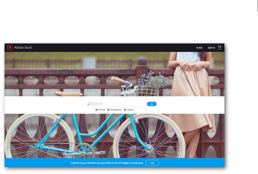
Adobe Stock
With Adobe Stock, you can purchase, access, and manage high-quality, high-resolution, royalty-free images directly
from Illustrator CC, Photoshop CC, InDesign CC, and other Adobe desktop apps. You can save images directly to
Creative Cloud Libraries. You can license an image immediately, or save a watermarked preview to use in a comp.
Thanks to Adobe CreativeSync, you can immediately access your images across your desktop and mobile devices, and
even share them with your team. When you're ready to use the non-watermarked version, you can license the image
for use directly in Illustrator.
For information on using Adobe Stock, see Using Adobe Stock .
For answers to questions about Adobe Stock service, see Adobe Stock Common Questions .
10x faster zoom, pan, scroll
Pan, zoom and scroll up to 10 times faster, thanks to Mercury Performance System enhancements that brings GPU
acceleration to both Mac and Windows.
Zoom is now animated, so you can quickly zoom in and out of your document by scrubbing left and right. You can also
click and hold the Zoom tool over a spot to dynamically zoom in.
Watch this video on the performance enhancements in Illustrator CC 2015 .
For more information, see the knowledgebase article on GPU Performance feature .
10x greater zoom magnification
Work with greater precision and make accurate and exact edits with the new 64,000% zoom level. Previously, the
maximum zoom achievable was 6,400%.
3
What's new
Last updated 6/5/2015
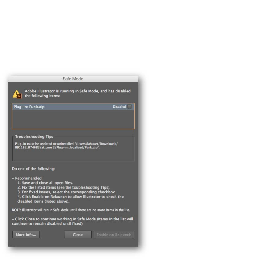
Safe Mode
Safe Mode is a new feature that enables Illustrator to launch even if there are fatal, crash-inducing files (for example,
corrupt fonts, out-of-date plug-ins, or incorrect drivers) in the system. You can choose to diagnose the cause of the
error. When the application starts after isolating and disabling crash-causing files, Illustrator is in Safe Mode.
The Safe Mode dialog provides you with information to diagnose and troubleshoot the problem area, thus providing
you with a way to fix any issues. When done, mark all issues resolved and enable Illustrator to relaunch in normal mode
at the next restart.
For more information, see Safe Mode.
Recover data in your files
Forgetting to periodically save your open projects can cause you to lose time and work if an improper shutdown
happens before you could save your files. An improper shutdown could be Illustrator crashing, an operating system
error, or a power outage.
When such an error occurs, simply relaunch Illustrator and your work can be restored. If the cause of error is a damaged
font or incompatible driver or plug-in, Illustrator provides you with options to diagnose the issue and fix any errors.
For more information, see the article on Recover document data after a crash.
4
What's new
Last updated 6/5/2015
Integration with Creative Cloud mobile apps
Illustrator no longer requires you to be at your studio or office to be creative and productive. Keep your ideas,
discoveries, and thoughts constantly evolving and rapidly developing into awesome artwork and projects – all while on-
the-go – using Adobe’s mobile apps. A few examples:
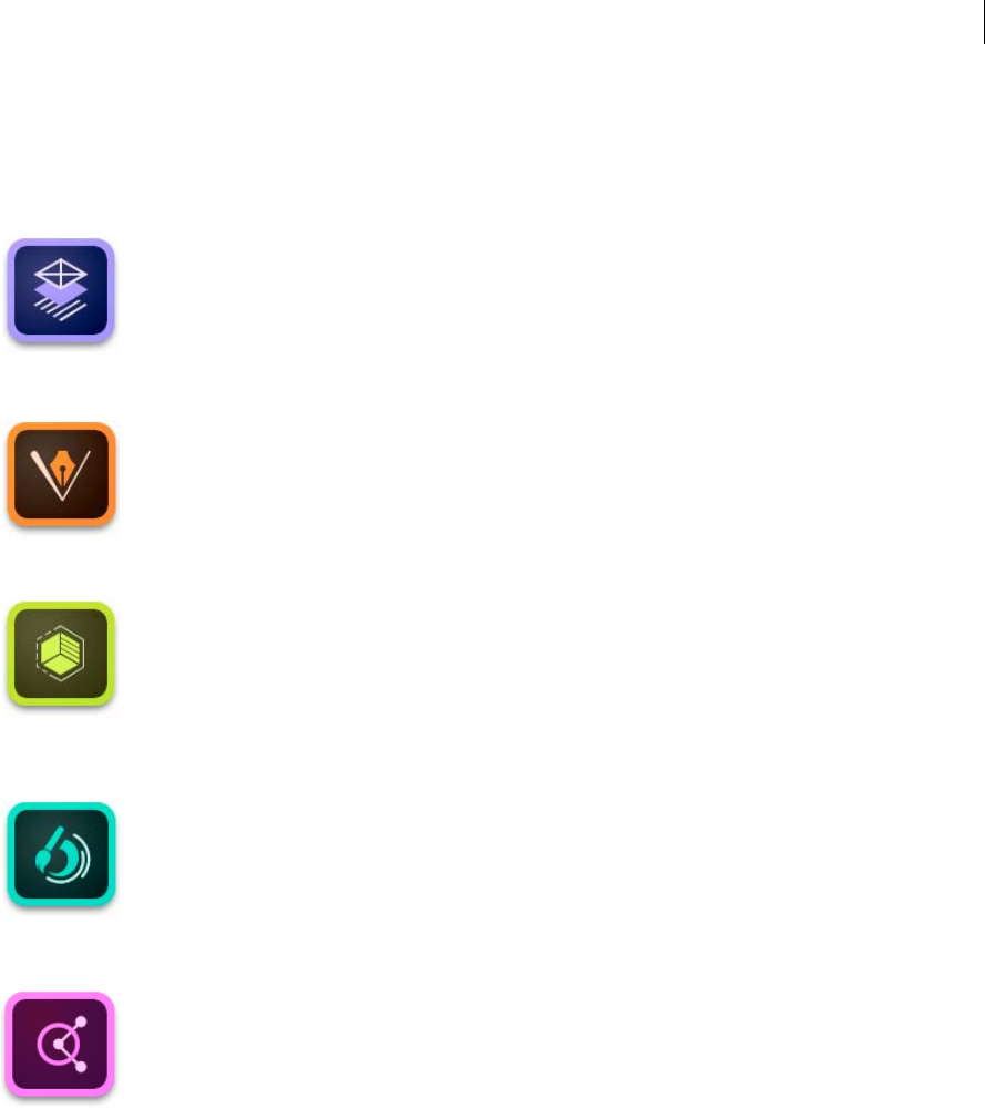
Adobe Comp CC. Pull creative assets into Comp from your or your team’s shared Creative Cloud Libraries, then
instantly send your layouts to Illustrator. All your text, images, and graphics are live and fully editable.
Comp for iPad is available as a free download through the iTunes App Store.
Illustrator Draw. Create with your favorite vector drawing tools and features in a streamlined, modern interface.
You can draw lines, shapes, and free-form illustrations and with ten drawing layers and a photo layer. Creative
Cloud connectivity makes it easy to apply finishing touches in Illustrator CC or Photoshop CC.
Draw for iOS (iPhone, iPad, and iPad Mini) is available as a free download through the iTunes App Store
Adobe Shape CC. Photograph any object, design, or shape - and convert them into vector shapes in a few simple
steps. Store the resulting vectors in your Creative Cloud Libraries, and access them or refine them in Illustrator or
Photoshop.
Shape is available as a free download through the iTunes App Store and Google Play.
Adobe Brush CC. Use your iPad or iPhone to design beautiful, high-quality brushes from photos of anything that
inspires you. Save the brushes to your Creative Cloud Library and access them anywhere across Photoshop and
Illustrator!
Adobe Brush for iOS is available as a free download through the iTunes App Store and Google Play.
Adobe Color. Capture inspiring color combinations wherever you see them, in a fun and intuitive way. Simply
point the camera at something colorful and Adobe Color CC will instantly extract a series of colors.
Color for iOS (iPad, iPad Mini, iPhone, and iPod Touch) and Android is available as a free download through the
iTunes App Store and Google Play.
5
What's new
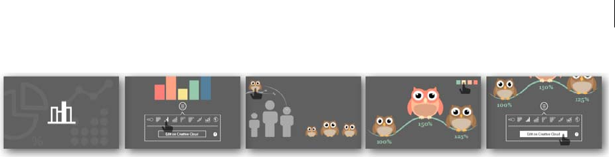
Creative Cloud Charts (Preview)
Create graphs and charts from your data, using a simple, intuitive interface. Replace the default chart elements with
Illustrator vector graphics, and generate custom infographics, charts, and graphs. Use the browser-based interface to
quickly import data from your data files (.csv, .xls, .xlsx type files) and transform it into graphical representations. Use
Creative Cloud Libraries to share and use charts across projects and teams.
For more information, see Creative Cloud Charts (Preview).
Note: The Creative Cloud Charts (Preview) feature is enabled for all US (en_US) and UK (en_GB) Illustrator CC 2015
users.
GPU Performance
The 2015 release of Illustrator CC now better leverages the power of GPU to render content — which means faster
artwork rendering during zooming, panning, and scrolling. Each art type has been rewritten, so that it is computed and
rendered on the graphic processor. GPU enhancements are now available for Macs as well.
For more information, see the knowledgebase article on GPU Performance feature .
Touch workspace enhancements
Image Place You can now place an image (raster format) in the Touch workspace.
Distribute Options in Align Panel Previously, the Align panel did not have distribute options. Now, users can use the
two most popular align options from the align panel in the Touch workspace.
Tools reset Some tools in the Touch workspace have options like Draw from Center in Shape Tools, Merge and Subtract
Mode in Shape Builder. When switching between tools, one often forgot that an option was enabled when the same tool
was used previously. This affected productivity. Now, whenever there is a change of tools in the Touch workspace, the
active tool becomes available with the default settings.
Flip buttons for Variable Width Stroke options in the Touch workspace have a way to apply variable-width profiles to
paths, to make them look organic. Variable-width profiles are based on an arbitrary direction (one end - thin, the other
- thick). With the introduction of Flip buttons for these profiles, you now have better control on variable-width profiles
they use on paths in the Touch workspace
Last updated 6/5/2015

6
What's new
Last updated 6/5/2015
Tool enhancements
Curvature tool
Separate Rubber-banding Preference Rubber-banding preferences for the Pen and Curvature tools were tied to one
single value. The Illustrator team found that users preferred this value for the Curvature tool than for the Pen tool. Now,
both tools have separate values so that users have independent control over both tools.
Joining two paths The Curvature tool only worked with one path at a time - the active path. Now it is possible to join
a non-active path and continue working with it.
Start from either ends The Curvature tool had a fixed direction of working - even when a path was deselected and
reselected. Now for any open path, users can pick which end of the path to start working with. To be able to draw from
the other end-point, click and move the end-point slightly, and then continue drawing with the Curvature tool.
Shape Builder Tool: free-form Mode
The Shape Builder tool previously had linear feedback for Merge and Subtract options. Now, this tool can be used in
free-form mode. This mode is on by default. To get back to older, straight-line feedback, change the option in the tool's
options dialog. This is available in the Touch workspace as well.
Pencil Tool: Turn off auto-close
Although most users loved auto-close in Pencil Tool, there were some users who required path closure to occur at their
own discretion. The Pencil tool options dialog now has an option to control auto-closing.
Other important enhancements
Copy-paste hexadecimal values
When copying a hexadecimal value from other applications, users most likely pick the '#' symbol with the actual
hexadecimal value. The Hex field in Color panel only accepts pure hexadecimal values, and repeated, precise copy-
paste actions are required until only the right value is pasted. Now, this field automatically removes pasted characters
that are not part of the hexadecimal value. This makes it much easier to bring in hexadecimal values using a copy-paste
workflow.
Used Swatches on gradient stops
There are times when gradient stops are defined by a swatch color. Previously, it was not possible to identify this swatch
when the Color Stop was double-clicked. Now, if a color swatch is used on the Color Stop, it retains the information
and highlights the swatch used when the Color Stop is accessed.
Copy-paste patterns
Patterns are based on tile origins that are specific to the document. So, even with the 'Transform Patterns' option on,
copy-pasting objects filled with patterns used to show a different tiling pattern if the document size was different. Now,
with this option on, the appearance of a pattern will be same irrespective of the document size the pattern is pasted in.

7
Last updated 6/5/2015
Chapter 2: Workspace
Workspace basics
Workspace overview
You create and manipulate your documents and files using various elements, such as panels, bars, and windows. Any
arrangement of these elements is called a workspace. The workspaces of the different applications in Creative Cloud
look similar so that you can move between the applications easily. You can also adapt each application to the way you
work by selecting from several preset workspaces or by creating one of your own.
Although the default workspace layout varies in different products, you manipulate the elements much the same way
in all of them.
•The Application bar across the top contains a workspace switcher, menus (Windows only), and other application
controls. On the Mac for certain products, you can show or hide it using the Window menu.
•The Tools panel contains tools for creating and editing images, artwork, page elements, and so on. Related tools are
grouped.
•The Control panel displays options for the currently selected tool. In Illustrator, the Control panel displays options
for the currently selected object. (In Adobe Photoshop® this is known as the Options bar. In Adobe Flash®, Adobe
Dreamweaver®, and Adobe Fireworks® this is known as the Property Inspector and includes properties of the
currently selected element.)
•The Document window displays the file you’re working on. Document windows can be tabbed and, in certain cases,
grouped and docked.
•Panels help you monitor and modify your work. Examples include the Timeline in Flash, the Brush panel in
Illustrator, the Layers panel in Adobe Photoshop®, and the CSS Styles panel in Dreamweaver. Panels can be grouped,
stacked, or docked.
•The Application frame groups all the workspace elements in a single, integrated window that lets you treat the
application as a single unit. When you move or resize the Application frame or any of its elements, all the elements
within it respond to each other so none overlap. Panels don’t disappear when you switch applications or when you
accidentally click out of the application. If you work with two or more applications, you can position each
application side by side on the screen or on multiple monitors.
If you are using a Mac and prefer the traditional, free-form user interface, you can turn off the Application frame.
In Adobe Illustrator®, for example, select Window > Application Frame to toggle it on or off. (In Flash, the
Application frame is on permanently for Mac, and Dreamweaver for Mac does not use an Application frame.)
8
Workspace
Last updated 6/5/2015
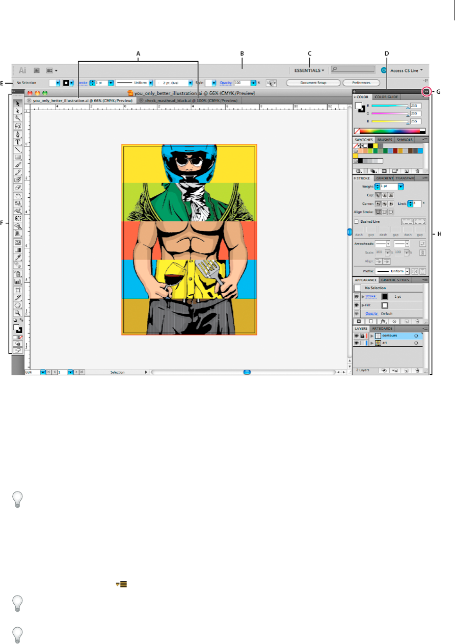
A Tabbed D ocume nt win dows B Application bar C Workspace switcher D Panel title bar E Control panel F Tools panel G Collapse To Icons
button H Four panel groups in vertical dock
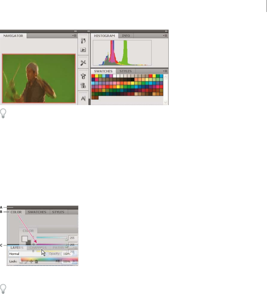
Hide or show all panels
•(Illustrator, Adobe InCopy®, Adobe InDesign®, Photoshop, Fireworks)To hide or show all panels, including the Tools
panel and Control panel, press Tab.
•(Illustrator, InCopy, InDesign, Photoshop) To hide or show all panels except the Tools panel and Control panel,
press Shift+Tab.
Tip: You can temporarily display hidden panels if Auto-Show Hidden Panels is selected in Interface preferences. It’s
always on in Illustrator. Move the pointer to the edge of the application window (Windows®) or to the edge of the
monitor (Mac OS®) and hover over the strip that appears.
•(Flash, Dreamweaver, Fireworks) To hide or show all panels, press F4.
Display panel options
❖Click the panel menu icon in the upper-right corner of the panel.
Tip: You can open a panel menu even when the panel is minimized.
Tip: In Photoshop, you can change the font size of the text in panels and tool tips. In the Interface preferences, choose
a size from the UI Font Size menu.

9
Workspace
Last updated 6/5/2015
(Illustrator) Adjust panel brightness
❖ In User Interface preferences, move the Brightness slider. This control affects all panels, including the Control panel.
Reconfigure the Tools panel
You can display the tools in the Tools panel in a single column, or side by side in two columns. (This feature is not
available in the Tools panel in Fireworks and Flash.)
In InDesign and InCopy, you also can switch from single-column to double-column (or single-row) display by setting
an option in Interface preferences.
❖ Click the double arrow at the top of the Tools panel.
Search For Help box
Use the Search For Help box on the right side of the Application bar to search for Help topics and online content. If you
have an active Internet connection, you can access all content on the Community Help website. If you search for Help
without an active Internet connection, search results are limited to Help content that is included with Illustrator.
1In the search box, type the name of the item on which you want to search (such as a feature, application, or tool).
2Press Enter.
All topics available from the Community Help center appear in a separate browser window.
About screen modes
You can change the visibility of the illustration window and menu bar using the mode options at the bottom of the Tools
panel. To access panels when in Full Screen Mode, position the cursor at the left or right edge of the screen and the
panels will pop up. If you’ve moved them from their default locations, you can access them from the Window menu.
You can choose one of the following modes:
•Normal Screen Mode displays artwork in a standard window, with a menu bar at the top and scroll bars on the
sides.
•Full Screen Mode With Menu Bar displays artwork in a full-screen window, with a menu bar at the top and scroll
bars.
•Full Screen Mode displays artwork in a full-screen window, with no title bar or menu bar.
Using the status bar
The status bar appears at the lower-left edge of the illustration window. It displays any of the following:
•current zoom level
•current tool in use
•current artboard in use
•navigation controls for multiple artboards
•date and time
•number of undos and redos available
•document color profile
•status of a managed file
10
Workspace
Last updated 6/5/2015
Click the status bar to do any of the following:
•Change the type of information displayed in the status bar by selecting an option from the Show submenu.
•Show the current file in Adobe Bridge by choosing Reveal In Bridge.
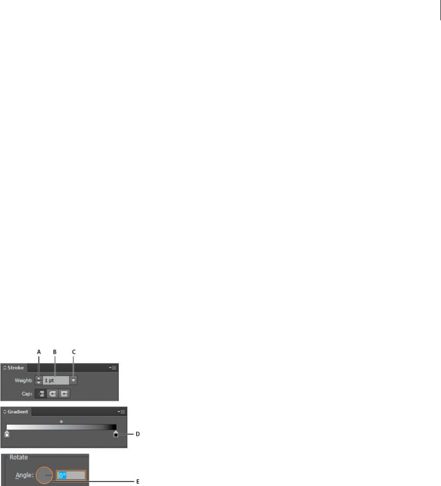
Enter values in panels and dialog boxes
You enter values using the same methods in all panels and dialog boxes. You can also perform simple math in any box
that accepts numeric values. For example, if you want to move a selected object 3 units to the right using the current
measurement units, you don’t have to work out the new horizontal position—simply type +3 after the current value in
the Transform panel.
Enter a value in a panel or dialog box
❖Do any of the following:
•Type a value in the box, and press Enter or Return.
•Drag the slider.
•Drag the dial.
•Click the arrow buttons in the panel to increase or decrease the value.
•Click in the box and then use the Up Arrow key and Down Arrow key on the keyboard to increase or decrease
the value. Hold down Shift and click an arrow key to magnify the increase rate or decrease rate.
•Select a value from the menu associated with the box.
Calculate values in a panel or dialog box
1In a text box that accepts numerical values, do one of the following:
•To replace the entire current value with a mathematical expression, select the entire current value.
•To use the current value as part of a mathematical expression, click before or after the current value.
2Type a simple mathematical expression using a single mathematical operator, such as + (plus), - (minus), x
(multiplication), / (division), or % (percent).
For example, 0p0 + 3 or 5mm + 4. Similarly, 3cm * 50% equals 3 centimeters multiplied by 50%, or 1.50 cm, and
50pt + 25% equals 50 points plus 25% of 50 points, or 62.5 points.
3Press Enter or Return to apply the calculation.
11
Workspace
Last updated 6/5/2015
Control panel overview
The Control panel offers quick access to options related to the objects you select. By default, the Control panel is docked
at the top of the workspace.
Options displayed in the Control panel vary depending on the type of object or tool you select. For example, when you
select a text object, the Control panel displays text-formatting options in addition to options for changing the color,
placement, and dimensions of the object. When a selection tool is active, you can access Document Setup and
Preferences from the Control panel.
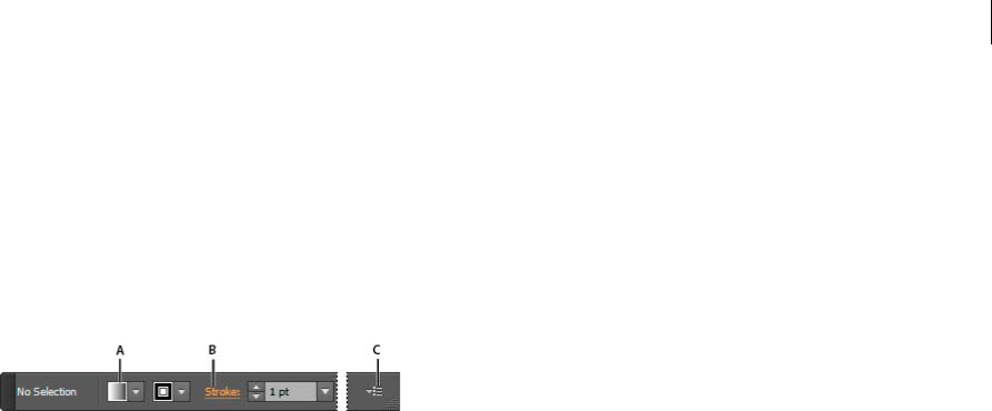
A Hidden options B Link to another panel C Panel menu
When text in the Control panel is blue and underlined, you can click the text to display a related panel or dialog box.
For example, click the word Stroke to display the Stroke panel.
Change the kinds of controls that appear in the Control panel
❖Select or deselect options in the Control panel menu.
Open and close a panel or dialog box from the Control panel
1Click a blue underlined word to open its associated panel or dialog box.
2Click anywhere outside of the panel or dialog box to close it.
Dock the Control panel at the bottom of the workspace
❖Choose Dock To Bottom from the Control panel menu.
Convert the Control panel to a floating panel
❖Drag the gripper bar (located on the left edge of the panel) away from its current position.
To redock the Control panel, drag the gripper bar to the top or bottom of the application window (Windows) or
screen (Mac OS).
More Help topics
Work with Adobe Bridge
Customizing the workspace
Customizing the workspace
Manage windows and panels
You can create a custom workspace by moving and manipulating Document windows and panels. You can also save
workspaces and switch among them. For Fireworks, renaming custom workspaces can lead to unexpected behavior.
12
Workspace
Last updated 6/5/2015
Note: The following examples use Photoshop for demonstration purposes. The workspace behaves the same in all the
products.
Rearrange, dock, or float document windows
When you open more than one file, the Document windows are tabbed.
•To rearrange the order of tabbed Document windows, drag a window’s tab to a new location in the group.
•To undock (float or untab) a Document window from a group of windows, drag the window’s tab out of the group.
note: In Photoshop you can also choose Window > Arrange > Float in Window to float a single Document window, or
Window > Arrange > Float All In Windows to float all of the Document windows at once. See tech note kb405298 for
more information.
note: Dreamweaver does not support docking and undocking Document windows. Use the Document window’s
Minimize button to create floating windows (Windows), or choose Window > Tile Vertically to create side-by-side
Document windows. Search “Tile Vertically” in Dreamweaver Help for more information on this topic. The workflow
is slightly different for Macintosh users.
•To dock a Document window to a separate group of Document windows, drag the window into the group.
•To create groups of stacked or tiled documents, drag the window to one of the drop zones along the top, bottom, or
sides of another window. You can also select a layout for the group by using the Layout button on the Application bar.
note: Some products do not support this functionality. However, your product may have Cascade and Tile commands
in the Window menu to help you lay out your documents.
•To switch to another document in a tabbed group when dragging a selection, drag the selection over the document’s
tab for a moment.
note: Some products do not support this functionality.
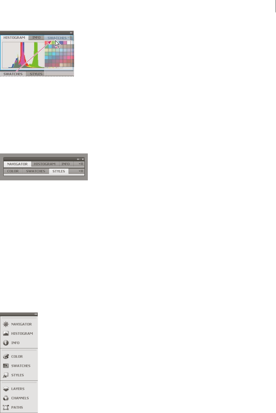
Dock and undock panels
A dock is a collection of panels or panel groups displayed together, generally in a vertical orientation. You dock and
undock panels by moving them into and out of a dock.
•To dock a panel, drag it by its tab into the dock, at the top, bottom, or in between other panels.
•To dock a panel group, drag it by its title bar (the solid empty bar above the tabs) into the dock.
•To remove a panel or panel group, drag it out of the dock by its tab or title bar. You can drag it into another dock or
make it free-floating.
13
Workspace
Last updated 6/5/2015
You can prevent panels from filling all the space in a dock. Drag the bottom edge of the dock up so it no longer meets
the edge of the workspace.
Move panels
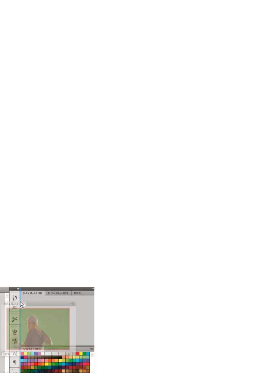
As you move panels, you see blue highlighted drop zones, areas where you can move the panel. For example, you can
move a panel up or down in a dock by dragging it to the narrow blue drop zone above or below another panel. If you
drag to an area that is not a drop zone, the panel floats freely in the workspace.
Note: The position of the mouse (rather than the position of the panel), activates the drop zone, so if you can’t see the drop
zone, try dragging the mouse to the place where the drop zone should be.
•To move a panel, drag it by its tab.
•To move a panel group, drag the title bar.
A Title bar B Tab C Drop zone
Press Ctrl (Windows) or Command (Mac OS) while moving a panel to prevent it from docking. Press Esc while moving
the panel to cancel the operation.
Add and remove panels
If you remove all panels from a dock, the dock disappears. You can create a dock by moving panels to the right edge of
the workspace until a drop zone appears.
•To remove a panel, right-click (Windows) or Control-click (Mac) its tab and then select Close, or deselect it from
the Window menu.
•To add a panel, select it from the Window menu and dock it wherever you want.
Manipulate panel groups
•To move a panel into a group, drag the panel’s tab to the highlighted drop zone in the group.
14
Workspace
Last updated 6/5/2015
•To rearrange panels in a group, drag a panel’s tab to a new location in the group.
•To remove a panel from a group so that it floats freely, drag the panel by its tab outside the group.
•To move a group, drag the title bar (the area above the tabs).
Stack floating panels
When you drag a panel out of its dock but not into a drop zone, the panel floats freely. The floating panel allows you to
position it anywhere in the workspace. You can stack floating panels or panel groups so that they move as a unit when
you drag the topmost title bar.
•To stack floating panels, drag a panel by its tab to the drop zone at the bottom of another panel.
•To change the stacking order, drag a panel up or down by its tab.
note: Be sure to release the tab over the narrow drop zone between panels, rather than the broad drop zone in a title bar.
•To remove a panel or panel group from the stack, so that it floats by itself, drag it out by its tab or title bar.
Resize panels
•To minimize or maximize a panel, panel group, or stack of panels, double-click a tab. You can also double-click the
tab area (the empty space next to the tabs).
•To resize a panel, drag any side of the panel. Some panels, such as the Color panel in Photoshop, cannot be resized
by dragging.
Collapse and expand panel icons
You can collapse panels to icons to reduce clutter on the workspace. In some cases, panels are collapsed to icons in the
default workspace.
15
Workspace
Last updated 6/5/2015
•To collapse or expand all panel icons in a column, click the double arrow at the top of the dock.
•To expand a single panel icon, click it.
•To resize panel icons so that you see only the icons (and not the labels), adjust the width of the dock until the text
disappears. To display the icon text again, make the dock wider.
•To collapse an expanded panel back to its icon, click its tab, its icon, or the double arrow in the panel’s title bar.
Tip: In some products, if you select Auto-Collapse Icon Panels from the Interface or User Interface Options
preferences, an expanded panel icon collapses automatically when you click away from it.
•To add a floating panel or panel group to an icon dock, drag it in by its tab or title bar. (Panels are automatically
collapsed to icons when added to an icon dock.)
•To move a panel icon (or panel icon group), drag the icon. You can drag panel icons up and down in the dock, into
other docks (where they appear in the panel style of that dock), or outside the dock (where they appear as floating
icons).
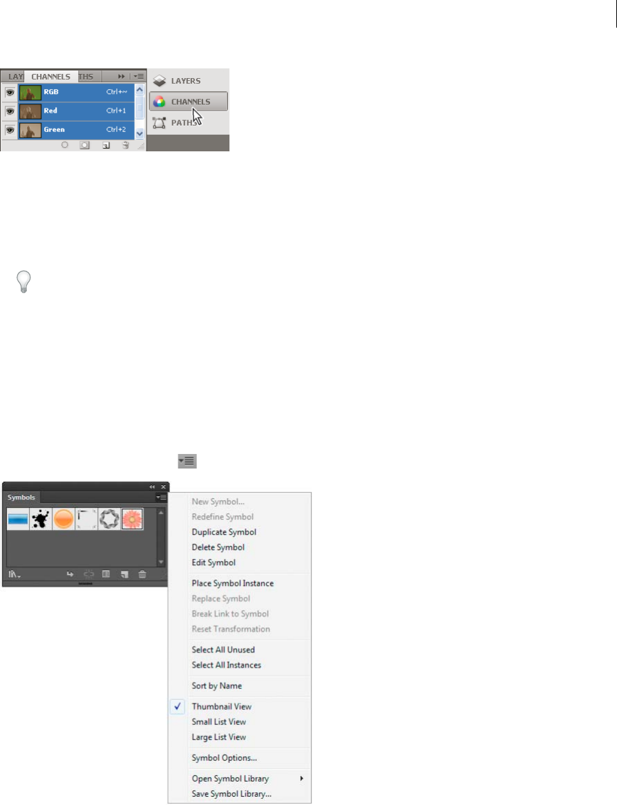
Use panel menus
Access the panel menus using the icon on the upper-right corner of the panel.
Rename or duplicate a workspace
1Choose Window > Workspace > Manage Workspaces.
2Do any of the following, and then click OK:
•To rename a workspace, select it, and edit the text.

16
Workspace
Last updated 6/5/2015
•To duplicate a workspace, select it, and click the New button.
For a video on customizing the workspace based on different workflows, see www.adobe.com/go/vid0032_en.
Save and switch workspaces
By saving the current size and position of panels as a named workspace, you can restore that workspace even if you
move or close a panel. The names of saved workspaces appear in the workspace switcher in the Application bar.
Save a custom workspace
1With the workspace in the configuration you want to save, do one of the following:
•(Illustrator) Choose Window > Workspace > Save Workspace.
•(Photoshop, InDesign, InCopy) Choose Window > Workspace > New Workspace.
•(Dreamweaver) Choose Window > Workspace Layout > New Workspace.
•(Flash) Choose New Workspace from the workspace switcher in the Application bar.
•(Fireworks) Choose Save Current from the workspace switcher in the Application bar.
2Type a name for the workspace.
3(Photoshop, InDesign) Under Capture, select one or more options:
Panel Locations Saves the current panel locations (InDesign only).
Keyboard shortcuts Saves the current set of keyboard shortcuts (Photoshop only).
Menus or Menu Customization Saves the current set of menus.
Display or switch workspaces
❖Select a workspace from the workspace switcher in the Application bar.
In Photoshop, you can assign keyboard shortcuts to each workspace to navigate among them quickly.
Delete a custom workspace
•Select Manage Workspaces from the workspace switcher in the Application bar, select the workspace, and then click
Delete. (The option is not available in Fireworks.)
•(Photoshop, InDesign, InCopy) Select Delete Workspace from the workspace switcher.
•(Illustrator) Choose Window > Workspace > Manage Workspaces, select the workspace, and then click the Delete
icon.
•(Photoshop, InDesign) Choose Window > Workspace >Delete Workspace, select the workspace, and then click
Delete.
Restore the default workspace
1Select the Default or Essentials workspace from the workspace switcher in the application bar. For Fireworks, see
the article http://www.adobe.com/devnet/fireworks/articles/workspace_manager_panel.html.
Note: In Dreamweaver, Designer is the default workspace.
2For Fireworks (Windows), delete these folders:Wi nd ow s
Vista\\Users\<username>\AppData\Roaming\Adobe\Fireworks CS4\ Windows XP\\Documents and
Settings\<username>\Application Data\Adobe\Fireworks CS4

17
Workspace
Last updated 6/5/2015
3(Photoshop, InDesign, InCopy) Select Window > Workspace > Reset [Workspace Name].
(Photoshop) Restore a saved workspace arrangement
In Photoshop, workspaces automatically appear as you last arranged them, but you can restore the original, saved
arrangement of panels.
•To restore an individual workspace, choose Window > Workspace > Reset Workspace Name.
•To restore all the workspaces installed with Photoshop, click Restore Default Workspaces in the Interface
preferences.
To rearrange the order of workspaces in the application bar, drag them.
Tools
Tools panel overview
The first time you start the application, the Tools panel appears at the left side of the screen. You can move the Tools
panel by dragging its title bar. You can also show or hide the Tools panel by choosing Window > Tools.
You use tools in the Tools panel to create, select, and manipulate objects in Illustrator. Some tools have options that
appear when you double-click a tool. These include tools that let you use type, and select, paint, draw, sample, edit, and
move images.
You can expand some tools to show hidden tools beneath them. A small triangle at the lower-right corner of the tool
icon signals the presence of hidden tools. To see the name of a tool, position the pointer over it.
You can also use the Tools panel to change the drawing mode from Draw Normal to Draw Behind or Draw Inside.
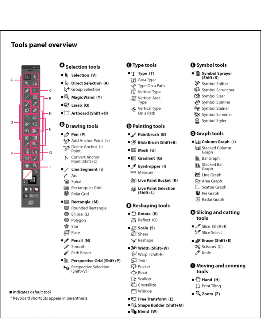
18
Workspace
Last updated 6/5/2015
View hidden tools
❖Hold down the mouse button on the visible tool.
View tool options
❖Double-click a tool in the Tools panel.
Move the Tools panel
❖Drag its title bar.
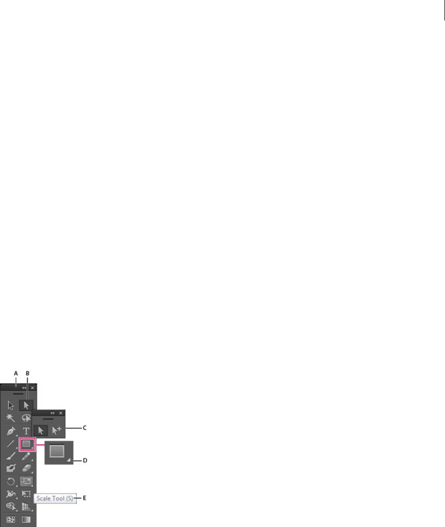
19
Workspace
Last updated 6/5/2015
View the Tools panel in double-stack or single-column
❖Click the double-arrow on the title bar to toggle between double-stack and single-column view of the Tools panel.
Hide the Tools panel
❖Choose Window > Tools.
Tear off hidden tools into a separate panel
❖Drag the pointer over the arrow at the end of the hidden tools panel and release the mouse button.
Close a separate tool panel
❖Click the close button on the panel’s title bar. The tools return to the Tools panel.
Select a tool
❖Do one of the following:
•Click a tool in the Tools panel. If there is a small triangle at a tool’s lower-right corner, hold down the mouse
button to view the hidden tools, and then click the tool you want to select.
•Hold down Alt (Windows) or Option (Mac OS), and then click a tool to cycle through and select hidden tools.
•Press the tool’s keyboard shortcut. The keyboard shortcut is displayed in its tool tip. For example, you can select
the Move tool by pressing the V key.
Tip: To hide tool tips, choose Edit > Preferences > General (Windows) or Illustrator > Preferences > General
(Mac OS), and deselect Show Tool Tips.
A Tools panel B Active tool C Tear off panel with hidden tools D Hidden tool triangle E Tool name and shortcut
Change tool pointers
The mouse pointer for most tools matches the tool’s icon. Each pointer has a different hotspot, where an effect or action
begins. With most tools, you can switch to precise cursors, which appear as cross hairs centered around the hotspot,
and provide for greater accuracy when working with detailed artwork.
❖Choose Edit > Preferences > General (Windows) or Illustrator > Preferences > General (Mac OS), and select Use
Precise Cursors. Alternatively, press Caps Lock on the keyboard.
More Help topics
Tool galleries
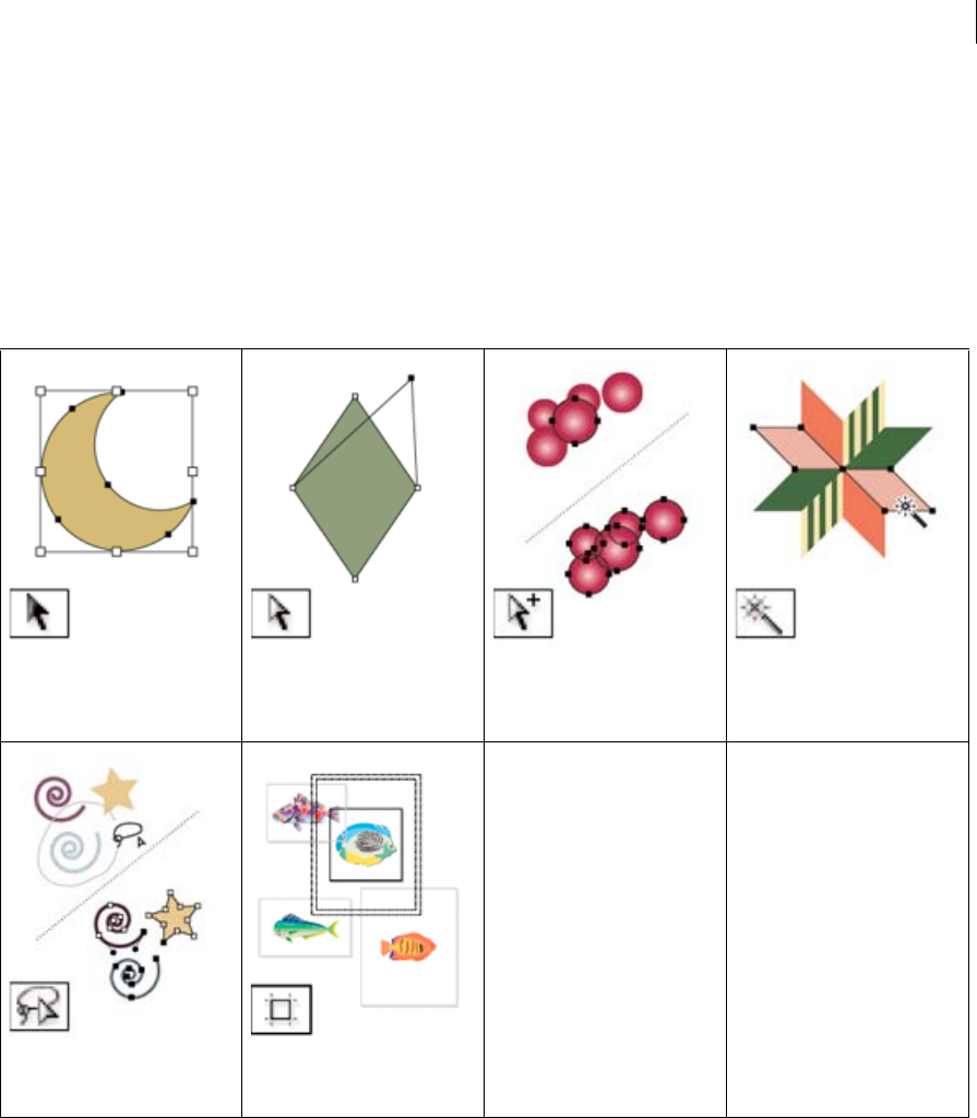
20
Workspace
Last updated 6/5/2015
Tool galleries
Illustrator provides many tools for creating and manipulating your artwork. These galleries provide a quick visual
overview for each tool.
Selection tool gallery
Illustrator provides the following selection tools:
Drawing tool gallery
Illustrator provides the following drawing tools:
The Selection tool (V) selects entire
objects. See Select objects with the
Selection tool.
The Direct Selection tool (A) selects
points or path segments within
objects. See Select paths, segments,
and anchor points.
The Group Selection tool selects
objects and groups within groups.
See Select objects and groups with
the Group Selection tool.
The Magic Wand tool (Y) selects
objects with similar attributes. See
Select objects with the Magic Wand
tool.
The Lasso tool (Q) selects points or
path segments within objects. See
Select objects with the Lasso tool.
The Artboard tool creates separate
artboards for printing or export.
See Create an artboard.
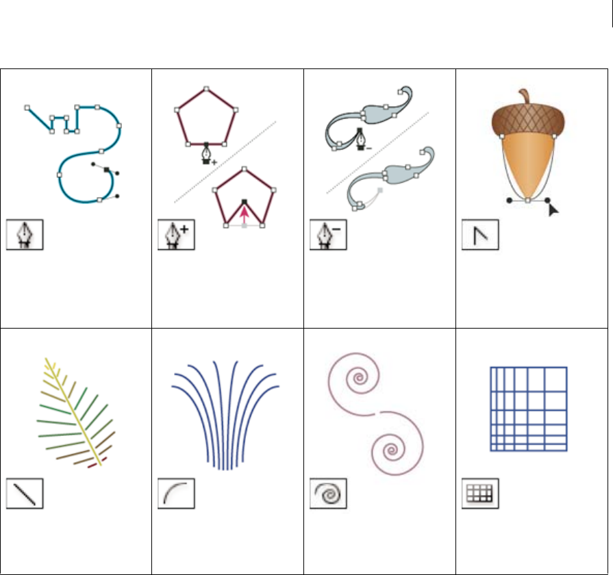
21
Workspace
Last updated 6/5/2015
The Pen tool (P) draws straight and
curved lines to create objects. See
Drawing with the Pen tool.
The Add Anchor Point tool (+) adds
anchor points to paths. See Adding
and deleting anchor points.
The Delete Anchor Point tool (-)
deletes anchor points from paths.
See Adding and deleting anchor
points.
The Convert Anchor Point tool
(Shift+C) changes smooth points to
corner points and vice versa. See
Convert between smooth points
and corner points.
The Line Segment tool (\) draws
individual straight line segments.
See Draw straight lines with the
Line Segment tool.
The Arc tool draws individual
concave or convex curve segments.
See Draw arcs.
The Spiral tool draws clockwise and
counterclockwise spirals. See Draw
spirals.
The Rectangular Grid tool draws
rectangular grids. See Draw
rectangular grids.
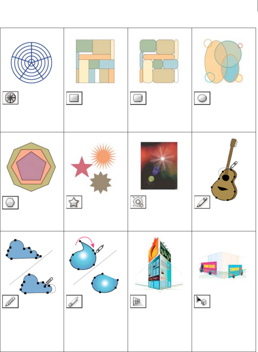
22
Workspace
Last updated 6/5/2015
Type tool gallery
Illustrator provides the following type tools:
The Polar Grid tool draws circular
chart grids. See Draw circular
(polar) grids.
The Rectangle tool (M) draws
squares and rectangles. See Draw
rectangles and squares.
The Rounded Rectangle tool draws
squares and rectangles with
rounded corners. See Draw
rectangles and squares.
The Ellipse tool (L) draws circles and
ovals. See Draw ellipses.
The Polygon tool draws regular,
multi-sided shapes. See Draw
polygons.
The Star tool draws stars. See Draw
stars.
The Flare tool creates lens-flare or
solar-flare-like effects. See Drawing
flares.
The Pencil tool (N) draws and edits
freehand lines. See Drawing with
the Pencil tool.
The Smooth tool smooths Bezier
paths. See Smooth paths.
The Path Eraser tool erases paths
and anchor points from the object.
See Erase artwork.
The Perspective Grid allows
creating and rendering artwork in
perspective. See About Perspective
Grid.
The Perspective Selection tool
allows you to bring objects, text,
and symbols in perspective, move
objects in perspective, move objects
in perpendicular to its current
direction. See About Perspective
Grid..
23
Workspace
Last updated 6/5/2015
Painting tool gallery
Illustrator provides the following painting tools:
The Type tool (T) creates individual
type and type containers and lets
you enter and edit type. See Enter
text in an area.
The Area Type tool changes closed
paths to type containers and lets
you enter and edit type within
them. See Enter text in an area.
The Type On A Path tool changes
paths to type paths, and lets you
enter and edit type on them. See
Creating type on a path .
The Vertical Type tool creates
vertical type and vertical type
containers and lets you enter and
edit vertical type. See Enter text in
an area.
The Vertical Area Type tool changes
closed paths to vertical type
containers and lets you enter and
edit type within them. See Enter text
in an area.
The Vertical Type On A Path tool
changes paths to vertical type
paths and lets you enter and edit
type on them. See Creating type on
a path .
24
Workspace
Last updated 6/5/2015
Reshaping tool gallery
Illustrator provides the following tools for reshaping objects:
The Paintbrush tool (B) draws
freehand and calligraphic lines, as
well as art, patterns, and bristle
brush strokes on paths. See Draw
paths and apply brush strokes
simultaneously.
The Mesh tool (U) creates and edits
meshes and mesh envelopes. See
Create mesh objects.
The Gradient tool (G) adjusts the
beginning and ending points and
angle of gradients within objects, or
applies a gradient to objects. See
Apply a gradient to an object.
The Eyedropper tool (I) samples and
applies color, type, and appearance
attributes, including effects, from
objects. See Copy appearance
attributes using the Eyedropper
tool.
The Live Paint Bucket tool (K) paints
faces and edges of Live Paint
groups with the current paint
attributes. See Paint with the Live
Paint Bucket tool.
The Live Paint Selection (Shift-
L)tool selects faces and edges
within Live Paint groups. See Select
items in Live Paint groups.
The Measure tool measures the
distance between two points. See
Measure the distance between
objects.
The Blob Brush tool (Shift-B)draws
paths that automatically expand
and merge calligraphic brush paths
that share the same color and are
adjacent in stacking order. See
Draw and merge paths with the
Blob Brush tool.
25
Workspace
Last updated 6/5/2015
The Rotate tool (R) rotates objects
around a fixed point. See Rotate
objects.
The Reflect tool (O) flips objects over
a fixed axis. See Reflect or flip
objects.
The Scale tool (S) resizes objects
around a fixed point. See Scale
objects.
The Shear tool skews objects
around a fixed point. See Shear
objects with the Shear tool.
26
Workspace
Last updated 6/5/2015
The Reshape tool adjusts selected
anchor points while keeping the
overall detail of the path intact. See
Stretch parts of a path without
distorting its overall shape.
The Free Transform tool (E) scales,
rotates, or skews a selection.
The Blend tool (W) creates a series
of objects blended between the
color and shape of multiple objects.
See Create blends.
The Width tool (Shift+W) allows
you to create a stroke with variable
width. See Using the Width tool.
The Warp tool (Shift+R) molds
objects with the movement of the
cursor (like molding clay, for
example). See Distort objects using
a liquify tool.
The Twirl tool creates swirling
distortions within an object. See
Distort objects using a liquify tool.
The Pucker tool deflates an object
by moving control points towards
the cursor. See Distort objects using
a liquify tool.
The Bloat tool inflates an object by
moving control points away from
the cursor. See Distort objects using
a liquify tool.
The Scallop tool adds random
curved details to the outline of an
object. See Distort objects using a
liquify tool.
The Crystallize tool adds random
spiked details to the outline of an
object. See Distort objects using a
liquify tool.
The Wrinkle tool adds wrinkle-like
details to the outline of an object.
See Distort objects using a liquify
tool.
The Shape Builder tool merges
simple shapes to create custom,
complex shapes. See Building new
shapes using the Shape Builder tool
.
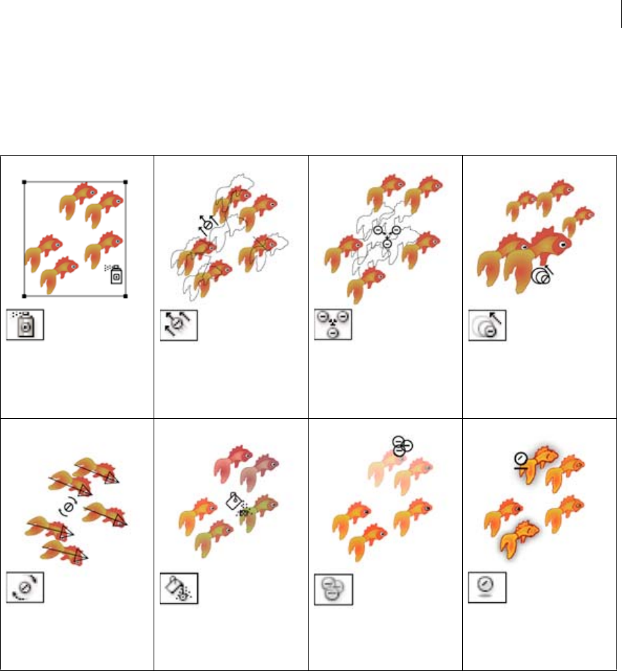
27
Workspace
Last updated 6/5/2015
Symbolism tool gallery
The symbolism tools let you create and modify sets of symbol instances. You create a symbol set using the Symbol
Sprayer tool. You can then use the other symbolism tools to change the density, color, location, size, rotation,
transparency, and style of the instances in the set.
Graph tool gallery
Illustrator provides nine graph tools, each one for creating a different type of graph. The type of graph you choose
depends on the information you want to communicate. See Create a graph.
The Symbol Sprayer tool (Shift+S)
places multiple symbol instances as
a set on the artboard. See Create
symbol sets.
The Symbol Shifter tool moves
symbol instances and change
stacking order. See Change
stacking order of symbol instances
in a set.
The Symbol Scruncher tool moves
symbol instances closer together or
farther apart. See Gather or scatter
symbol instances.
The Symbol Sizer tool resizes
symbol instances. See Resize
symbol instances.
The Symbol Spinner tool rotates
symbol instances. See Rotate
symbol instances.
The Symbol Stainer tool colorizes
symbol instances. See Stain symbol
instances.
The Symbol Screener tool applies
opacity to symbol instances. See
Adjust transparency of symbol
instances.
The Symbol Styler tool applies the
selected style to symbol instances.
See Apply a graphic style to symbol
instances.
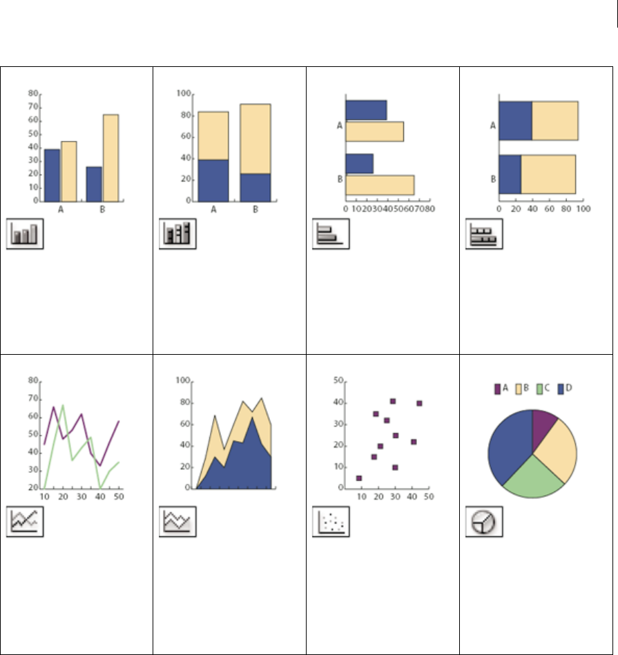
29
Workspace
Last updated 6/5/2015
The Column Graph tool (J) creates
graphs that compare values using
vertical columns.
The Stacked Column Graph tool
creates graphs that are similar to
column graphs, but stacks the
columns on top of one another,
instead of side by side. This graph
type is useful for showing the
relationship of parts to the total.
The Bar Graph tool creates graphs
that are similar to column graphs,
but positions the bars horizontally
instead of vertically.
The Stacked Bar Graph tool creates
graphs that are similar to stacked
column graphs, but stacks the bars
horizontally instead of vertically.
The Line Graph tool creates graphs
that use points to represent one or
more sets of values, with a different
line joining the points in each set.
This type of graph is often used to
show the trend of one or more
subjects over a period of time.
The Area Graph tool creates graphs
that are similar to line graphs, but
emphasizes totals as well as
changes in values.
The Scatter Graph tool creates
graphs that plot data points as
paired sets of coordinates along the
x and y axes. Scatter graphs are
useful for identifying patterns or
trends in data. They also can
indicate whether variables affect
one another.
The Pie Graph tool creates circular
graphs whose wedges represent the
relative percentages of the values
compared.
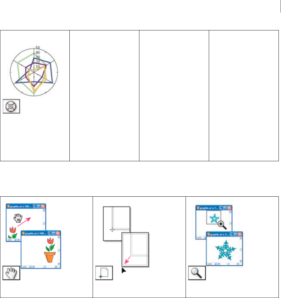
30
Workspace
Last updated 6/5/2015
Moving and zooming tool gallery
Illustrator provides the following tools for moving around in and controlling the view of the artboard:
More Help topics
Keys for selecting
Improved User Interface
The new user interface framework leverages performance enhancements and advantages like native 64-bit support to
render a cleaner interface, enabling a better user experience. Also, important additions and modifications to the user
interface and workflows make working with Illustrator an efficient experience.
The Radar Graph tool creates
graphs that compare sets of values
at given points in time or in
particular categories, and is
displayed in a circular format. This
type of graph is also called a web
graph.
The Hand
tool (H) moves the Illustrator artboard within
the illustration window.
The Print
Tiling tool adjusts the page grid to control where
artwork appears on the printed page.
The Zoom
tool (Z) increases and decreases the view
magnification in the illustration window.
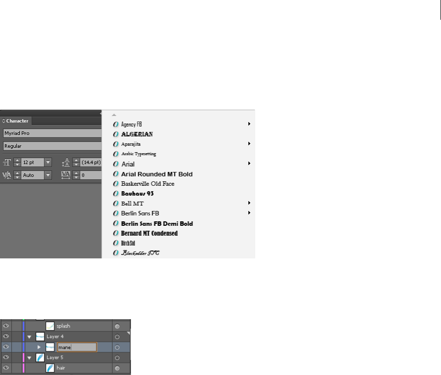
31
Workspace
Last updated 6/5/2015
Improved and efficient user interface
Efficient and flexible interface. The newer usability enhancements enable you to use fewer clicks and fewer steps to
achieve routine or frequent actions. For example, in the Character panel (Ctrl+T), the font list displays names in the
font style itself. You can quickly pick the font of your choice from the list.
Inline editing. Easily work with Layers, Actions, Swatches, Symbols, and other panels, with the ability to edit object
names directly in the panel. You no longer need an additional modal dialog for such routine actions. For example,
double-click the name of a layer in the Layers panel to switch to inline editing mode. Type the new name and press
Enter.
Quick-edit object attributes. In the user interface, values of object attributes are set through drop-down lists or text
fields. You can now quickly edit these fields by hovering your mouse pointer over a control, and scrolling the mouse
wheel. For example, to increase or decrease the weight of a stroke, hover the mouse pointer over the stroke weight
control, and scroll.
Dialog boxes. Buttons to commit an action or event are placed uniformly at the lower-right corner. Dialog boxes also
have full keyboard access.
Workspac es. New workspaces are task-based. A workspace can now 'remember' the state it was last left in, and then be
reset to default settings when necessary.
New icons. Updated to enhance usability, newer icons contribute to a better, more intuitive interface.
Cursors. Modifications have been done to make cursors larger and more precise.
User interface color and brightness
Illustrator, by default, is now available with a dark theme, which is in line with recent changes in other products like
Adobe Photoshop. This theme enables a a more pleasant visual experience, especially while working with rich colors
and designs.
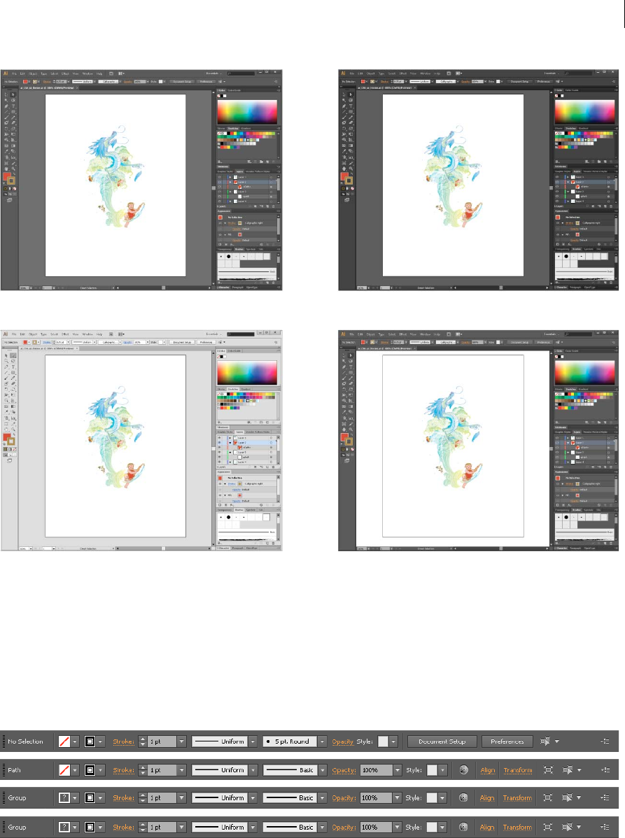
32
Workspace
Last updated 6/5/2015
You can easily vary the brightness of the user interface to a tone you prefer from the User Interface tab in the Preferences
dialog (Ctrl + K). Enable the Match User Interface Brightness option to set the tone of the canvas area to match the
brightness of the interface. If you prefer the classic Illustrator canvas color, you can set it to default to white.
For more information, view the video on user interface enhancements, by Lynda.com.
Panels
Control panel. Object controls that are used frequently are grouped and displayed together in the Control panel.
Grouping controls in this manner helps you work with objects faster and more systematically.
Transform panel. The Scale Strokes & Effects option has been included in the Transform panel and the Transform
Effect dialog.
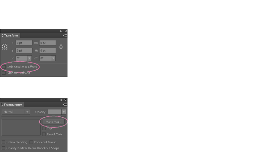
33
Workspace
Last updated 6/5/2015
Transparency panel. Masking features are now available in the Transparency panel. Use the Make Mask / Release
toggle switch to create opacity masks and work with them more easily.
Safe Mode
When you launch Adobe Illustrator, the necessary plug-ins, fonts, drivers, and other third-party elements that are
required to function properly are loaded. In the past, when Illustrator encountered an error, for example – a damaged
font, the application would crash and it was difficult to diagnose the cause of the problem.
Safe Mode is a new feature that:
•Enables Illustrator to start despite encountering fatal, crash-inducing fonts, plug-ins, or more.
•Determines the cause of a crash, prevents the particular file from loading with Illustrator, and provides a listing of
the problem-causing elements when Illustrator restarts
•Assists you in diagnosing and troubleshooting the problem-area, thus providing you with a way to fix any issues.
While running in Safe Mode, Illustrator functions normally, except that the disabled items will not be available for use
within Illustrator. For example, if a font has been found to be damaged, Illustrator will no longer display that font as an
available option to apply to text elements.
Safe Mode workflow
When you have crash-inducing elements in your Illustrator environment:
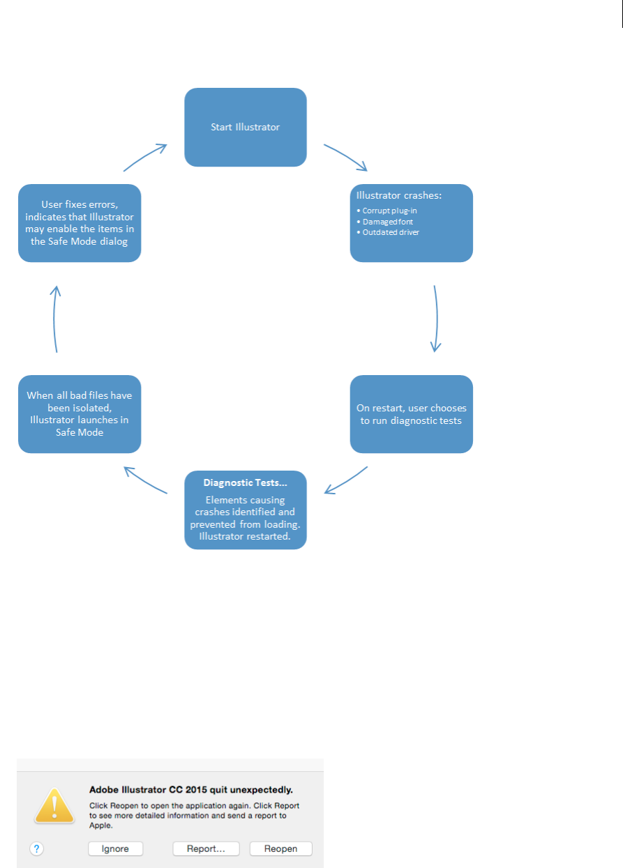
34
Workspace
Last updated 6/5/2015
Using Safe Mode
Note: This procedure assumes, at Step 1, that Illustrator has been functioning normally until now.
1Start Illustrator. If Illustrator detects a file that is corrupt or causes errors, the application exits.
2Do one of the following:
•Windows: Re-launch Illustrator.
•Mac: Choose Reopen.
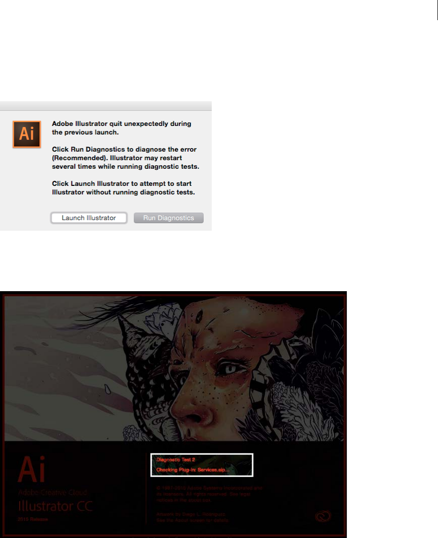
35
Workspace
Last updated 6/5/2015
3As Illustrator restarts, you can:
•Choose Run Diagnostics to switch Illustrator to Safe Mode, to help with troubleshooting the error.
•Choose Launch Illustrator to try to start Illustrator normally again.
4(This step may repeat multiple times) Illustrator restarts. If an error is found, the cause of the error (font, driver,
plug-in) is identified and disabled from obstructing Illustrator launch.
Note: This step is repeated for each crash-inducing file that Illustrator finds. Do not interrupt diagnostic tests.
5When all error-causing files have been isolated by the diagnostic steps and noted, Illustrator launches in Safe Mode.
6When Illustrator starts, the Safe Mode dialog displays a list of all the plug-ins, fonts, or drivers that are causing
Illustrator to crash. Choose from Step 7 or Step 8.
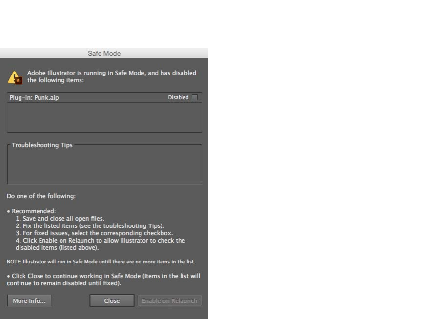
36
Workspace
Last updated 6/5/2015
7(Option 1 of 2) To fix errors:
aClick a row in the list.
bCheck the Troubleshooting Tips area for information.
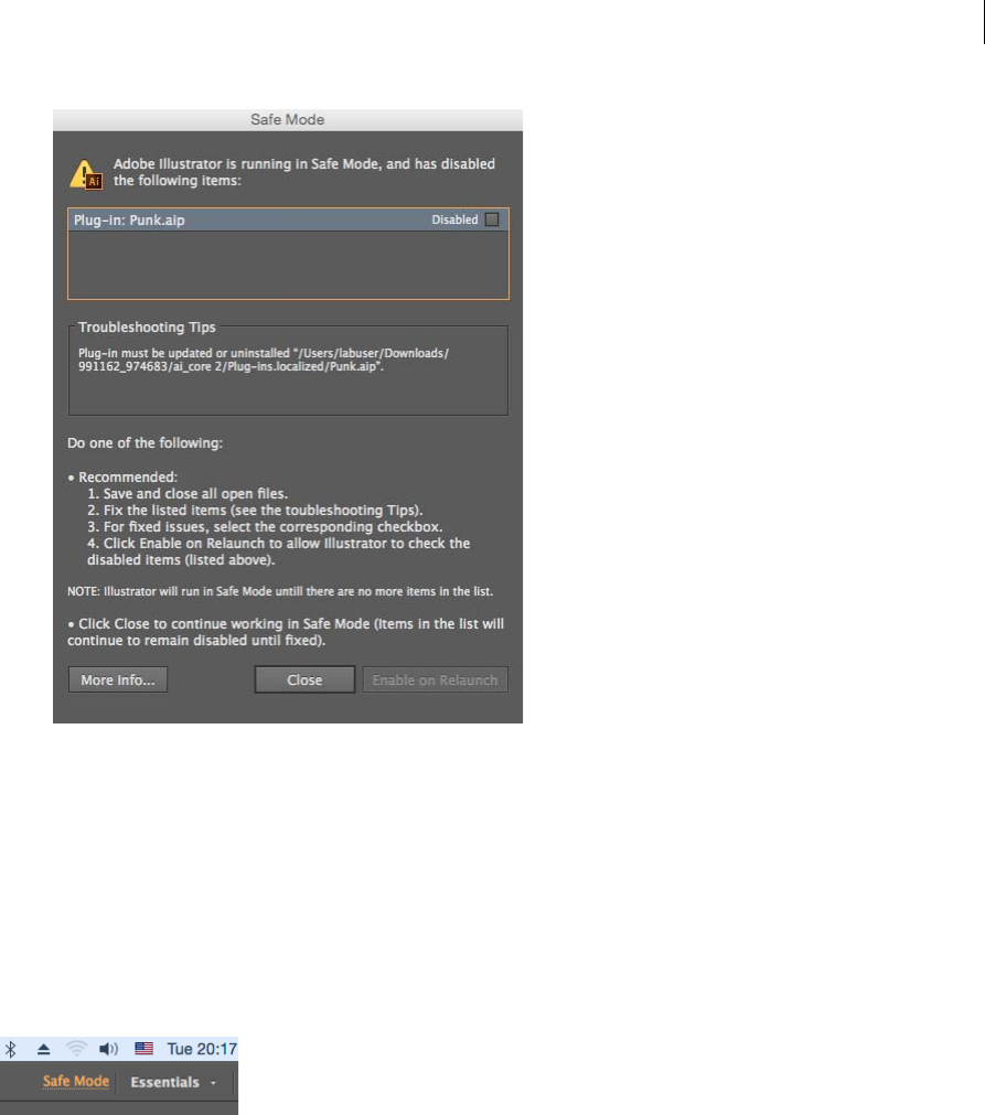
37
Workspace
Last updated 6/5/2015
cFollow the tips provided and replace a font, or update a plug-in, or uninstall error-causing items, as preferred.
dIf you believe the error has been fixed, select the checkbox available for each row.
eClick Enable on Re-launch, save your work, and restart Illustrator.
8(Option 2 of 2). To continue in Safe Mode: In the Safe Mode dialog (Step 6), click Close to continue running in Safe
Mode. All error-causing files will continue to be disabled.
Note: At any point in time, click the Safe Mode link in the App Bar to see the Safe Mode dialog. Or, you can click Help >
Safe Mode, to use the Safe Mode dialog.
Recover document data after a crash
The Illustrator Data Recovery feature is useful in the event that Illustrator crashes and you have not saved your work
yet. The Data Recovery feature takes a snapshot of the file that you are working on at regular intervals, and ensures that
you never have to lose work due Illustrator crashes that may occur on account of operating system or application errors.
While restarting Illustrator after a crash, these three conditions may occur:
•If a Data Recovery snapshot is found, the file is opened with [Recovered] appended to the file name. You can choose
to save the file as the original, or under a new file name in the Save As dialog.
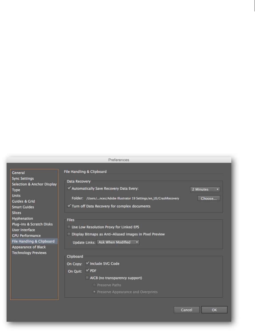
38
Workspace
Last updated 6/5/2015
•If a Data Recovery snapshot is not found for a file that was open when Illustrator crashed (indicates no unsaved
information), the file is opened afresh and is available for editing.
•If no usable Data Recovery information is found for a file that was open when Illustrator crashed, the file is opened
in its last saved state, and is available for editing.
Configurable preferences
The preferences for the Data Recovery feature are available in the Preferences panel (Preferences > File Handling &
Clipboard > Data Recovery area).
•Automatically Save Recovery Data Every. Select the checkbox to turn the Data Recovery feature on.
•Interval. Select an appropriate duration from the Interval dropdown. Illustrator will save a backup at this frequency
in minutes.
•Folder / Choose: Displays and allows you to configure the location at which Illustrator stores backup files.
•Turn off Data Recovery for complex documents. Select the checkbox to prevent the Data Recovery feature from
slowing down while backing up complex files.
Important considerations
Turn off Data Recovery for complex documents (Preferences, Default: Off) When Data Recovery is turned on,
Illustrator may seem to pause while backing up larger files that contain byte-heavy raster images or need a considerable
time to backup. If this interrupts your workflow, you can choose to turn this setting on.
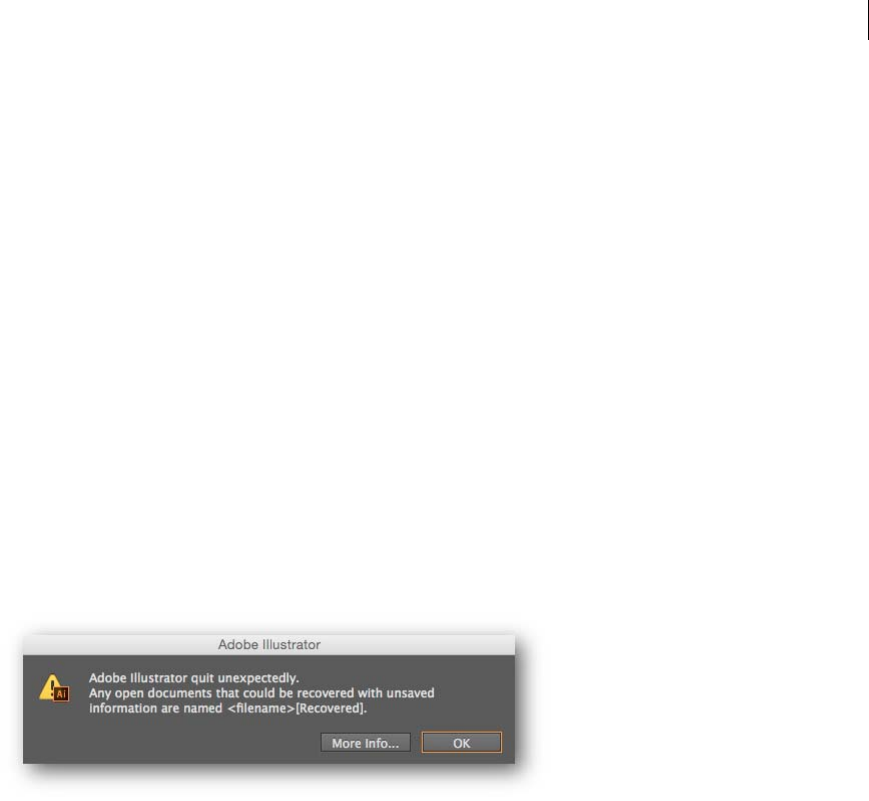
39
Workspace
Last updated 6/5/2015
Data Recovery Interval (Preferences, Default: 2 minutes) Setting a time interval that is too short may tend interrupt
your flow as you work, especially if you are working on extremely large or complex files. However, setting too long a
time interval may increase the potential for data loss in the event of a crash. Use your discretion to set a value that works
best for you.
Illustrator crashes during a Data Recovery operation If Illustrator crashes while the Data Recovery operation is either
saving a snapshot or opening a recovered file, then the Data Recovery option is turned off automatically. To continue
using the Data Recovery feature, you must re-enable it from the Preferences panel (Ctrl/Cmd + K).
How Data Recovery works
1You open an Illustrator file, and have enabled the Data Recovery feature to run through the Preferences Panel.
2At regular time intervals, as specified in the Data Recovery preferences, Illustrator takes a snapshot of your open file
with your current edits.
3Illustrator and/or the open file are closed under two conditions:
•You close the file or exit Illustrator. The recovery snapshot file is deleted.
•Illustrator encounters an unexpected condition and crashes. The snapshot is retained.
4When you restart Illustrator, if there are recoverable files available, a prompt is displayed to indicate that files have
been recovered.
5Data Recovery snapshot files are automatically opened. The file name for such files contains the text [Recovered].
For example, if the file being edited when Illustrator crashed was named logo_review.ai, the recovered file will be
named logo_review [Recovered].ai.
Note: The restored file contains data at the time the last automatic save was performed. Any actions performed between
an automatic save and application crash is not saved.
6When you attempt to save the file, the Save As dialog is displayed. Choose to overwrite the file or save the file with
a different file name, and then continue working on it.
Touch Workspace
Workspace layout and basics
The Touch workspace is an all-new reimagined, intuitive, and simplified workspace, designed to work with your
Windows 8 -powered touch-enabled device. The workspace is optimized for easy, quick, and efficient touch-based
interactions.
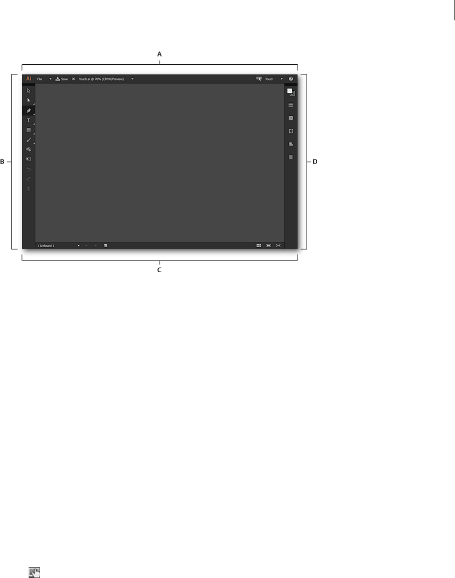
40
Workspace
Last updated 6/5/2015
A App bar B Tool bar C Control panel bar D Document bar
The layout has a cleaner interface that allows you to comfortably use a stylus or your finger tip to access the tools and
controls of the Touch workspace. Some important notes while working with the Touch workspace:
•Compared to the classic workspaces, panels are consolidated and reimagined to make using them easy
•Annotator sizes are larger to eliminate issues related to accuracy. This makes it easier to work with widgets, control
points, and handles
•Drawing tools use a precise cursor to help pinpoint the exact origins and endings of paths
•Panels like the Align panel have been redesigned and recreated for an intuitive approach to drawing and
repositioning of objects
•Illustrator-native gestures and Operating System gestures are supported
Switching between workspaces
Switching to the Touch workspace or back to a classic workspace is similar to switching between any of the previous
workspaces. However, the interface has additional options to switch quickly, and some special conditions under which
workspaces switch automatically.
Switch to the Touch workspace
Do one of the following while working in a classic workspace (for example, Essentials, Typography) in Illustrator CC
2014.1:
•Tap in the App bar
•From the Workspaces menu, choose Touch
•Tap Window > Workspace > Touch
•If attached, detach the keyboard for the device
Exit the Touch workspace
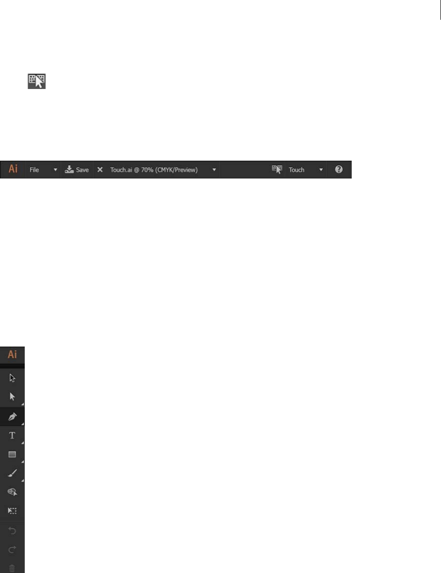
41
Workspace
Last updated 6/5/2015
When you exit the Touch workspace, the last used workspace is activated. Do one of the following in the Touch
workspace:
•Tap in the app bar
•From the workspaces menu, choose a different workspace.
•If detached, attach a keyboard to the device
App bar
The App bar provides information and options related to the active Illustrator document:
•File dropdown: Tap to create, close, save, or share documents.
•Save As / Save button: Tap to save the open document.
•Filename: Tap to view a list of open documents or close the current document.
•Previous workspace: Tap to switch the previously used workspace
•Workspac e drop down: Tap to view a list of available workspaces. Choose a workspace to switch to that workspace.
•Help overlays icon: Tap to view the Help Overlays that describe various parts of the Touch workspace and the
gestures supported in this workspace.
Tool bar
The Tool bar lists the various tools and basic editing actions (undo, redo, delete) available. Tap any tool to use it. When
you tap a Tool group, a drawer opens to display all the tools belonging to the group. Tap a tool in the group to select it.
Tools and Tool groups
Tools available in the Touch workspace are consolidated to best suit touch-enabled workflows:
•Selection tool
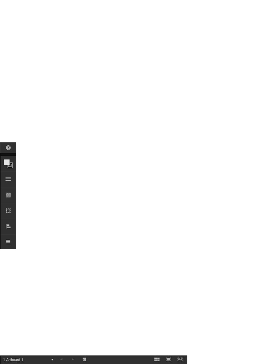
42
Workspace
Last updated 6/5/2015
•Selection tools group: Direction Selection tool, Group selection tool.
•Pen tools group: Curvature tool, Pen tool, Anchor Point tool.
•Type group: Type tool, Touch Type tool.
•Shapes group: Rectangle tool, Rounded Rectangle tool, Ellipse tool.
•Drawing tools group: Brush tool, Pencil tool, Stencil tool, Join tool.
•Shape Builder tool
•Free Transform tool
•Undo, Redo, Delete buttons
Control panel
The Control panel consists of other panels that are available for the selected tool or object. Available panels are:
•Color panel: Modify fill and stroke proxies using the RBG, CMYK, or Color picker tabs.
•Stroke panel: Specify the weight or profile of a stroke.
•Transparency panel: Choose blending modes or specify the opacity of an object.
•Transform: Modify the shape of an object, or manipulate corners in Rounded Rectangles.
•Align panel: Select objects and specify how they must align using this intuitive panel.
•Context menu: Choose from various actions you can perform on a selected object.
•Text panel: Specify font, font families, or the alignment of text in this panel.
Document bar
The Document bar provides information and options about the currently open Illustrator document:
•Artboard: Tap to view available artboards and tap an artboard name to switch to the artboard.
•Artboard controls: Navigate between artboards or create an artboard.
•View controls: View artboards, all at once, fitted to screen, or zoomed in at 100% magnification.

43
Workspace
Last updated 6/5/2015
Gestures
The Touch workspace provides gesture support to enable you to quickly work with objects drawn on your artboard:
•Zoom in (increase magnification): Pinch outward to zoom in on the artboard.
•Zoom out (reduce magnification): Pinch inwards to zoom out of the artboard.
•Pan: Drag across to screen with two fingers to pan across the artboard.
•Context widget: Tap and hold an object to bring up the Context widget.
•Select objects (Selection tool): Tap an object, or Tap on the artboard and drag across objects to select.
•Switch Selection / Drawing modes: Tap with two fingers to toggle between selection and drawing modes.
Artboard overview
Artboards represent the regions that can contain printable artwork. You resize and set the orientation for your artwork
by choosing settings in the Artboard Options dialog box. (In Illustrator CS3 and earlier, you use the Document Setup
dialog box to change the document size and orientation.)
You can use artboards as crop areas for printing or placement purposes—they work the same way as crop areas work
in Illustrator CS3. Multiple artboards are useful for creating a variety of things such as multiple page PDFs, printed
pages with different sizes or different elements, independent elements for websites, video storyboards, or individual
items for animation in Adobe Flash or After Effects.note: If you created crop areas in an Illustrator CS3 document, the
crop areas will be converted to artboards in CS5. You may be prompted to specify how you want the crop areas to convert.
You can have 1 to 100 artboards per document depending on size. You can specify the number of artboards for a
document when you first create it, and you can add and remove artboards at any time while working in a document.
You can create artboards in different sizes, resize them by using the Artboard tool , and position them anywhere
on the screen—even overlapping one another. Illustrator CS5 also provides options to reorder and rearrange artboards
using the Artboards panel. You can also specify custom names for an artboard and set reference points for artboards.
Viewing artboards and the canvas
You can view the page boundaries in relation to an artboard by showing print tiling (View > Show Print Tiling). When
print tiling is on, the printable and nonprintable areas are represented by a series of solid and dotted lines between the
outermost edge of the window and the printable area of the page.
Each artboard is bound by solid lines and represents the maximum printable area. To hide the artboard boundaries,
choose View > Hide Artboards. The canvas is the area outside the artboard that extends to the edge of the 220 inch
square window. The canvas represents a space on which you can create, edit, and store elements of artwork before
moving them onto an artboard. Objects placed onto the canvas are visible on-screen, but they do not print.
To center an artboard and zoom it to fit the screen, click the artboard number in the status bar, located at the bottom
of the application window.
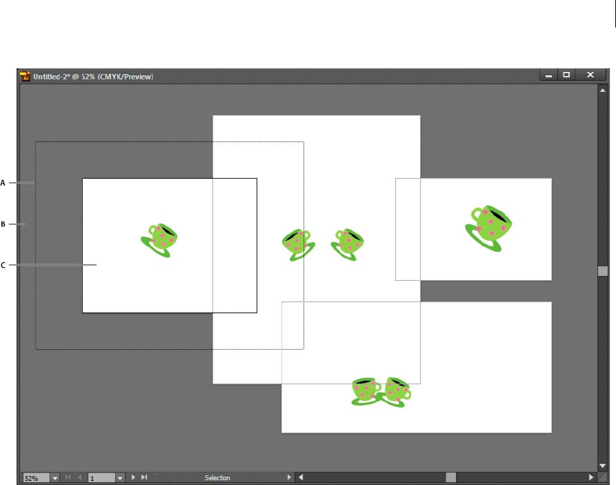
44
Workspace
Last updated 6/5/2015
A Printable area (determined by the specified printer) B Canvas C Artboard
Printing and saving artboards
All artboards in a document share the same media type format, such as Print. You can print each artboard individually,
tiled, or combined into one page. If you save a multiple-artboard Illustrator document to a previous version of
Illustrator, such as CS3, you can choose to save each artboard as a separate file, along with a master file that includes all
artboards merged.
Illustrator CS4 allowed you to save artboards as separate files only when downsaved, but in Illustrator CS5, you can save
individual artboards for current versions as well. The options to save each artboard as a separate .ai file is available in
the Illustrator Options dialog box.
You can preview artboards from the print dialog box before printing them. The print settings you choose are applied
to all of the artboards you selected to print.
By default all artwork is cropped to an artboard and all artboards print as individual pages. Use the Range option in the
Print dialog box to print specific pages, select Ignore Artboards and specify placement options to combine all art onto
a single page or tile the artwork as desired.
In Illustrator CS5, artboards in a document can automatically rotate to print to the chosen media size. Select the Auto-
Rotate check box in the Print dialog box to set auto rotation for Illustrator documents. For a document created in CS5,
Auto-Rotate is enabled by default.
For example, consider a document with both landscape (width is more than height) and portrait (height is more than
width) media size. If you select the paper size as portrait in the Size of the Print dialog box, then the landscape artboards
automatically rotate to portrait media when printing.
Note: If Auto-Rotate is selected, you cannot change the direction of the page.

45
Workspace
Last updated 6/5/2015
Rulers, grids, guides, and cropmarks
Use rulers
Rulers help you accurately place and measure objects in the illustration window or in an artboard. The point where 0
appears on each ruler is called the ruler origin.
In Illustrator CS5, rulers are similar to other Creative Suiteapplications like InDesign and Photoshop. Illustrator
provides separate rulers for documents and artboards. You can select only one of these rulers at one point.
Note: Window rulers would be called Global rulers in this document.
Global rulers appear at the top and left sides of the illustration window. The default ruler origin is located at the top-left
corner of the illustration window.
Artboard rulers appear at the top and left sides of the active artboard. The default artboard ruler origin is located at the
top-left corner of the artboard.
The difference between artboard rulers and global rulers is that if you select artboard rulers, the origin point changes
based on the active artboard. In addition, you can have different origin points for artboard rulers. Now, if you change
the artboard ruler origin, the pattern fills in objects on the artboards are not affected.
The default origin point for the global ruler is at the upper-left corner of the first artboard and the default origin for the
artboard rulers is at the top left corner of the respective artboard.
•To show or hide rulers, choose View > Rulers > Show Rulers or View> Rulers > Hide Rulers.
•To toggle between artboard rulers and global rulers, click the View > Rulers > Change to Global Rulers or View >
Rulers > Change to Artboard Rulers. By default, artboard rulers are displayed, so Change to Global Rulers option is
displayed under Rulers sub-menu.
•To show or hide video rulers, choose View > Show Video Rulers or View > Hide Video Rulers.
•To change the ruler origin, move the pointer to the upper-left corner where the rulers intersect, and drag the pointer
to where you want the new ruler origin.
As you drag, a cross hair in the window and in the rulers indicates the changing Global ruler origin.
note: Changing the Global ruler origin affects the tiling of patterns.
•To restore the default ruler origin, double-click the upper-left corner where the rulers intersect.
The coordinate system has now been switched to fourth quadrant, which was previously the first quadrant. In
Illustrator CS5, when you move downwards, the value of y-axis increases and if you move toward right, the value of x-
axis increases.
For saving to legacy versions of Illustrator, the Global rulers remain at the position set in legacy document. Although,
the origin point does not move to upper left, the coordinate system changes to fourth quadrant.
The change in coordinate system and the ruler origin does not apply to scripting, which allows you to retain old scripts.
However, when you transform objects using scripting, the Y coordinate values differ from the values that you set in the
Illustrator user interface. For example, if you apply a move operation of say Y= +10 points, then to emulate the same
movement with scripting, apply a transformation of Y = -10pts.

46
Workspace
Last updated 6/5/2015
Change the unit of measurement
The default unit of measurement in Illustrator is points (a point equals .3528 millimeter). You can change the unit that
Illustrator uses for general measurements, strokes, and type. You can override the default unit while entering values in
boxes.
•To change the default unit of measurement, choose Edit > Preferences > Units (Windows) or Illustrator >
Preferences > Units (Mac OS), and then select units for the General, Stroke, and Type options. If Show Asian
Options is selected in the Type preferences, you can also select a unit specifically for Asian type.
note: The “General” measurement option affects rulers, measuring the distance between points, moving and
transforming objects, setting grid and guides spacing, and creating shapes.
•To set the general unit of measurement for the current document only, choose File > Document Setup, choose the
unit of measure you want to use from the Units menu, and click OK.
•To change the unit of measurement when entering a value in a box, follow the value by any of the following
abbreviations: inch, inches, in, millimeters, millimetres, mm, Qs (one Q equals 0.25 millimeter), centimeters,
centimetres, cm, points, p, pt, picas, pc, pixel, pixels, and px.
Tip: When mixing picas and points, you can enter values as XpY, where X and Y are the number of picas and points
(for example, 12p6 for 12 picas, 6 points).
Use the grid
The grid appears behind your artwork in the illustration window, and it does not print.
•To use the grid, choose View > Show Grid.
•To hide the grid, choose View > Hide Grid.
•To snap objects to gridlines, choose View > Snap To Grid, select the object you want to move, and drag it to the
desired location.
When the object’s boundaries come within 2 pixels of a gridline, it snaps to the point.
note: When the View > Pixel Preview option is selected, Snap To Grid changes to Snap To Pixel.
•To specify the spacing between gridlines, grid style (lines or dots), grid color, or whether grids appear in the front
or back of artwork, choose Edit > Preferences > Guides & Grid (Windows) or Illustrator > Preferences > Guides &
Grid (Mac OS).
Use guides
Guides help you align text and graphic objects. You can create ruler guides (straight vertical or horizontal lines) and
guide objects (vector objects that you convert to guides). Like the grid, guides do not print.
You can choose between two guide styles—dots and lines—and you can change the color of guides by using either
predefined guide colors or colors you select using a color picker. By default, guides are unlocked so that you can move,
modify, delete, or revert them, but you can choose to lock them into place.
•To show or hide guides, choose View > Guides > Show Guides or View > Guides > Hide Guides.
•To change guide settings, choose Edit > Preferences > Guides & Grid (Windows) or Illustrator > Preferences >
Guides & Grid (Mac OS).
•To lock guides, select View > Guides > Lock Guides.

47
Workspace
Last updated 6/5/2015
Create guides
1If the rulers aren’t showing, choose View > Show Rulers.
2Position the pointer on the left ruler for a vertical guide or on the top ruler for a horizontal guide.
3Drag the guide into position.
You can also convert vector objects to guides by selecting them and choosing View > Guides > Make Guides.
To make working with multiple guides easier, move them into a separate layer.
4If you want to restrict the guides to an artboard and not to the entire canvas, then select the Artboard tool and then
drag the guides on to the artboard.
Move, delete, or release guides
1If guides are locked, select View > Guides > Lock Guides.
2Do any of the following:
•Move the guide by dragging or copying.
•Delete the guide by pressing Backspace (Windows) or Delete (Mac OS), or by choosing Edit > Cut or Edit > Clear.
•Delete all guides at once by choosing View > Guides > Clear Guides.
•Release the guide, turning it back into a regular graphic object, by selecting the guide and choosing View >
Guides > Release Guides.
Snap objects to anchor points and guides
1Choose View > Snap To Point.
2Select the object you want to move, and position the pointer on the exact point you want to align with anchor points
and guides.
Note: When snapping to a point, the snapping alignment depends on the position of the pointer, not the edges of the
dragged object.
3Drag the object to the desired location.
When the pointer comes within 2 pixels of an anchor point or guide, it snaps to the point. The pointer changes from
a filled arrowhead to a hollow arrowhead when a snap occurs.
Smart Guides
Smart Guides are temporary snap-to guides that appear when you create or manipulate objects or artboards. They help
you align, edit, and transform objects or artboards relative to other objects, artboards, or both by snap-aligning and
displaying X, Y location and delta values. You can specify the type of smart guides and feedback that appear (such as
measurement labels, object highlighting, or labels) by setting the Smart Guides preferences.
To see a video on using smart guides, see www.adobe.com/go/lrvid4020_ai.
Use Smart Guides
Smart Guides are on by default.
1Choose View > Smart Guides to turn guides on or off.

48
Workspace
Last updated 6/5/2015
2Use Smart Guides in the following ways:
•When you create an object with the pen or shape tools, use the Smart Guides to position a new object's anchor
points relative to an existing object. Or, when you create a new artboard, use Smart Guides to position it relative
to another artboard or an object.
•When you create an object with the pen or shape tools, or when you transform an object, use the smart guides’
construction guides to position anchor points to specific preset angles, such as 45 or 90 degrees. You set these
angles in the Smart Guides preferences.
•When you move an object or artboard, use the Smart Guides to align the selected object or artboard to other
objects or artboards. The alignment is based on the geometry of objects and artboards. Guides appear as the
object approaches the edge or center point of other objects.
note: Press Ctrl (Windows) or Command (Mac OS) to use the alignment behavior from Illustrator CS3, which uses
the center point or edge of one object or artboard.
•When you transform an object, Smart Guides automatically appear to assist the transformation.
You can change when and how Smart Guides appear by setting Smart Guide preferences.
Note: When Snap To Grid or Pixel Preview is turned on, you cannot use Smart Guides (even if the menu command is
selected).
Smart Guide preferences
Choose Edit > Preferences > Smart Guides (Windows) or Illustrator > Preferences > Smart Guides (Mac OS) to set the
following preferences:
Color Specifies the color of the guides.
Alignment Guides Displays guide lines that are generated along the center and edges of geometric objects, artboard,
and bleeds. They are generated when you move objects and when you perform operations such as drawing basic shapes,
using Pen tool, and transforming objects.
Anchor/Path Labels Displays information when paths intersect and when they are centered on an anchor point.
Measurement Labels Displays information for many tools (such as Drawing tools and Text tools) about the current
position the cursor as you position the cursor over an anchor point. While creating, selecting, moving, or transforming
objects it displays the x and y delta from the object’s original location. When you press Shift with a drawing tool
selected, the starting location appears.
Object Highlighting Highlights the object below the pointer as you drag around it. The highlight color matches the
object’s layer color.
Transform Tools Displays information when you scale, rotate, and shear objects.
Construction Guides Displays guidelines as you draw new objects. You specify the angles at which you want guidelines
drawn from the anchor points of a nearby object. You can set up to six angles. Type an angle in the selected Angles box,
select a set of angles from the Angles pop-up menu, or select a set of angles from the pop-up menu and change one of
the values in the box to customize a set of angles. The preview reflects your settings.
Snapping Tolerance Specifies the number of points the pointer must be from another object for Smart Guides to take
effect.
Measure the distance between objects
The Measure tool calculates the distance between any two points and displays the results in the Info panel.
1Select the Measure tool . (Press and hold the Eyedropper tool to see it in the Tools panel.)

49
Workspace
Last updated 6/5/2015
2Do one of the following:
•Click the two points to measure the distance between them.
•Click the first point and drag to the second point. Shift-drag to constrain the tool to multiples of 45°.
The Info panel shows the horizontal and vertical distances from the x and y axes, the absolute horizontal and
vertical distances, the total distances, and the angle measured.
Info panel overview
You use the Info panel (Window > Info) to get information on the area beneath the pointer and on selected objects.
•When an object is selected and a selection tool is active, the Info panel displays the object’s x and y coordinates,
width (W), and height (H). The values for width and height are affected by the Use Preview Bounds option in the
General preferences. When Use Preview Bounds is selected, Illustrator includes the stroke width (and other
attributes such as drop shadows) in the object’s dimensions. When Use Preview Bounds is deselected, Illustrator
measures only the dimensions defined by the object’s vector path.
•When you use the Pen tool or Gradient tool, or when you move a selection, the Info panel displays the change in x
(W), the change in y (H), the distance (D), and the angle as you drag.
•When you use the Zoom tool, the Info panel displays the magnification factor and the x and y coordinates after you
release the mouse button.
•When you use the Scale tool, the Info panel displays the percentage change in width (W) and height (H) and the
new width (W) and height (H) after the scaling is complete. When you use the rotate or reflect tools, the Info panel
displays the coordinates of the object’s center and the angle of rotation or reflection .
•When you use the Shear tool, the Info panel displays the coordinates of the object’s center, the angle of shear axis ,
and the amount of shear .
•When you use the Paintbrush tool, the Info panel displays the x and y coordinates and the name of the current brush.
•Select Show Options from the panel menu or click the double arrow on the panel tab to show values for the fill and
stroke colors of the selected object and the name of any pattern, gradient, or tint applied to the selected object.
note: If you select multiple objects, the Info panel displays only the information that is the same for all selected objects.
Custom Tools Panels
In this version of Illustrator CC, you can create custom tools panels. If you work with only a specific set of tools, you
can create a customized tools panel that contains only those tools.
Adding or removing tools to tools panels
1In Illustrator, click Window > Tools > New Tools Panel, and then provide a name and click OK.
A new Tools panel is created and displayed.
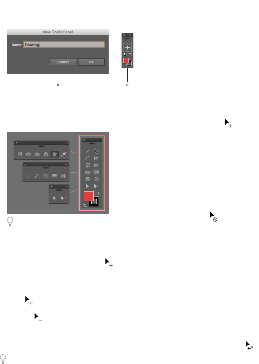
50
Workspace
Last updated 6/5/2015
A Provide a name for the new tools panel B New tools panel created with a default fill/stroke proxy
Note: A Fill/Stroke proxy is added by default. This cannot be removed from the custom tools panel.
2Drag a tool from an existing tools panel into a new or existing custom tools panel. If the tool is part of a group of
tools, then the topmost tool is copied. Release the mouse when the cursor appears with a plus sign ( ).
Dragging and dropping a tool when the mouse cursor appears with a cancel operation sign ( ) performs no
addition or deletion of tools.
3To get a tool that does not appear as the top-most tool in a group, do one of the following:
aPress Alt/Opt and click the tool group. This action cycles through all the tools present in the tool group.
bWhen the tool that you want appears at the top of the group, drag it to the custom tools panel. Release the mouse
when the cursor appears with a plus sign( ).
OR
cDrag the tool group into an empty portion of the workspace, to view it as a toolstrip.
dFrom the toolstrip, drag a tool to the new tools panel. Release the mouse when the cursor appears with a plus
sign( ).
4To remove a tool, drag the tool out of the custom tools panel, and drop it when the mouse cursor appears with a
minus sign ( ).
Note: A tool can be removed from a tools panel only when a document is open.
5To swap positions of tools within a custom-created tools panel, press the Alt/Opt key, drag a tool on top of the tool
you want to swap positions with, and then drop the tool when the cursor appears with a two-way arrow sign ( ).
A custom tools panel is persistent in the workspace it is created in. If you change to another workspace and then return
to the original workspace, any tools panels created are retained and reopened.
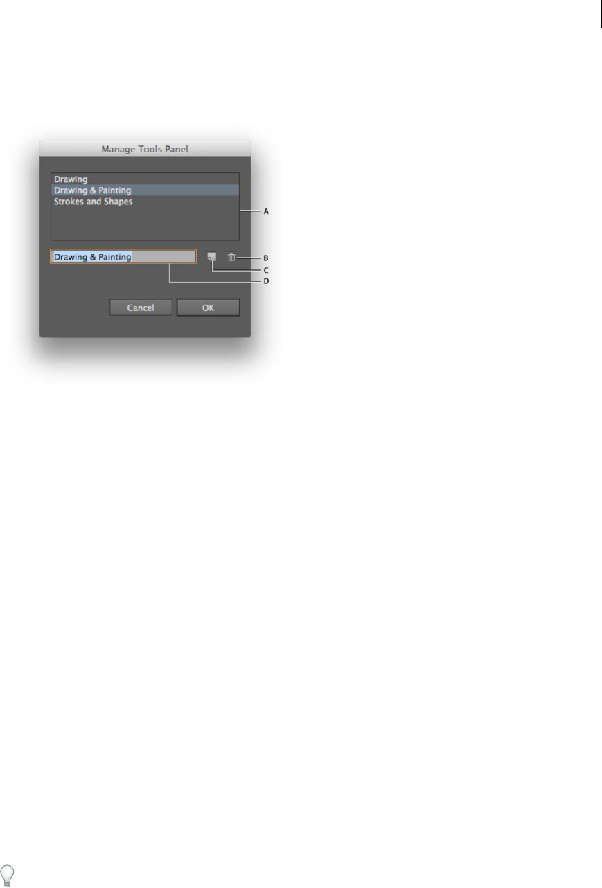
51
Workspace
Last updated 6/5/2015
Managing custom tools panels
1In Illustrator, click Windows > Tools > Manage Tools Panel.
A List of custom tools panels B Delete selected tools panel C Create a new tools panel, or a copy of the selected tools panel D Rename a selected
tools panel
2In the Manage Tools Panel dialog, do one of the following:
•Rename: Select a tools panel from the list, type a new name for the panel in the textbox, and then then click OK.
•New/Copy: Select a tools panel fom the list, click the copy button, rename the tools panel if required, and then
click OK. If no tools panel is selected, a new tools panel is created.
•Delete: Select a tools panel from the list, and then click the Delete button.
Viewing artwork
Specify Document Setup options
At any point you can change your document’s default setup options for units of measure, transparency grid display,
background color, and type settings such as language, quote style, superscript and subscript size, bleeds, and
exportability. The Edit Artboards button closes this dialog box and activates the Artboard tool.
1Choose File > Document Setup, or click theDocument Setup button in the Control panel. (This button is available
when nothing is selected.)
2Specify options as desired.
3If you want to edit artboards (for instance, to change from portrait to landscape orientation), click Edit Artboards
to enter artboard editing mode.
The Simulate Colored Paper option is useful if you plan to print the document on colored paper. For example, if you
draw a blue object on a yellow background, the object appears green. The simulation is only performed when the
transparency grid is not shown.
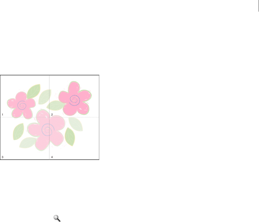
52
Workspace
Last updated 6/5/2015
About print tiling
By default, Illustrator prints each artboard on a single sheet of paper. However, if the artwork is larger than the page
sizes available on your printer, you can print onto multiple sheets of paper.
Dividing an artboard to fit a printer’s available page sizes is called tiling. You can choose a tiling option in the General
section of the Print dialog box. To view the print tiling boundaries on the artboard, choose View > Show Print Tiling.
When you divide the artboard into multiple tiles, the pages are numbered from left to right and from top to bottom,
starting with page 1. These page numbers appear on-screen for your reference only; they do not print. The numbers
enable you to print all of the pages in the file or specify particular pages to print.
Zoom in or out
There are several ways to zoom in or out of artwork.
•Select the Zoom tool . The pointer becomes a magnifying glass with a plus sign in its center. Click in the center
of the area that you want to magnify, or hold down Alt (Windows) or Option (Mac OS) and click in the center of the
area that you want to reduce. Each click magnifies or reduces the view to the previous preset percentage.
•Select the Zoom tool and drag a dotted rectangle, called a marquee, around the area you want to magnify. To move
the marquee around the artwork, hold down the spacebar, and continue dragging to move the marquee to a new
location.
•Choose View > Zoom In or View >Zoom Out. Each click magnifies or reduces the view to the next preset
percentage.
•Set the zoom level at the lower-left corner of the main window or in the Navigator panel.
•To display a file at 100%, choose View > Actual Size, or double-click the Zoom tool.
•To fill the window with the selected artboard, choose View > Fit Artboard In Window, or double-click the Hand tool.
•To view everything in the window, choose View > Fit All In Window.
Change the view area
You can bring a different area of the artboard into view by doing any of the following:
•Choose View > Actual Size to see all of your artboards in actual size.
•Choose View > Fit All In Window to zoom out so that all artboards are visible in on the screen.
•Choose View > Fit Artboard In Window to zoom in on the active artboard.
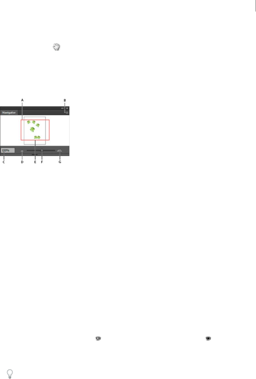
53
Workspace
Last updated 6/5/2015
•In the Navigator panel, click the area of the thumbnail display that you want to view in the illustration window.
Alternatively, drag the proxy view area (the colored box) to a different area of the thumbnail display.
•Select the Hand tool , and drag in the direction you want the artwork to move.
Navigator panel overview
You use the Navigator panel (Window > Navigator) to quickly change the view of your artwork using a thumbnail
display. The colored box in the Navigator (called the proxy view area) corresponds to the currently viewable area in the
illustration window.
A Thumbnail display of artwork B Panel menu button C Zoom box D Zoom Outbutton E Proxy preview area F Zoom slider G Zoom Inbutton
You can customize the Navigator panel in the following ways:
•To display artwork outside the boundaries of the artboard in the Navigator panel, click View Artboard Contents
Only from the panel menu to deselect it.
•To change the color of the proxy view area, select panel Options from the panel menu. Select a preset color from the
Color menu, or double-click the color box to choose a custom color.
•To display dashed lines in the document as solid lines in the Navigator panel, select panel Options from the panel
menu and select Draw Dashed Lines As Solid Lines.
View artwork as outlines
By default, Adobe Illustrator sets the view so that all artwork is previewed in color. However, you can choose to display
artwork so that only its outlines (or paths) are visible. Viewing artwork without paint attributes speeds up the time it
takes to redraw the screen when working with complex artwork.
In Outline mode, linked files are displayed by default as outlined boxes with an X inside. To view the contents of linked
files, choose File >Document Setup, and select Show Images In Outline Mode.
•To view all artwork as outlines, choose View > Outline. Choose View > Preview to return to previewing artwork in
color.
•To view all artwork in a layer as outlines, Ctrl-click (Windows) or Command-click (Mac OS) the eye icon for the
layer in the Layers panel. Ctrl-click (Windows) or Command-click (Mac OS) again to return to previewing artwork
in color. The eye icon has a hollow center when Outline view is enabled and a filled center when Preview view
is enabled.
•To view all items in unselected layers as outlines, Alt+Ctrl-click (Windows) or Option+Command-click (Mac OS)
the eye icon for the selected layer. Alternatively, select Outline Others from the Layers panel menu.
Tip: You can return all items in the Layers panel to Preview mode by choosing Preview All Layers from the Layers
panel menu.

54
Workspace
Last updated 6/5/2015
Use multiple windows and views
You can open multiple windows of a single document at the same time. Each window can have different view settings.
For example, you can set one window highly magnified for doing close-up work on some objects and create another
window less magnified for laying out those objects on the page.
(Windows) You can arrange multiple open windows to suit your needs, using options from the Window menu. Cascade
displays windows stacked and descending from the upper-left to the lower-right of the screen; Tile displays windows edge
to edge; Arrange Icons organizes minimized windows within the program window.
An alternative to creating multiple windows is creating multiple views. You can create and store up to 25 views for each
document.
Multiple windows and multiple views differ in the following ways:
•Multiple views are saved with the document, multiple windows are not.
•Multiple windows can be viewed at the same time.
•Multiple views can appear at the same time only if multiple windows are opened to display them in. Changing a view
alters the current windows, it does not open a new one.
Create a new window
❖Choose Window > New Window.
Create a new view
❖Set up the view as you want, and then choose View > New View, enter a name for the new view, and click OK.
Rename or delete a view
❖Choose View > Edit Views.
Switch between views
❖Select a view name from the bottom of the View menu.
Previewing artwork in its final output medium
Illustrator provides the following ways to preview how aspects of artwork will look when printed or viewed on the web
or a mobile device:
Overprint Preview mode (View > Overprint Preview) Provides an “ink preview” that approximates how blending,
transparency, and overprinting will appear in color-separated output.
Separations Preview mode (Window > Separations Preview) Provides a preview of how the separations will look when
printed.
Pixel Preview mode (View > Pixel Preview) Approximates how your artwork will appear when it is rasterized and
viewed in a web browser.
Flattener Preview panel (Window > Flattener Preview) Highlights areas of the artwork that meet certain criteria for
flattening when saved or printed.
Soft-proofs Approximate how your document’s colors will appear on a particular type of monitor or output device.
Anti-aliasing Gives vector objects a smoother on-screen appearance and provides a better idea of how vector artwork
will look when printed on a PostScript® printer. Anti-aliasing is helpful because screen resolution is relatively limited,

55
Workspace
Last updated 6/5/2015
but vector artwork is often printed at a high resolution. To turn on anti-aliasing, choose Edit > Preferences > General
(Windows) or Illustrator > Preferences > General (Mac OS), select Anti-aliased Artwork, and click OK.
Device Central (File > Device Central) Lets you preview how your document will appear on a particular mobile phone
or device.
Setting preferences
About preferences
Preferences are options regarding how you want Illustrator to work, including those for display, tools, ruler units, and
exporting information. Your preferences are saved in a file called AIPrefs (Windows) or Adobe Illustrator Prefs (Mac
OS), which is launched each time you start Illustrator.
Open a preferences dialog box
1Do one of the following:
•(Windows) Choose Edit > Preferences > [preference set name].
•(Mac OS) Choose Illustrator > Preferences > [preference set name].
•With nothing selected, click the Preferences button on the Control panel.
2To switch to a different preference set, do one of the following:
•Select an option from the menu at the upper-left of the Preferences dialog box.
•Click Next to display the next options, or click Prev to display the previous options.
Reset all preferences to default settings
Resetting preferences can be helpful if you are having problems with the application.
❖Do one of the following:
•Press and hold Alt+Control+Shift (Windows) or Option+Command+Shift (Mac OS) as you start Illustrator.
Your current settings are deleted.
•Remove or rename the AIPrefs file (Windows) or Adobe Illustrator Prefs file (Mac OS). New preferences files are
created the next time you start Illustrator.
note: It is safe to remove the entire Adobe Illustrator CS5 Settings folder. This folder contains various preferences that
can be regenerated.
Setting Illustrator preferences
The Illustrator preferences file manages the commands and panel settings in Illustrator. When you open Illustrator, the
positioning of panels and commands are stored in the Illustrator preferences file. If you want to restore the default
settings for Illustrator or change the current settings, delete the Illustrator preferences. Illustrator automatically creates
a preference file, when you restart Illustrator and save a file.
Depending on the operating system that you are using, the Illustrator preferences file is available at the following
location:
Note: The folder name may vary depending on the language version you have installed.

56
Workspace
Last updated 6/5/2015
Mac OS X
<startup drive>/Users/<username>/Library/Preferences/Adobe Illustrator CS5
Settings/en_US*/Adobe Illustrator Prefs
Windows XP
<startup drive>\ Documents and Settings\<username>\Application Data\Adobe\Adobe Illustrator
CS5 Settings\en_US*\AIPrefs
Windows Vista or Windows 7
<startup drive>\Users\<username>\AppData\Roaming\Adobe\Adobe Illustrator CS5
Settings\en_US*\AIPrefs.
Note: In Windows XP, the Application Data folder is hidden by default. The same is true for the AppData folder in
Windows Vista and Windows 7. To make this folder visible, open Folder Options in Control Panel and click the View tab.
In the Advanced Settings pane, select theShow Hidden Files and Folders or Show hidden files, folders, or drives option.
If you cannot locate the preferences file, use your operating system’s Find command, and search for AIPrefs (Windows)
or Adobe Illustrator Prefs (Mac OS).
About plug-in modules
Plug-in modules are software programs that add features to Adobe Illustrator. A number of special effects plug-ins
come with your program and are automatically installed in the Plug-ins folder inside the Illustrator folder.
You can install any commercial plug-in designed for use with Photoshop or Illustrator. To install an Adobe Systems
plug-in module, use the installer if one is provided. Otherwise, drag a copy of the module to the Plug-ins folder inside
the Illustrator folder. Then restart Illustrator for the plug-in to take effect. To install a third-party plug-in module,
follow the installation instructions that came with the plug-in module.
Note: The open architecture of the Adobe Illustrator program allows developers outside of Adobe to create features that are
accessible from within Adobe Illustrator. If you are interested in creating plug-in modules compatible with Adobe Illustrator,
see the Adobe Systems U.S. website at www.adobe.com.
Slicing and cutting tool gallery
Illustrator provides the following tools for slicing and cutting objects:
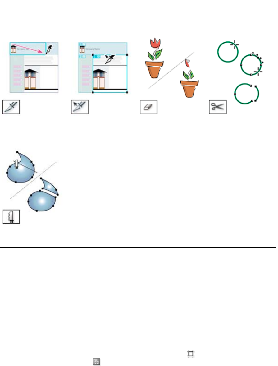
57
Workspace
Last updated 6/5/2015
More Help topics
Draw grids
Cutting and dividing objects
Using multiple artboards
Artboard options
You open the Artboard Options dialog box by double-clicking the Artboard tool , or clicking the Artboard tool and
then clicking Artboard Options button in the Control panel.
Preset Specifies artboard dimensions. These presets set the video ruler pixel aspect ratio appropriately for the specified
output.
Width and Height Specifies the size of the artboard.
Orientation Specifies portrait or landscape page orientation.
Constrain Proportions Keeps the aspect ratio of the artboard intact if you manually resize it.
The Slice tool divides artwork into
separate web images.Create slices
The Slice Selection tool (Shift-K)
selects web slices. See Select slices
The Eraser tool (Shift-E) erases any
area of the object over which you
drag. See Erase objects using the
Eraser tool
The Scissors tool (C) cuts paths at
specified points. See Split a path
The Knife tool cuts objects and
paths. See Cut objects with the
Knife tool.
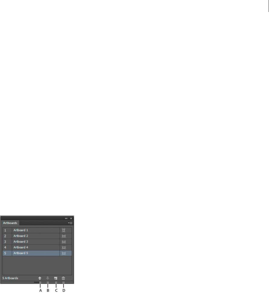
58
Workspace
Last updated 6/5/2015
X: and Y: Position Specifies the position of the artboard according to Illustrator’s workspace rulers. To view these rulers,
choose View > Show Rulers.
Show Center Mark Displays a point in the center of the artboard.
Show Cross Hairs Displays cross lines through the center of each side of the artboard.
Show Video Safe Areas Displays guides that represent the areas that fall inside the viewable area of video. You want to
keep all text and art that must be viewable to users inside the video safe areas.
Video Ruler Pixel Aspect Ratio Specifies the pixel aspect ratio used for the video rulers.
Fade Region Outside Artboard Displays the area outside of the artboard a darker shade than the area inside the
artboard when the Artboard tool is active.
Update While Dragging Keeps the area outside of the artboard darker as you drag to resize the artboard. If this is not
selected, the outside area displays in the same color as inside the artboard while resizing.
Artboards Indicates how many artboards exist.
Artboards panel
The Artboards panel allows you to perform various artboard operations such as:
•Add, reorder, rearrange, and delete artboards
•Reorder and renumber artboards
•Select and navigate through multiple artboards
•Specify artboard options such as presets, Artboard size, and relative artboard position
A Up Arrow B Down Arrow C Add new artboards D Delete artboards
•To access the Artboards panel, click Window > Artboards.
•To add artboards, do any one of the following:
•Click the New Artboard icon at the bottom of the Artboards panel.
•Select the New Artboard option from the Artboards panel menu (flyout menu) of the Artboards panel.
•To delete a single artboard or multiple artboards, do the following:
•Select the artboard to delete. To delete multiple artboards, press Shift key, and click the artboards listed in the
Artboards panel.
•Click the Delete Artboard icon at the bottom of the Artboards panel or select the Delete option from the
Artboards panel menu (flyout menu). To delete multiple non-contiguous artboards, press Ctrl (Windows) or
Command (Mac OS) key and click the artboards from the Artboards panel.

59
Workspace
Last updated 6/5/2015
•To rearrange artboards in the Artboards panel, select the Rearrange Artboards option from the Artboards panel
menu (flyout menu). Notice, however, that rearranging the artboards does not change the order the artboards.
•To duplicate artboards, do the following:
•Select the artboard that you want to duplicate. You can also duplicate artboards by dragging one or more
artboards on to the new artboard button in Artboards panel.
•From the Artboards panel menu, select Duplicate.
•To reset the artboard options, such as presets, artboard position, and display, select Artboards Options from the
Artboards panel menu (flyout menu).
For a video on using the Artboards panel, see www.adobe.com/go/lrvid5202_ai_en.
Create an artboard
1Do any of the following:
•To create a custom artboard, select the Artboard tool , and drag in the workspace to define the shape, size,
and location.
•To use a preset artboard, double-click the Artboard tool, select a preset in the Artboard Options dialog box, and
click OK. Drag the artboard to position it where you want.
•To create an artboard within an active artboard, hold down Shift and drag using the Artboard tool.
•To duplicate an existing artboard, select the Artboard tool, click to select the artboard you want to duplicate, and
click the New Artboard button in the Control panel ; then click where you want to place the duplicated
artboard. To create multiple duplicates, Alt-click as many times as you want. Or, using the Artboard tool, Alt-
drag (Windows) or Option-drag (Mac OS) the artboard you want to duplicate.
•To duplicate an artboard with the contents, select the Artboard tool, click to select the Move/Copy Artwork With
Artboard icon on the Control panel , press Alt (Windows) or Option (Mac OS), and then drag.
If you want the artwork to contain a bleed, make sure that there’s enough artwork beyond the artboard rectangle to
accommodate the bleed.
2To commit the artboard and exit the artboard-editing mode, click a different tool in the Tools panel or click Esc.
To see a video on using multiple artboards, see www.adobe.com/go/lrvid5202_ai_en.
Delete an artboard
❖Click the artboard and press Delete, click Delete in the Control panel, or click the Delete icon in an artboard’s
upper-right corner. You can delete all but the last remaining artboard.
Select and view artboards
1Select the Artboard tool .
2Do any of the following:
•Click an artboard to make it active. (Clicking in or drawing over an artboard using a different tool will also make
the Artboard tool active.) If artboards overlap, the artboard with the left edge closest to the click location
becomes the active artboard.
•To navigate between artboards, press Alt (Windows) or Option (Mac OS) and click an arrow key.
•To view artboards and their contents as outlines, right-click and choose Outline. To see artwork again, right-click
and choose Preview.

60
Workspace
Last updated 6/5/2015
Edit artboards
You can create multiple artboards for your document, but only one can be active at a time. When you have multiple
artboards defined, you can view them all by selecting the Artboard tool. Each artboard is numbered for easy reference.
You can edit or delete an artboard at any time, and you can specify different artboards each time you print or export.
1Select the Artboard tool , click to select an artboard.
2Do any of the following:
•To resize the artboard, position the pointer on an edge or corner until the cursor changes to a double-sided arrow,
and then drag to adjust. Or, specify new Width and Height values in the Control panel.
•To change the orientation of the artboard, click the Portrait or Landscape button in the Control panel.
•To rotate between artboards, press Alt (Windows) or Option (Mac OS) and click an arrow key.
•To view artboards and their contents as outlines, right-click and choose Outline. To see artwork again, right-click
and choose Preview.
Move an artboard
1Select the Artboard tool and click to select an artboard.
2Do one of the following:
•To move the artboard and its contents, click to select the Move/Copy Artwork With Artboard icon on the Control
panel , and then position the pointer in the artboard and drag. Or, specify new X and Y values in the Control
panel.
•To move the artboard without its contents, click to deselect the Move/Copy Artwork With Artboard icon on the
Control panel, and then position the pointer in the artboard and drag. Or, specify new X and Y values in the
Control panel.
Reorder artboards
In the Artboards panel, you can use the Up and Down Arrows at the bottom of the panel to reorder the artboards.
However, reordering artboards in the Artboards panel, does not reorder the artboards in the work area.
Rearrange artboards
To fit all artboards in view, you can rearrange artboards using the Grid by Row, Grid by Column, Arrange by Row, and
Arrange by Column options.
To rearrange artboards, do the following:
1Click the Artboards panel menu (flyout menu) and select the Rearrange Artboards option.
2In the Rearrange Artboards dialog box, select the layout. The options are:
Grid by Row Arranges multiple artboards in the specified number of rows. Specify the number of rows in the Rows
box. The default value creates the most square appearance possible with the specified number of artboards.
Grid by Column Arranges multiple artboards in the specified number of columns. Choose the number of columns
from the Columns menu. The default value creates the most square appearance possible with the specified number
of artboards.
Arrange by Row Arranges all the artboards in a single row.
Arrange by Column Arranges all the artboards in a single column.
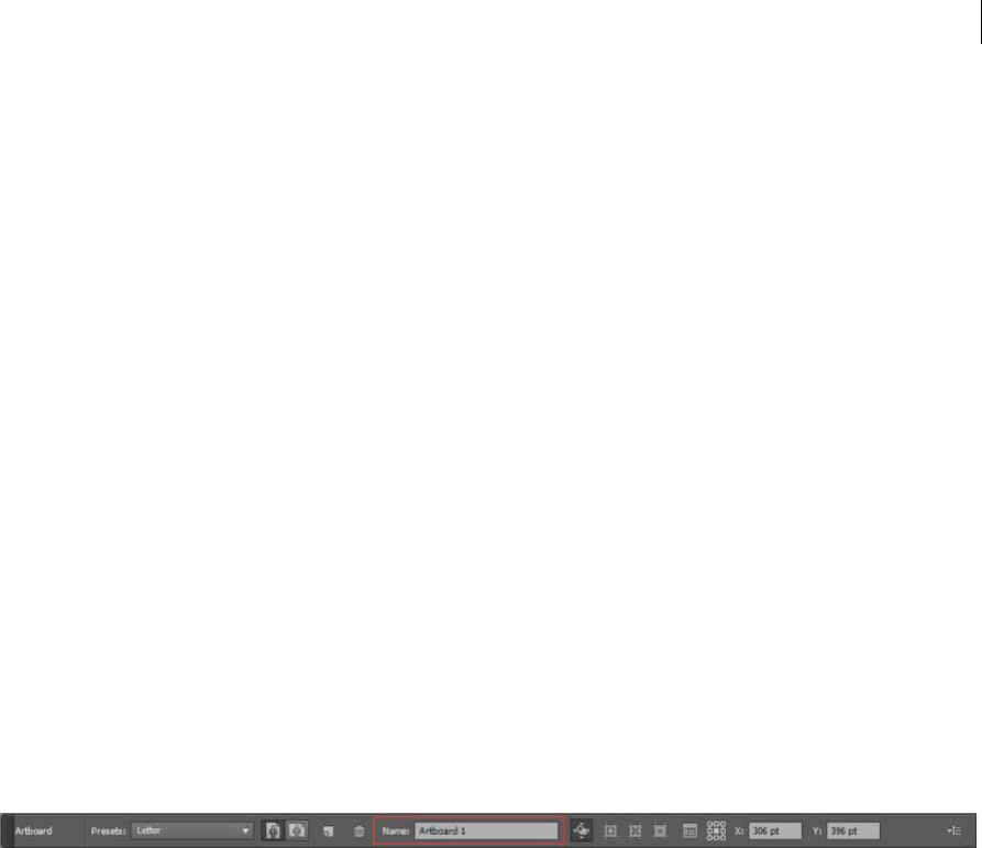
61
Workspace
Last updated 6/5/2015
Change to Right-to-Left Layout/Change to Left-to-Right Layout Arranges the artboards from left to right or right to
left. By default, artboards are arranged from left to right.
note: If you select the Change to Right-to-Left Layout option, the Grid by Row and Grid Column options change to
Right-to-Left Grid by Row and Right-to-Left Grid by Column.
3Specify the spacing between the artboards. This setting applies to both horizontal and vertical spacing.
4Select the Move Artwork with Artboard option to move the artwork whenever the artboards location changes.
Additionally, an artboard within an artboard is treated like a crop area and is moved along with the containing artboard.
Customize artboard names
Each artboard can now be given a custom name, when in artboard edit mode.
To assign a custom name to an artboard, do the following:
1Select the Artboard Tool to edit the artboard.
2Select the artboard and specify the artboard name in the Name box of the Artboard Control Panel.
Alternatively, you can provide a custom name in the Name field of the Artboard Options dialog box. To open the
dialog box, click Artboard Options in the Artboards Panel menu (flyout menu). Click OK to commit the new name
for the chosen artboard.
The new artboard name appears on the upper-left side of the artboard. The custom name also shows up in the Artboard
Navigation field and drop-down next to document’s status area.
If you assign a custom name to artboards, these names are added as suffix to the filename while saving artboard specific
files to all formats.
Note: To return to the default name, clear the name of the artboard from the Name field in the Control panel.
9-point referencing
To set reference points for artboards, use the Artboard Options dialog box or the Artboard options in the Control panel.
This option allows you to hinge a corner or center of an artboard while its size is being changed.
Display artboard rulers, center mark, crosshairs, or safe area
You can choose to display a center mark, cross hairs, video safe markers, and rulers around an artboard. Rulers are
useful when you’re working with art intended for export to video. The numbers on the rulers reflect device-specific
pixels, regardless of the measurement unit specified in preferences. The default Video Ruler Pixel Aspect Ratio (VPAR)
for Illustrator is 1.0 (for square pixels)—this value changes according to the preset you choose either in the Artboard
Options dialog box or the New Document dialog box.
If you’re using nonsquare pixels, the ruler provides for easier device-specific pixel calculations. For example, if you
specify an artboard of 100 x100 Illustrator points, and you want to know the exact size in device-dependent pixels
before exporting the file for use in an NTSC DV Widescreen, you can set the video ruler in Illustrator to use a video
ruler pixel aspect ratio of 1.2 (for wide pixels) and the ruler will reflect the change and display the artboard as 83 x100
device pixels (100/1.2 = 83.333).
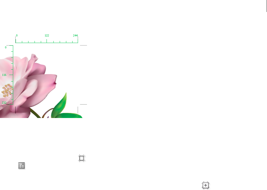
62
Workspace
Last updated 6/5/2015
Display center mark, cross hairs, or video safe areas
The center mark, cross hairs, and video safe area are video properties that assist you in creating videos while using
Creative Suite products. To display these properties:
1Double-click the Artboard tool in the Tools panel, or, with the Artboard tool active, click the Artboard Options
icon in the Control panel.
2In the Display section, select the options you’d like displayed in your artboards.
Note: You can also set or remove the center point by clicking the Show Center Mark icon in the Control panel.
Recovery, undo, and automation
Undo and redo changes
The Undo and Redo commands let you undo or redo operations, allowing you to correct mistakes as you work. You
can undo or redo an operation after you select the Save command (but not if you have closed and then reopened the
file).
❖Choose Edit > Undo or Edit > Redo.
You can undo an unlimited number of operations (depending on memory) by repeatedly choosing the Undo
command. If an operation cannot be undone, the Undo command is dimmed.
Revert to the last saved version
You can revert a file to the last saved version (but not if you have closed and then reopened the file). You cannot undo
this action.
❖Choose File > Revert.

63
Workspace
Last updated 6/5/2015
Automating tasks
Graphic design is a field characterized by creativity, but there are some aspects of the actual work of illustration that
can be repetitious. In fact, you’ll probably notice that the time you spend placing and replacing images, correcting
errors, and preparing files for printing and web display often reduces the time you have available for doing creative
work.
Illustrator provides a variety of ways to automate many of the repetitive tasks you have to do, leaving more time to
concentrate on the creative aspects of your work.
An action is a series of tasks that are recorded while using the Illustrator application—menu commands, tool options,
object selection, and so on. When you play an action, Illustrator performs all of the recorded tasks for you.
Illustrator provides prerecorded actions to assist you in performing common tasks. These actions are installed as a
default set in the Actions panel when you install the Illustrator application.
A script is a series of commands that tells your computer to perform a sequence of operations. These operations may
involve only Illustrator, or they may involve other applications, such as word-processing, spreadsheet, and database-
management programs. Illustrator provides default scripts to assist you in performing common tasks. You can access
these scripts by choosing File > Scripts.
Data-driven graphics streamline how designers and developers work together in high-volume publishing
environments.
Working with ConnectNow
Working with ConnectNow
Adobe® ConnectNow provides you with a secure, personal online meeting room where you can meet and collaborate
with others via the web in real time. With ConnectNow, you can share and annotate your computer screen, send chat
messages, and communicate using integrated audio. You can also broadcast live video, share files, capture meeting
notes, and control an attendee's computer.
You can access ConnectNow directly from the application interface.
1Choose File > Share My Screen.
2In the Sign In to Adobe CS Live dialog box, enter your email address and password, and click Sign In. If you don’t
have an Adobe ID, click the Create Adobe ID button.
3To share your screen, click the Share My Computer Screen button at the center of the ConnectNow application
window.
For complete instructions on using ConnectNow, see Adobe ConnectNow Help.
For a video tutorial about using ConnectNow, see Using ConnectNow to share your screen (7:12). (This demonstration
is in Dreamweaver.)
Files and templates

64
Workspace
Last updated 6/5/2015
About new document profiles
A document is the space in which you create artwork. In Illustrator, you can create documents destined for many
different types of output. (For information on creating Illustrator documents for video production, see the Enhancing
Video Production PDF at www.adobe.com/go/learn_ai_video.
You start a new document by choosing a new document profile based on your intended output. Each profile includes
preset values for size, color mode, units, orientation, transparency, and resolution. All use one artboard, by default. For
example, the Video And Film Document profile uses pixels instead of points, and you can choose a device-specific crop
area, such as NTSC DV Widescreen, to create a document in the exact dimensions required, with video-safe guides in
place to help you lay out your design for optimal viewing.
If you plan to output your file to a high-end printer, for example if you’re sending it to a service bureau, specify the Print
profile to ensure your artwork and any effects applied to the artwork are set to the proper resolution.
You can choose from the following profiles:
Print Document Uses a default letter size artboard, and provides a variety of other preset print sizes to choose from. Use
this profile if you plan to send this file to a service bureau for output to a high-end printer.
Web Document Provides preset options optimized for output to the web.
Flash Catalyst Creates an FXG document in RGB mode with 800px x 600px artboard as the default size. Align to Pixel
Grid is enabled for new art in the document and the Raster Effects Resolution is set to 72ppi. It also has Swatches,
Symbols, Graphic Styles and Brushes designed keeping Flash Catalyst and Flash Professional workflows in mind.
Mobile And Devices Document Creates a small file size that is preset for a specific mobile device. You can choose your
device from the Size menu. Click Device Central to open Adobe Device Central and view the document layout in a
specified device interface.
Video And Film Document Provides several preset video- and film-specific crop area sizes (note that the Artboard
option changes to Crop Size for this profile). Illustrator creates only square pixel files, so to ensure that the sizes are
interpreted correctly in video applications, Illustrator adjusts the Width and Height values. For example, if you choose
NTSC DV Standard, Illustrator uses a pixel size of 654 x 480, which translates to 740 x 480 pixels in video-based
applications.
Basic CMYK Document Uses a default letter size artboard, and provides a variety of other sizes to choose from. Use this
profile if you plan to send a document to multiple types of media. If one of the media types is a service bureau, you’ll
want to manually increase the Raster Effects setting to High.
Basic RGB Document Uses a default 800 x 600 size artboard, and provides a variety of other print-, video-, and web-
specific sizes to choose from. Do not use this option if you plan to send a document to a service bureau or output to a
high-end printer. Use this profile for documents that will be output to mid-level printers, to the web, or multiple types
of media.
For a video on setting up new documents, see www.adobe.com/go/vid0031.
For more information about creating custom new document profiles, see
www.adobe.com/go/learn_custom_document_profiles_en.
More Help topics
New document video
Video production

65
Workspace
Last updated 6/5/2015
Create new documents
You can create new Illustrator documents from a new document profile or from a template. Creating a document from
a new document profile gives you a blank document with the selected profile’s default fill and stroke colors, graphic
styles, brushes, symbols, actions, viewing preferences, and other settings. Creating a document from a template gives
you a document with preset design elements and settings, as well as content, such as cropmarks and guides, for specific
document types, such as brochures or CD covers.
You create a new document from the Welcome screen, or by using File > New or File > Device Central (for mobile
device output). To view the Welcome screen, select Help > Welcome.
For a video on setting up new documents, see www.adobe.com/go/vid0031.
More Help topics
About transparency
Using Adobe Device Central with Illustrator
Create a new document
You can start a new document from the Welcome screen or from the File menu.
1Do one of the following:
•If Illustrator is already open, choose File > New and from New Document Profile select the required document
profile.
•If the Welcome screen is open, click a document profile from the Create New list.
•If Illustrator is not open, open it and click a document profile from the Create New list in the Welcome screen.
note: In the Welcome screen, you can Alt-click (Windows) or Option-click (Mac OS) to open the new document
directly and skip the New Document dialog box.
2Type a name for your document.
3Specify the number of artboards for your document, and the order you’d like them laid out on screen:
Grid By Row Arranges multiple artboards in the specified number of rows. Choose the number of rows from the
Rows menu. The default value creates the most square appearance possible with the specified number of artboards.
Grid By Column Arranges multiple artboards in the specified number of columns. Choose the number of columns
from the Columns menu. The default value creates the most square appearance possible with the specified number
of artboards.
Arrange By Row Arranges artboards in one straight row.
Arrange By Column Arranges artboards in one straight column.
Change To Right-To-Left Layout Arranges multiple artboards in the specified row or column format, but displays
them from right to left.
4Specify the default spacing between artboards. This setting applies to both horizontal and vertical spacing.
5Specify the default size, units of measure, and layout for all artboards.
Note: Once your document opens, you can customize your artboards by moving and resizing them as desired.
6Specify the position of the bleed along each side of the artboard. To use different values for different sides, click the
Lock icon .
7Click Advanced to specify the following additional options:

66
Workspace
Last updated 6/5/2015
Note: You can change these settings after you create the document by choosing File > Document Setup and specifying
new settings.
Color Mode Specifies the color mode for the new document. Changing the color mode converts the default contents
(swatches, brushes, symbols, graphic styles) of the selected new document profile to a new color mode, resulting in
a color change. Watch for a warning icon when making changes.
Raster Effects Specifies the resolution for raster effects in the document. It is especially important to set this at High
when you plan to output to a high-end printer at high resolution. The Print profile sets this at High by default.
Transparency Grid Specifies the options for the transparency grid for documents that use the Video And Film
profile.
Preview Mode Sets the default preview mode for the document (you can change this at any time by using the View
menu):
•Default displays artwork created in the document in vector view with full color. Zoom in/out retains smoothness
in the curves.
•Pixel displays artwork with a rasterized (pixelated) appearance. It does not actually rasterize the content, but
displays a simulated preview, as if the contents were rasters.
•Overprint provides an “ink preview” that approximates how blending, transparency, and overprinting will appear
in color-separated output. (See About overprinting.)
Device Central If you’ve created a document using the Mobile and Devices profile, you can click Device Central to
preview your new document in the mobile device interface.
Align New Objects to Pixel Grid This option, if selected, aligns any new objects to the pixel grid. Because this option
is important for designs intended for display devices such as web, it is enabled by default for such documents. For
more information, see Drawing pixel-aligned paths for web workflows .
Create a new document from a template
1Do one of the following:
•Choose File > New From Template.
•Choose File > New. In the New Document dialog box, click Templates.
•In the Welcome screen, click From Template in the Create New list.
2In the New From Template dialog box, locate and select a template, and click New.
About templates
Templates let you create new documents that share common settings and design elements. For example, if you need to
design a series of business cards with a similar look and feel, you can create a template with the desired artboard size,
view settings (such as guides), and print options. The template can also contain symbols for common design elements
(such as logos) and specific sets of color swatches, brushes, and graphic styles.
Illustrator comes with a variety of templates, including templates for letterhead, business cards, envelopes, brochures,
labels, certificates, postcards, greeting cards, and websites.
When a template is selected via the New From Template command, Illustrator creates a new document with identical
content and document settings as the template, but leaves the original template file untouched.
Create a new template
1Open a new or existing document.

67
Workspace
Last updated 6/5/2015
2Customize the document in any of the following ways:
•Set up the document window as you want it to appear in new documents you create from the template. This
includes the magnification level, scroll position, ruler origin, guides, grids, crop areas, and options in the View
menu.
•Draw or import any artwork you want to appear in new documents you create from the template.
•Delete any existing swatches, styles, brushes, or symbols, you don’t want to retain.
•Create any new swatches, styles, brushes, and symbols, you want in the corresponding panels. You can also
import preset swatches, styles, brushes, symbols, and actions from a variety of libraries that come with Illustrator.
•Create any graph designs you want and add them to the Graph Design dialog box. You can also import preset
graph designs.
•Set the desired options in the Document Setup dialog box and Print Options dialog box.
3Choose File > Save As Template.
4In the Save As dialog box, select a location for the file, enter a filename, and click Save.
Illustrator saves the file in AIT (Adobe Illustrator Template) format.
Specify document setup options
At any point you can change your document’s default setup options for units of measure, transparency grid display,
background color, and type settings such as language, quote style, superscript and subscript size, and exportability. The
Edit Artboards button closes this dialog box and activates the Artboard tool. Use this button if you want to modify your
artboards.
1Choose File > Document Setup or click the Document Setup button in the Control panel (this button is visible when
nothing is selected).
2Specify options as desired.
Note: The Simulate Colored Paper option is useful if you plan to print the document on colored paper. For example, if you
draw a blue object on a yellow background, the object appears green. The simulation is performed only when the
transparency grid is not shown.
For specific information on these options, see related topics.
Open a file
You can open files that were created in Illustrator as well as compatible files that were created in other applications.
•To open an existing file, choose File > Open. Locate the file, and click Open.
•To open a recently saved file, choose the file from the Open A Recent Item list in the Welcome screen, or choose File
> Open Recent Files, and choose a file from the list.
•To open and preview a file using Adobe Bridge, choose File > Browse In Bridge to open Adobe Bridge. Locate the
file and choose File > Open With > Adobe Illustrator CS5.

68
Workspace
Last updated 6/5/2015
Browse for files using Adobe Bridge
Adobe® Bridge is a cross-platform application included with Adobe® Creative Suite® 5 components that helps you locate,
organize, and browse the assets you need to create print, web, video, and audio content. You can start Bridge from any
Creative Suite component, and use it to access both Adobe and non-Adobe asset types.
❖To open Adobe Bridge, do one of the following from within Illustrator:
•Choose File > Browse In Bridge.
•Click the Adobe Bridge icon in the Control panel.
•Choose Reveal In Bridge from the status bar.
From Adobe Bridge, you can do any of the following:
•Manage image, footage, and audio files: Preview, search, sort, and process files in Bridge without opening individual
applications. You can also edit metadata for files, and use Bridge to place files into your documents, projects, or
compositions.
•Manage your photos: Import and edit photos from your digital camera card, group related photos in stacks, and
open or import Photoshop® Camera Raw files and edit their settings without starting Photoshop.
•Perform automated tasks, such as batch commands.
•Synchronize color settings across color-managed Creative Suite components.
•Start a real-time web conference to share your desktop and review documents.
More Help topics
Adobe Bridge
Connect to CS Live
Import and export Illustrator CC settings
Import and Export Settings
You can export or import Illustrator settings using settings packages. Select a location, and then easily export Illustrator
settings available on the computer. Copy the package to a different computer and then use Illustrator CC on that
computer to import settings from the package.
Export settings
1In Illustrator, click Edit > My Settings > Export Settings.
2In the dialog that is displayed, select a location where you would like the settings package to be saved.
The settings package created is named in the format AI17Settings_date_time.
3Click OK, to create a settings package at the selected location.
You can copy the newly created file to another computer, and use it to import Illustrator settings on that computer.

69
Workspace
Last updated 6/5/2015
Import settings
Note: When you import settings, Illustrator is restarted to apply the settings. Save your artwork before importing settings.
1In Illustrator, click Edit > My Settings > Import Settings.
2In the Import Settings dialog displayed, select a settings package file.
The settings package is named in the format AI17Settings_date_time.
3Click OK to import settings.
4When prompted, click the buttons to complete the import action and restart Illustrator.
Important Considerations:
•Settings cannot be exported or imported between instances of Illustrator with different locale settings.
•Keyboard shortcuts are not imported when you copy settings across operating system platforms (Windows and
Macintosh).
File Info dialog
The file information dialog (File > File Info) is being recreated with a newer framework. The screenshot below displays
the new layout of the File Info dialog.
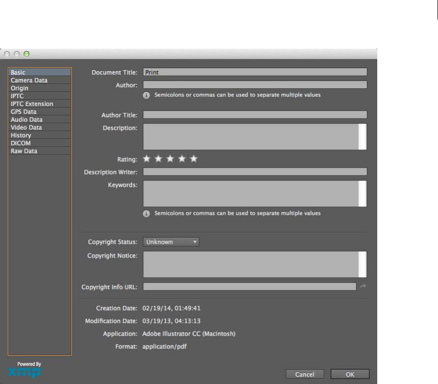
70
Workspace
Last updated 6/5/2015
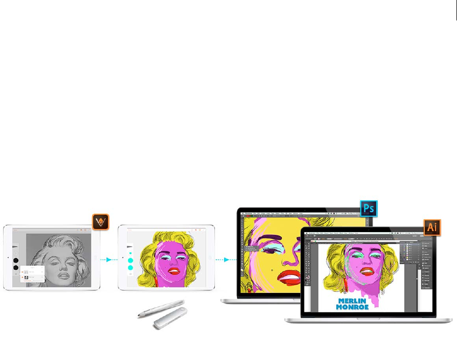
71
Last updated 6/5/2015
Chapter 3: Drawing
Drawing basics
Is ideating, tracing, or prototyping on your iPad or iPhone the beginning of your Design workflow?
Check out Adobe Illustrator Draw - an app for your iPad or iPhone. Draw incorporates your favorite vector drawing
tools and features into a streamlined, modern interface. You can draw lines, shapes, and freeform illustrations and with
ten drawing layers and a photo layer. And when you’re back at your desk, Creative Cloud connectivity makes it easy to
apply finishing touches in Illustrator CC or Photoshop CC.
Learn more about the Adobe Illustrator Draw app here.
Download the amazing Adobe Illustrator Draw app from the iTunes app store (Available for your iPhone and iPad).
About vector graphics
Vector graphics (sometimes called vector shapes or vector objects) are made up of lines and curves defined by
mathematical objects called vectors, which describe an image according to its geometric characteristics.
You can freely move or modify vector graphics without losing detail or clarity, because they are resolution-
independent—they maintain crisp edges when resized, printed to a PostScript printer, saved in a PDF file, or imported
into a vector-based graphics application. As a result, vector graphics are the best choice for artwork, such as logos, that
will be used at various sizes and in various output media.
The vector objects you create using the drawing and shape tools in Adobe Creative Suite are examples of vector
graphics. You can use the Copy and Paste commands to duplicate vector graphics betweenCreative Suite components.
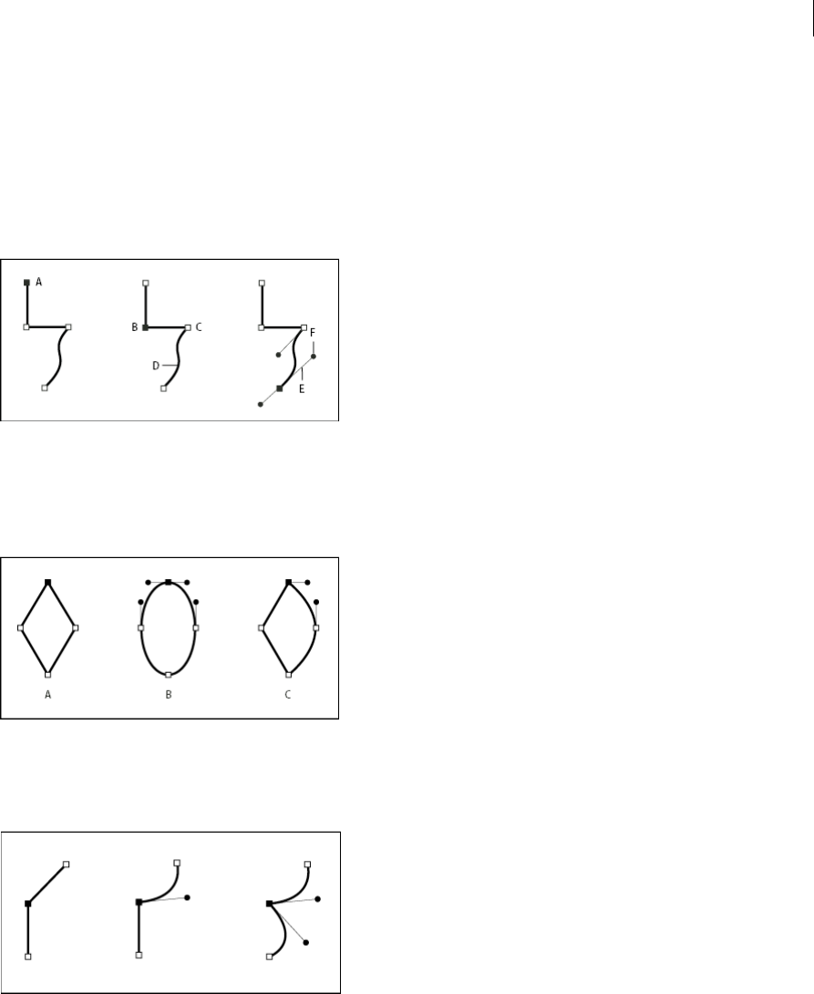
72
Drawing
Last updated 6/5/2015
About paths
As you draw, you create a line called a path. A path is made up of one or more straight or curved segments. The
beginning and end of each segment are marked by anchor points, which work like pins holding a wire in place. A path
can be closed (for example, a circle), or open, with distinct endpoints (for example, a wavy line).
You change the shape of a path by dragging its anchor points, the direction points at the end of direction lines that appear
at anchor points, or the path segment itself.
A Selected (solid) endpoint B Selected anchor point C Unselected anchor point D Curved path segment E Direction line F Direction point
Paths can have two kinds of anchor points: corner points and smooth points. At a corner point, a path abruptly changes
direction. At a smooth point, path segments are connected as a continuous curve. You can draw a path using any
combination of corner and smooth points. If you draw the wrong kind of point, you can always change it.
A Four corner points B Four smooth points C Combination of corner and smooth points
A corner point can connect any two straight or curved segments, while a smooth point always connects two curved
segments.
Note: Don’t confuse corner and smooth points with straight and curved segments.
A path’s outline is called a stroke. A color or gradient applied to an open or closed path’s interior area is called a fill. A
stroke can have weight (thickness), color, and a dash pattern (Illustrator and InDesign) or a stylized line pattern
(InDesign). After you create a path or shape, you can change the characteristics of its stroke and fill.
In InDesign, each path also displays a center point, which marks the center of the shape but is not part of the actual path.
You can use this point to drag the path, to align the path with other elements, or to select all anchor points on the path.
The center point is always visible; it can’t be hidden or deleted.
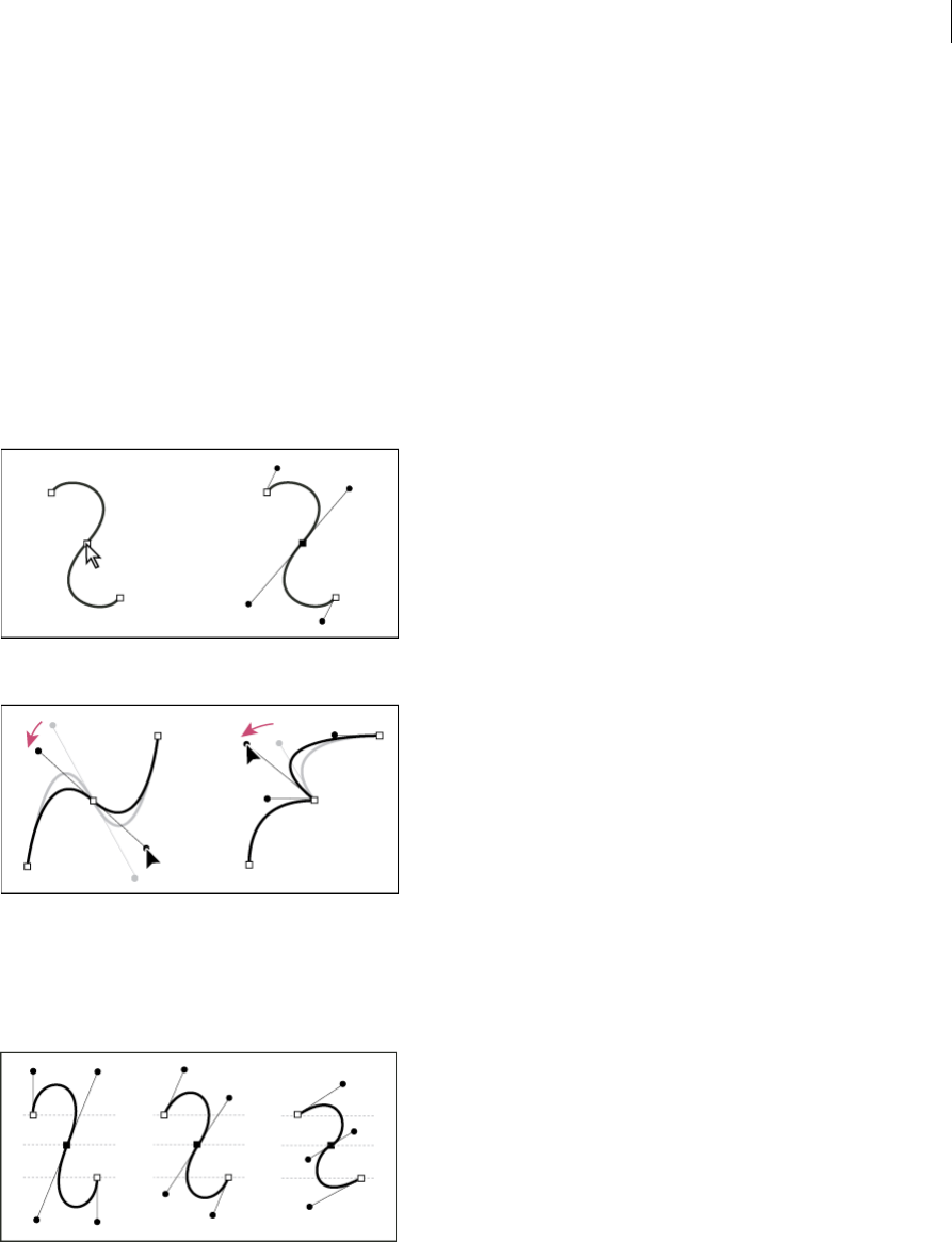
73
Drawing
Last updated 6/5/2015
About direction lines and direction points
When you select an anchor point that connects curved segments (or select the segment itself ), the anchor points of the
connecting segments display direction handles, which consist of direction lines that end in direction points. The angle
and length of the direction lines determine the shape and size of the curved segments. Moving the direction points
reshapes the curves. Direction lines don’t appear in the final output.
A smooth point always has two direction lines, which move together as a single, straight unit. When you move a
direction line on a smooth point, the curved segments on both sides of the point are adjusted simultaneously,
maintaining a continuous curve at that anchor point.
In comparison, a corner point can have two, one, or no direction lines, depending on whether it joins two, one, or no
curved segments, respectively. Corner point direction lines maintain the corner by using different angles. When you
move a direction line on a corner point, only the curve on the same side of the point as that direction line is adjusted.
Direction lines are always tangent to (perpendicular to the radius of) the curve at the anchor points. The angle of each
direction line determines the slope of the curve, and the length of each direction line determines the height, or depth,
of the curve.
Note: In Illustrator, you can show or hide anchor points, direction lines, and direction points by choosing View > Show
Edges or View > Hide Edges.
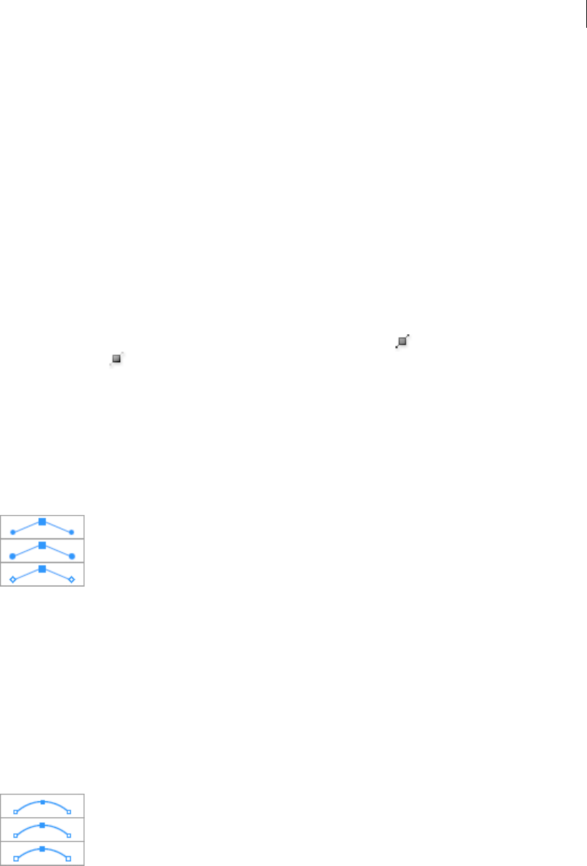
74
Drawing
Last updated 6/5/2015
Specify direction line and direction point appearance
When working with anchor points and paths, you may sometimes need to see direction lines (handles), while at other
times they may get in the way. You can show or hide direction lines for multiple selected anchor points. For a single
anchor point, the lines always appear.
You can choose to show or hide direction lines on a per-selection basis, or you can set a preference for direction line
display.
For a video on setting direction lines and points, see www.adobe.com/go/vid0037.
More Help topics
Specify selection preferences
Show or hide direction lines for selected anchor points
1Use the Direct Selection tool to select the desired anchor points.
2In the Control panel, click Show Handles For Multiple Selected Anchor Points > or Hide Handles For Multiple
Selected Anchor Points .
Note: You can also set a preference to always show or always hide handles when multiple anchor points are selected.
Set direction point and direction line display preferences
1Choose Edit > Preferences > Selection & Anchor Display (Windows) or Illustrator > Preferences > Selection &
Anchor Display (Mac OS).
2In the Anchor Point And Handle Display area, specify any of the following:
Handles Specifies the display of handle end points (direction points):
• Displays direction points as small solid circles.
• Displays direction points as large solid circles.
• Displays direction points as open crosses.
Show Handles When Multiple Anchors Are Selected Displays direction lines on all selected anchor points when you
use the Direct Selection tool or Group Selection tool to select an object. If you don’t select this option, direction lines
are displayed for an anchor point if it is the only anchor point selected on that path, or if the Bezier segment for the
direction line is selected and the anchor point from which the direction line extends is not selected.
Specify anchor point size preferences
1Choose Edit > Preferences > Selection & Anchor Display (Windows) or Illustrator > Preferences > Selection &
Anchor Display (Mac OS).
2In the Anchor Point And Handle Display area, specify any of the following:
Anchors Specifies the display of anchor points:
• Displays both selected and unselected anchor points as small points.
• Displays selected anchor points as large points and unselected anchor points as small points.
• Displays both selected and unselected anchor points as large points.
Highlight Anchors On Mouse Over Highlights the anchor point located directly below the mouse cursor.
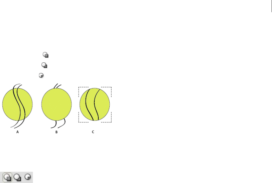
75
Drawing
Last updated 6/5/2015
Drawing modes
Illustrator CS5 provides the following drawing modes:
•Draw Normal ( )
•Draw Behind ( )
•Draw Inside ( )
The Draw Normal mode is the default drawing mode. You can select drawing modes from the Tools panel, below the
Color Selector tool.
To switch through drawing modes, click the Drawing Modes panel in the Tools panel and select the drawing mode. You
can also use the Shift+D keyboard shortcut to cycle through the drawing modes.
Note: The options, Paste, Paste in Place, and Paste on All Artboardshonor the drawing modes. However, Paste in Front and
Paste in Back commands are not affected by the drawing modes.
For a video on using the different drawing modes, see www.adobe.com/go/lrvid5209_ai_en.
Draw Behind mode
The Draw Behind mode allows you to draw behind all artwork on a selected layer if no artwork is selected. If an artwork
is selected, the new object is drawn directly beneath the selected object.
The draw behind mode is honored in the following cases:
•Creating new layers
•Placing symbols
•Placing files from the File menu
•Using Alt+Drag to duplicate objects
•Using Paste in Place and Paste on All Artboards options
Draw Inside mode
The Draw Inside mode allows you to draw inside the selected object. The Draw Inside mode eliminates the need to
perform multiple tasks such as drawing and altering stacking order or drawing, selecting, and creating a clipping mask.
The draw inside mode is enabled only when there is a single selected object (path, compound path, or text).

76
Drawing
Last updated 6/5/2015
To create clipping masks using the Draw Inside mode, select the path within which you want to draw and switch to the
Draw Inside mode. Subsequent paths are clipped by the path that was selected when you switch to the Draw Inside
mode, until you switch to the Draw Normal mode (Shift+D or double-click).
Note: The clipping masks created using Draw Inside retain the appearance on the clipping path unlike the menu command
Object > Clipping Mask > Make.
More Help topics
About bitmap images
Drawing simple lines and shapes
Drawing with the Pen or Pencil tool
Editing paths
Tracing artwork with Live Trace or template layers
Symbols
Drawing with the Pen, Pencil, or Flare tool
Drawing with the Pen tool
Draw straight line segments with the Pen tool
The simplest path you can draw with the Pen tool is a straight line, made by clicking the Pen tool to create two anchor
points. By continuing to click, you create a path made of straight line segments connected by corner points.
1Select the Pen tool.
2Position the Pen tool where you want the straight segment to begin, and click to define the first anchor point (do
not drag).
Note: The first segment you draw will not be visible until you click a second anchor point. (Select the Rubber Band
option in Photoshop to preview path segments.) Also, if direction lines appear, you’ve accidentally dragged the Pen tool;
choose Edit > Undo, and click again.
3Click again where you want the segment to end (Shift-click to constrain the angle of the segment to a multiple of
45°).
4Continue clicking to set anchor points for additional straight segments.
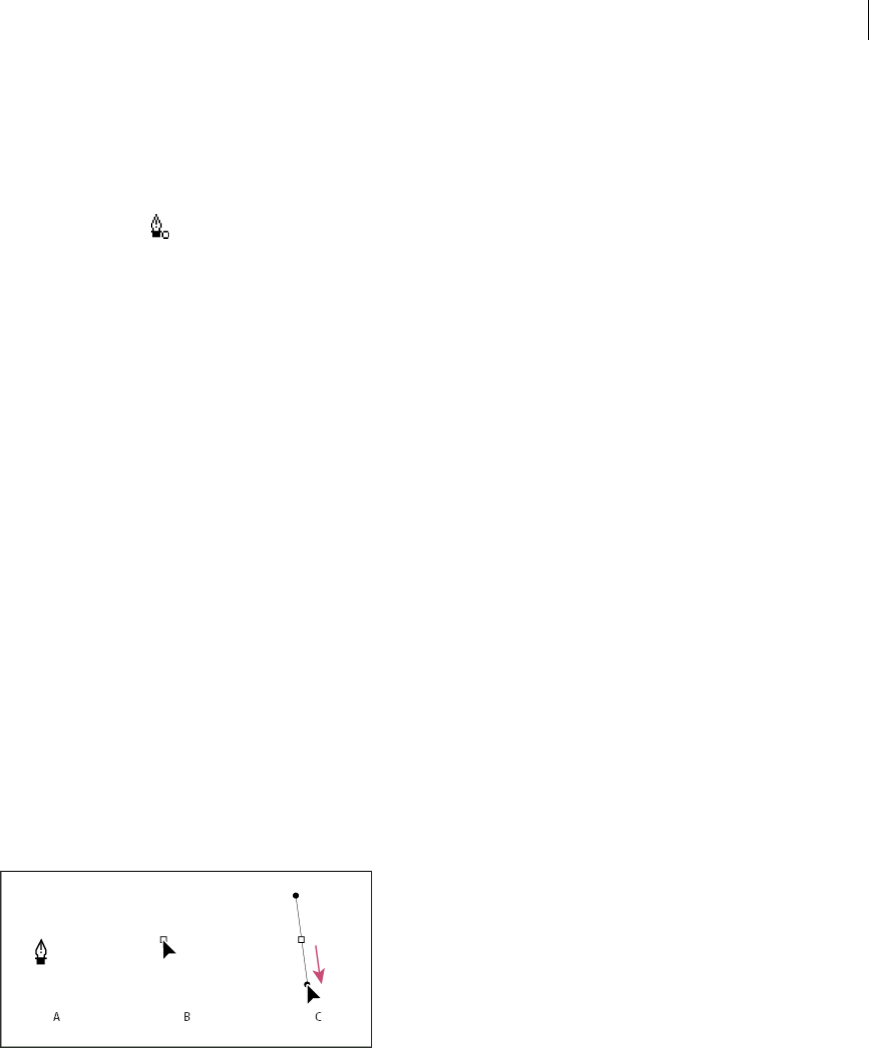
77
Drawing
Last updated 6/5/2015
The last anchor point you add always appears as a solid square, indicating that it is selected. Previously defined
anchor points become hollow, and deselected, as you add more anchor points.
5Complete the path by doing one of the following:
•To close the path, position the Pen tool over the first (hollow) anchor point. A small circle appears next to the
Pen tool pointer when it is positioned correctly. Click or drag to close the path.
note: To close a path in InDesign, you can also select the object and choose Object > Paths > Close Path.
•To leave the path open, Ctrl-click (Windows) or Command-click (Mac OS) anywhere away from all objects.
To leave the path open, you can also select a different tool, or choose Select > Deselect in Illustrator or Edit
>Deselect All in InDesign. In InDesign or Illustrator, you can also simply press Enter or Return to leave the path
open.
Draw curves with the Pen tool
You create a curve by adding an anchor point where a curve changes direction, and dragging the direction lines that
shape the curve. The length and slope of the direction lines determine the shape of the curve.
Curves are easier to edit and your system can display and print them faster if you draw them using as few anchor points
as possible. Using too many points can also introduce unwanted bumps in a curve. Instead, draw widely spaced anchor
points, and practice shaping curves by adjusting the length and angles of the direction lines.
1Select the Pen tool.
2Position the Pen tool where you want the curve to begin, and hold down the mouse button.
The first anchor point appears, and the Pen tool pointer changes to an arrowhead. (In Photoshop, the pointer
changes only after you’ve started dragging.)
3Drag to set the slope of the curve segment you’re creating, and then release the mouse button.
In general, extend the direction line about one third of the distance to the next anchor point you plan to draw. (You
can adjust one or both sides of the direction line later.)
Hold down the Shift key to constrain the tool to multiples of 45°.
A Positioning Pen tool B Starting to drag (mouse button pressed) C Dragging to extend direction lines
4Position the Pen tool where you want the curve segment to end, and do one of the following:
•To create a C-shaped curve, drag in a direction opposite to the previous direction line. Then release the mouse
button.
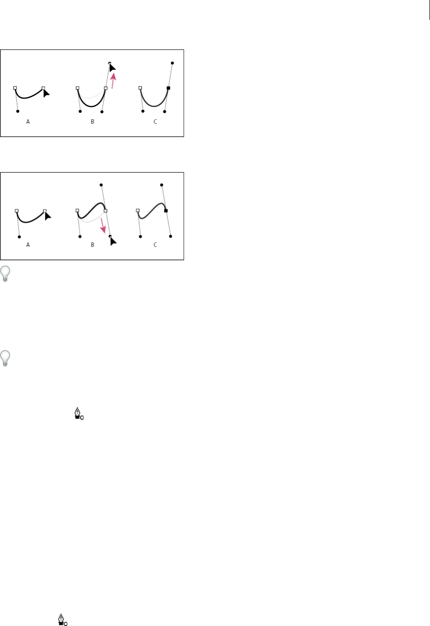
78
Drawing
Last updated 6/5/2015
•To create an S-shaped curve, drag in the same direction as the previous direction line. Then release the mouse
button.
(Photoshop only) To change the direction of the curve sharply, release the mouse button, and then Alt-drag
(Windows) or Option-drag (Mac OS) the direction point in the direction of the curve. Release the Alt
(Windows) or Option (Mac OS) key and the mouse button, reposition the pointer where you want the segment
to end, and drag in the opposite direction to complete the curve segment.
5Continue dragging the Pen tool from different locations to create a series of smooth curves. Note that you are
placing anchor points at the beginning and end of each curve, not at the tip of the curve.
Alt-drag (Windows) or Option-drag (Mac OS) direction lines to break out the direction lines of an anchor point.
6Complete the path by doing one of the following:
•To close the path, position the Pen tool over the first (hollow) anchor point. A small circle appears next to the
Pen tool pointer when it is positioned correctly. Click or drag to close the path.
note: To close a path in InDesign, you can also select the object and choose Object > Paths > Close Path.
•To leave the path open, Ctrl-click (Windows) or Command-click (Mac OS) anywhere away from all objects.
To leave the path open, you can also select a different tool, or choose Select > Deselect in Illustrator or Edit
>Deselect All in InDesign.
For a video on using the Pen tool in Illustrator, see www.adobe.com/go/vid0037.
Reposition anchor points as you draw
❖After you click to create an anchor point, keep the mouse button pressed down, hold down the spacebar, and drag
to reposition the anchor point.
Finish drawing a path
❖Complete a path in one of the following ways:
•To close a path, position the Pen tool over the first (hollow) anchor point. A small circle appears next to the Pen
tool pointer when it is positioned correctly. Click or drag to close the path.
note: To close a path in InDesign, you can also select the object and choose Object > Paths > Close Path.
•To leave a path open, Ctrl-click (Windows) or Command-click (Mac OS) anywhere away from all objects.
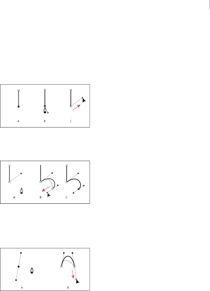
79
Drawing
Last updated 6/5/2015
To leave the path open, you can also select a different tool, or choose Select > Deselect in Illustrator or Edit > Deselect
All in InDesign. In InDesign, you can also simply press Enter or Return to leave the path open.
Draw straight lines followed by curves
1Using the Pen tool, click corner points in two locations to create a straight segment.
2Position the Pen tool over the selected endpoint. In Illustrator and InDesign, a convert-point icon appears next to
the Pen tool when it is positioned correctly (In Photoshop, a small diagonal line, or slash, appears next to the Pen
tool). To set the slope of the curved segment you’ll create next, click the anchor point, and drag the direction line
that appears.
A Straight segment completed B Positioning Pen tool over endpoint (the Convert Point icon appears only in Illustrator and InDesign)
C Dragging direction point
3Position the pen where you want the next anchor point; then click (and drag, if desired) the new anchor point to
complete the curve.
A Positioning Pen tool B Dragging direction line C New curve segment completed
Draw curves followed by straight lines
1Using the Pen tool, drag to create the first smooth point of the curved segment, and release the mouse button.
2Reposition the Pen tool where you want the curved segment to end, drag to complete the curve, and release the
mouse button.
A First smooth point of curved segment completed and Pen tool positioned over endpoint B Dragging to complete the curve
3Position the Pen tool over the selected endpoint. A convert-point icon appears next to the Pen tool when it is
positioned correctly. Click the anchor point to convert the smooth point to a corner point.
4Reposition the Pen tool where you want the straight segment to end, and click to complete the straight segment.
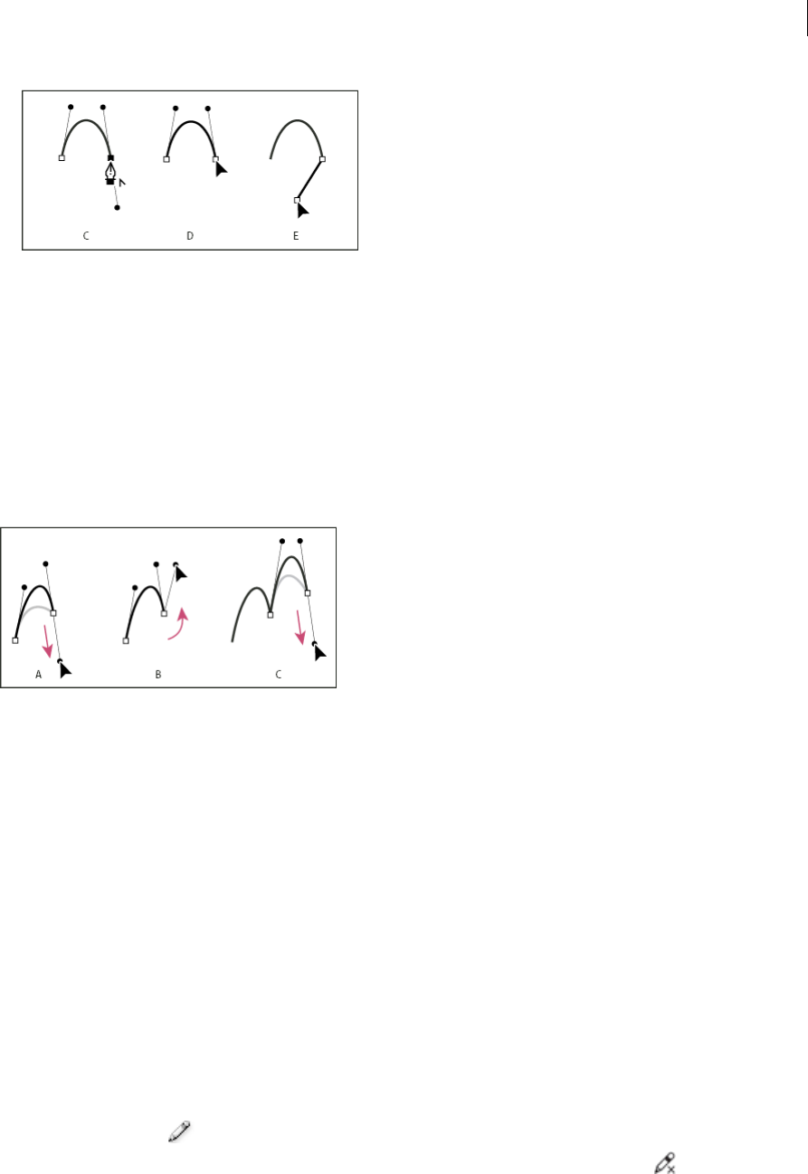
80
Drawing
Last updated 6/5/2015
A Positioning Pen tool over existing endpoint B Clicking endpoint C Clicking next corner point
Draw two curved segments connected by a corner
1Using the Pen tool, drag to create the first smooth point of a curved segment.
2Reposition the Pen tool and drag to create a curve with a second smooth point; then press and hold Alt (Windows)
or Option (Mac OS) and drag the direction line toward its opposing end to set the slope of the next curve. Release
the key and the mouse button.
This process converts the smooth point to a corner point by splitting the direction lines.
3Reposition the Pen tool where you want the second curved segment to end, and drag a new smooth point to
complete the second curved segment.
A Dragging a new smooth point B Pressing Alt/Option to split direction lines while dragging, and swinging direction line up C Result after
repositioning and dragging a third time
Drawing with the Pencil tool
Draw with the Pencil tool
The Pencil tool works primarily the same way in Adobe Illustrator and InDesign. It lets you draw open and closed paths
as if you were drawing with a pencil on paper. It is most useful for fast sketching or creating a hand-drawn look. Once
you draw a path, you can immediately change it if needed.
Anchor points are set down as you draw with the Pencil tool; you do not determine where they are positioned. However,
you can adjust them once the path is complete. The number of anchor points set down is determined by the length and
complexity of the path and by tolerance settings in the Pencil Tool Preferences dialog box. These settings control how
sensitive the Pencil tool is to the movement of your mouse or graphics-tablet stylus.
For a video on drawing with the Pencil tool in Illustrator, see www.adobe.com/go/vid0039.
Draw freeform paths with the Pencil tool
1Select the Pencil tool .
2Position the tool where you want the path to begin, and drag to draw a path. The Pencil tool displays a small x
to indicate drawing a freeform path.

81
Drawing
Last updated 6/5/2015
As you drag, a dotted line follows the pointer. Anchor points appear at both ends of the path and at various points
along it. The path takes on the current stroke and fill attributes, and remains selected by default.
Draw closed paths with the Pencil tool
1Select the Pencil tool.
2Position the tool where you want the path to begin, and start dragging to draw a path.
3After you’ve begun dragging, hold down Alt (Windows) or Option (Mac OS). The Pencil tool displays a small circle
(and, in InDesign, a solid eraser) to indicate that you’re creating a closed path.
4When the path is the size and shape you want, release the mouse button (but not the Alt or Option key). After the
path closes, release the Alt or Option key.
You don’t have to position the cursor over the starting point of the path in order to create a closed path; if you release
the mouse button in some other location, the Pencil tool will close the shape by creating the shortest possible line
back to the original point.
Edit paths with the Pencil tool
You can edit any path using the Pencil tool and add freeform lines and shapes to any shape.
Add to a path with the Pencil tool
1Select an existing path.
2Select the Pencil tool.
3Position the pencil tip on an endpoint of the path.
You can tell you’re close enough to the endpoint when the small x next to the pencil tip disappears.
4Drag to continue the path.
Connect two paths with the Pencil tool
1Select both paths (Shift-click or drag around the two with the Selection tool).
2Select the Pencil tool.
3Position the pointer where you want to begin from one path, and start dragging toward the other path.
4After you begin dragging, hold down Ctrl (Windows) or Command (Mac OS). The Pencil tool displays a small
merge symbol to indicate you’re adding to the existing path.
5Drag onto the endpoint of the other path, release the mouse button, and then release the Ctrl or Command key.
Note: For best results, drag from one path to the other as if you were simply continuing the paths in the direction they
were created.
Reshape paths with the Pencil tool
1Select the path you want to change.
2Position the Pencil tool on or near the path to redraw.
You can tell you’re close enough to the path when the small x disappears from the tool.
3Drag the tool until the path is the desired shape.
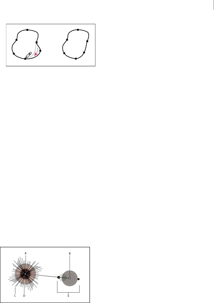
82
Drawing
Last updated 6/5/2015
Note: Depending on where you begin to redraw the path and in which direction you drag, you may get unexpected
results. For example, you may unintentionally change a closed path to an open path, change an open path to a closed
path, or lose a portion of a shape.
Pencil tool options
Double-click the Pencil tool to set any of the following options:
Fidelity Controls how far you have to move your mouse or stylus before a new anchor point is added to the path. The
higher the value, the smoother and less complex the path. The lower the value, the more the curves will match the
pointer’s movement, resulting in sharper angles. Fidelity can range from 0.5 to 20 pixels.
Smoothness Controls the amount of smoothing applied when you use the tool. Smoothness can range from 0% to
100%. The higher the value, the smoother the path. The lower the value, the more anchor points are created, and the
more the line’s irregularities are preserved.
Fill New Pencil Strokes (Illustrator only) Applies a fill to pencil strokes you draw after selecting this option, but not to
existing pencil strokes. Remember to select a fill before you draw the pencil strokes.
Keep Selected Determines whether to keep the path selected after you draw it. This option is selected by default.
Edit Selected Paths Determines whether or not you can change or merge a selected path when you are within a certain
distance of it (specified with the next option).
Within: _ pixels Determines how close your mouse or stylus must be to an existing path in order to edit the path with
the Pencil tool. This option is only available when the Edit Selected Paths option is selected.
Drawing flares
The Flare tool creates flare objects with a bright center, a halo, and rays and rings. Use this tool to create an effect similar
to a lens flare in a photograph.
Flares include a center handle and an end handle. Use the handles to position the flare and its rings. The center handle
is in the bright center of the flare—the flare path begins from this point.
A Center handle B End handle C Rays (shown black for clarity) D Halo E Rings
To learn more about creating and editing flares, see this topic in web Help.
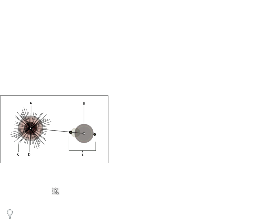
83
Drawing
Last updated 6/5/2015
Note: Complete, updated Help is on the web. The application did not detect an Internet connection. For a complete version
of this topic, click the link below or search complete Help at community.adobe.com/help.
Create a flare
The Flare tool creates flare objects with a bright center, a halo, and rays and rings. Use this tool to create an effect similar
to a lens flare in a photograph.
Flares include a center handle and an end handle. Use the handles to position the flare and its rings. The center handle
is in the bright center of the flare—the flare path begins from this point.
A Center handle B End handle C Rays (shown black for clarity) D Halo E Rings
Create a default flare
1Select the Flare tool .
2Press Alt (Windows) or Option (Mac OS), and click where you want the center handle of the flare to appear.
Flares often look best when drawn over existing objects.
Draw a flare
1Select the Flare tool.
2Press the mouse button down to place the center handle of the flare, then drag to set the size of the center, the size
of the halo, and to rotate the angle of the rays.
Before releasing the mouse, press Shift to constrain the rays to a set angle. Press Up Arrow or Down Arrow to add
or subtract rays. Press Ctrl (Windows) or Command (Mac OS) to hold the center of the flare constant.
3Release the mouse when the center, halo, and rays are as desired.
4Press and drag again to add rings to the flare and place the end handle.
Before releasing the mouse, Press Up Arrow or Down Arrow to add or subtract rings. Press the tilde (~) key to
randomly place the rings.
5Release the mouse when the end handle is in the desired location.
Each element (center, halo, rings, and rays) in the flare is filled with color at different opacity settings.
Create a flare using the Flare Tool Options dialog box
1Select the Flare tool, and click where you want to place the center handle of the flare.
2In the Flare Tool Options dialog box, do any of the following options, and click OK:
•Specify the overall diameter, opacity, and brightness of the flare’s center.

84
Drawing
Last updated 6/5/2015
•Specify the Growth of the halo as a percentage of the overall size, and specify the fuzziness of the halo (0 is crisp
and 100 is fuzzy).
•If you want the flare to contain rays, select Rays and specify the number of rays, the longest ray (as a percentage
of the average ray), and the fuzziness of the rays (0 is crisp and 100 is fuzzy).
•If you want the flare to contain rings, select Rings and specify the distance of the path between the halo’s center
point (center handle) and the center point of the furthest ring (end handle), the number of rings, the largest ring
(as a percentage of the average ring), and the direction or angle of the rings.
Edit a flare
Do any of the following:
•Select the flare, and double-click the Flare tool icon to open the Flare Tool Options dialog box. Change settings in
the dialog box.
Tip: To reset a flare to the default values, hold down Alt (Windows) or Option (Mac OS), and click Reset.
•Select the flare and the Flare tool. Drag an endpoint—from either the center handle or the end handle—to change
the length or direction of the flare.
•Select the flare, and choose Object > Expand. This makes the elements of the flare editable, like elements of blends.
More Help topics
Pen tool in Illustrator video
Pencil tool in Illustrator video
Drawing tool gallery
Expand objects
Drawing simple lines and shapes
Draw straight lines with the Line Segment tool
Use the Line Segment tool when you want to draw one straight line segment at a time. For a video on using the Line
Segment tool, see www.adobe.com/go/vid0036.
1Select the Line Segment tool .
2Do one of the following:
•Position the pointer where you want the line to begin, and drag to where you want the line to end.
•Click where you want the line to begin, and specify the length and angle of the line. If you want to fill the line
with the current fill color, select Fill Line. Then click OK.
Draw rectangles and squares
1Select the Rectangle tool or the Rounded Rectangle tool .

85
Drawing
Last updated 6/5/2015
2Do one of the following:
•To draw a rectangle, drag diagonally until the rectangle is the desired size.
•To draw a square, hold down the Shift key while you drag diagonally until the square is the desired size.
•To create a square or rectangle using values, click where you want the top-left corner to be. Specify a width and
height (and a corner radius for a rounded rectangle), and click OK.
For a video on using shape tools, see www.adobe.com/go/vid0036. For an example of using shape tools to draw
buildings, see www.adobe.com/go/learn_ai_tutorials_shapes_en.
Specify the corner radius of a rounded rectangle
The corner radius determines the roundness of the rectangle’s corners. You can change the default radius for all new
rectangles, and you can change the radius for individual rectangles as you draw them.
•To change the default corner radius, choose Edit> Preferences > General (Windows) or Illustrator > Preferences >
General (Mac OS), and enter a new value for Corner Radius. Alternatively, select the Rounded Rectangle tool, click
in the document window, and enter a new value for Corner Radius. The default radius applies only to new rounded
rectangles you draw, not to existing rounded rectangles.
•To change the corner radius while dragging with the Rounded Rectangle tool, press the Up Arrow key or Down
Arrow key. When the corners are the desired roundness, release the key.
•To create square corners while dragging with the Rounded Rectangle tool, press the Left Arrow key.
•To create the most rounded corners while dragging with the Rounded Rectangle tool, press the Right Arrow key.
Note: You cannot change the corner radius after you’ve drawn a rounded rectangle. If you feel that you might need to
change the corner radius, draw a normal rectangle and choose Effect > Convert to Shape > Rounded Rectangle and specify
the rounded rectangle parameters. To modify the corner radius or other parameters modify the effect parameters from the
Appearance panel.
Draw ellipses
1Select the Ellipse tool . Click and hold the rectangle tool to see and choose the ellipse tool. For more information
on selecting tools see Select a tool.
2Do one of the following:
•Drag diagonally until the ellipse is the desired size.
•Click where you want the top-left corner of the ellipse’s bounding box to be. Specify a width and height for the
ellipse, and click OK.
note: To create a circle, hold down the Shift key while dragging, or if you are specifying dimensions, once you’ve
entered a Width value you can click on the word Height to copy that value into the Height box.
For a video on using shape tools, see www.adobe.com/go/vid0036.
More Help topics
Drawing tool gallery
Keys for drawing
Tools panel over v iew

86
Drawing
Last updated 6/5/2015
Draw polygons
1Select the Polygon tool .
2Do one of the following:
•Drag until the polygon is the desired size. Drag the pointer in an arc to rotate the polygon. Press the Up Arrow
and Down Arrow keys to add and remove sides from the polygon.
•Click where you want the center of the polygon to be. Specify a radius and number of sides for the polygon, and
click OK.
Triangles are polygons too! You can draw one just as you would any other polygon.
For a video on using shape tools, see www.adobe.com/go/vid0036.
Draw stars
1Select the Star tool .
2Do one of the following:
•Drag until the star is the desired size. Drag the pointer in an arc to rotate the star. Press the Up Arrow and Down
Arrow to add and remove points from the star.
•Click where you want the center of the star to be. For Radius 1, specify the distance from the center of the star to
the star’s innermost points. For Radius 2, specify the distance from the center of the star to the star’s outermost
points. For Points, specify how many points you want the star to have. Then click OK. To increase or decrease
the number of points in the star, you can also use the up and down arrow keys while drawing the star.
For a video on using shape tools, see www.adobe.com/go/vid0036.
Draw arcs
1Select the Arc tool .
2Do one of the following:
•Position the pointer where you want the arc to begin, and drag to where you want the arc to end.
•Click where you want the arc to begin. In the dialog box, click a square on the reference point locator to
determine the point from which the arc is drawn. Then set any of the following options, and click OK. Length
X-Axis Specifies the width of the arc.Length Y-AxisSpecifies the height of the arc.Type Specifies whether you
want the object to be an open path or a closed path.Base Along Specifies the direction of the arc. Choose X Axis
or Y Axis depending on whether you want to draw the base of the arc along the horizontal (x) axis or vertical (y)
axis. Slope Specifies the direction of the arc’s slope. Enter a negative value for a concave (inward) slope. Enter a
positive value for a convex (outward) slope. A slope of 0 creates a straight line.Fill Arc Fills the arc with the
current fill color.note: To see a dynamic preview of the arc as you set options, double-click the arc tool in the Tools
panel.
For a video on using shape tools, see www.adobe.com/go/vid0036.
Draw spirals
1Select the Spiral tool .
2Do one of the following:
•Drag until the spiral is the desired size. Drag the pointer in an arc to rotate the spiral.
87
Drawing
Last updated 6/5/2015
•Click where you want the spiral to begin. In the dialog box, set any of the following options, and click OK.
RadiusSpecifies the distance from the center to the outermost point in the spiral.DecaySpecifies the amount by
which each wind of the spiral should decrease relative to the previous wind.SegmentsSpecifies how many
segments the spiral has. Each full wind of the spiral consists of four segments.Style Specifies the direction of the
spiral.
For a video on using shape tools, see www.adobe.com/go/vid0036.
Draw grids
Use the grid tools to quickly draw rectangular and polar grids. The Rectangular Grid tool creates rectangular grids of
a specified size with a specified number of dividers. The Polar Grid tool creates concentric circles of a specified size and
a specified number of dividers.
Draw rectangular grids
1Select the Rectangular Grid tool .
2Do one of the following:
•Drag until the grid is the desired size.
•Click to set the grid’s reference point. In the dialog box, click a square on the reference point locator to
determine the point from which the grid is drawn. Then set any of the following options, and click OK. Default
SizeSpecifies the width and height of the entire grid.Horizontal DividersSpecifies the number of horizontal
dividers you want to appear between the top and bottom of the grid. The Skew value determines how the
horizontal dividers are weighted toward the top or bottom of the grid.Ver tic a l DividersSpecifies the number of
dividers you want to appear between the left and right sides of the grid. The Skew value determines how the
vertical dividers are weighted to the left or right side.Use Outside Rectangle As FrameReplaces the top, bottom,
left, and right segments with a separate rectangular object.Fill GridFills the grid with the current fill color
(otherwise, the fill is set to none).
Draw circular (polar) grids
1Select the Polar Grid tool .
2Do one of the following:
•Drag until the grid is the desired size.
•Click to set the grid’s reference point. In the dialog box, click a square on the reference point locator to
determine the point from which the grid is drawn. Then set any of the following options, and click OK. Default
SizeSpecifies the width and height of the entire grid.Concentric DividersSpecifies the number of circular
concentric dividers you want to appear in the grid. The Skew value determines how the concentric dividers are
weighted toward the inside or outside of the grid.Radial DividersSpecifies the number of radial dividers you
want to appear between the center and the circumference of the grid. The Skew value determines how the radial
dividers are weighted counterclockwise or clockwise on the grid.Create Compound Path From
EllipsesConverts the concentric circles into separate compound paths and fill every other circle.Fill GridFills the
grid with the current fill color (otherwise, the fill is set to none).
More Help topics
Drawing tool gallery
Keys for drawing

88
Drawing
Last updated 6/5/2015
Drawing basics
Drawing with the Pen or Pencil tool
Editing paths
Select paths, segments, and anchor points
Before you can reshape or edit a path, you need to select the path’s anchor points, segments, or a combination of both.
Select anchor points
•If you can see the points, you can click them with the Direct Selection tool to select them. Shift-click to select
multiple points.
•Select the Direct Selection tool and drag a boundary around the anchor points. Shift-drag around additional anchor
points to select them.
•You can select anchor points from selected or unselected paths. Move the Direct Selection tool over the anchor point
until the pointer displays a hollow square for unselected and filled square for selected paths in a magnified state, and
then click the anchor point. Shift-click additional anchor points to select them.
•(Illustrator only) Select the Lasso tool, and drag around the anchor points. Shift-drag around additional anchor
points to select them.
Select path segments
Do any of the following:
•Select the Direct Selection tool , and click within 2 pixels of the segment, or drag a marquee over part of the
segment. Shift-click or Shift-drag around additional path segments to select them.
•(Illustrator only) Select the Lasso tool , and drag around part of the path segment. Shift-drag around additional
path segments to select them.
Select all anchor points and segments in a path
1Select the Direct Selection tool or, in Illustrator, the Lasso tool.
2Drag around the entire path.
If the path is filled, you can also click inside the path with the Direct Selection tool to select all anchor points.
Copy a path
❖Select a path or segment with the Selection tool or Direct Selection tool and do one of the following:
•Use the standard menu functions to copy and paste paths within or between applications.
•Press and hold Alt (Windows) or Option (Mac OS) and drag the path to the desired position, and then release
the mouse button and Alt/Option key.

89
Drawing
Last updated 6/5/2015
Adding and deleting anchor points
Adding anchor points can give you more control over a path, or it can extend an open path. However, it’s a good idea
not to add more points than necessary. A path with fewer points is easier to edit, display, and print. You can reduce the
complexity of a path by deleting unnecessary points. Adding and deleting anchor points works similarly in Adobe
applications.
The Tools panel contains three tools for adding or deleting points: the Pen tool , the Add Anchor Point tool , and
the Delete Anchor Point tool . In addition, the Control panel has a Remove Selected Anchor Points button
By default, the Pen tool changes to the Add Anchor Point tool as you position it over a selected path, or to the Delete
Anchor Point tool as you position it over an anchor point.
Note: Don’t use the Delete and Backspace keys or the Edit > Cut and Edit > Clear commands to delete anchor points: these
keys and commands delete the point and the line segments that connect to that point.
Add or delete anchor points
1Select the path you want to modify.
2To add an anchor point, select the Pen tool or the Add Anchor Point tool, position the pointer over the path segment,
and click.
3To delete an anchor point, do either of the following:
•Select the point with the Direct Selection tool and click Remove Selected Anchor Points in the Control panel.
•Select the Pen tool or the Delete Anchor Point tool, position the pointer over the anchor point, and click.
Find and delete stray anchor points
Stray anchor points are individual points that are not connected to other anchor points. It is a good practice to find and
delete stray anchor points.
1Deselect all objects.
2Choose Select > Object > Stray Points.
3Choose Edit > Cut or Edit > Clear commands, or press Delete or Backspace on the keyboard.
Disable or temporarily override automatic Pen tool switching
You can temporarily override or disable automatic switching to the Add Anchor Point tool or Delete Anchor Point tool.
•To temporarily override switching, hold down Shift as you position the Pen tool over the selected path or an anchor
point. This is useful when you want to start a new path on top of an existing path. To prevent Shift from constraining
the Pen tool, release Shift before you release the mouse button.
•To disable switching, choose Edit > Preferences > General (Windows) or Illustrator > Preferences > General (Mac
OS), and select Disable Auto Add/Delete.
Smooth and simplify paths
You can smooth the appearance of paths as well as simplify paths by removing excess anchor points.
Smooth paths
1Select the object.
2Select the Smooth tool .
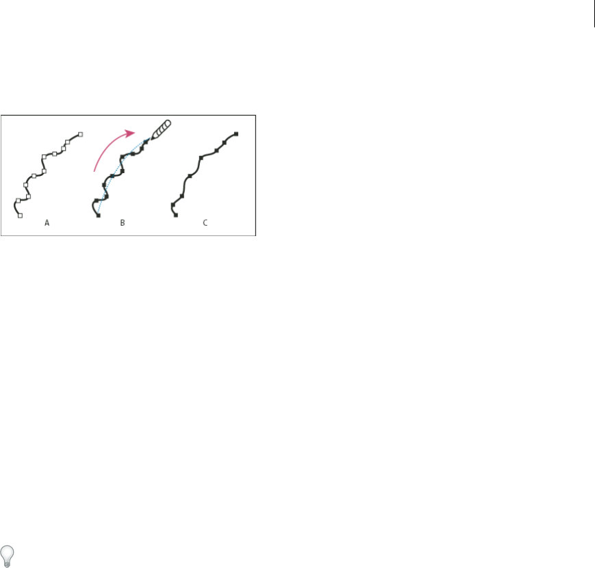
90
Drawing
Last updated 6/5/2015
3Drag the tool along the length of the path segment you want to smooth out.
4Continue smoothing until the stroke or path is the desired smoothness.
A Original path B Dragging across path with the Smooth tool C Result
5To change the amount of smoothing, double-click the Smooth tool and set the following options:
Fidelity Controls how far you have to move your mouse or stylus before Illustrator adds a new anchor point to the
path. For example, a Fidelity value of 2.5 means that tool movements of less than 2.5 pixels aren’t registered. Fidelity
can range from 0.5 to 20 pixels; the higher the value, the smoother and less complex the path.
Smoothness Controls the amount of smoothing that Illustrator applies when you use the tool. Smoothness can
range from 0% to 100%; the higher the value, the smoother the path.
Simplify paths
Simplifying a path removes extra anchor points without changing the shape of the path. Removing unnecessary anchor
points simplifies your artwork, reducing the file size, and making it display and print faster.
1Select the object.
2Choose Object > Path > Simplify.
3Set the Curve Precision to control how closely the simplified path follows the original path.
Select Preview to show a preview of the simplified path and list the number of points in the original and simplified
paths.
4Select additional options, and click OK:
Curve Precision Enter a value between 0% and 100% to set how closely the simplified path should follow the original
path. A higher percentage creates more points and a closer fit. Any existing anchor points are ignored except for
endpoints of a curve and corner points (unless you enter a value for Angle Threshold).
Angle Threshold Enter a value between 0 and 180° to control the smoothness of corners. If the angle of a corner
point is less than the angle threshold, the corner point is not changed. This option helps keep corners sharp, even if
the value for Curve Precision is low.
Straight Lines Creates straight lines between the object’s original anchor points. Corner points are removed if they
have an angle greater than the value set in Angle Threshold.
Show Original Shows the original path behind the simplified path.
Average the position of anchor points
1Select two or more anchor points (on the same path or on different paths).
2Choose Object > Path > Average.
3Choose to average along the horizontal (x) axis only, the vertical (y) axis only, or both axes, and click OK.
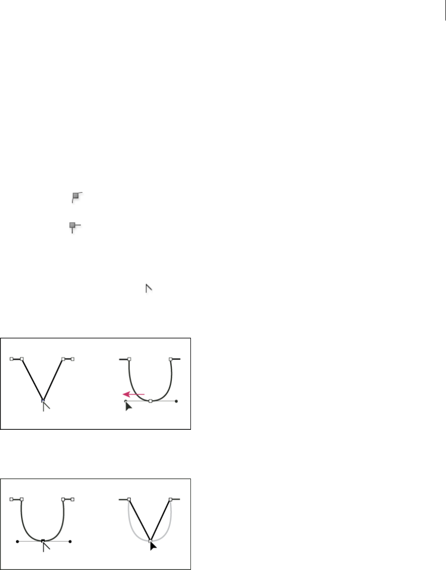
91
Drawing
Last updated 6/5/2015
Convert between smooth points and corner points
You can convert the points on a path between corner to smooth points. Using options in the Control panel, you can
quickly convert multiple anchor points. Using the Convert Anchor Point tool, you can choose to convert only one side
of the point, and you can precisely alter the curve as you convert the point.
Convert one or more anchor points using the Control panel
To use the anchor point conversion options in the Control panel, only relevant anchor points, not the entire object,
should be selected. If you select multiple objects, one of the objects must be only partially selected. When entire objects
are selected, the Control panel options change to those that affect the entire object.
1To convert one or more corner points to smooth points, select the points and then click the Convert Selected Anchor
Points To Smooth button in the Control panel.
2To convert one or more smooth points to corner points, select the points and then click the Convert Selected Anchor
Points To Corner button in the Control panel.
Convert an anchor point precisely using the Convert Anchor Point tool
1Select the entire path you want to modify so that you can see its anchor points.
2Select the Convert Anchor Point tool .
3Position the Convert Anchor Point tool over the anchor point you want to convert, and do one of the following:
•To convert a corner point to a smooth point, drag a direction point out of the corner point.
•To convert a smooth point to a corner point without direction lines, click the smooth point.
•To convert a smooth point to a corner point with independent direction lines, drag either direction point.
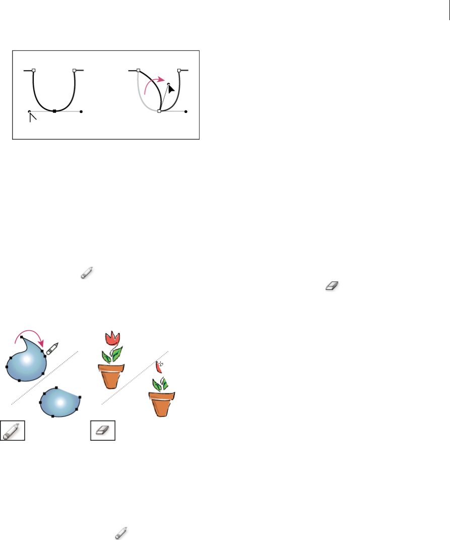
92
Drawing
Last updated 6/5/2015
•To convert a corner point without direction lines to a corner point with independent direction lines, first drag a
direction point out of a corner point (making it a smooth point with direction lines). Release the mouse button
only (don’t release any keys you may have pressed to activate the Convert Anchor Point tool), and then drag
either direction point.
Erase artwork
You can erase portions of your artwork using the Path Eraser tool, the Eraser tool, or the eraser on a Wacom stylus pen.
The Path Eraser tool lets you erase parts of a path by drawing along the path. This tool is useful when you want to
limit what you erase to a path segment, such as one edge of a triangle. The Eraser tool and the eraser on a Wacom
stylus pen let you erase any area of your artwork, regardless of structure. You can use the Eraser tool on paths,
compound paths, paths inside Live Paint groups, and clipping paths.
For a video on using the Eraser tool, see www.adobe.com/go/vid0036.
Erase part of a path using the Path Eraser tool
1Select the object.
2Select the Path Eraser tool .
3Drag the tool along the length of the path segment you want to erase. For best results, use a single, smooth, dragging
motion.
Erase objects using the Eraser tool
1Do one the following:
•To erase specific objects, select the objects or open the objects in isolation mode.
•To erase any object on the artboard, leave all objects unselected.
When you have nothing selected, the Eraser tool erases through and across all layers.

93
Drawing
Last updated 6/5/2015
2Select the Eraser tool .
3(Optional) Double-click the Eraser tool and specify options.
4Drag over the area you want to erase. You can control the tool by doing any of the following:
•To constrain the Eraser tool to a vertical, horizontal, or diagonal line, Shift-drag.
•To create a marquee around an area and erase everything inside the area, Alt-drag (Windows) or Option-drag
(Mac OS). To constrain the marquee to a square, Alt-Shift-drag (Windows) or Option-Shift-drag (Mac OS).
Erase objects using a Wacom stylus pen eraser
When you flip a stylus pen, the Eraser Tool automatically becomes active. When you flip the stylus pen back over, the
last active tool becomes active again.
❖Turn over the stylus pen and drag across the area you want to erase.
Press harder to increase the width of the erased path. (You may need to select the Pressure option in the Eraser Tool
Options dialog box first.)
Eraser tool options
You can change the Eraser tool options by double-clicking the tool in the Tools panel.
Note: You can change the diameter at any time by pressing ] to enlarge or [ to reduce.
Angle Determines the angle of rotation for the tool. Drag the arrowhead in the preview, or enter a value in the Angle
text box.
Roundness Determines roundness of the tool. Drag a black dot in the preview away from or toward the center, or enter
a value in the Roundness text box. The higher the value, the greater the roundness.
Diameter Determines the diameter of the tool. Use the Diameter slider, or enter a value in the Diameter text box.
The pop-up list to the right of each option lets you control variations in the shape of the tool. Select one of the following
options:
Fixed Uses a fixed angle, roundness, or diameter.
Random Uses random variations in angle, roundness, or diameter. Enter a value in the Variation text box to specify the
range within which the brush characteristic can vary. For example, when the Diameter value is 15 and the Variation
value is 5, the diameter can be 10, or 20, or any value in between.
Pressure Varies in angle, roundness, or diameter based on the pressure of a drawing stylus. This option is most useful
when used with Diameter. It is available only if you have a graphics tablet. Enter a value in the Variation text box to
specify how much more or less the original value the brush characteristic will vary. For example, when the Roundness
value is 75% and the Variation value is 25%, the lightest stroke is 50% and the heaviest stroke is 100%. The lighter the
pressure, the more angular the brush stroke.
Stylus Wheel Varies in diameter based on manipulation of the stylus wheel.
Tilt Varies in angle, roundness, or diameter based on the tilt of a drawing stylus. This option is most useful when used
with Roundness. It is available only if you have a graphics tablet that can detect the direction in which the pen is tilted.
Bearing Varies in angle, roundness, or diameter based on the pressure of a drawing stylus. This option is most useful
when used to control the angle of calligraphic brushes, especially when you’re using the brush like a paintbrush. It is
available only if you have a graphics tablet that can detect how close to vertical the pen is.
Rotation Varies in angle, roundness, or diameter based on how the drawing stylus pen tip is rotated. This option is most
useful when used to control the angle of calligraphic brushes, especially when you’re using the brush like a flat pen. It
is available only if you have a graphics tablet that can detect this type of rotation.

94
Drawing
Last updated 6/5/2015
Split a path
You can split a path at any anchor point or along any segment. When you split a path, keep the following in mind:
•If you want to split a closed path into two open paths, you must slice in two places along the path. If you slice a closed
path only once, you get a single path with a gap in it.
•Any paths resulting from a split inherit the path settings of the original path, such as stroke weight and fill color.
Stroke alignment is automatically reset to center.
1(Optional) Select the path to see its current anchor points.
2Do one of the following:
•Select the Scissors tool and click the path where you want to split it. When you split the path in the middle of a
segment, the two new endpoints appear on top of the other, and one endpoint is selected.
•Select the anchor point where you want to split the path, and then click the Cut Path At Selected Anchor Points
button in the Control panel. When you split the path at an anchor point, a new anchor point appears on top
of the original anchor point, and one anchor point is selected.
3Use the Direct Selection tool to adjust the new anchor point or path segment.
Note: You can divide an object into separate component faces by using the Knife tool (a face is an area undivided by a line
segment).
More Help topics
About paths
Curvature tool
Video Tutorial - Path Segment reshaping
Keys for editing shapes
Cut objects with the Knife tool
Drawing pixel-aligned paths forweb workflows
Pixel-aligned is an object level property, which enables an object to have its vertical and horizontal paths aligned to the
pixel grid. This property remains with the object when the object is modified. Any vertical or horizontal path in the
object gets aligned to pixel grid as long as the property is set for it.
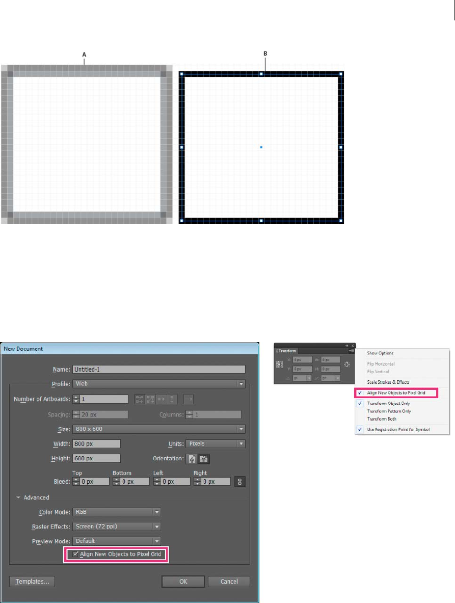
95
Drawing
Last updated 6/5/2015
A Object is not pixel-aligned B Object is pixel-aligned
For a video on drawing pixel-aligned paths for web workflows, see www.adobe.com/go/lrvid5201_ai_en.
Aligning new objects to pixel grid
The Align New Objects to Pixel Grid option is available in the Advanced section of the New Document dialog box.
This option is also available in the Transform panel menu (flyout menu) of the Transform panel.
If you enable this option, any new objects that you draw have the pixel-aligned property set by default. For new
documents created using the web document profile, this option is enabled by default.
The crisp appearance of pixel-aligned strokes is maintained in the raster output at a resolution of 72-ppi only. For other
resolutions, there is a high possibility of such strokes producing anti-aliased results.
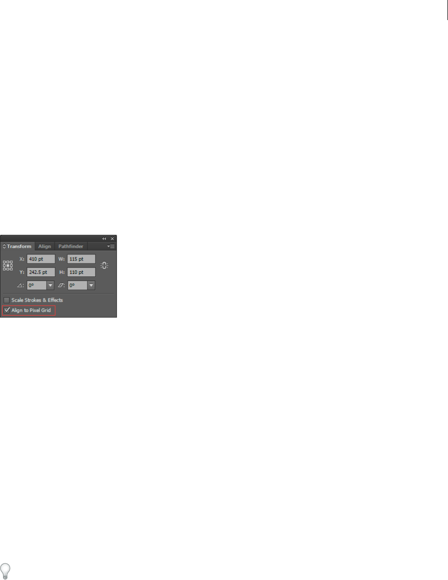
96
Drawing
Last updated 6/5/2015
Objects that are pixel-aligned, but do not have any straight vertical or horizontal segments, are not modified to align to
the pixel grid. For example, because a rotated rectangle does not have straight vertical or horizontal segments, it is not
nudged to produce crisp paths, when the pixel-aligned property is set for it.
Note: The document level property and pixel-aligned status of each object are saved in the .ai file.
For more information on aligning symbols to pixel grid, see Aligning symbols to pixel grid.
Aligning existing objects to pixel grid
An object with the Align to Pixel Grid option selected, is nudged to align to pixel grid whenever it is modified. For
example, if you move or transform a pixel-aligned object, the object is realigned to pixel grid according to its new
coordinates.
To align an existing object to pixel grid, select the object and check the Align to Pixel Grid check box at the bottom on
the Transform panel.
When you select this option, the vertical and horizontal segments of the paths of the object are nudged. As a result, the
appearance of such segments always shows crisp strokes, for all stroke widths and all locations. Objects with this option
selected, always have stroke widths in full integer values.
Bringing non-aligned objects into documents with the Align New Objects to Pixel Grid option enabled, does not
automatically pixel-align such objects. To make such objects pixel-aligned, select the object and then select the Align
to Pixel Grid option from the Transform panel. You cannot pixel-align objects such as rasters, raster effects, and text
objects because such objects do not have real paths.
Selecting objects not aligned to pixel grid
Click Select > Object > Not Aligned to Pixel Grid to select the objects.
Aligning symbols to pixel grid
To create a pixel-aligned symbol, select the Align to Pixel Grid option from the Symbol Options dialog box. Symbols
aligned to pixel grid remain aligned to the pixel grid at all locations of the artboard, in their actual size.
Note: A scaled symbol may not produce crisp paths although it is pixel-aligned by property.
For more information on aligning to pixel grid, see Drawing pixel-aligned paths for web workflows .
If the Reset button in the Control panel is active, it implies that the symbol has been transformed and is not in its actual
size.
Viewing the pixel grid
To view the pixel grid, zoom to 600% or higher in Pixel Preview mode.
To set the preferences for viewing pixel grid, click Preferences> Guides & Grid. Select the Show Pixel Grid (Above 600%
Zoom) option if it is not already selected.
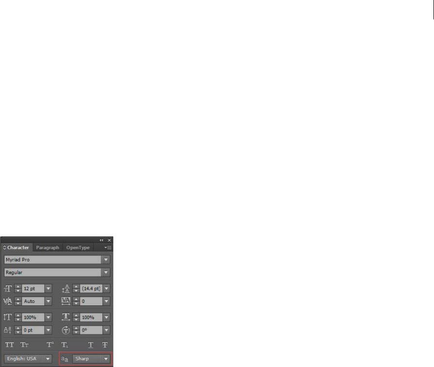
97
Drawing
Last updated 6/5/2015
Saving selected slices
To save only selected slices from the artwork, click File > Save Selected Slices.
Anti-aliasing options
Text anti-aliasing
The Character panel in Illustrator provides the following text anti-aliasing options:
•None
•Sharp
•Crisp
•Strong
You can set anti-aliasing options for each text frame. These text anti-aliasing attributes get saved as part of the
document. These options are also supported for PDF, AIT, and EPS formats. Text anti-aliasing options can be exported
to or imported from PSD.
While exporting to BMP, PNG, Targa, JPEG, or TIFF formats the following options are available in the anti-aliasing
drop-down list: None, Art Optimized and Type Optimized.
•Art optimized option produces raster for each of these formats in the same way as in earlier versions. However, text
anti-aliasing options are not honored while rasterizing the artwork in this case.
•Type optimized option honors the newly introduced anti-aliasing options for the text frames in the raster produced.
These options are also available in Save for Web dialog box.
Adjust path segments
Editing path segments works similarly in Adobe applications. You can edit a path segment at any time, but editing
existing segments is slightly different from drawing them. Keep the following tips in mind when editing segments:
•If an anchor point connects two segments, moving that anchor point always changes both segments.
•When drawing with the Pen tool, press Ctrl (Windows) or Command (Mac OS) to temporarily activate the last used
selection tool (Illustrator) or the Direct Selection tool (InDesign and Photoshop) so that you can adjust segments
you’ve already drawn.
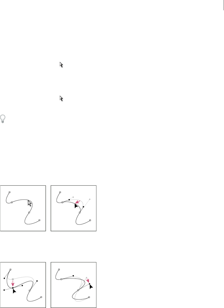
98
Drawing
Last updated 6/5/2015
•When you initially draw a smooth point with the Pen tool, dragging the direction point changes the length of the
direction line on both sides of the point. However, when you edit an existing smooth point with the Direct Selection
tool, you change the length of the direction line only on the side you’re dragging.
Move straight segments
1With the Direct Selection tool , select the segment you want to adjust.
2Drag the segment to its new position.
Adjust the length or angle of straight segments
1With the Direct Selection tool , select an anchor point on the segment you want to adjust.
2Drag the anchor point to the desired position. Shift-drag to constrain the adjustment to multiples of 45°.
In Illustrator or InDesign, if you’re simply trying to make a rectangle wider or narrower, it’s easier to select it with
the Selection tool and resize it using one of the handles on the sides of its bounding box.
Adjust the position or shape of curved segments
1With the Direct Selection tool, select a curved segment, or an anchor point on either end of the curved segment.
Direction lines appear, if any are present. (Some curved segments use just one direction line.)
2Do any of the following:
•To adjust the position of the segment, drag the segment. Shift-drag to constrain the adjustment to multiples of
45°.
•To adjust the shape of the segment on either side of a selected anchor point, drag the anchor point or the direction
point. Shift-drag to constrain movement to multiples of 45°.
Note: You can also apply a transformation, such as scaling or rotating, to a segment or anchor point.

99
Drawing
Last updated 6/5/2015
Delete a segment
1Select the Direct Selection tool , and select the segment you want to delete.
2Press Backspace (Windows) or Delete (Mac OS) to delete the selected segment. Pressing Backspace or Delete again
erases the rest of the path.
Extend an open path
1Using the Pen tool, position the pointer over the endpoint of the open path you want to extend. The pointer changes
when it’s precisely positioned over the endpoint.
2Click the endpoint.
3Do one of the following:
•To create a corner point, position the Pen tool where you want to end the new segment, and click. If you are
extending a path that ends at a smooth point, the new segment will be curved by the existing direction line.
Note: In Illustrator, if you extend a path that ends in a smooth point, the new segment will be straight.
•To create a smooth point, position the Pen tool where you want to end the new curved segment, and drag.
Connect two open paths
1Using the Pen tool, position the pointer over the endpoint of the open path that you want to connect to another path.
The pointer changes when it’s precisely positioned over the endpoint.
2Click the endpoint.
3Do one of the following:
•To connect the path to another open path, click an endpoint on the other path. When you precisely position the
Pen tool over the other path’s endpoint, a small merge symbol appears next to the pointer.
•To connect a new path to an existing path, draw the new path near the existing path, and then move the Pen tool
to the existing path’s (unselected) endpoint. Click that endpoint when you see the small merge symbol that
appears next to the pointer.
In InDesign, you can also use the Pathfinder panel to join paths. To close the path of an open path, use the Selection
tool to select the path and click Close Path in the Pathfinder panel. To close the end points between two paths, select the
paths and click Join Path. You may want to click Join Path a second time to join the second endpoint.
Join two endpoints
1Select the endpoints.
If the endpoints are coincident (on top of each other), drag a marquee through or around both endpoints to select
them.
2Click the Connect Selected End Points button in the Control panel.
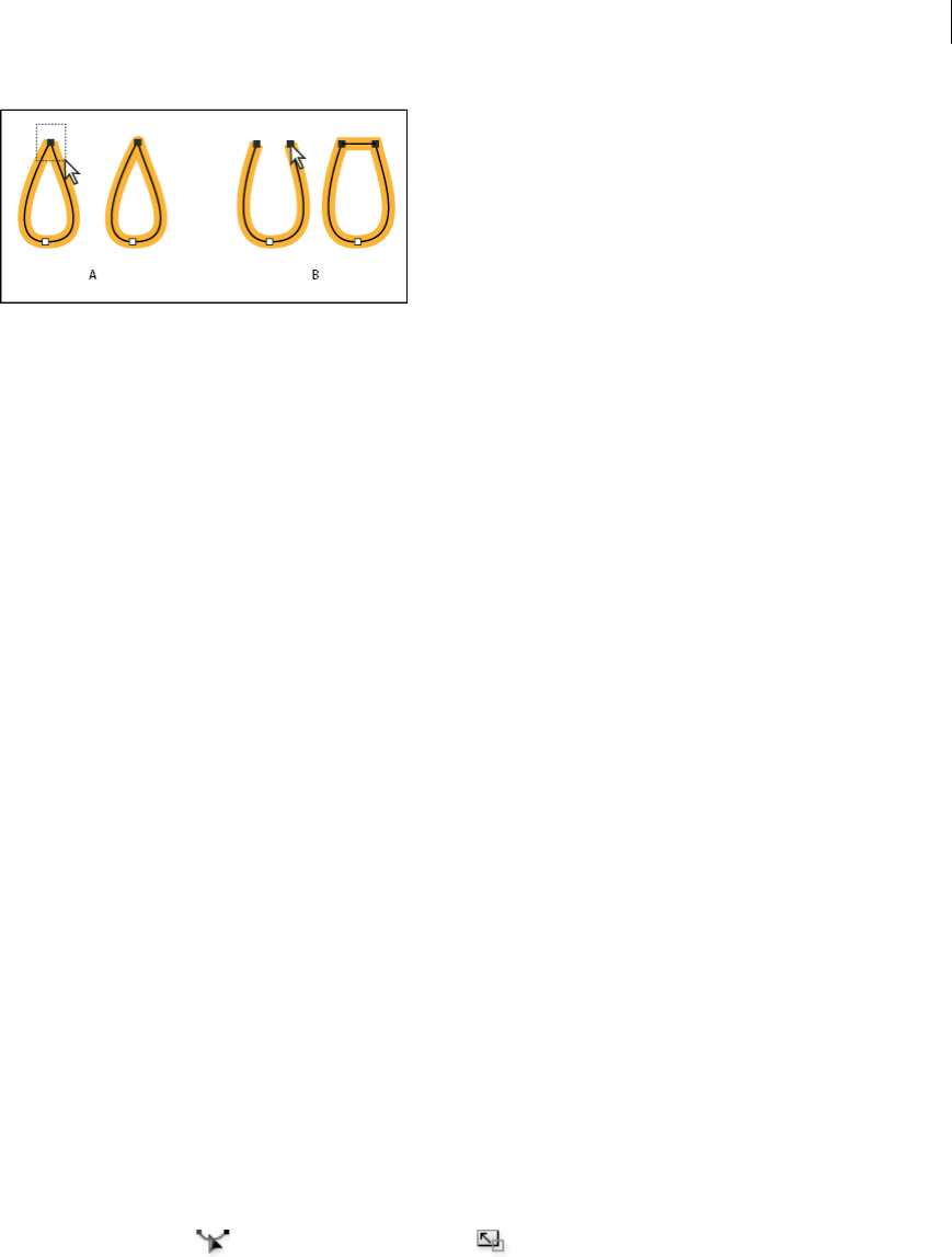
100
Drawing
Last updated 6/5/2015
A Selecting and joining coincident endpoints B Selecting and joining noncoincident endpoints
Note: In Illustrator CS5, only corner joins are used to join open paths.
Join two or more paths
Illustrator CS5 provides the option to join two or more open paths. To join one or more open paths, use the Selection
tool to select the open paths and click Object > Path > Join. You can also use the keyboard shortcut Ctrl+J (Windows)
or Cmd+J (Mac).
When anchor points are not overlapping, Illustrator adds a line segment to bridge the paths to join. While joining more
than two paths, Illustrator first looks for and joins the paths that have end points stationed closest to each other. This
process is repeated until all paths are joined. If you select only one path to join, it is converted into a closed path.
Note: In this process, you may lose complex aspects of your art styles.
The output path has the appearance of the topmost path in the selection.
The join option only results in a corner join regardless of whether you select anchor points to join or the entire path.
However, for overlapping anchor points, if you want the option to select a smooth or corner join, then use
Ctrl+Shift+Alt+J (Windows) or Cmd+Shift+Option+J (Mac OS).
Move or nudge anchor points or segments using the keyboard
1Select the anchor point or path segment.
Note: In Photoshop, you can move only anchor points in this manner.
2Click or hold down any of the arrow keys on the keyboard to move 1 pixel at a time in the direction of the arrow.
Hold down the Shift key in addition to the arrow key to move 10 pixels at a time.
Note: In Illustrator and InDesign, you can change the distance of a nudge by changing the Keyboard Increment preference.
When you change the default increment, holding down Shift nudges 10 times the specified distance.
Stretch parts of a path without distorting its overall shape
1Select the entire path.
2Select the Reshape tool (located under the Scale tool ).
3Position the cursor over the anchor point or path segment that you want to act as a focal point (that is, a point that
pulls selected path segments), and click.
If you click a path segment, a highlighted anchor point with a square around it is added to the path.
4Shift-click more anchor points or path segments to act as focal points. You can highlight an unlimited number of
anchor points or path segments.
5Drag the highlighted anchor points to adjust the path.
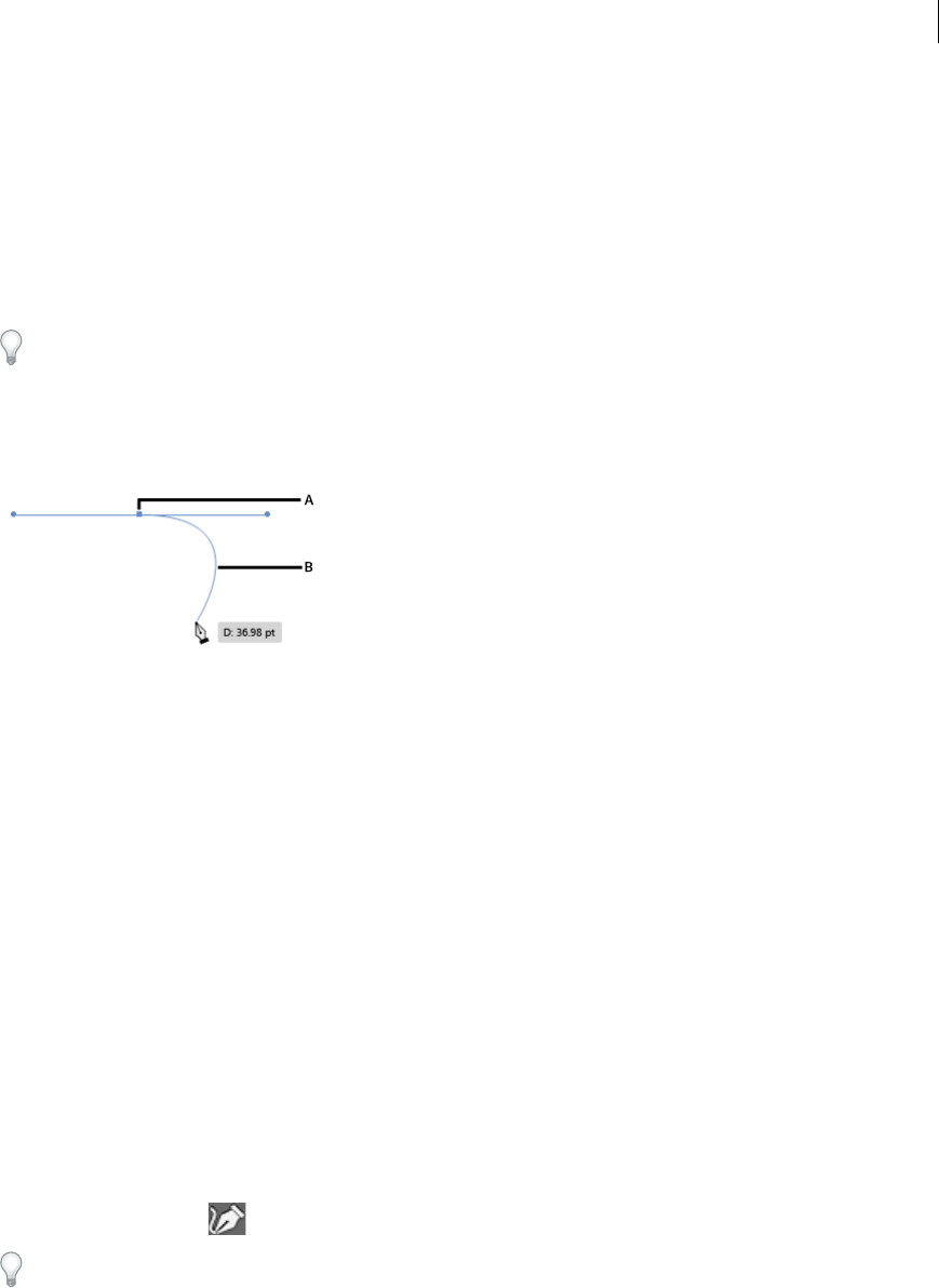
101
Drawing
Last updated 6/5/2015
Pen tool rubberband preview
While using the Pen tool, it has been difficult to predict the path that will be drawn, unless an anchor point is dropped
on the canvas. From the 2014 release of Illustrator CC, the Pen tool, displays a preview of the path that will be drawn
from the previous anchor point to the current position of the pointer.
1Using the Pen tool, click once on the artboard to draw a smooth point, and drag the mouse to create the handles as
required.
When you draw a smooth point with the Pen tool, the opposite handles are always equal and paired. Press Cmd /
Ctrl while dragging the handles of a smooth point, to create handles that are unequal in length (pairing remains
intact).
2Release the mouse button. When you move the mouse pointer across the artboard, a path is displayed indicating
what will be drawn if you choose to drop an anchor point at the location of the mouse pointer.
A First anchor point and its handles B Rubber Band preview of the path between the first anchor point and the mouse pointer
3When the preview displayed is the path that you wanted to draw, click the location, and Illustrator draws the path
as previewed.
Note: When the preview is on, pressing Esc stops showing the preview and ends the path. This is the same action as hitting
the keyboard shortcut P while working with the pen tool (with the preview feature off).
Turn the preview feature on or off:
1Open the Preferencesdialog (Ctrl + K)
2Browse to the Selection and Anchor Display tab
3Select or clear the Enable Rubber Band for Pen Tool checkbox.
Curvature Tool
The Curvature tool simplifies path creation and makes drawing easy and intuitive. The new tool enables you to create,
toggle, edit, add, or remove smooth or corner points - all with the same tool. You do not have to switch between
different tools to work quickly and precisely with paths.
1Select the Curvature tool .
The keyboard combination for the Curvature tool is Shift + ~ (simultaneously press Shift and the tilde symbol on
your keyboard).
2Drop two points on the artboard, and then view the rubber band preview display the shape of the resulting path
depending on where you hover your mouse.
Note: Rubber-banding is turned on by default in the tool. To turn it off, use preference setting: Preferences > Selection
& Anchor Display > Enable Rubber Band for Pen tool.
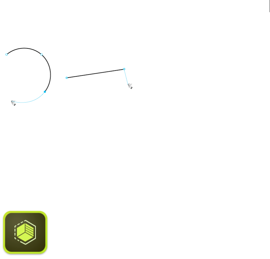
102
Drawing
Last updated 6/5/2015
3Use the mouse to drop a point or tap to create a smooth point. To create a corner point double-click or press the Alt
key while clicking or tapping.
4You can perform several actions:
•Option (Mac) / Alt (Win) + click to continue adding points to an existing path or shape.
•Double-click or double-tap a point to toggle the point between smooth or corner points.
•Click a point or tap it and then drag the point to move it.
•Click or tap a point and press Delete to delete the point. The curve is maintained.
•Press the Esc key to stop drawing.
Using Image Trace
If you want to base a new drawing on an existing piece of artwork, you can trace it. For example, you can create a graphic
based on a pencil sketch drawn on paper. Or, import a raster image saved in another graphics program, and trace over it.
The easiest way to trace artwork is to open or place a file into Illustrator, and automatically trace the artwork with the
Image Trace command.
Several tracing presets provide pre-specified tracing options for specific types of artwork. For example, if you’re tracing
an image that you plan to use as a technical drawing, choose the Technical Drawing preset. All the tracing options
change for optimal tracing of a technical drawing.
You can also control the level of detail and how the tracing is filled, and even save the settings as a custom preset for
future use.
For a video on tracing, see Image Trace in Illustrator CS6 on Adobe TV.
For users of Illustrator CS5 and earlier versions: Use the Live Trace feature to trace an image into vector artwork. See .
Use Adobe Shape CC your iPhone or iPad to photograph any object, design, or shape - and convert them into
vector shapes in a few simple steps. Store the resulting vectors in your Creative Cloud Libraries, and access them
or refine them in Illustrator or Photoshop.
Learn more about the Adobe Shape CC app here.
Download the awesome Adobe Shape CC app from the iTunes app store (Available for your iPhone and iPad).
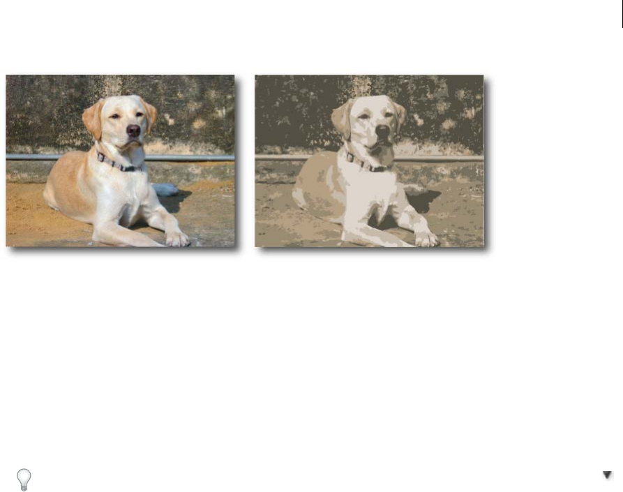
103
Drawing
Last updated 6/5/2015
Using Image Trace
1Open or place a bitmap image to use as a source.
2With the placed image selected, do one of the following:
•Choose Object > Image Trace > Make to trace with default parameters.
•Choose Window > Image Trace, and choose one of the default presets by clicking on the icons on top of the panel.
•Choose Window > Image Trace and choose a preset or specify the tracing options. In the Image Trace panel,
enable Preview to see the results of your modifications.
You can also click the Image Trace button in the Control panel, or select a preset from the Tracing Presets button .
3(Optional) Adjust the results of the tracing in the Image Trace panel (Windows > Image Trace).
4To manually edit the vector arwork, choose Object > Image Trace > Expand and convert the tracing object to paths .
Tracing options
Preset Specifies a tracing preset. Click the menu icon to save the current settings as a new preset, or to delete or rename
existing presets.
Note: You can’t edit or delete the default presets (default presets appear in brackets [ ]). However, you can make an editable
copy of a default preset by selecting the preset and clicking New.
View Specifies the view of the traced object. A tracing object is made up of two components: the original source image
and the tracing result (which is the vector artwork). You can choose to view the tracing result, source image, outlines,
and other options. Click the eye icon to overlay the selected view over the source image.
Mode Specifies a color mode for the tracing result.
Palette Specifies a palette for generating a color or grayscale tracing from the original image. (This option is available
only when Mode is set to Color or Grayscale.)
To let Illustrator determine the colors in the tracing, select Automatic.To use the document swatches as a palette for the
tracing, select Document Library.
Color settings Color settings are displayed based on the settings in the Mode and Palette options:
Colors Specifies the number of colors to use in a color tracing result. If you have selected Document Library as the
palette, you can choose a swatch. (This option is available only when Mode is set to Color.)

104
Drawing
Last updated 6/5/2015
Grays Specifies the number of grays to use in a grayscale tracing result. (This option is available only when Mode is set
to Grayscale.)
Threshold Specifies a value for generating a black and white tracing result from the original image. All pixels lighter
than the Threshold value are converted to white, all pixels darker than the Threshold value are converted to black. (This
option is available only when Mode is set to Black and White.)
Paths Controls the distance between the traced shape and the original pixel shape. Lower values create a tighter path
fitting; higher values create a looser path fitting.
Corners Specifies the emphasis on corners. A higher value results in more corners.
Noise Specifies an area in pixels that is ignored while tracing. A higher value results in less noise.
Method Specifies a method for tracing. Choosing abutting creates cutout paths, while choosing overlapping creates
stacked paths.
Fills Creates filled regions in the tracing result.
Strokes Creates stroked paths in the tracing result.
Stroke Specifies the maximum width of features in the original image that can be stroked. Features larger than the
maximum width become outlined areas in the tracing result.
Snap Curves To Lines Specifies if slightly curved lines are replaced with straight lines.
Ignore White Specifies if White fills area are replaced with no fills.
Enable Preview in the Image Trace panel to preview the result of the current settings.
Release a tracing object
If you want to discard a tracing but keep the original placed image, you can release the tracing object.
1Select the tracing object.
2Choose Object > Image Trace > Release.
Enhanced Pencil Tool
The Pencil Tool has been improved to facilitate better curve-fitting, auto-closing of paths, and drawing of constrained
and unconstrained straight line segments.
Pencil Tool
Presets
Double-click the Pencil Tool icon in the Toolbox to open the Pencil Tool Options dialog. The Fidelity slider has four
presets you can choose from. The leftmost slider preset (Accurate) is most accurate for drawing paths. The rightmost
slider preset (Smooth) creates the smoothest paths. Choose a preset that suits your drawing needs best.
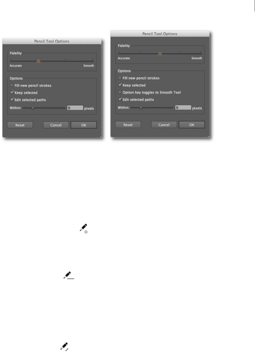
105
Drawing
Last updated 6/5/2015
Additional Fidelity preset (Introduced in the 2014 release of Illustrator CC)
The Fidelity slider has 5 presets from Illustrator CC 2014. A new slider preset (most accurate preset) has been added to
help you draw the most accurate path possible. Other dialogs that have the additional preset are the Smooth tool, Brush
tool, and Blob Brush tool dialogs.
Alt key toggles to Smooth Tool option(Introduced in the 2014 release of Illustrator CC)
With this checkbox enabled, while using the Pencil tool or the Brush tool, you can press Alt (Mac: Option) to switch to
the Smooth tool.
Auto-closing paths
When the endpoints of a path you are drawing are in close proximity and within a certain predefined number of pixels
of each other, the path-close cursor ( ) is shown. When you release the mouse button, such a path is closed
automatically.
The predefined number of pixels is set in the Pencil Tool Options dialog box > Within field.
Drawing constrained or unconstrained straight segments
You can use the pencil tool to draw constrained or unconstrained straight segments. While drawing a straight segment,
the straight-segment cursor ( ) is displayed.
Constrained straight segments Hold the Shift key, and then use the Pencil tool to draw straight segments constrained
to 0, 45 or 90 degrees.
Unconstrained straight segments Hold the Alt/Opt key to draw unconstrained straight segments. However, to draw a
polyline path:
1Draw a line segment.
2Do one of the following:
1Keeping the Shift or Alt/Opt key pressed, place the cursor at the endpoint of the line. When the path-
continuation cursor ( ) is displayed, click the mouse button and draw another line.
2Keeping the mouse button pressed, release and press the Shift or Alt/Opt key, and draw the next segment.
Continuing a path
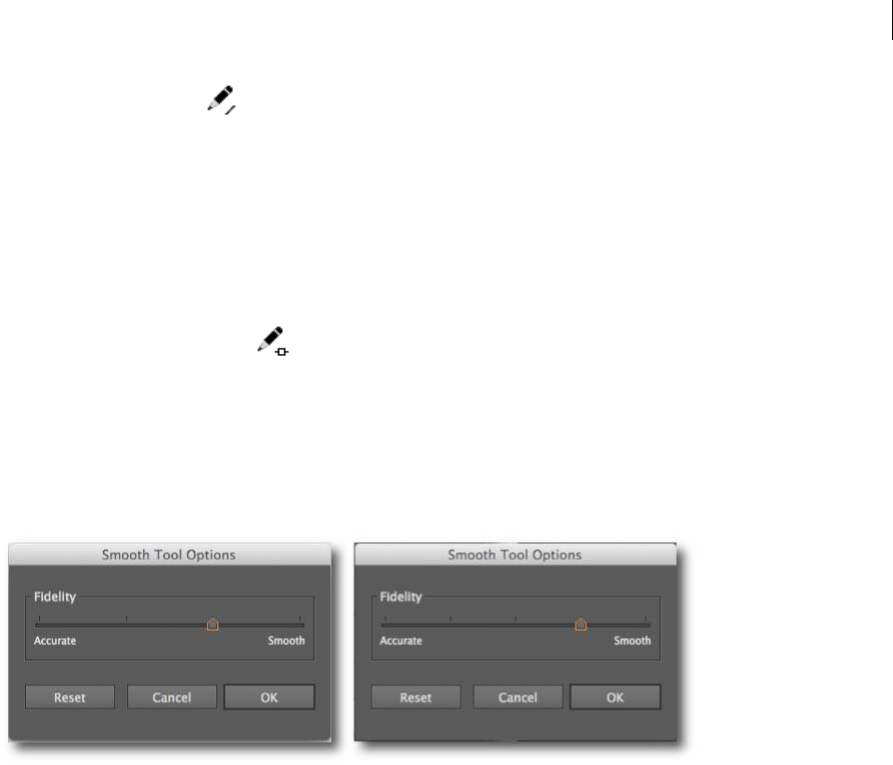
106
Drawing
Last updated 6/5/2015
The continue-path cursor ( ) is shown when the mouse pointer is within a predefined number of pixels from the
endpoint.
The predefined number of pixels is set in the Pencil Tool Options dialog box > Within field.
Merging paths
To merge two paths:
1Select the paths you want to merge.
2Extend one path, and bring it closer to the other path.
3When the path-merge cursor ( ) appears, release the mouse button to merge the paths.
Smooth Tool
Presets
Double-click the Smooth Tool icon in the Toolbox to open the Smooth Tool Options dialog. A preset-based Fidelity
slider is available for the Smooth tool.
Note: The Smooth tool is no longer available by holding Alt/Opt key while using the Pencil tool.
Paintbrush and Blob Brush tool
The four preset slider is also available in Paintbrush and Blob Brush Tool Options dialogs.
Anchor Point enhancements
Several enhancements have been introduced that afford you greater flexibility and control while working with anchor
points and their handles. Most enhancements have been built to not interfere with the existing workflows and
techniques.
Dragging inequal handles (Pen tool)
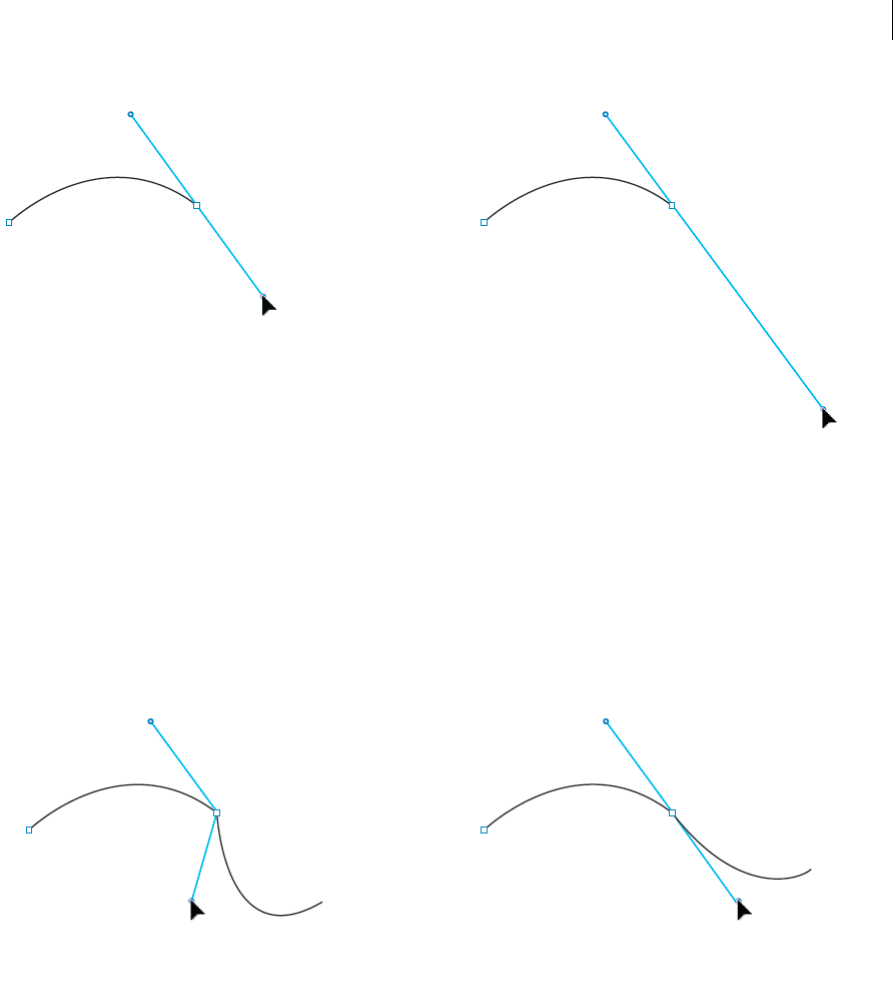
107
Drawing
Last updated 6/5/2015
In previous releases of Illustrator CC, when you drew a smooth point with the Pen too, the opposite handles were always
equal in length and paired.
Enhancement: In Illustrator CC 2014, press Cmd/Ctrl while dragging the handles of a smooth point, to make the
handles inequal in length (while keeping their pairing intact). The advantage this enhancement offers is that you now
have greater control on the next curve segment to be created.
Pairing broken handles (Anchor Point tool)
Traditionally, you could break the pairing of anchor point handles to create corner points. Later, if you decided to make
that point smooth, you had two options:
•Convert selected anchor points to smooth (in the Control Panel), or,
•Re-drag the handles using the Anchor Point tool.
While both techniques work, the original curve is always affected, and, may not look the same again.
Enhancement: In Illustrator CC 2014, select the Anchor Point tool, press Opt/Alt, and click on any of the handles to
pair the opposite handles and make the point smooth. With this enhancement, you get a smooth curve, while keeping
the opposite curve intact.
Disabling snapping of handles
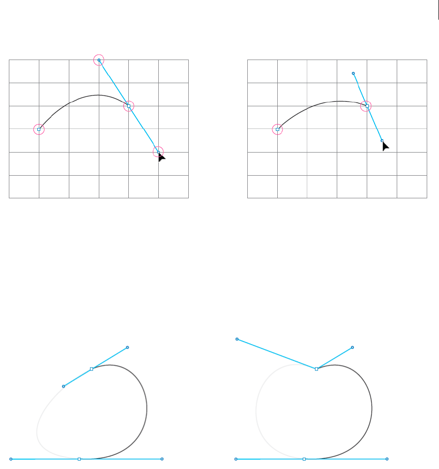
108
Drawing
Last updated 6/5/2015
This applies to situations when you have enabled any kind of snapping (pixel, grid, or point). For example, with Pixel
Preview mode, the Snap to Pixel feature gets enabled. This makes path drawing restrictive, because anchor points as
well as the handles snap to the pixels.
Enhancement: In Illustrator CC 2014, anchor points will continue to honor snapping rules, but handles will be free
from that restriction. You now have better control on curves, even when pixel/grid/point snapping is turned on.
Better control on closing paths
In previous versions of Illustrator, on a path that has a smooth starting point, there was no way you could adjust the
closing curve while closing a path. If the starting point of the path was a corner - then it could be done. However,
designers using a stylus usually created all anchor points as smooth (because of the sensitivity of the stylii, a clean click
is usually tough).
Enhancement: In Illustrator CC 2014, press Opt/Alt, and break the pairing of handles of the closing anchor point. You
can now make finer adjustments to the closing curve.
Repositioning the closing anchor point
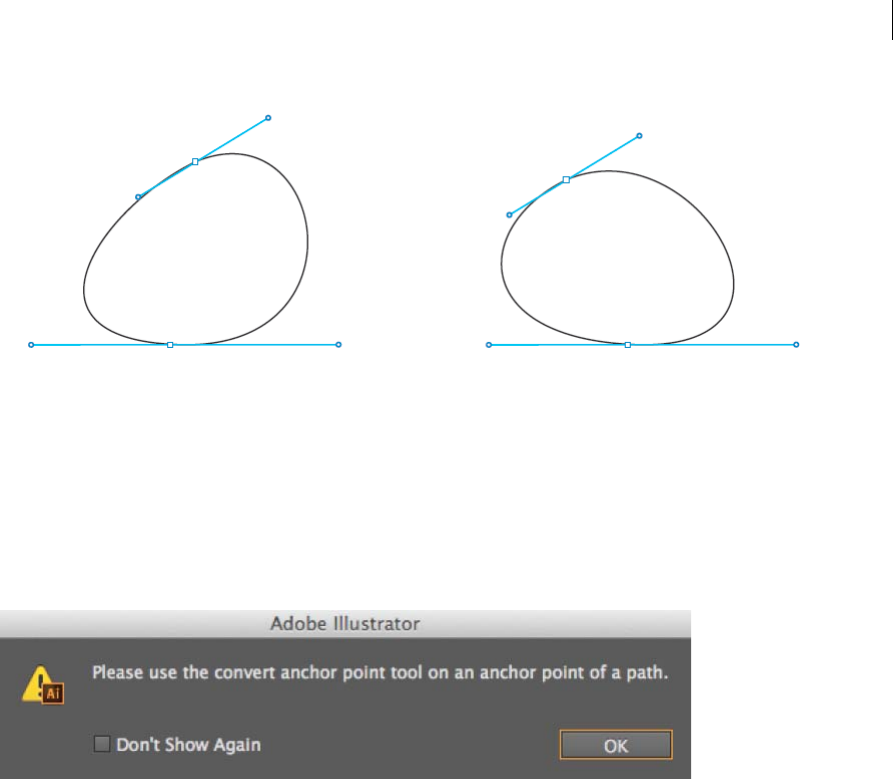
109
Drawing
Last updated 6/5/2015
There are many places in the application where pressing of spacebar, allows you to reposition an anchor point. This is
applicable to scenarios like dragging a shape, dragging the zoom, clicking the Pen tool, and more. However, this did not
work while attempting to close a path.
Enhancement: In Illustrator CC 2014, press the spacebar while closing a path to reposition the closing anchor point.
This enhancement enables better control on the starting and closing curves of a path.
Anchor Point tool warning removed
When working with the Anchor Point tool, it is extremely important to aim precisely, and click the handles (or an
anchor point). If you clicked anywhere else, a warning (above) appeared.
Enhancement: In Illustrator CC 2014, this warning has been removed. If you click incorrectly, no change occurs to the
selected path or anchor point. This change is aimed at reducing one click to dismiss the warning, translating into one
less break in a design workflow.
Symbols
About symbols
A symbol is an art object that you can reuse in a document. For example, if you create a symbol from a flower, you can
then add instances of that symbol multiple times to your artwork without actually adding the complex art multiple
times. Each symbol instance is linked to the symbol in the Symbols panel or to a symbols library. Using symbols can
save you time and greatly reduce file size.
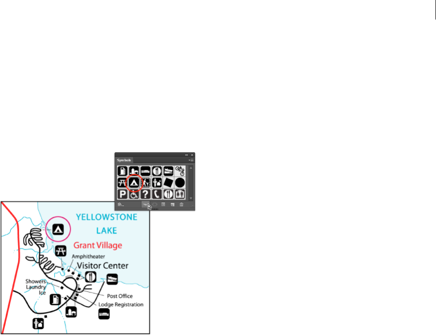
110
Drawing
Last updated 6/5/2015
Symbols also provide excellent support for SWF and SVG export. When you export to Flash, you can set the symbol
type to MovieClip. Once in Flash, you can choose another type if necessary. You can also specify 9-slice scaling in
Illustrator so that the symbols scale appropriately when used for user interface components.
Note: For information on using symbols in Flash, see Flash Help. For a video on using symbols effectively, see
www.adobe.com/go/lrvid5204_ai_en.
After you place a symbol, you can edit the symbol’s instances on the artboard and, if you want, redefine the original
symbol with the edits. The symbolism tools let you add and manipulate multiple symbol instances at once.
Symbols panel overview
You can use the Symbols panel (Window > Symbols) or the Control panel to manage the symbols for a document. The
Symbols panel contains a variety of preset symbols. You can add symbols from symbol libraries or libraries that you
create. See Symbol librariesfor information about using preset symbols.
Change the display of symbols in the panel
1Select a view option from the panel menu: Thumbnail View to display thumbnails, Small List View to display a list
of named symbols with a small thumbnail, or Large List View to display a list of named symbols along with a large
thumbnail.
2Drag the symbol to a different position. When a black line appears in the desired position, release the mouse button.
3Select Sort By Name from the panel menu to list the symbols in alphabetical order.
Duplicate a symbol in the panel
Duplicating or copying a symbol in the Symbols panel is an easy way to create a new symbol using an existing symbol
instance.
To create a copy of a symbol, select the symbol in the Symbols panel and choose Duplicate Symbol from the panel menu,
or drag the symbol onto the New Symbol button.
Note: If you want to duplicate a symbol instance on the artboard, for example, if you have scaled and rotated a symbol and
want to add another instance with the same scale and rotation, duplicate the instance. (See Work with symbol instances.)

111
Drawing
Last updated 6/5/2015
Rename a symbol
1To rename the symbol, select the symbol in the Symbols panel, choose Symbol Options from the panel menu, and
then type a new name in the Symbol Options dialog box.
2To rename a symbol instance, select a symbol instance in the artwork, and then type a new name in the Instance
Name text box in the Control panel.
Symbol registration point
The symbol registration point in Illustrator is similar to Adobe Flash Professional. A registration point is the origin of
the symbol definition art. This feature provides better interoperability between Illustrator and Flash.
When you create a symbol, you can choose the registration point from any of the 8-point across boundaries or center
of the symbol bounding box. The registration point is visible as a crosshair symbol in Symbol edit mode and in normal
mode when the symbol instance is selected. In isolation mode, you can snap your artwork with registration point mark.
In the Transform panel menu (flyout menu), the Use Registration Point for Symbol option is selected by default.
Coordinates of the registration point are visible in the Transform panel when symbol instance is selected. All
transformations of symbol instances correspond to the registration point of the symbol definition art.
The transformations applied on the symbol instance can be reset using the Reset Transformation option. For details see
Reset transformations.
Place or create a symbol
Place a symbol
1Select a symbol in the Symbols panel or a symbol library.
2Do one of the following:
•Click the Place Symbol Instance button in the Symbols panel to place the instance in the center of the current
viewable area of the document window.
•Drag the symbol to the artboard where you want it to appear.
•Choose Place Symbol Instance from the Symbols panel menu.
note: A single symbol placed anywhere in your artwork (as opposed to existing only in the panel) is called an
instance.
Create a symbol
1Select the artwork you want to use as a symbol.
2Do one of the following:
•Click the New Symbol button in the Symbols panel.
•Drag the artwork to the Symbols panel.
•Choose New Symbol from the panel menu.
Note: By default, the selected artwork becomes an instance of the new symbol. If you don’t want the artwork to become
an instance, press Shift as you create the new symbol. In addition, if you don’t want the New Symbol dialog box to open
when you create a new symbol, press Alt (Windows) or Option (Mac OS) as you create the symbol and Illustrator will
use a default name for the symbol, such as New Symbol 1.
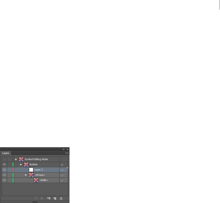
112
Drawing
Last updated 6/5/2015
3In the Symbol Options dialog box, type a name for the symbol.
4Select the symbol type as Movie Clip or Graphic. If you plan to export the symbols to Flash, do the following:
•Select Movie Clip for type. Movie Clip is the default symbol type in Flash and in Illustrator.
•Specify a location on the Registration grid where you want to set the symbol’s anchor point. The location of the
anchor point affects the position of the symbol within the screen coordinates.
•Select Enable Guides For 9-Slice Scaling if you want to utilize 9-Slice scaling in Flash.
5Select the Align to Pixel Grid option to apply the pixel-align property to the symbol. For more information, see
Aligning symbols to pixel grid.
You can create symbols from most Illustrator objects, including paths, compound paths, text objects, raster images,
mesh objects, and groups of objects. However, you cannot create a symbol from linked art or some groups, such as
groups of graphs.
Note: For a video on using symbols effectively between Illustrator and Flash, see www.adobe.com/go/vid0198.
Add sublayers for symbols
Symbols now have an independent layer hierarchy, which is maintained when you expand symbols. You can create
sublayers for symbols in symbol editing mode.
Paste Remember Layers option is honored when you paste content in symbol editing mode.
Use 9-slice scaling
You can use 9-slice scaling (scale-9) to specify component-style scaling for graphic style and movie clip symbols. This
type of scaling lets you create movie clip symbols that scale appropriately for use as user interface components, as
opposed to the type of scaling typically applied to graphics and design elements.
The symbol is conceptually divided into nine sections with a grid-like overlay, and each of the nine areas is scaled
independently. To maintain the visual integrity of the symbol, corners are not scaled, while the remaining areas of the
image are scaled (as opposed to being stretched) larger or smaller, as needed.
The 9-slice scaling grid is visible only in isolation mode. By default, the grid’s guides are placed at 25% (or 1/4) of the
symbol’s width and height from the edge of the symbol, and appear as dotted lines superimposed on the symbol.
Note: For more information on using 9-slice scaling in Flash, see Flash Help. For videos on using 9-slice scaling in Illustrator,
see www.adobe.com/go/lrvid5210_ai_en.
In Illustrator, you can create 9-slice grid for symbols with rotation, shear, and complex transformations. When you scale
a symbol, all the nine areas of the symbol can be scaled independently.

113
Drawing
Last updated 6/5/2015
Enable 9-slice scaling
1Select the symbol on the artboard or in the Symbols panel and choose Symbol Options from the panel menu.
2In the Symbol Options dialog box, select Movie Clip or Graphic for Type, and then select Enable Guides For 9-Slice
Scaling.
Note: You can also enable this option in the Symbol Options dialog box when creating a new symbol.
Edit the 9-slice scaling grid for a symbol
1To edit the scaling grid for a symbol, open the symbol in isolation mode by doing one of the following:
•Double-click the symbol in the Symbols panel.
•Select the symbol in the Symbols panel and choose Edit Symbol from the panel menu.
2To edit the scaling grid for a symbol instance, open the instance in isolation mode by doing one of the following:
•Double-click the symbol instance on the artboard.
•Select the symbol instance on the artboard and click Edit Symbol in the Control panel.
3Move the pointer over any of the four guides. When the pointer changes to the move pointer, drag the guide.
Note: Scaling still occurs if you move a guide away from the symbol boundaries (thus dividing the symbol into less than
9 slices). The symbol scales according to the slice in which it falls.
4Exit isolation mode by clicking the Exit Isolation Mode button at the upper-left corner of the artboard or in the
Control panel .
Work with symbol instances
You can move, scale, rotate, shear (or skew), or reflect symbol instances in the same way you can other objects. You can
also perform any operation from the Transparency, Appearance, and Graphic Styles panels and apply any effect from
the Effect menu. However, if you want to modify the individual components of a symbol instance, you must first expand
it. Expanding breaks the link between the symbol and the symbol instance and converts the instance to regular artwork.
For videos on selecting and aligning objects, including symbols, see www.adobe.com/go/vid0034 and
www.adobe.com/go/vid0035.
Note: The options to Replace a symbol instance with a different symbol, break link when you Expand a symbol instance,
and Reset transformationsdo not work on symbols in perspective.
More Help topics
Expand objects
Modify a symbol instance
After you modify a symbol instance, you can redefine the original symbol in the Symbols panel. When you redefine a
symbol, all existing symbol instances take on the new definition.
1Select an instance of the symbol.
2Click the Break Link To Symbol button in the Symbols panel or Control panel.
3Edit the artwork.

114
Drawing
Last updated 6/5/2015
4(Optional) do one of the following:
• To replace the parent symbol with this edited version, Alt-drag (Windows) or Option-drag (Mac OS) the
modified symbol on top of the old symbol in the Symbols panel. The symbol is replaced in the Symbols panel
and is updated in the current file.
•To create a new symbol with this edited version, drag the modified symbol to the Symbols panel or click New
Symbol in the Symbols panel.
Expand a symbol instance
1Select one or more symbol instances.
2Do one of the following:
•Click the Break Link To Symbol button in the Symbols panel or Control panel, or choose Break Link To
Symbol from the panel menu.
•Choose Object > Expand, and then click OK in the Expand dialog box.
Illustrator places the components of the symbol instance in a group. Once expanded, you can edit the artwork.
Duplicate a symbol instance on the artboard
If you’ve scaled, rotated, sheared (or skewed), or reflected a symbol instance and you want to add more instances with
exactly those same modifications, duplicate the modified instance.
1Select the symbol instance.
2Do one of the following:
•Alt-drag (Windows) or Option-drag (Mac OS) the symbol instance to another location on the artboard.
•Copy and paste the symbol instance.
Note: If you want to duplicate a symbol in the Symbols panel, for example to create a new symbol based on an existing
symbol, duplicate the symbol, not the instance. (See Symbols panel overview.)
Replace a symbol instance with a different symbol
1Select the symbol instance on the artboard.
2Do one of the following:
•Choose a new symbol from the Replace menu in the Control panel.
•Select a new symbol in the Symbols panel, and choose Replace Symbol from the Symbols panel menu.
Note: This option does not work for symbols in perspective. See Adding text and symbols in perspective.
Select all instances of a symbol in the document
Select a symbol in the Symbols panel, and then choose Select All Instances from the panel menu.
Reset transformations
To reset any transformations to symbols, select the symbol and click the Reset button in the Control panel. You can also
select the Reset Transformation option from the Symbols panel menu (flyout menu).

115
Drawing
Last updated 6/5/2015
Edit or redefine a symbol
You can edit a symbol by changing the symbol’s artwork or you can redefine the symbol by replacing it with new
artwork. Editing and redefining a symbol changes the appearance of the symbol in the Symbols panel, as well as all
instances of the symbol on the artboard.
Edit a symbol
1Do one of the following to open the symbol in isolation mode:
•Select an instance of the symbol and click Edit Symbol in the Control panel. When the Alert box opens, click OK.
•Double-click an instance of the symbol. When the Alert box opens, click OK.
•Double-click a symbol in the Symbols panel. A temporary instance of the symbol appears in the center of the
artboard.
2Edit the artwork.
3Exit isolation mode by clicking the Exit Isolation Mode button at the upper-left corner of the artboard or in the
Control panel or pressing Esc.
You can also apply the pixel-align property to a symbol. For more information, see Aligning symbols to pixel grid.
Redefine a symbol with different artwork
1Select the artwork that you want to use to redefine an existing symbol. Make sure to select original artwork and not
a symbol instance.
2In the Symbols panel, click the symbol you want to redefine, and choose Redefine Symbol from the panel menu.
Note: The selected artwork automatically becomes an instance of the symbol. If you don’t want the selected artwork to
become a symbol instance, press Shift as you choose Redefine Symbol from the panel menu.
If you are not able to locate the panel menu, see Use panel menus.
Symbol libraries
Symbol libraries are collections of preset symbols. When you open a symbol library, it appears in a new panel (not the
Symbols panel).
You select, sort, and view items in a symbol library the same as you do in the Symbols panel. However, you can’t add
items to, delete items from, or edit the items in symbol libraries.
Open symbol libraries
❖Do one of the following:
•Choose Window > Symbol Libraries > [symbol].
•Choose Open Symbol Library in the Symbols panel menu, and choose a library from the list that appears.
•Click the Symbols Library Menu button on the Symbols panel, and choose a library from the list that appears.
To automatically open a library when you start Illustrator, choose Persistent from the library’s panel menu.

116
Drawing
Last updated 6/5/2015
Move symbols from a library into the Symbols panel
A symbol is automatically added to the Symbols panel whenever you use it in a document.
❖Click a symbol in a library.
Create symbol libraries
1To add all the symbols from a library, Shift select all the symbols and choose Add to Symbols from the Symbol
Library option menu. Add the symbols you want in the library to the Symbols panel, and delete any symbols you
don’t want.
To select all symbols that aren’t used in a document, choose Select All Unused from the Symbols panel menu.
2Choose Save Symbol Library from the Symbols panel menu.
3Save the new library to the default Symbols folder. The library name will automatically appear in the User Defined
submenu of the Symbol Libraries and Open Symbol Library menu.
If you save the library to a different folder, you can open it by choosing Open Symbol Library > Other Library from
the Symbols panel menu. Once you open it using this process, it will appear in the Symbol Libraries submenu with
the other libraries.
Import a symbol library from another document
1Choose Window > Symbol Libraries > Other Library or choose Open Symbol Library > Other Library from the
Symbols panel menu.
2Select the file from which you want to import symbols, and click Open.
The symbols appear in a symbol library panel (not the Symbols panel).
More Help topics
Symbolism tools and symbol sets
Symbolism tools and symbol sets
Symbolism tools and symbol sets
About symbol sets
A symbol set is a group of symbol instances that you create with the Symbol Sprayer tool. You can create mixed sets of
symbol instances by using the Symbol Sprayer tool with one symbol and then using it again with another symbol.
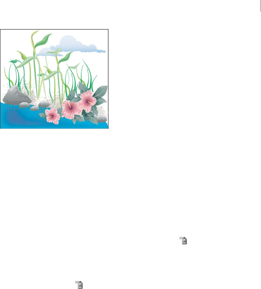
117
Drawing
Last updated 6/5/2015
As you work with symbol sets, keep in mind that the symbolism tools affect only the symbol or symbols selected in the
Symbols panel. For example, if you create a mixed symbol instance set that represents a meadow with grass and flowers,
you can change the orientation of just the grass by selecting the grass symbol in the Symbols panel and then using the
Symbol Spinner tool. To change the size of both the grass and the flowers, select both symbols in the Symbols panel and
then use the Symbol Sizer tool.
Note: When you select a mixed symbol set on the artboard, the symbol instance most recently added to the set is
automatically selected in the Symbols panel.
Create symbol sets
The Symbol Sprayer acts like a particle sprayer—letting you add a large number of identical objects to the artboard at
one time. For example, use the symbol sprayer to add hundreds of grass blades, wildflowers, bees, or snowflakes.
Spray sets of symbol instances onto artwork
1Select a symbol in the Symbols panel, and then select the Symbol Sprayer tool .
2Click or drag where you want the symbol instances to appear.
Add or delete symbol instances from an existing set
1Select the existing symbol set.
2Select the Symbol Sprayer tool and a symbol in the Symbols panel.
3Do one of the following:
•To add symbol instances, click or drag where you want the new instances to appear.
•To delete symbol instances, hold down Alt (Windows) or Option (Mac OS) as you click or drag where you want
to remove instances.
Modify symbol instances in a symbol set
You use the symbolism tools to modify multiple symbol instances in a set. For example, you can disperse instances over
a larger area using the Symbol Scruncher tool or gradually tinting the color of instances to make them look more
realistic.

118
Drawing
Last updated 6/5/2015
Although you can use symbolism tools on individual symbol instances, they are most effective when used on symbol
sets. When working with individual symbol instances, most of these tasks are easily accomplished using the tools and
commands you use on regular objects.
Change stacking order of symbol instances in a set
1Select the Symbol Shifter tool .
2Do one of the following:
•To move symbol instances, drag in the direction you want the symbol instances to move.
•To bring symbol instances forward, Shift-click the symbol instance.
•To send symbol instances backward, hold down Alt (Windows) or Option (Mac OS) and Shift-click the symbol
instance.
Gather or scatter symbol instances
1Select the Symbol Scruncher tool .
2Do one of the following:
•Click or drag in the area where you want to pull the symbol instances toward each other.
•Hold down Alt (Windows) or Option (Mac OS), and click or drag in the area where you want to push symbol
instances away from each other.
Resize symbol instances
1Select the Symbol Sizer tool .
2Do one of the following:
•Click or drag in the set where you want to increase the size of the symbol instances.
•Hold down Alt (Windows) or Option (Mac OS), and click or drag where you want to decrease the size of the
symbol instances.
•Hold down Shift as you click or drag to preserve the density of the symbol instances while resizing.
Rotate symbol instances
1Select the Symbol Spinner tool .
2Click or drag in the direction you want the symbol instances to orient.
Stain symbol instances
Staining a symbol instance changes the hue toward the tint color, while preserving the original luminosity. (It works in
the same way as the Tints and Shades colorization method of tinting brushes.) This method uses the luminosity of the
original color and the hue of the colorization color to generate the resulting color. Consequently, colors with very high
or very low luminosity change very little; black or white objects don’t change at all.
To achieve a method of colorization that will also affect black and white objects, use the Symbol Styler tool with a
graphic style that uses the desired fill color.
1In the Color panel, select the fill color that you want to use as the colorization color.
2Select the Symbol Stainer tool and do one of the following:
•Click or drag over the symbol instances you want to stain with the colorization color. The amount of colorization
gradually increases, and the symbol instance’s color gradually changes to the colorization color.
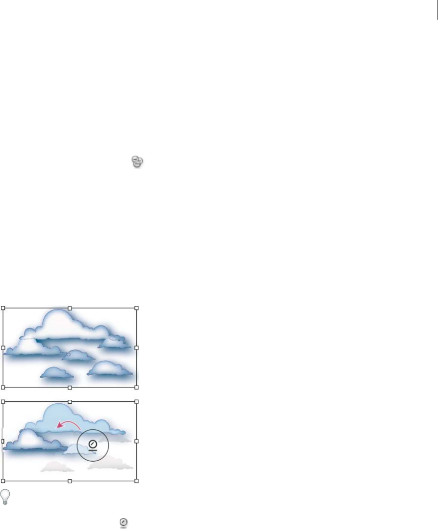
119
Drawing
Last updated 6/5/2015
•Hold down Alt (Windows) or Option (Mac OS) as you click or drag to decrease the colorization amount and
reveal more of the original symbol color.
•Hold down Shift as you click or drag to keep the colorization amount constant, while gradually changing the
color of the symbol instances to the colorization color.
note: Using the Symbol Stainer tool results in increased file size and decreased performance. When memory or
exported Flash/SVG file size is a concern, do not use this tool.
Adjust transparency of symbol instances
1Select the Symbol Screener tool .
2Do one of the following:
•Click or drag where you want to increase the symbol’s transparency.
•Hold down Alt (Windows) or Option (Mac OS), and click or drag where you want to decrease the symbol’s
transparency.
Apply a graphic style to symbol instances
The Symbol Styler tool lets you apply or remove a graphic style from a symbol instance. You can control the amount
and location of the application. For example, you can apply a style gradually so that some symbol instances display the
style at full strength and others display the style at partial strength.
You can switch to the Symbol Styler tool when using any other symbolism tool by clicking a style in the Graphic Styles
panel.
1Select the Symbol Styler tool .
2Select a style in the Graphic Styles panel, and do one of the following:
•Click or drag where you want to apply the style to the symbol set. The amount of style applied to the symbol
instances increases, and the style gradually changes.
•Hold down Alt (Windows) or Option (Mac OS) as you click or drag to decrease the style amount and reveal more
of the original, unstyled symbol.
•Hold down Shift as you click or drag to keep the amount of style constant, while gradually changing the symbol
instance style to the selected style.
note: It is very important to perform steps 1 and 2 in the specified order. If you select a style while a tool other than
the symbolism tool is selected, the style will apply immediately to the entire selected symbol instance set.

120
Drawing
Last updated 6/5/2015
Symbolism tool options
You access symbolism tool options by double-clicking a symbolism tool in the Tools panel.
General options, such as diameter, intensity, and density, appear at the top of the dialog box. Tool-specific options
appear at the bottom of the dialog box. To switch to options for a different tool, click a tool icon in the dialog
box.General optionsThe General options appear at the top of the Symbolism Tools Options dialog box regardless of
which symbolism tool is selected.Symbol Sprayer optionsThe Symbol Sprayer options (Scrunch, Size, Spin, Screen,
Stain, and Style) appear under the General options in the Symbolism Tools Options dialog box only when the Symbol
Sprayer tool is selected, and control how new symbol instances are added to symbol sets. Each of these offers two
choices:Symbol Sizer optionsThe Symbol Sizer options appear under the General options in the Symbolism Tools
Options dialog box only when the Symbol Sizer tool is selected.
More Help topics
Symbols
Perspective drawing
Introducing perspective drawing
In Illustrator CS5, you can easily draw or render artwork in perspective using a feature set that works on established
laws of perspective drawing.
Perspective grid allows you to approximately represent a scene on a flat surface, as it is naturally perceived (by the
human eye). For example, a road or a pair of railway tracks, which seem to meet or vanish in the line of vision.
The following features in Illustrator facilitate drawing in perspective:
•Utilities to define or edit one, two, and three vanishing point perspectives in a document.
•Control different perspective-defining parameters interactively.
•Create objects directly in perspective.
•Bring existing objects in perspective.
•Transform objects in perspective (move and scale objects).
•Move or duplicate objects toward a perpendicular plane (perpendicular movement).
•Define real work objects and draw objects with the specified real world measurements in perspective.
For a video on perspective drawing, see www.adobe.com/go/lrvid5205_ai_en.
Perspective grid presets
Illustrator provides presets for one-point, two-point, and three-point perspectives.
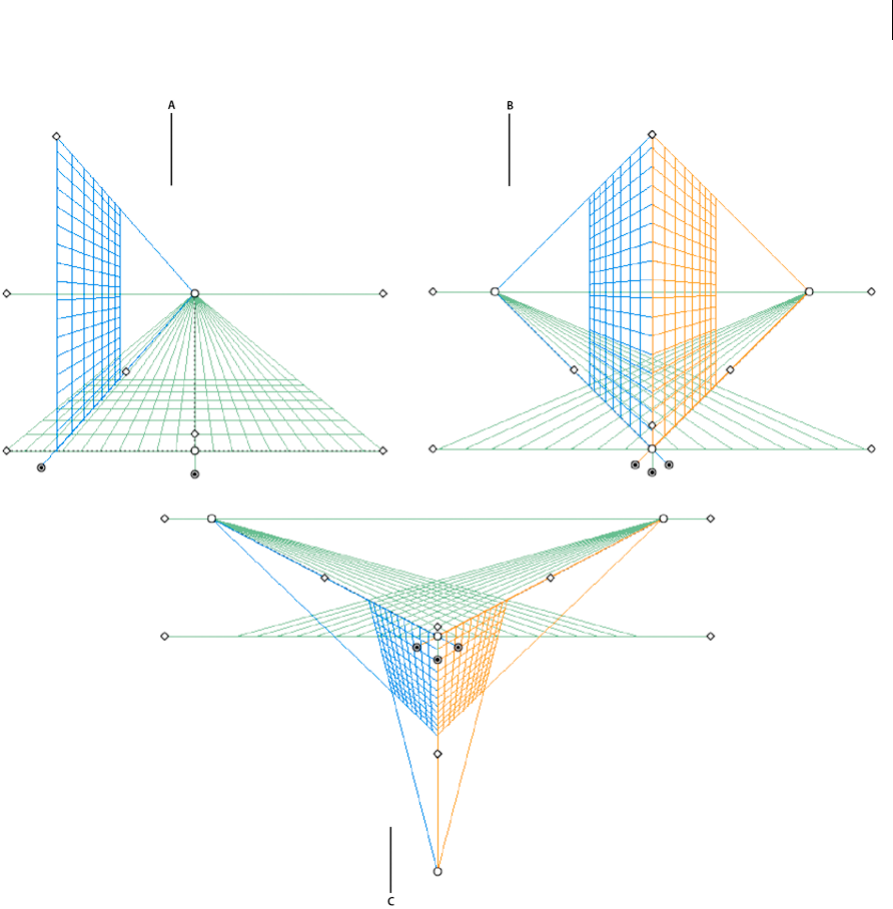
121
Drawing
Last updated 6/5/2015
A 1-point perspective B 2-point perspective (default) C 3-point perspective
To select one of the default perspective grid preset, click View> Perspective Grid and then select from the required
preset.
Define grid presets
To define grid settings, click View > Perspective Grid > Define Grid. In the Define Perspective Grid dialog box, you can
configure the following attributes for a preset:
Name To save a new preset, select the Custom option from the Name drop-down list.
Type Select the type of preset: One Point Perspective, Two Point Perspective, or Three Point Perspective.
Units Select the units to measure the grid size. The options are centimeters, inches, pixels, and points.
Scale Select the grid scale to view or set the artboard and real-world measurements. To customize the scale, select the
Custom option. In the Custom Scale dialog box, specify the Artboard and Real World proportions.
Gridline every This attribute determines the grid cell size.
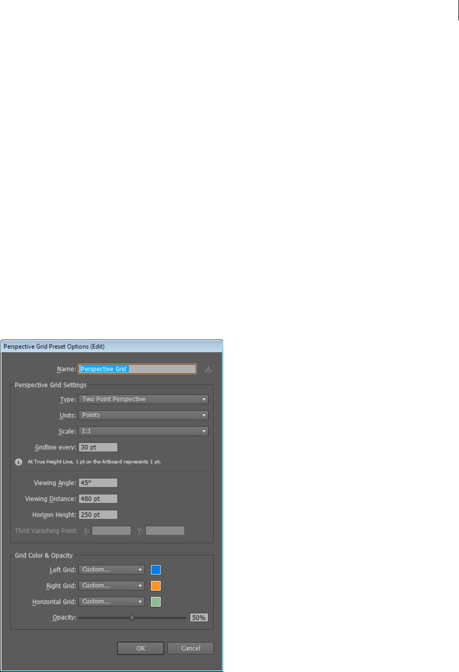
122
Drawing
Last updated 6/5/2015
Viewing Angle Imagine a cube in such an orientation that no face is parallel to the picture plane (in this case the
computer screen). Viewing Angle is the angle which the right face of this imaginary cube makes with the picture plane.
Therefore, the viewing angle determines the positions of the left and right vanishing points from the observer. A
viewing angle of 45° implies that the two vanishing points are equidistant from the line of vision of the observer. If the
viewing angle is greater than 45°, then the right vanishing point is closer to and the left vanishing point is farther away
from the line of vision and vice versa.
Viewing Distance Distance between the observer and the scene.
Horizon Height Specify the horizon height (observer’s eye level) for the preset. The height of the horizon line from the
ground level is displayed in the smart guide readout.
Third Vanishing Point This option is enabled when you select the three-point perspective. You can specify the x and y
coordinates for the preset in the X and Y boxes.
To change the colors for the left, right, and horizontal grids, select the color from the Left Grid, Right Grid, and
Horizontal Grid drop-down lists. You can also select a custom color from using the Color Selector as well.
Use the Opacity slider, to change the opacity of the grid.
To save the grid as a preset, click the Save Preset button.
Edit, delete, import, and export grid presets
To edit grid presets, click Edit > Perspective Grid Presets. In the Perspective Grid Presets dialog box, select the preset
to edit and click Edit.
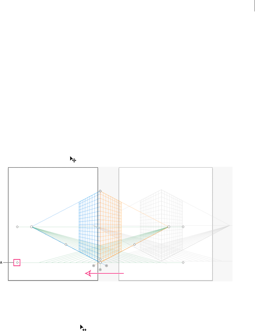
123
Drawing
Last updated 6/5/2015
The Perspective Grid Preset Options dialog box opens in edit mode. Enter the new grid setting and click OK to save
the new grid settings.
You cannot delete the default presets. To delete a user-defined preset, click Delete in the Perspective Grid Presets dialog
box.
Illustrator also allows you to import and export user-defined presets. To export a particular preset, click Export in the
Perspective Grid Presets dialog box. To import a preset, click Import.
Move the perspective grid
Illustrator can create only one grid in an Illustrator document. You can move the grid across artboards using the
Ground level widget while the Perspective Grid tool is selected, to place it at the required position.
Note: You must select the Perspective Grid tool to perform this task because the ground level widget is not displayed if this
tool is not selected.
To move the perspective grid do the following:
1Select the Perspective Grid tool from the Tools panel or press Shift+P.
2Drag-and-drop the left or right ground level widget on the grid. When you move the pointer over the ground level
point, the pointer changes to .
Adjust vanishing points, grid planes, horizon height, grid cell size, and grid extent
You can manually adjust vanishing points, grid plane controls, horizon height, and cell size using the respective widgets.
However, these widgets are only visible with the Perspective Grid tool selected.
To adjust the left and right vanishing points use the left and right vanishing point widgets. Notice that the pointer
changes to a two-way arrow pointer ( ) when you move the pointer over the vanishing points.
Note: While adjusting the third vanishing point in 3-point perspective, holding down the Shift key constrains the movement
to vertical axis.
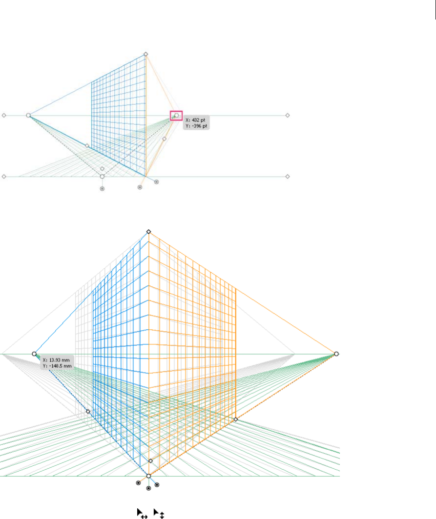
124
Drawing
Last updated 6/5/2015
Note: If you lock the station point using the View > Perspective Grid > Lock Station Point option, then both the vanishing
points move together.
You can also adjust the left, right, and horizontal grid planes using the respective grid plane control widgets. The
pointer changes to a two-way arrow ( , ) when you move the pointer over the grid plane controls.
Holding the Shift key while moving the grid planes, constrains the movement to the extent of cell size.
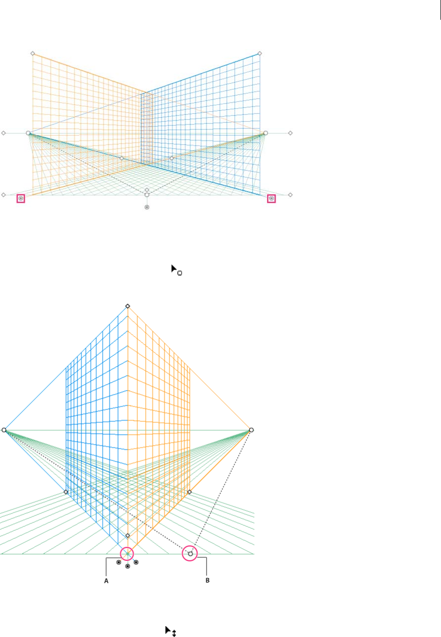
125
Drawing
Last updated 6/5/2015
If you shift the origin, the x and y coordinates of the horizontal plane and the x coordinate of vertical planes are affected.
When you select an object in perspective while the grid is visible, the x and y coordinates displayed in the Transform
and Info panels change with shift in origin. You can also see the change in coordinate measurements when you draw
objects using the rectangle or line group tools and press Shift, while the relevant grid plane is active. If you move the
mouse over the origin, the pointer changes to .
Note: If you move the ruler origin, you can see the station point.
A Station Point B Changed Ruler Origin
Adjust horizon height to fine-tune the observer's eye-level. When you move the pointer over the horizon line, the
pointer changes to a vertical two-way arrow .
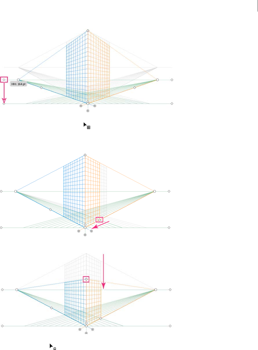
126
Drawing
Last updated 6/5/2015
You can change the grid extent to define the extent of the grid on the planes. When you move the pointer over the grid
extent widgets, the pointer changes to .
Note: Gridlines are set to display onscreen when there is a 1-pixel gap in them. Progressive zooming in brings in view more
gridlines that are closer toward Vanishing Point.
You can also adjust the grid extent to increase or decrease the vertical grid extent.
To increase or decrease the grid cell size, use the grid cell size widget. When you mouse over the grid cell size widget,
the pointer changes to .
Note: When you increase the grid cell size, the number of grid cells reduce.
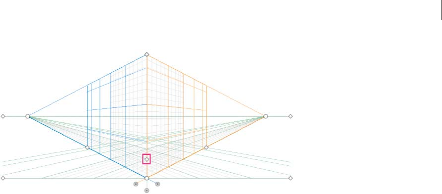
127
Drawing
Last updated 6/5/2015
Drawing new objects in perspective
To draw objects in perspective, use the line group tools or rectangle group tools while the grid is visible. While using
the rectangle or line group tools, you can switch to the Perspective Selection tool by pressing Cmd (Mac OS) or Ctrl
(Windows).
You can also switch the active plane using the keyboard shortcut 1 (left plane), 2 (horizontal plane), and 3 (right plane)
with these tools selected.
Note: The Flare tool is not supported with Perspective Grid.
When you draw an object in perspective, use Smart Guides to align the object to other objects. The alignment is based
on the perspective geometry of objects. Guides appear as the object approaches the edge or anchor point of other
objects.
You can use numerical values for any of the rectangle or line group tools (other than the Flare tool). You can specify
height and width values for the object in the same way as you would draw in regular mode, but the object is drawn in
perspective in this case. Also, the values represent real world dimensions of the objects.
Note: While drawing in perspective, you can use the regular shortcuts available for drawing objects such as Shift / Alt+drag
(Windows) or Option+drag (Mac OS).
While drawing in perspective, objects can be snapped to grid lines of the active plane. An object snaps to the grid lines
within 1/4th distance of the cell size.
You can enable or disable the Snap to Grid option from View > Perspective Grid > Snap to Grid.This option is enabled
by default.
For a video on drawing artwork in perspective, see www.adobe.com/go/lrvid5211_ai_en.
Attach objects to perspective
If you have already created objects, Illustrator provides the option to attach objects to an active plane on the perspective
grid.
To add an object to the left, right, or horizontal grid:
1Select the active plane on which you want to place the object. You can select the active plane using 1, 2, or 3 keyboard
shortcut command or by clicking on one of the faces of the cube in the Perspective Grid Widget.
2Click Object > Perspective > Attach to Active Plane.
Note: Using the Attach to Active Plane command does not affect the appearance of the object.

128
Drawing
Last updated 6/5/2015
For a video on mapping artwork to perspective, see www.adobe.com/go/lrvid5212_ai_en.
Release objects with perspective
If you want to release an object with a perspective view, click Object > Perspective> Release with Perspective option.
The selected object is released from the associated perspective plane and is available as a normal artwork.
Note: Using the Release with Perspective command does not affect the appearance of the object.
Bringing objects in perspective
When you bring an existing object or artwork into perspective, the appearance and scale of the selected object changes.
To bring regular objects into perspective, do the following:
1Select the object using the Perspective Selection tool.
2Select the active plane on which you want to place the object by using the Plane Switching widget or using the
keyboard shortcut 1 (left plane), 2 (horizontal plane), 3 (right plane).
3Drag-and-drop the object at the required location.
Selecting objects in perspective
Use the Perspective Selection tool to select objects in perspective. The Perspective Selection tool provides a marquee to
select objects using the active plane settings.
You can select between normal marquee and the perspective marquee after starting to drag using the Perspective
Selection tool and then switch between different planes of the grid using 1, 2, 3, or 4 keys.
Transforming objects
Moving objects
To move objects in perspective, switch to the Perspective Selection tool (Shift+V) and then either use the arrow keys or
the mouse to drag-and-drop objects.
Note: During the drag loop while moving the objects, changing the plane using the respective keyboard shortcut changes the
object's plane.
You can also move objects in perpendicular direction to the current object location. This technique is useful when
creating parallel objects such as the walls of a room. For this movement:
1Select the object using the Perspective Selection tool.
2Keeping the number 5 key pressed, drag the object to the required position. This action moves the object parallel to
its current location. Using Alt (Windows) or Option (Mac OS) along with the number 5 key while moving,
duplicates the object at the new location without changing the original object. In Draw Behind mode, this action
creates the object behind the original object.
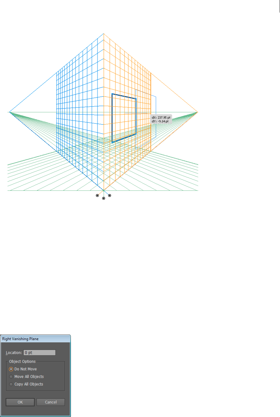
129
Drawing
Last updated 6/5/2015
Note: The arrow keys do not work when you move objects in perpendicular.
Use the keyboard shortcut, Alt+drag (Windows) or Option+drag (Mac OS) to copy the object. To constrain the
movement in perspective, press Shift+drag. To specify a precise location where you need to move the object during
perpendicular movement, see Precise perpendicular movement.
You can also use the Transform Again command (Object > Transform > Transform Again) or the keyboard shortcut
Ctrl+D (Windows) or Cmd+D (Mac OS) to move objects in perspective. This option also works when you move object
in perpendicular direction.
Note: The keyboard shortcut 5 for perpendicular movement and the keyboard shortcuts 1,2, and 3 for plane switching while
drawing or moving objects, work only from the main keyboard and not from the extended numeric keypad.
Precise perpendicular movement
To move objects in precise perpendicular movement, double-click the required plane widget using the Perspective
Selection tool. For example, double-click the right plane widget to set the options in the Right Vanishing Plane dialog
box.
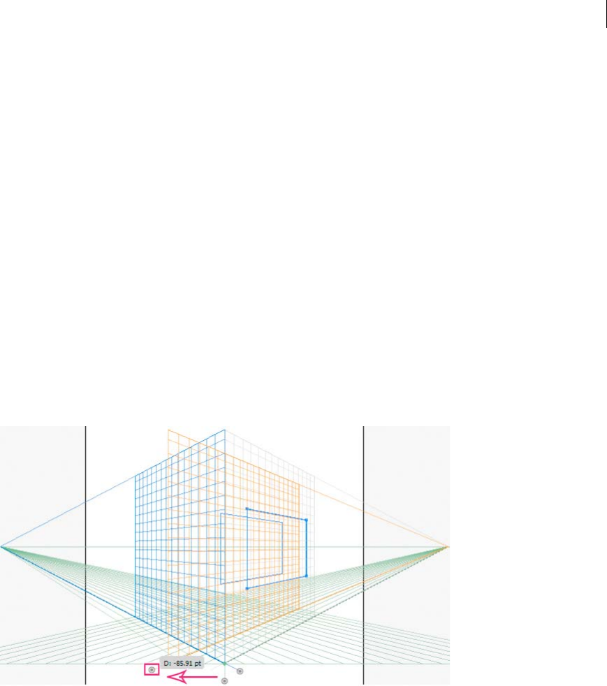
130
Drawing
Last updated 6/5/2015
For precise perpendicular movement, for all objects:
1In the Location box, specify the location where the objects need to be moved. By default, the current location of
objects is displayed in the dialog box.
2Select from the following movement options for objects:
Do Not Move If this option is selected, the object does not move when the grid is repositioned.
Move All Objects If you select this option, then all the objects on the plane move with the grid movement.
Copy All Objects If you select this option, then all the objects on the plane are copied on the plane.
To move a selected object in precise perpendicular movement, select the object and then double-click the required
plane widget. In this case, the following dialog box is displayed:
Perpendicular movement by dragging grid planes
You can also move objects in perpendicular direction by dragging the grid plane using grid plane controls. When you
move an object in perpendicular direction, the object is placed parallel to its existing or current location.
To move an object parallel to its current position:
1Select the Perspective Selection tool from the Tools panel or by pressing Shift+V.
2Press Shift and drag the grid plane control depending on the grid plane where the object is placed.
To create a copy of the object parallel to its current position:
1Select the Perspective Selection tool from the Tools panel or by pressing Shift+V.
2Press Alt and drag (Windows) or Option and drag (Mac OS) the grid plane control depending on the grid plane
where the object is placed.
Automatic plane positioning
The automatic plane positioning feature allows you to create objects by inferring the height or depth of the object. For
example, to draw a cube, the height of the top face of the cube must be known. With automatic plane positioning,
perspective grid automatically adjusts the horizontal grid plane to match the height of the top face of the cube.
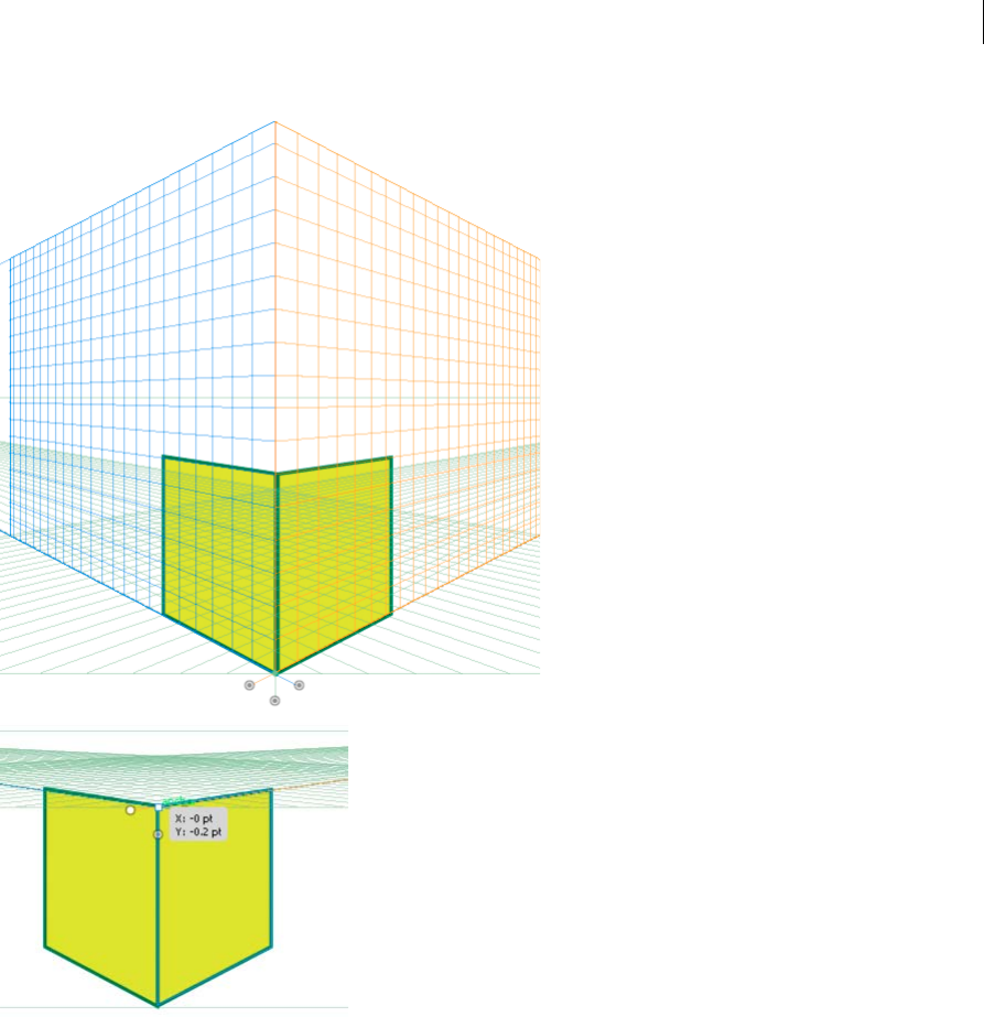
131
Drawing
Last updated 6/5/2015
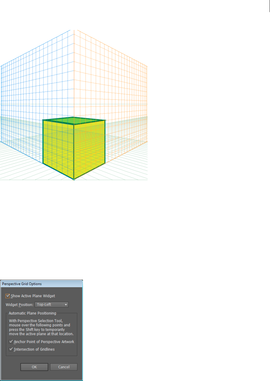
132
Drawing
Last updated 6/5/2015
Before drawing or placing objects, the object height can be inferred from:
• Other objects by going to one of the anchor points (getting the anchor label) and pressing Shift, which temporarily
hides other planes.
•Grid lines by going to the intersection point and pressing the Shift key. Changing plane in this state brings that plane
to the selected offset.
Once the object is drawn or placed, the inference mode is reset and all planes are restored to normal visibility.
Using the automatic plane positioning options, you can select to move the active plane temporarily when you mouse
over the anchor point or gridline intersection point by pressing the Shift key.
The automatic plane positioning options are available in the Perspective Grid Options dialog box. To display this dialog
box, double-click the Perspective Grid tool icon in the Tools panel.
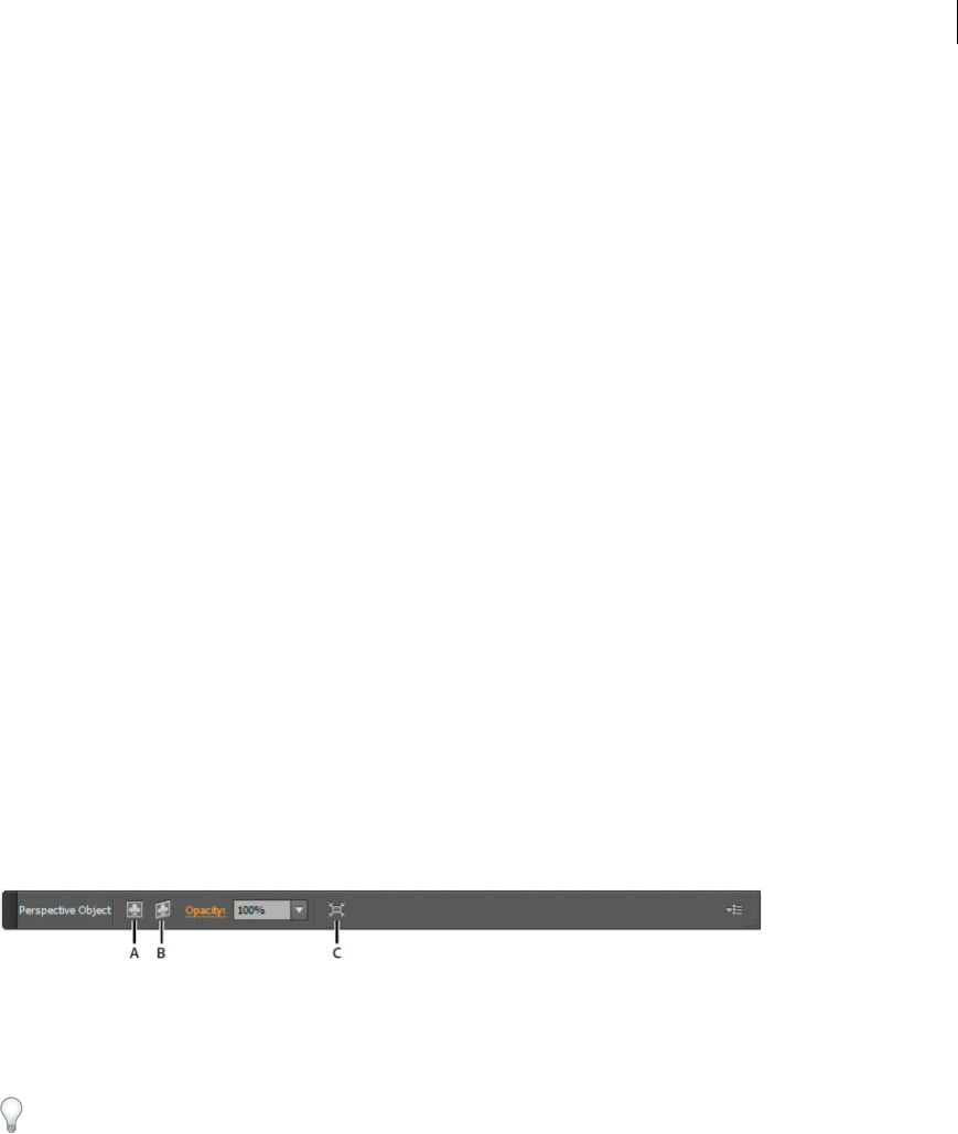
133
Drawing
Last updated 6/5/2015
Move plane to match object
When you want to draw or bring objects in perspective at the same depth or height as an existing object, select the
existing object in perspective and click Object > Perspective > Move Plane to Match Object to bring the corresponding
grid to the desired height or depth. You can now draw or bring new objects in perspective.
Scale objects in perspective
You can scale objects in perspective using the Perspective Selection tool. While scaling objects in perspective, the
following rules apply:
•Scaling is done in the object’s plane. When you scale an object, the height or distance is scaled based on the object’s
plane and not the current or active plane.
•For multiple objects, scaling is done for objects that are on the same plane. For example, if you select multiple objects
on the right and left plane, then all the objects that are on the same plane as the object whose bounding box is used
for scaling, are scaled.
•Objects that have been moved perpendicularly, are scaled on their respective plane and not the current or active
plane.
Adding text and symbols in perspective
You cannot directly add text and symbols to a perspective plane, when the grid is visible. However, you can bring text
or symbols into perspective after creating them in normal mode.
To bring text or symbols in perspective, do the following:
1Select the existing text or symbol using the Perspective Selection Tool and drag it to the required position on the
active plane, while the grid is visible.
2The Edit Text option is available in the Control panel and under the Object > Perspective menu. In addition, you
can edit text in isolation mode or by double-clicking the text object.
A Edit Text B Edit Perspective C Isolate Selected Object
The Edit Symbol option is also available in the Control panel and under the Object > Perspective menu. In addition,
you can edit a symbol in isolation mode or by double-clicking the object.
Depending on whether you are editing a symbol or text, the options in the Control panel change to Edit Symbol or
Edit Text.
A symbol instance in perspective is the same as an expanded symbol instance. You can edit a symbol definition just as
you would edit the symbol definition of a flat symbol instance. However, a symbol definition cannot contain art types
that are not supported in perspective such as raster (images), non-native art, envelope, legacy type, and gradient mesh.
Note: Functionalities such as replacing a symbol, breaking link when expanding the a symbol instance, and reset
transformation do not work on symbols in perspective.
As a workaround to replacing a symbol instance, you can Alt+drag (Windows) or Option+drag (Mac OS) a symbol
instance in perspective and leave it over the symbol in the Symbols panel. However, make a copy of the symbol before
replacing the symbol instance because when you drag the symbol instance, the previous symbol instance is
permanently deleted from your document.
You can edit or modify text in the same way as is done in the normal mode. For more information, see Creating text.
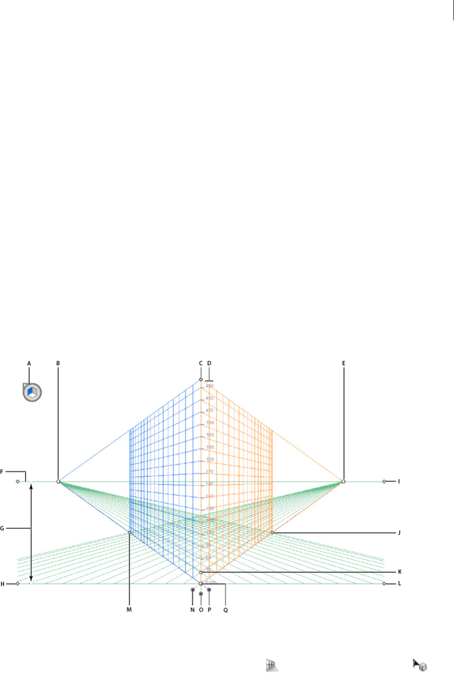
134
Drawing
Last updated 6/5/2015
Perspective Grid settings
You can configure the Perspective Grid settings using View > Perspective Grid. The options available include:
Show Rulers This option shows the ruler division only along the true height line. The gridline every determines the
ruler division.
Snap to Grid This option allows snapping to gridlines while bringing in perspective, moving, scaling, and drawing in
perspective.
Lock Grid This option restricts the grid movement and other grid editing using the Perspective Grid tool. Only the
visibility and the plane position can be changed.
Lock Station Point When the Lock Station Point option is selected, moving one vanishing point moves the other
vanishing point in sync with the movement. If not checked, then the movement is independent and the station point
also moves.
About Perspective Grid
To view the default two-point perspective grid in a document, you can do any of the following:
•Click View > Perspective Grid > Show Grid.
•Press Ctrl+Shift+I (on Windows) or Cmd+Shift+I (on Mac) to show the Perspective Grid. The same keyboard
shortcut can be used to hide the visible grid.
•Click the Perspective Grid tool from the Tools panel.
A Plane switching widget B Left Vanishing Point C Vertical Grid Extent D Perspective Grid Ruler E Right Vanishing Point F Horizon Line
G Horizon Height H Ground Level I Horizon Level J Extent of Grid K Grid Cell Size L Ground Level M Extent of Grid N Right Grid Plane
Control O Horizontal Grid Plane Control P Left Grid Plane Control Q Origin
The Perspective Grid tool group consists of the Perspective Grid tool and the Perspective Selection tool .

135
Drawing
Last updated 6/5/2015
You can select the Perspective Grid tool from the Tools panel or press Shift+P. When the Perspective Grid tool is
selected, it shows:
•Left and right grid controls to adjust planes (see Adjust vanishing points, grid planes, horizon height, grid cell size,
and grid extent)
•Horizon height (see Precise perpendicular movement)
•Left and right vertical plane position
•Visibility and extent of a grid cell
•Grid cell size
•Origin
•Left and right ground level widgets used for grid movement (see Move the perspective grid)
In addition, when you select the Perspective Grid, a Plane Switching Widget also appears. You can use this widget to
select the active grid plane. In Perspective Grid, an active plane is the plane on which you draw an object to project the
observer’s view of that portion of the scene.
A Left Grid Plane B No Active Grid Plane C Right Grid Plane D Horizontal Grid Plane
For a video on defining the perspective grid, see www.adobe.com/go/lrvid5205_ai_en.
You can set options to position the widget on any of the four screen corners and choose to display it when the
Perspective Grid is visible. To set these options, double-click the Perspective Grid icon in the Tools panel. In the
Perspective Grid Options dialog box, you can select the following:
Show Active Plane Widget This option is selected by default. If you deselect this check box, then the widget is not
displayed with the Perspective Grid.
Widget Position You can choose to display the widget on the upper left, upper-right, lower-left, or lower-right corner
of the document window.
When you select the Perspective Selection tool, the left, right, and horizontal grid controls are displayed. You can switch
to the Perspective Selection tool by pressing Shift+V or selecting it from the Tools panel. The Perspective Selection tool
enables you to:
•Bring objects, texts, and symbols in perspective
•Switch active planes using keyboard shortcuts
•Move, scale, and duplicate objects in perspective space
•Move and duplicate objects perpendicular to its current position in the perspective plane. (see Precise perpendicular
movement)
With the Perspective Selection tool, the active planes in the perspective grid are indicated by the following pointers.
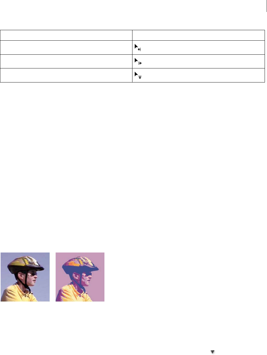
136
Drawing
Last updated 6/5/2015
The Perspective Selection tool snaps the objects to the grid of the active plane while moving, scaling, duplicating, and
bringing objects into perspective. Objects snap to the grid lines within 1/4th distance of the cell size.
You can enable or disable snapping from View > Perspective Grid > Snap to Grid.
This option is enabled by default.
Using Live Trace | CS5 and earlier
Trace artwork
If you want to base a new drawing on an existing piece of artwork, you can trace it. For example, you can create a graphic
based on a pencil sketch drawn on paper or on a raster image saved in another graphics program by bringing the
graphic into Illustrator and tracing over it.
The easiest way to trace artwork is to open or place a file into Illustrator and automatically trace the artwork with the
Live Trace command. You can control the level of detail and how the tracing is filled. When you are satisfied with the
tracing results, you can convert the tracing to vector paths or a Live Paint object.
Illustrator CS6 users: Use the ImageTrace feature to trace an image into vector artwork. See the Illustrator CS6 article, .
Automatically trace artwork using Live Trace
1Open or place a file to use as the source image for the tracing.
2With the source image selected, do one of the following:
•To trace the image using a tracing preset, click the Tracing Presets and Options button in the Control panel,
and select a preset.
•To trace the image using the default tracing options, click Live Trace in the Control panel, or choose Object >
Live Trace > Make.
Active Plane Pointers
Left Grid Plane
Right Grid Plane
Horizontal Grid Plane

137
Drawing
Last updated 6/5/2015
•To set tracing options before you trace the image, click the Tracing Presets and Options button in the Control
panel, and choose Tracing Options. Alternatively, choose Object > Live Trace > Tracing Options. Set tracing
options, and then click Trace.
3(Optional) Adjust the results of the tracing.
4(Optional) Convert the tracing to paths or to a Live Paint object.
Tracing options
Preset Specifies a tracing preset.
Mode Specifies a color mode for the tracing result.
Threshold Specifies a value for generating a black and white tracing result from the original image. All pixels lighter
than the Threshold value are converted to white, all pixels darker than the Threshold value are converted to black. (This
option is available only when Mode is set to Black and White.)
Palette Specifies a palette for generating a color or grayscale tracing from the original image. (This option is available
only when Mode is set to Color or Grayscale.)
To let Illustrator determine the colors in the tracing, select Automatic. To use a custom palette for the tracing, select a
swatch library name. (The swatch library must be open in order for it to appear in the Palette menu.)
Max Colors Specifies a maximum number of colors to use in a color or grayscale tracing result. (This option is available
only when Mode is set to Color or Grayscale and when panel is set to Automatic.)
Output To Swatches Creates a new swatch in the Swatches panel for each color in the tracing result.
Blur Blurs the original image before generating the tracing result. Select this option to reduce small artifacts and
smooth jagged edges in the tracing result.
Resample Resamples the original image to the specified resolution before generating the tracing result. This option is
useful for speeding up the tracing process for large images but can yield degraded results.note: The resample resolution
is not saved when you create a preset.
Fills Creates filled regions in the tracing result.
Strokes Creates stroked paths in the tracing result.
Max Stroke Weight Specifies the maximum width of features in the original image that can be stroked. Features larger
than the maximum width become outlined areas in the tracing result.
Min Stroke Length Specifies the minimum length of features in the original image that can be stroked. Features smaller
than the minimum length are omitted from the tracing result.
Path Fitting Controls the distance between the traced shape and the original pixel shape. Lower values create a tighter
path fitting; higher values create a looser path fitting.
Minimum Area Specifies the smallest feature in the original image that will be traced. For example, a value of 4 specifies
that features smaller than 2 pixels wide by 2 pixels high will be omitted from the tracing result.
Corner Angle Specifies the sharpness of a turn in the original image that is considered a corner anchor point in the
tracing result. For more information on the difference between a corner anchor point and a smooth anchor point, see
About paths.
Raster Specifies how to display the bitmap component of the tracing object. This view setting is not saved as part of the
tracing preset.
Vector Specifies how to display the tracing result. This view setting is not saved as part of the tracing preset.
138
Drawing
Last updated 6/5/2015
Select Preview in the Tracing Options dialog box to preview the result of the current settings.To set the default tracing
options, deselect all objects before you open the Tracing Options dialog box. When you’re finished setting options, click
Set Default.
For a video on using Live Trace, see www.adobe.com/go/vid0043. For a tutorial on tweaking Live Trace options for the
best possible results, see www.adobe.com/go/learn_ai_tutorials_livetrace_en.
Change the display of a tracing object
A tracing object is made up of two components: the original source image and the tracing result (which is the vector
artwork). By default, only the tracing result is visible. However, you can change the display of both the original image
and the tracing result to best suit your needs.
1Select the tracing object.
By default, all tracing objects are named “Tracing” in the Layers panel.
2Do any of the following:
•To change the display of the tracing result, click the Vector View button in the Control panel or choose Object
> Live Trace, and select a display option: No Tracing Result, Tracing Result, Outlines, or Outlines With Tracing.
•To change the display of the source image, click the Raster View button in the Control panel or choose Object
> Live Trace, and select a display option: No Image, Original Image, Adjusted Image (which displays the image
with any adjustments that are applied during tracing), or Transparent Image.
note: In order to view the source image, you must first change the Vector View to No Tracing Result or Outlines.
Adjust the results of a tracing object
Once you create a tracing object, you can adjust the results at any time.
1Select the tracing object.
2Do any of the following:
•Set basic options in the Control panel.
•Click the Tracing Options Dialog button in the Control panel to view all tracing options. Alternatively,
choose Object > Live Trace > Tracing Options. Adjust the options, and click Trace.
Use tracing presets to quickly change the results of a tracing.
Specify the colors used for tracing
1Create a swatch library that contains the colors you want to use in the tracing.
2Make sure that the swatch library is open, and click the Tracing Options Dialog button in the Control panel.
Alternatively, choose Object > Live Trace > Tracing Options.
3Select the swatch library name from the Palette menu, and click Trace.
More Help topics
Create a swatch library

139
Drawing
Last updated 6/5/2015
Use a tracing preset
Tracing presets provide pre-specified tracing options for specific types of artwork. For example, if you’re tracing an
image that you plan to use as a technical drawing, choose the Technical Drawing preset. All the tracing options change
for optimal tracing of a technical drawing: color is set to black and white, blur is set to 0 px, stroke width is limited to
3 px, and so on.
Specify a preset
•Choose Object > Live Trace > Tracing Options. (Alternatively, select a tracing object, and click the Tracing Options
Dialog button in the Control panel.) Set tracing options for the preset, and click Save Preset. Enter a name for
the preset, and click OK.
•Choose Edit > Tracing Presets. Click New, set tracing options for the preset, and click Done.
Tip: To base a new preset on an existing preset, select the preset, and click New.
Edit or delete a preset
1Choose Edit > Tracing Presets.
2Select the preset, and click Edit or Delete.
Note: You can’t edit or delete the default presets (default presets appear in brackets [ ]). However, you can make an
editable copy of a default preset by selecting the preset and clicking New.
Share presets with other users
1Choose Edit > Tracing Presets.
2Do one of the following:
•Click Export to save your presets to a file.
•Click Import to load presets from a file.
Convert a tracing object to a Live Paint object
When you are satisfied with the results of a tracing, you can convert the tracing object to paths or to a Live Paint object.
This final step allows you to work with the tracing as you do other vector artwork. Once you convert the tracing object,
you can no longer adjust the tracing options.
1Select the tracing object.
2Do one of the following:
•To convert the tracing to paths, click Expand in the Control panel or choose Object > Live Trace > Expand. Use
this method if you want to work with the components of the traced artwork as individual objects. The resulting
paths are grouped together.
•To convert the tracing to paths while preserving the current display options, choose Object > Live Trace >
Expand As Viewed. For example, if the display options are set to Outlines for the tracing result, then the
expanded paths will be outlines only (rather than filled and stroked). In addition, a snapshot of the tracing with
its current display options is preserved and grouped with the expanded paths. Use this method if you want to
preserve the tracing image as a guide for the expanded paths.
•To convert the tracing to a Live Paint object, click Live Paint in the Control panel or choose Object > Live Trace
> Convert To Live Paint. Use this method if you want to apply fills and strokes to the traced artwork using the
Live Paint Bucket tool.

140
Drawing
Last updated 6/5/2015
To create a tracing and convert the tracing object in one step, choose Object > Live Trace > Make And Expand or Object
> Live Trace > Make And Convert To Live Paint.
For a video on tracing, see www.adobe.com/go/vid0043.
More Help topics
Drawing basics
About Live Paint
Release a tracing object
If you want to discard a tracing but keep the original placed image, you can release the tracing object.
1Select the tracing object.
2Choose Object > Live Trace > Release.
Manually trace artwork using template layers
Template layers are locked, nonprinting layers that you can use to manually trace images. Template layers are dimmed
by 50% so you can easily see any paths you draw in front of the layer. You can create template layers when you place an
image or from existing layers.
1Do one of the following:
•To place an image as a template layer for tracing, choose File > Place, select the EPS, PDF, or raster image file you
want to trace, select Template, and then click Place. A new template layer appears below the current layer in the
panel.
•To trace an existing image, make sure the image is in its own layer, double-click the layer in the Layers panel,
select Template, and click OK; alternatively, select the layer and choose Template from the panel menu.
The eye icon is replaced by the template icon , and the layer is locked.
2Trace over the file using the Pen tool or the Pencil tool.
3To hide the template layer, choose View > Hide Template. Choose View > Show Template to see it again.
4To turn a template layer into a regular layer, double-click the template layer in the Layers panel, deselect Template,
and click OK.
Automatic corner generation | Illustrator CC
Overview
In a pattern brush, different tiles make up the overall pattern. A different tile is required for the sides, inner corner, outer
corner, beginning, and end of the pattern. In Illustrator CC, the experience of creating corner tiles in pattern brushes
has been improved.
To use the improved method, first define the image to be used as the side tile. When you drag the side tile into the
Brushes panel (F5), to create a pattern brush, Illustrator uses the tile to generate the remaining four tiles. These four
auto-generated options fit the corners perfectly.
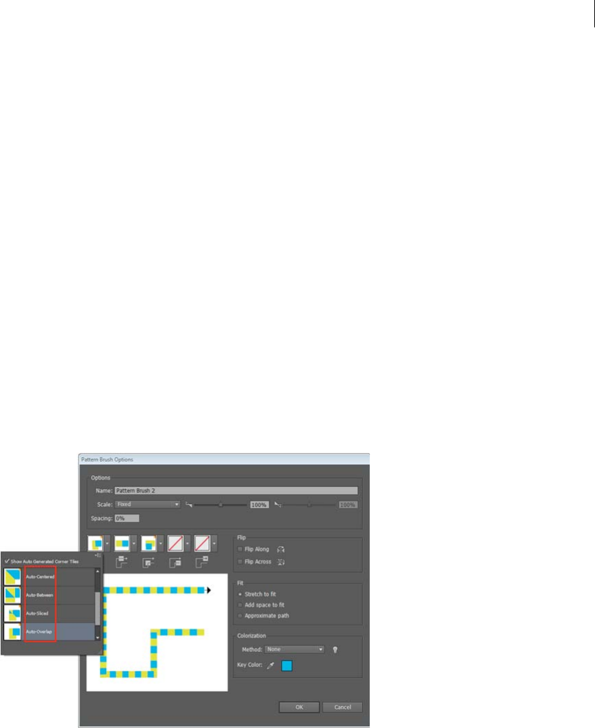
141
Drawing
Last updated 6/5/2015
In the Pattern Brush Options dialog, you can preview the brush, using a sample path. You can modify the tiles
(automatic/original art/pattern swatches), and preview the effect on the appearance of your brush strokes. The dialog
also provides you with the option to save your original art tile, or the automatically generated corner tiles, as a pattern
swatch.
The four types of automatic corners are:
Auto-Centered The Side tile is stretched around the corner, and centered on it.
Auto-Between Copies of the side tile extend all the way into the corner, with one copy on each side. Folding elimination
is used to stretch them into shape.
Auto-Sliced The side tile is sliced diagonally, and the pieces come together, similar to a miter joint in a wooden picture
frame.
Auto-overlap Copies of the tiles overlap at the corner.
Generate corners automatically
1In Illustrator, create or embed the artwork you want to use as a side tile.
2Drag the artwork into the Brushes panel. (F5)
3Choose what brush you want to create (Pattern Brush).
4In the Pattern Brush Options dialog, you can choose a tile each for Outer Corner, Side, Inner Corner, Start, and End
tiles.
A The area marked by the red outline displays the corners that have been generated automatically.
Creating arrows and arrowheads in Illustrator
Five methods to create a variety of arrows
Creating arrows and arrowheads in Illustrator

142
Last updated 6/5/2015
Chapter 4: Color
About color
Applying colors to artwork is a common Adobe Illustrator task, and one that requires some knowledge of color models
and color modes. When applying color to artwork, keep in mind the final medium in which the artwork will be
published, so that you can use the correct color model and color definitions. Experimenting and applying color is easy
using the feature-rich Swatches panel, Color Guide panel, and Edit Colors/Recolor Artwork dialog box in Illustrator.
Color models describe the colors we see and work with in digital graphics. Each color model, such as RGB, CMYK, or
HSB, represents a different method for describing and classifying color. Color models use numeric values to represent
the visible spectrum of color. A color space is a variant of a color model and has a specific gamut (range) of colors. For
example, within the RGB color model are a number of color spaces: Adobe® RGB, sRGB, and Apple® RGB. While each
of these color spaces defines color using the same three axes (R, G, and B), their gamuts are different.
About colors in digital graphics
We use color models to describe the colors we see and work with in digital graphics. Each color model, such as RGB,
CMYK, or HSB, represents a different method for describing and classifying color. Color models use numeric values to
represent the visible spectrum of color. A color space is a variant of a color model and has a specific gamut (range) of
colors. For example, within the RGB color model are a number of color spaces: Adobe® RGB, sRGB, and Apple® RGB.
While each of these color spaces defines color using the same three axes (R, G, and B), their gamuts are different.
When you work with the colors in a graphic, you are actually adjusting numerical values in the file. It’s easy to think of
a number as a color, but these numerical values are not absolute colors in themselves—they only have a color meaning
within the color space of the device that is producing the color.
Because each device has its own color space, it can reproduce colors only in its gamut. When an image moves from one
device to another, image colors may change because each device interprets the RGB or CMYK values according to its
own color space. For example, it is impossible for all the colors viewed on a monitor to be identically matched in a print
from a desktop printer. A printer operates in a CMYK color space, and a monitor operates in an RGB color space. Their
gamuts are different. Some colors produced by inks cannot be displayed on a monitor, and some colors that can be
displayed on a monitor cannot be reproduced using inks on paper.
Even though it is impossible to perfectly match all colors on different devices, you can use color management to ensure
that most colors are the same or similar enough so they appear consistent.
More Help topics
About color management in Adobe applications
Synchronize color settings across Adobe applications
RGB, CMYK, HSB, and Lab color models
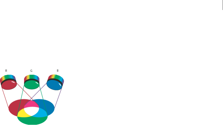
143
Color
Last updated 6/5/2015
RGB
A large percentage of the visible spectrum can be represented by mixing red, green, and blue (RGB) colored light in
various proportions and intensities. Where the colors overlap, they create cyan, magenta, and yellow.
RGB colors are called additive colors because you create white by adding R, G, and B together—that is, all light is
reflected back to the eye. Additive colors are used for lighting, television, and computer monitors. Your monitor, for
example, creates color by emitting light through red, green, and blue phosphors.
A Red B Green C Blue
You can work with color values using the RGB color mode, which is based on the RGB color model. In RGB mode, each
of the RGB components can use a value ranging from 0 (black) to 255 (white). For example, a bright red color might
have an R value of 246, a G value of 20, and a B value of 50. When the values of all three components are equal, the result
is a shade of gray. When the value of all components is 255, the result is pure white; when all components have values
of 0, the result is pure black.
Illustrator also includes a modified RGB color mode called Web Safe RGB, which includes only those RGB colors that
are appropriate for use on the web.
More Help topics
Change the color mode of a document
CMYK
Whereas the RGB model depends on a light source to create color, the CMYK model is based on the light-absorbing
quality of ink printed on paper. As white light strikes translucent inks, a portion of the spectrum is absorbed. Color that
is not absorbed is reflected back to your eye.
Combining pure cyan (C), magenta (M), and yellow (Y) pigments would result in black by absorbing, or subtracting,
all colors. For this reason they are called subtractive colors. Black (K) ink is added for better shadow density. (The letter
K came into use because black is the “key” color for registering other colors, and because the letter B also stands for
blue.) Combining these inks to reproduce color is called four-color process printing.
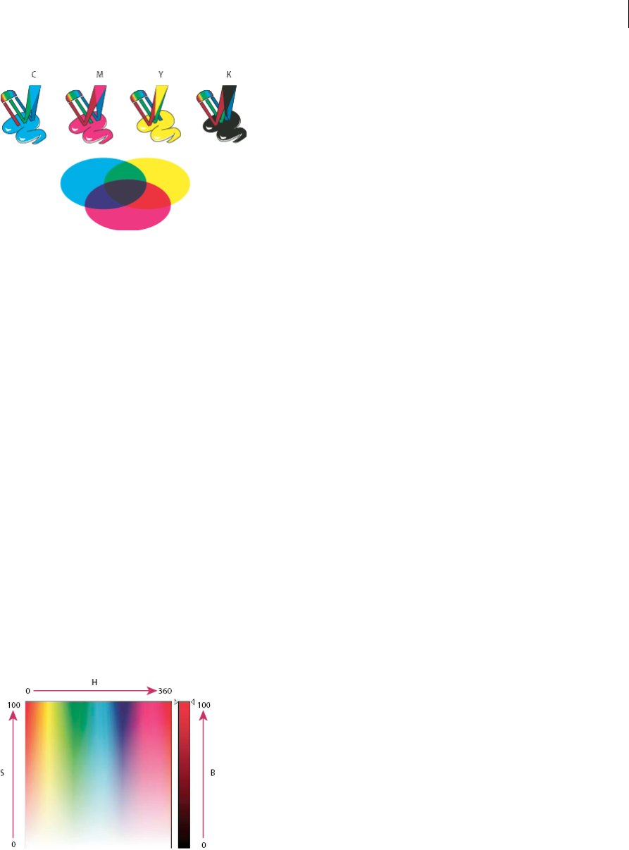
144
Color
Last updated 6/5/2015
A Cyan B Magenta C Yellow D Black
You can work with color values using the CMYK color mode, which is based on the CMYK color model. In CMYK
mode, each of the CMYK process inks can use a value ranging from 0 to 100%. The lightest colors are assigned small
percentages of process ink colors; darker colors have higher percentage values. For example, a bright red might contain
2% cyan, 93% magenta, 90% yellow, and 0% black. In CMYK objects, low ink percentages are closer to white, and high
ink percentages are closer to black.
Use CMYK when preparing a document to be printed using process inks.
More Help topics
Change the color mode of a document
HSB
Based on the human perception of color, the HSB model describes three fundamental characteristics of color:
Hue Color reflected from or transmitted through an object. It is measured as a location on the standard color wheel,
expressed as a degree between 0° and 360°. In common use, hue is identified by the name of the color, such as red,
orange, or green.
Saturation Strength or purity of the color (sometimes called chroma). Saturation represents the amount of gray in
proportion to the hue, measured as a percentage from 0% (gray) to 100% (fully saturated). On the standard color wheel,
saturation increases from the center to the edge.
Brightness Relative lightness or darkness of the color, usually measured as a percentage from 0% (black) to 100%
(white).
A Hue B Saturation C Brightness
More Help topics
Adjust the saturation of multiple colors

145
Color
Last updated 6/5/2015
Lab
The CIE Lab color model is based on the human perception of color. It is one of several color models produced by the
Commission Internationale d’Eclairage (CIE), an organization dedicated to creating standards for all aspects of light.
The numeric values in Lab describe all the colors that a person with normal vision sees. Because Lab describes how a
color looks rather than how much of a particular colorant is needed for a device (such as a monitor, desktop printer, or
digital camera) to produce colors, Lab is considered to be a device-independent color model. Color management
systems use Lab as a color reference to predictably transform a color from one color space to another color space.
In Illustrator, you can use the Lab model to create, display, and output spot color swatches. However, you cannot create
documents in Lab mode.
More Help topics
Display and output spot colors using Lab values
Grayscale
Grayscale uses tints of black to represent an object. Every grayscale object has a brightness value ranging from 0%
(white) to 100% (black). Images produced using black-and-white or grayscale scanners are typically displayed in
grayscale.
Grayscale also lets you convert color artwork to high-quality black-and-white artwork. In this case, Adobe Illustrator
discards all color information in the original artwork; the gray levels (shades) of the converted objects represent the
luminosity of the original objects.
When you convert grayscale objects to RGB, the color values for each object are assigned that object’s previous gray
value. You can also convert a grayscale object to a CMYK object.
More Help topics
Convert color to grayscale and vice versa
Color spaces and gamuts
A color space is a range of colors in the visible spectrum. A color space can also be a variant of a color model. Adobe
RGB, Apple RGB, and sRGB are examples of different color spaces based on the same color model.
A Visual gamut B RGB color space C CMYK color space

146
Color
Last updated 6/5/2015
The range of color encompassed by a color space is called a gamut. The different devices (computer monitor, scanner,
desktop printer, printing press, digital camera) throughout your workflow operate within different color spaces and
each with different gamuts. Some colors within the gamut of your computer monitor are not within the gamut of your
inkjet printer, and vice versa. When a color cannot be produced on a device, it’s considered to be outside the color space
of that particular device. In other words, the color is out of gamut.
More Help topics
Shift an out-of-gamut color to a printable color
Why colors sometimes don’t match
About spot and process colors
You can designate colors as either spot or process color types, which correspond to the two main ink types used in
commercial printing. In the Swatches panel, you can identify the color type of a color using icons that appear next to
the name of the color.
When applying color to paths and frames, keep in mind the final medium in which the artwork will be published, so
that you apply color using the most appropriate color mode.
If your color workflow involves transferring documents among devices, you may want to use a color-management
system (CMS) to help maintain and regulate colors throughout the process.
About spot colors
A spot color is a special premixed ink that is used instead of, or in addition to, process inks, and that requires its own
printing plate on a printing press. Use spot color when few colors are specified and color accuracy is critical. Spot color
inks can accurately reproduce colors that are outside the gamut of process colors. However, the exact appearance of the
printed spot color is determined by the combination of the ink as mixed by the commercial printer and the paper it’s
printed on, not by color values you specify or by color management. When you specify spot color values, you’re
describing the simulated appearance of the color for your monitor and composite printer only (subject to the gamut
limitations of those devices).
Keep the following guidelines in mind when specifying a spot color:
•For best results in printed documents, specify a spot color from a color-matching system supported by your
commercial printer. Several color-matching system libraries are included with the software.
•Minimize the number of spot colors you use. Each spot color you create will generate an additional spot color
printing plate for a printing press, increasing your printing costs. If you think you might require more than four
colors, consider printing your document using process colors.
•If an object contains spot colors and overlaps another object containing transparency, undesirable results may occur
when exporting to EPS format, when converting spot colors to process colors using the Print dialog box, or when
creating color separations in an application other than Illustrator or InDesign. For best results, use the Flattener
Preview or the Separations Preview to soft proof the effects of flattening transparency before printing. In addition,
you can convert the spot colors to process colors by using the Ink Manager in InDesign before printing or exporting.
•You can use a spot color printing plate to apply a varnish over areas of a process color job. In this case, your print
job would use a total of five inks—four process inks and one spot varnish.

147
Color
Last updated 6/5/2015
About process colors
A process color is printed using a combination of the four standard process inks: cyan, magenta, yellow, and black
(CMYK). Use process colors when a job requires so many colors that using individual spot inks would be expensive or
impractical, as when printing color photographs.
Keep the following guidelines in mind when specifying a process color:
•For best results in a high-quality printed document, specify process colors using CMYK values printed in process
color reference charts, such as those available from a commercial printer.
•The final color values of a process color are its values in CMYK, so if you specify a process color using RGB (or LAB,
in InDesign), those color values will be converted to CMYK when you print color separations. These conversions
differ based on your color-management settings and document profile.
•Don’t specify a process color based on how it looks on your monitor, unless you are sure you have set up a color-
management system properly, and you understand its limitations for previewing color.
•Avoid using process colors in documents intended for online viewing only, because CMYK has a smaller color
gamut than that of a typical monitor.
•Illustrator and InDesign let you specify a process color as either global or non-global. In Illustrator, global process
colors remain linked to a swatch in the Swatches panel, so that if you modify the swatch of a global process color, all
objects using that color are updated. Non-global process colors do not automatically update throughout the
document when the color is edited. Process colors are non-global by default. In InDesign, when you apply a swatch
to objects, the swatch is automatically applied as a global process color. Non-global swatches are unnamed colors,
which you can edit in the Color panel.
Note: Global and non-global process colors only affect how a particular color is applied to objects, never how colors separate
or behave when you move them between applications.
Using spot and process colors together
Sometimes it’s practical to use process and spot inks in the same job. For example, you might use one spot ink to print
the exact color of a company logo on the same pages of an annual report where photographs are reproduced using
process color. You can also use a spot color printing plate to apply a varnish over areas of a process color job. In both
cases, your print job would use a total of five inks—four process inks and one spot ink or varnish.
In InDesign, you can mix process and spot colors together to create mixed ink colors.
Comparing colors in InDesign and Illustrator
Adobe InDesign and Adobe Illustrator use slightly different methods for applying named colors. Illustrator lets you
specify a named color as either global or nonglobal, and InDesign treats all unnamed colors as nonglobal, process colors.
The InDesign equivalents to global colors are swatches. Swatches make it easier to modify color schemes without having
to locate and adjust each individual object. This is especially useful in standardized, production-driven documents like
magazines. Because InDesign colors are linked to swatches in the Swatches panel, any change to a swatch affects all
objects to which a color is applied.
The InDesign equivalents to nonglobal swatches are unnamed colors. Unnamed colors do not appear in the Swatches
panel, and they do not automatically update throughout the document when the color is edited in the Color panel. You
can, however, add an unnamed color to the Swatches panel later.
Named and unnamed colors only affect how a particular color updates in your document, never how colors separate
or behave when you move them between applications.

148
Color
Last updated 6/5/2015
More Help topics
Selecting colors
Using and creating swatches
Color groups (harmonies)
Adjusting colors
Selecting colors
About selecting colors
You can select colors for your artwork from a variety of tools, panels, and dialog boxes in Illustrator. How you select
color depends on the needs of your artwork. For example, if you want to use specific company-approved colors, you’ll
want to select colors from the company-approved swatch library. If you want to match your colors with colors in other
artwork, you can use the eyedropper or the Color Picker and enter exact color values.
You can use any of the following features for selecting color:
Swatches panel and swatch library panels Provide individual colors and color groups. You can choose from
preexisting swatches and libraries or create your own. You can also import libraries.
Color Picker Provides a color spectrum from which you can visually select colors, color value text boxes for manually
defining colors, and color swatches.
Eyedropper tool Samples colors from your artwork when you click.
Color panel Provides a color spectrum, individual color value sliders (such as a Cyan slider), and color value text boxes.
You can specify fill and stroke colors from the Color panel. From the Color panel menu, you can create inverse and
complementary colors for the current fill or stroke color, and create a swatch from the selected color.
Color Guide panel Provides several harmony rules to choose from for creating color groups using a base color that you
choose. You can create variations of colors using tints and shades, warm and cool colors, or vivid and muted colors.
From this panel, you can open a color group in the Edit Colors/Recolor Artwork dialog box.
Edit Colors/Recolor Artwork dialog box Part of this dialog box provides tools for precisely defining or adjusting the
colors in a color group or artwork. The other part lets you recolor your artwork using the colors from a color group, or
reduce or convert your colors for output.
Add Selected Colors command or New Color Group button Create a color group containing the colors in selected
artwork. This command and button are both located in the Swatches panel.
More Help topics
Using and creating swatches
Color groups (harmonies)
Color Picker overview
The Color Picker lets you select an object’s fill or stroke color by choosing from a color field and spectrum, defining
colors numerically, or clicking a swatch.
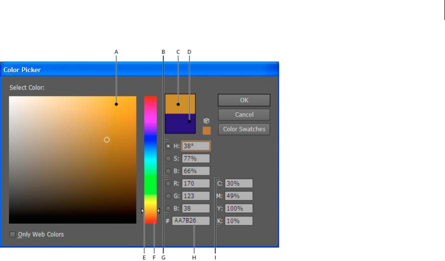
149
Color
Last updated 6/5/2015
A Color field B HSB color values C New color rectangle D Original color rectangle E Color slider F Color spectrum G RGB color values
H Hexadecimal color value I CMYK color values
More Help topics
About colors in digital graphics
Display the Color Picker
❖Double-click the fill or stroke color selection box in the Tools panel or Color panel.
Change the color spectrum displayed in the Color Picker
❖Click a letter: H (Hue), S (Saturation), B (Brightness), R (Red), G (Green), or B (Blue).
Display only web-safe colors
Web-safe colors are those colors used by all web browsers, regardless of the platform.
❖Select Only Web Colors.
View color swatches instead of the color spectrum
❖Click Color Swatches. Click Color Models to return to view the color spectrum.
Select colors using the Color Picker
Do any of the following:
1Click or drag inside the color spectrum. A circular marker indicates the color’s position in the spectrum.
2Drag the triangles along the color slider or click inside the color slider.
3Enter values in any of the text boxes.
4Click Color Swatches, select a swatch, and click OK.
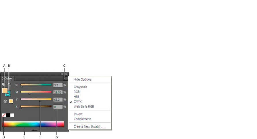
150
Color
Last updated 6/5/2015
Color panel overview
You use the Color panel (Window > Color) to apply color to an object’s fill and stroke, and also to edit and mix colors.
The Color panel can display color values using different color models. By default, only the most commonly used
options are visible in the Color panel.
A Fill color B Stroke color C panel menu D None box E Color spectrum bar F Color slider G Text box for a color component
More Help topics
About colors in digital graphics
Change the color model
❖Select Grayscale, RGB, HSB, CMYK, or Web Safe RGB from the panel menu.
Show all options in the panel
❖Select Show Options from the panel menu. Alternatively, click the double triangle on the panel’s tab to cycle through
the display sizes.
Select colors using the Color panel
1Select the color mode you want to use from the panel menu. The mode you select affects only the display of the Color
panel; it does not change the color mode of the document.
2Do one of the following:
•Drag or click in a slider.
•Shift-drag a color slider to move the other sliders in relation to it (except for HSB sliders). This keeps a similar
color but with a different tint or intensity.
•Enter values in any of the text boxes.
•Click in the color spectrum bar at the bottom of the panel. To select no color, click the None box at the left of the
color bar; to select white, click the white swatch at the upper-right corner of the color bar; to select black, click
the black swatch at the lower-right corner of the color bar.
More Help topics
About color
Using and creating swatches
Color groups (harmonies)
Adjusting colors

151
Color
Last updated 6/5/2015
Using and creating swatches
About swatches
Swatches are named colors, tints, gradients, and patterns. The swatches associated with a document appear in the
Swatches panel. Swatches can appear individually or in groups.
You can open libraries of swatches from other Illustrator documents and various color systems. Swatch libraries appear
in separate panels and are not saved with the document.
The Swatches panel and swatch library panels can contain the following types of swatches:
Process colors A process color is printed using a combination of the four standard process inks: cyan, magenta, yellow,
and black. By default, Illustrator defines new swatches as process colors.
Global process colors A global color is automatically updated throughout your artwork when you edit it. All spot colors
are global; however, process colors can be either global or local. You can identify global color swatches by the global
color icon (when the panel is in list view) or a triangle in the lower corner (when the panel is in thumbnail view).
Spot colors A spot color is a premixed ink that is used instead of, or in addition to, CMYK process inks. You can
identify spot-color swatches by the spot-color icon (when the panel is in list view) or a dot in the lower corner (when
the panel is in thumbnail view).
Gradients A gradient is a graduated blend between two or more colors or tints of the same color or different colors.
Gradient colors can be assigned as CMYK process colors, RGB colors, or a spot color. Transparency applied to a
gradient stop, is preserved when the gradient is saved as a gradient swatch. The aspect-ratio and angle values of elliptical
gradients (those created by adjusting the aspect ratio or angle of a radial gradient) are not saved.
Patterns Patterns are repeating (tiled) paths, compound paths, text with solid fills or no fill.
None The None swatch removes the stroke or fill from an object. You can’t edit or remove this swatch.
Registration The registration swatch is a built-in swatch that causes objects filled or stroked with it to print on every
separation from a PostScript printer. For example, registration marks use the Registration color so that printing plates
can be aligned precisely on a press. You can’t remove this swatch.
note: If you use the Registration color for type, and then you separate the file and print it, the type may not register properly
and the black ink may appear muddy. To avoid this, use black ink for type.
Color groups Color groups can contain process, spot, and global process colors. They cannot contain pattern, gradient,
none, or registration swatches. You create color groups based on harmonies by using either the Color Guide panel or
the Edit Colors/Recolor Artwork dialog box. To put existing swatches into a color group, select the swatches and click
the New Color Group icon in the Swatches panel. You can identify a color group by the folder icon .
You can also create tints in the Swatches panel. A tint is a global process color or spot color with a modified intensity.
Tints of the same color are linked together, so that if you edit the color of a tint swatch, all associated tint swatches (and
the objects painted with those swatches) change color, though the tint values remain unchanged. Tints are identified by
a percentage (when the Swatches panel is in list view)
Swatches panel overview
You use the Swatches panel (Window > Swatches) to control all document colors, gradients, and patterns. You can name
and store any of these items for instant access. When a selected object’s fill or stroke contains a color, gradient, pattern,
or tint applied from the Swatches panel, the applied swatch is highlighted in the Swatches panel.
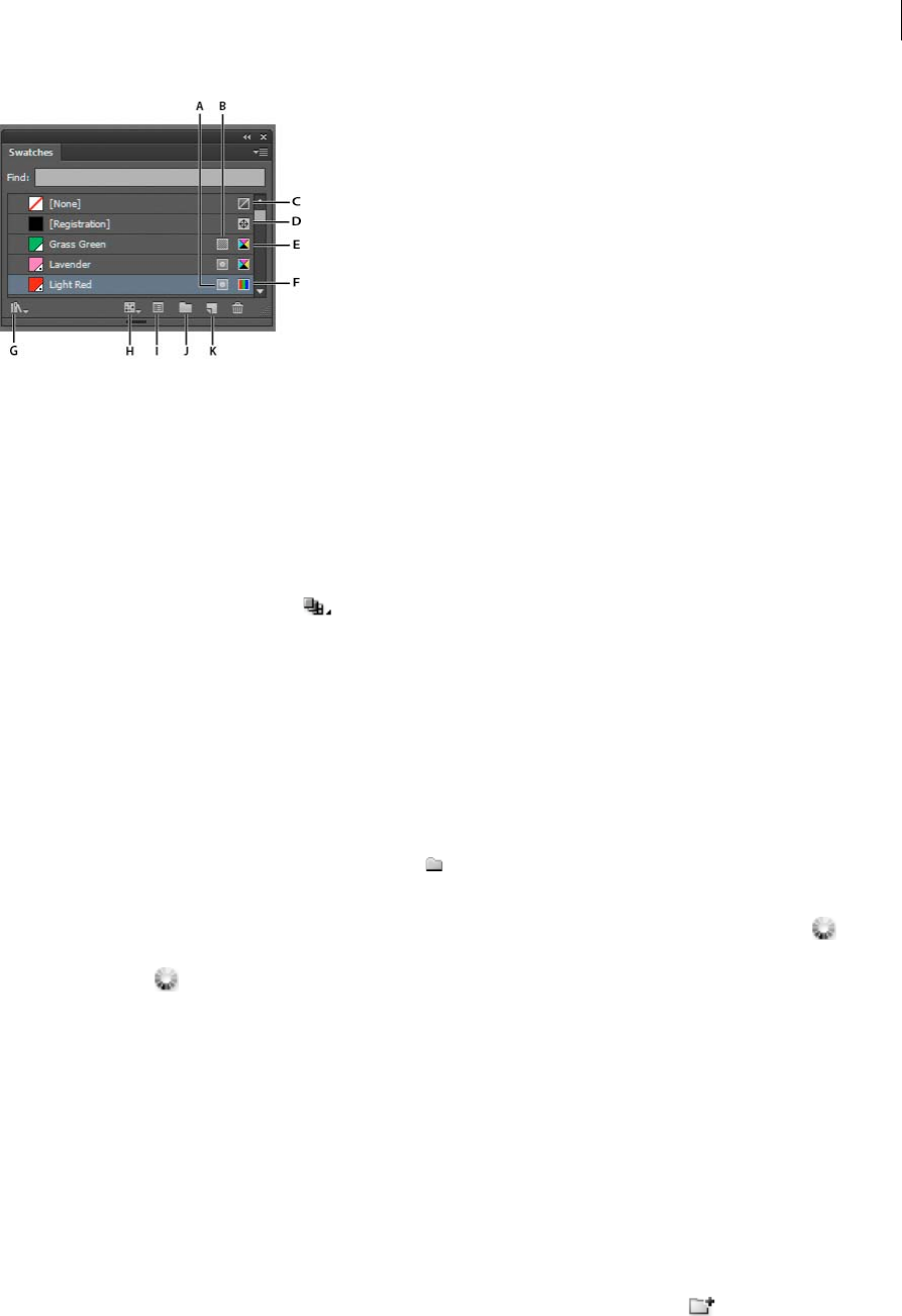
152
Color
Last updated 6/5/2015
A Spot color B Global color C Fill or stroke of None D Registration swatch (prints on all plates) E CMYK symbol (when document is open in
CMYK mode) F RGB symbol (when document is open in RGB mode) G Swatch Library Menu button H Show Swatch Kinds Menu button
I Swatch Options button J New ColorGroup button K New Swatch button
Change the display of swatches
❖Select a view option from the Swatches panel menu: Small Thumbnail View, Medium Thumbnail View, Large
Thumbnail View, Small List View, or L arge List View.
Show a specific type of swatch and hide all others
❖ Click the Show Swatch Kinds button and choose one of the following: Show All Swatches, Show Color Swatches,
Show Gradient Swatches, Show Pattern Swatches, or Show Color Groups.
Select all swatches that aren’t used in artwork
If you want to limit your Swatches panel to only the colors that are used in a document, you can select all unused
swatches and then delete them.
❖Choose Select All Unused in the Swatches panel menu.
Select a color group
•To select the entire group, click the color group icon .
•To select swatches inside the group, click individual swatches.
Note: To edit the selected color group, make sure no artwork is selected and click the Edit Color Group button , or
double-click the color group folder. To edit the selected color group and apply the edits to selected artwork, click the Edit Or
Apply Colors button , or double-click the color group folder. For more information, see Edit colors in the Edit Colors
dialog box.
Select a swatch by name
❖Select Show Find Field from the Swatches panel menu. Type the first letter or letters of the swatch’s name in the Find
text box at the top of the panel.
Note: This procedure does not work with double-byte characters.
You can also use this method to select a PANTONE® swatch by entering the PANTONE number.
Move swatches into a color group
1Drag individual color swatches to an existing color group folder.
2Select the colors you want in a new color group and click the New Color Group button .

153
Color
Last updated 6/5/2015
Change the order of swatches
You can reorder individual swatches as well as swatches inside a color group.
❖Do one of the following:
•Select Sort ByName or Sort By Kind from the Swatches panel menu. These commands only work on individual
swatches, not swatches in a color group.
•Drag a swatch to a new location.
Use swatch libraries
Swatch libraries are collections of preset colors, including ink libraries such as PANTONE, HKS, Trumatch,
FOCOLTONE, DIC, TOYO, and thematic libraries such as camouflage, nature, Greek, and jewel tones.
When you open a swatch library, it appears in a new panel (not the Swatches panel). You select, sort, and view swatches
in a swatch library the same as you do in the Swatches panel. However, you can’t add swatches to, delete swatches from,
or edit the swatches in the Swatch libraries panel.
To make a swatch library appear each time Illustrator is started, select Persistent from the swatch library’s panel menu.
Open a swatch library
❖Do one of the following:
•Choose Window > Swatch Libraries > [library name].
•In the Swatches panel menu, choose Open Swatch Library > [library name].
•In the Swatches panel, click the Swatch Libraries Menu button , and choose a library from the list.
Note: PANTONE color libraries are located in the Color Books subfolder (Swatch Libraries > Color Books > PANTONE...).
Create a swatch library
You create a swatch library by saving the current document as a swatch library.
1Edit the swatches in the Swatches panel so that it contains only the swatches you want in the swatch library.
2Select Save Swatch Library from the Swatches panel menu.
To remove all swatches that aren’t used in the document, choose Select All Unused from the Swatches panel menu,
and then click the Delete Swatch button .
Edit a swatch library
1 Choose File > Open, locate and open the library file. By default, swatch library files are stored in the
Illustrator/Presets/Swatches folder.
2Edit the colors in the Swatches panel and save your changes.
Move swatches from a swatch library to the Swatches panel
Do any of the following:
•Drag one or more swatches from the swatch library panel to the Swatches panel.
•Select the swatches you want to add, and select Add To Swatches from the library’s panel menu.
•Apply a swatch to an object in the document. If the swatch is a global or spot-color swatch, the swatch is
automatically added to the Swatches panel.

154
Color
Last updated 6/5/2015
Add colors from artwork to Swatches panel
You can automatically add all the colors from selected artwork or all the colors in your document to the Swatches panel.
Illustrator finds the colors that are not already in the Swatches panel, converts any process colors to global colors, and
adds them to the panel as new swatches.
When you automatically add colors to the Swatches panel, all colors in the document are included, except the following:
•Colors inside opacity masks (when not in opacity mask editing mode)
•Interpolated colors in blends
•Colors in image pixels
•Guide colors
•Colors in objects that are inside compound shapes and are not visible
If you change a gradient fill, pattern fill, or symbol instance to a new global color, the color is added as a new swatch
and the original color swatch is retained.
Add all document colors
❖Make sure that nothing is selected, and choose Add Used Colors from the Swatches panel menu.
Add colors from selected artwork
❖Select the objects containing the colors you want to add to the Swatches panel, and do one of the following:
•Choose Add Selected Colors from the Swatches panel menu.
•Click the New Color Group button in the Swatches panel. Specify options in the dialog box that appears.
Colors are arranged and saved using the Hue Forward rule.
Share swatches between applications
You can share the solid swatches you create in Photoshop, Illustrator, and InDesign by saving a swatch library for
exchange. The colors appear the same across applications as long as your color settings are synchronized.
Note: You can create and share color group swatches by using the Kuler panel or the Kuler website. (See Create color themes
with Kuler .)
1In the Swatches panel, create the process and spot-color swatches you want to share, and remove any swatches you
don’t want to share.
Note: You cannot share the following types of swatches between applications: patterns, gradients, and the Registration
swatch from Illustrator or InDesign; and book color references, HSB, XYZ, duotone, monitorRGB, opacity, total ink, and
webRGB swatches from Photoshop. These types of swatches are automatically excluded when you save swatches for
exchange.
2Select Save Swatches For Exchange from the Swatches panel menu, and save the swatch libraries in an easily
accessible location.
Note: When you load a library that contains swatches with identical names, the definitions of the identically-named
swatches are overwritten. Ensure that swatch names are unique.
3Load the swatch library into the Swatches panel for Photoshop, Illustrator, or InDesign.

155
Color
Last updated 6/5/2015
Import swatches from another document
You can import all swatches or individual swatches from another document.
•To import all swatches from another document, choose Window > Swatch Libraries > Other Library or choose Open
Swatch Library > Other Library from the Swatches panel menu. Select the file from which you want to import
swatches, and click Open. The imported swatches appear in a swatch library panel (not the Swatches panel).
•To import individual swatches from another document, copy and paste objects that use the swatches. The imported
swatches appear in the Swatches panel.
Note: If imported swatches for spot colors or global process colors have the same name but different color values as swatches
already in the document, a swatch conflict occurs. For spot color conflicts, the color values of the existing swatches are
preserved and imported swatches are automatically merged with the existing swatches. For process color conflicts, the
Swatch Conflict dialog box appears, and color values for existing swatches are automatically retained. You can choose “Add
Swatches” to add the swatches by appending a number to the conflicting swatch names or choose “Merge Swatches” to merge
the swatches using the color values of the existing swatches.
Create color swatches
You can create process color, spot color, or gradient color swatches.
More Help topics
Understanding spot and process colors
Gradients
Create a process color swatch
1Select a color using the Color Picker or Color panel, or select an object with the color you want.
2Do one of the following:
•Drag the color from the Tools panel or Color panel to the Swatches panel.
•In the Swatches panel, click the New Swatch button or select New Swatch from the panel menu. In the dialog box
that appears, select Global if you want the swatch to be a global color. Set additional swatch options, and click
OK. (See Swatch options.)
Create gradient swatches
1Create a gradient using the Gradient panel, or select an object with the gradient you want.
2Do one of the following:
•Drag the gradient fill from the Fill box in the Tools panel or Color panel to the Swatches panel.
•In the Gradient panel, click the gradient menu (next to the gradient box) and click the Save To Swatches Library
icon .
•In the Swatches panel, click the New Swatch button or select New Swatch from the Swatches panel menu. In the
dialog box that appears, enter a swatch name, and click OK. (See Swatch options.)
Create spot-color swatches
1Select a color using the Color Picker or Color panel, or select an object with the color you want.

156
Color
Last updated 6/5/2015
2Do one of the following:
•Ctrl-drag (Windows) or Command-drag (Mac OS) the color from the Tools panel or Color panel to the Swatches
panel.
•In the Swatches panel, Ctrl-click (Windows) or Command-click (Mac OS) the New Swatch button, or select New
Swatch from the panel menu. In the dialog box that appears, select Spot Color for Color Type. Set additional
swatch options and click OK. (See Swatch options.)
Create a swatch from the Color Guide panel
1Choose colors from the Harmony Rules menu in the Color Guide panel.
2Click the Save Color Group To Swatch Panel button at the bottom of the Color Guide panel.
Manage swatches
You can manage the swatches in your Swatches panel by duplicating, grouping, replacing, merging, or deleting them.
You can also specify swatch options such as swatch name, color type, color mode, or preview.
More Help topics
Create a color group in the Edit Colors dialog box
Duplicate swatches
1Select one or more swatches that you want to duplicate.
2Do one of the following:
•Select Duplicate Swatch from the Swatches panel menu.
•Drag the swatches to the New Swatch button in the Swatches panel.
Group swatches
When you want to keep specific colors together in the Swatches panel, create a color group. For example, you can create
a color group for colors you select in the Color Guide panel. When you save a color group in the Edit Colors dialog box,
it is automatically saved as a color group in the Swatches panel. You can also manually group any set of solid color
swatches.
1Select one or more swatches in the Swatches panel.
2Click the New Color Group button, or choose New Color Group from the panel menu.
Replace, merge, or delete swatches
•To replace a swatch, hold down Alt (Windows) or Option (Mac OS) and drag the color or gradient from the Color
panel, Gradient panel, an object, or the Tools panel to the Swatches panel, highlighting the swatch you want to
replace.
Replacing an existing color, gradient, or pattern in the Swatches panel globally changes objects in the file containing
that swatch color with the new color, gradient, or pattern. The only exception is for a process color that does not
have the Global option selected in the Swatch Options dialog box.
•To merge multiple swatches, select two or more swatches, and select Merge Swatches from the Swatches panel menu.
The first selected swatch name and color value replaces all other selected swatches.
•To delete a swatch, select one or more swatches. Select Delete Swatch from the panel menu, click the Delete Swatch
button, or drag the selected swatches to the Delete Swatch button.

157
Color
Last updated 6/5/2015
When you delete a spot-color or global process-color swatch (or a pattern or gradient containing a spot or global
process color), all objects painted with those colors are converted to the non-global process color equivalent.
Swatch options
To set swatch options, double-click an existing swatch or select New Swatch from the Swatches panel menu.
Swatch Name Specifies the name of the swatch in the Swatches panel.
Color Type Specifies if the swatch is a process color or spot color.
Global Creates a global process-color swatch.
Color Mode Specifies the color mode of the swatch.
After you select the color mode you want, you can use the color sliders to adjust the color. If you select a color that is
not web-safe, an alert cube appears. Click the cube to shift to the closest web-safe color (which is displayed to the
right of the cube). If you select an out-of-gamut color, an alert triangle appears. Click the triangle to shift to the
closest CMYK equivalent (which is displayed to the right of the triangle).
Preview Displays color adjustments on any objects to which the swatch is applied.
More Help topics
About color
Selecting colors
Color groups (harmonies)
Adjusting colors
Color groups (harmonies)
About color groups
A color group is an organization tool that lets you group together related color swatches in the Swatches panel. In
addition, a color group can be a container for color harmonies, which you create using the Edit Colors/Recolor Artwork
dialog box or the Color Guide panel. Color groups can contain only solid colors that include spot, process, or global
colors. Gradients and patterns cannot be grouped.
You can use the Color Guide panel or the Edit Colors/Recolor Artwork dialog box to create harmonious color groups.
Using either feature, you can choose a harmony rule to instantly generate a color scheme based on any color you want.
For example, choose the Monochromatic harmony rule to create a color group containing all the same hue, but with
different saturation levels. Or choose the High Contrast or Pentagram harmony rule to create a color group with
contrasting colors for more visual impact.
For inspiration, to share color harmonies, or to create color groups outside Illustrator, choose Window > Extensions >
Kuler and click through the different color harmonies available.
For more information, see the Kuler website at http://kuler.adobe.com/.

158
Color
Last updated 6/5/2015
More Help topics
Group swatches
Create color themes with Kuler
Color Guide panel overview
Use the Color Guide panel as a tool for color inspiration while you create your artwork. The Color Guide panel suggests
harmonious colors based on the current color in the Tools panel. You can use these colors to color artwork, or you can
edit them in the Edit Colors/Recolor Artwork dialog box, or save them as swatches or swatch groups in the Swatches
panel.
You can manipulate the colors that the Color Guide panel generates in several ways, including changing the harmony
rule, or adjusting the variation type (such as tints and shades or vivid and muted), and the number of variation colors
that appear. Note: If you have artwork selected, clicking a color variation changes the color of the selected artwork, just like
clicking a swatch in the Swatches panel.
A Harmony Rules menu and active color group B Set as base color C Active colors D Color variations E Limits colors to specified swatch library
F Edit Colors or Edit Or Apply Colors depending on selection (opens the colors in the Edit Colors/Recolor Artwork dialog box) G Save group to
Swatches panel
Note: To edit the selected color group, make sure that no artwork is selected and click the Edit Colors button . To edit
the selected color group and apply the edits to selected artwork, click the Edit Or Apply Colors button . For more
information, see Edit colors in the Edit Colors dialog box.
For a video on using the Color Guide to find and create color solutions, see www.adobe.com/go/vid0058.
Specify the type of color variations that appear in the panel
❖Choose one of the following variations from the Color Guide panel menu:
Show Tints/Shades Adds black to variations on the left and white to variations on the right
Show Warm/Cool Adds red to variations on the left and blue to variations on the right
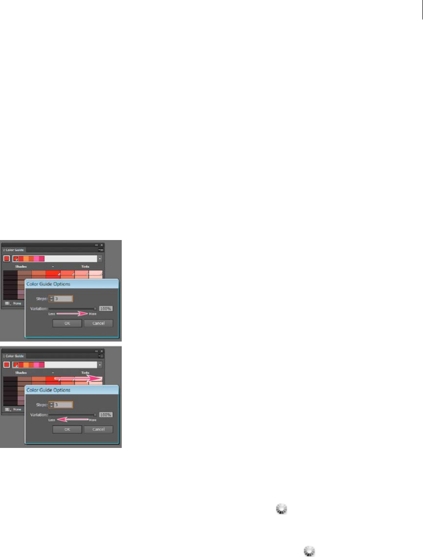
159
Color
Last updated 6/5/2015
Show Vivid/Muted Decreases the saturation toward gray in variations on the left and increases saturation toward
gray in variations on the right
Note: If you’re using spot colors, use only the Tints/Shades variation and choose colors from the tint (right) side of the
variation grid. All other variations cause spot colors to be converted to process.
Specify the number and range of color variations that appear in the panel
1Choose Color Guide Options from the Color Guide panel menu.
2Specify the number of colors you want to appear to the left and right of each color in the generated color group. For
example, choose 6 if you want to see six shades darker and six shades lighter of each color.
The original colors always appear down the center of the panel with a triangle directly above them, and the
variations on those colors appear to the left and right of them.
3Drag the Range slider to the left to decrease the variance range or drag to the right to increase the range.
Decreasing the range generates colors that are more similar to the originals.
Edit Colors/Recolor Artwork dialog box overview
The name of this dialog box changes depending on context:
When you have artwork selected and you access the dialog box by clicking the icon in the Control panel, Swatches
panel, or Color Guide panel, or when you choose Edit > Edit Colors > Recolor Artwork, the dialog box opens as the
Recolor Artwork dialog box and you have access to the Assign tab and the Edit tab.
When you do not have artwork selected and you access the dialog box by clicking the icon in the Control panel,
Swatches panel, or Color Guide panel, the dialog box opens as the Edit Colors dialog box and you have access to the
Edit tab only.
Regardless of which name appears at the top of the dialog box, the right side of it always displays the color groups for
the current document, along with two default color groups: Print Color and Grayscale. You can select and use these
color groups at anytime.
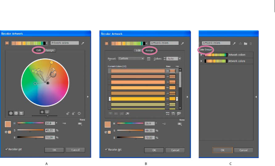
160
Color
Last updated 6/5/2015
A Create and edit a color group in the Edit tab B Assign colors in the Assign tab C Select a color group from the Color Groups list
The Recolor Art option at the bottom of the dialog box lets you preview colors on selected artwork, and specifies
whether artwork is recolored when you close the dialog box.
The main areas of the dialog box are:
Edit Use the Edit tab to create new color groups or edit existing color groups. Use the Harmony Rules menu and the
color wheel to experiment with color harmonies. The color wheel shows you how colors in a harmony are related, while
the color bars let you see and manipulate individual color values. In addition, you can adjust brightness, add and
remove colors, save color groups, and preview the colors on selected artwork.
Assign Use the Assign tab to view and control how colors from a color group replace original colors in your artwork.
You can assign colors only if you have artwork selected in the document. You can specify which new colors replace
which current colors, whether spots are preserved, and how colors are replaced (for example, you can replace colors
entirely or replace hue while retaining brightness). Use Assign to control how artwork is recolored with the current
color group or to reduce the number of colors in the current artwork.
Color Groups Lists all saved color groups for the open document (these same color groups appear in the Swatches
panel). While in the dialog box, you can edit, delete, and create new color groups using the Color Groups list. All your
changes are reflected in the Swatches panel. The selected color group denotes which color group is currently being
edited. You can select any color group and edit it or use it to recolor selected artwork. Saving a color group adds the
group to this list.
For a video on creating, editing, and experimenting with color groups in the Edit Colors/Recolor Artwork dialog box,
see www.adobe.com/go/lrvid4019_ai. For a video on integrating color harmonies with smart objects in Photoshop and
InDesign, see www.adobe.com/go/vid0191. To see an example of changing a vibrant color illustration to a grayscale
illustration, see www.adobe.com/go/learn_ai_tutorials_depth_en.
Open the Edit Colors/Recolor Artwork dialog box
❖Open the Edit Colors/Recolor Artwork dialog box from any of the following locations:
Edit > Edit Colors > Recolor Artwork or Recolor With Presets command Use these commands when you want to edit
colors in selected artwork.

161
Color
Last updated 6/5/2015
Recolor Artwork button in Control panel
Use this button when you want to edit the colors of the selected artwork using the Recolor Artwork dialog box. This
button is available when the selected artwork contains two or more colors.
note: Editing colors this way is a convenient way to globally adjust colors in artwork when global colors weren't used in
the artwork's creation.
Edit Colors or Edit Or Apply Colors button in Color Guide panel
Click this button when you want to edit the colors in the Color Guide panel, or edit and then apply the colors in the
Color Guide panel to selected art.
Edit Color Group or Edit Or Apply Color Group button in Swatches panel
Click this button when you want to edit the colors in the selected color group, or when you want to edit the colors
and apply them to the selected artwork. You can also double-click a color group in the Swatches panel to open the
dialog box.
Work with the Color Group list
•To show or hide the Color Group list, click the Hide Color Group Storage icon on the right side of the Edit
Colors/Recolor Artwork dialog box. To display the list again, click the icon again.
•To add a new color group to this list, create or edit a color group, and then click New Color Group . A new color
group appears in the list.
•To edit a color group, click it in the list to select it. Change the color group using the Edit tab, and then click Save
Changes To Color Group .
•To delete a color group, select it and click Delete ColorGroup .
Create color groups
You can create color groups using the Color Guide panel or the Edit Colors/Recolor Artwork dialog box. You can also
create and share color groups on the Adobe Kuler website (www.Kuler.adobe.com).
For a video on using the Color Guide to find and create color solutions, see www.adobe.com/go/vid0058. For a video
on creating, editing, and experimenting with color groups in Live Color, see www.adobe.com/go/lrvid4019_ai.
More Help topics
Swatches panel overview
Create a color group in the Color Guide panel
Make sure that no artwork is selected when you set the base color; otherwise, the selected artwork will change to the
base color.
1Open the Color Guide panel, and do any of the following to set the base color for the color harmony:
•Click a color swatch in the Swatches panel.
•Click a color in the Color panel. (You may want to drag out the Color panel so that you can use it along with the
Color Guide panel.)
•Double-click the Fill Color in the Tools panel and pick a color in the Color Picker.
•Using the eyedropper, click artwork containing the color you want.
•Select artwork containing the color you want, and then click the Set Base Color To The Current Color icon .

162
Color
Last updated 6/5/2015
•Click a color variation in the Color Guide panel, and then click the Set Base Color To The Current Color icon
.
2Choose a rule from the Harmony Rules menu.
Note: To confine colors to a swatch library, click the Limits The Color Group To Colors In A Swatch Library button ,
and choose library from the list.
3To save the color group or an individual color to the Swatches panel, do one of the following:
•To save the current color group in the Color Guide panel, click the Save Color Group To Swatches Panel button
.
•To save one or more color variations as individual swatches, drag the colors from the Color Guide panel to the
Swatches panel.
•To save multiple color variations as a group, select them in the Color Guide panel and click the Save Color Group
To Swatches Panel button .
To name the new group, select the group in the Swatches panel and choose Color Group Options from the panel
menu.
Note: To upload your color group swatch to the Kuler website, select it and choose Window > Extensions > Kuler. In the
Kuler dialog box, click Upload . You must register with Kuler before you can upload swatches.
4To color your artwork with a color from the color group, select your artwork and click any color in the Color Guide
panel.
Note: To color all objects in a grouped object, select it, choose Edit > Recolor Artwork, and specify options in the Recolor
Artwork dialog box. (See Assign colors to your artwork.)
Create a color group in the Edit Colors dialog box
You create a color group in the Edit Colors/Recolor Artwork dialog box by choosing a base color and a harmony rule.
The harmony rule uses the base color as the basis for generating the colors in the color group. For example, if you
choose a blue base color and the Complementary harmony rule, a color group is created using the base color, blue, and
its complement, red.
As you manipulate the colors in the color wheel, the selected harmony rule continues to govern the colors that are
generated for the group. To break the harmony rule and edit the colors freely, click the Unlink button .
1Open the Edit Colors/Recolor Artwork dialog box, and choose a color harmony from the Harmony Rules menu, if
desired.
Note: To confine colors to a swatch library, click the Limits The Color Group To Colors In A Swatch Library button ,
and choose a library from the list.
2If the color bars are showing, click a Color Wheel icon to display the color wheel instead.
3Set the base color by doing one of the following:
•Drag the base color marker (the largest, double-ringed color marker) around the wheel to set the base color you
want.
• Adjust the color sliders at the bottom of the dialog box.
4Choose a new harmony rule or move the color markers, as desired.
5To preview the new colors on selected artwork, click Recolor Art.
Note: Recolor Art will recolor selected artwork when you click OK to close the dialog box. If you don’t want to recolor
the selected art, make sure to deselect this option before clicking OK.
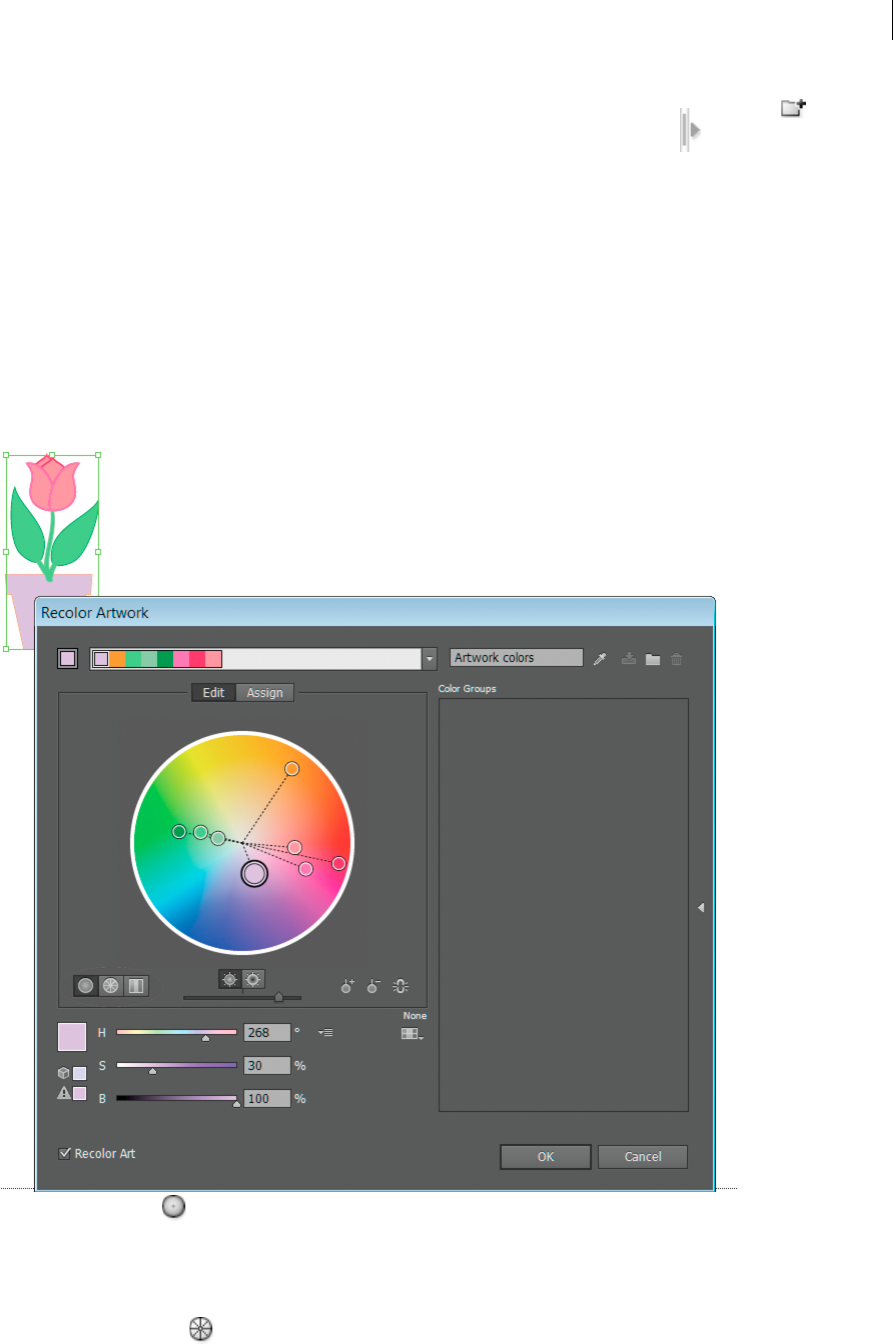
163
Color
Last updated 6/5/2015
6Type a name in the Name box to the right of the Harmony Rules menu, and click New Color Group .
Note: if the New Color Group icon is not visible, click the Show Color Group Storage icon .
7To save the new color group to the Swatches panel, click OK and close the Edit Colors/Recolor Artwork dialog box.
Note: You can also create a color group by using the Color Guide. (See Create a color group in the Color Guide panel.)
Edit colors in the Edit Colors dialog box
Editing colors in the Edit Colors/Recolor Artwork dialog box is a convenient way to globally adjust the colors in
selected artwork. It is especially useful when global colors weren't originally used in the artwork’s creation. You can edit
colors and color groups in the Edit Colors/Recolor Artwork dialog box and apply your edits to selected artwork, or save
the edited colors for later use.
When editing colors, you use the smooth color wheel, the segmented color wheel, or the color bars.
Smooth color wheel
Displays hue, saturation, and brightness in a smooth continuous circle. Each color in the current color group is drawn
on the wheel inside a circle. This wheel lets you choose from numerous colors with great precision, but it can be hard
to see individual colors because every pixel is a different color.
Segmented color wheel
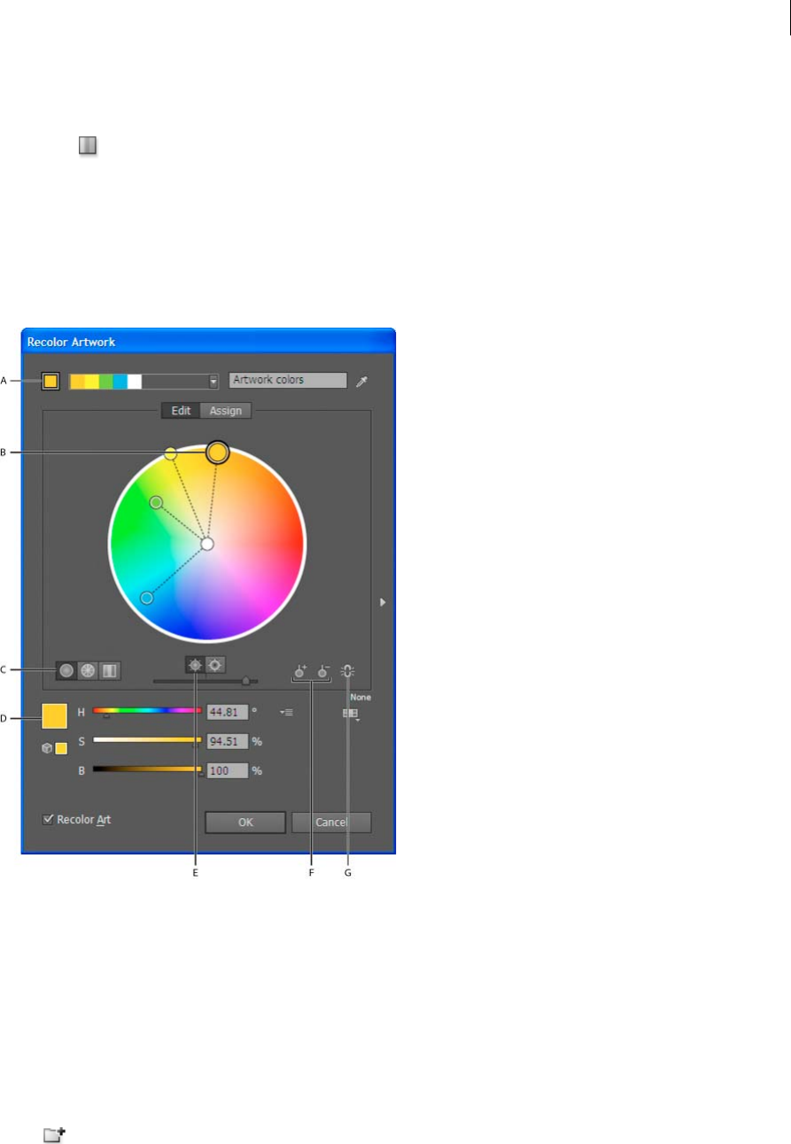
164
Color
Last updated 6/5/2015
Displays colors as a set of segmented color patches. This wheel makes it easy to see individual colors, but doesn’t provide
as many colors to choose from as the continuous wheel.
Color bars
Displays only colors from the color group. They appear as solid bars of color that you can select and edit individually.
You can reorganize colors in this display by dragging and dropping color bars to the left or right. You can right-click a
color and choose to remove it, set it as the base color, change its shade, or change it using the Color Picker.
For a video on creating, editing, and experimenting with color groups, see www.adobe.com/go/lrvid4019_ai. To see an
example of changing a vibrant color illustration to a grayscale illustration, see
www.adobe.com/go/learn_ai_tutorials_depth_en.
A Base color as it appears in Harmony Rules menu B Base color as it appears in color wheel C Color display options D Color of selected color
marker or color bar E Show saturation and hue on Wheel F Add and subtract color marker tools G Unlink harmony colors
Save changes to a color group
Before you start editing your color groups, make sure that you know how to save your changes correctly so you don’t
inadvertently overwrite your favorite color group! You have two options when saving your changes: you can overwrite
the original color group with the edited color group, or you can create a new color group with the changes, leaving the
original intact.
❖Do either of the following:
•To keep your original color group unchanged and save the changes as a new color group, click New Color Group
at the top of the Edit Colors/Recolor Artwork dialog box.

165
Color
Last updated 6/5/2015
•To save the changes to your original color group (thus overwriting the original color group), click Save Changes
To C olor Group .
Edit a color group using a color wheel
1In the Edit Colors/Recolor Artwork dialog box, select the desired color group from the Color Groups storage area,
if necessary.
2If you have selected an object on the artboard, click Recolor Art to preview the colors on the artwork. If you don’t
want to recolor the artwork, deselect Recolor Art before closing the dialog box, or click Cancel to close it.
Note: To edit the colors of the selected artwork, click Get Colors From Selected Art .
3To confine colors to a swatch library, click the Limits The Color Group To Colors In A Swatch Library button
and choose a library from the list.
4To change the base color to a different color in the current group, right-click the color in a color wheel or color bars
and choose Set As Base Color. Or click a color in the Active Colors box, and then click Set Current Color As Base
Color to the left of the Active Colors box.
5Drag a marker on the wheel to change its color. If the harmony is linked, all the colors move according to the rule
as you drag. If the harmony is unlinked, only the marker that you drag moves.
While editing, you can do any of the following:
aTo change hue, move the marker around the wheel. To change saturation or brightness, move it inward and
outward on the wheel.
bTo add a color, right-click in the color wheel where you want to add the color and choose Add New Color.
cTo remove a color, right-click on the color marker (or the line of the marker) in the color wheel and choose
Remove Color.
dTo change a color using the Color Picker, right-click the color and choose Color Picker.
eTo constrain the marker to move in only one direction, hold down the shift key as you drag.
fTo see hue and saturation instead of hue and brightness on the wheel, click the Show Saturation And Hue On
The Wheel button , directly below the wheel to toggle between the two views.
gTo change the color values manually, click the color marker or click the color in the Active Colors box. Edit the
color values using the sliders or color value text boxes under the color wheel.
hTo change the saturation and brightness of a color on the wheel, right-click a color marker, and choose Select
Shade; then click the desired color in the box that appears.
6Save your changes by clicking New Color Group , which keeps your original color group unchanged and saves
the changes as a new color group. Or click Save Changes To Color Group to overwrite your original color group
with the changes.
Note: To ensure that the colors are in gamut or web safe, select each color marker and click the Out Of Gamut or Out
Of Web buttons as necessary.
Reorder colors in a color group
❖Do one of the following:
•In the Active Colors menu, drag a color left or right.
•In Color Bars view, drag a color bar left or right.
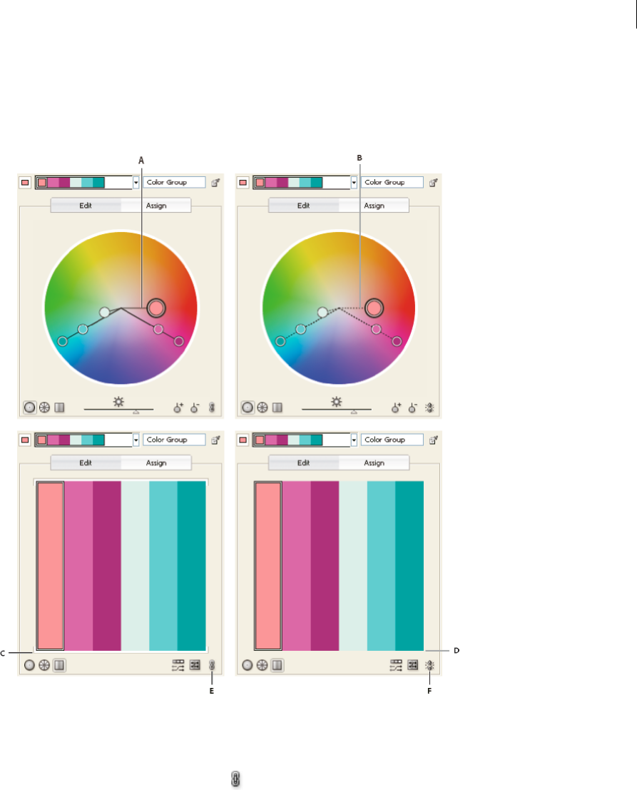
166
Color
Last updated 6/5/2015
Edit an individual color in a color group
When you use a harmony rule to create a color group, the colors are linked by default. When a color group is linked,
editing one color changes the other colors according to the harmony rule. To edit one color without changing the
others, unlink the color markers from the harmony rule.
A Color wheel view of linked colors B Color wheel view of unlinked colors C Color bars view of linked colors D Color bars view of unlinked colors
E Colors linked, click to unlink F Colors unlinked, click to relink
1In the Edit Colors/Recolor Artwork dialog box, select the color group you want to edit and click Edit.
2Click the Unlink Harmony Colors icon .
3Do one of the following in either the color wheel or color bar view:
•Drag the color marker you want to edit to set a new color.
•Click the color bar or color marker you want to change and manually edit the color values.
•Double-click (or right-click) the color bar or marker and choose a new color in the Color Picker.
•Right-click a color marker or color bar and pick a new shade.
4To relink the colors so that the markers move again according to the newly defined harmony rule, click the Link
Harmony Colors button.

167
Color
Last updated 6/5/2015
Edit colors in a color group using the Color Picker
You can use the Color Picker to change colors in a color group.
1In the Edit Colors/Recolor Artwork dialog box, do one of the following:
•Double-click a wheel marker or right-click a wheel marker and choose Color Picker.
•Double-click a color bar.
•Click the color swatch to the left of the color sliders.
2Save the edits by doing one of the following:
•To save the edited colors as a new group, type a new name in the name box at the top of the dialog box, and then
click New Color Group .
•To save the edits to the original color group, click Save Changes To Color Group .
Randomly change color order or saturation and brightness
In the Edit Colors/Recolor Artwork dialog box, you can explore random variations of the current color group by using
the Randomly Assign Brightness And Saturation button and the Randomly Change Color Order button.
1In the Edit Colors/Recolor Artwork dialog box, select a color group.
2Click Edit, and then click Display Color Bars; or click Assign.
3Do either of the following:
•To shuffle the order of the current color group, click Randomly Change Color Order . Use this button when
recoloring artwork to quickly explore the different ways artwork can be recolored with the current color group.
•To randomly change the brightness and saturation of the current color group while retaining the hues, click
Randomly Changes Saturation and Brightness .
Globally edit saturation, brightness, temperature, or luminosity
1In the Edit Colors/Recolor Artwork dialog box, click Edit.
2Click the Color Mode button , and choose Global Adjust.
3Change the values for Saturation, Brightness, Temperature, and Luminosity.
Note: If you’ve limited the colors to a swatch library, any adjustments you make are limited to the library colors.
Add or remove colors in a color group
1In the Edit Colors/Recolor Artwork dialog box, click Edit.
2Do either of the following:
•To add a color to the color group, right-click in the color wheel where you want to add the color and choose Add
New Color. If you click the line of an existing color marker, the new marker moves with that marker.
•To remove a color, right-click the color marker or color bar and choose Remove Color. You cannot remove the
base color marker.
note: In the color wheel, you can also use the Add Color Tool button or the Remove Color Tool button , and
then click in the color wheel on the color you want to add or remove.
•To remove a color from a color group in the Color Groups list, expand the color group, right-click the color
swatch you want to remove, and choose Remove Color.
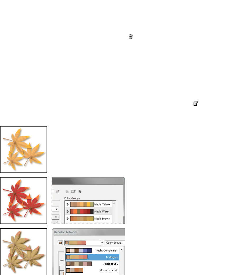
168
Color
Last updated 6/5/2015
Delete a color group
❖Select a color group in the Color Groups list and click Delete . Or right-click and choose Remove Color Group.
Assign colors to your artwork
The Assign tab of the Edit Colors/Recolor Artwork dialog box lets you assign colors from a color group to your artwork.
You can assign colors in the following ways:
•Assign new colors to your artwork using a color group from the Color Groups list.
•Assign new colors to your artwork using a new color group chosen from the Harmony Rules menu.
•Reassign current artwork colors among themselves. You can reset the Edit Colors/Recolor Artwork dialog box so
that the artwork is displayed with its original colors by clicking Get Colors From Selected Art .
Using the Current Colors and New columns, you control how colors are assigned. When you select Recolor Art, the
selected artwork is recolored with the active color group according to the columns assignments.
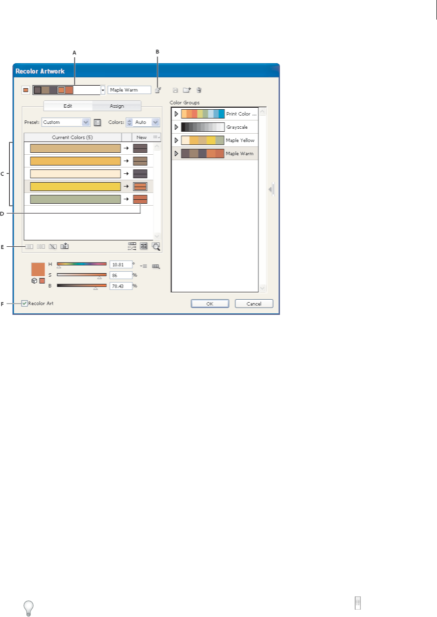
169
Color
Last updated 6/5/2015
A Active color group B Get Colors From Selected Art C Colors from selected artwork D New colors from active color group E Options for working
with entire rows F Recolor Artwork
For a video on assigning colors, see www.adobe.com/go/vid0061.
Assign new colors to selected artwork
1Select the artwork you want to recolor.
2Choose Edit > Edit Colors > Recolor Artwork.
The Recolor Artwork dialog box opens, displaying the Assign area with colors from the original artwork in both
columns.
3If you want to assign colors from a color group, do one of the following:
aChoose a color group from the Color Groups list.
bCreate a color group by selecting a new harmony rule from the menu from the Harmony Rules menu.
Note: If you create a color group, you can click Edit to fine-tune the colors, and then click Assign. Or, if you want to
adjust a few colors in the selected artwork, select the color you want to adjust and edit it with the color sliders.
4To preview the color changes in your artwork, click Recolor Art.
5Do any of the following to reassign colors:
•To assign a current color to a different color, drag the current color up or down in the Current Colors column
until it’s adjacent to the new color you want.
Tip: If a row contains multiple colors and you want to move them all, click the selector bar at the left of the row
and drag up or down.
170
Color
Last updated 6/5/2015
•To assign a new color to a different row of current colors, drag the new color up or down in the New column. (To
add a new color to or remove a color from the New column, right-click in the list and choose Add New Color or
Remove Color.)
•To change a color in the New column, right-click it and choose Color Picker to set a new color.
•To exclude a row of current colors from being reassigned, click the arrow between the columns. To include it
again, click the dash.
•To exclude a single current color from being reassigned, right-click the color and choose Exclude Colors, or click
the icon .
•To randomly reassign colors, click the Randomly Change Color Order button . The New colors move
randomly to different rows of current colors.
•To add a row to the Current Colors column, right-click and choose Add New Row, or click the icon .
6To separate or merge colors in the Current Colors row, do either of the following:
•To separate colors into separate rows, select the color block you want to move and right-click and choose Separate
Colors Into Different Rows, or click the icon .
•To merge colors into one row, Shift-click to select multiple colors, and then right-click and choose Merge Colors
Into A Row, or click the icon .
7To change tints or shades of new colors, click the triangle next to the right of a new color (or right-click a color and
choose Colorize Method), and choose an option. Select Apply To All if you want the same option to apply to all new
colors in the color group.
Note: Tints And Shades and Hue Shift are only available when you choose not to preserve spot colors.
8Click OK to recolor the artwork. If you don’t want to recolor the artwork, click Cancel, or deselect Recolor Artwork
and click OK.
Randomly change saturation and brightness in all colors
1If necessary, select an object and choose Edit > Edit Colors > Recolor Artwork.
2In the Edit Colors/Recolor Artwork dialog box, click the Randomly Change Saturation and Brightness button .
Note: You can also change saturation and brightness when editing a color group using the Color Bars display.
View original colors in your artwork as you assign new colors
When you recolor selected artwork, the colors in the selected color group replace the original colors. When assigning
new colors, it helps to see where an original color (from the Current Colors column) appears in your artwork, especially
if your artwork is very detailed, or contains many original colors.
1If necessary, select an object and choose Edit > Edit Colors > Recolor Artwork.
2In the Recolor Artwork dialog box, click the Click On Colors Above To Find Them In Artwork button , and then
click a color in the Current Colors column.
The artwork that uses that color appears in full color on the artboard while all other areas of the selected artwork
are dimmed.
3Click the icon again to return your artwork to full color.
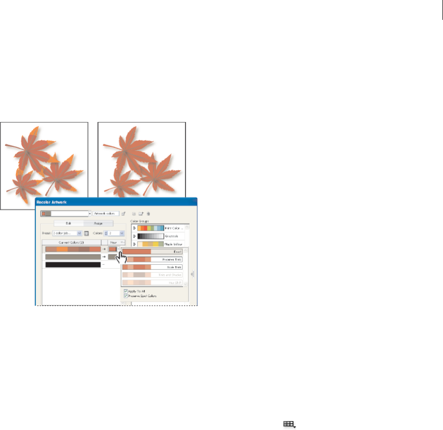
171
Color
Last updated 6/5/2015
Reduce colors in your artwork
Reducing colors for output, converting colors to grayscale, or limiting colors to a color library is often necessary when
you create artwork intended for multiple types of output media. You can easily reduce the number of colors in your
artwork using the Recolor Artwork dialog box. You can choose whether to use a preset for reducing colors, for example,
you can choose Grayscale Art to quickly convert your selected artwork to grayscale.
Quickly reduce colors using a preset
Reducing your colors by using a preset is a quick and easy way to limit your artwork to a specific number of colors or
a swatch library.
1Select the artwork you want to reduce.
2Choose Edit > Edit Colors > Recolor With Preset, and choose a preset option.
3Do one of the following:
•If you want to limit colors to a swatch library, click the library button , select the library you want, and then
click OK.
•If you don’t want to limit colors to a swatch library, click OK.
The Recolor Artwork dialog box opens. The New column displays the number of colors you chose as your preset,
plus black. The new colors are taken from your original artwork.
4Assign your original colors to the new colors as desired.
5Make sure that Recolor Art is selected, and click OK.
Reduce colors using custom options
1Select the artwork you want to recolor.
2Choose Edit > Edit Colors > Recolor Artwork.
The Recolor Artwork dialog box opens. The New column displays all the colors from your selected artwork.
3To use different colors, select or create a color group.
4Choose the number of colors you want to reduce down to from the Colors menu.

172
Color
Last updated 6/5/2015
5Click the Color Reduction Options button , specify any of the following options, and click OK:
Preset Specifies a preset color job, including the number of colors used and optimal settings for that job. If you select
a preset and then change any of the other options, the preset changes to Custom.
Colors Specifies the number of new colors that the current colors are reduced to.
Limit To Library Specifies a swatch library from which all new colors are derived.
Sort Determines how the original colors are sorted in the Current Colors column.
Colorize Method Specifies the types of variations allowed for the new colors.
•Exact exactly replaces each current color with the specified new color.
•Scale Tints (default option) replaces the darkest current color in the row with the specified new color. Other
current colors in the row are replaced with a proportionally lighter tint.
•Preserve Tints is the same as Scale Tints for non-global colors. For spot or global colors, it applies the current
color’s tint to the new color. Use Preserve Tints when all the current colors in the row are tints of the same or
similar global color. For best results when using Preserve Tints, also select Combine Tints.
•Tints And Shades replaces the current color with the average lightness and darkness with the specified new color.
Current colors that are lighter than the average are replaced with a proportionally lighter tint of the new color.
Current colors that are darker than the average are replaced by adding black to the new color.
•Hue Shift sets the most typical color in the Current Colors row as a key color and exactly replaces the key color
with the new color. The other current colors are replaced by colors that differ from the new color in brightness,
saturation, and hue by the same amounts that the current color differs from the key color.
Combine Tints Sorts all tints of the same global color into the same Current Colors row, even if colors are not being
reduced. Use this option only when the selected art contains global or spot colors applied at tints less than 100%. For
best results, use in combination with the Preserve Tints colorization method.
note: Even when Combine Tints is not selected, color reduction combines tints of the same global color before it combines
different non-global colors.
Preserve Determines whether white, black, or gray is preserved in the final reduction. If a color is preserved, it
appears in the Current Colors column as an excluded row.
6Assign current colors to the new colors as desired.
7Make sure that Recolor Art is selected, and click OK.
More Help topics
About color
Selecting colors
Using and creating swatches
Adjusting colors
Create color themes with Kuler

173
Color
Last updated 6/5/2015
About Kuler
The Kuler™ panel is your portal to groups of colors, or themes, created by an online community of designers. You can
use it to browse thousands of themes on Kuler, and then download some to edit or to include in your own projects. You
can also use the Kuler panel to share your themes with the Kuler community by uploading them.
The Kuler panel is available in Adobe Photoshop® CS5, Adobe Flash® Professional CS5, Adobe InDesign® CS5, Adobe
Illustrator® CS5, and Adobe Fireworks® CS5. The panel is not available in the French versions of these products.
For a video on the Kuler panel, see www.adobe.com/go/lrvid4088_xp.
For an article on Kuler and color inspiration, see Veerle Pieters' blog at
http://veerle.duoh.com/blog/comments/adobe_Kuler_update_and_color_tips/.
View and use themes
An Internet connection is required to browse themes online.
Search and view themes
1Select Window > Extensions > Kuler.
2In the Search box, enter the name of a theme, a tag, or a creator.
Note: Use only alphanumerical characters (Aa-Zz, 0-9) in searches.
3Filter the search results by selecting an option from the pop-up menus above the results.
4To view the next or previous set of themes, click the View Previous Set Of Themes or View Next Set Of themes icon
at the bottom of the Kuler panel.
5To refresh the view with the latest themes from the Kuler community, click the Refresh The Themes From The Kuler
Community icon at the bottom of the panel.
View a theme online on Kuler
1Select a theme in the search results.
2Click the triangle on the right side of the theme and selectView Online in Kuler.
Saving frequent searches
1Select Custom in the first pop-up menu located directly under the Search box.
2In the dialog box that opens, enter your search terms and click Save.
When you want to run the search, select it from the first pop-up menu.
To delete a saved search, select the Custom option in the pop-up menu and clear the searches you’d like to delete.
Add a theme to the Swatches panel in Illustrator
❖Select the theme and click the Add Selected Theme To Swatches icon at the bottom of the Kuler panel.
Upload your theme to Kuler community
1Select the theme in the Swatches panel.
2In the Kuler panel, click the Upload From Swatch Panel To Kuler Community icon.

174
Color
Last updated 6/5/2015
Color Themes panel
Adobe® Color® is a web-based application used to experiment with, create, and share color themes that you use in a
project. Illustrator CC has a Color Themes panel that enables you to view and use the color themes that you have
created or marked as favorite in the Adobe Color application.
Important: The Color Themes panel is not available in the French version of Illustrator.
Color Themes panel
In Illustrator CC, the Color Themes panel (Window > Color Themes) displays:
•Themes you created, and are synced with your account on the Adobe Color website (color.adobe.com).
•Public themes that you have marked as a favorite themes on the Adobe Color website.
The Adobe ID used in Illustrator CC is automatically used to sign in to the Adobe Color website, and the Color Themes
panel is refreshed .
Note: If the credentials you are using with Illustrator CC do not have an associated Adobe ID, then one is automatically
created using the Illustrator CC credentials. You can then access the Color Themes website using your Adobe ID credentials.
Creating themes on your iOS device
Using the Color Themes panel
Note: For the Color Themes panel to work, Internet connectivity is essential when you launch Illustrator. The Color Themes
panel cannot be used, if you do not have Internet connectivity while launching Illustrator.
The swatches and themes available in the Color Themes panel are read-only. You can use a swatch or theme in your
artwork, directly from the Color Themes panel. However, to modify or repurpose a swatch or theme, first add them to
the Swatches panel.
1Click Window > Color Themes, to open the panel.
All themes available in your Adobe Color account when Illustrator was launched are displayed in the Color Themes
panel.
2If you have added a theme in Color Themes after you started Illustrator, click Refresh in the Color Themes panel to
include the latest theme.
A simple and fun way to capture inspiring color combinations wherever you see them. Simply point the camera
at something colorful and Adobe Color CC will instantly extract a series of colors.
Learn more about the Adobe Color CC app here.
Download the amazing Adobe Color CC app from the iTunes app store (Available for your iPhone, iPad, and
iWatch!).
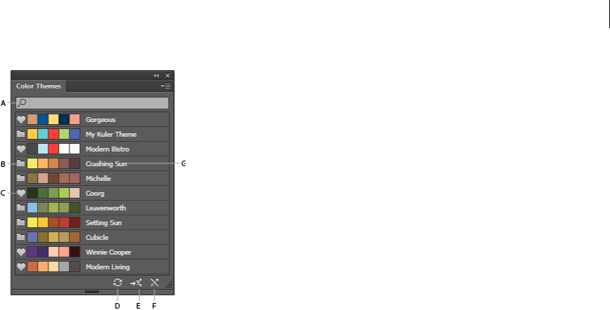
175
Color
Last updated 6/5/2015
A Theme search by name B Theme folder icon C Favorite theme icon D Refresh E Launch Adobe Color website F Change Icon that indicates
the themes cannot be edited G Color Theme name
Note: The Color Themes panel lists the themes that you have created, modified, or marked as favorite (listed under
Adobe Color website > My Themes)
3You can add a swatch or the entire theme to your Swatches panel (Window > Swatches).
To add a swatch:
•In the Color Themes panel, select a swatch, and then click the flyout menu > Add to Swatches.
To add multiple swatches:
•In the Color Themes panel, hold the Ctrl/Cmd key and select multiple swatches, and then click the flyout menu
> Add to Swatches. You can also use the Shift key to select multiple swatches.
To add a theme:
•In the Color Themes panel, select the entire theme by clicking the theme's folder icon. The entire theme is added
to the Swatches panel.
To add multiple themes:
•In the Color Themes panel, hold the Ctrl/Cmd key, click multiple theme folder icons, and then click the flyout
menu > Add to Swatches. You can also use the Shift key to select multiple themes.
4If you have an extensive list of themes, search the theme using the Find box (flyout menu > Show Find Field).
Searches are performed on the names of the themes.
5To view the details of the Adobe Color account being currently used, and the date and time when the Color Themes
panel was last refreshed, click the flyout menu.
Adjusting colors

176
Color
Last updated 6/5/2015
Shift an out-of-gamut color to a printable color
Some colors in the RGB and HSB color models, such as neon colors, cannot be printed, because they have no
equivalents in the CMYK model. If you select an out-of-gamut color, an alert triangle appears in the Color panel or
Color Picker.
❖Click the triangle to shift to the closest CMYK equivalent (which is displayed in a small box by the triangle).
More Help topics
Color spaces and gamuts
Shift a color to a web-safe color
Web-safe colors are the 216 colors used by all browsers, regardless of the platform. If you select a color that is not web-
safe, an alert cube appears in the Color panel, Color Picker, or Edit Colors/Recolor Artwork dialog box.
❖Click the cube to shift to the closest web-safe color (which is displayed in a small box by the cube).
More Help topics
About web graphics
Blend colors
The Blend commands create a series of intermediate colors from a group of three or more filled objects, based on the
objects’ vertical or horizontal orientation, or on their stacking order. Blending does not affect strokes or unpainted
objects.
1Select three or more filled objects.
2Do one of the following:
•To fill the intermediate objects with graduated blends between the frontmost and backmost filled objects, choose
Edit > Edit Colors > Blend Front To Back.
•To fill the intermediate objects with graduated blends between the leftmost and rightmost filled objects, choose
Edit > Edit Colors > Blend Horizontally.
•To fill the intermediate objects with graduated blends between the topmost and bottommost filled objects,
choose Edit > Edit Colors > Blend Vertically.
Change a color to its inverse or complement
1Select the color you want to change.
2In the Color panel, select an option from the panel menu:
Invert Changes each component of a color to the opposite value on the color scale. For example, if an RGB color
has an R value of 100, the Invert command will change the R value to 155 (255 – 100 = 155).
Complement Changes each component of a color to a new value based on the sum of the highest and lowest RGB
values in the selected color. Illustrator adds the lowest and highest RGB values of the current color, and then
subtracts the value of each component from that number to create new RGB values. For example, suppose you select
a color with an RGB value of 102 for red, 153 for green, and 51 for blue. Illustrator adds the high (153) and low (51)
values, to end up with a new value (204). Each of the RGB values in the existing color is subtracted from the new
value to create new complementary RGB values: 204 – 102 (the current red value) = 102 for the new red value, 204

177
Color
Last updated 6/5/2015
– 153 (the current green value) = 51 for the new green value, and 204 – 51 (the current blue value) = 153 for the new
blue value.
Change the tint of a color
1Select a global process color or spot color in the Swatches panel, or select an object to which you’ve applied a global
process color or spot color.
2In the Color panel, drag the T slider or enter a value in the text box to modify the color’s intensity. The tint range is
from 0% to 100%; the lower the number, the lighter the tint will be.
If you don’t see the T slider, make sure that you have a global process color or spot color selected. If you still don’t see
the T slider, choose Show Options from the Color panel menu.
3To save the tint as a swatch, drag the color to the Swatches panel, or click the New Swatch button in the Swatches
panel. The tint is saved with the same name as the base color, but with the tint percentage added to the name. For
example, if you saved a color named “Sky Blue” at 50 percent, the swatch name would be “Sky Blue 50%.”
More Help topics
About spot and process colors
Invert multiple colors
1Select the objects whose colors you want to invert.
2Choose Edit > Edit Colors > Invert Colors.
You can use the Color panel to invert individual colors.
Adjust color balance of one or more colors
1Select the objects whose colors you want to adjust.
2Choose Edit > Edit Colors > Adjust Color Balance.
3Set the Fill and Stroke options.
4Adjust the color values, and then click OK:
•If you selected any global process colors or spot colors, use the tint slider to adjust the intensity of the colors. Any
nonglobal process colors you selected are not affected.
•If you are working in CMYK color mode and selected nonglobal process colors, use the sliders to adjust the
percentages of cyan, magenta, yellow, and black.
•If you are working in RGB color mode and selected nonglobal process colors, use the sliders to adjust the
percentages of red, green, and blue.
•If you want to convert the colors you selected to grayscale, select Grayscale from the Color Mode list and select
the Convert option. Then use the slider to adjust the percentage of black.
•If you selected any global process or spot colors and you want to convert them to nonglobal process colors, select
either CMYK or RGB from the Color Mode list (depending on the color mode of the document) and select the
Convert option. Then use the sliders to adjust the colors.

178
Color
Last updated 6/5/2015
Change the color mode of a document
❖Choose File > Document Color Mode > CMYK Color or RGB Color.
Display and output spot colors using Lab values
Some predefined spot colors, such as colors from the TOYO, PANTONE, DIC, and HKS libraries, are defined using
Lab values. For backward compatibility with previous versions of Illustrator, colors from these libraries also include
CMYK definitions. The Swatches panel lets you control which values, Lab or CMYK, Illustrator uses to display, export,
and print these spot colors.
Lab values, when used in conjunction with the correct device profiles, give you the most accurate output across all
devices. If color management is critical to your project, Adobe recommends that you display, export, and print spot
colors using their Lab values.
Note: To improve on-screen accuracy, Illustrator uses the Lab values automatically if Overprint Preview is on. It also uses
Lab values when printing if you’ve selected Simulate for the Overprints option in the Advanced area of the Print dialog box.
1Choose Spot Colors from the Swatches panel menu.
2Do one of the following:
•Select Use Standard Lab Values Specified By The Book Manufacturer if you want the most accurate display and
output of colors.
•Select Use CMYK Values From The Manufacturer’s Process Book if you want spot colors to match earlier
versions of Illustrator.
More Help topics
Lab
Convert color to grayscale and vice versa
Convert colors to grayscale
1Select the objects whose colors you want to convert.
2Choose Edit > Edit Colors > Convert To Grayscale.
Use the Edit > Edit Colors> Adjust Colors command to convert objects to grayscale and adjust the shades of gray at
the same time.
More Help topics
Grayscale
Convert grayscale images to RGB or CMYK
1Select the grayscale image.
2Choose Edit > Edit Colors > Convert To CMYK or Convert To RGB (depending on the color mode of the
document).
Colorize grayscale or 1-bit images
1Select the bitmap object.

179
Color
Last updated 6/5/2015
2Make sure the Fill button in the Tools panel or Color panel is selected.
3Use the Color panel to color the image with black, white, a process color, or a spot color.
Note: If a grayscale image contains an alpha channel, you cannot colorize the image with a process color. Select a spot
color instead.
Adjust the saturation of multiple colors
1Select the objects whose colors you want to adjust.
2Choose Edit > Edit Colors > Saturate.
3Enter a value from –100% to 100% to specify the percentage by which to decrease or increase the color or the spot-
color tint.
More Help topics
HSB
Mix overlapping colors
You can use blending modes, the Hard Mix effect, or the Soft Mix effect to mix overlapping colors.
Blending modes Provide many options for controlling overlapping colors, and should always be used in place of Hard
Mix and Soft Mix for artwork containing spot colors, patterns, gradients, text, or other complex artwork.
Hard Mix effect Combines colors by choosing the highest value of each of the color components. For example, if Color
1 is 20% cyan, 66% magenta, 40% yellow, and 0% black; and Color 2 is 40% cyan, 20% magenta, 30% yellow, and 10%
black, the resulting hard color is 40% cyan, 66% magenta, 40% yellow, and 10% black.
Soft Mix effect Makes the underlying colors visible through the overlapping artwork, and then divides the image into
its component faces. You specify the percentage of visibility you want in the overlapping colors.
You can apply blending modes to individual objects, whereas you must apply the Hard Mix and Soft Mix effects to
entire groups or layers. Blending modes affect both the fill and stroke of an object, whereas the Hard and Soft Mix
effects result in removal of an object’s stroke.
Note: In most cases, applying the Hard Mix or Soft Mix effect to objects painted using a mix of process and spot colors
converts the color to CMYK. In the case of mixing a non-global process RGB color with a spot RGB color, all spot colors are
converted to a non-global process RGB color.
More Help topics
Apply Pathfinder effects
About blending modes
Targeting items for appearance attributes
Mix colors using the Hard Mix effect
1Target the group or layer.
2Choose Effect > Pathfinder > Hard Mix.
Mix colors using the Soft Mix effect
1Target the group or layer.

180
Color
Last updated 6/5/2015
2Choose Effect > Pathfinder > Soft Mix.
3Enter a value between 1% and 100% in the Mixing Rate text box to determine the percentage of visibility you want
in the overlapping colors, and click OK.
More Help topics
About color
Selecting colors
Using and creating swatches
Color groups (harmonies)

181
Last updated 6/5/2015
Chapter 5: Painting
About painting
To help you add visual interest to your artwork, Adobe Illustrator provides calligraphic, scatter, art, pattern, and bristle
brushes. In addition, you can use the Live Paint feature and Shape Builder tools, to paint different path segments and
fill enclosed paths with different colors, patterns, or gradients. Using the Shape Builder tool, you can create new
complex new shapes by merging simple shapes. Using opacity, masks, gradients, blends, meshes, and patterns provides
limitless opportunities for creativity. The Width tool provides the ability to create strokes with variable width that make
very articulate outlines.
More Help topics
Painting with fills and strokes
Live Paint groups
Brushes
Transparency and blending modes
Gradients
Meshes
Patterns
Painting with fills and strokes
Painting methods
Illustrator provides two methods of painting: assigning a fill, stroke, or both to an entire object, and converting the
object to a Live Paint group and assigning fills or strokes to the separate edges and faces of paths within it.
Paint an object
After you draw an object, you assign a fill, stroke, or both to it. You can then draw other objects that you can paint
similarly, layering each new object on top of the previous ones. The result is something like a collage made out of shapes
cut from colored paper, with the look of the artwork depending on which objects are on top in the stack of layered
objects.
For a video on using brushes, see www.adobe.com/go/vid0044.
Paint a Live Paint group
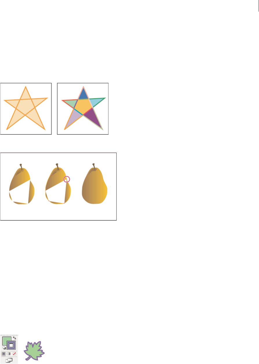
182
Painting
Last updated 6/5/2015
With the Live Paint method, you paint more like you would with a traditional coloring tool, without regard to layers or
stacking order, which can make for a more natural workflow. All objects in a Live Paint group are treated as if they are
part of the same flat surface. This means you can draw several paths and then color separately each area enclosed by
these paths (called a face). You can also assign different stroke colors and weights to portions of a path between
intersections (called an edge). The result is that, much like a coloring book, you can fill each face and stroke each edge
with a different color. As you move and reshape paths in a Live Paint group, the faces and edges automatically adjust in
response.
For a video on using Live Paint, see www.adobe.com/go/vid0042. For a video on painting techniques with the
Paintbrush tool, see www.adobe.com/go/vid0038.
About fills and strokes
A fill is a color, pattern, or gradient inside an object. You can apply fills to open and closed objects and to faces of Live
Paint groups.
A stroke can be the visible outline of an object, a path, or the edge of a Live Paint group. You can control the width and
color a stroke. You can also create dashed strokes using Path options, and paint stylized strokes using brushes. note:
When working with Live Paint groups, you can apply a brush to an edge only if you add a stroke to the group using the
Appearance panel.
The current fill and stroke colors are displayed in the Tools panel.
183
Painting
Last updated 6/5/2015
More Help topics
Keys for painting objects
Select colors using the Color Picker
Fill and Stroke controls
Controls for setting the fill and stroke are available in the Tools panel, the Control panel, and the Color panel.
You can use any of the following controls in the Tools panel to specify color:
Fill button
Double-click to select a fill color using the Color Picker.
Stroke button
Double-click to select a stroke color using the Color Picker.
Swap Fill And Stroke button
Click to swap colors between the fill and stroke.
Default Fill And Stroke button
Click to return to the default color settings (white fill and black stroke).
Color button
Click to apply the last-selected solid color to an object with a gradient fill or no stroke or fill.
Gradient button
Click to change the currently selected fill to the last-selected gradient.
None button
Click to remove the selected object’s fill or stroke.
You can also specify color and stroke for a selected object by using the following controls in the Control panel:
Fill color Click to open the Swatches panel or Shift-click to open an alternate color mode panel, and choose a color.
Stroke color Click to open the Swatches panel or Shift-click to open an alternate color mode panel, and choose a color.
Stroke panel Click the word Stroke to open the Stroke panel and specify options.
Stroke weight Choose a stroke weight from the pop-up menu.
Apply a fill color to an object
You can apply one color, pattern, or gradient to an entire object, or you can use Live Paint groups and apply different
colors to different faces within the object.
1Select the object using the Selection tool ( ) or the Direct Selection tool ( ).
2Click the Fill box in the Tools panel or the Color panel. Doing so indicates that you want to apply a fill rather than
a stroke.
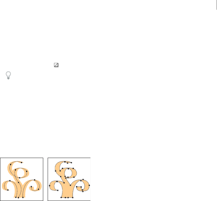
184
Painting
Last updated 6/5/2015
3Select a fill color by doing one of the following:
•Click a color in the Control panel, Color panel, Swatches panel, Gradient panel, or a swatch library.
•Double-click the Fill box and select a color from the Color Picker.
•Select the Eyedropper tool and Alt-click (Windows) or Option-click (Mac OS) an object to apply the current
attributes, including the current fill and stroke.
•Click the None button to remove the object’s current fill.
You can quickly apply color to an unselected object by dragging a color from the Fill box, Color panel, Gradient
panel, or Swatches panel onto the object. Dragging does not work on Live Paint groups.
More Help topics
Keys for painting objects
Select colors using the Color Picker
Live Paint groups
Draw and merge paths with the Blob Brush tool
Use the Blob Brush tool to paint filled shapes that you can intersect and merge with other shapes of the same color.
The Blob Brush tool uses the same default brush options as calligraphic brushes. (See Calligraphic brush options.)
To see a video on using the Blob Brush tool, see www.adobe.com/go/lrvid4018_ai. To see an example of using the Blob
Brush to create a complex drawing, see www.adobe.com/go/learn_ai_tutorials_blob_brush_en.
More Help topics
Paintbrush tool options
Blob Brush tool guidelines
When using the Blob Brush tool, keep the following guidelines in mind:
•To merge paths, they must be adjacent in stacking order.
•The Blob Brush tool creates paths with a fill and no stroke. If you want your Blob Brush paths to merge with existing
artwork, make sure that the artwork has the same fill color and no stroke.
•When drawing paths with the Blob Brush tool, new paths merge with the topmost matching path encountered. If
the new path touches more than one matching path within the same group or layer, all of the intersecting paths are
merged together.
•To apply paint attributes (such as effects or transparency) to the Blob Brush tool, select the brush and set the
attributes in the Appearances panel before you start drawing.

185
Painting
Last updated 6/5/2015
•You can use the Blob Brush tool to merge paths created by other tools. To do this make sure that the existing artwork
does not have a stroke; then set up the Blob Brush tool to have the same fill color, and draw a new path that intersects
all of the paths that you want to merge together.
Create merged paths
Remember that paths with strokes cannot be merged.
1Select the path into which you want to merge a new path.
2In the Appearances panel, deselect New Art Has Basic Appearance. When this option is deselected, the Blob Brush
tool uses the attributes of the selected artwork.
3Select the Blob Brush tool , and make sure it uses the same appearances as the selected artwork.
4Draw paths that intersect with the artwork. If the paths don’t merge, check to make sure that the Blob Brush tool’s
attributes exactly match the existing path attributes, and that neither uses a stroke.
Blob Brush tool options
Double-click the Blob Brush tool in the Tools panel and set any of the following options:
Keep Selected Specifies that when you draw a merged path, all paths are selected and remain selected as you continue
to draw. This option is useful for viewing all paths that are included in the merged path.
Merge only with Selection Specifies that new strokes merge only with the existing selected path. If you select this
option, the new stroke is not merged with another intersecting path that is not selected.
Fidelity Controls how far you have to move your mouse or stylus before Illustrator adds a new anchor point to the path.
For example, a Fidelity value of 2.5 means that tool movements of less than 2.5 pixels aren’t registered. Fidelity can range
from 0.5 to 20 pixels; the higher the value, the smoother and less complex the path.
Smoothness Controls the amount of smoothing that Illustrator applies when you use the tool. Smoothness can range
from 0% to 100%; the higher the percentage, the smoother the path.
Size Determines the size of the brush.
Angle Determines the angle of rotation for the brush. Drag the arrowhead in the preview, or enter a value in the Angle
text box.
Roundness Determines roundness of the brush. Drag a black dot in the preview away from or toward the center, or
enter a value in the Roundness text box. The higher the value, the greater the roundness.
Convert strokes to compound paths
Converting a stroke to a compound path lets you modify the outline of the stroke. For example, you can create a stroke
with a varied width or divide the stroke into pieces.
1Select the object.
2Choose Object > Path > Outline Stroke.
The resulting compound path is grouped with the filled object. To modify the compound path, first ungroup it from
the fill or select it with the Group Selection tool.
Use the Layers panel to identify the contents of a group.
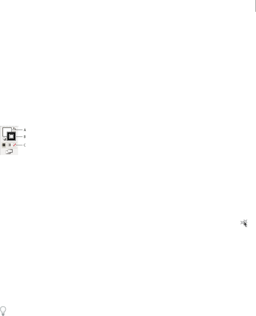
186
Painting
Last updated 6/5/2015
More Help topics
About compound paths
Group or ungroup objects
Remove the fill or stroke from an object
1Select the object.
2Click the Fill box or the Stroke box in the Tools panel. Doing so indicates whether you want to remove the object’s
fill or its stroke.
3Click the None button in the Tools panel, the Color panel, or the Swatches panel.
Note: You can also click the None icon in the Fill menu or the Stroke Color menu in the Control panel.
A Fill box B Stroke box C None button
Select objects with the same fill and stroke
You can select objects that have the same attributes, including fill color, stroke color, and stroke weight.
Note: The Select > Same > Fill Color, Stroke Color, and Stroke Weight commands work within a Live Paint group when
you select a face or edge with the Live Paint Selection tool; other Select > Same commands do not work. You cannot select
same objects both inside and outside a Live Paint group at the same time.
•To select objects with the same fill and stroke, select one of the objects, click the Select Similar Objects button in
the Control panel and choose what you want to base your selection on in the menu that appears.
•To select all objects with the same fill or stroke color, select an object with that fill or stroke color, or choose the color
from the Color panel or Swatches panel. Then choose Select > Same and click Fill Color, Stroke Color, or Fill &
Stroke on the submenu.
•To select all objects with the same stroke weight, select an object with that stroke weight or choose the stroke weight
from the Stroke panel. Then choose Select > Same > Stroke Weight.
•To apply the same selection options using a different object (for example, if you have already selected all red objects
using the Select > Same > Fill Color command and now you want to search for all green objects), select a new object
and then choose Select > Reselect.
Tip: To consider the tint of an object when selecting based on color, choose Edit > Preferences > General (Windows)
or Illustrator > Preferences > General (Mac OS), and then choose Select Same Tint %. With this option selected, if
you select an object filled with a 50% tint of PANTONE Yellow C and choose Select > Same > Fill Color, Illustrator
selects only those objects filled with a 50% tint of that color. With this option deselected, objects with any tint of
PANTONE Yellow C are selected.
Create multiple fills and strokes
You use the Appearance panel to create multiple fills and strokes for the same object. Adding multiple fills and strokes
to an object is the basis for creating many interesting effects. For example, you can create a second, narrower stroke on
top of a wide stroke, or you can apply an effect to one fill but not the other.
1Select one or more objects or groups (or target a layer in the Layers panel).
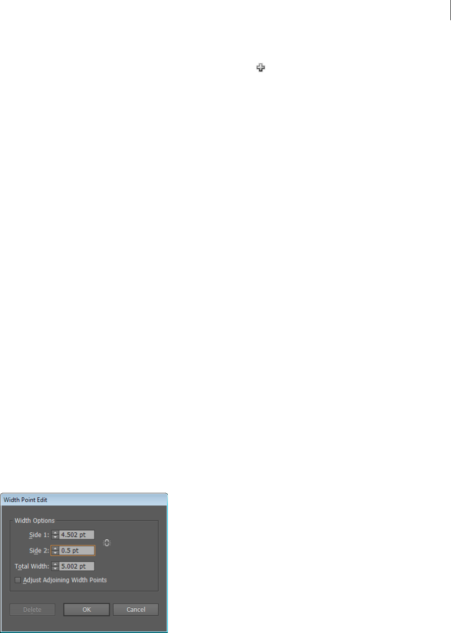
187
Painting
Last updated 6/5/2015
2Select Add New Fill or Add New Stroke from the Appearance panel menu. Alternatively, select a fill or stroke in the
Appearance panel, and click the Duplicate Selected Item button .
3Set the color and other properties for the new fill or stroke.
Note: It may be necessary to adjust the position of the new fill or stroke in the Appearance panel. For example, if you
create two strokes of different widths, make sure that the narrower stroke is above the wider stroke in the Appearance
panel.
More Help topics
Targeting items for appearance attributes
Appearance panel overview
Create strokes with variable widths
About the Width tool
The Width tool is available from the Tools panel. It allows you to create a variable width stroke and save the variable
width as a profile that can be applied to other strokes.
When you mouse over a stroke with the Width tool, a hollow diamond appears on the path with handles. You can adjust
the stroke width, move the width point, duplicate the width point, and delete the width point.
For multiple strokes, the width tool adjusts only the active stroke. If you want to adjust a stroke, make sure that you
select it as the active stroke in the Appearance panel.
For a video on using the Width tool, see www.adobe.com/go/lrvid5206_ai_en.
Using the Width tool
To create or modify a width point using the Width Point Edit dialog box, double-click the stroke using the Width tool
and edit the values for the width point. If you select the Adjust Adjoining Width Points option, changes to the selected
width point affect neighboring width points as well.
If you press Shift and double-click the width point, then this check box is selected automatically.
The Width tool distinguishes between continuous and discontinuous width points while adjusting variable width.
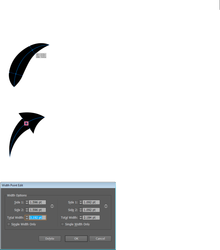
188
Painting
Last updated 6/5/2015
To create a discontinuous width point do the following:
1Create two width points on a stroke with different stroke widths.
2Drag one width point on to the other width point to create a discontinuous width point for the stroke.
For discontinuous points, the Width Point Edit dialog box shows both sets of side widths.
The Single Width Only check boxes allow using either incoming or outgoing width leaving a single continuous width
point.
Width tool controls
The following table lists the keyboard modifiers to use while working with the Width tool:
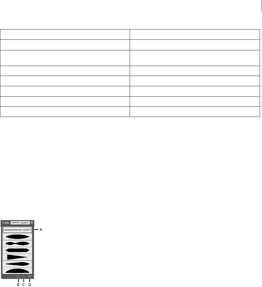
189
Painting
Last updated 6/5/2015
You can drag the handles outward or inward to adjust the stroke width at that location on the path. Width points created
at a corner or at a direct-selected anchor point, stick to the anchor point during basic editing of the path.
To change the position of the width point, drag the point along the path.
To select multiple width points, press Shift and click. The Width Point Edit dialog box is displayed, where you can
specify values for Side1 and Side 2 of multiple points. Any adjustment to the width points, would impact all the selected
width points.
You can also globally adjust the stroke weight for all the width points by specifying the stroke weight in the Weight
drop-down list of the Stroke panel.
Saving width profiles
After defining the stroke width, you can save the variable width profile from the Stroke panel or the Control panel.
A Uniform Width Profile option B Save Width Profile icon C Delete Width Profile icon D Reset Width Profile icon
Width profiles can be applied to selected paths by choosing them from the Width Profile drop-down list in the Control
panel or Stroke panel. When a stroke with no variable width is selected, the list displays the Uniform option. You can
also select the Uniform option to remove a variable width profile from an object.
To restore the default width profile set, click the Reset Profiles button at the bottom of the Profile drop down list.
Note: Restoring the default width profile set in the Stroke Options dialog box, removes any custom saved profiles.
If you apply a variable width profile to a stroke, then it is indicated with an asterisk (*) in the Appearance panel.
For Art and Pattern brushes, the Width Points/Profile option is automatically selected for size in Stroke Options dialog
box after editing a brush path with the Variable Width tool or applying a Width Profile preset. To remove any width
profile changes, select the Fixed option for size or one of the tablet data channels, such as Pressure, to restore the tablet
data options.
Width control tasks Keyboard modifiers
Create non-uniform widths Alt+drag (Windows) or Opt+drag (Mac OS)
Create a copy of the width point Alt+drag the width point (Windows) or Opt+drag the width point
(Mac OS)
Copy and move all the points along the path Alt+Shift+drag (Windows) or Opt+Shift+drag (Mac OS)
Change the position of multiple width points Shift+drag
Select multiple width points Shift+click
Delete selected width points Delete
Deselect a width point Esc
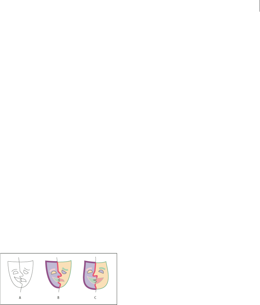
190
Painting
Last updated 6/5/2015
For a video on creating variable width profiles, see www.adobe.com/go/lrvid5215_ai_en.
More Help topics
About Live Paint
Illustrator Brushes
Walkthrough - How to work with brushes
Video - Pattern Fill
Live Paint groups
About Live Paint
Converting your artwork to Live Paint groups allows you to color them freely, as you would a drawing on canvas or
paper. You can stroke each path segment with a different color and fill each enclosed path (note, not just closed paths)
with a different color, pattern, or gradient.
Live Paint is an intuitive way to create colored drawings. It lets you use the full range of Illustrator’s vector drawing tools,
but treats all the paths you draw as though they are on the same flat surface. That is, none of the paths is behind or in
front of any other. Instead, the paths divide the drawing surface up into areas, any of which can be colored, regardless
of whether the area is bounded by a single path or by segments of multiple paths. The result is that painting objects is
like filling in a coloring book or using watercolors to paint a pencil sketch.
Once you’ve made a Live Paint group, each path remains fully editable. When you move or adjust a path’s shape, the
colors that had been previously applied don’t just stay where they were, like they do in natural media paintings or image
editing programs. Instead, Illustrator automatically reapplies them to the new regions that are formed by the edited
paths.
A Original B Live Paint group C Paths adjusted, Live Painting reflows
The paintable parts of Live Paint groups are called edges and faces. An edge is the portion of a path between where it
intersects with other paths. A face is the area enclosed by one or more edges. You can stroke edges and fill faces.
Take, for example, a circle with a line drawn across it. As a Live Paint group, the line (edge) dividing the circle creates
two faces in the circle. You can fill each face and stroke each edge with a different color using the Live Paint Bucket tool.

191
Painting
Last updated 6/5/2015
Note: Live Paint takes advantage of multiprocessors, which help Illustrator perform the operations more quickly.
For a video on using Live Paint, see www.adobe.com/go/vid0042.
More Help topics
Painting methods
About fills and strokes
Live Paint limitations
Fill and paint attributes are attached to faces and edges of a Live Paint group—not to the actual paths that define them,
as in other Illustrator objects. Because of this, some features and commands either work differently or are not applicable
to paths inside a Live Paint group.
Features and commands that work on an entire Live Paint group, but not on individual faces and edges
•Transparency
•Effects
•Multiple fills and strokes from the Appearance panel
•Object > Envelope Distort
•Object > Hide
•Object > Rasterize
•Object > Slice > Make
•Make Opacity Mask (in the Transparency panel menu)
•Brushes (You can apply brushes to an entire Live Paint group if you add a new stroke to the group using the
Appearance panel.)
Features that don’t work on Live Paint groups
•Gradient meshes
•Graphs
•Symbols from the Symbols panel
•Flares
•Align Stroke options from the Stroke panel
•The Magic Wand tool
Object commands that don’t work on Live Paint groups
•Outline Stroke
•Expand (You can use the Object > Live Paint > Expand command instead.)

192
Painting
Last updated 6/5/2015
•Blend
•Slice
•Clipping Mask > Make
•Create Gradient Mesh
Other commands that don’t work on Live Paint groups
•Pathfinder commands
•File > Place
•View > Guides > Make
•Select > Same >Blending Mode, Fill & Stroke, Opacity, Style, Symbol Instance, or Link Block Series
•Object > Text Wrap > Make
Create Live Paint groups
When you want to color objects using different colors for each edge, or intersection, convert the artwork into a Live
Paint Group.
Certain types of objects, such as type, bitmap images, and brushes, cannot be directly made into Live Paint groups. You
first need to convert these objects into paths. For example, if you try to convert an object that uses brushes or effects,
the complex visual appearance is lost in the conversion to Live Paint. However, you can retain much of the appearance
by first converting the objects to regular paths and then converting the resulting paths to Live Paint.note: When you
convert artwork to a Live Paint group, you cannot return the artwork to its original state. You can expand the group into
its individual components, or release the group back to its original paths with no fill and a .5 black stroke.
For a video on using Live Paint, see www.adobe.com/go/vid0042.
More Help topics
Keys for working with Live Paint groups
Create a Live Paint group
1Select one or more paths, compound paths, or both.
2Do one of the following:
•Choose Object > Live Paint > Make.
•Select the Live Paint Bucket tool and click the selected object.
Note: Certain properties may be lost in the conversion to a Live Paint group, such as transparency and effects, while other
objects cannot be converted (such as type, bitmap images, and brushes).
Convert objects to Live Paint groups
❖Do any of the following for objects that do not directly convert to Live Paint groups:
•For type objects, choose Type > Create Outlines. Then make the resulting paths into a Live Paint group.
•For bitmap images, choose Object > Live Trace > Make And Convert To Live Paint.
•For other objects, choose Object > Expand. Then make the resulting paths into a Live Paint group.
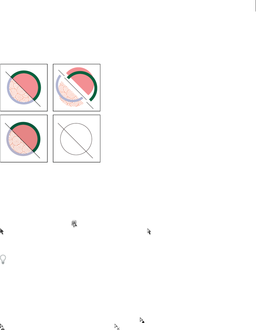
193
Painting
Last updated 6/5/2015
Expand or release a Live Paint group
Releasing a Live Paint group changes it to one or more ordinary paths with no fill and a .5-point black stroke. Expanding
a Live Paint group changes it to one or more ordinary paths that are visually similar to the Live Paint group, but are now
separate filled and stroked paths. You can use the Group Selection tool to select and modify these paths separately.
1Select the Live Paint group.
2Do one of the following:
•Choose Object > Live Paint > Expand.
•Choose Object > Live Paint > Release.
Select items in Live Paint groups
Use the Live Paint Selection tool to select individual faces and edges in a Live Paint group. Use the Selection tool
to select the entire Live Paint group, and the Direct Selection tool to select paths inside a Live Paint group. When
you’re working in a complex document, you can isolate a Live Paint group so that it is easy to select the exact face or
edge you want.
Choose a selection tool depending on what you want to affect in a Live Paint group. For example, use the Live Paint
Selection tool to apply different gradients across different faces in a Live Paint group, and use the Selection tool to apply
the same gradient across the entire Live Paint group.
More Help topics
Isolate artwork for editing
Select faces and edges
The Live Paint Selection tool pointer changes to the face pointer when it’s positioned over a face, the edge pointer
when it’s positioned over an edge, or the x pointer when it’s positioned outside of a Live Paint group.
❖Select the Live Paint Selection tool, and then:
•To select an individual face or edge, click a face or edge.
•To select multiple faces and edges, drag a marquee around the items you want to select. Partial selections are
included.
•To select all contiguous faces that are not separated by a painted edge, double-click a face.
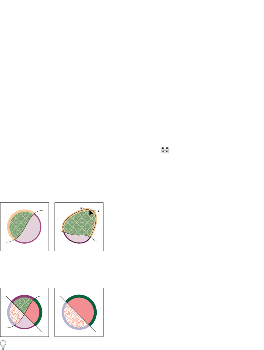
194
Painting
Last updated 6/5/2015
•To select faces or edges with the same fill or stroke, triple-click an item. Or click once, choose Select > Same, and
then choose Fill Color, Stroke Color, or Stroke Weight on the submenu.
•To add items to, or remove items from, the current selection, Shift-click or Shift-drag a marquee around the
items.
Select a Live Paint group
❖Using the Selection tool, click the group.
Select an original path within a Live Paint group
❖Using the Direct Selection tool, click a path inside the Live Paint group.
Isolate a Live Paint group from the rest of the artwork
❖Using the Selection tool, do one of the following:
•Double-click the group.
•Select the group, and then click the Isolate Selected Group button in the Control panel.
Modify Live Paint groups
When you modify a path in a Live Paint group, Illustrator colors the modified or new faces and edges using fills and
strokes from the existing group. If the results are not what you expect, you can reapply the colors you want using the
Live Paint Bucket tool.
When you delete edges, the fill floods across any newly expanded face. For example, if you delete a path that divides a
circle in half, the circle is filled with one of the fills previously in the circle. You can sometimes help guide the results.
For instance, before deleting a path that divides a circle, first move it so that the fill you want to keep is larger than the
fill you want to remove.
Save the fill and stroke colors used in Live Paint groups in the Swatches panel. That way, if a change loses a color you
want to keep, you can select its swatch and use the Live Paint Bucket tool to reapply the fill or stroke.
More Help topics
Isolate artwork for editing
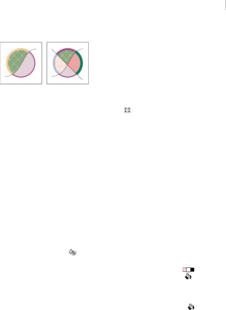
195
Painting
Last updated 6/5/2015
Add paths to a Live Paint group
As you add more paths to the Live Paint group, you can fill and stroke the new faces and edges that are created.
❖Do any of the following:
•Using the Selection tool, double-click a Live Paint group (or click the Isolate Selected Group button in the
Control panel) to put the group into isolation mode. Then draw another path. Illustrator adds the new path to
the Live Paint group. Click the Exit Isolation Mode button when you’re done adding new paths.
•Select a Live Paint group and the paths you want to add to it. Then choose Object > Live Paint > Merge, or click
Merge Live Paint in the Control panel.
•In the Layers panel, drag one or more paths into a Live Paint group.
note: Paths inside a Live Paint group may not exactly align with similar or identical paths outside the Live Paint
group.
Resize an individual object or path
❖Do one of the following:
•Using the Direct Selection tool, click the path or object to select it. Then choose the Selection tool and click the
path or object again to edit it.
•Using the Selection tool, double-click the Live Paint Group to put it into isolation mode. Then click a path or
object to edit it.
Paint with the Live Paint Bucket tool
The Live Paint Bucket tool lets you paint faces and edges of Live Paint groups with the current fill and stroke attributes.
The tool pointer displays as either one or three color squares, which represent the selected fill or stroke color and, if
you’re using colors from a swatch library, the two colors adjacent to the selected color in the library. You can access the
adjacent colors, as well as the colors next to those, and so on, by pressing the left or right arrow key.
1Select the Live Paint Bucket tool . Click and hold the Shape builder tool to see and select the Live Paint bucket
tool. See Select a toolto learn other methods for selecting tools. See Tools panel over viewto locate all the tools.
2Specify the fill color or stroke color and size you want.
Note: If you select a color from a the Swatches panel, the pointer changes to display three colors . The selected
color is in the middle, and the two adjacent colors are on either side. To use an adjacent color, click the left or right arrow
key.
3To paint a face, do any of the following:
•Click a face to fill it. (When the pointer is over a face, it changes to a half-filled paint bucket and highlight
lines surround the inside of the fill.)
•Drag across multiple faces to paint more than one face at a time.
•Double-click a face to fill across unstroked edges into adjacent faces (flood fill).

196
Painting
Last updated 6/5/2015
•Triple-click a face to fill all faces that currently have the same fill.
Tip: To switch to the Eyedropper tool and sample fills or strokes, Alt-click (Windows) or Option-click (Mac OS)
the fill or stroke you want.
4To paint an edge, double-click the Live Paint Bucket tool and select Paint Strokes, or temporarily toggle to the Paint
Strokes option, by pressing Shift; and then do any of the following:
•Click an edge to stroke it. (When the pointer is over an edge, it changes to a paint brush and the edge is
highlighted.)
•Drag across multiple edges to stroke more than one edge at a time.
•Double-click an edge to stroke all connected edges of the same color (flood stroke).
•Triple-click an edge to stroke all edges of the same stroke.
note: Pressing Shift lets you quickly toggle between painting only strokes and only fills. You can also specify these
changes in the Live Paint Bucket Options dialog box. If you currently have both the Paint Fills option and the Paint
Strokes option selected, pressing Shift switches to Paint Fills only. (This can be helpful when you are trying to fill a
small face surrounded by stroked edges.)
More Help topics
Tools panel over v iew
Fill and Stroke controls
Apply a fill color to an object
Live Paint Bucket options
The Live Paint Bucket options let you specify how the Live Paint Bucket tool works, choosing whether to paint just fills,
just strokes, or both, as well as how to highlight faces and edges as you move the tool over them. You can see these
options by double-clicking the Live Paint Bucket tool.
Paint Fills Paints the faces of Live Paint groups.
Paint Strokes Paints the edges of Live Paint groups.
Cursor Swatch Preview Displays when you choose a color from the Swatches panel. The Live Paint Bucket tool pointer
appears as three color swatches: the selected fill or stroke color plus the color directly to the left and right of it in the
Swatches panel.
Highlight Outlines the face or edge the cursor is currently over. Faces are highlighted with a thick line and edges are
highlighted with a thin line.
Color Sets the color for the highlight. You can choose a color from the menu or click the paint swatch to specify a
custom color.
Width Specifies how thick to make the highlight.
Close gaps in Live Paint groups
Gaps are small spaces between paths. If paint leaks through and paints faces you did not intend, you probably have a
gap in your artwork. You can create a new path that closes the gap, edit existing paths to close the gap, or adjust the gap
options in the Live Paint group.
You can avoid gaps in your Live Paint artwork by overdrawing paths (that is, extending them past each other). You can
then select and delete the excess edges that result, or apply a stroke of “None” to them.

197
Painting
Last updated 6/5/2015
Highlight gaps in a Live Paint group
❖Choose View > Show Live Paint Gaps.
This command highlights any gaps found on the currently selected Live Paint group, based on your gap options settings
for that group.
Set Live Paint gap options
❖Choose Object > Live Paint > Gap Options and specify any of the following:
Gap Detection When selected, Illustrator recognizes gaps in Live Paint paths and prevents paint from flowing
through them. Note that this may slow Illustrator when working on large, complex Live Paint groups. In this case,
you can choose Close Gaps With Paths to help speed Illustrator up again.
Paint Stops At Sets the size of the gap paint can’t flow through.
Custom Specifies a custom Paint Stops At gap size.
Gap Preview Color Sets the color for previewing gaps in Live Paint groups. You can choose a color from the menu,
or click the color well next to the Gap Preview Color menu to specify a custom color.
Close Gaps With Paths When selected, inserts unpainted paths into your Live Paint group to close gaps (rather than
simply preventing paint from flowing though the gaps). Note that since these paths are unpainted, it may appear
gaps are still there even though they have been closed.
Preview Displays currently detected gaps in Live Paint groups as colored lines, based on the preview color you
chose.
Gap rules for merged Live Paint groups
When you merge Live Paint groups that have different gap settings, Illustrator uses the following rules to handle the
gaps:
•If gap detection is off in all groups in the selection, gaps are closed and gap detection is turned on with Paint Stops
At set to Small Gaps.
•If gap detection is on and the same for all groups in the selection, gaps are closed and the gap setting is preserved.
•If gap detection is mixed for the selection, gaps are closed and the gap settings of the bottommost Live Paint group
are preserved (if gap detection is on for that group). If the bottommost group has gap detection turned off, gap
detection is turned on and Paint Stops At is set to Small Gaps.
Brushes
Did you know you can use your iPad or iPhone to design beautiful, high-quality brushes from photos of anything
that inspires you? Save the brushes to your Creative Cloud Library and access them anywhere across Photoshop
and Illustrator!
Learn more about the Adobe Brush CC iPad app here.
Download the awesome Adobe Brush CC app from the iTunes app store.
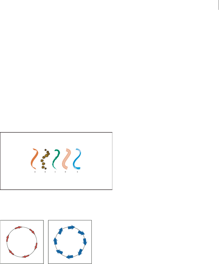
198
Painting
Last updated 6/5/2015
About brushes
Brushes let you stylize the appearance of paths. You can apply brush strokes to existing paths, or you can use the
Paintbrush tool to draw a path and apply a brush stroke simultaneously.
There are different types of brushes in Illustrator: calligraphic, scatter, art, pattern, and bristle. You can achieve the
following effects using these brushes:
Calligraphic brushes Create strokes that resemble those drawn with the angled point of a calligraphic pen and are
drawn along the center of the path. When you use the Blob Brush tool, you can paint with a calligraphic brush and
automatically expand the brush stroke into a fill shape that merges with other filled objects of the same color that
intersect or are adjacent in stacking order.
Scatter brushes Disperse copies of an object (such as a ladybug or a leaf) along the path.
Art brushes Stretch a brush shape (such as Rough Charcoal) or object shape evenly along the length of the path.
Bristle brush Create brush strokes with the appearance of a natural brush with bristles.
Pattern brushes Paint a pattern—made of individual tiles—that repeats along the path. Pattern brushes can include up
to five tiles, for the sides, inner corner, outer corner, beginning, and end of the pattern.
A Calligraphic Brush B Scatter Brush C Art Brush D Pattern Brush E Bristle Brush
Scatter brushes and Pattern brushes can often achieve the same effect. However, one way in which they differ is that
Pattern brushes follow the path exactly, while Scatter brushes do not.
For a video on using brushes, see www.adobe.com/go/vid0044.
More Help topics
Draw and merge paths with the Blob Brush tool

199
Painting
Last updated 6/5/2015
Brushes panel overview
The Brushes panel (Window > Brushes) displays brushes for the current file. Whenever you select a brush in a brush
library, it is automatically added to the Brushes panel. Brushes that you create and store in the Brushes panel are
associated only with the current file, which means that each Illustrator file can have a different set of brushes in its
Brushes panel.
More Help topics
Keys for the Brushes panel
Show or hide a type of brush
❖Choose any of the following from the panel menu: Show Calligraphic Brushes, Show Scatter Brushes, Show Art
Brushes, Show Bristle Brushes, Show Pattern Brushes.
Change the view of brushes
❖Choose Thumbnail View or List View from the panel menu.
Change the order of brushes in the Brushes panel
❖Drag a brush to a new location. You can move brushes only within their type. For example, you cannot move a
Calligraphic brush to the Scatter brush area.
Duplicate a brush in the Brushes panel
❖Drag the brush onto the New Brush button or choose Duplicate Brush from the Brushes panel menu.
Delete the brushes from the Brushes panel
❖Select the brushes and click the Delete Brush button . You can select brushes that aren’t used in a document by
choosing Select All Unused from the Brushes panel menu.
Work with brush libraries
Brush libraries (Window > Brush Libraries > [library]) are collections of preset brushes that come with Illustrator. You
can open multiple brush libraries to browse through their contents and select brushes. You can also open brush libraries
using the Brushes panel menu.
To automatically open a brush library when you start Illustrator, choose Persistent from the brush library’s panel menu.
Copy brushes from a brush library to the Brushes panel
❖Drag the brushes to the Brushes panel or choose Add To Brushes from the brush library’s panel menu.
Import brushes into the Brushes panel from another file
1Choose Window > Brushes Libraries > Other Library and select the file.
2In the Brush Library panel, click on the individual brush definition or all the brush definitions that you need to
import and select Add To Brushes from the Brush Library panel menu (flyout menu).
Create new brush libraries
1Add the brushes you want to the Brushes panel, and delete any brushes you don’t want.

200
Painting
Last updated 6/5/2015
2Choose Save Brush Library from the Brushes panel menu, and place the new library file in one of the following
folders so that it will appear in the Brush Libraries menu when you restart Illustrator:
•(Windows XP) Documents and Settings/User/Application Data/Adobe/Adobe IllustratorCS5 Settings/Brush
•(Windows Vista/Windows 7) User/AppData/Roaming/Adobe/Adobe Illustrator CS5 Settings/Brush
•(Mac OS) Library/Application Support/Adobe/Adobe Illustrator CS5/Brush
Note: If you place the file in a different folder, you can open the library by choosing Window > Brush Libraries > Other
Library and selecting the library file.
Apply brush strokes
You can apply brush strokes to a path created with any drawing tool, including the Pen tool, Pencil tool, or basic shape
tools.
❖Do one of the following:
•Select the path, and then select a brush in a brush library, the Brushes panel, or the Control panel.
•Drag a brush onto the path. If the path already has brush strokes applied to it, then the new brush replaces the
old brush.
If you want to apply a different brush to the path and want to use the brush stroke settings used with the original
brush, hold down Alt (Win) or Option (Mac OS) when clicking the new brush you want to apply.
Draw paths and apply brush strokes simultaneously
1Select a brush in a brush library or the Brushes panel.
2Select the Paintbrush tool .
3Position the pointer where you want the brush stroke to begin, and drag to draw a path. A dotted line follows the
pointer as you drag.
4Do one of the following:
•To draw an open path, release the mouse button when the path is the desired shape.
•To draw a closed shape, hold down Alt (Windows) or Option (Mac OS) as you drag. The Paintbrush tool displays
a small loop . Release the mouse button (but not the Alt or Option key) when you are ready to close the shape.
Illustrator sets down anchor points as you draw. The number of anchor points is determined by the length and
complexity of the path and by the Paintbrush tolerance settings.
Tip: To adjust the shape of a brushed path after you finish drawing it, first select the path. Then position the
Paintbrush tool on the path, and drag until the path is the desired shape. You can use the technique to extend a
brushed path as well as change the shape of the path between the existing end points.
Paintbrush tool options
Double-click the Paintbrush tool to set the following options:
Fidelity Controls how far you have to move your mouse or stylus before Illustrator adds a new anchor point to the path.
For example, a Fidelity value of 2.5 means that tool movements of less than 2.5 pixels aren’t registered. Fidelity can range
from 0.5 to 20 pixels; the higher the value, the smoother and less complex the path.
Smoothness Controls the amount of smoothing that Illustrator applies when you use the tool. Smoothness can range
from 0% to 100%; the higher the percentage, the smoother the path.

201
Painting
Last updated 6/5/2015
Fill New Brush Strokes Applies a fill to the path. This option is most useful when drawing closed paths.
Keep Selected Determines whether Illustrator keeps the path selected after you draw it.
Edit Selected Paths Determines whether you can change an existing path with the Paintbrush tool.
Within: _ pixels Determines how close your mouse or stylus must be to an existing path to edit the path with the
Paintbrush tool. This option is only available when the Edit Selected Paths option is selected.
Remove brush strokes
1Select a brushed path.
2In the Brushes panel, choose Remove Brush Stroke from the panel menu or click the Remove Brush Stroke button
.
3In CS5, you can also remove a brush stroke by selecting the Basic brush from the Brushes panel or Control panel.
Convert brush strokes to outlines
You can convert brush strokes into outlined paths to edit the individual components of a brushed path.
1Select a brushed path.
2Choose Object > Expand Appearance.
Illustrator places the components of the expanded path in a group. Within the group are a path and a subgroup
containing the brush stoke outlines.
Create or modify brushes
You can create and customize calligraphic, scatter, art, pattern, and bristle brushes depending on your requirement. For
scatter, art, and pattern brushes, you must first create the artwork.
Follow these guidelines when creating artwork for brushes:
•The artwork cannot contain gradients, blends, other brush strokes, mesh objects, bitmap images, graphs, placed
files, or masks.
•For art and pattern brushes, the artwork cannot contain type. To achieve a brush-stroke effect with type, create an
outline of the type and then create a brush with the outline.
•For pattern brushes, create up to five pattern tiles (depending on the brush configuration), and add the tiles to the
Swatches panel.
Note: You can make the brushes you create available for every new document by adding the brush definition to the New
Document Profile. For more information on new document profiles, see About new document profiles
More Help topics
About patterns
Create corner tiles for brush patterns
Create a brush
1For scatter and art brushes, select the artwork you want to use. For pattern brushes, you can select the artwork for
the side tile, but it isn’t necessary. For detailed guidelines to create pattern brushes, see Guidelines for constructing
pattern tiles. To know more about pattern brush options, see Pattern brush options.

202
Painting
Last updated 6/5/2015
Note: If you do not want to see a seam between the artwork pieces used to create the pattern brush, turn off the Anti-
Aliasing option from Edit > Preferences > General (Windows) or Illustrator > General > Preferences (Mac OS).
2Click the New Brush button in the Brushes panel. Alternatively, drag the selected artwork to the Brushes panel.
3Select the type of brush you want to create, and click OK.
4In the Brush Options dialog box, enter a name for the brush, set brush options, and click OK.
Modify a brush
•To change the options for a brush, double-click the brush in the Brushes panel. Set the brush options and click OK.
If the current document contains brushed paths that use the modified brush, a message appears. Click Apply To
Strokes to change pre-existing strokes. Click Leave Strokes to leave pre-existing strokes unchanged, and apply the
modified brush to new strokes only.
•To change the artwork used by a scatter, art, or pattern brush, drag the brush into your artwork and make the
changes you want. Then Alt-drag (Windows) or Option-drag (Mac OS) the modified brush onto the original brush
in the Brushes panel.
•To modify a brushed path without updating the corresponding brush, select the path and click the Options Of
Selected Object button in the Brushes panel or select options of selected object from the Brushes panel menu
(flyout menu).
Brush options
You can specify different options for the different types of brushes. To change the options for a brush, double-click the
brush in the Brushes panel.
Scatter, Art, and Pattern brushes all have identical options for colorization.
To customize a stroke instance for Art Brushes or Pattern Brushes, click the Options of Selected Objects icon in the
Brushes Panel and set the stroke options. For art brush you can set the stroke width along with flipping, colorization,
and overlapping options. For pattern brush, you can set the scaling options along with flipping, fitting, and colorization
options.
Calligraphic brush options
Angle Determines the angle of rotation for the brush. Drag the arrowhead in the preview, or enter a value in the Angle
box.
Roundness Determines roundness of the brush. Drag a black dot in the preview away from or toward the center, or
enter a value in the Roundness box. The higher the value, the greater the roundness.
Diameter Determines the diameter of the brush. Use the Diameter slider, or enter a value in the Diameter box.
The pop-up list to the right of each option lets you control variations in the shape of the brush. Select one of the
following options:
Fixed Creates a brush with a fixed angle, roundness, or diameter.
Random Creates a brush with random variations in angle, roundness, or diameter. Enter a value in the Variation box
to specify the range within which the brush characteristic can vary. For example, when the Diameter value is 15 and the
Variation value is 5, the diameter can be 10, or 20, or any value in between.
Pressure Creates a brush that varies in angle, roundness, or diameter based on the pressure of a drawing stylus. This
option is most useful when used with Diameter. It is available only if you have a graphics tablet. Enter a value in the
Variation box to specify how much more or less than the original value the brush characteristic will vary. For example,

203
Painting
Last updated 6/5/2015
when the Roundness value is 75% and the Variation value is 25%, the lightest stroke is 50% and the heaviest stroke is
100%. The lighter the pressure, the more angular the brush stroke.
Stylus Wheel Creates a brush that varies in diameter based on manipulation of the stylus wheel. This option is intended
to be used with an airbrush pen that has a stylus wheel on its barrel and with a graphics tablet that can detect that pen.
Tilt Creates a brush that varies in angle, roundness, or diameter based on the tilt of a drawing stylus. This option is most
useful when used with Roundness. It is available only if you have a graphics tablet that can detect how close to vertical
the pen is.
Bearing Creates a brush that varies in angle, roundness, or diameter based on the bearing of the pen. This option is
most useful when used to control the angle of calligraphic brushes, especially when you’re using the brush like a
paintbrush. It is available only if you have a graphics tablet that can detect the direction in which the pen is tilted.
Rotation Creates a brush that varies in angle, roundness, or diameter based on how the drawing stylus pen tip is
rotated. This option is most useful when used to control the angle of calligraphic brushes, especially when you’re using
the brush like a flat pen. It is available only if you have a graphics tablet that can detect this type of rotation.
Colorization options for scatter, art, and pattern brushes
The colors that a scatter, art, or pattern brush paints depend on the current stroke color and the colorization method
of the brush. To set the colorization method, select one of the following options in the Brush Options dialog box:
None Displays colors as they appear in the brush in the Brushes panel. Choose None to keep a brush the same colors
as in the Brushes panel.
Tints Displays the brush stroke in tints of the stroke color. Portions of the art that are black become the stroke color,
portions that aren’t black become tints of the stroke color, and white remains white. If you use a spot color as the stroke,
Tints generates tints of the spot color. Choose Tints for brushes that are in black and white, or when you want to paint
a brush stroke with a spot color.
Tints And Shades Displays the brush stroke in tints and shades of the stroke color. Tints and Shades maintains black
and white, and everything between becomes a blend from black to white through the stroke color. Because black is
added you may not be able to print to a single plate when using Tints and Shades with a spot color. Choose Tints and
Shades for brushes that are in grayscale.
Hue Shift Uses the key color in the brush artwork, as shown in the Key Color box. (By default, the key color is the most
prominent color in the art.) Everything in the brush artwork that is the key color becomes the stroke color. Other colors
in the brush artwork become colors related to the stroke color. Hue Shift maintains black, white, and gray. Choose Hue
Shift for brushes that use multiple colors. To change the key color, click the Key Color eyedropper, move the eyedropper
to the preview in the dialog box, and click the color you want to use as the key color. The color in the Key Color box
changes. Click the eyedropper again to deselect it.
For information and samples about each choice, click Tips.
Scatter brush options
Size Controls the size of the objects.
Spacing Controls the amount of space between objects.
Scatter Controls how closely objects follow the path independently on each side of the path. The higher the value, the
farther the objects are from the path.
Rotation Controls the angle of rotation of the objects.
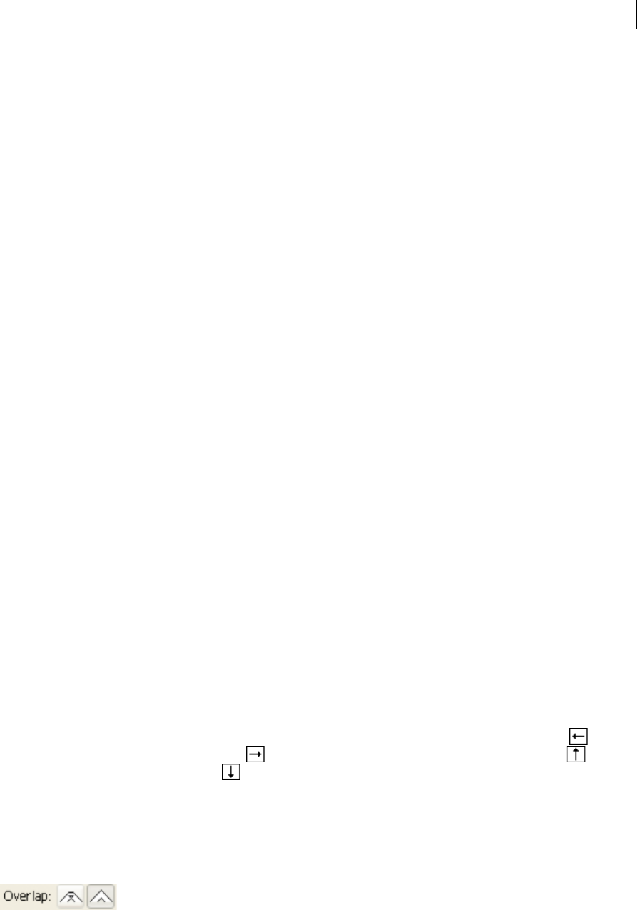
204
Painting
Last updated 6/5/2015
Rotation Relative To Sets the angle of rotation for scattered objects relative to the page or the path. For example, if you
select Page, at 0° of rotation, objects point to the top of the page. If you select Path, at 0° of rotation, objects are tangent
to the path.
The pop-up list to the right of each option lets you control variations in the shape of the brush. Select one of the
following options:
Fixed Creates a brush with a fixed size, spacing, scattering, and rotation.
Random Creates a brush with random variations in size, spacing, scattering, and rotation. Enter a value in the Variation
box to specify the range within which the brush characteristic can vary. For example, when the Diameter value is 15
and the Variation value is 5, the diameter can be 10, or 20, or any value in between.
Pressure Creates a brush that varies in angle, roundness, or diameter based on the pressure of a drawing stylus. This
option is available only if you have a graphics tablet. Enter a value in the rightmost box, or use the Maximum slider.
Pressure uses the Minimum value for the lightest tablet pressure and the Maximum value for the heaviest pressure.
When you choose this setting for Diameter, the heavier the stroke, the larger the objects.
Stylus Wheel Creates a brush that varies in diameter based on manipulation of the stylus wheel. This option is available
only if you have a graphics tablet that has a stylus wheel on its barrel and can detect input from that pen.
Tilt Creates a brush that varies in angle, roundness, or diameter based on the tilt of a drawing stylus. It is available only
if you have a graphics tablet that can detect how close to vertical the pen is.
Bearing Creates a brush that varies in angle, roundness, or diameter based on the bearing of a drawing stylus. This
option is most useful when used to control the angle of brushes. It is available only if you have a graphics tablet that can
detect the direction in which the pen is tilted.
Rotation Creates a brush that varies in angle, roundness, or diameter based on how the drawing stylus pen tip is
rotated. This option is most useful when used to control the angle of brushes. It is available only if you have a graphics
tablet that can detect this type of rotation.
Art brush options
Width Adjusts the width of the art relative to its original width. You can specify the width using the Width option slider.
The art brush Width pop-up menu has pen tablet options for adjusting scale variation, such as Pressure, Stylus Wheel,
Tilt, Bearing, and Rotation. The default art brush width is 100%.
note: If you use the Width tool on a particular Art brush stroke instance, all the tablet data is converted to Width points.
Notice that in the Width drop-down list settings, the Width Points/Profiles option is selected.
Brush Scale Options Preserves proportions in scaled art. The options available are: Scale Proportionately, Stretch to Fit
Stroke Length, Stretch Between Guides.
Direction Determines the direction of the artwork in relation to the line. Click an arrow to set the direction: to place
the left side of the art is the end of the stroke; to place the right side of the art is the end of the stroke; to place
the top of the art is the end of the stroke; to place the bottom of the art is the end of the stroke.
Flip Along or Flip Across Change the orientation of the art in relation to the line.
Colorization Pick a color for the stroke and method of colorization. You can select from different colorization methods
using this drop-down list. The options are Tints, Tints and Shades, and Hue Shift.
Overlap To avoid joins and folds of an object’s edges to overlap, you can select the Overlap adjustment button
.
For a video on using the enhanced features of art brushes, see www.adobe.com/go/lrvid5214_ai_en.
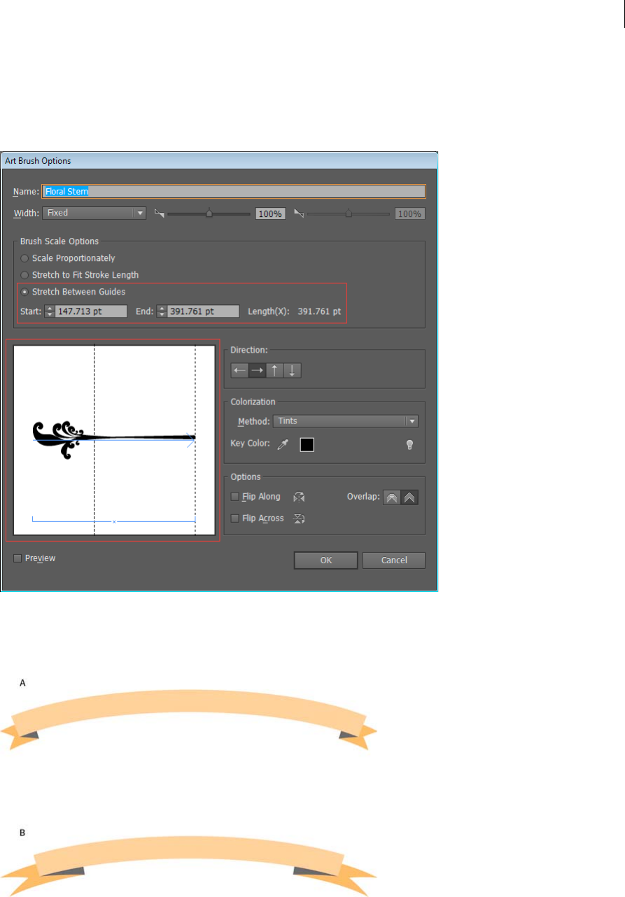
205
Painting
Last updated 6/5/2015
Segmented art brush
Segmented art brush is an ability to define a non-stretchable portion at the ends of an art brush. From the Art brush’s
Brush Options dialog box, select the Stretch Between Guides option, and adjust the guides in the preview section of the
dialog box.
The art enclosed between the guides is the only portion of the brush that stretches or contracts to make the art brush
fit the path length.
A Segmented art brush B Non segmented art brush
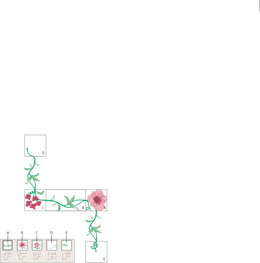
206
Painting
Last updated 6/5/2015
Pattern brush options
Scale Adjusts the size of tiles relative to their original size. Specify the scale using the Scale option slider. The Scale
drop-down list for pattern brush tool include pen tablet options for adjusting scale variations, such as Pressure, Stylus
Wheel, Tilt, Bearing, and Rotation.
note: If you use the Width tool on a particular Pattern brush stroke instance, all the tablet data is converted to Width points.
Notice that in the Scale pop-up menu for stroke options, the Width Points/Profiles option is selected.
Spacing Adjusts the space between tiles.
Tile buttons Let you apply different patterns to different parts of the path. Click a tile button for the tile you want to
define, and select a pattern swatch from the scroll list. Repeat to apply pattern swatches to other tiles as needed.
Note: You must add the pattern tiles you want to use to the Swatches panel before you set pattern brush options. After you
create a pattern brush, you can delete the pattern tiles from the Swatches panel if you don’t plan to use them for additional
artwork.
A Side tile B Outer Corner tile C Inner Corner tile D Start tile E End tile
Flip Along or Flip Across Changes the orientation of the pattern in relation to the line.
Fit Determines how the pattern fits on the path: Stretch To Fit lengthens or shortens the pattern tile to fit the object.
This option can result in uneven tiling. Add Space To Fit adds blank space between each pattern tile to apply the pattern
proportionally to the path. Approximate Path fits tiles to the closest approximate path without changing the tiles. This
option applies the pattern slightly inside or outside the path, rather than centered on the path, to maintain even tiling.

207
Painting
Last updated 6/5/2015
A Stretch To Fit B Add Space To Fit C Approximate Path
Colorization Pick a color for the stroke and method of colorization. You can select from different colorization methods
using this drop-down list. The options are Tints, Tints and Shades, and Hue Shift.
For a video on using the enhanced features of art brushes, see www.adobe.com/go/lrvid5214_ai_en.
Bristle brush
Bristle brush allows you to create brush strokes with the appearance of a natural brush with bristles. With Bristle brush,
you can:
•Create natural and fluid brush strokes that simulate the effects of painting with real brushes and media such as water
color.
•Select brushes from a predefined library or create your own brushes from the provided tip shapes such as round,
flat, or fan. You can also set other brush characteristics such as bristle length, stiffness, and paint opacity.
When you use Bristle brush with a graphic tablet, Illustrator interactively tracks the movements of the stylus over the
tablet. It interprets all aspects of its orientation and pressure input at any point along a drawing path. Illustrator provides
the output that is modeled on the stylus’s x-axis position, y-axis position, pressure, tilt, bearing, and rotation.
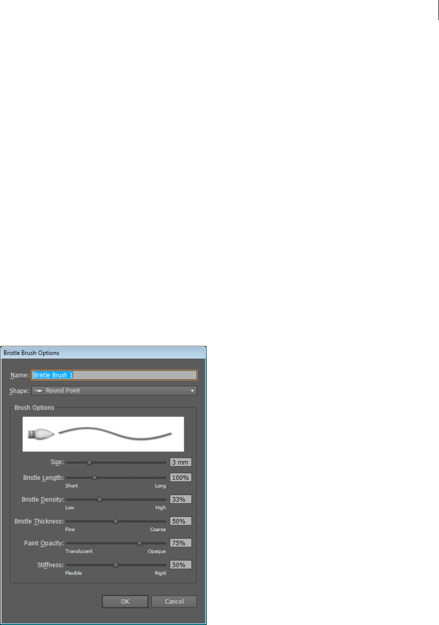
208
Painting
Last updated 6/5/2015
A cursor annotator that simulates the tip of an actual brush is displayed when using a tablet and stylus that support
rotation. This annotator does not appear when other input devices such as a mouse are used. The annotator is also
disabled while using the precise cursors.
Note: Use the Wacom Intuos 3 or higher tablet with Art (6D) pen to explore the full capabilities of the Bristle brush.
Illustrator can interpret all 6-degrees of freedom that this device combination provides. However, other devices including
the Wacom Grip pen and Art brush pen may not be able to interpret some attributes such as rotation. These uninterpreted
attributes are treated as constants in the resulting brush strokes.
While using a mouse, only x and y-axis movements are recorded. Other inputs, such as tilt, bearing, rotation, and
pressure remain fixed resulting in even and consistent strokes.
For Bristle brush strokes, feedback is displayed when you drag the tool. This feedback provides an approximate view of
the final stroke.
Note: Bristle brush strokes are made up of several overlapping, filled transparent paths. These paths, like any other filled
path in Illustrator, interact with the paint of other objects, including other bristle bush paths. However, the fill for strokes
does not self-interact. Therefore, layered, individual, bristle brush strokes build up and interact with each other, but a single
stoke scrubbed back and forth in place does not interact with itself and build up.
Using the Bristle brush
To use the Bristle brush do the following:
1Create a brush definition by clicking the new brush icon or selecting New Brush from the Brushes panel menu.
2Select the Bristle Brush option and click OK.

209
Painting
Last updated 6/5/2015
3In the Bristle Brush Options dialog box, specify:
Name of the bristle brush. Maximum length of the brush name can be 31 characters.
Shape Select from ten different brush models, which provide a different drawing experience and appearance of
bristle brush paths.
Size Brush size is the diameter of the brush. Like a physical media brush, the Bristle brush diameter is measured at
the point where the bristles meet the handle (the ferrule). Specify the brush size using the slider or directly entering
the size in the available text field. Range can be between 1mm and 10mm.
Brush size from the original Brush definition is displayed in Brush preview in the Brushes panel.
note: The bracket keys, [ and ], are used as shortcuts for decreasing and increasing the size, respectively. The bracket
keys increase and decrease the size in 1mm increments.
Bristle Length The bristle length starts from the point where the bristles meet the handle of the bristle tip. The
length of the bristles can be specified in the same way as other bristle brush options, by dragging the Bristle Length
slider, or specifying the exact value in the Bristle Length field (25% to 300%).
Bristle Density The bristle density is the number of bristles in a specified area of the brush neck. You can set this
attribute in the same way as other bristle brush options. It ranges between 1% and 100%, and is calculated based on
the brush size and bristle length.
Bristle Thickness The bristle thickness can vary from fine to coarse (between 1% and 100%). Set the bristle
thickness like other bristle brush settings, by dragging the slider, or specifying the thickness value in the field.
Paint Opacity This option lets you set the opacity of the paint being used. The paint opacity can vary between 1%
(Translucent) and 100% (opaque). The specified opacity value is the maximum opacity used in the brush. You can
use the numeric keys[0-9] as shortcut to set the opacity of bristle brush strokes where:
•0 = 100
•1 = 10%
•9 = 90
In other cases, for example, if you enter 35 in succession, the opacity is set to 35%, and if you enter 356 in succession
the opacity value is set to 56 (last two digits). Any string of digits that ends with 00 are set as 100%.
Stiffness Stiffness implies the rigidness of the bristles. If you set a low bristle stiffness value, the bristles are flexible.
They become more rigid when you set a higher value. The bristle stiffness ranges between 1% and 100%.
4Click OK to create the brush definition with the chosen settings.
With the brush tool selected, and a Bristle brush definition chosen in the Brushes panel, you can create artwork using
the Bristle brush.
If you try to print, save, or flatten transparency in a document with more than 30 bristle brush strokes, a warning
message is displayed. These warnings are displayed when you save, print, and flatten file content.
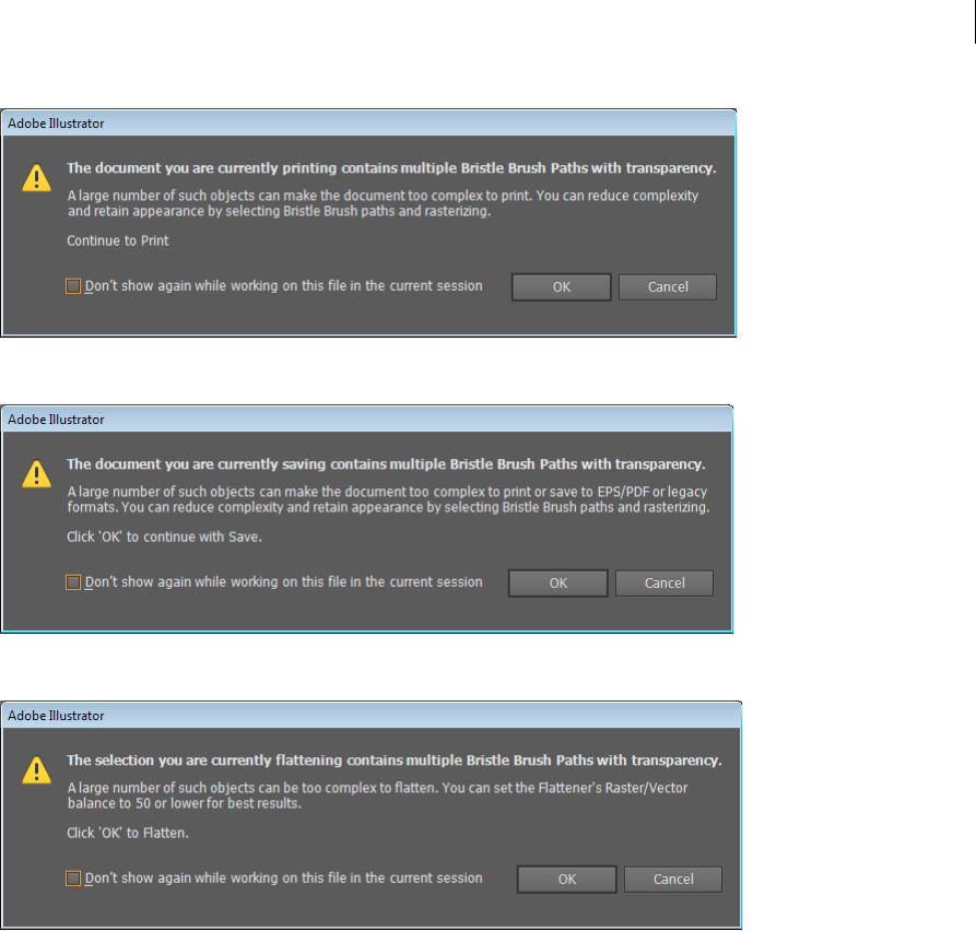
210
Painting
Last updated 6/5/2015
Transparency and blending modes
About transparency
Transparency is such an integral part of Illustrator that it’s possible to add transparency to your artwork without
realizing it. You can add transparency to artwork by doing any of the following:
•Lowering the opacity of objects so that underlying artwork becomes visible.
•Using opacity masks to create variations in transparency.
•Using a blending mode to change how colors interact among overlapping objects.
•Applying gradients and meshes that include transparency.
•Applying effects or graphic styles that include transparency, such as drop shadows.
•Importing Adobe Photoshop files that include transparency.

211
Painting
Last updated 6/5/2015
For a video on working with transparency, see www.adobe.com/go/vid0054.
For more information on working with transparency across AdobeCreative Suite, see
www.adobe.com/go/learn_ai_transparency_pdf_en.
More Help topics
Transparency tutorial
Printing and saving transparent artwork
Transparency panel overview
You use the Transparency panel (Window > Transparency) to specify the opacity and blending mode of objects, to
create opacity masks, or to knock out a portion of one object with the overlying portion of a transparent object.
Show all options in the Transparency panel
❖Choose Show Options from the panel menu.
Show a thumbnail of the selected object in the Transparency panel
❖Choose Show Thumbnail from the panel menu. Or, click the double triangle on the panel’s tab to cycle through the
display sizes.
View transparency in artwork
It’s important to be aware of when you’re using transparency, because you need to set some extra options when printing
and saving transparent artwork. To view transparency in your artwork, display a checkered background grid to identify
transparent areas of your artwork.
1Choose View > Show Transparency Grid.
2(Optional) Choose File > Document Setup, and set transparency grid options.
Note: You can also change the artboard color to simulate what your artwork will look like if printed on colored paper.
Change the opacity of artwork
You can change the opacity of a single object, the opacity of all objects in a group or layer, or the opacity of an object’s
fill or stroke.
1Select an object or group (or target a layer in the Layers panel).
If you want to change the opacity of a fill or stroke, select the object, and then select the fill or stroke in the
Appearance panel.
2Set the Opacity option in the Transparency panel or Control panel.
To select all objects that use a specific opacity, select an object with that opacity, or deselect everything and enter the
opacity value in the Transparency panel. Then choose Select > Same > Opacity.
If you select multiple objects in a layer and change the opacity setting, the transparency of overlapping areas of the
selected objects will change relative to the other objects and show an accumulated opacity. In contrast, if you target
a layer or group and then change the opacity, the objects in the layer or group are treated as a single object. Only
objects outside and below the layer or group are visible through the transparent objects. If an object is moved into
the layer or group, it takes on the layer’s or group’s opacity, and if an object is moved outside, it doesn’t retain the
opacity.
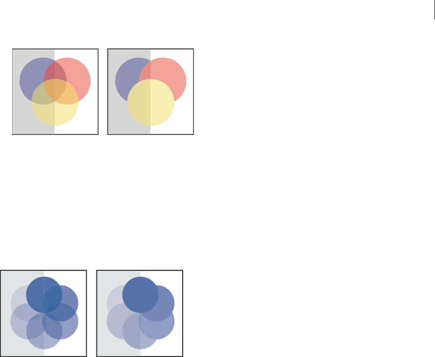
212
Painting
Last updated 6/5/2015
More Help topics
Targeting items for appearance attributes
Appearance panel overview
Printing and saving transparent artwork
Create a transparency knockout group
In a transparency knockout group, the elements of a group do not show through each other.
1In the Layers panel, target the group or layer you want to turn into a knockout group.
2In the Transparency panel, select Knockout Group. If this option isn’t visible, select Show Options from the panel
menu.
Selecting the Knockout Group option cycles it through three states: on (check mark), off (no mark), and neutral
(square with a line through it). Use the neutral option when you want to group artwork without interfering with the
knockout behavior determined by the enclosing layer or group. Use the off option when you want to ensure that a
layer or a group of transparent objects will never knock each other out.
More Help topics
Targeting items for appearance attributes
Printing and saving transparent artwork
Use opacity masks to create transparency
You use an opacity mask and a masking object to alter the transparency of artwork. The opacity mask (also referred to
as masked artwork) provides the shape through which other objects show. The masking object defines which areas are
transparent and the degree of transparency. You can use any colored object or raster image as the masking object.
Illustrator uses the grayscale equivalents of the colors in the masking object for the opacity levels in the mask. Where
the opacity mask is white, the artwork is fully visible. Where the opacity mask is black, the artwork is hidden. Shades
of gray in the mask result in varying degrees of transparency in the artwork.
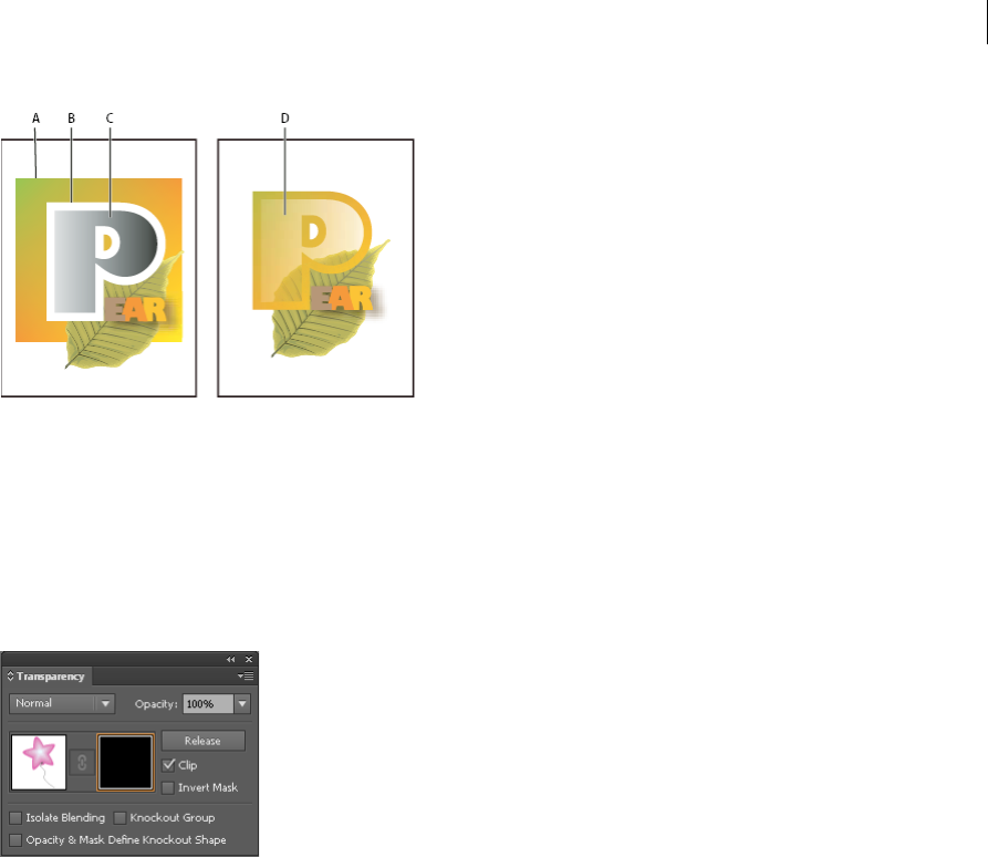
213
Painting
Last updated 6/5/2015
A Underlying objects B Opacity mask artwork C Masking object filled with black-to-white gradient D C moved over the area of B and masking B
When you create the opacity mask, a thumbnail of the masking object appears in the Transparency panel to the right
of the thumbnail of the masked artwork. (If these thumbnails aren’t visible, choose Show Thumbnails from the panel
menu.) By default, the masked artwork and the masking object are linked (as shown by a link between the thumbnails
in the panel). When you move the masked artwork, the masking object moves along with it. However, when you move
a masking object, the masked artwork doesn’t move. You can unlink the mask in the Transparency panel to lock the
mask in place and move the masked artwork independently of it.
You can move masks between Photoshop and Illustrator. Opacity masks in Illustrator convert to layer masks in
Photoshop, and vice versa.
Note: You cannot enter isolation mode when working in mask-editing mode, or vice versa.
For a video on working with opacity masks, see www.adobe.com/go/vid0056.
More Help topics
Targeting items for appearance attributes
Printing and saving transparent artwork
Create an opacity mask
1Select a single object or group, or target a layer in the Layers panel.
2Open the Transparency panel and, if necessary, choose Show Options from the panel menu to see the thumbnail
images.
3Double-click directly to the right of the thumbnail in the Transparency panel.
An empty mask is created and Illustrator automatically enters mask-editing mode
4Use the drawing tools to draw a mask shape.
5Click the masked artwork’s thumbnail (left thumbnail) in the Transparency panel to exit mask-editing mode.

214
Painting
Last updated 6/5/2015
Note: The Clip option sets the mask background to black. Therefore, black objects, such as black type, used to create an
opacity mask with the Clip option selected will not be visible. To see the objects, use a different color or deselect the Clip
option.
Convert an existing object into an opacity mask
❖Select at least two objects or groups, and choose Make Opacity Mask from the Transparency panel menu. The
topmost selected object or group is used as the mask.
Edit a masking object
You can edit a masking object to change the shape or transparency of the mask.
1Click the masking object’s thumbnail (right thumbnail) in the Transparency panel.
2Alt-click (Windows) or Option-click (Mac OS) the mask thumbnail to hide all other artwork in the document
window. (If the thumbnails aren’t visible, choose Show Thumbnails from the panel menu.)
3Use any of the Illustrator editing tools and techniques to edit the mask.
4Click the masked artwork’s thumbnail (left thumbnail) in the Transparency panel to exit mask-editing mode.
Unlink or relink an opacity mask
•To unlink a mask, target the masked artwork in the Layers panel, and then click the link symbol between the
thumbnails in the Transparency panel. Alternatively, select Unlink Opacity Mask from the Transparency panel
menu.
The masking object is locked in position and size, and the masked objects can be moved and resized independently
of the mask.
•To relink a mask, target the masked artwork in the Layers panel, and then click the area between the thumbnails in
the Transparency panel. Alternatively, select Link Opacity Mask from the Transparency panel menu.
Deactivate or reactivate an opacity mask
You can deactivate a mask to remove the transparency it creates.
•To deactivate a mask, target the masked artwork in the Layers panel, and then Shift-click the masking object’s
thumbnail (right thumbnail) in the Transparency panel. Alternatively, select Disable Opacity Mask from the
Transparency panel menu. When the opacity mask is deactivated, a red x appears over the mask thumbnail in the
Transparency panel.
•To reactivate a mask, target the masked artwork in the Layers panel, and then Shift-click the masking object’s
thumbnail in the Transparency panel. Alternatively, select Enable Opacity Mask from the Transparency panel menu.
Remove an opacity mask
❖Target the masked artwork in the Layers panel, and then select Release Opacity Mask from the Transparency panel
menu.
The masking object reappears on top of the objects that were masked.
Clip or invert an opacity mask
1Target the masked artwork in the Layers panel.

215
Painting
Last updated 6/5/2015
2Select either of the following options in the Transparency panel:
Clip Gives the mask a black background which crops the masked artwork to the boundaries of the masking object.
Deselect the Clip option to turn off the clipping behavior. To select clipping for new opacity masks by default, select
New Opacity Masks Are Clipping from the Transparency panel menu.
Invert Mask Reverses the luminosity values of the masking object, which reverses the opacity of the masked
artwork. For example, areas that are 90% transparent become 10% transparent after the mask is inverted. Deselect
the Invert Mask option to return the mask to the original state. To invert all masks by default, select New Opacity
Masks Are Inverted from the Transparency panel menu.
If these options aren’t visible, select Show Options from the panel menu.
Use transparency to shape a knockout
You can use the Opacity & Mask Define Knockout Shape option to make a knockout effect proportional to the object’s
opacity. In areas of the mask that are close to 100% opacity, the knockout effect will be strong; in areas with less opacity,
the knockout effect will be weaker. For example, if you use a gradient-masked object as a knockout, the underlying
object will be knocked out progressively, as if it were being shaded by a gradient. You can create knockout shapes with
both vector and raster objects. This technique is most useful for objects that use a blending mode other than Normal.
1Do one of the following:
•To use an opacity mask to shape the knockout, select the masked artwork, and then group it with the objects you
want to knock out.
•To use the alpha channel of a bitmap object to shape the knockout, select a bitmap object that contains
transparency, and then group it with the objects you want to knock out.
2Select the group.
3In the Transparency panel, select Knockout Group until the option displays a checkmark.
4Among the grouped objects, target the masking objects or transparent image in the Layers panel.
5In the Transparency panel, select Opacity & Mask Define Knockout Shape.
A Original artwork B Darken blending mode applied to the word “PEARS”, and Group option selected C Opacity & Mask Define Knockout
shape option applied to word
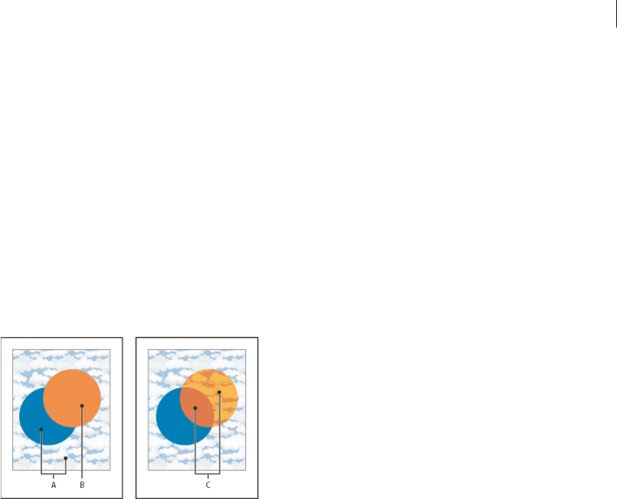
216
Painting
Last updated 6/5/2015
More Help topics
Targeting items for appearance attributes
Printing and saving transparent artwork
About blending modes
Blending modes let you vary the ways that the colors of objects blend with the colors of underlying objects. When you
apply a blending mode to an object, the effect of the blending mode is seen on any objects that lie beneath the object’s
layer or group.
It’s helpful to think in terms of the following color terminology when visualizing a blending mode’s effect:
•The blend color is the original color of the selected object, group, or layer.
•The base color is the underlying color in the artwork.
•The resulting color is the color resulting from the blend.
For a video on working with blending modes, see www.adobe.com/go/vid0055. To see an example of how blending
modes and gradients can be used to create comic book-inspired characters with depth and color, see
www.adobe.com/go/learn_ai_tutorials_blendingmode_en and www.adobe.com/go/learn_ai_tutorials_depth_en.
Illustrator provides the following blending modes:
Normal Paints the selection with the blend color, without interaction with the base color. This is the default mode.
Darken Selects the base or blend color—whichever is darker—as the resulting color. Areas lighter than the blend color
are replaced. Areas darker than the blend color do not change.
Multiply Multiplies the base color by the blend color. The resulting color is always a darker color. Multiplying any color
with black produces black. Multiplying any color with white leaves the color unchanged. The effect is similar to drawing
on the page with multiple magic markers.
Color Burn Darkens the base color to reflect the blend color. Blending with white produces no change.
Lighten Selects the base or blend color—whichever is lighter—as the resulting color. Areas darker than the blend color
are replaced. Areas lighter than the blend color do not change.
Screen Multiplies the inverse of the blend and base colors. The resulting color is always a lighter color. Screening with
black leaves the color unchanged. Screening with white produces white. The effect is similar to projecting multiple slide
images on top of each other.
Color Dodge Brightens the base color to reflect the blend color. Blending with black produces no change.
Overlay Multiplies or screens the colors, depending on the base color. Patterns or colors overlay the existing artwork,
preserving the highlights and shadows of the base color while mixing in the blend color to reflect the lightness or
darkness of the original color.

217
Painting
Last updated 6/5/2015
Soft Light Darkens or lightens the colors, depending on the blend color. The effect is similar to shining a diffused
spotlight on the artwork.
If the blend color (light source) is lighter than 50% gray, the artwork is lightened, as if it were dodged. If the blend color
is darker than 50% gray, the artwork is darkened, as if it were burned in. Painting with pure black or white produces a
distinctly darker or lighter area but does not result in pure black or white.
Hard Light Multiplies or screens the colors, depending on the blend color. The effect is similar to shining a harsh
spotlight on the artwork.
If the blend color (light source) is lighter than 50% gray, the artwork is lightened, as if it were screened. This is useful
for adding highlights to artwork. If the blend color is darker than 50% gray, the artwork is darkened, as if it were
multiplied. This is useful for adding shadows to artwork. Painting with pure black or white results in pure black or
white.
Difference Subtracts either the blend color from the base color or the base color from the blend color, depending on
which has the greater brightness value. Blending with white inverts the base-color values. Blending with black produces
no change.
Exclusion Creates an effect similar to but lower in contrast than the Difference mode. Blending with white inverts the
base-color components. Blending with black produces no change.
Hue Creates a resulting color with the luminance and saturation of the base color and the hue of the blend color.
Saturation Creates a resulting color with the luminance and hue of the base color and the saturation of the blend color.
Painting with this mode in an area with no saturation (gray) causes no change.
Color Creates a resulting color with the luminance of the base color and the hue and saturation of the blend color. This
preserves the gray levels in the artwork and is useful for coloring monochrome artwork and for tinting color artwork.
Luminosity Creates a resulting color with the hue and saturation of the base color and the luminance of the blend color.
This mode creates an inverse effect from that of the Color mode.
Note: The Difference, Exclusion, Hue, Saturation, Color, and Luminosity modes do not blend spot colors—and with most
blending modes, a black designated as 100% K knocks out the color on the underlying layer. Instead of 100% black, specify
a rich black using CMYK values.
Change the blending mode of artwork
1Select an object or group (or target a layer in the Layers panel).
If you want to change the blending mode of a fill or stroke, select the object, and then select the fill or stroke in the
Appearance panel.
2In the Transparency panel, choose a blending mode from the pop-up menu.
You can isolate the blending mode to a targeted layer or group in order to leave objects beneath unaffected. To do
this, select the target icon to the right of a group or layer in the Layers panel that contains an object using a blending
mode. In the Transparency panel, select Isolate Blending. (If the Isolate Blending option isn’t visible, select Show
Options from the Transparency panel menu.)
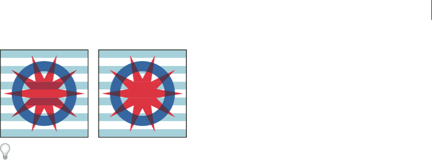
218
Painting
Last updated 6/5/2015
To select all objects that use the same blending mode, select an object with that blending mode, or deselect everything
and choose the blending mode in the Transparency panel. Then choose Select > Same > Blending Mode.
For a video on working with blending modes, see www.adobe.com/go/vid0055.
More Help topics
Targeting items for appearance attributes
Printing and saving transparent artwork
Appearance panel overview
Gradients
Use gradient fills to apply a graduated blend of colors as you would apply any other color. Creating a gradient fill is a
good way to create a smooth color gradation across one or more objects. You can save a gradient as a swatch to make
it easy to apply the gradient to multiple objects.
Note: if you want to create a single, multicolored object on which colors can flow in different directions use a mesh object.
For a video on using gradients to enhance your drawings, see www.adobe.com/go/lrvid4017_ai.
To see examples of using gradients, see www.adobe.com/go/learn_ai_tutorials_gradients_en and
www.adobe.com/go/learn_ai_tutorials_elliptical_gradients_en and www.adobe.com/go/learn_ai_tutorials_depth_en.
To see an example of using gradients and blending modes, see the tutorial at
www.adobe.com/go/learn_ai_tutorials_blendingmode_en.
More Help topics
Gradients tutorial
Blending objects
Blend colors
Meshes
Printing gradients, meshes, and color blends
Gradient panel and Gradient tool overview
You can use the Gradient panel (Window > Gradient) or the Gradient tool to apply, create, and modify gradients.
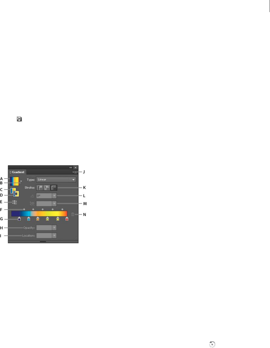
219
Painting
Last updated 6/5/2015
Gradient colors are defined by a series of stops along the gradient slider. A stop marks the point at which a gradient
changes from one color to the next, and is identified by a square below the gradient slider. The squares display the color
currently assigned to each gradient stop. With a radial gradient, the leftmost gradient stop defines the center point’s
color fill, which radiates outward to the color of the rightmost gradient stop.
Using the options in the Gradient panel or with the Gradient tool, you can specify the number and location of stops,
angle in which the colors display, aspect ratio of an elliptical gradient, and the opacity of each color.
Gradient panel
In the Gradient panel, the Gradient Fill box displays the current gradient colors and gradient type. When you click the
Gradient Fill box, the selected object is filled with the gradient. Directly to the right of this box is the Gradient menu
that lists all the default and presaved gradients from which you can choose. At the bottom of the list is a Save Gradient
button that you can click to save the current gradient settings as a swatch.
By default, the panel includes a start and end color box, but you can add more color boxes by clicking anywhere along
the gradient slider. Double-clicking a gradient stop opens the gradient stop color panel where you can choose a color
from the Color panel or Swatches panel.
It’s helpful to show all options when working with the panel (choose Show Options from the panel menu).
A Gradient Fill box B Gradient menu C Fill Gradient D Stroke Gradient E Reverse Gradient F Midpoints G Color Stop H Opacity I Location
J Panel Menu K Stroke Gradient Type L Angle M Aspect Ratio N Delete Stop
Gradient tool
You use the Gradient tool to add or edit gradients. When you click the Gradient tool in an unselected, nongradient filled
object it fills the object with the last used gradient. The Gradient tool also provides most of the same features as the
Gradient panel. When you select a gradient filled object and select the Gradient tool, a gradient annotator appears in
the object. You can use the gradient annotator to modify the angle, location, and spread of a linear gradient or the focal
point, origin, and spread of a radial gradient. If you position the tool directly over the gradient annotator, it becomes a
slider (same as in the Gradient panel) with gradient stops and location indicators. You can click the gradient annotator
to add new gradient stops, double-click individual gradient stops to specify new colors and opacity settings, or drag
gradient stops to new locations.
When you position the pointer over the gradient annotator and the rotation cursor appears you can drag to
reposition the angle of the gradient. Dragging the circular end of the gradient slider repositions the origin of the
gradient, and dragging the arrow end increases or decreases the range of the gradient.
To hide or show the gradient annotator, choose View > Hide Gradient Annotator or View > Show Gradient Annotator.
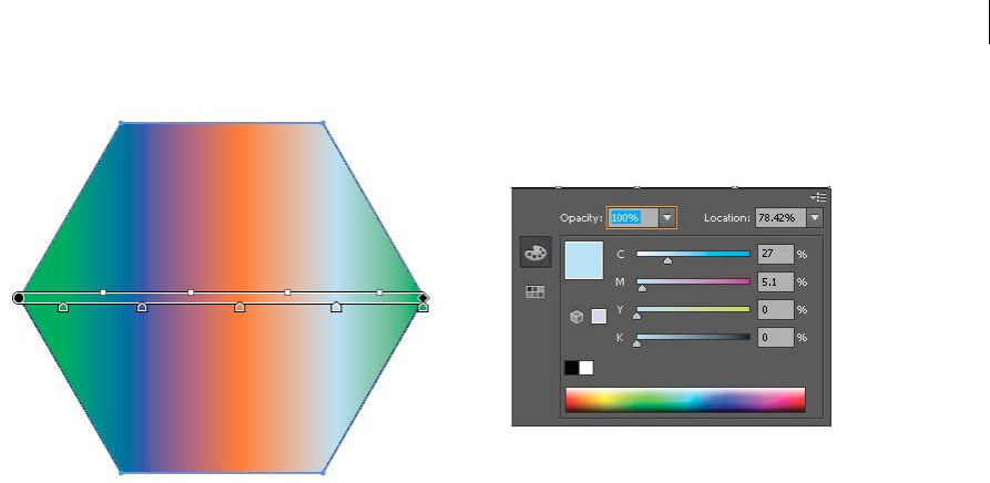
220
Painting
Last updated 6/5/2015
Patterns
About patterns
Illustrator comes with many patterns that you can access in the Swatches panel and in the Illustrator Extras folder on
the Illustrator CD. You can customize existing patterns and design patterns from scratch with any of the Illustrator
tools. Patterns intended for filling objects (fill patterns) differ in design and tiling from patterns intended to be applied
to a path with the Brushes panel (brush patterns). For best results, use fill patterns to fill objects and brush patterns to
outline objects.
When designing patterns, it helps to understand how Adobe Illustrator tiles patterns:
•All patterns tile from left to right from the ruler origin (by default, the bottom left of the artboard) to the opposite
side of the artwork. To adjust where all patterns in your artwork begin tiling, you can change the file’s ruler origin.
note: Ruler origin in CS5 is different from that in CS4. As a result, the appearance of tiling patterns may not match when
you copy-paste objects from CS4 to CS5. For such objects, tiles can be transformed using the Transform panel to match
the CS4 appearance.
•Fill patterns typically have only one tile.
•Brush patterns can consist of up to five tiles—for the sides, outer corners, inner corners, and the beginning and end
of the path. The additional corner tiles enable brush patterns to flow smoothly at corners.
•Fill patterns tile perpendicular to the x axis.
•Brush patterns tile perpendicular to the path (with the top of the pattern tile always facing outward). Also, corner
tiles rotate 90° clockwise each time the path changes direction.
•Fill patterns tile only the artwork within the pattern bounding box—an unfilled and unstroked (non-printing)
rectangle backmost in the artwork. For fill patterns, the bounding box acts as a mask.
•Brush patterns tile artwork within the pattern bounding box and protruding from or grouped with it.

221
Painting
Last updated 6/5/2015
More Help topics
About fills and strokes
Guidelines for constructing pattern tiles
Follow these general guidelines for constructing pattern tiles:
•To make the pattern less complex so that it prints more rapidly, remove any unnecessary detail from the pattern
artwork, and group objects that are painted with the same color so that they are adjacent in the stacking order.
•As you create your pattern tile, zoom in on the artwork to align elements more accurately, and then zoom out from
the artwork for the final selection.
•The more complex the pattern, the smaller should be the selection used to create it; however, the smaller the
selection (and the pattern tile it creates), the more copies are needed to create the pattern. Thus, a 1-inch-square tile
is more efficient than a 1/4-inch-square tile. If you are creating a simple pattern, you can include multiple copies of
the object within the selection intended for the pattern tile.
•To create simple line patterns, layer stroked lines of varying widths and colors, and place an unfilled, unstroked
bounding box behind the lines to create a pattern tile.
•To make an organic or textural pattern appear irregular, vary the tile artwork subtly for a more realistic effect. You
can use the Roughen effect to control variations.
•To ensure smooth tiling, close paths before defining the pattern.
•Enlarge your artwork view and check for flaws before defining a pattern.
•If you draw a bounding box around the artwork, make sure that the box is a rectangle, that it is the backmost object
of the tile, and that it is unfilled and unstroked. To have Illustrator use this bounding box for a brush pattern, make
sure that nothing protrudes from it.
Follow these additional guidelines when creating brush patterns:
•When possible, confine artwork to an unpainted bounding box so that you can control how the pattern tiles.
•Corner tiles must be square and have the same height as side tiles to align properly on the path. If you plan to use
corner tiles with your brush pattern, align objects in the corner tiles horizontally with objects in the side tiles so that
the patterns tile correctly.
•Create special corner effects for brush patterns using corner tiles.
More Help topics
Apply a fill color to an object
Create pattern swatches
1Create artwork for the pattern.
2(Optional) To control the spacing between pattern elements or to clip out portions of the pattern, draw a pattern
bounding box (an unfilled rectangle) around the artwork you want to use as a pattern. Choose Object > Arrange >
Send To Back to make the rectangle the backmost object. To use the rectangle as a bounding box for a brush or fill
pattern, fill and stroke it with None.
3Use the Selection tool to select the artwork and bounding box (if any) that will make up the pattern tile.
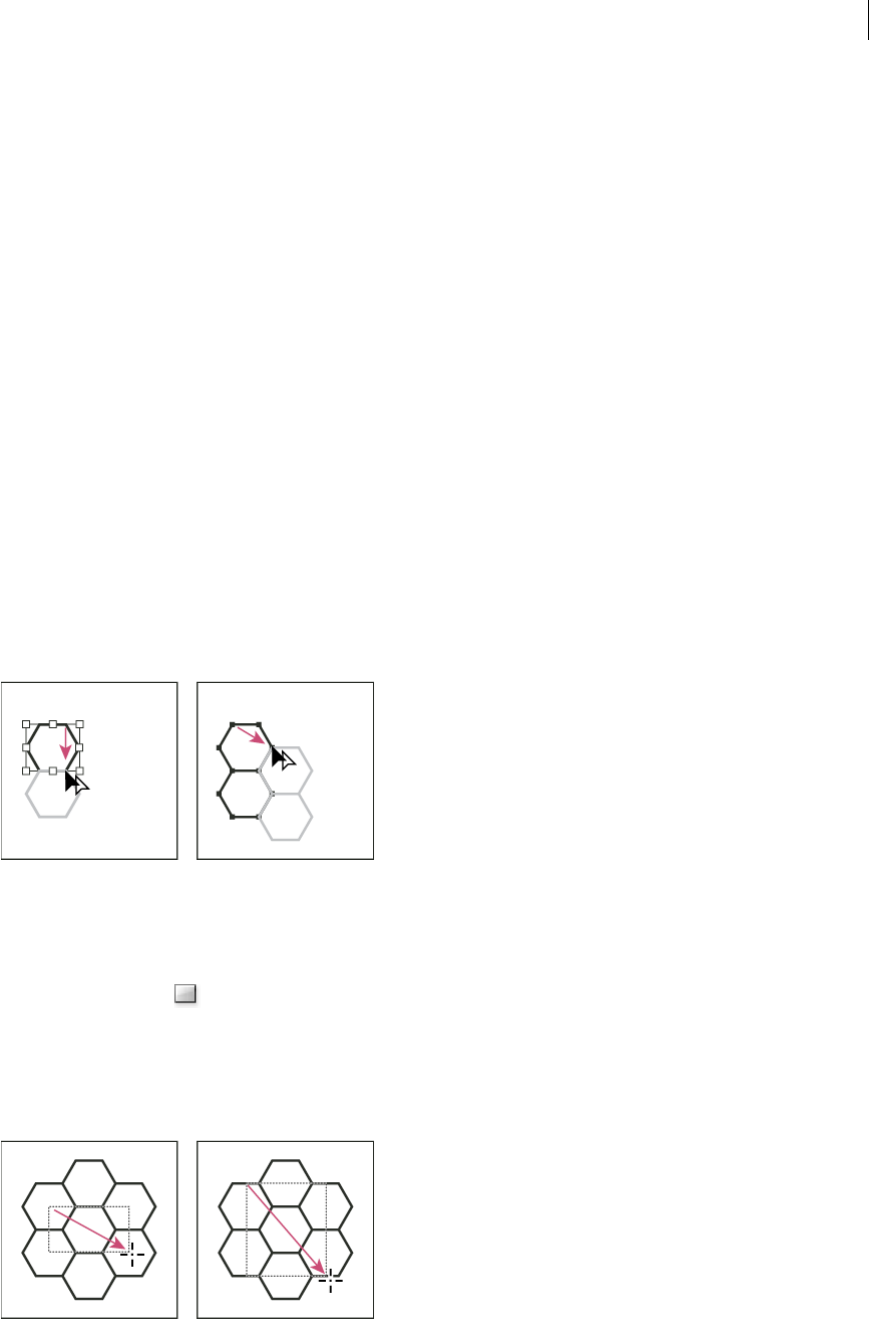
222
Painting
Last updated 6/5/2015
4Do one of the following:
•Choose Edit > Define Pattern, enter a name in the New Swatch dialog box, and click OK. The pattern displays in
the Swatches panel.
•Drag the artwork to the Swatches panel.
More Help topics
Guidelines for constructing pattern tiles
About swatches
Create seamless geometric patterns
1Make sure that Smart Guides are turned on and that Snap To Point is selected in the View menu.
2Select the geometric object. For precise positioning, position the Direct Selection tool on one of the object’s anchor
points.
3Begin dragging the object vertically from one of its anchor points; then press Alt+Shift (Windows) or Option+Shift
(Mac OS) to copy the object and constrain its movement.
4When the copy of the object has snapped into place, release the mouse button and then release the keys.
5Using the Group Selection tool, Shift-click to select both objects, and begin dragging the objects horizontally by one
of their anchor points; then press Alt+Shift (Windows) or Option+Shift (Mac OS) to create a copy and constrain the
move.
6When the copy of the object has snapped into place, release the mouse button, and then release the keys.
7Repeat steps 2 through 6 until you’ve built the pattern you want.
8Use the Rectangle tool to do one of the following:
•For a fill pattern, draw a bounding box from the center point of the upper left object to the center point of the
lower right object.
•For a brush pattern, draw a bounding box that surrounds the objects and coincides with their outer boundaries.
If the pattern is to be a corner tile, hold down Shift as you drag to constrain the bounding box to a square.
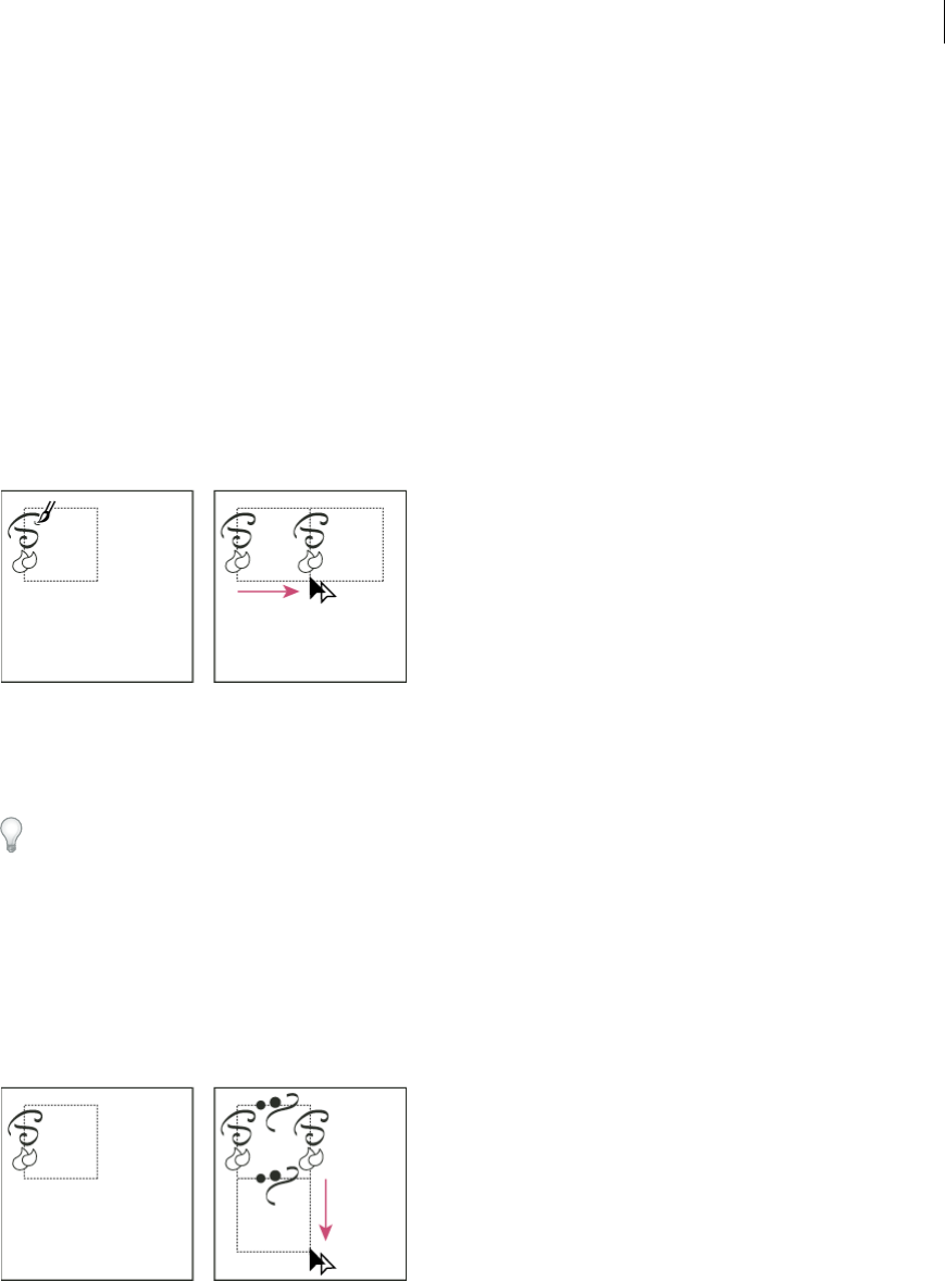
223
Painting
Last updated 6/5/2015
9Paint the geometric objects the desired color.
10 Save the geometric objects as a pattern swatch.
Construct irregularly textured patterns
1Choose View > Snap To Point.
2Draw a bounding box. If you are creating a brush pattern, skip to step 13.
3Draw the texture with the objects or lines that intersect only the left side of the bounding rectangle.
4Using the Direct Selection tool, select the texture and the rectangle, and place the pointer on the lower left corner of
the rectangle.
5Drag the rectangle to the right; then press Alt+Shift (Windows) or Option+Shift (Mac OS) to create a copy and to
constrain the move.
When the upper left corner point of the copy snaps to the upper right corner point of the bounding box, release the
mouse button, and then release the keys.
If you know the exact dimensions of the bounding box, you can select only the textures and use the Move command
to specify a horizontal move the width of the rectangle. Be sure to click Copy instead of OK in the Move dialog box.
6Click outside the rectangle to deselect it.
7Select the right rectangle, and delete it.
8Continue drawing your texture with only the objects or lines that intersect the top side of the rectangle.
9When you finish with the top side only, select all of the lines or objects crossing the top side and the bounding box;
then press Alt+Shift (Windows) or Option+Shift (Mac OS) and drag downward to create a copy and to constrain
the move.
10 When the upper left corner point of the copy snaps to the lower left corner point of the rectangle, release the mouse
button and then the keys.
11 Deselect everything.
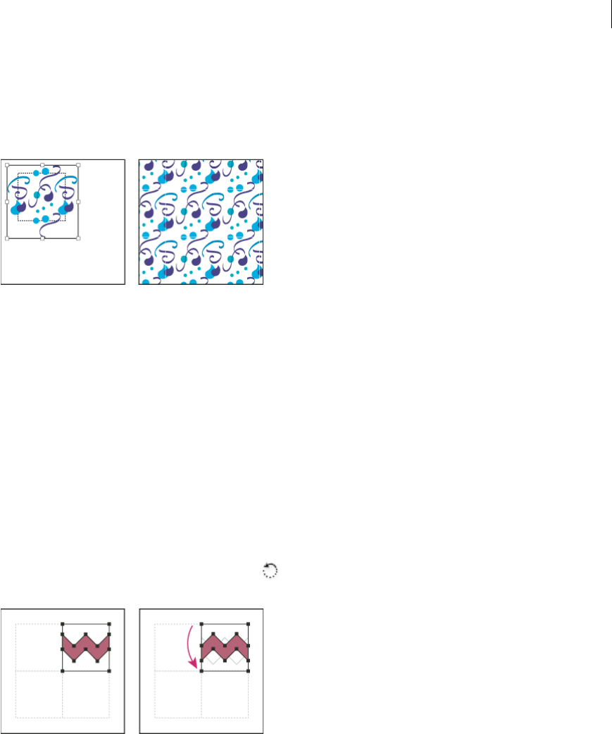
224
Painting
Last updated 6/5/2015
12 Select the lower rectangle and any objects that don’t cross the top rectangle, and delete them.
13 Using the Pencil tool, fill the middle of the rectangle with your texture. Be careful not to intersect any of the rectangle
edges. Paint the texture.
14 Save the artwork and rectangle as a pattern swatch.
Create corner tiles for brush patterns
Corner tiles lend special border effects when applying brush patterns. You can create corner tiles from scratch, or you
can use a brush pattern’s side tile as the basis for designing complementary outer and inner (reflected –135°) corner
tiles.
1Choose File > Open, locate a brush pattern file (supplied with Adobe Illustrator) that you want to use, and click
Open.
2Choose Window > Brushes. Select the tile you want to use, and drag it to the center of your artwork.
3If the tile does not have a square bounding box, create a box that completely encompasses the artwork, the same
height as the side tile. (Side tiles can be rectangular.) Fill and stroke the box with None, and choose Object > Arrange
> Send To Back to make the box backmost in your artwork. (The bounding box helps you align the new tile.)
4Select the tile and the bounding box.
5To create an outer corner tile, use the Rotate tool to rotate the tile and its bounding box 180°. Skip this step to
create an inner corner tile.
6Using the Rotate tool, Alt+Shift-click (Windows) or Option+Shift-click (Mac OS) the lower left corner of the
bounding box. Enter a value of 90°, and click Copy to create a copy flush left of the first tile. This tile becomes the
corner tile.
7Using the Selection tool, drag the left tile down by the top right anchor point, pressing Alt+Shift (Windows) or
Option+Shift (Mac OS) to make a copy and constrain the move so that you create a third tile beneath the second.
When the copy’s upper right anchor point snaps to the corner tile’s lower right anchor point, release the mouse
button and Alt+Shift (Windows) or Option+Shift (Mac OS).
You use the third copy for alignment.
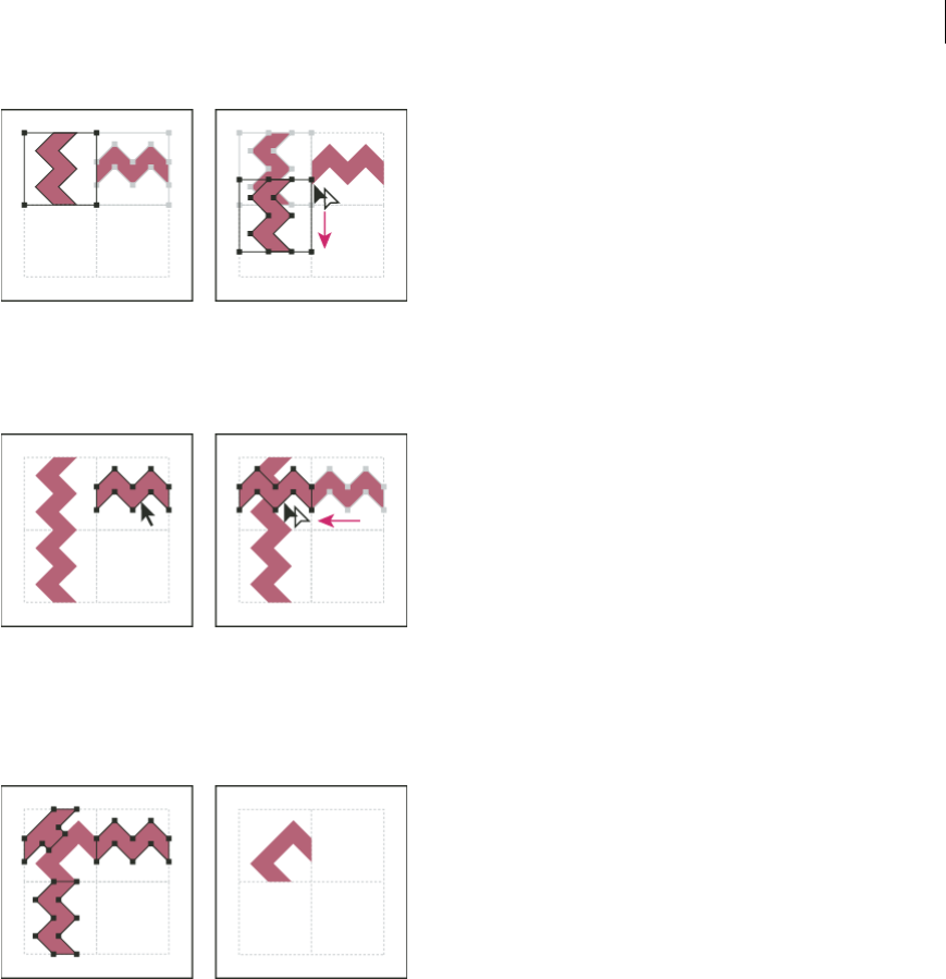
225
Painting
Last updated 6/5/2015
8Select the artwork in the right tile. Drag it to the left, pressing Alt+Shift (Windows) or Option+Shift (Mac OS) so
that the right-tile artwork overlaps that in the corner tile.
9Edit the corner tile so that its artwork lines up vertically and horizontally with the tiles next to it. Select and delete
any portions of the tile that you do not want in the corner, and edit the remaining art to create the final outer corner
tile.
10 Select all of the tile parts including the bounding box.
11 Save the new pattern as a swatch.
12 Double-click the new pattern swatch to bring up the Swatch Options dialog box, name the tile as a variation of the
original (for example, use the suffix “outer”), and click OK.
More Help topics
Create or modify brushes
Brush options
Modify patterns
1Make sure that nothing is selected in your artwork.
2In the Swatches panel, select the pattern swatch you want to modify.

226
Painting
Last updated 6/5/2015
3Drag the pattern swatch onto your artboard, and edit the pattern tile on the artboard.
4Select the pattern tile, and Alt-drag (Windows) or Option-drag (Mac OS) the modified pattern on top of the old
pattern swatch in the Swatches panel.
The pattern is replaced in the Swatches panel and is updated in the current file.
More Help topics
Swatches panel overview
Transform an object’s patterns
Meshes
A mesh object is a multicolored object on which colors can flow in different directions and transition smoothly from
one point to another. When you create a mesh object, multiple lines called mesh lines crisscross the object and provide
a way to easily manipulate color transitions on the object. By moving and editing points on the mesh lines, you can
change the intensity of a color shift, or change the extent of a colored area on the object.
At the intersection of two mesh lines is a special kind of anchor point called a mesh point. Mesh points appear as
diamonds and have all of the same properties as anchor points but with the added capability of accepting color. You can
add and delete mesh points, edit the mesh points, or change the color associated with each mesh point.
Anchor points also appear in the mesh (differentiated by their square rather than diamond shape), and can be added,
deleted, edited, and moved as with any anchor points in Illustrator. Anchor points can be placed on any mesh line; you
can click an anchor point and drag its direction lines to modify it.
The area between any four mesh points is called the mesh patch. You can also change the color of the mesh patch using
the same techniques as changing colors on a mesh point.
A Mesh line B Mesh patch C Mesh point D Anchor point
Create mesh objects
You can create mesh objects from vector objects, with the exception of compound paths and text objects. You cannot
create mesh objects from linked images.
To improve performance and redraw speed, keep the size of mesh objects to a minimum. Complex mesh objects can
greatly reduce performance. Therefore, it is better to create a few small, simple mesh objects than to create a single,
complex mesh object. When converting complex objects, use the Create Mesh command for the best results.
Note: When printing mesh objects, spot colors are preserved for EPS, PDF, and PostScript output.

227
Painting
Last updated 6/5/2015
For more information on creating a gradient mesh object, see the Achieve photo realism with Gradient Mesh tutorial
at www.adobe.com/go/learn_ai_tutorials_gradientmesh_en.
Create a mesh object with an irregular pattern of mesh points
1Select the Mesh tool , and select a fill color for the mesh points.
2Click where you want to position the first mesh point.
The object is converted to a mesh object with the minimum number of mesh lines.
3Continue clicking to add additional mesh points. Shift-click to add a mesh point without changing to the current
fill color.
Create a mesh object with a regular pattern of mesh points
1Select the object and choose Object > Create Gradient Mesh.
2Set the number of rows and columns, and select the direction of the highlight from the Appearance menu:
Flat Applies the object’s original color evenly across the surface, resulting in no highlight.
To Center Creates a highlight in the center of the object.
To Edge Creates a highlight on the edges of the object.
3Enter a percentage of white highlight to apply to the mesh object. A value of 100% applies maximum white highlight
to the object; a value of 0% applies no white highlight to the object.
Convert a gradient-filled object to a mesh object
1Select the object and choose Object > Expand.
2Select Gradient Mesh, and click OK.
The selected object is converted to a mesh object that takes the shape of the gradient, either circular (radial) or
rectangular (linear).
Convert a mesh object back to a path object
❖Select the mesh object, choose Object > Path > Offset Path, and then enter zero for the offset value.
Edit mesh objects
You can edit a mesh object by adding, deleting, and moving mesh points; changing the color of mesh points and mesh
patches; and converting the mesh object back to a regular object.
❖Edit a mesh object by doing any of the following:
•To add a mesh point, select the Mesh tool and select a fill color for the new mesh points. Then click anywhere
in the mesh object.
•To delete a mesh point, Alt-click (Windows) or Option-click (Mac OS) the mesh point with the Mesh tool.
•To move a mesh point, drag it with the Mesh tool or Direct Selection tool. Shift-drag a mesh point with the Mesh
tool to keep the mesh point on a mesh line. This is a convenient way to move a mesh point along a curved mesh
line without distorting the mesh line.
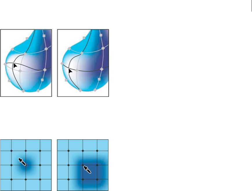
228
Painting
Last updated 6/5/2015
•To change the color of a mesh point or patch, Select the mesh object, and then drag a color from the Color panel
or Swatches panel onto the point or patch. Or, deselect all objects and select a fill color. Then select the mesh
object and use the Eyedropper tool to apply the fill color to mesh points or patches.
Set transparency for gradient meshes
You can set transparency and opacity values within gradient meshes. Transparency and opacity values can be assigned
to individual mesh nodes. To assign transparency values:
1Select one or more mesh nodes or patches.
2Set the opacity from the Opacity slider in Transparency Panel, Control Panel, or the Appearance panel.
Note: If you save the object to legacy format or EPS or PDF, the transparency on the mesh object is retained by creating
an opacity mask.
More Help topics
Gradient mesh
Apply a gradient to an object
Stroke an object
You use the Stroke panel (Window > Stroke) to specify whether a line is solid or dashed, the dash sequence and other
dash adjustments if it is dashed, the stroke weight, the stroke alignment, the miter limit, arrowheads, width profiles,
and the styles of line joins and line caps.
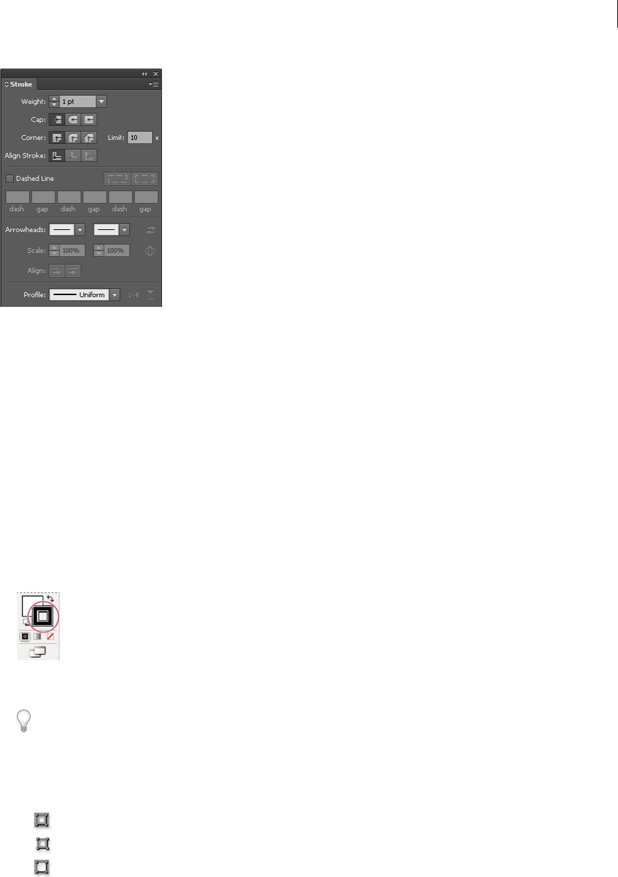
229
Painting
Last updated 6/5/2015
You can apply stroke options to an entire object, or you can use Live Paint groups and apply different strokes to different
edges within the object.
Layers Magazine instructor Dave Cross shows you how to apply fill and stroke in Illustrator and some handy shortcuts
to work with fill and stroke in this video.
More Help topics
Live Paint groups
Workspace basics
Apply a stroke color, width, or alignment
1Select the object. (To select an edge in a Live Paint group, use the Live Paint Selection tool.)
2Click the Stroke box in the Tools panel, the Color panel, or the Control panel. Doing so indicates that you want to
apply a stroke rather than a fill.
3Select a color from the Color panel, or a swatch from the Swatches panel or Control panel. Alternatively, double-
click the Stroke box to select a color using the Color Picker.
If you want to use the current color in the Stroke box, you can simply drag the color from the Stroke box onto the
object. Dragging does not work on Live Paint groups.
4Select a weight in the Strokes panel or Control panel.
5If the object is a closed path (and not a Live Paint group), choose an option from the Stroke panel to align the stroke
along the path:
• Align Stroke To Center
•Align Stroke To Inside
•Align Stroke To Outside
Note: If you try to align paths that use different stroke alignments, the paths may not exactly align. Make sure the path
alignment settings are the same if you need the edges to match up exactly when aligned.
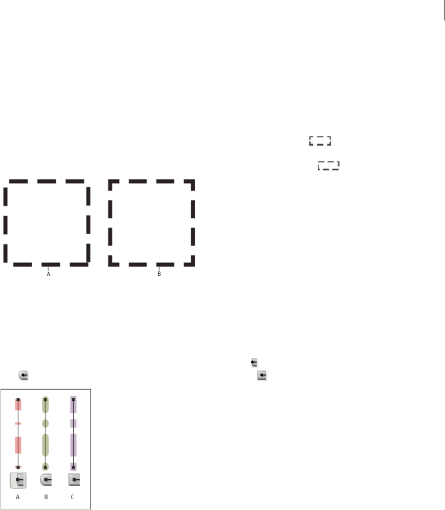
230
Painting
Last updated 6/5/2015
Create dotted or dashed lines
You can create a dotted or dashed line by editing an object’s stroke attributes.
1Select the object.
2In the Stroke panel, select Dashed Line. If the Dashed Line option isn’t showing, choose Show Options from the
Stroke panel menu.
3Click the icon: Align Dashes to Corners and Path Ends, Adjusting Length to Fit . This option allows you to
make the dashes at the corners and ends of the paths consistent and predictable. If you need to retain the appearance
of the dashes without aligning then select the Preserve exact dash and gap lengths icon.
A Preserved exact dash and gap lengths B Aligned dashes to corners and path ends, adjusting lengths to fit
4Specify a dash sequence by entering the lengths of dashes and the gaps between them.
The numbers entered are repeated in sequence so that once you have established the pattern, you don’t need to fill
in all the text boxes.
5Select a cap option to change the ends of the dashes. The Butt Cap option creates square-ended dashes; the Round
Cap option creates rounded dashes or dots; the Projecting Cap option extends the ends of dashes.
A Butt cap B Round cap C Projecting cap
For a video on creating perfectly dashed strokes, see www.adobe.com/go/lrvid5213_ai_en.
Change the caps or joins of a line
A cap is the end of an open line; a join is where a straight line changes direction (turns a corner). You can change the
caps and joins of a line by changing the object’s stroke attributes.
1Select the object.
2In the Stroke panel, select a cap option and a join option.
If the options aren’t showing, choose Show Options from the panel menu.
Butt Cap Creates stroked lines with squared ends.
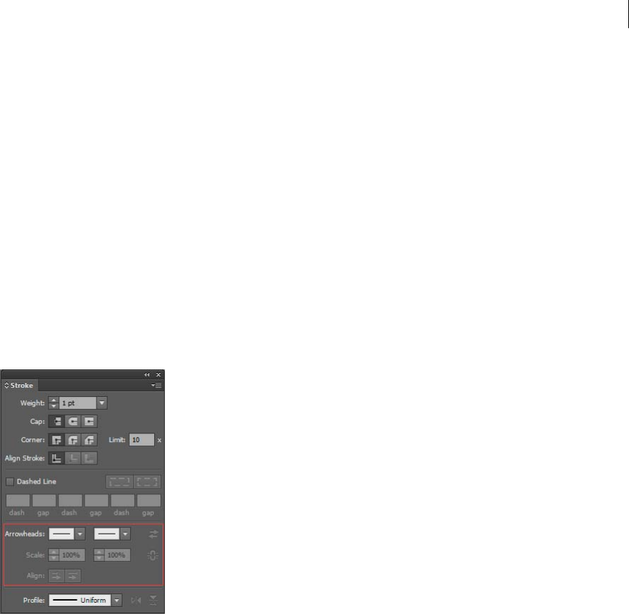
231
Painting
Last updated 6/5/2015
Round Cap Creates stroked lines with semicircular ends.
Projecting Cap Creates stroked lines with squared ends that extend half the line width beyond the end of the line.
This option makes the weight of the line extend equally in all directions around the line.
Miter Join Creates stroked lines with pointed corners. Enter a miter limit between 1 and 500. The miter limit
controls when the program switches from a mitered (pointed) join to a beveled (squared-off) join. The default miter
limit is 10, which means that when the length of the point reaches ten times the stroke weight, the program switches
from a miter join to a bevel join. A miter limit of 1 results in a bevel join.
Round Join Creates stroked lines with rounded corners.
Bevel Join Creates stroked lines with squared corners.
Add arrowheads
In Illustrator CS5, you can access arrowheads from the Stroke panel and associate controls to adjust size. Default
arrowheads are available from the Arrowheads drop-down list in the Stroke panel. Using the Stroke panel, you can also
easily swap arrowheads.
You can resize the tip and end of the arrowheads in
dependently, using Scale option. If you want to link the start and end of the arrowheads scale, click the Link Start and
End of Arrowheads Scales icon, adjacent to the Scale option.
You can also adjust the path to align to the tip or the end of the arrowhead, using the Align options. The options are:
•Extend arrow tip beyond end of path
•Place arrow tip at the end of path
note: To remove arrowheads from objects, choose the None arrowhead option from the drop-down list.
Customize arrowheads
To define custom arrowheads, open the Arrowheads.ai file, which is located under
ShowPackageContent\Required\Resources\<locale>\ (for Mac) and \Support Files\Required\Resources\<locale>\ (for
Windows). Follow the instructions in the file to create custom arrowheads.
Place the updated Arrowheads.ai file at: <Illustrator home>\Plug-ins\ and avoid replacing the existing Arrowheads.ai
file.

232
Painting
Last updated 6/5/2015
Create and edit patterns
This article describes the pattern creation and editing workflows available in Adobe Illustrator CS6 and later. For
information on working with patterns in an earlier version of Illustrator, see Patterns.
Create or edit a pattern
1Do one of the following:
•To create a pattern, select the artwork that you would like to create the pattern from, and then choose Object >
Pattern > Make.
•To edit an existing pattern, double-click the pattern in the pattern swatch, or select an object containing the
pattern and choose Object > Pattern > Edit Pattern..
2(Optional) In the Pattern Options dialog, provide a new name for the pattern, or modify the existing name.
3Modify the other options available in the Pattern Options dialog:
Tile Type Choose how the tiles must be laid out.
•Grid. The center of each tile is horizontally and vertically aligned to the center of the adjacent tiles.
•Brick by row. Tiles are rectangular in shape, and arranged in rows. Centers of tiles in rows are horizontally
aligned. Centers of tiles in alternate columns are vertically aligned.
•Brick by column. Tiles are rectangular in shape, and arranged in columns. Centers of tiles in columns are
vertically aligned. Centers of tiles in alternate columns are horizontally aligned.
•Hex by column. Tiles are hexagonal in shape, and arranged in columns. Centers of tiles in the columns are
vertically aligned. Centers of tiles in alternate columns are horizontally aligned.

233
Painting
Last updated 6/5/2015
•Hex by row. Tiles are hexagonal in shape, and arranged in rows. Centers of tiles in the rows are horizontally
aligned. Centers of tiles in alternate rows are vertically aligned.
Brick Offset Applies to:
•Brick by Row. Determines by how much tile width the centers of tiles in adjacent rows are out of vertical
alignment.
•Brick by Column. Determines by how much tile height the centers of tiles in adjacent columns are out of
horizontal alignment.
Width / Height Specifies the overall height and width of the tile. You can choose various values, smaller, or larger
than the height and width of the artwork. Values larger than the size of the artwork cause the tile to grow larger than
the artwork, and insert empty space between tiles. Values smaller than the size of the artwork cause artwork in
adjacent tiles to overlap.
Size Tile to Art Choosing this option causes the size of the tile to shrink to the size of the artwork being used to
create the pattern.
Move Tile with Art Choosing this option ensures that moving the artwork causes the tile to move as well.
H Spacing / V Spacing Places space between adjacent tiles.
Overlap When adjacent tiles overlap, determines which tile's appears in front.
Copies Determines how many rows and columns of tiles are visible while modifying the pattern.
Dim Copies to Determines the opacity of copies of the artwork tile previewed while modifying the pattern.
Show Tile Edge Displays a box around the tile.
Show Swatch Bounds Displays a unit portion of the pattern which is repeated to create the pattern.
4In the bar below the Control Panel, choose to save or discard changes to the pattern.
Note: If a new pattern was created, it is stored in the Swatches panel. If a pattern was edited, the definition of the pattern
is updated in the Swatches panel.
Apply or edit a gradient
After you apply a gradient to an object, you can quickly and easily replace or edit the gradient.
Apply a gradient to an object
❖Select an object and do one of the following:
•To apply the last used gradient, click the Gradient box in the Tools panel or the Gradient Fill box in the
Gradient panel.
•To apply the last used gradient to an unselected object that currently does not contain a gradient, click the object
with the Gradient tool .
•To apply a preset or previously saved gradient, choose a gradient from the Gradient menu in the Gradient panel
or click a gradient swatch in the Swatches panel.
Tip: To display only gradients in the Swatches panel, click the Show Swatch Kinds button and choose Show
Gradient Swatches.

234
Painting
Last updated 6/5/2015
Create an elliptical gradient
You can create linear, radial, or elliptical gradients. When you change the aspect ratio for a radial gradient, it becomes
an elliptical gradient for which you can also change the angle and make it tilt.
1In the Gradient panel, choose Radial from the Type menu.
2Specify an Aspect Ratio value other than 100%.
3To tilt the ellipse, specify an Angle value other than 0.
Modify the colors in a gradient
1Do one of the following:
•To modify a gradient without filling an object with it, deselect all objects and double-click the Gradient tool or
click the gradient box at the bottom of the Tools panel.
•To modify an object’s gradient, select the object, and open the Gradient panel.
•To modify a preset gradient, select a gradient from the Gradient menu in the Gradient panel. Or, click a gradient
swatch in the Swatches panel, and then open the Gradient panel.
2To change the color of a stop, do any of the following:
•Double-click a gradient stop (in either the Gradient panel or the selected object), and specify a new color in the
panel that appears. You can change the panel that appears by clicking the Color or Swatches icon along the left.
Click outside the panel to accept the selection.
•Drag a color from the Color panel or the Swatches panel onto the gradient stop.
Note: If you create a gradient between spot colors, you must deselect Convert To Process in the Separation Setup dialog
box to print the gradient in individual spot color separations.
3To add intermediate colors to a gradient, drag a color from the Swatches panel or the Color panel onto the gradient
slider in the Gradient panel. Or, click anywhere below the gradient slider, and then select a color as you would for
the starting or ending color.
4To delete an intermediate color, drag the square off the gradient slider or select it and click the Delete button in
the Gradient panel.
5To adjust the location of colors in the gradient, do any of the following:
•To adjust the midpoints of the gradient’s color stops (the point at which two color stops are 50%), drag a diamond
icon located above the slider or select the icon and enter a value from 0 through 100 in the Location box.
•To adjust the endpoints of the gradient’s color stops, drag the leftmost or rightmost gradient stop below the
gradient slider.
•To reverse the colors in the gradient, click Reverse Gradient in the Gradient panel.
6To change the opacity of a gradient color, click a color stop in the Gradient panel, and specify a value in the Opacity
box. When a gradient stop has an Opacity value less than 100%, the stop appears with a , and the color appears
checkered in the gradient slider.
7Click the New Swatch button in the Swatches panel to save the new or modified gradient as a swatch. Or, drag the
gradient from the Gradient panel or Tools panel to the Swatches panel.
Apply a gradient across multiple objects
1Fill all the objects with a gradient.
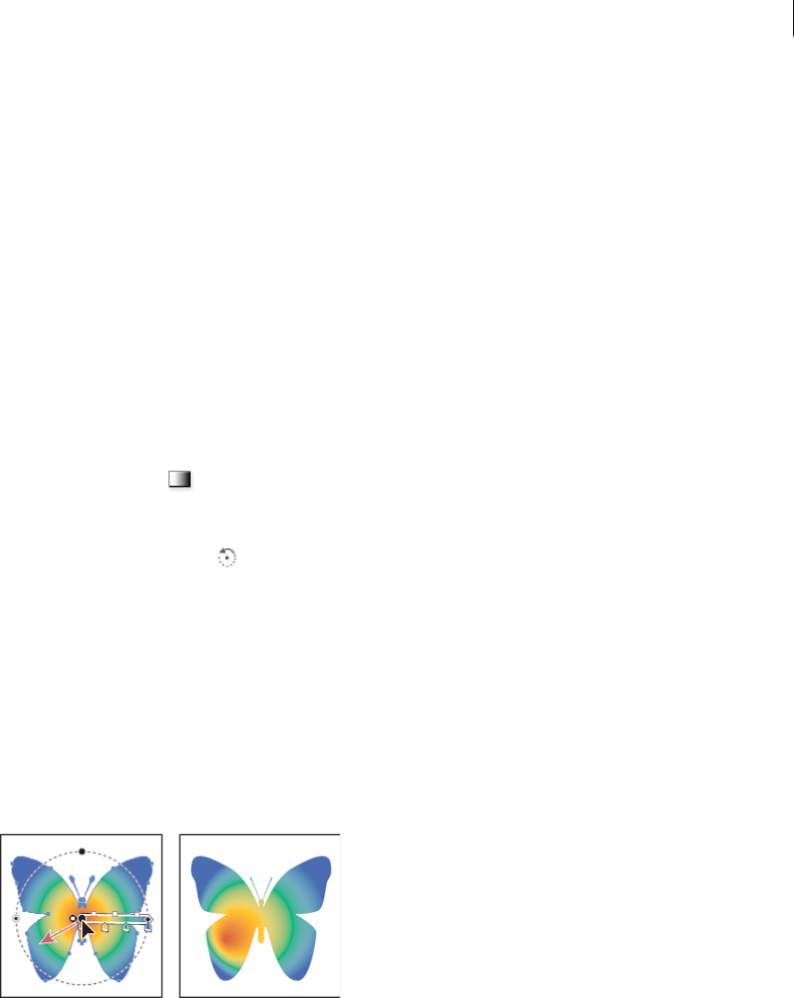
235
Painting
Last updated 6/5/2015
2Select all of the objects that you want filled.
3Using the Gradient tool, do one of the following:
•To create a gradient with one gradient slider, click in the artboard where you want the gradient to start, and drag
to where you want the gradient to end.
•To create a gradient with a gradient slider for every selected object, click in the artboard where you want the
gradient to start, and Alt-drag (Windows) or Option-drag (Mac OS) to where you want the gradient to end. You
can then adjust the different gradient sliders for the different objects. (Multiple gradient sliders are only created
for simple paths.)
Change gradient direction, radius, or origin
Once you have filled an object with a gradient, you can use the Gradient tool and the gradient annotator (slider) inside
the object to modify the gradient by drawing a new fill path. This tool lets you change the direction of a gradient, the
origin, and the beginning point and endpoint of a gradient.
1 Select the gradient-filled object.
2Select the Gradient tool and do any of the following:
•To change the direction of a linear gradient, click where you want the gradient to start and drag in the direction
you want it to appear. Or, position the Gradient tool on the gradient annotator in the object, and when the cursor
changes to the rotation icon , drag to set the angle of the gradient.
note: You can also change the direction by setting a new value in the Angle box in the Gradient panel.
•To change the radius of a radial or elliptical gradient, position the Gradient tool on the arrow of gradient
annotator in the object and drag to set the radius.
•To change the origin of the gradient, position the Gradient tool on the beginning of the gradient annotator in the
object and drag it to the desired location.
•To change the radius and angle at the same time, Alt-click (Windows) or Option-click (Mac OS) the end point,
and drag to the new location.
note: If the gradient annotator (gradient slider) does not appear when you position the Gradient tool in an object
that has a gradient, choose View > Show Gradient Annotator.
Images in brushes | Illustrator CC
In Illustrator CC, Brush definitions can now contain or hold images (non-vector artwork). Users can now define
Scatter, Art, and Pattern brushes using images. Any image that is embedded in an Illustrator file can be used as the
definition of a Brush.

236
Painting
Last updated 6/5/2015
The types of Brushes that support images are Scatter, Art, and Pattern. Drag an image into the Brushes panel (F5), and
then select either of the Scatter, Art, or Pattern type, to create a Brush. For more information on creating a brush, see
Create or modify brushes.
Images in a brush take the shape of the stroke, that is, the images can bend, scale, and stretch with the shape and type
of stroke. Also, such brushes behave and can be modified in the same way as other brushes, using the Brush Options
dialog.
Note: Using large images in brushes impacts performance. When you choose such an image, Illustrator prompts you to
allow it to rerasterize the image to a lower resolution, before proceeding to create the brush.
For example, the leftmost image (below) is the original image. When used in a brush definition, the three images on
the right could be drawn. Each stroke uses different scale options, specified the Brush Options dialog:
A Original image B Image in a brush, stretched to fit stroke length C Image in a brush, scaled proportionately D Image in a brush, stretched
between guides
Considerations
There are some considerations for the type of images that you can use for Illustrator images:
•Using large images in a brush impacts performance and speed negatively.
•Bitmap images cannot be used directly.
•If you are using one bitmap image, Illustrator first rasterizes the bitmap image to grayscale, before using it in a
brush.
•If there is a bitmap image among multiple images used to create a brush, Illustrator prompts you to convert to
the bitmap image to grayscale mode. You can attempt to create the brush again, thereafter.
For more information, see Brushes.

237
Last updated 6/5/2015
Chapter 6: Selecting and arranging objects
Selecting objects
To organize and lay out your artwork, you use tools for selecting, positioning, and stacking objects precisely. You can
measure and align objects; group objects so that they are treated as a single unit; and selectively isolate, lock, or hide
objects.
Selection options and preferences
Options for selecting objects
Before you can modify an object, you need to distinguish it from the objects around it. You do that by selecting the
object. Once you’ve selected an object, or a part of an object, you can edit it.
Illustrator provides the following selection methods and tools:
Isolation mode Lets you quickly isolate a layer, sublayer, path, or group of objects, from all other art in your document.
When in isolation mode, all nonisolated objects in the document appear dimmed and are not selectable or editable.
Layers panel Lets you quickly and precisely select individual or multiple objects. You can select a single object (even if
it’s in a group), all objects within a layer, and entire groups.
Selection tool Lets you select objects and groups by clicking or dragging over them. You can also select groups
within groups and objects within groups.
Direct Selection tool Lets you select individual anchor points or path segments by clicking on them, or select an
entire path or group by selecting any other spot on the item. You can also select one or more objects in a group of
objects.
note: When in outline mode, the Direct Selection tool may select imported graphics that are near the tool’s pointer. To avoid
selecting unwanted graphics, lock or hide the graphics before making the selection.
Group Selection tool Lets you select an object within a group, a single group within multiple groups, or a set of
groups within the artwork. Each additional click adds all objects from the next group in the hierarchy.
Perspective Selection tool Lets you bring objects and text in perspective, switch active planes, move objects in
perspective, and move objects in perpendicular direction.
Lasso tool Lets you select objects, anchor points, or path segments by dragging around all or part of the object.
Magic Wand tool Lets you select objects of the same color, stroke weight, stroke color, opacity, or blending mode
by clicking the object.
Live Paint Selection tool Lets you select faces (areas enclosed by paths) and edges (portions of paths between
intersections) of Live Paint groups.

238
Selecting and arranging objects
Last updated 6/5/2015
Selection commands (located in the Select menu) Let you quickly select or deselect all objects, and select objects based
on their position relative to other objects. You can select all objects of a specific type or that share specific attributes,
and save or load selections. You can also select all objects in the active artboard.
To temporarily activate the last-used selection tool (Selection tool, Direct-Selection tool, or Group Selection tool) when
using another type of tool, hold down Ctrl (Windows) or Command (Mac OS).
For a video on selecting and manipulating objects, see www.adobe.com/go/vid0034.
More Help topics
Editing paths
Specify selection preferences
Selecting paths and points in complex images can be challenging. Using the Selection and Anchor Display preferences,
you can specify the tolerance for pixel selection and choose other options that can make selection easier for a particular
document.
1Choose Edit > Preferences > Selection & Anchor Display (Windows) or Illustrator > Preferences > Selection &
Anchor Display (Mac OS).
2Specify any of the following Selection options:
Tolerance Specifies the pixel range for selecting anchor points. Higher values increase the width of the area around
an anchor point that you can click to select it.
Object Selection By Path Only Specifies whether you can select a filled object by clicking anywhere in the object or
whether you have to click a path.
Snap To Point Snaps objects to anchor points and guides. Specify the distance between the object and anchor point
or guide when the snap occurs.
More Help topics
Specify anchor point size preferences
Isolate artwork for editing
Isolation mode isolates objects so that you can easily select and edit particular objects or parts of objects. You can isolate
any of the following: layers, sublayers, groups, symbols, clipping masks, compound paths, gradient meshes, and paths.
In Isolation mode, you can delete, replace, and add new art relative to the isolated art. As soon as you exit isolation
mode, replaced or new art is added at the same location as the original isolated art. Isolation mode automatically locks
all other objects so that only the objects in isolation mode are affected by the edits you make— you don’t need to worry
about what layer an object is on, nor do you need to manually lock or hide the objects you don’t want affected by your
edits.
Note: When you edit a symbol’s definition, the symbol appears in isolation mode. (See Edit or redefine a symbol.)
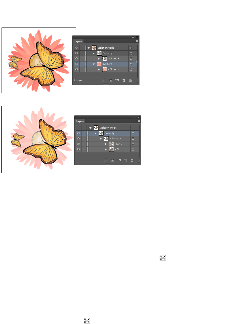
239
Selecting and arranging objects
Last updated 6/5/2015
When isolation mode is active, the isolated object appears in full color, while the rest of the artwork appears dimmed.
The isolated object’s name and location (sometimes referred to as bread crumbs) appears in the isolation mode border,
and the Layers panel displays only the artwork in the isolated sublayer or group. When you exit isolation mode, the
other layers and groups reappear in the Layers panel.
You can view isolated objects in outline mode or preview mode.
For a video on using layers and isolation mode, see www.adobe.com/go/vid0041.
Isolate a path, object, or group
❖Do one of the following:
•Double-click the path or group using the Selection tool.
•Select the group, object, or path and click the Isolate Selected Object button in the Control panel.
•Right-click (Windows) or Control-click (Mac OS) the group and choose Isolate Selected Group.
•Right-click (Windows) or Control-click (Mac OS) the path and choose Isolate Selected Path.
•Select the group, object, or path in the Layers panel and choose Enter Isolation Mode from the Layers panel menu
or click the Isolate Selected Object button in the Control panel.
Isolate a path inside a group
1Select the path by using the Direct-Selection tool or by targeting it in the Layers panel.
2Click the Isolate Selected Object button in the Control panel.
Isolate a layer or sublayer
❖Select the layer or sublayer in the Layers panel, and choose Enter Isolation Mode from the Layers panel menu.

240
Selecting and arranging objects
Last updated 6/5/2015
Exit isolation mode
❖Do one of the following:
•Press Esc.
•Click the Exit Isolation Mode button one or more times (if you’ve isolated a sublayer, one click takes you back
a level, two clicks exits isolation mode).
•Click anywhere in the isolation mode bar.
•Click the Exit Isolation Mode button in the Control panel.
•Using the Selection tool, double-click outside of the isolated group.
•Right-click (Windows) or Control-click (Mac OS) and choose Exit Isolation Mode.
Select behind objects
In Illustrator CS5, you can select objects that lie underneath other objects using Ctrl+click (Windows) or
Command+click (Mac OS). The pointer changes to Select Behind on the first Ctrl+click (Windows) or
Command+click (Mac OS). On subsequent usage of Ctrl+click (Windows) or Command+click (Mac OS), the selection
iterates through the objects directly underneath the pointer position.
Note: To enable or disable this option, click Edit > Preferences > Selection and Anchor Display (Windows) or Illustrator >
Preferences > Selection and Anchor Display (Mac OS). Then select the Control Click to Select Object Behind (Windows) or
Command Click to Select Objects Behind (Mac OS) check box in the Selection area.
Select the next object in the stacking order
You can select an object above or below a selected object in the stacking order. These commands do not work when in
isolation mode.
❖To select the nearest object above or below the selected object, choose Select > Next Object Above or Select > Next
Object Below.
Select objects using the Layers panel
1In the Layers panel, locate the object you want to select. You may have to click a toggle arrow to expand a layer or
group, or scroll up or down in the panel to locate the object.
2Do any of the following:
•To select individual objects, click in the object’s selection column (between the target button and the scroll bar).
Shift-click to add or to remove objects from the selection.
•To select all artwork in a layer or group, click in the layer’s or group’s selection column.
•To select all artwork in a layer based on the currently selected artwork, choose Select > Object > All On Same
Layers.
Selection color boxes appear next to each selected item in the panel.
For a video on working with layers, see www.adobe.com/go/vid0041.
More Help topics
Layers panel overview
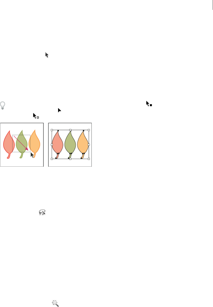
241
Selecting and arranging objects
Last updated 6/5/2015
Select an object with the Selection, Lasso, or Magic Wand tool
Select objects with the Selection tool
1Select the Selection tool .
2Do either of the following:
•Click an object.
•Drag a marquee around part or all of one or more objects.
3To add or remove objects from the selection, hold down Shift and click or drag around the objects you want to add
or remove.
Tip: When the Selection tool is over an unselected object or group, it changes to . When it is over a selected object
or group, the tool changes to . When it is over an anchor point on an unselected object, a hollow square appears
next to the arrow .
For a video on selecting objects, see www.adobe.com/go/vid0034.
More Help topics
Keys for selecting
Select objects with the Lasso tool
1Select the Lasso tool .
2Drag around or across the objects.
Select objects with the Magic Wand tool
Use the Magic Wand tool to select all objects in a document with the same or similar fill attributes (such as color and
pattern).
You can customize the Magic Wand tool to select objects based on stroke weight, stroke color, opacity, or blending
mode. You can also change the tolerances used by the Magic Wand tool to identify similar objects.
More Help topics
Workspace basics
Select objects based on fill color with the Magic Wand tool
1Select the Magic Wand tool .
2Do one of the following:
•To create a new selection, click the object containing the attributes you want to select. All objects with the same
attributes that were clicked are selected.

242
Selecting and arranging objects
Last updated 6/5/2015
•To add to the current selection, press Shift and click another object containing the attributes you want to add. All
objects with the same attributes that were clicked are also selected.
•To subtract from the current selection, press Alt (Windows) or Option (Mac OS) and click the object containing
the attributes you want to subtract. All objects with the same attributes are removed from the selection.
Customize the Magic Wand tool
1Do one of the following to open the Magic Wand panel:
•Double-click the Magic Wand tool in the Tools panel.
•Choose Window > Magic Wand.
2To select objects according to their fill color, select Fill Color, and then enter a Tolerance value between 0 and 255
pixels for RGB or 0 and 100 pixels for CMYK.
Low tolerance values select objects that are very similar to the object you click; higher tolerance values select objects
with a broader range of the selected property.
3Choose Show Stroke Options from the Magic Wand panel menu, and do any of the following:
•To select objects according to their stroke color, select Stroke Color, and then enter a Tolerance value between 0
and 255 pixels for RGB or 0 and 100 pixels for CMYK.
•To select objects according to their stroke weight, select Stroke Weight, and then enter a Tolerance value between
0 and 1000 points.
4Choose Show Transparency Options from the Magic Wand panel menu and do any of the following:
•To select objects according to their transparency or blending mode, select Opacity, and then enter a Tolerance
value between 0 and 100%.
•To select objects according to their blending mode, select Blending Mode.
Select filled objects
The Object Selection By Path Only preference determines whether you can select a filled object by clicking anywhere
within the object’s area with the Selection or Direct Selection tools, or whether you must click a path segment or anchor
point with these tools. By default, this preference is off. In some cases, you may want to turn the preference on—for
example, when you work with overlapping filled objects and you want to easily select underlying objects.
Note: The Object Selection By Path Only preference is not applicable when selecting unfilled objects or when viewing
artwork as outlines. In these cases, you can never select an object by clicking inside the object’s path. (See View artwork as
outlines.)
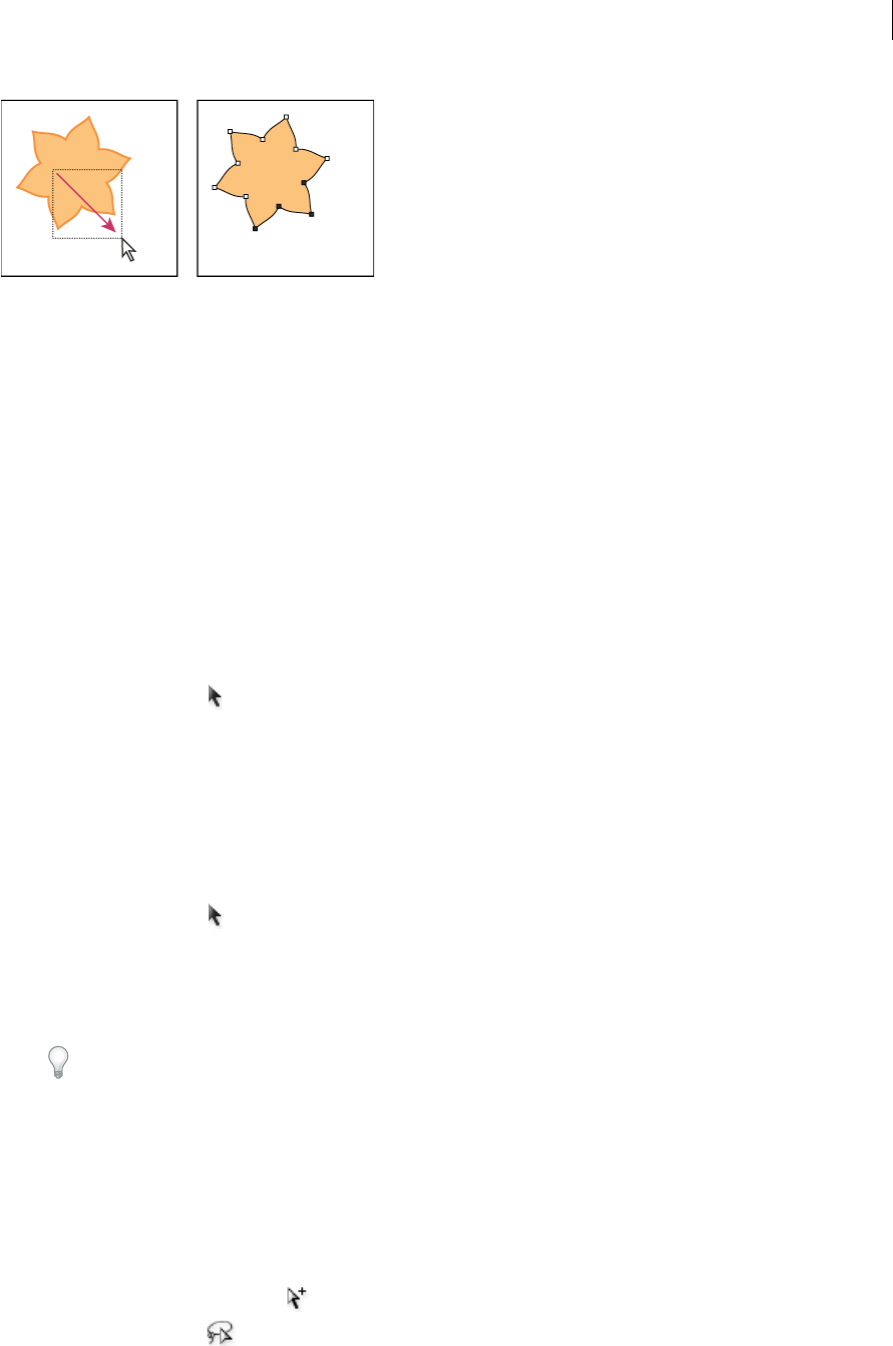
243
Selecting and arranging objects
Last updated 6/5/2015
❖Choose Edit > Preferences > Selection & Anchor Display (Windows) or Illustrator > Preferences > Selection &
Anchor Display (Mac OS), and select Object Selection By Path Only.
Select groups and objects in a group
Once objects are grouped, selecting any part of the group with the Selection tool or the Lasso tool selects the entire
group. If you are unsure whether an object is a part of a group, select it with the Selection tool.
The Direct-Selection tool and Lasso tool let you select a single path or object that is part of one group or several groups.
If you have groups of objects within other groups, you can select the next group in the grouping hierarchy by using the
Group-Selection tool. Each successive click adds another subset of grouped objects to the selection.
More Help topics
Group or ungroup objects
Select one or more groups with the Selection tool
1Select the Selection tool .
2Do one of the following to any object that’s within the group:
•Click the object.
•Drag around part or all of the object.
3To add or remove a group to the selection, hold down Shift while clicking the group to add or remove.
Select objects and groups within groups with the Selection tool
1Select the Selection tool .
2Double-click a group. The group appears in isolation mode.
3Do any of the following:
•Double-click to select further down into the group structure.
Tip: Double-clicking is a handy way to select objects (as opposed to faces and edges) within a Live Paint group.
•Click to select an object within the selected group.
•Draw to add an object to the selected group.
4Double-click outside the group to deselect the group.
Select a single object within a group
1Do one of the following:
•Select the Group Selection tool , and click the object.
•Select the Lasso tool , and drag around or across the object’s path.
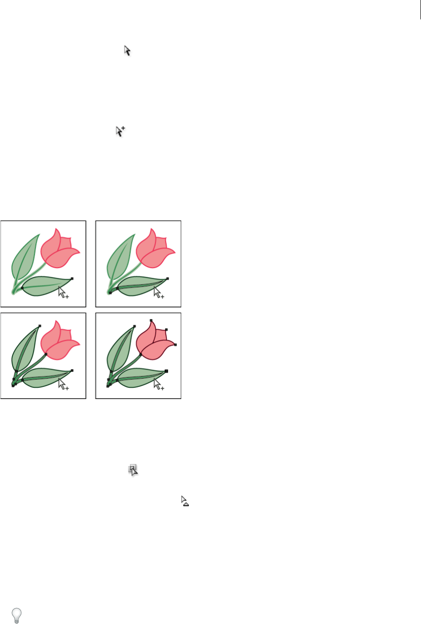
244
Selecting and arranging objects
Last updated 6/5/2015
•Select the Direct Selection tool , and click within the object, or drag a marquee around part or all of the object’s
path.
2To add or remove an object or group to or from the selection (with any selection tool), hold down Shift and select
the object to add or remove.
Select objects and groups with the Group Selection tool
1Select the Group Selection tool , and click an object that’s within the group you want to select. The object is
selected.
2To select the object’s parent group, click the same object again.
3Click the same object again to select additional groups that are grouped with the selected group until you have
selected everything you want to include in your selection.
Select faces and edges in a Live Paint group
You select faces and edges of a Live Paint tool using the Live Paint Selection tool. If you want to select the entire Live
Paint group, simply click it with the Selection tool.
1Select the Live Paint Selection tool .
2Move the tool over the Live Paint group until the face or edge you want to select is highlighted. (When the Live Paint
Selection tool is over an edge, the tool changes to .)
3Do any of the following:
•Click to select the highlighted face or edge.
•Drag a marquee around multiple faces or edges. Any face or edge that is fully or partially enclosed by the marquee
is included in the selection.
•Double-click a face or edge to select all connected faces/edges of the same color (flood select).
•Triple-click a face or edge to select all faces/edges of the same color (select same).
Tip: If you have difficulty selecting a small face or edge, magnify the view or set the Live Paint Selection tool
options to select only fills or strokes.

245
Selecting and arranging objects
Last updated 6/5/2015
4To add or remove faces and edges from the selection, hold down Shift and click the faces/edges you want to add or
remove.
To switch to the Eyedropper tool and sample fills and strokes, Alt-click (Windows) or Option-click (Mac OS) the fill
and stroke you want.
More Help topics
Live Paint groups
Keys for working with Live Paint groups
Live Paint Selection tool options
You access the Live Paint selection tool options by double-clicking the tool in the Tools panel.
Select Fills Selects the faces (the area within edges) of Live Paint groups.
Select Strokes Selects the edges of Live Paint groups.
Highlight Outlines the face or edge the cursor is currently over.
Color Sets the color for the highlight. You can choose a color from the menu or click the paint swatch to specify a
custom color.
Width Specifies how thick to make the selection highlight.
Select objects by characteristic
You can select objects based on various groupings, including by formatting attribute, by layer, or by kind, such as brush
strokes or clipping masks.
1To select all objects in a file, choose Select > All. (To deselect all objects, choose Select > Deselect.)
Note: Using any selection tool, you can also deselect all objects by clicking or dragging at least 2 pixels away from any
object.
2To select all objects with the same attributes, select one with the attribute you want, choose Select > Same, and then
choose an attribute from the list: Blending Mode, Fill & Stroke, Fill Color, Opacity, Stroke Color, Stroke Weight,
Style, Symbol Instance, or Link Block Series.
Link Block Series automatically selects threaded text boxes. You can select one of the text boxes and then use this
command to select all the other text boxes linked to that one. For more information see Threading text between
objects.
You can also use the Magic Wand tool to select all objects with the same color, stroke weight, stroke color, opacity, or
blending mode.
3To select all objects of a certain kind, deselect all artwork, choose Select > Object, and then choose an object type
(Brush Strokes, Clipping Masks, Stray Points, or Text Objects).
Repeat, invert, or save a selection
Repeat or invert a selection
•To repeat the last selection command used, choose Select > Reselect.
•To select all unselected objects, and deselect all selected objects, choose Select > Inverse.

246
Selecting and arranging objects
Last updated 6/5/2015
Save a selection
1Select one or more objects, and choose Select > Save Selection.
2In the Save Selection dialog box, type a name in the Name text box, and click OK.
You can reload a saved selection by choosing the selection name from the bottom of the Select menu. You can also
delete or rename a selection by choosing Select > Edit Selection.
Grouping and expanding objects
Group or ungroup objects
You can combine several objects into a group so that the objects are treated as a single unit. You can then move or
transform a number of objects without affecting their attributes or relative positions. For example, you might group the
objects in a logo design so that you can move and scale the logo as one unit.
Grouped objects are stacked in succession on the same layer of the artwork and behind the frontmost object in the
group; therefore, grouping may change the layering of objects and their stacking order on a given layer. If you select
objects in different layers and then group them, the objects are grouped in the layer of the topmost selected object.
Groups can also be nested—that is, they can be grouped within other objects or groups to form larger groups. Groups
appear as <Group> items in the Layers panel. You can use the Layers panel to move items in and out of groups.
1Select the objects to be grouped or the group to be ungrouped.
2Choose either Object > Group or Object > Ungroup.
More Help topics
Layers panel overview
Expand objects
Expanding objects enables you to divide a single object into multiple objects that make up its appearance. For example,
if you expand a simple object, such as a circle with a solid-color fill and a stroke, the fill and the stroke each become a
discrete object. If you expand more complex artwork, such as an object with a pattern fill, the pattern is divided into all
of the distinct paths that created it.
You typically expand an object when you want to modify the appearance attributes and other properties of specific
elements within it. In addition, expanding objects may be helpful when you want to use an object that is native to
Illustrator (such as a mesh object) in a different application that doesn’t recognize the object.
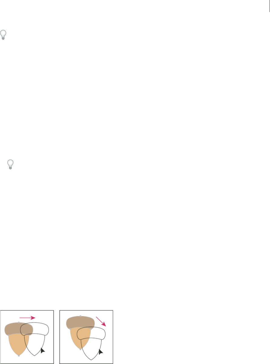
247
Selecting and arranging objects
Last updated 6/5/2015
Expanding is particularly helpful if you are having difficulty printing transparency effects, 3D objects, patterns,
gradients, strokes, blends, flares, envelopes, or symbols.
1Select the object.
2Choose Object > Expand.
If the object has appearance attributes applied to it, the Object > Expand command is dimmed. In this case, choose
Object > Expand Appearance and then choose Object > Expand.
3Set options, and then click OK:
Object Expands complex objects, including live blends, envelopes, symbol sets, and flares.
Fill Expands fills.
Stroke Expands strokes.
Gradient Mesh Expands gradients to a single mesh object.
Specify Sets the tolerance for color values between color stops. Higher numbers help maintain a smooth color
transition; low numbers can create a more banded appearance.
Hold down Alt (Windows) or Option (Mac OS) as you choose Object > Expand to expand a gradient using the
settings last entered in the Expand dialog box.
Moving, aligning, and distributing objects
Move objects
You can move objects by dragging them with specific tools, by using the arrow keys on the keyboard, or by entering
precise values in a panel or dialog box.
You c a n u s e snapping to help you position objects as you move them. For example, you can snap the pointer to guides
and anchor points and snap object boundaries to gridlines. You can also use the Align panel to position objects in
relation to each other.
You can then use the Shift key to constrain the movement of one or more objects so that they move in a precise
horizontal, vertical, or diagonal direction relative to the current orientation of the x and y axes. You can also use the
Shift key to rotate objects in multiples of 45°.
More Help topics
Use the grid
Rotate objects

248
Selecting and arranging objects
Last updated 6/5/2015
Transform panel overview
Drawing pixel-aligned paths for web workflows
Move or duplicate an object by pasting
1Select one or more objects.
2Choose Edit > Cut to move the selection or Edit > Copy to duplicate the selection.
3To paste an object into another file, open the file. (To paste between layers, see Pasting objects between layers.)
4Choose one of the following commands:
Edit > Paste Pastes the object into the center of the active window.
Edit > Paste In Front Pastes the object directly in front of the selected object.
Edit > Paste In Back Pastes the object directly in back of the selected object.
Edit > Paste in Place Pastes artwork on the active artboard at the same position as the artboard from where the
artwork is copied.
Edit > Paste on All Artboards Pastes artwork on all the artboards at the same location where the artwork is on the
current artboard.
Move an object by dragging
1Select one or more objects.
2Drag the object to a new location.
If a selected object is filled, you can drag from anywhere on the object. If a selected object is unfilled, if you are
viewing artwork as outlines, or if the Object Selection By Path Only preference is selected, you must drag from the
object’s path. (See Duplicate selections using drag and drop.)
You can use the Snap To Point command in the View menu to have the cursor snap to an anchor point or guide when
you drag an object within 2 pixels of the anchor point or guide.
Move an object using the arrow keys
1Select one or more objects.
2Press the arrow key for the direction in which you want to move the object. Press Shift+arrow to move the object
ten times the value specified by the Keyboard Increment preference.
The distance the object moves each time you press an arrow key is determined by the Keyboard Increment
preference. The default distance is 1 point (1/72 of an inch, or .3528 millimeter). To change the Keyboard Increment
preference, choose Edit > Preferences > General (Windows) or Illustrator > Preferences > General (Mac OS).
Move an object by a specific distance
1Select one or more objects.
2Choose Object > Transform > Move.
When an object is selected, you can also double-click the Selection, Direct Selection, or Group Selection tool to open
the Move dialog box.
3Do any of the following:
•To move the object left or right, enter either a negative value (moves left) or a positive value (moves right) in the
Horizontal text box.
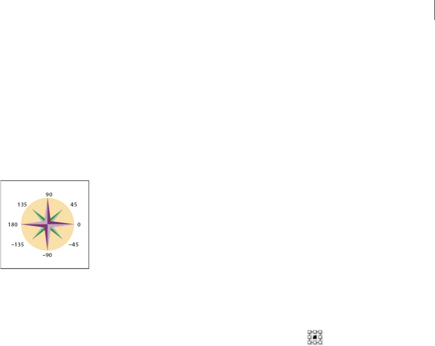
249
Selecting and arranging objects
Last updated 6/5/2015
•To move the object up or down, enter either a negative value (moves down) or positive value (moves up) in the
Ver tical text box.
•To move the object by an angle that’s relative to the object’s x axis, enter either a positive angle (counterclockwise
movement) or a negative angle (clockwise movement) in the Distance or Angle text box. You can also enter
values between 180° and 360°; these values are converted to their corresponding negative values (for example, a
value of 270° is converted to –90°).
4If the objects contain a pattern fill, select Patterns to move the pattern. Deselect Objects if you want to move the
pattern but not the objects.
5Click OK, or click Copy to move a copy of the objects.
Move an object using x and y coordinates
1Select one or more objects.
2In the Transform panel or Control panel, enter new values in either the X or Y text box, or both.
To change the reference point, click a white square on the reference point locator before you enter the values.
Move multiple objects at once
1Select one or more objects.
2Choose Object > Transform > Transform Each.
3Set the distance you want to move the selected objects in the Move section of the dialog box.
4Do one of the following:
•To move the objects by the specified amounts, click OK.
•To move the objects randomly, but no more than the specified amounts, select the Random option. For example,
if you draw a brick wall and want the bricks to appear slightly offset from each other instead of perfectly aligned,
you could select the Random option. Then click OK.
Paste an object relative to other objects
1Select the object you want to paste.
2Choose Edit > Copy or Edit > Cut.
3Select the object in front or in back of which you want to paste.
4Choose Edit > Paste In Front or Edit > Paste In Back.
If you paste more than one object, all pasted objects appear in front or in back of the selected artwork. However, the
relative painting order among the individual pasted objects remains the same.

250
Selecting and arranging objects
Last updated 6/5/2015
Pasting objects between layers
The Paste Remembers Layers option determines where artwork is pasted in the layer hierarchy. By default, Paste
Remembers Layers is off, and artwork is pasted into whichever layer is active in the Layers panel. When Paste
Remembers Layers is on, artwork is pasted into the layer from which it was copied, regardless of which layer is active
in the Layers panel.
You set this option by selecting Paste Remembers Layers from the Layers panel menu. A check mark displays when the
option is on.
Turn on Paste Remembers Layers if you’re pasting artwork between documents and you want to automatically place it
into a layer of the same name as that from which it originated. If the target document does not have a layer of the same
name, Illustrator creates a new layer.
More Help topics
Layers panel overview
Paste in place and paste on all artboards
The Paste in Place command pastes artwork on the active artboard. To use this command, click Edit > Paste in Place.
The keyboard shortcut is Ctrl+Shift+V (Windows) or Cmd+Shift+V (Mac).
The Paste on All Artboards command pastes the selected artwork on all the artboards. Before using the Paste on All
Artboards command, make sure that the artboard from which you are copying the object, is the active artboard.
To use the Paste on All Artboards command, click Edit > Paste on All Artboards when you cut or copy the artwork.
If you copy artwork, and then select Paste on All Artboards, the artwork is repasted on the artboard from where it is
copied. (Recommended) Cut and then paste objects if you do not need to modify the original objects before using the
Paste on All Artboards command.
Note: Paste in Place and Paste on All Artboards commands paste the object at the same position as the copied objects
referenced from the active artboard at the time of copying.
Align and distribute objects
You use the Align panel (Window > Align) and the align options in the Control panel to align or distribute selected
objects along the axis you specify. You can use either the object edges or anchor points as the reference point, and you
can align to a selection, an artboard, or a key object. A key object is one specific object in a selection of multiple objects.
The Align options are visible in the Control panel when an object is selected. If they do not appear, choose Align from
the Control panel menu.
By default, Illustrator calculates alignment and distribution based on the objects’ paths. However, when working with
objects that have different stroke weights, you can use the edge of the stroke to calculate alignment and distribution
instead. To do this, select Use Preview Bounds from the Align panel menu.
For a video on aligning and distributing objects, see www.adobe.com/go/vid0035.
More Help topics
Workspace basics
Using multiple artboards

251
Selecting and arranging objects
Last updated 6/5/2015
Align or distribute relative to the bounding box of all selected objects
1Select the objects to align or distribute.
2In the Align panel or Control panel, select Align To Selection , and then click the button for the type of alignment
or distribution you want.
Align or distribute relative to one anchor point
1Click the Direct-Selection tool, hold down Shift, and select the anchor points you want to align or distribute. The
last anchor point you select becomes the key anchor point.
The Align To Key Anchor option is automatically selected in the Align panel and Control panel.
2In the Align panel or Control panel, click the button for the type of alignment or distribution you want.
Align or distribute relative to a key object
1Select the objects to align or distribute.
2Click again on the object you want to use as a key object (you don’t need to hold down Shift as you click this time).
A blue outline appears around the key object, and Align To Key Object is automatically selected in the Control
panel and Align panel.
3In the Align panel or Control panel, click the button for the type of alignment or distribution you want.
Note: To stop aligning and distributing relative to an object, click again on the object to remove the blue outline, or
choose Cancel Key Object from the Align panel menu.
Align or distribute relative to an artboard
1Select the objects to align or distribute.
2Using the Selection tool, Shift-click in the artboard you want to use to activate it. The active artboard has a darker
outline than the others.
3In the Align panel or Control panel, select Align To Artboard , and then click the button for the type of alignment
or distribution you want.
Distribute objects by specific amounts
You can distribute objects using exact distances between their paths.
1Select the objects to distribute.
2Use the Selection tool to click the path of the object you want the other objects to distribute around. The object
you click will remain fixed in its position.
3In the Align panel, enter the amount of space to appear between objects in the Distribute Spacing text box.
If the Distribute Spacing options aren’t displayed, select Show Options from the panel menu.
4Click either the Vertical Distribute Space button or the Horizontal Distribute Space button.
Rotating and reflecting objects
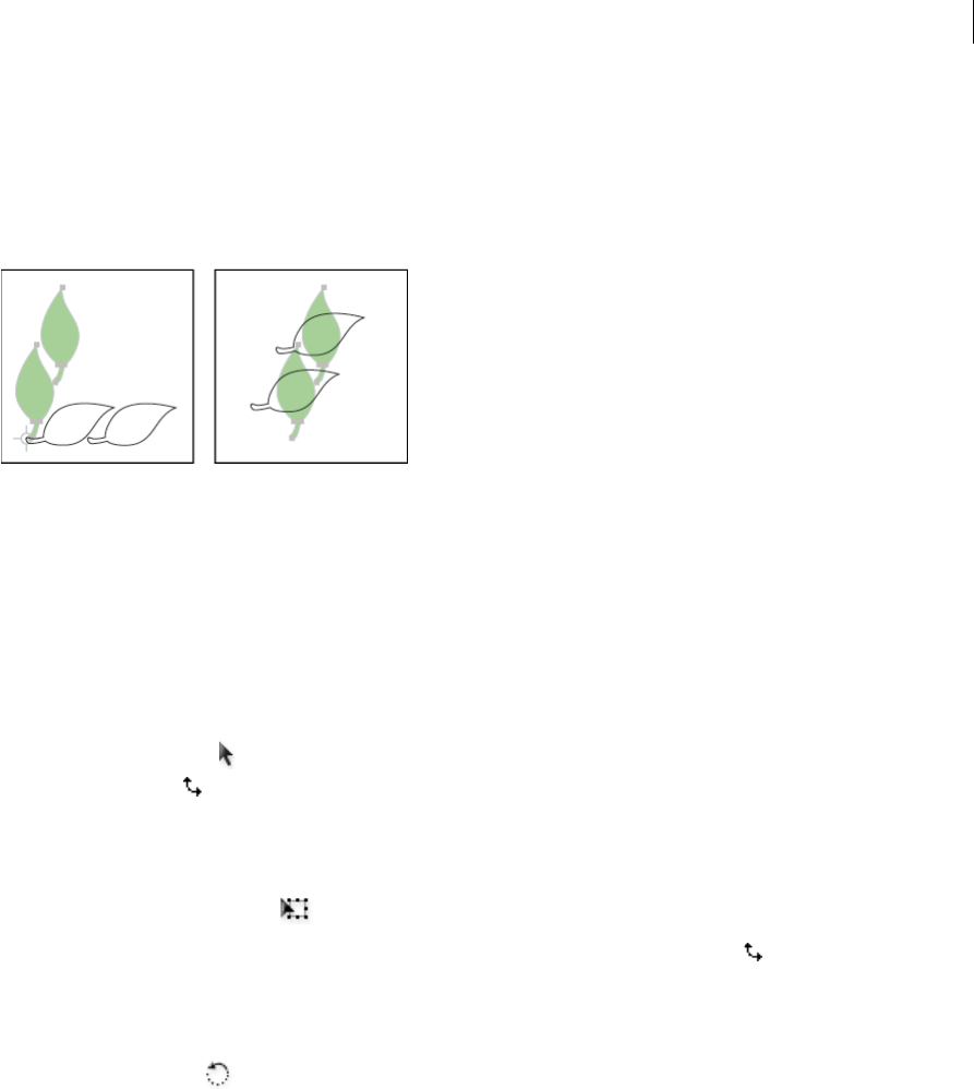
252
Selecting and arranging objects
Last updated 6/5/2015
Rotate objects
Rotating an object turns it around a fixed point that you designate. The default reference point is the object’s center
point. If you have multiple objects in a selection, the objects will rotate around a single reference point, which is the
center point of the selection or bounding box by default. To rotate each object around its own center point, use the
Transform Each command.
More Help topics
Transform panel overview
Move objects
Scale objects
Rotate an object using the bounding box
1Select one or more objects.
2With the Selection tool , move the pointer outside the bounding box and near a bounding box handle so that the
pointer changes to , and then drag.
Rotate an object with the Free Transform tool
1Select one or more objects.
2Select the Free Transform tool .
3Position the pointer anywhere outside the bounding box so that the pointer changes to , and then drag.
Rotate an object with the Rotate tool
1Select one or more objects.
2Select the Rotate tool .
3Do any of the following:
•To rotate the object around its center point, drag in a circular motion anywhere in the document window.
•To rotate the object around a different reference point, click once anywhere in the document window to
reposition the reference point. Then move the pointer away from the reference point and drag in a circular
motion.
•To rotate a copy of the object instead of the object itself, hold down Alt (Windows) or Option (Mac OS) after you
start to drag.
For finer control, drag farther from the object’s reference point.

253
Selecting and arranging objects
Last updated 6/5/2015
Rotate an object by a specific angle
You can control the exact angle of rotation with the Rotate command.
1Select one or more objects.
2Do one of the following:
•To rotate around a different reference point, select the Rotate tool. Then Alt-click (Windows) or Option-click
(Mac OS) where you want the reference point to be in the document window.
•To rotate around the center point, choose Object > Transform > Rotate, or double-click the Rotate tool.
3Enter the rotation angle in the Angle text box. Enter a negative angle to rotate the object clockwise; enter a positive
angle to rotate the object counterclockwise.
4If the objects contain a pattern fill, select Patterns to rotate the pattern. Deselect Objects if you want to rotate the
pattern but not the objects.
5Click OK, or click Copy to scale a copy of the objects.
To place multiple copies of the object in a circular pattern around a reference point, move the reference point away
from the center of the object, click Copy, and then repeatedly choose Object > Transform > Transform Again.
Rotate an object with the Transform panel
1Select one or more objects.
2Do one of the following:
•To rotate the object around its center point, enter a value for the Angle option in the panel.
•To rotate the object around a different reference point, click a white square on the reference point locator in
the panel, and enter a value for the Angle option.
Tip: You can also call up the Transform panel by clicking X, Y, W, or H in the Control panel.
3You can rotate a symbol around its registration point, using the Transform panel. For more information see Symbol
registration point.
Rotate multiple objects individually
1Select the objects to rotate.
2Choose Object > Transform > Transform Each.
3Do either of the following in the Rotate section of the dialog box:
•Click the angle icon or drag the angle line around the icon.
•In the Angle text box, enter an angle between –360° and 360°.
4Click OK, or click Copy to rotate a copy of each object.
Rotate the x and y axes of a document
By default, the x and y axes are parallel to the horizontal and vertical sides of the document window.
1Choose Edit > Preferences > General (Windows) or Illustrator > Preferences > General (Mac OS).
2Specify an angle in the Constrain Angle text box. A positive angle rotates the axes counterclockwise; a negative angle
rotates the axes clockwise.
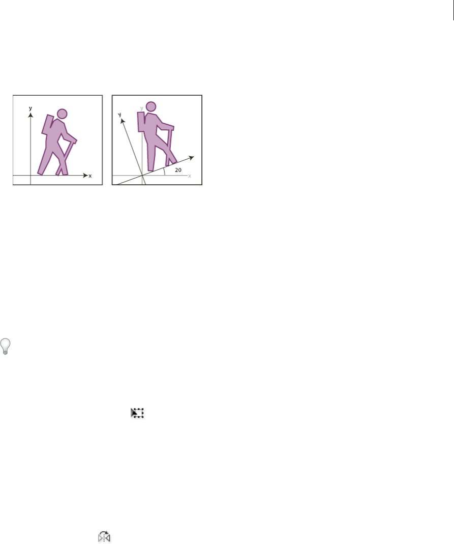
254
Selecting and arranging objects
Last updated 6/5/2015
Rotating the axes is useful if your artwork consists of elements that are rotated to the same angle, such as a logo and
text displayed on a 20° angle. Instead of rotating each element you add to the logo, you can simply rotate the axes by
20°. Everything you draw is created along the new axes.
The following objects and actions are not affected by the new axes:
•Objects that already exist
•Rotating and blending
•Drawing with the Pencil or Live Trace tool
Reflect or flip objects
Reflecting an object flips the object across an invisible axis that you specify. You can reflect objects using the Free
Transform tool, the Reflect tool, or the Reflect command. If you want to specify an axis from which to reflect, use the
Reflect tool.
To create a mirror image of an object, you can copy while reflecting.
Reflect an object with the Free Transform tool
1Select the object to reflect.
2Select the Free Transform tool .
3Do one of the following:
•Drag a handle of the bounding box past the opposite edge or handle until the object is at the desired level of
reflection.
•To maintain the object’s proportions, hold down Shift while dragging a corner handle past the opposite handle.
Reflect an object with the Reflect tool
1Select the object.
2Select the Reflect tool .
3To draw the invisible axis across which you want the object to reflect, click anywhere in the document window to
set one point of the axis. The pointer changes to an arrowhead.
4Position the pointer at another point to define the invisible axis, and do one of the following:
•Click to set the second point of the invisible axis. When you click, the selected object flips over the defined axis.
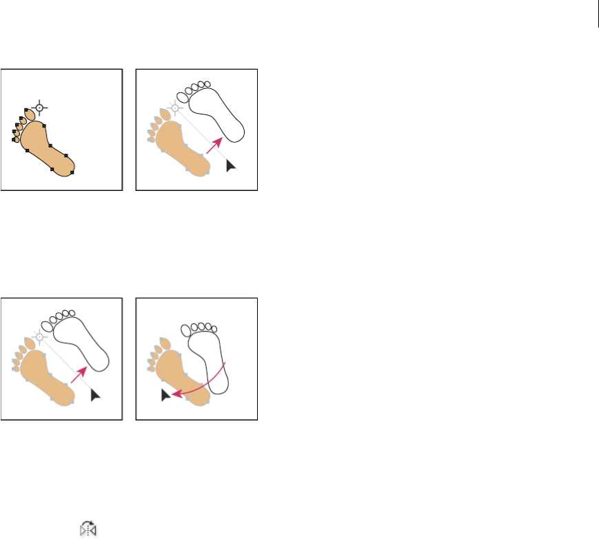
255
Selecting and arranging objects
Last updated 6/5/2015
•To reflect a copy of the object, hold down Alt (Windows) or Option (Mac OS) and click to set the second point
of the invisible axis.
•Adjust the axis of reflection by dragging instead of clicking. Shift-drag to constrain the angle by 45°. As you drag,
the invisible axis of reflection rotates around the point you clicked in step 3 and an outline of the object appears
reflected. When the outline is in the desired position, release the mouse button.
For finer control, drag farther from the object’s reference point.
Reflect by specifying an axis
1Select the object to reflect.
•To reflect the object around the object’s center point, choose Object > Transform > Reflect or double-click the
Reflect tool .
•To reflect the object around a different reference point, Alt-click (Windows) or Option-click (Mac OS) anywhere
in the document window.
2In the Reflect dialog box, select the axis across which you want the object to be reflected. You can reflect an object
across a horizontal, a vertical, or an angled axis.
3If the object contains patterns and you want to reflect the patterns, select Patterns. (To reflect only the patterns,
deselect Objects.)
4To preview the effect before you apply it, select Preview.
5Do one of the following:
•To reflect the object, click OK.
•To reflect a copy of the object, click Copy.
Layers
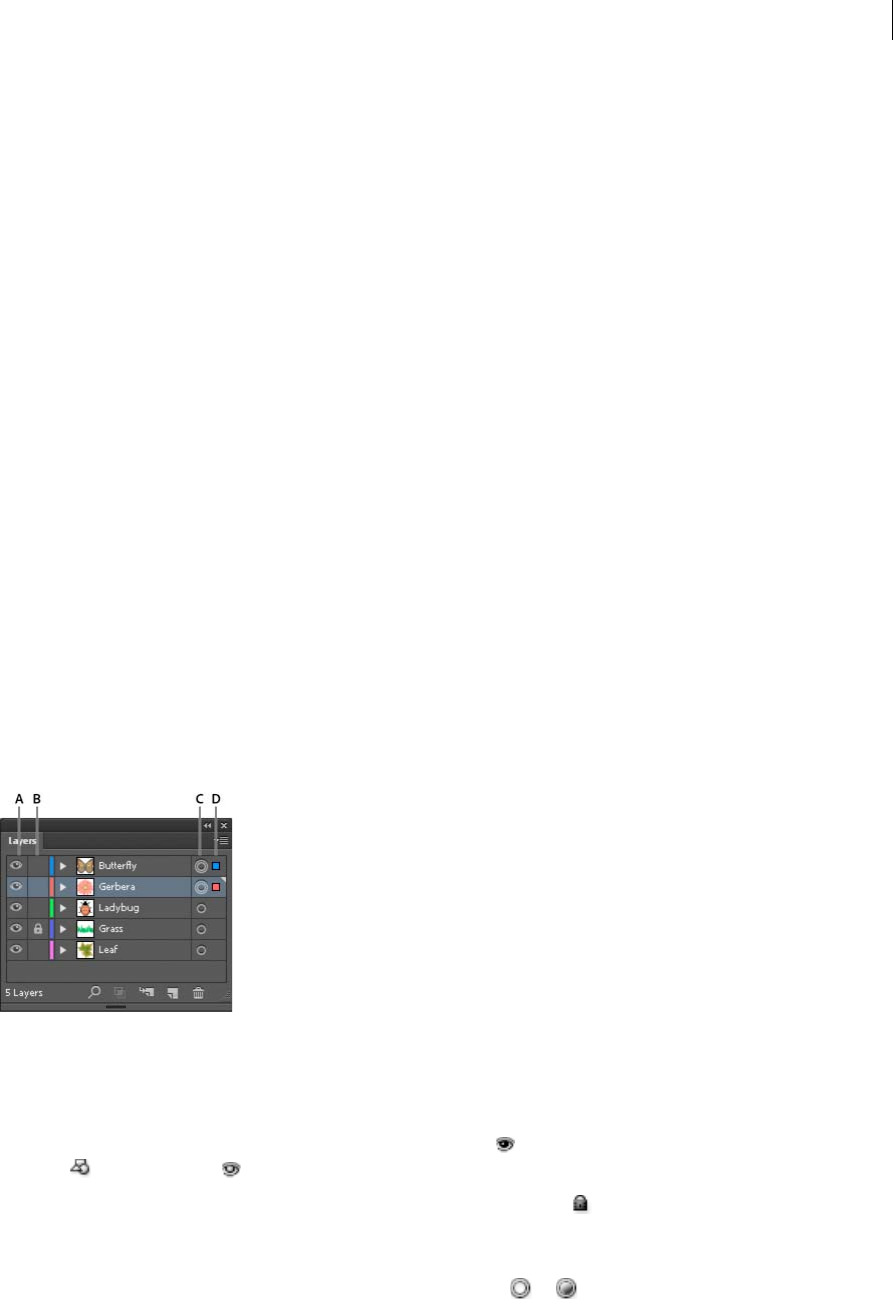
256
Selecting and arranging objects
Last updated 6/5/2015
About layers
When creating complex artwork, it’s a challenge to keep track of all the items in your document window. Small items
get hidden under larger items, and selecting artwork becomes difficult. Layers provide a way to manage all the items
that make up your artwork. Think of layers as clear folders that contain artwork. If you reshuffle the folders, you change
the stacking order of the items in your artwork. You can move items between folders and create subfolders within
folders.
The structure of layers in your document can be as simple or complex as you want it to be. By default, all items are
organized in a single, parent layer. However, you can create new layers and move items into them, or move elements
from one layer to another at any time. The Layers panel provides an easy way to select, hide, lock, and change the
appearance attributes of artwork. You can even create template layers, which you can use to trace artwork, and exchange
layers with Photoshop.
For a video on using layers and groups, see www.adobe.com/go/vid0041. For information on using layers to create
animations, see www.adobe.com/go/learn_ai_tutorials_layers_en.
Layers panel overview
You use the Layers panel (Window > Layers) to list, organize, and edit the objects in a document. By default, every new
document contains one layer, and each object you create is listed under that layer. However, you can create new layers
and rearrange items to best suit your needs.
By default, Illustrator assigns a unique color (up to nine colors) to each layer in the Layers panel. The color displays
next to the layer name in the panel. The same color displays in the illustration window in the bounding box, path,
anchor points, and center point of a selected object. You can use this color to quickly locate an object’s corresponding
layer in the Layers panel, and you can change the layer color to suit your needs.
When an item in the Layers panel contains other items, a triangle appears to the left of the item’s name. Click the
triangle to show or hide the contents. If no triangle appears, the item contains no additional items.
A Visibility column B Edit column C Targ et c olumn D Selection column
The Layers panel provides columns to the left and right of the listings. Click in a column to control the following
characteristics:
Visibility column Indicates whether items in the layers are visible or hidden (blank space), or whether they are
template layers or outline layers.
Edit column Indicates whether items are locked or unlocked. The lock icon indicates that the item is locked and
cannot be edited; a blank space indicates that the item is unlocked and can be edited.
Target column Indicates whether items are targeted for application of effects and edit attributes in the Appearance
panel. When the target button appears as a double ring icon (either or ), the item is targeted; a single ring icon
indicates that the item is not targeted.
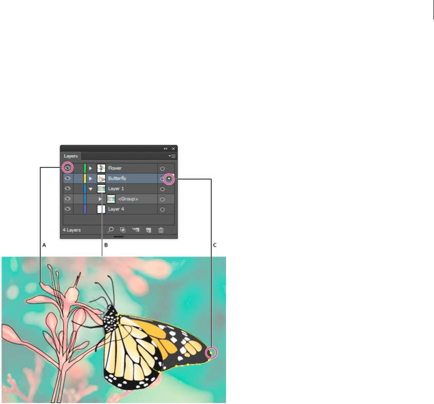
257
Selecting and arranging objects
Last updated 6/5/2015
Selection column Indicates whether items are selected. A color box appears when an item is selected. If an item, such
as a layer or group, contains some objects that are selected and other objects that are unselected, a smaller selection
color box appears next to the parent item. If all of the objects within the parent item are selected, the selection color
boxes are the same size as the marks that appear next to selected objects.
You can use the Layers panel to display some items as outlines and other items as they will appear in the final artwork.
You also can dim linked images and bitmap objects to make it easier to edit artwork on top of the image. This is
especially useful when tracing a bitmap image.
A Object displayed in Outline view B Bitmap object dimmed to 50% C Selected object displayed in Preview view
More Help topics
Workspace basics
View artwork as outlines
Trace artwork
Lock or unlock objects or layers
Hide or show objects or layers
Change the display of the Layers panel
1Choose panel Options from the Layers panel menu.
2Select Show Layers Only to hide paths, groups, and collective elements in the Layers panel.
3For Row Size, select an option to specify the height of rows. (To specify a custom size, enter a value between 12 and
100.)
4For Thumbnails, select a combination of layers, groups, and objects for which to display thumbnail previews.

258
Selecting and arranging objects
Last updated 6/5/2015
Note: Displaying thumbnails in the Layers panel may result in slow performance when you are working with complex
files. Turn off layer thumbnails to improve performance.
Set layer and sublayer options
1Do one of the following:
•Double-click the item name in the Layers panel.
•Click the item name and choose Options For <item name> from the Layers panel menu.
•Choose New Layer or New Sublayer from the Layers panel menu.
2Specify any of the following:
Name Specifies the name of the item as it appears in the Layers panel.
Color Specifies the layer’s color setting. You can either choose a color from the menu or double-click the color
swatch to select a color.
Template Makes the layer a template layer.
Lock Prevents changes to the item.
Show Displays all artwork contained in the layer on the artboard.
Print Makes the artwork contained in the layer printable.
Preview Displays the artwork contained in the layer in color instead of as outlines.
Dim Images Reduces the intensity of linked images and bitmap images contained in the layer to the specified
percentage.
Create a layer
1In the Layers panel, click the name of the layer above which (or in which) you want to add the new layer.
2Do one of the following:
•To add a new layer above the selected layer, click the Create New Layer button in the Layers panel.
•To create a new sublayer inside the selected layer, click the Create New Sublayer button in the Layers panel.
Tip: To set options when you create a new layer, choose New Layer or New Sublayer from the Layers panel menu.
For different drawing modes, Illustrator provides several options, which include:
•The Draw Behind mode automatically creates an active new layer behind the active layer.
•In draw behind mode, artwork is drawn behind all artwork on a selected layer if no artwork is selected.
Move an object to a different layer
1Select the object.
2Do one of the following:
•Click the name of the desired layer in the Layers panel. Then choose Object > Arrange > Send To Current Layer.
•Drag the selected-art indicator , located at the right of the layer in the Layers panel, to the layer you want.
Tip: You can move objects or layers into a new layer by selecting them and choosing Collect In New Layer from
the Layers panel menu. Hold down Ctrl (Windows) or Command (Mac OS) to select nonadjacent items; hold
down Shift to select adjacent items.
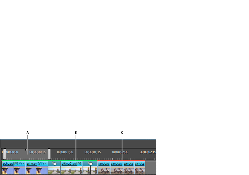
259
Selecting and arranging objects
Last updated 6/5/2015
Release items to separate layers
The Release To Layers command redistributes all of the items in a layer into individual layers and can build new objects
in each layer based on the object’s stacking order. You can use this feature to prepare files for web animation work.
1In the Layers panel, click the name of a layer or group.
2Do one of the following:
•To release each item to a new layer, choose Release To Layers (Sequence) from the Layers panel menu.
•To release items into layers and duplicate objects to create a cumulative sequence, choose Release To Layers
(Build) from the Layers panel menu. The bottommost object appears in each of the new layers, and the topmost
object only appears in the topmost layer. For example, assume Layer 1 contains a circle (bottommost object), a
square, and a triangle (topmost object). This command creates three layers—one with a circle, square, and
triangle; one with a circle and square; and one with just a circle. This is useful for creating cumulative animation
sequences.
Consolidate layers and groups
Merging and flattening layers are similar in that they both let you consolidate objects, groups, and sublayers into a single
layer or group. With merging, you can select which items you want to consolidate; with flattening, all visible items in
the artwork are consolidated in a single layer. With either option, the stacking order of the artwork remains the same,
but other layer-level attributes, such as clipping masks, aren’t preserved.
•To merge items into a single layer or group, hold down Ctrl (Windows) or Command (Mac OS) and click the names
of the layers or groups that you want to merge. Alternatively, hold down Shift to select all listings in between the
layer or group names you click. Then, select Merge Selected from the Layers panel menu. Note that items will be
merged into the layer or group that you selected last.
Layers can only merge with other layers that are on the same hierarchical level in the Layers panel. Likewise,
sublayers can only merge with other sublayers that are within the same layer and at the same hierarchical level.
Objects can’t be merged with other objects.
•To flatten layers, click the name of the layer into which you want to consolidate the artwork. Then select Flatten
Artwork from the Layers panel menu.
Locate an item in the Layers panel
When you select an item in your document window, you can quickly locate the corresponding item in the Layers panel
using the Locate Object command. This command is especially helpful for locating items in collapsed layers.
1Select an object in the document window. If you select more than one object, the frontmost object in the stacking
order will be located.
2Choose Locate Object from the Layers panel menu. This command changes to Locate Layer if the Show Layers Only
panel option is selected.

260
Selecting and arranging objects
Last updated 6/5/2015
More Help topics
Using layers to create animations
Locking, hiding, and deleting objects
Lock or unlock objects or layers
Locking objects prevents you from selecting and editing them. You can quickly lock multiple paths, groups, and
sublayers by locking their parent layer.
•To lock objects, click the edit column button (to the right of the eye icon) in the Layers panel for the object or layer
you want to lock. Drag across multiple edit column buttons to lock multiple items. Alternatively, select the objects
you want to lock, and then choose Object > Lock > Selection.
•To unlock objects, click the lock icon in the Layers panel for the object or layer you want to unlock.
You can also use the following commands to lock and unlock objects:
•To lock all objects that overlap the area of the selected object and that are in the same layer, select the object, and
then choose Object > Lock > All Artwork Above.
•To lock all layers other than the layer that contains a selected item or group, choose Object > Lock > Other Layers
or choose Lock Others from the Layers panel menu.
•To lock all the layers, select all the layers in the Layers panel, and then choose Lock All Layers from the panel menu.
•To unlock all objects in the document, choose Object > Unlock All.
•To unlock all objects within a group, select an unlocked and visible object within the group. Hold down Shift+Alt
(Windows) or Shift+Option (Mac OS) and choose Object > Unlock All.
•If you locked all layers, choose Unlock All Layers from the Layers panel menu to unlock them.
Note: The Lock menus are disabled when you’re in isolation mode.
More Help topics
Layers panel overview
Hide or show objects or layers
Choose from the following methods:
•In the Layers panel, click the eye icon next to the item you want to hide. Click again to redisplay the item. If you
hide a layer or group, all items in the layer or group are hidden.
•Drag across multiple eye icons to hide multiple items.
•Select an object you want to hide, and choose Object > Hide > Selection.
•To hide all objects above an object in a layer, select the object and choose Object > Hide > All Artwork Above.
•To hide all unselected layers, choose Hide Others from the Layers panel menu, or Alt-click (Windows) or
Option-click (Mac OS) the eye icon for the layer you want to show. Alternatively, to hide all other layers other than
the layer that contains the selected object or group, choose Object > Hide > Other Layers.

261
Selecting and arranging objects
Last updated 6/5/2015
•To show all objects, choose Object > Show All. All previously hidden objects are shown. Any previously selected
objects are selected.
•To show all layers and sublayers, select Show All Layers from the Layers panel menu. Hidden objects aren’t displayed
by this command, only hidden layers.
•To show all objects within a group, select an unlocked and visible object in the group. Hold down Shift+Alt
(Windows) or Shift+Option (Mac OS) and choose Object > Show All.
Note: The Show All and Hide menus are disabled when you’re in isolation mode.
More Help topics
Layers panel overview
Delete objects
❖Do one of the following:
•Select the objects and then press Backspace (Windows) or Delete.
•Select the objects and then choose Edit > Clear or Edit > Cut.
•Select the items you want to delete in the Layers panel, and then click the Delete icon . Alternatively, drag the
item name in the Layers panel to the Delete icon in the panel, or choose Delete “Layer name” from the Layers
panel menu.
Deleting a layer also deletes all artwork that is in the layer. For example, if you delete a layer that contains sublayers,
groups, paths, and clipping sets, all those elements will be deleted along with the layer.
Note: A document must have a least one layer. If a document has only one layer, the Delete icon and Delete command
are not available.
More Help topics
Layers panel overview
Duplicating objects
Duplicate objects by dragging
1Select one or more objects.
2Select the Selection, Direct Selection, or Group Selection.
3Alt-drag (Windows) or Option-drag (Mac OS) the selection (but not a handle on the bounding box).
Duplicate objects by using the Layers panel
You can quickly duplicate objects, groups, and entire layers by using the Layers panel.
1Select the items you want to duplicate in the Layers panel.
2Do one of the following:
•Choose Duplicate “Layer name” from the Layers panel menu.

262
Selecting and arranging objects
Last updated 6/5/2015
•Drag the item in the Layers panel to the New Layer button at the bottom of the panel.
•Start to drag the item to a new position in the Layers panel, and then hold down Alt (Windows) or Option (Mac
OS). Release the mouse button when the indicator is in the position where you want to place the duplicated item.
If you release the mouse button when the indicator is pointing to a layer or group, the duplicated item is added
to the top of the layer or group. If you release the mouse button when the indicator is between items, the
duplicated item will be added in the specified position.
Duplicate selections using drag and drop
You can use the Clipboard to transfer selections between an Illustrator file and other Adobe software including Adobe
Photoshop and Adobe InDesign. The Clipboard is particularly useful for importing paths because paths are copied to
the Clipboard as PostScript language descriptions. Artwork copied to the Clipboard is pasted in PICT format in most
applications. However, some applications take the PDF version (such as InDesign) or the AICB version. PDF preserves
transparency; AICB lets you specify whether you want to preserve the overall appearance of the selection or copy the
selection as a set of paths (which can be useful in Photoshop).
To specify copying preferences, choose Edit > Preferences > File Handling & Clipboard (Windows) or Illustrator >
Preferences > File Handling & Clipboard (Mac OS). Select PDF, AICB, or both. If you select AICB, select Preserve Paths
to discard any transparency in the copied artwork or Preserve Appearance And Overprints to flatten any transparency,
maintain the copied artwork’s appearance, and preserve overprinted objects.
Drag and drop artwork into a Photoshop document
1Select the artwork you want to copy.
2Open the Photoshop document into which you want to copy the selection.
3Do one of the following:
•To copy the artwork into Photoshop as bitmap images, drag the selection toward the Photoshop window, and
when a black outline appears, release the mouse button. To position the selection in the center of the Photoshop
image, hold down Shift before dragging the selection. By default, selected objects are copied as bitmap images to
the active layer.
•To copy vector artwork into Photoshop as paths, hold down Ctrl (Windows) or Command (Mac OS), and drag
the selection to the Photoshop document. When you release the mouse button, the selection becomes a
Photoshop path.
Drag and drop artwork from Photoshop into Illustrator
1Open the Photoshop document from which you want to copy.
2Select the artwork you want to copy.
3Select the Move tool and drag the selection from Photoshop into the Illustrator file.
Drag and drop artwork to the desktop (Mac OS only)
1Select the artwork you want to copy.
2Drag the selection onto the desktop.
Selections are copied to the desktop as a picture clipping, which can be dragged and dropped into the desired
document. Picture clippings are converted to PICT format when dragged to the desktop.

263
Selecting and arranging objects
Last updated 6/5/2015
Offset duplicate objects
You can create a replica of an object, set off from the selected object by a specified distance, by using the Offset Path
command or Offset Path effect. Offsetting objects is useful when you want to create concentric shapes or make many
replications of an object with regular distances between each replication.
You can offset an object’s path relative to its original path by using the Offset Path effect in the Effect menu. This effect
is useful for converting a mesh object into a regular path. For example, if you have released an envelope, or want to
convert a mesh shape for use in another application, apply the offset path command with an offset value of 0, and then
delete the mesh shape. You can then edit the remaining path.
More Help topics
About effects
Stroke an object
Offset objects using the Offset Path command
1Select one or more objects.
2Choose Object > Path > Offset Path.
3Specify the offset distance, line join type, and miter limit.
4Click OK.
Offset objects using the Offset Path effect
1Select one or more objects.
2Choose Effect > Path > Offset Path.
3Specify the offset distance, line join type, and miter limit.
4Click OK.
Offset objects using keyboard
1Select one or more objects.
2Hold down Alt and press an arrow key.
A duplicate object is created, and is offset by the Keyboard Increment value specified in the General preferences. The
location of the new object is determined by the arrow key you used.
Note: If a duplicate is not created, make sure that the Keyboard Increment preference is set to a value other than zero.
Stacking objects
Specify where to add new objects in the stacking order
Illustrator stacks successively drawn objects, beginning with the first object drawn.

264
Selecting and arranging objects
Last updated 6/5/2015
How objects are stacked determines how they display when they overlap. The stacking order of objects depends on the
drawing mode you are using. When a new layer is created in the Draw Normal mode, it is placed right above the active
layer and any new objects are drawn at the top of active layer. However, in the Draw Behind mode, when a new layer is
created, it is placed right below the active layer and any new objects are drawn behind the selected object (or at the
bottom of the active layer if no objects are selected).
You can change the stacking order (also called the painting order) of objects in your artwork at any time using either
the Layers panel or Object > Arrange commands.
❖In the Layers panel, do either of the following:
•In the Draw Behind mode, select the object below which you want to add the new object.
•In the Draw Normal mode, to add the new object to the top of a layer, click the name of the layer to make it active.
In the Draw Behind mode, to add the new object to the bottom of a layer, click the name of the layer to make it
active.
Change the stacking order using the Layers panel
The artwork at the top of the Layers panel is at the front of the stacking order, while artwork at the bottom of the Layers
panel is at the back of the stacking order. Within a layer, objects are also stacked hierarchically. By creating multiple
layers in your artwork, you can control how overlapping objects are displayed.
❖Do any of the following:
•Drag the item’s name and release the mouse button when black insertion marks appear in the desired position.
Black insertion marks appear either between two other items in the panel or on the left and right edges of a layer
or group. Items that are released over a layer or group are moved above all other objects in the item.
•Click in the item’s selection column (between the target button and the scroll bar), drag the selection color box
to a different item’s selection color box, and release the mouse button. If the item’s selection color box is dragged
to an object, the item is moved above the object; if it’s dragged to a layer or group, the item is moved above all
other objects in the layer or group.
•To reverse the order of items in the Layers panel, hold down Ctrl (Windows) or Command (Mac OS) and click
the names of the items whose order you want to reverse. The items must be at the same level in the layer
hierarchy. For example, you can select two top-level layers, but you cannot select two paths that are in different
layers. Then select Reverse Order from the Layers panel menu.
note: You cannot move a path, group, or collective element to the top position in the Layers panel—only layers can
reside at the top of the layer hierarchy.
More Help topics
Layers panel overview
Change the stacking order using commands
❖Do any of the following:
•To move an object to the top or bottom position in its group or layer, select the object you want to move and
choose Object > Arrange > Bring To Front or Object > Arrange > Send To Back.
•To move an object by one object to the front or one object to the back of a stack, select the object you want to
move, and choose Object > Arrange > Bring Forward or Object > Arrange > Send Backward.
For an example of how changing the stacking order in an illustration changes the design, see
www.adobe.com/go/learn_ai_tutorials_depth_en. This tutorial is available only in English.
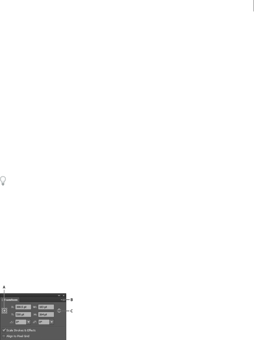
265
Last updated 6/5/2015
Chapter 7: Reshaping objects
Transforming objects
Transforming
Transforming encompasses moving, rotating, reflecting, scaling, and shearing objects. You can transform objects using
the Transform panel, Object > Transform commands, and specialized tools. You can also perform many types of
transformations by dragging the bounding box for a selection.
Sometimes you may want to repeat the same transformation several times, especially when you are copying objects.
The Transform Again command in the Object menu lets you repeat a move, scale, rotate, reflect, or shear operation as
many times as you want, until you perform a different transform operation.
Use the Info panel to view the current dimensions and position of your selection as you transform it.
For a video on scaling, skewing, and rotating objects, see www.adobe.com/go/vid0040.
Transform panel overview
The Transform panel (Window > Transform) displays information about the location, size, and orientation of one or
more selected objects. By typing new values, you can modify the selected objects, their pattern fills, or both. You can
also change the transformation reference point and lock the object’s proportions.
All values in the panel refer to the bounding boxes of the objects except for the X and Y values, which refer to the
selected reference point. To pixel-align individual objects to pixel grid, check the Align to Pixel Grid check box.note:
The reference point locator in the Transform panel specifies an object’s reference point only when you transform the object
by changing the values in the panel. Other methods of transforming (such as using the Scale tool) use the object’s center
point or the pointer location as the reference point.
A Reference point locator B Panel menu C Lock proportions icon
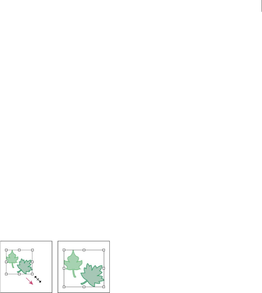
266
Reshaping objects
Last updated 6/5/2015
Transform an object’s patterns
When you move, rotate, reflect (flip), scale, or shear an object that is filled with a pattern, you can transform just the
object, just the pattern, or both the object and pattern. Once you transform an object’s fill pattern, all patterns that you
subsequently apply to that object are transformed the same way.
•To specify how you want to transform patterns when using the Transform panel, select an option from the panel
menu: Transform Object Only, Transform Pattern Only, or Transform Both.
•To specify how you want to transform patterns when using a transform command, set the Objects and Patterns
options in the corresponding dialog box. For example, select Patterns and deselect Objects if you want to transform
the pattern but not the object.
•To transform patterns but not objects when using a transform tool, hold down the tilde key (~) while dragging. The
borders of the object appear to be transformed, but when you release the mouse button, the borders snap back to
their original configuration, leaving only the pattern transformed.
•To prevent patterns from transforming when using transform tools, choose Edit > Preferences > General (Windows)
or Illustrator > Preferences > General (Mac OS) and deselect Transform Pattern Tiles.
•To return an object’s fill pattern to its original state, fill the object with a solid color, and then reselect the desired
pattern.
Transform using the bounding box
When you select one or more objects with the Selection tool, a bounding box displays around them. Use the bounding
box to easily move, rotate, duplicate, and scale objects by dragging the object or a handle (one of the hollow squares
along the bounding box).
•To hide the bounding box, choose View > Hide Bounding Box.
•To show the bounding box, choose View > Show Bounding Box.
•To reorient the bounding box after you rotate it, choose Object > Transform > Reset Bounding Box.
More Help topics
Scale objects
Shear objects
Move objects
Rotate objects
Reflect or flip objects
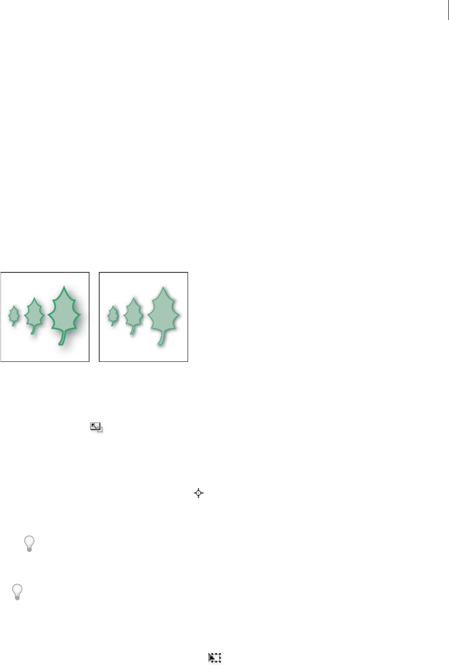
267
Reshaping objects
Last updated 6/5/2015
Scaling, shearing, and distorting objects
Scale objects
Scaling an object enlarges or reduces it horizontally (along the x axis), vertically (along the y axis), or both. Objects scale
relative to a reference point which varies depending on the scaling method you choose. You can change the default
reference point for most scaling methods, and you can also lock the proportions of an object.
Note: After you scale an object, Illustrator does not retain the original size of the object in memory. Therefore, you cannot
resume the original size of the object. However, you can see the resolution of the object in the Document Info panel and
decide on the scale at which you want to resize the object, while retaining the object’s resolution.
By default, strokes and effects are not scaled along with objects. To scale strokes and effects, choose Edit > Preferences
> General (Windows) or Illustrator > Preferences > General (Mac OS), and select Scale Strokes & Effects. If you want
to choose whether to scale strokes and effects on a case-by-case basis, use the Transform panel or the Scale command
to scale objects.
Scale objects with the Scale tool
1Select one or more objects.
2Select the Scale tool .
3Do any of the following:
•To scale relative to the object’s center point, drag anywhere in the document window until the object is the
desired size.
•To scale relative to a different reference point , click where you want the reference point to be in the document
window, move the pointer away from the reference point, and then drag until the object is the desired size.
•To maintain the object’s proportions as it scales, hold down Shift as you drag diagonally.
Tip: While using the Scale tool with the Shift key, start dragging at an angle of 45° horizontally or vertically but
in an angle.
•To scale the object along a single axis, hold down Shift as you drag vertically or horizontally.
For finer control over scaling, start dragging farther from the reference point.
Scale objects with the bounding box
1Select one or more objects.
2Select the Selection tool or the Free Transform tool .

268
Reshaping objects
Last updated 6/5/2015
3Drag a bounding box handle until the object is the desired size.
Objects scale relative to the opposite handle of the bounding box.
4Do any of the following to control the scaling behavior:
•To maintain the object’s proportions, hold down Shift as you drag.
•To scale relative to the object’s center point, hold down Alt (Windows) or Option (Mac OS) as you drag.
Scale objects to a specific width and height
1Select one or more objects.
2In the Transform panel, enter a new value in the Width (W) or Height (H) box, or both.
You can do any of the following before you enter a value to control the scaling behavior:
•To maintain the objects’ proportions, click the lock proportions button .
•To change the reference point for scaling, click a white square on the reference point locator .
•To scale stroked paths and any size-related effects along with the object, select Scale Strokes & Effects from the
panel menu.
You can also maintain proportions by entering a value in the W or H box, and then pressing Ctrl (Windows) or
Command (Mac OS) while you press Enter.
Scale objects by a specific percentage
1Select one or more objects.
2Do one of the following:
•To scale from the center, choose Object > Transform > Scale or double-click the Scale tool .
•To scale relative to a different reference point, select the Scale tool and Alt-click (Windows) or Option-click (Mac
OS) where you want the reference point to be in the document window.
3In the Scale dialog box, do one of the following:
•To maintain the object’s proportions as it scales, select Uniform, and enter a percentage in the Scale text box.
•To scale the height and width separately, select Non-Uniform, and enter a percentage in the Horizontal and
Ver tical text boxes.
The scale factors are relative to the reference point and can be negative or positive.
4To scale stroked paths and any size-related effects along with the object, select Scale Strokes & Effects.
5If the objects contain a pattern fill, select Patterns to scale the pattern. Deselect Objects if you want to scale the
pattern but not the objects.
6Click OK, or click Copy to scale a copy of the objects.
Scale multiple objects
1Select the objects.
2Choose Object > Transform > Transform Each.
Note: You cannot enter a specific width for scaling multiple objects. In Illustrator, you can only scale objects in
percentage measurements.
3Set percentages for horizontal and vertical scaling in the Scale section of the dialog box.
4To change the reference point, click a white square on the reference point locator .
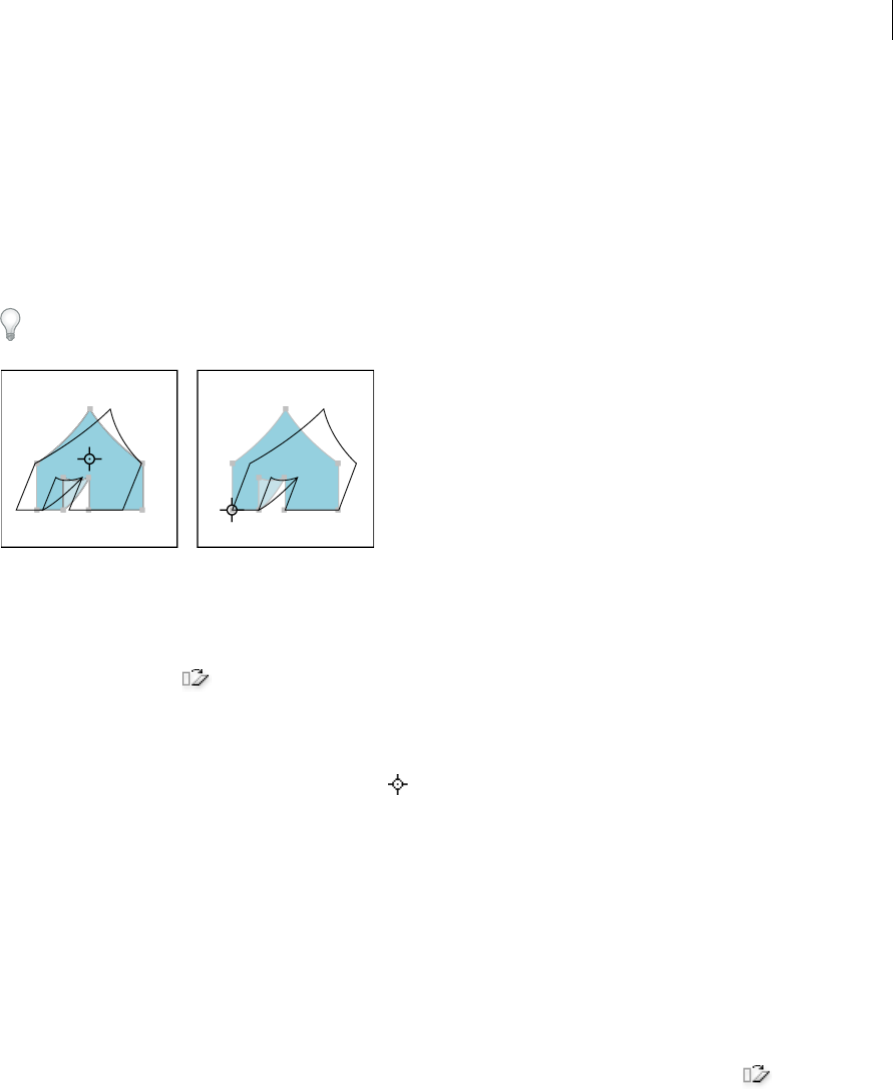
269
Reshaping objects
Last updated 6/5/2015
5Click OK, or click Copy to scale a copy of each object.
Shear objects
Shearing an object slants, or skews, the object along the horizontal or vertical axis, or a specified angle that’s relative to
a specified axis. Objects shear relative to a reference point which varies depending on the shearing method you choose
and can be changed for most shearing methods. You can lock one dimension of an object as you shear it, and you can
shear one object or multiple objects simultaneously.
Shearing is useful for creating cast shadows.
Shear objects with the Shear tool
1Select one or more objects.
2Select the Shear tool .
3Do one of the following:
•To shear relative to the object’s center, drag anywhere in the document window.
•To shear relative to a different reference point , click anywhere in the document window to move the reference
point, move the pointer away from the reference point, and then drag until the object is at the desired slant.
•To shear along the object’s vertical axis, drag anywhere in the document window in an up or down direction. To
constrain the object to its original width, hold down Shift.
•To shear along the object’s horizontal axis, drag anywhere in the document window in a left or right direction.
To constrain the object to its original height, hold down Shift.
Shear objects with the Shear command
1Select one or more objects.
2Do one of the following:
•To shear from the center, choose Object > Transform > Shear or double-click the Shear tool .
•To shear from a different reference point, select the Shear tool and Alt-click (Windows) or Option-click (Mac
OS) where you want the reference point to be in the document window.
3In the Shear dialog box, enter a shear angle from -359 to 359. The shear angle is the amount of slant applied to the
object in a clockwise direction and is relative to a line that’s perpendicular to the shear axis.
4Select the axis along which to shear the object.
If you chose an angled axis, enter a value between –359 and 359, relative to the horizontal axis.
5If the objects contain a pattern fill, select Patterns to move the pattern. Deselect Objects if you want to move the
pattern but not the objects.
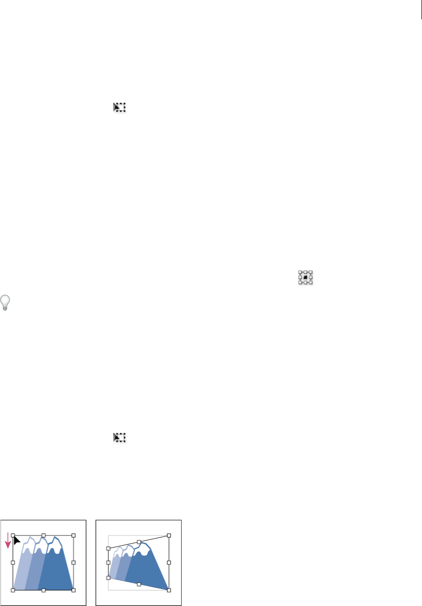
270
Reshaping objects
Last updated 6/5/2015
6Click OK, or click Copy to shear a copy of the objects.
Shear objects with the Free Transform tool
1Select one or more objects.
2Select the Free Transform tool .
3Do one of the following:
•To shear along the object’s vertical axis, start dragging the middle-left or middle-right bounding-box handle, and
then hold down Ctrl+Alt (Windows) or Option+Command (Mac OS) as you drag up or down. You can also hold
down Shift to constrain the object to its original width.
•To shear along the object’s horizontal axis, start dragging the top-middle or bottom-middle bounding-box
handle and then hold down Ctrl+Alt (Windows) or Option+Command (Mac OS) as you drag right or left. You
can also hold down Shift to constrain the object to its original height.
Shear objects with the Transform panel
1Select one or more objects.
2In the Transform panel, enter a value in the Shear text box.
To change the reference point, click a white square on the reference point locator before you enter the value.
You can also call up the Transform panel by clicking X, Y, W, or H in the Control panel.
Distort objects
You can distort objects by using the Free Transform tool or a liquify tool. Use the Free Transform tool when you want
to distort freely; use a liquify tool if you want to take advantage of specific preset distortions such as twirls, puckers, or
wrinkles.
Distort objects with the Free Transform tool
1Select one or more objects.
2Select the Free Transform tool .
3Start dragging a corner handle on the bounding box (not a side handle), and then do one of the following:
•Hold down Ctrl (Windows) or Command (Mac OS) until the selection is at the desired level of distortion.
•Hold down Shift+Alt+Ctrl (Windows) or Shift+Option+Command (Mac OS) to distort in perspective.
Distorting in perspective

271
Reshaping objects
Last updated 6/5/2015
Distort objects using a liquify tool
You cannot use liquify tools on linked files or objects that contain text, graphs, or symbols.
To find liquify tools in the Tools panel, see Tools panel over viewand Reshaping tool gallery.
1Select a liquify tool, and click or drag over the objects you want to distort.
2(Optional) To isolate the distortion to specific objects, select the objects before using the tool.
3(Optional) To change the size of the tool cursor and set other tool options, double-click the liquify tool and specify
any of the following:
Width and Height Controls the size of the tool cursor.
Angle Controls the orientation of the tool cursor.
Intensity Specifies the rate of change for the distortion. Higher values equal faster changes.
Use Pressure Pen Uses the input from a tablet or pen instead of the Intensity value. If you don’t have a pressure-
sensitive tablet attached, this option is dimmed.
Complexity (Scallop, Crystallize, and Wrinkle tools) Specifies how closely the results of the particular brush are
spaced on the object’s outline. This is closely tied with the Detail value.
Detail Specifies the spacing between points introduced into the object’s outline (higher values space points closer
together).
Simplify (Warp, Twirl, Pucker, and Bloat tools) Specifies how much you want to reduce the superfluous points that
do not measurably affect the overall appearance of the shape.
Twirl Rate (Twirl tool only) Specifies the rate at which the twirl is applied. Enter a value between –180° and 180°.
Negative values twirl the object clockwise and positive values twirl counterclockwise. The object twirls faster with
values that are closer to either –180° or 180°. To twirl slowly, specify a rate close to 0°.
Horizontal and Vertical (Wrinkle tool only) Specifies how far apart the control points are placed.
Brush Affects Anchor Points, Brush Affects In Tangent Handles, or Brush Affects Out Tangent Handles (Scallop,
Crystallize, Wrinkle tools) Enables the tool brush to make changes to these properties.
More Help topics
Transform panel overview
Move objects
Rotate objects
Reflect or flip objects
Reshaping tool gallery
Transform using the bounding box
Reshape using envelopes
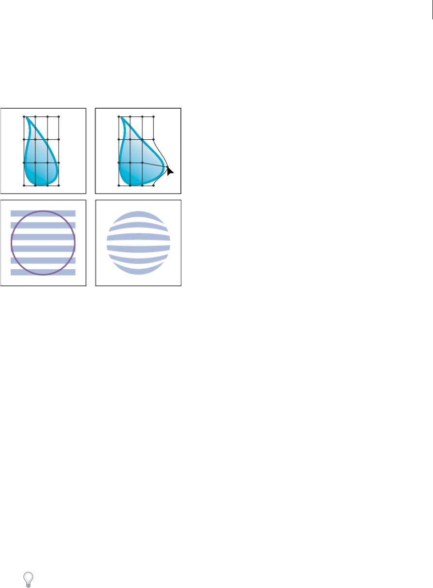
272
Reshaping objects
Last updated 6/5/2015
About envelopes
Envelopes are objects that distort or reshape selected objects. You can make an envelope out of an object on your
artboard, or you can use a preset warp shape or a mesh grid as an envelope. You can use envelopes on any object except
graphs, guides, or linked objects.
The Layers panel lists envelopes as <Envelope>. Once you apply an envelope, you can continue to edit the original
objects. You can also edit, delete, or expand an envelope at any time. You can edit an envelope shape or the enveloped
object, but not both at the same time.
Distort objects using an envelope
1Select one or more objects.
2Create the envelope using one of the following methods:
•To use a preset warp shape for the envelope, choose Object > Envelope Distort > Make With Warp. In the Warp
Options dialog box, select a warp style and set options.
•To set up a rectangular grid for the envelope, choose Object > Envelope Distort > Make With Mesh. In the
Envelope Mesh dialog box, set the number of rows and columns.
•To use an object as the shape of the envelope, make sure the object is at the top of the stacking order for the
selected object. If it’s not, use the Layers panel or an Arrange command to move it up, and reselect all the objects.
Then choose Object > Envelope Distort > Make With Top Object.
3Reshape the envelope by doing any of the following:
•Drag any anchor point on the envelope with the Direct Selection or Mesh tool.
•To delete anchor points on the mesh grid, select an anchor point with either the Direct Selection or Mesh tools,
and then press Delete.
•To add anchor points to the mesh grid, click on the grid with the Mesh tool.
Tip: To apply a stroke or fill to an envelope, use the Appearance panel.

273
Reshaping objects
Last updated 6/5/2015
Edit the contents of an envelope
1Select the envelope and do one of the following:
•Click the Edit Contents button in the Control panel.
•Choose Object > Envelope Distort > Edit Contents.
note: If your envelope consists of grouped paths, click the triangle to the left of the <Envelope> entry in the Layers
panel to view and target the path you want to edit.
2Edit it as desired.
Note: When you modify the contents of an envelope, the envelope shifts to recenter the results with the original content.
3To return the object to its enveloped state, do one of the following:
•Click the Edit Envelope button in the Control panel.
•Choose Object > Envelope Distort > Edit Envelope.
Reset an envelope
1Select the envelope.
2Do one of the following:
•To reset or switch to a preset warp style, choose a new warp style and set options in the Control panel. If desired,
click the Envelope Options button to open the dialog box and set more options.
•To reset or switch to a mesh grid envelope, choose Object > Envelope Distort > Reset With Mesh. Specify the
number of rows and columns for the mesh grid. Select Maintain Envelope Shape to keep the warp shape intact.
Remove an envelope
You can remove envelopes by either releasing them or expanding them. Releasing an enveloped object creates two
separate objects: the object in its original state and the envelope shape. Expanding an enveloped object removes the
envelope, but the object retains its distorted shape.
•To release an envelope, select the envelope, and choose Object > Envelope Distort > Release.
•To expand an envelope, select the envelope, and choose Object > Envelope Distort > Expand.
Envelope options
Envelope options determine how art is distorted to fit the envelope. To set envelope options, select the envelope object
and click the Envelope Options button in the Control panel, or choose Object > Envelope Distort > Envelope
Options.
Anti-Alias Smooths rasters when distorted with an envelope. Deselecting Anti-Alias can decrease the time it takes to
distort rasters.
Preserve Shape Using Specifies how rasters preserve their shape when distorted by nonrectangular envelopes. Select
Clipping Mask to use a clipping mask on the raster, or Transparency to apply an alpha channel to the raster.
Fidelity Specifies how precisely you want the object to fit the envelope mold. Increasing the Fidelity percentage can add
more points to the distorted paths and increase the time it takes to distort the objects.
Distort Appearance Distorts appearance attributes (such as applied effects or graphic styles) along with an object’s
shape.

274
Reshaping objects
Last updated 6/5/2015
Distort Linear Gradients Distorts linear gradients along with an object’s shape.
Distort Pattern Fills Distorts patterns along with an object’s shape.
note: If you expand the envelope with a Distort option selected, the respective property is expanded separately.
More Help topics
Reshaping objects with effects
Combining objects
Methods of combining objects
You can combine vector objects to create shapes in a variety of ways in Illustrator. The resulting paths or shapes differ
depending on the method you use to combine the paths.
Pathfinder effects
Pathfinder effects let you combine multiple objects using one of ten interaction modes. Unlike compound shapes, you
can’t edit the interactions between objects when you use a Pathfinder effect.
Compound shapes
Compound shapes let you combine multiple objects and specify how you want each object to interact with the other
objects. Compound shapes are more versatile than compound paths because they provide four kinds of interactions:
add, subtract, intersect, and exclude. In addition, the underlying objects are not changed, so you can select each object
within a compound shape to edit it or change its interaction mode.
Compound paths
Compound paths let you use an object to cut a hole in another object. For example, you can create a doughnut shape
from two nested circles. Once you create a compound path, the paths act as grouped objects. You can select and
manipulate the objects separately using the Direct Selection tool or Group Selection tool; or you can select and edit the
combined path.
Note: You can also add to an object by using the Blob Brush tool. When you use this brush, paths you paint are added to
adjacent paths that use identical fill attributes. (See Draw and merge paths with the Blob Brush tooland Building new
shapes using the Shape Builder tool .)
Pathfinder
Pathfinder panel overview
You use the Pathfinder panel (Window > Pathfinder) to combine objects into new shapes.
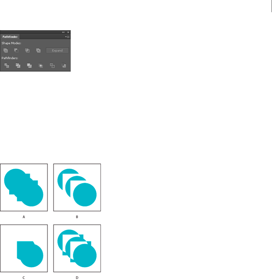
275
Reshaping objects
Last updated 6/5/2015
The top row of buttons in the panel, make paths or compound paths by default, and compound shapes only when you
press the Alt or Option key. You can choose from the following shape modes:
Add To Shape Area Adds the area of the component to the underlying geometry.
Subtract from Shape Area Cuts out the area of the component from the underlying geometry.
Intersect Shape Areas Uses the area of the component to clip the underlying geometry as a mask would.
Exclude Overlapping Shape Areas Uses the area of the component to invert the underlying geometry, turning filled
regions into holes and vice versa.
The bottom row of buttons in the panel, called Pathfinder effects, let you create final shape combinations on the first
click. (See Apply Pathfinder effects.)
A All components in Add mode B Subtract mode applied to squares C Intersect mode applied to squares D Exclude mode applied to squares
Pathfinder options
You can set Pathfinder Options from the Pathfinder panel menu or by double-clicking a Pathfinder effect in the
Appearance panel.
Precision Affects how precisely the Pathfinder effects calculate an object’s path. The more precise the calculation, the
more accurate the drawing and the more time is required to generate the resulting path.
Remove Redundant Points Removes unnecessary points as you click a Pathfinder button.
Divide And Outline Will Remove Unpainted Artwork Deletes any unfilled objects in the selected artwork as you click
the Divide or Outline button.

276
Reshaping objects
Last updated 6/5/2015
Apply Pathfinder effects
Pathfinder effects let you create new shapes out of overlapping objects. You can apply Pathfinder effects by using the
Effects menu or the Pathfinder panel.
•Pathfinder effects in the Effects menu can only be applied to groups, layers, and text objects. After you apply the
effect, you can still select and edit the original objects. You can also use the Appearance panel to modify or remove
the effect.
•Pathfinder effects in the Pathfinder panel can be applied to any combination of objects, groups, and layers. The final
shape combination is created when you click a pathfinder button; after that, you cannot edit the original objects. If
the effect results in multiple objects, they are automatically grouped together.
For a video on using Pathfinder effects and clipping masks and how to import clipping masks into Flash, see
www.adobe.com/go/vid0057.
More Help topics
Group or ungroup objects
Move an object to a different layer
Targeting items for appearance attributes
Building new shapes using the Shape Builder tool
Apply a Pathfinder effect using the Effects menu
1Do one of the following:
•Group together the objects you want to use, and select the group.
•Move the objects you want to use into a separate layer, and target the layer.
2Choose Effect > Pathfinder and choose a Pathfinder effect.
To quickly apply the same Pathfinder effect again, choose Effect > Apply [effect].
Apply a Pathfinder effect using the Pathfinder panel
1Select the objects to which you want to apply the effect.
To apply a Pathfinder effect to a group or layer, target the group or layer.
2In the Pathfinder panel, click a pathfinder button (in the bottom row), or Alt-click (Windows) or Option-click (Mac
OS) a Shape Mode button (in the top row).
Summary of Pathfinder effects
Add Traces the outline of all objects as if they were a single, merged object. The resulting shape takes on the paint
attributes of the top object.
Intersect Traces the outline of the region overlapped by all the objects.
Exclude Traces all nonoverlapping areas of the objects, and makes overlapping areas transparent. Where an even
number of objects overlap, the overlap becomes transparent. Where an odd number of objects overlap, the overlap
becomes filled.
Subtract Subtracts the frontmost objects from the backmost object. You can use this command to delete areas of an
illustration by adjusting the stacking order.

277
Reshaping objects
Last updated 6/5/2015
Minus Back Subtracts the objects in back from the frontmost object. You can use this command to delete areas of an
illustration by adjusting the stacking order.
Divide Separates a piece of artwork into its component filled faces (a face is an area undivided by a line segment).
note: When you use the Divide button in the Pathfinder panel, you can use the Direct Selection or Group Selection tool to
manipulate the resulting faces independently of each other. You can also choose to delete or preserve unfilled objects when
applying the Divide command.
Trim Removes the part of a filled object that is hidden. It removes any strokes and does not merge objects of the same
color.
Merge Removes the part of a filled object that is hidden. It removes any strokes and merges any adjoining or
overlapping objects filled with the same color.
Crop Divides artwork into its component filled faces, and then deletes all the parts of the artwork that fall outside the
boundary of the topmost object. It also removes any strokes.
Outline Divides an object into its component line segments, or edges. This command is useful for preparing artwork
that needs a trap for overprinting objects. (See Create a trap.)
note: When you use the Outline button in the Pathfinder panel, you can use the Direct Selection or Group Selection tool to
manipulate each edge independently. You can also choose to delete or preserve unfilled objects when applying the Outline
command.
Hard Mix Combines colors by choosing the highest value of each of the color components. For example, if Color 1 is
20% cyan, 66% magenta, 40% yellow, and 0% black; and Color 2 is 40% cyan, 20% magenta, 30% yellow, and 10% black,
the resulting hard color is 40% cyan, 66% magenta, 40% yellow, and 10% black.
Soft Mix Makes the underlying colors visible through the overlapping artwork, and then divides the image into its
component faces. You specify the percentage of visibility you want in the overlapping colors.
Trap Compensates for potential gaps between colors in artwork by creating a small area of overlap (called a trap)
between two adjoining colors.
Compound shapes
About compound shapes
A compound shape is editable art consisting of two or more objects, each assigned a shape mode. Compound shapes
make it easy to create complex shapes because you can precisely manipulate the shape mode, stacking order, shape,
location, and appearance of each path included.
Compound shapes act as grouped objects and appear as <Compound Shape> items in the Layers panel. You can use
the Layers panel to show, select, and manipulate the contents of a compound shape—for example, to change the
stacking order of its components. You can also use the Direct Selection tool or the Group Selection tool to select
components of a compound shape.
When you create a compound shape, it takes on the paint and transparency attributes of the topmost component in
Add, Intersect, or Exclude mode. Subsequently, you can change the paint, style, or transparency attributes of the
compound shape. Illustrator facilitates this process by automatically targeting the whole compound shape when you
select any part of it, unless you explicitly target a component in the Layers panel.
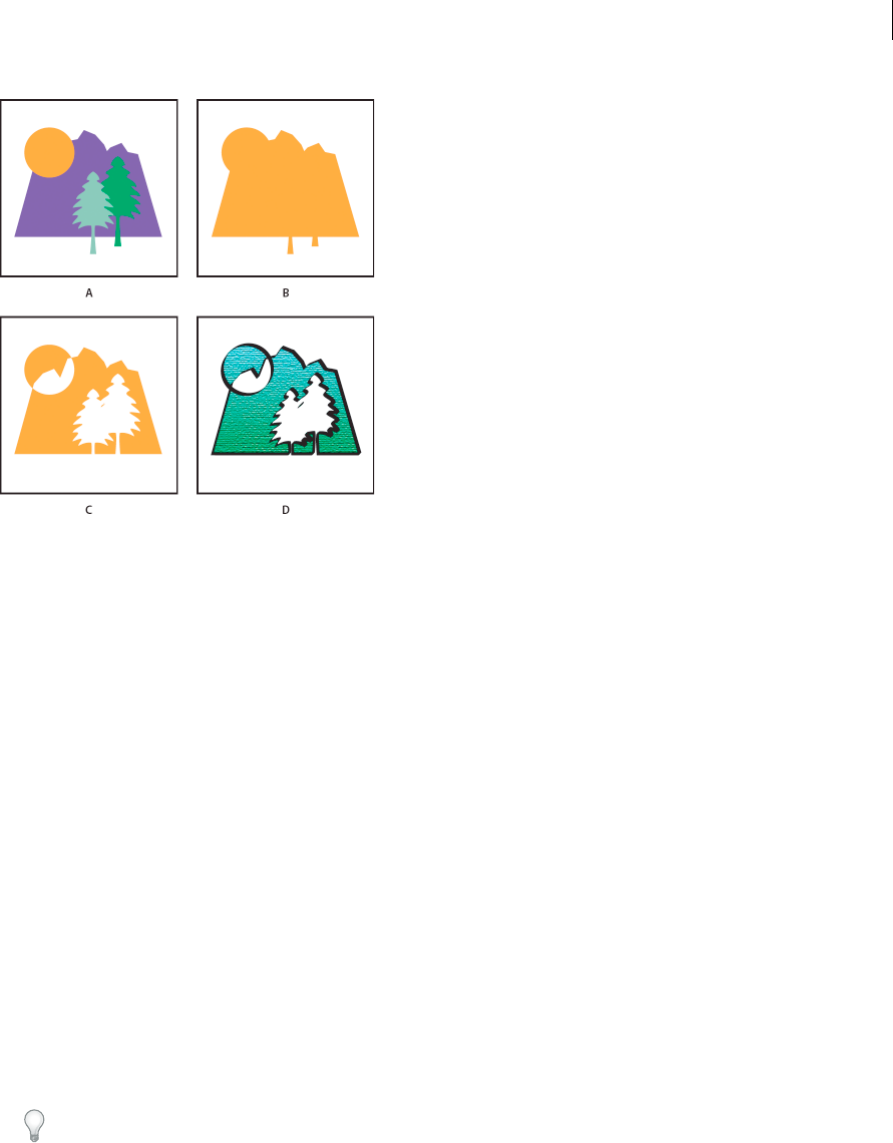
278
Reshaping objects
Last updated 6/5/2015
A Original objects B Compound shape created C Individual shape modes applied to each component D Style applied to entire compound shape
Work with compound shapes
Creating a compound shape is a two-part process. First, you establish a compound shape in which all components have
the same shape mode. Then, you assign shape modes to the components until you obtain the desired combination of
shape areas.
Create a compound shape
1Select all the objects you want to be part of the compound shape.
You can include paths, compound paths, groups, other compound shapes, blends, text, envelopes, and warps in a
compound shape. Any open paths you select are automatically closed.
2Do one of the following:
•In the Pathfinder panel, Alt-click (Windows) or Option-click (Mac OS) a Shape Modes button. Each component
of the compound shape is assigned the shape mode you select.
•Select Make Compound Shape from the Pathfinder panel menu. Each component of the compound shape is
assigned the Add mode by default.
3Change the shape mode of any component by selecting it with the Direct Selection tool or Layers panel and clicking
a Shape Mode button.
Note that you never need to change the mode of the backmost component, because its mode is not relevant to the
compound shape.
To sustain maximum performance, create complex compound shapes by nesting other compound shapes (containing
up to about 10 components each) instead of using many individual components.
Modify a compound shape
1Use the Direct Selection tool or Layers panel to select an individual component of the compound shape.
2Look for the highlighted Shape Mode button in the Pathfinder panel to identify which mode is currently applied to
a selected component.

279
Reshaping objects
Last updated 6/5/2015
Note: If you’ve selected two or more components that use different modes, question marks appear on the Shape Mode
buttons.
3In the Pathfinder panel, click a different Shape Mode button.
Release and expand a compound shape
Releasing a compound shape separates it back into separate objects. Expanding a compound shape maintains the shape
of the compound object, but you can no longer select the individual components.
1Select the compound shape using the Selection tool or Layers panel.
2Do one of the following:
•Click Expand in the Pathfinder panel.
•Choose Expand Compound Shape from the Pathfinder panel menu.
The compound shape is converted to a <Path> or <Compound Path> item in the Layers panel, depending on the
shape mode it used.
•Choose Release Compound Shape from the Pathfinder panel menu.
Move compound shapes between Illustrator and Photoshop
The shape layers and layer clipping paths (vector masks) in Adobe Photoshop are types of compound shapes. You can
import shape layers and layer clipping paths into Illustrator as compound shapes and continue to manipulate them. In
addition, you can export compound shapes to Photoshop. Keep the following in mind when using compound shapes
with Photoshop:
•Only compound shapes that reside at the top level of the layer hierarchy are exported to Photoshop as shape layers.
•A compound shape painted with a stroke using a join other than round, or with a weight in points that is not an
integer, is rasterized when exported to the PSD file format.
Compound paths
About compound paths
A compound path contains two or more paths that are painted so that holes appear where paths overlap. When you
define objects as a compound path, all objects in the compound path take on the paint and style attributes of the
backmost object in the stacking order.
Compound paths act as grouped objects and appear as <Compound Path> items in the Layers panel. Use the Direct
Selection tool or the Group Selection tool to select part of a compound path. You can manipulate the shape of individual
components of a compound path, but you cannot change appearance attributes, graphic styles, or effects for individual
components, and you cannot manipulate components individually in the Layers panel.
If you want more flexibility in the compound path creation, you can create a compound shape and then expand it.
Cut a hole in an object using a compound path
1Select the object to use as a hole, and position it so that it overlaps the object to cut. Repeat for any additional objects
you want to use as holes.
2Select all the objects you want to include in the compound path.
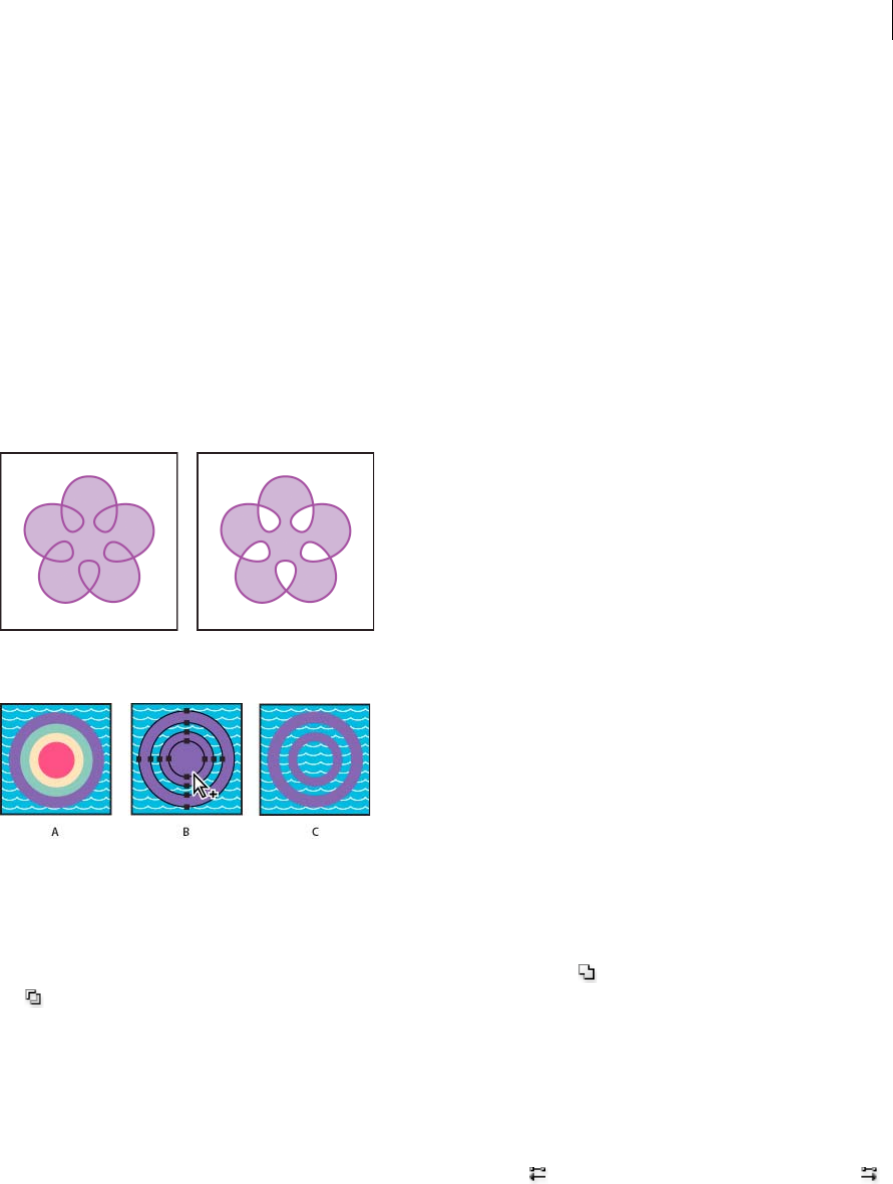
280
Reshaping objects
Last updated 6/5/2015
3Choose Object > Compound Path > Make.
Apply fill rules to compound paths
You can specify whether a compound path is a nonzero winding path or an even-odd path.
Nonzero winding fill rule Uses mathematical equations to determine if a point is outside or inside a shape. Illustrator
uses the nonzero winding rule as the default rule.
Even-odd fill rule Uses mathematical equations to determine if a point is outside or inside a shape. This rule is the more
predictable rule because every other region within an even-odd compound path is a hole, regardless of path direction.
Some applications, such as Adobe Photoshop, use the even-odd rule by default, so compound paths imported from
these applications will use the even-odd rule.
Self-intersecting paths are paths that intersect themselves. You can choose to make these paths either nonzero winding
or even-odd, depending on how you want them to look.
When you create a nonzero winding compound path, you can specify whether overlapping paths appear with holes or
are filled by clicking a Reverse Path Direction button in the Attributes panel.
A Four circular paths B Circular paths selected, converted into compound path C Reverse Path Direction applied to innermost path
Change the fill rule for a compound path
1Select the compound path using the Selection tool or Layers panel.
2In the Attributes panel, click the Use Non-Zero Winding Fill Rule button or the Use Even-Odd Fill Rule button
.
Change a hole in a compound path to a filled area
1Make sure that the compound path uses the nonzero winding fill rule.
2With the Direct Selection tool, select the part of the compound path to reverse. Do not select the entire compound
path.
3In the Attributes panel, click the Reverse Path Direction Off button or the Reverse Path Direction On button .
Return a compound path to its original components
1Select the compound path using the Selection tool or Layers panel.
2Choose Object > Compound Path > Release.

281
Reshaping objects
Last updated 6/5/2015
More Help topics
Mix overlapping colors
Trapping
Cutting and dividing objects
Methods for cutting, dividing, and trimming objects
Illustrator provides the following methods to cut, divide, and trim objects:
Divide Objects Below command Acts as a cookie cutter or stencil, using a selected object to cut through other objects,
discarding the original selection. To use this command, choose Object > Path > Divide Objects Below.
Cut Path At Selected Anchor Point button
Cuts a path at the anchor point and the one anchor point becomes two anchor points with one located directly on top
of the other. To access this button, select one or more anchor points with the Direct Selection tool and locate the button
in the Control panel.
Knife tool
Cuts objects along a freehand path you draw with the tool, dividing objects into their component filled faces (a face is
an area undivided by a line segment). Click and hold the Eraser tool to see and choose the Knife tool. See Cut objects
with the Knife tool.
Scissors tool
Splits a path, graphics frame, or empty text frame at an anchor point or along a segment. Click and hold the Eraser tool
to see and choose the Scissors tool. See Split a path.
Split Into Grid command Lets you divide one or more objects into multiple rectangular objects arranged in rows and
columns. You can precisely change the height, width, and gutter size between rows and columns, and quickly create
guides for laying out artwork. To use this command, choose Object > Path > Split Into Grid.
Compound paths and compound shapes Let you use an object to cut a hole in another object.
Pathfinder effects Provide various ways to divide and trim overlapping objects.
Clipping masks Let you use an object to hide portions of other objects. See Clipping masks
More Help topics
Clipping masks
Compound shapes
Compound paths
Pathfinder
Split a path

282
Reshaping objects
Last updated 6/5/2015
Cut objects with the Divide Objects Below command
1Select the object to use as a cutter, and position it so that it overlaps the objects to cut.
2Choose Object > Path > Divide Objects Below.
Cut objects with the Knife tool
1Select the Knife tool . Click and hold the eraser tool to see and select the Knife tool. See Select a toolfor other
methods of selecting tools.
2Do one of the following:
•To cut in a curved path, drag the pointer over the object.
•To cut in a straight path, hold down Alt (Windows) or Option (Mac OS) as you click on the artboard with the
Knife tool, and then drag.
More Help topics
Slicing and cutting tool gallery
Tools panel over v iew
Divide an object into a grid
1Select the object.
If you select more than one object, the resulting grid of objects uses the appearance attributes of the topmost object.
2Choose Object > Path > Split Into Grid.
3Enter the number of rows and columns you want.
4(Optional) Do any of the following:
•To set the size of each row and column, enter values for Height and Width.
•To set the amount of space that separates rows from one another and columns from one another, enter values for
Gutter.
•To change the dimensions of the entire grid of objects, enter values for Total.
•To add guides along the row and column edges, select Add Guides.
5Click OK.
More Help topics
Draw grids
Slicing and Cutting tools
Clipping masks
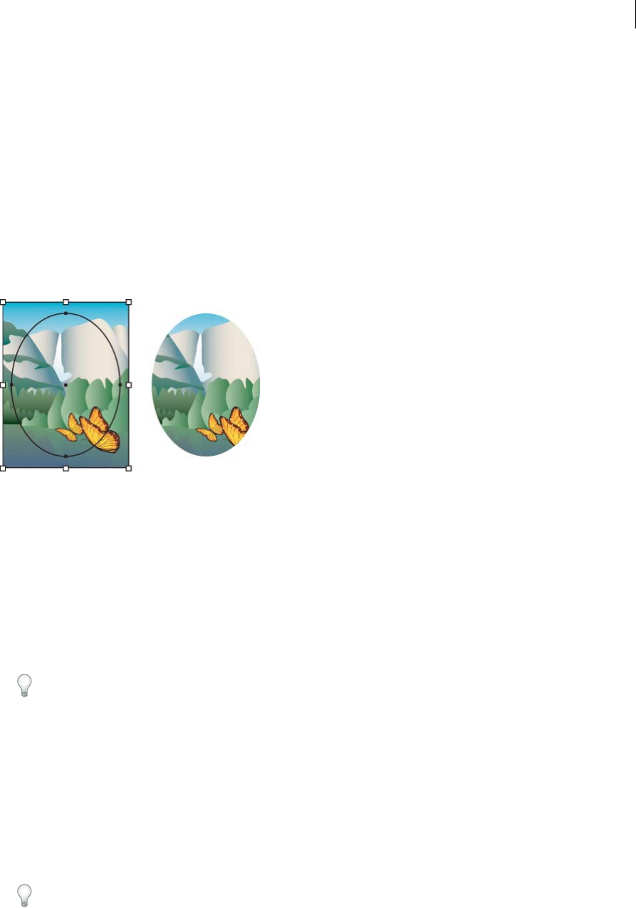
283
Reshaping objects
Last updated 6/5/2015
About clipping masks
A clipping mask is an object whose shape masks other artwork so that only areas that lie within the shape are visible—
in effect, clipping the artwork to the shape of the mask. The clipping mask and the objects that are masked are called a
clipping set. You can make a clipping set from a selection of two or more objects or from all objects in a group or layer.
Object-level clipping sets are combined as a group in the Layers panel. If you create layer-level clipping sets, the object
on top of the layer clips all of the objects below it. All operations that you perform on an object-level clipping set, such
as transformations and alignment, are based on the clipping mask’s boundary, not the unmasked boundary. Once you
have created an object-level clipping mask, you can only select the clipped content by using the Layers panel, the Direct
Selection tool, or by isolating the clipping set.
For a video on using Pathfinder effects and clipping masks and how to import clipping masks into Flash, see
www.adobe.com/go/vid0057.
The following guidelines apply to creating clipping masks:
•The objects that you mask are moved into the clipping mask’s group in the Layers panel if they don’t already reside
there.
•Only vector objects can be clipping masks; however, any artwork can be masked.
•If you use a layer or group to create a clipping mask, the first object in the layer or group masks everything that is a
subset of the layer or group.
•Regardless of its previous attributes, a clipping mask changes to an object with no fill or stroke.
Tip: To create a semitransparent mask, use the Transparency panel to create an opacity mask.
Hide parts of objects with a clipping mask
1Create the object you want to use as the mask.
This object is called the clipping path. Only vector objects can be clipping paths.
2Move the clipping path above the objects you want to mask in the stacking order.
3Select the clipping path and the objects you want to mask.
4Choose Object > Clipping Mask > Make.
To create a clipping path from the area where two or more objects overlap, group the objects first.

284
Reshaping objects
Last updated 6/5/2015
Create a clipping mask for a group or layer
1Create the object you want to use as the mask.
This object is called the clipping path. Only vector objects can be clipping paths.
2Move the clipping path and the objects you want to mask into a layer or group.
3In the Layers panel, make sure that the masking object is at the top of the group or layer, and then click the name of
the layer or group.
4Click the Make/Release Clipping Masks button at the bottom of the Layers panel or select Make Clipping Mask from
the Layers panel menu.
Edit a clipping mask
1In the Layers panel, select and target the clipping path. Or, select the clipping set and choose Object > Clipping Mask
> Edit Mask.
2Do any of the following:
•Move the clipping path by dragging the object’s center reference point with the Direct Selection tool.
•Reshape the clipping path using the Direct Selection tool.
•Apply a fill and stroke to a clipping path.
To select all clipping paths in a document, deselect all artwork. Then choose Select > Object > Clipping Masks.
Edit paths within a clipping set
To edit portions of a path that fall outside of the clipping mask, you must first select the specific path within in the
clipping mask boundary, and then edit the path.
1Do one of the following:
•Target the path in the Layers panel.
•Position the Direct Selection tool over a portion of the path that appears within the mask. When the path’s outline
appears, click it.
Note: To select a clipped path by clicking it, you must click the portion of it that appears inside the mask.
2Edit the path.
Add or remove an object from masked artwork
❖In the Layers panel, drag the object into or out of the group or layer that contains the clipping path.
Release objects from a clipping mask
❖Do one of the following:
•Select the group that contains the clipping mask, and choose Object > Clipping Mask > Release.
•In the Layers panel, click the name of the group or layer that contains the clipping mask. Click the Make/Release
Clipping Masks button at the bottom of the panel, or select Release Clipping Mask from the panel menu.
Because the clipping mask was assigned a fill and stroke value of None, it is now not visible unless you select it or
assign it new paint attributes.

285
Reshaping objects
Last updated 6/5/2015
More Help topics
Visual Tutorial - Creating a mask
Video Tutorial - Create a basic clipping mask
Layers panel overview
Using opacity masks
Stacking objects
Building new shapes using the Shape Buildertool
About the Shape Builder Tool
The Shape Builder tool is an interactive tool for creating complex shapes by merging and erasing simpler shapes.
It works on simple and compound paths.
It intuitively highlights edges and regions of the selected art, which can be merged to form new shapes. An edge is
defined as the section of a path, which does not intersect any other path of the selected objects. A region is a closed area
bounded by edges.
By default, the tool is in merge mode where it allows you to combine paths or regions. You can also switch to the erase
mode to delete any unwanted edges or regions by pressing Alt (Windows) or Option (Mac).
For a video on creating new shapes using the Shape Builder tool, see www.adobe.com/go/lrvid5203_ai_en.
Setting the Shape Builder tool options
You can set up and customize various options such as gap detection, coloring source, and highlighting to get the
required merging capability and better visual feedback.
Double-click the Shape Builder Tool icon in the Tools panel to set these options in the Shape Builder Tool Options
dialog box.
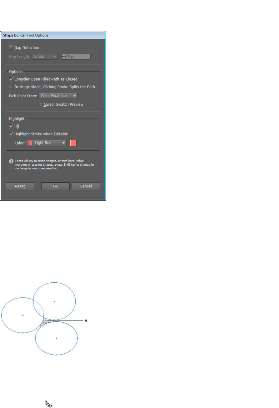
286
Reshaping objects
Last updated 6/5/2015
Gap Detection Set the gap length using the Gap Length drop-down list. The values available are Small (3 points),
Medium (6 points), and Large (12 points).
Select the Custom check box if you want to provide an exact gap length.
When you select the gap length, Illustrator finds the gaps only close to the specified gap length value. Make sure that
the gap length value is close (approximately) to the actual gap length of the art. You can check if the gaps are being
detected by providing different gap length values until the gaps in the art are detected.
For example, if you set the gap length to 12 points, whereas the shape that you need to merge contains gaps at 3 points,
Illustrator may not detect the gaps.
Consider Open Filled Paths as Closed If this option is selected, an invisible edge is created for an open path to make a
region. When you click inside the region, a shape is created.
In Merge Mode, Clicking the Stroke Splits the Path Select the check box, In Merge Mode, Clicking Stroke Splits the
Path. This option allows you to split the parent path into two. The first path is created from the edge on which you click
and second path is the remaining portion of the parent path excluding the first path. If this option is selected, the
pointer changes to , while splitting the path.

287
Reshaping objects
Last updated 6/5/2015
Pick Color From You can choose to color objects using the color swatches or the colors used in existing artwork. Use
the Pick Color From drop-down list to select the Color Swatches or Artwork option.
If you select the Color Swatches option, you get the Cursor Swatch Preview option. You can select the Cursor Swatch
Preview check box to preview and select colors. A Live Paint style cursor swatch is provided when you select this option.
It allows iteration (using the arrow keys) and selecting colors from the swatches panel.
note: You can iterate using the arrow keys even if the Cursor Swatch Preview is disabled.
To change the color of the stroke, move the pointer over object edges to highlight and change the color of the stroke.
This option works only if the option, In Merge Mode, Clicking Stroke Splits the Path is selected.
You can select the fill color of a region by pointing anywhere on the document.
note: The Cursor Swatch Preview is not displayed while merging, to ensure that the shapes are clearly visible.
If you select the Artwork option, Illustrator uses the same rules that are used for other art styles on merged objects. For
more information, see step 6 in Creating shapes using Shape Builder Tool.
Fill The Fill check box is selected by default. If this option is selected, the path or region that you can merge, is
highlighted in gray, when you mouse over the selected path. If this option is not selected, the selected region or path
appears as normal.
Highlight Stroke When Editable If this option is selected, Illustrator highlights the strokes that you can edit. The
editable stroke appears in the color that you choose from the Color drop-down list.
Live Rectangles and Rounded Rectangles
After you create a rectangle or rounded rectangle using the Shape tool, you can now continue to modify its properties
such as width, height, rounded corners, corner types, and radii (individually or collectively). These shape properties
are now editable using either the on-art controls or the numeric fields in the Transform panel, which now has a separate
Rectangle Properties section.
For more help, see the article on working with Live Corner widgets .
Capabilities of Live Rectangles
Note: To view the bounding box when you select an object, ensure that the setting is set to display the bounding box (View
> Show Bounding Box).
1Draw one or more rectangles or rounded rectangles, using the Shape tool.
Corner and Scale/Rotate widgets appear along the boundary of the Live Rectangles.
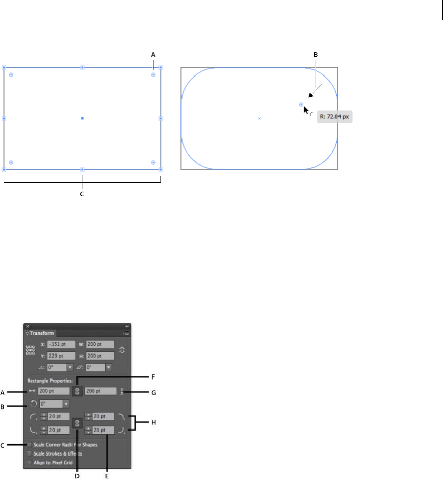
288
Reshaping objects
Last updated 6/5/2015
A Corner widgets (four per rectangle) B Dragging a Corner widget causes the corner radii to change C Scale/Rotate widgets (eight per
rectangle)
2The Transform panel is displayed (or, comes into focus if already open). If the Transform panel does not open:
•Press Shift + F8, or,
•Click Windows menu > Transform.
Note: To specify if the Transform panel appears or not when you create a rectangle or rounded rectangle, use the Show
on Shape Creation option in the Transform panel's flyout menu.
A Rectangle width B Rectangle angle C Scale corners proportionally D Link Corner radius values E Radius of the corner F Constrain
rectangle width and height G Rectangle height H Corner type dropdown
3If multiple Live Rectangles are selected:
•When the Rectangle or Rounded Rectangle tool is selected, you can modify properties of individual shapes using
the on-screen widgets.
•You can modify the properties of multiple shapes, using the Transform panel.
4Use your mouse on the Live Rectangleor the fields in the Transform panel (Rectangle Properties area) to do any of
the following:
•Change the height or width of the rectangle. The corners are maintained, and the radii do not change.
•Rotate the rectangle, using the Scale/Rotate widget.
•Use the Scale Corner Radii For Shapes checkbox to ensure that corner radii increase or decrease in direct
proportion to the object's transformation.
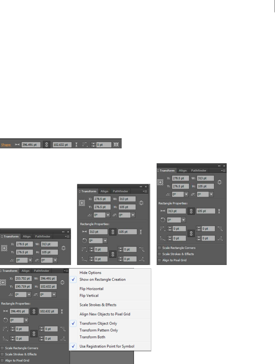
289
Reshaping objects
Last updated 6/5/2015
•Use the Corner type drop-downs in the Transform panel, to change the Corner type of any of the corners of the
rectangle.
•Use the stepper control or type in an absolute value in the Transform panel, for each of the corners of the
rectangle.
Note: Irrespective of which tool is selected, when rectangles are selected, editing properties in the Transform panel will
modify the selected artwork.
5In the Rectangle Properties area, use the Angle field to rotate the selected rectangle(s). The value of this field is the
angle by which the selected rectangle is rotated from the horizontal axis.
Accessing Live rectangle and rounded rectangle properties
You can access the properties of Live Rectangles and Rounded Rectangles from more different places in Illustrator CC.
The Control panel
The Transform panel
Selecting Live Rectangles and Rounded Rectangles
Layers panel
Live Rectangles and Rounded Rectangles are displayed as a different object type in the Layers panel. For example, when
you draw a Live Rectangle, the layer is named <Rectangle>, in the Layers panel. This helps in identifying the available
Live Shapes, for purposes of selection and modification.
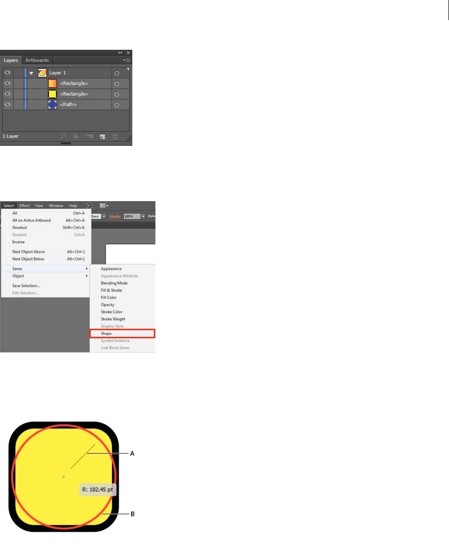
290
Reshaping objects
Last updated 6/5/2015
Select menu option
A new menu item, Shape, has been added to the Select > Same menu. When you select Select > Same > Shape option,
all the available Live Rectangles and Rounded Rectangles are selected.
Maximum radius
When you drag the corners of a Live Rectangle or Rounded Rectangle to the maximum possible limit, the preview of
the rounded corners is displayed in red.
A Dragging a corner to the center B The preview of the shape is shown in red when the maximum possible radius is reached
Converting rectangles
•When you open a document saved in an older version of Illustrator, the rectangles in that document are not
automatically editable as Live Rectangles. To convert a rectangle into a Live Rectangle, select the rectangle, and then
click Object > Shape > Convert to Rectangle.
•To convert a Live Rectangle into a rectangle, select the Live Rectangle, and then click Object > Shape > Expand
Rectangle.
CSS support
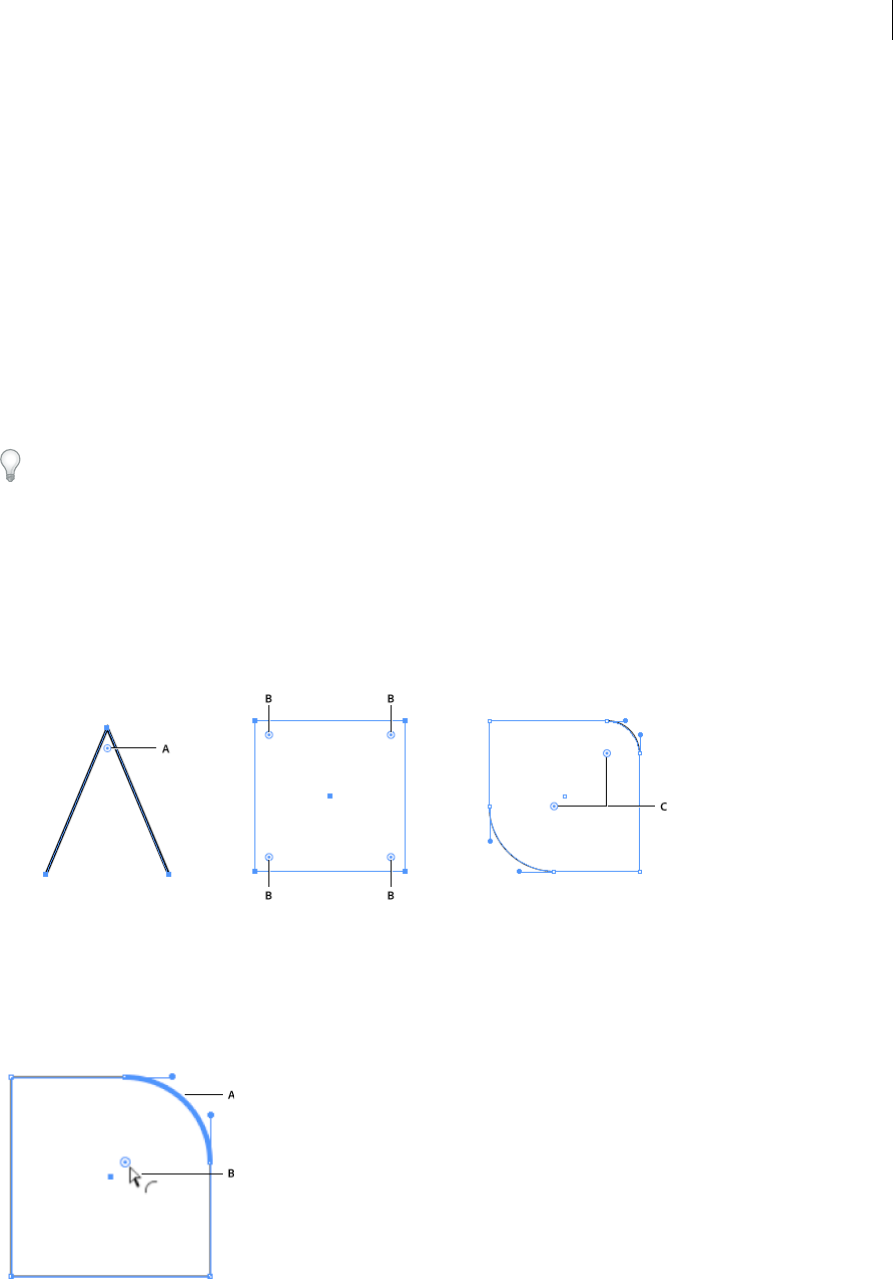
291
Reshaping objects
Last updated 6/5/2015
CSS Export honors individual radii information of a rounded rectangle with corners having different radii.
Working with Live Corners
Live Corners
You can select one or more corner anchor points in a simple path, or multiple anchor points across several paths in your
artwork. When selected, a Live Corners widget appears next to each corner point. Dragging a widget causes the corner
point to change shape, into one of three available corner types. The three available corner types are Round, Inverted
Round, and Chamfer.
For more information, see the article on Live Rectangles and Rounded Rectangles .
The Live Corners widget
The Live Corners widget is enabled when you select the Direct Selection tool and you have a path selection containing
corner points. A Live Corners widget is displayed next to a corner when you select:
•One or more path(s) that have corners.
•One or more rounded corners
A The Live Corners widget, when a path contains only one corner point B Live Corners widgets, when multiple corners are selected C Live
Corners widgets, when paths are selected (in this case, two opposite rounded paths)
Dragging the Live Corners widget with the Direct Selection Tool is the easiest way to convert a corner into a round
corner. Also, when you hover the mouse on a Live Corners widget, the corresponding round corner is highlighted
(shown below).
A A rounded corner is highlighted when the mouse hovers over, or is in proximity of, a Live Corners widget B Mouse pointer close to a Live
Corners widget
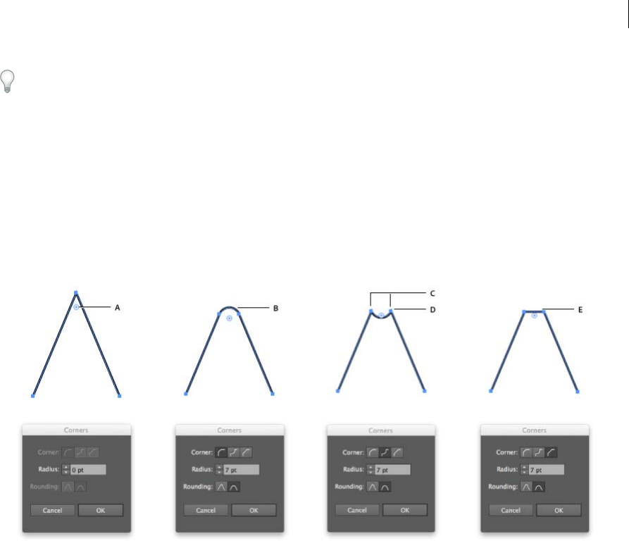
292
Reshaping objects
Last updated 6/5/2015
If you prefer not to see the Live Corners widget when you select the Direct Selection Tool, you can turn it off from View
> Hide Corner Widget.
The Corners dialog
The Corners dialog lets you manipulate corner settings. In the Corners dialog you can set the corner style, the radius
of the corner, and the type of rounding.
To access the corner settings:
•Double-click the Live Corners widget, or,
•Select the corner, and click the Corners link in the Control Panel.
A Live Corners widget B Round corner C Associated anchor points D Inverted round corner E Chamfer corner
How to: Using the Live Corners widget
1With your artwork open, use the Direct Selection Tool (A) to select one or more corner points. You may select:
•One or more corner points on a path
•More than one corner points on different paths
2Do one of the following:
•Drag the Live Corners widget.
•Click the Corners link in the Control Panel, and set the options available.
•Double-click the Live Corners widget, and then modify the options in the Corners dialog.
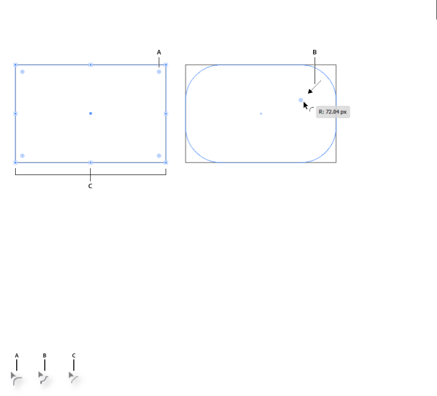
293
Reshaping objects
Last updated 6/5/2015
A Original corner B Direction in which the mouse is being dragged C Preview of the round corner D Live Corners widget E Radius of the
corner applied F Cursor indicating corner style being applied
Change the corner style
To change the corner style, do one of the following:
•While dragging a Live Corners widget, click the Up or Down arrow keys. The cursor is changed to display the
current Corner style.
•In the Control Panel, click the Corners link to open the Corners pop-up panel. Select the corner style you want to
apply.
•Double-click the Live Corners widget to display the Corners dialog, and select a Corner style from the dialog.
•Alt/Option + click on a widget cycles through the corner styles.
A Round corner B Inverted Round corner C Chamfer corner
Considerations
•You can use the Live Corners feature multiple times on a corner, and modify either the radius or the corner style.
However, if an associated anchor point in the corner is dragged or manipulated in such a way that the roundness is
lost, then the widget will no longer appear for that corner.
•A corner cannot be rounded beyond a point where the rounded corner:
•reaches the end of the path, or,
•reaches an adjacent anchor point, or,
•reaches an anchor point being created while modifying an adjacent corner.
•When you drag a Live Corners Widget to the maximum possible point, the rounded corner is displayed as a red path.

294
Reshaping objects
Last updated 6/5/2015
A A red path indicates that the maximum radius for the given corner has been achieved B Direction in which the Live Corner widget is being
pulled C Live Corner Widget
Live Corners widget preferences
Hide Corner Widget
•If you prefer not to see the Live Corners widget when you select the Direct Selection Tool, you can turn it off from
View > Hide Corner Widget.
•If you want to continue seeing the Live Corners widget when you select the Direct Selection Tool, click View > Show
Corner Widget.
Maximum Angle Limit
Users have the option to hide the Live Corners widget for corner angles greater than a specified value. You can specify
this value in the Preferences > Selection & Anchor Display > Hide Corner Widget for angles greater than field.
Blending objects
About blended objects
You can blend objects to create and distribute shapes evenly between two objects. You can also blend between two open
paths to create a smooth transition between objects, or you can combine blends of colors and objects to create color
transitions in the shape of a particular object.
Note: Blending objects is not the same as applying blending modes or transparency to objects. For information on blending
modes and transparency, see About blending modes.
Once you create a blend, the blended objects are treated as one object. If you move one of the original objects, or edit
the original object’s anchor points, the blend changes accordingly. In addition, the new objects blended between the
original objects don’t have their own anchor points. You can expand the blend in order to divide the blend into distinct
objects.
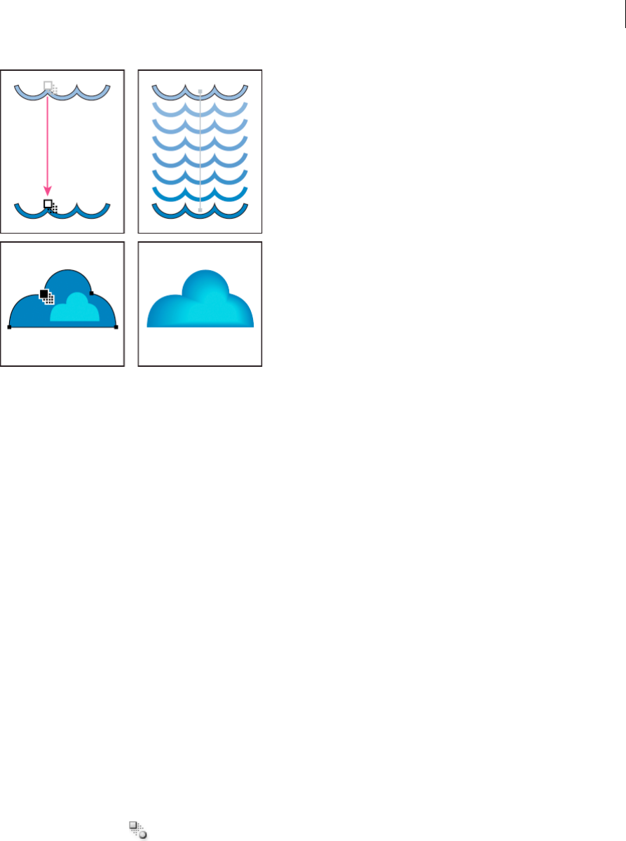
295
Reshaping objects
Last updated 6/5/2015
The following rules apply to blended objects and their associated colors:
•You cannot blend between mesh objects.
•If you blend between one object painted with a process color and another object painted with a spot color, the
blended shapes are painted with a blended process color. If you blend between two different spot colors, process
colors are used to paint the intermediate steps. If, however, you blend between tints of the same spot color, the steps
are all painted with percentages of the spot color.
•If you blend between two patterned objects, the blended steps will only use the fill of the object on the topmost layer.
•If you blend between objects that have blending modes specified with the Transparency panel, the blended steps will
only use the blending mode of the top object.
•If you blend between objects with multiple appearance attributes (effects, fills, or strokes), Illustrator attempts to
blend the options.
•If you blend between two instances of the same symbol, blended steps will be instances of that symbol. If, however,
you blend between two instances of different symbols, the blended steps will not be symbol instances.
•By default, blends are created as knockout transparency groups, so that if any of the steps consist of overlapping
transparent objects, these objects will not show through each other. You can change this setting by selecting the
blend and deselecting Knockout Group in the Transparency panel.
Create blends
The Blend tool and Make Blend command let you create blends, which are a series of intermediate objects and colors
between two or more selected objects.
Create a blend with the Blend tool
1Select the Blend tool .
2Do one of the following:
•To blend in sequential order with no rotation, click anywhere on each object, but avoid anchor points.
•To blend to a specific anchor point on an object, click the anchor point with the Blend tool. When the pointer is
over an anchor point, the pointer changes from a white square to transparent with a black dot in its center.
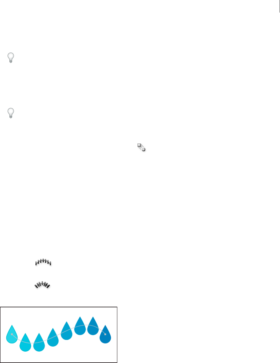
296
Reshaping objects
Last updated 6/5/2015
•To blend open paths, select an endpoint on each path.
3When you are finished adding objects to the blend, click the Blend tool again.
By default, Illustrator calculates the optimum number of steps to create a smooth color transition. To control the
number of steps or distance between steps, set blending options. (See Blend options.)
Create a blend with the Make Blend command
1Select the objects you want to blend.
2Choose Object > Blend > Make.
By default, Illustrator calculates the optimum number of steps to create a smooth color transition. To control the
number of steps or distance between steps, set blending options.
Blend options
You set blending options by double-clicking the Blend tool or choosing Object > Blend > Blend Options. To change
options for an existing blend, select the blended object first.
Spacing Determines how many steps are added to the blend.
Smooth Color Lets Illustrator auto-calculate the number of steps for the blends. If objects are filled or stroked with
different colors, the steps are calculated to provide the optimum number of steps for a smooth color transition. If the
objects contain identical colors, or if they contain gradients or patterns, the number of steps is based on the longest
distance between the bounding box edges of the two objects.
Specified Steps Controls the number of steps between the start and end of the blend.
Specified Distance Controls the distance between the steps in the blend. The distance specified is measured from the
edge of one object to the corresponding edge on the next object (for example, from the rightmost edge of one object to
the rightmost edge of the next).
Orientation Determines the orientation of blended objects.
Align to Page
Orients the blend perpendicular to the x axis of the page.
Align to Path
Orients the blend perpendicular to the path.
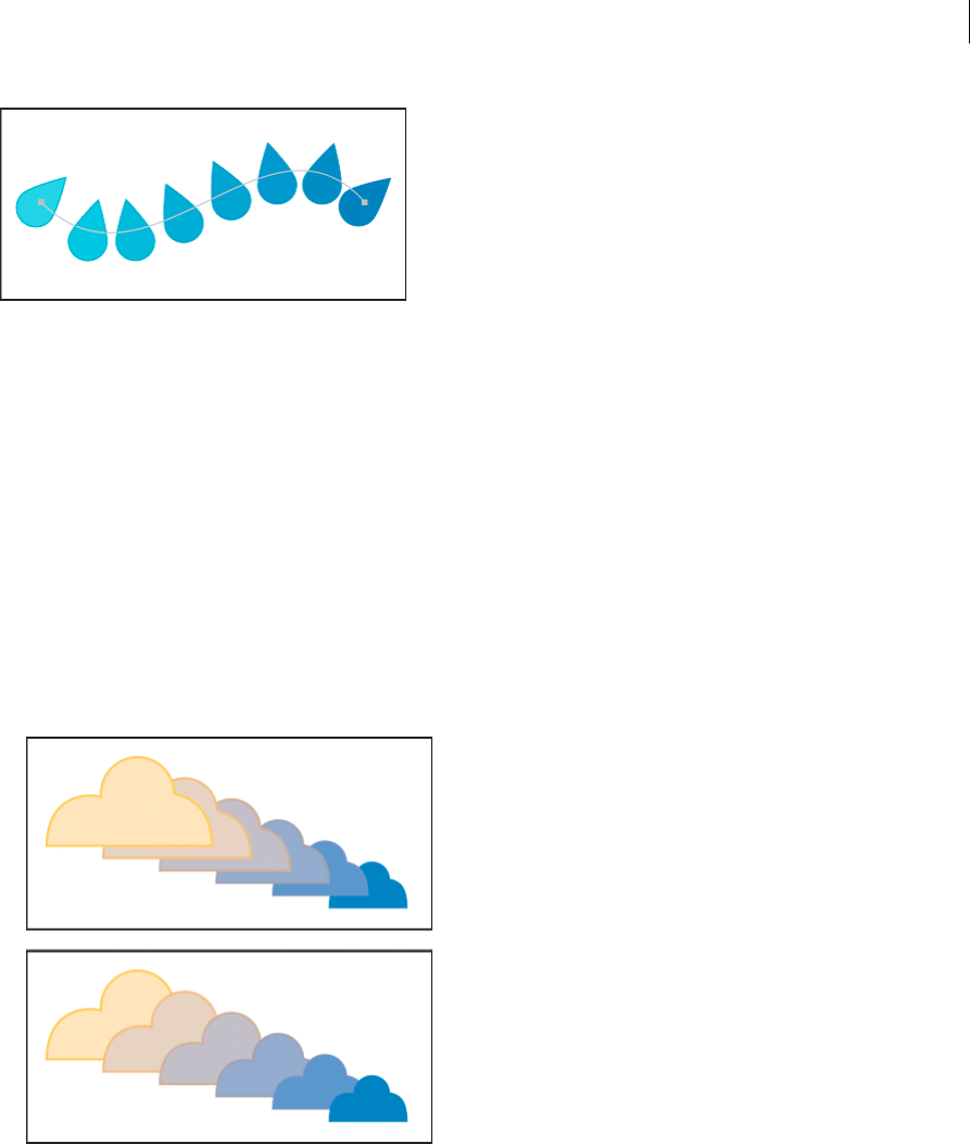
297
Reshaping objects
Last updated 6/5/2015
Change the spine of a blended object
The spine is the path along which the steps in a blended object are aligned. By default, the spine forms a straight line.
•To adjust the shape of the spine, drag the anchor points and path segments on the spine with the Direct Selection
tool.
•To replace the spine with a different path, draw an object to use as the new spine. Select the spine object and the
blended object, and choose Object > Blend > Replace Spine.
•To reverse the order of a blend on its spine, select the blended object and choose Object > Blend > Reverse Spine.
Reverse the stacking order in a blended object
1Select the blended object.
2Choose Object > Blend > Reverse Front To Back.
Release or expand a blended object
Releasing a blended object removes the new objects and restores the original objects. Expanding a blended object
divides the blend into distinct objects, which you can edit individually like any object.
1Select the blended object.
2Do one of the following:
•Choose Object > Blend > Release.
•Choose Object > Blend > Expand.

298
Reshaping objects
Last updated 6/5/2015
More Help topics
Reshaping objects
Stacking objects
Enhanced reshape workflows with touch support
Reshape segment workflows & touch support
The reshape path segment workflows have been enhanced to support reshaping with touch input on touch-based
devices.
In earlier releases of Illustrator, curved path segments could be reshaped using the Direct Selection tool, but their
handles were always constrained to their original angles. Now, the reshaping of segments is unconstrained. Also,
converting straight segments to curved paths is now possible by simply dragging the segment itself. There are three
ways to reshape path segments.
Pen Tool
1While using the pen tool, press the Alt / Option key.
2When you hover the pointer over a path segment, the cursor changes to the Reshape Segment cursor.
3Dragging a segment will reshape the path segment
A Original shape B The Reshape Segment cursor indicates a reshape-ready segment C When the Reshape Segment cursor is visible, modify
the shape of the segment by clicking and dragging. D Reshape as many segments as required E Final shape when reshaping tasks are complete
4To continue drawing with the Pen tool, release the Alt / Option key.
5To create a semi-circular segment hold the Shift key while reshaping a segment. Holding the Shift modifier
constrains the handles to a perpendicular direction, and ensures that the handles are of equal length.
Convert Anchor Point Tool
1Select the Convert Anchor Point tool, and then hover the pointer over a path segment.
2When the Reshape Segment cursor is displayed, drag the path segment to reshape it.
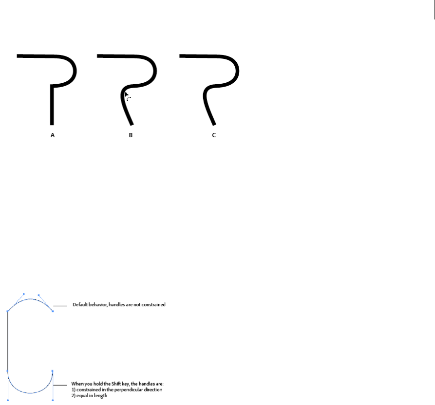
299
Reshaping objects
Last updated 6/5/2015
A Original artwork B Reshaping a segment with the Anchor Point tool C Modified shape
3To create a copy of the path segment, press Alt / Option while performing Step 2.
4To create a semi-circular segment hold the Shift key while reshaping a segment. Holding the Shift modifier
constrains the handles to a perpendicular direction, and ensures that the handles are of equal length.
Direct Selection Tool
Using the Direct Selection tool on a straight segment moves the segment. However, when used on a curved segment,
reshaping is unconstrained, similar to the Convert Anchor point tool or Pen tool.
Constraining Handles in the Perpendicular Direction
Holding the Shift key while reshaping with the Pen, Convert Anchor Point, and Direct Selection tools constrains the
handles in the perpendicular direction. This enables you to reshape curves to semi-circular shapes. This also ensures
that the handles are of equal length.
Reshaping objects with effects
Reshaping objects with effects
Using effects is a convenient way to reshape objects without making permanent changes to their underlying geometry.
Effects are live, which means that you can modify or remove the effect at any time.
You can use the following effects to reshape objects:
Convert To Shape Converts the shape of vector objects to a rectangle, rounded rectangle, or ellipse. Set the dimensions
of the shape using absolute or relative dimensions. For rounded rectangles, specify a corner radius to determine the
curvature of the rounded edge.
Distort & Transform Lets you quickly reshape vector objects.

300
Reshaping objects
Last updated 6/5/2015
Free Distort Lets you change the shape of a vector object by dragging any of four corner points.
Pucker & Bloat Pulls a vector object’s anchor points outward while curving the segments inward (Pucker) or inward
while curving the segments outward (Bloat). Both options pull the anchor points relative to the object’s center point.
Roughen Transforms a vector object’s path segments into a jagged array of peaks and valleys of various sizes. Set the
maximum length for segment paths using an absolute or relative size. Set the density of jagged edges per inch (Detail)
and choose between soft edges (Smooth) or sharp edges (Corner).
Transform Reshapes an object by resizing, moving, rotating, reflecting (flipping), and copying it.
Tweak Randomly curves and distorts path segments inward and outward. Set the vertical and horizontal distortion
using an absolute or relative amount. Specify whether or not to modify anchor points, move control points that lead
into anchor points on the path (“In” Control Points), and move control points that lead out of anchor points on the path
(“Out” Control Points).
Twist Rotates an object more sharply in the center than at the edges. Entering a positive value twists clockwise; entering
a negative value twists counterclockwise.
Zig Zag Transforms an object’s path segments into a jagged or wavy array of uniformly sized peaks and valleys. Set the
length between peaks and valleys using an absolute or relative size. Set the number of ridges per path segment and
choose between wavy edges (Smooth) or jagged edges (Corner).
Warp Distorts or deforms objects, including paths, text, meshes, blends, and bitmap images. Choose one of the
predefined warp shapes. Then select which axis the bending option affects and specify the amount of bending and
distortion to apply.
Round the corners of objects
The Round Corners effect converts the corner points of a vector object to smooth curves.
1In the Layers panel, target the items you want to round.
If you want to round a specific attribute of an object, such as its fill or stroke, target the object in the Layers panel
and then select the attribute in the Appearance panel.
2Choose Effect > Stylize > Round Corners. (The command is located in the first Stylize submenu.)
3To define the curvature of the rounded curve, enter a value in the Radius text box, and click OK.
More Help topics
About effects
Apply an effect
Modify or delete an effect
Creating 3D objects
Note: 3D tools are independent of the Perspective Grid tools and 3D objects are treated like any other object in perspective.
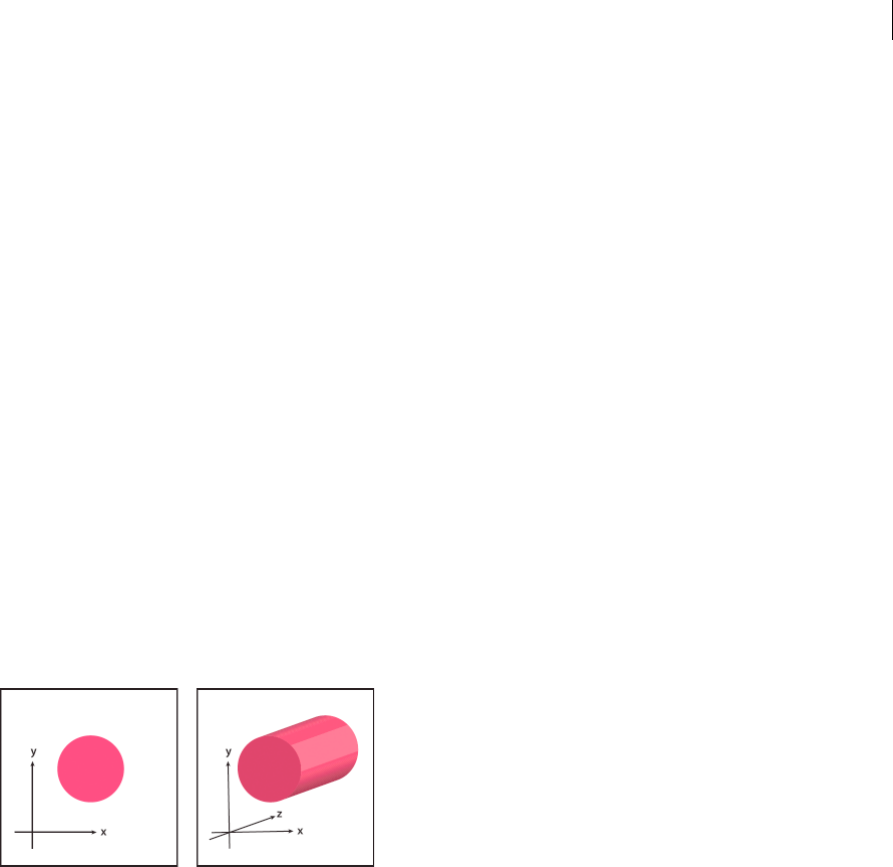
301
Reshaping objects
Last updated 6/5/2015
Create 3D objects
3D effects enable you to create three-dimensional (3D) objects from two-dimensional (2D) artwork. You can control
the appearance of 3D objects with lighting, shading, rotation, and other properties. You can also map artwork onto each
surface of a 3D object.
There are two ways to create a 3D object: by extruding or revolving. In addition, you can also rotate a 2D or 3D object
in three dimensions. To apply or modify 3D effects for an existing 3D object, select the object and then double-click the
effect in the Appearance panel.
Note: 3D objects may display anti-aliasing artifacts on screen, but these artifacts won’t print or appear in artwork
optimized for the web.
For more information about working with 3D objects in Illustrator, see the 3D tutorials at
www.adobe.com/go/learn_ai_tutorials_3d_en. For a video on creating 3D objects, see www.adobe.com/go/vid0053.
More Help topics
3D tutorials
Create a 3D object by extruding
Extruding extends a 2D object along the object’s z axis to add depth to the object. For example, if you extrude a 2D
ellipse, it becomes a cylinder.
Note: The object’s axis always lies perpendicular to the object’s front surface and moves relative to the object if the object is
rotated in the 3D Options dialog box.
1Select the object.
2Choose Effect > 3D > Extrude & Bevel.
3Click More Options to view the complete list of options, or Fewer Options to hide the extra options.
4Select Preview to preview the effect in the document window.
5Specify options:
Position Sets how the object is rotated and the perspective from which you view it. (See Set 3D rotation position
options.)
Extrude & Bevel Determines the object’s depth and the extent of any bevel added to or cut from it. (See Extrude &
Bevel options.)
Surface Creates a wide variety of surfaces, from dull and unshaded matte surfaces to glossy and highlighted surfaces
that look like plastic. (See Surface shading options.)
Lighting Adds one or more lights, varies the light intensity, changes the object’s shading color, and moves lights
around the object, for dramatic effects. (See Lighting options.)
Map Maps artwork onto the surfaces of a 3D object. (See Map artwork to a 3D object.)
6Click OK.
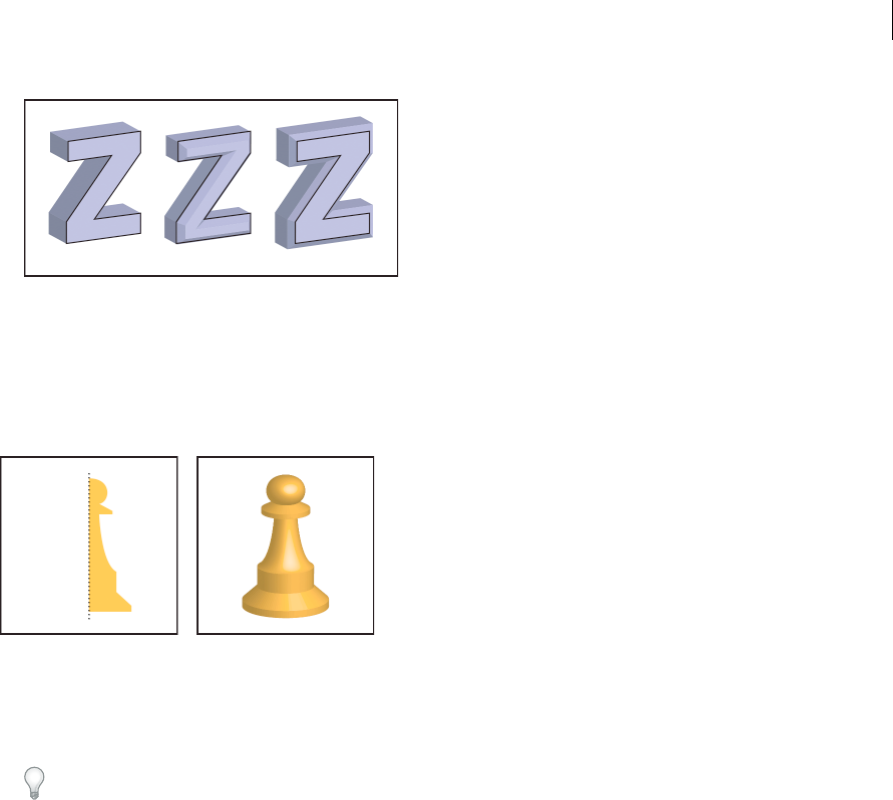
302
Reshaping objects
Last updated 6/5/2015
Create a 3D object by revolving
Revolving sweeps a path or profile in a circular direction around the global y axis (revolve axis) to create a 3D object.
Because the revolve axis is vertically fixed, the open or closed path that you revolve typically needs to depict half of the
desired 3D object’s profile in a vertical and front-facing position; you can then rotate the 3D object’s position in the
effect’s dialog box.
1Select the object.
Note: Applying the 3D Revolve effect to one or more objects simultaneously revolves each object around its own axis.
Each object resides in its own 3D space and can’t intersect other 3D objects. Applying the Revolve effect to a targeted
group or layer, on the other hand, revolves the objects around a single axis.
Revolving a filled path with no stroke is much faster than revolving a stroked path.
2Choose Effect > 3D > Revolve.
3Select Preview to preview the effect in the document window.
4Click More Options to view the complete list of options, or Fewer Options to hide the extra options.
Position Sets how the object is rotated and the perspective from which you view it. (See Set 3D rotation position
options.)
Revolve Determines how to sweep the path around the object to turn it into three dimensions. (See Revolve
options.)
Surface Creates a wide variety of surfaces, from dull and unshaded matte surfaces to glossy and highlighted surfaces
that look like plastic. (See Surface shading options.)
Lighting Adds one or more lights, varies the light intensity, changes the object’s shading color, and moves lights
around the object, for dramatic effects. (See Lighting options.)
Map Maps artwork onto the surfaces of a 3D object. (See Map artwork to a 3D object.)
5Click OK.
Set options
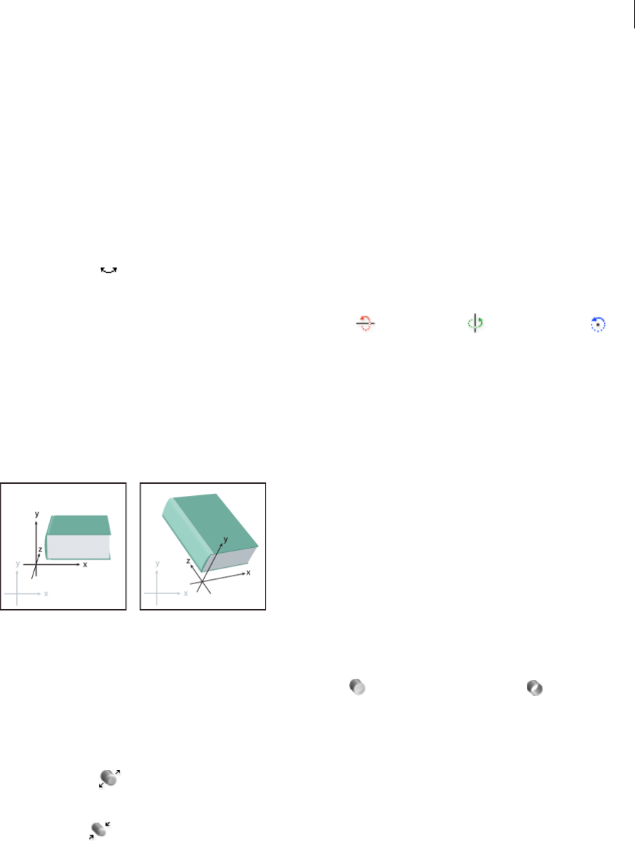
303
Reshaping objects
Last updated 6/5/2015
Set 3D rotation position options
❖Do any of the following:
•Choose a preset position from the Position menu.
•For unconstrained rotation, drag a track cube face. The front of the object is represented by the track cube’s blue
face, the object’s top and bottom faces are light gray, the sides are medium gray, and the back face is dark gray.
•To constrain the rotation along a global axis, hold down Shift while dragging horizontally (global y axis) or
vertically (global x axis). To rotate the object around the global z axis, drag in the blue band that surrounds the
track cube.
•To constrain the rotation around an object axis, drag an edge on the track cube. The pointer changes to a double-
sided arrow , and the cube edge changes color to identify the axis around which the object will rotate. Red
edges represent the object’s x axis, green edges represent the object’s y axis, and blue edges represent the object’s
z axis.
•Enter values between –180 and 180 in the horizontal (x) axis , vertical (y) axis , and depth (z) axis text
boxes.
•To adjust the perspective, enter a value between 0 and 160 in the Perspective text box. A smaller angle is similar
to a telephoto camera lens; a larger lens angle is similar to a wide-angle camera lens.
Note: A lens angle that is higher than 150 may result in objects extending beyond your point of view and appearing
distorted. Also, keep in mind that there are object x, y, and z axes and global x, y, and z axes. Object axes remain relative
to an object’s position in its 3D space. Global axes remain fixed relative to the computer screen; the x axis lies horizontally,
the y axis lies vertically, and the z axis lies perpendicular to the computer screen.
Extrude & Bevel options
Extrude Depth Sets the depth of the object, using a value between 0 and 2000.
Cap Specifies whether the object appears solid (Revolve Cap On ) or hollow (Revolve Cap Off ).
Bevel Applies the type of beveled edge you choose along the depth (z axis) of the object.
Height Sets the height between 1 and 100. Bevel heights that are too large for an object may cause the object to self-
intersect and produce unexpected results.
Bevel Extent Out
Adds the bevel to the object’s original shape.
Bevel Extent In
Carves the bevel out of the object’s original shape.
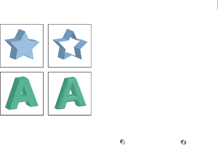
304
Reshaping objects
Last updated 6/5/2015
Revolve options
Angle Sets the number of degrees to revolve the path, between 0 and 360.
Cap Specifies whether the object appears solid (Revolve Cap On ) or hollow (Revolve Cap Off ).
Offset Adds distance between the revolve axis and the path, to create a ring-shaped object, for instance. You can enter
a value between 0 and 1000.
From Sets the axis around which the object revolves, either the Left Edge or Right Edge.
Surface shading options
Surface Lets you choose options for the shading surfaces:
Wireframe Outlines the contours of the object’s geometry and makes each surface transparent.
No Shading Adds no new surface properties to the object. The 3D object has the same color as the original 2D object.
Diffuse Shading Makes the object reflect light in a soft, diffuse pattern.
Plastic Shading Makes the object reflect light as if it were made of a shiny, high-gloss material.
note: Depending on what option you choose, different lighting options are available. If the object only uses the 3D Rotate
effect, the only Surface choices available are Diffuse Shading or No Shading.
Light Intensity Controls the light intensity between 0% and 100%.
Ambient Light Controls the global lighting, which changes the brightness of all the object’s surfaces uniformly. Enter a
value between 0% and 100%.
Highlight Intensity Controls how much the object reflects light, with values ranging from 0% to 100%. Lower values
produce a matte surface, and higher values create a shinier-looking surface.
Highlight Size Controls the size of the highlight from large (100%) to small (0%).
Blend Steps Controls how smoothly the shading appears across the object’s surfaces. Enter a value between 1 and 256.
Higher numbers produce smoother shades and more paths than lower numbers.
Draw Hidden Faces Displays the object’s hidden backfaces. The backfaces are visible if the object is transparent, or if
the object is expanded and then pulled apart.
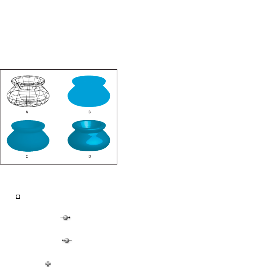
305
Reshaping objects
Last updated 6/5/2015
note: If your object has transparency and you want the hidden backfaces to display through the transparent front faces,
apply the Object > Group command to the object before you apply the 3D effect.
Preserve Spot Color (Extrude & Bevel effect, Revolve effect, and Rotate effect) Lets you preserve spot colors in the
object. Spot colors can’t be preserved if you chose Custom for the Shading Color option.
A Wireframe B No shading C Diffuse shading D Plastic shading
Lighting options
Light
Defines where the light is. Drag the light to where you want it on the sphere.
Move Light Back button
Moves the selected light behind the object.
Move Light Front button
Moves the selected light in front of the object.
New Light button
Adds a light. By default, new lights appear in the front center of the sphere.
Delete Light button Deletes the selected light.
note: By default, 3D Effects assigns one light to an object. You can add and delete lights, but the object must always have
at least one light.
Light Intensity Changes the selected light’s intensity between 0% and 100%.
Shading Color Controls the object’s shading color, depending on the command you choose:
None Adds no color to the shading.
Custom Lets you choose a custom color. If you choose this option, click the Shade Color box to select a color in the
Color Picker. Spot colors are changed to process colors.
Black Overprint Avoids process colors if you’re using a spot color workflow. The object is shaded by overprinting
shades of black on top of the object’s fill color. To view the shading, choose View >Overprint Preview.
Preserve Spot Color Lets you preserve spot colors in the object. Spot colors can’t be preserved if you chose Custom for
the Shading Color option.

306
Reshaping objects
Last updated 6/5/2015
A Selected light in front B Move selected light to back or front button C New light button D Delete light button
Add a custom bevel path
1Open the Bevels.ai file, which is located in the Adobe Illustrator CS5\Support Files\Required\Resources\en_US\
folder (Windows) or Adobe Illustrator CS5\Required\Resources\en_US folder ((Mac OS).
2Create a single open path in the Bevels.ai file.
3Choose Window > Symbols, and do one of the following to make the path a symbol:
•Drag the path to the Symbols panel.
•With the path selected, click the New Symbol button in the Symbols panel or choose New Symbol from the
panel menu.
4To rename the symbol, double-click the symbol in the Symbols panel, enter a name in the Symbol Options dialog
box, and click OK.
5Choose File > Save.
6Quit Illustrator and then relaunch Illustrator.
The Bevel menu in the 3D Extrude & Bevel Options dialog box lists the bevel.
7To apply the custom bevel, do one of the following:
•To apply the bevel to an extruded 3D object, select the 3D object, and then double-click the 3D Extrude & Bevel
effect in the Appearance panel. In the 3D Extrude & Bevel Options dialog box, choose the bevel from the Bevel
menu.
•To apply the custom bevel to 2D artwork, select the 2D object, and then choose Effect > 3D > Extrude & Bevel.
In the 3D Extrude & Bevel Options dialog box, choose the custom bevel from the Bevel menu.
Rotate an object in three dimensions
1Select the object.
2Choose Effect > 3D > Rotate.
3Select Preview to preview the effect in the document window.
4Click More Options to view the complete list of options, or Fewer Options to hide the extra options.
5Specify options:
Position Sets how the object is rotated and the perspective from which you view it. (See Set 3D rotation position
options.)
Surface Creates a wide variety of surfaces, from dull and unshaded matte surfaces to glossy and highlighted surfaces
that look like plastic. (See Surface shading options.)
6Click OK.
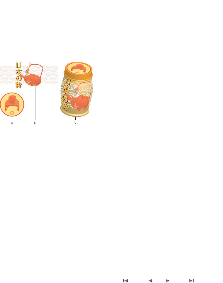
307
Reshaping objects
Last updated 6/5/2015
Map artwork to a 3D object
Every 3D object is composed of multiple surfaces. For example, an extruded square becomes a cube that is made of six
surfaces: the front and back faces, and the four side faces. You can map 2D artwork to each surface on a 3D object. For
example, you might want to map a label or text onto a bottle-shaped object or simply add different textures to each side
of an object.
A Symbol artwork B Symbol artwork C A and B mapped to 3D object
You can only map 2D artwork that’s stored in the Symbols panel to a 3D object. Symbols can be any Illustrator art object,
including paths, compound paths, text, raster images, mesh objects, and groups of objects.
When mapping 3D objects, consider the following:
•Because the Map Art feature uses symbols for mapping, you can edit a symbol instance and then automatically
update all surfaces that are mapped with it.
•You can interact with the symbol in the Map Art dialog box with normal bounding box controls to move, scale, or
rotate the object.
•The 3D effect remembers each mapped surface on an object as a number. If you edit the 3D object or apply the same
effect to a new object, there may be fewer or more sides than the original. If there are fewer surfaces than the number
of surfaces defined for the original mapping, the extra artwork will be ignored.
•Because a symbol’s position is relative to the center of an object surface, if the geometry of the surface changes, then
the symbol will be remapped relative to the new center of the object.
•You can map artwork to objects that use the Extrude & Bevel or Revolve effect, but you can’t map artwork to objects
that only use the Rotate effect.
1Select the 3D object.
2In the Appearance panel, double-click the 3D Extrude & Bevel or 3D Revolve effect.
3Click Map Art.
4Choose the artwork to map to the selected surface from the Symbol pop-up menu.
5To select which object surface you want to map, click the first , previous , next , and last surface arrow
buttons, or enter a surface number in the text box.
A light gray color mark appears on the surfaces that are currently visible. A dark gray color mark appears on the
surfaces that are hidden by the object’s current position. When a surface is selected in the dialog box, the selected
surface is outlined in red in the document window.
6Do any of the following:
•To move the symbol, position the pointer inside the bounding box and drag; to scale, drag a side or corner
handle; to rotate, drag outside and near a bounding box handle.

308
Reshaping objects
Last updated 6/5/2015
•To make the mapped artwork fit to the boundaries of the selected surface, click Scale To Fit.
•To remove artwork from a single surface, select the surface using the Surface options, and then either choose
None from the Symbol menu or click Clear.
•To remove all maps from all of the 3D object’s surfaces, click Clear All.
•To shade and apply the object’s lighting to the mapped artwork, select Shade Artwork.
•To show only the artwork map, not the geometry of a 3D object, select Invisible Geometry. This is useful when
you want to use the 3D mapping feature as a three-dimensional warping tool. For example, you could use this
option to map text to the side of an extruded wavy line, so that the text appears warped as if on a flag.
•To preview the effect, select Preview.
7Click OK in the Map Artwork dialog box.
Note: 3D tools are independent of Illustrator’s Perspective Grid tools. 3D objects are treated like any other art when
placed in Perspective Grid.
Touch-based tools and enhancements | Illustrator CC
With Illustrator CC, it is easier to use touch-enabled devices to interact with Illustrator text and objects. To
accommodate different styles of interacting with Illustrator, usability enhancements have been extended to the mouse
as well. You can use your mouse to work with and manipulate objects as easily as you would with a touch-enabled
device.
Also, many touch-enabled gestures have been enabled on operating systems. you can use Illustrator's user interface to
pan, swipe, and move objects related to the operating system.
To use Illustrator's features with touch, you would need:
•A Windows 7- or 8–based touchscreen computer, or,
•A Touchscreen device like Wacom Cintiq 24HD Touch
For panning and zooming using gestures, you would need:
•Direct touch device. For example, a touchscreen device.
•Indirect touch device. For example, the Trackpad on a Mac computer, touchpads, or the Wacom Intuos5 device.
Using touch to modify text (Touch Type tool)
Modify the properties of text using the Touch Type tool, using a mouse cursor or touch-based device (for example, a
touchscreen device).
1Pick the Touch Type tool (Shift + T) from the toolbar or Control Panel.
2Select a string or character of text.
3To modify the character (rotate, scale, move), manipulate the control handles that appear around the text using
touch or a mouse.
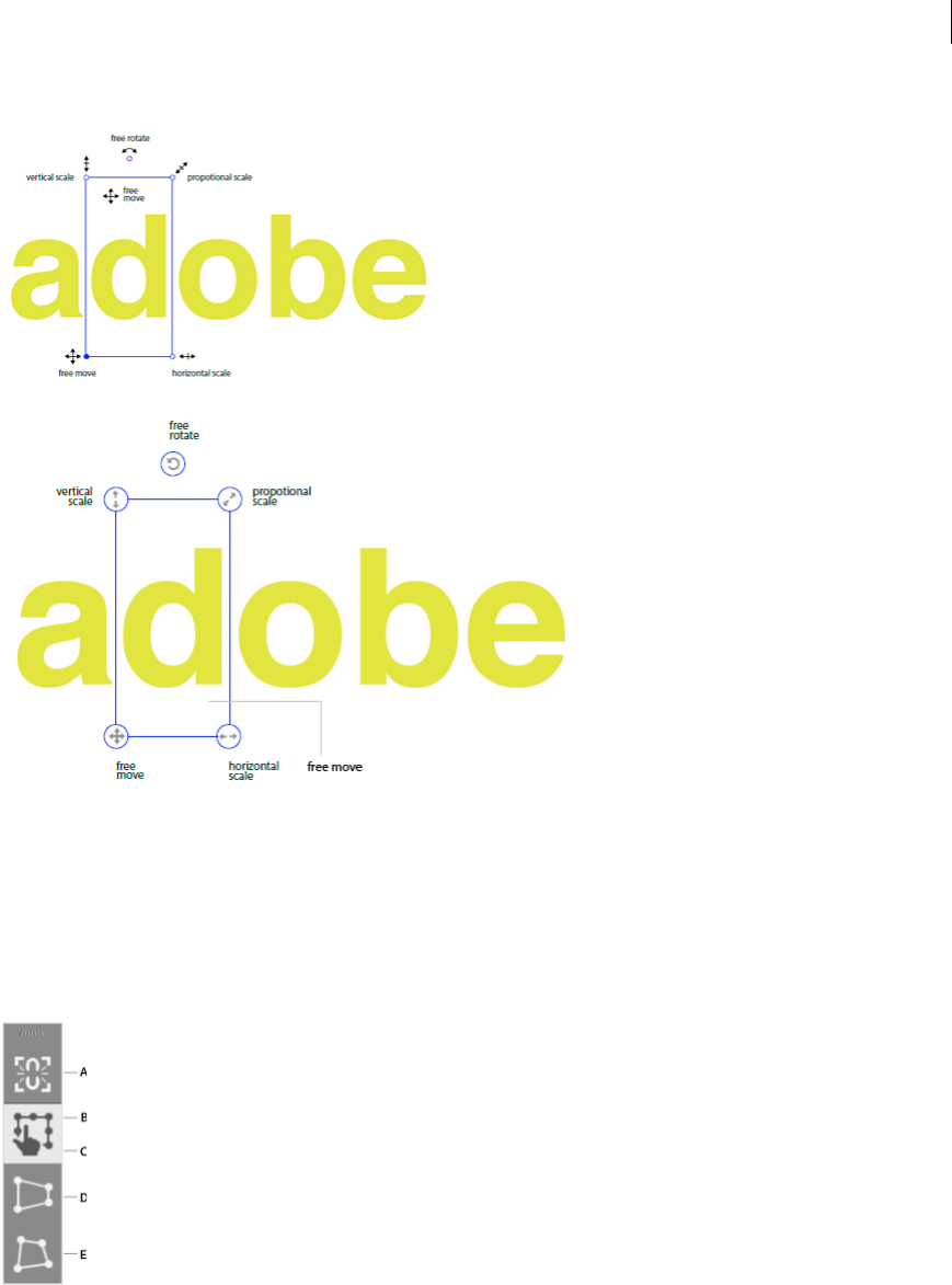
309
Reshaping objects
Last updated 6/5/2015
Using touch to modify shapes (Free Transform tool)
Move, scale, rotate, shear, or distort an object, using a mouse or touch-based device (for example, a touchscreen device).
1Select an object and pick the Free Transform tool.
2In the Free Transform tool widget, choose an appropriate action to perform on the selected object. Use the control
handles to move, scale, rotate, shear, or distort (perspective or free).
A Constrain B Free Transform C Selected action D Perspective distort E Free Distort
3When the Free Transform widget is active, the selected object has a movable reference point:
•Click and drag the reference point to any point on the artboard, to move the object relative to the position of the
reference point.
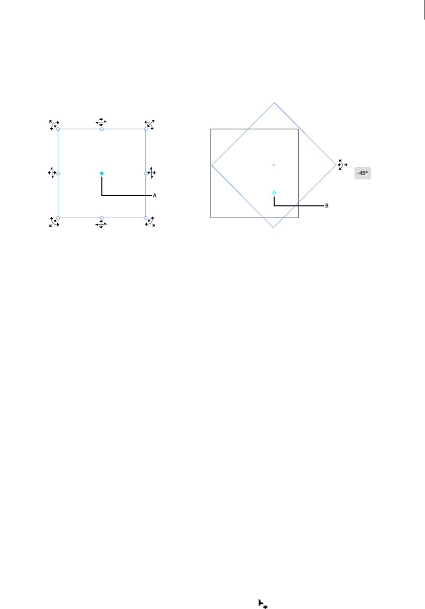
310
Reshaping objects
Last updated 6/5/2015
•You can also double-click any of the eight control handles to set it as a reference point. The rotate action will now
occur relative to the new reference point.
•Double-click the reference point to reset its position.
A Reference Point B When moved, the image rotates relative to the new location of the Reference Point
•Mouseover on the control handles shows permitted icons, and displays a reference point for the object.
•You can drag the reference point to another location, and then use the control handles to rotate the selected
artwork based on the new reference point.
OS-supported Gestures
Touch Gestures: Use Standard touch gestures (pinch and swipe) for panning and zooming. These gestures work on
devices that accept touch input:
•Pinch in or out, using two fingers (for example, use the thumb and forefinger), to zoom
•Place two fingers on the document, and move the fingers together to pan within the document
•Swipe or flick, to navigate artboards
•In artboard editing mode, use two fingers to rotate the artboard by 90º
Creating shapes using Shape BuilderTool
To create a shape using the Shape Builder tool, do the following:
1Create the shapes on which you want to apply the Shape Builder tool.
2Using the Selection tool, select the paths that you need to merge to create the shape.
Note: Make sure that you select only those paths on which you need to apply the tool. If you select all the paths before
merging, then there would be a performance overhead.
3Select the Shape Builder tool from the Tools panel or press Shift+M. By default, the tool is in merge mode, where
you can combine different paths. The pointer in this mode appears as .
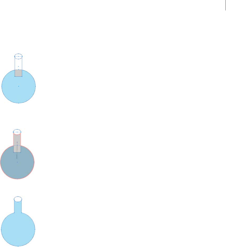
311
Reshaping objects
Last updated 6/5/2015
4Identify the region that you want to extract or merge.
5To break or extract the region from the rest of the shape, move the pointer and click the selected region.
Additional anchor points are introduced where the shapes break up.
6To merge paths, drag along the region and release the mouse, the two regions get merged to form a new shape.
The art style that the new shape inherits, depends on the following rules:
•The art style of the object from where the mouse drag was initiated is applied to the merging shapes.
•If no art style is available on mouse down, then the art style available on mouse release is applied to the merging
shapes.
•If no art style is available on mouse down or mouse release, then the art style of the topmost selected object in
the Layers panel, is applied.
For coloring, you can override these rules by selecting Color Swatches from the Pick Color From drop-down list in
the Shape Builder Tool Options dialog box. For details, see Setting the Shape Builder tool options.

312
Reshaping objects
Last updated 6/5/2015
Pressing Shift+click+drag displays a rectangular marquee, which allows you to easily merge multiple paths.
7To use the Erase mode of the Shape Builder tool, press the Alt key (Windows) or the Option key (Mac OS) and click
the closed region that you want to delete. When you press the Alt key (Windows) or Option key (Mac OS), the
pointer changes to .
In Erase mode, you can delete regions within selected shapes. If you delete a region that is shared by multiple objects,
the shapes are broken in such a way that the regions selected by the marquee are removed from the shapes.
You can also delete edges in erase mode. This option is useful when you want to clear the remaining portions after
creating the required shape.

313
Last updated 6/5/2015
Chapter 8: Importing, exporting, and
saving
Importing artwork files
You don’t have to create artwork from scratch in Adobe Illustrator—you can import both vector drawings and bitmap
images from files created in other applications. Illustrator recognizes all common graphic file formats. Tight integration
between Adobe products and support for a wide variety of file formats, makes it easy to move art from one application
to another by importing, exporting, or copying and pasting.
About linked and embedded artwork
When you place a graphic, you will see a screen-resolution version of the file in the layout, so that you can view and
position it, but the actual graphic file may be either linked or embedded.
•Linked artwork is connected to, but remains independent of, the document, resulting in a smaller document. You
can modify linked artwork using transformation tools and effects; however, you cannot select and edit individual
components in the artwork. You can use the linked graphic many times without significantly increasing the size of
the document; you can also update all links at once. When you export or print, the original graphic is retrieved,
creating the final output from the full resolution of the originals.
•Embedded artwork is copied into the document at full resolution, resulting in a larger document. You can update
the document whenever you like; as long as the artwork is embedded, your document is self-sufficient.
To determine if artwork is linked or embedded, or change its status from one to the other, use the Links panel.
If the embedded artwork contains multiple components, you can edit them discretely. For example, if the artwork
contains vector data, Illustrator converts it to paths, which you can then modify using Illustrator tools and commands.
Illustrator also preserves the object hierarchy (such as groups and layers) in artwork embedded from certain file
formats.
For a video on importing and copying and pasting between web applications, see www.adobe.com/go/vid0193.note:
For information on importing Adobe® FreeHand® files into Illustrator, see the Migrating from FreeHand to Illustrator PDF
at www.adobe.com/go/learn_ai_freehand_en.
More Help topics
FreeHand migration
Place (import) files
The Place command is the primary method of importing, because it provides the highest level of support for file
formats, placement options, and color. After you place a file, use the Links panel to identify, select, monitor, and update
it.
1Open the Illustrator document into which you want to place the artwork.
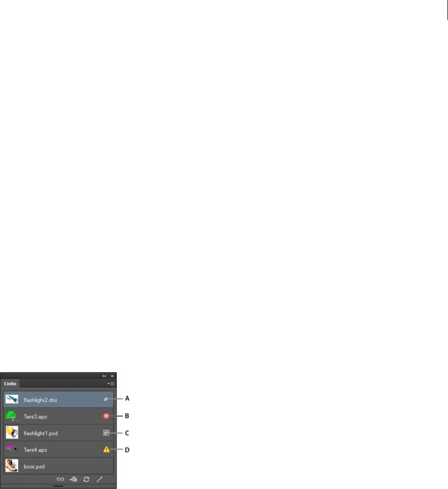
314
Importing, exporting, and saving
Last updated 6/5/2015
2Choose File > Place, and select the file you want to place.
3Select Link to create a link to the file, or deselect Link to embed the artwork in the Illustrator document.
4Click Place.
5If applicable, do one of the following:
•If you place a PDF file with multiple pages, you can choose which page you want to place and how to crop the
artwork.
•If you embed an Adobe® Photoshop® file, you can choose how to convert layers. If the file contains layer comps,
you can also choose which version of the image to import.
For a video on importing files into Illustrator, see www.adobe.com/go/vid0033. For a video on importing and copying
and pasting between web applications, see www.adobe.com/go/vid0193.
More Help topics
Adobe PDF placement options
Photoshop import options
Embedded and linked artwork in the Links panel
Links panel overview
You use the Links panel to see and manage all linked or embedded artwork. The panel displays a small thumbnail of
the artwork and uses icons to indicate artwork’s status.
A Transparency interaction B Missing artwork C Embedded artwork D Modified artwork E Linked artwork
File status options for the Links panel
A linked file can appear in the Links panel in any of the following ways:
Up-to-date An up-to-date file displays only the file’s name and (in Adobe® InDesign®) its page in the document.
Modified A modified file is one for which the version of the file on disk is more recent than the version in your
document. This would occur, for example, when someone modifies a Photoshop graphic that you have already placed
into Illustrator.
Missing A missing file is one for which the graphic is no longer in the location from which it was imported, although
it may still exist somewhere. This can happen if someone moves the original file to a different folder or server after it’s
been imported into a document. You can’t know whether a missing file is up to date until its original is located. If you
print or export a document when this icon is displayed, the file may not print or export at full resolution.

315
Importing, exporting, and saving
Last updated 6/5/2015
Embedded Embedding the contents of a linked file suspends management operations for that link.
Work with the Links panel
•To display the panel, choose Window > Links. Each linked file and embedded file is identified by name.
•To select and view a linked graphic, select a link and then click the Go To Link button , or choose Go To Link
in the Links panel menu. The display is centered around the selected graphic.
•To change the size of the thumbnails, select panel Options from the Links panel menu, and select an option for
displaying thumbnails.
•To sort links in a different order, choose the desired Sort command in the panel menu.
•To hide thumbnails, select panel Options from the Links panel menu, and choose None.
•To view DCS Transparency information, select panel Options from the Links panel menu, and choose Show DCS
Transparency Interactions.
View and save metadata via the Links panel
If a linked or embedded file contains metadata, you can view the metadata using the Links panel. You cannot edit or
replace metadata associated with a linked file; however, you can save a copy of the metadata in a template and apply it
to other files.
1Select a file in the Links panel and choose Link File Info from the panel menu.
2To save the metadata as a template, choose Save Metadata Template in the pop-up menu at the top of the dialog box
showing the metadata.
View file information about linked or embedded artwork
❖Do any of the following:
•Double-click the link in the Links panel. Alternatively, select the link and select Link Information from the panel
menu.
note: Don’t confuse “Link information” with “Link File Info” in the Links panel menu; “File Info” refers to metadata.
•Select the linked artwork in the illustration window. In the Control panel, click the file name and choose Link
Information.
To locate linked or embedded artwork in the document window, select a link and click the Go To Link button.
Alternatively, select Go To Link from the panel menu.
Update modified links
•To update specific links, in the Links panel select one or more modified links , and then click the Update Link
button or choose Update Link from the Links panel menu.
•To update specific links, select the linked artwork in the illustration window. In the Control panel, click the filename,
and then choose Update Link.
Note: By default, Illustrator prompts you to update a link if the source file changes. To specify that you want to update links
automatically or manually, choose Edit > Preferences > File Handling & Clipboard (Windows) or Illustrator > Preferences
> File Handling & Clipboard (Mac OS), and set the Update Links option.

316
Importing, exporting, and saving
Last updated 6/5/2015
Restore a single missing link or replace link with a different source file
You can restore or replace a missing link—one that shows the missing-link icon in the Links panel—or any linked
file with a different source file.
1Select the linked artwork on the page, or select a link name in the Links panel.
2Do one of the following:
•In the Links panel, click the Relink button , or choose Relink from the panel menu.
•Click the linked filename in the Control panel, and then choose Relink. (To access this option, you must select
the image in the artwork.)
3In the dialog box that appears, do one of the following:
•Locate and select a replacement file.
•Type the first, or first few, letters of the name of the desired replacement file to locate the file.
4Click Place.
Note: If all of a document’s missing links are located in the same folder, you can restore all of them at once. In the Links
panel, select all of the missing links, and then restore one of them; the Place dialog box stays open for you to reselect each
one.
Set placement options for linked artwork
1Do one of the following:
•Select the linked artwork in the illustration window. In the Control panel, click the filename and choose
Placement Options.
•In the Links panel, select the link and choose Placement Options from the panel menu.
2Select an option for Preserve.
If you select an option other than Transforms or Bounds, you can select a point on the Alignment icon from which
you want to align the artwork, relative to the bounding box. If you want to keep the artwork from overlapping the
bounding box, select Clip To Bounding Box.
Embed a linked file
Rather than linking to a file that you’ve placed in a document, you can embed (or store) the file within the document.
When you embed a file, you break the link to the original. Without the link, the Links panel doesn’t alert you when the
original has changed, and you cannot update the file automatically.
Keep in mind that embedding a file, rather than linking to the original, increases the document file size.
1Select a file in the Links panel, and choose Embed Image from the panel menu.
2Select the linked artwork in the illustration window. In the Control panel, click the Embed button.
The file remains in the Links panel marked with the embedded-link icon .
Unembed or relink an embedded file
1Select one or more embedded files in the Links panel.
2Click the Relink button or select Relink in the Links panel menu, locate and select the original file, and click
Place.

317
Importing, exporting, and saving
Last updated 6/5/2015
Edit original artwork
The Edit Original command lets you open most graphics in the application in which you created them so that you can
modify them as necessary. Once you save the original file, the document in which you linked it is updated with the new
version.
1Do any of the following:
•In the Links panel, select the link and click the Edit Original button . Alternatively, choose Edit Original
from the panel menu.
•Select the linked artwork on the page, and choose Edit > Edit Original.
•Select the linked artwork on the page, and click the Edit Original button in the Control panel.
2After making changes in the original application, save the file.
More Help topics
Importing bitmap images
Importing Adobe PDF files
Importing EPS, DCS, and AutoCAD files
Importing artwork from Photoshop
Saving artwork
Importing bitmap images
About bitmap images
Bitmap images—technically called raster images—use a rectangular grid of picture elements (pixels) to represent
images. Each pixel is assigned a specific location and color value. When working with bitmap images, you edit pixels
rather than objects or shapes. Bitmap images are the most common electronic medium for continuous-tone images,
such as photographs or digital paintings, because they can more efficiently represent subtle gradations of shades and
color.
Bitmap images are resolution-dependent—that is, they contain a fixed number of pixels. As a result, they can lose detail
and appear jagged if they are scaled to high magnifications on-screen or if they are printed at a lower resolution than
they were created for.
Bitmap images sometimes require large amounts of storage space, and often need to be compressed to keep file sizes
down when used in certain Creative Suite components. For instance, you compress an image file in its original
application before you import it into a layout.

318
Importing, exporting, and saving
Last updated 6/5/2015
Note: In Adobe Illustrator, you can create bitmap effects in your artwork using effects and graphic styles.
Image resolution guidelines for final output
Bitmap images contain a fixed number of pixels, usually measured in pixels per inch (ppi). An image with a high
resolution contains more, and therefore smaller, pixels than an image of the same printed dimensions with a low
resolution. For example, a 1-inch-by-1-inch image with a resolution of 72 ppi contains a total of 5184 pixels (72 pixels
wide x 72 pixels high = 5184). The same 1-inch-by-1-inch image with a resolution of 300 ppi would contain a total of
90,000 pixels.
For imported bitmap images, image resolution is determined by the source file. For bitmap effects, you can specify a
custom resolution. To determine the image resolution to use, consider the medium of final distribution for the image.
The following guidelines can help you determine your requirements for image resolution:
Commercial printing Commercial printing requires 150 to 300 ppi (or more) images, depending on the press (dpi) and
screen frequency (lpi) you’re using; always consult your prepress service provider before making production decisions.
Because commercial printing requires large, high-resolution images, which take more time to display while you’re
working with them, you may want to use low-resolution versions for layout and then replace them with high-resolution
versions at print time.
In Illustrator and InDesign, you can work with low resolution versions by using the Links panel. In InDesign you can
choose either Typical or Fast Display from the View > Display Performance menu; in Illustrator you can choose View
> Outline. Alternatively, if your service provider supports Open Prepress Interface (OPI), they may provide low-
resolution images to you.
Desktop printing Desktop printing usually requires images within the range of 72 ppi (for photographs printed on a
300 ppi printer) to 150 ppi (for photographs printed on devices up to 1000 ppi). For line art (1-bit images), make sure
that the resolution of your graphics matches the resolution of the printer.
Web publishing Because online publishing generally requires images with pixel dimensions that fit the intended
monitor, the images are usually less than 500 pixels wide and 400 pixels tall, to leave room for browser window controls
or such layout elements as captions. Creating an original image at screen resolution—96 ppi for Windows–based
images, and 72 ppi for Mac OS–based images—lets you see the image as it will likely appear when viewed from a typical
web browser. When you’re publishing online, the only times you’re likely to need resolutions above those ranges are
when you want viewers to be able to zoom in for more detail in a PDF document, or when you’re producing a document
for printing on demand.
More Help topics
About vector graphics
Importing Adobe PDF files

319
Importing, exporting, and saving
Last updated 6/5/2015
Importing Adobe PDF files
Adobe Portable Document Format (PDF) is a versatile file format that can represent both vector and bitmap data. You
can bring artwork from PDF files into Illustrator using the Open command, the Place command, the Paste command,
and the drag-and-drop feature.
•Use the Place command with the Link option selected to import a PDF file (or one page of the PDF if it is a multi-
page document) as a single image. You can modify the linked image using transformation tools; however, you
cannot select and edit its individual components.
•Use the Open command or the Place command with the Link option deselected to edit the contents of a PDF file.
Illustrator recognizes the individual components in the PDF artwork and lets you edit each component as a discrete
object.
•Use the Paste command or the drag-and-drop feature to import selected components from a PDF file, including
vector objects, bitmap images, and text.
note: If you are color-managing artwork in a document, embedded PDF images are part of the document and therefore
color-managed when sent to a printing device. In contrast, linked PDF images are not color-managed, even if color
management is turned on for the rest of the document.
More Help topics
About linked and embedded artwork
Adobe PDF placement options
When you place an Adobe PDF file, you specify which page you want to import. You also choose how to crop the
artwork by selecting a Crop To option:
Bounding Box Places the PDF page’s bounding box, or the minimum area that encloses the objects on the page,
including page marks.
Art Places the PDF only in the area defined by a rectangle that the author created as placeable artwork (for example,
clip art).
Crop Places the PDF only in the area that is displayed or printed by Adobe Acrobat.
Trim Identifies the place where the final produced page will be physically cut in the production process, if trim marks
are present.
Bleed Places only the area that represents where all page content should be clipped, if a bleed area is present. This
information is useful if the page is being output in a production environment. Note that the printed page may include
page marks that fall outside the bleed area.
Media Places the area that represents the physical paper size of the original PDF document (for example, the
dimensions of an A4 sheet of paper), including page marks.
More Help topics
Place (import) files
Importing monotone, duotone, and tritone images from Adobe PDF files
When you import artwork from an Adobe PDF file, it’s possible to introduce data that you can’t create within Illustrator.
This is called non-native art and includes monotone, duotone, and tritone images. You can also generate non-native art
within Illustrator by using the Flatten Transparency command to preserve spot colors.

320
Importing, exporting, and saving
Last updated 6/5/2015
Illustrator’s ability to preserve non-native art is useful in many situations. For example, Illustrator maintains the spot
color information in linked PDF files when you output color separations.
By default, non-native art is labeled <Non-Native Art> in the Layers and Appearance panels. You can select, move, save,
and perform basic transformations (such as scaling, rotating, or skewing) on non-native art. However, you cannot select
and edit its individual components. In addition, you must rasterize non-native art before editing it with the liquify tools.
To convert non-native art to an Illustrator object, choose Object > Rasterize.
More Help topics
Importing Adobe PDF files
Importing EPS, DCS, and AutoCAD files
Importing artwork from Photoshop
Importing artwork files
Importing EPS, DCS, and AutoCADfiles
Importing EPS files
Encapsulated PostScript (EPS) is a popular file format for transferring vector artwork between applications. You can
bring artwork from EPS files into Illustrator using the Open command, the Place command, the Paste command, and
the drag-and-drop feature.
Keep the following in mind when working with EPS artwork:
•When you open or embed an EPS file that was created in another application, Illustrator converts all objects to native
Illustrator objects. However, if the file contains data that Illustrator doesn’t recognize, some loss of data may occur.
As a result, unless you need to edit the individual objects in an EPS file, it’s best to link to the file rather than open
or embed it.
•EPS format does not support transparency; therefore, it is not a good choice for placing transparent artwork from
other applications into Illustrator. Instead, use PDF 1.4 format for this purpose.
•You may receive an error message when printing or saving artwork that includes linked EPS files, if those files were
saved in binary format (for example, in Photoshop's default EPS format). In this case, resave the EPS files in ASCII
format, embed the linked files into the Illustrator artwork, print to a Binary print port instead of an ASCII print port,
or save the artwork in AI or PDF format instead of EPS format.
•If you are color-managing artwork in a document, embedded EPS images are part of the document and therefore
color-managed when sent to a printing device. In contrast, linked EPS images are not color-managed, even if color
management is turned on for the rest of the document.
•If you import an EPS color that has the same name as a color in your document but a different definition, Illustrator
displays an alert. Select Use Linked File’s Color to replace the color in your document with the EPS color in the
linked file. All objects using this color in your document will get updated appropriately. Select Use Document’s
Color to leave the swatch as is and resolve all color conflicts using the document’s color. The EPS preview cannot be
changed, so the preview may be incorrect, but it will print to the correct plates. Selecting Apply to All will resolve all
color conflicts, using the definition either of the document or the linked file, depending on which option you
choose.

321
Importing, exporting, and saving
Last updated 6/5/2015
•Occasionally you may encounter a warning when opening an Illustrator document containing embedded EPS
images. If the application cannot find the original EPS image, you will be prompted to extract the EPS image. Select
the Extract option in the dialog box; the image will be extracted into the same directory as the current document.
Although the embedded file does not preview in the document, the file will now print correctly.
•By default, linked EPS files are displayed as a high resolution preview. If a linked EPS file isn’t visible in the document
window, it may be because the file’s preview is missing. (Previews are sometimes lost when transferring EPS files
saved with PICT previews from Mac OS to Windows.) To restore the preview, resave the EPS file with a TIFF
preview. If performance is negatively affected when you place the EPS, reduce the preview resolution: choose Edit >
Preferences > File Handling & Clipboard (Windows) or Illustrator > Preferences > File Handling & Clipboard (Mac
OS), and select Use Low Resolution Proxy For Linked EPS.
More Help topics
About linked and embedded artwork
Save in EPS format
Importing DCS files
Desktop Color Separation (DCS) is a version of the standard EPS format. The DCS 1.0 format supports only CMYK
images while the DCS 2.0 format supports multichannel CMYK files as well as multiple spot inks. (These spot inks
appear as spot colors in Illustrator’s Swatches panel.) Illustrator recognizes clipping paths in Photoshop-created DCS
1.0 and DCS 2.0 files. You can link DCS files in Illustrator, but you can’t embed or open them.
To see DCS transparency interactions in the Links panel, choose Panel Options from the Links panel menu and select
Show DCS Transparency Interactions.
Importing AutoCAD files
Note: Illustrator will not open AutoCAD files saved in a version later than AutoCAD 2007.
AutoCAD files include both DXF and DWG formats. You can import AutoCAD files from version 2.5 through version
2007. During import, you can specify scale, unit mapping (custom unit for interpreting all the length data in the
AutoCAD file), whether to scale lineweights, which layout to import, and whether to center the artwork.
Illustrator supports most AutoCAD data, including 3D objects, shapes and paths, external references, region objects,
spline objects (mapped to Bezier objects that retain the original shape), raster objects, and text objects. When importing
an AutoCAD file that contains external references, Illustrator reads the contents of the reference and places it at the
appropriate locations in the Illustrator file. If an external reference is not found, the Missing Link dialog box opens so
you can search for and retrieve the file.
More Help topics
Importing bitmap images
Importing Adobe PDF files
Importing artwork from Photoshop
Importing artwork files

322
Importing, exporting, and saving
Last updated 6/5/2015
Importing artwork from Photoshop
Importing artwork from Photoshop
You can bring artwork from Photoshop (PSD) files into Illustrator using the Open command, the Place command, the
Paste command, and the drag-and-drop feature.
Illustrator supports most Photoshop data, including layer comps, layers, editable text, and paths. This means that you
can transfer files between Photoshop and Illustrator without losing the ability to edit the artwork. For easy transfer of
files between the two applications, adjustment layers that have visibility turned off are imported (though inaccessible)
into Illustrator and restored when exported back to Photoshop.
Spot colors (up to 31 spot channels per file) import as a single N-Channel raster image, which is placed over the process
color image. The spot colors are added to the swatches panel as custom colors with the same name as in Photoshop.
Imported spot colors separate correctly.
Duotone PSD files import as flat raster images with a 256-indexed colorspace and an N-Channel colorspace containing
all of the duotone inks. Because Illustrator uses an N-Channel, blending mode interactions set in Photoshop may
appear differently in Illustrator. Ink colors from old color libraries are set to gray.
In cases where Illustrator must convert the Photoshop data, a warning message appears. For example, when importing
a 16-bit Photoshop file, Illustrator warns you that the image will be imported as an 8-bit, flat composite.
Photoshop import options
When you open or place a Photoshop file that contains multiple layers, you can set the following options:
Layer Comp If the Photoshop file contains layer comps, specifies which version of the image to import. Select Show
Preview to display a preview of the selected layer comp. The Comments text box displays comments from the
Photoshop file.
When Updating Link Specifies how to handle layer visibility settings when updating a linked Photoshop file that
includes layer comps.
Keep Layer Visibility Overrides Updates the linked image based on the state of layer visibility in the layer comp when
you originally placed the file.
Use Photoshop’s Layer Visibility Updates the linked image based on the current state of layer visibility in the Photoshop
file.
Convert Photoshop Layers To Objects And Make Text Editable Where Possible Preserves as much layer structure and
text editability as possible without sacrificing appearance. However, if the file includes features that Illustrator doesn’t
support, Illustrator preserves the appearance of the artwork by merging and rasterizing layers. For example:
•Layer sets that use the Dissolve blending mode as well as all layers in clipping masks get merged into single layers.
•Adjustment layers and layers that use a Knockout option are merged with the underlying layers, as are layers that
contain transparent pixels and use the Color Dodge, Color Burn, Difference, Linear Burn, Linear Dodge, Vivid
Light, Linear Light, or Pin Light blending mode.
•Layers that use layer effects may be merged; however, the specific merging behavior depends on the blending mode
of the layer, the presence of transparent pixels, and the layer’s blending options.
•Hidden layers that require merging are discarded.

323
Importing, exporting, and saving
Last updated 6/5/2015
note: The Convert Photoshop Layers To Objects And Make Text Editable Where Possible option is not available when you
link to a Photoshop file.
Flatten Photoshop Layers To A Single Image And Preserve Text Appearance Imports the file as a single bitmap image.
The converted file retains no individual objects, except for the document clipping path (if one exists). Opacity is
retained as part of the main image, but is not editable.
Import Hidden Layers Imports all layers from the Photoshop file, even those that are hidden. This option is not
available when linking to a Photoshop file.
Import Slices Preserves any slices that are included in the Photoshop file. This option is available only when opening
or embedding a file that includes slices.
Move part of an image from Photoshop to Illustrator
1In Photoshop, select the pixels you want to move. For more information, see Photoshop Help.
2Do one of the following:
•Copy the selection in Photoshop and paste it in Illustrator. If a layer mask is active when you choose the Copy
command, Photoshop copies the mask rather than the main layer.
•Select the Move tool in Photoshop, and drag the selection to Illustrator. Illustrator fills transparent pixels with
white.
Move paths from Photoshop to Illustrator
1In Photoshop, use the Path Component Selection tool or the Direct Selection tool to select the paths you want to
move.
You can select any path or path segment that appears in the Paths panel, including shape vector masks, work paths,
and saved paths. For more information on selecting paths, see Photoshop Help.
2Either copy and paste or drag the path to Illustrator.
3In the Paste Options dialog box, choose whether to paste the path as a compound shape or a compound path. Pasting
as a compound path is faster, but may result in some loss of editability.
To import all paths (but no pixels) from a Photoshop document, choose File > Export > Paths To Illustrator (in
Photoshop). Then open the resulting file in Illustrator.
More Help topics
Importing bitmap images
Importing Adobe PDF files
Importing EPS, DCS, and AutoCAD files
Importing artwork files
Saving artwork

324
Importing, exporting, and saving
Last updated 6/5/2015
About saving artwork
When you save or export artwork, Illustrator writes the artwork data to a file. The structure of the data depends on the
file format that you select.
There are five basic file formats—AI, PDF, EPS, FXG, and SVG—to which you can save artwork. These formats are
called native formats because they can preserve all Illustrator data, including multiple artboards. (For PDF and SVG
formats, you must select the Preserve Illustrator Editing Capabilities options to preserve all Illustrator data.) EPS and
FXG can save individual artboards as separate files. SVG saves the active artboard only; however, the content from all
artboards is displayed.
You can also export artwork in a variety of file formats for use outside of Illustrator. These formats are called non-native
formats because Illustrator will not be able to retrieve all of the data if you reopen the file in Illustrator. For this reason,
it is recommended that you save artwork in AI format until you are finished creating it, and then export the artwork to
the desired format.
Note: You may receive an error message when saving artwork that includes linked EPS files, if those files were saved in
binary format (for example, in Photoshop's default EPS format). In this case, resave the EPS files in ASCII format, embed
the linked files into the Illustrator artwork, or save the artwork in AI or PDF format instead of EPS format.
For a video on creating mobile content in Illustrator, see www.adobe.com/go/vid0207. For a video on saving for the
web, see www.adobe.com/go/vid0063. For a video on exporting content from Illustrator, including an overview on
different formats and when you should use them, see www.adobe.com/go/vid0062.
Save in Illustrator format
If your document contains more than one artboard and you want to save to a previous version of Illustrator, you can
choose to save each artboard as a separate file or combine the content from all artboards into a single file.
1Choose File > Save As or File > Save A Copy.
2Type a filename, and choose a location for the file.
3Choose Illustrator (*.AI) as the file format, and click Save.
4In the Illustrator Options dialog box, set the desired options and click OK:
Version Specifies the version of Illustrator with which you want your file to be compatible. Legacy formats don’t
support all the features in the current version of Illustrator. Therefore, when you select a version other than the
current version, some options for saving aren’t available, and certain kinds of data will be changed. Be sure to read
the warnings at the bottom of the dialog box so that you are aware of how the data will be changed.
Subset Embedded Fonts When Percent Of Characters Used Is Less Than Specifies when to embed the entire font (as
opposed to just the characters used in the document) based on how many of the font’s characters are used in the
document. For instance, if a font contains 1,000 characters but the document only uses 10 of those characters, you
may decide that embedding the font is not worth the extra file size.
Create PDF Compatible File Saves a PDF representation of the document in the Illustrator file. Select this option if
you want the Illustrator file to be compatible with other Adobe applications.
Include Linked Files Embeds files that are linked to the artwork.
Embed ICC Profiles Creates a color-managed document.
Use Compression Compresses PDF data in the Illustrator file. Using compression increases the time required to
save the document, so deselect this option if you’re experiencing very slow (8 to 15 minute) save times.
Save Each Artboard To A Separate File Saves each artboard as a separate file. A separate master file that includes all
of the artboards is also created. All of the content that touches an artboard is included with the file for that artboard.

325
Importing, exporting, and saving
Last updated 6/5/2015
If artwork needs to be shifted to fit it onto a single artboard, a warning appears to let you know. If you don’t select
this option, the artboards are combined into a single document and are converted to object guides and (in Illustrator
CS3) crop areas. The artboard used for the saved file is based on the size of the default document startup profile.
Transparency options Determines what happens to transparent objects when you choose a version of Illustrator
format earlier than 9.0. Select Preserve Paths to discard transparency effects and reset transparent artwork to 100%
opacity and Normal blending mode. Select Preserve Appearance And Overprints to preserve overprints that don’t
interact with transparent objects. Overprints that interact with transparent objects are flattened.
Note: If your artwork contains complex, overlapping areas and you require high-resolution output, click Cancel and
specify rasterization settings before continuing.
More Help topics
About color profiles
Rasterization options
Save in EPS format
Virtually all page layout, word-processing, and graphic applications accept imported or placed encapsulated PostScript
(EPS) files. The EPS format preserves many of the graphic elements you can create with Adobe Illustrator, which means
that EPS files can be reopened and edited as Illustrator files. Because EPS files are based on the PostScript language,
they can contain both vector and bitmap graphics. If your artwork contains multiple artboards, these artboards are
preserved when you save to EPS format.
1If your artwork contains transparency (including overprints) and you require high-resolution output, choose
Window > Flattener Preview to preview the effects of flattening.
2Choose File > Save As or File > Save A Copy.
3Type a filename, and choose a location for the file.
4Choose Illustrator EPS (*.EPS) as the file format, and click Save.
5If you want create separate files for each artboard, click Use Artboards, and select All or specify a range. Separate
files are saved with a master EPS file containing all artboards. If you deselect this option, a single EPS file is created
with all artboards preserved.
6In the EPS Options dialog box, set the desired options and click OK:
Version Specifies the version of Illustrator with which you want your file to be compatible. Legacy formats don’t
support all the features in the current version of Illustrator. Therefore, when you select a version other than the
current version, some options for saving aren’t available, and certain kinds of data will be changed. Be sure to read
the warnings at the bottom of the dialog box so that you are aware of how the data will be changed.
Format Determines the characteristics of the preview image that is saved in the file. The preview image is displayed
in applications that cannot display EPS artwork directly. If you don’t want to create a preview image, choose None
from the Format menu. Otherwise, select a black-and-white or color format.
If you select TIFF (8-bit Color) format, select a background option for the preview image:
Transparent Produces a transparent background.
Opaque Produces a solid background. (Select Opaque if the EPS document will be used in a Microsoft Office
application.)
Transparency options Determines what happens to transparent objects and overprints. The available options
change depending on the format version you select at the top of the dialog box.

326
Importing, exporting, and saving
Last updated 6/5/2015
If you choose a CS format, specify how to save overlapping colors that are set to overprint, and select a preset (or set
of options) for flattening transparency. Click Custom to customize the flattener settings.
If you choose a Legacy format earlier than 8.0, select Preserve Paths to discard transparency effects and reset
transparent artwork to 100% opacity and Normal blending mode. Select Preserve Appearance and Overprints to
preserve overprints that don’t interact with transparent objects. Overprints that interact with transparent objects are
flattened.
Embed Fonts (For Other Applications) Embeds all fonts that contain appropriate permissions from the font vendor.
Embedding fonts ensures that the original font is displayed and printed if the file is placed into another application,
such as Adobe InDesign. However, if the file is opened in Illustrator on a computer that does not have the font
installed, the font will be faux or substituted. This is to prevent illegal use of the embedded font.
note: Selecting the Embed Fonts option increases the size of the saved file.
Include Linked Files Embeds files that are linked to the artwork.
Include Document Thumbnails Creates a thumbnail image of the artwork. The thumbnail is displayed in the
Illustrator Open and Place dialog boxes.
Include CMYK PostScript In RGB Files Allows RGB color documents to be printed from applications that do not
support RGB output. When the EPS file is reopened in Illustrator, the RGB colors are preserved.
Compatible Gradient And Gradient Mesh Printing Enables older printers and PostScript devices to print gradients
and gradient meshes by converting gradient objects to JPEG format. Selecting this option can slow printing on
printers that don’t have problems with gradients.
Adobe PostScript® Determines what level of PostScript is used to save the artwork. PostScript Language Level 2
represents color as well as grayscale vector and bitmap images, and supports RGB, CMYK, and CIE-based color
models for both vector and bitmap graphics. PostScript Language Level 3 provides additional functionality to
Language Level 2, including the ability to print mesh objects when printing to a PostScript® 3™ printer. Because
printing to PostScript Language Level 2 devices converts gradient mesh objects to bitmap images, it is preferable to
print artwork that contains gradient mesh objects to a PostScript 3 printer.
More Help topics
Printing and saving transparent artwork
Preview which areas of artwork will be flattened
About overprinting
Save in SVG format
SVG is a vector format that produces high-quality, interactive web graphics. There are two versions of the SVG formats:
SVG and Compressed SVG (SVGZ). SVGZ can reduce file sizes by 50% to 80%; however, you cannot edit SVGZ files
using a text editor.
When you save artwork in an SVG format, mesh objects are rasterized. In addition, images that have no alpha channel
are converted to the JPEG format. Images with an alpha channel are converted to the PNG format. If your document
contains multiple artboards and you save to SVG, the active artboard is preserved. You cannot save individual artboards
as separate SVG files.

327
Importing, exporting, and saving
Last updated 6/5/2015
For a video on creating mobile content in Illustrator, see www.adobe.com/go/vid0207.
1If the artwork contains any SVG effects, select each item to which an SVG effect has been applied, and move the
effect to the bottom of the Appearance panel (just above the Opacity entry). If other effects follow an SVG effect, the
SVG output will consist of a raster object. In addition, if the artwork contains multiple artboards, select the artboard
you want to export.
2Choose File > Save As or File > Save A Copy.
3Type a filename, and choose a location for the file.
4Choose SVG (*.SVG) or SVG Compressed (*.SVGZ) as the file format, and click Save.
5In the SVG Options dialog box, set the desired options and click OK:
SVG Profiles Specifies the SVG XML Document Type Definition for the exported file.
SVG 1.0 and SVG 1.1 Suitable for SVG files that will be viewed on a desktop computer. SVG 1.1 is the full version of
the SVG specification, of which SVG Tiny 1.1, SVG Tiny 1.1 Plus, and SVG Basic 1.1 are subsets.
SVG Basic 1.1 Suitable for SVG files that will be viewed on medium powered devices, such as handheld devices.
Keep in mind that not all handhelds support the SVG Basic profile. As a result, selecting this option does not
guarantee that the SVG file will be viewable on all handhelds. SVG Basic does not support nonrectangular clipping
and some SVG filter effects.
SVG Tiny 1.1 and SVG Tiny 1.1+ Suitable for SVG files that will be viewed on small devices, such as mobile phones.
Keep in mind that not all mobile phones support the SVG Tiny and SVG Tiny Plus profiles. As a result, selecting
either of these options does not guarantee that the SVG file will be viewable on all small devices.
SVG Tiny 1.2 Suitable for SVG files that will be viewed on a variety of devices ranging from PDAs and mobile phones
to laptops and desktop computers.
SVG Tiny does not support gradients, transparency, clipping, masks, symbols, patterns, underline text, strike
through text, vertical text, or SVG filter effects. SVG Tiny Plus includes the ability to display gradients and
transparency, but does not support clipping, masks, symbols, or SVG filter effects.
Tip: For additional information on SVG profiles, see the SVG specification on the World Wide Web Consortium
(W3C) website (www.w3.org).
Font Type Specifies how fonts are exported:
Adobe CEF Uses font hinting for better rendering of small fonts. This font type is supported by the Adobe SVG
Viewer but may not be supported by other SVG viewers.
SVG Does not use font hinting. This font type is supported by all SVG viewers.
Convert To Outlines Converts type to vector paths. Use this option to preserve the visual appearance of type in all
SVG Viewers.
Font Subsetting Controls which glyphs (characters of a particular font) are embedded in the exported SVG file.
Choose None from the Subsetting menu if you can rely on the necessary fonts being installed on end-user systems.
Choose Only Glyphs Used to include only glyphs for text that exists in the current artwork. The other values
(Common English, Common English + Glyphs Used, Common Roman, Common Roman+ Glyphs Used, All
Glyphs) are useful when the textual content of the SVG file is dynamic (such as server-generated text or user-
interactive text).
Image Location Determines whether raster images are embedded directly in the file or linked to the exported JPEG
or PNG images from the original Illustrator file. Embedding images increases file size but ensures that rasterized
images will always be available.

328
Importing, exporting, and saving
Last updated 6/5/2015
Preserve Illustrator Editing Capabilities Preserves Illustrator-specific data by embedding an AI file in the SVG file
(resulting in a larger file size). Select this option if you plan to reopen and edit the SVG file in Illustrator. Note that
if you make manual changes to the SVG data, the changes are not reflected when you reopen the file. This is because
Illustrator reads the AI portion of the file, not the SVG portion.
CSS Properties Determines how style attributes are saved in the SVG code. The default method, Presentation
Attributes, applies properties at the highest point in the hierarchy, which allows the most flexibility for specific edits
and transformations. The Style Attributes method creates the most readable files but may increase the file size.
Choose this method if the SVG code will be used in transformations, for example, transformations using Extensible
Stylesheet Language Transformation (XSLT). The Style Attributes <Entity References> method results in faster
rendering times and reduced SVG file size. The Style Elements method is used when sharing files with HTML
documents. By selecting Style Elements, you can then modify the SVG file to move a style element into an external
style sheet file that is also referenced by the HTML file; however, the Style Elements option also results in slower
rendering speeds.
Decimal Places Specifies the precision of vector data in the SVG file. You can set a value of 1–7 decimal places. A
higher value results in a larger file size and increased image quality.
Encoding Determines how characters are encoded in the SVG file. UTF (UnicodeTransformation Format)
encoding is supported by all XML processors. (UTF-8 is an 8-bit format; UTF-16 is a 16-bit format.) ISO 8859-1 and
UTF-16 encoding do not preserve file metadata.
Optimize For Adobe SVG Viewer Maintains the highest level of Illustrator data while still allowing the SVG file to be
manually edited. Select this option to take advantage of faster rendering for features such as SVG filter effects.
Include Adobe Graphics Server Data Includes all information needed for variable substitution in the SVG file.
Include Slicing Data Includes slice locations and optimization settings.
Include XMP Includes XMP metadata in the SVG file. Choose File > Info or use the Bridge Browser to enter
metadata.
Output Fewer <tspan> Elements Allows Illustrator to ignore auto-kerning settings during export, which results in
a file with fewer <tspan> elements. Select this option to create an SVG file that is more editable and compact.
Deselect this option if maintaining the appearance of auto-kerned text is critical.
Use <textPath> Element For Text On Path Exports text on a path as a <textPath> element. However, note that the
text may appear differently in the SVG Viewer than it does in Illustrator since this export mode will not always be
able to maintain visual parity. In particular, overflow text will be visible in the SVG Viewer.
Show SVG Code Displays the code for the SVG file in a browser window.
Web Preview Displays the SVG file in a browser window.
Device Central Opens the file in Device Central for previewing on a particular mobile phone or device.
More Help topics
About SVG
Optimize an image for the web
Using Adobe Device Central with Illustrator
Data-driven graphics through templates and variables

329
Importing, exporting, and saving
Last updated 6/5/2015
Save artwork for Microsoft Office
The Save For Microsoft Office command lets you create a PNG file that you can use in Microsoft Office applications.
1Choose File > Save For Microsoft Office.
2In the Save For Office dialog box, select a location for the file, enter a filename, and click Save.
If you want to customize PNG settings, such as for resolution, transparency, and background color, use the Export
command instead of the Save For Microsoft Office command. You can also save artwork in PNG format using the
Save For Web & Devices command.
More Help topics
Optimize an image for the web
Changing vector graphics to bitmap images
About rasterization
Rasterization is the process of changing a vector graphic to a bitmap image. During rasterization, Illustrator converts
the graphic’s paths into pixels. The rasterization options you set determine the size and other characteristics of the
resulting pixels.
You can rasterize individual vector objects using the Object > Rasterize command or the Rasterize effect. You can also
rasterize an entire document by exporting it to a bitmap format, such as JPEG, GIF, or TIFF.
More Help topics
About raster effects
Rasterization options
Rasterize a vector object
1Select one or more objects.
2Do one of the following:
•To permanently rasterize the objects, choose Object > Rasterize.
•To create the appearance of rasterization without changing the objects’ underlying structure, choose Effect >
Rasterize.
3Set rasterization options (see Rasterization options), and click OK.
Package files
This feature is available in Adobe Illustrator CS6, CC, and later. To join Adobe Creative Cloud, see Adobe Creative
Cloud.
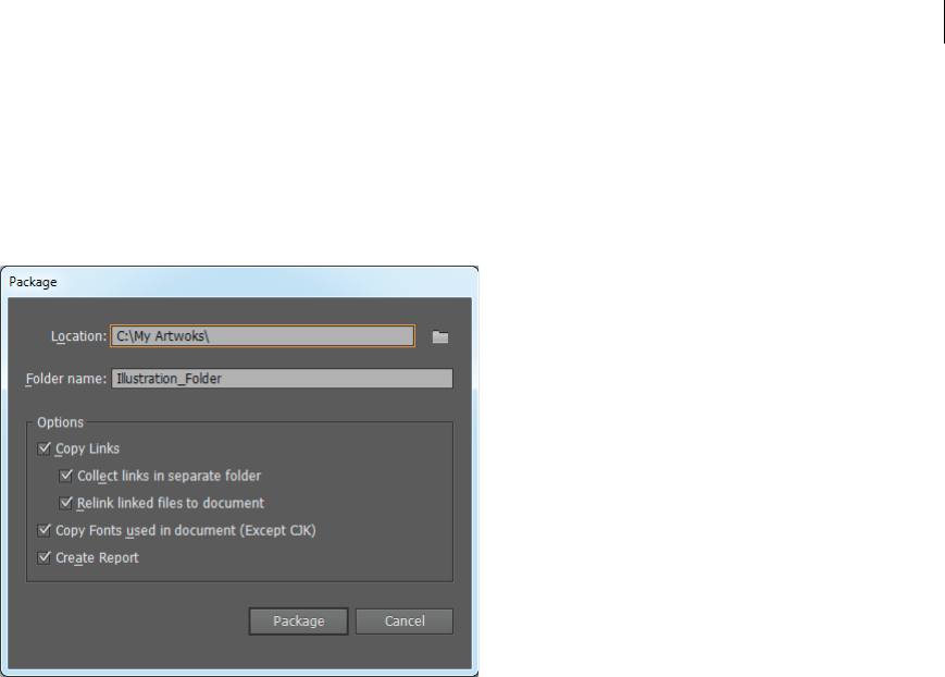
330
Importing, exporting, and saving
Last updated 6/5/2015
You can gather the files you’ve used, including fonts (except Chinese, Korean, and Japanese) and linked graphics, for
easy handoff. When you package a file, you create a folder that contains the Illustrator document, any necessary fonts,
linked graphics, and a package report. This report, which is saved as a text file, includes the information about the
packaged files.
1Choose File > Package.
2Specify the folder and location settings:
Location Specify the location to create the packaged folder
Folder Name Specify a name for the package. By default, the name of the folder is derived from the name of the
Illustrator document.
3Specify the following options:
Copy Links Copies linked graphics and files to the package folder location.
Collect Links in a Separate Folder Creates a Links folder and places all linked assets in that folder. If not selected,
assets are copied to the same folder level as the .ai file.
Relink Linked files to the Document Changes links to the package folder location. If not selected, a packaged
Illustrator document maintains links to assets in the original location, and assets are collected in the package
anyway.
Copy Fonts used in the Documents (Except CJK) Copies all necessary font files, not the entire font family.
Note: A warning displays when you package fonts. Check your license agreement to see if you’re permitted to copy fonts.
Create Report Creates a summary report to accompany the packaged files. It includes a summary of spot color
objects, all used and missing fonts, missing links, and details of all linked and embedded images.
4Click Package. The following folder structure is created, with assets placed in their respective folders.
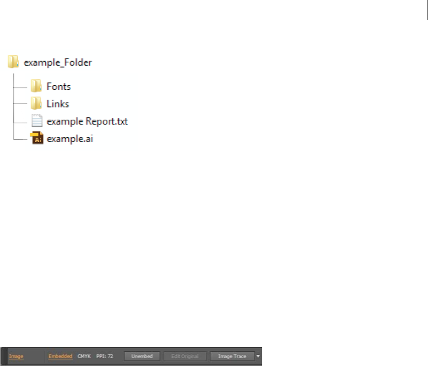
331
Importing, exporting, and saving
Last updated 6/5/2015
Unembed images
This feature is available in Adobe Illustrator CS6, CC, and later. To join Adobe Creative Cloud, see Adobe Creative
Cloud.
When you embed images in an Illustrator file, the image file is stored within the document. You can extract the
embedded images by unembedding them and replace the embedded images with the corresponding extracted PSD or
TIFF files. You can also use or edit the extracted files outside Illustrator.
1Select an embedded image in your document, and do one of the following:
•In the Control panel, click Unembed.
•From the Links panel menu, choose Unembed.
2In the Unembed dialog box, specify a name and location for the new file (PSD or TIFF only), and click Save.
The artwork is unembedded and linked to the Illustrator file.
For more information about linked and embedded files, see Importing artwork files.
Share on Behance
Setting up the Illustrator - Behance sharing workflow
Note: You must be signed in with a valid Adobe ID to use Behance sharing from Illustrator
You can upload your artwork to Behance directly from within Adobe Illustrator. Any artwork on the currently selected
artboard is available for sharing with Behance. A JPEG image is generated and uploaded to your Behance account
linked with your Adobe ID.
Launch the Share on Behance dialog
There are two ways that you can launch Behance from Illustrator:
•Click File > Share on Behance, or,
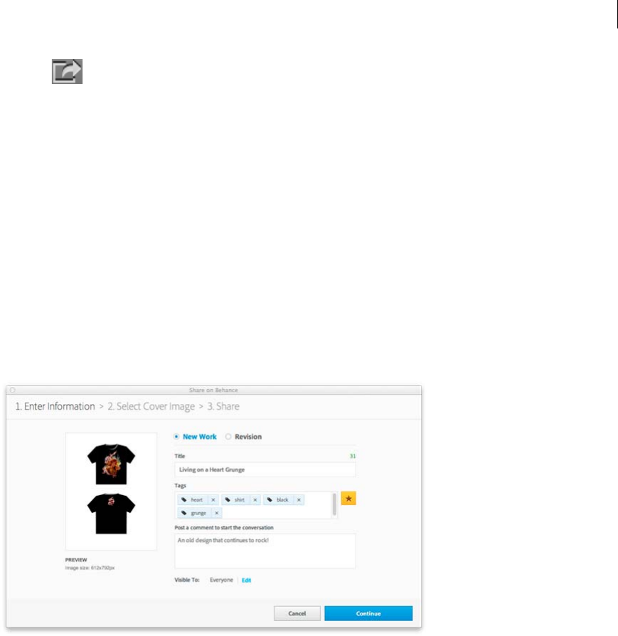
332
Importing, exporting, and saving
Last updated 6/5/2015
•Click the icon, at the lower-left corner of the active Illustrator window.
Upload new artwork to Behance
1Select the artboard that you would like to show or receive feedback for, from Behance.
Note: Artboards with a width 10 times greater than the height (or vice versa) will not be uploaded.
2Click the Behance icon or click File > Share on Behance.
3In the Share on Behance (Enter Information) dialog, select New Work, and fill in the rest of the information:
•Tag s. Click the Tags button to see existing tags, or type new tags. Use commas to separate multiple tags.
•Comments. Add a comment to start the conversation
•Visibility. Set the scope of the share – everyone or your Feedback Circle
If you have a Behance account already, your work will be uploaded to the account. If you don't yet have a Behance
account, you'll be creating one by sharing your work.
Click Continue.
4In the Share on Behance (Select Cover Image) dialog, choose the part of your artwork that will be used as a
thumbnail to identify your artwork.
Click Crop Cover and Publish.
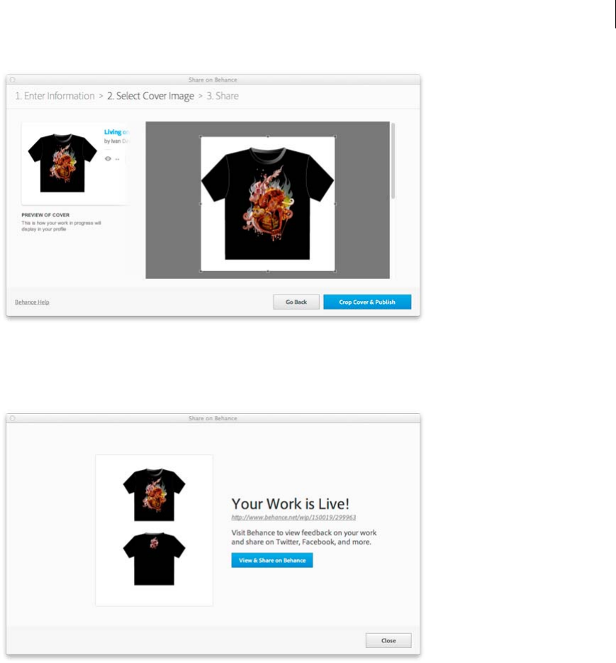
333
Importing, exporting, and saving
Last updated 6/5/2015
5On the final screen, you can click the link or the button to navigate to the Behance website and view the artwork you
have uploaded.
Upload a new version (revision) of artwork to Behance
1Select the artboard that you would like to show or receive feedback for, from Behance.
2Click the Behance icon or click File > Share on Behance.
3 In the Share on Behance (Enter Information) dialog, select Revision.
4From the Choose Existing drop-down, scroll and select the previous version of the artwork being uploaded. When
you select artwork, This will automatically populate the Tags, Visibility options associated with the previous artwork
chosen.
Click Continue.
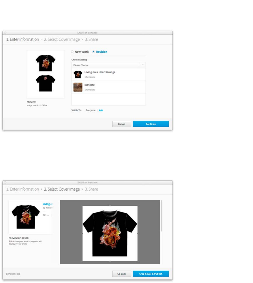
334
Importing, exporting, and saving
Last updated 6/5/2015
5In the Share on Behance (Select Cover Image) dialog, choose the part of your artwork that will be used as a
thumbnail to identify your artwork.
Click Crop Cover and Publish.
6On the final screen you can click the link or the button to navigate to the Behance website and view the artwork you
have uploaded.
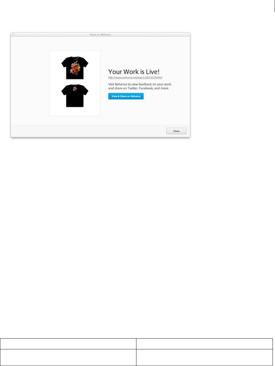
335
Importing, exporting, and saving
Last updated 6/5/2015
Creating Adobe PDF files
About Adobe PDF
Portable Document Format (PDF) is a universal file format that preserves the fonts, images, and layout of source
documents created on a wide range of applications and platforms. Adobe PDF is the standard for the secure, reliable
distribution and exchange of electronic documents and forms around the world. Adobe PDF files are compact and
complete, and can be shared, viewed, and printed by anyone with free Adobe Reader® software.
Adobe PDF is highly effective in print publishing workflows. By saving a composite of your artwork in Adobe PDF, you
create a compact, reliable file that you or your service provider can view, edit, organize, and proof. Then, at the
appropriate time in the workflow, your service provider can either output the Adobe PDF file directly, or process it
using tools from various sources for such post-processing tasks as preflight checks, trapping, imposition, and color
separation.
When you save in Adobe PDF, you can choose to create a PDF/X-compliant file. PDF/X (Portable Document Format
Exchange) is a subset of Adobe PDF that eliminates many of the color, font, and trapping variables that lead to printing
problems. PDF/X may be used wherever PDFs are exchanged as digital masters for print production—whether at the
creation or output stage of the workflow, as long as the applications and output devices support PDF/X.
Adobe PDFs can solve the following problems associated with electronic documents:
Common problem Adobe PDF solution
Recipients can't open files because they don't have the applications
used to create the files.
Anyone, anywhere can open a PDF. All you need is the free Adobe
Reader software.
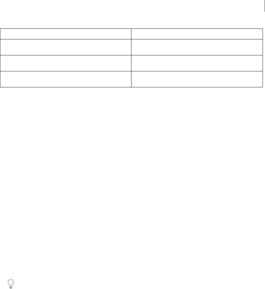
336
Importing, exporting, and saving
Last updated 6/5/2015
Create Adobe PDF files
You can create different types of PDF files from within Illustrator. You can create multipage PDFs, layered PDFs, and
PDF/x-compliant files. Layered PDFs allow you to save one PDF with layers that can be used in different contexts.
PDF/X-compliant files ease the burden of color, font, and trapping issues.
For a video on creating PDFs from Creative Suite applications, see www.adobe.com/go/vid0209. For a video on
exporting to PDF 1.7 for review or prepress purposes, see www.adobe.com/go/vid0210. For a video on creating
interactive PDFs, see www.adobe.com/go/vid0211.
More Help topics
About Adobe PDF
Color management and PDF/X options for PDF
Color-managing PDFs for printing
Create an Adobe PDF
1Choose File > Save As or File > Save A Copy.
2Type a filename, and choose a location for the file.
3Choose Adobe PDF (*.PDF) as the file format, and click Save.
4Either choose a preset from the Adobe PDF Preset menu, or select a category from the list on the left of the dialog
box and then customize the options.
5Click Save PDF.
To reset options to the default, hold down Alt (Windows) or Option (Mac OS) and click Reset.
Create a multiple-page Adobe PDF
1Create multiple artboards in a document.
2Choose File > Save As, and select Adobe PDF forSave As Type.
3Do one of the following:
•To save all of the artboards to one PDF, select All.
•To save a subset of the artboards to one PDF, select Range, and type the range of artboards.
4Click Save, and set additional PDF options in the Save Adobe PDF dialog box.
5Click Save PDF.
Combined paper and electronic archives are difficult to search, take up
space, and require the application in which a document was created.
PDFs are compact and fully searchable, and can be accessed at any
time using Reader. Links make PDFs easy to navigate.
Documents appear incorrectly on handheld devices. Tagged PDFs allow text to reflow for display on mobile platforms such
as Palm OS®, Symbian™, and Pocket PC® devices.
Documents with complex formatting are not accessible to visually
impaired readers.
Tagged PDFs contain information on content and structure, which
makes them accessible on-screen readers.
Common problem Adobe PDF solution

337
Importing, exporting, and saving
Last updated 6/5/2015
Create a layered Adobe PDF
Adobe InDesign and Adobe Acrobat both provide features for changing the visibility of layers in an Adobe PDF file. By
saving a layered PDF file in Illustrator, you allow your illustration to be used in different contexts. For example, rather
than creating multiple versions of the same illustration for a multilanguage publication, you can create one PDF file that
contains text for all languages.
1Set up your illustration so that the adjustable elements (those you want to show and hide) are in separate top-level
layers, not nested within sublayers.
For example, if you’re creating an illustration to be repurposed for multiple languages, put the text for each language
in a different top-level layer.
2Save the file in Adobe PDF format.
3In the Save Adobe PDF dialog box, choose Acrobat 8 (1.7) or Acrobat 7 (1.6) for Compatibility.
4Select Create Acrobat Layers from Top-Level Layers, set additional PDF options, and click Save PDF.
Create an Adobe PDF/X-compliant file
PDF/X (Portable Document Format Exchange) is an ISO standard for graphic content exchange that eliminates many
of the color, font, and trapping variables that lead to printing problems. Illustrator supports PDF/X-1a (for a CMYK
workflow), PDF/X-3 (for a color-managed workflow), and PDF/X-4 (for a color-managed workflow with added
support for preserving transparency as live rather than flattened).
You can create a PDF/X-compliant file during the process of saving a PDF file.
1In the Save Adobe PDF dialog box, choose a PDF/X preset, or choose a PDF/X format from the Standard menu.
2Click Output on the left side of the Save Adobe PDF dialog box, and set PDF/X options.
Create compact PDF documents
Illustrator CS5 provides the option to save a document in the smallest file size. To generate a compact PDF from
Illustrator, do the following:
1Click File > Save As and select PDF.
2In the Save Adobe PDF dialog box, select the Smallest File Size option from Adobe PDF Preset.
Make sure that you deselect the Preserve Illustrator Editing Capabilities check box to avoid saving the Illustrator
resources along with the document.
Adobe PDF presets
A PDF preset is a group of settings that affect the process of creating a PDF. These settings are designed to balance file
size with quality, depending on how the PDF will be used. Most predefined presets are shared across Adobe Creative
Suite components, including InDesign, Illustrator, Photoshop, and Acrobat. You can also create and share custom
presets for your unique output requirements.
A few of the presets listed below are not available until you move them—as needed—from the Extras folder (where they
are installed by default) to the Settings folder. Typically, the Extras and Settings folders are found in (Windows Vista
and Windows 7) ProgramData\Adobe\AdobePDF, (Windows XP) Documents and Settings\All Users\Application
Data\Adobe\Adobe PDF, or (Mac OS) Library/Application Support/Adobe PDF. Some presets are not available in some
Creative Suite components.

338
Importing, exporting, and saving
Last updated 6/5/2015
The custom settings are found in (Windows XP) Documents and Settings/[username]/Application Data/Adobe/Adobe
PDF/Settings, (Windows Vista and Windows 7) Users/[username]/AppData/Roaming/Adobe/Adobe PDF/Settings, or
(Mac OS) Users/[username]/Library/Application Support/Adobe/Adobe PDF/Settings.
Review your PDF settings periodically. The settings do not automatically revert to the default settings. Applications and
utilities that create PDFs use the last set of PDF settings defined or selected.
High Quality Print Creates PDFs for quality printing on desktop printers and proofing devices. This preset uses PDF
1.4, downsamples color and grayscale images to 300 ppi and monochrome images to 1200 ppi, embeds subsets of all
fonts, leaves color unchanged, and does not flatten transparency (for file types capable of transparency). These PDFs
can be opened in Acrobat 5.0 and Acrobat Reader 5.0 and later. In InDesign, this preset also creates tagged PDFs.
Illustrator Default (Illustrator only) Creates a PDF in which all Illustrator data is preserved. PDFs created with this
preset can be reopened in Illustrator without any loss of data.
Oversized Pages (Acrobat only) Creates PDFs suitable for viewing and printing of engineering drawings larger than
200 x 200 inches. These PDFs can be opened in Acrobat and Reader 7.0 and later.
PDF/A-1b: 2005 (CMYK and RGB) (Acrobat only) Used for long-term preservation (archival) of electronic documents.
PDF/A-1b uses PDF 1.4 and converts all colors to either CMYK or RGB, depending on which standard you choose.
These PDFs can be opened in Acrobat and Reader versions 5.0 and later.
PDF/X-1a (2001 and 2003) PDF/X-1a requires all fonts to be embedded, the appropriate marks and bleeds to be
specified, and color to appear as CMYK, spot colors, or both. Compliant files must contain information describing the
printing condition for which they are prepared. PDF files created with PDF/X-1a compliance can be opened in Acrobat
4.0 and Acrobat Reader 4.0 and later.
PDF/X-1a uses PDF 1.3, downsamples color and grayscale images to 300 ppi and monochrome images to 1200 ppi,
embeds subsets of all fonts, creates untagged PDFs, and flattens transparency using the High Resolution setting.
note: The PDF/X1-a:2003 and PDF/X-3 (2003) presets are placed on your computer during installation but are not
available until you move them from the Extras folder to the Settings folder.
PDF/X-3 This preset creates a PDF based on the ISO standard PDF/X-3:2002. The PDF created in this setting can be
opened in Acrobat 4.0 and Acrobat Reader 4.0 or later.
PDF/X-4 (2008) This preset creating ISO PDF/X-4:2008 files supports live transparency (transparency is not flattened)
and ICC color management. PDF files exported with this preset are in PDF 1.4 format. Images are downsampled and
compressed and fonts are embedded in the same manner as with the PDF/X-1a and PDF/X-3 settings. You can create
PDF/X-4:2008 compliant PDF files directly from Creative Suite 4 and 5 components including Illustrator, InDesign,
and Photoshop. Acrobat 9 Pro provides facilities to validate and preflight PDF files for PDF/X-4:2008 compliance as
well as convert non-PDF/X files to PDF/X-4:2008 if possible.
Adobe recommends PDF/X-4:2008 as the optimal PDF file format for reliable PDF print publishing workflows.
Press Quality Creates PDF files for high-quality print production (for example, for digital printing or for separations
to an imagesetter or platesetter), but does not create files that are PDF/X-compliant. In this case, the quality of the
content is the highest consideration. The objective is to maintain all the information in a PDF file that a commercial
printer or print service provider needs in order to print the document correctly. This set of options uses PDF 1.4,
converts colors to CMYK, downsamples color and grayscale images to 300 ppi and monochrome images to 1200 ppi,
embeds subsets of all fonts, and preserves transparency (for file types capable of transparency).
These PDF files can be opened in Acrobat 5.0 and Acrobat Reader 5.0 and later.
Note: Before creating an Adobe PDF file to send to a commercial printer or print service provider, find out what the output
resolution and other settings should be, or ask for a .joboptions file with the recommended settings. You might need to
customize the Adobe PDF settings for a particular provider and then provide a .joboptions file of your own.

339
Importing, exporting, and saving
Last updated 6/5/2015
Rich Content PDF Creates accessible PDF files that include tags, hyperlinks, bookmarks, interactive elements, and
layers. This set of options uses PDF 1.5 and embeds subsets of all fonts. It also optimizes files for byte serving. These
PDF files can be opened in Acrobat 6.0 and Adobe Reader 6.0 and later. (The Rich Content PDF preset is in the Extras
folder.)
note: This preset was called eBook in earlier versions of some applications.
Smallest File Size Creates PDF files for displaying on the web, an intranet, or for email distribution. This set of options
uses compression, downsampling, and a relatively low image resolution. It converts all colors to sRGB and embeds
fonts. It also optimizes files for byte serving. For best results, avoid using this preset if you intend to print the PDF file.
These PDF files can be opened in Acrobat 5.0 and Acrobat Reader 5.0 and later.
Magazine Ads 2006 (Japan) This preset creates a PDF based on the creation rules designed by Digital Data Delivery
committee.
Standard (Acrobat only) Creates PDF files to be printed to desktop printers or digital copiers, published on a CD, or
sent to a client as a publishing proof. This set of options uses compression and downsampling to keep the file size down,
but also embeds subsets of all (allowed) fonts used in the file, converts all colors to sRGB, and prints to a medium
resolution. Note that Windows font subsets are not embedded by default. PDF files created with this settings file can be
opened in Acrobat 5.0 and Acrobat Reader 5.0 and later.
For more information about shared PDF settings for Creative Suite components, see the PDF Integration Guide on the
Creative Suite DVD.
Customize PDF presets
Although the default PDF presets are based on best practices, you may discover that your workflow, or perhaps your
printer’s workflow, requires specialized PDF settings that aren’t available via any of the built-in presets. If this is the case,
you or your service provider can create custom presets.
1Choose Edit > Adobe PDF Presets.
2Do one of the following:
•To create a new preset, click New. If you want to base the new preset on an existing preset, select the preset first.
•To edit an existing custom preset, select the preset and click Edit. (You cannot edit the default presets.)
•To delete a preset, select it and click Delete.
•To save a preset in a location other than the default Settings folder in the Adobe PDF folder, select it and click
Save As. Specify a location and click Save.
3Set the PDF options, and click OK.
Alternatively, you can create a custom preset when you save a PDF file by clicking Save Preset at the bottom of the Save
Adobe PDF dialog box.
If you want to share your presets with a colleague, select one or more presets and click Export. The presets are saved to
a separate .joboptions file, which you can then transfer to your colleague via e-mail or over your computer network.
Load PDF presets
Illustrator comes with supplementary PDF presets (.joboptions) files. You may also receive custom PDF presets files
from service providers and colleagues.
❖To load PDF presets into all of your Creative Suite applications, do one of the following:
•Double-click the .joboptions file.

340
Importing, exporting, and saving
Last updated 6/5/2015
•Choose Edit > Adobe PDF Presets. Click Import, and select the .joboptions file you want to load.
Adobe PDF options
Adobe PDF options are divided into categories. Changing any option causes the name of the preset to change to
Custom. The categories are listed on the left side of the Save Adobe PDF dialog box, with the exception of the Standard
and Compatibility options, which are at the top of the dialog box.
Setting Adobe PDF options
Adobe PDF options are divided into categories. Changing any option causes the name of the preset to change to
Custom. The categories are listed on the left side of the Save Adobe PDF dialog box, with the exception of the Standard
and Compatibility options, which are at the top of the dialog box.
Standard Specifies a PDF standard for the file.
Compatibility Specifies a PDF version for the file.
General Specifies basic file options.
Compression Specifies if artwork should be compressed and downsampled, and if so, which method and settings to
use.
Marks and Bleeds Specifies printer’s marks and the bleed and slug areas. Although the options are the same as in the
Print dialog box, the calculations are subtly different because PDF is not output to a known page size.
Output Controls how colors and PDF/X output intent profiles are saved in the PDF file.
Advanced Controls how fonts, overprinting, and transparency are saved in the PDF file.
Security Adds security to the PDF file.
Summary Displays a summary of the current PDF settings. To save the summary as an ASCII text file, click Save
Summary.
About PDF/X standards
PDF/X standards are defined by the International Organization for Standardization (ISO). PDF/X standards apply to
graphic content exchange. During PDF conversion, the file that is being processed is checked against the specified
standard. If the PDF will not meet the selected ISO standard, a message appears, asking you to choose between
canceling the conversion or going ahead with the creation of a non-compliant file. The most widely used standards for
a print publishing workflow are several PDF/X formats: PDF/X-1a, PDF/X-3, and PDF/X-4.
Note: For more information on PDF/X, see the ISO website and the Adobe website.
PDF compatibility levels
When you create PDFs, you need to decide which PDF version to use. You can change the PDF version by switching to
a different preset or choosing a compatibility option when you save as PDF or edit a PDF preset.
Generally speaking, unless there’s a specific need for backward compatibility, you should use the most recent version
(in this case version 1.7). The latest version will include all the newest features and functionality. However, if you’re
creating documents that will be distributed widely, consider choosing Acrobat 5.0 (PDF 1.4) or Acrobat 6.0 (PDF 1.5)
to ensure that all users can view and print the document.

341
Importing, exporting, and saving
Last updated 6/5/2015
The following table compares some of the functionality in PDFs created using the different compatibility settings.
Note: Acrobat 8.0 and 9.0 also use PDF 1.7.
General options for PDF
You can set the following options in the General section of the Save Adobe PDF dialog box:
Description Displays the description from the selected preset, and provides a place for you to edit the description. You
can paste a description from the clipboard. Editing the description of a preset appends the word “(modified)” to the
preset name. Conversely, changing the settings in a preset prepends the description with “[Based on <Current Preset
Name>].”
Preserve Illustrator Editing Capabilities Saves all Illustrator data in the PDF file. Select this option if you want to be able
to reopen and edit the PDF file in Adobe Illustrator.
Note: The Preserve Illustrator Editing Capabilities option counteracts aggressive compression and downsampling. If file size
is a concern, deselect this option.
Embed Page Thumbnails Embeds a thumbnail preview for each page in the PDF, increasing the file size. Deselect this
setting when users of Acrobat 5.0 and later will view and print the PDF; these versions generate thumbnails dynamically
each time you click the Pages panel of a PDF.
Optimize For Fast Web View Optimizes the PDF file for faster viewing in a web browser.
View PDF After Saving Opens the newly-created PDF file in the default PDF viewing application.
Create Acrobat Layers From Top-level Layers Saves Illustrator’s top-level layers as Acrobat layers within the PDF file.
This allows Adobe Acrobat 6, 7, and 8 users to generate multiple versions of the document from a single file.
note: This option is only available when Compatibility is set to Acrobat 6 (1.5), Acrobat 7 (1.6), and Acrobat 8 (1.7).
Acrobat 3.0 (PDF 1.3) Acrobat 5.0 (PDF 1.4) Acrobat 6.0 (PDF 1.5) Acrobat 7.0 (PDF 1.6) and
Acrobat X (PDF 1.7)
PDFs can be opened with Acrobat
3.0 and Acrobat Reader 3.0 and
later.
PDFs can be opened with Acrobat
3.0 and Acrobat Reader 3.0 and
later. However, features specific to
later versions may be lost or not
viewable.
Most PDFs can be opened with
Acrobat 4.0 and Acrobat Reader
4.0 and later. However, features
specific to later versions may be
lost or not viewable.
Most PDFs can be opened with
Acrobat 4.0 and Acrobat Reader
4.0 and later. However, features
specific to later versions may be
lost or not viewable.
Cannot contain artwork that uses
live transparency effects. Any
transparency must be flattened
prior to converting to PDF 1.3.
Supports the use of live
transparency in artwork. (The
Acrobat Distiller feature flattens
transparency.)
Supports the use of live
transparency in artwork. (The
Acrobat Distiller feature flattens
transparency.)
Supports the use of live
transparency in artwork. (The
Acrobat Distiller feature flattens
transparency.)
Layers are not supported. Layers are not supported. Preserves layers when creating
PDFs from applications that
support the generation of layered
PDF documents, such as
Illustrator CS and later or InDesign
CS and later.
Preserves layers when creating
PDFs from applications that
support the generation of layered
PDF documents, such as
Illustrator CS and later or InDesign
CS and later.
DeviceN color space with 8
colorants is supported.
DeviceN color space with 8
colorants is supported.
DeviceN color space with up to 31
colorants is supported.
DeviceN color space with up to 31
colorants is supported.
Multibyte fonts can be
embedded. (Distiller converts the
fonts when embedding.)
Multibyte fonts can be
embedded.
Multibyte fonts can be
embedded.
Multibyte fonts can be
embedded.
40-bit RC4 security supported. 128-bit RC4 security supported. 128-bit RC4 security supported. 128-bit RC4 and 128-bit AES
(Advanced Encryption Standard)
security supported.

342
Importing, exporting, and saving
Last updated 6/5/2015
Compression and downsampling options for PDF
When saving artwork in Adobe PDF, you can compress text and line art, and compress and downsample bitmap images.
Depending on the settings you choose, compression and downsampling can significantly reduce the size of a PDF file
with little or no loss of detail and precision.
The Compression area of the Save Adobe PDF dialog box is divided into three sections. Each section provides the
following options for compressing and resampling color, grayscale, or monochrome images in your artwork.
Note: The Preserve Illustrator Editing Capabilities option (in the General preferences area) counteracts aggressive
compression and downsampling. If file size is a concern, deselect this option.
Downsampling If you plan to use the PDF file on the web, use downsampling to allow for higher compression. If you
plan to print the PDF file at high resolution, do not use downsampling. Deselect the option to disable all downsampling
options.
Downsampling refers to decreasing the number of pixels in an image. To downsample color, grayscale, or monochrome
images, choose an interpolation method—average downsampling, bicubic downsampling, or subsampling—and enter
the desired resolution (in pixels per inch). Then enter a resolution in the For Images Above text box. All images with
resolution above this threshold will be downsampled.
The interpolation method you choose determines how pixels are deleted:
Average Downsampling Averages the pixels in a sample area and replaces the entire area with the average pixel color
at the specified resolution.
Subsampling Chooses a pixel in the center of the sample area and replaces the entire area with that pixel color.
Subsampling significantly reduces the conversion time compared with downsampling but results in images that are less
smooth and continuous.
Bicubic Downsampling Uses a weighted average to determine pixel color, which usually yields better results than the
simple averaging method of downsampling. Bicubic is the slowest but most precise method, resulting in the smoothest
gradations.
Compression Determines the type of compression that is used. The Automatic option automatically sets the best
possible compression and quality for the artwork contained in the file. For most files, this option produces satisfactory
results. Use Automatic (JPEG) if you need the greatest compatibility. Use Automatic (JPEG2000) for superior
compression.
ZIP compression Works well on images with large areas of single colors or repeating patterns, and for black-and-white
images that contain repeating patterns. ZIP compression can be lossless or lossy, depending on the Quality setting.
JPEG compression Is suitable for grayscale or color images. JPEG compression is lossy, which means that it removes
image data and may reduce image quality; however, it attempts to reduce file size with a minimal loss of information.
Because JPEG compression eliminates data, it can achieve much smaller file sizes than ZIP compression.
JPEG2000 Is the new international standard for the compression and packaging of image data. Like JPEG compression,
JPEG2000 compression is suitable for grayscale or color images. It also provides additional advantages, such as
progressive display.
CCITT and Run Length compression Are only available for monochrome bitmap images. CCITT (Consultative
Committee on International Telegraphy and Telephony) compression is appropriate for black-and-white images and
any images scanned with an image depth of 1 bit. Group 4 is a general-purpose method that produces good
compression for most monochrome images. Group 3, used by most fax machines, compresses monochrome bitmaps
one row at a time. Run Length compression produces the best results for images that contain large areas of solid black
or white.

343
Importing, exporting, and saving
Last updated 6/5/2015
Image Quality Determines the amount of compression that is applied. The available options depend on the
compression method. For JPEG Compression, Illustrator provides Minimum, Low, Medium, High, and Maximum
Quality options. For ZIP compression, Illustrator provides 4-bit and 8-bit Quality options. If you use 4-bit ZIP
compression with 4-bit images, or 8-bit ZIP compression with 4-bit or 8-bit images, the ZIP method is lossless; that is,
data is not removed to reduce file size, so image quality is not affected. Using 4-bit ZIP compression with 8-bit data can
affect the quality, however, because data is lost.
Tile Size This option is only enabled when its corresponding Compression setting is JPEG2000. It determines the size
of the tiles for progressive display.
Compress Text And Line Art Applies compression to all text and line art in the file. This method results in no loss of
detail or quality.
Mark and bleed options for PDF
Bleed is the amount of artwork that falls outside of the printing bounding box, or outside the crop marks and trim
marks. You can include bleed in your artwork as a margin of error—to ensure that the ink extends all the way to the
edge of the page after the page is trimmed or to ensure that an image can be stripped into a keyline in a document.
The Marks & Bleed area of the Save Adobe PDF dialog box lets you specify the extent of the bleed and add a variety of
printer’s marks to the file.
All Printer’s Marks Enables all printer’s marks (Trim Marks, Registration Marks, Color Bars, and Page Information) in
the PDF file.
Printer Mark Type Lets you choose Roman printer’s marks, or Japanese marks for pages printed in Asian languages.
Trim Marks Places a mark at each corner of the trim area to indicate the PDF trim box boundaries.
Trim Mark Weight Determines the stroke weight of the trim marks.
Registration Marks Places marks outside the artboard for aligning the different separations in a color document.
Offset Determines the distance of all printer’s marks from the edge of the artboard. The trim marks are at the edge of
the space determined by the offset.
Color Bars Adds a small square of color for each spot or process color. Spot colors converted to process colors are
represented using process colors. Your service provider uses these marks to adjust ink density on the printing press.
Page Information Places page information outside the artboard of the page. Page information includes the filename,
page number, current date and time, and color separation name.
Use Document Bleed Settings uses the document’s bleed settings instead of the bleed settings in this dialog box.
Bleed Top, Bottom, Left, Right Controls the bleeds for the artwork. When the button is selected, these four values are
proportional—editing one will update the values in the other three.
Color management and PDF/X options for PDF
You can set the following options in the Output section of the Save Adobe PDF dialog box. Interactions between Output
options change depending on whether Color Management is on or off and which PDF standard is selected.
Color Conversion Specifies how to represent color information in the Adobe PDF file. When you convert color objects
to RGB or CMYK, also select a destination profile from the pop-up menu. All spot color information is preserved
during color conversion; only the process color equivalents convert to the designated color space.
No Conversion Preserves color data as is. This is the default when PDF/X-3 is selected.

344
Importing, exporting, and saving
Last updated 6/5/2015
Convert To Destination (Preserve Numbers) Preserves color numbers for untagged content in the same color space as
the destination profile (by assigning the destination profile, not converting to it). All other content is converted to the
destination space. This option is not available if color management is turned off. Whether the profile is included or not
is determined by the Profile Inclusion Policy.
Convert To Destination Converts all colors to the profile selected for Destination. Whether the profile is included or
not is determined by the Profile Inclusion Policy.
note: When Convert to Destination is selected, and the Destination doesn’t match the document profile, a warning icon
appears beside the option.
Destination Describes the gamut of the final RGB or CMYK output device, such as your monitor or a SWOP standard.
Using this profile, Illustrator converts the document’s color information (defined by the source profile in the Working
Spaces section of the Color Settings dialog box) to the color space of the target output device.
Profile Inclusion Policy Determines whether a color profile is included in the file.
Output Intent Profile Name Specifies the characterized printing condition for the document. An output intent profile
is required for creating PDF/X-compliant files. This menu is only available if a PDF/X standard (or preset) is selected
in the Save Adobe PDF dialog box. The available options depend on whether color management is on or off. For
example, if color management is off, the menu lists available printer profiles. If color management is on, the menu lists
the same profile selected for Destination Profile (provided it is a CMYK output device), in addition to other predefined
printer profiles.
Output Condition Name Describes the intended printing condition. This entry can be useful for the intended receiver
of the PDF document.
Output Condition Identifier A pointer to more information on the intended printing condition. The identifier is
automatically entered for printing conditions that are included in the ICC registry.
Registry Name Indicates the web address for more information on the registry. The URL is automatically entered for
ICC registry names.
Mark as Trapped Indicates the state of trapping in the document. PDF/X compliance requires a value of True (selected)
or False (deselected). Any document that doesn’t meet the requirement will fail PDF/X compliance checking.
Font and flattening options for PDF
You can set the following options in the Advanced section of the Save Adobe PDF dialog box:
Subset Embedded Fonts When Percent Of Characters Used Is Less Than Specifies when to embed the entire font (as
opposed to just the characters used in the document) based on how many of the font’s characters are used in the
document. For instance, if a font contains 1,000 characters but the document only uses 10 of those characters, you may
decide that embedding the font is not worth the extra file size.
Overprints Specifies how to save overlapping colors that are set to overprint. You can choose to preserve the
overprinting or discard the overprinting. If Compatibility (at the top of the dialog box) is set to Acrobat 4 (PDF 1.3),
you can also choose to simulate overprinting by flattening the artwork.
Preset If Compatibility (at the top of the dialog box) is set to Acrobat 4 (PDF 1.3) and the artwork contains
transparency, you can specify a preset (or set of options) for flattening transparency. Alternately, click Custom to
customize the flattener settings.
Note: Acrobat 5 (PDF 1.4), Acrobat 6 (PDF 1.5), and Acrobat 7 (PDF 1.6) automatically preserve transparency in artwork.
As a result, the Preset and Custom options are not available for these levels of compatibility.

345
Importing, exporting, and saving
Last updated 6/5/2015
Adding security to PDF files
When saving as PDF, you can add password protection and security restrictions, limiting not only who can open the
file, but also who can copy or extract contents, print the document, and more.
A PDF file can require passwords to open a document (document open password) and to change security settings
(permissions password). If you set any security restrictions in your file, you should set both passwords; otherwise,
anyone who opens the file could remove the restrictions. If a file is opened with a permissions password, the security
restrictions are temporarily disabled.
The RC4 method of security from RSA Corporation is used to password-protect PDF files. Depending on the
Compatibility setting (in the General category), the encryption level will be high or low.
Note: Adobe PDF presets don’t support passwords and security settings. If you select passwords and security settings in the
Export Adobe PDF dialog box, and then click Save Preset, the passwords and security settings won’t be preserved.
Security options
You can set the following options when you create a PDF or when you apply password protection to a PDF. Options
vary depending on the Compatibility setting. Security options are not available for PDF/X standards or presets.
Compatibility Sets the type of encryption for opening a password-protected document. Acrobat 6 and later lets you
enable metadata for searching.
Be aware that anyone using an earlier version of Acrobat cannot open a PDF document with a higher compatibility
setting. For example, if you select the Acrobat 8 option, the document cannot be opened in Acrobat 6.0 or earlier.
Require Password To Open The Document Select this option to require users to type the password you specify to open
the document.
Document Open Password Specify the password that users must type to open the PDF file.
Note: If you forget a password, there is no way to recover it from the document. It’s a good idea to store passwords in a
separate secure location in case you forget them.
Use A Password To Restrict Editing Security And Permissions Settings Restricts access to the PDF file’s security
settings. If the file is opened in Adobe Acrobat, the user can view the file but must enter the specified Permissions
password in order to change the file’s Security and Permissions settings. If the file is opened in Illustrator, Photoshop,
or InDesign, the user must enter the Permissions password, since it is not possible to open the file in a view-only mode.
Permissions Password Specify a password that is required to change the permissions settings. This option is available
only if the previous option is selected.
Printing Allowed Specifies the level of printing that users are allowed for the PDF document.
None Prevents users from printing the document.
Low Resolution (150 dpi) Lets users print at no higher than 150-dpi resolution. Printing may be slower because each
page is printed as a bitmap image. This option is available only if the Compatibility option is set to Acrobat 5 (PDF 1.4)
or later.
High Resolution Lets users print at any resolution, directing high-quality vector output to PostScript and other printers
that support advanced high-quality printing features.
Changes Allowed Defines which editing actions are allowed in the PDF document.
None Prevents users from making any changes to the document that are listed in the Changes Allowed menu, such as
filling in form fields and adding comments.

346
Importing, exporting, and saving
Last updated 6/5/2015
Inserting, Deleting, And Rotating Pages Lets users insert, delete, and rotate pages, and create bookmarks and
thumbnails. This option is only available for high (128-bit RC4 or AES) encryption.
Filling In Form Fields, And Signing Lets users fill in forms and add digital signatures. This option doesn’t allow them to
add comments or create form fields. This option is only available for high (128-bit RC4 or AES) encryption.
Commenting, Filling In Form Fields, And Signing Lets users add comments and digital signatures, and fill in forms.
This option doesn’t allow users to move page objects or create form fields.
Any Except Extracting Of Pages Lets users edit the document, create and fill in form fields, and add comments and
digital signatures.
Enable Copying of Text, Images, And Other Content Lets users to select and copy the contents of a PDF.
Enable Text Access For Screen Reader Devices For The Visually Impaired Lets visually impaired users read the
document with screen readers, but doesn’t allow users to copy or extract the document’s contents. This option is
available only for high (128-bit RC4 or AES) encryption.
Enable Plaintext Metadata Allows users to copy and extract content from the PDF. This option is only available when
Compatibility is set to Acrobat 6 or later. Selecting this option allows storage/search systems and search engines to
access metadata stored in the document.
More Help topics
Printing and saving transparent artwork
Create Adobe PDF files
About Adobe PDF
Color-managing PDFs for printing
About overprinting
Exporting artwork
Export artwork
1Choose File > Export.
2Select a location for the file, and enter a filename.
3Select a format from the Save As Type (Windows) or Format (Mac OS) pop-up menu.
4Click Save (Windows) or Export (Mac OS).
For a video on exporting content from Illustrator, including an overview on different formats and when you should use
them, see www.adobe.com/go/vid0062.
More Help topics
About saving artwork
Optimize an image for the web

347
Importing, exporting, and saving
Last updated 6/5/2015
File formats for exporting artwork
Note: You can export multiple artboards only to the following formats: SWF, JPEG, PSD, PNG, and TIFF.
AutoCAD Drawing and AutoCAD Interchange File (DWG and DXF) AutoCAD Drawing is the standard file format for
saving vector graphics created in AutoCAD. AutoCAD Interchange File is a drawing interchange format for exporting
AutoCAD drawings to or importing drawings from other applications. For more information, see AutoCAD export
options.
note: By default, white strokes or fills in Illustrator artwork are exported to the AutoCAD formats as black strokes or fills;
and black strokes or fills in Illustrator are exported to the AutoCAD format as white.
BMP A standard Windows image format. You can specify a color model, resolution, and anti-alias setting for rasterizing
the artwork, as well as a format (Windows or OS/2) and a bit depth to determine the total number of colors (or shades
of gray) that the image can contain. For 4-bit and 8-bit images using Windows format, you can also specify RLE
compression.
Enhanced Metafile (EMF) Widely used by Windows applications as an interchange format for exporting vector graphics
data. Illustrator may rasterize some vector data when exporting artwork to EMF format.
JPEG (Joint Photographic Experts Group) Commonly used to save photographs. JPEG format retains all color
information in an image but compresses file size by selectively discarding data. JPEG is a standard format for displaying
images over the web. For more information, see JPEG export options. You can also save an image as a JPEG file using
the Save For Web & Devices command.
note: Artifacts, such as wave-like patterns or blocky areas of banding, are added to a file each time you save the file as a
JPEG. Always save JPEG files from the original image, not from a previously saved JPEG.
Macintosh PICT Used with Mac OS graphics and page-layout applications to transfer images between applications.
PICT is especially effective at compressing images with large areas of solid color.
Flash (SWF) A vector-based graphics format for interactive, animated web graphics. You can export artwork to the
Flash (SWF) format for use in web design, and view the artwork in any browser equipped with the Flash Player plug-in.
For more information, see Flash export options. You can also save an image as an SWF file using the Save For Web &
Devices command (see SWF optimization options (Illustrator) ), and you can export text as Flash Dynamic or Input
text (see Tag text for export to Flash). In addition to exporting artwork in Flash format, you can copy Illustrator artwork
and paste it into Flash. The fidelity of artwork is maintained across the clipboard.
You can create vector artwork for Flex skins in Adobe Illustrator and export it using the Create Flex Skin script. Flex
skins and extensions for Illustrator are available from www.adobe.com/go/flex_skinning_en. For more information
about Flex skins and Flex Builder, see the Flex documentation on Adobe.com.
Photoshop (PSD) The standard Photoshop format. If your artwork contains data that cannot be exported to Photoshop
format, Illustrator preserves the appearance of the artwork by merging the layers in the document or by rasterizing the
artwork. As a result, there may be times when layers, sublayers, compound shapes, and editable text are not preserved
in the Photoshop file, even though you selected the appropriate export option. For more information, see Photoshop
export options.
PNG (Portable Network Graphics) Used for lossless compression and for display of images on the web. Unlike GIF, PNG
supports 24-bit images and produces background transparency without jagged edges; however, some web browsers do
not support PNG images. PNG preserves transparency in grayscale and RGB images. For more information, see PNG
export options. You can also save an image as a PNG file using the Save For Web & Devices command.
Targa (TGA) Designed for use on systems that use the Truevision® video board. You can specify a color model,
resolution, and anti-alias setting for rasterizing the artwork, as well as a bit depth to determine the total number of
colors (or shades of gray) that the image can contain.
Text Format (T XT ) Used to export text in an illustration to a text file. (See Export text to a text file.)

348
Importing, exporting, and saving
Last updated 6/5/2015
TIFF (Tagged-Image File Format) Used to exchange files between applications and computer platforms. TIFF is a
flexible bitmap image format supported by most paint, image-editing, and page-layout applications. Most desktop
scanners can produce TIFF files. For more information, see TIFF export options.
Windows Metafile (WMF) An intermediate exchange format for 16-bit Windows applications. WMF format is
supported by almost all Windows drawing and layout programs. However, it has limited vector graphics support, and
wherever possible, EMF format should be used in place of WMF format.
AutoCAD export options
When you export artwork to either DXF or DWG format, you can set the following options:
AutoCAD Version Specifies the version of AutoCAD that supports the exported file.
Scale Enter values for Scale Units to specify how Illustrator interprets length data when writing the AutoCAD file.
Scale Lineweights Scales the lineweights, along with the rest of the drawing, in the exported file.
Number of Colors Determines the color depth of the exported file.
Raster File Format Specifies whether images and objects that are rasterized during export are saved in PNG or JPEG
format. Only PNG supports transparency; if you need to preserve appearance to the maximum extent possible, choose
PNG.
Preserve Appearance Select if you need the appearance to be maintained and don’t need to make edits to the exported
file. Selecting this option may lead to a significant loss of editability. For example, text may be outlined and effects will
be rasterized. You can select this option or Maximum Editability, but not both.
Maximum Editability Select if the need to edit the file in AutoCAD outweighs the need for maintaining appearance.
This option may lead to significant loss of appearance, especially if you’ve applied style effects. You can select this option
or Preserve Appearance, but not both.
Export Selected Art Only Exports only the artwork in the file that is selected at the time of export. If no artwork is
selected, a blank file is exported.
Alter Paths For Appearance Changes the paths in AutoCAD to maintain the original appearance, if necessary. For
example, if during the export, a path overlaps other objects and changes their appearance, this option alters the path to
maintain the objects’ appearance.
Outline Text Converts all text to paths before export to maintain appearance. Illustrator and AutoCAD may interpret
text attributes differently. Select this option to maintain maximum visual fidelity (at the cost of editability). If you need
to edit the text in AutoCAD, don’t select this option.
Flash export options
When you export artwork to SWF format, you can set the following Basic and Advanced options. You can export
multiple artboards to SWF format. For a video on exporting SWF files from Illustrator, see
www.adobe.com/go/vid0214. (For a video on importing Illustrator files into Flash, see www.adobe.com/go/vid0197,
and for a video on using Flash and Illustrator together, see www.adobe.com/go/lrvid4099_xp.)
At any time, you can click Web Preview to preview the file in the default web browser (Flash Player browser plug-in
should be installed for the browser), or click Device Central to preview the file in Flash Player on a particular mobile
phone or device.note: If your goal is to bring Illustrator artwork into a Flash document, you can simply paste it in. All
paths, strokes, gradients, text (specify Flash Text), masks, effects (such as drop shadow on text), and symbols are
maintained. In addition, you can specify how layers are imported when pasting: as Flash layers, frames, or graphic symbols.
For a video on importing and copying and pasting between web applications, see www.adobe.com/go/vid0193.

349
Importing, exporting, and saving
Last updated 6/5/2015
Before you click Save (Windows) or Export (Mac OS) in the Export dialog box, specify how to export multiple
artboards. If you want to export artboards as separate SWF files, select Use Artboards in the Export dialog box. To
export only a range of artboards, specify the range. Then click Save (Windows) or Export (Mac OS) and specify the
following options:
Preset Specifies the preset option settings file to use for exporting. If you change the default settings, this option
changes to Custom. You can save a custom option settings as a new preset for reuse with other files. To save option
settings as a preset, click Save Preset.
Export As Specifies how to convert Illustrator layers:
AI File To SWF File Exports the artwork to a single frame. Select this option to preserve layer clipping masks.
AI Layers To SWF Frames Exports the artwork on each layer to a separate SWF frame, creating an animated SWF.
AI Layers To SWF Files Exports the artwork on each layer to a separate SWF file. The result is multiple SWF files, each
containing a single frame with the artwork from a single Illustrator layer.
AI Layers To SWF Symbols Converts the artwork on each layer to a symbol and exports it to a single SWF file. AI layers
are exported as SWF Movie Clip symbols. The symbols are named using their corresponding layer names. For a video
on using symbols effectively between Illustrator and Flash, see www.adobe.com/go/vid0198.
AI Artboards To SWF Files Exports each of the selected artboards to a separate SWF file. This is the only option
available when you choose to preserve multiple artboards in the Save As dialog box. If you save a preset with this option
selected, you can use that saved preset only on files with multiple artboards.
Version Specifies the version of Flash Player for browsing imported files. The Compress File option isn’t available in
Flash version 5 and earlier. Dynamic Text and Input Text aren’t available in version 3 and earlier.
Clip To Artboard Size Exports the Illustrator artwork within the selected artboard’s borders) to the SWF file. Any
artwork outside the borders will be clipped off. This option is checked and disabled when exporting multiple artboards.
Preserve Appearance Select Preserve Appearance to flatten artwork to a single layer before export. Selecting this
option limits the editability of the file.
Compress File Compresses the SWF data, resulting in a smaller file size. Note that Flash players prior to Flash Player 6
can’t open or display compressed files. Don’t use this option if you’re not sure what version of the Flash player the file
will be viewed on.
Export Symbols In The Panel Exports all the symbols in the Symbols panel. If a symbol doesn’t have an active instance
in the artwork, the symbol isn’t included in the exported frames; however, it is available for use in the Flash Symbol
Library within the Flash Authoring environment.
Export Text As Outlines Converts type to vector paths. Use this option to preserve the visual appearance of type in all
Flash players. If you prefer to have maximum text editing ability, deselect this option. (For a video on using text
effectively between Flash and Illustrator, see www.adobe.com/go/vid0199.
Ignore Kerning Information For Text Exports text without the kerning values.
Include Metadata Exports the metadata associated with the file. Exported XMP information is minimized to keep file
size small. For example, thumbnails aren’t included.
Protect From Import Prohibits users from modifying the exported SWF file.
Password Type a password to protect the file from being opened by unauthorized users or in applications other than
Adobe Flash.
Curve Quality Determines the accuracy of the Bezier curves. A lower value decreases the exported file size with a slight
loss of curve quality. A higher value increases the accuracy of the Bezier curve reproduction, but results in a larger file
size.

350
Importing, exporting, and saving
Last updated 6/5/2015
Background Color Specifies a background color for the exported SWF file.
Local Playback Security Specifies whether you want the file to access only local files or network files during playback.
To specify Advanced options, click Advanced and specify any of the following:
Image Format Determines how the artwork is compressed. Lossless compression maintains the highest image quality
but creates a large SWF file. Lossy (JPEG) compression creates a smaller SWF file but adds artifacts to the image. Select
Lossless if you intend to continue to work on the file (or files) in Flash; select Lossy if you’re exporting the final SWF file.
JPEG Quality Specifies the amount of detail in the exported image. The higher the quality, the larger the file size. (This
option is available only if you choose Lossy compression.)
Method Specifies the type of JPEG compression that is used. Baseline (Standard) applies the standard type of
compression, while Baseline Optimized applies additional optimization. (These options are available only if you choose
Lossy compression.)
Resolution Adjusts the screen resolution for bitmap images. Resolution for exported SWF files can be 72 to 600 pixels
per inch (ppi). Higher resolution values result in better image quality but larger file sizes.
Frame Rate Specifies the rate at which the animation will be played in Flash Player. (This option is available only for
AI Layers To SWF Frames.)
Looping Causes the animation to loop continuously, rather than play once and then stop, when played in Flash Player.
(This option is available only for AI Layers To SWF Frames.)
Animate Blends Specifies whether or not to animate blended objects. Selecting this option produces the same results
as manually releasing blended objects to layers before you export. Blends are always animated from start to end
irrespective of the layer order.
If you select Animate Blends, select a method for exporting the blend:
In Sequence Exports each object in the blend to a separate frame in the animation.
In Build Builds up a cumulative sequence of objects in the animation frames. For example, the bottommost object in
the blend appears in each of the frames, and the topmost object in the blend appears only in the last frame.
Layer Order Determines the timeline of the animation. Select Bottom Up to export layers starting with the bottommost
layer in the Layers panel. Select Top Down to export layers starting with the topmost layer in the Layers panel. (This
option is available only for AILayers To SWF Frames.)
Export Static Layers Specifies one or more layers or sublayers to be used as static content in all the exported SWF
Frames. Content from the selected layers or sublayers will be present as background art in every exported SWF frame.
(This option is only available for AI Layers To SWF Frames.)
More Help topics
Creating animations
Using multiple artboards
Working with Illustrator and Flash

351
Importing, exporting, and saving
Last updated 6/5/2015
JPEG export options
If your document contains multiple artboards, specify how to export the artboards before you click Save (Windows) or
Export (Mac OS) in the Export dialog box. To export each artboard as a separate JPEG file, select Use Artboards in the
Export dialog box. To export only a range of artboards, specify the range. Then click Save (Windows) or Export (Mac
OS) and specify the following options:
Quality Determines the quality and size of the JPEG file. Choose an option from the Quality menu or enter a value
between 0 and 10 in the Quality text box.
Color Model Determines the color model of the JPEG file.
Method and Scans Select Baseline (“Standard”) to use a format recognized by most web browsers, Baseline Optimized
for optimized color and a slightly smaller file size, Progressive to display a series of increasingly detailed scans (you
specify how many) as the image downloads. Baseline Optimized and Progressive JPEG images are not supported by all
web browsers.
Depth Determines the resolution of the JPEG file. Choose Custom to specify a resolution.
Anti-Alias Removes jagged edges in the artwork by supersampling it. Deselecting this option helps maintain the hard
edges of line art when it is rasterized.
Imagemap Generates code for image maps. If you select this option, select Client-side (.html) or Server-side (.map) to
determine the type of file that is generated.
Embed ICC Profiles Saves ICC profiles in the JPEG file.
More Help topics
About colors in digital graphics
Optimize an image for the web
About color profiles
Photoshop export options
If your document contains multiple artboards, specify how to export the artboards before you click Save (Windows) or
Export (Mac OS) in the Export dialog box. To export each artboard as a separate PSD file, select Use Artboards in the
Export dialog box. To export only a range of artboards, specify the range. Then click Save (Windows) or Export (Mac
OS) and specify the following options:
Color Model Determines the color model of the exported file. Exporting a CMYK document as RGB, or vice versa, may
cause unexpected changes in the appearance of transparent areas, especially those that include blending modes. If you
change the color model, you must export the artwork as a flat image (the Write Layers option isn’t available).
Resolution Determines the resolution of the exported file.
Flat Image Merges all layers and exports the Illustrator artwork as a rasterized image. Choosing this option preserves
the visual appearance of the artwork.
Write Layers Exports groups, compound shapes, nested layers, and slices as separate, editable Photoshop layers. Nested
layers that are more than five levels deep are merged into a single Photoshop layer. Select Maximum Editability to
export transparent objects (that is, objects with an opacity mask, a constant opacity less than 100%, or a blending mode
other than Normal) as live, editable Photoshop layers.
Preserve Text Editability Exports horizontal and vertical point type in layers (including nested layers up to five levels
deep) to editable Photoshop type. If doing so compromises the appearance of the artwork, you can deselect this option
to rasterize the text instead.

352
Importing, exporting, and saving
Last updated 6/5/2015
Maximum Editability Writes each top-level sublayer to a separate Photoshop layer if doing so doesn’t compromise the
appearance of the artwork. Top-level layers become Photoshop layer sets. Transparent objects remain editable
transparent objects. Also creates a Photoshop shape layer for each compound shape in a top-level layer if doing so
doesn’t compromise the appearance of the artwork. To write compound shapes with solid strokes, change the Join type
to Round. Whether or not you select this option, all layers over 5 levels deep are merged into a single Photoshop layer.
note: Illustrator cannot export compound shapes that have graphic styles, dashed strokes, or brushes applied to them. Such
compound shapes become rasterized.
Anti-Alias Removes jagged edges in the artwork by supersampling it. Deselecting this option helps maintain the hard
edges of line art when it’s rasterized.
Embed ICC Profiles Creates a color-managed document.
More Help topics
Image resolution guidelines for final output
About colors in digital graphics
Stroke an object
PNG export options
If your document contains multiple artboards, specify how to export the artboards before you click Save (Windows) or
Export (Mac OS) in the Export dialog box. To export each artboard as a separate PNG file, select Use Artboards in the
Export dialog box. To export only a range of artboards, specify the range. Then click Save (Windows) or Export (Mac
OS) and specify the following options:
Resolution Determines the resolution of the rasterized image. Higher resolution values result in better image quality
but larger file sizes.
note: Some applications open PNG files at 72 ppi, regardless of the resolution you specify. In such applications, the
dimensions of the image will be altered. (For example, artwork saved at 150 ppi will be over twice as large as artwork saved
at 72 ppi.) Therefore, only change the resolution when you know the target application supports non-72-ppi resolutions.
Color Specifies a color for filling transparency. Choose Transparent to preserve transparency, White to fill transparency
with white, Black to fill transparency with black, or Other to select another color for filling transparency.
Anti-Alias Removes jagged edges in the artwork by supersampling it. Deselecting this option helps maintain the hard
edges of line art when it is rasterized.
Interlaced Displays low-resolution versions of the image as the file downloads in a browser. Interlacing makes
download time seem shorter, but also increases file size.
More Help topics
Image resolution guidelines for final output
Optimize an image for the web

353
Importing, exporting, and saving
Last updated 6/5/2015
TIFF export options
If your document contains multiple artboards, specify how to export the artboards before you click Save (Windows) or
Export (Mac OS) in the Export dialog box. To export each artboard as a separate TIFF file, select Use Artboards in the
Export dialog box. To export only a range of artboards, specify the range. Then click Save (Windows) or Export (Mac
OS) and specify the following options:
Color Model Determines the color model of the exported file.
Resolution Determines the resolution of the rasterized image. Higher resolution values result in better image quality
but larger file sizes.
Anti-Alias Removes jagged edges in the artwork by supersampling it. Deselecting this option helps maintain the hard
edges of line art when it is rasterized.
LZW Compression Applies LZW compression, a lossless compression method that does not discard detail from the
image. Select this option to produce a smaller file.
Byte Order Determines the appropriate sequence of bytes for writing the image file, based on the platform you choose.
Illustrator and most recent applications can read files using the byte order for either platform. However, if you don’t
know what kind of program the file may be opened in, select the platform on which the file will be read.
Embed ICC Profiles Creates a color-managed document.
More Help topics
Image resolution guidelines for final output
About colors in digital graphics
File information and metadata
Metadata is a set of standardized information about a file, such as author name, resolution, color space, copyright, and
keywords applied to it.
File information found in the Document Info panel provides general file information and object characteristics, as well
as the number and names of graphic styles, custom colors, gradients, fonts, and placed art.
About the XMP standard
Working with metadata in Adobe Bridge and Adobe Creative Suite components
Document Info panel overview
You use the Document Info panel to see listings of general file information and object characteristics, as well as the
number and names of graphic styles, custom colors, patterns, gradients, fonts, and placed art. To display the panel,
choose Window > Document Info.
•To view a different type of information, select an option from the panel menu: Document, Objects, Graphic Styles,
Brushes, Spot Color Objects, Pattern Objects, Gradient Objects, Fonts, Linked Images, Embedded Images, and Font
Details.
•To view information on only the selected object, choose Selection Only from the panel menu. Leaving this option
deselected lists information about the entire document.
•To save a copy of the file information as a text file, choose Save from the panel menu. Specify a name and location,
and then click Save.
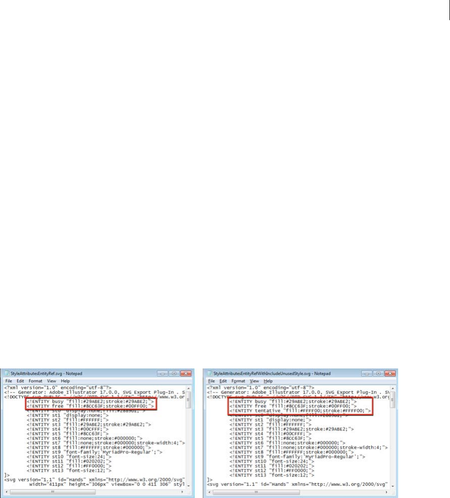
354
Importing, exporting, and saving
Last updated 6/5/2015
•To view artboard dimensions, click the Artboard tool, choose Document from the panel menu, and then click to
select the artboard you want to view.
More Help topics
Add metadata using the File Info dialog box
Work with metadata templates
Import metadata into a document
Workspace overview
Export SVG graphics styles in CSS | Illustrator CC
While creating artwork that contains multiple elements, Designers follow a theme. For example, website design involves
the creation of various assets closely related in style and look-and-feel. While one designer uses certain styles, another
designer may use other styles (defined, but unused) to create other assets.
In Illustrator CC, the Save as SVG feature enables you to:
Export unused styles. When you export artwork in SVG format, you may now choose to export even unused styles that
you created but are not using in this particular artwork. This allows another designer or developer who is importing
the styles to use the unused graphic styles in other artwork.
Export graphic style names In the exported CSS code, graphic styles now have names associated with them, making it
easy to identify the right graphic style.
To export unused styles:
1When you want to save a file in SVG format, click File > Save As.
2In the Save as type drop down, select SVG, type a file name, and then click Save.
3In the SVG Options dialog, click More Options, in the Advanced Options area, select the Include Unused Graphic
Styles option, and then click OK.

355
Importing, exporting, and saving
Last updated 6/5/2015
Extract CSS | Illustrator CC
You can create the design for an HTML page in Illustrator. This serves as a good visual guide for a Web Developer who
can then code the layout, styles, and objects into a page in an HTML editor. However, replicating the exact appearance
and position of components and objects is a time-consuming and tedious process.
With Illustrator CC, when you create the layout for an HTML page, you can also generate and export the underlying
CSS code that determines the appearance of the components and objects on the page. CSS allows you to control the
appearance of text and objects (similar to character and graphic styles). You can choose to export the CSS code for
individual objects, or for the entire layout designed in Illustrator.
The CSS Properties panel (Window > CSS Properties) let users do following:
•View the CSS code for selected objects
•Copy the CSS code for selected objects
•Export one or more, or all selected Illustrator elements to a CSS file
•Export rasterizable images used
•Generate browser-specific CSS code
View and extract CSS code
To generate CSS code, do one of the following:
•Ensure that objects in your Illustrator document are named in the Layer's panel.
•Click Window > CSS Properties > flyout menu > Export Options, and select the Generate CSS for Unnamed Objects
check box.
1Select Window > CSS Properties.
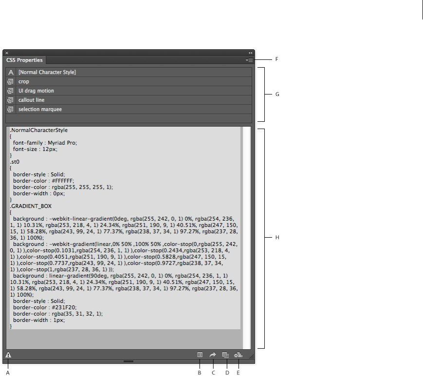
356
Importing, exporting, and saving
Last updated 6/5/2015
A Warning, if some styles could not be converted to CSS code B CSS Export Options dialog box C Export Selected CSS to file D Copy Selected
Style to the clipboard E Generate CSS F Flyout menu G Styles used in the selected objects H CSS code
2In an open Illustrator document, do one of the following:
•Select one object. The CSS code for the object is displayed in the CSS Properties panel.
•Hold Shift, select multiple objects, and then click the Generate CSS button in the CSS Properties panel.
•Press Ctrl/Cmd + A to select all the objects, and then click the Generate CSS button in the CSS Properties panel.
The generated CSS code is displayed.
3To obtain the CSS code that has been generated, do one of the following:
•To copy selected code, select specific code, and then:
•To copy to the clipboard, click Copy Selected Style
•To export to a file, click the flyout menu, and then click Export Selected CSS
•To copy all the code, make no selection in the CSS code, and then:
•To copy to the clipboard, click Copy Selected Style
•To export to a file, click the flyout menu, and then click Export All
4While saving CSS code to a file, choose from the following options:
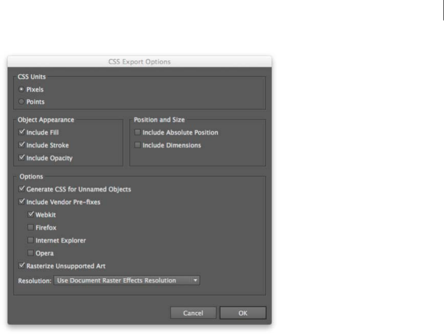
357
Importing, exporting, and saving
Last updated 6/5/2015
Note: To modify the content of the CSS code that is generated, in the CSS Properties panel, click Export Options, and
then make the appropriate selections.
Sample CSS Code

358
Importing, exporting, and saving
Last updated 6/5/2015
Rectangle with a gradient applied (all browsers)
.GRADIENT_BOX
{
background : -moz-linear-gradient(0% 50% 0deg,rgba(255, 242, 0, 1) 0%,rgba(254, 236, 1, 1)
10.31%,rgba(253, 218, 4, 1) 24.34%,rgba(251, 190, 9, 1) 40.51%,rgba(247, 150, 15, 1)
58.28%,rgba(243, 99, 24, 1) 77.37%,rgba(238, 37, 34, 1) 97.27%,rgba(237, 28, 36, 1) 100%);
background : -webkit-linear-gradient(0deg, rgba(255, 242, 0, 1) 0%, rgba(254, 236, 1, 1)
10.31%, rgba(253, 218, 4, 1) 24.34%, rgba(251, 190, 9, 1) 40.51%, rgba(247, 150, 15, 1) 58.28%,
rgba(243, 99, 24, 1) 77.37%, rgba(238, 37, 34, 1) 97.27%, rgba(237, 28, 36, 1) 100%);
background : -webkit-gradient(linear,0% 50% ,100% 50% ,color-stop(0,rgba(255, 242, 0, 1)
),color-stop(0.1031,rgba(254, 236, 1, 1) ),color-stop(0.2434,rgba(253, 218, 4, 1) ),color-
stop(0.4051,rgba(251, 190, 9, 1) ),color-stop(0.5828,rgba(247, 150, 15, 1) ),color-
stop(0.7737,rgba(243, 99, 24, 1) ),color-stop(0.9727,rgba(238, 37, 34, 1) ),color-
stop(1,rgba(237, 28, 36, 1) ));
background : -o-linear-gradient(0deg, rgba(255, 242, 0, 1) 0%, rgba(254, 236, 1, 1) 10.31%,
rgba(253, 218, 4, 1) 24.34%, rgba(251, 190, 9, 1) 40.51%, rgba(247, 150, 15, 1) 58.28%,
rgba(243, 99, 24, 1) 77.37%, rgba(238, 37, 34, 1) 97.27%, rgba(237, 28, 36, 1) 100%);
background : -ms-linear-gradient(0deg, rgba(255, 242, 0, 1) 0%, rgba(254, 236, 1, 1) 10.31%,
rgba(253, 218, 4, 1) 24.34%, rgba(251, 190, 9, 1) 40.51%, rgba(247, 150, 15, 1) 58.28%,
rgba(243, 99, 24, 1) 77.37%, rgba(238, 37, 34, 1) 97.27%, rgba(237, 28, 36, 1) 100%);
-ms-filter: "progid:DXImageTransform.Microsoft.gradient(startColorstr='#FFF200',
endColorstr='#ED1C24' ,GradientType=0)";
background : linear-gradient(90deg, rgba(255, 242, 0, 1) 0%, rgba(254, 236, 1, 1) 10.31%,
rgba(253, 218, 4, 1) 24.34%, rgba(251, 190, 9, 1) 40.51%, rgba(247, 150, 15, 1) 58.28%,
rgba(243, 99, 24, 1) 77.37%, rgba(238, 37, 34, 1) 97.27%, rgba(237, 28, 36, 1) 100%);
border-style : Solid;
border-color : #231F20;
border-color : rgba(35, 31, 32, 1);
border-width : 1px;
filter:
progid:DXImageTransform.Microsoft.gradient(startColorstr='#FFF200',endColorstr='#ED1C24' ,
GradientType=1);
}
Rectangle with a gradient applied (webkit-based browsers only)
.GRADIENT_BOX
{
background : -webkit-linear-gradient(0deg, rgba(255, 242, 0, 1) 0%, rgba(254, 236, 1, 1)
10.31%, rgba(253, 218, 4, 1) 24.34%, rgba(251, 190, 9, 1) 40.51%, rgba(247, 150, 15, 1) 58.28%,
rgba(243, 99, 24, 1) 77.37%, rgba(238, 37, 34, 1) 97.27%, rgba(237, 28, 36, 1) 100%);
background : -webkit-gradient(linear,0% 50% ,100% 50% ,color-stop(0,rgba(255, 242, 0, 1)
),color-stop(0.1031,rgba(254, 236, 1, 1) ),color-stop(0.2434,rgba(253, 218, 4, 1) ),color-
stop(0.4051,rgba(251, 190, 9, 1) ),color-stop(0.5828,rgba(247, 150, 15, 1) ),color-
stop(0.7737,rgba(243, 99, 24, 1) ),color-stop(0.9727,rgba(238, 37, 34, 1) ),color-
stop(1,rgba(237, 28, 36, 1) ));
background : linear-gradient(90deg, rgba(255, 242, 0, 1) 0%, rgba(254, 236, 1, 1) 10.31%,
rgba(253, 218, 4, 1) 24.34%, rgba(251, 190, 9, 1) 40.51%, rgba(247, 150, 15, 1) 58.28%,
rgba(243, 99, 24, 1) 77.37%, rgba(238, 37, 34, 1) 97.27%, rgba(237, 28, 36, 1) 100%);
border-style : Solid;
border-color : #231F20;
border-color : rgba(35, 31, 32, 1);
border-width : 1px;
}

359
Importing, exporting, and saving
Last updated 6/5/2015
Multiple objects
.NormalCharacterStyle
{
font-family : Myriad Pro;
font-size : 12px;
}
.st0
{
border-style : Solid;
border-color : #FFFFFF;
border-color : rgba(255, 255, 255, 1);
border-width : 0px;
}
.GRADIENT_BOX
{
background : -webkit-linear-gradient(0deg, rgba(255, 242, 0, 1) 0%, rgba(254, 236, 1, 1)
10.31%, rgba(253, 218, 4, 1) 24.34%, rgba(251, 190, 9, 1) 40.51%, rgba(247, 150, 15, 1) 58.28%,
rgba(243, 99, 24, 1) 77.37%, rgba(238, 37, 34, 1) 97.27%, rgba(237, 28, 36, 1) 100%);
background : -webkit-gradient(linear,0% 50% ,100% 50% ,color-stop(0,rgba(255, 242, 0, 1)
),color-stop(0.1031,rgba(254, 236, 1, 1) ),color-stop(0.2434,rgba(253, 218, 4, 1) ),color-
stop(0.4051,rgba(251, 190, 9, 1) ),color-stop(0.5828,rgba(247, 150, 15, 1) ),color-
stop(0.7737,rgba(243, 99, 24, 1) ),color-stop(0.9727,rgba(238, 37, 34, 1) ),color-
stop(1,rgba(237, 28, 36, 1) ));
background : linear-gradient(90deg, rgba(255, 242, 0, 1) 0%, rgba(254, 236, 1, 1) 10.31%,
rgba(253, 218, 4, 1) 24.34%, rgba(251, 190, 9, 1) 40.51%, rgba(247, 150, 15, 1) 58.28%,
rgba(243, 99, 24, 1) 77.37%, rgba(238, 37, 34, 1) 97.27%, rgba(237, 28, 36, 1) 100%);
border-style : Solid;
border-color : #231F20;
border-color : rgba(35, 31, 32, 1);
border-width : 1px;
}
Links information
This feature is available in Adobe Illustrator CS6, CC, and later. To join Adobe Creative Cloud, see Adobe Creative
Cloud.
The Links panel (Window > Links) displays a list of all artwork that is placed (embedded or linked) in an Illustrator
document. Links Information is displayed in the Links panel. To view file information for linked files, do one of the
following:
•In the Links panel, double-click a link.
•In the Links panel, select a link, and then click the Show Link Info button.
•Select a linked object, click the Object Type hyperlink in the Control panel to open the Links panel, and then click
the Link Information button.
A Object type B Linked file details
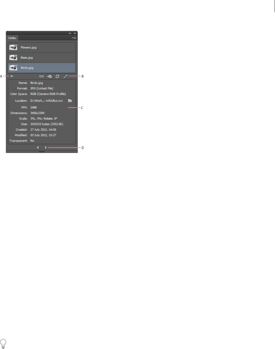
360
Importing, exporting, and saving
Last updated 6/5/2015
A Show Link Info B Links actions C Link Info area D Previous/Next Navigation Icons
Use the icons to Relink, Go to Link, Update Link, and Edit Original. As before, these options are also available from the
panel menu.
The Links Information panel displays the following information:
Name Displays the name of the linked file
Format Displays the file type of the linked file and type of linking: linked or embedded.
Color space Displays the color space and color profile of the linked file. Blank for embedded files.
Location Displays the folder location of the linked file. Click the Folder icon to open the folder in Explorer (Windows)
or Finder (Mac OS).
PPI Displays the effective Pixels per Inch (PPI) of the linked file.
Dimensions Displays the original dimensions of the linked file. This value does not change even if you transform
(resize, rotate) the linked file.
Scale Displays the artwork’s values for scale and rotation.
Created Displays the date the file was created.
Modified Displays the date the file was most recently modified.
Transparent Indicates if the image contains alpha transparency.
For more information about the Links panel, see Links panel overview.
To view Links information in earlier versions of Illustrator, choose Window > Document Info, and then choose Linked
Images from the panel menu. For more information, see Document Info panel overview.
Place multiple files | Illustrator CC
The Place command is the primary method of importing external files into an Illustrator document. the Place feature
provides the highest level of support for file formats, placement options, and color. After you place a file, use the Links
panel to identify, select, monitor, and update it.
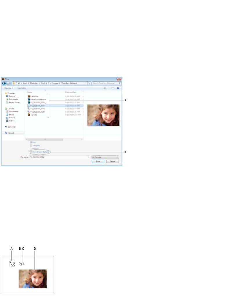
361
Importing, exporting, and saving
Last updated 6/5/2015
You can place one or more files in a single action. Use this feature to select multiple images and then place the images
one by one, in an Illustrator document.
Place multiple files at a time
1Open an Illustrator file that you want to place external files in, and then click File > Place.
2In the Place dialog, select multiple files using the Ctrl (Cmd) or Shift (Opt) keys.
A Select one or more files B Show Import Options checkbox
3Do one of the following:
•Click Place. In the Illustrator document, the pointer turns into the loaded graphics icon.
•Select the Show Import Options check box, and then click Place. The Import Options dialog box is displayed for
assets that have import settings in Illustrator. When you finish selecting the options for each asset, the pointer
turns into the loaded graphics icon.
Note: The settings that you specify in the Import Options dialog determine the preview image of the asset, displayed next
to the loaded graphics pointer.
A Loaded graphics pointer B Position of the currently displayed asset, in the list of loaded graphics C Total number of assets loaded
D Thumbnail preview of the current asset
4Use the Left or Right Arrow keys to browse the list of loaded assets. A thumbnail preview of the current asset is
displayed whenever you press the Left or Right Arrow key.
5To place an image, do one of the following:
•Point the loaded graphics pointer at a location, and click the precise location in the Illustrator file. The current
asset is placed at its original dimensions.
•Point the loaded graphics pointer at a location, and then drag the loaded graphics pointer. The current asset is
placed in a rectangle bounding box. The dimensions of the rectangle are proportionate to the size of the original
asset.

362
Importing, exporting, and saving
Last updated 6/5/2015
6To quickly view and modify the import options of an asset:
•Press the Left or Right Arrow keys to preview the loaded assets.
•When you see the preview of the asset whose import options you would like to modify, press Shift and click the
mouse.
•Modify the necessary options, and then click OK.
7To discard an asset that is loaded and ready to be placed, use the arrow keys to navigate to the asset, and then press
Esc.

363
Last updated 6/5/2015
Chapter 9: Type
Importing and exporting text
Importing text
You can import text into your artwork from a file that was created in another application. Illustrator supports the
following formats for importing text:
•Microsoft® Word for Windows 97, 98, 2000, 2002, 2003, and 2007
•Microsoft Word for Mac OS X, 2004, and 2008
•RTF (Rich Text Format)
•Plain text (ASCII) with ANSI, Unicode, Shift JIS, GB2312, Chinese Big 5, Cyrillic, GB18030, Greek, Turkish, Baltic,
and Central European encoding
One advantage of importing text from a file, rather than copying and pasting it, is that imported text retains its
character and paragraph formatting. For example, text from an RTF file retains its font and style specifications in
Illustrator. You can also set encoding and formatting options when importing text from a plain text file.
Note: When importing text from Microsoft Word and RTF files, make sure that the fonts used in the file are available
on your system. Missing fonts and font styles—including fonts that have the same name but different formats (Type 1,
TrueType, or CID)—may cause unexpected results. On Japanese systems, differences in character sets may prevent text
that was entered in Windows from appearing on-screen in Mac OS.
Import text into a new file
1Choose File > Open.
2Select the text file you want to open, and click Open.
Import text into an existing file
1Choose File > Place. Select the text file you want to import, and click Place.
2If you are placing a plain text (.txt) file, do the following, and then click OK:
•Specify the character set and platform that were used to create the file.
•Select an Extra Carriage Returns option to determine how Illustrator processes extra carriage returns in the file.
•Select the Extra Spaces option if you want Illustrator to replace strings of spaces in the file with tabs. Enter the
number of spaces to be replaced by a tab.
Exporting text

364
Type
Last updated 6/5/2015
Export text to a text file
1Using a type tool, select the text you want to export.
2Choose File > Export.
3In the Export dialog box, select a location for the file and enter a filename.
4Choose Text Format (TXT) as the file format.
5Enter the name of the new text file in the name box, and click Save (Windows) or Export (Mac OS).
6Choose a platform and encoding method, and click Export.
Tag text for export to Flash
You can export text from Illustrator to Adobe Flash in a variety of ways. You can export text as a static, dynamic, or
input text. Dynamic text also allows you to specify a URL for the site that will open when a user clicks the text. For more
information about dynamic and input text, see Flash Help.
Flash text can contain point text, area text, or text on a path; all text is converted to area text in SWF format. Bounding
boxes remain the same and any transformations applied to them are preserved in SWF format. Threaded text objects
are exported individually —if you want to tag and export all objects in a thread, make sure that you select and tag each
one. Overflow text is imported into Flash Player intact.
Once you tag text, you can import it into Flash by either exporting the text from Illustrator or copying and pasting the
text.
For a video on using text effectively between Illustrator and Flash, see www.adobe.com/go/vid0199.
Note: Tagging or untagging text does not change the original text in Illustrator. You can change the tag at anytime without
altering the original.
1Select a text object and click Flash Text in the Control panel.
2In the Flash Text panel, select one of the following from the Type menu:
Static Text Exports text to Flash Player as a regular text object that cannot be changed dynamically or
programmatically in Flash. The content and appearance of static text are determined when you author the text.
Dynamic Text Exports the text as Dynamic text, which can update programmatically at run time through Action
script commands and tags. You can use dynamic text for sports scores, stock quotes, news headlines, and similar
purposes in which you want the text to update dynamically.
Input Text Exports the text as Input text, which is the same as Dynamic text, but also allows users to edit the text in
Flash Player. You use input text for forms, surveys, or other similar purposes in which you want users to input or
edit text.
3(Optional) Enter an instance name for the text object. If you do not enter an instance name, the default name of the
text object in the Layers panel is used in Flash to manipulate the text object.
4Specify a Rendering Type. The Use Device Fonts option converts glyphs to device fonts (anti-aliasing is not available
for device fonts).
Note: Font names are normally used verbatim and passed directly to the playback platform’s font system to locate the
font. However, there are several special indirect font names that are mapped to different font names depending on the
playback platform. These indirect mappings are hard-coded into each platform-specific port of Flash Player, and the
fonts for each platform are chosen from among system default fonts or other fonts that are likely to be available. As a
secondary consideration, the indirect mappings are specified to maximize the similarity of indirect fonts across
platforms.
Animation Optimizes text for output to animation.

365
Type
Last updated 6/5/2015
Readability Optimizes text for readability.
Custom Lets you specify custom values for Thickness and Sharpness of text.
Use Device Fonts Converts glyphs to device fonts. Anti-aliasing is not available for device fonts.
_sans, _serif, and _typewriter Map western indirect fonts across platforms to ensure a similar appearance.
Gothic, Tohaba (Gothic Mono), and Mincho Map Japanese indirect fonts across platforms to ensure a similar
appearance.
Note: For more information on indirect fonts, see the Flash specification document, which you can find on Adobe.com.
5(Optional) Select any of the following:
Selectable Makes the exported text selectable in Flash.
Show Border Around Text Makes the text borders visible in Flash.
Edit Character Options Opens the Character Embedding dialog box so that you can embed specific characters in
the text object. You can choose the characters you want to embed from the provided list, type the characters in the
Include These Characters text box, click Auto Fill to automatically select characters that need to be embedded, or
do any combination of these.
6(Optional) If you tagged the text as Dynamic text, you can specify the URL of the page you want to open when the
text is clicked, and then choose a target window to specify where you want to load the page:
_self Specifies the current frame in the current window.
_blank Specifies a new window.
_parent Specifies the parent of the current frame.
_top Specifies the top-level frame in the current window.
7If you tagged the text as Input Text, specify the Maximum Characters that can be typed into the text object.
Once you tag text as Flash text, you can select all such text at once by choosing Select > Object > Flash Dynamic Text
or Flash Input Text.
More Help topics
Flash text video
Flash export options
SWF optimization options (Illustrator)
Creating text
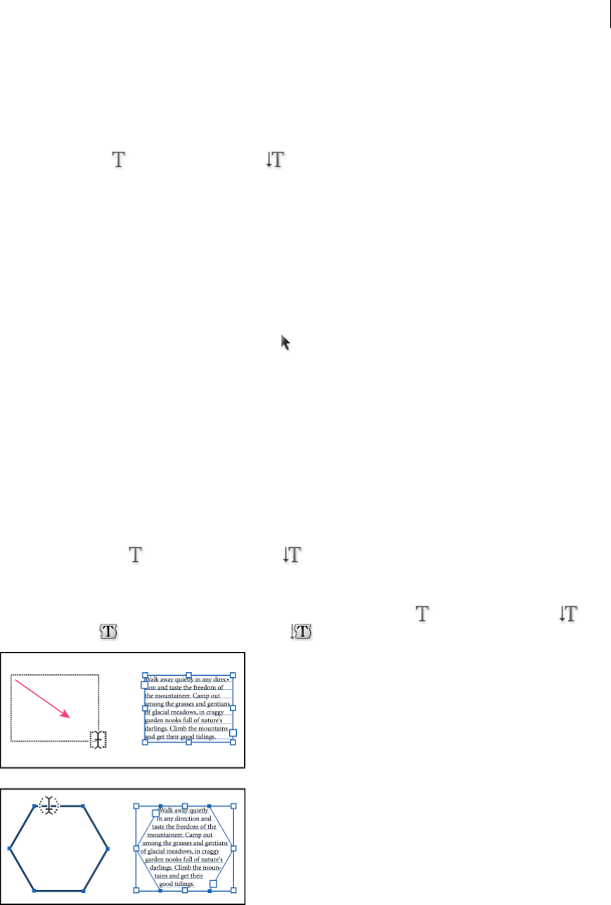
366
Type
Last updated 6/5/2015
Enter text at a point
Point type is a horizontal or vertical line of text that begins where you click and expands as you enter characters. Each
line of text is independent—the line expands or shrinks as you edit it, but doesn’t wrap to the next line. Entering text
this way is useful for adding a few words to your artwork.
1Select the Type tool or the Vertical Type tool .
The pointer changes to an I-beam within a dotted box. The small horizontal line near the bottom of the I-beam
marks the position of the baseline, on which the text rests.
2(Optional) Set text-formatting options in the Control panel, Character panel, or Paragraph panel.
3Click where you want the line of text to begin.
Note: Be sure not to click an existing object, because doing so converts the type object into area type or type on a path.
If an existing object is located where you want to enter text, lock or hide the object.
4Enter the text. Press Enter or Return to begin a new line of text within the same type object.
5When you finish entering text, click the Selection tool to select the type object. Alternatively, Ctrl-click (Windows)
or Command-click (Mac OS) the text.
Note: For more information about working with type in Illustrator, see the Working with Type white paper at
www.adobe.com/go/learn_ai_type_en.
Enter text in an area
Area type (also called paragraph type) uses the boundaries of an object to control the flow of characters, either
horizontally or vertically. When the text reaches a boundary, it automatically wraps to fit inside the defined area.
Entering text this way is useful when you want to create one or more paragraphs, such as for a brochure.
1Define the bounding area:
•Select the Type tool or the Vertical Type tool , and drag diagonally to define a rectangular bounding
area.
•Draw the object you want to use as the bounding area. (It doesn’t matter if the object has stroke or fill attributes,
because Illustrator automatically removes them.) Then select the Type tool , the Vertical Type tool , the
Area Type tool , or the Vertical Area Type tool and click anywhere on the object’s path.
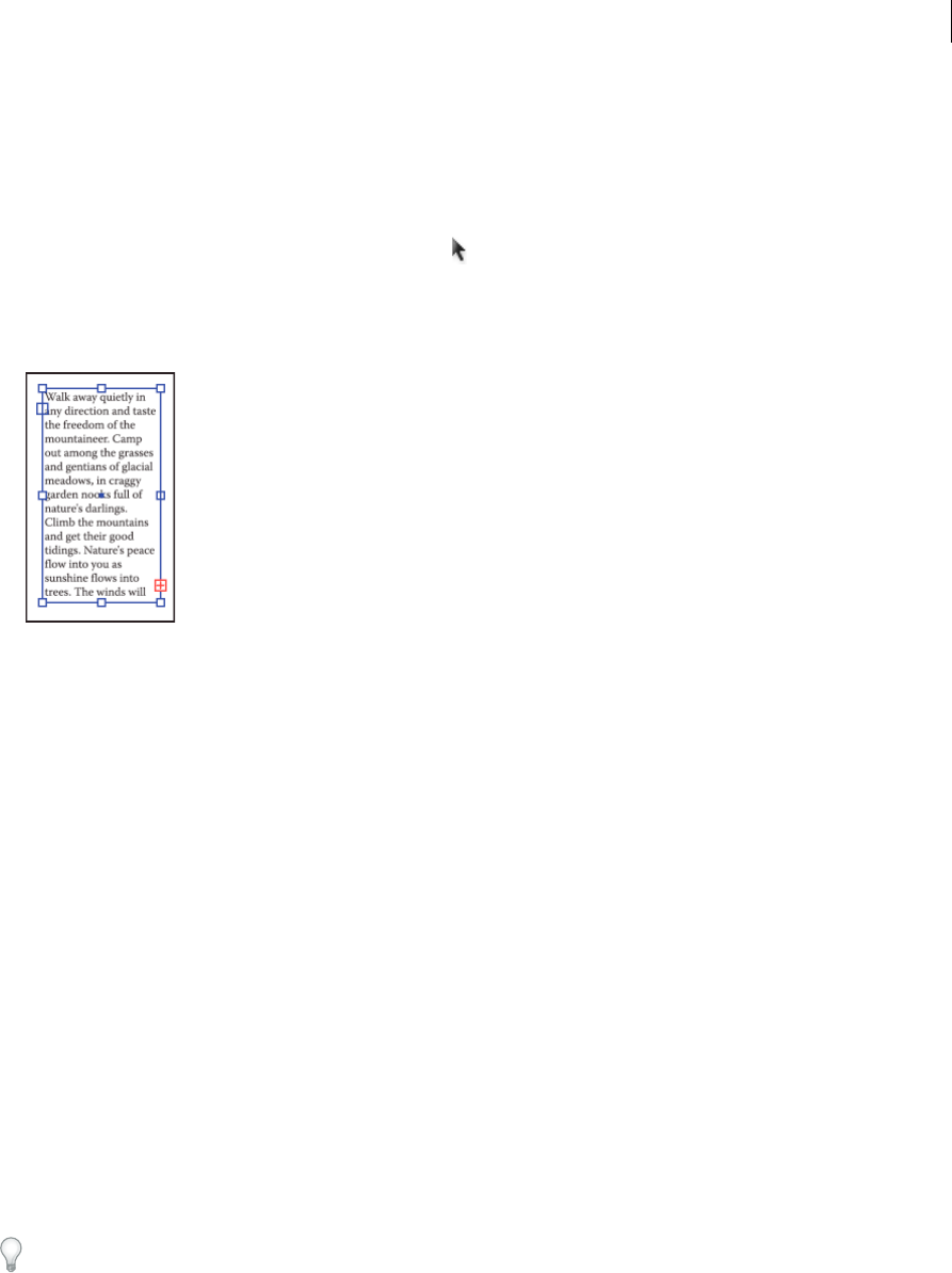
367
Type
Last updated 6/5/2015
Note: If the object is an open path, you must use the Area Type tool to define the bounding area. Illustrator draws an
imaginary line between the endpoints of the path to define the boundaries.
2(Optional) Set text-formatting options in the Control panel, Character panel, or Paragraph panel.
3Enter the text. Press Enter or Return to begin a new paragraph.
4When you finish entering text, click the Selection tool to select the type object. Alternatively, Ctrl-click (Windows)
or Command-click (Mac OS) the text.
If you enter more text than can fit within an area, a small box containing a plus symbol (+) appears near the bottom
of the bounding area.
You can resize the text area or extend the path to display the overflow text. You can also thread the text into another
object.
For a video on creating point and area type, see www.adobe.com/go/vid0045. For more information about working
with type in Illustrator, see the Working with Type white paper at www.adobe.com/go/learn_ai_type.
Manage the text area
Resize a text area
You can resize text in different ways, depending on the whether you are creating point type, area type, or text along a
path.
There is no limit for the amount of text that can be written using point type, so resizing of the text box is not required
in this case.
When using the area type tool, you drag an object and type inside the selected area. In this case, the text resizes when
you resize the object using the Direct Selection tool.
When you type text along a path, you can thread text between objects (see Threading text between objects), if the text
does not fit in the selected path. In this case also, the text is resized if you resize the path using the Direct Selection tool.
Make sure that the bounding box setting is set to Show Bounding Box. If you are not able to see the bounding box, then
click View > Show Bounding Box.
❖To resize, do one of the following:
•Select the type object using the Selection tool or Layers panel, and drag a handle on the bounding box.
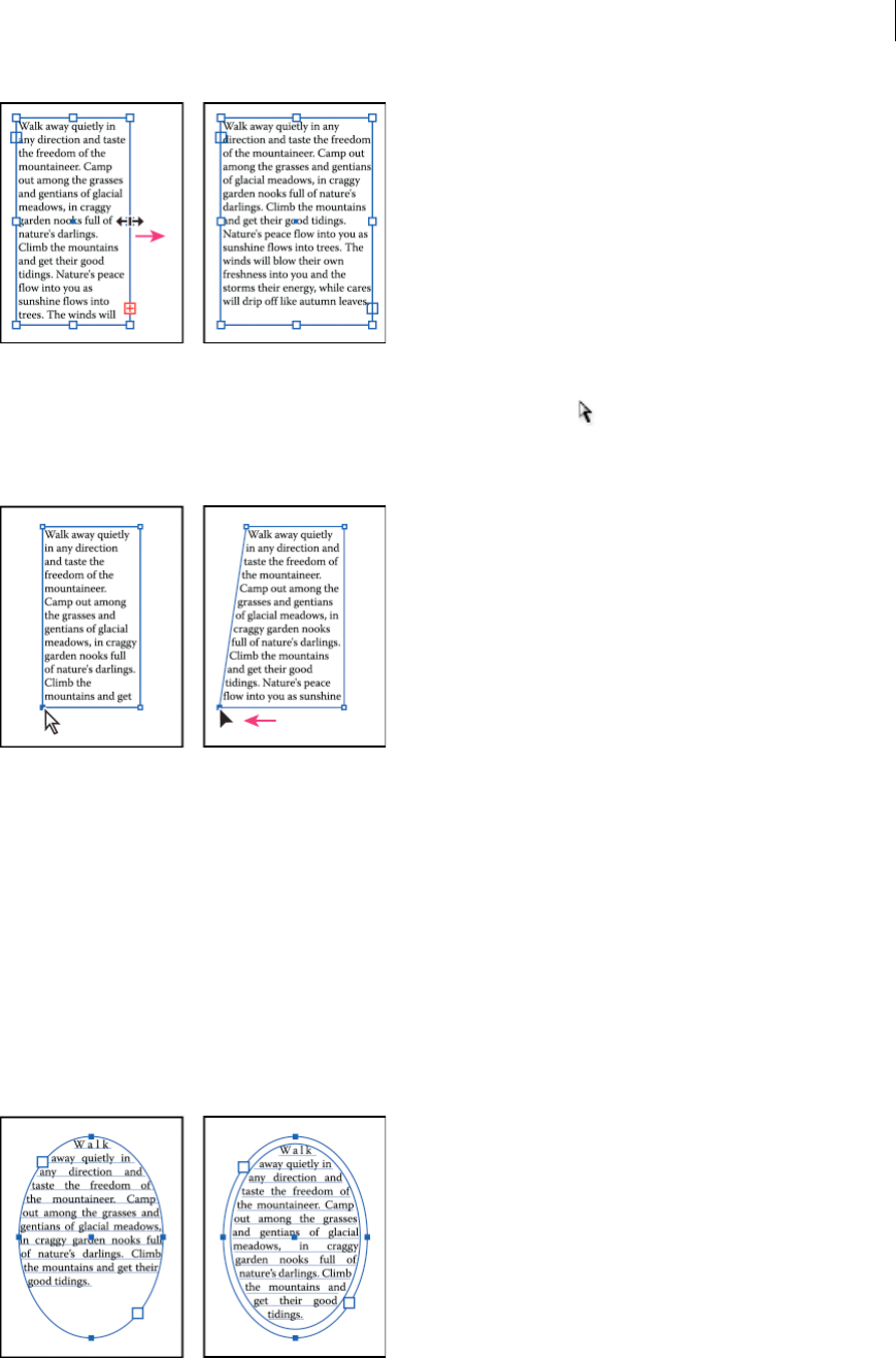
368
Type
Last updated 6/5/2015
•Select the edge or corner of the type path with the Direct Selection tool . Then drag to adjust the shape of the
path.
Tip: Adjusting the type path using the Direct Selection tool is easiest when you’re in Outline view.
•Select the type object using the Selection tool or Layers panel, and choose Type > Area Type Options. Enter
values for Width and Height, and click OK. If the text area is not a rectangle, these values determine the
dimensions of the object’s bounding box.
Change the margin around a text area
When working with an area type object, you can control the margin between the text and the bounding path. This
margin is referred to as the inset spacing.
1Select an area type object.
2Choose Type > Area Type Options.
3Specify a value for Inset Spacing, and click OK.
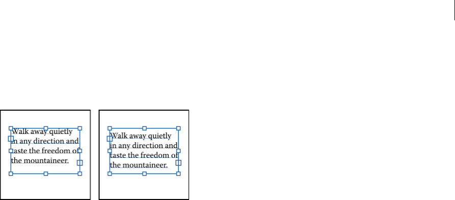
369
Type
Last updated 6/5/2015
Raise or lower the first baseline in a text area
When working with an area type object, you can control the alignment of the first line of text with the top of the object.
This alignment is referred to as the first baseline offset. For example, you can make text stick up above the top of the
object or fall a specific distance below the top of the object.
1Select an area type object.
2Choose Type > Area Type Options.
3For First Baseline, choose one of the following options:
Ascent The height of the “d” character falls below the top of the type object.
Cap Height The tops of uppercase letters touch the top of the type object.
Leading Uses the text’s leading value as the distance between the baseline of the first line of text and the top of the
type object.
x Height The height of the “x” character falls below the top of the type object.
Em Box Height The top of the em box in Asian fonts touches the top of the type object. This option is available
regardless of the Show Asian Options preference.
Fixed Specifies the distance between the baseline of the first line of text and the top of the type object in the Min box.
Legacy Uses the first baseline default used in Adobe Illustrator 10 or earlier.
4For Min, specify the value for the baseline offset.
More Help topics
Shift the baseline
Display Asian type options
Create rows and columns of text
1Select an area type object.
2Choose Type > Area Type Options.
3In the Rows and Columns sections of the dialog box, set the following options:
Number Specifies the number of rows and columns you want the object to contain.
Span Specifies the height of individual rows and the width of individual columns.
Fixed Determines what happens to the span of rows and columns if you resize the type area. When this option is
selected, resizing the area can change the number of rows and columns, but not their width. Leave this option
deselected if you want row and column widths to change when you resize the type area.
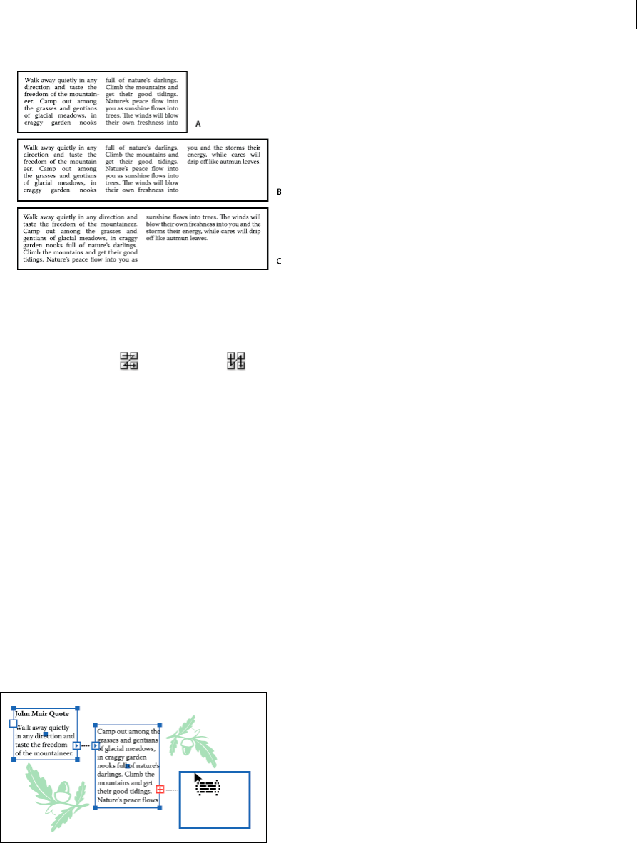
370
Type
Last updated 6/5/2015
Gutter Specifies the distance between rows or columns.
4In the Options section of the dialog box, select a Text Flow option to determine how text flows between rows and
columns: By Rows or By Columns .
5Click OK.
Fit a headline across the full width of a type area
1Select a type tool, and click in the paragraph you want to fit across the type area.
2Choose Type > Fit Headline.
Note: If you change the formatting of the type, be sure to reapply the Fit Headline command.
Threading text between objects
To thread (or continue) text from one object to the next, you link the objects. Linked type objects can be of any shape;
however, the text must be entered in an area or along a path (not at a point).
Each area type object contains an in port and an out port, which enable you to link to other objects and create a linked
copy of the type object. An empty port indicates that all the text is visible and that the object isn’t linked. An arrow in
a port indicates that the object is linked to another object. A red plus sign in an out port indicates that the object
contains additional text. This remaining unseen text is called overflow text.
You can break threads and have the text flow into either the first or the next object, or you can remove all threads and
have the text stay in place.

371
Type
Last updated 6/5/2015
Note: When working with threaded text, it can be useful to see the threads. To view threads, choose View > Show Text
Threads and then select a linked object.
Thread text
1Use the Selection tool to select an area type object.
2Click the in port or the out port of the selected type object. The pointer changes to the loaded text icon .
3Do one of the following:
•To link to an existing object, position the pointer on the object’s path. The pointer changes to a . Click the
path to link the objects.
•To link to a new object, click or drag on an empty part of the artboard. Clicking creates an object of the same size
and shape as the original; dragging lets you create a rectangular object of any size.
Another method for threading text between objects is to select an area type object, select the object (or objects)
you want to thread to, and then choose Type > Threaded Text > Create.
Remove or break threads
1Select a linked type object.
2Do any of the following:
•To break the thread between two objects, double-click the port on either end of the thread. The text flows into
the first object.
•To release an object from a text thread, choose Type > Threaded Text > Release Selection. The text flows into the
next object.
•To remove all threads, choose Type > Threaded Text > Remove Threading. The text stays in place.
Wrap text around an object
You can wrap area text around any object, including type objects, imported images, and objects you draw in Illustrator.
If the wrap object is an embedded bitmap image, Illustrator wraps the text around opaque or partially opaque pixels and
ignores fully transparent pixels.
Wrapping is determined by the stacking order of objects, which you can view in the Layers panel by clicking the triangle
next to the layer name. To wrap text around an object, the wrap object must be in the same layer as the text and located
directly above the text in the layer hierarchy. You can drag contents up or down in the Layers panel to change hierarchy.
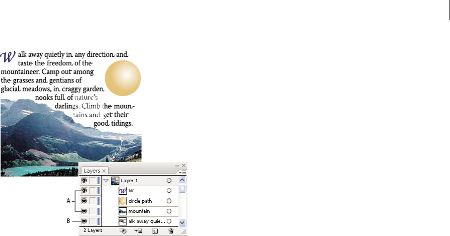
372
Type
Last updated 6/5/2015
A Wrap objects B Wrapped text
More Help topics
Stacking objects
Creating type on a path
Wrap text
1Make sure that the following conditions are true for the type you want to wrap:
•It is area type (typed in a box).
•It is in the same layer as the wrap object.
•It is located directly under the wrap object in the layer’s hierarchy.
Note: If the layer contains multiple type objects, move any that you don’t want to wrap around the wrap object either
into another layer or above the wrap object.
2Select the object or objects around which you want the text to wrap.
3Choose Object > Text Wrap > Make.
Set wrap options
You can set wrap options before or after you wrap the text.
1Select the wrap object.
2Choose Object > Text Wrap > Text Wrap Options and specify the following options:
Offset Specifies the amount of space between the text and the wrap object. You can enter a positive or negative
value.
Invert Wrap Wraps the text around the reverse side of the object.
Unwrap text from an object
1Select the wrap object.
2Choose Object > Text Wrap > Release.

373
Type
Last updated 6/5/2015
Align type to object
To align text according to the bounding box of the actual glyphs instead of the font metrics, do the following:
1Apply the Outline Object live effect to the text object using Effect > Path > Outline Object.
2Set the Align panel to use preview bounds by selecting the Use Preview Bounds option from the Align panel menu
(flyout).
After applying these settings, you get exactly the same alignment as outlined text, while keeping the text live.
Delete empty type objects from your artwork
Deleting unused type objects makes your artwork easier to print and reduces the file size. You can create empty type
objects, for example, if you inadvertently click the Type tool in the artwork area and then choose another tool.
1Choose Object > Path > Clean Up.
2Select Empty Text Paths, and click OK.
Creating type on a path
Type on a path flows along the edge of an open or a closed path. When you enter text horizontally, the characters are
parallel to the baseline. When you enter text vertically, the characters that are perpendicular to the baseline. In either
case, the text flows in the direction in which points were added to the path.
Enter text on a path
1Do one of the following:
•To create horizontal text along a path, select the Type tool or the Type On A Path tool .
•To create vertical text along a path, select the Vertical type tool or the Vertical Type On A Path tool .
2(Optional) Set text-formatting options in the Control panel, Character panel, or Paragraph panel.
3Position the pointer on the path, and click. (It doesn’t matter if the path has stroke or fill attributes, because
Illustrator automatically removes them.)
Note: If the path is closed, rather than open, you must use the Type On A Path tool.
4Enter the text.
5When you finish entering text, click the Selection tool to select the type object. Alternatively, Ctrl-click (Windows)
or Command-click (Mac OS) the text.
If you enter more text than can fit within an area or along a path, a small box containing a plus symbol (+) appears near
the bottom of the bounding area.
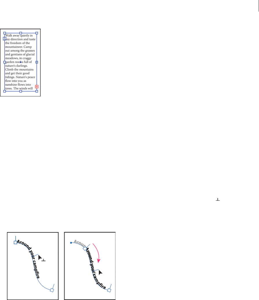
374
Type
Last updated 6/5/2015
You can resize the text area or extend the path to display the overflow text. You can also thread the text into another
object.
For a video on creating type on a path, see www.adobe.com/go/vid0046. For more information about working with type
in Illustrator, see the Working with Type white paper at www.adobe.com/go/learn_ai_type.
Move or flip text along a path
1Select the path type object.
A bracket appears at the beginning of the type, at the end of the path, and at the midpoint between the start and end
brackets.
2Position the pointer over the type’s center bracket until a small icon appears next to the pointer .
3Do one of the following:
•To move text along the path, drag the center bracket along the path. Hold down Ctrl (Windows) or Command
(Mac OS) to prevent the type from flipping to the other side of the path.
•To flip the direction of text along a path, drag the bracket across the path. Alternatively, choose Type > Type On
A Path > Type On A Path Options, select Flip, and click OK.
Flipping type along a path
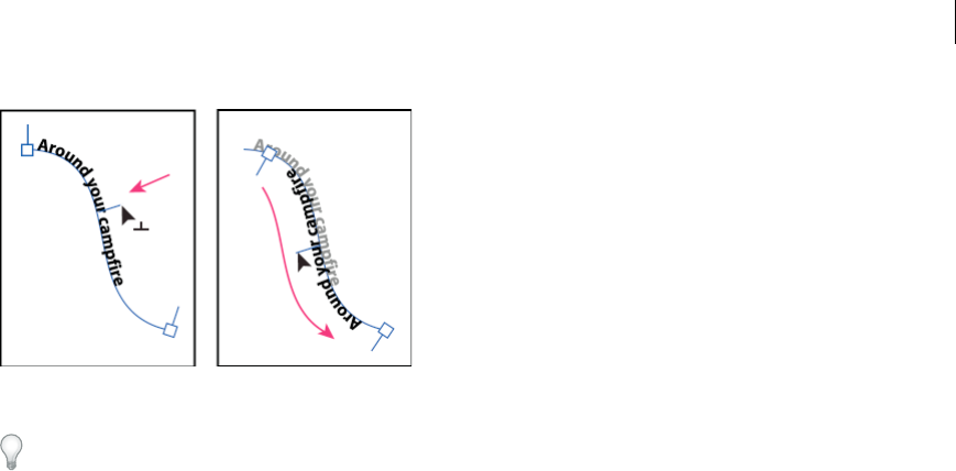
375
Type
Last updated 6/5/2015
Tip: To move type across a path without changing the direction of the type, use the Baseline Shift option in the
Character panel. For example, if you created type that runs from left to right across the top of a circle, you can enter
a negative number in the Baseline Shift text box to drop the type so that it flows inside the top of the circle.For a video
on creating type on a path, see www.adobe.com/go/vid0046.
More Help topics
Shift the baseline
Apply effects to type on a path
Path type effects let you distort the orientation of characters on a path. You must first create type on a path before you
can apply these effects.
1Select the path type object.
2Do one of the following:
•Choose Type > Type On A Path and select an effect from the submenu.
•Choose Type > Type On A Path > Type On A Path Options. Then select an option from the Effect menu, and
click OK.
Note: Applying the Gravity effect to text on a perfectly circular path creates a result that looks like the default
Rainbow effect. It performs as expected on paths that are oval, square, rectangular or otherwise irregularly
shaped.
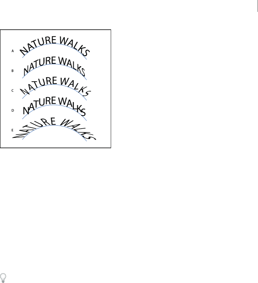
376
Type
Last updated 6/5/2015
Adjust the vertical alignment of type on a path
1Select the type object.
2Choose Type > Type On A Path > Type On A Path Options.
3Choose an option from the Align To Path menu to specify how to align all characters to the path, relative to a font’s
total height:
Ascender Aligns along the font’s top edge.
Descender Aligns along the font’s bottom edge.
Center Aligns along the point halfway between the font’s ascender and descender.
Baseline Aligns along the baseline. This is the default setting.note: Characters without ascenders or descenders (such
as a letter e) or a baseline (such as an apostrophe) are vertically aligned with characters that have ascenders, descenders,
and baselines. These font dimensions are permanently specified by the font designer.
Tip: For more control over vertical alignment, use the Baseline Shift option in the Character panel. For example,
type a negative value in the Baseline Shift box to lower the type.
Adjust character spacing around sharp turns
When characters flow around a sharp curve or acute angle, they fan out in such a way that there may appear to be extra
space between them. You can tighten the spacing of characters on curves using the Spacing option in the Type On A
Path Options dialog box.
1Select the type object.
2Choose Type > Type On A Path > Type On A Path Options.
3For Spacing, type a value in points. Higher values remove the extra space from between characters positioned on
sharp curves or angles.
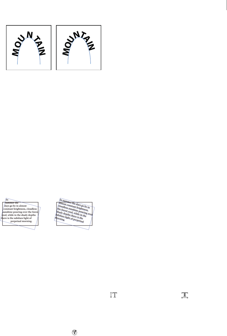
377
Type
Last updated 6/5/2015
Note: The Spacing value has no effect on characters positioned on straight segments. To change spacing of characters
anywhere along the path, select them, and then apply kerning or tracking.
Scaling and rotating type
Selecting type for transformations
You can rotate, reflect, scale, and shear type just as you do other objects. However, how you select the type affects the
transformation results:
•To transform the type along with its bounding path, select the type object and use the Rotate tool to rotate the object
and text.
•To transform just the bounding path, but not the type it contains, select the type object and drag with the Selection
tool.
Adjust the scale of type
You can specify the proportion between the height and width of the type, relative to the original width and height of
the characters. Unscaled characters have a value of 100%. Some type families include a true expanded font, which is
designed with a larger horizontal spread than the plain type style. Scaling distorts the type, so it is generally preferable
to use a font that is designed as condensed or expanded, if one is available.
1Select the characters or type objects you want to change. If you don’t select any text, the scale applies to new text you
create.
2In the Character panel, set the Vertical Scaling option or the Horizontal Scaling option .
Rotate type
•To rotate the characters within a type object by a specific number of degrees, select the characters or type objects
you want to change. (If you don’t select any text, the rotation applies to new text you create.) In the Character panel,
set the Character Rotation option .

378
Type
Last updated 6/5/2015
•To change horizontal type to vertical type, and vice versa, select the type object and choose Type > Type Orientation
> Horizontal or Type > Type Orientation > Vertical.
•To rotate an entire type object (both the characters and the type bounding box), select the type object and use the
bounding box, Free Transform tool, Rotate tool, Rotate command, or Transform panel to perform the rotation.
•To rotate multiple characters in vertical Asian text, use the tate-chu-yoko option to rotate multiple characters.
More Help topics
Transforming objects
Character panel overview
Use tate-chu-yoko
Rotate objects
Spelling and language dictionaries
Check spelling
1Choose Edit > Check Spelling.
2To set options for finding and ignoring words, click the arrow icon at the bottom of the dialog box and set the
options as desired.
3Click Start to begin checking the spelling.
4When Illustrator displays misspelled words or other possible errors, do one of the following:
•Click Ignore or Ignore All to continue spell-checking without changing a certain word.
•Select a word from the Suggestions list or type the correct word in the top box, and then click Change to change
only that occurrence of the misspelled word. You can also click Change All to change all occurrences of the
misspelled word in your document.
•Click Add to have Illustrator store an acceptable but unrecognized word in the dictionary so that subsequent
occurrences are not considered misspellings.
5When Illustrator finishes checking your document, click Done.
Illustrator can check for spelling errors in a variety of languages, based on the language that you assign to words.
Edit the spelling dictionary
1Choose Edit > Edit Custom Dictionary.
2Do any of the following, and click Done:
•To add a word to the dictionary, type the word in the Entry box, and click Add.
•To remove a word from the dictionary, select the word in the list, and click Delete.
•To modify a word in the dictionary, select the word in the list. Then type the new word in the Entry box, and
click Change.

379
Type
Last updated 6/5/2015
Assign languages to text
Illustrator uses Proximity language dictionaries for both spelling and hyphenation. Each dictionary contains hundreds
of thousands of words with standard syllable breaks. You can assign a language to an entire document or apply a
language to selected text.
A “Glockenspiel” in English B “Glockenspiel” in Traditional German C “Glockenspiel” in Reformed German
Apply a language to all text
1Choose Edit > Preferences > Hyphenation (Windows) or Illustrator > Preferences > Hyphenation (Mac OS).
2Select a dictionary from the Default Language pop-up menu, and click OK.
Assign a language to selected text
1Select the text.
2In the Character panel, choose the appropriate dictionary from the Language menu. If the Language menu isn’t
showing, choose Show Options from the Character panel menu.
About Unicode
Illustrator supports Unicode, a standard that assigns a unique number to every single character, no matter which
language or type of computer you use. Unicode is:
Portable Letters and numbers will not change when you move the file from one workstation to another. Adding a
foreign language to a document doesn’t cause confusion, because foreign characters have their own designations that
don’t interfere with the encoding from other languages in the same project.
Platform-neutral Because Windows and Macintosh operating systems now support Unicode, moving a file between
the two platforms is easier. No longer will you need to proofread an Illustrator file just because you moved to it a
Windows computer from a Macintosh computer or vice versa.
Robust Because Unicode-compliant fonts offer a larger number of potential characters, specialty type characters are
readily available.
Flexible With Unicode support, substituting a typeface in a project won’t result in substituted characters. With a
Unicode-compliant font, a g is a g no matter which typeface is used.
All of these things make it possible for a French designer to design for a client in Korea and hand the job off to a partner
in the United States without having to struggle with the text. All the U.S. designer needs to do is enable the correct
language in the operating system, load the foreign-language font, and continue the project.
Fonts

380
Type
Last updated 6/5/2015
About fonts
A font is a complete set of characters—letters, numbers, and symbols—that share a common weight, width, and style,
such as 10-pt Adobe Garamond Bold.
Typefaces (often called type families or font families) are collections of fonts that share an overall appearance, and are
designed to be used together, such as Adobe Garamond.
A type style is a variant version of an individual font in a font family. Typically, the Roman or Plain (the actual name
varies from family to family) member of a font family is the base font, which may include type styles such as regular,
bold, semibold, italic, and bold italic.
For CJK-language fonts, the font style name is often determined by the variation in thickness (also called weight). For
example, the Japanese font Kozuka-Mincho Std includes six weights: Extra Light, Light, Regular, Medium, Bold and
Heavy. The font style name which is displayed depends on the font manufacturer. Each font style is a stand-alone file.
If the font style file has not been installed, that font style cannot be selected from Font Style.
In addition to the fonts installed on your system, you can also create the following folders and use fonts installed in
them:
Windows Program Files/Common Files/Adobe/Fonts
Mac OS Library/Application Support/Adobe/Fonts
If you install a Type 1, TrueType, OpenType, or CID font into the local Fonts folder, the font appears in Adobe
applications only.
OpenType fonts
OpenType fonts use a single font file for both Windows® and Macintosh® computers, so you can move files from one
platform to another without worrying about font substitution and other problems that cause text to reflow. They may
include a number of features, such as swashes and discretionary ligatures, that aren’t available in current PostScript and
TrueType fonts.
OpenType fonts display the icon.
When working with an OpenType font, you can automatically substitute alternate glyphs, such as ligatures, small
capitals, fractions, and old style proportional figures, in your text.
A Ordinals B Discretionary ligatures C Swashes
OpenType fonts may include an expanded character set and layout features to provide richer linguistic support and
advanced typographic control. OpenType fonts from Adobe that include support for central European (CE) languages
include the word “Pro,” as part of the font name in application font menus. OpenType fonts that don’t contain central
European language support are labeled “Standard,” and have an “Std” suffix. All OpenType fonts can also be installed
and used alongside PostScript Type 1 and TrueType fonts.

381
Type
Last updated 6/5/2015
For more information on OpenType fonts, see www.adobe.com/go/opentype.
Previewing fonts
You can view samples of a font in the font family and font style menus in the Character panel and other areas in the
application from where you can choose fonts. The following icons are used to indicate different kinds of fonts:
•OpenType
•Type 1
•TrueType
•Multiple Master
•Composite
You can turn off the preview feature or change the point size of the font names or font samples in Type preferences.
Select a font family and style
1Select the characters or type objects you want to change. If you don’t select any text, the font applies to new text you
create.
2Select a font family and style using the Control panel, Type menu, or Character panel:
•In the Control panel, set the Font and Font Style options.
•In the Type menu, select a name from the Font or Recent Fonts submenu. Using the Font menu is convenient
because it displays a preview of the available fonts.
•In the Character panel, set the Font Family and Font Style options. In addition to choosing a name from the
pop-up menus, you can click the current name and type in the first few characters of the name you want.
Tip: To change the number of fonts in the Recent Fonts submenu, choose Edit > Preferences > Type (Windows)
or Illustrator > Preferences > Type (Mac OS), and set the Number Of Recent Fonts option.
Specify a typeface size
By default, typeface size is measured in points (a point equals 1/72 of an inch). You can specify any typeface size from
0.1 to 1296 points, in 0.001-point increments.
Note: In Fireworks, the typeface size is measured in pixels by default.
1Select the characters or type objects you want to change. If you don’t select any text, the typeface size applies to new
text you create.
2Do one of the following:
•In the Character panel or Control bar set the Font Size option.
•Choose a size from the Type > Size menu. Choosing Other lets you type a new size in the Character panel.
Tip: You can change the unit of measurement for type in the Preferences dialog box. This option is not available
in Fireworks.
Find and replace fonts
1Choose Type > Find Font.

382
Type
Last updated 6/5/2015
Move the Find Font dialog box so that you can see all the text in your document.
2Select the name of a font you want to find in the top section of the dialog box. The first occurrence of the font is
highlighted in the document window.
3Select a replacement font in the bottom section of the dialog box. You can customize the list of replacement fonts by
doing the following:
•Choose an option from the Replace With Font From pop-up menu: Document to list only the fonts that are used
in the document or System to list all fonts on your computer.
•Select the kinds of fonts you want to include in the list; deselect the kinds of fonts you don’t want to include.
4Do one of the following:
•Click Change to change just one occurrence of the selected font.
•Click Change All to change all occurrences of the selected font.
When there are no more occurrences of a font in your document, its name is removed from the Fonts in
Document list.
5Repeat steps 2 through 4 to find and replace a different font.
6Click Done to close the dialog box.
Note: When you replace a font using the Find Font command, all other type attributes remain the same.
Work with missing fonts
If a document uses fonts not installed on your system, an alert message appears when you open it. Illustrator indicates
which fonts are missing and substitutes missing fonts with available matching fonts.
•To substitute missing fonts with a different font, select the text that uses the missing font and apply any other
available font.
•To make missing fonts available in Illustrator, either install the missing fonts on your system or activate the missing
fonts using a font management application.
•To highlight substituted fonts in pink, choose File >Document Setup, and select Highlight Substituted Fonts (and
Highlighted Substituted Glyphs, if desired), and then click OK.
Find missing fonts (Typekit workflow)
In the 2014 release of Illustrator CC, when you open an artwork file, if a missing font is detected, the Typekit library is
checked for availability of the missing font. If available on the Typekit website, you can quickly sync the fonts to your
computer, to restore the appearance of your Illustrator artwork.
For more information on how to generally work with fonts available on the Typekit website (through your Typekit
subscription), see the article on Typekit fonts .
The enhanced Find Font dialog
The Find Font dialog has been enhanced to provide more information and do more with a modern interface.
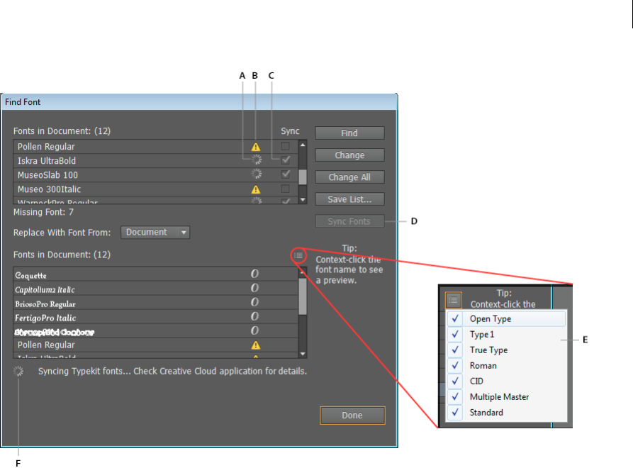
383
Type
Last updated 6/5/2015
A Sync-in-progress icon B Missing font icon C Sync checkbox D Sync Fonts button E Flyout menu F Status
Enhancements include:
Sync-in-progress icon Indicates a missing font being synced from the Typekit library.
Missing font icon Indicates a missing font.
Sync checkbox Select the checkbox to sync the missing font.
Sync Fonts button. Click the button to sync missing fonts, from the Typekit website to the local computer.
Flyout menu Click the flyout menu, and select the checkboxes to filter the list of displayed fonts.
Status Displays the current action being performed.
Find missing fonts using Typekit
Important: For this feature to work, you must:
1Sign into the Creative Cloud app
2Enable Font Sync in the Creative Cloud app (Creative Cloud app > Preferences > Fonts tab > Sync On/Off option)
1Open an artwork file that contains Text elements. If a Text element uses a font that is not available on your local
computer, the text is highlighted in pink.
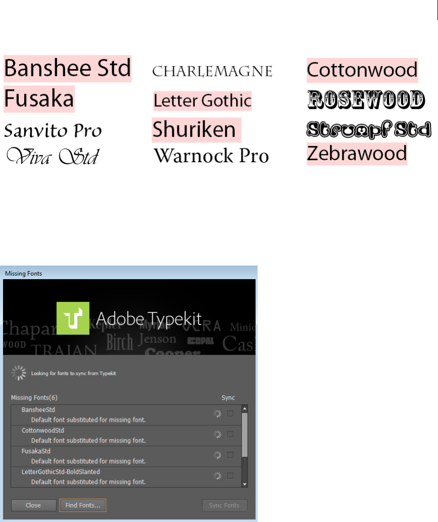
384
Type
Last updated 6/5/2015
2The Missing Fonts dialog displays a list of missing fonts. A spinning wheel against the font name indicates that a
check for availability in the Typekit library is in progress.
•A selected checkbox against the font name indicates that the font is available in the Typekit library. To sync these
fonts, click Sync Typekit Fonts.
•An empty checkbox against the font name indicates that the font is not available on the Typekit website. To find
and substitute fonts, click Find Fonts.
3(Optional) In the Missing Fonts dialog, click Find Fonts, to inspect the list of missing fonts more closely, and:
•Select checkboxes for missing fonts, in the Fonts in Document list, and click Sync Fonts, or,
•Use the Replace With Font From dropdown, and substitute any fonts that are unavailable on the Typekit website
with other fonts.
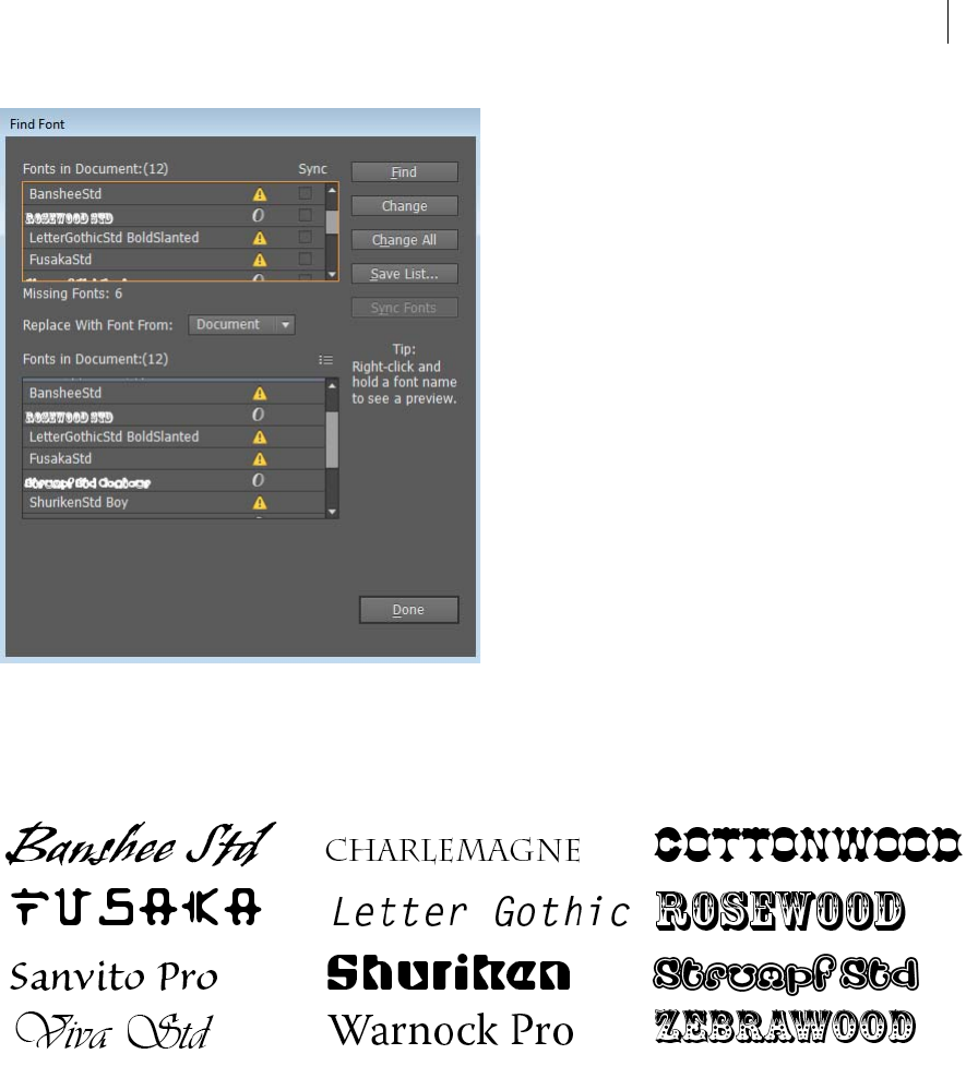
385
Type
Last updated 6/5/2015
4In the Missing Fonts dialog, click Close.
When the missing fonts have been synced to your computer, the Creative Cloud app displays a notification
indicating the number of the fonts (or the name of a single font) downloaded. The document is updated, and Text
elements are rendered in the correct fonts.
Substituted fonts preference
When text in an Illustrator document uses a font that is not available on your computer, the text is rendered in with a
substitute font, and the content is highlighted in pink.
•The preference to highlight a substituted font is now available in the Preferences dialog (Ctrl/Cmd + K > Type tab
> Highlight Substituted Fonts checkbox).
•The preference is switched ON, by default.
•This setting is now Illustrator-specific, and is applicable to all files opened.
Note: Prior to this release, the Highlight Substituted Fonts was available in the Document Setup dialog, and was a file-
specific setting. From the 2014 release of Illustrator CC this option is an application-level setting.

386
Type
Last updated 6/5/2015
Text enhancements
Text-related layout and typing features have been enhanced in the 2014 release of Illustrator CC:
•Additional hidden characters (Type > Show Hidden Characters) have been added to depict typographic notations
(see table below)
•The end-of-paragraph notation and the end-of-line notation are now different glyphs.
•The font used to display hidden characters is changed to Adobe Sans MM.
•The Illustrator text editor now honors the justification of lines that end with soft returns (Shift + Enter/Return)
•The Illustrator text editor now supports IVS (Ideographic Variation Sequence). This results in two important
enhancements:
1Any imported or copied text will continue to show the correct variation of a glyph as originally typed in the
source.
2When you type using an IVS-supported font, variations of glyphs are displayed as expected.
Working with Typekit Fonts
Working with Typekit fonts
Creative Cloud users can use Typekit fonts that have been synced on your computer. The fonts appear alongside other
locally installed fonts. However, you can now use an option to view only the Typekit fonts in the Fonts list. This makes
it easier to work with your favorite Typekit-based fonts.
Original Character Original Unicode Alternate Glyph Alternate Glyph Name Alternate Unicode
Space 0020 ·Middle Dot 00B7
Carriage Return 000D ¶Pilcrow Sign 00B6
Tab 0009 »Right-Pointing Double
Angle Quotation Mark
00BB
Soft Return 0003 ¬Not Sign 00AC
Paragraph Separator 2029 ¬Not Sign 00AC
End of Text # Number Sign 0023
Discretionary Hyphen 00AD -Hyphen Minus 002D
Em Space 2003 _Em Dash 2014
En Space 2002 -En Dash 2013
Hair Space 200A Diaeresis 00A8
Thin Space 2009 Caron 02C7
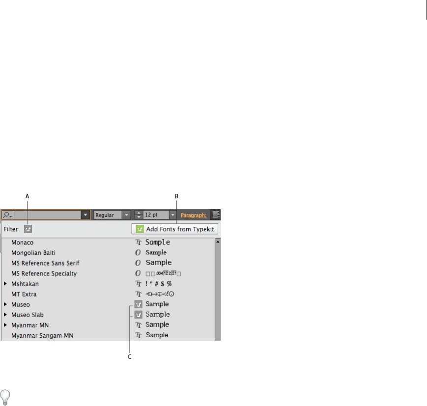
387
Type
Last updated 6/5/2015
Note: Typekit fonts are protected fonts. They cannot be packaged with other fonts while creating an Illustrator package file.
If you package a file with Typekit fonts, when you open the Illustrator file on a different computer running Illustrator CC
or later, you will be notified of unavailable fonts. You can then use the Find Font dialog to identify and download the
missing fonts from the Typekit website.For more information, see Find missing fonts (Typekit workflow).
Filtering Typekit fonts
1To view the list of fonts available to Illustrator, do one of the following:
•Browse to Character panel (Ctrl + T) > Font Family drop-down
•Browse to Control panel > Font Family drop-down
2In the Font Family drop-down, click the Typekit font filter icon.
A Typekit font filter B Typekit website C Typekit font indicator icon
In an unfiltered view, Typekit fonts are indicated with a Typekit font icon.
3To view your favorite fonts, or to add more fonts from Typekit, click the Typekit website icon in the drop-down.
The Typekit font filter is available at two locations:
•Character panel (Ctrl + T) > font drop-down
•Control panel > font drop-down
Filtering Typekit fonts:
•Click the Typekit font filter (A, image above), to view only Typekit-based fonts.
•Click the Typekit website icon (B, image above), to open the Typekit website in your default browser.
•In an unfiltered view, all Typekit fonts are indicated with a Typekit font icon
•Search for fonts by typing the full or partial name of a font in the drop-down.
Accessing the Typekit website from Illustrator:
Browsing to the Typekit website from within Illustrator, also automatically signs you in. To go to the Typekit website,
do one of the following:
•In the Control Panel, click the Font Family drop-down, and then click the Typekit website icon.
•In the Character panel (Ctrl/Cmd + T), click the Font Family drop-down, and then click the Typekit website icon.
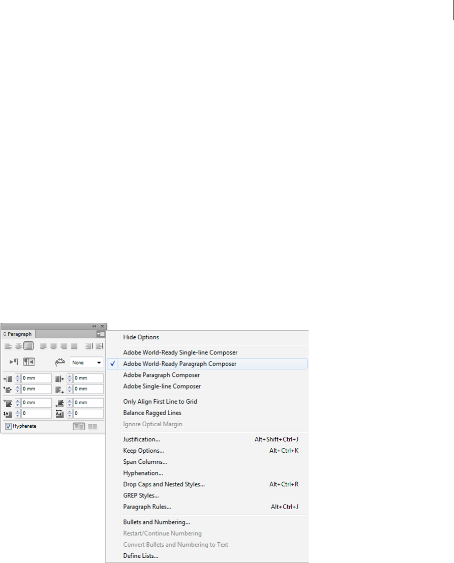
388
Type
Last updated 6/5/2015
Missing fonts workflow (Illustrator CC 2014)
You may open Illustrator files that contain Typekit-based fonts that are not available on your local computer. The
enhanced Find Font dialog in Illustrator CC 2014 detects available fonts on the Typekit website and provides you with
options to sync the missing fonts to your local computer.
For more information, read the article on finding missing fonts using the Typekit workflow .
Arabic and Hebrew type
New and improved features for working in Arabic and Hebrew are available in the Middle East and North African
edition of this software.
Adobe World-Ready Composers
Adobe World-Ready composers enable you to create content in middle-eastern languages. You can type in, and mix
between, Arabic, Hebrew, English, French, German, Russian, and other Latin languages.
You can choose between available composers from the Paragraph panel menu (Windows > Paragraph > panel menu).
For example, in InDesign, you can use the Adobe World-Ready Paragraph Composer. Or in Illustrator, you can use the
Middle Eastern Single-line Composer.
You can also save your files with Arabic and Hebrew names.
More Help topics
Compose text
Formatting paragraphs
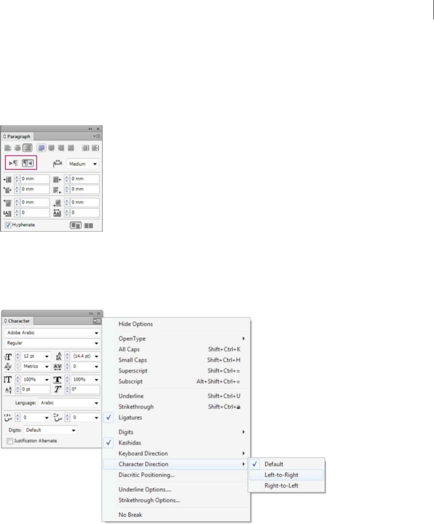
389
Type
Last updated 6/5/2015
Text direction
To create content in Arabic and Hebrew, you can make the right-to-left (RTL) direction the default text direction.
However, for documents that include left-to-right (LTR) text, you can now seamlessly switch between the two
directions.
Select the paragraph direction from the Paragraph panel.
If you have a mix of languages in the same paragraph, you can specify the direction of text at a character level. Also, to
insert dates or numbers, specify the direction of text at the character level.
From the Character panel menu, choose Character Direction and then select a direction.
Digit Types
When you are working in Arabic or Hebrew, you can select the type of digits you want to use. You can choose between
Arabic, Hindi, and Farsi.
By default, in Arabic, the Hindi version is auto-selected, and in case of Hebrew, the Arabic type digits are selected.
However, you can switch to Arabic digits, if necessary:
1Select the digits in the text typed.
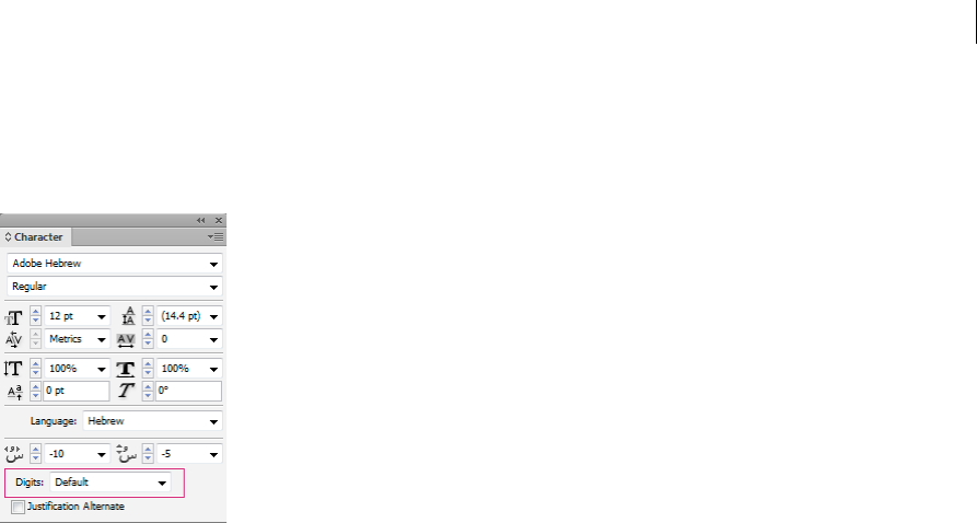
390
Type
Last updated 6/5/2015
2In the Character panel (Ctrl + T), use the Digits list to select the font that the digits must appear in.
You can ensure that Arabic digits are used by enabling the Use Native Digits when typing in Arabic Scripts option. To
use this option, choose Edit > Preferences > Advanced Type.
Legacy font support
Fonts that have been traditionally used (for example, AXT fonts) can continue to be used in this release of the software.
However, it is recommended that newer Open Type fonts be used for text-based elements.
Missing Glyph Protection (Edit > Preferences > Advanced Type) is enabled by default. Text is handled automatically,
where glyphs are not available in the font you are using.
Default fonts
When you install a Middle Eastern or North African version, the default typing font is set to the installation-specific
language, by default. For example, if you have installed the English/Arabic-enabled version, the default typing font is
set to Adobe Arabic. Similarly, if you have installed the English/Hebrew-enabled version, the default typing font is set
to Adobe Hebrew (or Myriad Hebrew in Photoshop).
Automatic Kashida insertion
In Arabic, text is justified by adding Kashidas. Kashidas are added to arabic characters to lengthen them. Whitespace
is not modified. Use automatic Kashida insertion to justify paragraphs of arabic text.
Select the paragraph and from the Paragraph panel (Window > Type & Tables > Paragraph), choose a setting from the
Insert Kashida drop-down list. The options available are: None, Short, Medium, Long, or Stylistic. Kashidas are only
inserted if the paragraph is justified. This setting is not applicable for paragraphs that have alignment settings.
To apply Kashidas to a group of characters, select the characters and choose Kashidas from the Character panel menu.
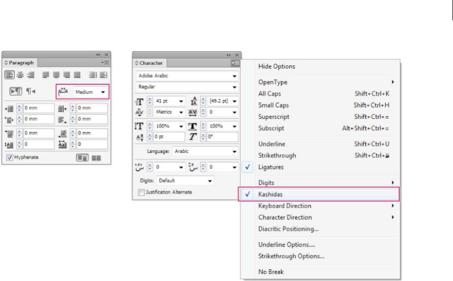
391
Type
Last updated 6/5/2015
Ligatures
You can automatically apply ligatures to character pairs in Arabic and Hebrew. Ligatures are typographic replacement
characters for certain letter pairs if they are available in a given Open Type font.
When you choose Ligatures from the Character panel menu or Control panel menu, a standard ligature defined in the
font is produced.
1Select text.
2Choose Ligatures from the Character panel menu or the Control panel menu.
However, some Open Type fonts include more ornate, optional ligatures, which can be produced when you choose
Discretionary Ligatures. These ligatures are found at Character panel > OpenType > Discretionary Ligatures.
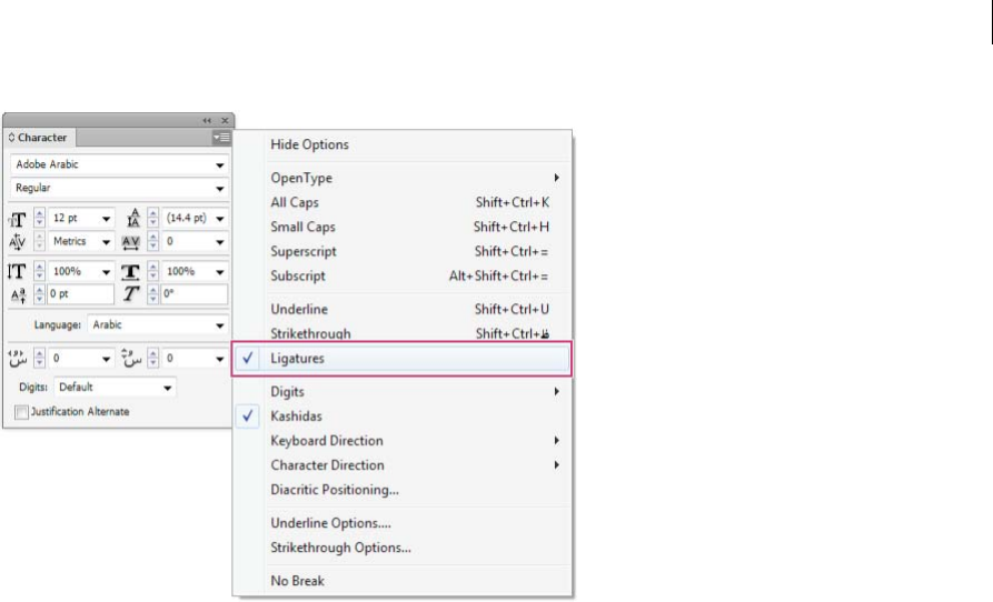
392
Type
Last updated 6/5/2015
Copy-paste from Microsoft Word
You can copy text from Microsoft Word, and paste it directly into a document. The pasted text's alignment and
direction is automatically set to that of the arabic or hebrew text.
Hyphenation
Sentences that have more words that can fit into one line of text automatically wrap into the next line. The type of text
justification when wrapping occurs sometimes causes unnecessary spaces to appear in the line that are not aesthetically
pleasing or linguistically correct. Hyphenation enables you to split the word at the end of a line, using a hyphen. This
fragmentation causes the sentence to wrap into the next line in a better way.
Mixed text: The Kashida insertion feature affects how hyphenation occurs in mixed text. When enabled, Kashidas are
inserted where applicable, and non-Arabic text is not hyphenated. When the Kashida feature is disabled, only non-
Arabic text is considered for hyphenation.
Hebrew text: Hyphenation is allowed. To enable hyphenation and customize settings, choose Paragraph panel > Panel
menu > Hyphenation Settings.

393
Type
Last updated 6/5/2015
Find and replace
Arabic and Hebrew users can perform full text search and replace. In addition to searching and replacing simple text,
you can also search and replace text with specific characteristics. These characteristics can include diacritical marks,
Kashidas, special characters (for example, Alef), digits in different languages (for example, digits in Hindi), and more.
To perform text find-and-replace:
•InDesign: Edit > Find/Change
•Illustrator: Edit > Find and Replace
In InDesign, you can use the Transliterate tab (Edit > Find/Change) to find and replace digits between Arabic, Hindi,
and Farsi. For example, you can find digits typed in Hindi and convert them to Arabic.
Diacritical marks
In the Arabic script, a diacritic or a diacritical mark is a glyph used to indicate consonant length or short vowels. A
diacritical mark is placed above or below the script. For better styling of text, or improved readability of certain fonts,
you can control the vertical or horizontal position of diacritical marks:
1Select text that has diacritical marks
2In the Character panel, modify the position of the diacritic marks relative to the script. Values you can change are,
Adjust Horizontal Diacritic Position, and the Adjust Vertical Diacritic Position.
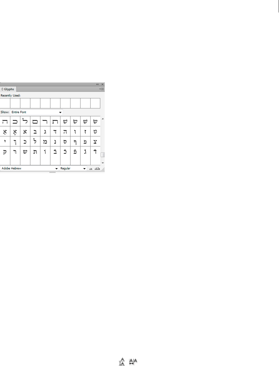
394
Type
Last updated 6/5/2015
Glyphs
Arabic and Hebrew users can apply glyphs from the default character set. However, to browse, select, and apply a glyph
from the default character set or a different language set, use the Glyphs panel:
•InDesign: Window > Type & Tables > Glyphs
•Illustrator: Window > Type > Glyphs
Line and character spacing
Set the leading
The vertical space between lines of type is called leading (rhymes with sledding). Leading is measured from the baseline
of one line of text to the baseline of the line above it. Baseline is the invisible line on which most letters sit.
The default auto-leading option sets the leading at 120% of the typeface size (for example, 12-point leading for 10-point
type). When auto-leading is in use, the leading value appears in parentheses in the Leading menu of the Character
panel. You can change this default auto-leading by choosing Justification from the Paragraph panel menu and
specifying a percentage from 0 to 500.
By default, leading is a character attribute, which means that you can apply more than one leading value within the same
paragraph. The largest leading value in a line of type determines the leading for that line.
Note: When working with horizontal Asian type, you can specify how leading is measured, either from baseline to baseline
or from the top of one line to the top of the next.
1Select the characters or type objects you want to change. If you don’t select any text, the leading applies to new text
you create.
2In the Character panel, set the Leading option ( for vertical text).

395
Type
Last updated 6/5/2015
Shift the baseline
Use Baseline Shift to move selected characters up or down relative to the baseline of the surrounding text. Shifting the
baseline is especially useful when you’re hand-setting fractions or adjusting the position of a picture font.
1Select the characters or type objects you want to change. If you don’t select any text, the shift applies to new text you
create.
2In the Character panel, set the Baseline Shift option. Positive values move the character’s baseline above the baseline
of the rest of the line; negative values move it below the baseline.
Kern and track
Kerning is the process of adding or subtracting space between specific pairs of characters. Tracking is the process of
loosening or tightening the spacing between the characters in selected text or an entire block of text.
Note: Values for kerning and tracking affect Japanese text but normally these options are used to adjust the aki between
Roman characters.
You can automatically kern type using metrics kerning or optical kerning. Metrics kerning (also called Auto kerning)
uses kern pairs, which are included with most fonts. Kern pairs contain information about the spacing of specific pairs
of letters. Some of these are: LA, P., To, Try, Ta, Tu, Te, Ty, Wa, WA, We, Wo, Ya, and Yo. Metrics kerning is set as the
default so that specific pairs are automatically kerned when you import or type text.
Some fonts include robust kern-pair specifications. However, when a font includes only minimal built-in kerning or
none at all, or if you use two different typefaces or sizes in one or more words on a line, you may want to use the optical
kerning option. Optical kerning adjusts the spacing between adjacent characters based on their shapes.
A Original text B Text with optical kerning C Text with manual kerning between W and a D Text with tracking E Cumulative kerning and
tracking
You c a n a l s o us e manual kerning, which is ideal for adjusting the space between two letters. Tracking and manual
kerning are cumulative, so you can first adjust individual pairs of letters, and then tighten or loosen a block of text
without affecting the relative kerning of the letter pairs.

396
Type
Last updated 6/5/2015
When you click to place the insertion point between two letters, kerning values appear in the Character panel. Metrics
and optical kerning values (or defined kern pairs) appear in parentheses. Similarly, if you select a word or a range of
text, the tracking values appear in the Character panel.
Tracking and kerning are both measured in 1/1000 em, a unit of measure that is relative to the current typeface size. In
a 6-point font, 1 em equals 6 points; in a 10-point font, 1 em equals 10 points. Kerning and tracking are strictly
proportional to the current typeface size.
Note: Values for kerning and tracking affect Japanese text, but normally these options are used to adjust the aki between
roman characters.
Adjust kerning
❖Do any of the following:
•To use a font’s built-in kerning information for selected characters, select Auto or Metrics for the Kerning option
in the Character panel.
•To automatically adjust the spacing between selected characters based on their shapes, select Optical for the
Kerning option in the Character panel.
•To adjust kerning manually, place an insertion point between two characters, and set the desired value for the
Kerning option in the Character panel. (Note that if a range of text is selected, you can’t manually kern the text.
Instead, use tracking.)
Tip: Press Alt+Left/Right Arrow (Windows) or Option+Left/Right Arrow (Mac OS) to decrease or increase the
kerning between two characters.
•To turn off kerning for selected characters, set the Kerning option in the Character panel to 0 (zero).other: To see
a list of time-saving techniques for working with type, search for “keyboard shortcuts” in Help.
Adjust tracking
1Select the range of characters or the type object that you want to adjust.
2In the Character panel, set the Tracking option.
Turn fractional character widths off or on
By default, the software uses fractional character widths between characters. This means that the spacing between
characters varies, and will sometimes use only fractions of whole pixels.
In most situations, fractional character widths provide the best spacing for type appearance and readability. However,
for type in small sizes (less than 20 points) displayed online, fractional character widths could cause type to run
together or have too much extra space, making it difficult to read.
Turn off fractional widths when you want to fix type spacing in whole-pixel increments and prevent small type from
running together. The fractional character width setting applies to all characters on a type layer—you cannot set the
option for selected characters.
❖Do any of the following:
•To set type spacing for the entire document in whole-pixel increments, choose System Layout from the Character
panel menu.
•To re-enable fractional character widths, choose Fractional Widths from the Character panel menu.
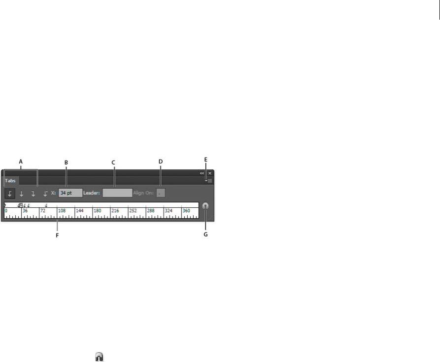
397
Type
Last updated 6/5/2015
Tabs
You use the Tabs panel (Window > Type > Tabs) to set tab stops for a paragraph or type object. For more information
on using and setting tabs, see web Help.
Tabs panel overview
You use the Tabs panel (Window > Type > Tabs) to set tab stops for a paragraph or type object.
A Tab alignment buttons B Tab position C Tab lead er b ox D Align On box E Panel menu F Tab ruler G Snap panel above frame
You can access additional commands and options in the Tabs panel menu. To use this menu, click the triangle in the
upper right corner of the panel.
Align the Tabs panel with a selected type object
You can position the Tabs panel anywhere in the work area; however, it is usually helpful to align the Tabs panel with a
type object.
❖Click the magnet icon . The Tabs panel moves directly above the selected text object, with the zero point aligned
with the left margin. If necessary, you can drag the resize button at the lower right corner of the panel to expand or
reduce the ruler.
Snap tab stops to the ruler units
By default, you can position tab stops anywhere along the tab ruler.
❖Choose Snap To Unit from the panel menu or hold down Shift as you drag a tab stop.
Change the units of measure for the tab ruler
The units of measure for the tab ruler are defined by the General units settings specified in the Units preferences (for
all files) or by the units specified in the Document Setupdialog box (for the current file).
•To change the units of measure for all files, specify a new value for General Units in the Units preferences.
•To change the units of measure for the current file, specify a new units value in the Document Setup dialog box.
Set tabs
Tab stops apply to an entire paragraph. When you set the first tab, Illustrator deletes all default tab stops to the left of
that stop. As you set more tab stops, Illustrator deletes all default tabs between the tabs you set.
1Insert the cursor in a paragraph, or select a type object to set tab stops for all paragraphs in the object.
2In the Tabs panel, click a tab-alignment button to specify how text aligns relative to the tab’s position:
Left-Justified Tab to align horizontal text to the left, keeping the right margin ragged.
Center-Justified Tab to center text on the tab mark.
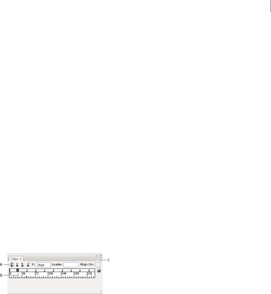
398
Type
Last updated 6/5/2015
Right-Justified Tab to align horizontal text to the right, keeping the left margin ragged.
Bottom-Justified Tab to align vertical text to the bottom margin, keeping the top margin ragged.
Top-Justified Tab to align vertical text to the top margin, keeping the bottom margin ragged.
Decimal-Justified Tab to place text in alignment with a specified character, such as a period or a dollar sign. This
option is useful for creating columns of numbers.
You can change the alignment of any tab by simply selecting it and clicking one of these buttons.
3Do one of the following:
•Click a location on the tab ruler to position a new tab stop.
•Type a position in the X box (for horizontal text) or Y box (for vertical text), and press Enter or Return. If the X
or Y value is selected, press the Up Arrow or Down Arrow key to increase or decrease the tab value by 1 point,
respectively.
note: When you use the tab ruler, you cannot set tab stops in increments smaller than 1. However, if you specify a
position in the X or Y box, you can set stops at intervals as small as 0.01 point.
4Repeat steps 2 and 3 to add additional tab stops.
Note: For information on setting indents using the Tabs panel, see Indent text.
Repeat tabs
The Repeat Tab command creates multiple tabs based on the distance between the tab and the left indent or the
previous tab stop.
1Click an insertion point in the paragraph.
2In the Tabs panel, select a tab stop on the ruler.
3Choose Repeat Tab from the panel menu.
A Tab-alignment buttons B Tab stop on the ruler C Panel menu
Move tabs
1In the Tabs panel, select a tab stop on the ruler.
2Do one of the following:
•Type a new location in the X box (for horizontal text) or Y box (for vertical text), and press Enter or Return.
•Drag the tab to a new location.
•To move all tab stops simultaneously, Ctrl-drag (Windows) or Command-drag (Mac OS) a tab.
As you move a tab stop, a visual guide appears in the selected text.

399
Type
Last updated 6/5/2015
Remove tabs
❖Do one of the following:
•Drag the tab off the tab ruler.
•Select the tab, and choose Delete Tab from the panel menu.
•To return to the default tab stops, choose Clear All from the panel menu.
Specify characters for decimal tabs
You use decimal tabs to align text with a character you specify, such as a period or a dollar sign.
1In the Tabs panel, create or select a decimal tab on the tab ruler.
2In the Align On box, type the character to which you want to align. You can type or paste any character. Make sure
that the paragraphs you’re aligning contain that character.
Add tab leaders
A tab leader is a repeated pattern of characters, such as a series of dots or dashes, between a tab and the following text.
1In the Tabs panel, select a tab stop on the ruler.
2Type a pattern of as many as eight characters in the Leader box, and then press Enter or Return. The characters you
entered repeat across the width of the tab.
3To change the font or other formatting of the tab leader, select the tab character in the text frame, and use the
Character panel or Type menu to apply formatting.
More Help topics
Workspace overview
Change the unit of measurement
Special characters
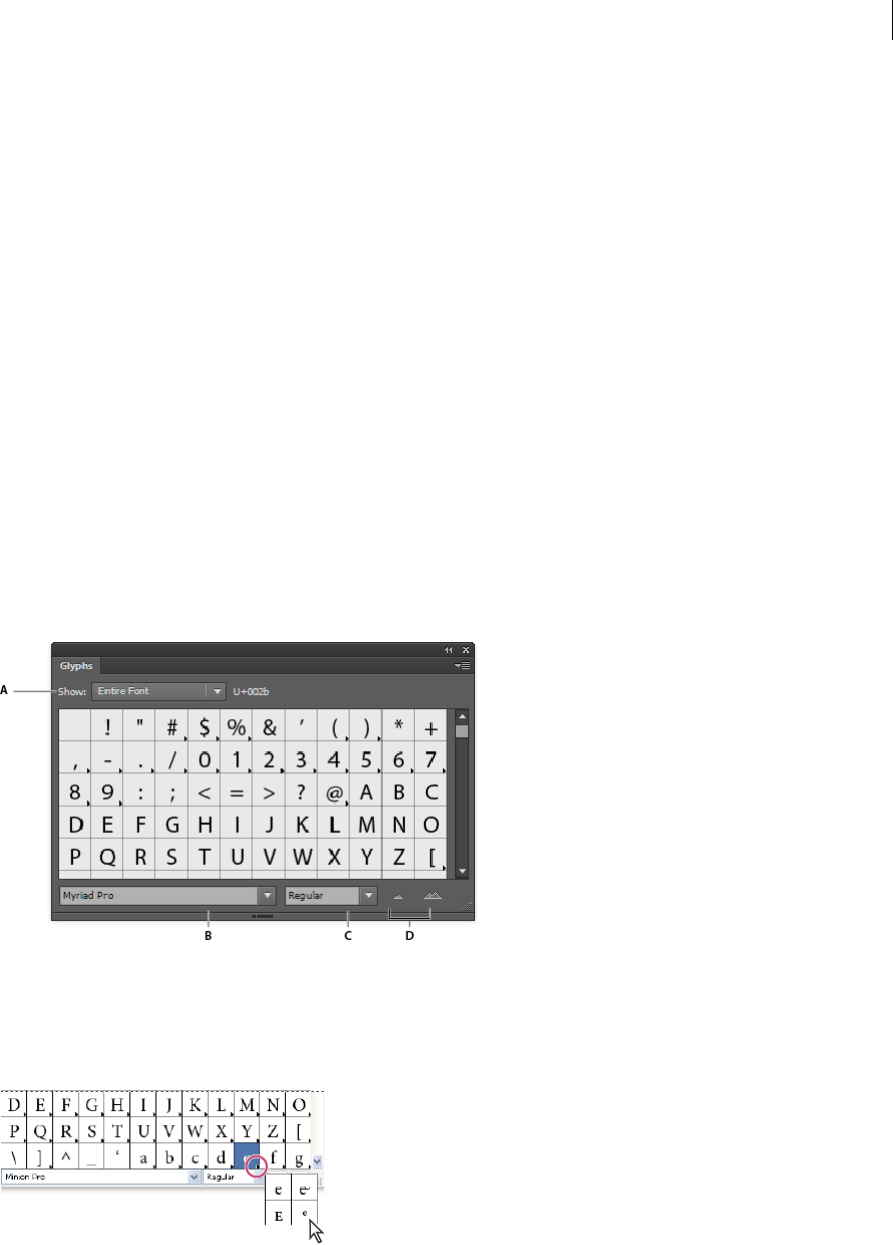
400
Type
Last updated 6/5/2015
About character sets and alternate glyphs
Typefaces include many characters in addition to the ones you see on your keyboard. Depending on the font, these
characters can include ligatures, fractions, swashes, ornaments, ordinals, titling and stylistic alternates, superior and
inferior characters, old-style figures, and lining figures. A glyph is a specific form of a character. For example, in certain
fonts, the capital letter A is available in several forms, such as swash and small cap.
There are two ways to insert alternate glyphs:
•The Glyphs panel lets you view and insert glyphs from any typeface.
•The OpenType panel lets you set up rules for using glyphs. For example, you can specify that you want to use
ligatures, titling characters, and fractions in a given text block. Using the OpenType panel is easier than inserting
glyphs one at a time and ensures a more consistent result. However, the panel works only with OpenType fonts.
Glyphs panel overview
You use the Glyphs panel (Window > Type > Glyphs) to view the glyphs in a font and insert specific glyphs in your
document.
By default, the Glyphs panel displays all the glyphs for the currently selected font. You can change the font by selecting
a different font family and style at the bottom of the panel. If any characters are currently selected in your document,
you can display alternate characters by selecting Alternates For Current Selection from the Show menu at the top of the
panel.
A Show menu B Font family C Font style D Zoom buttons
When you select an OpenType font in the Glyphs panel, you can restrict the panel to display certain kinds of glyphs by
selecting a category from the Show menu. You can also display a pop-up menu of alternate glyphs by clicking the
triangle in the lower right corner of the glyph box where applicable.
For a video on working with the Glyphs panel and the OpenType panel, see www.adobe.com/go/vid0048.
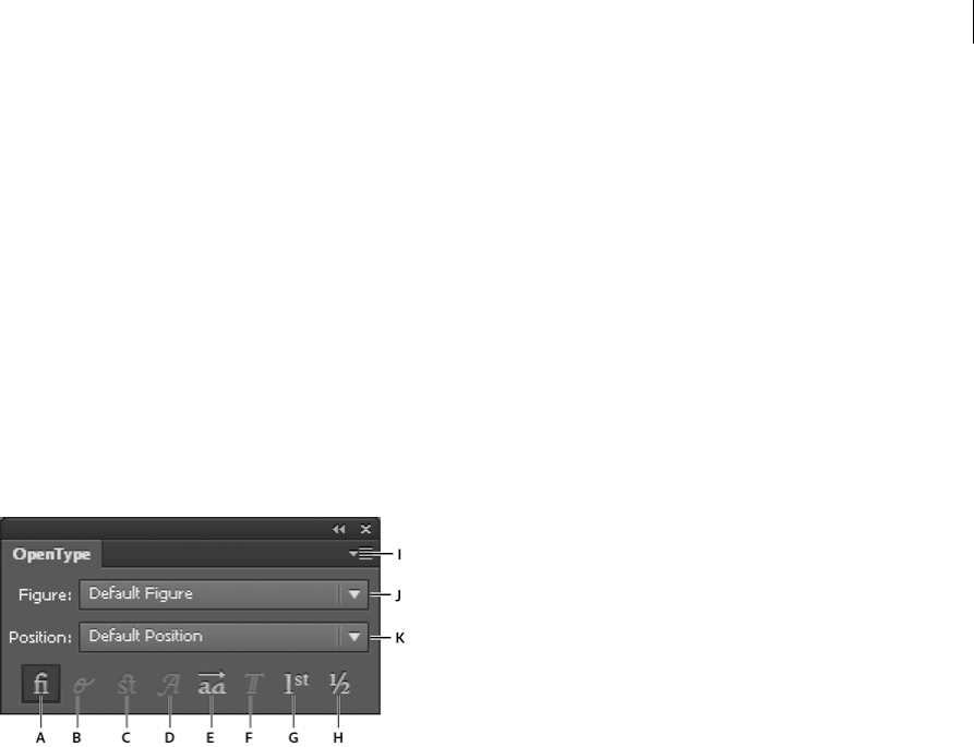
401
Type
Last updated 6/5/2015
Insert or replace a character using the Glyphs panel
1To insert a character, click with a type tool to place the insertion point where you want to enter the character, and
then double-click the character you want to insert in the Glyphs panel.
2To replace a character, choose Alternates For Current Selection from the Show pop-up menu, select a character in
your document using a type tool. Double-click a glyph in the Glyphs panel, if one is available.
Note: Additional replacement options are available for Asian glyphs.
OpenType panel overview
You use the OpenType panel (Window > Type > OpenType) to specify how you want to apply alternate characters in
OpenType fonts. For example, you can specify that you want to use standard ligatures in new or existing text.
Keep in mind that OpenType fonts vary greatly in the kinds of features they offer; not all options in the OpenType panel
are available in every font. You can view the characters in a font using the Glyphs panel.
A Standard Ligatures B Contextual Alternates C Discretionary Ligatures D Swash E Stylistic Alternates F Titling Alternates G Ordinals
H Fractions I panel menu J Figure type K Character position
Note: Additional features may be available for Asian OpenType fonts.
You can access additional commands and options in the OpenType panel menu in the upper right corner of the panel.
For a video on working with the Glyphs panel and the Open Type panel, see www.adobe.com/go/vid0048.
More Help topics
Set Asian OpenType font attributes
Highlight alternate glyphs in the text
1Choose File > Document Setup.
2Select Highlight Substituted Glyphs, and click OK. Substituted glyphs in the text are highlighted.
Use ligatures and contextual alternates
Ligatures are typographic replacement characters for certain letter pairs. Most fonts include ligatures for standard letter
pairs such as fi, fl, ff, ffi, and ffl. In addition, some fonts include discretionary ligatures for letter pairs such as ct, st, and
ft. Although the characters in ligatures appear to be joined, they are fully editable and do not cause the spell checker to
flag a word erroneously.

402
Type
Last updated 6/5/2015
Contextual alternates are alternate characters included in some script typefaces to provide better joining behavior. For
example, when using Caflisch Script Pro with contextual alternates enabled, the letter pair “bl” in the word “bloom” is
joined so that it looks more like handwriting.
1Select the characters or type objects to which you want to apply the setting. If you don’t select any text, the setting
applies to new text you create.
2Make sure that an OpenType font is selected.
3In the OpenType panel, do any of the following:
•Click the Standard Ligatures button to enable or disable ligatures for standard letter pairs (such as fi, fl, ff, ffi, and
ffl).
•Click the Discretionary Ligatures button to enable or disable optional ligatures (if available in the current font).
•Click the Contextual Alternates button to enable or disable contextual alternates (if available in the current font).
Use swashes, titling alternates, or stylistic alternates
Many OpenType fonts include stylized characters that let you add decorative elements to type. Swashes are characters
with exaggerated flourishes. Titling alternates are characters (usually all in capitals) designed for use in large-size
settings, such as titles. Stylistic alternates are stylized characters that create a purely esthetic effect.
1Select the characters or type objects to which you want to apply the setting. If you don’t select any text, the setting
applies to new text you create.
2Make sure that an OpenType font is selected.
3In the OpenType panel, do one of the following:
•Click the Swash button to enable or disable swash characters (if available in the current font).
•Click the Stylistic Alternates button to enable or disable stylistic alternates (if available in the current font).
•Click the Titling Alternates button to enable or disable titling alternates (if available in the current font).
Show or hide nonprinting characters
Nonprinting characters include hard returns (line breaks), soft returns (line breaks), tabs, spaces, nonbreaking spaces,
double-byte characters (including spaces), discretionary hyphens, and the end-of-text character.
To make the characters visible as you format and edit type, choose Type > Show Hidden Characters. A check mark
indicates that nonprinting characters are visible.
More Help topics
OpenType fonts
Formatting Asian characters
Illustrator provides a variety of options for formatting Asian characters. For example, you can set Asian Open Type font
attributes, use tate-chu-yoko, aki, warichu, mojisoroe, mojikumi, kinsoku, burasagari, and kurikaeshi moji shori. In
addition, you can combine Asian and roman fonts and create composite fonts.
Note: To enable support for GB18030 fonts for Simplified Chinese in Windows XP, see the Readme file in the Illustrator
CS5\Simplified Chinese\Goodies\Optional Extensions\GB18030 folder.

403
Type
Last updated 6/5/2015
Display Asian type options
By default, Illustrator hides Asian type options in the Character panel, Paragraph panel, OpenType panel, and Type
menu.
1Choose Edit > Preferences > Type (Windows) or Illustrator > Preferences > Type (Mac OS).
2Select Show Asian Options, and click OK.
You can also control how font names are displayed (in English or in the native language) by selecting or deselecting
Show Font Names in English.
Note: Your operating system must support the languages in which you wish to work. Consult your system software
manufacturer for more information.
Set Asian OpenType font attributes
Asian OpenType fonts may include a number of features that aren’t available in current PostScript and TrueType fonts.
In addition, Asian OpenType fonts provide alternate glyphs for many characters.
1Select the characters or type objects to which you want to apply the setting. If you don’t select any text, the setting
applies to new text you create.
2Make sure that an OpenType font is selected.
Look in the Type > Font menu; OpenType fonts display the icon.
3In the OpenType panel, set any of the following options:
Proportional Metrics Kerning is according to the proportional metrics of the font.
H or V Style Switches hiragana fonts, which have different glyphs for horizontal and vertical such as contracted
sounds, double consonants, and phonetic indexes.
Roman Italics Changes half-width alphanumerics to italics.
Replace Asian characters with a different glyph form
1Select the characters you want to replace.
2Choose an option from the Glyphs panel menu. If you don’t see the following options, select Show Asian Options in
the Type preferences. If an option is dimmed, the glyph form is not available for the current font:
Traditional Forms Replaces the selected characters with traditional forms.
Expert Forms Replaces the selected characters with their expert forms.
JIS 04 Forms Replaces the selected characters with JIS 04 forms.
JIS 90 Forms Replaces the selected characters with JIS 90 forms.
JIS 78 Forms Replaces the selected characters with JIS 78 forms.
JIS 83 Forms Replaces the selected characters with JIS 83 forms.
Monospaced Half-Width Forms Changes the glyphs of the selected Latin characters to monospace hankaku (half
width).
Monospaced Third-Width Forms Changes the glyphs of the selected Latin characters to monospace third width.
Monospaced Quarter-Width Forms Changes the glyphs of the selected Latin characters to monospace quarter
width.
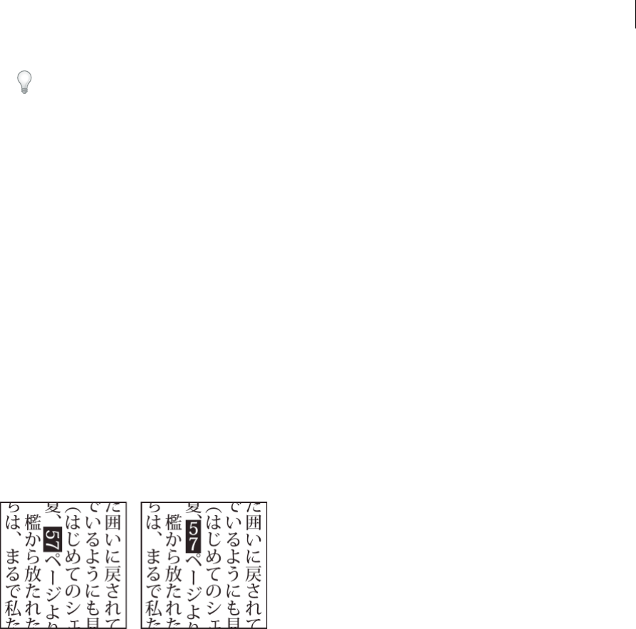
404
Type
Last updated 6/5/2015
Tip: To revert an alternate glyph to its default form, select it and choose Revert To Default Forms from the Glyphs
panel menu. You cannot use this method to revert alternate glyphs that were applied using a character style.
Specify how leading is measured in Asian type
1Select the paragraphs you want to adjust.
2Choose a leading option from the Paragraph panel menu.
bottom-to-bottom leadingtop-to-top leadingleading in Asian typeAsian type:leading inTop-to-top Leading
Measures the spacing between lines of type from the top of one line to the top of the next line. When you use
top-to-top leading, the first line of type in a paragraph is aligned flush with the top of the bounding box.
Bottom-to-bottom Leading For horizontal type, measures the space between lines of type from the type baseline.
When you use bottom-to-bottom leading, space appears between the first line of type and the bounding box. A
check mark indicates which option is selected.
note: The leading option you choose does not affect the amount of leading between lines, only how the leading is
measured.
Rotate half-width characters in vertical text
The direction of half-width characters, such as roman text or numbers, changes in vertical text. By default, half-width
characters are rotated individually.
If you don’t want half-width characters to rotate, deselect Standard Vertical Roman Alignment from the Character
panel menu.
More Help topics
Rotate type
Use tate-chu-yoko
Tate-chu-yoko (also called kumimoji and renmoji) is a block of horizontal type laid out within vertical type lines. Using
tate-chu-yoko makes it easier to read half-width characters such as numbers, dates, and short foreign words in vertical
text.
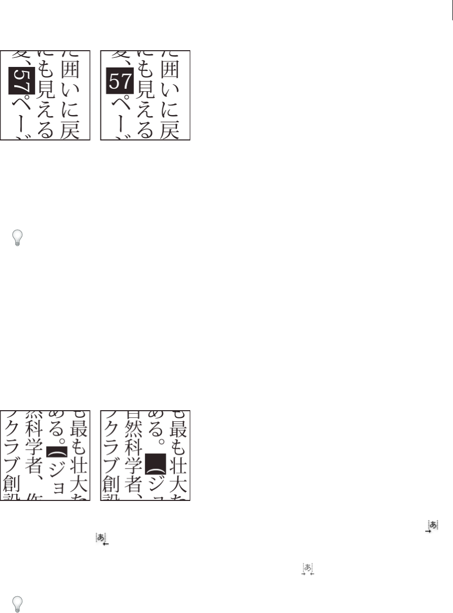
405
Type
Last updated 6/5/2015
1Select characters and choose Tate-chu-yoko from the Character panel menu. (Select it again to turn Tate-chu-yoko
off.)
2Select any of the following tate-chu-yoko settings from the Character panel menu:
Up/Down Specifies a positive value to move the text up and a negative value to move it down.
Left/Right Specifies a positive value to move the text to the right and a negative value to move it to the left.
Tip: Use tsume or tracking in the Character panel to adjust the character spacing for tate-chu-yoko.
note: If the Tate-chu-yoko option isn’t showing, you need to select Show Asian Options in the Type preferences.
More Help topics
Kern and track
Use aki
Aki is the white space before or after a character. Usually, fixed spacing is applied between the characters based on the
mojikumi setting for a paragraph. You can change the mojikumi setting for special characters using the Insert Aki
options in the Character panel. For example, to add a space before an opening parenthesis, use the Insert Aki (Left)
option.
❖Select the characters you want to adjust with the Type tool, and do any of the following in the Character panel:
•To add aki before or after a character, choose the amount of aki you want to add from the Insert Aki (Left) or
Insert Aki (Right) menu in the Character panel. For example, if you specify 2bu, half a full-width space is
added, and if you specify 4bu, a quarter of a full-width space is added.
•To compress the aki between characters, specify a percentage for Tsume . The higher the percentage, the
narrower the aki between characters.
If you don’t see the Insert Aki or Tsume options, select Show Asian Options in the Type preferences.
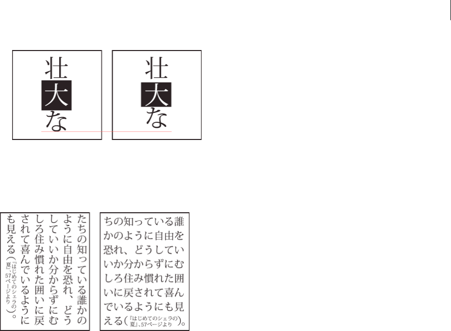
406
Type
Last updated 6/5/2015
Use warichu
The Warichu option in the Character panel decreases the typeface size of selected text to a percentage of the original
and stacks the type—horizontally or vertically, according to the orientation—on multiple lines.
1Select text and choose Warichu from the Character panel menu. (Select it again to turn it off.)
2Select any of the following warichu settings from the Character panel menu:
Lines Specifies how many lines of text will appear as warichu characters.
Line Gap Determines the distance between the lines of warichu characters.
Scale Sets the size of warichu characters as a percentage of the size of the parent text.
Alignment Specifies the alignment of warichu characters. For example, in a vertical frame grid, selecting Top will
align the beginning of the warichu characters at the top of the frame. The alignment proxy shows how the warichu
text appears relative to the parent text.
Line Breaking Options Specifies the minimum number of characters required before and after the line breaks to
start a new line.
Align Asian characters with mojisoroe
Mojisoroe is the alignment of characters in Asian type. When a line of text contains different sizes of characters, you can
specify how to align text to the largest characters in the line: to the top, center, or bottom of the em box (right, center,
and left for vertical frames), to the roman baseline, or to the top or bottom of the ICF box (right or left for vertical
frames). ICF (Ideographic Character Space) is the average height and width used by the font designer to design the
ideographic characters which comprise a font.

407
Type
Last updated 6/5/2015
A Small characters aligned to the bottom B Small characters aligned to the center C Small characters aligned to the top
❖In the Character panel menu, choose an option from the Character Alignment submenu:
Roman Baseline Aligns the small characters in a line to the large character.
Em box Top/Right, Em box Center, or Em box Bottom/Left Aligns the small characters in a line to the specified
position of the large character’s em box. In vertical text frames, Em box Top/Right aligns the text to the right of the
em box, and Em box Bottom/Left aligns the text to the left of the em box.
ICF Top/Right and ICF Bottom/Left Aligns the small characters in a line to the ICF specified by the large characters.
In vertical text frames, ICF Top/Right aligns the text to the right of the ICF, and ICF Bottom/Left aligns the text to
the left of the ICF.
Use mojikumi
Mojikumi specifies Japanese text composition for spacing of Japanese characters, roman characters, punctuation,
special characters, line start, line end, and numbers. You can also specify paragraph indents.
The existing character spacing rules in Illustrator follow the Japanese Industrial Standards (JIS) specification,
JISx4051-1995. You can select from the predefined mojikumi sets provided by Illustrator.
Furthermore, you can create specific mojikumi sets. In a new mojikumi set, you can edit the settings for spacing that
you use a lot, such as the spacing between a period and subsequent opening parenthesis. For example, you might create
an interview format in which you want to have an em dash before a question, and answers enclosed in parentheses.
Select a mojikumi set for a paragraph
1In the Character panel, set Kerning to zero.
2In the Paragraph panel, choose an option from the Mojikumi Set pop-up menu:
None Turns off the use of mojikumi.
YakumonoHankaku mojikumi setYakumonoHankaku Uses half-width spacing for punctuation.
GyoumatsuYakumonoHankaku mojikumi setGyoumatsuYakumonoHankaku Uses full-width spacing for most
characters except the last character in the line.
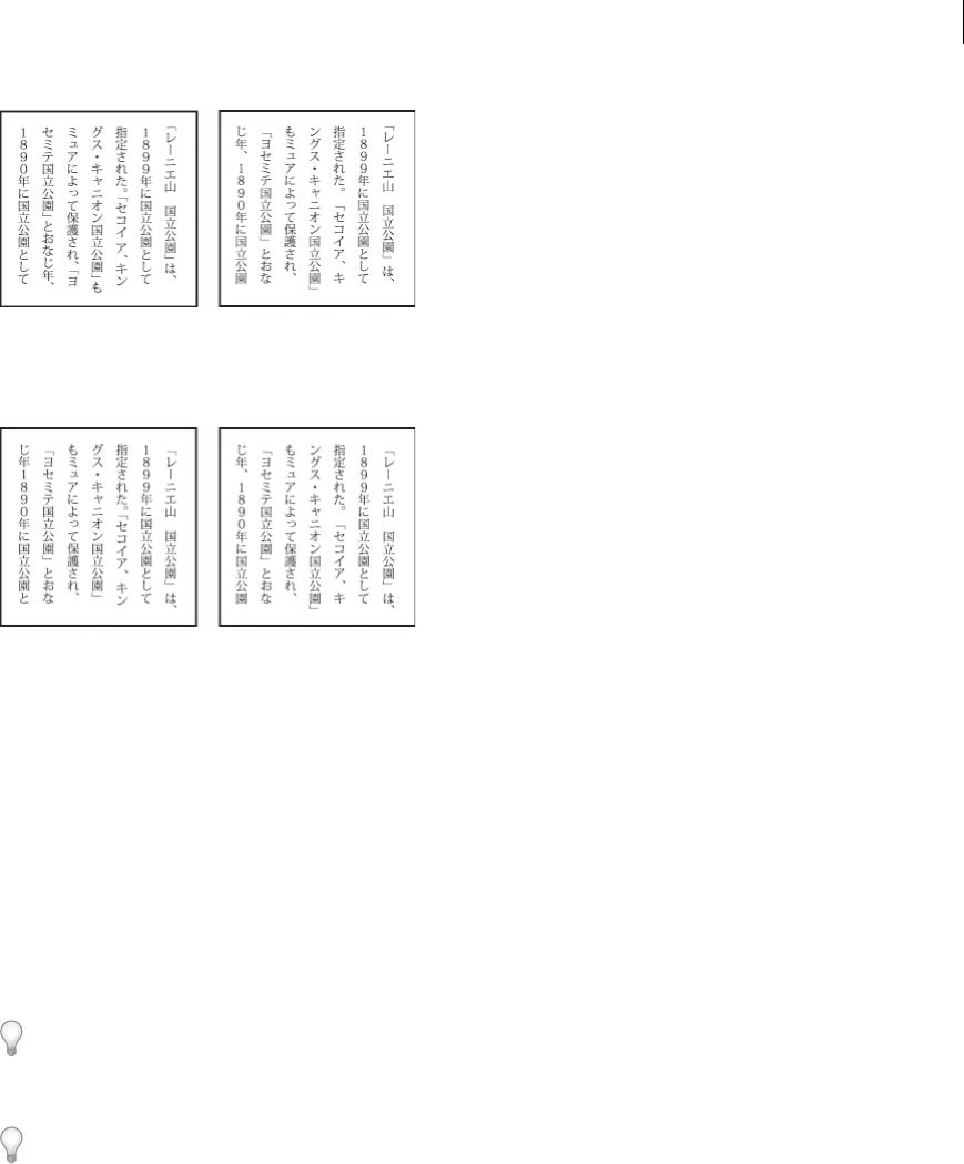
408
Type
Last updated 6/5/2015
GyoumatsuYakumonoZenkaku mojikumi setGyoumatsuYakumonoZenkaku Uses full-width spacing for most
characters and the last character in the line.
YakumonoZenkaku mojikumi setYakumonoZenkaku Uses full-width spacing for punctuation.
Create a mojikumi set
1Do one of the following:
•Choose Type > Mojikumi Settings.
•Choose Mojikumi Settings from the Mojikumi Set pop-up menu in the Paragraph panel.
2Click New in the Mojikumi Settings dialog box.
3Enter a name for the new mojikumi set, specify the existing set on which the new set will be based, and click OK.
4Choose Use Percentage (%) or Bu from the Units pop-up menu.
5Specify Desired, Minimum, and Maximum values for each option. The Minimum value is used to compress lines
for kinsoku (specify a value less than the Desired value). The Maximum value is used to spread lines for fully
justified text (specify a value greater than the Desired value).
Depending on the character type, you can specify the same values for Desired, Minimum, and Maximum if you don’t
want to change the spacing.
6Click Save or OK to save the settings. Click Cancel if you don’t want to save the settings.
When you compose Japanese text with a lot of half-width spaces or roman parentheses, problems relating to text
composition increase. We recommend that you avoid using roman parentheses, and use full-width parentheses for
Japanese composition. Only use roman parentheses when using relatively long English sentences in Japanese text, or
when a more serious problem results if you don’t use roman parentheses.
Work with mojikumi sets
❖In the Mojikumi Settings dialog box, do any of the following:
•To export a set, click Export, select a location for the file, type a filename, and click Save. Illustrator saves the file
in MJK format.
•To import a set, click Import, select an MJK file, and click Open.
•To delete a set, choose it from the Mojikumi pop-up menu and then click Delete. All the text to which the
mojikumi set was applied will return to the default settings.

409
Type
Last updated 6/5/2015
Note: You cannot delete predefined mojikumi sets.
Use kinsoku
Kinsoku specifies line breaks for Japanese text. Characters that cannot be placed at the beginning or end of a line are
known as kinsoku characters. Illustrator has hard kinsoku sets and soft kinsoku sets and Photoshop has weak and
maximum sets. Soft or weak kinsoku sets omit long vowel symbols and small hiragana characters. You can use these
existing sets, or add or delete kinsoku characters to create new sets.
You can also define hanging characters for hanging Japanese punctuation and define characters that cannot be split
when a line is exceeded.
You can specify whether to push in or push out text so that kinsoku characters are not placed inappropriately.
Select kinsoku settings for a paragraph
❖In the Paragraph panel, choose an option from the Kinsoku Set pop-up menu:
None Turns off the use of kinsoku shori.
Soft or Hard Prevents selected characters from beginning or ending a line.
Create a kinsoku set
1Do one of the following:
•Choose Type > Kinsoku Shori Settings.
•Choose Kinsoku Settings from the Kinsoku Set pop-up menu in the Paragraph panel.
2In the Kinsoku Shori Settings dialog box, click New Set.
3Enter a name for the kinsoku set, specify the existing set on which the new set will be based, and click OK.
4To add a character to a field, select the field, and do one of the following:
•Enter a character in the Input box, and click Add.
•Specify the code system (Shift JIS, JIS, Kuten, or Unicode), enter the code, and click Add.
5To delete a character in a field, select the character and click Delete. Alternatively, press Backspace (Windows) or
Delete (Mac OS).
6To check the character code currently selected, select Shift JIS, JIS, Kuten, or Unicode, and display the code system.
7Click Save or OK to save the settings. Click Cancel if you don’t want to save the settings.
Use kinsoku sets
❖In the Kinsoku Shori Settings dialog box, do any of the following:
•To export a kinsoku set, click Export. Select a location for the file, enter a filename, and click Save.
Illustrator saves the file in KSK format.
•To import a kinsoku set, click Import. Select a KSK file, and click Open.
•To delete a kinsoku set, choose the kinsoku set you want to delete from the pop-up menu. Then click Delete Set.
note: You cannot delete predefined kinsoku settings.

410
Type
Last updated 6/5/2015
Specify a kinsoku line-breaking option
Kinsoku shori or mojikumi must be selected to use the following line-breaking options.
❖From the Paragraph panel menu, choose Kinsoku Shori Type and then choose one of the following methods:
Push In First Moves characters up to the previous line to prevent prohibited characters from ending or beginning a
line.
Push Out First Moves characters down to the next line to prevent prohibited characters from ending or beginning
a line.
Push Out Only Always moves characters down to the next line to prevent prohibited characters from ending or
beginning a line. A push-in is not attempted.
A check mark indicates which method is selected.
Set bunri-kinshi on and off
When Bunri-kinshi is selected, the characters specified in the Bunri-Kinshi section of the Kinsoku Shori Settings dialog
box will not be split.
❖In the Paragraph panel, choose Bunri-kinshi from the panel menu.
Note: This option is only available when kinsoku shori is on.
Specify a burasagari option
Burasagari lets single-byte periods, double-byte periods, single-byte commas, and double-byte commas fall outside the
paragraph bounding box.
1In the Paragraph panel, choose Burasagari from the panel menu.
2Choose an option from the submenu:
None Turns off hanging punc tuation.
Regular Turns on hanging punctuation without forcing ragged lines to the bounding box edge.
Force Forces punctuation outside the bounding box by spreading lines that end within the bounding box and end
with one of the hanging characters.
note: The Burasagari options are not available when Kinsoku Shori is set to None.
Use kurikaeshi moji shori
You can control how repeated characters in Japanese text are handled using the Kurikaeshi Moji Shori option in the
Paragraph panel. By default, a repeat character mark is substituted for the second character when two identical
characters follow one after the other in a body of text. When this option is selected, both characters are displayed if they
are separated by a line break.

411
Type
Last updated 6/5/2015
1Using any type tool, select a paragraph of text to which you want to apply repeated character processing. If no text
exists, the setting applies to new text typed.
2In the Paragraph panel, select Kurikaeshi Moji Shori from the panel menu.
More Help topics
About Unicode
About character sets and alternate glyphs
OpenType fonts
OpenType panel overview
Glyphs panel overview
Formatting type
Selecting type
Selecting characters lets you edit them, format them using the Character panel, apply fill and stroke attributes to them,
and change their transparency. You can apply these changes to one character, a range of characters, or all characters in
a type object. When characters are selected, they are highlighted in the document window and the word “Characters”
appears in the Appearance panel.
Selecting a type object lets you apply global formatting options to all the characters in the object, including options from
the Character and Paragraph panels, fill and stroke attributes, and transparency settings. In addition, you can apply
effects, multiple fills and strokes, and opacity masks to a selected type object. (This is not possible for individually
selected characters.) When a type object is selected, a bounding box appears around it in the document window and
the word “Type” appears in the Appearance panel.
Selecting a type path lets you adjust its shape and apply fill and stroke attributes to it. This level of selection is not
available for point type. When a type path is selected, the word “Path” appears in the Appearance panel.
Select characters
❖Select any type tool, and do one of the following:
•Drag to select one or more characters. Shift-drag to extend or reduce the selection.
•Position the pointer in a word, and double-click to select that word.

412
Type
Last updated 6/5/2015
•Position the pointer in a paragraph, and triple-click to select the entire paragraph.
•Select one or more characters, and choose Select > All to select all the characters in the type object.
Select type objects
Selecting a type object lets you apply global formatting options to all the characters in the object, including options from
the Character and Paragraph panels, fill and stroke attributes, and transparency settings. In addition, you can apply
effects, multiple fills and strokes, and opacity masks to a selected type object. (This is not possible for individually
selected characters.) When a type object is selected, a bounding box appears around it in the document window and
the word “Type” appears in the Appearance panel.
❖Do any of the following:
•In the document window, click the type with the Selection tool or the Direct Selection tool . Shift-click to
select additional type objects.
•In the Layers panel, locate the type object you want to select and then click its right edge, between the target
button and the scroll bar. Shift-click at the right edge of items in the Layers panel to add or remove objects to the
existing selection.
•To select all type objects in a document, choose Select > Object > Text Objects.
Select a type path
Selecting a type path lets you adjust its shape and apply fill and stroke attributes to it. This level of selection is not
available for point type. When a type path is selected, the word “Path” appears in the Appearance panel.
Selecting a type path is easiest when you’re in Outline view.
1Select the Direct Selection tool or the Group Selection tool .
2If the type object is selected, click outside the object’s bounding box to deselect it.
3Click the type path, being careful not to click the characters. (If you do click a character, you will select the type
object instead of the type path.)
Note: The Type Object Selection By Path Only preference determines the sensitivity of the selection tools when selecting type
objects in the document window. When this preference is selected, you must click directly on the type path to select the type.
When this preference is deselected, you can click the type or the path to select the type. You can set this preference by
choosing Edit > Preferences > Type (Windows) or Illustrator > Preferences > Type (Mac OS).
Find and replace text
1Choose Edit > Find and Replace.
2Enter the text string you want to find and, if desired, the text string with which to replace it.
You can choose a variety of special characters from the pop-up menus to the right of the Find and Replace With
options.
3To customize how Illustrator searches for the specified text string, select any of the following options:
Match Case Searches only for text strings that exactly match the uppercase and lowercase text in the Find box.
Find Whole Word Searches only for entire words that match the text in the Find box.
Search Backwards Searches the file from the bottom to the top of the stacking order.

413
Type
Last updated 6/5/2015
Check Hidden Layers Searches for text in hidden layers. When this option is deselected, Illustrator ignores text in
hidden layers.
Check Locked Layers Searches for text in locked layers. When this option is deselected, Illustrator ignores text in
locked layers.
4Click Find to begin the search.
5If Illustrator finds an instance of the text string, do one of the following:
•Click Replace to replace the text string, then click Find Next to find the next instance.
•Click Replace & Find to replace the text string and find the next instance.
•Click Replace All to replace all instances of the text string in the document.
6Click Done to close the dialog box.
To find the next instance of a text string when the Find And Replace dialog box is closed, choose Edit > Find Next.
Change the color and appearance of characters
You can change the color and appearance of type objects by applying fills, strokes, transparency settings, effects, and
graphic styles. The text remains editable as long as you don’t rasterize it.
1Do one of the following:
•To change the appearance of specific characters in a type object, select the characters.
•To change the appearance of all characters in a type object, or to apply multiple fills and strokes, select the type
object.
•To fill or stroke a type path, select the type path.
2Apply fills, strokes, transparency settings, effects, and graphic styles as desired.
When you change the color of a type object, Illustrator overwrites the attributes of individual characters in the type
object.
Use the Control panel to quickly change the color of selected type.
More Help topics
About appearance attributes
Character panel overview
You use the Character panel (Window > Type > Character) to apply options for formatting individual characters in your
documents. When type is selected or when the Type tool is active, you can also use options in the Control panel to
format characters.
For a video on working with character and paragraph styles, see www.adobe.com/go/vid0047.
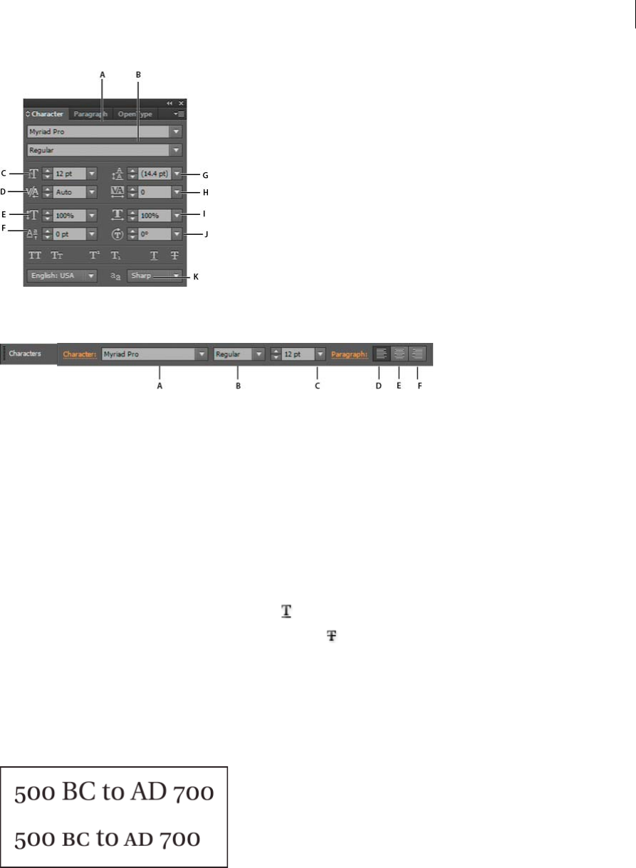
414
Type
Last updated 6/5/2015
A Font B Font Style C Font Size D Kerning E Horizontal Scale F Baseline Shift G Leading H Tracking I Vertical Scale J Character Rotation
K Language
A Font B Font Style C Font Size D Align left E Align center F Align right
By default, only the most commonly used options are visible in the Character panel. To show all options, choose Show
Options from the options menu. Alternatively, click the double triangle on the panel’s tab to cycle through the display
sizes.
Underline or strike through text
1Select the type you want to underline or strike through. If you don’t select any text, the setting applies to new text
you create.
2Do one of the following:
•To underline type, click the Underline button in the Character panel.
•To strike through type, click the Strikethrough button in the Character panel.
The default weight of an underline and strikethrough depends on the size of the type.
Apply all caps and small caps
When you format text as small caps, Illustrator automatically uses the small-cap characters designed as part of the font,
if available. Otherwise, Illustrator synthesizes the small caps using scaled-down versions of the regular capital letters.
1Select the characters or type objects you want to change. If you don’t select any text, the setting applies to new text
you create.
2Choose All Caps or Small Caps from the Character panel menu.

415
Type
Last updated 6/5/2015
To specify the size for synthesized small caps, choose File > Document Setup. For Small Caps, type a percentage of the
original font size for text to be formatted as small caps. (The default value is 70%.)
To change the capitalization style of text to uppercase, lowercase, title case, or sentence case, use the Type > Change
Case command.
Change capitalization styles
1Select the characters or type objects you want to change.
2Choose one of the following in the Type > Change Case submenu:
UPPERCASE to change all characters to uppercase.
note: The UPPERCASE command causes discretionary ligatures to revert to normal text. This also occurs with the Title
Case and Sentence Case commands when a discretionary ligature appears at the beginning of a word.
lowercase to change all characters to lowercase.
Title Case to capitalize the first letter of each word.
Sentence Case to capitalize the first letter of each sentence.
note: The Sentence Case command assumes that the period (.), exclamation point (!), and question mark (?) characters
mark the ends of sentences. Applying Sentence Case may cause unexpected case changes when these characters are used
in other ways, as in abbreviations, filenames, or URLs. In addition, proper names may become lowercase.
Tip: If you’re using an OpenType font, you may want to take advantage of All Caps formatting to create more elegant
type.
Specify curly or straight quotes
Typographer’s quotes, often referred to as curly quotes, blend in with the curves of the font. Typographer’s quotes are
traditionally used for quotation marks and apostrophes. Straight quotes are traditionally used as abbreviations for feet
and inches.
❖Choose File > Document Setup, and do one of the following; then click OK:
•To use straight quotes, deselect Use Typographer’s Quotes.
•To use typographer’s quotes, select Use Typographer’s Quotes, choose the language for which you want to set
quotes, and choose options for Double Quotes and Single Quotes.
note: You can set quote options for multiple languages. These quotes are applied to text based on the language you
assign using the Character panel or Default Language preference.
Tip: You can use the Smart Punctuation command to replace straight quotes with typographer’s quotes.
Set anti-aliasing options for type
When you save artwork in a bitmap format—such as JPEG, GIF, or PNG—Illustrator rasterizes all objects at 72 pixels
per inch and applies anti-aliasing to them. However, if your artwork contains type, the default anti-aliasing settings may
not produce the desired results. Illustrator provides several options specifically for rasterizing type. To take advantage
of these options, you must rasterize type objects before you save the artwork.
1Select the type object, and do one of the following:
•To permanently rasterize the type, choose Object > Rasterize.
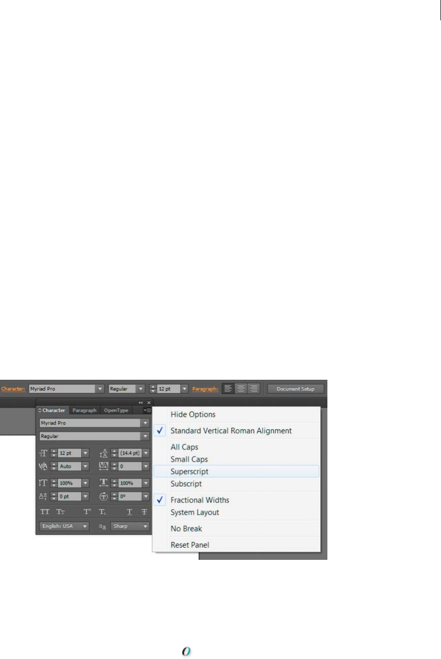
416
Type
Last updated 6/5/2015
•To create the appearance of rasterization without changing the object’s underlying structure, choose Effect >
Rasterize.
2Choose an anti-aliasing option:
None Applies no anti-aliasing and maintains the hard edges of type when it is rasterized.
Art Optimized (Supersampling) Default option that rasterizes all objects, including text objects by the specified
resolution and applies anti-aliasing to them. Default resolution is 300 pixels per inch.
Type Optimized (Hinted) Applies anti-aliasing that is best suited to type. Anti-aliasing reduces the appearance of
jagged edges in the rasterized image and gives type a smoother on-screen appearance. However, it can also make
small text difficult to read.
Creating superscripts or subscripts
Superscript and subscript text (also called superior and inferior text) is reduced-size text that is raised or lowered in
relation to a font’s baseline.
When you create superscript or subscript type, Illustrator applies a predefined baseline shift value and typeface size.
The values applied are percentages of the current font size and leading, and are based on settings in the Type section of
the Document Setup dialog box.
Create superscripts or subscripts in regular fonts
1Select the type you want to change. If you don’t select any type, any new text you create will be rendered as
superscripts or subscripts.
2Choose Superscript or Subscript from the Character panel menu. You can access the Character panel from the
Control panel.
A CALLOUT_DEFINITION B CALLOUT_DEFINITION C CALLOUT_DEFINITION
Create superscripts or subscripts in OpenType fonts
1Select the characters you want to change to superscript or subscript. If you don’t select any text, the setting applies
to new text you create.
2Make sure that an OpenType font is selected. One way to determine if a font is an OpenType font is to look in the
Type > Font menu; OpenType fonts display the icon.

417
Type
Last updated 6/5/2015
3In the OpenType panel, choose an option from the Position pop-up menu:
Default Position Uses the default position for the current font.
Superscript/Superior Uses raised characters (if available in the current font).
Subscript/Inferior Uses lowered characters (if available in the current font).
Numerator Uses characters designed as fraction numerators (if available in the current font).
Denominator Uses characters designed as fraction denominators (if available in the current font).
Change the size and position of superscripts or subscripts
❖Choose File > Document Setup, specify the following values for Superscript and Subscript, and then click OK:
•For Size, type a percentage of the font size for superscripted and subscripted text.
•For Position, type a percentage of the regular leading to specify how much the superscript and subscript text will
move.
Convert type to outlines
You can turn type into a set of compound paths, or outlines, that you can edit and manipulate as you would any other
graphic object. Type as outlines are useful for changing the look of large display type, but they are rarely useful for body
text or other type at small sizes.
Font outline information comes from the actual font files installed on your system. When you create outlines from type,
characters are converted in their current positions; they retain all graphics formatting such as their stroke and fill.
A Original type object B Type converted to outlines, ungrouped, and modified
Note: You can’t convert bitmap fonts or outline-protected fonts to outlines.
When you convert type to outlines, the type loses its hints—instructions built into fonts to adjust their shape so that
your system displays or prints them optimally at a wide range of sizes. If you plan to scale the type, adjust its point size
before converting.
You must convert all the type in a selection; you cannot convert a single letter within a string of type. To convert a single
letter into an outline, create a separate type object containing only that letter.
1Select the type object.
2Choose Type > Create Outlines.

418
Type
Last updated 6/5/2015
Choose a number style in OpenType fonts
1To change the style of existing numbers, select the characters or type objects you want to change. If you don’t select
any text, the setting applies to new text you create.
2Make sure that an OpenType font is selected.
3In the OpenType panel, choose an option from the Figures pop-up menu:
Default Figure Uses the default style for the current font.
Tabular Lining Uses full-height figures all of the same width (if available for the current font). This option is
appropriate in situations where numbers need to line up from one line to the next, as in tables.
lining numbersProportional Lining Uses full-height figures with varying widths (if available for the current font).
This option is recommended for text that uses all caps.
oldstyle figuresProportional Oldstyle Uses varying-height figures with varying widths (if available for the current
font). This option is recommended for a classic, sophisticated look in text that doesn’t use all caps.
Tabular Oldstyle Uses varying-height figures with fixed, equal widths (if available for the current font). This option
is recommended when you want the classic appearance of old-style figures, but need them to align in columns, as
in an annual report.
Format fractions and ordinals in OpenType fonts
When using an OpenType font, you can automatically format ordinal numbers with superscript characters (for
example, ). Characters such as the superscript “a” and “o” in the Spanish words segunda ( ) and segundo ( ) are
also typeset properly. You can also convert numbers separated by a slash (such as 1/2) to a shilling fraction (such as ).
1Select the characters or type objects to which you want to apply the setting. If you don’t select any text, the setting
applies to new text you create.
2Make sure that an OpenType font is selected.
3In the OpenType panel, click the Ordinals button to enable or disable ordinals or the Fractions button to enable or
disable fractions. These buttons have an effect only if ordinals and fractions are available in the font.
Use smart punctuation
The Smart Punctuation command searches for keyboard punctuation characters and replaces them with their
typographic equivalents. In addition, you can use the Smart Punctuation command to globally insert ligatures and
fractions, if the font includes these characters.
If you’re using an OpenType font, use the OpenType panel instead of the Smart Punctuation dialog box to typeset
ligatures and fractions.
1If you want to replace characters in specific text, rather than all text in the document, select the desired text objects
or characters.
2Choose Type > Smart Punctuation.
3Select one or more of the following options:
ff, fi, ffi Ligatures Renders ff, fi, or ffi letter combinations as ligatures.
ff, fl, ffl Ligatures Renders ff, fl, or ffl letter combinations as ligatures.
straight quotesSmart Quotes Changes straight keyboard quotation marks into curly quotes.

419
Type
Last updated 6/5/2015
note: The Smart Quotes option always replaces straight quotes with curly quotes, regardless of the Double Quotes and
Single Quotes settings in the Document Setup dialog box.
extra spaces, eliminatingSmart Spaces Eliminates multiple spaces after a period.
en and em dashes, smart punctuation optiondashes, en and emEn, Em Dashes Replaces a double keyboard dash
with an en dash and a triple keyboard dash with an em dash.
Ellipses Replaces three keyboard periods with ellipsis points.
Expert Fractions Replaces separate characters used to represent fractions with their single-character equivalents.
4Select Entire Document to replace text symbols in the entire file or Text Only to replace symbols only in selected
text.
5(Optional) Select Report Results to see a list of the number of symbols replaced.
6Click OK to search for and replace selected characters.
More Help topics
Keys for working with type
OpenType fonts
OpenType panel overview
Use ligatures and contextual alternates
Formatting paragraphs
Paragraph panel overview
You use the Paragraph panel (Window > Type > Paragraph) to change the formatting of columns and paragraphs. When
type is selected or when the Type tool is active, you can also use options in the Control panel to format paragraphs.
For a video on working with character and paragraph styles, see www.adobe.com/go/vid0047.
A Alignment and Justification B Left Indent C First Line Left Indent D Space Before Paragraph E Hyphenation F Right Indent G Space After
Paragraph
A Font B Font Style C Font Size D Align left E Align center F Align right

420
Type
Last updated 6/5/2015
By default, only the most commonly-used options in the Paragraph panel are visible. To show all options, choose Show
Options from the panel menu. Alternatively, click the double triangle on the panel’s tab to cycle through the display
sizes.
Align text
Area type and type on a path can be aligned with one or both edges of a type path.
1Select the type object or insert the cursor in the paragraph you want to change.
If you don’t select a type object or insert the cursor in a paragraph, the alignment applies to new text you create.
2In the Control panel or Paragraph panel, click an alignment button.
Justify text
Text is justified when it is aligned with both edges. You can justify all text in a paragraph either including or excluding
the last line.
1Select the type object or insert the cursor in the paragraph you want to justify.
If you don’t select a type object or insert the cursor in a paragraph, the justification applies to new text you create.
2In the Paragraph panel, click a justification button.
Adjust word and letterspacing in justified text
You can precisely control how Adobe applications space letters and words and scale characters. Adjusting spacing is
especially useful with justified type, although you can also adjust spacing for unjustified type.
1Insert the cursor in the paragraph you want to change, or select a type object or frame to change all of its paragraphs.
2Choose Justification from the Paragraph panel menu.
3Enter values for Word Spacing, Letter Spacing, and Glyph Spacing. The Minimum and Maximum values define a
range of acceptable spacing for justified paragraphs only. The Desired value defines the desired spacing for both
justified and unjustified paragraphs:
Word Spacing The space between words that results from pressing the spacebar. Word Spacing values can range
from 0% to 1000%; at 100%, no additional space is added between words.
Letter Spacing The distance between letters, including kerning or tracking values. Letter Spacing values can range
from -100% to 500%: at 0%, no space is added between letters; at 100%, an entire space width is added between
letters.
Glyph Scaling The width of characters (a glyph is any font character). Glyph Spacing values can range from 50% to
200%.
Tip: Spacing options are always applied to an entire paragraph. To adjust the spacing in a few characters, but not
an entire paragraph, use the Tracking option.
4Set the Single Word Justification option to specify how you want to justify single-word paragraphs.
In narrow columns, a single word can occasionally appear by itself on a line. If the paragraph is set to full
justification, a single word on a line may appear to be too stretched out. Instead of leaving such words fully justified,
you can center them or align them to the left or right margins.
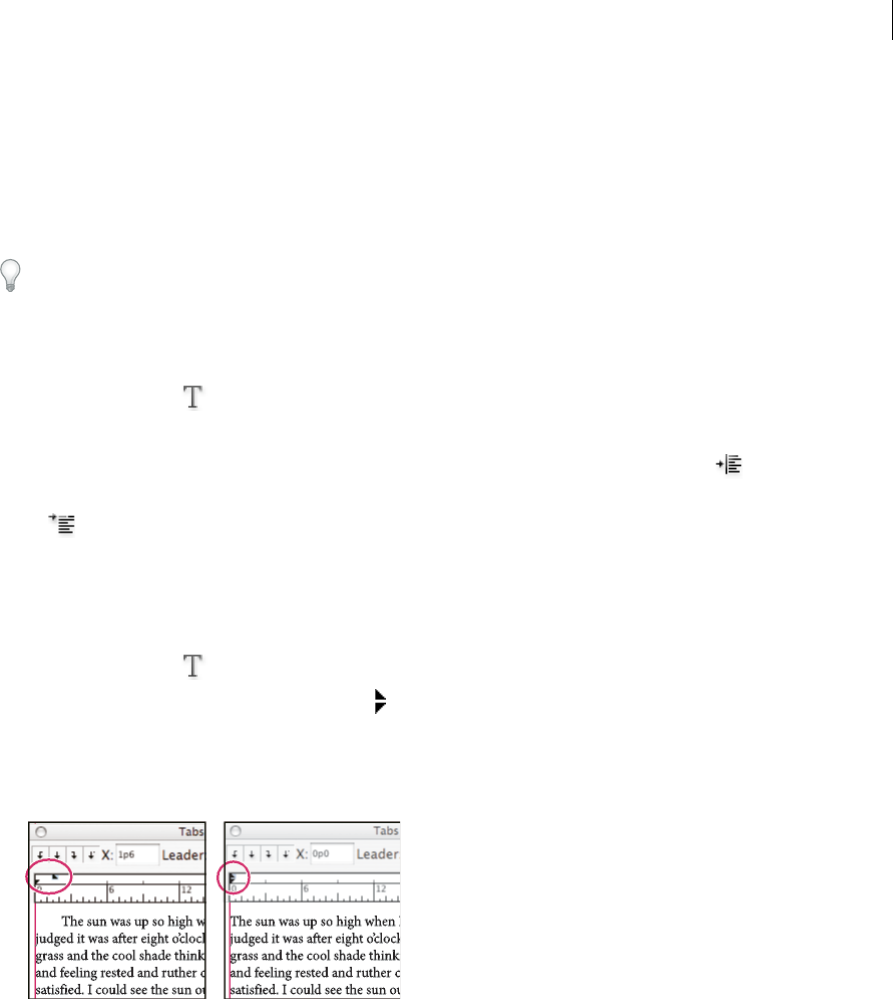
421
Type
Last updated 6/5/2015
Indent text
Indention is the amount of space between text and the boundary of a type object. Indention affects only the selected
paragraph or paragraphs, so you can easily set different indentions for different paragraphs.
You can set indents using the Tabs panel, the Control panel, or the Paragraph panel. When working with area type, you
can also control indention using tabs or by changing the inset spacing for the type object.
When working with Japanese type, you can use the mojikumi setting instead of the Paragraph panel to specify the indent
for the first line. If you specify the indent for the first line in the Paragraph panel, and specify mojikumi settings for the
first line indent, the text is placed inside the total of both indents.
Set indents using the Paragraph panel
1Using the Type tool , click in the paragraph you want to indent.
2Adjust the appropriate indent values in the Paragraph panel. For example, do the following:
•To indent the entire paragraph one pica, type a value (such as 1p) in the Left Indent box .
•To indent only the first line of a paragraph one pica, type a value (such as 1p) in the First Line Left Indent box
.
•To create a hanging indent of one pica, type a positive value (such as 1p) in the Left Indent box and type a
negative value (such as -1p) in the First Line Left Indent box.
Set an indent using the Tabs panel
1Using the Type tool , click in the paragraph you want to indent.
2Do one of the following to the indent markers in the Tabs panel:
•Drag the top marker to indent the first line of text. Drag the bottom marker to indent all but the first line. Ctrl-
drag (Windows) or Command-drag (Mac OS) the bottom marker to move both markers and indent the entire
paragraph.
•Select the top marker and type a value for X to indent the first line of text. Select the bottom marker and type a
value for X to move all but the first sentence.
Create a hanging indent
In a hanging indent, all the lines in a paragraph are indented except for the first line. Hanging indents are especially
useful when you want to add inline graphics at the beginning of the paragraph, or when you want to create a bulleted
list.
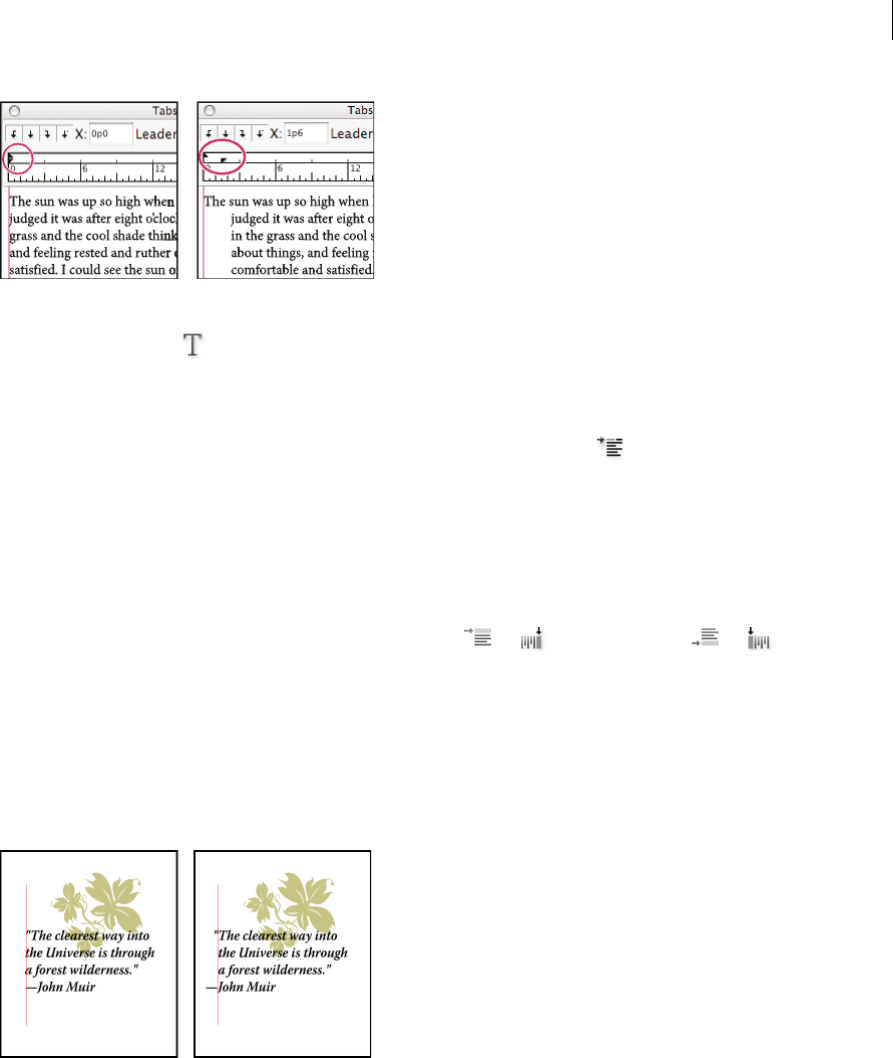
422
Type
Last updated 6/5/2015
1Using the Type tool , click in the paragraph you want to indent.
2In the Control panel or the Tabs panel, specify a left indent value greater than zero.
3To specify a negative first-line left indent value, do one of the following:
•In the Paragraph panel, type a negative value for the first-line left indent .
•In the Tabs panel, drag the top marker to the left, or the bottom marker to the right.
Adjust paragraph spacing
1Insert the cursor in the paragraph you want to change, or select a type object to change all of its paragraphs. If you
don’t insert the cursor in a paragraph or select a type object, the setting applies to new text you create.
2In the Paragraph panel, adjust the values for Space Before( or ) and Space After ( or ).
Note: If a paragraph begins at the top of a column, no extra space is added before the paragraph. In this case, you can
increase the leading of the first line of the paragraph or change the inset spacing for the type object.
Hanging punctuation
Hanging punctuation makes the edges of text appear more even by moving punctuation marks outside the paragraph
margins.
Illustrator provides the following options for hanging punctuation:
Roman Hanging Punctuation Controls the alignment of punctuation marks for a specific paragraph. When Roman
Hanging Punctuation is turned on, the following characters appear 100% outside the margins: single quotes, double
quotes, hyphens, periods, and commas; the following characters appear 50% outside the margins: asterisks, tildes,
ellipses, en dashes, em dashes, colons, semicolons. To apply this setting, insert the cursor in the paragraph and select
Roman Hanging Punctuation from the Paragraph panel menu.
Optical Margin Alignment Controls the alignment of punctuation marks for all paragraphs within a type object. When
Optical Margin Alignment is turned on, roman punctuation marks as well as the edges of letters (such as W and A)

423
Type
Last updated 6/5/2015
hang outside the text margins so that the type looks aligned. To apply this setting, select the type object and choose Type
> Optical Margin Alignment.
Burasagari Controls the alignment of double-byte punctuation marks (available in Chinese, Japanese, and Korean
fonts). These punctuation marks are not affected by the Roman Hanging Punctuation option or Optical Margin
Alignment option.
Keep in mind that the paragraph alignment determines the margin from which the punctuation hangs. For left-aligned
and right-aligned paragraphs, punctuation hangs off the left and right margin, respectively. For top-aligned and
bottom-aligned paragraphs, punctuation hangs off the top and bottom margin, respectively. For centered and justified
paragraphs, punctuation hangs off both margins.
note: When a punctuation character is followed by a quotation mark, both characters hang.
More Help topics
Keys for working with type
Change the margin around a text area
Set the leading
Specify a burasagari option
Hyphenation and line breaks
You can specify how words and lines break by adjusting hyphenation settings automatically, or by using the
hyphenation dictionary.
Illustrator uses the same composition methods for line and word breaks that is used in Adobe InDesign. For more
information on using these features, see web Help.
Adjust hyphenation automatically
The settings you choose for hyphenation affect the horizontal spacing of lines and the aesthetic appeal of type on a page.
Hyphenation options determine whether words can be hyphenated and, if so, what breaks are allowable.
1To use automatic hyphenation, do any of the following:
•To turn automatic hyphenation on or off, select or deselect the Hyphenate option in the Paragraph panel.
•To apply hyphenation to specific paragraphs, first select only the paragraphs that you want to affect.
•To choose a hyphenation dictionary, choose a language from the Language menu at the bottom of the Character
panel.
2To specify options, choose Hyphenation from the Paragraph panel menu, and specify the following options:
Words Longer Than _ Letters Specifies the minimum number of characters for hyphenated words.
After First _ Letters And Before Last _ Letters Specifies the minimum number of characters at the beginning or end
of a word that can be broken by a hyphen. For example, by specifying 3 for these values, aromatic would be
hyphenated as aro- matic instead of ar- omatic or aromat- ic.
Hyphen Limit Specifies the maximum number of consecutive lines on which hyphenation may occur. Zero means
unlimited consecutive hyphens are allowed at ends of lines.

424
Type
Last updated 6/5/2015
Hyphenation Zone Specifies a distance from the right edge of a paragraph, demarcating a portion of the line where
hyphenation is not allowed. A setting of 0 allows all hyphenation. This option applies only when you use the Adobe
Single-line Composer.
Hyphenate Capitalized Words Select to prevent capitalize words from being hyphenated.
Note: Hyphenation settings apply only to Roman characters; double-byte characters available in Chinese, Japanese, and
Korean fonts are not affected by these settings.
Use the hyphenation dictionary
Illustrator uses Proximity language dictionaries to determine when to hyphenate words. These dictionaries let you
specify a different language for as little as a single character of text. You can select a default dictionary and customize
the dictionary in the Preferences dialog box.
1Choose Edit > Preferences > Hyphenation (Windows) or Illustrator > Preferences > Hyphenation (Mac OS).
2Do any of the following:
•To choose a default hyphenation dictionary, select an option for Default Language, and click OK.
•To add a word to the exceptions list, type the word in the New Entry box, and click Add.
•To remove a word from the exceptions list, select the word, and click Delete.
Prevent words from breaking
You can prevent words from breaking at the end of lines—for example, proper names or words that could be misread
when hyphenated. You can also keep multiple words or groups of words together—for example, clusters of initials and
a last name.
1Select the characters you want to prevent from breaking.
2Choose No Break from the Character panel menu.
Note: If you apply the No Break option to too many adjacent characters, the text may wrap in the middle of a word.
However, if you apply the No Break option to more than a single line of text, none of the text will appear.
Composition methods
The appearance of type on the page depends on a complex interaction of processes called composition. Using the word
spacing, letterspacing, glyph spacing, and hyphenation options you’ve selected, Adobe applications evaluate possible
line breaks and choose the one that best supports the specified parameters.
You can choose between two composition methods: the Adobe Every-line Composer and the Adobe Single-line
Composer. Both methods evaluate possible breaks and choose the one that best supports the hyphenation and
justification options you’ve specified for a given paragraph. The composition method affects only the selected
paragraph or paragraphs, so you can easily set different composition methods for different paragraphs.
Every-line Composer
The Every-line Composer considers a network of break points for a range of lines and thus can optimize earlier lines
in the paragraph in order to eliminate especially unattractive breaks later on.
The Every-line Composer approaches composition by identifying possible break points, evaluating them, and assigning
a weighted penalty based on the following principles:
•For left-, right-, or center-aligned text, lines that fall closer to the right side are favored and have a lower penalty.

425
Type
Last updated 6/5/2015
•For justified text, the highest importance is given to evenness of letter and word spacing.
•Hyphenation is avoided when possible.
Single-line Composer
The Single-line composer offers a traditional approach to composing type one line at a time. This option is useful if you
want manual control over how lines break. The Single-line Composer uses the following principles when considering
a breakpoint:
•Longer lines are favored over shorter lines.
•In justified text, compressed or expanded word spacing is preferable to hyphenation.
•In nonjustified text, hyphenation is preferable to compressed or expanded letterspacing.
•If spacing must be adjusted, compression is better than expansion.
To choose one of these methods, select it from the Paragraph panel menu. To apply the method to all paragraphs,
first select the type object; to apply the method to the current paragraph only, first insert the cursor in that
paragraph.
Updating text from Illustrator10
Type objects created in Illustrator 10 and earlier are uneditable until you update them for use in later versions. After
you update you have access to all the text features in Illustrator CS5, such as paragraph and character styles, optical
kerning, and full OpenType® font support.
Updating type created in Illustrator 10
Type objects created in Illustrator 10 and earlier are uneditable until you update them for use in later versions. After
you update you have access to all the text features in Illustrator CS5, such as paragraph and character styles, optical
kerning, and full OpenType® font support.
You don’t have to update the text if you don’t need to edit it. Text that has not been updated is called legacy text. You can
view, move, and print legacy text, but you can’t edit it. Legacy text has an x through its bounding box when selected.
After updating legacy text, you may notice some minor reflow changes. You can easily readjust the text on your own,
or you can use a copy of the original text for reference. By default, Illustrator appends the word “[Converted]” to the
filename whether or not you update the text in a file, effectively making a copy of your document to preserve the
integrity of your original file. You can then choose to update the original later or, if you already updated it, go back to
the original version.note: If you don’t want Illustrator to append the filename, choose Edit > Preferences > General
(Windows) or Illustrator > Preferences > General (Mac OS), and deselect Append [Converted] Upon Opening Legacy Files.
Update all legacy text in a document
❖Do one of the following:
•When opening the document, click Update when prompted by Illustrator.
•After opening the document, choose Type > Legacy Text > Update All Legacy Text.
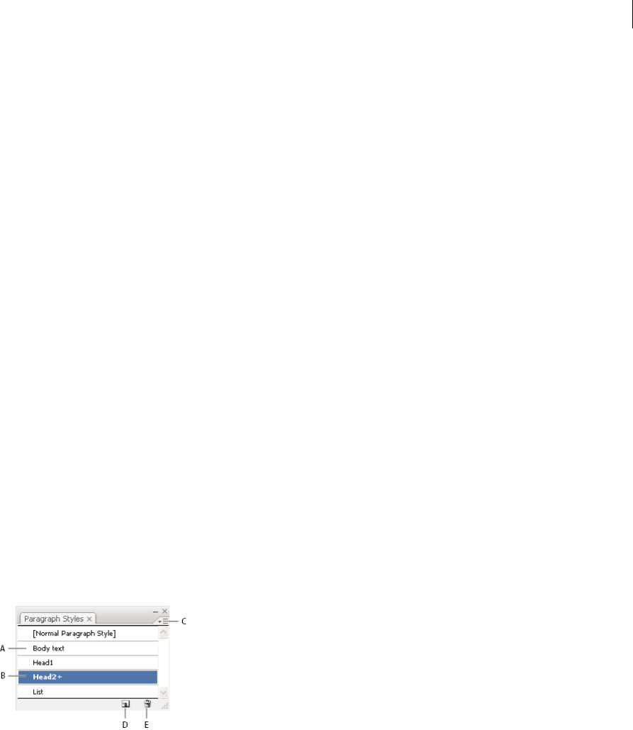
426
Type
Last updated 6/5/2015
Update selected legacy text
❖Do one of the following:
•To update the text without creating a copy, select the type object and choose Type > Legacy Text > Update
Selected Legacy Text. Alternatively, select a type tool and click in the text that you want to update, or double-click
the text that you want to update using the Selection tool. Then click Update.
•To preserve the legacy text on a layer below the updated text, select a type tool and click in the text that you want
to update. Alternatively, double-click the text that you want to update using the Selection tool. Then click Copy
Text Layer. This allows you to compare the layout of the legacy text to the updated text.
If you create a copy of legacy text when you update it, you can use the following commands:
•Type > Legacy Text > Show Copies or Hide Copies to show or hide the copied text objects.
•Type > Legacy Text > Select Copies to select copied text objects.
•Type > Legacy Text > Delete Copies to delete copied text objects.
Character and paragraph styles
About character and paragraph styles
A character style is a collection of character-formatting attributes that you can apply to a selected range of text. A
paragraph style includes both character- and paragraph-formatting attributes, and can be applied to a selected
paragraph or range of paragraphs. Using character and paragraph styles saves time and ensures consistent formatting.
You use the Character Styles and Paragraph Styles panels to create, apply, and manage character and paragraph styles.
To apply a style, simply select text and click a style name in one of the panels. If you don’t select any text, the style applies
to new text you create.
A Style name B Style with additional formatting (overrides) C Panel menu D New Style button E Delete icon
You can create, edit, and delete styles in stand-alone InCopy documents or in InCopy content that is linked to an
InDesign document. When the contents are updated in InDesign, new styles are added to the InDesign document, but
any style modifications made in InCopy will be overridden by the InDesign style. For linked content, it is usually best
to manage your styles in InDesign.
When you select text or insert the cursor in text, the active styles are highlighted in the Character Styles and Paragraph
Styles panels. By default, every character in a document is assigned the Normal Character Style and every paragraph is
assigned the Normal Paragraph Style. These default styles are the building blocks for all other styles you create.

427
Type
Last updated 6/5/2015
A plus sign next to a style name indicates that there are overrides to the style. An override is any formatting that doesn’t
match the attributes defined by the style. Any time you change settings in the Character and OpenType panel, you
create an override to the current character style; likewise, when you change settings in the Paragraph panel, you create
an override to the current paragraph style.
For a video about using character and paragraph styles in Illustrator, see www.adobe.com/go/vid0047.
Create character or paragraph styles
1If you want to base the new style on the formatting of existing text, select the text.
2In the Character Styles panel or the Paragraph Styles panel, do one of the following:
•To create a style with the default name, click the Create New Style button.
•To create a style with a custom name, choose New Style in the panel menu. Type a name, and click OK.
Tip: To create a copy of a character or paragraph style, drag the style onto the New Style button.
Edit character or paragraph styles
You can change the definition of the default character and paragraph styles, as well as any new styles you create. When
you change the definition of a style, all of the text formatted with that style changes to match the new style definition.
1In the Character Styles panel or the Paragraph Styles panel, do one of the following:
•Select the style in the panel, and choose Character Style Options from the Character Styles panel menu or
Paragraph Style Options from the Paragraph Styles panel menu.
•Double-click the style name.
note: Double-clicking applies the style to any selected text or, if no text is selected, sets the style for any new text you
type. If you don’t want to apply the style, hold down Shift+Ctrl (Windows) or Shift+Command (Mac OS) when you
double-click the style name.
2On the left side of the dialog box, select a category of formatting options and set the options you want. You can
switch to a different group of formatting options by selecting a different category.
If you need more information about any of the formatting options, search for the option name in Help.
3When you finish setting options, click OK.
Remove style overrides
A plus sign next to the style name in the Character Styles panel or the Paragraph Styles panel indicates that there are
overrides to the style. An override is any formatting that doesn’t match the attributes defined by the style. There are
several ways to remove style overrides:
•To clear overrides and return text to the appearance defined by the style, reapply the same style or choose Clear
Overrides from the panel menu.
•To clear overrides when applying a different style, Alt-click (Windows) or Option-click (Mac OS) the style name.
•To redefine the style and maintain the current appearance of the text, select at least one character of the text and
choose the Redefine Style command from the panel menu.
If you use styles to maintain consistent formatting, you should probably avoid overrides. If you’re formatting quick,
one-time-only text, these overrides pose no problem.

428
Type
Last updated 6/5/2015
Delete character or paragraph styles
When you delete styles, the appearance of paragraphs tagged with the style doesn’t change, but their formatting is no
longer associated with a style.
1Select the style name or names in the Character Styles panel or the Paragraph Styles panel.
2Do one of the following:
•Choose Delete Character Style or Delete Paragraph Style from the panel menu.
•Click the Delete icon at the bottom of the panel.
•Drag the style to the Delete icon at the bottom of the panel.
Tip: To delete all unused styles, choose Select All Unused from the panel menu, and then click the Delete icon.
Load character and paragraph styles from another Illustrator document
1In the Character Styles panel or the Paragraph Styles panel, do one of the following:
•Choose Load Character Styles or Load Paragraph Styles from the panel menu.
•Choose Load All Styles from the panel menu to load both character and paragraph styles.
2Double-click the Illustrator document containing the styles you want to import.
More Help topics
Using styles in Illustrator video
Creating composite fonts
You can mix characters from Japanese and roman fonts and use them as one composite font. Composite fonts are
displayed at the beginning of the font list.
Composite fonts must be based on Japanese fonts. For example, you cannot create fonts that include Chinese or Korean
fonts, nor can you use Chinese or Korean-based composite fonts copied from another application.
Create a composite font
You can mix characters from Japanese and roman fonts and use them as one composite font. Composite fonts are
displayed at the beginning of the font list.
Note: Composite fonts must be based on Japanese fonts. For example, you cannot create fonts that include Chinese or
Korean fonts, nor can you use Chinese or Korean-based composite fonts copied from another application.
1Choose Type > Composite Fonts. If you don’t see this command, select Show Asian Options in the Type preferences.
2Click New, enter the name for the composite font, and click OK.
3If you’ve previously saved composite fonts, you can also choose a composite font on which to base the new
composite font.
4Select a category of characters.
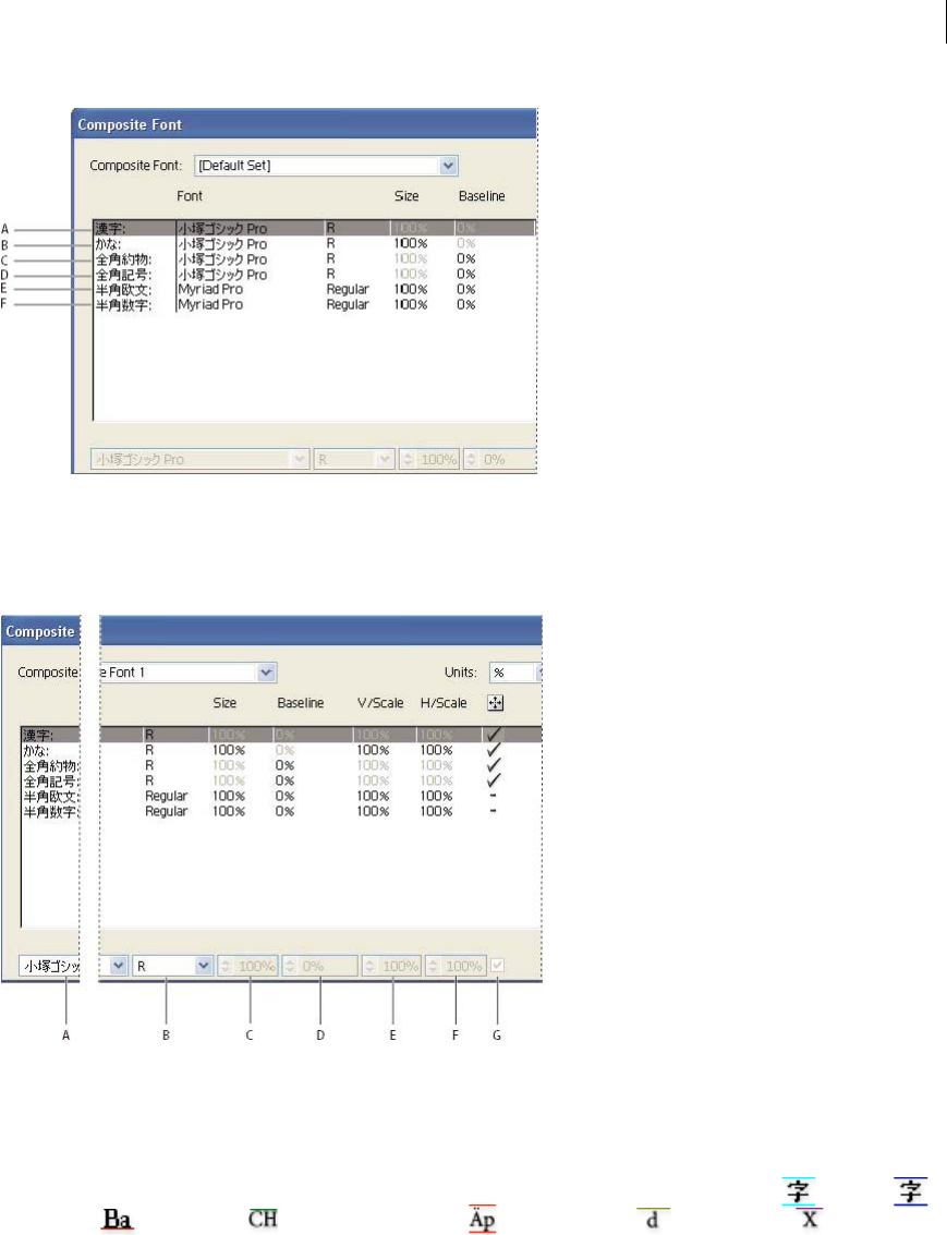
429
Type
Last updated 6/5/2015
A Kanji B Kana C Punctuation D Symbols E Roman F Numerals
5Choose an option from the Units pop-up menu to specify the unit used for font attributes: % or Q.
6Set font attributes for the selected category of characters. Some attributes are not available for certain categories.
A Font Family B Font Style C Size D Baseline E Vertical Scale F Horizontal Scale G Scale at Center
7To view a sample of the composite font, click Show Sample.
You can change the sample in the following ways:
•Click the buttons on the right side of the sample to show or hide lines indicating the ICF Box , Embox ,
Baseline , Cap Height , Max Ascent/Descent , Max Ascender , and x-height .
•Choose a magnification level from the Zoom pop-up menu.
8Click Save to save the settings for the composite font, and then click OK.
Categories of characters in composite fonts
Kanji The base font of the composite font. The size and baseline for other characters are set according to the sizes and
baselines specified here.
Kana The font used for hiragana and katakana characters.

430
Type
Last updated 6/5/2015
Punctuation The font used for punctuation.
Symbols The font used for symbols.
Roman The font used for half-width roman characters.
Numbers The font used for half-width numbers. This is usually a roman font.
Font attributes for composite fonts
Font Family And Style The font used for the characters.
Size The size of the characters in relation to the size of kanji characters. The size may differ for different fonts, even
when the same font size is used.
Baseline The position of the baseline in relation to the baseline for kanji characters.
Vertical And Horizontal Scale The degree to which characters are scaled. You can scale kana characters, half-width
katakana characters, gaiji characters, half-width roman characters, and numbers.
Scale At Center Scaling for kana characters. When this option is selected, characters are scaled from the center. When
this option is deselected, characters are scaled from the roman baseline.
Tip: To specify the same transformation scale for all characters, specify a value for Size and fix the value for scale at
100%. To have a different character transformation scale for horizontal and vertical, fix Size at 100%, and set Scale.
Customize characters in a composite font
1Choose Type > Composite Fonts. If you don’t see this command, select Show Asian Options in the Type preferences.
2Click Custom in the Composite Font dialog box.
3Do one of the following:
•If you’ve previously saved custom character sets, select the set you want to edit.
•To create a custom set, click New, enter a name for the character set, and click OK. If there are existing custom
sets, you can also choose a set on which to base the new set.
4Do any of the following:
•To add a character directly, choose Direct Entry from the Character pop-up menu, enter the characters in the
box, and click Add.
•To add a character using a code, choose an encoding type from the Character pop-up menu, enter the code, and
click Add.
note: You cannot add 32-bit characters to a custom set.
•To delete a character, select it in the list box, and click Delete.
5When you’ve finished customizing the character set, click Save, and then click OK.
Note: When there are several custom characters in one composite font, the bottom set takes precedence over all the above
sets.
Delete a composite font
1Choose Type > Composite Fonts. If you don’t see this command, select Show Asian Options in the Type preferences.
2Select the composite font from the Composite Font dialog box.
3Click Delete Font, and then click Yes.

431
Type
Last updated 6/5/2015
Export a composite font
Composite fonts exported from Illustrator can be imported into the Japanese version of Adobe InDesign 2 or later.
1Choose Type > Composite Fonts. If you don’t see this command, select Show Asian Options in the Type preferences.
2Click Export in the Composite Font dialog box.
3Select a location for the file, enter a filename, and click Save.
More Help topics
Display Asian type options
Indic support with new Composers | Illustrator CC
Illustrator CC includes enhanced support for Indic languages. You can now create documents using Indic text. The
additional Middle Eastern & South Asian Composer provides correct word shaping for many of the non-Western
scripts.
The Middle Eastern & South Asian Composers support Indian languages:
•Bengali
•Gujarati
•Hindi
•Kannada
•Malayalam
•Marathi
•Oriya
•Punjabi
•Tamil
•Telugu
This feature is enabled through the Preferences menu (Ctrl + K). The option is available in Preferences > Type > Show
Indic Options.
Note: The option Show Asian Options in previous versions of Illustrator is now renamed to Show East Asian Options.
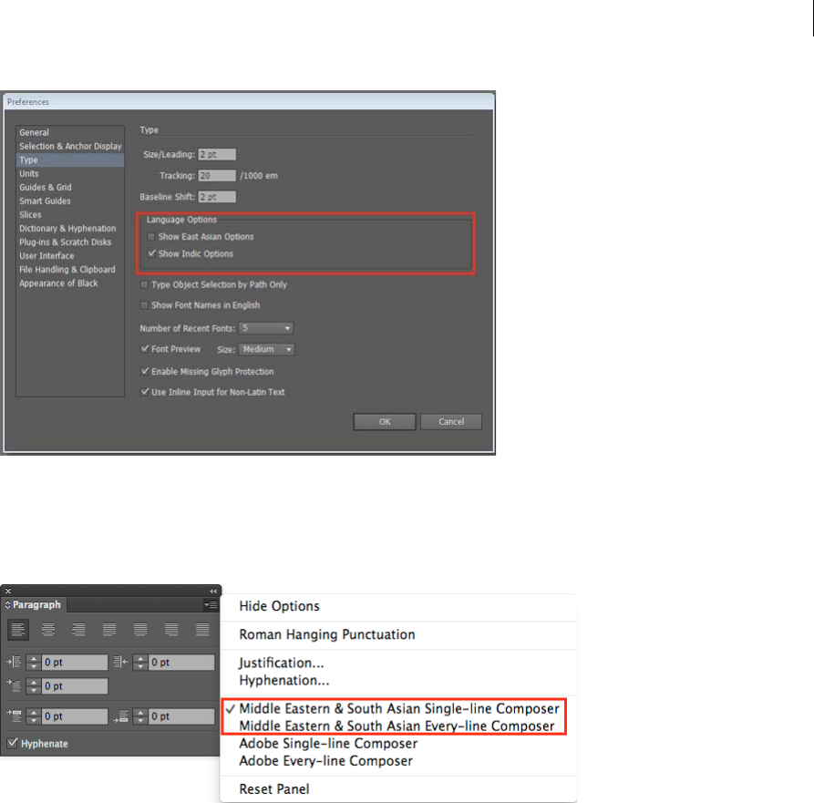
432
Type
Last updated 6/5/2015
When you enable Indic options, two additional composers are enabled in the flyout menu of the Paragraph panel
(available in the Control panel or through Ctrl + T). The two additional options are:
•Middle Eastern & South Asian Single-line Composer
•Middle Eastern & South Asian Every-line Composer
Note: In Preferences > Type, you can select only one of the Indic and Asian options at a same time. You can choose to have
both options off, or select one of the two.

433
Last updated 6/5/2015
Chapter 10: Creating special effects
Appearance attributes
You can change the appearance of any object, group, or layer in Adobe Illustrator by using effects and the Appearance
and Graphic Styles panels. In addition, you can divide an object into its essential parts to modify elements of the object
independently.
About appearance attributes
Appearance attributes are properties that affect the look of an object without altering its underlying structure.
Appearance attributes include fills, strokes, transparency, and effects. If you apply an appearance attribute to an object
and later edit or remove that attribute, it does not change the underlying object or any other attributes applied to the
object.
You can set appearance attributes at any level of the layer hierarchy. For example, if you apply a drop shadow effect to
a layer, all objects in the layer take on the drop shadow. However, if you move an object out of the layer, that object will
no longer have a drop-shadow because the effect belongs to the layer, not to each object within the layer.
The Appearance panel is the gateway to working with appearance attributes. Because you can apply appearance
attributes to layers, groups, and objects—and often to fills and strokes too—the hierarchy of attributes in your artwork
can become very complex. For example, if you apply one effect to an entire layer and another effect to an object in the
layer, it may be difficult to determine which effect is causing the artwork to change. The Appearance panel shows you
the fills, strokes, graphic styles, and effects that have been applied to an object, group, or layer.
For a video on using the Appearance panel and the Graphics Styles panel, see www.adobe.com/go/lrvid4022_ai.
Appearance panel overview
You use the Appearance panel (Window > Appearance) to view and adjust the appearance attributes for an object,
group, or layer. Fills and strokes are listed in stacking order; top to bottom in the panel correlates to front to back in the
artwork. Effects are listed from top to bottom in the order in which they are applied to the artwork.
For a video on using the Appearance panel and the Graphics Styles panel, see www.adobe.com/go/lrvid4022_ai.
A Path with stroke, fill, and drop shadow effect B Path with effect C Add New Stroke button D Add New Fill button E Add Effect button F Clear
Appearance button G Duplicate Selected Item button

434
Creating special effects
Last updated 6/5/2015
Reveal additional items in the Appearance panel
When you select items that contain other items, such as a layer or group, the Appearance panel displays a Contents item.
❖Double-click the Contents item.
List character attributes for a text object in the Appearance panel
When you select a text object, the panel displays a Characters item.
1 Double-click the Characters item in the Appearance panel.
Note: To see individual character attributes for text with mixed appearance, select the individual character.
2Click Type at the top of the panel to return to the main view.
Turn an attribute on or off for selected object
•To turn an individual attribute on or off, click the eyeball icon next to the attribute.
•To turn all hidden attributes on, choose Show All Hidden Attributes from the Appearance panel menu.
Edit an attribute
•Click in the attribute row to display and set values.
•Click the underlined text and specify new values in the dialog box that appears.
Show or hide thumbnails in the Appearance panel
❖Choose Show Thumbnail or Hide Thumbnail from the Appearance panel menu.
Specify how appearance attributes are applied to new objects
You can specify whether you want new objects to inherit appearance attributes or have only basic attributes.
•To apply only a single fill and stroke to new objects, choose New Art Has Basic Appearance from the panel menu.
•To apply all of the current appearance attributes to new objects, deselect New Art Has Basic Appearance from the
panel menu.
Targeting items for appearance attributes
Before you can set an appearance attribute or apply a style or an effect to a layer, group, or object, you must target the
item in the Layers panel. Selecting an object or group using any selection method also targets the object or group in the
Layers panel, but layers can be targeted only by using the panel.
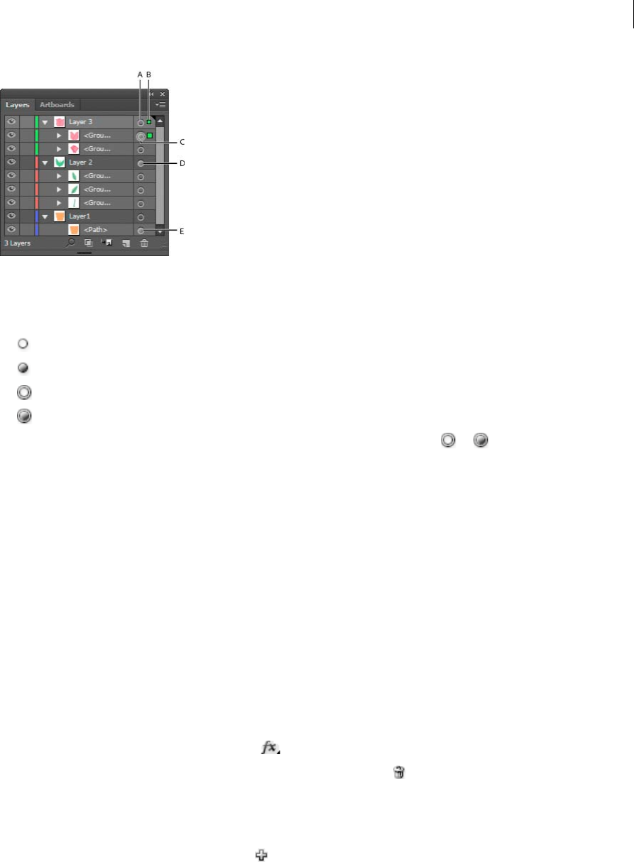
435
Creating special effects
Last updated 6/5/2015
A Targeting and appearance column B Selection column C Group with appearance attributes D Layer with appearance attributes E Object with
appearance attributes
The target icon indicates whether an item in the layer hierarchy has any appearance attributes and whether it is targeted:
• Indicates the item is not targeted and has no appearance attributes beyond a single fill and a single stroke.
• Indicates the item is not targeted but has appearance attributes.
• Indicates the item is targeted but has no appearance attributes beyond a single fill and a single stroke.
• Indicates the item is targeted and has appearance attributes.
To target an item in the Layers panel, click the item’s target icon. A double ring or indicates that the item is
targeted. Shift-click to target additional items.
Note: When an object or group is selected by any method, the item is also targeted in the Layers panel. In contrast, a
layer can be targeted only by clicking its target icon in the Layers panel.
Manage appearance attributes
Edit or add an appearance attribute
You can open an appearance attribute, such as an effect, and change the settings at any time.
❖In the Appearance panel, do any of the following:
•To edit an attribute, click the blue underlined name of the attribute, and specify changes in the dialog box that
appears.
•To edit a fill color, click the fill row and choose a new color from the color box.
•To add a new effect, click Add New Effect .
•To delete an attribute, click the attribute row, and then click Delete .
Duplicate an appearance attribute
❖Select an attribute in the Appearance panel, and do one of the following:
•Click the Duplicate Selected Item button in the panel, or choose Duplicate Item from the panel menu.
•Drag the appearance attribute onto the Duplicate Selected Item button in the panel.

436
Creating special effects
Last updated 6/5/2015
Change the stacking order of appearance attributes
❖Drag an appearance attribute up or down in the Appearance panel. (If necessary, click the toggle triangle next to an
item to display its contents.) When the outline of the appearance attribute you are dragging appears in the desired
position, release the mouse button.
Remove or hide appearance attributes
1Select the object or group (or target a layer in the Layers panel).
2Do one of the following:
•To temporarily hide an attribute applied to your artwork, click the Visibility icon in the Appearance panel.
Click it again to see the attribute applied again.
•To remove a specific attribute, select the attribute in the Appearance panel, and click the Delete icon .
Alternatively, select Remove Item from the panel menu, or drag the attribute to the Delete icon.
•To remove all appearance attributes except a single fill and stroke, choose Reduce To Basic Appearance from the
panel menu. Alternatively, drag the target icon for an item in the Layers panel onto the Delete icon in the Layers
panel.
•To remove all appearance attributes, including any fill or stroke, click the Clear Appearance button in the
Appearance panel or choose Clear Appearance from the panel menu.
Copy appearance attributes between objects
You can copy or move appearance attributes by dragging or by using the Eyedropper tool.
More Help topics
Layers panel overview
Copy appearance attributes by dragging
1Select the object or group (or target the layer in the Layers panel) whose appearance you want to copy.

437
Creating special effects
Last updated 6/5/2015
2Do one of the following:
•Drag the thumbnail at the top of the Appearance panel onto an object in the document window. If a thumbnail
isn’t showing, choose Show Thumbnail from the panel menu.
•Alt-drag (Windows) or Option-drag (Mac OS) the target icon in the Layers panel onto the item to which you
want to copy appearance attributes.
•To move appearance attributes instead of copying them, drag the target icon in the Layers panel from any item
that has the desired attributes onto the item to which you want to apply it.
Copy appearance attributes using the Eyedropper tool
You can use the Eyedropper tool to copy appearance attributes from one object to another, including character,
paragraph, fill, and stroke attributes between type objects. By default, the Eyedropper tool affects all attributes of a
selection. To customize the attributes affected by this tool, use the Eyedropper dialog box.
1Select the object, type object, or characters whose attributes you want to change.
2Select the Eyedropper tool .
3Move the Eyedropper tool onto the object whose attributes you want to sample. (When you’re correctly positioned
over type, the pointer displays a small T.)
4Do one of the following:
•Click the Eyedropper tool to sample all appearance attributes and apply them to the selected object.
•Shift-click to sample only the color from a portion of a gradient, pattern, mesh object, or placed image and apply
the color to the selected fill or stroke.
•Hold down the Shift key and then the Alt (Windows) or Option (Mac OS) key while clicking to add the
appearance attributes of an object to the selected object’s appearance attributes. Alternatively, click first, and then
hold down Shift+Alt (Windows) or Shift+Option (Mac OS).
note: You can also click an unselected object to sample its attributes and Alt-click (Windows) or Option-click (Mac
OS) an unselected object to which you want to apply the attributes.
Copy attributes from the desktop using the Eyedropper tool
1Select the object whose attributes you want to change.
2Select the Eyedropper tool.
3Click anywhere on the document and continue to hold down the mouse button.
4Without releasing the mouse button, move the pointer over the object on your computer desktop whose attributes
you want to copy. When directly over the object, release the mouse button.
Note: The Eyedropper tool samples only the RGB color from the screen when sampling anywhere outside the current
document. The Eyedropper tool indicates it is sampling RGB color from the screen by displaying a black-colored square
to the right of the tool.
Specify which attributes you can copy with the Eyedropper tool
1Double-click the Eyedropper tool.
2Select the attributes you want to copy with the Eyedropper tool. You can sample appearance attributes including
transparency, and various fill and stroke properties, as well as character and paragraph properties.
3Choose the sample size area from the Raster Sample Size menu.
4Click OK.

438
Creating special effects
Last updated 6/5/2015
Working with effects
About effects
Illustrator includes a variety of effects, which you can apply to an object, group, or layer to change its characteristics.
Illustrator CS3 and earlier included effects and filters, but now Illustrator includes only effects (with the exception of
SVG Filters). The primary difference between a filter and an effect is that a filter permanently modifies an object or
layer, but an effect and its properties can be changed or removed at any time.
Once you apply an effect to an object, the effect appears in the Appearance panel. From the Appearance panel, you can
edit the effect, move it, duplicate it, delete it, or save it as part of a graphic style. When you use an effect, you must
expand the object before you can access the new points.note: Previous versions of Illustrator included filters and effects.
The effects in the top half of the Effects menu are vector effects. You can apply these effects only to vector objects or to
the fill or stroke of a bitmap object in the Appearance panel. The following effects and effects categories from the top
section are exceptions to this rule and can be applied to both vector and bitmap objects: 3D effects, SVG Filters, Warp
effects, Transform effects, Drop Shadow, Feather, Inner Glow, and Outer Glow.
The effects in the bottom half of the Effects menu are raster effects. You can apply them to either vector or bitmap
objects.
For a video on using the Appearance panel and the Graphics Styles panel, see www.adobe.com/go/lrvid4022_ai.
More Help topics
Effects quick reference
Expand objects
Apply an effect
1Select the object or group (or target a layer in the Layers panel).
If you want to apply an effect to a specific attribute of an object, such as its fill or stroke, select the object and then
select the attribute in the Appearance panel.
2Do one of the following:
•Choose a command from the Effect menu.
•Click Add New Effect in the Appearance panel, and choose an effect.
3If a dialog box appears, set options, and then click OK.
To apply the effect and settings that were used last, choose Effect > Apply [Effect Name]. To apply the last used effect
and set its options, choose Effect > [Effect Name].
More Help topics
Targeting items for appearance attributes
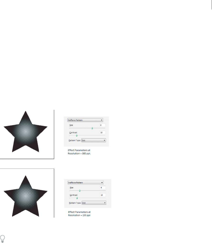
439
Creating special effects
Last updated 6/5/2015
About raster effects
Raster effects are effects that generate pixels, rather than vector data. Raster effects include SVG Filters, all of the effects
at the bottom section of the Effect menu, and the Drop Shadow, Inner Glow, Outer Glow, and Feather commands in
the Effect > Stylize submenu.
The Resolution Independent Effects (RIE) capability in Illustrator CS5 makes it possible to do the following:
•When the resolution in Document Raster Effects Settings (DRES) changes, the parameters in the effect are
interpreted to a different value so that there is minimal or no change in the appearance of the effect. The new
modified parameter values are reflected in the Effect dialog box.
•For effects with more than one parameter, Illustrator reinterprets only those parameters that are related to the
document raster effects resolution setting.
For example, there are different parameters in the Halftone Pattern dialog box. However, only the Size value changes
when the DRES changes.
You set rasterization options for a document by choosing Effect > Document Raster Effects Settings. (See Rasterization
options.)
If an effect looks good on-screen, but loses detail or appears jagged when printed, increase the document raster effects
resolution.
Rasterization options
You can set the following options for all raster effects in a document or when you rasterize a vector object.
Color Model Determines the color model that is used during rasterization. You can generate an RGB or CMYK color
image (depending on the color mode of your document), a grayscale image, or a 1-bit image (which may be black and
white or black and transparent, depending on the background option selected).
Resolution Determines the number of pixels per inch (ppi) in the rasterized image. When rasterizing a vector object,
select Use Document Raster Effects Resolution to use global resolution settings.
Background Determines how transparent areas of the vector graphic are converted to pixels. Select White to fill
transparent areas with white pixels, or select Transparent to make the background transparent. If you select

440
Creating special effects
Last updated 6/5/2015
Transparent, you create an alpha channel (for all images except 1-bit images). The alpha channel is retained if the
artwork is exported into Photoshop. (This option anti-aliases better than the Create Clipping Mask option.)
Anti-alias Applies anti-aliasing to reduce the appearance of jagged edges in the rasterized image. When setting
rasterization options for a document, deselect this option to maintain the crispness of fine lines and small text.
When rasterizing a vector object, select None to apply no anti-aliasing and maintain the hard edges of line art when it
is rasterized. Select Art Optimized to apply anti-aliasing that is best suited to artwork without type. Select Type
Optimized to apply anti-aliasing that is best suited to type.
Create Clipping Mask Creates a mask that makes the background of the rasterized image appear transparent. You do
not need to create a clipping mask if you selected Transparent for Background.
Add Around Object Adds a padding or border around the rasterized image, using the specified number of pixels. The
resulting image’s dimensions appear as the original dimensions plus the Add Around Object setting’s value. You can use
this setting, for example, to create a snapshot effect: Specify a value for Add Around Object setting, choose White
Background, and do not select Create Clipping Mask. The white boundary added to the original object becomes a
visible border on the image. You can then apply a Drop Shadow or Outer Glow effect to make the original artwork look
like a photo.
More Help topics
Rasterize a vector object
Image resolution guidelines for final output
Applying effects to bitmap images
Effects let you apply a special look to bitmap images as well as vector objects. For example, you can apply an
impressionistic look, apply lighting changes, distort images, and produce many other interesting visual effects.
Consider the following information when applying effects specifically to bitmap objects:
•Effects do not work on linked bitmap objects. If you apply an effect to a linked bitmap, it is applied to an embedded
copy of the bitmap instead of to the original. To apply the effect to the original, you must embed the original bitmap
in the document.
•Adobe Illustrator supports plug-in effects from Adobe products such as Adobe Photoshop and from non-Adobe
software developers. Once installed, most plug-in effects appear in the Effect menu and work the same way as do
built-in effects.
•Some effects can be memory-intensive, especially when applied to a high-resolution bitmap image.
More Help topics
About linked and embedded artwork
About plug-in modules
Improving performance for effects
Some effects are very memory-intensive. The following techniques can help improve performance when applying these
effects:
•Select the Preview option in effect dialog boxes to save time and prevent unintended results.
•Change the settings. Some commands, such as Glass, are extremely memory-intensive. Try different settings to
increase their speed.

441
Creating special effects
Last updated 6/5/2015
•If you plan to print to a grayscale printer, convert a copy of the bitmap image to grayscale before applying effects.
Note, however, that in some cases, applying an effect to a color bitmap image and then converting it to grayscale may
not have the same result as applying the same effect directly to a grayscale version of the image.
Modify or delete an effect
You modify or delete an effect by using the Appearance panel.
1Select the object or group (or target the layer in the Layers panel) that uses the effect.
2Do one of the following:
•To modify the effect, click its blue underlined name in the Appearance panel. In the effect’s dialog box, make the
desired alterations, and then click OK.
•To delete the effect, select the effect listing in the Appearance panel, and click the Delete button.
Summary of effects
Effects quick reference
Effect Action
Effect > 3D Convert open or closed paths, or bitmap objects, into three-
dimensional (3D) objects, which you can rotate, light, and shade.
See also: Create 3D objects
Effect > Artistic Simulate a painterly appearance on traditional media.
See also: Artistic effects
Effect > Blur Retouch images and smooth transitions by averaging the pixels next
to the hard edges of defined lines and shaded areas in an image.
See also: Blur effects
Effect > Brush Strokes Create a painterly or fine-arts look using different brush- and ink-
stroke effects.
See also: Brush Strokes effects
Effect > Convert To Shape Reshape either a vector or a bitmap object.
See also: Reshaping objects with effects
Effect > Crop Marks Applies crop marks to the selected object.
See also: Specify crop marks for trimming or aligning
Effect > Distort & Transform
(top section of menu)
Reshape vector objects, or apply the effects to a fill or stroke added to
a bitmap object with the Appearance panel.
See also: Reshaping objects with effects
Effect > Distort
(bottom section of menu)
Geometrically distort and reshape an image.
See also: Distort effects (bottom of menu)

442
Creating special effects
Last updated 6/5/2015
Effect > Path Offset an object’s path relative to its original location, turn type into a
set of compound paths that you can edit and manipulate as you would
any other graphic object, and change the stroke of a selected object to
a filled object that’s the same width as the original stroke. You can also
apply these commands to a fill or stroke added to a bitmap object with
the Appearance panel.
See also: Offset duplicate objects, Convert type to outlines, Convert
strokes to compound paths
Effect > Pathfinder Combine groups, layers, or sublayers into single editable objects.
See also: Apply Pathfinder effects
Effect > Pixelate Sharply define a selection by clumping pixels of similar color values.
See also: Pixelate effects
Effect > Rasterize Convert a vector object to a bitmap object.
See also: Rasterize a vector object
Effect > Sharpen Focus blurry images by increasing the contrast of adjacent pixels.
See also: Sharpen effect
Effect > Sketch Add texture to images, often for a three-dimensional effect. The
effects are also useful for creating a fine-arts or hand-drawn look.
See also: Sketch effects
Effect > Stylize
(top section of menu)
Add arrowheads, drop shadows, round corners, feathered-edged,
glowing, and scribble-styled appearances to objects.
See also: Create a drop shadow, Apply an inner or outer glow, Add
arrowheads, Feather the edges of an object, Create a sketch using the
Scribble effect, Round the corners of objects
Effect > Stylize
(bottom section of menu)
The Glowing Edges command produces a painted or impressionistic
effect on a selection by displacing pixels and by finding and
heightening contrast in an image.
See also: Stylize effect (bottom of menu)
Effect > SVG Filters Add XML-based graphic properties such as drop shadows to your
artwork.
See also: Apply SVG effects
Effect > Texture Give an image the appearance of depth or substance, or add an
organic look.
See also: Texture effects
Effect > Video Optimize images captured from video or artwork intended for
television.
See also: Video effects
Effect > Warp Distort or deform objects, including paths, text, meshes, blends, and
raster images.
See also: Reshaping objects with effects
Effect Action

443
Creating special effects
Last updated 6/5/2015
Artistic effects
Artistic effects are raster-based and use the document’s raster effects settings whenever you apply the effect to a vector
object.
Colored Pencil Draws an image using colored pencils on a solid background. Important edges are retained and given a
rough crosshatch appearance; the solid background color shows through the smoother areas.
Cutout Portrays an image as though it were made from roughly cut-out pieces of colored paper. High-contrast images
appear as if in silhouette; colored images are built up as if from several layers of colored paper.
Dry Brush Paints the edges of the image using a dry-brush technique (between oil and watercolor). The effect simplifies
an image by reducing its range of colors.
Film Grain Applies an even pattern to the shadow tones and midtones of an image. A smoother, more saturated pattern
is added to the image’s lighter areas. This effect is useful for eliminating banding in blends and visually unifying
elements from various sources.
Fresco Paints an image in a coarse manner using short, rounded strokes as if hastily applied.
Neon Glow Adds various types of glows to the objects in an image. This effect is useful for colorizing an image while
softening its look. To select a glow color, click the glow box and select a color from the color picker.
Paint Daubs Lets you choose from various brush sizes (from 1 to 50) and types for a painterly effect. Brush types
include simple, light rough, light dark, wide sharp, wide blurry, and sparkle.
Palette Knife Reduces detail in an image to give the effect of a thinly painted canvas that reveals the texture underneath.
Plastic Wrap Coats the image as if in shiny plastic, accentuating the surface detail.
Poster Edges Reduces the number of colors in an image according to the Posterization value you set; then finds the
edges of the image and draws black lines on them. Broader areas of the image have simple shading, while fine, dark
detail is distributed throughout the image.
Rough Pastels Makes an image appear as if stroked with colored pastel chalk on a textured background. In areas of
bright color, the chalk appears thick with little texture; in darker areas, the chalk appears scraped off to reveal the
texture.
Smudge Stick Softens an image using short diagonal strokes to smudge or smear the darker areas of the images. Lighter
areas become brighter and lose detail.
Sponge Creates images with highly textured areas of contrasting color as if painted with a sponge.
Underpainting Paints the image on a textured background, and then paints the final image over it.
Watercolor Paints the image in a watercolor style, simplifying details, and using a medium brush loaded with water and
color. Where significant tonal changes occur at edges, the effect saturates the color.
Blur effects
The commands in the Blur submenu in the Effect menu are raster-based and use the document’s raster effects settings
whenever you apply the effect to a vector object.
Gaussian Blur Quickly blurs a selection by an adjustable amount. This effect removes high-frequency detail and can
produce a hazy effect.
Radial Blur Simulates the soft blur created by a zooming or rotating camera. Choose Spin to blur along concentric
circular lines, and then specify a degree of rotation. Choose Zoom to blur along radial lines, as if zooming in or out of
the image, and specify an amount from 1 to 100. Blur quality ranges from Draft for the fastest but grainy results to Good

444
Creating special effects
Last updated 6/5/2015
and Best for smoother results, which are indistinguishable except on a large selection. Specify the origin of the blur by
dragging the pattern in the Blur Center box.
Smart Blur Blurs an image with precision. You can specify a radius, a threshold, and a blur quality. The Radius value
determines the size of the area searched for dissimilar pixels. The Threshold value determines how dissimilar the pixels
must be before they are affected. You also can set a mode for the entire selection (Normal) or for the edges of color
transitions (Edge Only and Overlay). Where significant contrast occurs, Edge Only applies black-and-white edges, and
Overlay Edge applies white.
Brush Strokes effects
The Brush Strokes effects are raster-based and use the document’s raster effects settings whenever you apply the effect
to a vector object.
Accented Edges Accentuates the edges of an image. When the Edge Brightness control is set to a high value, the accents
resemble white chalk. When it is set to a low value, the accents resemble black ink.
Angled Strokes Repaints an image using diagonal strokes. The lighter areas of the image are painted in strokes going
in one direction, while the darker areas are painted in strokes going the opposite direction.
Crosshatch Preserves the details and features of the original image while adding texture and roughening the edges of
the colored areas in the image with simulated pencil hatching. The Strength option controls the number of hatching
passes (from 1 to 3).
Dark Strokes Paints dark areas of an image closer to black with short strokes, and paints lighter areas of the image with
long, white strokes.
Ink Outlines Redraws an image with fine narrow lines over the original details, in pen-and-ink style.
Spatter Replicates the effect of a spatter airbrush. Increasing the values of the options simplifies the overall effect.
Sprayed Strokes Repaints an image using its dominant colors with angled, sprayed strokes of color.
Sumi-e Paints an image in Japanese style as if with a wet brush full of black ink on rice paper. The effect is soft, blurry
edges with rich blacks.
Distort effects (bottom of menu)
The Distort commands can be very memory-intensive. They are raster-based and use the document’s raster effects
settings whenever you apply the effect to a vector object.
Diffuse Glow Renders an image as if it were being viewed through a soft diffusion filter. The effect adds see-through
white noise to an image, with the glow fading from the center of a selection.
Glass Makes an image appear as if it were being viewed through different types of glass. You can choose a preset glass
effect or create your own glass surface using a Photoshop file. You can adjust scaling, distortion, and smoothness
settings, as well as texturizing options.
Ocean Ripple Adds randomly spaced ripples to the artwork, making the artwork look as if it were under water.

445
Creating special effects
Last updated 6/5/2015
Pixelate effects
The Pixelate effects are raster-based and use the document’s raster effects settings whenever you apply the effect to a
vector object.
Color Halftone Simulates the effect of using an enlarged halftone screen on each channel of the image. For each
channel, the effect divides the image into rectangles and replaces each rectangle with a circle. The circle size is
proportional to the brightness of the rectangle.
To use the effect, enter a value in pixels for the maximum radius of a halftone dot (from 4 to 127), and enter a screen-
angle value (the angle of the dot relative to the true horizontal) for one or more channels. For Grayscale images, use
only channel 1. For RGB images, use channels 1, 2, and 3, which correspond to the red, green, and blue channels. For
CMYK images, use all four channels, which correspond to the cyan, magenta, yellow, and black channels.
Crystallize Clumps colors into polygon shapes.
Mezzotint Converts an image to a random pattern of black-and-white areas, or of fully saturated colors in a color
image. To use the effect, choose a dot pattern from the Type pop-up menu in the Mezzotint dialog box.
Pointillize Breaks up the color in an image into randomly placed dots, as in a pointillist painting, and uses the
background color as a canvas area between the dots.
Sharpen effect
The Unsharp Mask command in the Sharpen submenu in the Effect menu focuses blurry images by increasing the
contrast of adjacent pixels. This effect is raster-based and uses the document’s raster effects settings whenever you apply
the effect to a vector graphic.
Unsharp Mask Finds the areas in the image where significant color changes occur and sharpens them. Use the Unsharp
Mask effect to adjust the contrast of edge detail and produce a lighter and darker line on each side of the edge. This
effect emphasizes the edge and creates the illusion of a sharper image.
Sketch effects
Many of the Sketch effects use black and white colors to redraw the image. The effects are raster-based and use the
document’s raster effects settings whenever you apply the effect to a vector graphic.
Bas Relief Transforms an image to appear carved in low relief and lit to accent the surface variations. Dark areas of the
image are colored black; light colors are colored white.
Chalk & Charcoal Redraws an image’s highlights and midtones with a solid midtone gray background drawn in coarse
chalk. Shadow areas are replaced with diagonal charcoal lines. The charcoal is drawn in black, the chalk in white.
Charcoal Redraws an image to create a posterized, smudged effect. Major edges are drawn boldly while midtones are
sketched using a diagonal stroke. Charcoal is colored black; the paper is colored white.
Chrome Treats the image as if it were a polished chrome surface. Highlights are high points and shadows are low points
in the reflecting surface.
Conté Crayon Replicates the texture of dense dark and pure white Conté crayons on an image. The Conté Crayon effect
uses black for dark areas and the white for light areas.
Graphic Pen Uses fine, linear ink strokes to capture the details in the original image. The effect replaces color in the
original image using black for ink and white for paper. This command is especially striking with scanned images.
Halftone Pattern Simulates the effect of a halftone screen while maintaining the continuous range of tones.

446
Creating special effects
Last updated 6/5/2015
Note Paper Creates an image that appears to be constructed of handmade paper. The effect simplifies an image, and
combines the effect of the Grain command (Texture submenu) with an embossed appearance. Dark areas of the image
appear as holes in the top layer of paper surrounded by white.
Photocopy Simulates the effect of photocopying an image. Large areas of darkness tend to copy only around their
edges; midtones fall away to either solid black or white.
Plaster Molds an image as if from plaster, and then colorizes the result using black and white. Dark areas are raised;
light areas are sunken.
Reticulation Simulates the controlled shrinking and distorting of film emulsion to create an image that appears
clumped in the shadow areas and lightly grained in the highlights.
Stamp Simplifies the image to appear stamped with a rubber or wood stamp. This command is best used with black-
and-white images.
Torn Edges Reconstructs the image as ragged, torn pieces of paper, and then colorizes the image using black and white.
This command is useful for images consisting of text or high-contrast objects.
Water Paper Uses blotchy daubs that appear painted onto fibrous, damp paper, causing the colors to flow and blend.
Stylize effect (bottom of menu)
The Glowing Edges effect is raster-based and uses the document’s raster effects settings whenever you apply the effect
to a vector graphic.
Glowing Edges Identifies the edges of color and adds a neon-like glow to them.
Texture effects
The Texture effects are raster-based and use the document’s raster effects settings whenever you apply the effect to a
vector graphic.
Craquelure Paints an image onto a high-relief plaster surface, producing a fine network of cracks that follow the
contours of the image. Use this effect to create an embossing effect with images that contain a broad range of color or
grayscale values.
Grain Adds texture to an image by simulating different kinds of grain—regular, soft, sprinkles, clumped, contrasty,
enlarged, stippled, horizontal, vertical, or speckle. For more information on using these texturizing options, see Use
texture and glass surface controls.
Mosaic Tiles Draws the image as if it were made up of small chips or tiles and adds grout between the tiles. (In contrast,
the Pixelate > Mosaic command breaks up an image into blocks of different-colored pixels.)
Patchwork Breaks up an image into squares filled with the predominant color in that area of the image. The effect
randomly reduces or increases the tile depth to replicate highlights and shadows.
Stained Glass Repaints an image as single-colored adjacent cells outlined in the foreground color.
Texturizer Applies a texture you select or create to an image.
Video effects
The Video effects are raster-based and use the document’s raster effects settings whenever you apply the effect to a
vector graphic.
De-Interlace Smooths moving images captured on video by removing either the odd or even interlaced lines in a video
image. You can choose to replace the discarded lines by duplication or interpolation.

447
Creating special effects
Last updated 6/5/2015
NTSC Colors Restricts the gamut of colors to those acceptable for television reproduction to prevent oversaturated
colors from bleeding across television scan lines.
Use texture and glass surface controls
Some effects included in Illustrator have texturizing options, such as the Glass, Rough Pastels, Grain, and Fresco effects.
The texturizing options can make an object appear as though painted onto various textures, such as canvas or brick, or
viewed through glass blocks.
1In the effect’s dialog box, choose a texture type from the Texture pop-up menu (if available), or choose Load Texture
(only available for Rough Pastels or Glass commands) to specify a file.
2Set other options, if available:
•Drag the Scaling slider to enlarge or reduce the effect on the bitmap image’s surface.
•Drag the Relief slider to adjust the depth of the texture’s surface.
•From the Light Direction pop-up menu, choose the direction from which you want the light to appear.
•Select Invert to reverse the surface’s light and dark colors.
Create a drop shadow
1Select an object or group (or target a layer in the Layers panel).
2Choose Effect > Stylize > Drop Shadow.
3Set options for the drop shadow, and click OK:
Mode Specifies a blending mode for the drop shadow.
Opacity Specifies the percentage of opacity you want for the drop shadow.
X Offset and Y Offset Specifies the distance you want the drop shadow to be offset from the object.
Blur Specifies the distance from the edge of the shadow where you want any blurring to occur. Illustrator creates a
transparent raster object to simulate the blur.
Color Specifies a color for the shadow.
Darkness Specifies the percentage of black you want added for the drop shadow. In a CMYK document, a value of
100%, used with a selected object that contains a fill or stroke color other than black, creates a multicolored black
shadow. A value of 100% used with a selected object that contains only a black fill or stroke creates a 100% black
shadow. A value of 0% creates a drop shadow the color of the selected object.
Drop shadows, glows, and feathering
Apply an inner or outer glow
1Select an object or group (or target a layer in the Layers panel).
2Choose Effect > Stylize > Inner Glow or Effect > Stylize > Outer Glow.
3Click the color preview square next to the blending mode menu to specify a color for the glow.
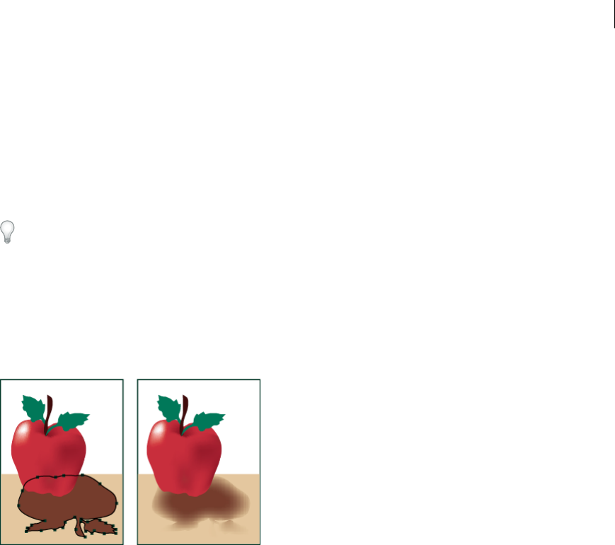
448
Creating special effects
Last updated 6/5/2015
4Set additional options, and click OK:
Mode Specifies a blending mode for the glow.
Opacity Specifies the percentage of opacity you want for the glow.
Blur Specifies the distance from the center or edge of the selection where you want any blurring to occur.
Center (Inner Glow only) Applies a glow that emanates from the center of the selection.
Edge (Inner Glow only) Applies a glow that emanates from the inside edges of the selection.
When you expand an object that uses an inner-glow effect, the inner glow reveals itself as an opacity mask If you
expand an object that uses an outer glow, the outer glow becomes a transparent raster object.
Feather the edges of an object
1Select the object or group (or target a layer in the Layers panel).
2Choose Effect > Stylize > Feather.
3Set the distance over which the object fades from opaque to transparent, and click OK.
More Help topics
About effects
Targeting items for appearance attributes
About raster effects
Selecting objects
Creating sketches and mosaics
Create a sketch using the Scribble effect
1Do one of the following:
•Select the object or group (or target a layer in the Layers panel).
•To apply the effect to a specific object attribute, such as a stroke or fill, select the object, and then select the
attribute in the Appearance panel.
•To apply the effect to a graphic style, select a graphic style in the Graphic Styles panel.

449
Creating special effects
Last updated 6/5/2015
2Choose Effect > Stylize > Scribble.
3Do one of the following:
•To use a preset scribble effect, choose one from the Settings menu.
•To create a custom scribble effect, begin with any preset, and then adjust the Scribble options.
4If creating a custom scribble, adjust any of the following Scribble options and click OK:
Angle Controls the direction of the scribble lines. You can click any point on the angle icon, drag the angle line
around the angle icon, or enter a value between –179 and 180 in the box. (If you enter a value that’s outside that
range, the value is translated to its equivalent in-range value.)
Path Overlap Controls the amount the scribble lines stay within or extend beyond the path boundaries. A negative
value constrains the scribble lines within the path boundary and a positive value extends the scribble lines beyond
the path boundary.
Variation (for Path Overlap) Controls the lengths of the difference in scribble line lengths relative to each other.
Stroke Width Controls the width of the scribble lines.
Curviness Controls the amount the scribble lines curve before they reverse direction.
Variation (for Curviness) Controls how different the scribble line curves are relative to each other.
Spacing Controls the amount of space between scribble line folds.
Variation (for Spacing) Controls how different the amount of space is between scribble line folds.
Create a mosaic
1Import a bitmap image to use as the basis for the mosaic. The image must be embedded, not linked.
You can also rasterize a vector object to use it as the basis for the mosaic.
2Select the image.
3Choose Object > Create Object Mosaic.
4If you want to change the dimensions of the mosaic, enter values for New Size.
5Set options to control the spacing between tiles and the total number of tiles, along with any other additional
options, and click OK:
Constrain Ratio Locks the width or height dimensions to the dimensions of the original bitmap image. Width
calculates the appropriate number of tiles to use for the width of the mosaic, based on the original number of tiles
for the width. Height calculates the appropriate number of tiles to use for the height of the mosaic, based on the
original number of tiles for the height.
Result Specifies whether the mosaic tiles are color or grayscale.
Resize Using Percentages Changes the size of the image by percentages of width and height.
Delete Raster Deletes the original bitmap image.
Use Ratio Makes the tiles square, using the number of tiles specified in Number Of Tiles. This option is located
below the Cancel button.
More Help topics
Targeting items for appearance attributes
About effects

450
Creating special effects
Last updated 6/5/2015
Modify or delete an effect
Selecting objects
Rasterize a vector object
About linked and embedded artwork
Graphic styles
About graphic styles
A graphic style is a set of reusable appearance attributes. Graphic styles allow you to quickly change the look of an
object; for example, you can change its fill and stroke color, alter its transparency, and apply effects in one step. All the
changes you apply with graphic styles are completely reversible.
You can apply graphic styles to objects, groups, and layers. When you apply a graphic style to a group or layer, every
object in the group or layer takes on the attributes of the graphic style. For example, assume you have a graphic style
that consists of 50% opacity. If you apply the graphic style to a layer, all objects in or added to that layer will appear 50%
opaque. However, if you move an object out of the layer, the object’s appearance reverts to its previous opacity.
For a video on using the Appearance panel and the Graphics Styles panel, see www.adobe.com/go/lrvid4022_ai.
If you apply a graphic style to a group or layer, but the style’s fill color doesn’t appear in the artwork, drag the Fill
attribute above the Contents entry in the Appearance panel.
Graphic Styles panel overview
You use the Graphic Styles panel (Window > Graphic Styles) to create, name, and apply sets of appearance attributes.
The panel lists a default set of graphic styles when you create a document. Graphic styles that are saved with the active
document appear in the panel when that document is open and active.
If a style doesn’t have a fill and stroke (for example, an effect-only style) the thumbnail appears in the shape of the object
with a black outline and white fill. In addition, a little red slash appears, indicating the absence of a fill or stroke.
If you’ve created a style for type, choose Use Text For Preview from the Graphics Styles panel menu to see a thumbnail
of the style applied to a letter rather than a square.
To see any style more clearly, or to preview the style on a selected object, right-click (Windows) or Ctrl-click (Mac OS)
the style’s thumbnail in the Graphic Styles panel and view the large pop-up thumbnail that appears.
For a video on using the Appearance panel and the Graphics Styles panel, see www.adobe.com/go/lrvid4022_ai.
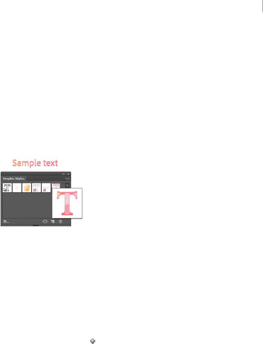
451
Creating special effects
Last updated 6/5/2015
Change how graphic styles are listed in the panel
❖Do any of the following:
•Select a view size option from the panel menu. Select Thumbnail View to display thumbnails. Select Small List
View to display a list of named styles with a small thumbnail. Select Large List View to display a list of named
styles along with a large thumbnail.
•Select Use Square For Preview from the panel menu to view the style on a square or the shape of the object on
which it was created.
•Drag the graphic style to a different position. When a black line appears in the desired position, release the mouse
button.
•Select Sort By Name from the panel menu to list the graphic styles in alphabetic or numeric order (Unicode
order).
•Select Use Text For Preview from the panel menu to view the style on the letter T. This view provides a more
accurate visual description for styles applied to text.
Create graphic styles
You can create a graphic from scratch by applying appearance attributes to an object, or you can base a graphic style on
other graphic styles. You can also duplicate existing graphic styles.
Create a graphic style
1Select an object and apply any combination of appearance attributes, including fills and strokes, effects, and
transparency settings.
You can use the Appearance panel to adjust and order the appearance attributes and create multiple fills and strokes.
For example, you can have three fills in a graphic style, each with a different opacity and blending mode that defines
how the various colors interact.
2Do any of the following:
•Click the New Graphic Style button in the Graphic Styles panel.
•Select New Graphic Style from the panel menu, type a name in the Style Name box, and click OK.
•Drag the thumbnail from the Appearance panel (or the object from the illustration window) into the Graphic
Styles panel.
•Alt-click (Windows) or Option-click (Mac OS) the New Graphic Style button, enter the name of the graphic style,
and click OK.
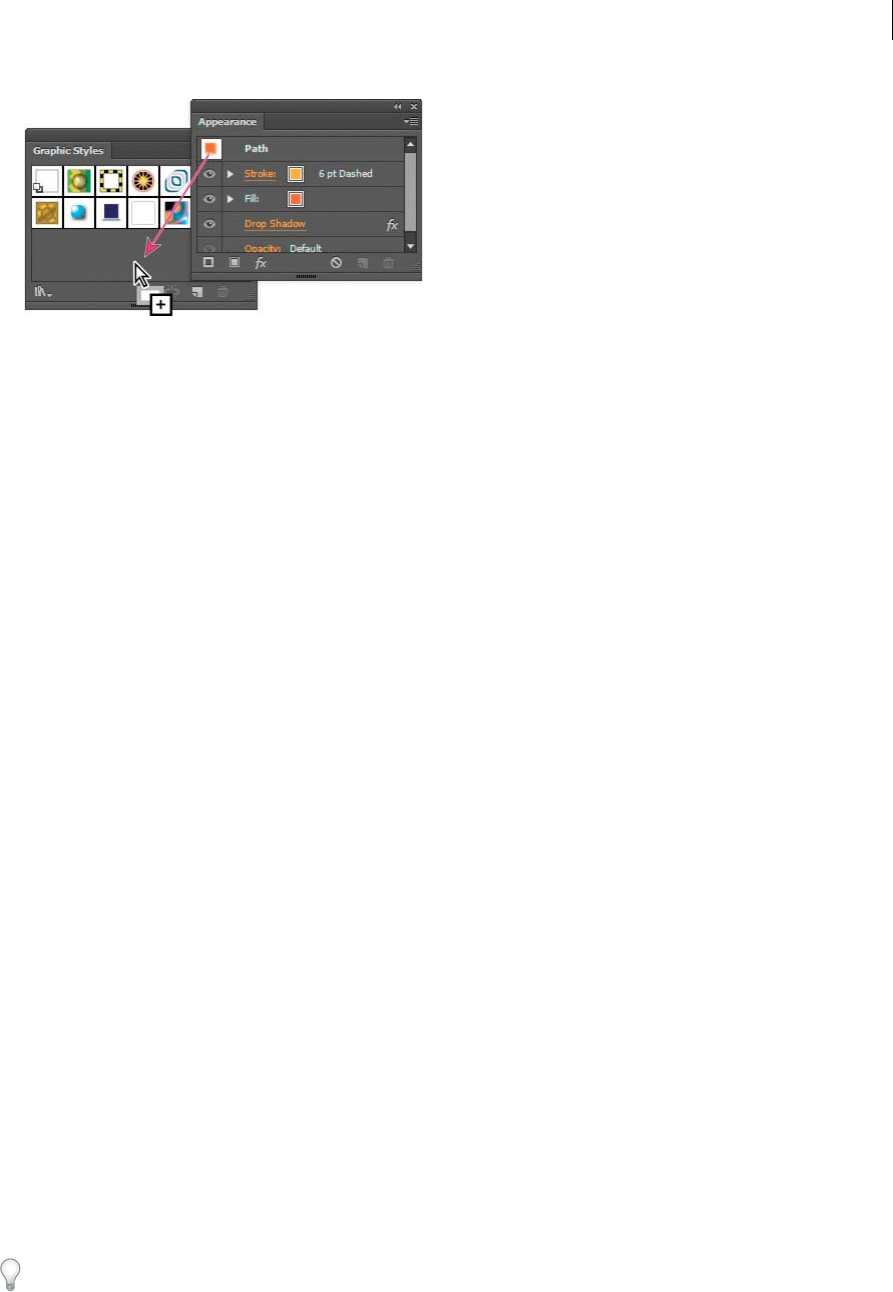
452
Creating special effects
Last updated 6/5/2015
Create a graphic style based on two or more existing graphic styles
❖Ctrl-click (Windows) or Command-click (Mac OS) to select all the graphic styles you want to merge, and then
choose Merge Graphic Styles from the panel menu.
The new graphic style contains all the attributes of the selected graphic styles and is added to the end of the list of
graphic styles in the panel.
Duplicate a graphic style
❖Choose Duplicate Graphic Style from the panel menu, or drag the graphic style onto the New Graphic Style button.
The new graphic style appears at the bottom of the list in the Graphic Styles panel.
Apply a graphic style
1Select an object or group (or target a layer in the Layers panel).
2To apply a single style to an object, do either of the following:
•Select a style from the Styles menu in the Control panel, the Graphic Styles panel, or a graphic style library.
•Drag the graphic style onto an object in the document window. (The object does not have to be selected first.)
3To merge a style with an object’s existing style attributes, or apply multiple styles to an object, do either of the
following:
•Alt-drag (Windows) or Option-drag (Mac OS) the style from the Graphic Styles panel to the object.
•Select the object, and then Alt-click (Windows) or Option-click (Mac OS) the style in the Graphic Styles panel.
Note: To preserve the color of type when applying a graphic style, deselect Override Character Color in the Graphic
Styles panel menu.
Use graphic style libraries
Graphic style libraries are collections of preset graphic styles. When you open a graphic style library, it appears in a new
panel (not the Graphic Styles panel). You select, sort, and view items in a graphic style library the same as you do in the
Graphic Styles panel. However, you can’t add items to, delete items from, or edit the items in graphic style libraries.
Open a graphic style library
❖Select a library from the Window > Graphic Style Libraries submenu or the Open Graphic Style Library submenu
in the Graphic Styles panel menu.
To automatically open a library when you start Illustrator, choose Persistent from the library’s panel menu.

453
Creating special effects
Last updated 6/5/2015
Create a graphic style library
1Add the graphic styles you want to the Graphic Styles panel, and delete any graphic styles you don’t want.
To select all graphic styles that aren’t used in a document, choose Select All Unused from the Graphic Styles panel
menu.
2Choose Save Graphic Style Library from the Graphic Styles panel menu.
You can save the library anywhere. However, if you save the library file in the default location, the library name will
appear in the User Defined submenu of the Graphic Style Libraries and Open Graphic Style Library menu.
Move graphic styles from a library to the Graphic Styles panel
•Drag one or more graphic styles from the graphic styles library to the Graphic Styles panel.
•Select the graphic styles you want to add, and select Add To Graphic Styles from the library’s panel menu.
•Apply a graphic style to an object in the document. The graphic style is automatically added to the Graphic Styles
panel.
Work with graphic styles
In the Graphic Styles panel, you can rename or delete graphic styles, break the link to a graphic style, and replace
graphic style attributes.
Rename a graphic style
❖Choose Graphic Style Options from the panel menu, rename the file, and then click OK.
Delete a graphic style
❖Choose Delete Graphic Style from the panel menu and click Yes, or drag the style onto the Delete icon.
Any objects, groups, or layers that used the graphic style retain the same appearance attributes; however, these
attributes are no longer associated with a graphic style.
Break the link to a graphic style
1Select the object, group, or layer that has the graphic style applied to it.
2Do one of the following:
•Choose Break Link To Graphic Style from the Graphic Styles panel menu, or click the Break Link To Graphic
Style button in the panel.
•Change any appearance attribute of the selection (such as a fill, stroke, transparency, or effect).
The object, group, or layer retains the same appearance attributes and is now independently editable. However,
these attributes are no longer associated with a graphic style.
Replace graphic style attributes
•Alt-drag (Windows) or Option-drag (Mac OS) the graphic style you want to use onto the graphic style you want to
replace.
•Select an object or group (or target a layer in the Layers panel) that has the attributes you want to use. Then Alt-drag
(Windows) or Option-drag (Mac OS) the thumbnail at the top of the Appearance panel onto the graphic style you
want to replace in the Graphic Styles panel.
•Select the graphic style you want to replace. Then select artwork (or target an item in the Layers panel) that has the
attributes you want to use, and choose Redefine Graphic Style “Style name” from the Appearance panel menu.

454
Creating special effects
Last updated 6/5/2015
The replaced graphic style keeps its name but takes on new appearance attributes. All occurrences of the graphic
style in the Illustrator document are updated to use the new attributes.
Import all graphic styles from another document
1Choose Window > Graphic Style Libraries > Other Library or select Open Graphic Style Library > Other Library
from the Graphic Styles panel menu.
2Select the file from which you want to import graphic styles, and click Open.
The graphic styles appear in a graphic style library panel (not the Graphic Styles panel).

455
Last updated 6/5/2015
Chapter 11: Web graphics
Best practices for creating webgraphics
Illustrator provides a variety of tools for creating layout for web pages, or creating and optimizing web graphics. For
example, use web-safe colors, balance image quality with file size, and choose the best file format for your graphic. Web
graphics can take advantage of slices and image maps, and you can use a variety of optimization options and work with
Device Central to ensure your files display well on the web.
About web graphics
When designing graphics for the web, you must consider different issues than when designing graphics for print. For
a video on saving graphics for the web, see www.adobe.com/go/vid0063. For a video on importing, and copying and
pasting between web applications, see www.adobe.com/go/vid0193.
To help you make informed decisions about web graphics, keep in mind the following three guidelines:
Use web-safe colors.
Color is often a key aspect of artwork. However, the colors you see on your artboard aren’t necessarily the colors that
will appear in a web browser on someone else’s system. You can prevent dithering (the method of simulating unavailable
colors) and other color problems by taking two precautionary steps when creating web graphics. First, always work in
RGB color mode. Second, use a web-safe color.
Balance image quality with file size.
Creating small graphics file sizes is essential to distributing images on the web. With smaller file sizes, web servers can
store and transmit images more efficiently, and viewers can download images more quickly. You can view the size and
the estimated download time for a web graphic in the Save For Web & Devices dialog box.
Choose the best file format for your graphic.
Different types of graphics need to be saved in different file formats to display their best and create a file size suitable
for the web. For more information on specific formats, see Web graphics optimization options .
There are many Illustrator templates made specifically for the web, including web pages and banners. Choose File >
New From Template to choose a template.
More Help topics
Save For Web & Devices overview
Optimize an image for the web
Shift a color to a web-safe color

456
Web graphics
Last updated 6/5/2015
About pixel preview mode
To enable web designers to create pixel accurate designs, the pixel-aligned property has been added in Illustrator CS5.
When the pixel-aligned property is enabled for an object, all the horizontal and vertical segments in the object get
aligned to the pixel grid, which provides a crisp appearance to strokes. On any transformation, as long as this property
is set for the object, it gets realigned to the pixel grid according to its new coordinates. You can enable this property by
selecting the Align to Pixel Grid option from the Transform panel. Illustrator CS5 also provides the Align New Objects
to Pixel Grid option at the document level, which is enabled by default for Web documents. With this property enabled,
any new objects that you draw have the pixel-aligned property set by default.
For more information, see Drawing pixel-aligned paths for web workflows .
When you save artwork in a bitmap format, such as JPEG, GIF, or PNG, Illustrator rasterizes the artwork at 72 pixels
per inch. You can preview how objects will appear when rasterized by choosing View > Pixel Preview. This is especially
helpful when you want to control the precise placement, size, and anti-aliasing of objects in a rasterized graphic.
To understand how Illustrator divides objects into pixels, open a file that contains vector objects, choose View > Pixel
Preview, and magnify the artwork so that you can see its individual pixels. The placement of pixels is determined by the
pixel grid that divides the artboard into 1-point (1/72 inch) increments. You can view the pixel grid if you zoom in to
600% view. If you move, add, or transform an object, the object snaps to the pixel grid. As a result, any anti-aliasing
along the “snapped” edges of the object (usually the left and top edges) disappears. Now deselect the View > Snap To
Pixel command, and move the object. This time, you’ll be able to position the object between the grid lines. Notice how
this affects the anti-aliasing of the object. As you can see, making very minor adjustments can affect how the object is
rasterized.
Note: The pixel grid is sensitive to the ruler origin (0,0). Moving the origin of the ruler will change how Illustrator rasterizes
artwork.
More Help topics
Drawing pixel-aligned paths for web workflows
About bitmap images
Using Adobe Device Central with Illustrator
Device Central enables Illustrator users to preview how Illustrator files will look on a variety of mobile devices.
For example, a graphic artist may use Illustrator to design a wallpaper for mobile phones. After creating the file, the
artist can easily test the file on a wide variety of phones. The artist can then make adjustments, such as altering the file
so that it looks good on a number of phones, or creating two separate files that cover a range of popular phone screen
sizes.
More Help topics
Creating mobile content in Illustrator

457
Web graphics
Last updated 6/5/2015
Access Illustrator from Adobe Device Central
1Start Device Central.
2Select File > New Document In > Illustrator.
In Device Central, the New Document panel appears with the correct options to create a new mobile document in
the selected application.
3Make any necessary changes, such as selecting a Player Version, Display Size, Flash Version, or Content type.
4Do one of the following:
•Select the Custom Size for All Selected Devices option and add a width and height (in pixels).
•Select a device or multiple devices from the Device Sets list or Available Devices list.
5If you selected multiple devices, Device Central selects a size for you. If you want to select a different size, click on a
different device or set of devices.
6Click Create.
The selected application opens with a new mobile document ready to edit.
Create mobile content with Adobe Device Central and Illustrator
1In Illustrator, select File > New.
2In New Document Profile, select Mobile and Devices.
3Click Device Central to close the dialog box in Illustrator and open Device Central.
4Select a content type.
The available Devices list on the left is updated and shows the devices that support the content type selected.
5In Device Central, select a device, several devices, or a device set.
Based on the device(s) selected and content type, Device Central suggests one or multiple artboard sizes to be
created. To create one document at a time, select a suggested document size (or select the Custom Size for all selected
Devices option and enter custom values for Width and Height).
6Click Create.
A blank AI file of the specified size opens in Illustrator. The new file has the following parameters set by default:
•Color Mode: RGB
•Raster Resolution: 72 ppi
7Fill the blank AI file with content in Illustrator.
8When you finish, select File > Save For Web& Devices.
9In the Save for Web & Devices dialog box, select the desired format and change other export settings as desired.
10 Click Device Central.
A temporary file with the export settings specified is displayed in the Device Central Emulator tab. To continue
testing, double-click the name of a different device in the Device Sets orAvailable Devices lists.
11 If, after previewing the file in Device Central, you need to make changes to the file, go back to Illustrator.
12 In the Illustrator Save for Web & Devices dialog box, make adjustments such as selecting a different format or quality
for export.
13 To test the file again with the new export settings, click Device Central.

458
Web graphics
Last updated 6/5/2015
14 When you are satisfied with the results, click Save in the Illustrator Save for Web & Devices dialog box.
Note: To simply open Device Central from Illustrator (instead of creating and testing a file), select File > Device Central.
For a tutorial about creating content with Illustrator and Device Central, see http://www.adobe.com/go/vid0207.
Tips for creating Illustrator images for mobile devices
To optimize graphical content for mobile devices, save artwork created in Illustrator in any SVG format, including
SVG-t, which is especially designed for mobile devices.
Use the following tips to ensure that images created in Illustrator display well on mobile devices:
•Use the SVG standard to create content. Using SVG to publish vector graphics on mobile devices results in a small
file size, display independence, superior color control, zooming ability, and editable text (within the source code).
Also, because SVG is XML-based, you can incorporate interactivity into images, such as highlighting, tool tips,
special effects, audio, and animation.
•Work within the final dimensions of your target mobile device(s) from the beginning. Although SVG is scalable,
working within the correct size will ensure that final graphics are optimized in quality and size for the target
device(s).
•Set Illustrator color mode to RGB. SVG is viewed on RGB raster display devices, such as a monitor.
•To reduce file size, try reducing the number of objects (including groups) or making it less complex (fewer points).
Using fewer points significantly reduces the amount of textual information needed to describe the artwork in the
SVG file. To reduce points, select Object > Path > Simplify and try different combinations to find a balance between
quality and number of points.
•Use symbols when possible. Symbols define the vectors that describe an object once, instead of multiple times. This
is useful if artwork contains objects like button backgrounds that are reused.
•When animating graphics, limit the number of objects used and try to reuse objects whenever possible to reduce file
size. Apply animations to groups of objects instead of to individual objects to avoid code repetition.
•Consider using SVGZ, the compressed gzipped version of SVG. Compression can reduce file size dramatically,
depending on the content. Text can usually be heavily compressed, but binary-encoded content, such as embedded
rasters (JPEG, PNG, or GIF files), cannot be compressed significantly. SVGZ files can be uncompressed by any
application that expands files compressed with gzip. To use SGVZ successfully, check that your target mobile device
can decompress gzip files.
For more tips and techniques for creating content for mobile phones and devices, see
www.adobe.com/go/learn_cs_mobilewiki_en.
Slices and image maps
About slices
Web pages can contain many elements—HTML text, bitmap images, and vector graphics, to name a few. In Illustrator,
you can use slices to define the boundaries of different web elements in your artwork. For example, if your artwork
contains a bitmap image that needs to be optimized in JPEG format, while the rest of the image is better optimized as
a GIF file, you can isolate the bitmap image using a slice. When you save the artwork as a web page using the Save For
Web & Devices command, you can choose to save each slice as an independent file with its own format, settings, and
color table.
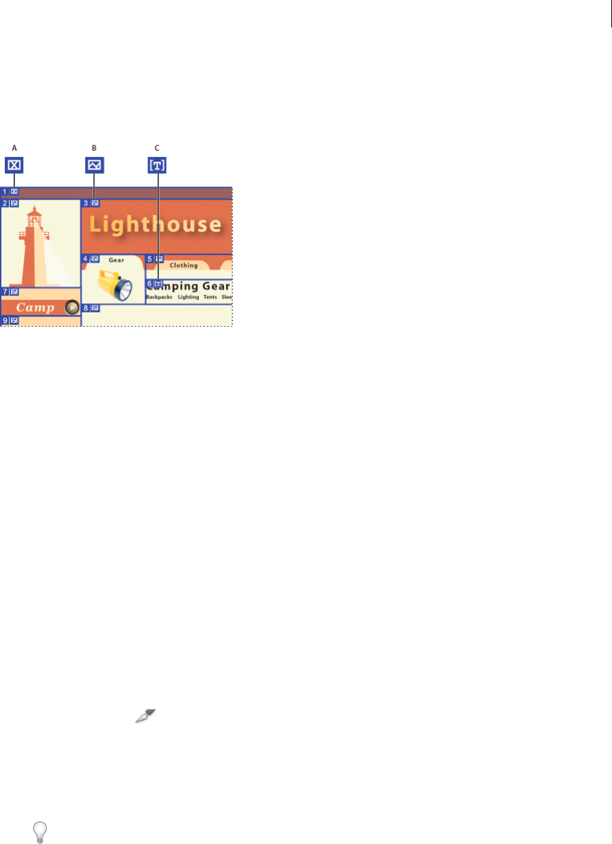
459
Web graphics
Last updated 6/5/2015
Slices in an Illustrator document correspond to table cells in the resulting web page. By default, the slice area is exported
as an image file that is enclosed in a table cell. If you want the table cell to contain HTML text and a background color
instead of an image file, you can change the slice type to No Image. If you want to convert Illustrator text to HTML text,
you can change the slice type to HTML Text.
A No Image slice B Image slice C HTML Text slice
You can view slices on the artboard and in the Save For Web & Devices dialog box. Illustrator numbers slices from left
to right and top to bottom, beginning in the upper left corner of the artwork. If you change the arrangement or total
number of slices, slice numbers are updated to reflect the new order.
When you create a slice, Illustrator slices the surrounding artwork into automatic slices to maintain the layout using a
web-based table. There are two types of automatic slices: auto slices and subslices. Auto slices account for the areas of
your artwork that you did not define as a slice. Illustrator regenerates auto slices every time you add or edit slices.
Subslices indicate how overlapping user-defined slices will be divided. Although subslices are numbered and display a
slice symbol, you cannot select them separately from the underlying slice. Illustrator regenerates subslices and auto
slices as needed while you work.
More Help topics
Save For Web & Devices overview
Slice output options
Create slices
❖Do one of the following:
•Select one or more objects on the artboard, and choose Object > Slice > Make.
•Select the Slice tool and drag over the area where you want to create a slice. Shift-drag to constrain the slice
to a square. Alt-drag (Windows) or Option-drag (Mac OS) to draw from the center.
•Select one or more objects on the artboard, and choose Object > Slice > Create From Selection.
•Place guides where you want to slice the artwork, and choose Object > Slice > Create From Guides.
•Select an existing slice, and choose Object > Slice > Duplicate Slice.
Tip: Use the Object > Slice > Make command when you want the slice dimensions to match the boundary of an
element in your artwork. If you move or modify the element, the slice area automatically adjusts to encompass
the new artwork. Also use this command to create a slice that captures text and basic formatting characteristics from
a text object.

460
Web graphics
Last updated 6/5/2015
Tip: Use the Slice tool, the Create From Selection command, or the Create From Guides command when you want
the slice dimensions to be independent of the underlying artwork. Slices that you create in one of these ways
appear as items in the Layers panel, and you can move, resize, and delete them in the same way as other vector
objects.
Select slices
Use the Slice Select tool to select a slice in the illustration window or the Save For Web & Devices dialog box.
•To select a slice, click it.
•To select multiple slices, Shift-click. (In the SaveFor Web & Devices dialog box, you can also Shift-drag.)
•To select an underlying slice when working with overlapping slices, click the visible section of it.
In addition, you can select slices in the illustration window by doing one of the following:
•To select a slice that was created using the Object > Slice > Make command, select the corresponding artwork on the
artboard. If the slice is tied to a group or layer, select the target icon adjacent to the group or layer in the Layers panel.
•To select a slice that was created using the Slice tool, the Create From Selection command, or the Create From
Guides command, target the slice in the Layers panel.
•Click on the slice path with the Selection tool .
•To select a slice path segment or slice anchor point, click on either item with the Direct Selection tool.
note: You cannot select auto slices. These slices are dimmed.
Set slice options
A slice’s options determine how the content of the slice will look and function in the resulting web page.
1Do one of the following with the Slice Select tool:
•Select a slice in the illustration window, and choose Object > Slice > Slice Options.
•Double-click a slice in the Save For Web & Devices dialog box with the Slice Select tool.
2Select a slice type and set the corresponding options:
Image Select this type if you want the slice area to be an image file in the resulting web page. If you want the image
to be an HTML link, enter a URL and target frameset. You can also specify a message that will appear in the browser’s
status area when the mouse is positioned over the image, alternative text that will appear when the image is not
visible, and a background color for the table cell.
No Image Select this type if you want the slice area to contain HTML text and a background color in the resulting
web page. Enter the text you want in the Text Displayed In Cell text box and format the text using standard HTML
tags. Be careful not to enter more text than can be displayed in the slice area. (If you enter too much text, it will
extend into neighboring slices and affect the layout of your web page. However, because you cannot see the text on
the artboard, this will not be apparent until you view the web page in a web browser.) Set the Horiz and Vert options
to change the alignment of text in the table cell.
HTML Text This type is available only when you created the slice by selecting a text object and choosing Object >
Slice > Make. The Illustrator text is converted to HTML text with basic formatting attributes in the resulting web
page. To edit the text, update the text in your artwork. Set the Horiz and Vert options to change the alignment of
text in the table cell. You can also select a background color for the table cell.

461
Web graphics
Last updated 6/5/2015
Tip: To edit the text for HTML Text slices in the Slice Options dialog box, change the slice type to No Image. This
breaks the link with the text object on the artboard. To ignore text formatting, enter <unformatted> as the first word
in the text object.
Lock slices
Locking slices prevents you from making changes accidentally, such as resizing or moving.
•To lock all slices, choose View > Lock Slices.
•To lock individual slices, click the slices’ edit column in the Layers panel.
Adjust slice boundaries
If you created a slice using the Object > Slice > Make command, the position and size of the slice is tied to the artwork
it contains. Therefore, if you move or resize the artwork, the slice boundaries adjust automatically.
If you created a slice using the Slice tool, the Create From Selection command, or the Create From Guides command,
you can manually adjust slices in the following ways:
•To move a slice, drag the slice to a new position with the Slice Selection tool . Press Shift to restrict movement
to a vertical, horizontal, or 45° diagonal line.
•To resize a slice, select the slice with Slice Selection tool, and drag any corner or side of the slice. You can also use
the Selection tool and Transform panel to resize slices.
•To align or distribute slices, use the Align panel. Aligning slices can eliminate unneeded auto slices to generate a
smaller, more efficient HTML file.
•To change the stacking order of slices, drag the slice to a new position in the Layers panel or select an Object >
Arrange command.
•To divide a slice, select the slice and choose Object > Slice > Divide Slices.
You can combine slices that were created by any method. Select the slices and choose Object > Slice > Combine
Slices. The resulting slice takes its dimensions and position from the rectangle created by joining the outer edges of
the combined slices. If the combined slices are not adjacent or are of different proportions or alignments, the new
slice may overlap other slices.
To resize all slices to the artboard boundaries, choose Object > Slice > Clip To Artboard. Slices that extend beyond
the artboard are truncated to fit the artboard and autoslices that lie within the artboard are extended to the artboard
boundaries; all artwork remains the same.
Remove slices
You can remove slices by deleting them or by releasing them from the corresponding artwork.
•To delete a slice, select the slice, and press Delete. If the slice was created using the Object > Slice > Make command,
the corresponding artwork is deleted at the same time. If you want to keep the corresponding artwork, release the
slice instead of deleting it.
•To delete all slices, choose Object > Slice > Delete All. Slices created with the Object > Slice > Make command are
released, not deleted.
•To release a slice, select the slice and choose Object > Slice > Release.

462
Web graphics
Last updated 6/5/2015
Show or hide slices
•To hide slices in the illustration window, choose View > Hide Slices.
•To hide slices in the Save For Web & Devices dialog box, click the Toggle Slices Visibility button .
•To hide slice numbers and change the color of slice lines, choose Edit > Preferences > Smart Guides & Slices
(Windows) or Illustrator > Preferences > Smart Guides & Slices (Mac OS).
Create image maps
Image maps enable you to link one or more areas of an image—called hotspots—to a URL. When a user clicks on the
hotspot, the web browser loads the linked file.
The main difference between using image maps and using slices to create links is in how the artwork is exported as a
web page. Using image maps keeps the artwork intact as a single image file, while using slices causes the artwork to be
divided into separate files. Another difference between image maps and slices is that image maps enable you to link
polygonal or rectangular areas in your artwork, while slices enable you to link only rectangular areas. If you need to link
only rectangular areas, using slices may be preferable to using an image map.
Note: To avoid unexpected results, don’t create image-map hotspots in slices that contain URL links—either the image map
links or the slice links may be ignored in some browsers.
1Select the object that you want to link to a URL.
2In the Attributes panel, select a shape for the image map from the Image Map menu.
3Enter a relative or full URL in the URL text box, or select from the list of available URLs. You can verify the URL
location by clicking the Browser button.
To increase the number of visible entries in the URL menu, select panel Options from the Attributes panel menu.
Enter a value from 1 to 30 to define how many URL entries you want to be displayed in the URL list.
More Help topics
Best practices for creating web graphics
SVG
About SVG
Bitmap image formats for the web—GIF, JPEG, WBMP, and PNG—describe images using a grid of pixels. The resulting
files tend to be bulky, limited to a single (often low) resolution, and consume large amounts of bandwidth on the web.
SVG, on the other hand, is a vector format that describes images as shapes, paths, text, and filter effects. The resulting
files are compact and provide high-quality graphics on the web, in print, and even on resource-constrained, handheld
devices. Users can magnify their view of an SVG image on-screen without sacrificing sharpness, detail, or clarity. In
addition, SVG provides superior support for text and colors, which ensures that users will see images as they appear on
your Illustrator artboard.
The SVG format is entirely XML-based and offers many advantages to developers and users alike. With SVG, you can
use XML and JavaScript to create web graphics that respond to user actions with sophisticated effects such as
highlighting, tool tips, audio, and animation.

463
Web graphics
Last updated 6/5/2015
You can save artwork in SVG format using the Save, Save As, Save A Copy, or Save For Web & Devices command. To
access the complete set of SVG export options, use the Save, Save As, or Save A Copy command. The Save For Web &
Devices command provides a subset of SVG export options which are applicable to web-oriented work.
For a video on creating mobile content in Illustrator, see www.adobe.com/go/vid0207.
How you set up your artwork in Illustrator will affect the resulting SVG file. Keep in mind the following guidelines:
•Use layers to add structure to an SVG file. When you save artwork in SVG format, each layer is converted to a group
(<g>) element. (For example, a layer named Button1 becomes <g id="Button1_ver3.0"> in the SVG file.) Nested
layers become SVG nested groups, and hidden layers are preserved with the display="none" SVG styling property.
•If you want objects on different layers to appear transparent, adjust the opacity of each object instead of each layer.
If you alter opacity at the layer level, the resulting SVG file will not display transparency as it appears in Illustrator.
•Raster data is not scalable in the SVG Viewer and cannot be edited like other SVG elements. If possible, avoid
creating artwork that will be rasterized in the SVG file. Gradient meshes and objects that use the Rasterize, Artistic,
Blur, Brush Strokes, Distort, Pixelate, Sharpen, Sketch, Stylize, Texture, and Video effects are rasterized when saved
in SVG format. Similarly, graphic styles that include these effects also produce rasterization. Use SVG effects to add
graphic effects without causing rasterization.
•Use symbols and simplify the paths in your artwork to improve SVG performance. Also avoid using brushes that
produce a lot of path data, such as the Charcoal, Fire Ash, and Scroll Pen, if performance is a high priority.
•Use slices, image maps, and scripts to add web links to an SVG file.
•A scripting language, such as JavaScript, opens unlimited functionality to an SVG file. Pointer and keyboard
movements can invoke scripting functions such as rollover effects. Scripts can also use the document object model
(DOM) to access and modify the SVG file—inserting or deleting SVG elements, for example.
Apply SVG effects
You can use SVG effects to add graphic properties such as drop shadows to your artwork. SVG effects differ from their
bitmap counterparts in that they are XML-based and resolution-independent. In fact, an SVG effect is nothing more
than a series of XML properties that describe various mathematical operations. The resulting effect is rendered to the
target object instead of the source graphic.
Illustrator provides a default set of SVG effects. You can use the effects with their default properties, edit the XML code
to produce custom effects, or write new SVG effects.
To modify Illustrator’s default SVG filters, use a text editor to edit the Adobe SVG Filters.svg file in the Documents and
Settings/<userdir>/Application Data/Adobe/Adobe Illustrator CS5 Settings/<location> folder. You can modify existing
filter definitions, delete filter definitions, and add new filter definitions.
1Select an object or group (or target a layer in the Layers panel).
2Do one of the following:
•To apply an effect with its default settings, select the effect from the bottom section of the Effect > SVG Filters
submenu.
•To apply an effect with custom settings, choose Effect > SVG Filters > Apply SVG Filter. In the dialog box, select
the effect, and click the Edit SVG Filter button . Edit the default code and click OK.
•To create and apply a new effect, choose Effect > SVG Filters > Apply SVG Filter. In the dialog box, click the New
SVG Filter button , enter the new code, and click OK.
When you apply an SVG filter effect, Illustrator displays a rasterized version of the effect on the artboard. You
can control the resolution of this preview image by modifying the document’s rasterization resolution setting.

464
Web graphics
Last updated 6/5/2015
Note: An SVG effect must be the last effect when an object uses multiple effects; in other words, it must appear at the
bottom of the Appearance panel (just above the Transparency entry). If other effects follow an SVG effect, the SVG
output will consist of a raster object.
Import effects from an SVG file
1Choose Effect > SVG Filter > Import SVG Filter.
2Select the SVG file you want to import effects from, and click Open.
SVG Interactivity panel overview
You use the SVG Interactivity panel (Window > SVG Interactivity) to add interactivity to your artwork when it is
exported for viewing in a web browser. For example, by creating an event that triggers a JavaScript command, you can
quickly create movement on a web page when the user performs an action such as moving a mouse cursor over an
object. The SVG Interactivity panel also lets you see all the events and JavaScript files associated with the current file.
Delete an event from the SVG Interactivity panel
•To delete one event, select it and click the Delete button or choose Delete Event from the panel menu.
•To delete all events, choose Clear Events from the panel menu.
List, add, or remove events linked to a file
1Click the Link JavaScript Files button .
2In the JavaScript Files dialog box, select a JavaScript entry and do one of the following:
•Click Add to browse for additional JavaScript files.
•Click Remove to remove the selected JavaScript entry.
Add SVG interactivity to artwork
1In the SVG Interactivity panel, select an event. (See SVG events.)
2Enter the corresponding JavaScript, and press Enter.
SVG events
onfocusin Triggers the action when the element receives focus, such as selection by the pointer.
onfocusout Triggers the action when the element loses focus (often when another element receives focus).
onactivate Triggers the action with a mouse click or keypress, depending upon the SVG element.
onmousedown Triggers the action when the mouse button is pressed down over an element.
onmouseup Triggers the action when the mouse button is released over an element.
onclick Triggers the action when the mouse is clicked over an element.
onmouseover Triggers the action when the pointer is moved onto an element.
onmousemove Triggers the action while the pointer is over an element.
onmouseout Triggers the action when the pointer is moved away from an element.
onkeydown Triggers the action when a key is pressed down.

465
Web graphics
Last updated 6/5/2015
onkeypress Triggers the action while a key is pressed down.
onkeyup Triggers the action when a key is released.
onload Triggers the action after the SVG document has been completely parsed by the browser. Use this event to call
one-time-only initialization functions.
onerror Triggers the action when an element does not load properly or another error occurs.
onabort Triggers the action when the page loading is stopped before the element is completely loaded.
onunload Triggers the action when the SVG document is removed from a window or frame.
onzoom Triggers the action when the zoom level is changed for the document.
onresize Triggers the action when the document view is resized.
onscroll Triggers the action when the document view is scrolled or panned.
More Help topics
Optimize an image for the web
Save in SVG format
About raster effects
Modify or delete an effect
Best practices for creating web graphics
Creating animations
About Flash graphics
The Flash (SWF) file format is a vector-based graphics file format for scalable, compact graphics for the web. Because
the file format is vector-based, the artwork maintains its image quality at any resolution and is ideal for the creation of
animation frames. In Illustrator, you can create individual animation frames on layers and then export the image layers
into individual frames for use on a website. You can also define symbols in an Illustrator file to reduce the size of an
animation. When exported, each symbol is defined only once in the SWF file.
You can save artwork as a SWF file by using the Export command or the Save For Web & Devices command. Benefits
of each include: Export (SWF) commandProvides the most control over animation and bitmap compression.Save For
Web & Devices commandProvides more control over the mix of SWF and bitmap formats in a sliced layout. This
command offers fewer Image options than the Export (SWF) command, but uses the Export command’s last-used
settings. (See SWF optimization options (Illustrator) .)
Keep the following information in mind when preparing artwork to save as SWF:
•To keep the file size as small as possible when using symbols, apply effects to the symbol in the Symbols panel rather
than to symbol instances in the artwork.
•Using the Symbol Stainer and Symbol Styler tools results in larger SWF files because Illustrator must create a copy
of each symbol instance to maintain their appearances.

466
Web graphics
Last updated 6/5/2015
•Mesh objects and gradients with more than eight stops are rasterized and will appear as bitmap-filled shapes.
Gradients with fewer than eight stops are exported as gradients.
•Patterns are rasterized into small images the size of the pattern art and tiled to fill the art.
•If a bitmap object extends beyond the boundaries of a slice, the entire object is included in the exported file.
•SWF supports rounded caps and joins only. Beveled or square caps and joins become rounded when exported to
SWF.
•Pattern-filled text and pattern-filled strokes convert to paths and are filled with the pattern.
•Although text retains many of its features when exported to SWF, some information is lost. When importing a SWF
file into Flash, leading, kerning, and tracking aren’t maintained. Instead, text is broken into separate records to
simulate the look of leading. When the SWF file is subsequently played in Flash Player, the appearance of the
leading, kerning, and tracking in the file is maintained. If you wish to export text as paths, select Text As Outlines
in the SWF Options dialog box, or convert the text to outlines before exporting to SWF by choosing the Create
Outlines command.
For a video on using Illustrator and Flash together, see www.adobe.com/go/lrvid4099_xp. For a video on using symbols
effectively between Illustrator and Flash, see www.adobe.com/go/vid0198. For a video on using text effectively between
Illustrator and Flash, see www.adobe.com/go/vid0199
Create Flash animations
There are many ways to create Flash animations in Illustrator. One of the easiest is to place each animation frame on a
separate Illustrator layer, and select the AI Layers To SWF Frames option when you export the artwork.
For a video on exporting SWF files from Illustrator, see www.adobe.com/go/vid0214. For a video on creating mobile
content in Illustrator, see www.adobe.com/go/vid0207. You can also go to Adobe Studio (http://studio.adobe.com) for
tips and tutorials on creating Flash animations.
1Create the artwork you want to animate. Use symbols to reduce the file size of the animation and simplify your work.
2Create a separate layer for each frame in the animation.
You can do this by pasting the base artwork into a new layer and then editing the artwork. Or, you can use the
Release To Layers command to automatically generate layers consisting of objects that build up cumulatively.
3Make sure the layers are in the order in which you want to display them as animation frames.
4Do one of the following:
•Choose File > Export, choose Flash (SWF) for the format, and click Export. In the SWF Options dialog box,
select AI Layers To SWF Frames for Export As. Set additional animation options, and click OK.
•Choose File > Save For Web & Devices. Choose SWF from the Optimized File Format menu. From the Type Of
Export menu, choose AI Layers To SWF Frames. Set additional options, and click Save.
Working with Illustrator and Flash
You can move Illustrator artwork into the Flash editing environment or directly into Flash Player. You can copy and
paste artwork, save files in SWF format, or export artwork directly to Flash. In addition, Illustrator provides support
for Flash dynamic text and movie clip symbols. For a video on using Flash and Illustrator together, see
www.adobe.com/go/lrvid4099_xp.
You can also use Device Central to see how Illustrator artwork will appear in Flash Player on different handheld devices.
Pasting Illustrator artwork

467
Web graphics
Last updated 6/5/2015
You can create graphically rich artwork in Illustrator and copy and paste it into Flash simply, quickly, and seamlessly.
When you paste Illustrator artwork into Flash, the following attributes are preserved:
•Paths and shapes
•Scalability
•Stroke weights
•Gradient definitions
•Text (including OpenType fonts)
•Linked images
•Symbols
•Blending modes
In addition, Illustrator and Flash support pasted artwork in the following ways:
•When you select entire top-level layers in Illustrator artwork and paste them into Flash, the layers are preserved
along with their properties (visibility and locking).
•Non-RGB Illustrator colors (CMYK, grayscale, and custom) convert to RGB in Flash. RGB colors paste as expected.
•When you import or paste Illustrator artwork, you can use various options to preserve effects (such as drop shadow
on text) as Flash filters.
•Flash preserves Illustrator masks.
Exporting SWF files from Illustrator
From Illustrator, you can export SWF files that match the quality and compression of SWF files exported from Flash.
When you export, you can choose from a variety of presets to ensure optimal output, and you can specify how to handle
multiple artboards, symbols, layers, text, and masks. For example, you can specify whether Illustrator symbols are
exported as movie clips or graphics, or you can choose to create SWF symbols from Illustrator layers.
Importing Illustrator files into Flash
When you want to create complete layouts in Illustrator and then import them into Flash in one step, you can save your
artwork in the native Illustrator format (AI) and import it, with high fidelity, into Flash using the File > Import To Stage
or File > Import To Library commands in Flash.
If your Illustrator file contains multiple artboards, you select the artboard you want to import from the Import dialog
box in Flash, and specify settings for each layer in that artboard. All objects on the selected artboard import as a single
layer in Flash. If you import another artboard from that same AI file, the objects from that artboard import as a new
layer in Flash.
When you import Illustrator artwork as an AI, EPS, or PDF file, Flash preserves the same attributes as for pasted
Illustrator artwork. In addition, when an imported Illustrator file contains layers, you can import them in any of the
following ways:
•Convert Illustrator layers to Flash layers
•Convert Illustrator layers to Flash frames
•Convert all Illustrator layers to a single Flash layer
Symbol workflow

468
Web graphics
Last updated 6/5/2015
Symbol workflow in Illustrator is similar to symbol workflow in Flash.
Symbol creation When you create a symbol in Illustrator, the Symbol Options dialog box lets you name the symbol
and set options specific to Flash: movie clip symbol type (which is the default for Flash symbols), Flash registration grid
location, and 9-slice scaling guides. In addition, you can use many of the same symbol keyboard shortcuts in Illustrator
and Flash (such as F8 to create a symbol).
Isolation mode for symbol editing In Illustrator, double-click a symbol to open it in isolation mode for easier editing.
In isolation mode, only the symbol instance is editable—all other objects on the artboard are dimmed and unavailable.
After you exit isolation mode, the symbol in the Symbols panel, and all instances of that symbol are updated
accordingly. In Flash, symbol-editing mode and the Library panel work in a similar fashion.
Symbol properties and links Using the Symbols panel or the Control panel, you can easily assign names to symbol
instances, break links between instances and symbols, swap a symbol instance with another symbol, or create a copy of
the symbol. In Flash, the editing features in the Library panel work in a similar way.
Static, dynamic, and input text objects
When you bring static text from Illustrator into Flash, Flash converts the text to outlines. In addition, you can set up
your text in Illustrator as dynamic text. Dynamic text enables you to edit text content programmatically in Flash, and
easily manage projects that require localization in multiple languages.
In Illustrator, you can specify individual text objects as static, dynamic, or input text. Dynamic text objects in Illustrator
and Flash have similar properties. For example, both use kerning that affects all characters in a text block rather than
individual characters, both anti-alias text the same way, and both can be linked to an external XML file containing text.
More Help topics
About symbols
Release items to separate layers
Flash export options
SWF optimization options (Illustrator)
Optimizing images
Web graphics optimization options
Output settings for web graphics
Best practices for creating web graphics

469
Last updated 6/5/2015
Chapter 12: Printing
Setting up documents for printing
To make optimum decisions about printing, you should understand basic printing principles, including how the
resolution of your printer or the calibration and resolution of you monitor can affect the way your artwork appears
when printed. Illustrator’s Print dialog box is designed to help you through the printing workflow. Each set of options
in the dialog box is organized to guide you through the printing process.
Print a composite of artwork
A composite is a single-page version of artwork that corresponds to what you see in the illustration window—in other
words, a straightforward print job. Composites are also useful for proofing the overall page design, verifying image
resolution, and identifying problems that may occur on an imagesetter (such as PostScript errors).
1Choose File > Print.
2Select a printer from the Printer menu. To print to a file instead of a printer, select Adobe PostScript® File or Adobe
PDF.
3Choose one of the following artboard options:
•To print everything on one page, select Ignore Artboards.
•To print each artboard separately, deselect Ignore Artboards and specify if you want to print all artboards (All),
or a specific range, such as 1-3.
4Select Output on the left side of the Print dialog box, and make sure that Mode is set to Composite.
5Set additional printing options.
6Click Print.
If your document uses layers, you can specify which ones to print. Choose File > Print, and select an option from the
Print Layers menu: Visible And Printable Layers, Visible Layers, or All Layers. For a video on creating crop areas
for print, see www.adobe.com/go/vid0213.
Make artwork nonprintable
The Layers panel makes it easy to print different versions of your artwork. For example, you can choose to print only
the type objects in a document in order to proof your text. You can also add nonprinting elements to artwork to record
important information.
•To prevent artwork from displaying in the document window, printing, and exporting, hide the corresponding items
in the Layers panel.
•To prevent artwork from printing, but not from showing on the artboard or exporting, double-click a layer name in
the Layers panel. In the Layer Options dialog box, deselect the Print option, and click OK. The layer name changes
to italics in the Layers panel.

470
Printing
Last updated 6/5/2015
•To create artwork that does not print or export, even when visible on the artboard, select Template in the Layer
Options dialog box.
Note: You can also specify multiple artboards in your document and then choose one artboard at a time for printing in the
Print dialog box. Only artwork within the artboard prints. For a video on defining crop artboards, see
www.adobe.com/go/lrvid4016_ai.
More Help topics
Layers panel overview
Using multiple artboards
Print dialog box options
Each category of options in the Print dialog box—from General options to Summary options—is organized to guide
you through the process of printing your document. To display a set of options, select the set name on the left side of
the dialog box. Many of these options are preset by the startup profile you chose when you started your document.
General Set the page size and orientation, specify how many pages to print, scale the artwork, specify tiling options and
choose which layers to print.
Marks & Bleed Select printer’s marks and create a bleed.
Output Create color separations.
Graphics Set printing options for paths, fonts, PostScript files, gradients, meshes, and blends.
Color Management Select a color profile and rendering intent for printing.
Advanced Control the flattening (or possible rasterization) of vector artwork during printing.
Summary View and save a summary of print settings.
More Help topics
Create new documents
Reposition artwork on the page
The preview image in the Print dialog box shows you where artwork will be printed on the page.
1Choose File > Print.
2Do one of the following:
•Drag the artwork in the preview image at the lower left corner of the dialog box.
•Click a square or arrow on the Placement icon to specify the origin point for aligning the artwork in relation to
the page. Enter values for Origin X and Origin Y to fine-tune the position of the artwork.
Tip: To move the printable area directly on the artboard, drag in the illustration window with the Print Tiling
tool. As you drag, the Print Tiling tool responds as if you were moving the printable area from its lower left corner.
You can move the printable area anywhere on the artboard; however, any part of a page that extends past the
printable area boundary is not printed.

471
Printing
Last updated 6/5/2015
More Help topics
Layers panel overview
Using multiple artboards
Print multiple artboards
When you create a document with multiple artboards, you can print the document in a variety of ways. You can ignore
the artboards and print everything on one page (tiling may be required if your artboards expand the page boundaries).
Or you can print each artboard as an individual page. When you print artboards as individual pages, you can choose
to print all artboards, or a range of artboards.
1Choose File > Print.
2Do one of the following:
•To print all artboards as separate pages, select All. You can see all the pages listed in the preview area in the lower
left corner of the Print dialog box.
•To print a subset of artboards as separate pages, select Range, and specify the artboards to print.
•To print the artwork on all the artboards together on a single page, select Ignore Artboards. If the artwork extends
past the boundaries of the page, you can scale or tile it.
3Specify other print options as desired, and click Print.
Automatically rotate artboards for printing
In Illustrator CS5, all the artboards in a document can automatically rotate to print to the chosen media size. Select the
Auto-Rotate check box in the Print dialog box to set auto rotation for Illustrator documents. For a document created
in CS5, Auto-Rotate is enabled by default.
For example, consider a document with both landscape (width is more than height) and portrait (height is more than
width) media size. If you select the media size as portrait in the Print dialog box, then the landscape artboards
automatically rotate to portrait media when printing.
Note: When Auto-Rotate is selected, you cannot change the page orientation.
Tile artwork on multiple pages
If you are printing artwork from a single artboard (or ignored artboards) that cannot fit on a single page, you can tile
the artwork onto multiple pages. If your document has multiple art
1Choose File > Print.
2Select Tile option:
Note: If your document has multiple artboards, first select Ignore Artboards, or specify 1 page in the Range option and
select Fit To Page.
Full Pages Divides the artboard into full media-sized pages for output.
Imageable Areas Divides the artboard into pages based on what the selected device can image. This option is useful
for outputting artwork that is larger than your device can handle, because it allows you to reassemble tiled pieces
into the original larger artwork.
3(Optional) If you selected Full Pages, set the Overlap option to specify the amount of overlap between pages.

472
Printing
Last updated 6/5/2015
More Help topics
About print tiling
Scale a document for printing
To fit an oversized document on a piece of paper smaller than the artwork’s actual dimensions, you can use the Print
dialog box to scale the document’s width and height, either symmetrically or asymmetrically. Asymmetric scaling is
useful when, for example, you’re printing film for use on a flexographic press: if you know in which direction the plate
will be mounted on the press drum, scaling can compensate for the 2% to 3% stretching of the plate that usually occurs.
Scaling does not affect the size of the pages in the document, it just changes the scale at which the document prints.
1Choose File > Print.
2Do one of the following:
•To prevent scaling, select Do Not Scale.
•To scale the document automatically to fit to the page, select Fit To Page. The scaling percentage is determined
by the imageable area defined by the selected PPD.
•To activate the Width and Height text boxes, select Custom. Enter percentages from 1 to 1000 for the width or
height. Deselect the Constrain Proportions button to change the document width-to-height ratio.
Change the printer resolution and screen frequency
Adobe Illustrator prints fastest and best by using the default printer resolution and screen frequency. However, in some
cases, you might want to change the printer resolution and screen frequency—for example, if you draw a very long
curved path that won’t print due to a limit-check error, if printing is slow, or if gradients and meshes show banding
when printed.
1Choose File > Print.
2For Printer, select a PostScript printer, Adobe PostScript® File, or Adobe PDF.
3Select Output on the left side of the Print dialog box.
4For Printer Resolution, select a screen frequency (lpi) and printer resolution (dpi) combination.
Printer resolution is measured in the number of ink dots produced per inch (dpi). Most desktop laser printers have a
resolution of 600 dpi, and imagesetters have a resolution of 1200 dpi or higher. Inkjet printers produce a microscopic
spray of ink, not actual dots; however, most inkjet printers have an approximate resolution of 300 to 720 dpi.
When printing to a desktop laser printer, but especially to imagesetters, you must also consider screen frequency.
Screen frequency is the number of halftone cells per inch used to print grayscale images or color separations. Also
known as screen ruling or line screen, screen frequency is measured in lines per inch (lpi)—or lines of cells per inch in
a halftone screen.
A high line-screen ruling (for example, 150 lpi) spaces the dots used to create an image close together to create a finely
rendered image on the press; a low screen ruling (60 lpi to 85 lpi) spaces the dots farther apart to create a coarser image.
The size of the dots is also determined by the line screen. A high line-screen ruling uses small dots; a low screen ruling
uses large dots. The most important factor in choosing a line-screen ruling is the type of printing press your job uses.
Ask your print shop how fine a line screen its press can hold, and make your choices accordingly.

473
Printing
Last updated 6/5/2015
The PPD files for high-resolution imagesetters offer a wide range of possible line-screen rulings paired with various
imagesetter resolutions. The PPD files for lower-resolution printers typically have only a few choices for line screens,
and they are coarser screens of between 53 lpi and 85 lpi. The coarser screens, however, give optimum results on lower-
resolution printers. Using a finer screen of 100 lpi, for example, actually decreases the quality of your image when a low-
resolution printer is used for final output. That’s because increasing the lpi for a given resolution decreases the number
of colors that can be reproduced.
Note: Some imagesetters and desktop laser printers use screening technologies other than halftoning. If you are printing an
image on a nonhalftone printer, consult your service provider or your printer documentation for the recommended
resolutions.
Change the page size and orientation
Adobe Illustrator normally uses the default page size defined by the PPD file for the selected printer. However, you can
change the media size to any of the sizes listed in the PPD file as well as specify portrait (vertical) or landscape
(horizontal) orientation. The largest page size you can specify depends on the maximum imageable area of your
imagesetter.
Note: Changing page size and orientation in the Print dialog box is for printing purposes only. To change the page size
or orientation of your artboard, use the Artboard Options dialog box or the Artboard options in the Control panel. (See
Edit artboards.)
Note the following when specifying the page size and orientation:
•If you select a different media size (for example, if you change from US Letter to US Legal), the artwork is
repositioned in the preview window. This is because the preview window displays the entire imageable area of the
selected media; when the media size is changed, the preview window automatically rescales to include the imageable
area.
note: The imageable area may vary by PPD file, even for the same media size (for example, US Letter), because different
printers and imagesetters define the sizes of their imageable areas differently.
•The default placement of the page on the film or paper depends on the imagesetter used to print the page.
•Make sure that your media size is large enough to contain your artwork as well as trim marks, registration marks,
and other necessary printing information. To conserve imagesetter film or paper, however, select the smallest page
size that accommodates your artwork and necessary printing information.
•If your imagesetter can accommodate the longest side of your imageable area, you can conserve a considerable
amount of film or paper by using Transverse or changing the orientation of the printed artwork. Consult the
documentation on your specific printer for more information.
1Choose File > Print.
2Select a page size from the Size menu. The available sizes are determined by the current printer and PPD file. If the
PPD file for the printer allows it, you can select Custom to specify a custom page size in the Width and Height text
boxes.
3Click an Orientation button to set the page direction:
Portrait Up Prints in portrait orientation, right side up.
Landscape Left Prints in landscape orientation, rotated to the left.
Portrait Down Prints in portrait orientation, upside down.
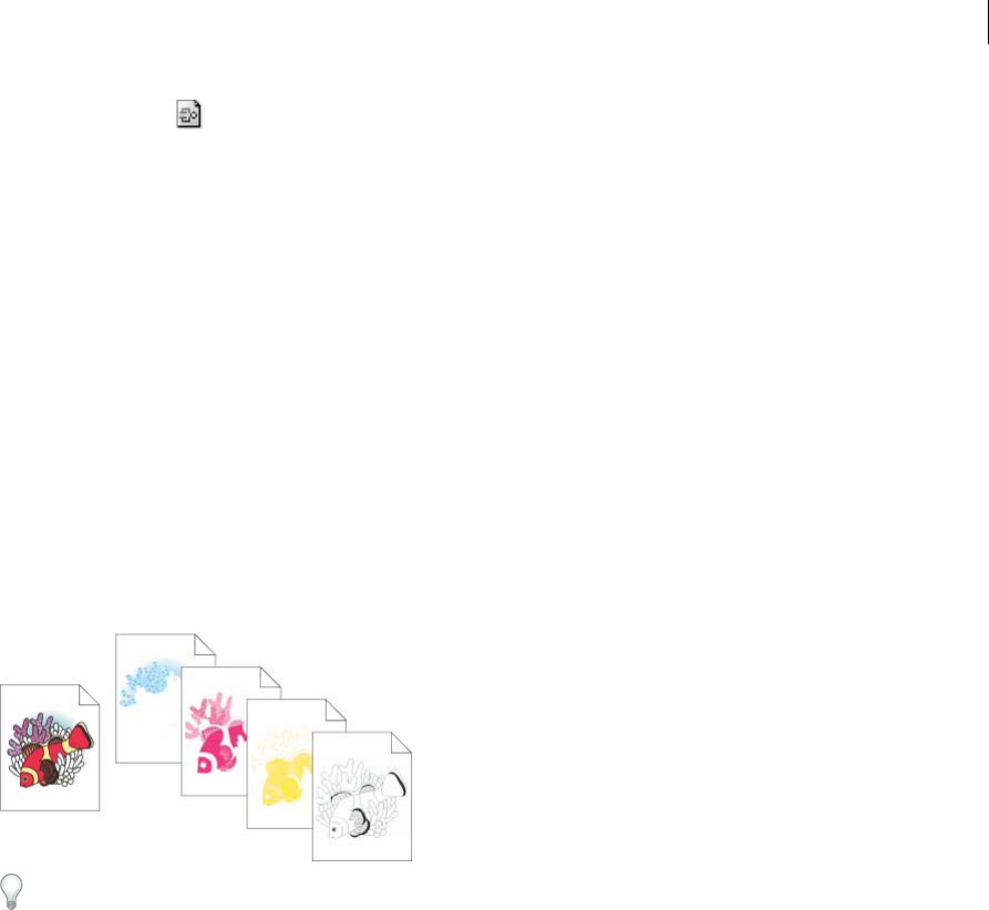
474
Printing
Last updated 6/5/2015
Landscape Right Prints in landscape orientation, rotated to the right.
4(Optional) Select Transverse to rotate the printed artwork 90°. To use this option, you must use a PPD that supports
transverse printing and custom page sizes.
Printing color separations
About color separations
To reproduce color and continuous-tone images, printers usually separate artwork into four plates (called process
colors)—one plate for each of the cyan, magenta, yellow, and black portions of the image. You can also include custom
inks (called spot colors). In this case, a separate plate is created for each spot color. When inked with the appropriate
color and printed in register with one another, these colors combine to reproduce the original artwork.
The process of dividing the image into two or more colors is called color separating, and the film from which the plates
are created are called the separations.
To produce high-quality separations, you should work closely with the print shop that will produce your separations,
consulting its experts before beginning each job and during the process. To see a video on using the Separations Preview
panel, see www.adobe.com/go/lrvid4021_ai.
More Help topics
About spot colors
About process colors
Preparing artwork for color separating
Before you print color separations from Illustrator, it’s a good idea to perform the following prepress tasks:
•Set up color management, including calibrating your monitor and selecting an Illustrator Color Setting.
•Soft-proof how color will appear on the intended output device. Choose Window > Separations Preview to preview
how the color separations will look.
•If the document is in RGB mode, choose File > Document Color Mode > CMYK Color to convert it to CMYK Mode.
•If your artwork contains color blends, optimize them so that they print smoothly (without discrete bands of color).
•If your artwork requires trapping, set up appropriate overprinting and trapping.
•If your artwork contains areas of transparent, overlapping colors, preview which areas will be affected by flattening
and note which flattening options you want to use.

475
Printing
Last updated 6/5/2015
Use the Live Color dialog box to globally convert and reduce colors. For example, if you want to convert a process color
document to a 2-color spot document use the Assign portion of Live Color, and specify which colors you want and how
they are assigned to existing colors.
More Help topics
Printing and saving transparent artwork
Reduce colors in your artwork
Create a trap
Set up overprinting
About color management in Adobe applications
Preview color separations
You can preview color separations and overprinting using the Separations Preview panel. To see a video on using the
Separations Preview panel, see www.adobe.com/go/lrvid4021_ai.
Previewing separations on your monitor lets you preview spot color objects in your document, and check the following:
Rich black Previewing separations lets you identify areas that will print as rich black, or process black (K) ink mixed
with color inks for increased opacity and richer color.
Overprinting You can preview how blending, transparency, and overprinting will appear in color-separated output.
You can also see overprinting effects when you output to a composite printing device.
Note: The Separation Preview panel in Illustrator is slightly different from the Separation Preview panels in InDesign and
Acrobat, for instance, the Preview panel in Illustrator is for CMYK document mode only.
1Choose Window > Separations Preview.
2Select Overprint Preview.
3Do any of the following:
•To hide a separation ink on screen, click the eye icon to the left of the separation name. Click again to view
the separation.
•To hide all separation inks on screen except one, Alt-click (Windows) or Option-click (Mac OS) the eye icon for
that separation. Alt-click (Windows) or Option-click (Mac OS) the eye icon again to view all separations again.
•To view all process plates at once, click the CMYK icon .
4To return to normal view, deselect Overprint Preview.
While previewing separations on your monitor can help you detect problems without the expense of printing
separations, it does not let you preview trapping, emulsion options, printer’s marks, and halftone screens and
resolution. Work with your commercial printer to verify these settings using integral or overlay proofs. Setting inks to
be visible or hidden on screen in the Separations Preview panel does not affect the actual separations process—it only
affects how they appear on your screen during the preview.
Note: Objects on hidden layers are not included in an on-screen preview.
Print color separations
1Choose File > Print.
2Select a printer and PPD file. To print to a file instead of a printer, select Adobe PostScript® File or Adobe PDF.
476
Printing
Last updated 6/5/2015
3Select Output on the left side of the Print dialog box.
4For Mode, select either Separations (Host-Based) or In-RIP Separations.
5Specify an emulsion, image exposure, and printer resolution for the separations.
6Set options for the color plates you want to separate:
•To disable printing of a color plate, click the printer icon next to the color in the Document Ink Options list.
Click again to restore printing for the color.
•To convert all spot colors to process colors, so that they are printed as part of the process-color plates rather than
on a separate plate, select Convert All Spot Colors To Process.
•To convert an individual spot color to process colors, click the spot color icon next to the color in the
Document Ink Options list. A four-color process icon appears. Click again to revert the color back to a spot
color.
•To overprint all black ink, select Overprint Black.
•To change the screen frequency, screen angle, and shape of halftone dots for a plate, double-click the ink name.
Alternatively, click the existing setting in the Document Ink Options list, and make the desired changes. Note
however, that the default angles and frequencies are determined by the selected PPD file. Check with your print
shop for the preferred frequency and angle before creating your own halftone screens.
Tip: If your art contains more than one spot color, particularly interactions between two or more spot colors,
assign different screen angles to each spot color.
7Set additional options in the Print dialog box.
In particular, you can specify how to position, scale, and crop the artwork; set up printer’s marks and a bleed; and
choose flattening settings for transparent artwork.
8Click Print.
Note: To see a video on using the Separations Preview panel, see www.adobe.com/go/lrvid4021_ai.
More Help topics
Change the printer resolution and screen frequency
Print dialog box options
Color separation modes
Illustrator supports two common PostScript workflows, or modes, for creating color separations. The main difference
between the two is where separations are created—at the host computer (the system using Illustrator and the printer
driver), or at the output device’s RIP (raster image processor).
In the traditional host-based, preseparated workflow, Illustrator creates PostScript data for each of the separations
required for the document, and sends that information to the output device.
In the newer RIP-based workflow, a new generation of PostScript RIPs perform color separations, trapping, and even
color management at the RIP, leaving the host computer free to perform other tasks. This approach takes less time for
Illustrator to generate the file, and minimizes the amount of data transmitted for any given print job. For example,
instead of sending PostScript information for four or more pages to print host-based color separations, Illustrator sends
the PostScript information for a single composite PostScript file for processing in the RIP.

477
Printing
Last updated 6/5/2015
Emulsion and image exposure
Emulsion refers to the photosensitive layer on a piece of film or paper. Up (Right Reading) means that type in the image
is readable (that is, “right reading”) when the photosensitive layer is facing you. Down (Right Reading) means that type
is readable when the photosensitive layer is facing away from you. Normally, images printed on paper are printed Up
(Right Reading), whereas images printed on film are usually printed Down (Right Reading). Check with your print
shop to determine which emulsion direction it prefers.
To tell whether you are looking at the emulsion side or the nonemulsion side (also referred to as the base), examine the
final film under bright light. One side appears shinier than the other. The dull side is the emulsion side; the shiny side
is the base.
Image exposure refers to whether artwork prints as a positive or negative image. Typically, print shops require negative
film in the United States and positive film in Europe and Japan. If you are unsure about which image type to use, consult
your print shop.
Print an object on all plates
If you want to print an object on all plates in the printing process, including spot-color plates, you can convert it to a
registration color. Registration marks, trim marks, and page information are automatically assigned registration colors.
1Select the object.
2In the Swatches panel, click the Registration color swatch , located in the first row of swatches, by default.
To change the on-screen appearance of the registration color from the default black, use the Color panel. The color
you specify will be used for representing registration-colored objects on the screen. These objects will always print as
gray on composites and as an equal tint of all inks in separations.
Printer’s marks and bleeds
About printer’s marks
When you prepare artwork for printing, a number of marks are needed for the printer device to register the artwork
elements precisely and verify correct color. You can add the following kinds of printer’s marks to your artwork:
Trim Marks Fine (hairline) horizontal and vertical rules that define where the page should be trimmed. Trim marks can
also help register (align) one color separation to another.
Registration Marks Small targets outside the page area for aligning the different separations in a color document.
Color Bars Small squares of color representing the CMYK inks and tints of gray (in 10% increments). Your service
provider uses these marks to adjust ink density on the printing press.
Page Information Labels the film with the name of the artboard number, the time and date of printout, the line screen
used, the screen angle for the separation, and the color of each particular plate. These labels appear at the tops of the
images.
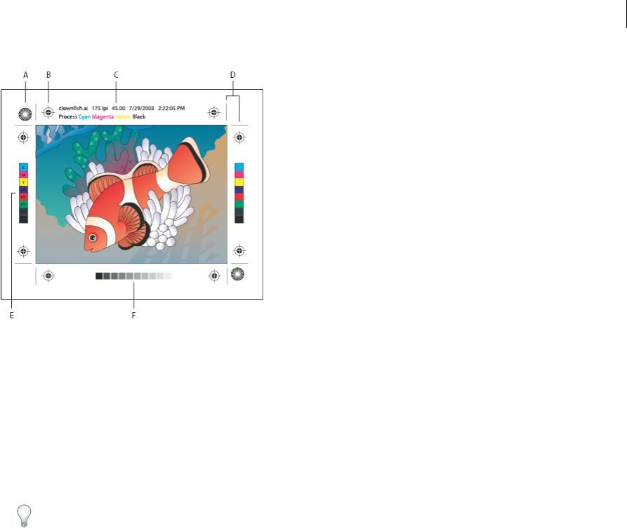
478
Printing
Last updated 6/5/2015
A Star target (not optional) B Registration mark C Page information D Trim marks E Color bar F Tint bar
Add printer’s marks
1Choose File > Print.
2Select Marks & Bleed on the left side of the Print dialog box.
3Select the kinds of printer’s marks you want to add. You can also choose between Roman and Japanese-style marks.
4(Optional) If you select Trim Marks, specify the width of trim-mark lines and the offset distance between the trim
marks and the artwork.
To avoid drawing printer’s marks on a bleed, be sure to enter an Offset value greater than the Bleed value.
More Help topics
Specify crop marks for trimming or aligning
About bleeds
Bleed is the amount of artwork that falls outside of the printing bounding box, or outside the crop area and trim marks.
You can include bleed in your artwork as a margin of error—to ensure that the ink is still printed to the edge of the page
after the page is trimmed or that an image can be stripped into a keyline in a document. Once you create the artwork
that extends into the bleed, you can use Illustrator to specify the extent of the bleed. Increasing the bleed makes
Illustrator print more of the artwork that is located beyond the trim marks. The trim marks still define the same size
printing bounding box, however.
The size of the bleed you use depends on its purpose. A press bleed (that is, an image that bleeds off the edge of the
printed sheet) should be at least 18 points. If the bleed is to ensure that an image fits a keyline, it needs to be no more
than 2 or 3 points. Your print shop can advise you on the size of the bleed necessary for your particular job.
Add a bleed
1Choose File > Print.
2Select Marks & Bleed on the left side of the Print dialog box.

479
Printing
Last updated 6/5/2015
3Do one of the following:
•Enter values for Top, Left, Bottom, and Right to specify the placement of the bleed marks. Click the link icon to
make all the values the same.
•Select Use Document Bleed to use the bleed settings defined in the New Document dialog box.
The maximum bleed you can set is 72 points; the minimum bleed is 0 points.
PostScript printing
PostScript printers use a PPD file (PostScript Printer Description file) to customize the behavior of the driver for your
specific PostScript printer. A PPD file contains information about the output device, including printer-resident fonts,
available media sizes and orientation, optimized screen frequencies, screen angles, resolution, and color output
capabilities. It’s important to set up the correct PPD before you print. Selecting the PPD that corresponds to your
PostScript printer or imagesetter populates the Print dialog box with the available settings for the output device.
About PPD files
A PPD file (PostScript Printer Description file) customizes the behavior of the driver for your specific PostScript
printer. It contains information about the output device, including printer-resident fonts, available media sizes and
orientation, optimized screen frequencies, screen angles, resolution, and color output capabilities. It’s important to set
up the correct PPD before you print. Selecting the PPD that corresponds to your PostScript printer or imagesetter
populates the Print dialog box with the available settings for the output device. You can switch to a different one to suit
your needs. Applications use the information in the PPD file to determine which PostScript information to send to the
printer when printing a document.
For best printing results, Adobe recommends that you obtain the latest version of the PPD file for your output device
from the manufacturer. Many print service providers and commercial printers have PPDs for the imagesetters they use.
Be sure to store PPDs in the location specified by the operating system. For details, consult the documentation for your
operating system.
Change the PPD file
When you print to a PostScript printer, PostScript file, or PDF, Illustrator automatically uses the default PPD
(PostScript Printer Description) for that device. You can switch to a different one to suit your needs.
1Choose File > Print.
2From the PPD menu, select one of the following:
•A PPD that corresponds to the current output device.
•Other. Lets you select a custom PPD, such as one provided by your service bureau for use with the specified
printer. The PPD’s filename corresponds to the printer’s or imagesetter’s name and model, and may display a .ppd
file extension (depending on how your system is set up.) Navigate to the PPD you want, select it, and click Open.
note: Certain PPD features commonly found in imagesetter PPDs aren’t accessible from the Illustrator Print dialog
box. To set those printer-specific features, click Setup (Windows) or Printer (Mac OS) in the Print dialog box.

480
Printing
Last updated 6/5/2015
Add a PPD file
For best printing results, Adobe recommends that you obtain the latest version of the PPD file for your output device
from the manufacturer. Many print service providers and commercial printers have PPDs for the imagesetters they use.
Be sure to store PPDs in the location specified by the operating system. For details, consult the documentation for your
operating system.
❖In Windows and in Mac OS, you select a PPD file in the same way you add a printer. The steps for selecting a PPD
file are different for each platform. See your operating system documentation for details.
Printing long, complex paths
If you are printing Adobe Illustrator files containing overly long or complicated paths, the file may not print and you
may receive limit-check error messages from your printer. To simplify long, complex paths, you can split them into two
or more separate paths. You can also change the number of line segments used to approximate curves and adjust the
printer resolution.
More Help topics
Split a path
Change the number of line segments used to print vector objects
Curves in artwork are defined by the PostScript interpreter as small straight line segments; the smaller the line
segments, the more accurate the curve. As the number of line segments increases, so does the complexity of the curve.
Depending on your printer and the amount of memory it has, a curve may be too complex for a PostScript interpreter
to rasterize. In this case, a PostScript limit-check error can result, and the curve won’t print.
1Choose File > Print.
2For Printer, select a PostScript printer, Adobe PostScript® File, or Adobe PDF.
3Select Graphics on the left side of the Print dialog box.
4Deselect Automatic, and use the Flatness slider to set the accuracy of curves.
A lower setting (toward Quality) creates more, smaller straight line segments, more closely approximating the curve.
A higher setting (toward Speed) results in longer and fewer line segments, creating a less accurate curve, but
improving performance.
Split paths for printing
Illustrator treats split paths in the artwork as separate objects. To change your artwork once paths are split, you must
either work with the separate shapes or rejoin the paths to work with the image as a single shape.
It’s a good idea to save a copy of your original artwork before splitting paths. That way, you still have the original, unsplit
file to work with if needed.
❖Do any of the following:
•To split a stroked path, use the Scissors tool .
•To split a compound path, choose Object > Compound Paths > Release to remove the compound path. Then
break the path into pieces using the Scissors tool, and redefine the pieces as compound paths.
•To split a mask, choose Object > Clipping Mask > Release to remove the mask. Then break the path into pieces
using the Scissors tool, and redefine the pieces as masks.

481
Printing
Last updated 6/5/2015
Tip: To rejoin a path after you split it, select all of the split paths that made up the original object, and click the
Add To Shape Area button in the Pathfinder panel. The path is rejoined, with an anchor point placed at each
intersection where a split path was reconnected.
Control how fonts are downloaded to a printer
Printer-resident fonts are fonts stored in a printer’s memory or on a hard drive connected to the printer. Type 1 and
TrueType fonts can be stored either on the printer or on your computer; bitmap fonts are stored only on your computer.
Illustrator downloads fonts as needed, provided they are installed on your computer’s hard disk.
1Choose File > Print.
2For Printer, select a PostScript printer, Adobe PostScript® File, or Adobe PDF.
3Select Graphics on the left side of the Print dialog box, and select a Download option:
None Includes a reference to the font in the PostScript file which tells the RIP or a post-processor where the font
should be included. This option is appropriate if the fonts reside in the printer. TrueType fonts are named according
to the PostScript name in the font; however, not all applications can interpret these names. To ensure that TrueType
fonts are interpreted correctly, use one of the other font downloading options.
Subset Downloads only the characters (glyphs) used in the document. Glyphs are downloaded once per page. This
option typically results in faster and smaller PostScript files when used with single-page documents, or with short
documents without much text.
Complete Downloads all fonts required for the document at the beginning of the print job. This option typically
results in faster and smaller PostScript files when used with multipage documents.
note: Some font manufacturers restrict the embedding of font files. Restrictions apply to copying font software. You are
required to comply with applicable copyright law and the terms of your license agreement. For font software licensed
from Adobe, your license agreement provides that you may take a copy of the font(s) you have used for a particular file
to a commercial printer or other service provider, and the service provider may use the font(s) to process your file,
provided the service provider has informed you that it has the right to use that particular software. For other font
software, please obtain permission from your vendor.
More Help topics
About fonts
Change the PostScript level for printing
When you print to a PostScript or PDF file, Illustrator automatically selects the PostScript level of your output device.
If you want to change the Postscript level or data format for PostScript files, do the following:
1Choose File > Print.
2For Printer, select Adobe PostScript® File or Adobe PDF.
3Select Graphics on the left side of the Print dialog box.
4For PostScript, select the level of compatibility with the interpreters in PostScript output devices.
Level 2 improves the printing speed and output quality of graphics printed on a PostScript Level 2 or greater output
device. Level 3 provides the best speed and output quality on a PostScript 3 device.
5(Optional) If you chose Adobe PostScript® File as the printer, select a Data Format option to specify how Illustrator
sends the image data from your computer to a printer.

482
Printing
Last updated 6/5/2015
Binary exports the image data as binary code, which is more compact than ASCII but may not be compatible with
all systems. ASCII exports the image data as ASCII text, which is compatible with older networks and parallel
printers and is usually the best choice for graphics used on multiple platforms. It is also usually the best choice for
documents used only on Mac OS.
Printing with color management
When you print with color management, you can let Illustrator manage the colors, or you can let the printer manage
the colors.
Let your application manage colors when printing
1Choose File > Print.
2Select Color Management on the left side of the Print dialog box.
3For Color Handling, choose Let Illustrator Determine Colors.
4For Printer Profile, select the profile for your output device.
The more accurately the profile describes the behavior of an output device and printing conditions (such as paper
type), the more accurately the color management system can translate the numeric values of the actual colors in a
document. (See About color profiles .)
5(Optional) Set the Rendering Intent option to specify how the application converts colors to the destination color
space.
In most cases, it is best to use the default rendering intent. For more information on rendering intents, search in
Help.
6Click Setup (Windows) or Printer (Mac OS) at the bottom of the Print dialog box to access the operating system
print settings.
7Access the color management settings for the printer driver by doing one of the following:
•In Windows, right-click the printer you are using, and select Properties. Then locate the color management
settings for the printer driver. For most printer drivers, color management settings are labeled Color Management
or ICM.
•In Mac OS, select the printer you are using, and select the color management option from the pop-up menu. For
most printer drivers, this option is labeled ColorSync.
8Turn off color management for the printer driver.
Every printer driver has different color management options. If it’s not clear how to turn off color management,
consult your printer documentation.
9Return to the Illustrator Print dialog box, and click Print.
Let your printer manage colors when printing
1Choose File > Print.
2Select a PostScript printer from the Printer menu. To print to a file instead of a printer, select Adobe PostScript® File
or Adobe PDF.
3Select Color Management on the left side of the Print dialog box.

483
Printing
Last updated 6/5/2015
4For Color Handling, choose Let PostScript® Printer Determine Colors.
5(Optional) Set any of the following options. In most cases, it is best to use the default settings.
Rendering Intent Specifies how the application converts colors to the destination color space.
Preserve RGB Numbers (for RGB output) or Preserve CMYK Numbers (for CMYK output) Determines how Illustrator
handles colors that do not have a color profile associated with them (for example, imported images without
embedded profiles). When this option is selected, Illustrator sends the color numbers directly to the output device.
When this option is deselected, Illustrator first converts the color numbers to the color space of the output device.
Preserving numbers is recommended when you are following a safe CMYK workflow. Preserving numbers is not
recommended for printing RGB documents.
6Click Setup (Windows) or Printer (Mac OS) at the bottom of the Print dialog box to access the operating system
print settings.
7Access the color management settings for the printer driver by doing one of the following:
•In Windows, right-click the printer you are using, and select Properties. Then locate the color management
settings for the printer driver. For most printer drivers, color management settings are labeled Color Management
or ICM.
•In Mac OS, select the printer you are using, and select the color management option from the pop-up menu. For
most printer drivers, this option is labeled ColorSync.
8Specify the color management settings to let your printer driver handle the color management during printing.
Every printer driver has different color management options. If it’s not clear how to set color management options,
consult your printer documentation.
9Return to the Illustrator Print dialog box, and click Print.
More Help topics
About rendering intents
Using a safe CMYK workflow
Printing with color management
Printing and saving transparentartwork
When you save an Illustrator file in certain formats, the native transparency information is retained. For example, when
you save a file in Illustrator CS (or later) EPS format, the file contains both native Illustrator data and EPS data. When
you reopen the file in Illustrator, the native (unflattened) data is read. When you place the file into another application,
the EPS (flattened) data is read.
About flattening
If your document or artwork contains transparency, to be output it usually needs to undergo a process called flattening.
Flattening divides transparent artwork into vector-based areas and rasterized areas. As artwork becomes more complex
(mixing images, vectors, type, spot colors, overprinting, and so on), so does the flattening and its results.
Flattening may be necessary when you print or when you save or export to other formats that don’t support
transparency. To retain transparency without flattening when you create PDF files, save your file as Adobe PDF 1.4
(Acrobat 5.0) or later.

484
Printing
Last updated 6/5/2015
You can specify flattening settings and then save and apply them as transparency flattener presets. Transparent objects
are flattened according to the settings in the selected flattener preset.
Note: Transparency flattening cannot be undone after the file is saved.
For more information on transparency output issues, see the Print Service Provider Resources page of the Adobe
Solutions Network (ASN) (English only), available on the Adobe website.
File formats that retain transparency
When you save an Illustrator file in certain formats, the native transparency information is retained. For example, when
you save a file in Illustrator CS (or later) EPS format, the file contains both native Illustrator data and EPS data. When
you reopen the file in Illustrator, the native (unflattened) data is read. When you place the file into another application,
the EPS (flattened) data is read.
When possible, keep your file in a format in which native transparency data is retained, allowing you to make edits as
necessary.
Native transparency data is retained when you save to the following formats:
•AI9 and later
•AI9 EPS and later
•PDF 1.4 and later (when Preserve Illustrator Editing Capabilities option is selected)
Illustrator flattens artwork when you perform any of the following actions:
•Print a file that contains transparency.
•Save a file that contains transparency in a legacy format such as native Illustrator 8 and earlier, Illustrator 8 EPS and
earlier, or PDF 1.3 format. (For the Illustrator and Illustrator EPS formats, you can choose to discard transparency
rather than flatten it.)
•Export a file that contains transparency to a vector format that does not understand transparency (such as EMF or
WMF).
•Copy and paste transparent art from Illustrator into another application with both the AICB and the Preserve
Appearance options checked (in the File Handling & Clipboard section of the Preferences dialog box).
•Export in SWF (Flash) or use the Flatten Transparency command with the Preserve Alpha Transparency option
selected. This command lets you preview how artwork will look when exported in SWF.
For more information on creating and printing transparency, see the Transparency white paper in the Adobe Technical
Info/White Papers folder on the Illustrator CD. You can also find more information on printing and flattening files with
transparency in the Adobe Illustrator User to User forum. This is a public forum that offers a wealth of tips and answers to
frequently asked questions, and can be found at www.adobe.com/support/forums.

485
Printing
Last updated 6/5/2015
Set transparency flattening options for printing
1Choose File > Print.
2Select Advanced on the left side of the Print dialog box.
3Select a flattening preset from the Preset menu, or click Custom to set specific flattening options.
4If the artwork contains overprinted objects that interact with transparent objects, select an option from the
Overprints menu. You can preserve, simulate, or discard overprints.
Note: If the artwork does not contain transparency, the document will not be flattened and the flattening settings are
not relevant. Use the Flattener Preview panel to determine which areas of the artwork contain transparency.
Transparency Flattener options
You can set Transparency Flattener options when creating, editing, or previewing flattener presets in Illustrator,
InDesign, or Acrobat.
Highlight (preview) options
None (Color Preview) Disables previewing.
Rasterized Complex Regions Highlights the areas that will be rasterized for performance reasons (as determined by the
Rasters/Vectors slider). Keep in mind that the boundary of the highlight area has a higher probability of producing
stitching problems (depending on the print-driver settings and the rasterization resolution). To minimize stitching
problems, select Clip Complex Regions.
Transparent Objects Highlights the objects that are sources of transparency, such as objects with partial opacity
(including images with alpha channels), objects with blending modes, and objects with opacity masks. In addition, note
that styles and effects may contain transparency, and overprinted objects may be treated as sources of transparency if
they are involved in transparency or if the overprint needs to be flattened.
All Affected Objects Highlights all objects that are involved in transparency, including transparent objects and objects
that are overlapped by transparent objects. The highlighted objects will be affected by the flattening process—their
strokes or patterns will be expanded, portions of them may get rasterized, and so on.
Affected Linked EPS Files (Illustrator only) Highlights all linked EPS files that are affected by transparency.
Affected Graphics (InDesign only) Highlights all placed content affected by transparency or transparency effects. This
option is useful for service providers who need to see graphics that require attention to print properly.
Expanded Patterns (Illustrator and Acrobat) Highlights all patterns that will be expanded if involved in transparency.
Outlined Strokes Highlights all strokes that will be outlined if involved in transparency or because Convert All Strokes
To Outlines is selected.
Outlined Text (Illustrator and InDesign) Highlights all text that will be outlined if involved in transparency or because
Convert All Text To Outlines is selected.
note: In the final output, outlined strokes and text may appear slightly different from native ones, especially very thin strokes
and very small text. However, the Flattener Preview doesn’t highlight this altered appearance.
Raster-Fill Text And Strokes (InDesign only) Highlights text and strokes that have rasterized fills as a result of flattening.
All Rasterized Regions (Illustrator and InDesign) Highlights objects and intersections of objects that will be rasterized
because there is no other way of representing them in PostScript or because they are more complex than the threshold
specified by the Rasters/Vectors slider. For example, the intersection of two transparent gradients will always be
rasterized, even if the Rasters/Vectors value is 100. The All Rasterized Regions option also shows raster graphics (such

486
Printing
Last updated 6/5/2015
as Photoshop files) involved in transparency, and raster effects such as drop shadows and feathers. Note that this option
takes longer to process than the others.
Transparency Flattener Preset options
Name/Preset Specifies the name of the preset. Depending on the dialog box, you can type a name in the Name text box
or accept the default. You can enter the name of an existing preset to edit that preset. However, you can’t edit the default
presets.
Raster/Vector balance Specifies the amount of vector information that will be preserved. Higher settings preserve
more vector objects, while lower settings rasterize more vector objects; intermediate settings preserve simple areas in
vector form and rasterize complex ones. Select the lowest setting to rasterize all the artwork.
Note: The amount of rasterization that occurs depends on the complexity of the page and the types of overlapping objects.
Line Art And Text Resolution Rasterizes all objects, including images, vector artwork, text, and gradients, to the
specified resolution. Acrobat and InDesign allow a maximum of 9600 pixels per inch (ppi) for line art, and 1200 ppi for
gradient mesh. Illustrator allows a maximum of 9600 ppi for both line art and gradient mesh. The resolution affects the
precision of intersections when flattened. Line Art and Text Resolution should generally be set to 600-1200 to provide
high-quality rasterization, especially on serif or small point sized type.
Gradient And Mesh Resolution Specifies the resolution for gradients and Illustrator mesh objects rasterized as a result
of flattening, from 72 to 2400 ppi. The resolution affects the precision of intersections when flattened. Gradient and
mesh resolution should generally be set between 150 and 300 ppi, because the quality of the gradients, drop shadows,
and feathers do not improve with higher resolutions, but printing time and file size increase.
Convert All Text To Outlines Converts all type objects (point type, area type, and path type) to outlines and discards all
type glyph information on pages containing transparency. This option ensures that the width of text stays consistent
during flattening. Note that enabling this option will cause small fonts to appear slightly thicker when viewed in
Acrobat or printed on low-resolution desktop printers. It doesn’t affect the quality of the type printed on high-
resolution printers or imagesetters.
Convert All Strokes To Outlines Converts all strokes to simple filled paths on pages containing transparency. This
option ensures that the width of strokes stays consistent during flattening. Note that enabling this option causes thin
strokes to appear slightly thicker and may degrade flattening performance.
Clip Complex Regions Ensures that the boundaries between vector artwork and rasterized artwork fall along object
paths. This option reduces stitching artifacts that result when part of an object is rasterized while another part of the
object remains in vector form. However, selecting this option may result in paths that are too complex for the printer
to handle.
note: Some print drivers process raster and vector art differently, sometimes resulting in color stitching. You may be able to
minimize stitching problems by disabling some print-driver specific color-management settings. These settings vary with
each printer, so see the documentation that came with your printer for details.
(Illustrator only) Select Preserve Alpha Transparency (Flatten Transparency dialog box only) Preserves the overall
opacity of flattened objects. With this option, blending modes and overprints are lost, but their appearance is retained
within the processed artwork, along with the level of alpha transparency (as when you rasterize artwork using a

487
Printing
Last updated 6/5/2015
transparent background). Preserve Alpha Transparency can be useful if you are exporting to SWF or SVG, since both
of these formats support alpha transparency.
(Illustrator only) Select Preserve Spot Colors And Overprints (Flatten Transparency dialog box only) Generally
preserves spot colors. It also preserves overprinting for objects that aren’t involved in transparency. Select this option
when printing separations if the document contains spot colors and overprinted objects. Deselect this option when
saving files for use in page-layout applications. With this option selected, overprinted areas that interact with
transparency are flattened, while overprinting in other areas is preserved. The results are unpredictable when the file is
output from a page-layout application.
Preserve Overprint (Acrobat only) Blends the color of transparent artwork with the background color to create an
overprint effect.
Preview which areas of artwork will be flattened
Use the preview options in the Flattener Preview to highlight areas that are affected by flattening. You can use this color-
coded information to adjust flattening options.
Note: The Flattener Preview is not intended for precise previewing of spot colors, overprints, and blending modes. Instead,
use Overprint Preview mode for those purposes.
1Display the Flattener Preview panel (or dialog box):
•In Illustrator, choose Window > Flattener Preview.
•In Acrobat, choose Tools > Print Production > Flattener Preview.
•In InDesign, choose Window > Output > Flattener Preview.
2From the Highlight menu, choose the kind of areas you want to highlight. The availability of options depends on
the content of the artwork.
3Select the flattening settings you want to use: Either choose a preset or, if available, set specific options.
Note: (Illustrator) If the flattening settings aren’t visible, select Show Options from the panel menu to display them.
4If the artwork contains overprinted objects that interact with transparent objects, in Illustrator, select an option from
the Overprints menu. You can preserve, simulate, or discard overprints. In Acrobat, choose Preserve Overprint to
blend the color of transparent artwork with the background color to create an overprint effect.
5At any time, click Refresh to display a fresh preview version based on your settings. Depending on the complexity
of the artwork, you may need to wait a few seconds for the preview image to appear. In InDesign, you can also choose
Auto Refresh Highlight.
In Illustrator and Acrobat, to magnify the preview, click in the preview area. To zoom out, Alt-click/Option-click in
the preview area. To pan the preview, hold down the spacebar and drag in the preview area.
Flattener Preview panel overview
You use the preview options in the Flattener Preview panel to highlight the areas affected by flattening artwork. You can
use this information to adjust the flattening options, and even use the panel to save flattener presets. To display the
Flattener Preview panel, choose Window > Flattener Preview.
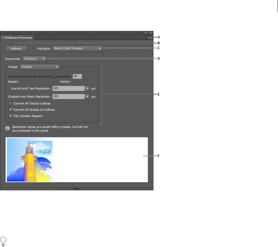
488
Printing
Last updated 6/5/2015
A Panel menu B Refresh button C Highlight menu D Overprint menu E Transparency flattening settings F Preview area
You can control the speed and quality of the preview image by selecting an option from the panel menu. Select Quick
Preview to compute the quickest preview; select Detailed Preview to add the option All Rasterized Regions to the
Highlight pop-up menu (this option is more performance-intensive to compute).
Keep in mind that the Flattener Preview panel is not intended for precise previewing of spot colors, overprints, blending
modes, and image resolution. Use Overprint Preview mode in Illustrator to preview spot colors, overprints, and
blending modes as they will appear when output.
About transparency flattener presets
If you regularly print or export documents that contain transparency, you can automate the flattening process by saving
flattening settings in a transparency flattener preset. You can then apply these settings for print output as well as for
saving and exporting files to PDF 1.3 (Acrobat 4.0) and EPS and PostScript formats. In addition, in Illustrator you can
apply them when saving files to earlier versions of Illustrator or when copying to the clipboard; in Acrobat, you can also
apply them when optimizing PDFs.
These settings also control how flattening occurs when you export to formats that don’t support transparency.
You can choose a flattener preset in the Advanced panel of the Print dialog box or of the format-specific dialog box that
appears after the initial Export or Save As dialog box. You can create your own flattener presets or choose from the
default options provided with the software. The settings of each of these defaults are designed to match the quality and
speed of the flattening with an appropriate resolution for rasterized transparent areas, depending on the document’s
intended use:
[High Resolution] is for final press output and for high-quality proofs, such as separations-based color proofs.
[Medium Resolution] is for desktop proofs and print-on-demand documents that will be printed on PostScript color
printers.

489
Printing
Last updated 6/5/2015
[Low Resolution] is for quick proofs that will be printed on black-and-white desktop printers and for documents that
will be published on the web or exported to SVG.
Create or edit a transparency flattener preset
You can save transparency flattener presets in a separate file, making it easy to back them up or to make them available
to your service providers, clients, or others in your workgroup. In InDesign, transparency flattener preset files have an
.flst extension.
1Choose Edit > Transparency Flattener Presets.
2Do one of the following:
•To create a new preset, click New.
•To base a preset on a predefined preset, select one in the list and click New.
•To edit an existing preset, select the preset and click Edit.
Note: You can’t edit the default flattener presets.
3Set flattening options.
4Click OK to return to the Transparency Flattener Presets dialog box, and click OK again.
Export and import a custom transparency flattener preset
You can export and import transparency flattener presets in order to share them with your service providers, your
clients, or others in your workgroup.
1Choose Edit > Transparency Flattener Presets.
2Select a preset in the list.
3Do one of the following:
•To export a preset to a separate file, click Save (InDesign) or Export (Illustrator), specify a name and location,
and then click Save.
Consider saving the preset outside of the application’s preferences folder. That way, it won’t be lost if you delete
your preferences.
•To import presets from a file, click Load (InDesign) or Import (Illustrator). Locate and select the file containing
the preset you want to load, and then click Open.
Rename or delete a custom transparency flattener preset
1Choose Edit > Transparency Flattener Presets.
2Select a preset in the list.
3Do one of the following:
•To rename an existing preset, click Edit, type a new name, and then click OK.
•To delete a preset, click Delete, and then click OK to confirm the deletion.note: You cannot delete the default
presets.

490
Printing
Last updated 6/5/2015
Flatten transparency for individual objects
The Flatten Transparency command lets you see what your artwork will look like when flattened. For instance, you
might use this command before saving the file in SWF (Flash) format or if you are having problems printing legacy art
where transparency may be the culprit.
1Select the object.
2Choose Object > Flatten Transparency.
3Select the flattening settings you want to use, either by choosing a preset or setting specific options.
4Click OK.
To save the flattening settings for use with other objects and documents in the current session, click Save Preset. If
you want to create a permanent preset, choose Edit > Transparency Flattener Presets instead.
More Help topics
Transparency Flattener options
Rasterize all artwork during printing
When you print to a low-resolution or non-PostScript printer, such as a desktop inkjet printer, you can choose to
rasterize all artwork during printing. This option is useful when printing documents that contain complex objects (such
as objects with smooth shading or gradients) because it reduces the possibility of errors.
1Choose File > Print.
2Select Advanced on the left side of the Print dialog box.
3Select Print As Bitmap.
This option is only available if the printer driver for the selected printer supports bitmap printing.
Printing gradients, meshes, andcolor blends
Files with gradients, meshes, or color blends can be difficult for some printers to print smoothly (without discrete bands
of color) or at all.
Printing gradients, meshes, and color blends
Files with gradients, meshes, or color blends can be difficult for some printers to print smoothly (without discrete bands
of color) or at all. Follow these general guidelines to improve the printed results:
•Use a blend that changes at least 50% between two or more process-color components.
•Use shorter blends. The optimum length depends on the colors in your blend, but try to keep blends shorter than
7.5 inches.
•Use lighter colors, or make dark blends short. Banding is most likely to occur between very dark colors and white.
•Use an appropriate line screen that retains 256 levels of gray.
•If you create a gradient between two or more spot colors, assign different screen angles to the spot colors when you
create color separations. If you’re not sure what the angles should be, consult your print shop.
•Print to an output device that supports PostScript® Language Level 3 whenever possible.

491
Printing
Last updated 6/5/2015
•If you have to print to an output device that supports Postscript Language Level 2, or when printing meshes that
include transparency, you can choose to rasterize gradients and meshes during printing. As a result, Illustrator
converts gradients and meshes from vector objects to JPEG images.
Rasterize gradients and meshes during printing
1Choose File > Print.
2Select Graphics on the left side of the Print dialog box, and select Compatible Gradient And Gradient Mesh Printing.
Note: The Compatible Gradient And Gradient Mesh Printing option can slow printing on printers that don’t have
problems with gradients, so only select this option if you experience printing problems.
Setting the proper screen frequency for printing gradients, meshes, and
blends
When printing your file, you may find that the resolution of your printer, when combined with the chosen screen
frequency, allows fewer than 256 levels of gray. A higher screen frequency decreases the levels of gray available to the
printer. For example, if you are printing at a resolution of 2400 dpi, using a line screen higher than 150 results in fewer
than 256 levels of gray. The following table lists the maximum line-screen setting you can use with printers to maintain
all 256 levels of gray:
More Help topics
Change the printer resolution and screen frequency
Final Imagesetter Resolution Maximum Line Screen to Use
300 19
400 25
600 38
900 56
1000 63
1270 79
1446 90
1524 95
1693 106
2000 125
2400 150
2540 159
3000 188
3252 203
3600 225
4000 250

492
Printing
Last updated 6/5/2015
Calculate the maximum blend length for gradients
Illustrator calculates the number of steps in a gradient based on the percentage of change between the colors in the
gradient. The number of steps, in turn, determines the maximum length of the blend before banding occurs.
1Select the Measure tool , and click the beginning point and the endpoint of the gradient.
2Note the distance displayed in the Info panel on a piece of paper. This distance represents the length of the gradient
or color blend.
3Calculate the number of steps in the blend using this formula:
Number of steps = 256 (number of grays) X Percentage change in color
To figure out the percentage change in color, subtract the lower color value from the higher color value. For example,
a blend between 20% black and 100% black is an 80%—or 0.8—change in color.
When blending process colors, use the largest change that occurs within any one color. For instance, take a blend
from 20% cyan, 30% magenta, 80% yellow, and 60% black to 20% cyan, 90% magenta, 70% yellow, and 40% black.
This indicates a 60% change, because the greatest change occurs in magenta—from 30% to 90%.
4Using the number of steps calculated in step 3, see if the length of the gradient is larger than the relevant maximum
length indicated in the next chart. If it is, reduce the length of the gradient or change the colors.
Number of Steps Adobe Illustrator Recommends Maximum Blend Length
Points
Cms
Inches
10
.3
.762
21.6
20
.6
1.524
43.2
30
.9
2.286
64.8
40
1.2
3.048
86.4
50
1.5
3.810
108.0
60
1.8
4.572
129.6

493
Printing
Last updated 6/5/2015
70
2.1
5.334
151.2
80
2.4
6.096
172.8
90
2.7
6.858
194.4
100
3.0
7.620
216.0
110
3.3
8.382
237.6
120
3.6
9.144
259.2
130
3.9
9.906
280.8
140
4.2
10.668
302.4
150
4.5
11.430
324.0
160
4.8
12.192
345.6
170
5.1
12.954
367.2
Number of Steps Adobe Illustrator Recommends Maximum Blend Length
Points
Cms
Inches

494
Printing
Last updated 6/5/2015
More Help topics
Document Info panel overview
180
5.4
13.716
388.8
190
5.7
14.478
410.4
200
6.0
15.240
432.0
210
6.3
16.002
453.6
220
6.6
16.764
475.2
230
6.9
17.526
496.8
240
7.2
18.288
518.4
250
7.5
19.050
540.0
256
7.7
19.507
553.0
Number of Steps Adobe Illustrator Recommends Maximum Blend Length
Points
Cms
Inches

495
Printing
Last updated 6/5/2015
Overprinting
By default, when you print opaque, overlapping colors, the top color knocks out the area underneath. Overprinting
prevents knockouts and makes the topmost overlapping printing ink appear transparent in relation to the underlying
ink.
Where colors printed from separate plates overlap or adjoin one another, press misregistration can cause gaps between
colors on the final output. To compensate for potential gaps between colors in artwork, print shops use a technique
called trapping to create a small area of overlap (called a trap) between two adjoining colors. You can use a separate,
dedicated trapping program to create traps automatically, or you can use Illustrator to create traps manually.
About overprinting
By default, when you print opaque, overlapping colors, the top color knocks out the area underneath. You can use
overprinting to prevent knockout and make the topmost overlapping printing ink appear transparent in relation to the
underlying ink. The degree of transparency in printing depends on the ink, paper, and printing method used. Consult
your print shop to determine how these variables will affect your final artwork.
You may want to overprint in the following situations:
•Overprint black ink to aid in registration. Because black ink is opaque (and usually the last to be printed), it doesn’t
look much different when printed over a color as opposed to a white background. Overprinting black can prevent
gaps from appearing between black and colored areas of your artwork.
•Overprint when the artwork does not share common ink colors and you want to create a trap or overlaid ink effects.
When overprinting process color mixes or custom colors that do not share common ink colors, the overprint color
is added to the background color. For example, if you print a fill of 100% magenta over a fill of 100% cyan, the
overlapping fills appear violet, not magenta.
After you set overprinting options, you should use the Overprint Preview mode (View > Overprint Preview) to see
an approximation of how the overprinting colors will print. You should also carefully check overprinted colors on
separated artwork using integral proofs (where each separation is shown in register on a single piece of paper) or
overlay proofs (where the separations are shown in register on separate plastic sheets stacked on top of each other).
Set up overprinting
1Select the object or objects that you want to overprint.
2In the Attributes panel, select Overprint Fill, Overprint Stroke, or both.
If you use the Overprint option on a 100% black stroke or fill, the black ink may not be opaque enough to prevent
the underlying ink colors from showing through. To eliminate the show-through problem, use a four-color (rich)
black instead of a 100% black. Consult with your print shop about the exact percentages of color to add to the black.

496
Printing
Last updated 6/5/2015
Overprint black
To overprint all black in your artwork, select the Overprint Black option in the Print dialog box when you create color
separations. This option works on all objects that have black applied through the K color channel. However, it does not
work for objects that appear black because of their transparency settings or graphic styles.
You can also use the Overprint Black command to set up overprinting for objects that contain a specific percentage of
black. To use the Overprint Black command:
1Select all the objects you might want to overprint.
2Choose Edit > Edit Colors > Overprint Black.
3Enter the percentage of black you want to overprint. All objects with the specified percentage will overprint.
4Select Fill, Stroke, or both to specify how to apply the overprinting.
5To overprint process colors that include cyan, magenta, or yellow as well as the specified percentage of black, select
Include Blacks with CMY.
6To overprint spot colors whose process equivalents include the specified percentage of black, select Include Spot
Blacks. If you are overprinting a spot color that contains process colors as well as the specified percentage of black,
select both Include Blacks with CMY and Include Spot Blacks.
To remove overprinting from objects that contain a specific percentage of black, select Remove Black instead of Add
Black in the Overprint Black dialog box.
Simulate or discard overprinting
In most cases, only separation devices support overprinting. When you print to a composite, or when your artwork
contains overprinted objects that interact with transparency objects, you choose to simulate or discard overprinting.
1Choose File > Print.
2Select Advanced on the left side of the Print dialog box.
3Select Simulate or Discard from the Overprints menu.
Trapping
About trapping
Where colors printed from separate plates overlap or adjoin one another, press misregistration can cause gaps between
colors on the final output. To compensate for potential gaps between colors in artwork, print shops use a technique
called trapping to create a small area of overlap (called a trap) between two adjoining colors. You can use a separate,
dedicated trapping program to create traps automatically, or you can use Illustrator to create traps manually.
There are two types of trap: a spread, in which a lighter object overlaps a darker background and seems to expand into
the background; and a choke, in which a lighter background overlaps a darker object that falls within the background
and seems to squeeze or reduce the object.
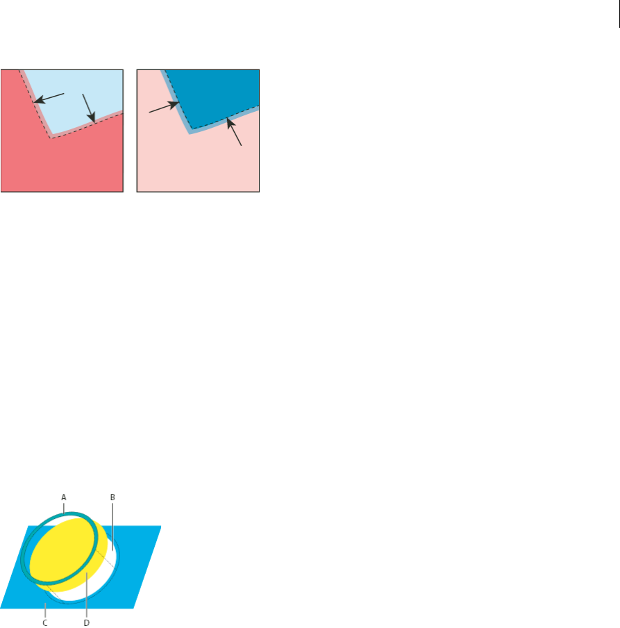
497
Printing
Last updated 6/5/2015
When overlapping painted objects share a common color, trapping may be unnecessary if the color that is common to
both objects creates an automatic trap. For example, if two overlapping objects contain cyan as part of their CMYK
values, any gap between them is covered by the cyan content of the object underneath.
Trapping type can present special problems. Avoid applying mixed process colors or tints of process colors to type at
small point sizes, because any misregistration can make the text difficult to read. Likewise, trapping type at small point
sizes can result in hard-to-read type. As with tint reduction, check with your print shop before trapping such type. For
example, if you are printing black type on a colored background, simply overprinting the type onto the background
may be enough.
Create a trap
The Trap command creates traps for simple objects by identifying the lighter-colored artwork—whether it’s the object
or the background—and overprinting (trapping) it into the darker artwork. You can apply the Trap command from the
Pathfinder panel or as an effect. The advantage of using the Trap effect is that you can alter the trap settings at any time.
A Area of overprinting B Area of knockout C Background color D Foreground color
In some cases, the top and bottom objects may have similar color densities so that one color is not obviously darker
than the other. In this case, the Trap command determines the trap based on slight differences in color; if the trap
specified by the Trap dialog box is not satisfactory, you can use the Reverse Trap option to switch the way in which the
Trap command traps the two objects.
1If the document is in RGB mode, choose File > Document Color Mode > CMYK Color to convert it to CMYK Mode.
2Select two or more objects.
3Do one of the following:
•To apply the command directly to the objects, choose Window > Pathfinder, and choose Trap from the panel
menu.
•To apply the command as an effect, choose Effect > Pathfinder >Trap. Select Preview if you want to preview the
effect.
4Set trap options, and click OK.
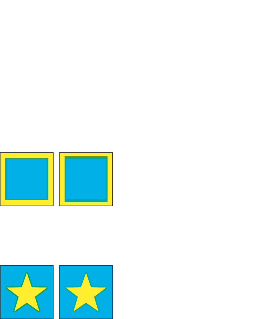
498
Printing
Last updated 6/5/2015
More Help topics
About effects
Apply Pathfinder effects
Pathfinder panel overview
Trap options
Thickness Specifies a stroke width between 0.01 and 5000 points. Check with your print shop to determine what value
to use.
Height/Width Specifies the trap on horizontal lines as a percentage of the trap on vertical lines. Specifying different
horizontal and vertical trap values lets you compensate for on-press irregularities, such as paper stretch. Contact your
print shop for help in determining this value. The default value of 100% results in the same trap width on horizontal
lines and on vertical lines. To increase the trap thickness on horizontal lines without changing the vertical trap, set the
Height/Width value to greater than 100%. To decrease the trap thickness on horizontal lines without changing the
vertical trap, set the Height/Width value to less than 100%.
Tint Reduction Reduces the tint of the lighter color being trapped; the darker color remains at 100%. This option is
useful when trapping two light-colored objects, where the trap line may show through the darker of the two colors,
resulting in an unsightly dark border. For example, if you trap a light yellow object into a light blue object, a bright green
border is visible where the trap is created. Check with your print shop to find out what percentage of tint is most
appropriate given the type of press, inks, paper stock, and so on being used.
Traps With Process Color Converts spot-color traps to equivalent process colors. This option creates an object of the
lighter of the spot colors and overprints it.
Reverse Traps Traps darker colors into lighter colors. This option does not work with rich black—that is, black that
contains additional CMY inks.
Precision (as effect only) Affects how precisely an object's path is calculated. The more precise the calculation, the
more accurate the drawing and the more time is required to generate the resulting path.
Remove Redundant Points (as effect only) Removes unnecessary points.

499
Printing
Last updated 6/5/2015
Create a spread or choke
For more precise control of trapping and for trapping complex objects, you can create the effect of a trap by stroking an
object and setting the stroke to overprint.
1Select the topmost object of the two objects that must trap into each other.
2In the Stroke box in the Tools panel or the Color panel, do one of the following:
•Create a spread by entering the same color values for the Stroke as appear in the Fill box. You can change the
stroke’s color values by selecting the stroke and then adjusting its color values in the Color panel. This method
enlarges the object by stroking its boundaries with the same color as the object’s fill.
•Create a choke by entering the same color values for the Stroke as appear in the lighter background (again, using
the Color panel); the Stroke and Fill values will differ. This method reduces the darker object by stroking its
boundaries with the lighter background color.
3Choose Window > Stroke.
A Overprinted stroke creates choke trap B Fill creates knockout C Area of trap D Area of knockout
4In the Weight text box, enter a stroke width of between 0.01 and 1000 points. Check with your print shop to
determine what value to use.
For example, a stroke weight of 0.6 point creates a trap of 0.3 point. A stroke weight of 2.0 points creates a trap of 1.0
point.
5Choose Window > Attributes.
6Select Overprint Stroke.
Trap a line
1Select the line to be trapped.
2In the Stroke box in the Tools panel or the Color panel, assign the stroke a color of white.
3In the Stroke panel, select the desired line weight.
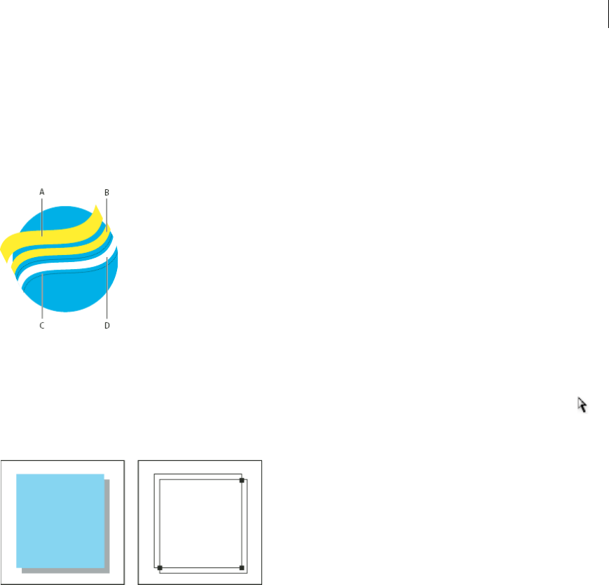
500
Printing
Last updated 6/5/2015
4Copy the line, and choose Edit >Paste In Front. The copy is used to create a trap.
5In the Stroke box in the Tools panel or the Color panel, stroke the copy with the desired color.
6In the Stroke panel, choose a line weight that is wider than the bottom line.
7Choose Window > Attributes.
8Select Overprint Stroke for the top line.
A Overprinted top stroke creates spread trap B Bottom stroke creates knockout C Area of knockout D Area of trap
Trap a portion of an object
1Draw a line along the edge or edges that you want to trap. If the object is complex, use the Direct Selection tool to
select the edges to be trapped, copy them, and choose Edit > Paste In Front to paste the copy directly on top of the
original.
2In the Stroke box in the Tools panel or the Color panel, select a color value for the Stroke to create either a spread or
a choke.
3Choose Window > Attributes.
4Select Overprint Stroke.
Print presets
If you regularly output to different printers or job types, you can automate print jobs by saving all output settings as
print presets. Using print presets is a fast, reliable way to print jobs that require consistently accurate settings for many
options in the Print dialog box.
Create print presets
If you regularly output to different printers or job types, you can automate print jobs by saving all output settings as
print presets. Using print presets is a fast, reliable way to print jobs that require consistently accurate settings for many
options in the Print dialog box.

501
Printing
Last updated 6/5/2015
You can save and load print presets, making it easy to back them up or to make them available to your service providers,
clients, or others in your workgroup.
You can create and review print presets in the Print Presets dialog box.
❖Do one of the following:
•Choose File > Print, adjust print settings, and click Save Preset . Type a name or use the default, and then click
OK. With this method, the preset is saved in the preferences file.
•Choose Edit > Print Presets, and then click New. In the Print Presets dialog box, type a new name or use the
default, adjust print settings, and then click OK to return to the Print Presets dialog box. Then click OK again.
Apply print presets
1Choose File > Print.
2Choose a print preset from the Print Preset menu. If you like, confirm the printer settings in the Print dialog box.
3Click Print.
Edit print presets
❖Do one of the following:
•Choose File > Print, adjust print settings, and click Save Preset . In the Save Preset dialog box that appears,
either type a name in the text box or use the current name. (If the current name is an existing preset, saving
overwrites that preset’s settings.) Click OK.
•Choose Edit > Print Presets, select a preset from the list, and then click Edit. Adjust print settings, and click OK
to return to the Print Presets dialog box. Then click OK again.
Tip: You can edit the default preset as you would any other using the steps outlined above.
Delete print presets
1Choose Edit > Print Presets.
2Select one or more presets from the list and click Delete. Shift-click to select adjacent presets. Ctrl-click (Windows)
or Command-click (Mac OS) to select nonadjacent presets.
Export or import print presets
You can save print presets in separate files, making it easy to back them up or to make them available to your service
providers, clients, or others in your workgroup.
1Choose Edit > Print Presets.
2Do one of the following:
•To export presets, select one or more presets in the list and click Export. Shift-click to select adjacent presets.
Ctrl-click (Windows) or Command-click (Mac OS) to select nonadjacent presets. Specify a name and location,
and then click Save.
•To import presets, click Import. Locate and click the file containing the presets you want to load, and then click
OK.

502
Printing
Last updated 6/5/2015
Consider saving presets outside of the preferences folder. That way, they won’t be lost if you ever delete your preferences.
View a summary of print settings/presets
Use the Summary panel of the Print dialog box to view your output settings prior to printing, and then adjust them as
necessary. For example, you can see if the document will omit certain graphics for OPI replacement by the service
provider.
1Choose File > Print.
2In the Print dialog box, click Summary.
3If you want to save the summary as a text file, click Save Summary.
4Accept the default filename or type another name for the text file, and click Save.
Specify crop marks for trimming or aligning
In addition to specifying different artboards to crop artwork for output, you can also create and use multiple sets of crop
marks within your artwork. Crop marks indicate where you want the printed paper to be cut. Crop marks are useful
when you want to create marks around several objects on a page—for example, when printing a sheet of business cards.
They are also helpful for aligning Illustrator artwork that you’ve exported to another application.
Crop marks differ from the artboard in the following ways:
•Artboards specify the printable boundaries of artwork, whereas crop marks don’t affect the printed area at all.
•You can activate only one artboard at a time, whereas you can create and display multiple crop marks.
•The artboard is indicated by visible but non-printing marks, whereas crop marks are printed with registration black
(so that they print to every separation plate, similar to printer’s marks).
Note: Crop marks do not replace trim marks created with the Marks & Bleed options in the Print dialog box.
Create crop marks around an object
In Illustrator CS5, you can create editable trim/crop marks or create crop marks as live effects.
To use crop marks, do the following:
1Select the object.
2To create editable trim marks or crop marks, select Object > Create Trim Marks.
3To create crop marks as live effect, select Effect > Crop Marks.
Delete crop marks
To delete an editable crop or trim marks, select the trim marks and press the Delete key.
To delete a crop marks effect, select Crop Marks in the Appearance panel, and click the Delete Selected Item icon .
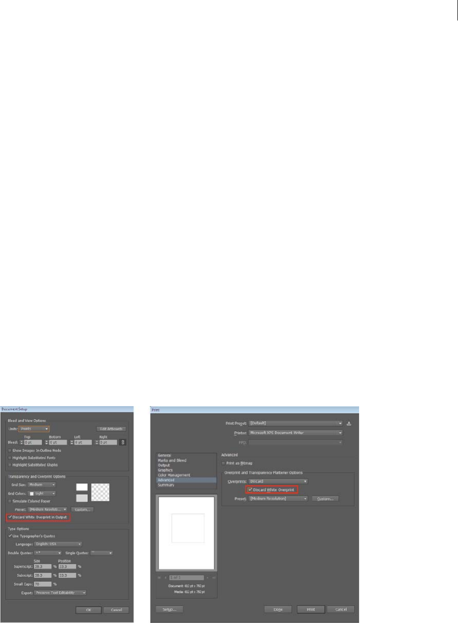
503
Printing
Last updated 6/5/2015
Use Japanese-style crop marks
Japanese-style crop marks have double lines, which visually define a default bleed value of 8.5 points (3 millimeters).
1Choose Edit > Preferences > General (Windows) or Illustrator > Preferences > General (Mac OS).
2Select Use Japanese Crop Marks, and then click OK.
White Overprint | Illustrator CC
Artwork created in Illustrator can have white objects applied with unintentional overprint. This becomes apparent only
when one turns on the overprint preview or printing separations. This causes delays in the production process and
reprinting may need to be performed. Though Illustrator warns users if a white object is applied with overprint, there
are scenarios when a white overprint may occur without it coming to the user’s notice. For example:
From this version of Illustrator, you have the Discard White Overprint option to remove white overprint attributes in
the Document Setup and Print dialogs. This option is, by default, switched on in both dialogs . If the Discard White
Overprint option is not selected in the Document Setup dialog, it can be overridden by selecting the option in the Print
dialog.
Scenario 1 An object with overprint is selected, and then a new object with white fill/stroke is created. In this scenario
the appearance attributes of previously selected objects is copied to the new object, resulting in overprint applied to the
white-filled object.
Scenario 2 A non-white object with overprint is changed to an object with white fill. To overcome this problem, we
now remove the overprint attribute from white objects during operations like printing or saving to EPS or PDF. This
enables users to use print and output without the need to check and correct for white-object overprint in artwork. This
approach will be optimal for most scenarios - legacy artwork, new artwork, non-White objects with Overprint applied
to them when changed to White.
Spot White objects with overprint are not affected by this operation. This affects only the saved files or the output of an
Illustrator file. Also, artwork remains unaffected by this setting.

504
Last updated 6/5/2015
Chapter 13: Automating tasks
Automation with actions
About actions
An action is a series of tasks that you play back on a single file or a batch of files—menu commands, panel options, tool
actions, and so on. For example, you can create an action that changes the size of an image, applies an effect to the
image, and then saves the file in the desired format.
Actions can include steps that let you perform tasks that cannot be recorded (for example, using a painting tool).
Actions can also include modal controls that let you enter values in a dialog box while playing an action.
In Photoshop, actions are the basis for droplets, which are small applications that automatically process all files that are
dragged onto their icon.
Photoshop and Illustrator come with predefined actions installed that help you perform common tasks. You can use
these actions as is, customize them to meet your needs, or create new actions. Actions are stored in sets to help you
organize them.
You can record, edit, customize, and batch-process actions, and you can manage groups of actions by working with
action sets.
Actions panel overview
You use the Actions panel (Window > Actions) to record, play, edit, and delete individual actions. This panel also lets
you save and load action files.
A Action set B Action C Recorded commands D Included command E Modal control (toggles on or off)
Expand and collapse sets, actions, and commands
❖Click the triangle to the left of the set, action, or command in the Actions panel. Alt-click (Windows) or Option-
click (Mac OS) the triangle to expand or collapse all actions in a set or all commands in an action.

505
Automating tasks
Last updated 6/5/2015
View actions by name only
❖Choose Button Mode from the Actions panel menu. Choose Button Mode again to return to list mode.
Note: You can’t view individual commands or sets in Button mode.
Select actions in the Actions panel
❖Click an action name. Shift-click action names to select multiple, contiguous actions, and Ctrl-click (Windows) or
Command-click (Mac OS) action names to select multiple, discontiguous actions.
Play an action on a file
Playing an action executes the action’s recorded commands in the active document. (Some actions require that you
make a selection before playing; some can be executed on an entire file.) You can exclude specific commands from an
action or play only a single command. If the action includes a modal control, you can specify values or use tools in a
dialog box when the action pauses.
Note: In Button mode, clicking a button executes the entire action—although commands previously excluded are not
executed.
1If necessary, select objects on which to play the action, or open a file.
2Do one of the following:
•(Illustrator) To play a set of actions, select the set name, and click the Play button in the Actions panel, or
choose Play from the panel menu.
•To play an entire single action, select the action name, and click the Play button in the Actions panel, or choose
Play from the panel menu.
•If you assigned a key combination to the action, press that combination to play the action automatically.
•To play only a part of an action, select the command from which you want to start playing, and click the Play
button in the Actions panel, or choose Play from the panel menu.
•To play a single command, select the command, and then Ctrl-click (Windows) or Command-click (Mac OS) the
Play button in the Actions panel. You can also press Ctrl (Windows) or Command (Mac OS), and double-click
the command.
Tip: In Photoshop, to undo an action, take a snapshot in the History panel before you play an action, and then select
the snapshot to undo the action.
Record an action
When you create a new action, the commands and tools you use are added to the action until you stop recording.
Tip: To guard against mistakes, work in a copy: at the beginning of the action before applying other commands, record
the File > Save A Copy command (Illustrator) or record the File > Save As command and select As A Copy (Photoshop).
Alternatively, in Photoshop you can click the New Snapshot button on the History panel to make a snapshot of the image
before recording the action.
1Open a file.
2In the Actions panel, click the Create New Action button , or choose New Action from the Actions panel menu.
3Enter an action name, select an action set, and set additional options:
Function Key Assigns a keyboard shortcut to the action. You can choose any combination of a function key, the Ctrl
key (Windows) or Command key (Mac OS), and the Shift key (for example, Ctrl+Shift+F3), with these exceptions:
In Windows, you cannot use the F1 key, nor can you use F4 or F6 with the Ctrl key.

506
Automating tasks
Last updated 6/5/2015
note: If you assign an action the same shortcut that is used for a command, the shortcut will apply the action rather
than the command.
Color Assigns a color for display in Button mode.
4Click Begin Recording. The Begin Recording button in the Actions panel turns red .
Note: When recording the Save As command, do not change the filename. If you enter a new filename, that new name
is recorded and used each time you run the action. Before saving, if you navigate to a different folder, you can specify a
different location without having to specify a filename.
5Perform the operations and commands you want to record.
Not all tasks in actions can be recorded directly; however, you can insert most nonrecordable tasks using commands
in the Actions panel menu.
6To stop recording, either click the Stop Playing/Recording button, or choose Stop Recording from the Actions panel
menu. (In Photoshop, you can also press the Esc key.)
To resume recording in the same action, choose Start Recording from the Actions panel menu.
Insert nonrecordable tasks into actions
Not all tasks in actions can be recorded directly. For example, you can’t record commands in the Effects and View
menus, commands that display or hide panels, and use of the Selection, Pen, Paintbrush, Pencil, Gradient, Mesh,
Eyedropper, Live Paint Bucket, and Scissors tools.
To tell which tasks cannot be recorded, watch the Actions panel. If the name of the command or tool doesn’t appear
after you perform the task, you may still be able to add the task using commands in the Actions panel menu.
To insert a nonrecordable task after you create an action, select an item within the action after which you want to insert
the task. Then choose the appropriate command from the Actions panel menu.
Insert a nonrecordable menu command
1Choose Insert Menu Item from the Actions panel menu.
2Select the command from its menu, or begin typing the command name in the text box, and click Find. Then click
OK.
Insert a path
❖Select the path, and choose Insert Select Path from the Actions panel menu.
Insert selection of an object
1 Enter a name for the object in the Note box of the Attributes panel before you start recording. (Select Show Note
from the Attributes panel menu to display the Note box.)
2When you record the action, choose Select Object from the Actions panel menu.
3Enter the name of the object, and click OK.
Record optimization options for multiple slices in the Save For Web dialog box
❖Set the slice optimization options before you start recording the action. Then press Alt (Windows) or Option (Mac
OS) and click Remember in the Save For Web dialog box.
When you record the action, Illustrator will remember the settings.

507
Automating tasks
Last updated 6/5/2015
Insert a stop
You can include stops in an action that let you perform a task that cannot be recorded (for example, using a painting
tool). After you complete the task, click the Play button in the Actions panel to complete the action.
You can also display a short message when the action reaches the stop as a reminder of what needs to be done before
continuing with the action. You can include a Continue button in the message box in case no other task needs to be
done.
1Choose where to insert the stop by doing one of the following:
•Select an action’s name to insert a stop at the end of the action.
•Select a command to insert a stop after the command.
2Choose Insert Stop from the Actions panel menu.
3Type the message you want to appear.
4If you want the option to continue the action without stopping, select Allow Continue.
5Click OK.
You can insert a stop when recording an action or after it has been recorded.
Change settings when playing an action
By default, actions are completed using the values specified when they were originally recorded. If you want to change
the settings for a command within an action, you can insert a modal control. A modal control pauses an action so that
you can specify values in a dialog box or use a modal tool. (A modal tool requires pressing Enter or Return to apply its
effect—once you press Enter or Return, the action resumes its tasks.)
A modal control is indicated by a dialog box icon to the left of a command, action, or set in the Actions panel. A red
dialog box icon indicates an action or set in which some, but not all, commands are modal. You can’t set a modal
control in Button mode.
❖Do one of the following:
•To enable a modal control for a command within an action, click the box to the left of the command name. Click
again to disable the modal control.
•To enable or disable modal controls for all commands in an action, click the box to the left of the action name.
•To enable or disable modal controls for all actions in a set, click the box to the left of the set name.
Exclude commands from an action
You can exclude commands that you don’t want to play as part of a recorded action. You can’t exclude commands in
Button mode.
1If necessary, expand the listing of commands in the action by clicking the triangle to the left of the action name in
the Actions panel.
2Do one of the following:
•To exclude a single command, click to clear the check mark to the left of the command name. Click again to
include the command.
•To exclude or include all commands or actions in an action or set, click the check mark to the left of the action
or set name.

508
Automating tasks
Last updated 6/5/2015
•To exclude or include all commands except the selected command, Alt-click (Windows) or Option-click (Mac
OS) its check mark.
To indicate that some of the commands within the action are excluded, in Photoshop the check mark of the
parent action turns red; in Illustrator the check mark of the parent action becomes dimmed.
Specify playback speed
You can adjust an action’s playback speed or pause it to help you debug an action.
1Choose Playback Options from the Actions panel menu.
2Specify a speed, and click OK:
Accelerated Plays the action at normal speed (the default).
note: When you play an action at accelerated speed, the screen may not update as the action executes—files may be
opened, modified, saved, and closed without ever appearing on-screen, enabling the action to execute more quickly. If
you want to see the files on-screen as the action executes, specify the Step By Step speed instead.
Step By Step Completes each command and redraws the image before going on to the next command in the action.
Pause For __ Seconds Specifies the amount of time the application should pause between carrying out each
command in the action.
Edit and rerecord actions
It is easy to edit and customize actions. You can tweak the settings of any specific command within an action, add
commands to an existing action, or step through an entire action and change any or all settings.
Add commands to an action
1Do one of the following:
•Select the action name to insert a new command at the end of the action.
•Select a command in the action to insert a command after it.
2Click the Begin Recording button, or choose Start Recording from the Actions panel menu.
3Record the additional commands.
4When finished, click the Stop Playing/Recording button in the Actions panel or choose Stop Recording from the
panel menu.
Rearrange commands within an action
❖In the Actions panel, drag a command to its new location within the same or another action. When the highlighted
line appears in the desired position, release the mouse button.
Record an action again
1Select an action, and choose Record Again from the Actions panel menu.
2If a modal tool appears, use the tool to create a different result, and press Enter or Return, or just press Enter or
Return to retain the same settings.
3If a dialog box appears, change the settings, and click OK to record them, or click Cancel to retain the same values.

509
Automating tasks
Last updated 6/5/2015
Record a single task again
1Select an object of the same type for which you want to rerecord the action. For example, if a task is only available
for vector objects, you must have a vector object selected when you rerecord.
2In the Actions panel, double-click the command.
3Enter the new values and click OK.
Manage action sets
You can create and organize sets of task-related actions that can be saved to disk and transferred to other computers.
Note: Any actions that you create are automatically listed in the Actions panel, but to truly save an action and not risk
losing it if you delete your preferences file (Illustrator) or Actions panel file (Photoshop), you have to save it as part of an
action set.
Save a set of actions
1Select a set.
If you want to save a single action, first create an action set and move the action to the new set.
2Choose Save Actions from the Actions panel menu.
3Type a name for the set, choose a location, and click Save.
You can save the file anywhere. You can save only the entire contents of a set in the Actions panel, not individual
actions.
Note: (Photoshop only) If you place the saved action-set file in the Presets/Actions folder, the set will appear at the
bottom of the Actions panel menu after you restart the application.
(Photoshop only) Press Ctrl+Alt (Windows) or Command+Option (Mac OS) when you choose the Save Actions
command to save the actions in a text file. You can use this file to review or print the contents of an action. However,
you can’t reload the text file back into Photoshop.
Load a set of actions
By default, the Actions panel displays predefined actions (shipped with the application) and any actions you create. You
can also load additional actions into the Actions panel.
❖Do one of the following:
•Choose Load Actions from the Actions panel menu. Locate and select the action set file, and then click Load
(Photoshop) or Open (Illustrator).
•(Photoshop only) Select an action set from the bottom of the Actions panel menu.
Photoshop action set files have the extension .atn; Illustrator action set files have the extension .aia.
Restore actions to the default set
1Choose Reset Actions from the Actions panel menu.
2Click OK to replace the current actions in the Actions panel with the default set, or click Append to add the set of
default actions to the current actions in the Actions panel.

510
Automating tasks
Last updated 6/5/2015
Organize action sets
To help you organize your actions, you can create sets of actions and save the sets to disk. You can organize sets of
actions for different types of work—such as print publishing and online publishing—and transfer sets to other
computers.
•To create a new set of actions, click the Create New Set button in the Actions panel or choose New Set from the
panel menu. Then enter the name of the set, and click OK.
note: If you plan to create a new action and group it in a new set, make sure you create the set first. Then, the new set
will appear in the set popup menu when you create your new action.
•To move an action to a different set, drag the action to that set. When the highlighted line appears in the desired
position, release the mouse button.
•To rename a set of actions, double-click the name of the set in the Actions panel or choose Set Options from the
Actions panel menu. Then enter the new name of the set, and click OK.
•To replace all actions in the Actions panel with a new set, choose Replace Actions from the Actions panel menu.
Select an actions file, and click Load (Photoshop) or Open (Illustrator).
Note: The Replace Actions command replaces all sets of actions in the current document. Before using the command,
make sure that you have already saved a copy of your current set of actions using the Save Actions command.
Play an action on a batch of files
The Batch command lets you play an action on a folder of files and subfolders. You can also use the Batch command to
populate a template for data-driven graphics with different sets of data.
1Choose Batch from the Actions panel menu.
2For Play, select the action you want to play.
3For Source, choose the folder on which to play the action. Or select Data Sets to play the action on each data set in
the current file.
If you select a folder, you can set additional options for playing the action.
4For Destination, specify what you want to do with the processed files. You can leave the files open without saving
the changes (None), save and close the file in their current location (Save And Close), or save the files to a different
location (Folder).
Depending on the Destination option you select, you can set additional options for saving the files.
5Specify how you want Illustrator to handle errors during the batch process. If you select Log Errors To File, click
Save As, and name the error file.
6Click OK.
Saving files using the Batch command options always saves the files in the same format as the original files. To create
a batch process that saves files in a new format, record the Save As or Save A Copy command, followed by the Close
command, as part of your original action. Then choose None for the Destination when setting up the batch process.
To batch-process using multiple actions, create a new action, and record the Batch command for each action you
want to use. This technique also lets you process multiple folders in a single batch. To batch-process multiple folders,
create aliases within a folder to the other folders you want to process.

511
Automating tasks
Last updated 6/5/2015
Batch options
If you select Folder for Source, you can set the following options:
Override Action “Open” Commands Opens the files from the specified folder and ignores any Open commands
recorded as part of the original action.
Include All Subdirectories Processes all files and folders within the specified folder.
If the action contains any save or export commands, you can set the following options:
Override Action “Save” Commands Saves the processed files in the specified destination folder and not to a location
recorded in the action. Click Choose to specify the destination folder.
Override Action “Export” Commands Exports the processed files to the specified destination folder and not to a
location recorded in the action. Click Choose to specify the destination folder.
If you select Data Sets for Source, you can set an option for generating filenames when overriding Save and Export
commands:
File + Number Generates the filename by taking the original document’s filename, removing any extension, and then
appending a three-digit number corresponding to the data set.
File + Data Set Name Generates the filename by taking the original document’s filename, removing any extension, and
then appending an underscore and the name of the data set.
Data Set Name Generates the filename by taking the name of the data set.
More Help topics
Data-driven graphics through templates and variables
Automation with scripts
When you run a script, your computer performs a sequence of operations. These operations may involve only
Illustrator, or they may involve other applications, such as word-processing, spreadsheet, and database-management
programs.
Illustrator supports multiple scripting environments (including Microsoft Visual Basic, AppleScript, JavaScript, and
ExtendScript). You can use the standard scripts that come with Illustrator, and you can create your own scripts and add
them to the Scripts submenu.
For more information about scripting in Illustrator, see the latest documentation at
www.adobe.com/devnet/illustrator/scripting.html. Sample scripts are installed in the Adobe Illustrator CS5/Scripting
folder.
Run a script
❖Choose File > Scripts, and choose a script. Alternatively, choose File > Scripts > Other Script, and navigate to a script.
Note: If you edit a script while Illustrator is running, you must save your changes for them to take effect.
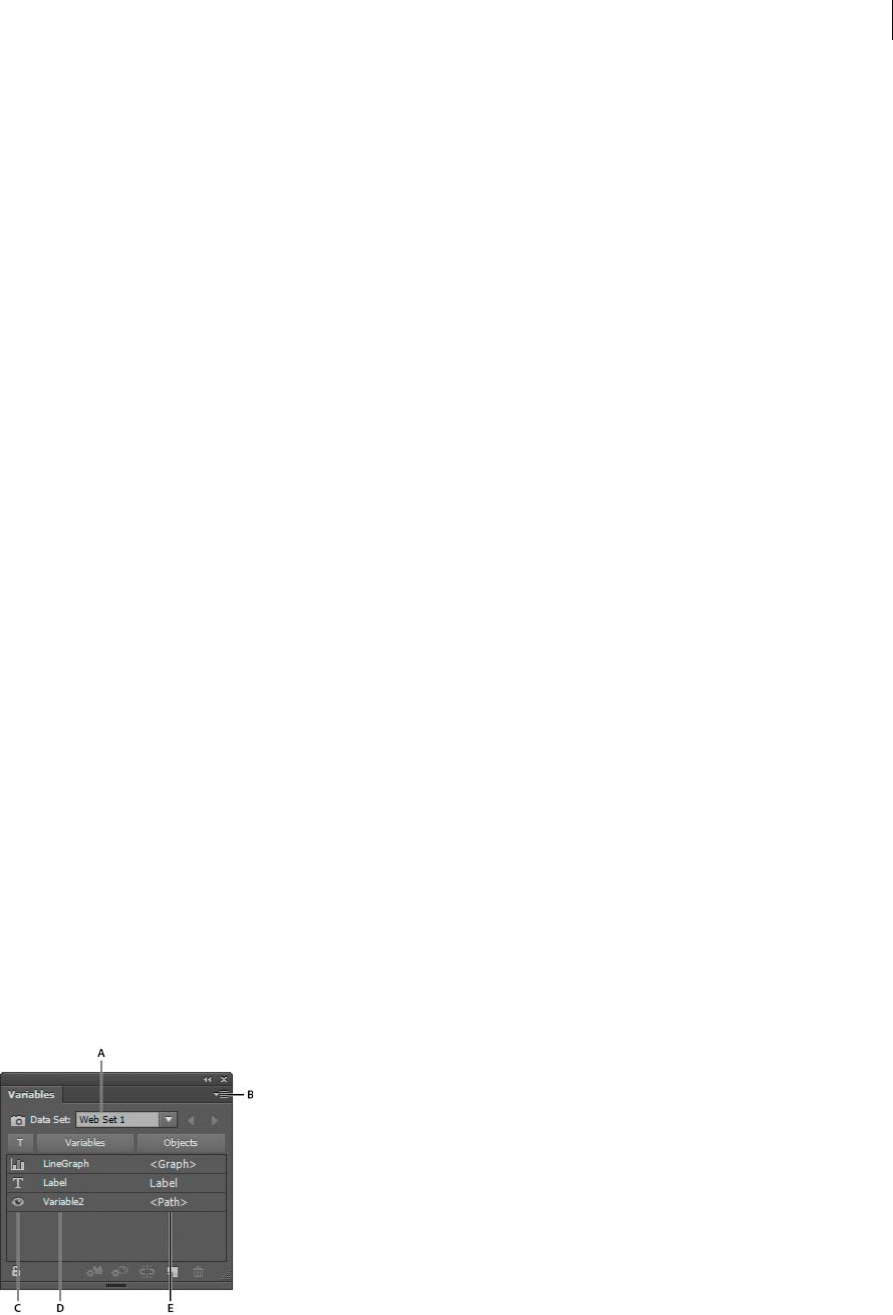
512
Automating tasks
Last updated 6/5/2015
Install a script
❖Copy the script to your computer’s hard disk.
If you place the script in the Adobe Illustrator CS5 Scripts folder, the script will appear in the File > Scripts submenu.
If you place the script in another location on the hard disk, you can run the script in Illustrator by choosing File >
Scripts > Other Script.
Note: If you place a script in the Adobe Illustrator CS5 Scripts folder while Illustrator is running, you must restart
Illustrator for the script to appear in the Scripts submenu.
Data-driven graphics through templates andvariables
In Illustrator, you can turn any piece of artwork into a template for data-driven graphics. All you need to do is define
which objects on the artboard are dynamic (changeable) using variables. You use variables to change text strings, linked
images, graph data, and the visibility setting of objects in your artwork. In addition, you can create different sets of
variable data to easily view what your template will look like when it is rendered.
Data-driven graphics make it possible to produce multiple versions of artwork quickly and accurately. For example,
suppose that you need to produce 500 different web banners based on the same template. Manually populating the
template with data (images, text, and so on) is time-consuming. Instead, you can use a script that references a database
to generate the web banners for you.
Data-driven graphics are designed for use in collaborative work environments. Following are some examples of how
data-driven graphics fit into different job roles:
•If you’re a designer, creating a template gives you control over the dynamic elements of your design. When you hand
your template over for production, you can be sure that only the variable data will change.
•If you’re a developer, you can code variables and data sets directly into an XML file. The designer can then import
the variables and data sets into an Illustrator file to create a design based on your specifications.
•If you’re responsible for production, you can use scripts within Illustrator or the Batch command. You can also use
a dynamic imaging server such as Adobe® Scene7 to further automate the rendering process.
Variables panel overview
You use the Variables panel (Window > Variables) to work with variables and data sets. The type and name of each
variable in the document are listed in the panel. If the variable is bound to an object, then the Objects column displays
the name of the bound object as it appears in the Layers panel.
A Data set B Panel menu C Variable ty pe D Variable name E Name of bound object
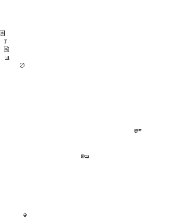
513
Automating tasks
Last updated 6/5/2015
The Variables panel uses the following icons to indicate a variable’s type:
•Visibility variable .
•Text St r ing variable .
•Linked File variable .
•Graph Data variable .
•No Type (unbound) variable .
You can sort the rows by clicking items in the header bar: by variable name, object name, or by variable type.
Create variables
You can create four types of variables in Illustrator: Graph Data, Linked File, Text String, and Visibility. A variable’s type
indicates which object attributes are changeable (dynamic).
Note: The Variable panel menu also provides commands for creating variables.
Create a Visibility variable
❖Select the objects that you want to show or hide and click the Make Visibility Dynamic button in the Variables
panel.
Create a Text String variable
❖Select a type object and click the Make Object Dynamic button in the Variables panel.
Create a Linked File variable
❖Select a linked file and click the Make Object Dynamic button in the Variables panel.
Create a Graph Data variable
❖Select a graph object and click the Make Object Dynamic button in the Variables panel.
Create a variable without binding it to an object
❖Click the New Variable button in the Variables panel. To subsequently bind an object to the variable, select the
object and the variable, and click the Make Visibility Dynamic button or the Make Object Dynamic button.
Edit variables
You can edit a variable’s name or type, unbind a variable, and lock a variable using the Variables panel.
Unbinding a variable breaks the link between the variable and its object. Locking variables prevents you from creating
variables, deleting variables, and editing variable options. However, you can bind and unbind objects to locked
variables.
Change the name and type of a variable
❖Double-click the variable in the Variables panel. Alternatively, select the variable in the Variables panel, and choose
Variable Options from the Variables panel menu.

514
Automating tasks
Last updated 6/5/2015
Unbind a variable
❖Click the Unbind Variable button in the Variables panel, or choose Unbind Variable from the Variables panel
menu.
Lock or unlock all variables in a document
❖Click the Lock/Unlock Variables button or in the Variables panel.
Delete variables
Deleting a variable removes it from the Variables panel. If you delete a variable that is bound to an object, the object
becomes static (unless the object is also bound to a variable of a different type).
1Select a variable you want to delete.
2Do one of the following:
•Click the Delete Variable icon in the Variables panel, or choose Delete Variable from the Variables panel
menu.
•To delete the variable without confirmation, drag it to the Delete Variable icon.
Edit dynamic objects
You change the data associated with a variable by editing the object to which it is bound. For example, if you’re working
with a Visibility variable, you change the object’s state of visibility in the Layers panel. Editing dynamic objects lets you
create multiple data sets for use in the template.
1Select a dynamic object on the artboard, or do one of the following to automatically select a dynamic object:
•Alt-click (Windows) or Option-click (Mac OS) a variable in the Variables panel.
•Select a variable in the Variables panel, and choose Select Bound Object from the Variables panel menu.
•To select all dynamic objects, choose Select All Bound Objects from the Variables panel menu.
2Edit the data associated with the object as follows:
•For text, edit the text string on the artboard.
•For linked files, replace the image using the Links panel or the File > Place command.
•For graphs, edit the data in the Graph Data dialog box.
•For all objects with dynamic visibility, change the state of visibility for the object in the Layers panel.
Identifying dynamic objects using XML IDs
The Variables panel displays the names of dynamic objects as they appear in the Layers panel. If you save the template
in SVG format for use with other Adobe products, these object names must conform to XML naming conventions. For
example, XML names must begin with a letter, underscore, or colon, and cannot contain spaces.
Illustrator automatically assigns a valid XML ID to every dynamic object you create. To view, edit, and export object
names using XML IDs, choose Edit > Preferences > Units (Windows) or Illustrator > Preferences > Units (Mac OS),
and select XML ID.

515
Automating tasks
Last updated 6/5/2015
Data sets
A data set is a collection of variables and associated data. When you create a data set, you capture a snapshot of the
dynamic data that is currently displayed on the artboard. You can switch between data sets to upload different data into
your template.
The name of the current data set is displayed at the top of the Variables panel. If you change the value of a variable so
that the artboard no longer reflects the data stored in the set, the name of the data set is displayed in italic type. You can
then create a new data set, or you can update the data set to overwrite the saved data with the new data.
Create a data set
❖Click the Capture Data Set button in the Variables panel. Alternatively, choose Capture Data Set from the
Variables panel menu.
Switch between data sets
❖Select a data set from the Data Set list in the Variables panel. Alternatively, click the Previous Data Set button or
the Next Data Set button .
Apply the data on the artboard to the current data set
❖Choose Update Data Set from the Variables panel menu.
Rename a data set
❖Edit the text directly in the Data Set text box. Alternatively, double-click the words Data Set: (to the left of the Data
Set text box), enter a new name, and click OK.
Delete a data set
❖Choose Delete Data Set from the Variables panel menu.
About variable libraries
In a collaborative environment, coordination between team members is essential to the success of a project. For
example, in a company that creates websites, the web designer is responsible for the look and feel of the site, while the
web developer is responsible for the underlying code and scripting. If the designer changes the layout of the web page,
those changes must be communicated to the developer. Likewise, if the developer needs to add functionality to the web
page, the design may need to be updated.
Variable libraries enable designers and developers to coordinate their work through an XML file. For example, a
designer can create a template for business cards in Illustrator and export variable data as an XML file. The developer
can then use the XML file to link variables and data sets to a database and write a script to render the final artwork.
This workflow can also be reversed, where the developer codes the variable and data set names in an XML file, and the
designer imports the variable libraries into an Illustrator document.
To import variables into Illustrator from an XML file, choose Load Variable Library from the Variables panel menu.
To export variables from Illustrator to an XML file, choose Save Variable Library from the Variables panel menu.

516
Automating tasks
Last updated 6/5/2015
Save a template for data-driven graphics
When you define variables in an Illustrator document, you are creating a template for data-driven graphics. You can
save the template in SVG format for use with other Adobe products, such as Adobe® Graphics Server. For example, a
developer working with Adobe Graphics Server can bind the variables in the SVG file directly to a database or another
data source.
1Choose File > Save As, enter a filename, select SVG as the file format, and click Save.
2Click More Options, and select Include Adobe Graphics Server Data. This option includes all information needed
for variable substitution in the SVG file.
3Click OK.
More Help topics
Links panel overview
Enter graph data
Layers panel overview
Play an action on a batch of files

517
Last updated 6/5/2015
Chapter 14: Graphs
Creative Cloud Charts (Preview)
What is a Technology Preview?
Technology Previews are features and services that are released to the public before they are fully complete as features.
A Preview gives you the opportunity to try out the feature, provide feedback, and help guide the development of the
feature before it ships as final in a later release of Illustrator.
Creative Cloud Charts (CC Charts) — a new Creative Cloud service — allows designers to create compelling charts and
infographics and take them to Illustrator as live objects. You can now use any custom art to represent data values in a
chart's design. Users now have unprecedented control and flexibility on chart elements – they can be stylized and
treated for visual appeal, to create aesthetic charts, without breaking the link to the underlying data.
Important: The Creative Cloud Charts (Preview) feature is enabled for all US (en_US) and UK (en_GB) Illustrator CC
2015 users.
A typical CC Charts workflow
The CC Charts tool allows you to represent numerical data with custom vector art. You can edit the appearance of a
chart in Illustrator. However, to edit the data and further modify and refine the appearance of the chart, use the CC
Charts web view . Here's how a typical workflow looks like:
1Use the CC Charts tool to create a chart or drag an available chart from a library in the Libraries panel to the
artboard.
2In Illustrator:
•Replace the chart element used
•Edit individual chart elements
3In the Chart object context menu, click Edit on Creative Cloud. A new browser tab or window is opened.
4In the browser interface:
•Modify the appearance of the chart
•Import or add data , or edit data
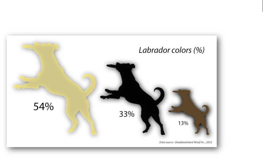
518
Graphs
Last updated 6/5/2015
Creating a new chartGet Started!
Replacing chart artwork Change the default artwork!
Replacing chart artwork Set that outlier apart!
Creative Cloud Charts web view All the action happens here!
Modifying chart layout Move stuff around - customize!
Importing/ Defining chart data Get your numbers in!
Editing chart data Make your numbers count!
Creating a new chart
1Select the CC Charts tool from the Tools panel (Shortcut key: J).
2Click-drag on the artboard to create a chart of the desired size. A Scale chart is created.
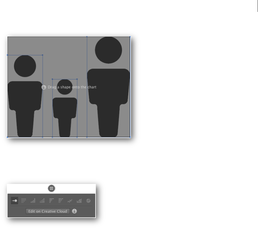
519
Graphs
Last updated 6/5/2015
3Click the Charts pin below the chart to view the Context menu for the chart.
Replacing chart artwork
1In Illustrator, select a chart.
2In your document, draw new artwork, or drop any available artwork on the canvas.
Note: Complex artwork such as objects with a gradient mesh, and raster objects are not supported.
3Drag-drop the artwork on the chart. The bars of the chart are updated to show the custom graph bars.
Note: Some complex appearances such as effects, multiple fills, etc. do not appear while editing the chart on Creative
Cloud.
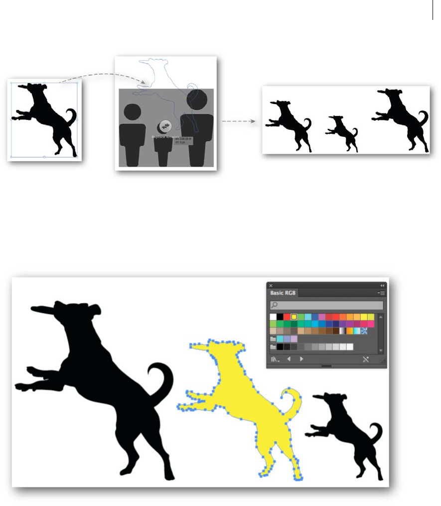
520
Graphs
Last updated 6/5/2015
Editing chart artwork
1In Illustrator, select a chart, and then click the Direct Selection Tool (A).
2Select one or more data representations, and modify the appearance of the objects.
Note: Some complex appearances such as effects, multiple fills, etc. do not appear while editing the chart on Creative
Cloud.
Creative Cloud Charts web view
When you create a Chart object, you can change the artwork used to represent data, or modify the apperance of one or
more instances of the artwork. However, to continue working with the layout of the chart, import or modify data, and
more, you must edit the chart online, in Creative Cloud.
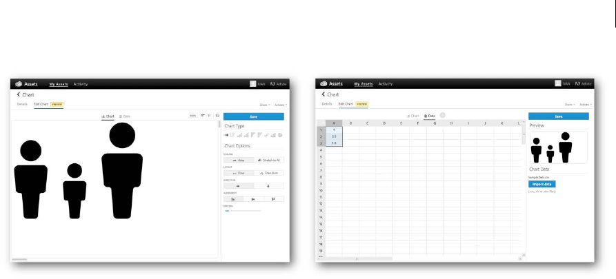
521
Graphs
Last updated 6/5/2015
When you edit a chart on Creative Cloud, in addition to modifying the data and the appearance of the chart, you can
perform other actions.
•Details. Click the link to view various details about the chart.
•Zoom. In the Chart tab, specify a zoom value, choose fit the chart to the available space, or a realistic 1:1 view.Note:
The zoom value is only for display purposes and does not affect the dimensions of the chart artwork.
•Share. Click Share > Send Link to forward a link of the image of the chart to a mail recipient.
•Actions. Choose from these actions:
•Rename. Provide a new name for the Chart.
•Delete. Delete the chart.
Modifying chart layout
1In Illustrator, select a chart, and then do one of the following:
•Click the Chart pin, and then click Edit on Creative Cloud Charts
•In the Control Panel, click Edit on Creative Cloud Charts
•Right-click the chart and then click Edit on Creative Cloud Chart
2In the browser window that opens, ensure that you are in the Chart tab.
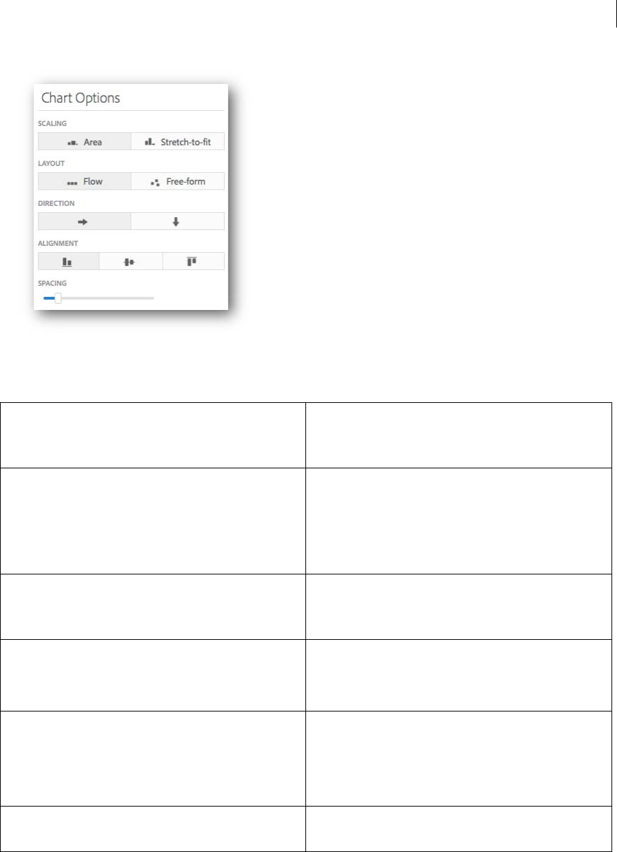
522
Graphs
Last updated 6/5/2015
3Options to edit the appearance of the chart:
4Click Save to retain any modifications to the layout.
Scaling •Area: Artwork size scales in size according to data.
•Stretch-to-fit: Artwork stretches in the Direction setting you
specify.
Stretch artwork Option available when Scaling = Stretch-to-fit:
•Verti c ally: Artwork stretches in the vertical
direction to depict data values.
•Horizontally: Artwork stretches in the horizontal
direction to depict higher data values.
Layout •Flow. Artwork is arranged in the order specified using Direction,
Align, and Spacing settings.
•Free-form. Artwork can be manually moved around.
Direction Option available when Layout = Flow:
•Left to Right
•Top to Bottom
Alignment Option available when Layout = Flow:
•Bottom-aligned:
•Middle-alighned:
•Top-aligned:
Spacing Option available when Layout = Flow
Use the slider to alter the spacing between successive artwork.

523
Graphs
Last updated 6/5/2015
Importing/ Defining chart data
When you change data in the Charts tab, remember to click Apply, and then click Save, to ensure that the chart is
updated in Illustrator.
1In Illustrator, select a chart, and then do one of the following:
•Click the Chart pin, and then click Edit on Creative Cloud Charts
•In the Control Panel, click Edit on Creative Cloud Charts
•Right-click the chart and then click Edit on Creative Cloud Chart
2In the browser window that opens, click the Data tab.
3Click Choose File to import data from a Comma Separated Values (.csv) or Microsoft Excel (.xls or .xlsx) file.
Note: Any data you import will always overwrite existing data already available for the chart.
4(Important) From the available rows and columns, click and drag the mouse over the data cells to represent in the
chart, and then click Apply ( ).
The Chart Preview page area is updated with a representation of the values that you have selected for the chart.
5Add, modify, and refine your data, and then click Save.
Each time you click Save, the chart is updated in Illustrator.
The speed at which the chart is updated in Illustrator depends on the speed of internet connectivity. This may vary
from as little as nearly-immediately to upto 12-15 seconds.
Editing chart data
When you change data in the Charts tab, remember to click Apply, and then click Save, to ensure that the chart is
updated in Illustrator.
1In Illustrator, select a chart, and then do one of the following:
•Click the Chart pin, and then click Edit on Creative Cloud Charts
•In the Control Panel, click Edit on Creative Cloud Charts
•Right-click the chart and then click Edit on Creative Cloud Chart
2In the browser window that opens, click the Data tab.
3Click any cell that contains data, or select a range of cells.
A context-sensitive pin ( ) appears.
4In the pin, click the three dots ( ) to see the additional options available with the selected data.
5Select an option from the context-menu that appears to insert, delete, or sort cells.
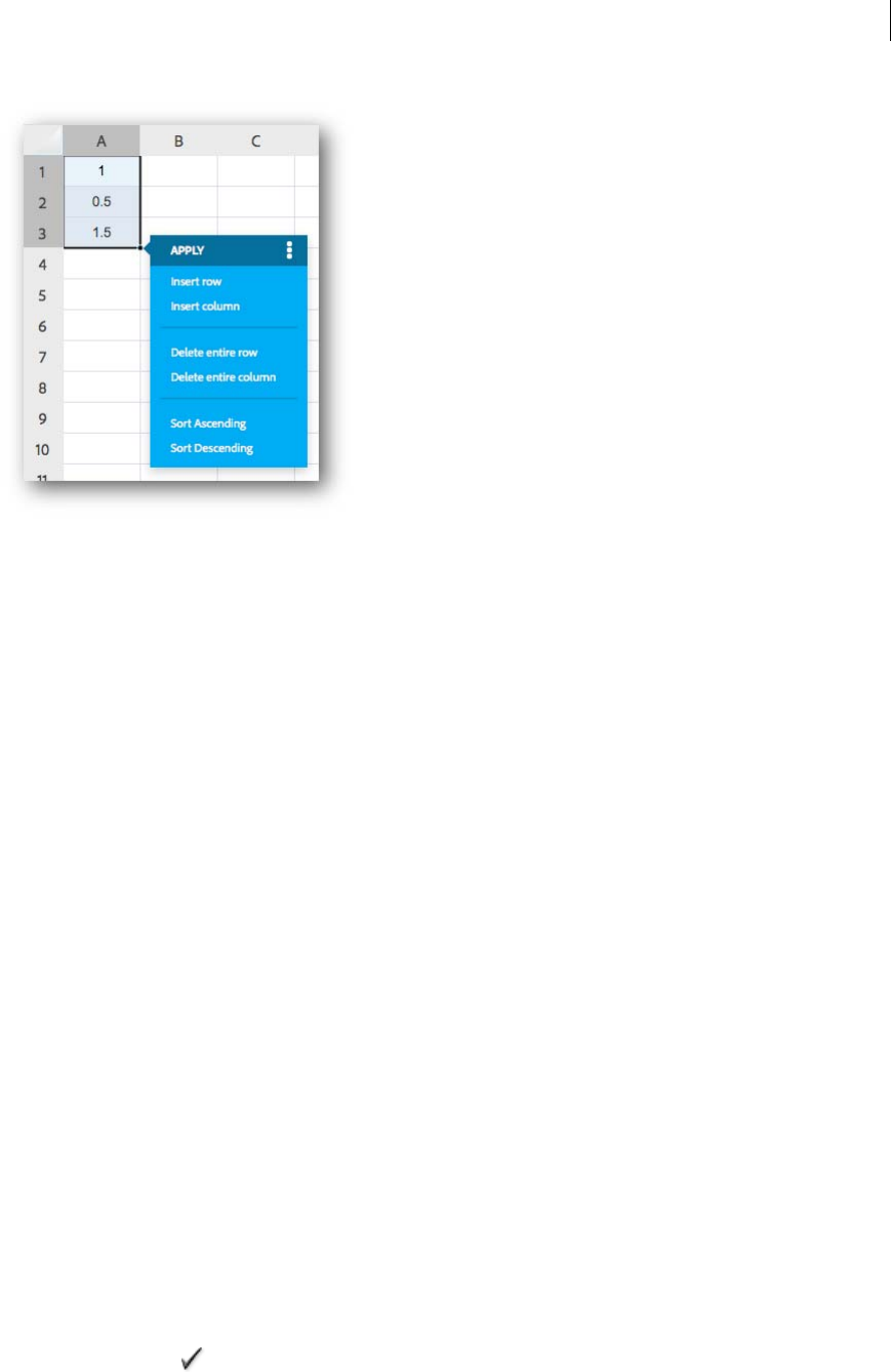
524
Graphs
Last updated 6/5/2015
6When done, click Apply, and then click Save, to ensure the changes are available inside Illustrator.
Graphs
Creating graphs
Graphs let you communicate statistical information in a visual way. In Adobe Illustrator, you can create nine different
types of graphs and customize them to suit your needs. Click and hold the graph tool in the Tools panel to see all
different types of graphs you can create.
Create a graph
1Select a graph tool.
The tool you use initially determines the type of graph Illustrator generates; however, you can easily change the type
of graph later on.
2Define the dimensions of the graph in any of the following ways:
•Drag diagonally from the corner where you want the graph to begin to the opposite corner. Alt-drag (Windows)
or Option-drag (Mac OS) to draw the graph from its center. Hold down Shift to constrain the graph to a square.
•Click where you want to create the graph. Enter a width and height for the graph, and click OK.
Note: The dimensions you define are for the main body of the graph and do not encompass the graph’s labels and
legend.
3Enter data for the graph in the Graph Data window.
Note: Graph data must be arranged in a specific order, which varies by graph type. Before you start to enter data, be
sure to read about how to organize labels and data sets in the worksheet.
4Click the Apply button , or press the Enter key on the numeric keypad to create the graph.
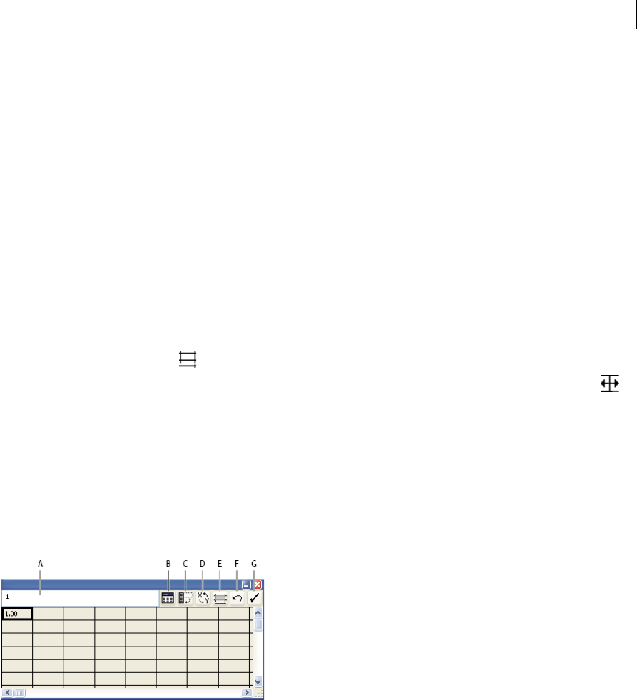
525
Graphs
Last updated 6/5/2015
The Graph Data window stays open until you close it. This allows you to easily switch between editing graph data
and working on the artboard.
More Help topics
Graph tool gallery
Adjust column width or decimal precision
Adjusting the column width has no effect on the width of columns in the graph; it only lets you view more or fewer
digits in a column.
With the default value of 2 decimals, the number 4 entered in a cell appears in the Graph Data window box as 4.00, and
the number 1.55823 entered in a cell displays as 1.56.
Adjust the width of columns
❖Do one of the following:
•Click the Cell Style button , and enter a value between 0 and 20 in the Column Width text box.
•Position the pointer at the edge of the column you want to adjust. The pointer changes to a double arrow .
Then drag the handle to the desired position.
Adjust the decimal precision for cells
❖ Click the Cell Style button, and enter a value between 0 and 10 in the Number of Decimals text box.
Enter graph data
You use the Graph Data window to enter the data for your graph. The Graph Data window appears automatically when
you use a graph tool and stays open until you close it.
A Entry text box B Import data C Transpose row/column D Switch x/y E Cell style F Revert G Apply
1Display the Graph Data window for an existing graph: select the entire graph with the Selection tool, and then
choose Object > Graph > Data.
2Enter data in any of the following ways:
•Select a cell in the worksheet, and enter the data in the text box at the top of the window. Press Tab to input the
data and select the next cell in the same row; press Enter or Return to input the data and select the next cell in
the same column; use the arrow keys to move from cell to cell; or simply click another cell to select it.
•Copy data from a spreadsheet application such as Lotus® 1-2-3 or Microsoft Excel. In the Graph Data window,
click the cell that will be the upper-left cell of the data you paste, and choose Edit > Paste.
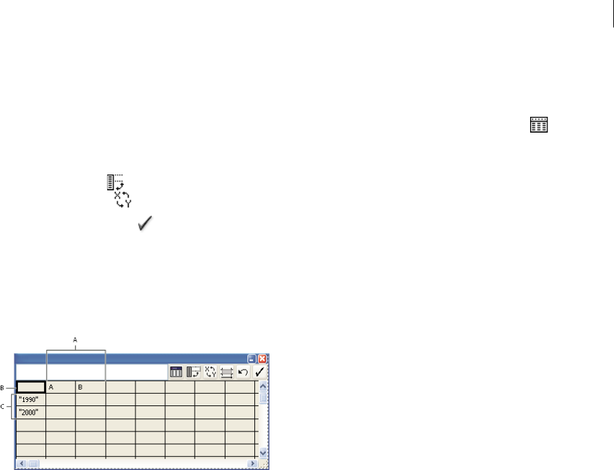
526
Graphs
Last updated 6/5/2015
•Use a word-processing application to create a text file in which the data for each cell is separated by a tab, and the
data for each row is separated by a paragraph return. The data can only contain decimal points or decimal
commas; otherwise, the data is not plotted. (For example, enter 732000, not 732,000.) In the Graph Data window,
click the cell that will be the upper-left cell of the data you import, click the Import Data button , and select
the text file.
Note: If you accidentally enter graph data backward (that is, in rows instead of columns, or vice versa), click the
Transpose button to switch the columns and rows of data. To switch the x and y axes of scatter graphs, click the
Switch X/Y button .
3Click the Apply button or press the Enter key on the numeric keypad to regenerate the graph.
Use graph labels and data sets
Labels are words or numbers that describe two things: the sets of data you want to compare, and the categories across
which you want to compare them. For column, stacked column, bar, stacked bar, line, area, and radar graphs, you enter
labels in the worksheet as follows:
A Data set labels B Blank cell C Category labels
Enter labels
❖For column, stacked column, bar, stacked bar, line, area, and radar graphs, enter labels in the worksheet as follows:
•If you want Illustrator to generate a legend for the graph, delete the contents of the upper-left cell and leave the
cell blank.
•Enter labels for the different sets of data in the top row of cells. These labels will appear in the legend. If you don’t
want Illustrator to generate a legend, don’t enter data-set labels.
•Enter labels for the categories in the left column of cells. Categories are often units of time, such as days, months,
or years. These labels appear along either the horizontal axis or vertical axis of the graph, with the exception of
radar graphs, for which each label results in a separate axis.
•To create labels consisting only of numbers, enclose the numbers in straight quotation marks. For example, enter
"1996" to use the year 1996 as a label.
•To create line breaks in labels, use the vertical bar key to separate lines. For example, type
Total|subscriptions|1996 to produce the following graph label:
Total
subscriptions
1996
Enter data sets for scatter graphs
A scatter graph differs from the other kinds of graphs in that both axes measure values; there are no categories.
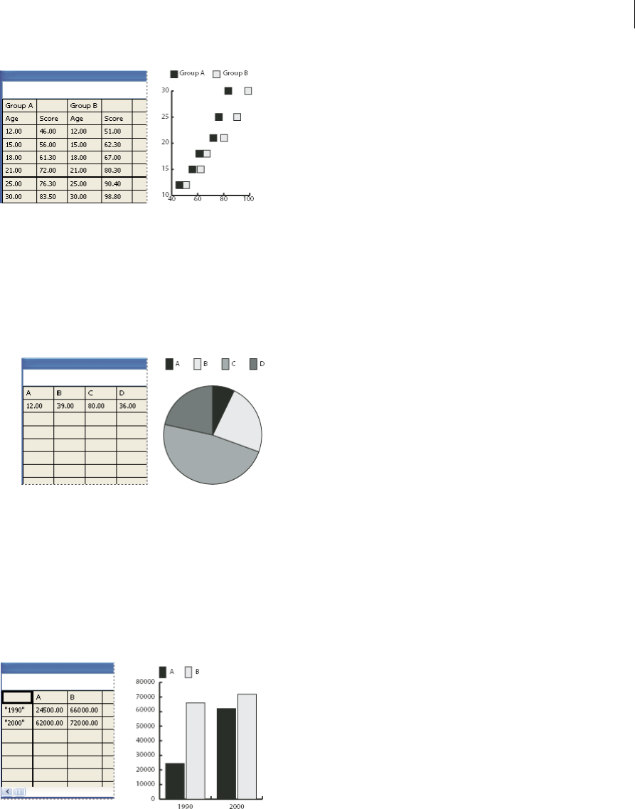
527
Graphs
Last updated 6/5/2015
•Enter data-set labels in every other cell along the top row of the worksheet, starting with the first cell. These labels
will appear in the legend.
•Enter y-axis data in the first column and x-axis data in the second column.
Enter data sets for pie graphs
You organize data sets for pie graphs similarly to other graphs. However, each row of data in the worksheet generates a
separate graph.
•Enter data-set labels as for column, stacked column, bar, stacked bar, line, area, and radar graphs. Enter category
labels if you want to generate graph names.
•To create a single pie graph, plot only one row of data, either all positive or all negative values.
•To create multiple pie graphs, plot additional rows of data, either all positive or all negative values. By default, the
size of the individual pie graphs is proportional to the total of each graph’s data.
Enter data sets for column, bar, line, area, and radar graphs
After you enter the labels for your graph, you’re ready to enter each set of data under the appropriate column.
Column, stacked column, bar, stacked bar graphs The height of the column or length of the bar corresponds to the
amount being compared. For column or bar graphs, you can combine positive and negative values; negative values
appear as columns extending below the horizontal axis. For stacked column graphs, numbers must be all positive or all
negative.
Line graphs Each column of data corresponds to one line in the line graph. You can combine positive and negative
values in a line graph.

528
Graphs
Last updated 6/5/2015
Area graphs Values must be all positive or all negative. Each row of data entered corresponds to a filled area on the area
graph. Area graphs add each column’s values to the previous column’s totals. Therefore, even if area graphs and line
graphs contain the same data, they appear substantially different.
Radar graphs Each number is plotted on an axis and connected to the others in the same axis to create a “web.” You can
combine positive and negative values in a radar graph.
Formatting graphs
Formatting and customizing graphs
Graphs can be formatted in a variety of ways. For example, you can change the appearance and position of the graph’s
axes, add drop shadows, move the legend, and combine different graph types. You can view the formatting options for
a graph by selecting a graph with the Selection tool and choosing Object > Graph > Type.
You can also manually customize your graph in numerous ways. You can change the colors of shading; change the
typeface and type style; move, reflect, shear, rotate, or scale any or all parts of the graph; and customize column and
marker designs. You can apply transparency, gradients, blends, brush strokes, graphic styles, and other effects to graphs.
You should always apply these types of changes last, because regenerating the graph will remove them.
To get ideas for how you can customize graphs, see the examples in the Cool Extras/Sample Files/Graph Designs folder
inside the Illustrator application folder.
Keep in mind that a graph is a grouped object that is related to its data. Never ungroup the graph; if you do, you cannot
change the graph. To edit a graph, select the parts you want to edit without ungrouping the graph, using either the
Direct Selection tool or the Group Selection tool.
It is also important to understand how elements of a graph are related. The entire graph with its legends is one group.
All the sets of data are a subgroup of the graph; in turn, each set of data with its legend box is a subgroup of all the sets
of data. Each value is a subgroup of its set of data, and so on. Never ungroup or regroup objects that are within the
graph.
Change the graph type
1Select a graph with the Selection tool.
2Choose Object > Graph > Type, or double-click the graph tool in the Tools panel.
3In the Graph Type dialog box, click the button that corresponds to the desired graph type, and click OK.
Note: Once graph objects are painted with gradients, changing graph types can cause unexpected results. To prevent
undesirable results, either do not apply gradients until the graph is finished, or use the Direct Selection tool to select
gradient-painted objects and paint those objects with a process color; then reapply the original gradients.
Format a graph’s axes
With the exception of pie graphs, all graphs have a value axis which displays the unit of measurement for the graph. You
can choose to display the value axis on one side or both sides of the graph. Bar, stacked bar, column, stacked column,
line, and area graphs also have a category axis which defines the categories of data in the graph.
You can control how many tick marks appear on each axis, change the length of tick marks, and add a prefix and suffix
to numbers on the axis.
1Select the graph with the Selection tool.
2Choose Object > Graph > Type, or double-click the graph tool in the Tools panel.

529
Graphs
Last updated 6/5/2015
3To change the position of the value axis, select an option from the Value Axis menu.
4To format tick marks and labels, select an axis from the pop-up menu at the top of the dialog box, and set the
following options:
Tick Values Determines the placement of tick marks on value axes, left axes, right axes, bottom axes, or top axes.
Select Override Calculated Values to manually calculate the placement of tick marks. Either accept the values set
when you created the graph or enter a minimum value, a maximum value, and the number of divisions between
labels.
Tick Marks Determines the length of tick marks and number of tick marks per division. For category axes, select
Draw Tick Marks Between Labels to draw tick marks on either side of the labels or columns, or deselect the option
to center tick marks over the labels or columns.
Add Labels Specifies a prefix and suffix for numbers on value axes, left axes, right axes, bottom axes, or top axes.
For example, you can add a dollar sign or percent sign to axis numbers.
Assign different scales to the value axes
If your graph has a value axis on both sides, you can assign a different set of data to each axis. This causes Illustrator to
generate a different scale for each axis. This technique is especially useful when you combine different graph types in
the same graph.
1Select the Group Selection tool .
2Click the legend for the data set you want to assign to the axis.
3Without moving the Group Selection tool pointer from the legend, click again. All of the columns grouped with the
legend are selected.
4Choose Object > Graph > Type, or double-click the graph tool in the Tools panel.
5From the Value Axis pop-up menu, select the axis to which you want to assign the data.
6Click OK.
More Help topics
Selection tool gallery
Format columns, bars, and lines
For column, stacked column, bar, and stacked bar graphs, you can adjust the amount of space between each column or
bar in the graph. You can also adjust the amount of space between the categories, or clusters, of data in the graph. For
line, scatter, and radar graphs, you can adjust the appearance of lines and data points.
1Select the graph with the Selection tool.
2Choose Object > Graph > Type, or double-click the graph tool in the Tools panel.
3To adjust the space between columns and bars in a column, stacked column, bar, or stacked bar graph, enter a value
between 1% and 1000% in the Column Width, Bar Width, or Cluster Width text box.
A value greater than 100% causes the columns, bars, or clusters to overlap one another. A value less than 100% leaves
space between the columns, bars, or clusters. A value of 100% moves the columns, bars, or clusters flush against each
other.
4To adjust lines and data points in line, scatter, and radar graphs, set the Mark Data Points, Connect Data Points,
Edge-to-Edge Lines, and Draw Filled Lines options.
5To change how columns, bars, and lines overlap, set the First Row In Front and First Column In Front options.

530
Graphs
Last updated 6/5/2015
Note: Always select First Column In Front for area graphs; if you do not, some areas may not appear.
General graph options
You can access general graph options by selecting the graph with the Selection tool and double-clicking the graph tool
in the Tools panel.
Value Axis Determines where the value axis (the axis that displays the unit of measurement) appears.
Add Drop Shadow Applies drop shadows behind the columns, bars, or lines in a graph, and to entire pie graphs.
Add Legend Across Top Displays the legend horizontally across the top of the graph instead of to the right of the graph.
First Row In Front Controls how the categories, or clusters, of data in a graph overlap when the Cluster Width is greater
than 100%. This option is the most useful when working with column and bar graphs.
First Column In Front Places the column, bar, or line that corresponds to the first column of data in the Graph Data
window on top. This option also determines which column is on top for column and stacked column graphs with a
Column Width greater than 100% and for bar and stacked bar graphs with a Bar Width greater than 100%.
Mark Data Points Places square markers at each data point.
Connect Data Points Draws lines that make it easier to see relationships among data.
Edge-to-Edge Lines Draws lines that extend across the graph, from left to right along the horizontal (x) axis. This
option is not available for scatter graphs.
Draw Filled Lines Creates a wider line according to the value you enter in the Line Width text box, and which fills the
line with paint according to the specifications for that series of data. This option becomes available when you select
Connect Data Points.
Add drop shadows
You can apply drop shadows behind the columns, bars, or lines in a graph, and to entire pie graphs.
1Select a graph with the Selection tool.
2Choose Object > Graph > Type, or double-click the graph tool in the Tools panel.
3In the Graph Type dialog box, select Add Drop Shadow, and click OK.
Change the position of a legend
By default, the legend is displayed to the right of the graph. However, you can choose to display it horizontally across
the top of the graph.
1Select a graph with the Selection tool.
2Choose Object > Graph > Type, or double-click the graph tool in the Tools panel.
3In the Graph Type dialog box, select Add Legend Across Top, and click OK.
Format pie graphs
You can change the placement of the legend and how wedges are sorted in pie graphs. You can also specify how you
want to display multiple pie graphs.
1Select the graph with the Selection tool.
2Choose Object > Graph > Type, or double-click the graph tool in the Tools panel.
3Do any of the following:
•To change the placement of the legend, select an option for Legend.

531
Graphs
Last updated 6/5/2015
•To specify how multiple pie graphs are displayed, select an option for Position.
•To specify how wedges are sorted, select an option for Sort.
Tip: Percentages and legends are painted black by default. If a pie wedge with a dark background obscures a
legend, repaint the dark background. Use the Group Selection tool to select the dark pie wedges, and paint the
wedges using the Color panel or Swatches panel.
Pie graph options
Legend Determines the placement of the legend.
Standard Legend Places column labels outside the graph; this is the default. Use this option when you combine pie
graphs with other kinds of graphs.
Legends In Wedges Inserts labels into the corresponding wedges.
No Legend Omits legends entirely.
Position Specifies how multiple pie graphs are displayed.
Ratio Sizes the graphs proportionally.
Even Makes all the pie graphs the same diameter.
Stacked Stacks each pie graph on top of the other, and each graph is sized proportionally to each other.
Sort Specifies how wedges are sorted.
All Sorts the wedges of the selected pie graphs from largest to smallest value proceeding clockwise from the top of the
pie graph.
First Sorts the wedges of the selected pie graphs so that the largest value in the first graph will be placed in the first
wedge, and the rest will sort from largest to smallest. All other graphs will follow the order of the wedges in the first
graph.
None Sorts the wedges of the selected pie graphs in the order in which you entered values proceeding clockwise from
the top of the graphs.
Combine different graph types
You can combine different graph types in one graph. For example, you may want one set of data to appear as a column
graph and other sets of data to appear as a line graph. You can combine any type of graph with any other, with the
exception of scatter graphs. Scatter graphs cannot be combined with any other graph type.
1Select the Group Selection tool .
2Click the legend for the data whose graph type you want to change.
3Without moving the Group Selection tool pointer from the legend, click again. All of the columns grouped with the
legend are selected.
4Choose Object > Graph > Type, or double-click the graph tool in the Tools panel.

532
Graphs
Last updated 6/5/2015
5Select the graph type and options you want.
If a graph uses more than one graph type, you may want one set of data along the right axis and the other set of data
along the left axis. In this way, each axis measures different data.
Note: If you use stacked column graphs with other graph types, be sure to use the same axis for all sets of data that are
represented by stacked column graphs. If some sets of data use the right axis while others use the left, the column heights
may be misleading or may overlap.
Select parts of a graph
1Select the Group Selection tool .
2Click the legend of the columns you want to select.
3Without moving the Group Selection tool pointer from the legend, click again. All of the columns grouped with the
legend are selected.
You can also select a group by clicking one of its parts, clicking again to select columns grouped with it, and clicking
a third time to select the legend. Each click adds another layer of grouped objects to the selection, beginning with
the next group up in the hierarchy. You can click as many times as the number of groups to add to a selection.
4To deselect part of a selected group, select the Direct Selection tool , and Shift-click the object.
Format the text in a graph
Illustrator uses a default font and font size when generating text for the graph’s labels and legend. However, you can
easily change the formatting of type to add visual interest to your graph.
1Select the Group Selection tool .
2Click once to select the baseline of the type you want to change; click twice to select all of the type.
3Change the type attributes as desired.
Adding pictures and symbols to graphs
About graph designs
You use graph designs to add illustrations to columns and markers. Graph designs can be simple drawings, logos, or
other symbols representing values in a graph; they can also be complex objects that contain patterns and guide objects.
Illustrator comes with a variety of preset graph designs. In addition, you can create new graph designs and store them
in the Graph Design dialog box.
You c a n app ly gr aph d e s ig n to columns in several ways:
Vertically scaled design Is stretched or compressed vertically. Its width does not change.
Uniformly scaled design Is scaled both vertically and horizontally. The horizontal spacing of the designs is not adjusted
for the different widths.
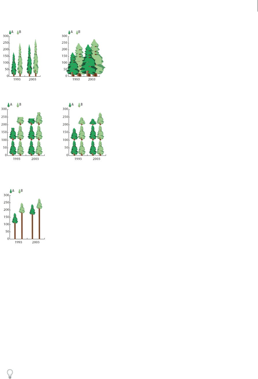
533
Graphs
Last updated 6/5/2015
Repeating design Stacks a design to fill the columns. You can specify the value that each design represents, as well as
whether you want to chop or scale designs that represent fractions.
Sliding design Is similar to a vertically scaled design, except that you can specify where in the design to stretch or
compress it. For example, if you were using a person to represent data, you might stretch or compress only the body,
but not the head. Using the Vertically Scaled option would scale the entire person.
Import a column or marker design
Illustrator comes with a variety of preset designs that you can use in your graphs. You can also transfer the graph designs
you create between documents.
1Choose Window > Swatch Libraries > Other Library.
2Do one of the following:
•To import preset graph designs, navigate to the Cool Extras/Sample Files/Graph Designs folder inside the
Illustrator application folder. Then select a graph designs file, and click Open.
•To import graph designs from another document, select the document, and click Open.
Initially, all that appears is a new panel with colors, gradients, and patterns from the imported file. However, the
imported graph designs will be available when you open the Graph Column or Graph Marker dialog box.
Create a column design
1Create a rectangle as the backmost object in the design. The rectangle represents the boundary of the graph design.
Copy and paste the smallest column in your graph to use it as the bounding rectangle for your design.
534
Graphs
Last updated 6/5/2015
2Paint the rectangle as desired, or fill and stroke it with None so that it is invisible.
3Create the design using any of the drawing tools, or position an existing design in front of the rectangle.
4Using the Selection tool , select the entire design, including the rectangle.
5Choose Object > Group to group the design.
6Choose Object > Graph > Design.
7Click New Design. A preview of the selected design appears. Only the portion of the design that fits inside the
backmost rectangle is visible, but the whole design appears when used in the graph.
8Click Rename to name the design.
Creating a graph design is similar to creating a pattern.
More Help topics
About patterns
Create a sliding column design
1Create a rectangle as the backmost object in the design. This rectangle is the boundary for the graph design.
2Create the design using one of the drawing tools, or place an existing design in front of the rectangle.
3Use the Pen tool to draw a horizontal line to define where the design is to be stretched or compressed.
4Select all parts of the design, including the horizontal line.
5Choose Object > Group to group the design.
6Use the Direct Selection tool or Group Selection tool to select the horizontal line. Be sure to select only the
horizontal line.
7Choose View > Guides > Make Guides.
8Choose View > Guides > Lock Guides to remove the check mark next to Lock so you can unlock the guides. Move
the design around to make sure that the guide moves with the design.
9Use the Selection tool to select the whole design.
10 Choose Object > Graph > Design.
11 Click New Design. A preview of the selected design appears.
12 Click Rename to name the design.
Add totals to a column design
1Create the column design.
2Select the Type tool . Position the pointer at a point where you want the value to appear, near or in the rectangle
that defines the design.
For example, you can place the value in, above, below, to the left, or to the right of the design.
3Click and type a percent sign (%) followed by two digits from 0 to 9. The digits control how the data is displayed.
The first digit determines how many places appear before the decimal point. For example, if your total was 122, a
digit of 3 would display 122. If you enter 0 for the first digit, the program adds the number of places necessary for
the value.
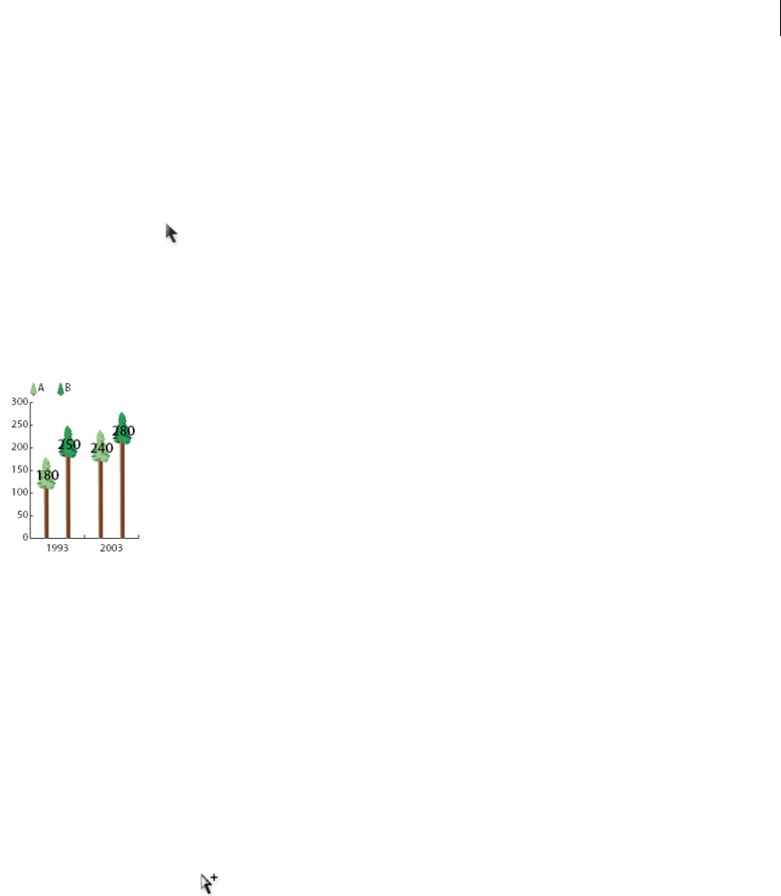
535
Graphs
Last updated 6/5/2015
The second digit determines how many places appear after the decimal point. Zeros are added as necessary, and
values are rounded up or down as necessary. You can vary these numbers, depending on how many digits you need.
4To change the type attributes, choose Window > Type > Character, specify the attributes you want, and close the
panel.
5To align the decimal points, choose Window > Type > Paragraph and click the Align Text Right button.
6Using the Selection tool , select the entire design, including the rectangle and any type.
7Choose Object > Group to group the design.
8Choose Object > Graph > Design.
9Click New Design. You see a preview of the selected design.
10 Click Rename to name the design.
Create a marker design
1Select and copy a marker rectangle from the graph, and paste it where you're going to create your design. This will
be the backmost object in your graph design and will establish the size of the marker.
2Make the marker artwork the size you want it to be in the graph, even if it’s larger than the marker rectangle you
copied.
3Once you’ve got the marker design the way you want it, select the design, choose Object > Graph > Design, and click
New Design.
4Click Rename to name the design.
Apply a column design to a graph
1Create or import the column design.
2Use the Group Selection tool to select the columns or bars you want to fill with the design, or select the entire
graph.
3Choose Object > Graph > Column.
4Select a column design type.
If you choose the Repeating Column Type, enter a value in the Each Design Represents text box. Also select whether
to chop or scale any fractions of the design from the For Fractions pop-up menu. Chop Design cuts off a fraction of
the top design as necessary; Scale Design scales the last design to fit in the column.
5Select the design you want to use. A preview of the selected design appears.
6Click OK.
Apply a marker design to a line or scatter graph
1Create or import the column design.

536
Graphs
Last updated 6/5/2015
2Use the Group Selection tool to select the markers and the legends in the graph that you want to replace with a
design. Do not select any lines.
3Choose Object > Graph > Marker. Select a design, and click OK.
The design is scaled so that the backmost rectangle in the design is the same size as the default square marker on the
line or scatter graph.
Reuse a graph design
You can reuse a graph design that you created and edit it to make a new design. If you have the original artwork, you
can alter it and then rename the design using the Graph Design dialog box.
If you don’t have the original artwork defined as a graph design, you can retrieve the original by pasting the graph
design into your artwork.
1Choose Select > Deselect to deselect all of the artwork.
2Choose Object > Graph > Design.
3Select the graph design that you want to paste into your artwork, and click Paste Design.
4Click OK. The graph design is pasted into your artwork. You can now edit it and define it as a new graph design.
More Help topics
Graph tool gallery

537
Last updated 6/5/2015
Chapter 15: Keyboard shortcuts
Customizing keyboard shortcuts
Keyboard shortcuts make you more productive in Illustrator. You can use the default shortcuts included with
Illustrator, or add and customize shortcuts to suit your needs.
Customize keyboard shortcuts
Illustrator lets you view a list of all shortcuts, and edit or create shortcuts. The Keyboard Shortcuts dialog box serves as
a shortcut editor, and includes all commands that support shortcuts, some of which aren’t addressed in the default
shortcut set.
You can define your own sets of shortcuts, change individual shortcuts within a set, and switch between sets of
shortcuts. For example, you can create separate sets for different workspaces chosen from the Window > Workspace
menu.
If you have previously saved a set of keyboard shortcuts other than the default, then the keyboard shortcuts are stored
in a .kys file in Illustrator's preferences folder. You can copy this file into the same location (in Ai’s preferences folder)
in the new computer. You can then choose this set from Illustrator’s Keyboard Shortcuts dialog.
You can use the same .kys file across platforms as long as the modified shortcuts are valid for the platforms.
Following are the locations where the custom Illustrator keyboard shortcuts are saved by default:
Mac OS:
user/Library/Preferences/Illustrator CS5 Settings/[language]/mycustomshortcut.kys
Windows Vista and Windows 7
<rootdir>\Users\[user name]\AppData\Roaming\Adobe\Adobe Illustrator
CS5 Settings\[language]\mycustomshortcut.kys
Win XP
<rootdir>\Document and Settings\<user name>\Application Data\Adobe\Adobe
Illustrator CS5 Settings\[language]\mycustomshortcut.kys
In addition to using keyboard shortcuts, you can access many commands using context-sensitive menus. Context-
sensitive menus display commands that are relevant to the active tool, selection, or panel. To display a context-sensitive
menu, right-click (Windows) or Control-click (Mac OS) in the document window or panel.
1Choose Edit > Keyboard Shortcuts.
2Choose a set of shortcuts from the Set menu at the top of the Keyboard Shortcuts dialog box.
3Choose a shortcut type (Menu Commands or Tools) from the menu above the shortcut display.
4Do any of the following:
•To activate the set of shortcuts, click OK.

538
Keyboard shortcuts
Last updated 6/5/2015
•To change a shortcut, click in the Shortcut column of the scroll list and type a new shortcut. If you enter a shortcut
that is already assigned to another command or tool, an alert appears at the bottom of the dialog box. Click Undo
to undo the change, or click Go To to go to the other command or tool and assign it a new shortcut. In the Symbol
column, type the symbol that will appear in the menu or tool tip for the command or tool. You can use any of the
characters that are allowed in the Shortcut column.
note: Mac OS does not allow you to assign Command+Option+8 as a menu shortcut.
•To save changes to the current set of shortcuts, click OK. (You can’t save changes to the set named Illustrator
Defaults.)
•To save a new set of shortcuts, click Save. Enter a name for the new set, and click OK. The new key set will appear
in the pop-up menu under the new name.
•To delete the set of shortcuts, click Delete. (You can’t delete the set named Illustrator Defaults.)
•To export the displayed set of shortcuts into a text file, click Export Text. In the Save Key Set File As dialog box,
enter a filename for the current key set that you are saving, and click Save. You can use this text file to print out
a copy of your keyboard shortcuts.
More Help topics
Default keyboard shortcuts
Default keyboard shortcuts
Keys for selecting tools
Result Windows Mac OS
Artboard tool Shift + O Shift + O
Selection tool V V
Direct Selection tool A A
Magic Wand tool Y Y
Lasso tool Q Q
Pen tool P P
Blob Brush tool Shift + B Shift + B
Add Anchor Point tool + (plus) + (plus)
Delete Anchor Point tool - (minus) - (minus)
Convert Anchor Point tool Shift + C Shift + C
Type tool T T
Line Segment tool \ (backslash) \ (backslash)
Rectangle tool M M
Ellipse tool L L

539
Keyboard shortcuts
Last updated 6/5/2015
Keys for viewing artwork
This is not a complete list of keyboard shortcuts. This table lists only those shortcuts that are not displayed in menu
commands or tool tips.
Paintbrush tool B B
Pencil tool N N
Rotate tool R R
Reflect tool O O
Scale tool S S
Warp tool Shift + R Shift + R
Width Tool Shift+W Shift+W
Free Transform tool E E
Shape Builder Tool Shift+M Shift+M
Perspective Grid Tool Shift+P Shift+P
Perspective Selection Tool Shift+V Shift+V
Symbol Sprayer tool Shift + S Shift + S
Column Graph tool J J
Mesh tool U U
Gradient tool G G
Eyedropper tool I I
Blend tool W W
Live Paint Bucket tool K K
Live Paint Selection tool Shift + L Shift + L
Slice tool Shift + K Shift + K
Eraser tool Shift + E Shift + E
Scissors tool C C
Hand tool H H
Zoom tool Z Z
Switch to Smooth tool while using Blob Brush
tool
Press Alt Press Option
Result Windows Mac OS
Toggle between screen modes: Normal
Screen Mode, Full Screen Mode with Menu
Bar, Full Screen Mode
F F
Fit imageable area in window Double-click Hand tool Double-click Hand tool
Magnify 100% Double-click Zoom tool Double-click Zoom tool
Result Windows Mac OS

540
Keyboard shortcuts
Last updated 6/5/2015
Keys for drawing
This is not a complete list of keyboard shortcuts. This table lists only those shortcuts that are not displayed in menu
commands or tool tips.
Switch to Hand tool (when not in text-edit
mode)
Spacebar Spacebar
Switch to Zoom tool in magnify mode Ctrl + Spacebar Spacebar + Command
Switch to Zoom tool in reduce mode Ctrl + Alt + Spacebar Spacebar + Command + Option
Move Zoom marquee while dragging with the
Zoom tool
Spacebar Spacebar
Hide unselected artwork Control + Alt + Shift + 3 Command + Option + Shift + 3
Convert between horizontal and vertical
guide
Alt-drag guide Option-drag guide
Release guide Ctrl + Shift-double-click guide Command + Shift-double-click guide
Show/Hide artboards Ctrl + Shift + H Command + Shift + H
Show/Hide artboard rulers Ctrl + Alt + R Command + Option + R
View all artboards in window Ctrl + Alt + 0 (zero) Command + Option + 0 (zero)
Paste in place on the active artboard Ctrl+Shift+V Command+Shift+V
Exit Artboard tool mode Esc Esc
Create artboard inside another artboard Shift-drag Shift-drag
Select multiple artboards in the Artboards
panel
Ctrl+click Command+click
Navigate to next document Ctrl + F6 Command+F6
Navigate to previous document Ctrl + Shift + F6 Command+Shift+F6
Navigate to next document group Ctrl + Alt + F6 Command+Option+F6
Navigate to previous document group Ctrl + Alt + Shift + F6 Command+Option+Shift+F6
Exit Full Screen mode Esc Esc
Save multiple artboards to Illustrator CS3 or
earlier format
Alt + v
Result Windows Mac OS

541
Keyboard shortcuts
Last updated 6/5/2015
Result Windows Mac OS
Constrain a shape’s proportions or orientation
to:
•equal height and width for rectangles,
rounded rectangles, ellipses, and grids
•Increments of 45° for line and arc segments
•Original orientation for polygons, stars, and
flares
Shift-drag Shift-drag
Move a shape while drawing it spacebar-drag spacebar-drag
Draw from the center of a shape (except for
polygons, stars, and flares)
Alt-drag Option-drag
Increase or decrease polygon sides, star
points, arc angle, spiral winds, or flare rays
Start dragging, then press the Up Arrow or
Down Arrow
Start dragging, then press the Up Arrow or
Down Arrow
Keep the inner radius of a star constant Start dragging, then hold down Ctrl Start dragging, then hold down Command
Keep the sides of a star straight Alt-drag Option-drag
Switch between an open and closed arc Start dragging, then hold down C Start dragging, then hold down C
Flip an arc, keeping the reference point
constant
Start dragging, then hold down F Start dragging, then hold down SF
Add or subtract winds from a spiral while
increasing the length of the spiral
Start dragging, then Alt-drag Start dragging then Option-drag
Change the decay rate of a spiral Start dragging then Ctrl-drag Start dragging then Command-drag
Add or remove horizontal lines from a
rectangular grid or concentric lines from a
polar grid
Start dragging, then press the Up Arrow or
Down Arrow
Start dragging, then press the Up Arrow or
Down Arrow
Add or remove vertical lines from a
rectangular grid or radial lines from a polar
grid
Start dragging, then press the Right Arrow or
Left Arrow
Start dragging, then press the Right Arrow or
Left Arrow
Decrease the skew value for horizontal
dividers in a rectangular grid or radial dividers
in a polar grid by 10%
Start dragging, then press F Start dragging, then press F
Increase the skew value for horizontal dividers
in a rectangular grid or radial dividers in a
polar grid by 10%
Start dragging, then press V Start dragging, then press V
Decrease the skew value for vertical dividers
in a rectangular grid or concentric dividers in
a polar grid by 10%
Start dragging, then press X Start dragging, then press X
Increase the skew value for vertical dividers in
a rectangular grid or concentric dividers in a
polar grid by 10%
Start dragging, then press C Start dragging, then press C
Create and expand a Live Trace object in one
step
Alt-click Live Trace in the Control panel, or
hold down Alt and select a tracing preset.
Option-click Live Trace in the Control panel, or
hold down Option and select a tracing preset.
Increase size of Blob Brush ] (right square bracket) ] (right square bracket)
Decrease size of Blob Brush [ (left square bracket) [ (left square bracket)
Constrain Blob Brush path horizontally or
vertically
Shift Shift
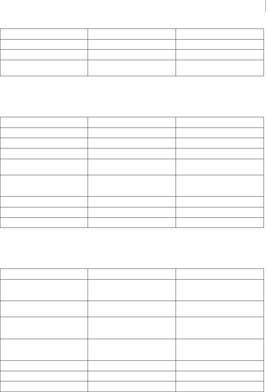
542
Keyboard shortcuts
Last updated 6/5/2015
Keys for drawing in perspective
This is not a complete list of keyboard shortcuts. This table lists only those shortcuts that are not displayed in menu
commands or tool tips.
Keys for selecting
This is not a complete list of keyboard shortcuts. This table lists only those shortcuts that are not displayed in menu
commands or tool tips.
Switch through drawing modes Shift+D Shift+D
Join two or more paths Select the paths, then press Ctrl+J Select the paths, then press Command+J
Create corner or smooth join Select the paths, then press Shift+Ctrl+Alt+j Select the anchor point, then press
Shift+Command+Option+j
Results Windows Mac OS
Perspective Grid Tool Shift+P Shift+P
Perspective Selection Tool Shift+V Shift+V
Perspective Grid Ctrl+Shift+I Command+Shift+I
Moving objects perpendicularly Press the number 5 key, then click and drag
the object
Press the number 5 key, then click and drag
the object
Switching perspective planes Use the Perspective Selection tool and then
press 1 for left grid, 2 for horizontal grid, 3 for
right grid, or 4 for no active grid
Use the Perspective Selection tool and then
press 1 for left grid, 2 for horizontal grid, 3 for
right grid, or 4 for no active grid
Copying objects in perspective Ctrl+Alt+drag Command+Alt+drag
Repeat transforming objects in perspective Ctrl+D Command+D
Switching between drawing modes Shift+D Shift+D
Result Windows Mac OS
Switch to last-used selection tool (Selection
tool, Direct Selection tool, or Group Selection
tool)
Ctrl Command
Switch between Direct Selection tool and
Group Selection tool
Alt Option
Add to a selection with Selection tool, Direct
Selection tool, Group Selection tool, Live Paint
Selection tool, or Magic Wand tool
Shift-click Shift-click
Subtract a selection with Selection tool, Direct
Selection tool, Group Selection tool, or LIve
Paint Selection tool
Shift-click Shift-click
Subtract from selection with Magic Wand tool Alt-click Option-click
Add to selection with Lasso tool Shift-drag Shift-drag
Subtract from selection with Lasso tool Alt-drag Option-drag
Result Windows Mac OS
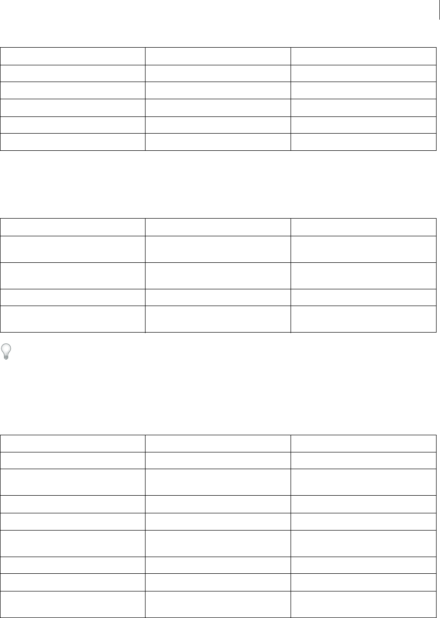
543
Keyboard shortcuts
Last updated 6/5/2015
Keys for moving selections
This is not a complete list of keyboard shortcuts. This table lists only those shortcuts that are not displayed in menu
commands or tool tips.
Set keyboard increments in General Preferences
Keys for editing shapes
This is not a complete list of keyboard shortcuts. This table lists only those shortcuts that are not displayed in menu
commands or tool tips.
Change pointer to cross hair for Lasso tool Caps Lock Caps Lock
Select artwork in active artboard Ctrl + Alt + A Command + Option + A
Create crop marks around selected object Alt + c + o
Select behind an object Press Ctrl+click twice Press Command+click twice
Select behind in isolation mode Ctrl+click twice Command+click twice
Result Windows Mac OS
Move selection in user-defined increments Right Arrow, Left Arrow, Up Arrow, or Down
Arrow
Right Arrow, Left Arrow, Up Arrow, or Down
Arrow
Move selection in 10x user-defined
increments
Shift + Right Arrow, Left Arrow, Up Arrow, or
Down Arrow
Shift + Right Arrow, Left Arrow, Up Arrow, or
Down Arrow
Lock all deselected artwork Ctrl + Alt + Shift + 2 Command + Option + Shift + 2
Constrain movement to 45° angle (except
when using Reflect tool)
Hold down Shift Hold down Shift
Result Windows Mac OS
Switch Pen tool to Convert Anchor Point tool Alt Option
Switch between Add Anchor Point tool and
Delete Anchor Point tool
Alt Option
Switch Scissors tool to Add Anchor Point tool Alt Option
Switch Pencil tool to Smooth tool Alt Option
Move current anchor point while drawing
with Pen tool
Spacebar-drag Spacebar-drag
Cut a straight line with Knife tool Alt-drag Option-drag
Cut at 45° or 90° with Knife tool Shift + Alt-drag Shift + Option-drag
Use shape mode buttons in Pathfinder panel
to create compound paths
Alt + Shape mode Option + Shape mode
Result Windows Mac OS
544
Keyboard shortcuts
Last updated 6/5/2015
Keys for painting objects
This is not a complete list of keyboard shortcuts. This table lists only those shortcuts that are not displayed in menu
commands or tool tips.
Keys for working with Live Paint groups
This is not a complete list of keyboard shortcuts. This table lists only those shortcuts that are not displayed in menu
commands or tool tips.
Erase unwanted closed regions created using
Shape Builder tool
Alt+click the closed region Option+click the closed region
Select the Shape Builder tool Shift+M Shift+M
Display rectangular marquee to easily merge
multiple paths (when using Shape Builder
tool)
Shift+click+drag Shift+click+drag
Result Windows Mac OS
Toggle between fill and stroke X X
Set fill and stroke to default D D
Swap fill and stroke Shift + X Shift + X
Select gradient fill mode > >
Select color fill mode < <
Select no stroke/fill mode / (forward slash) / (forward slash)
Sample color from an image or intermediate
color from gradient
Shift + Eyedropper tool Shift + Eyedropper tool
Sample style and append appearance of
currently selected item
Alt + Shift-click + Eyedropper tool Option + Shift-click + Eyedropper tool
Add new fill Ctrl + / (forward slash) Command + / (forward slash)
Add new stroke Ctrl + Alt + / (forward slash) Command + Option + / (forward slash)
Reset gradient to black and white Ctrl-click gradient button in Tools panel or
Gradient panel
Command-click gradient button in Tools
panel or Gradient panel
Open Mosaic options for selected raster
object
Alt + o + j
Decrease Bristle brush size [ [
Increase Bristle brush size ] ]
Set Bristle brush paint opacity value Number keys 1 - 0.
Number key 1 increases the value to 10%
Number key 0 increases the value to 100%
Number keys 1 - 0.
Number key 1 increases the value to 10%
Number key 0 increases the value to 100%
Result Windows Mac OS
545
Keyboard shortcuts
Last updated 6/5/2015
Keys for transforming objects
This is not a complete list of keyboard shortcuts. This table lists only those shortcuts that are not displayed in menu
commands or tool tips.
Keys for creating variable width points
This is not a complete list of keyboard shortcuts. This table lists only those shortcuts that are not displayed in menu
commands or tool tips.
Result Windows Mac OS
Switch to Eyedropper tool and sample fill
and/or stroke
Alt-click + Live Paint Bucket tool Option-click + Live Paint Bucket tool
Switch to Eyedropper tool and sample color
from an image or intermediate color from a
gradient
Alt + Shift-click + Live Paint Bucket tool Option + Shift-click + Live Paint Bucket tool
Select opposite Live Paint Bucket tool options
(if Paint Fills and Paint Strokes are currently
selected, switch to Paint Fills only)
Shift + Live Paint Bucket tool Shift + Live Paint Bucket tool
Fill across unstroked edges into adjacent faces Double-click + Live Paint Bucket tool Double-click + Live Paint Bucket tool
Fill all faces that have same fill and stroke all
edges that have same stroke
Triple-click + Live Paint Bucket tool Triple-click + Live Paint Bucket tool
Switch to Eyedropper tool and sample fill
and/or stroke
Alt-click + Live Paint Selection tool Option-click + Live Paint Selection tool
Switch to Eyedropper tool and sample color
from an image or intermediate color from a
gradient
Alt + Shift-click + Live Paint Selection tool Option + Shift-click + Live Paint Selection tool
Add to/subtract from a selection Shift-click + Live Paint Selection tool Shift-click + Live Paint Selection tool
Select all connected faces /edges with same
fill/stroke
Double-click + Live Paint Selection tool Double-click + Live Paint Selection tool
Select all faces/edges with same fill/stroke Triple-click + Live Paint Selection tool Triple-click + Live Paint Selection tool
Result Windows Mac OS
Set origin point and open dialog box when
using Rotate tool, Scale tool, Reflect tool, or
Shear tool
Alt-click Option-click
Duplicate and transform selection when using
Selection tool, Scale tool, Reflect tool, or Shear
tool
Alt-drag Option-drag
Transform pattern (independent of object)
when using Selection tool, Scale tool, Reflect
tool, or Shear tool
Tilde (~)-drag Tilde (~)-drag
546
Keyboard shortcuts
Last updated 6/5/2015
Keys for working with type
This is not a complete list of keyboard shortcuts. This table lists only those shortcuts that are not displayed in menu
commands or tool tips.
Results Windows Mac OS
Select multiple width points Shift+click Shift+click
Create non-uniform widths Alt+drag Option+drag
Create a copy of the width point Alt+drag the width point Options+drag the width point
Change the position of multiple width points Shift+drag Shift+drag
Delete selected width point Delete Delete
Deselect a width point Esc Esc
Result Windows Mac OS
Move one character right or left Right Arrow or Left Arrow Right Arrow or Left Arrow
Move up or down one line Up Arrow or Down Arrow Up Arrow or Down Arrow
Move one word right or left Ctrl + Right Arrow or Left Arrow Command + Right Arrow or Left Arrow
Move up or down one paragraph Ctrl + Up Arrow or Down Arrow Command + Up Arrow or Down Arrow
Select one word right or left Shift + Ctrl + Right Arrow or Left Arrow Shift + Command + Right Arrow or Left Arrow
Select one paragraph before or after Shift + Ctrl + Up Arrow or Down Arrow Shift + Command + Up Arrow or Down Arrow
Extend existing selection Shift-click Shift-click
Align paragraph left, right, or center Ctrl + Shift + L, R, or C Command + Shift + L, R, or C
Justify paragraph Ctrl + Shift + J Command + Shift + J
Insert soft return Shift + Enter Shift + Return
Highlight kerning Ctrl + Alt + K Command + Option + K
Reset horizontal scale to 100% Ctrl + Shift + X Command + Shift + X
Increase or decrease type size Ctrl + Shift + > or < Command + Shift + > or <
Increase or decrease leading Alt + Up or Down Arrow (horizontal text) or
Right or Left Arrow (vertical text)
Option + Up or Down Arrow (horizontal text)
or Right or Left Arrow (vertical text)
Reset tracking/kerning to 0 Ctrl + Alt + Q Command + Option + Q
Increase or decrease kerning and tracking Alt + Right or Left Arrow (horizontal text) or
Up or Down Arrow (vertical text)
Option + Right or Left Arrow (horizontal text)
or Up or Down Arrow (vertical text)
Increase or decrease kerning and tracking by
five times
Ctrl + Alt + Right or Left Arrow (horizontal
text) or Up or Down Arrow (vertical text)
Command + Option + Right or Left Arrow
(horizontal text) or Up or Down Arrow (vertical
text)
547
Keyboard shortcuts
Last updated 6/5/2015
To change the increment value for type shortcuts, choose Edit > Preferences >Type (Windows) or Illustrator >
Preferences >Type (Mac OS). Enter the values you want in the Size/Leading, Baseline Shift, and Tracking text boxes,
and click OK.
Keys for using panels
This is not a complete list of keyboard shortcuts. This table lists only those shortcuts that are not displayed in menu
commands or tool tips.
Keys for the Actions panel
This is not a complete list of keyboard shortcuts. This table lists only those shortcuts that are not displayed in menu
commands or tool tips.
Increase or decrease baseline shift Alt + Shift + Up or Down Arrow (horizontal
text) or Right or Left Arrow (vertical text)
Option + Shift + Up or Down Arrow
(horizontal text) or Right or Left Arrow
(vertical text)
Switch between Type and Vertical Type, Area
Type and Vertical Area Type, and Path Type
and Vertical Path Type tools
Shift Shift
Switch between Area Type and Path Type,
Vertical Area Type and Vertical Path Type tools
Alt Option
Result Windows Mac OS
Set options (except for Actions, Brushes,
Swatches, and Symbols panels)
Alt-click New button Option-click New button
Delete without confirmation (except for
Layers panel)
Alt-click Delete button Option-click Delete button
Apply value and keep text box active Shift + Enter Shift + Return
Select range of actions, brushes, layers, links,
styles, or swatches
Shift-click Shift-click
Select noncontiguous actions, brushes, layers
(same level only), links, styles, or swatches
Ctrl-click Command-click
Show/Hide all panels Tab Tab
Show/Hide all panels except the Tools panel
and Control panel
Shift + Tab Shift + Tab
Result Windows Mac OS
Expand/Collapse entire hierarchy for action
set
Alt-click expansion triangle Option-click expansion triangle
Set options for action set Double-click folder icon Double-click folder icon
Play a single command Ctrl-click Play Current Selection button Command-click Play Current Selection button
Begin recording actions without confirmation Alt-click New Action button Option-click New Action button
Result Windows Mac OS
548
Keyboard shortcuts
Last updated 6/5/2015
Keys for the Brushes panel
This is not a complete list of keyboard shortcuts. This table lists only those shortcuts that are not displayed in menu
commands or tool tips.
Keys for the Character and Paragraph panels
This is not a complete list of keyboard shortcuts. This table lists only those shortcuts that are not displayed in menu
commands or tool tips.
Keys for the Color panel
This is not a complete list of keyboard shortcuts. This table lists only those shortcuts that are not displayed in menu
commands or tool tips.
Keys for the Gradient panel
This is not a complete list of keyboard shortcuts. This table lists only those shortcuts that are not displayed in menu
commands or tool tips.
Result Windows Mac OS
Open Brush Options dialog box Double-click brush Double-click brush
Duplicate brush Drag brush to New Brush button Drag brush to New Brush button
Result Windows Mac OS
Increase/decrease the selected value by a
small increment
Up Arrow or Down Arrow Up Arrow or Down Arrow
Increase/decreases the selected value by a
large increment
Shift + Up Arrow or Down Arrow Shift + Up Arrow or Down Arrow
Highlight the font name field in the Character
panel
Ctrl + Alt + Shift + F Command + Option + Shift + F
Result Windows Mac OS
Select the complement for the current color
fill/stroke
Ctrl-click color bar Command-click color bar
Change the nonactive fill/stroke Alt-click color bar Option-click color bar
Select the complement for the nonactive
fill/stroke
Ctrl + Alt-click color bar Command + Option-click color bar
Select the inverse for the current fill/stroke Ctrl + Shift-click color bar Command + Shift-click color bar
Select the inverse for the nonactive fill/stroke Ctrl + Shift + Alt-click color bar Command + Shift + Option-click color bar
Change the color mode Shift-click color bar Shift-click color bar
Move color sliders in tandem Shift-drag color slider Shift-drag color slider
Switch between percentage and 0-255 values
for RGB
Double-click to right of a numerical field Double-click to right of a numerical field
549
Keyboard shortcuts
Last updated 6/5/2015
Keys for the Layers panel
This is not a complete list of keyboard shortcuts. This table lists only those shortcuts that are not displayed in menu
commands or tool tips.
Keys for the Swatches panel
This is not a complete list of keyboard shortcuts. This table lists only those shortcuts that are not displayed in menu
commands or tool tips.
Result Windows Mac OS
Duplicate color stops Alt-drag Option-drag
Swap color stops Alt-drag color stop onto another stop Option-drag color stop onto another color
stop
Apply swatch color to active (or selected)
color stop
Alt-click swatch in the Swatches panel Option-click swatch in the Swatches panel
Reset the gradient fill to default black and
white linear gradient
Ctrl-click Gradient Fill box in the Gradient
panel
Command-click Gradient Fill box in the
Gradient panel
Show/Hide gradient arrow Ctrl + Alt + G Command + Option + G
Modify angle and end-point together Alt-drag end point of gradient annotator Option-drag end point of gradient annotator
Constrain Gradient tool or Gradient annotator
while dragging
Shift-drag Shift-drag
View Gradient annotator in selected gradient
filled object
G G
Result Windows Mac OS
Select all objects on the layer Alt-click layer name Option-click layer name
Show/hide all layers but the selected one Alt-click eye icon Option-click eye icon
Select Outline/Preview view for the selected
layer
Ctrl-click eye icon Command-click eye icon
Selects Outline/Preview view for all other
layers
Ctrl + Alt-click eye icon Command + Option-click eye icon
Lock/unlock all other layers Alt-click lock icon Option-click lock icon
Expand all sublayers to display entire
hierarchy
Alt-click expansion triangle Option-click expansion triangle
Set options as you create new layer Alt-click New Layer button Option-click New Layer button
Set options as you create new sublayer Alt-click New Sublayer button Option-click New Sublayer button
Place new sublayer at bottom of layer list Ctrl + Alt-click New Sublayer button Command + Option-click New Sublayer
button
Place layer at top of layer list Ctrl-click New Layer button Command-click New Layer button
Place layer below selected layer Ctrl + Alt-click New Layer button Command + Option-click New Layer button
Copy the selection to a layer, sublayer, or
group
Alt-drag selection Option-drag selection
550
Keyboard shortcuts
Last updated 6/5/2015
Keys for the Transform panel
This is not a complete list of keyboard shortcuts. This table lists only those shortcuts that are not displayed in menu
commands or tool tips.
Keys for the Transparency panel
This is not a complete list of keyboard shortcuts. This table lists only those shortcuts that are not displayed in menu
commands or tool tips.
Function keys
This is not a complete list of keyboard shortcuts. This table lists only those shortcuts that are not displayed in menu
commands or tool tips.
Result Windows Mac OS
Create new spot color Ctrl-click New Swatch button Command-click New Swatch button
Create new global process color Ctrl + Shift-click New Swatch button Command + Shift-click New Swatch button
Replace swatch with another Alt-drag a swatch over another Option-drag a swatch over another
Result Windows Mac OS
Apply a value and keep focus in edit field Shift + Enter Shift + Return
Apply a value and copy object Alt + Enter Option + Return
Apply a value and scale option
proportionately for width or height
Ctrl + Enter Command + Return
Result Windows Mac OS
Change mask to grayscale image for editing Alt-click on mask thumbnail Option-click on mask thumbnail
Disable opacity mask Shift-click on mask thumbnail Shift-click on mask thumbnail
Re-enable opacity mask Shift-click on disabled mask thumbnail Shift-click on disabled mask thumbnail
Increase/decrease opacity in 1% increments Click opacity field + Up Arrow or Down Arrow Click opacity field + Up Arrow or Down Arrow
Increase/decrease opacity in 10% increments Shift-click opacity field + Up Arrow or Down
Arrow
Shift-click opacity field + Up Arrow or Down
Arrow
Result Windows Mac OS
Invoke Help F1 F1
Cut F2 F2
Copy F3 F3
Paste F4 F4
Show/hide Brushes panel F5 F5
Show/hide Color panel F6 F6
Show/hide Layers panel F7 F7

551
Keyboard shortcuts
Last updated 6/5/2015
Create new symbol F8 F8
Show/hide Info panel Ctrl + F8 Command + F8
Show/hide Gradient panel Ctrl + F9 Command + F9
Show/hide Stroke panel Ctrl + F10 Command + F10
Show/hide Attributes panel Ctrl + F11 Command + F11
Revert F12 F12
Show/hide Graphic Styles panel Shift + F5 Shift + F5
Show/hide Appearance panel Shift + F6 Shift + F6
Show/hide Align panel Shift + F7 Shift + F7
Show/hide Transform panel Shift + F8 Shift + F8
Show/hide Pathfinder panel Shift + Ctrl + F9 Shift + Command + F9
Show/hide Transparency panel Shift + Ctrl + F10 Shift + Command + F10
Show/hide Symbols panel Shift + Ctrl + F11 Shift + Command + F11
Show/hide perspective grid Ctrl+Shift+I Command+Shift+I
Result Windows Mac OS
