Adobe Illustrator CS3 User Guide En
User Manual: adobe Illustrator - CS3 - User Guide Free User Guide for Adobe Illustrator Software, Manual
Open the PDF directly: View PDF ![]() .
.
Page Count: 495 [warning: Documents this large are best viewed by clicking the View PDF Link!]
- Contents
- Chapter 1: Getting started
- Chapter 2: Work area
- Chapter 3: Drawing
- Chapter 4: Color
- About color
- Selecting colors
- Using and creating swatches
- About swatches
- About swatch libraries
- Swatches panel overview
- Add colors from artwork to Swatches panel
- Share swatches between applications
- Create a process-color swatch
- Create spot-color swatches
- Display and output spot colors using Lab values
- Swatch options
- Change the tint of a color
- Create gradient swatches
- Managing swatches
- Working with color groups
- About color groups
- Color Guide overview
- Create a color harmony using the Color Guide
- Color artwork with colors from the Color Guide
- Save Color Guide colors to the Swatches panel
- Live Color overview
- Create a color group in Live Color
- Edit colors in the Live Color dialog box
- Assign colors to your artwork
- Reduce colors in your artwork
- Adjusting colors
- Shift an out-of-gamut color to a printable color
- Shift a color to a web-safe color
- Blend colors
- Change a color to its inverse or complement
- Invert multiple colors
- Adjust color balance of one or more colors
- Convert colors to grayscale
- Convert grayscale images to RGB or CMYK
- Colorize grayscale or 1-bit images
- Adjust the saturation of multiple colors
- Mix overlapping colors
- Chapter 5: Color management
- Understanding color management
- Keeping colors consistent
- Color-managing imported images
- Color-managing documents for online viewing
- Proofing colors
- Color-managing documents when printing
- Working with color profiles
- About color profiles
- About monitor calibration and characterization
- Calibrate and profile your monitor
- Install a color profile
- Embed a color profile
- Embed a color profile (Acrobat)
- Changing the color profile for a document
- Assign or remove a color profile (Illustrator, Photoshop)
- Assign or remove a color profile (InDesign)
- Convert document colors to another profile (Photoshop)
- Convert document colors to another profile
- Color settings
- Chapter 6: Painting
- Chapter 7: Selecting and arranging objects
- Selecting objects
- Options for selecting objects
- Specify selection preferences
- Isolate groups and sublayers
- Select objects using the Layers panel
- Select objects with the Selection tool
- Select objects with the Lasso tool
- Select objects with the Magic Wand tool
- Select filled objects
- Select groups and objects in a group
- Select faces and edges in a Live Paint group
- Live Paint Selection tool options
- Select the next object in the stacking order
- Select objects by characteristic
- Repeat or invert a selection
- Save a selection
- Grouping and expanding objects
- Moving, aligning, and distributing objects
- Rotating and reflecting objects
- Using layers
- Locking, hiding, and deleting objects
- Stacking objects
- Duplicating objects
- Selecting objects
- Chapter 8: Reshaping objects
- Chapter 9: Importing, exporting, and saving
- Importing files
- About linked and embedded artwork
- Place (import) files
- Links panel overview
- View and save metadata via the Links panel
- View file information about linked or embedded artwork
- Update modified links
- Restore a single missing link or replace link with a different source file
- Set placement options for linked artwork
- Embed a linked file
- Unembed a linked file
- Relink an embedded file
- Edit original artwork
- Importing bitmap images
- Importing Adobe PDF files
- Importing EPS, DCS, and AutoCAD files
- Importing artwork from Photoshop
- Saving artwork
- Exporting artwork
- Creating Adobe PDF files
- Adobe PDF options
- File information and metadata
- Importing files
- Chapter 10: Type
- Creating and importing type
- Working with area type
- Working with type on a path
- Scaling and rotating type
- Spelling and language dictionaries
- Fonts
- Formatting type
- Selecting type
- Find and replace text
- Change the color and appearance of characters
- Character panel overview
- Underline or strike through text
- Apply all caps and small caps
- Change capitalization styles
- Specify curly or straight quotes
- Set anti-aliasing options for type
- Creating superscripts or subscripts
- Convert type to outlines
- Choose a number style in OpenType fonts
- Format fractions and ordinals in OpenType fonts
- Use smart punctuation
- Line and character spacing
- Special characters
- About character sets and alternate glyphs
- Glyphs panel overview
- OpenType panel overview
- Insert or replace a character using the Glyphs panel
- Highlight alternate glyphs in the text
- Ligatures and contextual alternates
- Use ligatures and contextual alternates
- Use swashes, titling alternates, or stylistic alternates
- Show or hide nonprinting characters
- Formatting paragraphs
- Hyphenation and line breaks
- Tabs
- Character and paragraph styles
- Exporting text
- Formatting Asian characters
- Display Asian type options
- Set Asian OpenType font attributes
- Replace Asian characters with a different glyph form
- Specify how leading is measured in Asian type
- Rotate half-width characters in vertical text
- Use tate-chu-yoko
- Use aki
- Use warichu
- Use mojisoroe to align Asian characters
- Use mojikumi
- Use kinsoku
- Specify a burasagari option
- Use kurikaeshi moji shori
- Creating composite fonts
- Updating text from Illustrator 10
- Chapter 11: Creating special effects
- Appearance attributes
- About appearance attributes
- Appearance panel overview
- Specify how appearance attributes are applied to new objects
- Targeting items for appearance attributes
- Duplicate an appearance attribute
- Change the stacking order of appearance attributes
- Remove appearance attributes
- Copy appearance attributes between objects
- Working with effects and filters
- Summary of effects and filters
- Effects and filters quick reference
- Artistic filters and effects
- Blur filters and effects
- Brush Strokes filters and effects
- Distort filters and effects (bottom of menu)
- Pixelate filters and effects
- Sharpen filter and effect
- Sketch filters and effects
- Stylize filter and effect (bottom of menu)
- Texture filters and effects
- Video filters and effects
- Use texture and glass surface controls
- Drop shadows, glows, and feathering
- Creating sketches and mosaics
- Changing vector graphics to bitmap images
- Graphic styles
- Appearance attributes
- Chapter 12: Web graphics
- Best practices for creating web graphics
- Slices and image maps
- SVG
- Creating animations
- Optimizing images
- Save For Web & Devices overview
- Optimize an image for the web
- Save or delete optimization presets
- Work with slices in the Save For Web & Devices dialog box
- Compress a web graphic to a specific file size
- Resize artwork while optimizing
- Generate CSS layers for web graphics
- Preview optimized images in a web browser
- Web graphics optimization options
- Web graphic formats
- JPEG optimization options
- GIF and PNG-8 optimization options
- Optimize transparency in GIF and PNG images
- View the color table for an optimized slice
- Customize the color table for GIF and PNG-8 images
- PNG-24 optimization options
- WBMP optimization options
- SWF optimization options (Illustrator)
- SVG optimization options (Illustrator)
- Output settings for web graphics
- Chapter 13: Printing
- Basic printing tasks
- Printing color separations
- Setting up pages for printing
- Printer’s marks and bleed
- PostScript printing
- Printing with color management
- Printing gradients, meshes, and color blends
- Printing and saving transparent artwork
- About flattening
- File formats that retain transparency
- Set transparency flattening options for printing
- Transparency Flattener options
- Preview which areas of artwork will be flattened
- Flattener Preview panel overview
- About transparency flattener presets
- Create or edit a transparency flattener preset
- Export and import a custom transparency flattener preset
- Rename or delete a custom transparency flattener preset
- Flatten transparency for individual objects
- Rasterize all artwork during printing
- Overprinting
- Trapping
- Print presets
- Chapter 14: Automating tasks
- Chapter 15: Graphs
- Creating graphs
- Formatting graphs
- Formatting and customizing graphs
- Change the graph type
- Format a graph’s axes
- Assign different scales to the value axes
- Format columns, bars, and lines
- General graph options
- Add drop shadows
- Change the position of a legend
- Format pie graphs
- Combine different graph types
- Select parts of a graph
- Format the text in a graph
- Adding pictures and symbols to graphs
- Chapter 16: Keyboard shortcuts
- Customizing keyboard shortcuts
- Default keyboard shortcuts
- Keys for selecting tools
- Keys for viewing artwork
- Keys for drawing
- Keys for selecting
- Keys for moving selections
- Keys for editing shapes
- Keys for painting objects
- Keys for working with Live Paint groups
- Keys for transforming objects
- Keys for working with type
- Keys for using panels
- Keys for the Actions panel
- Keys for the Brushes panel
- Keys for the Character and Paragraph panels
- Keys for the Color panel
- Keys for the Gradient panel
- Keys for the Layers panel
- Keys for the Swatches panel
- Keys for the Transform panel
- Keys for the Transparency panel
- Function keys
- Index
- Numerics
- A
- Accented Edges command 358
- accessibility
- Acrobat. See Adobe Acrobat
- action playback speed 437
- action sets 439
- actions 51
- Actions palette
- activation of software 1
- Actual Size command 43
- Add (Pathfinder) effect 231
- Add Anchor Point tool 26
- Add New Fill command 157
- Add New Stroke command 157
- additive colors 93
- Adjust Colors filter 125
- Adobe Acrobat
- Adobe Bridge
- Adobe Design Center 9
- Adobe Flash
- Adobe Flash, exporting text to 331
- Adobe GoLive
- Adobe Graphics Server 442, 446
- Adobe Help 2
- Adobe Illustrator
- Adobe Illustrator files
- Adobe InDesign
- Adobe PDF conversion settings 278
- Adobe PDF. See PDF files
- Adobe Photoshop
- Adobe RGB color space 147
- Adobe Version Cue
- Adobe Video Workshop 5
- AI file format. See Adobe Illustrator
- AI files. See Adobe Illustrator files
- AIPrefs file 50
- AIT files 36
- aki 335
- Align panel 205
- alignment guides 48
- All Artwork Above (Hide) command 215
- All Artwork Above (Lock) command 215
- all caps, in type 309
- All On Same Layers command 196
- ALT text 373
- AlterCast. See Adobe Graphics Server
- alternate glyphs
- anchor points
- angle of rotation 207, 208
- Angled Strokes command 358
- animations
- annotations
- anti-aliasing
- appearance attributes
- AppleScript 441
- Apply SVG Filter command 376
- arcs
- area graphs
- area type
- Area Type tool 28
- Arrange (Object) commands 217
- arrowheads, adding to lines 156
- art brushes 166, 172
- artboard
- Artistic effects and filters
- artwork
- ASCII file format 291
- Asian type. See type, Asian
- Assign Profile command 144, 145
- auto slices 372
- AutoCAD file formats 269
- automation. See actions
- Average command 73
- axes
- B
- background color
- background images 400
- banding, in blends and gradients 416
- bar graphs
- Bas Relief command 360
- base (nonemulsion side) 405
- base color, setting for color group 110
- baseline offset 293
- baseline shift 314
- Basic CMYK new document profile 33
- Basic RGB new document profile 33
- batch processing 439, 440
- bevel joins, for strokes 155
- bevels, for 3D objects 250
- bitmap images
- black point compensation 149
- black-and-white artwork 96
- bleeds
- Blend tool 29, 240
- Blending Mode (Select Same) command 201
- Blending Mode command 181
- blending modes
- blends
- Bloat tool 29
- Blur effects and filters 358
- BMP file format 269
- Bottom-to-bottom leading 334
- bounding boxes
- Bridge Home 8
- Bridge. See Adobe Bridge
- brightness
- Bring Forward command 217
- Bring To Front command 217
- brochure templates 36
- browser dithering 388
- browser-safe colors. See web-safe colors
- brush strokes
- brushes
- bunri-kinshi 340
- burasagari 323, 340
- business card templates 36
- Button Mode command 434
- C
- calligraphic brushes 76, 166, 170
- capitalization, changing 309
- caps, for strokes 155
- Cascade command 45
- Cascading Style Sheets (CSS)
- category axis, for graphs 451
- center point 53
- certificate templates 36
- Chalk & Charcoal command 360
- Change Case commands 309
- character spacing 321
- character styles
- characters
- Charcoal command 360
- Check Spelling command 301
- choke trap 426
- chroma 95
- Chrome command 360
- circular grids 59
- Clean Up (Path) command 292
- Clear command 216
- Clear Guides command 48
- Clip To Artboard command 374
- clipboard, importing and exporting artwork with 218
- clipping masks
- Close Path command in InDesign 64, 66, 68
- closed paths
- CMS. See color matching systems
- CMYK
- CMYK spot colors 97
- color bars 408
- Color blending mode 180
- color blends, printing 414
- Color Burn blending mode 180
- Color Dodge blending mode 180
- color gamuts 128
- color groups
- Color Guide panel
- Color Halftone command 359
- color management
- See also color profiles, color settings
- about 128, 129, 130
- color settings reference 146
- considerations for importing images 134, 135
- considerations for printing documents 139
- considerations for process and spot colors 133
- creating a viewing environment 130
- for online graphics 136
- for PDFs 136, 140
- setting up 131
- soft-proofing colors 137, 138
- synchronizing color settings 132
- color model working space 144
- color models
- Color panel
- Color Picker 100
- color profiles
- color reduction options 123
- color separations
- color settings
- color spaces 93, 96
- Color Table palette 391
- color tables
- color variations
- Colored Pencil command 357
- colorizing
- colors
- See also color management, color model
- adjusting multiple colors 125
- applying to objects 151, 152
- applying to type 307
- blending 125, 127, 182
- changing to complement 125
- color-matching libraries 102, 106
- comparing in InDesign and Illustrator 98
- converting to grayscale 126
- deleting 393
- editing in Live Color 112, 116
- gradients 182
- in blending modes 179
- in digital graphics 93
- inverting 125
- locking in Color Table palette 393
- mapping to transparency 393
- mixing 127
- mixing spot and process inks 98
- out-of-gamut 124
- printable 124
- process 102, 105
- range of 96
- reducing for output 122
- removing 156
- saturating 126
- selecting 99, 100, 101
- shifting to Web palette 392
- spot 97, 102, 105
- Swatches panel 102, 103
- tints 102, 107
- web-safe 124, 370
- column and marker designs. See graph designs
- Column command (graphs) 459
- column graphs
- columns of text, creating 294
- Combine Slices command 374
- combining objects
- complementary colors, changing to 125
- composite fonts
- composites
- composition methods 325
- compound paths
- compound shapes
- compression
- conserving paper and film 407
- consolidating layers 214
- constraining movements 203
- Conté Crayon command 360
- content, protecting 287
- contextual alternates 318
- continuous-tone images, printing 403
- Control panel 17
- conversion settings
- Convert Anchor Point tool 26, 74
- Convert To Grayscale filter 126
- Convert To Profile command 145
- Convert To Shape effect 243
- converting smooth points to corner points 67
- copying objects
- corner radius, changing 56
- corners, rounding 244
- correcting mistakes 51
- Craquelure command 361
- Create (Threaded Text) command 295
- Create From Guides command 372, 373, 374
- Create From Selection command 372, 373, 374
- Create Outlines command 312
- Crop (Pathfinder) effect 232
- Crop Marks command 41
- cropping artwork
- Crosshatch command 358
- Crystallize command 359
- Crystallize tool 29
- CSS layers, generating 385
- curves
- Cutout command 357
- cutting objects 235
- D
- Dark Strokes command 358
- Darken blending mode 180
- dashed lines 155
- dashes, en and em 313
- data sets, creating 444
- data-driven graphics
- date and time, displayed in status bar 16
- DCS file format, importing 261
- Default Fill And Stroke button 152
- default workspace
- De-Interlace command 362
- Delete All command 374
- Delete Anchor Point tool 26
- Delete Color command 394
- Delete Workspace command 22
- deleting
- Deselect All Colors command 392
- Deselect command 201
- Design Center 9
- designs, graph. See graph designs
- desktop printers, color profiles for 139
- devices, color gamut of 96
- dialog boxes
- DIC color system 102
- dictionaries
- Difference blending mode 180
- Diffuse Glow command 359
- diffusion dither 389
- digital cameras, color gamut of 96
- digital masters 276
- Direct Selection tool 68
- direction lines and points
- direction points and lines
- Distort & Transform effect 243
- distorting objects
- distributing objects 205, 206
- dithering
- Divide (Pathfinder) effect 231
- Divide Objects Below command 236
- Divide Slices command 374
- dividing objects 235
- document clipping path, in Photoshop files 263
- Document Info command 288
- document profiles. See color profiles
- document raster effects settings 352
- documents
- downloading fonts 412
- downloads 10
- downsampling, in PDF files 282
- dpi (dots per inch) 402
- drawing
- drop shadows
- Dry Brush command 357
- duotones
- Duplicate Swatch command 107
- duplicating objects 203
- DXF/DWG file format 269
- dynamic objects 444
- Dynamic text 331
- E
- Edit Custom Dictionary command 301
- Edit Original command 257
- Edit Selection command 201
- Edit Views command 45
- effects
- Ellipse tool 26, 57
- embedded files
- EMF file format 269
- EMF files
- empty cells 398
- emulsion options 405
- en and em dashes, smart punctuation option 313
- endpoints
- envelope templates 36
- envelopes 226, 227, 228, 229
- EPS file format
- EPS files
- EPS format
- erasing artwork 26, 75
- Every-line Composer 325
- Exclude (Pathfinder) effect 231
- Exclusion blending mode 180
- Expand (Blend) command 243
- Expand (Envelope) command 228
- Expand Appearance command 169, 202
- Expand command 202
- Expand Compound Shape command 233
- expanding
- exporting artwork
- exporting text 331
- Extensible Metadata Platform (XMP) 287
- extra spaces, eliminating 313
- Extras 7
- extruding objects 245
- Eyedropper tool
- F
- Feather effect 363
- file formats
- File Handling & Clipboard preferences 256, 261, 418
- File Info command 255
- files
- fills
- film
- Film Grain command 357
- filters
- Find And Replace command 307
- Find Next command 307
- first baseline offset 293
- First Column In Front option, for graphs 453
- first line indents 321
- First Object Above (Select) command 201
- First Row In Front option, for graphs 453
- Fit Headline command 295
- Fit In Window command 43
- Flare tool 26
- Flash
- Flash graphics
- Flash. See Adobe Flash
- Flatten Transparency command 424
- Flattener Preview panel 46, 422
- flattening
- flexographic printing 408
- floating boxes. See CSS layers
- FOCOLTONE color system 102
- font installation 2
- fonts
- form fields, securing 287
- four-color process printing 94
- fractional character widths 316
- fractions
- frames, splitting 77
- Free Distort effect 243
- Free Transform tool
- Fresco command 357, 362
- Full Screen mode 16
- function keys 471
- G
- gamut, of colors 96, 124
- gamuts 128
- Gaussian Blur command 358
- General preferences
- GIF file format
- Glass command 359, 362
- global colors
- Glowing Edges command 361
- glows, creating 363
- glyphs
- GoLive. See Adobe GoLive
- gradients
- about 182
- applying last-selected 152
- applying to objects 153, 182, 184
- calculating maximum blend length 416
- changing direction of 184
- creating and modifying 182
- creating new 183
- Gradient panel 182
- Gradient panel shortcuts 469
- Gradient tool 28, 50
- in graphs 451
- in SWF (Flash) files 379
- printing 183, 414
- proper screen frequency for printing 415
- spot colors 183
- swatches for 102, 107
- Grain command 361, 362
- graph designs
- Graphic Pen command 360
- graphic styles
- graphics
- graphs
- graphs, formatting
- gray levels, for printing 415
- grayscale images
- greeting card templates 36
- grids
- Group command 202
- Group Selection tool 25, 193, 199
- groups
- guides
- Guides & Grid preferences 48
- GyoumatsuYakumonoHankaku mojikumi set 338
- GyoumatsuYakumonoZenkaku mojikumi set 338
- H
- Halftone Pattern command 360
- halftoning, resolution for 402
- Hand tool 33, 44
- hanging indents 322
- hanging punctuation 323
- Hard Light blending mode 180
- Hard Mix effect 127
- harmony rules
- headlines, fitting across text 295
- Help
- High Quality Print, PDF preset 278
- hiragana fonts 333
- HKS color system 102
- horizontal (landscape) page orientation 407
- horizontal type, converting to vertical 301
- host-based separations 405
- hotspots, in web graphics 375
- HSB color model 95
- HTML
- hue 95
- Hue blending mode 180
- hyphenation 302, 324
- I
- ICC profiles
- icons
- Illustrator. See Adobe Illustrator
- image exposure 405
- image maps
- images
- imagesetting
- Import SVG Filter command 377
- importing
- in ports 295
- indenting text 321
- indents, hanging 322
- InDesign. See Adobe InDesign
- Info panel 50
- Ink Outlines command 358
- ink preview 46
- Inner Glow effect 363
- input device profiles 141, 143
- Input text 331
- in-RIP separations 405
- Insert Stop command 436
- inset spacing for type 293
- instances, symbol 82
- interactivity
- International Color Consortium (ICC) 130
- Intersect (Pathfinder) effect 231
- intersecting shapes
- Inverse (Select) command 201
- inverting colors 125
- ISO standards 281
- isolation mode
- J
- K
- L
- Lab color model 96
- label templates 36
- landscape (horizontal) page orientation 407
- language
- Lasso tool 193, 196
- Last Object Below (Select) command 201
- layer comps, in Photoshop files 262
- layers
- about 211
- adding objects to 216
- consolidating 214
- converting to CSS layers 385
- creating 213
- duplicating objects in 217
- exporting to Adobe Photoshop 274
- groups within 201
- hiding 215
- Layers panel 211, 347
- locating items in 214
- locking and unlocking 215
- making nonprintable 401
- moving objects between 213
- pasting objects into 205
- preserving in Adobe Acrobat 282
- releasing objects to 213
- selecting objects in 193, 196
- stacking order 217
- sublayers, isolation mode 195
- template 78
- viewing as outlines 45
- Layers panel 348
- leading
- legacy text 344, 345
- legends, for graphs 453
- letter spacing 315, 321
- letterhead templates 36
- libraries
- ligatures 318
- Lighten blending mode 180
- lighting 3D objects 245, 246
- limit-check error 403, 411
- line breaks, showing 319
- line graphs
- Line Segment tool 26, 56
- lines
- lining numbers 312
- Linked File variables 442, 444
- linked files
- linking
- links
- liquify tools 226
- Live Color dialog box
- live effects. See effects
- Live Paint
- LiveDocs 2
- Load Actions command 439
- loading
- Lock All Layers command 215
- Lock Guides command 48
- Lock/Unlock Selected Colors command 393
- locking objects 215
- lpi (lines per inch) 402
- Luminosity blending mode 181
- M
- Macromedia FreeHand, importing paths from 234
- Magic Wand tool 25, 193, 197
- magnifying artwork 43
- Make (Blend) command 241
- Make (Clipping Mask) command 238
- Make (Compound Path) command 234
- Make (Envelope) commands 227
- Make (Slice) command 372
- Make Guides command 48
- Make Text Wrap command 297
- Manage Workspaces command 22
- mapping 3D objects 251
- mapping colors to transparency 393
- Marker command (graphs) 459
- marker designs. See graph designs
- masks
- mathematical operations in text boxes 16
- Maximized Screen mode 16
- Measure tool 28, 49
- Merge (Pathfinder) effect 232
- merging
- mesh grid envelopes 226
- meshes
- metadata
- Mezzotint command 359
- Microsoft
- Minus Back (Pathfinder) effect 231
- misregistration of inks 426
- mistakes, undoing 51
- miter options 155
- Mobile new document profile 33
- modal controls, in actions 436
- Mojikumi 339
- mojikumi 337, 338
- monitor profiles 141, 142, 143
- monitors, color gamut of 96
- monotones, imported from PDF files 260
- Move command 204
- moving objects
- multinational language features 291
- Multiple Master fonts 304
- multiple pages, creating PDF with 277
- Multiply blending mode 180
- N
- navigation shortcuts 4
- Navigator panel 44
- negative film 405
- Neon Glow command 357
- nested groups 201
- New Action command 434
- New Color command 391
- new document profiles 33
- New View command 45
- Next Object (Select) commands 201
- No Break command 325
- noise
- None button, for fills and strokes 152
- None swatch, for fills and strokes 102
- non-native art 260
- nonprintable area 41
- nonprinting characters 319
- nonrecordable tasks, in actions 435
- Normal blending mode 180
- Note Paper command 360
- NTSC Colors command 362
- nudging anchor points and path segments 71
- numbers, formatting 312
- O
- Object (Select) commands 201
- objects
- 3D. See 3D objects
- aligning and distributing 205, 206
- combining 229, 234
- creating layers from 213
- cutting or dividing 235
- default attributes 347
- deleting 216
- duplicating 217
- expanding 202
- hiding 215
- locking and unlocking 215
- masking 237
- moving 47, 48, 203, 205
- offsetting 355
- organizing with layers 211
- rasterizing 365
- reflecting 209
- reshaping 226, 243
- rotating 206
- scaling 222
- selecting 193
- shearing 224
- Smart Guides 48
- stacking order of 216
- viewing 211
- warping 243
- Ocean Ripple command 359
- offset objects, creating 355
- Offset Path command 219
- oldstyle figures 312
- online resources 7
- line graphs
- opacity
- Open command
- open passwords, in PDFs 286
- open paths
- OpenType fonts
- optical margin alignment 323
- Optimize palette
- optimizing
- optimizing web graphics
- ordinals 313
- Other Layers (Hide) command 215
- Other Layers (Lock) command 215
- Other Library command 109
- out ports 295
- Outer Glow effect 363
- Outline (Pathfinder) effect 232
- Outline Object effect 312
- Outline Stroke command 156
- outlines, viewing 45
- outlining shapes
- out-of-gamut colors
- output device profiles 139, 141, 143
- Output Settings dialog box
- overflow text 289, 295
- Overlay blending mode 180
- Overprint Preview command 425
- overprinting
- oversized documents, printing 408
- Oversized Pages, PDF preset 278
- P
- page information, printing and 408
- Page tool 33, 406
- pages
- Paint Daubs command 357
- Paintbrush tool 28, 168
- painting
- painting order. See stacking order
- Palette Knife command 357
- palettes
- panel menu, displaying 15
- panels
- PANTONE color system 102
- paper stretch, during printing 427
- paragraph styles 329, 330
- Paragraph Styles panel
- paragraphs
- passwords, in PDFs 286
- Patchwork command 361
- Path Eraser tool 75
- path segments
- Path Type tool 28
- Pathfinder effects
- paths
- See also anchor points, lines, shapes, clipping paths
- about 52
- adding to 62
- adjusting angle and length 69
- adjusting segments 69
- brushed 168
- closing 64, 66, 68
- combining 70
- compound 229, 234
- connecting 62, 70
- copying 68
- copying segment of 68
- copying to and from Photoshop 218, 263
- curved segments 53, 66
- deleting 70
- direction lines and points on 54
- drawing, with Pen tool 63, 64, 66
- drawing, with Pencil tool 61, 62
- joining and splitting 77, 411
- leaving open 68
- moving 69
- reshaping 52, 62, 69
- selecting 68
- self-intersecting 235
- smoothing and simplifying 72
- splitting 77
- straight segments 53, 66
- SVG file format and 376
- viewing without fills and strokes 45
- wavy and Zig Zag 243
- pattern dither 389
- patterns
- PDF conversion settings 278
- PDF files
- bleed 284
- compared to other formats 264
- compliance with PDF/X standard 281
- compression 282
- downsampling 282
- flattening transparency 285
- importing 259
- non-native art in 260
- overprinting 285
- placement options 259
- presets 279
- saving, general 277
- saving, with layers 277
- saving, with multiple pages 277
- transparency in 418
- PDF presets
- PDF version capabilities 281
- PDF/X-compliant files
- PDFs
- Pen tool
- Pencil tool
- performance, improving 353
- permissions passwords
- Persistent command 103
- Photocopy command 360
- Photoshop. See Adobe Photoshop
- picas 47
- PICT file format 270
- PICT files
- picture clippings, dragging to desktop 218
- pie graphs
- Pixel Preview mode 46, 370
- Pixelate effects and filters 359
- pixels
- Place command
- Plaster command 360
- Plastic Wrap command 357
- Playback Options command 437
- plug-ins 7, 50
- PNG file formats 275
- PNG-24 file format
- PNG-8 file format
- point size 304
- point type 289, 290
- pointer 25
- Pointillize command 359
- points
- points on a path
- Polar Grid tool 26, 59
- Polygon tool 26, 57
- Portable Document Format (PDF). See PDF files
- portrait (vertical) page orientation 407
- positive film 405
- postcard templates 36
- Poster Edges command 357
- PostScript file format 266
- PPD files
- preferences
- presets
- press bleed 409
- Press Quality, PDF presets 279
- previewing
- print bounding box 38
- Print command 401
- Print new document profile 33
- printable area 41
- printable colors 124
- printer resolution 402, 403
- printer styles 430
- printer’s marks 408
- printer-resident fonts 412
- printing
- See also color separations
- as bitmap 424
- bleed 409
- color blends 414
- color management considerations 139
- composites 401
- continuous-tone images 403
- curves 411
- effects and filters 353
- embedded EPS images 261
- file and error information 288
- gradients 183, 414
- limit-check error 411
- making artwork nonprintable 401
- multiple pages 42
- objects on all plates 406
- on multiple pages 406
- oversized documents 408
- PostScript level 412
- transparent artwork 417
- process colors
- Proof Setup command 137
- Proximity language dictionaries 302
- proxy view area 44
- Pucker & Bloat effect 243
- Pucker tool 29
- punctuation
- Q
- R
- radar graphs
- Radial Blur command 358
- raster images. See bitmap images
- rasterization
- read me file 2
- recent files, opening 36
- Recolor Artwork command 121
- Recolor Artwork With Preset command 122, 123
- recording
- rectangles, drawing 56
- rectangular grids 59
- reducing colors in artwork 122
- reference point, for rotating 206
- reflecting
- registration
- registration of software 1
- Release (Blend) command 243
- Release (Clipping Mask) command 239
- Release (Compound Path) command 235
- Release (Crop Area) command 39
- Release (Envelope) command 228
- Release (Slice) command 374
- Release Compound Shape command 233
- Release Guides command 48
- Release Selection (Threaded Text) command 296
- Release Text Wrap command 297
- Release To Layers command 213
- relinking files 256
- Remove Threading (Threaded Text) command 296
- rendering intents 149
- Replace Actions command 439
- Replace Spine command 242
- requirements, system 1
- Reselect command 157, 201
- Reset Actions command 439
- Reset Bounding Box command 221
- Reshape tool 29, 71
- reshaping objects. See distorting objects, transforming
- resizing objects. See scaling objects
- resolution
- Reticulation command 360
- Reverse Spine command 242
- reversing paths 235
- Revert command 51
- revolving objects 246
- RGB
- RGB color space, Adobe 146
- Rich Content PDF setting 279
- right reading. See emulsion
- RIP (raster image processor) 405
- roman hanging punctuation 323
- rotating
- rotating objects
- rotating x and y axes of documents 208
- Rough Pastels command 358, 362
- Roughen effect 243
- Round Corners effect 244
- round joins 155
- Rounded Rectangle tool 26, 56
- rows of text, creating 294
- RTF file format 291
- rulers 46, 47
- S
- saturation
- Save Actions command 438
- Save Current command 22
- Save For Microsoft Office command 269
- Save For Web dialog box
- Save Selection command 201
- Save Workspace command 22
- saving
- saving artwork
- scaling
- Scallop tool 29
- scanners, color gamut of 96
- scatter brushes 166, 171
- scatter graphs 449
- Scissors tool 32, 77
- scratch area 41
- screen blending mode 180
- screen frequency
- screen modes 16
- Scribble effect 364
- scripts
- security, PDF files 286
- segments, path 52
- Select Again command 157
- Select All command 201
- Select Same command 201
- selecting
- selecting objects
- selections, saving 201
- Send Backward command 217
- Send To Back command 217
- Send To Current Layer command 213
- separations. See color separations
- shading 3D objects 245, 246, 250
- shapes
- Sharpen effects and filters 356, 360
- shearing objects
- shearing type 300
- Show All command 216
- showing and hiding
- sidecar files 287
- Simplify command 73
- Simulate Ink Black option 138
- Simulate Paper White option 138
- simulating colored paper 42
- Single-line Composer 325
- Sketch effects and filters 356, 360
- skewing. See shearing objects
- slanting. See shearing objects
- slices
- small caps 309
- Smallest File Size PDF setting 279
- Smart Guides 48, 49
- Smart Guides & Slices preferences 49
- Smart Punctuation command 313
- Smooth tool 26, 72
- Smudge Stick command 358
- Snap To Pixel command 371
- Snap To Point command 203
- snapping 47, 48, 49
- Soft Light blending mode 180
- Soft Mix effect 127
- soft return 467
- soft-proofing 46
- software
- software downloads 10
- Sort By Hue command 391
- Sort By Luminance command 391
- Sort By Popularity command 391
- spacer cells 399
- spacing
- Spatter command 359
- special characters
- spell-checking
- spine, in blended objects 242
- spinning. See Twist effect
- spirals, drawing 58
- Split Into Grid command 235, 236
- splitting paths
- Sponge command 358
- spot colors
- Sprayed Strokes command 359
- spread trap 426
- sRGB color space 136, 147
- stacking order
- Stained Glass command 361
- Stamp command 361
- Standard Screen mode 16
- Star tool 26, 57
- static text 331
- status bar 16
- stops, inserting in recordings 436
- straight quotes 310, 313
- Stray Points command 72
- strokes
- about 151, 152
- applying 155, 157
- as appearance attributes 346
- color, selecting objects by 197, 201
- controls for 152
- converting to objects 202
- converting to outlines 156
- hiding 45
- removing 156
- scaling 222
- Stroke Color (Select Same) command 157
- Stroke command 428
- Stroke panel 154
- Stroke Weight (Select Same) command 157, 201
- switching with fill color 152
- unit of measurement for 47
- Style (Select Same) command 201
- styles. See graphic styles, paragraphs, characters
- Stylize effects and filters 356, 361
- sublayers. See layers
- subscript type 311
- Subtract (Pathfinder) effect 231
- subtractive colors 94
- Sumi-e command 359
- superscript type 311
- SVG (scalable vector graphics)
- swashes, in type 319
- swatches
- SWF files
- SWF files. See Flash graphics
- SWF format
- Symbol Instance (Select Same) command 201
- Symbol Shifter tool 89
- Symbol Sizer tool 90
- Symbol Sprayer tool 88, 89
- Symbol Styler tool 91
- symbol workflow 381
- symbols
- 9-slice scaling 84
- about 82
- and blended objects 240
- applying graphic styles to 91
- as 3D object surface 251
- changing color of 90
- creating 84
- editing 86
- expanding 85, 202
- importing from another document 87
- in Flash animations 378
- isolation mode 86, 194
- libraries 87
- placing 83, 88
- sets 88
- sets of 88, 89
- SVG file format and 376
- symbolism tools 91
- Symbols panel 83, 87
- using with Flash 82
- working with symbol instances 85
- system requirements 1
- T
- tabs
- Targa file format 270
- targeting 348
- tate-chu-yoko 335
- template layers 78
- templates
- text
- text boxes, units of measurement 47
- text formatting
- Text String variables 442, 444
- text threads, showing and hiding 295
- text, in slices 373
- Texture effects and filters 361
- Texturizer command 361
- threaded text frames 295
- three-dimensional objects. See 3D objects
- thumbnails
- tick values and marks, for graphs 452
- TIFF file format 270
- tiling 42, 45, 406
- Tint Reduction value 428
- tints 102, 107
- titling characters, in type 319
- tools
- Tools panel, configuring 16
- Top-to-top leading 334
- Torn Edges command 361
- TOYO color system 102
- tracing artwork
- tracking 315, 316
- transforming objects
- transparency
- See also flattening
- about 173
- adding to symbols 90
- applying 174
- as appearance attributes 346
- creating knockout groups 175
- dithering 389
- file formats that preserve 418
- flattener presets 420
- flattening for output 417
- masks 175, 177
- saving 265, 266
- selecting objects with same 174, 197
- Transparency panel 173
- using to shape a knockout 178
- in web graphics 390
- Transparency Flattener Presets command 423
- trapping
- Trim (Pathfinder) effect 232
- trim marks 408
- trimming objects 235
- tritones, imported from PDF files 260
- TrueType fonts 304
- Trumatch color system 102
- tryouts 10
- Tweak effect 243
- Twirl tool 29
- Twist effect 243
- type
- Type 1 fonts 304
- type blocks. See area type
- type on paths
- Type preferences
- Type tool 28, 290, 291
- type, Asian
- aki 335
- aligning characters 337
- burasagari 340
- composite fonts 341, 343, 344
- glyphs 333
- kinsoku sets 339, 340
- kurikaeshi moji shori 341
- leading 334
- line-breaking options 340
- mojikumi sets 337, 338, 339
- mojisoroe 337
- OpenType fonts 333
- rotating half-width characters 334
- showing options for 333
- tate-chu-yoko 335
- Unicode support 302
- warichu 336
- type, creating 28, 290, 291
- type, editing
- anti-aliasing options 310
- assigning a language 302
- changing capitalization 309
- converting to outlines 312
- finding and replacing text 307
- flipping text across paths 297
- hyphenation 324, 325
- punctuation 310, 313, 324
- resizing a text area 292
- showing hidden characters 319
- spell-checking 301
- transforming type 300
- Unicode support 302
- updating type from AI 10 and earlier 344, 345
- type, formatting
- See also character styles, paragraph styles, tabs
- all caps and small caps 309
- area type options 293, 294
- baseline shift 314
- Character panel 308
- color 307
- composition methods 325
- fonts 304
- fractional character widths 316
- fractions and ordinals 313
- graphic styles 307, 368
- hanging punctuation 323
- indenting 321
- kerning and tracking 315, 316
- leading 314
- ligatures and contextual alternates 318
- missing fonts 305
- numbers 312
- OpenType fonts 303
- OpenType panel 317
- Paragraph panel 319
- paragraph spacing 322
- scaling 300
- size 304
- spacing between words 321
- special characters 316
- strikethrough 309
- superscript and subscript 311
- swashes 319
- transforming 300, 301
- type on a path options 298, 299
- underlining 309
- wrapping around objects 296
- type, importing and exporting 274, 291, 379
- type, selecting 306
- typeface. See fonts
- typographer’s quotes 310
- U
- underlining type 309
- Underpainting command 358
- undoing and redoing changes 16, 51
- Ungroup command 202
- Unicode 291, 302
- Units & Display Performance preferences 44, 47, 444
- units of measurement 47
- unlocking objects 215
- Unsharp Mask command 360
- Unshift All Colors command 393
- unwrapping text from around objects 297
- Update Legacy Text commands 344
- updates 10
- URLs, assigning to object 375
- Use Adobe Dialog option 37
- V
- value axis, for graphs 451
- variables
- vector graphics
- Version Cue. See Adobe Version Cue
- vertical (portrait) page orientation 407
- Vertical Area Type tool 28, 290
- Vertical Path Type tool 28
- Vertical Type On A Path tool 291
- Vertical Type tool 28, 290, 291
- vertical type, converting to horizontal 301
- Video And Film new document profile 33
- Video effects and filters 362
- Video Workshop 5
- views
- Visibility variables 442, 444
- W
- warichu 336
- warping objects
- Water Paper command 361
- Watercolor command 358
- wavy lines, creating 243
- WBMP file format
- web documents, presets for 33
- web file formats
- web graphics
- web graphics, color management considerations 136
- Web Shift/Unshift Selected Colors command 392
- web tables. See slices
- web-safe colors
- website templates 36
- Welcome screen, using 34
- windows, creating multiple 45
- WMF file format 270
- WMF files
- WMMP optimization options 394
- word breaks, preventing 325
- word spacing 321
- work area
- workflows, cross-product 218
- working spaces, color 146
- workspaces
- wrapping text around objects 296, 297
- Wrinkle tool 29
- X
- Y
- Z
USER GUIDE
ADOBE® ILLUSTRATOR® CS3

Copyright
© 2007 Adobe Systems Incorporated. All rights reserved.
Adobe® Illustrator® CS3 User Guide for Windows® and Macintosh
If this guide is distributed with software that includes an end user agreement, this guide, as well as the software described in it, is furnished under license and may be used or
copied only in accordance with the terms of such license. Except as permitted by any such license, no part of this guide may be reproduced, stored in a retrieval system, or trans-
mitted, in any form or by any means, electronic, mechanical, recording, or otherwise, without the prior written permission of Adobe Systems Incorporated. Please note that the
content in this guide is protected under copyright law even if it is not distributed with software that includes an end user license agreement.
The content of this guide is furnished for informational use only, is subject to change without notice, and should not be construed as a commitment by Adobe Systems Incorpo-
rated. Adobe Systems Incorporated assumes no responsibility or liability for any errors or inaccuracies that may appear in the informational content contained in this guide.
Please remember that existing artwork or images that you may want to include in your project may be protected under copyright law. The unauthorized incorporation of such
material into your new work could be a violation of the rights of the copyright owner. Please be sure to obtain any permission required from the copyright owner.
Any references to company names in sample templates are for demonstration purposes only and are not intended to refer to any actual organization.
Adobe, the Adobe logo, Acrobat, After Effects, Creative Suite, Dreamweaver, Flash, Illustrator, InDesign, the Open Type logo, and Photoshop are either registered trademarks or
trademarks of Adobe Systems Incorporated in the United States and/or other countries.
Microsoft, OpenType, and Windows are registered trademarks of Microsoft Corporation in the U.S and/or other countries. Apple, Mac, Mac OS, and Macintosh are trademarks
of Apple Inc. registered in the United States and other countries. Certain trademarks are owned by The Proximity Division of Franklin Electronic Publishers, Inc., and are used
by permission. Merriam-Webster is a trademark of Merriam-Webster, Inc. All other trademarks are the property of their respective owners.
This product includes either BISAFE and/or TIPEM software by RSA Data Security, Inc.Copyright © 1995-2002 Metrowerks Corporation. All rights reserved.Copyright © 1994
Hewlett-Packard CompanyCopyright © 1996, 1997 Silicon Graphics Computer Systems, Inc.Copyright © 1998 Gilles VollantThis product includes software developed by the
Apache Software Foundation (http://www.apache.org)This Program was written with MacApp®: ©1985-1988 Apple Computer, Inc. The MacApp software is proprietary to Apple
Computer, Inc. and is licensed to Adobe for distribution only for use in combination with Adobe Illustrator.PANTONE® Colors displayed in the software application or in the
user documentation may not match PANTONE-identified standards.Consult current PANTONE Color Publications for accurate color. PANTONE® and other Pantone, Inc.
trademarks are property of Pantone, Inc. © Pantone, Inc. 2006. Pantone, Inc. is the copyright owner of color data and/or software which are licensed to Adobe Systems Incorpo-
rated to distribute for use only in combination with Adobe Illustrator. PANTONE Color Data and/or Software shall not be copied onto another disk or into memory unless as
part of the execution of Adobe Illustrator software.Software is produced under DIC's copyrights of color-data-base derived from Sample Books.Flash 9 video is powered by On2
TrueMotion video technology. © 1992-2005 On2 Technologies, Inc. All Rights Reserved. http://www.on2.com This product includes software developed by the OpenSymphony
Group (http://www.opensymphony.com/)Portions of this code are licensed from Nellymoser (www.nellymoser.com)Sorenson Spark™ video compression and decompression
technology licensed from Sorenson Media, Inc.
Certain Spelling portions of this product are based on Proximity Linguistic Technology. ©Copyright 1990 Merriam-Webster Inc. ©Copyright 1990 All rights reserved. Proximity
Technology A Division of Franklin Electronic Publishers, Inc. Burlington, New Jersey USA. ©Copyright 2003 Franklin Electronic Publishers Inc.©Copyright 2003 All rights
reserved. Proximity Technology A Division of Franklin Electronic Publishers, Inc. Burlington, New Jersey USA. Legal Supplement ©Copyright 1990/1994 Merriam-Webster
Inc./Franklin Electronic Publishers Inc. ©Copyright 1994 All rights reserved. Proximity Technology A Division of Franklin Electronic Publishers, Inc. Burlington, New Jersey
USA. ©Copyright 1990/1994 Merriam-Webster Inc./Franklin Electronic Publishers Inc. ©Copyright 1997All rights reserved. Proximity Technology A Division of Franklin
Electronic Publishers, Inc. Burlington, New Jersey USA ©Copyright 1990 Merriam-Webster Inc. ©Copyright 1993 All rights reserved. Proximity Technology A Division of
Franklin Electronic Publishers, Inc. Burlington, New Jersey USA. ©Copyright 2004 Franklin Electronic Publishers Inc. ©Copyright 2004 All rights reserved. Proximity
Technology A Division of Franklin Electronic Publishers, Inc. Burlington, New Jersey USA. ©Copyright 1991 Dr. Lluis de Yzaguirre I Maura ©Copyright 1991 All rights reserved.
Proximity Technology A Division of Franklin Electronic Publishers, Inc. Burlington, New Jersey USA. ©Copyright 1990 Munksgaard International Publishers Ltd. ©Copyright
1990 All rights reserved. Proximity Technology A Division of Franklin Electronic Publishers, Inc. Burlington, New Jersey USA. ©Copyright 1990 Van Dale Lexicografie bv
©Copyright 1990 All rights reserved. Proximity Technology A Division of Franklin Electronic Publishers, Inc. Burlington, New Jersey USA. ©Copyright 1995 Van Dale
Lexicografie bv ©Copyright 1996 All rights reserved. Proximity Technology A Division of Franklin Electronic Publishers, Inc. Burlington, New Jersey USA. ©Copyright 1990
IDE a.s. ©Copyright 1990 All rights reserved. Proximity Technology A Division of Franklin Electronic Publishers, Inc. Burlington, New Jersey USA. ©Copyright 1992
Hachette/Franklin Electronic Publishers Inc. ©Copyright 2004 All rights reserved. Proximity Technology A Division of Franklin Electronic Publishers, Inc. Burlington, New
Jersey USA. ©Copyright 1991 Text & Satz Datentechnik ©Copyright 1991 All rights reserved. Proximity Technology A Division of Franklin Electronic Publishers, Inc.
Burlington, New Jersey USA. ©Copyright 2004 Bertelsmann Lexikon Verlag ©Copyright 2004 All rights reserved. Proximity Technology A Division of Franklin Electronic
Publishers, Inc. Burlington, New Jersey USA. ©Copyright 2004 MorphoLogic Inc. ©Copyright 2004 All rights reserved. Proximity Technology A Division of Franklin Electronic
Publishers, Inc. Burlington, New Jersey USA. ©Copyright 1990 William Collins Sons & Co. Ltd. ©Copyright 1990 All rights reserved. Proximity Technology A Division of
Franklin Electronic Publishers, Inc. Burlington, New Jersey USA. ©Copyright 1993-95 Russicon Company Ltd. ©Copyright 1995 All rights reserved. Proximity Technology A
Division of Franklin Electronic Publishers, Inc. Burlington, New Jersey USA. ©Copyright 2004 IDE a.s. ©Copyright 2004 All rights reserved. Proximity Technology A Division
of Franklin Electronic Publishers, Inc. Burlington, New Jersey USA. The Hyphenation portion of this product is based on Proximity Linguistic Technology. ©Copyright 2003
Franklin Electronic Publishers Inc.©Copyright 2003 All rights reserved. Proximity Technology A Division of Franklin Electronic Publishers, Inc. Burlington, New Jersey USA.
©Copyright 1984 William Collins Sons & Co. Ltd. ©Copyright 1988 All rights reserved. Proximity Technology A Division of Franklin Electronic Publishers, Inc. Burlington, New
Jersey USA. ©Copyright 1990 Munksgaard International Publishers Ltd. ©Copyright 1990 All rights reserved. Proximity Technology A Division of Franklin Electronic
Publishers, Inc. Burlington, New Jersey USA. ©Copyright 1997 Van Dale Lexicografie bv ©Copyright 1997 All rights reserved. Proximity Technology A Division of Franklin
Electronic Publishers, Inc. Burlington, New Jersey USA. ©Copyright 1984 Editions Fernand Nathan ©Copyright 1989 All rights reserved. Proximity Technology A Division of
Franklin Electronic Publishers, Inc. Burlington, New Jersey USA. ©Copyright 1983 S Fischer Verlag ©Copyright 1997 All rights reserved. Proximity Technology A Division of
Franklin Electronic Publishers, Inc. Burlington, New Jersey USA. ©Copyright 1989 Zanichelli ©Copyright 1989 All rights reserved. Proximity Technology A Division of Franklin
Electronic Publishers, Inc. Burlington, New Jersey USA. ©Copyright 1989 IDE a.s. ©Copyright 1989 All rights reserved. Proximity Technology A Division of Franklin Electronic
Publishers, Inc. Burlington, New Jersey USA. ©Copyright 1990 Espasa-Calpe ©Copyright 1990 All rights reserved. Proximity Technology A Division of Franklin Electronic
Publishers, Inc. Burlington, New Jersey USA. ©Copyright 1989 C.A. Stromberg AB. ©Copyright 1989 All rights reserved. Proximity Technology A Division of Franklin Electronic
Publishers, Inc. Burlington, New Jersey USA.
Notice to U.S. Government End Users: The Software and Documentation are “Commercial Items,” as that term is defined at 48 C.F.R. §2.101, consisting of “Commercial
Computer Software” and “Commercial Computer Software Documentation,” as such terms are used in 48 C.F.R. §12.212 or 48 C.F.R. §227.7202, as applicable. Consistent with
48 C.F.R. §12.212 or 48 C.F.R. §§227.7202-1 through 227.7202-4, as applicable, the Commercial Computer Software and Commercial Computer Software Documentation are
being licensed to U.S. Government end users (a) only as Commercial Items and (b) with only those rights as are granted to all other end users pursuant to the terms and conditions
herein. Unpublished-rights reserved under the copyright laws of the United States. Adobe agrees to comply with all applicable equal opportunity laws including, if appropriate,
the provisions of Executive Order 11246, as amended, Section 402 of the Vietnam Era Veterans Readjustment Assistance Act of 1974 (38 USC 4212), and Section 503 of the
Rehabilitation Act of 1973, as amended, and the regulations at 41 CFR Parts 60-1 through 60-60, 60-250, and 60-741. The affirmative action clause and regulations contained in
the preceding sentence shall be incorporated by reference.
Adobe Systems Incorporated, 345 Park Avenue, San Jose, California 95110, USA.

iii
Contents
Chapter 1: Getting started
Installation . . . . . . . . . . . . . . . . . . . . . . . . . . . . . . . . . . . . . . . . . . . . . . . . . . . . . . . . . . . . . . . . . . . . . . . . . . . . . . . 1
Adobe Help . . . . . . . . . . . . . . . . . . . . . . . . . . . . . . . . . . . . . . . . . . . . . . . . . . . . . . . . . . . . . . . . . . . . . . . . . . . . . . . 2
Resources . . . . . . . . . . . . . . . . . . . . . . . . . . . . . . . . . . . . . . . . . . . . . . . . . . . . . . . . . . . . . . . . . . . . . . . . . . . . . . . . 5
What’s new . . . . . . . . . . . . . . . . . . . . . . . . . . . . . . . . . . . . . . . . . . . . . . . . . . . . . . . . . . . . . . . . . . . . . . . . . . . . . . 11
Chapter 2: Work area
Work area basics . . . . . . . . . . . . . . . . . . . . . . . . . . . . . . . . . . . . . . . . . . . . . . . . . . . . . . . . . . . . . . . . . . . . . . . . . 14
Customizing the workspace . . . . . . . . . . . . . . . . . . . . . . . . . . . . . . . . . . . . . . . . . . . . . . . . . . . . . . . . . . . . . . 18
Tools . . . . . . . . . . . . . . . . . . . . . . . . . . . . . . . . . . . . . . . . . . . . . . . . . . . . . . . . . . . . . . . . . . . . . . . . . . . . . . . . . . . . 23
Files and templates . . . . . . . . . . . . . . . . . . . . . . . . . . . . . . . . . . . . . . . . . . . . . . . . . . . . . . . . . . . . . . . . . . . . . . 33
Cropping artwork . . . . . . . . . . . . . . . . . . . . . . . . . . . . . . . . . . . . . . . . . . . . . . . . . . . . . . . . . . . . . . . . . . . . . . . . 38
Viewing artwork . . . . . . . . . . . . . . . . . . . . . . . . . . . . . . . . . . . . . . . . . . . . . . . . . . . . . . . . . . . . . . . . . . . . . . . . . 41
Rulers, grids, and guides . . . . . . . . . . . . . . . . . . . . . . . . . . . . . . . . . . . . . . . . . . . . . . . . . . . . . . . . . . . . . . . . . 46
Setting preferences . . . . . . . . . . . . . . . . . . . . . . . . . . . . . . . . . . . . . . . . . . . . . . . . . . . . . . . . . . . . . . . . . . . . . . 50
Recovery, undo, and automation . . . . . . . . . . . . . . . . . . . . . . . . . . . . . . . . . . . . . . . . . . . . . . . . . . . . . . . . . 51
Chapter 3: Drawing
Drawing basics . . . . . . . . . . . . . . . . . . . . . . . . . . . . . . . . . . . . . . . . . . . . . . . . . . . . . . . . . . . . . . . . . . . . . . . . . . 52
Drawing simple lines and shapes . . . . . . . . . . . . . . . . . . . . . . . . . . . . . . . . . . . . . . . . . . . . . . . . . . . . . . . . . 56
Drawing flares . . . . . . . . . . . . . . . . . . . . . . . . . . . . . . . . . . . . . . . . . . . . . . . . . . . . . . . . . . . . . . . . . . . . . . . . . . . 60
Drawing with the Pencil tool . . . . . . . . . . . . . . . . . . . . . . . . . . . . . . . . . . . . . . . . . . . . . . . . . . . . . . . . . . . . . 61
Drawing with the Pen tool . . . . . . . . . . . . . . . . . . . . . . . . . . . . . . . . . . . . . . . . . . . . . . . . . . . . . . . . . . . . . . . . 63
Editing paths . . . . . . . . . . . . . . . . . . . . . . . . . . . . . . . . . . . . . . . . . . . . . . . . . . . . . . . . . . . . . . . . . . . . . . . . . . . . 68
Tracing artwork . . . . . . . . . . . . . . . . . . . . . . . . . . . . . . . . . . . . . . . . . . . . . . . . . . . . . . . . . . . . . . . . . . . . . . . . . . 77
Symbols . . . . . . . . . . . . . . . . . . . . . . . . . . . . . . . . . . . . . . . . . . . . . . . . . . . . . . . . . . . . . . . . . . . . . . . . . . . . . . . . . 82
Symbolism tools and symbol sets . . . . . . . . . . . . . . . . . . . . . . . . . . . . . . . . . . . . . . . . . . . . . . . . . . . . . . . . . 88
Chapter 4: Color
About color . . . . . . . . . . . . . . . . . . . . . . . . . . . . . . . . . . . . . . . . . . . . . . . . . . . . . . . . . . . . . . . . . . . . . . . . . . . . . . 93
Selecting colors . . . . . . . . . . . . . . . . . . . . . . . . . . . . . . . . . . . . . . . . . . . . . . . . . . . . . . . . . . . . . . . . . . . . . . . . . . 99
Using and creating swatches . . . . . . . . . . . . . . . . . . . . . . . . . . . . . . . . . . . . . . . . . . . . . . . . . . . . . . . . . . . . 102
Managing swatches . . . . . . . . . . . . . . . . . . . . . . . . . . . . . . . . . . . . . . . . . . . . . . . . . . . . . . . . . . . . . . . . . . . . . 107
Working with color groups . . . . . . . . . . . . . . . . . . . . . . . . . . . . . . . . . . . . . . . . . . . . . . . . . . . . . . . . . . . . . . 109
Adjusting colors . . . . . . . . . . . . . . . . . . . . . . . . . . . . . . . . . . . . . . . . . . . . . . . . . . . . . . . . . . . . . . . . . . . . . . . . 124
Chapter 5: Color management
Understanding color management . . . . . . . . . . . . . . . . . . . . . . . . . . . . . . . . . . . . . . . . . . . . . . . . . . . . . . 128
Keeping colors consistent . . . . . . . . . . . . . . . . . . . . . . . . . . . . . . . . . . . . . . . . . . . . . . . . . . . . . . . . . . . . . . . 130
Color-managing imported images . . . . . . . . . . . . . . . . . . . . . . . . . . . . . . . . . . . . . . . . . . . . . . . . . . . . . . . 134
Color-managing documents for online viewing . . . . . . . . . . . . . . . . . . . . . . . . . . . . . . . . . . . . . . . . . . 136
Proofing colors . . . . . . . . . . . . . . . . . . . . . . . . . . . . . . . . . . . . . . . . . . . . . . . . . . . . . . . . . . . . . . . . . . . . . . . . . 137
Color-managing documents when printing . . . . . . . . . . . . . . . . . . . . . . . . . . . . . . . . . . . . . . . . . . . . . . 139

iv
Working with color profiles . . . . . . . . . . . . . . . . . . . . . . . . . . . . . . . . . . . . . . . . . . . . . . . . . . . . . . . . . . . . . . 141
Color settings . . . . . . . . . . . . . . . . . . . . . . . . . . . . . . . . . . . . . . . . . . . . . . . . . . . . . . . . . . . . . . . . . . . . . . . . . . . 146
Chapter 6: Painting
Painting with fills and strokes . . . . . . . . . . . . . . . . . . . . . . . . . . . . . . . . . . . . . . . . . . . . . . . . . . . . . . . . . . . . 151
Live Paint groups . . . . . . . . . . . . . . . . . . . . . . . . . . . . . . . . . . . . . . . . . . . . . . . . . . . . . . . . . . . . . . . . . . . . . . . 158
Brushes . . . . . . . . . . . . . . . . . . . . . . . . . . . . . . . . . . . . . . . . . . . . . . . . . . . . . . . . . . . . . . . . . . . . . . . . . . . . . . . . . 165
Transparency and blending modes . . . . . . . . . . . . . . . . . . . . . . . . . . . . . . . . . . . . . . . . . . . . . . . . . . . . . . 173
Gradients, meshes, and color blends . . . . . . . . . . . . . . . . . . . . . . . . . . . . . . . . . . . . . . . . . . . . . . . . . . . . . 182
Patterns . . . . . . . . . . . . . . . . . . . . . . . . . . . . . . . . . . . . . . . . . . . . . . . . . . . . . . . . . . . . . . . . . . . . . . . . . . . . . . . . 187
Chapter 7: Selecting and arranging objects
Selecting objects . . . . . . . . . . . . . . . . . . . . . . . . . . . . . . . . . . . . . . . . . . . . . . . . . . . . . . . . . . . . . . . . . . . . . . . 193
Grouping and expanding objects . . . . . . . . . . . . . . . . . . . . . . . . . . . . . . . . . . . . . . . . . . . . . . . . . . . . . . . . 201
Moving, aligning, and distributing objects . . . . . . . . . . . . . . . . . . . . . . . . . . . . . . . . . . . . . . . . . . . . . . . 203
Rotating and reflecting objects . . . . . . . . . . . . . . . . . . . . . . . . . . . . . . . . . . . . . . . . . . . . . . . . . . . . . . . . . . 206
Using layers . . . . . . . . . . . . . . . . . . . . . . . . . . . . . . . . . . . . . . . . . . . . . . . . . . . . . . . . . . . . . . . . . . . . . . . . . . . . . 211
Locking, hiding, and deleting objects . . . . . . . . . . . . . . . . . . . . . . . . . . . . . . . . . . . . . . . . . . . . . . . . . . . . 215
Stacking objects . . . . . . . . . . . . . . . . . . . . . . . . . . . . . . . . . . . . . . . . . . . . . . . . . . . . . . . . . . . . . . . . . . . . . . . . 216
Duplicating objects . . . . . . . . . . . . . . . . . . . . . . . . . . . . . . . . . . . . . . . . . . . . . . . . . . . . . . . . . . . . . . . . . . . . . 217
Chapter 8: Reshaping objects
Transforming objects . . . . . . . . . . . . . . . . . . . . . . . . . . . . . . . . . . . . . . . . . . . . . . . . . . . . . . . . . . . . . . . . . . . 220
Scaling, shearing, and distorting objects . . . . . . . . . . . . . . . . . . . . . . . . . . . . . . . . . . . . . . . . . . . . . . . . . 222
Reshape using envelopes . . . . . . . . . . . . . . . . . . . . . . . . . . . . . . . . . . . . . . . . . . . . . . . . . . . . . . . . . . . . . . . 226
Combining objects . . . . . . . . . . . . . . . . . . . . . . . . . . . . . . . . . . . . . . . . . . . . . . . . . . . . . . . . . . . . . . . . . . . . . . 229
Cutting and dividing objects . . . . . . . . . . . . . . . . . . . . . . . . . . . . . . . . . . . . . . . . . . . . . . . . . . . . . . . . . . . . 235
Clipping masks . . . . . . . . . . . . . . . . . . . . . . . . . . . . . . . . . . . . . . . . . . . . . . . . . . . . . . . . . . . . . . . . . . . . . . . . . 237
Blending objects . . . . . . . . . . . . . . . . . . . . . . . . . . . . . . . . . . . . . . . . . . . . . . . . . . . . . . . . . . . . . . . . . . . . . . . . 239
Reshaping objects with effects . . . . . . . . . . . . . . . . . . . . . . . . . . . . . . . . . . . . . . . . . . . . . . . . . . . . . . . . . . 243
Creating 3D objects . . . . . . . . . . . . . . . . . . . . . . . . . . . . . . . . . . . . . . . . . . . . . . . . . . . . . . . . . . . . . . . . . . . . . 244
Chapter 9: Importing, exporting, and saving
Importing files . . . . . . . . . . . . . . . . . . . . . . . . . . . . . . . . . . . . . . . . . . . . . . . . . . . . . . . . . . . . . . . . . . . . . . . . . . 253
Importing bitmap images . . . . . . . . . . . . . . . . . . . . . . . . . . . . . . . . . . . . . . . . . . . . . . . . . . . . . . . . . . . . . . . 258
Importing Adobe PDF files . . . . . . . . . . . . . . . . . . . . . . . . . . . . . . . . . . . . . . . . . . . . . . . . . . . . . . . . . . . . . . 259
Importing EPS, DCS, and AutoCAD files . . . . . . . . . . . . . . . . . . . . . . . . . . . . . . . . . . . . . . . . . . . . . . . . . . 260
Importing artwork from Photoshop . . . . . . . . . . . . . . . . . . . . . . . . . . . . . . . . . . . . . . . . . . . . . . . . . . . . . 262
Saving artwork . . . . . . . . . . . . . . . . . . . . . . . . . . . . . . . . . . . . . . . . . . . . . . . . . . . . . . . . . . . . . . . . . . . . . . . . . . 264
Exporting artwork . . . . . . . . . . . . . . . . . . . . . . . . . . . . . . . . . . . . . . . . . . . . . . . . . . . . . . . . . . . . . . . . . . . . . . 269
Creating Adobe PDF files . . . . . . . . . . . . . . . . . . . . . . . . . . . . . . . . . . . . . . . . . . . . . . . . . . . . . . . . . . . . . . . . 276
Adobe PDF options . . . . . . . . . . . . . . . . . . . . . . . . . . . . . . . . . . . . . . . . . . . . . . . . . . . . . . . . . . . . . . . . . . . . . 280
File information and metadata . . . . . . . . . . . . . . . . . . . . . . . . . . . . . . . . . . . . . . . . . . . . . . . . . . . . . . . . . . 287
Chapter 10: Type
Creating and importing type . . . . . . . . . . . . . . . . . . . . . . . . . . . . . . . . . . . . . . . . . . . . . . . . . . . . . . . . . . . . 289
Working with area type . . . . . . . . . . . . . . . . . . . . . . . . . . . . . . . . . . . . . . . . . . . . . . . . . . . . . . . . . . . . . . . . . 292

v
Working with type on a path . . . . . . . . . . . . . . . . . . . . . . . . . . . . . . . . . . . . . . . . . . . . . . . . . . . . . . . . . . . . 297
Scaling and rotating type . . . . . . . . . . . . . . . . . . . . . . . . . . . . . . . . . . . . . . . . . . . . . . . . . . . . . . . . . . . . . . . 300
Spelling and language dictionaries . . . . . . . . . . . . . . . . . . . . . . . . . . . . . . . . . . . . . . . . . . . . . . . . . . . . . . 301
Fonts . . . . . . . . . . . . . . . . . . . . . . . . . . . . . . . . . . . . . . . . . . . . . . . . . . . . . . . . . . . . . . . . . . . . . . . . . . . . . . . . . . . 303
Formatting type . . . . . . . . . . . . . . . . . . . . . . . . . . . . . . . . . . . . . . . . . . . . . . . . . . . . . . . . . . . . . . . . . . . . . . . . 305
Line and character spacing . . . . . . . . . . . . . . . . . . . . . . . . . . . . . . . . . . . . . . . . . . . . . . . . . . . . . . . . . . . . . . 314
Special characters . . . . . . . . . . . . . . . . . . . . . . . . . . . . . . . . . . . . . . . . . . . . . . . . . . . . . . . . . . . . . . . . . . . . . . . 316
Formatting paragraphs . . . . . . . . . . . . . . . . . . . . . . . . . . . . . . . . . . . . . . . . . . . . . . . . . . . . . . . . . . . . . . . . . . 319
Hyphenation and line breaks . . . . . . . . . . . . . . . . . . . . . . . . . . . . . . . . . . . . . . . . . . . . . . . . . . . . . . . . . . . . 324
Tabs . . . . . . . . . . . . . . . . . . . . . . . . . . . . . . . . . . . . . . . . . . . . . . . . . . . . . . . . . . . . . . . . . . . . . . . . . . . . . . . . . . . . 326
Character and paragraph styles . . . . . . . . . . . . . . . . . . . . . . . . . . . . . . . . . . . . . . . . . . . . . . . . . . . . . . . . . . 329
Exporting text . . . . . . . . . . . . . . . . . . . . . . . . . . . . . . . . . . . . . . . . . . . . . . . . . . . . . . . . . . . . . . . . . . . . . . . . . . 331
Formatting Asian characters . . . . . . . . . . . . . . . . . . . . . . . . . . . . . . . . . . . . . . . . . . . . . . . . . . . . . . . . . . . . . 333
Creating composite fonts . . . . . . . . . . . . . . . . . . . . . . . . . . . . . . . . . . . . . . . . . . . . . . . . . . . . . . . . . . . . . . . 341
Updating text from Illustrator 10 . . . . . . . . . . . . . . . . . . . . . . . . . . . . . . . . . . . . . . . . . . . . . . . . . . . . . . . . 344
Chapter 11: Creating special effects
Appearance attributes . . . . . . . . . . . . . . . . . . . . . . . . . . . . . . . . . . . . . . . . . . . . . . . . . . . . . . . . . . . . . . . . . . 346
Working with effects and filters . . . . . . . . . . . . . . . . . . . . . . . . . . . . . . . . . . . . . . . . . . . . . . . . . . . . . . . . . . 350
Summary of effects and filters . . . . . . . . . . . . . . . . . . . . . . . . . . . . . . . . . . . . . . . . . . . . . . . . . . . . . . . . . . . 354
Drop shadows, glows, and feathering . . . . . . . . . . . . . . . . . . . . . . . . . . . . . . . . . . . . . . . . . . . . . . . . . . . . 362
Creating sketches and mosaics . . . . . . . . . . . . . . . . . . . . . . . . . . . . . . . . . . . . . . . . . . . . . . . . . . . . . . . . . . 364
Changing vector graphics to bitmap images . . . . . . . . . . . . . . . . . . . . . . . . . . . . . . . . . . . . . . . . . . . . . 365
Graphic styles . . . . . . . . . . . . . . . . . . . . . . . . . . . . . . . . . . . . . . . . . . . . . . . . . . . . . . . . . . . . . . . . . . . . . . . . . . . 366
Chapter 12: Web graphics
Best practices for creating web graphics . . . . . . . . . . . . . . . . . . . . . . . . . . . . . . . . . . . . . . . . . . . . . . . . . 370
Slices and image maps . . . . . . . . . . . . . . . . . . . . . . . . . . . . . . . . . . . . . . . . . . . . . . . . . . . . . . . . . . . . . . . . . . 371
SVG . . . . . . . . . . . . . . . . . . . . . . . . . . . . . . . . . . . . . . . . . . . . . . . . . . . . . . . . . . . . . . . . . . . . . . . . . . . . . . . . . . . . 375
Creating animations . . . . . . . . . . . . . . . . . . . . . . . . . . . . . . . . . . . . . . . . . . . . . . . . . . . . . . . . . . . . . . . . . . . . 378
Optimizing images . . . . . . . . . . . . . . . . . . . . . . . . . . . . . . . . . . . . . . . . . . . . . . . . . . . . . . . . . . . . . . . . . . . . . . 381
Web graphics optimization options . . . . . . . . . . . . . . . . . . . . . . . . . . . . . . . . . . . . . . . . . . . . . . . . . . . . . . 386
Output settings for web graphics . . . . . . . . . . . . . . . . . . . . . . . . . . . . . . . . . . . . . . . . . . . . . . . . . . . . . . . . 397
Chapter 13: Printing
Basic printing tasks . . . . . . . . . . . . . . . . . . . . . . . . . . . . . . . . . . . . . . . . . . . . . . . . . . . . . . . . . . . . . . . . . . . . . 401
Printing color separations . . . . . . . . . . . . . . . . . . . . . . . . . . . . . . . . . . . . . . . . . . . . . . . . . . . . . . . . . . . . . . . 403
Setting up pages for printing . . . . . . . . . . . . . . . . . . . . . . . . . . . . . . . . . . . . . . . . . . . . . . . . . . . . . . . . . . . . 406
Printer’s marks and bleed . . . . . . . . . . . . . . . . . . . . . . . . . . . . . . . . . . . . . . . . . . . . . . . . . . . . . . . . . . . . . . . 408
PostScript printing . . . . . . . . . . . . . . . . . . . . . . . . . . . . . . . . . . . . . . . . . . . . . . . . . . . . . . . . . . . . . . . . . . . . . . 410
Printing with color management . . . . . . . . . . . . . . . . . . . . . . . . . . . . . . . . . . . . . . . . . . . . . . . . . . . . . . . . 413
Printing gradients, meshes, and color blends . . . . . . . . . . . . . . . . . . . . . . . . . . . . . . . . . . . . . . . . . . . . . 414
Printing and saving transparent artwork . . . . . . . . . . . . . . . . . . . . . . . . . . . . . . . . . . . . . . . . . . . . . . . . . 417
Overprinting . . . . . . . . . . . . . . . . . . . . . . . . . . . . . . . . . . . . . . . . . . . . . . . . . . . . . . . . . . . . . . . . . . . . . . . . . . . . 424
Trapping . . . . . . . . . . . . . . . . . . . . . . . . . . . . . . . . . . . . . . . . . . . . . . . . . . . . . . . . . . . . . . . . . . . . . . . . . . . . . . . . 426
Print presets . . . . . . . . . . . . . . . . . . . . . . . . . . . . . . . . . . . . . . . . . . . . . . . . . . . . . . . . . . . . . . . . . . . . . . . . . . . . 430

vi
Chapter 14: Automating tasks
Actions . . . . . . . . . . . . . . . . . . . . . . . . . . . . . . . . . . . . . . . . . . . . . . . . . . . . . . . . . . . . . . . . . . . . . . . . . . . . . . . . . 433
Scripts . . . . . . . . . . . . . . . . . . . . . . . . . . . . . . . . . . . . . . . . . . . . . . . . . . . . . . . . . . . . . . . . . . . . . . . . . . . . . . . . . . 441
Data-driven graphics . . . . . . . . . . . . . . . . . . . . . . . . . . . . . . . . . . . . . . . . . . . . . . . . . . . . . . . . . . . . . . . . . . . . 441
Chapter 15: Graphs
Creating graphs . . . . . . . . . . . . . . . . . . . . . . . . . . . . . . . . . . . . . . . . . . . . . . . . . . . . . . . . . . . . . . . . . . . . . . . . . 447
Formatting graphs . . . . . . . . . . . . . . . . . . . . . . . . . . . . . . . . . . . . . . . . . . . . . . . . . . . . . . . . . . . . . . . . . . . . . . 451
Adding pictures and symbols to graphs . . . . . . . . . . . . . . . . . . . . . . . . . . . . . . . . . . . . . . . . . . . . . . . . . . 456
Chapter 16: Keyboard shortcuts
Customizing keyboard shortcuts . . . . . . . . . . . . . . . . . . . . . . . . . . . . . . . . . . . . . . . . . . . . . . . . . . . . . . . . 460
Default keyboard shortcuts . . . . . . . . . . . . . . . . . . . . . . . . . . . . . . . . . . . . . . . . . . . . . . . . . . . . . . . . . . . . . 461
Index . . . . . . . . . . . . . . . . . . . . . . . . . . . . . . . . . . . . . . . . . . . . . . . . . . . . . . . . . . . . . . . . . . . . . . . . . . . . . . . . . . 472

1
Chapter 1: Getting started
If you haven’t installed your new software, begin by reading some information on installation and other prelimi-
naries. Before you begin working with your software, take a few moments to read an overview of Adobe Help and of
the many resources available to users. You have access to instructional videos, plug-ins, templates, user communities,
seminars, tutorials, RSS feeds, and much more.
Installation
Requirements
❖To review complete system requirements and recommendations for your Adobe® software, see the Read Me file
on the installation DVD.
Install the software
1 Close any other Adobe applications open on your computer.
2 Insert the installation disc into your DVD drive, and follow the on-screen instructions.
Note: For more information, see the Read Me file on the installation DVD.
Activate the software
If you have a single-user retail license for your Adobe software, you will be asked to activate your software; this is a
simple, anonymous process that you must complete within 30 days of starting the software.
For more information on product activation, see the Read Me file on your installation DVD, or visit the Adobe
website at www.adobe.com/go/activation.
1 If the Activation dialog box isn’t already open, choose Help > Activate.
2 Follow the on-screen instructions.
Note: If you want to install the software on a different computer, you must first deactivate it on your computer. Choose
Help > Deactivate.
Register
Register your product to receive complimentary installation support, notifications of updates, and other services.
❖To register, follow the on-screen instructions in the Registration dialog box, which appears after you install and
activate the software.
If you postpone registration, you can register at any time by choosing Help > Registration.
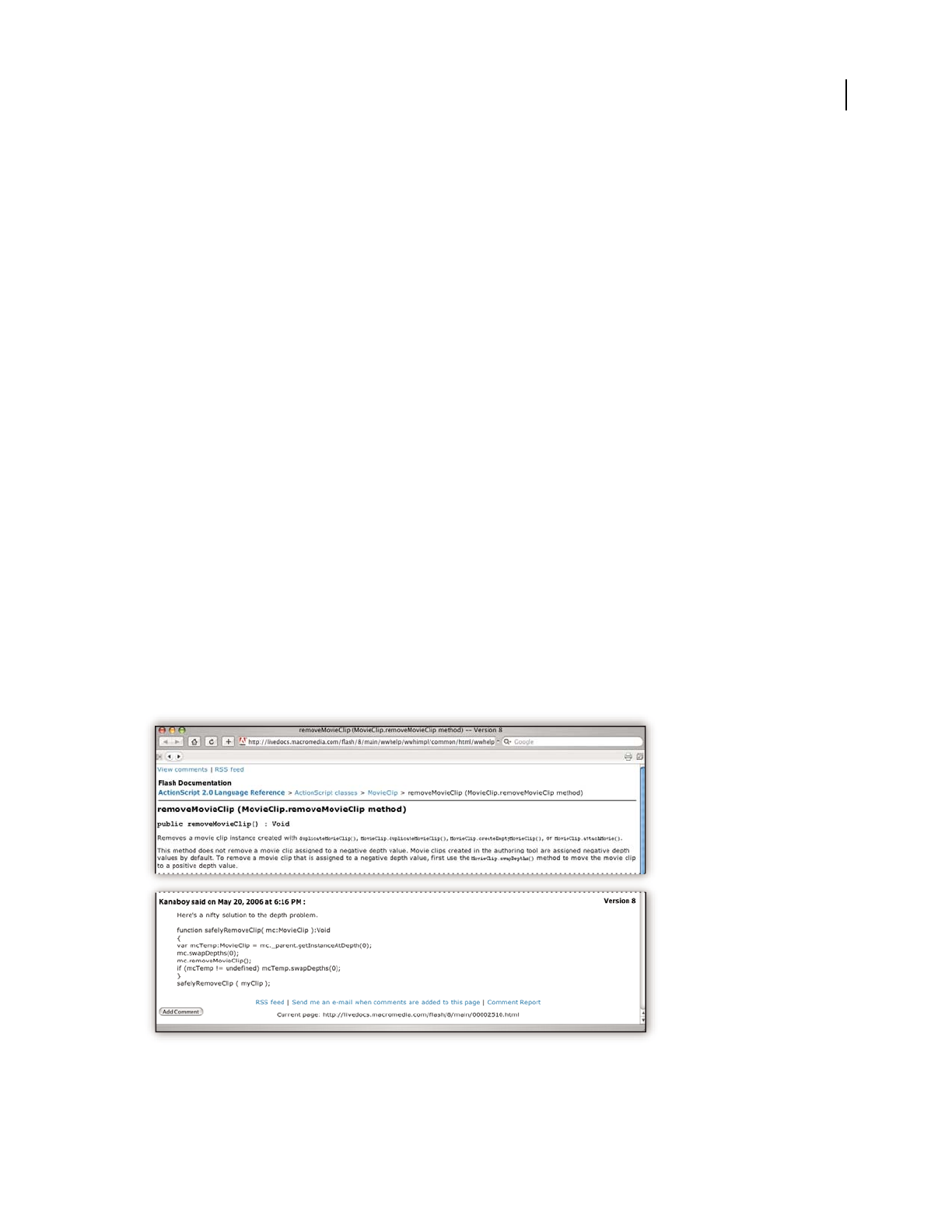
ILLUSTRATOR CS3
User Guide
2
Read Me
The installation DVD contains the Read Me file for your software. (This file is also copied to the application folder
during product installation.) Open the file to read important information about the following topics:
•System requirements
•Installation (including uninstalling the software)
•Activation and registration
•Font installation
•Troubleshooting
•Customer support
•Legal notices
Adobe Help
Adobe Help resources
Documentation for your Adobe software is available in a variety of formats.
In-product and LiveDocs Help
In-product Help provides access to all documentation and instructional content available at the time the software
ships. It is available through the Help menu in your Adobe software.
LiveDocs Help includes all the content from in-product Help, plus updates and links to additional instructional
content available on the web. For some products, you can also add comments to the topics in LiveDocs Help. Find
LiveDocs Help for your product in the Adobe Help Resource Center, at www.adobe.com/go/documentation.

ILLUSTRATOR CS3
User Guide
3
Most versions of in-product and LiveDocs Help let you search across the Help systems of multiple products. Topics
may also contain links to relevant content on the web or to topics in the Help of another product.
Think of Help, both in the product and on the web, as a hub for accessing additional content and communities of
users. The most complete and up-to-date version of Help is always on the web.
PDF documentation
The in-product Help is also available as a PDF that is optimized for printing. Other documents, such as installation
guides and white papers, may also be provided as PDFs.
All PDF documentation is available through the Adobe Help Resource Center, at www.adobe.com/go/documen-
tation. To see the PDF documentation included with your software, look in the Documents folder on the installation
or content DVD.
Printed documentation
Printed editions of the in-product Help are available for purchase in the Adobe Store, at www.adobe.com/go/store.
You can also find books published by Adobe publishing partners in the Adobe Store.
A printed workflow guide is included with all Adobe Creative Suite® 3 products, and stand-alone Adobe products
may include a printed getting started guide.
Using Help in the product
In-product Help is available through the Help menu. After you start the Adobe Help Viewer, click Browse to see Help
for additional Adobe products installed on your computer.
These Help features facilitate cross-product learning:
•Topics may contain links to the Help systems of other Adobe products or to additional content on the web.
•Some topics are shared across two or more products. For instance, if you see a Help topic with an Adobe
Photoshop® icon and an Adobe After Effects® icon, you know that the topic either describes functionality that is
similar in the two products or describes cross-product workflows.
•You can search across the Help systems of multiple products.
If you search for a phrase, such as “shape tool,” enclose it in quotation marks to see only those topics that include all
the words in the phrase.
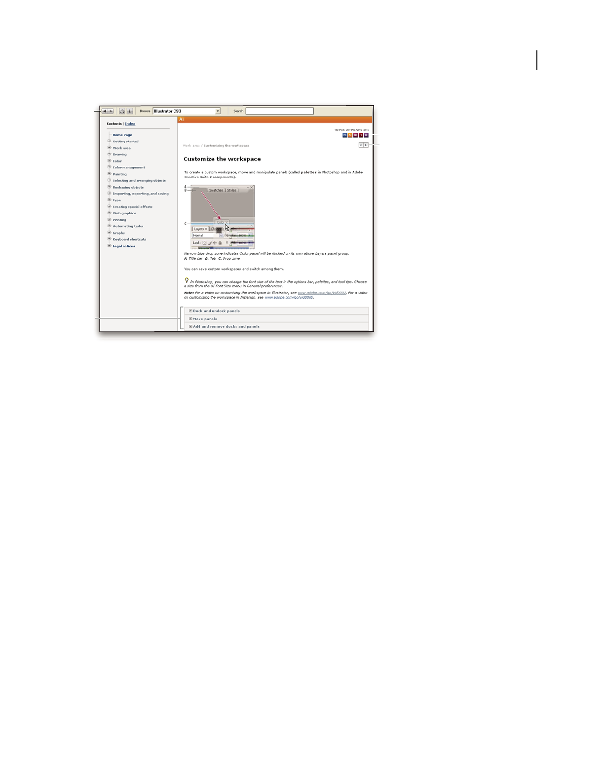
ILLUSTRATOR CS3
User Guide
4
Adobe Help
A. Back/Forward buttons (previously visited links) B. Expandable subtopics C. Icons indicating shared topic D. Previous/Next buttons (topics
in sequential order)
Accessibility features
Adobe Help content is accessible to people with disabilities—such as mobility impairments, blindness, and low
vision. In-product Help supports these standard accessibility features:
•The user can change text size with standard context menu commands.
•Links are underlined for easy recognition.
•If link text doesn’t match the title of the destination, the title is referenced in the Title attribute of the Anchor tag.
For example, the Previous and Next links include the titles of the previous and next topics.
•Content supports high-contrast mode.
•Graphics without captions include alternate text.
•Each frame has a title to indicate its purpose.
•Standard HTML tags define content structure for screen reading or text-to-speech tools.
•Style sheets control formatting, so there are no embedded fonts.
Keyboard shortcuts for Help toolbar controls (Windows)
Back button Alt+Left Arrow
Forward button Alt+Right Arrow
Print Ctrl+P
About button Ctrl+I
Browse menu Alt+Down Arrow or Alt+Up Arrow to view Help for another application
Search box Ctrl+S to place the insertion point in the Search box
C
D
B
A
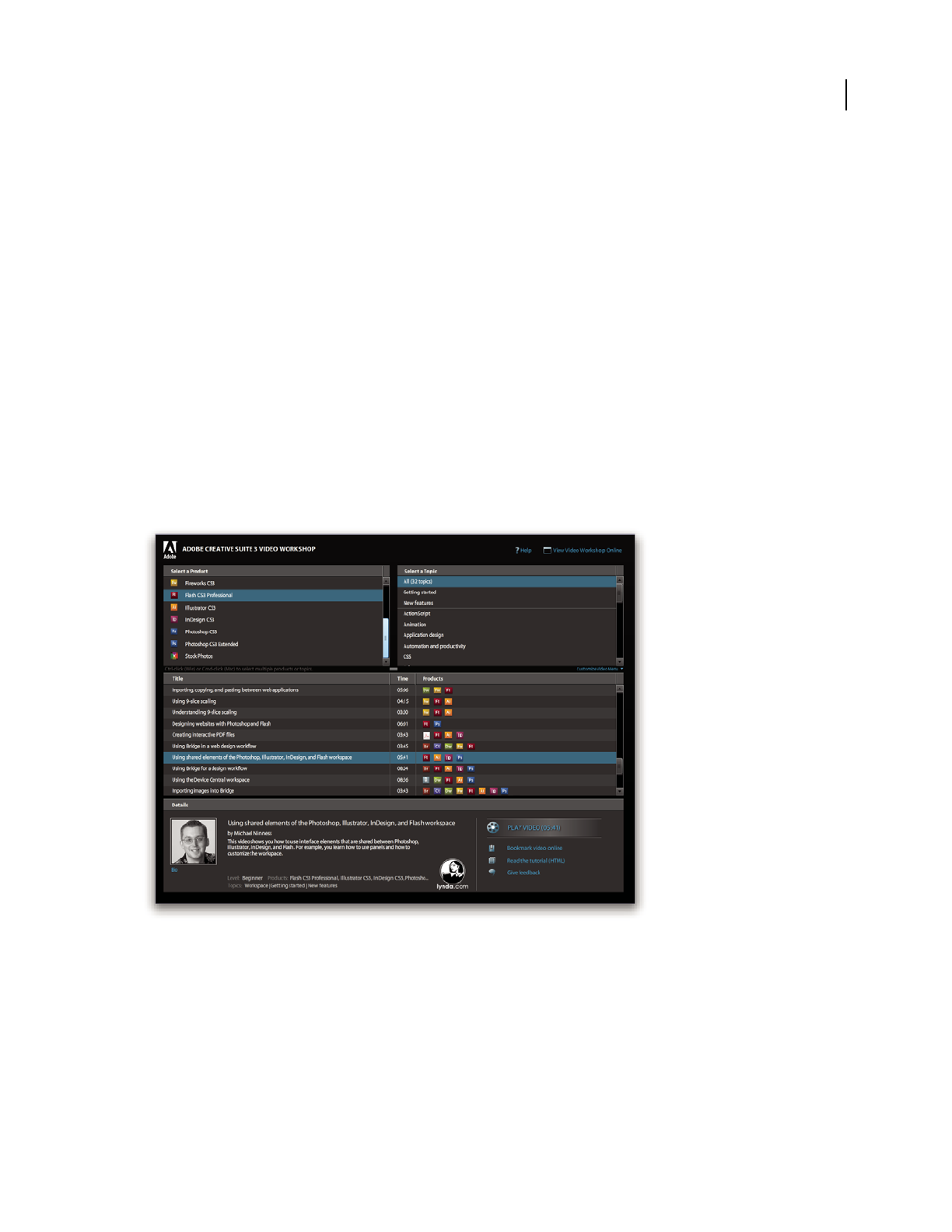
ILLUSTRATOR CS3
User Guide
5
Keyboard shortcuts for Help navigation (Windows)
•To move between panes, press Ctrl+Tab (forward) and Shift+Ctrl+Tab (backward).
•To move through and outline links in a pane, press Tab (forward) or Shift+Tab (backward).
•To activate an outlined link, press Enter.
•To make text bigger, press Ctrl+equal sign.
•To make text smaller, press Ctrl+hyphen.
Resources
Adobe Video Workshop
The Adobe Creative Suite 3 Video Workshop offers over 200 training videos covering a wide range of subjects for
print, web, and video professionals.
You can use the Adobe Video Workshop to learn about any Creative Suite 3 product. Many videos show you how to
use Adobe applications together.
ILLUSTRATOR CS3
User Guide
6
When you start the Adobe Video Workshop, you choose the products you want to learn and the subjects you want
to view. You can see details about each video to focus and direct your learning.
Community of presenters
With this release, Adobe Systems invited the community of its users to share their expertise and insights. Adobe and
lynda.com present tutorials, tips, and tricks from leading designers and developers such as Joseph Lowery, Katrin
Eismann, and Chris Georgenes. You can see and hear Adobe experts such as Lynn Grillo, Greg Rewis, and Russell
Brown. In all, over 30 product experts share their knowledge.
Tutorials and source files
The Adobe Video Workshop includes training for novices and experienced users. You’ll also find videos on new
features and key techniques. Each video covers a single subject and typically runs about 3-5 minutes. Most videos
come with an illustrated tutorial and source files, so you can print detailed steps and try the tutorial on your own.
Using Adobe Video Workshop
You can access Adobe Video Workshop using the DVD included with your Creative Suite 3 product. It’s also available
online at www.adobe.com/go/learn_videotutorials. Adobe will regularly add new videos to the online Video
Workshop, so check in to see what’s new.
Illustrator CS3 videos
Adobe Video Workshop covers a wide range of subjects for Adobe Illustrator® CS3, including these:
•Creating and setting up a new document
•Importing content into Illustrator
•Selecting, manipulating, and aligning objects
•Using Smart Objects and Live Color

ILLUSTRATOR CS3
User Guide
7
•Saving files for the web
Videos also show you how to use Illustrator CS3 with other Adobe products:
•Using text and symbols effectively between Illustrator and Flash®
•Creating mobile content in Illustrator
•Using shared elements in Photoshop, Illustrator, InDesign®, and Flash
•Exporting animated SWF files from Illustrator
To access Adobe Creative Suite 3 video tutorials, visit Adobe Video Workshop at
www.adobe.com/go/learn_videotutorials.
Extras
You have access to a wide variety of resources that will help you make the most of your Adobe software. Some of
these resources are installed on your computer during the setup process; additional helpful samples and documents
are included on the installation or content DVD. Unique extras are also offered online by the Adobe Exchange
community, at www.adobe.com/go/exchange.
Installed resources
During software installation, a number of resources are placed in your application folder. To view those files, navigate
to the application folder on your computer.
•Windows®: [startup drive]/Program files/Adobe/Adobe [application]
•Mac OS®: [startup drive]/Applications/Adobe [application]
The application folder may contain the following resources:
Plug-ins Plug-in modules are small software programs that extend or add features to your software. Once installed,
plug-in modules appear as options in the Import or Export menu; as file formats in the Open, Save As, and Export
Original dialog boxes; or as filters in the Filter submenus. For example, a number of special effects plug-ins are
automatically installed in the Plug-ins folder inside the Photoshop CS3 folder.
Presets Presets include a wide variety of useful tools, preferences, effects, and images. Product presets include
brushes, swatches, color groups, symbols, custom shapes, graphic and layer styles, patterns, textures, actions,
workspaces, and more. Preset content can be found throughout the user interface. Some presets (for example,
Photoshop Brush libraries) become available only when you select the corresponding tool. If you don’t want to create
an effect or image from scratch, go to the preset libraries for inspiration.
Templates Template files can be opened and viewed from Adobe Bridge, opened from the Welcome Screen, or
opened directly from the File menu. Depending on the product, template files range from letterheads, newsletters,

ILLUSTRATOR CS3
User Guide
8
and websites to DVD menus and video buttons. Each template file is professionally constructed and represents a
best-use example of product features. Templates can be a valuable resource when you need to jump-start a project.
Samples Sample files include more complicated designs and are a great way to see new features in action. These files
demonstrate the range of creative possibilities available to you.
Fonts Several OpenType® fonts and font families are included with your Creative Suite product. Fonts are copied to
your computer during installation:
•Windows: [startup drive]/Program Files/Common Files/Adobe/Fonts
•Mac OS X: [startup drive]/Library/Application Support/Adobe/Fonts
For information about installing fonts, see the Read Me file on the installation DVD.
DVD content
The installation or content DVD included with your product contains additional resources for use with your
software. The Goodies folder contains product-specific files such as templates, images, presets, actions, plug-ins, and
effects, along with subfolders for Fonts and Stock Photography. The Documentation folder contains a PDF version
of the Help, technical information, and other documents such as specimen sheets, reference guides, and specialized
feature information.
Adobe Exchange
For more free content, visit www.adobe.com/go/exchange, an online community where users download and share
thousands of free actions, extensions, plug-ins, and other content for use with Adobe products.
Bridge Home
Bridge Home, a new destination in Adobe Bridge CS3, provides up-to-date information on all your Adobe Creative
Suite
3 software in one convenient location. Start Adobe Bridge, then click the Bridge Home icon at the top of the
Favorites panel to access the latest tips, news, and resources for your Creative Suite tools.
ET VERO EOS ET ACCUSAM ET JUSTO
DUO DOLORES ET EA REBUM. STET CLITA KASD.
ET
COSETETUR SADIPSCING
01
PelletirInc.
CORE INVESTMENT SPECTRUM
Vel illum dolore eu feugiat nulla facilisis at vero eros et accumsan
et iusto odio dignissim qui.
RETIREMENT SAVING PLAN
Vel illum dolore eu feugiat nulla facilisis at vero eros et accumsan
et iusto odio dignissim qui.
Your Investment Guide
Are you leaving money on the table?
01
Typi non habent claritatem insitam; est usus legentis in iis qui facit eorum
claritatem. Investigationes demonstraverunt lectores legere me lius quod ii
legunt saepius. Claritas est etiam processus.
Typi non habent claritatem insitam; est usus legentis in iis qui facit eorum
claritatem. Investigationes demonstraverunt lectores legere me lius quod ii
legunt saepius. Claritas est etiam processus.
Travel Earth
Best 100 places to see on the planet
in your lifetime
volute
ipsummy
, commy
re eugia-
rud tem
eraes-
exer
n ullutet
Vel: Ad : Vulputate:
SURVICE MENU
NULCHE
vero dio eum
nulche
agiamet ad lorperit
sum a
$45
agiamet ad atin utet
vero dio eum
nulche suma
agaimet ad eum
nullam
$25
lorperit sum a
agiamet ad lorperit
vero dio
eum nullam
$35
SUCCIVEROS
sucicvero dio
vero dio eum
nulche suma
$15
eum nullam
vero dio eum
nulche suma
agaimet ad eum
nullam
$35
N
eum nullam
$35
SUCCIVEROS
sucicvero dio
vero dio eum
nulche suma
$15
eum nullam
vero dio eum
nulche suma
agaimet ad eum
nullam
$35
CC
a
si
o
p
i
a
S
p
A
ILLUSTRATOR CS3
User Guide
9
Note: Bridge Home may not be available in all languages.
Adobe Design Center
Adobe Design Center offers articles, inspiration, and instruction from industry experts, top designers and Adobe
publishing partners. New content is added monthly.
You can find hundreds of tutorials for design products and learn tips and techniques through videos, HTML
tutorials, and sample book chapters.
ILLUSTRATOR CS3
User Guide
10
New ideas are the heart of Think Tank, Dialog Box, and Gallery:
•Think Tank articles consider how today’s designers engage with technology and what their experiences mean for
design, design tools, and society.
•In Dialog Box, experts share new ideas in motion graphics and digital design.
•The Gallery showcases how artists communicate design in motion.
Visit Adobe Design Center at www.adobe.com/designcenter.
Adobe Developer Center
Adobe Developer Center provides samples, tutorials, articles, and community resources for developers who build
rich Internet applications, websites, mobile content, and other projects using Adobe products. The Developer Center
also contains resources for developers who develop plug-ins for Adobe products.
In addition to sample code and tutorials, you'll find RSS feeds, online seminars, SDKs, scripting guides, and other
technical resources.
Visit Adobe Developer Center at www.adobe.com/go/developer.
Customer support
Visit the Adobe Support website, at www.adobe.com/support, to find troubleshooting information for your product
and to learn about free and paid technical support options. Follow the Training link for access to Adobe Press books,
a variety of training resources, Adobe software certification programs, and more.
Downloads
Visit www.adobe.com/go/downloads to find free updates, tryouts, and other useful software. In addition, the Adobe
Store (at www.adobe.com/go/store) provides access to thousands of plug-ins from third-party developers, helping
you to automate tasks, customize workflows, create specialized professional effects, and more.

ILLUSTRATOR CS3
User Guide
11
Adobe Labs
Adobe Labs gives you the opportunity to experience and evaluate new and emerging technologies and products from
Adobe.
At Adobe Labs, you have access to resources such as these:
•Prerelease software and technologies
•Code samples and best practices to accelerate your learning
•Early versions of product and technical documentation
•Forums, wiki-based content, and other collaborative resources to help you interact with like-minded developers
Adobe Labs fosters a collaborative software development process. In this environment, customers quickly become
productive with new products and technologies. Adobe Labs is also a forum for early feedback, which the Adobe
development teams use to create software that meets the needs and expectations of the community.
Visit Adobe Labs at www.adobe.com/go/labs.
User communities
User communities feature forums, blogs, and other avenues for users to share technologies, tools, and information.
Users can ask questions and find out how others are getting the most out of their software. User-to-user forums are
available in English, French, German, and Japanese; blogs are posted in a wide range of languages.
To participate in forums or blogs, visit www.adobe.com/communities.
What’s new
Superior design features
Live Color
Explore color harmonies and dynamically apply color at once to multiple vector graphics. With Live Color, you can
discover new color combinations, quickly test them, and then save and reuse them. You can preview changes to your
artwork, shift an artwork’s entire tone by playing with the color wheel, or merely adjust one color with maximum
precision. (See “Live Color overview” on page 112.)
Swatches panel
Save a color group to the Swatches panel so you can quickly refer back to a favorite set of colors. (See “Save Color
Guide colors to the Swatches panel” on page 112.)
Isolation mode
Use isolation mode to protect areas of an artwork from being edited. You can group, hide, lock, and restack layers
with confidence, knowing that isolated portions of your artwork will not be inadvertently changed. (See “Isolate
groups and sublayers” on page 194.)

ILLUSTRATOR CS3
User Guide
12
Better integration
Integration with Adobe Flash
Create intricate vectors, storyboards, and test sequences without having to redraw them in Adobe Flash. Save
production time with type, layers, and symbols that maintain their structure and editability when you copy/past
them into Flash. You can move back and forth between Illustrator and Flash, harnessing the strengths of each
program. (See “Tag text for export to Flash” on page 331 and “About Flash graphics” on page 378.)
Symbols
Take advantage of the power of Illustrator with symbols that are now more practical to create, more easily to
customize, and can be used in Flash with confidence. (See “About symbols” on page 82.)
Printing
When printing, preserve native color spaces. Thanks to DeviceN support, you can be assured that your artwork will
separate correctly when it is printed. (See “Printing color separations” on page 403.)
Enhanced workplace efficiency
New document profiles
Speed startup when you open a new document by selecting a pre-built New Document Profile. These profiles are
tailored for different kinds of projects—mobile, print, web, and video, for example. You can save custom profiles with
startup parameters such as artboard dimensions, swatches, brushes, styles, and color spaces. (See “About new
document profiles” on page 33.)
Custom workspaces
Customize your workspace with collapsible panels and new icon views. You can save your workspace as a preset and
in so doing optimize your workspace for given tasks. (See “Customize the workspace” on page 18.)
Operating performance
Work more fluidly and efficiently without waiting for Illustrator to catch up with your hands and your thoughts. The
underlying architecture of Illustrator has been improved. You’ll notice increased scroll and zoom times, snappier
refresh rates, and better responsiveness.
Access libraries from panels
Easily access libraries of pre-built brushes, thematic swatches, and graphic styles. Now you can quickly apply just the
effect you want by pulling down your library list with an icon located in the bottom bar of the tool panels. (See, for
example, “Brushes panel overview” on page 166.)
Advanced drawing tools and controls
Control panel
Find the tool you need for the task at hand with the Control panel, which displays the options that are most appro-
priate for your current selection. You can access anchor-point controls, selection tools, clipping masks, and envelope
distortions from the top of the screen. Workspace clutter is reduced because you don’t have to keep as many panels
open. (See “Control panel overview” on page 17.)

ILLUSTRATOR CS3
User Guide
13
Path editing
As soon as you select points, the Control panel displays path-editing tools You can fine-tune your work faster and
even hide and show handles with one click. (See “Specify direction line and direction point appearance” on page 55.)
Point selection
Run your cursor over any anchor point and enlarge it so you can easily see and select it. Your cursor shows a larger
square anywhere it detects a point. (See “Specify anchor point size preferences” on page 55.)
Point alignment
Align and distribute points just like you align and distribute objects. When you select more than one point, the whole
range of alignment buttons appears in the Control panel. You can also align points to the artboard or a crop area.
(See “Align and distribute objects” on page 205.)
Eraser tool
Quickly remove areas of artwork as easily as you can erase pixels in Photoshop. All you have to do is stroke the mouse
or stylus over any shape or set of shapes. Illustrator creates new paths along the edges of the erased stroke; the
smoothness of your erasure is preserved. (See “Erase artwork” on page 75.)
Crop Area tool
Draw multiple crop areas with either custom or predefined characteristics. You can quickly create one-page PDFs
perfectly cropped to your selection, making it possible to save artwork variations to show clients and colleagues. (See
“Create, edit, and delete crop areas” on page 38.)

14
Chapter 2: Work area
Welcome to Adobe® Illustrator® CS3. Illustrator gives you an efficient work area and user interface to create and edit
artwork for print, the web, and mobile devices.
Work area basics
Workspace overview
You create and manipulate your documents and files using various elements such as panels, bars, and windows. Any
arrangement of these elements is called a workspace. When you first start an Adobe Creative Suite component, you
see the default workspace, which you can customize for the tasks you perform there. For instance, you can create one
workspace for editing and another for viewing, save them, and switch between them as you work.
You can restore the default workspace at any time by choosing the default option on the Window > Workspace menu.
Although default workspaces vary across Flash, Illustrator, InCopy, InDesign, and Photoshop, you manipulate the
elements much the same way in all of them. The Photoshop default workspace is typical:
•The menu bar across the top organizes commands under menus.
•The Tools panel (called the Tools palette in Photoshop) contains tools for creating and editing images, artwork,
page elements, and so on. Related tools are grouped together.
•The Control panel (called the options bar in Photoshop) displays options for the currently selected tool. (Flash has
no Control panel.)
•The Document window (called the Stage in Flash) displays the file you’re working on.
•Panels (called palettes in Photoshop) help you monitor and modify your work. Examples include the Timeline in
Flash and the Layers palette in Photoshop. Certain panels are displayed by default, but you can add any panel by
selecting it from the Window menu. Many panels have menus with panel-specific options. Panels can be grouped,
stacked, or docked.
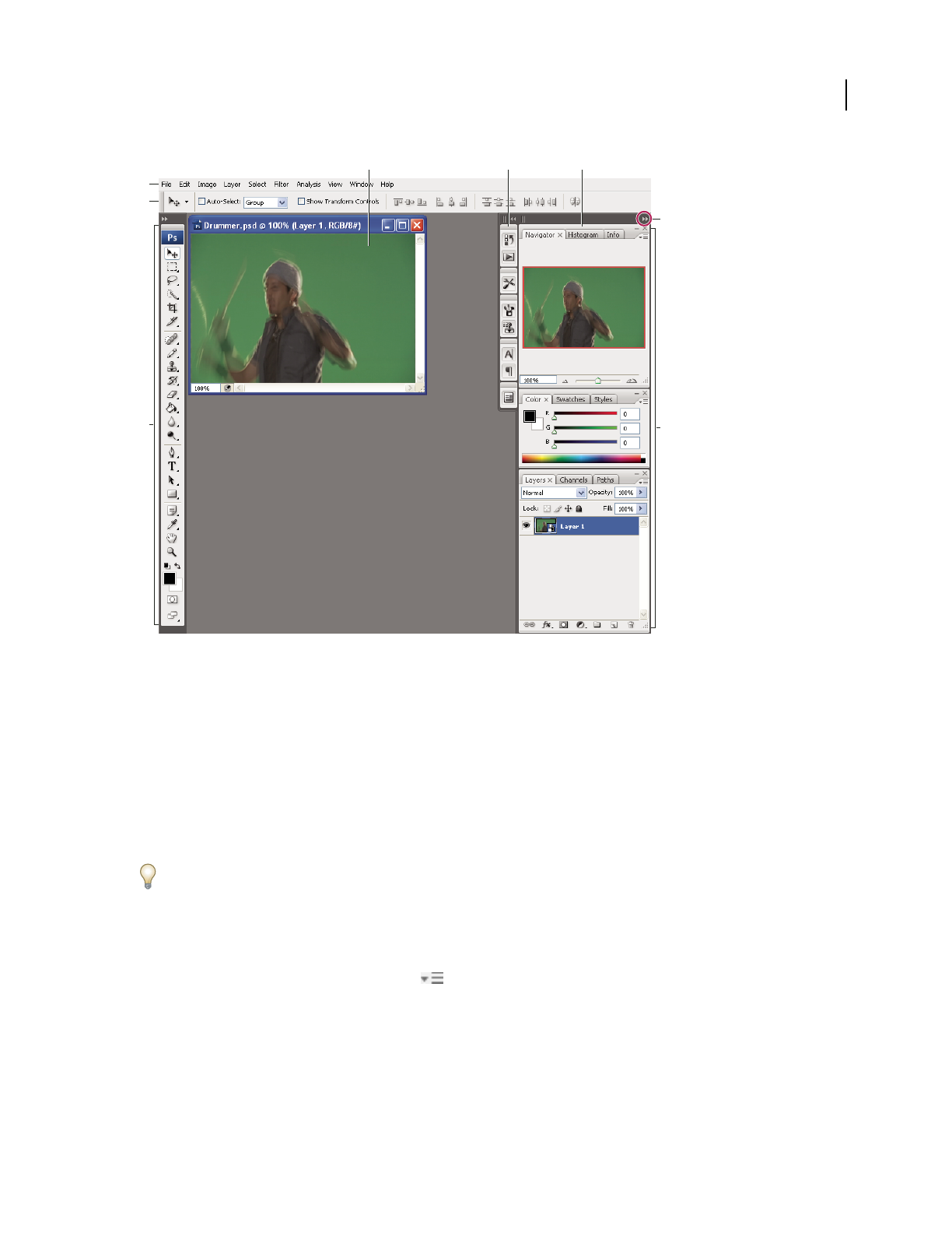
ILLUSTRATOR CS3
User Guide
15
Default Photoshop workspace
A. Document window B. Dock of panels collapsed to icons C. Panel title bar D. Menu bar E. Options bar F. Tools palette G. Collapse To
Icons button H. Three palette (panel) groups in vertical dock
For a video on understanding the workspace, see www.adobe.com/go/vid0187.
Hide or show all panels
•(Illustrator, InCopy, InDesign, Photoshop) To hide or show all panels, including the Tools panel and options bar
or Control panel, press Tab.
•(Illustrator, InCopy, InDesign, Photoshop) To hide or show all panels except the Tools panel and options bar or
Control panel, press Shift+Tab.
You can temporarily display panels hidden by these techniques by moving the pointer to the edge of the application
window (Windows) or to the edge of the monitor (Mac OS) and hovering over the strip that appears.
•(Flash) To hide or show all panels, press F4.
Display panel menu options
❖ Position the pointer on the panel menu icon in the upper-right corner of the panel, and press the mouse
button.
(Illustrator) Adjust panel brightness
❖ In User Interface preferences, move the Brightness slider. This control affects all panels, including the Control
panel.
D
E
FH
G
A B C

ILLUSTRATOR CS3
User Guide
16
Reconfigure the Tools panel
You can display the tools in the Tools panel in a single column, or side by side in two columns.
In InDesign, you also can switch from single-column to double-column display by setting an option in Interface
preferences.
❖ Click the double arrow at the top of the Tools panel.
About screen modes
You can change the visibility of the illustration window and menu bar using the mode options at the bottom of the
Tools panel:
•Maximized Screen Mode displays artwork in a maximized window with a menu bar at the top, scroll bars on
the sides, and no title bar.
•Standard Screen Mode displays artwork in a standard window, with a menu bar at the top and scroll bars on
the sides.
•Full Screen Mode with Menu Bar displays artwork in a full-screen window with a menu bar but with no title
bar or scroll bars.
•Full Screen Mode displays artwork in a full-screen window, with no title bar, menu bar, or scroll bars.
Using the status bar
The status bar appears at the lower-left edge of the illustration window when you’re in Maximized Screen mode. It
displays the current zoom level and information about one of the following topics: the current tool in use, the date
and time, the number of undos and redos available, the document color profile, or the status of a managed file.
Click the status bar to do any of the following:
•Change the type of information displayed in the status bar by selecting an option from the Show submenu.
•Show the current file in Adobe Bridge by choosing Reveal In Bridge.
•Access Version Cue® commands.
Enter values in panels and dialog boxes
You enter values using the same methods in all panels and dialog boxes. You can also perform simple math in any
box that accepts numeric values. For example, if you want to move a selected object 3 units to the right using the
current measurement units, you don’t have to work out the new horizontal position—simply type +3 after the
current value in the Transform panel.
Enter a value in a panel or dialog box
❖Do any of the following:
•Type a value in the box, and press Enter or Return.
•Drag the slider.
•Drag the dial.
•Click the arrow buttons in the panel to increase or decrease the value.
•Click in the box and then use the Up Arrow key and Down Arrow key on the keyboard to increase or decrease the
value. Hold down Shift and click an arrow key to magnify the increase rate or decrease rate.

ILLUSTRATOR CS3
User Guide
17
•Select a value from the menu associated with the box.
Ways to enter values
A. Arrow buttons B. Text box C. Menu arrow D. Slider E. Dial
Calculate values in a panel or dialog box
1
In a text box that accepts numerical values, do one of the following:
•To replace the entire current value with a mathematical expression, select the entire current value.
•To use the current value as part of a mathematical expression, click before or after the current value.
2 Type a simple mathematical expression using a single mathematical operator, such as + (plus), - (minus), x (multi-
plication), / (division), or % (percent).
For example, 0p0 + 3 or 5mm + 4. Similarly, 3cm * 50% equals 3 centimeters multiplied by 50%, or 1.50 cm, and
50pt + 25% equals 50 points plus 25% of 50 points, or 62.5 points.
3 Press Enter or Return to apply the calculation.
Control panel overview
The Control panel offers quick access to options related to the objects you select. By default, the Control panel is
docked at the top of the work area.
Options displayed in the Control panel vary depending on the type of object or tool you select. For example, when
you select a text object, the Control panel displays text-formatting options in addition to options for changing the
color, placement, and dimensions of the object.
Control panel
A. Hidden options B. Link to another panel C. Panel menu
When text in the Control panel is blue and underlined, you can click the text to display a related panel or dialog box.
For example, click the word Stroke to display the Stroke panel.
Change the kinds of controls that appear in the Control panel
❖Select or deselect options in the Control panel menu.
A B C
E
D
A B C
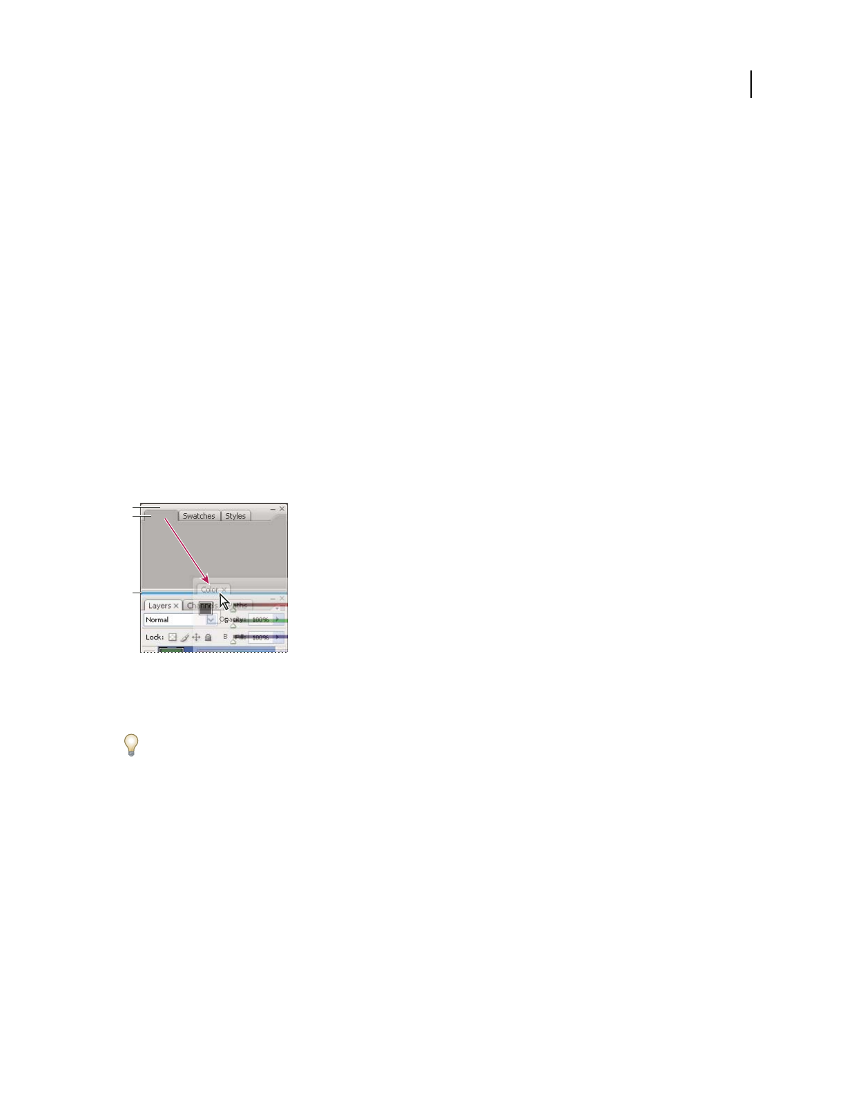
ILLUSTRATOR CS3
User Guide
18
Open and close a panel or dialog box from the Control panel
1
Click a blue underlined word to open its associated panel or dialog box.
2 Click anywhere outside of the panel or dialog box to close it.
Dock the Control panel at the bottom of the work area
❖Choose Dock To Bottom from the Control panel menu.
Convert the Control panel to a floating panel
❖Drag the gripper bar (located on the left edge of the panel) away from its current position.
To redock the Control panel, drag the gripper bar to the top or bottom of the application window (Windows) or
screen (Mac
OS).
Customizing the workspace
Customize the workspace
To create a custom workspace, move and manipulate panels (called palettes in Photoshop and in Adobe Creative
Suite 2 components).
Narrow blue drop zone indicates Color panel will be docked on its own above Layers panel group.
A. Title bar B. Tab C. Drop zone
You can save custom workspaces and switch among them.
In Photoshop, you can change the font size of the text in the options bar, palettes, and tool tips. Choose a size from
the UI Font Size menu in General preferences.
Note: For a video on customizing the workspace in Illustrator, see www.adobe.com/go/vid0032. For a video on custom-
izing the workspace in InDesign, see www.adobe.com/go/vid0065.
Dock and undock panels
A dock is a collection of panels or panel groups displayed together, generally in a vertical orientation. You dock and
undock panels by moving them into and out of a dock.
Note: Docking is not the same as stacking. A stack is a collection of free-floating panels or panel groups, joined top to
bottom.
•To dock a panel, drag it by its tab into the dock, at the top, bottom, or in between other panels.
•To dock a panel group, drag it by its title bar (the solid empty bar above the tabs) into the dock.
A
B
C

ILLUSTRATOR CS3
User Guide
19
•To remove a panel or panel group, drag it out of the dock by its tab or title bar. You can drag it into another dock
or make it free-floating.
Navigator panel being dragged out to new dock, indicated by blue vertical highlight
Navigator panel now in its own dock
To prevent panels from filling all space in a dock, drag the bottom edge of the dock up so it no longer meets the edge
of the workspace.
Move panels
As you move panels, you see blue highlighted drop zones, areas where you can move the panel. For example, you can
move a panel up or down in a dock by dragging it to the narrow blue drop zone above or below another panel. If you
drag to an area that is not a drop zone, the panel floats freely in the workspace.
•To move a panel, drag it by its tab.
•To move a panel group or a stack of free-floating panels, drag the title bar.
Press Ctrl (Windows) or Control (Mac OS) while moving a panel to prevent it from docking.
Add and remove docks and panels
If you remove all panels from a dock, the dock disappears. You can create new docks by moving panels to drop zones
next to existing docks or at the edges of the workspace.
•To remove a panel, click its close icon (the X at the upper-right corner of the tab), or deselect it from the Window menu.
•To add a panel, select it from the Window menu and dock it wherever you wish.
Manipulate panel groups
•To move a panel into a group, drag the panel’s tab to the highlighted drop zone at the top of the group.
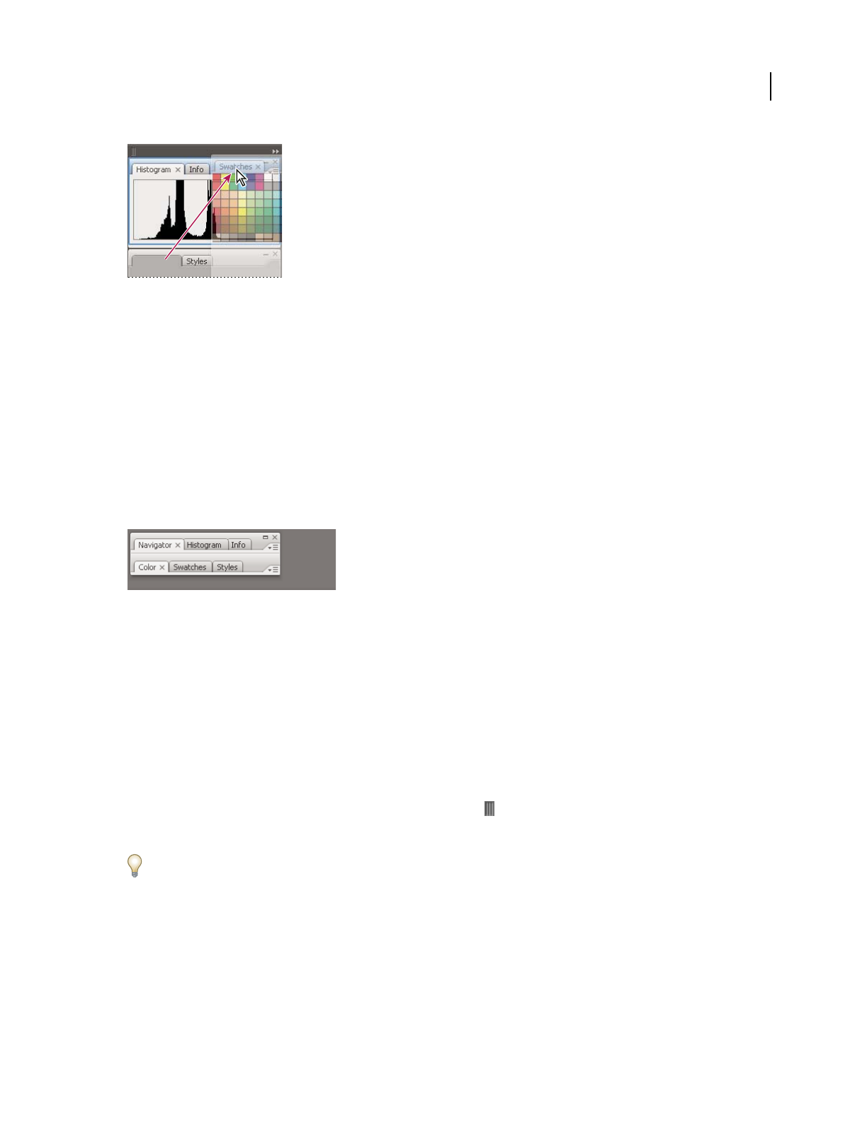
ILLUSTRATOR CS3
User Guide
20
Adding a panel to a panel group
•To rearrange panels in a group, drag a panel’s tab to a new location in the group.
•To remove a panel from a group so that it floats freely, drag the panel by its tab outside the group.
•To make a panel appear at the front of its group, click its tab.
•To move grouped panels together, drag their title bar (above the tabs).
Stack free-floating panels
When you drag a panel out of its dock but not into a drop zone, the panel floats freely, allowing you to position it
anywhere in the workspace. Panels may also float in the workspace when first selected from the Window menu. You
can stack free-floating panels or panel groups together so that they move as a unit when you drag the topmost title
bar. (Panels that are part of a dock cannot be stacked or moved as a unit in this way.)
Free-floating stacked panels
•To stack free-floating panels, drag a panel by its tab to the drop zone at the bottom of another panel.
•To change the stacking order, drag a panel up or down by its tab.
Note: Be sure to release the tab over the narrow drop zone between panels, rather than the broad drop zone in a title bar.
•To remove a panel or panel group from the stack, so that it floats by itself, drag it out by its tab or title bar.
Resize or minimize panels
•To resize a panel, drag any side of the panel or drag the size box at its lower-right corner. Some panels, such as the
Color panel in Photoshop, cannot be resized by dragging.
•To change the width of all the panels in a dock, drag the gripper at the top left of the dock.
•To minimize a panel, panel group, or stack of panels, click the Minimize button in its title bar.
You can open a panel menu even when the panel is minimized.
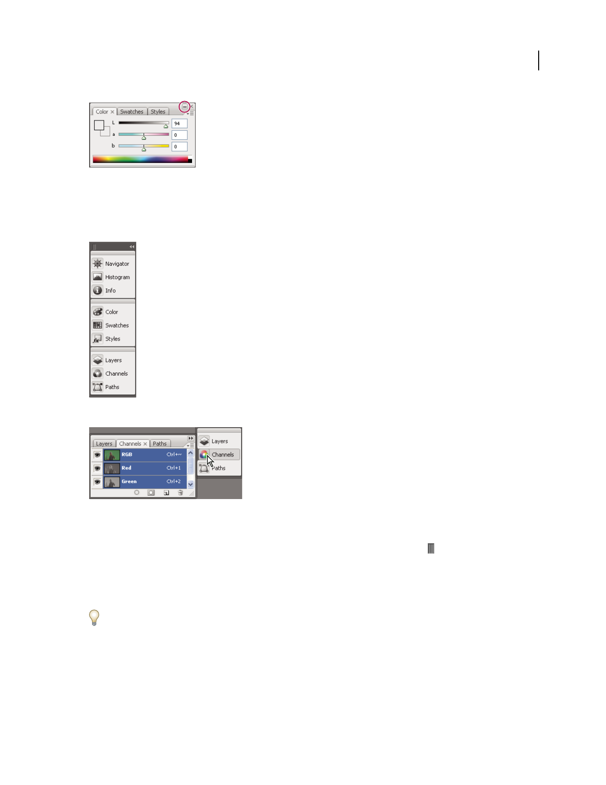
ILLUSTRATOR CS3
User Guide
21
Minimize button
Manipulate panels collapsed to icons
Collapse panels to icons to reduce clutter on the workspace. (In some cases, panels are collapsed to icons in the
default workspace.) Click a panel icon to expand the panel. You can expand only one panel or panel group at a time.
Panels collapsed to icons
Panels expanded from icons
•To collapse or expand all panels in a dock, click the double arrow at the top of the dock.
•To resize panel icons so that you see only the icons (and not the labels), drag the gripper at the top of the dock
toward the icons until the text disappears. (To display the icon text again, drag the gripper away from the panels.)
•To expand a single panel icon, click it.
•To collapse an expanded panel back to its icon, click its tab, its icon, or the double arrow in the panel’s title bar.
If you select Auto-Collapse Icon Panels from the Interface or User Interface Options preferences, an expanded panel
icon will collapse automatically when you click away from it.
•To add a panel or panel group to an icon dock, drag it in by its tab or title bar. (Panels are automatically collapsed
to icons when added to an icon dock.)
•To move a panel icon (or panel icon group), drag the bar that appears above the icon. You can drag panel icons up
and down in the dock, into other docks (where they appear in the panel style of that dock), or outside the dock
(where they appear as free-floating, expanded panels).

ILLUSTRATOR CS3
User Guide
22
Rename or duplicate a workspace
1 Choose Window > Workspace > Manage Workspaces.
2 Do any of the following, and then click OK:
•To rename a workspace, select it, and edit the text.
•To duplicate a workspace, select it, and click the New button.
For a video on customizing the work area based on different workflows, see www.adobe.com/go/vid0032.
Save, delete, and switch between workspaces
By saving the current size and position of panels as a named workspace, you can restore that workspace even if you
move or close a panel. The names of saved workspaces appear in the Window
> Workspace menu.
In Photoshop, the saved workspace can include a specific keyboard shortcut set and menu set.
Save a custom workspace
1
With the workspace in the configuration you want to save, do one of the following:
•(Photoshop, Illustrator, InDesign) Choose Window > Workspace > Save Workspace.
•(Flash) Choose Window > Workspace > Save Current, or choose Save Current from the Workspace menu in the
Edit bar.
•(Photoshop) Choose Save Workspace from the Workspace menu in the options bar.
2 Type a name for the workspace.
3 (Photoshop) Under Capture, select one or more options:
Palette Locations Saves the current palette locations.
Keyboard Shortcuts Saves the current set of keyboard shortcuts.
Menus Saves the current set of menus.
4 Click OK.
Display or switch between workspaces
Flash, Illustrator, InDesign, and Photoshop include preset workspaces designed to make certain tasks easier.
•Choose Window > Workspace, and select a workspace.
•(Photoshop) Select a workspace from the Workspace menu in the options bar.
•(Flash) Select a workspace from the Workspace menu in the Edit bar.
(InDesign and Photoshop) Assign keyboard shortcuts to each workspace to navigate among them quickly.
Delete a custom workspace
•(Illustrator) Choose Window > Workspace > Manage Workspaces, select the workspace, and then click the Delete icon.
•(InDesign) Choose Window > Workspace > Delete Workspace, select the workspace, and then click Delete.
•(Flash) Choose Manage from the Workspace menu in the Edit bar, select the workspace, and then click Delete.
Alternatively, choose Window > Workspace > Manage, select the workspace, and then click Delete.

ILLUSTRATOR CS3
User Guide
23
•(Photoshop) Choose Delete Workspace from the Workspace menu in the options bar. Alternatively, choose
Window > Workspace > Delete Workspace, select the workspace, and then click Delete.
(Photoshop) Start with the last or default palette locations
When you start Photoshop, palettes can either appear in their original default locations, or appear as you last used them.
❖In Interface preferences:
•To display palettes in their last locations on startup, select Remember Palette Locations.
•To display palettes in their default locations on startup, deselect Remember Palette Locations.
Tools
Tools panel overview
The first time you start the application, the Tools panel appears at the left side of the screen. You can move the Tools
panel by dragging its title bar or the Illustrator icon. You can also show or hide the Tools panel by choosing
Window
> Tools.
You use tools in the Tools panel to create, select, and manipulate objects in Illustrator. Some tools have options that
appear when you double-click a tool. These include tools that let you use type, and select, paint, draw, sample, edit,
and move images.
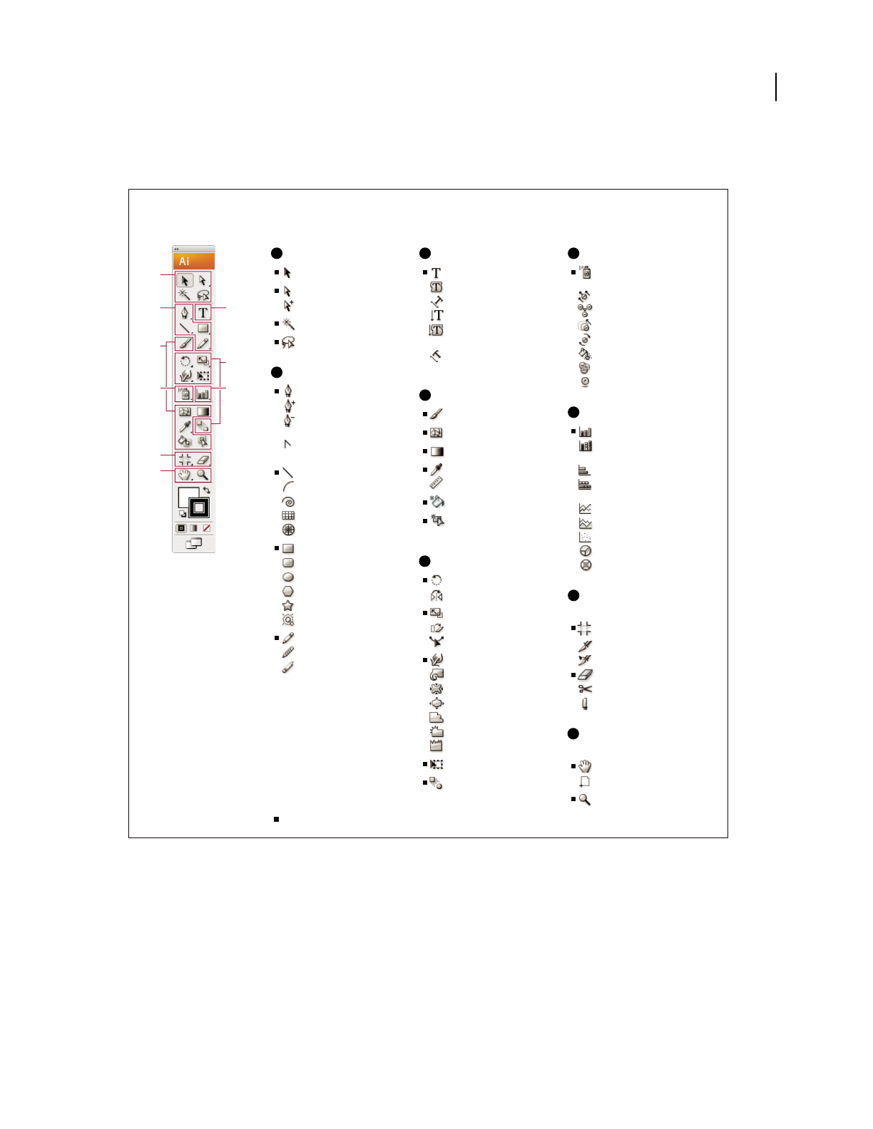
ILLUSTRATOR CS3
User Guide
24
You can expand some tools to show hidden tools beneath them. A small triangle at the lower-right corner of the tool
icon signals the presence of hidden tools. To see the name of a tool, position the pointer over it.
View hidden tools
❖Hold down the mouse button on the visible tool.
View tool options
❖Double-click a tool.
Move the Tools panel
❖Drag its title bar or the Illustrator icon.
Tools panel overview
A
BC
D
F
H
I
E
G
A
B
C
D
E
F
G
H
I
Indicates default tool * Keyboard shortcuts appear in parenthesis
Selection tools
Selection (V)
Direct Selection (A)
Group Selection
Magic Wand (Y)
Lasso (Q)
Drawing tools
Pen (P)
Add Anchor Point (+)
Delete Anchor (-)
Point
Convert Anchor
Point
Line Segment (\)
Arc
Spiral
Rectangular Grid
Polar Grid
Rectangle (M)
Rounded Rectangle
Ellipse (L)
Polygon
Star
Flare
Pencil (N)
Smooth
Path Eraser
Type tools
Type (T)
Area Type
Type On a Path
Vertical Type
Vertical Area
Type
Vertical Type
On a Path
Painting tools
Paintbrush (B)
Mesh (U)
Gradient (G)
Eyedropper (I)
Measure
Live Paint Bucket (K)
Live Paint Selection
(Shift+L)
Reshaping tools
Rotate (R)
Reect (O)
Scale (S)
Shear
Reshape
Warp (Shift-R)
Twirl
Pucker
Bloat
Scallop
Crystallize
Wrinkle
Free Transform (E)
Blend (W)
Symbol tools
Symbol Sprayer
(Shift +S)
Symbol Shifter
Symbol Scruncher
Symbol Sizer
Symbol Spinner
Symbol Stainer
Symbol Screener
Symbol Styler
Graph tools
Column Graph (J)
Stacked Column
Graph
Bar Graph
Stacked Bar
Graph
Line Graph
Area Graph
Scatter Graph
Pie Graph
Radar Graph
Slicing and cutting
tools
Crop Area (Shift +O)
Slice (Shift+K)
Slice Select
Eraser (Shift +E)
Scissors (C)
Knife
Moving and zooming
tools
Hand (H)
Page
Zoom (Z)
ILLUSTRATOR CS3
User Guide
25
Hide the Tools panel
❖Choose Window > Tools.
Tear off hidden tools into a separate panel
❖Drag the pointer over the arrow at the end of the Tools panel and release the mouse button.
Close a separate tool panel
❖Click the close button on the panel’s title bar. The tools return to the Tools panel.
Select a tool
❖Do one of the following:
•Click a tool in the Tools panel. If there is a small triangle at a tool’s lower-right corner, hold down the mouse button
to view the hidden tools, and then click the tool you want to select.
•Hold down Alt (Windows) or Option (Mac OS), and then click a tool to cycle through and select hidden tools.
•Press the tool’s keyboard shortcut. The keyboard shortcut is displayed in its tool tip. For example, you can select
the Move tool by pressing the V key.
To hide tool tips, choose Edit > Preferences > General (Windows) or Illustrator > Preferences > General (Mac OS),
and deselect Show Tool Tips.
Selecting a hidden tool
A. Tools panel B. Active tool C. Tear off panel with hidden tools D. Hidden tool triangle E. Tool name and shortcut
Change tool pointers
The mouse pointer for most tools matches the tool’s icon. Each pointer has a different hotspot, where an effect or
action begins. With most tools, you can switch to precise cursors, which appear as cross hairs centered around the
hotspot, and provide for greater accuracy when working with detailed artwork.
❖Choose Edit > Preferences > General (Windows) or Illustrator > Preferences > General (Mac OS), and select Use
Precise Cursors. Alternatively, press Caps Lock on the keyboard.
Selection tool gallery
Illustrator provides the following selection tools:
A B
D
E
C
ILLUSTRATOR CS3
User Guide
26
See also
“Keys for selecting” on page 464
Drawing tool gallery
Illustrator provides the following drawing tools:
The Selection tool (V) selects
entire objects.
The Direct Selection tool (A)
selects points or path
segments within objects.
The Group Selection tool
selects objects and groups
within groups.
The Magic Wand tool (Y)
selects objects with similar
attributes.
The Lasso tool (Q) selects
points or path segments
within objects.
The Pen tool (P) draws
straight and curved lines to
create objects.
The Add Anchor Point tool
(+) adds anchor points to
paths.
The Delete Anchor Point tool
(-) deletes anchor points from
paths.
The Convert Anchor Point
tool (Shift+C) changes
smooth points to corner
points and vice versa.

ILLUSTRATOR CS3
User Guide
27
The Line Segment tool (\)
draws individual straight line
segments.
The Arc tool draws
individual concave or convex
curve segments.
The Spiral tool draws
clockwise and counter-
clockwise spirals.
The Rectangular Grid tool
draws rectangular grids.
The Polar Grid tool draws
circular chart grids.
The Rectangle tool (M)
draws squares and
rectangles.
The Rounded Rectangle tool
draws squares and rectangles
with rounded corners.
The Ellipse tool (L) draws
circles and ovals.
The Polygon tool draws
regular, multi-sided shapes.
The Star tool draws stars. The Flare tool creates lens-
flare or solar-flare-like
effects.
The Pencil tool (N) draws
and edits freehand lines.
The Smooth tool smooths
Bezier paths.
The Path Eraser tool erases
paths and anchor points from
the object.
ILLUSTRATOR CS3
User Guide
28
Type tool gallery
Illustrator provides the following type tools:
Painting tool gallery
Illustrator provides the following painting tools:
The Type tool (T) creates
individual type and type
containers and lets you enter
and edit type.
The Area Type tool changes
closed paths to type
containers and lets you enter
and edit type within them.
The Type On A Path tool
changes paths to type paths,
and lets you enter and edit
type on them.
The Vertical Type tool creates
vertical type and vertical
type containers and lets you
enter and edit vertical type.
The Vertical Area Type tool
changes closed paths to
vertical type containers and
lets you enter and edit type
within them.
The Vertical Type On A Path
tool changes paths to vertical
type paths and lets you enter
and edit type on them
The Paintbrush tool (B)
draws freehand and calli-
graphic lines, as well as art
and patterns on paths.
The Mesh tool (U) creates
and edits meshes and mesh
envelopes.
The Gradient tool (G)
adjusts the beginning and
ending points and angle of
gradients within objects.
The Eyedropper tool (I)
samples and applies color,
type, and appearance
attributes, including effects,
from objects.

ILLUSTRATOR CS3
User Guide
29
Reshaping tool gallery
Illustrator provides the following tools for reshaping objects:
The Live Paint Bucket tool
(K) paints faces and edges of
Live Paint groups with the
current paint attributes.
The Live Paint Selection tool
selects faces and edges
within Live Paint groups.
The Measure tool measures
the distance between two
points.
The Rotate tool (R) rotates
objects around a fixed point.
The Reflect tool (O) flips
objects over a fixed axis.
The Scale tool (S) resizes
objects around a fixed point.
The Shear tool skews objects
around a fixed point.
The Reshape tool adjusts
selected anchor points while
keeping the overall detail of
the path intact.
The Free Transform tool (E)
scales, rotates, or skews a
selection.
The Blend tool (W) creates a
series of objects blended
between the color and shape
of multiple objects.

ILLUSTRATOR CS3
User Guide
30
Symbolism tool gallery
The symbolism tools let you create and modify sets of symbol instances. You create a symbol set using the Symbol
Sprayer tool. You can then use the other symbolism tools to change the density, color, location, size, rotation, trans-
parency, and style of the instances in the set.
The Warp tool (Shift+R)
molds objects with the
movement of the cursor (like
molding clay, for example).
The Twirl tool creates
swirling distortions within an
object.
The Pucker tool deflates an
object by moving control
points towards the cursor.
The Bloat tool inflates an
object by moving control
points away from the cursor.
The Scallop tool adds
random curved details to the
outline of an object.
The Crystallize tool adds
random spiked details to the
outline of an object.
The Wrinkle tool adds
wrinkle-like details to the
outline of an object.
The Symbol Sprayer tool
(Shift+S) places multiple
symbol instances as a set on
the artboard.
The Symbol Shifter tool
moves symbol instances
The Symbol Scruncher tool
moves symbol instances
closer together or farther
apart.
The Symbol Sizer tool resizes
symbol instances.

ILLUSTRATOR CS3
User Guide
31
Graph tool gallery
Illustrator provides nine graph tools, each one for creating a different type of graph. The type of graph you choose
depends on the information you want to communicate.
The Symbol Spinner tool
rotates symbol instances.
The Symbol Stainer tool
colorizes symbol instances.
The Symbol Screener tool
applies opacity to symbol
instances.
The Symbol Styler tool
applies the selected style to
symbol instances.
The Column Graph tool (J)
creates graphs that compare
values using vertical
columns.
The Stacked Column graph
tool creates graphs that are
similar to column graphs, but
stacks the columns on top of
one another, instead of side
by side. This graph type is
useful for showing the
relationship of parts to the
total.
The Bar Graph tool creates
graphs that are similar to
column graphs, but positions
the bars horizontally instead
of vertically.
The Stacked Bar Graph tool
creates graphs that are
similar to stacked column
graphs, but stacks the bars
horizontally instead of verti-
cally.
0
10
20
30
40
50
60
70
80
B A
0
20
40
60
80
100
B A 0 10 20 30 40 50 60 70 80
B
A
0 20 40 60 80 100
B
A
ILLUSTRATOR CS3
User Guide
32
Slicing and cutting tool gallery
Illustrator provides the following tools for slicing and cutting objects:
The Line Graph tool creates
graphs that use points to
represent one or more sets of
values, with a different line
joining the points in each set.
This type of graph is often
used to show the trend of one
or more subjects over a
period of time.
The Area Graph tool creates
graphs that are similar to line
graphs, but emphasizes totals
as well as changes in values.
The Scatter Graph tool
creates graphs that plot data
points as paired sets of
coordinates along the x and y
axes. Scatter graphs are
useful for identifying
patterns or trends in data.
They also can indicate
whether variables affect one
another.
The Pie Graph tool creates
circular graphs whose wedges
represent the relative
percentages of the values
compared.
The Radar Graph tool creates
graphs that compare sets of
values at given points in time
or in particular categories,
and is displayed in a circular
format. This type of graph is
also called a web graph.
The Crop Area tool selects
specified areas for printing or
export.
The Slice tool divides artwork
into separate web images.
The Slice Selection tool selects
web slices.
The Eraser tool erases any
area of the object over which
you drag
20
30
40
50
60
70
80
50 40 30 20 10
0
20
40
60
80
100
10 20 30 40 50
0
10
20
30
40
50
D C B A
10
20
30
40
50
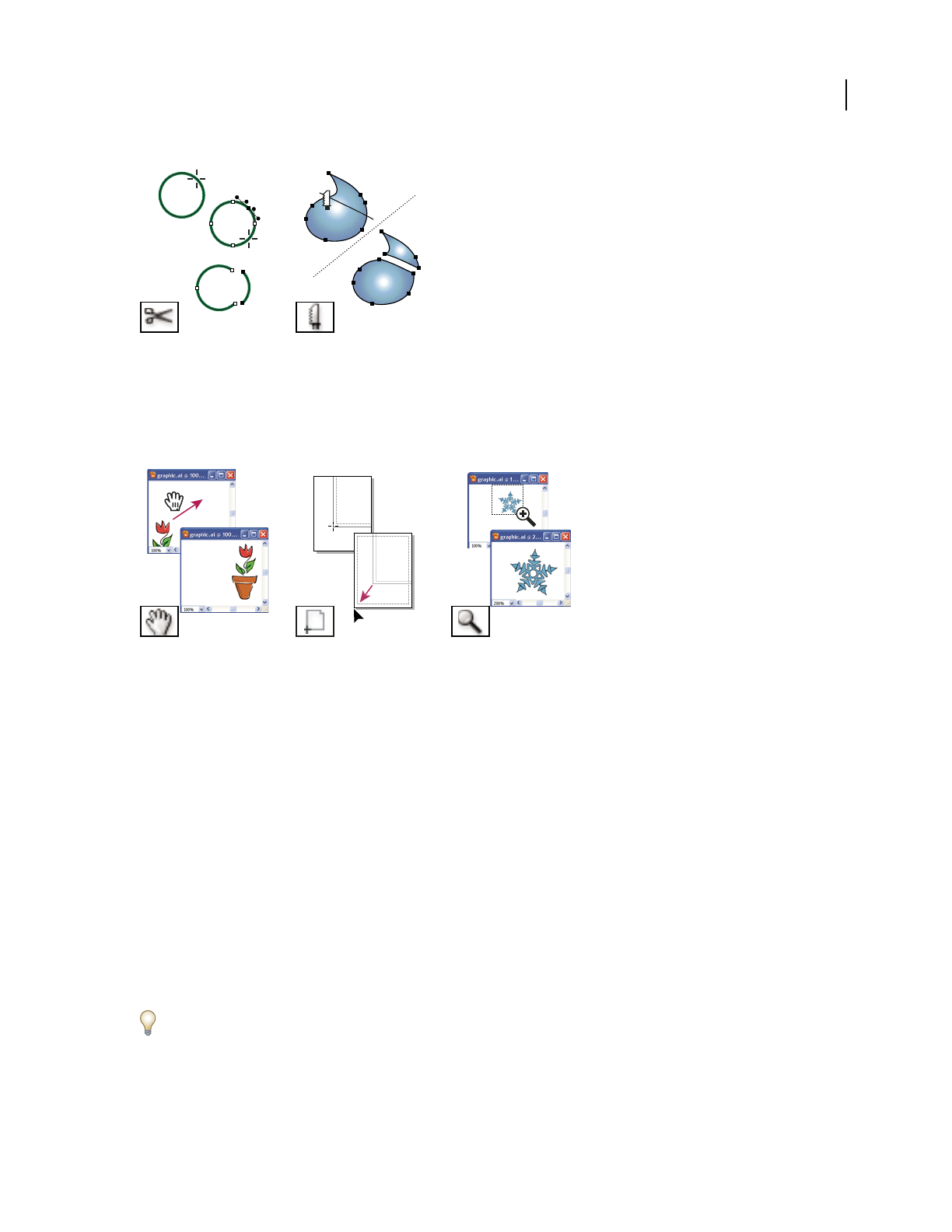
ILLUSTRATOR CS3
User Guide
33
Moving and zooming tool gallery
Illustrator provides the following tools for moving around in and controlling the view of the artboard:
Files and templates
About new document profiles
A document is the space in which you create artwork. In Illustrator, you can create documents destined for many
different types of output. (For information on creating Illustrator documents for video production, see the
Enhancing Video Production PDF at www.adobe.com/go/learn_ai_video.
You start a new document by choosing a new document profile based on your intended output. Each profile includes
preset values for size, color mode, units, orientation, transparency, and resolution. For example, the Video And Film
Document profile uses pixels instead of points, and you can choose a device-specific crop area, such as NTSC DV
Widescreen, to create a document in the exact dimensions required, with video-safe guides in place to help you lay
out your design for optimal viewing.
If you plan to output your file to a high-end printer, for example if you’re sending it to a service bureau, specify the
Print profile to ensure your artwork and any effects applied to the artwork are set to the proper resolution.
The Scissors tool (C) cuts
paths at specified points.
The Knife tool cuts objects
and paths.
The Hand tool (H) moves the
Illustrator artboard within
the illustration window.
The Page tool adjusts the
page grid to control where
artwork appears on the
printed page.
The Zoom tool (Z) increases
and decreases the view
magnification in the illus-
tration window.

ILLUSTRATOR CS3
User Guide
34
You can choose from the following profiles:
Print Document Uses a default letter size artboard, and provides a variety of other preset print sizes to choose from.
Use this profile if you plan to send this file to a service bureau for output to a high-end printer.
Web Document Provides preset options optimized for output to the web.
Mobile And Devices Document Creates a small file size that is preset for a specific mobile device. You can choose
your device from the Size menu. Click Device Central to open Adobe Device Central and view the document layout
in a specified device interface.
Video And Film Document Provides several preset video- and film-specific crop area sizes (note that the Artboard
option changes to Crop Size for this profile). Illustrator creates only square pixel files, so to ensure that the sizes are
interpreted correctly in video applications, Illustrator adjusts the Width and Height values. For example, if you
choose NTSC DV Standard, Illustrator uses a pixel size of 648 x 480, which translates to 740 x 480 pixels in video-
based applications.
Basic CMYK Document Uses a default letter size artboard, and provides a variety of other sizes to choose from. Use
this profile if you plan to send a document to multiple types of media. If one of the media types is a service bureau,
you’ll want to manually increase the Raster Effects setting to High.
Basic RGB Document Uses a default 800 x 600 size artboard, and provides a variety of other print-, video-, and web-
specific sizes to choose from. Do not use this option if you plan to send a document to a service bureau or output to
a high-end printer. Use this profile for documents that will be output to mid-level printers, to the web, or multiple
types of media.
For a video on setting up new documents, see www.adobe.com/go/vid0031.
Create new documents
You can create new Illustrator documents from a new document profile or from a template. Creating a document
from a new document profile gives you a blank document with the selected profile’s default fill and stroke colors,
graphic styles, brushes, symbols, actions, viewing preferences, and other settings. Creating a document from a
template gives you a document with preset design elements and settings, as well as content, such as cropmarks and
guides, for specific document types, such as brochures or CD covers.
You create a new document from the Welcome screen, or by using File > New or File > Device Central (for mobile
device output). The Welcome screen appears whenever a document is not currently open.
For a video on setting up new documents, see www.adobe.com/go/vid0031.
See also
“About new document profiles” on page 33
“About templates” on page 36
“About transparency” on page 173
Create a new document using the Welcome screen
1
Open Illustrator, or if Illustrator is already open, choose Help > Welcome Screen.
2 Do any of the following:
•Select a new document profile from the Create New list. The New Document dialog box opens with all options
set to the optimized values for the selected new document profile. You can change any of the preset values as
desired and click OK to open the new document.

ILLUSTRATOR CS3
User Guide
35
Note: Alt-click (Windows) or Option-click (Mac OS) to open the new document directly and skip the New Document
dialog box.
•Select From Template in the Create New list. Select a template and click OK.
Create a custom document
You can customize any document by changing the settings in the New Document dialog box. However, it’s always
best to start with the new document profile that represents your intended output.
If you want to use the preset options from another Illustrator file or template, choose Browse from the New
Document Profile menu and open the file you want to use.
1 Do one of the following:
•Choose File > New. In the New Document dialog box, type a name for your document, and choose a new
document profile.
•In the Welcome Screen, choose a new document profile from the Create New list. In the New Document dialog
box, type a name for your document.
2 Specify options as desired to customize the document. Click Advanced to specify the following additional options:
Color Mode Specifies the color mode for the new document. Changing the color mode converts the default contents
(swatches, brushes, symbols, graphic styles) of the selected new document profile to a new color mode, resulting in
a color change. Watch for a warning icon when making changes.
Raster Effects Specifies the resolution for raster effects in the document. It is especially important to set this at High
when you plan to output to a high-end printer at high resolution. The Print profile sets this at High by default.
Transparency Grid Specifies the options for the transparency grid for documents that use the Video and Film profile.
Preview Mode Sets the default preview mode for the document (you can change this at any time by using the View
menu):
•Default displays artwork created in the document in vector view with full color. Zoom in/out retains smoothness
in the curves.
•Pixel displays artwork with a rasterized (pixilated) appearance. It does not actually rasterize the content, but
displays a simulated preview, as if the contents were rasters.
•Overprint provides an “ink preview” that approximates how blending, transparency, and overprinting will appear
in color-separated output. (See “About overprinting” on page 424.)
3 (Optional) If you choose the Mobile profile, you can preview your new document in the mobile device interface
by clicking Device Central.
Note: You can change these settings after you create the document by choosing File > Document Setup and specifying
new settings.
Create a new document from a template
❖Do one of the following:
•Choose File > New From Template, select a template, and click New.
•Choose File > New. In the New Document dialog box, click Templates, select a template, and click New.

ILLUSTRATOR CS3
User Guide
36
About templates
Templates let you create new documents that share common settings and design elements. For example, if you need
to design a series of business cards with a similar look and feel, you can create a template with the desired artboard
size, view settings (such as guides), and print options. The template can also contain symbols for common design
elements (such as logos) and specific sets of color swatches, brushes, and graphic styles.
Illustrator comes with a variety of templates, including templates for letterhead, business cards, envelopes, brochures,
labels, certificates, postcards, greeting cards, and websites.
When a template is selected via the New From Template command, Illustrator creates a new document with identical
content and document settings as the template, but leaves the original template file untouched.
See also
“Create new documents” on page 34
Create a new template
1 Open a new or existing document.
2 Customize the document in any of the following ways:
•Set up the document window as you want it to appear in new documents you create from the template. This
includes the magnification level, scroll position, ruler origin, guides, grids, crop areas, and options in the View
menu.
•Draw or import any artwork you want to appear in new documents you create from the template.
•Delete any existing swatches, styles, brushes, or symbols, you don’t want to retain.
•Create any new swatches, styles, brushes, and symbols, you want in the corresponding panels. You can also import
preset swatches, styles, brushes, symbols, and actions from a variety of libraries that come with Illustrator.
•Create any graph designs you want and add them to the Graph Design dialog box. You can also import preset
graph designs.
•Set the desired options in the Document Setup dialog box and Print Options dialog box.
3 Choose File > Save As Template.
4 In the Save As dialog box, select a location for the file, enter a filename, and click Save.
Illustrator saves the file in AIT (Adobe Illustrator Template) format.
Open a file
You can open files that were created in Illustrator as well as files that were created in other applications.
•To open an existing file, choose File > Open. Locate the file, and click Open.
•To open a recently saved file, choose the file from the Open A Recent Item list in the Welcome screen, or choose
File > Open Recent Files, and choose a file from the list.
•To open and preview a file using Adobe Bridge, choose File > Browse to open Adobe Bridge. Locate the file and
choose File > Open With > Adobe Illustrator CS3.

ILLUSTRATOR CS3
User Guide
37
See also
“Importing Adobe PDF files” on page 259
“Importing EPS files” on page 260
“Importing artwork from Photoshop” on page 262
Browse for files using Adobe Bridge
Adobe® Bridge is a cross-platform application included with Adobe® Creative Suite® 3 components that helps you
locate, organize, and browse the assets you need to create print, web, video, and audio content. You can start Bridge
from any Creative Suite component (except Adobe® Acrobat® 8), and use it to access both Adobe and non-Adobe
asset types.
❖To open Adobe Bridge, do one of the following from within Illustrator:
•Choose File > Browse.
•Click the Adobe Bridge icon in the Control panel.
•Choose Reveal In Bridge from the status bar.
From Adobe Bridge, you can do any of the following:
•Manage image, footage, and audio files: Preview, search, sort, and process files in Bridge without opening
individual applications. You can also edit metadata for files, and use Bridge to place files into your documents,
projects, or compositions.
•Manage your photos: Import and edit photos from your digital camera card, group related photos in stacks, and
open or import Photoshop® Camera Raw files and edit their settings without starting Photoshop. You can also
search leading stock libraries and download royalty-free images by way of Adobe Stock Photos.
•Work with Adobe Version Cue®-managed assets.
•Perform automated tasks, such as batch commands.
•Synchronize color settings across color-managed Creative Suite components.
•Start a real-time web conference to share your desktop and review documents.
Adobe Version Cue
Adobe® Version Cue® is a file-version manager included with Adobe Creative Suite 3 Design, Web, and Master
Collection editions that consists of two pieces: the Version
Cue Server and Version Cue connectivity. The
Version
Cue Server hosts Version Cue projects and PDF reviews, and can be installed locally or on a centralized
computer. Version
Cue connectivity enables you to connect to Version Cue Servers, and is included with all
Version
Cue-enabled components (Adobe Acrobat®, Adobe Flash®, Adobe Illustrator®, Adobe InDesign®, Adobe
InCopy®, Adobe Photoshop®, and Adobe Bridge).
Use Version Cue to track changes to a file as you work on it, and to enable workgroup collaboration such as file
sharing, version control, and online reviews. You can use Version
Cue in a single Version Cue-enabled Creative Suite
component, such as Photoshop, or across multiple components, such as Photoshop, Flash, and Illustrator.
You access Version Cue features by way of the Adobe dialog box or through Adobe Bridge, depending on whether
you are using Version
Cue-enabled software and whether or not you have installed a Creative Suite software set (for
example, Adobe Creative Suite 3 Design Premium).

ILLUSTRATOR CS3
User Guide
38
Version Cue handles the following tasks:
•Creating versions of your files
•Enabling workgroup collaboration (file sharing, version control, the ability to check files in and out)
•Organizing files into private or shared projects
•Providing thumbnails so you can browse and view files
•Organizing data so you can view and search on file information, version comments, and file status
•Creating and managing user access, projects, and PDF reviews by way of Version Cue Server Administration
Cropping artwork
Create, edit, and delete crop areas
The crop area sets the position of the printer’s marks on your document and defines the exportable boundaries of
the artwork. By default, Illustrator crops artwork to the boundaries of the artboard, which you specify when you
select a document profile in the New Document dialog box. However, you can choose to crop your artwork to a
preset crop area or to a custom crop area that you define.
You can create multiple crop areas for your document, but only one crop area can be active at a time. When you have
multiple crop areas defined, you can view them all by selecting the Crop tool and pressing Alt. Each crop area is
numbered for easy reference. You can edit or delete a crop area at any time, and you can specify different crop areas
each time you print or export.
Crop area boundaries are represented by a dashed line surrounding the artwork—areas outside of the crop area
appear dimmed while the Crop Area tool is active. You can also choose to display a center mark, cross hairs, video
safe and screen edge markers, and rulers around the crop area.
To see a video on using the Crop Area tool, see www.adobe.com/go/vid0213.
Define a single crop area
1
Do one of the following:
•To define a custom crop area using the Crop Area tool, select the Crop Area tool and drag in the work area to
define the crop area.
•To use a preset crop area, double-click the Crop Area tool, select a preset for the crop area size in the Crop Area
Options dialog box, and click OK. Drag the crop area to position it where you want.
If you want the artwork to contain a bleed, make sure that there’s enough artwork beyond the crop area rectangle to
accommodate the bleed.
2 To commit the crop area and exit the crop-editing mode, click a different tool in the Tools panel.
Define and view additional crop areas
❖Select the Crop Area tool, and then do any of the following:
•To create a new crop area, hold down Alt and drag. Each crop area has a unique number in the upper-left corner.
•To view all crop areas, press Alt.
•To set a crop area as the active crop area, hold down Alt and click the crop area you want active.

ILLUSTRATOR CS3
User Guide
39
•To rotate between crop areas, press Alt and click an arrow key.
Delete a crop area
❖Select the Crop Area tool, and do one of the following:
•To delete the active crop area, click Delete in the Control panel.
•To delete one of multiple crop areas, hold down Alt to view all existing crop areas, and click the Delete icon in
the upper-right corner of the crop area you want to delete.
•To delete all crop areas, click Delete All in the Control panel or press Alt+Delete.
Edit or move a crop area
❖Select the Crop Area tool, and do one of the following:
•To edit the crop area, position the pointer on an edge or corner of the crop area, and, when the cursor changes to
a double-sided arrow, drag to adjust. Or, specify new Width and Height values in the Control panel.
•To move the crop area, position the pointer in the middle of the crop area and when the cursor changes to a four-
sided arrow drag it. Or you can select it and press an arrow key (press Shift+arrow key to move in 10 point incre-
ments), or specify new X and Y values in the Control panel.
Use crop area rulers
You can display rulers by selecting Show Crop Area Rulers in the Crop Area Options dialog box, which you open by
double-clicking the Crop Area tool. Rulers are useful when you’re working with art intended for export to video. The
numbers on the rulers reflect device-specific pixels, regardless of the measurement unit specified in preferences. The
default Pixel Aspect Ratio (PAR) for Illustrator is 1.0 (for square pixels)—this value changes according to the crop
area preset you choose either in the Crop Area Options dialog box or the New Document dialog box.
If you’re using nonsquare pixels, the ruler provides for easier device-specific pixel calculations. For example, if you
specify a crop area of 100 x100 Illustrator points, and you want to know the exact size in device-dependent pixels
before exporting the file for use in a NTSC DV Widescreen, you can set the crop area ruler in Illustrator to use a pixel
aspect ratio of 1.2 (for wide pixels) and the ruler will reflect the change and display the crop area as 83 x100 device
pixels (100/1.2 = 83.333).
Crop area with rulers
1 Double-click the Crop Area tool in the Tools panel.
2 Select Show Crop Area Rulers and set a value for Ruler Pixel Aspect Ratio.

ILLUSTRATOR CS3
User Guide
40
Crop area options
You open the Crop Area Options dialog box by double-clicking the Crop Area tool. You can also specify many of
these options in the Control panel when the Crop Area tool is active.
Preset Specifies crop area dimensions. These presets set the ruler Pixel Aspect Ratio appropriately for the specified
output.
Width and Height Specifies the size of the crop area.
Constrain Proportions Keeps the aspect ratio of the crop area intact if you manually resize the crop area.
X: and Y: Position Specifies the position of the crop area according to Illustrator’s work area rulers. To view these
rulers, choose View > Show Rulers.
Show Center Mark Displays a point in the center of the crop area.
Show Cross Hairs Displays cross lines through the center of each side of the crop area.
Show Video Safe Areas Displays guides that represent the areas that fall inside the viewable area of video. You want
to keep all text and art that must be viewable to users inside the video safe areas.
Show Screen Edge Displays guides that represent the edge of the video screen.
Show Crop Area Rulers
Displays rulers around the crop area. The zero point of these rulers is in the upper-left corner,
as with video rulers. The dimensions reflected are determined by the value in the Ruler Pixel Aspect Ratio box.
Ruler Pixel Aspect Ratio Specifies the pixel aspect ratio used for the rulers.
Fade Region Outside Crop Area Displays the area outside of the crop area a darker shade than the area inside the
crop area when the Crop tool is active.
Update While Dragging Keeps the area outside of the crop area darker as you drag to resize the crop area. If this is
not selected, the outside area displays in the same color as inside the crop area while resizing.
Crop Areas Indicates how many crop areas exist.
Specify how to crop artwork for printing
1 Choose File > Print.
2 Select Setup on the left side of the Print dialog box.
3 For Crop Artwork To, specify whether to crop the artwork to the artboard, to the bounding box of all artwork in
the document, or to the defined crop area.
If you want to crop artwork to the crop area, you must first define the crop area.
Specify crop marks for trimming or aligning
In addition to specifying how to crop artwork for output, you can also create and use multiple sets of crop marks
within your artwork. Crop marks indicate where you want the printed paper to be cut. Crop marks are useful when
you want to create marks around several objects on a page—for example, when printing a sheet of business cards.
They are also helpful for aligning Illustrator artwork that you’ve exported to another application.
Crop marks differ from the crop area in the following ways:
•Crop areas specify the printable boundaries of artwork, whereas crop marks don’t affect the printed area at all.
•You can activate only one crop area at a time, whereas you can create and display multiple crop marks.
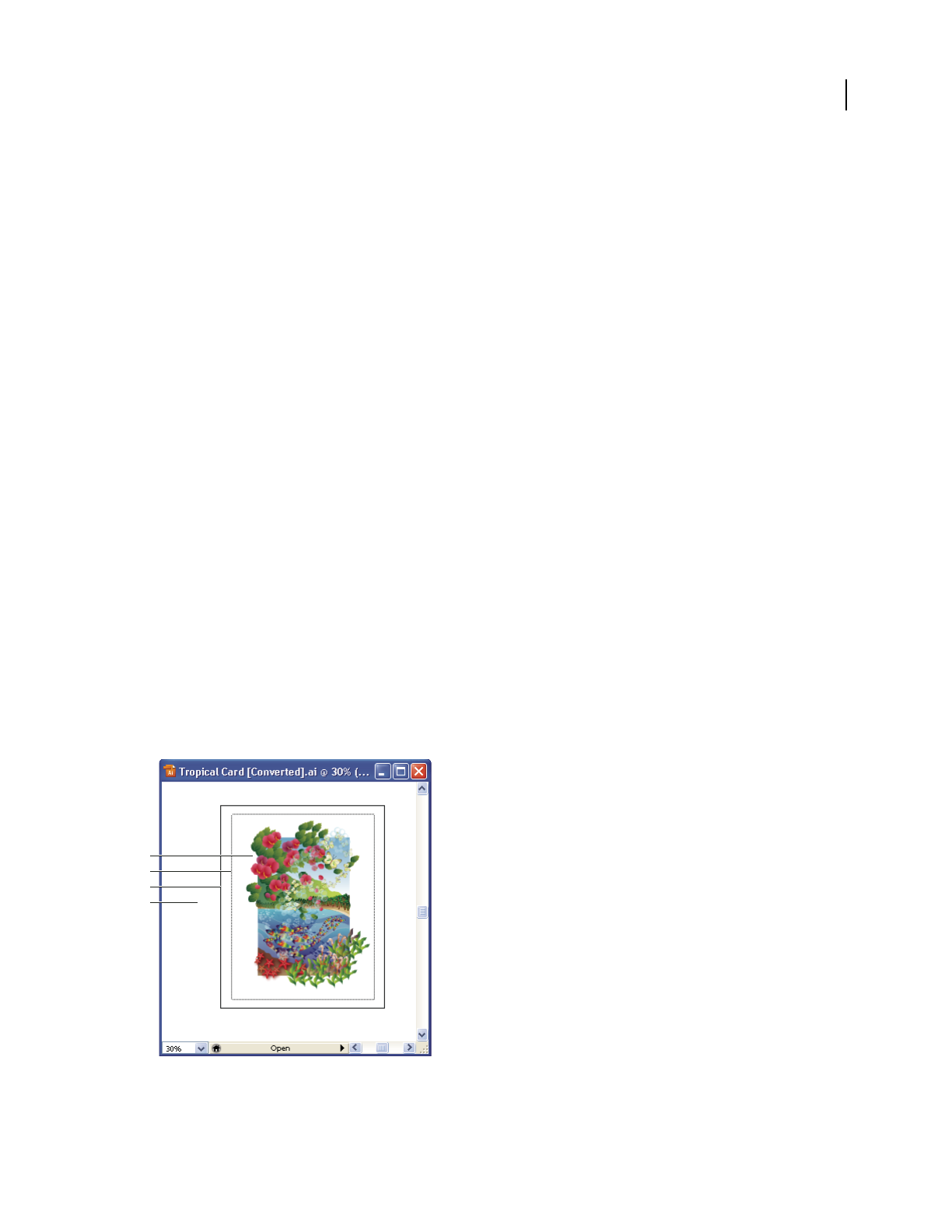
ILLUSTRATOR CS3
User Guide
41
•The crop area is indicated by visible but non-printing marks, whereas crop marks are printed with registration
black (so that they print to every separation plate, similar to printer’s marks).
Note: Crop marks do not replace trim marks created with the Marks & Bleed options in the Print dialog box or with the
Object > Crop Area > Make command.
Create crop marks around an object
1
Select the object or objects.
2 Choose Filter > Create > Crop Marks.
Delete crop marks
❖Select the crop mark and press Delete.
Use Japanese-style crop marks
Japanese-style crop marks have double lines, which visually define a default bleed value of 8.5 points (3 millimeters).
1 Choose Edit > Preferences > General (Windows) or Illustrator > Preferences > General (Mac OS).
2 Select Use Japanese Crop Marks, and then click OK.
Viewing artwork
Artboard overview
The artboard represents the entire region that can contain printable artwork. However, the artboard’s dimensions do
not necessarily match the current page size. For example, your artboard may be 10 x 20 inches while your print
settings specify 8-1/2 x 11 inch paper, or 864 x 480 pixels. You can view the page boundaries in relation to the
artboard by showing page tiling (View
> Show Page Tiling). When page tiling is on, the printable and nonprintable
areas are represented by a series of solid and dotted lines between the outermost edge of the window and the
printable area of the page.
Illustration window
A. Printable area B. Nonprintable area C. Edge of the page D. Artboard
A
B
C
D

ILLUSTRATOR CS3
User Guide
42
The printable area is bounded by the innermost dotted lines and represents the portion of the page on which the
selected printer can print. Many printers cannot print to the edge of the paper.
The nonprintable area is between the two sets of dotted lines representing any nonprintable margin of the page.
The page edge is indicated by the outermost set of dotted lines.
The artboard is bounded by solid lines and represents the maximum printable area. To hide the artboard boundaries,
choose View
> Hide Artboard.
The scratch area is the area outside the artboard that extends to the edge of the 227-inch square window. The scratch
area represents a space on which you can create, edit, and store elements of artwork before moving them onto the
artboard. Objects placed onto the scratch area are visible on-screen, but they do not print.
See also
“Change the page size and orientation” on page 407
“Reposition artwork on the page” on page 406
“Print artwork on multiple pages” on page 406
Change the size and color of the artboard
1 Choose File > Document Setup.
2 From the menu at the upper-left of the Document Setup window, do either of the following:
•To change the size of the artboard, choose Artboard, and then set the size and orientation for the artboard.
•To change the color of the artboard, choose Transparency. Select Simulate Colored Paper, click the top color
swatch, and select a new color using the Color dialog box.
Changing the color of the artboard lets you view your document as it might appear when printed on colored paper.
For example, if you draw a blue object on a yellow background, the object appears green. The simulation is only
performed when the transparency grid is not shown.
About page tiling
By default, Illustrator prints your artwork on a single sheet of paper. However, if the artwork is larger than the page
sizes available on your printer, you can print onto multiple sheets of paper.
Dividing the artboard to fit a printer’s available page sizes is called tiling. You can choose a tiling option in the Setup
section of the Print dialog box. To view the page tiling boundaries on the artboard, choose View
> Show Page Tiling.

ILLUSTRATOR CS3
User Guide
43
Artboard divided into multiple page tiles
When you divide the artboard into multiple page tiles, the pages are numbered from left to right and from top to
bottom, starting with page 1. These page numbers appear on-screen for your reference only; they do not print. The
numbers enable you to print all of the pages in the file or specify particular pages to print.
See also
“Change the page size and orientation” on page 407
“Print artwork on multiple pages” on page 406
Zoom in or out
There are several ways to zoom in or out of artwork.
•Select the Zoom tool . The pointer becomes a magnifying glass with a plus sign in its center. Click in the center
of the area that you want to magnify, or hold down Alt (Windows) or Option (Mac OS) and click in the center of
the area that you want to reduce. Each click magnifies or reduces the view to the previous preset percentage.
•Select the Zoom tool and drag a dotted rectangle, called a marquee, around the area you want to magnify. To move
the marquee around the artwork, hold down the spacebar, and continue dragging to move the marquee to a new
location.
•Choose View > Zoom In or View > Zoom Out. Each click magnifies or reduces the view to the next preset
percentage.
•Set the zoom level at the lower-left corner of the main window or in the Navigator panel.
•To display a file at 100%, choose View > Actual Size, or double-click the Zoom tool.
•To change the view to fit the document window, choose View > Fit In Window, or double-click the Hand tool.
See also
“Moving and zooming tool gallery” on page 33
“Keys for viewing artwork” on page 462

ILLUSTRATOR CS3
User Guide
44
Move the view area
You can bring a different area of the artboard into view by doing either of the following:
•Select the Hand tool , and drag in the direction you want the artwork to move.
•In the Navigator panel, click the area of the thumbnail display that you want to view in the illustration window.
Alternatively, drag the proxy view area (the colored box) to a different area of the thumbnail display.
To specify the quality of the display when using the Hand tool, choose Edit > Preferences > Units & Display Perfor-
mance (Windows) or Illustrator > Preferences > Units & Display Performance (Mac OS). Drag the Hand Tool slider
left to improve the quality of the view when you move it with the Hand tool, or right to improve the speed at which you
can move the view with the Hand tool.
See also
“Moving and zooming tool gallery” on page 33
“Keys for viewing artwork” on page 462
Navigator panel overview
You use the Navigator panel (Window > Navigator) to quickly change the view of your artwork using a thumbnail
display. The colored box in the Navigator (called the proxy view area) corresponds to the currently viewable area in
the illustration window.
Navigator panel
A. Thumbnail display of artwork B. panel menu button C. Zoom box D. Zoom Out button E. Proxy preview area F. Zoom slider G. Zoom
In button
You can customize the Navigator panel in the following ways:
•To display artwork outside the boundaries of the artboard in the Navigator panel, click View Artboard/Crop Area
Only from the panel menu to deselect it.
•To change the color of the proxy view area, select panel Options from the panel menu. Select a preset color from
the Color menu, or double-click the color box to choose a custom color.
•To display dashed lines in the document as solid lines in the Navigator panel, select panel Options from the panel
menu and select Draw Dashed Lines As Solid Lines.
•To specify the size at which text is replaced by a gray bar in the Navigator panel, select panel Options from the
panel menu and enter a font size in the Greeking box.
See also
“Customize the workspace” on page 18
A
CDE FG
B

ILLUSTRATOR CS3
User Guide
45
View artwork as outlines
By default, Adobe Illustrator sets the view so that all artwork is previewed in color. However, you can choose to
display artwork so that only its outlines (or paths) are visible. Viewing artwork without paint attributes speeds up the
time it takes to redraw the screen when working with complex artwork.
In Outline mode, linked files are displayed by default as outlined boxes with an X inside. To view the contents of
linked files, choose File
> Document Setup, choose Artboard at the top of the dialog box, and select Show Images In
Outline.
•To view all artwork as outlines, choose View > Outline. Choose View > Preview to return to previewing artwork
in color.
•To view all artwork in a layer as outlines, Ctrl-click (Windows) or Command-click (Mac OS) the eye icon for the
layer in the Layers panel. Ctrl-click (Windows) or Command-click (Mac OS) again to return to previewing
artwork in color. The eye icon has a hollow center when Outline view is enabled and a filled center when
Preview view is enabled.
•To view all items in unselected layers as outlines, Alt+Ctrl-click (Windows) or Option+Command-click (Mac OS)
the eye icon for the selected layer. Alternatively, select Outline Others from the Layers panel menu.
You can return all items in the Layers panel to Preview mode by choosing Preview All Layers from the Layers panel
menu.
See also
“Layers panel overview” on page 211
Use multiple windows and views
You can open multiple windows of a single document at the same time. Each window can have different view
settings. For
example, you can set one window highly magnified for doing close-up work on some objects and create
another window less magnified for laying out those objects on the page.
(Windows) You can arrange multiple open windows to suit your needs, using options from the Window menu.
Cascade displays windows stacked and descending from the upper-left to the lower-right of the screen; Tile displays
windows edge to edge; Arrange Icons organizes minimized windows within the program window.
An alternative to creating multiple windows is creating multiple views. You can create and store up to 25 views for
each document.
Multiple windows and multiple views differ in the following ways:
•Multiple views are saved with the document, multiple windows are not.
•Multiple windows can be viewed at the same time.
•Multiple views can only appear at the same time if multiple windows are opened to display them in. Changing a
view alters the current windows, it does not open a new one.
Create a new window
❖ Choose Window > New Window.
Create a new view
❖ Set up the view as you want, and then choose View > New View, enter a name for the new view, and click OK.

ILLUSTRATOR CS3
User Guide
46
Rename or delete a view
❖ Choose View > Edit Views.
Switch between views
❖Select a view name from the bottom of the View menu.
Previewing artwork in its final output medium
Illustrator provides the following ways to preview how aspects of artwork will look when printed or viewed on the
web or a mobile device:
Overprint Preview mode (View > Overprint Preview) Provides an “ink preview” that approximates how blending,
transparency, and overprinting will appear in color-separated output.
Pixel Preview mode (View > Pixel Preview) Approximates how your artwork will appear when it is rasterized and
viewed in a web browser.
Flattener Preview panel (Window > Flattener Preview) Highlights areas of the artwork that meet certain criteria for
flattening when saved or printed.
Soft-proofs Approximate how your document’s colors will appear on a particular type of monitor or output device.
Anti-aliasing Gives vector objects a smoother on-screen appearance and provides a better idea of how vector
artwork will look when printed on a PostScript® printer. Anti-aliasing is helpful because screen resolution is relatively
limited, but vector artwork is often printed at a high resolution. To turn on anti-aliasing, choose Edit > Preferences >
General (Windows) or Illustrator > Preferences > General (Mac OS), select Anti-aliased Artwork, and click OK.
Device Central (File > Device Central) Lets you preview how your document will appear on a particular mobile
phone or device.
See also
“About overprinting” on page 424
“About pixel preview mode” on page 370
“Preview which areas of artwork will be flattened” on page 421
“Soft-proof colors” on page 137
“Save For Web & Devices overview” on page 381
Rulers, grids, and guides
Use rulers
Rulers help you accurately place and measure objects in the illustration window. Rulers appear at the top and left
sides of the illustration window. The point where 0 appears on each ruler is called the ruler origin. The default ruler
origin is located at the lower-left corner of the artboard.
•To show rulers, choose View > Show Rulers.
•To hide rulers, choose View > Hide Rulers.

ILLUSTRATOR CS3
User Guide
47
•To change the ruler origin, move the pointer to the upper-left corner of the illustration window where the rulers
intersect, and drag the pointer to where you want the new ruler origin.
As you drag, a cross hair in the window and in the rulers indicates the changing ruler origin.
Note: Changing the ruler origin affects the tiling of patterns.
•To restore the default ruler origin, double-click the upper-left corner of the illustration window where the rulers
intersect.
Note: Rulers are also available for individual crop areas. To set rulers around crop areas, double-click the Crop tool to
open the Crop Area Options dialog box, and select Show Crop Area Rulers.
Change the unit of measurement
The default unit of measurement in Illustrator is points (a point equals .3528 millimeter). You can change the unit
that Illustrator uses for general measurements, strokes, and type. You can override the default unit while entering
values in boxes.
•To change the default unit of measurement, choose Edit > Preferences > Units & Display Performance (Windows)
or Illustrator > Preferences > Units & Display Performance (Mac OS), and then select units for the General,
Stroke, and Type options. If Show Asian Options is selected in the Type preferences, you can also select a unit
specifically for Asian type.
Note: The “General” measurement option affects rulers, measuring the distance between points, moving and trans-
forming objects, setting grid and guides spacing, and creating shapes.
•To set the general unit of measurement for the current document only, choose File > Document Setup, select
Artboard from the menu at the upper-left of the Document Setup dialog box, set the unit of measure you want to
use, and click OK.
•To change the unit of measurement when entering a value in a box, follow the value by any of the following abbre-
viations: inch, inches, in, millimeters, millimetres, mm, Qs (one Q equals 0.25 millimeter), centimeters, centi-
metres, cm, points, p, pt, picas, pc, pixel, pixels, and px.
When mixing picas and points, you can enter values as XpY, where X and Y are the number of picas and points (for
example, 12p6 for 12 picas, 6 points).
Use the grid
The grid appears behind your artwork in the illustration window, and it does not print.
•To use the grid, choose View > Show Grid.
•To hide the grid, choose View > Hide Grid.
•To snap objects to gridlines, choose View > Snap To Grid, select the object you want to move, and drag it to the
desired location.
When the object’s boundaries come within 2 pixels of a gridline, it snaps to the point.
Note: When the View > Pixel Preview option is selected, Snap To Grid changes to Snap To Pixel.
•To specify the spacing between gridlines, grid style (lines or dots), grid color, or whether grids appear in the front
or back of artwork, choose Edit > Preferences > Guides & Grid (Windows) or Illustrator > Preferences > Guides
& Grid (Mac OS).

ILLUSTRATOR CS3
User Guide
48
Use guides
Guides help you align text and graphic objects. You can create ruler guides (straight vertical or horizontal lines) and
guide objects (vector objects that you convert to guides). Like the grid, guides do not print.
You can choose between two guide styles—dots and lines—and you can change the color of guides by using either
predefined guide colors or colors you select using a color picker. By default, guides are unlocked so that you can
move, modify, delete, or revert them, but you can choose to lock them into place.
•To show or hide guides, choose View > Guides > Show Guides or View > Guides > Hide Guides.
•To change guide settings, choose Edit > Preferences > Guides & Grid (Windows) or Illustrator > Preferences >
Guides & Grid (Mac OS).
•To lock guides, select View > Guides > Lock Guides.
Create guides
1
If the rulers aren’t showing, choose View > Show Rulers.
2 Position the pointer on the left ruler for a vertical guide or on the top ruler for a horizontal guide.
3 Drag the guide into position.
You can also convert vector objects to guides by selecting them and choosing View > Guides > Make Guides.
To make working with multiple guides easier, move them into a separate layer.
Move, delete, or release guides
1
If guides are locked, select View > Guides > Lock Guides.
2 Do any of the following:
•Move the guide by dragging or copying.
•Delete the guide by pressing Backspace (Windows) or Delete (Mac OS), or by choosing Edit > Cut or Edit > Clear.
•Delete all guides at once by choosing View > Guides > Clear Guides.
•Release the guide, turning it back into a regular graphic object, by selecting the guide and choosing View >
Guides > Release Guides.
Snap objects to anchor points and guides
1
Choose View > Snap To Point.
2 Select the object you want to move, and position the pointer on the exact point you want to align with anchor
points and guides.
Important: When snapping to a point, the snapping alignment depends on the position of the pointer, not the edges of
the dragged object.
3 Drag the object to the desired location.
When the pointer comes within 2 pixels of an anchor point or guide, it snaps to the point. The pointer changes from
a filled arrowhead to a hollow arrowhead when a snap occurs.
About Smart Guides
Smart Guides are temporary snap-to guides that help you create, align, edit, and transform objects relative to other
objects. To activate Smart Guides, choose View
> Smart Guides.

ILLUSTRATOR CS3
User Guide
49
You can use Smart Guides in the following ways:
•When you create an object with the pen or shape tools, use the Smart Guides to position a new object's anchor
points relative to an existing object.
•When you move an object, use the Smart Guides to align your cursor to construction guides and existing paths.
The alignment is based on the position of the pointer, not the edges of the object, so be sure to click to the exact
point you want to align to.
•When you transform an object, Smart Guides automatically appear to assist the transformation.
You can change when and how Smart Guides appear by setting Smart Guide preferences.
Note: When Snap To Grid is turned on, you cannot use Smart Guides (even if the menu command is selected).
Smart Guide preferences
Choose Edit > Preferences > Smart Guides & Slices (Windows) or Illustrator > Preferences > Smart Guides & Slices
(Mac
OS) to set the following preferences:
Text Label Hints Displays information about the position the cursor is currently snapped to (such as center) as you
manipulate the cursor.
Construction Guides Displays guidelines in the file as you use Smart Guides.
Transform Tools Displays information when you scale, rotate, and shear objects.
Object Highlighting Highlights the object below the pointer as you drag around it.
Angles Sets angles at which you want guidelines drawn from the anchor points of a nearby object. You can set up to
six angles. Type an angle in the selected Angles box, select a set of angles from the Angles pop-up menu, or select a
set of angles from the pop-up menu and change one of the values in the box to customize a set of angles. The preview
reflects your settings.
Snapping Tolerance Specifies the number of points the pointer must be from another object for Smart Guides to
take effect.
Measure the distance between objects
The Measure tool calculates the distance between any two points and displays the results in the Info panel.
1 Select the Measure tool .
2 Do one of the following:
•Click the two points to measure the distance between them.
•Click the first point and drag to the second point. Shift-drag to constrain the tool to multiples of 45˚.
The Info panel shows the horizontal and vertical distances from the x and y axes, the absolute horizontal and vertical
distances, the total distances, and the angle measured.

ILLUSTRATOR CS3
User Guide
50
Info panel overview
You use the Info panel (Window > Info) to get information on the area beneath the pointer and on selected objects.
•When an object is selected and a selection tool is active, the Info panel displays the object’s x and y coordinates,
width (W), and height (H). The values for width and height are affected by the Use Preview Bounds option in the
General preferences. When Use Preview Bounds is selected, Illustrator includes the stroke width (and other
attributes such as drop shadows) in the object’s dimensions. When Use Preview Bounds is deselected, Illustrator
measures only the dimensions defined by the object’s vector path.
•When you use the Pen tool or Gradient tool, or when you move a selection, the Info panel displays the change in
x (W), the change in y (H), the distance (D), and the angle as you drag.
•When you use the Zoom tool, the Info panel displays the magnification factor and the x and y coordinates after
you release the mouse button.
•When you use the Scale tool, the Info panel displays the percentage change in width (W) and height (H) and the
new width (W) and height (H) after the scaling is complete. When you use the rotate or reflect tools, the Info panel
displays the coordinates of the object’s center and the angle of rotation or reflection .
•When you use the Shear tool, the Info panel displays the coordinates of the object’s center, the angle of shear
axis , and the amount of shear .
•When you use the Paintbrush tool, the Info panel displays the x and y coordinates and the name of the current
brush.
•Select Show Options from the panel menu or click the double arrow on the panel tab to show values for the fill
and stroke colors of the selected object and the name of any pattern, gradient, or tint applied to the selected object.
Note: If you select multiple objects, the Info panel displays only the information that is the same for all selected objects.
Setting preferences
About preferences
Preferences are options regarding how you want Illustrator to work, including those for display, tools, ruler units, and
exporting information. Your preferences are saved in a file called AIPrefs (Windows) or Adobe Illustrator Prefs
(Mac
OS), which is launched each time you start Illustrator. To restore Illustrator’s default settings, you can remove
or rename preferences file and relaunch Illustrator. This can be helpful if you are having problems with the appli-
cation.
Note: It is safe to remove the entire Adobe Illustrator CS3 Settings folder. This folder contains various preferences that
can be regenerated.
You set preferences in the Preferences dialog box. To open the Preferences dialog box, choose Edit > Preferences
(Windows) or Illustrator
> Preferences (Mac OS), followed by the type of preferences you want. To switch to
different options in the Preferences dialog box, select an option from the menu at the upper-left of the Preferences
dialog box. You can also click Next to display the next options, or click Prev to display the previous options.
About plug-in modules
Plug-in modules are software programs that add features to Adobe Illustrator. A number of special effects plug-ins
come with your program and are automatically installed in the Plug-ins folder inside the Illustrator folder.

ILLUSTRATOR CS3
User Guide
51
You can install any commercial plug-in designed for use with Photoshop or Illustrator. To install an Adobe Systems
plug-in module, use the installer if one is provided. Otherwise, drag a copy of the module to the Plug-ins folder inside
the Illustrator folder. Then restart Illustrator for the plug-in to take effect. To install a third-party plug-in module,
follow the installation instructions that came with the plug-in module.
Note: The open architecture of the Adobe Illustrator program allows developers outside of Adobe to create features that
are accessible from within Adobe Illustrator. If you are interested in creating plug-in modules compatible with Adobe
Illustrator, see the Adobe Systems U.S. website at www.adobe.com.
Recovery, undo, and automation
Undo and redo changes
The Undo and Redo commands let you undo or redo operations, allowing you to correct mistakes as you work. You
can undo or redo an operation after you select the Save command (but not if you have closed and then reopened the
file).
❖Choose Edit > Undo or Edit > Redo.
You can undo an unlimited number of operations (depending on memory) by repeatedly choosing the Undo
command. If an operation cannot be undone, the Undo command is dimmed.
Revert to the last saved version
You can revert a file to the last saved version (but not if you have closed and then reopened the file). You cannot undo
this action.
❖Choose File > Revert.
Automating tasks
Graphic design is a field characterized by creativity, but there are some aspects of the actual work of illustration that can
be repetitious. In fact, you’ll probably notice that the time you spend placing and replacing images, correcting errors,
and preparing files for printing and web display often reduces the time you have available for doing creative work.
Illustrator provides a variety of ways to automate many of the repetitive tasks you have to do, leaving more time to
concentrate on the creative aspects of your work.
An action is a series of tasks that are recorded while using the Illustrator application—menu commands, tool options,
object selection, and so on. When you play an action, Illustrator performs all of the recorded tasks for you.
Illustrator provides prerecorded actions to assist you in performing common tasks. These actions are installed as a
default set in the Actions panel when you install the Illustrator application.
A script is a series of commands that tells your computer to perform a sequence of operations. These operations may
involve only Illustrator, or they may involve other applications, such as word-processing, spreadsheet, and database-
management programs. Illustrator provides default scripts to assist you in performing common tasks. You can access
these scripts by choosing File
> Scripts.
Data-driven graphics streamline how designers and developers work together in high-volume publishing environ-
ments.
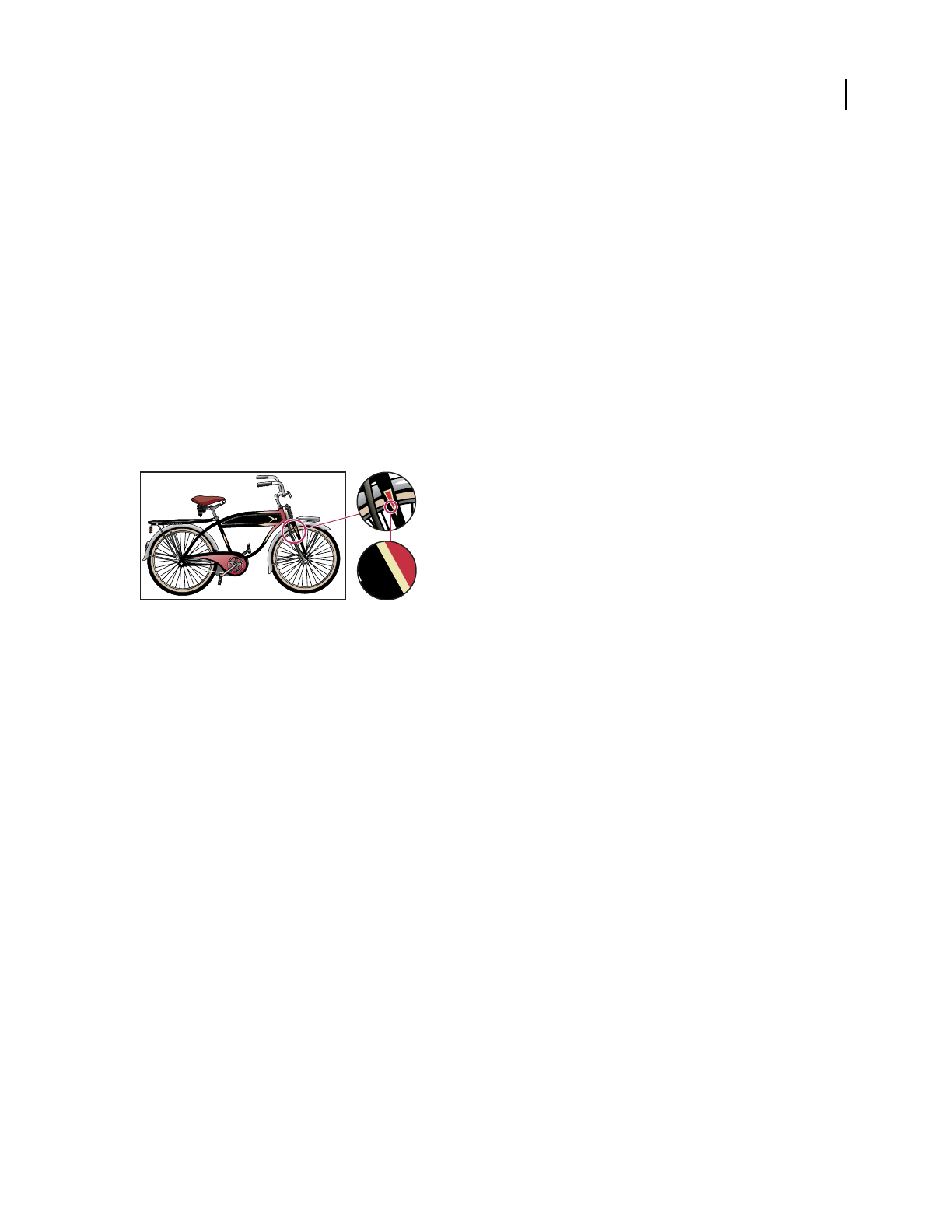
52
Chapter 3: Drawing
You draw and modify paths using a set of drawing tools and techniques common to Adobe Illustrator, Adobe®
InDesign®, and Adobe® Photoshop®. Use these applications to draw paths, and freely copy and paste them between
programs. You can also create symbols for use in both Adobe Illustrator and Adobe® Flash® CS3 Professional.
Drawing basics
About vector graphics
Vector graphics (sometimes called vector shapes or vector objects) are made up of lines and curves defined by mathe-
matical objects called vectors, which describe an image according to its geometric characteristics.
Example of a vector image at different levels of magnification
You can freely move or modify vector graphics without losing detail or clarity, because they are resolution-
independent—they maintain crisp edges when resized, printed to a PostScript printer, saved in a PDF file, or
imported into a vector-based graphics application. As a result, vector graphics are the best choice for artwork, such
as logos, that will be used at various sizes and in various output media.
The vector objects you create using the drawing and shape tools in Adobe Creative Suite are examples of vector
graphics. You can use the Copy and Paste commands to duplicate vector graphics between Creative Suite compo-
nents.
See also
“About bitmap images” on page 258
About paths
As you draw, you create a line called a path. A path is made up of one or more straight or curved segments. The
beginning and end of each segment are marked by anchor points, which work like pins holding a wire in place. A path
can be closed (for example, a circle), or open, with distinct endpoints (for example, a wavy line).
You change the shape of a path by dragging its anchor points, the direction points at the end of direction lines that
appear at anchor points, or the path segment itself.
24:1
3:1
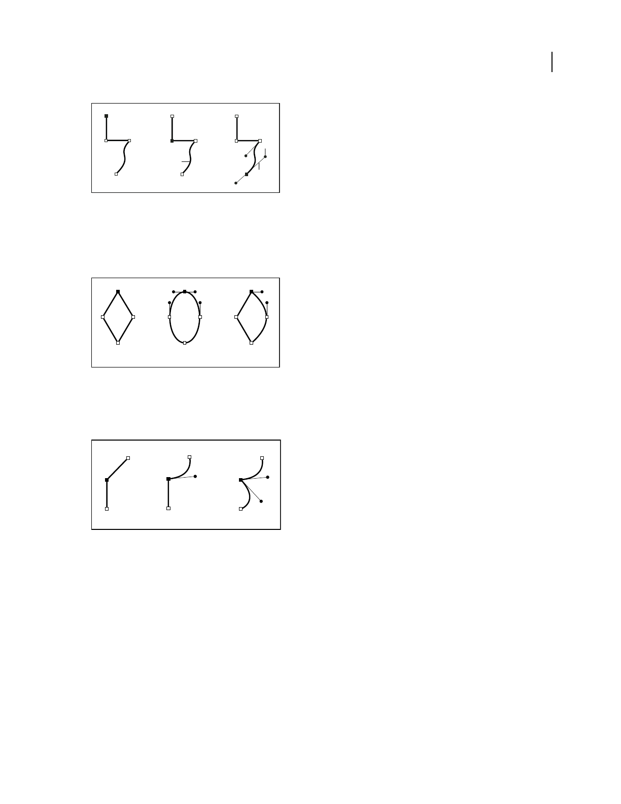
ILLUSTRATOR CS3
User Guide
53
Components of a path
A. Selected (solid) endpoint B. Selected anchor point C. Unselected anchor point D. Curved path segment E. Direction line F. Direction point
Paths can have two kinds of anchor points: corner points and smooth points. At a corner point, a path abruptly
changes direction. At a smooth point, path segments are connected as a continuous curve. You can draw a path using
any combination of corner and smooth points. If you draw the wrong kind of point, you can always change it.
Points on a path
A. Four corner points B. Four smooth points C. Combination of corner and smooth points
A corner point can connect any two straight or curved segments, while a smooth point always connects two curved
segments.
A corner point can connect both straight segments and curved segments.
Note: Don’t confuse corner and smooth points with straight and curved segments.
A path’s outline is called a stroke. A color or gradient applied to an open or closed path’s interior area is called a fill.
A stroke can have weight (thickness), color, and a dash pattern (Illustrator and InDesign) or a stylized line pattern
(InDesign). After you create a path or shape, you can change the characteristics of its stroke and fill.
In InDesign, each path also displays a center point, which marks the center of the shape but is not part of the actual
path. You can use this point to drag the path, to align the path with other elements, or to select all anchor points on
the path. The center point is always visible; it can’t be hidden or deleted.
A
B
D
C
E
F
AB C
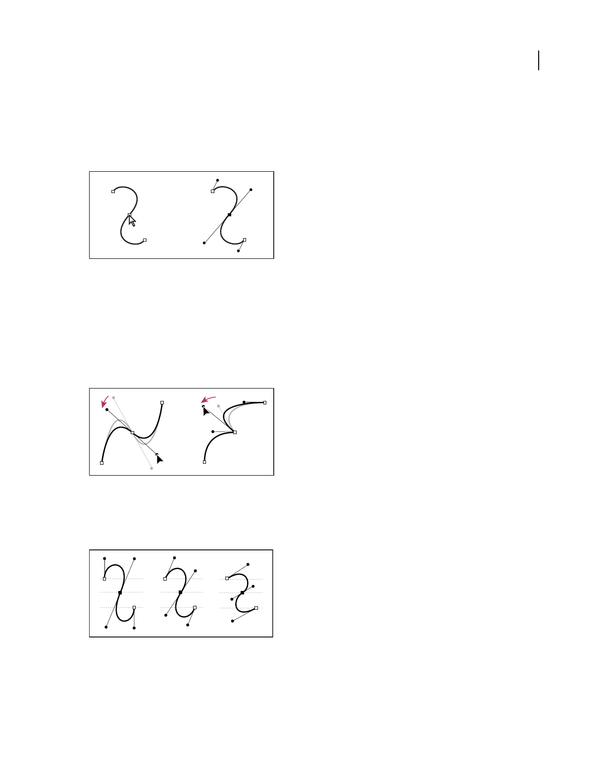
ILLUSTRATOR CS3
User Guide
54
About direction lines and direction points
When you select an anchor point that connects curved segments (or select the segment itself), the anchor points of
the connecting segments display direction handles, which consist of direction lines that end in direction point. The
angle and length of the direction lines determine the shape and size of the curved segments. Moving the direction
points reshapes the curves. Direction lines don’t appear in the final output.
After selecting an anchor point (left), direction lines appear on any curved segments connected by the anchor point (right).
A smooth point always has two direction lines, which move together as a single, straight unit. When you move a
direction line on a smooth point, the curved segments on both sides of the point are adjusted simultaneously,
maintaining a continuous curve at that anchor point.
In comparison, a corner point can have two, one, or no direction lines, depending on whether it joins two, one, or
no curved segments, respectively. Corner point direction lines maintain the corner by using different angles. When
you move a direction line on a corner point, only the curve on the same side of the point as that direction line is
adjusted.
Adjusting direction lines on a smooth point (left) and a corner point (right)
Direction lines are always tangent to (perpendicular to the radius of) the curve at the anchor points. The angle of
each direction line determines the slope of the curve, and the length of each direction line determines the height, or
depth, of
the curve.
Moving and resizing direction lines changes the slope of curves.
Note: In Illustrator, you can show or hide anchor points, direction lines, and direction points by choosing View > Show
Edges or View > Hide Edges.

ILLUSTRATOR CS3
User Guide
55
Specify direction line and direction point appearance
When working with anchor points and paths, you may sometimes need to see direction lines (handles), while at
other times they may get in the way. You can show or hide direction lines for multiple selected anchor points. For a
single anchor point, the lines always appear.
You can choose to show or hide direction lines on a per-selection basis, or you can set a preference for direction line
display.
For a video on setting direction lines and points, see www.adobe.com/go/vid0037.
See also
“Specify selection preferences” on page 194
Show or hide direction lines for selected anchor points
1
Use the Direct Selection tool to select the desired anchor points.
2 In the Control panel, click Show Handles For Multiple Selected Anchor Points > or Hide Handles For Multiple
Selected Anchor Points .
Note: You can also set a preference to always show or always hide handles when multiple anchor points are selected.
Set direction point and direction line display preferences
1
Choose Edit > Preferences > Selection & Anchor Display (Windows) or Illustrator > Preferences > Selection &
Anchor Display (Mac OS).
2 In the Anchor Point And Handle Display area, specify any of the following:
Handles Specifies the display of handle end points (direction points):
• Displays direction points as small solid circles.
• Displays direction points as large solid circles.
• Displays direction points as open crosses.
Show Handles When Multiple Anchors Are Selected Displays direction lines on all selected anchor points when you
use the Direct Selection tool or Group Selection tool to select an object. If you don’t select this option, direction lines
are displayed for an anchor point if it is the only anchor point selected on that path, or if the Bezier segment for the
direction line is selected and the anchor point from which the direction line extends is not selected.
Specify anchor point size preferences
1 Choose Edit > Preferences > Selection & Anchor Display (Windows) or Illustrator > Preferences > Selection &
Anchor Display (Mac OS).
2 In the Anchor Point And Handle Display area, specify any of the following:
Anchors Specifies the display of anchor points:
• Displays both selected and unselected anchor points as small points.
• Displays selected anchor points as large points and unselected anchor points as small points.
• Displays both selected and unselected anchor points as large points.
Highlight Anchors On Mouse Over Highlights the anchor point located directly below the mouse cursor.

ILLUSTRATOR CS3
User Guide
56
Drawing simple lines and shapes
Draw straight lines with the Line Segment tool
Use the Line Segment tool when you want to draw one straight line segment at a time. For a video on using the Line
Segment tool, see www.adobe.com/go/vid0036.
1 Select the Line Segment tool .
2 Do one of the following:
•Position the pointer where you want the line to begin, and drag to where you want the line to end.
•Click where you want the line to begin, and specify the length and angle of the line. If you want to fill the line with
the current fill color, select Fill Line. Then click OK.
See also
“Drawing tool gallery” on page 26
“Keys for drawing” on page 462
Draw rectangles and squares
1 Select the Rectangle tool or the Rounded Rectangle tool .
2 Do one of the following:
•To draw a rectangle, drag diagonally until the rectangle is the desired size.
•To draw a square, hold down the Shift key while you drag diagonally until the square is the desired size.
•To create a square or rectangle using values, click where you want the top-left corner to be. Specify a width and
height (and a corner radius for a rounded rectangle), and click OK.
For a video on using shape tools, see www.adobe.com/go/vid0036.
See also
“Drawing tool gallery” on page 26
“Keys for drawing” on page 462
Change the corner radius of a rounded rectangle
The corner radius determines the roundness of the rectangle’s corners.
•To change the default corner radius, choose Edit> Preferences > General (Windows) or Illustrator > Preferences >
General (Mac OS), and enter a new value for Corner Radius. Alternatively, select the Rounded Rectangle tool,
click in the document window, and enter a new value for Corner Radius. The default radius applies only to new
rounded rectangles you draw, not to existing rounded rectangles.
•To change the corner radius while dragging with the Rounded Rectangle tool, press the Up Arrow key or Down
Arrow key. When the corners are the desired roundness, release the key.
•To create square corners while dragging with the Rounded Rectangle tool, press the Left Arrow key.
•To create the most rounded corners while dragging with the Rounded Rectangle tool, press the Right Arrow key.

ILLUSTRATOR CS3
User Guide
57
Draw ellipses
1 Select the Ellipse tool .
2 Do one of the following:
•Drag diagonally until the ellipse is the desired size.
•Click where you want the top-left corner of the ellipse’s bounding box to be. Specify a width and height for the
ellipse, and click OK.
Note: To create a circle, hold down the Shift key while dragging, or if you are specifying dimensions, once you’ve entered
a Width value you can click on the word Height to copy that value into the Height box.
For a video on using shape tools, see www.adobe.com/go/vid0036.
See also
“Drawing tool gallery” on page 26
“Keys for drawing” on page 462
Draw polygons
1 Select the Polygon tool .
2 Do one of the following:
•Drag until the polygon is the desired size. Drag the pointer in an arc to rotate the polygon. Press the Up Arrow
and Down Arrow keys to add and remove sides from the polygon.
•Click where you want the center of the polygon to be. Specify a radius and number of sides for the polygon, and
click OK.
Triangles are polygons too! You can draw one just as you would any other polygon.
For a video on using shape tools, see www.adobe.com/go/vid0036.
See also
“Drawing tool gallery” on page 26
“Keys for drawing” on page 462
Draw stars
1 Select the Star tool .
2 Do one of the following:
•Drag until the star is the desired size. Drag the pointer in an arc to rotate the star. Press the Up Arrow and Down
Arrow to add and remove points from the star.
•Click where you want the center of the star to be. For Radius 1, specify the distance from the center of the star to
the star’s innermost points. For Radius 2, specify the distance from the center of the star to the star’s outermost
points. For Points, specify how many points you want the star to have. Then click OK.
For a video on using shape tools, see www.adobe.com/go/vid0036.

ILLUSTRATOR CS3
User Guide
58
See also
“Drawing tool gallery” on page 26
“Keys for drawing” on page 462
Draw arcs
1 Select the Arc tool .
2 Do one of the following:
•Position the pointer where you want the arc to begin, and drag to where you want the arc to end.
•Click where you want the arc to begin. In the dialog box, click a square on the reference point locator to
determine the point from which the arc is drawn. Then set any of the following options, and click OK.
Length X-Axis Specifies the width of the arc.
Length Y-Axis Specifies the height of the arc.
Type Specifies whether you want the object to be an open path or a closed path.
Base Along Specifies the direction of the arc. Choose X Axis or Y Axis depending on whether you want to draw the
base of the arc along the horizontal (x) axis or vertical (y) axis.
Slope Specifies the direction of the arc’s slope. Enter a negative value for a concave (inward) slope. Enter a positive
value for a convex (outward) slope. A slope of 0 creates a straight line.
Fill Arc Fills the arc with the current fill color.
Note: To see a dynamic preview of the arc as you set options, double-click the arc tool in the Tools panel.
See also
“Drawing tool gallery” on page 26
“Keys for drawing” on page 462
Draw spirals
1 Select the Spiral tool .
2 Do one of the following:
•Drag until the spiral is the desired size. Drag the pointer in an arc to rotate the spiral.
•Click where you want the spiral to begin. In the dialog box, set any of the following options, and click OK.
Radius Specifies the distance from the center to the outermost point in the spiral.
Decay Specifies the amount by which each wind of the spiral should decrease relative to the previous wind.
Segments Specifies how many segments the spiral has. Each full wind of the spiral consists of four segments.
Style Specifies the direction of the spiral.
See also
“Drawing tool gallery” on page 26
“Keys for drawing” on page 462

ILLUSTRATOR CS3
User Guide
59
Draw grids
Use the grid tools to quickly draw rectangular and polar grids. The Rectangular Grid tool creates rectangular grids
of a specified size with a specified number of dividers. The Polar Grid tool creates concentric circles of a specified
size and a specified number of dividers.
See also
“Drawing tool gallery” on page 26
“Keys for drawing” on page 462
Draw rectangular grids
1
Select the Rectangular Grid tool .
2 Do one of the following:
•Drag until the grid is the desired size.
•Click to set the grid’s reference point. In the dialog box, click a square on the reference point locator to
determine the point from which the grid is drawn. Then set any of the following options, and click OK.
Default Size Specifies the width and height of the entire grid.
Horizontal Dividers Specifies the number of horizontal dividers you want to appear between the top and bottom of
the grid. The Skew value determines how the horizontal dividers are weighted toward the top or bottom of the grid.
Vertical Dividers Specifies the number of dividers you want to appear between the left and right sides of the grid.
The Skew value determines how the vertical dividers are weighted to the left or right side.
Use Outside Rectangle As Frame Replaces the top, bottom, left, and right segments with a separate rectangular
object.
Fill Grid Fills the grid with the current fill color (otherwise, the fill is set to none).
Draw circular (polar) grids
1
Select the Polar Grid tool .
2 Do one of the following:
•Drag until the grid is the desired size.
•Click to set the grid’s reference point. In the dialog box, click a square on the reference point locator to
determine the point from which the grid is drawn. Then set any of the following options, and click OK.
Default Size Specifies the width and height of the entire grid.
Concentric Dividers Specifies the number of circular concentric dividers you want to appear in the grid. The Skew
value determines how the concentric dividers are weighted toward the inside or outside of the grid.
Radial Dividers
Specifies the number of radial dividers you want to appear between the center and the circumference
of the grid. The Skew value determines how the radial dividers are weighted counterclockwise or clockwise on the grid.
Create Compound Path From Ellipses Converts the concentric circles into separate compound paths and fill every
other circle.
Fill Grid Fills the grid with the current fill color (otherwise, the fill is set to none).
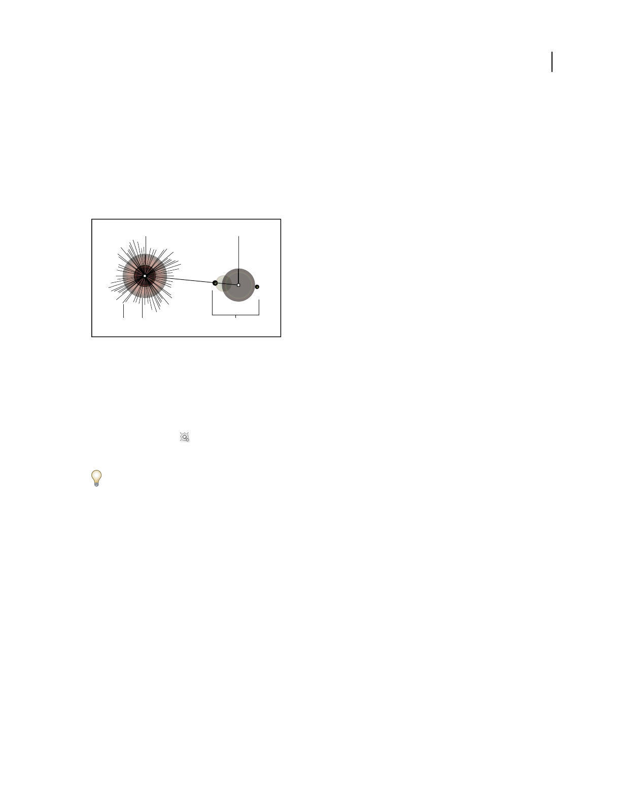
ILLUSTRATOR CS3
User Guide
60
Drawing flares
Create a flare
The Flare tool creates flare objects with a bright center, a halo, and rays and rings. Use this tool to create an effect
similar to a lens flare in a photograph.
Flares include a center handle and an end handle. Use the handles to position the flare and its rings. The center
handle is in the bright center of the flare—the flare path begins from this point.
Components of a flare
A. Center handle B. End handle C. Rays (shown black for clarity) D. Halo E. Rings
See also
“Drawing tool gallery” on page 26
Create a default flare
1
Select the Flare tool .
2 Press Alt (Windows) or Option (Mac OS), and click where you want the center handle of the flare to appear.
Flares often look best when drawn over existing objects.
Draw a flare
1
Select the Flare tool.
2 Press the mouse button down to place the center handle of the flare, then drag to set the size of the center, the size
of the halo, and to rotate the angle of the rays.
Before releasing the mouse, press Shift to constrain the rays to a set angle. Press Up Arrow or Down Arrow to add
or subtract rays. Press Ctrl (Windows) or Command (Mac
OS) to hold the center of the flare constant.
3 Release the mouse when the center, halo, and rays are as desired.
4 Press and drag again to add rings to the flare and place the end handle.
Before releasing the mouse, Press Up Arrow or Down Arrow to add or subtract rings. Press the tilde (~) key to
randomly place the rings.
5 Release the mouse when the end handle is in the desired location.
Each element (center, halo, rings, and rays) in the flare is filled with color at different opacity settings.
A B
C D E

ILLUSTRATOR CS3
User Guide
61
Create a flare using the Flare Tool Options dialog box
1
Select the Flare tool, and click where you want to place the center handle of the flare.
2 In the Flare Tool Options dialog box, do any of the following options, and click OK:
•Specify the overall diameter, opacity, and brightness of the flare’s center.
•Specify the Growth of the halo as a percentage of the overall size, and specify the fuzziness of the halo (0 is crisp
and 100 is fuzzy).
•If you want the flare to contain rays, select Rays and specify the number of rays, the longest ray (as a percentage
of the average ray), and the fuzziness of the rays (0 is crisp and 100 is fuzzy).
•If you want the flare to contain rings, select Rings and specify the distance of the path between the halo’s center
point (center handle) and the center point of the furthest ring (end handle), the number of rings, the largest ring
(as a percentage of the average ring), and the direction or angle of the rings.
Edit a flare
Do any of the following:
•Select the flare, and double-click the Flare tool icon to open the Flare Tool Options dialog box. Change settings in
the dialog box.
To reset a flare to the default values, hold down Alt (Windows) or Option (Mac OS), and click Reset.
•Select the flare and the Flare tool. Drag an endpoint—from either the center handle or the end handle—to change
the length or direction of the flare.
•Select the flare, and choose Object > Expand. This makes the elements of the flare editable, like elements of blends.
See also
“Expand objects” on page 202
Drawing with the Pencil tool
Draw with the Pencil tool
The Pencil tool works primarily the same way in Adobe Illustrator and InDesign. It lets you draw open and closed
paths as if you were drawing with a pencil on paper. It is most useful for fast sketching or creating a hand-drawn look.
Once you draw a path, you can immediately change it if needed.
Anchor points are set down as you draw with the Pencil tool; you do not determine where they are positioned.
However, you can adjust them once the path is complete. The number of anchor points set down is determined by
the length and complexity of the path and by tolerance settings in the Pencil Tool Preferences dialog box. These
settings control how sensitive the Pencil tool is to the movement of your mouse or graphics-tablet stylus.
For a video on drawing with the Pencil tool in Illustrator, see www.adobe.com/go/vid0039.
Draw freeform paths with the Pencil tool
1
Select the Pencil tool .

ILLUSTRATOR CS3
User Guide
62
2 Position the tool where you want the path to begin, and drag to draw a path. The Pencil tool displays a small
x to indicate drawing a freeform path.
As you drag, a dotted line follows the pointer. Anchor points appear at both ends of the path and at various points
along it. The path takes on the current stroke and fill attributes, and remains selected by default.
Draw closed paths with the Pencil tool
1
Select the Pencil tool.
2 Position the tool where you want the path to begin, and start dragging to draw a path.
3 After you’ve begun dragging, hold down Alt (Windows) or Option (Mac OS). The Pencil tool displays a small
circle (and, in InDesign, a solid eraser) to indicate that you’re creating a closed path.
4 When the path is the size and shape you want, release the mouse button (but not the Alt or Option key). After the
path closes, release the Alt or Option key.
You don’t have to position the cursor over the starting point of the path in order to create a closed path; if you release
the mouse button in some other location, the Pencil tool will close the shape by creating the shortest possible line
back to the original point.
Edit paths with the Pencil tool
You can edit any path using the Pencil tool and add freeform lines and shapes to any shape.
Add to a path with the Pencil tool
1
Select an existing path.
2 Select the Pencil tool.
3 Position the pencil tip on an endpoint of the path.
You can tell you’re close enough to the endpoint when the small x next to the pencil tip disappears.
4 Drag to continue the path.
Connect two paths with the Pencil tool
1
Select both paths (Shift-click or drag around the two with the Selection tool).
2 Select the Pencil tool.
3 Position the pointer where you want to begin from one path, and start dragging toward the other path.
4 After you begin dragging, hold down Ctrl (Windows) or Command (Mac OS). The Pencil tool displays a small
merge symbol to indicate you’re adding to the existing path.
5 Drag onto the endpoint of the other path, release the mouse button, and then release the Ctrl or Command key.
Note: For best results, drag from one path to the other as if you were simply continuing the paths in the direction they
were created.
Reshape paths with the Pencil tool
1
Select the path you want to change.
2 Position the Pencil tool on or near the path to redraw.
You can tell you’re close enough to the path when the small x disappears from the tool.
3 Drag the tool until the path is the desired shape.

ILLUSTRATOR CS3
User Guide
63
Using the Pencil tool to edit a closed shape
Note: Depending on where you begin to redraw the path and in which direction you drag, you may get unexpected
results. For example, you may unintentionally change a closed path to an open path, change an open path to a closed
path, or lose a portion of a shape.
Pencil tool options
Double-click the Pencil tool to set any of the following options:
Fidelity Controls how far you have to move your mouse or stylus before a new anchor point is added to the path.
The higher the value, the smoother and less complex the path. The lower the value, the more the curves will match
the pointer’s movement, resulting in sharper angles. Fidelity can range from 0.5 to 20 pixels.
Smoothness Controls the amount of smoothing applied when you use the tool. Smoothness can range from 0% to
100%. The higher the value, the smoother the path. The lower the value, the more anchor points are created, and the
more the line’s irregularities are preserved.
Fill New Pencil Strokes (Illustrator only) Applies a fill to pencil strokes you draw after selecting this option, but not
to existing pencil strokes. Remember to select a fill before you draw the pencil strokes.
Keep Selected Determines whether to keep the path selected after you draw it. This option is selected by default.
Edit Selected Paths Determines whether or not you can change or merge an existing path when you are within a
certain distance of it (specified with the next option).
Within: _ pixels Determines how close your mouse or stylus must be to an existing path in order to edit the path with
the Pencil tool. This option is only available when the Edit Selected Paths option is selected.
Drawing with the Pen tool
Draw straight line segments with the Pen tool
The simplest path you can draw with the Pen tool is a straight line, made by clicking the Pen tool to create two anchor
points. By continuing to click, you create a path made of straight line segments connected by corner points.

ILLUSTRATOR CS3
User Guide
64
Clicking Pen tool creates straight segments.
1 Select the Pen tool.
2 Position the Pen tool where you want the straight segment to begin, and click to define the first anchor point (do
not drag).
Note: The first segment you draw will not be visible until you click a second anchor point. (Select the Rubber Band option
in Photoshop to preview path segments.) Also, if direction lines appear, you’ve accidentally dragged the Pen tool; choose
Edit > Undo, and click again.
3
Click again where you want the segment to end (Shift-click to constrain the angle of the segment to a multiple of 45˚).
4 Continue clicking to set anchor points for additional straight segments.
The last anchor point you add always appears as a solid square, indicating that it is selected. Previously defined
anchor points become hollow, and deselected, as you add more anchor points.
5 Complete the path by doing one of the following:
•To close the path, position the Pen tool over the first (hollow) anchor point. A small circle appears next to the Pen
tool pointer when it is positioned correctly. Click or drag to close the path.
Note: To close a path in InDesign, you can also select the object and choose Object > Paths > Close Path.
•To leave the path open, Ctrl-click (Windows) or Command-click (Mac OS) anywhere away from all objects.
To leave the path open, you can also select a different tool, or choose Select > Deselect in Illustrator or Edit > Deselect
All in InDesign.
Draw curves with the Pen tool
You create a curve by adding an anchor point where a curve changes direction, and dragging the direction lines that
shape the curve. The length and slope of the direction lines determine the shape of the curve.
Curves are easier to edit and your system can display and print them faster if you draw them using as few anchor
points as possible. Using too many points can also introduce unwanted bumps in a curve. Instead, draw widely
spaced anchor points, and practice shaping curves by adjusting the length and angles of the direction lines.
1 Select the Pen tool.
2 Position the Pen tool where you want the curve to begin, and hold down the mouse button.
The first anchor point appears, and the Pen tool pointer changes to an arrowhead. (In Photoshop, the pointer
changes only after you’ve started dragging.)
3 Drag to set the slope of the curve segment you’re creating, and then release the mouse button.
In general, extend the direction line about one third of the distance to the next anchor point you plan to draw. (You
can adjust one or both sides of the direction line later.)
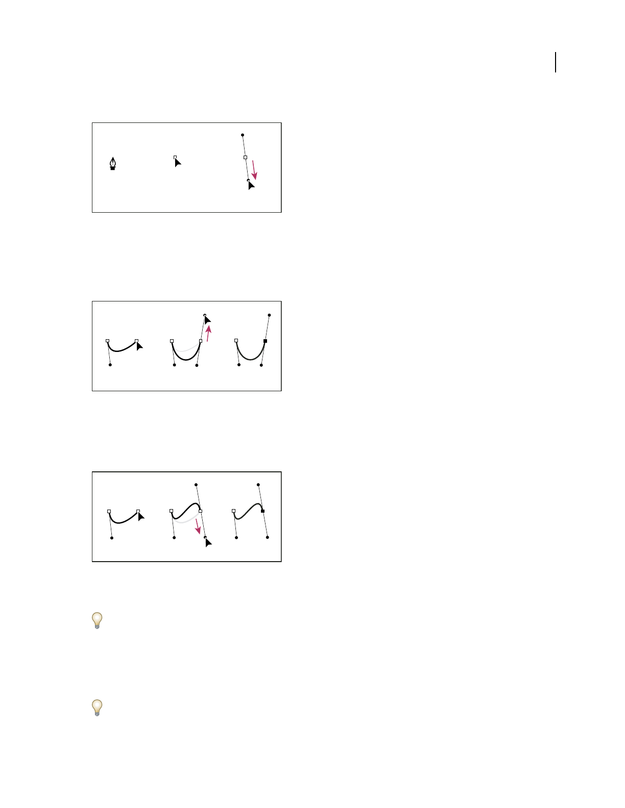
ILLUSTRATOR CS3
User Guide
65
Hold down the Shift key to constrain the tool to multiples of 45˚.
Drawing the first point in a curve
A. Positioning Pen tool B. Starting to drag (mouse button pressed) C. Dragging to extend direction lines
4 Position the Pen tool where you want the curve segment to end, and do one of the following:
•To create a C-shaped curve, drag in a direction opposite to the previous direction line. Then release the mouse
button.
Drawing the second point in a curve
A. Starting to drag second smooth point B. Dragging away from previous direction line, creating a C curve C. Result after releasing mouse
button
•To create an S-shaped curve, drag in the same direction as the previous direction line. Then release the mouse
button.
Drawing an S curve
A. Starting to drag new smooth point B. Dragging in same direction as previous direction line, creating an S curve C. Result after releasing
mouse button
(Photoshop only) To change the direction of the curve sharply, release the mouse button, and then Alt-drag
(Windows) or Option-drag (Mac OS) the direction point in the direction of the curve. Release the Alt (Windows) or
Option (Mac OS) key and the mouse button, reposition the pointer where you want the segment to end, and drag in the
opposite direction to complete the curve segment.
5 Continue dragging the Pen tool from different locations to create a series of smooth curves. Note that you are
placing anchor points at the beginning and end of each curve, not at the tip of the curve.
Alt-drag (Windows) or Option-drag (Mac OS) direction lines to break out the direction lines of an anchor point.
AB C
ABC
ABC

ILLUSTRATOR CS3
User Guide
66
6 Complete the path by doing one of the following:
•To close the path, position the Pen tool over the first (hollow) anchor point. A small circle appears next to the Pen
tool pointer when it is positioned correctly. Click or drag to close the path.
Note: To close a path in InDesign, you can also select the object and choose Object > Paths > Close Path.
•To leave the path open, Ctrl-click (Windows) or Command-click (Mac OS) anywhere away from all objects.
To leave the path open, you can also select a different tool, or choose Select > Deselect in Illustrator or Edit > Deselect
All in InDesign.
For a video on using the Pen tool in Illustrator, see www.adobe.com/go/vid0037.
Draw straight lines followed by curves
1 Using the Pen tool, click corner points in two locations to create a straight segment.
2 Position the Pen tool over the selected endpoint. In Illustrator and InDesign, a convert-point icon appears next to
the Pen tool when it is positioned correctly (In Photoshop, a small diagonal line, or slash, appears next to the Pen
tool). To set the slope of the curved segment you’ll create next, click the anchor point, and drag the direction line
that appears.
Drawing a straight segment followed by a curved segment (part 1)
A. Straight segment completed B. Positioning Pen tool over endpoint (the Convert Point icon appears only in Illustrator and InDesign)
C. Dragging direction point
3 Position the pen where you want the next anchor point; then click (and drag, if desired) the new anchor point to
complete the curve.
Drawing a straight segment followed by a curved segment (part 2)
A. Holding Pen tool down B. Dragging direction line C. New curve segment completed
Draw curves followed by straight lines
1 Using the Pen tool, drag to create the first smooth point of the curved segment, and release the mouse button.
2 Reposition the Pen tool where you want the curved segment to end, drag to complete the curve, and release the
mouse button.
ABC
ABC

ILLUSTRATOR CS3
User Guide
67
Drawing a curved segment followed by a straight segment (part 1)
A. First smooth point of curved segment completed and Pen tool positioned over endpoint B. Dragging to complete the curve
3 Position the Pen tool over the selected endpoint. A convert-point icon appears next to the Pen tool when it is
positioned correctly. Click the anchor point to convert the smooth point to a corner point.
4 Reposition the Pen tool where you want the straight segment to end, and click to complete the straight segment.
Drawing a curved segment followed by a straight segment (part 2)
C. Positioning Pen tool over existing endpoint D. Clicking endpoint E. Clicking next corner point
Draw two curved segments connected by a corner
1 Using the Pen tool, drag to create the first smooth point of a curved segment.
2 Reposition the Pen tool and drag to create a curve with a second smooth point; then press and hold Alt (Windows)
or Option (Mac OS) and drag the direction line toward its opposing end to set the slope of the next curve. Release
the key and the mouse button.
This process converts the smooth point to a corner point by splitting the direction lines.
3 Reposition the Pen tool where you want the second curved segment to end, and drag a new smooth point to
complete the second curved segment.
Drawing two curves
A. Dragging a new smooth point B. Pressing Alt/Option to split direction lines while dragging, and swinging direction line up C. Result after
repositioning and dragging a third time
Reposition anchor points as you draw
❖After you click to create an anchor point, keep the mouse button pressed down, hold down the spacebar, and drag
to reposition the anchor point.
AB
DE
C
ABC

ILLUSTRATOR CS3
User Guide
68
Finish drawing a path
❖Complete a path in one of the following ways:
•To close a path, position the Pen tool over the first (hollow) anchor point. A small circle appears next to the Pen
tool pointer when it is positioned correctly. Click or drag to close the path.
Note: To close a path in InDesign, you can also select the object and choose Object > Paths > Close Path.
•To leave a path open, Ctrl-click (Windows) or Command-click (Mac OS) anywhere away from all objects.
To leave the path open, you can also select a different tool, or choose Select > Deselect in Illustrator or Edit > Deselect
All in InDesign.
Editing paths
Select paths, segments, and anchor points
Before you can reshape or edit a path, you need to select the path’s anchor points, segments, or a combination of both.
Select anchor points
•If you can see the points, you can click them with the Direct Selection tool to select them. Shift-click to select
multiple points.
•Select the Direct Selection tool and drag a boundary around the anchor points. Shift-drag around additional
anchor points to select them.
•Make sure the path that contains the anchor points is not selected. Move the Direct Selection tool over the anchor
point until the pointer displays a hollow square, and then click the anchor point. Shift-click additional anchor
points to select them.
•(Illustrator only) Select the Lasso tool , and drag around the anchor points. Shift-drag around additional anchor
points to select them.
Select path segments
Do any of the following:
•Select the Direct Selection tool , and click within 2 pixels of the segment, or drag a marquee over part of the
segment. Shift-click or Shift-drag around additional path segments to select them.
•(Illustrator only) Select the Lasso tool , and drag around part of the path segment. Shift-drag around
additional path segments to select them.
Select all anchor points and segments in a path
1
Select the Direct Selection tool or, in Illustrator, the Lasso tool.
2 Drag around the entire path.
If the path is filled, you can also click inside the path with the Direct Selection tool to select all anchor points.
Copy a path
❖Select a path or segment with the Selection tool or Direct Selection tool and do one of the following:
•Use the standard menu functions to copy and paste paths within or between applications.
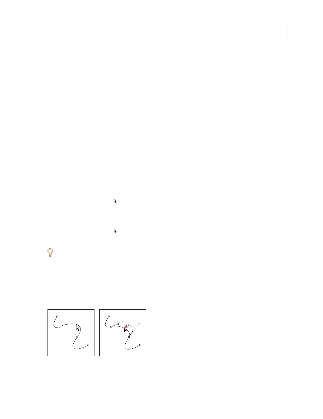
ILLUSTRATOR CS3
User Guide
69
•Press and hold Alt (Windows) or Option (Mac OS) and drag the path to the desired position, and then release the
mouse button and Alt/Option key.
Adjust path segments
Editing path segments works similarly in Adobe applications. You can edit a path segment at any time, but editing
existing segments is slightly different from drawing them. Keep the following tips in mind when editing segments:
•If an anchor point connects two segments, moving that anchor point always changes both segments.
•When drawing with the Pen tool, press Ctrl (Windows) or Command (Mac OS) to temporarily activate the last
used selection tool (Illustrator) or the Direct Selection tool (InDesign and Photoshop) so that you can adjust
segments you’ve already drawn.
•When you initially draw a smooth point with the Pen tool, dragging the direction point changes the length of the
direction line on both sides of the point. However, when you edit an existing smooth point with the Direct
Selection tool, you change the length of the direction line only on the side you’re dragging.
See also
“Select paths, segments, and anchor points” on page 68
“Reshaping tool gallery” on page 29
Move straight segments
1
With the Direct Selection tool , select the segment you want to adjust.
2 Drag the segment to its new position.
Adjust the length or angle of straight segments
1
With the Direct Selection tool , select an anchor point on the segment you want to adjust.
2 Drag the anchor point to the desired position. Shift-drag to constrain the adjustment to multiples of 45˚.
In Illustrator or InDesign, if you’re simply trying to make a rectangle wider or narrower, it’s easier to select it with
the Selection tool and resize it using one of the handles on the sides of its bounding box.
Adjust the position or shape of curved segments
1
With the Direct Selection tool, select a curved segment, or an anchor point on either end of the curved segment.
Direction lines appear, if any are present. (Some curved segments use just one direction line.)
2 Do any of the following:
•To adjust the position of the segment, drag the segment. Shift-drag to constrain the adjustment to multiples of 45˚.
Click to select the curve segment. Then drag to adjust.
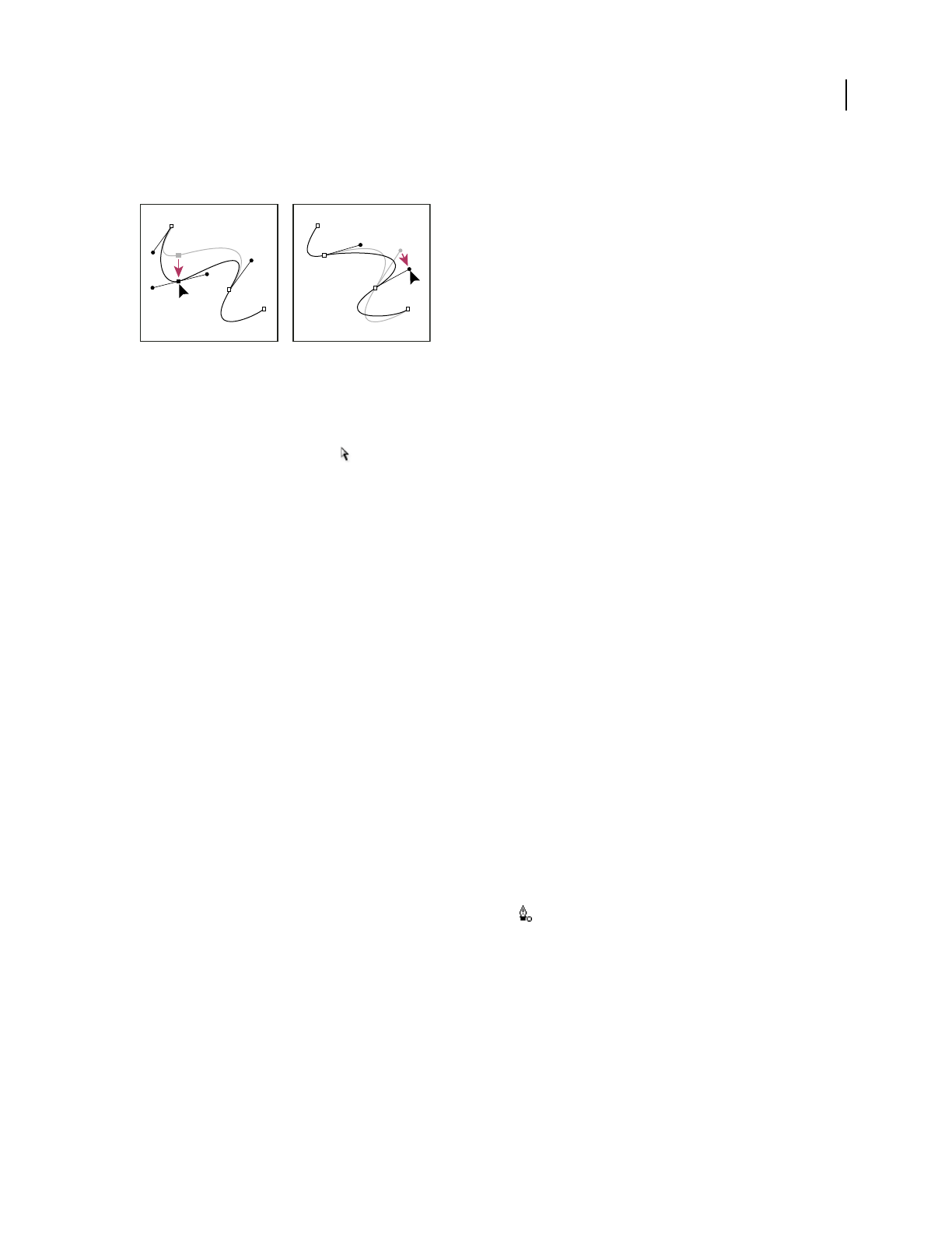
ILLUSTRATOR CS3
User Guide
70
•To adjust the shape of the segment on either side of a selected anchor point, drag the anchor point or the direction
point. Shift-drag to constrain movement to multiples of 45˚.
Drag the anchor point, or drag the direction point.
Note: You can also apply a transformation, such as scaling or rotating, to a segment or anchor point.
Delete a segment
1
Select the Direct Selection tool , and select the segment you want to delete.
2 Press Backspace (Windows) or Delete (Mac OS) to delete the selected segment. Pressing Backspace or Delete
again erases the rest of the path.
Extend an open path
1
Using the Pen tool, position the pointer over the endpoint of the open path you want to extend. The pointer
changes when it’s precisely positioned over the endpoint.
2 Click the endpoint.
3 Do one of the following:
•To create a corner point, position the Pen tool where you want to end the new segment, and click. If you are
extending a path that ends at a smooth point, the new segment will be curved by the existing direction line.
Note: In Illustrator, if you extend a path that ends in a smooth point, the new segment will be straight.
•To create a smooth point, position the Pen tool where you want to end the new curved segment, and drag.
Connect two open paths
1
Using the Pen tool, position the pointer over the endpoint of the open path that you want to connect to another
path. The pointer changes when it’s precisely positioned over the endpoint.
2 Click the endpoint.
3 Do one of the following:
•To connect the path to another open path, click an endpoint on the other path. When you precisely position the
Pen tool over the other path’s endpoint, a small merge symbol appears next to the pointer.
•To connect a new path to an existing path, draw the new path near the existing path, and then move the Pen tool
to the existing path’s (unselected) endpoint. Click that endpoint when you see the small merge symbol that appears
next to the pointer.
Join two endpoints
1
Select the endpoints.
If the endpoints are coincident (on top of each other), drag a marquee through or around both endpoints to select
them.
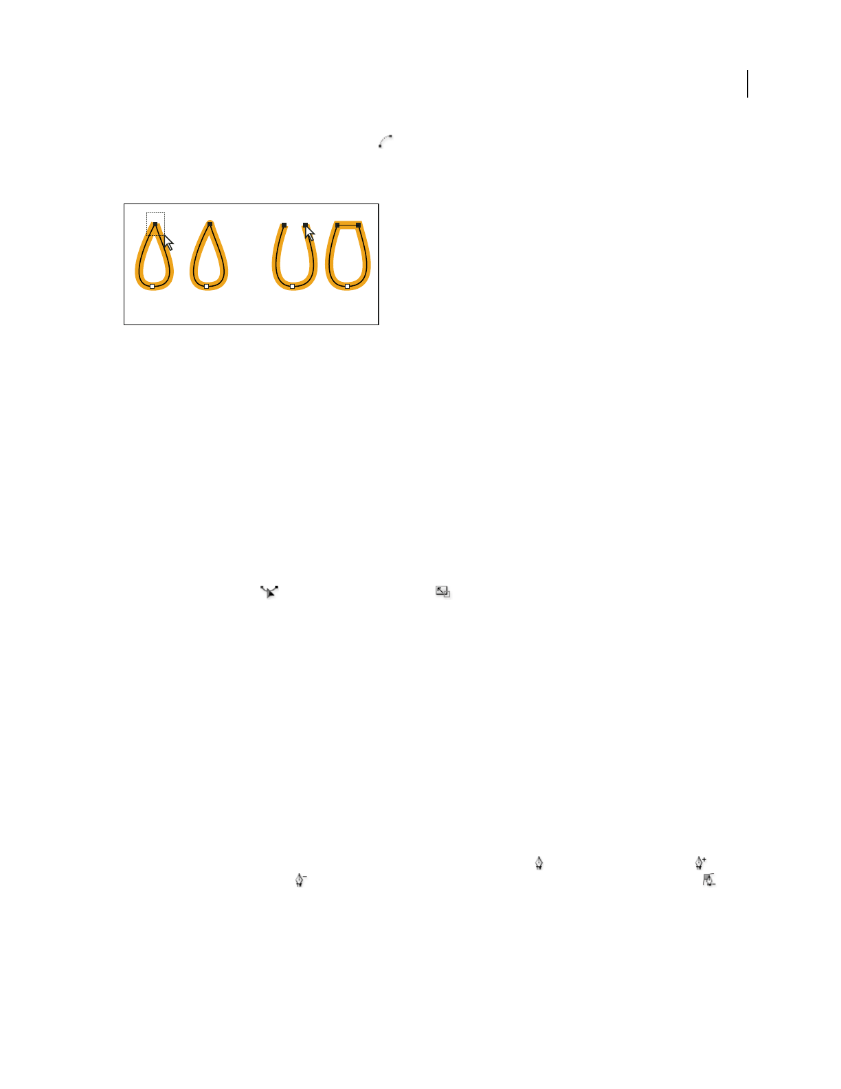
ILLUSTRATOR CS3
User Guide
71
2 Click the Connect Selected End Points button in the Control panel.
3 If the endpoints are coincident, a dialog box appears to let you specify the type of join you want. Select the Corner
option (the default) or the Smooth option, and click OK.
Joining endpoints
A. Selecting and joining coincident endpoints B. Selecting and joining noncoincident endpoints
Move or nudge anchor points or segments using the keyboard
1
Select the anchor point or path segment.
Note: In Photoshop, you can move only anchor points in this manner.
2 Click or hold down any of the arrow keys on the keyboard to move 1 pixel at a time in the direction of the arrow.
Hold down the Shift key in addition to the arrow key to move 10 pixels at a time.
Note: In Illustrator and InDesign, you can change the distance of a nudge by changing the Keyboard Increment
preference. When you change the default increment, holding down Shift nudges 10 times the specified distance.
Stretch parts of a path without distorting its overall shape
1
Select the entire path.
2 Select the Reshape tool (located under the Scale tool ).
3 Position the cursor over the anchor point or path segment that you want to act as a focal point (that is, a point that
pulls selected path segments), and click.
If you click a path segment, a highlighted anchor point with a square around it is added to the path.
4 Shift-click more anchor points or path segments to act as focal points. You can highlight an unlimited number of
anchor points or path segments.
5 Drag the highlighted anchor points to adjust the path.
Adding and deleting anchor points
Adding anchor points can give you more control over a path, or it can extend an open path. However, it’s a good idea
not to add more points than necessary. A path with fewer points is easier to edit, display, and print. You can reduce
the complexity of a path by deleting unnecessary points. Adding and deleting anchor points works similarly in
Adobe applications.
The Tools panel contains three tools for adding or deleting points: the Pen tool , the Add Anchor Point tool ,
and the Delete Anchor Point tool . In addition, the Control panel has a Remove Selected Anchor Points button
By default, the Pen tool changes to the Add Anchor Point tool as you position it over a selected path, or to the Delete
Anchor Point tool as you position it over an anchor point.
Note: Don’t use the Delete, Backspace, and Clear keys or the Edit > Cut and Edit > Clear commands to delete anchor
points: these keys and commands delete the point and the line segments that connect to that point.
A B

ILLUSTRATOR CS3
User Guide
72
See also
“Drawing tool gallery” on page 26
“Select paths, segments, and anchor points” on page 68
Add or delete anchor points
1
Select the path you want to modify.
2 To add an anchor point, select the Pen tool or the Add Anchor Point tool, position the pointer over the path
segment, and click.
3 To delete an anchor point, do either of the following:
•Select the point with the Direct Selection tool and click Remove Selected Anchor Points in the Control panel.
•Select the Pen tool or the Delete Anchor Point tool, position the pointer over the anchor point, and click.
Find and delete stray anchor points
Stray anchor points are individual points that are not connected to other anchor points. It is a good practice to find
and delete stray anchor points.
1 Deselect all objects.
2 Choose Select > Object > Stray Points.
3 Choose Edit > Cut or Edit > Clear commands, or press Delete or Backspace on the keyboard.
Disable or temporarily override automatic Pen tool switching
You can temporarily override or disable automatic switching to the Add Anchor Point tool or Delete Anchor Point
tool.
•To temporarily override switching, hold down Shift as you position the Pen tool over the selected path or an
anchor point. This is useful when you want to start a new path on top of an existing path. To prevent Shift from
constraining the Pen tool, release Shift before you release the mouse button.
•To disable switching, choose Edit > Preferences > General (Windows) or Illustrator > Preferences > General
(Mac OS), and select Disable Auto Add/Delete.
Smooth and simplify paths
You can smooth the appearance of paths as well as simplify paths by removing excess anchor points.
See also
“Drawing tool gallery” on page 26
“Keys for editing shapes” on page 464
“Select paths, segments, and anchor points” on page 68
Smooth paths
1
Select the object.
2 Select the Smooth tool .
3 Drag the tool along the length of the path segment you want to smooth out.
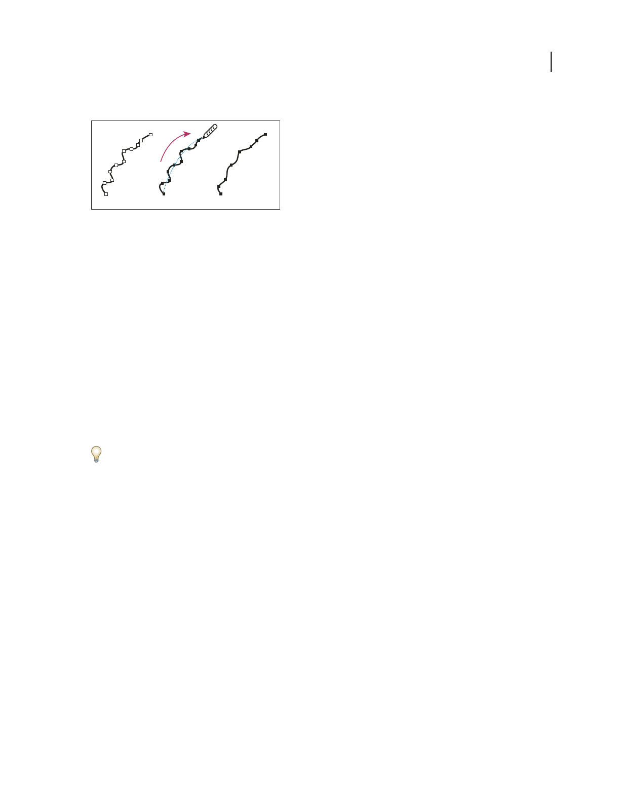
ILLUSTRATOR CS3
User Guide
73
4 Continue smoothing until the stroke or path is the desired smoothness.
Using the Smooth tool
A. Original path B. Dragging across path with the Smooth tool C. Result
5 To change the amount of smoothing, double-click the Smooth tool and set the following options:
Fidelity Controls how far you have to move your mouse or stylus before Illustrator adds a new anchor point to the
path. For example, a Fidelity value of 2.5 means that tool movements of less than 2.5 pixels aren’t registered. Fidelity
can range from 0.5 to 20 pixels; the higher the value, the smoother and less complex the path.
Smoothness Controls the amount of smoothing that Illustrator applies when you use the tool. Smoothness can
range from 0% to 100%; the higher the value, the smoother the path.
Simplify paths
Simplifying a path removes extra anchor points without changing the shape of the path. Removing unnecessary
anchor points simplifies your artwork, reducing the file size, and making it display and print faster.
1 Select the object.
2 Choose Object > Path > Simplify.
3 Set the Curve Precision to control how closely the simplified path follows the original path.
Select Preview to show a preview of the simplified path and list the number of points in the original and simplified
paths.
4 Select additional options, and click OK:
Curve Precision Enter a value between 0% and 100% to set how closely the simplified path should follow the original
path. A higher percentage creates more points and a closer fit. Any existing anchor points are ignored except for
endpoints of a curve and corner points (unless you enter a value for Angle Threshold).
Angle Threshold Enter a value between 0 and 180˚ to control the smoothness of corners. If the angle of a corner
point is less than the angle threshold, the corner point is not changed. This option helps keep corners sharp, even if
the value for Curve Precision is low.
Straight Lines Creates straight lines between the object’s original anchor points. Corner points are removed if they
have an angle greater than the value set in Angle Threshold.
Show Original Shows the original path behind the simplified path.
Average the position of anchor points
1
Select two or more anchor points (on the same path or on different paths).
2 Choose Object > Path > Average.
3 Choose to average along the horizontal (x) axis only, the vertical (y) axis only, or both axes, and click OK.
A B C
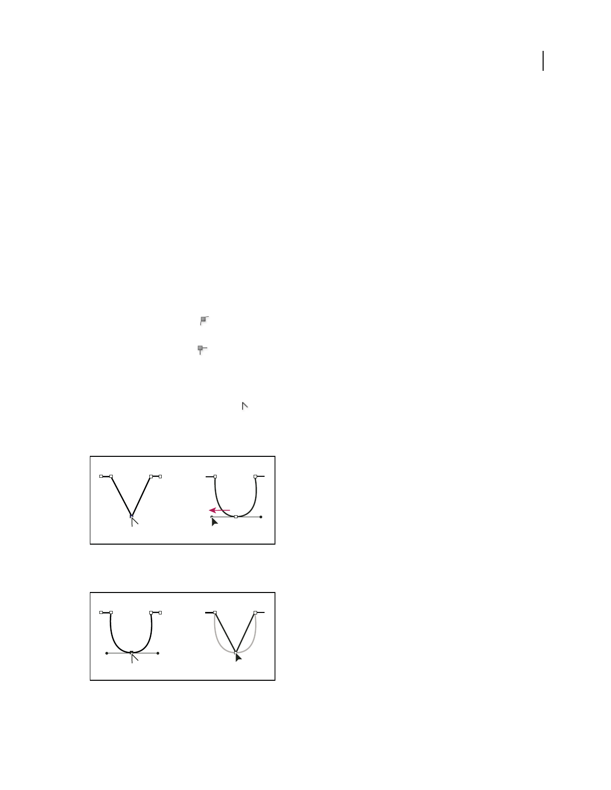
ILLUSTRATOR CS3
User Guide
74
Convert between smooth points and corner points
You can convert the points on a path between corner to smooth points. Using options in the Control panel, you can
quickly convert multiple anchor points. Using the Convert Anchor Point tool, you can choose to convert only one
side of the point, and you can precisely alter the curve as you convert the point.
See also
“About paths” on page 52
“Drawing tool gallery” on page 26
“About direction lines and direction points” on page 54
Convert one or more anchor points using the Control panel
To use the anchor point conversion options in the Control panel, only relevant anchor points, not the entire object,
should be selected. If you select multiple objects, one of the objects must be only partially selected. When entire
objects are selected, the Control panel options change to those that affect the entire object.
•To convert one or more corner points to smooth points, select the points and then click the Convert Selected
Anchor Points To Smooth button in the Control panel.
•To convert one or more smooth points to corner points, select the points and then click the Convert Selected
Anchor Points To Corner button in the Control panel.
Convert an anchor point precisely using the Convert Anchor Point tool
1
Select the entire path you want to modify so that you can see its anchor points.
2 Select the Convert Anchor Point tool .
3 Position the Convert Anchor Point tool over the anchor point you want to convert, and do one of the following:
•To convert a corner point to a smooth point, drag a direction point out of the corner point.
Dragging a direction point out of a corner point to create a smooth point
•To convert a smooth point to a corner point without direction lines, click the smooth point.
Clicking a smooth point to create a corner point
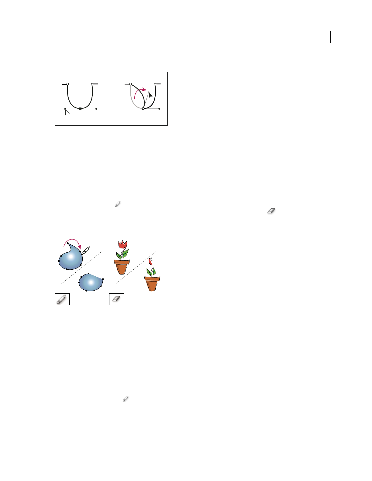
ILLUSTRATOR CS3
User Guide
75
•To convert a smooth point to a corner point with independent direction lines, drag either direction point.
Converting a smooth point to a corner point
•To convert a corner point without direction lines to a corner point with independent direction lines, first drag a
direction point out of a corner point (making it a smooth point with direction lines). Release the mouse button
only (don’t release any keys you may have pressed to activate the Convert Anchor Point tool), and then drag either
direction point.
Erase artwork
You can erase portions of your artwork using the Path Eraser tool, the Eraser tool, or the eraser on a Wacom stylus
pen. The Path Eraser tool
lets you erase parts of a path by drawing along the path. This tool is useful when you
want to limit what you erase to a path segment, such as one edge of a triangle. The Eraser tool and the eraser on
a Wacom stylus pen let you erase any area of your artwork, regardless of structure. You can use the Eraser tool on
paths, compound paths, paths inside Live Paint groups, and clipping paths.
Using the Path Eraser tool to erase portions of a path (left), using the Eraser tool to erase part of a grouped object (right)
For a video on using the Eraser tool, see www.adobe.com/go/vid0036.
See also
“Drawing tool gallery” on page 26
“Keys for editing shapes” on page 464
Erase part of a path using the Path Eraser tool
1
Select the object.
2 Select the Path Eraser tool .
3 Drag the tool along the length of the path segment you want to erase. For best results, use a single, smooth,
dragging motion.

ILLUSTRATOR CS3
User Guide
76
Erase objects using the Eraser tool
1
Do one the following:
•To erase specific objects, select the objects or open the objects in isolation mode.
•To erase any object on the artboard, leave all objects unselected.
When you have nothing selected, the Eraser tool erases through and across all layers.
2 Select the Eraser tool .
3 (Optional) Double-click the Eraser tool and specify options.
4 Drag over the area you want to erase. You can control the tool by doing any of the following:
•To constrain the Eraser tool to a vertical, horizontal, or diagonal line, Shift-drag.
•To create a marquee around an area and erase everything inside the area, Alt-drag (Windows) or Option-drag
(Mac OS). To constrain the marquee to a square, Alt-Shift-drag (Windows) or Option-Shift-drag (Mac OS).
Erase objects using a Wacom stylus pen eraser
When you flip a stylus pen, the Eraser Tool automatically becomes active. When you flip the stylus pen back over,
the last active tool becomes active again.
❖Turn over the stylus pen and drag across the area you want to erase.
Press harder to increase the width of the erased path.
Eraser tool options
You can change the Eraser tool options by double-clicking the tool in the Tools panel.
Note: You can change the diameter at any time by pressing ] to enlarge or [ to reduce.
Angle Determines the angle of rotation for the tool. Drag the arrowhead in the preview, or enter a value in the Angle
text box.
Roundness Determines roundness of the tool. Drag a black dot in the preview away from or toward the center,
or enter a value in the Roundness text box. The higher the value, the greater the roundness.
Diameter Determines the diameter of the tool. Use the Diameter slider, or enter a value in the Diameter text box.
The pop-up list to the right of each option lets you control variations in the shape of the tool. Select one of the
following options:
Fixed Uses a fixed angle, roundness, or diameter.
Random Uses random variations in angle, roundness, or diameter. Enter a value in the Variation text box to specify
the range within which the brush characteristic can vary. For example, when the Diameter value is 15 and the
Variation value is 5, the diameter can be 10, or 20, or any value in between.
Pressure Varies in angle, roundness, or diameter based on the pressure of a drawing stylus. This option is most
useful when used with Diameter. It is available only if you have a graphics tablet. Enter a value in the Variation text
box to specify how much more or less the original value the brush characteristic will vary. For example, when the
Roundness value is 75% and the Variation value is 25%, the lightest stroke is 50% and the heaviest stroke is 100%.
The lighter the pressure, the more angular the brush stroke.
Stylus Wheel Varies in diameter based on manipulation of the stylus wheel.

ILLUSTRATOR CS3
User Guide
77
Tilt Varies in angle, roundness, or diameter based on the tilt of a drawing stylus. This option is most useful when
used with Roundness. It is available only if you have a graphics tablet that can detect the direction in which the pen
is tilted.
Bearing Varies in angle, roundness, or diameter based on the pressure of a drawing stylus. This option is most useful
when used to control the angle of calligraphic brushes, especially when you’re using the brush like a paintbrush. It is
available only if you have a graphics tablet that can detect how close to vertical the pen is.
Rotation Varies in angle, roundness, or diameter based on how the drawing stylus pen tip is rotated. This option is
most useful when used to control the angle of calligraphic brushes, especially when you’re using the brush like a flat
pen. It is available only if you have a graphics tablet that can detect this type of rotation.
Split a path
You can split a path, graphics frame, or empty text frame at any anchor point or along any segment. When you split
a path, keep the following in mind:
•If you want to split a closed path into two open paths, you must slice in two places along the path. If you slice a
closed path only once, you get a single path with a gap in it.
•Any paths resulting from a split inherit the path settings of the original path, such as stroke weight and fill color.
You may need to reset stroke alignment from inside to outside.
1 (Optional) Select the path to see its current anchor points.
2 Do one of the following:
•Select the Scissors tool and click the path where you want to split it. When you split the path in the middle of a
segment, the two new endpoints appear on top of the other, and one endpoint is selected.
•Select the anchor point where you want to split the path, and then click the Cut Path At Selected Anchor Points
button in the Control panel. When you split the path at an anchor point, a new anchor point appears on top
of the original anchor point, and one anchor point is selected.
3 Use the Direct Selection tool to adjust the new anchor point or path segment.
Note: You can divide an object into separate component faces by using the Knife tool (a face is an area undivided by a
line segment).
See also
“Cut objects with the Knife tool” on page 236
Tracing artwork
Trace artwork
If you want to base a new drawing on an existing piece of artwork, you can trace it. For example, you can create a
graphic based on a pencil sketch drawn on paper or on a raster image saved in another graphics program by bringing
the graphic into Illustrator and tracing over it.
The easiest way to trace artwork is to open or place a file into Illustrator and automatically trace the artwork with the
Live Trace command. You can control the level of detail and how the tracing is filled. When you are satisfied with
the tracing results, you can convert the tracing to vector paths or a Live Paint object.

ILLUSTRATOR CS3
User Guide
78
Before and after tracing a bitmap image with the Live Trace command
For a video on using Live Trace, see www.adobe.com/go/vid0043.
Automatically trace artwork
1
Open or place a file to use as the source image for the tracing.
2 With the source image selected, do one of the following:
•To trace the image using a tracing preset, click the Tracing Presets and Options button in the Control panel,
and select a preset.
•To trace the image using the default tracing options, click Live Trace in the Control panel, or choose Object > Live
Trace > Make.
•To set tracing options before you trace the image, click the Tracing Presets and Options button in the Control
panel, and choose Tracing Options. Alternatively, choose Object > Live Trace > Tracing Options. Set tracing
options, and then click Trace.
3 (Optional) Adjust the results of the tracing.
4 (Optional) Convert the tracing to paths or to a Live Paint object.
Use template layers to manually trace artwork
Template layers are locked, nonprinting layers that you can use to manually trace images. Template layers are
dimmed by 50% so you can easily see any paths you draw in front of the layer. You can create template layers when
you place an image or from existing layers.
1 Do one of the following:
•To place an image as a template layer for tracing, choose File > Place, select the EPS, PDF, or raster image file you
want to trace, select Template, and then click Place. A new template layer appears below the current layer in the
panel.
•To trace an existing image, make sure the image is in its own layer, double-click the layer in the Layers panel, select
Template, and click OK; alternatively, select the layer and choose Template from the panel menu.
The eye icon is replaced by the template icon , and the layer is locked.
2 Trace over the file using the Pen tool or the Pencil tool.
3 To hide the template layer, choose View > Hide Template. Choose View > Show Template layer to see it again.
4 To turn a template layer into a regular layer, double-click the template layer in the Layers panel, deselect Template,
and click OK.
Tracing options
Preset Specifies a tracing preset.

ILLUSTRATOR CS3
User Guide
79
Mode Specifies a color mode for the tracing result.
Threshold Specifies a value for generating a black and white tracing result from the original image. All pixels lighter
than the Threshold value are converted to white, all pixels darker than the Threshold value are converted to black.
(This option is available only when Mode is set to Black and White.)
Panel Specifies a panel for generating a color or grayscale tracing from the original image. (This option is available
only when Mode is set to Color or Grayscale.)
To let Illustrator determine the colors in the tracing, select Automatic. To use a custom panel for the tracing, select
a swatch library name. (The swatch library must be open in order for it to appear in the panel menu.)
Max Colors Specifies a maximum number of colors to use in a color or grayscale tracing result. (This option is
available only when Mode is set to Color or Grayscale and when panel is set to Automatic.)
Output To Swatches Creates a new swatch in the Swatches panel for each color in the tracing result.
Blur Blurs the original image before generating the tracing result. Select this option to reduce small artifacts and
smooth jagged edges in the tracing result.
Resample Resamples the original image to the specified resolution before generating the tracing result. This option
is useful for speeding up the tracing process for large images but can yield degraded results.
Note: The resample resolution is not saved when you create a preset.
Fills Creates filled regions in the tracing result.
Strokes Creates stroked paths in the tracing result.
Max Stroke Weight Specifies the maximum width of features in the original image that can be stroked. Features
larger than the maximum width become outlined areas in the tracing result.
Min Stroke Length Specifies the minimum length of features in the original image that can be stroked. Features
smaller than the minimum length are omitted from the tracing result.
Path Fitting Controls the distance between the traced shape and the original pixel shape. Lower values create a
tighter path fitting; higher values create a looser path fitting.
Minimum Area Specifies the smallest feature in the original image that will be traced. For example, a value of 4
specifies that features smaller than 2 pixels wide by 2 pixels high will be omitted from the tracing result.
Corner Angle Specifies the sharpness of a turn in the original image that is considered a corner anchor point in the
tracing result. For more information on the difference between a corner anchor point and a smooth anchor point,
see “About paths” on page 52.
Raster Specifies how to display the bitmap component of the tracing object. This view setting is not saved as part of
the tracing preset.
Vector Specifies how to display the tracing result. This view setting is not saved as part of the tracing preset.
Select Preview in the Tracing Options dialog box to preview the result of the current settings.To set the default tracing
options, deselect all objects before you open the Tracing Options dialog box. When you’re finished setting options,
click Set Default.
For a video on using Live Trace, see www.adobe.com/go/vid0043. For a tutorial on tweaking Live Trace options for
the best possible results, see www.adobe.com/go/learn_ai_tutorials_livetrace.

ILLUSTRATOR CS3
User Guide
80
Change the display of a tracing object
A tracing object is made up of two components: the original source image and the tracing result (which is the vector
artwork). By default, only the tracing result is visible. However, you can change the display of both the original image
and the tracing result to best suit your needs.
1 Select the tracing object.
By default, all tracing objects are named “Tracing” in the Layers panel.
2 Do any of the following:
•To change the display of the tracing result, click the Vector View button in the Control panel or choose
Object > Live Trace, and select a display option: No Tracing Result, Tracing Result, Outlines, or Outlines With
Tracing.
•To change the display of the source image, click the Raster View button in the Control panel or choose
Object > Live Trace, and select a display option: No Image, Original Image, Adjusted Image (which displays the
image with any adjustments that are applied during tracing), or Transparent Image.
Note: In order to view the source image, you must first change the Vector View to No Tracing Result or Outlines.
Adjust the results of a tracing
Once you create a tracing object, you can adjust the results at any time.
1 Select the tracing object.
2 Do any of the following:
•Set basic options in the Control panel.
•Click the Tracing Options Dialog button in the Control panel to view all tracing options. Alternatively, choose
Object > Live Trace > Tracing Options. Adjust the options, and click Trace.
Use tracing presets to quickly change the results of a tracing.
Specify the colors used for tracing
1 Create a swatch library that contains the colors you want to use in the tracing.
2 Make sure that the swatch library is open, and click the Tracing Options Dialog button in the Control panel.
Alternatively, choose Object > Live Trace > Tracing Options.
3 Select the swatch library name from the panel menu, and click Trace.
See also
“Create swatch libraries” on page 109
Use a tracing preset
Tracing presets provide pre-specified tracing options for specific types of artwork. For example, if you’re tracing an
image that you plan to use as a technical drawing, choose the Technical Drawing preset. All the tracing options
change for optimal tracing of a technical drawing: color is set to black and white, blur is set to 0 px, stroke width is
limited to 3 px, and so on.

ILLUSTRATOR CS3
User Guide
81
Specify a preset
•Choose Object > Live Trace > Tracing Options. (Alternatively, select a tracing object, and click the Tracing
Options Dialog button in the Control panel.) Set tracing options for the preset, and click Save Preset. Enter a
name for the preset, and click OK.
•Choose Edit > Tracing Presets. Click New, set tracing options for the preset, and click Done.
To base a new preset on an existing preset, select the preset, and click New.
Edit or delete a preset
1
Choose Edit > Tracing Presets.
2 select the preset, and click Edit or Delete.
Note: You can’t edit or delete the default presets (default presets appear in brackets [ ]). However, you can make an
editable copy of a default preset by selecting the preset and clicking New.
Share presets with other users
1
Choose Edit > Tracing Presets.
2 Do one of the following:
•Click Export to save your presets to a file.
•Click Import to load presets from a file.
Convert a tracing object to a Live Paint object
When you are satisfied with the results of a tracing, you can convert the tracing object to paths or to a Live Paint
object. This final step allows you to work with the tracing as you do other vector artwork. Once you convert the
tracing object, you can no longer adjust the tracing options.
1 Select the tracing object.
2 Do one of the following:
•To convert the tracing to paths, click Expand in the Control panel or choose Object > Live Trace > Expand. Use
this method if you want to work with the components of the traced artwork as individual objects. The resulting
paths are grouped together.
•To convert the tracing to paths while preserving the current display options, choose Object > Live Trace > Expand
As Viewed. For example, if the display options are set to Outlines for the tracing result, then the expanded paths
will be outlines only (rather than filled and stroked). In addition, a snapshot of the tracing with its current display
options is preserved and grouped with the expanded paths. Use this method if you want to preserve the tracing
image as a guide for the expanded paths.
•To convert the tracing to a Live Paint object, click Live Paint in the Control panel or choose Object > Live Trace >
Convert To Live Paint. Use this method if you want to apply fills and strokes to the traced artwork using the Live
Paint Bucket tool.
To create a tracing and convert the tracing object in one step, choose Object > Live Trace > Make And Expand or
Object > Live Trace > Make And Convert To Live Paint.
For a video on tracing, see www.adobe.com/go/vid0043.
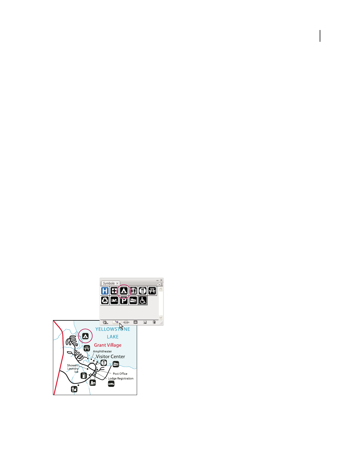
ILLUSTRATOR CS3
User Guide
82
See also
“About paths” on page 52
“About Live Paint” on page 158
Release a tracing object
If you want to discard a tracing but keep the original placed image, you can release the tracing object.
1 Select the tracing object.
2 Choose Object > Live Trace > Release.
Symbols
About symbols
A symbol is an art object that you can reuse in a document. For example, if you create a symbol from a flower, you
can then add instances of that symbol multiple times to your artwork without actually adding the complex art
multiple times. Each symbol instance is linked to the symbol in the Symbols panel or to a symbols library. Using
symbols can save you time and greatly reduce file size.
Symbols also provide excellent support for SWF and SVG export. When you export to Flash, you can set the symbol
type to MovieClip. Once in Flash, you can choose another type if necessary. You can also specify 9-slice scaling in
Illustrator so that the movie clips scale appropriately when used for user interface components.
Note: For information on using symbols in Flash, see Flash Help. For a video on using symbols effectively between
Illustrator and Flash, see www.adobe.com/go/vid0198.
After you place a symbol, you can edit the symbol’s instances on the artboard and, if you want, redefine the original
symbol with the edits. The symbolism tools let you add and manipulate multiple symbol instances at once.
Artwork with symbol instances

ILLUSTRATOR CS3
User Guide
83
Symbols panel overview
You can use the Symbols panel (Window > Symbols) or the Control panel to manage the symbols for a document.
The Symbols panel contains a variety of preset symbols. You can add symbols from symbol libraries or libraries that
you create.
Change the display of symbols in the panel
•Select a view option from the panel menu: Thumbnail View to display thumbnails, Small List View to display a list
of named symbols with a small thumbnail, or Large List View to display a list of named symbols along with a large
thumbnail.
•Drag the symbol to a different position. When a black line appears in the desired position, release the mouse
button.
•Select Sort By Name from the panel menu to list the symbols in alphabetical order.
Duplicate a symbol in the panel
Duplicating or copying a symbol in the Symbols panel is an easy way to create a new symbol based on an existing
symbol.
❖Do one of the following:
•Select a symbol in the Symbols panel and choose Duplicate Symbol from the panel menu, or drag the symbol onto
the New Symbol button.
•Select a symbol instance and click Duplicate in the Control panel.
Note: If you want to duplicate a symbol instance on the artboard, for example, if you’ve scaled and rotated it and want
to add another instance with the same scale and rotation, duplicate the instance. (See “Work with symbol instances” on
page 85
Rename a symbol
1
To rename the symbol, select the symbol in the Symbols panel, choose Symbol Options from the panel menu, and
then type a new name in the Symbol Options dialog box.
2 To rename a symbol instance, select a symbol instance in the artwork, and then type a new name in the Instance
Name text box in the Control panel.
Place a symbol
1 Select a symbol in the Symbols panel or a symbol library.
2 Do one of the following:
•Click the Place Symbol Instance button in the Symbols panel to place the instance in the center of the
artboard.
•Drag the symbol to the artboard where you want it to appear.
•Choose Place Symbol Instance from the Symbols panel menu.
Note: A single symbol placed anywhere in your artwork (as opposed to existing only in the panel) is called an instance.

ILLUSTRATOR CS3
User Guide
84
Create a symbol
You can create symbols from most Illustrator objects, including paths, compound paths, text objects, raster images,
mesh objects, and groups of objects. However, you cannot create a symbol from linked art or some groups, such as
groups of graphs.
1 Select the artwork you want to use as a symbol.
2 Do one of the following:
•Click the New Symbol button in the Symbols panel.
•Drag the artwork to the Symbols panel.
•Choose New Symbol from the panel menu.
Note: By default, the selected artwork becomes an instance of the new symbol. If you don’t want the artwork to become
an instance, press Shift as you create the new symbol. In addition, if you don’t want the New Symbol dialog box to open
when you create a new symbol, press Alt (Windows) or Option (Mac OS) as you create the symbol and Illustrator will
use a default name for the symbol, such as New Symbol 1.
3 In the Symbol Options dialog box, type a name for the symbol.
4 If you plan to export the symbols to Flash, do the following:
•Select Movie Clip for type. Movie Clip is the default symbol type in Flash.
•Specify a location on the Flash Registration grid where you want to set the symbol’s anchor point. The location of
the anchor point affects the position of the symbol within the screen coordinates.
•Select Enable Guides For 9-Slice Scaling if you want to utilize 9-Slice scaling in Flash.
Note: For a video on using symbols effectively between Illustrator and Flash, see www.adobe.com/go/vid0198.
Use 9-slice scaling
You can use 9-slice scaling (scale-9) to specify component-style scaling for movie clip symbols destined for export
to Flash. This type of scaling lets you create movie clip symbols that scale appropriately for use as user interface
components, as opposed to the type of scaling typically applied to graphics and design elements.
The movie clip is conceptually divided into nine sections with a grid-like overlay, and each of the nine areas is scaled
independently. To maintain the visual integrity of the movie clip, corners are not scaled, while the remaining areas
of the image are scaled (as opposed to being stretched) larger or smaller, as needed.
The 9-slice scaling grid is visible only in isolation mode. By default, the grid’s guides are placed at 25% (or 1/4) of the
symbol’s width and height from the edge of the symbol, and appear as dotted lines superimposed on the symbol.
Note: For more information on using 9-slice scaling in Flash, see Flash Help. For videos on 9-slice scaling and using
9-slice scaling in Illustrator and Flash, see www.adobe.com/go/vid0204 and www.adobe.com/go/vid0205.
Enable 9-slice scaling
1
Select the symbol on the artboard or in the Symbols panel and choose Symbol Options from the panel menu.
2 In the Symbol Options dialog box, select Movie Clip for Type, and then select Enable Guides For 9-Slice Scaling.
Note: You can also enable this option in the Symbol Options dialog box when creating a new symbol.

ILLUSTRATOR CS3
User Guide
85
Edit the 9-slice scaling grid for a symbol
1
To edit the scaling grid for a symbol, open the symbol in isolation mode by doing one of the following:
•Double-click the symbol in the Symbols panel.
•Select the symbol in the Symbols panel and choose Edit Symbol from the panel menu.
2 To edit the scaling grid for a symbol instance, open the instance in isolation mode by doing one of the following:
•Double-click the symbol instance on the artboard.
•Select the symbol instance on the artboard and click Edit Contents in the Control panel.
3 Move the pointer over any of the four guides. When the pointer changes to the move pointer , drag the guide.
Note: Scaling still occurs if you move a guide away from the symbol boundaries (thus dividing the symbol into less than
9 slices). The symbol scales according to the slice in which it falls.
4 Exit isolation mode by clicking the Exit Isolation Mode button at the upper-left corner of the artboard or in
the Control panel .
Work with symbol instances
You can move, scale, rotate, shear (or skew), or reflect symbol instances in the same way you can other objects. You
can also perform any operation from the Transparency, Appearance, and Graphic Styles panels and apply any effect
from the Effect menu. However, if you want to modify the individual components of a symbol instance, you must
first expand it. Expanding breaks the link between the symbol and the symbol instance and converts the instance to
regular artwork.
For videos on selecting and aligning objects, including symbols, see www.adobe.com/go/vid0034 and
www.adobe.com/go/vid0035.
See also
“Expand objects” on page 202
Modify a symbol instance
After you modify a symbol instance, you can redefine the original symbol in the Symbols panel. When you redefine
a symbol, all existing symbol instances take on the new definition.
1 Select an instance of the symbol.
2 Click the Break Link To Symbol button in the Symbols panel or Control panel.
3 Edit the artwork.
4 (Optional) do one of the following:
• To replace the parent symbol with this edited version, Alt-drag (Windows) or Option-drag (Mac OS) the
modified symbol on top of the old symbol in the Symbols panel. The symbol is replaced in the Symbols panel and
is updated in the current file.
•To create a new symbol with this edited version, drag the modified symbol to the Symbols panel or click New
Symbol in the Symbols panel.
Expand a symbol instance
1
Select one or more symbol instances.

ILLUSTRATOR CS3
User Guide
86
2 Do one of the following:
•Click the Break Link To Symbol button in the Symbols panel or Control panel, or choose Break Link To
Symbol from the panel menu.
•Choose Object > Expand, and then click OK in the Expand dialog box.
Illustrator places the components of the symbol instance in a group. Once expanded, you can edit the artwork.
Duplicate a symbol instance on the artboard
If you’ve scaled, rotated, sheared (or skewed), or reflected a symbol instance and you want to add more instances with
exactly those same modifications, duplicate the modified instance.
1 Select the symbol instance.
2 Do one of the following:
•Alt-drag (Windows) or Option-drag (Mac OS) the symbol instance to another location on the artboard.
•Copy and paste the symbol instance.
Note: If you want to duplicate a symbol in the Symbols panel, for example to create a new symbol based on an existing
symbol, duplicate the symbol, not the instance. (See “Symbols panel overview” on page 83.)
Replace a symbol instance with a different symbol
1
Select the symbol instance on the artboard.
2 Do one of the following:
•Choose a new symbol from the Replace menu in the Control panel.
•Select a new symbol in the Symbols panel, and choose Replace Symbol from the Symbols panel menu.
Select all instances of a symbol in the document
❖Select a symbol in the Symbols panel, and then choose Select All Instances from the panel menu.
Edit or redefine a symbol
You can edit a symbol by changing the symbol’s artwork or you can redefine the symbol by replacing it with new
artwork. Editing and redefining a symbol changes the appearance of the symbol in the Symbols panel, as well as all
instances of the symbol on the artboard.
Edit a symbol
1
Do one of the following to open the symbol in isolation mode:
•Select an instance of the symbol and click Edit Symbol in the Control panel. When the Alert box opens, click OK.
•Double-click an instance of the symbol. When the Alert box opens, click OK.
•Double-click a symbol in the Symbols panel. A temporary instance of the symbol appears in the center of the
artboard.
2 Edit the artwork.
3 Exit isolation mode by clicking the Exit Isolation Mode button at the upper-left corner of the artboard or in
the Control panel .

ILLUSTRATOR CS3
User Guide
87
Redefine a symbol with different artwork
1
Select the artwork that you want to use to redefine an existing symbol. Make sure to select original artwork and
not a symbol instance.
2 In the Symbols panel, click the symbol you want to redefine, and choose Redefine Symbol from the panel menu.
Note: The selected artwork automatically becomes an instance of the symbol. If you don’t want the selected artwork to
become a symbol instance, press Shift as you choose Redefine Symbol from the panel menu.
Symbol libraries
Symbol libraries are collections of preset symbols. When you open a symbol library, it appears in a new panel (not
the Symbols panel).
You select, sort, and view items in a symbol library the same as you do in the Symbols panel. However, you can’t add
items to, delete items from, or edit the items in symbol libraries.
Open symbol libraries
❖Do one of the following:
•Choose Window > Symbol Libraries > [symbol].
•Choose Open Symbol Library in the Symbols panel menu, and choose a library from the list that appears.
•Click the Symbols Library Menu button on the Symbols panel, and choose a library from the list that appears.
To automatically open a library when you start Illustrator, choose Persistent from the library’s panel menu.
Move symbols from a library into the Symbols panel
A symbol is automatically added to the Symbols panel whenever you use it in a document.
❖Click a symbol in a library.
Create symbol libraries
1
Add the symbols you want in the library to the Symbols panel, and delete any symbols you don’t want.
To select all symbols that aren’t used in a document, choose Select All Unused from the Symbols panel menu.
2 Choose Save Symbol Library from the Symbols panel menu.
3 Save the new library to the default Symbols folder. The library name will automatically appear in the Symbol
Libraries submenu and the Open Symbol Library submenu.
If you save the library to a different folder, you can open it by choosing Open Symbol Library > Other Library from
the Symbols panel menu. Once you open it using this process, it will appear in the Symbol Libraries submenu with
the other libraries.
Import a symbol library from another document
1
Choose Window > Symbol Libraries > Other Library or choose Open Symbol Library > Other Library from the
Symbols panel menu.
2 Select the file from which you want to import symbols, and click Open.
The symbols appear in a symbol library panel (not the Symbols panel).
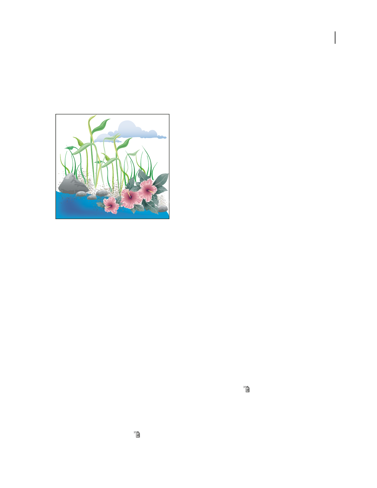
ILLUSTRATOR CS3
User Guide
88
Symbolism tools and symbol sets
About symbol sets
A symbol set is a group of symbol instances that you create with the Symbol Sprayer tool. You can create mixed sets
of symbol instances by using the Symbol Sprayer tool with one symbol and then using it again with another symbol.
Artwork created with the symbolism tools
As you work with symbol sets, keep in mind that the symbolism tools affect only the symbol or symbols selected in
the Symbols panel. For example, if you create a mixed symbol instance set that represents a meadow with grass and
flowers, you can change the orientation of just the grass by selecting the grass symbol in the Symbols panel and then
using the Symbol Spinner tool. To change the size of both the grass and the flowers, select both symbols in the
Symbols panel and then use the Symbol Sizer tool.
Note: When you select a mixed symbol set on the artboard, the symbol instance most recently added to the set is
automatically selected in the Symbols panel.
Create symbol sets
The Symbol Sprayer acts like a particle sprayer—letting you add a large number of identical objects to the artboard
at one time. For example, use the symbol sprayer to add hundreds of grass blades, wildflowers, bees, or snowflakes.
See also
“Symbolism tool gallery” on page 30
“Symbolism tool options” on page 91
Spray sets of symbol instances onto artwork
1
Select a symbol in the Symbols panel, and then select the Symbol Sprayer tool .
2 Click or drag where you want the symbol instances to appear.
Add or delete symbol instances from an existing set
1
Select the existing symbol set.
2 Select the Symbol Sprayer tool and a symbol in the Symbols panel.

ILLUSTRATOR CS3
User Guide
89
3 Do one of the following:
•To add symbol instances, click or drag where you want the new instances to appear.
•To delete symbol instances, hold down Alt (Windows) or Option (Mac OS) as you click or drag where you want
to remove instances.
Modify symbol instances in a symbol set
You use the symbolism tools to modify multiple symbol instances in a set. For example, you can disperse instances
over a larger area using the Symbol Scruncher tool or gradually tinting the color of instances to make them look more
realistic.
Although you can use symbolism tools on individual symbol instances, they are most effective when used on symbol
sets. When working with individual symbol instances, most of these tasks are easily accomplished using the tools
and commands you use on regular objects.
See also
“Symbolism tool gallery” on page 30
“Symbolism tool options” on page 91
Change stacking order of symbol instances in a set
1
Select the Symbol Shifter tool .
2 Do one of the following:
•To move symbol instances, drag in the direction you want the symbol instances to move.
•To bring symbol instances forward, Shift-click the symbol instance.
•To send symbol instances backward, hold down Alt (Windows) or Option (Mac OS) and Shift-click the symbol
instance.
Gather or scatter symbol instances
1
Select the Symbol Scruncher tool .
2 Do one of the following:
•Click or drag in the area where you want to pull the symbol instances toward each other.
•Hold down Alt (Windows) or Option (Mac OS), and click or drag in the area where you want to push symbol
instances away from each other.
Resize symbol instances
1
Select the Symbol Sizer tool .
2 Do one of the following:
•Click or drag in the set where you want to increase the size of the symbol instances.
•Hold down Alt (Windows) or Option (Mac OS), and click or drag where you want to decrease the size of the
symbol instances.
•Hold down Shift as you click or drag to preserve the density of the symbol instances while resizing.

ILLUSTRATOR CS3
User Guide
90
Rotate symbol instances
1
Select the Symbol Spinner tool .
2 Click or drag in the direction you want the symbol instances to orient.
Stain symbol instances
Staining a symbol instance changes the hue toward the tint color, while preserving the original luminosity. (It works
in the same way as the Tints and Shades colorization method of tinting brushes.) This method uses the luminosity
of the original color and the hue of the colorization color to generate the resulting color. Consequently, colors with
very high or very low luminosity change very little; black or white objects don’t change at all.
To achieve a method of colorization that will also affect black and white objects, use the Symbol Styler tool with a
graphic style that uses the desired fill color.
1 In the Color panel, select the fill color that you want to use as the colorization color.
2 Select the Symbol Stainer tool and do one of the following:
•Click or drag over the symbol instances you want to stain with the colorization color. The amount of colorization
gradually increases, and the symbol instance’s color gradually changes to the colorization color.
•Hold down Alt (Windows) or Option (Mac OS) as you click or drag to decrease the colorization amount and
reveal more of the original symbol color.
•Hold down Shift as you click or drag to keep the colorization amount constant, while gradually changing the color
of the symbol instances to the colorization color.
Note: Using the Symbol Stainer tool results in increased file size and decreased performance. When memory or exported
Flash/SVG file size is a concern, do not use this tool.
Adjust transparency of symbol instances
1
Select the Symbol Screener tool .
2 Do one of the following:
•Click or drag where you want to increase the symbol’s transparency.
•Hold down Alt (Windows) or Option (Mac OS), and click or drag where you want to decrease the symbol’s trans-
parency.
Apply a graphic style to symbol instances
The Symbol Styler tool lets you apply or remove a graphic style from a symbol instance. You can control the amount
and location of the application. For example, you can apply a style gradually so that some symbol instances display
the style at full strength and others display the style at partial strength.
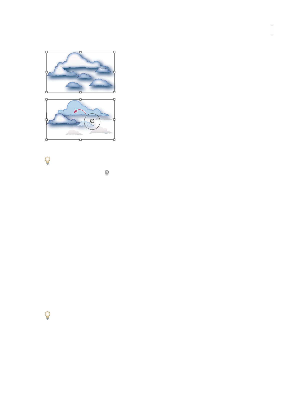
ILLUSTRATOR CS3
User Guide
91
Graphic style applied at full strength (top) compared to graphic style applied at varying strengths (bottom)
You can switch to the Symbol Styler tool when using any other symbolism tool by clicking a style in the Graphic Styles
panel.
1 Select the Symbol Styler tool .
2 Select a style in the Graphic Styles panel, and do one of the following:
•Click or drag where you want to apply the style to the symbol set. The amount of style applied to the symbol
instances increases, and the style gradually changes.
•Hold down Alt (Windows) or Option (Mac OS) as you click or drag to decrease the style amount and reveal more
of the original, unstyled symbol.
•Hold down Shift as you click or drag to keep the amount of style constant, while gradually changing the symbol
instance style to the selected style.
Note: It is very important to perform steps 1 and 2 in the specified order. If you select a style while a tool other than the
symbolism tool is selected, the style will apply immediately to the entire selected symbol instance set.
Symbolism tool options
You access symbolism tool options by double-clicking a symbolism tool in the Tools panel.
General options, such as diameter, intensity, and density, appear at the top of the dialog box. Tool-specific options
appear at the bottom of the dialog box. To switch to options for a different tool, click a tool icon in the dialog box.
General options The General options appear at the top of the Symbolism Tools Options dialog box regardless of
which symbolism tool is selected.
•Diameter Specifies the tool’s brush size.
At any time while using a symbolism tool, press [ to decrease the diameter or ] to increase it.
•Intensity Specifies the rate of change (higher values equal faster changes), or select Use Pressure Pen to use the
input from a tablet or pen instead of the Intensity value.

ILLUSTRATOR CS3
User Guide
92
•Symbol Set Density Specifies an attraction value for the symbol set (higher values result in more densely packed
symbol instances). This setting applies to an entire symbol set. If a symbol set is selected, the density changes for all
symbol instances in the set, not just newly created instances.
•Method Specifies how the Symbol Scruncher, Sizer, Spinner, Stainer, Screener, and Styler tools adjust symbol
instances.
Select User Defined to gradually adjust symbols in relation to the position of the cursor. Select Random to modify
the symbols randomly in the area under the cursor. Select Average to gradually smooth out the symbol values.
•Show Brush Size And Intensity Displays the size as you use the tool.
Symbol Sprayer options The Symbol Sprayer options (Scrunch, Size, Spin, Screen, Stain, and Style) appear under the
General options in the Symbolism Tools Options dialog box only when the Symbol Sprayer tool is selected, and
control how new symbol instances are added to symbol sets. Each of these offers two choices:
•Average To add a new symbol with the average value of existing symbol instances within the brush radius. For
example, an instance added to an area where the average existing symbol instance is 50% transparent will be 50%
transparent; an instance added to an area with no instances will be opaque.
Note: The Average setting only takes into account other instances within the Symbol Sprayer tool’s brush radius, which
you set using the Diameter option. To see the radius as you work, select Show Brush Size and Intensity.
•User Defined To apply specific preset values for each parameter: Scrunch (density) is based on the original symbol
size; Size uses the original symbol size; Spin uses the mouse direction (or no orientation if the mouse doesn’t move);
Screen uses 100% opacity; Stain uses the current fill color and full tint amount; Style uses the current style.
Symbol Sizer options The Symbol Sizer options appear under the General options in the Symbolism Tools Options
dialog box only when the Symbol Sizer tool is selected.
•Proportional Resizing Keep each symbol instance shape uniform as you resize.
•Resizing Affects Density Move symbol instances away from each other when they are scaled up and move them
toward each other when they are scaled down.

93
Chapter 4: Color
Applying colors to artwork is a common Adobe Illustrator task, and one that requires some knowledge of color
models and color modes. When applying color to artwork, keep in mind the final medium in which the artwork will
be published, so that you can use the correct color model and color definitions. Experimenting and applying color
is easy using the feature-rich Swatches panel, Color Guide panel, and Live Color dialog box in Illustrator.
About color
About colors in digital graphics
We use color models to describe the colors we see and work with in digital graphics. Each color model, such as RGB,
CMYK, or HSB, represents a different method for describing and classifying color. Color models use numeric values
to represent the visible spectrum of color. A color space is a variant of a color model and has a specific gamut (range)
of colors. For example, within the RGB color model are a number of color spaces: Adobe® RGB, sRGB, and Apple®
RGB. While each of these color spaces defines color using the same three axes (R, G, and
B), their gamuts are
different.
When you work with the colors in a graphic, you are actually adjusting numerical values in the file. It’s easy to think
of a number as a color, but these numerical values are not absolute colors in themselves—they only have a color
meaning within the color space of the device that is producing the color.
Because each device has its own color space, it can reproduce colors only in its gamut. When an image moves from
one device to another, image colors may change because each device interprets the RGB or CMYK values according
to its own color space. For example, it is impossible for all the colors viewed on a monitor to be identically matched
in a print from a desktop printer. A printer operates in a CMYK color space, and a monitor operates in an RGB color
space. Their gamuts are different. Some colors produced by inks cannot be displayed on a monitor, and some colors
that can be displayed on a monitor cannot be reproduced using inks on paper.
Even though it is impossible to perfectly match all colors on different devices, you can use color management to
ensure that most colors are the same or similar enough so they appear consistent.
See also
“About color management in Adobe applications” on page 130
“Synchronize color settings across Adobe applications” on page 132
RGB
A large percentage of the visible spectrum can be represented by mixing red, green, and blue (RGB) colored light in
various proportions and intensities. Where the colors overlap, they create cyan, magenta, and yellow.
RGB colors are called additive colors because you create white by adding R, G, and B together—that is, all light is
reflected back to the eye. Additive colors are used for lighting, television, and computer monitors. Your monitor, for
example, creates color by emitting light through red, green, and blue phosphors.
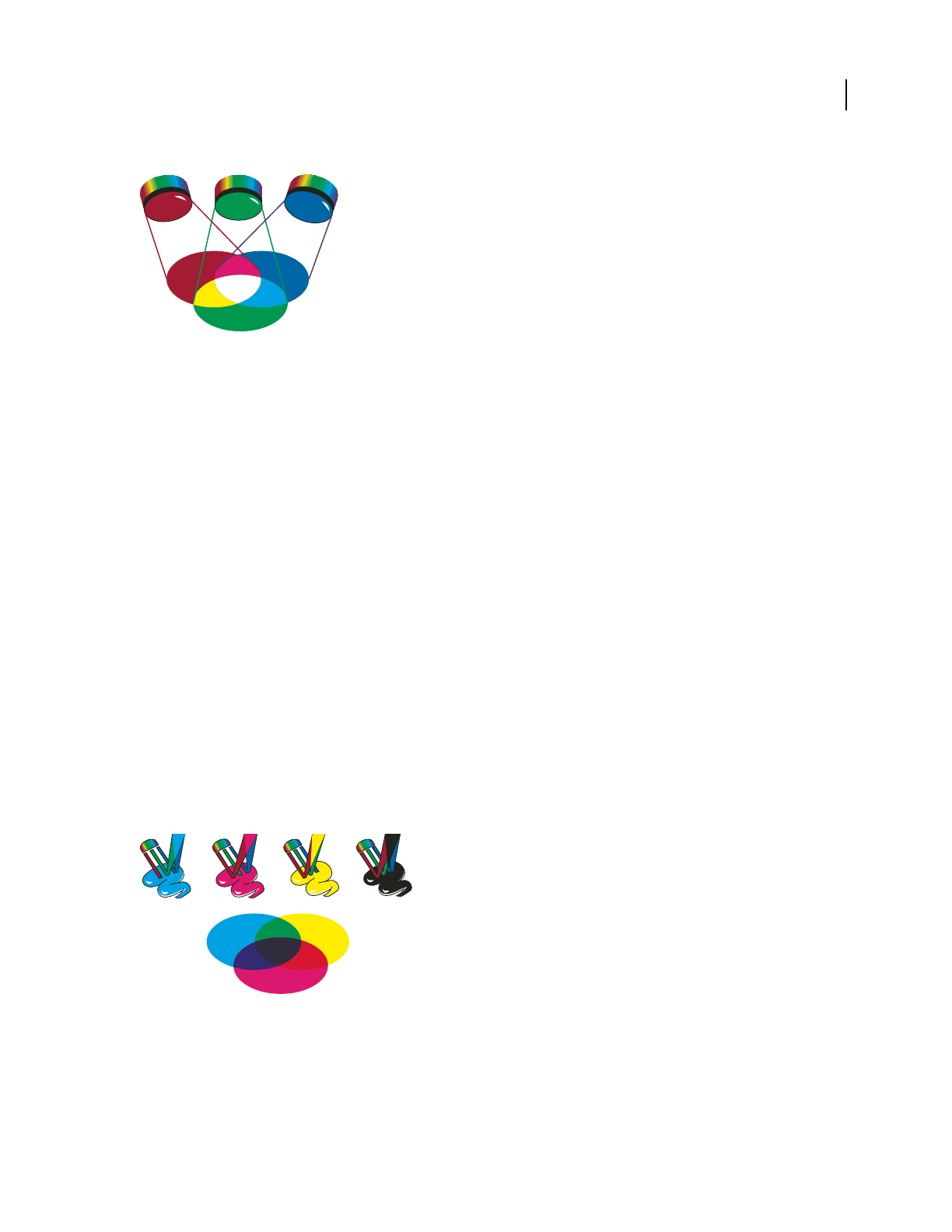
ILLUSTRATOR CS3
User Guide
94
Additive colors (RGB)
R. Red G. Green B. Blue
You can work with color values using the RGB color mode, which is based on the RGB color model. In RGB mode,
each of the RGB components can use a value ranging from 0 (black) to 255 (white). For example, a bright red color
might have an R value of 246, a G value of 20, and a B value of 50. When the values of all three components are equal,
the result is a shade of gray. When the value of all components is 255, the result is pure white; when all components
have values of 0, the result is pure black.
Illustrator also includes a modified RGB color mode called Web Safe RGB, which includes only those RGB colors
that are appropriate for use on the web.
See also
“Change the color mode of a document” on page 95
CMYK
Whereas the RGB model depends on a light source to create color, the CMYK model is based on the light-absorbing
quality of ink printed on paper. As
white light strikes translucent inks, a portion of the spectrum is absorbed. Color
that is not absorbed is reflected back to your eye.
Combining pure cyan (C), magenta (M), and yellow (Y) pigments would result in black by absorbing, or subtracting,
all colors. For this reason they are called subtractive colors. Black (K) ink is added for better shadow density. (The
letter K came into use because black is the “key” color for registering other colors, and because the letter B also stands
for blue.) Combining these inks to reproduce color is called four-color process printing.
Subtractive colors (CMYK)
C. Cyan M. Magenta Y. Yel low K. Black
R G B
C M Y K

ILLUSTRATOR CS3
User Guide
95
You can work with color values using the CMYK color mode, which is based on the CMYK color model. In CMYK
mode, each of the CMYK process inks can use a value ranging from 0 to 100%. The lightest colors are assigned small
percentages of process ink colors; darker colors have higher percentage values. For example, a bright red might
contain 2% cyan, 93% magenta, 90% yellow, and 0% black. In CMYK objects, low ink percentages are closer to white,
and high ink percentages are closer to black.
Use CMYK when preparing a document to be printed using process inks.
See also
“Change the color mode of a document” on page 95
Change the color mode of a document
❖Choose File > Document Color Mode > CMYK Color or RGB Color. Most raster effects in Illustrator can only be
applied while you are in RGB mode.
HSB
Based on the human perception of color, the HSB model describes three fundamental characteristics of color:
Hue Color reflected from or transmitted through an object. It is measured as a location on the standard color wheel,
expressed as a degree between 0˚ and 360˚. In common use, hue is identified by the name of the color, such as red,
orange, or green.
Saturation Strength or purity of the color (sometimes called chroma). Saturation represents the amount of gray in
proportion to the hue, measured as a percentage from 0% (gray) to 100% (fully saturated). On the standard color
wheel, saturation increases from the center to the edge.
Brightness Relative lightness or darkness of the color, usually measured as a percentage from 0% (black) to 100%
(white).
HSB color model
H. Hue S. Saturation B. Brightness
See also
“Adjust the saturation of multiple colors” on page 126
0
100
0 360
0
100
H
S B

ILLUSTRATOR CS3
User Guide
96
Lab
The CIE Lab color model is based on the human perception of color. It is one of several color models produced by
the Commission Internationale d’Eclairage (CIE), an organization dedicated to creating standards for all aspects of
light.
The numeric values in Lab describe all the colors that a person with normal vision sees. Because Lab describes how
a color looks rather than how much of a particular colorant is needed for a device (such as a monitor, desktop printer,
or digital camera) to produce colors, Lab is considered to be a device-independent color model. Color management
systems use Lab as a color reference to predictably transform a color from one color space to another color space.
In Illustrator, you can use the Lab model to create, display, and output spot color swatches. However, you cannot
create documents in Lab mode.
See also
“Display and output spot colors using Lab values” on page 106
Grayscale
Grayscale uses tints of black to represent an object. Every grayscale object has a brightness value ranging from 0%
(white) to 100% (black). Images produced using black-and-white or grayscale scanners are typically displayed in
grayscale.
Grayscale also lets you convert color artwork to high-quality black-and-white artwork. In this case, Adobe Illustrator
discards all color information in the original artwork; the gray levels (shades) of the converted objects represent the
luminosity of the original objects.
When you convert grayscale objects to RGB, the color values for each object are assigned that object’s previous gray
value. You can also convert a grayscale object to a CMYK object.
See also
“Convert colors to grayscale” on page 126
“Convert grayscale images to RGB or CMYK” on page 126
Color spaces and gamuts
A color space is a range of colors in the visible spectrum. A color space can also be a variant of a color model. Adobe
RGB, Apple RGB, and sRGB are examples of different color spaces based on the same color model.
Gamuts of different color spaces
A. Visual gamut B. RGB color space C. CMYK color space
A
B
C

ILLUSTRATOR CS3
User Guide
97
The range of color encompassed by a color space is called a gamut. The different devices (computer monitor, scanner,
desktop printer, printing press, digital camera) throughout your workflow operate within different color spaces and
each with different gamuts. Some colors within the gamut of your computer monitor are not within the gamut of
your inkjet printer, and vice versa. When a color cannot be produced on a device, it’s considered to be outside the
color space of that particular device. In other words, the color is out of gamut.
See also
“Shift an out-of-gamut color to a printable color” on page 124
“Why colors sometimes don’t match” on page 128
About spot and process colors
You can designate colors as either spot or process color types, which correspond to the two main ink types used in
commercial printing. In the Swatches panel, you can identify the color type of a color using icons that appear next
to the name of the color.
When applying color to paths and frames, keep in mind the final medium in which the artwork will be published,
so that you apply color using the most appropriate color mode.
If your color workflow involves transferring documents among devices, you may want to use a color-management
system (CMS) to help maintain and regulate colors throughout the process.
About spot colors
A spot color is a special premixed ink that is used instead of, or in addition to, CMYK process inks, and that requires
its own printing plate on a printing press. Use spot color when few colors are specified and color accuracy is critical.
Spot color inks can accurately reproduce colors that are outside the gamut of process colors. However, the exact
appearance of the printed spot color is determined by the combination of the ink as mixed by the commercial printer
and the paper it’s printed on, not by color values you specify or by color management. When you specify spot color
values, you’re describing the simulated appearance of the color for your monitor and composite printer only (subject
to the gamut limitations of those devices).
Keep the following guidelines in mind when specifying a spot color:
•For best results in printed documents, specify a spot color from a color-matching system supported by your
commercial printer. Several color-matching system libraries are included with the software.
•Minimize the number of spot colors you use. Each spot color you create will generate an additional spot color
printing plate for a printing press, increasing your printing costs. If you think you might require more than four
colors, consider printing your document using process colors.
•If an object contains spot colors and overlaps another object containing transparency, undesirable results may
occur when exporting to EPS format, when converting spot colors to process colors using the Print dialog box,
or when creating color separations in an application other than Illustrator or InDesign. For best results, use the
Flattener Preview or the Separations Preview to soft proof the effects of flattening transparency before printing.
In addition, you can convert the spot colors to process colors by using the Ink Manager in InDesign before printing
or exporting.
•You can use a spot color printing plate to apply a varnish over areas of a process color job. In this case, your print
job would use a total of five inks—four process inks and one spot varnish.

ILLUSTRATOR CS3
User Guide
98
About process colors
A process color is printed using a combination of the four standard process inks: cyan, magenta, yellow, and black
(CMYK). Use process colors when a job requires so many colors that using individual spot inks would be expensive
or impractical, as when printing color photographs.
Keep the following guidelines in mind when specifying a process color:
•For best results in a high-quality printed document, specify process colors using CMYK values printed in process
color reference charts, such as those available from a commercial printer.
•The final color values of a process color are its values in CMYK, so if you specify a process color using RGB (or
LAB, in InDesign), those color values will be converted to CMYK when you print color separations. These conver-
sions differ based on your color-management settings and document profile.
•Don’t specify a process color based on how it looks on your monitor, unless you are sure you have set up a color-
management system properly, and you understand its limitations for previewing color.
•Avoid using process colors in documents intended for online viewing only, because CMYK has a smaller color
gamut than that of a typical monitor.
•Illustrator lets you specify a process color as either global or non-global. Global process colors remain linked to a
swatch in the Swatches panel, so that if you modify the swatch of a global process color, all objects using that color
are updated. Non-global process colors do not automatically update throughout the document when the color is
edited. Process colors are non-global by default.
Note: Global and non-global process colors only affect how a particular color is applied to objects, never how colors
separate or behave when you move them between applications.
Using spot and process colors together
Sometimes it’s practical to use process and spot inks in the same job. For example, you might use one spot ink to
print the exact color of a company logo on the same pages of an annual report where photographs are reproduced
using process color. You can also use a spot color printing plate to apply a varnish over areas of a process color job.
In both cases, your print job would use a total of five inks—four process inks and one spot ink or varnish.
In InDesign, you can mix process and spot colors together to create mixed ink colors.
Comparing colors in InDesign and Illustrator
Adobe InDesign and Adobe Illustrator use slightly different methods for applying named colors. Illustrator lets you
specify a named color as either global or nonglobal, and InDesign treats all unnamed colors as nonglobal, process
colors.
The InDesign equivalents to global colors are swatches. Swatches make it easier to modify color schemes without
having to locate and adjust each individual object. This is especially useful in standardized, production-driven
documents like magazines. Because InDesign colors are linked to swatches in the Swatches panel, any change to a
swatch affects all objects to which a color is applied.
The InDesign equivalents to nonglobal swatches are unnamed colors. Unnamed colors do not appear in the Swatches
panel, and they do not automatically update throughout the document when the color is edited in the Color panel.
You can, however, add an unnamed color to the Swatches panel later.
Named and unnamed colors only affect how a particular color updates in your document, never how colors separate
or behave when you move them between applications.

ILLUSTRATOR CS3
User Guide
99
Selecting colors
About selecting colors
You can select colors for your artwork from a variety of tools, panels, and dialog boxes in Illustrator. How you select
color depends on the needs of your artwork. For example, if you want to use specific company-approved colors, you’ll
want to select colors from the company-approved swatch library. If you want to match your colors with colors in
other artwork, you can use the eyedropper or the Color Picker and enter exact color values.
You can use any of the following features for selecting color:
Swatches panel and swatch library panels Provide individual colors and color groups. You can choose from preex-
isting swatches and libraries or create your own. You can also import libraries.
Color Picker Provides a color spectrum from which you can visually select colors, color value text boxes for manually
defining colors, and color swatches.
Eyedropper tool Samples colors from your artwork when you click.
Color panel Provides a color spectrum, individual color value sliders (such as a Cyan slider), and color value text
boxes. You can specify fill and stroke colors from the Color panel. From the Color panel menu, you can create inverse
and complementary colors for the current fill or stroke color, and create a swatch from the selected color.
Color Guide panel Provides several harmony rules to choose from for creating color groups using a base color that
you choose. You can create variations of colors using tints and shades, warm and cool colors, or vivid and muted
colors. From the Color Guide panel you can open a color group in the Live Color dialog box.
Live Color dialog box Provides tools for precisely defining or adjusting the colors in a color group or artwork. You
can also recolor your artwork using the colors from the color group, or reduce or convert your colors for output.
Add Selected Colors command or New Color Group button Create a new color group containing the colors in
selected artwork. This command and button are both located in the Swatches panel.
See also
“About swatches” on page 102
“About swatch libraries” on page 102
“Color Picker overview” on page 99
“Color Guide overview” on page 110
“Live Color overview” on page 112
Color Picker overview
The Color Picker lets you select an object’s fill or stroke color by choosing from a color field and spectrum, defining
colors numerically, or clicking a swatch.
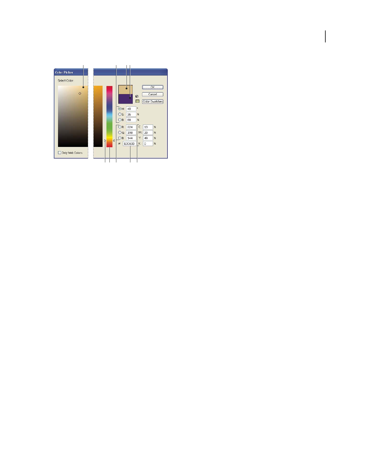
ILLUSTRATOR CS3
User Guide
100
Color Picker
A. Color field B. HSB color values C. Current color D. Previous color E. Color spectrum slider F. Color spectrum G. RGB color values
H. Hexadecimal color value I. CMYK color values
See also
“About colors in digital graphics” on page 93
Display the Color Picker
❖Double-click the fill or stroke color selection box in the Tools panel or Color panel.
Change the color spectrum displayed in the Color Picker
❖Click a letter: H (Hue), S (Saturation), B (Brightness), R (Red), G (Green), or B (Blue).
Display only web-safe colors
Web-safe colors are those used by all web browsers, regardless of the platform.
❖Select Only Web Colors.
View color swatches instead of the color spectrum
❖Click Color Swatches. Click Color Models to return to view the color spectrum.
Select colors using the Color Picker
Do any of the following:
•Click or drag inside the color spectrum. A circular marker indicates the color’s position in the spectrum.
•Drag the triangles along the color slider or click inside the color slider.
•Enter values in any of the text boxes.
•Click Color Swatches, select a swatch, and click OK.
B
E
F
G
H
I
C A D

ILLUSTRATOR CS3
User Guide
101
Color panel overview
You use the Color panel (Window > Color) to apply color to an object’s fill and stroke, and also to edit and mix colors.
The Color panel can display color values using different color models. By default, only the most commonly used
options are visible in the Color panel.
Color panel
A. Fill color B. Stroke color C. panel menu D. None box E. Color spectrum bar F. Color slider G. Text box for a color component
See also
“About colors in digital graphics” on page 93
“Customize the workspace” on page 18
Change the color model
❖Select Grayscale, RGB, HSB, CMYK, or Web Safe RGB from the panel menu.
Show all options in the panel
❖Select Show Options from the panel menu. Alternatively, click the double triangle on the panel’s tab to cycle
through the display sizes.
Select colors using the Color panel
1 Select the color mode you want to use from the panel menu. The mode you select affects only the display of the
Color panel; it does not change the color mode of the document.
2 Do one of the following:
•Drag or click in a slider.
•Shift-drag a color slider to move the other sliders in relation to it (except for HSB sliders). This keeps a similar
color but with a different tint or intensity.
•Enter values in any of the text boxes.
•Click in the color spectrum bar at the bottom of the panel. To select no color, click the None box at the left of the
color bar; to select white, click the white swatch at the upper-right corner of the color bar; to select black, click the
black swatch at the lower-right corner of the color bar.
A
D E F G
B C

ILLUSTRATOR CS3
User Guide
102
Using and creating swatches
About swatches
Swatches are named colors, tints, gradients, and patterns. The swatches associated with a document appear in the
Swatches panel. Swatches can appear individually or in groups.
You can open libraries of swatches from other Illustrator documents and various color systems. Swatch libraries
appear in separate panels and are not saved with the document.
The Swatches panel and swatch library panels can contain the following types of swatches:
Process colors A process color is printed using a combination of the four standard process inks: cyan, magenta,
yellow, and black. By default, Illustrator defines new swatches as process colors. (See “About process colors” on
page 98.)
Global process colors A global color is automatically updated throughout your artwork when you edit it. All spot
colors are global; however, process colors can be either global or local. You can identify global color swatches by the
global color icon (when the panel is in list view) or a triangle in the lower corner (when the panel is in thumbnail
view).
Spot colors A spot color is a premixed ink that is used instead of, or in addition to, CMYK process inks. You can
identify spot-color swatches by the spot-color icon (when the panel is in list view) or a dot in the lower corner
(when the panel is in thumbnail view). (See “About spot colors” on page 97.)
Gradients A gradient is a graduated blend between two or more colors or tints of the same color or different colors.
Gradient colors can be assigned as CMYK process colors, RGB colors, or a spot color.
Patterns Patterns are repeating (tiled) paths, compound paths, text with solid fills or no fill.
None The None swatch removes the stroke or fill from an object. You can’t edit or remove this swatch.
Registration The registration swatch is a built-in swatch that causes objects filled or stroked with it to print on
every separation from a PostScript printer. For example, registration marks use the Registration color so that
printing plates can be aligned precisely on a press. You can’t remove this swatch.
Note: If you use the Registration color for type, and then you separate the file and print it, the type may not register
properly and the black ink may appear muddy. To avoid this, use black ink for type.
Color groups Color groups can contain process, spot, and global process colors. They cannot contain pattern,
gradient, none, or registration swatches. You create color groups based on harmonies by using either the Color Guide
panel or the Live Color dialog box. To put existing swatches into a color group, select the swatches and click the New
Color Group icon in the Swatches panel. You can identify a color group by the folder icon .
You can also create tints in the Swatches panel. A tint is a global process color or spot color with a modified intensity.
Tints of the same color are linked together, so that if you edit the color of a tint swatch, all associated tint swatches
(and the objects painted with those swatches) change color, though the tint values remain unchanged. Tints are
identified by a percentage (when the Swatches panel is in list view)
About swatch libraries
Swatch libraries are collections of preset colors, including ink libraries such as PANTONE®, HKS, Trumatch,
FOCOLTONE, DIC, TOYO, and thematic libraries such as camouflage, nature, Greek, and jewel tones.
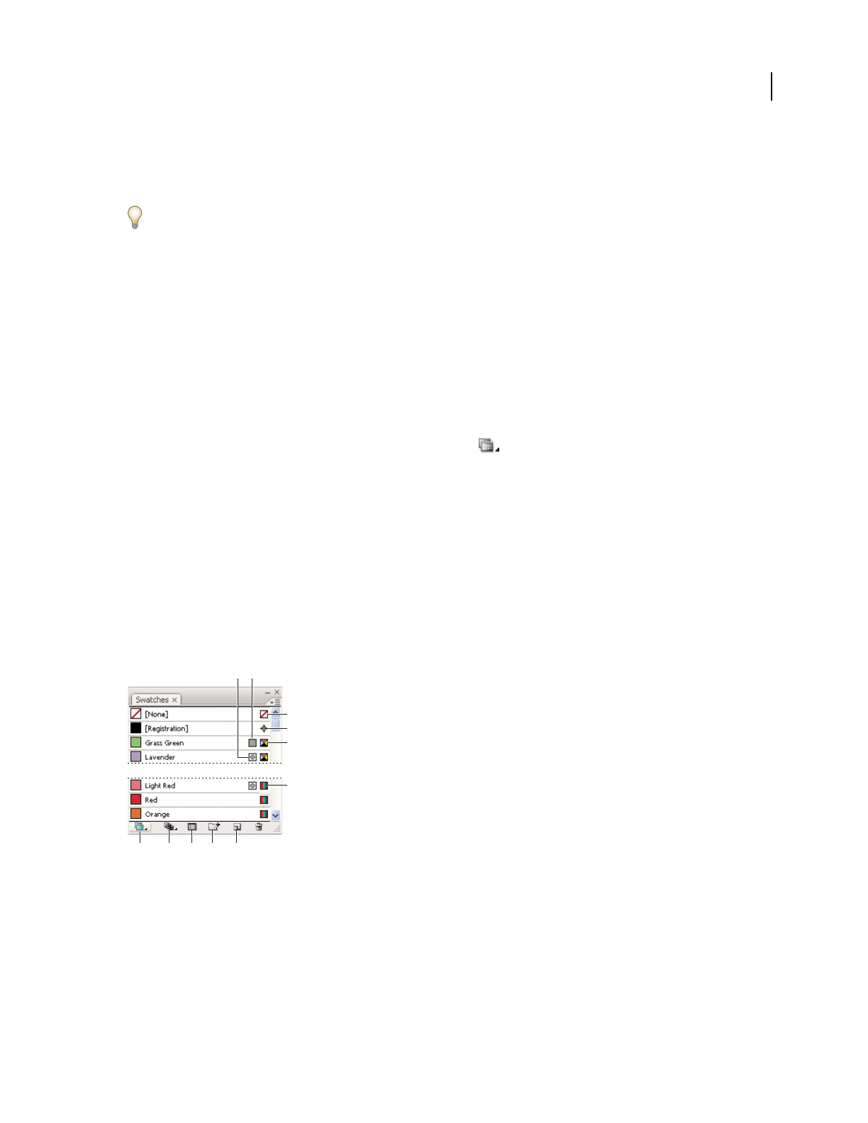
ILLUSTRATOR CS3
User Guide
103
When you open a swatch library, it appears in a new panel (not the Swatches panel). You select, sort, and view
swatches in a swatch library the same as you do in the Swatches panel. However, you can’t add swatches to, delete
swatches from, or edit the swatches in the Swatch libraries panel.
To make a swatch library appear each time Illustrator is started, select Persistent from the swatch library’s panel
menu.
See also
“Create swatch libraries” on page 109
“Share swatches between applications” on page 105
Open a swatch library
❖Do one of the following:
•Choose Window > Swatch Libraries > [library name].
•In the Swatches panel menu, choose Open Swatch Library > [library name].
•In the Swatches panel, click the Swatch Libraries Menu button , and choose a library from the list.
Edit a swatch library
1
Choose File > Open, locate and open the library file. By default, swatch library files are stored in the
Illustrator/Presets/Swatches folder.
2 Edit the colors in the Swatches panel and save your changes.
Swatches panel overview
You use the Swatches panel (Window > Swatches) to control all document colors, gradients, and patterns. You can
name and store any of these items for instant access. When a selected object’s fill or stroke contains a color, gradient,
pattern, or tint applied from the Swatches panel, the applied swatch is highlighted in the Swatches panel.
Swatches panel in Small List view
A. Spot color B. Global color C. Fill or stroke of None D. Registration swatch (prints on all plates) E. CMYK symbol (when document is open
in CMYK mode) F. RGB symbol (when document is open in RGB mode) G. Swatch Library Menu button H. Show Swatch Kinds Menu
button I. Swatch Options Menu button J. New Color Group button K. New Swatch button
See also
“Customize the workspace” on page 18
AB
C
D
E
F
GHJK
I

ILLUSTRATOR CS3
User Guide
104
Change the display of swatches
❖Select a view option from the Swatches panel menu: Small Thumbnail View, Medium Thumbnail View, Large
Thumbnail View, Small List View, or Large List View.
Show a specific type of swatch and hide all others
❖ Click the Show Swatch Kinds button and choose one of the following: Show All Swatches, Show Color
Swatches, Show Gradient Swatches, Show Pattern Swatches, or Show Color Groups.
Select all swatches that aren’t used in artwork
If you want to limit your Swatches panel to only the colors that are used in a document, you can select all unused
swatches and then delete them.
❖Choose Select All Unused in the Swatches panel menu.
Select a color group
•To select the entire group, click the color group icon .
•To select swatches inside the group, click individual swatches.
Note: To edit the selected color group, click the Edit Color Group button , or double-click the color group folder. For
more information, see “Edit colors in the Live Color dialog box” on page 115.
Select a swatch by name
❖Select Show Find Field from the Swatches panel menu. Type the first letter or letters of the swatch’s name in the
Find text box at the top of the panel.
You can also use this method to select a PANTONE swatch by entering the PANTONE number.
Move swatches into a color group
•Drag individual color swatches to an existing color group folder.
•Select the colors you want in a new color group and click the New Color Group button .
Change the order of swatches
❖Do one of the following:
•Select Sort By Name or Sort By Kind from the Swatches panel menu.
•Drag a swatch to a new location.
Add colors from artwork to Swatches panel
You can automatically add all the colors from selected artwork or all the colors in your document to the Swatches
panel. Illustrator finds the colors that are not already in the Swatches panel, converts any process colors to global
colors, and adds them to the panel as new swatches.
When you automatically add colors to the Swatches panel, all colors in the document are included, except the
following:
•Colors inside opacity masks (when not in opacity mask editing mode)
•Interpolated colors in blends
•Colors in image pixels

ILLUSTRATOR CS3
User Guide
105
•Guide colors
•Colors in objects that are inside compound shapes and are not visible
If you change a gradient fill, pattern fill, or symbol instance to a new global color, the color is added as a new swatch
and the original color swatch is retained.
Add all document colors
❖Make sure nothing is selected, and choose Add Used Colors from the Swatches panel menu.
Add colors from selected artwork
❖Select the objects containing the colors you want to add to the Swatches panel, and do one of the following:
•Choose Add Selected Colors from the Swatches panel menu.
•Click the New Color Group button in the Swatches panel. Specify options in the dialog box that appears.
Share swatches between applications
You can share the solid swatches you create in Photoshop, Illustrator, and InDesign by saving a swatch library for
exchange. The colors appear exactly the same across applications as long as your color settings are synchronized.
1 In the Swatches panel, create the process and spot-color swatches you want to share, and remove any swatches you
don’t want to share.
Note: You cannot share the following types of swatches between applications: patterns, gradients, and the Registration
swatch from Illustrator or InDesign; and book color references, HSB, XYZ, duotone, monitorRGB, opacity, total ink, and
webRGB swatches from Photoshop. These types of swatches are automatically excluded when you save swatches for
exchange.
2 Select Save Swatches For Exchange from the Swatches panel menu, and save the swatch libraries in an easily acces-
sible location.
3 Load the swatch library into the Swatches panel for Photoshop, Illustrator, or InDesign.
Create a process-color swatch
1 Select a color using the Color Picker or Color panel, or select an object with the color you want.
2 Do one of the following:
•Drag the color from the Tools panel or Color panel to the Swatches panel.
•In the Swatches panel, click the New Swatch button or select New Swatch from the panel menu. In the dialog box
that appears, select Global if you want the swatch to be a global color. Set additional swatch options, and click OK.
(See “Swatch options” on page 106.)
See also
“About swatches” on page 102
“About process colors” on page 98
Create spot-color swatches
1 Select a color using the Color Picker or Color panel, or select an object with the color you want.

ILLUSTRATOR CS3
User Guide
106
2 Do one of the following:
•Ctrl-drag (Windows) or Command-drag (Mac OS) the color from the Tools panel or Color panel to the Swatches
panel.
•In the Swatches panel, Ctrl-click (Windows) or Command-click (Mac OS) the New Swatch button, or select New
Swatch from the panel menu. In the dialog box that appears, select Spot Color for Color Type. Set additional
swatch options and click OK. (See “Swatch options” on page 106.)
See also
“About swatches” on page 102
“About spot colors” on page 97
Display and output spot colors using Lab values
Some predefined spot colors, such as colors from the TOYO, PANTONE, DIC, and HKS libraries, are defined using
Lab values. For backward compatibility with previous versions of Illustrator, colors from these libraries also include
CMYK definitions. The Swatches panel lets you control which values, Lab or CMYK, Illustrator uses to display,
export, and print these spot colors.
Lab values, when used in conjunction with the correct device profiles, give you the most accurate output across all
devices. If color management is critical to your project, Adobe recommends that you display, export, and print spot
colors using their Lab values.
Note: To improve on-screen accuracy, Illustrator uses the Lab values automatically if Overprint Preview is on. It also
uses Lab values when printing if you’ve selected Simulate for the Overprints option in the Advanced area of the Print
dialog box.
1 Choose Spot Colors from the Swatches panel menu.
2 Do one of the following:
•Select Use Standard Lab Values Specified By The Book Manufacturer if you want the most accurate display and
output of colors.
•Select Use CMYK Values From The Manufacturer’s Process Book if you want spot colors to match earlier versions
of Illustrator.
See also
“Lab” on page 96
Swatch options
To set swatch options, double-click an existing swatch or select New Swatch from the Swatches panel menu.
Swatch Name Specifies the name of the swatch in the Swatches panel.
Color Type Specifies if the swatch is a process color or spot color.
Global Creates a global process-color swatch.
Color Mode Specifies the color mode of the swatch.
After you select the color mode you want, you can use the color sliders to adjust the color. If you select a color that
is not web-safe, an alert cube appears. Click the cube to shift to the closest web-safe color (which is displayed to

ILLUSTRATOR CS3
User Guide
107
the right of the cube). If you select an out-of-gamut color, an alert triangle appears. Click the triangle to shift to
the closest CMYK equivalent (which is displayed to the right of the triangle).
Preview Displays color adjustments on any objects to which the swatch is applied.
Change the tint of a color
1 Select a global process color or spot color in the Swatches panel, or select an object to which you’ve applied a global
process color or spot color.
2 In the Color panel, drag the T slider or enter a value in the text box to modify the color’s intensity. The tint range
is from 0% to 100%; the lower the number, the lighter the tint will be.
If you don’t see the T slider, make sure that you have a global process color or spot color selected. If you still don’t see
the T slider, choose Show Options from the Color panel menu.
3 To save the tint as a swatch, drag the color to the Swatches panel, or click the New Swatch button in the Swatches
panel. The tint is saved with the same name as the base color, but with the tint percentage added to the name. For
example, if you saved a color named “Sky Blue” at 50 percent, the swatch name would be “Sky Blue 50%.”
See also
“About spot colors” on page 97
“About process colors” on page 98
Create gradient swatches
1 Create a gradient using the Gradient panel, or select an object with the gradient you want.
2 Do one of the following:
•Drag the gradient from the Tools panel or Color panel to the Swatches panel.
•In the Swatches panel, click the New Swatch button or select New Swatch from the Swatches panel menu. In the
dialog box that appears, enter a swatch name, and click OK. (See “Swatch options” on page 106.)
See also
“Gradient panel overview” on page 182
“Create or modify gradients” on page 182
Managing swatches
Duplicate swatches
1 Select one or more swatches that you want to duplicate.
2 Do one of the following:
•Select Duplicate Swatch from the Swatches panel menu.
•Drag the swatches to the New Swatch button in the Swatches panel.

ILLUSTRATOR CS3
User Guide
108
See also
“Swatches panel overview” on page 103
Group swatches
When you want to keep specific colors together in the Swatches panel, create a color group. For example, you can
create a color group for colors you select in the Color Guide panel. When you save a color group in the Live Color
dialog box, it is automatically saved as a color group in the Swatches panel. You can also manually group any set of
solid color swatches.
1 Select one or more swatches in the Swatches panel.
2 Click the New Color Group button, or choose New Color Group from the panel menu.
See also
“Create a color group in Live Color” on page 114
“Save Color Guide colors to the Swatches panel” on page 112
Replace, merge, or delete swatches
•To replace a swatch, hold down Alt (Windows) or Option (Mac OS) and drag the color or gradient from the Color
panel, Gradient panel, an object, or the Tools panel to the Swatches panel, highlighting the swatch you want to
replace.
Replacing an existing color, gradient, or pattern in the Swatches panel globally changes objects in the file containing
that swatch color with the new color, gradient, or pattern. The only exception is for a process color that does not have
the
Global option selected in the Swatch Options dialog box.
•To merge multiple swatches, select two or more swatches, and select Merge Swatches from the Swatches panel
menu. The first selected swatch name and color value replaces all other selected swatches.
•To delete a swatch, select one or more swatches. Select Delete Swatch from the panel menu, click the Delete Swatch
button, or drag the selected swatches to the Delete Swatch button.
When you delete a spot-color or global process-color swatch (or a pattern or gradient containing a spot or global
process color), all objects painted with those colors are converted to the non-global process color equivalent.
See also
“Swatches panel overview” on page 103
Move swatches from a swatch library to the Swatches panel
Do any of the following:
•Drag one or more swatches from the swatch library panel to the Swatches panel.
•Select the swatches you want to add, and select Add To Swatches from the library’s panel menu.
•Apply a swatch to an object in the document. If the swatch is a global or spot-color swatch, the swatch is automat-
ically added to the Swatches panel.

ILLUSTRATOR CS3
User Guide
109
See also
“Swatches panel overview” on page 103
“About swatch libraries” on page 102
Import swatches from another document
You can import all swatches or individual swatches from another document.
•To import all swatches from another document, choose Window > Swatch Libraries > Other Library or choose
Open Swatch Library > Other Library from the Swatches panel menu. Select the file from which you want to
import swatches, and click Open. The imported swatches appear in a swatch library panel (not the Swatches
panel).
•To import individual swatches from another document, copy and paste objects that use the swatches. The
imported swatches appear in the Swatches panel.
Note: If imported swatches have the same name (but different color values) as swatches already in the document, a
swatch conflict occurs. For spot color conflicts, the color values of the existing swatches are automatically preserved. For
process color conflicts, the Swatch Conflict dialog box appears. You can choose to add the conflicting swatches by
appending a number to the swatch names or merge the swatches using the color values of the existing swatches.
See also
“Swatches panel overview” on page 103
“About swatch libraries” on page 102
Create swatch libraries
You create a swatch library by saving the current document as a swatch library.
1 Edit the swatches in the Swatches panel so that it contains only the swatches you want in the swatch library.
2 Select Save Swatch Library from the Swatches panel menu.
To remove all swatches that aren’t used in the document, choose Select All Unused from the Swatches panel menu,
and then click the Delete Swatch button .
See also
“About swatch libraries” on page 102
Working with color groups
About color groups
A color group is an organization tool that lets you group related color swatches together in the Swatches panel. In
addition, a color group can be a container for color harmonies, which you create using the Live Color dialog box or
the Color Guide panel. Color groups can contain only solid colors which include spot, process, or global colors.
Gradients and patterns cannot be grouped.
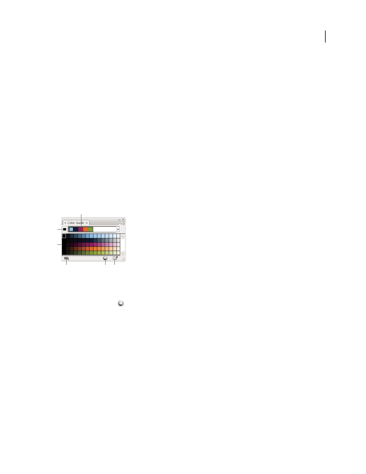
ILLUSTRATOR CS3
User Guide
110
You can use the Color Guide panel or the Live Color dialog box to create harmonious color groups. Using either
feature, you can choose a harmony rule to instantly generate a color scheme based on any color you want. For
example, choose the Monochromatic harmony rule to create a color group containing all the same hue, but with
different saturation levels. Or choose the High Contrast or Pentagram harmony rule to create a color group with
contrasting colors for more visual impact.
See also
“Group swatches” on page 108
Color Guide overview
Use the Color Guide panel (Window > Color Guide) as tool for color inspiration while you create your artwork. The
Color Guide panel suggests harmonious colors based on the current color in the Tools panel. You can use these colors
to color artwork or you can save them as swatches.
You can manipulate the colors that the Color Guide panel generates in a number of ways, including changing the
harmony rule, or adjusting the variation type and the number of variation colors that appear.
Note: If you have artwork selected, clicking a color variation changes the color of the selected artwork, just like clicking
a swatch in the Swatches panel.
A. Color harmony rule menu and current color group B. Set as base color C. Color variations D. Limits colors to specified swatch library
E. Edit colors (opens the colors in the Live Color dialog box) F. Save group to Swatches panel
You can save the color group and color variations to the Swatches panel. If you want more control over the colors,
click the Edit Colors button
to open the Live Color dialog box.
For a video on using the Color Guide to find and create color solutions, see www.adobe.com/go/vid0058.
See also
“About swatches” on page 102
“Swatches panel overview” on page 103
“Create a color group in Live Color” on page 114
Create a color harmony using the Color Guide
Make sure no artwork is selected when you set the base color; otherwise, the selected artwork will change to the base
color.
1 Open the Color Guide panel, and do any of the following to set the base color for the color harmony:
•Click a color swatch in the Swatches panel.
B
A
C
DEF

ILLUSTRATOR CS3
User Guide
111
•Click a color in the Color panel. (You may want to drag out the Color panel so that you can use it along with the
Color Guide panel.)
•Double-click the Fill Color in the Tools panel and pick a color in the Color Picker.
•Using the eyedropper, click on artwork containing the color you want.
•Select artwork containing the color you want, and then click the Set Base Color To The Current Color icon .
•Click a color variation in the Color Guide panel, and then click the Set Base Color To The Current Color icon .
2 Choose a rule from the Harmony Rules menu.
3 Click the Save Color Group To Swatch Panel button . To name the new group, select the group in the Swatches
panel and choose Color Group Options from the panel menu.
Note: To confine colors to a swatch library, click the Limits The Color Scheme To Colors In A Swatch Library button ,
and choose library from the list.
Specify the type of color variations
❖Choose one of the following variations from the Color Guide panel menu:
Show Tints/Shades Adds black to variations on the left and white to variations on the right.
Show Warm/Cool Adds red to variations on the left and blue to variations on the right.
Show Vivid/Muted Decreases the saturation toward gray in variations on the left and increases saturation toward
gray in variations on the right.
Note: If you’re using spot colors, use only the Tints/Shades variation and choose colors from the tint (right) side of the
variation grid. All other variations cause spot colors to be converted to process.
Specify the number and range of color variations
1
Choose Color Guide Options from the Color Guide panel menu.
2 Specify the number of colors you want to appear to the left and right of each color in the generated color group.
For example, choose 6 if you want to see six shades darker and six shades lighter of each color.
The original colors always appear down the center of the panel, and the variations on those colors appear to the left
and right of them.
3 Drag the Range slider to the left to decrease the variance range or drag to the right to increase the range.
Decreasing the range generates colors that are more similar to the originals.
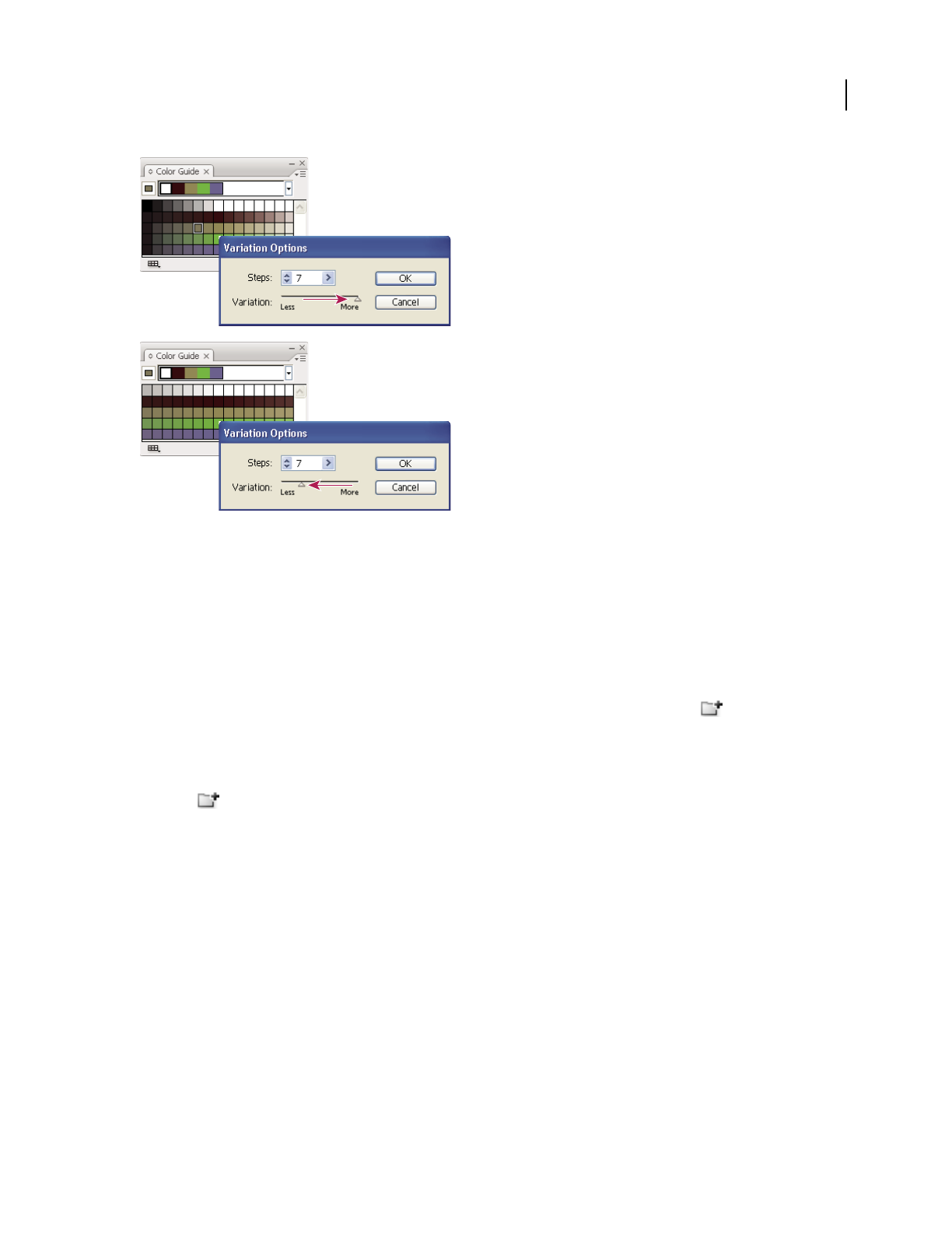
ILLUSTRATOR CS3
User Guide
112
Adjusting the range of color variations
Color artwork with colors from the Color Guide
❖Select your artwork and click any color in the Color Guide panel.
Save Color Guide colors to the Swatches panel
From the Color Guide panel, you can save the active color group or a selection of color variations as a color group
in the Swatches panel.
•To save the current color group in the Color Guide panel, click the New Color Group button .
•To save one or more color variations as individual swatches, drag the colors from the Color Guide panel to the
Swatches panel.
•To save multiple color variations as a group, select them in the Color Guide panel and click the New Color Group
button .
Live Color overview
You use the Live Color dialog box to create and edit color groups, as well as reassign or reduce the colors in your
artwork. All of the color groups that you create for a particular document appear in the Color Groups storage area
of the Live Color dialog box (as well as the Swatches panel). You can select and use these color groups at anytime.

ILLUSTRATOR CS3
User Guide
113
Create or edit color groups, and assign colors using the Live Color dialog box.
A. Create and edit a color group in the Edit tab B. Assign colors in the Assign tab C. Select a color group from the Color Groups list
The Recolor Art option at the bottom of the dialog box lets you preview colors on selected artwork, and specifies
whether or not artwork is recolored when you close the Live Color dialog box.
The main areas of the Live Color dialog box are:
Edit Use the Edit tab to create new color groups or edit existing color groups. Use the harmony rule menu and the
color wheel to experiment with color harmonies. The color wheel shows you how colors in a harmony are related,
while the color bars let you see and manipulate individual color values. In addition, you can adjust brightness, add
and remove colors, save color groups, and preview the colors on selected artwork.
Assign Use the Assign tab to view and control how colors from a color group replace original colors in your artwork.
You can assign colors only if you have artwork selected in the document. You can specify which new colors replace
which current colors, whether spots are preserved, and how colors are replaced (for example, you can replace colors
entirely or replace hue while retaining brightness). Use Assign to control how artwork is recolored with the current
color group or to reduce the number of colors in the current artwork.
Color Groups Lists all saved color groups for the open document (these same color groups appear in the Swatches
panel). While in the Live Color dialog box, you can edit, delete, and create new color groups using the Color Groups
list. All your changes are reflected in the Swatches panel. The selected color group denotes which color group is
currently being edited. You can select any color group and edit it or use it to recolor selected artwork. Saving a color
group adds the group to this list.
For a video on creating, editing, and experimenting with color groups in Live Color, see
www.adobe.com/go/vid0059. For a video on integrating Live Color with smart objects in Photoshop and InDesign,
see www.adobe.com/go/vid0191.
See also
“Create a color group in Live Color” on page 114
“Edit colors in the Live Color dialog box” on page 115
“Assign colors to your artwork” on page 119
“Reduce colors in your artwork” on page 122
ABC

ILLUSTRATOR CS3
User Guide
114
Open the Live Color dialog box
❖Open the Live Color dialog box from any of the following locations:
Edit > Edit Colors > Recolor Artwork or Recolor With Presets command Use these commands when you want to edit
colors in selected artwork.
Edit Colors button in Control panel Use this button when you want to edit the colors of the selected artwork
using the Live Color dialog box. This button is available when the selected artwork contains two or more colors.
Note: Editing colors this way is a convenient way to globally adjust colors in artwork when global colors weren't used in
the artwork's creation.
Edit Colors button in Color Guide panel Click this button when you want to edit the colors in the Color Guide
panel, or apply the colors in the Color Guide panel to selected art.
Edit Color Group button in Swatches panel Double-click a color group in the Swatches panel or select a group
and click this button when you want to edit colors in a color group in the Swatches panel.
Work with the Color Group list
•To show or hide the Color Group list, click the Hide Color Group Storage icon on the right side of the Live Color
dialog box. To display the list again, click the icon again.
•To add a new color group to this list, create or edit a color group, and then click New Color Group . A new
color group appears in the list.
•To edit an existing color group, click it in the list to select it. Make changes to the color group using the Edit tab,
and then click Save Changes To Color Group .
•To delete a color group, select it and click Delete Color Group .
Create a color group in Live Color
You create a color group in the Live Color dialog box by choosing a base color and a harmony rule. The harmony
rule uses the base color as the basis for generating the colors in the color group. For example, if you choose a blue
base color and the Complementary harmony rule, a color group is created using the base color, blue, and its
compliment, red.
As you manipulate the colors in the color wheel, the selected harmony rule continues to govern the colors that are
generated for the group. To break the harmony rule and edit the colors freely, click the Unlink button
.
1 Open the Live Color dialog box, and choose a color harmony from the Harmony Rules menu, if desired.
Note: To confine colors to a swatch library, click the Limits The Color Scheme To Colors In A Swatch Library button ,
and choose a library from the list.
2 If the color bars are showing, click the Color Wheel icon to display the color wheel instead.
3 Set the base color by doing one of the following:
•
Drag the base color marker (the largest, double-ringed color marker) around the wheel to set the base color you want.
• Adjust the color sliders at the bottom of the dialog box.
4 Choose a new harmony rule or move the color markers, as desired.
5 To preview the new colors on selected artwork, click Recolor Art.
Note: Recolor Art will recolor selected artwork when you click OK to close the dialog box. If you don’t want to recolor
the selected art, make sure to deselect this option before clicking OK.
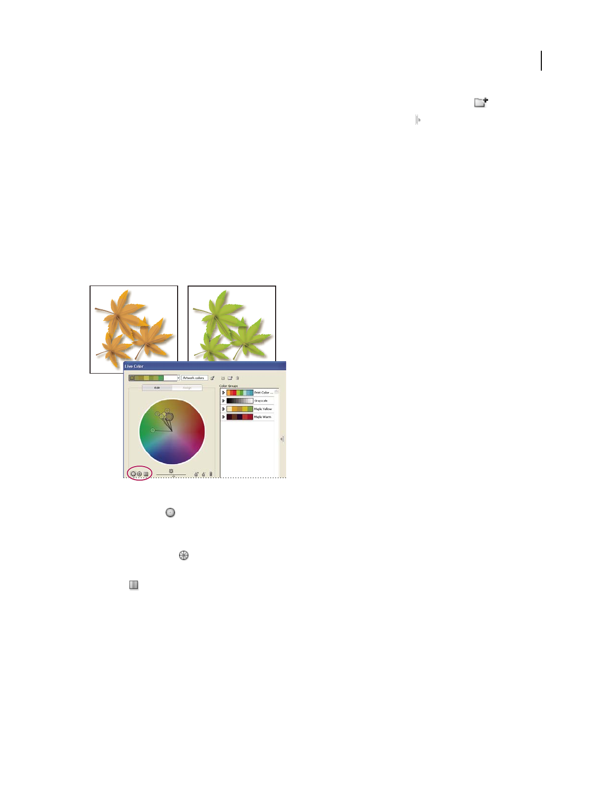
ILLUSTRATOR CS3
User Guide
115
6 Type a name in the Name box to the right of the Harmony rules menu, and click New Color Group .
Note: if the New Color Group icon is not visible, click the Show Color Group Storage icon .
7 To save the new color group to the Swatches panel, click OK and close the Live Color dialog box.
Note: You can also create a color group by using the Color Guide. (See “Create a color harmony using the Color Guide”
on page 110.) For a video on creating, editing, and experimenting with color groups in Live Color, see
www.adobe.com/go/vid0059.
Edit colors in the Live Color dialog box
Editing colors in the Live Color dialog box is a convenient way to globally adjust the colors in selected artwork. It is
especially useful when global colors weren't originally used in the artwork's creation. You can edit colors and color
groups in the Live Color dialog box and apply your edits to selected artwork, or save the edited colors for later use.
When editing colors, you use the smooth color wheel, the segmented color wheel, or the color bars.
Editing colors by moving color markers on the smooth color wheel
Smooth color wheel Displays hue, saturation, and brightness in a smooth continuous circle. Each color in the
current color group is drawn on the wheel inside a circle. This wheel lets you choose from numerous colors with great
precision, but it can be hard to see individual colors because every pixel is a different color.
Segmented color wheel Displays colors as a set of segmented color patches. This wheel makes it easy to see
individual colors, but doesn’t provide as many colors to choose from as the continuous wheel.
Color bars Displays only colors from the color group. They appear as solid bars of color that you can select and
edit individually.
For a video on creating, editing, and experimenting with color groups in Live Color, see
www.adobe.com/go/vid0059.
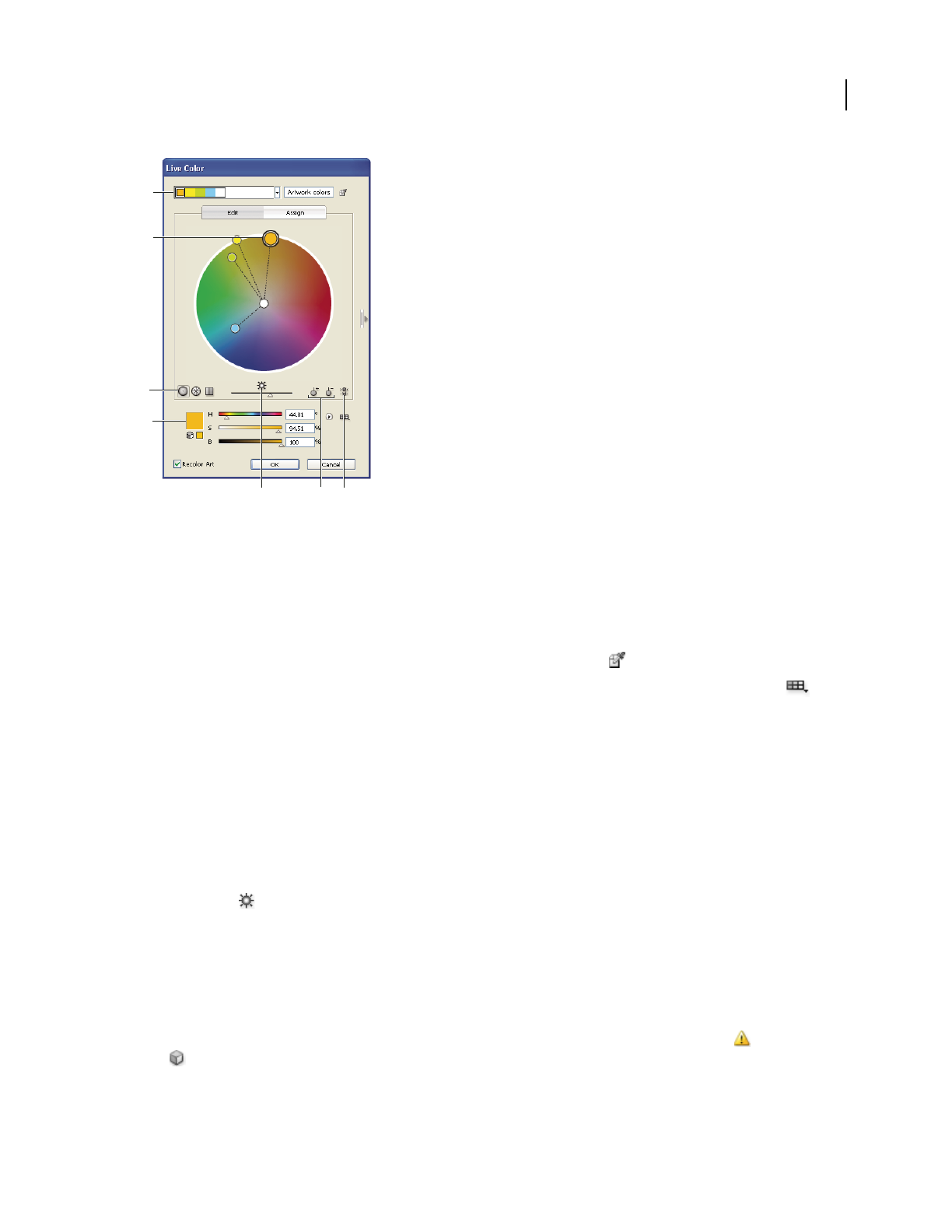
ILLUSTRATOR CS3
User Guide
116
A. Base color as it appears in Harmony Rule menu B. Base color as it appears in color wheel C. Color display options D. Color of selected
color marker or color bar E. Show saturation and hue on Wheel F. Add and subtract color marker tools G. Unlink harmony colors
Edit a color group using a color wheel
1
In the Live Color dialog box, select the desired color group from the Color Groups storage area, if necessary.
2 If you have selected an object on the artboard, click Recolor Art to preview the colors on the artwork. If you don’t
want to recolor the artwork, deselect Recolor Art before closing the dialog box, or click Cancel to close it.
Note: To edit the colors of the selected artwork, click Get Colors From Selected Art .
3 To confine colors to a swatch library, click the Limits The Color Group To Colors In A Swatch Library button
and choose a library from the list.
4 Drag a marker on the wheel to change its color. If the harmony is linked, all the colors move according to the rule
as you drag. If the harmony is unlinked, only the marker that you drag moves.
While editing, you can do any of the following:
•To change hue, move the marker around the wheel. To change saturation or brightness, move it inward and
outward on the wheel.
•To constrain the marker to move in only one direction, hold down the shift key as you drag.
•To see hue and saturation instead of hue and brightness on the wheel, click the Show Saturation And Hue On The
Wheel button , directly below the wheel to toggle between the two views.
•To change the color values manually, click the color marker for the color you want to change, or click the color in
the color group in the Active Colors box at the top of the dialog box. Edit the color values using the sliders or color
value text boxes under the color wheel.
•To change the saturation and brightness of a color on the wheel, right-click a color marker, and then click on the
desired color in the saturation and brightness box that appears.
Note: To ensure the colors are in gamut or web safe, select each color marker and click the Out Of Gamut or Out Of
Web buttons as necessary.
A
E
B
C
D
G
F

ILLUSTRATOR CS3
User Guide
117
Edit a color group using the Color Picker
You can use the Color Picker to change colors in a color group.
1 In the Live Color dialog box, do one of the following:
•Double-click a wheel marker.
•Double-click a color bar.
•Double-click a color in the Color Groups list.
•Double-click a color in the active colors display at the top of the dialog box.
•Click the color swatch to the left of the color sliders.
2 Save the edits by doing one of the following:
•To save the edited colors as a new group, type a new name in the name text box at the top of the dialog box, and
then click New Color Group ..
•To save the edits to the original color group, click Save Changes To Color Group .
Edit an individual color in a color group
When you use a harmony rule to create a color group, the colors are linked by default. When a color group is linked,
editing one color changes the other colors according to the harmony rule. To edit one color without changing the
others, you need to unlink the color markers from the harmony rule.

ILLUSTRATOR CS3
User Guide
118
A. Color wheel view of linked colors B. Color wheel view of unlinked colors C. Color bars view of linked colors D. Color bars view of unlinked
colors E. Colors linked, click to unlink F. Colors unlinked, click to relink
1 In the Live Color dialog box, select the color group you want to edit and click Edit.
2 Click the Unlink Harmony Colors icon .
3 Do one of the following:
•Drag the color marker you want to edit to set a new color.
•Click the Display Color Bars button . Click the color bar you want to change and manually edit the color values,
or double-click the color bar and choose a new color in the Color Picker.
•Right-click a color marker or color bar and pick a new shade.
4 To relink the colors so that the markers move again according to the newly defined harmony rule, click the button
again.
F
E
A
B
C
D

ILLUSTRATOR CS3
User Guide
119
Randomly change color order or saturation and brightness
In the Live Color dialog box, you can explore random variations of the current color group by using the Randomly
Assign Brightness And Saturation button and the Randomly Change Color Order button.
1 In the Live Color dialog box, select a color group.
2 Click Edit, and then click Display Color Bars; or click Assign.
3 Do either of the following:
•To randomly change the brightness and saturation of the current color group while retaining the hues, click
Randomly Change Color Order .
•To shuffle the order of the current color group, click Randomize Saturation And Brightness . Use this button
when recoloring artwork to quickly explore the different ways artwork can be recolored with the current color
group.
Globally edit saturation, brightness, temperature, or luminosity
1
In the Live Color dialog box, click Edit.
2 Click the Color Mode button , and choose Global Adjust.
3 Change the values for Saturation, Brightness, Temperature, and Luminosity.
Note: If you’ve limited the colors to a swatch library, any adjustments you make are limited to the library colors.
Add or remove colors in a color group
1
In the Live Color dialog box, click Edit.
2 View the color group using a color wheel, not the color bars.
3 Do either of the following:
•To add a color to the color group, click the Add Color Tool button , and then click in the color wheel on the
color you want to add. If you click on the line of an existing color marker, the new marker moves with that marker.
•To remove a color, click the Remove Color Tool button , and then click the color marker you want to remove.
You cannot remove the base color marker.
Delete a color group
❖Select a color group in the Color Groups list and click Delete .
Assign colors to your artwork
The Assign tab of the Live Color dialog box lets you assign colors from a color group to your artwork. You can assign
colors in the following ways:
•Assign new colors to your artwork using a color group from the Color Groups list.
•Assign new colors to your artwork using a new color group chosen from the Harmony Rule menu.
•Reassign current artwork colors amongst themselves. You can reset the Live Color dialog box so that the artwork
is displayed with its original colors by clicking Get Colors From Selected Art .
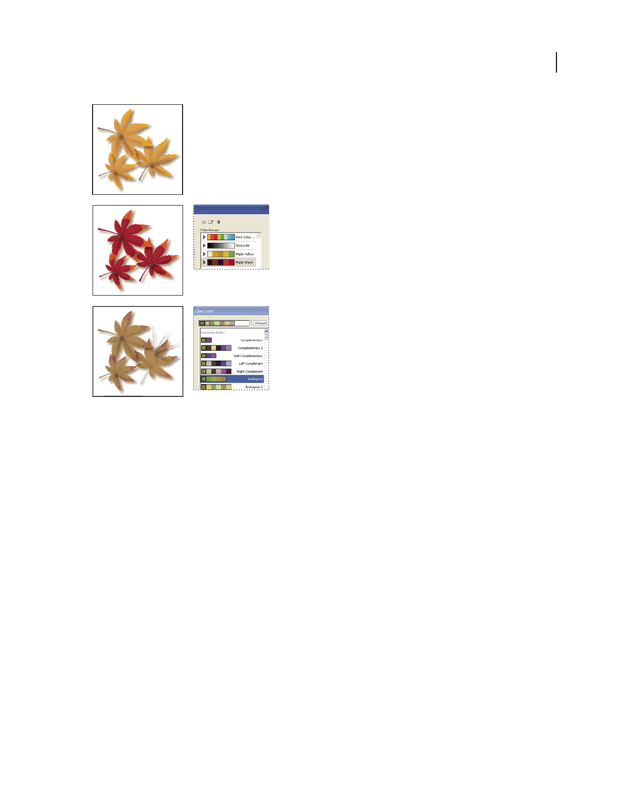
ILLUSTRATOR CS3
User Guide
120
Original artwork colors (top), assigning new colors by selecting a color group in the Color Groups list (center), and assigning new colors by
creating a new color group using the Harmony Rule menu (bottom).
Using the Current Colors and New columns, you control how colors are assigned. When you select Recolor Art, the
selected artwork is recolored with the active color group according to the columns assignments.
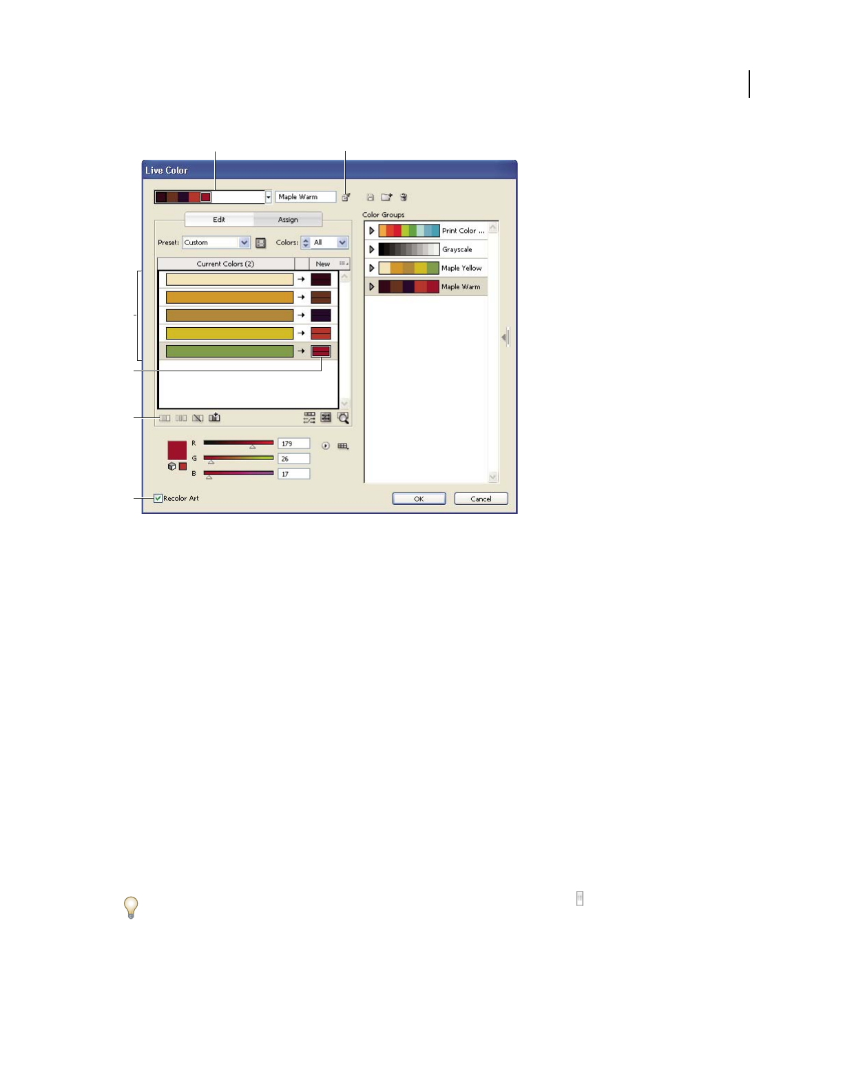
ILLUSTRATOR CS3
User Guide
121
A. Active color group B. Get Colors From Selected Art C. Colors from selected artwork D. New colors from active color group E. Exclude
Row F. Recolor Artwork
For a video on assigning colors in Live Color, see www.adobe.com/go/vid0061.
Assign new colors to selected artwork
1
Select the artwork you want to recolor.
2 Choose Edit > Edit Colors > Recolor Artwork.
The Live Color dialog box opens, displaying the Assign area with colors from the original artwork in both columns.
3 If you want to assign colors from a color group, do one of the following:
•Choose a color group from the Color Groups list.
•Create a new color group by selecting a new harmony rule from the menu from the Harmony Rules menu.
Note: If you create a new color group, you can click Edit to fine tune the colors, and then click Assign. Or, if you want to
adjust a few colors in the selected artwork, select the color you want to adjust and edit it with the color sliders.
4 To preview the color changes in your artwork, click Recolor Art.
5 Do any of the following to reassign colors:
•To assign a current color to a different color, drag the current color up or down in the Current Colors column until
it’s adjacent to the new color you want.
If a row contains multiple colors and you want to move them all, click the selector bar at the left of the row and
drag up or down.
•To assign a new color to a different row of current colors, drag the new color up or down in the New column.
AB
C
D
E
F

ILLUSTRATOR CS3
User Guide
122
•To exclude a row of current colors from being reassigned, click the arrow between the columns. To include it
again, click the dash.
•To exclude a single current color from being reassigned, select the color and click Excludes Selected Colors So
They Will Not Be Recolored .
•To randomly reassign colors, click the Randomly Change Color Order button . The New colors move
randomly to different rows of current colors.
•To add a row to the Current Colors column, click Add A Row .
6 To separate or merge colors in the Current Colors row, do either of the following:
•To separate colors into separate rows, select the color block you want to move and click Separate Colors Into
Different Rows .
•To merge colors into one row, Shift-click to select multiple colors, and then click Merge Colors Into A Row .
7 To change tints or shades of new colors, click the triangle next to the right of a new color and choose an option.
Select Apply To All if you want the same option to apply to all new colors in the color group.
Note: Tints And Shades and Hue Shift are only available when you choose not to preserve spot colors.
8 Click OK to recolor the artwork. If you don’t want to recolor the artwork, click Cancel, or deselect Recolor
Artwork and click OK.
Randomly change saturation and brightness in all colors
1
If necessary, select an object and choose Edit > Edit Colors > Recolor Artwork.
2 In the Live Color dialog box, click the Randomly Change Saturation and Brightness button .
Note: You can also do this when editing a color group using the Color Bars display.
View original colors in your artwork as you assign new colors
When you recolor selected artwork, the original colors are replaced by those in the selected color group. When
deciding how to assign new colors, you may need to see where an original color (from the Current Colors column)
appears in your artwork, especially if your artwork is very detailed or contains many original colors.
1 If necessary, select an object and choose Edit > Edit Colors > Recolor Artwork.
2 In the Live Color dialog box, click the Click On Colors Above To Find Them In Artwork button , and then
click a color in the Current Colors column.
The artwork that uses that color appears in full color on the artboard while all other areas of the selected artwork are
dimmed.
3 Click the icon again to return your artwork to full color.
Reduce colors in your artwork
Reducing colors for output, converting colors to grayscale, or limiting colors to a color library is often necessary
when you create artwork intended for multiple types of output media. You can easily reduce the number of colors in
your artwork using the Live Color dialog box. You can choose whether to use a preset for reducing colors, for
example, you can choose Grayscale Art to quickly convert your selected artwork to grayscale.
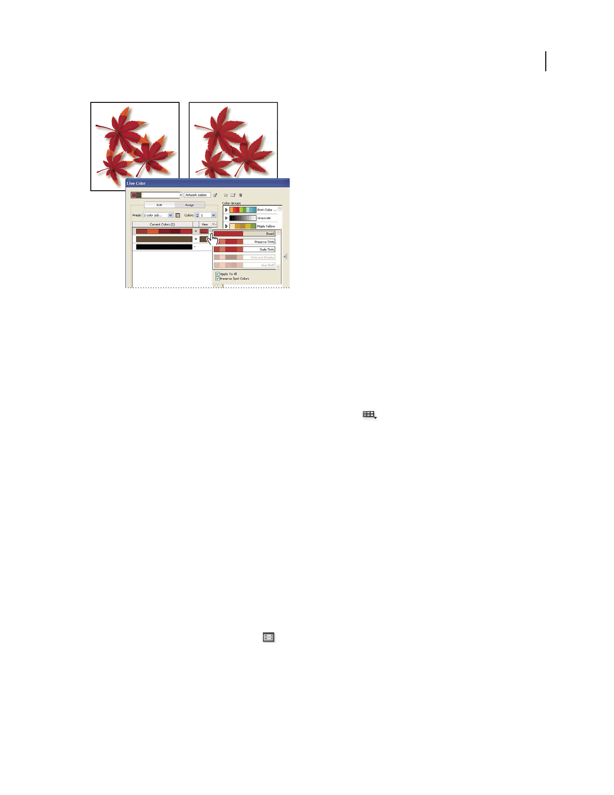
ILLUSTRATOR CS3
User Guide
123
Reducing selected artwork to two colors
Quickly reduce colors using a preset
Reducing your colors by using a preset is a quick and easy way to limit your artwork to a specific number of colors
or a swatch library.
1 Select the artwork you want to reduce.
2 Choose Edit > Edit Colors > Recolor With Preset, and choose a preset option.
3 Do one of the following:
•If you want to limit colors to a swatch library, click the library button , select the library you want, and then
click OK.
•If you don’t want to limit colors to a swatch library, click OK.
The Live Color dialog box opens. The New column displays the number of colors you chose as your preset, plus
black. The new colors are taken from your original artwork.
4 Assign your original colors to the new colors as desired.
5 Make sure Recolor Art is selected, and click OK.
Reduce colors using custom options
1
Select the artwork you want to recolor.
2 Choose Edit > Edit Colors > Recolor Artwork.
The Live Color dialog box opens. The New column displays all the colors from your selected artwork.
3 To use different colors, select or create a new color group.
4 Choose the number of colors you want to reduce down to from the Colors menu.
5 Click the Color Reduction Options button , specify any of the following options, and click OK:
Preset Specifies a preset color job, including the number of colors used and optimal settings for that job. If you select
a preset and then change any of the other options, the preset changes to Custom.
Colors Specifies the number of new colors that the current colors are reduced to.
Limit To Library Specifies a swatch library from which all new colors are derived.

ILLUSTRATOR CS3
User Guide
124
Sort Determines how the original colors are sorted in the Current Colors column.
Colorize Method Specifies the types of variations allowed for the new colors.
•Exact exactly replaces each current color with the specified new color.
•Scale Tints (default option) replaces the darkest current color in the row with the specified new color. Other
current colors in the row are replaced with a proportionally lighter tint.
•Preserve Tints is the same as Scale Tints for non-global colors. For spot or global colors, it applies the current
color’s tint to the new color. Use Preserve Tints when all the current colors in the row are tints of the same or
similar global color. For best results when using Preserve Tints, also select Combine Tints.
•Tints And Shades replaces the current color with the average lightness and darkness with the specified new color.
Current colors that are lighter than the average are replaced with a proportionally lighter tint of the new color.
Current colors that are darker than the average are replaced by adding black to the new color.
•Hue Shift sets the most typical color in the Current Colors row as a key color and exactly replaces the key color
with the new color. The other current colors are replaced by colors that differ from the new color in brightness,
saturation, and hue by the same amounts that the current color differs from the key color.
Combine Tints Sorts all tints of the same global color into the same Current Colors row, even if colors are not being
reduced. Use this option only when the selected art contains global or spot colors applied at tints less than 100%. For
best results, use in combination with the Preserve Tints colorization method.
Note: Even when Combine Tints is not selected, color reduction combines tints of the same global color before it
combines different non-global colors.
Preserve Determines whether white, black, or gray is preserved in the final reduction. If a color is preserved, it
appears in the Current Colors column as an excluded row.
6 Assign current colors to the new colors as desired.
7 Make sure Recolor Art is selected, and click OK.
Adjusting colors
Shift an out-of-gamut color to a printable color
Some colors in the RGB and HSB color models, such as neon colors, cannot be printed, because they have no equiv-
alents in the CMYK model. If you select an out-of-gamut color, an alert triangle appears in the Color panel or
Color Picker.
❖Click the triangle to shift to the closest CMYK equivalent (which is displayed in a small box by the triangle).
See also
“Color spaces and gamuts” on page 96
Shift a color to a web-safe color
Web-safe colors are the 216 colors used by all browsers, regardless of the platform. If you select a color that is not
web-safe, an alert cube
appears in the Color panel, Color Picker, or Live Color dialog box.
❖Click the cube to shift to the closest web-safe color (which is displayed in a small box by the cube).

ILLUSTRATOR CS3
User Guide
125
See also
“About web graphics” on page 370
Blend colors
The Blend commands create a series of intermediate colors from a group of three or more filled objects, based on the
objects’ vertical or horizontal orientation, or on their stacking order. Blending does not affect strokes or unpainted
objects.
1 Select three or more filled objects.
2 Do one of the following:
•To fill the intermediate objects with graduated blends between the frontmost and backmost filled objects, choose
Edit > Edit Colors > Blend Front To Back.
•To fill the intermediate objects with graduated blends between the leftmost and rightmost filled objects, choose
Edit > Edit Colors > Blend Horizontally.
•To fill the intermediate objects with graduated blends between the topmost and bottommost filled objects, choose
Edit > Edit Colors > Blend Vertically.
Change a color to its inverse or complement
1 Select the color you want to change.
2 In the Color panel, select an option from the panel menu:
Invert Changes each component of a color to the opposite value on the color scale. For example, if an RGB color has
an R value of 100, the Invert command will change the R value to 155 (255 – 100 = 155).
Complement Changes each component of a color to a new value based on the sum of the highest and lowest RGB
values in the selected color. Illustrator adds the lowest and highest RGB values of the current color, and then subtracts
the value of each component from that number to create new RGB values. For example, suppose you select a color
with an RGB value of 102 for red, 153 for green, and 51 for blue. Illustrator adds the high (153) and low (51) values,
to end up with a new value (204). Each of the RGB values in the existing color is subtracted from the new value to
create new complementary RGB values: 204 – 102 (the current red value) = 102 for the new red value, 204 – 153 (the
current green value) = 51 for the new green value, and 204 – 51 (the current blue value) = 153 for the new blue value.
Invert multiple colors
1 Select the objects whose colors you want to invert.
2 Choose Edit > Edit Colors > Invert Colors.
You can use the Color panel to invert individual colors.
Adjust color balance of one or more colors
1 Select the objects whose colors you want to adjust.
2 Choose Edit > Edit Colors > Adjust Color Balance.
3 Set the Fill and Stroke options.

ILLUSTRATOR CS3
User Guide
126
4 Adjust the color values, and then click OK:
•If you selected any global process colors or spot colors, use the tint slider to adjust the intensity of the colors. Any
nonglobal process colors you selected are not affected.
•If you are working in CMYK color mode and selected nonglobal process colors, use the sliders to adjust the
percentages of cyan, magenta, yellow, and black.
•If you are working in RGB color mode and selected nonglobal process colors, use the sliders to adjust the
percentages of red, green, and blue.
•If you want to convert the colors you selected to grayscale, select Grayscale from the Color Mode list and select
the Convert option. Then use the slider to adjust the percentage of black.
•If you selected any global process or spot colors and you want to convert them to nonglobal process colors, select
either CMYK or RGB from the Color Mode list (depending on the color mode of the document) and select the
Convert option. Then use the sliders to adjust the colors.
Convert colors to grayscale
1 Select the objects whose colors you want to convert.
2 Choose Edit > Edit Colors > Convert To Grayscale.
Use the Edit > Edit Colors> Adjust Colors command to convert objects to grayscale and adjust the shades of gray at
the same time.
See also
“Grayscale” on page 96
Convert grayscale images to RGB or CMYK
1 Select the grayscale image.
2 Choose Edit > Edit Colors > Convert To CMYK or Convert To RGB (depending on the color mode of the
document).
Colorize grayscale or 1-bit images
1 Select the bitmap object.
2 Make sure the Fill button in the Tools panel or Color panel is selected.
3 Use the Color panel to color the image with black, white, a process color, or a spot color.
Note: If a grayscale image contains an alpha channel, you cannot colorize the image with a process color. Select a spot
color instead.
Adjust the saturation of multiple colors
1 Select the objects whose colors you want to adjust.
2 Choose Edit > Edit Colors > Saturate.
3 Enter a value from –100% to 100% to specify the percentage by which to decrease or increase the color or the spot-
color tint.

ILLUSTRATOR CS3
User Guide
127
See also
“HSB” on page 95
Mix overlapping colors
You can use blending modes, the Hard Mix effect, or the Soft Mix effect to mix overlapping colors.
Blending modes Provide many options for controlling overlapping colors, and should always be used in place of
Hard Mix and Soft Mix for artwork containing spot colors, patterns, gradients, text, or other complex artwork.
Hard Mix effect Combines colors by choosing the highest value of each of the color components. For example, if
Color 1 is 20% cyan, 66% magenta, 40% yellow, and 0% black; and Color 2 is 40% cyan, 20% magenta, 30% yellow,
and 10% black, the resulting hard color is 40% cyan, 66% magenta, 40% yellow, and 10% black.
Soft Mix effect Makes the underlying colors visible through the overlapping artwork, and then divides the image
into its component faces. You specify the percentage of visibility you want in the overlapping colors.
You can apply blending modes to individual objects, whereas you must apply the Hard Mix and Soft Mix effects to
entire groups or layers. Blending modes affect both the fill and stroke of an object, whereas the Hard and Soft Mix
effects result in removal of an object’s stroke.
Note: In most cases, applying the Hard Mix or Soft Mix effect to objects painted using a mix of process and spot colors
converts the color to CMYK. In the case of mixing a non-global process RGB color with a spot RGB color, all spot colors
are converted to a non-global process RGB color.
See also
“Apply Pathfinder effects” on page 230
“About blending modes” on page 179
“Targeting items for appearance attributes” on page 347
Mix colors using the Hard Mix effect
1
Target the group or layer.
2 Choose Effect > Pathfinder > Hard Mix
Mix colors using the Soft Mix effect
1
Target the group or layer.
2 Choose Effect > Pathfinder > Soft Mix.
3 Enter a value between 1% and 100% in the Mixing Rate text box to determine the percentage of visibility you want
in the overlapping colors, and click OK.
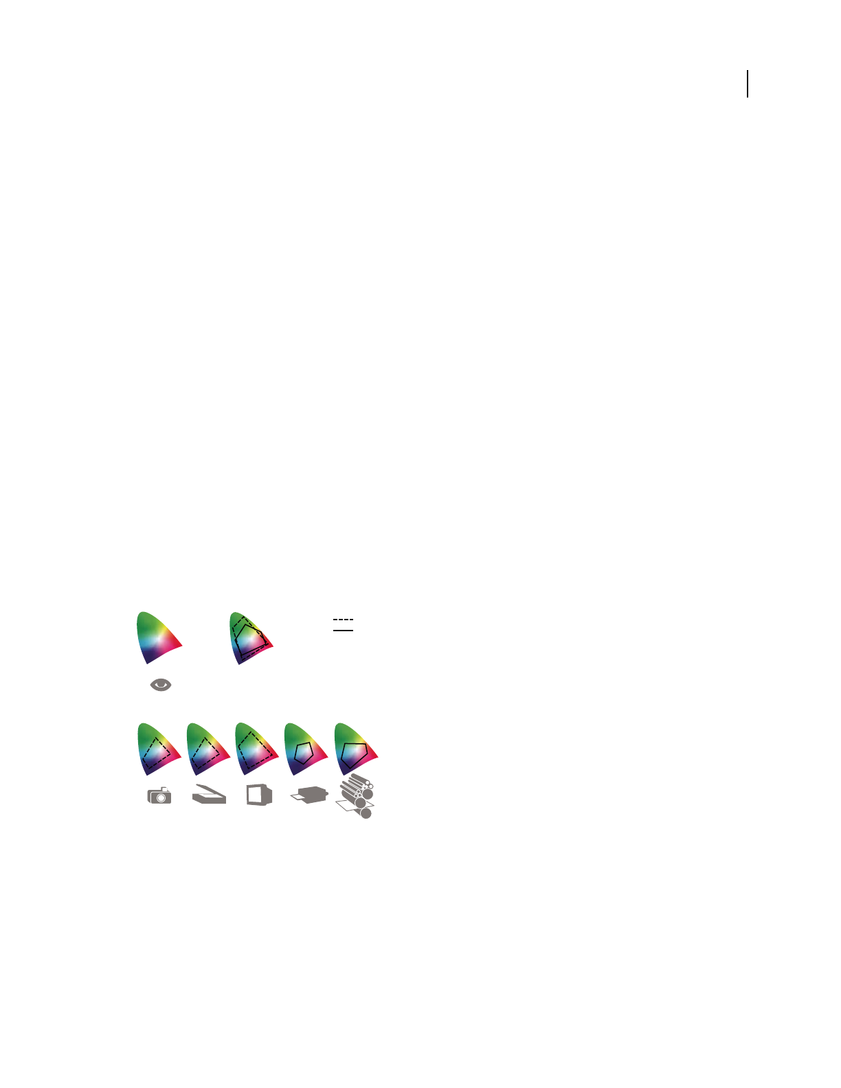
128
Chapter 5: Color management
A color management system reconciles color differences among devices so that you can be reasonably certain of the
colors your system ultimately produces. Viewing color accurately allows you to make sound color decisions
throughout your workflow, from digital capture through final output. Color management also allows you to create
output based on ISO, SWOP, and Japan Color print production standards.
Understanding color management
Why colors sometimes don’t match
No device in a publishing system is capable of reproducing the full range of colors viewable to the human eye. Each
device operates within a specific color space that can produce a certain range, or
gamut, of colors.
A color model determines the relationship between values, and the color space defines the absolute meaning of those
values as colors. Some color models (such as CIE L*a*b) have a fixed color space because they relate directly to the
way humans perceive color. These models are described as being device-independent. Other color models (RGB,
HSL, HSB, CMYK, and so forth) can have many different color spaces. Because these models vary with each
associated color space or device, they are described as being device-dependent.
Because of these varying color spaces, colors can shift in appearance as you transfer documents between different
devices. Color variations can result from differences in image sources; the way software applications define color;
print media (newsprint paper reproduces a smaller gamut than magazine-quality paper); and other natural varia-
tions, such as manufacturing differences in monitors or monitor age.
Color gamuts of various devices and documents
A. Lab color space B. Documents (working space) C. Devices
What is a color management system?
Color-matching problems result from various devices and software using different color spaces. One solution is to
have a system that interprets and translates color accurately between devices. A color management system (CMS)
compares the color space in which a color was created to the color space in which the same color will be output, and
makes the necessary adjustments to represent the color as consistently as possible among different devices.
CMYK
RGB
A B
C

ILLUSTRATOR CS3
User Guide
129
A color management system translates colors with the help of color profiles. A profile is a mathematical description
of a device’s color space. For example, a scanner profile tells a color management system how your scanner “sees”
colors. Adobe color management uses ICC profiles, a format defined by the International Color Consortium (ICC)
as a cross-platform standard.
Because no single color-translation method is ideal for all types of graphics, a color management system provides a
choice of rendering intents, or translation methods, so that you can apply a method appropriate to a particular
graphics element. For example, a color translation method that preserves correct relationships among colors in a
wildlife photograph may alter the colors in a logo containing flat tints of color.
Note: Don’t confuse color management with color correction. A color management system won’t correct an image that
was saved with tonal or color balance problems. It provides an environment where you can evaluate images reliably in
the context of your final output.
See also
“About color profiles” on page 141
“About rendering intents” on page 149
Do you need color management?
Without a color management system, your color specifications are device-dependent. You might not need color
management if your production process is tightly controlled for one medium only. For example, you or your print
service provider can tailor CMYK images and specify color values for a known, specific set of printing conditions.
The value of color management increases when you have more variables in your production process. Color
management is recommended if you anticipate reusing color graphics for print and online media, using various
kinds of devices within a single medium (such as different printing presses), or if you manage multiple workstations.
You will benefit from a color management system if you need to accomplish any of the following:
•Get predictable and consistent color output on multiple output devices including color separations, your desktop
printer, and your monitor. Color management is especially useful for adjusting color for devices with a relatively
limited gamut, such as a four-color process printing press.
•Accurately soft-proof (preview) a color document on your monitor by making it simulate a specific output device.
(Soft-proofing is subject to the limitations of monitor display, and other factors such as room lighting conditions.)
•Accurately evaluate and consistently incorporate color graphics from many different sources if they also use color
management, and even in some cases if they don’t.
•Send color documents to different output devices and media without having to manually adjust colors in
documents or original graphics. This is valuable when creating images that will eventually be used both in print
and online.
•Print color correctly to an unknown color output device; for example, you could store a document online for
consistently reproducible on-demand color printing anywhere in the world.

ILLUSTRATOR CS3
User Guide
130
Creating a viewing environment for color management
Your work environment influences how you see color on your monitor and on printed output. For best results,
control the colors and light in your work environment by doing the following:
•View your documents in an environment that provides a consistent light level and color temperature. For example,
the color characteristics of sunlight change throughout the day and alter the way colors appear on your screen, so
keep shades closed or work in a windowless room. To eliminate the blue-green cast from fluorescent lighting, you
can install D50 (5000˚ Kelvin) lighting. You can also view printed documents using a D50 lightbox.
•View your document in a room with neutral-colored walls and ceiling. A room’s color can affect the perception of
both monitor color and printed color. The best color for a viewing room is neutral gray. Also, the color of your
clothing reflecting off the glass of your monitor may affect the appearance of colors on-screen.
•Remove colorful background patterns on your monitor desktop. Busy or bright patterns surrounding a document
interfere with accurate color perception. Set your desktop to display neutral grays only.
•View document proofs in the real-world conditions under which your audience will see the final piece. For
example, you might want to see how a housewares catalog looks under the incandescent light bulbs used in homes,
or view an office furniture catalog under the fluorescent lighting used in offices. However, always make final color
judgements under the lighting conditions specified by the legal requirements for contract proofs in your country.
Keeping colors consistent
About color management in Adobe applications
Adobe color management helps you maintain the appearance of colors as you bring images in from external sources,
edit documents and transfer them between Adobe applications, and output your finished compositions. This system
is based on conventions developed by the International Color Consortium, a group responsible for standardizing
profile formats and procedures so that consistent and accurate color can be achieved throughout a workflow.
By default, color management is turned on in color-managed Adobe applications. If you purchased the Adobe
Creative Suite, color settings are synchronized across applications to provide consistent display for RGB and CMYK
colors. This means that colors look the same no matter which application you view them in.
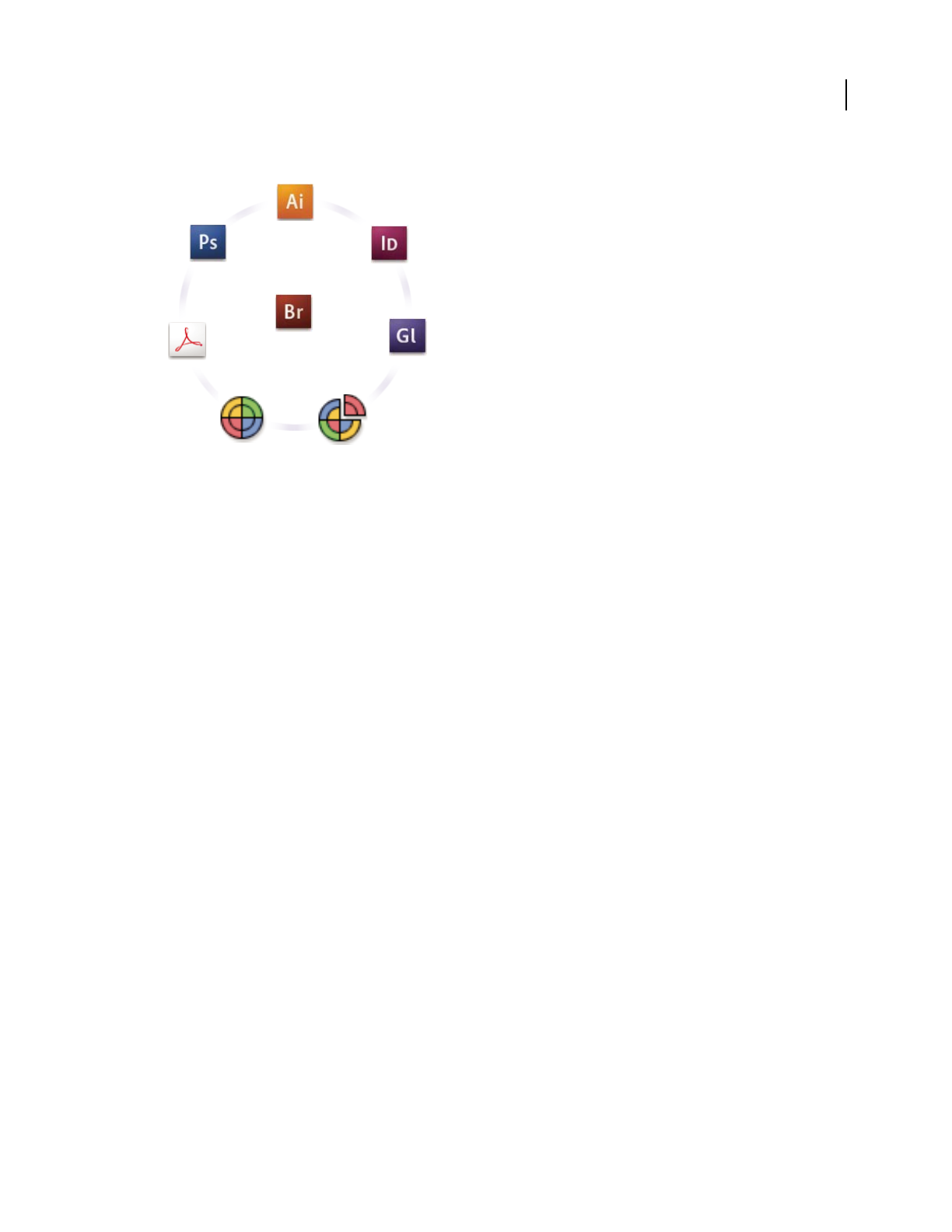
ILLUSTRATOR CS3
User Guide
131
Color settings for Adobe Creative Suite are synchronized in a central location through Adobe Bridge.
If you decide to change the default settings, easy-to-use presets let you configure Adobe color management to match
common output conditions. You can also customize color settings to meet the demands of your particular color
workflow.
Keep in mind that the kinds of images you work with and your output requirements influence how you use color
management. For example, there are different color-consistency issues for an RGB photo printing workflow, a
CMYK commercial printing workflow, a mixed RGB/CMYK digital printing workflow, and an Internet publishing
workflow.
Basic steps for producing consistent color
1. Consult with your production partners (if you have any) to ensure that all aspects of your color
management workflow integrate seamlessly with theirs.
Discuss how the color workflow will be integrated with your workgroups and service providers, how software and
hardware will be configured for integration into the color management system, and at what level color management
will be implemented. (See “Do you need color management?” on page 129.)
2. Calibrate and profile your monitor.
A monitor profile is the first profile you should create. Seeing accurate color is essential if you are making creative
decisions involving the color you specify in your document. (See “Calibrate and profile your monitor” on page 143.)
3. Add color profiles to your system for any input and output devices you plan to use, such as scanners and
printers.
The color management system uses profiles to know how a device produces color and what the actual colors in a
document are. Device profiles are often installed when a device is added to your system. You can also use third-party
software and hardware to create more accurate profiles for specific devices and conditions. If your document will be
commercially printed, contact your service provider to determine the profile for the printing device or press
condition. (See “About color profiles” on page 141 and “Install a color profile” on page 143.)

ILLUSTRATOR CS3
User Guide
132
4. Set up color management in Adobe applications.
The default color settings are sufficient for most users. However, you can change the color settings by doing one of
the following:
•If you use multiple Adobe applications, use Adobe® Bridge CS3 to choose a standard color management configu-
ration and synchronize color settings across applications before working with documents. (See “Synchronize color
settings across Adobe applications” on page 132.)
•If you use only one Adobe application, or if you want to customize advanced color management options, you can
change color settings for a specific application. (See “Set up color management” on page 132.)
5. (Optional) Preview colors using a soft proof.
After you create a document, you can use a soft proof to preview how colors will look when printed or viewed on a
specific device. (See “Soft-proofing colors” on page 137.)
Note: A soft proof alone doesn’t let you preview how overprinting will look when printed on an offset press. If you work
with documents that contain overprinting, turn on Overprint Preview to accurately preview overprints in a soft proof.
6. Use color management when printing and saving files.
Keeping the appearance of colors consistent across all of the devices in your workflow is the goal of color
management. Leave color management options enabled when printing documents, saving files, and preparing files
for online viewing. (See “Printing with color management” on page 139 and “Color-managing documents for online
viewing” on page 136.)
Synchronize color settings across Adobe applications
If you use Adobe Creative Suite, you can use Adobe Bridge to automatically synchronize color settings across appli-
cations. This synchronization ensures that colors look the same in all color-managed Adobe applications.
If color settings are not synchronized, a warning message appears at the top of the Color Settings dialog box in each
application. Adobe recommends that you synchronize color settings before you work with new or existing
documents.
1 Open Bridge.
To open Bridge from a Creative Suite application, choose File > Browse. To open Bridge directly, either choose Adobe
Bridge from the Start menu (Windows) or double-click the Adobe Bridge icon (Mac
OS).
2 Choose Edit > Creative Suite Color Settings.
3 Select a color setting from the list, and click Apply.
If none of the default settings meet your requirements, select Show Expanded List Of Color Setting Files to view
additional settings. To install a custom settings file, such as a file you received from a print service provider, click
Show Saved Color Settings Files.
Set up color management
1 Do one of the following:
•(Illustrator, InDesign, Photoshop) Choose Edit > Color Settings.
•(Acrobat) Select the Color Management category of the Preferences dialog box.
2 Select a color setting from the Settings menu, and click OK.

ILLUSTRATOR CS3
User Guide
133
The setting you select determines which color working spaces are used by the application, what happens when you
open and import files with embedded profiles, and how the color management system converts colors. To view a
description of a setting, select the setting and then position the pointer over the setting name. The description
appears at the bottom of the dialog box.
Note: Acrobat color settings are a subset of those used in InDesign, Illustrator, and Photoshop.
In certain situations, such as if your service provider supplies you with a custom output profile, you may need to
customize specific options in the Color Settings dialog box. However, customizing is recommended for advanced
users only.
Note: If you work with more than one Adobe application, it is highly recommended that you synchronize your color
settings across applications. (See “Synchronize color settings across Adobe applications” on page 132.)
See also
“Customize color settings” on page 146
Change the appearance of CMYK black (Illustrator, InDesign)
Pure CMYK black (K=100) appears jet black (or rich black) when viewed on-screen, printed to a non-PostScript
desktop printer, or exported to an RGB file format. If you prefer to see the difference between pure black and rich
black as it will appear when printed on a commercial press, you can change the Appearance Of Black preferences.
These preferences do not change the color values in a document.
1 Choose Edit > Preferences > Appearance Of Black (Windows) or application name > Preferences > Appearance
Of Black (Mac OS).
2 Choose an option for On Screen:
Display All Blacks Accurately Displays pure CMYK black as dark gray. This setting allows you to see the difference
between pure black and rich black.
Display All Blacks As Rich Black Displays pure CMYK black as jet black (RGB=000). This setting makes pure black
and rich black appear the same on-screen.
3 Choose an option for Printing/Exporting:
Output All Blacks Accurately When printing to a non-PostScript desktop printer or exporting to an RGB file format,
outputs pure CMYK black using the color numbers in the document. This setting allows you to see the difference
between pure black and rich black.
Output All Blacks As Rich Black When printing to a non-PostScript desktop printer or exporting to an RGB file
format, outputs pure CMYK black as jet black (RGB=000). This setting makes pure black and rich black appear the
same.
Managing process and spot colors
When color management is on, any color you apply or create within a color-managed Adobe application automati-
cally uses a color profile that corresponds to the document. If you switch color modes, the color management system
uses the appropriate profiles to translate the color to the new color model you choose.
Keep in mind the following guidelines for working with process and spot colors:
•Choose a CMYK working space that matches your CMYK output conditions to ensure that you can accurately
define and view process colors.

ILLUSTRATOR CS3
User Guide
134
•Select colors from a color library. Adobe applications come with several standard color libraries, which you can
load using the Swatches panel menu.
•(Acrobat, Illustrator, and InDesign) Turn on Overprint Preview to get an accurate and consistent preview of spot
colors.
•(Acrobat, Illustrator, and InDesign) Use Lab values (the default) to display predefined spot colors (such as colors
from the TOYO, PANTONE, DIC, and HKS libraries) and convert these colors to process colors. Using Lab values
provides the greatest accuracy and guarantees the consistent display of colors across Creative Suite applications. If
you want the display and output of these colors to match earlier versions of Illustrator or InDesign, use CMYK
equivalent values instead. For instructions on switching between Lab values and CMYK values for spot colors,
search Illustrator or InDesign Help.
Note: Color-managing spot colors provides a close approximation of a spot color on your proofing device and monitor.
However, it is difficult to exactly reproduce a spot color on a monitor or proofing device because many spot color inks
exist outside the gamuts of many of those devices.
Color-managing imported images
Color-managing imported images (Illustrator, InDesign)
How imported images are integrated into a document’s color space depends on whether or not the image has an
embedded profile:
•When you import an image that contains no profile, the Adobe application uses the current document profile to
define the colors in the image.
•When you import an image that contains an embedded profile, color policies in the Color Settings dialog box
determine how the Adobe application handles the profile.
See also
“Color management policy options” on page 148
Using a safe CMYK workflow
A safe CMYK workflow ensures that CMYK color numbers are preserved all the way to the final output device, as
opposed to being converted by your color management system. This workflow is beneficial if you want to incremen-
tally adopt color management practices. For example, you can use CMYK profiles to soft-proof and hard-proof
documents without the possibility of unintended color conversions occurring during final output.
Illustrator and InDesign support a safe CMYK workflow by default. As a result, when you open or import a CMYK
image with an embedded profile, the application ignores the profile and preserves the raw color numbers. If you want
your application to adjust color numbers based on an embedded profile, change the CMYK color policy to Preserve
Embedded Profiles in the Color Settings dialog box. You can easily restore the safe CMYK workflow by changing the
CMYK color policy back to Preserve Numbers (Ignore Linked Profiles).
You can override safe CMYK settings when you print a document or save it to PDF. However, doing so may cause
colors to be reseparated. For example, pure CMYK black objects may be reseparated as rich black. For more infor-
mation on color management options for printing and saving PDFs, search in Help.

ILLUSTRATOR CS3
User Guide
135
See also
“Color management policy options” on page 148
Preparing imported graphics for color management
Use the following general guidelines to prepare graphics for being color-managed in Adobe applications:
•Embed an ICC-compliant profile when you save the file. The file formats that support embedded profiles are
JPEG, PDF, PSD (Photoshop), AI (Illustrator), INDD (InDesign), Photoshop EPS, Large Document Format, and
TIFF.
•If you plan to reuse a color graphic for multiple final output devices or media, such as for print, video, and the web,
prepare the graphic using RGB or Lab colors whenever possible. If you must save in a color model other than RGB
or Lab, keep a copy of the original graphic. RGB and Lab color models represent larger color gamuts than most
output devices can reproduce, retaining as much color information as possible before being translated to a smaller
output color gamut.
See also
“Embed a color profile” on page 144
View or change profiles for imported bitmap images (InDesign)
InDesign allows you to view, override, or disable profiles for imported bitmap images. This may be necessary when
you are importing an image containing no profile or an incorrectly embedded profile. For example, if the scanner
manufacturer’s default profile was embedded but you have since generated a custom profile, you can assign the newer
profile.
1 Do one of the following:
•If the graphic is already in layout, select it and choose Object > Image Color Settings.
•If you’re about to import the graphic, choose File > Place, select Show Import Options, select and open the file,
and then select the Color tab.
2 For Profile, choose the source profile to apply to the graphic in your document. If a profile is currently embedded,
the profile name appears at the top of the Profile menu.
3 (Optional) Choose a rendering intent, and then click OK. In most cases, it’s best to use the default rendering
intent.
Note: You can also view or change profiles for objects in Acrobat.
See also
“Convert document colors to another profile (Photoshop)” on page 145

ILLUSTRATOR CS3
User Guide
136
Color-managing documents for online viewing
Color-managing documents for online viewing
Color management for online viewing is very different from color management for printed media. With printed
media, you have far more control over the appearance of the final document. With online media, your document
will appear on a wide range of possibly uncalibrated monitors and video display systems, significantly limiting your
control over color consistency.
When you color-manage documents that will be viewed exclusively on the web, Adobe recommends that you use the
sRGB color space. sRGB is the default working space for most Adobe color settings, but you can verify that sRGB is
selected in the Color Settings dialog box (Photoshop, Illustrator, InDesign) or the Color Management preferences
(Acrobat). With the working space set to sRGB, any RGB graphics you create will use sRGB as the color space.
When working with images that have an embedded color profile other than sRGB, you should convert the image’s
colors to sRGB before you save the image for use on the web. If you want the application to automatically convert the
colors to sRGB when you open the image, select Convert To Working Space as the RGB color management policy.
(Make sure that your RGB working space is set to sRGB.) In Photoshop and InDesign, you can also manually convert
the colors to sRGB using the Edit
> Convert To Profile command.
Note: In InDesign, the Convert To Profile command only converts colors for native, not placed, objects in the document.
See also
“About color working spaces” on page 146
“Color management policy options” on page 148
Color-managing PDFs for online viewing
When you export PDFs, you can choose to embed profiles. PDFs with embedded profiles reproduce color consis-
tently in Acrobat 4.0 or later running under a properly configured color management system.
Keep in mind that embedding color profiles increases the size of PDFs. RGB profiles are usually small (around 3 KB);
however, CMYK profiles can range from .5 to 2
MB.
See also
“Printing with color management” on page 139
Color-managing HTML documents for online viewing
Many web browsers do not support color management. Of the browsers that do support color management, not all
instances can be considered color-managed because they may be running on systems where the monitors are not
calibrated. In addition, few web pages contain images with embedded profiles. If you manage a highly controlled
environment, such as the intranet of a design studio, you may be able to achieve some degree of HTML color
management for images by equipping everyone with a browser that supports color management and calibrating all
monitors.
You can approximate how colors will look on non-calibrated monitors by using the sRGB color space. However,
because color reproduction varies among uncalibrated monitors, you still won’t be able to anticipate the true range
of potential display variations.
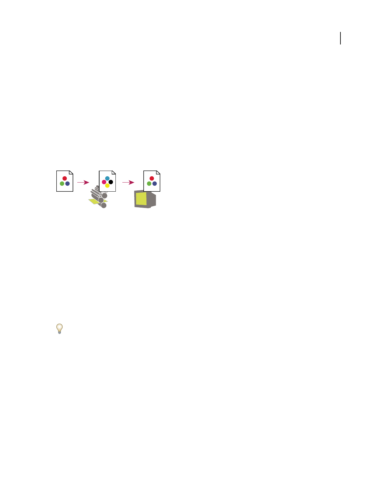
ILLUSTRATOR CS3
User Guide
137
Proofing colors
Soft-proofing colors
In a traditional publishing workflow, you print a hard proof of your document to preview how its colors will look
when reproduced on a specific output device. In a color-managed workflow, you can use the precision of color
profiles to soft-proof your document directly on the monitor. You can display an on-screen preview of how your
document’s colors will look when reproduced on a particular output device.
Keep in mind that the reliability of the soft proof depends upon the quality of your monitor, the profiles of your
monitor and output devices, and the ambient lighting conditions of your work environment.
Note: A soft proof alone doesn’t let you preview how overprinting will look when printed on an offset press. If you work
with documents that contain overprinting, turn on Overprint Preview to accurately preview overprints in a soft proof.
Using a soft proof to preview the final output of a document on your monitor
A. Document in the working space B. Document’s color values are translated to color space of chosen proof profile (usually the output device’s
profile). C. Monitor displays proof profile’s interpretation of document’s color values.
Soft-proof colors
1 Choose View > Proof Setup, and do one of the following:
•Choose a preset that corresponds to the output condition you want to simulate.
•Choose Custom (Photoshop and InDesign) or Customize (Illustrator) to create a custom proof setup for a specific
output condition. This option is recommended for the most accurate preview of your final printed piece.
2 Choose View > Proof Colors to toggle the soft-proof display on and off. When soft proofing is on, a check mark
appears next to the Proof Colors command, and the name of the proof preset or profile appears at the top of the
document window.
To compare the colors in the original image and the colors in the soft proof, open the document in a new window
before you set up the soft proof.
Soft-proof presets
Working CMYK Creates a soft proof of colors using the current CMYK working space as defined in the Color Settings
dialog box.
Document CMYK (InDesign) Creates a soft proof of colors using the document’s CMYK profile.
Working Cyan Plate, Working Magenta Plate, Working Yellow Plate, Working Black Plate, or Working CMY Plates
(Photoshop) Creates a soft proof of specific CMYK ink colors using the current CMYK working space.
Macintosh RGB or Windows RGB (Photoshop and Illustrator) Creates a soft proof of colors in an image using either a
standard Mac OS or Windows monitor as the proof profile space to simulate. Both options assume that the simulated
device will display your document without using color management. Neither option is available for Lab or CMYK
documents.
AB C

ILLUSTRATOR CS3
User Guide
138
Monitor RGB (Photoshop and Illustrator) Creates a soft proof of colors in an RGB document using your current
monitor color space as the proof profile space. This option assumes that the simulated device will display your
document without using color management. This option is unavailable for Lab and CMYK documents.
Custom soft-proof options
Device To Simulate Specifies the color profile of the device for which you want to create the proof. The usefulness of
the chosen profile depends on how accurately it describes the device’s behavior. Often, custom profiles for specific
paper and printer combinations create the most accurate soft proof.
Preserve CMYK Numbers or Preserve RGB Numbers Simulates how the colors will appear without being converted to
the color space of the output device. This option is most useful when you are following a safe CMYK workflow.
Rendering Intent (Photoshop and Illustrator) When the Preserve Numbers option is deselected, specifies a
rendering intent for converting colors to the device you are trying to simulate.
Use Black Point Compensation (Photoshop) Ensures that the shadow detail in the image is preserved by simulating
the full dynamic range of the output device. Select this option if you plan to use black point compensation when
printing (which is recommended in most situations).
Simulate Paper Color Simulates the dingy white of real paper, according to the proof profile. Not all profiles support
this option.
Simulate Black Ink Simulates the dark gray you really get instead of a solid black on many printers, according to the
proof profile. Not all profiles support this option.
In Photoshop, if you want the custom proof setup to be the default proof setup for documents, close all document
windows before choosing the View > Proof Setup > Custom command.
Save or load a custom proof setup
1 Choose View > Proof Setup > Custom.
2 Do either of the following:
•To save a custom proof setup, click Save. To ensure that the new preset appears in the View > Proof Setup menu,
save the preset in the default location.
•To load a custom proof setup, click Load.
Soft-proof colors (Acrobat)
1 Choose Advanced > Print Production > Output Preview.
2 Choose the color profile of a specific output device from the Simulation Profile menu.
3 Choose a soft-proof option:
Simulate Black Ink Simulates the dark gray you really get instead of a solid black on many printers, according to the
proof profile. Not all profiles support this option.
Simulate Paper Color Simulates the dingy white of real paper, according to the proof profile. Not all profiles support
this option.

ILLUSTRATOR CS3
User Guide
139
Color-managing documents when printing
Printing with color management
Color management options for printing let you specify how you want Adobe applications to handle the outgoing
image data so the printer will print colors consistent with what you see on your monitor. Your options for printing
color-managed documents depend on the Adobe application you use, as well as the output device you select. In
general, you have the following choices for handling colors during printing:
•Let the printer determine colors.
•Let the application determine colors.
•(Photoshop and InDesign) Do not use color management. In this workflow, no color conversion occurs. You may
also need to turn off color management in your printer driver. This method is useful primarily for printing test
targets or generating custom profiles.
Letting the printer determine colors when printing
In this workflow, the application does no color conversion, but sends all necessary conversion information to the
output device. This method is especially convenient when printing to inkjet photo printers, because each combi-
nation of paper type, printing resolution, and additional printing parameters (such as high-speed printing) requires
a different profile. Most new inkjet photo printers come with fairly accurate profiles built into the driver, so letting
the printer select the right profile saves time and alleviates mistakes. This method is also recommended if you are
not familiar with color management.
If you choose this method, it is very important that you set up printing options and turn on color management in
your printer driver. Search Help for additional instructions.
If you select a PostScript printer, you can take advantage of PostScript color management. PostScript color
management makes it possible to perform color composite output or color separations at the raster image processor
(RIP)—a process called in-RIP separations—so that a program need only specify parameters for separation and let
the device calculate the final color values. PostScript color-managed output workflows require an output device that
supports PostScript color management using PostScript level 2 version 2017 or later, or PostScript 3.
Letting the application determine colors when printing
In this workflow, the application does all the color conversion, generating color data specific to one output device.
The application uses the assigned color profiles to convert colors to the output device’s gamut, and sends the resulting
values to the output device. The accuracy of this method depends on the accuracy of the printer profile you select.
Use this workflow when you have custom ICC profiles for each specific printer, ink, and paper combination.
If you choose this option, it is very important that you disable color management in your printer driver. Letting the
application and the printer driver simultaneously manage colors during printing results in unpredictable color.
Search Help for additional instructions.
Obtaining custom profiles for desktop printers
If the output profiles that come with your printer don’t produce satisfactory results, you obtain custom profiles in the
following ways:
•Purchase a profile for your type of printer and paper. This is usually the easiest and least expensive method.

ILLUSTRATOR CS3
User Guide
140
•Purchase a profile for your specific printer and paper. This method involves printing a profiling target on your
printer and paper, and providing that target to a company that will create a specific profile. This is more expensive
than purchasing a standard profile, but can provide better results because it compensates for any manufacturing
variations in printers.
•Create your own profile using a scanner-based system. This method involves using profile-creation software and
your own flatbed scanner to scan the profiling target. It can provide excellent results for matte surface papers, but
not glossy papers. (Glossy papers tend to have fluorescent brighteners in them that look different to a scanner than
they do in room light.)
•Create your own profile using a hardware profile-creation tool. This method is expensive but can provide the best
results. A good hardware tool can create an accurate profile even with glossy papers.
•Tweak a profile created using one of the previous methods with profile-editing software. This software can be
complex to use, but it lets you correct problems with a profile or simply adjust a profile to produce results more to
your taste.
See also
“Install a color profile” on page 143
Color-managing PDFs for printing
When you create Adobe PDFs for commercial printing, you can specify how color information is represented. The
easiest way to do this is using a PDF/X standard; however, you can also specify color-handling options manually in
the Output section of the PDF dialog box. For more information about PDF/X and how to create PDFs, search Help.
In general, you have the following choices for handling colors when creating PDFs:
•(PDF/X-3) Does not convert colors. Use this method when creating a document that will be printed or displayed
on various or unknown devices. When you select a PDF/X-3 standard, color profiles are automatically embedded
in the PDF.
•(PDF/X-1a) Converts all colors to the destination CMYK color space. Use this method if you want to create a
press-ready file that does not require any further color conversions. When you select a PDF/X-1a standard, no
profiles are embedded in the PDF.
•(Illustrator and InDesign) Converts colors that have embedded profiles to the destination color space, but
preserves the numbers for those colors without embedded profiles. You can manually select this option in the
Output section of the PDF dialog box. Use this method if the document contains CMYK images that aren’t color-
managed and you want to make sure that the color numbers are preserved.
Note: All spot color information is preserved during color conversion; only the process color equivalents convert to the
designated color space.
See also
“Using a safe CMYK workflow” on page 134

ILLUSTRATOR CS3
User Guide
141
Working with color profiles
About color profiles
Precise, consistent color management requires accurate ICC-compliant profiles of all of your color devices. For
example, without an accurate scanner profile, a perfectly scanned image may appear incorrect in another program,
simply due to any difference between the scanner and the program displaying the image. This misleading represen-
tation may cause you to make unnecessary, time-wasting, and potentially damaging “corrections” to an already satis-
factory image. With an accurate profile, a program importing the image can correct for any device differences and
display a scan’s actual colors.
A color management system uses the following kinds of profiles:
Monitor profiles Describe how the monitor is currently reproducing color. This is the first profile you should create
because viewing color accurately on your monitor allows for critical color decisions in the design process. If what
you see on your monitor is not representative of the actual colors in your document, you will not be able to maintain
color consistency.
Input device profiles Describe what colors an input device is capable of capturing or scanning. If your digital camera
offers a choice of profiles, Adobe recommends that you select Adobe RGB. Otherwise, use sRGB (which is the default
for most cameras). Advanced users may also consider using different profiles for different light sources. For scanner
profiles, some photographers create separate profiles for each type or brand of film scanned on a scanner.
Output device profiles Describe the color space of output devices like desktop printers or a printing press. The color
management system uses output device profiles to properly map the colors in a document to the colors within the
gamut of an output device’s color space. The output profile should also take into consideration specific printing
conditions, such as the type of paper and ink. For example, glossy paper is capable of displaying a different range of
colors than matte paper.
Most printer drivers come with built-in color profiles. It’s a good idea to try these profiles before you invest in custom
profiles.
Document profiles Define the specific RGB or CMYK color space of a document. By assigning, or tagging, a
document with a profile, the application provides a definition of actual color appearances in the document. For
example, R=127, G=12, B=107 is just a set of numbers that different devices will display differently. But when tagged
with the AdobeRGB color space, these numbers specify an actual color or wavelength of light; in this case, a specific
color of purple.
When color management is on, Adobe applications automatically assign new documents a profile based on Working
Space options in the Color Settings dialog box. Documents without assigned profiles are known as untagged and
contain only raw color numbers. When working with untagged documents, Adobe applications use the current
working space profile to display and edit colors.
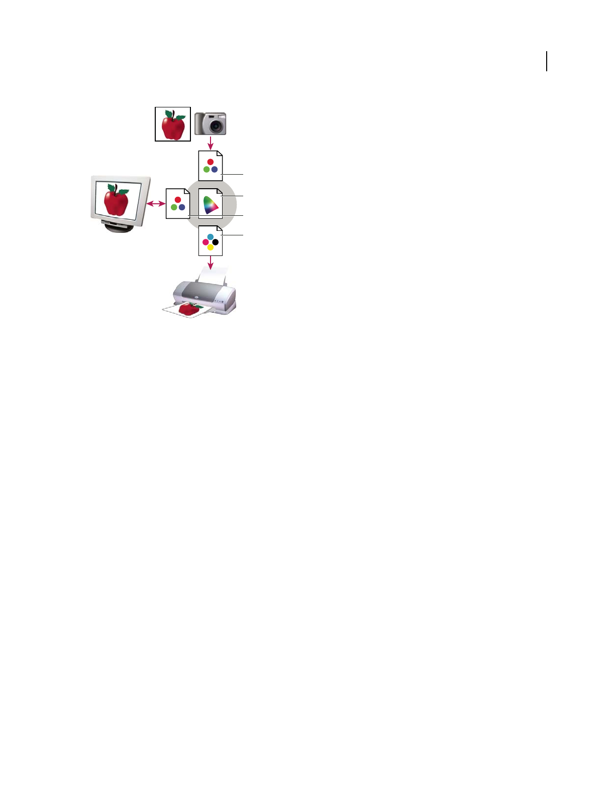
ILLUSTRATOR CS3
User Guide
142
Managing color with profiles
A. Profiles describe the color spaces of the input device and the document. B. Using the profiles’ descriptions, the color management system
identifies the document’s actual colors. C. The monitor’s profile tells the color management system how to translate the document’s numeric
values to the monitor’s color space. D. Using the output device’s profile, the color management system translates the document’s numeric values
to the color values of the output device so the correct appearance of colors is printed.
See also
“Calibrate and profile your monitor” on page 143
“Letting the printer determine colors when printing” on page 139
“Obtaining custom profiles for desktop printers” on page 139
“About color working spaces” on page 146
About monitor calibration and characterization
Profiling software can both calibrate and characterize your monitor. Calibrating your monitor brings it into
compliance with a predefined standard—for example, adjusting your monitor so that it displays color using the
graphics arts standard white point color temperature of 5000
K (Kelvin). Characterizing your monitor simply creates
a profile that describes how the monitor is currently reproducing color.
Monitor calibration involves adjusting the following video settings:
Brightness and contrast The overall level and range, respectively, of display intensity. These parameters work just as
they do on a television. A monitor calibration utility helps you set an optimum brightness and contrast range for
calibration.
Gamma The brightness of the midtone values. The values produced by a monitor from black to white are
nonlinear—if you graph the values, they form a curve, not a straight line. Gamma defines the value of that curve
halfway between black and white.
Phosphors The substances that CRT monitors use to emit light. Different phosphors have different color character-
istics.
White point The color and intensity of the brightest white the monitor can reproduce.
A
B
C
D

ILLUSTRATOR CS3
User Guide
143
Calibrate and profile your monitor
When you calibrate your monitor, you are adjusting it so it conforms to a known specification. Once your monitor
is calibrated, the profiling utility lets you save a color profile. The profile describes the color behavior of the
monitor—what colors can or cannot be displayed on the monitor and how the numeric color values in an image must
be converted so that colors are displayed accurately.
1 Make sure your monitor has been turned on for at least a half hour. This gives it sufficient time to warm up and
produce more consistent output.
2 Make sure your monitor is displaying thousands of colors or more. Ideally, make sure it is displaying millions of
colors or 24-bit or higher.
3 Remove colorful background patterns on your monitor desktop and set your desktop to display neutral grays.
Busy patterns or bright colors surrounding a document interfere with accurate color perception.
4 Do one of the following to calibrate and profile your monitor:
•In Windows, install and use a monitor calibration utility.
•In Mac OS, use the Calibrate utility, located on the System Preferences/Displays/Color tab.
•For the best results, use third-party software and measuring devices. In general, using a measuring device such as
a colorimeter along with software can create more accurate profiles because an instrument can measure the colors
displayed on a monitor far more accurately than the human eye.
Note: Monitor performance changes and declines over time; recalibrate and profile your monitor every month or so. If
you find it difficult or impossible to calibrate your monitor to a standard, it may be too old and faded.
Most profiling software automatically assigns the new profile as the default monitor profile. For instructions on how
to manually assign the monitor profile, refer to the Help system for your operating system.
Install a color profile
Color profiles are often installed when a device is added to your system. The accuracy of these profiles (often called
generic profiles or canned profiles) varies from manufacturer to manufacturer. You can also obtain device profiles
from your service provider, download profiles from the web, or create custom profiles using professional profiling
equipment.
•In Windows, right-click a profile and select Install Profile. Alternatively, copy the profiles into the
WINDOWS\system32\spool\drivers\color folder (Windows XP) or the WINNT\system32\spool\drivers\color
folder (Windows 2000).
•In Mac OS, copy profiles into the /Library/ColorSync/Profiles folder or the
/Users/username/Library/ColorSync/Profiles folder.
After installing color profiles, be sure to restart Adobe applications.
See also
“Obtaining custom profiles for desktop printers” on page 139

ILLUSTRATOR CS3
User Guide
144
Embed a color profile
To embed a color profile in a document you created in Illustrator, InDesign, or Photoshop, you must save or export
the document in a format that supports ICC profiles.
1 Save or export the document in one of the following file formats: Adobe PDF, PSD (Photoshop), AI (Illustrator),
INDD (InDesign), JPEG, Photoshop EPS, Large Document Format, or TIFF.
2 Select the option for embedding ICC profiles. The exact name and location of this option varies between applica-
tions. Search Adobe Help for additional instructions.
Embed a color profile (Acrobat)
You can embed a color profile in an object or an entire PDF. Acrobat attaches the appropriate profile, as specified in
the Destination Space area of the Convert Colors dialog box, to the selected color space in the PDF. For more infor-
mation, see the color conversion topics in Complete Acrobat Help.
Changing the color profile for a document
There are very few situations that require you to change the color profile for a document. This is because your appli-
cation automatically assigns the color profile based on the settings you select in the Color Settings dialog box. The
only times you should manually change a color profile are when preparing a document for a different output desti-
nation or correcting a policy behavior that you no longer want implemented in the document. Changing the profile
is recommended for advanced users only.
You can change the color profile for a document in the following ways:
•Assign a new profile. The color numbers in the document remain the same, but the new profile may dramatically
change the appearance of the colors as displayed on your monitor.
•Remove the profile so that the document is no longer color-managed.
•(Acrobat, Photoshop and InDesign) Convert the colors in the document to the color space of a different profile.
The color numbers are shifted in an effort to preserve the original color appearances.
Assign or remove a color profile (Illustrator, Photoshop)
1 Choose Edit > Assign Profile.
2 Select an option, and click OK:
Don’t Color Manage This Document Removes the existing profile from the document. Select this option only if you
are sure that you do not want to color-manage the document. After you remove the profile from a document, the
appearance of colors is defined by the application’s working space profiles.
Working [color model: working space] Assigns the working space profile to the document.
Profile Lets you select a different profile. The application assigns the new profile to the document without
converting colors to the profile space. This may dramatically change the appearance of the colors as displayed on
your monitor.
See also
“Changing the color profile for a document” on page 144

ILLUSTRATOR CS3
User Guide
145
Assign or remove a color profile (InDesign)
1 Choose Edit > Assign Profiles.
2 For RGB Profile and CMYK Profile, select one of the following:
Discard (Use Current Working Space) Removes the existing profile from the document. Select this option only if you
are sure that you do not want to color-manage the document. After you remove the profile from a document, the
appearance of colors is defined by the application’s working space profiles, and you can no longer embed a profile in
the document.
Assign Current Working Space [working space] Assigns the working space profile to the document.
Assign Profile Lets you select a different profile. The application assigns the new profile to the document without
converting colors to the profile space. This may dramatically change the appearance of the colors as displayed on
your monitor.
3 Choose a rendering intent for each type of graphic in your document. For each graphic type, you can choose one
of the four standard intents, or the Use Color Settings Intent, which uses the rendering intent currently specified in
the Color Settings dialog box. For more information on rendering intents, search in Help.
The graphic types include the following:
Solid Color Intent Sets the rendering intent for all vector art (solid areas of color) in InDesign native objects.
Default Image Intent Sets the default rendering intent for bitmap images placed in InDesign. You can still override
this setting on an image-by-image basis.
After-Blending Intent Sets the rendering intent to the proofing or final color space for colors that result from trans-
parency interactions on the page. Use this option when your document includes transparent objects.
4 To preview the effects of the new profile assignment in the document, select Preview, and then click OK.
See also
“Changing the color profile for a document” on page 144
“View or change profiles for imported bitmap images (InDesign)” on page 135
Convert document colors to another profile (Photoshop)
1 Choose Edit > Convert To Profile.
2 Under Destination Space, choose the color profile to which you want to convert the document’s colors. The
document will be converted to and tagged with this new profile.
3 Under Conversion Options, specify a color management engine, a rendering intent, and black point and dither
options (if available). (See “Color conversion options” on page 149.)
4 (Illustrator) To flatten all layers of the document onto a single layer upon conversion, select Flatten Image.
5 To preview the effects of the conversion in the document, select Preview. In Illustrator, this preview becomes more
accurate if you select Flatten Image.
See also
“Changing the color profile for a document” on page 144

ILLUSTRATOR CS3
User Guide
146
Convert document colors to another profile
You convert colors in a PDF using the Convert Colors tool on the Print Production toolbar. For more information,
see the color conversion topics in Complete Acrobat Help.
Color settings
Customize color settings
For most color-managed workflows, it is best to use a preset color setting that has been tested by Adobe Systems.
Changing specific options is recommended only if you are knowledgeable about color management and very
confident about the changes you make.
After you customize options, you can save them as a preset. Saving color settings ensures that you can reuse them
and share them with other users or applications.
•To save color settings as a preset, click Save in the Color Settings dialog box. To ensure that the application displays
the setting name in the Color Settings dialog box, save the file in the default location. If you save the file to a
different location, you must load the file before you can select the setting.
•To load a color settings preset that’s not saved in the standard location, click Load in the Color Settings dialog box,
select the file you want to load, and click Open.
Note: In Acrobat, you cannot save customized color settings. To share customized color settings with Acrobat, you must
create the file in InDesign, Illustrator, or Photoshop, and then save it in the default Settings folder. It will then be available
in the Color Management category of the Preferences dialog box. You can also add settings manually to the default
Settings folder.
About color working spaces
A working space is an intermediate color space used to define and edit color in Adobe applications. Each color model
has a working space profile associated with it. You can choose working space profiles in the Color Settings dialog box.
A working space profile acts as the source profile for newly created documents that use the associated color model.
For example, if Adobe RGB (1998) is the current RGB working space profile, each new RGB document that you
create will use colors within the Adobe RGB (1998) gamut. Working spaces also determine the appearance of colors
in untagged documents.
If you open a document embedded with a color profile that doesn’t match the working space profile, the application
uses a color management policy to determine how to handle the color data. In most cases, the default policy is to
preserve the embedded profile.
See also
“About missing and mismatched color profiles” on page 147
“Color management policy options” on page 148
Working Space options
To display working space options in Photoshop, Illustrator and InDesign, choose Edit > Color Settings. In Acrobat,
select the Color Management category of the Preferences dialog box.

ILLUSTRATOR CS3
User Guide
147
To view a description of any profile, select the profile and then position the pointer over the profile name. The
description appears at the bottom of the dialog box.
RGB Determines the RGB color space of the application. In general, it’s best to choose Adobe RGB or sRGB, rather
than the profile for a specific device (such as a monitor profile).
sRGB is recommended when you prepare images for the web, because it defines the color space of the standard
monitor used to view images on the web. sRGB is also a good choice when you work with images from consumer-
level digital cameras, because most of these cameras use sRGB as their default color space.
Adobe RGB is recommended when you prepare documents for print, because Adobe RGB’s gamut includes some
printable colors (cyans and blues in particular) that can't be defined using sRGB. Adobe RGB is also a good choice
when working with images from professional-level digital cameras, because most of these cameras use Adobe RGB
as their default color space.
CMYK Determines the CMYK color space of the application. All CMYK working spaces are device-dependent,
meaning that they are based on actual ink and paper combinations. The CMYK working spaces Adobe supplies are
based on standard commercial print conditions.
Gray (Photoshop) or Grayscale (Acrobat) Determines the grayscale color space of the application.
Spot (Photoshop) Specifies the dot gain to use when displaying spot color channels and duotones.
Note: In Acrobat, you can use the color space in an embedded output intent instead of a document color space for
viewing and printing. Select Output Intent Overrides Working Spaces. For more information on output intents, see
Complete Acrobat Help.
Adobe applications ship with a standard set of working space profiles that have been recommended and tested by
Adobe Systems for most color management workflows. By default, only these profiles appear in the working space
menus. To display additional color profiles that you have installed on your system, select Advanced Mode (Illustrator
and InDesign) or More Options (Photoshop). A color profile must be bi-directional, that is, contain specifications
for translating both into and out of color spaces, in order to appear in the working space menus.
Note: In Photoshop, you can create custom working space profiles. However, Adobe recommends that you use a standard
working space profile rather than create a custom profile. For more information, see the Photoshop support knowl-
edgebase at www.adobe.com/support/products/photoshop.html.
About missing and mismatched color profiles
For a newly created document, the color workflow usually operates seamlessly: unless specified otherwise, the
document uses the working space profile associated with its color mode for creating and editing colors.
However, some existing documents may not use the working space profile that you have specified, and some existing
documents may not be color-managed. It is common to encounter the following exceptions to your color-managed
workflow:
•You might open a document or import color data (for example, by copying and pasting or dragging and dropping)
from a document that is not tagged with a profile. This is often the case when you open a document created in an
application that either does not support color management or has color management turned off.
•You might open a document or import color data from a document that is tagged with a profile different from the
current working space. This may be the case when you open a document that was created using different color
management settings, or scanned and tagged with a scanner profile.
In either case, the application uses a color management policy to decide how to handle the color data in the document.

ILLUSTRATOR CS3
User Guide
148
If the profile is missing or does not match the working space, the application may display a warning message,
depending on options you set in the Color Settings dialog box. Profile warnings are turned off by default, but you
can turn them on to ensure the appropriate color management of documents on a case-by-case basis. The warning
messages vary between applications, but in general you have the following options:
•(Recommended) Leave the document or imported color data as it is. For example, you can choose to use the
embedded profile (if one exists), leave the document without a color profile (if one doesn’t exist), or preserve the
numbers in pasted color data.
•Adjust the document or imported color data. For example, when opening a document with a missing color profile,
you can choose to assign the current working space profile or a different profile. When opening a document with
a mismatched color profile, you can choose to discard the profile or convert the colors to the current working
space. When importing color data, you can choose to convert the colors to the current working space in order to
preserve their appearance.
Color management policy options
A color management policy determines how the application handles color data when you open a document or import
an image. You can choose different policies for RGB and CMYK images, and you can specify when you want warning
messages to appear. To display color management policy options, choose Edit
> Color Settings.
To view a description of a policy, select the policy and then position the pointer over the policy name. The description
appears at the bottom of the dialog box.
RGB, CMYK, and Gray Specifies a policy to follow when bringing colors into the current working space (either by
opening files or importing images into the current document). (The Grayscale option is available for Photoshop
only.) Choose from the following options:
•Preserve Embedded Profiles Always preserves embedded color profiles when opening files. This is the recom-
mended option for most workflows because it provides consistent color management. One exception is if you’re
concerned about preserving CMYK numbers, in which case you should select Preserve Numbers (Ignore Linked
Profiles) instead.
•Convert To Working Space Converts colors to the current working space profile when opening files and
importing images. Select this option if you want to force all colors to use a single profile (the current working space
profile).
•Preserve Numbers (Ignore Linked Profiles) This option is available in InDesign and Illustrator for CMYK.
Preserves color numbers when opening files and importing images, but still allows you to use color management to
view colors accurately in Adobe applications. Select this option if you want to use a safe CMYK workflow. In
InDesign, you can override this policy on a per-object basis by choosing Object > Image Color Settings.
•Off Ignores embedded color profiles when opening files and importing images, and does not assign the working
space profile to new documents. Select this option if you want to discard any color metadata provided by the original
document creator.
Profile Mismatches: Ask When Opening Displays a message whenever you open a document tagged with a profile
other than the current working space. You will be given the option to override the policy’s default behavior. Select
this option if you want to ensure the appropriate color management of documents on a case-by-case basis.
Profile Mismatches: Ask When Pasting Displays a message whenever color profile mismatches occur as colors are
imported into a document through pasting or dragging-and-dropping. You will be given the option to override the
policy’s default behavior. Select this option if you want to ensure the appropriate color management of pasted colors
on a case-by-case basis.

ILLUSTRATOR CS3
User Guide
149
Missing Profiles: Ask When Opening Displays a message whenever you open an untagged document. You will be
given the option to override the policy’s default behavior. Select this option if you want to ensure the appropriate
color management of documents on a case-by-case basis.
Color conversion options
Color conversion options let you control how the application handles the colors in a document as it moves from one
color space to another. Changing these options is recommended only if you are knowledgeable about color
management and very confident about the changes you make. To display conversion options, choose Edit
> Color
Settings, and select Advanced Mode (Illustrator and InDesign) or More Options (Photoshop). In Acrobat, select the
Color Management category of the Preferences dialog box.
Engine Specifies the Color Management Module (CMM) used to map the gamut of one color space to the gamut of
another. For most users, the default Adobe (ACE) engine fulfills all conversion needs.
To view a description of an engine or intent option, select the option and then position the pointer over the option
name. The description appears at the bottom of the dialog box.
Intent (Photoshop, Illustrator, InDesign) Specifies the rendering intent used to translate one color space to another.
Differences between rendering intents are apparent only when you print a document or convert it to a different
working space.
Use Black Point Compensation Ensures that the shadow detail in the image is preserved by simulating the full
dynamic range of the output device. Select this option if you plan to use black point compensation when printing
(which is recommended in most situations).
Use Dither (Photoshop) Controls whether to dither colors when converting 8-bit-per-channel images between color
spaces. When the Use Dither option is selected, Photoshop mixes colors in the destination color space to simulate a
missing color that existed in the source space. Although dithering helps to reduce the blocky or banded appearance
of an image, it may also result in larger file sizes when images are compressed for web use.
About rendering intents
A rendering intent determines how a color management system handles color conversion from one color space to
another. Different rendering intents use different rules to determine how the source colors are adjusted; for example,
colors that fall inside the destination gamut may remain unchanged, or they may be adjusted to preserve the original
range of visual relationships when translated to a smaller destination gamut. The result of choosing a rendering
intent depends on the graphical content of documents and on the profiles used to specify color spaces. Some profiles
produce identical results for different rendering intents.
In general, it is best to use the default rendering intent for the selected color setting, which has been tested by Adobe
Systems to meet industry standards. For example, if you choose a color setting for North America or Europe, the
default rendering intent is Relative Colorimetric. If you choose a color setting for Japan, the default rendering intent is
Perceptual.
You can select a rendering intent when you set color conversion options for the color management system, soft-proof
colors, and print artwork:
Perceptual Aims to preserve the visual relationship between colors so it’s perceived as natural to the human eye, even
though the color values themselves may change. This intent is suitable for photographic images with lots of out-of-
gamut colors. This is the standard rendering intent for the Japanese printing industry.

ILLUSTRATOR CS3
User Guide
150
Saturation Tries to produce vivid colors in an image at the expense of color accuracy. This rendering intent is
suitable for business graphics like graphs or charts, where bright saturated colors are more important than the exact
relationship between colors.
Relative Colorimetric Compares the extreme highlight of the source color space to that of the destination color space
and shifts all colors accordingly. Out-of-gamut colors are shifted to the closest reproducible color in the destination
color space. Relative Colorimetric preserves more of the original colors in an image than Perceptual. This is the
standard rendering intent for printing in North America and Europe.
Absolute Colorimetric Leaves colors that fall inside the destination gamut unchanged. Out-of-gamut colors are
clipped. No scaling of colors to destination white point is performed. This intent aims to maintain color accuracy at
the expense of preserving relationships between colors and is suitable for proofing to simulate the output of a
particular device. This intent is particularly useful for previewing how paper color affects printed colors.
Advanced controls in Photoshop
In Photoshop you display advanced controls for managing color by choosing Edit > Color Settings and selecting
More Options.
Desaturate Monitor Colors By Determines whether to desaturate colors by the specified amount when displayed on
the monitor. When selected, this option can aid in visualizing the full range of color spaces with gamuts larger than
that of the monitor. However, this causes a mismatch between the monitor display and the output. When the option
is deselected, distinct colors in the image may display as a single color.
Blend RGB Colors Using Gamma Controls how RGB colors blend together to produce composite data (for example,
when you blend or paint layers using Normal mode). When the option is selected, RGB colors are blended in the
color space corresponding to the specified gamma. A gamma of 1.00 is considered “colorimetrically correct” and
should result in the fewest edge artifacts. When the option is deselected, RGB colors are blended directly in the
document’s color space.
Note: When you select Blend RGB Colors Using Gamma, layered documents will look different when displayed in other
applications than they do in Photoshop.

151
Chapter 6: Painting
To help you add visual interest to your artwork, Adobe Illustrator provides calligraphic, scatter, art, and pattern
brushes. In addition, you can use the Live Paint feature, to paint different path segments and fill enclosed paths with
different colors, patterns, or gradients. Using opacity, masks, gradients, blends, meshes, and patterns provide
limitless opportunities for creativity.
Painting with fills and strokes
Painting methods
Illustrator provides two methods of painting: assigning a fill, stroke, or both to an entire object, and converting the
object to a Live Paint group and assigning fills or strokes to the separate edges and faces of paths within it.
Paint an object
After you draw an object, you assign a fill, stroke, or both to it. You can then draw other objects that you can paint
similarly, layering each new object on top of the previous ones. The result is something like a collage made out of
shapes cut from colored paper, with the look of the artwork depending on which objects are on top in the stack of
layered objects.
For a video on using brushes, see www.adobe.com/go/vid0044.
Paint a Live Paint group
With the Live Paint method, you paint more like you would with a traditional coloring tool, without regard to layers
or stacking order, which can make for a more natural workflow. All objects in a Live Paint group are treated as if they
are part of the same flat surface. This means you can draw several paths and then color separately each area enclosed
by these paths (called a face). You can also assign different stroke colors and weights to portions of a path between
intersections (called an edge). The result is that, much like a coloring book, you can fill each face and stroke each
edge with a different color. As you move and reshape paths in a Live Paint group, the faces and edges automatically
adjust in response.
An object consisting of a single path painted with the existing method has a single fill and a single stroke (left). The same object converted to a
Live Paint group can be painted with a different fill for each face and a different stroke for each edge (right).
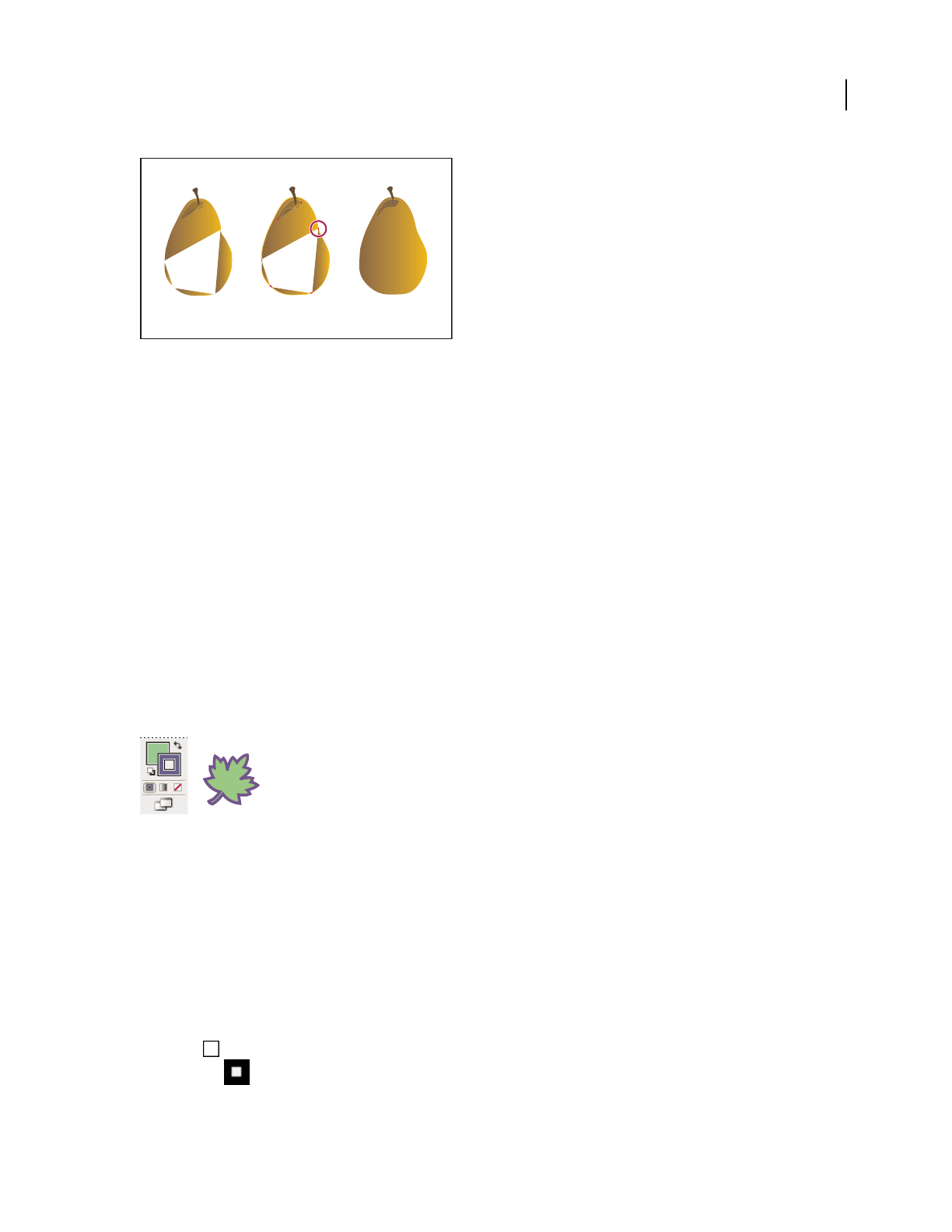
ILLUSTRATOR CS3
User Guide
152
Painting an object the traditional way leaves some areas that cannot be filled (left). Painting a Live Paint group with gap detection (center) lets
you avoid gaps and overprinting (right).
For a video on using Live Paint, see www.adobe.com/go/vid0042. For a video on painting techniques with the Paint-
brush tool, see www.adobe.com/go/vid0038.
See also
“About Live Paint” on page 158
About fills and strokes
A fill is a color, pattern, or gradient inside an object. You can apply fills to open and closed objects and to faces of
Live Paint groups.
A stroke can be the visible outline of an object, a path, or the edge of a Live Paint group. You can control the width
and color a stroke. You can also create dashed strokes using Path options, and paint stylized strokes using brushes.
Note: When working with Live Paint groups, you can apply a brush to an edge only if you add a stroke to the group using
the Appearance panel.
The current fill and stroke colors are displayed in the Tools panel.
Fill and Stroke controls
See also
“Keys for painting objects” on page 465
“Select colors using the Color Picker” on page 100
Fill and Stroke controls
Controls for setting the fill and stroke are available in the Tools panel and in the Control panel.
You can use any of the following controls in the Tools panel to specify color:
Fill button Double-click to select a fill color using the Color Picker.
Stroke button Double-click to select a stroke color using the Color Picker.
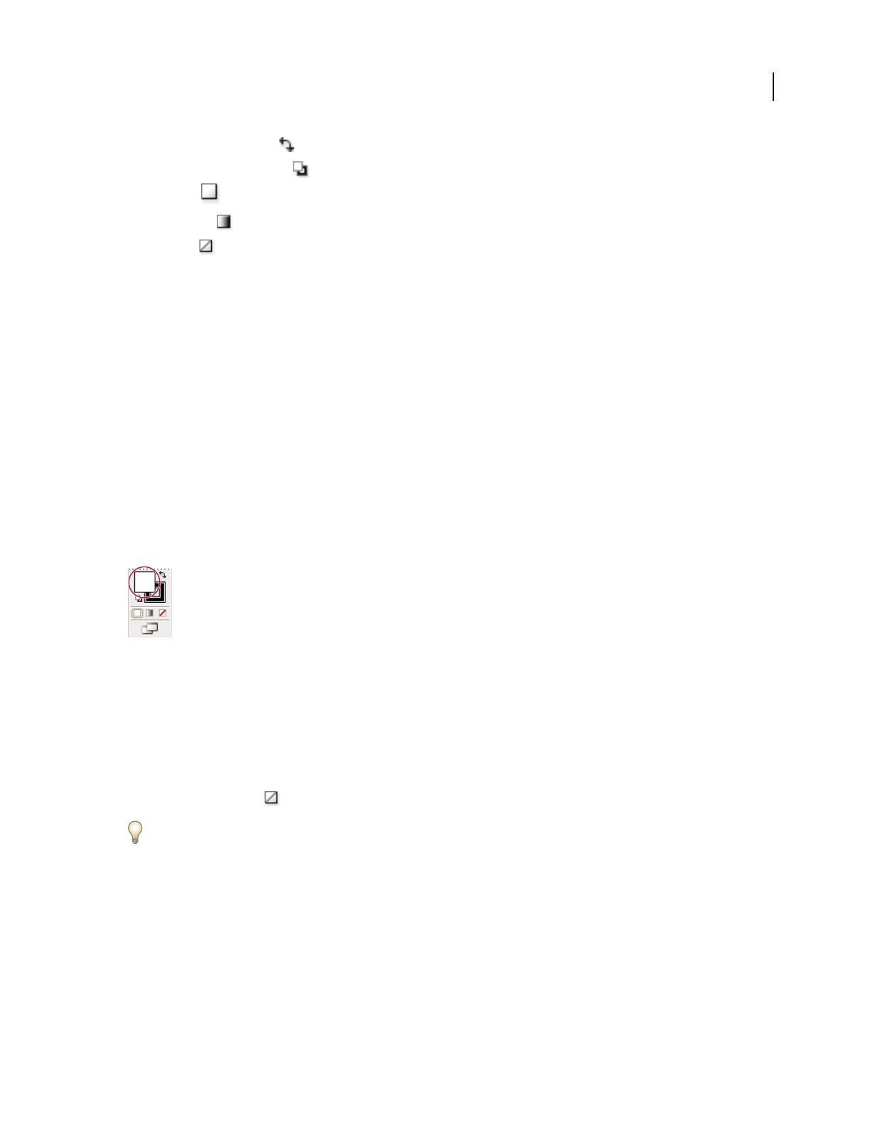
ILLUSTRATOR CS3
User Guide
153
Swap Fill And Stroke button Click to swap colors between the fill and stroke.
Default Fill And Stroke button Click to return to the default color settings (white fill and black stroke).
Color button Click to apply the last-selected solid color to an object with a gradient fill or no stroke or fill.
Gradient button Click to change the currently selected fill to the last-selected gradient.
None button Click to remove the selected object’s fill or stroke.
You can also specify color and stroke for a selected object by using the following controls in the Control panel:
Fill color Click to open the Swatches panel or Shift-click to open an alternate color mode panel, and choose a color.
Stroke color Click to open the Swatches panel or Shift-click to open an alternate color mode panel, and choose a
color.
Stroke panel Click the word Stroke to open the Stroke panel and specify options.
Stroke weight Choose a stroke weight from the pop-up menu.
Apply a fill color to an object
You can apply one color, pattern, or gradient to an entire object, or you can use Live Paint groups and apply different
colors to different faces within the object.
1 Select the object.
2 Click the Fill box in the Tools panel or the Color panel. Doing so indicates that you want to apply a fill rather than
a stroke.
Fill box
3 Select a fill color by doing one of the following:
•Click a color in the Control panel, Color panel, Swatches panel, Gradient panel, or a swatch library.
•Double-click the Fill box and select a color from the Color Picker.
•Select the Eyedropper tool and Alt-click (Windows) or Option-click (Mac OS) an object to apply the current
attributes, including the current fill and stroke.
•Click the None button to remove the object’s current fill.
You can quickly apply color to an unselected object by dragging a color from the Fill box, Color panel, Gradient panel,
or Swatches panel onto the object. Dragging does not work on Live Paint groups.
See also
“Select items in Live Paint groups” on page 161
“Paint with the Live Paint Bucket tool” on page 163
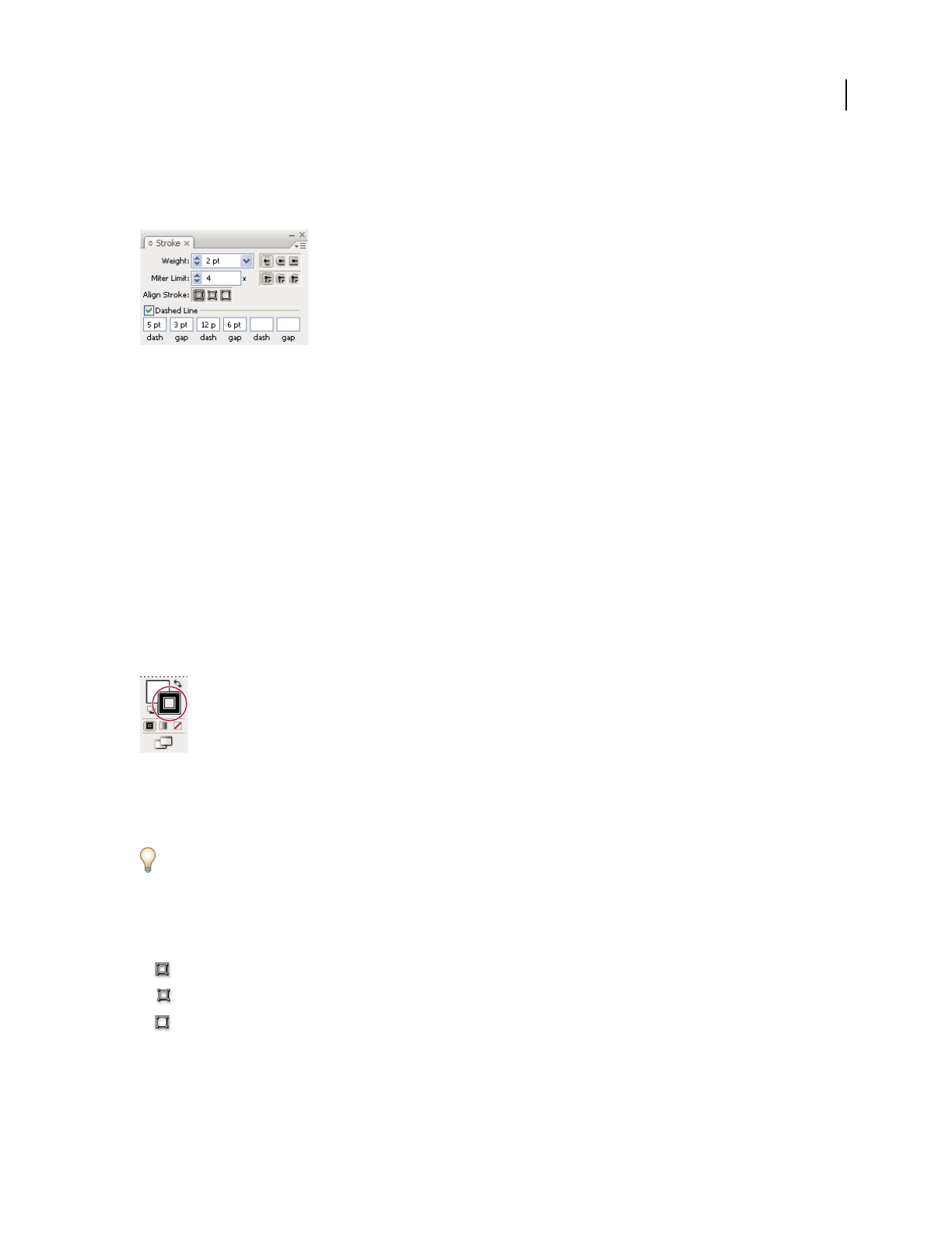
ILLUSTRATOR CS3
User Guide
154
Stroke an object
You use the Stroke panel (Window > Stroke) to control whether a line is solid or dashed, the dash sequence if it is
dashed, the stroke weight, the stroke alignment, the miter limit, and the styles of line joins and line caps.
Strokes panel
You can apply stroke options to an entire object, or you can use Live Paint groups and apply different strokes to
different edges within the object.
See also
“Workspace overview” on page 14
“Select items in Live Paint groups” on page 161
“Paint with the Live Paint Bucket tool” on page 163
Apply a stroke color, width, or alignment
1
Select the object. (To select an edge in a Live Paint group, use the Live Paint Selection tool.)
2 Click the Stroke box in the Tools panel, the Color panel, or the Control panel. Doing so indicates that you want
to apply a stroke rather than a fill.
Stroke box
3 Select a color from the Color panel, or a swatch from the Swatches panel or Control panel. Alternatively, double-
click the Stroke box to select a color using the Color Picker.
If you want to use the current color in the Stroke box, you can simply drag the color from the Stroke box onto the
object. Dragging does not work on Live Paint groups.
4 Select a weight in the Strokes panel or Control panel.
5 If the object is a closed path (and not a Live Paint group), choose an option from the Stroke panel to align the
stroke along the path:
• Align Stroke To Center
• Align Stroke To Inside
• Align Stroke To Outside
Note: If you try to align paths that use different stroke alignments, the paths may not exactly align. Make sure the path
alignment settings are the same if you need the edges to match up exactly when aligned.
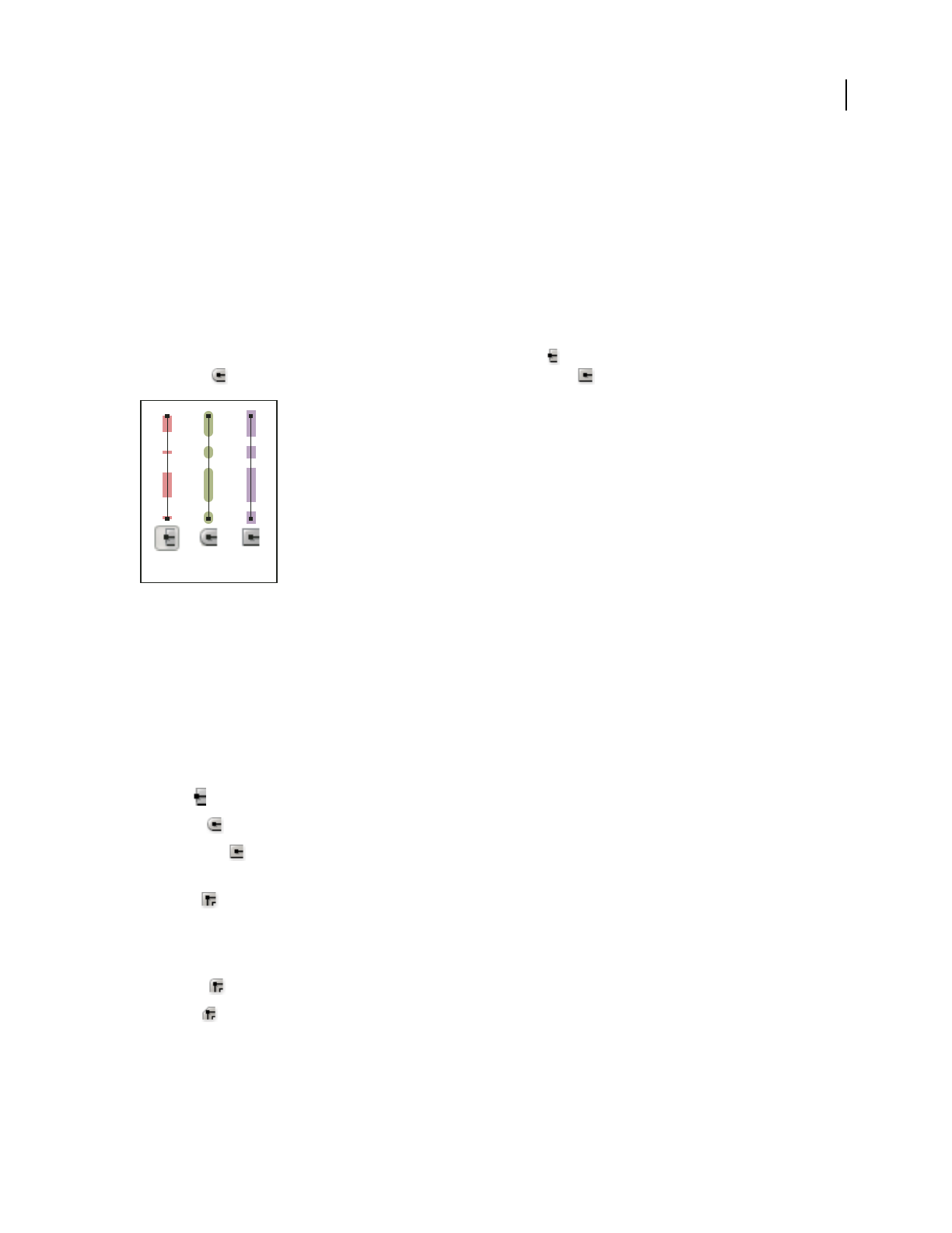
ILLUSTRATOR CS3
User Guide
155
Create dotted or dashed lines
You can create a dotted or dashed line by editing an object’s stroke attributes.
1 Select the object.
2 In the Stroke panel, select Dashed Line. If the Dashed Line option isn’t showing, choose Show Options from the
Stroke panel menu.
3 Specify a dash sequence by entering the lengths of dashes and the gaps between them.
The numbers entered are repeated in sequence so that once you have established the pattern, you don’t need to fill
in all the text boxes.
4 Select a cap option to change the ends of the dashes. The Butt Cap option creates square-ended dashes; the
Round Cap option creates rounded dashes or dots; the Projecting Cap option extends the ends of dashes.
6-point dashed lines with dash gaps of 2, 12, 16, 12
A. Butt cap B. Round cap C. Projecting cap
Change the caps or joins of a line
A cap is the end of an open line; a join is where a straight line changes direction (turns a corner). You can change the
caps and joins of a line by changing the object’s stroke attributes.
1 Select the object.
2 In the Stroke panel, select a cap option and a join option.
If the options aren’t showing, choose Show Options from the panel menu.
Butt Cap Creates stroked lines with squared ends.
Round Cap Creates stroked lines with semicircular ends.
Projecting Cap Creates stroked lines with squared ends that extend half the line width beyond the end of the line.
This option makes the weight of the line extend equally in all directions around the line.
Miter Join Creates stroked lines with pointed corners. Enter a miter limit between 1 and 500. The miter limit
controls when the program switches from a mitered (pointed) join to a beveled (squared-off) join. The default miter
limit is 4, which means that when the length of the point reaches four times the stroke weight, the program switches
from a miter join to a bevel join. A miter limit of 1 results in a bevel join.
Round Join Creates stroked lines with rounded corners.
Bevel Join Creates stroked lines with squared corners.
ABC

ILLUSTRATOR CS3
User Guide
156
Convert strokes to compound paths
Converting a stroke to a compound path lets you modify the outline of the stroke. For example, you can create a
stroke with a varied width or divide the stroke into pieces.
1 Select the object.
2 Choose Object > Path > Outline Stroke.
The resulting compound path is grouped with the filled object. To modify the compound path, first ungroup it from
the fill or select it with the Group Selection tool.
Use the Layers panel to identify the contents of a group.
See also
“About compound paths” on page 234
“Group or ungroup objects” on page 201
Add arrowheads to lines
1 Select an object or group (or target a layer in the Layers panel).
Note: You can add arrowheads to a Live Paint group as a whole, but not to individual paths within Live Paint groups.
2 Choose Effect > Stylize > Add Arrowheads or Filter > Stylize > Add Arrowhead.
3 Choose from various arrowhead designs for the start and end of the line by clicking the forward and back buttons
below the Start and End arrow boxes. The start and end of the line refer to the order in which the line was drawn.
4 To rescale the size of an arrowhead, enter the percentage you want in the Scale text box. This scales the arrowhead
relative to the stroke weight of the line.
5 Click OK.
If applied as a filter, the resulting arrowheads are distinct objects grouped with the line; the arrowheads can be edited
and moved like any other grouped object. If applied as an effect, the arrows are similar to brush strokes; that is, the
arrows change location, direction, and color along with the line, but they cannot be edited separately.
See also
“Targeting items for appearance attributes” on page 347
“About effects and filters” on page 350
Remove the fill or stroke from an object
1 Select the object.
2 Click the Fill box or the Stroke box in the Tools panel. Doing so indicates whether you want to remove the object’s
fill or its stroke.
3 Click the None button in the Tools panel, the Color panel, or the Swatches panel.

ILLUSTRATOR CS3
User Guide
157
Fill and Stroke boxes
A. Fill box B. Stroke box C. None button
Note: You can also click the None icon in the Fill menu or the Stroke Color menu in the Control panel.
Select objects with the same fill and stroke
You can select objects that have the same attributes, including fill color, stroke color, and stroke weight.
Note: The Select > Same > Fill Color, Stroke Color, and Stroke Weight commands work within a Live Paint group when
you select a face or edge with the Live Paint Selection tool; other Select > Same commands do not work. You cannot select
same objects both inside and outside a Live Paint group at the same time.
•To select objects with the same fill and stroke, select one of the objects, click the Select Similar Objects button
in the Control panel and choose what you want to base your selection on in the menu that appears.
•To select all objects with the same fill or stroke color, select an object with that fill or stroke color, or choose the
color from the Color panel or Swatches panel. Then choose Select > Same and click Fill Color, Stroke Color, or Fill
& Stroke on the submenu.
•To select all objects with the same stroke weight, select an object with that stroke weight or choose the stroke
weight from the Stroke panel. Then choose Select > Same > Stroke Weight.
•To apply the same selection options using a different object (for example, if you have already selected all red
objects using the Select > Same > Fill Color command and now you want to search for all green objects), select a
new object and then choose Select > Reselect.
To consider the tint of an object when selecting based on color, choose Edit > Preferences > General (Windows) or
Illustrator > Preferences > General (Mac OS), and then choose Select Same Tint %. With this option selected, if you
select an object filled with a 50% tint of PANTONE Yellow C and choose Select > Same > Fill Color, Illustrator selects
only those objects filled with a 50% tint of that color. With this option deselected, objects with any tint of PANTONE
Yellow C are selected.
Create multiple fills and strokes
You use the Appearance panel to create multiple fills and strokes for the same object. Adding multiple fills and
strokes to an object is the basis for creating many interesting effects. For example, you can create a second, narrower
stroke on top of a wide stroke, or you can apply an effect to one fill but not the other.
1 Select one or more objects or groups (or target a layer in the Layers panel).
2 Select Add New Fill or Add New Stroke from the Appearance panel menu. Alternatively, select a fill or stroke in
the Appearance panel, and click the Duplicate Selected Item button .
3 Set the color and other properties for the new fill or stroke.
Note: It may be necessary to adjust the position of the new fill or stroke in the Appearance panel. For example, if you
create two strokes of different widths, make sure that the narrower stroke is above the wider stroke in the Appearance
panel.
B
C
A
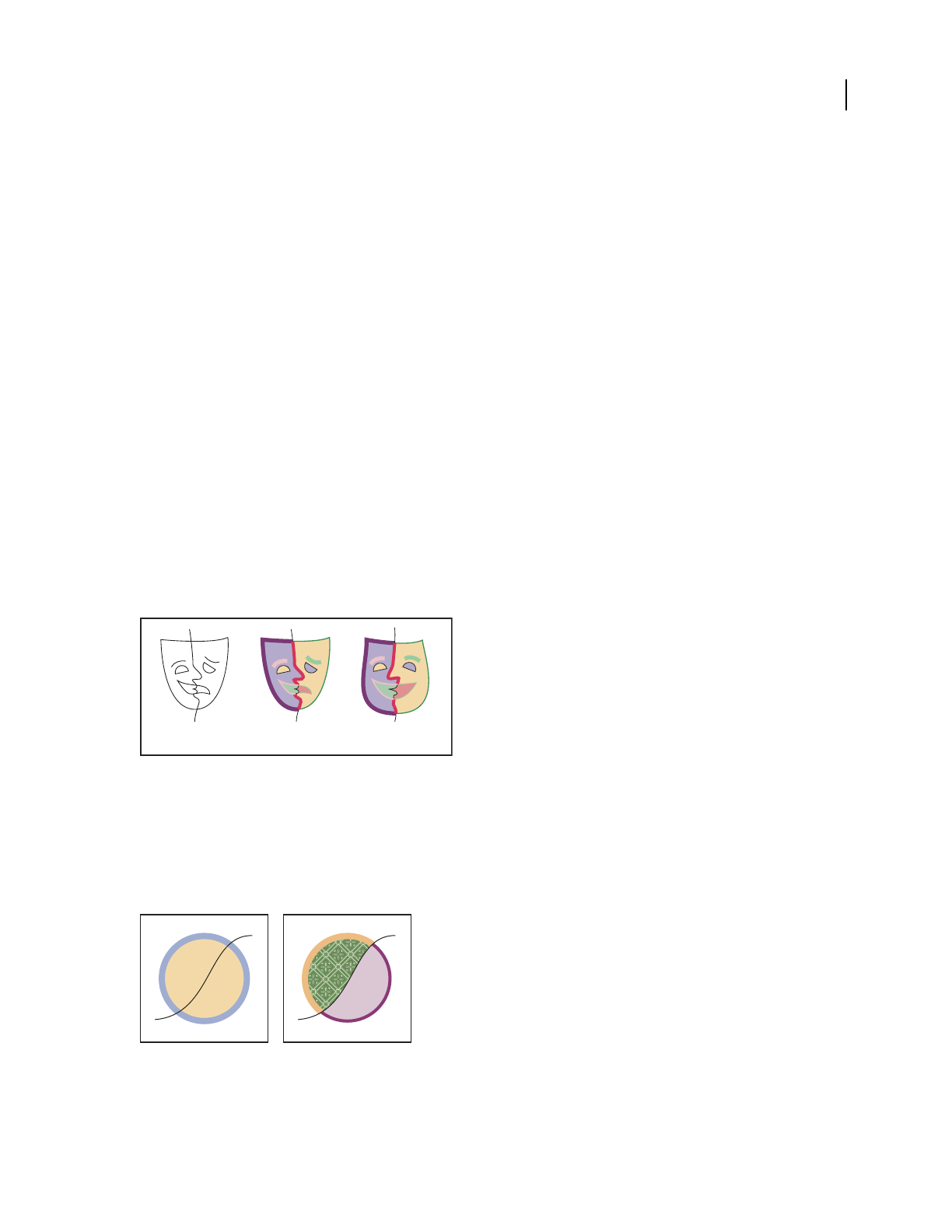
ILLUSTRATOR CS3
User Guide
158
See also
“Targeting items for appearance attributes” on page 347
“Appearance panel overview” on page 346
Live Paint groups
About Live Paint
Converting your artwork to Live Paint groups allows you to color them freely, as you would a drawing on canvas or
paper. You can stroke each path segment with a different color and fill each enclosed path (note, not just closed paths)
with a different color, pattern, or gradient.
Live Paint is an intuitive way to create colored drawings. It lets you use the full range of Illustrator’s vector drawing
tools, but treats all the paths you draw as though they are on the same flat surface. That is, none of the paths is behind
or in front of any other. Instead, the paths divide the drawing surface up into areas, any of which can be colored,
regardless of whether the area is bounded by a single path or by segments of multiple paths. The result is that painting
objects is like filling in a coloring book or using watercolors to paint a pencil sketch.
Once you’ve made a Live Paint group, each path remains fully editable. When you move or adjust a path’s shape, the
colors that had been previously applied don’t just stay where they were, like they do in natural media paintings or
image editing programs. Instead, Illustrator automatically reapplies them to the new regions that are formed by the
edited paths.
Adjusting Live Paint paths
A. Original B. Live Paint group C. Paths adjusted, Live Painting reflows
The paintable parts of Live Paint groups are called edges and faces. An edge is the portion of a path between where it
intersects with other paths. A face is the area enclosed by one or more edges. You can stroke edges and fill faces.
Take, for example, a circle with a line drawn across it. As a Live Paint group, the line (edge) dividing the circle creates
two faces in the circle. You can fill each face and stroke each edge with a different color using the Live Paint Bucket tool.
Circle and line (left) compared to circle and line after conversion to a Live Paint group and filling faces and stroking edges (right).
Note: Live Paint takes advantage of multiprocessors, which help Illustrator perform the operations more quickly.
ABC

ILLUSTRATOR CS3
User Guide
159
For a video on using Live Paint, see www.adobe.com/go/vid0042.
See also
“Painting methods” on page 151
“About fills and strokes” on page 152
Live Paint limitations
Fill and paint attributes are attached to faces and edges of a Live Paint group—not to the actual paths that define
them, as in other Illustrator objects. Because of this, some features and commands either work differently or are not
applicable to paths inside a Live Paint group.
Features and commands that work on an entire Live Paint group, but not on individual faces and edges
•Transparenc y
•Effects
•Multiple fills and strokes from the Appearance panel
•Envelope Distort
•Object > Hide
•Object > Rasterize
•Object > Slice > Make Guides
•Make Opacity Mask (in the Transparency panel menu)
•Brushes (You can apply brushes to an entire Live Paint group if you add a new stroke to the group using the
Appearance panel.)
Features that don’t work on Live Paint groups
•Gradient meshes
•Graphs
•Symbols from the Symbols panel
•Flares
•Align Stroke options from the Stroke panel
•The Magic Wand tool
Object commands that don’t work on Live Paint groups
•Outline Stroke
•Expand (You can use the Object > Live Paint > Expand command instead.)
•Blend
•Slice
•Clipping Mask > Make
•Crop Area > Make
•Create Gradient Mesh

ILLUSTRATOR CS3
User Guide
160
Other commands that don’t work on Live Paint groups
•Pathfinder commands
•File > Place
•View > Guides > Make
•Select > Same >Blending Mode, Fill & Stroke, Opacity, Style, Symbol Instance, or Link Block Series
•Object > Text Wrap > Make
Create Live Paint groups
When you want to color objects using different colors for each edge, or intersection, convert the artwork into a Live
Paint Group.
Certain types of objects, such as type, bitmap images, and brushes, cannot be directly made into Live Paint groups.
You first need to convert these objects into paths. For example, if you try to convert an object that uses brushes or
effects, the complex visual appearance is lost in the conversion to Live Paint. However, you can retain much of the
appearance by first converting the objects to regular paths and then converting the resulting paths to Live Paint.
Note: When you convert artwork to a Live Paint group, you cannot return the artwork to its original state. You can
expand the group into its individual components, or release the group back to its original paths with no fill and a .5 black
stroke.
For a video on using Live Paint, see www.adobe.com/go/vid0042.
See also
“Keys for working with Live Paint groups” on page 465
Create a Live Paint group
1
Select one or more paths, compound paths, or both.
2 Do one of the following:
•Choose Object > Live Paint > Make.
•Select the Live Paint Bucket tool and click the selected object.
Note: Certain properties may be lost in the conversion to a Live Paint group, such as transparency and effects, while
other objects cannot be converted (such as type, bitmap images, and brushes).
Convert objects to Live Paint groups
❖Do any of the following for objects that do not directly convert to Live Paint groups:
•For type objects, choose Type > Create Outlines. Then make the resulting paths into a Live Paint group.
•For bitmap images, choose Object > Live Trace > Make And Convert To Live Paint.
•For other objects, choose Object > Expand. Then make the resulting paths into a Live Paint group.
Expand or release a Live Paint group
Releasing a Live Paint group changes it to one or more ordinary paths with no fill and a .5-point black stroke.
Expanding a Live Paint group changes it to one or more ordinary paths that are visually similar to the Live Paint
group, but are now separate filled and stroked paths. You can use the Group Selection tool to select and modify these
paths separately.
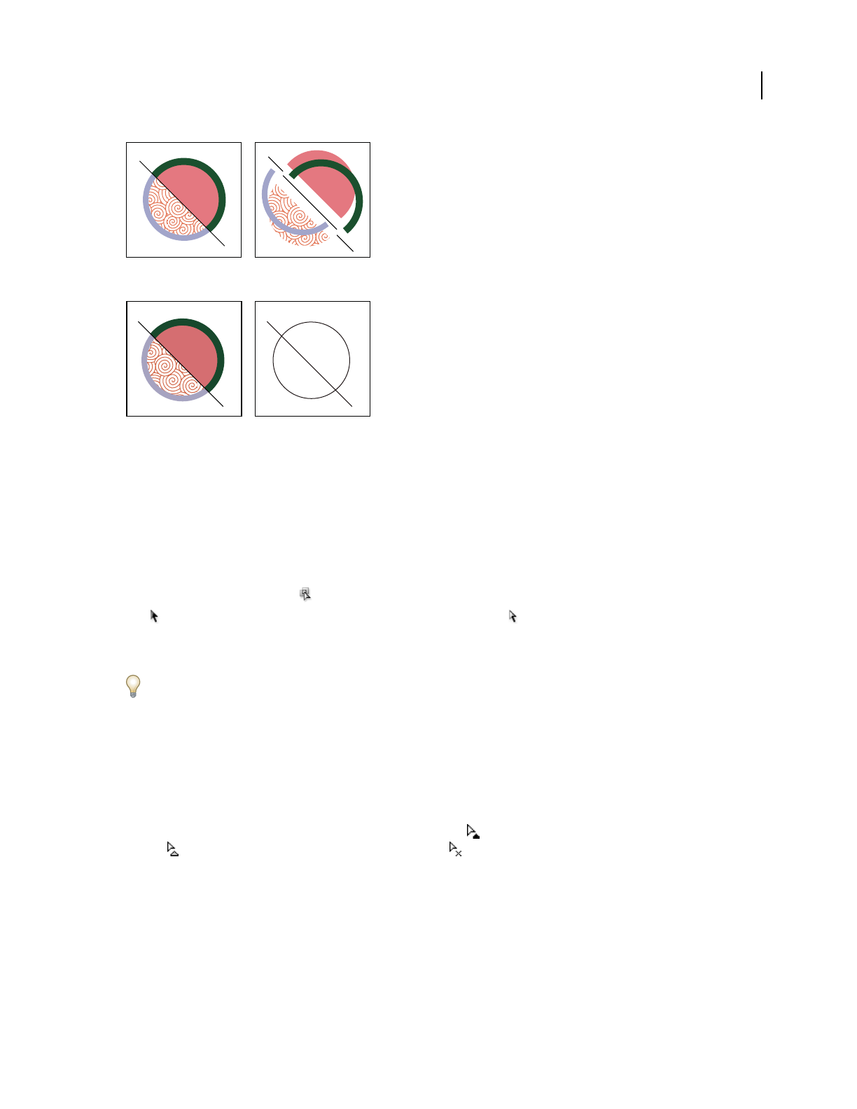
ILLUSTRATOR CS3
User Guide
161
Live Paint group before (left) and after expanding and dragging to separate faces and edges (right)
Live Paint group before (left) and after Release command applied (right)
1 Select the Live Paint group.
2 Do one of the following:
•Choose Object > Live Paint > Expand.
•Choose Object > Live Paint > Release.
Select items in Live Paint groups
Use the Live Paint Selection tool to select individual faces and edges in a Live Paint group. Use the Selection
tool to select the entire Live Paint group, and the Direct Selection tool to select paths inside a Live Paint group.
When you’re working in a complex document, you can isolate a Live Paint group so that it is easy to select the exact
face or edge you want.
Choose a selection tool depending on what you want to affect in a Live Paint group. For instance, use the Live Paint
Selection tool to apply different gradients across different faces in a Live Paint group, and use the Selection tool to
apply the same gradient across the entire Live Paint group.
See also
“Isolate groups and sublayers” on page 194
Select faces and edges
The Live Paint Selection tool pointer changes to the face pointer when it’s positioned over a face, the edge
pointer when it’s positioned over an edge, or the x pointer when it’s positioned outside of a Live Paint group.
❖Select the Live Paint Selection tool, and then:
•To select an individual face or edge, click a face or edge.
•To select multiple faces and edges, drag a marquee around the items you want to select. Partial selections are
included.
•To select all contiguous faces that are not separated by a painted edge, double-click a face.
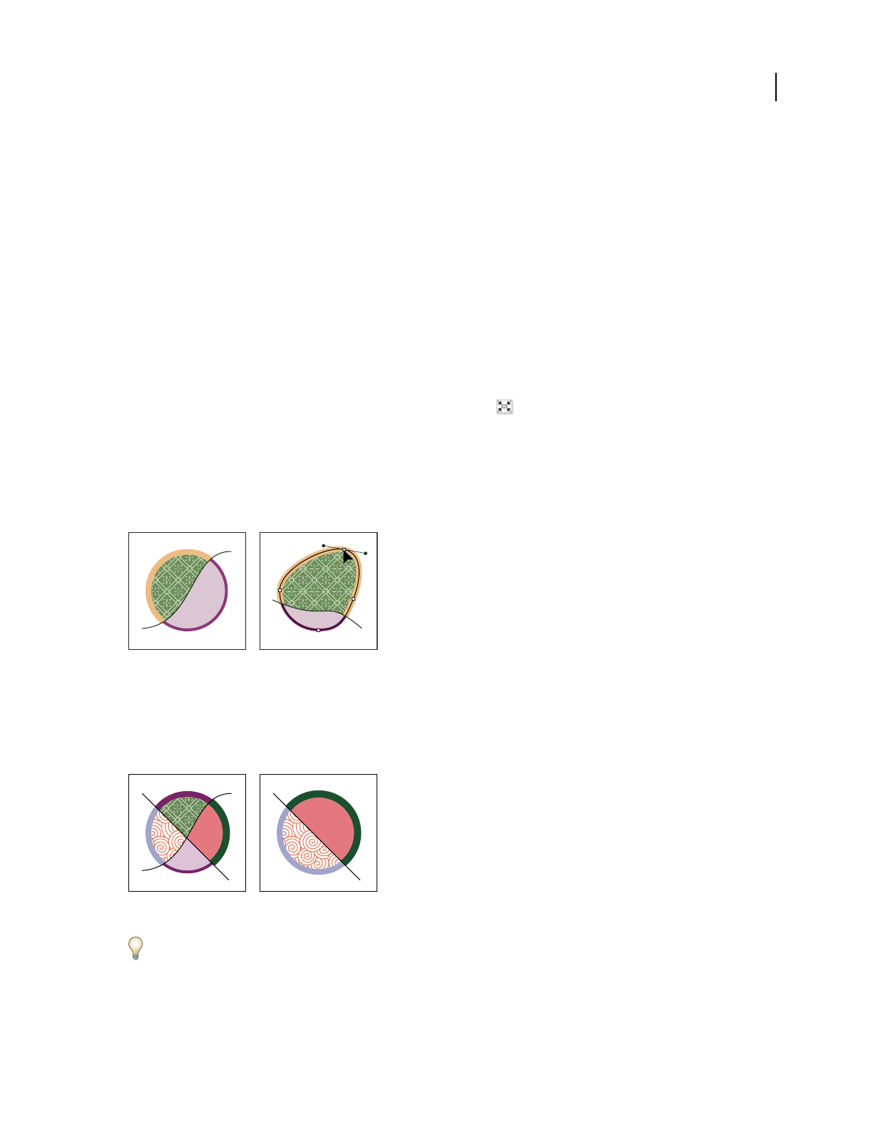
ILLUSTRATOR CS3
User Guide
162
•To select faces or edges with the same fill or stroke, triple-click an item. Or click once, choose Select > Same, and
then choose Fill Color, Stroke Color, or Stroke Weight on the submenu.
•To add items to, or remove items from, the current selection, Shift-click or Shift-drag a marquee around the items.
Select a Live Paint group
❖Using the Selection tool, click the group.
Select an original path within a Live Paint group
❖Using the Direct Selection tool, click a path inside the Live Paint group.
Isolate a Live Paint group from the rest of the artwork
❖Using the Selection tool, do one of the following:
•Double-click the group.
•Select the group, and then click the Isolate Selected Group button in the Control panel.
Modify Live Paint groups
When you modify a path in a Live Paint group, Illustrator colors the modified or new faces and edges using fills and
strokes from the existing group. If the results are not what you expect, you can reapply the colors you want using the
Live Paint Bucket tool.
Live Paint group before (left) and after adjusting paths (right)
When you delete edges, the fill floods across any newly expanded face. For example, if you delete a path that divides
a circle in half, the circle is filled with one of the fills previously in the circle. You can sometimes help guide the
results. For instance, before deleting a path that divides a circle, first move it so that the fill you want to keep is larger
than the fill you want to remove.
Live Paint group before (left) and after selecting and deleting a path (right)
Save the fill and stroke colors used in Live Paint groups in the Swatches panel. That way, if a change loses a color you
want to keep, you can select its swatch and use the Live Paint Bucket tool to reapply the fill or stroke.
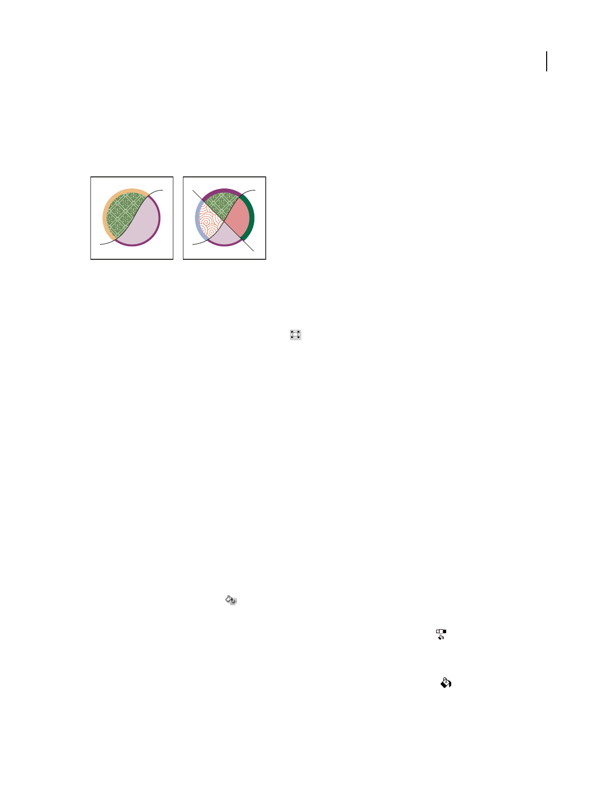
ILLUSTRATOR CS3
User Guide
163
See also
“Isolate groups and sublayers” on page 194
Add paths to a Live Paint group
As you add more paths to the Live Paint group, you can fill and stroke the new faces and edges that are created.
Live Paint group before (left) and after adding a new path and painting the new faces and edges created by it (right)
❖Do any of the following:
•Using the Selection tool, double-click a Live Paint group (or click the Isolate Selected Group button in the Control
panel) to put the group into isolation mode. Then draw another path. Illustrator adds the new path to the Live
Paint group. Click the Exit Isolation Mode button when you’re done adding new paths.
•Select a Live Paint group and the paths you want to add to it. Then choose Object > Live Paint > Merge, or click
Merge Live Paint in the Control panel.
•In the Layers panel, drag one or more paths into a Live Paint group.
Note: Paths inside a Live Paint group may not exactly align with similar or identical paths outside the Live Paint group.
Resize an individual object or path
❖Do one of the following:
•Using the Direct Selection tool, click the path or object to select it. Then choose the Selection tool and click the
path or object again to edit it.
•Using the Selection tool, double-click the Live Paint Group to put it into isolation mode. Then click a path or
object to edit it.
Paint with the Live Paint Bucket tool
The Live Paint Bucket tool lets you paint faces and edges of Live Paint groups with the current fill and stroke
attributes. The tool pointer displays as either one or three color squares, which represent the selected fill or stroke
color and, if your using colors from a swatch library, the two colors adjacent to the selected color in the library. You
can access the adjacent colors, as well as the colors next to those, and so on, by pressing the left or right arrow key.
1 Select the Live Paint Bucket tool .
2 Specify the fill color or stroke color and size you want.
Note: If you select a color from a the Swatches panel, the pointer changes to display three colors . The selected color is
in the middle, and the two adjacent colors are on either side. To use an adjacent color, click the left or right arrow key.
3 To paint a face, do any of the following:
•Click a face to fill it. (When the pointer is over a face, it changes to a half-filled paint bucket and highlight lines
surround the inside of the fill.)

ILLUSTRATOR CS3
User Guide
164
•Drag across multiple faces to paint more than one face at a time.
•Double-click a face to fill across unstroked edges into adjacent faces (flood fill).
•Triple-click a face to fill all faces that currently have the same fill.
To switch to the Eyedropper tool and sample fills or strokes, Alt-click (Windows) or Option-click (Mac OS) the fill or
stroke you want.
4 To paint an edge, double-click the Live Paint Bucket tool and select Paint Strokes, or temporarily toggle to the
Paint Strokes option, by pressing Shift; and then do any of the following:
•Click an edge to stroke it. (When the pointer is over an edge, it changes to a paint brush and the edge is
highlighted.)
•Drag across multiple edges to stroke more than one edge at a time.
•Double-click an edge to stroke all connected edges of the same color (flood stroke).
•Triple-click an edge to stroke all edges of the same stroke.
Note: Pressing Shift lets you quickly toggle between painting only strokes and only fills. You can also specify these changes
in the Live Paint Bucket Options dialog box. If you currently have both the Paint Fills option and the Paint Strokes option
selected, pressing Shift switches to Paint Fills only. (This can be helpful when you are trying to fill a small face surrounded
by stroked edges.)
See also
“Fill and Stroke controls” on page 152
“Apply a fill color to an object” on page 153
“Stroke an object” on page 154
Live Paint Bucket options
The Live Paint Bucket options let you specify how the Live Paint Bucket tool works, choosing whether to paint just
fills, just strokes, or both, as well as how to highlight faces and edges as you move the tool over them. You can see
these options by double-clicking the Live Paint Bucket tool.
Paint Fills Paints the faces of Live Paint groups.
Paint Strokes Paints the edges of Live Paint groups.
Cursor Swatch Preview Displays when you choose a color from the Swatches panel. The Live Paint Bucket tool
pointer appears as three color swatches: the selected fill or stroke color plus the color directly to the left and right of
it in the Swatches panel.
Highlight Outlines the face or edge the cursor is currently over. Faces are highlighted with a thick line and edges are
highlighted with a thin line.
Color Sets the color for the highlight. You can choose a color from the menu or click the paint swatch to specify a
custom color.
Width Specifies how thick to make the highlight.

ILLUSTRATOR CS3
User Guide
165
Close gaps in Live Paint groups
Gaps are small spaces between paths. If paint leaks through and paints faces you did not intend, you probably have
a gap in your artwork. You can create a new path that closes the gap, edit existing paths to close the gap, or adjust the
gap options in the Live Paint group.
You can avoid gaps in your Live Paint artwork by overdrawing paths (that is, extending them past each other). You
can then select and delete the excess edges that result, or apply a stroke of “None” to them.
Highlight gaps in a Live Paint group
❖Choose View > Show Live Paint Gaps.
This command highlights any gaps found on the currently selected Live Paint group, based on your gap options
settings for that group.
Set Live Paint gap options
❖Choose Object > Live Paint > Gap Options and specify any of the following:
Gap Detection When selected, Illustrator recognizes gaps in Live Paint paths and prevents paint from flowing
through them. Note that this may slow Illustrator when working on large, complex Live Paint groups. In this case,
you can choose Close Gaps With Paths to help speed Illustrator up again.
Paint Stops At Sets the size of the gap paint can’t flow through.
Custom Specifies a custom Paint Stops At gap size.
Gap Preview Color Sets the color for previewing gaps in Live Paint groups. You can choose a color from the menu,
or click the color well next to the Gap Preview Color menu to specify a custom color.
Close Gaps With Paths When selected, inserts unpainted paths into your Live Paint group to close gaps (rather than
simply preventing paint from flowing though the gaps). Note that since these paths are unpainted, it may appear gaps
are still there even though they have been closed.
Preview Displays currently detected gaps in Live Paint groups as colored lines, based on the preview color you chose.
Gap rules for merged Live Paint groups
When you merge Live Paint groups that have different gap settings, Illustrator uses the following rules to handle the gaps:
•If gap detection is off in all groups in the selection, gaps are closed and gap detection is turned on with Paint Stops
At set to Small Gaps.
•If gap detection is on and the same for all groups in the selection, gaps are closed and the gap setting is preserved.
•If gap detection is mixed for the selection, gaps are closed and the gap settings of the bottommost Live Paint group
are preserved (if gap detection is on for that group). If the bottommost group has gap detection turned off, gap
detection is turned on and Paint Stops At is set to Small Gaps.
Brushes
About brushes
Brushes let you stylize the appearance of paths. You can apply brush strokes to existing paths, or you can use the
Paintbrush tool to draw a path and apply a brush stroke simultaneously.

ILLUSTRATOR CS3
User Guide
166
There are four types of brushes in Illustrator—calligraphic, scatter, art, and pattern. You can achieve the following
effects using these brushes:
Calligraphic brushes Create strokes that resemble those drawn with the angled point of a calligraphic pen and are
drawn along the center of the path.
Scatter brushes Disperse copies of an object (such as a ladybug or a leaf) along the path.
Art brushes Stretch a brush shape (such as Rough Charcoal) or object shape evenly along the length of the path.
Pattern brushes Paint a pattern—made of individual tiles—that repeats along the path. Pattern brushes can include
up to five tiles, for the sides, inner corner, outer corner, beginning, and end of the pattern.
Sample brushes
A. Calligraphic brush B. Scatter brush C. Art brush D. Pattern brush
Scatter brushes and Pattern brushes can often achieve the same effect. However, one way in which they differ is that
Pattern brushes follow the path exactly, while Scatter brushes do not.
Arrows in a Pattern brush bend to follow the path (left), but arrows remain straight in a Scatter brush (right).
For a video on using brushes, see www.adobe.com/go/vid0044.
Brushes panel overview
The Brushes panel (Window > Brushes) displays brushes for the current file. Whenever you select a brush in a brush
library, it is automatically added to the Brushes panel. Brushes that you create and store in the Brushes panel are
associated only with the current file, which means that each Illustrator file can have a different set of brushes in its
Brushes panel.
See also
“Keys for the Brushes panel” on page 468
ABCD

ILLUSTRATOR CS3
User Guide
167
Show or hide a type of brush
❖Choose any of the following from the panel menu: Show Calligraphic Brushes, Show Scatter Brushes, Show Art
Brushes, Show Pattern Brushes.
Change the view of brushes
❖ Choose Thumbnail View or List View from the panel menu.
Change the order of brushes in the Brushes panel
❖Drag a brush to a new location. You can move brushes only within their type. For example, you cannot move a
Calligraphic brush to the Scatter brush area.
Duplicate a brush in the Brushes panel
❖Drag the brush onto the New Brush button or choose Duplicate Brush from the Brushes panel menu.
Delete the brushes from the Brushes panel
❖Select the brushes and click the Delete Brush button . You can select brushes that aren’t used in a document by
choosing Select All Unused from the Brushes panel menu.
Work with brush libraries
Brush libraries (Window > Brush Libraries > [library]) are collections of preset brushes that come with Illustrator.
You can open multiple brush libraries to browse through their contents and select brushes. You can also open brush
libraries using the Brushes panel menu.
To automatically open a brush library when you start Illustrator, choose Persistent from the brush library’s panel
menu.
Copy brushes from a brush library to the Brushes panel
❖Drag the brushes to the Brushes panel or choose Add To Brushes from the brush library’s panel menu.
Import brushes into the Brushes panel from another file
❖Choose Window > Brushes Libraries > Other Library and select the file.
Create new brush libraries
1
Add the brushes you want to the Brushes panel, and delete any brushes you don’t want.
2 Choose Save Brush Library from the Brushes panel menu, and place the new library file in the
Illustrator/Presets/Brushes folder. It will appear in the Brush Libraries menu when you restart Illustrator.
Note: If you place the file in a different folder, you can open the library by choosing Window > Brush Libraries > Other
Library and selecting the library file.
Apply brush strokes
You can apply brush strokes to a line created with any drawing tool, including the Pen tool, Pencil tool, or basic shape
tools.
❖Do one of the following:
•Select the line, and then select a brush in a brush library, the Brushes panel, or the Control panel.

ILLUSTRATOR CS3
User Guide
168
•Drag a brush onto the line. If the line already has brush strokes applied to it, then the new brush replaces the old
brush.
When replacing brush strokes with a different brush, Alt-click (Windows) or Option-click (Mac OS) the new brush
to preserve brush-stroke options previously applied to the line.
Draw lines and apply brush strokes simultaneously
1 Select a brush in a brush library or the Brushes panel.
2 Select the Paintbrush tool .
3 Position the pointer where you want the brush stroke to begin, and drag to draw a line. A dotted line follows the
pointer as you drag.
4 Do one of the following:
•To draw an open line, release the mouse button when the line is the desired shape.
•To draw a closed shape, hold down Alt (Windows) or Option (Mac OS) as you drag. The Paintbrush tool displays
a small loop . Release the mouse button (but not the Alt or Option key) when you are ready to close the shape.
Illustrator sets down anchor points as you draw. The number of anchor points is determined by the length and
complexity of the line and by the Paintbrush tolerance settings.
To adjust the shape of a brushed line after you finish drawing it, first select the line. Then position the Paintbrush
tool on the line, and drag until the line is the desired shape. You can use the technique to extend a brushed line as
well as change the shape of the line between the existing end points.
Paintbrush tool options
Double-click the Paintbrush tool to set the following options:
Fidelity Controls how far you have to move your mouse or stylus before Illustrator adds a new anchor point to the
path. For example, a Fidelity value of 2.5 means that tool movements of less than 2.5 pixels aren’t registered. Fidelity
can range from 0.5 to 20 pixels; the higher the value, the smoother and less complex the path.
Smoothness Controls the amount of smoothing that Illustrator applies when you use the tool. Smoothness can
range from 0% to 100%; the higher the percentage, the smoother the path.
Fill New Brush Strokes Applies a fill to the path. This option is most useful when drawing closed paths.
Keep Selected Determines whether or not Illustrator keeps the path selected after you draw it.
Edit Selected Paths Determines whether or not you can change an existing path with the Paintbrush tool.
Within: _ pixels Determines how close your mouse or stylus must be to an existing path to edit the path with the
Paintbrush tool. This option is only available when the Edit Selected Paths option is selected.
Remove brush strokes
1 Select a brushed line.
2 In the Brushes panel, choose Remove Brush Stroke from the panel menu or click the Remove Brush Stroke
button .

ILLUSTRATOR CS3
User Guide
169
Convert brush strokes to outlines
You can convert brush strokes into outlined paths in order to edit the individual components of a brushed line.
1 Select a brushed line.
2 Choose Object > Expand Appearance.
Illustrator places the components of the expanded path in a group. Within the group are a path and a subgroup
containing the brush stoke outlines.
Create or modify brushes
You can create new calligraphic, scatter, art, and pattern brushes based on your own settings. For scatter, art, and
pattern brushes, you must first create the artwork you want to use. Follow these guidelines when creating artwork
for brushes:
•The artwork cannot contain gradients, blends, other brush strokes, mesh objects, bitmap images, graphs, placed
files, or masks.
•For art and pattern brushes, the artwork cannot contain type. To achieve a brush-stroke effect with type, create an
outline of the type and then create a brush with the outline.
•For pattern brushes, create up to five pattern tiles (depending on the brush configuration), and add the tiles to the
Swatches panel.
See also
“About patterns” on page 187
“Create corner tiles for brush patterns” on page 191
Create a brush
1
For scatter and art brushes, select the artwork you want to use. For pattern brushes, you can select the artwork for
the side tile, but it isn’t necessary.
2 Click the New Brush button in the Brushes panel. Alternatively, drag the selected artwork to the Brushes
panel.
3 Select the type of brush you want to create, and click OK.
4 In the Brush Options dialog box, enter a name for the brush, set brush options, and click OK.
Modify a brush
•To change the options for a brush, double-click the brush in the Brushes panel. Set the brush options and click OK.
If the current document contains brushed paths that use the modified brush, a message appears. Click Apply To
Strokes to change pre-existing strokes. Click Leave Strokes to leave pre-existing strokes unchanged, and apply the
modified brush to new strokes only.
•To change the artwork used by a scatter, art, or pattern brush, drag the brush into your artwork and make the
changes you want. Then Alt-drag (Windows) or Option-drag (Mac OS) the modified brush onto the original
brush in the Brushes panel.
•To modify a brushed line without updating the corresponding brush, select the line and click the Options Of
Selected Object button in the Brushes panel.

ILLUSTRATOR CS3
User Guide
170
Brush options
You can specify different options for the different types of brushes. To change the options for a brush, double-click
the brush in the Brushes panel.
Scatter, Art, and Pattern brushes all have identical options for colorization.
Colorization options for brushes
The colors that a scatter, art, or pattern brush paints depend on the current stroke color and the colorization method
of the brush. To set the colorization method, select one of the following options in the Brush Options dialog box:
None Displays colors as they appear in the brush in the Brushes panel. Choose None to keep a brush the same colors
as in the Brushes panel.
Tints Displays the brush stroke in tints of the stroke color. Portions of the art that are black become the stroke color,
portions that aren’t black become tints of the stroke color, and white remains white. If you use a spot color as the
stroke, Tints generates tints of the spot color. Choose Tints for brushes that are in black and white, or when you want
to paint a brush stroke with a spot color.
Tints And Shades Displays the brush stroke in tints and shades of the stroke color. Tints and Shades maintains black
and white, and everything between becomes a blend from black to white through the stroke color. Because black is
added you may not be able to print to a single plate when using Tints and Shades with a spot color. Choose Tints and
Shades for brushes that are in grayscale.
Hue Shift Uses the key color in the brush artwork, as shown in the Key Color box. (By default, the key color is the
most prominent color in the art.) Everything in the brush artwork that is the key color becomes the stroke color.
Other colors in the brush artwork become colors related to the stroke color. Hue Shift maintains black, white, and
gray. Choose Hue Shift for brushes that use multiple colors. To change the key color, click the Key Color eyedropper,
move the eyedropper to the preview in the dialog box, and click the color you want to use as the key color. The color
in the Key Color box changes. Click the eyedropper again to deselect it.
For information and samples about each choice, click Tips.
Calligraphic brush options
Angle Determines the angle of rotation for the brush. Drag the arrowhead in the preview, or enter a value in the
Angle text box.
Roundness Determines roundness of the brush. Drag a black dot in the preview away from or toward the center,
or enter a value in the Roundness text box. The higher the value, the greater the roundness.
Diameter Determines the diameter of the brush. Use the Diameter slider, or enter a value in the Diameter text box.
The pop-up list to the right of each option lets you control variations in the shape of the brush. Select one of the
following options:
Fixed Creates a brush with a fixed angle, roundness, or diameter.
Random Creates a brush with random variations in angle, roundness, or diameter. Enter a value in the Variation text
box to specify the range within which the brush characteristic can vary. For example, when the Diameter value is 15
and the Variation value is 5, the diameter can be 10, or 20, or any value in between.
Pressure Creates a brush that varies in angle, roundness, or diameter based on the pressure of a drawing stylus. This
option is most useful when used with Diameter. It is available only if you have a graphics tablet. Enter a value in the
Variation text box to specify how much more or less than the original value the brush characteristic will vary.
For example, when the Roundness value is 75% and the Variation value is 25%, the lightest stroke is 50% and the
heaviest stroke is 100%. The lighter the pressure, the more angular the brush stroke.

ILLUSTRATOR CS3
User Guide
171
Stylus Wheel Creates a brush that varies in diameter based on manipulation of the stylus wheel. This option is
available only if you have a graphics tablet that can detect the direction in which the pen is tilted.
Tilt Creates a brush that varies in angle, roundness, or diameter based on the tilt of a drawing stylus. This option is
most useful when used with Roundness. It is available only if you have a graphics tablet that can detect the direction
in which the pen is tilted.
Bearing Creates a brush that varies in angle, roundness, or diameter based on the pressure of a drawing stylus. This
option is most useful when used to control the angle of calligraphic brushes, especially when you’re using the brush
like a paintbrush. It is available only if you have a graphics tablet that can detect how close to vertical the pen is.
Rotation Creates a brush that varies in angle, roundness, or diameter based on how the drawing stylus pen tip is
rotated. This option is most useful when used to control the angle of calligraphic brushes, especially when you’re
using the brush like a flat pen. It is available only if you have a graphics tablet that can detect this type of rotation.
Scatter brush options
Size Controls the size of the objects.
Spacing Controls the amount of space between objects.
Scatter Controls how closely objects follow the path independently on each side of the path. The higher the value,
the farther the objects are from the path.
Rotation Controls the angle of rotation of the objects.
Rotation Relative To Sets the angle of rotation for scattered objects relative to the page or the path. For example, if
you select Page, at 0˚ of rotation, objects point to the top of the page. If you select Path, at 0˚ of rotation, objects are
tangent to the path.
The pop-up list to the right of each option lets you control variations in the shape of the brush. Select one of the
following options:
Fixed Creates a brush with a fixed size, spacing, scattering, and rotation.
Random Creates a brush with random variations in size, spacing, scattering, and rotation. Enter a value in the
Variation text box to specify the range within which the brush characteristic can vary. For example, when the
Diameter value is 15 and the Variation value is 5, the diameter can be 10, or 20, or any value in between.
Pressure Creates a brush that varies in angle, roundness, or diameter based on the pressure of a drawing stylus. This
option is available only if you have a graphics tablet. Enter a value in the rightmost text box, or use the Maximum
slider. Pressure uses the Minimum value for the lightest tablet pressure and the Maximum value for the heaviest
pressure. When you choose this setting for Diameter, the heavier the stroke, the larger the objects.
Stylus Wheel Creates a brush that varies in diameter based on manipulation of the stylus wheel. This option is
available only if you have a graphics tablet that can detect the direction in which the pen is tilted
Tilt Creates a brush that varies in angle, roundness, or diameter based on the tilt of a drawing stylus. This option is
most useful when used with Roundness. It is available only if you have a graphics tablet that can detect the direction
in which the pen is tilted.
Bearing Creates a brush that varies in angle, roundness, or diameter based on the pressure of a drawing stylus. This
option is most useful when used to control the angle of brushes. It is available only if you have a graphics tablet that
can detect how close to vertical the pen is.
Rotation Creates a brush that varies in angle, roundness, or diameter based on how the drawing stylus pen tip is
rotated. This option is most useful when used to control the angle of brushes. It is available only if you have a graphics
tablet that can detect this type of rotation.
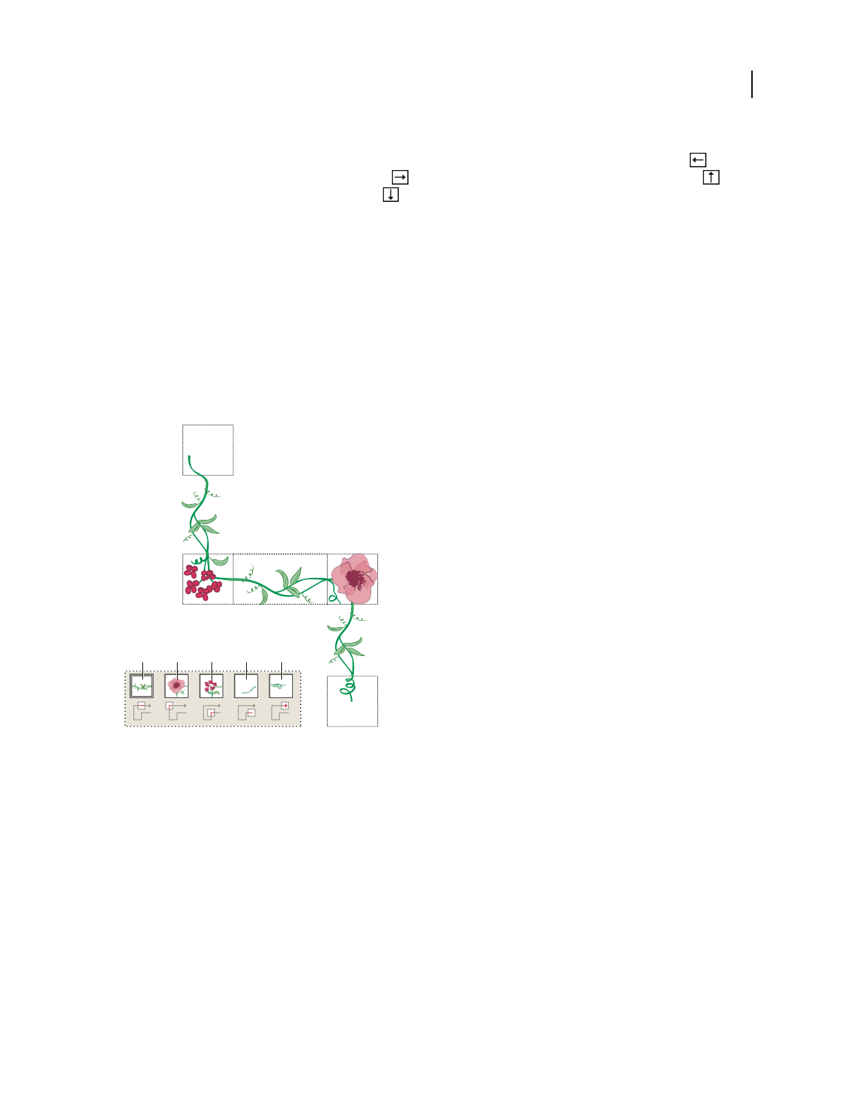
ILLUSTRATOR CS3
User Guide
172
Art brush options
Direction Determines the direction of the artwork in relation to the line. Click an arrow to set the direction: to
place the left side of the art is the end of the stroke; to place the right side of the art is the end of the stroke;
to place the top of the art is the end of the stroke; to place the bottom of the art is the end of the stroke.
Width Adjusts the width of the art relative to its original width.
Proportional Preserves proportions in scaled art.
Flip Along or Flip Across Change the orientation of the art in relation to the line.
Pattern brush options
Tile buttons Let you apply different patterns to different parts of the line. Click a tile button for the tile you want to
define, and select a pattern swatch from the scroll list. Repeat to apply pattern swatches to other tiles as needed.
Note: You must add the pattern tiles you want to use to the Swatches panel before you set pattern brush options. After
you create a pattern brush, you can delete the pattern tiles from the Swatches panel if you don’t plan to use them for
additional artwork.
Tiles in a pattern brush
A. Side tile B. Outer Corner tile C. Inner Corner tile D. Start tile E. End tile
Scale Adjusts the size of tiles relative to their original size.
Spacing Adjusts the space between tiles.
Flip Along or Flip Across Changes the orientation of the pattern in relation to the line.
Fit Determines how the pattern fits on the line: Stretch To Fit lengthens or shortens the pattern tile to fit the object.
This option can result in uneven tiling. Add Space To Fit adds blank space between each pattern tile to apply the
pattern proportionally to the path. Approximate Path fits tiles to the closest approximate path without changing the
tiles. This option applies the pattern slightly inside or outside the path, rather than centered on the path, to maintain
even tiling.
E
E
D
D
C
C
B
B
A
A
B
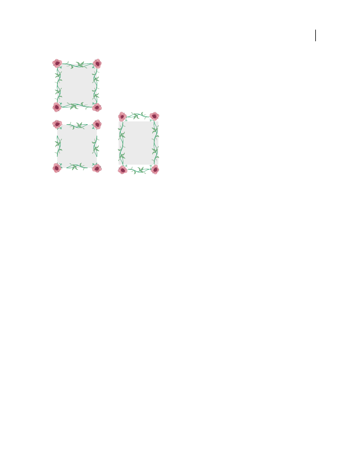
ILLUSTRATOR CS3
User Guide
173
Fit options
A. Stretch To Fit B. Add Space To Fit C. Approximate Path
Transparency and blending modes
About transparency
Transparency is such an integral part of Illustrator that it’s possible to add transparency to your artwork without
realizing it. You can add transparency to artwork by doing any of the following:
•Lowering the opacity of objects so that underlying artwork becomes visible.
•Using opacity masks to create variations in transparency.
•Using a blending mode to change how colors interact among overlapping objects.
•Applying gradients and meshes that include transparency.
•Applying effects or graphic styles that include transparency, such as drop shadows.
•Importing Adobe Photoshop files that include transparency.
For a video on working with transparency, see www.adobe.com/go/vid0054. For more information on working with
transparency across Adobe Creative Suite, see www.adobe.com/go/learn_ai_transparency_pdf.
See also
“Printing and saving transparent artwork” on page 417
“About blending modes” on page 179
Transparency panel overview
You use the Transparency panel (Window > Transparency) to specify the opacity and blending mode of objects, to
create opacity masks, or to knock out a portion of one object with the overlying portion of a transparent object.
A
BC
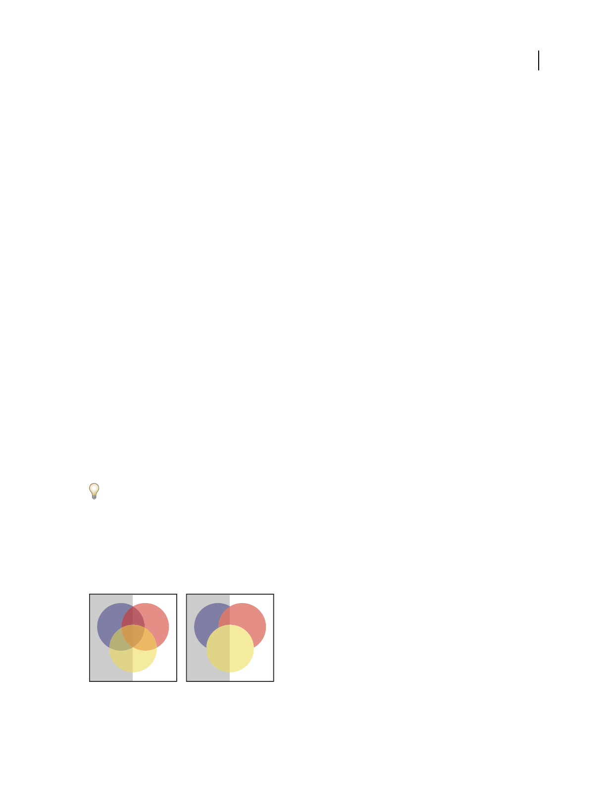
ILLUSTRATOR CS3
User Guide
174
See also
“Workspace overview” on page 14
Show all options in the Transparency panel
❖ Choose Show Options from the panel menu.
Show a thumbnail of the selected object in the Transparency panel
❖Choose Show Thumbnail from the panel menu. Or, click the double triangle on the panel’s tab to cycle through
the display sizes.
View transparency in artwork
It’s important to be aware of when you’re using transparency, because you need to set some extra options when
printing and saving transparent artwork. To view transparency in your artwork, display a checkered background grid
to identify transparent areas of your artwork.
1 Choose View > Show Transparency Grid.
2 (Optional) Choose File > Document Setup, and select Transparency from the menu at the top of the Document
Setup dialog box and set grid options.
Note: You can also change the artboard color to simulate what your artwork will look like if printed on colored paper.
Change the opacity of artwork
You can change the opacity of a single object, the opacity of all objects in a group or layer, or the opacity of an object’s
fill or stroke.
1 Select an object or group (or target a layer in the Layers panel).
If you want to change the opacity of a fill or stroke, select the object, and then select the fill or stroke in the
Appearance panel.
2 Set the Opacity option in the Transparency panel or Control panel.
To select all objects that use a specific opacity, select an object with that opacity, or deselect everything and enter the
opacity value in the Transparency panel. Then choose Select > Same > Opacity.
If you select multiple objects in a layer and change the opacity setting, the transparency of overlapping areas of the
selected objects will change relative to the other objects and show an accumulated opacity. In contrast, if you target
a layer or group and then change the opacity, the objects in the layer or group are treated as a single object. Only
objects outside and below the layer or group are visible through the transparent objects. If an object is moved into
the layer or group, it takes on the layer’s or group’s opacity, and if an object is moved outside, it doesn’t retain the
opacity.
Individual objects selected and set to 50% opacity (left) compared to layer targeted and set to 50% opacity (right)
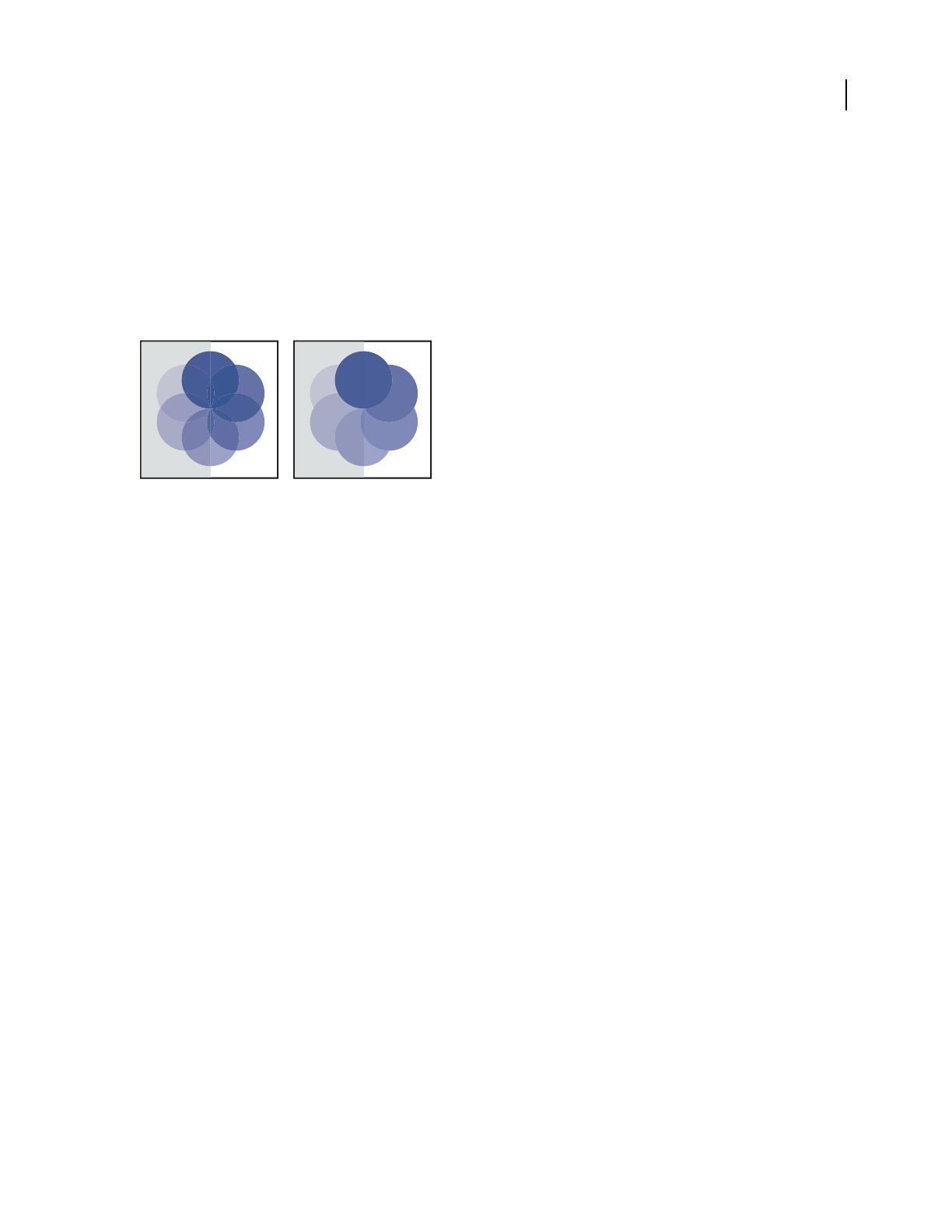
ILLUSTRATOR CS3
User Guide
175
See also
“Targeting items for appearance attributes” on page 347
“Appearance panel overview” on page 346
“Printing and saving transparent artwork” on page 417
Create a transparency knockout group
In a transparency knockout group, the elements of a group do not show through each other.
Group with Knockout Group option deselected (left) compared to selected (right)
1 In the Layers panel, target the group or layer you want to turn into a knockout group.
2
In the Transparency panel, select Knockout Group. If this option isn’t visible, select Show Options from the panel menu.
Selecting the Knockout Group option cycles it through three states: on (check mark), off (no mark), and neutral
(square with a line through it). Use the neutral option when you want to group artwork without interfering with the
knockout behavior determined by the enclosing layer or group. Use the off option when you want to ensure that a
layer or a group of transparent objects will never knock each other out.
See also
“Targeting items for appearance attributes” on page 347
“Printing and saving transparent artwork” on page 417
Use opacity masks to create transparency
You use an opacity mask and a masking object to alter the transparency of the underlying artwork. The opacity mask
(also referred to as masked artwork) provides the shape through which other objects show. The masking object
defines which areas are transparent and the degree of transparency. You can use any colored object or raster image
as the masking object. Illustrator uses the grayscale equivalents of the colors in the masking object for the opacity
levels in the mask. Where the opacity mask is white, the artwork is fully visible. Where the opacity mask is black, the
artwork is hidden. Shades of gray in the mask result in varying degrees of transparency in the artwork.
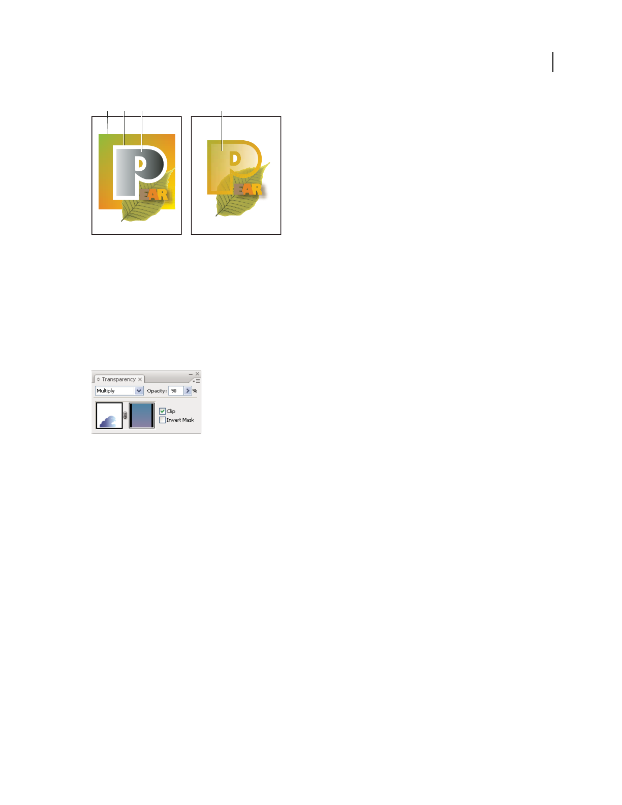
ILLUSTRATOR CS3
User Guide
176
Creating an opacity mask
A. Underlying objects B. Opacity mask artwork C. Masking object filled with black-to-white gradient D. C moved over the area of B and
masking B
When you create the opacity mask, a thumbnail of the masking object appears in the Transparency panel to the right
of the thumbnail of the masked artwork. (If these thumbnails aren’t visible, choose Show Thumbnails from the panel
menu.) By default, the masked artwork and the masking object are linked (as shown by a link between the thumb-
nails in the panel). When you move the masked artwork, the masking object moves along with it. However, when
you move a masking object, the masked artwork doesn’t move. You can unlink the mask in the Transparency panel
to lock the mask in place and move the masked artwork independently of it.
Transparency panel displays opacity mask thumbnails: left thumbnail represents the opacity mask, right thumbnail represents masking objects
You can move masks between Photoshop and Illustrator. Opacity masks in Illustrator convert to layer masks in
Photoshop, and vice versa.
Note: You cannot enter isolation mode when working in mask-editing mode, or vice versa.
For a video on working with opacity masks, see www.adobe.com/go/vid0056.
See also
“Printing and saving transparent artwork” on page 417
“Targeting items for appearance attributes” on page 347
Create an opacity mask
1
Select a single object or group, or target a layer in the Layers panel.
2 Double-click directly to the right of the thumbnail in the Transparency panel.
3 If the thumbnail isn’t visible, choose Show Thumbnails from the panel menu. An empty mask is created and
Illustrator automatically enters mask-editing mode.
4 Use the drawing tools to draw a mask shape.
5 Click the masked artwork’s thumbnail (left thumbnail) in the Transparency panel to exit mask-editing mode.
AB C D

ILLUSTRATOR CS3
User Guide
177
Note: The Clip option sets the mask background to black. Therefore, black objects, such as black type, used to create an
opacity mask with the Clip option selected will not be visible. To see the objects, use a different color or deselect the Clip
option.
Convert an existing object into an opacity mask
❖Select at least two objects or groups, and choose Make Opacity Mask from the Transparency panel menu. The
topmost selected object or group is used as the mask.
Edit a masking object
You can edit a masking object to change the shape or transparency of the mask.
1 Click the masking object’s thumbnail (right thumbnail) in the Transparency panel.
2 Alt-click (Windows) or Option-click (Mac OS) the mask thumbnail to hide all other artwork in the document
window. (If the thumbnails aren’t visible, choose Show Thumbnails from the panel menu.)
3 Use any of the Illustrator editing tools and techniques to edit the mask.
4 Click the masked artwork’s thumbnail (left thumbnail) in the Transparency panel to exit mask-editing mode.
Unlink or relink an opacity mask
•To unlink a mask, target the masked artwork in the Layers panel, and then click the link symbol between the
thumbnails in the Transparency panel. Alternatively, select Unlink Opacity Mask from the Transparency panel
menu.
The masking object is locked in position and size, and the masked objects can be moved and resized independently
of the mask.
•To relink a mask, target the masked artwork in the Layers panel, and then click the area between the thumbnails
in the Transparency panel. Alternatively, select Link Opacity Mask from the Transparency panel menu.
Deactivate or reactivate an opacity mask
You can deactivate a mask to remove the transparency it creates.
•To deactivate a mask, target the masked artwork in the Layers panel, and then Shift-click the masking object’s
thumbnail (right thumbnail) in the Transparency panel. Alternatively, select Disable Opacity Mask from the
Transparency panel menu. When the opacity mask is deactivated, a red x appears over the mask thumbnail in the
Transparency panel.
•To reactivate a mask, target the masked artwork in the Layers panel, and then Shift-click the masking object’s
thumbnail in the Transparency panel. Alternatively, select Enable Opacity Mask from the Transparency panel menu.
Remove an opacity mask
❖Target the masked artwork in the Layers panel, and then select Release Opacity Mask from the Transparency panel
menu.
The masking object reappears on top of the objects that were masked.
Clip or invert an opacity mask
1
Target the masked artwork in the Layers panel.

ILLUSTRATOR CS3
User Guide
178
2 Select either of the following options in the Transparency panel:
Clip Gives the mask a black background which crops the masked artwork to the boundaries of the masking object.
Deselect the Clip option to turn off the clipping behavior. To select clipping for new opacity masks by default, select
New Opacity Masks Are Clipping from the Transparency panel menu.
Invert Mask Reverses the luminosity values of the masking object, which reverses the opacity of the masked artwork.
For example, areas that are 90% transparent become 10% transparent after the mask is inverted. Deselect the Invert
Mask option to return the mask to the original state. To invert all masks by default, select New Opacity Masks Are
Inverted from the Transparency panel menu.
If these options aren’t visible, select Show Options from the panel menu.
Use transparency to shape a knockout
You can use the Opacity & Mask Define Knockout Shape option to make a knockout effect proportional to the
object’s opacity. In areas of the mask that are close to 100% opacity, the knockout effect will
be strong; in areas with
less opacity, the knockout effect will be weaker. For example, if you
use a gradient-masked object as a knockout,
the
underlying object will be knocked out progressively, as if it were being shaded by a gradient. You can create
knockout shapes with both vector and raster objects. This technique is most useful for objects that use a blending
mode other than Normal.
1 Do one of the following:
•To use an opacity mask to shape the knockout, select the masked artwork, and then group it with the objects you
want to knock out.
•To use the alpha channel of a bitmap object to shape the knockout, select a bitmap object that contains trans-
parency, and then group it with the objects you want to knock out.
2 Select the group.
3 In the Transparency panel, select Knockout Group until the option displays a checkmark.
4 Among the grouped objects, target the masking objects or transparent image in the Layers panel.
5 In the Transparency panel, select Opacity & Mask Define Knockout Shape.
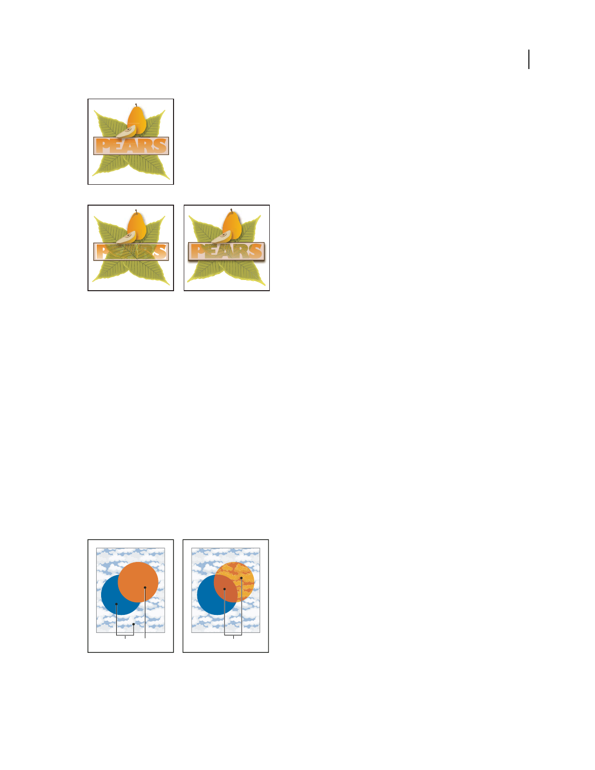
ILLUSTRATOR CS3
User Guide
179
Knocking out shapes using a bitmap object
A. Original artwork B. Darken blending mode applied to the word “PEARS”, and Group option selected C. Opacity & Mask Define Knockout
shape option applied to word
See also
“Printing and saving transparent artwork” on page 417
“Targeting items for appearance attributes” on page 347
About blending modes
Blending modes let you vary the ways that the colors of objects blend with the colors of underlying objects. When
you apply a blending mode to an object, the effect of the blending mode is seen on any objects that lie beneath the
object’s layer or group.
It’s helpful to think in terms of the following color terminology when visualizing a blending mode’s effect:
•The blend color is the original color of the selected object, group, or layer.
•The base color is the underlying color in the artwork.
•The resulting color is the color resulting from the blend.
Topmost object with Normal blending (left) compared to Hard Light blending mode (right)
A. Base colors in underlying objects at 100% opacity B. Blend color in topmost object C. Resulting colors after applying the Hard Light
blending mode to the topmost object
A
C
B
ABC

ILLUSTRATOR CS3
User Guide
180
For a video on working with blending modes, see www.adobe.com/go/vid0055.
Illustrator provides the following blending modes:
Normal Paints the selection with the blend color, without interaction with the base color. This is the default mode.
Darken Selects the base or blend color—whichever is darker—as the resulting color. Areas lighter than the blend
color are replaced. Areas darker than the blend color do not change.
Multiply Multiplies the base color by the blend color. The resulting color is always a darker color. Multiplying any
color with black produces black. Multiplying any color with white leaves the color unchanged. The effect is similar
to drawing on the page with multiple magic markers.
Color Burn Darkens the base color to reflect the blend color. Blending with white produces no change.
Lighten Selects the base or blend color—whichever is lighter—as the resulting color. Areas darker than the blend
color are replaced. Areas lighter than the blend color do not change.
Screen Multiplies the inverse of the blend and base colors. The resulting color is always a lighter color. Screening
with black leaves the color unchanged. Screening with white produces white. The effect is similar to projecting
multiple slide images on top of each other.
Color Dodge Brightens the base color to reflect the blend color. Blending with black produces no change.
Overlay Multiplies or screens the colors, depending on the base color. Patterns or colors overlay the existing artwork,
preserving the highlights and shadows of the base color while mixing in the blend color to reflect the lightness or
darkness of the original color.
Soft Light Darkens or lightens the colors, depending on the blend color. The effect is similar to shining a diffused
spotlight on the artwork.
If the blend color (light source) is lighter than 50% gray, the artwork is lightened, as if it were dodged. If the blend
color is darker than 50% gray, the artwork is darkened, as if it were burned in. Painting with pure black or white
produces a distinctly darker or lighter area but does not result in pure black or white.
Hard Light Multiplies or screens the colors, depending on the blend color. The effect is similar to shining a harsh
spotlight on the artwork.
If the blend color (light source) is lighter than 50% gray, the artwork is lightened, as if it were screened. This is useful
for adding highlights to artwork. If the blend color is darker than 50% gray, the artwork is darkened, as if it were
multiplied. This is useful for adding shadows to artwork. Painting with pure black or white results in pure black or
white.
Difference Subtracts either the blend color from the base color or the base color from the blend color, depending on
which has the greater brightness value. Blending with white inverts the base-color values. Blending with black
produces no change.
Exclusion Creates an effect similar to but lower in contrast than the Difference mode. Blending with white inverts
the base-color components. Blending with black produces no change.
Hue Creates a resulting color with the luminance and saturation of the base color and the hue of the blend color.
Saturation Creates a resulting color with the luminance and hue of the base color and the saturation of the blend
color. Painting with this mode in an area with no saturation (gray) causes no change.
Color Creates a resulting color with the luminance of the base color and the hue and saturation of the blend color.
This preserves the gray levels in the artwork and is useful for coloring monochrome artwork and for tinting color
artwork.
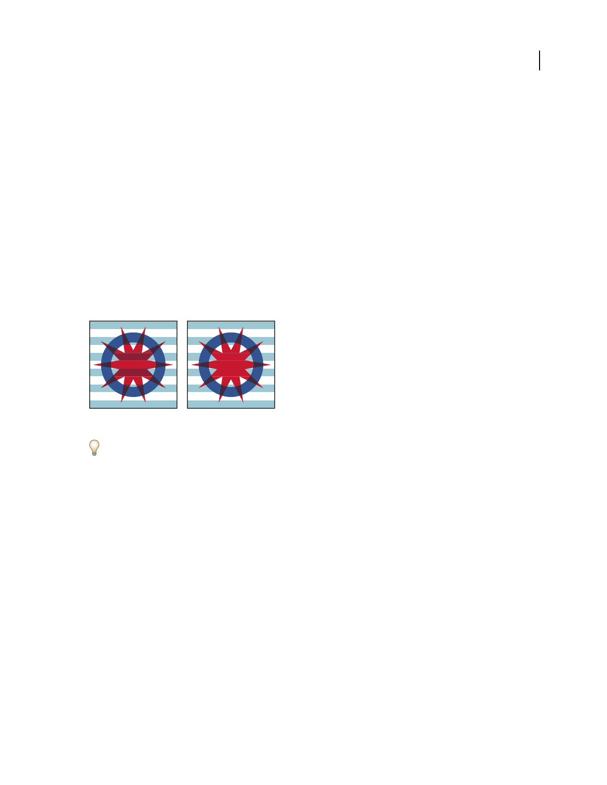
ILLUSTRATOR CS3
User Guide
181
Luminosity Creates a resulting color with the hue and saturation of the base color and the luminance of the blend
color. This mode creates an inverse effect from that of the Color mode.
Note: The Difference, Exclusion, Hue, Saturation, Color, and Luminosity modes do not blend spot colors—and with
most blending modes, a black designated as 100% K knocks out the color on the underlying layer. Instead of 100% black,
specify a rich black using CMYK values.
Change the blending mode of artwork
1 Select an object or group (or target a layer in the Layers panel).
If you want to change the blending mode of a fill or stroke, select the object, and then select the fill or stroke in the
Appearance panel.
2 In the Transparency panel, choose a blending mode from the pop-up menu.
You can isolate the blending mode to a targeted layer or group in order to leave objects beneath unaffected. To do
this, select the target icon to the right of a group or layer in the Layers panel that contains an object using a blending
mode. In the Transparency panel, select Isolate Blending. (If the Isolate Blending option isn’t visible, select Show
Options from the Transparency panel menu.)
Group (star and circle) with Isolate Blending option deselected (left) compared to selected (right)
To select all objects that use the same blending mode, select an object with that blending mode, or deselect everything
and choose the blending mode in the Transparency panel. Then choose Select > Same > Blending Mode.
For a video on working with blending modes, see www.adobe.com/go/vid0055.
See also
“Transparency panel overview” on page 173
“Appearance panel overview” on page 346
“Targeting items for appearance attributes” on page 347
“Printing and saving transparent artwork” on page 417
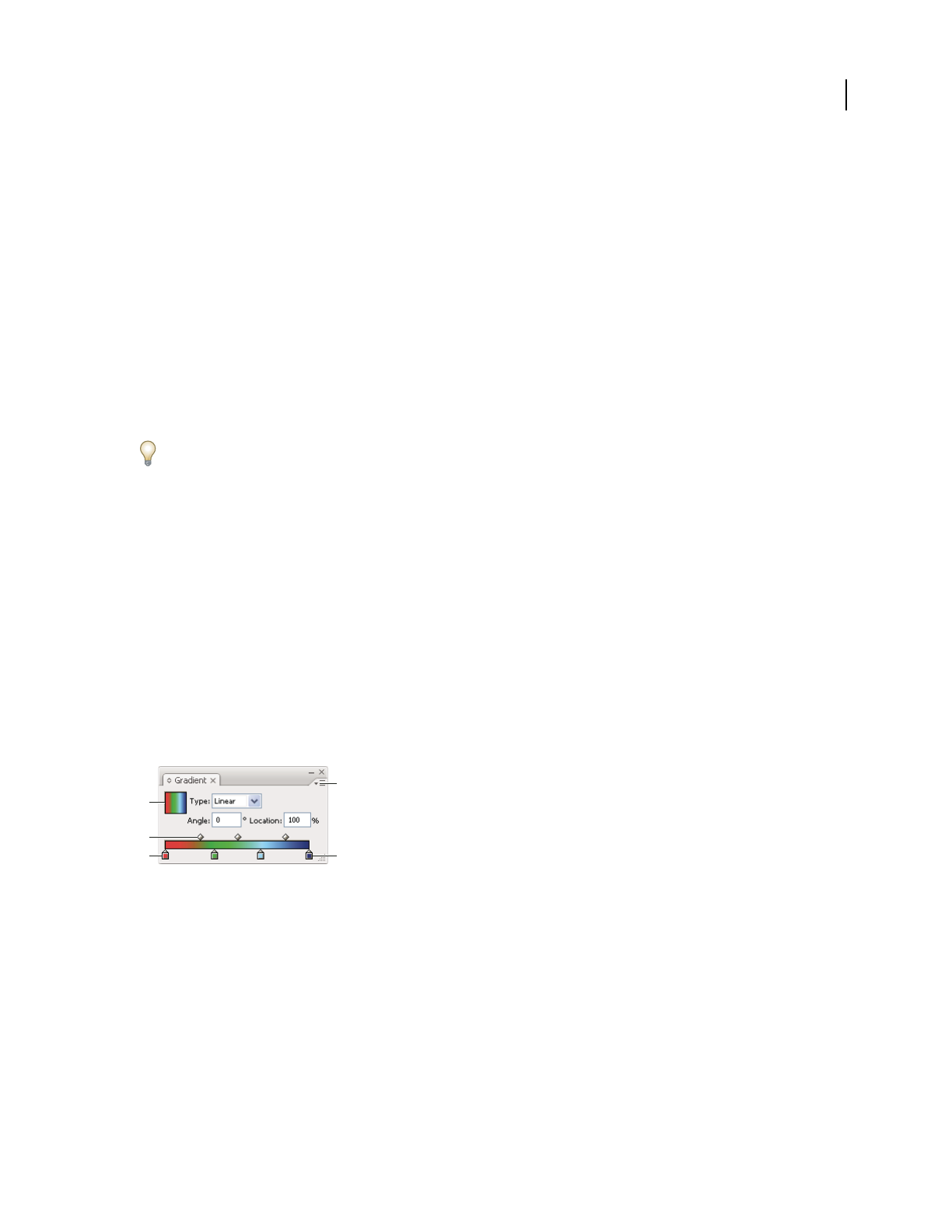
ILLUSTRATOR CS3
User Guide
182
Gradients, meshes, and color blends
About gradients and meshes
Depending on the effect you want, you can use the following methods to apply color gradients to objects.
Gradient fill Use if you want to apply a graduated blend of colors as you would apply any other color. Creating a
gradient fill is a good way to create a smooth color gradation across one or more objects. You can save a gradient as
a swatch to make it easy to apply the gradient to multiple objects.
Mesh object Use if you want to create a single, multicolored object on which colors can flow in different directions—
and transition smoothly from one point to another. By creating a fine mesh on an object and manipulating the color
characteristics at each point in the mesh, you can precisely manipulate the coloring of the mesh object. You can also
apply color to four mesh points at the same time by clicking the patch between them to create broad color changes
on a portion of the object.
If you want to create blends of colors, opacities, and shapes between objects, use the Blend command or the Blend
tool. You select the beginning and ending shapes, opacities, and colors, and Illustrator creates the intermediate steps
to create the final blend.
See also
“Blending objects” on page 239
“Blend colors” on page 125
Gradient panel overview
Use the Gradient panel (Window > Gradient) to apply, create, and modify gradients. It’s helpful to show all options
when working with this panel (choose Show Options from the panel menu).
The Gradient Fill box displays the current gradient colors and type. When you click this box, the selected object is
filled with the gradient. By default, the panel includes a start and end color box, but you can add more color boxes
by clicking anywhere along the color slider.
Gradient panel
A. Gradient Fill box B. Gradient slider C. Start color D. Panel menu E. End color
See also
“Workspace overview” on page 14
Create or modify gradients
Gradient colors are defined by a series of stops in the gradient slider. A stop is the point at which a gradient changes
from one color to the next and is identified by a square below the gradient slider. The squares in the Gradient panel
display the color currently assigned to each gradient stop. With a radial gradient, the leftmost gradient slider defines
the center point’s color fill, which
radiates outward to the color of the rightmost gradient slider.
D
A
B
CE

ILLUSTRATOR CS3
User Guide
183
For a video on using gradients to enhance your drawings, see www.adobe.com/go/vid0050. For a tutorial on creating
gradients, see the Unleash the power of gradients tutorial at www.adobe.com/go/learn_ai_tutorials_gradients.
1 Do one of the following:
•To create a new gradient, deselect all objects and click the gradient box at the bottom of the Tools panel.
•To modify an object’s gradient, select the object.
•To modify a preset gradient, click a gradient swatch in the Swatches panel.
To display only gradients in the Swatches panel, click the Show Swatch Kinds button and choose Show Gradient
Swatches.
2 In the Gradient panel, select a gradient type (Linear or Radial).
3 If you select Linear, enter an angle of direction for the gradient in the Angle text box. Or, drag the Gradient
tool in the document window to set the angle.
4 Select colors for the gradient:
•To define the starting and ending colors of a gradient, click the leftmost or rightmost gradient stop. Specify a color
in the Color panel, or Alt-click (Windows) or Option-click (Mac OS) a color swatch in the Swatches panel. Or,
drag a color from the Color panel or the Swatches panel onto the gradient stop.
Note: If you create a gradient between spot colors, you must deselect Convert To Process in the Separation Setup dialog
box to print the gradient in individual spot color separations.
•To add intermediate colors to a gradient, drag a color from the Swatches panel or the Color panel onto the gradient
slider. Or, click anywhere below the gradient slider, and then select a color as you would for the starting or ending
color. To delete an intermediate color, drag the square off the gradient slider.
•To adjust the midpoints of the gradient’s color stops (the point at which two color stops are 50%), drag a diamond
icon located above the slider or select the icon and enter a value between 0 and 100 in the Location text box.
•To adjust the endpoints of the gradient’s color stops, drag the leftmost or rightmost gradient stop below the
gradient slider.
5 Click the New Swatch button in the Swatches panel to save the new or modified gradient as a swatch. Or, drag the
gradient from the Gradient panel or Tools panel to the Swatches panel.
Note: To modify the direction of the gradient, see “Change gradient direction or apply across multiple objects” on
page 184.
See also
“Printing gradients, meshes, and color blends” on page 414
Apply an existing gradient to an object
❖Select an object and do one of the following:
•To apply the last used gradient, click the Gradient box in the Tools panel or the Gradient Fill box in the
Gradient panel.
•To apply a preset or previously saved gradient, click a gradient swatch in the Swatches panel.
To display only gradients in the Swatches panel, click the Show Swatch Kinds button and choose Show Gradient
Swatches.

ILLUSTRATOR CS3
User Guide
184
See also
“Create or modify gradients” on page 182
Change gradient direction or apply across multiple objects
Once you have filled an object with a gradient, you can use the Gradient tool to modify the gradient by “drawing” a
new fill path. This tool lets you change the direction of a gradient, change the beginning point and endpoint of a
gradient, and apply a gradient across multiple objects.
1 Fill the object or objects with a gradient. To apply a gradient across multiple objects, fill all the objects with a
gradient.
2 Select the object or objects.
3 Select the Gradient tool .
4 Position the pointer where you want to define the beginning point of the gradient, and drag across the object in
the direction you want the gradient to be painted.
5 Release the mouse button where you want to define the endpoint of the gradient.
About mesh objects
A mesh object is a multicolored object on which colors can flow in different directions and transition smoothly from
one point to another. When you create a mesh object, multiple lines called mesh lines crisscross the object and
provide a way to easily manipulate color transitions on the
object. By moving and editing points on the mesh lines,
you can change the intensity of a color shift, or change the extent of a colored area on the
object.
At the intersection of two mesh lines is a special kind of anchor point called a mesh point. Mesh points appear as
diamonds and have all of the same properties as anchor points but with the added capability of accepting color. You
can add and delete mesh points, edit the mesh points, or change the color associated with each mesh point.
Anchor points also appear in the mesh (differentiated by their square rather than diamond shape), and can be added,
deleted, edited, and moved as with any anchor points in Illustrator. Anchor points can be placed on any mesh line;
you can click an anchor point and drag its direction lines to modify it.
The area between any four mesh points is called the mesh patch. You can also change the color of the mesh patch
using the same techniques as changing colors on a mesh point.
Diagram of a mesh object
A. Mesh line B. Mesh patch C. Mesh point D. Anchor point
B
A
C
D

ILLUSTRATOR CS3
User Guide
185
Create mesh objects
You can create mesh objects from vector objects, with the exception of compound paths and text objects. You cannot
create mesh objects from linked images.
To improve performance and redraw speed, keep the size of mesh objects to a minimum. Complex mesh objects can
greatly reduce performance. Therefore, it is better to create a few small, simple mesh objects than to create a single,
complex mesh object. When converting complex objects, use the Create Mesh command for the best results.
Note: When printing mesh objects, spot colors are preserved for EPS, PDF, and PostScript output.
For more information on creating a gradient mesh object, see the Achieve photo realism with Gradient Mesh tutorial
at www.adobe.com/go/learn_ai_tutorials_gradientmesh.
See also
“Apply an existing gradient to an object” on page 183
Create a mesh object with an irregular pattern of mesh points
1
Select the Mesh tool , and select a fill color for the mesh points.
2 Click where you want to position the first mesh point.
The object is converted to a mesh object with the minimum number of mesh lines.
3 Continue clicking to add additional mesh points. Shift-click to add a mesh point without changing to the current
fill color.
Create a mesh object with a regular pattern of mesh points
1
Select the object and choose Object > Create Gradient Mesh.
2 Set the number of rows and columns, and select the direction of the highlight from the Appearance menu:
Flat Applies the object’s original color evenly across the surface, resulting in no highlight.
To Center Creates a highlight in the center of the object.
To Edge Creates a highlight on the edges of the object.
3 Enter a percentage of white highlight to apply to the mesh object. A value of 100% applies maximum white
highlight to the object; a value of 0% applies no white highlight to the object.
Convert a gradient-filled object to a mesh object
1
Select the object and choose Object > Expand.
2 Select Gradient Mesh, and click OK.
The selected object is converted to a mesh object that takes the shape of the gradient, either circular (radial) or
rectangular (linear).
Edit mesh objects
You can edit a mesh object by adding, deleting, and moving mesh points; changing the color of mesh points and mesh
patches; and converting the mesh object back to a regular object.
Add a mesh point
❖Select the Mesh tool and select a fill color for the new mesh points. Then click anywhere in the mesh object.
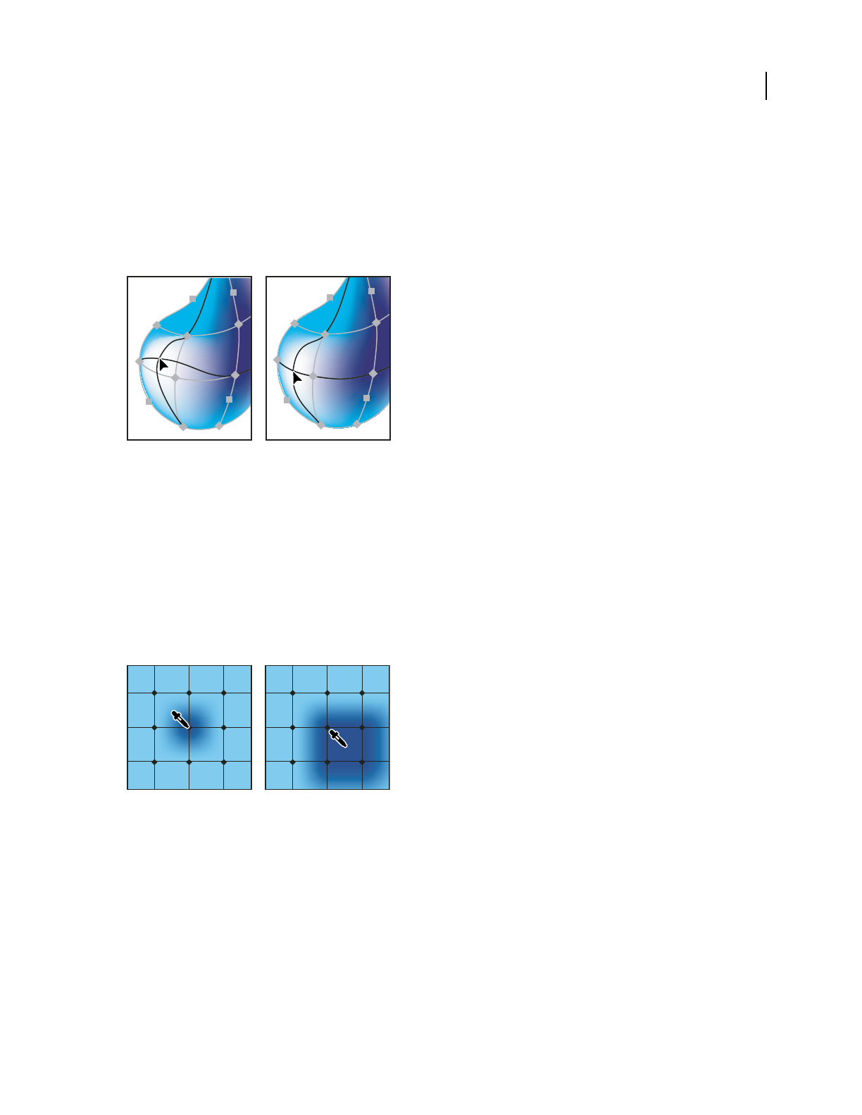
ILLUSTRATOR CS3
User Guide
186
Delete a mesh point
❖Alt-click (Windows) or Option-click (Mac OS) the mesh point with the Mesh tool.
Move a mesh point
❖Drag it with the Mesh tool or Direct Selection tool. Shift-drag a mesh point with the Mesh tool to keep the mesh
point on a mesh line. This is a convenient way to move a mesh point along a curved mesh line without distorting the
mesh line.
Dragging to move mesh point (left) compared to Shift- dragging with the Mesh tool to constrain the point to the mesh line (right)
Note: When you select the mesh point with the Mesh tool or Direct Selection tool, direction lines appear on it. You can
drag the direction lines to edit the mesh point as you would any anchor point. Shift-drag a direction point with the Mesh
tool to move all direction lines for the mesh point at once.
Change the color of a mesh point or patch
❖Do one of the following:
•Select the mesh object, and the drag a color from the Color panel or Swatches panel onto the point or patch.
•Deselect all objects and select a fill color. Then select the mesh object and use the Eyedropper tool to apply the fill
color to mesh points or patches.
Adding color to a mesh point (left) compared to adding color to a mesh patch (right)
Convert a mesh object back to a path object
❖Select the mesh object, choose Object > Path > Offset Path, and then enter zero for the offset value.

ILLUSTRATOR CS3
User Guide
187
Patterns
About patterns
Illustrator comes with many patterns that you can access in the Swatches panel and in the Illustrator Extras folder on
the Illustrator CD. You can customize existing patterns and design patterns from scratch with any of the Illustrator
tools. Patterns intended for filling objects (fill patterns) differ in design and tiling from patterns intended to be
applied to a path with the Brushes panel (brush patterns). For best results, use fill patterns to fill objects and brush
patterns to outline objects.
When designing patterns, it helps to understand how Adobe Illustrator tiles patterns:
•All patterns tile from left to right from the ruler origin (by default, the bottom left of the artboard) to the opposite
side of the artwork. To adjust where all patterns in your artwork begin tiling, you can change the file’s ruler origin.
•Fill patterns typically have only one tile.
•Brush patterns can consist of up to five tiles—for the sides, outer corners, inner corners, and the beginning and
end of the path. The additional corner tiles enable brush patterns to flow smoothly at corners.
•Fill patterns tile perpendicular to the x axis.
•Brush patterns tile perpendicular to the path (with the top of the pattern tile always facing outward). Also, corner
tiles rotate 90˚ clockwise each time the path changes direction.
•Fill patterns tile only the artwork within the pattern bounding box—an unfilled and unstroked (non-printing)
rectangle backmost in the artwork. For fill patterns, the bounding box acts as a mask.
•Brush patterns tile artwork within the pattern bounding box and protruding from or grouped with it.
See also
“About fills and strokes” on page 152
Guidelines for constructing pattern tiles
Follow these general guidelines for constructing pattern tiles:
•To make the pattern less complex so that it prints more rapidly, remove any unnecessary detail from the pattern
artwork, and group objects that are painted with the same color so that they are adjacent in the stacking order.
•As you create your pattern tile, zoom in on the artwork to align elements more accurately, and then zoom out from
the artwork for the final selection.
•The more complex the pattern, the smaller should be the selection used to create it; however, the smaller the
selection (and the pattern tile it creates), the more copies are needed to create the pattern. Thus, a 1-inch-square
tile is more efficient than a 1/4-inch-square tile. If you are creating a simple pattern, you can include multiple
copies of the object within the selection intended for the pattern tile.
•To create simple line patterns, layer stroked lines of varying widths and colors, and place an unfilled, unstroked
bounding box behind the lines to create a pattern tile.
•To make an organic or textural pattern appear irregular, vary the tile artwork subtly for a more realistic effect. You
can use the Roughen effect to control variations.
•To ensure smooth tiling, close paths before defining the pattern.
•Enlarge your artwork view and check for flaws before defining a pattern.

ILLUSTRATOR CS3
User Guide
188
•If you draw a bounding box around the artwork, make sure that the box is a rectangle, that it is the backmost object
of the tile, and that it is unfilled and unstroked. To have Illustrator use this bounding box for a brush pattern, make
sure that nothing protrudes from it.
Follow these additional guidelines when creating brush patterns:
•When possible, confine artwork to an unpainted bounding box so that you can control how the pattern tiles.
•Corner tiles must be square and have the same height as side tiles to align properly on the path. If you plan to use
corner tiles with your brush pattern, align objects in the corner tiles horizontally with objects in the side tiles so
that the patterns tile correctly.
•Create special corner effects for brush patterns using corner tiles.
See also
“Apply a fill color to an object” on page 153
Create pattern swatches
1 Create artwork for the pattern.
2 (Optional) To control the spacing between pattern elements or to clip out portions of the pattern, draw a pattern
bounding box (an unfilled rectangle) around the artwork you want to use as a pattern. Choose Object > Arrange >
Send To Back to make the rectangle the backmost object. To use the rectangle as a bounding box for a brush or fill
pattern, fill and stroke it with None.
3 Use the Selection tool to select the artwork and bounding box (if any) that will make up the pattern tile.
4 Do one of the following:
•Choose Edit > Define Pattern, enter a name in the New Swatch dialog box, and click OK. The pattern displays in
the Swatches panel.
•Drag the artwork to the Swatches panel.
See also
“Guidelines for constructing pattern tiles” on page 187
“About swatches” on page 102
Create seamless geometric patterns
1 Make sure that Smart Guides are turned on and that Snap To Point is selected in the View menu.
2 Select the geometric object. For precise positioning, position the Direct Selection tool on one of the object’s anchor
points.
3 Begin dragging the object vertically from one of its anchor points; then press Alt+Shift (Windows) or
Option+Shift (Mac OS) to copy the object and constrain its movement.
4 When the copy of the object has snapped into place, release the mouse button and then release the keys.
5 Using the Group Selection tool, Shift-click to select both objects, and begin dragging the objects horizontally by
one of their anchor points; then press Alt+Shift (Windows) or Option+Shift (Mac OS) to create a copy and constrain
the move.
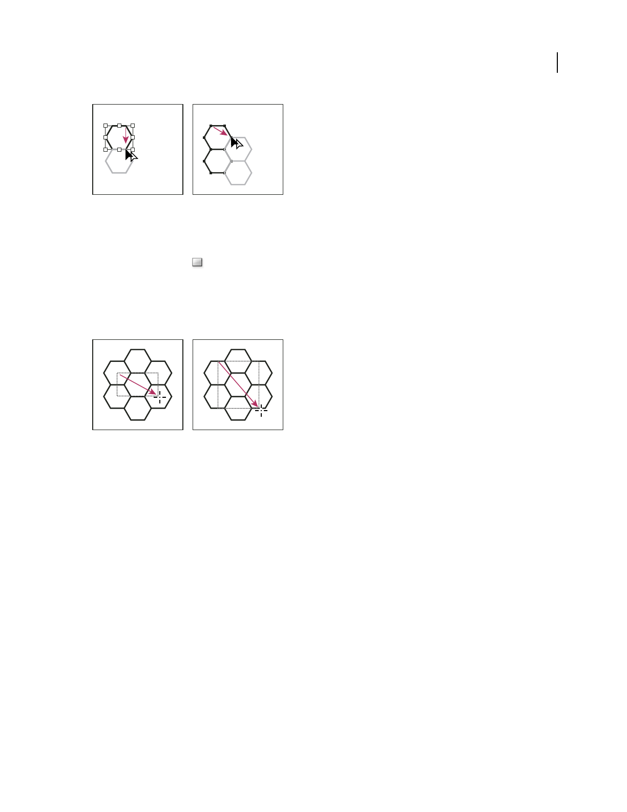
ILLUSTRATOR CS3
User Guide
189
Select both objects (left) and drag to create a copy (right).
6 When the copy of the object has snapped into place, release the mouse button, and then release the keys.
7 Repeat steps 2 through 6 until you’ve built the pattern you want.
8 Use the Rectangle tool to do one of the following:
•For a fill pattern, draw a bounding box from the center point of the upper left object to the center point of the
lower right object.
•For a brush pattern, draw a bounding box that surrounds the objects and coincides with their outer boundaries.
If the pattern is to be a corner tile, hold down Shift as you drag to constrain the bounding box to a square.
Bounding box for a fill pattern (left) compared to the bounding box for a brush pattern (right)
9 Paint the geometric objects the desired color.
10 Save the geometric objects as a pattern swatch.
Construct irregularly textured patterns
1 Choose View > Snap To Point.
2 Draw a bounding box. If you are creating a brush pattern, skip to step 13.
3 Draw the texture with the objects or lines that intersect only the left side of the bounding rectangle.
4 Using the Direct Selection tool, select the texture and the rectangle, and place the pointer on the lower left corner
of the rectangle.
5 Drag the rectangle to the right; then press Alt+Shift (Windows) or Option+Shift (Mac OS) to create a copy and
to constrain the move.
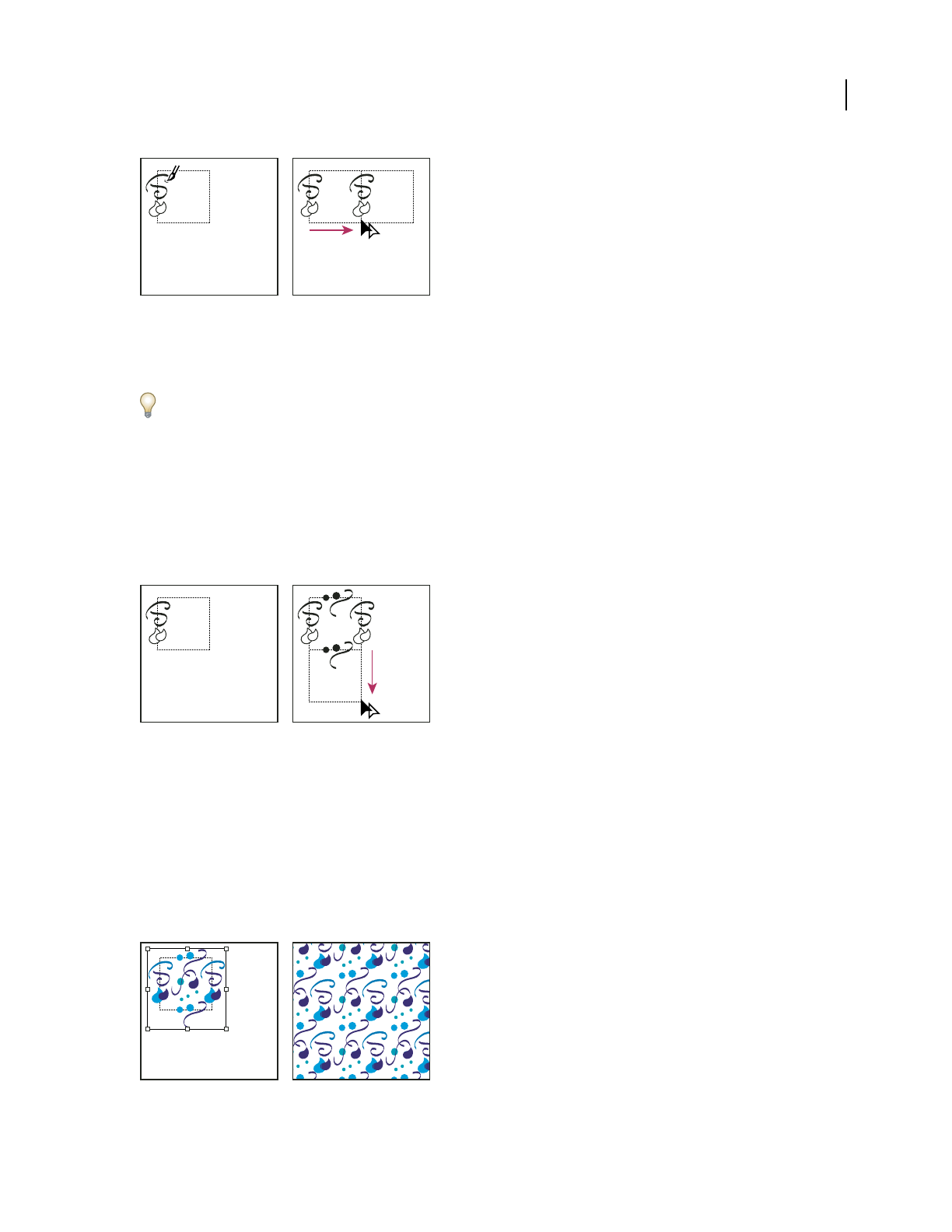
ILLUSTRATOR CS3
User Guide
190
Draw texture on the left side of bounding box (left), and then copy texture and rectangle (right).
When the upper left corner point of the copy snaps to the upper right corner point of the bounding box, release the
mouse button, and then release the keys.
If you know the exact dimensions of the bounding box, you can select only the textures and use the Move command
to specify a horizontal move the width of the rectangle. Be sure to click Copy instead of OK in the Move dialog box.
6 Click outside the rectangle to deselect it.
7 Select the right rectangle, and delete it.
8 Continue drawing your texture with only the objects or lines that intersect the top side of the rectangle.
9 When you finish with the top side only, select all of the lines or objects crossing the top side and the bounding
box; then press Alt+Shift (Windows) or Option+Shift (Mac OS) and drag downward to create a copy and to
constrain the move.
Draw texture on top side of bounding box (left), and then copy texture and rectangle (right).
10 When the upper left corner point of the copy snaps to the lower left corner point of the rectangle, release the
mouse button and then the keys.
11 Deselect everything.
12 Select the lower rectangle and any objects that don’t cross the top rectangle, and delete them.
13 Using the Pencil tool, fill the middle of the rectangle with your texture. Be careful not to intersect any of the
rectangle edges. Paint the texture.
14 Save the artwork and rectangle as a pattern swatch.
Defining artwork and rectangle as a pattern (left) compared to filling an area with the pattern (right)
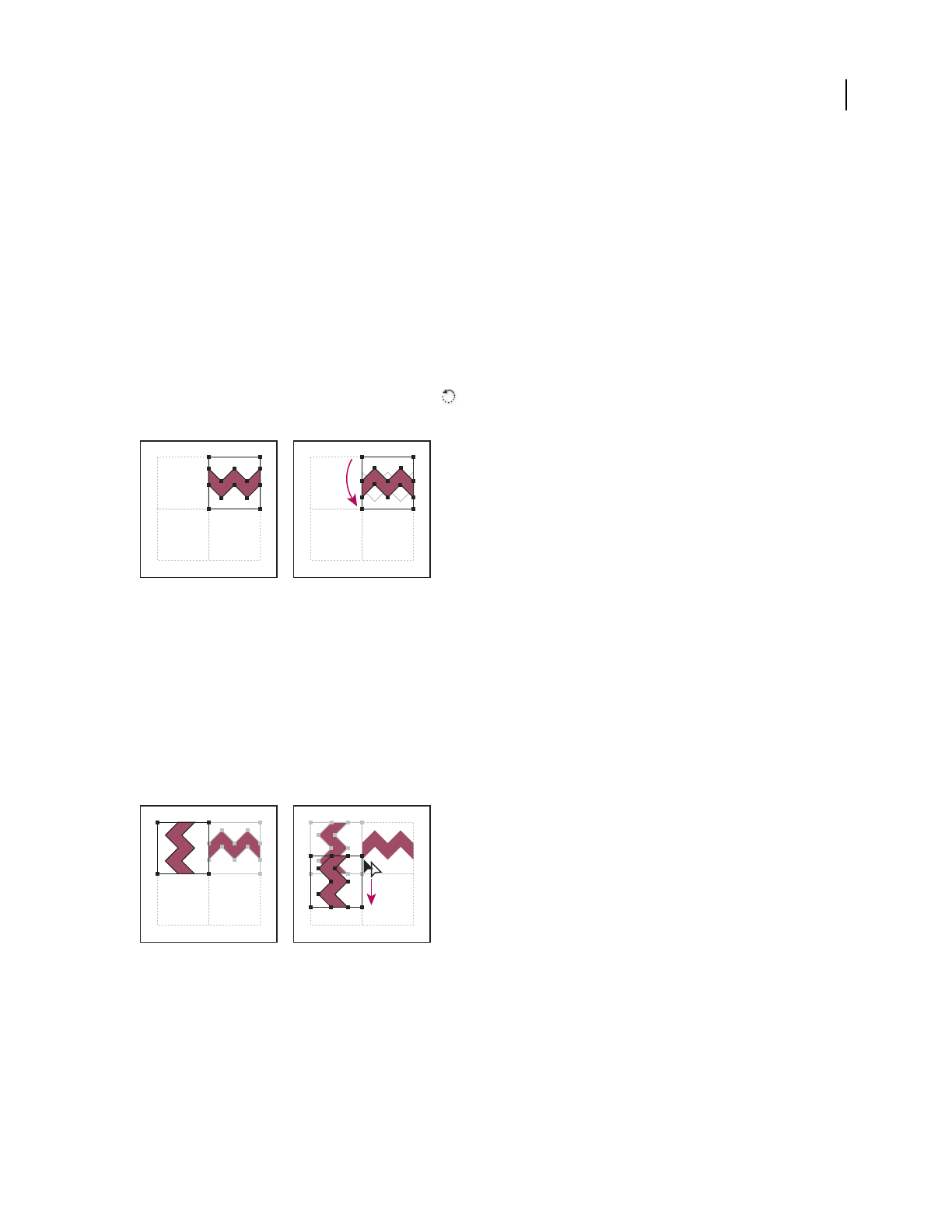
ILLUSTRATOR CS3
User Guide
191
Create corner tiles for brush patterns
Corner tiles lend special border effects when applying brush patterns. You can create corner tiles from scratch, or
you can use a brush pattern’s side tile as the basis for designing complementary outer and inner (reflected –135˚)
corner tiles.
1
Choose File > Open, locate a brush pattern file (supplied with Adobe Illustrator) that you want to use, and click Open.
2 Choose Window > Brushes. Select the tile you want to use, and drag it to the center of your artwork.
3 If the tile does not have a square bounding box, create a box that completely encompasses the artwork, the same
height as the side tile. (Side tiles can be rectangular.) Fill and stroke the box with None, and choose Object >
Arrange > Send To Back to make the box backmost in your artwork. (The bounding box helps you align the new tile.)
4 Select the tile and the bounding box.
5 To create an outer corner tile, use the Rotate tool to rotate the tile and its bounding box 180˚. Skip this step to
create an inner corner tile.
Pasted tile (left) compared to same tile rotated 180˚ (right)
6 Using the Rotate tool, Alt+Shift-click (Windows) or Option+Shift-click (Mac OS) the lower left corner of the
bounding box. Enter a value of 90˚, and click Copy to create a copy flush left of the first tile. This tile becomes the
corner tile.
7 Using the Selection tool, drag the left tile down by the top right anchor point, pressing Alt+Shift (Windows) or
Option+Shift (Mac OS) to make a copy and constrain the move so that you create a third tile beneath the second.
When the copy’s upper right anchor point snaps to the corner tile’s lower right anchor point, release the mouse
button and Alt+Shift (Windows) or Option+Shift (Mac OS).
You use the third copy for alignment.
Rotate 90˚ and copy left tile (left), and then Alt-drag (Windows) or Option-drag (Mac OS) a corner tile to make a copy beneath it (right).
8 Select the artwork in the right tile. Drag it to the left, pressing Alt+Shift (Windows) or Option+Shift (Mac OS) so
that the right-tile artwork overlaps that in the corner tile.
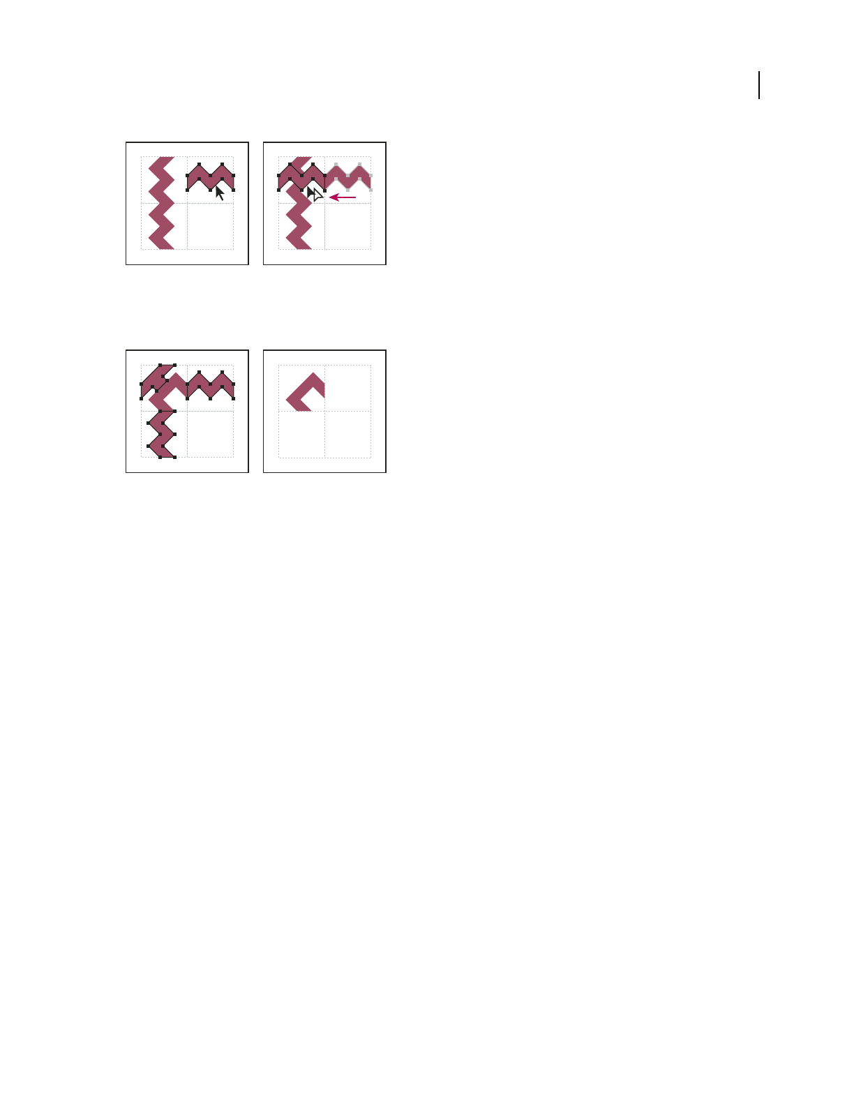
ILLUSTRATOR CS3
User Guide
192
Copy (left) and move upper right tile over corner tile (right).
9 Edit the corner tile so that its artwork lines up vertically and horizontally with the tiles next to it. Select and delete
any portions of the tile that you do not want in the corner, and edit the remaining art to create the final outer corner tile.
Deleting unnecessary elements (left) produces a final outer corner tile (right).
10 Select all of the tile parts including the bounding box.
11 Save the new pattern as a swatch.
12 Double-click the new pattern swatch to bring up the Swatch Options dialog box, name the tile as a variation of
the original (for example, use the suffix “outer”), and click OK.
See also
“Create or modify brushes” on page 169
“Brush options” on page 170
Modify patterns
1 Make sure that nothing is selected in your artwork.
2 In the Swatches panel, select the pattern swatch you want to modify.
3 Drag the pattern swatch onto your artboard, and edit the pattern tile on the artboard.
4 Select the pattern tile, and Alt-drag (Windows) or Option-drag (Mac OS) the modified pattern on top of the old
pattern swatch in the Swatches panel.
The pattern is replaced in the Swatches panel and is updated in the current file.
See also
“Swatches panel overview” on page 103
“Transform an object’s patterns” on page 221

193
Chapter 7: Selecting and arranging
objects
Organizing and laying out your artwork in Adobe Illustrator is made easy with tools that enable you to select,
position, and stack objects precisely. Tools are available that let you measure and align objects; group objects so that
they are treated as a single unit; and selectively isolate, lock, or hide objects.
Selecting objects
Options for selecting objects
Before you can modify an object, you need to distinguish it from the objects around it. You do that by selecting the
object. Once you’ve selected an object, or a part of an object, you can edit it.
Illustrator provides the following selection methods and tools:
Isolation mode Lets you quickly isolate a group of objects or a sublayer from all other art in your document. When
in isolation mode, all nonisolated objects in the document appear dimmed and are not selectable or editable.
Layers panel Lets you quickly and precisely select individual or multiple objects. You can select a single object (even
if it’s in a group), all objects within a layer, and entire groups.
Selection tool Lets you select objects and groups by clicking or dragging over them. You can also select groups
within groups and objects within groups.
Direct Selection tool Lets you select individual anchor points or path segments by clicking on them, or select an
entire path or group by selecting any other spot on the item. You can also select one or more objects in a group of
objects.
Group Selection tool Lets you select an object within a group, a single group within multiple groups, or a set of
groups within the artwork. Each additional click adds all objects from the next group in the hierarchy.
Lasso tool Lets you select objects, anchor points, or path segments by dragging around all or part of the object.
Magic Wand tool Lets you select objects of the same color, stroke weight, stroke color, opacity, or blending mode
by clicking the object.
Live Paint Selection tool Lets you select faces (areas enclosed by paths) and edges (portions of paths between
intersections) of Live Paint groups.
Selection commands (located in the Select menu) Let you quickly select or deselect all objects, and select objects
based on their position relative to other objects. You can also select all objects of a specific type or that share specific
attributes, and save or load selections.
To temporarily activate the last-used selection tool when using another type of tool, hold down Ctrl (Windows) or
Command (Mac OS).
For a video on selecting and manipulating objects, see www.adobe.com/go/vid0034.

ILLUSTRATOR CS3
User Guide
194
See also
“Select paths, segments, and anchor points” on page 68
Specify selection preferences
Selecting paths and points in complex images can be challenging. Using the Selection and Anchor Display prefer-
ences, you can specify the tolerance for pixel selection and choose other options that can make selection easier for a
particular document.
1 Choose Edit > Preferences > Selection & Anchor Display (Windows) or Illustrator > Preferences > Selection &
Anchor Display (Mac OS).
2 Specify any of the following Selection options:
Tolerance Specifies the pixel range for selecting anchor points. Higher values increase the width of the area around
an anchor point that you can click to select it.
Object Selection By Path Only Specifies whether you can select a filled object by clicking anywhere in the object or
whether you have to click a path.
Snap To Point Snaps objects to anchor points and guides. Specify the distance between the object and anchor point
or guide when the snap occurs.
See also
“Select filled objects” on page 198
“Specify anchor point size preferences” on page 55
Isolate groups and sublayers
Isolation mode isolates groups or sublayers so that you can easily select and edit particular objects or parts of objects.
When you use isolation mode, you don’t need to worry about what layer an object is on, nor do you need to manually
lock or hide the objects you don’t want affected by your edits—Illustrator automatically locks all other objects so that
only the objects in the isolated group are affected by the edits you make.
An isolated group or sublayer appears in full color, while the rest of the artwork appears dimmed. The isolation mode
border appears across the top of the illustration window, separated by a line that is the color of the isolated group’s
layer or the isolated sublayer. The isolated group’s or sublayer’s name and location (sometimes referred to as bread
crumbs) appears in the isolation mode border.
Note: When you edit a symbol’s definition, the symbol appears in isolation mode. (See “Edit or redefine a symbol” on
page 86.)
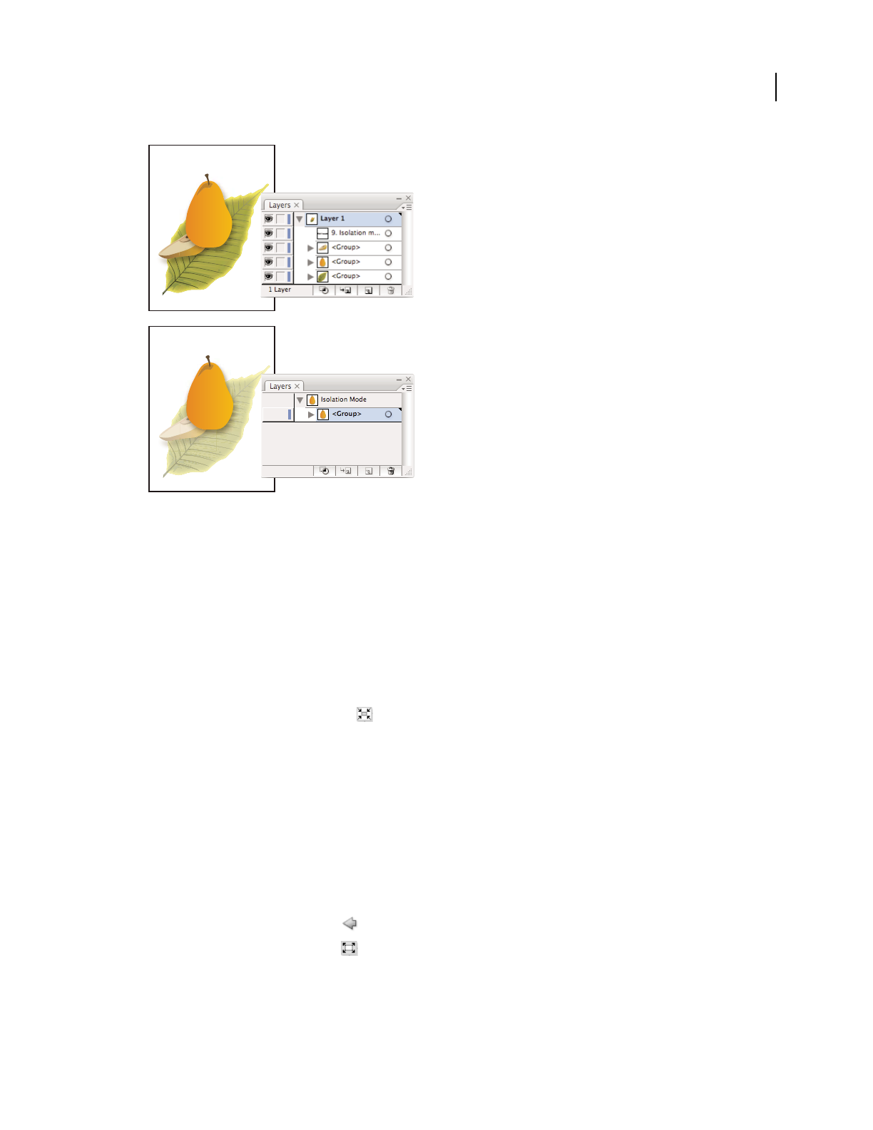
ILLUSTRATOR CS3
User Guide
195
Isolating the pear sublayer
When isolation mode is active, the Layers panel displays only the artwork in the isolated sublayer or group. When
you exit isolation mode, the other layers and groups reappear in the Layers panel.
Note: You cannot enter opacity mask editing mode from inside isolation mode, or vice versa.
For a video on using layers and isolation mode, see www.adobe.com/go/vid0041.
Isolate a group
❖Do one of the following:
•Double-click the group using the Selection tool.
•Click the Isolate Selected Group button in the Control panel.
•Right-click (Windows) or Control-click (Mac OS) the group and choose Isolate Selected Group.
•Select the group in the Layers panel and choose Enter Isolation Mode from the Layers panel menu.
Isolate a sublayer
❖Select the sublayer in the Layers panel, and choose Enter Isolation Mode from the Layers panel menu.
You cannot isolate top level layers.
Exit isolation mode
❖Do one of the following:
•Click the Exit Isolation Mode button or anywhere in the isolation mode bar.
•Click the Exit Isolated Group button in the Control panel.
•Double-click outside of the isolated group.
•Right-click (Windows) or Control-click (Mac OS) and choose Exit Isolated Group.
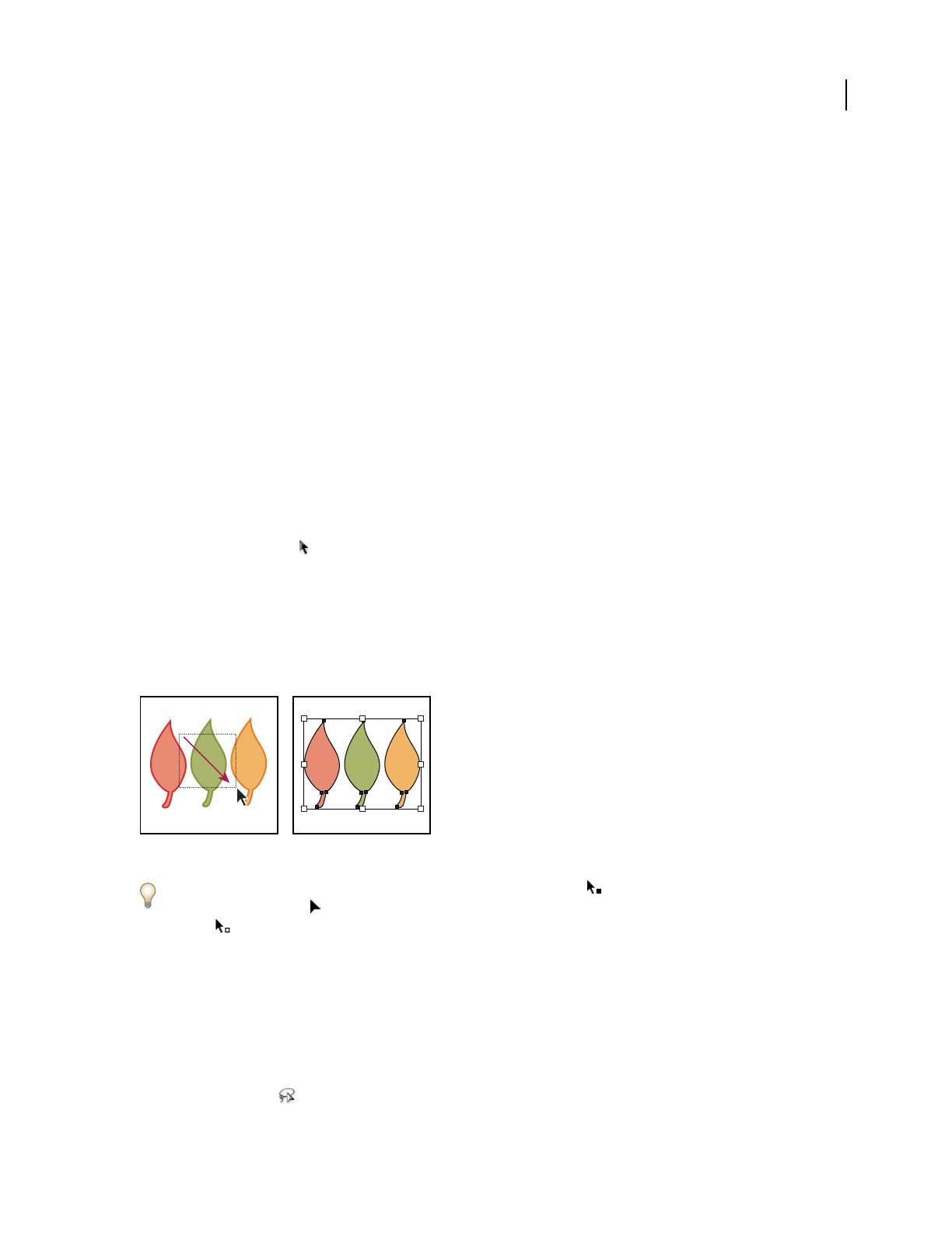
ILLUSTRATOR CS3
User Guide
196
Select objects using the Layers panel
1 In the Layers panel, locate the object you want to select. You may have to click a toggle arrow to expand a layer or
group, or scroll up or down in the panel to locate the object.
2 Do any of the following:
•To select individual objects, click in the object’s selection column (between the target button and the scroll bar).
Shift-click to add or to remove objects from the selection.
•To select all artwork in a layer or group, click in the layer’s or group’s selection column.
•To select all artwork in a layer based on the currently selected artwork, choose Select > Object > All On Same
Layers.
Selection color boxes appear next to each selected item in the panel.
For a video on working with layers, see www.adobe.com/go/vid0041.
See also
“Layers panel overview” on page 211
Select objects with the Selection tool
1 Select the Selection tool .
2 Do either of the following:
•Click an object.
•Drag a marquee around part or all of one or more objects.
3 To add or remove objects from the selection, hold down Shift and click or drag around the objects you want to
add or remove.
Dragging over objects to select them
When the Selection tool is over an unselected object or group, it changes to . When it is over a selected object or
group, the tool changes to . When it is over an anchor point on an unselected object, a hollow square appears next
to the arrow .
For a video on selecting objects, see www.adobe.com/go/vid0034.
See also
“Keys for selecting” on page 464
Select objects with the Lasso tool
1 Select the Lasso tool .

ILLUSTRATOR CS3
User Guide
197
2 Drag around or across the objects.
Select objects with the Magic Wand tool
Use the Magic Wand tool to select all objects in a document with the same or similar fill attributes (such as color and
pattern).
You can customize the Magic Wand tool to select objects based on stroke weight, stroke color, opacity, or blending
mode. You can also change the tolerances used by the Magic Wand tool to identify similar objects.
See also
“Workspace overview” on page 14
Select objects based on fill color with the Magic Wand tool
1
Select the Magic Wand tool .
2 Do one of the following:
•To create a new selection, click the object containing the attributes you want to select. All objects with the same
attributes that were clicked are selected.
•To add to the current selection, press Shift and click another object containing the attributes you want to add. All
objects with the same attributes that were clicked are also selected.
•To subtract from the current selection, press Alt (Windows) or Option (Mac OS) and click the object containing
the attributes you want to subtract. All objects with the same attributes are removed from the selection.
Customize the Magic Wand tool
1
Do one of the following to open the Magic Wand panel:
•Double-click the Magic Wand tool in the Tools panel.
•Choose Window > Magic Wand.
2 To select objects according to their fill color, select Fill Color, and then enter a Tolerance value between 0 and 255
pixels for RGB or 0 and 100 pixels for CMYK.
Low tolerance values select objects that are very similar to the object you click; higher tolerance values select objects
with a broader range of the selected property.
3 Choose Show Stroke Options from the Magic Wand panel menu, and do any of the following:
•To select objects according to their stroke color, select Stroke Color, and then enter a Tolerance value between 0
and 255 pixels for RGB or 0 and 100 pixels for CMYK.
•To select objects according to their stroke weight, select Stroke Weight, and then enter a Tolerance value between
0 and 1000 points.
4 Choose Show Transparency Options from the Magic Wand panel menu and do any of the following:
•To select objects according to their transparency or blending mode, select Opacity, and then enter a Tolerance
value between 0 and 100%.
•To select objects according to their blending mode, select Blending Mode.
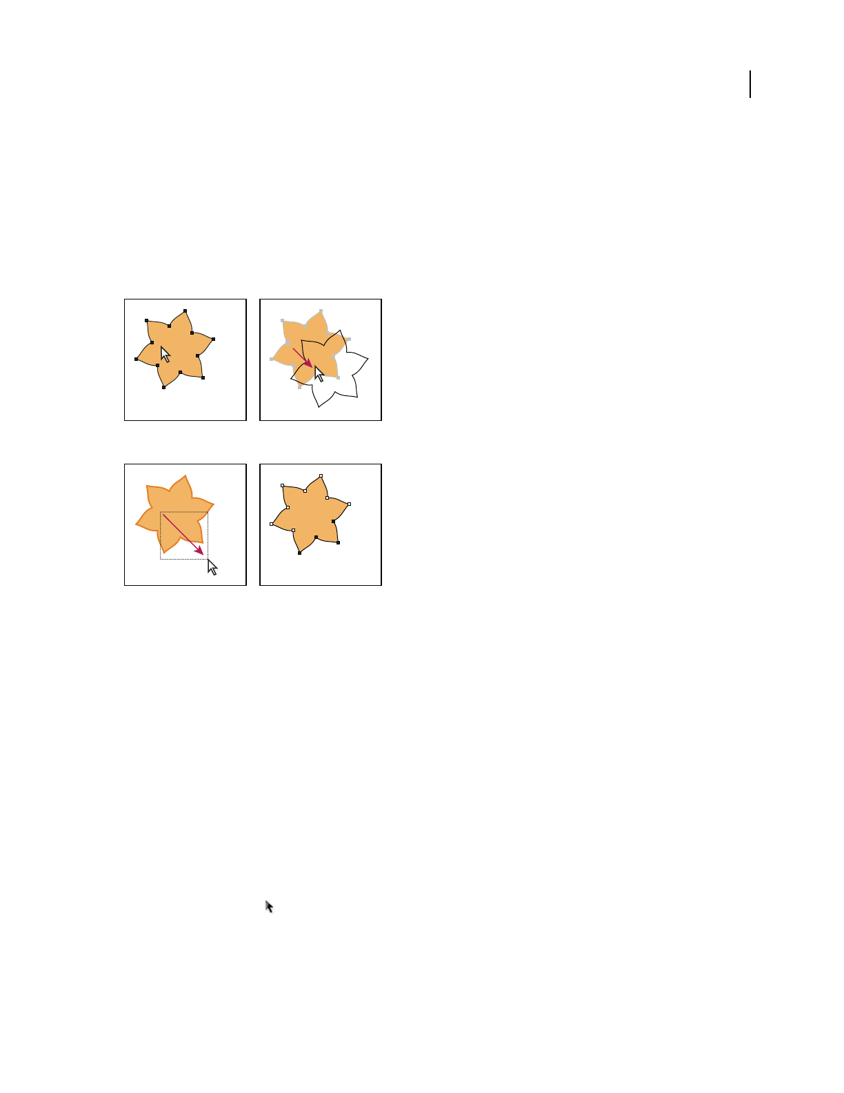
ILLUSTRATOR CS3
User Guide
198
Select filled objects
The Object Selection By Path Only preference determines whether you can select a filled object by clicking anywhere
within the object’s area with the Selection or Direct Selection tools, or whether you must click a path segment or
anchor point with these tools. By default, this preference is off. In some cases, you may want to turn the preference
on—for example, when you work with overlapping filled objects and you want to easily select underlying objects.
Note: The Object Selection By Path Only preference is not applicable when selecting unfilled objects or when viewing
artwork as outlines. In these cases, you can never select an object by clicking inside the object’s path. (See “View artwork
as outlines” on page 45.)
With Object Selection By Path Only deselected, clicking inside the object and dragging selects and moves an object.
With Object Selection By Path Only selected, dragging with the Direct Selection tool selects points and segments within a marquee.
❖Choose Edit > Preferences > Selection & Anchor Display (Windows) or Illustrator > Preferences > Selection &
Anchor Display (Mac OS), and select Object Selection By Path Only.
Select groups and objects in a group
Once objects are grouped, selecting any part of the group with the Selection tool or the Lasso tool selects the entire
group. If you are unsure whether an object is a part of a group, select it with the Selection tool.
The Direct-Selection tool and Lasso tool let you select a single path or object that is part of one group or several
groups. If you have groups of objects within other groups, you can select the next group in the grouping hierarchy
by using the Group-Selection tool. Each successive click adds another subset of grouped objects to the selection.
See also
“Group or ungroup objects” on page 201
Select one or more groups with the Selection tool
1
Select the Selection tool .
2 Do one of the following to any object that’s within the group:
•Click the object.

ILLUSTRATOR CS3
User Guide
199
•Drag around part or all of the object.
3 To add or remove a group to the selection, hold down Shift while clicking the group to add or remove.
Select objects and groups within groups with the Selection tool
1
Select the Selection tool .
2 Double-click a group. The group is selected and is highlighted with a gray border.
3 Do any of the following:
•Double-click to select further down into the group structure.
Double-clicking is a handy way to select objects (as opposed to faces and edges) within a Live Paint group.
•Click to select an object within the selected group.
•Draw to add an object to the selected group.
4 Double-click outside the group to deselect the group.
Select a single object within a group
1
Do one of the following:
•Select the Group Selection tool , and click the object.
•Select the Lasso tool , and drag around or across the object’s path.
•Select the Direct Selection tool , and click within the object, or drag a marquee around part or all of the object’s path.
2 To add or remove an object or group to the selection (with any selection tool), hold down Shift and select the
object to add or remove.
Select objects and groups with the Group Selection tool
1
Select the Group Selection tool , and click an object that’s within the group you want to select. The object is
selected.
2 To select the object’s parent group, click the same object again.
3 Click the same object again to select additional groups that are grouped with the selected group until you have
selected everything you want to include in your selection.
The first click with the Group Selection tool selects an object in a group (left); the second click selects the object’s group (right).
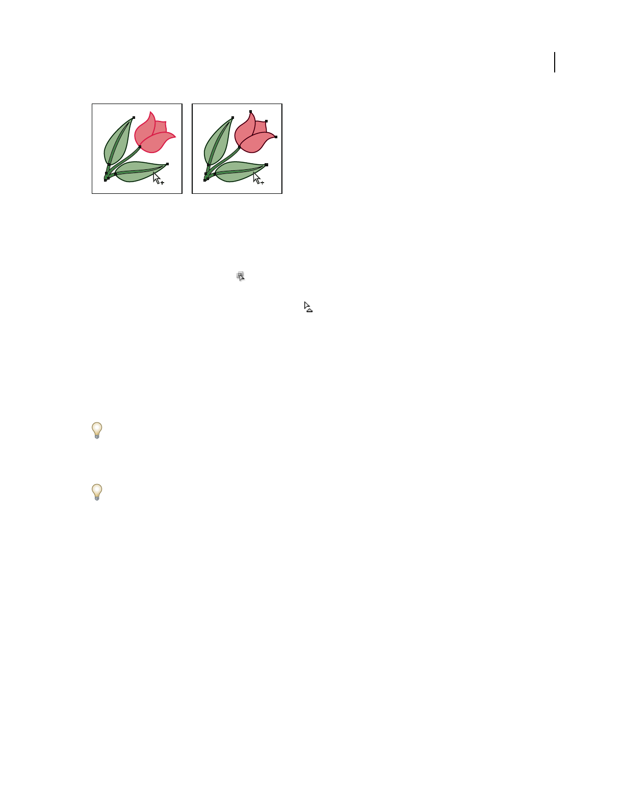
ILLUSTRATOR CS3
User Guide
200
The third click adds the next group to the selection (left); the fourth click adds the third group (right).
Select faces and edges in a Live Paint group
You select faces and edges of a Live Paint tool using the Live Paint Selection tool. If you want to select the entire Live
Paint group, simply click it with the Selection tool.
1 Select the Live Paint Selection tool .
2 Move the tool over the Live Paint group until the face or edge you want to select is highlighted. (When the Live
Paint Selection tool is over an edge, the tool changes to .)
3 Do any of the following:
•Click to select the highlighted face or edge.
•Drag a marquee around multiple faces or edges. Any face or edge that is fully or partially enclosed by the marquee
is included in the selection.
•Double-click a face or edge to select all connected faces/edges of the same color (flood select).
•Triple-click a face or edge to select all faces/edges of the same color (select same).
If you have difficulty selecting a small face or edge, magnify the view or set the Live Paint Selection tool options to
select only fills or strokes.
4 To add or remove faces and edges from the selection, hold down Shift and click the faces/edges you want to add
or remove.
To switch to the Eyedropper tool and sample fills and strokes, Alt-click (Windows) or Option-click (Mac OS) the fill
and stroke you want.
See also
“About Live Paint” on page 158
“Keys for working with Live Paint groups” on page 465
Live Paint Selection tool options
You access the Live Paint selection tool options by double-clicking the tool in the Tools panel.
Select Fills Selects the faces (the area within edges) of Live Paint groups.
Select Strokes Selects the edges of Live Paint groups.
Highlight Outlines the face or edge the cursor is currently over.
Color Sets the color for the highlight. You can choose a color from the menu or click the paint swatch to specify a
custom color.
Width Specifies how thick to make the selection highlight.

ILLUSTRATOR CS3
User Guide
201
Select the next object in the stacking order
You can select an object above or below a selected object in the stacking order. These commands do not work when
in isolation mode.
❖Do one of the following:
•To select the nearest object above or below the selected object, choose Select > Next Object Above or Select > Next
Object Below.
•To select the topmost or bottommost object that overlaps the selected object’s area and that is in a different layer,
right-click (Windows) or Control-click (Mac OS) and choose First Object Above or Last Object Below from the
context menu.
Select objects by characteristic
You can select objects based on various groupings, including by formatting attribute, by layer, or by kind, such as
brush strokes or clipping masks.
•To select all objects in a file, choose Select > All. (To deselect all objects, choose Select > Deselect.)
Note: Using any selection tool, you can also deselect all objects by clicking or dragging at least 2 pixels away from any
object.
•To select all objects with the same attributes, select one with the attribute you want, choose Select > Same, and
then choose an attribute from the list (Blending Mode, Fill & Stroke, Fill Color, Opacity, Stroke Color, Stroke
Weight, Style, Symbol Instance, or Link Block Series).
You can also use the Magic Wand tool to select all objects with the same color, stroke weight, stroke color, opacity, or
blending mode.
•To select all objects of a certain kind, deselect all artwork, choose Select > Object, and then choose an object type
(All On Same Layers, Direction Handles, Brush Strokes, Clipping Masks, Stray Points, or Text Objects).
Repeat or invert a selection
•To repeat the last selection command used, choose Select > Reselect.
•To select all unselected objects, and deselect all selected objects, choose Select > Inverse.
Save a selection
1 Select one or more objects, and choose Select > Save Selection.
2 In the Save Selection dialog box, type a name in the Name text box, and click OK.
You can reload a saved selection by choosing the selection name from the bottom of the Select menu. You can also
delete or rename a selection by choosing Select
> Edit Selection.
Grouping and expanding objects
Group or ungroup objects
You can combine several objects into a group so that the objects are treated as a single unit. You can then move or
transform a number of objects without affecting their attributes or relative positions. For example, you might group
the objects in a logo design so that you can move and scale the logo as one unit.

ILLUSTRATOR CS3
User Guide
202
Grouped objects are stacked in succession on the same layer of the artwork and behind the frontmost object in the
group; therefore, grouping may change the layering of objects and their stacking order on a given layer. If you select
objects in different layers and then group them, the objects are grouped in the layer of the topmost selected object.
Groups can also be nested—that is, they can be grouped within other objects or groups to form larger groups. Groups
appear as <Group> items in the Layers panel. You can use the Layers panel to move items in and out of groups.
1 Select the objects to be grouped or the group to be ungrouped.
2 Choose either Object > Group or Object > Ungroup.
See also
“Layers panel overview” on page 211
Expand objects
Expanding objects enables you to divide a single object into multiple objects that make up its appearance. For
example, if you expand a simple object, such as a circle with a solid-color fill and a stroke, the fill and the stroke each
become a discrete object. If you expand more complex artwork, such as an object with a pattern fill, the pattern is
divided into all of the distinct paths that created it.
You typically expand an object when you want to modify the appearance attributes and other properties of specific
elements within it. In addition, expanding objects may be helpful when you want to use an object that is native to
Illustrator (such as a mesh object) in a different application that doesn’t recognize the object.
Before (left) and after (right) expanding an object that has a fill and stroke
Expanding is particularly helpful if you are having difficulty printing transparency effects, 3D objects, patterns,
gradients, strokes, blends, flares, envelopes, or symbols.
1 Select the object.
2 Choose Object > Expand.
If the object has appearance attributes applied to it, the Object > Expand command is dimmed. In this case, choose
Object
> Expand Appearance and then choose Object > Expand.
3 Set options, and then click OK:
Object Expands complex objects, including live blends, envelopes, symbol sets, and flares.
Fill Expands fills.
Stroke Expands strokes.
Gradient Mesh Expands gradients to a single mesh object.
Specify Expands gradients into the number of objects you specify. Higher numbers help maintain a smooth color
transition; low numbers can create a more banded appearance.
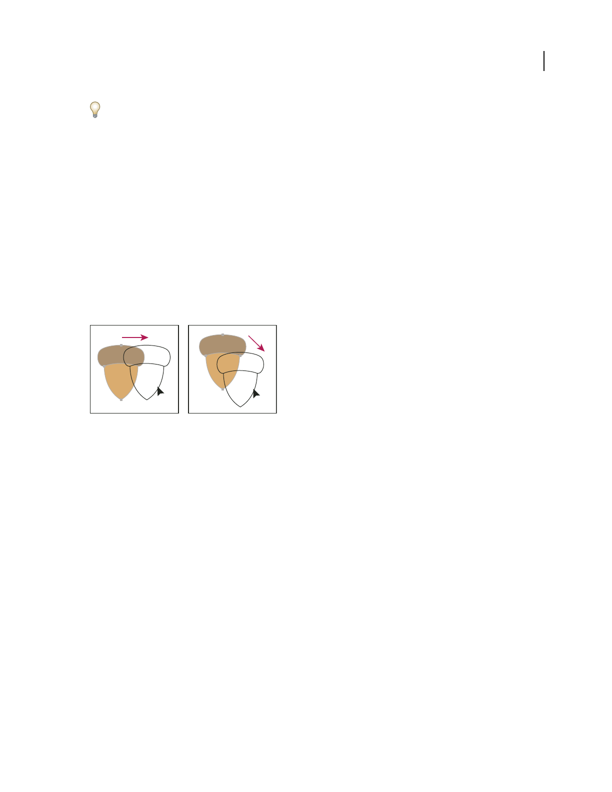
ILLUSTRATOR CS3
User Guide
203
Hold down Alt (Windows) or Option (Mac OS) as you choose Object > Expand to expand a gradient using the
settings last entered in the Expand dialog box.
Moving, aligning, and distributing objects
Move objects
You can move objects by dragging them with specific tools, by using the arrow keys on the keyboard, or by entering
precise values in a panel or dialog box.
You can use snapping to help you position objects as you move them. For example, you can snap the pointer to guides
and anchor points and snap object boundaries to gridlines. You can also use the Align panel to position objects in
relation to each other.
You can then use the Shift key to constrain the movement of one or more objects so that they move in a precise
horizontal, vertical, or diagonal direction relative to the current orientation of the x and y axes. You can also use the
Shift key to rotate objects in multiples of 45˚.
Hold down Shift while dragging or drawing to limit movement to the nearest 45˚ angle.
See also
“Use the grid” on page 47
“Rotate objects” on page 206
“Transform panel overview” on page 220
Move or duplicate an object by pasting
1
Select one or more objects.
2 Choose Edit > Cut to move the selection or Edit > Copy to duplicate the selection.
3 To paste an object into another file, open the file. (To paste between layers, see “Pasting objects between layers”
on page 205.)
4 Choose one of the following commands:
Edit > Paste Pastes the object into the center of the active window.
Edit > Paste In Front Pastes the object directly in front of the selected object.
Edit > Paste In Back Pastes the object directly in back of the selected object.
Move an object by dragging
1
Select one or more objects.
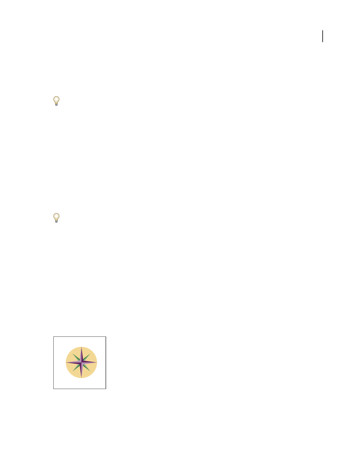
ILLUSTRATOR CS3
User Guide
204
2 Drag the object to a new location.
If a selected object is filled, you can drag from anywhere on the object. If a selected object is unfilled, if you are
viewing artwork as outlines, or if the Object Selection By Path Only preference is selected, you must drag from the
object’s path. (See “Duplicate selections using drag and drop” on page 218.)
You can use the Snap To Point command in the View menu to have the cursor snap to an anchor point or guide when
you drag an object within 2 pixels of the anchor point or guide.
Move an object using the arrow keys
1
Select one or more objects.
2 Press the arrow key for the direction in which you want to move the object. Press Shift+arrow to move the object
ten times the value specified by the Keyboard Increment preference.
The distance the object moves each time you press an arrow key is determined by the Keyboard Increment
preference. The default distance is 1
point (1/72 of an inch, or .3528 millimeter). To change the Keyboard Increment
preference, choose Edit
> Preferences > General (Windows) or Illustrator > Preferences > General (Mac OS).
Move an object by a specific distance
1
Select one or more objects.
2 Choose Object > Transform > Move.
When an object is selected, you can also double-click the Selection, Direct Selection, or Group Selection tool to open
the Move dialog box.
3 Do any of the following:
•To move the object left or right, enter either a negative value (moves left) or a positive value (moves right) in the
Horizontal text box.
•To move the object up or down, enter either a negative value (moves down) or positive value (moves up) in the
Vertical text box.
•To move the object by an angle that’s relative to the object’s x axis, enter either a positive angle (counterclockwise
movement) or a negative angle (clockwise movement) in the Distance or Angle text box. You can also enter values
between 180˚ and 360˚; these values are converted to their corresponding negative values (for example, a value of
270˚ is converted to –90˚).
4 If the objects contain a pattern fill, select Patterns to move the pattern. Deselect Objects if you want to move the
pattern but not the objects.
5 Click OK, or click Copy to move a copy of the objects.
Directions relative to the x axis
Move an object using x and y coordinates
1
Select one or more objects.
90
45
–45
135
–135
0
180
–90

ILLUSTRATOR CS3
User Guide
205
2 In the Transform panel or Control panel, enter new values in either the X or Y text box, or both.
To change the reference point, click a white square on the reference point locator before you enter the values.
Move multiple objects at once
1
Select one or more objects.
2 Choose Object > Transform > Transform Each.
3 Set the distance you want to move the selected objects in the Move section of the dialog box.
4 Do one of the following:
•To move the objects by the specified amounts, click OK.
•To move the objects randomly, but no more than the specified amounts, select the Random option. For example,
if you draw a brick wall and want the bricks to appear slightly offset from each other instead of perfectly aligned,
you could select the Random option. Then click OK.
Paste an object relative to other objects
1 Select the object you want to paste.
2 Choose Edit > Copy or Edit > Cut.
3 Select the object in front or in back of which you want to paste.
4 Choose Edit > Paste In Front or Edit > Paste In Back.
If you paste more than one object, all pasted objects appear in front or in back of the selected artwork. However, the
relative painting order among the individual pasted objects remains the same.
Pasting objects between layers
The Paste Remembers Layers option determines where artwork is pasted in the layer hierarchy. By default, Paste
Remembers Layers is off, and artwork is pasted into whichever layer is active in the Layers panel. When Paste
Remembers Layers is on, artwork is pasted into the layer from which it was copied, regardless of which layer is active
in the Layers panel.
You set this option by selecting Paste Remembers Layers from the Layers panel menu. A check mark displays when
the option is
on.
Turn on Paste Remembers Layers if you’re pasting artwork between documents and you want to automatically place
it into a layer of the same name as that from which it originated. If the target document does not have a layer of the
same name, Illustrator creates a new layer.
See also
“Layers panel overview” on page 211
Align and distribute objects
You use the Align panel (Window > Align) and the align options in the Control panel to align or distribute selected
objects along the axis you specify. You can use either the object edges or anchor points as the reference point.
The Align options are visible in the Control panel when an object is selected. If they do not appear, choose Align
from the Control panel menu.

ILLUSTRATOR CS3
User Guide
206
For a video on aligning and distributing objects, see www.adobe.com/go/vid0035.
See also
“Workspace overview” on page 14
“Create, edit, and delete crop areas” on page 38
Align or distribute objects
1
Select the objects to align or distribute. To align an anchor point on the object, use the Direct Selection tool and
select the anchor point.
2 In the Align panel or Control panel, do any of the following:
•To align or distribute relative to the bounding box of all selected objects, click the button for the type of alignment
or distribution you want.
•To align or distribute relative to one of the selected objects, click that object again (you don’t need to hold down
Shift as you click this time). Then click the button for the type of alignment or distribution you want.
Note: To stop aligning and distributing relative to an object, choose Cancel Key Object from the Align panel menu.
•To align relative to a crop area, specify the crop area you want to align to by selecting it with the Crop tool. Click
the Align To Crop Area button or click the Align menu and choose Align To Crop Area. Then click the
button for the type of alignment you want.
•To align relative to the artboard, click the Align To Artboard button or click the Align menu and choose
Align To Artboard. Then click the button for the type of alignment you want.
By default, Illustrator calculates alignment and distribution based on the objects’ paths. However, when working
with objects that have different stroke weights, you can use the edge of the stroke to calculate alignment and distri-
bution instead. To do this, select Use Preview Bounds from the Align panel menu.
Distribute objects by specific amounts
You can distribute objects using exact distances between their paths.
1 Select the objects to distribute.
2 In the Align panel, enter the amount of space to appear between objects in the Distribute Spacing text box.
If the Distribute Spacing options aren’t displayed, select Show Options from the panel menu.
3 Use the Selection tool to click the path of the object you want the other objects to distribute around. The object
you click will remain fixed in its position.
4 Click either the Vertical Distribute Space button or the Horizontal Distribute Space button.
Rotating and reflecting objects
Rotate objects
Rotating an object turns it around a fixed point that you designate. The default reference point is the object’s center
point. If you have multiple objects in a selection, the objects will rotate around a single reference point, which is the
center point of the selection or bounding box by default. To rotate each object around its own center point, use the
Transform Each command.
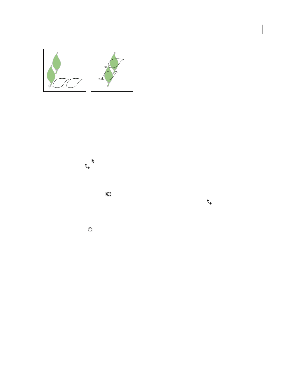
ILLUSTRATOR CS3
User Guide
207
Results of Rotate tool (left) compared to Transform Each command (right)
See also
“Transform panel overview” on page 220
“Move objects” on page 203
“Scale objects” on page 222
Rotate an object using the bounding box
1
Select one or more objects.
2 With the Selection tool , move the pointer outside the bounding box and near a bounding box handle so that
the pointer changes to , and then drag.
Rotate an object with the Free Transform tool
1
Select one or more objects.
2 Select the Free Transform tool .
3 Position the pointer anywhere outside the bounding box so that the pointer changes to , and then drag.
Rotate an object with the Rotate tool
1
Select one or more objects.
2 Select the Rotate tool .
3 Do any of the following:
•To rotate the object around its center point, drag in a circular motion anywhere in the document window.
•To rotate the object around a different reference point, click once anywhere in the document window to reposition
the reference point. Then move the pointer away from the reference point and drag in a circular motion.
•To rotate a copy of the object instead of the object itself, hold down Alt (Windows) or Option (Mac OS) after you
start to drag.
For finer control, drag farther from the object’s reference point.
Rotate an object by a specific angle
You can control the exact angle of rotation with the Rotate command.
1 Select one or more objects.
2 Do one of the following:
•To rotate around the center point, choose Object > Transform > Rotate, or double-click the Rotate tool.

ILLUSTRATOR CS3
User Guide
208
•To rotate around a different reference point, select the Rotate tool. Then Alt-click (Windows) or Option-click
(Mac OS) where you want the reference point to be in the document window.
3 Enter the rotation angle in the Angle text box. Enter a negative angle to rotate the object clockwise; enter a positive
angle to rotate the object counterclockwise.
4 If the objects contain a pattern fill, select Patterns to rotate the pattern. Deselect Objects if you want to rotate the
pattern but not the objects.
5 Click OK, or click Copy to scale a copy of the objects.
To place multiple copies of the object in a circular pattern around a reference point, move the reference point away
from the center of the object, click Copy, and then repeatedly choose Object > Transform > Transform Again.
Rotate an object with the Transform panel
1
Select one or more objects.
2 Do one of the following:
•To rotate the object around its center point, enter a value for the Angle option in the panel.
•To rotate the object around a different reference point, click a white square on the reference point locator in
the panel, and enter a value for the Angle option.
You can also call up the Transform panel by clicking X, Y, W, or H in the Control panel.
Rotate multiple objects individually
1
Select the objects to rotate.
2 Choose Object > Transform > Transform Each.
3 Do either of the following in the Rotate section of the dialog box:
•Click on the angle icon or drag the angle line around the icon.
•In the Angle text box, enter an angle between –360˚ and 360˚.
4 Click OK, or click Copy to rotate a copy of each object.
Rotate the x and y axes of a document
By default, the x and y axes are parallel to the horizontal and vertical sides of the document window.
1 Choose Edit > Preferences > General (Windows) or Illustrator > Preferences > General (Mac OS).
2 Specify an angle in the Constrain Angle text box. A positive angle rotates the axes counterclockwise; a negative
angle rotates the axes clockwise.
Rotating the axes is useful if your artwork consists of elements that are rotated to the same angle, such as a logo and
text displayed on a 20˚ angle. Instead of rotating each element you add to the logo, you can simply rotate the axes by
20˚. Everything you draw is created along the new axes.
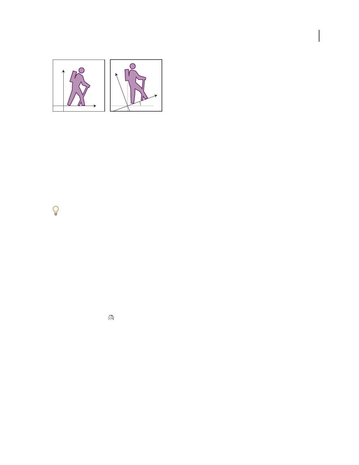
ILLUSTRATOR CS3
User Guide
209
Object aligned with default axes (left) compared to alignment with axes rotated 20˚ (right)
The following objects and actions are not affected by the new axes:
•Objects that already exist
•Rotating and blending
•Drawing with the Pencil or Auto Trace tool
Reflect objects
Reflecting an object flips the object across an invisible axis that you specify. You can reflect objects using the Free
Transform tool, the Reflect tool, or the Reflect command.
To create a mirror image of an object, you can copy while reflecting.
Reflect an object with the Free Transform tool
1
Select the object to reflect.
2 Select the Free Transform tool.
3 Do one of the following:
•Drag a handle of the bounding box past the opposite edge or handle until the object is at the desired level of
reflection.
•To maintain the object’s proportions, hold down Shift while dragging a corner handle past the opposite handle.
Reflect an object with the Reflect tool
1
Select the object.
2 Select the Reflect tool .
3 To draw the invisible axis across which you want the object to reflect, click anywhere in the document window to
set one point of the axis. The pointer changes to an arrowhead.
4 Position the pointer at another point to define the invisible axis, and do one of the following:
•Click to set the second point of the invisible axis. When you click, the selected object flips over the defined axis.
x
y
20 x
y
y
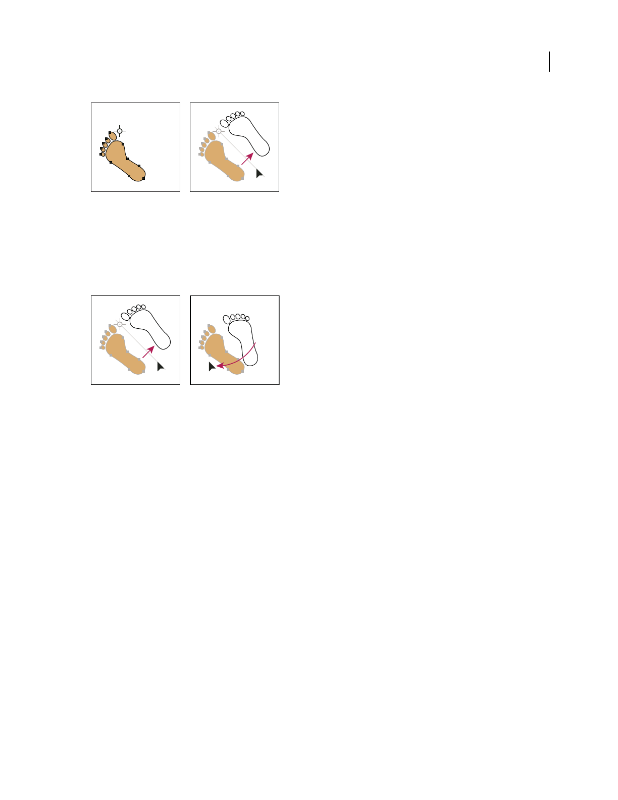
ILLUSTRATOR CS3
User Guide
210
Click to set one point of the axis (left), then click again to set the other axis point and reflect the object across the axis (right).
•To reflect a copy of the object, hold down Alt (Windows) or Option (Mac OS) and click to set the second point of
the invisible axis.
•Adjust the axis of reflection by dragging instead of clicking. Shift-drag to constrain the angle by 45˚. As you drag,
the invisible axis of reflection rotates around the point you clicked in step 3 and an outline of the object appears
reflected. When the outline is in the desired position, release the mouse button.
Dragging the second point of the reflect axis to rotate the axis
For finer control, drag farther from the object’s reference point.
Reflect by specifying an axis
1
Select the object to reflect.
•To reflect the object around the object’s center point, choose Object > Transform > Reflect or double-click the
Reflect tool.
•To reflect the object around a different reference point, Alt-click (Windows) or Option-click (Mac OS) anywhere
in the document window.
2 In the Reflect dialog box, select the axis across which you want the object to be reflected. You can reflect an object
across a horizontal, a vertical, or an angled axis.
3 If the object contains patterns and you want to reflect the patterns, select Patterns. (To reflect only the patterns,
deselect Objects.)
4 To preview the effect before you apply it, select Preview.
5 Do one of the following:
•To reflect the object, click OK.
•To reflect a copy of the object, click Copy.
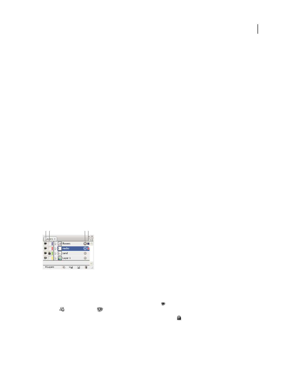
ILLUSTRATOR CS3
User Guide
211
Using layers
About layers
When creating complex artwork, it’s a challenge to keep track of all the items in your document window. Small items
get hidden under larger items, and selecting artwork becomes difficult. Layers provide a way to manage all the items
that make up your artwork. Think of layers as clear folders that contain artwork. If you reshuffle the folders, you
change the stacking order of the items in your artwork. You can move items between folders and create subfolders
within folders.
The structure of layers in your document can be as simple or complex as you want it to be. By default, all items are
organized in a single, parent layer. However, you can create new layers and move items into them, or move elements
from one layer to another at any time. The Layers panel provides an easy way to select, hide, lock, and change the
appearance attributes of artwork. You can even create template layers, which you can use to trace artwork, and
exchange layers with Photoshop.
For a video on using layers and groups, see www.adobe.com/go/vid0041. For information on using layers to create
animations, see www.adobe.com/go/learn_ai_tutorials_layers.
Layers panel overview
You use the Layers panel (Window > Layers) to list, organize, and edit the objects in a document. By default, every
new document contains one layer, and each object you create is listed under that layer. However, you can create new
layers and rearrange items to best suit your needs.
By default, Illustrator assigns a unique color (up to nine colors) to each layer in the Layers panel. The color displays
next to the layer name in the panel. The same color displays in the illustration window in the bounding box, path,
anchor points, and center point of a selected object. You can use this color to quickly locate an object’s corresponding
layer in the Layers panel, and you can change the layer color to suit your needs.
When an item in the Layers panel contains other items, a triangle appears to the left of the item’s name. Click the
triangle to show or hide the contents. If no triangle appears, the item contains no additional items.
Layers panel
A. Visibility column B. Edit column C. Target column D. Selection column
The Layers panel provides columns to the left and right of the listings. Click in a column to control the following
characteristics:
Visibility column Indicates whether items in the layers are visible or hidden (blank space), or whether they are
template layers or outline layers.
Edit column Indicates whether items are locked or unlocked. The lock icon indicates that the item is locked and
cannot be edited; a blank space indicates that the item is unlocked and can be edited.
A B C D

ILLUSTRATOR CS3
User Guide
212
Target column Indicates whether items are targeted for application of effects and edit attributes in the Appearance
panel. When the target button appears as a double ring icon (either or ), the item is targeted; a single ring icon
indicates that the item is not targeted.
Selection column Indicates whether items are selected. A color box appears when an item is selected. If an item, such
as a layer or group, contains some objects that are selected and other objects that are unselected, a smaller selection
color box appears next to the parent item. If all of the objects within the parent item are selected, the selection color
boxes are the same size as the marks that appear next to selected objects.
You can use the Layers panel to display some items as outlines and other items as they will appear in the final artwork.
You also can dim linked images and bitmap objects to make it easier to edit artwork on top of the image. This is
especially useful when tracing a bitmap image.
Display options for layered artwork
A. Object displayed in Outline view B. Bitmap object dimmed to 50% C. Selected object displayed in Preview view
See also
“Workspace overview” on page 14
“View artwork as outlines” on page 45
“Trace artwork” on page 77
Change the display of the Layers panel
1
Choose panel Options from the Layers panel menu.
2 Select Show Layers Only to hide paths, groups, and collective elements in the Layers panel.
3 For Row Size, select an option to specify the height of rows. (To specify a custom size, enter a value between 12
and 100.)
4 For Thumbnails, select a combination of layers, groups, and objects for which to display thumbnail previews.
Note: Displaying thumbnails in the Layers panel may result in slow performance when you are working with complex
files. Turn off layer thumbnails to improve performance.
BC A

ILLUSTRATOR CS3
User Guide
213
Set layer and sublayer options
1
Do one of the following:
•Double-click the item name in the Layers panel.
•Click the item name and choose Options For <item name> from the Layers panel menu.
•Choose New Layer or New Sublayer from the Layers panel menu.
2 Specify any of the following:
Name Specifies the name of the item as it appears in the Layers panel.
Color Specifies the layer’s color setting. You can either choose a color from the menu or double-click the color swatch
to select a color.
Template Makes the layer a template layer.
Lock Prevents changes to the item.
Show Displays all artwork contained in the layer on the artboard.
Print Makes the artwork contained in the layer printable.
Preview Displays the artwork contained in the layer in color instead of as outlines.
Dim Images Reduces the intensity of linked images and bitmap images contained in the layer to the specified
percentage.
Create a new layer
1 In the Layers panel, click the name of the layer above which (or in which) you want to add the new layer.
2 Do one of the following:
•To add a new layer above the selected layer, click the Create New Layer button in the Layers panel.
•To create a new sublayer inside the selected layer, click the Create New Sublayer button in the Layers panel.
To set options when you create a new layer, choose New Layer or New Sublayer from the Layers panel menu.
Move an object to a different layer
1 Select the object.
2 Do one of the following:
•Click the name of the desired layer in the Layers panel. Then choose Object > Arrange > Send To Current Layer.
•Drag the selected-art indicator , located at the right of the layer in the Layers panel, to the layer you want.
You can move objects or layers into a new layer by selecting them and choosing Collect In New Layer from the Layers
panel menu. Hold down Ctrl (Windows) or Command (Mac OS) to select nonadjacent items; hold down Shift to
select adjacent items.
Release items to separate layers
The Release To Layers command redistributes all of the items in a layer into individual layers and can build new
objects in each layer based on the object’s stacking order. You can use this feature to prepare files for web animation
work.
1 In the Layers panel, click the name of a layer or group.
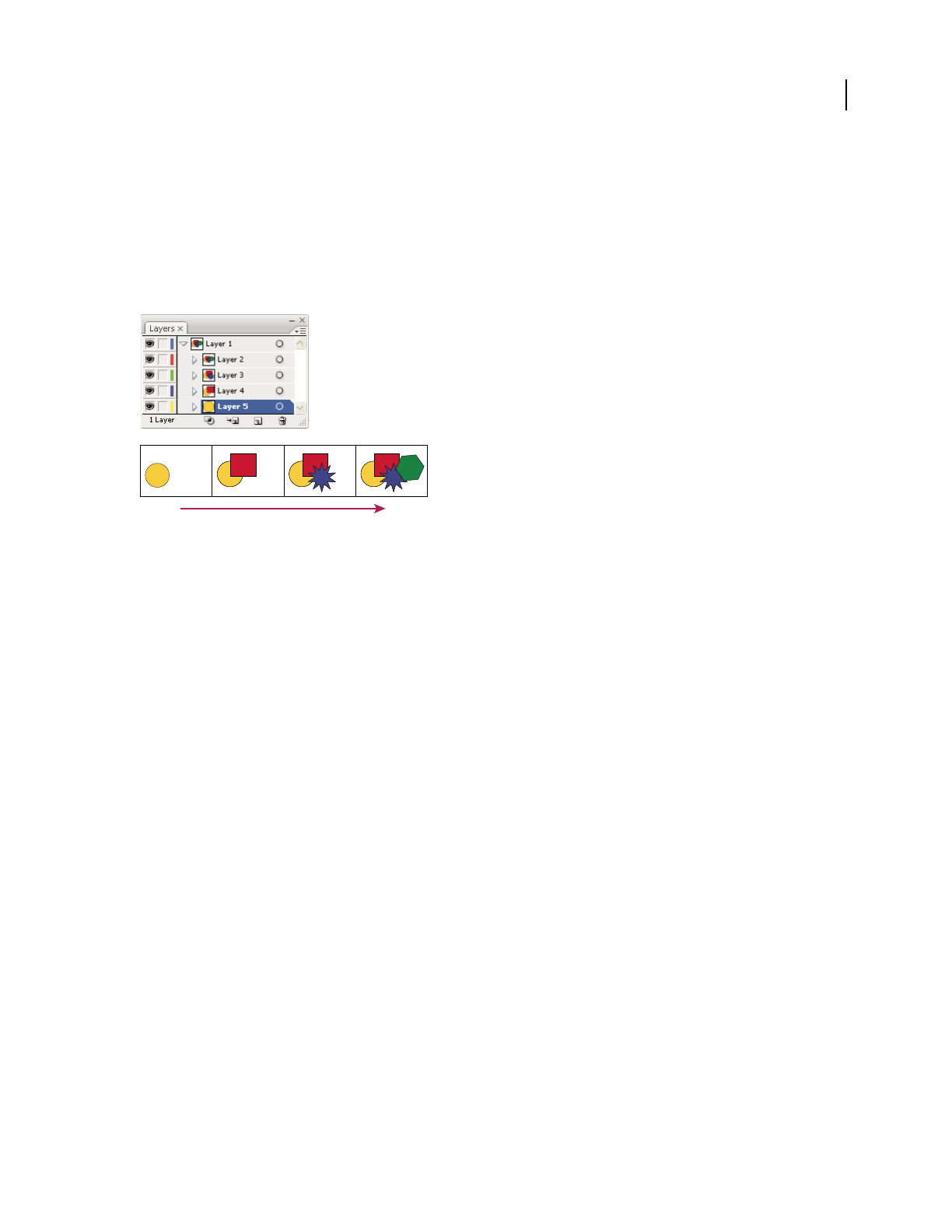
ILLUSTRATOR CS3
User Guide
214
2 Do one of the following:
•To release each item to a new layer, choose Release To Layers (Sequence) from the Layers panel menu.
•To release items into layers and duplicate objects to create a cumulative sequence, choose Release To Layers (Build)
from the Layers panel menu. The bottommost object appears in each of the new layers, and the topmost object
only appears in the topmost layer. For example, assume Layer 1 contains a circle (bottommost object), a square,
and a triangle (topmost object). This command creates three layers—one with a circle, square, and triangle; one
with a circle and square; and one with just a circle. This is useful for creating cumulative animation sequences.
Release To Layers (Build) command creates new layers.
Consolidate layers and groups
Merging and flattening layers are similar in that they both let you consolidate objects, groups, and sublayers into a
single layer or group. With merging, you can select which items you want to consolidate; with flattening, all visible
items in the artwork are consolidated in a single layer. With either option, the stacking order of the artwork remains
the same, but other layer-level attributes, such as clipping masks, aren’t preserved.
•To merge items into a single layer or group, hold down Ctrl (Windows) or Command (Mac OS) and click the
names of the layers or groups that you want to merge. Alternatively, hold down Shift to select all listings in between
the layer or group names you click. Then, select Merge Selected from the Layers panel menu. Note that items will
be merged into the layer or group that you selected last.
Layers can only merge with other layers that are on the same hierarchical level in the Layers panel. Likewise,
sublayers can only merge with other sublayers that are within the same layer and at the same hierarchical level.
Objects can’t be merged with other objects.
•To flatten layers, click the name of the layer into which you want to consolidate the artwork. Then select Flatten
Artwork from the Layers panel menu.
Locate an item in the Layers panel
When you select an item in your document window, you can quickly locate the corresponding item in the Layers
panel using the Locate Object command. This command is especially helpful for locating items in collapsed layers.
1 Select an object in the document window. If you select more than one object, the frontmost object in the stacking
order will be located.
2 Choose Locate Object from the Layers panel menu. This command changes to Locate Layer if the Show Layers
Only panel option is selected.

ILLUSTRATOR CS3
User Guide
215
Locking, hiding, and deleting objects
Lock or unlock objects or layers
Locking objects prevents you from selecting and editing them. You can quickly lock multiple paths, groups, and
sublayers by locking their parent layer.
•To lock objects, click the edit column button (to the right of the eye icon) in the Layers panel for the object or layer
you want to lock. Drag across multiple edit column buttons to lock multiple items. Alternatively, select the objects
you want to lock, and then choose Object > Lock > Selection.
•To unlock objects, click the lock icon in the Layers panel for the object or layer you want to unlock.
You can also use the following commands to lock and unlock objects:
•To lock all objects that overlap the area of the selected object and that are in the same layer, select the object, and
then choose Object > Lock > All Artwork Above.
•To lock all layers other than the layer that contains a selected item or group, choose Object > Lock > Other Layers
or choose Lock Others from the Layers panel menu.
•
To lock all the layers, select all the layers in the Layers panel, and then choose Lock All Layers from the panel menu.
•To unlock all objects in the document, choose Object > Unlock All.
•To unlock all objects within a group, select an unlocked and visible object within the group. Hold down Shift+Alt
(Windows) or Shift+Option (Mac OS) and choose Object > Unlock All.
•If you locked all layers, choose Unlock All Layers from the Layers panel menu to unlock them.
Note: The Lock menus are disabled when you’re in isolation mode.
See also
“Layers panel overview” on page 211
Hide or show objects or layers
Choose from the following methods:
•In the Layers panel, click the eye icon next to the item you want to hide. Click again to redisplay the item. If
you hide a layer or group, all items in the layer or group are hidden.
•Drag across multiple eye icons to hide multiple items.
•Select an object you want to hide, and choose Object > Hide > Selection.
•To hide all objects above an object in a layer, select the object and choose Object > Hide > All Artwork Above.
•To hide all unselected layers, choose Hide Others from the Layers panel menu, or Alt-click (Windows) or
Option-click (Mac OS) the eye icon for the layer you want to show. Alternatively, to hide all other layers other than
the layer that contains the selected object or group, choose Object > Hide > Other Layers.
•To show all objects, choose Object > Show All. All previously hidden objects are shown. Any previously selected
objects are selected.
•To show all layers and sublayers, select Show All Layers from the Layers panel menu. Hidden objects aren’t
displayed by this command, only hidden layers.

ILLUSTRATOR CS3
User Guide
216
•To show all objects within a group, select an unlocked and visible object in the group. Hold down Shift+Alt
(Windows) or Shift+Option (Mac OS) and choose Object > Show All.
Note: The Show All and Hide menus are disabled when you’re in isolation mode.
See also
“Layers panel overview” on page 211
Delete objects
❖Do one of the following:
•Select the objects and then press Backspace (Windows) or Delete.
•Select the objects and then choose Edit > Clear or Edit > Cut.
•Select the items you want to delete in the Layers panel, and then click the Delete icon . Alternatively, drag the item
name in the Layers panel to the Delete icon in the panel, or choose Delete “Layer name” from the Layers panel menu.
Deleting a layer also deletes all artwork that is in the layer. For example, if you delete a layer that contains sublayers,
groups, paths, and clipping sets, all those elements will be deleted along with the layer.
Note: A document must have a least one layer. If a document has only one layer, the Delete icon and Delete command
are not available.
See also
“Layers panel overview” on page 211
Stacking objects
Specify where to add new objects in the stacking order
Illustrator stacks successively drawn objects, beginning with the first object drawn. How objects are stacked deter-
mines how they display when they overlap. You can change the stacking order (also called the painting order) of
objects in your artwork at any time using either the Layers panel or Object
> Arrange commands.
❖In the Layers panel, do either of the following:
•Click the name of the object above which you want to add the new object.
•To add the new object to the top of a layer or group, click the layer or group name.
Alt+Ctrl-click (Windows) or Option+Command-click (Mac OS) anywhere in the layer list, and type the name or
number of the layer you want to select. (For example, you can type 30 to go to layer 30.)

ILLUSTRATOR CS3
User Guide
217
Change the stacking order using the Layers panel
The stacking order of objects corresponds to the hierarchy of items in the Layers panel. Artwork at the top of the
Layers panel is at the front of the stacking order, while artwork at the bottom of the Layers panel is at the back of the
stacking order. Within a layer, objects are also stacked hierarchically. By creating multiple layers in your artwork, you
can control how overlapping objects are displayed.
❖Do any of the following:
•Drag the item’s name and release the mouse button when black insertion marks appear in the desired position.
Black insertion marks appear either between two other items in the panel or on the left and right edges of a layer
or group. Items that are released over a layer or group are moved above all other objects in the item.
•Click in the item’s selection column (between the target button and the scroll bar), drag the selection color box to
a different item’s selection color box, and release the mouse button. If the item’s selection color box is dragged to
an object, the item is moved above the object; if it’s dragged to a layer or group, the item is moved above all other
objects in the layer or group.
•To reverse the order of items in the Layers panel, hold down Ctrl (Windows) or Command (Mac OS) and click the
names of the items whose order you want to reverse. The items must be at the same level in the layer hierarchy.
For example, you can select two top-level layers, but you cannot select two paths that are in different layers. Then
select Reverse Order from the Layers panel menu.
Note: You cannot move a path, group, or collective element to the top position in the Layers panel—only layers can reside
at the top of the layer hierarchy.
See also
“Layers panel overview” on page 211
Change the stacking order using commands
❖Do any of the following:
•To move an object to the top or bottom position in its group or layer, select the object you want to move and choose
Object > Arrange > Bring To Front or Object > Arrange > Send To Back.
•To move an object by one object to the front or one object to the back of a stack, select the object you want to move,
and choose Object > Arrange > Bring Forward or Object > Arrange > Send Backward.
Duplicating objects
Duplicate objects by dragging
1 Select one or more objects.
2 Select the Selection, Direct Selection, or Group Selection.
3 Alt-drag (Windows) or Option-drag (Mac OS) the selection (but not a handle on the bounding box).
Duplicate objects by using the Layers panel
You can quickly duplicate objects, groups, and entire layers by using the Layers panel.
1 Select the items you want to duplicate in the Layers panel.

ILLUSTRATOR CS3
User Guide
218
2 Do one of the following:
•Choose Duplicate “Layer name” from the Layers panel menu.
•Drag the item in the Layers panel to the New Layer button at the bottom of the panel.
•Start to drag the item to a new position in the Layers panel, and then hold down Alt (Windows) or Option
(Mac OS). Release the mouse button when the indicator is in the position where you want to place the duplicated
item. If you release the mouse button when the indicator is pointing to a layer or group, the duplicated item is
added to the top of the layer or group. If you release the mouse button when the indicator is between items, the
duplicated item will be added in the specified position.
Duplicate selections using drag and drop
You can use the Clipboard to transfer selections between an Illustrator file and other Adobe software including
Adobe Photoshop, Adobe GoLive, and Adobe InDesign. The Clipboard is particularly useful for importing paths
because paths are copied to the Clipboard as PostScript language descriptions. Artwork copied to the Clipboard is
pasted in PICT format in most applications. However, some applications take the PDF version (such as InDesign) or
the AICB version. PDF preserves transparency; AICB lets you specify whether you want to preserve the overall
appearance of the selection or copy the selection as a set of paths (which can be useful in Photoshop).
To specify copying preferences, choose Edit > Preferences > File Handling & Clipboard (Windows) or Illustrator >
Preferences
> File Handling & Clipboard (Mac OS). Select PDF, AICB, or both. If you select AICB, select Preserve
Paths to discard any transparency in the copied artwork or Preserve Appearance and Overprints to flatten any trans-
parency, maintain the copied artwork’s appearance, and preserve overprinted objects.
Drag and drop artwork into a Photoshop document
1
Select the artwork you want to copy.
2 Open the Photoshop document into which you want to copy the selection.
3 Do one of the following:
•To copy the artwork into Photoshop as bitmap images, drag the selection toward the Photoshop window, and
when a black outline appears, release the mouse button. To position the selection in the center of the Photoshop
image, hold down Shift before dragging the selection. By default, selected objects are copied as bitmap images to
the active layer.
•To copy vector artwork into Photoshop as paths, hold down Ctrl (Windows) or Command (Mac OS), and drag the
selection to the Photoshop document. When you release the mouse button, the selection becomes a Photoshop path.
Drag and drop artwork from Photoshop into Illustrator
1
Open the Photoshop document from which you want to copy.
2 Select the artwork you want to copy.
3 Select the Move tool and drag the selection from Photoshop into the Illustrator file.
Drag and drop artwork to the desktop (Mac OS only)
1
Select the artwork you want to copy.
2 Drag the selection onto the desktop.
Selections are copied to the desktop as a picture clipping, which can be dragged and dropped into the desired
document. Picture clippings are converted to PICT format when dragged to the desktop.

ILLUSTRATOR CS3
User Guide
219
Offset duplicate objects
You can create a replica of an object, set off from the selected object by a specified distance, by using the Offset Path
command or Offset Path effect. Offsetting objects is useful when you
want to create concentric shapes or make many
replications of an object with regular distances between each replication.
You can offset an object’s path relative to its original path by using the Offset Path command in the Effect menu. This
effect is useful for converting a mesh object into a regular path. For example, if
you have released an envelope, or
want to convert a mesh shape for use in another application, apply the offset path command with an offset value of
0, and then delete the mesh shape. You can then edit the remaining path.
See also
“About effects and filters” on page 350
“Stroke an object” on page 154
Offset objects using the Offset Path command
1
Select one or more objects.
2 Choose Object > Path > Offset Path.
3 Specify the offset distance, line join type, and miter limit.
4 Click OK.
Offset objects using the Offset Path effect
1
Select one or more objects.
2 Choose Effect > Path > Offset Path.
3 Specify the offset distance, line join type, and miter limit.
4 Click OK.

220
Chapter 8: Reshaping objects
You can easily modify an object’s size or shape in Adobe Illustrator by using tools and commands, or by applying
filters, effects, and masks. You can also easily create 3D objects.
Transforming objects
Transforming
Transforming encompasses moving, rotating, reflecting, scaling, and shearing objects. You can transform objects
using the Transform panel, Object
> Transform commands, and specialized tools. You can also perform many types
of transformations by dragging the bounding box for a selection.
Sometimes you may want to repeat the same transformation several times, especially when you are copying objects.
The Transform Again command in the Object menu lets you repeat a move, scale, rotate, reflect, or shear operation
as many times as you want, until you perform a different transform operation.
Use the Info panel to view the current dimensions and position of your selection as you transform it.
For a video on scaling, skewing, and rotating objects, see www.adobe.com/go/vid0040.
See also
“Transform panel overview” on page 220
“Scale objects” on page 222
“Shear objects” on page 224
“Move objects” on page 203
“Rotate objects” on page 206
“Reflect objects” on page 209
Transform panel overview
The Transform panel (Window > Transform) displays information about the location, size, and orientation of one
or more selected objects. By typing new values, you can modify the selected objects, their pattern fills, or both. You
can also change the transformation reference point and lock the object’s proportions.
All values in the panel refer to the bounding boxes of the objects except for the X and Y values, which refer to the
selected reference point.
Note: The reference point locator in the Transform panel specifies an object’s reference point only when you transform
the object by changing the values in the panel. Other methods of transforming (such as using the Scale tool) use the
object’s center point or the pointer location as the reference point.
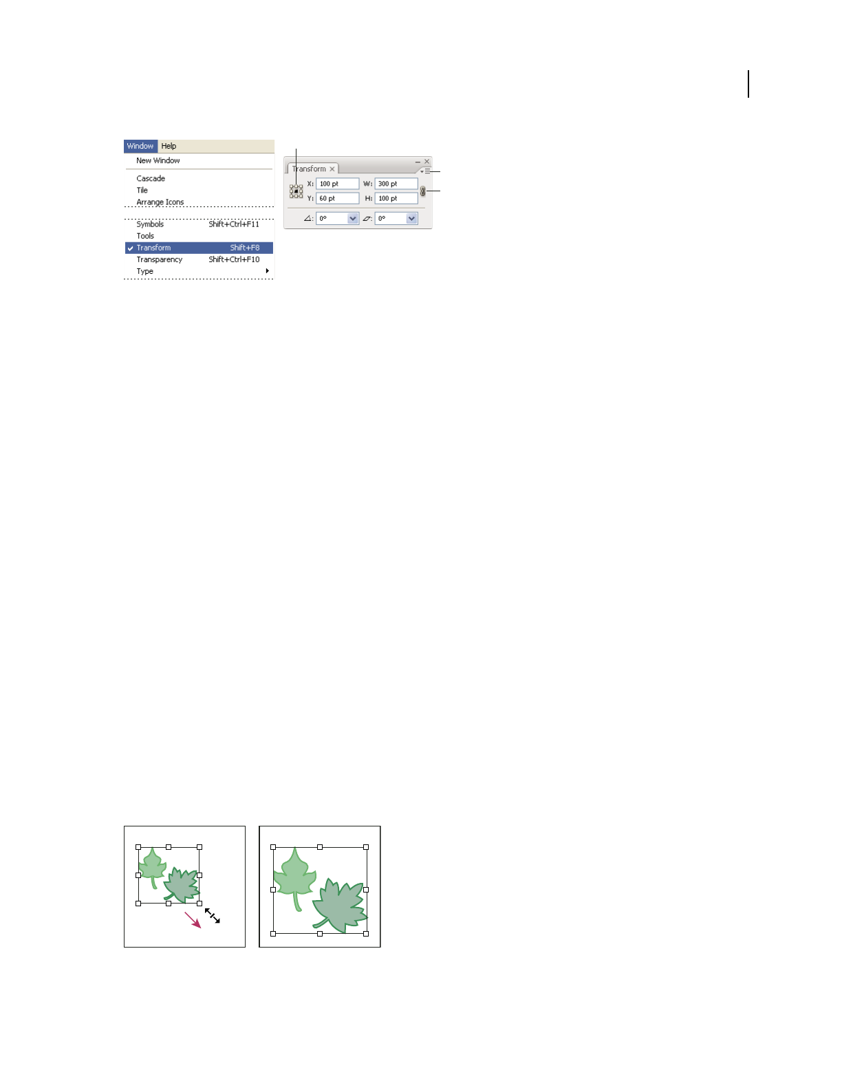
ILLUSTRATOR CS3
User Guide
221
Transform panel
A. Reference point locator B. Panel menu C. Lock proportions icon
Transform an object’s patterns
When you move, rotate, reflect, scale, or shear an object that is filled with a pattern, you can transform just the object,
just the pattern, or both the object and pattern. Once you transform an object’s fill pattern, all patterns that you
subsequently apply to that object are transformed the same way.
•To specify how you want to transform patterns when using the Transform panel, select an option from the panel
menu: Transform Object Only, Transform Pattern Only, or Transform Both.
•To specify how you want to transform patterns when using a transform command, set the Objects and Patterns
options in the corresponding dialog box. For example, select Patterns and deselect Objects if you want to
transform the pattern but not the object.
•To transform patterns but not objects when using a transform tool, hold down the tilde key (~) while dragging.
The borders of the object appear to be transformed, but when you release the mouse button, the borders snap back
to their original configuration, leaving only the pattern transformed.
•To prevent patterns from transforming when using transform tools, choose Edit > Preferences > General
(Windows) or Illustrator > Preferences > General (Mac OS) and deselect Transform Pattern Tiles.
•To return an object’s fill pattern to its original state, fill the object with a solid color, and then reselect the desired
pattern.
Transform using the bounding box
When you select one or more objects with the Selection tool, a bounding box displays around them. Use the bounding
box to easily move, rotate, duplicate, and scale objects by dragging the object or a handle (one of the hollow squares
along the bounding box).
•To hide the bounding box, choose View > Hide Bounding Box.
•To show the bounding box, choose View > Show Bounding Box.
•To reorient the bounding box after you rotate it, choose Object > Transform > Reset Bounding Box.
Selected objects before (left) compared to after (right) scaling using the bounding box
A
B
C
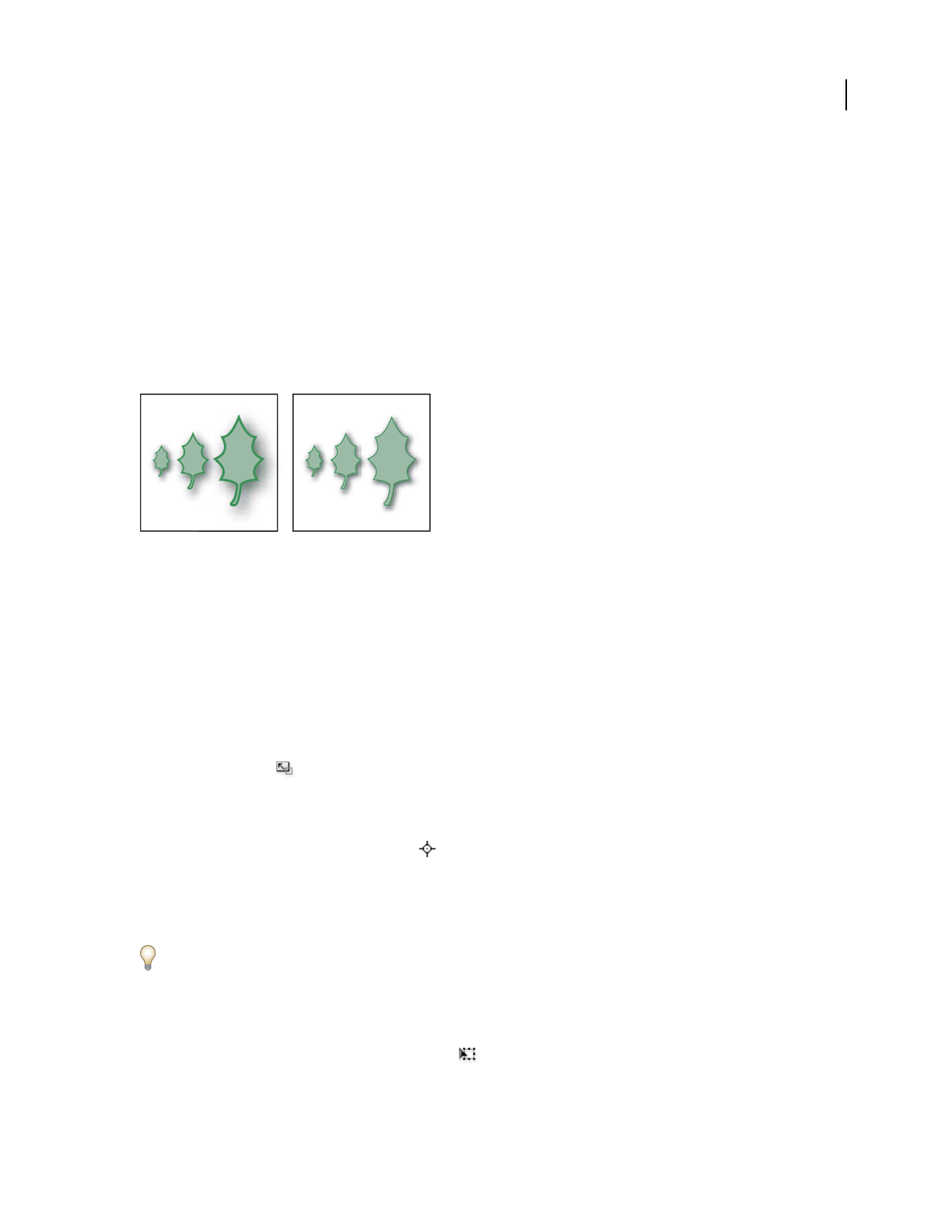
ILLUSTRATOR CS3
User Guide
222
Scaling, shearing, and distorting objects
Scale objects
Scaling an object enlarges or reduces it horizontally (along the x axis), vertically (along the y axis), or both. Objects
scale relative to a reference point which varies depending on the scaling method you choose. You can change the
default reference point for most scaling methods, and you can also lock the proportions of an object.
By default, strokes and effects are not scaled along with objects. To scale strokes and effects, choose Edit >
Preferences
> General (Windows) or Illustrator > Preferences > General (Mac OS), and select Scale Strokes &
Effects. If you want to choose whether to scale strokes and effects on a case-by-case basis, use the Transform panel
or the Scale command to scale objects.
The Scale Strokes & Effects option scales the object, the drop shadow effect, and the stroke (left); only the object scales when this option is off
(right).
See also
“Reshaping tool gallery” on page 29
“Transform using the bounding box” on page 221
“Transform panel overview” on page 220
Scale objects with the Scale tool
1
Select one or more objects.
2 Select the Scale tool .
3 Do any of the following:
•To scale relative to the object’s center point, drag anywhere in the document window until the object is the desired size.
•To scale relative to a different reference point , click where you want the reference point to be in the document
window, move the pointer away from the reference point, and then drag until the object is the desired size.
•To maintain the object’s proportions as it scales, hold down Shift as you drag diagonally.
•To scale the object along a single axis, hold down Shift as you drag vertically or horizontally.
For finer control over scaling, start dragging farther from the reference point.
Scale objects with the bounding box
1
Select one or more objects.
2 Select the Selection tool or the Free Transform tool .
3 Drag a bounding box handle until the object is the desired size.

ILLUSTRATOR CS3
User Guide
223
Objects scale relative to the opposite handle of the bounding box.
4 Do any of the following to control the scaling behavior:
•To maintain the object’s proportions, hold down Shift as you drag.
•To scale relative to the object’s center point, hold down Alt (Windows) or Option (Mac OS) as you drag.
Scale objects to a specific width and height
1
Select one or more objects.
2 In the Transform panel, enter a new value in the Width (W) or Height (H) box, or both.
You can do any of the following before you enter a value to control the scaling behavior:
•To maintain the objects’ proportions, click the lock proportions button .
•To change the reference point for scaling, click a white square on the reference point locator .
•To scale stroked paths and any size-related effects along with the object, select Scale Strokes & Effects from the
panel menu.
You can also maintain proportions by entering a value in the W or H box, and then pressing Ctrl (Windows) or
Command (Mac OS) while you press Enter.
Scale objects by a specific percentage
1
Select one or more objects.
2 Do one of the following:
•To scale from the center, choose Object > Transform > Scale or double-click the Scale tool .
•To scale relative to a different reference point, select the Scale tool and Alt-click (Windows) or Option-click
(Mac OS) where you want the reference point to be in the document window.
3 In the Scale dialog box, do one of the following:
•To maintain the object’s proportions as it scales, select Uniform, and enter a percentage in the Scale text box.
•To scale the height and width separately, select Non-Uniform, and enter a percentage in the Horizontal and
Vertical text boxes.
The scale factors are relative to the reference point and can be negative or positive.
4 To scale stroked paths and any size-related effects along with the object, select Scale Strokes & Effects.
5 If the objects contain a pattern fill, select Patterns to scale the pattern. Deselect Objects if you want to scale the
pattern but not the objects.
6 Click OK, or click Copy to scale a copy of the objects.
Scale multiple objects
1
Select the objects.
2 Choose Object > Transform > Transform Each.
3 Set percentages for horizontal and vertical scaling in the Scale section of the dialog box.
4 To change the reference point, click a white square on the reference point locator .
5 Click OK, or click Copy to scale a copy of each object.
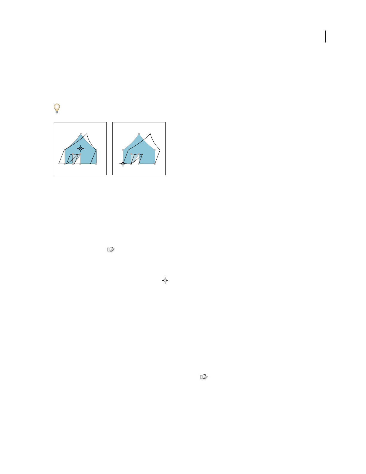
ILLUSTRATOR CS3
User Guide
224
Shear objects
Shearing an object slants, or skews, the object along the horizontal or vertical axis, or a specified angle that’s relative
to a specified axis. Objects shear relative to a reference point which varies depending on the shearing method you
choose and can be changed for most shearing methods. You can lock one dimension of an object as you shear it, and
you can shear one object or multiple objects simultaneously.
Shearing is useful for creating cast shadows.
Shearing relative to the center (left) compared to shearing relative to a user-defined reference point (right)
See also
“Reshaping tool gallery” on page 29
“Transform panel overview” on page 220
Shear objects with the Shear tool
1
Select one or more objects.
2 Select the Shear tool .
3 Do one of the following:
•To shear relative to the object’s center, drag anywhere in the document window.
•To shear relative to a different reference point , click anywhere in the document window to move the reference
point, move the pointer away from the reference point, and then drag until the object is at the desired slant.
•To shear along the object’s vertical axis, drag anywhere in the document window in an up or down direction. To
constrain the object to its original width, hold down Shift.
•To shear along the object’s horizontal axis, drag anywhere in the document window in a left or right direction. To
constrain the object to its original height, hold down Shift.
Shear objects with the Shear command
1
Select one or more objects.
2 Do one of the following:
•To shear from the center, choose Object > Transform > Shear or double-click the Shear tool.
•To shear from a different reference point, select the Shear tool and Alt-click (Windows) or Option-click
(Mac OS) where you want the reference point to be in the document window.
3 In the Shear dialog box, enter a shear angle from -359 to 359. The shear angle is the amount of slant applied to the
object in a clockwise direction and is relative to a line that’s perpendicular to the shear axis.
4 Select the axis along which to shear the object.

ILLUSTRATOR CS3
User Guide
225
If you chose an angled axis, enter a value between –359 and 359, relative to the horizontal axis.
5 If the objects contain a pattern fill, select Patterns to move the pattern. Deselect Objects if you want to move the
pattern but not the objects.
6 Click OK, or click Copy to shear a copy of the objects.
Shear objects with the Free Transform tool
1
Select one or more objects.
2 Select the Free Transform tool .
3 Do one of the following:
•To shear along the object’s vertical axis, start dragging the middle-left or middle-right bounding-box handle, and
then hold down Ctrl+Alt (Windows) or Option+Command (Mac OS) as you drag up or down. You can also hold
down Shift to constrain the object to its original width.
•To shear along the object’s horizontal axis, start dragging the top-middle or bottom-middle bounding-box handle
and then hold down Ctrl+Alt (Windows) or Option+Command (Mac OS) as you drag right or left. You can also
hold down Shift to constrain the object to its original height.
Shear objects with the Transform panel
1
Select one or more objects.
2 In the Transform panel, enter a value in the Shear text box.
To change the reference point, click a white square on the reference point locator before you enter the value.
You can also call up the Transform panel by clicking X, Y, W, or H in the Control panel.
Distort objects
You can distort objects by using the Free Transform tool or a liquify tool. Use the Free Transform tool when you want
to distort freely; use a liquify tool if you want to take advantage of specific preset distortions such as twirls, puckers,
or wrinkles.
See also
“Transform using the bounding box” on page 221
“Reshaping objects with effects” on page 243
“Reshaping tool gallery” on page 29
Distort objects with the Free Transform tool
1
Select one or more objects.
2 Select the Free Transform tool .
3 Start dragging a corner handle on the bounding box (not a side handle), and then do one of the following:
•Hold down Ctrl (Windows) or Command (Mac OS) until the selection is at the desired level of distortion.
•Hold down Shift+Alt+Ctrl (Windows) or Shift+Option+Command (Mac OS) to distort in perspective.

ILLUSTRATOR CS3
User Guide
226
Distorting in perspective
Distort objects using a liquify tool
You cannot use liquify tools on linked files or objects that contain text, graphs, or symbols.
1 Select a liquify tool, and click or drag over the objects you want to distort.
2 (Optional) To isolate the distortion to specific objects, select the objects before using the tool.
3 (Optional) To change the size of the tool cursor and set other tool options, double-click the liquify tool and specify
any of the following:
Width and Height Controls the size of the tool cursor.
Angle Controls the orientation of the tool cursor.
Intensity Specifies the rate of change for the distortion. Higher values equal faster changes.
Use Pressure Pen Uses the input from a tablet or pen instead of the Intensity value. If you don’t have a pressure-
sensitive tablet attached, this option is dimmed.
Complexity (Scallop, Crystallize, and Wrinkle tools) Specifies how closely the results of the particular brush are
spaced on the object’s outline. This is closely tied with the Detail value.
Detail Specifies the spacing between points introduced into the object’s outline (higher values space points closer
together).
Simplify (Warp, Twirl, Pucker, and Bloat tools) Specifies how much you want to reduce the superfluous points that
do not measurably affect the overall appearance of the shape.
Twirl Rate (Twirl tool only) Specifies the rate at which the twirl is applied. Enter a value between –180˚ and 180˚.
Negative values twirl the object clockwise and positive values twirl counterclockwise. The object twirls faster with
values that are closer to either –180˚ or 180˚. To twirl slowly, specify a rate close to 0˚.
Horizontal and Vertical (Wrinkle tool only) Specifies how far apart the control points are placed.
Brush Affects Anchor Points, Brush Affects In Tangent Handles, or Brush Affects Out Tangent Handles (Scallop,
Crystallize, Wrinkle tools) Enables the tool brush to make changes to these properties.
Reshape using envelopes
About envelopes
Envelopes are objects that distort or reshape selected objects. You can make an envelope out of an object on your
artboard, or you can use a preset warp shape or a mesh grid as an envelope. You can use envelopes on any object
except graphs, guides, or linked objects.
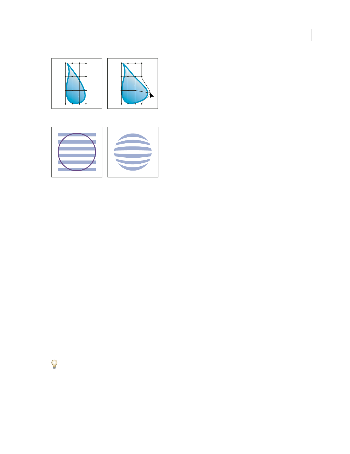
ILLUSTRATOR CS3
User Guide
227
Mesh grid envelope
Envelope created from another object
The Layers panel lists envelopes as <Envelope>. Once you apply an envelope, you can continue to edit the original
objects. You can also edit, delete, or expand an envelope at any time. You can edit an envelope shape or the enveloped
object, but not both at the same time.
Distort objects using an envelope
1 Select one or more objects.
2 Create the envelope using one of the following methods:
•To use a preset warp shape for the envelope, choose Object > Envelope Distort > Make With Warp. In the Warp
Options dialog box, select a warp style and set options.
•To set up a rectangular grid for the envelope, choose Object > Envelope Distort > Make With Mesh. In the
Envelope Mesh dialog box, set the number of rows and columns.
•To use an object as the shape of the envelope, make sure the object is at the top of the stacking order for the selected
object. If it’s not, use the Layers panel or an Arrange command to move it up, and reselect all the objects. Then
choose Object > Envelope Distort > Make With Top Object.
3 Reshape the envelope by doing any of the following:
•Drag any anchor point on the envelope with the Direct Selection or Mesh tool.
•To delete anchor points on the mesh grid, select an anchor point with either the Direct Selection or Mesh tools,
and then press Delete.
•To add anchor points to the mesh grid, click on the grid with the Mesh tool.
To apply a stroke or fill to an envelope, use the Appearance panel.

ILLUSTRATOR CS3
User Guide
228
See also
“Reshaping objects with effects” on page 243
“Envelope options” on page 229
Edit the contents of an envelope
1 Select the envelope and do one of the following:
•Click the Edit Contents button in the Control panel.
•Choose Object > Envelope Distort > Edit Contents.
Note: If your envelope consists of grouped paths, click the triangle to the left of the <Envelope> entry in the Layers panel
to view and target the path you want to edit.
2 Edit it as desired.
Note: When you modify the contents of an envelope, the envelope shifts to recenter the results with the original content.
3 To return the object to its enveloped state, do one of the following:
•Click the Edit Envelope button in the Control panel.
•Choose Object > Envelope Distort > Edit Envelope.
See also
“Envelope options” on page 229
Reset an envelope
1 Select the envelope.
2 Do one of the following:
•To reset or switch to a preset warp style, choose a new warp style and set options in the Control panel. If desired,
click the Envelope Options button to open the dialog box and set more options.
•To reset or switch to a mesh grid envelope, choose Object > Envelope Distort > Reset With Mesh. Specify the
number of rows and columns for the mesh grid. Select Maintain Envelope Shape to keep the warp shape intact.
Remove an envelope
You can remove envelopes by either releasing them or expanding them. Releasing an enveloped object creates two
separate objects: the object in its original state and the envelope shape. Expanding an enveloped object removes the
envelope, but the object retains its distorted shape.
•To release an envelope, select the envelope, and choose Object > Envelope Distort > Release.
•To expand an envelope, select the envelope, and choose Object > Envelope Distort > Expand.

ILLUSTRATOR CS3
User Guide
229
Envelope options
Envelope options determine how art is distorted to fit the envelope. To set envelope options, select the envelope
object and click the Envelope Options button
in the Control panel, or choose Object > Envelope Distort >
Envelope Options.
Anti-Alias Smooths rasters when distorted with an envelope. Deselecting Anti-Alias can decrease the time it takes
to distort rasters.
Preserve Shape Using Specifies how rasters preserve their shape when distorted by nonrectangular envelopes. Select
Clipping Mask to use a clipping mask on the raster, or Transparency to apply an alpha channel to the raster.
Fidelity Specifies how precisely you want the object to fit the envelope mold. Increasing the Fidelity percentage can
add more points to the distorted paths and increase the time it takes to distort the objects.
Distort Appearance Distorts appearance attributes (such as applied effects or graphic styles) along with an object’s
shape.
Distort Linear Gradients Distorts linear gradients along with an object’s shape.
Distort Pattern Fills Distorts patterns along with an object’s shape.
Note: If you expand the envelope with a Distort option selected, the respective property is expanded separately.
Combining objects
Methods of combining objects
You can combine vector objects to create shapes in a variety of ways in Illustrator. The resulting paths or shapes differ
depending on the method you use to combine the paths.
Pathfinder effects
Pathfinder effects let you combine multiple objects using one of ten interaction modes. Unlike compound shapes,
you can’t edit the interactions between objects when you use a Pathfinder effect.
Compound shapes
Compound shapes let you combine multiple objects and specify how you want each object to interact with the other
objects. Compound shapes are more versatile than compound paths because they provide four kinds of interactions:
add, subtract, intersect, and exclude. In addition, the underlying objects are not changed, so you can select each
object within a compound shape to edit it or change its interaction mode.
Compound paths
Compound paths let you use an object to cut a hole in another object. For example, you can create a doughnut shape
from two nested circles. Once you create a compound path, the paths act as grouped objects. You can select and
manipulate the objects separately using the Direct Selection tool or Group Selection tool; or you can select and edit
the combined path.
Pathfinder panel overview
You use the Pathfinder panel (Window > Pathfinder) to combine objects into new shapes.
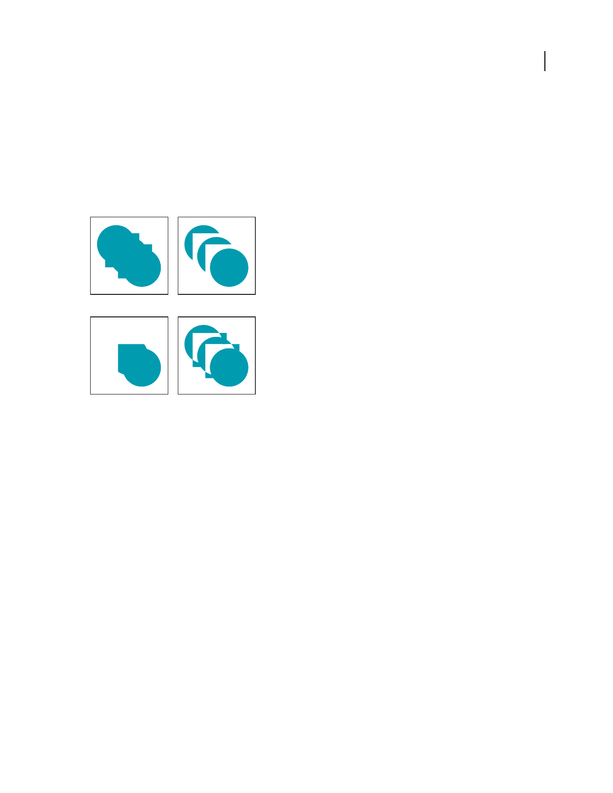
ILLUSTRATOR CS3
User Guide
230
The top row of buttons in the panel, called shape modes, let you control the interaction between components of a
compound shape. You can choose from the following shape modes:
Add To Shape Area Adds the area of the component to the underlying geometry.
Subtract from Shape Area Cuts out the area of the component from the underlying geometry.
Intersect Shape Areas Uses the area of the component to clip the underlying geometry as a mask would.
Exclude Overlapping Shape Areas Uses the area of the component to invert the underlying geometry, turning filled
regions into holes and vice versa.
Shape modes
A. All components in Add mode B. Subtract mode applied to squares C. Intersect mode applied to squares D. Exclude mode applied to squares
The bottom row of buttons in the panel, called pathfinder effects, let you create final shape combinations on the first
click. (See “Apply Pathfinder effects” on page 230.)
Pathfinder options
You can set Pathfinder Options from the Pathfinder panel menu or by double-clicking a Pathfinder effect in the
Appearance panel.
Precision Affects how precisely the Pathfinder filters calculate an object’s path. The more precise the calculation, the
more accurate the drawing and the more time is required to generate the resulting path.
Remove Redundant Points Removes unnecessary points as you click a Pathfinder button.
Divide And Outline Will Remove Unpainted Artwork Deletes any unfilled objects in the selected artwork as you click
the Divide or Outline button.
Apply Pathfinder effects
Pathfinder effects let you create new shapes out of overlapping objects. You can apply Pathfinder effects by using the
Effects menu or the Pathfinder panel.
•Pathfinder effects in the Effects menu can only be applied to groups and layers. After you apply the effect, you can
still select and edit the original objects. You can also use the Appearance panel to modify or remove the effect.
AB
CD

ILLUSTRATOR CS3
User Guide
231
•Pathfinder effects in the Pathfinder panel can be applied to any combination of objects, groups, and layers. The
final shape combination is created when you click a pathfinder button; after that, you cannot edit the original
objects. If the effect results in multiple objects, they are automatically grouped together.
For a video on using Pathfinder effects and clipping masks and how to import clipping masks into Flash, see
www.adobe.com/go/vid0057.
See also
“Methods of combining objects” on page 229
“Group or ungroup objects” on page 201
“Move an object to a different layer” on page 213
“Targeting items for appearance attributes” on page 347
Apply a Pathfinder effect using the Effects menu
1
Do one of the following:
•Group together the objects you want to use, and select the group.
•Move the objects you want to use into a separate layer, and target the layer.
2 Choose Effect > Pathfinder and choose a Pathfinder effect.
To quickly apply the same Pathfinder effect again, choose Effect > Apply [effect].
Apply a Pathfinder effect using the Pathfinder panel
1
Select the objects to which you want to apply the effect.
To apply a Pathfinder effect to a group or layer, target the group or layer.
2 In the Pathfinder panel, click a pathfinder button (in the bottom row), or Alt-click (Windows) or Option-click
(Mac OS) a Shape Mode button (in the top row).
Summary of Pathfinder effects
Add Traces the outline of all objects as if they were a single, merged object. The resulting shape takes on the paint
attributes of the top object.
Intersect Traces the outline of the region overlapped by all the objects.
Exclude Traces all nonoverlapping areas of the objects, and makes overlapping areas transparent. Where an even
number of objects overlap, the overlap becomes transparent. Where an odd number of objects overlap, the overlap
becomes filled.
Subtract Subtracts the frontmost objects from the backmost object. You can use this command to delete areas of an
illustration by adjusting the stacking order.
Minus Back Subtracts the objects in back from the frontmost object. You can use this command to delete areas of an
illustration by adjusting the stacking order.
Divide Separates a piece of artwork into its component filled faces (a face is an area undivided by a line segment).
Note: When you use the Divide button in the Pathfinder panel, you can use the Direct Selection or Group Selection tool
to manipulate the resulting faces independently of each other. You can also choose to delete or preserve unfilled objects
when applying the Divide command.
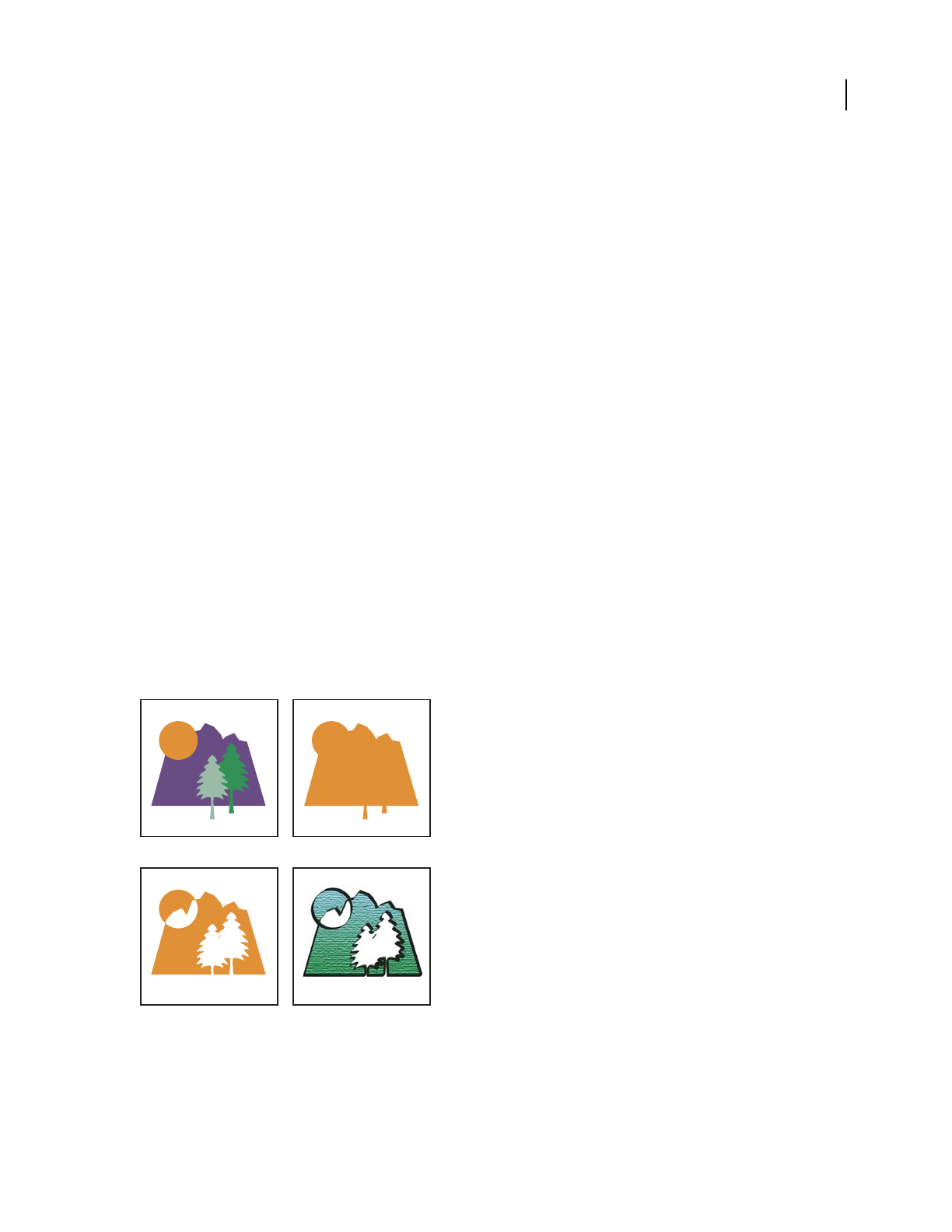
ILLUSTRATOR CS3
User Guide
232
Trim Removes the part of a filled object that is hidden. It removes any strokes and does not merge objects of the same
color.
Merge Removes the part of a filled object that is hidden. It removes any strokes and merges any adjoining or
overlapping objects filled with the same color.
Crop Divides artwork into its component filled faces, and then deletes all the parts of the artwork that fall outside
the boundary of the topmost object. It also removes any strokes.
Outline Divides an object into its component line segments, or edges. This command is useful for preparing artwork
that needs a trap for overprinting objects. (See “Create a trap” on page 426.)
Note: When you use the Outline button in the Pathfinder panel, you can use the Direct Selection or Group Selection tool
to manipulate each edge independently. You can also choose to delete or preserve unfilled objects when applying the
Outline command.
About compound shapes
A compound shape is editable art consisting of two or more objects, each assigned a shape mode. Compound shapes
make it easy to create complex shapes because you can precisely manipulate the shape mode, stacking order, shape,
location, and appearance of each path included.
Compound shapes act as grouped objects and appear as <Compound Shape> items in the Layers panel. You can use
the Layers panel to show, select, and manipulate the contents of a compound shape—for example, to change the
stacking order of its components. You can also use the Direct Selection tool or the Group Selection tool to select
components of a compound shape.
When you create a compound shape, it takes on the paint and transparency attributes of the topmost component in
Add, Intersect, or Exclude mode. Subsequently, you can change the paint, style, or transparency attributes of the
compound shape. Illustrator facilitates this process by automatically targeting the whole compound shape when you
select any part of it, unless you explicitly target a component in the Layers panel.
Working with compound shapes
A. Original objects B. Compound shape created C. Individual shape modes applied to each component D. Style applied to entire compound
shape
AB
CD

ILLUSTRATOR CS3
User Guide
233
Work with compound shapes
Creating a compound shape is a two-part process. First, you establish a compound shape in which all components
have the same shape mode. Then, you assign shape modes to the components until you obtain the desired combi-
nation of shape areas.
Create a compound shape
1
Select all the objects you want to be part of the compound shape.
You can include paths, compound paths, groups, other compound shapes, blends, text, envelopes, and warps in a
compound shape. Any open paths you select are automatically closed.
2 Do one of the following:
•In the Pathfinder panel, click a Shape Modes button. Each component of the compound shape is assigned the
shape mode you select.
•Select Make Compound Shape from the Pathfinder panel menu. Each component of the compound shape is
assigned the Add mode by default.
3 Change the shape mode of any component by selecting it with the Direct Selection tool or Layers panel and
clicking a Shape Mode button.
Note that you never need to change the mode of the backmost component, because its mode is not relevant to the
compound shape.
To sustain maximum performance, create complex compound shapes by nesting other compound shapes (containing
up to about 10 components each) instead of using many individual components.
Modify a compound shape
1
Use the Direct Selection tool or Layers panel to select an individual component of the compound shape.
2 Look for the highlighted Shape Mode button in the Pathfinder panel to identify which mode is currently applied
to a selected component.
Note: If you’ve selected two or more components that use different modes, question marks appear on the Shape Mode
buttons.
3 In the Pathfinder panel, click a different Shape Mode button.
Release and expand a compound shape
Releasing a compound shape separates it back into separate objects. Expanding a compound shape maintains the
shape of the compound object, but you can no longer select the individual components.
1 Select the compound shape using the Selection tool or Layers panel.
2 Do one of the following:
•Click Expand in the Pathfinder panel.
•Choose Expand Compound Shape from the Pathfinder panel menu.
The compound shape is converted to a <Path> or <Compound Path> item in the Layers panel, depending on the
shape mode it used.
•Choose Release Compound Shape from the Pathfinder panel menu.

ILLUSTRATOR CS3
User Guide
234
Move compound shapes between Illustrator and Photoshop
The shape layers and layer clipping paths (vector masks) in Adobe Photoshop are types of compound shapes. You
can import shape layers and layer clipping paths into Illustrator as compound shapes and continue to manipulate
them. In addition, you can export compound shapes to Photoshop. Keep the following in mind when using
compound shapes with Photoshop:
•Only compound shapes that reside at the top level of the layer hierarchy are exported to Photoshop as shape layers.
•A compound shape painted with a stroke using a join other than round, or with a weight in points that is not an
integer, is rasterized when exported to the PSD file format.
About compound paths
A compound path contains two or more paths that are painted so that holes appear where paths overlap. When you
define objects as a compound path, all objects in the compound path take on the paint and style attributes of the
backmost object in the stacking order.
Compound paths act as grouped objects and appear as <Compound Path> items in the Layers panel. Use the Direct
Selection tool or the Group Selection tool to select part of a compound path. You can manipulate the shape of
individual components of a compound path, but you cannot change appearance attributes, graphic styles, or effects
for
individual components, and you cannot manipulate components individually in the Layers panel.
If you want more flexibility in the compound path creation, you can create a compound shape and then expand it.
Cut a hole in an object using a compound path
1 Select the object to use as a hole, and position it so that it overlaps the object to cut. Repeat for any additional
objects you want to use as holes.
2 Select all the objects you want to include in the compound path.
3 Choose Object > Compound Path > Make.
Apply fill rules to compound paths
You can specify whether a compound path is a nonzero winding path or an even-odd path.
Nonzero winding fill rule Uses mathematical equations to determine if a point is outside or inside a shape. Illustrator
uses the nonzero winding rule as the default rule.
Even-odd fill rule Uses mathematical equations to determine if a point is outside or inside a shape. This rule is the
more predictable rule because every other region within an even-odd compound path is a hole, regardless of path
direction. Some applications, such as Adobe Photoshop, use the even-odd rule by default, so compound paths
imported from these applications will use the even-odd rule.
Self-intersecting paths are paths that intersect themselves. You can choose to make these paths either nonzero
winding or even-odd, depending on how you want them to look.
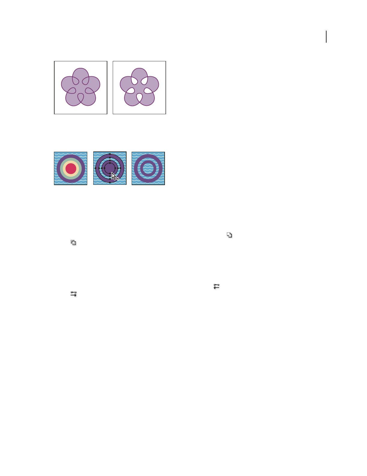
ILLUSTRATOR CS3
User Guide
235
Self-intersecting path with Use Non-Zero Winding Fill Rule (left) compared with Use Even-Odd Fill Rule (right)
When you create a nonzero winding compound path, you can specify whether overlapping paths appear with holes
or are filled by clicking a Reverse Path Direction button in the Attributes panel.
Fill rules
A. Four circular paths B. Circular paths selected, converted into compound path C. Reverse Path Direction applied to innermost path
Change the fill rule for a compound path
1
Select the compound path using the Selection tool or Layers panel.
2 In the Attributes panel, click the Use Non-Zero Winding Fill Rule button or the Use Even-Odd Fill Rule
button .
Change a hole in a compound path to a filled area
1
Make sure that the compound path uses the nonzero winding fill rule.
2
With the Direct Selection tool, select the part of the compound path to reverse. Do not select the entire compound path.
3 In the Attributes panel, click the Reverse Path Direction Off button or the Reverse Path Direction On
button .
Return a compound path to its original components
1 Select the compound path using the Selection tool or Layers panel.
2 Choose Object > Compound Path > Release.
Cutting and dividing objects
Methods for cutting, dividing, and trimming objects
Illustrator provides the following methods to cut, divide, and trim objects:
Divide Objects Below command Acts as a cookie cutter or stencil, using a selected object to cut through other
objects, discarding the original selection. To use this command, choose Object > Path > Divide Objects Below.
BCA

ILLUSTRATOR CS3
User Guide
236
Cut Path At Selected Anchor Point button Cuts a path at the anchor point and the one anchor point becomes two
anchor points with one located directly on top of the other. To access this button, select one or more anchor points
with the Direct Selection tool and locate the button in the Control panel.
Knife tool Cuts objects along a freehand path you draw with the tool, dividing objects into their component filled
faces (a face is an area undivided by a line segment).
Scissors tool Splits a path, graphics frame, or empty text frame at an anchor point or along a segment.
Split Into Grid command Lets you divide one or more objects into multiple rectangular objects arranged in rows and
columns. You can precisely change the height, width, and gutter size between rows and columns, and quickly create
guides for laying out artwork. To use this command, choose Object > Path > Split Into Grid.
Compound paths and compound shapes Let you use an object to cut a hole in another object.
Pathfinder effects Provide various ways to divide and trim overlapping objects.
Clipping masks Let you use an object to hide portions of other objects.
See also
“About clipping masks” on page 237
“About compound shapes” on page 232
“About compound paths” on page 234
“Cut a hole in an object using a compound path” on page 234
“Apply Pathfinder effects” on page 230
“Split a path” on page 77
Cut objects with the Divide Objects Below command
1 Select the object to use as a cutter, and position it so that it overlaps the objects to cut.
2 Choose Object > Path > Divide Objects Below.
Cut objects with the Knife tool
1 Select the Knife tool .
2 Do one of the following:
•To cut in a curved path, drag the pointer over the object.
•To cut in a straight path, hold down Alt (Windows) or Option (Mac OS) as you click on the artboard with the
Knife tool, and then drag.
See also
“Slicing and cutting tool gallery” on page 32
Divide an object into a grid
1 Select the object.
If you select more than one object, the resulting grid of objects use the appearance attributes of the topmost object.

ILLUSTRATOR CS3
User Guide
237
2 Choose Object > Path > Split Into Grid.
3 Enter the number of rows and columns you want.
4 (Optional) Do any of the following:
•To set the size of each row and column, enter values for Height and Width.
•To set the amount of space that separates rows from one another and columns from one another, enter values for
Gutter.
•To change the dimensions of the entire grid of objects, enter values for Total.
•To add guides along the row and column edges, select Add Guides.
5 Click OK.
See also
“Draw grids” on page 59
Clipping masks
About clipping masks
A clipping mask is an object whose shape masks other artwork so that only areas that lie within the shape are visible—
in effect, clipping the artwork to the shape of the mask. The clipping mask and the objects that are masked are called
a clipping set and are marked with a dotted line in the Layers panel. You can make a clipping set from a selection of
two or more objects or from all objects in a group or layer.
For a video on using Pathfinder effects and clipping masks and how to import clipping masks into Flash, see
www.adobe.com/go/vid0057.
Before masking (left) compared to after masking (right)
The following guidelines apply to creating clipping masks:
•The objects that you mask are moved into the clipping mask’s group in the Layers panel if they don’t already reside
there.
•Only vector objects can be clipping masks; however, any artwork can be masked.
•If you use a layer or group to create a clipping mask, the first object in the layer or group masks everything that is
a subset of the layer or group.

ILLUSTRATOR CS3
User Guide
238
•Regardless of its previous attributes, a clipping mask changes to an object with no fill or stroke.
To create a semitransparent mask, use the Transparency panel to create an opacity mask.
For more information on using masks and transparency, see www.adobe.com/go/learn_ai_tutorials_mask.
See also
“Methods for cutting, dividing, and trimming objects” on page 235
“Use opacity masks to create transparency” on page 175
Hide parts of objects with a clipping mask
1 Create the object you want to use as the mask.
This object is called the clipping path. Only vector objects can be clipping paths.
2 Move the clipping path above the objects you want to mask in the stacking order.
3 Select the clipping path and the objects you want to mask.
4 Choose Object > Clipping Mask > Make.
To create a clipping path from the area where two or more objects overlap, group the objects first.
See also
“Stacking objects” on page 216
Create a clipping mask for a group or layer
1 Create the object you want to use as the mask.
This object is called the clipping path. Only vector objects can be clipping paths.
2 Move the clipping path and the objects you want to mask into a layer or group.
3 In the Layers panel, make sure that the masking object is at the top of the group or layer, and then click the name
of the layer or group.
4 Click the Make/Release Clipping Masks button at the bottom of the Layers panel or select Make Clipping Mask
from the Layers panel menu.
See also
“Layers panel overview” on page 211
“Stacking objects” on page 216
Edit a clipping mask
1 In the Layers panel, select the clipping path.
2 Do any of the following
•Move the clipping path by dragging the object’s center reference point with the Direct Selection tool.

ILLUSTRATOR CS3
User Guide
239
•Reshape the clipping path using the Direct Selection tool.
•Apply a fill and stroke to a clipping path.
To select all clipping paths in a document, deselect all artwork. Then choose Select > Object > Clipping Masks.
See also
“Layers panel overview” on page 211
Add or remove an object from masked artwork
❖In the Layers panel, drag the object into or out of the group or layer that contains the clipping path.
See also
“Layers panel overview” on page 211
Release objects from a clipping mask
❖Do one of the following:
•Select the group that contains the clipping mask, and choose Object > Clipping Mask > Release.
•In the Layers panel, click the name of the group or layer that contains the clipping mask. Click the Make/Release
Clipping Masks button at the bottom of the panel, or select Release Clipping Mask from the panel menu.
Because the clipping mask was assigned a fill and stroke value of None, it is now not visible unless you select it or
assign it new paint attributes.
See also
“Layers panel overview” on page 211
Blending objects
About blended objects
You can blend objects to create and distribute shapes evenly between two objects. You can also blend between two
open paths to create a smooth transition between objects, or you can combine blends of colors and objects to create
color transitions in the shape of a particular object.
Note: Blending objects is not the same as applying blending modes or transparency to objects. For information on
blending modes and transparency, see “About blending modes” on page 179.
Once you create a blend, the blended objects are treated as one object. If you move one of the original objects, or edit
the original object’s anchor points, the blend changes accordingly. In addition, the new objects blended between the
original objects don’t have their own anchor points. You can expand the blend in order to divide the blend into
distinct objects.
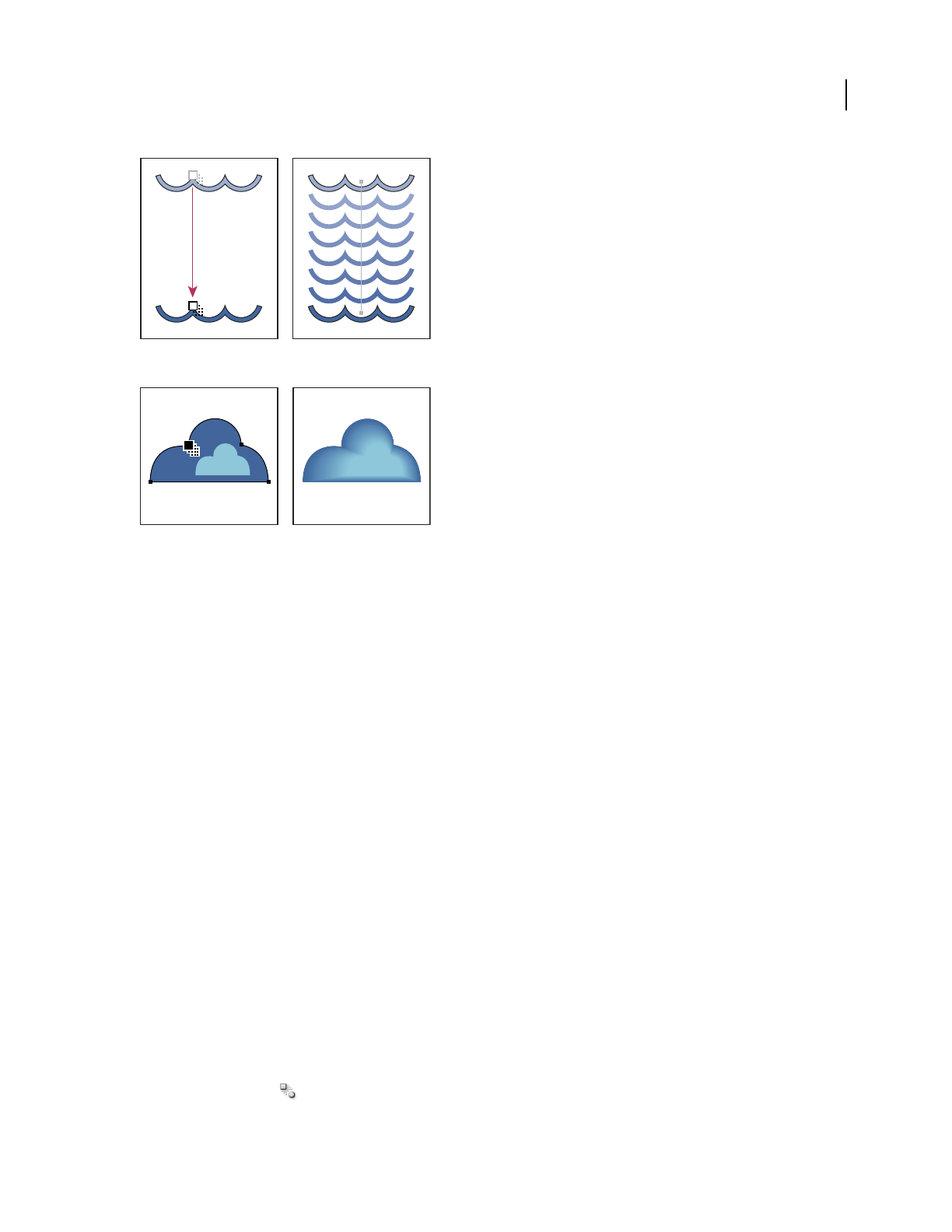
ILLUSTRATOR CS3
User Guide
240
Example of using a blend to distribute shapes evenly between two objects
Example of using a blend to distribute color smoothly between two objects
The following rules apply to blended objects and their associated colors:
•You cannot blend between mesh objects.
•If you blend between one object painted with a process color and another object painted with a spot color, the
blended shapes are painted with a blended process color. If you blend between two different spot colors, process
colors are used to paint the intermediate steps. If, however, you blend between tints of the same spot color, the
steps are all painted with percentages of the spot color.
•If you blend between two patterned objects, the blended steps will only use the fill of the object on the topmost
layer.
•If you blend between objects that have blending modes specified with the Transparency panel, the blended steps
will only use the blending mode of the top object.
•If you blend between objects with multiple appearance attributes (effects, fills, or strokes), Illustrator attempts to
blend the options.
•If you blend between two instances of the same symbol, blended steps will be instances of that symbol. If, however,
you blend between two instances of different symbols, the blended steps will not be symbol instances.
•By default, blends are created as knockout transparency groups, so that if any of the steps consist of overlapping
transparent objects, these objects will not show through each other. You can change this setting by selecting the
blend and deselecting Knockout Group in the Transparency panel.
Create blends
The Blend tool and Make Blend command let you create blends, which are a series of intermediate objects and colors
between two or more selected objects.
Create a blend with the Blend tool
1
Select the Blend tool .
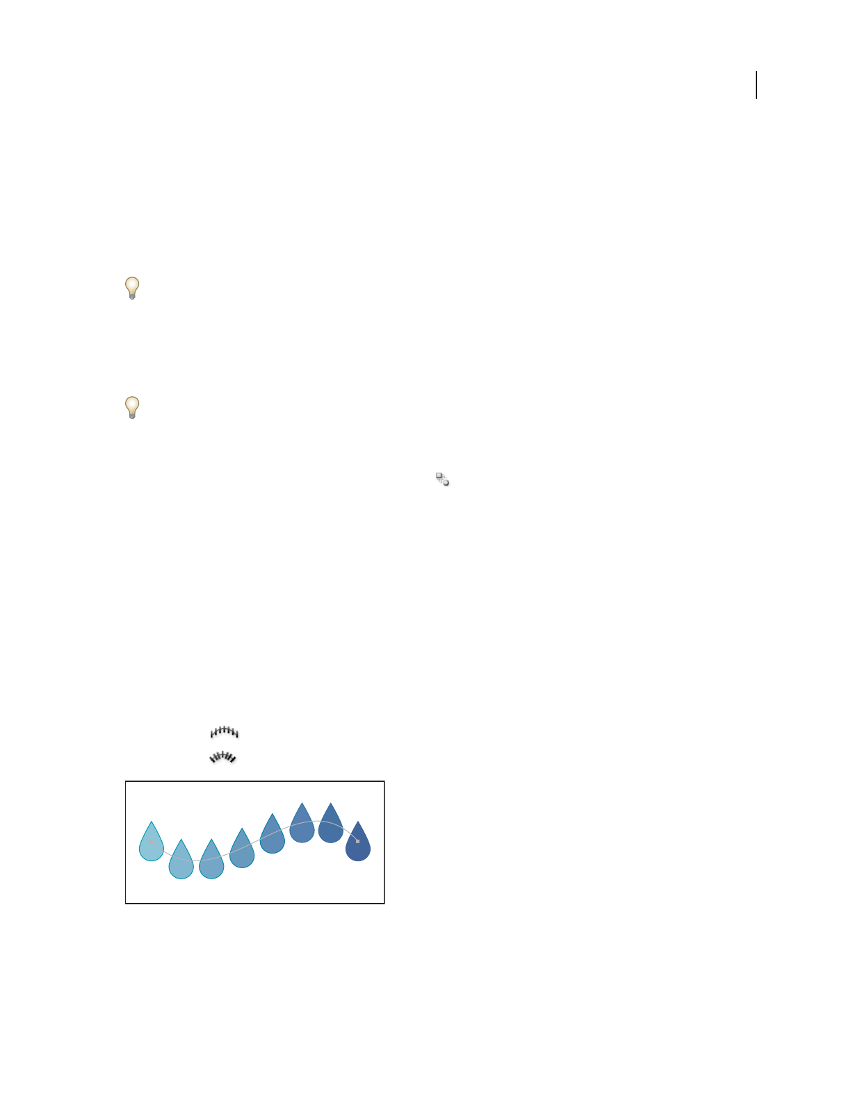
ILLUSTRATOR CS3
User Guide
241
2 Do one of the following:
•To blend in sequential order with no rotation, click anywhere on each object, but avoid anchor points.
•To blend to a specific anchor point on an object, click the anchor point with the Blend tool. When the pointer is
over an anchor point, the pointer changes from a white square to transparent with a black dot in its center.
•To blend open paths, select an endpoint on each path.
3 When you are finished adding objects to the blend, click the Blend tool again.
By default, Illustrator calculates the optimum number of steps to create a smooth color transition. To control the
number of steps or distance between steps, set blending options. (See “Blend options” on page 241.)
Create a blend with the Make Blend command
1
Select the objects you want to blend.
2 Choose Object > Blend > Make.
By default, Illustrator calculates the optimum number of steps to create a smooth color transition. To control the
number of steps or distance between steps, set blending options.
Blend options
You set blending options by double-clicking the Blend tool or choosing Object > Blend > Blend Options. To
change options for an existing blend, select the blended object first.
Spacing Determines how many steps are added to the blend.
•Smooth Color Lets Illustrator auto-calculate the number of steps for the blends. If objects are filled or stroked with
different colors, the steps are calculated to provide the optimum number of steps for a smooth color transition. If the
objects contain identical colors, or if they contain gradients or patterns, the number of steps is based on the longest
distance between the bounding box edges of the two objects.
•Specified Steps Controls the number of steps between the start and end of the blend.
•Specified Distance Controls the distance between the steps in the blend. The distance specified is measured from
the edge of one object to the corresponding edge on the next object (for example, from the rightmost edge of one
object to the rightmost edge of the next).
Orientation Determines the orientation of blended objects.
•Align to Page Orients the blend perpendicular to the x axis of the page.
•Align to Path Orients the blend perpendicular to the path.
Align to Page option applied to a blend
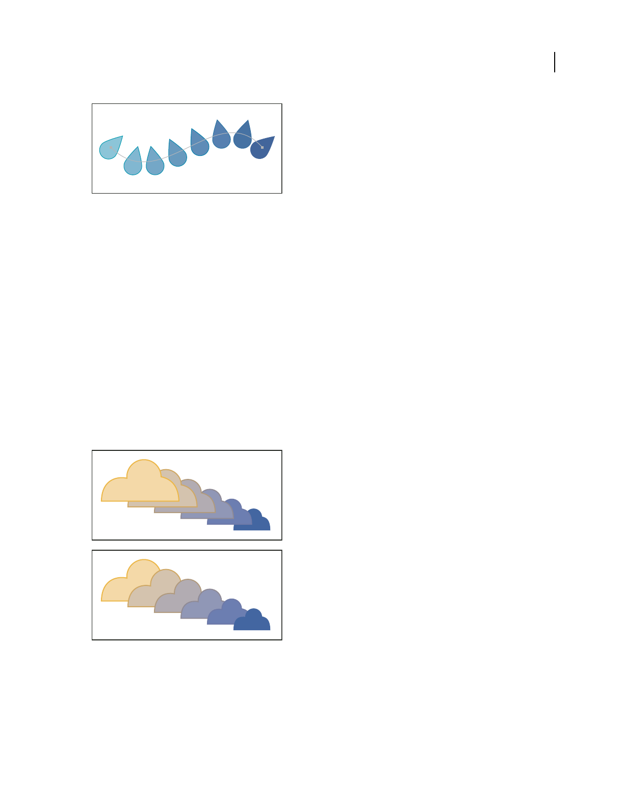
ILLUSTRATOR CS3
User Guide
242
Align to Path option applied to a blend
Change the spine of a blended object
The spine is the path along which the steps in a blended object are aligned. By default, the spine forms a straight line.
•To adjust the shape of the spine, drag the anchor points and path segments on the spine with the Direct Selection
tool.
•To replace the spine with a different path, draw an object to use as the new spine. Select the spine object and the
blended object, and choose Object > Blend > Replace Spine.
•To reverse the order of a blend on its spine, select the blended object and choose Object > Blend > Reverse Spine.
See also
“Reshaping objects” on page 220
Reverse the stacking order in a blended object
1 Select the blended object.
2 Choose Object > Blend > Reverse Front To Back.
Original stacking order (top) compared to applying Reverse Front To Back command (bottom)
See also
“Stacking objects” on page 216

ILLUSTRATOR CS3
User Guide
243
Release or expand a blended object
Releasing a blended object removes the new objects and restores the original objects. Expanding a blended object
divides the blend into distinct objects, which you can edit individually like any object.
1 Select the blended object.
2 Do one of the following:
•Choose Object > Blend > Release.
•Choose Object > Blend > Expand.
Reshaping objects with effects
Reshaping objects with effects
Using effects is a convenient way to reshape objects without making permanent changes to their underlying
geometry. Effects are live, which means that you can modify or remove the effect at any time.
You can use the following effects to reshape objects:
Convert To Shape Converts the shape of vector objects to a rectangle, rounded rectangle, or ellipse. Set the dimen-
sions of the shape using absolute or relative dimensions. For rounded rectangles, specify a corner radius to determine
the curvature of the rounded edge.
Distort & Transform Lets you quickly reshape vector objects.
Free Distort Lets you change the shape of a vector object by dragging any of four corner points.
Pucker & Bloat Pulls a vector object’s anchor points outward while curving the segments inward (Pucker) or inward
while curving the segments outward (Bloat). Both options pull the anchor points relative to the object’s center point.
Roughen Transforms a vector object’s path segments into a jagged array of peaks and valleys of various sizes. Set the
maximum length for segment paths using an absolute or relative size. Set the density of jagged edges per inch (Detail)
and choose between soft edges (Smooth) or sharp edges (Corner).
Transform Reshapes an object by resizing, moving, rotating, reflecting, and copying it.
Tweak Randomly curves and distorts path segments inward and outward. Set the vertical and horizontal distortion
using an absolute or relative amount. Specify whether or not to modify anchor points, move control points that lead
into anchor points on the path (“In” Control Points), and move control points that lead out of anchor points on the
path (“Out” Control Points).
Twist Rotates an object more sharply in the center than at the edges. Entering a positive value twists clockwise;
entering a negative value twists counterclockwise.
Zig Zag Transforms an object’s path segments into a jagged or wavy array of uniformly sized peaks and valleys. Set
the length between peaks and valleys using an absolute or relative size. Set the number of ridges per path segment
and choose between wavy edges (Smooth) or jagged edges (Corner).
You can achieve the same results with filters (Filter > Distort in the top section of the Filter menu). However, you
can’t change a filter after you apply it, whereas you can modify or remove the effect at any time.
Warp Distorts or deforms objects, including paths, text, meshes, blends, and bitmap images. Choose one of the
predefined warp shapes. Then select which axis the bending option affects and specify the amount of bending and
distortion to apply.

ILLUSTRATOR CS3
User Guide
244
See also
“About effects and filters” on page 350
“Apply an effect or filter” on page 351
“Modify or delete an effect” on page 353
Round the corners of objects
The Round Corners effect converts the corner points of a vector object to smooth curves.
1 In the Layers panel, target the items you want to round.
If you want to round a specific attribute of an object, such as its fill or stroke, target the object in the Layers panel and
then select the attribute in the Appearance panel.
2 Choose Effect > Stylize > Round Corners. (The command is located in the first Stylize submenu.)
3 To define the curvature of the rounded curve, enter a value in the Radius text box, and click OK.
You can achieve the same results with the Round Corners filter (Filter > Stylize > Round Corners). However, you
can’t change a filter after you apply it, whereas you can modify or remove the effect at any time.
See also
“About effects and filters” on page 350
“Apply an effect or filter” on page 351
“Modify or delete an effect” on page 353
Creating 3D objects
Create 3D objects
3D effects enable you to create three-dimensional (3D) objects from two-dimensional (2D) artwork. You can control
the appearance of 3D objects with lighting, shading, rotation, and other properties. You can also map artwork onto
each surface of a 3D object.
There are two ways to create a 3D object: by extruding or revolving. In addition, you can also rotate a 2D or 3D object
in three dimensions. To apply or modify 3D effects for an existing 3D object, select the object and then double-click
the effect in the Appearance panel.
Note: 3D objects may display anti-aliasing artifacts on screen, but these artifacts won’t print or appear in artwork
optimized for the web.
For more information about working with 3D objects in Illustrator, see the 3D tutorials at
www.adobe.com/go/learn_ai_tutorials_3D. For a video on creating 3D objects, see www.adobe.com/go/vid0053.
See also
“Add a custom bevel path” on page 250

ILLUSTRATOR CS3
User Guide
245
Create a 3D object by extruding
Extruding extends a 2D object along the object’s z axis to add depth to the object. For example, if you extrude a 2D
ellipse, it becomes a cylinder.
Note: The object’s axis always lies perpendicular to the object’s front surface and moves relative to the object if the object
is rotated in the 3D Options dialog box.
Extruding an object
1 Select the object.
2 Choose Effect > 3D > Extrude & Bevel.
3 Click More Options to view the complete list of options, or Fewer Options to hide the extra options.
4 Select Preview to preview the effect in the document window.
5 Specify options:
Position Sets how the object is rotated and the perspective from which you view it. (See “Set 3D rotation position
options” on page 246.)
Extrude & Bevel Determines the object’s depth and the extent of any bevel added to or cut from it. (See “Extrude &
Bevel options” on page 247.)
Surface Creates a wide variety of surfaces, from dull and unshaded matte surfaces to glossy and highlighted surfaces
that look like plastic. (See “Surface shading options” on page 248.)
Lighting Adds one or more lights, varies the light intensity, changes the object’s shading color, and moves lights
around the object, for dramatic effects. (See “Lighting options” on page 249.)
Map Maps artwork onto the surfaces of a 3D object. (See “Map artwork to a 3D object” on page 251.)
6 Click OK.
Extruded object without a beveled edge (left) compared to object with Bevel Extent In (middle) and with Bevel Extent Out (right)
y
x
y
z
x

ILLUSTRATOR CS3
User Guide
246
Create a 3D object by revolving
Revolving sweeps a path or profile in a circular direction around the global y axis (revolve axis) to create a 3D object.
Because the revolve axis is vertically fixed, the open or closed path that you revolve typically needs to depict half of
the desired 3D object’s profile in a vertical and front-facing position; you can then rotate the 3D object’s position in
the effect’s dialog box.
Revolving an object
1 Select the object.
Note: Applying the 3D Revolve effect to one or more objects simultaneously revolves each object around its own axis.
Each object resides in its own 3D space and can’t intersect other 3D objects. Applying the Revolve effect to a targeted
group or layer, on the other hand, revolves the objects around a single axis.
Revolving a filled path with no stroke is much faster than revolving a stroked path.
2 Choose Effect > 3D > Revolve.
3 Select Preview to preview the effect in the document window.
4 Click More Options to view the complete list of options, or Fewer Options to hide the extra options.
Position Sets how the object is rotated and the perspective from which you view it. (See “Set 3D rotation position
options” on page 246.)
Revolve Determines how to sweep the path around the object to turn it into three dimensions. (See “Revolve
options” on page 248.)
Surface Creates a wide variety of surfaces, from dull and unshaded matte surfaces to glossy and highlighted surfaces
that look like plastic. (See “Surface shading options” on page 248.)
Lighting Adds one or more lights, varies the light intensity, changes the object’s shading color, and moves lights
around the object, for dramatic effects. (See “Lighting options” on page 249.)
Map Maps artwork onto the surfaces of a 3D object. (See “Map artwork to a 3D object” on page 251.)
5 Click OK.
Set 3D rotation position options
❖Do any of the following:
•Choose a preset position from the Position menu.
•For unconstrained rotation, drag a track cube face. The front of the object is represented by the track cube’s blue
face, the object’s top and bottom faces are light gray, the sides are medium gray, and the back face is dark gray.
•To constrain the rotation along a global axis, hold down Shift while dragging horizontally (global y axis) or vertically
(global x axis). To rotate the object around the global z axis, drag in the blue band that surrounds the track cube.
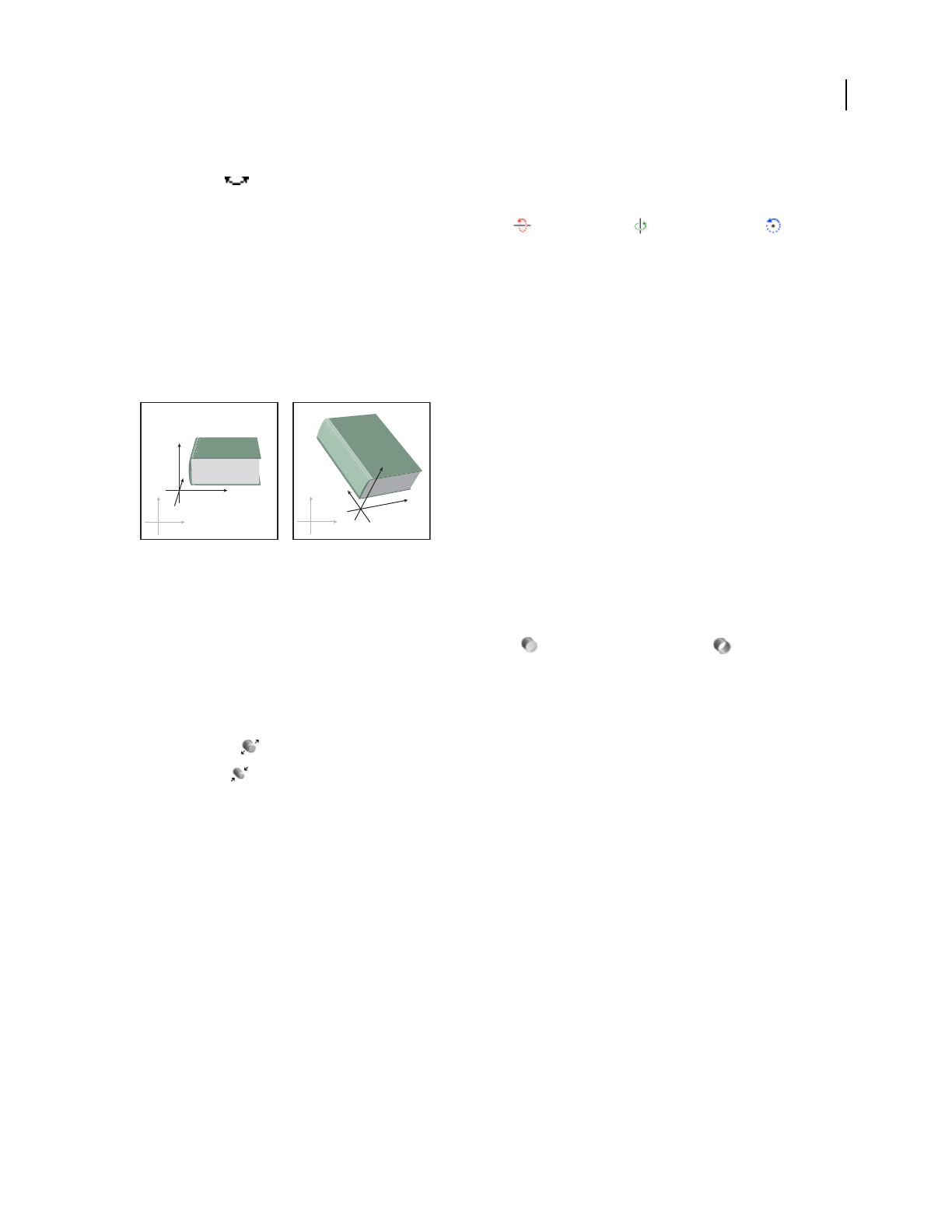
ILLUSTRATOR CS3
User Guide
247
•To constrain the rotation around an object axis, drag an edge on the track cube. The pointer changes to a double-
sided arrow , and the cube edge changes color to identify the axis around which the object will rotate. Red edges
represent the object’s x axis, green edges represent the object’s y axis, and blue edges represent the object’s z axis.
•Enter values between –180 and 180 in the horizontal (x) axis , vertical (y) axis , and depth (z) axis text
boxes.
•To adjust the perspective, enter a value between 0 and 160 in the Perspective text box. A smaller lens angle is
similar to a telephoto camera lens; a larger lens angle is similar to a wide-angle camera lens.
Note: A lens angle that is higher than 150 may result in objects extending beyond your point of view and appearing
distorted. Also, keep in mind that there are object x, y, and z axes and global x, y, and z axes. Object axes remain relative
to an object’s position in its 3D space. Global axes remain fixed relative to the computer screen; the x axis lies horizon-
tally, the y axis lies vertically, and the z axis lies perpendicular to the computer screen.
Object axes (in black) move with the object; global axes (in gray) are fixed.
Extrude & Bevel options
Extrude Depth Sets the depth of the object, using a value between 0 and 2000.
Cap Specifies whether the object appears solid (Revolve Cap On ) or hollow (Revolve Cap Off ).
Bevel Applies the type of beveled edge you choose along the depth (z axis) of the object.
Height Sets the height between 1 and 100. Bevel heights that are too large for an object may cause the object to self-
intersect and produce unexpected results.
Bevel Extent Out Adds the bevel to the object’s original shape.
Bevel Extent In Carves the bevel out of the object’s original shape.
y
x
y
x
y
z
x
y
z
x
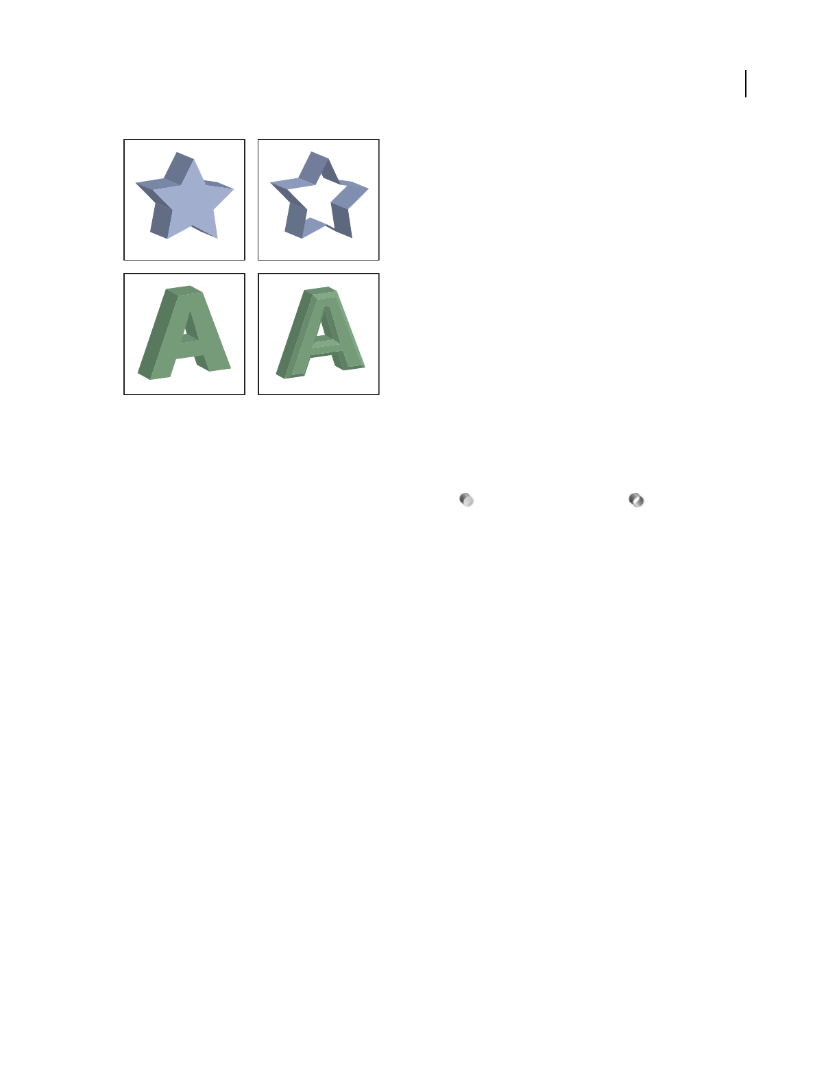
ILLUSTRATOR CS3
User Guide
248
Extruded object with cap (top left) compared to no cap (top right); object without a beveled edge (bottom left) compared to object with a beveled
edge (bottom right)
Revolve options
Angle Sets the number of degrees to revolve the path, between 0 and 360.
Cap Specifies whether the object appears solid (Revolve Cap On ) or hollow (Revolve Cap Off ).
Offset Adds distance between the revolve axis and the path, to create a ring-shaped object, for instance. You can
enter a value between 0 and 1000.
From Sets the axis around which the object revolves, either the Left Edge or Right Edge.
Surface shading options
Surface Lets you choose options for the shading surfaces:
•Wireframe Outlines the contours of the object’s geometry and make each surface transparent.
•No Shading Adds no new surface properties to the object. The 3D object has the same color as the original 2D
object.
•Diffuse Shading Makes the object reflect light in a soft, diffuse pattern.
•Plastic Shading Makes the object reflect light as if it were made of a shiny, high-gloss material.
Note: Depending on what option you choose, different lighting options are available.If the object only uses the 3D Rotate
effect, the only Surface choices available are Diffuse Shading or No Shading.
Light Intensity Controls the light intensity between 0% and 100%.
Ambient Light Controls the global lighting, which changes the brightness of all the object’s surfaces uniformly. Enter
a value between 0% and 100%.
Highlight Intensity Controls how much the object reflects light, with values ranging from 0% to 100%. Lower values
produce a matte surface, and higher values create a shinier-looking surface.
Highlight Size Controls the size of the highlight from large (100%) to small (0%).
Blend Steps Controls how smoothly the shading appears across the object’s surfaces. Enter a value between 1 and
256. Higher numbers produce smoother shades and more paths than lower numbers.
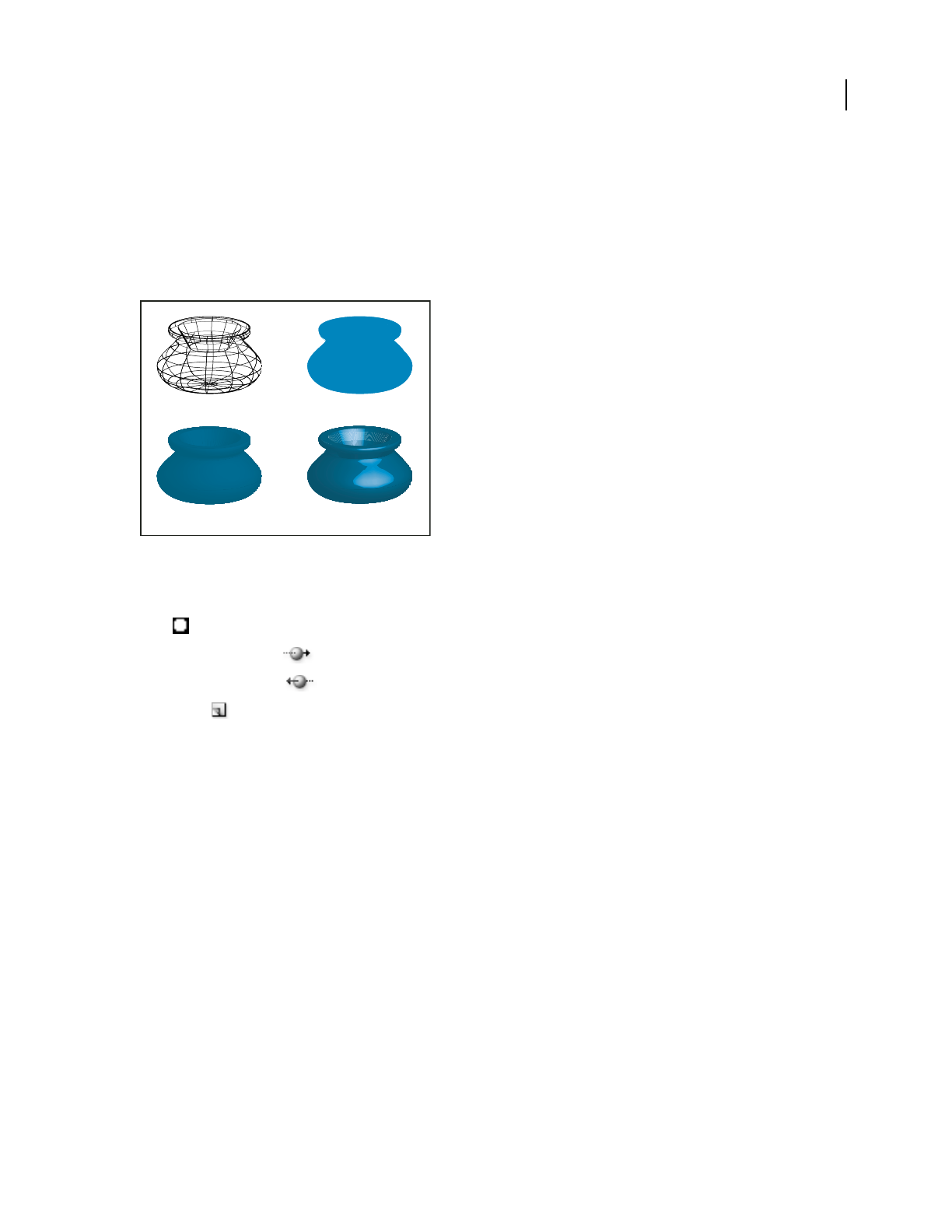
ILLUSTRATOR CS3
User Guide
249
Draw Hidden Faces Displays the object’s hidden backfaces. The backfaces are visible if the object is transparent, or if
the object is expanded and then pulled apart.
Note: If your object has transparency and you want the hidden backfaces to display through the transparent front faces,
apply the Object > Group command to the object before you apply the 3D effect.
Preserve Spot Color (Extrude & Bevel effect and Revolve effect) Lets you preserve spot colors in the object. Spot
colors can’t be preserved if you chose Custom for the Shading Color option.
Examples of different surface shading choices
A. Wireframe B. No shading C. Diffuse shading D. Plastic shading
Lighting options
Light Defines where the light is. Drag the light to where you want it on the sphere.
Move Light Back button Moves the selected light behind the object.
Move Light Front button Moves the selected light in front of the object.
New button Adds a light. By default, new lights appear in the front center of the sphere.
Delete Light button Deletes the selected light.
Note: By default, 3D Effects assigns one light to an object. You can add and delete lights, but the object must always have
at least one light.
Light Intensity Changes the selected light’s intensity between 0% and 100%.
Shading Color Controls the object’s shading color, depending on the command you choose:
•None Adds no color to the shading.
•Custom Lets you choose a custom color. If you choose this option, click the Shade Color box to select a color in
the Color Picker. Spot colors are changed to process colors.
•Black Overprint Avoids process colors if you’re using a spot color workflow. The object is shaded by overprinting
shades of black on top of the object’s fill color. To view the shading, choose View > Overprint Preview.
•Preserve Spot Color Lets you preserve spot colors in the object. Spot colors can’t be preserved if you chose Custom
for the Shading Color option.
AB
CD

ILLUSTRATOR CS3
User Guide
250
Lighting Sphere
A. Selected light in front B. Move selected light to back or front button C. New light button D. Delete light button
Add a custom bevel path
1 Open the Bevels.ai file located in the Adobe Illustrator Plug-ins folder.
2 Create a single open path in the Bevels.ai file.
3 Choose Window > Symbols, and do one of the following to make the path a symbol:
•Drag the path to the Symbols panel.
•With the path selected, click the New Symbol button in the Symbols panel or choose New Symbol from the
panel menu.
4 To rename the symbol, double-click the symbol in the Symbols panel, enter a name in the Symbol Options dialog
box, and click OK.
5 Choose File > Save.
6 Quit Illustrator and then relaunch Illustrator.
The Bevel menu in the 3D Extrude & Bevel Options dialog box lists the bevel.
7 To apply the custom bevel, do one of the following:
•
To apply the bevel to an extruded 3D object, select the 3D object, and then double-click the 3D Extrude & Bevel effect
in the Appearance panel. In the 3D Extrude & Bevel Options dialog box, choose the bevel from the Bevel menu.
•To apply the custom bevel to 2D artwork, select the 2D object, and then choose Effect > 3D > Extrude & Bevel. In
the 3D Extrude & Bevel Options dialog box, choose the custom bevel from the Bevel menu.
Rotate an object in three dimensions
1 Select the object.
2 Choose Effect > 3D > Rotate.
3 Select Preview to preview the effect in the document window.
4 Click More Options to view the complete list of options, or Fewer Options to hide the extra options.
5 Specify options:
Position Sets how the object is rotated and the perspective from which you view it. (See “Set 3D rotation position
options” on page 246.)
Surface Creates a wide variety of surfaces, from dull and unshaded matte surfaces to glossy and highlighted surfaces
that look like plastic. (See “Surface shading options” on page 248.)
6 Click OK.
B C D
A
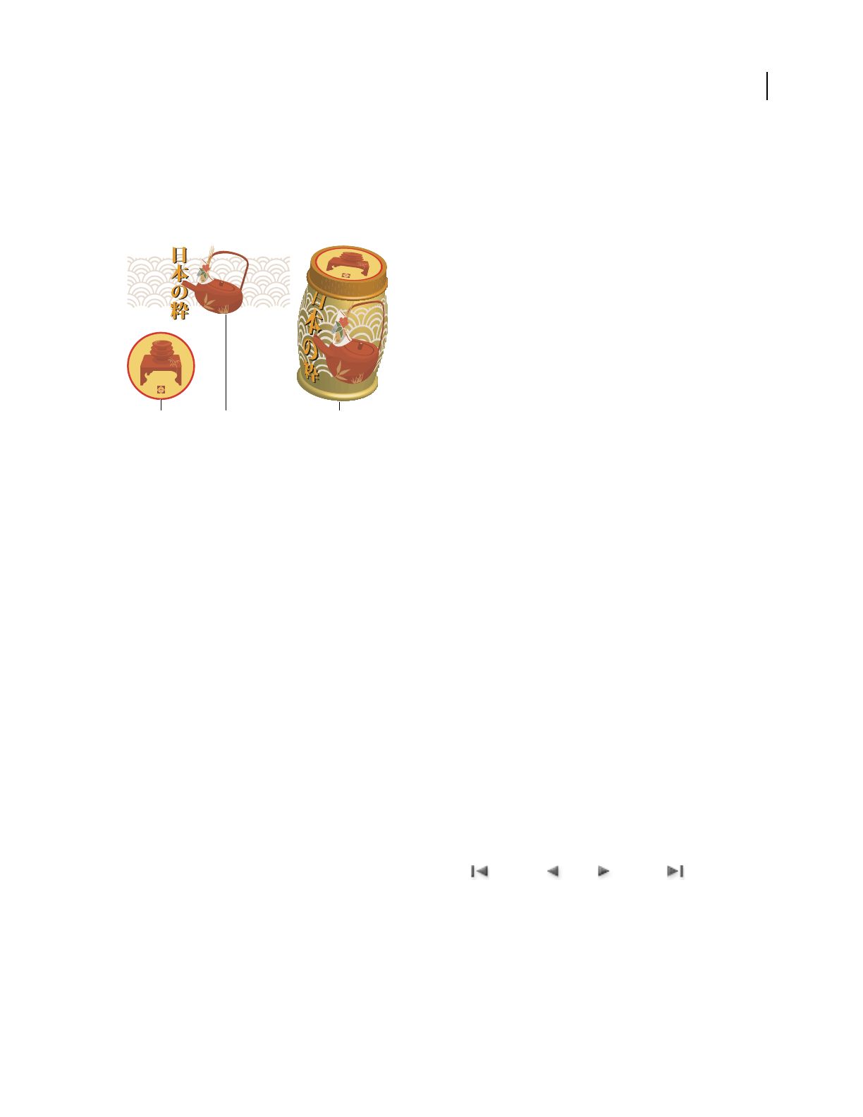
ILLUSTRATOR CS3
User Guide
251
Map artwork to a 3D object
Every 3D object is composed of multiple surfaces. For example, an extruded square becomes a cube that is made of
six surfaces: the front and back faces, and the four side faces. You can map 2D artwork to each surface on a 3D object.
For example, you might want to map a label or text onto a bottle-shaped object or simply add different textures to
each side of an object.
3D object with artwork mapped to each side
A. Symbol artwork B. Symbol artwork C. A and B mapped to 3D object
You can only map 2D artwork that’s stored in the Symbols panel to a 3D object. Symbols can be any Illustrator art
object, including paths, compound paths, text, raster images, mesh objects, and groups of objects.
When mapping 3D objects, consider the following:
•Because the Map Art feature uses symbols for mapping, you can edit a symbol instance and then automatically
update all surfaces that are mapped with it.
•You can interact with the symbol in the Map Art dialog box with normal bounding box controls to move, scale,
or rotate the object.
•The 3D effect remembers each mapped surface on an object as a number. If you edit the 3D object or apply the
same effect to a new object, there may be fewer or more sides than the original. If there are fewer surfaces than the
number of surfaces defined for the original mapping, the extra artwork will be ignored.
•Because a symbol’s position is relative to the center of an object surface, if the geometry of the surface changes,
then the symbol will be remapped relative to the new center of the object.
•You can map artwork to objects that use the Extrude & Bevel or Revolve effect, but you can’t map artwork to
objects that only use the Rotate effect.
1 Select the 3D object.
2 In the Appearance panel, double-click the Extrude & Bevel or Revolve effect.
3 Click Map Art.
4 Choose the artwork to map to the selected surface from the Symbol pop-up menu.
5 To select which object surface you want to map, click the first , previous , next , and last Surface
arrow buttons, or enter a surface number in the text box.
A light gray color marks surfaces that are currently visible. A dark gray color marks surfaces that are hidden by the
object’s current position. When a surface is selected in the dialog box, the selected surface is outlined in red in the
document window.
AB C

ILLUSTRATOR CS3
User Guide
252
6 Do any of the following:
•To move the symbol, position the pointer inside the bounding box and drag; to scale, drag a side or corner handle;
to rotate, drag outside and near a bounding box handle.
•To make the mapped artwork fit to the boundaries of the selected surface, click Scale To Fit.
•To remove artwork from a single surface, select the surface using the Surface options, and then either choose None
from the Symbol menu or click Clear.
•To remove all maps from all of the 3D object’s surfaces, click Clear All.
•To shade and apply the object’s lighting to the mapped artwork, select Shade Artwork.
•To show only the artwork map, not the geometry of a 3D object, select Invisible Geometry. This is useful when
you want to use the 3D mapping feature as a three-dimensional warping tool. For example, you could use this
option to map text to the side of an extruded wavy line, so that the text appears warped as if on a flag.
•To preview the effect, select Preview.
7 Click OK in the Map Artwork dialog box.

253
Chapter 9: Importing, exporting, and
saving
You don’t have to create artwork from scratch in Adobe Illustrator—you can import both vector drawings and bitmap
images from files created in other applications. Illustrator recognizes all common graphic file formats. Tight
integration between Adobe products and support for a wide variety of file formats, makes it easy to move art from
one application to another by importing, exporting, or copying and pasting.
Importing files
About linked and embedded artwork
When you place a graphic, you will see a screen-resolution version of the file in the layout, so that you can view and
position it, but the actual graphic file may be either linked or embedded.
•Linked artwork is connected to, but remains independent of, the document, resulting in a smaller document. You
can modify linked artwork using transformation tools and effects; however, you cannot select and edit individual
components in the artwork. You can use the linked graphic many times without significantly increasing the size
of the document; you can also update all links at once. When you export or print, the original graphic is retrieved,
creating the final output from the full resolution of the originals.
•Embedded artwork is copied into the document at full resolution, resulting in a larger document. You can update
the document whenever you like; as long as the artwork is embedded, your document is self-sufficient.
To determine if artwork is linked or embedded, or change its status from one to the other, use the Links panel.
If the embedded artwork contains multiple components, you can edit them discretely. For example, if the artwork
contains vector data, Illustrator converts it to paths, which you can then modify using Illustrator tools and
commands. Illustrator also preserves the object hierarchy (such as groups and layers) in artwork embedded from
certain file formats.
For a video on importing and copying and pasting between web applications, see www.adobe.com/go/vid0193.
Note: For information on importing Adobe® FreeHand® files into Illustrator, see the Migrating from FreeHand to
Illustrator PDF at www.adobe.com/go/learn_ai_freehand.
Place (import) files
The Place command is the primary method of importing, because it provides the highest level of support for file
formats, placement options, and color. After you place a file, use the Links panel to identify, select, monitor, and
update it.
1 Open the Illustrator document into which you want to place the artwork.
2 Choose File > Place, and select the file you want to place.
Note: To display Adobe® Version Cue® options in the Place dialog box, click the Use Adobe Dialog button.
3 Select Link to create a link to the file, or deselect Link to embed the artwork in the Illustrator document.
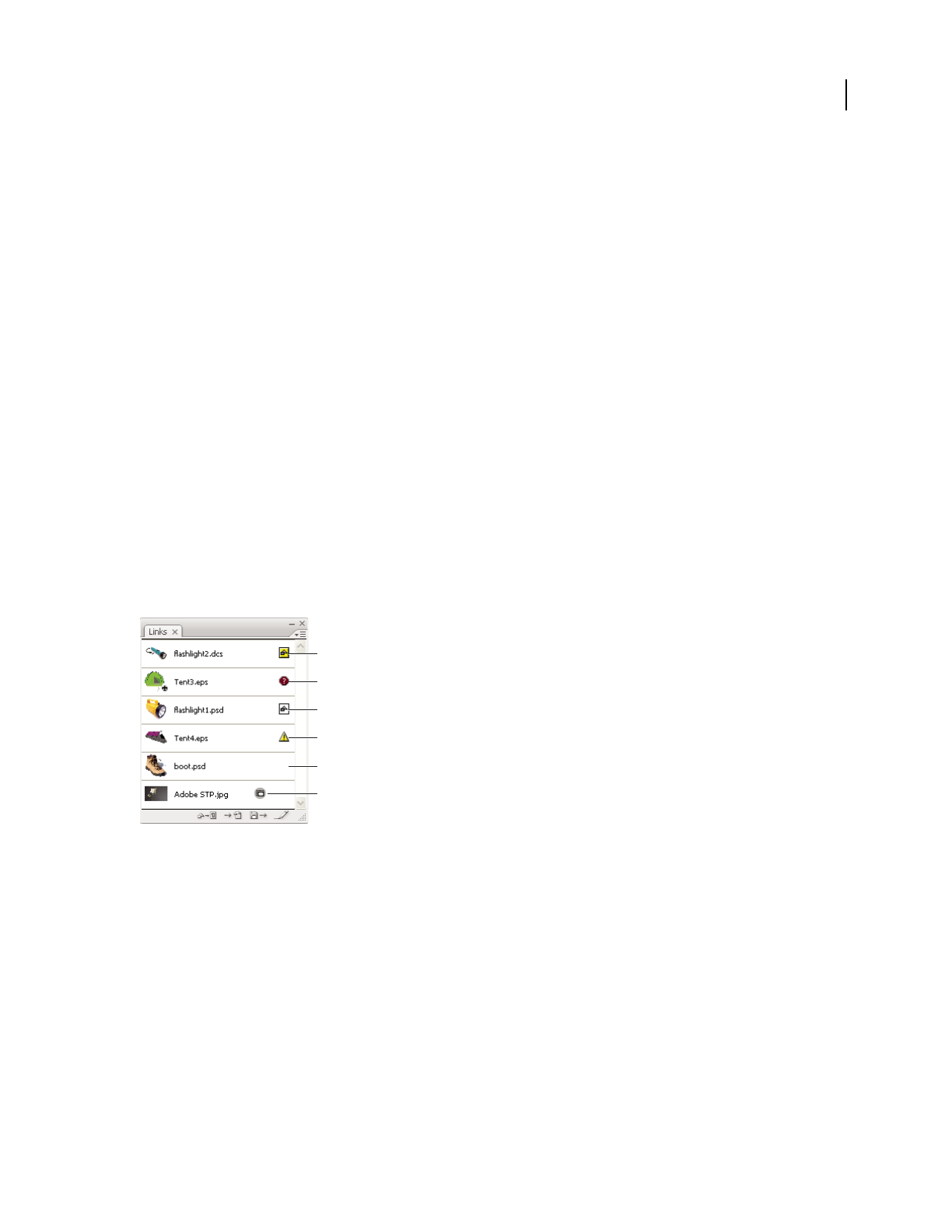
ILLUSTRATOR CS3
User Guide
254
4 Click Place.
5 If applicable, do one of the following:
•If you place a PDF file with multiple pages, you can choose which page you want to place and how to crop the
artwork.
•If you embed an Adobe® Photoshop® file, you can choose how to convert layers. If the file contains layer comps,
you can also choose which version of the image to import.
For a video on importing files into Illustrator, see www.adobe.com/go/vid0033. For a video on importing and
copying and pasting between web applications, see www.adobe.com/go/vid0193.
See also
“About linked and embedded artwork” on page 253
“Adobe PDF placement options” on page 259
“Photoshop import options” on page 262
Links panel overview
You use the Links panel to see and manage all linked or embedded artwork. The panel displays a small thumbnail of
the artwork and uses icons to indicate artwork’s status.
Note: If you’re working with files from an Adobe Version Cue project, the Links panel displays additional file infor-
mation.
Links panel
A. Transparency interaction B. Missing artwork C. Embedded artwork D. Modified artwork E. Linked artwork
See also
“Workspace overview” on page 14
File status options for the Links panel
A linked file can appear in the Links panel in any of the following ways:
Up-to-date An up-to-date file displays only the file’s name and (in Adobe® InDesign®) its page in the document.
Modified A modified file is one for which the version of the file on disk is more recent than the version in your
document. This would occur, for example, when someone modifies a Photoshop graphic that you have already
placed into Illustrator.
A
B
C
D
E
F

ILLUSTRATOR CS3
User Guide
255
Missing A missing file is one for which the graphic is no longer in the location from which it was imported, although
it may still exist somewhere. This can happen if someone moves the original file to a different folder or server after
it’s been imported into a document. You can’t know whether a missing file is up to date until its original is located. If
you print or export a document when this icon is displayed, the file may not print or export at full resolution.
Embedded Embedding the contents of a linked file suspends management operations for that link. If the selected
link is currently in an “edit in place” operation, this option is not enabled. Unembedding the file restores
management operations to the link.
Work with the Links panel
•To display the panel, choose Window > Links. Each linked file and embedded file is identified by name.
•To select and view a linked graphic, select a link and then click the Go To Link button , or choose Go To Link
in the Links panel menu. The display is centered around the selected graphic.
•To purchase a linked Adobe Stock Photo, select the photo and choose Purchase This Image from the Links panel
menu. Then follow the prompts in Adobe Bridge.
•To change the size of the thumbnails, in Illustrator select panel Options from the Links panel menu, and select an
option for displaying thumbnails; in InDesign choose Small panel Rows from the panel menu.
•To sort links in a different order, choose the desired Sort command in the panel menu.
•(Illustrator only) To hide thumbnails, select panel Options from the Links panel menu, and choose None.
View and save metadata via the Links panel
If a linked or embedded file contains metadata, you can view the metadata using the Links panel. You cannot edit or
replace metadata associated with a linked file; however, you can save a copy of the metadata in a template and apply
it to other files.
1 Select a file in the Links panel and choose Link File Info from the panel menu.
2 To save the metadata as a template, choose Save Metadata Template in the pop-up menu at the top of the dialog
box showing the metadata.
In InDesign, you can also view metadata in the Info panel. Select the object whose metadata you want to view, and
choose File Info from the Info panel menu.
View file information about linked or embedded artwork
❖Do any of the following:
•Double-click the link in the Links panel. Alternatively, select the link and select Link Information from the panel menu.
Note: Don’t confuse “Link information” with “Link File Info” in the Links panel menu; “File Info” refers to metadata.
•Select the linked artwork in the illustration window. In the Control panel, click the file name and choose Link
Information.
To locate linked or embedded artwork in the document window, select a link and click the Go To Link button. Alter-
natively, select Go To Link from the panel menu.
Update modified links
•To update specific links, in the Links panel select one or more modified links , and then click the Update Link
button or choose Update Link from the Links panel menu.

ILLUSTRATOR CS3
User Guide
256
•To update specific links, select the linked artwork in the illustration window. In the Control panel, click the
filename, and then choose Update Link.
Note: By default, Illustrator prompts you to update a link if the source file changes. To specify that you want to update
links automatically or manually, choose Edit > Preferences > File Handling & Clipboard (Windows) or Illustrator >
Preferences > File Handling & Clipboard (Mac OS), and set the Update Links option.
Restore a single missing link or replace link with a different source file
You can restore or replace a missing link—one that shows the missing-link icon in the Links panel—or any linked
file with a different source file.
1 Select the linked artwork on the page, or select a link name in the Links panel.
2 Do one of the following:
•In the Links panel, click the Relink button , or choose Relink from the panel menu.
•Click the linked filename in the Control panel, and then choose Relink. (To access this option, you must select the
image in the artwork.)
3 In the dialog box that appears, do one of the following:
•Locate and select a replacement file.
•Type the first, or first few, letters of the name of the desired replacement file to locate the file.
4 Click Place.
The new artwork retains the size, placement, and transformation characteristics of the artwork that it replaced.
Note: If all of a document’s missing links are located in the same folder, you can restore all of them at once. In the Links panel,
select all of the missing links, and then restore one of them; the Place dialog box stays open for you to reselect each one.
Set placement options for linked artwork
1 Do one of the following:
•Select the linked artwork in the illustration window. In the Control panel, click the filename and choose Placement
Options.
•In the Links panel, select the link and choose Placement Options from the panel menu.
2 Select an option for Preserve.
If you select an option other than Transforms or Bounds, you can select a point on the Alignment icon from which
you want to align the artwork, relative to the bounding box. If you want to keep the artwork from overlapping the
bounding box, select Clip To Bounding Box.
See also
“Links panel overview” on page 254
“About linked and embedded artwork” on page 253
“Control panel overview” on page 17

ILLUSTRATOR CS3
User Guide
257
Embed a linked file
Rather than linking to a file that you’ve placed in a document, you can embed (or store) the file within the document.
When you embed a file, you break the link to the original. Without the link, the Links panel doesn’t alert you when
the original has changed, and you cannot update the file automatically.
Keep in mind that embedding a file, rather than linking to the original, increases the document file size.
•Select a file in the Links panel, and choose Embed Image from the panel menu.
•Select the linked artwork in the illustration window. In the Control panel, click the Embed button.
The file remains in the Links panel marked with the embedded-link icon .
Unembed a linked file
1 Select one or more embedded files in the Links panel.
2 Click the Relink button or select Relink in the Links panel menu, locate and select the original file, and click
Place.
Relink an embedded file
1 Select one or more embedded files in the Links panel.
2 Click the Relink button or select Relink in the Links panel menu, locate and select the original file, and click
Place.
Edit original artwork
The Edit Original command lets you open most graphics in the application in which you created them so that you
can modify it as necessary. Once you save the original file, the document in which you linked it is updated with the
new version.
Note: In InDesign, if you check out and select a managed graphics frame (one that has been exported to InCopy), rather
than the graphic itself, the graphic opens in InCopy.
1 Do any of the following:
•In the Links panel, select the link and click the Edit Original button . Alternatively, choose Edit Original from
the panel menu.
•Select the linked artwork on the page, and choose Edit > Edit Original.
•In Illustrator, select the linked artwork on the page, and click the Edit Original button in the Control panel.
2 After making changes in the original application, save the file.

ILLUSTRATOR CS3
User Guide
258
Importing bitmap images
About bitmap images
Bitmap images—technically called raster images—use a rectangular grid of picture elements (pixels) to represent
images. Each pixel is assigned a specific location and color value. When working with bitmap images, you edit pixels
rather than objects or shapes. Bitmap images are the most common electronic medium for continuous-tone images,
such as photographs or digital paintings, because they can more efficiently represent subtle gradations of shades and
color.
Bitmap images are resolution-dependent—that is, they contain a fixed number of pixels. As a result, they can lose
detail and appear jagged if they are scaled to high magnifications on-screen or if they are printed at a lower resolution
than they were created for.
Example of a bitmap image at different levels of magnification
Bitmap images sometimes require large amounts of storage space, and often need to be compressed to keep file sizes
down when used in certain Creative Suite components. For instance, you compress an image file in its original appli-
cation before you import it into a layout.
Note: In Adobe Illustrator, you can create bitmap effects in your artwork using filters, effects, and graphic styles.
See also
“About vector graphics” on page 52
Image resolution guidelines for final output
Bitmap images contain a fixed number of pixels, usually measured in pixels per inch (ppi). An image with a high
resolution contains more, and therefore smaller, pixels than an image of the same printed dimensions with a low
resolution. For example, a
1-inch-by-1-inch image with a resolution of 72 ppi contains a total of 5184 pixels (72
pixels wide x 72 pixels high = 5184). The same 1-inch-by-1-inch image with a resolution of 300
ppi would contain a
total of 90,000 pixels.
For imported bitmap images, image resolution is determined by the source file. For bitmap effects, you can specify
a custom resolution. To determine the image resolution to use, consider the medium of final distribution for the
image. The following guidelines can help you determine your requirements for image resolution:
Commercial printing Commercial printing requires 150 to 300 ppi (or more) images, depending on the press (dpi)
and screen frequency (lpi) you’re using; always consult your prepress service provider before making production
decisions. Because commercial printing requires large, high-resolution images, which take more time to display
while you’re working with them, you may want to use low-resolution versions for layout and then replace them with
high-resolution versions at print time.
24:1
3:1

ILLUSTRATOR CS3
User Guide
259
In Illustrator and InDesign, you can work with low resolution versions by using the Links panel. In InDesign you can
choose either Typical or Fast Display from the View > Display Performance menu; in Illustrator you can choose
View > Outline, or change settings in the Display Performances preferences. Alternatively, if your service provider
supports Open Prepress Interface (OPI), they may provide low-resolution images to you.
Desktop printing Desktop printing usually requires images within the range of 72 ppi (for photographs printed on
a 300 ppi printer) to 150 ppi (for photographs printed on devices up to 1000 ppi). For line art (1-bit images), make
sure that the resolution of your graphics matches the resolution of the printer.
Web publishing Because online publishing generally requires images with pixel dimensions that fit the intended
monitor, the images are usually less than 500 pixels wide and 400 pixels tall, to leave room for browser window
controls or such layout elements as captions. Creating an original image at screen resolution—96 ppi for Windows–
based images, and 72 ppi for Mac OS–based images—lets you see the image as it will likely appear when viewed from
a typical web browser. When you’re publishing online, the only times you’re likely to need resolutions above those
ranges are when you want viewers to be able to zoom in for more detail in a PDF document, or when you’re
producing a document for printing on demand.
Importing Adobe PDF files
Importing Adobe PDF files
Adobe Portable Document Format (PDF) is a versatile file format that can represent both vector and bitmap data.
You can bring artwork from PDF files into Illustrator using the Open command, the Place command, the Paste
command, and the drag-and-drop feature.
•Use the Place command with the Link option selected to import a PDF file (or one page of the PDF if it is a multi-
page document) as a single image. You can modify the linked image using transformation tools; however, you
cannot select and edit its individual components.
•Use the Open command or the Place command with the Link option deselected to edit the contents of a PDF file.
Illustrator recognizes the individual components in the PDF artwork and lets you edit each component as a
discrete object.
•Use the Paste command or the drag-and-drop feature to import selected components from a PDF file, including
vector objects, bitmap images, and text.
Note: If you are color-managing artwork in a document, embedded PDF images are part of the document and therefore
color-managed when sent to a printing device. In contrast, linked PDF images are not color-managed, even if color
management is turned on for the rest of the document.
See also
“About linked and embedded artwork” on page 253
Adobe PDF placement options
When you place an Adobe PDF file, you specify which page you want to import. You also choose how to crop the
artwork by selecting a Crop To option:
Bounding Box Places the PDF page’s bounding box, or the minimum area that encloses the objects on the page,
including page marks.

ILLUSTRATOR CS3
User Guide
260
Art Places the PDF only in the area defined by a rectangle that the author created as placeable artwork (for example,
clip art).
Crop Places the PDF only in the area that is displayed or printed by Adobe Acrobat.
Trim Identifies the place where the final produced page will be physically cut in the production process, if trim
marks are present.
Bleed Places only the area that represents where all page content should be clipped, if a bleed area is present. This
information is useful if the page is being output in a production environment. Note that the printed page may include
page marks that fall outside the bleed area.
Media Places the area that represents the physical paper size of the original PDF document (for example, the dimen-
sions of an A4 sheet of paper), including page marks.
See also
“Place (import) files” on page 253
Importing monotone, duotone, and tritone images from Adobe PDF files
When you import artwork from an Adobe PDF file, it’s possible to introduce data that you can’t create within
Illustrator. This is called non-native art and includes monotone, duotone, and tritone images. You can also generate
non-native art within Illustrator by using the Flatten Transparency command to preserve spot colors.
Illustrator’s ability to preserve non-native art is useful in many situations. For example, Illustrator maintains the spot
color information in linked PDF files when you output color separations.
By default, non-native art is labeled <Non-Native Art> in the Layers and Appearance panels. You can select, move,
save, and perform basic transformations (such as scaling, rotating, or skewing) on non-native art. However, you
cannot select and edit its individual components. In addition, you must rasterize non-native art before editing it with
the liquify tools.
To convert non-native art to an Illustrator object, choose Object > Rasterize.
See also
“Importing Adobe PDF files” on page 259
“Rasterize a vector object” on page 366
Importing EPS, DCS, and AutoCAD files
Importing EPS files
Encapsulated PostScript (EPS) is a popular file format for transferring vector artwork between applications. You can
bring artwork from EPS files into Illustrator using the Open command, the Place command, the Paste command,
and the drag-and-drop feature.

ILLUSTRATOR CS3
User Guide
261
Keep the following in mind when working with EPS artwork:
•When you open or embed an EPS file that was created in another application, Illustrator converts all objects to
native Illustrator objects. However, if the file contains data that Illustrator doesn’t recognize, some loss of data may
occur. As a result, unless you need to edit the individual objects in an EPS file, it’s best to link to the file rather than
open or embed it.
•EPS format does not support transparency; therefore, it is not a good choice for placing transparent artwork from
other applications into Illustrator. Instead, use PDF 1.4 format for this purpose.
•You may receive an error message when printing or saving artwork that includes linked EPS files, if those files were
saved in binary format (for example, in Photoshop's default EPS format). In this case, resave the EPS files in ASCII
format, embed the linked files into the Illustrator artwork, print to a Binary print port instead of an ASCII print
port, or save the artwork in AI or PDF format instead of EPS format.
•If you are color-managing artwork in a document, embedded EPS images are part of the document and therefore
color-managed when sent to a printing device. In contrast, linked EPS images are not color-managed, even if color
management is turned on for the rest of the document.
•If you import an EPS color that has the same name as a color in your document but a different definition,
Illustrator displays an alert. Select Use Linked File’s Color to replace the color in your document with the EPS color
in the linked file. All objects using this color in your document will get updated appropriately. Select Use
Document’s Color to leave the swatch as is and resolve all color conflicts using the document’s color. The EPS
preview cannot be changed, so the preview may be incorrect, but it will print to the correct plates. Selecting Apply
to All will resolve all color conflicts, using the definition either of the document or the linked file, depending on
which option you choose.
•Occasionally you may encounter a warning when opening an Illustrator document containing embedded EPS
images. If the application cannot find the original EPS image, you will be prompted to extract the EPS image.
Select the Extract option in the dialog box; the image will be extracted into the same directory as the current
document. Although the embedded file does not preview in the document, the file will now print correctly.
•By default, linked EPS files are displayed as a low resolution preview to increase performance. If a linked EPS file
isn’t visible in the document window, it may be because the file’s preview is missing. (Previews are sometimes lost
when transferring EPS files saved with PICT previews from Mac OS to Windows.) To view linked EPS files at full
resolution, choose Edit > Preferences > File Handling & Clipboard (Windows) or Illustrator > Preferences > File
Handling & Clipboard (Mac OS), and deselect Use Low Resolution Proxy For Linked EPS. To restore the preview,
resave the EPS file with a TIFF preview.
See also
“About linked and embedded artwork” on page 253
“Save in EPS format” on page 265
Importing DCS files
Desktop Color Separation (DCS) is a version of the standard EPS format. The DCS 1.0 format supports only CMYK
images while the DCS 2.0 format supports multichannel CMYK files as well as multiple spot inks. (These spot inks
appear as spot colors in Illustrator’s Swatches panel.) Illustrator recognizes clipping paths in Photoshop-created DCS
1.0 and DCS 2.0 files. You can link DCS files in Illustrator, but you can’t embed or open them.

ILLUSTRATOR CS3
User Guide
262
Importing AutoCAD files
AutoCAD files include both DXF and DWG formats. You can import AutoCAD files from version 2.5 through
version 2006. During import, you can specify scale, unit mapping (custom unit for interpreting all the length data in
the AutoCAD file), whether to scale lineweights, which layout to import, and whether to center the artwork.
Illustrator supports most AutoCAD data, including 3D objects, shapes and paths, external references, region objects,
spline objects (mapped to Bezier objects that retain the original shape), raster objects, and text objects. When
importing an AutoCAD file that contains external references, Illustrator reads the contents of the reference and
places it at the appropriate locations in the Illustrator file. If an external reference is not found, the Missing Link
dialog box opens so you can search for and retrieve the file.
Importing artwork from Photoshop
Importing artwork from Photoshop
You can bring artwork from Photoshop (PSD) files into Illustrator using the Open command, the Place command,
the Paste command, and the drag-and-drop feature.
Illustrator supports most Photoshop data, including layer comps, layers, editable text, and paths. This means that you
can transfer files between Photoshop and Illustrator without losing the ability to edit the artwork. For easy transfer
of files between the two applications, adjustment layers that have visibility turned off are imported (though inacces-
sible) into Illustrator and restored when exported back to Photoshop.
Spot colors (up to 31 spot channels per file) import as a single N-Channel raster image, which is placed over the
process color image. The spot colors are added to the swatches panel as custom colors with the same name as in
Photoshop. Imported spot colors separate correctly.
Duotone PSD files import as flat raster images with a 256-indexed colorspace and an N-Channel colorspace
containing all of the duotone inks. Because Illustrator uses an N-Channel, blending mode interactions set in
Photoshop may appear differently in Illustrator. Ink colors from old color libraries are set to gray.
In cases where Illustrator must convert the Photoshop data, a warning message appears. For example, when
importing a 16-bit Photoshop file, Illustrator warns you that the image will be imported as an 8-bit, flat composite.
Photoshop import options
When you open or place a Photoshop file that contains multiple layers, you can set the following options:
Layer Comp If the Photoshop file contains layer comps, specifies which version of the image to import. Select Show
Preview to display a preview of the selected layer comp. The Comments text box displays comments from the
Photoshop file.
When Updating Link Specifies how to handle layer visibility settings when updating a linked Photoshop file that
includes layer comps.
•Keep Layer Visibility Overrides Updates the linked image based on the state of layer visibility in the layer comp
when you originally placed the file.
•Use Photoshop’s Layer Visibility Updates the linked image based on the current state of layer visibility in the
Photoshop file.

ILLUSTRATOR CS3
User Guide
263
Convert Photoshop Layers To Objects And Make Text Editable Where Possible Preserves as much layer structure
and text editability as possible without sacrificing appearance. However, if the file includes features that Illustrator
doesn’t support, Illustrator preserves the appearance of the artwork by merging and rasterizing layers. For example:
•Layer sets that use the Dissolve blending mode as well as all layers in clipping masks get merged into single layers.
•Adjustment layers and layers that use a Knockout option are merged with the underlying layers, as are layers that
contain transparent pixels and use the Color Dodge, Color Burn, Difference, Linear Burn, Linear Dodge, Vivid
Light, Linear Light, or Pin Light blending mode.
•Layers that use layer effects may be merged; however, the specific merging behavior depends on the blending
mode of the layer, the presence of transparent pixels, and the layer’s blending options.
•Hidden layers that require merging are discarded.
Note: The Convert Photoshop Layers To Objects And Make Text Editable Where Possible option is not available when
you link to a Photoshop file.
Flatten Photoshop Layers To A Single Image And Preserve Text Appearance Imports the file as a single bitmap
image. The converted file retains no individual objects, except for the document clipping path (if one exists). Opacity
is retained as part of the main image, but is not editable.
Import Hidden Layers Imports all layers from the Photoshop file, even those that are hidden. This option is not
available when linking to a Photoshop file.
Import Slices Preserves any slices that are included in the Photoshop file. This option is available only when opening
or embedding a file that includes slices.
Move part of an image from Photoshop to Illustrator
1 In Photoshop, select the pixels you want to move. For more information, see Photoshop Help.
2 Do one of the following:
•Copy the selection in Photoshop and paste it in Illustrator. If a layer mask is active when you choose the Copy
command, Photoshop copies the mask rather than the main layer.
•Select the Move tool in Photoshop, and drag the selection to Illustrator. Illustrator fills transparent pixels with
white.
Move paths from Photoshop to Illustrator
1 In Photoshop, use the Path Component Selection tool or the Direct Selection tool to select the paths you want to
move.
You can select any path or path segment that appears in the Paths panel, including shape vector masks, work paths,
and saved paths. For more information on selecting paths, see Photoshop Help.
2 Either copy and paste or drag the path to Illustrator.
3 In the Paste Options dialog box, choose whether to paste the path as a compound shape or a compound path.
Pasting as a compound path is faster, but may result in some loss of editability.
To import all paths (but no pixels) from a Photoshop document, choose File > Export > Paths To Illustrator (in
Photoshop). Then open the resulting file in Illustrator.

ILLUSTRATOR CS3
User Guide
264
Saving artwork
About saving and exporting artwork
When you save or export artwork, Illustrator writes the artwork data to a file. The structure of the data depends on
the file format that you select.
There are four basic file formats—AI, PDF, EPS, and SVG—to which you can save artwork. These formats are called
native formats because they can preserve all Illustrator data. (For PDF and SVG formats, you must select the Preserve
Illustrator Editing Capabilities options to preserve all Illustrator data.)
You can also export artwork in a variety of file formats for use outside of Illustrator. These formats are called non-
native formats because Illustrator will not be able to retrieve all of the data if you reopen the file in Illustrator. For
this reason, it is recommended that you save artwork in AI format until you are finished creating it, and then export
the artwork to the desired format.
Note: You may receive an error message when saving artwork that includes linked EPS files, if those files were saved in
binary format (for example, in Photoshop's default EPS format). In this case, resave the EPS files in ASCII format, embed
the linked files into the Illustrator artwork, or save the artwork in AI or PDF format instead of EPS format.
For a video on creating mobile content in Illustrator, see www.adobe.com/go/vid0207. For a video on saving for the
web, see www.adobe.com/go/vid0063. For a video on exporting content from Illustrator, including an overview on
different formats and when you should use them, see www.adobe.com/go/vid0062.
See also
“About Adobe PDF” on page 276
Save in Illustrator format
1 Choose File > Save As or File > Save A Copy.
2 Type a filename, and choose a location for the file.
Note: To display Version Cue options in the Save As and Save A Copy dialog boxes, click the Use Adobe Dialog button.
3 Choose Illustrator (*.AI) as the file format, and click Save.
To create a file that is compatible with a previous version of Illustrator, set the Version option at the top of the
Illustrator Options dialog box.
4 In the Illustrator Options dialog box, set the desired options and click OK:
Version Specifies the version of Illustrator with which you want your file to be compatible. Legacy formats don’t
support all the features in the current version of Illustrator. Therefore, when you select a version other than the
current version, some options for saving aren’t available, and certain kinds of data will be changed. Be sure to read
the warnings at the bottom of the dialog box so that you are aware of how the data will be changed.
Subset Embedded Fonts When Percent Of Characters Used Is Less Than Specifies when to embed the entire font (as
opposed to just the characters used in the document) based on how many of the font’s characters are used in the
document. For instance, if a font contains 1,000 characters but the document only uses 10 of those characters, you
may decide that embedding the font is not worth the extra file size.
Create PDF Compatible File Saves a PDF representation of the document in the Illustrator file. Select this option if
you want the Illustrator file to be compatible with other Adobe applications.
Include Linked Files Embeds files that are linked to the artwork.

ILLUSTRATOR CS3
User Guide
265
Use Compression Compresses PDF data in the Illustrator file. Using compression increases the time required to save
the document, so deselect this option if you’re experiencing very slow (8 to 15 minute) save times.
Embed ICC Profiles Creates a color-managed document.
Transparency options Determines what happens to transparent objects when you choose a version of Illustrator
format earlier than 9.0. Select Preserve Paths to discard transparency effects and reset transparent artwork to 100%
opacity and Normal blending mode. Select Preserve Appearance And Overprints to preserve overprints that don’t
interact with transparent objects. Overprints that interact with transparent objects are flattened.
Important: If your artwork contains complex, overlapping areas and you require high-resolution output, click Cancel
and specify rasterization settings before continuing.
See also
“About color profiles” on page 141
“Rasterization options” on page 352
Save in EPS format
Virtually all page layout, word-processing, and graphic applications accept imported or placed encapsulated
PostScript (EPS) files. The EPS format preserves many of the graphic elements you can create with Adobe Illustrator,
which means that EPS files can be reopened and edited as Illustrator files. Because EPS files are based on the
PostScript language, they can contain both vector and bitmap graphics.
1 If your artwork contains transparency (including overprints) and you require high-resolution output, choose
Window > Flattener Preview to preview the effects of flattening.
2 Choose File > Save As or File > Save A Copy.
3 Type a filename, and choose a location for the file.
Note: To display Version Cue options in the Save As and Save A Copy dialog boxes, click the Use Adobe Dialog button.
4 Choose Illustrator EPS (*.EPS) as the file format, and click Save.
To create a file that is compatible with a previous version of Illustrator, set the Version option at the top of the EPS
Options dialog box.
5 In the EPS Options dialog box, set the desired options and click OK:
Version Specifies the version of Illustrator with which you want your file to be compatible. Legacy formats don’t
support all the features in the current version of Illustrator. Therefore, when you select a version other than the
current version, some options for saving aren’t available, and certain kinds of data will be changed. Be sure to read
the warnings at the bottom of the dialog box so that you are aware of how the data will be changed.
Format Determine the characteristics of the preview image that is saved in the file. The preview image is displayed
in applications that cannot display EPS artwork directly. If you don’t want to create a preview image, choose None
from the Format menu. Otherwise, select a black-and-white or color format.
If you select TIFF (8-bit Color) format, select a background option for the preview image:
•Transparent Produces a transparent background.
•Opaque Produces a solid background. (Select Opaque if the EPS document will be used in a Microsoft Office
application.)

ILLUSTRATOR CS3
User Guide
266
Transparency options Determines what happens to transparent objects and overprints. The available options
change depending on the format version you select at the top of the dialog box.
If you choose a CS format, specify how to save overlapping colors that are set to overprint, and select a preset (or set
of options) for flattening transparency. Click Custom to customize the flattener settings.
If you choose a Legacy format earlier than 8.0, select Preserve Paths to discard transparency effects and reset trans-
parent artwork to 100% opacity and Normal blending mode. Select Preserve Appearance and Overprints to preserve
overprints that don’t interact with transparent objects. Overprints that interact with transparent objects are flattened.
Embed Fonts (For Other Applications) Embeds all fonts that contain appropriate permissions from the font vendor.
Embedding fonts ensures that the original font is displayed and printed if the file is placed into another application,
such as Adobe InDesign. However, if the file is opened in Illustrator on a computer that does not have the font
installed, the font will be faux or substituted. This is to prevent illegal use of the embedded font.
Note: Selecting the Embed Fonts option increases the size of the saved file.
Include Linked Files Embeds files that are linked to the artwork.
Include Document Thumbnails Creates a thumbnail image of the artwork. The thumbnail is displayed in the
Illustrator Open and Place dialog boxes.
Include CMYK PostScript In RGB Files Allows RGB color documents to be printed from applications that do not
support RGB output. When the EPS file is reopened in Illustrator, the RGB colors are preserved.
Compatible Gradient And Gradient Mesh Printing Enables older printers and PostScript devices to print gradients
and gradient meshes by converting gradient objects to JPEG format. Selecting this option can slow printing on
printers that don’t have problems with gradients.
Adobe PostScript® Determines what level of PostScript is used to save the artwork. PostScript Language Level 2
represents color as well as grayscale vector and bitmap images, and supports RGB, CMYK, and CIE-based color
models for both vector and bitmap graphics. PostScript Language Level 3 provides additional functionality to
Language Level 2, including the ability to print mesh objects when printing to a PostScript® 3™ printer. Because
printing to PostScript Language Level 2 devices converts gradient mesh objects to bitmap images, it is preferable to
print artwork that contains gradient mesh objects to a PostScript 3 printer.
See also
“Preview which areas of artwork will be flattened” on page 421
“Printing and saving transparent artwork” on page 417
“About overprinting” on page 424
Save in SVG format
SVG is a vector format that produces high-quality, interactive web graphics. There are two versions of the SVG
formats: SVG and Compressed SVG (SVGZ). SVGZ can reduce file sizes by 50% to 80%; however, you cannot edit
SVGZ files using a text editor.
When you export artwork in an SVG format, mesh objects are rasterized. In addition, images that have no alpha
channel are converted to the JPEG format. Images with an alpha channel are converted to the PNG format.

ILLUSTRATOR CS3
User Guide
267
For a video on creating mobile content in Illustrator, see www.adobe.com/go/vid0207.
1 If the artwork contains any SVG effects, select each item to which an SVG effect has been applied, and move the
effect to the bottom of the Appearance panel (just above the Opacity entry). If other effects follow an SVG effect, the
SVG output will consist of a raster object.
2 Choose File > Save As or File > Save A Copy.
3 Type a filename, and choose a location for the file.
Note: To display Version Cue options in the Save As and Save A Copy dialog boxes, click the Use Adobe Dialog button.
4 Choose SVG (*.SVG) or SVG Compressed (*.SVGZ) as the file format, and click Save.
5 In the SVG Options dialog box, set the desired options and click OK:
SVG Profiles Specifies the SVG XML Document Type Definition for the exported file.
•SVG 1.0 and SVG 1.1 Suitable for SVG files that will be viewed on a desktop computer. SVG 1.1 is the full version
of the SVG specification, of which SVG Tiny 1.1, SVG Tiny 1.1 Plus, and SVG Basic 1.1 are subsets.
•SVG Basic 1.1 Suitable for SVG files that will be viewed on medium powered devices, such as handheld devices.
Keep in mind that not all handhelds support the SVG Basic profile. As a result, selecting this option does not
guarantee that the SVG file will be viewable on all handhelds. SVG Basic does not support nonrectangular clipping
and some SVG filter effects.
•SVG Tiny 1.1 and SVG Tiny 1.1+ Suitable for SVG files that will be viewed on small devices, such as mobile phones.
Keep in mind that not all mobile phones support the SVG Tiny and SVG Tiny Plus profiles. As a result, selecting
either of these options does not guarantee that the SVG file will be viewable on all small devices.
•SVG Tiny 1.2 Suitable for SVG files that will be viewed on a variety of devices ranging from PDAs and mobile
phones to laptops and desktop computers.
SVG Tiny does not support gradients, transparency, clipping, masks, symbols, patterns, underline text, strike
through text, vertical text, or SVG filter effects. SVG Tiny Plus includes the ability to display gradients and trans-
parency, but does not support clipping, masks, symbols, or SVG filter effects.
For additional information on SVG profiles, see the SVG specification on the World Wide Web Consortium (W3C)
website (www.w3.org).
Font Type Specifies how fonts are exported:
•Adobe CEF Uses font hinting for better rendering of small fonts. This font type is supported by the Adobe SVG
Viewer but may not be supported by other SVG viewers.
•SVG Does not use font hinting. This font type is supported by all SVG viewers.
•Convert To Outlines Converts type to vector paths. Use this option to preserve the visual appearance of type in all
SVG Viewers.
Font Subsetting Controls which glyphs (characters of a particular font) are embedded in the exported SVG file.
Choose None from the Subsetting menu if you can rely on the necessary fonts being installed on end-user systems.
Choose Only Glyphs Used to include only glyphs for text that exists in the current artwork. The other values
(Common English, Common English + Glyphs Used, Common Roman, Common Roman + Glyphs Used, All
Glyphs) are useful when the textual content of the SVG file is dynamic (such as server-generated text or user-inter-
active text).
Image Location Determines whether raster images are embedded directly in the file or linked to the exported JPEG
or PNG images from the original Illustrator file. Embedding images increases file size but ensures that rasterized
images will always be available.

ILLUSTRATOR CS3
User Guide
268
Preserve Illustrator Editing Capabilities Preserves Illustrator-specific data by embedding an AI file in the SVG file
(resulting in a larger file size). Select this option if you plan to reopen and edit the SVG file in Illustrator. Note that
if you make manual changes to the SVG data, the changes are not reflected when you reopen the file. This is because
Illustrator reads the AI portion of the file, not the SVG portion.
CSS Properties Determines how style attributes are saved in the SVG code. The default method, Presentation
Attributes, applies properties at the highest point in the hierarchy, which allows the most flexibility for specific edits
and transformations. The Style Attributes method creates the most readable files but may increase the file size.
Choose this method if the SVG code will be used in transformations—for example, transformations using Extensible
Stylesheet Language Transformation (XSLT). The Style Attributes <Entity References> method results in faster
rendering times and reduced SVG file size. The Style Elements method is used when sharing files with HTML
documents. By selecting Style Elements, you can then modify the SVG file to move a style element into an external
style sheet file that is also referenced by the HTML file; however, the Style Elements option also results in slower
rendering speeds.
Decimal Places Specifies the precision of vector data in the SVG file. You can set a value of 1–7 decimal places. A
higher value results in a larger file size and increased image quality.
Encoding Determines how characters are encoded in the SVG file. UTF (Unicode Transformation Format)
encoding is supported by all XML processors. (UTF-8 is an 8-bit format; UTF-16 is a 16-bit format.) ISO 8859-1 and
UTF-16 encoding do not preserve file metadata.
Optimize For Adobe SVG Viewer Maintains the highest level of Illustrator data while still allowing the SVG file to be
manually edited. Select this option to take advantage of faster rendering for features such as SVG filter effects.
Include Adobe Graphics Server Data Includes all information needed for variable substitution in the SVG file. (See
“About data-driven graphics” on page 441.)
Include Slicing Data Includes slice locations and optimization settings.
Include XMP Includes XMP metadata in the SVG file. Choose File > Info or use the Bridge Browser to enter
metadata.
Output Fewer <tspan> Elements Allows Illustrator to ignore auto-kerning settings during export, which results in
a file with fewer <tspan> elements. Select this option to create an SVG file that is more editable and compact.
Deselect this option if maintaining the appearance of auto-kerned text is critical.
Use <textPath> Element For Text On Path Exports text on a path as a <textPath> element. However, note that the
text may appear differently in the SVG Viewer than it does in Illustrator since this export mode will not always be
able to maintain visual parity. In particular, overflow text will be visible in the SVG Viewer.
Show SVG Code Displays the code for the SVG file in a browser window.
Web Preview Displays the SVG file in a browser window.
Device Central Opens the file in Device Central for previewing on a particular mobile phone or device.
See also
“About SVG” on page 375
“Optimize an image for the web” on page 383
“About metadata” on page 287

ILLUSTRATOR CS3
User Guide
269
Save artwork for Microsoft Office
The Save For Microsoft Office command lets you create a PNG file that you can use in Microsoft Office applications.
1 Choose File > Save For Microsoft Office.
2 In the Save For Office dialog box, select a location for the file, enter a filename, and click Save.
If you want to customize PNG settings, such as for resolution, transparency, and background color, use the Export
command instead of the Save For Microsoft Office command. You can also save artwork in PNG format using the
Save For Web & Devices command.
See also
“Optimize an image for the web” on page 383
Exporting artwork
Export artwork
1 Choose File > Export.
2 Select a location for the file, and enter a filename.
Note: To display Version Cue options in the Export dialog box, click the Use Adobe Dialog button.
3 Select a format from the Save As Type (Windows) or Format (Mac OS) pop-up menu.
4 Click Save.
For a video on exporting content from Illustrator, including an overview on different formats and when you should
use them, see www.adobe.com/go/vid0062.
See also
“About saving and exporting artwork” on page 264
“Optimize an image for the web” on page 383
File formats for exporting artwork
AutoCAD Drawing and AutoCAD Interchange File (DWG and DXF) AutoCAD Drawing is the standard file format for
saving vector graphics created in AutoCAD. AutoCAD Interchange File is a drawing interchange format for
exporting AutoCAD drawings to or importing drawings from other applications. For more information, see
“AutoCAD export options” on page 270.
Note: By default, white strokes or fills in Illustrator artwork are exported to the AutoCAD formats as black strokes or
fills; and black strokes or fills in Illustrator are exported to the AutoCAD format as white.
BMP A standard Windows image format. You can specify a color model, resolution, and anti-alias setting for raster-
izing the artwork, as well as a format (Windows or OS/2) and a bit depth to determine the total number of colors (or
shades of gray) that the image can contain. For 4-bit and 8-bit images using Windows format, you can also specify
RLE compression.
Enhanced Metafile (EMF) Widely used by Windows applications as an interchange format for exporting vector
graphics data. Illustrator may rasterize some vector data when exporting artwork to EMF format.

ILLUSTRATOR CS3
User Guide
270
JPEG (Joint Photographic Experts Group) Commonly used to save photographs. JPEG format retains all color infor-
mation in an image but compresses file size by selectively discarding data. JPEG is a standard format for displaying
images over the web. For more information, see “JPEG export options” on page 273. You can also save an image as a
JPEG file using the Save For Web & Devices command.
Note: Artifacts, such as wave-like patterns or blocky areas of banding, are added to a file each time you save the file as
a JPEG. Always save JPEG files from the original image, not from a previously saved JPEG.
Macintosh PICT Used with Mac OS graphics and page-layout applications to transfer images between applications.
PICT is especially effective at compressing images with large areas of solid color.
Flash (SWF) A vector-based graphics format for interactive, animated web graphics. You can export artwork to the
Flash (SWF) format for use in web design, and view the artwork in any browser equipped with the Flash Player
plug-in. For more information, see “Flash export options” on page 271. You can also save an image as an SWF file
using the Save For Web & Devices command (see “SWF optimization options (Illustrator)” on page 395), and you
can export text as Flash Dynamic or Input text (see “Tag text for export to Flash” on page 331). In addition to
exporting artwork in Flash format, you can copy Illustrator artwork and paste it into Flash. The fidelity of artwork
is maintained across the clipboard.
Photoshop (PSD) The standard Photoshop format. If your artwork contains data that cannot be exported to
Photoshop format, Illustrator preserves the appearance of the artwork by merging the layers in the document or by
rasterizing the artwork. As a result, there may be times when layers, sublayers, compound shapes, and editable text
are not preserved in the Photoshop file, even though you selected the appropriate export option. For more infor-
mation, see “Photoshop export options” on page 274.
PNG (Portable Network Graphics) Used for lossless compression and for display of images on the web. Unlike GIF,
PNG supports 24-bit images and produces background transparency without jagged edges; however, some web
browsers do not support PNG images. PNG preserves transparency in grayscale and RGB images. For more infor-
mation, see “PNG export options” on page 275. You can also save an image as a PNG file using the Save For Web &
Devices command.
Targa (TGA) Designed for use on systems that use the Truevision® video board. You can specify a color model,
resolution, and anti-alias setting for rasterizing the artwork, as well as a bit depth to determine the total number of
colors (or shades of gray) that the image can contain.
Text Format (TXT) Used to export text in an illustration to a text file. (See “Export text to a text file” on page 331.)
TIFF (Tagged-Image File Format) Used to exchange files between applications and computer platforms. TIFF is a
flexible bitmap image format supported by most paint, image-editing, and page-layout applications. Most desktop
scanners can produce TIFF files. For more information, see “TIFF export options” on page 275.
Windows Metafile (WMF) An intermediate exchange format for 16-bit Windows applications. WMF format is
supported by almost all Windows drawing and layout programs. However, it has limited vector graphics support, and
wherever possible, EMF format should be used in place of WMF format.
See also
“About saving and exporting artwork” on page 264
“Export artwork” on page 269
AutoCAD export options
When you export artwork to either DXF or DWG format, you can set the following options:
AutoCAD Version Specifies the earliest version of AutoCAD that supports the exported file.

ILLUSTRATOR CS3
User Guide
271
Scale Enter values for Scale Units to specify how Illustrator interprets length data when writing the AutoCAD file.
Scale Lineweights Scales the lineweights, along with the rest of the drawing, in the exported file.
Number of Colors Determines the color depth of the exported file.
Raster File Format Specifies whether images and objects that are rasterized during export are saved in PNG or JPEG
format. Only PNG supports transparency; if you need to preserve appearance to the maximum extent possible,
choose PNG.
Preserve Appearance Select if you need the appearance to be maintained and don’t need to make edits to the
exported file. Selecting this option may lead to a significant loss of editability. For example, text may be outlined and
effects and filters will be rasterized. You can select this option or Maximum Editability, but not both.
Maximum Editability Select if the need to edit the file in AutoCAD outweighs the need for maintaining appearance.
This option may lead to significant loss of appearance, especially if you’ve applied style effects. You can select this
option or Preserve Appearance, but not both.
Export Selected Art Only Exports only the artwork in the file that is selected at the time of export. If no artwork is
selected, a blank file is exported.
Alter Paths For Appearance Changes the paths in AutoCAD to maintain the original appearance, if necessary. For
example, if during the export, a path overlaps other objects and changes their appearance, this option alters the path
to maintain the objects’ appearance.
Outline Text Converts all text to paths before export to maintain appearance. Illustrator and AutoCAD may
interpret text attributes differently. Select this option to maintain maximum visual fidelity (at the cost of editability).
If you need to edit the text in AutoCAD, don’t select this option.
Flash export options
When you export artwork to SWF format, you can set the following Basic and Advanced options. For a video on
exporting SWF files from Illustrator, see www.adobe.com/go/vid0214. (For a video on importing Illustrator files into
Flash, see www.adobe.com/go/vid0197.)
At any time, you can click Web Preview to preview the file in the default web browser (Flash Player browser plug-in
should be installed for the browser), or click Device Central to preview the file in Flash Player on a particular mobile
phone or device.
Note: If your goal is to bring Illustrator artwork into a Flash document, you can simply paste it in. All paths, strokes,
gradients, text (specify Flash Text), masks, effects (such as drop shadow on text), and symbols are maintained. In
addition, you can specify how layers are imported when pasting: as Flash layers, frames, or graphic symbols. For a video
on importing and copying and pasting between web applications, see www.adobe.com/go/vid0193.
Preset Specifies the preset option settings file to use for exporting. If you change the default settings, this option
changes to Custom. You can save a custom option settings as a new preset for reuse with other files. To save option
settings as a preset, click Save Preset.
Export As Specifies how to convert Illustrator layers:
•AI File To SWF File Exports the artwork to a single frame. Select this option to preserve layer clipping masks.
•AI Layers To SWF Frames Exports the artwork on each layer to a separate SWF frame, creating an animated SWF.
•AI Layers To SWF Files Exports the artwork on each layer to a separate SWF file. The result is multiple SWF files,
each containing a single frame with the artwork from a single Illustrator layer.

ILLUSTRATOR CS3
User Guide
272
•AI Layers To SWF Symbols Converts the artwork on each layer to a symbol and exports it to a single SWF file. AI
layers are exported as SWF Movie Clip symbols. The symbols are named using their corresponding layer names. For
a video on using symbols effectively between Illustrator and Flash, see www.adobe.com/go/vid0198.
Version Specifies the earliest version of Flash Player in which the file can open. The Compress File option isn’t
available in Flash version 5 and earlier. Dynamic Text and Input Text aren’t available in version 3 and earlier.
Clip To Artboard Size Exports the entire Illustrator document page (and any artwork within its borders) to the SWF
file. Any artwork outside the page’s borders will be clipped off.
Clip To Crop Area Exports the area inside the selected crop area.
Preserve Appearance Select Preserve Appearance to flatten artwork to a single layer before export. Selecting this
option limits the editability of the file.
Compress File Compresses the SWF data, resulting in a smaller file size. Note that Flash players prior to Flash Player
6 can’t open or display compressed files. Don’t use this option if you’re not sure what version of the Flash player the
file will be viewed on.
Export Symbols In The Panel Exports all the symbols in the Symbols panel. If a symbol doesn’t have an active
instance in the artwork, the symbol isn’t included in the exported frames; however, it is available for use in the Flash
Symbol Library within the Flash Authoring environment.
Export Text As Outlines Converts type to vector paths. Use this option to preserve the visual appearance of type in
all Flash players. If you prefer to have maximum text editing ability, deselect this option. (For a video on using text
effectively between Flash and Illustrator, see www.adobe.com/go/vid0199.
Ignore Kerning Information For Text Exports text without the kerning values.
Include Metadata Exports the metadata associated with the file. Exported XMP information is minimized to keep
file size small. For example, thumbnails aren’t included.
Protect From Import Prohibits users from modifying the exported SWF file.
Password Type a password to protect the file from being opened by unauthorized users or in applications other than
Adobe Flash.
Curve Quality Determines the accuracy of the Bezier curves. A lower value decreases the exported file size with a
slight loss of curve quality. A higher value increases the accuracy of the Bezier curve reproduction, but results in a
larger file size.
Background Color Specifies a background color for the exported SWF file.
Local Playback Security Specifies whether you want the file to access only local files or network files during
playback.
To specify Advanced options, click Advanced and specify any of the following:
Image Format Determines how the artwork is compressed. Lossless compression maintains the highest image
quality but creates a large SWF file. Lossy (JPEG) compression creates a smaller SWF file but adds artifacts to the
image. Select Lossless if you intend to continue to work on the file (or files) in Flash; select Lossy if you’re exporting
the final SWF file.
JPEG Quality Specifies the amount of detail in the exported image. The higher the quality, the larger the file size.
(This option is available only if you choose Lossy compression.)
Method Specifies the type of JPEG compression that is used. Baseline (Standard) applies the standard type of
compression, while Baseline Optimized applies additional optimization. (These options are available only if you
choose Lossy compression.)

ILLUSTRATOR CS3
User Guide
273
Resolution Adjusts the screen resolution for bitmap images. Resolution for exported SWF files can be 72 to 600
pixels per inch (ppi). Higher resolution values result in better image quality but larger file sizes.
Frame Rate Specifies the rate at which the animation will be played in Flash Player. (This option is available only for
AI Layers To SWF Frames.)
Looping Causes the animation to loop continuously, rather than play once and then stop, when played in Flash
Player. (This option is available only for AI Layers To SWF Frames.)
Animate Blends Specifies whether or not to animate blended objects. Selecting this option produces the same results
as manually releasing blended objects to layers before you export. Blends are always animated from start to end
irrespective of the layer order.
If you select Animate Blends, select a method for exporting the blend:
•In Sequence Exports each object in the blend to a separate frame in the animation.
•In Build Builds up a cumulative sequence of objects in the animation frames. For example, the bottommost object
in the blend appears in each of the frames, and the topmost object in the blend appears only in the last frame.
Layer Order Determines the timeline of the animation. Select Bottom Up to export layers starting with the
bottommost layer in the Layers panel. Select Top Down to export layers starting with the topmost layer in the Layers
panel. (This option is available only for AI Layers To SWF Frames.)
Export Static Layers Specifies one or more layers or sublayers to be used as static content in all the exported SWF
Frames. Content from the selected layers or sublayers will be present as background art in every exported SWF
frame. (This option is only available for AI Layers To SWF Frames.)
See also
“About Flash graphics” on page 378
“Create Flash animations” on page 379
“Create, edit, and delete crop areas” on page 38
“Working with Illustrator and Flash” on page 380
JPEG export options
When you export artwork to JPEG format, you can set the following options:
Quality Determines the quality and size of the JPEG file. Choose an option from the Quality menu or enter a value
between 0 and 10 in the Quality text box.
Color Model Determines the color model of the JPEG file.
Method and Scans Select Baseline (“Standard”) to use a format recognized by most web browsers, Baseline
Optimized for optimized color and a slightly smaller file size, Progressive to display a series of increasingly detailed
scans (you specify how many) as the image downloads. Baseline Optimized and Progressive JPEG images are not
supported by all web browsers.
Depth Determines the resolution of the JPEG file. Choose Custom to specify a resolution.
Anti-Alias Removes jagged edges in the artwork by supersampling it. Deselecting this option helps maintain the hard
edges of line art when it is rasterized.
Imagemap Generates code for image maps. If you select this option, select Client-side (.html) or Server-side (.map)
to determine the type of file that is generated.

ILLUSTRATOR CS3
User Guide
274
Embed ICC Profiles Saves ICC profiles in the JPEG file.
See also
“About colors in digital graphics” on page 93
“Optimize an image for the web” on page 383
“About color profiles” on page 141
Photoshop export options
When you export artwork to Photoshop format, you can set the following options:
Color Model Determines the color model of the exported file. Exporting a CMYK document as RGB, or vice versa,
may cause unexpected changes in the appearance of transparent areas, especially those that include blending modes.
If you change the color model, you must export the artwork as a flat image (the Write Layers option isn’t available).
Resolution Determines the resolution of the exported file.
Flat Image Merges all layers and exports the Illustrator artwork as a rasterized image. Choosing this option preserves
the visual appearance of the artwork.
Write Layers Exports groups, compound shapes, nested layers, and slices as separate, editable Photoshop layers.
Nested layers that are more than five levels deep are merged into a single Photoshop layer. Select Maximum
Editability to export transparent objects (that is, objects with an opacity mask, a constant opacity less than 100%, or
a blending mode other than Normal) as live, editable Photoshop layers.
Preserve Text Editability Exports horizontal and vertical point type in layers (including nested layers up to five levels
deep) to editable Photoshop type. If doing so compromises the appearance of the artwork, you can deselect this
option to rasterize the text instead.
Maximum Editability Writes each top-level sublayer to a separate Photoshop layer if doing so doesn’t compromise
the appearance of the artwork. Top-level layers become Photoshop layer sets. Transparent objects remain editable
transparent objects. Also creates a Photoshop shape layer for each compound shape in a top-level layer if doing so
doesn’t compromise the appearance of the artwork. To write compound shapes with solid strokes, change the Join
type to Round. Whether or not you select this option, all layers over 5 levels deep are merged into a single Photoshop
layer.
Note: Illustrator cannot export compound shapes that have graphic styles, dashed strokes, or brushes applied to them.
Such compound shapes become rasterized.
Anti-Alias Removes jagged edges in the artwork by supersampling it. Deselecting this option helps maintain the hard
edges of line art when it’s rasterized.
Embed ICC Profiles Creates a color-managed document.
See also
“Image resolution guidelines for final output” on page 258
“About colors in digital graphics” on page 93
“Stroke an object” on page 154

ILLUSTRATOR CS3
User Guide
275
PNG export options
When you export artwork to PNG format, you can set the following options:
Resolution Determines the resolution of the rasterized image. Higher resolution values result in better image quality
but larger file sizes.
Note: Some applications open PNG files at 72 ppi, regardless of the resolution you specify. In such applications, the
dimensions of the image will be altered. (For example, artwork saved at 150 ppi will be over twice as large as artwork
saved at 72 ppi.) Therefore, only change the resolution when you know the target application supports non-72-ppi resolu-
tions.
Color Specifies a color for filling transparency. Choose Transparent to preserve transparency, White to fill trans-
parency with white, Black to fill transparency with black, or Other to select another color for filling transparency.
Anti-Alias Removes jagged edges in the artwork by supersampling it. Deselecting this option helps maintain the hard
edges of line art when it is rasterized.
Interlaced Displays low-resolution versions of the image as the file downloads in a browser. Interlacing makes
download time seem shorter, but also increases file size.
See also
“Image resolution guidelines for final output” on page 258
“Optimize an image for the web” on page 383
TIFF export options
When you export artwork to TIFF format, you can set the following options:
Color Model Determines the color model of the exported file.
Resolution Determines the resolution of the rasterized image. Higher resolution values result in better image quality
but larger file sizes.
Anti-Alias Removes jagged edges in the artwork by supersampling it. Deselecting this option helps maintain the hard
edges of line art when it is rasterized.
LZW Compression Applies LZW compression, a lossless compression method that does not discard detail from the
image. Select this option to produce a smaller file.
Byte Order Determines the appropriate sequence of bytes for writing the image file, based on the platform you
choose. Illustrator and most recent applications can read files using the byte order for either platform. However, if
you don’t know what kind of program the file may be opened in, select the platform on which the file will be read.
Embed ICC Profiles Creates a color-managed document.
See also
“Image resolution guidelines for final output” on page 258
“About colors in digital graphics” on page 93

ILLUSTRATOR CS3
User Guide
276
Creating Adobe PDF files
About Adobe PDF
Portable Document Format (PDF) is a universal file format that preserves the fonts, images, and layout of source
documents created on a wide range of applications and platforms. Adobe PDF is the standard for the secure, reliable
distribution and exchange of electronic documents and forms around the world. Adobe PDF files are compact and
complete, and can be shared, viewed, and printed by anyone with free Adobe Reader® software.
Adobe PDF is highly effective in print publishing workflows. By saving a composite of your artwork in Adobe PDF,
you create a compact, reliable file that you or your service provider can view, edit, organize, and proof. Then, at the
appropriate time in the workflow, your service provider can either output the Adobe PDF file directly, or process it
using tools from various sources for such post-processing tasks as preflight checks, trapping, imposition, and color
separation.
When you save in Adobe PDF, you can choose to create a PDF/X-compliant file. PDF/X (Portable Document Format
Exchange) is a subset of Adobe PDF that eliminates many of the color, font, and trapping variables that lead to
printing problems. PDF/X may be used wherever PDFs are exchanged as digital masters for print production—
whether at the creation or output stage of the workflow, as long as the applications and output devices support
PDF/X.
Adobe PDFs can solve the following problems associated with electronic documents:
Create Adobe PDF files
You can create different types of PDF files from within Illustrator. You can create multipage PDFs, layered PDFs, and
PDF/x-compliant files. Layered PDFs allow you to save one PDF with layers that can be used in different contexts.
PDF/X-compliant files ease the burden of color, font, and trapping issues.
For a video on creating PDFs from Creative Suite applications, see www.adobe.com/go/vid0209. For a video on
exporting to PDF 1.7 for review or prepress purposes, see www.adobe.com/go/vid0210. For a video on creating inter-
active PDFs, see www.adobe.com/go/vid0211.
Common problem Adobe PDF solution
Recipients can't open files
because they don't have the
applications used to create
the files.
Anyone, anywhere can open a
PDF. All you need is the free
Adobe Reader software.
Combined paper and elec-
tronic archives are difficult to
search, take up space, and
require the application in
which a document was
created.
PDFs are compact and fully
searchable, and can be
accessed at any time using
Reader. Links make PDFs easy
to navigate.
Documents appear incorrectly
on handheld devices.
Tagged PDFs allow text to
reflow for display on mobile
platforms such as Palm OS®,
Symbian™, and Pocket PC®
devices.
Documents with complex
formatting are not accessible
to visually impaired readers.
Tagged PDFs contain informa-
tion on content and structure,
which makes them accessible
on-screen readers.

ILLUSTRATOR CS3
User Guide
277
See also
“Adobe PDF presets” on page 278
“Setting Adobe PDF options” on page 280
“Color management and PDF/X options for PDF” on page 284
“Color-managing PDFs for printing” on page 140
Create an Adobe PDF file
1
Choose File > Save As or File > Save A Copy.
2 Type a filename, and choose a location for the file.
Note: To display Version Cue options in the Save As and Save A Copy dialog boxes, click the Use Adobe Dialog button.
3 Choose Adobe PDF (*.PDF) as the file format, and click Save.
4 Either choose a preset from the Adobe PDF Preset menu, or select a category from the list on the left of the dialog
box and then customize the options.
5 Click Save PDF.
To reset options to the default, hold down Alt (Windows) or Option (Mac OS) and click Reset.
Create a multiple-page Adobe PDF file
1
Choose File > Print, and set the media size to the size you want the PDF pages to be.
2 Select Setup on the left side of the Print dialog box. Set the following options, and click Done:
•For Crop Artwork To, select Artboard.
•For Tiling, select Tile Full Pages or Tile Imageable Areas.
3 Set up the artboard so that it is big enough to display all pages, and choose View > Show Page Tiling. (See “About
page tiling” on page 42.)
4 Lay out the artwork for each page within the page tiling boundaries on the artboard.
5 Save the file in Adobe PDF format.
6 In the Save Adobe PDF dialog box, select Create Multi-Page PDF From Page Tiles.
7 Set additional PDF options, and click Save PDF.
Create a layered Adobe PDF file
Adobe InDesign and Adobe Acrobat both provide features for changing the visibility of layers in an Adobe PDF file.
By saving a layered PDF file in Illustrator, you allow your illustration to be used in different contexts. For example,
rather than creating multiple versions of the same illustration for a multilanguage publication, you can create one
PDF file that contains text for all languages.
1 Set up your illustration so that the adjustable elements (those you want to show and hide) are in separate top-level
layers, not nested within sublayers.
For example, if you’re creating an illustration to be repurposed for multiple languages, put the text for each language
in a different top-level layer.
2 Save the file in Adobe PDF format.
3 In the Save Adobe PDF dialog box, choose Acrobat 8 (1.7) or Acrobat 7 (1.6) for Compatibility.

ILLUSTRATOR CS3
User Guide
278
4 Select Create Acrobat Layers from Top-Level Layers, set additional PDF options, and click Save PDF.
Create an Adobe PDF/X-compliant file
PDF/X (Portable Document Format Exchange) is an ISO standard for graphic content exchange that eliminates
many of the color, font, and trapping variables that lead to printing problems. Illustrator supports PDF/X-1a (for a
CMYK workflow) and PDF/X-3 (for a color-managed workflow).
You can create a PDF/X-compliant file during the process of saving a PDF file.
1 In the Save Adobe PDF dialog box, choose a PDF/X preset, or choose a PDF/X format from the Standard menu.
2 Click Output on the left side of the Save Adobe PDF dialog box, and set PDF/X options.
Adobe PDF presets
A PDF preset is a group of settings that affect the process of creating a PDF. These settings are designed to balance
file size with quality, depending on how the PDF will be used. Most predefined presets are shared across Adobe
Creative Suite components, including InDesign, Illustrator, Photoshop, and Acrobat. You can also create and share
custom presets for your unique output requirements.
A few of the presets listed below are not available until you move them—as needed—from the Extras folder (where
they are installed by default) to the Settings folder. Typically, the Extras and Settings folders are found in (Windows)
Documents and Settings\All Users\Application Data\Adobe\Adobe PDF or (Mac
OS) Library/Application
Support/Adobe PDF. Some presets are not available in some Creative Suite components.
Review your PDF settings periodically. The settings do not automatically revert to the default settings. Applications
and utilities that create PDFs use the last set of PDF settings defined or selected.
High Quality Print Creates PDFs for quality printing on desktop printers and proofing devices. This preset uses PDF
1.4 (Windows) or PDF 1.6 (Mac OS), downsamples color and grayscale images to 300 ppi and monochrome images
to 1200 ppi, embeds subsets of all fonts, leaves color unchanged, and does not flatten transparency (for file types
capable of transparency). These PDFs can be opened in Acrobat 5.0 and Acrobat Reader 5.0 and later. In InDesign,
this preset also creates tagged PDFs.
Illustrator Default (Illustrator only) Creates a PDF in which all Illustrator data is preserved. PDFs created with this
preset can be reopened in Illustrator without any loss of data.
Oversized Pages (Acrobat only) Creates PDFs suitable for viewing and printing of engineering drawings larger than
200 x 200 inches. These PDFs can be opened in Acrobat and Reader 7.0 and later.
PDF/A-1b: 2005 (CMYK and RGB) (Acrobat only) Used for long-term preservation (archival) of electronic
documents. PDF/A-1b uses PDF 1.4 and converts all colors to either CMYK or RGB, depending on which standard
you choose. These PDFs can be opened in Acrobat and Reader versions 5.0 and later.
PDF/X-1a (2001 and 2003) PDF/X-1a requires all fonts to be embedded, the appropriate PDF bounding boxes to be
specified, and color to appear as CMYK, spot colors, or both. Compliant files must contain information describing
the printing condition for which they are prepared. PDF files created with PDF/X-1a compliance can be opened in
Acrobat 4.0 and Acrobat Reader 4.0 and later.
PDF/X-1a uses PDF 1.3, downsamples color and grayscale images to 300 ppi and monochrome images to 1200 ppi,
embeds subsets of all fonts, creates untagged PDFs, and flattens transparency using the High Resolution setting.
Note: The PDF/X1-a:2003 and PDF/X-3 (2003) presets are placed on your computer during installation but are not
available until you move them from the Extras folder to the Settings folder.

ILLUSTRATOR CS3
User Guide
279
PDF/X-4 (2007) In Acrobat 8, this preset is called PDF/X-4 DRAFT to reflect the draft state of the ISO specification
at Acrobat ship time. This preset is based on PDF 1.4, which includes support for live transparency. PDF/X-4 has the
same color management and International Color Consortium (ICC) color specifications as PDF/X-3. You can create
PDF/X-4-compliant files directly with Creative Suite 3 components (Illustrator, InDesign, and Photoshop). In
Acrobat 8, use the Preflight feature to convert PDFs to PDF/X-4 DRAFT.
PDF files created with PDF/X-4 compliance can be opened in Acrobat 7.0 and Reader 7.0 and later.
Press Quality Creates PDF files for high-quality print production (for example, for digital printing or for separations
to an imagesetter or platesetter), but does not create files that are PDF/X-compliant. In this case, the quality of the
content is the highest consideration. The objective is to maintain all the information in a PDF file that a commercial
printer or print service provider needs in order to print the document correctly. This set of options uses PDF 1.4,
converts colors to CMYK, downsamples color and grayscale images to 300 ppi and monochrome images to 1200 ppi,
embeds subsets of all fonts, and preserves transparency (for file types capable of transparency).
These PDF files can be opened in Acrobat 5.0 and Acrobat Reader 5.0 and later.
Note: Before creating an Adobe PDF file to send to a commercial printer or print service provider, find out what the
output resolution and other settings should be, or ask for a .joboptions file with the recommended settings. You might
need to customize the Adobe PDF settings for a particular provider and then provide a .joboptions file of your own.
Rich Content PDF Creates accessible PDF files that include tags, hyperlinks, bookmarks, interactive elements, and
layers. This set of options uses PDF 1.5 and embeds subsets of all fonts. It also optimizes files for byte serving. These
PDF files can be opened in Acrobat 6.0 and Adobe Reader 6.0 and later. (The Rich Content PDF preset is in the
Extras folder.)
Note: This preset was called eBook in earlier versions of some applications.
Smallest File Size Creates PDF files for displaying on the web or an intranet, or for distribution through an e-mail
system. This set of options uses compression, downsampling, and a relatively low image resolution. It converts all
colors to sRGB, and (for Distiller-based conversions) does not embed fonts. It also optimizes files for byte serving.
These PDF files can be opened in Acrobat 5.0 and Acrobat Reader 5.0 and later.
Standard (Acrobat only) Creates PDF files to be printed to desktop printers or digital copiers, published on a CD, or
sent to a client as a publishing proof. This set of options uses compression and downsampling to keep the file size
down, but also embeds subsets of all (allowed) fonts used in the file, converts all colors to sRGB, and prints to a
medium resolution. Note that Windows font subsets are not embedded by default. PDF files created with this settings
file can be opened in Acrobat 5.0 and Acrobat Reader 5.0 and later.
For more information about shared PDF settings for Creative Suite components, see the PDF Integration Guide on
the Creative Suite CD.
Customize PDF presets
Although the default PDF presets are based on best practices, you may discover that your workflow, or perhaps your
printer’s workflow, requires specialized PDF settings that aren’t available via any of the built-in presets. If this is the
case, you or your service provider can create custom presets.
1 Choose Edit > Adobe PDF Presets.
2 Do one of the following:
•To create a new preset, click New. If you want to base the new preset on an existing preset, select the preset first.
•To edit an existing custom preset, select the preset and click Edit. (You cannot edit the default presets.)
3 Set the PDF options, and click OK.

ILLUSTRATOR CS3
User Guide
280
Alternatively, you can create a custom preset when you save a PDF file by clicking Save Preset at the bottom of the
Save Adobe PDF dialog box.
PDF presets are stored in .joboptions files located in /Documents and Settings/All Users/Documents/Adobe
PDF/Settings (Windows) or /Library/Application Support/Adobe PDF/Settings (Mac
OS). All custom presets you save
in these locations are available in your other Creative Suite applications.
If you want to share your presets with a colleague, select one or more presets and click Export. The presets are saved
to a separate .joboptions file, which you can then transfer to your colleague via e-mail or over your computer
network.
See also
“Setting Adobe PDF options” on page 280
Load PDF presets
Illustrator comes with supplementary PDF presets (.joboptions) files, which are installed in the Extras folder in
/Documents and Settings/All Users/Documents/Adobe PDF (Windows) or /Library/Application Support/Adobe PDF
(Mac
OS). You may also receive custom PDF presets files from service providers and colleagues.
❖To load PDF presets into all of your Creative Suite 2 applications, do one of the following:
•Double-click the .joboptions file.
•Choose Edit > Adobe PDF Presets. Click Import, and select the .joboptions file you want to load.
Adobe PDF options
Setting Adobe PDF options
Adobe PDF options are divided into categories. Changing any option causes the name of the preset to change to
Custom. The categories are listed on the left side of the Save Adobe PDF dialog box, with the exception of the
Standard and Compatibility options, which are at the top of the dialog box.
Standard Specifies a PDF standard for the file.
Compatibility Specifies a PDF version for the file.
General Specifies basic file options.
Compression
Specifies if artwork should be compressed and downsampled, and if so, which method and settings to use.
Marks and Bleeds Specifies printer’s marks and the bleed and slug areas. Although the options are the same as in the
Print dialog box, the calculations are subtly different because PDF is not output to a known page size.
Output Controls how colors and PDF/X output intent profiles are saved in the PDF file.
Advanced Controls how fonts, overprinting, and transparency are saved in the PDF file.
Security Adds security to the PDF file.
Summary Displays a summary of the current PDF settings. To save the summary as an ASCII text file, click Save
Summary.
ILLUSTRATOR CS3
User Guide
281
About PDF/X standards
PDF/X standards are defined by the International Organization for Standardization (ISO). PDF/X standards apply
to graphic content exchange. During PDF conversion, the file that is being processed is checked against the specified
standard. If the PDF will not meet the selected ISO standard, a message appears, asking you to choose between
canceling the conversion or going ahead with the creation of a non-compliant file. The most widely used standards
for a print publishing workflow are several PDF/X formats: PDF/X-1a, PDF/X-3, and PDF/X-4.
Note: For more information on PDF/X, see the ISO website and the Adobe website.
PDF compatibility levels
When you create PDFs, you need to decide which PDF version to use. You can change the PDF version by switching
to a different preset or choosing a compatibility option when you save as PDF or edit a PDF preset.
Generally speaking, unless there’s a specific need for backward compatibility, you should use the most recent version
(in this case version 1.7). The latest version will include all the newest features and functionality. However, if you’re
creating documents that will be distributed widely, consider choosing Acrobat 5 (PDF 1.4) or Acrobat 6 (PDF 1.5)
to ensure that all users can view and print the document.
The following table compares some of the functionality in PDFs created using the different compatibility settings.
Acrobat 4 (PDF 1.3) Acrobat 5 (PDF 1.4) Acrobat 6 (PDF 1.5) Acrobat 7 (PDF 1.6) and
Acrobat 8 (PDF 1.7)
PDFs can be opened with
Acrobat 3.0 and Acrobat Reader
3.0 and later.
PDFs can be opened with
Acrobat 3.0 and Acrobat Reader
3.0 and later. However, features
specific to later versions may be
lost or not viewable.
Most PDFs can be opened with
Acrobat 4.0 and Acrobat Reader
4.0 and later. However, features
specific to later versions may be
lost or not viewable.
Most PDFs can be opened with
Acrobat 4.0 and Acrobat Reader
4.0 and later. However, features
specific to later versions may be
lost or not viewable.
Cannot contain artwork that
uses live transparency effects.
Any transparency must be flat-
tened prior to converting to PDF
1.3.
Supports the use of live trans-
parency in artwork. (The
Acrobat Distiller feature flattens
transparency.)
Supports the use of live trans-
parency in artwork. (The
Acrobat Distiller feature flattens
transparency.)
Supports the use of live trans-
parency in artwork. (The
Acrobat Distiller feature flattens
transparency.)
Layers are not supported. Layers are not supported. Preserves layers when creating
PDFs from applications that
support the generation of
layered PDF documents, such as
Illustrator CS and later or
InDesign CS and later.
Preserves layers when creating
PDFs from applications that
support the generation of
layered PDF documents, such as
Illustrator CS and later or
InDesign CS and later.
DeviceN color space with 8 colo-
rants is supported.
DeviceN color space with 8 colo-
rants is supported.
DeviceN color space with up to
31 colorants is supported.
DeviceN color space with up to
31 colorants is supported.
Multibyte fonts can be
embedded. (Distiller converts
the fonts when embedding.)
Multibyte fonts can be
embedded.
Multibyte fonts can be
embedded.
Multibyte fonts can be
embedded.
40-bit RC4 security supported. 128-bit RC4 security supported. 128-bit RC4 security supported. 128-bit RC4 and 128-bit AES
(Advanced Encryption Stan-
dard) security supported.

ILLUSTRATOR CS3
User Guide
282
General options for PDF
You can set the following options in the General section of the Save Adobe PDF dialog box:
Description Displays the description from the selected preset, and provides a place for you to edit the description.
You can paste a description from the clipboard. Editing the description of a preset appends the word “(modified)”
to the preset name. Conversely, changing the settings in a preset prepends the description with “[Based on <Current
Preset Name>].”
Preserve Illustrator Editing Capabilities Saves all Illustrator data in the PDF file. Select this option if you want to be
able to reopen and edit the PDF file in Adobe Illustrator.
Important: The Preserve Illustrator Editing Capabilities option counteracts aggressive compression and downsampling.
If file size is a concern, deselect this option.
Embed Page Thumbnails Creates a thumbnail image of artwork. The thumbnail is displayed in the Illustrator Open
or Place dialog boxes.
Optimize For Fast Web View Optimizes the PDF file for faster viewing in a web browser.
View PDF After Saving Opens the newly-created PDF file in the default PDF viewing application.
Create Acrobat Layers From Top-level Layers Saves Illustrator’s top-level layers as Acrobat layers within the PDF file.
This allows Adobe Acrobat 6, 7, and 8 users to generate multiple versions of the document from a single file.
Note: This option is only available when Compatibility is set to Acrobat 6 (1.5), Acrobat 7 (1.6), and Acrobat 8 (1.7).
Save Tiled Artboard To Multiple Page PDF Document Saves each tile in the Illustrator document as a separate page
in the PDF file.
See also
“About Adobe PDF” on page 276
“Printing and saving transparent artwork” on page 417
“Create Adobe PDF files” on page 276
Compression and downsampling options for PDF
When saving artwork in Adobe PDF, you can compress text and line art, and compress and downsample bitmap
images. Depending on the settings you choose, compression and downsampling can significantly reduce the size of
a PDF file with little or no loss of detail and precision.
The Compression area of the Save Adobe PDF dialog box is divided into three sections. Each section provides the
following options for compressing and resampling color, grayscale, or monochrome images in your artwork.
Important: The Preserve Illustrator Editing Capabilities option (in the General preferences area) counteracts aggressive
compression and downsampling. If file size is a concern, deselect this option.
Downsampling If you plan to use the PDF file on the web, use downsampling to allow for higher compression. If you
plan to print the PDF file at high resolution, do not use downsampling. Deselect the option to disable all downsam-
pling options.
Downsampling refers to decreasing the number of pixels in an image. To downsample color, grayscale, or
monochrome images, choose an interpolation method—average downsampling, bicubic downsampling, or subsam-
pling—and enter the desired resolution (in pixels per inch). Then enter a resolution in the For Images Above text
box. All images with resolution above this threshold will be downsampled.

ILLUSTRATOR CS3
User Guide
283
The interpolation method you choose determines how pixels are deleted:
•Average Downsampling Averages the pixels in a sample area and replaces the entire area with the average pixel
color at the specified resolution.
•Bicubic Downsampling Uses a weighted average to determine pixel color, which usually yields better results than
the simple averaging method of downsampling. Bicubic is the slowest but most precise method, resulting in the
smoothest gradations.
•Subsampling Chooses a pixel in the center of the sample area and replaces the entire area with that pixel color.
Subsampling significantly reduces the conversion time compared with downsampling but results in images that are
less smooth and continuous.
Compression Determines the type of compression that is used. The Automatic option automatically sets the best
possible compression and quality for the artwork contained in the file. For most files, this option produces satis-
factory results. Use Automatic (JPEG) if you need the greatest compatibility. Use Automatic (JPEG2000) for superior
compression.
•ZIP compression Works well on images with large areas of single colors or repeating patterns, and for black-and-
white images that contain repeating patterns. ZIP compression can be lossless or lossy, depending on the Quality
setting.
•JPEG compression Is suitable for grayscale or color images. JPEG compression is lossy, which means that it
removes image data and may reduce image quality; however, it attempts to reduce file size with a minimal loss of
information. Because JPEG compression eliminates data, it can achieve much smaller file sizes than ZIP
compression.
•JPEG2000 Is the new international standard for the compression and packaging of image data. Like JPEG
compression, JPEG2000 compression is suitable for grayscale or color images. It also provides additional advantages,
such as progressive display.
•CCITT and Run Length compression Are only available for monochrome bitmap images. CCITT (Consultative
Committee on International Telegraphy and Telephony) compression is appropriate for black-and-white images and
any images scanned with an image depth of 1 bit. Group 4 is a general-purpose method that produces good
compression for most monochrome images. Group 3, used by most fax machines, compresses monochrome bitmaps
one row at a time. Run Length compression produces the best results for images that contain large areas of solid black
or white.
Image Quality Determines the amount of compression that is applied. The available options depend on the
compression method. For JPEG Compression, Illustrator provides Minimum, Low, Medium, High, and Maximum
Quality options. For ZIP compression, Illustrator provides 4-bit and 8-bit Quality options. If you use 4-bit ZIP
compression with 4-bit images, or 8-bit ZIP compression with 4-bit or 8-bit images, the ZIP method is lossless; that
is, data is not removed to reduce file size, so image quality is not affected. Using 4-bit ZIP compression with 8-bit
data can affect the quality, however, because data is lost.
Tile Size This option is only enabled when its corresponding Compression setting is JPEG2000. It determines the
size of the tiles for progressive display.
Compress Text And Line Art Applies compression to all text and line art in the file. This method results in no loss of
detail or quality.
See also
“About Adobe PDF” on page 276

ILLUSTRATOR CS3
User Guide
284
Mark and bleed options for PDF
Bleed is the amount of artwork that falls outside of the printing bounding box, or outside the crop marks and trim
marks. You can include bleed in your artwork as a margin of error—to ensure that the ink extends all the way to the
edge of the page after the page is trimmed or to ensure that an image can be stripped into a keyline in a document.
The Marks & Bleed area of the Save Adobe PDF dialog box lets you specify the extent of the bleed and add a variety
of printer’s marks to the file.
All Printer’s Marks Enables all printer’s marks (Trim Marks, Registration Marks, Color Bars, and Page Information)
in the PDF file.
Printer Mark Type Lets you choose Roman printer’s marks, or Japanese marks for pages printed in Asian languages.
Trim Marks Places a mark at each corner of the trim area to indicate the PDF trim box boundaries.
Trim Mark Weight Determines the stroke weight of the trim marks.
Registration Marks Places marks outside the crop area for aligning the different separations in a color document.
Offset Determines the distance of all printer’s marks from the edge of the artboard. The trim marks are at the edge
of the space determined by the offset.
Color Bars Adds a small square of color for each spot or process color. Spot colors converted to process colors are
represented using process colors. Your service provider uses these marks to adjust ink density on the printing press.
Page Information Places page information outside the crop area of the page. Page information includes the filename,
page number, current date and time, and color separation name.
Bleed Top, Bottom, Left, Right Controls the bleeds for the artwork. When the button is selected, these four values
are proportional—editing one will update the values in the other three.
See also
“About Adobe PDF” on page 276
Color management and PDF/X options for PDF
You can set the following options in the Output section of the Save Adobe PDF dialog box. Interactions between
Output options change depending on whether Color Management is on or off and which PDF standard is selected.
Color Conversion Specifies how to represent color information in the Adobe PDF file. When you convert color
objects to RGB or CMYK, also select a destination profile from the pop-up menu. All spot color information is
preserved during color conversion; only the process color equivalents convert to the designated color space.
•No Conversion Preserves color data as is. This is the default when PDF/X-3 is selected.
•Convert To Destination Converts all colors to the profile selected for Destination. Whether the profile is included
or not is determined by the Profile Inclusion Policy.
Note: When Convert to Destination is selected, and the Destination doesn’t match the document profile, a warning icon
appears beside the option.
•Convert To Destination (Preserve Numbers) Preserves color numbers for untagged content in the same color
space as the destination profile (by assigning the destination profile, not converting to it). All other content is
converted to the destination space. This option is not available if color management is turned off. Whether the profile
is included or not is determined by the Profile Inclusion Policy.

ILLUSTRATOR CS3
User Guide
285
Destination Describes the gamut of the final RGB or CMYK output device, such as your monitor or a SWOP
standard. Using this profile, Illustrator converts the document’s color information (defined by the source profile in
the Working Spaces section of the Color Settings dialog box) to the color space of the target output device.
Profile Inclusion Policy Determines whether a color profile is included in the file.
Output Intent Profile Name Specifies the characterized printing condition for the document. An output intent
profile is required for creating PDF/X-compliant files. This menu is only available if a PDF/X standard (or preset) is
selected in the Save Adobe PDF dialog box. The available options depend on whether color management is on or off.
For example, if color management is off, the menu lists available printer profiles. If color management is on, the
menu lists the same profile selected for Destination Profile (provided it is a CMYK output device), in addition to
other predefined printer profiles.
Output Condition Describes the intended printing condition. This entry can be useful for the intended receiver of
the PDF document.
Output Condition Identifier A pointer to more information on the intended printing condition. The identifier is
automatically entered for printing conditions that are included in the ICC registry.
Registry Name Indicates the web address for more information on the registry. The URL is automatically entered for
ICC registry names.
Trapped Indicates the state of trapping in the document. PDF/X compliance requires a value of True (selected) or
False (deselected). Any document that doesn’t meet the requirement will fail PDF/X compliance checking.
See also
“About Adobe PDF” on page 276
“Color-managing PDFs for printing” on page 140
Font and flattening options for PDF
You can set the following options in the Advanced section of the Save Adobe PDF dialog box:
Subset Embedded Fonts When Percent Of Characters Used Is Less Than Specifies when to embed the entire font (as
opposed to just the characters used in the document) based on how many of the font’s characters are used in the
document. For instance, if a font contains 1,000 characters but the document only uses 10 of those characters, you
may decide that embedding the font is not worth the extra file size.
Overprint Specifies how to save overlapping colors that are set to overprint. You can choose to preserve the
overprinting or discard the overprinting. If Compatibility (at the top of the dialog box) is set to Acrobat 4 (PDF 1.3),
you can also choose to simulate overprinting by flattening the artwork.
Preset If Compatibility (at the top of the dialog box) is set to Acrobat 4 (PDF 1.3) and the artwork contains trans-
parency, you can specify a preset (or set of options) for flattening transparency. Alternately, click Custom to
customize the flattener settings.
Note: Acrobat 5 (PDF 1.4), Acrobat 6 (PDF 1.5), and Acrobat 7 (PDF 1.6) automatically preserve transparency in
artwork. As a result, the Preset and Custom options are not available for these levels of compatibility.

ILLUSTRATOR CS3
User Guide
286
See also
“About Adobe PDF” on page 276
“Printing and saving transparent artwork” on page 417
“About overprinting” on page 424
Adding security to PDF files
When saving as PDF, you can add password protection and security restrictions, limiting not only who can open the
file, but also who can copy or extract contents, print the document, and more.
A PDF file can require passwords to open a document (document open password) and to change security settings
(permissions password). If you set any security restrictions in your file, you should set both passwords; otherwise,
anyone who opens the file could remove the restrictions. If a file is opened with a permissions password, the security
restrictions are temporarily disabled.
The RC4 method of security from RSA Corporation is used to password-protect PDF files. Depending on the
Compatibility setting (in the General category), the encryption level will be high or low.
Note: Adobe PDF presets don’t support passwords and security settings. If you select passwords and security settings in
the Export Adobe PDF dialog box, and then click Save Preset, the passwords and security settings won’t be preserved.
Security options
You can set the following options when you create a PDF or when you apply password protection to a PDF. Options
vary depending on the Compatibility setting. Security options are not available for PDF/X standards or presets.
Compatibility Sets the type of encryption for opening a password-protected document. Acrobat 6 and later lets you
enable metadata for searching.
Be aware that anyone using an earlier version of Acrobat cannot open a PDF document with a higher compatibility
setting. For example, if you select the Acrobat 8 option, the document cannot be opened in Acrobat 6.0 or earlier.
Require Password to Open the Document Select this option to require users to type the password you specify to
open the document.
Document Open Password Specify the password that users must type to open the PDF file.
Note: If you forget a password, there is no way to recover it from the document. It’s a good idea to store passwords in a
separate secure location in case you forget them.
Use A Password To Restrict Editing And Printing Of The Document Restricts access to the PDF file’s security settings.
If the file is opened in Adobe Acrobat, the user can view the file but must enter the specified Permissions password
in order to change the file’s Security and Permissions settings. If the file is opened in Illustrator, Photoshop, or
InDesign, the user must enter the Permissions password, since it is not possible to open the file in a view-only mode.
Permissions Password Specify a password that is required to change the permissions settings. This option is
available only if the previous option is selected.
Printing Allowed Specifies the level of printing that users are allowed for the PDF document.
•None Prevents users from printing the document.
•Low Resolution (150 dpi) Lets users print at no higher than 150-dpi resolution. Printing may be slower because
each page is printed as a bitmap image. This option is available only if the Compatibility option is set to Acrobat 5
(PDF 1.4) or later.

ILLUSTRATOR CS3
User Guide
287
•High Resolution Lets users print at any resolution, directing high-quality vector output to PostScript and other
printers that support advanced high-quality printing features.
Changes Allowed Defines which editing actions are allowed in the PDF document.
•None Prevents users from making any changes to the document that are listed in the Changes Allowed menu,
such as filling in form fields and adding comments.
•Inserting, Deleting, And Rotating Pages Lets users insert, delete, and rotate pages, and create bookmarks and
thumbnails. This option is only available for high (128-bit RC4 or AES) encryption.
•Filling In Form Fields, And Signing Lets users fill in forms and add digital signatures. This option doesn’t allow
them to add comments or create form fields. This option is only available for high (128-bit RC4 or AES) encryption.
•Commenting, Filling In Form Fields, And Signing Lets users add comments and digital signatures, and fill in
forms. This option doesn’t allow users to move page objects or create form fields.
•Any Except Extracting Of Pages Lets users edit the document, create and fill in form fields, and add comments
and digital signatures.
Enable Copying of Text, Images, and Other Content Lets users to select and copy the contents of a PDF.
Enable Text Access For Screen Reader Devices For The Visually Impaired Lets visually impaired users read the
document with screen readers, but doesn’t allow users to copy or extract the document’s contents. This option is
available only for high (128-bit RC4 or AES) encryption.
Enable Plaintext Metadata Allows users to copy and extract content from the PDF. This option is only available
when Compatibility is set to Acrobat 6 or later. Selecting this option allows storage/search systems and search
engines to access metadata stored in the document.
File information and metadata
About metadata
Metadata is a set of standardized information about a file, such as author name, resolution, color space, copyright,
and keywords applied to it. For example, most digital cameras attach some basic information to an image file, such
as height, width, file format, and time the image was taken. You can use metadata to streamline your workflow and
organize your files.
About the XMP standard
Metadata information is stored using the Extensible Metadata Platform (XMP) standard, on which Adobe Bridge,
Adobe Illustrator, Adobe InDesign, and Adobe Photoshop are built. Adjustments made to images with Photoshop®
Camera Raw are stored as XMP metadata. XMP is built on XML, and in most cases the metadata is stored in the file.
If it isn’t possible to store the information in the file, metadata is stored in a separate file called a sidecar file. XMP
facilitates the exchange of metadata between Adobe applications and across publishing workflows. For example, you
can save metadata from one file as a template, and then import the metadata into other files.
Metadata that is stored in other formats, such as Exif, IPTC (IIM), GPS, and TIFF, is synchronized and described
with XMP so that it can be more easily viewed and managed. Other applications and features (for example, Adobe
Version Cue) also use XMP to communicate and store information such as version comments, which you can search
using Bridge.

ILLUSTRATOR CS3
User Guide
288
In most cases the metadata remains with the file even when the file format changes, for example, from PSD to JPG.
Metadata is also retained when files are placed in an Adobe document or project.
You can use the XMP Software Development Kit to customize the creation, processing, and interchange of metadata.
For example, you can use the XMP SDK to add fields to the File Info dialog box. For more information on XMP and
the XMP SDK, visit the Adobe website.
Working with metadata in Bridge and Adobe Creative Suite components
Many of the powerful Bridge features that allow you to organize, search, and keep track of your files and versions
depend on XMP metadata in your files. Bridge provides two ways of working with metadata: through the Metadata
panel and through the File Info dialog box.
In some cases, multiple views may exist for the same metadata property. For example, a property may be labeled
Author in one view and Creator in another, but both refer to the same underlying property. Even if you customize
these views for specific workflows, they remain standardized through XMP.
Document Info panel overview
You use the Document Info panel to see listings of general file information and object characteristics, as well as the
number and names of graphic styles, custom colors, patterns, gradients, fonts, and placed art. To display the panel,
choose Window
> Document Info.
•To view a different type of information, select an option from the panel menu: Document, Objects, Graphic Styles,
Brushes, Spot Color Objects, Pattern Objects, Gradient Objects, Fonts, Linked Images, Embedded Images, and
Font Details.
•To view information on only the selected object, choose Selection Only from the panel menu. Leaving this option
deselected lists information about the entire document.
•To save a copy of the file information as a text file, choose Save from the panel menu. Specify a name and location,
and then click Save.
See also
“Workspace overview” on page 14

289
Chapter 10: Type
Among the most powerful aspects of Adobe Illustrator are its type features. You can add a single line of type to your
artwork, create columns and rows of text, flow text into a shape or along a path, and work with letterforms as graphic
objects. The fonts you choose and the settings you select in Illustrator for leading, kerning, and spacing before and
after paragraphs are examples of decisions you can make about the appearance of the text in your artwork.
Creating and importing type
Entering text
You can create type by using one of three methods: at a point, inside an area, and along a path.
•Point type is a horizontal or vertical line of text that begins where you click and expands as you enter characters.
Each line of text is independent—the line expands or shrinks as you edit it, but doesn’t wrap to the next line.
Entering text this way is useful for adding a few words to your artwork.
•Area type (also called paragraph type) uses the boundaries of an object to control the flow of characters, either
horizontally or vertically. When the text reaches a boundary, it automatically wraps to fit inside the defined area.
Entering text this way is useful when you want to create one or more paragraphs, such as for a brochure.
•Type on a path flows along the edge of an open or a closed path. When you enter text horizontally, the characters
are parallel to the baseline. When you enter text vertically, the characters that are perpendicular to the baseline. In
either case, the text flows in the direction in which points were added to the path.
If you enter more text than can fit within an area or along a path, a small box containing a plus symbol (+) appears
near the bottom of the bounding area.
Example of overflow text
You can resize the text area or extend the path in order to display the overflow text. You can also thread the text into
another object.
For a video on creating point and area type, see www.adobe.com/go/vid0045. For a video on creating type on a path,
see www.adobe.com/go/vid0046. For more information about working with type in Illustrator, see the Working with
Type white paper at www.adobe.com/go/learn_ai_type.
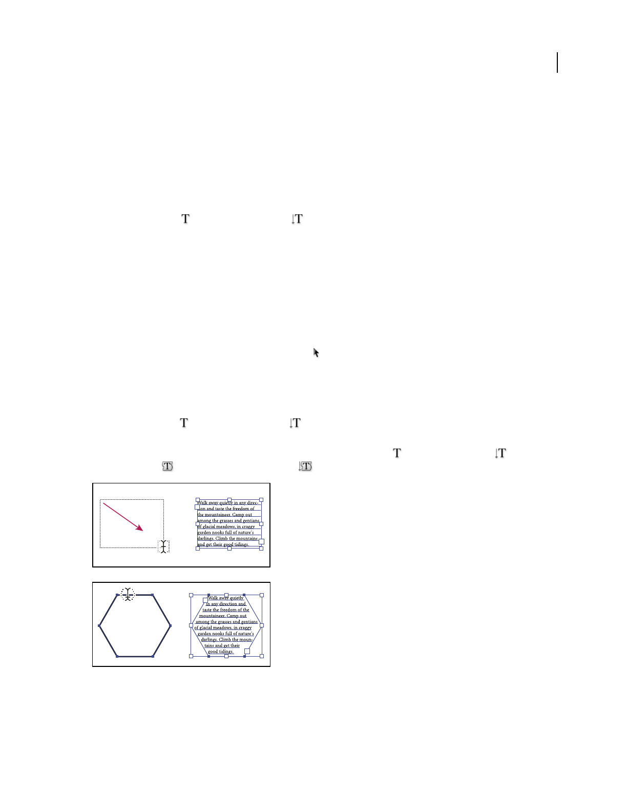
ILLUSTRATOR CS3
User Guide
290
See also
“Import text files into artwork” on page 291
“Threading text between objects” on page 295
“Working with area type” on page 292
“Working with type on a path” on page 297
Enter text at a point
1
Select the Type tool or the Vertical Type tool .
The pointer changes to an I-beam within a dotted box. The small horizontal line near the bottom of the I-beam
marks the position of the baseline, on which the text rests.
2 (Optional) Set text-formatting options in the Control panel, Character panel, or Paragraph panel.
3 Click where you want the line of text to begin.
Important: Be sure not to click an existing object, because doing so converts the type object into area type or type on a
path. If an existing object is located where you want to enter text, lock or hide the object.
4 Enter the text. Press Enter or Return to begin a new line of text within the same type object.
5 When you finish entering text, click the Selection tool to select the type object. Alternatively, Ctrl-click
(Windows) or Command-click (Mac OS) the text.
Enter text in an area
1
Define the bounding area:
•Select the Type tool or the Vertical Type tool , and drag diagonally to define a rectangular bounding area.
•Draw the object you want to use as the bounding area. (It doesn’t matter if the object has stroke or fill attributes,
because Illustrator automatically removes them.) Then select the Type tool , the Vertical Type tool , the
Area Type tool , or the Vertical Area Type tool and click anywhere on the object’s path.
Creating a type area by dragging (top) compared to converting an existing shape to a type area (bottom)
Note: If the object is an open path, you must use the Area Type tool to define the bounding area. Illustrator draws an
imaginary line between the endpoints of the path to define the boundaries.

ILLUSTRATOR CS3
User Guide
291
2 (Optional) Set text-formatting options in the Control panel, Character panel, or Paragraph panel.
3 Enter the text. Press Enter or Return to begin a new paragraph.
4 When you finish entering text, click the Selection tool to select the type object. Alternatively, Ctrl-click
(Windows) or Command-click (Mac OS) the text.
Enter text along a path
1
Do one of the following:
•To create horizontal text along a path, select the Type tool or the Type On A Path tool .
•To create vertical text along a path, select the Vertical type tool or the Vertical Type On A Path tool .
2 (Optional) Set text-formatting options in the Control panel, Character panel, or Paragraph panel.
3 Position the pointer on the path, and click. (It doesn’t matter if the path has stroke or fill attributes, because
Illustrator automatically removes them.)
Note: If the path is closed, rather than open, you must use the Type On A Path tool.
4 Enter the text.
5 When you finish entering text, click the Selection tool to select the type object. Alternatively, Ctrl-click
(Windows) or Command-click (Mac OS) the text.
Import text files into artwork
You can import text into your artwork from a file that was created in another application. Illustrator supports the
following formats for importing text:
•Microsoft Word for Windows 97, 98, 2000, 2002, 2003, and 2007
•Microsoft Word for Mac OS X and 2004
•RTF (Rich Text Format)
•Plain text (ASCII) with ANSI, Unicode, Shift JIS, GB2312, Chinese Big 5, Cyrillic, GB18030, Greek, Turkish,
Baltic, and Central European encoding
One advantage of importing text from a file, rather than copying and pasting it, is that imported text retains its
character and paragraph formatting. For example, text from an RTF file retains its font and style specifications in
Illustrator. You can also set encoding and formatting options when importing text from a plain text file.
Important: When importing text from Microsoft Word and RTF files, make sure that the fonts used in the file are
available on your system. Missing fonts and font styles—including fonts that have the same name but different formats
(Type 1, TrueType, or CID)—may cause unexpected results. On Japanese systems, differences in character sets may
prevent text that was entered in Windows from appearing on-screen in Mac OS.
Import text into a new file
1
Choose File > Open.
2 Select the text file you want to open, and click Open.
Import text into an existing file
1
Choose File > Place. Select the text file you want to import, and click Place.
2 If you are placing a plain text (.txt) file, do the following, and then click OK:
•Specify the character set and platform that were used to create the file.
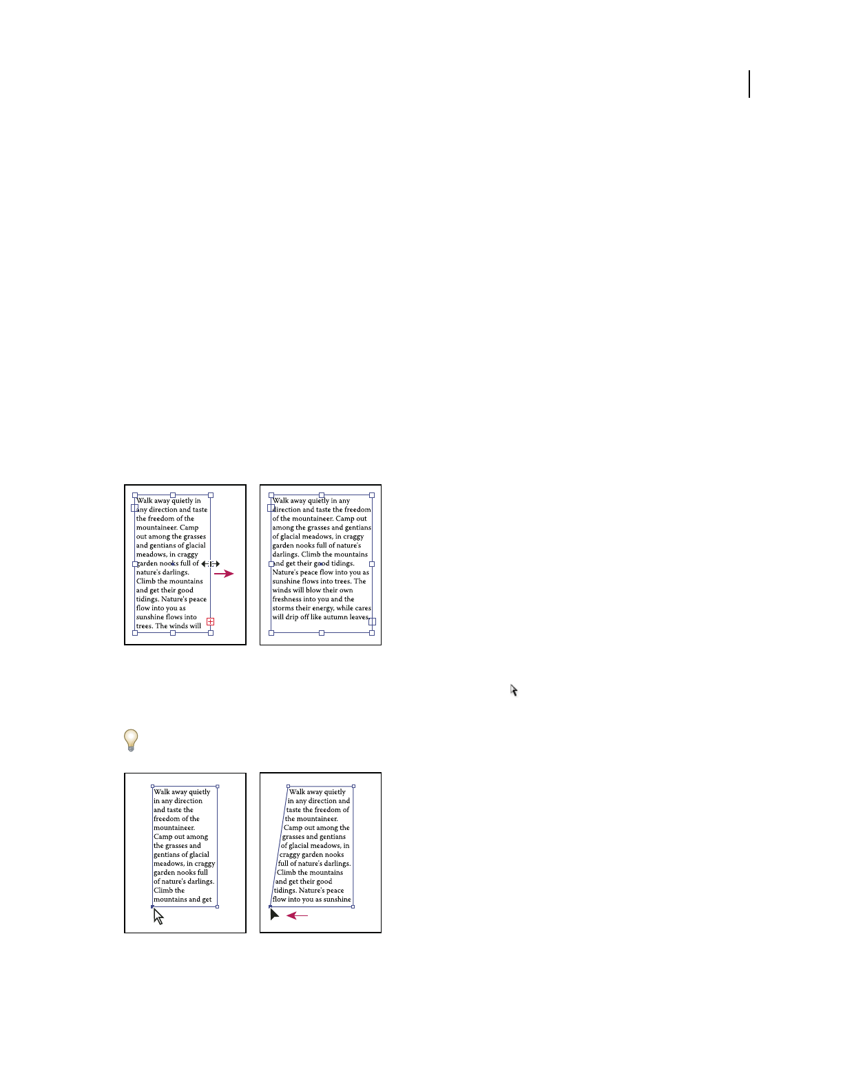
ILLUSTRATOR CS3
User Guide
292
•Select an Extra Carriage Returns option to determine how Illustrator processes extra carriage returns in the file.
•Select the Extra Spaces option if you want Illustrator to replace strings of spaces in the file with tabs. Enter the
number of spaces to be replaced by a tab.
Delete empty type objects from your artwork
Deleting unused type objects makes your artwork easier to print and reduces the file size. You can create empty type
objects, for example, if you inadvertently click the Type tool in the artwork area and then choose another tool.
1 Choose Object > Path > Clean Up.
2 Select Empty Text Paths, and click OK.
Working with area type
Resize a text area
❖Do one of the following:
•Select the type object using the Selection tool or Layers panel, and drag a handle on the bounding box.
Resizing a text area with the Selection tool
•Select the edge or corner of the type path with the Direct Selection tool . Then drag to adjust the shape of the
path.
Adjusting the type path using the Direct Selection tool is easiest when you’re in Outline view.
Resizing a type area with the Direct Selection tool
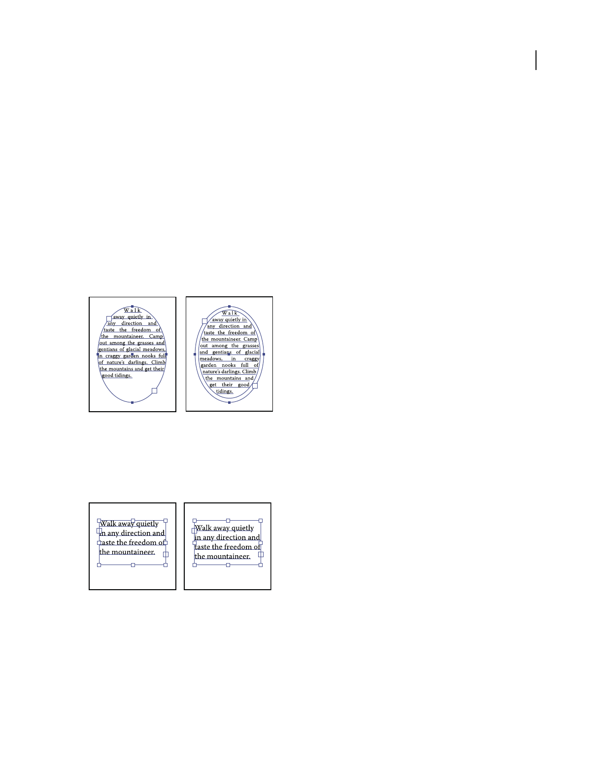
ILLUSTRATOR CS3
User Guide
293
•Select the type object using the Selection tool or Layers panel, and choose Type > Area Type Options. Enter values
for Width and Height, and click OK. If the text area is not a rectangle, these values determine the dimensions of
the object’s bounding box.
See also
“Entering text” on page 289
Change the margin around a text area
When working with an area type object, you can control the margin between the text and the bounding path. This
margin is referred to as the inset spacing.
1 Select an area type object.
2 Choose Type > Area Type Options.
3 Specify a value for Inset Spacing, and click OK.
Type without inset spacing (left) compared to type with inset spacing (right)
Raise or lower the first baseline in a text area
When working with an area type object, you can control the alignment of the first line of text with the top of the
object. This alignment is referred to as the first baseline offset. For example, you can make text stick up above the top
of the object or fall a specific distance below the top of the object.
Type with First Baseline set to Cap Height (left) compared to type with First Baseline set to Leading (right)
1 Select an area type object.
2 Choose Type > Area Type Options.
3 For First Baseline, choose one of the following options:
Ascent The height of the “d” character falls below the top of the type object.
Cap Height The tops of uppercase letters touch the top of the type object.

ILLUSTRATOR CS3
User Guide
294
Leading Uses the text’s leading value as the distance between the baseline of the first line of text and the top of the
type object.
x Height The height of the “x” character falls below the top of the type object.
Em Box Height The top of the em box in Asian fonts touches the top of the type object. This option is available only
when the Show Asian Options preference is selected.
Fixed
Specifies the distance between the baseline of the first line of text and the top of the type object in the Min text box.
4 For Min, specify the minimum value for the baseline offset.
For example, if you select Leading for First Baseline and specify a minimum value of 1p, Illustrator uses the leading
value only when it’s greater than 1 pica.
See also
“Shift the baseline” on page 314
“Display Asian type options” on page 333
Create rows and columns of text
1 Select an area type object.
2 Choose Type > Area Type Options.
3 In the Rows and Columns sections of the dialog box, set the following options:
Number Specifies the number of rows and columns you want the object to contain.
Span Specifies the height of individual rows and the width of individual columns.
Fixed Determines what happens to the span of rows and columns if you resize the type area. When this option is
selected, resizing the area can change the number of rows and columns, but not their width. Leave this option
deselected if you want row and column widths to change when you resize the type area.
Options for resizing rows and columns
A. Original columns B. Columns resized with Fixed selected C. Columns resized with Fixed deselected
Gutter Specifies the distance between rows or columns.
4 In the Options section of the dialog box, select a Text Flow option to determine how text flows between rows and
columns: By Rows or By Columns .
5 Click OK.
A
B
C
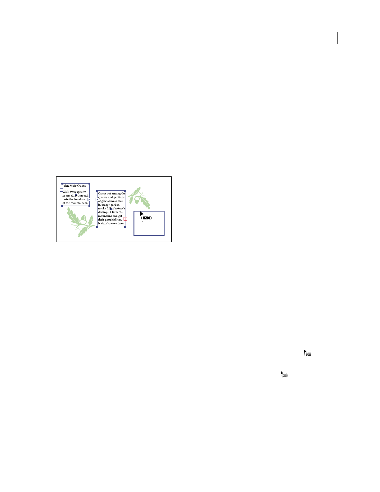
ILLUSTRATOR CS3
User Guide
295
Fit a headline across the full width of a type area
1 Select a type tool, and click in the paragraph you want to fit across the type area.
2 Choose Type > Fit Headline.
Note: If you change the formatting of the type, be sure to reapply the Fit Headline command.
Threading text between objects
To thread (or continue) text from one object to the next, you link the objects. Linked type objects can be of any shape;
however, the text must be entered in an area or along a path (not at a point).
Each area type object contains an in port and an out port, which enable you to link to other objects and create a linked
copy of the type object. An empty port indicates that all the text is visible and that the object isn’t linked. An arrow
in a port indicates that the object is linked to another object. A red plus sign in an out port indicates that the object
contains additional text. This remaining unseen text is called overflow text.
Ports on linked type objects
You can break threads and have the text flow into either the first or the next object, or you can remove all threads
and have the text stay in place.
Note: When working with threaded text, it can be useful to see the threads. To view threads, choose View > Show Text
Threads and then select a linked object.
See also
“Entering text” on page 289
Thread text
1
Use the Selection tool to select an area type object.
2 Click the in port or the out port of the selected type object. The pointer changes to the loaded text icon .
3 Do one of the following:
•To link to an existing object, position the pointer on the object’s path. The pointer changes to a . Click the path
to link the objects.
•To link to a new object, click or drag on an empty part of the artboard. Clicking creates an object of the same size
and shape as the original; dragging lets you create a rectangular object of any size.
Another method for threading text between objects is to select an area type object, select the object (or objects) you
want to thread to, and then choose Type
> Threaded Text > Create.
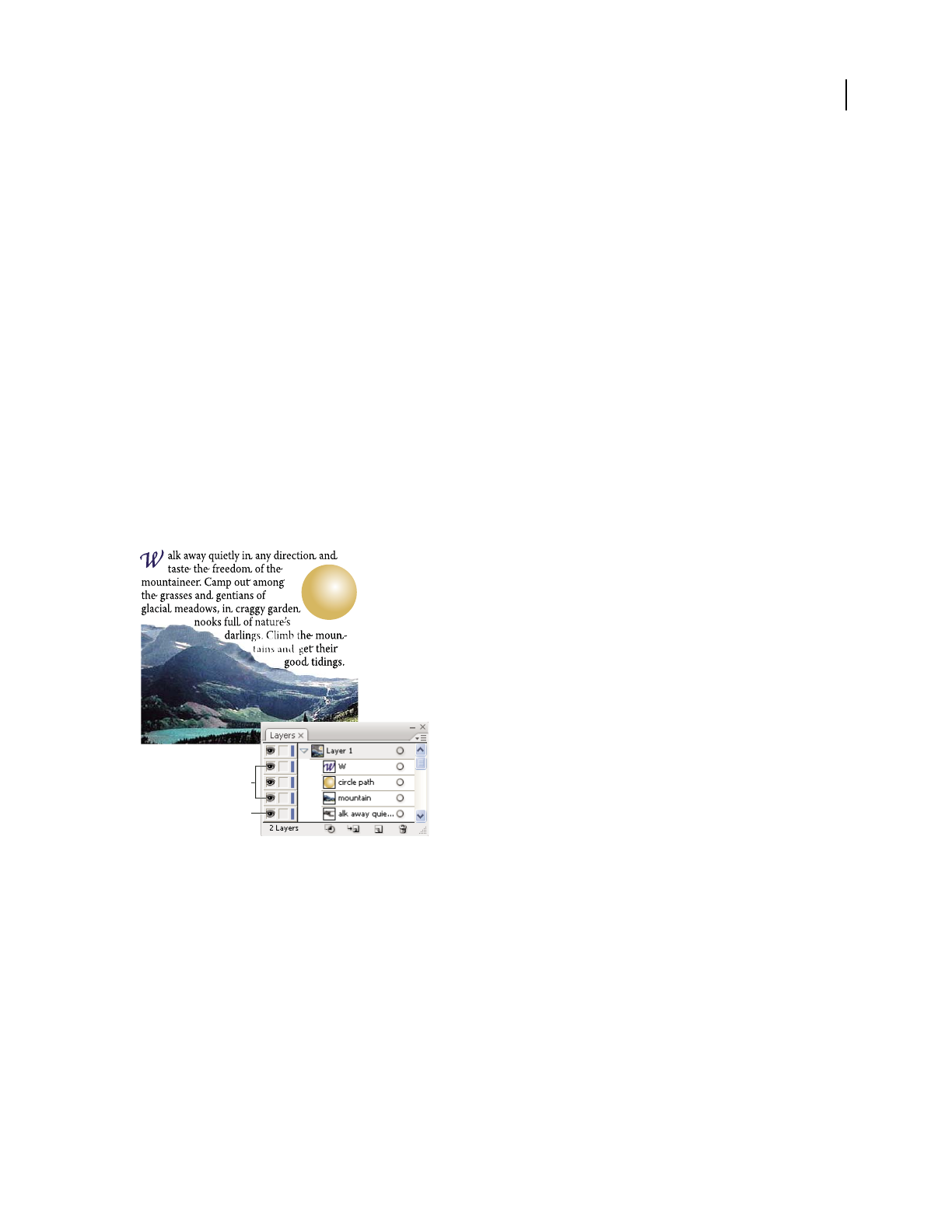
ILLUSTRATOR CS3
User Guide
296
Remove or break threads
1
Select a linked type object.
2 Do any of the following:
•To break the thread between two objects, double-click the port on either end of the thread. The text flows into the
first object.
•To release an object from a text thread, choose Type > Threaded Text > Release Selection. The text flows into the
next object.
•To remove all threads, choose Type > Threaded Text > Remove Threading. The text stays in place.
Wrap text around an object
You can wrap area text around any object, including type objects, imported images, and objects you draw in
Illustrator. If the wrap object is an embedded bitmap image, Illustrator wraps the text around opaque or partially
opaque pixels and ignores fully transparent pixels.
Wrapping is determined by the stacking order of objects, which you can view in the Layers panel by clicking the
triangle next to the layer name. To wrap text around an object, the wrap object must be in the same layer as the text
and located directly above the text in the layer hierarchy. You can drag contents up or down in the Layers panel to
change hierarchy.
Text wrapped around objects
A. Wrap objects B. Wrapped text
See also
“Layers panel overview” on page 211
“Stacking objects” on page 216
Wrap text
1
Make sure the following conditions are true for the type you want to wrap:
•It is area type (typed in a text box).
•It is in the same layer as the wrap object.
•It is located directly under the wrap object in the layer’s hierarchy.
A
B
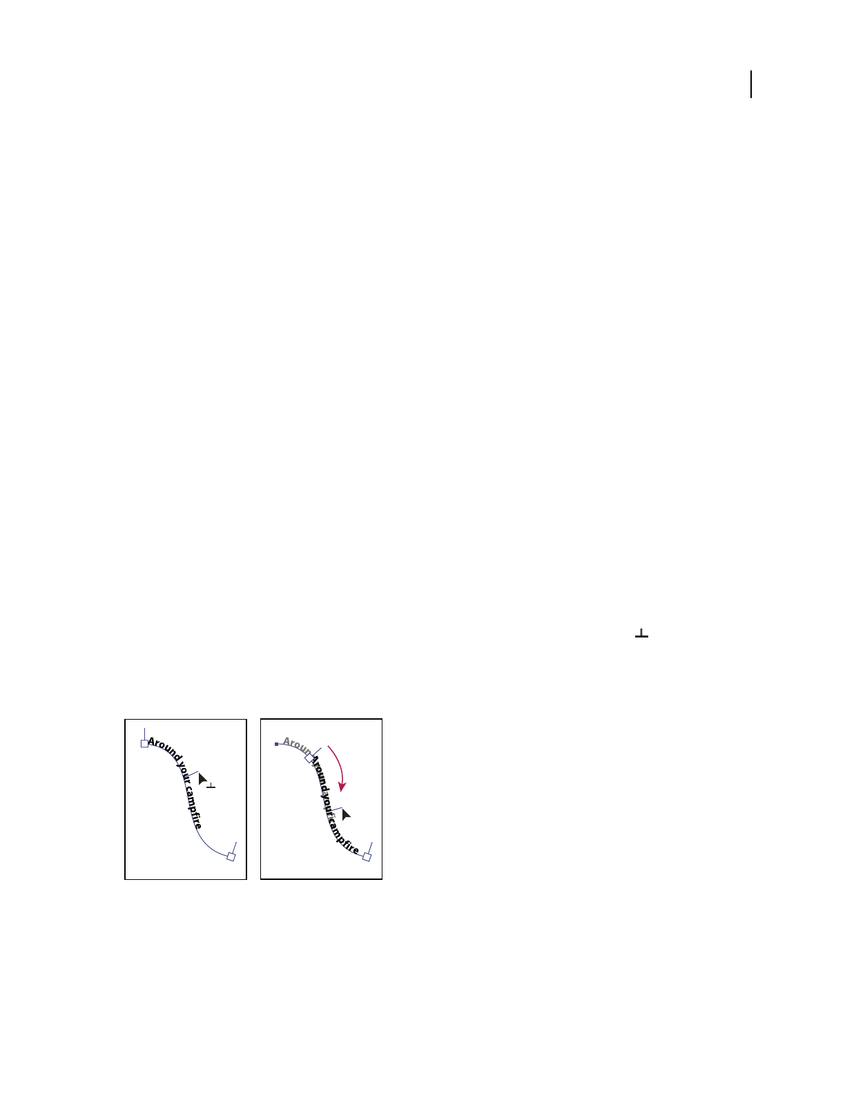
ILLUSTRATOR CS3
User Guide
297
Important: If the layer contains multiple type objects, move any that you don’t want to wrap around the wrap object
either into another layer or above the wrap object.
2 Select the object or objects around which you want the text to wrap.
3 Choose Object > Text Wrap > Make.
Set wrap options
You can set wrap options before or after you wrap the text.
1 Select the wrap object.
2 Choose Object > Text Wrap > Text Wrap Options and specify the following options:
Offset Specifies the amount of space between the text and the wrap object. You can enter a positive or negative value.
Invert Wrap Wraps the text around the reverse side of the object.
Unwrap text from an object
1
Select the wrap object.
2 Choose Object > Text Wrap > Release.
Working with type on a path
Move or flip text along a path
1 Select the type object.
A bracket appears at the beginning of the type, at the end of the path, and at the midpoint between the start and end
brackets.
2 Position the pointer over the type’s center bracket until a small icon appears next to the pointer .
3 Do one of the following:
•To move text along the path, drag the center bracket along the path. Hold down Ctrl (Windows) or Command
(Mac OS) to prevent the type from flipping to the other side of the path.
Moving type along a path
•To flip the direction of text along a path, drag the bracket across the path. Alternatively, choose Type > Type On
A Path > Type On A Path Options, select Flip, and click OK.

ILLUSTRATOR CS3
User Guide
298
Flipping type along a path
To move type across a path without changing the direction of the type, use the Baseline Shift option in the Character
panel. For example, if you created type that runs from left to right across the top of a circle, you can enter a negative
number in the Baseline Shift text box to drop the type so that it flows inside the top of the circle.
For a video on creating type on a path, see www.adobe.com/go/vid0046.
See also
“Entering text” on page 289
“Shift the baseline” on page 314
Apply path type effects
Path type effects let you distort the orientation of characters on a path.
1 Select the type object.
2 Do one of the following:
•Choose Type > Type On A Path and select an effect from the submenu.
•Choose Type > Type On A Path > Type On A Path Options. Then select an option from the Effect menu, and
click OK.

ILLUSTRATOR CS3
User Guide
299
Path type effects
A. Rainbow B. Skew C. 3D Ribbon D. Stair Step E. Gravity
Adjust the vertical alignment of type on a path
1 Select the type object.
2 Choose Type > Type On A Path > Type On A Path Options.
3 Choose an option from the Align To Path menu to specify how to align all characters to the path, relative to a font’s
total height:
Ascender Aligns along the font’s top edge.
Descender Aligns along the font’s bottom edge.
Center Aligns along the point halfway between the font’s ascender and descender.
Baseline Aligns along the baseline. This is the default setting.
Note: Characters without ascenders or descenders (such as a letter e) or a baseline (such as an apostrophe) are vertically
aligned with characters that have ascenders, descenders, and baselines. These font dimensions are permanently specified
by the font designer.
For more control over vertical alignment, use the Baseline Shift option in the Character panel. For example, type a
negative value in the Baseline Shift text box to lower the type.
See also
“Shift the baseline” on page 314
Adjust character spacing around sharp turns
When characters flow around a sharp curve or acute angle, they fan out in such a way that there may appear to be
extra space between them. You can tighten the spacing of characters on curves using the Spacing option in the Type
On A Path Options dialog box.
1 Select the type object.
2 Choose Type > Type On A Path > Type On A Path Options.
A
B
C
D
E
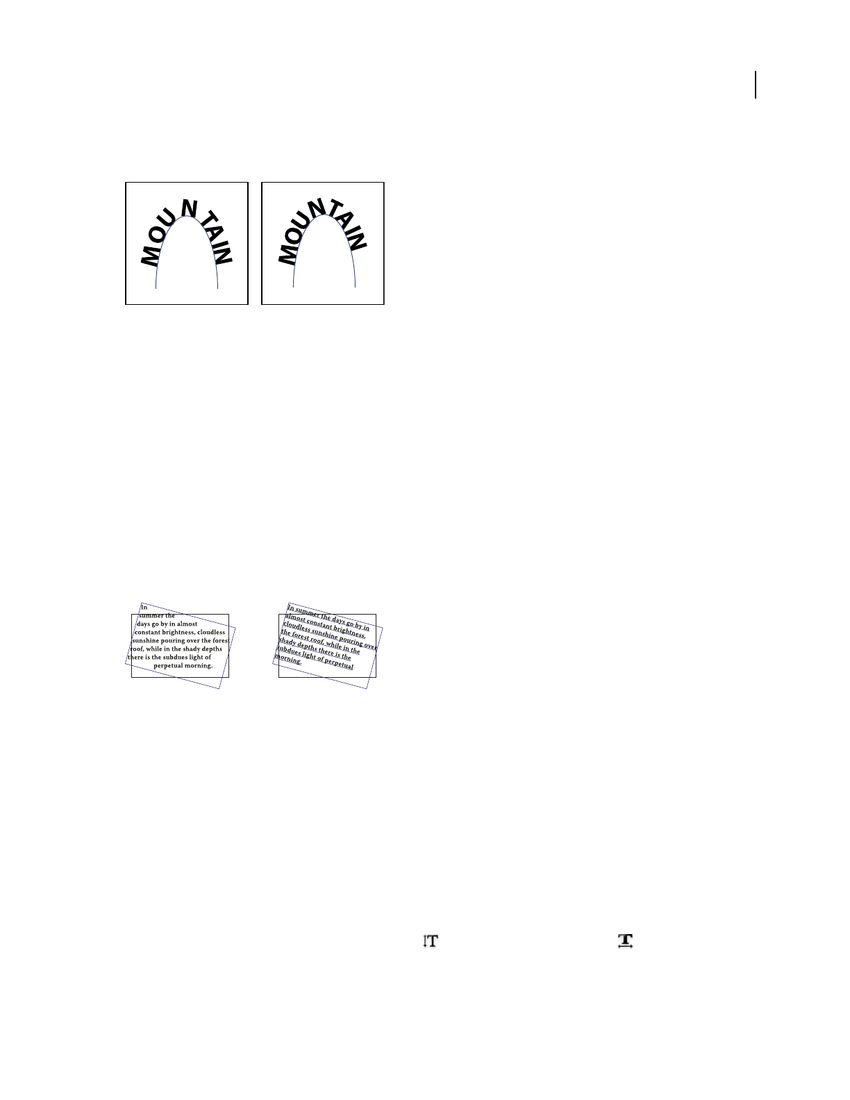
ILLUSTRATOR CS3
User Guide
300
3 For Spacing, type a value in points. Higher values remove the extra space from between characters positioned on
sharp curves or angles.
Type without spacing adjustment (left) compared to type with spacing adjustment (right)
Note: The Spacing value has no effect on characters positioned on straight segments. To change spacing of characters
anywhere along the path, select them, and then apply kerning or tracking.
Scaling and rotating type
Selecting type for transformations
You can rotate, reflect, scale, and shear type just as you do other objects. However, how you select the type affects the
transformation results:
•To transform the type along with its bounding path, select the type object and use the Rotate tool to rotate the
object and text.
•To transform just the bounding path, but not the type it contains, select the type object and drag with the Selection tool.
Rotated type path (left) compared to rotated type and path (right)
See also
“Transforming objects” on page 220
Adjust the scale of type
You can specify the proportion between the height and width of the type, relative to the original width and height of
the characters. Unscaled characters have a value of 100%. Some type families include a true expanded font, which is
designed with a larger horizontal spread than the plain type style. Scaling distorts the type, so it is generally
preferable to use a font that is designed as condensed or expanded, if one is available.
1 Select the characters or type objects you want to change. If you don’t select any text, the scale applies to new text
you create.
2 In the Character panel, set the Vertical Scaling option or the Horizontal Scaling option .

ILLUSTRATOR CS3
User Guide
301
Rotate type
•To rotate the characters within a type object by a specific number of degrees, select the characters or type objects
you want to change. (If you don’t select any text, the rotation applies to new text you create.) In the Character panel,
set the Character Rotation option .
•To change horizontal type to vertical type, and vice versa, select the type object and choose Type > Type
Orientation > Horizontal or Type > Type Orientation > Vertical.
•To rotate an entire type object (both the characters and the type bounding box), select the type object and use the
bounding box, Free Transform tool, Rotate tool, Rotate command, or Transform panel to perform the rotation.
•To rotate multiple characters in vertical Asian text, use the tate-chu-yoko option to rotate multiple characters.
See also
“Character panel overview” on page 308
“Use tate-chu-yoko” on page 335
“Rotate objects” on page 206
Spelling and language dictionaries
Check spelling
1 Choose Edit > Check Spelling.
2 To set options for finding and ignoring words, click the arrow icon at the bottom of the dialog box and set the
options as desired.
3 Click Start to begin checking the spelling.
4 When Illustrator displays misspelled words or other possible errors, do one of the following:
•Click Ignore or Ignore All to continue spell-checking without changing a certain word.
•Select a word from the Suggestions list or type the correct word in the top text box, and then click Change to
change only that occurrence of the misspelled word. You can also click Change All to change all occurrences of
the misspelled word in your document.
•Click Add to have Illustrator store an acceptable but unrecognized word in the dictionary so that subsequent
occurrences are not considered misspellings.
5 When Illustrator finishes checking your document, click Done.
Illustrator can check for spelling errors in a variety of languages, based on the language that you assign to words.
Edit the spelling dictionary
1 Choose Edit > Edit Custom Dictionary.
2 Do any of the following, and click Done:
•To add a word to the dictionary, type the word in the Entry text box, and click Add.
•To remove a word from the dictionary, select the word in the list, and click Delete.

ILLUSTRATOR CS3
User Guide
302
•To modify a word in the dictionary, select the word in the list. Then type the new word in the Entry text box, and
click Change.
Assign languages to text
Illustrator uses Proximity language dictionaries for both spelling and hyphenation. Each dictionary contains
hundreds of thousands of words with standard syllable breaks. You can assign a language to an entire document or
apply a language to selected text.
Examples of hyphenation for different languages
A. “Glockenspiel” in English B. “Glockenspiel” in Traditional German C. “Glockenspiel” in Reformed German
Apply a language to all text
1
Choose Edit > Preferences > Hyphenation (Windows) or Illustrator > Preferences > Hyphenation (Mac OS).
2 Select a dictionary from the Default Language pop-up menu, and click OK.
Assign a language to selected text
1
Select the text.
2 In the Character panel, choose the appropriate dictionary from the Language menu. If the Language menu isn’t
showing, choose Show Options from the Character panel menu.
About Unicode
Illustrator supports Unicode, a standard that assigns a unique number to every single character, no matter which
language or type of computer you use. Unicode is:
Portable Letters and numbers will not change when you move the file from one workstation to another. Adding a
foreign language to a document doesn’t cause confusion, because foreign characters have their own designations that
don’t interfere with the encoding from other languages in the same project.
Platform-neutral Because Windows and Macintosh operating systems now support Unicode, moving a file between
the two platforms is easier. No longer will you need to proofread an Illustrator file just because you moved to it a
Windows computer from a Macintosh computer or vice versa.
Robust Because Unicode-compliant fonts offer a larger number of potential characters, specialty type characters are
readily available.
Flexible With Unicode support, substituting a typeface in a project won’t result in substituted characters. With a
Unicode-compliant font, a g is a g no matter which typeface is used.
All of these things make it possible for a French designer to design for a client in Korea and hand the job off to a
partner in the United States without having to struggle with the text. All the U.S. designer needs to do is enable the
correct language in the operating system, load the foreign-language font, and continue the project.
A
B
C
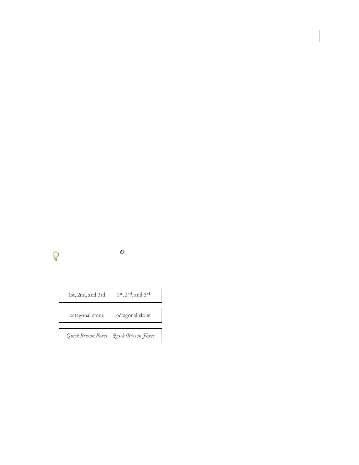
ILLUSTRATOR CS3
User Guide
303
Fonts
About fonts
A font is a complete set of characters—letters, numbers, and symbols—that share a common weight, width, and style,
such as 10-pt Adobe Garamond Bold.
Typefaces (often called type families or font families) are collections of fonts that share an overall appearance, and are
designed to be used together, such as Adobe Garamond.
A type style is a variant version of an individual font in a font family. Typically, the Roman or Plain (the actual name
varies from family to family) member of a font family is the base font, which may include type styles such as regular,
bold, semibold, italic, and bold italic.
In addition to the fonts installed on your system, you can also use the fonts installed in these folders:
Windows Program Files/Common Files/Adobe/Fonts
Mac OS Library/Application Support/Adobe/Fonts
If you install a Type 1, TrueType, OpenType, or CID font into the local Fonts folder, the font appears in Adobe appli-
cations only.
OpenType fonts
OpenType fonts use a single font file for both Windows® and Macintosh® computers, so you can move files from one
platform to another without worrying about font substitution and other problems that cause text to reflow. They may
include a number of features, such as swashes and discretionary ligatures, that aren’t available in current PostScript
and TrueType fonts.
OpenType fonts display the icon.
When working with an OpenType font, you can automatically substitute alternate glyphs, such as ligatures, small
capitals, fractions, and old style proportional figures, in your text.
Regular (left) and OpenType (right) fonts
A. Ordinals B. Discretionary ligatures C. Swashes
OpenType fonts may include an expanded character set and layout features to provide richer linguistic support and
advanced typographic control. OpenType fonts from Adobe that include support for central European (CE)
languages include the word “Pro,” as part of the font name in application font menus. OpenType fonts that don’t
contain central European language support are labeled “Standard,” and have an “Std” suffix. All OpenType fonts can
also be installed and used alongside PostScript Type
1 and TrueType fonts.
For more information on OpenType fonts, see www.adobe.com/go/opentype.
A
B
C

ILLUSTRATOR CS3
User Guide
304
Previewing fonts
You can view samples of a font in the font family and font style menus in the Character panel and other areas in the
application from where you can choose fonts. The following icons are used to indicate different kinds of fonts:
•OpenType
•Type 1
•TrueType
•Multiple Master
•Composite
You can turn off the preview feature or change the point size of the font names in Type preferences.
Select a font family and style
1 Select the characters or type objects you want to change. If you don’t select any text, the font applies to new text
you create.
2 Select a font family and style using the Control panel, Type menu, or Character panel:
•In the Control panel, set the Font and Font Style options.
•In the Type menu, select a name from the Font or Recent Fonts submenu. Using the Font menu is convenient
because it displays a preview of the available fonts.
•In the Character panel, set the Font Family and Font Style options. In addition to choosing a name from the
pop-up menus, you can click the current name and type in the first few characters of the name you want.
To change the number of fonts in the Recent Fonts submenu, choose Edit > Preferences > Type (Windows) or
Illustrator > Preferences > Type (Mac OS), and set the Number Of Recent Fonts option.
Specify a typeface size
By default, typeface size is measured in points (a point equals 1/72 of an inch). You can specify any typeface size from
0.1 to 1296 points, in 0.001-point increments.
1 Select the characters or type objects you want to change. If you don’t select any text, the typeface size applies to
new text you create.
2 Do one of the following:
•In the Character panel or Control bar set the Font Size option.
•Choose a size from the Type > Size menu. Choosing Other lets you type a new size in the Character panel.
You can change the unit of measurement for type in the Preferences dialog box.
Find and replace fonts
1 Choose Type > Find Font.
Move the Find Font dialog box so that you can see all the text in your document.
2 Select the name of a font you want to find in the top section of the dialog box. The first occurrence of the font is
highlighted in the document window.

ILLUSTRATOR CS3
User Guide
305
3 Select a replacement font in the bottom section of the dialog box. You can customize the list of replacement fonts
by doing the following:
•Choose an option from the Replace With Font From pop-up menu: Document to list only the fonts that are used
in the document or System to list all fonts on your computer.
•Select the kinds of fonts you want to include in the list; deselect the kinds of fonts you don’t want to include.
4 Do one of the following:
•Click Change to change just one occurrence of the selected font.
•Click Change All to change all occurrences of the selected font.
When there are no more occurrences of a font in your document, its name is removed from the Fonts in Document
list.
5 Repeat steps 2 through 4 to find and replace a different font.
6 Click Done to close the dialog box.
Note: When you replace a font using the Find Font command, all other type attributes remain the same.
Work with missing fonts
If a document uses fonts not installed on your system, an alert message appears when you open it. Illustrator
indicates which fonts are missing and substitutes missing fonts with available matching fonts.
•To substitute missing fonts with a different font, select the text that uses the missing font and apply any other
available font.
•To make missing fonts available in Illustrator, either install the missing fonts on your system or activate the missing
fonts using a font management application.
•To highlight substituted fonts in pink, choose File > Document Setup, and choose Type from the pop-up menu at
the top of the dialog box. Then select Substituted Fonts, and then click OK.
Formatting type
Selecting type
Selecting characters lets you edit them, format them using the Character panel, apply fill and stroke attributes to
them, and change their transparency. You can apply these changes to one character, a range of characters, or all
characters in a type object. When characters are selected, they are highlighted in the document window and the word
“Characters” appears in the Appearance panel.
Selecting a type object lets you apply global formatting options to all the characters in the object, including options
from the Character and Paragraph panels, fill and stroke attributes, and transparency settings. In addition, you can
apply effects, multiple fills and strokes, and opacity masks to a selected type object. (This is not possible for individ-
ually selected characters.) When a type object is selected, a bounding box appears around it in the document window
and the word “Type” appears in the Appearance panel.
Selecting a type path lets you adjust its shape and apply fill and stroke attributes to it. This level of selection is not
available for point type. When a type path is selected, the word “Path” appears in the Appearance panel.

ILLUSTRATOR CS3
User Guide
306
See also
“Keys for working with type” on page 466
“Selection tool gallery” on page 25
Select characters
Selecting characters lets you edit them, format them using the Character panel, apply fill and stroke attributes to
them, and change their transparency. You can apply these changes to one character, a range of characters, or all
characters in a type object. When characters are selected, they are highlighted in the document window and the word
“Characters” appears in the Appearance panel.
❖Select any type tool, and do one of the following:
•Drag to select one or more characters. Shift-drag to extend or reduce the selection.
•Position the pointer in a word, and double-click to select that word.
•Position the pointer in a paragraph, and triple-click to select the entire paragraph.
•Select one or more characters, and choose Select > All to select all the characters in the type object.
Select type objects
Selecting a type object lets you apply global formatting options to all the characters in the object, including options
from the Character and Paragraph panels, fill and stroke attributes, and transparency settings. In addition, you can
apply effects, multiple fills and strokes, and opacity masks to a selected type object. (This is not possible for individ-
ually selected characters.) When a type object is selected, a bounding box appears around it in the document window
and the word “Type” appears in the Appearance panel.
❖Do any of the following:
•In the document window, click the type with the Selection tool or the Direct Selection tool . Shift-click to
select additional type objects.
•In the Layers panel, locate the type object you want to select and then click its right edge, between the target button
and the scroll bar. Shift-click at the right edge of items in the Layers panel to add or remove objects to the existing
selection.
•To select all type objects in a document, choose Select > Object > Text Objects.
Select a type path
Selecting a type path lets you adjust its shape and apply fill and stroke attributes to it. This level of selection is not
available for point type. When a type path is selected, the word “Path” appears in the Appearance panel.
Selecting a type path is easiest when you’re in Outline view.
1 Select the Direct Selection tool or the Group Selection tool .
2 If the type object is selected, click outside the object’s bounding box to deselect it.
3 Click on the type path, being careful not to click on the characters. (If you do click on a character, you will select
the type object instead of the type path.)

ILLUSTRATOR CS3
User Guide
307
Note: The Type Object Selection By Path Only preference determines the sensitivity of the selection tools when selecting
type objects in the document window. When this preference is selected, you must click directly on the type path in order
to select the type. When this preference is deselected, you can click anywhere in the type bounding box to select the type.
You can set this preference by choosing Edit > Preferences > Type (Windows) or Illustrator > Preferences > Type
(Mac OS).
Find and replace text
1 Do one of the following:
•To search the entire document, deselect all objects.
•To limit the search to a type object, select the object.
•To limit the search to a range of characters, select the characters.
2 Choose Edit > Find and Replace.
3 Enter the text string you want to find and, if desired, the text string with which to replace it.
You can choose a variety of special characters from the pop-up menus to the right of the Find and Replace With
options.
4 To customize how Illustrator searches for the specified text string, select any of the following options:
Match Case Searches only for text strings that exactly match the uppercase and lowercase text in the Find text box.
Find Whole Word Searches only for entire words that match the text in the Find text box.
Search Backwards Searches the file from the bottom to the top of the stacking order.
Check Hidden Layers Searches for text in hidden layers. When this option is deselected, Illustrator ignores text in
hidden layers.
Check Locked Layers Searches for text in locked layers. When this option is deselected, Illustrator ignores text in
locked layers.
5 Click Find to begin the search.
6 If Illustrator finds an instance of the text string, do one of the following:
•Click Replace to replace the text string, then click Find Next to find the next instance.
•Click Replace & Find to replace the text string and find the next instance.
•Click Replace All to replace all instances of the text string in the document.
7 Click the close icon to close the dialog box.
To find the next instance of a text string when the Find And Replace dialog box is closed, choose Edit > Find Next.
Change the color and appearance of characters
You can change the color and appearance of type objects by applying fills, strokes, transparency settings, effects, and
graphic styles. The text remains editable as long as you don’t rasterize it.
1 Do one of the following:
•To change the appearance of specific characters in a type object, select the characters.
•To change the appearance of all characters in a type object, or to apply multiple fills and strokes, select the type
object.
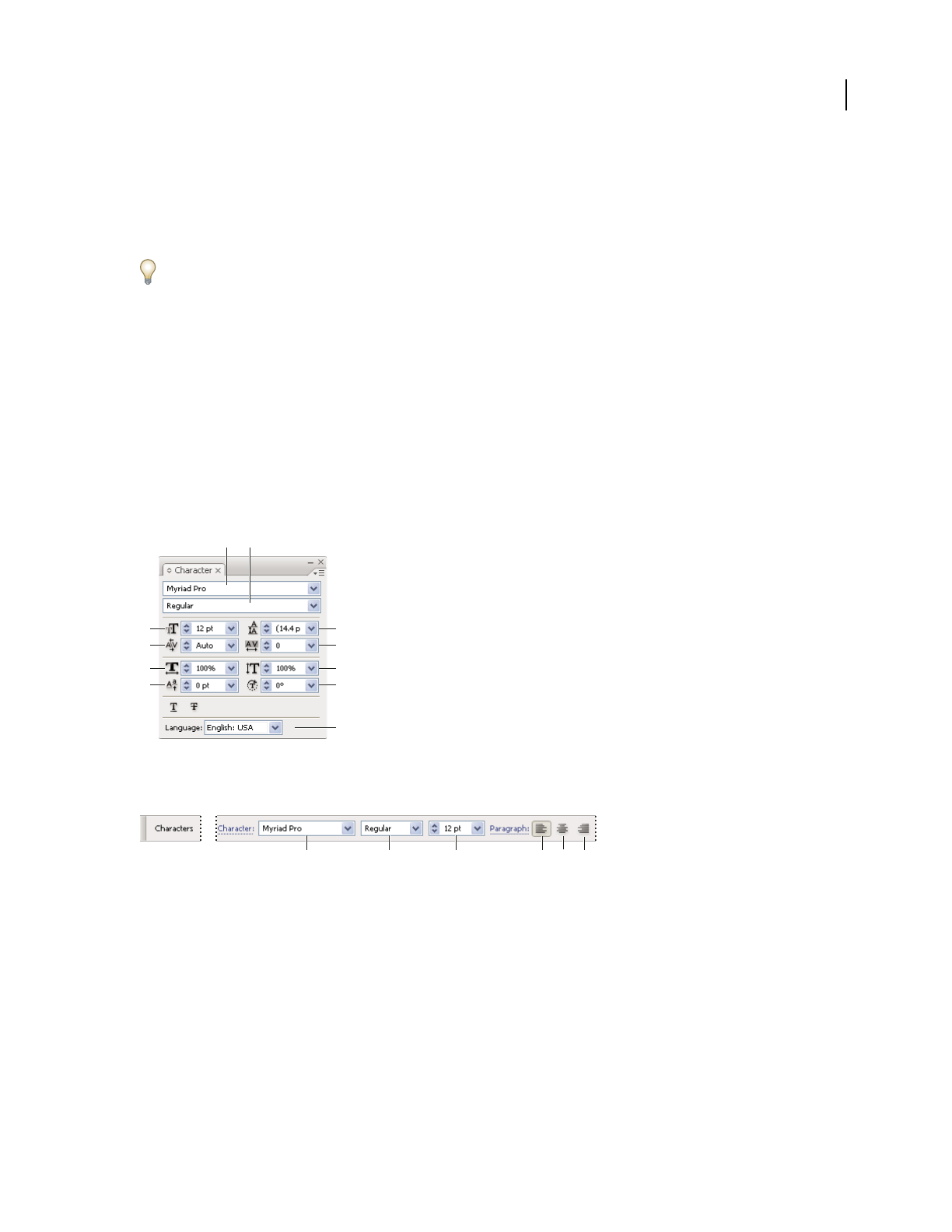
ILLUSTRATOR CS3
User Guide
308
•To fill or stroke a type path, select the type path.
2 Apply fills, strokes, transparency settings, effects, and graphic styles as desired.
When you change the color of a type object, Illustrator overwrites the attributes of individual characters in the type
object.
Use the Control panel to quickly change the color of selected type.
See also
“About appearance attributes” on page 346
Character panel overview
You use the Character panel (Window > Type > Character) to apply options for formatting individual characters in
your documents. When type is selected or when the Type tool is active, you can also use options in the Control panel
to format characters. You can find many of these same controls and options in the Control panel when your type is
selected.
For a video on working with character and paragraph styles, see www.adobe.com/go/vid0047.
Character panel
A. Font B. Font Style C. Font Size D. Kerning E. Horizontal Scale F. Baseline Shift G. Leading H. Tracking I. Vertical Scale J. Character
Rotation K. Language
A. Font B. Font Style C. Font Size D. Align left E. Align center F. Align right
By default, only the most commonly used options are visible in the Character panel. To show all options, choose
Show Options from the options menu. Alternatively, click the double triangle on the panel’s tab to cycle through the
display sizes.
See also
“Keys for working with type” on page 466
“Workspace overview” on page 14
B A
G
H
I
J
K
C
D
E
F
ABCDEF
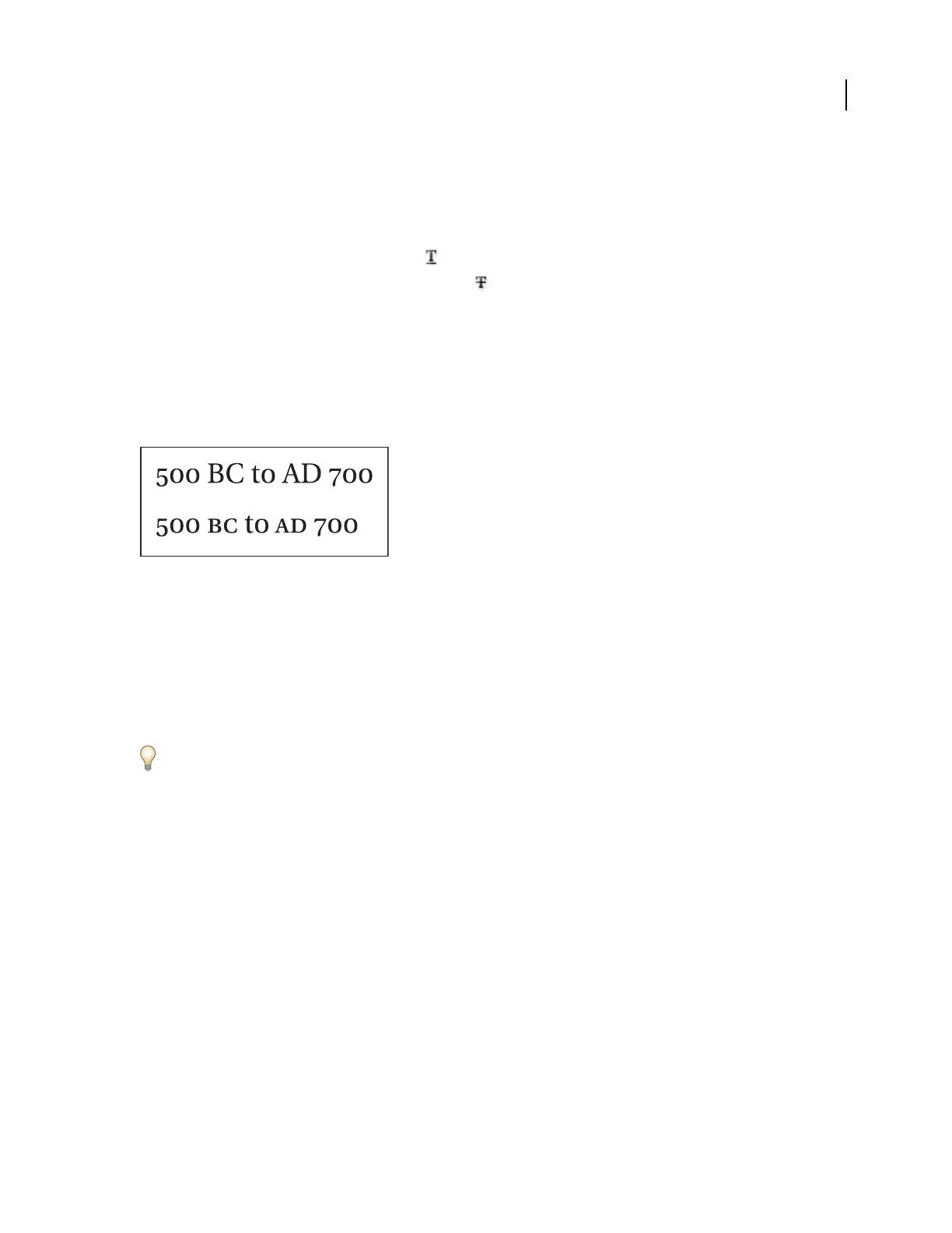
ILLUSTRATOR CS3
User Guide
309
Underline or strike through text
1 Select the type you want to underline or strike through. If you don’t select any text, the setting applies to new text
you create.
2 Do one of the following:
•To underline type, click the Underline button in the Character panel.
•To strike through type, click the Strikethrough button in the Character panel.
The default weight of an underline and strikethrough depends on the size of the type.
Apply all caps and small caps
When you format text as small caps, Illustrator automatically uses the small-cap characters designed as part of the
font, if available. Otherwise, Illustrator synthesizes the small caps using scaled-down versions of the regular capital
letters.
Regular capital letters (top) compared to small-cap letters (bottom)
1 Select the characters or type objects you want to change. If you don’t select any text, the setting applies to new text
you create.
2 Choose All Caps or Small Caps from the Character panel menu.
To specify the size for synthesized small caps, choose File > Document Setup, and choose Type from the pop-up
menu at the top of the dialog box. For Small Caps, type a percentage of the original font size for text to be formatted
as small caps. (The default value is 70%.)
To change the capitalization style of text to uppercase, lowercase, title case, or sentence case, use the Type > Change
Case command.
See also
“Character panel overview” on page 308
Change capitalization styles
1 Select the characters or type objects you want to change.
2 Choose one of the following in the Type > Change Case submenu:
UPPERCASE to change all characters to uppercase.
Note: The UPPERCASE command causes discretionary ligatures to revert to normal text. This also occurs with the Title
Case and Sentence Case commands when a discretionary ligature appears at the beginning of a word.
lowercase to change all characters to lowercase.
Title Case to capitalize the first letter of each word.
Sentence Case to capitalize the first letter of each sentence.

ILLUSTRATOR CS3
User Guide
310
Note: The Sentence Case command assumes that the period (.), exclamation point (!), and question mark (?) characters
mark the ends of sentences. Applying Sentence Case may cause unexpected case changes when these characters are used
in other ways, as in abbreviations, filenames, or URLs. In addition, proper names may become lowercase.
If you’re using an OpenType font, you may want to take advantage of All Caps formatting to create more elegant type.
See also
“Apply all caps and small caps” on page 309
Specify curly or straight quotes
Typographer’s quotes, often referred to as curly quotes, blend in with the curves of the font. Typographer’s quotes are
traditionally used for quotation marks and apostrophes. Straight quotes are traditionally used as abbreviations for feet
and inches.
1 Choose File > Document Setup, and choose Type from the pop-up menu at the top of the dialog box.
2 Do one of the following, and click OK:
•To use straight quotes, deselect Use Typographer’s Quotes.
•To use typographer’s quotes, select Use Typographer’s Quotes, choose the language for which you want to set
quotes, and choose options for Double Quotes and Single Quotes.
Note: You can set quote options for multiple languages. These quotes are applied to text based on the language you assign
using the Character panel or Default Language preference.
You can use the Smart Punctuation command to replace straight quotes with typographer’s quotes.
See also
“Assign languages to text” on page 302
“Use smart punctuation” on page 313
Set anti-aliasing options for type
When you save artwork in a bitmap format—such as JPEG, GIF, or PNG—Illustrator rasterizes all objects at 72 pixels
per inch and applies anti-aliasing to them. However, if your artwork contains type, the default anti-aliasing settings
may not produce the desired results. Illustrator provides several options specifically for rasterizing type. In order to
take advantage of these options, you must rasterize type objects before you save the artwork.
1 Select the type object, and do one of the following:
•To permanently rasterize the type, choose Object > Rasterize.
•To create the appearance of rasterization without changing the object’s underlying structure, choose Effect >
Rasterize.
2 Choose an anti-aliasing option:
None Applies no anti-aliasing and maintains the hard edges of type when it is rasterized.

ILLUSTRATOR CS3
User Guide
311
Type Optimized Applies anti-aliasing that is best suited to type. Anti-aliasing reduces the appearance of jagged edges
in the rasterized image and gives type a smoother on-screen appearance. However, it can also make small text
difficult to read.
Creating superscripts or subscripts
Superscript and subscript text (also called superior and inferior text) is reduced-size text that is raised or lowered in
relation to a font’s baseline.
When you create superscript or subscript type, Illustrator applies a predefined baseline shift value and type size. The
values applied are percentages of the current font size and leading, and are based on settings in the Type section of
the Document Setup dialog box.
See also
“OpenType fonts” on page 303
“OpenType panel overview” on page 317
Create superscripts or subscripts in regular fonts
1
Select the type you want to change. If you don’t select any type, any new text you create will be rendered as super-
scripts or subscripts.
2 Choose Superscript or Subscript from the Character panel menu.
Create superscripts or subscripts in OpenType fonts
1
Select the characters you want to change to superscript or subscript. If you don’t select any text, the setting applies
to new text you create.
2 Make sure that an OpenType font is selected. One way to determine if a font is an OpenType font is to look in the
Type > Font menu; OpenType fonts display the icon.
3 In the OpenType panel, choose an option from the Position pop-up menu:
Default Position Uses the default position for the current font.
Superscript/Superior Uses raised characters (if available in the current font).
Subscript/Inferior Uses lowered characters (if available in the current font).
Numerator Uses characters designed as fraction numerators (if available in the current font).
Denominator Uses characters designed as fraction denominators (if available in the current font).
Change the size and position of superscripts or subscripts
1
Choose File > Document Setup, and choose Type from the pop-up menu at the top of the dialog box.
2 Specify the following values for Superscript and Subscript, and then click OK:
•For Size, type a percentage of the font size for superscripted and subscripted text.
•For Position, type a percentage of the regular leading to specify how much the superscript and subscript text will
move.

ILLUSTRATOR CS3
User Guide
312
Convert type to outlines
You can turn type into a set of compound paths, or outlines, that you can edit and manipulate as you would any other
graphic object. Type as outlines are useful for changing the look of large display type, but they are rarely useful for
body text or other type at small sizes.
Font outline information comes from the actual font files installed on your system. When you create outlines from
type, characters are converted in their current positions; they retain all graphics formatting such as their stroke and
fill.
Modifying a letterform
A. Original type object B. Type converted to outlines, ungrouped, and modified
Note: You can’t convert bitmap fonts or outline-protected fonts to outlines.
When you convert type to outlines, the type loses its hints—instructions built into fonts to adjust their shape so that
your system displays or prints them optimally at a wide range of sizes. If you plan to scale the type, adjust its point
size before converting.
You must convert all the type in a selection; you cannot convert a single letter within a string of type. To convert a
single letter into an outline, create a separate type object containing only that letter.
1 Select the type object.
2 Choose Type > Create Outlines.
Choose a number style in OpenType fonts
1 To change the style of existing numbers, select the characters or type objects you want to change. If you don’t select
any text, the setting applies to new text you create.
2 Make sure that an OpenType font is selected.
3 In the OpenType panel, choose an option from the Figures pop-up menu:
Default Figure Uses the default style for the current font.
Tabular Lining Uses full-height figures all of the same width (if available for the current font). This option is appro-
priate in situations where numbers need to line up from one line to the next, as in tables.
Proportional Lining Uses full-height figures with varying widths (if available for the current font). This option is
recommended for text that uses all caps.
Proportional Oldstyle Uses varying-height figures with varying widths (if available for the current font). This option
is recommended for a classic, sophisticated look in text that doesn’t use all caps.
A
B

ILLUSTRATOR CS3
User Guide
313
Tabular Oldstyle Uses varying-height figures with fixed, equal widths (if available for the current font). This option
is recommended when you want the classic appearance of old-style figures, but need them to align in columns, as in
an annual report.
See also
“OpenType fonts” on page 303
“OpenType panel overview” on page 317
Format fractions and ordinals in OpenType fonts
When using an OpenType font, you can automatically format ordinal numbers with superscript characters (for
example, ). Characters such as the superscript “a” and “o” in the Spanish words segunda ( ) and segundo ( )
are also typeset properly. You can also convert numbers separated by a slash (such as 1/2) to a shilling fraction
(such
as ).
1 Select the characters or type objects to which you want to apply the setting. If you don’t select any text, the setting
applies to new text you create.
2 Make sure that an OpenType font is selected.
3 In the OpenType panel, click the Ordinals button to enable or disable ordinals or the Fractions button to enable
or disable fractions. These buttons have an effect only if ordinals and fractions are available in the font.
See also
“OpenType fonts” on page 303
“OpenType panel overview” on page 317
Use smart punctuation
The Smart Punctuation command searches for keyboard punctuation characters and replaces them with their
typographic equivalents. In addition, you can use the Smart Punctuation command to globally insert ligatures and
fractions, if the font includes these characters.
If you’re using an OpenType font, use the OpenType panel instead of the Smart Punctuation dialog box to typeset
ligatures and fractions.
1 If you want to replace characters in specific text, rather than all text in the document, select the desired text objects
or characters.
2 Choose Type > Smart Punctuation.
3 Select one or more of the following options:
ff, fi, ffi Ligatures Renders ff, fi, or ffi letter combinations as ligatures.
ff, fl, ffl Ligatures Renders ff, fl, or ffl letter combinations as ligatures.
Smart Quotes Changes straight keyboard quotation marks into curly quotes.
Note: The Smart Quotes option always replaces straight quotes with curly quotes, regardless of the Double Quotes and
Single Quotes settings in the Document Setup dialog box.
Smart Spaces Eliminates multiple spaces after a period.
En, Em Dashes Replaces a double keyboard dash with an en dash and a triple keyboard dash with an em dash.

ILLUSTRATOR CS3
User Guide
314
Ellipses Replaces three keyboard periods with ellipsis points.
Expert Fractions Replaces separate characters used to represent fractions with their single-character equivalents.
4 Select Entire Document to replace text symbols in the entire file or Text Only to replace symbols only in selected text.
5 (Optional) Select Report Results to see a list of the number of symbols replaced.
6 Click OK to search for and replace selected characters.
See also
“Use ligatures and contextual alternates” on page 318
Line and character spacing
Set the leading
The vertical space between lines of type is called leading (rhymes with sledding). Leading is measured from the
baseline of
one line of text to the baseline of the line above it. Baseline is the invisible line on which most letters sit.
The default auto-leading option sets the leading at 120% of the type size (for example, 12-point leading for 10-point
type). When auto-leading is in use, the leading value appears in parentheses in the Leading menu of the Character
panel. You can change this default auto-leading by choosing Justification from the Paragraph panel menu and speci-
fying a percentage from 0 to 500.
By default, leading is a character attribute, which means that you can apply more than one leading value within the
same paragraph. The largest leading value in a line of type determines the leading for that line.
Note: When working with horizontal Asian type, you can specify how leading is measured, either from baseline to
baseline or from the top of one line to the top of the next.
1 Select the characters or type objects you want to change. If you don’t select any text, the leading applies to new text
you create.
2 In the Character panel, set the Leading option ( for vertical text).
Shift the baseline
Use Baseline Shift to move selected characters up or down relative to the baseline of the surrounding text. Shifting
the baseline is especially useful when you’re hand-setting fractions or adjusting the position of a picture font.
1 Select the characters or type objects you want to change. If you don’t select any text, the shift applies to new text
you create.
2 In the Character panel, set the Baseline Shift option. Positive values move the character’s baseline above the
baseline of the rest of the line; negative values move it below the baseline.
Type with different Baseline Shift values
-2-6026
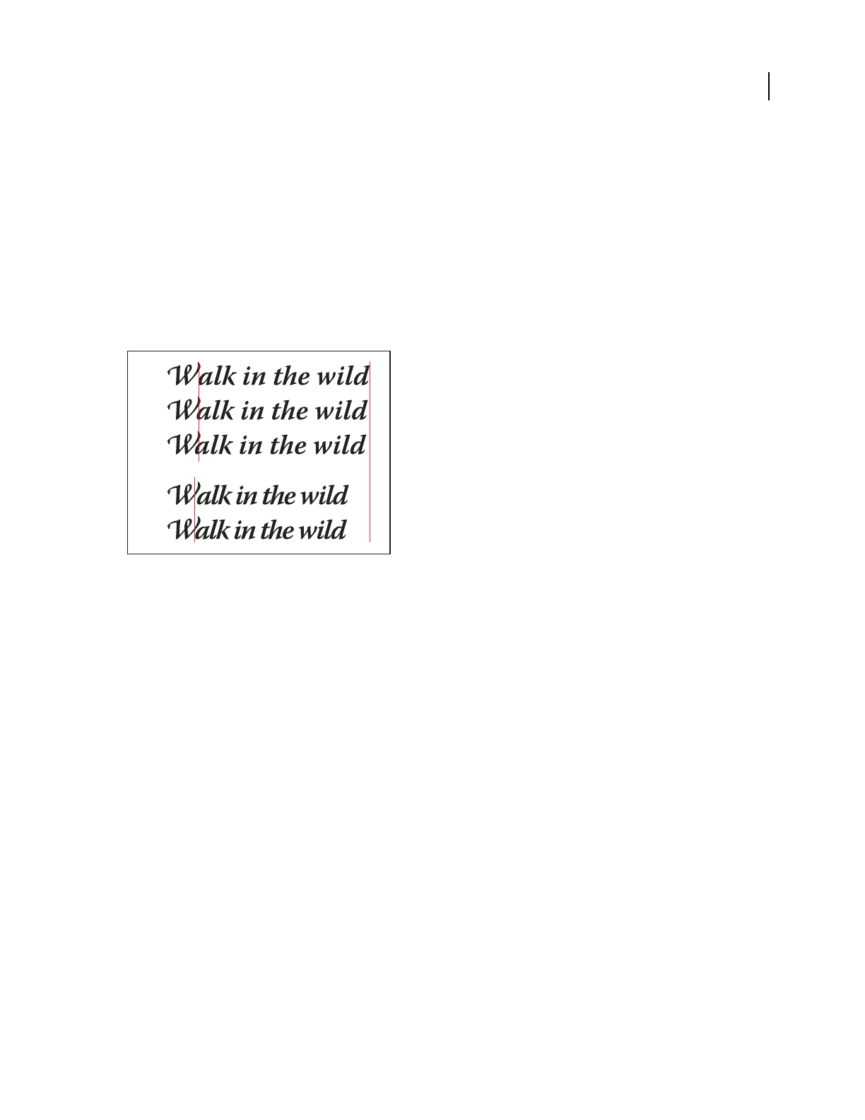
ILLUSTRATOR CS3
User Guide
315
Kern and track
Kerning is the process of adding or subtracting space between specific pairs of characters. Tracking is the process of
loosening or tightening the spacing between the characters in selected text or an entire block of text.
You can automatically kern type using metrics kerning or optical kerning. Metrics kerning (also called Auto kerning)
uses kern pairs, which are included with most fonts. Kern pairs contain information about the spacing of specific
pairs of letters. Some of these are: LA, P., To, Try, Ta, Tu, Te, Ty, Wa, WA, We, Wo, Ya, and Yo. Metrics kerning is set
as the default so that specific pairs are automatically kerned when you import or type text.
Some fonts include robust kern-pair specifications. However, when a font includes only minimal built-in kerning or
none at all, or if you use two different typefaces or sizes in one or more words on a line, you may want to use the
optical kerning option. Optical kerning adjusts the spacing between adjacent characters based on their shapes.
Kerning and tracking options
A. Original text B. Text with optical kerning C. Text with manual kerning between W and a D. Text with tracking E. Cumulative kerning
and tracking
You can also use manual kerning, which is ideal for adjusting the space between two letters. Tracking and manual
kerning are cumulative, so you can first adjust individual pairs of letters, and then tighten or loosen a block of text
without affecting the relative kerning of the letter pairs.
When you click to place the insertion point between two letters, kerning values appear in the Character panel.
Metrics and optical kerning values (or defined kern pairs) appear in parentheses. Similarly, if you select a word or a
range of text, the tracking values appear in the Character panel.
Tracking and kerning are both measured in 1/1000 em, a unit of measure that is relative to the current typeface size.
In a 6-point font, 1 em equals 6 points; in a 10-point font, 1 em equals 10 points. Kerning and tracking are strictly
proportional to the current typeface size.
Note: Values for kerning and tracking affect Japanese text, but normally these options are used to adjust the aki between
roman characters.
Adjust kerning
❖Do any of the following:
•To use a font’s built-in kerning information for selected characters, select Auto or Metrics for the Kerning option
in the Character panel.
•To automatically adjust the spacing between selected characters based on their shapes, select Optical for the
Kerning option in the Character panel.
A
B
C
D
E

ILLUSTRATOR CS3
User Guide
316
•To adjust kerning manually, place an insertion point between two characters, and set the desired value for the
Kerning option in the Character panel. (Note that if a range of text is selected, you can’t manually kern the text.
Instead, use tracking.)
Press Alt+Left/Right Arrow (Windows) or Option+Left/Right Arrow (Mac OS) to decrease or increase the kerning
between two characters.
•To turn off kerning for selected characters, set the Kerning option in the Character panel to 0 (zero).
Adjust tracking
1
Select the range of characters or the type object that you want to adjust.
2 In the Character panel, set the Tracking option.
Turn fractional character widths off or on
By default, the software uses fractional character widths between characters. This means that the spacing between
characters varies, and will sometimes use only fractions of whole pixels.
In most situations, fractional character widths provide the best spacing for type appearance and readability. However,
for type in small sizes (less than 20
points) displayed online, fractional character widths could cause type to run
together or have too much extra space, making it difficult to read.
Turn off fractional widths when you want to fix type spacing in whole-pixel increments and prevent small type from
running together. The fractional character width setting applies to all characters on a type layer—you cannot set the
option for selected characters.
❖Do any of the following:
•To set type spacing for the entire document in whole-pixel increments, choose System Layout from the Character
panel menu.
•To re-enable fractional character widths, choose Fractional Widths from the Character panel menu.
Special characters
About character sets and alternate glyphs
Typefaces include many characters in addition to the ones you see on your keyboard. Depending on the font, these
characters can include ligatures, fractions, swashes, ornaments, ordinals, titling and stylistic alternates, superior and
inferior characters, old-style figures, and lining figures. A glyph is a specific form of a character. For example, in
certain fonts, the capital letter A is available in several forms, such as swash and small cap.
There are two ways to insert alternate glyphs:
•The Glyphs panel lets you view and insert glyphs from any typeface.
•The OpenType panel lets you set up rules for using glyphs. For example, you can specify that you want to use
ligatures, titling characters, and fractions in a given text block. Using the OpenType panel is easier than inserting
glyphs one at a time and ensures a more consistent result. However, the panel works only with OpenType fonts.
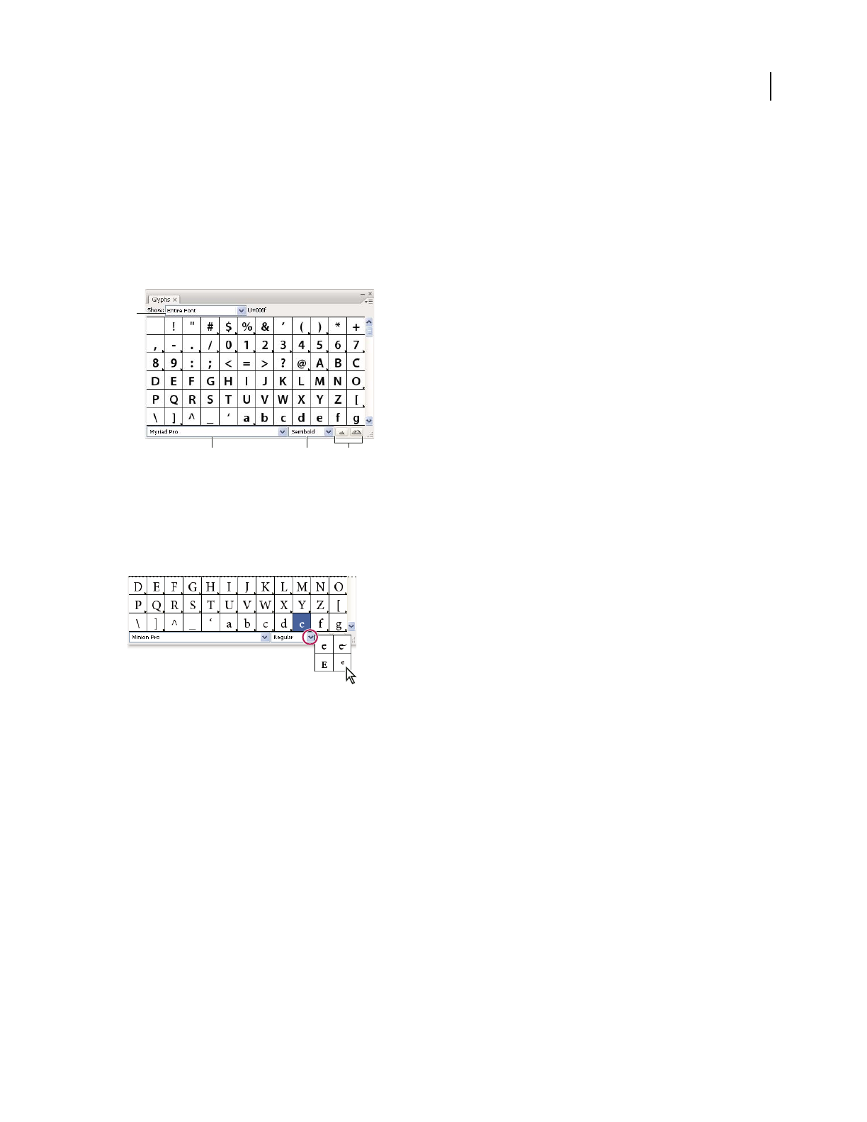
ILLUSTRATOR CS3
User Guide
317
Glyphs panel overview
You use the Glyphs panel (Window > Type > Glyphs) to view the glyphs in a font and insert specific glyphs in your
document.
By default, the Glyphs panel displays all the glyphs for the currently selected font. You can change the font by
selecting a different font family and style at the bottom of the panel. If any characters are currently selected in your
document, you can display alternate characters by selecting Alternates For Current Selection from the Show menu
at the top of the panel.
Glyphs panel
A. Show menu B. Font family C. Font style D. Zoom buttons
When you select an OpenType font in the Glyphs panel, you can restrict the panel to display certain kinds of glyphs
by selecting a category from the Show menu. You can also display a pop-up menu of alternate glyphs by clicking the
triangle in the lower right corner of the glyph box where applicable.
Pop-up menu for alternate glyphs
For a video on working with the Glyphs panel and the Open Type panel, see www.adobe.com/go/vid0048.
See also
“Workspace overview” on page 14
OpenType panel overview
You use the OpenType panel (Window > Type > OpenType) to specify how you want to apply alternate characters in
OpenType fonts. For example, you can specify that you want to use standard ligatures in new or existing text.
Keep in mind that OpenType fonts vary greatly in the kinds of features they offer; not all options in the OpenType
panel are available in every font. You can view the characters in a font using the Glyphs panel.
A
BCD

ILLUSTRATOR CS3
User Guide
318
OpenType panel
A. Standard Ligatures B. Contextual Alternates C. Discretionary Ligatures D. Swash E. Stylistic Alternates F. Titling Alternates G. Ordinals
H. Fractions I. panel menu J. Figure type K. Character position
Note: Additional features may be available for Asian OpenType fonts.
You can access additional commands and options in the OpenType panel menu in the upper right corner of the
panel. For a video on working with the Glyphs panel and the Open Type panel, see www.adobe.com/go/vid0048.
See also
“Set Asian OpenType font attributes” on page 333
“Workspace overview” on page 14
Insert or replace a character using the Glyphs panel
1 To insert a character, click with a type tool to place the insertion point where you want to enter the character, and
then double-click the character you want to insert in the Glyphs panel.
2 To replace a character, choose Alternates For Current Selection from the Show pop-up menu, select a character in
your document using a type tool. Double-click a glyph in the Glyphs panel, if one is available.
Note: Additional replacement options are available for Asian glyphs.
Highlight alternate glyphs in the text
1 Choose File > Document Setup, and choose Type from the pop-up menu at the top of the dialog box.
2 Select Substituted Glyphs, and click OK. Substituted glyphs in the text are highlighted.
Ligatures and contextual alternates
Ligatures are typographic replacement characters for certain letter pairs. Most fonts include ligatures for standard
letter pairs such as fi, fl, ff, ffi, and ffl. In addition, some fonts include discretionary ligatures for letter pairs such as
ct, st, and ft. Although the characters in ligatures appear to be joined, they are fully editable and do not cause the
spell checker to flag a word erroneously.
Contextual alternates are alternate characters included in some script typefaces to provide better joining behavior.
For example, when using Caflisch Script Pro with contextual alternates enabled, the letter pair “bl” in the word
“bloom” is joined so that it looks more like handwriting.
Use ligatures and contextual alternates
1 Select the characters or type objects to which you want to apply the setting. If you don’t select any text, the setting
applies to new text you create.
2 Make sure that an OpenType font is selected.
ABCDE FGH
I
J
K

ILLUSTRATOR CS3
User Guide
319
3 In the OpenType panel, do any of the following:
•Click the Standard Ligatures button to enable or disable ligatures for standard letter pairs (such as fi, fl, ff, ffi, and
ffl).
•Click the Discretionary Ligatures button to enable or disable optional ligatures (if available in the current font).
•Click the Contextual Alternates button to enable or disable contextual alternates (if available in the current font).
See also
“OpenType fonts” on page 303
“OpenType panel overview” on page 317
Use swashes, titling alternates, or stylistic alternates
Many OpenType fonts include stylized characters that let you add decorative elements to type. Swashes are characters
with exaggerated flourishes. Titling alternates are characters (usually all in capitals) designed for use in large-size
settings, such as titles. Stylistic alternates are stylized characters that create a purely esthetic effect.
1 Select the characters or type objects to which you want to apply the setting. If you don’t select any text, the setting
applies to new text you create.
2 Make sure that an OpenType font is selected.
3 In the OpenType panel, do one of the following:
•Click the Swash button to enable or disable swash characters (if available in the current font).
•Click the Stylistic Alternates button to enable or disable stylistic alternates (if available in the current font).
•Click the Titling Alternates button to enable or disable titling alternates (if available in the current font).
See also
“OpenType fonts” on page 303
“OpenType panel overview” on page 317
Show or hide nonprinting characters
Nonprinting characters include hard returns (line breaks), soft returns (line breaks), tabs, spaces, nonbreaking
spaces, double-byte characters (including spaces), discretionary hyphens, and the end-of-text character.
To make the characters visible as you format and edit type, choose Type > Show Hidden Characters. A check mark
indicates that nonprinting characters are
visible.
Formatting paragraphs
Paragraph panel overview
You use the Paragraph panel (Window > Type > Paragraph) to change the formatting of columns and paragraphs.
When type is selected or when the Type tool is active, you can also use options in the Control panel to format
paragraphs.

ILLUSTRATOR CS3
User Guide
320
For a video on working with character and paragraph styles, see www.adobe.com/go/vid0047.
Paragraph panel (all options shown)
A. Alignment and Justification B. Left Indent C. First Line Left Indent D. Space Before Paragraph E. Hyphenation F. Right Indent G. Space
After Paragraph
A. Font B. Font Style C. Font Size D. Align left E. Align center F. Align right
By default, only the most commonly-used options in the Paragraph panel are visible. To show all options, choose
Show Options from the panel menu. Alternatively, click the double triangle on the panel’s tab to cycle through the
display sizes.
See also
“Workspace overview” on page 14
“Keys for working with type” on page 466
Align text
Area type and type on a path can be aligned with one or both edges of a type path.
1 Select the type object or insert the cursor in the paragraph you want to change.
If you don’t select a type object or insert the cursor in a paragraph, the alignment applies to new text you create.
2 In the Control panel or Paragraph panel, click an alignment button.
Justify text
Text is justified when it is aligned with both edges. You can justify all text in a paragraph either including or excluding
the last line.
1 Select the type object or insert the cursor in the paragraph you want to justify.
If you don’t select a type object or insert the cursor in a paragraph, the justification applies to new text you create.
2 In the Paragraph panel, click a justification button.
A
F
B
C
E
D G
ABCDEF

ILLUSTRATOR CS3
User Guide
321
Adjust word and letterspacing in justified text
You can precisely control how Adobe applications space letters and words and scale characters. Adjusting spacing is
especially useful with justified type, although you can also adjust spacing for unjustified type.
1 Insert the cursor in the paragraph you want to change, or select a type object or frame to change all of its
paragraphs.
2 Choose Justification from the Paragraph panel menu.
3 Enter values for Word Spacing, Letter Spacing, and Glyph Spacing. The Minimum and Maximum values define a
range of acceptable spacing for justified paragraphs only. The Desired value defines the desired spacing for both
justified and unjustified paragraphs:
Word Spacing The space between words that results from pressing the spacebar. Word Spacing values can range
from 0% to 1000%; at 100%, no additional space is added between words.
Letter Spacing The distance between letters, including kerning or tracking values. Letter Spacing values can range
from -100% to 500%: at 0%, no space is added between letters; at 100%, an entire space width is added between
letters.
Glyph Spacing The width of characters (a glyph is any font character). Glyph Spacing values can range from 50% to
200%; at 100%, the height of characters is not scaled.
Spacing options are always applied to an entire paragraph. To adjust the spacing in a few characters, but not an entire
paragraph, use the Tracking option.
4 Set the Single Word Justification option to specify how you want to justify single-word paragraphs.
In narrow columns, a single word can occasionally appear by itself on a line. If the paragraph is set to full justification,
a single word on a line may appear to be too stretched out. Instead of leaving such words fully justified, you can center
them or align them to the left or right margins.
Indent text
Indention is the amount of space between text and the boundary of a type object. Indention affects only the selected
paragraph or paragraphs, so you can easily set different indentions for different paragraphs.
You can set indents using the Tabs panel, the Control panel, or the Paragraph panel. When working with area type,
you can also control indention using tabs or by changing the inset spacing for the type object.
When working with Japanese type, you can use the mojikumi setting instead of the Paragraph panel to specify the
indent for the first line. If you specify the indent for the first line in the Paragraph panel, and specify mojikumi
settings for the first line indent, the text is placed inside the total of both indents.
See also
“Paragraph panel overview” on page 319
“Change the margin around a text area” on page 293
Set indents using the Paragraph panel
1
Using the Type tool , click in the paragraph you want to indent.
2 Adjust the appropriate indent values in the Paragraph panel. For example, do the following:
•To indent the entire paragraph one pica, type a value (such as 1p) in the Left Indent box .
•To indent only the first line of a paragraph one pica, type a value (such as 1p) in the First Line Left Indent box .
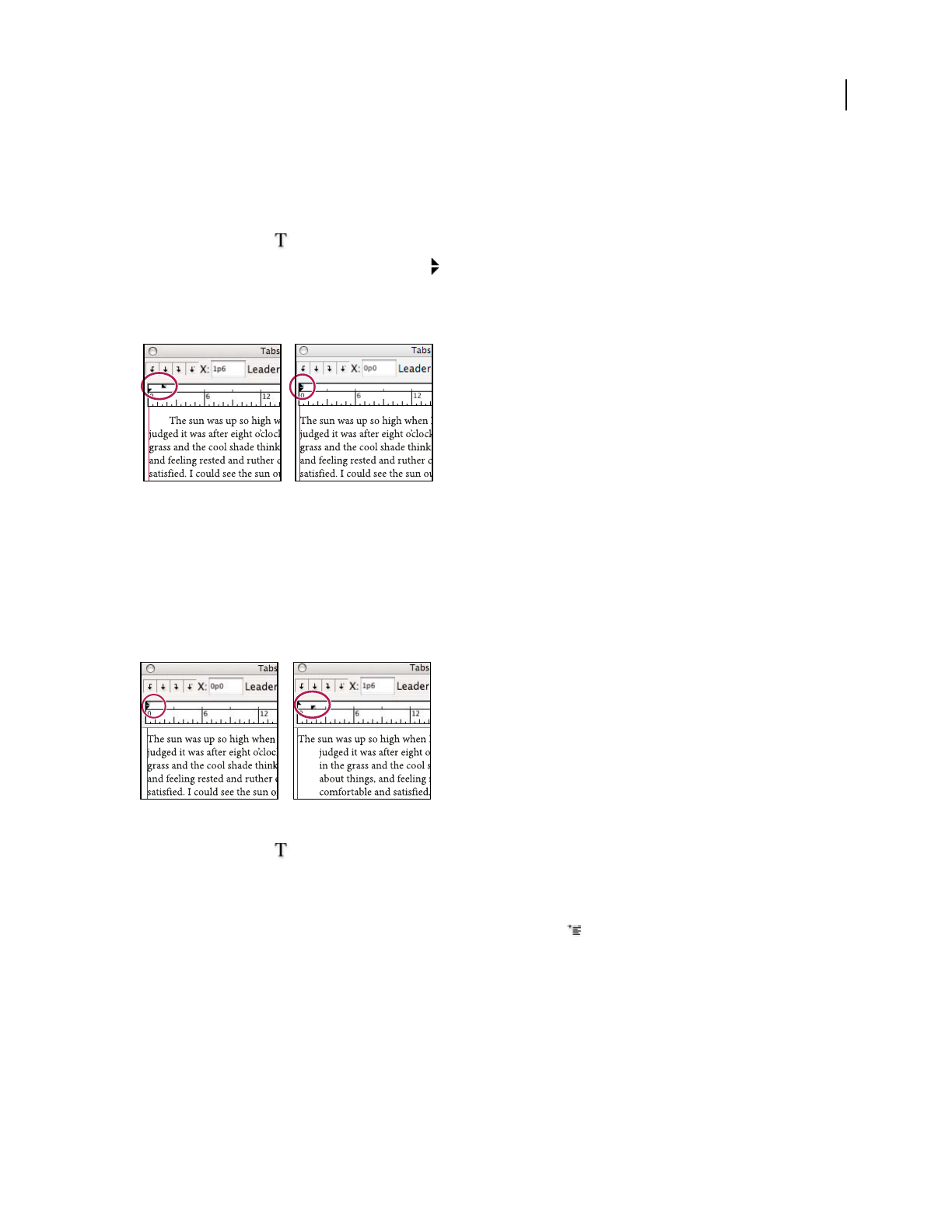
ILLUSTRATOR CS3
User Guide
322
•To create a hanging indent of one pica, type a positive value (such as 1p) in the Left Indent box and type a negative
value (such as -1p) in the First Line Left Indent box.
Set an indent using the Tabs panel
1
Using the Type tool , click in the paragraph you want to indent.
2 Do one of the following to the indent markers in the Tabs panel:
•Drag the top marker to indent the first line of text. Drag the bottom marker to move both markers and indent the
entire paragraph.
First-line indent (left) and no indent (right)
•Select the top marker and type a value for X to indent the first line of text. Select the bottom marker and type a
value for X to move both markers and indent the entire paragraph.
Create a hanging indent
In a hanging indent, all the lines in a paragraph are indented except for the first line. Hanging indents are especially
useful when you want to add inline graphics at the beginning of the paragraph, or when you want to create a bulleted list.
No indent (left) and hanging indent (right)
1 Using the Type tool , click in the paragraph you want to indent.
2 In the Control panel or the Tabs panel, specify a left indent value greater than zero.
3 To specify a negative first-line left indent value, do one of the following:
•In the Control panel, type a negative value for the first-line left indent .
•In the Tabs panel, drag the top marker to the left, or select the marker and type a negative value for X.
In most cases you’ll specify the negative equivalent of the value you entered in step 2; for instance, if you specified a
left indent of 2 picas, your first-line left indent will typically be –2 picas.
Adjust paragraph spacing
1 Insert the cursor in the paragraph you want to change, or select a type object to change all of its paragraphs. If you
don’t insert the cursor in a paragraph or select a type object, the setting applies to new text you create.

ILLUSTRATOR CS3
User Guide
323
2 In the Paragraph panel, adjust the values for Space Before( or ) and Space After ( or ).
Note: If a paragraph begins at the top of a column, no extra space is added before the paragraph. In this case, you can
increase the leading of the first line of the paragraph or change the inset spacing for the type object.
See also
“Paragraph panel overview” on page 319
“Set the leading” on page 314
Hanging punctuation
Hanging punctuation makes the edges of text appear more even by moving punctuation marks outside the paragraph
margins.
Paragraph without hanging punctuation (left) compared to paragraph with hanging punctuation (right)
Illustrator provides the following options for hanging punctuation:
Roman Hanging Punctuation Controls the alignment of punctuation marks for a specific paragraph. When Roman
Hanging Punctuation is turned on, the following characters appear 100% outside the margins: single quotes, double
quotes, hyphens, periods, and commas; the following characters appear 50% outside the margins: asterisks, tildes,
ellipses, en dashes, em dashes, colons, semicolons. To apply this setting, insert the cursor in the paragraph and select
Roman Hanging Punctuation from the Paragraph panel menu.
Optical Margin Alignment Controls the alignment of punctuation marks for all paragraphs within a type object.
When Optical Margin Alignment is turned on, roman punctuation marks as well as the edges of letters (such as W
and A) hang outside the text margins so that the type looks aligned. To apply this setting, select the type object and
choose Type > Optical Margin Alignment.
Burasagari Controls the alignment of double-byte punctuation marks (available in Chinese, Japanese, and Korean
fonts). These punctuation marks are not affected by the Roman Hanging Punctuation option or Optical Margin
Alignment option.
Keep in mind that the paragraph alignment determines the margin from which the punctuation hangs. For left-
aligned and right-aligned paragraphs, punctuation hangs off the left and right margin, respectively. For top-aligned
and bottom-aligned paragraphs, punctuation hangs off the top and bottom margin, respectively. For centered and
justified paragraphs, punctuation hangs off both margins.
Note: When a punctuation character is followed by a quotation mark, both characters hang.

ILLUSTRATOR CS3
User Guide
324
See also
“Paragraph panel overview” on page 319
“Specify a burasagari option” on page 340
Hyphenation and line breaks
Adjust hyphenation automatically
The settings you choose for hyphenation affect the horizontal spacing of lines and the aesthetic appeal of type on a
page. Hyphenation options determine whether words can be hyphenated and, if so, what breaks are allowable.
1 To use automatic hyphenation, do any of the following:
•To turn automatic hyphenation on or off, select or deselect the Hyphenate option in the Paragraph panel.
•To apply hyphenation to specific paragraphs, first select only the paragraphs that you want to affect.
•To choose a hyphenation dictionary, choose a language from the Language menu at the bottom of the Character
panel.
2 To specify options, choose Hyphenation from the Paragraph panel menu, and specify the following options:
Words Longer Than _ Letters Specifies the minimum number of characters for hyphenated words.
After First _ Letters And Before Last _ Letters Specifies the minimum number of characters at the beginning or end
of a word that can be broken by a hyphen. For example, by specifying 3 for these values, aromatic would be
hyphenated as aro- matic instead of ar- omatic or aromat- ic.
Hyphen Limit Specifies the maximum number of consecutive lines on which hyphenation may occur. Zero means
unlimited consecutive hyphens are allowed at ends of lines.
Hyphenation Zone Specifies a distance from the right edge of a paragraph, demarcating a portion of the line where
hyphenation is not allowed. A setting of 0 allows all hyphenation. This option applies only when you use the Adobe
Single-line Composer.
Hyphenate Capitalized Words Select to prevent capitalize words from being hyphenated.
Note: Hyphenation settings apply only to Roman characters; double-byte characters available in Chinese, Japanese, and
Korean fonts are not affected by these settings.
Use the hyphenation dictionary
Illustrator uses Proximity language dictionaries to determine when to hyphenate words. These dictionaries let you
specify a different language for as little as a single character of text. You can select a default dictionary and customize
the dictionary in the Preferences dialog box.
1 Choose Edit > Preferences > Hyphenation (Windows) or Illustrator > Preferences > Hyphenation (Mac OS).
2 Do any of the following:
•To choose a default hyphenation dictionary, select an option for Default Language, and click OK.
•To add a word to the exceptions list, type the word in the New Entry text box, and click Add.
•To remove a word from the exceptions list, select the word, and click Delete.

ILLUSTRATOR CS3
User Guide
325
Prevent words from breaking
You can prevent words from breaking at the end of lines—for example, proper names or words that could be misread
when hyphenated. You can also keep multiple words or groups of words together—for example, clusters of initials
and a last name.
1 Select the characters you want to prevent from breaking.
2 Choose No Break from the Character panel menu.
Note: If you apply the No Break option to too many adjacent characters, the text may wrap in the middle of a word.
Composition methods
The appearance of type on the page depends on a complex interaction of processes called composition. Using the
word spacing, letterspacing, glyph spacing, and hyphenation options you’ve selected, Adobe applications evaluate
possible line breaks and choose the one that best supports the specified parameters.
You can choose between two composition methods: the Adobe Every-line Composer and the Adobe Single-line
Composer. Both methods evaluate possible breaks and choose the one that best supports the hyphenation and justi-
fication options you’ve specified for a given paragraph. The composition method affects only the selected paragraph
or paragraphs, so you can easily set different composition methods for different paragraphs.
Every-line Composer
The Every-line Composer considers a network of break points for a range of lines and thus can optimize earlier lines
in the paragraph in order to eliminate especially unattractive breaks later on.
The Every-line Composer approaches composition by identifying possible break points, evaluating them, and
assigning a weighted penalty based on the following principles:
•For left-, right-, or center-aligned text, lines that fall closer to the right side are favored and have a lower penalty.
•For justified text, the highest importance is given to evenness of letter and word spacing.
•Hyphenation is avoided when possible.
Single-line Composer
The Single-line composer offers a traditional approach to composing type one line at a time. This option is useful if
you want manual control over how lines break. The Single-line Composer uses the following principles when consid-
ering a breakpoint:
•Longer lines are favored over shorter lines.
•In justified text, compressed or expanded word spacing is preferable to hyphenation.
•In nonjustified text, hyphenation is preferable to compressed or expanded letterspacing.
•If spacing must be adjusted, compression is better than expansion.
To choose one of these methods, select it from the Paragraph panel menu. To apply the method to all paragraphs,
first select the type object; to apply the method to the current paragraph only, first insert the cursor in that paragraph.
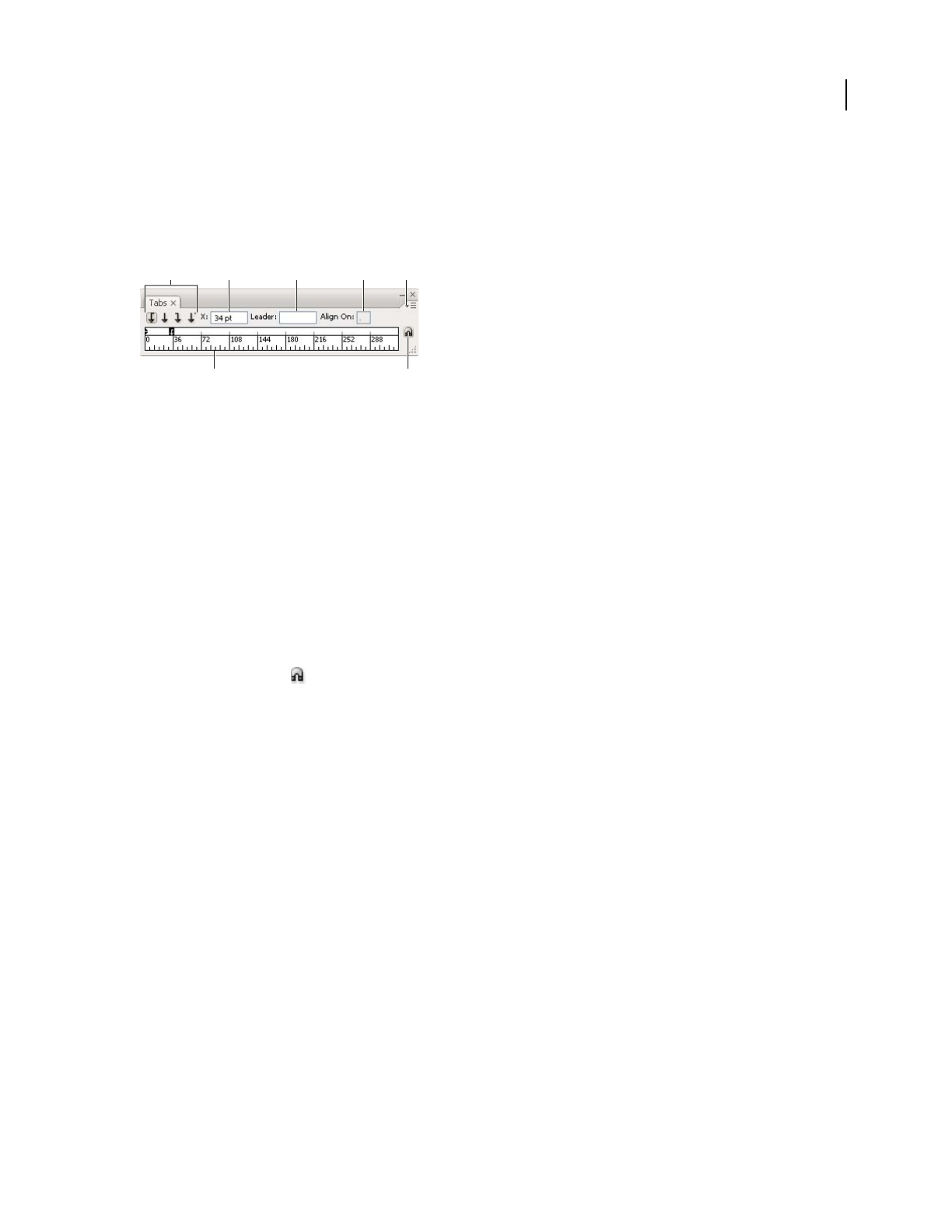
ILLUSTRATOR CS3
User Guide
326
Tabs
Tabs panel overview
You use the Tabs panel (Window > Type > Tabs) to set tab stops for a paragraph or type object.
Tabs panel
A. Tab alignment buttons B. Tab position C. Tab leader box D. Align On box E. panel menu F. Tab ruler G. Snap panel above frame
You can access additional commands and options in the Tabs panel menu. To use this menu, click the triangle in the
upper right corner of the panel.
See also
“Workspace overview” on page 14
“Change the unit of measurement” on page 47
Align the Tabs panel with a selected type object
You can position the Tabs panel anywhere in the work area; however, it is usually helpful to align the Tabs panel with
a type object.
❖ Click the magnet icon . The Tabs panel moves directly above the selected text object, with the zero point
aligned with the left margin. If necessary, you can drag the resize button at the lower right corner of the panel to
expand or reduce the ruler.
Snap tab stops to the ruler units
By default, you can position tab stops anywhere along the tab ruler.
❖Choose Snap To Unit from the panel menu or hold down Shift as you drag a tab stop.
Change the units of measure for the tab ruler
The units of measure for the tab ruler are defined by the General units settings specified in the Units & Display
Performance preferences (for all files) or by the units specified in the Document Setup dialog box (for the current
file).
•To change the units of measure for all files, specify a new value for General Units in the Units & Display Perfor-
mance preferences.
•To change the units of measure for the current file, specify a new units value in the Document Setup dialog box.
A B C D
FG
E

ILLUSTRATOR CS3
User Guide
327
Set tabs
Tab stops apply to an entire paragraph. When you set the first tab, Illustrator deletes all default tab stops to the left
of that stop. As you set more tab stops, Illustrator deletes all default tabs between the tabs you set.
1 Insert the cursor in a paragraph, or select a type object to set tab stops for all paragraphs in the object.
2 In the Tabs panel, click a tab-alignment button to specify how text aligns relative to the tab’s position:
Left-Justified Tab to align horizontal text to the left, keeping the right margin ragged.
Center-Justified Tab to center text on the tab mark.
Right-Justified Tab to align horizontal text to the right, keeping the left margin ragged.
Bottom-Justified Tab to align vertical text to the bottom margin, keeping the top margin ragged.
Top-Justified Tab to align vertical text to the top margin, keeping the bottom margin ragged.
Decimal-Justified Tab to place text in alignment with a specified character, such as a period or a dollar sign. This
option is useful for creating columns of numbers.
You can change the alignment of any tab by simply selecting it and clicking one of these buttons.
3 Do one of the following:
•Click a location on the tab ruler to position a new tab stop.
•Type a position in the X box (for horizontal text) or Y box (for vertical text), and press Enter or Return. If the X
or Y value is selected, press the Up Arrow or Down Arrow key to increase or decrease the tab value by 1 point,
respectively.
Note: When you use the tab ruler, you cannot set tab stops in increments smaller than 1. However, if you specify a
position in the X or Y box, you can set stops at intervals as small as 0.01 point.
4 Repeat steps 2 and 3 to add additional tab stops.
Note: For information on setting indents using the Tabs panel, see “Indent text” on page 321.
Repeat tabs
The Repeat Tab command creates multiple tabs based on the distance between the tab and the left indent or the
previous tab stop.
1 Click an insertion point in the paragraph.
2 In the Tabs panel, select a tab stop on the ruler.
3 Choose Repeat Tab from the panel menu.
Repeated tabs
A. Tab-alignment buttons B. Tab stop on the ruler C. Panel menu
Move tabs
1 In the Tabs panel, select a tab stop on the ruler.
C
B
A
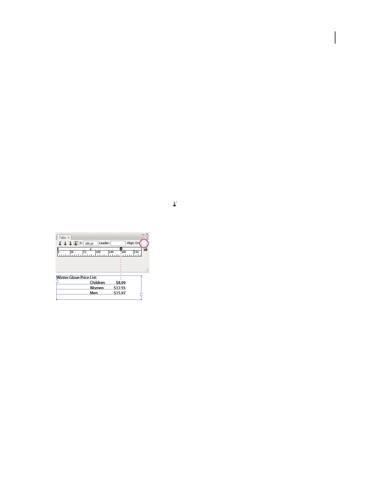
ILLUSTRATOR CS3
User Guide
328
2 Do one of the following:
•Type a new location in the X box (for horizontal text) or Y box (for vertical text), and press Enter or Return.
•Drag the tab to a new location.
•To move all tab stops simultaneously, Ctrl-drag (Windows) or Command-drag (Mac OS) a tab.
As you move a tab stop, a visual guide appears in the selected text.
Remove tabs
❖Do one of the following:
•Drag the tab off the tab ruler.
•Select the tab, and choose Delete Tab from the panel menu.
•To return to the default tab stops, choose Clear All from the panel menu.
Specify characters for decimal tabs
You use decimal tabs to align text with a character you specify, such as a period or a dollar sign.
1 In the Tabs panel, create or select a decimal tab on the tab ruler.
2 In the Align On box, type the character to which you want to align. You can type or paste any character. Make sure
that the paragraphs you’re aligning contain that character.
Text aligned using a decimal tab
Add tab leaders
A tab leader is a repeated pattern of characters, such as a series of dots or dashes, between a tab and the following text.
1 In the Tabs panel, select a tab stop on the ruler.
2 Type a pattern of as many as eight characters in the Leader box, and then press Enter or Return. The characters
you entered repeat across the width of the tab.
3 To change the font or other formatting of the tab leader, select the tab character in the text frame, and use the
Character panel or Type menu to apply formatting.
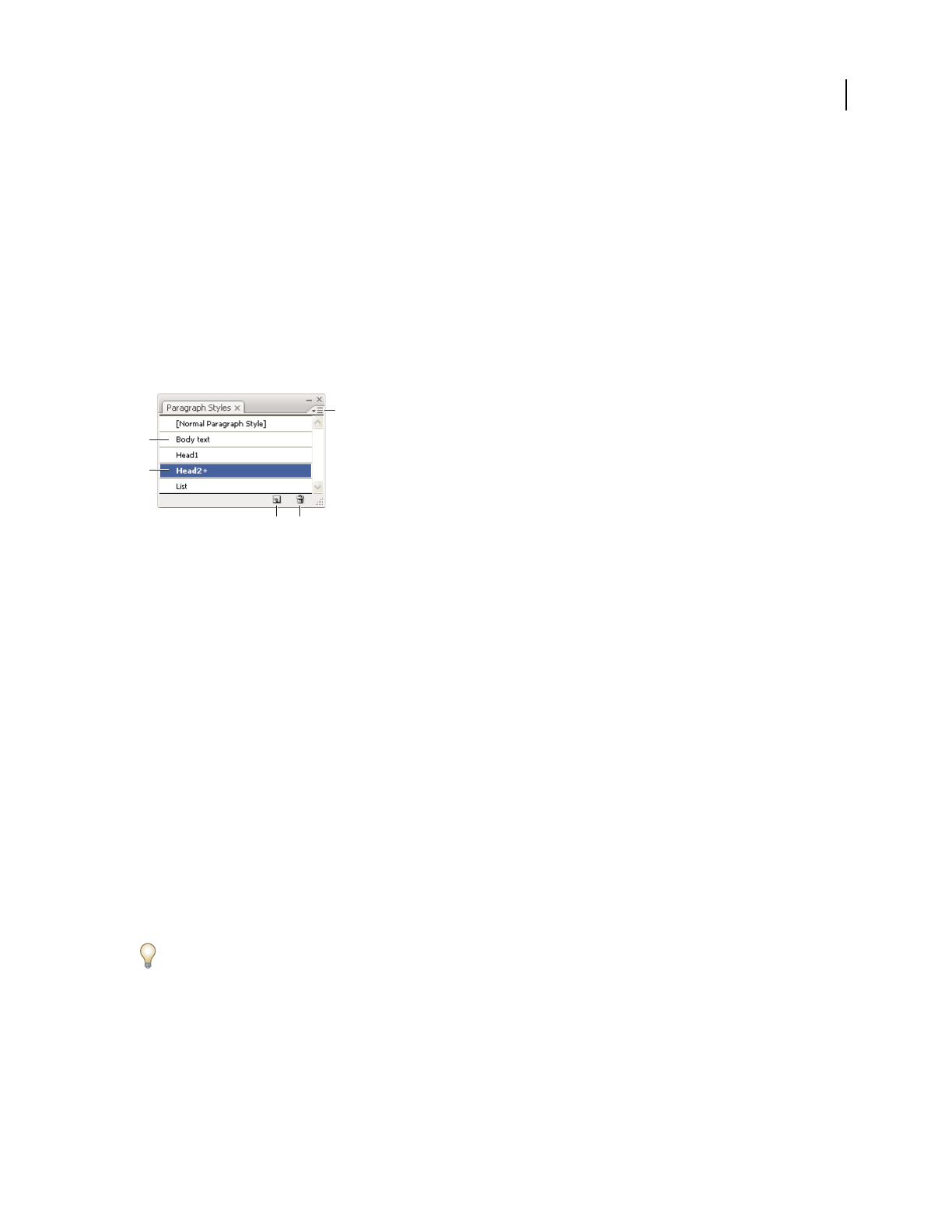
ILLUSTRATOR CS3
User Guide
329
Character and paragraph styles
About character and paragraph styles
A character style is a collection of character-formatting attributes that you can apply to a selected range of text. A
paragraph style includes both character- and paragraph-formatting attributes, and can be applied to a selected
paragraph or range of paragraphs. Using character and paragraph styles saves time and ensures consistent
formatting.
You use the Character Styles and Paragraph Styles panels to create, apply, and manage character and paragraph styles.
To apply a style, simply select text and click a style name in one of the panels. If you don’t select any text, the style
applies to new text you create.
Paragraph Styles panel
A. Style name B. Style with additional formatting (overrides) C. Panel menu D. New Style button E. Delete icon
When you select text or insert the cursor in text, the active styles are highlighted in the Character Styles and
Paragraph Styles panels. By default, every character in a document is assigned the Normal Character Style and every
paragraph is assigned the Normal Paragraph Style. These default styles are the building blocks for all other styles you
create.
A plus sign next to a style name indicates that there are overrides to the style. An override is any formatting that
doesn’t match the attributes defined by the style. Any time you change settings in the Character and OpenType panel,
you create an override to the current character style; likewise, when you change settings in the Paragraph panel, you
create an override to the current paragraph style.
For a video about using character and paragraph styles in Illustrator, see www.adobe.com/go/vid0047.
Create character or paragraph styles
1 If you want to base the new style on the formatting of existing text, select the text.
2 In the Character Styles panel or the Paragraph Styles panel, do one of the following:
•To create a new style with the default name, click the Create New Style button.
•To create a new style with a custom name, choose New Style in the panel menu. Type a name, and click OK.
To create a copy of a character or paragraph style, drag the style onto the New Style button.
A
C
B
DE

ILLUSTRATOR CS3
User Guide
330
Edit character or paragraph styles
You can change the definition of the default character and paragraph styles, as well as any new styles you create.
When you change the definition of a style, all of the text formatted with that style changes to match the new style
definition.
1 In the Character Styles panel or the Paragraph Styles panel, do one of the following:
•Select the style in the panel, and choose Character Style Options from the Character Styles panel menu or
Paragraph Style Options from the Paragraph Styles panel menu.
•Double-click the style name.
Note: Double-clicking applies the style to any selected text or, if no text is selected, sets the style for any new text you type.
If you don’t want to apply the style, hold down Shift+Ctrl (Windows) or Shift+Command (Mac OS) when you double-
click the style name.
2 On the left side of the dialog box, select a category of formatting options and set the options you want. You can
switch to a different group of formatting options by selecting a different category.
If you need more information about any of the formatting options, search for the option name in Help.
3 When you finish setting options, click OK.
Remove style overrides
A plus sign next to the style name in the Character Styles panel or the Paragraph Styles panel indicates that there are
overrides to the style. An override is any formatting that doesn’t match the attributes defined by the style. There are
several ways to remove style overrides:
•To clear overrides and return text to the appearance defined by the style, reapply the same style or choose Clear
Overrides from the panel menu.
•To clear overrides when applying a different style, Alt-click (Windows) or Option-click (Mac OS) the style name.
•To redefine the style and maintain the current appearance of the text, select at least one character of the text and
choose the Redefine Style command from the panel menu.
If you use styles to maintain consistent formatting, you should probably avoid overrides. If you’re formatting quick,
one-time-only text, these overrides pose no problem.
Delete character or paragraph styles
When you delete styles, the appearance of paragraphs tagged with the style doesn’t change, but their formatting is no
longer associated with a style.
1 Select the style name or names in the Character Styles panel or the Paragraph Styles panel.
2 Do one of the following:
•Choose Delete Character Style or Delete Paragraph Style from the panel menu.
•Click the Delete icon at the bottom of the panel.
•Drag the style to the Delete icon at the bottom of the panel.
To delete all unused styles, choose Select All Unused from the panel menu, and then click the Delete icon.

ILLUSTRATOR CS3
User Guide
331
Load character and paragraph styles from another Illustrator document
1 In the Character Styles panel or the Paragraph Styles panel, do one of the following:
•Choose Load Character Styles or Load Paragraph Styles from the panel menu.
•Choose Load All Styles from the panel menu to load both character and paragraph styles.
2 Double-click the Illustrator document containing the styles you want to import.
Exporting text
Export text to a text file
1 Using a type tool, select the text you want to export.
2 Choose File > Export.
3 In the Export dialog box, select a location for the file and enter a filename.
4 Choose Text Format (TXT) as the file format.
5 Enter the name of the new text file in the name box, and click Save (Windows) or Export (Mac OS).
6 Choose a platform and encoding method, and click Export.
Tag text for export to Flash
You can export text from Illustrator to Flash in a variety of ways. You can export text as a static, dynamic, or input
text. Dynamic text also allows you to specify a URL for the site that will open when a user clicks the text. For more
information about dynamic and input text, see Flash Help.
Flash text can contain point text, area text, or text on a path; all text is converted to area text in SWF format.
Bounding boxes remain the same and any transformations applied to them are preserved in SWF format. Threaded
text objects are exported individually —if you want to tag and export all objects in a thread, make sure you select and
tag each one. Overflow text is imported into Flash Player intact.
Once you tag text, you can import it into Flash by either exporting the text from Illustrator or copying and pasting
the text.
For a video on using text effectively between Illustrator and Flash, see www.adobe.com/go/vid0199.
Note: Tagging or untagging text does not change the original text in Illustrator. You can change the tag at anytime
without altering the original.
1 Select a text object and click Flash Text in the Control panel.
2 In the Flash Text panel, select one of the following from the Type menu:
Static Text Exports text to Flash Player as a regular text object that cannot be changed dynamically or programati-
cally in Flash. The content and appearance of static text are determined when you author the text.
Dynamic Text Exports the text as Dynamic text, which can update programatically at run time through Action script
commands and tags. You can use dynamic text for sports scores, stock quotes, news headlines, and similar purposes
in which you want the text to update dynamically.
Input Text
Exports the text as Input text, which is the same as Dynamic text, but also allows users to edit the text in Flash
Player. You use input text for forms, surveys, or other similar purposes in which you want users to input or edit text.

ILLUSTRATOR CS3
User Guide
332
3 (Optional) Enter an instance name for the text object. If you do not enter an instance name, the default name of
the text object in the Layers panel is used in Flash to manipulate the text object.
4 Specify a Rendering Type. The Use Device Fonts option converts glyphs to device fonts (anti-aliasing is not
available for device fonts).
Note: Font names are normally used verbatim and passed directly to the playback platform’s font system to locate the
font. However, there are several special indirect font names that are mapped to different font names depending on the
playback platform. These indirect mappings are hard-coded into each platform-specific port of Flash Player, and the
fonts for each platform are chosen from among system default fonts or other fonts that are likely to be available. As a
secondary consideration, the indirect mappings are specified to maximize the similarity of indirect fonts across
platforms.
Animation Optimizes text for output to animation.
Readability Optimizes text for readability.
Custom Lets you specify custom values for Thickness and Sharpness of text.
Use Device Fonts Converts glyphs to device fonts. Anti-aliasing is not available for device fonts.
_sans, _serif, and _typewriter Map western indirect fonts across platforms to ensure a similar appearance.
Gothic, Tohaba (Gothic Mono), and Mincho Map Japanese indirect fonts across platforms to ensure a similar
appearance.
Note: For more information on indirect fonts, see the Flash specification document, which you can find on Adobe.com.
5 (Optional) Select any of the following:
Selectable Makes the exported text selectable in Flash.
Show Border Around Text Makes the text borders visible in Flash.
Edit Character Options Opens the Character Embedding dialog box so that you can embed specific characters
in the text object. You can choose the characters you want to embed from the provided list, type the characters in the
Include These Characters text box, click Auto Fill to automatically select characters that need to be embedded, or do
any combination of these.
6 (Optional) If you tagged the text as Dynamic text, you can specify the URL of the page you want to open when
the text is clicked, and then choose a target window to specify where you want to load the page:
_self Specifies the current frame in the current window.
_blank Specifies a new window.
_parent Specifies the parent of the current frame.
_top Specifies the top-level frame in the current window.
7 If you tagged the text as Input Text, specify the Maximum Characters that can be typed into the text object.
Once you tag text as Flash text, you can select all such text at once by choosing Select > Object > Flash Dynamic Text
or Flash Input Text.
See also
“Flash export options” on page 271
“SWF optimization options (Illustrator)” on page 395

ILLUSTRATOR CS3
User Guide
333
Formatting Asian characters
Display Asian type options
By default, Illustrator hides Asian type options in the Character panel, Paragraph panel, OpenType panel, and Type
menu.
1 Choose Edit > Preferences > Type (Windows) or Illustrator > Preferences > Type (Mac OS).
2 Select Show Asian Options, and click OK.
You can also control how font names are displayed (in English or in the native language) by selecting or deselecting
Show Font Names in English.
Note: Your operating system must support the languages in which you wish to work. Consult your system software
manufacturer for more information.
See also
“About Unicode” on page 302
Set Asian OpenType font attributes
Asian OpenType fonts may include a number of features that aren’t available in current PostScript and TrueType
fonts. In addition, Asian OpenType fonts provide alternate glyphs for many characters.
1 Select the characters or type objects to which you want to apply the setting. If you don’t select any text, the setting
applies to new text you create.
2 Make sure that an OpenType font is selected.
Look in the Type > Font menu; OpenType fonts display the icon.
3 In the OpenType panel, set any of the following options:
Proportional Metrics Kerning is according to the proportional metrics of the font.
H or V Style Switches hiragana fonts, which have different glyphs for horizontal and vertical such as contracted
sounds, double consonants, and phonetic indexes.
Roman Italics Changes half-width alphanumerics to italics.
See also
“About character sets and alternate glyphs” on page 316
“OpenType fonts” on page 303
“OpenType panel overview” on page 317
Replace Asian characters with a different glyph form
1 Select the characters you want to replace.
2 Choose an option from the Glyphs panel menu. If you don’t see the following options, select Show Asian Options
in the Type preferences. If an option is dimmed, the glyph form is not available for the current font:
Traditional Forms Replaces the selected characters with traditional forms.

ILLUSTRATOR CS3
User Guide
334
Expert Forms Replaces the selected characters with their expert forms.
JIS 78 Forms Replaces the selected characters with JIS 78 forms.
JIS 83 Forms Replaces the selected characters with JIS 83 forms.
Monospaced Half-Width Forms Changes the glyphs of the selected Latin characters to monospace hankaku (half
width).
Monospaced Third-Width Forms Changes the glyphs of the selected Latin characters to monospace third width.
Monospaced Quarter-Width Forms Changes the glyphs of the selected Latin characters to monospace quarter width.
To revert an alternate glyph to its default form, select it and choose Revert To Default Forms from the Glyphs panel
menu. You cannot use this method to revert alternate glyphs that were applied using a character style.
See also
“About character sets and alternate glyphs” on page 316
“Glyphs panel overview” on page 317
“Display Asian type options” on page 333
Specify how leading is measured in Asian type
1 Select the paragraphs you want to adjust.
2 Choose a leading option from the Paragraph panel menu.
Top-to-top Leading
Measures the spacing between lines of type from the top of one line to the top of the next line.
When you use top-to-top leading, the first line of type in a paragraph is aligned flush with the top of the bounding box.
Bottom-to-bottom Leading For horizontal type, measures the space between lines of type from the type baseline.
When you use bottom-to-bottom leading, space appears between the first line of type and the bounding box. A check
mark indicates which option is selected.
Note: The leading option you choose does not affect the amount of leading between lines, only how the leading is
measured.
Rotate half-width characters in vertical text
The direction of half-width characters, such as roman text or numbers, changes in vertical text. By default, half-width
characters are rotated individually.
If you don’t want half-width characters to rotate, deselect Standard Vertical Roman Alignment from the Character
panel menu.
Roman text before and after rotation
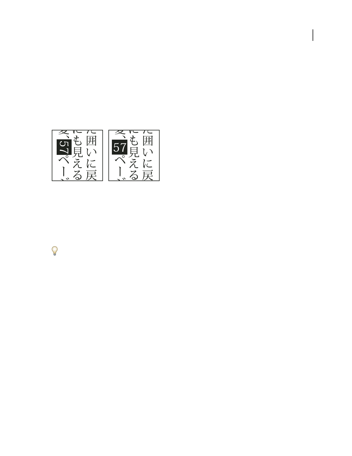
ILLUSTRATOR CS3
User Guide
335
See also
“Display Asian type options” on page 333
“Rotate type” on page 301
Use tate-chu-yoko
Tate-chu-yoko (also called kumimoji and renmoji) is a block of horizontal type laid out within vertical type lines.
Using tate-chu-yoko makes it easier to read half-width characters such as numbers, dates, and short foreign words
in vertical text.
Numerals without tate-chu-yoko (left) compared to numerals rotated with tate-chu-yoko (right)
1 Select characters and choose Tate-chu-yoko from the Character panel menu. (Select it again to turn Tate-chu-
yoko off.)
2 Select any of the following tate-chu-yoko settings from the Character panel menu:
Up/Down Specifies a positive value to move the text up and a negative value to move it down.
Left/Right Specifies a positive value to move the text to the right and a negative value to move it to the left.
Use tsume or tracking in the Character panel to adjust the character spacing for tate-chu-yoko.
Note: If the Tate-chu-yoko option isn’t showing, you need to select Show Asian Options in the Type preferences.
See also
“Kern and track” on page 315
“Display Asian type options” on page 333
Use aki
Aki is the white space before or after a character. Usually, fixed spacing is applied between the characters based on
the mojikumi setting for a paragraph. You can change the mojikumi setting for special characters using the Insert
Aki options in the Character panel. For example, to add a space before an opening parenthesis, use the Insert Aki
(Left) option.
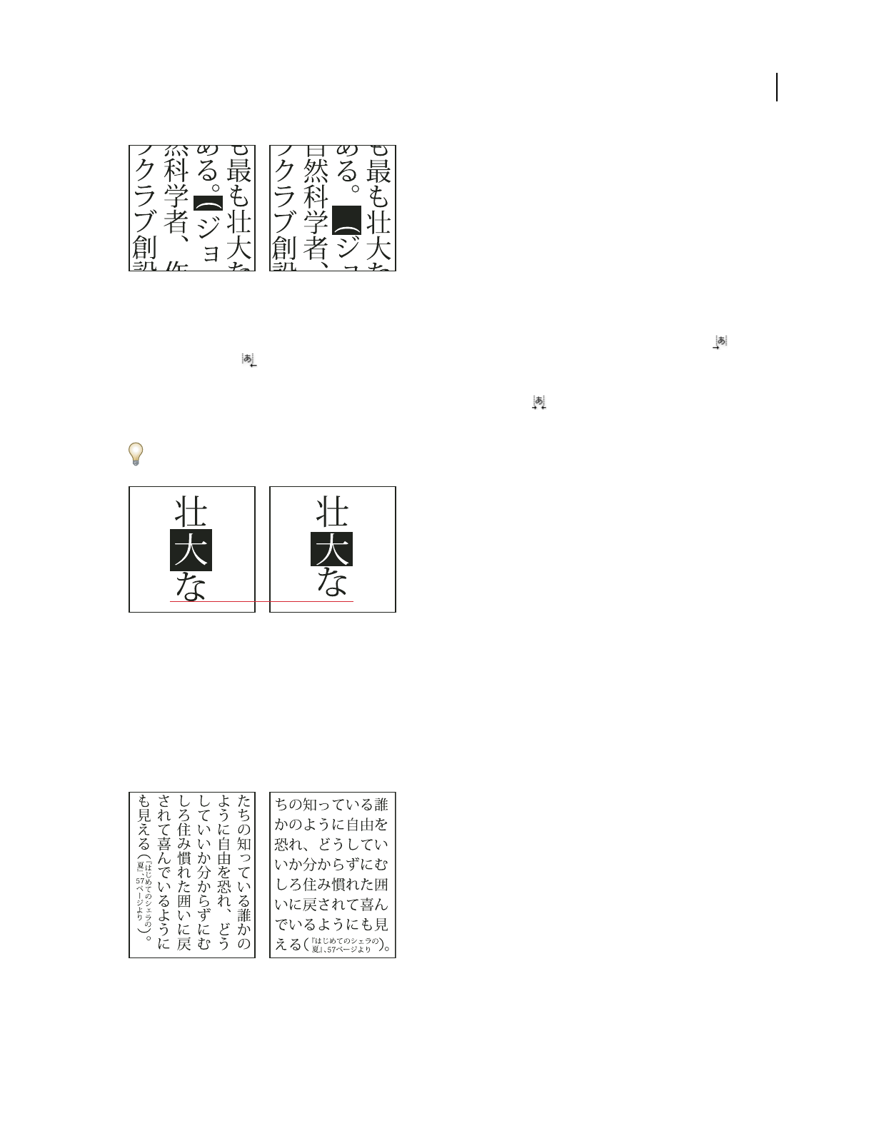
ILLUSTRATOR CS3
User Guide
336
Parenthesis without aki (left) compared to parenthesis with aki (right)
❖Select the characters you want to adjust with the Type tool, and do any of the following in the Character panel:
•To add aki before or after a character, choose the amount of aki you want to add from the Insert Aki (Left) or
Insert Aki (Right) menu in the Character panel. For example, if you specify 2bu, half a full-width space is
added, and if you specify 4bu, a quarter of a full-width space is added.
•To compress the aki between characters, specify a percentage for Tsume . The higher the percentage, the
narrower the aki between characters.
If you don’t see the Insert Aki or Tsume options, select Show Asian Options in the Type preferences.
Character without tsume (left) compared to character with tsume (right)
See also
“Display Asian type options” on page 333
Use warichu
The Warichu option in the Character panel decreases the type size of selected text to a percentage of the original and
stacks the type—horizontally or vertically, according to the orientation—on multiple lines.
Vertical and horizontal text with warichu
1 Select text and choose Warichu from the Character panel menu. (Select it again to turn it off.)
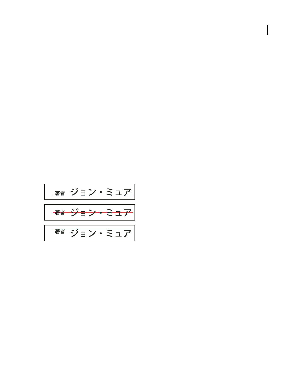
ILLUSTRATOR CS3
User Guide
337
2 Select any of the following warichu settings from the Character panel menu:
Lines Specifies how many lines of text will appear as warichu characters.
Line Gap Determines the distance between the lines of warichu characters.
Scale Sets the size of warichu characters as a percentage of the size of the parent text.
Alignment Specifies the alignment of warichu characters. For example, in a vertical frame grid, selecting Top will
align the beginning of the warichu characters at the top of the frame. The alignment proxy shows how the warichu
text appears relative to the parent text.
Line Breaking Options Specifies the minimum number of characters required before and after the line breaks to start
a new line.
See also
“Display Asian type options” on page 333
Use mojisoroe to align Asian characters
Mojisoroe is the alignment of characters in Asian type. When a line of text contains different sizes of characters, you
can specify how to align text to the largest characters in the line: to the top, center, or bottom of the embox (right,
center, and left for vertical frames), to the roman baseline, or to the top or bottom of the ICF box (right or left for
vertical frames). The ICF is the space where characters can be placed.
Character alignment options
A. Small characters aligned to the bottom B. Small characters aligned to the middle C. Small characters aligned to the top
❖In the Character panel menu, choose an option from the Character Alignment submenu:
Roman Baseline Aligns the small characters in a line to the large character.
Embox Top/Right, Embox Center, or Embox Bottom/Left Aligns the small characters in a line to the specified
position of the large character’s embox. In vertical text frames, Embox Top/Right aligns the text to the right of the
embox, and Embox Bottom/Left aligns the text to the left of the embox.
ICF Top/Right and ICF Bottom/Left Aligns the small characters in a line to the ICF specified by the large characters.
In vertical text frames, ICF Top/Right aligns the text to the right of the ICF, and ICF Bottom/Left aligns the text to
the left of the ICF.
Use mojikumi
Mojikumi specifies Japanese text composition for spacing of Japanese characters, roman characters, punctuation,
special characters, line start, line end, and numbers. You can also specify paragraph indents.
A
B
C

ILLUSTRATOR CS3
User Guide
338
The existing character spacing rules in Illustrator follow the Japanese Industrial Standards (JIS) specification,
JISx4051-1995. You can select from the predefined mojikumi sets provided by Illustrator.
Furthermore, you can create specific mojikumi sets. In a new mojikumi set, you can edit the settings for spacing that
you use a lot, such as the spacing between a period and subsequent opening parenthesis. For example, you might
create an interview format in which you want to have an em dash before a question, and answers enclosed in paren-
theses.
See also
“Display Asian type options” on page 333
Select a mojikumi set for a paragraph
1
In the Character panel, set Kerning to zero.
2 In the Paragraph panel, choose an option from the Mojikumi Set pop-up menu:
None Turns off the use of mojikumi.
YakumonoHankaku Uses half-width spacing for punctuation.
GyoumatsuYakumonoHankaku Uses full-width spacing for most characters except the last character in the line.
YakumonoHankaku (left) and GyoumatsuYakumonoHankaku (right)
GyoumatsuYakumonoZenkaku Uses full-width spacing for most characters and the last character in the line.
YakumonoZenkaku Uses full-width spacing for punctuation.
GyoumatsuYakumonoZenkaku (left) and YakumonoZenkaku (right)
Create a new mojikumi set
1
Do one of the following:
•Choose Type > Mojikumi Settings.
•Choose Mojikumi Settings from the Mojikumi Set pop-up menu in the Paragraph panel.
2 Click New in the Mojikumi Settings dialog box.
3 Enter a name for the new mojikumi set, specify the existing set on which the new set will be based, and click OK.

ILLUSTRATOR CS3
User Guide
339
4 Choose Use Percentage (%) or Bu from the Units pop-up menu.
5 Specify Desired, Minimum, and Maximum values for each option. The Minimum value is used to compress lines
for kinsoku (specify a value less than the Desired value). The Maximum value is used to spread lines for fully justified
text (specify a value greater than the Desired value).
Depending on the character type, you can specify the same values for Desired, Minimum, and Maximum if you don’t
want to change the spacing.
6 Click Save or OK to save the settings. Click Cancel if you don’t want to save the settings.
When you compose Japanese text with a lot of half-width spaces or roman parentheses, problems relating to text
composition increase. We recommend that you avoid using roman parentheses, and use full-width parentheses for
Japanese composition. Only use roman parentheses when using relatively long English sentences in Japanese text, or
when a more serious problem results if you don’t use roman parentheses.
Work with mojikumi sets
❖In the Mojikumi Settings dialog box, do any of the following:
•To export a set, click Export, select a location for the file, type a filename, and click Save. Illustrator saves the file
in MJK format.
•To import a set, click Import, select an MJK file, and click Open.
•To delete a set, choose it from the Mojikumi pop-up menu and then click Delete. All the text to which the
mojikumi set was applied will return to the default settings.
Note: You cannot delete predefined mojikumi sets.
Use kinsoku
Kinsoku specifies line breaks for Japanese text. Characters that cannot be placed at the beginning or end of a line are
known as kinsoku characters. Illustrator has hard kinsoku sets and soft kinsoku sets and Photoshop has weak and
maximum sets. Soft or weak kinsoku sets omit long vowel symbols and small hiragana characters. You can use these
existing sets, or add or delete kinsoku characters to create new sets.
You can also define hanging characters for hanging Japanese punctuation and define characters that cannot be split
when a line is exceeded.
You can specify whether to push in or push out text so that kinsoku characters are not placed inappropriately.
See also
“Display Asian type options” on page 333
Select kinsoku settings for a paragraph
❖In the Paragraph panel, choose an option from the Kinsoku Set pop-up menu:
None Turns off the use of kinsoku shori.
Soft or Hard Prevents selected characters from beginning or ending a line.
Create a new kinsoku set
1
Do one of the following:
•Choose Type > Kinsoku Shori Settings.

ILLUSTRATOR CS3
User Guide
340
•Choose Kinsoku Settings from the Kinsoku Set pop-up menu in the Paragraph panel.
2 In the Kinsoku Shori Settings dialog box, click New Set.
3 Enter a name for the kinsoku set, specify the existing set on which the new set will be based, and click OK.
4 To add a character to a field, select the field, and do one of the following:
•Enter a character in the Input box, and click Add.
•Specify the code system (Shift JIS, JIS, Kuten, or Unicode), enter the code, and click Add.
5 To delete a character in a field, select the character and click Delete. Alternatively, press Backspace (Windows) or
Delete (Mac OS).
6 To check the character code currently selected, select Shift JIS, JIS, Kuten, or Unicode, and display the code
system.
7 Click Save or OK to save the settings. Click Cancel if you don’t want to save the settings.
Use kinsoku sets
❖In the Kinsoku Shori Settings dialog box, do any of the following:
•To export a kinsoku set, click Export. Select a location for the file, enter a filename, and click Save.
Illustrator saves the file in KSK format.
•To import a kinsoku set, click Import. Select a KSK file, and click Open.
•To delete a kinsoku set, choose the kinsoku set you want to delete from the pop-up menu. Then click Delete Set.
Note: You cannot delete predefined kinsoku settings.
Specify a kinsoku line-breaking option
Kinsoku shori or mojikumi must be selected to use the following line-breaking options.
❖From the Paragraph panel menu, choose Kinsoku Shori Type and then choose one of the following methods:
Push In First
Moves characters up to the previous line to prevent prohibited characters from ending or beginning a line.
Push Out First
Moves characters down to the next line to prevent prohibited characters from ending or beginning a line.
Push Out Only Always moves characters down to the next line to prevent prohibited characters from ending or
beginning a line. A push-in is not attempted.
A check mark indicates which method is selected.
Set bunri-kinshi on and off
When Bunri-kinshi is selected, the characters specified in the Bunri-Kinshi section of the Kinsoku Shori Settings
dialog box will not be split.
❖In the Paragraph panel, choose Bunri-kinshi from the panel menu.
Note: This option is only available when kinsoku shori is on.
Specify a burasagari option
Burasagari lets single-byte periods, double-byte periods, single-byte commas, and double-byte commas fall outside
the paragraph bounding box.
1 In the Paragraph panel, choose Burasagari from the panel menu.
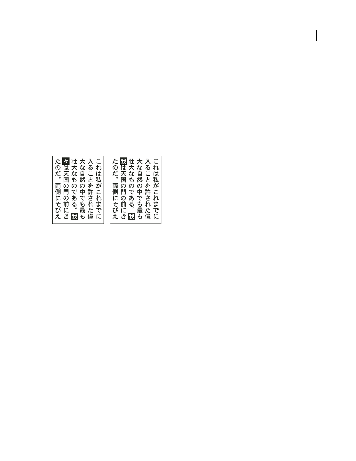
ILLUSTRATOR CS3
User Guide
341
2 Choose an option from the submenu:
None Turns off hanging punctuation.
Regular Turns on hanging punctuation without forcing ragged lines to the bounding box edge.
Force Forces punctuation outside the bounding box by spreading lines that end within the bounding box and end
with one of the hanging characters.
Use kurikaeshi moji shori
You can control how repeated characters in Japanese text are handled using the Kurikaeshi Moji Shori option in the
Paragraph panel. By
default, a repeat character mark is substituted for the second character when two identical
characters follow one after the other in a body of text. When this option is selected, both characters are displayed if
they are separated by a line break.
Text without Kurikaeshi Moji Shori option (left) compared to text with Kurikaeshi Moji Shori option (right)
1 Using any type tool, select a paragraph of text to which you want to apply repeated character processing. If no text
exists, the setting applies to new text typed.
2 In the Paragraph panel, select Kurikaeshi Moji Shori from the panel menu.
See also
“Display Asian type options” on page 333
Creating composite fonts
Create a composite font
You can mix characters from Japanese and roman fonts and use them as one composite font. Composite fonts are
displayed at the beginning of the font list.
Important: Composite fonts must be based on Japanese fonts. For example, you cannot create fonts that include Chinese
or Korean fonts, nor can you use Chinese or Korean-based composite fonts copied from another application.
1 Choose Type > Composite Fonts. If you don’t see this command, select Show Asian Options in the Type prefer-
ences.
2 Click New, enter the name for the composite font, and click OK.
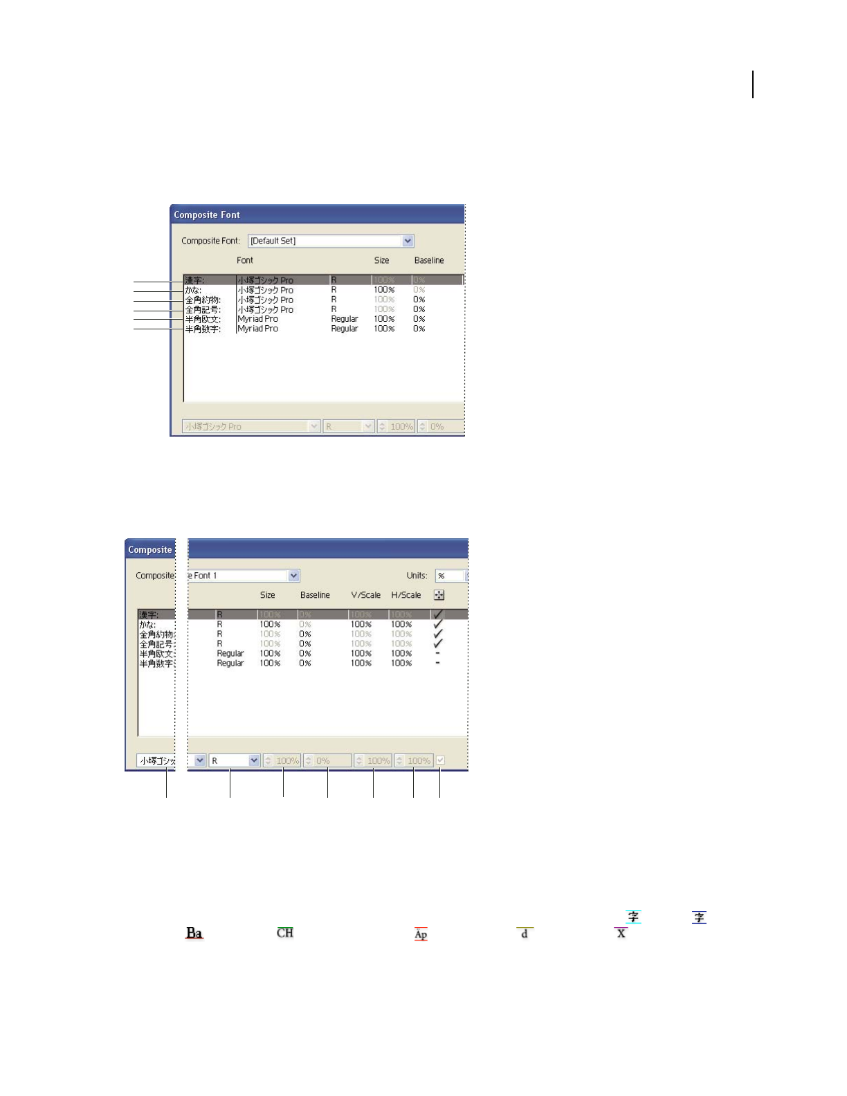
ILLUSTRATOR CS3
User Guide
342
3 If you’ve previously saved composite fonts, you can also chose a composite font on which to base the new
composite font.
4 Select a category of characters.
Categories of characters
A. Kanji B. Kana C. Punctuation D. Symbols E. Roman F. Numerals
5 Choose an option from the Units pop-up menu to specify the unit used for font attributes: % or Q.
6 Set font attributes for the selected category of characters. Some attributes are not available for certain categories.
Font attributes
A. Font Family B. Font Style C. Size D. Baseline E. Vertical Scale F. Horizontal Scale G. Scale at Center
7 To view a sample of the composite font, click Show Sample.
You can change the sample in the following ways:
•Click the buttons on the right side of the sample to show or hide lines indicating the ICF Box , Embox ,
Baseline , Cap Height , Max Ascent/Descent , Max Ascender , and x-height .
•Choose a magnification level from the Zoom pop-up menu.
A
B
C
D
E
F
ABCDEFG

ILLUSTRATOR CS3
User Guide
343
8 Click Save to save the settings for the composite font, and then click OK.
See also
“Display Asian type options” on page 333
Categories of characters in composite fonts
Kanji The base font of the composite font. The size and baseline for other characters are set according to the sizes
and baselines specified here.
Kana The font used for hiragana and katakana characters.
Punctuation The font used for punctuation.
Symbols The font used for symbols.
Roman The font used for half-width roman characters.
Numbers The font used for half-width numbers. This is usually a roman font.
Font attributes for composite fonts
Font Family And Style The font used for the characters.
Size The size of the characters in relation to the size of kanji characters. The size may differ for different fonts, even
when the same font size is used.
Baseline The position of the baseline in relation to the baseline for kanji characters.
Vertical And Horizontal Scale The degree to which characters are scaled. You can scale kana characters, half-width
katakana characters, gaiji characters, half-width roman characters, and numbers.
Scale At Center Scaling for kana characters. When this option is selected, characters are scaled from the center.
When this option is deselected, characters are scaled from the roman baseline.
To specify the same transformation scale for all characters, specify a value for Size and fix the value for scale at 100%.
To have a different character transformation scale for horizontal and vertical, fix Size at 100%, and set Scale.
Customize characters in a composite font
1 Choose Type > Composite Fonts. If you don’t see this command, select Show Asian Options in the Type prefer-
ences.
2 Click Custom in the Composite Font dialog box.
3 Do one of the following:
•If you’ve previously saved custom character sets, select the set you want to edit.
•To create a new custom set, click New, enter a name for the character set, and click OK. If there are existing custom
sets, you can also choose a set on which to base the new set.
4 Do any of the following:
•To add a character directly, choose Direct Entry from the Character pop-up menu, enter the characters in the text
box, and click Add.
•To add a character using a code, choose an encoding type from the Character pop-up menu, enter the code and
click Add.
Note: You cannot add 32-bit characters to a custom set.

ILLUSTRATOR CS3
User Guide
344
•To delete a character, select it in the list box, and click Delete.
5 When you’ve finished customizing the character set, click Save, and then click OK.
Note: When there are several custom characters in one composite font, the bottom set takes precedence over all the above
sets.
Delete a composite font
1 Choose Type > Composite Fonts. If you don’t see this command, select Show Asian Options in the Type prefer-
ences.
2 Select the composite font from the Composite Font dialog box.
3 Click Delete Font, and then click Yes.
Export a composite font
Composite fonts exported from Illustrator can be imported into the Japanese version of Adobe InDesign 2 or later.
1 Choose Type > Composite Fonts. If you don’t see this command, select Show Asian Options in the Type prefer-
ences.
2 Click Export in the Composite Font dialog box.
3 Select a location for the file, enter a filename, and click Save.
Updating text from Illustrator 10
Updating type created in Illustrator 10
Type objects created in Illustrator 10 and earlier are uneditable until you update them for use in later versions. After
you update you have access to all the text features in Illustrator CS3, such as paragraph and character styles, optical
kerning, and full OpenType® font support.
You don’t have to update the text if you don’t need to edit it. Text that has not been updated is called legacy text. You
can view, move, and print legacy text, but you can’t edit it. Legacy text has an x through its bounding box when
selected.
After updating legacy text, you may notice some minor reflow changes. You can easily readjust the text on your own,
or you can use a copy of the original text for reference. By default, Illustrator appends the word “[Converted]” to the
filename whether or not you update the text in a file, effectively making a copy of your document to preserve the
integrity of your original file. You can then choose to update the original later or, if you already updated it, go back
to the original version.
Note: If you don’t want Illustrator to append the filename, choose Edit > Preferences > General (Windows) or
Illustrator > Preferences > General (Mac OS), and deselect Append [Converted] Upon Opening Legacy Files.
Update all legacy text in a document
❖Do one of the following:
•When opening the document, click Update when prompted by Illustrator.
•After opening the document, choose Type > Legacy Text > Update All Legacy Text.

ILLUSTRATOR CS3
User Guide
345
Update selected legacy text
❖Do one of the following:
•To update the text without creating a copy, select the type object and choose Type > Legacy Text > Update Selected
Legacy Text. Alternatively, select a type tool and click in the text that you want to update, or double-click the text
that you want to update using the Selection tool. Then click Update.
•To preserve the legacy text on a layer below the updated text, select a type tool and click in the text that you want
to update. Alternatively, double-click the text that you want to update using the Selection tool. Then click Copy
Text Layer. This allows you to compare the layout of the legacy text to the updated text.
If you create a copy of legacy text when you update it, you can use the following commands:
•Type > Legacy Text > Show Copies or Hide Copies to show or hide the copied text objects.
•Type > Legacy Text > Select Copies to select copied text objects.
•Type > Legacy Text > Delete Copies to delete copied text objects.
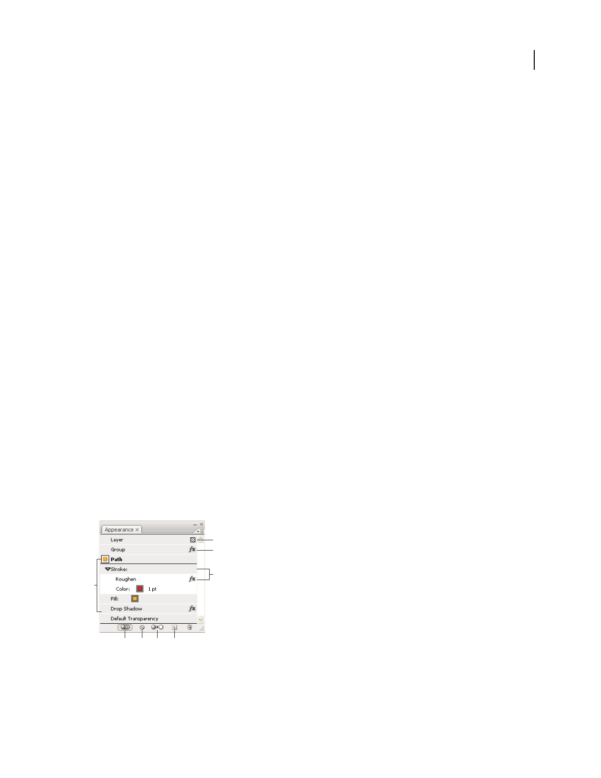
346
Chapter 11: Creating special effects
You can change the appearance of any object, group, or layer in Adobe Illustrator by using effects, filters, and the
Appearance and Graphic Styles panels. In addition, you can divide an object into its essential parts in order to modify
elements of the object independently.
Appearance attributes
About appearance attributes
Appearance attributes are properties that affect the look of an object without altering its underlying structure.
Appearance attributes include fills, strokes, transparency, and effects. If you apply an appearance attribute to an
object and later edit or remove that attribute, it
does not change the underlying object or any other attributes applied
to the object.
You can set appearance attributes at any level of the layer hierarchy. For example, if you apply a drop shadow effect
to a layer, all objects in the layer take on the drop shadow. However, if you move an object out of the layer, that object
will no longer have a drop-shadow because the effect belongs to the layer, not to each object within the layer.
The Appearance panel is the gateway to working with appearance attributes. Because you can apply appearance
attributes to layers, groups, and objects—and often to fills and strokes too—the hierarchy of attributes in your
artwork can become very complex. For example, if you apply one effect to an entire layer and another effect to an
object in the layer, it may be difficult to determine which effect is causing the artwork to change. The Appearance
panel shows you the fills, strokes, graphic styles, and effects that have been applied to an object, group, or layer.
Appearance panel overview
You use the Appearance panel (Window > Appearance) to view and adjust the appearance attributes for an object,
group, or layer. Fills and strokes are listed in stacking order; top to bottom in the panel correlates to front to back in
the artwork. Effects are listed from top to bottom in the order in which they are applied to the artwork.
For a video on using the Appearance panel and effects, see www.adobe.com/go/vid0051.
Appearance panel listing attributes of a grouped object
A. Object with stroke, fill, and drop shadow effect B. Layer with transparency C. Group with effect D. Stroke with roughen effect E. New Art
(Maintains/Has Basic) Appearance button F. Clear Appearance button G. Reduce To Basic Appearance button H. Duplicate Selected Item
button
B
C
D
A
EFGH
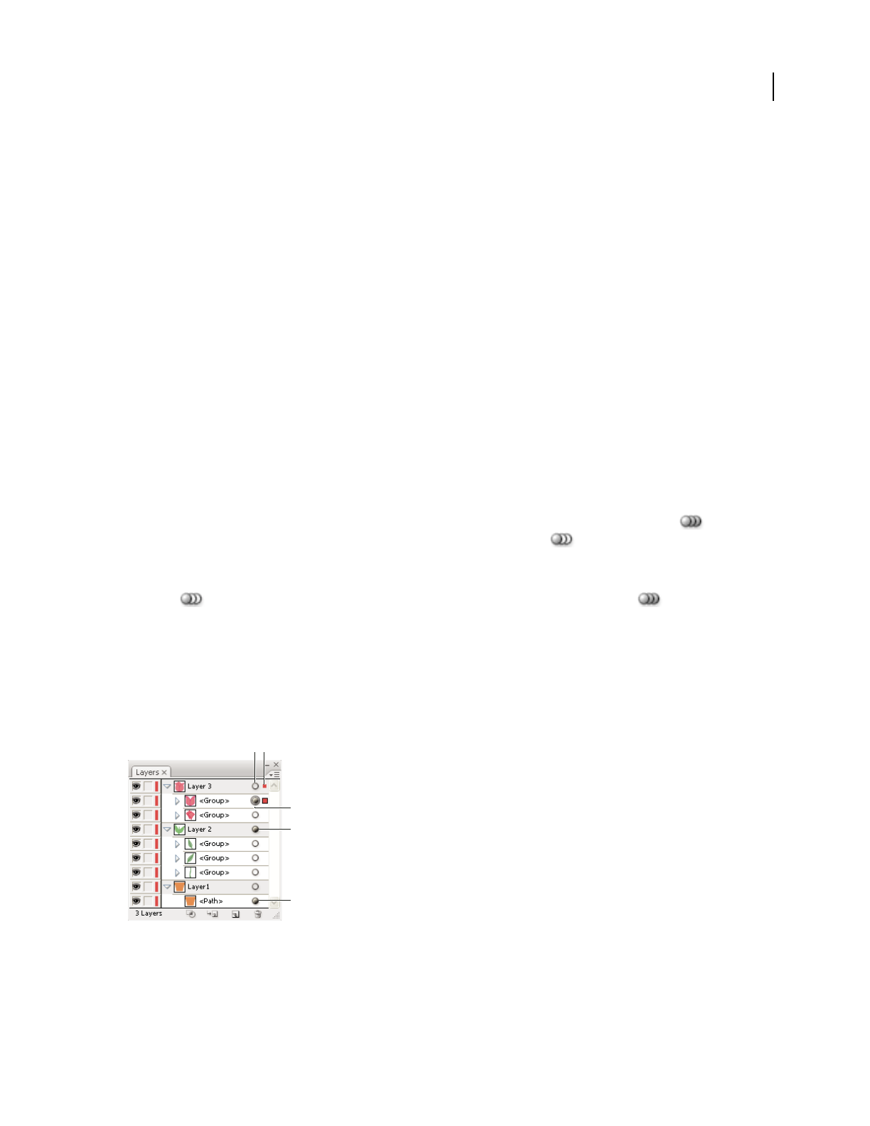
ILLUSTRATOR CS3
User Guide
347
Show or hide additional attributes in the Appearance panel
When an item in the Appearance panel contains additional attributes, a triangle appears to the left of the item’s name.
❖Click the triangle next to an item’s name.
Reveal additional items in the Appearance panel
When you select items that contain other items, such as a layer or group, the Appearance panel displays a Contents
item.
❖Double-click the Contents item.
List character attributes for a text object in the Appearance panel
When you select a text object, the panel displays a Characters item.
❖ Double-click the Characters item.
Show or hide thumbnails in the Appearance panel
❖Choose Show Thumbnail or Hide Thumbnail from the Appearance panel menu.
Specify how appearance attributes are applied to new objects
You can specify whether you want new objects to inherit appearance attributes or have only basic attributes.
•To apply only a single fill and stroke to new objects, click the New Art Maintains Appearance button in the
Appearance panel to change it to the New Art Has Basic Appearance button , or choose New Art Has Basic
Appearance from the panel menu.
•To apply all of the current appearance attributes to new objects, click the New Art Has Basic Appearance
button in the Appearance panel to change it to New Art Maintains Appearance button , or deselect
New Art Has Basic Appearance from the panel menu.
Targeting items for appearance attributes
Before you can set an appearance attribute or apply a style or an effect to a layer, group, or object, you must target the
item in the Layers panel. Selecting an object or group using any selection method also targets the object or group in
the Layers panel, but layers can only be targeted using the panel.
Shaded target icons in the Layers panel indicate which items contain appearance attributes.
A. Targeting and appearance column B. Selection column C. Group with appearance attributes D. Layer with appearance attributes
E. Object with appearance attributes
A
C
D
E
B
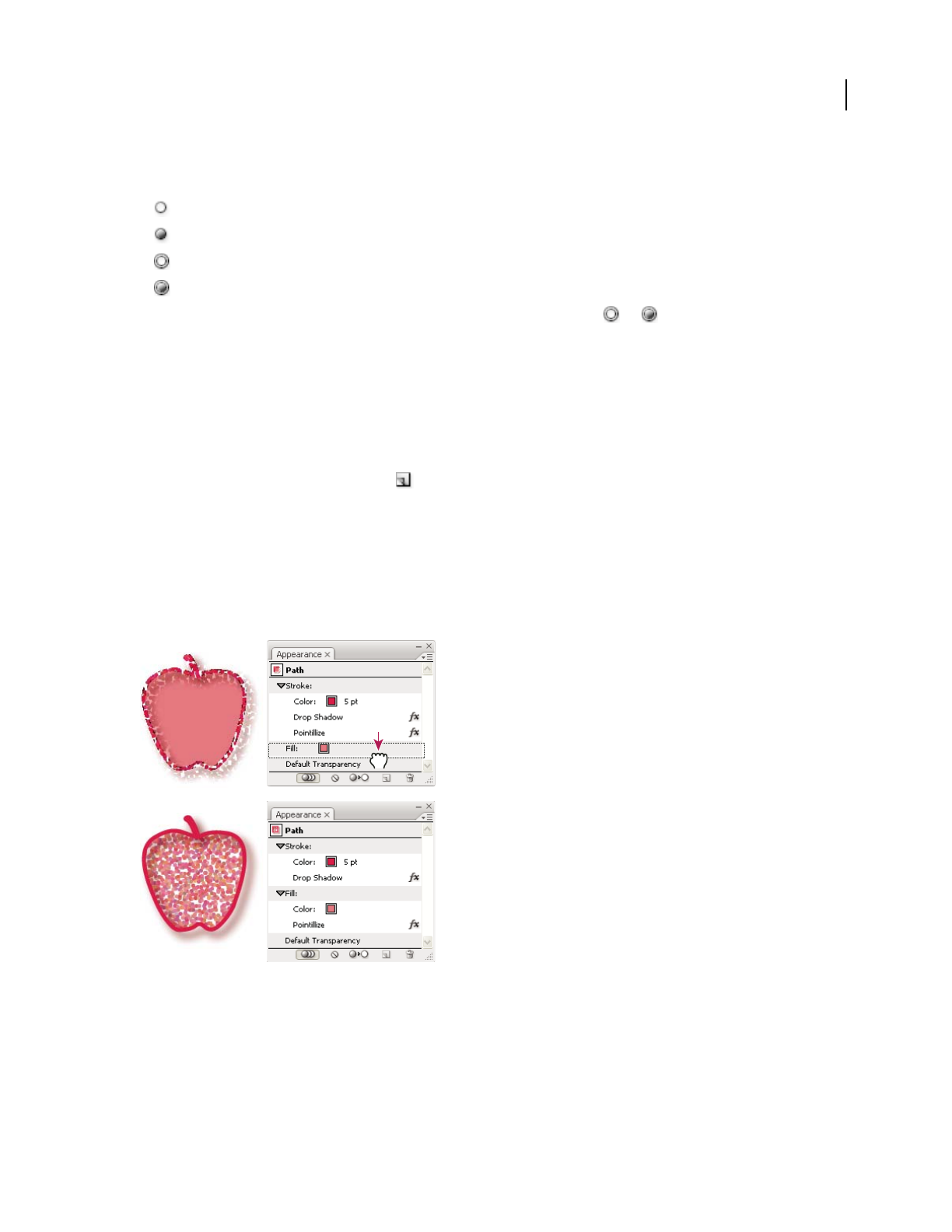
ILLUSTRATOR CS3
User Guide
348
The target icon indicates whether an item in the layer hierarchy has any appearance attributes and whether it is
targeted:
• Indicates the item is not targeted and has no appearance attributes beyond a single fill and a single stroke.
• Indicates the item is not targeted but has appearance attributes.
• Indicates the item is targeted but has no appearance attributes beyond a single fill and a single stroke.
• Indicates the item is targeted and has appearance attributes.
To target an item in the Layers panel, click the item’s target icon. A double ring or indicates that the item is
targeted. Shift-click to target additional items.
Note: When an object or group is selected by any method, the item is also targeted in the Layers panel. In contrast, a
layer can be targeted only by clicking its target icon in the Layers panel.
Duplicate an appearance attribute
❖Select an attribute in the Appearance panel, and do one of the following:
•Click the Duplicate Selected Item button in the panel, or choose Duplicate Item from the panel menu.
•Drag the appearance attribute onto the Duplicate Selected Item button in the panel.
Change the stacking order of appearance attributes
❖Drag an appearance attribute up or down in the Appearance panel. (If necessary, click the toggle triangle next to
an item to display its contents.) When the outline of the appearance attribute you are dragging appears in the desired
position, release the mouse button.
Pointillize effect applied to stroke (top) compared to same effect moved to fill (bottom)
Remove appearance attributes
1 Select the object or group (or target a layer in the Layers panel).

ILLUSTRATOR CS3
User Guide
349
2 Do one of the following:
•To remove a specific attribute, select the attribute in the Appearance panel, and click the Delete icon . Alterna-
tively, select Remove Item from the panel menu, or drag the attribute to the Delete icon.
•To remove all appearance attributes except a single fill and stroke, click the Reduce To Basic Appearance
button in the Appearance panel or choose Reduce To Basic Appearance from the panel menu. Alternatively,
drag the target icon for an item in the Layers panel onto the Delete icon in the Layers panel.
•To remove all appearance attributes, including any fill or stroke, click the Clear Appearance button in the
Appearance panel or choose Clear Appearance from the panel menu.
Copy appearance attributes between objects
You can copy or move appearance attributes by dragging or by using the Eyedropper tool.
See also
“Targeting items for appearance attributes” on page 347
“Layers panel overview” on page 211
“Appearance panel overview” on page 346
Copy appearance attributes by dragging
1
Select the object or group (or target the layer in the Layers panel) whose appearance you want to copy.
2 Do one of the following:
•Drag the thumbnail at the top of the Appearance panel onto an object in the document window. If a thumbnail
isn’t showing, choose Show Thumbnail from the panel menu.
•Alt-drag (Windows) or Option-drag (Mac OS) the target icon in the Layers panel onto the item to which you want
to copy appearance attributes.
•To move appearance attributes instead of copying them, drag the target icon in the Layers panel from any item
that has the desired attributes onto the item to which you want to apply it.
Copy appearance attributes using the Eyedropper tool
You can use the Eyedropper tool to copy appearance attributes from one object to another, including character,
paragraph, fill, and stroke attributes between type objects. By default, the Eyedropper tool affects all attributes of a
selection. To customize the attributes affected by this tool, use the Eyedropper dialog box.
1 Select the object, type object, or characters whose attributes you want to change.
2 Select the Eyedropper tool .
3 Move the Eyedropper tool onto the object whose attributes you want to sample. (When you’re correctly positioned
over type, the pointer displays a small T.)
4 Do one of the following:
•Click the Eyedropper tool to sample all appearance attributes and apply them to the selected object.
•Shift-click to sample only the color from a portion of a gradient, pattern, mesh object, or placed image and apply
the color to the selected fill or stroke.

ILLUSTRATOR CS3
User Guide
350
•Hold down the Shift key and then the Alt (Windows) or Option (Mac OS) key while clicking to add the
appearance attributes of an object to the selected object’s appearance attributes. Alternatively, click first, and then
hold down Shift and then Alt or Option.
Note: You can also click an unselected object to sample its attributes and Alt-click (Windows) or Option-click (Mac OS)
an unselected object to which you want to apply the attributes.
Copy attributes from the desktop using the Eyedropper tool
1
Select the object whose attributes you want to change.
2 Select the Eyedropper tool.
3 Click anywhere on the document and continue to hold down the mouse button.
4 Without releasing the mouse button, move the pointer over the object on your computer’s desktop whose
attributes you want to copy. When directly over the object, release the mouse button.
Important: The Eyedropper tool only samples the RGB color from the screen when sampling anywhere outside the
current document. The Eyedropper tool indicates it is sampling RGB color from the screen by displaying a black-colored
square to the right of the tool.
Specify which attributes you can copy with the Eyedropper tool
1
Double-click the Eyedropper tool.
2 Select the attributes you want to copy with the Eyedropper tool. You can sample appearance attributes including
transparency, and various fill and stroke properties, as well as character and paragraph properties.
3 Choose the sample size area from the Raster Sample Size menu.
4 Click OK.
Working with effects and filters
About effects and filters
Many commands for changing the look of objects are available in both the Filter and Effect menus. For example, all
of the commands in the Filter
> Artistic submenu are also listed in the Effect > Artistic submenu. However, filters
and effects have different consequences, so it’s important to understand the difference in their use.
Effects are live, which means you can apply an effect command to an object and then continue to modify the effect’s
options or remove the effect at any time using the Appearance panel. Once you apply an effect to an object, the
Appearance panel lists the effect and enables you to edit the effect, move it, duplicate it, delete it, or save it as part of
a graphic style.
Filters change the underlying object, and the changes can’t be modified or removed after the filter is applied. But one
advantage to reshaping an object with a filter command is that you have immediate access to the new or modified
anchor points created by the filter. (When you use an effect, you must expand the object before you can access the
new points.)
For a video on using the Appearance panel and effects, see www.adobe.com/go/vid0051.
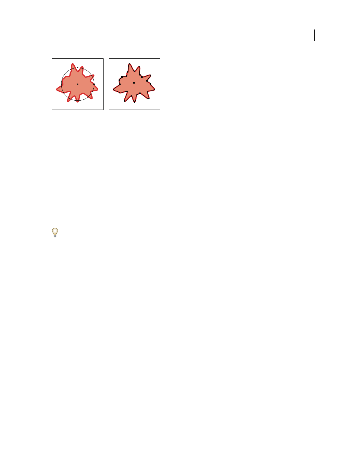
ILLUSTRATOR CS3
User Guide
351
Ellipse using Roughen effect (left) maintains original anchor points and path segments, while the Roughen filter (right) creates new anchor
points along the modified path.
See also
“Effects and filters quick reference” on page 354
“Expand objects” on page 202
Apply an effect or filter
1 Select the object or group (or target a layer in the Layers panel).
If you want to apply an effect to a specific attribute of an object, such as its fill or stroke, select the object and then
select the attribute in the Appearance panel.
2 Choose a command from the Effect or Filter menu.
3 If a dialog box appears, set options, and then click OK.
To apply the filter or effect and settings that were used last, choose Filter > Apply [Filter Name] or Effect > Apply
[Effect Name]. To apply the last used filter or effect and set its options, choose Filter > [Filter Name] or Effect >
[Effect Name].
See also
“Targeting items for appearance attributes” on page 347
Unavailable effect and filter commands
Effect and filter commands are dimmed when they aren’t available for the targeted item. For example, the command
may work on vector objects, but not on bitmap images.
Following are some guidelines to help you determine when effects and filters are available.
All of the commands in the top section of the Effect menu (3D, Convert To Shape, Distort & Transform, Path,
Pathfinder, Rasterize, Stylize, SVG Filters, and Warp) can be applied to vector objects. These same effects won’t affect
a bitmap object unless you apply the effect to a fill or stroke added to the object in the Appearance panel; the excep-
tions to this are the effects in the 3D, SVG Filters, and Warp submenus, and the Transform, Drop Shadow, Feather,
Inner Glow, and Outer Glow effects, which will affect a bitmap object. All of the commands in the bottom section of
the Effect menu (starting with Artistic) are raster effects and can be applied to either bitmap or vector objects. When
these raster effects are applied to an object, they use the document’s raster effects settings.
Important: The effects and filters in the Artistic, Brush Strokes, Distort, Sketch, Stylize, Texture, and Video submenus
aren’t available with documents in CMYK color mode. If an RGB document that uses any of these commands is
converted to CMYK, the effects remain listed in the object’s Appearance panel but don’t affect the object’s appearance.

ILLUSTRATOR CS3
User Guide
352
All of the commands in the top section of the Filter menu (Colors, Create, Distort, and Stylize) can be applied to
vector objects (with the exception of Object Mosaic), but only some commands in the Create and Colors submenus
can also be applied to bitmap objects. All of the commands in the bottom section of the Filter menu are raster filters
and can be applied to bitmap objects, but not to vector objects or 1-bit (black-and-white) bitmap objects.
About raster effects
Raster effects are effects that generate pixels, rather than vector data. Raster effects include SVG Filters, all of the
effects in the bottom section of the Effect menu, and the Drop Shadow, Inner Glow, Outer Glow, and Feather
commands in the Effect
> Stylize submenu.
Whenever you apply a raster effect, Illustrator uses the document’s raster effects settings to determine the resolution
of the resulting image. These settings have a large impact on the resulting artwork; therefore, it’s important to check
the document raster effects settings before you start working with filters and effects.
You set rasterization options for a document by choosing Effect > Document Raster Effects Settings. (See “Raster-
ization options” on page 352.)
If an effect looks good on-screen, but loses detail or appears jagged when printed, you need to increase the document
raster effects resolution.
Rasterization options
You can set the following options for all raster effects in a document or when you rasterize a vector object.
Color Model Determines the color model that is used during rasterization. You can generate an RGB or CMYK color
image (depending on the color mode of your document), a grayscale image, or a 1-bit image (which may be black
and white or black and transparent, depending on the background option selected).
Resolution Determines the number of pixels per inch (ppi) in the rasterized image. When rasterizing a vector object,
select Use Document Raster Effects Resolution to use global resolution settings.
Background Determines how transparent areas of the vector graphic are converted to pixels. Select White to fill
transparent areas with white pixels, or select Transparent to make the background transparent. If you select Trans-
parent, you create an alpha channel (for all images except 1-bit images). The alpha channel is retained if the artwork
is exported into Photoshop. (This option anti-aliases better than the Create Clipping Mask option.)
Anti-alias Applies anti-aliasing to reduce the appearance of jagged edges in the rasterized image. When setting
rasterization options for a document, deselect this option to maintain the crispness of fine lines and small text.
When rasterizing a vector object, select None to apply no anti-aliasing and maintain the hard edges of line art when
it is rasterized. Select Art Optimized to apply anti-aliasing that is best suited to artwork without type. Select Type
Optimized to apply anti-aliasing that is best suited to type.
Create Clipping Mask Creates a mask that makes the background of the rasterized image appear transparent. You do
not need to create a clipping mask if you selected Transparent for Background.
Add Around Object Adds the specified number of pixels around the rasterized image.
See also
“About raster effects” on page 352
“Rasterize a vector object” on page 366
“Image resolution guidelines for final output” on page 258

ILLUSTRATOR CS3
User Guide
353
Applying filters and effects to bitmap images
Filters and effects let you apply a special look to bitmap images as well as vector objects. For example, you can apply
an impressionistic or mosaic look, apply lighting changes, distort images, and produce many other interesting
visual
effects.
Consider the following information when applying filters or effects specifically to bitmap objects:
•Filters and effects don’t work on linked bitmap objects. If you apply a filter or effect to a linked bitmap, it is applied
to an embedded copy of the bitmap instead of to the original. To apply the filter or effect to the original, you can
embed the bitmap in the document.
•Adobe Illustrator supports plug-in filters and effects from Adobe products such as Adobe Photoshop and from
non-Adobe software developers. Once installed, most plug-in filters and effects appear in the Filter and Effect
menus and work the same way as do built-in filters and effects.
•Some filters and effects can be memory-intensive, especially when applied to a high-resolution bitmap image.
See also
“About linked and embedded artwork” on page 253
“About plug-in modules” on page 50
Improving performance for filters and effects
Some filters and effects are very memory-intensive. The following techniques can help improve performance when
applying these filters and effects:
•Select the Preview option in filter or effect dialog boxes to save time and prevent unintended results.
•Change the settings. Some commands, such as Glass, are extremely memory-intensive. Try different settings to
increase their speed.
•Make sure Illustrator has enough RAM allocated for performing tasks and for the scratch disk (the temporary disk
space used to work with bitmap images).
•If you plan to print to a grayscale printer, convert a copy of the bitmap image to grayscale before applying filters.
Note, however, that in some cases, applying a filter to a color bitmap image and then converting it to grayscale may
not have the same result as applying the same filter directly to a grayscale version of the image.
Modify or delete an effect
1 Select the object or group (or target the layer in the Layers panel) that uses the effect.
2 Do one of the following:
•To modify the effect, double-click the effect listing in the Appearance panel. In the effect’s dialog box, make the
desired alterations, and then click OK.
•To delete the effect, select the effect listing in the Appearance panel, and click the Delete button.
ILLUSTRATOR CS3
User Guide
354
Summary of effects and filters
Effects and filters quick reference
Effect/Filter Action
Effect > 3D Convert open or closed paths,
or bitmap objects, into three-
dimensional (3D) objects,
which you can rotate, light,
and shade.
See also: “Create 3D objects”
on page 244
Effect > Artistic
Filter > Artistic
Simulate a painterly appear-
ance on traditional media.
Available: RGB mode only
See also: “Artistic filters and
effects” on page 357
Effect > Blur
Filter > Blur
Retouch images and smooth
transitions by averaging the
pixels next to the hard edges
of defined lines and shaded
areas in an image.
See also: “Blur filters and
effects” on page 358
Effect > Brush Strokes
Filter > Brush Strokes
Create a painterly or fine-arts
look using different brush-
and ink- stroke effects.
See also: “Brush Strokes filters
and effects” on page 358
Effect > Convert To Shape Reshape either a vector or a
bitmap object.
See also: “Reshaping objects
with effects” on page 243
Filter > Create Transform the colors in a
bitmap object to mosaic tiles
(Object Mosaic). Define where
your artwork should be
trimmed inside the artboard
area (Crop Marks).
See also: “Create a mosaic” on
page 365, “Specify crop marks
for trimming or aligning” on
page 40

ILLUSTRATOR CS3
User Guide
355
Filter > Distort
Effect > Distort & Transform
(top section of menu)
Reshape vector objects, or
apply the effects to a fill or
stroke added to a bitmap
object with the Appearance
panel.
Available: RGB mode only
See also: “Reshaping objects
with effects” on page 243
Effect > Distort
Filter > Distort
(bottom section of menu)
Geometrically distort and
reshape an image.
See also: “Distort filters and
effects (bottom of menu)” on
page 359
Effect > Path Offset an object’s path relative
to its original location, turn
type into a set of compound
paths that you can edit and
manipulate as you would any
other graphic object, and
change the stroke of a
selected object to a filled
object that’s the same width
as the original stroke. You can
also apply these commands to
a fill or stroke added to a
bitmap object with the
Appearance panel.
See also: “Offset duplicate
objects” on page 219,
“Convert type to outlines” on
page 312, “Convert strokes to
compound paths” on
page 156
Effect > Pathfinder Combine groups, layers, or
sublayers into single editable
objects.
See also: “Apply Pathfinder
effects” on page 230
Effect > Pixelate
Filter > Pixelate
Sharply define a selection by
clumping pixels of similar
color values.
See also: “Pixelate filters and
effects” on page 359
Effect > Rasterize Convert a vector object to a
bitmap object.
See also: “Rasterize a vector
object” on page 366
Effect/Filter Action
ILLUSTRATOR CS3
User Guide
356
Effect > Sharpen
Filter > Sharpen
Focus blurry images by
increasing the contrast of
adjacent pixels.
See also: “Sharpen filter and
effect” on page 360
Effect > Sketch
Filter > Sketch
Add texture to images, often
for a three-dimensional effect.
The filters are also useful for
creating a fine-arts or hand-
drawn look.
Available: RGB mode only
See also: “Sketch filters and
effects” on page 360
Effect > Stylize
Filter > Stylize
(top section of menu)
Add arrowheads, drop
shadows, round corners,
feathered-edged, glowing,
and scribble-styled appear-
ances to objects.
Available: RGB mode only
See also: “Create a drop
shadow” on page 362, “Apply
an inner or outer glow” on
page 363, “Add arrowheads to
lines” on page 156, “Feather
the edges of an object” on
page 363, “Create a sketch
using the Scribble effect” on
page 364, “Round the corners
of objects” on page 244
Effect > Stylize
Filter > Stylize
(bottom section of menu)
The Glowing Edges command
produces a painted or impres-
sionistic effect on a selection
by displacing pixels and by
finding and heightening
contrast in an image.
See also: “Stylize filter and
effect (bottom of menu)” on
page 361
Effect > SVG Filters Add XML-based graphic prop-
erties such as drop shadows to
your artwork.
See also: “Apply SVG effects”
on page 376
Effect/Filter Action
ILLUSTRATOR CS3
User Guide
357
Artistic filters and effects
Artistic effects are available only for documents in RGB color mode. They are raster-based and use the document’s
raster effects settings whenever you apply the effect to a vector object.
Colored Pencil Draws an image using colored pencils on a solid background. Important edges are retained and given
a rough crosshatch appearance; the solid background color shows through the smoother areas.
Cutout Portrays an image as though it were made from roughly cut-out pieces of colored paper. High-contrast
images appear as if in silhouette; colored images are built up as if from several layers of colored paper.
Dry Brush Paints the edges of the image using a dry-brush technique (between oil and watercolor). The filter
simplifies an image by reducing its range of colors.
Film Grain Applies an even pattern to the shadow tones and midtones of an image. A smoother, more saturated
pattern is added to the image’s lighter areas. This filter is useful for eliminating banding in blends and visually
unifying elements from various sources.
Fresco Paints an image in a coarse manner using short, rounded strokes as if hastily applied.
Neon Glow Adds various types of glows to the objects in an image. This filter is useful for colorizing an image while
softening its look. To select a glow color, click the glow box and select a color from the color picker.
Paint Daubs Lets you choose from various brush sizes (from 1 to 50) and types for a painterly effect. Brush types
include simple, light rough, light dark, wide sharp, wide blurry, and sparkle.
Palette Knife Reduces detail in an image to give the effect of a thinly painted canvas that reveals the texture under-
neath.
Plastic Wrap Coats the image as if in shiny plastic, accentuating the surface detail.
Poster Edges Reduces the number of colors in an image according to the Posterization value you set, then finds the
edges of the image and draws black lines on them. Broader areas of the image have simple shading, while fine, dark
detail is distributed throughout the image.
Effect > Texture
Filter > Texture
Give an image the appearance
of depth or substance, or add
an organic look.
Available: RGB mode only
See also: “Texture filters and
effects” on page 361
Effect > Video
Filter > Video
Optimize images captured
from video or artwork
intended for television.
Available: RGB mode only
See also: “Video filters and
effects” on page 362
Effect > Warp Distort or deform objects,
including paths, text, meshes,
blends, and raster images.
See also: “Reshaping objects
with effects” on page 243
Effect/Filter Action

ILLUSTRATOR CS3
User Guide
358
Rough Pastels Makes an image appear as if stroked with colored pastel chalk on a textured background. In areas of
bright color, the chalk appears thick with little texture; in darker areas, the chalk appears scraped off to reveal the
texture.
Smudge Stick Softens an image using short diagonal strokes to smudge or smear the darker areas of the images.
Lighter areas become brighter and lose detail.
Sponge Creates images with highly textured areas of contrasting color as if painted with a sponge.
Underpainting Paints the image on a textured background, and then paints the final image over it.
Watercolor Paints the image in a watercolor style, simplifying details and using a medium brush loaded with water
and color. Where significant tonal changes occur at edges, the filter saturates the color.
See also
“Effects and filters quick reference” on page 354
“Use texture and glass surface controls” on page 362
Blur filters and effects
The commands in the Blur submenu in the Effect menu are raster-based and use the document’s raster effects
settings whenever you apply the effect to a vector object.
Gaussian Blur Quickly blurs a selection by an adjustable amount. This filter removes high-frequency detail and can
produce a hazy effect.
Radial Blur Simulates the soft blur created by a zooming or rotating camera. Choose Spin to blur along concentric
circular lines, and then specify a degree of rotation; Zoom to blur along radial lines, as if zooming in or out of the
image, and specify an amount from 1 to 100. Blur quality ranges from Draft for the fastest but grainy results to Good
and Best for smoother results, which are indistinguishable except on a large selection. Specify the origin of the blur
by dragging the pattern in the Blur Center box.
See also
“Effects and filters quick reference” on page 354
Brush Strokes filters and effects
The Brush Strokes effects are raster-based and use the document’s raster effects settings whenever you apply the
effect to a vector object.
Accented Edges Accentuates the edges of an image. When the Edge Brightness control is set to a high value, the
accents resemble white chalk; when set to a low value, the accents resemble black ink.
Angled Strokes Repaints an image using diagonal strokes. The lighter areas of the image are painted in strokes going
in one direction, while the darker areas are painted in strokes going the opposite direction.
Crosshatch Preserves the details and features of the original image while adding texture and roughening the edges
of the colored areas in the image with simulated pencil hatching. The Strength option controls the number of
hatching passes (from 1 to 3).
Dark Strokes Paints dark areas of an image closer to black with short strokes, and paints lighter areas of the image
with long, white strokes.
Ink Outlines Redraws an image with fine narrow lines over the original details, in pen-and-ink style.

ILLUSTRATOR CS3
User Guide
359
Spatter Replicates the effect of a spatter airbrush. Increasing the values of the options simplifies the overall effect.
Sprayed Strokes Repaints an image using its dominant colors with angled, sprayed strokes of color.
Sumi-e Paints an image in Japanese style as if with a wet brush full of black ink on rice paper. The effect is soft, blurry
edges with rich blacks.
See also
“Effects and filters quick reference” on page 354
Distort filters and effects (bottom of menu)
The Distort commands can be very memory-intensive. They are raster-based and use the document’s raster effects
settings whenever you apply the effect to a vector object. Note that these filters and effects are available only for
documents in RGB color mode.
Diffuse Glow Renders an image as if it were being viewed through a soft diffusion filter. The filter adds see-through
white noise to an image, with the glow fading from the center of a selection.
Glass Makes an image appear as if it were being viewed through different types of glass. You can choose a preset glass
effect or create your own glass surface using a Photoshop file. You can adjust scaling, distortion, and smoothness
settings, as well as texturizing options.
Ocean Ripple Adds randomly spaced ripples to the artwork, making the artwork look as if it were under water.
See also
“Use texture and glass surface controls” on page 362
“Effects and filters quick reference” on page 354
Pixelate filters and effects
The Pixelate effects are raster-based and use the document’s raster effects settings whenever you apply the effect to
a vector object.
Color Halftone Simulates the effect of using an enlarged halftone screen on each channel of the image. For each
channel, the filter divides the image into rectangles and replaces each rectangle with a circle. The circle size is propor-
tional to the brightness of the rectangle.
To use the filter or effect, enter a value in pixels for the maximum radius of a halftone dot (from 4 to 127), and enter
a screen-angle value (the angle of the dot relative to the true horizontal) for one or more channels. For Grayscale
images, use only channel 1; for RGB images, use channels 1, 2, and 3, which correspond to the red, green, and blue
channels; for CMYK images, use all four channels, which correspond to the cyan, magenta, yellow, and black
channels.
Crystallize Clumps colors into polygon shapes.
Mezzotint Converts an image to a random pattern of black-and-white areas, or of fully saturated colors in a color
image. To use the filter, choose a dot pattern from the Type pop-up menu in the Mezzotint dialog box.
Pointillize Breaks up the color in an image into randomly placed dots, as in a pointillist painting, and uses the
background color as a canvas area between the dots.

ILLUSTRATOR CS3
User Guide
360
See also
“Effects and filters quick reference” on page 354
Sharpen filter and effect
The Unsharp Mask command in the Sharpen submenu in the Effect menu focuses blurry images by increasing the
contrast of adjacent pixels. This effect is raster-based and uses the document’s raster effects settings whenever you
apply the effect to a vector graphic.
Unsharp Mask Finds the areas in the image where significant color changes occur and sharpens them. Use the
Unsharp Mask filter to adjust the contrast of edge detail and produce a lighter and darker line on each side of the
edge. This emphasizes the edge and creates the illusion of a sharper image.
See also
“Effects and filters quick reference” on page 354
Sketch filters and effects
Many of the Sketch filters use black and white colors to redraw the image. The effects are raster-based and use the
document’s raster effects settings whenever you apply the effect to a vector graphic. These filters and effects are
available only for documents in RGB color mode.
Bas Relief Transforms an image to appear carved in low relief and lit to accent the surface variations. Dark areas of
the image are colored black; light colors are colored white.
Chalk & Charcoal Redraws an image’s highlights and midtones with a solid midtone gray background drawn in
coarse chalk. Shadow areas are replaced with diagonal charcoal lines. The charcoal is drawn in black, the chalk in
white.
Charcoal Redraws an image to create a posterized, smudged effect. Major edges are drawn boldly while midtones are
sketched using a diagonal stroke. Charcoal is colored black; the paper is colored white.
Chrome Treats the image as if it were a polished chrome surface. Highlights are high points and shadows are low
points in the reflecting surface.
Conté Crayon Replicates the texture of dense dark and pure white Conté crayons on an image. The Conté Crayon
filter uses black for dark areas and the white for light areas.
Graphic Pen Uses fine, linear ink strokes to capture the details in the original image. The filter replaces color in the
original image using black for ink and white for paper. This command is especially striking with scanned images.
Halftone Pattern Simulates the effect of a halftone screen while maintaining the continuous range of tones.
Note Paper Creates an image that appears to be constructed of handmade paper. The filter simplifies an image, and
combines the effect of the Grain command (Texture submenu) with an embossed appearance. Dark areas of the
image appear as holes in the top layer of paper surrounded by white.
Photocopy Simulates the effect of photocopying an image. Large areas of darkness tend to copy only around their
edges; midtones fall away to either solid black or white.
Plaster Molds an image as if from plaster, and then colorizes the result using black and white. Dark areas are raised;
light areas are sunken.
Reticulation Simulates the controlled shrinking and distorting of film emulsion to create an image that appears
clumped in the shadow areas and lightly grained in the highlights.

ILLUSTRATOR CS3
User Guide
361
Stamp Simplifies the image to appear stamped with a rubber or wood stamp. This command is best used with black-
and-white images.
Torn Edges Reconstructs the image as ragged, torn pieces of paper, and then colorizes the image using black and
white. This command is particularly useful for images consisting of text or high-contrast objects.
Water Paper Uses blotchy daubs that appear painted onto fibrous, damp paper, causing the colors to flow and blend.
See also
“Effects and filters quick reference” on page 354
Stylize filter and effect (bottom of menu)
The Glowing Edges effect is raster-based and uses the document’s raster effects settings whenever you apply the
effect to a vector graphic. This command is available only for documents in RGB color mode.
Glowing Edges Identifies the edges of color and adds a neon-like glow to them.
See also
“Effects and filters quick reference” on page 354
Texture filters and effects
The Texture effects are raster-based and use the document’s raster effects settings whenever you apply the effect to a
vector graphic. They are available only for documents in RGB color mode.
Craquelure Paints an image onto a high-relief plaster surface, producing a fine network of cracks that follow the
contours of the image. Use this filter to create an embossing effect with images that contain a broad range of color or
grayscale values.
Grain Adds texture to an image by simulating different kinds of grain—regular, soft, sprinkles, clumped, contrasty,
enlarged, stippled, horizontal, vertical, or speckle. For more information on using this command’s texturizing
options, see “Use texture and glass surface controls” on page 362.
Mosaic Tiles Draws the image as if it were made up of small chips or tiles and adds grout between the tiles. (In
contrast, the Pixelate > Mosaic command breaks up an image into blocks of different-colored pixels.)
Patchwork Breaks up an image into squares filled with the predominant color in that area of the image. The filter
randomly reduces or increases the tile depth to replicate highlights and shadows.
Stained Glass Repaints an image as single-colored adjacent cells outlined in the foreground color.
Texturizer Applies a texture you select or create to an image.
See also
“Effects and filters quick reference” on page 354

ILLUSTRATOR CS3
User Guide
362
Video filters and effects
The Video effects are raster-based and use the document’s raster effects settings whenever you apply the effect to a
vector graphic. They are available only for documents in RGB color mode.
De-Interlace Smooths moving images captured on video by removing either the odd or even interlaced lines in a
video image. You can choose to replace the discarded lines by duplication or interpolation.
NTSC Colors Restricts the gamut of colors to those acceptable for television reproduction to prevent oversaturated
colors from bleeding across television scan lines.
See also
“Effects and filters quick reference” on page 354
Use texture and glass surface controls
Some effects and filters included in Illustrator have texturizing options, such as the Glass, Rough Pastels, Grain, and
Fresco effects. The texturizing options can make an object appear as though painted onto various textures, such as
canvas or brick, or viewed through glass blocks.
1 In the filter or effect’s dialog box, choose a texture type from the Texture pop-up menu (if available), or choose
Load Texture (only available for Rough Pastels or Glass commands) to specify a file.
2 Set other options, if available:
•Drag the Scaling slider to enlarge or reduce the effect on the bitmap image’s surface.
•Drag the Relief slider to adjust the depth of the texture’s surface.
•From the Light Direction pop-up menu, choose the direction from which you want the light to appear.
•Select Invert to reverse the surface’s light and dark colors.
Drop shadows, glows, and feathering
Create a drop shadow
1 Select an object or group (or target a layer in the Layers panel).
2 Choose Effect > Stylize > Drop Shadow or Filter > Stylize > Drop Shadow.
3 Set options for the drop shadow, and click OK:
Mode Specifies a blending mode for the drop shadow.
Opacity Specifies the percentage of opacity you want for the drop shadow.
X Offset and Y Offset Specifies the distance you want the drop shadow to be offset from the object.
Blur Specifies the distance from the edge of the shadow where you want any blurring to occur. Illustrator creates a
transparent raster object to simulate the blur.
Color Specifies a color for the shadow.
Darkness Specifies the percentage of black you want added for the drop shadow. In a CMYK document, a value of
100%, used with a selected object that contains a fill or stroke color other than black, creates a multicolored black

ILLUSTRATOR CS3
User Guide
363
shadow. A value of 100% used with a selected object that contains only a black fill or stroke creates a 100% black
shadow. A value of 0% creates a drop shadow the color of the selected object.
Create Separate Shadows (Drop Shadow filter only) Places each shadow directly behind the object to which the
shadow is applied. Otherwise, the shadows are all placed together behind the bottommost selected object.
See also
“Targeting items for appearance attributes” on page 347
“Selecting objects” on page 193
“About effects and filters” on page 350
“About blending modes” on page 179
Apply an inner or outer glow
1 Select an object or group (or target a layer in the Layers panel).
2 Choose Effect > Stylize > Inner Glow or Effect > Stylize > Outer Glow.
3 Click the color preview square next to the blending mode menu to specify a color for the glow.
4 Set additional options, and click OK:
Mode Specifies a blending mode for the glow.
Opacity Specifies the percentage of opacity you want for the glow.
Blur Specifies the distance from the center or edge of the selection where you want any blurring to occur.
Center (Inner Glow only) Applies a glow that emanates from the center of the selection.
Edge (Inner Glow only) Applies a glow that emanates from the inside edges of the selection.
When you expand an object that uses an inner-glow effect, the inner glow reveals itself as an opacity mask; if you
expand an object that uses an outer glow, the outer glow becomes a transparent raster object.
See also
“Targeting items for appearance attributes” on page 347
“Selecting objects” on page 193
“About effects and filters” on page 350
“About blending modes” on page 179
Feather the edges of an object
1 Select the object or group (or target a layer in the Layers panel).
2 Choose Effect > Stylize > Feather.
3 Set the distance over which the object fades from opaque to transparent, and click OK.

ILLUSTRATOR CS3
User Guide
364
Original object selected (left) and using feather effect (right)
See also
“About effects and filters” on page 350
“Targeting items for appearance attributes” on page 347
“About raster effects” on page 352
“Selecting objects” on page 193
Creating sketches and mosaics
Create a sketch using the Scribble effect
1 Do one of the following:
•Select the object or group (or target a layer in the Layers panel).
•To apply the effect to a specific object attribute, such as a stroke or fill, select the object, and then select the
attribute in the Appearance panel.
•To apply the effect to a graphic style, select a graphic style in the Graphic Styles panel.
2 Choose Effect > Stylize > Scribble.
3 Do one of the following:
•To use a preset scribble effect, choose one from the Settings menu.
•To create a custom scribble effect, begin with any preset, and then adjust the Scribble options.
4 If creating a custom scribble, adjust any of the following Scribble options and click OK:
Angle Controls the direction of the scribble lines. You can click any point on the angle icon, drag the angle line
around the angle icon, or enter a value between –179 and 180 in the box. (If you enter a value that’s outside that range,
the value is translated to its equivalent in-range value.)
Path Overlap Controls the amount the scribble lines stay within or extend beyond the path boundaries. A negative
value constrains the scribble lines within the path boundary and a positive value extends the scribble lines beyond
the path boundary.
Variation (for Path Overlap) Controls the lengths of the difference in scribble line lengths relative to each other.
Stroke Width Controls the width of the scribble lines.
Curviness Controls the amount the scribble lines curve before they reverse direction.

ILLUSTRATOR CS3
User Guide
365
Variation (for Curviness) Controls how different the scribble line curves are relative to each other.
Spacing Controls the amount of space between scribble line folds.
Variation (for Spacing) Controls how different the amount of space is between scribble line folds.
See also
“Targeting items for appearance attributes” on page 347
“About effects and filters” on page 350
“Modify or delete an effect” on page 353
“Selecting objects” on page 193
Create a mosaic
1 Import a bitmap image to use as the basis for the mosaic. The image must be embedded, not linked.
You can also rasterize a vector object to use it as the basis for the mosaic.
2 Select the image.
3 Choose Filter > Create > Object Mosaic.
4 If you want to change the dimensions of the mosaic, enter values for New Size.
5 Set options to control the spacing between tiles and the total number of tiles, along with any other additional
options, and click OK:
Constrain Ratio Locks the width or height dimensions to those of the original bitmap image. Width calculates the
appropriate number of tiles to use for the width of the mosaic, based on the original number of tiles for the width.
Height calculates the appropriate number of tiles to use for the height of the mosaic, based on the original number
of tiles for the height.
Result Specifies whether the mosaic tiles are color or grayscale.
Resize Using Percentages Changes the size of the image by percentages of width and height.
Delete Raster Deletes the original bitmap image.
Use Ratio Makes the tiles square, using the number of tiles specified in Number Of Tiles. This option is located
below the Cancel button.
See also
“Rasterize a vector object” on page 366
“About linked and embedded artwork” on page 253
Changing vector graphics to bitmap images
About rasterization
Rasterization is the process of changing a vector graphic to a bitmap image. During rasterization, Illustrator converts
the graphic’s paths into pixels. The rasterization options you set determine the size and other characteristics of the
resulting pixels.

ILLUSTRATOR CS3
User Guide
366
You can rasterize individual vector objects using the Object > Rasterize command or the Rasterize effect. You can
also rasterize an entire document by exporting it to a bitmap format, such as JPEG, GIF, or TIFF.
See also
“About saving and exporting artwork” on page 264
Rasterize a vector object
1 Select one or more objects.
2 Do one of the following:
•To permanently rasterize the objects, choose Object > Rasterize.
•To create the appearance of rasterization without changing the objects’ underlying structure, choose Effect >
Rasterize.
3 Set rasterization options (see “Rasterization options” on page 352), and click OK.
See also
“About effects and filters” on page 350
“Modify or delete an effect” on page 353
Graphic styles
About graphic styles
A graphic style is a set of reusable appearance attributes. Graphic styles allow you to quickly change the look of an
object; for example, you can change its fill and stroke color, alter its transparency, and apply effects in one step. All
the changes you apply with graphic styles are completely reversible.
You can apply graphic styles to objects, groups, and layers. When you apply a graphic style to a group or layer, every
object in the group or layer takes on the attributes of the graphic style. For example, assume you have a graphic style
that consists of 50% opacity. If you apply the graphic style to a layer, all objects in or added to that layer will appear
50% opaque. However, if you move an object out of the layer, the object’s appearance reverts to its previous opacity.
If you apply a graphic style to a group or layer, but the style’s fill color doesn’t appear in the artwork, drag the Fill
attribute above the Contents entry in the Appearance panel.
Graphic Styles panel overview
You use the Graphic Styles panel (Window > Graphic Styles) to create, name, and apply sets of appearance attributes.
The panel lists a default set of graphic styles when you create a new document. Graphic styles that are saved with the
active document will display in the panel when that document is open and active.

ILLUSTRATOR CS3
User Guide
367
Change how graphic styles are listed in the panel
❖Do any of the following:
•Select a view option from the panel menu: Thumbnail View to display thumbnails, Small List View to display a list
of named styles with a small thumbnail, or Large List View to display a list of named styles along with a large
thumbnail.
• Drag the graphic style to a different position. When a black line appears in the desired position, release the mouse
button.
•Select Sort By Name from the panel menu to list the graphic styles in alphabetical order.
Create graphic styles
You can create a graphic from scratch by applying appearance attributes to an object, or you can base a graphic style
off of other graphic styles. You can also duplicate existing graphic styles.
Create a graphic style
1
Select an object and apply any combination of appearance attributes, including fills and strokes, effects, and trans-
parency settings.
You can use the Appearance panel to adjust and order the appearance attributes and create multiple fills and strokes.
For
example, you can have three fills in a graphic style, each with a different opacity and blending mode that defines
how the various colors interact.
2 Do any of the following:
•Click the New Graphic Style button in the Graphic Styles panel.
•Select New Graphic Style from the panel menu.
•Drag the thumbnail from the Appearance panel (or the object from the illustration window) into the Graphic
Styles panel.
•Alt-click (Windows) or Option-click (Mac OS) the New Graphic Style button, enter the name of the graphic style,
and click OK.
Drag the thumbnail from the Appearance panel to the Graphic Styles panel to save the attributes.
Create a new graphic style based on two or more existing graphic styles
❖Ctrl-click (Windows) or Command-click (Mac OS) to select all the graphic styles you want to merge, and then
choose Merge Graphic Styles from the panel menu.
The new graphic style contains all the attributes of the selected graphic styles and is added to the end of the list of
graphic styles in the panel.

ILLUSTRATOR CS3
User Guide
368
Duplicate a graphic style
❖Choose Duplicate Graphic Style from the panel menu, or drag the graphic style onto the New Style button.
The new graphic style appears at the bottom of the list in the Graphic Styles panel.
Apply a graphic style
1 Select an object or group (or target a layer in the Layers panel).
2 Select a style in the Control panel, the Graphic Styles panel, or a graphic style library.
You can also drag the graphic style onto an object in the document window. (The object does not have to be selected
first.)
Note: To preserve the color of type when applying a graphic style, deselect Override Character Color in the Graphic Styles
panel menu.
Work with graphic styles
In the Graphic Styles panel, you can rename or delete graphic styles, break the link to a graphic style, and replace
graphic style attributes.
Rename a graphic style
❖Choose Graphic Style Options from the panel menu, rename the file, and then click OK.
Delete a graphic style
❖Choose Delete Graphic Style from the panel menu and click Yes, or drag the style onto the Delete icon.
Any objects, groups, or layers that used the graphic style retain the same appearance attributes; however, these
attributes are no longer associated with a
graphic style.
Break the link to a graphic style
1
Select the object, group, or layer that has the graphic style applied to it.
2 Do one of the following:
•Choose Break Link To Graphic Style from the Graphic Styles panel menu, or click the Break Link To Graphic Style
button in the panel.
•Change any appearance attribute of the selection (such as a fill, stroke, transparency, or effect).
The object, group, or layer retains the same appearance attributes and is now independently editable. However, these
attributes are no longer associated with a graphic style.
Replace graphic style attributes
•Alt-drag (Windows) or Option-drag (Mac OS) the graphic style you want to use onto the graphic style you want
to replace.
•Select an object or group (or target a layer in the Layers panel) that has the attributes you want to use. Then
Alt-drag (Windows) or Option-drag (Mac OS) the thumbnail at the top of the Appearance panel onto the graphic
style you want to replace in the Graphic Styles panel.
•Select the graphic style you want to replace. Then select artwork (or target an item in the Layers panel) that has
the attributes you want to use, and choose Redefine Graphic Style “Style name” from the Appearance panel menu.

ILLUSTRATOR CS3
User Guide
369
The replaced graphic style keeps its name but takes on new appearance attributes. All occurrences of the graphic style
in the Illustrator document are updated to use the new attributes.
Use graphic style libraries
Graphic style libraries are collections of preset graphic styles. When you open a graphic style library, it appears in a
new panel (not the Graphic Styles panel). You select, sort, and view items in a graphic style library the same as you
do in the Graphic Styles panel. However, you can’t add items to, delete items from, or edit the items in graphic style
libraries.
Open a graphic style library
❖Select a library from the Window > Graphic Style Libraries submenu or the Open Graphic Style Library submenu
in the Graphic Styles panel menu.
To automatically open a library when you start Illustrator, choose Persistent from the library’s panel menu.
Create a graphic style library
1
Add the graphic styles you want to the Graphic Styles panel, and delete any graphic styles you don’t want.
To select all graphic styles that aren’t used in a document, choose Select All Unused from the Graphic Styles panel
menu.
2 Choose Save Graphic Style Library from the Graphic Style panel menu.
You can save the library anywhere. However, if you save the library file in the default location, the library name will
appear in the Graphic Style Libraries submenu and the Open Graphic Style Library submenu when you restart
Illustrator.
Move graphic styles from a library to the Graphic Styles panel
•Drag one or more graphic styles from the graphic styles library to the Graphic Styles panel.
•Select the graphic styles you want to add, and select Add To Graphic Styles from the library’s panel menu.
•Apply a graphic style to an object in the document. The graphic style is automatically added to the Graphic Styles
panel.
Import all graphic styles from another document
1 Choose Window > Graphic Style Libraries > Other Library or select Open Graphic Style Library > Other Library
from the Graphic Styles panel menu.
2 Select the file from which you want to import graphic styles, and click Open.
The graphic styles appear in a graphic style library panel (not the Graphic Styles panel).

370
Chapter 12: Web graphics
Adobe Illustrator provides a variety of tools for laying out a web page, and for creating and optimizing web graphics.
Best practices for creating web graphics
About web graphics
When designing graphics for the web, you must consider different issues than when designing graphics for print. For
a video on saving graphics for the web, see www.adobe.com/go/vid0063. For a video on importing, and copying and
pasting between web applications, see www.adobe.com/go/vid0193.
To help you make informed decisions about web graphics, keep in mind the following three guidelines:
1. Use web-safe colors.
Color is often a key aspect of artwork. However, the colors you see on your artboard aren’t necessarily the colors that
will appear in a web browser on someone else’s system. You can prevent dithering (the method of simulating
unavailable colors) and other color problems by taking two precautionary steps when creating web graphics. First,
always work in RGB color mode. Second, use a web-safe color.
2. Balance image quality with file size.
Creating small graphics file sizes is essential to distributing images on the web. With smaller file sizes, web servers
can store and transmit images more efficiently, and viewers can download images more quickly. You can view the
size and the estimated download time for a web graphic in the Save For Web & Devices dialog box.
3. Choose the best file format for your graphic.
Different types of graphics need to be saved in different file formats to display their best and create a file size suitable
for the web. For more information on specific formats, see “Web graphics optimization options” on page 386.
There are many Illustrator templates made specifically for the web, including web pages and banners. Choose File >
New From Template to choose a template.
See also
“Save For Web & Devices overview” on page 381
“Optimize an image for the web” on page 383
“Shift a color to a web-safe color” on page 124
About pixel preview mode
When you save artwork in a bitmap format—such as JPEG, GIF, or PNG—Illustrator rasterizes the artwork at 72
pixels per inch. You can preview how objects will appear when rasterized by choosing View
> Pixel Preview. This is
especially helpful when you want to control the precise placement, size, and anti-aliasing of objects in a rasterized
graphic.

ILLUSTRATOR CS3
User Guide
371
To understand how Illustrator divides objects into pixels, open a file that contains vector objects, choose View > Pixel
Preview, and magnify the artwork so that you can see its individual pixels. The placement of pixels is determined by
an invisible grid that divides the artboard into 1-point (1/72 inch) increments. If you move, add, or transform an
object, you’ll notice that the object snaps to the pixel grid. As a result, any anti-aliasing along the “snapped” edges of
the object (usually the left and top edges) disappears. Now deselect the View
> Snap To Pixel command, and move
the object. This time, you’ll be able to position the object between the grid lines. Notice how this affects the anti-
aliasing of the object. As you can see, making very minor adjustments can affect how the object is rasterized.
Pixel Preview off (top) compared to on (bottom)
Important: The pixel grid is sensitive to the ruler origin (0,0). Moving the origin of the ruler will change how Illustrator
rasterizes artwork.
See also
“About bitmap images” on page 258
Slices and image maps
About slices
Web pages can contain many elements—HTML text, bitmap images, and vector graphics, to name a few. In
Illustrator, you can use slices to define the boundaries of different web elements in your artwork. For
example, if your
artwork contains a bitmap image that needs to be optimized in JPEG format, while the rest of the image is better
optimized as a GIF file, you can isolate the bitmap image using a slice. When you save the artwork as a web
page
using the Save For Web & Devices command, you can choose to save each slice as an independent file with its own
format, settings, and
color panel.
Slices in an Illustrator document correspond to table cells in the resulting web page. By default, the slice area is
exported as a image file that is enclosed in a table cell. If you want the table cell to contain HTML text and a
background color instead of an image file, you can change the slice type to No Image. If you want to convert
Illustrator text to HTML text, you can change the slice type to HTML Text.
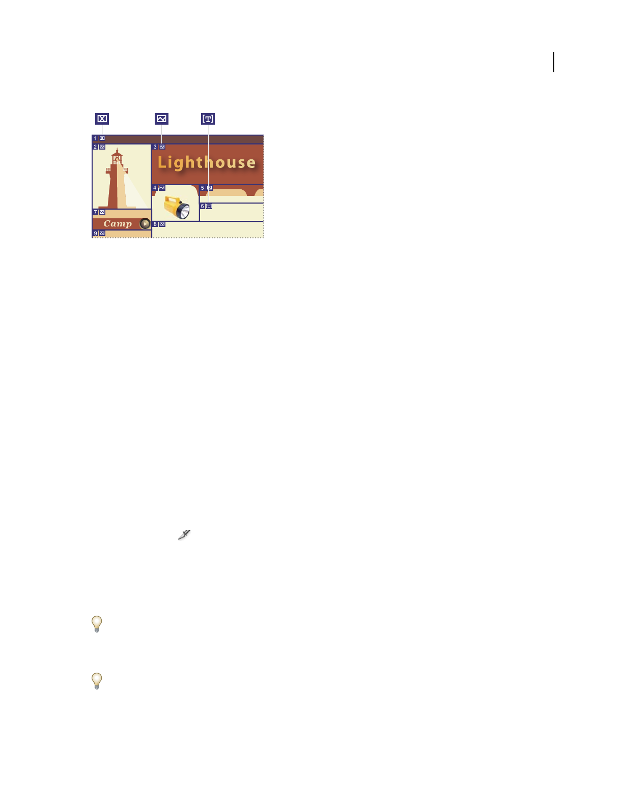
ILLUSTRATOR CS3
User Guide
372
Sliced artwork using different slice types
A. No Image slice B. Image slice C. HTML Text slice
You can view slices on the artboard and in the Save For Web & Devices dialog box. Illustrator numbers slices from
left to right and top to bottom, beginning in the upper left corner of the artwork. If you change the arrangement or
total number of slices, slice numbers are updated to reflect the new order.
When you create a slice, Illustrator slices the surrounding artwork into automatic slices to maintain the layout using
a web-based table. There are two types of automatic slices: auto slices and subslices. Auto slices account for the areas
of your artwork that you did not define as a slice. Illustrator regenerates auto slices every time you add or edit slices.
Subslices indicate how overlapping user-defined slices will be divided. Although subslices are numbered and display
a slice symbol, you cannot select them separately from the underlying slice. Illustrator regenerates subslices and auto
slices as needed while you work.
See also
“Save For Web & Devices overview” on page 381
“Slice output options” on page 398
Create slices
❖Do one of the following:
•Select one or more objects on the artboard, and choose Object > Slice > Make.
•Select the Slice tool and drag over the area where you want to create a slice. Shift-drag to constrain the slice
to a square. Alt-drag (Windows) or Option-drag (Mac OS) to draw from the center.
•Select one or more objects on the artboard, and choose Object > Slice > Create From Selection.
•Place guides where you want to slice the artwork, and choose Object > Slice > Create From Guides.
•Select an existing slice, and choose Object > Slice > Duplicate Slice.
Use the Object > Slice > Make command when you want the slice dimensions to match the boundary of an element
in your artwork. If you move or modify the element, the slice area automatically adjusts to encompass the new
artwork. Also use this command to create a slice that captures text and basic formatting characteristics from a text
object.
Use the Slice tool, the Create From Selection command, or the Create From Guides command when you want the
slice dimensions to be independent of the underlying artwork. Slices that you create in one of these ways appear as
items in the Layers panel, and you can move, resize, and delete them in the same way as other vector objects.
Camping Gear
Backpacks Lighting Tents Slee
Gear Clothing
ABC

ILLUSTRATOR CS3
User Guide
373
Select slices
Use the Slice Select tool to select a slice in the illustration window or the Save For Web & Devices dialog box.
•To select a slice, click it.
•To select multiple slices, Shift-click. (In the Save For Web & Devices dialog box, you can also Shift-drag.)
•To select an underlying slice when working with overlapping slices, click the visible section of it.
In addition, you can select slices in the illustration window by doing one of the following:
•To select a slice that was created using the Object > Slice > Make command, select the corresponding artwork on
the artboard. If the slice is tied to a group or layer, select the target icon adjacent to the group or layer in the Layers
panel.
•To select a slice that was created using the Slice tool, the Create From Selection command, or the Create From
Guides command, target the slice in the Layers panel.
•Click on the slice path with the Selection tool .
•To select a slice path segment or slice anchor point, click on either item with the Direct Selection tool.
Note: You cannot select auto slices. These slices are dimmed.
Set slice options
A slice’s options determine how the content of the slice will look and function in the resulting web page.
1 Do one of the following with the Slice Select tool:
•Select a slice in the illustration window, and choose Object > Slice > Slice Options.
•Double-click a slice in the Save For Web & Devices dialog box with the Slice Select tool.
2 Select a slice type and set the corresponding options:
Image Select this type if you want the slice area to be an image file in the resulting web page. If you want the image
to be an HTML link, enter a URL and target frameset. You can also specify a message that will appear in the browser’s
status area when the mouse is positioned over the image, alternative text that will appear when the image is not
visible, and a background color for the table cell.
No Image Select this type if you want the slice area to contain HTML text and a background color in the resulting
web page. Enter the text you want in the Text Displayed In Cell text box and format the text using standard HTML
tags. Be careful not to enter more text than can be displayed in the slice area. (If you enter too much text, it will extend
into neighboring slices and affect the layout of your web page. However, because you cannot see the text on the
artboard, this will not be apparent until you view the web page in a web browser.) Set the Horiz and Vert options to
change the alignment of text in the table cell.
HTML Text This type is available only when you created the slice by selecting a text object and choosing Object >
Slice > Make. The Illustrator text is converted to HTML text with basic formatting attributes in the resulting web
page. To edit the text, update the text in your artwork. Set the Horiz and Vert options to change the alignment of text
in the table cell. You can also select a background color for the table cell.
To edit the text for HTML Text slices in the Slice Options dialog box, change the slice type to No Image. This breaks
the link with the text object on the artboard. To ignore text formatting, enter <unformatted> as the first word in the
text object.

ILLUSTRATOR CS3
User Guide
374
Lock slices
Locking slices prevents you from making changes accidentally, such as resizing or moving.
•To lock all slices, choose View > Lock Slices.
•To lock individual slices, click the slices’ edit column in the Layers panel.
See also
“Layers panel overview” on page 211
Adjust slice boundaries
If you created a slice using the Object > Slice > Make command, the position and size of the slice is tied to the artwork
it contains. Therefore, if you move or resize the artwork, the slice boundaries adjust automatically.
If you created a slice using the Slice tool, the Create From Selection command, or the Create From Guides command,
you can manually adjust slices in the following ways:
•To move a slice, drag the slice to a new position with the Slice Selection tool . Press Shift to restrict movement
to a vertical, horizontal, or 45˚ diagonal line.
•To resize a slice, select the slice with Slice Selection tool, and drag any corner or side of the slice. You can also use
the Selection tool and Transform panel to resize slices.
•To align or distribute slices, use the Align panel. Aligning slices can eliminate unneeded auto slices to generate a
smaller, more efficient HTML file.
•To change the stacking order of slices, drag the slice to a new position in the Layers panel or select an Object >
Arrange command.
•To divide a slice, select the slice and choose Object > Slice > Divide Slices.
You can combine slices that were created by any method. Select the slices and choose Object > Slice > Combine
Slices. The resulting slice takes its dimensions and position from the rectangle created by joining the outer edges of
the combined slices. If the combined slices are not adjacent or are of different proportions or alignments, the new
slice may overlap other slices.
To resize all slices to the artboard boundaries, choose Object > Slice > Clip To Artboard. Slices that extend beyond
the artboard are truncated to fit the artboard and autoslices that lie within the artboard are extended to the artboard
boundaries; all artwork remains the same.
Remove slices
You can remove slices by deleting them or by releasing them from the corresponding artwork.
•To delete a slice, select the slice, and press Delete. If the slice was created using the Object > Slice > Make
command, the corresponding artwork is deleted at the same time. If you want to keep the corresponding artwork,
release the slice instead of deleting it.
•To delete all slices, choose Object > Slice > Delete All. Slices created with the Object > Slice > Make command are
released, not deleted.
•To release a slice, select the slice and choose Object > Slice > Release.

ILLUSTRATOR CS3
User Guide
375
Show or hide slices
•To hide slices in the illustration window, choose View > Hide Slices.
•To hide slices in the Save For Web & Devices dialog box, click the Toggle Slices Visibility button .
•To hide slice numbers and change the color of slice lines, choose Edit > Preferences > Smart Guides & Slices
(Windows) or Illustrator > Preferences > Smart Guides & Slices (Mac OS).
Create image maps
Image maps enable you to link one or more areas of an image—called hotspots—to a URL. When a user clicks on
the hotspot, the web browser loads the linked file.
The main difference between using image maps and using slices to create links is in how the artwork is exported as
a web page. Using image maps keeps the artwork intact as a single image file, while using slices causes the artwork
to be divided into separate files. Another difference between image maps and slices is that image maps enable you to
link polygonal or rectangular areas in your artwork, while slices enable you to link only rectangular areas. If you need
to link only rectangular areas, using slices may be preferable to using an image map.
Note: To avoid unexpected results, don’t create image-map hotspots in slices that contain URL links—either the image
map links or the slice links may be ignored in some browsers.
1 Select the object that you want to link to a URL.
2 In the Attributes panel, select a shape for the image map from the Image Map menu.
3 Enter a relative or full URL in the URL text box, or select from the list of available URLs. You can verify the URL
location by clicking the Browser button.
To increase the number of visible entries in the URL menu, select panel Options from the Attributes panel menu.
Enter a value from 1 to 30 to define how many URL entries you want to be displayed in the URL list.
SVG
About SVG
Bitmap image formats for the web—GIF, JPEG, WBMP, and PNG—describe images using a grid of pixels. The
resulting files tend to be bulky, limited to a single (often low) resolution, and consume large amounts of bandwidth
on the web. SVG, on the other hand, is a vector format that describes images as shapes, paths, text, and filter effects.
The
resulting files are compact and provide high-quality graphics on the web, in print, and even on resource-
constrained, handheld devices. Users can magnify their view of an SVG image on-screen without sacrificing
sharpness, detail, or clarity. In addition, SVG provides superior support for text and colors, which ensures that users
will see images as they appear on your Illustrator artboard.
The SVG format is entirely XML-based and offers many advantages to developers and users alike. With SVG, you
can use XML and JavaScript to create web graphics that respond to user actions with sophisticated effects such as
highlighting, tool tips, audio, and animation.
You can save artwork in SVG format using the Save, Save As, Save A Copy, or Save For Web & Devices command. To
access the complete set of SVG export options, use the Save, Save As, or Save A Copy command. The Save For Web
& Devices command provides a subset of SVG export options which are applicable to web-oriented work.
For a video on creating mobile content in Illustrator, see www.adobe.com/go/vid0207.

ILLUSTRATOR CS3
User Guide
376
How you set up your artwork in Illustrator will affect the resulting SVG file. Keep in mind the following guidelines:
•Use layers to add structure to an SVG file. When you save artwork in SVG format, each layer is converted to a
group (<g>) element. (For example, a layer named Button1 becomes <g id="Button1_ver3.0"> in the SVG file.)
Nested layers become SVG nested groups, and hidden layers are preserved with the SVG styling property
“display:none”.
•If you want objects on different layers to appear transparent, adjust the opacity of each object instead of each layer.
If you alter opacity at the layer level, the resulting SVG file will not display transparency as it appears in Illustrator.
•Raster data is not scalable in the SVG Viewer and cannot be edited like other SVG elements. If possible, avoid
creating artwork that will be rasterized in the SVG file. Gradient meshes and objects that use the Rasterize,
Artistic, Blur, Brush Strokes, Distort, Pixelate, Sharpen, Sketch, Stylize, Texture, and Video effects are rasterized
when saved in SVG format. Similarly, graphic styles that include these effects also produce rasterization. Use SVG
effects to add graphic effects without causing rasterization.
•Use symbols and simplify the paths in your artwork to improve SVG performance. Also avoid using brushes that
produce a lot of path data, such as the Charcoal, Fire Ash, and Scroll Pen, if performance is a high priority.
•Use slices, image maps, and scripts to add web links to an SVG file.
•A scripting language, such as JavaScript, opens unlimited functionality to an SVG file. Pointer and keyboard
movements can invoke scripting functions such as rollover effects. Scripts can also use the document object model
(DOM) to access and modify the SVG file—inserting or deleting SVG elements, for example.
See also
“Optimize an image for the web” on page 383
“Save in SVG format” on page 266
Apply SVG effects
You can use SVG effects to add graphic properties such as drop shadows to your artwork. SVG effects differ from
their bitmap counterparts in that they are XML-based and resolution-independent. In fact, an SVG effect is nothing
more than a series of XML properties that describe various mathematical operations. The resulting effect is rendered
to the target object instead of the source graphic.
Illustrator provides a default set of SVG effects. You can use the effects with their default properties, edit the XML
code to produce custom effects, or write new SVG effects.
To modify Illustrator’s default SVG filters, use a text editor to edit the Adobe SVG Filters.svg file in the
<userdir>/Application Data/Adobe/Adobe Illustrator CS3 Settings folder. You can modify existing filter definitions,
delete filter definitions, and add new filter definitions.
1 Select an object or group (or target a layer in the Layers panel).
2 Do one of the following:
•To apply an effect with its default settings, select the effect from the bottom section of the Effect > SVG Filters
submenu.
•To apply an effect with custom settings, choose Effect > SVG Filters > Apply SVG Filter. In the dialog box, select
the effect, and click the Edit SVG Filter button . Edit the default code and click OK.
•To create and apply a new effect, choose Effect > SVG Filters > Apply SVG Filter. In the dialog box, click the
New SVG Filter button , enter the new code, and click OK.

ILLUSTRATOR CS3
User Guide
377
When you apply an SVG filter effect, Illustrator displays a rasterized version of the effect on the artboard. You can
control the resolution of this preview image by modifying the document’s rasterization resolution setting.
Important: An SVG effect must be the last effect when an object uses multiple effects; in other words, it must appear at
the bottom of the Appearance panel (just above the Transparency entry). If other effects follow an SVG effect, the SVG
output will consist of a raster object.
See also
“About raster effects” on page 352
“Modify or delete an effect” on page 353
Import effects from an SVG file
1 Choose Effect > SVG Filter > Import SVG Filter.
2 Select the SVG file you want to import effects from, and click Open.
SVG Interactivity panel overview
You use the SVG Interactivity panel (Window > SVG Interactivity) to add interactivity to your artwork when it is
exported for viewing in a web browser. For example, by creating an event that triggers a JavaScript command, you
can quickly create movement on a web page when the user performs an action such as moving a mouse cursor over
an object. The SVG Interactivity panel also lets you see all the events and JavaScript files associated with the current
file.
See also
“Optimize an image for the web” on page 383
“Save in SVG format” on page 266
Delete an event from the SVG Interactivity panel
•To delete one event, select it and click the Delete button or choose Delete Event from the panel menu.
•To delete all events, choose Clear Events from the panel menu.
List, add, or remove events linked to a file
1
Click the Link JavaScript Files button .
2 In the JavaScript Files dialog box, select a JavaScript entry and do one of the following:
•Click Add to browse for additional JavaScript files.
•Click Remove to remove the selected JavaScript entry.
Add SVG interactivity to artwork
1 In the SVG Interactivity panel, select an event. (See “SVG events” on page 377.)
2 Enter the corresponding JavaScript, and press Enter.
SVG events
onfocusin Triggers the action when the element receives focus, such as selection by the pointer.

ILLUSTRATOR CS3
User Guide
378
onfocusout Triggers the action when the element loses focus (often when another element receives focus).
onactivate Triggers the action with a mouse click or keypress, depending upon the SVG element.
onmousedown Triggers the action when the mouse button is pressed down over an element.
onmouseup Triggers the action when the mouse button is released over an element.
onclick Triggers the action when the mouse is clicked over an element.
onmouseover Triggers the action when the pointer is moved onto an element.
onmousemove Triggers the action while the pointer is over an element.
onmouseout Triggers the action when the pointer is moved away from an element.
onkeydown Triggers the action when a key is pressed down.
onkeypress Triggers the action while a key is pressed down.
onkeyup Triggers the action when a key is released.
onload Triggers the action after the SVG document has been completely parsed by the browser. Use this event to call
one-time-only initialization functions.
onerror Triggers the action when an element does not load properly or another error occurs.
onabort Triggers the action when the page loading is stopped before the element is completely loaded.
onunload Triggers the action when the SVG document is removed from a window or frame.
onzoom Triggers the action when the zoom level is changed for the document.
onresize Triggers the action when the document view is resized.
onscroll Triggers the action when the document view is scrolled or panned.
Creating animations
About Flash graphics
The Flash (SWF) file format is a vector-based graphics file format for scalable, compact graphics for the web.
Because
the file format is vector-based, the artwork maintains its image quality at any resolution and is ideal for the
creation of animation frames. In Illustrator, you can create individual animation frames on layers and then export
the image layers into individual frames for use on a website. You
can also define symbols in an Illustrator file to
reduce the size of an animation. When exported, each symbol is defined only once in the SWF file.
You can save artwork as a SWF file by using the Export command or the Save For Web & Devices command. Benefits
of each include:
Export (SWF) command Provides the most control over animation and bitmap compression.
Save For Web & Devices command Provides more control over the mix of SWF and bitmap formats in a sliced layout.
This command offers fewer Image options than the Export (SWF) command, but uses the Export command’s last-
used settings. (See “SWF optimization options (Illustrator)” on page 395.)
Keep the following information in mind when preparing artwork to save as SWF:
•To keep the file size as small as possible when using symbols, apply effects to the symbol in the Symbols panel
rather than to symbol instances in the artwork.

ILLUSTRATOR CS3
User Guide
379
•Using the Symbol Stainer and Symbol Styler tools results in larger SWF files because Illustrator must create a copy
of each symbol instance to maintain their appearances.
•Mesh objects and gradients with more than eight stops are rasterized and will appear as bitmap-filled shapes.
Gradients with fewer than eight stops are exported as gradients.
•Patterns are rasterized into small images the size of the pattern art and tiled to fill the art.
•If a bitmap object extends beyond the boundaries of a slice, the entire object is included in the exported file.
•
SWF supports rounded caps and joins only. Beveled or square caps and joins become rounded when exported to SWF.
•Pattern-filled text and pattern-filled strokes convert to paths and are filled with the pattern.
•Although text retains many of its features when exported to SWF, some information is lost. When importing a
SWF file into Flash, leading, kerning, and tracking aren’t maintained. Instead, text is broken into separate records
to simulate the look of leading. When the SWF file is subsequently played in Flash Player, the appearance of the
leading, kerning, and tracking in the file is maintained. If you wish to export text as paths, select Export Text As
Outlines in the SWF Options dialog box, or convert the text to outlines before exporting to SWF by choosing the
Create Outlines command.
For a video on using symbols effectively between Illustrator and Flash, see www.adobe.com/go/vid0198. For a video
on using text effectively between Illustrator and Flash, see www.adobe.com/go/vid0199.
See also
“Optimize an image for the web” on page 383
“Flash export options” on page 271
“About symbols” on page 82
Create Flash animations
There are many ways to create Flash animations in Illustrator. One of the easiest is to place each animation frame on
a separate Illustrator layer, and select the AI Layers To SWF Frames option when you export the artwork.
For a video on exporting SWF files from Illustrator, see www.adobe.com/go/vid0214. For a video on creating mobile
content in Illustrator, see www.adobe.com/go/vid0207. You can also go to Adobe Studio (http://studio.adobe.com)
for tips and tutorials on creating Flash animations.
1 Create the artwork you want to animate. Use symbols to reduce the file size of the animation and simplify your
work.
2 Create a separate layer for each frame in the animation.
You can do this by pasting the base artwork into a new layer and then editing the artwork. Or, you can use the Release
To Layers command to automatically generate layers consisting of objects that build up cumulatively.
3 Make sure the layers are in the order in which you want to display them as animation frames.
4 Do one of the following:
•Choose File > Export, choose Flash (SWF) for the format, and click Export. In the SWF Options dialog box, select
AI Layers To SWF Frames for Export As. Set additional animation options, and click OK.
•Choose File > Save For Web & Devices. Choose SWF from the Optimized File Format menu. From the Type Of
Export menu, choose AI Layers To SWF Frames. Set additional options, and click Save.

ILLUSTRATOR CS3
User Guide
380
See also
“About symbols” on page 82
“Release items to separate layers” on page 213
“Flash export options” on page 271
“SWF optimization options (Illustrator)” on page 395
Working with Illustrator and Flash
You can move Illustrator artwork into the Flash editing environment or directly into Flash Player. You can copy and
paste artwork, save files in SWF format, or export artwork directly to Flash. In addition, Illustrator provides support
for Flash dynamic text and movie clip symbols.
You can also use Device Central to see how Illustrator artwork will appear in Flash Player on different handheld
devices.
Pasting Illustrator artwork
You can create graphically rich artwork in Illustrator and copy and paste it into Flash simply, quickly, and seamlessly.
When you paste Illustrator artwork into Flash, the following attributes are preserved:
•Paths and shapes
•Scalability
•Stroke weights
•Gradient definitions
•Text (including OpenType fonts)
•Linked images
•Symbols
•Blending modes
In addition, Illustrator and Flash support pasted artwork in the following ways:
•When you select entire top-level layers in Illustrator artwork and paste them into Flash, the layers are preserved
along with their properties (visibility and locking).
•Non-RGB Illustrator colors (CMYK, grayscale, and custom) convert to RGB in Flash. RGB colors paste as
expected.
•When you import or paste Illustrator artwork, you can use various options to preserve effects (such as drop
shadow on text) as Flash filters.
•Flash preserves Illustrator masks.
Exporting SWF files from Illustrator
From Illustrator, you can export SWF files that match the quality and compression of SWF files exported from Flash.
When you export, you can choose from a variety of presets to ensure optimal output, and you can specify how to
handle symbols, layers, text, and masks. For example, you can specify whether Illustrator symbols are exported as
movie clips or graphics, or you can choose to create SWF symbols from Illustrator layers.

ILLUSTRATOR CS3
User Guide
381
Importing Illustrator files into Flash
When you want to create complete layouts in Illustrator and then import them into Flash in one step, you can save
your artwork in the native Illustrator format (AI) and import it, with high fidelity, into Flash using the File
> Import
To Stage or File
> Import To Library commands in Flash.
When you import Illustrator artwork as an AI, EPS, or PDF file, Flash preserves the same attributes as for pasted
Illustrator artwork.
In addition, when an imported Illustrator file contains layers, you can import them in any of the following ways:
•Convert Illustrator layers to Flash layers
•Convert Illustrator layers to Flash frames
•Convert each Illustrator layer to a Flash graphic symbol
•Covert all Illustrator layers to a single Flash layer
Symbol workflow
Symbol workflow in Illustrator is similar to symbol workflow in Flash.
Symbol creation When you create a symbol in Illustrator, the Symbol Options dialog box lets you name the symbol
and set options specific to Flash: movie clip symbol type (which is the default for Flash symbols), Flash registration
grid location, and 9-slice scaling guides. In addition, you can use many of the same symbol keyboard shortcuts in
Illustrator and Flash (such as F8 to create a symbol).
Isolation mode for symbol editing In Illustrator, double-click a symbol to open it in isolation mode for easier
editing. In isolation mode, only the symbol instance is editable—all other objects on the artboard are dimmed and
unavailable. After you exit isolation mode, the symbol in the Symbols panel, and all instances of that symbol are
updated accordingly. In Flash, symbol-editing mode and the Library panel work in a similar fashion.
Symbol properties and links Using the Symbols panel or the Control panel, you can easily assign names to symbol
instances, break links between instances and symbols, swap a symbol instance with another symbol, or create a copy
of the symbol. In Flash, the editing features in the Library panel work in a similar way.
Static, dynamic, and input text objects
When you bring static text from Illustrator into Flash, Flash converts the text to outlines. If you have a Smart Object
workflow in Illustrator, you can take the text back to Illustrator for editing. In addition, you can set up your text in
Illustrator as dynamic text. Dynamic text enables you to edit text content programmatically in Flash, and easily
manage projects that require localization in multiple languages.
In Illustrator, you can specify individual text objects as static, dynamic, or input text. Dynamic text objects in
Illustrator and Flash have similar properties. For example, both use kerning that affects all characters in a text block
rather than individual characters, both anti-alias text the same way, and both can be linked to an external XML file
containing text.
Optimizing images
Save For Web & Devices overview
You use the Save For Web & Devices dialog box (File > Save For Web & Devices) to select optimization options and
preview optimized artwork.
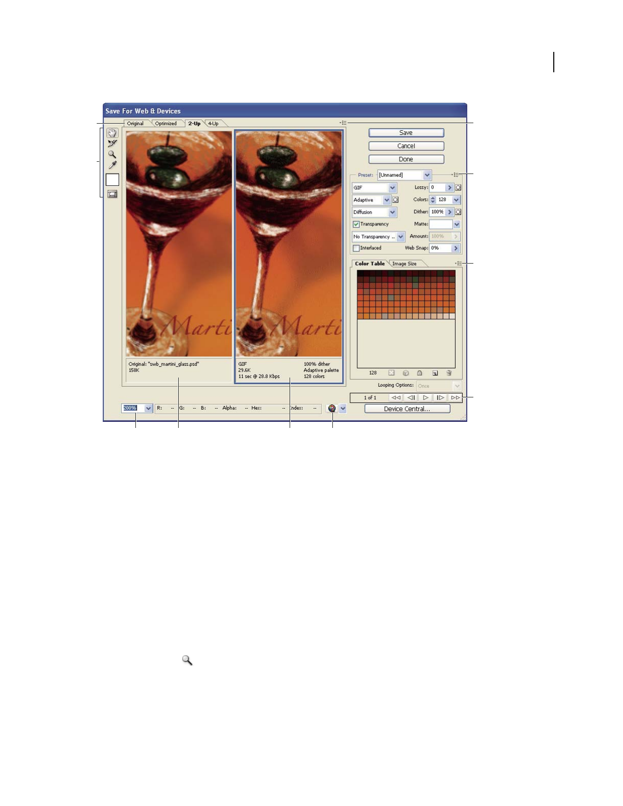
ILLUSTRATOR CS3
User Guide
382
Save For Web & Devices dialog box
A. Display options B. Toolbox C. Preview pop-up menu D. Optimize pop-up menu E. Color Table pop-up menu F. Animation controls
G. Zoom text box H. Original image I. Optimized image J. Preview In Browser menu
Preview images in the dialog box
❖Click a tab at the top of the image area to select a display option:
Original Displays the image with no optimization.
Optimized Displays image with the current optimization settings applied.
2-Up Displays two versions of the image side by side.
4-Up Displays four versions of the image side by side.
Navigate in the dialog box
If the entire artwork is not visible in the Save For Web & Devices dialog box, you can use the Hand tool to bring
another area into view. Use the Zoom tool to magnify or reduce the view.
•Select the Hand tool (or hold down the spacebar), and drag in the view area to pan over the image.
•Select the Zoom tool , and click in a view to zoom in; hold down Alt (Windows) or Option (Mac OS), and click
in a view to zoom out.
You can also type a magnification percentage or choose one at the bottom of the dialog box.
HI
G
D
B
AC
E
F
J

ILLUSTRATOR CS3
User Guide
383
View optimized image information and download time
The annotation area below each image in the Save For Web & Devices dialog box provides optimization information.
The annotation for the original image shows the file name and file size. The annotation for the optimized image
shows the current optimization options, the size of the optimized file, and the estimated download time using the
selected modem speed. You can choose a modem speed in the Preview pop-up menu.
Preview browser dither
If an image contains more colors than the monitor can display, the browser will dither, or approximate, the colors
that it cannot display by blending colors that it can.
❖To show or hide the preview of browser dither, choose Browser Dither from the Preview pop-up menu. A check
mark indicates that browser dithering is active. Activating Browser Dither does not affect final image output.
Optimize an image for the web
1 Choose File > Save For Web & Devices.
2 Click a tab at the top of the dialog box to select a display option: Optimized, 2-Up, or 4-Up. If you select 4-Up,
click the preview you want to optimize.
3 (Optional) If your image contains multiple slices, select one or more slices you want to optimize.
4 Select a preset optimization setting from the Preset menu, or set individual optimization options. The available
options change depending on the file format you select.
If you’re working in 4-Up mode, choose Repopulate Views from the Optimize menu to automatically generate lower-
quality versions of the image after you change the optimization settings.
5 Fine-tune the optimization settings until you are satisfied with the balance of image quality and file size. If your
image contains multiple slices, be sure to optimize all the slices.
To restore an optimized preview to the original version, select it and then choose Original from the Settings pop-up
menu.
6 If optimizing an image with an embedded color profile other than sRGB, you should convert the image’s colors to
sRGB before you save the image for use on the web. On the Optimize menu, make sure that Convert to sRGB is
selected.
7 Click Save.
8 In the Save Optimized As dialog box, do the following, and then click Save:
•Enter a file name, and select a location for the resulting file or files.
•Select a Format option to specify what kind of files you want to save: HTML file and image files, only image files,
or only an HTML file.
•(Optional) Set output settings for HTML and image files.
•If your image contains multiple slices, select an option for saving slices from the Slices menu: All Slices or Selected
Slices.
To reset optimization settings to the last saved version, press Alt (Windows) or Option (Mac OS), and click Reset. To
keep the same settings the next time you open the Save For Web & Devices dialog box, press Alt/Option and click
Remember.
For a video on saving files for the web in Illustrator, see www.adobe.com/go/vid0063.

ILLUSTRATOR CS3
User Guide
384
See also
“Web graphics optimization options” on page 386
“Preview optimized images in a web browser” on page 386
“Set output options” on page 397
Save or delete optimization presets
You can save optimization settings as a named set and apply the settings to other images. Settings that you save
appear in the Preset pop-up menu, together with the predefined named settings. If you edit a named set or a
predefined set, the Preset menu displays the term “Unnamed.”
1 Set optimization options as desired, and choose Save Settings from the Optimize palette menu.
2 Name the settings, and save them in the Presets/Optimized Settings folder inside the Photoshop program folder,
or Presets/Save For Web Settings/Optimize folder inside the Adobe Illustrator application folder.
Note: If you save the settings in a another location, they will not be available from the Preset pop-up menu.
3 To delete a preset, select the preset from Settings menu, and select Delete Settings from the Optimize menu.
Work with slices in the Save For Web & Devices dialog box
If your image contains multiple slices, you must specify the slices to be optimized. You can apply optimization
settings to additional slices by linking the slices. Linked slices in GIF and PNG-8 format share a color palette and
dither pattern to prevent the appearance of seams between the slices.
•To show or hide all slices, click the Toggle Slices Visibility button .
•(Photoshop only) To show or hide auto slices, choose Hide Auto Slices from the Preview pop-up menu.
•To select slices in the Save For Web & Devices dialog box, choose the Slice Select tool , and then click a slice
to select it. Shift-click or Shift-drag to select multiple slices.
Note: In the Save For Web & Devices dialog box, unselected slices are dimmed. This does not affect the color of the final
image.
•To view slice options in the Save For Web & Devices dialog box, select the Slice Select tool, and double-click a slice.
•To link slices, select two or more slices and choose Link Slices from the Optimize pop-up menu (to the right
of the Preset menu). The link icon appears on the linked slices.
•To unlink a slice, select the slice, and then choose Unlink Slice from the Optimize pop-up menu.
•To unlink all slices in an image, choose Unlink All Slices from the Optimize pop-up menu.
Compress a web graphic to a specific file size
1 Choose File > Save For Web & Devices.
2 Click a tab at the top of the Save For Web & Devices dialog box to select a display option: Optimized, 2-Up, or
4-Up. If you select 4-Up, select the preview you want to optimize.
3 (Optional) Select the slices you want to optimize and the file format you want to use.
4 Select Optimize To File Size from the Optimize menu (to the right of the Settings menu).
5 Enter the desired file size.

ILLUSTRATOR CS3
User Guide
385
6 Select a Start With option:
Current Settings Uses the current file format.
Auto Select GIF/JPEG Automatically selects the optimal format depending on image content.
7 Select a Use option to specify whether you want to apply the specified file size to current slice only, to each slice
in the image, or to all slices. Click OK.
Resize artwork while optimizing
In the Save For Web & Devices dialog box, you can resize an image to specified pixel dimensions or to a percentage
of the original size.
1 Click the Image Size tab in the Save For Web & Devices dialog box.
2 Enter new pixel dimensions or specify a percentage by which to resize the image.
3 Set any of the additional options, and click Apply:
Constrain Proportions Maintains the current proportions of pixel width to pixel height.
Quality (Photoshop only) Specifies the interpolation method. Bicubic Sharper generally produces better results
when you are reducing image size.
Anti-Alias (Illustrator only) Removes jagged edges in the artwork by applying anti-aliasing.
Clip To Artboard (Illustrator only) Clips the artwork size to match the document’s Artboard boundary. Any artwork
outside the Artboard boundary will be deleted.
Note: None of the features in the Image Size palette are available for the SWF and SVG file formats except Clip To
Artboard.
Generate CSS layers for web graphics
You can use layers in your Illustrator artwork to generate CSS layers in the resulting HTML file. A CSS layer is an
element that has an absolute position and can overlap with other elements in a web page. Exporting CSS layers is
useful when you plan to create dynamic effects in your web page.
The Layers palette in the Save For Web & Devices dialog box gives you control over which top-level layers in your
artwork are exported as CSS layers, and whether exported layers are visible or hidden.
1 Click the Layers tab in the Save For Web & Devices dialog box.
2 Select Export As CSS Layers.
3 Select a layer from the Layer pop-up menu, and set the following options as desired:
Visible Creates a visible CSS layer in the resulting HTML file.
Hidden Creates a hidden CSS layer in the resulting HTML file.
CSS layers are the same as GoLive layers. Using Adobe GoLive, you can animate a CSS layer and use built-in
JavaScript actions to create interactive effects.
See also
“Save For Web & Devices overview” on page 381
“Optimize an image for the web” on page 383
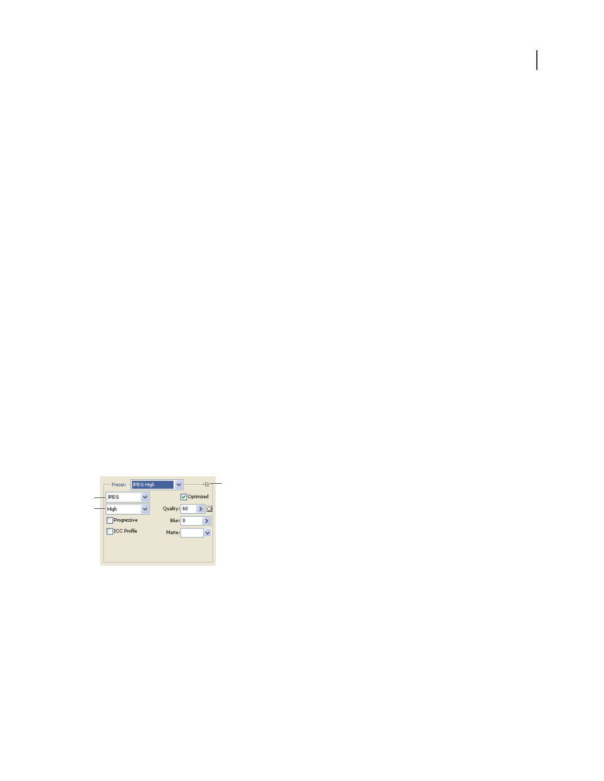
ILLUSTRATOR CS3
User Guide
386
Preview optimized images in a web browser
You can preview an optimized image in any web browser installed on your system from the Save For Web & Devices
dialog box (File
> Save For Web & Devices). The browser preview displays the image with a caption listing the image’s
file type, pixel dimensions, file size, compression specifications, and other HTML information.
•To preview an image in your default web browser, click the browser icon at the bottom of the Save For Web &
Devices dialog box.
•To select a different browser, select Other from the browser pop-up menu (next to the browser icon).
•To add, edit, or remove a browser in the browser pop-up menu, select Edit List from the browser pop-up menu.
In the Browsers dialog box, you can find all browsers on your computer and set the default browser to preview
your image.
Web graphics optimization options
Web graphic formats
Web graphics formats can be either bitmap (raster) or vector. The bitmap formats—GIF, JPEG, PNG, and WBMP—
are resolution-dependent, meaning that a bitmap image’s dimensions, and possibly image quality, will change at
different monitor resolutions. The vector formats—SVG and SWF—are resolution-independent and can be scaled up
or down without losing any image quality. The vector formats can also include raster data. You can export from Save
For Web & Devices to SVG and SWF in Adobe Illustrator only.
JPEG optimization options
JPEG is the standard format for compressing continuous-tone images such as photographs. Optimizing an image as
a JPEG format relies on lossy compression, which selectively discards data.
Note: Since image data is lost when saving a file in JPEG format, it’s a good idea to save the source file in its original
format (for example, Photoshop .PSD) if you plan to edit the file further or create additional JPEG versions.
Optimization settings for JPEG
A. File Format menu B. Compression Quality menu C. Optimize menu
Quality Determines the level of compression. The higher the Quality setting, the more detail the compression
algorithm preserves. However, using a high Quality setting results in a larger file size than using a low Quality setting.
View the optimized image at several quality settings to determine the best balance of quality and file size.
Optimized Creates an enhanced JPEG with a slightly smaller file size. The Optimized JPEG format is recommended
for maximum file compression; however, some older browsers do not support this feature.
C
A
B
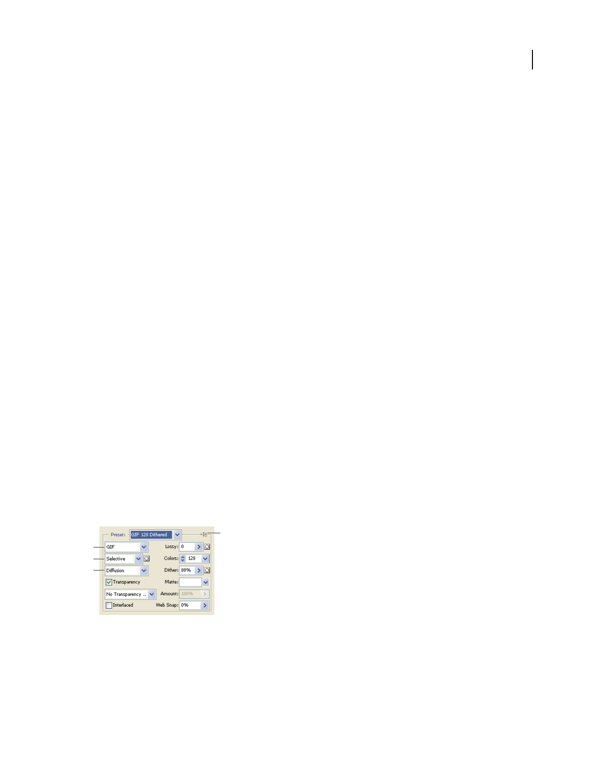
ILLUSTRATOR CS3
User Guide
387
Progressive Displays the image progressively in a web browser. The image appears as a series of overlays, enabling
viewers to see a low-resolution version of the image before it downloads completely. The Progressive option requires
use of the Optimized JPEG format.
Note: Progressive JPEGs require more RAM for viewing and are not supported by some browsers.
Blur Specifies the amount of blur to apply to the image. This option applies an effect identical to that of the Gaussian
Blur filter and allows the file to be compressed more, resulting in a smaller file size. A setting of 0.1 to 0.5 is recom-
mended.
ICC Profile Preserves the ICC profile of the artwork with the file. Some browsers use ICC profiles for color
correction. This option is available only after you saved an image with an ICC profile—it is not available for unsaved
images.
Matte Specifies a fill color for pixels that were transparent in the original image. Click the Matte color swatch to
select a color in the color picker, or select an option from the Matte menu: Eyedropper (to use the color in the
eyedropper sample box), Foreground Color, Background Color, White, Black, or Other (to use the color picker).
Pixels that were fully transparent in the original image are filled with the selected color; pixels that were partially
transparent in the original image are blended with the selected color.
See also
“Optimize an image for the web” on page 383
GIF and PNG-8 optimization options
GIF is the standard format for compressing images with flat color and crisp detail, such as line art, logos, or illustra-
tions with type. Like the GIF format, the PNG-8 format efficiently compresses solid areas of color while preserving
sharp detail.
PNG-8 and GIF files support 8-bit color, so they can display up to 256 colors. The process of determining which
colors to use is called indexing, so images in GIF and PNG-8 formats are sometimes called indexed color images. To
convert an image to indexed color, Photoshop builds a color lookup table, which stores and indexes the colors in the
image. If a color in the original image does not appear in the color lookup table, the application either chooses the
closest color in the table or simulates the color using a combination of available colors.
In addition to the following options, you can also adjust the number of colors in the image’s color table. See
“Customize the color table for GIF and PNG-8 images” on page 391.
Optimization settings for GIF
A. File Format menu B. Color Reduction Algorithm menu C. Dithering Algorithm menu D. Optimize menu
Lossy (GIF only) Reduces file size by selectively discarding data. A higher Lossy setting results in more data being
discarded. You can often apply a Lossy value of 5–10, and sometimes up to 50, without degrading the image. The
Lossy option can reduce file size by 5% to 40%.
D
A
B
C
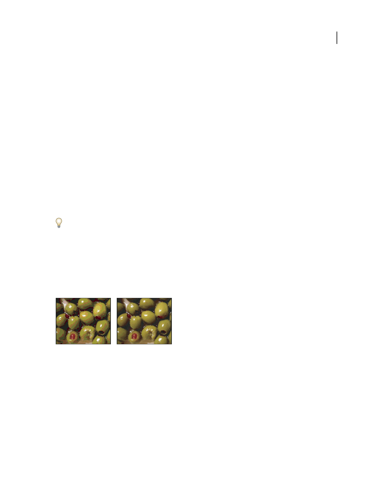
ILLUSTRATOR CS3
User Guide
388
Note: You cannot use the Lossy option with the Interlaced option or with Noise or Pattern Dither algorithms.
Color Reduction Method and Colors Specifies a method for generating the color lookup table and the number of
colors you want in the color lookup table. You can select one of the following color reduction methods:
•Perceptual Creates a custom color table by giving priority to colors for which the human eye has greater sensi-
tivity.
•Selective Creates a color table similar to the Perceptual color table, but favoring broad areas of color and the
preservation of web colors. This color table usually produces images with the greatest color integrity. Selective is the
default option.
•Adaptive Creates a custom color table by sampling colors from the predominant spectrum in the image. For
example, an image with only the colors green and blue produces a color table made primarily of greens and blues.
Most images concentrate colors in particular areas of the spectrum.
•(Restrictive) Web Uses the standard 216-color color table common to the Windows and Mac OS 8-bit (256-color)
palettes. This option ensures that no browser dither is applied to colors when the image is displayed using 8-bit color.
(This palette is also called the web-safe palette.) Using the web palette can create larger files, and is recommended
only when avoiding browser dither is a high priority.
•Custom Uses a color palette that is created or modified by the user. If you open an existing GIF or PNG-8 file, it
will have a custom color palette.
Use the Color Table palette in the Save For Web & Devices dialog box to customize the color lookup table.
•Black and White, Grayscale, Mac OS, Windows Use a set palette of colors.
Dithering Method and Dither Determines the method and amount of application dithering. Dithering refers to the
method of simulating colors not available in the color display system of your computer. A higher dithering
percentage creates the appearance of more colors and more detail in an image, but can also increase the file size. For
optimal compression, use the lowest percentage of dither that provides the color detail you require. Images with
primarily solid colors may work well with no dither. Images with continuous-tone color (especially color gradients)
may require dithering to prevent color banding.
GIF image with 0% dither (left), and with 100% dither (right)
You can select one of the following dithering methods:
•Diffusion Applies a random pattern that is usually less noticeable than Pattern dither. The dither effects are
diffused across adjacent pixels.
•Pattern Applies a halftone-like square pattern to simulate any colors not in the color table.
•Noise Applies a random pattern similar to the Diffusion dither method, but without diffusing the pattern across
adjacent pixels. No seams appear with the Noise dither method.
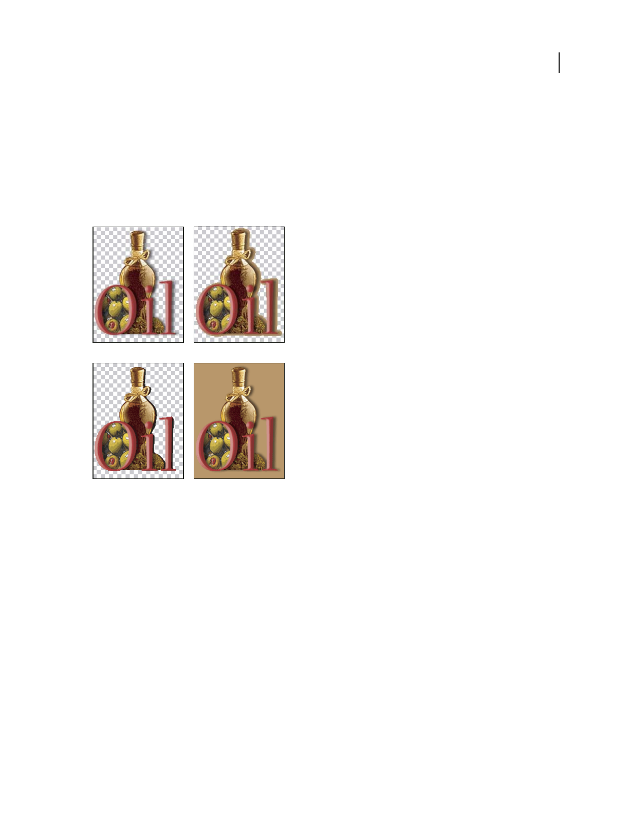
ILLUSTRATOR CS3
User Guide
389
Transparency and Matte Determines how transparent pixels in the image are optimized.
•To make fully transparent pixels transparent and blend partially transparent pixels with a color, select Trans-
parency and select a matte color.
•To fill fully transparent pixels with a color and blend partially transparent pixels with the same color, select a matte
color and deselect Transparency.
•To select a matte color, click the Matte color swatch and select a color in the color picker. Alternatively, select an
option from the Matte menu: Eyedropper (to use the color in the eyedropper sample box), Foreground Color,
Background Color, White, Black, or Other (to use the color picker).
Examples of transparency and matting
A. Original image B. Transparency selected with a matte color C. Transparency selected with no matting D. Transparency deselected with a
matte color
Transparency Dithering When the Transparency option is selected, you can choose a method for dithering partially
transparent pixels:
•No Transparency Dither applies no dither to partially transparent pixels in the image.
•Diffusion Transparency Dither applies a random pattern that is usually less noticeable than Pattern dither. The
dither effects are diffused across adjacent pixels. If you select this algorithm, specify a Dither percentage to control
the amount of dithering that is applied to the image.
•Pattern Transparency Dither applies a halftone-like square pattern to partially transparent pixels.
•Noise Transparency Dither applies a random pattern similar to the Diffusion algorithm, but without diffusing the
pattern across adjacent pixels. No seams appear with the Noise algorithm.
AB
CD
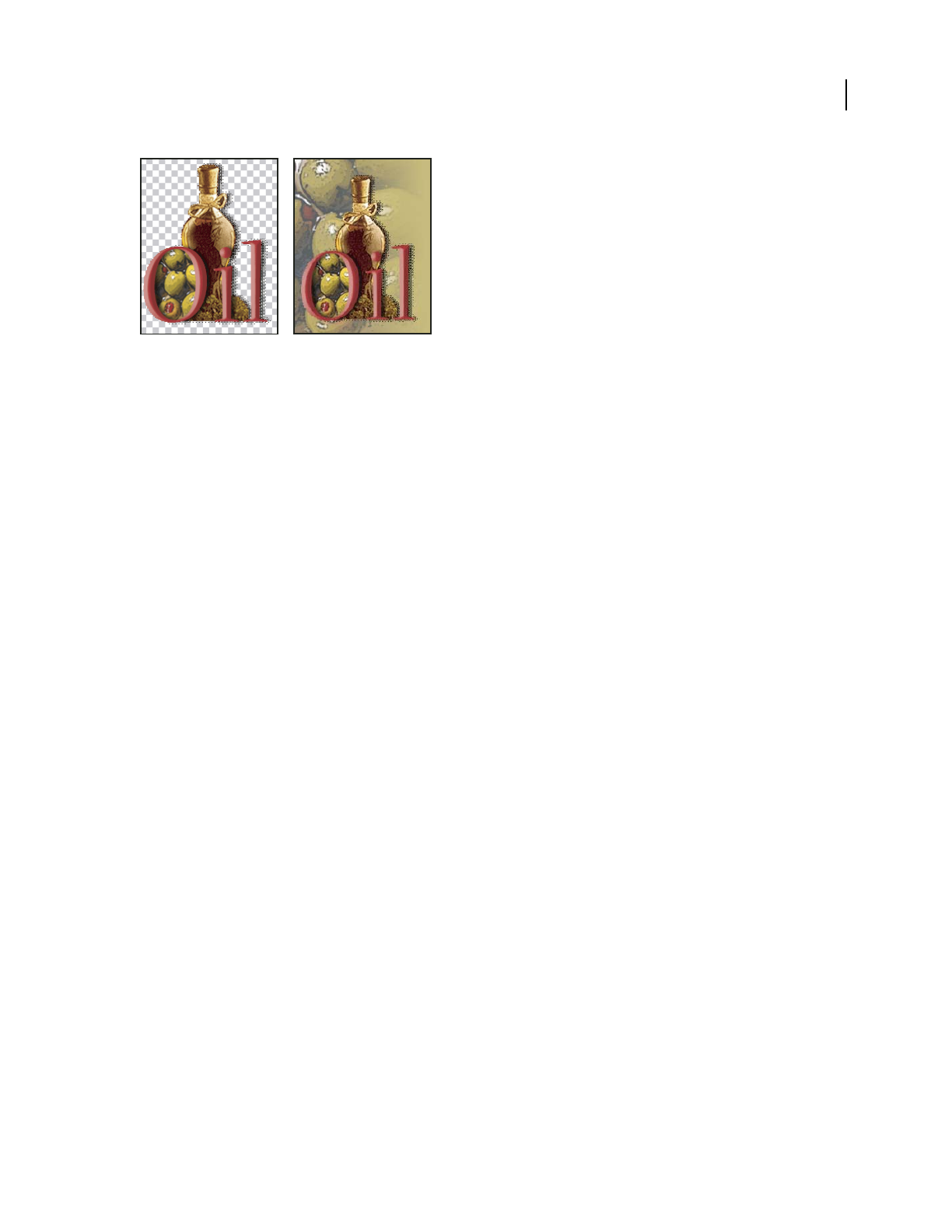
ILLUSTRATOR CS3
User Guide
390
Example of Pattern Transparency dithering (left) and applied to a web page background (right)
Interlace Displays a low-resolution version of the image in a browser while the full image file is downloading. Inter-
lacing can make downloading time seem shorter and can assure viewers that downloading is in progress. However,
interlacing also increases file size.
Web Snap Specifies a tolerance level for shifting colors to the closest web palette equivalents (and prevent the colors
from dithering in a browser). A higher value shifts more colors.
See also
“Optimize an image for the web” on page 383
Optimize transparency in GIF and PNG images
Transparency makes it possible to create nonrectangular images for the web. Background transparency preserves
transparent pixels in the image. This allows the background of the web page to show through the transparent areas
of your image. Background matting simulates transparency by filling or blending transparent pixels with a matte
color that can match the web page background. Background matting works best if the web page background is a solid
color and if you know what that color is.
Use the Transparency and Matte options in the Save For Web & Devices dialog box to specify how transparent pixels
in GIF and PNG images are optimized.
•(GIF and PNG-8) To make fully transparent pixels transparent and blend partially transparent pixels with a color,
select Transparency and select a matte color.
•To fill fully transparent pixels with a color and blend partially transparent pixels with the same color, select a matte
color and deselect Transparency.
•(GIF and PNG-8) To make all pixels with greater than 50% transparency fully transparent and all pixels with 50%
or less transparency fully opaque, select Transparency and select None from the Matte menu.
•(PNG-24) To save an image with multilevel transparency (up to 256 levels), select Transparency. The Matte option
is disabled since multilevel transparency allows an image to blend with any background color.
Note: In browsers that do not support PNG-24 transparency, transparent pixels may be displayed against a default
background color, such as gray.
To select a matte color, click the Matte color swatch and select a color in the color picker. Alternatively, select an
option from the Matte menu: Eyedropper (to use the color in the eyedropper sample box), Foreground Color,
Background Color, White, Black, or Other (to use the color picker).

ILLUSTRATOR CS3
User Guide
391
View the color table for an optimized slice
The color table for a slice appears in the Color Table panel in the Save For Web & Devices dialog box.
❖Select a slice that is optimized in GIF or PNG-8 format. The color table for the selected slice appears in the Save
For Web & Devices color table.
If an image has multiple slices, the colors in the color table may vary between slices (you can link the slices first to
prevent this from happening). If you select multiple slices that use different color tables, the color table is empty and
its status bar displays the message “Mixed.”
Customize the color table for GIF and PNG-8 images
You use the color table in the Save For Web & Devices dialog box to customize the colors in optimized GIF and
PNG-8 images. Reducing the number of colors often preserves image quality while reducing the file size of the image.
You can add and delete colors in the color table, shift selected colors to web-safe colors, and lock selected colors to
prevent them from being dropped from the palette.
Sort a color table
Choose a sorting order from the Color Table palette menu:
•Unsorted restores the original sorting order.
•Sort By Hue sorts by the location of the color on the standard color wheel (expressed as a degree from 0 to 360).
Neutral colors are assigned a hue of 0 and located with the reds.
•Sort By Luminance sorts by the lightness or brightness of a color.
•Sort By Popularity sorts by the colors’ frequency of occurrence in the image.
Add a new color to the color table
You can add colors that were left out in building the color table. Adding a color to a dynamic table shifts the color in
the palette closest to the new color. Adding a color to a fixed or Custom table adds an additional color to the palette.
1 If any colors are currently selected in the color table, choose Deselect All Colors from the Color Table palette
menu to deselect them.
2 Choose a color by doing one of the following:
•Click the Eyedropper Color box in the Save For Web & Devices dialog box and choose a color from the
color picker.
•Select the Eyedropper tool in the Save For Web & Devices dialog box and click in the image.
•Select the Eyedropper tool in the toolbox, click in the image, hold the mouse down, and drag anywhere on the
desktop. You can use this option to select a color displayed in another application, such as a color in a web page
displayed in a browser.
3 Do one of the following:
•Click the New Color button in the color table.
•Select New Color from the Color Table palette menu.
To switch the color table to a Custom palette, hold down Ctrl (Windows) or Command (Mac OS) when you add the
new color.

ILLUSTRATOR CS3
User Guide
392
The new color appears in the color table with a small white square in the lower right corner, indicating that the color
is locked. If the color table is dynamic, the original color is displayed in the upper left and the new color is displayed
in the lower right.
Select colors in the color table
A white border appears around selected colors in the Color Table.
•To select a color, click the color in the Color Table.
•To select multiple colors in the color table, press Shift and click another color. All colors in the rows between the
first and second selected colors are selected. To select a nonadjacent group of colors, press Ctrl (Windows) or
Command (Mac OS) and click each color that you want to select. The Color Table palette menu also provides
commands for selecting colors.
•To select a color in the preview image, click in the preview with the Save For Web & Devices Eyedropper tool.
Shift-click to select additional colors.
•To deselect all colors, choose Deselect All Colors from the Color Table palette menu.
Shift a color
You can change a selected color in the color table to any other RGB color value. When you regenerate the optimized
image, the selected color changes to the new color wherever it appears in the image.
1 Double-click the color in the color table to display the default color picker.
2 Select a color.
The original color appears at the upper left of the color swatch and the new color at the lower right. The small square
at the lower right of the color swatch indicates that the color is locked. If you shift to a web-safe color, a small white
diamond appears at the center of the swatch.
3 To revert a shifted color to its original color, do one of the following:
•Double-click the swatch for the shifted color. The original color is selected in the color picker. Click OK to restore
the color.
•To revert all shifted colors in a color table (including web-shifted colors), choose Unshift All Colors from the
Color Table palette menu.
Shift colors to the closest web palette equivalent
To protect colors from dithering in a browser, you can shift the colors to their closest equivalents in the web palette.
This ensures that the colors won’t dither when displayed in browsers on either Windows or Macintosh operating
systems capable of displaying only 256 colors.
1 Select one or more colors in the optimized image or color table.
2 Do one of the following:
•Click the Web Shift button in the Color Table palette.
•Choose Shift/Unshift Selected Colors To/From Web Palette from the Color Table palette menu.The original color
appears at the upper left of the color swatch and the new color at the lower right. The small white diamond in
the center of the color swatch indicates that the color is web-safe; the small square at the lower right of the color
swatch indicates that the color is locked.
3 To set a tolerance for shifting, enter a value for Web Snap. A higher value shifts more colors.

ILLUSTRATOR CS3
User Guide
393
4 To revert web-shifted colors, do one of the following:
•Select a web-shifted color in the color table and click the Web Shift button in the Color Table palette.
•To revert all web-shifted colors in the color table, choose Unshift All Colors from the Color Table palette menu.
Map colors to transparency
You can add transparency to an optimized image by mapping existing colors to transparency.
1 Select one or more colors in the optimized image or color table.
2 Do one of the following:
•Click the Map Transparency button in the Color Table palette.
•Choose Map/Unmap Selected Colors To/From Transparent from the Color Table palette menu.
The transparency grid appears in half of each mapped color. The small square at the lower right of the color
swatch indicates that the color is locked.
3 To revert transparency to original color, do one of the following:
•Select the colors you want to revert and click the Map Transparency button or choose Map/Unmap Selected
Colors To/From Transparent from the Color Table palette menu.
•To revert all transparency-mapped colors, choose Unmap All Transparent Colors.
Lock or unlock a color
You can lock selected colors in the color table to prevent them from being dropped when the number of colors is
reduced and to prevent them from dithering in the application.
Note: Locking colors does not prevent them from dithering in a browser.
1 Select one or more colors in the color table.
2 Lock the color by doing one of the following:
•Click the Lock button .
•Choose Lock/Unlock Selected Colors from the Color Table palette menu.
A white square appears in the lower right corner of each locked color.
3 Unlock the color by doing one of the following:
•Click the Lock button .
•Choose Lock/Unlock Selected Colors from the Color Table palette menu.
The white square disappears from the color swatch.
Delete selected colors
You can delete selected colors from the color table to decrease the image file size. When you delete a color, areas of
the optimized image that previously included that color are rerendered using the closest color remaining in the
palette.
When you delete a color, the color table automatically changes to a Custom palette. This is because the Adaptive,
Perceptual, and Selective palettes automatically add the deleted color back into the palette when you reoptimize the
image—the Custom palette does not change when you reoptimize the image.
1 Select one or more colors in the color table.

ILLUSTRATOR CS3
User Guide
394
2 Delete the color by doing one of the following:
•Click the Delete icon .
•Choose Delete Color from the Color Table palette menu.
Save a color table
You can save color tables from optimized images to use with other images and to load color tables created in other
applications. Once you load a new color table into an image, the colors in the optimized image are changed to reflect
the colors in the new color table.
1 Select Save Color Table from the Color Table palette menu.
2 Name the color table and choose a location where it will be saved. By default, the color table file is given the
extension .act (for Adobe Color Table).
If you want to access the color table when selecting Optimization options for a GIF or PNG image, save the color
table in the Presets/Optimized Colors folder inside the Photoshop program folder.
3 Click Save.
Important: When you reload the table, all shifted colors will appear as full swatches and will be unlocked.
Load a color table
1
Select Load Color Table from the Color Table palette menu.
2 Navigate to a file containing the color table you want to load—either an Adobe Color Table (.act) file, an Adobe
Color Swatch (.aco) file, or a GIF file (to load the file’s embedded color table).
3 Click Open.
PNG-24 optimization options
PNG-24 is suitable for compressing continuous-tone images; however, it produces much larger files than JPEG
format. The advantage of using PNG-24 is that it can preserve up to 256 levels of transparency in an image.
Transparency and Matte Determine how transparent pixels in the image are optimized. See “Optimize transparency
in GIF and PNG images” on page 390.
Interlace Displays a low-resolution version of the image in a browser while the full image file is downloading. Inter-
lacing can make downloading time seem shorter and can assure viewers that downloading is in progress. However,
interlacing also increases file size.
See also
“Optimize an image for the web” on page 383
WBMP optimization options
WBMP format is the standard format for optimizing images for mobile devices, such as cell phones. WBMP supports
1-bit color, which means that WBMP images contain only black and white pixels.
The Dithering Method and Dither options determine the method and amount of application dithering. For optimal
compression, use the lowest percentage of dither that provides the detail you require.
You can select one of the following dithering methods:
No Dither Applies no dithering at all, rendering the image in purely black and purely white pixels.
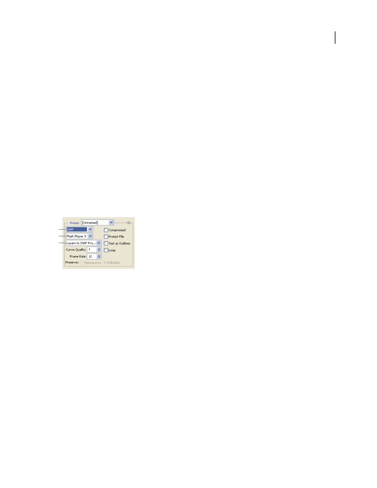
ILLUSTRATOR CS3
User Guide
395
Diffusion Applies a random pattern that is usually less noticeable than Pattern dither. The dither effects are diffused
across adjacent pixels. If you select this algorithm, specify a Dither percentage to control the amount of dithering
applied to the image.
Note: Diffusion dither may cause detectable seams to appear across slice boundaries. Linking slices diffuses the dither
pattern across all linked slices, and eliminates the seams.
Pattern Applies a halftone-like square pattern to determine the value of pixels.
Noise Applies a random pattern similar to the Diffusion dithering, but without diffusing the pattern across adjacent
pixels. No seams appear with the Noise algorithm.
See also
“Optimize an image for the web” on page 383
SWF optimization options (Illustrator)
The Adobe Flash (SWF) file format is a vector-based graphics file format for the creation of scalable, compact
graphics for the web. Because
the file format is vector-based, the artwork maintains its image quality at any
resolution. The SWF format is ideal for the creation of animation frames, but you can also save raster images in SWF
format or mix raster and vector graphics.
Optimization settings for SWF
A. File format menu B. Flash Player menu C. Export menu
Preset Specifies the preconfigured set of options you want to use for export. You can create new presets by setting
options as desired, and then choosing Save Settings from the panel menu. (To open the panel menu, click the triangle
to the right of the Preset menu.)
Flash Player Version Specifies the earliest version of Flash Player that will support the exported file.
Type Of Export Determines how layers are exported. Select AI File To SWF File to export the artwork to a single
frame. Select Layers To SWF Frames to export the artwork on each layer to a separate SWF frame, creating an
animated SWF.
Note: Select AI File To SWF File to preserve layer clipping masks.
Curve Quality Specifies the accuracy of the bezier curves. A low number decreases the exported file size with a slight
loss of curve quality. A higher number increases the accuracy of the bezier curve reproduction, but results in a larger
file size.
Frame Rate Specifies the rate at which the animation will play in a Flash viewer. This option is available only for
Layers To SWF Frames.
Loop Causes the animation to loop continuously, rather than play once and then stop, when played in a Flash viewer.
This option is available only for Layers To SWF Frames.
A
B
C

ILLUSTRATOR CS3
User Guide
396
Preserve Appearance Expands strokes into stroke-shaped fills and flattens any blending modes and transparency
that SWF doesn’t support.
Preserve Editability Where Possible Converts strokes to SWF strokes, and approximates or ignores transparency
that SWF doesn’t support.
Note: SWF supports object-level opacity only.
Use the Export command instead of the Save For Web & Devices command to maintain artwork’s stacking order by
exporting each layer to a separate SWF file. You can then import the exported SWF files into Adobe Flash simulta-
neously.
Compressed Compresses the exported file.
Protect File Protects the file so that it cannot be imported by applications other than Flash.
Text As Outlines Converts all text to outlines to maintain appearance. If you plan to edit the text in Flash, don’t select
this option.
SVG optimization options (Illustrator)
SVG is a vector format that describes images as shapes, paths, text, and filter effects. The resulting files are compact
and provide high-quality graphics on the web, in print, and even on resource-constrained handheld devices.
Optimization settings for SVG
A. File format menu B. SVG Profiles menu C. Font Subsetting menu D. Image Location menu E. CSS Properties menu F. Font Type menu
G. Encoding menu
Compressed Creates a Compressed SVG (SVGZ) file.
SVG Profiles Specifies the SVG XML Document Type Definition for the exported file.
•SVG 1.0 and SVG 1.1 Suitable for SVG files to be viewed on a desktop computer. SVG 1.1 is the full version of the
SVG specification, of which SVG Tiny 1.1, SVG Tiny 1.1 Plus, and SVG Basic 1.1 are subsets.
•SVG Basic 1.1 Suitable for SVG files to be viewed on medium powered devices, such as handhelds. Keep in mind
that not all handhelds support the SVG Basic profile. As a result, selecting this option doesn’t guarantee that the SVG
file will be viewable on all handhelds. SVG Basic doesn’t support nonrectangular clipping and some SVG filter
effects.
•SVG Tiny 1.1 and SVG Tiny 1.1+ Suitable for SVG files to be viewed on small devices, such as mobile phones. Keep
in mind that not all mobile phones support the SVG Tiny and SVG Tiny Plus profiles. As a result, selecting either of
these options doesn’t guarantee that the SVG file will be viewable on all small devices.
•SVG Tiny 1.2 Suitable for SVG files to be viewed on a variety of devices ranging from PDAs and cellphones to
laptops and desktop computers.
SVG Tiny doesn’t support gradients, transparency, clipping, masks, symbols, or SVG filter effects. SVG Tiny Plus
includes the ability to display gradients and transparency, but it doesn’t support clipping, masks, symbols, or SVG
filter effects.
A
B
C
D
E
F
G

ILLUSTRATOR CS3
User Guide
397
For additional information on SVG profiles, see the SVG specification on the World Wide Web Consortium (W3C)
website (www.w3.org).
Decimals Determines the precision of vector data in the SVG file. You can set a value of 1 to 7 decimal places. A high
value results in a larger file size and increased image quality.
Font Subsetting Controls which glyphs are embedded from the SVG file. Select None from the Subsetting menu if
you can rely on the necessary fonts being installed on end-user systems. Select Only Glyphs Used to only include
glyphs for text that exists in the current artwork. The other values (Common English, Common English + Glyphs
Used, Common Roman, Common Roman + Glyphs Used, All Glyphs) are useful when the textual content of the
SVG file is dynamic (such as server-generated text or user-interactive text).
Font Type Specifies how fonts are exported.
•Adobe CEF Uses font hinting for better rendering of small fonts. This font type is supported by the Adobe SVG
Viewer but may not be supported by other SVG viewers.
•SVG Doesn’t use font hinting. This font type is supported by all SVG viewers.
•Convert To Outlines Converts type to vector paths. Use this option to preserve the visual appearance of type in all
SVG Viewers.
Image Location Specifies whether to embed or link to images. Embedding images increases file size but ensures that
rasterized images are always available.
CSS Properties Determines how CSS style attributes are saved in the SVG code. The default method, Presentation
Attributes, applies properties at the highest point in the hierarchy, allowing the most flexibility for specific edits and
transformations. The Style Attributes method creates the most readable files but may increase file size. Choose this
method if the SVG code will be used in transformations—for example, transformations using XSLT (Extensible
Stylesheet Language Transformation). The Entity References method results in faster rendering times and reduced
SVG file size. The Style Element method is used when sharing files with HTML documents. By selecting Style
Element, you can then modify the SVG file to move a style element into an external stylesheet file that is also refer-
enced by the HTML file—however, the Style Element option also results in slower rendering speeds.
Encoding Determines how characters are encoded in the SVG file. UTF (Unicode Transformation Format)
encoding is supported by all XML processors. (UTF-8 is an 8-bit format; UTF-16 is a 16-bit format.) ISO 8859-1 and
UTF-16 encoding don’t preserve file metadata.
Optimize For Adobe SVG Viewer Optimizes images for Adobe SVG Viewer.
Output settings for web graphics
Set output options
Output settings control how HTML files are formatted, how files and slices are named, and how background images
are handled when you save an optimized image. You set these options in the Output Settings dialog box.
You can save your output settings and apply them to other files.
1 To display the Output Settings dialog box, do one of the following:
•When you save an optimized image, choose Other from the Settings pop-up menu in the Save Optimized or Save
Optimized As dialog box.
•Choose Edit Output Settings from the Optimize pop-up menu in the Save For Web & Devices dialog box.

ILLUSTRATOR CS3
User Guide
398
2 (Optional) To display predefined output options, choose an option from the Settings pop-up menu.
3 Edit each set of options as needed. To switch to a different set of options, choose an options set from the pop-up
menu below the Settings menu. Alternatively, click Next to display the next set in the menu list; click Prev to display
the previous set.
4 (Optional) To save output settings, set the options as desired, and click Save. Type a file name, choose a location
for the saved file, and click Save.
You can save the output settings anywhere. However, if you place the file in the Presets/Optimized Output Settings
folder inside the Photoshop program folder or the Presets/Save For Web Settings/Output Settings folder inside the
Illustrator application folder, the file will appear in the Settings pop-up menu.
5 (Optional) To load output settings, click Load, select a file, and click Open.
HTML output options
You can set the following options in the HTML set:
Output XHTML Creates web pages meeting the XHTML standard on export. Choosing Output XHTML disables
other output options that might conflict with this standard. Selecting this option automatically sets the Tags Case
and Attribute Case options.
Tags Case Specifies the capitalization for tags.
Attribute Case Specifies the capitalization for attributes.
Indent Specifies a method for indenting lines of code: using the authoring application’s tab settings, using a specified
number of spaces, or using no indention.
Line Endings Specifies a platform for line ending compatibility.
Encoding Specifies a default character encoding for the web page.
Include Comments Adds explanatory comments to the HTML code.
Always Add Alt Attribute Adds the ALT attribute to IMG elements to comply with government web accessibility
standards.
Always Quote Attributes Places quotation marks around all tag attributes. Placing quotation marks around
attributes is required for compatibility with certain early browsers and for strict HTML compliance. However, always
quoting attributes is not recommended. Quotation marks are used when necessary to comply with most browsers if
this option is deselected.
Close All Tags Adds close tags for all HTML elements in the file for XHTML compliance.
Include Zero Margins On Body Tag Removes default internal margins in a browser window. Adds marginwidth,
marginheight, leftmargin, and topmargin tags with values of zero to the body tag.
Slice output options
You can set the following options in the Slices set:
Generate Table Aligns slices using an HTML table rather than a cascading stylesheet.
Empty Cells Specifies how empty slices are converted to table cells. Select GIF, IMG W&H to use a 1-pixel GIF with
width and height values specified on the IMG tag. Select GIF, TD W&H to use a 1-pixel GIF with width and height
values specified on the TD tag. Select NoWrap, TD W&H to place a nonstandard NoWrap attribute on the table data
and also place width and height values specified on the TD tags.

ILLUSTRATOR CS3
User Guide
399
TD W&H Specifies when to include width and height attributes for table data: Always, Never, or Auto (the recom-
mended setting).
Spacer Cells Specifies when to add one row and one column of empty spacer cells around the generated table: Auto
(the recommended setting), Auto (Bottom), Always, Always (Bottom), or Never. For table layouts in which slice
boundaries do not align, adding spacer cells can prevent the table from breaking apart in some browsers.
Generate CSS Generates a cascading stylesheet rather than an HTML table.
Referenced Specifies how slice positions are referenced in the HTML file when using CSS:
•By ID Positions each slice using styles that are referenced by a unique ID.
•Inline Includes style elements in the declaration of the block element <DIV> tag.
•By Class Positions each slice using classes that are referenced by a unique ID.
Default Slice Naming Choose elements from the pop-up menus or enter text into the fields to create default names
for slices. Elements include the document name, the word slice, numbers or letters designating slices or rollover
states, the slice creation date, punctuation, or none.
Image Maps output settings
You can set the following options in the Image Maps set of the Output Settings dialog box:
Type Specifies what type of image map is created:
•Client-Side Includes all required code for the image map in the image’s HTML file.
•NCSA Server-Side Creates a separate .map file in addition to the HTML file, using NCSA specifications.
•CERN Server-Side Creates a separate .map file in addition to the HTML file, using CERN specifications.
•Client & NCSA Server-Side Creates both a client-side and server-side compatible image map, using NCSA speci-
fications.
•Client & CERN Server-Side Creates both a client-side and server-side compatible image map, using CERN speci-
fications.
Note: Contact your Internet service provider to find out whether to use NCSA or CERN specifications for server-side
image maps.
Placement Specifies the location of the image map declaration (the <MAP> tag) in the HTML file:
•Top Places the image map declaration at the top of the HTML body section.
•Body Places the image map declaration above the <IMG SRC> tag for the associated slice.
•Bottom Places the image map declaration at the bottom of the HTML body section.
See also
“Output settings for web graphics” on page 397
“Optimize an image for the web” on page 383

ILLUSTRATOR CS3
User Guide
400
Background output settings
You can set the following options in the Background set of the Output Settings dialog box:
View Document As Select Image if you want the web page to display an image or a solid color as a background
behind the current image. Select Background if you want the web page to display the optimized image as a tiled
background.
Background Image Enter the location of an image file, or click Choose and select an image. The file you specify will
be tiled behind the optimized image on the web page.
Color
Click the Color box, and select a background color using the color picker, or select an option from the pop-up menu.
Saving Files output settings
You set the following options in the Saving Files set of the Output Settings dialog box:
File Naming Choose elements from the pop-up menus or enter text into the boxes to be combined into the default
names for all files. Elements include document name, slice name, rollover state, trigger slice, file creation date, slice
number, punctuation, and file extension. Some options are relevant only if the file contains slices or rollover states.
The text boxes let you change the order and formatting of the filename parts (for example, letting you indicate
rollover state by an abbreviation instead of the full word).
Filename Compatibility Select one or multiple options to make the filename compatible with Windows (permits
longer filenames), Macintosh, and UNIX operating systems.
Put Images In Folder Specifies a folder name where optimized images are saved (available only with documents
containing multiple slices).
Copy Background Image When Saving Preserves a background image that has been specified in the Background
preferences set.
Include Copyright Includes copyright information with the image.
Include XMP Includes any metadata file information that was added to the document (choose File > File Info to view
or enter document metadata). Metadata is supported by GIF, JPEG, and PNG file formats.

401
Chapter 13: Printing
To make optimum decisions about printing, you should understand basic printing principles, including how the
resolution of your printer or the calibration and resolution of you monitor can affect the way your artwork appears
when printed. Illustrator’s Print dialog box is designed to help you through the printing workflow. Each set of options
in the dialog box is organized to guide you through the printing process.
Basic printing tasks
Print a composite of artwork
A composite is a single-page version of artwork that corresponds to what you see in the illustration window—in
other words, a straightforward print job. Composites are also useful for proofing the overall page design, verifying
image resolution, and identifying problems that may occur on an imagesetter (such as PostScript errors).
1 Choose File > Print.
2
Select a printer from the Printer menu. To print to a file instead of a printer, select Adobe PostScript® File or Adobe PDF.
3 Select Output on the left side of the Print dialog box, and make sure that Mode is set to Composite.
4 Set additional printing options.
5 Click Print.
If your document uses layers, you can specify which ones to print. Choose File > Print, and select an option from the
Print Layers menu: Visible And Printable Layers, Visible Layers, or All Layers. You can also specify specific areas to
print by using crop areas. For a video on creating crop areas for print, see www.adobe.com/go/vid0213.
See also
“Print dialog box options” on page 402
“Create, edit, and delete crop areas” on page 38
“Printing gradients, meshes, and color blends” on page 414
“Printing long, complex paths” on page 411
“Printing and saving transparent artwork” on page 417
Make artwork nonprintable
The Layers panel makes it easy to print different versions of your artwork. For example, you can choose to print only
the type objects in a document in order to proof your text. You can also add nonprinting elements to artwork to
record important information.
•To prevent artwork from displaying in the document window, printing, and exporting, hide the corresponding
items in the Layers panel.
•To prevent artwork from printing, but not from showing on the artboard or exporting, double-click a layer name
in the Layers panel. In the Layer Options dialog box, deselect the Print option, and click OK. The layer name
changes to italics in the Layers panel.

ILLUSTRATOR CS3
User Guide
402
•To create artwork that does not print or export, even when visible on the artboard, select Template in the Layer
Options dialog box.
Note: You can also specify multiple crop areas in your document and then choose one area at a time for printing in the
Print dialog box. Only artwork within the crop area prints. For a video on defining crop areas for print, see
www.adobe.com/go/vid0213.
See also
“Layers panel overview” on page 211
“Create, edit, and delete crop areas” on page 38
Print dialog box options
Each category of options in the Print dialog box—from General options to Summary options—is organized to guide
you through the process of printing your document. To display a set of options, select the set name on the left side
of the dialog box. Many of these options are preset by the startup profile you chose when you started your document.
General Set the page size and orientation, specify how many pages to print, scale the artwork, and choose which
layers to print.
Setup Specify how to crop the artwork, change the placement of artwork on the page, and specify how to print
artwork that doesn’t fit on a single page.
Marks & Bleed Select printer’s marks and create a bleed.
Output Create color separations.
Graphics Set printing options for paths, fonts, PostScript files, gradients, meshes, and blends.
Color Management Select a color profile and rendering intent for printing.
Advanced Control the flattening (or possible rasterization) of vector artwork during printing.
Summary View and save a summary of print settings.
See also
“Create new documents” on page 34
Printer resolution and screen frequency
Printer resolution is measured in the number of ink dots produced per inch (dpi). Most desktop laser printers have
a resolution of 600 dpi, and imagesetters have a resolution of 1200 dpi or higher. Inkjet printers produce a micro-
scopic spray of ink, not actual dots; however, most inkjet printers have an approximate resolution of 300 to 720 dpi.
When printing to a desktop laser printer, but especially to imagesetters, you must also consider screen frequency.
Screen frequency is the number of halftone cells per inch used to print grayscale images or color separations. Also
known as screen ruling or line screen, screen frequency is measured in lines per inch (lpi)—or lines of cells per inch
in a halftone screen.
A high line-screen ruling (for example, 150 lpi) spaces the dots used to create an image close together to create a
finely rendered image on the press; a low screen ruling (60 lpi to 85 lpi) spaces the dots farther apart to create a
coarser image. The size of the dots is also determined by the line screen. A high line-screen ruling uses small dots; a
low screen ruling uses large dots. The most important factor in choosing a line-screen ruling is the type of printing
press your job uses. Ask your print shop how fine a line screen its press can hold, and make your choices accordingly.
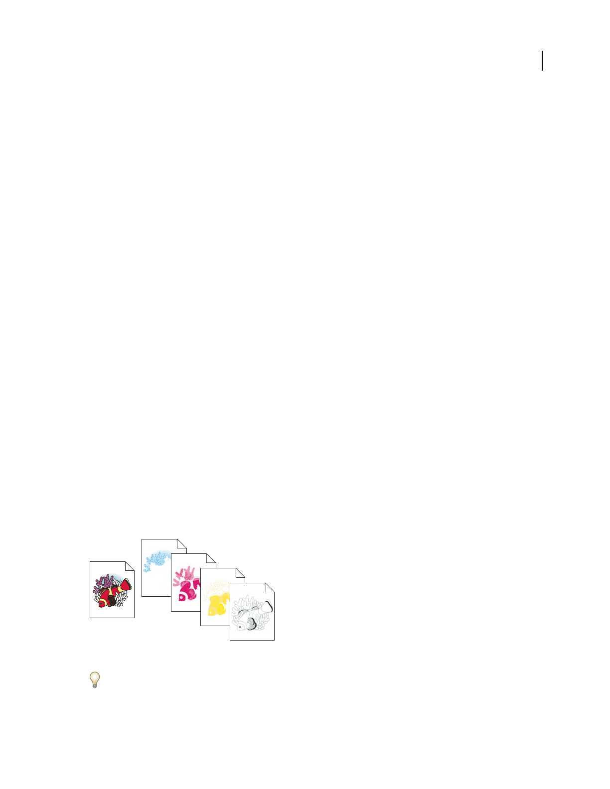
ILLUSTRATOR CS3
User Guide
403
The PPD files for high-resolution imagesetters offer a wide range of possible line-screen rulings paired with various
imagesetter resolutions. The
PPD files for lower-resolution printers typically have only a few choices for line screens,
and they are coarser screens of between 53 lpi and
85 lpi. The coarser screens, however, give optimum results on
lower-resolution printers. Using a finer screen of 100 lpi, for example, actually decreases the quality of your image
when a low-resolution printer is used for final output. That’s because increasing the lpi for a given resolution
decreases the number of colors that can be reproduced.
Note: Some imagesetters and desktop laser printers use screening technologies other than halftoning. If you are printing
an image on a nonhalftone printer, consult your service provider or your printer documentation for the recommended
resolutions.
Change the printer resolution and screen frequency
Adobe Illustrator prints fastest and best by using the default printer resolution and screen frequency. However, in
some cases, you might want to change the printer resolution and screen frequency—for example, if you draw a very
long curved path that won’t print due to a limit-check error, if printing is slow, or if gradients and meshes show
banding when printed.
1 Choose File > Print.
2 For Printer, select a PostScript printer, Adobe PostScript® File, or Adobe PDF.
3 Select Output on the left side of the Print dialog box.
4 For Printer Resolution, select a screen frequency (lpi) and printer resolution (dpi) combination.
Printing color separations
About color separations
To reproduce color and continuous-tone images, printers usually separate artwork into four plates (called process
colors)—one plate for each of the cyan, magenta, yellow, and black portions of the image. You can also include custom
inks (called spot colors). In this case, a separate plate is created for each spot color. When inked with the appropriate
color and printed in register with one another, these colors combine to reproduce the original artwork.
The process of dividing the image into two or more colors is called color separating, and the film from which the
plates are created are called the separations.
Composite image printed on a color laser printer compared to four-color separations printed on an imagesetter.
To produce high-quality separations, you should work closely with the print shop that will produce your separations,
consulting its experts before beginning each job and during the process.

ILLUSTRATOR CS3
User Guide
404
See also
“About process colors” on page 98
“About spot colors” on page 97
Preparing artwork for color separating
Before you print color separations from Illustrator, it’s a good idea to perform the following prepress tasks:
•Set up color management, including calibrating your monitor and selecting an Illustrator Color Setting.
•Soft-proof how color will appear on the intended output device.
•If the document is in RGB mode, choose File > Document Color Mode > CMYK Color to convert it to CMYK Mode.
•If your artwork contains color blends, optimize them so that they print smoothly (without discrete bands of color).
•If your artwork requires trapping, set up appropriate overprinting and trapping.
•If your artwork contains areas of transparent, overlapping colors, preview which areas will be affected by flattening
and note which flattening options you want to use.
Use the Live Color dialog box to globally convert and reduce colors. For example, if you want to convert a process
color document to a 2-color spot document use the Assign portion of Live Color, and specify which colors you want
and how they are assigned to existing colors.
See also
“Printing and saving transparent artwork” on page 417
“Reduce colors in your artwork” on page 122
“Create a trap” on page 426
“Set up overprinting” on page 425
“About color management in Adobe applications” on page 130
Print color separations
1 Choose File > Print.
2 Select a printer and PPD file. To print to a file instead of a printer, select Adobe PostScript® File or Adobe PDF.
3 Select Output on the left side of the Print dialog box.
4 For Mode, select either Separations (Host-Based) or In-RIP Separations.
5 Specify an emulsion, image exposure, and printer resolution for the separations.
6 Set options for the color plates you want to separate:
•To disable printing of a color plate, click the printer icon next to the color in the Document Ink Options list.
Click again to restore printing for the color.
•To convert all spot colors to process colors, so that they are printed as part of the process-color plates rather than
on a separate plate, select Convert All Spot Colors To Process.
•To convert an individual spot color to process colors, click the spot color icon next to the color in the
Document Ink Options list. A four-color process icon appears. Click again to revert the color back to a
spot color.

ILLUSTRATOR CS3
User Guide
405
•To overprint all black ink, select Overprint Black.
•To change the screen frequency, screen angle, and shape of halftone dots for a plate, double-click the ink name.
Alternatively, click the existing setting in the Document Ink Options list, and make the desired changes. Note
however, that the default angles and frequencies are determined by the selected PPD file. Check with your print
shop for the preferred frequency and angle before creating your own halftone screens.
If your art contains more than one spot color, particularly interactions between two or more spot colors, assign
different screen angles to each spot color.
7 Set additional options in the Print dialog box.
In particular, you can specify how to position, scale, and crop the artwork; set up printer’s marks and a bleed; and
choose flattening settings for transparent artwork.
8 Click Print.
See also
“Printer resolution and screen frequency” on page 402
“Print an object on all plates” on page 406
“Print dialog box options” on page 402
Color separation modes
Illustrator supports two common PostScript workflows, or modes, for creating color separations. The main
difference between the two is where separations are created—at the host computer (the system using Illustrator and
the printer driver), or at the output device’s RIP (raster image processor).
In the traditional host-based, preseparated workflow, Illustrator creates PostScript data for each of the separations
required for the document, and sends that information to the output device.
In the newer RIP-based workflow, a new generation of PostScript RIPs perform color separations, trapping, and even
color management at the RIP, leaving the host computer free to perform other tasks. This approach takes less time
for Illustrator to generate the file, and minimizes the amount of data transmitted for any given print job. For example,
instead of sending PostScript information for four or more pages to print host-based color separations, Illustrator
sends the PostScript information for a single composite PostScript file for processing in the RIP.
Emulsion and image exposure
Emulsion refers to the photosensitive layer on a piece of film or paper. Up (Right Reading) means that type in the
image is readable (that is, “right reading”) when the photosensitive layer is facing you. Down (Right Reading) means
that type is readable when the photosensitive layer is facing away from you. Normally, images printed on paper are
printed Up (Right Reading), whereas images printed on film are usually printed Down (Right Reading). Check with
your print shop to determine which emulsion direction it prefers.
To tell whether you are looking at the emulsion side or the nonemulsion side (also referred to as the base), examine
the final film under bright light. One side appears shinier than the other. The dull side is the emulsion side; the shiny
side is the base.
Image exposure refers to whether artwork prints as a positive or negative image. Typically, print shops require
negative film in the United States and positive film in Europe and Japan. If you are unsure about which image type
to use, consult your print shop.

ILLUSTRATOR CS3
User Guide
406
Print an object on all plates
If you want to print an object on all plates in the printing process, including spot-color plates, you can convert it to
a registration color. Registration marks, trim marks, and page information are automatically assigned registration
colors.
1 Select the object.
2 In the Swatches panel, click the Registration color swatch , located in the first row of swatches, by default.
To change the on-screen appearance of the registration color from the default black, use the Color panel. The color
you specify will be used for representing registration-colored objects on the screen. These objects will always print as
gray on composites and as an equal tint of all inks in separations.
Setting up pages for printing
Reposition artwork on the page
The preview image in the Print dialog box shows you where artwork will be printed on the page.
1 Choose File > Print.
2 Do one of the following:
•Drag the artwork in the preview image at the lower left corner of the dialog box.
•Select Setup on the left side of the Print dialog box. Click a square or arrow on the Placement icon to specify the
origin point for aligning the artwork in relation to the page. Enter values for Origin X and Origin Y to fine-tune
the position of the artwork.
To move the printable area directly on the artboard, drag in the illustration window with the Page tool. As you drag,
the Page tool responds as if you were moving the printable area from its lower left corner. You can move the printable
area anywhere on the artboard; however, any part of a page that extends past the printable area boundary is not printed.
See also
“Layers panel overview” on page 211
“Create, edit, and delete crop areas” on page 38
Print artwork on multiple pages
If you are printing artwork that cannot fit on a single page, you can tile the artwork onto multiple pages.
1 Choose File > Print.
2 Select Setup from the list of options on the left side of the Print dialog box, and select a Tiling option:
Tile Full Pages Divides the artboard into full media-sized pages for output.
Tile Imageable Areas Divides the artboard into pages based on what the selected device can image. This option is
useful for outputting artwork that is larger than your device can handle, because it allows you to reassemble tiled
pieces into the original larger artwork.
3 (Optional) If you selected Tile Full Pages, set the Overlap option to specify the amount of overlap between pages.
4 (Optional) Select General on the left side of the Print dialog box. Specify how many copies to print, how to collate
copies, and in which order to print the pages.

ILLUSTRATOR CS3
User Guide
407
To print a range of pages, select Range. Then use numbers separated by a hyphen to indicate an adjacent range, or
use a comma to separate nonadjacent pages or ranges.
See also
“About page tiling” on page 42
Change the page size and orientation
Adobe Illustrator normally uses the default page size defined by the PPD file for the selected printer. However, you
can change the media size to any of the sizes listed in the PPD file as well as specify portrait (vertical) or landscape
(horizontal) orientation. The largest page size you can specify depends on the maximum imageable area of your
imagesetter.
Note the following when specifying the page size and orientation:
•If you select a different media size (for example, if you change from US Letter to US Legal), the artwork is reposi-
tioned in the preview window. This is because the preview window displays the entire imageable area of the
selected media; when the media size is changed, the preview window automatically rescales to include the
imageable area.
Note: The imageable area may vary by PPD file, even for the same media size (for example, US Letter), because different
printers and imagesetters define the sizes of their imageable areas differently.
•The default placement of the page on the film or paper depends on the imagesetter used to print the page.
•Make sure that your media size is large enough to contain your artwork as well as trim marks, registration marks,
and other necessary printing information. To conserve imagesetter film or paper, however, select the smallest page
size that accommodates your artwork and necessary printing information.
•If your imagesetter can accommodate the longest side of your imageable area, you can conserve a considerable
amount of film or paper by using Transverse or changing the orientation of the printed artwork. Consult the
documentation on your specific printer for more information.
1 Choose File > Print.
2 Select a page size from the Size menu. The available sizes are determined by the current printer and PPD file. If
the PPD file for the printer allows it, you can select Custom to specify a custom page size in the Width and Height
text boxes.
3 Click an Orientation button to set the page direction:
Portrait Up Prints in portrait orientation, right side up.
Landscape Left Prints in landscape orientation, rotated to the left.
Portrait Down Prints in portrait orientation, upside down.
Landscape Right Prints in landscape orientation, rotated to the right.
4 (Optional) Select Transverse to rotate the printed artwork 90˚. To use this option, you must use a PPD that
supports transverse printing and custom page sizes.
See also
“About PPD files” on page 410

ILLUSTRATOR CS3
User Guide
408
Scale a document for printing
To fit an oversized document on a piece of paper smaller than the artwork’s actual dimensions, you can use the Print
dialog box to scale the document’s width and height, either symmetrically or asymmetrically. Asymmetric scaling is
useful when, for example, you’re printing film for use on a flexographic press: if you know in which direction the
plate will be mounted on the press drum, scaling can compensate for the 2% to 3% stretching of the plate that usually
occurs. Scaling does not affect the size of the pages in the document, it just changes the scale at which the document
prints.
1 Choose File > Print.
2 Do one of the following:
•To prevent scaling, select Do Not Scale.
•To scale the document automatically to fit to the page, select Fit To Page. The scaling percentage is determined by
the imageable area defined by the selected PPD.
•To activate the Width and Height text boxes, select Custom Scale. Enter percentages from 1 to 1000 for the width
or height. Deselect the Constrain Proportions button to change the document width-to-height ratio.
Printer’s marks and bleed
About printer’s marks
When you prepare artwork for printing, a number of marks are needed for the printer device to register the artwork
elements precisely and verify correct color. You can add the following kinds of printer’s marks to your artwork:
Trim Marks Fine (hairline) horizontal and vertical rules that define where the page should be trimmed. Trim marks
can also help register (align) one color separation to another.
Registration Marks Small targets outside the page area for aligning the different separations in a color document.
Color Bars Small squares of color representing the CMYK inks and tints of gray (in 10% increments). Your service
provider uses these marks to adjust ink density on the printing press.
Page Information Labels the film with the name of the file, the time and date of printout, the line screen used, the
screen angle for the separation, and the color of each particular plate. These labels appear at the tops of the images.
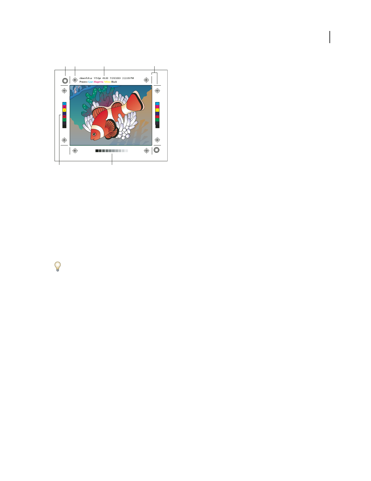
ILLUSTRATOR CS3
User Guide
409
Printer’s marks
A. Star target (not optional) B. Registration mark C. Page information D. Trim marks E. Color bar F. Tint bar
Add printer’s marks
1 Choose File > Print.
2 Select Marks & Bleed on the left side of the Print dialog box.
3 Select the kinds of printer’s marks you want to add. You can also choose between Roman and Japanese-style
marks.
4 (Optional) If you select Trim Marks, specify the width of trim-mark lines and the offset distance between the trim
marks and the artwork.
To avoid drawing printer’s marks on a bleed, be sure to enter an Offset value greater than the Bleed value.
See also
“Specify crop marks for trimming or aligning” on page 40
About bleed
Bleed is the amount of artwork that falls outside of the printing bounding box, or outside the crop area and trim
marks. You can include bleed in your artwork as a margin of error—to ensure that the ink is still printed to the edge
of the page after the page is trimmed or that an image can be stripped into a keyline in a document. Once you create
the artwork that extends into the bleed, you
can use Illustrator to specify the extent of the bleed. Increasing the bleed
makes Illustrator print more of the artwork that is located beyond the trim marks. The trim marks still define the
same size printing bounding box, however.
The size of the bleed you use depends on its purpose. A press bleed (that is, an image that bleeds off the edge of the
printed sheet) should be at least 18 points. If the bleed is to ensure that an image fits a keyline, it needs to be no more
than 2 or 3 points. Your print shop can advise you on the size of the bleed necessary for your particular job.
Add a bleed
1 Choose File > Print.
2 Select Marks & Bleed on the left side of the Print dialog box.
C B D
A
E F

ILLUSTRATOR CS3
User Guide
410
3 Enter values for Top, Left, Bottom, and Right to specify the placement of the bleed marks. Click the link icon
to make all the values the same.
The maximum bleed you can set is 72 points; the minimum bleed is 0 points.
PostScript printing
About PPD files
A PPD (PostScript Printer Description) file customizes the behavior of the driver for your specific PostScript printer.
It contains information about the output device, including printer-resident fonts, available media sizes and orien-
tation, optimized screen frequencies, screen angles, resolution, and color output capabilities. It’s important to select
the correct PPD before you print. Selecting the PPD that corresponds to your PostScript printer or imagesetter
populates the Print dialog box with the available settings for the output device. You can switch to a different one to
suit your needs.
Applications use the information in the PPD file to determine which PostScript information to send to the printer
when printing a document. For example, the application assumes that the fonts listed in your PPD file reside in the
printer, so they are not downloaded when you print, unless you explicitly include them.
For best printing results, Adobe recommends that you obtain the latest version of the PPD file for your output device
from the manufacturer. Many print service providers and commercial printers have PPDs for the imagesetters they
use. Be sure to store PPDs in the location specified by the operating system. For details, consult the documentation
for your operating system.
Change the PPD file
When you print to a PostScript printer, PostScript file, or PDF, Illustrator automatically uses the default PPD
(PostScript Printer Description) for that device. You can switch to a different one to suit your needs.
1 Choose File > Print.
2 From the PPD menu, select one of the following:
•A PPD that corresponds to the current output device.
•Other. Lets you select a custom PPD, such as one provided by your service bureau for use with the specified
printer. The PPD’s filename corresponds to the printer’s or imagesetter’s name and model, and may display a .ppd
file extension (depending on how your system is set up.) Navigate to the PPD you want, select it, and click Open.
Note: Certain PPD features commonly found in imagesetter PPDs aren’t accessible from the Illustrator Print dialog box.
To set those printer-specific features, click Setup (Windows) or Printer (Mac OS) in the Print dialog box.
Select a PPD file
The steps for selecting a PPD file are different for each platform.
Select a PPD file in Windows
1
Depending on your version of Windows, do one of the following to open the Add Printer wizard:
•In Windows 2000, choose Start > Settings > Printers > Add Printer.
•In Windows XP, choose Start, open the Printers and Faxes control panel, and click Add a Printer.

ILLUSTRATOR CS3
User Guide
411
2 Follow the instructions to add a printer and specify a PPD file.
Select a PPD file in Mac OS
1
Open the area where you add printers.
2 Click Add in the Printer List window.
3 From the top menu, choose a connection method.
4 Select a printer, or enter the printer’s IP address.
5 From the bottom menu, select a printer model.
6 In the list that appears, select a PPD file, and then click Add.
Printing long, complex paths
If you are printing Adobe Illustrator files containing overly long or complicated paths, the file may not print and you
may receive limit-check error messages from your printer. To simplify long, complex paths, you can split them into
two or more separate paths. You can also change the number of line segments used to approximate curves and adjust
the printer resolution.
See also
“Split a path” on page 77
Change the number of line segments used to print vector objects
Curves in artwork are defined by the PostScript interpreter as small straight line segments; the smaller the line
segments, the more accurate the curve. As the number of line segments increases, so does the complexity of the
curve. Depending on your printer and the amount of memory it has, a curve may be too complex for a PostScript
interpreter to rasterize. In this case, a PostScript limit-check error can result, and the curve won’t print.
1 Choose File > Print.
2 For Printer, select a PostScript printer, Adobe PostScript® File, or Adobe PDF.
3 Select Graphics on the left side of the Print dialog box.
4 Deselect Automatic, and use the Flatness slider to set the accuracy of curves.
A lower setting (toward Quality) creates more, smaller straight line segments, more closely approximating the curve.
A higher setting (toward Speed) results in longer and fewer line segments, creating a less accurate curve, but
improving performance.
Split paths for printing
Illustrator treats split paths in the artwork as separate objects. To change your artwork once paths are split, you must
either work with the separate shapes or rejoin the paths to work with the image as a single shape.
It’s a good idea to save a copy of your original artwork before splitting paths. That way, you still have the original,
unsplit file to work with if needed.
❖Do any of the following:
•To split a stroked path, use the Scissors tool .
•To split a compound path, choose Object > Compound Paths > Release to remove the compound path. Then
break the path into pieces using the Scissors tool, and redefine the pieces as compound paths.

ILLUSTRATOR CS3
User Guide
412
•To split a mask, choose Object > Clipping Mask > Release to remove the mask. Then break the path into pieces
using the Scissors tool, and redefine the pieces as masks.
To rejoin a path after you split it, select all of the split paths that made up the original object, and click the Add To
Shape Area button in the Pathfinder panel. The path is rejoined, with an anchor point placed at each intersection
where a split path was reconnected.
Control how fonts are downloaded to a printer
Printer-resident fonts are fonts stored in a printer’s memory or on a hard drive connected to the printer. Type 1 and
TrueType fonts can be stored either on the printer or on your computer; bitmap fonts are stored only on your
computer. Illustrator downloads fonts as needed, provided they are installed on your computer’s hard disk.
1 Choose File > Print.
2 For Printer, select a PostScript printer, Adobe PostScript® File, or Adobe PDF.
3 Select Graphics on the left side of the Print dialog box, and select a Download option:
None Includes a reference to the font in the PostScript file which tells the RIP or a post-processor where the font
should be included. This option is appropriate if the fonts reside in the printer. TrueType fonts are named according
to the PostScript name in the font; however, not all applications can interpret these names. To ensure that TrueType
fonts are interpreted correctly, use one of the other font downloading options.
Subset Downloads only the characters (glyphs) used in the document. Glyphs are downloaded once per page. This
option typically results in faster and smaller PostScript files when used with single-page documents, or with short
documents without much text.
Complete Downloads all fonts required for the document at the beginning of the print job. This option typically
results in faster and smaller PostScript files when used with multipage documents.
Note: Some font manufacturers restrict the embedding of font files. Restrictions apply to copying font software. You are
required to comply with applicable copyright law and the terms of your license agreement. For font software licensed
from Adobe, your license agreement provides that you may take a copy of the font(s) you have used for a particular file
to a commercial printer or other service provider, and the service provider may use the font(s) to process your file,
provided the service provider has informed you that it has the right to use that particular software. For other font
software, please obtain permission from your vendor.
See also
“About fonts” on page 303
Change the PostScript level for printing
When you print to a PostScript or PDF file, Illustrator automatically selects the PostScript level of your output device.
If you want to change the Postscript level or data format for PostScript files, do the following:
1 Choose File > Print.
2 For Printer, select Adobe PostScript® File or Adobe PDF.
3 Select Graphics on the left side of the Print dialog box.
4 For PostScript, select the level of compatibility with the interpreters in PostScript output devices.
Level 2 improves the printing speed and output quality of graphics printed on a PostScript Level 2 or greater output
device. Level 3 provides the best speed and output quality on a PostScript 3 device.

ILLUSTRATOR CS3
User Guide
413
5 (Optional) If you chose Adobe PostScript® File as the printer, select a Data Format option to specify how Illustrator
sends the image data from your computer to a printer.
Binary exports the image data as binary code, which is more compact than ASCII but may not be compatible with
all systems. ASCII exports the image data as ASCII text, which is compatible with older networks and parallel
printers and is usually the best choice for graphics used on multiple platforms. It is also usually the best choice for
documents used only on Mac
OS systems.
Printing with color management
Let your application manage colors when printing
1 Choose File > Print.
2 Select Color Management on the left side of the Print dialog box.
3 For Color Handling, choose Let Illustrator Determine Colors.
4 For Printer Profile, select the profile for your output device.
The more accurately the profile describes the behavior of an output device and printing conditions (such as paper
type), the more accurately the color management system can translate the numeric values of the actual colors in a
document. (See “About color profiles” on page 141.)
5 (Optional) Set the Rendering Intent option to specify how the application converts colors to the destination color
space.
In most cases, it is best to use the default rendering intent. For more information on rendering intents, search in Help.
6 Click Setup (Windows) or Printer (Mac OS) at the bottom of the Print dialog box to access the operating system
print settings.
7 Access the color management settings for the printer driver by doing one of the following:
•In Windows, right-click the printer you are using, and select Properties. Then locate the color management
settings for the printer driver. For most printer drivers, color management settings are labeled Color Management
or ICM.
•In Mac OS, select the printer you are using, and select the color management option from the pop-up menu. For
most printer drivers, this option is labeled ColorSync.
8 Turn off color management for the printer driver.
Every printer driver has different color management options. If it’s not clear how to turn off color management,
consult your printer documentation.
9 Return to the Illustrator Print dialog box, and click Print.
See also
“Printing with color management” on page 139
Let your printer manage colors when printing
1 Choose File > Print.

ILLUSTRATOR CS3
User Guide
414
2 Select a PostScript printer from the Printer menu. To print to a file instead of a printer, select Adobe PostScript®
File or Adobe PDF.
3 Select Color Management on the left side of the Print dialog box.
4 For Color Handling, choose Let PostScript® Printer Determine Colors.
5 (Optional) Set any of the following options. In most cases, it is best to use the default settings.
Rendering Intent Specifies how the application converts colors to the destination color space.
Preserve RGB Numbers (for RGB output) or Preserve CMYK Numbers (for CMYK output) Determines how Illustrator
handles colors that do not have a color profile associated with them (for example, imported images without
embedded profiles). When this option is selected, Illustrator sends the color numbers directly to the output device.
When this option is deselected, Illustrator first converts the color numbers to the color space of the output device.
Preserving numbers is recommended when you are following a safe CMYK workflow. Preserving numbers is not
recommended for printing RGB documents.
6 Click Setup (Windows) or Printer (Mac OS) at the bottom of the Print dialog box to access the operating system
print settings.
7 Access the color management settings for the printer driver by doing one of the following:
•In Windows, right-click the printer you are using, and select Properties. Then locate the color management
settings for the printer driver. For most printer drivers, color management settings are labeled Color Management
or ICM.
•In Mac OS, select the printer you are using, and select the color management option from the pop-up menu. For
most printer drivers, this option is labeled ColorSync.
8 Specify the color management settings to let your printer driver handle the color management during printing.
Every printer driver has different color management options. If it’s not clear how to set color management options,
consult your printer documentation.
9 Return to the Illustrator Print dialog box, and click Print.
See also
“About rendering intents” on page 149
“Using a safe CMYK workflow” on page 134
“Printing with color management” on page 139
Printing gradients, meshes, and color blends
Printing gradients, meshes, and color blends
Files with gradients, meshes, or color blends can be difficult for some printers to print smoothly (without discrete
bands of color) or at all. Follow these general guidelines to improve the printed results:
•Use a blend that changes at least 50% between two or more process-color components.
•Use shorter blends. The optimum length depends on the colors in your blend, but try to keep blends shorter than
7.5 inches.

ILLUSTRATOR CS3
User Guide
415
•Use lighter colors, or make dark blends short. Banding is most likely to occur between very dark colors and white.
•Use an appropriate line screen that retains 256 levels of gray.
•If you create a gradient between two or more spot colors, assign different screen angles to the spot colors when
you create color separations. If you’re not sure what the angles should be, consult your print shop.
•Print to an output device that supports PostScript® Language Level 3 whenever possible.
•If you have to print to an output device that supports Postscript Language Level 2, or when printing meshes that
include transparency, you can choose to rasterize gradients and meshes during printing. As a result, Illustrator
converts gradients and meshes from vector objects to JPEG images.
Rasterize gradients and meshes during printing
1 Choose File > Print.
2 Select Graphics on the left side of the Print dialog box, and select Compatible Gradient And Gradient Mesh
Printing.
Important: The Compatible Gradient And Gradient Mesh Printing option can slow printing on printers that don’t have
problems with gradients, so only select this option if you experience printing problems.
Setting the proper screen frequency for printing gradients, meshes, and blends
When printing your file, you may find that the resolution of your printer, when combined with the chosen screen
frequency, allows fewer than 256 levels of gray. A higher screen frequency decreases the levels of gray available to the
printer. For example, if you are printing at a resolution of 2400 dpi, using a line screen higher than 150 results in fewer
than 256 levels of gray. The following table lists the maximum line-screen setting you can use with printers to
maintain all 256 levels of gray:
Final Imagesetter Resolution Maximum Line Screen
to Use
300 19
400 25
600 38
900 56
1000 63
1270 79
1446 90
1524 95
1693 106
2000 125
2400 150
2540 159
3000 188
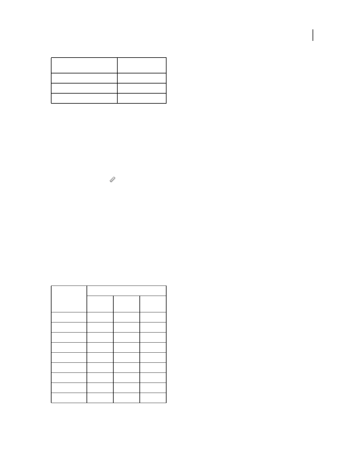
ILLUSTRATOR CS3
User Guide
416
See also
“Printer resolution and screen frequency” on page 402
“Change the printer resolution and screen frequency” on page 403
Calculate the maximum blend length for gradients
Illustrator calculates the number of steps in a gradient based on the percentage of change between the colors in the
gradient. The number of steps, in turn, determines the maximum length of the blend before banding occurs.
1 Select the Measure tool , and click the beginning point and the endpoint of the gradient.
2 Note the distance displayed in the Info panel on a piece of paper. This distance represents the length of the
gradient or color blend.
3 Calculate the number of steps in the blend using this formula:
Number of steps = 256 (number of grays) X Percentage change in color
To figure out the percentage change in color, subtract the lower color value from the higher color value. For example,
a blend between 20% black and 100% black is an 80%—or 0.8—change in color.
When blending process colors, use the largest change that occurs within any one color. For instance, take a blend
from 20% cyan, 30% magenta, 80% yellow, and 60% black to 20% cyan, 90% magenta, 70% yellow, and 40% black.
This indicates a 60% change, because the greatest change occurs in magenta—from 30% to 90%.
4 Using the number of steps calculated in step 3, see if the length of the gradient is larger than the relevant
maximum length indicated in the next chart. If it is, reduce the length of the gradient or change the colors.
3252 203
3600 225
4000 250
Number of Steps
Adobe
Illustrator
Recommends
Maximum Blend Length
Points Inches Cms
10 21.6 .3 .762
20 43.2 .6 1.524
30 64.8 .9 2.286
40 86.4 1.2 3.048
50 108.0 1.5 3.810
60 129.6 1.8 4.572
70 151.2 2.1 5.334
80 172.8 2.4 6.096
90 194.4 2.7 6.858
Final Imagesetter Resolution Maximum Line Screen
to Use

ILLUSTRATOR CS3
User Guide
417
See also
“Document Info panel overview” on page 288
Printing and saving transparent artwork
About flattening
If your document or artwork contains transparency, to be output it usually needs to undergo a process called
flattening. Flattening divides transparent artwork into vector-based areas and rasterized areas. As artwork becomes
more complex (mixing images, vectors, type, spot colors, overprinting, and so on), so does the flattening and its
results.
Flattening may be necessary when you print or when you save or export to other formats that don’t support trans-
parency. To retain transparency without flattening when you create PDF files, save your file as Adobe PDF 1.4
(Acrobat
5.0) or later.
You can specify flattening settings and then save and apply them as transparency flattener presets. Transparent
objects are flattened according to the settings in the selected flattener preset.
Note: Transparency flattening cannot be undone after the file is saved.
100 216.0 3.0 7.620
110 237.6 3.3 8.382
120 259.2 3.6 9.144
130 280.8 3.9 9.906
140 302.4 4.2 10.668
150 324.0 4.5 11.430
160 345.6 4.8 12.192
170 367.2 5.1 12.954
180 388.8 5.4 13.716
190 410.4 5.7 14.478
200 432.0 6.0 15.240
210 453.6 6.3 16.002
220 475.2 6.6 16.764
230 496.8 6.9 17.526
240 518.4 7.2 18.288
250 540.0 7.5 19.050
256 553.0 7.7 19.507
Number of Steps
Adobe
Illustrator
Recommends
Maximum Blend Length
Points Inches Cms

ILLUSTRATOR CS3
User Guide
418
Overlapping art is divided when flattened.
For more information on transparency output issues, see the Print Service Provider Resources page of the Adobe
Solutions Network (ASN) (English only), available on the Adobe website.
File formats that retain transparency
When you save an Illustrator file in certain formats, the native transparency information is retained. For example,
when you save a file in Illustrator CS (or later) EPS format, the file contains both native Illustrator data and EPS data.
When you reopen the file in Illustrator, the native (unflattened) data is read. When you place the file into another
application, the EPS (flattened) data is read.
When possible, keep your file in a format in which native transparency data is retained, allowing you to make edits
as necessary.
Native transparency data is retained when you save to the following formats:
•AI9 and later
•AI9 EPS and later
•PDF 1.4 and later (when Preserve Illustrator Editing Capabilities option is selected)
Illustrator flattens artwork when you perform any of the following actions:
•Print a file that contains transparency.
•Save a file that contains transparency in a legacy format such as native Illustrator 8 and earlier, Illustrator 8 EPS
and earlier, or PDF 1.3 format. (For the Illustrator and Illustrator EPS formats, you can choose to discard trans-
parency rather than flatten it.)
•Export a file that contains transparency to a vector format that does not understand transparency (such as EMF
or WMF).
•Copy and paste transparent art from Illustrator into another application with both the AICB and the Preserve
Appearance options checked (in the File Handling & Clipboard section of the Preferences dialog box).
•Export in SWF (Flash) or use the Flatten Transparency command with the Preserve Alpha Transparency option
selected. This command lets you preview how artwork will look when exported in SWF.
For more information on creating and printing transparency, see the Transparency white paper in the Adobe
Technical Info/White Papers folder on the Illustrator CD. You can also find more information on printing and
flattening files with transparency in the Adobe Illustrator User to User forum. This is a public forum that offers a wealth
of tips and answers to frequently asked questions, and can be found at www.adobe.com/support/forums.
Set transparency flattening options for printing
1 Choose File > Print.

ILLUSTRATOR CS3
User Guide
419
2 Select Advanced on the left side of the Print dialog box.
3 Select a flattening preset from the Preset menu, or click Custom to set specific flattening options.
4 If the artwork contains overprinted objects that interact with transparent objects, select an option from the
Overprints menu. You can preserve, simulate, or discard overprints.
Note: If the artwork does not contain transparency, the document will not be flattened and the flattening settings are not
relevant. Use the Flattener Preview panel to determine which areas of the artwork contain transparency.
See also
“Transparency Flattener options” on page 419
Transparency Flattener options
You can set Transparency Flattener options when creating, editing, or previewing flattener presets in Illustrator,
InDesign, or Acrobat.
Highlight (preview) options
None (Color Preview) Disables previewing.
Rasterized Complex Regions Highlights the areas that will be rasterized for performance reasons (as determined by
the Rasters/Vectors slider). Keep in mind that the boundary of the highlight area has a higher probability of
producing stitching problems (depending on the print-driver settings and the rasterization resolution). To minimize
stitching problems, select Clip Complex Regions.
Transparent Objects Highlights the objects that are sources of transparency, such as objects with partial opacity
(including images with alpha channels), objects with blending modes, and objects with opacity masks. In addition,
note that styles and effects may contain transparency, and overprinted objects may be treated as sources of trans-
parency if they are involved in transparency or if the overprint needs to be flattened.
All Affected Objects Highlights all objects that are involved in transparency, including transparent objects and
objects that are overlapped by transparent objects. The highlighted objects will be affected by the flattening process—
their strokes or patterns will be expanded, portions of them may get rasterized, and so on.
Affected Linked EPS Files (Illustrator only) Highlights all linked EPS files that are affected by transparency.
Affected Graphics (InDesign only) Highlights all placed content affected by transparency or transparency effects.
This option is useful for service providers who need to see graphics that require attention to print properly.
Expanded Patterns (Illustrator and Acrobat) Highlights all patterns that will be expanded if involved in trans-
parency.
Outlined Strokes Highlights all strokes that will be outlined if involved in transparency or because Convert All
Strokes To Outlines is selected.
Outlined Text (Illustrator and InDesign) Highlights all text that will be outlined if involved in transparency or
because Convert All Text To Outlines is selected.
Note: In the final output, outlined strokes and text may appear slightly different from native ones, especially very thin
strokes and very small text. However, the Flattener Preview doesn’t highlight this altered appearance.
Raster-Fill Text And Strokes (InDesign only) Highlights text and strokes that have rasterized fills as a result of
flattening.

ILLUSTRATOR CS3
User Guide
420
All Rasterized Regions (Illustrator and InDesign) Highlights objects and intersections of objects that will be
rasterized because there is no other way of representing them in PostScript or because they are more complex than
the threshold specified by the Rasters/Vectors slider. For example, the intersection of two transparent gradients will
always be rasterized, even if the Rasters/Vectors value is 100. The All Rasterized Regions option also shows raster
graphics (such as Photoshop files) involved in transparency, and raster effects such as drop shadows and feathers.
Note that this option takes longer to process than the others.
Transparency Flattener Preset options
Name/Preset Specifies the name of the preset. Depending on the dialog box, you can type a name in the Name text
box or accept the default. You can enter the name of an existing preset to edit that preset. However, you can’t edit the
default presets.
Raster/Vector balance Specifies the amount of vector information that will be preserved. Higher settings preserve
more vector objects, while lower settings rasterize more vector objects; intermediate settings preserve simple areas
in vector form and rasterize complex ones. Select the lowest setting to rasterize all the artwork.
Note: The amount of rasterization that occurs depends on the complexity of the page and the types of overlapping objects.
Line Art And Text Resolution Rasterizes all objects, including images, vector artwork, text, and gradients, to the
specified resolution. Acrobat and InDesign allow a maximum of 9600 pixels per inch (ppi) for line art, and 1200 ppi
for gradient mesh. Illustrator allows a maximum of 9600 ppi for both line art and gradient mesh. The resolution
affects the precision of intersections when flattened. Line Art and Text Resolution should generally be set to
600-1200 to provide high-quality rasterization, especially on serif or small point sized type.
Gradient And Mesh Resolution Specifies the resolution for gradients and Illustrator mesh objects rasterized as a
result of flattening, from 72 to 2400 ppi. The resolution affects the precision of intersections when flattened. Gradient
and mesh resolution should generally be set between 150 and 300 ppi, because the quality of the gradients, drop
shadows, and feathers do not improve with higher resolutions, but printing time and file size increase.
Convert All Text To Outlines Converts all type objects (point type, area type, and path type) to outlines and discards
all type glyph information on pages containing transparency. This option ensures that the width of text stays
consistent during flattening. Note that enabling this option will cause small fonts to appear slightly thicker when
viewed in Acrobat or printed on low-resolution desktop printers. It doesn’t affect the quality of the type printed on
high-resolution printers or imagesetters.
Convert All Strokes To Outlines Converts all strokes to simple filled paths on pages containing transparency. This
option ensures that the width of strokes stays consistent during flattening. Note that enabling this option causes thin
strokes to appear slightly thicker and may degrade flattening performance.
Clip Complex Regions Ensures that the boundaries between vector artwork and rasterized artwork fall along object
paths. This option reduces stitching artifacts that result when part of an object is rasterized while another part of the
object remains in vector form. However, selecting this option may result in paths that are too complex for the printer
to handle.
Stitching, where rasters and vectors meet.

ILLUSTRATOR CS3
User Guide
421
Note: Some print drivers process raster and vector art differently, sometimes resulting in color stitching. You may be able
to minimize stitching problems by disabling some print-driver specific color-management settings. These settings vary
with each printer, so see the documentation that came with your printer for details.
(Illustrator only) Select Preserve Alpha Transparency (Flatten Transparency dialog box only) Preserves the overall
opacity of flattened objects. With this option, blending modes and overprints are lost, but their appearance is
retained within the processed artwork, along with the level of alpha transparency (as when you rasterize artwork
using a transparent background). Preserve Alpha Transparency can be useful if you are exporting to SWF or SVG,
since both of these formats support alpha transparency.
(Illustrator only) Select Preserve Spot Colors And Overprints (Flatten Transparency dialog box only) Generally
preserves spot colors. It also preserves overprinting for objects that aren’t involved in transparency. Select this option
when printing separations if the document contains spot colors and overprinted objects. Deselect this option when
saving files for use in page-layout applications. With this option selected, overprinted areas that interact with trans-
parency are flattened, while overprinting in other areas is preserved. The results are unpredictable when the file is
output from a page-layout application.
Preserve Overprint (Acrobat only) Blends the color of transparent artwork with the background color to create an
overprint effect.
Preview which areas of artwork will be flattened
Use the preview options in the Flattener Preview to highlight areas that are affected by flattening. You can use this
color-coded information to adjust flattening options.
Note: The Flattener Preview is not intended for precise previewing of spot colors, overprints, and blending modes.
Instead, use Overprint Preview mode for those purposes.
1 Display the Flattener Preview panel (or dialog box):
•In Illustrator, choose Window > Flattener Preview.
•In Acrobat, choose Advanced > Print Production > Flattener Preview.
•In InDesign, choose Window > Output > Flattener Preview.
2 From the Highlight menu, choose the kind of areas you want to highlight. The availability of options depends on
the content of the artwork.
3 Select the flattening settings you want to use: Either choose a preset or, if available, set specific options.
Note: (Illustrator) If the flattening settings aren’t visible, select Show Options from the panel menu to display them.
4 If the artwork contains overprinted objects that interact with transparent objects, in Illustrator, select an option
from the Overprints menu. You can preserve, simulate, or discard overprints. In Acrobat, choose Preserve Overprint
to blend the color of transparent artwork with the background color to create an overprint effect.
5 At any time, click Refresh to display a fresh preview version based on your settings. Depending on the complexity
of the artwork, you may need to wait a few seconds for the preview image to appear. In InDesign, you can also choose
Auto Refresh Highlight.
In Illustrator and Acrobat, to magnify the preview, click in the preview area. To zoom out, Alt-click/Option-click in
the preview area. To pan the preview, hold down the spacebar and drag in the preview area.
See also
“About flattening” on page 417
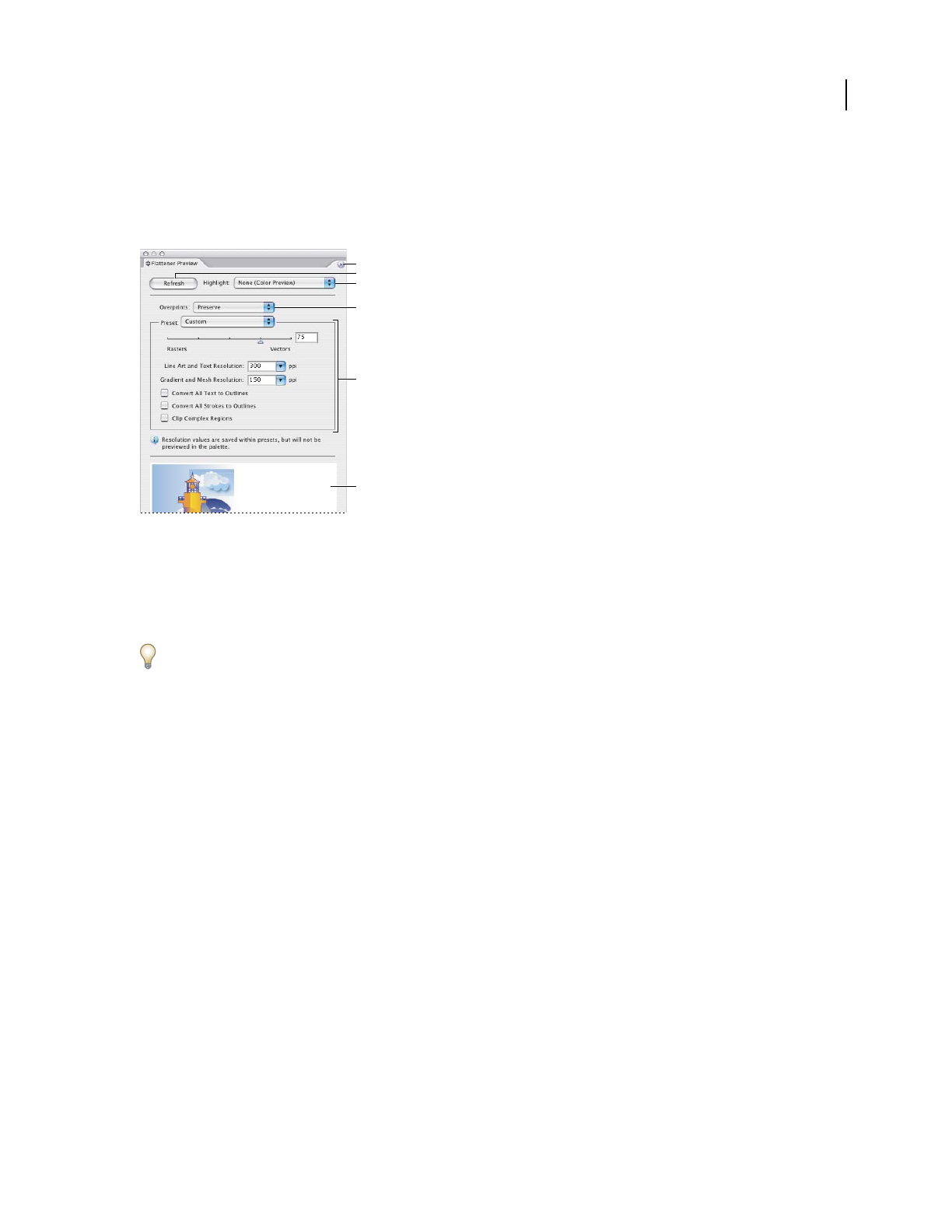
ILLUSTRATOR CS3
User Guide
422
Flattener Preview panel overview
You use the preview options in the Flattener Preview panel to highlight the areas affected by flattening artwork. You
can use this information to adjust the flattening options, and even use the panel to save flattener presets. To display
the Flattener Preview panel, choose Window
> Flattener Preview.
Flattener Preview panel
A. Panel menu B. Refresh button C. Highlight menu D. Overprint menu E. Transparency flattening settings F. Preview area
You can control the speed and quality of the preview image by selecting an option from the panel menu. Select Quick
Preview to compute the quickest preview; select Detailed Preview to add the option All Rasterized Regions to the
Highlight pop-up menu (this option is more performance-intensive to compute).
Keep in mind that the Flattener Preview panel is not intended for precise previewing of spot colors, overprints,
blending modes, and image resolution. Use Overprint Preview mode in Illustrator to preview spot colors, overprints,
and blending modes as they will appear when output.
See also
“Transparency Flattener options” on page 419
About transparency flattener presets
If you regularly print or export documents that contain transparency, you can automate the flattening process by
saving flattening settings in a transparency flattener preset. You can then apply these settings for print output as well
as for saving and exporting files to PDF
1.3 (Acrobat 4.0) and EPS and PostScript formats. In addition, in Illustrator
you can apply them when saving files to earlier versions of Illustrator or when copying to the clipboard; in InDesign
you can also apply them when exporting to SVG format; in Acrobat, you can also apply them when optimizing PDFs.
These settings also control how flattening occurs when you export to formats that don’t support transparency.
You can choose a flattener preset in the Advanced panel of the Print dialog box or of the format-specific dialog box
that appears after the initial Export or Save As dialog box. You can create your own flattener presets or choose from
the default options provided with the software. The settings of each of these defaults are designed to match the
quality and speed of the flattening with an appropriate resolution for rasterized transparent areas, depending on the
document’s intended use:
[High Resolution] is for final press output and for high-quality proofs, such as separations-based color proofs.
A
D
F
E
C
B

ILLUSTRATOR CS3
User Guide
423
[Medium Resolution] is for desktop proofs and print-on-demand documents that will be printed on PostScript color
printers.
[Low Resolution] is for quick proofs that will be printed on black-and-white desktop printers and for documents that
will be published on the web or exported to SVG.
Create or edit a transparency flattener preset
You can save transparency flattener presets in a separate file, making it easy to back them up or to make them
available to your service providers, clients, or others in your workgroup. In InDesign, transparency flattener preset
files have an .flst extension.
1 Choose Edit > Transparency Flattener Presets.
2 Do one of the following:
•To create a new preset, click New.
•To base a preset on a predefined preset, select one in the list and click New.
•To edit an existing preset, select the preset and click Edit.
Note: You can’t edit the default flattener presets.
3 Set flattening options.
4 Click OK to return to the Transparency Flattener Presets dialog box, and click OK again.
Export and import a custom transparency flattener preset
You can export and import transparency flattener presets in order to share them with your service providers, your
clients, or others in your workgroup.
1 Choose Edit > Transparency Flattener Presets.
2 Select a preset in the list.
3 Do one of the following:
•To export a preset to a separate file, click Save (InDesign) or Export (Illustrator), specify a name and location, and
then click Save.
Consider saving the preset outside of the application’s preferences folder. That way, it won’t be lost if you delete your
preferences.
•To import presets from a file, click Load (InDesign) or Import (Illustrator). Locate and select the file containing
the preset you want to load, and then click Open.
Rename or delete a custom transparency flattener preset
1 Choose Edit > Transparency Flattener Presets.
2 Select a preset in the list.
3 Do one of the following:
•To rename an existing preset, click Edit, type a new name, and then click OK.
•To delete a preset, click Delete, and then click OK to confirm the deletion.
Note: You cannot delete the default presets.

ILLUSTRATOR CS3
User Guide
424
Flatten transparency for individual objects
The Flatten Transparency command lets you see what your artwork will look like when flattened. For instance, you
might use this command before saving the file in SWF (Flash) format or if you are having problems printing legacy
art where transparency may be the culprit.
1 Select the object.
2 Choose Object > Flatten Transparency.
3 Select the flattening settings you want to use, either by choosing a preset or setting specific options.
4 Click OK.
To save the flattening settings for use with other objects and documents in the current session, click Save Preset. If
you want to create a permanent preset, choose Edit > Transparency Flattener Presets instead.
See also
“Transparency Flattener options” on page 419
Rasterize all artwork during printing
When you print to a low-resolution or non-PostScript printer, such as a desktop inkjet printer, you can choose to
rasterize all artwork during printing. This option is useful when printing documents that contain complex objects
(such
as objects with smooth shading or gradients) because it reduces the possibility of errors.
1 Choose File > Print.
2 Select Advanced on the left side of the Print dialog box.
3 Select Print As Bitmap.
This option is only available if the printer driver for the selected printer supports bitmap printing.
Overprinting
About overprinting
By default, when you print opaque, overlapping colors, the top color knocks out the area underneath. You can use
overprinting to prevent knockout and make the topmost overlapping printing ink appear transparent in relation to
the underlying ink. The degree of transparency in printing depends on the ink, paper, and printing method used.
Consult your print shop to determine how these variables will affect your final artwork.
You may want to overprint in the following situations:
•Overprint black ink to aid in registration. Because black ink is opaque (and usually the last to be printed), it doesn’t
look much different when printed over a color as opposed to a white background. Overprinting black can prevent
gaps from appearing between black and colored areas of your artwork.
•Overprint when the artwork does not share common ink colors and you want to create a trap or overlaid ink
effects. When overprinting process color mixes or custom colors that do not share common ink colors, the
overprint color is added to the background color. For example, if you print a fill of 100% magenta over a fill of
100% cyan, the overlapping fills appear violet, not magenta.
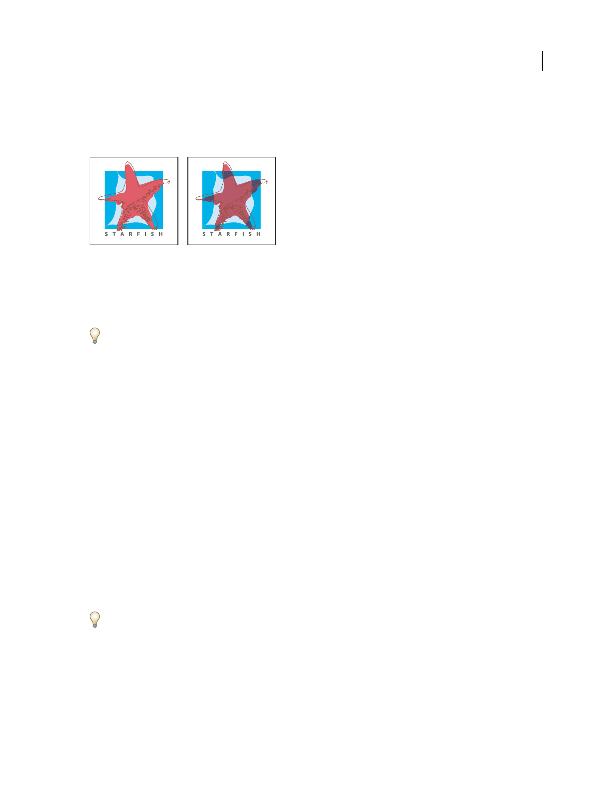
ILLUSTRATOR CS3
User Guide
425
After you set overprinting options, you should use the Overprint Preview mode (View > Overprint Preview) to see
an approximation of how the overprinting colors will print. You should also carefully check overprinted colors on
separated artwork using integral proofs (where each separation is shown in register on a single piece of paper) or
overlay proofs (where the separations are shown in register on separate plastic sheets stacked on top of each other).
Colors knocked out (by default) and with overprinting
Set up overprinting
1 Select the object or objects that you want to overprint.
2 In the Attributes panel, select Overprint Fill, Overprint Stroke, or both.
If you use the Overprint option on a 100% black stroke or fill, the black ink may not be opaque enough to prevent
the underlying ink colors from showing through. To eliminate the show-through problem, use a four-color (rich)
black instead of a 100% black. Consult with your print shop about the exact percentages of color to add to the black.
Overprint black
To overprint all black in your artwork, select the Overprint Black option in the Print dialog box when you create
color separations. This option works on all objects that have black applied through the K color channel. However, it
does not work for objects that appear black because of their transparency settings or graphic styles.
You can also use the Overprint Black command to set up overprinting for objects that contain a specific percentage
of black. To use the Overprint Black command:
1 Select all the objects you might want to overprint.
2 Choose Edit > Edit Colors > Overprint Black.
3 Enter the percentage of black you want to overprint. All objects with the specified percentage will overprint.
4 Select Fill, Stroke, or both to specify how to apply the overprinting.
5 To overprint process colors that include cyan, magenta, or yellow as well as the specified percentage of black, select
Include Blacks with CMY.
6 To overprint spot colors whose process equivalents include the specified percentage of black, select Include Spot
Blacks. If you are overprinting a spot color that contains process colors as well as the specified percentage of black,
select both Include Blacks with CMY and Include Spot Blacks.
To remove overprinting from objects that contain a specific percentage of black, select Remove Black instead of Add
Black in the Overprint Black dialog box.
Simulate or discard overprinting
In most cases, only separation devices support overprinting. When you print to a composite, or when your artwork
contains overprinted objects that interact with transparency objects, you choose to simulate or discard overprinting.
1 Choose File > Print.
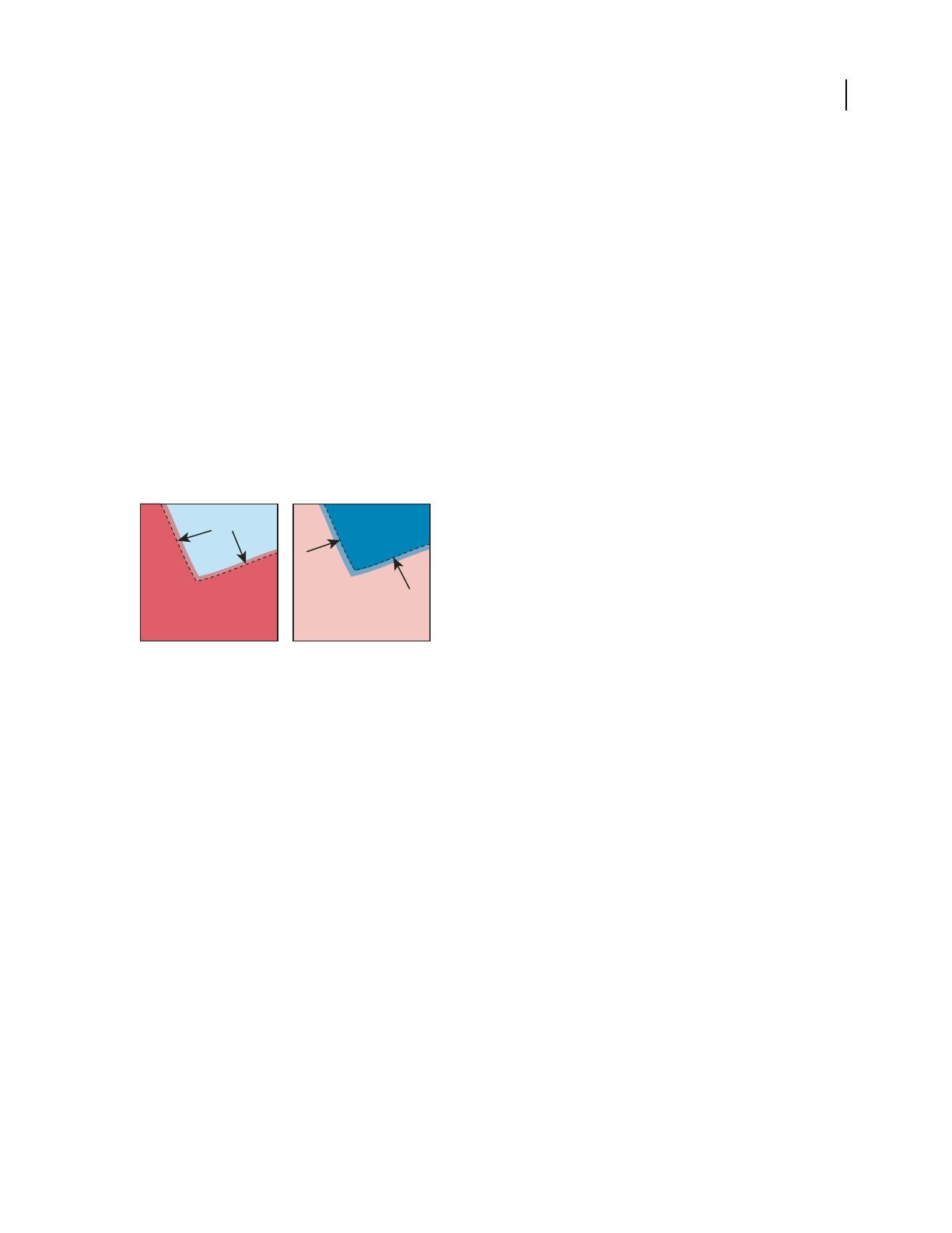
ILLUSTRATOR CS3
User Guide
426
2 Select Advanced on the left side of the Print dialog box.
3 Select Simulate or Discard from the Overprints menu.
Trapping
About trapping
Where colors printed from separate plates overlap or adjoin one another, press misregistration can cause gaps
between colors on
the final output. To compensate for potential gaps between colors in artwork, print shops use a
technique called trapping to create a small area of overlap (called a trap) between two adjoining colors. You can use
a separate, dedicated trapping program to create traps automatically, or you can use Illustrator to create traps
manually.
There are two types of trap: a spread, in which a lighter object overlaps a darker background and seems to expand
into the background; and a choke, in which a lighter background overlaps a darker object that falls within the
background and seems to squeeze or reduce the object.
Spread (object overlaps background) compared to choke (background overlaps object)
When overlapping painted objects share a common color, trapping may be unnecessary if the color that is common
to both objects creates an automatic trap. For example, if two overlapping objects contain cyan as part of their CMYK
values, any gap between them is covered by the cyan content of the object underneath.
Trapping type can present special problems. Avoid applying mixed process colors or tints of process colors to type at
small point sizes, because any misregistration can make the text difficult to read. Likewise, trapping type at small
point sizes can result in hard-to-read type. As with tint reduction, check with your print shop before trapping such
type. For example, if you are printing black type on a colored background, simply overprinting the type onto the
background may be enough.
Create a trap
The Trap command creates traps for simple objects by identifying the lighter-colored artwork—whether it’s the
object or the background—and overprinting (trapping) it into the darker artwork. You can apply the Trap command
from the Pathfinder panel or as an effect. The advantage of using the Trap effect is that you can alter the trap settings
at any time.

ILLUSTRATOR CS3
User Guide
427
What the Trap command does
A. Area of overprinting B. Area of knockout C. Background color D. Foreground color
In some cases, the top and bottom objects may have similar color densities so that one color is not obviously darker
than the other. In this case, the Trap command determines the trap based on slight differences in color; if the trap
specified by the Trap dialog box is not satisfactory, you can use the Reverse Trap option to switch the way in which
the Trap command traps the two objects.
1
If the document is in RGB mode, choose File > Document Color Mode > CMYK Color to convert it to CMYK Mode.
2 Select two or more objects.
3 Do one of the following:
•To apply the command directly to the objects, choose Window > Pathfinder, and choose Trap from the panel
menu.
•To apply the command as an effect, choose Effect > Pathfinder >Trap. Select Preview if you want to preview the
effect.
4 Set trap options, and click OK.
See also
“About effects and filters” on page 350
“Apply Pathfinder effects” on page 230
“Pathfinder panel overview” on page 229
Trap options
Thickness Specifies a stroke width between 0.01 and 5000 points. Check with your print shop to determine what
value to use.
Height/Width Specifies the trap on horizontal lines as a percentage of the trap on vertical lines. Specifying different
horizontal and vertical trap values lets you compensate for on-press irregularities, such as paper stretch. Contact
your print shop for help in determining this value. The default value of 100% results in the same trap width on
horizontal lines and on vertical lines. To increase the trap thickness on horizontal lines without changing the vertical
trap, set the Height/Width value to greater than 100%. To decrease the trap thickness on horizontal lines without
changing the vertical trap, set the Height/Width value to less than 100%.
A B
C D
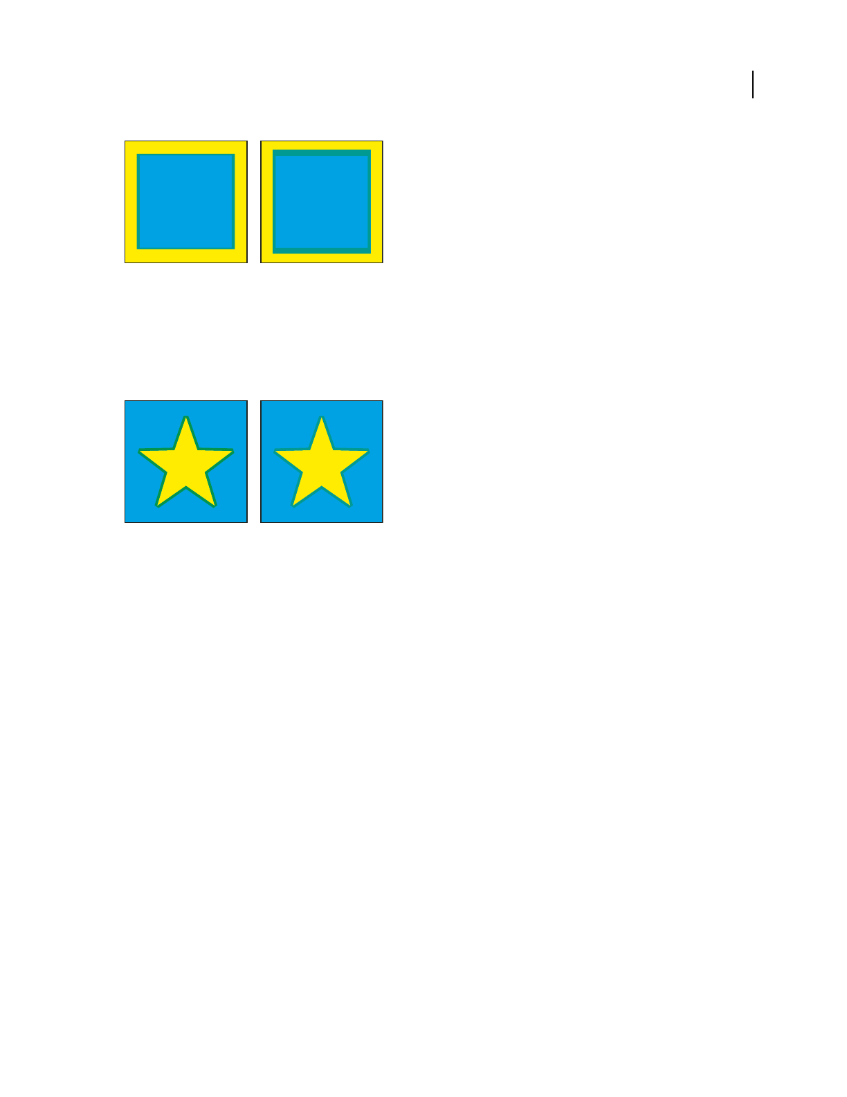
ILLUSTRATOR CS3
User Guide
428
Height/Width set to 50% (left) compared to 200% (right)
Tint Reduction Reduces the tint of the lighter color being trapped; the darker color remains at 100%. This option is
useful when trapping two light-colored objects, where the trap line may show through the darker of the two colors,
resulting in an unsightly dark border. For example, if you trap a light yellow object into a light blue object, a bright
green border is visible where the trap is created. Check with your print shop to find out what percentage of tint is
most appropriate given the type of press, inks, paper stock, and so on being used.
Tint reduction value of 100% (trap contains 100% of lighter color) compared to tint reduction value of 50% (trap contains 50% of lighter color)
Traps With Process Color Converts spot-color traps to equivalent process colors. This option creates an object of the
lighter of the spot colors and overprints it.
Reverse Traps Traps darker colors into lighter colors. This option does not work with rich black—that is, black that
contains additional CMY inks.
Precision (as effect only) Affects how precisely an object's path is calculated. The more precise the calculation, the
more accurate the drawing and the more time is required to generate the resulting path.
Remove Redundant Points (as effect only) Removes unnecessary points.
Create a spread or choke
For more precise control of trapping and for trapping complex objects, you can create the effect of a trap by stroking
an object and setting the stroke to overprint.
1 Select the topmost object of the two objects that must trap into each other.
2 In the Stroke box in the Tools panel or the Color panel, do one of the following:
•Create a spread by entering the same color values for the Stroke as appear in the Fill box. You can change the
stroke’s color values by selecting the stroke and then adjusting its color values in the Color panel. This method
enlarges the object by stroking its boundaries with the same color as the object’s fill.
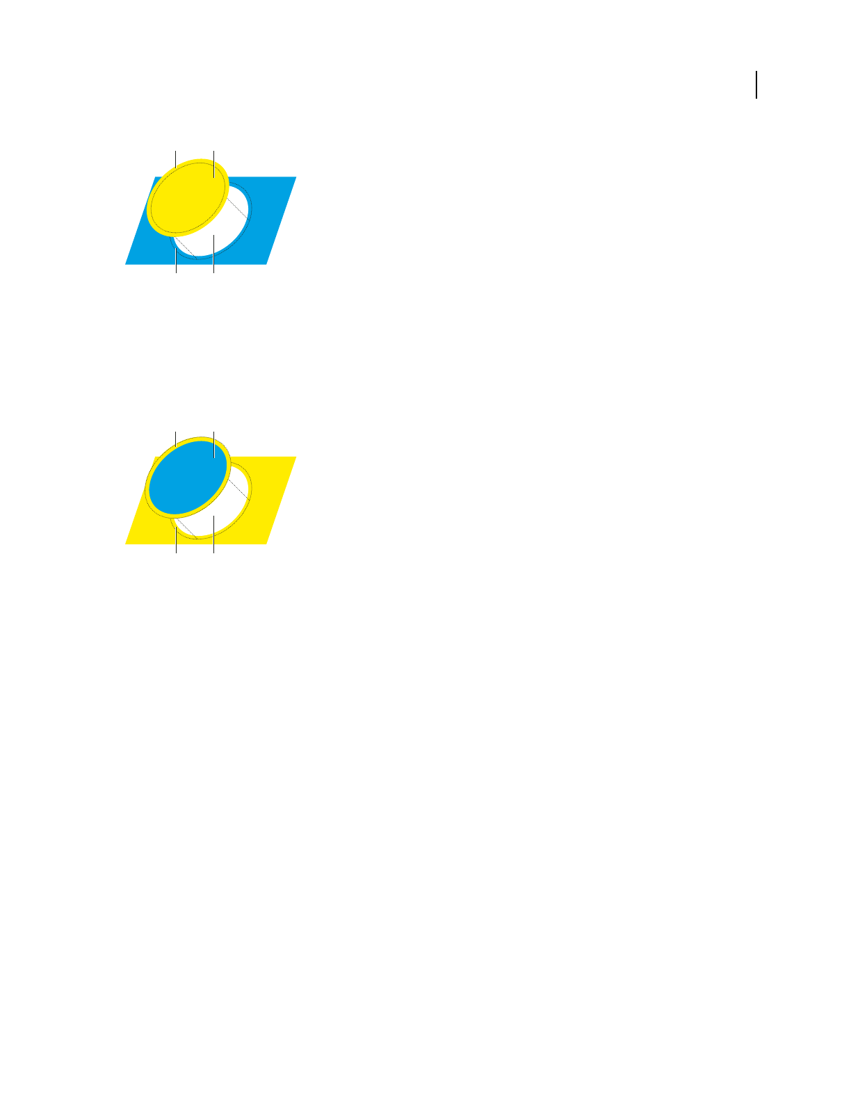
ILLUSTRATOR CS3
User Guide
429
Object stroked with fill color
A. Overprinted stroke creates spread trap B. Fill creates knockout C. Area of trap D. Area of knockout
•Create a choke by entering the same color values for the Stroke as appear in the lighter background (again, using
the Color panel); the Stroke and Fill values will differ. This method reduces the darker object by stroking its
boundaries with the lighter background color.
3 Choose Window > Stroke.
Object stroked with background color
A. Overprinted stroke creates choke trap B. Fill creates knockout C. Area of trap D. Area of knockout
4 In the Weight text box, enter a stroke width of between 0.01 and 1000 points. Check with your print shop to
determine what value to use.
For example, a stroke weight of 0.6 point creates a trap of 0.3 point. A stroke weight of 2.0 points creates a trap of 1.0
point.
5 Choose Window > Attributes.
6 Select Overprint Stroke.
Trap a line
1 Select the line to be trapped.
2 In the Stroke box in the Tools panel or the Color panel, assign the stroke a color of white.
3 In the Stroke panel, select the desired line weight.
4 Copy the line, and choose Edit >Paste In Front. The copy is used to create a trap.
5 In the Stroke box in the Tools panel or the Color panel, stroke the copy with the desired color.
6 In the Stroke panel, choose a line weight that is wider than the bottom line.
7 Choose Window > Attributes.
8 Select Overprint Stroke for the top line.
A B
C D
A B
C D
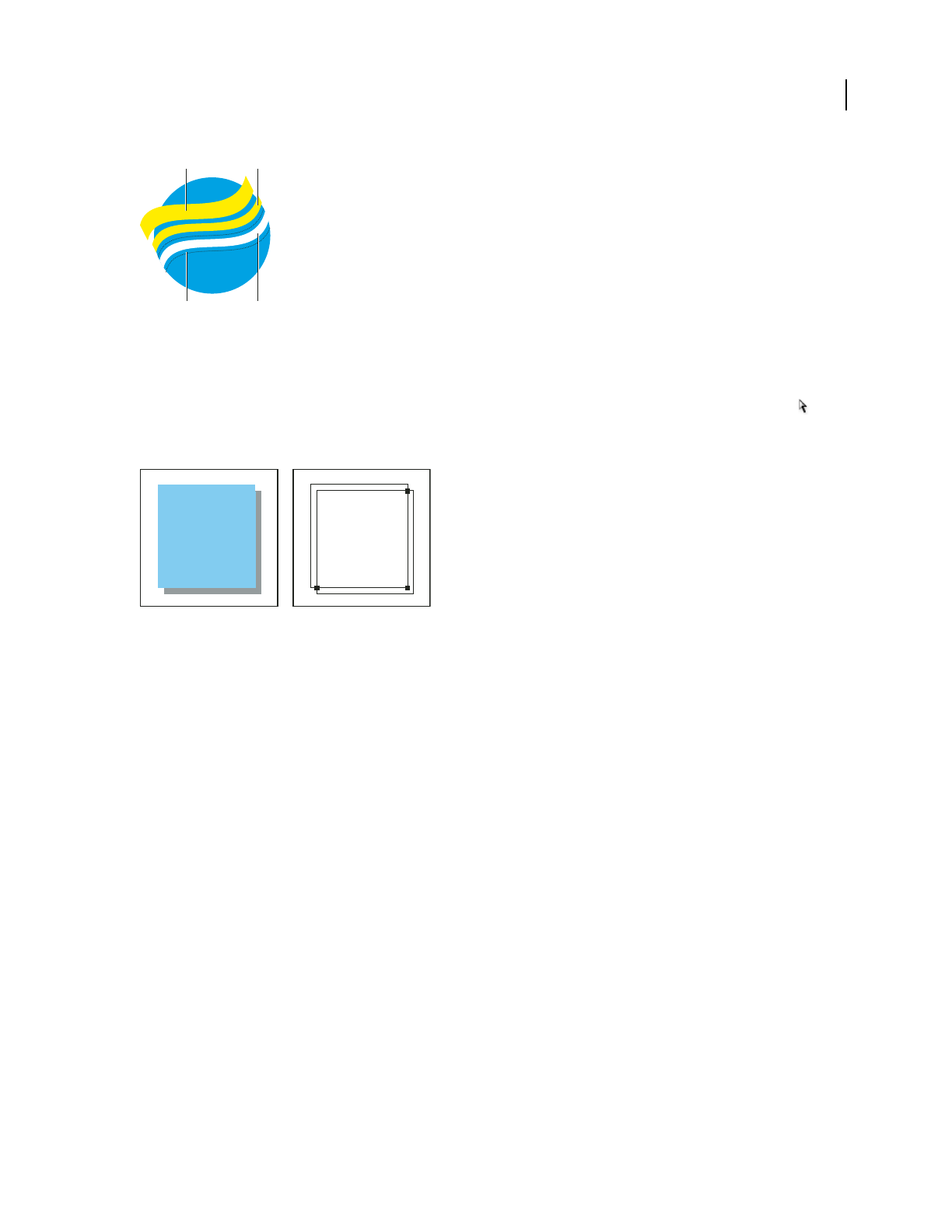
ILLUSTRATOR CS3
User Guide
430
Copy of stroke used for spread trap
A. Overprinted top stroke creates spread trap B. Bottom stroke creates knockout C. Area of knockout D. Area of trap
Trap a portion of an object
1 Draw a line along the edge or edges that you want to trap. If the object is complex, use the Direct Selection tool
to select the edges to be trapped, copy them, and choose Edit > Paste In Front to paste the copy directly on top of the
original.
Drop shadow with a trap (left) is based on the line drawn where the object and its drop shadow meet (right).
2 In the Stroke box in the Tools panel or the Color panel, select a color value for the Stroke to create either a spread
or a choke.
3 Choose Window > Attributes.
4 Select Overprint Stroke.
Print presets
Create print presets
If you regularly output to different printers or job types, you can automate print jobs by saving all output settings as
print presets. Using print presets is a fast, reliable way to print jobs that require consistently accurate settings for
many options in the Print dialog box.
You can save and load print presets, making it easy to back them up or to make them available to your service
providers, clients, or others in your workgroup.
You can create and review print presets in the Print Presets dialog box.
❖Do one of the following:
•Choose File > Print, adjust print settings, and click Save Preset. Type a name or use the default, and then click OK.
With this method, the preset is saved in the preferences file.
A B
C D

ILLUSTRATOR CS3
User Guide
431
•Choose Edit > Print Presets (Illustrator) or File > Print Presets > Define (InDesign), and then click New. In the
dialog box that appears, type a new name or use the default, adjust print settings, and then click OK to return to
the Print Presets dialog box. Then click OK again.
Apply print presets
1 Choose File > Print.
2 Choose a print preset from the Print Preset menu. If you like, confirm the printer settings in the Print dialog box.
3 Click Print.
Note: In InDesign, you can also print using a print preset by choosing one from the File > Print Presets menu.
Edit print presets
❖Do one of the following:
•Choose File > Print, adjust print settings, and click Save Preset. In the Save Preset dialog box that appears, either
type a name in the text box or use the current name. (If the current name is an existing preset, saving overwrites
that preset’s settings.) Click OK.
•Choose Edit > Print Presets (Illustrator) or File > Print Presets > Define (InDesign), select a preset from the list,
and then click Edit. Adjust print settings, and click OK to return to the Print Presets dialog box. Then click OK
again.
You can edit the default preset as you would any other using the steps outlined above.
Delete print presets
1 Choose Edit > Print Presets (Illustrator) or File > Print Presets > Define (InDesign).
2 Select one or more presets from the list and click Delete. Shift-click to select adjacent presets. Ctrl-click
(Windows) or Command-click (Mac OS) to select nonadjacent presets.
Export or import print presets
You can save print presets in separate files, making it easy to back them up or to make them available to your service
providers, clients, or others in your workgroup.
1 Choose Edit > Print Presets (Illustrator) or File > Print Presets > Define (InDesign).
2 Do one of the following:
•To export presets, select one or more presets in the list and click Export (Illustrator) or Save (InDesign). Shift-click
to select adjacent presets. Ctrl-click (Windows) or Command-click (Mac OS) to select nonadjacent presets.
Specify a name and location, and then click Save.
•To import presets, click Import (Illustrator) or Load (InDesign). Locate and click the file containing the presets
you want to load, and then click OK.
Consider saving presets outside of the preferences folder. That way, they won’t be lost if you ever delete your prefer-
ences.
Note: Printer styles created in previous versions of InDesign can be loaded into Adobe® InDesign® CS3 and saved as
printer presets.

ILLUSTRATOR CS3
User Guide
432
View a summary of print settings/presets
Use the Summary panel of the Print dialog box to view your output settings prior to printing, and then adjust them
as necessary. For example, you can see if the document will omit certain graphics for OPI replacement by the service
provider.
1 Choose File > Print.
2 In the Print dialog box, click Summary.
3 If you want to save the summary as a text file, click Save Summary.
4 Accept the default filename or type another name for the text file, and click Save.
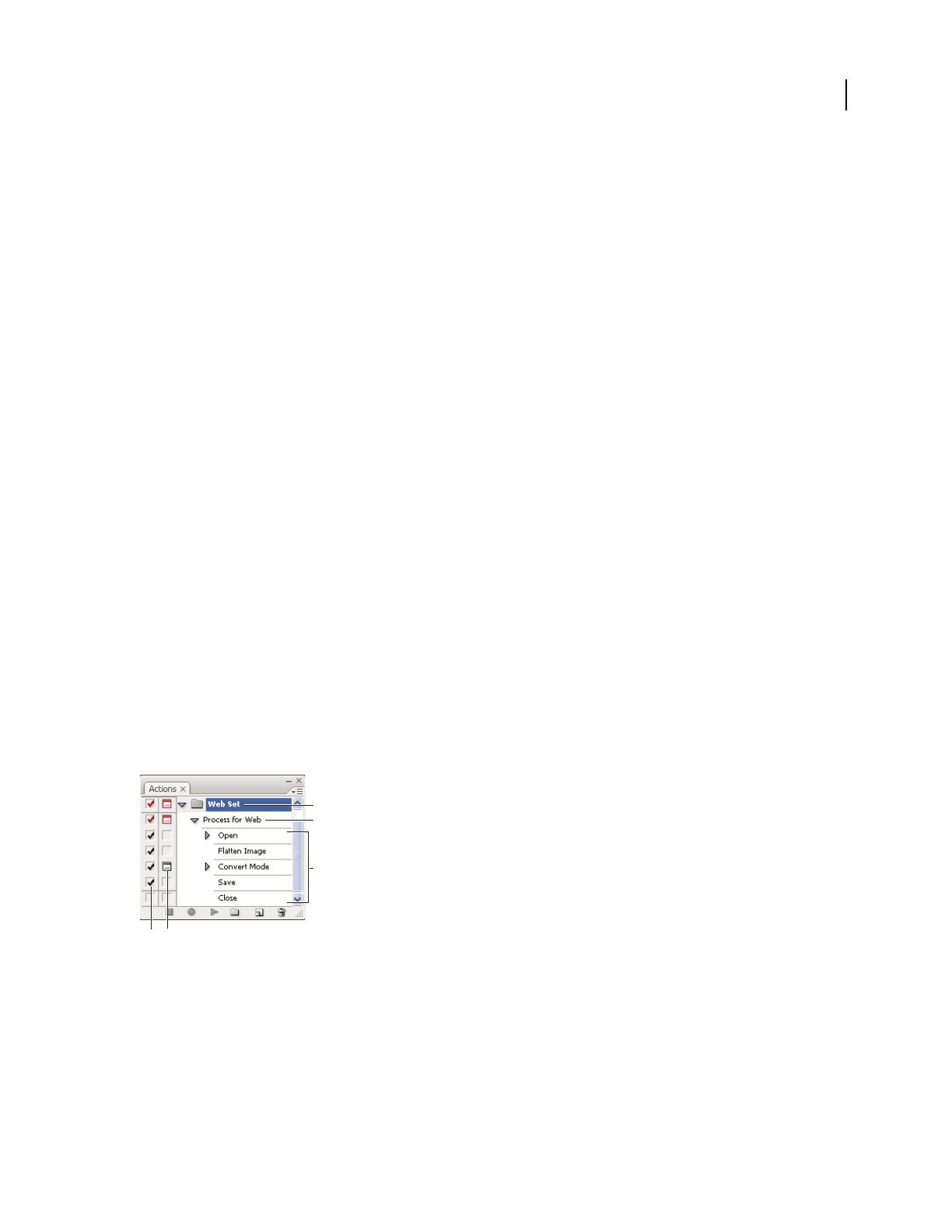
433
Chapter 14: Automating tasks
Automating tasks can save you time and ensure consistent results for many types of operations. Illustrator provides
a variety of ways to automate tasks by using actions, scripts, and data-driven graphics.
Actions
About actions
An action is a series of tasks that you play back on a single file or a batch of files—menu commands, palette options,
tool actions, and so on. For example, you can create an action that changes the size of an image, applies a filter to the
image for a particular effect, and then saves the file in the desired format.
Actions can include stops that let you perform tasks that cannot be recorded (for example, using a painting tool).
Actions can also include modal controls that let you enter values in a dialog box while playing an action.
In Photoshop, actions are the basis for droplets, which are small applications that automatically process all files that
are dragged onto their icon.
Photoshop and Illustrator come with predefined actions installed that help you perform common tasks. You can use
these actions as is, customize them to meet your needs, or create new actions. Actions are stored in sets to help you
organize them.
You can record, edit, customize, and batch-process actions, and you can manage groups of actions by working with
action sets.
Actions palette overview
You use the Actions palette (Window > Actions) to record, play, edit, and delete individual actions. This palette
(called the Actions panel in Illustrator) also lets you save and load action files.
Photoshop Actions palette
A. Action set B. Action C. Recorded commands D. Included command E. Modal control (toggles on or off)
Expand and collapse sets, actions, and commands
❖Click the triangle to the left of the set, action, or command in the Actions palette. Alt-click (Windows) or Option-
click (Mac OS) the triangle to expand or collapse all actions in a set or all commands in an action.
A
D E
B
C

ILLUSTRATOR CS3
User Guide
434
View actions by name only
❖Choose Button Mode from the Actions palette menu. Choose Button Mode again to return to list mode.
Note: You can’t view individual commands or sets in Button mode.
Select actions in the Actions palette
❖Click an action name. Shift-click action names to select multiple, contiguous actions, and Ctrl-click (Windows)
or Command-click (Mac OS) action names to select multiple, discontiguous actions.
Play an action on a file
Playing an action executes the action’s recorded commands in the active document. (Some actions require that you
make a selection before playing; some can be executed on an entire file.) You can exclude specific commands from
an action or play only a single command. If the action includes a modal control, you can specify values in a dialog
box or use a modal tool when the action pauses.
Note: In Button mode, clicking a button executes the entire action—although commands previously excluded are not
executed.
1 If necessary, select objects on which to play the action, or open a file.
2 Do one of the following:
•(Illustrator) To play a set of actions, select the set name, and click the Play button in the Actions palette, or
choose Play from the palette menu.
•To play an entire single action, select the action name, and click the Play button in the Actions palette, or choose
Play from the palette menu.
•If you assigned a key combination to the action, press that combination to play the action automatically.
•To play only a part of an action, select the command from which you want to start playing, and click the Play
button in the Actions palette, or choose Play from the palette menu.
•To play a single command, select the command, and then Ctrl-click (Windows) or Command-click (Mac OS) the
Play button in the Actions palette. You can also press Ctrl (Windows) or Command (Mac OS), and double-click
the command.
In Photoshop, to undo an action, take a snapshot in the History palette before you play an action, and then select the
snapshot to undo the action.
Record an action
When you create a new action, the commands and tools you use are added to the action until you stop recording.
To guard against mistakes, work in a copy: at the beginning of the action before applying other commands, record
the File > Save A Copy command (Illustrator) or record the File > Save As command and select As A Copy
(Photoshop). Alternatively, in Photoshop you can click the New Snapshot button on the History palette to make a
snapshot of the image before recording the action.
1 Open a file.
2 In the Actions palette, click the Create New Action button , or choose New Action from the Actions palette menu.

ILLUSTRATOR CS3
User Guide
435
3 Enter an action name, select an action set, and set additional options:
Function Key Assigns a keyboard shortcut to the action. You can choose any combination of a function key, the Ctrl
key (Windows) or Command key (Mac OS), and the Shift key (for example, Ctrl+Shift+F3), with these exceptions:
In Windows, you cannot use the F1 key, nor can you use F4 or F6 with the Ctrl key.
Note: If you assign an action the same shortcut that is used for a command, the shortcut will apply the action rather
than the command.
Color Assigns a color for display in Button mode.
4 Click Begin Recording. The Begin Recording button in the Actions palette turns red .
Important: When recording the Save As command, do not change the filename. If you enter a new filename, that new
name is recorded and used each time you run the action. Before saving, if you navigate to a different folder, you can
specify a different location without having to specify a filename.
5 Perform the operations and commands you want to record.
Not all tasks in actions can be recorded directly; however, you can insert most nonrecordable tasks using commands
in the Actions palette menu.
6 To stop recording, either click the Stop Playing/Recording button, or choose Stop Recording from the Actions
palette menu. (In Photoshop, you can also press the Esc key.)
To resume recording in the same action, choose Start Recording from the Actions palette menu.
Insert nonrecordable tasks into actions
Not all tasks in actions can be recorded directly. For example, you can’t record commands in the Effects and View
menus, commands that display or hide panels, and use of the Selection, Pen, Paintbrush, Pencil, Gradient, Mesh,
Eyedropper, Live Paint Bucket, and Scissors tools.
To tell which tasks cannot be recorded, watch the Actions panel. If the name of the command or tool doesn’t appear
after you perform the task, you may still be able to add the task using commands in the Actions panel menu.
To insert a nonrecordable task after you create an action, select an item within the action after which you want to
insert the task. Then choose the appropriate command from the Actions panel menu.
See also
“Actions palette overview” on page 433
Insert a nonrecordable menu command
1
Choose Insert Menu Item from the Actions panel menu.
2 Select the command from its menu, or begin typing the command name in the text box, and click Find. Then click OK.
Insert a path
❖Select the path, and choose Insert Select Path from the Actions panel menu.
Insert selection of an object
1
Enter a name for the object in the Note box of the Attributes panel before you start recording. (Select Show Note
from the Attributes panel menu to display the Note box.)

ILLUSTRATOR CS3
User Guide
436
2 When you record the action, choose Select Object from the Actions panel menu.
3 Enter the name of the object, and click OK.
Record optimization options for multiple slices in the Save For Web dialog box
❖Set the slice optimization options before you start recording the action; then press Alt (Windows) or Option
(Mac OS) and click Remember in the Save For Web dialog box.
When you record the action, Illustrator will remember the settings.
Insert a stop
You can include stops in an action that let you perform a task that cannot be recorded (for example, using a painting
tool). After you complete the task, click the Play button in the Actions palette to complete the action.
You can also display a short message when the action reaches the stop as a reminder of what needs to be done before
continuing with the action. You can include a Continue button in the message box in case no other task needs to be done.
1 Choose where to insert the stop by doing one of the following:
•Select an action’s name to insert a stop at the end of the action.
•Select a command to insert a stop after the command.
2 Choose Insert Stop from the Actions palette menu.
3 Type the message you want to appear.
4 If you want the option to continue the action without stopping, select Allow Continue.
5 Click OK.
You can insert a stop when recording an action or after it has been recorded.
Change settings when playing an action
By default, actions are completed using the values specified when they were originally recorded. If you want to
change the settings for a command within an action, you can insert a modal control. A modal control pauses an action
so that you can specify values in a dialog box or use a modal tool. (A modal tool requires pressing Enter or Return
to apply its effect—once you press Enter or Return, the action resumes its tasks.)
A modal control is indicated by a dialog box icon to the left of a command, action, or set in the Actions palette.
A red dialog box icon indicates an action or set in which some, but not all, commands are modal. You can’t set a
modal control in Button mode.
❖Do one of the following:
•To enable a modal control for a command within an action, click the box to the left of the command name. Click
again to disable the modal control.
•To enable or disable modal controls for all commands in an action, click the box to the left of the action name.
•To enable or disable modal controls for all actions in a set, click the box to the left of the set name.

ILLUSTRATOR CS3
User Guide
437
Exclude commands from an action
You can exclude commands that you don’t want to play as part of a recorded action. You can’t exclude commands in
Button mode.
1 If necessary, expand the listing of commands in the action by clicking the triangle to the left of the action name
in the Actions palette.
2 Do one of the following:
•To exclude a single command, click to clear the check mark to the left of the command name. Click again to
include the command.
•To exclude or include all commands or actions in an action or set, click the check mark to the left of the action or
set name.
•To exclude or include all commands except the selected command, Alt-click (Windows) or Option-click (Mac OS)
its check mark.
To indicate that some of the commands within the action are excluded, in Photoshop the check mark of the parent
action turns red; in Illustrator the check mark of the parent action becomes dimmed.
Specify playback speed
You can adjust an action’s playback speed or pause it to help you debug an action.
1 Choose Playback Options from the Actions palette menu.
2 Specify a speed, and click OK:
Accelerated Plays the action at normal speed (the default).
Note: When you play an action at accelerated speed, the screen may not update as the action executes—files may be
opened, modified, saved, and closed without ever appearing on-screen, enabling the action to execute more quickly. If
you want to see the files on-screen as the action executes, specify the Step By Step speed instead.
Step By Step Completes each command and redraws the image before going on to the next command in the action.
Pause For __ Seconds Specifies the amount of time the application should pause between carrying out each
command in the action.
3 (Photoshop only) Select Pause For Audio Annotation to ensure that each audio annotation in an action is played
before the next step in the action is initiated. Deselect this option if you want an action to continue while an audio
annotation is playing.
Edit and rerecord actions
It is easy to edit and customize actions. You can tweak the settings of any specific command within an action, add
commands to an existing action, or step through an entire action and change any or all settings.
See also
“Actions palette overview” on page 433
Add commands to an action
1
Do one of the following:
•Select the action name to insert a new command at the end of the action.

ILLUSTRATOR CS3
User Guide
438
•Select a command in the action to insert a command after it.
2 Click the Begin Recording button, or choose Start Recording from the Actions palette menu.
3 Record the additional commands.
4 When finished, click the Stop Playing/Recording button in the Actions palette or choose Stop Recording from the
palette menu.
Rearrange commands within an action
❖In the Actions palette, drag a command to its new location within the same or another action. When the
highlighted line appears in the desired position, release the mouse button.
Record an action again
1
Select an action, and choose Record Again from the Actions palette menu.
2 If a modal tool appears, use the tool to create a different result, and press Enter or Return, or just press Enter or
Return to retain the same settings.
3 If a dialog box appears, change the settings, and click OK to record them, or click Cancel to retain the same values.
Record a single task again
1
Select an object of the same type for which you want to rerecord the action. For example, if a task is only available
for vector objects, you must have a vector object selected when you rerecord.
2 In the Actions panel, double-click the command.
3 Enter the new values and click OK.
Manage action sets
You can create and organize sets of task-related actions that can be saved to disk and transferred to other computers.
Note: Any actions that you create are automatically listed in the Actions palette, but to truly save an action and not risk
losing it if you delete your preferences file (Illustrator) or Actions palette file (Photoshop), you have to save it as part of
an action set.
Save a set of actions
1
Select a set.
If you want to save a single action, first create an action set and move the action to the new set.
2 Choose Save Actions from the Actions palette menu.
3 Type a name for the set, choose a location, and click Save.
You can save the file anywhere. You can save only the entire contents of a set in the Actions palette, not individual
actions.
Note: (Photoshop only) If you place the saved action-set file in the Presets/Actions folder inside the Adobe Photoshop
CS3 program folder, the set will appear at the bottom of the Actions palette menu after you restart the application.
(Photoshop only) Press Ctrl+Alt (Windows) or Command+Option (Mac OS) when you choose the Save Actions
command to save the actions in a text file. You can use this file to review or print the contents of an action. However,
you can’t reload the text file back into Photoshop.

ILLUSTRATOR CS3
User Guide
439
Load a set of actions
By default, the Actions palette displays predefined actions (shipped with the application) and any actions you create.
You can also load additional actions into the Actions palette.
❖Do one of the following:
•Choose Load Actions from the Actions palette menu. Locate and select the action set file, and then click Load
(Photoshop) or Open (Illustrator).
•(Photoshop only) Select an action set from the bottom of the Actions palette menu.
Photoshop action set files have the extension .atn; Illustrator action set files have the extension .aia.
Restore actions to the default set
1
Choose Reset Actions from the Actions palette menu.
2 Click OK to replace the current actions in the Actions palette with the default set, or click Append to add the set
of default actions to the current actions in the Actions palette.
Organize action sets
To help you organize your actions, you can create sets of actions and save the sets to disk. You can organize sets of
actions for different types of work—such as print publishing and online publishing—and transfer sets to other
computers.
•To create a new set of actions, click the Create New Set button in the Actions palette or choose New Set from
the palette menu. Then enter the name of the set, and click OK.
Note: If you plan to create a new action and group it in a new set, make sure you create the set first. Then, the new set
will appear in the set popup menu when you create your new action.
•To move an action to a different set, drag the action to that set. When the highlighted line appears in the desired
position, release the mouse button.
•To rename a set of actions, double-click the name of the set in the Actions palette or choose Set Options from the
Actions palette menu. Then enter the new name of the set, and click OK.
•To replace all actions in the Actions palette with a new set, choose Replace Actions from the Actions palette menu.
Select an actions file, and click Load (Photoshop) or Open (Illustrator).
Important: The Replace Actions command replaces all sets of actions in the current document. Before using the
command, make sure that you have already saved a copy of your current set of actions using the Save Actions command.
Play an action on a batch of files
The Batch command lets you play an action on a folder of files and subfolders. You can also use the Batch command
to populate a template for data-driven graphics with different sets of data.
1 Choose Batch from the Actions panel menu.
2 For Play, select the action you want to play.
3 For Source, choose the folder on which to play the action, or select Data Sets to play the action on each data set in
the current file.
If you select a folder, you can set additional options for playing the action.

ILLUSTRATOR CS3
User Guide
440
4 For Destination, specify what you want to do with the processed files. You can leave the files open without saving
the changes (None), save and close the file in their current location (Save And Close), or save the files to a different
location (Folder).
Depending on the Destination option you select, you can set additional options for saving the files.
5 Specify how you want Illustrator to handle errors during the batch process. If you select Log Errors To File, click
Save As, and name the error file.
6 Click OK.
Saving files using the Batch command options always saves the files in the same format as the original files. To create
a batch process that saves files in a new format, record the Save As or Save A Copy command, followed by the Close
command, as part of your original action. Then choose None for the Destination when setting up the batch process.
To batch-process using multiple actions, create a new action, and record the Batch command for each action you
want to use. This technique also lets you process multiple folders in a single batch. To batch-process multiple folders,
create aliases within a folder to the other folders you want to process.
See also
“Actions palette overview” on page 433
“Use data sets” on page 444
Batch options
If you select Folder for Source, you can set the following options:
Override Action “Open” Commands Opens the files from the specified folder and ignores any Open commands
recorded as part of the original action.
Include All Subdirectories Processes all files and folders within the specified folder.
If the action contains any save or export commands, you can set the following options:
Override Action “Save” Commands Saves the processed files in the specified destination folder and not to a location
recorded in the action. Click Choose to specify the destination folder.
Override Action “Export” Commands Exports the processed files to the specified destination folder and not to a
location recorded in the action. Click Choose to specify the destination folder.
If you select Data Sets for Source, you can set an option for generating file names when overriding Save and Export
commands:
File + Number Generates the filename by taking the original document’s filename, removing any extension, and then
appending a three-digit number corresponding to the data set.
File + Data Set Name Generates the filename by taking the original document’s filename, removing any extension,
and then appending an underscore and the name of the data set.
Data Set Name Generates the filename by taking the name of the data set.

ILLUSTRATOR CS3
User Guide
441
Scripts
Use a script
When you run a script, your computer performs a sequence of operations. These operations may involve only
Illustrator, or they may involve other applications, such as word-processing, spreadsheet, and database-management
programs.
Illustrator supports multiple scripting environments (including Microsoft Visual Basic, AppleScript, JavaScript, and
ExtendScript). You can use the standard scripts that come with Illustrator, and you can create your own scripts and
add them to the Scripts submenu.
For more information about scripting in Illustrator, see the sample scripts and scripting documentation in the Adobe
Illustrator CS3/Scripting folder/
Run a script
❖Choose File > Scripts, and choose a script. Alternatively, choose File > Scripts > Browse, and navigate to a script.
Note: If you edit a script while Illustrator is running, you must save your changes for them to take effect.
Install a script
❖Copy the script to your computer’s hard disk.
If you place the script in the Adobe Illustrator CS3/Presets/Scripts folder, the script will appear in the File > Scripts
submenu.
If you place the script in another location on the hard disk, you can run the script in Illustrator by choosing File >
Scripts
> Browse.
Note: If you place a script in the Adobe Illustrator CS3/Presets/Scripts folder while Illustrator is running, you must
restart Illustrator for the script to appear in the Scripts submenu.
Data-driven graphics
About data-driven graphics
Data-driven graphics make it possible to produce multiple versions of artwork quickly and accurately. Let’s say, for
example, that you need to produce 500 different web banners based on the same template. In the past, you had to
manually populate the template with data (images, text, and so on). With data-driven graphics, you can use a script
referencing a database to generate the web banners for you.
In Illustrator, you can turn any piece of artwork into a template for data-driven graphics. All you need to do is define
which objects on the artboard are dynamic (changeable) using variables. You use variables to change text strings,
linked images, graph data, and the visibility setting of objects in your artwork. In addition, you can create different
sets of variable data in order to easily view what your template will look like when it is rendered.
Data-driven graphics are designed for use in collaborative work environments. Following are some examples of how
data-driven graphics fit into different job roles:
•If you’re a designer, creating a template gives you control over the dynamic elements of your design. When you
hand your template over for production, you can be sure that only the variable data will change.
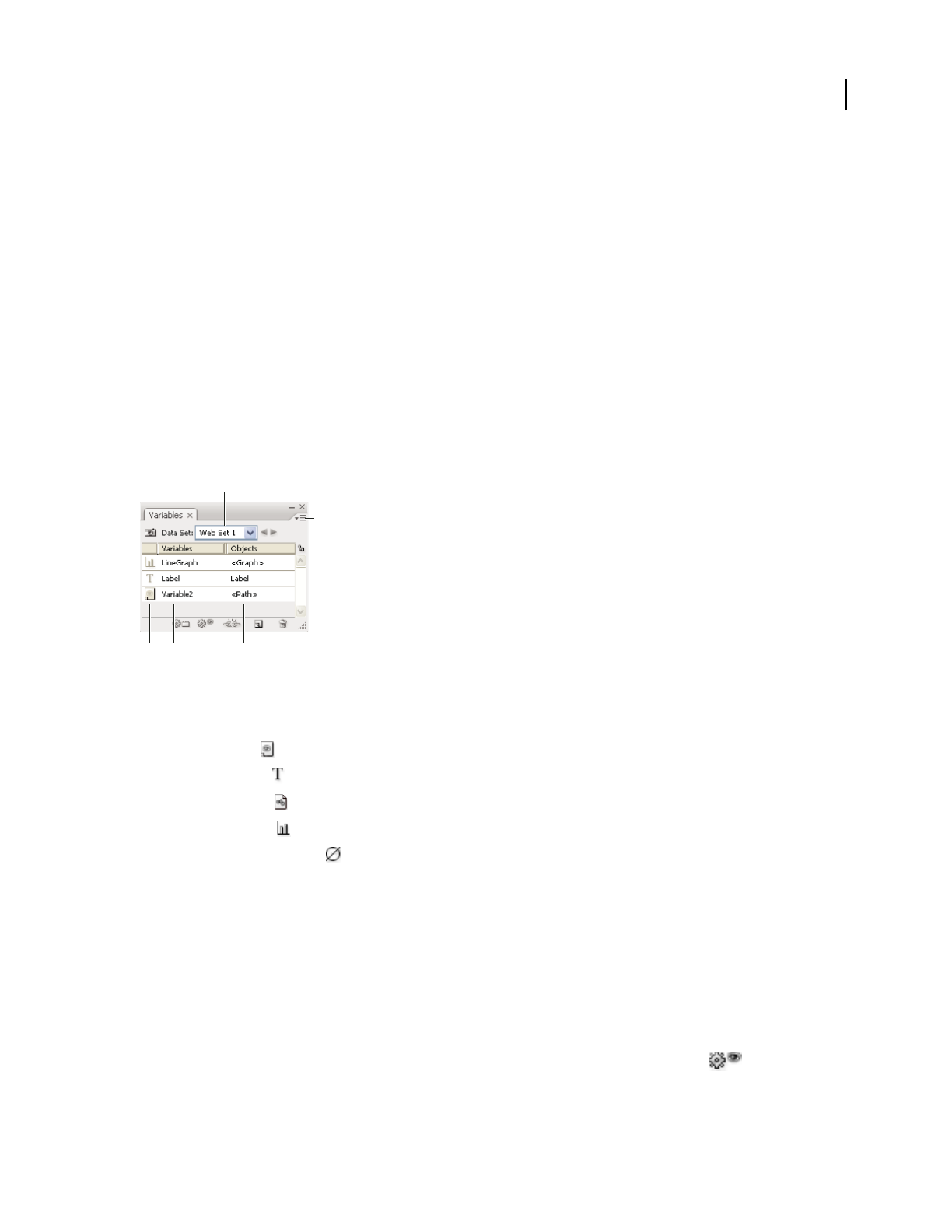
ILLUSTRATOR CS3
User Guide
442
•If you’re a developer, you can code variables and data sets directly into an XML file. The designer can then import
the variables and data sets into an Illustrator file to create a design based on your specifications.
•If you’re responsible for production, you can use scripts within Illustrator, the Batch command, or a web
production tool such as Adobe GoLive 6.0 to render the final graphics. You can also use a dynamic imaging server
such as Adobe® Graphics Server to further automate the rendering process.
See also
“Use data sets” on page 444
“About variable libraries” on page 445
Variables panel overview
You use the Variables panel (Window > Variables) to work with variables and data sets. The type and name of each
variable in the document are listed in the panel. If
the variable is bound to an object, then the Objects column
displays the name of the bound object as it appears in the Layers panel.
Variables panel
A. Data set B. Panel menu C. Variable type D. Variable name E. Name of bound object
The Variables panel uses the following icons to indicate a variable’s type:
•Visibility variable .
•Text String variable .
•Linked File variable .
•Graph Data variable .
•No Type (unbound) variable .
You can sort the rows by clicking items in the header bar: by variable name, object name, or by variable type.
Create variables
You can create four types of variables in Illustrator: Graph Data, Linked File, Text String, and Visibility. A variable’s
type indicates which object attributes are changeable (dynamic).
Note: The Variable panel menu also provides commands for creating variables.
Create a Visibility variable
❖Select the objects that you want to show or hide and click the Make Visibility Dynamic button in the
Variables panel.
B
A
C D E

ILLUSTRATOR CS3
User Guide
443
Create a Text String variable
❖Select a type object and click the Make Object Dynamic button in the Variables panel.
Create a Linked File variable
❖Select a linked file and click the Make Object Dynamic button in the Variables panel.
Create a Graph Data variable
❖Select a graph object and click the Make Object Dynamic button in the Variables panel.
Create a variable without binding it to an object
❖Click the New Variable button in the Variables panel. To subsequently bind an object to the variable, select the
object and the variable, and click the Make Visibility Dynamic button or the Make Object Dynamic button.
Edit variables
You can edit a variable’s name or type, unbind a variable, and lock a variable using the Variables panel.
Unbinding a variable breaks the link between the variable and its object. Locking variables prevents you from
creating variables, deleting variables, and editing variable options. However, you can bind and unbind objects to
locked variables.
See also
“Variables panel overview” on page 442
Change the name and type of a variable
❖Double-click the variable in the Variables panel. Alternatively, select the variable in the Variables panel, and
choose Variable Options from the Variables panel menu.
Unbind a variable
❖Click the Unbind Variable button in the Variables panel, or choose Unbind Variable from the Variables
panel menu.
Lock or unlock all variables in a document
❖Click the Lock/Unlock Variables button or in the Variables panel.
Delete variables
Deleting a variable removes it from the Variables panel. If you delete a variable that is bound to an object, the object
becomes static (unless the object is also bound to a variable of a different type).
1 Select a variable you want to delete.
2 Do one of the following:
•Click the Delete Variable icon in the Variables panel, or choose Delete Variable from the Variables panel menu.
•To delete the variable without confirmation, drag it to the Delete Variable icon.
See also
“Variables panel overview” on page 442

ILLUSTRATOR CS3
User Guide
444
Edit dynamic objects
You change the data associated with a variable by editing the object to which it is bound. For example, if you’re
working with a Visibility variable, you change the object’s state of visibility in the Layers panel. Editing dynamic
objects lets you create multiple data sets for use in the template.
1 Select a dynamic object on the artboard, or do one of the following to automatically select a dynamic object:
•Alt-click (Windows) or Option-click (Mac OS) a variable in the Variables panel.
•Select a variable in the Variables panel, and choose Select Bound Object from the Variables panel menu.
•To select all dynamic objects, choose Select All Bound Objects from the Variables panel menu.
2 Edit the data associated with the object as follows:
•For text, edit the text string on the artboard.
•For linked files, replace the image using the Links panel or the File > Place command.
•For graphs, edit the data in the Graph Data dialog box.
•For all objects with dynamic visibility, change the state of visibility for the object in the Layers panel.
See also
“Links panel overview” on page 254
“Enter graph data” on page 448
“Layers panel overview” on page 211
“Variables panel overview” on page 442
Identifying dynamic objects using XML IDs
The Variables panel displays the names of dynamic objects as they appear in the Layers panel. If you save the template
in SVG format for use with other Adobe products, these object names must conform to XML naming conventions.
For
example, XML names must begin with a letter, underscore, or colon, and cannot contain spaces.
Illustrator automatically assigns a valid XML ID to every dynamic object you create. To view, edit, and export object
names using XML IDs, choose Edit
> Preferences > Units & Display Performance (Windows) or Illustrator >
Preferences
> Units & Display Performance (Mac OS), and select XML ID.
See also
“Variables panel overview” on page 442
Use data sets
A data set is a collection of variables and associated data. When you create a data set, you capture a snapshot of the
dynamic data that is currently displayed on the artboard. You can switch between data sets to upload different data
into your template.
The name of the current data set is displayed at the top of the Variables panel. If you change the value of a variable
so that the artboard no longer reflects the data stored in the set, the name of the data set is displayed in italic type.
You can then create a new data set, or you can update the data set to overwrite the saved data with the new data.

ILLUSTRATOR CS3
User Guide
445
See also
“About data-driven graphics” on page 441
“Play an action on a batch of files” on page 439
“Variables panel overview” on page 442
Create a new data set
❖Click the Capture Data Set button in the Variables panel. Alternatively, choose Capture Data Set from the
Variables panel menu.
Switch between data sets
❖Select a data set from the Data Set list in the Variables panel. Alternatively, click the Previous Data Set button
or the Next Data Set button .
Apply the data on the artboard to the current data set
❖Choose Update Data Set from the Variables panel menu.
Rename a data set
❖Edit the text directly in the Data Set text box. Alternatively, double-click the words Data Set: (to the left of the Data
Set text box), enter a new name, and click OK.
Delete a data set
❖Choose Delete Data Set from the Variables panel menu.
About variable libraries
In a collaborative environment, coordination between team members is essential to the success of a project. For
example, in a company that creates websites, the web designer is responsible for the look and feel of the site, while
the web developer is responsible for the underlying code and scripting. If the designer changes the layout of the web
page, those changes must be communicated to the developer. Likewise, if the developer needs to add functionality
to the web page, the design may need to be updated.
Variable libraries enable designers and developers to coordinate their work through an XML file. For example, a
designer can create a template for business cards in Illustrator and export variable data as an XML file. The developer
can then use the XML file to link variables and data sets to a database and write a script to render the final artwork.
This workflow can also be reversed, where the developer codes the variable and data set names in an XML file, and
the designer imports the variable libraries into an Illustrator document.
To import variables into Illustrator from an XML file, choose Load Variable Library from the Variables panel menu.
To export variables from Illustrator to an XML file, choose Save Variable Library from the Variables panel menu.
See also
“About data-driven graphics” on page 441
“Use data sets” on page 444
“Variables panel overview” on page 442

ILLUSTRATOR CS3
User Guide
446
Save a template for data-driven graphics
When you define variables in an Illustrator document, you are creating a template for data-driven graphics. You can
save the template in SVG
format for use with other Adobe products, such as Adobe® Graphics Server and Adobe®
GoLive®. For example, a GoLive user can place an SVG template in a page layout, bind its variables to a database using
dynamic links, and then use Adobe Graphics Server to generate iterations of the artwork. Likewise, a developer
working with Adobe Graphics Server can bind the variables in the SVG file directly to a database or another data
source.
1 Choose File > Save As, enter a file name, select SVG as the file format, and click Save.
2 Click More Options, and select Include Adobe Graphics Server Data. This option includes all information needed
for variable substitution in the SVG file.
3 Click OK.

447
Chapter 15: Graphs
Graphs let you communicate statistical information in a visual way. In Adobe Illustrator, you can create nine different
types of graphs and customize them to suit your needs.
Creating graphs
Create a graph
1 Select a graph tool.
The tool you use initially determines the type of graph Illustrator generates; however, you can easily change the type
of graph later on.
2 Define the dimensions of the graph in any of the following ways:
•Drag diagonally from the corner where you want the graph to begin to the opposite corner. Alt-drag (Windows)
or Option-drag (Mac OS) to draw the graph from its center. Hold down Shift to constrain the graph to a square.
•Click where you want to create the graph. Enter a width and height for the graph, and click OK.
Note: The dimensions you define are for the main body of the graph and do not encompass the graph’s labels and legend.
3 Enter data for the graph in the Graph Data window.
Important: Graph data must be arranged in a specific order, which varies by graph type. Before you start to enter data,
be sure to read about how to organize labels and data sets in the worksheet.
4 Click the Apply button , or press the Enter key on the numeric keypad to create the graph.
The Graph Data window stays open until you close it. This allows you to easily switch between editing graph data
and working on the artboard.
See also
“Graph tool gallery” on page 31
“Enter graph data” on page 448
“Formatting and customizing graphs” on page 451
Adjust column width or decimal precision
Adjusting the column width has no effect on the width of columns in the graph; it only lets you view more or fewer
digits in a column.
With the default value of 2 decimals, the number 4 entered in a cell appears in the Graph Data window box as 4.00,
and the number 1.55823 entered in a cell displays as 1.56.
Adjust the width of columns
❖Do one of the following:
•Click the Cell Style button , and enter a value between 0 and 20 in the Column Width text box.
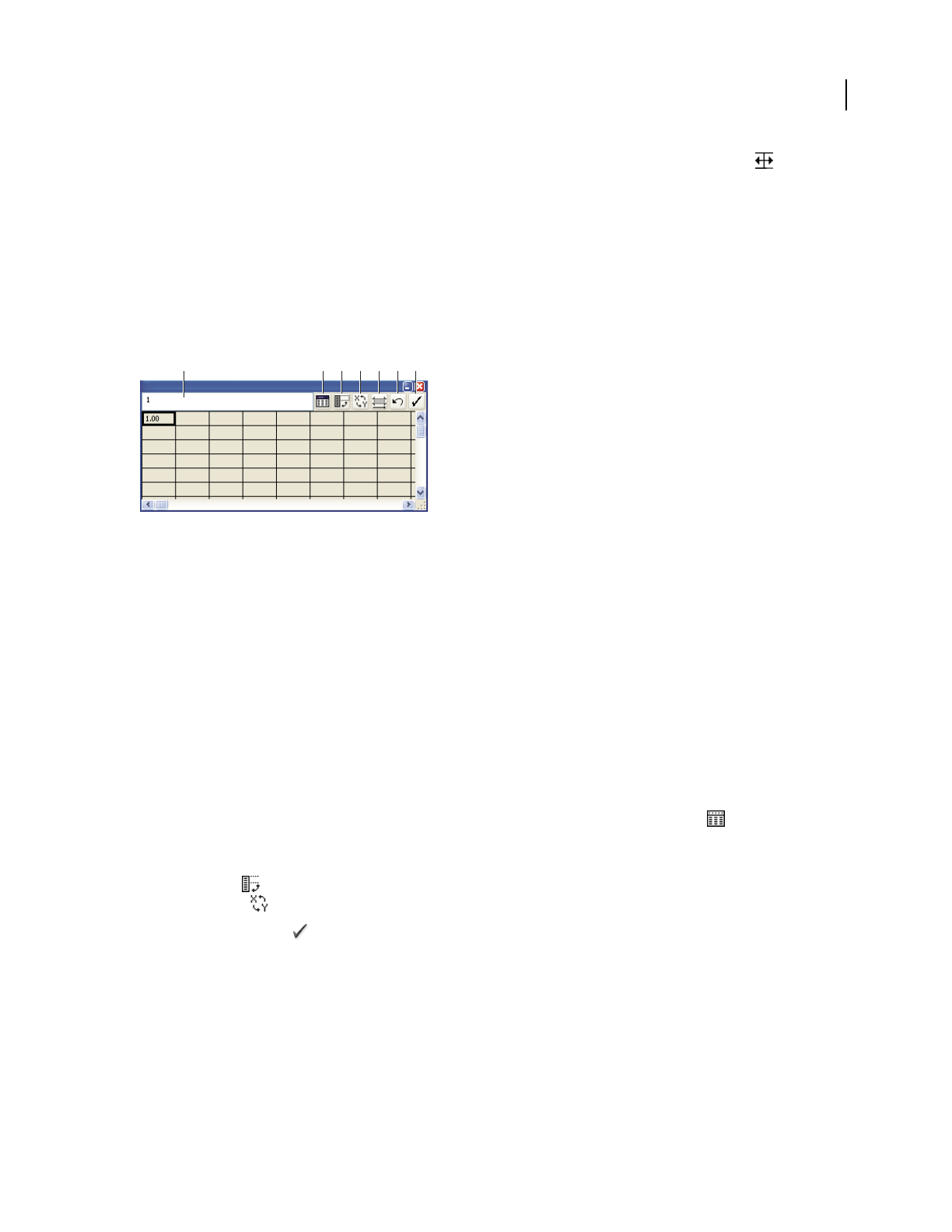
ILLUSTRATOR CS3
User Guide
448
•Position the pointer at the edge of the column you want to adjust. The pointer changes to a double arrow . Then
drag the handle to the desired position.
Adjust the decimal precision for cells
❖ Click the Cell Style button, and enter a value between 0 and 10 in the Number of Decimals text box.
Enter graph data
You use the Graph Data window to enter the data for your graph. The Graph Data window appears automatically
when you use a graph tool and stays open until you close it.
Graph data window
A. Entry text box B. Import data C. Transpose row/column D. Switch x/y E. Cell style F. Revert G. Apply
1 Display the Graph Data window for an existing graph: select the entire graph with the Selection tool, and then
choose Object > Graph > Data.
2 Enter data in any of the following ways:
•Select a cell in the worksheet, and enter the data in the text box at the top of the window. Press Tab to input the
data and select the next cell in the same row; press Enter or Return to input the data and select the next cell in the
same column; use the arrow keys to move from cell to cell; or simply click another cell to select it.
•Copy data from a spreadsheet application such as Lotus® 1-2-3 or Microsoft Excel. In the Graph Data window,
click the cell that will be the upper-left cell of the data you paste, and choose Edit > Paste.
•Use a word-processing application to create a text file in which the data for each cell is separated by a tab, and the
data for each row is separated by a paragraph return. The data can only contain decimal points or decimal
commas; otherwise, the data is not plotted. (For example, enter 732000, not 732,000.) In the Graph Data window,
click the cell that will be the upper-left cell of the data you import, click the Import Data button , and select the
text file.
Note: If you accidentally enter graph data backward (that is, in rows instead of columns, or vice versa), click the
Transpose button to switch the columns and rows of data. To switch the x and y axes of scatter graphs, click the
Switch X/Y button .
3 Click the Apply button or press the Enter key on the numeric keypad to regenerate the graph.
Use graph labels and data sets
Labels are words or numbers that describe two things: the sets of data you want to compare, and the categories across
which you want to compare them. For column, stacked column, bar, stacked bar, line, area, and radar graphs, you
enter labels in the worksheet as follows:
A B C D E F G
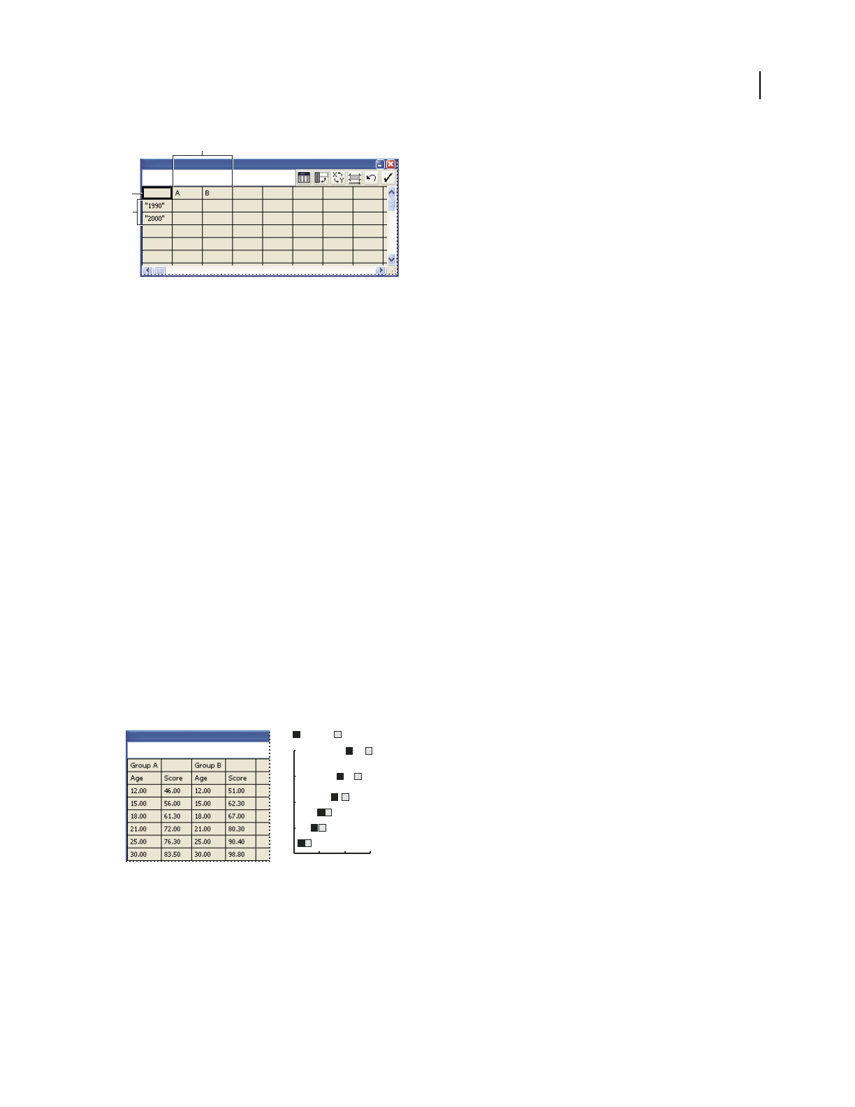
ILLUSTRATOR CS3
User Guide
449
Labels in Graph Data window
A. Data set labels B. Blank cell C. Category labels
Enter labels
❖For column, stacked column, bar, stacked bar, line, area, and radar graphs, enter labels in the worksheet as follows:
•If you want Illustrator to generate a legend for the graph, delete the contents of the upper-left cell and leave the
cell blank.
•Enter labels for the different sets of data in the top row of cells. These labels will appear in the legend. If you don’t
want Illustrator to generate a legend, don’t enter data-set labels.
•Enter labels for the categories in the left column of cells. Categories are often units of time, such as days, months,
or years. These labels appear along either the horizontal axis or vertical axis of the graph, with the exception of
radar graphs, for which each label results in a separate axis.
•To create labels consisting only of numbers, enclose the numbers in straight quotation marks. For example, to use
the year 1996 as a label, enter "1996".
•To create line breaks in labels, use the vertical bar key to separate lines. For example, type Total|subscrip-
tions|1996 to produce the following graph label:
Tot a l
subscriptions
1996
Enter data sets for scatter graphs
A scatter graph differs from the other kinds of graphs in that both axes measure values; there are no categories.
Scatter graph data
•Enter data-set labels in every other cell along the top row of the worksheet, starting with the first cell. These labels
will appear in the legend.
•Enter y-axis data in the first column and x-axis data in the second column.
B
C
A
40 60 80 100
10
15
20
25
30
Group B Group A
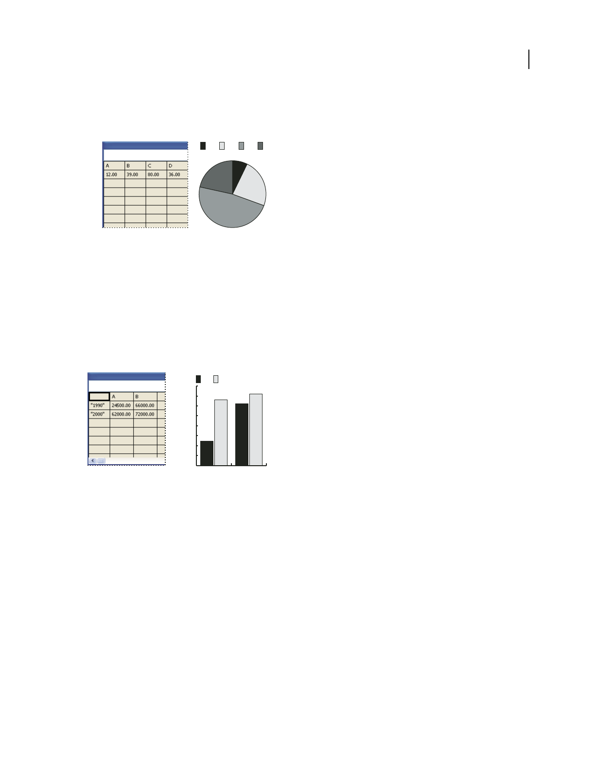
ILLUSTRATOR CS3
User Guide
450
Enter data sets for pie graphs
You organize data sets for pie graphs similarly to other graphs. However, each row of data in the worksheet generates
a separate graph.
Pie graph data
•Enter data-set labels as for column, stacked column, bar, stacked bar, line, area, and radar graphs. Enter category
labels if you want to generate graph names.
•To create a single pie graph, plot only one row of data, either all positive or all negative values.
•To create multiple pie graphs, plot additional rows of data, either all positive or all negative values. By default, the
size of the individual pie graphs is proportional to the total of each graph’s data.
Enter data sets for column, bar, line, area, and radar graphs
After you enter the labels for your graph, you’re ready to enter each set of data under the appropriate column.
Column graph data
Column, stacked column, bar, stacked bar graphs The height of the column or length of the bar corresponds to the
amount being compared. For column or bar graphs, you can combine positive and negative values; negative values
appear as columns extending below the horizontal axis. For stacked column graphs, numbers must be all positive or
all negative.
Line graphs Each column of data corresponds to one line in the line graph. You can combine positive and negative
values in a line graph.
Area graphs Values must be all positive or all negative. Each row of data entered corresponds to a filled area on the
area graph. Area graphs add each column’s values to the previous column’s totals. Therefore, even if area graphs and
line graphs contain the same data, they appear substantially different.
Radar graphs Each number is plotted on an axis and connected to the others in the same axis to create a “web.” You
can combine positive and negative values in a radar graph.
D C B A
0
10000
20000
30000
40000
50000
60000
70000
80000
B A
2000 1990

ILLUSTRATOR CS3
User Guide
451
Formatting graphs
Formatting and customizing graphs
Graphs can be formatted in a variety of ways. For example, you can change the appearance and position of the graph’s
axes, add drop shadows, move the legend, and combine different graph types. You can view the formatting options
for a graph by selecting a graph with the Selection tool and choosing Object
> Graph > Type.
You can also manually customize your graph in numerous ways. You can change the colors of shading; change the
typeface and type style; move, reflect, shear, rotate, or scale any or all parts of the graph; and customize column and
marker designs. You can apply transparency, gradients, blends, brush strokes, graphic styles, and other effects to
graphs. You should always apply these types of changes last, because regenerating the graph will remove them.
To get ideas for how you can customize graphs, see the examples in the Cool Extras/Sample Files/Graph Designs
folder inside the Illustrator application folder.
Keep in mind that a graph is a grouped object that is related to its data. Never ungroup the graph; if you do, you
cannot change the graph. To edit a graph, select the parts you want to edit without ungrouping the graph, using either
the Direct Selection tool or the Group Selection tool.
It is also important to understand how elements of a graph are related. The entire graph with its legends is one group.
All the sets of data are a subgroup of the graph; in turn, each set of data with its legend box is a subgroup of all the
sets of data. Each value is a subgroup of its set of data, and so on. Never ungroup or regroup objects that are within
the graph.
See also
“About graph designs” on page 456
Change the graph type
1 Select a graph with the Selection tool.
2 Choose Object > Graph > Type, or double-click the graph tool in the Tools panel.
3 In the Graph Type dialog box, click the button that corresponds to the desired graph type, and click OK.
Note: Once graph objects are painted with gradients, changing graph types can cause unexpected results. To prevent
undesirable results, either do not apply gradients until the graph is finished, or use the Direct Selection tool to select
gradient-painted objects and paint those objects with a process color; then reapply the original gradients.
Format a graph’s axes
With the exception of pie graphs, all graphs have a value axis which displays the unit of measurement for the graph.
You can choose to display the value axis on one side or both sides of the graph. Bar, stacked bar, column, stacked
column, line, and area graphs also have a category axis which defines the categories of data in the graph.
You can control how many tick marks appear on each axis, change the length of tick marks, and add a prefix and
suffix to numbers on the axis.
1 Select the graph with the Selection tool.
2 Choose Object > Graph > Type, or double-click the graph tool in the Tools panel.
3 To change the position of the value axis, select an option from the Value Axis menu.

ILLUSTRATOR CS3
User Guide
452
4 To format tick marks and labels, select an axis from the pop-up menu at the top of the dialog box, and set the
following options:
Tick Values Determines the placement of tick marks on value axes, left axes, right axes, bottom axes, or top axes.
Select Override Calculated Values to manually calculate the placement of tick marks. Either accept the values set
when you created the graph or enter a minimum value, a maximum value, and the number of divisions between
labels.
Tick Marks Determines the length of tick marks and number of tick marks per division. To prevent numbers from
appearing on an axis, enter 0 in the Draw Tick Marks Per Division text box. For category axes, select Draw Tick
Marks Between Labels to draw tick marks on either side of the labels or columns, or deselect the option to center tick
marks over the labels or columns.
Add Labels Specifies a prefix and suffix for numbers on value axes, left axes, right axes, bottom axes, or top axes. For
example, you can add a dollar sign or percent sign to axis numbers.
Assign different scales to the value axes
If your graph has a value axis on both sides, you can assign a different set of data to each axis. This causes Illustrator
to generate a different scale for each axis. This technique is especially useful when you combine different graph types
in the same graph.
1 Select the Group Selection tool .
2 Click the legend for the data set you want to assign to the axis.
3 Without moving the Group Selection tool pointer from the legend, click again. All of the columns grouped with
the legend are selected.
4 Choose Object > Graph > Type, or double-click the graph tool in the Tools panel.
5 From the Value Axis pop-up menu, select the axis to which you want to assign the data.
6 Click OK.
See also
“Selection tool gallery” on page 25
Format columns, bars, and lines
For column, stacked column, bar, and stacked bar graphs, you can adjust the amount of space between each column
or bar in the graph. You can also adjust the amount of space between the categories, or clusters, of data in the graph.
For line, scatter, and radar graphs, you can adjust the appearance of lines and data points.
1 Select the graph with the Selection tool.
2 Choose Object > Graph > Type, or double-click the graph tool in the Tools panel.
3 To adjust the space between columns and bars in a column, stacked column, bar, or stacked bar graph, enter a
value between 1% and 1000% in the Column Width, Bar Width, or Cluster Width text box.
A value greater than 100% causes the columns, bars, or clusters to overlap one another. A value less than 100% leaves
space between the columns, bars, or clusters. A value of 100% moves the columns, bars, or clusters flush against each
other.
4 To adjust lines and data points in line, scatter, and radar graphs, set the Mark Data Points, Connect Data Points,
Edge-to-Edge Lines, and Draw Filled Lines options.

ILLUSTRATOR CS3
User Guide
453
5 To change how columns, bars, and lines overlap, set the First Row In Front and First Column In Front options.
Note: Always select First Column In Front for area graphs; if you do not, some areas may not appear.
General graph options
You can access general graph options by selecting the graph with the Selection tool and double-clicking the graph
tool in the Tools panel.
Value Axis Determines where the value axis (the axis that displays the unit of measurement) appears.
Add Drop Shadow Applies drop shadows behind the columns, bars, or lines in a graph, and to entire pie graphs.
Add Legend Across Top Displays the legend horizontally across the top of the graph instead of to the right of the
graph.
First Row In Front Controls how the categories, or clusters, of data in a graph overlap when the Cluster Width is
greater than 100%. This option is the most useful when working with column and bar graphs.
First Column In Front Places the column, bar, or line that corresponds to the first column of data in the Graph Data
window on top. This option also determines which column is on top for column and stacked column graphs with a
Column Width greater than 100% and for bar and stacked bar graphs with a Bar Width greater than 100%.
Mark Data Points Places square markers at each data point.
Connect Data Points Draws lines that make it easier to see relationships among data.
Edge-to-Edge Lines Draws lines that extend across the graph, from left to right along the horizontal (x) axis. This
option is not available for scatter graphs.
Draw Filled Lines Creates a wider line according to the value you enter in the Line Width text box, and which fills
the line with paint according to the specifications for that series of data. This option becomes available when you
select Connect Data Points.
Add drop shadows
You can apply drop shadows behind the columns, bars, or lines in a graph, and to entire pie graphs.
1 Select a graph with the Selection tool.
2 Choose Object > Graph > Type, or double-click the graph tool in the Tools panel.
3 In the Graph Type dialog box, select Add Drop Shadow, and click OK.
Change the position of a legend
By default, the legend is displayed to the right of the graph. However, you can choose to display it horizontally across
the top of the graph.
1 Select a graph with the Selection tool.
2 Choose Object > Graph > Type, or double-click the graph tool in the Tools panel.
3 In the Graph Type dialog box, select Add Legend Across Top, and click OK.

ILLUSTRATOR CS3
User Guide
454
Format pie graphs
You can change the placement of the legend and how wedges are sorted in pie graphs. You can also specify how you
want to display multiple pie graphs.
1 Select the graph with the Selection tool.
2 Choose Object > Graph > Type, or double-click the graph tool in the Tools panel.
3 Do any of the following:
•To change the placement of the legend, select an option for Legend.
•To specify how multiple pie graphs are displayed, select an option for Position.
•To specify how wedges are sorted, select an option for Sort.
Percentages and legends are painted black by default. If a pie wedge with a dark background obscures a legend,
repaint the dark background. Use the Group Selection tool to select the dark pie wedges, and paint the wedges using
the Color panel or Swatches panel.
Pie graph options
Legend Determines the placement of the legend.
•Standard Legend Places column labels outside the graph; this is the default. Use this option when you combine
pie graphs with other kinds of graphs.
•Legends In Wedges Inserts labels into the corresponding wedges.
•No Legend Omits legends entirely.
Position Specifies how multiple pie graphs are displayed.
•Ratio Sizes the graphs proportionally.
•Even Makes all the pie graphs the same diameter.
•Stacked Stacks each pie graph on top of the other, and each graph is sized proportionally to each other.
Sort Specifies how wedges are sorted.
•All Sorts the wedges of the selected pie graphs from largest to smallest value proceeding clockwise from the top
of the pie graph.
•First Sorts the wedges of the selected pie graphs so that the largest value in the first graph will be placed in the first
wedge, and the rest will sort from largest to smallest. All other graphs will follow the order of the wedges in the first
graph.
•None Sorts the wedges of the selected pie graphs in the order in which you entered values proceeding clockwise
from the top of the graphs.
Combine different graph types
You can combine different graph types in one graph. For example, you may want one set of data to appear as a
column graph and other sets of data to appear as a line graph. You
can combine any type of graph with any other,
with the exception of scatter graphs. Scatter graphs cannot be combined with any other graph type.

ILLUSTRATOR CS3
User Guide
455
Combining columns and lines in one graph
1 Select the Group Selection tool .
2 Click the legend for the data whose graph type you want to change.
3 Without moving the Group Selection tool pointer from the legend, click again. All of the columns grouped with
the legend are selected.
4 Choose Object > Graph > Type, or double-click the graph tool in the Tools panel.
5 Select the graph type and options you want.
If a graph uses more than one graph type, you may want one set of data along the right axis and the other set of data
along the left axis. In this way, each axis measures different data.
Note: If you use stacked column graphs with other graph types, be sure to use the same axis for all sets of data that are
represented by stacked column graphs. If some sets of data use the right axis while others use the left, the column heights
may be misleading or may overlap.
Select parts of a graph
1 Select the Group Selection tool .
2 Click the legend of the columns you want to select.
3 Without moving the Group Selection tool pointer from the legend, click again. All of the columns grouped with
the legend are selected.
You can also select a group by clicking one of its parts, clicking again to select columns grouped with it, and clicking
a third time to select the legend. Each click adds another layer of grouped objects to the selection, beginning with
the next group up in the hierarchy. You can click as many times as the number of groups to add to a selection.
4 To deselect part of a selected group, select the Direct Selection tool , and Shift-click the object.
Format the text in a graph
Illustrator uses a default font and font size when generating text for the graph’s labels and legend. However, you can
easily change the formatting of type to add visual interest to your graph.
1 Select the Group Selection tool .
2 Click once to select the baseline of the type you want to change; click twice to select all of the type.
3 Change the type attributes as desired.
0%
50%
100%
150%
200%
250%
$0
$5
$10
$15
$20
$25
Wholesale
Retail
Product C Product B Product A
2000 1990 1980
Varietal Retail
Price per Unit
Retail and
Wholesale
Price Index
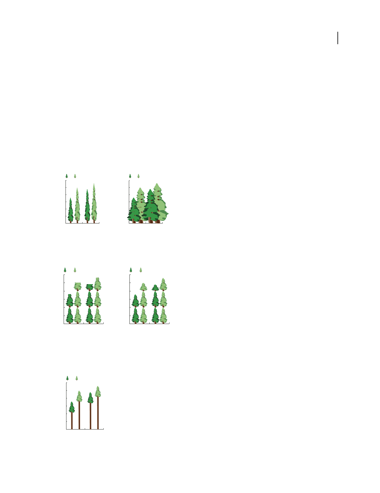
ILLUSTRATOR CS3
User Guide
456
Adding pictures and symbols to graphs
About graph designs
You use graph designs to add illustrations to columns and markers. Graph designs can be simple drawings, logos, or
other symbols representing values in a graph; they can also be complex objects that contain patterns and guide
objects. Illustrator comes with a variety of preset graph designs. In addition, you can create new graph designs and
store them in the Graph Design dialog box.
You can apply graph design to columns in several ways:
Vertically scaled design Is stretched or compressed vertically. Its width does not change.
Uniformly scaled design Is scaled both vertically and horizontally. The horizontal spacing of the designs is not
adjusted for the different widths.
Vertically scaled graph design compared to uniformly scaled graph design
Repeating design Stacks a design to fill the columns. You can specify the value that each design represents, as well
as whether you want to chop or scale designs that represent fractions.
Repeating graph with chopped design compared to repeating graph with scaled design
Sliding design Is similar to a vertically scaled design, except that you can specify where in the design to stretch or
compress it. For example, if you were using a person to represent data, you might stretch or compress only the body,
but not the head. Using the Vertically Scaled option would scale the entire person.
Sliding graph design
0
50
100
150
200
250
300
B A
2003 1993
0
50
100
150
200
250
300
B A
2003 1993
0
50
100
150
200
250
300
B A
2003 1993
0
50
100
150
200
250
300
B A
2003 1993
0
50
100
150
200
250
300
B A
2003 1993

ILLUSTRATOR CS3
User Guide
457
Import a column or marker design
Illustrator comes with a variety of preset designs that you can use in your graphs. You can also transfer the graph
designs you create between documents.
1 Choose Window > Swatch Libraries > Other Library.
2 Do one of the following:
•To import preset graph designs, navigate to the Cool Extras/Sample Files/Graph Designs folder inside the
Illustrator application folder. Then select a graph designs file, and click Open.
•To import graph designs from another document, select the document, and click Open.
Initially, all that appears is a new panel with colors, gradients, and patterns from the imported file. However, the
imported graph designs will be available when you open the Graph Column or Graph Marker dialog box.
Create a column design
1 Create a rectangle as the backmost object in the design. The rectangle represents the boundary of the graph
design.
Copy and paste the smallest column in your graph to use it as the bounding rectangle for your design.
2 Paint the rectangle as desired, or fill and stroke it with None so that it is invisible.
3 Create the design using any of the drawing tools, or position an existing design in front of the rectangle.
4 Using the Selection tool , select the entire design, including the rectangle.
5 Choose Object > Group to group the design.
6 Choose Object > Graph > Design.
7 Click New Design. A preview of the selected design appears. Only the portion of the design that fits inside the
backmost rectangle is visible, but the whole design appears when used in the graph.
8 Click Rename to name the design.
Creating a graph design is similar to creating a pattern.
See also
“About patterns” on page 187
Create a sliding column design
1 Create a rectangle as the backmost object in the design. This rectangle is the boundary for the graph design.
2 Create the design using one of the drawing tools, or place an existing design in front of the rectangle.
3 Use the Pen tool to draw a horizontal line to define where the design is to be stretched or compressed.
4 Select all parts of the design, including the horizontal line.
5 Choose Object > Group to group the design.
6 Use the Direct Selection tool or Group Selection tool to select the horizontal line. Be sure to select only the
horizontal line.
7 Choose View > Guides > Make Guides.
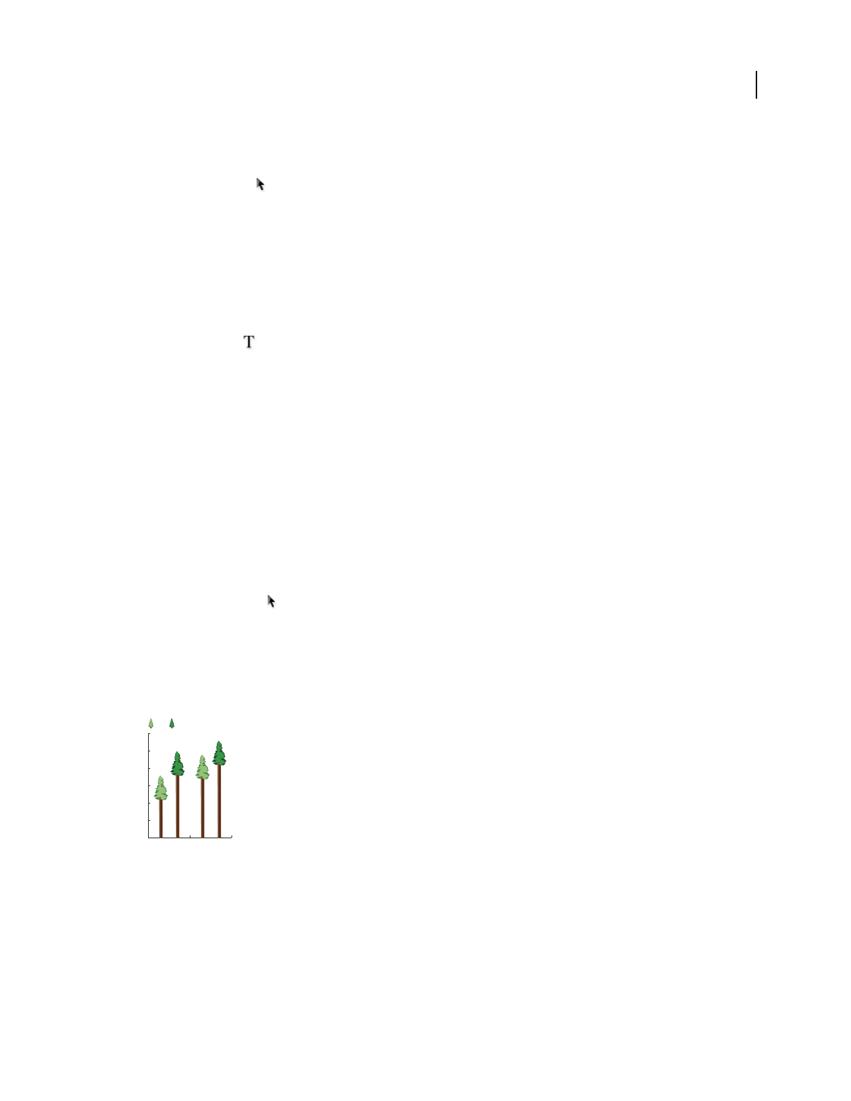
ILLUSTRATOR CS3
User Guide
458
8 Choose View > Guides > Lock Guides to remove the check mark next to Lock so you can unlock the guides. Move
the design around to make sure that the guide moves with the design.
9 Use the Selection tool to select the whole design.
10 Choose Object > Graph > Design.
11 Click New Design. A preview of the selected design appears.
12 Click Rename to name the design.
Add totals to a column design
1 Create the column design.
2 Select the Type tool . Position the pointer at a point where you want the value to appear, near or in the rectangle
that defines the design.
For example, you can place the value in, above, below, to the left, or to the right of the design.
3 Click and type a percent sign (%) followed by two digits from 0 to 9. The digits control how the data is displayed.
The first digit determines how many places appear before the decimal point. For example, if your total was 122, a
digit of 3 would display 122. If you enter 0 for the first digit, the program adds the number of places necessary for
the value.
The second digit determines how many places appear after the decimal point. Zeros are added as necessary, and
values are rounded up or down as necessary. You can vary these numbers, depending on how many digits you need.
4 To change the type attributes, choose Window > Type > Character, specify the attributes you want, and close the
panel.
5 To align the decimal points, choose Window > Type > Paragraph and click the Align Text Right button.
6 Using the Selection tool , select the entire design, including the rectangle and any type.
7 Choose Object > Group to group the design.
8 Choose Object > Graph > Design.
9 Click New Design. You see a preview of the selected design.
10 Click Rename to name the design.
Sliding graph design with column totals
Create a marker design
1 Select and copy a marker rectangle from the graph, and paste it where you're going to create your design. This will
be the backmost object in your graph design and will establish the size of the marker.
2 Make the marker artwork the size you want it to be in the graph, even if it’s larger than the marker rectangle you
copied.
0
50
100
150
200
250
300
250
280
180
240
B A
2003 1993
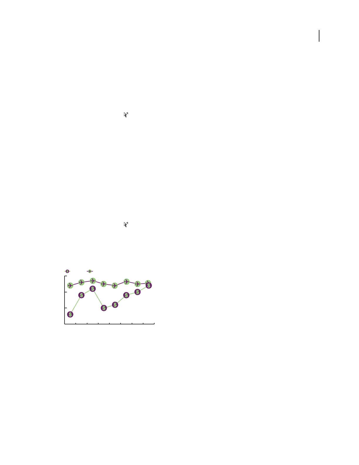
ILLUSTRATOR CS3
User Guide
459
3 Once you’ve got the marker design the way you want it, select the design, choose Object > Graph > Design, and
click New Design.
4 Click Rename to name the design.
Apply a column design to a graph
1 Create or import the column design.
2 Use the Group Selection tool to select the columns or bars you want to fill with the design, or select the entire
graph.
3 Choose Object > Graph > Column.
4 Select a column design type.
If you choose the Repeating Column Type, enter a value in the Each Design Represents text box. Also select whether
to chop or scale any fractions of the design from the For Fractions pop-up menu. Chop Design cuts off a fraction of
the top design as necessary; Scale Design scales the last design to fit in the column.
5 Select the design you want to use. A preview of the selected design appears.
6 Click OK.
Apply a marker design to a line or scatter graph
1 Create or import the column design.
2 Use the Group Selection tool to select the markers and the legends in the graph that you want to replace with
a design. Do not select any lines.
3 Choose Object > Graph > Marker. Select a design, and click OK.
The design is scaled so that the backmost rectangle in the design is the same size as the default square marker on the
line or scatter graph.
Line graph with marker designs
Reuse a graph design
You can reuse a graph design that you created and edit it to make a new design. If you have the original artwork, you
can alter it and then rename the design using the Graph Design dialog box.
If you don’t have the original artwork defined as a graph design, you can retrieve the original by pasting the graph
design into your artwork.
1 Choose Select > Deselect to deselect all of the artwork.
2 Choose Object > Graph > Design.
3 Select the graph design that you want to paste into your artwork, and click Paste Design.
4 Click OK. The graph design is pasted into your artwork. You can now edit it and define it as a new graph design.
150
200
250
300
B A

460
Chapter 16: Keyboard shortcuts
Keyboard shortcuts make you more productive in Illustrator. You can use the default shortcuts listed here, or add
and customize shortcuts to suit your needs.
Customizing keyboard shortcuts
Customize keyboard shortcuts
Illustrator lets you view a list of all shortcuts, and edit or create shortcuts. The Keyboard Shortcuts dialog box serves
as a shortcut editor, and includes all commands that support shortcuts, some of which aren’t addressed in the default
shortcut set.
You can define your own sets of shortcuts, change individual shortcuts within a set, and switch between sets of shortcuts.
For example, you can create separate sets for different workspaces chosen from the Window
> Workspace menu.
In addition to using keyboard shortcuts, you can access many commands using context-sensitive menus. Context-
sensitive menus display commands that are relevant to the active tool, selection, or panel. To display a context-
sensitive menu, right-click (Windows) or Control-click (Mac OS) in the document window or panel.
1 Choose Edit > Keyboard Shortcuts.
2 Choose a set of shortcuts from the Set menu at the top of the Keyboard Shortcuts dialog box.
3 Choose a shortcut type (Menu Commands or Tools) from the menu above the shortcut display.
4 Do any of the following:
•To activate the set of shortcuts, click OK.
•To change a shortcut, click in the Shortcut column of the scroll list and type a new shortcut. If you enter a shortcut
that is already assigned to another command or tool, an alert appears at the bottom of the dialog box. Click Undo
to undo the change, or click Go To to go to the other command or tool and assign it a new shortcut. In the Symbol
column, type the symbol that will appear in the menu or tool tip for the command or tool. You can use any of the
characters that are allowed in the Shortcut column.
Note: Mac OS does not allow you to assign Command+Option+8 as a menu shortcut.
•To save changes to the current set of shortcuts, click OK. (You can’t save changes to the set named Illustrator
Defaults.)
•To save a new set of shortcuts, click Save. Enter a name for the new set, and click OK. The new key set will appear
in the pop-up menu under the new name.
•To delete the set of shortcuts, click Delete. (You can’t delete the set named Illustrator Defaults.)
•To export the displayed set of shortcuts into a text file, click Export Text. In the Save Key Set File As dialog box,
enter a filename for the current key set that you are saving, and click Save. You can use this text file to print out a
copy of your keyboard shortcuts.

ILLUSTRATOR CS3
User Guide
461
Default keyboard shortcuts
Keys for selecting tools
This is not a complete list of keyboard shortcuts. This table lists only those shortcuts that are not displayed in menu
commands or tool tips.
Result Windows Mac OS
Selection tool V V
Direct Selection tool A A
Magic Wand tool YY
Lasso tool Q Q
Pen tool P P
Add Anchor Point tool + (plus)+ (plus)
Delete Anchor Point tool - (minus)- (minus)
Convert Anchor Point tool Shift + C Shift + C
Type tool T T
Line Segment tool \ (backslash)\ (backslash)
Rectangle tool M M
Ellipse tool L L
Paintbrush tool B B
Pencil tool NN
Rotate tool R R
Reflect tool O O
Scale tool S S
Warp tool Shift + R Shift + R
Free Transform tool E E
Symbol Sprayer tool Shift + S Shift + S
Column Graph tool J J
Mesh tool U U
Gradient tool G G
Eyedropper tool I I
Blend tool W W
Live Paint Bucket tool K K
Live Paint Selection tool Shift + L Shift + L
Crop Area tool Shift + O Shift + O
Slice tool Shift + K Shift + K
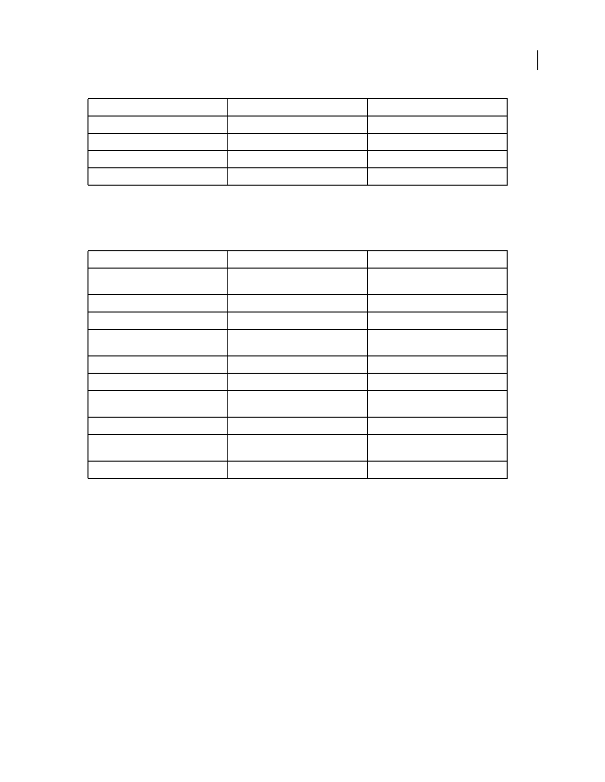
ILLUSTRATOR CS3
User Guide
462
Keys for viewing artwork
This is not a complete list of keyboard shortcuts. This table lists only those shortcuts that are not displayed in menu
commands or tool tips.
Keys for drawing
This is not a complete list of keyboard shortcuts. This table lists only those shortcuts that are not displayed in menu
commands or tool tips.
Eraser tool Shift + E Shift + E
Scissors tool C C
Hand tool H H
Zoom tool Z Z
Result Windows Mac OS
Toggle between screen modes: Standard,
Full, Full with menu bar, and Maximized
FF
Fit imageable area in window Double-click Hand tool Double-click Hand tool
Magnify 100% Double-click Zoom tool Double-click Zoom tool
Switch to Hand tool (when not in text-edit
mode)
Spacebar Spacebar
Switch to Zoom tool in magnify mode Ctrl + Spacebar Command + Spacebar
Switch to Zoom tool in reduce mode Ctrl + Alt + Spacebar Command + Option + Spacebar
Move Zoom marquee while dragging with
the Zoom tool
Spacebar Spacebar
Hide unselected artwork Control + Alt + Shift + 3 Command + Option + Shift + 3
Convert between horizontal and vertical
guide
Alt-drag guide Option-drag guide
Release guide Ctrl + Shift-double-click guide Command + Shift-double-click guide
Result Windows Mac OS
ILLUSTRATOR CS3
User Guide
463
Result Windows Mac OS
Constrain a shape’s proportions or orienta-
tion to:
•equal height and width for rectangles,
rounded rectangles, ellipses, and grids
•Increments of 45˚ for line and arc
segments
•Original orientation for polygons, stars,
and flares
Shift-drag Shift-drag
Move a shape while drawing it spacebar-drag spacebar-drag
Draw from the center of a shape (except for
polygons, stars, and flares)
Alt-drag Option-drag
Continuously duplicate a shape ‘ (grave accent)-drag ‘ (grave accent)-drag
Increase or decrease polygon sides, star
points, arc angle, spiral winds, or flare rays
Start dragging, then press the Up Arrow or
Down Arrow
Start dragging, then press the Up Arrow or
Down Arrow
Keep the inner radius of a star constant Start dragging, then hold down Ctrl Start dragging, then hold down Command
Keep the sides of a star straight Alt-drag Option-drag
Switch between an open and closed arc Start dragging, then hold down C Start dragging, then hold down C
Flip an arc, keeping the reference point
constant
Start dragging, then hold down F Start dragging, then hold down SF
Add or subtract winds from a spiral while
increasing the length of the spiral
Alt-drag Option-drag
Change the decay rate of a spiral Ctrl-drag Command-drag
Add or remove horizontal lines from a rect-
angular grid or concentric lines from a polar
grid
Start dragging, then press the Up Arrow or
Down Arrow
Start dragging, then press the Up Arrow or
Down Arrow
Add or remove vertical lines from a rectan-
gular grid or radial lines from a polar grid
Start dragging, then press the Right Arrow
or Left Arrow
Start dragging, then press the Right Arrow
or Left Arrow
Decrease the skew value for horizontal
dividers in a rectangular grid or radial
dividers in a polar grid by 10%
Start dragging, then press F Start dragging, then press F
Increase the skew value for horizontal
dividers in a rectangular grid or radial
dividers in a polar grid by 10%
Start dragging, then press V Start dragging, then press V
Decrease the skew value for vertical dividers
in a rectangular grid or concentric dividers
in a polar grid by 10%
Start dragging, then press X Start dragging, then press X
Increase the skew value for vertical dividers
in a rectangular grid or concentric dividers
in a polar grid by 10%
Start dragging, then press C Start dragging, then press C
Create and expand a Live Trace object in
one step
Alt-click Live Trace in the Control panel, or
hold down Alt and select a tracing preset.
Option-click Live Trace in the Control panel,
or hold down Option and select a tracing
preset.
ILLUSTRATOR CS3
User Guide
464
Keys for selecting
This is not a complete list of keyboard shortcuts. This table lists only those shortcuts that are not displayed in menu
commands or tool tips.
Keys for moving selections
This is not a complete list of keyboard shortcuts. This table lists only those shortcuts that are not displayed in menu
commands or tool tips.
Set keyboard increments in General Preferences
Keys for editing shapes
This is not a complete list of keyboard shortcuts. This table lists only those shortcuts that are not displayed in menu
commands or tool tips.
Result Windows Mac OS
Switch to last-used selection tool (Selection
tool, Direct Selection tool, or Group Selec-
tion tool)
Ctrl Command
Switch between Direct Selection tool and
Group Selection tool
Alt Option
Add to a selection with Selection tool,
Direct Selection tool, Group Selection tool,
Live Paint Selection tool, or Magic Wand
tool
Shift-click Shift-click
Subtract a selection with Selection tool,
Direct Selection tool, Group Selection tool,
or LIve Paint Selection tool
Shift-click Shift-click
Subtract from selection with Magic Wand
tool
Alt-click Option-click
Add to selection with Lasso tool Shift-drag Shift-drag
Subtract from selection with Lasso tool Alt-drag Option-drag
Change pointer to cross hair for selected
tools
Caps Lock Caps Lock
Result Windows Mac OS
Move selection in user-defined increments Right Arrow, Left Arrow, Up Arrow, or Down
Arrow
Right Arrow, Left Arrow, Up Arrow, or Down
Arrow
Move selection in 10x user-defined incre-
ments
Shift + Right Arrow, Left Arrow, Up Arrow, or
Down Arrow
Shift + Right Arrow, Left Arrow, Up Arrow, or
Down Arrow
Lock all deselected artwork Ctrl + Alt + Shift + 2 Command + Option + Shift + 2
Constrain movement to 45˚ angle (except
when using Reflect tool)
Hold down Shift Hold down Shift
ILLUSTRATOR CS3
User Guide
465
Keys for painting objects
This is not a complete list of keyboard shortcuts. This table lists only those shortcuts that are not displayed in menu
commands or tool tips.
Keys for working with Live Paint groups
This is not a complete list of keyboard shortcuts. This table lists only those shortcuts that are not displayed in menu
commands or tool tips.
Result Windows Mac OS
Switch Pen tool to Convert Anchor Point
tool
Alt Option
Switch between Add Anchor Point tool and
Delete Anchor Point tool
Alt Option
Switch Scissors tool to Add Anchor Point
tool
Alt Option
Switch Pencil tool to Smooth tool Alt Option
Move current anchor point while drawing
with Pen tool
Spacebar-drag Spacebar-drag
Cut a straight line with Knife tool Alt-drag Option-drag
Cut at 45˚ or 90˚ with Knife tool Shift + Alt-drag Shift + Option-drag
Turn shape mode buttons in Pathfinder
panel into Pathfinder commands
Alt + Shape mode Option + Shape mode
Result Windows Mac OS
Toggle between fill and stroke X X
Set fill and stroke to default D D
Swap fill and stroke Shift + X Shift + X
Select gradient fill mode > >
Select color fill mode < <
Select no stroke/fill mode / (forward slash)/ (forward slash)
Sample color from an image or interme-
diate color from gradient
Shift + Eyedropper tool Shift + Eyedropper tool
Sample style and append appearance of
currently selected item
Alt + Shift-click + Eyedropper tool Option + Shift-click + Eyedropper tool
Add new fill Ctrl + / (forward slash)Command + / (forward slash)
Add new stroke Ctrl + Alt + / (forward slash)Command + Option + / (forward slash)
Reset gradient to black and white Ctrl-click gradient button in Toolbox Command-click gradient button in Toolbox
ILLUSTRATOR CS3
User Guide
466
Keys for transforming objects
This is not a complete list of keyboard shortcuts. This table lists only those shortcuts that are not displayed in menu
commands or tool tips.
Keys for working with type
This is not a complete list of keyboard shortcuts. This table lists only those shortcuts that are not displayed in menu
commands or tool tips.
Result Windows Mac OS
Switch to Eyedropper tool and sample fill
and/or stroke
Alt-click + Live Paint Bucket tool Option-click + Live Paint Bucket tool
Switch to Eyedropper tool and sample color
from an image or intermediate color from a
gradient
Alt + Shift-click + Live Paint Bucket tool Option + Shift-click + Live Paint Bucket tool
Select opposite Live Paint Bucket tool
options (if Paint Fills and Paint Strokes are
currently selected, switch to Paint Fills only)
Shift + Live Paint Bucket tool Shift + Live Paint Bucket tool
Fill across unstroked edges into adjacent
faces
Double-click + Live Paint Bucket tool Double-click + Live Paint Bucket tool
Fill all faces that have same fill and stroke all
edges that have same stroke
Triple-click + Live Paint Bucket tool Triple-click + Live Paint Bucket tool
Switch to Eyedropper tool and sample fill
and/or stroke
Alt-click + Live Paint Selection tool Option-click + Live Paint Selection tool
Switch to Eyedropper tool and sample color
from an image or intermediate color from a
gradient
Alt + Shift-click + Live Paint Selection tool Option + Shift-click + Live Paint Selection
tool
Add to/subtract from a selection Shift-click + Live Paint Selection tool Shift-click + Live Paint Selection tool
Select all connected faces /edges with same
fill/stroke
Double-click + Live Paint Selection tool Double-click + Live Paint Selection tool
Select all faces/edges with same fill/stroke Triple-click + Live Paint Selection tool Triple-click + Live Paint Selection tool
Result Windows Mac OS
Set origin point and open dialog box when
using Rotate tool, Scale tool, Reflect tool, or
Shear tool
Alt-click Option-click
Duplicate and transform selection when
using Selection tool, Scale tool, Reflect tool,
or Shear tool
Alt-drag Option-drag
Transform pattern (independent of object)
when using Selection tool, Scale tool,
Reflect tool, or Shear tool
Tilde (~)-drag Tilde (~)-drag

ILLUSTRATOR CS3
User Guide
467
To change the increment value for type shortcuts, choose Edit > Preferences >Type (Windows) or Illustrator >
Preferences >Type (Mac OS). Enter the values you want in the Size/Leading, Baseline Shift, and Tracking text boxes,
and click OK.
Result Windows Mac OS
Move one character right or left Right Arrow or Left Arrow Right Arrow or Left Arrow
Move up or down one line Up Arrow or Down Arrow Up Arrow or Down Arrow
Move one word right or left Ctrl + Right Arrow or Left Arrow Command + Right Arrow or Left Arrow
Move up or down one paragraph Ctrl + Up Arrow or Down Arrow Command + Up Arrow or Down Arrow
Select one word right or left Shift + Ctrl + Right Arrow or Left Arrow Shift + Command + Right Arrow or Left
Arrow
Select one paragraph before or after Shift + Ctrl + Up Arrow or Down Arrow Shift + Command + Up Arrow or Down
Arrow
Extend existing selection Shift-click Shift-click
Align paragraph left, right, or center Ctrl + Shift + L, R, or C Command + Shift + L, R, or C
Justify paragraph Ctrl + Shift + J Command + Shift + J
Insert soft return Shift + Enter Shift + Return
Highlight kerning Ctrl + Alt + K Command + Option + K
Reset horizontal scale to 100% Ctrl + Shift + X Command + Shift + X
Increase or decrease type size Ctrl + Shift + > or < Command + Shift + > or <
Increase or decrease leading Alt + Up or Down Arrow (horizontal text) or
Right or Left Arrow (vertical text)
Option + Up or Down Arrow (horizontal
text) or Right or Left Arrow (vertical text)
Set leading to the type size Double-click leading icon in the Character
panel
Double-click leading icon in the Character
panel
Reset tracking/kerning to 0 Ctrl + Alt + Q Command + Option + Q
Add or remove space (kerning) between
two characters
Alt + Right or Left Arrow (horizontal text) or
Up or Down Arrow (vertical text)
Option + Right or Left Arrow (horizontal
text) or Up or Down Arrow (vertical text)
Add or remove space (kerning) between
characters by five times the increment value
Ctrl + Alt + Right or Left Arrow (horizontal
text) or Up or Down Arrow (vertical text)
Command + Option + Right or Left Arrow
(horizontal text) or Up or Down Arrow
(vertical text)
Increase or decrease baseline shift Alt + Shift + Up or Down Arrow (horizontal
text) or Right or Left Arrow (vertical text)
Option + Shift + Up or Down Arrow (hori-
zontal text) or Right or Left Arrow (vertical
text)
Switch between Type and Vertical Type,
Area Type and Vertical Area Type, and Path
Type and Vertical Path Type tools
Shift Shift
Switch between Area Type and Type, Path
Type and Area Type, and Vertical Path Type
and Vertical Area Type tools
Alt-click Type tool Option-click Type tool
ILLUSTRATOR CS3
User Guide
468
Keys for using panels
This is not a complete list of keyboard shortcuts. This table lists only those shortcuts that are not displayed in menu
commands or tool tips.
Keys for the Actions panel
This is not a complete list of keyboard shortcuts. This table lists only those shortcuts that are not displayed in menu
commands or tool tips.
Keys for the Brushes panel
This is not a complete list of keyboard shortcuts. This table lists only those shortcuts that are not displayed in menu
commands or tool tips.
Keys for the Character and Paragraph panels
This is not a complete list of keyboard shortcuts. This table lists only those shortcuts that are not displayed in menu
commands or tool tips.
Result Windows Mac OS
Set options (except for Actions, Brushes,
Swatches, and Symbols panels)
Alt-click New button Option-click New button
Delete without confirmation (except for
Variable panel)
Alt-click Delete button Option-click Delete button
Apply value and keep text box active Shift + Enter Shift + Return
Select range of actions, brushes, layers,
links, styles, or swatches
Shift-click Shift-click
Select noncontiguous actions, brushes,
layers (same level only), links, styles, or
swatches
Ctrl-click Command-click
Show/Hide all panels Tab Tab
Show/Hide all panels except the Toolbox
and Control panel
Shift + Tab Shift + Tab
Result Windows Mac OS
Expand/Collapse entire hierarchy for action
set
Alt-click expansion triangle Option-click expansion triangle
Set options for action set Double-click folder icon Double-click folder icon
Play a single command Alt-click Play button Option-click Play button
Play the current action Ctrl-double-click Play button Command-double-click Play button
Begin recording actions without confirma-
tion
Alt-click New Action button Option-click New Action button
Result Windows Mac OS
Open Brush Options dialog box Double-click brush Double-click brush
Duplicate brush Drag brush to New Brush button Drag brush to New Brush button
ILLUSTRATOR CS3
User Guide
469
Keys for the Color panel
This is not a complete list of keyboard shortcuts. This table lists only those shortcuts that are not displayed in menu
commands or tool tips.
Keys for the Gradient panel
This is not a complete list of keyboard shortcuts. This table lists only those shortcuts that are not displayed in menu
commands or tool tips.
Keys for the Layers panel
This is not a complete list of keyboard shortcuts. This table lists only those shortcuts that are not displayed in menu
commands or tool tips.
Result Windows Mac OS
Increase/decrease the selected value by a
small increment
Up Arrow or Down Arrow Up Arrow or Down Arrow
Increase/decreases the selected value by a
large increment
Shift + Up Arrow or Down Arrow Shift + Up Arrow or Down Arrow
Highlight the font name field in the Char-
acter panel
Ctrl + Alt + Shift + F Command + Option + Shift + F
Result Windows Mac OS
Select the complement for the current color
fill/stroke
Ctrl-click color bar Command-click color bar
Change the nonactive fill/stroke Alt-click color bar Option-click color bar
Select the complement for the nonactive
fill/stroke
Ctrl + Alt-click color bar Command + Option-click color bar
Select the inverse for the current fill/stroke Ctrl + Shift-click color bar Command + Shift-click color bar
Select the inverse for the nonactive
fill/stroke
Ctrl + Shift + Alt-click color bar Command + Shift + Option-click color bar
Change the color mode Shift-click color bar Shift-click color bar
Move color sliders in tandem Shift-drag color slider Shift-drag color slider
Switch between percentage and 0-255
values for RGB
Double-click to right of a numerical field Double-click to right of a numerical field
Result Windows Mac OS
Duplicate color stops Alt-drag Option-drag
Swap color stops Alt-drag color stop onto another stop Option-drag color stop onto another color
stop
Apply swatch color to active (or selected)
color stop
Alt-click swatch in the Swatches panel Option-click swatch in the Swatches panel
ILLUSTRATOR CS3
User Guide
470
Keys for the Swatches panel
This is not a complete list of keyboard shortcuts. This table lists only those shortcuts that are not displayed in menu
commands or tool tips.
Keys for the Transform panel
This is not a complete list of keyboard shortcuts. This table lists only those shortcuts that are not displayed in menu
commands or tool tips.
Result Windows Mac OS
Select all objects on the layer Alt-click layer name Option-click layer name
Show/hide all layers but the selected one Alt-click eye icon Option-click eye icon
Select Outline/Preview view for the selected
layer
Ctrl-click eye icon Command-click eye icon
Selects Outline/Preview view for all other
layers
Ctrl + Alt-click eye icon Command + Option-click eye icon
Lock/unlock all other layers Alt-click lock icon Option-click lock icon
Expand all sublayers to display entire hier-
archy
Alt-click expansion triangle Option-click expansion triangle
Set options as you create new layer Alt-click New Layer button Option-click New Layer button
Set options as you create new sublayer Alt-click New Sublayer button Option-click New Sublayer button
Place new sublayer at bottom of layer list Ctrl + Alt-click New Sublayer button Command + Option-click New Sublayer
button
Place layer at top of layer list Ctrl-click New Layer button Command-click New Layer button
Place layer below selected layer Ctrl + Alt-click New Layer button Command + Option-click New Layer button
Copy the selection to a new layer, sublayer,
or group
Alt-drag selection Option-drag selection
Result Windows Mac OS
Create new spot color Ctrl-click New Swatch button Command-click New Swatch button
Create new global process color Ctrl + Shift-click New Swatch button Command + Shift-click New Swatch button
Replace swatch with another Alt-drag a swatch over another Option-drag a swatch over another
Select swatch by name (using keyboard)Ctrl + Alt-click in the swatch color list Command + Option-click in the swatch
color list
Result Windows Mac OS
Apply a value and keep focus in edit field Shift + Enter Shift + Return
Apply a value and copy object Alt + Enter Option + Return
Apply a value and scale option proportion-
ately for width or height
Ctrl + Enter Command + Return

ILLUSTRATOR CS3
User Guide
471
Keys for the Transparency panel
This is not a complete list of keyboard shortcuts. This table lists only those shortcuts that are not displayed in menu
commands or tool tips.
Function keys
This is not a complete list of keyboard shortcuts. This table lists only those shortcuts that are not displayed in menu
commands or tool tips.
Result Windows Mac OS
Change mask to grayscale image for editing Alt-click on mask thumbnail Option-click on mask thumbnail
Disable opacity mask Shift-click on mask thumbnail Shift-click on mask thumbnail
Re-enable opacity mask Shift-click on disabled mask thumbnail Shift-click on disabled mask thumbnail
Increase/decrease opacity in 1% increments Click opacity field + Up Arrow or Down
Arrow
Click opacity field + Up Arrow or Down
Arrow
Increase/decrease opacity in 10% incre-
ments
Shift-click opacity field + Up Arrow or Down
Arrow
Shift-click opacity field + Up Arrow or Down
Arrow
Result Windows Mac OS
Invoke Help F1 F1
Cut F2 F2
Copy F3 F3
Paste F4 F4
Show/hide Brushes panel F5 F5
Show/hide Color panel F6 F6
Show/hide Layers panel F7 F7
Create new symbol F8 F8
Show/hide Info panel Ctrl + F8 Command + F8
Show/hide Gradient panel Ctrl + F9 Command + F9
Show/hide Stroke panel Ctrl + F10 Command + F10
Show/hide Attributes panel Ctrl + F11 Command + F11
Revert F12 F12
Show/hide Graphic Styles panel Shift + F5 Shift + F5
Show/hide Appearance panel Shift + F6 Shift + F6
Show/hide Align panel Shift + F7 Shift + F7
Show/hide Transform panel Shift + F8 Shift + F8
Show/hide Pathfinder panel Shift + Ctrl + F9 Shift + Command + F9
Show/hide Transparency panel Shift + Ctrl + F10 Shift + Command + F10
Show/hide Symbols panel Shift + Ctrl + F11 Shift + Command + F11

472
Index
Numerics
3D objects
about 244
custom bevels for 250
extruding 245
lighting 246
mapping images to surface 251
revolving 246
rotating 246, 250
surface shading 245, 246, 250
9-slice scaling, symbols 84
A
Accented Edges command 358
accessibility
of Help 4
Acrobat. See Adobe Acrobat
action playback speed 437
action sets 439
actions 51
about 433
batch-processing files 439, 440
changing recorded values in 436
excluding tasks from 437
inserting stops in 436
loading 439
nonrecordable tasks 435
playing 434
recording 434
recording again 438
selecting 434
undoing 434
Actions palette
about 433
activation of software 1
Actual Size command 43
Add (Pathfinder) effect 231
Add Anchor Point tool 26
Add New Fill command 157
Add New Stroke command 157
additive colors 93
Adjust Colors filter 125
Adobe Acrobat
comparing versions 281
layered PDF files in 277
presets for exporting to 278
Adobe Bridge
about 37
Creative Suite color settings 130,
132
metadata in 288
showing current file in 16
Adobe Design Center 9
Adobe Flash
integration with Illustrator 380
symbols 82, 84
Adobe Flash, exporting text to 331
Adobe GoLive
creating dynamic data for 446
exporting Illustrator files for 218
Adobe Graphics Server 442, 446
Adobe Help 2
Adobe Illustrator
file format, saving to 264
integration with Flash 380
metadata in 287
performance, improving 353
Prefs file 50
Adobe Illustrator files
importing into Flash 380
Adobe InDesign
exporting artwork to 218
metadata in 287
placing Illustrator files in 418
Adobe PDF conversion settings 278
Adobe PDF. See PDF files
Adobe Photoshop
compounds paths from 234
copying objects to or from 218
embedded artwork 353
exporting Illustrator files for 218,
269, 274
importing files from 262
metadata in 287
moving part of image to
Illustrator 263
moving paths to Illustrator 263
using Photoshop effects in
Illustrator 353
Adobe RGB color space 147
Adobe Version Cue
about 37
accessing commands in status
bar 16
Adobe Video Workshop 5
AI file format. See Adobe Illustrator
AI files. See Adobe Illustrator files
AIPrefs file 50
AIT files 36
aki 335
Align panel 205
alignment guides 48
All Artwork Above (Hide)
command 215
All Artwork Above (Lock)
command 215
all caps, in type 309
All On Same Layers command 196
ALT text 373
AlterCast. See Adobe Graphics Server
alternate glyphs
about 316
Asian 333
fractions and ordinals 313
Glyphs panel 317
highlighting 318
inserting 318
ligatures and contextual
alternates 318
numbers 312
OpenType fonts 303, 317
swashes 319
anchor points
about 52
adding 71
converting smooth and corner 74
joining endpoints 70
moving 73
moving and nudging 69, 71
preferences 55
removing 71, 73
selecting 68

INDEX 473
showing and hiding 54
snapping objects to 48
stray points, finding 72
types of 54
angle of rotation 207, 208
Angled Strokes command 358
animations
creating 378, 379
releasing objects to layers 213
saving, with Export command 271
annotations
playing in actions 437
viewing in Save For Web dialog
box 383
anti-aliasing
in envelopes 229
for images generated by effects 352
in type 310
preferences for artwork 46
previewing 370
in web graphics 385
when saving artwork 273, 274, 275
appearance attributes
See also targeting
about 346
Appearance panel 346
copying between objects 349, 350
duplicating 348
for new objects 347
multiple fills and strokes 157
of new objects 347
removing from objects 348
stacking order 348
targeting items for 347
AppleScript 441
Apply SVG Filter command 376
arcs
Arc tool 26
drawing 58
area graphs
See also graph designs, graphs
about 31
entering data for 450
area type
about 289
creating 290
first baseline offset 293
inset spacing 293
resizing 292
rows and columns 294
Area Type tool 28
Arrange (Object) commands 217
arrowheads, adding to lines 156
art brushes 166, 172
artboard
about 41
adding gridlines to 47
adding guides to 48
changing the size and color 42
scrolling 44
tiling 42
zooming 43
Artistic effects and filters
about 357
artwork
copying from Photoshop 263
previewing in output medium 46
viewing as outlines 45
ASCII file format 291
Asian type. See type, Asian
Assign Profile command 144, 145
auto slices 372
AutoCAD file formats 269
automation. See actions
Average command 73
axes
adjusting axis of reflection 210
rotating 208
B
background color
document window 42
slices 373
web pages 400
background images 400
banding, in blends and gradients 416
bar graphs
See also graph designs, graphs
about 31
entering data for 450
Bas Relief command 360
base (nonemulsion side) 405
base color, setting for color group 110
baseline offset 293
baseline shift 314
Basic CMYK new document
profile 33
Basic RGB new document profile 33
batch processing 439, 440
bevel joins, for strokes 155
bevels, for 3D objects 250
bitmap images
about 258
applying effects to 351, 353
colorizing 126
copying from Photoshop 263
created by effects 352
created from vector 365
dimming 212
publishing online 259
texturizing 362
tracing 77, 78
black point compensation 149
black-and-white artwork 96
bleeds
about 409
adding 409
clipping imported PDF to 260
crop marks and 38
saving in PDF files 284
Blend tool 29, 240
Blending Mode (Select Same)
command 201
Blending Mode command 181
blending modes
about 179
changing 181
isolating to groups or layers 181
mixing overlapping colors 127
selecting objects with same 197
blends
about 240
changing spine of 242
creating 240, 241
expanding 243
options for 241
printing issues 414, 416
releasing 243
reversing 242
Bloat tool 29
Blur effects and filters 358
BMP file format 269
See also exporting artwork
Bottom-to-bottom leading 334

INDEX 474
bounding boxes
in patterns 187
about 221
rotating objects with 207
Bridge Home 8
Bridge. See Adobe Bridge
brightness
adjusting in Illustrator 15
in HSB color model 95
Bring Forward command 217
Bring To Front command 217
brochure templates 36
browser dithering 388
browser-safe colors. See web-safe
colors
brush strokes
applying 167
converting to outlines 169
effects and filters 358
removing 168
brushes
applying brush strokes 168
Brushes panel 167
colorization options 170
creating 169
expanding 169
libraries of 167
modifying 169
options for 76, 170, 171, 172
types of 166
bunri-kinshi 340
burasagari 323, 340
business card templates 36
Button Mode command 434
C
calligraphic brushes 76, 166, 170
capitalization, changing 309
caps, for strokes 155
Cascade command 45
Cascading Style Sheets (CSS)
Generate CSS slice output
option 399
category axis, for graphs 451
center point 53
certificate templates 36
Chalk & Charcoal command 360
Change Case commands 309
character spacing 321
character styles
about 329
deleting 330
removing 330
characters
See also type, formatting
Character panel 308
scaling 300
selecting 306
space between 315
special 316
styles for 329, 330
Unicode 302
Charcoal command 360
Check Spelling command 301
choke trap 426
chroma 95
Chrome command 360
circular grids 59
Clean Up (Path) command 292
Clear command 216
Clear Guides command 48
Clip To Artboard command 374
clipboard, importing and exporting
artwork with 218
clipping masks
about 237
creating 238
modifying 238, 239
Close Path command in InDesign 64,
66, 68
closed paths
about 52
creating with Pen tool 68
creating, with Pencil tool 62
CMS. See color matching systems
CMYK
about 94
changing to RGB 95
process colors 102
spot colors 102, 106
tints 102, 107
CMYK spot colors 97
color bars 408
Color blending mode 180
color blends, printing 414
Color Burn blending mode 180
Color Dodge blending mode 180
color gamuts 128
color groups
about 109
adding or removing colors 119
creating 110
creating in Live Color 114
deleting 119
editing colors and color
groups 115
limiting to swatch library 114
Live Color dialog box 112
presets 123
reducing colors 122
setting base color 110
Swatches panel 102, 104
Color Guide panel
about 110
coloring artwork 112
selecting colors 99
Color Halftone command 359
color management
See also color profiles, color
settings
about 128, 129, 130
color settings reference 146
considerations for importing
images 134, 135
considerations for printing
documents 139
considerations for process and
spot colors 133
creating a viewing
environment 130
for online graphics 136
for PDFs 136, 140
setting up 131
soft-proofing colors 137, 138
synchronizing color settings 132
color model working space 144
color models
about 93, 96
changing 95
CMYK 94
grayscale 96
HSB 95
for images generated by effects 352
Lab 96
RGB 93
Color panel
about 101
selecting colors 99, 101

INDEX 475
Color Picker 100
about 99
editing color group 117
selecting colors 99, 100
color profiles
about 141
assigning and removing 144
assigning and removing from
documents 144
converting 145
for desktop printers 139
for imported images 134, 135
for monitors 142, 143
installing 143
warning messages for 147
color reduction options 123
color separations
about 403
creating 404
host-based vs. in-RIP 405
preparing artwork for 404
problems with spot colors and
transparent artwork 97
color settings
See also color management
color conversions 149
color management policies 147
customizing 146
for Adobe applications 132
presets for 146
rendering intents 149
synchronizing with other
applications 132
working spaces 146
color spaces 93, 96
Color Table palette 391
color tables
sorting 391
color variations
in Color Guide panel 111
options 111
Colored Pencil command 357
colorizing
grayscale images 126
symbols 90
colors
See also color management, color
model
adjusting multiple colors 125
applying to objects 151, 152
applying to type 307
blending 125, 127, 182
changing to complement 125
color-matching libraries 102, 106
comparing in InDesign and
Illustrator 98
converting to grayscale 126
deleting 393
editing in Live Color 112, 116
gradients 182
in blending modes 179
in digital graphics 93
inverting 125
locking in Color Table palette 393
mapping to transparency 393
mixing 127
mixing spot and process inks 98
out-of-gamut 124
printable 124
process 102, 105
range of 96
reducing for output 122
removing 156
saturating 126
selecting 99, 100, 101
shifting to Web palette 392
spot 97, 102, 105
Swatches panel 102, 103
tints 102, 107
web-safe 124, 370
column and marker designs. See
graph designs
Column command (graphs) 459
column graphs
See also graph designs, graphs
about 31
entering data for 450
columns of text, creating 294
Combine Slices command 374
combining objects
about 229
with clipping masks 237
with compound paths 234
with compound shapes 232
with Pathfinder effects 230
complementary colors, changing
to 125
composite fonts
creating 341
customizing 343
deleting 344
exporting 344
previewing in Font menu 304
composites
printing 401
composition methods 325
compound paths
about 229, 234
adjusting 234
creating 234
creating from strokes 156
fill rules 235
releasing 235
compound shapes
about 229, 232
sharing with Photoshop 234, 274
working with 233
compression
Illustrator format 265
PDF 282
conserving paper and film 407
consolidating layers 214
constraining movements 203
Conté Crayon command 360
content, protecting 287
contextual alternates 318
continuous-tone images,
printing 403
Control panel 17
conversion settings
presets 278
Convert Anchor Point tool 26, 74
Convert To Grayscale filter 126
Convert To Profile command 145
Convert To Shape effect 243
converting smooth points to corner
points 67
copying objects
about the clipboard 218
commands for 203
by dragging 217
into layers 205
pasting in front or in back 205
corner radius, changing 56
corners, rounding 244
correcting mistakes 51
Craquelure command 361
Create (Threaded Text)
command 295

INDEX 476
Create From Guides command 372,
373, 374
Create From Selection
command 372, 373, 374
Create Outlines command 312
Crop (Pathfinder) effect 232
Crop Marks command 41
cropping artwork
crop area, defining and editing 38,
39, 40
crop marks 40
crop marks, Japanese-style 41
for printing 40
rulers 39
Crosshatch command 358
Crystallize command 359
Crystallize tool 29
CSS layers, generating 385
curves
drawing 58
drawing, with Pen tool 64, 66
printing 411
reshaping 52, 69
Cutout command 357
cutting objects 235
D
Dark Strokes command 358
Darken blending mode 180
dashed lines 155
dashes, en and em 313
data sets, creating 444
data-driven graphics
See also variables
about 51, 441
creating variables 442
editing dynamic objects 444
editing variables 443
saving templates for 446
using data sets 444
using variable libraries 445
date and time, displayed in status
bar 16
DCS file format, importing 261
Default Fill And Stroke button 152
default workspace
restoring 14
De-Interlace command 362
Delete All command 374
Delete Anchor Point tool 26
Delete Color command 394
Delete Workspace command 22
deleting
empty type objects 292
objects 216
slices 374
Deselect All Colors command 392
Deselect command 201
Design Center 9
designs, graph. See graph designs
desktop printers, color profiles
for 139
devices, color gamut of 96
dialog boxes
calculating values in 17
entering values 16
DIC color system 102
dictionaries
assigning to text 302
editing 301
Difference blending mode 180
Diffuse Glow command 359
diffusion dither 389
digital cameras, color gamut of 96
digital masters 276
Direct Selection tool 68
about 25, 193
selecting with 68
using 199
direction lines and points
about 52, 54
moving 69
showing and hiding 54
direction points and lines
preferences 55
specifying 55
Distort & Transform effect 243
distorting objects
effects 243
envelopes 226
Free Distort effect 243
Free Transform tool 225
liquify tools 226
distributing objects 205, 206
dithering
browser 388
No Dither setting 394
shifting to web-safe colors 392
transparency, in Optimize
palette 389
Divide (Pathfinder) effect 231
Divide Objects Below command 236
Divide Slices command 374
dividing objects 235
document clipping path, in
Photoshop files 263
Document Info command 288
document profiles. See color profiles
document raster effects settings 352
documents
adding multiple pages 42
in Bridge 37
creating 34
creating templates 36
managing with Version Cue 37
new document profiles 33
opening 36
scaling 408
setting up 42, 45, 47
types 33
units of measurement for 47
Welcome screen 34
downloading fonts 412
downloads 10
updates, plug-ins, and tryouts 10
downsampling, in PDF files 282
dpi (dots per inch) 402
drawing
See also brushes, symbols
arcs 58
changing anchor points 74
ellipses 57
grids 59
lines 56
paths, with Pen tool 63, 64, 66
paths, with Pencil tool 61, 62
polygons 57
rectangles and squares 56
spirals 58
stars 57
drop shadows
creating 362
in graphs 453
options for 362
Dry Brush command 357

INDEX 477
duotones
imported from PDF files 260
Duplicate Swatch command 107
duplicating objects 203
by dragging 217
in Layers panel 217
offsetting 219
by pasting 203
DXF/DWG file format 269
dynamic objects 444
Dynamic text 331
E
Edit Custom Dictionary
command 301
Edit Original command 257
Edit Selection command 201
Edit Views command 45
effects
See also individual effect names
about 350
applying 351
applying to bitmap images 353
as appearance attributes 346
editing and deleting 353
raster 352
scaling 222
for SVG files 376, 377
why some are unavailable 351
Ellipse tool 26, 57
embedded files
See also linked files
adding to a document 253
applying effects and filters to 353
compared to linked files 253
converting from linked files 257
EMF file format 269
See also exporting artwork
EMF files
flattening 417
empty cells 398
emulsion options 405
en and em dashes, smart punctuation
option 313
endpoints
connecting 70
of paths 52
envelope templates 36
envelopes 226, 227, 228, 229
EPS file format
compared to other formats 264
options for saving 265
printing embedded files 261
saving 265
EPS files
problems with spot colors and
transparent artwork 97
EPS format
importing files 260
erasing artwork 26, 75
Every-line Composer 325
Exclude (Pathfinder) effect 231
Exclusion blending mode 180
Expand (Blend) command 243
Expand (Envelope) command 228
Expand Appearance command 169,
202
Expand command 202
Expand Compound Shape
command 233
expanding
brushed paths 169
flares 61
objects 202
symbol instances 85
tracing objects 81
exporting artwork
See also saving artwork
compared to saving artwork 264
Microsoft-compatible format 269
PostScript format 266
procedure for 269
supported file formats 269
exporting text 331
Extensible Metadata Platform
(XMP) 287
extra spaces, eliminating 313
Extras 7
extruding objects 245
Eyedropper tool
about 28, 99
copying attributes with 349
F
Feather effect 363
file formats
AIT 36
ASCII 291
AutoCAD 269
BMP 269
DWG and DXF 269
EMF 269
EPS 265
Illustrator (AI) 264
JPEG 270
Photoshop 270
PICT 270
PNG 270
RTF 291
SVG and SVGZ 266, 375
SWF (Flash) 378
Targa 270
text 291
TIFF 270
WMF 270
File Handling & Clipboard
preferences 256, 261, 418
File Info command 255
files
See also documents, file formats
batch-processing 439, 440
linked vs. embedded 253
opening in Illustrator 36
placing 253
restoring 51
saving 264
sizes of web graphics 370
fills
See also colors, gradients, patterns
about 151, 152
applying to objects 153
as appearance attributes 346
controls for 152
converting to objects 202
creating multiple 157
Fill & Stroke (Select Same)
command 157, 201
Fill button 152
Fill Color (Select Same)
command 157, 201
hiding 45
removing 156
film
base 405
conserving 407
Film Grain command 357
filters
See also individual filter names
about 350

INDEX 478
applying 351
applying to bitmap images 353
why some are unavailable 351
Find And Replace command 307
Find Next command 307
first baseline offset 293
First Column In Front option, for
graphs 453
first line indents 321
First Object Above (Select)
command 201
First Row In Front option, for
graphs 453
Fit Headline command 295
Fit In Window command 43
Flare tool 26
Flash
See Adobe Flash
Flash graphics
about 378
creating animations 379
saving, with Export command 271
Flash. See Adobe Flash
Flatten Transparency command 424
Flattener Preview panel 46, 422
flattening
about 417
during printing 418
individual objects 424
layers 214
presets for 422
presets, creating and editing 423
presets, exporting and
importing 423
presets, working with 423
previewing 421
transparency in PDF files 285
flexographic printing 408
floating boxes. See CSS layers
FOCOLTONE color system 102
font installation 2
fonts
choosing 304
composite 341, 343, 344
downloading 412
embedding 266, 412
finding and replacing 304
font families 303
missing 305
OpenType 303
previewing 304
printer-resident 412
form fields, securing 287
four-color process printing 94
fractional character widths 316
fractions
OpenType fonts 313
Smart Punctuation command 313
frames, splitting 77
Free Distort effect 243
Free Transform tool
about 29
distorting objects with 225
reflecting objects with 209
rotating objects with 207
shearing objects with 225
Fresco command 357, 362
Full Screen mode 16
function keys 471
G
gamut, of colors 96, 124
gamuts 128
Gaussian Blur command 358
General preferences
Anti-aliased Artwork 46
Append Converted Upon Opening
Legacy Files 344
Corner Radius 56
Keyboard Increment 204, 464
Scale Strokes & Effects 222
Select Same Tint % 157
Show Tool Tips 25
Transform Pattern Tiles 221
Use Japanese Crop Marks 41
Use Precise Cursors 25
Use Preview Bounds 50
GIF file format
compared to other web graphics
formats 375
optimization options for 387
saving to 310, 365, 370
web optimization 371
web optimization settings 387
Glass command 359, 362
global colors
process 102
using Live Color instead 115
Glowing Edges command 361
glows, creating 363
glyphs
about 316
Asian 333
fractions and ordinals 313
Glyphs panel 317
highlighting 318
in OpenType fonts 303
inserting 318
ligatures and contextual
alternates 318
numbers 312
OpenType fonts 317
spacing of 321
swashes 319
GoLive. See Adobe GoLive
gradients
about 182
applying last-selected 152
applying to objects 153, 182, 184
calculating maximum blend
length 416
changing direction of 184
creating and modifying 182
creating new 183
Gradient panel 182
Gradient panel shortcuts 469
Gradient tool 28, 50
in graphs 451
in SWF (Flash) files 379
printing 183, 414
proper screen frequency for
printing 415
spot colors 183
swatches for 102, 107
Grain command 361, 362
graph designs
about 456
applying 459
creating 457, 458
importing 457
reusing 459
Graphic Pen command 360
graphic styles
about 366
applying 368
applying to symbols 90, 91
breaking the link to 368
creating 367
deleting 368

INDEX 479
duplicating 368
Graphic Styles panel 366
importing from another
document 369
libraries 369
Override Character Color
option 368
replacing 368
graphics
embedding 257
graphs
assigning scales to axes 452
changing type of 451
combining types 454
creating 447
entering data for 448, 449, 450
gradients in 451
labels 448
legends 453
types of 31
variables in 442, 444
graphs, formatting
about 451
adding drop shadows 453
axes 451
columns, bars, and lines 452
pie graphs 454
selecting parts of 455
text 455
gray levels, for printing 415
grayscale images
about 96
colorizing 126
converting color to 126
greeting card templates 36
grids
creating 235, 236
drawing 59
preferences 47
rectangular 59
using with artwork 47
Group command 202
Group Selection tool 25, 193, 199
groups
about 201
creating 202
isolation mode 194
nested 201
selecting 196, 198, 199
selecting objects within 199
viewing as outlines 45
guides
aligning text and graphics 48
showing and hiding 48
Smart Guides 48
Guides & Grid preferences 48
GyoumatsuYakumonoHankaku
mojikumi set 338
GyoumatsuYakumonoZenkaku
mojikumi set 338
H
Halftone Pattern command 360
halftoning, resolution for 402
Hand tool 33, 44
hanging indents 322
hanging punctuation 323
Hard Light blending mode 180
Hard Mix effect 127
harmony rules
choosing in Live Color 110, 114
headlines, fitting across text 295
Help
about 2
High Quality Print, PDF preset 278
hiragana fonts 333
HKS color system 102
horizontal (landscape) page
orientation 407
horizontal type, converting to
vertical 301
host-based separations 405
hotspots, in web graphics 375
HSB color model 95
HTML
output settings 398
hue 95
Hue blending mode 180
hyphenation 302, 324
automatic 324
composition methods and 325
options 324
preventing breaks 325
I
ICC profiles
See also color profiles
displayed in status bar 16
embedding in files 265, 274, 275,
387
icons
panels as 21
Illustrator. See Adobe Illustrator
image exposure 405
image maps
creating 375
output settings for 399
images
reszing in Save For Web dialog
box 385
imagesetting
bitmap graphics and 258
Import SVG Filter command 377
importing
DCS files 261
EPS files 260
monotone, duotone, and tritone
images 260
PDF files 259
Photoshop files 262, 263
swatches from another
document 108
text files 218, 291
in ports 295
indenting text 321
indents, hanging 322
InDesign. See Adobe InDesign
Info panel 50
Ink Outlines command 358
ink preview 46
Inner Glow effect 363
input device profiles 141, 143
Input text 331
in-RIP separations 405
Insert Stop command 436
inset spacing for type 293
instances, symbol 82
interactivity
adding to SVG files 377
creating with CSS layers 385
International Color Consortium
(ICC) 130
Intersect (Pathfinder) effect 231

INDEX 480
intersecting shapes
See compound shapes, pathfinder
effects
Inverse (Select) command 201
inverting colors 125
ISO standards 281
isolation mode
about 193, 194
symbols 86
J
Japanese type. See type, Asian
JavaScript 377, 441
Join command 70
joins, for strokes 155
JPEG files, export options for 273
JPEG format
optimization options 386
justified text, adjusting spacing 321
K
kerning 315
keyboard shortcuts
customizing 460
in Help 4
kinsoku 339
Knife tool 32, 235, 236
knockouts
creating transparency
knockouts 175
preventing using overprinting 424
varying transparency
knockouts 178
kurikaeshi moji shori 341
L
Lab color model 96
label templates 36
landscape (horizontal) page
orientation 407
language
assigning to text 302
Unicode support 302
Lasso tool 193, 196
selecting anchor points with 68
selecting with 68
Last Object Below (Select)
command 201
layer comps, in Photoshop files 262
layers
about 211
adding objects to 216
consolidating 214
converting to CSS layers 385
creating 213
duplicating objects in 217
exporting to Adobe Photoshop 274
groups within 201
hiding 215
Layers panel 211, 347
locating items in 214
locking and unlocking 215
making nonprintable 401
moving objects between 213
pasting objects into 205
preserving in Adobe Acrobat 282
releasing objects to 213
selecting objects in 193, 196
stacking order 217
sublayers, isolation mode 195
template 78
viewing as outlines 45
Layers panel 348
leading
in Asian type 334
setting 314
legacy text 344, 345
legends, for graphs 453
letter spacing 315, 321
letterhead templates 36
libraries
brush 167
graph design 457
graphic style 369
swatch 102, 106
symbol 87
ligatures 318
inserting with Smart Punctuation
command 313
using in OpenType fonts 318
Lighten blending mode 180
lighting 3D objects 245, 246
limit-check error 403, 411
line breaks, showing 319
line graphs
See also graph designs, graphs
about 31
entering data for 450
Line Segment tool 26, 56
lines
See also paths, strokes
adding arrowheads 156
adding to, with Pencil tool 62
adjusting angle and length 69
changing width of 154
connecting, with Pencil tool 62
dashed 155
drawing, with Line Segment
tool 56
drawing, with Pen tool 63, 64, 66
drawing, with Pencil tool 61
moving 69
reshaping 52, 62
trapping 429
lining numbers 312
Linked File variables 442, 444
linked files
adding to a document 253
applying effects to 353
color management
considerations 134
compared to embedded files 253
editing original file 257
embedding 257, 264
placement options for 256
previews for EPS files 261
relinking 256
showing in Outline mode 45
updating 255
viewing information for 255
linking
Links panel 254
type objects 295
links
viewing metadata 255
liquify tools 226
Live Color dialog box
about 112
assigning colors 117
creating color 114
creating color groups 110
editing colors 115
opening 114
reducing colors 122
selecting colors 99
unlinking colors 117
using Color Picker 117

INDEX 481
live effects. See effects
Live Paint
about 151, 158
adding to group 163
converting objects to 81, 160
creating groups 160
expanding and releasing
groups 160
limitations 159
Live Paint Bucket tool 28
Live Paint Selection tool 25, 28,
193, 200
painting with 163, 164
selecting faces and edges 200
LiveDocs 2
Load Actions command 439
loading
color tables 394
output settings 397
Lock All Layers command 215
Lock Guides command 48
Lock/Unlock Selected Colors
command 393
locking objects 215
lpi (lines per inch) 402
Luminosity blending mode 181
M
Macromedia FreeHand, importing
paths from 234
Magic Wand tool 25, 193, 197
magnifying artwork 43
Make (Blend) command 241
Make (Clipping Mask) command 238
Make (Compound Path)
command 234
Make (Envelope) commands 227
Make (Slice) command 372
Make Guides command 48
Make Text Wrap command 297
Manage Workspaces command 22
mapping 3D objects 251
mapping colors to transparency 393
Marker command (graphs) 459
marker designs. See graph designs
masks
clipping 237
opacity 175, 177
splitting 411
mathematical operations in text
boxes 16
Maximized Screen mode 16
Measure tool 28, 49
Merge (Pathfinder) effect 232
merging
layers 214
shapes. See compound shapes
swatches 108
mesh grid envelopes 226
meshes
about 182, 184
creating 185
editing 185
Mesh tool 185
in SWF (Flash) files 379
metadata
about 287
viewing 255
Mezzotint command 359
Microsoft
importing text from 291
saving files for 269
Visual Basic 441
Minus Back (Pathfinder) effect 231
misregistration of inks 426
mistakes, undoing 51
miter options 155
Mobile new document profile 33
modal controls, in actions 436
Mojikumi 339
mojikumi 337, 338
monitor profiles 141, 142, 143
monitors, color gamut of 96
monotones, imported from PDF
files 260
Move command 204
moving objects
aligning and distributing 205
methods for 203
Smart Guides 48
to a different layer 213
multinational language features 291
Multiple Master fonts 304
multiple pages, creating PDF
with 277
Multiply blending mode 180
N
navigation shortcuts 4
Navigator panel 44
negative film 405
Neon Glow command 357
nested groups 201
New Action command 434
New Color command 391
new document profiles 33
New View command 45
Next Object (Select) commands 201
No Break command 325
noise
dither 389
None button, for fills and strokes 152
None swatch, for fills and strokes 102
non-native art 260
nonprintable area 41
nonprinting characters 319
nonrecordable tasks, in actions 435
Normal blending mode 180
Note Paper command 360
NTSC Colors command 362
nudging anchor points and path
segments 71
numbers, formatting 312
O
Object (Select) commands 201
objects
3D. See 3D objects
aligning and distributing 205, 206
combining 229, 234
creating layers from 213
cutting or dividing 235
default attributes 347
deleting 216
duplicating 217
expanding 202
hiding 215
locking and unlocking 215
masking 237
moving 47, 48, 203, 205
offsetting 355
organizing with layers 211
rasterizing 365
reflecting 209
reshaping 226, 243
rotating 206

INDEX 482
scaling 222
selecting 193
shearing 224
Smart Guides 48
stacking order of 216
viewing 211
warping 243
Ocean Ripple command 359
offset objects, creating 355
Offset Path command 219
oldstyle figures 312
online resources 7
line graphs
See also transparency
opacity
Opacity (Select Same)
command 174, 201
opacity masks 175
Open command
Adobe Photoshop files 262
DCS files 261
EPS files 260
PDF files 259
open passwords, in PDFs 286
open paths
about 52
creating, with Pen tool 68
creating, with Pencil tool 61
OpenType fonts
about 303
Asian type options 333
fractions and ordinals 313
ligatures and contextual
alternates 318
number styles 312
OpenType panel 317
previewing 304
swashes 319
optical margin alignment 323
Optimize palette
specifying transparency dithering
in 389
optimizing
GIF and PNG-8 files 387
JPEG files 386
SWF (Flash) files 395
optimizing web graphics
basic procedure for 383
compressing to specific file
size 384
file formats for 386
generating CSS layers 385
previewing results 386
saving presets 384
SVG options 396
using Color Table panel for
slices 391
ordinals 313
Other Layers (Hide) command 215
Other Layers (Lock) command 215
Other Library command 109
out ports 295
Outer Glow effect 363
Outline (Pathfinder) effect 232
Outline Object effect 312
Outline Stroke command 156
outlines, viewing 45
outlining shapes
Outline mode 45
paths 230
reshaping tools 29
out-of-gamut colors
about 96
shifting 124
output device profiles 139, 141, 143
Output Settings dialog box
HTML output options in 398
setting options in 397
overflow text 289, 295
Overlay blending mode 180
Overprint Preview command 425
overprinting
black 424, 425
discarding 425
fills 425
in PDF files 285
previewing 46, 425
simulating 425
trapping by 429, 430
oversized documents, printing 408
Oversized Pages, PDF preset 278
P
page information, printing and 408
Page tool 33, 406
pages
adding 42
size 407
viewing edges of 41
Paint Daubs command 357
Paintbrush tool 28, 168
painting
See also colors, fills, Live Paint,
strokes
about 151
tools for 28
painting order. See stacking order
Palette Knife command 357
palettes
See also panels
about 14
panel menu, displaying 15
panels
See also palettes
about 14
calculating values in 17
collapsing to icons 21
docking 18
entering values
grouping 19
moving 19
showing and hiding 15
stacking 20
PANTONE color system 102
paper stretch, during printing 427
paragraph styles 329, 330
Paragraph Styles panel
about 329
paragraphs
hyphenation 324, 325
indenting 321
Paragraph panel 319
spacing between 322
styles for 329, 330
word and letter spacing 321
passwords, in PDFs 286
Patchwork command 361
Path Eraser tool 75
path segments
nudging 71
Path Type tool 28
Pathfinder effects
about 230
applying 231
options for 230
Pathfinder panel 229
summary of 231

INDEX 483
paths
See also anchor points, lines,
shapes, clipping paths
about 52
adding to 62
adjusting angle and length 69
adjusting segments 69
brushed 168
closing 64, 66, 68
combining 70
compound 229, 234
connecting 62, 70
copying 68
copying segment of 68
copying to and from
Photoshop 218, 263
curved segments 53, 66
deleting 70
direction lines and points on 54
drawing, with Pen tool 63, 64, 66
drawing, with Pencil tool 61, 62
joining and splitting 77, 411
leaving open 68
moving 69
reshaping 52, 62, 69
selecting 68
self-intersecting 235
smoothing and simplifying 72
splitting 77
straight segments 53, 66
SVG file format and 376
viewing without fills and
strokes 45
wavy and Zig Zag 243
pattern dither 389
patterns
about 187
and blended objects 240
applying to objects 153
bounding box for 187
brushes 166, 172
corner tiles 191
creating 187, 188
expanding 202
irregular 189
modifying 192
preferences 221
rotating 204, 207
scaling 223
seamless 188
shearing 225
swatches for 102
SWF (Flash) files and 379
tiling 187
transforming 221
PDF conversion settings 278
PDF files
bleed 284
compared to other formats 264
compliance with PDF/X
standard 281
compression 282
downsampling 282
flattening transparency 285
importing 259
non-native art in 260
overprinting 285
placement options 259
presets 279
saving, general 277
saving, with layers 277
saving, with multiple pages 277
transparency in 418
PDF presets
about 278
creating 278
PDF version capabilities 281
PDF/X-compliant files
color management
considerations 140
creating 278
options 284
standards 281
PDFs
color management
considerations 136, 140
compatibility levels 281
exporting 276
security 286
transparency in 417
Pen tool
about 26
drawing curves 64, 67
drawing curves and lines 66
drawing straight lines 63
measuring coordinates with 50
switching to Add or Delete Anchor
Point tool 72
Pencil tool
about 61
adding to paths 62
connecting paths 62
drawing with 61, 62
options for 63
reshaping paths 62
performance, improving 353
permissions passwords
in PDFs 286
Persistent command 103
Photocopy command 360
Photoshop. See Adobe Photoshop
picas 47
PICT file format 270
See also exporting artwork
PICT files
flattening 417
picture clippings, dragging to
desktop 218
pie graphs
See also graph designs, graphs
about 31
entering data for 450
formatting 454
Pixel Preview mode 46, 370
Pixelate effects and filters 359
pixels
about 258
Place command
about 253
Adobe Photoshop files 262
DCS files 261
EPS files 260
PDF files 259
Plaster command 360
Plastic Wrap command 357
Playback Options command 437
plug-ins 7, 50
in Adobe Store 10
PNG file formats 275
See also Illustrator Help
PNG-24 file format
optimization options 394
PNG-8 file format
optimization options 387
point size 304
point type 289, 290
pointer 25

INDEX 484
Pointillize command 359
points
measuring distance between 49
as a unit of measurement 47
points on a path
types of 53
Polar Grid tool 26, 59
Polygon tool 26, 57
Portable Document Format (PDF).
See PDF files
portrait (vertical) page
orientation 407
positive film 405
postcard templates 36
Poster Edges command 357
PostScript file format 266
PPD files
about 410
for imagesetters 403
and page size 407
selecting in Mac OS 411
preferences
See also specific preferences
categories
about 50
anchor point 55
direction points and lines 55
restoring 50
selection 194, 198
presets
See also libraries
for converting files 278
flattening 422
PDF 279
PDF export 278
printer 430
tracing 81
transparency flattener 420
press bleed 409
Press Quality, PDF presets 279
previewing
artwork in output medium 46
colors. See soft-proofing
EPS files 261
Preview command 45
print bounding box 38
Print command 401
Print new document profile 33
printable area 41
printable colors 124
printer resolution 402, 403
printer styles 430
printer’s marks 408
printer-resident fonts 412
printing
See also color separations
as bitmap 424
bleed 409
color blends 414
color management
considerations 139
composites 401
continuous-tone images 403
curves 411
effects and filters 353
embedded EPS images 261
file and error information 288
gradients 183, 414
limit-check error 411
making artwork nonprintable 401
multiple pages 42
objects on all plates 406
on multiple pages 406
oversized documents 408
PostScript level 412
transparent artwork 417
process colors
See also color matching systems
about 97, 98, 403
and blended objects 240
color management
considerations 133
creating swatches for 102, 105
global 102
tints 107
tips for using 98
using with spot colors 98
Proof Setup command 137
Proximity language dictionaries 302
proxy view area 44
Pucker & Bloat effect 243
Pucker tool 29
punctuation
hanging 323
smart 313
Q
Q (unit) 47
quotation marks
curly or straight 310
smart 313
R
radar graphs
See also graph designs, graphs
about 31
entering data for 450
Radial Blur command 358
raster images. See bitmap images
rasterization
improving performance 353
of artwork during printing 424
of type 310
of vector graphics 365
previewing 370
raster effects 352
read me file 2
recent files, opening 36
Recolor Artwork command 121
Recolor Artwork With Preset
command 122, 123
recording
inserting stops in 436
rectangles, drawing 56
rectangular grids 59
reducing colors in artwork 122
reference point, for rotating 206
reflecting
objects 29, 209
type 300
registration
color 102, 406
marks 408
registration of software 1
Release (Blend) command 243
Release (Clipping Mask)
command 239
Release (Compound Path)
command 235
Release (Crop Area) command 39
Release (Envelope) command 228
Release (Slice) command 374
Release Compound Shape
command 233
Release Guides command 48

INDEX 485
Release Selection (Threaded Text)
command 296
Release Text Wrap command 297
Release To Layers command 213
relinking files 256
Remove Threading (Threaded Text)
command 296
rendering intents 149
Replace Actions command 439
Replace Spine command 242
requirements, system 1
Reselect command 157, 201
Reset Actions command 439
Reset Bounding Box command 221
Reshape tool 29, 71
reshaping objects. See distorting
objects, transforming
resizing objects. See scaling objects
resolution
of images generated by effects 352
of printer 402
of web graphics 370
Reticulation command 360
Reverse Spine command 242
reversing paths 235
Revert command 51
revolving objects 246
RGB
about 93
changing to CMYK 95
RGB color space, Adobe 146
Rich Content PDF setting 279
right reading. See emulsion
RIP (raster image processor) 405
roman hanging punctuation 323
rotating
patterns 204, 207
symbols 90
type 300, 301
rotating objects
3D 246
about 206
with bounding box 207
Free Transform tool 207
Rotate command 207
Rotate tool 29, 207
by specific angle 207
three-dimensional 250
Transform Each command 208
Transform panel 208
rotating x and y axes of
documents 208
Rough Pastels command 358, 362
Roughen effect 243
Round Corners effect 244
round joins 155
Rounded Rectangle tool 26, 56
rows of text, creating 294
RTF file format 291
rulers 46, 47
S
saturation
about 95
blending mode 180
Saturate filter 126
Save Actions command 438
Save Current command 22
Save For Microsoft Office
command 269
Save For Web dialog box
about 381
Color Table panel in 391
Image Size panel in 385
resizing images in 385
viewing annotations in 383
working with slices in 384
Save Selection command 201
Save Workspace command 22
saving
color tables 394
transparent artwork 417
saving artwork
See also exporting artwork
about 264
EPS format 265
Illustrator (AI) format 264
SVG and SVGZ format 266
scaling
documents when printing 408
objects 29, 222
symbols 89
type 300
Scallop tool 29
scanners, color gamut of 96
scatter brushes 166, 171
scatter graphs 449
Scissors tool 32, 77
scratch area 41
screen blending mode 180
screen frequency
about 402
changing 403
for gradients, meshes, and
blends 415
screen modes 16
Scribble effect 364
scripts
about 51, 441
in SVG files 377
using 441
security, PDF files 286
segments, path 52
Select Again command 157
Select All command 201
Select Same command 201
selecting
anchor points 68
colors 99
paths 68
selecting objects
about 193
by characteristic 201
by face or edge 200
by fill or path 198
in groups 198, 199, 200
Lasso tool 196
Layers panel 196
Magic Wand tool 197
next in stacking order 201
by opacity 174
preferences 194
Selection tool 25, 193, 196, 198,
199
by tint 157
selections, saving 201
Send Backward command 217
Send To Back command 217
Send To Current Layer
command 213
separations. See color separations
shading 3D objects 245, 246, 250
shapes
arcs 58
blending 182
compound 229, 232
drawing, with Pen tool 63
drawing, with Pencil tool 62
ellipses 57

INDEX 486
grids 59
polygons 57
rectangles 56
spirals 58
stars 57
Sharpen effects and filters 356, 360
shearing objects
methods for 224
repeating 220
Shear tool 29, 224
Transform panel 225
shearing type 300
Show All command 216
showing and hiding
artboard 41
artwork 215
bounding box 221
gridlines 47
hidden characters 319
layers 215
objects 215, 442, 444
objects, using variables 442
rulers 46
slices 375
Smart Guides 49
tool tips 25
unselected artwork 462
sidecar files 287
Simplify command 73
Simulate Ink Black option 138
Simulate Paper White option 138
simulating colored paper 42
Single-line Composer 325
Sketch effects and filters 356, 360
skewing. See shearing objects
slanting. See shearing objects
slices
about 371
compared to image maps 375
deleting and releasing 374
options for 373
saving in SVG format 268
showing and hiding 375
Slice Selection tool 32
Slice tool 32, 372
viewing 372
working with in Save For Web 384
small caps 309
Smallest File Size PDF setting 279
Smart Guides 48, 49
Smart Guides & Slices preferences 49
Smart Punctuation command 313
Smooth tool 26, 72
Smudge Stick command 358
Snap To Pixel command 371
Snap To Point command 203
snapping 47, 48, 49
Soft Light blending mode 180
Soft Mix effect 127
soft return 467
soft-proofing 46
about 137
in Acrobat 138
in Photoshop, Illustrator and
InDesign 137
software
activation 1
registration 1
software downloads 10
Sort By Hue command 391
Sort By Luminance command 391
Sort By Popularity command 391
spacer cells 399
spacing
between objects 219, 355
between words and letters 321
type around curves 299
Spatter command 359
special characters
about 316
Asian 333
highlighting 318
in OpenType fonts 303
inserting using Glyphs panel 318
ligatures and contextual
alternates 318
numbers 312, 313
OpenType panel 317
swashes 319
spell-checking
about 301
spine, in blended objects 242
spinning. See Twist effect
spirals, drawing 58
Split Into Grid command 235, 236
splitting paths
to print complex shapes 411
with the Scissors tool 77
Sponge command 358
spot colors
about 97, 403
in blended objects 240
color management
considerations 133
creating swatches for 105
displaying Lab values 106
in gradients 183
problems exporting 97
in Swatches panel 102
tints 107
using with process colors 98
Sprayed Strokes command 359
spread trap 426
sRGB color space 136, 147
stacking order
adding objects to 216
changing 217
layers and 211
Stained Glass command 361
Stamp command 361
Standard Screen mode 16
Star tool 26, 57
static text 331
status bar 16
stops, inserting in recordings 436
straight quotes 310, 313
Stray Points command 72
strokes
about 151, 152
applying 155, 157
as appearance attributes 346
color, selecting objects by 197, 201
controls for 152
converting to objects 202
converting to outlines 156
hiding 45
removing 156
scaling 222
Stroke Color (Select Same)
command 157
Stroke command 428
Stroke panel 154
Stroke Weight (Select Same)
command 157, 201
switching with fill color 152
unit of measurement for 47
Style (Select Same) command 201

INDEX 487
styles. See graphic styles, paragraphs,
characters
Stylize effects and filters 356, 361
sublayers. See layers
subscript type 311
Subtract (Pathfinder) effect 231
subtractive colors 94
Sumi-e command 359
superscript type 311
SVG (scalable vector graphics)
about 375
compared to other formats 264
effects 376, 377
events 377
Save As command 266
Save For Web command 396
scripting 377
variables in 444, 446
swashes, in type 319
swatches
about 102
color groups 102, 104, 108
deleting 108
display and output of spot
colors 106
duplicating 107
gradient 107
importing 108, 109
libraries 102, 109, 110
merging 108
options for 106
process 105
replacing 108
saving from Color Guide panel 112
spot 105
Swatches panel 99, 103
SWF files
exporting from Illustrator 380
SWF files. See Flash graphics
SWF format
about 395
Symbol Instance (Select Same)
command 201
Symbol Shifter tool 89
Symbol Sizer tool 90
Symbol Sprayer tool 88, 89
Symbol Styler tool 91
symbol workflow 381
symbols
9-slice scaling 84
about 82
and blended objects 240
applying graphic styles to 91
as 3D object surface 251
changing color of 90
creating 84
editing 86
expanding 85, 202
importing from another
document 87
in Flash animations 378
isolation mode 86, 194
libraries 87
placing 83, 88
sets 88
sets of 88, 89
SVG file format and 376
symbolism tools 91
Symbols panel 83, 87
using with Flash 82
working with symbol instances 85
system requirements 1
T
tabs
adding leaders 328
decimal 328
moving tab stops 327
setting tab stops 327
showing and hiding 319
Tabs panel 326
using tab stops 327, 328
Targa file format 270
See also exporting artwork
targeting 348
tate-chu-yoko 335
template layers 78
templates
about 36
creating 36
for data-driven graphics 441, 446
text
importing from Illustrator into
Flash 381
text boxes, units of measurement 47
text formatting
See also fonts, character styles,
paragraph styles
Roman or plain 303
Text String variables 442, 444
text threads, showing and hiding 295
text, in slices 373
Texture effects and filters 361
Texturizer command 361
threaded text frames 295
three-dimensional objects. See 3D
objects
thumbnails
in EPS files 266
in PDF files 282
tick values and marks, for graphs 452
TIFF file format 270
See also exporting artwork
tiling 42, 45, 406
Tint Reduction value 428
tints 102, 107
titling characters, in type 319
tools
changing pointers 25
selecting 25
tool tips 25
Tools panel 23
Tools panel, configuring 16
Top-to-top leading 334
Torn Edges command 361
TOYO color system 102
tracing artwork
adjusting tracing results 80
converting tracing objects 81
displaying tracing objects 80
methods 77
options 78, 79
presets 80
releasing tracing objects 82
specifying colors 80
tracing object, about 80
tracking 315, 316
transforming objects
about 220
distorting 225
moving 203, 204
patterns 221
reflecting 210
rotating 207

INDEX 488
scaling 222
shearing 224
Transform effect 243
Transform panel 220
with Smart Guides 48
transparency
See also flattening
about 173
adding to symbols 90
applying 174
as appearance attributes 346
creating knockout groups 175
dithering 389
file formats that preserve 418
flattener presets 420
flattening for output 417
masks 175, 177
saving 265, 266
selecting objects with same 174,
197
Transparency panel 173
using to shape a knockout 178
in web graphics 390
Transparency Flattener Presets
command 423
trapping
about 426
creating traps 428
lines 429
Trim (Pathfinder) effect 232
trim marks 408
trimming objects 235
tritones, imported from PDF files 260
TrueType fonts 304
Trumatch color system 102
tryouts 10
Tweak effect 243
Twirl tool 29
Twist effect 243
type
Dynamic text 331
importing and exporting 331
strikethrough 309
style of 303
tagging for Flash 331
threading between objects 295
units of measurement for 47
Type 1 fonts 304
type blocks. See area type
type on paths
about 289
creating 291
effects for 298
flipping and moving text on 297
spacing around curves 299
vertical alignment 299
Type preferences
Baseline Shift 467
Number Of Recent Fonts 304
Show Asian Options 333
Size/Leading 467
Tracking 467
Type Object Selection By Path
Only 306
Type tool 28, 290, 291
type, Asian
aki 335
aligning characters 337
burasagari 340
composite fonts 341, 343, 344
glyphs 333
kinsoku sets 339, 340
kurikaeshi moji shori 341
leading 334
line-breaking options 340
mojikumi sets 337, 338, 339
mojisoroe 337
OpenType fonts 333
rotating half-width characters 334
showing options for 333
tate-chu-yoko 335
Unicode support 302
warichu 336
type, creating 28, 290, 291
type, editing
anti-aliasing options 310
assigning a language 302
changing capitalization 309
converting to outlines 312
finding and replacing text 307
flipping text across paths 297
hyphenation 324, 325
punctuation 310, 313, 324
resizing a text area 292
showing hidden characters 319
spell-checking 301
transforming type 300
Unicode support 302
updating type from AI 10 and
earlier 344, 345
type, formatting
See also character styles, paragraph
styles, tabs
all caps and small caps 309
area type options 293, 294
baseline shift 314
Character panel 308
color 307
composition methods 325
fonts 304
fractional character widths 316
fractions and ordinals 313
graphic styles 307, 368
hanging punctuation 323
indenting 321
kerning and tracking 315, 316
leading 314
ligatures and contextual
alternates 318
missing fonts 305
numbers 312
OpenType fonts 303
OpenType panel 317
Paragraph panel 319
paragraph spacing 322
scaling 300
size 304
spacing between words 321
special characters 316
strikethrough 309
superscript and subscript 311
swashes 319
transforming 300, 301
type on a path options 298, 299
underlining 309
wrapping around objects 296
type, importing and exporting 274,
291, 379
type, selecting 306
typeface. See fonts
typographer’s quotes 310
U
underlining type 309
Underpainting command 358
undoing and redoing changes 16, 51
Ungroup command 202

INDEX 489
Unicode 291, 302
Units & Display Performance
preferences 44, 47, 444
units of measurement 47
unlocking objects 215
Unsharp Mask command 360
Unshift All Colors command 393
unwrapping text from around
objects 297
Update Legacy Text commands 344
updates 10
URLs, assigning to object 375
Use Adobe Dialog option 37
V
value axis, for graphs 451
variables
about 441
changing associated data 444
creating 442
creating data sets 444
deleting 443
editing 443
importing and exporting 445
saving in SVG format 268
Variables panel 442
viewing XML IDs 444
vector graphics
about 52
converting to bitmap 365
previewing rasterization of 370
SWF (Flash) file format 395
Version Cue. See Adobe Version Cue
vertical (portrait) page
orientation 407
Vertical Area Type tool 28, 290
Vertical Path Type tool 28
Vertical Type On A Path tool 291
Vertical Type tool 28, 290, 291
vertical type, converting to
horizontal 301
Video And Film new document
profile 33
Video effects and filters 362
Video Workshop 5
views
creating 45
view area, moving 44
Visibility variables 442, 444
W
warichu 336
warping objects
envelopes 227
Warp effect 243
Warp tool 226
Water Paper command 361
Watercolor command 358
wavy lines, creating 243
WBMP file format
See web graphics
web documents, presets for 33
web file formats
GIF and PNG-8 387
JPEG 386
PNG-24 394
web graphics
See also specific file formats
color management
considerations 136
colors in 124
designing 370
file formats, compared 386
generating CSS layers 385
image maps 375
output settings 399, 400
previewing 386
previewing rasterization 370
slices 371
web graphics, color management
considerations 136
Web Shift/Unshift Selected Colors
command 392
web tables. See slices
web-safe colors
about 370, 388
alert triangle 106
color groups 116
shifting to 124
Web Safe RGB mode 94
website templates 36
Welcome screen, using 34
windows, creating multiple 45
WMF file format 270
See also exporting artwork
WMF files
flattening 417
WMMP optimization options 394
word breaks, preventing 325
word spacing 321
work area
about 14
workflows, cross-product 218
working spaces, color 146
workspaces
customizing 22
duplicating 22
renaming 22
wrapping text around objects 296,
297
Wrinkle tool 29
X
x and y axes, rotating 208
x and y coordinates 50
XHTML-compliant web pages 398
XML
about 375
importing and exporting
variables 445
SVG effects and 376
XML ID preference 444
XMP (Extensible Metadata
Platform) 287
XMP Software Development Kit 288
Y
YakumonoHankaku mojikumi
set 338
YakumonoZenkaku mojikumi
set 338
Z
zero origin (rulers) 46
Zig Zag effect 243
zoom level, displayed in status bar 16
Zoom tool 33, 43
